Embed Size (px)
Citation preview
Version 04 – 14.01.2019
Beglaubigte Übersetzung aus dem Englischen
[Logo VELUX]
1 /22
www.velux.com
LEITPAPIER
VELUX MODULAR SKYLIGHTS
SELBSTTRAGENDES SATTEL-LICHTBAND
Bestimmung der strukturellen Bemessungswerte
1. Einführung Ziel dieses Dokuments ist es, in Verbindung mit ETA-17/0467 vom 28.01.2019 die Bestimmung der Bemessungswerte zu ermöglichen. ETA-17/0467 enthält Informationen zum Set, z. B. das strukturelle System, die mechanischen Komponenten, die Profilquerschnitte und die Kennwerte. Einfachheitshalber werden eine Reihe von relevanten Kennwerten in diesem Dokument wiederholt angegeben. Mittels struktureller Berechnungen und der Bemessungswerte kann gezeigt werden, ob die Anforderungen an die Tragfähigkeit eines spezifischen Sets, das in einem bestimmten Gebäude an einem bestimmten Standort montiert ist, erfüllt werden. Die Berechnungen sind von einer dazu befähigten Einrichtung durchzuführen. Die Beispiele in diesem Dokument zeigen, wie die Berechnungen durchgeführt werden können. In nationalen Normen und Anhängen können andere Lasten und Kombinationen daraus spezifiziert sein, die in diesem Dokument nicht genannt werden. Die Tragfähigkeit der Verglasung ist nicht Gegenstand dieses Dokuments. 2. Prinzip
Die Bemessungswerte der Tragfähigkeit (1) Rd und Cd errechnen sich anhand folgender Gleichungen (vgl. ETAG 010, 6.3.1.1 und 6.3.1.2):
Rd = Rk/(ɣMR*Kt*Ku*Kθ) und
Cd = Ck/(ɣMC*Ct*Cu*Cθ)
wobei:
Rk = Kenntragfähigkeit (ULS) berechnet nach ETA-17/0467 Ck = Kenntragfähigkeit (SLS) berechnet nach ETA-17/0467 ɣMR = Teilsicherheitsbeiwert für ULS ɣMC = Teilsicherheitsbeiwert für SLS Kt = Einfluss der Dauer auf ULS (2) Ct = Einfluss der Dauer auf SLS (2) Ku = Alterungs-/Umwelteinfluss auf ULS (2) Cu = Alterungs-/Umwelteinfluss auf SLS (2) Kθ = Temperatureinfluss auf ULS (2) Cθ = Temperatureinfluss auf SLS (2)
Version 04 – 14.01.2019
Beglaubigte Übersetzung aus dem Englischen
[Logo VELUX]
2 /22
www.velux.com
Hinweise: (1) Das Eigengewicht, einschließlich der Teilsicherheitsbeiwerte, errechnet sich gemäß Absatz 6. (2) Gilt nur für Profile und mechanische Verbindungen, die mit Profilen verbunden sind.
3. Teilsicherheitsbeiwerte, Verstärkungs- und Minderungsfaktoren Sofern möglich, sind international und/oder national festgelegte Parameter und Faktoren zu berücksichtigen. Als Standard werden die in Tabelle 1, 2 und 5 gezeigten Parameter und Faktoren empfohlen. Die empfohlenen Parameter basieren auf: „BÜV-Empfehlung Tragende Kunststoffbauteile im Bauwesen [TKB] – Entwurf, Bemessung und Konstruktion - Stand 08/2010“ (BÜV) sowie einige europäische Normen und VELUX Prüfberichte. Tabelle 1: Teilsicherheitsbeiwerte
Hinweise:
(1) Vgl. BÜV Tabelle E-1 (2) Vgl. EN 1993-1-8:2005, Abschnitt 2.2 (3) Vgl. BÜV Abschnitt 5.5
Tabelle 2: Verstärkungs- und Minderungsfaktoren (8)
ULS SLS
Kt
(1) (2)
10 Minuten 1,10 Ct
(1) (4)
10 Minuten 1,02
1 Woche 1,48 1 Woche 1,08
3 Wochen 1,55 3 Wochen 1,09
1 Monat 1,58 1 Monat 1,10
3 Monate 1,66 3 Monate 1,11 6 Monate 1,71 6 Monate 1,11 25 Jahre 2,02 25 Jahre 1,15
Ku (1) (3) 1,2 Cu (1) (5) 1,2
Kθ (1) 0 °C (6) 0,95 Cθ (1) 0 °C (6) 1,00 20 °C (6) 1,00 20 °C (6) 1,00 40 °C (7) 1,35 40 °C (7) 1,05 60 °C (6) 1,50 60 °C (6) 1,05 80 °C (6) 2,05 80 °C (6) 1,10
Teilsicherheitsbeiwert ɣMR ɣMC
Rahmenprofile an den Verbindungen 1,5 (1) Nicht relevant
Bolzen/Niet/Montagebeschlag/Fußbeschlag/Montageklemme 1,25 (2) Nicht relevant
Rahmenprofile 1,2 (1) 1,1 (3)
Version 04 – 14.01.2019
Beglaubigte Übersetzung aus dem Englischen
[Logo VELUX]
3 /22
www.velux.com
Hinweise: (1) Kt = Af
1 , Ct = AE
1 (Vgl. ETAG 010: 2002, Abschnitt 6.3 und Anhang H, BÜV Abschnitt 5.2) Ku = Af
2 , Cu = AE
2 (Vgl. ETAG 010: 2002, Abschnitt 6.3 und Anhang H, BÜV Abschnitt 5.2) Kθ = Af
3 , Cθ = AE
3 (Vgl. ETAG 010: 2002, Abschnitt 6.3 und Anhang H, BÜV Abschnitt 5.2)
(2) Vgl. BÜV Tabelle B-1a und Gleichung 8.2.
(3) Vgl. BÜV Tabelle B-2.
(4) Vgl. BÜV Tabelle B-1b und Gleichung 8.2.
(5) Vgl. BÜV Tabelle B-2.
(6) Vgl. VELUX Prüfberichte Nr. 147775 und 145611 und DTI-Bericht Nr. 743795-2.
(7) Konservativer Näherungswert auf Grundlage der Messungen im Rahmen der VELUX Prüfberichte Nr. 147775 und 145611.
(8) Gilt nur für Profile und deren mechanische Verbindungen.
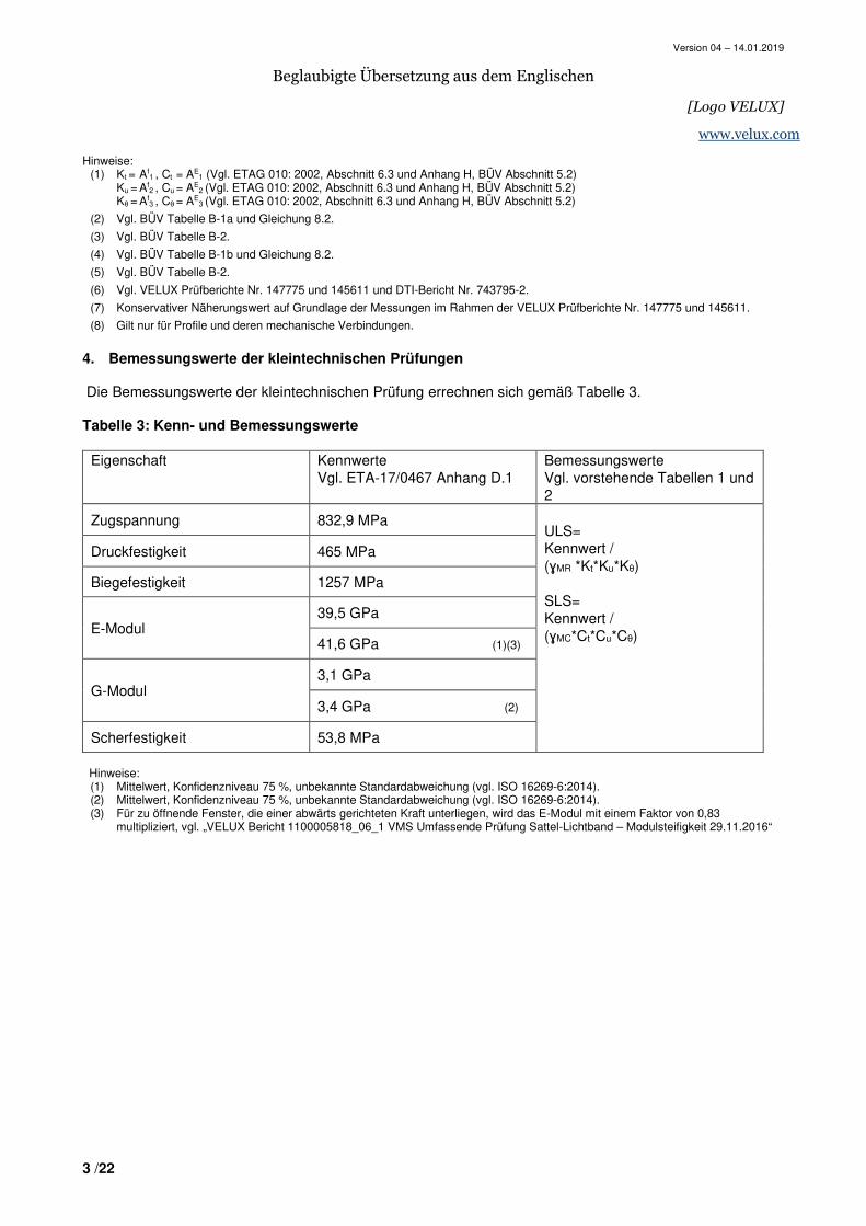
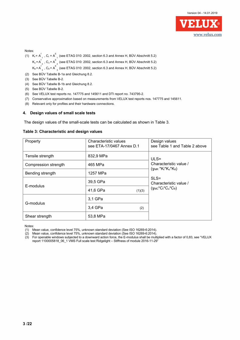
4. Bemessungswerte der kleintechnischen Prüfungen
Die Bemessungswerte der kleintechnischen Prüfung errechnen sich gemäß Tabelle 3. Tabelle 3: Kenn- und Bemessungswerte
Eigenschaft Kennwerte Vgl. ETA-17/0467 Anhang D.1
Bemessungswerte Vgl. vorstehende Tabellen 1 und 2
Zugspannung 832,9 MPa ULS= Kennwert / (ɣMR *Kt*Ku*Kθ) SLS= Kennwert / (ɣMC*Ct*Cu*Cθ)
Druckfestigkeit 465 MPa
Biegefestigkeit 1257 MPa
E-Modul 39,5 GPa
41,6 GPa (1)(3)
G-Modul 3,1 GPa
3,4 GPa (2)
Scherfestigkeit 53,8 MPa
Hinweise:
(1) Mittelwert, Konfidenzniveau 75 %, unbekannte Standardabweichung (vgl. ISO 16269-6:2014). (2) Mittelwert, Konfidenzniveau 75 %, unbekannte Standardabweichung (vgl. ISO 16269-6:2014). (3) Für zu öffnende Fenster, die einer abwärts gerichteten Kraft unterliegen, wird das E-Modul mit einem Faktor von 0,83
multipliziert, vgl. „VELUX Bericht 1100005818_06_1 VMS Umfassende Prüfung Sattel-Lichtband – Modulsteifigkeit 29.11.2016“
Version 04 – 14.01.2019
Beglaubigte Übersetzung aus dem Englischen
[Logo VELUX]
4 /22
www.velux.com
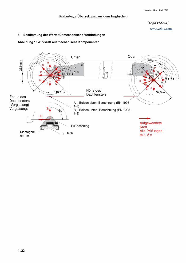
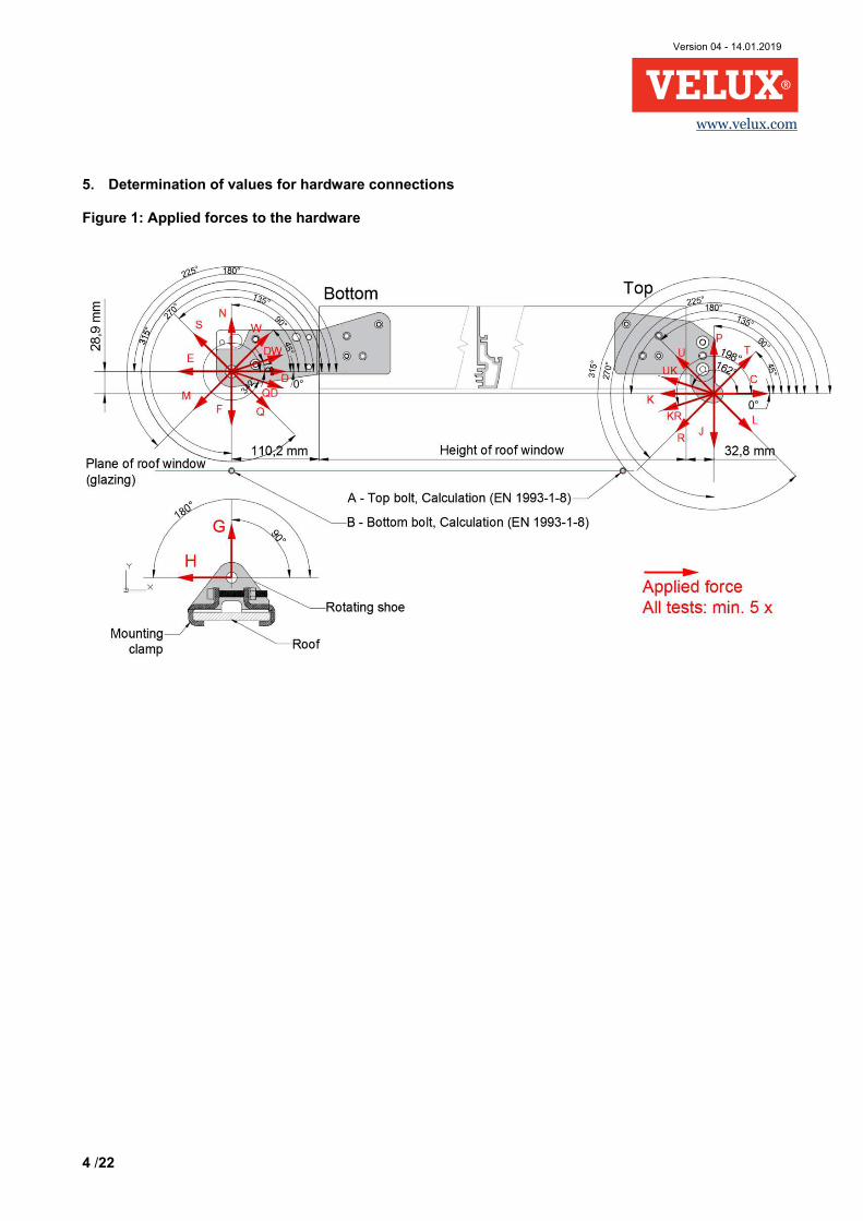
5. Bestimmung der Werte für mechanische Verbindungen Abbildung 1: Wirkkraft auf mechanische Komponenten
Unten Oben
Ebene des Dachfensters (Verglasung) Verglasung:
Höhe des Dachfensters
A – Bolzen oben, Berechnung (EN 1993-1-8) B – Bolzen unten, Berechnung (EN 1993-1-8)
Fußbeschlag
Dach Montageklemme
Aufgewendete Kraft Alle Prüfungen: min. 5 x
Version 04 – 14.01.2019
Beglaubigte Übersetzung aus dem Englischen
[Logo VELUX]
5 /22
www.velux.com
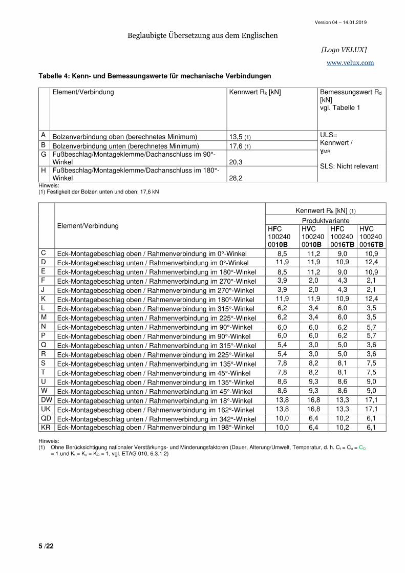
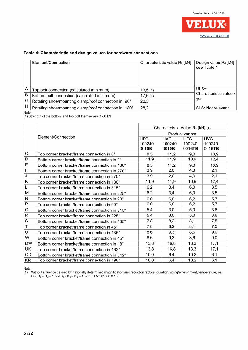
Tabelle 4: Kenn- und Bemessungswerte für mechanische Verbindungen
Element/Verbindung Kennwert Rk [kN] Bemessungswert Rd
[kN] vgl. Tabelle 1
A Bolzenverbindung oben (berechnetes Minimum) 13,5 (1) ULS= Kennwert / ɣMR SLS: Nicht relevant
B Bolzenverbindung unten (berechnetes Minimum) 17,6 (1) G Fußbeschlag/Montageklemme/Dachanschluss im 90°-
Winkel 20,3 H Fußbeschlag/Montageklemme/Dachanschluss im 180°-
Winkel 28,2 Hinweis: (1) Festigkeit der Bolzen unten und oben: 17,6 kN
Element/Verbindung
Kennwert Rk [kN] (1)
Produktvariante HFC 100240 0010B
HVC 100240 0010B
HFC 100240 0016TB
HVC 100240 0016TB
C Eck-Montagebeschlag oben / Rahmenverbindung im 0°-Winkel 8,5 11,2 9,0 10,9 D Eck-Montagebeschlag unten / Rahmenverbindung im 0°-Winkel 11,9 11,9 10,9 12,4 E Eck-Montagebeschlag unten / Rahmenverbindung im 180°-Winkel 8,5 11,2 9,0 10,9 F Eck-Montagebeschlag unten / Rahmenverbindung im 270°-Winkel 3,9 2,0 4,3 2,1 J Eck-Montagebeschlag oben / Rahmenverbindung im 270°-Winkel 3,9 2,0 4,3 2,1 K Eck-Montagebeschlag oben / Rahmenverbindung im 180°-Winkel 11,9 11,9 10,9 12,4 L Eck-Montagebeschlag oben / Rahmenverbindung im 315°-Winkel 6,2 3,4 6,0 3,5 M Eck-Montagebeschlag unten / Rahmenverbindung im 225°-Winkel 6,2 3,4 6,0 3,5 N Eck-Montagebeschlag unten / Rahmenverbindung im 90°-Winkel 6,0 6,0 6,2 5,7 P Eck-Montagebeschlag oben / Rahmenverbindung im 90°-Winkel 6,0 6,0 6,2 5,7 Q Eck-Montagebeschlag unten / Rahmenverbindung im 315°-Winkel 5,4 3,0 5,0 3,6 R Eck-Montagebeschlag oben / Rahmenverbindung im 225°-Winkel 5,4 3,0 5,0 3,6 S Eck-Montagebeschlag unten / Rahmenverbindung im 135°-Winkel 7,8 8,2 8,1 7,5 T Eck-Montagebeschlag oben / Rahmenverbindung im 45°-Winkel 7,8 8,2 8,1 7,5 U Eck-Montagebeschlag oben / Rahmenverbindung im 135°-Winkel 8,6 9,3 8,6 9,0 W Eck-Montagebeschlag unten / Rahmenverbindung im 45°-Winkel 8,6 9,3 8,6 9,0 DW Eck-Montagebeschlag unten / Rahmenverbindung im 18°-Winkel 13,8 16,8 13,3 17,1 UK Eck-Montagebeschlag oben / Rahmenverbindung im 162°-Winkel 13,8 16,8 13,3 17,1 QD Eck-Montagebeschlag unten / Rahmenverbindung im 342°-Winkel 10,0 6,4 10,2 6,1 KR Eck-Montagebeschlag oben / Rahmenverbindung im 198°-Winkel 10,0 6,4 10,2 6,1
Hinweis: (1) Ohne Berücksichtigung nationaler Verstärkungs- und Minderungsfaktoren (Dauer, Alterung/Umwelt, Temperatur, d. h. Ct = Cu = CQ
= 1 und Kt = Ku = KQ = 1, vgl. ETAG 010, 6.3.1.2)

Version 04 – 14.01.2019
Beglaubigte Übersetzung aus dem Englischen
[Logo VELUX]
6 /22
www.velux.com
Version 04 – 14.01.2019
Beglaubigte Übersetzung aus dem Englischen
[Logo VELUX]
7 /22
www.velux.com
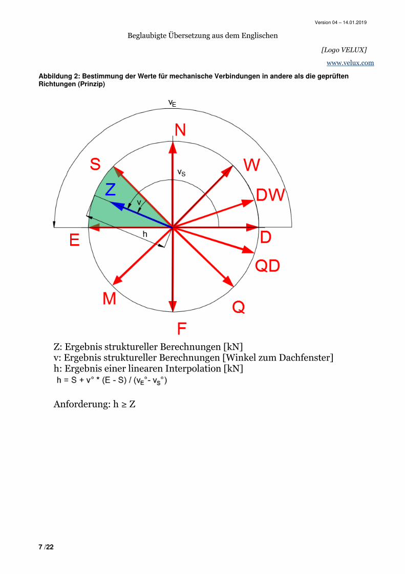
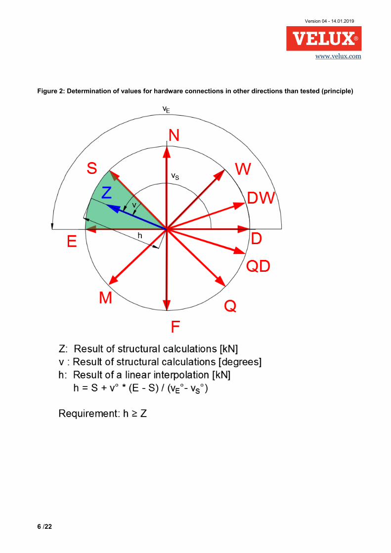
Abbildung 2: Bestimmung der Werte für mechanische Verbindungen in andere als die geprüften Richtungen (Prinzip)
Z: Ergebnis struktureller Berechnungen [kN] v: Ergebnis struktureller Berechnungen [Winkel zum Dachfenster] h: Ergebnis einer linearen Interpolation [kN]
Anforderung: h ≥ Z
Version 04 – 14.01.2019
Beglaubigte Übersetzung aus dem Englischen
[Logo VELUX]
8 /22
www.velux.com
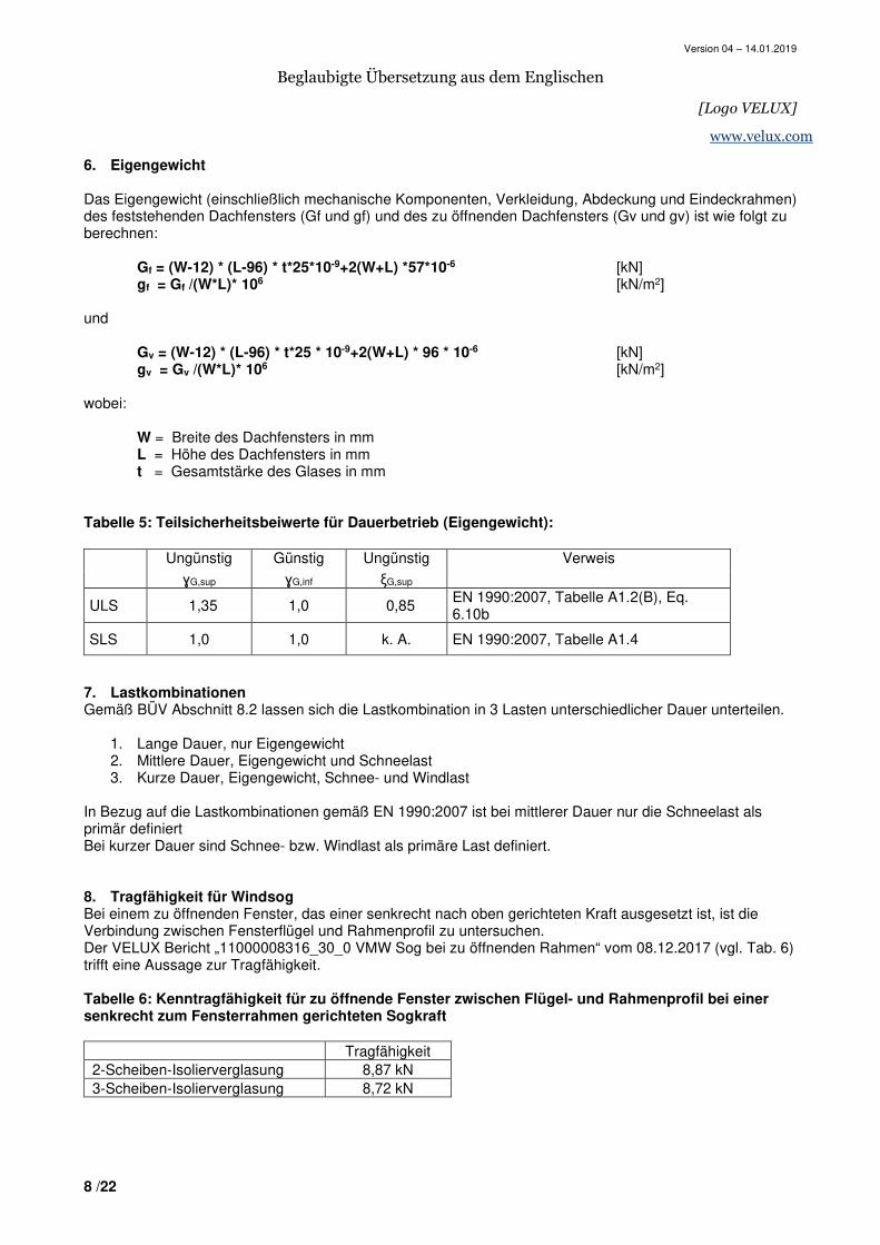
6. Eigengewicht Das Eigengewicht (einschließlich mechanische Komponenten, Verkleidung, Abdeckung und Eindeckrahmen) des feststehenden Dachfensters (Gf und gf) und des zu öffnenden Dachfensters (Gv und gv) ist wie folgt zu berechnen:
Gf = (W-12) * (L-96) * t*25*10-9+2(W+L) *57*10-6 [kN] gf = Gf /(W*L)* 106 [kN/m2] und Gv = (W-12) * (L-96) * t*25 * 10-9+2(W+L) * 96 * 10-6 [kN] gv = Gv /(W*L)* 106 [kN/m2] wobei: W = Breite des Dachfensters in mm L = Höhe des Dachfensters in mm t = Gesamtstärke des Glases in mm Tabelle 5: Teilsicherheitsbeiwerte für Dauerbetrieb (Eigengewicht):
7. Lastkombinationen Gemäß BÜV Abschnitt 8.2 lassen sich die Lastkombination in 3 Lasten unterschiedlicher Dauer unterteilen.
1. Lange Dauer, nur Eigengewicht 2. Mittlere Dauer, Eigengewicht und Schneelast 3. Kurze Dauer, Eigengewicht, Schnee- und Windlast
In Bezug auf die Lastkombinationen gemäß EN 1990:2007 ist bei mittlerer Dauer nur die Schneelast als primär definiert Bei kurzer Dauer sind Schnee- bzw. Windlast als primäre Last definiert. 8. Tragfähigkeit für Windsog Bei einem zu öffnenden Fenster, das einer senkrecht nach oben gerichteten Kraft ausgesetzt ist, ist die Verbindung zwischen Fensterflügel und Rahmenprofil zu untersuchen. Der VELUX Bericht „11000008316_30_0 VMW Sog bei zu öffnenden Rahmen“ vom 08.12.2017 (vgl. Tab. 6) trifft eine Aussage zur Tragfähigkeit. Tabelle 6: Kenntragfähigkeit für zu öffnende Fenster zwischen Flügel- und Rahmenprofil bei einer senkrecht zum Fensterrahmen gerichteten Sogkraft
Tragfähigkeit 2-Scheiben-Isolierverglasung 8,87 kN 3-Scheiben-Isolierverglasung 8,72 kN
Ungünstig Günstig Ungünstig Verweis
ɣG,sup ɣG,inf ξG,sup
ULS 1,35 1,0 0,85 EN 1990:2007, Tabelle A1.2(B), Eq. 6.10b
SLS 1,0 1,0 k. A. EN 1990:2007, Tabelle A1.4
Version 04 – 14.01.2019
Beglaubigte Übersetzung aus dem Englischen
[Logo VELUX]
9 /22
www.velux.com
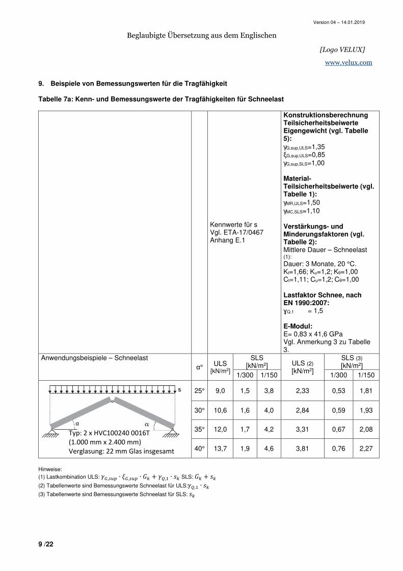
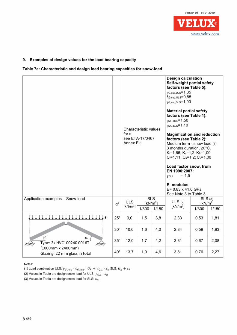
9. Beispiele von Bemessungswerten für die Tragfähigkeit Tabelle 7a: Kenn- und Bemessungswerte der Tragfähigkeiten für Schneelast
Kennwerte für s Vgl. ETA-17/0467 Anhang E.1
Konstruktionsberechnung Teilsicherheitsbeiwerte Eigengewicht (vgl. Tabelle 5):
γG,sup,ULS=1,35 ξG,sup,ULS=0,85 γG,sup,SLS=1,00 Material-Teilsicherheitsbeiwerte (vgl. Tabelle 1):
γMR,ULS=1,50 γMC,SLS=1,10 Verstärkungs- und Minderungsfaktoren (vgl. Tabelle 2): Mittlere Dauer – Schneelast (1): Dauer: 3 Monate, 20 °C. Kt=1,66; Ku=1,2; Kθ=1,00 Ct=1,11; Cu=1,2; Cθ=1,00 Lastfaktor Schnee, nach EN 1990:2007: ɣQ,1 = 1,5 E-Modul: E= 0,83 x 41,6 GPa Vgl. Anmerkung 3 zu Tabelle 3.
Anwendungsbeispiele – Schneelast α° ULS
[kN/m2]
SLS [kN/m2] ULS (2)
[kN/m2]
SLS (3) [kN/m2]
1/300 1/150 1/300 1/150
25° 9,0 1,5 3,8 2,33 0,53 1,81
30° 10,6 1,6 4,0 2,84 0,59 1,93
35° 12,0 1,7 4,2 3,31 0,67 2,08
40° 13,7 1,9 4,6 3,81 0,76 2,27
Hinweise: (1) Lastkombination ULS: ��,��� ∙ ��,��� ∙ + ��, ∙ � SLS: + �
(2) Tabellenwerte sind Bemessungswerte Schneelast für ULS:��, ∙ �
(3) Tabellenwerte sind Bemessungswerte Schneelast für SLS: �
Typ: 2 x HVC100240 0016T
(1.000 mm x 2.400 mm)
Verglasung: 22 mm Glas insgesamt
Version 04 – 14.01.2019
Beglaubigte Übersetzung aus dem Englischen
[Logo VELUX]
10 /22
www.velux.com
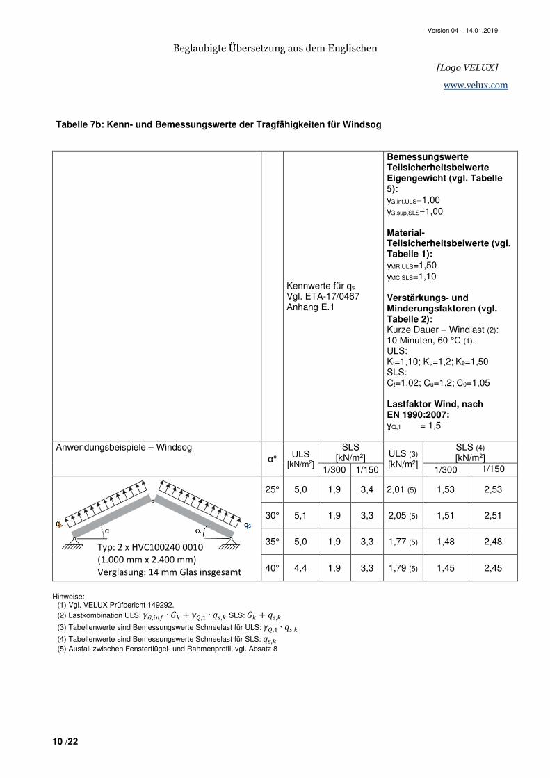
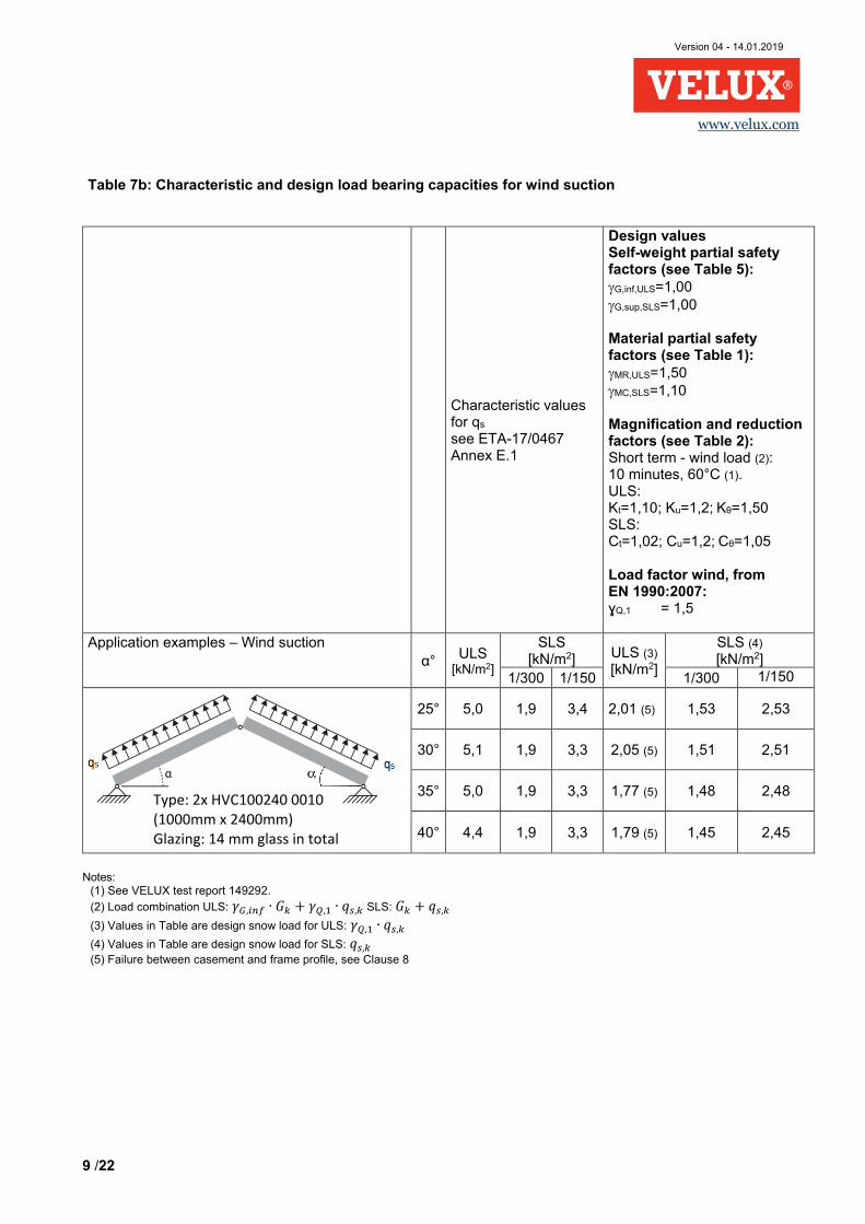
Tabelle 7b: Kenn- und Bemessungswerte der Tragfähigkeiten für Windsog
Kennwerte für qs Vgl. ETA-17/0467 Anhang E.1
Bemessungswerte Teilsicherheitsbeiwerte Eigengewicht (vgl. Tabelle 5):
γG,inf,ULS=1,00 γG,sup,SLS=1,00 Material-Teilsicherheitsbeiwerte (vgl. Tabelle 1):
γMR,ULS=1,50 γMC,SLS=1,10 Verstärkungs- und Minderungsfaktoren (vgl. Tabelle 2): Kurze Dauer – Windlast (2): 10 Minuten, 60 °C (1). ULS: Kt=1,10; Ku=1,2; Kθ=1,50 SLS: Ct=1,02; Cu=1,2; Cθ=1,05 Lastfaktor Wind, nach EN 1990:2007: ɣQ,1 = 1,5
Anwendungsbeispiele – Windsog α° ULS
[kN/m2]
SLS [kN/m2] ULS (3)
[kN/m2]
SLS (4) [kN/m2]
1/300 1/150 1/300 1/150
25° 5,0 1,9 3,4 2,01 (5) 1,53 2,53
30° 5,1 1,9 3,3 2,05 (5) 1,51 2,51
35° 5,0 1,9 3,3 1,77 (5) 1,48 2,48
40° 4,4 1,9 3,3 1,79 (5) 1,45 2,45
Hinweise:
(1) Vgl. VELUX Prüfbericht 149292. (2) Lastkombination ULS: ��,��� ∙ + ��, ∙ ��, SLS: + ��,
(3) Tabellenwerte sind Bemessungswerte Schneelast für ULS: ��, ∙ ��,
(4) Tabellenwerte sind Bemessungswerte Schneelast für SLS: ��, (5) Ausfall zwischen Fensterflügel- und Rahmenprofil, vgl. Absatz 8
Typ: 2 x HVC100240 0010
(1.000 mm x 2.400 mm)
Verglasung: 14 mm Glas insgesamt
Version 04 – 14.01.2019
Beglaubigte Übersetzung aus dem Englischen
[Logo VELUX]
11 /22
www.velux.com
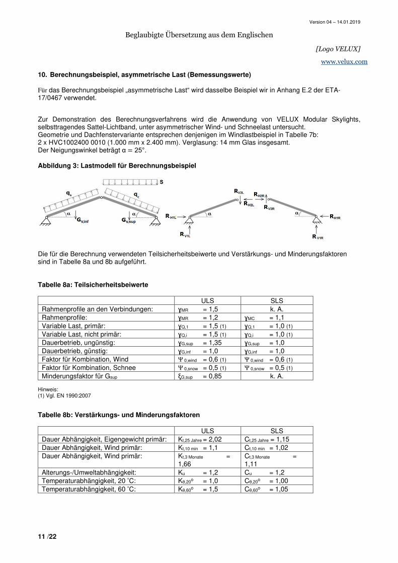
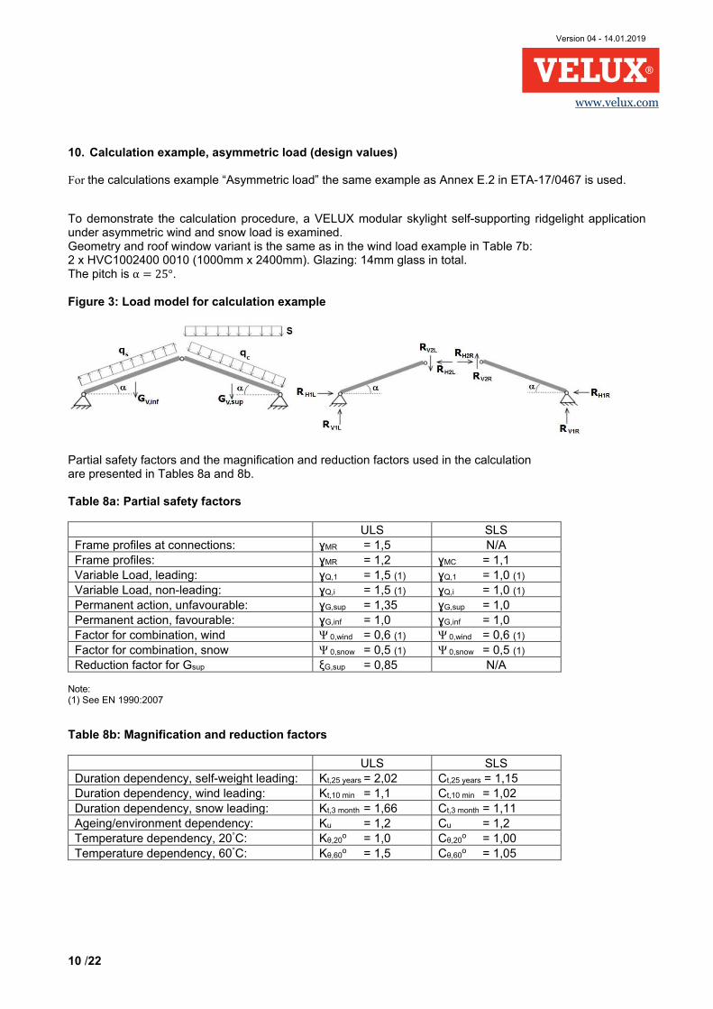
10. Berechnungsbeispiel, asymmetrische Last (Bemessungswerte) Für das Berechnungsbeispiel „asymmetrische Last“ wird dasselbe Beispiel wir in Anhang E.2 der ETA-17/0467 verwendet. Zur Demonstration des Berechnungsverfahrens wird die Anwendung von VELUX Modular Skylights, selbsttragendes Sattel-Lichtband, unter asymmetrischer Wind- und Schneelast untersucht. Geometrie und Dachfenstervariante entsprechen denjenigen im Windlastbeispiel in Tabelle 7b: 2 x HVC1002400 0010 (1.000 mm x 2.400 mm). Verglasung: 14 mm Glas insgesamt. Der Neigungswinkel beträgt α � 25°.
Abbildung 3: Lastmodell für Berechnungsbeispiel
Die für die Berechnung verwendeten Teilsicherheitsbeiwerte und Verstärkungs- und Minderungsfaktoren sind in Tabelle 8a und 8b aufgeführt.
Tabelle 8a: Teilsicherheitsbeiwerte
ULS SLS Rahmenprofile an den Verbindungen: ɣMR = 1,5 k. A. Rahmenprofile: ɣMR = 1,2 ɣMC = 1,1 Variable Last, primär: ɣQ,1 = 1,5 (1) ɣQ,1 = 1,0 (1) Variable Last, nicht primär: ɣQ,i = 1,5 (1) ɣQ,i = 1,0 (1) Dauerbetrieb, ungünstig: ɣG,sup = 1,35 ɣG,sup = 1,0 Dauerbetrieb, günstig: ɣG,inf = 1,0 ɣG,inf = 1,0 Faktor für Kombination, Wind Ψ 0,wind = 0,6 (1) Ψ 0,wind = 0,6 (1) Faktor für Kombination, Schnee Ψ 0,snow = 0,5 (1) Ψ 0,snow = 0,5 (1) Minderungsfaktor für Gsup ξG,sup = 0,85 k. A.
Hinweis: (1) Vgl. EN 1990:2007 Tabelle 8b: Verstärkungs- und Minderungsfaktoren
ULS SLS Dauer Abhängigkeit, Eigengewicht primär: Kt,25 Jahre = 2,02 Ct,25 Jahre = 1,15 Dauer Abhängigkeit, Wind primär: Kt,10 min = 1,1 Ct,10 min = 1,02 Dauer Abhängigkeit, Wind primär: Kt,3 Monate =
1,66 Ct,3 Monate = 1,11
Alterungs-/Umweltabhängigkeit: Ku = 1,2 Cu = 1,2 Temperaturabhängigkeit, 20 °C: Kθ,20o = 1,0 Cθ,20o = 1,00 Temperaturabhängigkeit, 60 °C: Kθ,60o = 1,5 Cθ,60o = 1,05
Version 04 – 14.01.2019
Beglaubigte Übersetzung aus dem Englischen
[Logo VELUX]
12 /22
www.velux.com
Version 04 – 14.01.2019
Beglaubigte Übersetzung aus dem Englischen
[Logo VELUX]
13 /22
www.velux.com
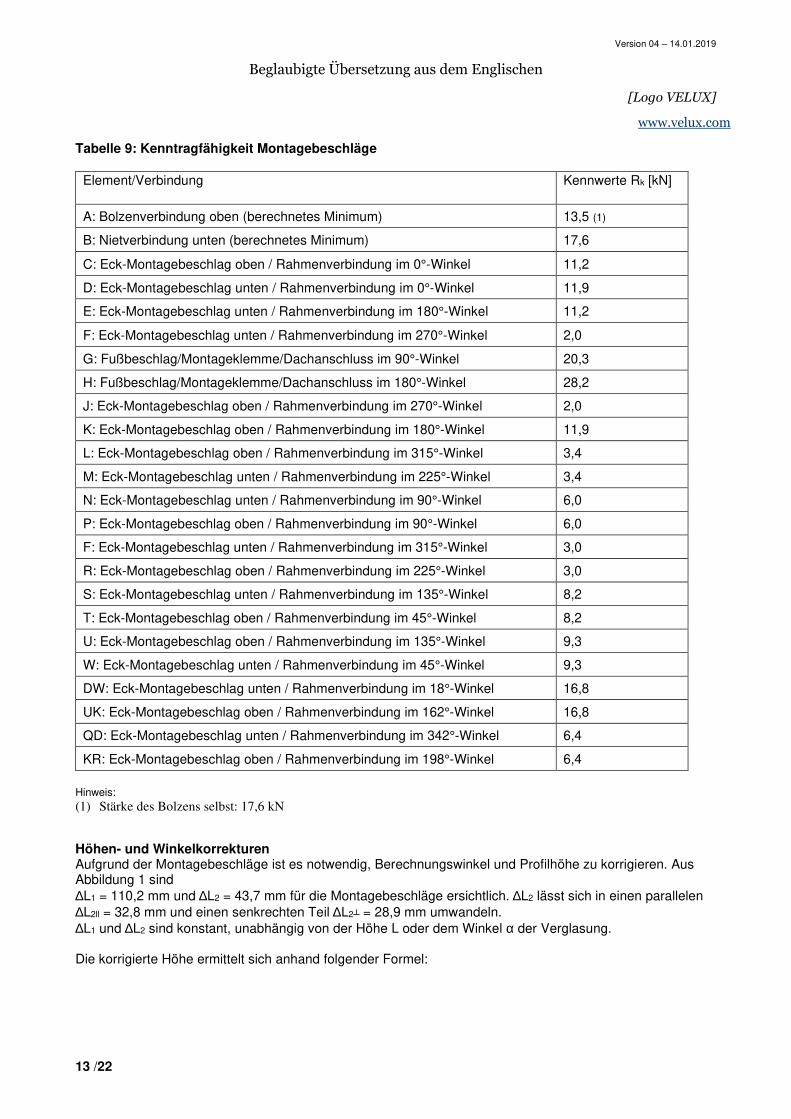
Tabelle 9: Kenntragfähigkeit Montagebeschläge
Element/Verbindung Kennwerte Rk [kN]
A: Bolzenverbindung oben (berechnetes Minimum) 13,5 (1)
B: Nietverbindung unten (berechnetes Minimum) 17,6
C: Eck-Montagebeschlag oben / Rahmenverbindung im 0°-Winkel 11,2
D: Eck-Montagebeschlag unten / Rahmenverbindung im 0°-Winkel 11,9
E: Eck-Montagebeschlag unten / Rahmenverbindung im 180°-Winkel 11,2
F: Eck-Montagebeschlag unten / Rahmenverbindung im 270°-Winkel 2,0
G: Fußbeschlag/Montageklemme/Dachanschluss im 90°-Winkel 20,3
H: Fußbeschlag/Montageklemme/Dachanschluss im 180°-Winkel 28,2
J: Eck-Montagebeschlag oben / Rahmenverbindung im 270°-Winkel 2,0
K: Eck-Montagebeschlag oben / Rahmenverbindung im 180°-Winkel 11,9
L: Eck-Montagebeschlag oben / Rahmenverbindung im 315°-Winkel 3,4
M: Eck-Montagebeschlag unten / Rahmenverbindung im 225°-Winkel 3,4
N: Eck-Montagebeschlag unten / Rahmenverbindung im 90°-Winkel 6,0
P: Eck-Montagebeschlag oben / Rahmenverbindung im 90°-Winkel 6,0
F: Eck-Montagebeschlag unten / Rahmenverbindung im 315°-Winkel 3,0
R: Eck-Montagebeschlag oben / Rahmenverbindung im 225°-Winkel 3,0
S: Eck-Montagebeschlag unten / Rahmenverbindung im 135°-Winkel 8,2
T: Eck-Montagebeschlag oben / Rahmenverbindung im 45°-Winkel 8,2
U: Eck-Montagebeschlag oben / Rahmenverbindung im 135°-Winkel 9,3
W: Eck-Montagebeschlag unten / Rahmenverbindung im 45°-Winkel 9,3
DW: Eck-Montagebeschlag unten / Rahmenverbindung im 18°-Winkel 16,8
UK: Eck-Montagebeschlag oben / Rahmenverbindung im 162°-Winkel 16,8
QD: Eck-Montagebeschlag unten / Rahmenverbindung im 342°-Winkel 6,4
KR: Eck-Montagebeschlag oben / Rahmenverbindung im 198°-Winkel 6,4
Hinweis: (1) Stärke des Bolzens selbst: 17,6 kN Höhen- und Winkelkorrekturen Aufgrund der Montagebeschläge ist es notwendig, Berechnungswinkel und Profilhöhe zu korrigieren. Aus Abbildung 1 sind ∆L1 = 110,2 mm und ∆L2 = 43,7 mm für die Montagebeschläge ersichtlich. ∆L2 lässt sich in einen parallelen ∆L2ll = 32,8 mm und einen senkrechten Teil ∆L2┴ = 28,9 mm umwandeln. ∆L1 und ∆L2 sind konstant, unabhängig von der Höhe L oder dem Winkel α der Verglasung.
Die korrigierte Höhe ermittelt sich anhand folgender Formel:
Version 04 – 14.01.2019
Beglaubigte Übersetzung aus dem Englischen
[Logo VELUX]
14 /22
www.velux.com
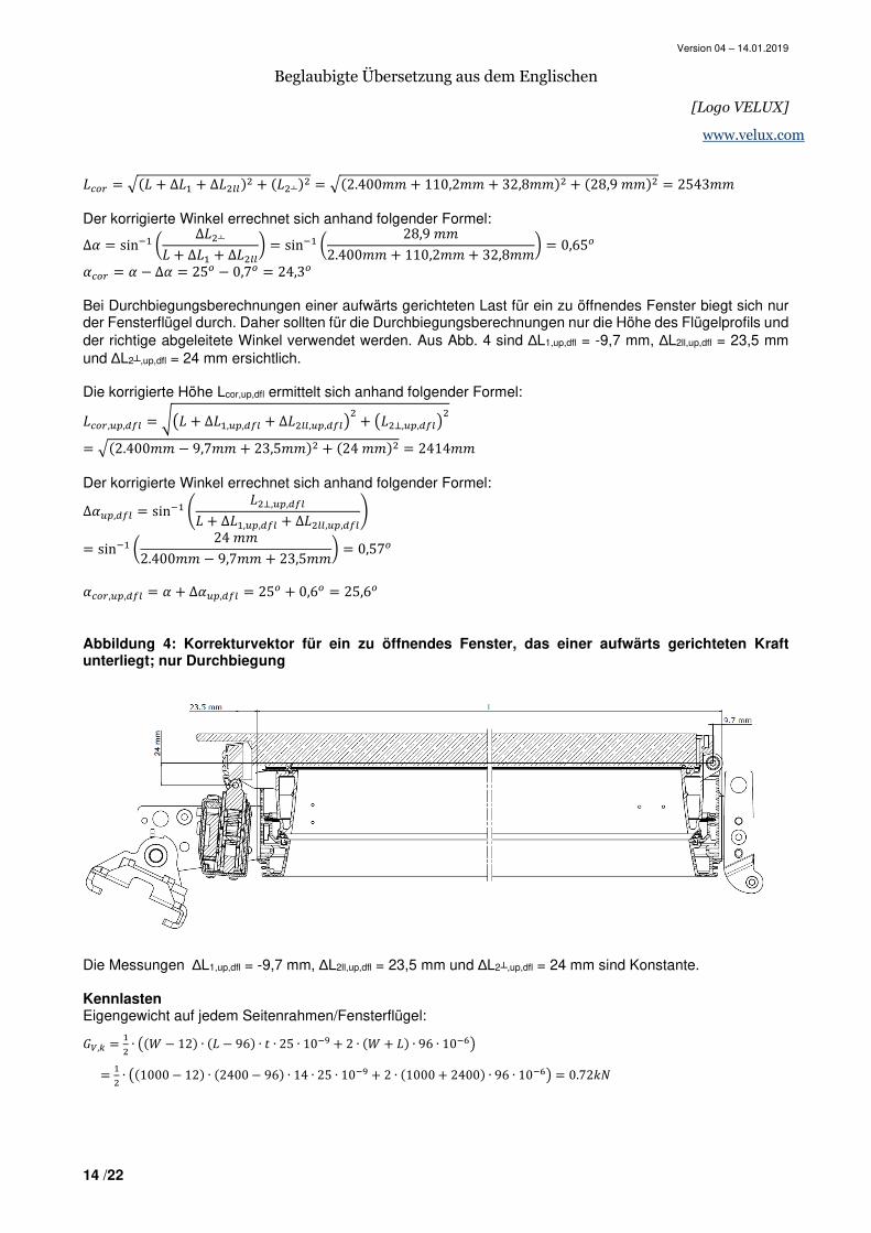
���� � ��� + ∆� + ∆������ + ���┴�� � ��2.400## + 110,2## + 32,8##�� + �28,9 ##�� � 2543##
Der korrigierte Winkel errechnet sich anhand folgender Formel:
∆* � sin. / ∆��┴� + ∆� + ∆����0 � sin. / 28,9 ##2.400## + 110,2## + 32,8##0 � 0,65�
*��� � * − ∆* � 25� − 0,7� � 24,3�
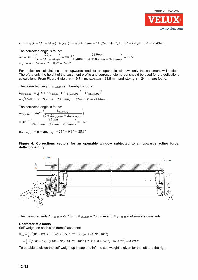
Bei Durchbiegungsberechnungen einer aufwärts gerichteten Last für ein zu öffnendes Fenster biegt sich nur der Fensterflügel durch. Daher sollten für die Durchbiegungsberechnungen nur die Höhe des Flügelprofils und der richtige abgeleitete Winkel verwendet werden. Aus Abb. 4 sind ∆L1,up,dfl = -9,7 mm, ∆L2ll,up,dfl = 23,5 mm und ∆L2┴,up,dfl = 24 mm ersichtlich. Die korrigierte Höhe Lcor,up,dfl ermittelt sich anhand folgender Formel:
����,��,4�� � 56� + ∆� ,��,4�� + ∆����,��,4��7� + 6��8,��,4��7�
� ��2.400## − 9,7## + 23,5##�� + �24 ##�� � 2414## Der korrigierte Winkel errechnet sich anhand folgender Formel:
∆*��,4�� � sin. 9 ��8,��,4��� + ∆� ,��,4�� + ∆����,��,4��:
� sin. / 24 ##2.400## − 9,7## + 23,5##0 � 0,57�
*���,��,4�� � * + ∆*��,4�� � 25� + 0,6� � 25,6�
Abbildung 4: Korrekturvektor für ein zu öffnendes Fenster, das einer aufwärts gerichteten Kraft unterliegt; nur Durchbiegung
Die Messungen ∆L1,up,dfl = -9,7 mm, ∆L2ll,up,dfl = 23,5 mm und ∆L2┴,up,dfl = 24 mm sind Konstante. Kennlasten Eigengewicht auf jedem Seitenrahmen/Fensterflügel:
;, � � ∙ 6�< − 12� ∙ �� − 96� ∙ = ∙ 25 ∙ 10.> + 2 ∙ �< + �� ∙ 96 ∙ 10.?7
� � ∙ 6�1000 − 12� ∙ �2400 − 96� ∙ 14 ∙ 25 ∙ 10.> + 2 ∙ �1000 + 2400� ∙ 96 ∙ 10.?7 � 0.72@A
Version 04 – 14.01.2019
Beglaubigte Übersetzung aus dem Englischen
[Logo VELUX]
15 /22
www.velux.com
Für die Aufteilung des Eigengewichts in sup und inf wird das Eigengewicht für den linken und rechten Rahmen/Fensterflügel angegeben. ;B, � ;C, � 0,72@A In diesem Beispiel wird der vom Wind verursachte Spitzendruck (qp,k) auf 0,8kN/m2 festgesetzt und der Formfaktor (c) beträgt 0,5 für die dem Wind ausgesetzte Seite und -0,5 für die Unterdruckseite. Somit wirkt die Last
��, � ��, � �D,@ ∙ E ∙ < 2⁄ � 0,8@A/#� ∙ 0,5 ∙ 1,0# 2⁄ � 0,2@A/#, HIJ KLMLN OLP=LNQHℎ#LN/SLN�=LQJTüVLT Die Windlast wird mittels des ursprünglichen Winkels in eine vertikale und eine horizontale Komponente zerlegtα. Mit der korrigierten Höhe Lcor ermittelt sich die äquivalente konzentrierte Last.
W�X, � W�X, � ��, ∙ ���� ∙ sin�*� � 0,2@A/# ∙ 2,543# ∙ sin�25�� � 0,21@A HIJ KLMLN OLP=LNQHℎ#LN/SLN�=LQJTüVLT W�;, � W�;, � ��, ∙ ���� ∙ cos�*� � 0,2@A/# ∙ 2,543# ∙ cos�25�� � 0,46 @A HIJ KLMLN OLP=LNQHℎ#LN/SLN�=LQJTüVLT Für die Schneelast in diesem Beispiel werden die beiden C-Faktoren (gemäß EN 1991-1-3) mit 1,0 festgelegt, der Formfaktor µ2 mit 0,8 und der Kennwert der Schneelast am Boden ist Sk=1,0kN/m2, bei gegebener Schneelast sk: � � [� ∙ \] ∙ \^ ∙ O � 0,8 ∙ 1,0 ∙ 1,0 ∙ 1,0@A #�⁄ � 0,8@A #�⁄ → ��,� 0,4@A/# , HIJ KLMLN OLP=LNQHℎ#LN/SLN�=LQJTüVLT Die Schneelast wirkt nur vertikal und die korrigierte Höhe Lcor wird zur Ermittlung der äquivalenten konzentrierten Last genutzt. O;, � � ∙ cos�*� ∙ ���� � 0,4@A/# ∙ cos�25�� ∙ 2,543# � 0,92@A
Reaktionen in den Montagebeschlägen
Die korrigierte Höhe Lcor und der Winkel αcor dienen im statischen System zur Bestimmung der Reaktionen. Diese Berechnungen werden hier nicht vorgestellt. Die Reaktionen werden getrennt für jeden Lasttyp berechnet und sind in Tabelle 10 zu finden. Aus diesen Kennreaktionen errechnen sich unterschiedliche Lastkombinationen anhand der Teilsicherheitsbeiwerte aus Tabelle 8a: CC2 (vgl. EN 1990:2007, Tabelle B1) wird angenommen: a) Kennlastkombination: 1,0 ∙ ;B. + 1,0 ∙ ;C, + 1,0 ∙ W + 1,0 ∙ O;,
b) Lange Dauer: Eigengewichtkombination primär: ��,��` ∙ ;B, + ��,��� ∙ ;C, =>
1,35 ∙ ;B, + 1,35 ∙ ;C,
c) Mittlere Dauer: Schneekombination primär: ��,��� ∙ ;B, + ��,��� ∙ ��,��� ∙ ;C, + ��, ∙ O;, =>
1,0 ∙ ;B, + 1,35 ∙ 0,85 ∙ ;C, + 1,5 ∙ O;,
d) Kurze Dauer: Windkombination primär, mit Schnee: ��,��� ∙ ;B, + ��,��� ∙ ��,��� ∙ ;C, + ��, ∙ W + ��,� ∙ Ψb,���c ∙ O;, => 1,0 ∙ ;B, + 1,35 ∙ 0,85 ∙ ;C, + 1,5 ∙ W + 1,5 ∙ 0,5 ∙ O;, e) Kurze Dauer: Windkombination primär, ohne Schnee: ��,��� ∙ ;B, + ��,��� ∙ ��,��� ∙ ;C, + ��, ∙ W => 1,0 ∙ ;B, + 1,35 ∙ 0,85 ∙ ;C, + 1,5 ∙ W f) Kurze Dauer: Schneekombination primär, mit Wind: ��,��� ∙ ;B, + ��,��� ∙ ��,��� ∙ ;C, + ��,� ∙ Ψb,c��4 ∙ W + ��, ∙ O;, => 1,0 ∙ ;B, + 1,35 ∙ 0,85 ∙ ;C, + 1,5 ∙ 0,6 ∙ W + 1,5 ∙ O;,
Version 04 – 14.01.2019
Beglaubigte Übersetzung aus dem Englischen
[Logo VELUX]
16 /22
www.velux.com
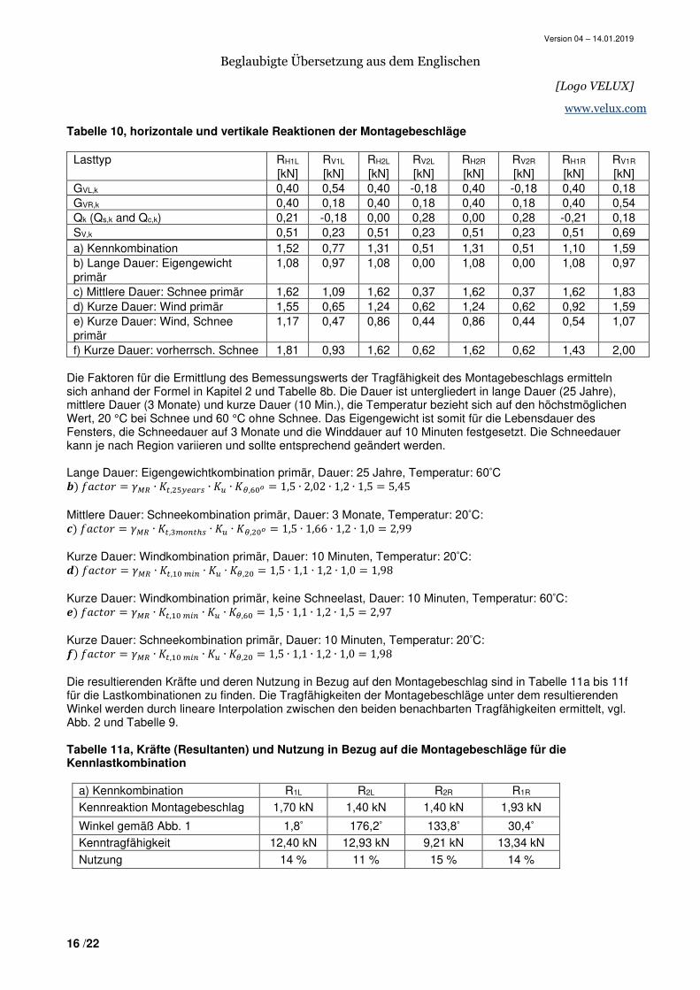
Tabelle 10, horizontale und vertikale Reaktionen der Montagebeschläge
Lasttyp RH1L [kN]
RV1L [kN]
RH2L [kN]
RV2L [kN]
RH2R [kN]
RV2R [kN]
RH1R [kN]
RV1R [kN]
GVL,k 0,40 0,54 0,40 -0,18 0,40 -0,18 0,40 0,18 GVR,k 0,40 0,18 0,40 0,18 0,40 0,18 0,40 0,54 Qk (Qs,k and Qc,k) 0,21 -0,18 0,00 0,28 0,00 0,28 -0,21 0,18 SV,k 0,51 0,23 0,51 0,23 0,51 0,23 0,51 0,69 a) Kennkombination 1,52 0,77 1,31 0,51 1,31 0,51 1,10 1,59 b) Lange Dauer: Eigengewicht primär
1,08 0,97 1,08 0,00 1,08 0,00 1,08 0,97
c) Mittlere Dauer: Schnee primär 1,62 1,09 1,62 0,37 1,62 0,37 1,62 1,83 d) Kurze Dauer: Wind primär 1,55 0,65 1,24 0,62 1,24 0,62 0,92 1,59 e) Kurze Dauer: Wind, Schnee primär
1,17 0,47 0,86 0,44 0,86 0,44 0,54 1,07
f) Kurze Dauer: vorherrsch. Schnee 1,81 0,93 1,62 0,62 1,62 0,62 1,43 2,00 Die Faktoren für die Ermittlung des Bemessungswerts der Tragfähigkeit des Montagebeschlags ermitteln sich anhand der Formel in Kapitel 2 und Tabelle 8b. Die Dauer ist untergliedert in lange Dauer (25 Jahre), mittlere Dauer (3 Monate) und kurze Dauer (10 Min.), die Temperatur bezieht sich auf den höchstmöglichen Wert, 20 °C bei Schnee und 60 °C ohne Schnee. Das Eigengewicht ist somit für die Lebensdauer des Fensters, die Schneedauer auf 3 Monate und die Winddauer auf 10 Minuten festgesetzt. Die Schneedauer kann je nach Region variieren und sollte entsprechend geändert werden. Lange Dauer: Eigengewichtkombination primär, Dauer: 25 Jahre, Temperatur: 60°C d� JHE=eQ � �fC ∙ g^,�hi]j�� ∙ g� ∙ gk,?bl � 1,5 ∙ 2,02 ∙ 1,2 ∙ 1,5 � 5,45 Mittlere Dauer: Schneekombination primär, Dauer: 3 Monate, Temperatur: 20°C: m� JHE=eQ � �fC ∙ g^,no��^p� ∙ g� ∙ gk,�bl � 1,5 ∙ 1,66 ∙ 1,2 ∙ 1,0 � 2,99 Kurze Dauer: Windkombination primär, Dauer: 10 Minuten, Temperatur: 20°C: q� JHE=eQ � �fC ∙ g^, b o�� ∙ g� ∙ gk,�b � 1,5 ∙ 1,1 ∙ 1,2 ∙ 1,0 � 1,98 Kurze Dauer: Windkombination primär, keine Schneelast, Dauer: 10 Minuten, Temperatur: 60°C: r� JHE=eQ � �fC ∙ g^, b o�� ∙ g� ∙ gk,?b � 1,5 ∙ 1,1 ∙ 1,2 ∙ 1,5 � 2,97 Kurze Dauer: Schneekombination primär, Dauer: 10 Minuten, Temperatur: 20°C: s� JHE=eQ � �fC ∙ g^, b o�� ∙ g� ∙ gk,�b � 1,5 ∙ 1,1 ∙ 1,2 ∙ 1,0 � 1,98 Die resultierenden Kräfte und deren Nutzung in Bezug auf den Montagebeschlag sind in Tabelle 11a bis 11f für die Lastkombinationen zu finden. Die Tragfähigkeiten der Montagebeschläge unter dem resultierenden Winkel werden durch lineare Interpolation zwischen den beiden benachbarten Tragfähigkeiten ermittelt, vgl. Abb. 2 und Tabelle 9. Tabelle 11a, Kräfte (Resultanten) und Nutzung in Bezug auf die Montagebeschläge für die Kennlastkombination
a) Kennkombination R1L R2L R2R R1R
Kennreaktion Montagebeschlag 1,70 kN 1,40 kN 1,40 kN 1,93 kN
Winkel gemäß Abb. 1 1,8° 176,2° 133,8° 30,4°
Kenntragfähigkeit 12,40 kN 12,93 kN 9,21 kN 13,34 kN
Nutzung 14 % 11 % 15 % 14 %
Version 04 – 14.01.2019
Beglaubigte Übersetzung aus dem Englischen
[Logo VELUX]
17 /22
www.velux.com
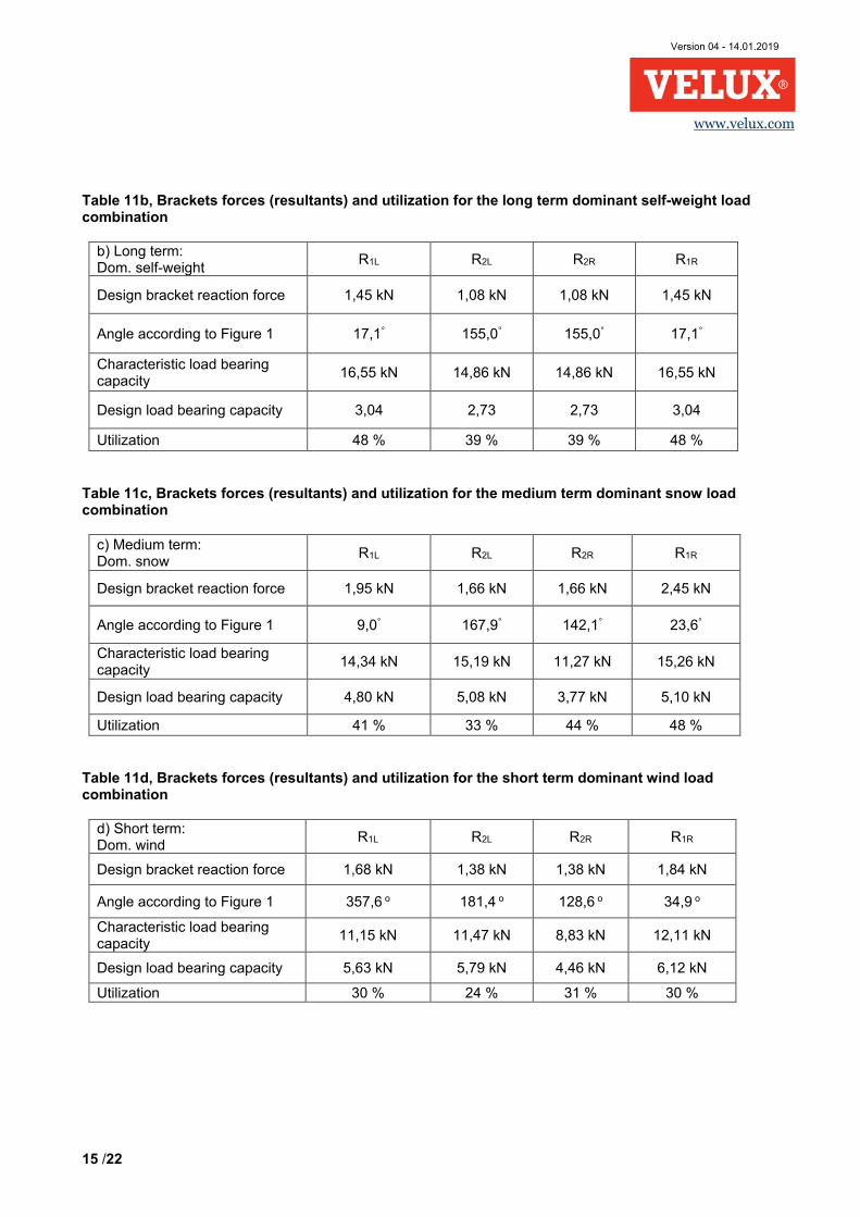
Tabelle 11b, Kräfte (Resultanten) und Nutzung in Bezug auf die Montagebeschläge für die Lastkombination Eigengewicht primär, lange Dauer
b) Lange Dauer: Eigengewicht primär
R1L R2L R2R R1R
Bemessungsreaktionskraft Montagebeschlag
1,45 kN 1,08 kN 1,08 kN 1,45 kN
Winkel gemäß Abb. 1 17,1° 155,0° 155,0° 17,1°
Kenntragfähigkeit 16,55 kN 14,86 kN 14,86 kN 16,55 kN
Bemessungstragfähigkeit 3,04 2,73 2,73 3,04
Nutzung 48 % 39 % 39 % 48 % Tabelle 11c, Kräfte (Resultanten) und Nutzung in Bezug auf die Montagebeschläge für Schneelastkombination primär, mittlere Dauer
c) Mittlere Dauer: Schnee primär
R1L R2L R2R R1R
Bemessungsreaktionskraft Montagebeschlag
1,95 kN 1,66 kN 1,66 kN 2,45 kN
Winkel gemäß Abb. 1 9,0° 167,9° 142,1° 23,6°
Kenntragfähigkeit 14,34 kN 15,19 kN 11,27 kN 15,26 kN
Bemessungstragfähigkeit 4,80 kN 5,08 kN 3,77 kN 5,10 kN
Nutzung 41 % 33 % 44 % 48 % Tabelle 11d, Kräfte (Resultanten) und Nutzung in Bezug auf die Montagebeschläge für Windlastkombination primär, kurze Dauer
d) Kurze Dauer: Wind primär
R1L R2L R2R R1R
Bemessungsreaktionskraft Montagebeschlag
1,68 kN 1,38 kN 1,38 kN 1,84 kN
Winkel gemäß Abb. 1 357,6 o 181,4 o 128,6 o 34,9 o
Kenntragfähigkeit 11,15 kN 11,47 kN 8,83 kN 12,11 kN
Bemessungstragfähigkeit 5,63 kN 5,79 kN 4,46 kN 6,12 kN
Nutzung 30 % 24 % 31 % 30 %
Version 04 – 14.01.2019
Beglaubigte Übersetzung aus dem Englischen
[Logo VELUX]
18 /22
www.velux.com
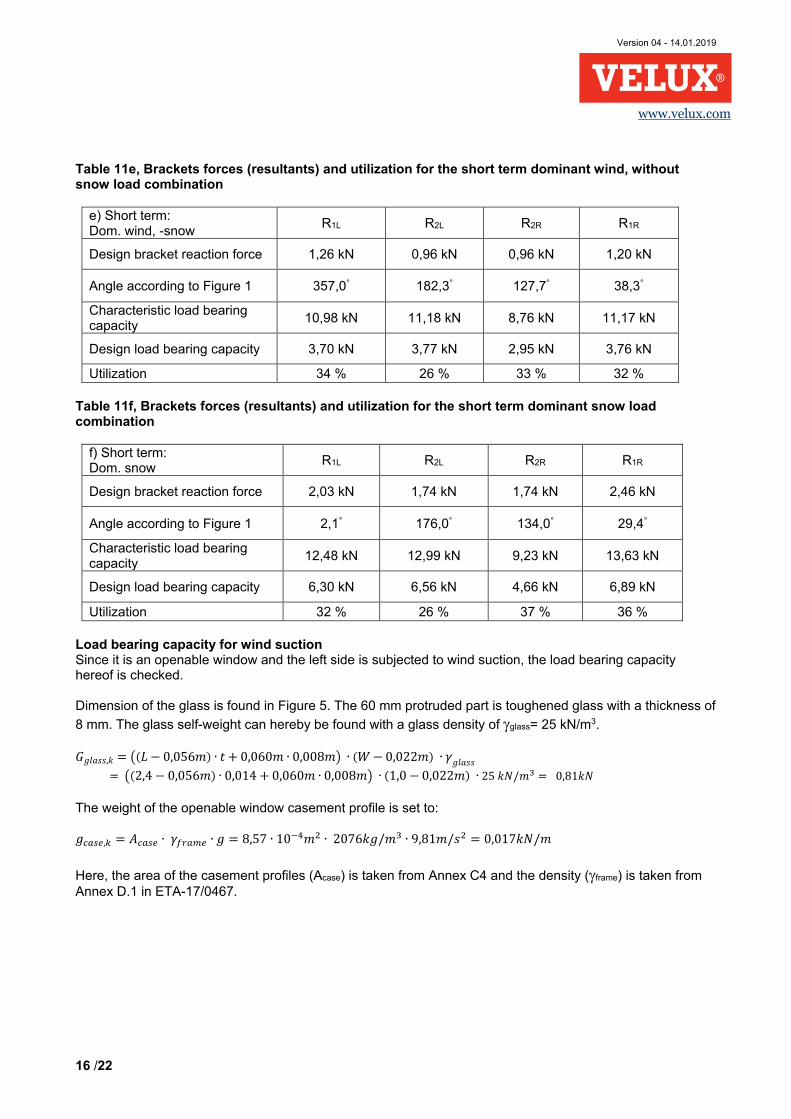
Tabelle 11e, Kräfte (Resultanten) und Nutzung in Bezug auf die Montagebeschläge für Windlastkombination primär, kurze Dauer, ohne Schneelast
e) Kurze Dauer: Wind, Schnee primär
R1L R2L R2R R1R
Bemessungsreaktionskraft Montagebeschlag
1,26 kN 0,96 kN 0,96 kN 1,20 kN
Winkel gemäß Abb. 1 357,0° 182,3° 127,7° 38,3°
Kenntragfähigkeit 10,98 kN 11,18 kN 8,76 kN 11,17 kN
Bemessungstragfähigkeit 3,70 kN 3,77 kN 2,95 kN 3,76 kN
Nutzung 34 % 26 % 33 % 32 % Tabelle 11f, Kräfte (Resultanten) und Nutzung in Bezug auf die Montagebeschläge für Schneelastkombination primär, kurze Dauer
f) Kurze Dauer: Schnee primär
R1L R2L R2R R1R
Bemessungsreaktionskraft Montagebeschlag
2,03 kN 1,74 kN 1,74 kN 2,46 kN
Winkel gemäß Abb. 1 2,1° 176,0° 134,0° 29,4°
Kenntragfähigkeit 12,48 kN 12,99 kN 9,23 kN 13,63 kN
Bemessungstragfähigkeit 6,30 kN 6,56 kN 4,66 kN 6,89 kN
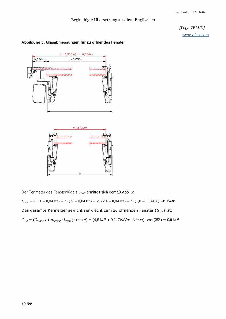
Nutzung 32 % 26 % 37 % 36 % Tragfähigkeit für Windsog Da es sich um ein zu öffnendes Fenster handelt, dessen linke Seite einem Windsog ausgesetzt ist, wird die Tragfähigkeit geprüft. Die Abmessungen des Glases sind aus Abb. 5 ersichtlich. Beim vorstehenden Teil (60 mm) handelt es sich um gehärtetes Glas mit einer Stärke von 8 mm. Das Glaseigengewicht lässt sich mit einer Glasdichte von
γglass= 25 kN/m3 ermitteln. VTH��,@ � 6�� − 0,056#� ∙ = + 0,060# ∙ 0,008#7 ∙ �< − 0,022#� ∙ �VTH�� � 6�2,4 − 0,056#� ∙ 0,014 + 0,060# ∙ 0,008#7 ∙ �1,0 − 0,022#� ∙ 25 @A/#n � 0,81@A Das Gewicht des zu öffnenden Fensterflügelprofils wird festgesetzt auf: V�j�], � t�j�] ∙ ���jo] ∙ V � 8,57 ∙ 10.u#� ∙ 2076@V/#n ∙ 9,81#/�� � 0,017@A/#
Der Fläche der Fensterflügelprofile (Acase) ist Anhang C4 und die Dichte (γframe) Anhang D.1 in ETA-17/0467 entnommen.
Version 04 – 14.01.2019
Beglaubigte Übersetzung aus dem Englischen
[Logo VELUX]
19 /22
www.velux.com
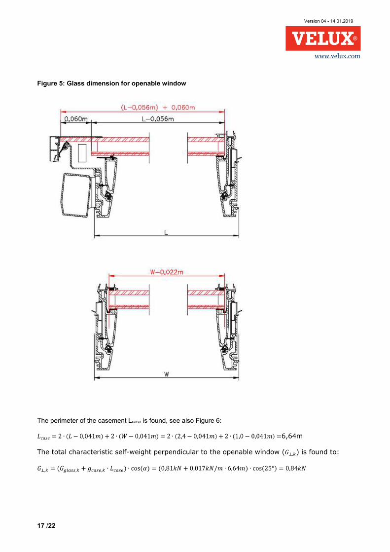
Abbildung 5: Glasabmessungen für zu öffnendes Fenster
Der Perimeter des Fensterflügels Lcase ermittelt sich gemäß Abb. 6: �EH�L � 2 ∙ �� − 0,041#� + 2 ∙ �< − 0,041#� � 2 ∙ �2,4 − 0,041#� + 2 ∙ �1,0 − 0,041#� �6,64m
Das gesamte Kenneigengewicht senkrecht zum zu öffnenden Fenster (8,) ist:
8, � �v�j��, + V�j�], ∙ ��j�]� ∙ cos �*� � �0,81@A + 0,017@A/# ∙ 6,64#� ∙ cos �25°� � 0,84@A
Version 04 – 14.01.2019
Beglaubigte Übersetzung aus dem Englischen
[Logo VELUX]
20 /22
www.velux.com
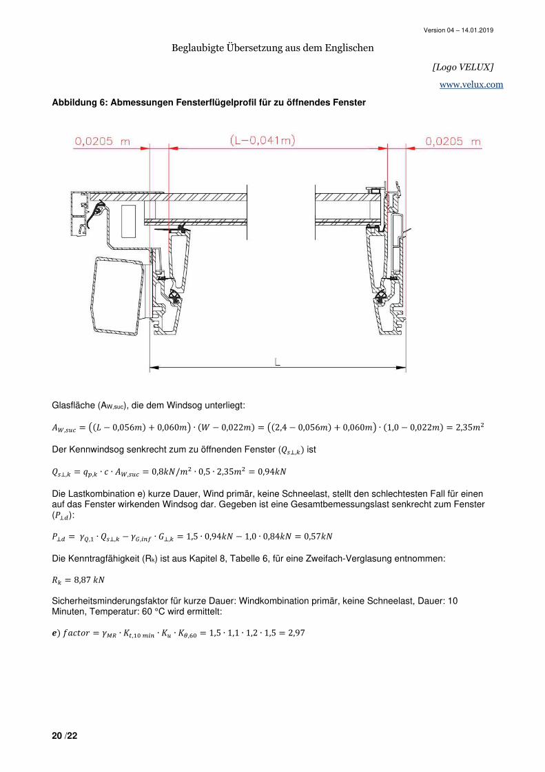
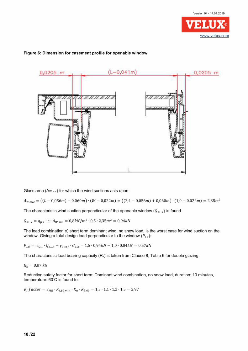
Abbildung 6: Abmessungen Fensterflügelprofil für zu öffnendes Fenster
Glasfläche (AW,suc), die dem Windsog unterliegt: tx,��� � 6�� − 0,056#� + 0,060#7 ∙ �< − 0,022#� � 6�2,4 − 0,056#� + 0,060#7 ∙ �1,0 − 0,022#� � 2,35#� Der Kennwindsog senkrecht zum zu öffnenden Fenster (W�8,� ist W�8, � ��, ∙ E ∙ tx,��� � 0,8@A/#� ∙ 0,5 ∙ 2,35#� � 0,94@A
Die Lastkombination e) kurze Dauer, Wind primär, keine Schneelast, stellt den schlechtesten Fall für einen auf das Fenster wirkenden Windsog dar. Gegeben ist eine Gesamtbemessungslast senkrecht zum Fenster (y84): y84 � ��, ∙ W�8, − ��,��� ∙ 8, � 1,5 ∙ 0,94@A − 1,0 ∙ 0,84@A � 0,57@A Die Kenntragfähigkeit (Rk) ist aus Kapitel 8, Tabelle 6, für eine Zweifach-Verglasung entnommen: z � 8,87 @A Sicherheitsminderungsfaktor für kurze Dauer: Windkombination primär, keine Schneelast, Dauer: 10 Minuten, Temperatur: 60 °C wird ermittelt: r� JHE=eQ � �fC ∙ g^, b o�� ∙ g� ∙ gk,?b � 1,5 ∙ 1,1 ∙ 1,2 ∙ 1,5 � 2,97
Version 04 – 14.01.2019
Beglaubigte Übersetzung aus dem Englischen
[Logo VELUX]
21 /22
www.velux.com
Bemessungstragfähigkeit (Rd):
z4 � 8,87@A2,97 � 2,99@A
Nutzung: y84/z4 ∙ 100 � 0,57@A/2,99@A ∙ 100 � 19% Biegung von Fensterflügel und Rahmenprofil Die Biegung von Fensterflügel und Rahmenprofil ist in diesem Beispiel nur für die Schneekombination primär, mittlere Dauer, berechnet, wobei das Berechnungsverfahren dargestellt wird. Normalerweise sollten alle Lastkombinationen untersucht werden.
Bemessungskapazität von Fensterflügel und Rahmenprofil, Dauer: 3 Monate, Temperatur: 20°C:
|C,4 � |C,�fC ∙ g^,n o��^p ∙ g� ∙ gk,�bl � 1257A/##�1,2 ∙ 1,66 ∙ 1,2 ∙ 1,0 � 526A/##�
(Zur Kennbiegefestigkeit vgl. Tabelle 3, zu Teilsicherheitsbeiwerten vgl. Tabelle 8a/ULS und zu Verstärkungs- und Minderungsfaktoren vgl. Tabelle 8b/ULS). Die Kennlast durch das Eigengewicht, senkrecht zum Dachfenster, wird als gp,k und die Last in senkrechter Linie durch den Kennschneedruck als sp,k bezeichnet. Die korrigierte Höhe, jedoch mit dem ursprünglichen Winkel wird angewendet:
V�, � ;C, ∙ Ee� �*����� � 0,72 ∙ Ee� �25�
2,543 � 0,26@A/# , HIJ KLMLN OLP=LNQHℎ#LN/SLN�=LQJTüVLT ��, � ��,@ ∙ cos �*� � 0,40@A/# ∙ cos �25� � 0,36@A/# , HIJ KLMLN OLP=LNQHℎ#LN/SLN�=LQJTüVLT }4 � 1
8 ∙ 6��,��` ∙ ��,��` ∙ V�, + ��, ∙ ��,7 ∙ ����� � 1
8 ∙ �1,35 ∙ 0,85 ∙ 0,26 + 1,5 ∙ 0,36�@A/# ∙ �2,543#�� � 0,68@A# }��jo],4 � }4 ∙ ~�����
~������~�������� � 0,68@A# ∙ b,??>∙ b�oo�b,??>∙ b�oo��b,>nb∙ b�oo� � 0,28@A#
|��jo],4 ≈ f�����,�x�,����� � b,��∙ b��oo
>,>n∙ b�oo� � 28,7A/##� Nutzung:
������,���,� ∙ 100 � ��,��/oo�
h�?�/oo� ∙ 100 � 5,4%
}�j�]o]�^,4 � }4 ∙ ~��������~������~�������� � 0,68@A# ∙ b,>nb∙ b�oo�b,??>∙ b�oo��b,>nb∙ b�oo� � 0,40@A#
|�j�]o]�^,4 ≈ f��������,�,x�,�������� � b,ub∙ b��oo
?,u∙ b�oo� � 24,1A/##� Nutzung:
���������,���,� ∙ 100 � �u, �/oo�
h�?�/oo� ∙ 100 � 4,6%
Hier wurde die Kennbiegefestigkeit aus Anhang D.1, ETA-17/0467, entnommen. Flächenträgheitsmoment und Widerstandsmoment wurden aus Anhang C.1 und C.4, ETA-17/0467, entnommen. Die Drehung der Hauptachse wird nicht berücksichtigt, da sie nur geringen Einfluss auf das Ergebnis hat und die resultierende Belastung wesentlich geringer als die Biegefestigkeit ist. Scherkraft im Rahmenprofil Die Scherkraft im Rahmenprofil ist in diesem Beispiel nur für die Schneekombination primär, mittlere Dauer, berechnet, wobei das Berechnungsverfahren dargestellt wird. Normalerweise sollten alle Lastkombinationen untersucht werden.
Bemessungskapazität Scherbelastung auf Rahmen, Dauer: 3 Monate, Temperatur: 20°C:
Version 04 – 14.01.2019
Beglaubigte Übersetzung aus dem Englischen
[Logo VELUX]
22 /22
www.velux.com
���jo],C,4 � ���jo],C,�fC ∙ g^,n o��^p ∙ g� ∙ gk,�bl � 53,8A/##�1,2 ∙ 1,66 ∙ 1,2 ∙ 1,0 � 22,5A/##�
(Zur Kennscherfestigkeit vgl. Tabelle 3, zu Teilsicherheitsbeiwerten vgl. Tabelle 8a/ULS und zu Verstärkungs- und Minderungsfaktoren vgl. Tabelle 8b/ULS). Die Scherkraft wird im Allgemeinen gemeinsam von Rahmen und Fensterflügelprofil aufgenommen, in Richtung des Dachfensterendes jedoch komplett vom Rahmenprofil. Es wird der ursprüngliche Winkel angewendet. In diesem Beispiel liegt die größte Scherkraft im rechten Dachfenster:
���jo] � z; C ∙ Ee��*� − zX C∙ �PN�*�
= 1,83@A ∙ Ee��25� − 1,62@A ∙ �PN �25�
= 0,97@A
���jo] � ;��������� ≈ b,>�∙ b��
hhboo� � 1,77A/##�
Nutzung: ������
������,�,� ∙ 100 � ,���/oo���,h�/oo� ∙ 100 � 7,9%
Hier wurde die Kennscherfestigkeit aus Anhang D.1 und Aweb aus Anhang C.1, ETA-17/0467, entnommen. Durchbiegung Durchbiegungen werden für jede Seite getrennt und senkrecht zum korrigierten Dachfensterwinkel geprüft. 6 SLS Lastkombination lassen sich daher für diesen Lastfall erstellen: g) Lange Dauer: Eigengewicht primär: ;C, h) Mittlere Dauer: Schnee primär: ;C, + O;, i) Kurze Dauer: Winddruck primär, mit Schnee: ;C, + W�, + Ψb,���c ∙ O;, => ;C, + W�, + 0,5 ∙ O;, j) Kurze Dauer: Winddruck primär, kein Schnee ;C, + W�, k) Kurze Dauer: Schnee primär, mit Wind: ;C, + Ψb,c��4 ∙ W�, + O;, => ;C, + 0,6 ∙ W�, + O;, l) Kurze Dauer: Windsog primär, kein Schnee ;B, + W�, Die Faktoren für die Ermittlung des Bemessungswerts der Durchbiegung von Rahmenprofil/Fensterflügel sind aus der Formel in Kapitel 2 und Tabelle 8b ersichtlich. Die Dauer ist untergliedert in lange Dauer (25 Jahre), mittlere Dauer (3 Monate) und kurze Dauer (10 Min.), die Temperatur bezieht sich auf den höchstmöglichen Wert, 20°C bei Schnee und 60°C ohne Schnee. Das Eigengewicht ist somit für die Lebensdauer des Fensters, die Schneedauer auf 3 Monate und die Winddauer auf 10 Minuten festgesetzt. Die Schneedauer kann je nach Region variieren und sollte entsprechend geändert werden.
Version 04 – 14.01.2019
Beglaubigte Übersetzung aus dem Englischen
[Logo VELUX]
23 /22
www.velux.com
Lange Dauer: Eigengewichtkombination primär, Dauer: 25 Jahre, Temperatur: 60°C: �� JHE=eQ � �f� ∙ \^,�h i]j�� ∙ \� ∙ \k,?bl � 1,1 ∙ 1,15 ∙ 1,2 ∙ 1,05 � 1,59 Mittlere Dauer: Schneekombination primär, Dauer: 3 Monate, Temperatur: 20°C: �� JHE=eQ � �f� ∙ \^,no��^p� ∙ \� ∙ \k,�bl � 1,1 ∙ 1,11 ∙ 1,2 ∙ 1,0 � 1,47 Kurze Dauer: Winddruckkombination primär, Dauer: 10 Minuten, Temperatur: 20°C: �� JHE=eQ � �f� ∙ \^, bo�� ∙ \� ∙ \k,�bl � 1,1 ∙ 1,02 ∙ 1,2 ∙ 1,0 � 1,35 Kurze Dauer: Winddruckkombination primär, keine Schneelast, Dauer: 10 Minuten, Temperatur: 60°C: �� JHE=eQ � �f� ∙ \^, bo�� ∙ \� ∙ \k,?bl � 1,1 ∙ 1,02 ∙ 1,2 ∙ 1,05 � 1,41 Kurze Dauer: Schneekombination primär, Dauer: 10 Minuten, Temperatur: 20°C: � JHE=eQ � �f� ∙ \^, bo�� ∙ \� ∙ \k,�bl � 1,1 ∙ 1,02 ∙ 1,2 ∙ 1,0 � 1,35 Kurze Dauer: Windsogkombination primär, keine Schneelast, Dauer: 10 Minuten, Temperatur: 60°C: ¡� JHE=eQ � �f� ∙ \^, bo�� ∙ \� ∙ \k,?bl � 1,1 ∙ 1,02 ∙ 1,2 ∙ 1,05 � 1,41 (Zu Teilsicherheitsbeiwerten vgl. Tabelle 8a/SLS und zu Verstärkungs- und Minderungsfaktoren vgl. Tabelle 8b/SLS). Kenneigengewicht senkrecht zum korrigierten Dachfensterwinkel:
V�,���, � ; ∙ Ee� �*�������� � 0,72 ∙ Ee� �24,3�
2,543 � 0,26@A/# , HIJ KLMLN OLP=LNQHℎ#LN/SLN�=LQJTüVLT
Kennwinddruck und Windsog senkrecht zum korrigierten Dachfensterwinkel:
��,���, � ��, ∙ cos �−∆*� � 0,2@A/# ∙ cos �0,7� � 0,20@A/# , HIJ KLMLN OLP=LNQHℎ#LN/SLN�=LQJTüVLT
Kennschneelast senkrecht zum korrigierten Dachfensterwinkel:
��,���, � ��,@ ∙ cos �*����� � 0,40@A/# ∙ cos �24,3� � 0,33@A/# , HIJ KLMLN OLP=LNQHℎ#LN/SLN�=LQJTüVLT Für die Durchbiegungsberechnungen wurde das Flächenträgheitsmoment entnommen aus ETA-17/0467 Anhang C.1 und Anhang C.4 und für das E-Modul vgl. Tabelle 3 einschließlich Anmerkung 3 g) Durchbiegung für lange Dauer: Eigengewicht primär
I � hn�u ∙ �v¢,�l�,£� ∙ B�l��
¤∙6~������~��������7∙�j�^��,v
� hn�u ∙ �b,�?��/oo ∙ ��.hun oo��
u ?bb�/oo�∙b,�n∙�b,??>∙ b�oo��b,>nb∙ b�oo��∙ ,h> � 4,1## < ����150 � 17 ## h) Durchbiegung für mittlere Dauer: Schnee primär
I � hn�u ∙ �v¢,�l�,£�∙�¢,�l�,£� ∙ B�l��
¤∙6~������~��������7 ∙�j�^��,p
� hn�u ∙ �b,�?�b,nn��/oo ∙ ��.hun oo��
u ?bb�/oo�∙b,�n∙�b,??>∙ b�oo��b,>nb∙ b�oo��∙ ,u� � 8,6## < ����150 � 17 ##
Version 04 – 14.01.2019
Beglaubigte Übersetzung aus dem Englischen
[Logo VELUX]
24 /22
www.velux.com
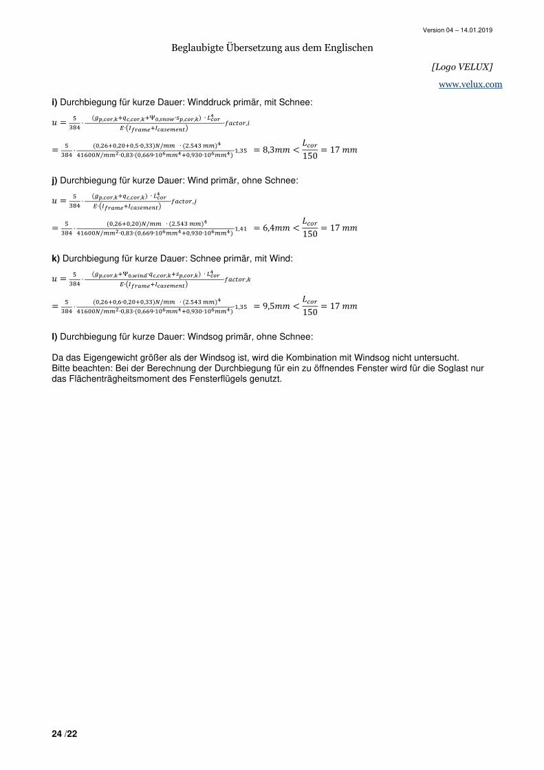
i) Durchbiegung für kurze Dauer: Winddruck primär, mit Schnee:
I � hn�u ∙ �v¢,�l�,£�¦�,�l�,£�§¨,��l�∙�¢,�l�,£� ∙ B�l��
¤∙6~������~��������7 ∙�j�^��,�
� hn�u ∙ �b,�?�b,�b�b,h∙b,nn��/oo ∙ ��.hun oo��
u ?bb�/oo�∙b,�n∙�b,??>∙ b�oo��b,>nb∙ b�oo��∙ ,nh � 8,3## < ����150 � 17 ## j) Durchbiegung für kurze Dauer: Wind primär, ohne Schnee:
I � hn�u ∙ �v¢,�l�,£�¦�,�l�,£� ∙ B�l��
¤∙6~������~��������7 ∙�j�^��,©
� hn�u ∙ �b,�?�b,�b��/oo ∙ ��.hun oo��
u ?bb�/oo�∙b,�n∙�b,??>∙ b�oo��b,>nb∙ b�oo��∙ ,u � 6,4## < ����150 � 17 ## k) Durchbiegung für kurze Dauer: Schnee primär, mit Wind:
I � hn�u ∙ �v¢,�l�,£�§¨,�ª��∙¦�,�l�,£��¢,�l�,£� ∙ B�l��
¤∙6~������~��������7 ∙�j�^��,
� hn�u ∙ �b,�?�b,?∙b,�b�b,nn��/oo ∙ ��.hun oo��
u ?bb�/oo�∙b,�n∙�b,??>∙ b�oo��b,>nb∙ b�oo��∙ ,nh � 9,5## < ����150 � 17 ## l) Durchbiegung für kurze Dauer: Windsog primär, ohne Schnee: Da das Eigengewicht größer als der Windsog ist, wird die Kombination mit Windsog nicht untersucht. Bitte beachten: Bei der Berechnung der Durchbiegung für ein zu öffnendes Fenster wird für die Soglast nur das Flächenträgheitsmoment des Fensterflügels genutzt.
Version 04 - 14.01.2019
1 /22
www.velux.com
GUIDANCE PAPER
VELUX MODULAR SKYLIGHTS
SELF-SUPPORTING RIDGELIGHT
Determination of structural design values
1. Introduction The aim of this document – together with ETA 17/0467 of 2019-01-28 is to provide guidance to the determination of design values. ETA-17/0467 contains information on the kit, e.g. the structural system, hardware, cross section of the profiles, as well as the characteristic values. For convenience, a number of the relevant characteristic values are repeated in this document. By means of structural calculations and design values, it can be demonstrated whether the requirements of the load bearing capacity of a specific kit, installed in a given building on a given location, are met. The calculations should be carried out by a competent body. The examples in this document demonstrate how the calculations could be carried out. National Standards and Annexes may specify different loads and combinations hereof, that are not mentioned in this document. The load bearing capacity of the glazing is not subject to this document. 2. Principle
The design load bearing capacities (1) Rd and Cd shall be calculated using the following equations (see ETAG 010, 6.3.1.1 and 6.3.1.2):
Rd = Rk/(ɣMR*Kt*Ku*Kθ) and
Cd = Ck/(ɣMC*Ct*Cu*Cθ)
where:
Rk = Characteristic load bearing capacity (ULS) calculated in accordance with ETA-17/0467 Ck = Characteristic load bearing capacity (SLS) calculated in accordance with ETA-17/0467 ɣMR = partial safety factor for ULS ɣMC = partial safety factor for SLS Kt = effect of duration for ULS (2) Ct = effect of duration for SLS (2) Ku = effect of ageing/environment for ULS (2)
Version 04 - 14.01.2019
2 /22
www.velux.com
Cu = effect of ageing/environment for SLS (2) Kθ = effect of temperature for ULS (2) Cθ = effect of temperature for SLS (2)
Notes: (1) The self-weight, including partial safety factors, shall be calculated in accordance with Clause 6. (2) Relevant only for profiles and hardware connections connected to the profiles.
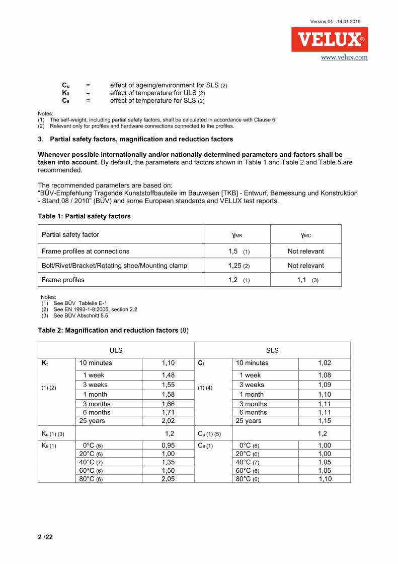
3. Partial safety factors, magnification and reduction factors Whenever possible internationally and/or nationally determined parameters and factors shall be taken into account. By default, the parameters and factors shown in Table 1 and Table 2 and Table 5 are recommended. The recommended parameters are based on: “BÜV-Empfehlung Tragende Kunststoffbauteile im Bauwesen [TKB] - Entwurf, Bemessung und Konstruktion - Stand 08 / 2010” (BÜV) and some European standards and VELUX test reports. Table 1: Partial safety factors
Notes:
(1) See BÜV Tablelle E-1 (2) See EN 1993-1-8:2005, section 2.2 (3) See BÜV Abschnitt 5.5
Table 2: Magnification and reduction factors (8)
ULS SLS
Kt
(1) (2)
10 minutes 1,10 Ct
(1) (4)
10 minutes 1,02
1 week 1,48 1 week 1,08
3 weeks 1,55 3 weeks 1,09
1 month 1,58 1 month 1,10
3 months 1,66 3 months 1,11 6 months 1,71 6 months 1,11 25 years 2,02 25 years 1,15
Ku (1) (3) 1,2 Cu (1) (5) 1,2
Kθ (1) 0°C (6) 0,95 Cθ (1) 0°C (6) 1,00 20°C (6) 1,00 20°C (6) 1,00 40°C (7) 1,35 40°C (7) 1,05 60°C (6) 1,50 60°C (6) 1,05 80°C (6) 2,05 80°C (6) 1,10
Partial safety factor ɣMR ɣMC
Frame profiles at connections 1,5 (1) Not relevant
Bolt/Rivet/Bracket/Rotating shoe/Mounting clamp 1,25 (2) Not relevant
Frame profiles 1,2 (1) 1,1 (3)
Version 04 - 14.01.2019
3 /22
www.velux.com
Notes:
(1) Kt = Af
1
, Ct = A
E
1 (see ETAG 010: 2002, section 6.3 and Annex H, BÜV Abschnitt 5.2)
Ku = Af
2
, Cu = A
E
2 (see ETAG 010: 2002, section 6.3 and Annex H, BÜV Abschnitt 5.2)
Kθ = Af
3
, Cθ = A
E
3 (see ETAG 010: 2002, section 6.3 and Annex H, BÜV Abschnitt 5.2)
(2) See BÜV Tabelle B-1a and Gleichung 8.2.
(3) See BÜV Tabelle B-2.
(4) See BÜV Tabelle B-1b and Gleichung 8.2.
(5) See BÜV Tabelle B-2.
(6) See VELUX test reports no. 147775 and 145611 and DTI report no. 743795-2.
(7) Conservative approximation based on measurements from VELUX test reports nos. 147775 and 145611.
(8) Relevant only for profiles and their hardware connections.
4. Design values of small scale tests
The design values of the small-scale tests can be calculated as shown in Table 3. Table 3: Characteristic and design values
Property Characteristic values see ETA-17/0467 Annex D.1
Design values see Table 1 and Table 2 above
Tensile strength 832,9 MPa ULS= Characteristic value / (ɣMR *Kt*Ku*Kθ) SLS= Characteristic value / (ɣMC*Ct*Cu*Cθ)
Compression strength 465 MPa
Bending strength 1257 MPa
E-modulus 39,5 GPa
41,6 GPa (1)(3)
G-modulus 3,1 GPa
3,4 GPa (2)
Shear strength 53,8 MPa
Notes:
(1) Mean value, confidence level 75%, unknown standard deviation (See ISO 16269-6:2014). (2) Mean value, confidence level 75%, unknown standard deviation (See ISO 16269-6:2014). (3) For openable windows subjected to a downward action force, the E-modulus shall be multiplied with a factor of 0,83, see “VELUX
report 1100005818_06_1 VMS Full scale test Ridgelight – Stiffness of module 2016-11-29”
Version 04 - 14.01.2019
4 /22
www.velux.com
5. Determination of values for hardware connections Figure 1: Applied forces to the hardware
Version 04 - 14.01.2019
5 /22
www.velux.com
Table 4: Characteristic and design values for hardware connections
Element/Connection Characteristic value Rk [kN] Design value Rd [kN] see Table 1
A Top bolt connection (calculated minimum) 13,5 (1) ULS= Characteristic value / ɣMR SLS: Not relevant
B Bottom bolt connection (calculated minimum) 17,6 (1) G Rotating shoe/mounting clamp/roof connection in 90° 20,3 H Rotating shoe/mounting clamp/roof connection in 180° 28,2
Note: (1) Strength of the bottom and top bolt themselves: 17,6 kN
Element/Connection
Characteristic Value Rk [kN] (1)
Product variant HFC 100240 0010B
HVC 100240 0010B
HFC 100240 0016TB
HVC 100240 0016TB
C Top corner bracket/frame connection in 0° 8,5 11,2 9,0 10,9 D Bottom corner bracket/frame connection in 0° 11,9 11,9 10,9 12,4
E Bottom corner bracket/frame connection in 180° 8,5 11,2 9,0 10,9 F Bottom corner bracket/frame connection in 270° 3,9 2,0 4,3 2,1
J Top corner bracket/frame connection in 270° 3,9 2,0 4,3 2,1
K Top corner bracket/frame connection in 180° 11,9 11,9 10,9 12,4
L Top corner bracket/frame connection in 315° 6,2 3,4 6,0 3,5
M Bottom corner bracket/frame connection in 225° 6,2 3,4 6,0 3,5
N Bottom corner bracket/frame connection in 90° 6,0 6,0 6,2 5,7 P Top corner bracket/frame connection in 90° 6,0 6,0 6,2 5,7
Q Bottom corner bracket/frame connection in 315° 5,4 3,0 5,0 3,6
R Top corner bracket/frame connection in 225° 5,4 3,0 5,0 3,6
S Bottom corner bracket/frame connection in 135° 7,8 8,2 8,1 7,5
T Top corner bracket/frame connection in 45° 7,8 8,2 8,1 7,5
U Top corner bracket/frame connection in 135° 8,6 9,3 8,6 9,0
W Bottom corner bracket/frame connection in 45° 8,6 9,3 8,6 9,0
DW Bottom corner bracket/frame connection in 18° 13,8 16,8 13,3 17,1
UK Top corner bracket/frame connection in 162° 13,8 16,8 13,3 17,1
QD Bottom corner bracket/frame connection in 342° 10,0 6,4 10,2 6,1
KR Top corner bracket/frame connection in 198° 10,0 6,4 10,2 6,1 Note: (1) Without influence caused by nationally determined magnification and reduction factors (duration, aging/environment, temperature, i.e.
Ct = Cu = CQ = 1 and Kt = Ku = KQ = 1, see ETAG 010, 6.3.1.2)
Version 04 - 14.01.2019
6 /22
www.velux.com
Figure 2: Determination of values for hardware connections in other directions than tested (principle)
Version 04 - 14.01.2019
7 /22
www.velux.com
6. Self-weight The self-weight (including hardware, lining, cladding and flashing) of the fixed roof window (Gf and gf) and the openable roof window (Gv and gv) shall be calculated as follows:
Gf = (W-12) * (L-96) * t*25*10-9+2(W+L) *57*10-6 [kN] gf = Gf /(W*L)* 106 [kN/m2] and Gv = (W-12) * (L-96) * t*25 * 10-9+2(W+L) * 96 * 10-6 [kN] gv = Gv /(W*L)* 106 [kN/m2] where: W = Width of the roof window in mm L = Height of the roof window in mm t = Sum of glass thicknesses in mm Table 5: Partial safety factors for permanent action (self-weight):
7. Load combinations According to BÜV Abschnitt 8.2 the load combinations can be divided up into 3 load durations.
1. Long term, only self-weight 2. Medium term, self-weight and snow load 3. Short term, self-weight, snow load and wind load
In medium term, only the snow load is set as dominate load regarding the load combinations from EN 1990:2007 In short term respectively snow and wind load is set as the dominate load. 8. Load bearing capacity for wind suction For an openable window subjected to a perpendicular upward force the connection between the casement and frame profile is to be investigated. The load bearing capacity is found in VELUX report: “11000008316_30_0 VMW Suction on venting Frames” dated 2017-12-08 and shown in Table 6. Table 6: Characteristic load bearing capacity for openable windows between casement and frame profile, for a suction force perpendicular to the window frame
Load bearing capacity Double glazing 8,87 kN Triple glazing 8,72 kN
Unfavourable Favourable Unfavourable Reference
ɣG,sup ɣG,inf ξG,sup
ULS 1,35 1,0 0,85 EN 1990:2007, Table A1.2(B), Eq. 6.10b
SLS 1,0 1,0 N/A EN 1990:2007, Table A1.4
Version 04 - 14.01.2019
8 /22
www.velux.com
9. Examples of design values for the load bearing capacity Table 7a: Characteristic and design load bearing capacities for snow-load
Characteristic values for s see ETA-17/0467 Annex E.1
Design calculation Self-weight partial safety factors (see Table 5):
γG,sup,ULS=1,35 ξG,sup,ULS=0,85 γG,sup,SLS=1,00 Material partial safety factors (see Table 1):
γMR,ULS=1,50 γMC,SLS=1,10 Magnification and reduction factors (see Table 2): Medium term - snow load (1): 3 months duration, 20°C. Kt=1,66; Ku=1,2; Kθ=1,00 Ct=1,11; Cu=1,2; Cθ=1,00 Load factor snow, from EN 1990:2007: ɣQ,1 = 1,5 E- modulus: E= 0,83 x 41,6 GPa See Note 3 to Table 3.
Application examples – Snow-load
α° ULS [kN/m2]
SLS [kN/m2] ULS (2)
[kN/m2]
SLS (3) [kN/m2]
1/300 1/150 1/300 1/150
25° 9,0 1,5 3,8 2,33 0,53 1,81
30° 10,6 1,6 4,0 2,84 0,59 1,93
35° 12,0 1,7 4,2 3,31 0,67 2,08
40° 13,7 1,9 4,6 3,81 0,76 2,27
Notes:
(1) Load combination ULS: 𝛾𝛾𝐺𝐺,𝑠𝑠𝑠𝑠𝑠𝑠 ∙ 𝜉𝜉𝐺𝐺,𝑠𝑠𝑠𝑠𝑠𝑠 ∙ 𝐺𝐺𝑘𝑘 + 𝛾𝛾𝑄𝑄,1 ∙ 𝑠𝑠𝑘𝑘 SLS: 𝐺𝐺𝑘𝑘 + 𝑠𝑠𝑘𝑘
(2) Values in Table are design snow load for ULS: 𝛾𝛾𝑄𝑄,1 ∙ 𝑠𝑠𝑘𝑘
(3) Values in Table are design snow load for SLS: 𝑠𝑠𝑘𝑘
Type: 2x HVC100240 0016T
(1000mm x 2400mm) Glazing: 22 mm glass in total
Version 04 - 14.01.2019
9 /22
www.velux.com
Table 7b: Characteristic and design load bearing capacities for wind suction
Characteristic values for qs see ETA-17/0467 Annex E.1
Design values Self-weight partial safety factors (see Table 5):
γG,inf,ULS=1,00 γG,sup,SLS=1,00 Material partial safety factors (see Table 1):
γMR,ULS=1,50 γMC,SLS=1,10 Magnification and reduction factors (see Table 2): Short term - wind load (2): 10 minutes, 60°C (1). ULS: Kt=1,10; Ku=1,2; Kθ=1,50 SLS: Ct=1,02; Cu=1,2; Cθ=1,05 Load factor wind, from EN 1990:2007: ɣQ,1 = 1,5
Application examples – Wind suction α° ULS
[kN/m2]
SLS [kN/m2] ULS (3)
[kN/m2]
SLS (4) [kN/m2]
1/300 1/150 1/300 1/150
25° 5,0 1,9 3,4 2,01 (5) 1,53 2,53
30° 5,1 1,9 3,3 2,05 (5) 1,51 2,51
35° 5,0 1,9 3,3 1,77 (5) 1,48 2,48
40° 4,4 1,9 3,3 1,79 (5) 1,45 2,45
Notes:
(1) See VELUX test report 149292.
(2) Load combination ULS: 𝛾𝛾𝐺𝐺,𝑖𝑖𝑖𝑖𝑖𝑖 ∙ 𝐺𝐺𝑘𝑘 + 𝛾𝛾𝑄𝑄,1 ∙ 𝑞𝑞𝑠𝑠,𝑘𝑘 SLS: 𝐺𝐺𝑘𝑘 + 𝑞𝑞𝑠𝑠,𝑘𝑘
(3) Values in Table are design snow load for ULS: 𝛾𝛾𝑄𝑄,1 ∙ 𝑞𝑞𝑠𝑠,𝑘𝑘
(4) Values in Table are design snow load for SLS: 𝑞𝑞𝑠𝑠,𝑘𝑘 (5) Failure between casement and frame profile, see Clause 8
Type: 2x HVC100240 0010
(1000mm x 2400mm) Glazing: 14 mm glass in total
Version 04 - 14.01.2019
10 /22
www.velux.com
10. Calculation example, asymmetric load (design values) For the calculations example “Asymmetric load” the same example as Annex E.2 in ETA-17/0467 is used.
To demonstrate the calculation procedure, a VELUX modular skylight self-supporting ridgelight application under asymmetric wind and snow load is examined. Geometry and roof window variant is the same as in the wind load example in Table 7b: 2 x HVC1002400 0010 (1000mm x 2400mm). Glazing: 14mm glass in total. The pitch is α = 25°.
Figure 3: Load model for calculation example
Partial safety factors and the magnification and reduction factors used in the calculation are presented in Tables 8a and 8b.
Table 8a: Partial safety factors
ULS SLS Frame profiles at connections: ɣMR = 1,5 N/A Frame profiles: ɣMR = 1,2 ɣMC = 1,1 Variable Load, leading: ɣQ,1 = 1,5 (1) ɣQ,1 = 1,0 (1) Variable Load, non-leading: ɣQ,i = 1,5 (1) ɣQ,i = 1,0 (1) Permanent action, unfavourable: ɣG,sup = 1,35 ɣG,sup = 1,0 Permanent action, favourable: ɣG,inf = 1,0 ɣG,inf = 1,0 Factor for combination, wind Ψ 0,wind = 0,6 (1) Ψ 0,wind = 0,6 (1) Factor for combination, snow Ψ 0,snow = 0,5 (1) Ψ 0,snow = 0,5 (1) Reduction factor for Gsup ξG,sup = 0,85 N/A
Note: (1) See EN 1990:2007
Table 8b: Magnification and reduction factors
ULS SLS Duration dependency, self-weight leading: Kt,25 years = 2,02 Ct,25 years = 1,15 Duration dependency, wind leading: Kt,10 min = 1,1 Ct,10 min = 1,02 Duration dependency, snow leading: Kt,3 month = 1,66 Ct,3 month = 1,11 Ageing/environment dependency: Ku = 1,2 Cu = 1,2 Temperature dependency, 20°C: Kθ,20o = 1,0 Cθ,20o = 1,00 Temperature dependency, 60°C: Kθ,60o = 1,5 Cθ,60o = 1,05
Version 04 - 14.01.2019
11 /22
www.velux.com
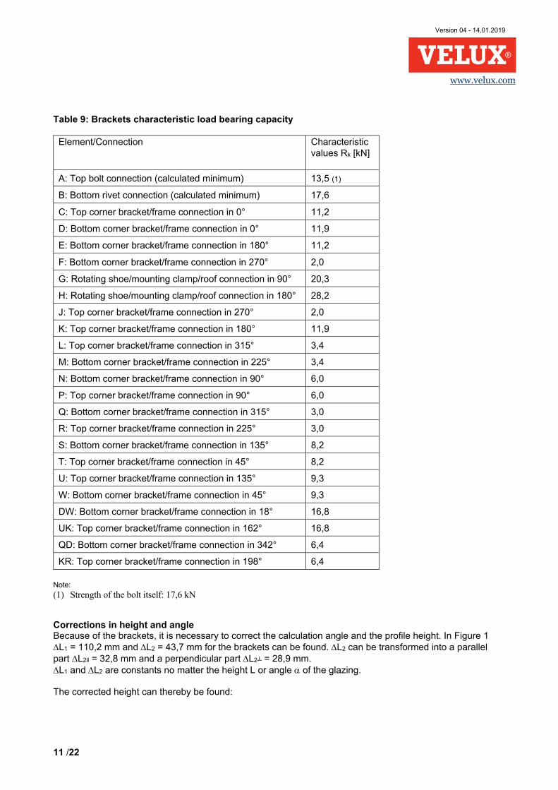
Table 9: Brackets characteristic load bearing capacity
Element/Connection Characteristic values Rk [kN]
A: Top bolt connection (calculated minimum) 13,5 (1)
B: Bottom rivet connection (calculated minimum) 17,6
C: Top corner bracket/frame connection in 0° 11,2
D: Bottom corner bracket/frame connection in 0° 11,9
E: Bottom corner bracket/frame connection in 180° 11,2
F: Bottom corner bracket/frame connection in 270° 2,0
G: Rotating shoe/mounting clamp/roof connection in 90° 20,3
H: Rotating shoe/mounting clamp/roof connection in 180° 28,2
J: Top corner bracket/frame connection in 270° 2,0
K: Top corner bracket/frame connection in 180° 11,9
L: Top corner bracket/frame connection in 315° 3,4
M: Bottom corner bracket/frame connection in 225° 3,4
N: Bottom corner bracket/frame connection in 90° 6,0
P: Top corner bracket/frame connection in 90° 6,0
Q: Bottom corner bracket/frame connection in 315° 3,0
R: Top corner bracket/frame connection in 225° 3,0
S: Bottom corner bracket/frame connection in 135° 8,2
T: Top corner bracket/frame connection in 45° 8,2
U: Top corner bracket/frame connection in 135° 9,3
W: Bottom corner bracket/frame connection in 45° 9,3
DW: Bottom corner bracket/frame connection in 18° 16,8
UK: Top corner bracket/frame connection in 162° 16,8
QD: Bottom corner bracket/frame connection in 342° 6,4
KR: Top corner bracket/frame connection in 198° 6,4
Note:
(1) Strength of the bolt itself: 17,6 kN
Corrections in height and angle Because of the brackets, it is necessary to correct the calculation angle and the profile height. In Figure 1 ∆L1 = 110,2 mm and ∆L2 = 43,7 mm for the brackets can be found. ∆L2 can be transformed into a parallel part ∆L2ll = 32,8 mm and a perpendicular part ∆L2┴ = 28,9 mm. ∆L1 and ∆L2 are constants no matter the height L or angle α of the glazing.
The corrected height can thereby be found:
Version 04 - 14.01.2019
12 /22
www.velux.com
𝐿𝐿𝑐𝑐𝑐𝑐𝑐𝑐 = �(𝐿𝐿 + ∆𝐿𝐿1 + ∆𝐿𝐿2𝑙𝑙𝑙𝑙)2 + (𝐿𝐿2┴)2 = �(2400𝑚𝑚𝑚𝑚 + 110,2𝑚𝑚𝑚𝑚 + 32,8𝑚𝑚𝑚𝑚)2 + (28,9𝑚𝑚𝑚𝑚)2 = 2543𝑚𝑚𝑚𝑚
The corrected angle is found: ∆𝛼𝛼 = sin−1 � ∆𝐿𝐿2┴𝐿𝐿 + ∆𝐿𝐿1 + ∆𝐿𝐿2𝑙𝑙𝑙𝑙� = sin−1 � 28,9𝑚𝑚𝑚𝑚
2400𝑚𝑚𝑚𝑚 + 110,2𝑚𝑚𝑚𝑚 + 32,8𝑚𝑚𝑚𝑚� = 0,65𝑐𝑐 𝛼𝛼𝑐𝑐𝑐𝑐𝑐𝑐 = 𝛼𝛼 − ∆𝛼𝛼 = 25𝑐𝑐 − 0,7𝑐𝑐 = 24,3𝑐𝑐
For deflection calculations of an upwards load for an openable window, only the casement will deflect. Therefore only the height of the casement profile and correct angle hereof should be used for the deflections calculations. From Figure 4 ∆L1,up,dfl = -9,7 mm, ∆L2ll,up,dfl = 23,5 mm and ∆L2┴,up,dfl = 24 mm are found. The corrected height Lcor,up,dfl can thereby by found: 𝐿𝐿𝑐𝑐𝑐𝑐𝑐𝑐,𝑠𝑠𝑠𝑠,𝑑𝑑𝑖𝑖𝑙𝑙 = ��𝐿𝐿 + ∆𝐿𝐿1,𝑠𝑠𝑠𝑠,𝑑𝑑𝑖𝑖𝑙𝑙 + ∆𝐿𝐿2𝑙𝑙𝑙𝑙,𝑠𝑠𝑠𝑠,𝑑𝑑𝑖𝑖𝑙𝑙�2 + �𝐿𝐿2⊥,𝑠𝑠𝑠𝑠,𝑑𝑑𝑖𝑖𝑙𝑙�2 = �(2400𝑚𝑚𝑚𝑚 − 9,7𝑚𝑚𝑚𝑚 + 23,5𝑚𝑚𝑚𝑚)2 + (24𝑚𝑚𝑚𝑚)2 = 2414𝑚𝑚𝑚𝑚 The corrected angle is found: ∆𝛼𝛼𝑠𝑠𝑠𝑠,𝑑𝑑𝑖𝑖𝑙𝑙 = sin−1 � 𝐿𝐿2⊥,𝑠𝑠𝑠𝑠,𝑑𝑑𝑖𝑖𝑙𝑙𝐿𝐿 + ∆𝐿𝐿1,𝑠𝑠𝑠𝑠,𝑑𝑑𝑖𝑖𝑙𝑙 + ∆𝐿𝐿2𝑙𝑙𝑙𝑙,𝑠𝑠𝑠𝑠,𝑑𝑑𝑖𝑖𝑙𝑙�
= sin−1 � 24𝑚𝑚𝑚𝑚2400𝑚𝑚𝑚𝑚 − 9,7𝑚𝑚𝑚𝑚 + 23,5𝑚𝑚𝑚𝑚� = 0,57𝑐𝑐
𝛼𝛼𝑐𝑐𝑐𝑐𝑐𝑐,𝑠𝑠𝑠𝑠,𝑑𝑑𝑖𝑖𝑙𝑙 = 𝛼𝛼 + ∆𝛼𝛼𝑠𝑠𝑠𝑠,𝑑𝑑𝑖𝑖𝑙𝑙 = 25𝑐𝑐 + 0,6𝑐𝑐 = 25,6𝑐𝑐
Figure 4: Corrections vectors for an openable window subjected to an upwards acting force, deflections only
The measurements ∆L1,up,dfl = -9,7 mm, ∆L2ll,up,dfl = 23,5 mm and ∆L2┴,up,dfl = 24 mm are constants. Characteristic loads Self-weight on each side frame/casement: 𝐺𝐺𝑉𝑉,𝑘𝑘 =
12 ∙ �(𝑊𝑊 − 12) ∙ (𝐿𝐿 − 96) ∙ 𝑡𝑡 ∙ 25 ∙ 10−9 + 2 ∙ (𝑊𝑊 + 𝐿𝐿) ∙ 96 ∙ 10−6�
=12 ∙ �(1000 − 12) ∙ (2400 − 96) ∙ 14 ∙ 25 ∙ 10−9 + 2 ∙ (1000 + 2400) ∙ 96 ∙ 10−6� = 0.72𝑘𝑘𝑘𝑘
To be able to divide the self-weight up in sup and inf, the self-weight is given for the left and the right
Version 04 - 14.01.2019
13 /22
www.velux.com
frame/casement. 𝐺𝐺𝑉𝑉𝑉𝑉,𝑘𝑘 = 𝐺𝐺𝑉𝑉𝑉𝑉,𝑘𝑘 = 0,72𝑘𝑘𝑘𝑘 In this example, the wind peak velocity pressure (qp,k) is set to 0,8kN/m2 and the shape factor (c) is set to 0,5 for wind pressure and -0,5 for wind suction. Hence, the load is 𝑞𝑞𝑐𝑐,𝑘𝑘 = 𝑞𝑞𝑠𝑠,𝑘𝑘 = 𝑞𝑞𝑝𝑝,𝑘𝑘 ∙ 𝑐𝑐 ∙ 𝑊𝑊 2⁄ = 0,8𝑘𝑘𝑘𝑘/𝑚𝑚2 ∙ 0,5 ∙ 1,0𝑚𝑚 2⁄ = 0,2𝑘𝑘𝑘𝑘/𝑚𝑚 , 𝑜𝑜𝑜𝑜 𝑒𝑒𝑒𝑒𝑐𝑐ℎ 𝑠𝑠𝑠𝑠𝑠𝑠𝑒𝑒 𝑓𝑓𝑓𝑓𝑒𝑒𝑚𝑚𝑒𝑒/𝑐𝑐𝑒𝑒𝑠𝑠𝑒𝑒𝑚𝑚𝑒𝑒𝑜𝑜𝑡𝑡 The wind load is split into a vertical and a horizontal component, using the original angle α. Using the corrected height, Lcor to find the equivalent concentrated load. 𝑄𝑄𝑠𝑠𝑠𝑠,𝑘𝑘 = 𝑄𝑄𝑐𝑐𝑠𝑠,𝑘𝑘 = 𝑞𝑞𝑐𝑐,𝑘𝑘 ∙ 𝐿𝐿𝑐𝑐𝑐𝑐𝑐𝑐 ∙ sin(𝛼𝛼) = 0,2𝑘𝑘𝑘𝑘/𝑚𝑚 ∙ 2,543𝑚𝑚 ∙ sin(25𝑐𝑐) = 0,21𝑘𝑘𝑘𝑘 𝑜𝑜𝑜𝑜 𝑒𝑒𝑒𝑒𝑐𝑐ℎ 𝑠𝑠𝑠𝑠𝑠𝑠𝑒𝑒 𝑓𝑓𝑓𝑓𝑒𝑒𝑚𝑚𝑒𝑒/𝑐𝑐𝑒𝑒𝑠𝑠𝑒𝑒𝑚𝑚𝑒𝑒𝑜𝑜𝑡𝑡 𝑄𝑄𝑠𝑠𝑉𝑉,𝑘𝑘 = 𝑄𝑄𝑐𝑐𝑉𝑉,𝑘𝑘 = 𝑞𝑞𝑐𝑐,𝑘𝑘 ∙ 𝐿𝐿𝑐𝑐𝑐𝑐𝑐𝑐 ∙ cos(𝛼𝛼) = 0,2𝑘𝑘𝑘𝑘/𝑚𝑚 ∙ 2,543𝑚𝑚 ∙ cos(25𝑐𝑐) = 0,46𝑘𝑘𝑘𝑘 𝑜𝑜𝑜𝑜 𝑒𝑒𝑒𝑒𝑐𝑐ℎ 𝑠𝑠𝑠𝑠𝑠𝑠𝑒𝑒 𝑓𝑓𝑓𝑓𝑒𝑒𝑚𝑚𝑒𝑒/𝑐𝑐𝑒𝑒𝑠𝑠𝑒𝑒𝑚𝑚𝑒𝑒𝑜𝑜𝑡𝑡 For the snow load in this example the two C factors (according to EN 1991-1-3) are set to 1,0, the shape factor µ2 set to 0,8 and the characteristic value of snow load on the ground Sk=1,0kN/m2, given the characteristic snow load sk: 𝑠𝑠𝑘𝑘 = 𝜇𝜇2 ∙ 𝐶𝐶𝑒𝑒 ∙ 𝐶𝐶𝑡𝑡 ∙ 𝑆𝑆𝑘𝑘 = 0,8 ∙ 1,0 ∙ 1,0 ∙ 1,0𝑘𝑘𝑘𝑘 𝑚𝑚2⁄ = 0,8𝑘𝑘𝑘𝑘 𝑚𝑚2⁄ → 𝑠𝑠𝑠𝑠,𝑘𝑘 = 0,4𝑘𝑘𝑘𝑘/𝑚𝑚 , 𝑜𝑜𝑜𝑜 𝑒𝑒𝑒𝑒𝑐𝑐ℎ 𝑠𝑠𝑠𝑠𝑠𝑠𝑒𝑒 𝑓𝑓𝑓𝑓𝑒𝑒𝑚𝑚𝑒𝑒/𝑐𝑐𝑒𝑒𝑠𝑠𝑒𝑒𝑚𝑚𝑒𝑒𝑜𝑜𝑡𝑡 The snow load is only vertical, and the corrected height Lcor is used to find the equivalent concentrated load. 𝑆𝑆𝑉𝑉,𝑘𝑘 = 𝑠𝑠 ∙ cos(𝛼𝛼) ∙ 𝐿𝐿𝑐𝑐𝑐𝑐𝑐𝑐 = 0,4𝑘𝑘𝑘𝑘/𝑚𝑚 ∙ cos(25𝑐𝑐) ∙ 2,543𝑚𝑚 = 0,92𝑘𝑘𝑘𝑘
Reactions in brackets
The corrected height Lcor and angle αcor are used in the static system to determine the reactions. These calculations are not presented here. Reactions are calculated separately for each load type and are found in Table 10. From the characteristic reactions, different load combinations are made from the partial safety factors found in Table 8a. CC2 (see EN 1990:2007, Table B1) is assumed: a) Characteristic load combination: 1,0 ∙ 𝐺𝐺𝑉𝑉𝑉𝑉.𝑘𝑘 + 1,0 ∙ 𝐺𝐺𝑉𝑉𝑉𝑉,𝑘𝑘 + 1,0 ∙ 𝑄𝑄𝑘𝑘 + 1,0 ∙ 𝑆𝑆𝑉𝑉,𝑘𝑘
b) Long term: Dominant self-weight combination: 𝛾𝛾𝐺𝐺,𝑠𝑠𝑠𝑠𝑠𝑠 ∙ 𝐺𝐺𝑉𝑉𝑉𝑉,𝑘𝑘 + 𝛾𝛾𝐺𝐺,𝑠𝑠𝑠𝑠𝑠𝑠 ∙ 𝐺𝐺𝑉𝑉𝑉𝑉,𝑘𝑘 =>
1,35 ∙ 𝐺𝐺𝑉𝑉𝑉𝑉,𝑘𝑘 + 1,35 ∙ 𝐺𝐺𝑉𝑉𝑉𝑉,𝑘𝑘
c) Medium term: Dominant snow combination: 𝛾𝛾𝐺𝐺,𝑖𝑖𝑖𝑖𝑖𝑖 ∙ 𝐺𝐺𝑉𝑉𝑉𝑉,𝑘𝑘 + 𝛾𝛾𝐺𝐺,𝑠𝑠𝑠𝑠𝑠𝑠 ∙ 𝜉𝜉𝐺𝐺,𝑠𝑠𝑠𝑠𝑠𝑠 ∙ 𝐺𝐺𝑉𝑉𝑉𝑉,𝑘𝑘 + 𝛾𝛾𝑄𝑄,1 ∙ 𝑆𝑆𝑉𝑉,𝑘𝑘 =>
1,0 ∙ 𝐺𝐺𝑉𝑉𝑉𝑉,𝑘𝑘 + 1,35 ∙ 0,85 ∙ 𝐺𝐺𝑉𝑉𝑉𝑉,𝑘𝑘 + 1,5 ∙ 𝑆𝑆𝑉𝑉,𝑘𝑘
d) Short term: Dominant wind combination, with snow: 𝛾𝛾𝐺𝐺,𝑖𝑖𝑖𝑖𝑖𝑖 ∙ 𝐺𝐺𝑉𝑉𝑉𝑉,𝑘𝑘 + 𝛾𝛾𝐺𝐺,𝑠𝑠𝑠𝑠𝑠𝑠 ∙ 𝜉𝜉𝐺𝐺,𝑠𝑠𝑠𝑠𝑠𝑠 ∙ 𝐺𝐺𝑉𝑉𝑉𝑉,𝑘𝑘 + 𝛾𝛾𝑄𝑄,1 ∙ 𝑄𝑄𝑘𝑘 + 𝛾𝛾𝑄𝑄,𝑖𝑖 ∙ Ψ0,𝑠𝑠𝑖𝑖𝑐𝑐𝑠𝑠 ∙ 𝑆𝑆𝑉𝑉,𝑘𝑘 => 1,0 ∙ 𝐺𝐺𝑉𝑉𝑉𝑉,𝑘𝑘 + 1,35 ∙ 0,85 ∙ 𝐺𝐺𝑉𝑉𝑉𝑉,𝑘𝑘 + 1,5 ∙ 𝑄𝑄𝑘𝑘 + 1,5 ∙ 0,5 ∙ 𝑆𝑆𝑉𝑉,𝑘𝑘 e) Short term: Dominant wind combination, without snow: 𝛾𝛾𝐺𝐺,𝑖𝑖𝑖𝑖𝑖𝑖 ∙ 𝐺𝐺𝑉𝑉𝑉𝑉,𝑘𝑘 + 𝛾𝛾𝐺𝐺,𝑠𝑠𝑠𝑠𝑠𝑠 ∙ 𝜉𝜉𝐺𝐺,𝑠𝑠𝑠𝑠𝑠𝑠 ∙ 𝐺𝐺𝑉𝑉𝑉𝑉,𝑘𝑘 + 𝛾𝛾𝑄𝑄,1 ∙ 𝑄𝑄𝑘𝑘 => 1,0 ∙ 𝐺𝐺𝑉𝑉𝑉𝑉,𝑘𝑘 + 1,35 ∙ 0,85 ∙ 𝐺𝐺𝑉𝑉𝑉𝑉,𝑘𝑘 + 1,5 ∙ 𝑄𝑄𝑘𝑘 f) Short term: Dominant snow combination, with wind: 𝛾𝛾𝐺𝐺,𝑖𝑖𝑖𝑖𝑖𝑖 ∙ 𝐺𝐺𝑉𝑉𝑉𝑉,𝑘𝑘 + 𝛾𝛾𝐺𝐺,𝑠𝑠𝑠𝑠𝑠𝑠 ∙ 𝜉𝜉𝐺𝐺,𝑠𝑠𝑠𝑠𝑠𝑠 ∙ 𝐺𝐺𝑉𝑉𝑉𝑉,𝑘𝑘 + 𝛾𝛾𝑄𝑄,𝑖𝑖 ∙ Ψ0,𝑠𝑠𝑖𝑖𝑖𝑖𝑑𝑑 ∙ 𝑄𝑄𝑘𝑘 + 𝛾𝛾𝑄𝑄,1 ∙ 𝑆𝑆𝑉𝑉,𝑘𝑘 => 1,0 ∙ 𝐺𝐺𝑉𝑉𝑉𝑉,𝑘𝑘 + 1,35 ∙ 0,85 ∙ 𝐺𝐺𝑉𝑉𝑉𝑉,𝑘𝑘 + 1,5 ∙ 0,6 ∙ 𝑄𝑄𝑘𝑘 + 1,5 ∙ 𝑆𝑆𝑉𝑉,𝑘𝑘
Version 04 - 14.01.2019
14 /22
www.velux.com
Table 10, Horizontal and vertical reactions of the brackets
Load type RH1L [kN]
RV1L [kN]
RH2L [kN]
RV2L [kN]
RH2R [kN]
RV2R [kN]
RH1R [kN]
RV1R [kN]
GVL,k 0,40 0,54 0,40 -0,18 0,40 -0,18 0,40 0,18 GVR,k 0,40 0,18 0,40 0,18 0,40 0,18 0,40 0,54 Qk (Qs,k and Qc,k) 0,21 -0,18 0,00 0,28 0,00 0,28 -0,21 0,18 SV,k 0,51 0,23 0,51 0,23 0,51 0,23 0,51 0,69
a) Characteristic combi. 1,52 0,77 1,31 0,51 1,31 0,51 1,10 1,59 b) Long term: Dom. self-weight 1,08 0,97 1,08 0,00 1,08 0,00 1,08 0,97 c) Medium term: Dom. snow 1,62 1,09 1,62 0,37 1,62 0,37 1,62 1,83 d) Short term: Dom. wind 1,55 0,65 1,24 0,62 1,24 0,62 0,92 1,59 e) Short term: Dom. wind, -snow 1,17 0,47 0,86 0,44 0,86 0,44 0,54 1,07 f) Short term: Dom. snow 1,81 0,93 1,62 0,62 1,62 0,62 1,43 2,00
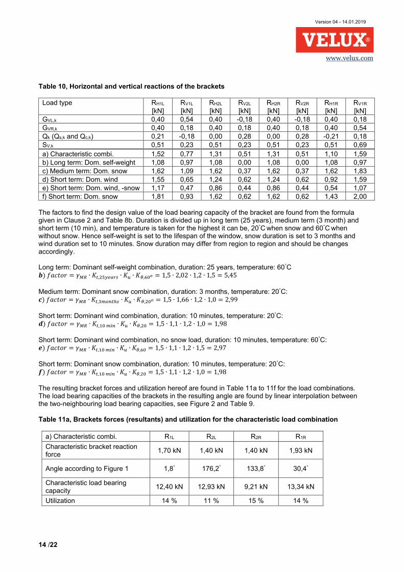
The factors to find the design value of the load bearing capacity of the bracket are found from the formula given in Clause 2 and Table 8b. Duration is divided up in long term (25 years), medium term (3 month) and short term (10 min), and temperature is taken for the highest it can be, 20°C when snow and 60°C when without snow. Hence self-weight is set to the lifespan of the window, snow duration is set to 3 months and wind duration set to 10 minutes. Snow duration may differ from region to region and should be changes accordingly. Long term: Dominant self-weight combination, duration: 25 years, temperature: 60°C 𝒃𝒃) 𝑓𝑓𝑒𝑒𝑐𝑐𝑡𝑡𝑜𝑜𝑓𝑓 = 𝛾𝛾𝑀𝑀𝑉𝑉 ∙ 𝐾𝐾𝑡𝑡,25𝑦𝑦𝑒𝑒𝑦𝑦𝑐𝑐𝑠𝑠 ∙ 𝐾𝐾𝑠𝑠 ∙ 𝐾𝐾𝜃𝜃,60𝑜𝑜 = 1,5 ∙ 2,02 ∙ 1,2 ∙ 1,5 = 5,45 Medium term: Dominant snow combination, duration: 3 months, temperature: 20°C: 𝒄𝒄) 𝑓𝑓𝑒𝑒𝑐𝑐𝑡𝑡𝑜𝑜𝑓𝑓 = 𝛾𝛾𝑀𝑀𝑉𝑉 ∙ 𝐾𝐾𝑡𝑡,3𝑚𝑚𝑐𝑐𝑖𝑖𝑡𝑡ℎ𝑠𝑠 ∙ 𝐾𝐾𝑠𝑠 ∙ 𝐾𝐾𝜃𝜃,20𝑜𝑜 = 1,5 ∙ 1,66 ∙ 1,2 ∙ 1,0 = 2,99 Short term: Dominant wind combination, duration: 10 minutes, temperature: 20°C: 𝒅𝒅) 𝑓𝑓𝑒𝑒𝑐𝑐𝑡𝑡𝑜𝑜𝑓𝑓 = 𝛾𝛾𝑀𝑀𝑉𝑉 ∙ 𝐾𝐾𝑡𝑡,10 𝑚𝑚𝑖𝑖𝑖𝑖 ∙ 𝐾𝐾𝑠𝑠 ∙ 𝐾𝐾𝜃𝜃,20 = 1,5 ∙ 1,1 ∙ 1,2 ∙ 1,0 = 1,98 Short term: Dominant wind combination, no snow load, duration: 10 minutes, temperature: 60°C: 𝒆𝒆) 𝑓𝑓𝑒𝑒𝑐𝑐𝑡𝑡𝑜𝑜𝑓𝑓 = 𝛾𝛾𝑀𝑀𝑉𝑉 ∙ 𝐾𝐾𝑡𝑡,10 𝑚𝑚𝑖𝑖𝑖𝑖 ∙ 𝐾𝐾𝑠𝑠 ∙ 𝐾𝐾𝜃𝜃,60 = 1,5 ∙ 1,1 ∙ 1,2 ∙ 1,5 = 2,97 Short term: Dominant snow combination, duration: 10 minutes, temperature: 20°C: 𝒇𝒇) 𝑓𝑓𝑒𝑒𝑐𝑐𝑡𝑡𝑜𝑜𝑓𝑓 = 𝛾𝛾𝑀𝑀𝑉𝑉 ∙ 𝐾𝐾𝑡𝑡,10 𝑚𝑚𝑖𝑖𝑖𝑖 ∙ 𝐾𝐾𝑠𝑠 ∙ 𝐾𝐾𝜃𝜃,20 = 1,5 ∙ 1,1 ∙ 1,2 ∙ 1,0 = 1,98 The resulting bracket forces and utilization hereof are found in Table 11a to 11f for the load combinations. The load bearing capacities of the brackets in the resulting angle are found by linear interpolation between the two-neighbouring load bearing capacities, see Figure 2 and Table 9. Table 11a, Brackets forces (resultants) and utilization for the characteristic load combination
a) Characteristic combi. R1L R2L R2R R1R
Characteristic bracket reaction force
1,70 kN 1,40 kN 1,40 kN 1,93 kN
Angle according to Figure 1 1,8° 176,2° 133,8° 30,4°
Characteristic load bearing capacity
12,40 kN 12,93 kN 9,21 kN 13,34 kN
Utilization 14 % 11 % 15 % 14 %
Version 04 - 14.01.2019
15 /22
www.velux.com
Table 11b, Brackets forces (resultants) and utilization for the long term dominant self-weight load combination
b) Long term: Dom. self-weight
R1L R2L R2R R1R
Design bracket reaction force 1,45 kN 1,08 kN 1,08 kN 1,45 kN
Angle according to Figure 1 17,1° 155,0° 155,0° 17,1°
Characteristic load bearing capacity
16,55 kN 14,86 kN 14,86 kN 16,55 kN
Design load bearing capacity 3,04 2,73 2,73 3,04
Utilization 48 % 39 % 39 % 48 %
Table 11c, Brackets forces (resultants) and utilization for the medium term dominant snow load combination
c) Medium term: Dom. snow
R1L R2L R2R R1R
Design bracket reaction force 1,95 kN 1,66 kN 1,66 kN 2,45 kN
Angle according to Figure 1 9,0° 167,9° 142,1° 23,6°
Characteristic load bearing capacity
14,34 kN 15,19 kN 11,27 kN 15,26 kN
Design load bearing capacity 4,80 kN 5,08 kN 3,77 kN 5,10 kN
Utilization 41 % 33 % 44 % 48 % Table 11d, Brackets forces (resultants) and utilization for the short term dominant wind load combination
d) Short term: Dom. wind
R1L R2L R2R R1R
Design bracket reaction force 1,68 kN 1,38 kN 1,38 kN 1,84 kN
Angle according to Figure 1 357,6 o 181,4 o 128,6 o 34,9 o
Characteristic load bearing capacity
11,15 kN 11,47 kN 8,83 kN 12,11 kN
Design load bearing capacity 5,63 kN 5,79 kN 4,46 kN 6,12 kN
Utilization 30 % 24 % 31 % 30 %
Version 04 - 14.01.2019
16 /22
www.velux.com
Table 11e, Brackets forces (resultants) and utilization for the short term dominant wind, without snow load combination
e) Short term: Dom. wind, -snow
R1L R2L R2R R1R
Design bracket reaction force 1,26 kN 0,96 kN 0,96 kN 1,20 kN
Angle according to Figure 1 357,0° 182,3° 127,7° 38,3°
Characteristic load bearing capacity
10,98 kN 11,18 kN 8,76 kN 11,17 kN
Design load bearing capacity 3,70 kN 3,77 kN 2,95 kN 3,76 kN
Utilization 34 % 26 % 33 % 32 % Table 11f, Brackets forces (resultants) and utilization for the short term dominant snow load combination
f) Short term: Dom. snow
R1L R2L R2R R1R
Design bracket reaction force 2,03 kN 1,74 kN 1,74 kN 2,46 kN
Angle according to Figure 1 2,1° 176,0° 134,0° 29,4°
Characteristic load bearing capacity
12,48 kN 12,99 kN 9,23 kN 13,63 kN
Design load bearing capacity 6,30 kN 6,56 kN 4,66 kN 6,89 kN
Utilization 32 % 26 % 37 % 36 % Load bearing capacity for wind suction Since it is an openable window and the left side is subjected to wind suction, the load bearing capacity hereof is checked. Dimension of the glass is found in Figure 5. The 60 mm protruded part is toughened glass with a thickness of
8 mm. The glass self-weight can hereby be found with a glass density of γglass= 25 kN/m3. 𝐺𝐺𝑔𝑔𝑔𝑔𝑒𝑒𝑠𝑠𝑠𝑠,𝑘𝑘 = �(𝐿𝐿 − 0,056𝑚𝑚) ∙ 𝑡𝑡+ 0,060𝑚𝑚 ∙ 0,008𝑚𝑚� ∙ (𝑊𝑊− 0,022𝑚𝑚) ∙ 𝛾𝛾𝑔𝑔𝑔𝑔𝑒𝑒𝑠𝑠𝑠𝑠 = �(2,4− 0,056𝑚𝑚) ∙ 0,014 + 0,060𝑚𝑚 ∙ 0,008𝑚𝑚� ∙ (1,0− 0,022𝑚𝑚) ∙ 25 𝑘𝑘𝑘𝑘/𝑚𝑚3 = 0,81𝑘𝑘𝑘𝑘
The weight of the openable window casement profile is set to: 𝑔𝑔𝑐𝑐𝑦𝑦𝑠𝑠𝑒𝑒,𝑘𝑘 = 𝐴𝐴𝑐𝑐𝑦𝑦𝑠𝑠𝑒𝑒 ∙ 𝛾𝛾𝑖𝑖𝑐𝑐𝑦𝑦𝑚𝑚𝑒𝑒 ∙ 𝑔𝑔 = 8,57 ∙ 10−4𝑚𝑚2 ∙ 2076𝑘𝑘𝑔𝑔/𝑚𝑚3 ∙ 9,81𝑚𝑚/𝑠𝑠2 = 0,017𝑘𝑘𝑘𝑘/𝑚𝑚
Here, the area of the casement profiles (Acase) is taken from Annex C4 and the density (γframe) is taken from Annex D.1 in ETA-17/0467.
Version 04 - 14.01.2019
17 /22
www.velux.com
Figure 5: Glass dimension for openable window
The perimeter of the casement Lcase is found, see also Figure 6: 𝐿𝐿𝑐𝑐𝑒𝑒𝑠𝑠𝑒𝑒 = 2 ∙ (𝐿𝐿 − 0,041𝑚𝑚) + 2 ∙ (𝑊𝑊− 0,041𝑚𝑚) = 2 ∙ (2,4− 0,041𝑚𝑚) + 2 ∙ (1,0− 0,041𝑚𝑚) =6,64m The total characteristic self-weight perpendicular to the openable window (𝐺𝐺⊥,𝑘𝑘) is found to:
𝐺𝐺⊥,𝑘𝑘 = (𝐺𝐺𝑔𝑔𝑙𝑙𝑦𝑦𝑠𝑠𝑠𝑠,𝑘𝑘 + 𝑔𝑔𝑐𝑐𝑦𝑦𝑠𝑠𝑒𝑒,𝑘𝑘 ∙ 𝐿𝐿𝑐𝑐𝑦𝑦𝑠𝑠𝑒𝑒) ∙ cos (𝛼𝛼) = (0,81𝑘𝑘𝑘𝑘 + 0,017𝑘𝑘𝑘𝑘/𝑚𝑚 ∙ 6,64𝑚𝑚) ∙ cos (25°) = 0,84𝑘𝑘𝑘𝑘
Version 04 - 14.01.2019
18 /22
www.velux.com
Figure 6: Dimension for casement profile for openable window
Glass area (AW,suc) for which the wind suctions acts upon: 𝐴𝐴𝑊𝑊,𝑠𝑠𝑠𝑠𝑐𝑐 = �(𝐿𝐿 − 0,056𝑚𝑚) + 0,060𝑚𝑚� ∙ (𝑊𝑊 − 0,022𝑚𝑚) = �(2,4 − 0,056𝑚𝑚) + 0,060𝑚𝑚� ∙ (1,0 − 0,022𝑚𝑚) = 2,35𝑚𝑚2 The characteristic wind suction perpendicular of the openable window (𝑄𝑄𝑠𝑠⊥,𝑘𝑘) is found 𝑄𝑄𝑠𝑠⊥,𝑘𝑘 = 𝑞𝑞𝑠𝑠,𝑘𝑘 ∙ 𝑐𝑐 ∙ 𝐴𝐴𝑊𝑊,𝑠𝑠𝑠𝑠𝑐𝑐 = 0,8𝑘𝑘𝑘𝑘/𝑚𝑚2 ∙ 0,5 ∙ 2,35𝑚𝑚2 = 0,94𝑘𝑘𝑘𝑘
The load combination e) short term dominant wind, no snow load, is the worst case for wind suction on the window. Giving a total design load perpendicular to the window (𝑃𝑃⊥𝑑𝑑): 𝑃𝑃⊥𝑑𝑑 = 𝛾𝛾𝑄𝑄,1 ∙ 𝑄𝑄𝑠𝑠⊥,𝑘𝑘 − 𝛾𝛾𝐺𝐺,𝑖𝑖𝑖𝑖𝑖𝑖 ∙ 𝐺𝐺⊥,𝑘𝑘 = 1,5 ∙ 0,94𝑘𝑘𝑘𝑘 − 1,0 ∙ 0,84𝑘𝑘𝑘𝑘 = 0,57𝑘𝑘𝑘𝑘 The characteristic load bearing capacity (Rk) is taken from Clause 8, Table 6 for double glazing: 𝑅𝑅𝑘𝑘 = 8,87 𝑘𝑘𝑘𝑘 Reduction safety factor for short term: Dominant wind combination, no snow load, duration: 10 minutes, temperature: 60°C is found to: 𝒆𝒆) 𝑓𝑓𝑒𝑒𝑐𝑐𝑡𝑡𝑜𝑜𝑓𝑓 = 𝛾𝛾𝑀𝑀𝑉𝑉 ∙ 𝐾𝐾𝑡𝑡,10 𝑚𝑚𝑖𝑖𝑖𝑖 ∙ 𝐾𝐾𝑠𝑠 ∙ 𝐾𝐾𝜃𝜃,60 = 1,5 ∙ 1,1 ∙ 1,2 ∙ 1,5 = 2,97
Version 04 - 14.01.2019
19 /22
www.velux.com
Design load bearing capacity (Rd): 𝑅𝑅𝑑𝑑 =
8,87𝑘𝑘𝑘𝑘2,97
= 2,99𝑘𝑘𝑘𝑘
Utilization: 𝑃𝑃⊥𝑑𝑑/𝑅𝑅𝑑𝑑 ∙ 100 = 0,57𝑘𝑘𝑘𝑘/2,99𝑘𝑘𝑘𝑘 ∙ 100 = 19% Bending in frame and casement profile The bending in frame and casement profile is in this example only calculated for the medium term dominate snow combination, hereby showing the calculations procedure. Normally all load combination should be investigated.
Design capacity of frame and casement, duration: 3 months, temperature: 20°C: 𝜎𝜎𝑉𝑉,𝑑𝑑 =𝜎𝜎𝑉𝑉,𝑘𝑘𝛾𝛾𝑀𝑀𝑉𝑉 ∙ 𝐾𝐾𝑡𝑡,3 𝑚𝑚𝑐𝑐𝑖𝑖𝑡𝑡ℎ ∙ 𝐾𝐾𝑠𝑠 ∙ 𝐾𝐾𝜃𝜃,20𝑜𝑜 =
1257𝑘𝑘/𝑚𝑚𝑚𝑚21,2 ∙ 1,66 ∙ 1,2 ∙ 1,0
= 526𝑘𝑘/𝑚𝑚𝑚𝑚2
(For characteristic bending strength see Table 3, for partial safety factors see Table 8a/ULS and for magnification and reduction factors see Table 8b/ULS.) The characteristic line load from self-weight perpendicular to the roof window is denoted gp,k and perpendicular line load from the characteristic snow pressure is denoted sp,k. The corrected height is applied but the original angle is used: 𝑔𝑔𝑠𝑠,𝑘𝑘 =
𝐺𝐺𝑉𝑉𝑉𝑉,𝑘𝑘 ∙ 𝑐𝑐𝑜𝑜𝑠𝑠 (𝛼𝛼)𝐿𝐿𝑐𝑐𝑐𝑐𝑐𝑐 =0,72 ∙ 𝑐𝑐𝑜𝑜𝑠𝑠 (25)
2,543= 0,26𝑘𝑘𝑘𝑘/𝑚𝑚 , 𝑜𝑜𝑜𝑜 𝑒𝑒𝑒𝑒𝑐𝑐ℎ 𝑠𝑠𝑠𝑠𝑠𝑠𝑒𝑒 𝑓𝑓𝑓𝑓𝑒𝑒𝑚𝑚𝑒𝑒/𝑐𝑐𝑒𝑒𝑠𝑠𝑒𝑒𝑚𝑚𝑒𝑒𝑜𝑜𝑡𝑡 𝑠𝑠𝑠𝑠,𝑘𝑘 = 𝑠𝑠𝑠𝑠,𝑘𝑘 ∙ cos (𝛼𝛼) = 0,40𝑘𝑘𝑘𝑘/𝑚𝑚 ∙ cos (25) = 0,36𝑘𝑘𝑘𝑘/𝑚𝑚 , 𝑜𝑜𝑜𝑜 𝑒𝑒𝑒𝑒𝑐𝑐ℎ 𝑠𝑠𝑠𝑠𝑠𝑠𝑒𝑒 𝑓𝑓𝑓𝑓𝑒𝑒𝑚𝑚𝑒𝑒/𝑐𝑐𝑒𝑒𝑠𝑠𝑒𝑒𝑚𝑚𝑒𝑒𝑜𝑜𝑡𝑡 𝑀𝑀𝑑𝑑 =
1
8∙ �𝛾𝛾𝐺𝐺,𝑠𝑠𝑠𝑠𝑠𝑠 ∙ 𝜉𝜉𝐺𝐺,𝑠𝑠𝑠𝑠𝑠𝑠 ∙ 𝑔𝑔𝑠𝑠,𝑘𝑘 + 𝛾𝛾𝑄𝑄,1 ∙ 𝑠𝑠𝑠𝑠,𝑘𝑘� ∙ 𝐿𝐿𝑐𝑐𝑐𝑐𝑐𝑐2
=1
8∙ (1,35 ∙ 0,85 ∙ 0,26 + 1,5 ∙ 0,36)𝑘𝑘𝑘𝑘/𝑚𝑚 ∙ (2,543𝑚𝑚)2 = 0,68𝑘𝑘𝑘𝑘𝑚𝑚 𝑀𝑀𝑖𝑖𝑐𝑐𝑦𝑦𝑚𝑚𝑒𝑒,𝑑𝑑 = 𝑀𝑀𝑑𝑑 ∙ 𝐼𝐼𝑓𝑓𝑓𝑓𝑓𝑓𝑓𝑓𝑓𝑓𝐼𝐼𝑓𝑓𝑓𝑓𝑓𝑓𝑓𝑓𝑓𝑓+𝐼𝐼𝑐𝑐𝑓𝑓𝑐𝑐𝑓𝑓𝑓𝑓𝑓𝑓𝑐𝑐𝑐𝑐 = 0,68𝑘𝑘𝑘𝑘𝑚𝑚 ∙ 0,669∙106𝑚𝑚𝑚𝑚40,669∙106𝑚𝑚𝑚𝑚4+0,930∙106𝑚𝑚𝑚𝑚4 = 0,28𝑘𝑘𝑘𝑘𝑚𝑚 𝜎𝜎𝑖𝑖𝑐𝑐𝑦𝑦𝑚𝑚𝑒𝑒,𝑑𝑑 ≈ 𝑀𝑀𝑓𝑓𝑓𝑓𝑓𝑓𝑓𝑓𝑓𝑓,𝑑𝑑𝑊𝑊𝑦𝑦,𝑓𝑓𝑓𝑓𝑓𝑓𝑓𝑓𝑓𝑓 =
0,28∙106𝑁𝑁𝑚𝑚𝑚𝑚9,93∙103𝑚𝑚𝑚𝑚3 = 28,7𝑘𝑘/𝑚𝑚𝑚𝑚2
Utilization: 𝜎𝜎𝑓𝑓𝑓𝑓𝑓𝑓𝑓𝑓𝑓𝑓,𝑑𝑑𝜎𝜎𝑅𝑅,𝑑𝑑 ∙ 100 =
28,7𝑁𝑁/𝑚𝑚𝑚𝑚2526𝑁𝑁/𝑚𝑚𝑚𝑚2 ∙ 100 = 5,4% 𝑀𝑀𝑐𝑐𝑦𝑦𝑠𝑠𝑒𝑒𝑚𝑚𝑒𝑒𝑖𝑖𝑡𝑡,𝑑𝑑 = 𝑀𝑀𝑑𝑑 ∙ 𝐼𝐼𝑐𝑐𝑓𝑓𝑐𝑐𝑓𝑓𝑓𝑓𝑓𝑓𝑐𝑐𝑐𝑐𝐼𝐼𝑓𝑓𝑓𝑓𝑓𝑓𝑓𝑓𝑓𝑓+𝐼𝐼𝑐𝑐𝑓𝑓𝑐𝑐𝑓𝑓𝑓𝑓𝑓𝑓𝑐𝑐𝑐𝑐 = 0,68𝑘𝑘𝑘𝑘𝑚𝑚 ∙ 0,930∙106𝑚𝑚𝑚𝑚40,669∙106𝑚𝑚𝑚𝑚4+0,930∙106𝑚𝑚𝑚𝑚4 = 0,40𝑘𝑘𝑘𝑘𝑚𝑚 𝜎𝜎𝑐𝑐𝑦𝑦𝑠𝑠𝑒𝑒𝑚𝑚𝑒𝑒𝑖𝑖𝑡𝑡,𝑑𝑑 ≈ 𝑀𝑀𝑐𝑐𝑓𝑓𝑐𝑐𝑓𝑓𝑓𝑓𝑓𝑓𝑐𝑐𝑐𝑐,𝑑𝑑,𝑊𝑊𝑦𝑦,𝑐𝑐𝑓𝑓𝑐𝑐𝑓𝑓𝑓𝑓𝑓𝑓𝑐𝑐𝑐𝑐 =0,40∙106𝑁𝑁𝑚𝑚𝑚𝑚16,4∙103𝑚𝑚𝑚𝑚3 = 24,1𝑘𝑘/𝑚𝑚𝑚𝑚2
Utilization: 𝜎𝜎𝑐𝑐𝑓𝑓𝑐𝑐𝑓𝑓𝑓𝑓𝑓𝑓𝑐𝑐𝑐𝑐,𝑑𝑑𝜎𝜎𝑅𝑅,𝑑𝑑 ∙ 100 =
24,1𝑁𝑁/𝑚𝑚𝑚𝑚2526𝑁𝑁/𝑚𝑚𝑚𝑚2 ∙ 100 = 4,6%
Here, the characteristic bending strength is taken from Annex D.1 in ETA-17/0467. Second moment of area and section modulus are taken from Annex C.1 and C.4 in ETA-17/0467. The rotation of the main axis is ignored, as it has little influence on the result, and the resulting stress is much lower than the bending strength. Shear force in frame profile The shear force in frame profile is in this example only calculated for the medium term dominate snow combination, hereby showing the calculations procedure. Normally all load combination shall be investigated.
Design capacity shear stress of frame, duration: 3 months, temperature: 20°C:
Version 04 - 14.01.2019
20 /22
www.velux.com
𝜏𝜏𝑖𝑖𝑐𝑐𝑦𝑦𝑚𝑚𝑒𝑒,𝑉𝑉,𝑑𝑑 =𝜏𝜏𝑖𝑖𝑐𝑐𝑦𝑦𝑚𝑚𝑒𝑒,𝑉𝑉,𝑘𝑘𝛾𝛾𝑀𝑀𝑉𝑉 ∙ 𝐾𝐾𝑡𝑡,3 𝑚𝑚𝑐𝑐𝑖𝑖𝑡𝑡ℎ ∙ 𝐾𝐾𝑠𝑠 ∙ 𝐾𝐾𝜃𝜃,20𝑜𝑜 =
53,8𝑘𝑘/𝑚𝑚𝑚𝑚21,2 ∙ 1,66 ∙ 1,2 ∙ 1,0
= 22,5𝑘𝑘/𝑚𝑚𝑚𝑚2
(For characteristic shear strength see Table 3, for partial safety factors see Table 8a/ULS and for magnification and reduction factors see Table 8b/ULS.) The shear force is generally taken in combination by the frame and casement profile, but near the ends of the roof window, the entire shear force is taken by the frame profile. The original angle is used. Largest shear force is in the right roof window in this example: 𝑉𝑉𝑖𝑖𝑐𝑐𝑦𝑦𝑚𝑚𝑒𝑒 = 𝑅𝑅𝑉𝑉1𝑉𝑉 ∙ 𝑐𝑐𝑜𝑜𝑠𝑠(𝛼𝛼) − 𝑅𝑅𝑠𝑠1𝑉𝑉∙ 𝑠𝑠𝑠𝑠𝑜𝑜(𝛼𝛼)
= 1,83𝑘𝑘𝑘𝑘 ∙ 𝑐𝑐𝑜𝑜𝑠𝑠(25) − 1,62𝑘𝑘𝑘𝑘 ∙ 𝑠𝑠𝑠𝑠𝑜𝑜 (25)
= 0,97𝑘𝑘𝑘𝑘
𝜏𝜏𝑖𝑖𝑐𝑐𝑦𝑦𝑚𝑚𝑒𝑒 = 𝑉𝑉𝑓𝑓𝑓𝑓𝑓𝑓𝑓𝑓𝑓𝑓𝐴𝐴𝑤𝑤𝑓𝑓𝑤𝑤 ≈ 0,97∙103𝑁𝑁550𝑚𝑚𝑚𝑚2 = 1,77𝑘𝑘/𝑚𝑚𝑚𝑚2
Utilization: 𝜏𝜏𝑓𝑓𝑓𝑓𝑓𝑓𝑓𝑓𝑓𝑓𝜏𝜏𝑓𝑓𝑓𝑓𝑓𝑓𝑓𝑓𝑓𝑓,𝑅𝑅,𝑑𝑑 ∙ 100 =
1,77𝑁𝑁/𝑚𝑚𝑚𝑚222,5𝑁𝑁/𝑚𝑚𝑚𝑚2 ∙ 100 = 7,9%
Here, the characteristic shear strength is taken from Annex D.1 and Aweb from Annex C.1 in ETA-17/0467. Deflection Deflections are checked for each side separately and perpendicular to the corrected roof window angle. 6 SLS load combinations can therefore be made, for this load case: g) Long term: Dominant self-weight: 𝐺𝐺𝑉𝑉𝑉𝑉,𝑘𝑘 h) Medium term: Dominant snow: 𝐺𝐺𝑉𝑉𝑉𝑉,𝑘𝑘 + 𝑆𝑆𝑉𝑉,𝑘𝑘 i) Short term: Dominant wind pressure, with snow: 𝐺𝐺𝑉𝑉𝑉𝑉,𝑘𝑘 + 𝑄𝑄𝑐𝑐,𝑘𝑘 + Ψ0,𝑠𝑠𝑖𝑖𝑐𝑐𝑠𝑠 ∙ 𝑆𝑆𝑉𝑉,𝑘𝑘 => 𝐺𝐺𝑉𝑉𝑉𝑉,𝑘𝑘 + 𝑄𝑄𝑐𝑐,𝑘𝑘 + 0,5 ∙ 𝑆𝑆𝑉𝑉,𝑘𝑘 j) Short term: Dominant wind pressure, no snow 𝐺𝐺𝑉𝑉𝑉𝑉,𝑘𝑘 + 𝑄𝑄𝑐𝑐,𝑘𝑘 k) Short term: Dominant snow, with wind: 𝐺𝐺𝑉𝑉𝑉𝑉,𝑘𝑘 + Ψ0,𝑠𝑠𝑖𝑖𝑖𝑖𝑑𝑑 ∙ 𝑄𝑄𝑐𝑐,𝑘𝑘 + 𝑆𝑆𝑉𝑉,𝑘𝑘 => 𝐺𝐺𝑉𝑉𝑉𝑉,𝑘𝑘 + 0,6 ∙ 𝑄𝑄𝑐𝑐,𝑘𝑘 + 𝑆𝑆𝑉𝑉,𝑘𝑘 l) Short term: Dominant wind suction, no snow 𝐺𝐺𝑉𝑉𝑉𝑉,𝑘𝑘 + 𝑄𝑄𝑠𝑠,𝑘𝑘 The factors to find the design value of the deflection of the frame/casement are found from the formula given in Clause 2 and Table 8b. Duration is divided up in long term (25 years), medium term (3 month) and short term (10 min), and temperature is taken for the highest it can be, 20°C when snow and 60°C when without snow. Hence self-weight is set to the lifespan of the window, snow duration is set to 3 months and wind duration set to 10 minutes. Snow duration may differ from region to region and should be changes accordingly.
Version 04 - 14.01.2019
21 /22
www.velux.com
Long term: Dominant self-weight combination, duration: 25 years, temperature: 60°C: 𝒈𝒈) 𝑓𝑓𝑒𝑒𝑐𝑐𝑡𝑡𝑜𝑜𝑓𝑓 = 𝛾𝛾𝑀𝑀𝑀𝑀 ∙ 𝐶𝐶𝑡𝑡,25 𝑦𝑦𝑒𝑒𝑦𝑦𝑐𝑐𝑠𝑠 ∙ 𝐶𝐶𝑠𝑠 ∙ 𝐶𝐶𝜃𝜃,60𝑜𝑜 = 1,1 ∙ 1,15 ∙ 1,2 ∙ 1,05 = 1,59 Medium term: Dominant snow combination, duration: 3 months, temperature: 20°C: 𝒉𝒉) 𝑓𝑓𝑒𝑒𝑐𝑐𝑡𝑡𝑜𝑜𝑓𝑓 = 𝛾𝛾𝑀𝑀𝑀𝑀 ∙ 𝐶𝐶𝑡𝑡,3𝑚𝑚𝑐𝑐𝑖𝑖𝑡𝑡ℎ𝑠𝑠 ∙ 𝐶𝐶𝑠𝑠 ∙ 𝐶𝐶𝜃𝜃,20𝑜𝑜 = 1,1 ∙ 1,11 ∙ 1,2 ∙ 1,0 = 1,47 Short term: Dominant wind pressure combination, duration: 10 minutes, temperature: 20°C: 𝒊𝒊) 𝑓𝑓𝑒𝑒𝑐𝑐𝑡𝑡𝑜𝑜𝑓𝑓 = 𝛾𝛾𝑀𝑀𝑀𝑀 ∙ 𝐶𝐶𝑡𝑡,10𝑚𝑚𝑖𝑖𝑖𝑖 ∙ 𝐶𝐶𝑠𝑠 ∙ 𝐶𝐶𝜃𝜃,20𝑜𝑜 = 1,1 ∙ 1,02 ∙ 1,2 ∙ 1,0 = 1,35 Short term: Dominant wind pressure combination, no snow load, duration: 10 minutes, temperature: 60°C: 𝒋𝒋) 𝑓𝑓𝑒𝑒𝑐𝑐𝑡𝑡𝑜𝑜𝑓𝑓 = 𝛾𝛾𝑀𝑀𝑀𝑀 ∙ 𝐶𝐶𝑡𝑡,10𝑚𝑚𝑖𝑖𝑖𝑖 ∙ 𝐶𝐶𝑠𝑠 ∙ 𝐶𝐶𝜃𝜃,60𝑜𝑜 = 1,1 ∙ 1,02 ∙ 1,2 ∙ 1,05 = 1,41 Short term: Dominant snow combination, duration: 10 minutes, temperature: 20°C: 𝒌𝒌) 𝑓𝑓𝑒𝑒𝑐𝑐𝑡𝑡𝑜𝑜𝑓𝑓 = 𝛾𝛾𝑀𝑀𝑀𝑀 ∙ 𝐶𝐶𝑡𝑡,10𝑚𝑚𝑖𝑖𝑖𝑖 ∙ 𝐶𝐶𝑠𝑠 ∙ 𝐶𝐶𝜃𝜃,20𝑜𝑜 = 1,1 ∙ 1,02 ∙ 1,2 ∙ 1,0 = 1,35 Short term: Dominant wind suction combination, no snow load, duration: 10 minutes, temperature: 60°C: 𝒍𝒍) 𝑓𝑓𝑒𝑒𝑐𝑐𝑡𝑡𝑜𝑜𝑓𝑓 = 𝛾𝛾𝑀𝑀𝑀𝑀 ∙ 𝐶𝐶𝑡𝑡,10𝑚𝑚𝑖𝑖𝑖𝑖 ∙ 𝐶𝐶𝑠𝑠 ∙ 𝐶𝐶𝜃𝜃,60𝑜𝑜 = 1,1 ∙ 1,02 ∙ 1,2 ∙ 1,05 = 1,41 (For partial safety factors see Table 8a/SLS and for magnification and reduction factors see Table 8b/SLS). Characteristic Self-weight perpendicular to the corrected roof window angle: 𝑔𝑔𝑠𝑠,𝑐𝑐𝑐𝑐𝑐𝑐,𝑘𝑘 =
𝐺𝐺𝑉𝑉 ∙ 𝑐𝑐𝑜𝑜𝑠𝑠 (𝛼𝛼𝑐𝑐𝑐𝑐𝑐𝑐)𝐿𝐿𝑐𝑐𝑐𝑐𝑐𝑐 =0,72 ∙ 𝑐𝑐𝑜𝑜𝑠𝑠 (24,3)
2,543= 0,26𝑘𝑘𝑘𝑘/𝑚𝑚 , 𝑜𝑜𝑜𝑜 𝑒𝑒𝑒𝑒𝑐𝑐ℎ 𝑠𝑠𝑠𝑠𝑠𝑠𝑒𝑒 𝑓𝑓𝑓𝑓𝑒𝑒𝑚𝑚𝑒𝑒/𝑐𝑐𝑒𝑒𝑠𝑠𝑒𝑒𝑚𝑚𝑒𝑒𝑜𝑜𝑡𝑡
Characteristic wind pressure and suction perpendicular to the corrected roof window angle: 𝑞𝑞𝑐𝑐,𝑐𝑐𝑐𝑐𝑐𝑐,𝑘𝑘 = 𝑞𝑞𝑐𝑐,𝑘𝑘 ∙ cos (−∆𝛼𝛼) = 0,2𝑘𝑘𝑘𝑘/𝑚𝑚 ∙ cos (0,7) = 0,20𝑘𝑘𝑘𝑘/𝑚𝑚 , 𝑜𝑜𝑜𝑜 𝑒𝑒𝑒𝑒𝑐𝑐ℎ 𝑠𝑠𝑠𝑠𝑠𝑠𝑒𝑒 𝑓𝑓𝑓𝑓𝑒𝑒𝑚𝑚𝑒𝑒/𝑐𝑐𝑒𝑒𝑠𝑠𝑒𝑒𝑚𝑚𝑒𝑒𝑜𝑜𝑡𝑡
Characteristic snow load perpendicular to the corrected roof window angle: 𝑠𝑠𝑠𝑠,𝑐𝑐𝑐𝑐𝑐𝑐,𝑘𝑘 = 𝑠𝑠𝑠𝑠,𝑘𝑘 ∙ cos (𝛼𝛼𝑐𝑐𝑐𝑐𝑐𝑐)2 = 0,40𝑘𝑘𝑘𝑘/𝑚𝑚 ∙ cos (24,3) = 0,33𝑘𝑘𝑘𝑘/𝑚𝑚 , 𝑜𝑜𝑜𝑜 𝑒𝑒𝑒𝑒𝑐𝑐ℎ 𝑠𝑠𝑠𝑠𝑠𝑠𝑒𝑒 𝑓𝑓𝑓𝑓𝑒𝑒𝑚𝑚𝑒𝑒/𝑐𝑐𝑒𝑒𝑠𝑠𝑒𝑒𝑚𝑚𝑒𝑒𝑜𝑜𝑡𝑡 In the deflection calculations, the second moment of area are found in ETA-17/0467 Annex C.1 and Annex C.4 and for E-modulus see Table 3 including Note 3 g) Deflection for long term: Dominant self-weight 𝑢𝑢 =
5384 ∙ (𝑔𝑔𝑝𝑝,𝑐𝑐𝑜𝑜𝑓𝑓,𝑘𝑘) ∙ 𝑉𝑉𝑐𝑐𝑜𝑜𝑓𝑓4 𝐸𝐸∙�𝐼𝐼𝑓𝑓𝑓𝑓𝑓𝑓𝑓𝑓𝑓𝑓+𝐼𝐼𝑐𝑐𝑓𝑓𝑐𝑐𝑓𝑓𝑓𝑓𝑓𝑓𝑐𝑐𝑐𝑐�∙𝑖𝑖𝑦𝑦𝑐𝑐𝑡𝑡𝑐𝑐𝑐𝑐,𝑔𝑔
=5384 ∙ (0,26)𝑁𝑁/𝑚𝑚𝑚𝑚 ∙ (2543𝑚𝑚𝑚𝑚)4 41600𝑁𝑁/𝑚𝑚𝑚𝑚2∙0,83∙(0,669∙106𝑚𝑚𝑚𝑚4+0,930∙106𝑚𝑚𝑚𝑚4)
∙1,59 = 4,1𝑚𝑚𝑚𝑚 <𝐿𝐿𝑐𝑐𝑐𝑐𝑐𝑐150
= 17 𝑚𝑚𝑚𝑚
h) Deflection for medium term: Dominant snow 𝑢𝑢 =
5384 ∙ (𝑔𝑔𝑝𝑝,𝑐𝑐𝑜𝑜𝑓𝑓,𝑘𝑘+∙𝑠𝑠𝑝𝑝,𝑐𝑐𝑜𝑜𝑓𝑓,𝑘𝑘) ∙ 𝑉𝑉𝑐𝑐𝑜𝑜𝑓𝑓4 𝐸𝐸∙�𝐼𝐼𝑓𝑓𝑓𝑓𝑓𝑓𝑓𝑓𝑓𝑓+𝐼𝐼𝑐𝑐𝑓𝑓𝑐𝑐𝑓𝑓𝑓𝑓𝑓𝑓𝑐𝑐𝑐𝑐� ∙𝑖𝑖𝑦𝑦𝑐𝑐𝑡𝑡𝑐𝑐𝑐𝑐,ℎ =
5384 ∙ (0,26+0,33)𝑁𝑁/𝑚𝑚𝑚𝑚 ∙ (2543𝑚𝑚𝑚𝑚)4 41600𝑁𝑁/𝑚𝑚𝑚𝑚2∙0,83∙(0,669∙106𝑚𝑚𝑚𝑚4+0,930∙106𝑚𝑚𝑚𝑚4)∙1,47 = 8,6𝑚𝑚𝑚𝑚 <
𝐿𝐿𝑐𝑐𝑐𝑐𝑐𝑐150
= 17 𝑚𝑚𝑚𝑚
Version 04 - 14.01.2019
22 /22
www.velux.com
i) Deflection for short term: Dominant wind pressure, with snow: 𝑢𝑢 =
5384 ∙ (𝑔𝑔𝑝𝑝,𝑐𝑐𝑜𝑜𝑓𝑓,𝑘𝑘+𝑞𝑞𝑐𝑐,𝑐𝑐𝑜𝑜𝑓𝑓,𝑘𝑘+Ψ0,𝑐𝑐𝑐𝑐𝑜𝑜𝑤𝑤∙𝑠𝑠𝑝𝑝,𝑐𝑐𝑜𝑜𝑓𝑓,𝑘𝑘) ∙ 𝑉𝑉𝑐𝑐𝑜𝑜𝑓𝑓4 𝐸𝐸∙�𝐼𝐼𝑓𝑓𝑓𝑓𝑓𝑓𝑓𝑓𝑓𝑓+𝐼𝐼𝑐𝑐𝑓𝑓𝑐𝑐𝑓𝑓𝑓𝑓𝑓𝑓𝑐𝑐𝑐𝑐� ∙𝑖𝑖𝑦𝑦𝑐𝑐𝑡𝑡𝑐𝑐𝑐𝑐,𝑖𝑖 =
5384 ∙ (0,26+0,20+0,5∙0,33)𝑁𝑁/𝑚𝑚𝑚𝑚 ∙ (2543𝑚𝑚𝑚𝑚)4 41600𝑁𝑁/𝑚𝑚𝑚𝑚2∙0,83∙(0,669∙106𝑚𝑚𝑚𝑚4+0,930∙106𝑚𝑚𝑚𝑚4)∙1,35 = 8,3𝑚𝑚𝑚𝑚 <
𝐿𝐿𝑐𝑐𝑐𝑐𝑐𝑐150
= 17 𝑚𝑚𝑚𝑚
j) Deflection for short term: Dominant wind, without snow: 𝑢𝑢 =
5384 ∙ (𝑔𝑔𝑝𝑝,𝑐𝑐𝑜𝑜𝑓𝑓,𝑘𝑘+𝑞𝑞𝑐𝑐,𝑐𝑐𝑜𝑜𝑓𝑓,𝑘𝑘) ∙ 𝑉𝑉𝑐𝑐𝑜𝑜𝑓𝑓4 𝐸𝐸∙�𝐼𝐼𝑓𝑓𝑓𝑓𝑓𝑓𝑓𝑓𝑓𝑓+𝐼𝐼𝑐𝑐𝑓𝑓𝑐𝑐𝑓𝑓𝑓𝑓𝑓𝑓𝑐𝑐𝑐𝑐� ∙𝑖𝑖𝑦𝑦𝑐𝑐𝑡𝑡𝑐𝑐𝑐𝑐,𝑗𝑗 =
5384 ∙ (0,26+0,20)𝑁𝑁/𝑚𝑚𝑚𝑚 ∙ (2543𝑚𝑚𝑚𝑚)4 41600𝑁𝑁/𝑚𝑚𝑚𝑚2∙0,83∙(0,669∙106𝑚𝑚𝑚𝑚4+0,930∙106𝑚𝑚𝑚𝑚4)∙1,41 = 6,4𝑚𝑚𝑚𝑚 <
𝐿𝐿𝑐𝑐𝑐𝑐𝑐𝑐150
= 17 𝑚𝑚𝑚𝑚
k) Deflection for short term: Dominant snow, with wind: 𝑢𝑢 =
5384 ∙ (𝑔𝑔𝑝𝑝,𝑐𝑐𝑜𝑜𝑓𝑓,𝑘𝑘+Ψ0,𝑤𝑤𝑤𝑤𝑐𝑐𝑑𝑑∙𝑞𝑞𝑐𝑐,𝑐𝑐𝑜𝑜𝑓𝑓,𝑘𝑘+𝑠𝑠𝑝𝑝,𝑐𝑐𝑜𝑜𝑓𝑓,𝑘𝑘) ∙ 𝑉𝑉𝑐𝑐𝑜𝑜𝑓𝑓4 𝐸𝐸∙�𝐼𝐼𝑓𝑓𝑓𝑓𝑓𝑓𝑓𝑓𝑓𝑓+𝐼𝐼𝑐𝑐𝑓𝑓𝑐𝑐𝑓𝑓𝑓𝑓𝑓𝑓𝑐𝑐𝑐𝑐� ∙𝑖𝑖𝑦𝑦𝑐𝑐𝑡𝑡𝑐𝑐𝑐𝑐,𝑘𝑘 =
5384 ∙ (0,26+0,6∙0,20+0,33)𝑁𝑁/𝑚𝑚𝑚𝑚 ∙ (2543𝑚𝑚𝑚𝑚)4 41600𝑁𝑁/𝑚𝑚𝑚𝑚2∙0,83∙(0,669∙106𝑚𝑚𝑚𝑚4+0,930∙106𝑚𝑚𝑚𝑚4)∙1,35 = 9,5𝑚𝑚𝑚𝑚 <
𝐿𝐿𝑐𝑐𝑐𝑐𝑐𝑐150
= 17 𝑚𝑚𝑚𝑚
l) Deflection for short term: Dominant wind suction, without snow: Since the self-weight is larger than the wind suction, the combination with wind suction as is not investigated. Please note that for a suction load, only the second moment of area of the casement is used when calculating the deflection for an openable window.