Embed Size (px)
Citation preview
499
Lindab PascalRegula Master
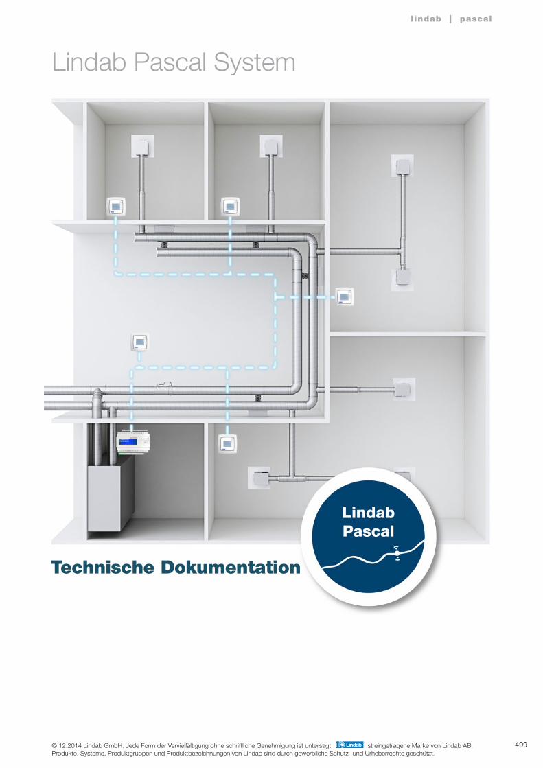
Lindab Pascal System
Technische Dokumentation
l indab | pascal
© 12.2014 Lindab GmbH. Jede Form der Vervielfältigung ohne schriftliche Genehmigung ist untersagt. ist eingetragene Marke von Lindab AB.Produkte, Systeme, Produktgruppen und Produktbezeichnungen von Lindab sind durch gewerbliche Schutz- und Urheberrechte geschützt.
1
2
3
4
5
6
7
8
9
10
11
12
13
14
15
16
17
18
500
l indab | pascal
LCP-P
REGULA MASTER
LCC-P
515
519
517
LKP-P 516
501
502
504
REGULA COMBI 520
VRU-MF 521
MBBV 518
Änderungen vorbehalten
Systemüberblick Pascal
Inhaltsverzeichnis
Funktionen SeiteProdukt
Systemeinführung
Systembeschreibung
Entwurfsanleitung
501
1
2
3
4
5
6
7
8
9
10
11
12
13
14
15
16
17
18
l indab | pascal
Regula Master
Änderungen vorbehalten
Vereinfachte VAV-Lösung
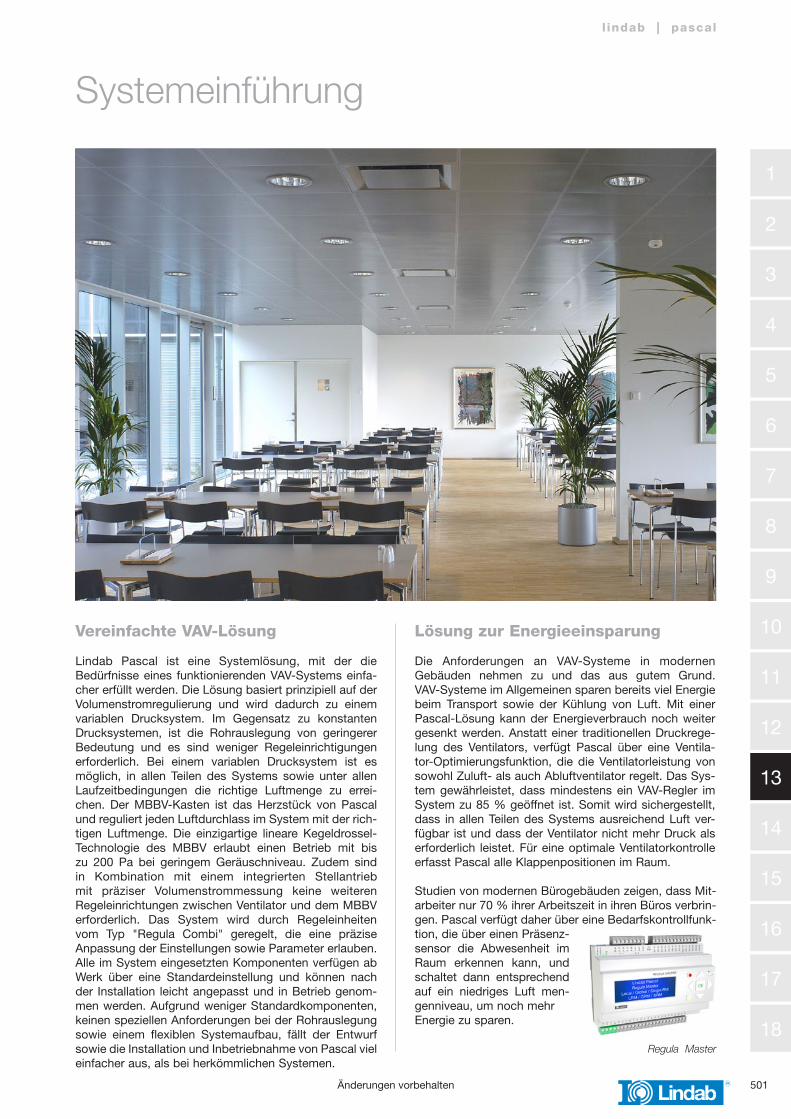
Lindab Pascal ist eine Systemlösung, mit der die Bedürfnisse eines funktionierenden VAV-Systems einfa-cher erfüllt werden. Die Lösung basiert prinzipiell auf der Volumenstromregulierung und wird dadurch zu einem variablen Drucksystem. Im Gegensatz zu konstanten Drucksystemen, ist die Rohrauslegung von geringerer Bedeutung und es sind weniger Regeleinrichtigungen erforderlich. Bei einem variablen Drucksystem ist es möglich, in allen Teilen des Systems sowie unter allen Laufzeitbedingungen die richtige Luftmenge zu errei-chen. Der MBBV-Kasten ist das Herzstück von Pascal und reguliert jeden Luftdurchlass im System mit der rich-tigen Luftmenge. Die einzigartige lineare Kegeldrossel-Technologie des MBBV erlaubt einen Betrieb mit bis zu 200 Pa bei geringem Geräuschniveau. Zudem sind in Kombination mit einem integrierten Stellantrieb mit präziser Volumenstrommessung keine weiteren Regeleinrichtungen zwischen Ventilator und dem MBBV erforderlich. Das System wird durch Regeleinheiten vom Typ "Regula Combi" geregelt, die eine präzise Anpassung der Einstellungen sowie Parameter erlauben. Alle im System eingesetzten Komponenten verfügen ab Werk über eine Standardeinstellung und können nach der Installation leicht angepasst und in Betrieb genom-men werden. Aufgrund weniger Standardkomponenten, keinen speziellen Anforderungen bei der Rohrauslegung sowie einem flexiblen Systemaufbau, fällt der Entwurf sowie die Installation und Inbetriebnahme von Pascal viel einfacher aus, als bei herkömmlichen Systemen.
Lösung zur Energieeinsparung
Die Anforderungen an VAV-Systeme in modernen Gebäuden nehmen zu und das aus gutem Grund. VAV-Systeme im Allgemeinen sparen bereits viel Energie beim Transport sowie der Kühlung von Luft. Mit einer Pascal-Lösung kann der Energieverbrauch noch weiter gesenkt werden. Anstatt einer traditionellen Druckrege-lung des Ventilators, verfügt Pascal über eine Ventila-tor-Optimierungsfunktion, die die Ventilatorleistung von sowohl Zuluft- als auch Abluftventilator regelt. Das Sys-tem gewährleistet, dass mindestens ein VAV-Regler im System zu 85 % geöffnet ist. Somit wird sichergestellt, dass in allen Teilen des Systems ausreichend Luft ver-fügbar ist und dass der Ventilator nicht mehr Druck als erforderlich leistet. Für eine optimale Ventilatorkontrolle erfasst Pascal alle Klappenpositionen im Raum.
Studien von modernen Bürogebäuden zeigen, dass Mit-arbeiter nur 70 % ihrer Arbeitszeit in ihren Büros verbrin-gen. Pascal verfügt daher über eine Bedarfskontrollfunk-tion, die über einen Präsenz-sensor die Abwesenheit im Raum erkennen kann, und schaltet dann entsprechend auf ein niedriges Luft men-genniveau, um noch mehr Energie zu sparen.
Systemeinführung
1
2
3
4
5
6
7
8
9
10
11
12
13
14
15
16
17
18
502
l indab | pascal
›
COOLHEAT
STANDBYSERVICE
OFF
›
COOLHEAT
STANDBYSERVICE
OFF
›
COOLHEAT
STANDBYSERVICE
OFF
›
COOLHEAT
STANDBYSERVICE
OFF
›
COOLHEAT
STANDBYSERVICE
OFF
›
COOLHEAT
STANDBYSERVICE
OFF
›
COOLHEAT
STANDBYSERVICE
OFF
›
COOLHEAT
STANDBYSERVICE
OFF
0 -
10 V
flo
w
0 -
10 V
flo
w
Exhaust fan
CO2
PS
Exoline
2 -
10 V
po
siti
on
GRM
2 -
10 V
po
siti
on
Lindab Pascal
LRM
LRM
VRU SLU
Supply fan
LCP LCP LCP LCP
MBBV MBBV MBBV MBBV
MBB MBB MBB MBB
LCP LCP LCP LCP
LCP-P LCP LCP-P LCP
MBBV MBBV MBBV MBBV
SRC
ERC
ERC
ERC
SRC
SRC SRC
SRC
P1
RxT
x
P2
RxT
x
P/B
B 5
0
A 5
1
N 5
2
E 5
3
P 1 P 2
1 G
+
2 G
0 -
3 4 +
C
10 G
DO
11 D
O1
12 D
O2
13 D
O3
14 D
O4
15 D
O5
16 D
O6
17 D
O7
30 A
gnd
31 A
I1
32 A
I2
33 A
gnd
34 A
I3
35 A
I4
40 A
gnd
41 U
I1
42 U
I2
43 A
gnd
44 U
I3
45 U
I4
B 6
0
A 6
1
N 6
2
E 6
3
DI1
71
DI2
72
DI3
73
DI4
74
DI5
75
DI6
76
DI7
77
DI8
78
Agn
d 90
AO
1 91
AO
2 92
AO
3 93
AO
4 94
AO
5 95Ext.
Disp.
REGULA MASTER
Lindab PascalGlobal RM
11:09:21 11:33
P1
RxT
x
P2
RxT
x
P/B
B 5
0
A 5
1
N 5
2
E 5
3
P 1 P 2
1 G
+
2 G
0 -
3 4 +
C
10 G
DO
11 D
O1
12 D
O2
13 D
O3
14 D
O4
15 D
O5
16 D
O6
17 D
O7
30 A
gnd
31 A
I1
32 A
I2
33 A
gnd
34 A
I3
35 A
I4
40 A
gnd
41 U
I1
42 U
I2
43 A
gnd
44 U
I3
45 U
I4
B 6
0
A 6
1
N 6
2
E 6
3
DI1
71
DI2
72
DI3
73
DI4
74
DI5
75
DI6
76
DI7
77
DI8
78
Agn
d 90
AO
1 91
AO
2 92
AO
3 93
AO
4 94
AO
5 95Ext.
Disp.
REGULA MASTER
Lindab PascalLocal RM
11:09:21 11:33
Exo
line 0
- 10
V f
low
0 -
10 V
flo
w
Exoline
2 -
10 V
po
siti
on
2 -
10 V
po
siti
on
VRU SLU
CO2
PS
0 -
10 V
flo
w
Exoline
VRU SLU
2 -
10 V
po
siti
on
VRU SLU
0 -
10 V
flo
w
2 -
10 V
po
siti
on
0 -
10 V
flo
w
2 -
10 V
po
siti
on
0 -
10 V
flo
w
2 -
10 V
po
siti
on
0 - 10 V Signal
0 - 10 V Signal
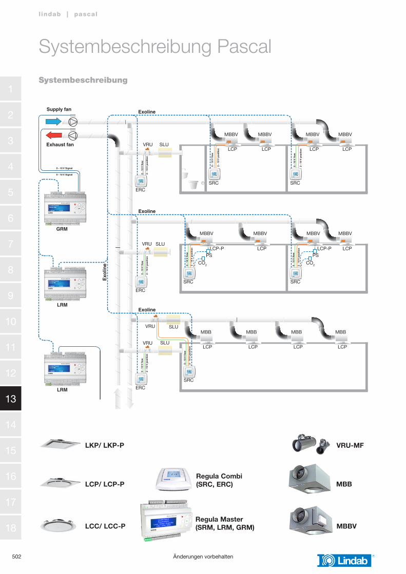
LKP/ LKP-P
LCP/ LCP-P
LCC/ LCC-P MBBV
MBB
VRU-MF
Regula Combi(SRC, ERC)
VRU SLU
SLU
SLU
SLU
VRU
ERC
ERC
ERC
SRC
MBBV
LCP LCP LCP
SRC
SRCSRC
SRC
LCP
MBBV MBBV
MBBV
MBB MBB MBB MBB
MBBV MBBV
LCP-PLCP-P LCPLCP
LCP LCP LCP LCP
PSPS
CO2CO2
MBBV
MBBV
VRU
VRU
Regula Master(SRM, LRM, GRM)
Änderungen vorbehalten
Systembeschreibung Pascal
Systembeschreibung
503
1
2
3
4
5
6
7
8
9
10
11
12
13
14
15
16
17
18
l indab | pascal
Änderungen vorbehalten
Regelbare Luftdurchlasslösung• Deckenbündig montierter Luftdurchlass• Verwendung in Kombination mit dem motorbetriebenen Anschlusskasten MBBV• Arbeitsbereich 0 – 100 % Luftmenge• Geringe Luftmengen mit hoher Untertemperatur ohne Zugluft• Integrierter Anwesenheitssensor für Bedarfskontrolle
Bedarfskontrolle• Integrierter Anwesenheitssensor im Luftdurchlass• Standby-Volumenstrom bei Abwesenheit im Raum• Lichtkontrolle bei Abwesenheit ist über eine Relaisfunktion möglich
Volumenstromregulierung• Variables Drucksystem gewährleistet zu jeder Zeit die richtigen Luftmengen• Volumenstrommessung und -regelung mittels MBBV und VRU• Anschlusskasten MBBV ermöglicht Betrieb mit bis zu 200 Pa bei geringem Geräuschniveau• Keine zusätzlichen Einregulierklappen zwischen Ventilator und Zuluftdurchlässen notwendig• Einfache Verdrahtung mit Regula Connect am MBBV
Raumregelung• Temperatursteuerung mit fl exiblen Parametern• CO2-Kontrolle möglich• Anwesenheitskontrolle möglich
Abluftsteuerung• Regula Master regelt die Abluft-VRU, um einen Abgleich zu erreichen• Eine Volumenstrommessung in den Rohren ist für die Master-/ Slave-Funktion nicht erforderlich• Ein konstanter Volumenstromanteil kann ergänzt werden• Eine Volumenstromdiff erenz kann programmiert werden für Unter-/Überdruck• ERC wandelt das Exoline-Signal in ein 0 – 10 V Volumenstromsignal für die Abluftdrossel um
Kommunikation• Exoline BUS-Kommunikation zwischen Regula Combi und Regula Master• Exoline BUS-Kommunikation mit der Gebäudeleittechnik (GLT)• Eine Kommunikation mit anderen Teilen der GLT ist über eine OPC Lösung (GLT Integration) möglich.
Ventilator-Optimierer• Regula Master registriert alle Klappenpositionen im System • Optimiert die Ventilatorleistung, um den Energieverbrauch zu senken• Gewährleistet, dass mindestens ein Regler zu 85 % geöffnet ist Laufzeitkontrolle
Betriebskontrolle• Regula Master registriert die Klappenbewegungen im System• Regula Master warnt, wenn keine Klappenbewegung erfolgt
Systembeschreibung Pascal
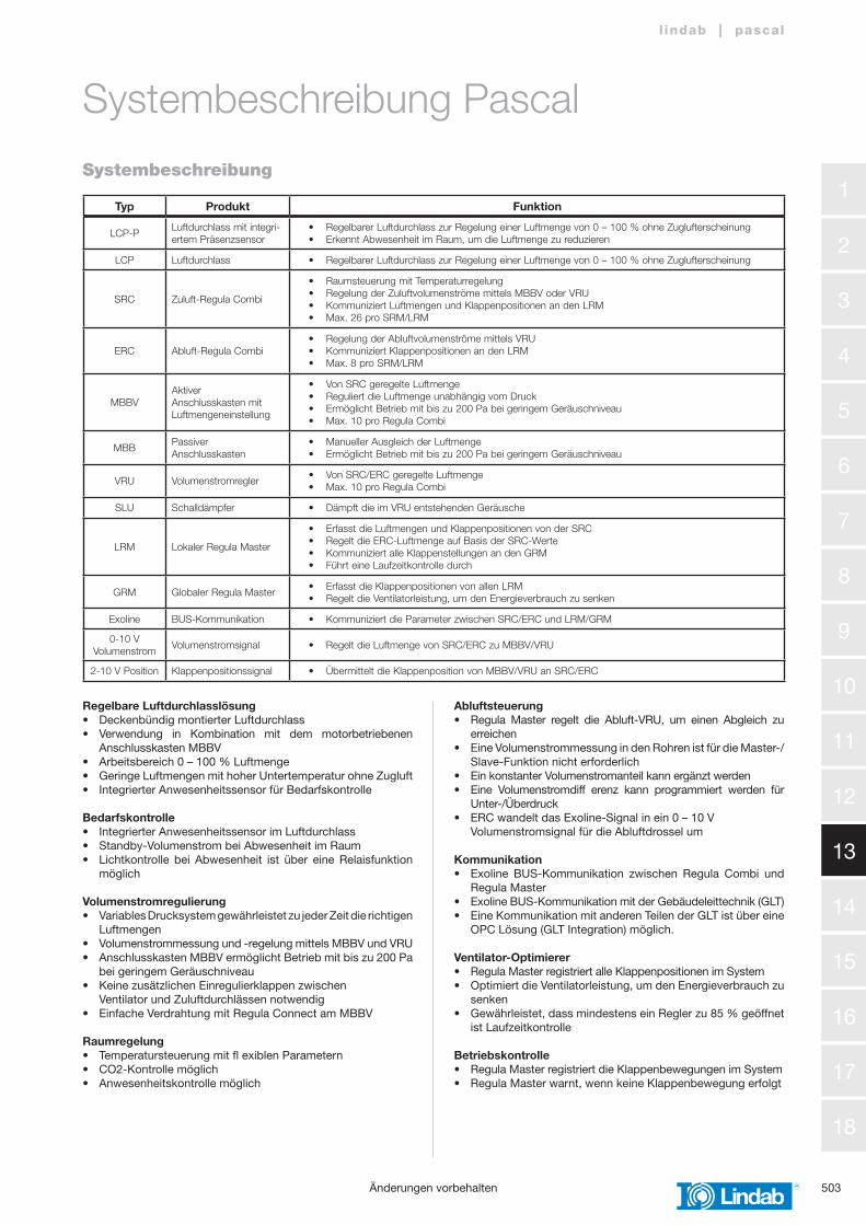
Typ Produkt Funktion
LCP-PLuftdurchlass mit integri-ertem Präsenzsensor
• Regelbarer Luftdurchlass zur Regelung einer Luftmenge von 0 – 100 % ohne Zuglufterscheinung• Erkennt Abwesenheit im Raum, um die Luftmenge zu reduzieren
LCP Luftdurchlass • Regelbarer Luftdurchlass zur Regelung einer Luftmenge von 0 – 100 % ohne Zuglufterscheinung
SRC Zuluft-Regula Combi
• Raumsteuerung mit Temperaturregelung• Regelung der Zuluftvolumenströme mittels MBBV oder VRU• Kommuniziert Luftmengen und Klappenpositionen an den LRM• Max. 26 pro SRM/LRM
ERC Abluft-Regula Combi• Regelung der Abluftvolumenströme mittels VRU• Kommuniziert Klappenpositionen an den LRM• Max. 8 pro SRM/LRM
MBBVAktiverAnschlusskasten mitLuftmengeneinstellung
• Von SRC geregelte Luftmenge• Reguliert die Luftmenge unabhängig vom Druck• Ermöglicht Betrieb mit bis zu 200 Pa bei geringem Geräuschniveau• Max. 10 pro Regula Combi
MBBPassiver Anschlusskasten
• Manueller Ausgleich der Luftmenge• Ermöglicht Betrieb mit bis zu 200 Pa bei geringem Geräuschniveau
VRU Volumenstromregler• Von SRC/ERC geregelte Luftmenge• Max. 10 pro Regula Combi
SLU Schalldämpfer • Dämpft die im VRU entstehenden Geräusche
LRM Lokaler Regula Master
• Erfasst die Luftmengen und Klappenpositionen von der SRC• Regelt die ERC-Luftmenge auf Basis der SRC-Werte• Kommuniziert alle Klappenstellungen an den GRM• Führt eine Laufzeitkontrolle durch
GRM Globaler Regula Master• Erfasst die Klappenpositionen von allen LRM• Regelt die Ventilatorleistung, um den Energieverbrauch zu senken
Exoline BUS-Kommunikation • Kommuniziert die Parameter zwischen SRC/ERC und LRM/GRM
0-10 V Volumenstrom
Volumenstromsignal • Regelt die Luftmenge von SRC/ERC zu MBBV/VRU
2-10 V Position Klappenpositionssignal • Übermittelt die Klappenposition von MBBV/VRU an SRC/ERC
Systembeschreibung
1
2
3
4
5
6
7
8
9
10
11
12
13
14
15
16
17
18
504
l indab | pascal
Änderungen vorbehalten
Entwurf eines Pascal Systems
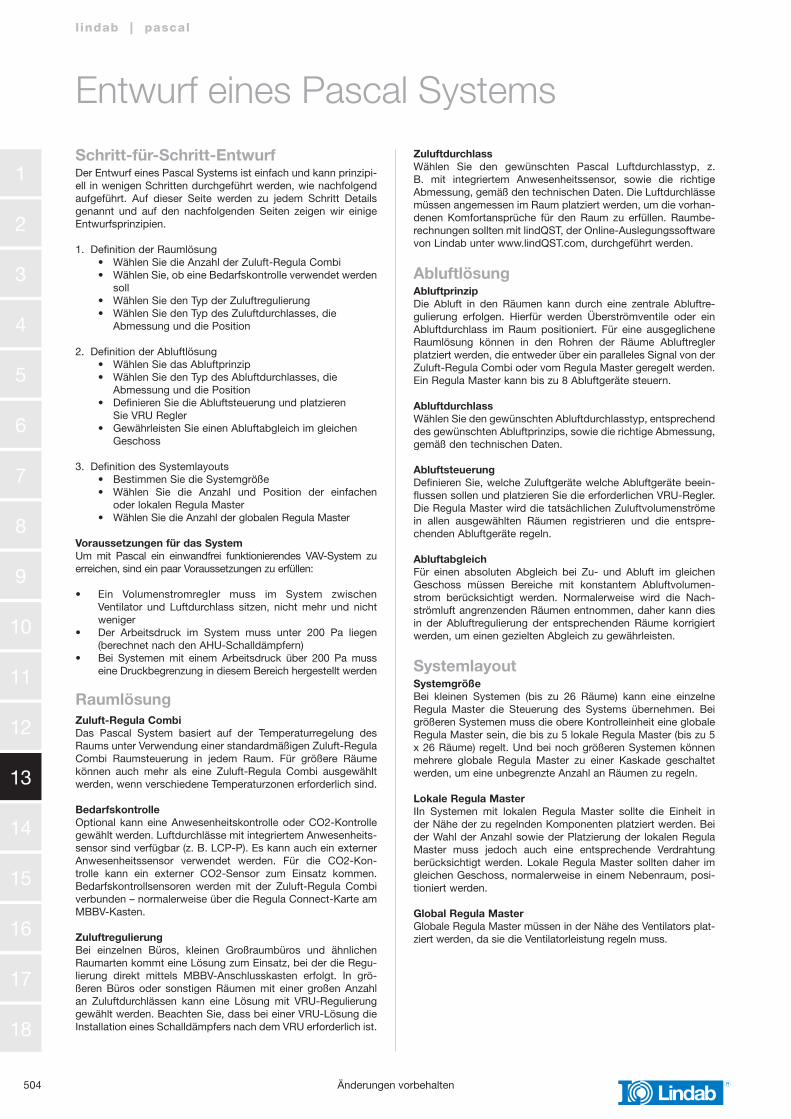
Schritt-für-Schritt-EntwurfDer Entwurf eines Pascal Systems ist einfach und kann prinzipi-ell in wenigen Schritten durchgeführt werden, wie nachfolgend aufgeführt. Auf dieser Seite werden zu jedem Schritt Details genannt und auf den nachfolgenden Seiten zeigen wir einige Entwurfsprinzipien.
1. Definition der Raumlösung • Wählen Sie die Anzahl der Zuluft-Regula Combi • Wählen Sie, ob eine Bedarfskontrolle verwendet werden soll • Wählen Sie den Typ der Zuluftregulierung • Wählen Sie den Typ des Zuluftdurchlasses, die Abmessung und die Position
2. Definition der Abluftlösung • Wählen Sie das Abluftprinzip • Wählen Sie den Typ des Abluftdurchlasses, die Abmessung und die Position • Definieren Sie die Abluftsteuerung und platzieren Sie VRU Regler • Gewährleisten Sie einen Abluftabgleich im gleichen Geschoss
3. Definition des Systemlayouts • Bestimmen Sie die Systemgröße • Wählen Sie die Anzahl und Position der einfachen oder lokalen Regula Master • Wählen Sie die Anzahl der globalen Regula Master
Voraussetzungen für das SystemUm mit Pascal ein einwandfrei funktionierendes VAV-System zu erreichen, sind ein paar Voraussetzungen zu erfüllen:
• Ein Volumenstromregler muss im System zwischen Ventilator und Luftdurchlass sitzen, nicht mehr und nicht weniger• Der Arbeitsdruck im System muss unter 200 Pa liegen (berechnet nach den AHU-Schalldämpfern)• Bei Systemen mit einem Arbeitsdruck über 200 Pa muss eine Druckbegrenzung in diesem Bereich hergestellt werden
RaumlösungZuluft-Regula CombiDas Pascal System basiert auf der Temperaturregelung des Raums unter Verwendung einer standardmäßigen Zuluft-Regula Combi Raumsteuerung in jedem Raum. Für größere Räume können auch mehr als eine Zuluft-Regula Combi ausgewählt werden, wenn verschiedene Temperaturzonen erforderlich sind.
BedarfskontrolleOptional kann eine Anwesenheitskontrolle oder CO2-Kontrolle gewählt werden. Luftdurchlässe mit integriertem Anwesenheits-sensor sind verfügbar (z. B. LCP-P). Es kann auch ein externer Anwesenheitssensor verwendet werden. Für die CO2-Kon-trolle kann ein externer CO2-Sensor zum Einsatz kommen. Bedarfskontrollsensoren werden mit der Zuluft-Regula Combi verbunden – normalerweise über die Regula Connect-Karte am MBBV-Kasten.
ZuluftregulierungBei einzelnen Büros, kleinen Großraumbüros und ähnlichen Raumarten kommt eine Lösung zum Einsatz, bei der die Regu-lierung direkt mittels MBBV-Anschlusskasten erfolgt. In grö-ßeren Büros oder sonstigen Räumen mit einer großen Anzahl an Zuluftdurchlässen kann eine Lösung mit VRU-Regulierung gewählt werden. Beachten Sie, dass bei einer VRU-Lösung die Installation eines Schalldämpfers nach dem VRU erforderlich ist.
ZuluftdurchlassWählen Sie den gewünschten Pascal Luftdurchlasstyp, z. B. mit integriertem Anwesenheitssensor, sowie die richtige Abmessung, gemäß den technischen Daten. Die Luftdurchlässe müssen angemessen im Raum platziert werden, um die vorhan-denen Komfortansprüche für den Raum zu erfüllen. Raumbe-rechnungen sollten mit lindQST, der Online-Auslegungssoftware von Lindab unter www.lindQST.com, durchgeführt werden.
AbluftlösungAbluftprinzipDie Abluft in den Räumen kann durch eine zentrale Abluftre-gulierung erfolgen. Hierfür werden Überströmventile oder ein Abluftdurchlass im Raum positioniert. Für eine ausgeglichene Raumlösung können in den Rohren der Räume Abluftregler platziert werden, die entweder über ein paralleles Signal von der Zuluft-Regula Combi oder vom Regula Master geregelt werden. Ein Regula Master kann bis zu 8 Abluftgeräte steuern.
AbluftdurchlassWählen Sie den gewünschten Abluftdurchlasstyp, entsprechend des gewünschten Abluftprinzips, sowie die richtige Abmessung, gemäß den technischen Daten.
AbluftsteuerungDefinieren Sie, welche Zuluftgeräte welche Abluftgeräte beein-flussen sollen und platzieren Sie die erforderlichen VRU-Regler. Die Regula Master wird die tatsächlichen Zuluftvolumenströme in allen ausgewählten Räumen registrieren und die entspre-chenden Abluftgeräte regeln.
AbluftabgleichFür einen absoluten Abgleich bei Zu- und Abluft im gleichen Geschoss müssen Bereiche mit konstantem Abluftvolumen-strom berücksichtigt werden. Normalerweise wird die Nach-strömluft angrenzenden Räumen entnommen, daher kann dies in der Abluftregulierung der entsprechenden Räume korrigiert werden, um einen gezielten Abgleich zu gewährleisten.
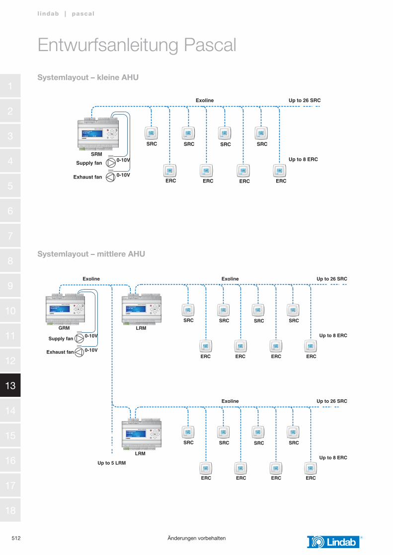
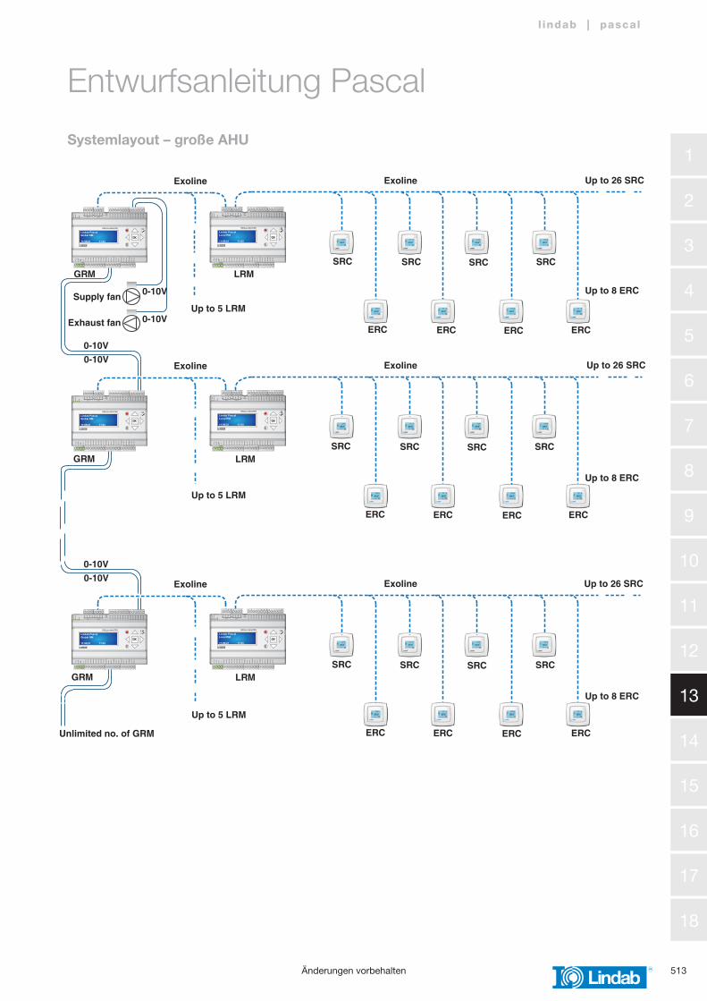
SystemlayoutSystemgrößeBei kleinen Systemen (bis zu 26 Räume) kann eine einzelne Regula Master die Steuerung des Systems übernehmen. Bei größeren Systemen muss die obere Kontrolleinheit eine globale Regula Master sein, die bis zu 5 lokale Regula Master (bis zu 5 x 26 Räume) regelt. Und bei noch größeren Systemen können mehrere globale Regula Master zu einer Kaskade geschaltet werden, um eine unbegrenzte Anzahl an Räumen zu regeln.
Lokale Regula MasterIIn Systemen mit lokalen Regula Master sollte die Einheit in der Nähe der zu regelnden Komponenten platziert werden. Bei der Wahl der Anzahl sowie der Platzierung der lokalen Regula Master muss jedoch auch eine entsprechende Verdrahtung berücksichtigt werden. Lokale Regula Master sollten daher im gleichen Geschoss, normalerweise in einem Nebenraum, posi-tioniert werden.
Global Regula MasterGlobale Regula Master müssen in der Nähe des Ventilators plat-ziert werden, da sie die Ventilatorleistung regeln muss.
505
1
2
3
4
5
6
7
8
9
10
11
12
13
14
15
16
17
18
l indab | pascal
›
COOLHEAT
STANDBYSERVICE
OFF
0 -
10 V
flo
w
Pas
cal 12 -
10 V
po
siti
on LCP LCP
MBBVMBBV
OLC
SRC
›
COOLHEAT
STANDBYSERVICE
OFF
0 -
10 V
flo
w
Pas
cal 2
2 -
10 V
po
siti
on LCP LCP
SRC
MBBV MBB
Änderungen vorbehalten
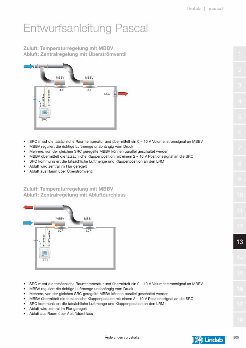
• SRC misst die tatsächliche Raumtemperatur und übermittelt ein 0 – 10 V Volumenstromsignal an MBBV• MBBV reguliert die richtige Luftmenge unabhängig vom Druck • Mehrere, von der gleichen SRC geregelte MBBV können parallel geschaltet werden• MBBV übermittelt die tatsächliche Klappenposition mit einem 2 – 10 V Positionssignal an die SRC• SRC kommuniziert die tatsächliche Luftmenge und Klappenposition an den LRM• Abluft wird zentral im Flur geregelt• Abluft aus Raum über Überströmventil
• SRC misst die tatsächliche Raumtemperatur und übermittelt ein 0 – 10 V Volumenstromsignal an MBBV• MBBV reguliert die richtige Luftmenge unabhängig vom Druck• Mehrere, von der gleichen SRC geregelte MBBV können parallel geschaltet werden• MBBV übermittelt die tatsächliche Klappenposition mit einem 2 – 10 V Positionssignal an die SRC• SRC kommuniziert die tatsächliche Luftmenge und Klappenposition an den LRM• Abluft wird zentral im Flur geregelt• Abluft aus Raum über Abluftdurchlass
Zuluft: Temperaturregelung mit MBBVAbluft: Zentralregelung mit Überströmventil
Entwurfsanleitung Pascal
Zuluft: Temperaturregelung mit MBBVAbluft: Zentralregelung mit Abluftdurchlass
1
2
3
4
5
6
7
8
9
10
11
12
13
14
15
16
17
18
506
l indab | pascal
›
COOLHEAT
STANDBYSERVICE
OFF
0 -
10 V
flo
w
Pas
cal 42 -
10 V
po
siti
on
SRC
LCP LCP
MBBV MBB
VRU
›
COOLHEAT
STANDBYSERVICE
OFF
0 -
10 V
flo
w
Pas
cal 32 -
10 V
po
siti
on
CO2
PS
SRC
LCP-P LCP
MBBV MBBV
Änderungen vorbehalten
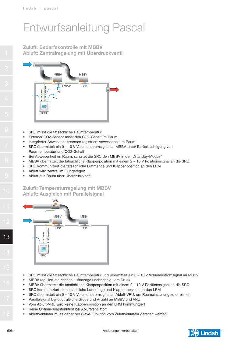
Zuluft: Bedarfskontrolle mit MBBVAbluft: Zentralregelung mit Überdruckventil
Zuluft: Temperaturregelung mit MBBVAbluft: Ausgleich mit Parallelsignal
Entwurfsanleitung Pascal
• SRC misst die tatsächliche Raumtemperatur• Externer CO2-Sensor misst den CO2-Gehalt im Raum• Integrierter Anwesenheitssensor registriert Anwesenheit im Raum• SRC übermittelt ein 0 – 10 V Volumenstromsignal an MBBV, unter Berücksichtigung von Raumtemperatur und CO2-Gehalt• Bei Abwesenheit im Raum, schaltet die SRC den MBBV in den „Standby-Modus“• MBBV übermittelt die tatsächliche Klappenposition mit einem 2 – 10 V Positionssignal an die SRC• SRC kommuniziert die tatsächliche Luftmenge und Klappenposition an den LRM• Abluft wird zentral im Flur geregelt• Abluft aus Raum über Überdruckventil
• SRC misst die tatsächliche Raumtemperatur und übermittelt ein 0 – 10 V Volumenstromsignal an MBBV• MBBV reguliert die richtige Luftmenge unabhängig vom Druck• MBBV übermittelt die tatsächliche Klappenposition mit einem 2 – 10 V Positionssignal an die SRC• SRC kommuniziert die tatsächliche Luftmenge und Klappenposition an den LRM• SRC übermittelt ein 0 – 10 V Volumenstromsignal an Abluft-VRU, um Raumeinstellung zu erreichen• Parallelsignal benötigt gleiche Größe und Anzahl an MBBV und VRU• Vom Abluft-VRU wird keine Klappenposition an den LRM kommuniziert• Keine Optimierungsfunktion bei Abluftventilator• Abluftventilator muss daher per Slave-Funktion vom Zuluftventilator geregelt werden
507
1
2
3
4
5
6
7
8
9
10
11
12
13
14
15
16
17
18
l indab | pascal
›
COOLHEAT
STANDBYSERVICE
OFF
›
COOLHEAT
STANDBYSERVICE
OFF
0 -
10 V
flo
w
2 -
10 V
po
siti
on LCP
ERC
SRC
VRU
LCPLCP
MBBV MBBV MBB
›
COOLHEAT
STANDBYSERVICE
OFF
›
COOLHEAT
STANDBYSERVICE
OFF
0 -
10 V
flo
w
2 -
10 V
po
siti
on LCP
ERC
SRC
VRU
VRU
LCPLCP
MBB MBB MBB
Änderungen vorbehalten
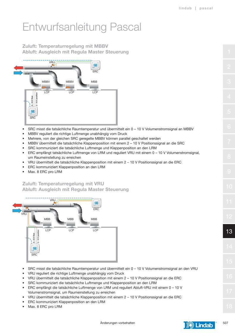
Zuluft: Temperaturregelung mit MBBVAbluft: Ausgleich mit Regula Master Steuerung
Zuluft: Temperaturregelung mit VRUAbluft: Ausgleich mit Regula Master Steuerung
Entwurfsanleitung Pascal
• SRC misst die tatsächliche Raumtemperatur und übermittelt ein 0 – 10 V Volumenstromsignal an MBBV• MBBV reguliert die richtige Luftmenge unabhängig vom Druck• Mehrere, von der gleichen SRC geregelte MBBV können parallel geschaltet werden• MBBV übermittelt die tatsächliche Klappenposition mit einem 2 – 10 V Positionssignal an die SRC• SRC kommuniziert die tatsächliche Luftmenge und Klappenposition an den LRM• ERC empfängt tatsächliche Luftmenge von LRM und reguliert VRU mit einem 0 – 10 V Volumenstromsignal, um Raumeinstellung zu erreichen• VRU übermittelt die tatsächliche Klappenposition mit einem 2 – 10 V Positionssignal an die ERC• ERC kommuniziert Klappenposition an den LRM• Max. 8 ERC pro LRM
• SRC misst die tatsächliche Raumtemperatur und übermittelt ein 0 – 10 V Volumenstromsignal an den VRU• VRU reguliert die richtige Luftmenge unabhängig vom Druck• VRU übermittelt die tatsächliche Klappenposition mit einem 2 – 10 V Positionssignal an die ERC• SRC kommuniziert die tatsächliche Luftmenge und Klappenposition an den LRM• ERC empfängt die tatsächliche Luftmenge von LRM und reguliert Abluft-VRU mit einem 0 – 10 V Volumenstromsignal, um Raumeinstellung zu erreichen• VRU übermittelt die tatsächliche Klappenposition mit einem 2 – 10 V Positionssignal an die ERC• ERC kommuniziert Klappenposition an den LRM• Max. 8 ERC pro LRM
1
2
3
4
5
6
7
8
9
10
11
12
13
14
15
16
17
18
508
l indab | pascal
›
COOLHEAT
STANDBYSERVICE
OFF
Pas
cal 70
- 10
V f
low
2 -
10 V
po
siti
on
ERC
VRU
KSU KSU KSU
Änderungen vorbehalten
Entwurfsanleitung Pascal
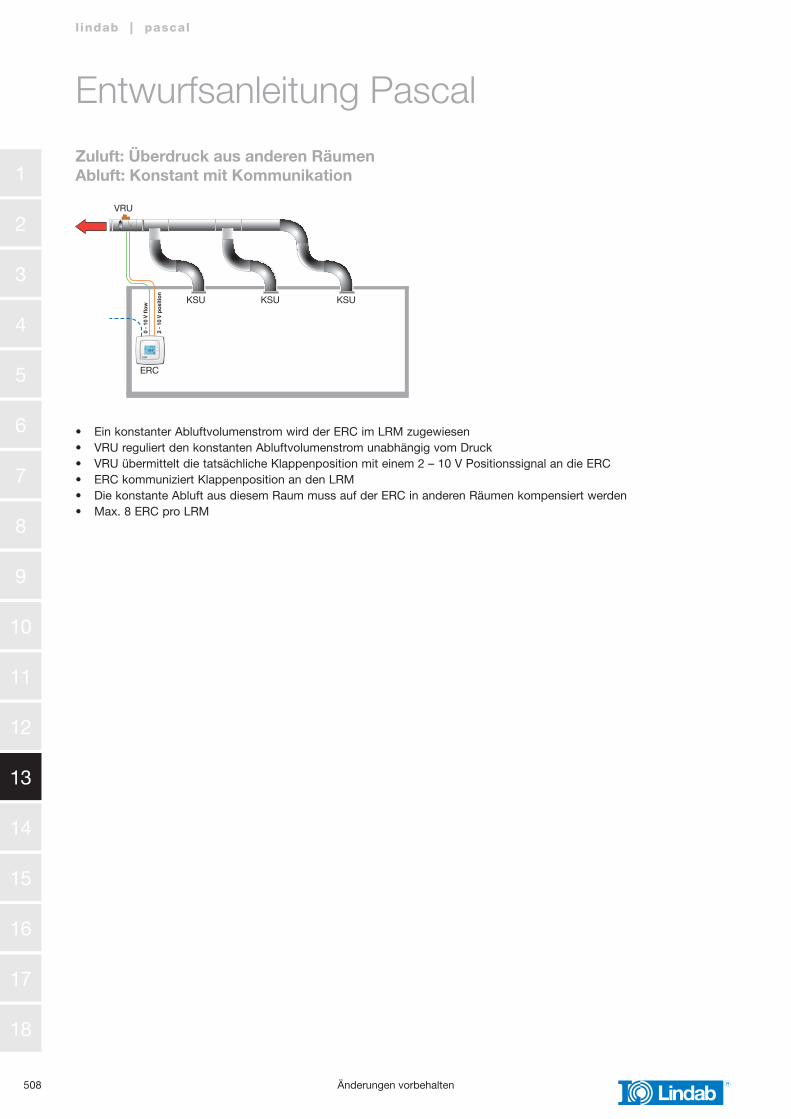
Zuluft: Überdruck aus anderen RäumenAbluft: Konstant mit Kommunikation
• Ein konstanter Abluftvolumenstrom wird der ERC im LRM zugewiesen• VRU reguliert den konstanten Abluftvolumenstrom unabhängig vom Druck• VRU übermittelt die tatsächliche Klappenposition mit einem 2 – 10 V Positionssignal an die ERC• ERC kommuniziert Klappenposition an den LRM• Die konstante Abluft aus diesem Raum muss auf der ERC in anderen Räumen kompensiert werden• Max. 8 ERC pro LRM
509
1
2
3
4
5
6
7
8
9
10
11
12
13
14
15
16
17
18
l indab | pascal
Änderungen vorbehalten
›
COOLHEAT
STANDBYSERVICE
OFF
P1
RxT
x
P2
RxT
x
P/B
B 5
0
A 5
1
N 5
2
E 5
3
P 1 P 2
1 G
+
2 G
0 -
3 4 +
C
10 G
DO
11 D
O1
12 D
O2
13 D
O3
14 D
O4
15 D
O5
16 D
O6
17 D
O7
30 A
gnd
31 A
I1
32 A
I2
33 A
gnd
34 A
I3
35 A
I4
40 A
gnd
41 U
I1
42 U
I2
43 A
gnd
44 U
I3
45 U
I4
B 6
0
A 6
1
N 6
2
E 6
3
DI1
71
DI2
72
DI3
73
DI4
74
DI5
75
DI6
76
DI7
77
DI8
78
Agn
d 90
AO
1 91
AO
2 92
AO
3 93
AO
4 94
AO
5 95Ext.
Disp.
REGULA MASTER
Lindab PascalLocal RM
11:09:21 11:33
›
COOLHEAT
STANDBYSERVICE
OFF
›
COOLHEAT
STANDBYSERVICE
OFF
›
COOLHEAT
STANDBYSERVICE
OFF
›
COOLHEAT
STANDBYSERVICE
OFF
›
COOLHEAT
STANDBYSERVICE
OFF
›
COOLHEAT
STANDBYSERVICE
OFF
0 -
10 V
flo
w
VRU SLU
2 -
10 V
po
siti
on
2 -
10 V
po
siti
on
0 -
10 V
flo
w
0 -
10 V
flo
w
0 -
10 V
flo
w
A
B C
2 -
10 V
po
siti
on
2 -
10 V
po
siti
on
1 1 1 2 3
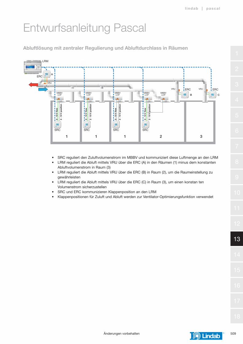
Abluftlösung mit zentraler Regulierung und Abluftdurchlass in Räumen
Entwurfsanleitung Pascal
• SRC reguliert den Zuluftvolumenstrom im MBBV und kommuniziert diese Luftmenge an den LRM• LRM reguliert die Abluft mittels VRU über die ERC (A) in den Räumen (1) minus dem konstanten Abluftvolumenstrom in Raum (3)• LRM reguliert die Abluft mittels VRU über die ERC (B) in Raum (2), um die Raumeinstellung zu gewährleisten• LRM reguliert die Abluft mittels VRU über die ERC (C) in Raum (3), um einen konstan ten Volumenstrom sicherzustellen• SRC und ERC kommunizieren Klappenposition an den LRM• Klappenpositionen für Zuluft und Abluft werden zur Ventilator-Optimierungsfunktion verwendet
LRM
ERC
VRU
VRU VRU ERCERC
SRC SRC SRC SRC
MBBV LCP
MBBV LCP
MBBV LCP
MBBV LCP
MBBV LCP
1
2
3
4
5
6
7
8
9
10
11
12
13
14
15
16
17
18
510
l indab | pascal
›
COOLHEAT
STANDBYSERVICE
OFF
›
COOLHEAT
STANDBYSERVICE
OFF
›
COOLHEAT
STANDBYSERVICE
OFF
›
COOLHEAT
STANDBYSERVICE
OFF
›
COOLHEAT
STANDBYSERVICE
OFF
›
COOLHEAT
STANDBYSERVICE
OFF
›
COOLHEAT
STANDBYSERVICE
OFF
P1
RxT
x
P2
RxT
x
P/B
B 5
0
A 5
1
N 5
2
E 5
3
P 1 P 2
1 G
+
2 G
0 -
3 4 +
C
10 G
DO
11 D
O1
12 D
O2
13 D
O3
14 D
O4
15 D
O5
16 D
O6
17 D
O7
30 A
gnd
31 A
I1
32 A
I2
33 A
gnd
34 A
I3
35 A
I4
40 A
gnd
41 U
I1
42 U
I2
43 A
gnd
44 U
I3
45 U
I4
B 6
0
A 6
1
N 6
2
E 6
3
DI1
71
DI2
72
DI3
73
DI4
74
DI5
75
DI6
76
DI7
77
DI8
78
Agn
d 90
AO
1 91
AO
2 92
AO
3 93
AO
4 94
AO
5 95Ext.
Disp.
REGULA MASTER
Lindab PascalLocal RM
11:09:21 11:33
0 -
10 V
flo
w
2 -
10 V
po
siti
on
2 -
10 V
po
siti
on
0 -
10 V
flo
w
0 -
10 V
flo
w
0 -
10 V
flo
w
2 -
10 V
po
siti
on
2 -
10 V
po
siti
on
A
B C
1 1 1 2 3
VRU
VRU VRU
LRM
ERC
SRCSRC SRC SRC
ERC ERCMBBV LCP
MBBV LCP
MBBV LCP
MBBV LCP
MBBV LCP
Änderungen vorbehalten
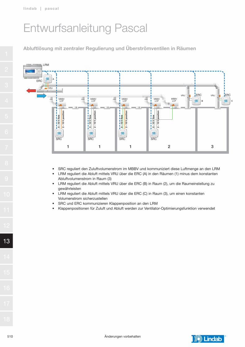
Abluftlösung mit zentraler Regulierung und Überströmventilen in Räumen
Entwurfsanleitung Pascal
• SRC reguliert den Zuluftvolumenstrom im MBBV und kommuniziert diese Luftmenge an den LRM• LRM reguliert die Abluft mittels VRU über die ERC (A) in den Räumen (1) minus dem konstanten Abluftvolumenstrom in Raum (3)• LRM reguliert die Abluft mittels VRU über die ERC (B) in Raum (2), um die Raumeinstellung zu gewährleisten• LRM reguliert die Abluft mittels VRU über die ERC (C) in Raum (3), um einen konstanten Volumenstrom sicherzustellen• SRC und ERC kommunizieren Klappenposition an den LRM• Klappenpositionen für Zuluft und Abluft werden zur Ventilator-Optimierungsfunktion verwendet
511
1
2
3
4
5
6
7
8
9
10
11
12
13
14
15
16
17
18
l indab | pascal
›
COOLHEAT
STANDBYSERVICE
OFF
›
COOLHEAT
STANDBYSERVICE
OFF
›
COOLHEAT
STANDBYSERVICE
OFF
›
COOLHEAT
STANDBYSERVICE
OFF
›
COOLHEAT
STANDBYSERVICE
OFF
›
COOLHEAT
STANDBYSERVICE
OFF
P1
RxT
x
P2
RxT
x
P/B
B 5
0
A 5
1
N 5
2
E 5
3
P 1 P 2
1 G
+
2 G
0 -
3 4 +
C
10 G
DO
11 D
O1
12 D
O2
13 D
O3
14 D
O4
15 D
O5
16 D
O6
17 D
O7
30 A
gnd
31 A
I1
32 A
I2
33 A
gnd
34 A
I3
35 A
I4
40 A
gnd
41 U
I1
42 U
I2
43 A
gnd
44 U
I3
45 U
I4
B 6
0
A 6
1
N 6
2
E 6
3
DI1
71
DI2
72
DI3
73
DI4
74
DI5
75
DI6
76
DI7
77
DI8
78
Agn
d 90
AO
1 91
AO
2 92
AO
3 93
AO
4 94
AO
5 95Ext.
Disp.
REGULA MASTER
Lindab PascalLocal RM
11:09:21 11:33
0 -
10 V
flo
w
2 -
10 V
po
siti
on
2 -
10 V
po
siti
on
0 -
10 V
flo
w
0 -
10 V
flo
w
0 -
10 V
flo
w
2 -
10 V
po
siti
on
2 -
10 V
po
siti
on
BA A A
C
1 1 1 2 3
VRU VRU VRU
VRU VRU
LRM
SRC SRCSRCSRC
ERC ERCMBBV LCP
MBBV LCP
MBBV LCP
MBBV LCP
MBBV LCP
Änderungen vorbehalten
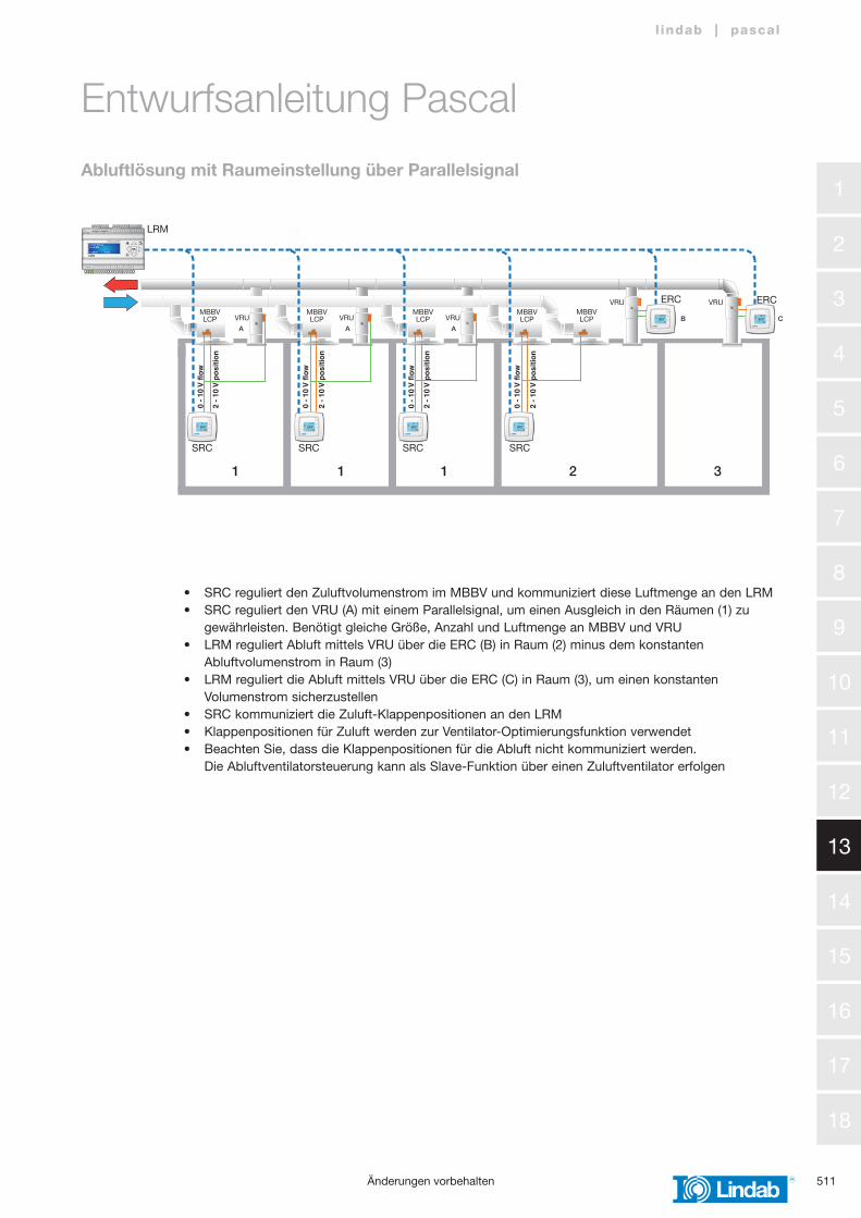
Abluftlösung mit Raumeinstellung über Parallelsignal
Entwurfsanleitung Pascal
• SRC reguliert den Zuluftvolumenstrom im MBBV und kommuniziert diese Luftmenge an den LRM• SRC reguliert den VRU (A) mit einem Parallelsignal, um einen Ausgleich in den Räumen (1) zu gewährleisten. Benötigt gleiche Größe, Anzahl und Luftmenge an MBBV und VRU• LRM reguliert Abluft mittels VRU über die ERC (B) in Raum (2) minus dem konstanten Abluftvolumenstrom in Raum (3)• LRM reguliert die Abluft mittels VRU über die ERC (C) in Raum (3), um einen konstanten Volumenstrom sicherzustellen• SRC kommuniziert die Zuluft-Klappenpositionen an den LRM• Klappenpositionen für Zuluft werden zur Ventilator-Optimierungsfunktion verwendet• Beachten Sie, dass die Klappenpositionen für die Abluft nicht kommuniziert werden. Die Abluftventilatorsteuerung kann als Slave-Funktion über einen Zuluftventilator erfolgen
1
2
3
4
5
6
7
8
9
10
11
12
13
14
15
16
17
18
512
l indab | pascal
›
COOLHEAT
STANDBYSERVICE
OFF
›
COOLHEAT
STANDBYSERVICE
OFF
›
COOLHEAT
STANDBYSERVICE
OFF
›
COOLHEAT
STANDBYSERVICE
OFF
›
COOLHEAT
STANDBYSERVICE
OFF
›
COOLHEAT
STANDBYSERVICE
OFF
›
COOLHEAT
STANDBYSERVICE
OFF
›
COOLHEAT
STANDBYSERVICE
OFF
›
COOLHEAT
STANDBYSERVICE
OFF
›
COOLHEAT
STANDBYSERVICE
OFF
›
COOLHEAT
STANDBYSERVICE
OFF
›
COOLHEAT
STANDBYSERVICE
OFF
›
COOLHEAT
STANDBYSERVICE
OFF
›
COOLHEAT
STANDBYSERVICE
OFF
›
COOLHEAT
STANDBYSERVICE
OFF
›
COOLHEAT
STANDBYSERVICE
OFF
›
COOLHEAT
STANDBYSERVICE
OFF
›
COOLHEAT
STANDBYSERVICE
OFF
›
COOLHEAT
STANDBYSERVICE
OFF
›
COOLHEAT
STANDBYSERVICE
OFF
›
COOLHEAT
STANDBYSERVICE
OFF
›
COOLHEAT
STANDBYSERVICE
OFF
›
COOLHEAT
STANDBYSERVICE
OFF
›
COOLHEAT
STANDBYSERVICE
OFF
P1
RxT
x
P2
RxT
x
P/B
B 5
0
A 5
1
N 5
2
E 5
3
P 1 P 2
1 G
+
2 G
0 -
3 4 +
C
10 G
DO
11 D
O1
12 D
O2
13 D
O3
14 D
O4
15 D
O5
16 D
O6
17 D
O7
30 A
gnd
31 A
I1
32 A
I2
33 A
gnd
34 A
I3
35 A
I4
40 A
gnd
41 U
I1
42 U
I2
43 A
gnd
44 U
I3
45 U
I4
B 6
0
A 6
1
N 6
2
E 6
3
DI1
71
DI2
72
DI3
73
DI4
74
DI5
75
DI6
76
DI7
77
DI8
78
Agn
d 90
AO
1 91
AO
2 92
AO
3 93
AO
4 94
AO
5 95Ext.
Disp.
REGULA MASTER
Lindab PascalLocal RM
11:09:21 11:33
P1
RxT
x
P2
RxT
x
P/B
B 5
0
A 5
1
N 5
2
E 5
3
P 1 P 2
1 G
+
2 G
0 -
3 4 +
C
10 G
DO
11 D
O1
12 D
O2
13 D
O3
14 D
O4
15 D
O5
16 D
O6
17 D
O7
30 A
gnd
31 A
I1
32 A
I2
33 A
gnd
34 A
I3
35 A
I4
40 A
gnd
41 U
I1
42 U
I2
43 A
gnd
44 U
I3
45 U
I4
B 6
0
A 6
1
N 6
2
E 6
3
DI1
71
DI2
72
DI3
73
DI4
74
DI5
75
DI6
76
DI7
77
DI8
78
Agn
d 90
AO
1 91
AO
2 92
AO
3 93
AO
4 94
AO
5 95Ext.
Disp.
REGULA MASTER
Lindab PascalSingle RM
11:09:21 11:33
P1
RxT
x
P2
RxT
x
P/B
B 5
0
A 5
1
N 5
2
E 5
3
P 1 P 2
1 G
+
2 G
0 -
3 4 +
C
10 G
DO
11 D
O1
12 D
O2
13 D
O3
14 D
O4
15 D
O5
16 D
O6
17 D
O7
30 A
gnd
31 A
I1
32 A
I2
33 A
gnd
34 A
I3
35 A
I4
40 A
gnd
41 U
I1
42 U
I2
43 A
gnd
44 U
I3
45 U
I4
B 6
0
A 6
1
N 6
2
E 6
3
DI1
71
DI2
72
DI3
73
DI4
74
DI5
75
DI6
76
DI7
77
DI8
78
Agn
d 90
AO
1 91
AO
2 92
AO
3 93
AO
4 94
AO
5 95Ext.
Disp.
REGULA MASTER
Lindab PascalGlobal RM
11:09:21 11:33
Exhaust fan
Supply fan
Exoline
SRC SRC SRC SRC
ERC ERC ERC ERC
0-10V
0-10V
Exhaust fan
GRM
SRM
Supply fan
SRC SRC SRC SRC
ERC ERCERCERC
0-10V
0-10V
LRM
LRM
SRC SRC SRC SRC
ERCERCERCERC
Exoline
Up to 26 SRC
Up to 8 ERC
Up to 8 ERC
Up to 8 ERC
Exoline Up to 26 SRC
Exoline Up to 26 SRC
Up to 5 LRM
›
COOLHEAT
STANDBYSERVICE
OFF
›
COOLHEAT
STANDBYSERVICE
OFF
›
COOLHEAT
STANDBYSERVICE
OFF
›
COOLHEAT
STANDBYSERVICE
OFF
›
COOLHEAT
STANDBYSERVICE
OFF
›
COOLHEAT
STANDBYSERVICE
OFF
›
COOLHEAT
STANDBYSERVICE
OFF
›
COOLHEAT
STANDBYSERVICE
OFF
›
COOLHEAT
STANDBYSERVICE
OFF
›
COOLHEAT
STANDBYSERVICE
OFF
›
COOLHEAT
STANDBYSERVICE
OFF
›
COOLHEAT
STANDBYSERVICE
OFF
›
COOLHEAT
STANDBYSERVICE
OFF
›
COOLHEAT
STANDBYSERVICE
OFF
›
COOLHEAT
STANDBYSERVICE
OFF
›
COOLHEAT
STANDBYSERVICE
OFF
›
COOLHEAT
STANDBYSERVICE
OFF
›
COOLHEAT
STANDBYSERVICE
OFF
›
COOLHEAT
STANDBYSERVICE
OFF
›
COOLHEAT
STANDBYSERVICE
OFF
›
COOLHEAT
STANDBYSERVICE
OFF
›
COOLHEAT
STANDBYSERVICE
OFF
›
COOLHEAT
STANDBYSERVICE
OFF
›
COOLHEAT
STANDBYSERVICE
OFF
P1
RxT
x
P2
RxT
x
P/B
B 5
0
A 5
1
N 5
2
E 5
3
P 1 P 2
1 G
+
2 G
0 -
3 4 +
C
10 G
DO
11 D
O1
12 D
O2
13 D
O3
14 D
O4
15 D
O5
16 D
O6
17 D
O7
30 A
gnd
31 A
I1
32 A
I2
33 A
gnd
34 A
I3
35 A
I4
40 A
gnd
41 U
I1
42 U
I2
43 A
gnd
44 U
I3
45 U
I4
B 6
0
A 6
1
N 6
2
E 6
3
DI1
71
DI2
72
DI3
73
DI4
74
DI5
75
DI6
76
DI7
77
DI8
78
Agn
d 90
AO
1 91
AO
2 92
AO
3 93
AO
4 94
AO
5 95Ext.
Disp.
REGULA MASTER
Lindab PascalLocal RM
11:09:21 11:33
P1
RxT
x
P2
RxT
x
P/B
B 5
0
A 5
1
N 5
2
E 5
3
P 1 P 2
1 G
+
2 G
0 -
3 4 +
C
10 G
DO
11 D
O1
12 D
O2
13 D
O3
14 D
O4
15 D
O5
16 D
O6
17 D
O7
30 A
gnd
31 A
I1
32 A
I2
33 A
gnd
34 A
I3
35 A
I4
40 A
gnd
41 U
I1
42 U
I2
43 A
gnd
44 U
I3
45 U
I4
B 6
0
A 6
1
N 6
2
E 6
3
DI1
71
DI2
72
DI3
73
DI4
74
DI5
75
DI6
76
DI7
77
DI8
78
Agn
d 90
AO
1 91
AO
2 92
AO
3 93
AO
4 94
AO
5 95Ext.
Disp.
REGULA MASTER
Lindab PascalSingle RM
11:09:21 11:33
P1
RxT
x
P2
RxT
x
P/B
B 5
0
A 5
1
N 5
2
E 5
3
P 1 P 2
1 G
+
2 G
0 -
3 4 +
C
10 G
DO
11 D
O1
12 D
O2
13 D
O3
14 D
O4
15 D
O5
16 D
O6
17 D
O7
30 A
gnd
31 A
I1
32 A
I2
33 A
gnd
34 A
I3
35 A
I4
40 A
gnd
41 U
I1
42 U
I2
43 A
gnd
44 U
I3
45 U
I4
B 6
0
A 6
1
N 6
2
E 6
3
DI1
71
DI2
72
DI3
73
DI4
74
DI5
75
DI6
76
DI7
77
DI8
78
Agn
d 90
AO
1 91
AO
2 92
AO
3 93
AO
4 94
AO
5 95Ext.
Disp.
REGULA MASTER
Lindab PascalGlobal RM
11:09:21 11:33
Exhaust fan
Supply fan
Exoline
SRC SRC SRC SRC
ERC ERC ERC ERC
0-10V
0-10V
Exhaust fan
GRM
SRM
Supply fan
SRC SRC SRC SRC
ERC ERCERCERC
0-10V
0-10V
LRM
LRM
SRC SRC SRC SRC
ERCERCERCERC
Exoline
Up to 26 SRC
Up to 8 ERC
Up to 8 ERC
Up to 8 ERC
Exoline Up to 26 SRC
Exoline Up to 26 SRC
Up to 5 LRM
Änderungen vorbehalten
Systemlayout – kleine AHU
Systemlayout – mittlere AHU
Entwurfsanleitung Pascal
513
1
2
3
4
5
6
7
8
9
10
11
12
13
14
15
16
17
18
l indab | pascal
›
COOLHEAT
STANDBYSERVICE
OFF
›
COOLHEAT
STANDBYSERVICE
OFF
›
COOLHEAT
STANDBYSERVICE
OFF
›
COOLHEAT
STANDBYSERVICE
OFF
›
COOLHEAT
STANDBYSERVICE
OFF
›
COOLHEAT
STANDBYSERVICE
OFF
›
COOLHEAT
STANDBYSERVICE
OFF
›
COOLHEAT
STANDBYSERVICE
OFF
›
COOLHEAT
STANDBYSERVICE
OFF
›
COOLHEAT
STANDBYSERVICE
OFF
›
COOLHEAT
STANDBYSERVICE
OFF
›
COOLHEAT
STANDBYSERVICE
OFF
›
COOLHEAT
STANDBYSERVICE
OFF
›
COOLHEAT
STANDBYSERVICE
OFF
›
COOLHEAT
STANDBYSERVICE
OFF
›
COOLHEAT
STANDBYSERVICE
OFF
›
COOLHEAT
STANDBYSERVICE
OFF
›
COOLHEAT
STANDBYSERVICE
OFF
›
COOLHEAT
STANDBYSERVICE
OFF
›
COOLHEAT
STANDBYSERVICE
OFF
›
COOLHEAT
STANDBYSERVICE
OFF
›
COOLHEAT
STANDBYSERVICE
OFF
›
COOLHEAT
STANDBYSERVICE
OFF
›
COOLHEAT
STANDBYSERVICE
OFF
P1
RxT
x
P2
RxT
x
P/B
B 5
0
A 5
1
N 5
2
E 5
3
P 1 P 2
1 G
+
2 G
0 -
3 4 +
C
10 G
DO
11 D
O1
12 D
O2
13 D
O3
14 D
O4
15 D
O5
16 D
O6
17 D
O7
30 A
gnd
31 A
I1
32 A
I2
33 A
gnd
34 A
I3
35 A
I4
40 A
gnd
41 U
I1
42 U
I2
43 A
gnd
44 U
I3
45 U
I4
B 6
0
A 6
1
N 6
2
E 6
3
DI1
71
DI2
72
DI3
73
DI4
74
DI5
75
DI6
76
DI7
77
DI8
78
Agn
d 90
AO
1 91
AO
2 92
AO
3 93
AO
4 94
AO
5 95Ext.
Disp.
REGULA MASTER
Lindab PascalLocal RM
11:09:21 11:33
P1
RxT
x
P2
RxT
x
P/B
B 5
0
A 5
1
N 5
2
E 5
3
P 1 P 2
1 G
+
2 G
0 -
3 4 +
C
10 G
DO
11 D
O1
12 D
O2
13 D
O3
14 D
O4
15 D
O5
16 D
O6
17 D
O7
30 A
gnd
31 A
I1
32 A
I2
33 A
gnd
34 A
I3
35 A
I4
40 A
gnd
41 U
I1
42 U
I2
43 A
gnd
44 U
I3
45 U
I4
B 6
0
A 6
1
N 6
2
E 6
3
DI1
71
DI2
72
DI3
73
DI4
74
DI5
75
DI6
76
DI7
77
DI8
78
Agn
d 90
AO
1 91
AO
2 92
AO
3 93
AO
4 94
AO
5 95Ext.
Disp.
REGULA MASTER
Lindab PascalGlobal RM
11:09:21 11:33
P1
RxT
x
P2
RxT
x
P/B
B 5
0
A 5
1
N 5
2
E 5
3
P 1 P 2
1 G
+
2 G
0 -
3 4 +
C
10 G
DO
11 D
O1
12 D
O2
13 D
O3
14 D
O4
15 D
O5
16 D
O6
17 D
O7
30 A
gnd
31 A
I1
32 A
I2
33 A
gnd
34 A
I3
35 A
I4
40 A
gnd
41 U
I1
42 U
I2
43 A
gnd
44 U
I3
45 U
I4
B 6
0
A 6
1
N 6
2
E 6
3
DI1
71
DI2
72
DI3
73
DI4
74
DI5
75
DI6
76
DI7
77
DI8
78
Agn
d 90
AO
1 91
AO
2 92
AO
3 93
AO
4 94
AO
5 95Ext.
Disp.
REGULA MASTER
Lindab PascalLocal RM
11:09:21 11:33
P1
RxT
x
P2
RxT
x
P/B
B 5
0
A 5
1
N 5
2
E 5
3
P 1 P 2
1 G
+
2 G
0 -
3 4 +
C
10 G
DO
11 D
O1
12 D
O2
13 D
O3
14 D
O4
15 D
O5
16 D
O6
17 D
O7
30 A
gnd
31 A
I1
32 A
I2
33 A
gnd
34 A
I3
35 A
I4
40 A
gnd
41 U
I1
42 U
I2
43 A
gnd
44 U
I3
45 U
I4
B 6
0
A 6
1
N 6
2
E 6
3
DI1
71
DI2
72
DI3
73
DI4
74
DI5
75
DI6
76
DI7
77
DI8
78
Agn
d 90
AO
1 91
AO
2 92
AO
3 93
AO
4 94
AO
5 95Ext.
Disp.
REGULA MASTER
Lindab PascalGlobal RM
11:09:21 11:33
Exhaust fan
GRM LRM
Supply fan
Exoline
SRC SRC SRC SRC
ERC ERC ERC ERC
0-10V
0-10V
Exoline
GRM
Exoline
SRC SRC SRC SRC
ERC ERC ERC ERC
LRM
Exoline
GRM
Exoline
SRC SRC SRC SRC
ERC ERC ERC ERC
LRM
Exoline
0-10V 0-10V
0-10V0-10V
Up to 26 SRC
Up to 8 ERC
Up to 8 ERC
Up to 8 ERC
Up to 5 LRM
Up to 5 LRM
Up to 26 SRC
Up to 5 LRM
Up to 26 SRC
Unlimited no. of GRM
Änderungen vorbehalten
Systemlayout – große AHU
Entwurfsanleitung Pascal

l indab | pascal
We reserve the right to make changes without prior notice 51505-05-2014
1
2
3
4
5
6
7
8
9
10
11
12
13
14
15
16
17
18
Pascal diffuser LCP / LCP-P
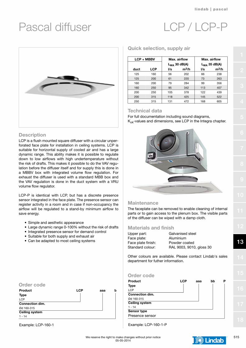
DescriptionLCP is a flush mounted square diffuser with a circular unper-forated face plate for installation in ceiling systems. LCP issuitable for horizontal supply of cooled air and has a largedynamic range. This ability makes it is possible to regulatedown to low airflows with high undertemperature withoutthe risk of drafts. This makes it possible to do the VAV regu-lation before the diffuser itself and for supply this is done ina MBBV box with integrated volume flow regulation. Forexhaust the diffuser is used with a standard MBB box andthe VAV regulation is done in the duct system with a VRUvolume flow regulator.
LCP-P is identical with LCP, but has a discrete presencesensor integrated in the face plate. The presence sensor canregister activity in a room and in case if non-occupancy theairflow will be regulated to a stand-by minimum airflow tosave energy.
• Simple and aesthetic appearance • Large dynamic range 0-100% without the risk of drafts• Integrated presence sensor for demand control• Suitable for both supply and exhaust air• Can be adapted to most ceiling systems
Quick selection, supply air
Technical dataFor full documentation including sound diagrams, Kok-values and dimensions, see LCP in the Integra chapter.
MaintenanceThe faceplate can be removed to enable cleaning of internalparts or to gain access to the plenum box. The visible partsof the diffuser can be wiped with a damp cloth.
Materials and finishUpper part: Galvanised steelFace plate: AluminiumFace plate finish: Powder coatedStandard colour: RAL 9003, 9010, gloss 30
Other colours are available. Please contact Lindab's salesdepartment for futher information.
Order codeProduct LCP aaa bTypeLCP
Connection dim.Ød 160-315Ceiling system1 - 14
Example: LCP-160-1
LCP + MBBV Max. airflow Max. airflow
duct LCP
LWA 30 dB(A) LWA 35 dB(A)
l/s m3/h l/s m3/h125 160 56 202 66 238
125 200 61 220 73 263
160 200 79 284 99 356
160 250 95 342 113 407
200 250 105 378 122 439
200 315 118 425 145 522
250 315 131 472 168 605
Order codeProduct LCP aaa bb PTypeLCP
Connection dim.Ød 160-315Ceiling system1 - 14Sensor typePresence sensor
Example: LCP-160-1-P
516 We reserve the right to make changes without prior notice05-05-2014
l indab | pascal
1
2
3
4
5
6
7
8
9
10
11
12
13
14
15
16
17
18
Pascal diffuser LKP / LKP-P
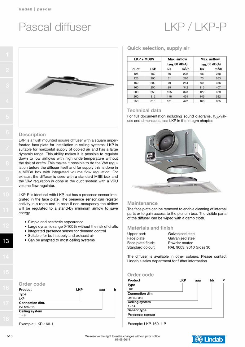
DescriptionLKP is a flush mounted square diffuser with a square unper-forated face plate for installation in ceiling systems. LKP issuitable for horizontal supply of cooled air and has a largedynamic range. This ability makes it is possible to regulatedown to low airflows with high undertemperature withoutthe risk of drafts. This makes it possible to do the VAV regu-lation before the diffuser itself and for supply this is done ina MBBV box with integrated volume flow regulation. Forexhaust the diffuser is used with a standard MBB box andthe VAV regulation is done in the duct system with a VRUvolume flow regulator.
LKP-P is identical with LKP, but has a presence sensor inte-grated in the face plate. The presence sensor can registeractivity in a room and in case if non-occupancy the airflowwill be regulated to a stand-by minimum airflow to saveenergy.
• Simple and aesthetic appearance • Large dynamic range 0-100% without the risk of drafts• Integrated presence sensor for demand control• Suitable for both supply and exhaust air• Can be adapted to most ceiling systems
Quick selection, supply air
Technical dataFor full documentation including sound diagrams, Kok-val-ues and dimensions, see LKP in the Integra chapter.
MaintenanceThe face plate can be removed to enable cleaning of internalparts or to gain access to the plenum box. The visible partsof the diffuser can be wiped with a damp cloth.
Materials and finishUpper part: Galvanised steelFace plate: Galvanised steelFace plate finish: Powder coatedStandard colour: RAL 9003, 9010 Gloss 30
The diffuser is available in other colours. Please contactLindab's sales department for futher information.
Order codeProduct LKP aaa bTypeLKP
Connection dim.Ød 160-315Ceiling system1 - 14
Example: LKP-160-1
LKP + MBBV Max. airflow Max. airflow
duct LKP
LWA 30 dB(A) LWA 35 dB(A)
l/s m3/h l/s m3/h125 160 56 202 66 238
125 200 61 220 73 263
160 200 79 284 99 356
160 250 95 342 113 407
200 250 105 378 122 439
200 315 118 425 145 522
250 315 131 472 168 605
Order codeProduct LKP aaa bb PTypeLKP
Connection dim.Ød 160-315Ceiling system1 - 14Sensor typePresence sensor
Example: LKP-160-1-P
l indab | pascal
We reserve the right to make changes without prior notice 51705-05-2014
1
2
3
4
5
6
7
8
9
10
11
12
13
14
15
16
17
18
Pascal diffuser LCC / LCC-P
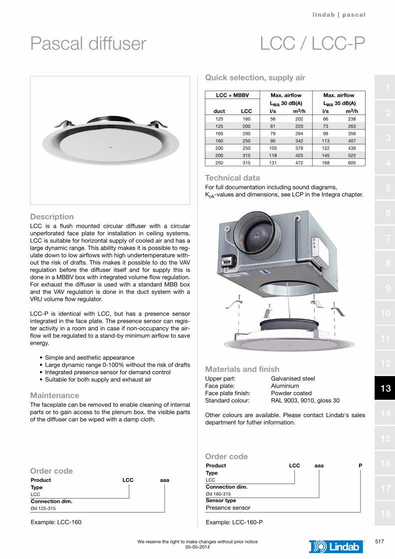
DescriptionLCC is a flush mounted circular diffuser with a circularunperforated face plate for installation in ceiling systems.LCC is suitable for horizontal supply of cooled air and has alarge dynamic range. This ability makes it is possible to reg-ulate down to low airflows with high undertemperature with-out the risk of drafts. This makes it possible to do the VAVregulation before the diffuser itself and for supply this isdone in a MBBV box with integrated volume flow regulation.For exhaust the diffuser is used with a standard MBB boxand the VAV regulation is done in the duct system with aVRU volume flow regulator.
LCC-P is identical with LCC, but has a presence sensorintegrated in the face plate. The presence sensor can regis-ter activity in a room and in case if non-occupancy the air-flow will be regulated to a stand-by minimum airflow to saveenergy.
• Simple and aesthetic appearance • Large dynamic range 0-100% without the risk of drafts• Integrated presence sensor for demand control• Suitable for both supply and exhaust air
MaintenanceThe faceplate can be removed to enable cleaning of internalparts or to gain access to the plenum box. the visible partsof the diffuser can be wiped with a damp cloth.
Quick selection, supply air
Technical dataFor full documentation including sound diagrams, Kok-values and dimensions, see LCP in the Integra chapter.
Materials and finishUpper part: Galvanised steelFace plate: AluminiumFace plate finish: Powder coatedStandard colour: RAL 9003, 9010, gloss 30
Other colours are available. Please contact Lindab's salesdepartment for futher information.
Order codeProduct LCC aaaTypeLCC
Connection dim.Ød 125-315
Example: LCC-160
LCC + MBBV Max. airflow Max. airflow
duct LCC
LWA 30 dB(A) LWA 35 dB(A)
l/s m3/h l/s m3/h125 160 56 202 66 238
125 200 61 220 73 263
160 200 79 284 99 356
160 250 95 342 113 407
200 250 105 378 122 439
200 315 118 425 145 522
250 315 131 472 168 605
Order codeProduct LCC aaa PTypeLCC
Connection dim.Ød 160-315Sensor typePresence sensor
Example: LCC-160-P
518 We reserve the right to make changes without prior notice13-05-2014
l indab | pascal
1
2
3
4
5
6
7
8
9
10
11
12
13
14
15
16
17
18
Pascal plenum box MBBV
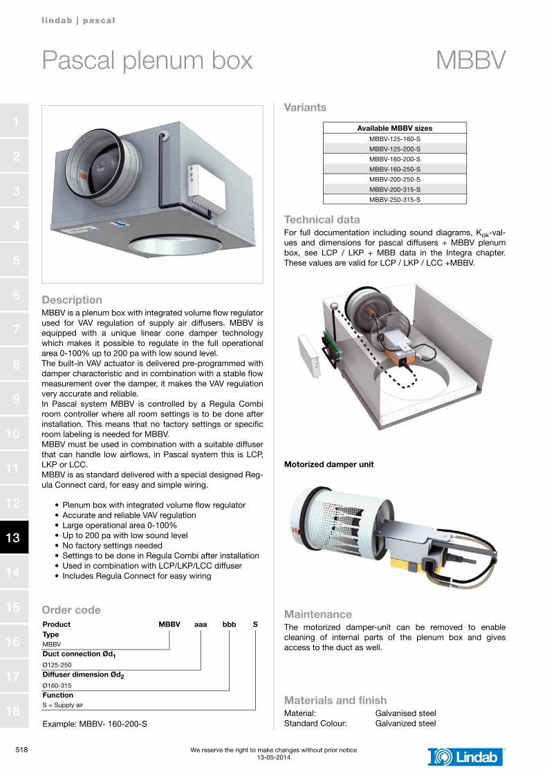
DescriptionMBBV is a plenum box with integrated volume flow regulatorused for VAV regulation of supply air diffusers. MBBV isequipped with a unique linear cone damper technologywhich makes it possible to regulate in the full operationalarea 0-100% up to 200 pa with low sound level.The built-in VAV actuator is delivered pre-programmed withdamper characteristic and in combination with a stable flowmeasurement over the damper, it makes the VAV regulationvery accurate and reliable.In Pascal system MBBV is controlled by a Regula Combiroom controller where all room settings is to be done afterinstallation. This means that no factory settings or specificroom labeling is needed for MBBV. MBBV must be used in combination with a suitable diffuserthat can handle low airflows, in Pascal system this is LCP,LKP or LCC.MBBV is as standard delivered with a special designed Reg-ula Connect card, for easy and simple wiring.
• Plenum box with integrated volume flow regulator• Accurate and reliable VAV regulation• Large operational area 0-100%• Up to 200 pa with low sound level• No factory settings needed• Settings to be done in Regula Combi after installation• Used in combination with LCP/LKP/LCC diffuser• Includes Regula Connect for easy wiring
Variants
Technical dataFor full documentation including sound diagrams, Kok-val-ues and dimensions for pascal diffusers + MBBV plenumbox, see LCP / LKP + MBB data in the Integra chapter.These values are valid for LCP / LKP / LCC +MBBV.
Motorized damper unit
MaintenanceThe motorized damper-unit can be removed to enablecleaning of internal parts of the plenum box and givesaccess to the duct as well.
Order codeProduct MBBV aaa bbb STypeMBBV
Duct connection Ød1
Ø125-250
Diffuser dimension Ød2
Ø160-315
FunctionS = Supply air
Example: MBBV- 160-200-S
Available MBBV sizesMBBV-125-160-S
MBBV-125-200-S
MBBV-160-200-S
MBBV-160-250-S
MBBV-200-250-S
MBBV-200-315-S
MBBV-250-315-S
Materials and finishMaterial: Galvanised steelStandard Colour: Galvanized steel
l indab | pascal
We reserve the right to make changes without prior notice 51903-11-2014
1
2
3
4
5
6
7
8
9
10
11
12
13
14
15
16
17
18
Controller Regula Master
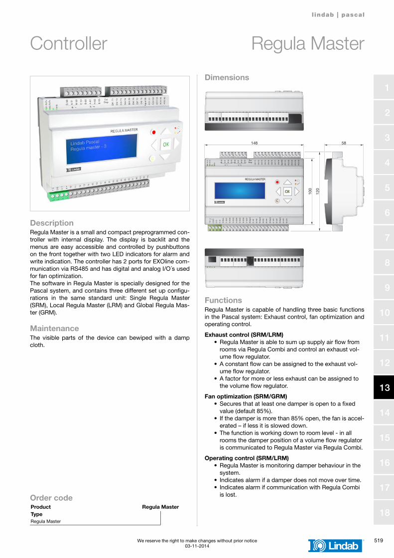
DescriptionRegula Master is a small and compact preprogrammed con-troller with internal display. The display is backlit and themenus are easy accessible and controlled by pushbuttonson the front together with two LED indicators for alarm andwrite indication. The controller has 2 ports for EXOline com-munication via RS485 and has digital and analog I/O´s usedfor fan optimization.The software in Regula Master is specially designed for thePascal system, and contains three different set up configu-rations in the same standard unit: Single Regula Master(SRM), Local Regula Master (LRM) and Global Regula Mas-ter (GRM).
MaintenanceThe visible parts of the device can bewiped with a dampcloth.
Dimensions
FunctionsRegula Master is capable of handling three basic functionsin the Pascal system: Exhaust control, fan optimization andoperating control.
Exhaust control (SRM/LRM)• Regula Master is able to sum up supply air flow from
rooms via Regula Combi and control an exhaust vol-ume flow regulator.
• A constant flow can be assigned to the exhaust vol-ume flow regulator.
• A factor for more or less exhaust can be assigned to the volume flow regulator.
Fan optimization (SRM/GRM)• Secures that at least one damper is open to a fixed
value (default 85%).• If the damper is more than 85% open, the fan is accel-
erated – if less it is slowed down.• The function is working down to room level - in all
rooms the damper position of a volume flow regulator is communicated to Regula Master via Regula Combi.
Operating control (SRM/LRM)• Regula Master is monitoring damper behaviour in the
system.• Indicates alarm if a damper does not move over time.• Indicates alarm if communication with Regula Combi
is lost.Order codeProduct Regula MasterTypeRegula Master
148 58
120
100
P1
RxT
x
P2
RxT
x
P/B
B 5
0
A 5
1
N 5
2
E 5
3
P 1 P 2
B 6
0
A 6
1
N 6
2
E 6
3
DI1
71
DI2
72
DI3
73
DI4
74
DI5
75
DI6
76
DI7
77
DI8
78
Agn
d 90
AO
1 91
AO
2 92
AO
3 93
AO
4 94
AO
5 95Ext.
Disp.
REGULA MASTER
1 G
+
2 G
0 -
3 4 +
C
10 G
DO
11 D
O1
12 D
O2
13 D
O3
14 D
O4
15 D
O5
16 D
O6
17 D
O7
30 A
gnd
31 A
I1
32 A
I2
33 A
gnd
34 A
I3
35 A
I4
40 A
gnd
41 U
I1
42 U
I2
43 A
gnd
44 U
I3
45 U
I4
520 We reserve the right to make changes without prior notice27-11-2014
l indab | pascal
1
2
3
4
5
6
7
8
9
10
11
12
13
14
15
16
17
18
Controller Regula Combi Pascal
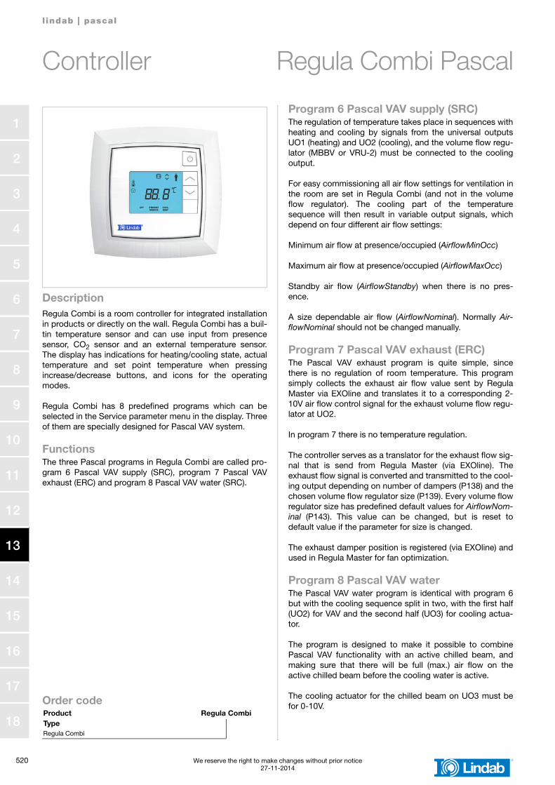
DescriptionRegula Combi is a room controller for integrated installationin products or directly on the wall. Regula Combi has a buil-tin temperature sensor and can use input from presencesensor, CO2 sensor and an external temperature sensor.The display has indications for heating/cooling state, actualtemperature and set point temperature when pressingincrease/decrease buttons, and icons for the operatingmodes.
Regula Combi has 8 predefined programs which can beselected in the Service parameter menu in the display. Threeof them are specially designed for Pascal VAV system.
FunctionsThe three Pascal programs in Regula Combi are called pro-gram 6 Pascal VAV supply (SRC), program 7 Pascal VAVexhaust (ERC) and program 8 Pascal VAV water (SRC).
Program 6 Pascal VAV supply (SRC)The regulation of temperature takes place in sequences withheating and cooling by signals from the universal outputsUO1 (heating) and UO2 (cooling), and the volume flow regu-lator (MBBV or VRU-2) must be connected to the coolingoutput.
For easy commissioning all air flow settings for ventilation inthe room are set in Regula Combi (and not in the volumeflow regulator). The cooling part of the temperaturesequence will then result in variable output signals, whichdepend on four different air flow settings:
Minimum air flow at presence/occupied (AirflowMinOcc)
Maximum air flow at presence/occupied (AirflowMaxOcc)
Standby air flow (AirflowStandby) when there is no pres-ence.
A size dependable air flow (AirflowNominal). Normally Air-flowNominal should not be changed manually.
Program 7 Pascal VAV exhaust (ERC)The Pascal VAV exhaust program is quite simple, sincethere is no regulation of room temperature. This programsimply collects the exhaust air flow value sent by RegulaMaster via EXOline and translates it to a corresponding 2-10V air flow control signal for the exhaust volume flow regu-lator at UO2.
In program 7 there is no temperature regulation.
The controller serves as a translator for the exhaust flow sig-nal that is send from Regula Master (via EXOline). Theexhaust flow signal is converted and transmitted to the cool-ing output depending on number of dampers (P138) and thechosen volume flow regulator size (P139). Every volume flowregulator size has predefined default values for AirflowNom-inal (P143). This value can be changed, but is reset todefault value if the parameter for size is changed.
The exhaust damper position is registered (via EXOline) andused in Regula Master for fan optimization.
Program 8 Pascal VAV waterThe Pascal VAV water program is identical with program 6but with the cooling sequence split in two, with the first half(UO2) for VAV and the second half (UO3) for cooling actua-tor.
The program is designed to make it possible to combinePascal VAV functionality with an active chilled beam, andmaking sure that there will be full (max.) air flow on theactive chilled beam before the cooling water is active.
The cooling actuator for the chilled beam on UO3 must befor 0-10V. Order code
Product Regula CombiTypeRegula Combi
l indab | pascal
We reserve the right to make changes without prior notice 52128-03-2014
1
2
3
4
5
6
7
8
9
10
11
12
13
14
15
16
17
18
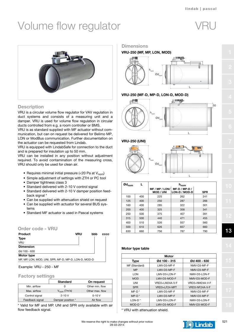
Volume flow regulator VRU
DescriptionVRU is a circular volume flow regulator for VAV regulation induct systems and consists of a measuring unit and adamper. VRU is used for volume flow regulation in circularducts controlled from e.g. a room controller or BMS.VRU is as standard supplied with MF actuator without com-munication, but can on request be delivered for Belimo MP,LON or ModBus communication. Further documentation onthe actuator can be requested from Lindab.VRU is equipped with LindabSafe for connection to the ductand is prepared for insulation up to 50 mm.VRU can be installed in any position without adjustmentrequired. To avoid contamination of the measuring cross,VRU should only be used for clean air.
• Requires minimal initial pressure (<20 Pa at Vnom)• Simple adjustment of settings with ZTH or PC tool• Damper tightness class 3• Standard delivered with 2-10 V control signal• Standard delivered with 2-10 V damper position feed-
back signal *• Can be supplied with attenuation shield on request• Can be supplied with actuator for several BUS sys-
tems• Standard MF actuator is used in Pascal systems
DimensionsVRU-250 (MF, MP, LON, MOD)
VRU-250 (MF-D, MP-D, LON-D, MOD-D)
VRU-250 (UNI)
Motor type table
* VRU with attenuation shield.
Order code - VRU
* Valid for MF and MP. UNI and SPR only available with airflow feedback signal.
Product VRU bbb ccccTypeVRU
Dimension Ød 100 - 630
Motor typeMF, MP, LON, MOD, UNI, SPR, MF-D, MP-D, LON-D, MOD-D
Example: VRU - 250 - MF
Factory settingsStandard On request
Min. airflow 0 Other min. flow
Max. airflow Vnom (7m/s) Other max. flow
Control signal 2-10 V 0-10 V
Feedback signal Damper position * Air flow
Ødnom L hnom MF / MP / LON/
MOD / UNIMF-D / MP-D /
LON-D / MOD-D SPR
100 400 225 262 241
125 400 250 287 266
160 400 285 322 301
200 400 325 358 341
250 500 375 407 391
315 500 440 471 455
400 510 526 557 560
500 610 626 657 660
630 660 756 787 790
MotorType Ød 100 - 315 Ød 400 - 630
MF (Standard) LMV-D3-MF-F NMV-D3-MF-F
MP LMV-D3-MP-F NMV-D3-MP-F
LON LMV-D3-LON-F NMV-D3-LON-F
MOD LMV-D3-MOD-F NMV-D3-MOD-F
UNI VRD3+LM24A-V-F VRD3+NM24A-V-F
SPR VRD3+LF24-MFT VRD3-NF24A-V-F
MF-D * LMV-D3-MF-F NMV-D3-MF-F
MP-D * LMV-D3-MP-F NMV-D3-MP-F
LON-D * LMV-D3-LON-F NMV-D3-LON-F
MOD-D * LMV-D3-MOD-F NMV-D3-MOD-F
L
Ødnom
hnom
L
Ødnom
hnom
50
L
Ødnom
hnom
522 We reserve the right to make changes without prior notice28-03-2014
l indab | pascal
1
2
3
4
5
6
7
8
9
10
11
12
13
14
15
16
17
18
Volume flow regulator VRU
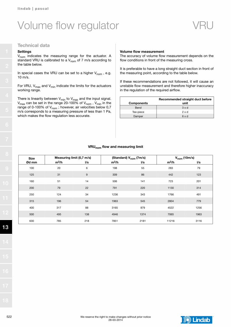
Technical dataSettingsVnom indicates the measuring range for the actuator. Astandard VRU is calibrated to a Vnom of 7 m/s according tothe table below.
In special cases the VRU can be set to a higher Vnom , e.g.10 m/s.
For VRU, Vmax and Vmin indicate the limits for the actuatorsworking range.
There is linearity between Vmin to Vmax and the input signal.Vmax can be set in the range 20-100% of Vnom , Vmin in therange of 0-100% of Vnom ; however, air velocities below 0,7m/s corresponds to a measuring pressure of less than 1 Pa,which makes the flow regulation less accurate.
Volume flow measurementThe accuracy of volume flow measurement depends on theflow conditions in front of the measuring cross.
It is preferable to have a long straight duct section in front ofthe measuring point, according to the table below.
If these recommendations are not followed, it will cause anunstable flow measurement and therefore higher inaccuracyin the regulation of the required airflow.
ComponentsRecommended straight duct before
unitBend 3 x d
Tee-piece 2 x d
Damper 6 x d
VRUnom flow and measuring limit
SizeØd mm
Measuring limit (0,7 m/s) (Standard) Vnom (7m/s) Vnom (10m/s)m3/h l/s m3/h l/s m3/h l/s
100 20 6 198 55 283 79
125 31 9 309 86 442 123
160 51 14 506 141 723 201
200 79 22 791 220 1130 314
250 124 34 1236 343 1766 491
315 196 54 1963 545 2804 779
400 317 88 3165 879 4522 1256
500 495 138 4946 1374 7065 1963
630 785 218 7851 2181 11216 3116
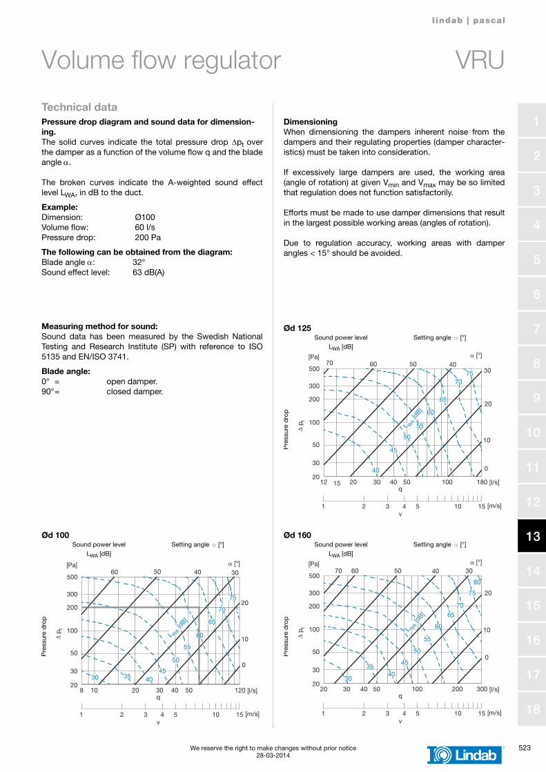
l indab | pascal
We reserve the right to make changes without prior notice 52328-03-2014
1
2
3
4
5
6
7
8
9
10
11
12
13
14
15
16
17
18
Volume flow regulator VRU
Technical dataPressure drop diagram and sound data for dimension-ing. The solid curves indicate the total pressure drop Δpt overthe damper as a function of the volume flow q and the bladeangle α.
The broken curves indicate the A-weighted sound effectlevel LWA, in dB to the duct.
Example:Dimension: Ø100Volume flow: 60 l/sPressure drop: 200 Pa
The following can be obtained from the diagram:Blade angle α: 32°Sound effect level: 63 dB(A)
DimensioningWhen dimensioning the dampers inherent noise from thedampers and their regulating properties (damper character-istics) must be taken into consideration.
If excessively large dampers are used, the working area(angle of rotation) at given Vmin and Vmax may be so limitedthat regulation does not function satisfactorily.
Efforts must be made to use damper dimensions that resultin the largest possible working areas (angles of rotation).
Due to regulation accuracy, working areas with damperangles < 15° should be avoided.
Measuring method for sound:Sound data has been measured by the Swedish NationalTesting and Research Institute (SP) with reference to ISO5135 and EN/ISO 3741.
Blade angle:0° = open damper.90°= closed damper.
Ød 125
Pre
ssur
e d
rop
Setting angle α [°]
v
q
[Pa] α [°]
Δ p t
500
100
200
300
50
20
30
12 15 20 30 40 50 100 180
1 2 3 4 5 10 15
0
70 60 50 40
10
20
30
[l/s]
[m/s]
40
75
45
50
55
60
65
70
L WA [d
B]
Sound power levelLWA [dB]
Ød 100
Pre
ssur
e d
rop
Setting angle α [°]
v
q
[Pa] α [°]
Δ p t
500
100
200
300
50
20
30
8 10 20 30 40 50 120
1 2 3 4 5 10 15
0
60 50 40
10
20
30
[l/s]
[m/s]
403530
75
45
50
55
60
65
70
L WA [d
B]
60
Sound power levelLWA [dB]
Ød 160
Pre
ssur
e d
rop
Setting angle α [°]
v
q
[Pa] α [°]
Δ p t
500
100
200
300
50
20
30
20 100 20030 40 50 300
1 2 3 4 5 10 15
70 60 50 40
10
0
20
30
[l/s]
[m/s]
4035
30
80
45
50
55
60
65
70
75
L WA [d
B]
Sound power levelLWA [dB]
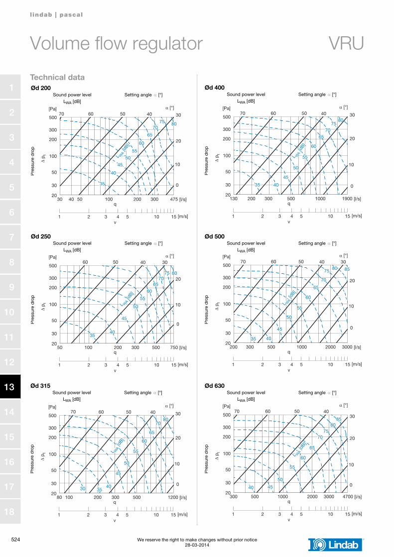
524 We reserve the right to make changes without prior notice28-03-2014
l indab | pascal
1
2
3
4
5
6
7
8
9
10
11
12
13
14
15
16
17
18
Volume flow regulator VRU
Technical data
Ød 250
Pre
ssur
e d
rop
Setting angle α [°]
v
q
[Pa] α [°]
Δ p t
500
100
200
300
50
20
30
50 100 200 300 500 750
1 2 3 4 5 10 15
0
60 50 40
10
20
30
[l/s]
[m/s]
4035
80
45
50
55
60
6570
75
L WA [d
B]
Sound power levelLWA [dB]
Ød 500
Pre
ssur
e d
rop
Setting angle α [°]
v
q
[Pa] α [°]
Δ p t
500
100
200
300
50
20
30
200 1000 2000300 500 3000
1 2 3 4 5 10 15
0
70 60 50 40
10
20
30
[l/s]
[m/s]
4035
80 85
45
50
55
60
65
70
75
L WA [d
B]
Sound power levelLWA [dB]
Ød 315
Pre
ssur
e d
rop
Setting angle α [°]
v
q
[Pa] α [°]
Δ p t
500
100
200
300
50
20
30
80 100 200 300 500 1200
1 2 3 4 5 10 15
0
70 60 50 40
10
20
30
[l/s]
[m/s]
4030 35
80
45
50
55
60
65
70
L WA
[dB]
Sound power levelLWA [dB]
Ød 630
Pre
ssur
e d
rop
Setting angle α [°]
v
q
[Pa] α [°]
Δ p t
500
100
200
300
50
20
30
300 500 1000 2000 3000 4700
1 2 3 4 5 10 15
0
70 60 50 40
10
20
30
[l/s]
[m/s]
40
8580
45
50
55
60
65
7075
L WA [d
B]
Sound power levelLWA [dB]
Ød 400
Pre
ssur
e d
rop
Setting angle α [°]
v
q
[Pa] α [°]
Δ p t
500
100
200
300
50
20
30
130 1000200 300 500 1900
1 2 3 4 5 10 15
0
70 60 50 40
10
20
30
[l/s]
[m/s]
4035
80
45
50
55
60
6570
75
L WA [d
B]
Sound power levelLWA [dB]
Ød 200
Pre
ssur
e d
rop
Setting angle α [°]
v
q
[Pa] α [°]
Δ p t
500
100
200
300
50
20
30
30 100 20040 50 475300
1 2 3 4 5 10 15
0
70 60 50 40
10
20
30
[l/s]
[m/s]
40
35
75 80
45
50
55
60
65
70
L WA [d
B]
Sound power levelLWA [dB]
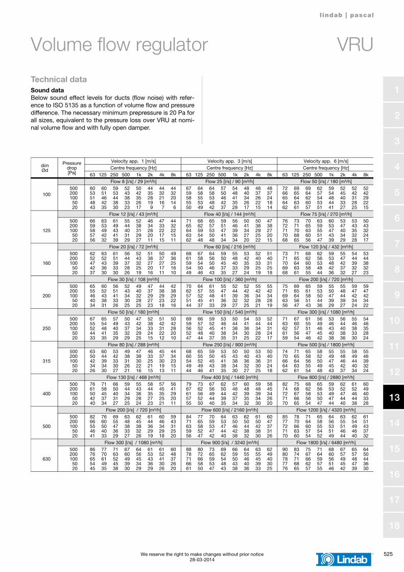
l indab | pascal
We reserve the right to make changes without prior notice 52528-03-2014
1
2
3
4
5
6
7
8
9
10
11
12
13
14
15
16
17
18
Volume flow regulator VRU
Technical dataSound dataBelow sound effect levels for ducts (flow noise) with refer-ence to ISO 5135 as a function of volume flow and pressuredifference. The necessary minimum prepressure is 20 Pa forall sizes, equivalent to the pressure loss over VRU at nomi-nal volume flow and with fully open damper.
dimØd
Pressure drop[Pa]
Velocity app. 1 [m/s] Velocity app. 3 [m/s] Velocity app. 6 [m/s]Centre frequency [Hz] Centre frequency [Hz] Centre frequency [Hz]
63 125 250 500 1k 2k 4k 8k 63 125 250 500 1k 2k 4k 8k 63 125 250 500 1k 2k 4k 8k
100
Flow 8 [l/s] / 29 [m³/h] Flow 25 [l/s] / 90 [m³/h] Flow 50 [l/s] / 180 [m³/h]5002001005020
60 60 59 52 50 44 44 4453 51 53 43 42 35 32 3251 46 44 38 35 28 21 2048 42 38 33 26 19 16 1443 35 30 23 17 9 7 6
67 64 64 57 54 48 48 4859 58 58 50 48 40 37 3758 55 53 46 41 34 26 2455 53 48 42 35 26 22 1850 49 42 37 28 17 15 14
72 69 69 62 59 52 52 5266 65 64 57 54 45 42 4265 64 62 54 48 40 31 2964 63 60 53 44 33 28 2262 61 57 51 41 27 25 15
Flow 12 [l/s] / 43 [m³/h] Flow 40 [l/s] / 144 [m³/h] Flow 75 [l/s] / 270 [m³/h]
125
5002001005020
66 63 61 55 52 46 47 4459 53 49 44 38 34 33 3258 49 43 40 31 28 22 2257 42 41 31 29 20 17 1556 32 39 29 27 11 15 11
71 68 65 59 56 50 50 4765 62 57 51 46 41 38 3864 59 53 47 39 34 29 2763 54 50 41 36 27 25 2062 48 48 34 34 20 22 15
76 73 70 63 60 53 53 5072 71 65 59 53 47 43 4371 70 63 55 47 40 35 3270 68 60 51 43 34 32 2468 65 56 47 39 29 28 17
Flow 20 [l/s] / 72 [m³/h] Flow 60 [l/s] / 216 [m³/h] Flow 120 [l/s] / 432 [m³/h]
160
5002001005020
62 63 61 56 52 51 50 4952 52 51 44 43 38 37 3647 43 39 37 32 27 27 2542 36 33 28 25 20 17 1637 30 30 26 19 16 11 10
68 67 64 59 55 53 52 5161 58 56 50 48 42 40 4059 54 50 45 40 35 33 3154 50 46 37 33 29 25 2549 46 43 35 27 24 19 18
73 71 68 62 59 55 54 5371 65 62 56 53 47 44 4470 64 60 53 48 42 39 3869 63 58 48 42 37 32 3268 61 55 44 36 32 27 23
Flow 30 [l/s] / 108 [m³/h] Flow 100 [l/s] / 360 [m³/h] Flow 200 [l/s] / 720 [m³/h]
200
5002001005020
65 60 56 52 49 47 44 4255 52 51 43 40 37 38 3846 43 41 34 32 29 29 2940 38 33 30 28 27 23 2234 31 26 25 25 23 18 16
70 64 61 55 52 52 55 5562 57 55 47 44 42 42 4257 52 48 41 39 36 34 3451 45 41 36 32 32 28 2844 37 33 29 27 25 21 19
75 69 65 59 55 55 59 5971 65 61 53 50 48 47 4769 64 58 50 47 44 42 4263 56 51 44 39 39 34 3456 47 43 36 29 27 24 22
Flow 50 [l/s] / 180 [m³/h] Flow 150 [l/s] / 540 [m³/h] Flow 300 [l/s] / 1080 [m³/h]
250
5002001005020
67 65 57 50 47 52 51 5055 54 49 43 42 38 42 4252 48 40 37 34 33 31 2844 41 35 32 29 24 22 2033 35 29 29 25 15 12 10
69 66 59 53 50 54 53 5259 57 52 46 44 41 44 4456 52 45 41 38 36 34 3152 48 40 38 34 30 28 2447 44 37 35 31 25 22 17
71 67 61 56 53 56 55 5463 60 55 49 46 44 46 4662 57 51 46 43 40 38 3561 56 47 45 40 38 33 2859 54 46 42 38 36 30 24
Flow 80 [l/s] / 288 [m³/h] Flow 250 [l/s] / 900 [m³/h] Flow 500 [l/s] / 1800 [m³/h]
315
5002001005020
63 60 53 49 47 46 45 4450 44 42 38 38 33 37 3442 39 33 31 30 25 30 2334 34 30 26 22 21 19 1526 30 27 21 16 15 13 11
68 65 59 53 50 50 53 5060 55 50 45 43 40 43 4054 52 45 41 38 36 36 3149 49 43 38 34 32 30 2444 46 41 35 30 27 25 18
74 71 65 58 55 55 58 5570 65 58 52 49 48 49 4666 64 56 50 47 46 44 3964 63 55 49 45 42 40 3262 61 54 48 43 37 34 24
Flow 130 [l/s] / 468 [m³/h] Flow 400 [l/s] / 1440 [m³/h] Flow 800 [l/s] / 2880 [m³/h]
400
5002001005020
76 71 66 59 55 58 57 5661 58 50 44 43 44 45 4150 45 40 34 36 35 35 2942 37 31 29 28 27 25 2040 34 27 25 24 23 21 11
79 73 67 62 57 60 59 5867 62 56 50 48 48 48 4561 56 49 44 42 39 39 3457 52 44 39 37 35 34 2655 50 40 35 34 32 30 20
82 75 68 65 59 62 61 6074 68 62 56 53 52 52 4972 67 58 53 49 47 46 4071 66 56 50 47 44 44 3370 65 54 47 44 40 38 28
Flow 200 [l/s] / 720 [m³/h] Flow 600 [l/s] / 2160 [m³/h] Flow 1200 [l/s] / 4320 [m³/h]
500
5002001005020
82 76 69 63 62 61 60 5966 60 55 48 45 44 46 4355 50 47 38 38 36 34 3146 40 36 33 32 29 29 2541 33 29 27 26 19 18 20
84 77 70 64 63 62 61 6071 65 59 53 50 50 50 4763 58 53 47 46 44 42 3759 52 47 44 42 38 38 3156 47 42 40 38 32 30 26
85 78 71 65 64 63 62 6177 70 64 58 56 55 54 5172 66 60 55 53 51 49 4371 63 57 54 51 46 46 3770 60 54 52 49 44 40 32
Flow 300 [l/s] / 1080 [m³/h] Flow 900 [l/s] / 3240 [m³/h] Flow 1800 [l/s] / 6480 [m³/h]
630
5002001005020
86 77 71 67 64 61 61 6076 70 63 60 56 53 52 4865 61 52 49 45 43 41 3754 49 45 39 34 36 30 2645 35 38 30 29 29 26 20
88 80 73 69 66 64 63 6278 72 65 62 59 55 55 4971 66 59 54 50 46 45 4066 58 53 48 43 40 39 3061 50 47 43 38 36 33 25
90 83 75 71 68 67 65 6480 74 67 64 60 57 57 5078 71 66 59 56 49 48 4477 68 62 57 51 45 47 3676 65 57 55 46 42 39 30