Embed Size (px)
Citation preview
mit externem Laderegeler
with external charge controller
avec régulateur de charge externe
07/2010 Sprache / language / langue: deutsch / english / français
Innovative Mobile Technology
MontageanleitungInstallation Instructions / Manuel de montage
Inhaltsverzeichnis / Table of content / Manuel d’utilisation
2
Deutsch 3 English 24 Français 45

Deutsch D
3
D
4
Inhaltsverzeichnis
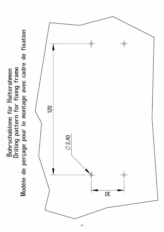
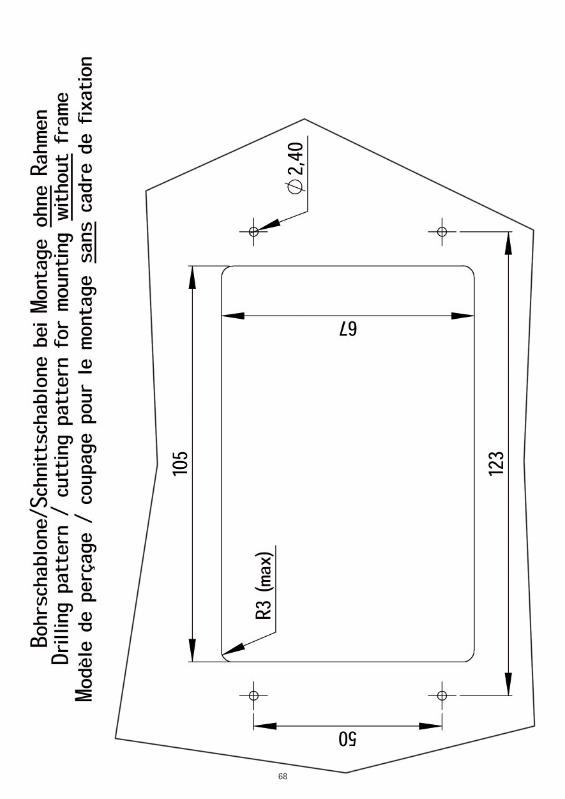
Bestimmungsgemäße Verwendung 5 Lieferumfang 6 Montagevorarbeiten 7 Schritt 1: Montageplatte montieren 9 Schritt 2: System aufsetzen 10 Schritt 3: Konfi guration des Ladereglers Solara SR 135 12 Schritt 4: Spannungsversorgung 14 Schritt 5: Die erste Inbetriebnahme 17 Schritt 6 : Montage des Solarpanels 18 Schritt 7: Kalibration 19 Fehlermeldungen und Fehlerdiagnose 21 Demontage der Anlage 22 Hinweise zum Umweltschutz 23 Schablonen 66
D
5
Bestimmungsgemäße Verwendung
Die bestimmungsgemäße Verwendung dieses Produktes ist die Festmontage auf Wohnmobilen oder Wohnanhängern (Caravans) mit einer Höchstgeschwindigkeit von nicht mehr als 130 km/h. Die Anlage dient zum Zwecke des Aufl adens der im Fahrzeug eingebauten, wiederaufl adbaren Batterien (Akkumulatoren). Hierbei muss es sich um handelsübliche Akkumulatoren mit einer Nennspannung von 12V (6 Zellen) und einer Nennkapazität von mindestens 50Ah handeln.
Ein anderer Einsatz als vorgegeben ist nicht zulässig.
Bitte beachten Sie auch folgende Herstellervorschriften:
Eine Veränderung des Gesamtgerätes durch Entfernen einzelner Komponenten oder Hinzufügen anderer Komponenten ist nicht zulässig. Die Montage hat unter genauer Beachtung dieser Montageanleitung, die Teil der Bedienungsanleitung ist, durch ausreichend qualifi ziertes Personal zu erfolgen. Einschlägige, anerkannte Richtlinien des KFZ-Gewerbes sind zu beachten und zu erfüllen. Die Montage ist nur auf harten Fahrzeugdächern mit ausreichender Festigkeit und Eigenstabilität zulässig. Das Produkt bedarf keiner regelmäßigen Wartung. Die Gehäuse dürfen nicht geöffnet werden. Überlassen Sie Überprüfungsarbeiten stets nur einem qualifi zierten Fachmann. Bei Unklarheiten oder Problemen wenden Sie sich bitte an den Hersteller oder eine vom Hersteller anerkannte Fachwerkstatt. Die beiden Leitungen welche den Solarstrom liefern (schwarz/gelb) NIEMALS direkt an der Batterie anschließen!
Durch den Einbau dieses Produktes als Zubehörteil kann sich die Gesamthöhe des KFZ vergrößern. Der Einbaubetrieb ist verpfl ichtet, den Auftraggeber über ‚ eine ggf. veränderte Fahrzeughöhe detailliert zu informieren.
D
6
Lieferumfang
Das sollte jetzt vor Ihnen liegen:
Bedienteil Außeneinheit mit Montageplatte Solarmodul Schraubenpackung Kabelsatz zur Außeneinheit Bedienungsanleitung Montageanleitung Laderegler Entsorgungshinweis für Verpackungen
Verpackungen und Packhilfsmittel sind recyclingfähig und müssen grund-sätzlich der stoffl ichen Wiederverwertung zugeführt werden.Verpackungsmaterialien wie z.B. Folienbeutel gehören nicht in Kinderhände.
D
7
Montagevorarbeiten
1. Vorbereitung
Bevor Sie die Montage beginnen, achten Sie bitte darauf, dass das Dach Ihres Fahr-zeugs ausreichend stabil ist. Weiterhin sollten Sie die bei der Montage und beim Besteigen des Daches die zulässige Dachlast Ihres Wohnmobils nicht überschreiten.
Bei ungenügender oder zweifelhafter Dachstabilität für die Anlage kann ein ca. 3 mm starkes Blech mit ca. 100 x 100 cm auf der Dachaußenhaut befestigt werden, um die Dachstabilität zu verbessern. Erkundigen Sie sich dazu bei Ihrem Fahrzeug-hersteller.
Zur Montage der Anlage benötigen Sie je einen Gabelschlüssel der Größen 13 mm und 27 mm, einen großen Kreuzschlitzschraubendreher, Bohrer mit 20 mm Durchmesser oder Fräser, eine Bohrmaschine, scharfes Messer (Teppichmesser), Schlitzschraubendreher 3 mm, eine Kneifzange, Industrie-reiniger zum Reinigen der Montageplatte und eine stark klebende Karosseriedichtmasse (z.B. Sikafl ex).
2. Platzbedarf der Außeneinheit
Achten Sie darauf, dass für das zusammengeklappte System sowie für den Aktions-radius (Drehradius) ausreichend Platz vorhanden ist.
Bei der Wahl des Montageplatzes ist zu beachten, dass sich keine größeren Metall-teile (z. B. Umsturzbügel / Überrollbügel, etc.) und keine Bauteile die Magnetfelder erzeugen können (z. B. Lautsprecher, Lüftungsmotoren, etc.) in unmittelbarer Nähe (Umkreis von ca. 75 cm) der Anlage befi nden, damit die Kompassfunktion nicht gestört wird.
Nachdem nun sämtliche Zweifel bezüglich der Dachstabilität ausgeräumt sind bzw. alle notwendigen Maßnahmen für eine ordnungsgemäße Montage getroffen wurden, setzen Sie die Außeneinheit mit Montageplatte vorläufi g auf den dafür vor-gesehenen Montageplatz auf.
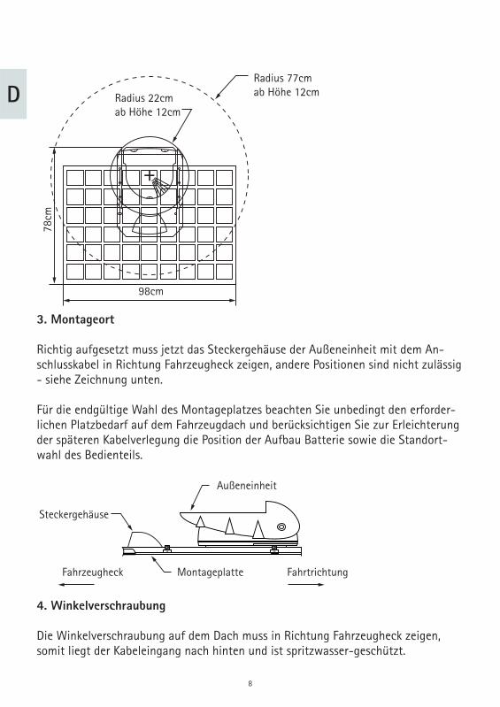
Stellen Sie anhand der folgenden Grafi k sicher, dass innerhalb des angegebenen Bereichs keine Hindernisse vorhanden sind.
D
8
Radius 77cmab Höhe 12cmRadius 22cm
ab Höhe 12cm
98cm
78cm
3. Montageort
Richtig aufgesetzt muss jetzt das Steckergehäuse der Außeneinheit mit dem An-schlusskabel in Richtung Fahrzeugheck zeigen, andere Positionen sind nicht zulässig - siehe Zeichnung unten.
Für die endgültige Wahl des Montageplatzes beachten Sie unbedingt den erforder-lichen Platzbedarf auf dem Fahrzeugdach und berücksichtigen Sie zur Erleichterung der späteren Kabelverlegung die Position der Aufbau Batterie sowie die Standort-wahl des Bedienteils.
Außeneinheit
FahrtrichtungFahrzeugheck Montageplatte
Steckergehäuse
4. Winkelverschraubung
Die Winkelverschraubung auf dem Dach muss in Richtung Fahrzeugheck zeigen, somit liegt der Kabeleingang nach hinten und ist spritzwasser-geschützt.
D
9
Schritt 1: Montageplatte montieren
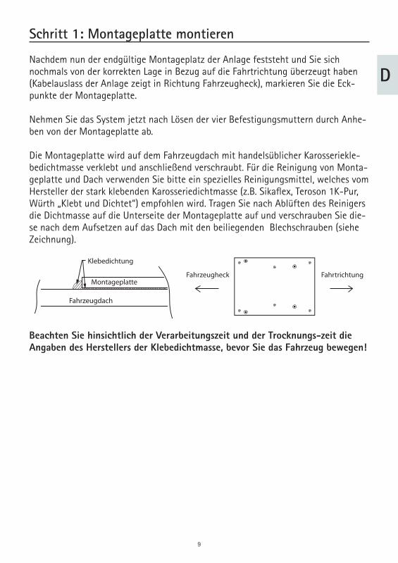
Nachdem nun der endgültige Montageplatz der Anlage feststeht und Sie sich nochmals von der korrekten Lage in Bezug auf die Fahrtrichtung überzeugt haben (Kabelauslass der Anlage zeigt in Richtung Fahrzeugheck), markieren Sie die Eck-punkte der Montageplatte.
Nehmen Sie das System jetzt nach Lösen der vier Befestigungsmuttern durch Anhe-ben von der Montageplatte ab.
Die Montageplatte wird auf dem Fahrzeugdach mit handelsüblicher Karosseriekle-bedichtmasse verklebt und anschließend verschraubt. Für die Reinigung von Monta-geplatte und Dach verwenden Sie bitte ein spezielles Reinigungsmittel, welches vom Hersteller der stark klebenden Karosseriedichtmasse (z.B. Sikafl ex, Teroson 1K-Pur, Würth „Klebt und Dichtet“) empfohlen wird. Tragen Sie nach Ablüften des Reinigers die Dichtmasse auf die Unterseite der Montageplatte auf und verschrauben Sie die-se nach dem Aufsetzen auf das Dach mit den beiliegenden Blechschrauben (siehe Zeichnung).
Beachten Sie hinsichtlich der Verarbeitungszeit und der Trocknungs-zeit die Angaben des Herstellers der Klebedichtmasse, bevor Sie das Fahrzeug bewegen!
Fahrzeugdach
Montageplatte
Klebedichtung
Fahrzeugheck Fahrtrichtung
D
10
Schritt 2: System aufsetzen
Setzen Sie die Außeneinheit auf die Montageplatte so auf, dass das Steckergehäuse und der Kabelauslass der Außeneinheit zum Fahrzeugheck zeigen. Jede andere Posi-tion der Anlage ist nicht zulässig und führt zum Erlöschen der Gewährleistung. Wurde die Montageplatte vorher richtig montiert, so zeigen das LNB und der Kabel-auslass jetzt in Richtung Fahrzeugheck.
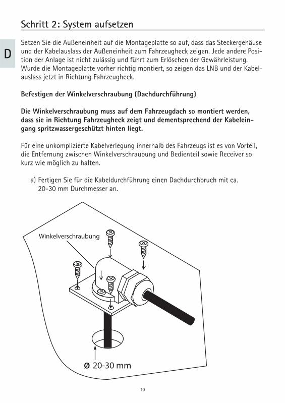
Befestigen der Winkelverschraubung (Dachdurchführung)
Die Winkelverschraubung muss auf dem Fahrzeugdach so montiert werden, dass sie in Richtung Fahrzeugheck zeigt und dementsprechend der Kabelein-gang spritzwassergeschützt hinten liegt.
Für eine unkomplizierte Kabelverlegung innerhalb des Fahrzeugs ist es von Vorteil, die Entfernung zwischen Winkelverschraubung und Bedienteil sowie Receiver so kurz wie möglich zu halten.
a) Fertigen Sie für die Kabeldurchführung einen Dachdurchbruch mit ca. 20-30 mm Durchmesser an.
Winkelverschraubung
ø 20-30 mm
D
11
b) Verlegen Sie das Kabel ordentlich auf dem Fahrzeugdach z.B. in einem Kabelkanal und führen dann das aus der Winkelverschraubung kommende Kabel nach unten zum Bedienteil. c) Die kleine Montageplatte für die Winkelverschraubung wird auf dem Fahrzeugdach mit handelsüblicher Karosserieklebedichtmasse verklebt und anschließend verschraubt. Für die Reinigung der kleinen Montageplatte und des Daches verwenden Sie bitte ein spezielles Reinigungsmittel, welches vom Hersteller der stark klebenden Karosseriedichtmasse (z.B. Sikafl ex, Teroson 1K-Pur, Würth Klebt und dichtet) empfohlen wird. Tragen Sie nach Ablüften des Reinigers die Dichtmasse auf die Unterseite der Montageplatte auf und verschrauben Sie diese nach dem Aufsetzen auf das Dach mit den beiliegenden 4 Blechschrauben.
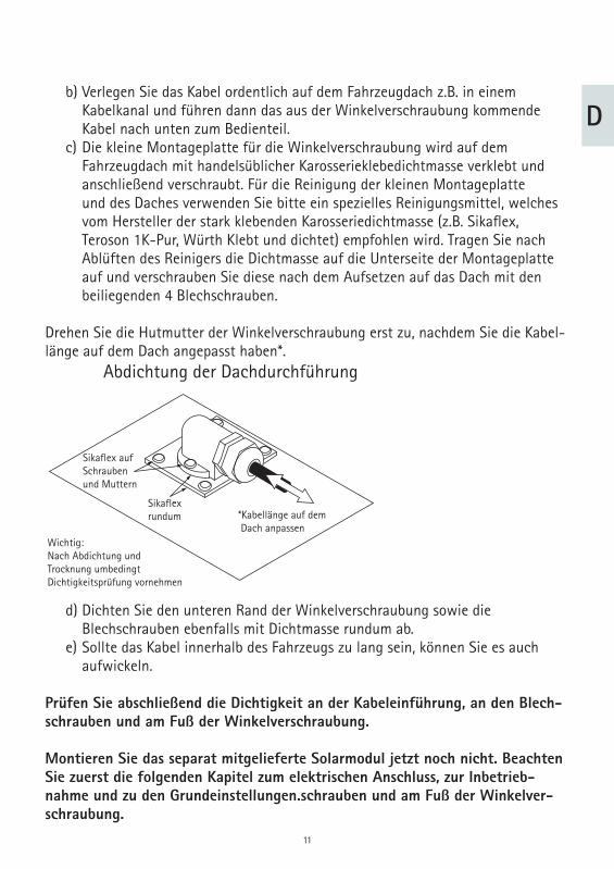
Drehen Sie die Hutmutter der Winkelverschraubung erst zu, nachdem Sie die Kabel-länge auf dem Dach angepasst haben*.
Abdichtung der Dachdurchführung
Wichtig:Nach Abdichtung undTrocknung umbedingtDichtigkeitsprüfung vornehmen
*Kabellänge auf dem Dach anpassen
Sikaflexrundum
Sikaflex aufSchraubenund Muttern
d) Dichten Sie den unteren Rand der Winkelverschraubung sowie die Blechschrauben ebenfalls mit Dichtmasse rundum ab. e) Sollte das Kabel innerhalb des Fahrzeugs zu lang sein, können Sie es auch aufwickeln.
Prüfen Sie abschließend die Dichtigkeit an der Kabeleinführung, an den Blech-schrauben und am Fuß der Winkelverschraubung.
Montieren Sie das separat mitgelieferte Solarmodul jetzt noch nicht. Beachten Sie zuerst die folgenden Kapitel zum elektrischen Anschluss, zur Inbetrieb-nahme und zu den Grundeinstellungen.schrauben und am Fuß der Winkelver-schraubung.
12
Schritt 3: Konfiguration des Ladereglers Solara SR 135
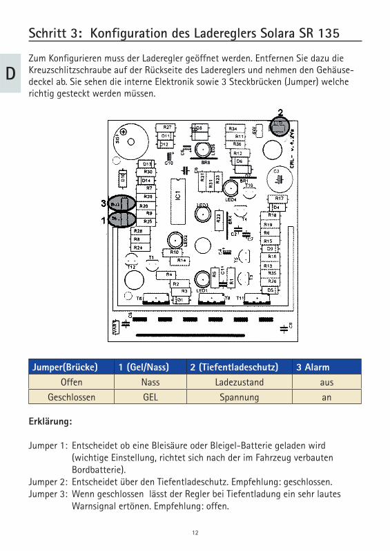
Zum Konfi gurieren muss der Laderegler geöffnet werden. Entfernen Sie dazu die Kreuzschlitzschraube auf der Rückseite des Ladereglers und nehmen den Gehäuse-deckel ab. Sie sehen die interne Elektronik sowie 3 Steckbrücken (Jumper) welche richtig gesteckt werden müssen.
Jumper(Brücke) 1 (Gel/Nass) 2 (Tiefentladeschutz) 3 Alarm Offen Nass Ladezustand aus
Geschlossen GEL Spannung an
Erklärung:
Jumper 1: Entscheidet ob eine Bleisäure oder Bleigel-Batterie geladen wird (wichtige Einstellung, richtet sich nach der im Fahrzeug verbauten Bordbatterie). Jumper 2: Entscheidet über den Tiefentladeschutz. Empfehlung: geschlossen. Jumper 3: Wenn geschlossen lässt der Regler bei Tiefentladung ein sehr lautes Warnsignal ertönen. Empfehlung: offen.
D
13
Beispiel: Wir haben eine Gel Batterie im Fahrzeug. Der Tiefentladeschutz überwacht die Batteriespannung. Es soll im Fall einer Tiefentladung kein Warnsignal ertönen:
Brücke 1: GeschlossenBrücke 2: GeschlossenBrücke 3: Offen(Eine detaillierte Beschreibung des Solara SR 135 Ladereglers fi nden Sie auf dem Beiblatt in dessen Verpackung)
Den Laderegler mit 2 Schrauben vorzugsweise in Batterienähe montieren.Die Anschlussarbeiten am Bordnetz sind hiermit abgeschlossen.
D
14
D
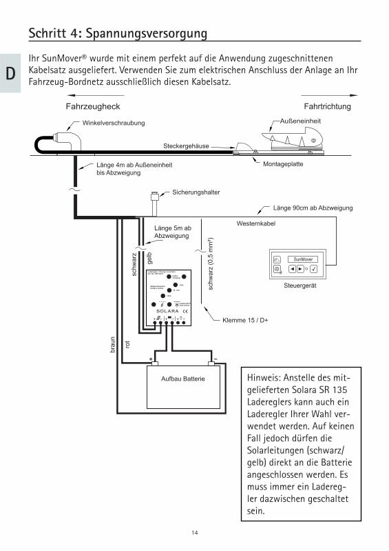
Schritt 4: Spannungsversorgung
Ihr SunMover® wurde mit einem perfekt auf die Anwendung zugeschnittenen Kabelsatz ausgeliefert. Verwenden Sie zum elektrischen Anschluss der Anlage an Ihr Fahrzeug-Bordnetz ausschließlich diesen Kabelsatz.
SunMover
Fahrtrichtung
Außeneinheit
Montageplatte
Steckergehäuse
Klemme 15 / D+
Länge 4m ab Außeneinheitbis Abzweigung
Sicherungshalter
Länge 5m abAbzweigung
schw
arz
(0,5
mm
²)
gelb
schw
arz
brau
n
rot
Aufbau Batterie
Länge 90cm ab Abzweigung
Westernkabel
Steuergerät
Winkelverschraubung
Fahrzeugheck
Laderegler / Charge controllerArt. No. SR135TL
Ladencharging
Batteriezustandbattery status
>75%
25 - 75%
<25%
Lastzustandload status
SOLARA
Hinweis: Anstelle des mit-gelieferten Solara SR 135 Ladereglers kann auch ein Laderegler Ihrer Wahl ver-wendet werden. Auf keinen Fall jedoch dürfen die Solarleitungen (schwarz/gelb) direkt an die Batterie angeschlossen werden. Es muss immer ein Ladereg-ler dazwischen geschaltet sein.
15
DZunächst schließen Sie bitte an die Abzweigung des Kabelsatzes das Bedienteil an. Der Stecker am Westernkabel („RJ11-Stecker“) muss mit einem hörbaren und spür-baren „Klick“ im Bedienteil einrasten.
Der aus der Kabelabzweigung neben dem Westernkabel hervorgehende schwarze Draht muss mit der Zündungsschaltung über Klemme 15 oder D+ der Bordelektrik verbunden werden. Dies sind Leitungen, die bei eingeschalteter Zündung Spannung führen und bei ausgeschalteter Zündung keine Spannung. Dieser Draht steuert eini-ge wichtige Funktionen Ihres SunMovers®, schließen Sie diese Leitung deshalb kor-rekt an. Sie können diese Leitung entweder im Innenraum z.B. zu einer vorhandenen Trittstufensteuerung oder zu einem Kühlschrank mit entsprechender Umschaltung legen und dort verbinden, oder sie können die Leitung zusammen mit der Batterie Anschluss-/Ladeleitung in den Unterfl urbereich legen und dort an geeigneter Stelle auf ein vorhandenes Zündungssignal klemmen.
Achtung: Es ist zwingend erforderlich die Anlage über die schwarze Leitung (0,5mm²) mit K15 oder D+ der Bordelektrik Ihres Fahrzeuges zu verbinden!
Alle 5 Kabel, welche mit dem Bordnetz des Fahrzeug verbunden werden müssen (2,5mm²: rot, braun, gelb, schwarz / 0,5mm²: schwarz), können nach Belieben gekürzt werden.
An der Kabelabzweigung befi nden sich zwei Steckkontakte, die in den beiliegenden schwarzen Kunststoffsicherungshalter gesteckt werden müssen. Die Kabelenden müssen mit einem hörbaren Klick einrasten.
Danach die beiliegende 10 Ampere Sicherung einstecken.Als nächstes müssen Sie die Batterie Anschluss-/Ladeleitung direkt an die Aufbau-/Wohnraumbatterie anschließen.
Achtung: Schließen Sie das rote und braune Kabel Ihres SunMovers® immer nur direkt an die Batterieklemmen der Aufbau-/Wohnraumbatterie an, niemals hinter irgendwelchen Zusatzgeräten. Schließen Sie Ihren SunMover® auch nie-mals an der Starterbatterie an.
16
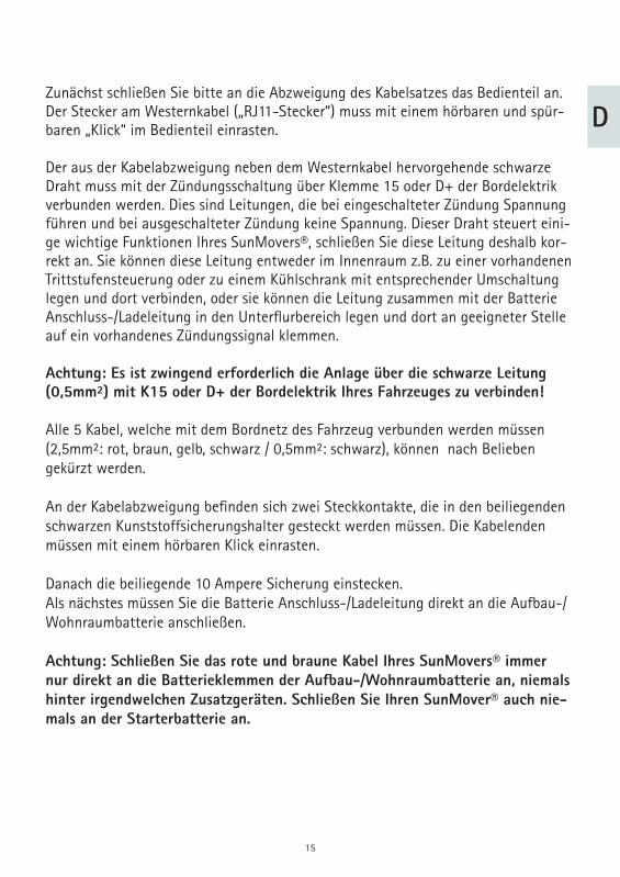
DBei korrekt erfolgtem Anschluss führt die Steuerung einen kurzen Selbsttest durch und geht dann in den Ruhezustand.Danach müssen Sie die Kabel, welche mit den Solarstrom liefern (schwarz/gelb) an einen Laderegler anschließen. Die folgende Abbildung zeigt den Anschluss an den mitgelieferten Laderegler Solara SR 135. Dieser Laderegler ist für handelsübli-che Bleigel- und Bleisäure-Batterien geeignet. Falls Sie die beiden Kabel an einen anderen Laderegler ihrer Wahl oder an einen Fahrzeug-Energieblock anschließen möchten, beachten Sie bitte die Vorschriften des jeweiligen Herstellers.
Anschluss des Ladereglers Solara SR135:
Gelbes KabelSunMover®
Schwarzes KabelSunMover®
Pluspol Bordbatterie
Minuspol (Masse)Bordbatterie
Laderegler / Charge controllerArt. No. SR135TL
Ladencharging
Batteriezustandbattery status
>75%
25 - 75%
<25%
Lastzustandload status
SOLARA
D
17
Schritt 5: Die erste Inbetriebnahme
Wenn alle Montage- und Anschlussarbeiten – außer der Montage des Solarpanels – soweit abgeschlossen sind, kann die Anlage zum ersten Mal eingeschaltet werden.
Sollte der Microprozessor beim Anschluss des SunMovers® an die Batterie wäh-rend des automatischen Selbsttests einen Fehler erkannt haben, wird dieser in der Anzeige des Bedienteiles eingeblendet. Wenn kein Fehler erkannt wurde hat sich die Anlage selbsttätig abgeschaltet. Bei eventuellen Fehlermeldungen lesen Sie bitte das Kapitel „Fehlermeldungen und Fehlerdiagnose“ auf Seite 20 durch.
Sie können die Anlage jetzt durch Drücken der Taste am Bedienteil aktivie-ren. Bevor die Anlage ausfährt, wird normalerweise zunächst vom eingebauten GPS-Empfänger der aktuelle Standort und die Uhrzeit ermittelt. Dies wird auf dem Bedienteil durch die Meldung „Synchronisation“ angezeigt und kann unter Umstän-den mehrere Minuten dauern. Um die Anlage jetzt sofort in die für die Montage des Solarpanels nötige Position zu fahren, drücken Sie bitte gleichzeitig die Tasten und am Bedienteil. Der Haltearm fährt nun in die aufrechte Montageposition.
Drücken Sie während der „Synchronisation“ gleichzeitig die Tasten und am Bedienteil, um den Haltearm in eine aufrechte Montageposition zu fahren. Beachten Sie dabei die notwendige Deckenhöhe!
Die Bedienung der Anlage wird in der mitgelieferten Bedienungsanleitung ausführ-lich erklärt.
D
18
Schritt 6 : Montage des Solarpanels
Das Solarpanel wird auf die zwei weißen Arme gelegt und mit beiliegenden 6 Stück M8 Schrauben und den Federringen verschraubt. Da die Schrauben unterschiedlich lang sind, achten Sie bitte auf die entsprechende Zuordnung. Die längste Schraube ist unten, die kürzeste oben. Danach wird das schwarze Gehäuse auf der Rückseite des Solarpanels mit einem schmalem Schlitzschraubendreher durch nach Innendrü-cken der Laschen geöffnet und das zweipolige Kabel aus der Außeneinheit zuerst durch die Bohrungen des Vierkantrohres geführt und dann durch die Verschraubung in die schwarze Kabelbox am Solarpanel. Achten Sie darauf, dass der Isolierschlauch mit in die Verschraubung eingeführt wird.
In der Anschlussbox wird das rote Pluskabel an die mit „+“ gekennzeichnete Öff-nung geklemmt, das braune Minuskabel an die mit „-„ gekennzeichnete Öffnung. Dazu drücken Sie mit einem kleinen Schraubendreher von oben kräftig auf die jeweilige Klemme und schieben gleichzeitig das Kabel in die Öffnung. Überzeugen Sie sich durch Ziehen am Kabel, dass die Kabel richtig geklemmt sind. Anschließend wird der Deckel wieder aufgedrückt und die Kunststoffmutter angezogen.
Mit beiliegendem Kabelbinder fi xieren Sie das zweipolige Kabel direkt hinter dem Vierkantrohr, so dass das Kabel bei allen Neigungen des Solarpanels nicht einge-klemmt oder aus dem Gehäuse gezogen wird.Nachdem Sie das Solarpanel montiert und angeschlossen haben, können Sie jetzt die Anlage mit der Taste entweder einfahren und abschalten, oder mit der Taste den Solarmodus aktivieren.
Als Nächstes sollten Sie die Sicherheitsschaltung testen:
Schalten Sie die Anlage ein und warten, bis das Solarpanel in die richtige Position gefahren ist.
Schalten Sie jetzt die Zündung des Fahrzeuges ein.
Überzeugen Sie sich durch Sichtkontrolle davon, dass die Anlage einfährt.
Ihre Anlage ist jetzt nahezu betriebsbereit. Nun muss noch der anlageninterne Kom-pass kalibriert werden.
D
19
Schritt 7: Kalibration
Um das Solarmodul jederzeit korrekt auf die Sonne ausrichten zu können, verwendet Ihr SunMover® unter anderem einen elektronischen Kompasssensor. Dieser Sensor wurde im Werk vorkalibriert (eingestellt), so dass die Anlage in der Regel problemlos funktionieren wird. Allerdings haben Kraftfahrzeuge häufi g einen gewissen Ein-fl uss auf die Funktion des Kompasssensors, indem sie das Erdmagnetfeld ein wenig verzerren.
Ihre Anlage verwendet einen automatischen Abgleich, der sich ständig an sich mög-licherweise verändernde Gegebenheiten anpasst, so dass Sie im Normalbetrieb stets mit korrekter Ausrichtung des Solarpanels zur Sonne rechnen können. Allerdings ist es absolut nicht vorhersehbar, wie stark der externe Einfl uss auf die Anlage in jedem Einzelfall ist. Deshalb empfi ehlt es sich, die Anlage nach der Montage einmalig zu kalibrieren. In Fällen, in denen die Anlage eine starke Beeinfl ussung erkennt, wird die Kalibration sogar vom Mikroprozessor explizit angefordert.
Die eigentliche Kalibration erfolgt, in dem Sie mit Ihrem Fahrzeug zwei Mal langsam und gleichmäßig einen vollständigen Kreis ausfahren. Dabei werden die äußeren Einfl üsse ermittelt und können dann später korre kt ausgeglichen werden.
Um die Kalibration durchführen zu können, sollten Sie einen ausreichend großen, leeren Platz, eine Wendeplatte o.ä., zur Verfügung haben, wo Sie anderen Verkehr nicht stören oder behindern.
Sie führen die Kalibration durch, indem Sie zunächst das Fahrzeug an einem geeig-neten Ort starten. Das Bedienteil muss jetzt die Meldung an-zeigen.
Drücken Sie jetzt mehrmals die Taste, bis Sie die Meldung in der Anzeige sehen. Durch gleichzeitiges Drücken der Tasten und können sie jetzt den Kalibrationsmodus starten, dies wird durch die Meldung bestätigt.
Fahren Sie nun 2 Mal langsam einen Vollkreis aus. Es spielt dabei keine Rolle, ob Sie rechts herum oder links herum fahren, Sie dürfen lediglich keine „Schlangenlinien“ fahren. Nach zwei Kreisen ist die Kalibration beendet und der Kalibrationsmodus wird automatisch verlassen.
Zündung an
CAL x/y:.....
CALIBRATE
D
20
In der Anzeige sollte jetzt zu sehen sein. In diesem Fall ist alles in Ordnung und Ihr SunMover® hat sich an die Gegebenheiten Ihres Fahrzeuges angepasst.
Sollten Sie eventuell die Meldung auf der Anzeige des Be-dienteiles sehen, so müssen den Vorgang wiederholen, da der Mikroprozessor die benötigten Daten nicht ermitteln konnte, was aber beim zweiten Versuch ziemlich sicher gelingen wird.
Sehen Sie die Meldung sollten Sie den Vorgang ebenfalls wiederholen. Erscheint erneut dieselbe Fehlermeldung, so ist es möglich, dass Ihr Fahrzeug sehr starke magnetische Einfl üsse auf die Anlage auf dem Fahrzeugdach ausübt. In so einem Fall ist ein zuverlässiger Betrieb nicht gewährleistet. Sie sollten prüfen, ob es irgendwo in der Nähe des Montageortes der Anlage starke Magnete oder Magnetfelder gibt und diese wenn möglich entfernen. Danach sollte sich die Kalibration ohne weiteres durchführen lassen. Natürlich dürfen Sie die magneti-schen Teile nach der Kalibration nicht wieder anbringen!
Zusätzlich zur beschriebenen Kalibration verwendet Ihr SunMover® einen automati-schen, selbstlernenden Abgleich.
Der automatische Abgleich des elektronischen Kompasses fi ndet während der Fahrt statt. Sie brauchen in keinster Weise einzugreifen. Bitte beachten Sie aber, dass neu installierte Anlagen naturgemäß noch keinen automatischen Abgleich haben können, da dieser sehr fahrzeugspezifi sch ist. Es wird also einiger Fahrtstrecken bedürfen, bis der Abgleich optimal ist. Ein unvollständiger Abgleich führt schlimms-tenfalls dazu, dass Ihr SunMover® beim Ausfahren die Sonne nicht perfekt trifft, sondern einige Grad daneben zielt. Dies können Sie im Einzellfall mit der manuellen Richtungskorrektur kompensieren (s. Bedienungsanleitung).
Die Anlage ist nun betriebsbereit.
CALIBRATION OK
CAL ERROR
LIMIT ERROR
D
21
Fehlermeldungen und Fehlerdiagnose
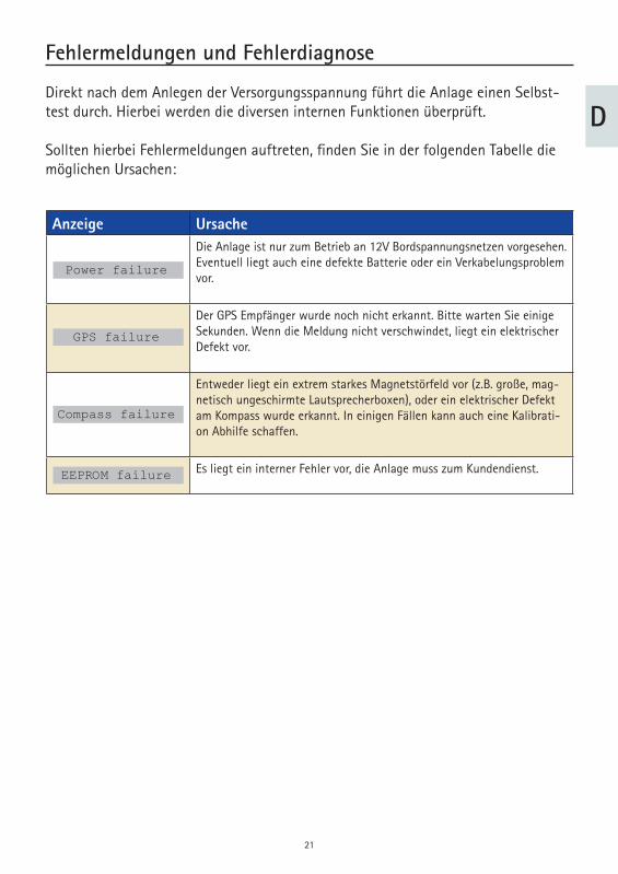
Direkt nach dem Anlegen der Versorgungsspannung führt die Anlage einen Selbst-test durch. Hierbei werden die diversen internen Funktionen überprüft.
Sollten hierbei Fehlermeldungen auftreten, fi nden Sie in der folgenden Tabelle die möglichen Ursachen:
Anzeige UrsacheDie Anlage ist nur zum Betrieb an 12V Bordspannungsnetzen vorgesehen.Eventuell liegt auch eine defekte Batterie oder ein Verkabelungsproblem vor.
Der GPS Empfänger wurde noch nicht erkannt. Bitte warten Sie einige Sekunden. Wenn die Meldung nicht verschwindet, liegt ein elektrischer Defekt vor.
Entweder liegt ein extrem starkes Magnetstörfeld vor (z.B. große, mag-netisch ungeschirmte Lautsprecherboxen), oder ein elektrischer Defekt am Kompass wurde erkannt. In einigen Fällen kann auch eine Kalibrati-on Abhilfe schaffen.
Es liegt ein interner Fehler vor, die Anlage muss zum Kundendienst.
GPS failure
Power failure
Compass failure
EEPROM failure
D
22
Demontage der Anlage
Für die Demontage der Außeneinheit benötigen Sie zusätzlich einen Gabelschlüssel SW 10.
Es ist nicht notwendig die Zuleitung zu demontieren.
Gehen Sie wie folgt vor:
Lösen Sie die vier Muttern M8, welche die Grundplatte mit der Montageplatte verbinden. Dann heben Sie die Anlage ab. Lösen Sie die vier Muttern M6 am Abdeckblech unterhalb des kleinen weißen Steckergehäuses und ziehen Sie das Abdeckblech heraus. Lösen Sie die Steckverbindung des Daten- und des Stromkabels durch Drehen gegen den Uhrzeigersinn an den Steckern der Zuleitung. Lösen Sie die Steckverbindung des Sat-Kabels durch Drehen gegen den Uhrzeigersinn an dem Stecker des Koax-Kabels der Zuleitung. Jetzt können Sie die Anlage entfernen.
Um die Anlage wieder zu montieren gehen Sie in der umgekehrten Reihenfolge vor.
D
23
Hinweise zum Umweltschutz
Dieses Produkt darf am Ende seiner Lebensdauer nicht über den normalen Haushaltsabfall entsorgt werden, sondern muss an einem Sammelpunkt für das Recycling von elektrischen und elektronischen Geräten abgegeben werden. Das Symbol auf dem Produkt, der Ge-brauchsanleitung oder der Verpackung weist darauf hin.
Die Werkstoffe sind gemäß ihrer Kennzeichnung wiederverwertbar. Mit der Wieder-verwertung, der stoffl ichen Verwertung oder anderen Formen der Verwertung von Altgeräten leisten Sie einen wichtigen Beitrag zum Schutze unserer Umwelt. Bitte erfragen Sie bei der Gemeindeverwaltung die zuständige Entsorgungsstelle.
Altfahrzeugverordnung - ELVDer Receiver ist als Zubehör zur Verwendung auf Kraftfahrzeugen zertifi ziert und vorgesehen. Die Entsorgung kann demgemäß im Rahmen der Altfahrzeug-Verord-nung (Europäische Altfahrzeugrichtlinie ELV, 2000/ 53/EG; für Deutschland: Altfahr-zeugV) zusammen mit dem Kraftfahrzeug erfolgen. Der Receiver enthält keine der gemäß Richtlinie als umweltschädlich eingestuften Stoffe.
Abschließend wünschen wir Ihnen viel Freude mit Ihrem neuen ten Haaft Produkt!

English E
24
25
E
Table of contents
Proper use and operation 26 Scope of supply 27 Installation preparation 28 Step 1: Installing the mounting plate 30 Step 2: Locating the external unit 31 Step 3: Confi guration of Solara SR 135 charge controller 33 Step 4: Power supply 35 Step 5: Initial operation 38 Step 6: Installation of the solar panel 39 Step 7: Calibration 40 Fault messages and fault diagnosis 42 Removal of the system 43 Notes on the protection of the environment 44 Patterns 66
26
E
Proper use and operation
This product has been designed for use in a fi xed installation on mobile homes or camper trailers with maximum speeds of 130 km/h. The system is intended for the purpose of charging the rechargeable battery/batteries installed in the vehicle. The-se batteries must be standard commercially available batteries with a voltage rating of 12 V (6 cells) and a rated capacity of at least 50 Ah.
Use of the equipment for any other purpose than the one specifi ed is not permitted.
Please also note the following instructions from the manufacturer:
It is not permitted to change the overall device by removing or adding individual components. Installation must only be performed by suffi ciently qualifi ed personnel. All instructions in these Installation Instructions, which form part of the Operating Instructions, must be carefully followed. All of the relevant and approved guidelines of the automotive industry must be observed and complied with. The equipment must only be installed on hard vehicle roofs which are suffi ciently strong and inherently stable. The product does not require any regular maintenance. All housings and enclosures must not be opened. Any maintenance work must be carried out a qualifi ed professional. In the event of any problems, or if you are unsure about anything, please contact the manufacturer directly or a specialist workshop which is approved by the manufacturer. The two lines supplying solar power (black, yellow) MUST NEVER be connected directly to the battery. The retrofi tting of this product may increase the total height of the vehicle. The installer is obliged to provide detailed information about any change of vehicle height to the commissioner or vehicle owner.
27
E
Scope of supply
Your system is supplied with the following items:
Control panel External unit with mounting plate Solar module Fastener package Wiring harness to external unit Operating Instructions Installation instructions Charge controller Information about disposal of packaging
Packaging and packaging materials can be recycled. Please observe the applicable legislation in your country governing recycling and your duty to dispose of recyclab-le waste in the proper way.Keep packaging materials such as plastic bags away from children.
28
E
Installation preparation
1. Preparation
Before starting the installation, ensure that the roof of your vehicle is suffi ciently sturdy. Ensure that the permissible roof load of your vehicle is not exceeded when installing the system and accessing the roof.
If the roof is not strong enough, or if you are in any doubt, attach a sheet-metal panel (approx. 3 mm thick, 100 x 100 cm) to the outer skin of the roof to improve the roof stability. Check with the vehicle manufacturer.
For installation of the system you will need a 13 mm spanner, a 27 mm spanner, a large Phillips screwdriver, a 3 mm fl at-blade screwdriver, a drill with a 20 mm drill bit or milling head, a cutter (e.g. carpet knife), a pair of nipper pliers, industrial cleaner for cleaning the mounting plate and a cartridge of strongly adhesive body sealing compound (e.g. Sikafl ex).
2. Space requirements for the external unit
Make sure that there is enough space for the system when it is folded down and for the action radius (pivoting radius).
When selecting an installation location, ensure that no larger metal parts (e.g. pro-tection bars, roll bars, etc.) and no components that may generate magnetic fi elds (e.g. loudspeakers, fan motors, etc.) are in the direct vicinity of the system (radius of approx. 75 cm) as these may affect the compass function.
Once you are sure that the roof is sturdy enough, or you have undertaken the necessary measures for safe installation, position the external unit with mounting plate temporarily on the designated installation position.
Use the diagram below to check that there are no obstructions within the specifi ed area.
29
E
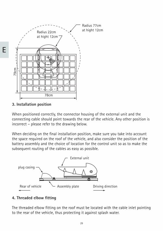
Radius 77cmat hight 12cmRadius 22cm
at hight 12cm
78cm
79cm
3. Installation position
When positioned correctly, the connector housing of the external unit and the connecting cable should point towards the rear of the vehicle. Any other position is incorrect – please refer to the drawing below.
When deciding on the fi nal installation position, make sure you take into account the space required on the roof of the vehicle, and also consider the position of the battery assembly and the choice of location for the control unit so as to make the subsequent routing of the cables as easy as possible.
External unit
Driving directionRear of vehicle Assembly plate
plug casing
4. Threaded elbow fi tting
The threaded elbow fi tting on the roof must be located with the cable inlet pointing to the rear of the vehicle, thus protecting it against splash water.
30
E
Step 1: Installing the mounting plate
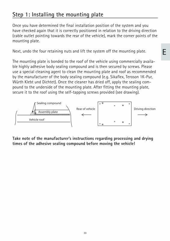
Once you have determined the fi nal installation position of the system and you have checked again that it is correctly positioned in relation to the driving direction (cable outlet pointing towards the rear of the vehicle), mark the corner points of the mounting plate.
Next, undo the four retaining nuts and lift the system off the mounting plate.
The mounting plate is bonded to the roof of the vehicle using commercially availa-ble highly adhesive body sealing compound and is then secured by screws. Please use a special cleaning agent to clean the mounting plate and roof as recommended by the manufacturer of the body sealing compound (e.g. Sikafl ex, Teroson 1K-Pur, Würth Klebt und Dichtet). Once the cleaner has dried off, apply the sealing com-pound to the underside of the mounting plate. After fi tting the mounting plate, secure it to the roof using the self-tapping screws provided (see drawing).
Take note of the manufacturer’s instructions regarding processing and drying times of the adhesive sealing compound before moving the vehicle!
Vehicle roof
Assembly plate
Sealing compound
Rear of vehicle Driving direction
31
E
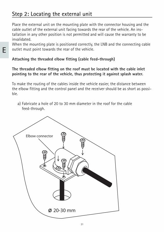
Step 2: Locating the external unit
Place the external unit on the mounting plate with the connector housing and the cable outlet of the external unit facing towards the rear of the vehicle. An ins-tallation in any other position is not permitted and will cause the warranty to be invalidated. When the mounting plate is positioned correctly, the LNB and the connecting cable outlet must point towards the rear of the vehicle.
Attaching the threaded elbow fi tting (cable feed-through)
The threaded elbow fi tting on the roof must be located with the cable inlet pointing to the rear of the vehicle, thus protecting it against splash water.
To make the routing of the cables inside the vehicle easier, the distance between the elbow fi tting and the control panel and the receiver should be as short as possi-ble.
a) Fabricate a hole of 20 to 30 mm diameter in the roof for the cable feed-through.
Elbow connector
ø 20-30 mm
32
E
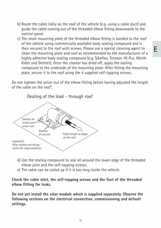
b) Route the cable tidily on the roof of the vehicle (e.g. using a cable duct) and guide the cable coming out of the threaded elbow fi tting downwards to the control panel. c) The small mounting plate of the threaded elbow fi tting is bonded to the roof of the vehicle using commercially available body sealing compound and is then secured to the roof with screws. Please use a special cleaning agent to clean the mounting plate and roof as recommended by the manufacturer of a highly adhesive body sealing compound (e.g. Sikafl ex, Teroson 1K-Pur, Würth Klebt und Dichtet). Once the cleaner has dried off, apply the sealing compound to the underside of the mounting plate. After fi tting the mounting plate, secure it to the roof using the 4 supplied self-tapping screws.
Do not tighten the union nut of the elbow fi tting before having adjusted the length of the cable on the roof*.
Dealing of the lead - through roof
Important:After sealing and drying -verify the impermeability!
*Cabel length to adapt on the roof
Sikaflexall around
Sikaflex onscrews andscrew nuts
d) Use the sealing compound to seal all around the lower edge of the threaded elbow joint and the self-tapping screws. e) The cable can be coiled up if it is too long inside the vehicle.
Check the cable inlet, the self-tapping screws and the foot of the threaded elbow fi tting for leaks.
Do not yet install the solar module which is supplied separately. Observe the following sections on the electrical connection, commissioning and default settings.
33
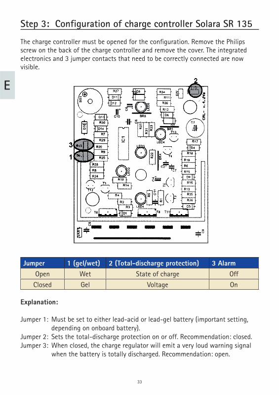
Step 3: Configuration of charge controller Solara SR 135
The charge controller must be opened for the confi guration. Remove the Philips screw on the back of the charge controller and remove the cover. The integrated electronics and 3 jumper contacts that need to be correctly connected are now visible.
Jumper 1 (gel/wet) 2 (Total-discharge protection) 3 Alarm Open Wet State of charge Off
Closed Gel Voltage On
Explanation:
Jumper 1: Must be set to either lead-acid or lead-gel battery (important setting, depending on onboard battery). Jumper 2: Sets the total-discharge protection on or off. Recommendation: closed. Jumper 3: When closed, the charge regulator will emit a very loud warning signal when the battery is totally discharged. Recommendation: open.
E
34
Example: The vehicle is equipped with a lead-gel battery. The battery‘s voltage is monitored by the total-discharge protection function. If no signal shall sound in the event of a total discharge:
Brücke 1: closedBrücke 2: closedBrücke 3: Open(Please see the product information sheet in the package of the Solara SR 135 charge controller for more details.)
Install the charge controller near the battery, if possible, using the two screws.The connections to the onboard electric system are now complete.
E
35
E
Step 4: Power supply
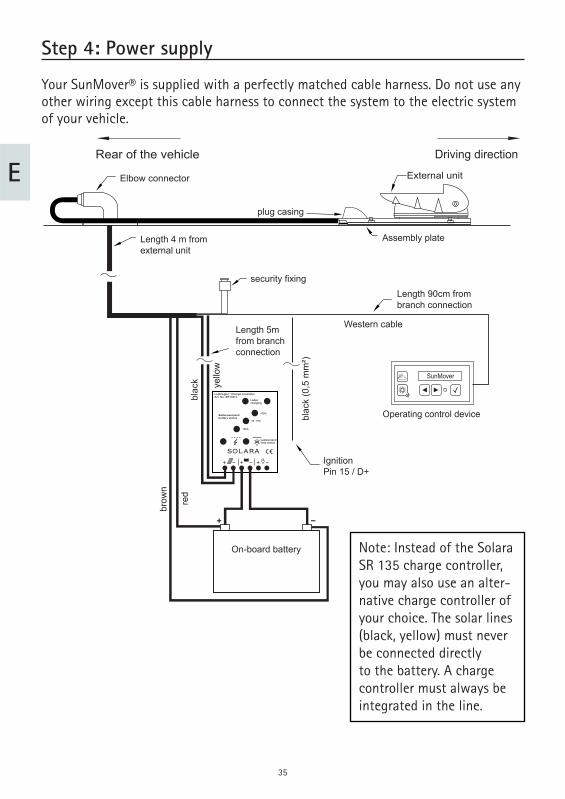
Your SunMover® is supplied with a perfectly matched cable harness. Do not use any other wiring except this cable harness to connect the system to the electric system of your vehicle.
SunMover
Driving direction
External unit
Assembly plate
plug casing
IgnitionPin 15 / D+
Length 4 m fromexternal unit
security fixing
Length 5m from branch connection
blac
k (0
,5 m
m²)
yello
w
blac
k
brow
n
red
On-board battery
Length 90cm from branch connection
Western cable
Operating control device
Elbow connector
Rear of the vehicle
Laderegler / Charge controllerArt. No. SR135TL
Ladencharging
Batteriezustandbattery status
>75%
25 - 75%
<25%
Lastzustandload status
SOLARA
Note: Instead of the Solara SR 135 charge controller, you may also use an alter-native charge controller of your choice. The solar lines (black, yellow) must never be connected directly to the battery. A charge controller must always be integrated in the line.
36
E
First connect the branch of the wiring harness to the control panel. The ‚Western‘ jack (RJ11 connector) must engage in the control panel with an audible click that can also be felt.
The black cable which comes out from the cable branch next to the Western jack-cable needs to be connected to the ignition circuit at terminal 15 or D+. These cir-cuits carry voltage when the ignition is on, and carry no voltage when the ignition is off. This cable controls some important functions of your SunMover®, hence the correct connection of this cable must be ensured. You can either route this cable in the interior, for example to an existing entry-step control system or to a refrigerator with a corresponding changeover contact, and connect it there. You can also route the cable together with the battery connection/charging cable to the underfl oor area, where you can connect it at a suitable point to an existing ignition-signal line.
Caution: It is absolutely essential that the system is connected via the black cable (0.5 mm²) to K15 or D+ of the electric system of your vehicle.
All 5 cables that must be connected to the onboard electric system (2.5 mm²: red, brown, yellow, black / 0.5 mm²: black) may be shortened to length.
There are two contacts at the cable branch which need to be plugged into the enc-losed black plastic fuse holder. Ensure that the cable ends click audibly as they latch in the holder.
Then fi t the enclosed 10-A fuse.Next you need to connect the battery connection/charging cable directly to the onboard/auxiliary battery.
Caution: Always connect the red and the brown cable of your SunMover® di-rectly to the terminals of the onboard/auxiliary battery – never downstream of any auxiliary equipment. You must also never connect your SunMover® to the starter battery.
37
E
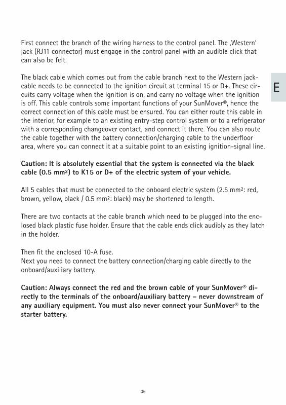
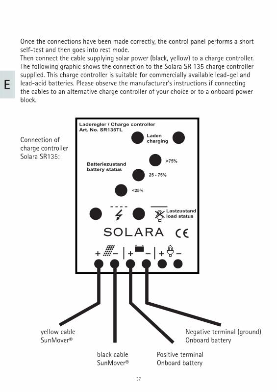
Once the connections have been made correctly, the control panel performs a short self-test and then goes into rest mode.Then connect the cable supplying solar power (black, yellow) to a charge controller. The following graphic shows the connection to the Solara SR 135 charge controller supplied. This charge controller is suitable for commercially available lead-gel and lead-acid batteries. Please observe the manufacturer‘s instructions if connecting the cables to an alternative charge controller of your choice or to a onboard power block.
Connection of charge controller Solara SR135:
yellow cableSunMover®
black cableSunMover®
Positive terminal Onboard battery
Negative terminal (ground)Onboard battery
Laderegler / Charge controllerArt. No. SR135TL
Ladencharging
Batteriezustandbattery status
>75%
25 - 75%
<25%
Lastzustandload status
SOLARA
38
E
Step 5: Initial operation
Once all the installation work has been carried out and all of the electrical connec-tions have been made (apart from the installation of the solar panel), the system is ready to be switched on for the fi rst time.
If the microprocessor discovered a fault during the automatic self-test after con-nection of the SunMover® to the battery, this will be shown on the display of the control panel. If no fault was discovered then the system will have switched off again automatically. Please refer to the information in section „Error messages and fault diagnosis“ on page 20 if any error messages are displayed.
You can now activate the system by pressing on the control panel. Before the system opens, the integrated GPS receiver usually determines the current position and time. This is indicated on the control panel with the message „Clock sync wait“, which may take several minutes. To move the system immediately into the position required for installation of the solar panel, press and on the control panel at the same time. The holding arm will then move into the vertical assembly position.
While „Clock sync wait“ is being displayed, press and on the control panel at the same time to move the holding arm into the vertical assembly position. Make sure there is enough space above the vehicle!
Operation of the system is explained in detail in the supplied Operating Instructions.
39
E
Step 6 : Installation of the solar panel
Place the solar panel onto the two white arms and secure it with the 6 enclosed M8 bolts and lock washers. As the bolts have different lengths, please make sure that the longest bolt is at the bottom and the shortest is at the top. Afterwards, open the black housing on the rear of the solar panel using a narrow fl at screwdriver to press in the tabs. Then guide the double cable from the external unit fi rst through the bores of the rectangular tube and then through the screwed connection into the black cable box of the solar panel. Make sure that the insulating tubing is also guided into the screwed connection.
Inside the terminal box, connect the red positive cable to the opening marked „ + „ and the brown negative cable to the opening marked „ – „. To make the connection, fi rmly press down the terminals using a small screwdriver and insert the wire ends into the opening. Gently pull on the cable to make sure that the wire ends are secu-rely connected. Then press the cover back on and tighten the plastic nut.
Secure the double cable directly behind the rectangular tube using the enclosed cable tie so that the cable cannot be trapped or pulled out of the housing in any position of the solar panel.Once you have installed and connected the solar panel, you can either press the to close down the system or press key to activate solar mode.
Now you should test the safety function:
Switch the system on and wait until the solar panel has reached the correct positi-on.
Switch on the vehicle ignition.
Verify by visual check that the external unit retracts.
Your system is now almost ready for operation. All you need to do now is calibrate the internal compass.
40
E
Step 7: Calibration
Your SunMover® also uses an electronic compass sensor to keep the solar module correctly aligned towards the sun at all times. This sensor has been calibrated at the factory, so the system should work without problems in most cases. However, motor vehicles often exert a certain infl uence on the function of the compass sensor by slightly distorting the geomagnetic fi eld.
Your system uses an automatic calibration routine to continuously adapt to any changes in conditions. This means that when the system is in normal operating mode, you can always rely on the solar panel being correctly aligned towards the sun. However, it is completely impossible to anticipate the magnitude of any exter-nal infl uence on the system in every specifi c case. We therefore recommend that a one-off calibration of the system is performed after installation. In cases where the system detects a strong external infl uence, this calibration will be expressly reques-ted by the microprocessor.
The actual calibration is performed by slowly and steadily driving two complete circles with your vehicle. The system then determines the external infl uences for subsequently compensation.
To perform the calibration you will need a large enough open space where you can perform the manoeuvre without disturbing or obstructing other road users.
To perform the calibration, start the vehicle in a suitable place. The control panel should now display the .
Now press repeatedly until the message is shown in the display. You can now start the calibration mode by pressing and at the same time. The message is displayed as confi rmation.
Next, slowly complete 2 full circles with the vehicle. It does not matter whether you do this clockwise or anti-clockwise. However, it is important that the circles are smooth, with no zigzagging. The calibration is complete after two circles, after which the system automatically exits the calibration mode.
Ignition on
CAL x/y:.....
CALIBRATE
41
E
The display should now show the message . In this case, everything is in order and your SunMover® has adapted itself to the conditions in your vehicle.
If the message is displayed in control panel, repeat the pro-cedure as the microprocessor was not able to obtain the required data. A second attempt will almost certainly remedy this.
If the message is displayed, you should also repeat the pro-cedure. If the same fault message is displayed again, then it is possible that your vehicle is exerting a very strong magnetic infl uence on the system on your vehicle‘s roof. If this is the case a reliable operation of the system cannot be ensured. Check whether there are any powerful magnets or magnetic fi elds close to the installation location, and remove such infl uences if possible. Afterwards it should be possible to perform the calibration without further diffi culties. Don’t forget that the magnetic parts must not be put back again after calibration!
In addition to the calibration procedure described above, your SunMover® also uses an automatic, self-learning calibration routine.
The automatic calibration of the electronic compass takes place while driving. You will not need to intervene in this process in any way. However, please also note that, of course, newly installed systems cannot run an automatic calibration process as such a process is highly vehicle-specifi c. This means that you will need to take the system on a few journeys before the calibration process is optimised. The worst thing that can happen if the calibration process is incomplete is that your SunMo-ver® might be slightly misaligned with the sun when it is opened. If this happens, it will only be out by a few degrees, and you can correct this in individual cases via the manual orientation correction function (see Operating Instructions).
The system is now ready for operation.
CALIBRATION OK
CAL ERROR
LIMIT ERROR
42
E
Fault messages and fault diagnosis
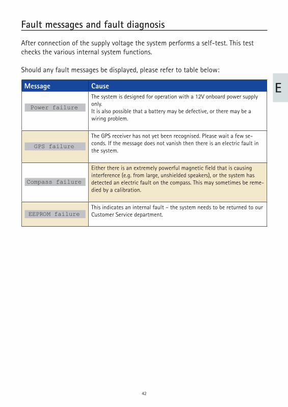
After connection of the supply voltage the system performs a self-test. This test checks the various internal system functions.
Should any fault messages be displayed, please refer to table below:
Message CauseThe system is designed for operation with a 12V onboard power supply only.It is also possible that a battery may be defective, or there may be a wiring problem.
The GPS receiver has not yet been recognised. Please wait a few se-conds. If the message does not vanish then there is an electric fault in the system.
Either there is an extremely powerful magnetic fi eld that is causing interference (e.g. from large, unshielded speakers), or the system has detected an electric fault on the compass. This may sometimes be reme-died by a calibration.
This indicates an internal fault – the system needs to be returned to our Customer Service department.
GPS failure
Power failure
Compass failure
EEPROM failure
43
E
Removal of the system
The removal of the exterior unit requires a 10-mm open-end spanner.
The supply line does not need to be removed.
Proceed as follows:
Undo the four M8 nuts securing the base plate to the mounting plate. Lift off the system. Remove the four M6 nuts at the cover panel below the small white connector housing and pull out the cover panel. Disconnect the data and power cables by rotating the supply line connectors counter-clockwise. Disconnect the satellite cable by rotating the connector counter-clockwise. The system can now be removed.
To reinstall the unit, perform the steps above in reversed order.
44
E
Notes on the protection of the environment
At the end of its lifecycle, this product must not be disposed of with your normal waste, but instead must be returned to a recycling facility for electric and electronic devices. This is indicated by the symbol on the product, the operating manual or the packaging.
The materials can be reused in accordance with their identifi cation. By reusing or recycling old equipment or making use of it in other ways you are making an impor-tant contribution to protecting our environment. Please contact your local council to fi nd out where your nearest disposal facility is.
EC End-of-Life Vehicle DirectiveThe receiver is certifi ed and intended for use as an accessory of a motor vehicle. The system may be disposed of together with the vehicle in accordance with the End-of-Life Vehicle Directive ELV, 2000/53/EC. The receiver does not contain any materi-als rated as hazardous to the environment according to the directive.
We hope you get a lot of enjoyment out of your new ten Haaft product!
45
Français F
46
F
Table des matières
Utilisation conforme à la destination 47 Volume de la livraison 48 Préparation du montage 49 Pas 1 : Monter la plaque de fi xation 51 Pas 2 : Mise en place du système 52 Pas 3 : Confi guration de régulateur charge Solara SR 135 54 Pas 4 : Alimentation électrique 56 Pas 5 : Première mise en service 59 Pas 6 : Montage du panneau solaire 60 Pas 7: Calibration 61 Messages d’erreur et diagnostic des anomalies 63 Démontage du système 64 Consignes sur la protection de l´environnement 65 Modèles 66
47
F
Utilisation conforme à la destination
L’utilisation conforme à la destination de ce produit est un montage fi xe sur un camping car ou une caravane dont la vitesse ne doit pas dépasser 130 km/h en vue de charger les batteries (accumulateurs rechargeables) montées dans le véhicule. Il doit s’agir d’accumulateurs au plomb ou au gel de plomb du commerce d‘une tensi-on nominale de 12 V (6 éléments) et d’une capacité nominale d‘au moins 50 Ah.
Lorsque le véhicule porteur est en stationnement, le produit est capable d’orienter automatiquement l’antenne parabolique intégrée vers un des satellites géostation-naires européens de diffusion directe de télévision. Toute utilisation autre que défi nie ci-dessus est interdite.
Veuillez également observer les consignes suivantes du fabricant :
Evitez de laver votre camping-car dans un tunnel de lavage, dans une station de lavage à brosses ou au karcher. En cas de vent ou de tempête, n´oubliez pas de refermer votre antenne. l´utilisation d´autres composants que ceux d´origine est interdite. L’appareil dans son ensemble ne doit pas être modifi é par suppression de composants individuels ou ajout d’autres composants. Les directives afférentes reconnues par le secteur automobile doivent être observées. Le montage n’est autorisé que sur des toits de véhicules rigides et présentant une résistance et une stabilité de forme suffi santes. Le produit ne nécessite aucun entretien régulier. Ne pas ouvrir les boîtiers. Faites toujours effectuer les opérations de vérifi cation par un technicien qualifi é. En cas de doute ou de problème, veuillez vous adresser au fabricant ou à un atelier spécialisé agréé par le fabricant. Ne branchez JAMAIS les deux câbles (noir/jaune) qui fournissent de l´electricité solaire direcetement sur la batterie. Il est possible que l´installation de ce produit fasse augmenter la hauteur totale de votre véhicule. Dans ce cas, la maison qui se sera occupée du montage devra informer le client dans les moindres détails de cette modifi cation.
48
F
Volume de la livraison
Ce que vous devriez avoir devant vous :
Boîtier de commande Unité extérieure avec module solaire prémonté et antenne parabolique Plaque de fi xation Jeu de vis Faisceau de câblage allant à l’unité extérieure Instructions d’utilisation Instructions de montage Régulateur de charge
Instructions concernant l’élimination des emballages:
Les emballages et matériaux d’emballage sont recyclables et doivent être soumis à la valorisation matières.Ne pas laisser les matériaux d’emballage comme des sacs en plastique. à la portée des enfants.
49
F
Préparation du montage
1. Préparation du montage
Avant de commencer le montage veuillez vous assurer de la stabilité de votre toit. Surtout en montant dessus, veillez à ne pas dépasser la charge autorisée.
Si vous doutez de la stabilité du toit, vous pourrez fi xer une tôle de 100 X 100 et de 3 mm d´épaisseur sur le panneau extérieur. Veuillez vous renseigner auprès du constructeur du véhicule.
Pour le montage du système, vous aurez besoin de clés à fourche de 13 et 27 mm, d’un gros tournevis cruciforme, d’un foret ou d’une fraise de 20 mm de diamèt-re, d’une perceuse, d’un cutter, d’un tournevis à lame plate de 3 mm, de tenailles, d’un nettoyant industriel pour le nettoyage de la plaque de fi xation et d’un adhésif d’étanchéité de carrosserie à fort pouvoir adhésif (ex : Sikafl ex).
2. Encombrement de la SunMover®
Il est important qu´il y ait assez de place lorsque l´antenne est refermée, mais aussi pour le rayon de rotation.
En choisissant l´endroit du montage il faudra faire particulièrement attention à ce qu´ il n´y ait ni grosse pièce en métal à proximité (ex arceaux de sécurité), ni pièces pouvant produire des champs magnétiques (ex hauts-parleur, moteurs d´aération) près de l´antenne (dans un rayon d´au moins 75 cm). Cela brouillerait la fonction de la boussole.
Une fois que tous les doutes concernant la stabilité du toit ont été éliminés et que toutes les mesures nécessaires ont été prises pour un montage correct, positionnez provisoirement l’unité extérieure avec sa plaque de fi xation sur l’emplacement prévu à cet effet.
50
F
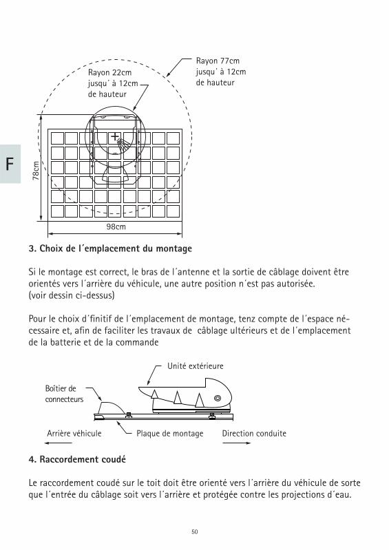
Rayon 77cmjusqu´ à 12cmde hauteur
Rayon 22cmjusqu´ à 12cmde hauteur
98cm
78cm
3. Choix de l´emplacement du montage
Si le montage est correct, le bras de l´antenne et la sortie de câblage doivent être orientés vers l´arrière du véhicule, une autre position n´est pas autorisée.(voir dessin ci-dessus)
Pour le choix d´fi nitif de l´emplacement de montage, tenz compte de l´espace né-cessaire et, afi n de faciliter les travaux de câblage ultérieurs et de l´emplacement de la batterie et de la commande
Unité extérieure
Direction conduiteArrière véhicule Plaque de montage
Boîtier de connecteurs
4. Raccordement coudé
Le raccordement coudé sur le toit doit être orienté vers l´arrière du véhicule de sorte que l´entrée du câblage soit vers l´arrière et protégée contre les projections d´eau.
51
F
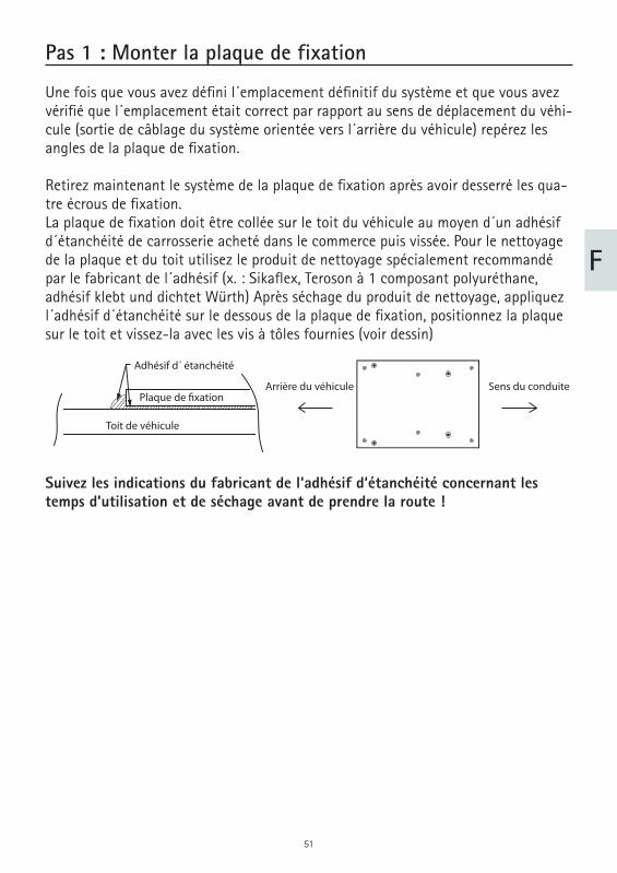
Pas 1 : Monter la plaque de fixation
Une fois que vous avez défi ni l´emplacement défi nitif du système et que vous avez vérifi é que l´emplacement était correct par rapport au sens de déplacement du véhi-cule (sortie de câblage du système orientée vers l´arrière du véhicule) repérez les angles de la plaque de fi xation.
Retirez maintenant le système de la plaque de fi xation après avoir desserré les qua-tre écrous de fi xation.La plaque de fi xation doit être collée sur le toit du véhicule au moyen d´un adhésif d´étanchéité de carrosserie acheté dans le commerce puis vissée. Pour le nettoyage de la plaque et du toit utilisez le produit de nettoyage spécialement recommandé par le fabricant de l´adhésif (x. : Sikafl ex, Teroson à 1 composant polyuréthane, adhésif klebt und dichtet Würth) Après séchage du produit de nettoyage, appliquez l´adhésif d´étanchéité sur le dessous de la plaque de fi xation, positionnez la plaque sur le toit et vissez-la avec les vis à tôles fournies (voir dessin)
Suivez les indications du fabricant de l‘adhésif d‘étanchéité concernant les temps d’utilisation et de séchage avant de prendre la route !
Toit de véhicule
Plaque de fixation
Adhésif d´ étanchéité
Arrière du véhicule Sens du conduite
52
F
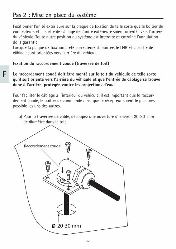
Pas 2 : Mise en place du système
Positionner l’unité extérieure sur la plaque de fi xation de telle sorte que le boîtier de connecteurs et la sortie de câblage de l‘unité extérieure soient orientés vers l‘arrière du véhicule. Toute autre position du système est interdite et entraîne l’annulation de la garantie. Lorsque la plaque de fi xation a été correctement montée, le LNB et la sortie de câblage sont orientées vers l‘arrière du véhicule.
Fixation du raccordement coudé (traversée de toit)
Le raccordement coudé doit être monté sur le toit du véhicule de telle sorte qu’il soit orienté vers l’arrière du véhicule et que l’entrée de câblage se trouve donc à l‘arrière, protégée contre les projections d‘eau.
Pour faciliter le câblage à l´intérieur du véhicule, il est important que le raccor-dement coudé, le boîtier de commande ainsi que le récepteur soient le plus près possible les uns des autres.
a) Pour la traversée de câble, découpez une ouverture d’ environ 20-30 mm de diamètre dans le toit.
Raccordement coudé
ø 20-30 mm
53
F
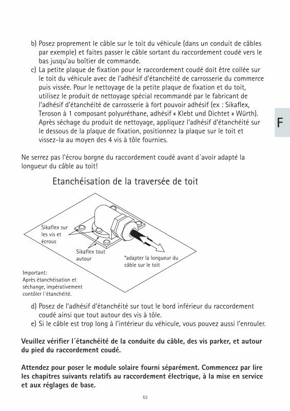
b) Posez proprement le câble sur le toit du véhicule (dans un conduit de câbles par exemple) et faites passer le câble sortant du raccordement coudé vers le bas jusqu’au boîtier de commande. c) La petite plaque de fi xation pour le raccordement coudé doit être collée sur le toit du véhicule avec de l’adhésif d’étanchéité de carrosserie du commerce puis vissée. Pour le nettoyage de la petite plaque de fi xation et du toit, utilisez le produit de nettoyage spécial recommandé par le fabricant de l’adhésif d’étanchéité de carrosserie à fort pouvoir adhésif (ex : Sikafl ex, Teroson à 1 composant polyuréthane, adhésif « Klebt und Dichtet » Würth). Après séchage du produit de nettoyage, appliquez l’adhésif d’étanchéité sur le dessous de la plaque de fi xation, positionnez la plaque sur le toit et vissez-la au moyen des 4 vis à tôle fournies.
Ne serrez pas l’écrou borgne du raccordement coudé avant d´avoir adapté la longueur du câble au toit!
Etanchéisation de la traversée de toit
Important:Après étanchéisation etséchange, impérativementcontôler l´étanchéité.
*adapter la longueur du câble sur le toit
Sikaflex toutautour
Sikaflex surles vis etécrous
d) Posez de l’adhésif d’étanchéité sur tout le bord inférieur du raccordement coudé ainsi que tout autour des vis à tôle. e) Si le câble est trop long à l’intérieur du véhicule, vous pouvez aussi l’enrouler.
Veuillez vérifi er l´étanchéité de la conduite du câble, des vis parker, et autour du pied du raccordement coudé.
Attendez pour poser le module solaire fourni séparément. Commencez par lire les chapitres suivants relatifs au raccordement électrique, à la mise en service et aux réglages de base.
54
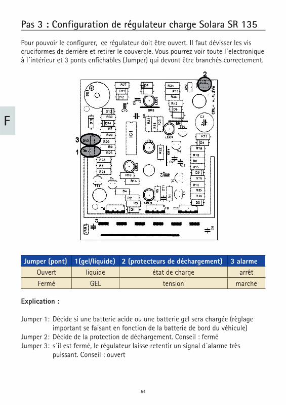
Pas 3 : Configuration de régulateur charge Solara SR 135
Pour pouvoir le confi gurer, ce régulateur doit être ouvert. Il faut dévisser les vis cruciformes de derrière et retirer le couvercle. Vous pourrez voir toute l´electronique à l´intérieur et 3 ponts enfi chables (Jumper) qui devont être branchés correctement.
Jumper (pont) 1(gel/liquide) 2 (protecteurs de déchargement) 3 alarmeOuvert liquide état de charge arrêt
Fermé GEL tension marche
Explication :
Jumper 1: Décide si une batterie acide ou une batterie gel sera chargée (règlage important se faisant en fonction de la batterie de bord du véhicule) Jumper 2: Décide de la protection de déchargement. Conseil : fermé Jumper 3: s´il est fermé, le régulateur laisse retentir un signal d´alarme très puissant. Conseil : ouvert
F
55
Exemple: Nous avons une batterie gel dans le véhicule. Le protecteur de décharge surveille la tension de la batterie. On ne devra pas entendre de signal en cas de déchargement :
Pont 1: ferméPont 2: ferméPont 3: ouvert(une description détaillée du régulateur Solara SR 135 se trouve en supplément de son emballage)
Fixer le régulateur avec deux vis et de préférence à proximité de la batterieLe travail de connexion sur le résaeu de bord est ainsi terminé.
F
56
F
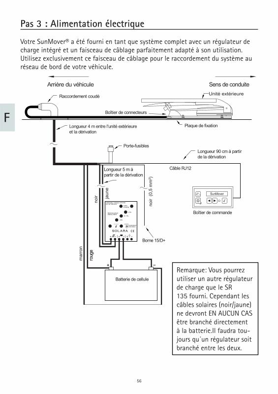
Pas 3 : Alimentation électrique
Votre SunMover® a été fourni en tant que système complet avec un régulateur de charge intégré et un faisceau de câblage parfaitement adapté à son utilisation. Utilisez exclusivement ce faisceau de câblage pour le raccordement du système au réseau de bord de votre véhicule.
Sens de conduiteUnité extérieure
Plaque de fixation
Boîtier de connecteurs
Longueur 4 m entre l'unité extérieureet la dérivation
Porte-fusibles
Longueur 5 m à partir de la dérivation
noir
(0,5
mm
²)
jaun
e
noir
mar
ron
roug
e
Batterie de cellule
Longueur 90 cm à partir de la dérivation
Câble RJ12
Boîtier de commande
Borne 15/D+
Raccordement coudé
Arrière du véhicule
Laderegler / Charge controllerArt. No. SR135TL
Ladencharging
Batteriezustandbattery status
>75%
25 - 75%
<25%
Lastzustandload status
SOLARA
SunMover
Remarque: Vous pourrezutiliser un autre régulateurde charge que le SR135 fourni. Cependant lescâbles solaires (noir/jaune)ne devront EN AUCUN CASêtre branché directementà la batterie.Il faudra tou-jours qu´un régulateur soitbranché entre les deux.
57
F
Commencez pas raccorder le boîtier de commande à la dérivation du faisceau de câblage. Le connecteur sur le câble Western (connecteur RJ11) doit s’engager avec un déclic audible et sensible dans le boîtier de commande.
Le fi l noir sortant de la dérivation près du câble Western doit être relié au circuit d‘allumage par la borne 15 ou D+ du réseau de bord. Ces lignes sont sous tension lorsque le contact est établi et hors tension lorsqu’il est coupé. Ce fi l commande quelques fonctions importantes de votre SunMover®, veillez à ce qu’il soit correc-tement raccordé. Vous pouvez connecter ce câble dans l‘habitacle à une commande de marchepieds existante ou à un réfrigérateur avec la commutation appropriée ou le faire passer avec le câble de connexion/charge de batterie sous le plancher et le connecter à l’endroit approprié à un signal d’allumage existant.
Attention: Le raccordement du système au réseau de bord du véhicule doit obligatoirement s’effectuer au moyen du câble noir relié à la borne K15 ou D+.
Tous les 5 câbles qui sont branchés sur le réseau de bord du véhicule (2,5 mm2 rouge-brun-jaune –noir/ 0,5mm2 noir) pourront être raccourcis.
Sur la dérivation se strouvent 2 contacts à fi che qui doivent êtew insérés dans le porte-fusible noir fourni. Les deux extrémités des câbles doivent s´enclencher avec un déclic sonore.
Ensuite mettez le fusible fourni10 A en place.Ensuite, vous devrez procéder au branchement de la batterie connexion/circuit d´alimentation directement à la batterie de la construction/ pièce habitable.
Attention : Branchez toujours directement le câble rouge et le câble brun de votre SunMover® sur les bornes de la batterie de cellule/espace habitable, jamais sur un autre appareil supplémentaire. Ne branchez jamais votre SunMo-ver® dur la batterie de démarrage
58
F
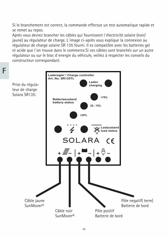
Si le branchement est correct, la commande effectue un test automatique rapide et se remet au repos.Après vous devrez brancher les câbles qui fournissent l´électricité solaire (noir/jaune) au régulateur de charge. L´image ci-après vous explique la connexion au régulateur de charge solaire SR 135 fourni. Il es compatible avec les batteries gel et acide que l´on trouve dans le commerce.Si ces câbles sont branchés sur un autre régulateur ou sur le bloc d´energie du véhicule, veillez à respecter les conseils du constructeur correspondant.
Prise du régula-teur de charge Solara SR135:
Câble jauneSunMover®
Câble noirSunMover®
Pôle positif Batterie de bord
Pôle negatif( terre) Batterie de bord
Laderegler / Charge controllerArt. No. SR135TL
Ladencharging
Batteriezustandbattery status
>75%
25 - 75%
<25%
Lastzustandload status
SOLARA
59
F
Pas 5 : Première mise en service
Une fois effectués tous les travaux de montage et de raccordement (à l’exception de la pose du panneau solaire), le système peut être mis pour la première fois sous tension. Si, après le raccordement du SunMover à la batterie, le microprocesseur détecte une anomalie lors de l’autodiagnostic automatique, celle-ci est signalée surl’écran du boîtier de commande. Si aucune anomalie n’est décelée, le système se met automatiquement hors tension. Si des messages d’erreur sont présents, veuillez vous reporter au chapitre « Messages d’erreur et diagnostic des anomalies ».
Vous pouvez maintenant activer le système en appuyant sur la touche du boîtier de commande. Normalement, avant que le système ne se déploie, le récepteur GPS intégré détermine l’emplacement actuel du véhicule et l’heure. Cette opération est signalée par l’affi chage du message « Synchronisation » sur le boîtier de commande et peut prendre quelques minutes. Pour mettre le système dans la position néces-saire pour la pose du panneau solaire, appuyez maintenant en même temps sur les touches et du boîtier de commande. Le bras de support doit se placer dans la position verticale de montage.
Pendant la « synchronisation », appuyez simultanément sur les touches et du boîtier de commande pour placer le bras de support dans la position verticale de montage. Ce faisant, vérifi ez la hauteur sous plafond requise!
L’utilisation du système est expliquée en détail dans les instructions d‘utilisation fournies. Vous y trouverez aussi des informations détaillées sur le menu principal et le choix de la position de montage.
60
F
Pas 6 : Montage du panneau solaire
Le panneau solaire se pose sur les deux bras blancs à l’aide des 6 vis M8 avec rondelles élastiques bombées fournies. Les vis n’ayant pas toute la même longueur, veillez à utiliser chacune à l’endroit approprié. La vis la plus longue est en bas, la plus courte en haut. Ensuite, ouvrez le boîtier noir au dos du panneau solaire à l’aide d’un tournevis à lame plate étroite en enfonçant les languettes, puis passez le câble à deux conducteurs de l’unité extérieure à travers les trous du tube rectangulaire et à travers le boulonnage dans la boîte de câblage noire sur le panneau solaire. Veillez à ce que le tuyau isolant soit introduit en même temps dans le boulonnage.
Dans le boîtier de raccordement, branchez le câble positif rouge sur l’alvéole mar-quée « + », le câble négatif marron sur celle marquée « -« . Pour ce faire, avec un petit tournevis, poussez fortement sur la borne appropriée tout en insérant le câble dans l’alvéole. Vérifi ez que le câble est correctement branché en tirant dessus. Puis reposez le couvercle et serrez l’écrou en plastique. Avec l‘attache-câble fourni, fi xez le câble à deux conducteurs immédiatement derrière le tube rectangulaire, de telle sorte que le câble ne puisse pas être coincé à toutes les inclinaisons du panneau solaire ou arraché du boîtier. Une fois le panneau solaire posé et branché, vous pouvez replier et mettre hors tension le système en appuyant sur la touche ou activer le mode solaire en appuyant sur la touche .
Ensuite vous devrez vérifi er le circuit de sécurité.
Mettez votre système en marche et attendez que le panneau solaire se soit mis sur la bonne position
Mettez le contact de votre véhicule. Jetez un coup d´oeil sur votre antenne pour vous assurer qu´elle se referme bien.
Votre antenne est pratiquement prête à fonctionner. Imaintenant il faut calibrer le compas interne du système.
61
F
Pas 7: Calibration
Pour pouvoir à tout moment orienter correctement le module solaire vers le soleil, votre SamY Solar+ utilise un capteur compas électronique. Ce capteur a été pré étalonné en usine de sorte que, normalement, le système devrait fonctionner sans problème. Toutefois, les véhicules à moteur ont fréquemment une certaine infl u-ence sur le fonctionnement du capteur compas en déformant légèrement le champ magnétique terrestre.
Votre système utilise une fonction de compensation automatique qui s‘adapte cons-tamment à une éventuelle variation des conditions pour que vous puissiez (en prin-cipe) toujours compter sur la correcte orientation du panneau solaire par rapport au soleil. Toutefois, on ne peut jamais prévoir quelle sera la force de cette infl uence externe sur un système donné. C’est pourquoi nous recommandons d’étalonner le système après le montage. Dans les cas où le système détecte une forte infl uence, la calibration est même demandée explicitement par le microprocesseur.
La calibration proprement dite consiste à faire effectuer deux tours complets, à vitesse lente et régulière, au véhicule. Ceci permet de déterminer les infl uences extérieures et de les compenser correctement par la suite.
Pour pouvoir effectuer la calibration, vous devez disposer d’une surface vide suffi -samment vaste, une aire de retournement par exemple, où vous ne risquez pas de perturber ou d’empêcher la circulation.
Commencez l’opération de calibration en démarrant le moteur dans un endroit approprié. Le boîtier de commande doit maintenant affi cher le message .
Puis appuyez plusieurs fois sur la touche jusqu’à ce que le message apparaisse à l’écran. Enfi n, appuyez simultanément sur les touches et pour activer le mode de calibration, qui est confi rmé par le message (Calibrer).
Ensuite, effectuez deux cercles complets à petite vitesse. Le sens de rotation n’a pas d’importance, l’essentiel est de ne pas suivre une trajectoire sinueuse. Après deux cercles, la calibration est terminée et le système quitte automatiquement le mode de calibration. L’écran doit maintenant affi cher . Dans ce cas, tout est conforme : votre SamY Solar+ s’est adapté aux particularités de votre véhicule.
allumage actif
CAL x/y:.....
CALIBRATE
CALIBRATION OK
62
F
Si le message (Erreur cal) s’affi che sur l’écran du boîtier de commande, vous devez répéter la procédure car le microprocesseur n’a pas pu obtenir les informations nécessaires. Dans la plupart des cas, l’opération réussit au deuxième essai.
Si le message (Erreur limite) s’affi che, répétez également la procédure. Si le même message d‘erreur apparaît, il se peut que votre véhicu-le exerce des infl uences magnétiques très puissantes sur le système sur le toit du véhicule. Dans ce cas, nous ne pouvons pas garantir la fi abilité de fonctionnement du système. Déterminez s’il existe des aimants ou champs magnétiques puissants à proximité de l‘emplacement du système et, le cas échéant, éloignez-les si possible. La calibration ne devrait plus poser de problème. Naturellement, il ne faudra pas reposer les éléments aimantés après la calibration.
La compensation automatique du compas électronique s’effectue pendant la conduite. Aucune intervention n’est requise de votre part. Veuillez toutefois noter que les systèmes nouvellement installés n’ont pas encore pu effectuer de compensation automatique car celle-ci est très spécifi que aux différents véhicules. Il faudra donc quelques trajets avant que la compensation ne soit optimale. Dans le pire des cas, une compensation incomplète peut conduire à ce que le SamY Solar+ ne s’oriente pas parfaitement vers le soleil au déploie-ment, avec un décalage de quelques degrés. Vous pouvez y remédier au cas par cas à l‘aide de la fonction de correction manuelle de l’orientation (se reporter aux instructions d’utilisation).
Le système est prêt à fonctionner.
CAL ERROR
LIMIT ERROR
63
F
Messages d’erreur et diagnostic des anomalies
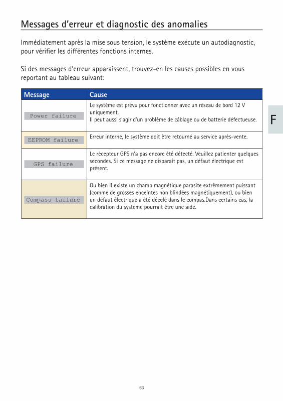
Immédiatement après la mise sous tension, le système exécute un autodiagnostic, pour vérifi er les différentes fonctions internes.
Si des messages d‘erreur apparaissent, trouvez-en les causes possibles en vous reportant au tableau suivant:
Message CauseLe système est prévu pour fonctionner avec un réseau de bord 12 V uniquement.Il peut aussi s’agir d’un problème de câblage ou de batterie défectueuse.
Erreur interne, le système doit être retourné au service après-vente.
Le récepteur GPS n’a pas encore été détecté. Veuillez patienter quelques secondes. Si ce message ne disparaît pas, un défaut électrique est présent.
Ou bien il existe un champ magnétique parasite extrêmement puissant (comme de grosses enceintes non blindées magnétiquement), ou bien un défaut électrique a été décelé dans le compas.Dans certains cas, la calibration du système pourrait être une aide.
GPS failure
Power failure
Compass failure
EEPROM failure
64
F
Démontage du système
Pour démonter l’unité extérieure, vous aurez en plus besoin d’une clé à fourche de 10 mm.
Il n’est pas nécessaire de démonter la ligne d’alimentation.
Procédez comme suit:
Desserrez les quatre écrous M8 qui fi xent la plaque de base sur la plaque de fi xation puis détachez le système. Desserrez les quatre écrous M6 sur le panneau de protection sous le petit boîtier de connecteurs blanc et retirez le panneau. Détachez les connecteurs des câbles de données et d’alimentation en tournant dans le sens contraire des aiguilles d’une montre les connecteurs de la ligne d’alimentation. Détachez le connecteur du câble satellite en tournant dans le sens contraire des aiguilles d’une montre le connecteur du câble coaxial de la ligne d’alimentation. Vous pouvez maintenant retirer le système.
Pour reposer le système, procédez dans l’ordre inverse .
65
F
Consignes sur la protection de l´environnement
Á la fi n de sa vie, ce produit ne devra pas être éliminé avec les déchets ménagers habituels. Il devra être déposé dans un point de collecte spécifi que au recyclage d´appareils électroniques et électriques. C´est ce que signifi e le symbole fi gurant sur le produit, sur l´emballage ou dans le mode d´emploi.
Conformément à leur identifi cation, les matériaux sont récupérables. En procédant à ce recyglage, aini qu ´au recyclage des matières premières ou autre recyclage, vous contribuez de façon importante à la protection de notre environnent. Veuillez demander à la municipalité où se trouve votre point de recyclage.
Les vieux véhicules selon le décret ELVLe récepteur est un accessoire prévu et certifi é pour son utilisation sur les véhicules automobiles. Par conséquent son élimination pourra ce faire dans le cadre du décret correspondant aux vieux véhicules et véhicules automobiles (directives Européen-nes concernant les vieux véhicules ELV2000/53/EG, pour l´Allemagne: vieux véhicu-les).Le récepteur ne contient aucune substance considérée comme dangereuse pour l´environnement.
Pour terminer, nous vous souhaitons un bon divertissement avec votre nouveau produit ten Haaft!
66
67
68
www.ten-haaft.com
ten Haaft GmbH
Oberer Strietweg 8
75245 Neulingen-Göbrichen
GERMANY
Telefon + 49 (0) 72 37 / 48 55– 0
Telefax + 49 (0) 72 37 / 48 55– 50
E-Mail: [email protected]
Öffnungszeiten / hours of opening / temps d‘ouverture :
MO – FR / 08:00 – 12:00 h
LU – VE 13:00 – 16:30 h