Embed Size (px)
Citation preview

1
Identifikations-Systeme BISKompaktauswerteeinheit
BIS M-4_ _-007-...-S115
Handbuch
English – please turn over!
M-4_ _-007-S115_854304_0910_de.p65
2
Nr. 854 304 D/E • Ausgabe 0910Änderungen vorbehalten.Ersetzt Ausgabe 0706.
Balluff GmbHSchurwaldstraße 973765 Neuhausen a.d.F.DeutschlandTel. +49 7158 173-0Fax +49 7158 [email protected] www.balluff.com

3
3deutsch
Inhaltsverzeichnis
Sicherheitshinweise ................................................................................................................... 4Einführung Identifikations-System BIS M-4_ _ ...................................................................... 5/6Basiswissen für die Anwendung Auswerteeinheit BIS M-4_ _ ............................................... 7Konfiguration .........................................................................................................................8-16Programmierinformationen .................................................................................................. 17-29Fehlernummern .................................................................................................................... 30/31Schreib-/Lesezeiten ................................................................................................................. 32Montage RS232 ...................................................................................................................33-42Schnittstelleninformationen RS232.......................................................................................... 43Anschlusspläne RS232 ............................................................................................................ 44Montage RS422 ........................................................................................................................ 45Schnittstelleninformationen RS422.......................................................................................... 46Technische Daten ..................................................................................................................... 47Bestellinformationen ................................................................................................................ 48Zubehör ..................................................................................................................................... 49Symbole / Abkürzungen .......................................................................................................... 50Anhang, ASCII-Tabelle ............................................................................................................. 51
M-4_ _-007-S115_854304_0910_de.p65
4
deutsch4
Sicherheitshinweise
Auswerteeinheiten BIS M-4_ _ bilden zusammen mit den anderen Bausteinen des SystemsBIS M das Identifikations-System und dürfen nur für diese Aufgabe im industriellen Bereichentsprechend Klasse A des EMV-Gesetzes eingesetzt werden.
Installation und Betrieb sind nur durch geschultes Fachpersonal zulässig. Unbefugte Ein-griffe und unsachgemäße Verwendung führen zum Verlust von Garantie- und Haftungsan-sprüchen.
Bei der Installation der Auswerteeinheit sind die Kapitel mit den Anschlußplänen genau zubeachten. Besondere Sorgfalt erfordert der Anschluß der Auswerteeinheit an externe Steue-rungen, speziell bezüglich Auswahl und Polung der Verbindungen und der Stromversor-gung.
Für die Stromversorgung der Auswerteeinheit dürfen nur zugelassene Stromversorgungenbenutzt werden. Einzelheiten enthält das Kapitel Technische Daten.
Für den Einsatz des Identifikations-Systems sind die einschlägigen Sicherheitsvorschriftenzu beachten. Insbesondere müssen Maßnahmen getroffen werden, daß bei einem Defektdes Identifikations-Systems keine Gefahren für Personen und Sachen entstehen können.
Hierzu gehören die Einhaltung der zulässigen Umgebungsbedingungen und die regelmäßigeÜberprüfung der Funktionsfähigkeit des Identifikations-Systems mit allen damit verbunde-nen Komponenten.
Wenn Anzeichen erkennbar sind, daß das Identifikations-System nicht ordnungsgemäßarbeitet, ist es außer Betrieb zu nehmen und gegen unbefugte Benutzung zu sichern.
Diese Beschreibung gilt für Auswerteeinheiten der Baureihe BIS M-40_-007-00_-0_-S115(ab Software-Stand V1.4, Hardware-Stand V2.0).
Gültigkeit
Funktionsstörungen
Installation undBetrieb
Einsatz und Prüfung
Bestimmungs-gemäßer Betrieb

5
5deutsch
Prinzip
Dieses Handbuch soll den Anwender bei der Installation und Inbetriebnahme der Kompo-nenten des Identifikations-Systems BIS M-4_ _ anleiten, so daß sich ein sofortiger, rei-bungsloser Betrieb anschließt.
Das Identifikations-System BIS M-4_ _ gehört zur Kategorie derberührungslos arbeitenden Systeme,die sowohl lesen als auch schreiben können.
Diese Doppel-Funktion ermöglicht Einsätze, bei denen nicht nur fest in den Datenträgerprogrammierte Informationen transportiert, sondern auch aktuelle Informationen gesammeltund weitergegeben werden.
Einige der wesentlichen Einsatzgebiete finden sich– in der Produktion zur Steuerung des Materialflusses
(z. B. bei variantenspezifischen Prozessen),beim Werkstücktransport mit Förderanlagen,zur Erfassung sicherheitsrelevanter Daten,
– in der Betriebsmittelorganisation.
Die Auswerteeinheit und der Lesekopf bilden eine kompakte Einheit, die in einem Gehäuseuntergebracht ist.
Der Datenträger stellt eine eigenständige Einheit dar, benötigt also keine leitungsgebundeneStromzuführung. Er bekommt seine Energie vom integrierten Lesekopf im Identifikations-Sy-stem BIS M-4_ _. Dieser sendet ständig ein Trägersignal aus, das den Datenträger versorgt,sobald der notwendige Abstand erreicht ist. In dieser Phase findet der Schreib-/Lesevorgangstatt. Dieser kann statisch oder dynamisch erfolgen. Die Daten werden seriell ausgegeben unddem steuernden System zur Verfügung gestellt. Steuernde Systeme können sein:– ein Steuerrechner (z.B. Industrie-PC) mit serieller Schnittstelle oder– eine speicherprogrammierbare Steuerung (SPS) mit serieller Schnittstelle.
EinführungIdentifikations-System BIS M-4_ _
Einsatzgebiete
Funktionder System-komponenten
M-4_ _-007-S115_854304_0910_de.p65
6
deutsch6
System-komponenten
Die Hauptbestandteile des Identifikations-Systems BIS M-4_ _ sind
– Auswerteeinheit mit integriertem Lesekopf und– Datenträger.
EinführungIdentifikations-System BIS M-4_ _
Datenträger BIS M-1_ _SchematischeDarstellung einesIdentifikations-Systems (Beispiel)
Verbindungen zumsteuernden System
Verbindungen zumsteuernden System
BIS
M-4
00...
BIS
M-4
01...

7
7deutsch
Auswerteeinheit BIS M-4_ _Basiswissen für die Anwendung
Bei der Übertragung der Daten zwischen Schreib-/Lesekopf und Datenträger bedarf eseines Verfahrens, welches erkennen kann, ob die Daten richtig gelesen bzw. richtig ge-schrieben worden sind.
Bei der Auslieferung ist die Auswerteeinheit auf das bei Balluff gebräuchliche Verfahrendes doppelten Einlesens mit anschliessendem Vergleich eingestellt. Neben diesem Verfah-ren steht ein zweites als Alternative zur Verfügung: die CRC_16-Datenprüfung.
Hier wird ein Prüfcode auf den Datenträger geschrieben, der jederzeit und überall das Kon-trollieren der Daten auf Gültigkeit erlaubt.
Vorteil des CRC_16 Checks Vorteile des doppelten Lesens
Datensicherheit auf während der nicht aktiven Beim Datenträger gehen keine NutzbytePhase (CT außerhalb des S/L-Kopfes). zur Speicherung eines Prüfcodes
verloren.
Kürzere Lesezeiten, da jede Seite nur einmal Kürzere Schreibzeiten, da kein CRCgelesen wird. geschrieben werden muss.
Da beide Varianten je nach Anwendung vorteilhaft sind, kann die Methode der Datensicher-heit vom Kunden eingestellt werden (siehe Konfiguration 8-16).
Um die Methode mit dem CRC-Check verwenden zu können, müssen die Datenträger in-itialisiert werden. Entweder man benutzt Datenträger mit dem Datensatz bei Werksaus-lieferung (alle Daten sind 0), oder man muss den Datenträger über die Auswerteeinheit mitdem speziellen Initialisierungsbefehl 'Z' beschreiben.
Ein Mischbetrieb der beiden Prüfverfahren ist nicht möglich!
Datensicherheit mitCRC_16
M-4_ _-007-S115_854304_0910_de.p65
8
deutsch8
Konfiguration
Vor Beginn der Programmierung ist die Konfiguration der Auswerteeinheit durchzuführen,falls nicht mit der Werkseinstellung gearbeitet werden soll.
Die Konfiguration wird mittels PC und der Balluff-Software Konfigurationssoftware BIS vor-genommen und in der Auswerteeinheit gespeichert. Sie kann jederzeit überschrieben wer-den. Die Konfiguration kann in einer Datei gespeichert werden und ist so immer wiederverfügbar.
☞ Bei der Konfiguration der Auswerteeinheit darf sich kein Datenträger vor dem Lesekopfbefinden.
9
9deutsch
Konfiguration
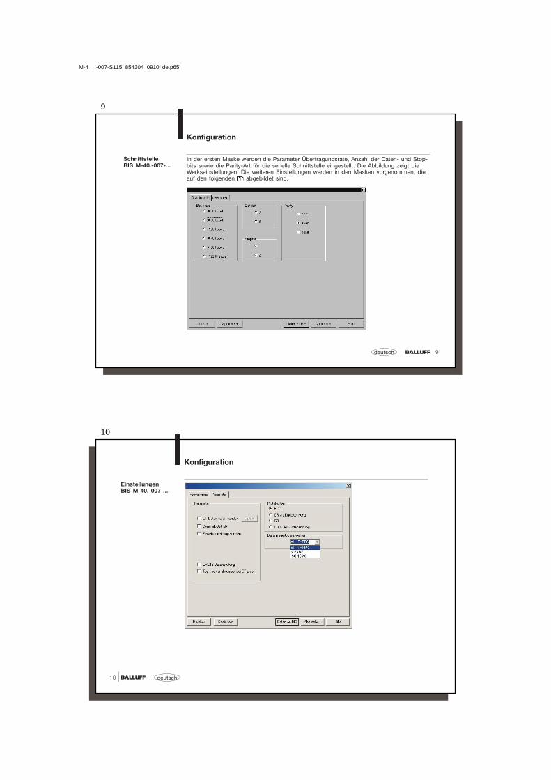
In der ersten Maske werden die Parameter Übertragungsrate, Anzahl der Daten- und Stop-bits sowie die Parity-Art für die serielle Schnittstelle eingestellt. Die Abbildung zeigt dieWerkseinstellungen. Die weiteren Einstellungen werden in den Masken vorgenommen, dieauf den folgenden abgebildet sind.
SchnittstelleBIS M-40.-007-...
M-4_ _-007-S115_854304_0910_de.p65
10
deutsch10
EinstellungenBIS M-40.-007-...
Konfiguration

11
11deutsch
Werkseitig ist auf Betrieb mit Blockcheck BCC eingestellt. Für Steuergeräte, die ein Ende-kennungszeichen benötigen, kann die zusätzliche Verwendung von Carriage Return 'CR'oder Linefeed mit Carriage Return 'LF CR' eingerichtet werden. Auf der folgenden findenSie Beispiele für die verschiedenen Möglichkeiten.
Beispiele für denAbschluss derTelegramme:
Protokolltyp
Protokollvarianten Telegramm mit Befehl,Adresse und Anzahl Bytes
Abschluß Quittung Ende-kennung
mit Blockcheck BCC 'R 0000 0001' BCC <ACK> '0'
mit Carriage return 'R 0000 0001' 'CR' <ACK> '0'
mit EndekennungCarriage return
'R 0000 0001' 'CR' <ACK> '0' 'CR'
mit EndekennungCarriage return und Line feed
'R 0000 0001' 'LF CR' <ACK> '0' 'LF CR'
Konfiguration
M-4_ _-007-S115_854304_0910_de.p65
12
deutsch12
Konfiguration
– CT-Daten sofort sendenBei jedem Neuerkennen eines Datenträgers wird dieser je nach Konfiguration ausgelesenund die Daten werden an die Schnittstelle ausgegeben. Mit dieser Einstellung erübrigtsich der Lesebefehl im Dialogmodus.
– DynamikbetriebDiese Funktion schaltet die Fehlermeldung "Kein Datenträger vorhanden" aus, d.h.:-> Im Dynamikbetrieb wird ein Lese- oder Schreibtelegramm so lange gespeichert, bis
ein Datenträger in den Arbeitsbereich des betreffenden Schreib-/Lesekopfs kommt.-> Ohne Dynamikbetrieb wird ein Lese- oder Schreibbefehl mit der Fehlermeldung <NAK>
'1' abgelehnt, wenn sich kein Datenträger im Arbeitsbereich des Schreib-/Lesekopfsbefindet; die Auswerteeinheit geht in den Ruhezustand.
– Einschaltmeldung sendenIst diese Funktion aktiviert, so meldet sich die Auswerteeinheit nach anlegen der Be-triebsspannung mit dem Gerätenamen und der Software-Version.
– Seriennummer bei CT Pres.Ist die Funktion "Typ und serial number bei CT pres." parametriert, wird die Nummer desDatenträgertyps und anschließend die 8 Byte der einmaligen Seriennummer (bei Mifare 4Byte + 4 Byte '0Hex') ausgegeben.
Parameter

13
13deutsch
Parameter(Fortsetzung)
Konfiguration
Datenträgerdaten ohne direkten Befehl lesen und senden:Die vorgegebene Datenmenge (Anzahl Byte ab Startadresse) wird vom neu erkanntenDatenträger ausgelesen.
Nach dem Lesen werden die Daten automatisch an die Schnittstelle gesendet.
Wahlweise können zusätzlich als Abschluss ein BBC und/oder 1 bzw. 2 frei definierbareAbschlusszeichen gesendet werden.
M-4_ _-007-S115_854304_0910_de.p65
14
deutsch14
Parameter(Fortsetzung)
Konfiguration
CRC_16 DatenprüfungUm das CRC_16-Verfahren verwenden zu können, müssen die Datenträger zunächst mitdem Z-Befehl initialisiert werden (siehe 28). Die CRC_16-Initialisierung wird wie ein nor-maler Schreibauftrag verwendet. Dieser wird mit einer Fehlermeldung abgelehnt, wenn dieAuswerteeinheit erkennt, dass der Datenträger nicht die richtigen CRC_16-Prüfsumme ent-hält. Datenträger ab Werksauslieferung (alle Daten sind 0) können sofort mit CRC-geprüftenDaten beschrieben werden.
Ist die CRC_16-Datenprüfung aktiviert, wird bei Erkennen eines CRC-Fehlers eine spezielleFehlermeldung ausgegeben.
Wenn die Fehlermeldung keine Folge aus einem missglückten Schreibauftrag ist, kann da-von ausgegangen werden, dass eine oder mehrere Speicherzellen auf dem Datenträgerdefekt sind. Der betreffende Datenträger ist auszutauschen.
Ist der CRC-Fehler jedoch eine Folge aus einem missglückten Schreibauftrag, muss derDatenträger neu initialisiert werden, um ihn wieder verwenden zu können.

15
15deutsch
Konfiguration
Wurde CRC_16 parametriert und es wird ein Datenträger erkannt, dessen CRC_16-Prüf-summe fehlerhaft ist, so werden die Lesedaten nicht ausgegeben. Die LED TP (TagPresent) wird eingeschaltet – der Datenträger kann mit dem Initialisierungsbefehl (Z) bear-beitet werden.
Die Prüfsumme wird je CRC-Block (entspricht 16 Byte) auf den Datenträger als 2 Byte gro-ße Information geschrieben. Es gehen 2 Byte pro CRC-Block verloren, d.h. der CRC-Blockenthält nur noch 14 Byte Nutzdaten. Dies bedeutet, dass sich die konkret nutzbare AnzahlByte verringert.
CRC_16
CRC_16 undCodetag Present
MifareBalluff Datenträgertyp Hersteller Bezeichnung Speicherkapazität Nutzbare Byte bei CRC SpeichertypBIS M-1_ _-01 Philips Mifare Classic 752 Byte 658 Byte EEPROM
ISO15693Balluff Datenträgertyp Hersteller Bezeichnung Speicherkapazität Nutzbare Byte bei CRC SpeichertypBIS M-1_ _-02 Fujitsu MB89R118 2000 Byte 1750 Byte FRAMBIS M-1_ _-031 Philips SL2ICS20 112 Byte 98 Byte EEPROMBIS M-1_ _-041 Texas Inst. TAG-IT Plus 256 Byte 224 Byte EEPROMBIS M-1_ _-051 Infineon SRF55V02P 224 Byte 196 Byte EEPROMBIS M-1_ _-061 EM EM4135 288 Byte 252 Byte EEPROMBIS M-1_ _-071 Infineon SRF55V10P 992 Byte 868 Byte EEPROM
UnterstützteDatenträger undSpeicherkapazität
1 auf Anfrage
M-4_ _-007-S115_854304_0910_de.p65
16
deutsch16
Konfiguration
Auswählen des Datenträgertyps, der bearbeitet werden soll:
- ALL TYPES- MIFARE- ISO 15693
ALL TYPES: Alle von Balluff unterstützten Datenträger können bearbeitet werden.
MIFARE: Alle von Balluff unterstützten Mifare-Datenträger können bearbeitet werden.
ISO 15693: Alle von Balluff unterstützten Datenträger der ISO 15693 können bearbeitetwerden.
(Siehe 15 "Unterstützte Datenträger und Speicherkapazität".)
Datenträger-Typ

17
17deutsch
Nachdem in den vorangegangenen Kapiteln der prinzipielle Telegrammablauf und die Kon-figuration dargestellt wurden, folgen nun die Informationen zum korrekten Aufbau der Tele-gramme.
Für die einzelnen Aufgaben im Identifikations-System BIS M existieren spezifische Telegram-me. Sie beginnen stets mit dem Befehl, der der Telegrammart zugeordnet ist:
'L' Lesen des Datenträgers mit 2 Byte Reservierung
'P' Schreiben des Datenträgers mit 2 Byte Reservierung
'C' Schreiben eines konstanten Wertes auf den Datenträger mit 2 Byte Reservierung
'R' Lesen des Datenträgers
'W' Schreiben auf den Datenträger
'Q' Neustart der Auswerteeinheit (Quitt)
'Z' CRC_16-Datenprüfung initialisieren mit 2 Byte Reservierung
'U' Lesen der Datenträger ID und Ausgabe mit Status-Byte.
Bitte beachten Sie:– Eine Dauerabfrage auf der Schnittstelle ist nicht zulässig!
Telegrammartenmit zugehörigemBefehl(ASCII-Zeichen)
Programmierinformationen
M-4_ _-007-S115_854304_0910_de.p65
18
deutsch18
Erklärung einigerTelegramminhalte
Startadresse und Die Startadresse (A3, A2, A1, A0) und die Anzahl der zu übertragendenAnzahl Byte Bytes (L3, L2, L1, L0) werden dezimal als ASCII-Zeichen übertragen. Für
die Startadresse kann der Bereich 0000 bis "Speicherkapazität -1" undfür die Anzahl Byte 0001 bis "Speicherkapazität" verwendet werden.A3 ... L0 stehen für je ein ASCII-Zeichen.Bitte beachten Sie: Startadresse + Anzahl Byte darf maximal
1024 Byte groß sein.
Reserviert Bei den Befehlen 'L' (Lesen vom Datenträger mit L-Befehl), 'P'(Schreiben auf den Datenträger mit P-Befehl), 'C' (Schreiben auf denDatenträger mit C-Befehl) und 'Z' (CRC_16-Datenprüfung initialisieren)werden die 2 Byte, die nach der Adresse und der Anzahl der zulesenden/schreibenden 8 Byte angegeben werden, mit '1' reserviert.
Quittung Die Quittung <ACK> '0' wird vom Identifikations-System gesendet,wenn die seriell übertragenen Zeichen als richtig erkannt wurden undsich ein Datenträger im Arbeitsbereich eines Schreib-/Lesekopfs befin-det. Beim Befehl 'R' wird <ACK> '0' erst gegeben, wenn die Daten zurÜbertragung bereit sind.Mit <NAK> + Fehlernr.' wird quittiert, wenn ein Fehler erkannt wurdeoder wenn sich kein Datenträger im Arbeitsbereich des Schreib-/Lese-kopfs befindet.
Start Mit <STX> wird die Datenübertragung gestartet.
Übertragene Die Daten werden codetransparent (ohne Datenwandlung) übertragen.Byte
Programmierinformationen

19
19deutsch
Der Blockcheck BCC wird als EXOR-Verknüpfung aus den seriell übertragenen Binär-zeichen des Telegrammblocks gebildet. Beispiel: Lesen ab Adresse 13, 128 Byte sind zulesen.Die Befehlszeile ohne BCC lautet: 'L 0013 0128 11'. BCC wird gebildet:
'L = 0100 1100 EXOR0 = 0011 0000 EXOR0 = 0011 0000 EXOR1 = 0011 0001 EXOR3 = 0011 0011 EXOR0 = 0011 0000 EXOR1 = 0011 0001 EXOR2 = 0011 0010 EXOR8 = 0011 1000 EXOR1 = 0011 0000 EXOR
1' = 0011 0000 EXORergibt als Blockcheck: BCC = 0100 0101 = 'E'
Bei Bedarf kann der Abschluss mittels Blockcheck BCC durch ein spezielles ASCII-Zeichenersetzt werden. Dies ist:
– Carriage Return 'CR'
Für Steuereinheiten, die immer ein Endekennungszeichen benötigen, muss dieses überallin die Telegramme eingefügt werden. Zur Verfügung stehen:
– Carriage Return 'CR' oder– Line Feed mit Carriage Return 'LF CR'.
Auf der folgenden werden die verschiedenen Protokollvarianten dargestellt.Siehe auch: Konfiguration ab 8.
Bildung desBlockchecks BCC
Variante beiAbschluss mit BCC,Endekennung
Programmierinformationen
M-4_ _-007-S115_854304_0910_de.p65
20
deutsch20
Darstellung derverschiedenenProtokollvarianten
Die jeweiligen Positionen für die zusätzliche Endekennung sind in den tabellarischenDarstellungen kursiv abgesetzt.
Programmierinformationen
Von der vorangegangenen stammt die Befehlszeile 'L 0013 0128 11 E' mit 'E' als BCC.Diese Befehlszeile wird hier in den möglichen Varianten gegenübergestellt; dabei werdenauch die verschiedenen Formen der Quittung mit und ohne Endekennung dargestellt:
Befehlszeile vom Quittung vom BIS Quittung vom BISsteuernden System zum BIS bei korrektem Empfang bei inkorrektem Empfang
mit BCC als Abschluss,ohne Endekennung ohne Endekennung ohne Endekennung'L 0013 0128 11 E' <ACK> '0' <NAK> '1'
mit 'CR' anstatt BCC,ohne Endekennung ohne Endekennung ohne Endekennung'L 0013 0128 11 CR' <ACK> '0' <NAK> '1'
ohne BCC,mit Endekennung 'CR' mit Endekennung 'CR' mit Endekennung 'CR''L 0013 0128 11 CR' <ACK> '0 CR' <NAK> '1 CR'
ohne BCC,mit Endekennung 'LF CR' mit Endekennung 'LF CR' mit Endekennung 'LF CR''L 0013 0128 11 LF CR' <ACK> '0 LF CR' <NAK> '1 LF CR'
Bei <NAK> mit Fehlernummer wurde hier '1' (kein Datenträger vorhanden) als Fehler-beispiel ausgegeben.

21
21deutsch
Angaben in Hochkommata stellen das/die jeweilige/n Zeichen im ASCII-Code dar.
Programmierinformationen
Lesen vom Datenträger mit L-BefehlSchreiben auf den Datenträger P-Befehl
1) Der Befehl 'Quitt' ist an dieser Stelle nicht zugelassen.2) Statt Blockcheck BCC kann je nach Protokollvariante entweder Carriage Return 'CR' oder Line Feed mit Carriage Return 'LF CR'
verwendet werden.3) Als Quittung kommt <ACK> '0', wenn kein Fehler aufgetreten ist, oder <NAK> + Fehlernr., wenn ein Fehler aufgetreten ist.4) Bei Protokollvarianten, die immer eine Endekennung benötigen, muss hier eines der Abschlusszeichen 'CR' oder 'LF CR' eingefügt werden.5) Die Anzahl der zu übertragenden Bytes darf 1024 Byte nicht überschreiten.
Task Datenfluss Be-fehl
Startadressedes erstenzu übertra-genden Byte
Anzahl derzu über-tragendenBytes
reser-viert
Ab-schluss2)
Quit-tung3)
Ende-ken-nung4)
StartzurÜber-tragung
Ende-ken-nung4)
Daten (vonStartadresse bisStartadresse +Anzahl Bytes)
Ab-schluss2)
Quit-tung3)
Ende-ken-nung4)
Lesen vomsteuerndenSystemzum BIS
'L' A3 A2 A1 A0'0 0 0 0'bisSpeicherka-pazität -1
L3 L2 L1 L0'0 0 0 1'bisSpeicherka-pazität 5)
'1' '1'BCCodersiehe2)
<STX> 'CR'oder'LFCR'
vom BISzumsteuerndenSystem
<ACK>-'0' oder<NAK>+ F-Nr.
'CR'oder'LFCR'
D1 D2 D3 ... Dn BCCodersiehe2)
1) 1)
Schreiben vomsteuerndenSystemzum BIS
'P' A3 A2 A1 A0'0 0 0 0'bisSpeicherka-pazität -1
L3 L2 L1 L0'0 0 0 1'bisSpeicherka-pazität 5)
'1' '1'BCCodersiehe2)
<STX> D1 D2 D3 ... Dn BCCodersiehe2)
vom BISzumsteuerndenSystem
<ACK>-'0' oder<NAK>+ F-Nr.
'CR'oder'LFCR'
<ACK>-'0' oder<NAK>+ F-Nr.
'CR'oder'LFCR'
1) 1)
M-4_ _-007-S115_854304_0910_de.p65
22
deutsch22
-> Es sollen 10 Byte ab Adresse 50 vom Datenträger gelesen werden.
Das Steuersystem sendet 'L 0 0 5 0 0 0 1 0 1 1 H' BCC (48Hex)
Adresse des ersten zu lesenden ByteAnzahl der zu lesenden Byte
reserviertDie BIS-Auswerteeinheit quittiert mit <ACK> '0'Das Steuersystem gibt den Startbefehl <STX>Die BIS-Auswerteeinheit liefert die Daten vom Datenträger 1 2 3 4 5 6 7 8 9 0 '1' BCC (31Hex)
-> Es sollen 5 Byte ab Adresse 100 auf den Datenträger geschrieben werden.
Das Steuersystem sendet 'P 0 1 0 0 0 0 0 5 1 1 T' BCC (54Hex)
Adresse des ersten zu schreibenden ByteAnzahl der zu schreibenden Byte
reserviertDie BIS-Auswerteeinheit quittiert mit <ACK> '0'Das Steuersystem gibt den Startbefehl und die Daten <STX> 1 2 3 4 5 '3' BCC (33Hex)Die Auswerteeinheit quittiert mit <ACK> '0'
Angaben in Hochkommata stellen das/die jeweilige/n Zeichen im ASCII-Code dar.
Telegrammbeispielzu 21:Schreiben auf denDatenträger mitP-Befehlmit Blockcheck (BCC)
Programmierinformationen
Telegrammbeispielzu 21:Lesen vomDatenträger mitL-Befehlmit Blockcheck (BCC)
23
23deutsch
Angaben in spitzen Klammern stellen ein Steuerzeichen dar.Angaben in Hochkommata stellen das/die jeweilige/n Zeichen im ASCII-Code dar.
1) Der Befehl 'Quitt' ist an dieser Stelle nicht zugelassen.2) Statt Blockcheck BCC kann je nach Protokollvariante entweder Carriage Return 'CR' oder Line Feed mit Carriage Return 'LF CR' verwen
det werden.3) Als Quittung kommt <ACK> '0', wenn kein Fehler aufgetreten ist, oder <NAK> + 'Fehlernr.', wenn ein Fehler aufgetreten ist.4) Bei Protokollvarianten, die immer eine Endekennung benötigen, muss hier eines der Abschlusszeichen 'CR' oder 'LF CR' eingefügt werden.5) Die Anzahl der zu übertragenden Bytes darf 1024 Byte nicht überschreiten.
Programmierinformationen
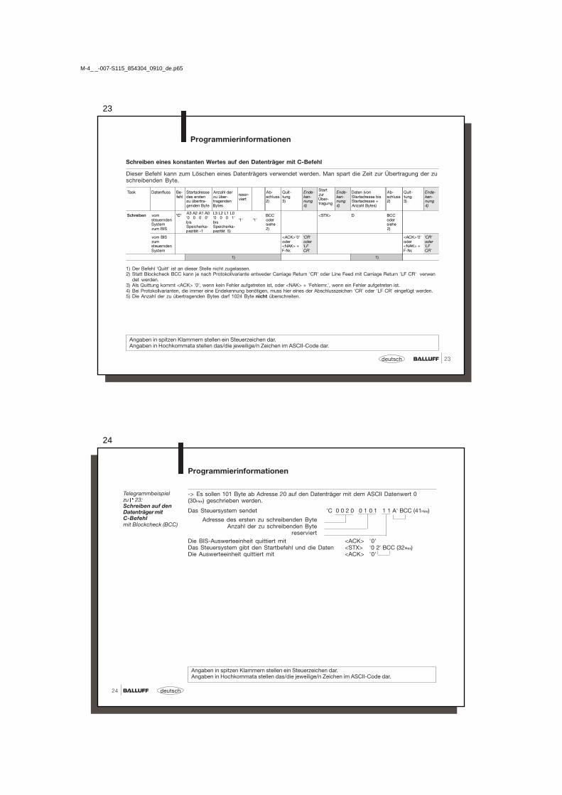
Schreiben eines konstanten Wertes auf den Datenträger mit C-Befehl
Dieser Befehl kann zum Löschen eines Datenträgers verwendet werden. Man spart die Zeit zur Übertragung der zuschreibenden Byte.
Task Datenfluss Be-fehl
Startadressedes erstenzu übertra-genden Byte
Anzahl derzu über-tragendenBytes
reser-viert
Ab-schluss2)
Quit-tung3)
Ende-ken-nung4)
StartzurÜber-tragung
Ende-ken-nung4)
Daten (vonStartadresse bisStartadresse +Anzahl Bytes)
Ab-schluss2)
Quit-tung3)
Ende-ken-nung4)
Schreiben vomsteuerndenSystemzum BIS
'C' A3 A2 A1 A0'0 0 0 0'bisSpeicherka-pazität -1
L3 L2 L1 L0'0 0 0 1'bisSpeicherka-pazität 5)
'1' '1'BCCodersiehe2)
<STX> D BCCodersiehe2)
vom BISzumsteuerndenSystem
<ACK>'0'oder<NAK> +F-Nr.
'CR'oder'LFCR'
<ACK>'0'oder<NAK> +F-Nr.
'CR'oder'LFCR'
1) 1)
M-4_ _-007-S115_854304_0910_de.p65
24
deutsch24
-> Es sollen 101 Byte ab Adresse 20 auf den Datenträger mit dem ASCII Datenwert 0(30Hex) geschrieben werden.
Das Steuersystem sendet 'C 0 0 2 0 0 1 0 1 1 1 A' BCC (41Hex)
Adresse des ersten zu schreibenden ByteAnzahl der zu schreibenden Byte
reserviertDie BIS-Auswerteeinheit quittiert mit <ACK> '0'Das Steuersystem gibt den Startbefehl und die Daten <STX> '0 2' BCC (32Hex)Die Auswerteeinheit quittiert mit <ACK> '0'
Telegrammbeispielzu 23:Schreiben auf denDatenträger mitC-Befehlmit Blockcheck (BCC)
Programmierinformationen
Angaben in spitzen Klammern stellen ein Steuerzeichen dar.Angaben in Hochkommata stellen das/die jeweilige/n Zeichen im ASCII-Code dar.

25
25deutsch
Programmierinformationen
Lesen vom Datenträger, Schreiben auf den Datenträger
Angaben in Hochkommata stellen das/die jeweilige/n Zeichen im ASCII-Code dar.
1) Der Befehl 'Quitt' ist an dieser Stelle nicht zugelassen.2) Statt Blockcheck BCC kann je nach Protokollvariante Carriage Return 'CR' oder Line Feed mit Carriage Return 'LF CR' verwendet werden.3) Als Quittung kommt <ACK> '0', wenn kein Fehler aufgetreten ist, oder <NAK> + Fehlernr., wenn ein Fehler aufgetreten ist.4) Bei Protokollvarianten, die immer eine Endekennung benötigen, muss hier eines der Abschlusszeichen 'CR' oder 'LF CR' eingefügt
werden.5) Die Anzahl der zu übertragenden Bytes darf 1024 Byte nicht überschreiten.
Task Datenfluss Be-fehl
Startadressedes erstenzu übertra-genden Byte
Anzahl zuübertragen-der Bytes
Ab-schluss2)
Quit-tung3)
Ende-ken-nung4)
StartzurÜber-tragung
Ende-ken-nung4)
Daten (vonStartadressebis Startadresse+ Anzahl Bytes)
Ab-schluss2)
Quit-tung3)
Ende-ken-nung4)
Lesen vomsteuerndenSystem zumBIS
'R' A3 A2 A1 A0'0 0 0 0'bisSpeicherka-pazität -1
L3 L3 L1 L0'0 0 0 1'bisSpeicherka-pazität 5)
BCCodersiehe2)
<STX> 'CR'oder'LFCR'
vom BISzumsteuerndenSystem
<ACK>'-0' oder<NAK> +F-Nr.
'CR'oder'LFCR'
D1 D2 D3 ... Dn BCCodersiehe2)
1)
Schreiben vomsteuerndenSystem zumBIS
'W' A3 A2 A1 A0'0 0 0 0'bisSpeicherka-pazität -1
L3 L2 L1 L0'0 0 0 1'bisSpeicherka-pazität 5)
BCCodersiehe2)
<STX> D1 D2 D3 ... Dn BCCodersiehe2)
vom BISzumsteuerndenSystem
<ACK>'-0' oder<NAK> +F-Nr.
'CR'oder'LFCR'
<ACK>'-0' oder<NAK> +F-Nr.
'CR'oder'LFCR'
1) 1)
M-4_ _-007-S115_854304_0910_de.p65
26
deutsch26
Lesen vom Datenträger: -> Es sollen 10 Byte ab Adresse 50 gelesen werden.
Das Steuersystem sendet 'R 0 0 5 0 0 0 1 0 V' BCC (56Hex)
Adresse des ersten zu lesenden ByteAnzahl der zu lesenden Byte
Die BIS-Auswerteeinheit quittiert mit <ACK> '0'Das Steuersystem gibt den Startbefehl <STX>Die BIS-Auswerteeinheit liefert
die Daten vom Datenträger 1 2 3 4 5 6 7 8 9 0 'SOH'BCC (01Hex)
Schreiben auf den Datenträger: -> Es sollen 5 Byte ab Adresse 100 geschrieben werden.
Das Steuersystem sendet 'W 0 1 0 0 0 0 0 5 S' BCC (53Hex)Die BIS-Auswerteeinheit quittiert mit <ACK> '0'Das Steuersystem sendet die Daten <STX> 1 2 3 4 5 '3' BCC (33Hex)Die BIS-Auswerteeinheit quittiert mit <ACK> '0'
Programmierinformationen
Telegrammbeispielzu 25:Lesen vomDatenträgermit Blockcheck (BCC)
Die Befehle 'R' und 'W' stellen eine Untermenge der Befehle 'L' und 'P' dar.
Angaben in Hochkommata stellen das/die jeweilige/n Zeichen im ASCII-Code dar.
Telegrammbeispielzu 25:Schreiben auf denDatenträgermit Blockcheck (BCC)

27
27deutsch
Neustart derAuswerteeinheit(Quitt)
Programmierinformationen
Durch das Absenden des Telegramms Neustart wird ein in Arbeit befindliches Telegrammabgebrochen und die Auswerteeinheit in den Grundzustand gebracht. Nach der Quittierungdieses Telegramms sind ca. 500 ms Pause vorzusehen, bevor ein neues Telegramm ge-startet wird.
Wichtig! Der Befehl Quitt ist nicht zugelassen, während die Auswerteeinheit auf ein Ab-schlusszeichen wartet (BCC, 'CR' oder 'LF CR'). In dieser Situation würde Quitt als Abschluss-oder Nutzzeichen fehlinterpretiert.
1) Der Befehl 'Quitt' ist an dieser Stelle nicht zugelassen.2) Statt Blockcheck BCC kann je nach Protokollvariante entweder Carriage Return 'CR' oder Line Feed mit
Carriage Return 'LF CR' verwendet werden.
Das System BIS soll in den Grundzustand gebracht werden.
Das Steuersystem sendet 'Q Q' BCC (51Hex)
Die BIS-Auswerteeinheit quittiert mit 'Q Q' BCC (51Hex)
Telegrammbeispiel:Neustart derAuswerteeinheit(Quitt)mit Blockcheck (BCC):
Angaben in Hochkommata stellen das/die jeweilige/n Zeichen im ASCII-Code dar.
Task Datenfluss Befehl Abschluss 2) Quittung Abschluss 2)
Neustart(Quitt)
vom steuernden Systemzum BIS
'Q' BCC odersiehe 2)
vom BIS zum steuerndenSystem
'Q' BCC oder siehe2)
1)
M-4_ _-007-S115_854304_0910_de.p65
28
deutsch28
CRC_16-Datenprüfung initialisieren
Mit diesem Telegramm wird ein Datenträger, der sich vor dem Schreib-/Lesekopf befindet, für die Verwendung beiCRC_16-Datenprüfung initialisiert. Dieses Telegramm muss auch dann erneut gesendet werden, wenn ein CRC-Fehler als Folge aus einem missglückten Schreibauftrag aufgetreten ist, d.h. der Datenträger muss neu initialisiertwerden, um ihn wieder verwenden zu können.
Bitte beachten Sie die Tabelle auf 15! Die angegebene Anzahl nutzbarer Byte darf nicht überschritten werden. D.h. dieSumme aus Startadresse plus Anzahl Byte darf die nutzbare Datenträger-Kapazität nicht überschreiten!
Task Datenfluss Be-fehl
Startadressedes erstenzu übertra-genden Byte
Anzahl derzu über-tragendenBytes
reser-viert
Ab-schluss2)
Quit-tung3)
Ende-ken-nung4)
StartzurÜber-tragung
Daten(von Startadressebis Startadresse+ Anzahl Byte)
Ab-schluss2)
Quit-tung3)
Ende-ken-nung4)
CRC_16-Bereichinitialisieren
vomsteuerndenSystemzum BIS
'Z' A3 A2 A1 A0'0 0 0 0'bisnutzbareByte beiCRC -1
L3 L3 L1 L0'0 0 0 1'bisnutzbareByte beiCRC 5)
'1' '1'BCCodersiehe2)
<STX> D1 D2 D3 .... Dn BCCodersiehe2)
vom BISzumsteuerndenSystem
<ACK>'0'oder<NAK> +F-Nr.
'CR'oder'LFCR'
<ACK>'0'oder<NAK> +F-Nr.
'CR'oder'LFCR'
1) 1)
1) Der Befehl 'Quitt' ist an dieser Stelle nicht zugelassen.2) Statt Blockcheck BCC kann je nach Protokollvariante entweder Carriage Return 'CR' oder Line Feed mit Carriage Return 'LF CR' verwendet werden.3) Als Quittung kommt <ACK> '0', wenn kein Fehler aufgetreten ist, oder <NAK> + 'Fehlernr.', wenn ein Fehler aufgetreten ist.4) Bei Protokollvarianten, die immer eine Endekennung benötigen, muss hier eines der Abschlusszeichen 'CR' oder 'LF CR' eingefügt werden.5) Die Anzahl der zu übertragenden Bytes darf 1024 Byte nicht überschreiten.
Die Angaben zwischen den Hochkommata stellen das/die jeweilige/n Zeichen im ASCII-Code dar. '_' = Leertaste (Space) =ASCII-Zeichen 20Hex.
Programmierinformationen
29
29deutsch
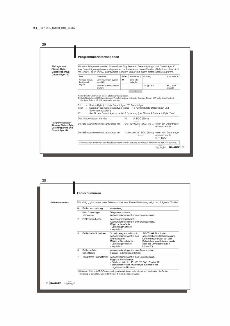
Mit dem Telegramm werden Status-Byte (Tag Present), Datenträgertyp und Datenträger IDvon Datenträgern gelesen und gesendet. Im Unterschied zum Standard-Befehl wird hier nichtmit <ACK> oder <NAK> geantwortet, sondern immer mit einem festen Datentelegramm.
1) Der Befehl 'Quitt' ist an dieser Stelle nicht zugelassen.2) Statt Blockcheck BCC kann je nach Protokollvariante entweder Carriage Return 'CR' oder Line Feed mit
Carriage Return 'LF CR' verwendet werden.
S1 = Status-Byte ('1' kein Datenträger; '0' Datenträger)Typ1 = Nummer des Datenträgertyps (siehe 15 "Unterstützte Datenträger und
Speicherkapazität")ID1 = die ID des Datenträgerstyps ist 8 Byte lang (bei Mifare 4 Byte + 4 Byte '0Hex')
Das Steuersystem sendet 'U U' BCC (55Hex)
Die BIS-Auswerteeinheit antwortet mit '0�123400005' BCC (35Hex) wenn ein Datenträgererkannt wurde
Die BIS-Auswerteeinheit antwortet mit '1xxxxxxxxx1' BCC (31Hex) wenn kein Datenträgererkannt wurde(x = 'NUL')
Die Angaben zwischen den Hochkommata stellen das/die jeweilige/n Zeichen im ASCII-Code dar.
Abfrage vonStatus-Byte,Datenträgertyp,Datenträger ID
Programmierinformationen
Task Datenfluss Befehl Abschluss 2) Quittung Abschluss 2)
Abfrage Status,Tagtyp undTag ID
vom steuernden Systemzum BIS
'U' BCC odersiehe 2)
vom BIS zum steuerndenSystem
S1 Typ1 ID1 BCC odersiehe 2)
1)
Telegrammbeispiel:Abfrage Status-Byte,Datenträgertyp undDatenträger ID
M-4_ _-007-S115_854304_0910_de.p65
30
deutsch30
Fehlernummern
Fehlernummern
BIS M-4_ _ gibt immer eine Fehlernummer aus. Deren Bedeutung zeigt nachfolgende Tabelle.
Nr. Fehlerbeschreibung Auswirkung
1 Kein Datenträgervorhanden
Telegrammabbruch,Auswerteeinheit geht in den Grundzustand.
2 Fehler beim Lesen Lesetelegrammabbruch,Auswerteeinheit geht in den Grundzustand.Mögliche Lesefehler:- Datenträger entfernt- Key falsch
4 Fehler beim Schreiben Schreibtelegrammabbruch,Auswerteeinheit geht in denGrundzustand.Mögliche Schreibfehler:- Datenträger entfernt- Key falsch
ACHTUNG: Durch denabgebrochenen Schreibvorgangkönnten neue Daten auf denDatenträger geschrieben wordensein, die unvollständig seinkönnen! *)
6 Fehler auf derSchnittstelle
Auswerteeinheit geht in den Grundzustand.(Paritäts- oder Stoppbitfehler)
7 Telegramm-Formatfehler Auswerteeinheit geht in den Grundzustand.Mögliche Formatfehler:- Befehl ist kein 'L', 'P', 'C', 'R', 'W', 'Z' oder 'U'.- Startadresse oder Anzahl Byte außerhalb des zugelassenen Bereichs
*) Hinweis: Wird mit CRC-Datencheck gearbeitet, kann beim nächsten Lesebefehl die Fehler- meldung E auftreten, wenn der Fehler 4 nicht behoben wurde.

31
31deutsch
Fehlernummern(Fortsetzung)
Fehlernummern
Nr. Fehlerbeschreibung Auswirkung
8 BCC-Fehler, der über-tragene BCC ist falsch.
Telegrammabbruch,Auswerteeinheit geht in den Grundzustand.
D CT-Fehler Gestörtes CT-Signal,Auswerteeinheit geht in den Grundzustand.
E CRC-Fehler, der CRC auf dem Datenträger istfalsch. *)
Telegrammabbruch,Auswerteeinheit geht in den Grundzustand.
*) Hinweis: Wird mit CRC-Datencheck gearbeitet, kann die Fehlermeldung E als Folge auftreten, wenn beim vorausgegangenen Befehl der Fehler 4 gemeldet wurde.
M-4_ _-007-S115_854304_0910_de.p65
32
deutsch32
Lesezeiten
Alle Angaben sind typische Werte. Abweichungen sind je nach Anwendung und Kombination vonSchreib-/Lesekopf und Datenträger möglich!Die Angaben gelten für den statischen Betrieb, keine CRC_16-Datenprüfung.
Schreibzeiten
Schreib-/Lesezeiten
☞
Schwankungen im ms-Bereich sind möglich.Elektrische Störeinflüsse können die Schreib-/Lesezeit erhöhen.☞
Datenträger mit je 16 Byte/Block BIS M-1_ _-01 BIS M-1_ _-02Zeit zur Datenträgererkennung/serial ID < 20 ms < 20 msLesen von Byte 0 bis 15 < 20 ms < 30 msfür jeweils weitere angebrochene16 Byte addieren Sie weitere
< 10 ms < 15 ms
Datenträger mit je 16 Byte/Block BIS M-1_ _-01 BIS M-1_ _-02Zeit zur Datenträgererkennung/serial ID < 20 ms < 20 msSchreiben von Byte 0 bis 15 < 40 ms < 60 msfür jeweils weitere angebrochene16 Byte addieren Sie weitere
< 30 ms < 40 ms
33
33deutsch
BIS M-4_ _Montage
Montage BIS M-4_ _und zulässigeAbstände
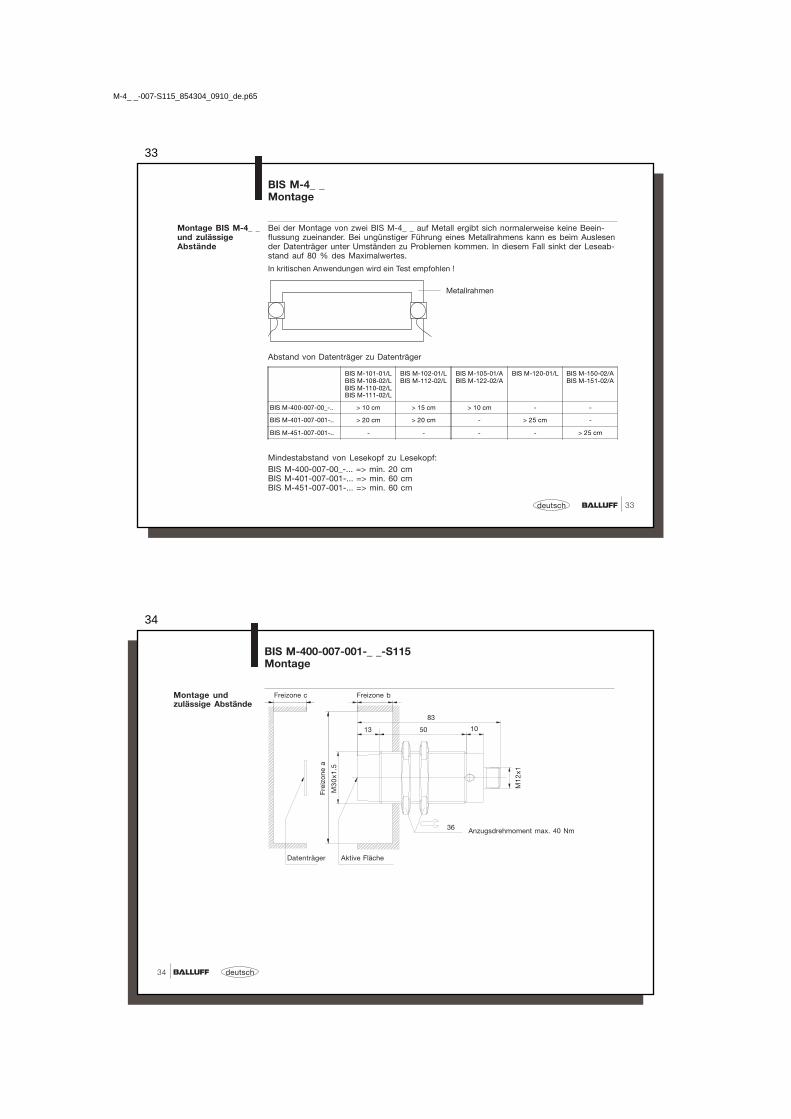
Bei der Montage von zwei BIS M-4_ _ auf Metall ergibt sich normalerweise keine Beein-flussung zueinander. Bei ungünstiger Führung eines Metallrahmens kann es beim Auslesender Datenträger unter Umständen zu Problemen kommen. In diesem Fall sinkt der Leseab-stand auf 80 % des Maximalwertes.
In kritischen Anwendungen wird ein Test empfohlen !
BIS M-101-01/LBIS M-108-02/LBIS M-110-02/LBIS M-111-02/L
BIS M-102-01/LBIS M-112-02/L
BIS M-105-01/ABIS M-122-02/A
BIS M-120-01/L BIS M-150-02/ABIS M-151-02/A
BIS M-400-007-00_-.. > 10 cm > 15 cm > 10 cm - -
BIS M-401-007-001-.. > 20 cm > 20 cm - > 25 cm -
BIS M-451-007-001-.. - - - - > 25 cm
Mindestabstand von Lesekopf zu Lesekopf:BIS M-400-007-00_-... => min. 20 cmBIS M-401-007-001-... => min. 60 cmBIS M-451-007-001-... => min. 60 cm
Abstand von Datenträger zu Datenträger
Metallrahmen
M-4_ _-007-S115_854304_0910_de.p65
34
deutsch34
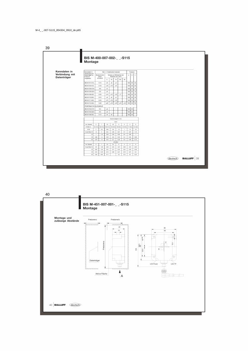
BIS M-400-007-001-_ _-S115Montage
Montage undzulässige Abstände
Fre
izo
ne a
M3
0x1
.5
Datenträger Aktive Fläche
Anzugsdrehmoment max. 40 Nm
M1
2x1
36
13
83
50 10
Freizone c Freizone b

35
35deutsch
BIS M-400-007-001-_ _-S115Montage
Kenndaten inVerbindung mitDatenträger
Geschwindigkeit in m/s
lesen
min. Abstand 9 10 3,5 3,5 9 8 9 14
DT BIS M-... 101-01/L 102-01/L 105-01/A 105-02/A 108-02/L 110-02/L 111-02/L 112-02/L
ID-Nr. 2,4 3,3 1,25 0,93 1,6 1,33 1,6 2,4
Anzahl Byte 16 1,65 2,2 0,8 0,55 1 0,76 1 1,3
32 1,5 1,8 0,7 0,42 0,8 0,65 0,8 1
48 1,28 1,58 0,5 0,38 0,6 0,5 0,6 0,86
64 1,1 1,4 0,4 0,3 0,5 0,43 0,5 0,7
schreiben
min. Abstand 9 10 3,5 3,5 9 8 9 14
Anzahl Byte 16 1,05 1,45 0,52 0,27 0,7 0,5 0,7 0,9
32 0,73 1,1 0,38 0,19 0,45 0,33 0,45 0,6
48 0,58 0,8 0,2 0,15 0,36 0,23 0,36 0,48
64 0,48 0,65 0,15 0,12 0,28 0,17 0,28 0,38
Kenndaten inVerbindung mitDatenträger (inFreizoneeingebaut)
Bei v = 0 (statischer Zustand) Freizone
Abstand(mm)
Versatz zur Mittelachse bei Abstandvon: (mm)
a b c
5 15 20 30 35
BIS M-101-01/L 0-20 ±14 ±10 ±5 - - 100 30 50
BIS M-102-01/L 0-28 ±20 ±20 ±15 - - 150 30 50
BIS M-105-01/A 0-7 ±7 - - - - 100 20 20
BIS M-105-02/A 0-11 ±8 - - - - 100 20 20
BIS M-108-02/L 0-28 ±16 ±14 ±14 - - 100 30 25
BIS M-110-02/L 0-20 ±12 ±8 ±5 - - 100 30 25
BIS M-111-02/L 0-28 ±16 ±14 ±14 - - 100 30 25
BIS M-112-02/L 0-38 ±22 ±20 ±20 ±16 ±10 150 30 50
(Datenträger bündig eingebaut)
BIS M-108-02/L 0-16 ±10 ±6 - - - 100 30 -
M-4_ _-007-S115_854304_0910_de.p65
36
deutsch36
BIS M-401-007-001-_ _-S115Montage
Montage undzulässige Abstände

37
37deutsch
BIS M-401-007-001-_ _-S115Montage
Kenndaten inVerbindung mitDatenträger (inFreizoneeingebaut)
Bei v = 0 (statischer Zustand) Freizone
Abstand(mm)
Versatz zur Mittelachse bei Abstand von: (mm)
a b c20 30 40 50 60
BIS M-101-01/L 0-28 ±15 - - - - 200 70 50
BIS M-102-01/L 0-45 ±30 ±24 ±15 - - 200 70 50
BIS M-120-01/L 0 - 50x ±40 ±40 ±28 ±4 -
250 70 80y ±30 ±28 ±18 ±4 -
BIS M-108-02/L 0-40 ±25 ±20 ±15 - - 200 50 70
BIS M-110-02/L 0-30 ±20 ±10 - - - 200 50 70
BIS M-111-02/L 0-40 ±25 ±20 ±15 - - 200 50 70
BIS M-112-02/L 20-60 - ±35 ±35 ±25 ±25 200 50 70
Kenndaten inVerbindung mitDatenträger
Geschwindigkeit in m/s
lesen
min. Abstand 9 14 15 10 9 12 20
DT BIS M-... 101-01/L 102-01/L 120-01/L 108-02/L 110-02/L 111-02/L 112-02/L
ID-Nr. 4,1 4,5 4,8 3,2 2,6 3,2 4,3
Anzahl Byte 16 2,7 3,8 4,2 1,88 1,4 1,88 2,6
32 2,28 3 3,9 1,56 1,13 1,56 2,3
48 1,76 2,25 3,25 1,25 0,85 1,25 1,8
64 1,5 1,9 3 0,98 0,65 0,98 1,5
schreiben
min. Abstand 9 14 15 10 9 12 20
Anzahl Byte 16 1,55 2,2 3,1 1,25 0,85 1,25 1,65
32 1,34 1,78 2,25 0,84 0,55 0,84 1,08
48 1 1,3 1,75 0,7 0,38 0,7 0,88
64 0,93 1 1,53 0,5 0,25 0,5 0,78
M-4_ _-007-S115_854304_0910_de.p65
38
deutsch38
BIS M-400-007-002-_ _-S115Montage
Montage undzulässige Abstände
Frei
zone
a
Datenträger Aktive Fläche
Anzugsdrehmoment max. 40 Nm
Freizone c Freizone b
39
39deutsch
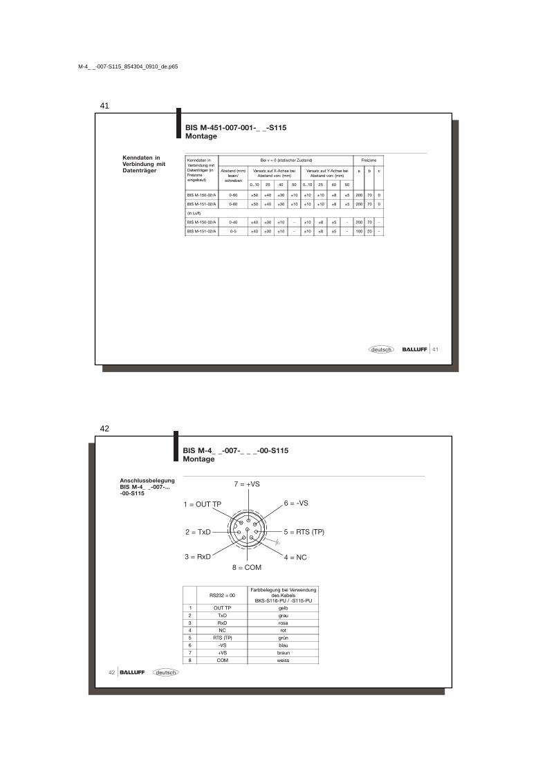
Kenndaten inVerbindung mitDatenträger
Kenndaten inVerbindung mitDatenträger (inFreizoneeingebaut)
Bei v = 0 (statischer Zustand) Freizone
Abstand (mm)lesen/
schreiben
Versatz zur Mittelachse beiAbstand von: (mm)
a b c
5 10 15 20 25
BIS M-101-01/L 0-15 ±9 ±6 ±4 - - 100 30 25
BIS M-102-01/L 0-18 ±16 ±12 ±8 - - 150 30 50
BIS M-105-01/A 0-6 ±4 - - - - 100 20 10
BIS M-105-02/A 0-9 ±6 - - - - 100 20 10
BIS M-108-02/L 0-20 ±14 ±12 ±10 ±7 - 100 30 25
BIS M-110-02/L 0-15 ±8 ±6 ±4 - - 100 30 25
BIS M-111-02/L 0-20 ±12 ±10 ±10 - - 100 30 25
BIS M-112-02/L 0-28 ±20 ±18 ±18 ±16 ±12 150 30 50
(Datenträger bündig eingebaut)
BIS M-105-01/A 0-5 ±2 - - - - 100 20 -
BIS M-105-02/A 0-5 ±2 - - - - 100 20 -
BIS M-108-02/L 0-12 ±8 ±6 - - - 100 30 -
Geschwindigkeit in m/s
lesen
min. Abstand 6 7 3,5 3,5 6 5 6 8
DT BIS M-... 101-01/L 102-01/L 105-01/A 105-02/A 108-02/L 110-02/L 111-02/L 112-02/L
ID-Nr. 2 2,6 0,85 0,6 1,3 1 1,3 1,8
Anzahl Byte 16 1,3 2 0,54 0,38 0,87 0,7 0,87 1,15
32 1 1,75 0,48 0,28 0,66 0,5 0,66 1
48 0,88 1,4 0,38 0,21 0,52 0,4 0,52 0,88
64 0,78 1,3 0,33 0,17 0,48 0,3 0,48 0,73
schreiben
min. Abstand 6 7 3,5 3,5 6 5 6 8
Anzahl Byte 16 0,9 1,38 0,38 0,25 0,51 0,38 0,51 0,82
32 0,62 1,05 0,24 0,11 0,33 0,25 0,33 0,58
48 0,44 0,78 0,19 0,08 0,27 0,18 0,27 0,4
64 0,38 0,62 0,11 - 0,2 0,15 0,2 0,32
BIS M-400-007-002-_ _-S115Montage
M-4_ _-007-S115_854304_0910_de.p65
40
deutsch40
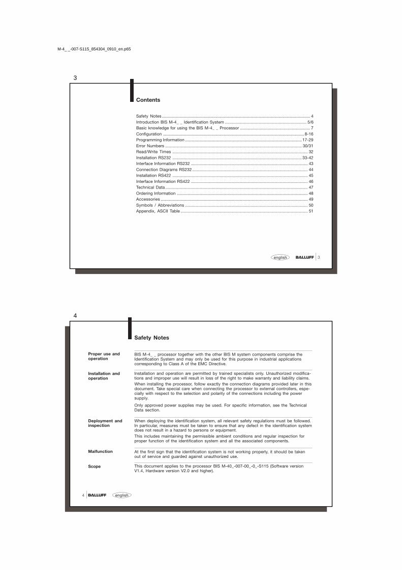
Montage undzulässige Abstände
BIS M-451-007-001-_ _-S115Montage
Datenträger
Frei
zone
a
Aktive Fläche
Freizone c Freizone b
41
41deutsch
BIS M-451-007-001-_ _-S115Montage
Kenndaten inVerbindung mitDatenträger
Kenndaten inVerbindung mitDatenträger (inFreizoneeingebaut)
Bei v = 0 (statischer Zustand) Freizone
Abstand (mm)lesen/
schreiben
Versatz auf X-Achse beiAbstand von: (mm)
Versatz auf Y-Achse beiAbstand von: (mm)
a b c
0...10 25 40 50 0...10 25 40 50
BIS M-150-02/A 0-60 ±50 ±40 ±30 ±10 ±10 ±10 ±8 ±5 200 70 0
BIS M-151-02/A 0-60 ±50 ±40 ±30 ±10 ±10 ±10 ±8 ±5 200 70 0
(in Luft)
BIS M-150-02/A 0-40 ±40 ±30 ±10 - ±10 ±8 ±5 - 200 70 -
BIS M-151-02/A 0-5 ±40 ±30 ±10 - ±10 ±8 ±5 - 100 20 -
M-4_ _-007-S115_854304_0910_de.p65
42
deutsch42
BIS M-4_ _-007-_ _ _-00-S115Montage
AnschlussbelegungBIS M-4_ _-007-...-00-S115
RS232 = 00Farbbelegung bei Verwendung
des KabelsBKS-S116-PU / -S115-PU
1 OUT TP gelb
2 TxD grau
3 RxD rosa
4 NC rot
5 RTS (TP) grün
6 -VS blau
7 +VS braun
8 COM weiss

43
43deutsch
SchnittstelleV.24 / RS232
BIS M-4_ _-007-_ _ _-00-S115Schnittstelleninformationen
➀ Verbindung RTS (TP) ermöglicht die Anzeige TP im Programm BISCOMRW.EXE.
➁ OUT TP schaltet nach +24V, wenn sich ein Datenträger im Aktionsfeld befindet.
9-pol. Anschluss
M-4_ _-007-...-00-S115
M-4_ _-007-S115_854304_0910_de.p65
44
deutsch44
BIS M-4_ _-007-_ _ _-00-S115Anschlusspläne
Beschaltung desAusganges OUT TP(nur bei RS232verfügbar)
Spannungsversorgung: DC 24 V +10% / –20% (inkl. Restwelligkeit)Ausgang Strom: max. 200 mASpannungsabfall bei 50 mA: < 1.5 V

45
45deutsch
BIS M-4_ _-007-_ _ _-02-S115Montage
AnschlussbelegungBIS M-4_ _-007-...-02-S115
RS422 = 02Farbbelegung bei Verwendung
des KabelsBKS-S116-PU / -S115-PU
1 A (R+) gelb
2 Y (T+) grau
3 B (R-) rosa
4 n.c. rot
5 Z (T-) grün
6 -VS blau
7 +VS braun
8 COM weiss
M-4_ _-007-S115_854304_0910_de.p65
46
deutsch46
SchnittstelleRS4224 DrahtPunkt zu Punkt
BIS M-4_ _-007-_ _ _-02-S115Schnittstelleninformationen
M-4_ _-007-...-02-S115
* Für Stromversorgung und RS422-Schnittstelle wird eine galvanische Trennung empfohlen! Datenleitungen paarweise verdrillt.
1) Abschlusswiderstand
1)

47
47deutsch
Allgemeine Daten Gehäuse M-400-... M-401-...CuZn vernickelt Kunststoff (PBT)
Umgebungstemperatur 0 °C bis +70 °C
Schutzart IP 67
Betriebsspannung VS DC 24 V +10 % / –20 % (inkl. Restwelligkeit)LPS Class 2
Stromaufnahme ≤ 50 mA ohne Last
Power LED grünTag Present (TP) LED gelb
BIS M-4_ _Technische Daten
Temperaturbereich
Schutzart
Spannungs-versorgung
Dieses Produkt wurde unter Beachtung geltender europäischer Normen undRichtlinien entwickelt und gefertigt.
LED Funktions-anzeige
Control No 3TLJFile No E227256
Process Control Equipment
CE-Konformitätser-klärung und Anwen-dersicherheit
☞ Sie können eine Konformitätserklärung separat anfordern.
Weitere Sicherheitsmaßnahmen entnehmen Sie bitte dem Kapitel Sicherheit (siehe 4).
M-4_ _-007-S115_854304_0910_de.p65
48
deutsch48
Balluff Identifikations-System
Baureihe M
Hardware-Typ4_ _ = Auswerteeinheit
400 = M30-Gehäuse401 = Maxisensor451 = Maxisensor für Datenträger auf Metall
Software-Typ007 = Balluff-Protokoll
Hardware-Variante001 = Luftspule002 = M18 Schreib-/Lesekopf
Schnittstelle00 = RS23202 = RS422 (4 Draht, Punkt zu Punkt)
ModulS115 = M12 8-polige Buchse
BIS M-4_ _-007-00_-0_-S115
BIS M-4_ _Bestellinformationen
Typenschlüssel

49
49deutsch
BIS M-4_ _Bestellinformationen
Zubehör(optional, nicht imLieferumfang)
Typ Bestellbezeichnung
Anschlussstecker ohne Kabel BKS-S115-00
Anschlusskabel (Anschlussbelegung siehe 40) BKS-S116-PU-..Anschlusskabel (Anschlussbelegung siehe 40) BKS-S115-PU-..
Die Anschlusskabel sind in verschiedenen Längen erhältlich:2 m, 5 m, 10 m, 15 m, 20 m, 25 m
Beispiel: BKS-S115-PU-02 Bestellbezeichnung für 2 m AnschlusskabelBKS-S116-PU-15 Bestellbezeichnung für 15 m Anschlusskabel
Bei BIS M-4_ _-007-00_-0_-S115 und einer Baudrate von 19.200 Kabellänge max. 15 m 9.600 Kabellänge max. 20 m☞
M-4_ _-007-S115_854304_0910_de.p65
50
deutsch50
Symbole / Abkürzungen
DC Current
Limited Power Source Class 2
Funktionserde
ESD Symbol
LPS

51
51deutsch
Anhang, ASCII-Tabelle
Deci-mal
HexControlCode
ASCIIDeci-mal
HexControlCode
ASCIIDeci-mal
Hex ASCIIDeci-mal
Hex ASCIIDeci-mal
Hex ASCIIDeci-mal
Hex ASCII
0 00 Ctrl @ NUL 22 16 Ctrl V SYN 44 2C , 65 41 A 86 56 V 107 6B k
1 01 Ctrl A SOH 23 17 Ctrl W ETB 45 2D - 66 42 B 87 57 W 108 6C l
2 02 Ctrl B STX 24 18 Ctrl X CAN 46 2E . 67 43 C 88 58 X 109 6D m
3 03 Ctrl C ETX 25 19 Ctrl Y EM 47 2F / 68 44 D 89 59 Y 110 6E n
4 04 Ctrl D EOT 26 1A Ctrl Z SUB 48 30 0 69 45 E 90 5A Z 111 6F o
5 05 Ctrl E ENQ 27 1B Ctrl [ ESC 49 31 1 70 46 F 91 5B [ 112 70 p
6 06 Ctrl F ACK 28 1C Ctrl \ FS 50 32 2 71 47 G 92 5C \ 113 71 q
7 07 Ctrl G BEL 29 1D Ctrl ] GS 51 33 3 72 48 H 93 5D ] 114 72 r
8 08 Ctrl H BS 30 1E Ctrl ^ RS 52 34 4 73 49 I 94 5E ^ 115 73 s
9 09 Ctrl I HT 31 1F Ctrl _ US 53 35 5 74 4A J 95 5F _ 116 74 t
10 0A Ctrl J LF 32 20 SP 54 36 6 75 4B K 96 60 ` 117 75 u
11 0B Ctrl K VT 33 21 ! 55 37 7 76 4C L 97 61 a 118 76 v
12 0C Ctrl L FF 34 22 " 56 38 8 77 4D M 98 62 b 119 77 w
13 0D Ctrl M CR 35 23 # 57 39 9 78 4E N 99 63 c 120 78 x
14 0E Ctrl N SO 36 24 $ 58 3A : 79 4F O 100 64 d 121 79 y
15 0F Ctrl O SI 37 25 % 59 3B ; 80 50 P 101 65 e 122 7A z
16 10 Ctrl P DLE 38 26 & 60 3C < 81 51 Q 102 66 f 123 7B {
17 11 Ctrl Q DC1 39 27 ' 61 3D = 82 52 R 103 67 g 124 7C |18 12 Ctrl R DC2 40 28 ( 62 3E > 83 53 S 104 68 h 125 7D }
19 13 Ctrl S DC3 41 29 ) 63 3F ? 84 54 T 105 69 i 126 7E ~
20 14 Ctrl T DC4 42 2A * 64 40 @ 85 55 U 106 6A j 127 7F DEL
21 15 Ctrl U NAK 43 2B +
M-4_ _-007-S115_854304_0910_de.p65

1
Identification Systems BISCompact Processor
BIS M-4_ _-007-...-S115
Manual
Deutsch – bitte wenden!
M-4_ _-007-S115_854304_0910_en.p65
2
No. 854 304 D/E • Edition 0910Subject to modification.Replaces edition 0706.
Balluff GmbHSchurwaldstrasse 973765 Neuhausen a.d.F.GermanyPhone +49 7158 173-0Fax +49 7158 [email protected] www.balluff.com
3
3english
Contents
Safety Notes ............................................................................................................................... 4Introduction BIS M-4_ _ Identification System ...................................................................... 5/6Basic knowledge for using the BIS M-4_ _ Processor ............................................................ 7Configuration .........................................................................................................................8-16Programming Information .................................................................................................... 17-29Error Numbers ..................................................................................................................... 30/31Read/Write Times .................................................................................................................... 32Installation RS232 ............................................................................................................... 33-42Interface Information RS232 .................................................................................................... 43Connection Diagrams RS232................................................................................................... 44Installation RS422 .................................................................................................................... 45Interface Information RS422 .................................................................................................... 46Technical Data .......................................................................................................................... 47Ordering Information ................................................................................................................ 48Accessories .............................................................................................................................. 49Symbols / Abbreviations ......................................................................................................... 50Appendix, ASCII Table ............................................................................................................. 51
M-4_ _-007-S115_854304_0910_en.p65
4
english4
Safety Notes
BIS M-4_ _ processor together with the other BIS M system components comprise theIdentification System and may only be used for this purpose in industrial applicationscorresponding to Class A of the EMC Directive.
Installation and operation are permitted by trained specialists only. Unauthorized modifica-tions and improper use will result in loss of the right to make warranty and liability claims.When installing the processor, follow exactly the connection diagrams provided later in thisdocument. Take special care when connecting the processor to external controllers, espe-cially with respect to the selection and polarity of the connections including the powersupply.
Only approved power supplies may be used. For specific information, see the TechnicalData section.
When deploying the identification system, all relevant safety regulations must be followed.In particular, measures must be taken to ensure that any defect in the identification systemdoes not result in a hazard to persons or equipment.This includes maintaining the permissible ambient conditions and regular inspection forproper function of the identification system and all the associated components.
At the first sign that the identification system is not working properly, it should be takenout of service and guarded against unauthorized use.
This document applies to the processor BIS M-40_-007-00_-0_-S115 (Software versionV1.4, Hardware version V2.0 and higher).
Scope
Malfunction
Installation andoperation
Deployment andinspection
Proper use andoperation

5
5english
IntroductionBIS M-4_ _ Identification System
Principle
This manual is intended to guide the user in installing and commissioning the componentsin the BIS M-4_ _ identification system, so that start-up time is reduced to an absoluteminimum.
The BIS M-4_ _ identification system belongs to the category ofnon-contacting systems,which can both read and write.
This dual function permits uses where not only information permanently stored in the datacarrier can be transported, but also current information can be collected and transported.
The main areas of application include– in production for controlling material flow
(e.g., for part-specific processes),in workpiece transport using conveying systems,for obtaining safety-relevant data,
– in process materials organization.
The processor and the read head form a compact unit which is contained in a housing.The data carrier represents an independent unit. It does not require line-fed power andreceives its energy from the integrated read head in the BIS M-4_ _ identification system.The read head continuously sends a carrier signal which supplies the data carrier as soonas the latter has reached the required distance from the read head. The read/write processtakes place during this phase. This may be static or dynamic. The data are output seriallyand made available to the host system. These host systems may be:– a control computer (e.g., industrial PC) having a serial port, or– a programmable logic controller (PLC).
Applications
System componentfunction
M-4_ _-007-S115_854304_0910_en.p65
6
english6
IntroductionBIS M-4_ _ Identification System
Systemcomponents
The main components of the BIS M-4_ _ identification system are– the processor with integrated read head, and– the data carrier(s).
Schematicrepresentation of anidentification system(example)
Connections tohost system
Connections tohost system
BIS
M-4
00...
BIS
M-4
01...
Data carriers BIS M-1..

7
7english
BIS M-4_ _ ProcessorBasic knowledge for application
Data integrity withCRC_16
When sending data between the read/write head and the data carrier a procedure isrequired for recognizing whether the data were correctly read or written.
The processor is supplied with standard Balluff procedure of double reading and compar-ing. In addition to this procedure a second alternative is available: CRC_16 data checking.
Here a test code is written to the data carrier, allowing data to be checked for validity atany time or location.
Advantages of CRC_16 Advantages of double reading
Data checking even during the non-active phase No bytes on the data carrier need to be(CT outside read/write head zone). reserved for storing a check code.
Shorter read times since each page is read only Shorter write times since no CRC needsonce. to be written.
Since both variations have their advantages depending on the application, the user is freeto select which method of data checking he wishes to use (see Configuration 8-16).
To use the CRC check method, the data carriers must be initialized. You use either datacarriers with the data map factory configured (all data are 0), or you must use the proces-sor to write the special initialization command 'Z' to the data carriers.
It is not permitted to operate the system using both check procedures!
M-4_ _-007-S115_854304_0910_en.p65
8
english8
Configuration
Before programming, the processor configuration must be carried out, in case the factorysettings will not be used.
Configuration is done using a computer and the Balluff software Configuration software BIS,and it is stored in the processor. It may be overwritten at any time. The configuration can bestored in a file, making it accessible when required.
☞ No data carrier is allowed in front of the read head while configuring the processor.
9
9english
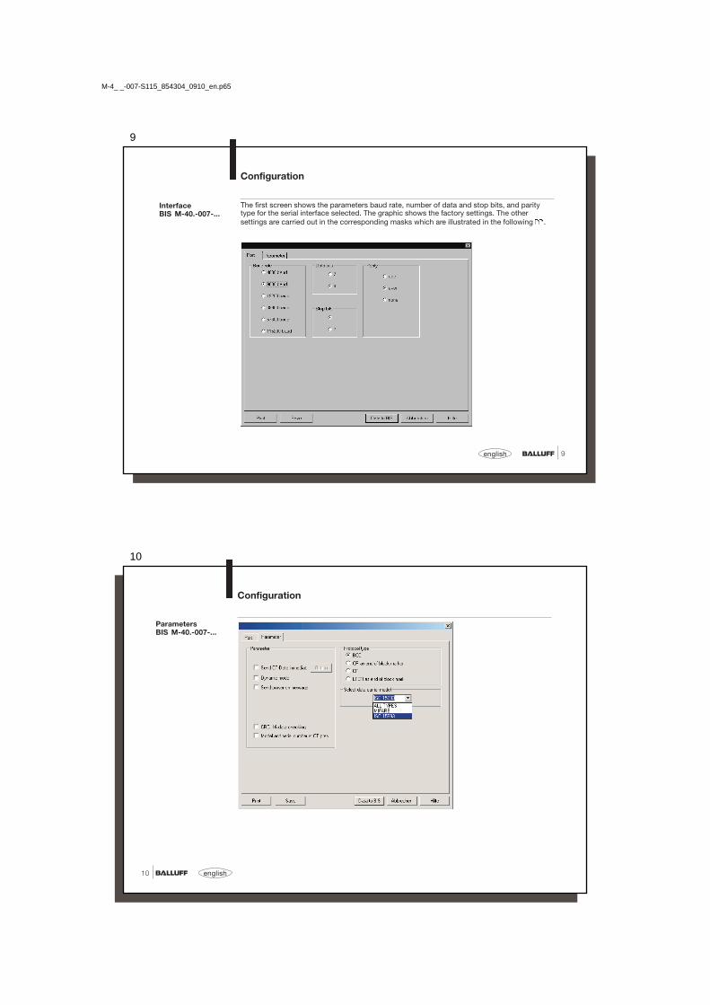
The first screen shows the parameters baud rate, number of data and stop bits, and paritytype for the serial interface selected. The graphic shows the factory settings. The othersettings are carried out in the corresponding masks which are illustrated in the following .
Configuration
InterfaceBIS M-40.-007-...
M-4_ _-007-S115_854304_0910_en.p65
10
english10
ParametersBIS M-40.-007-...
Configuration

11
11english
Operation with blockcheck BCC is factory set. For host devices which require a terminator,the additional use of Carriage Return 'CR' or Line Feed with Carriage Return 'LF CR' is madeavailable. The following page contains examples of the various possibilities.
Examples forterminating telegrams:
Protocol Type
Configuration
Protocol Variants Telegram with command,Address and no. of bytes
End Acknow-ledge
Terminator
with blockcheck BCC 'R 0000 0001' BCC <ACK> '0'
with Carriage Return 'R 0000 0001' 'CR' <ACK> '0'
with TerminatorCarriage Return
'R 0000 0001' 'CR' <ACK> '0' 'CR'
with TerminatorCarriage return and Line feed
'R 0000 0001' 'LF CR' <ACK> '0' 'LF CR'
M-4_ _-007-S115_854304_0910_en.p65
12
english12
Configuration
– Immediately send CT dataEach time another data carrier is detected, it is read according to the configuration and thedata are output. This setting eliminates the read command in dialog mode.
– Dynamic ModeThis function switches off the error-message "No data carrier present", i.e.:-> In dynamic mode, a read or write telegram is stored until a data carrier enters the
working range of the corresponding read/write head.-> Without dynamic mode, a read or write telegram is acknowledged with an error
message (<NAK> '1') if there is no data carrier present in front of a read/write head;the processor goes into the ground state.
– Send power-on messageIf this function is activated, the processor sends the device name and software versionas soon as power is turned on.
– Serial number when CT Pres.If the function "Type and serial number when CT pres." is parameterized, the number ofthe data carrier type followed by the 8-byte unique serial number (at Mifare 4 bytes+ 4 bytes '0Hex') is sent.
Parameters
13
13english
Parameters(continued)
Configuration
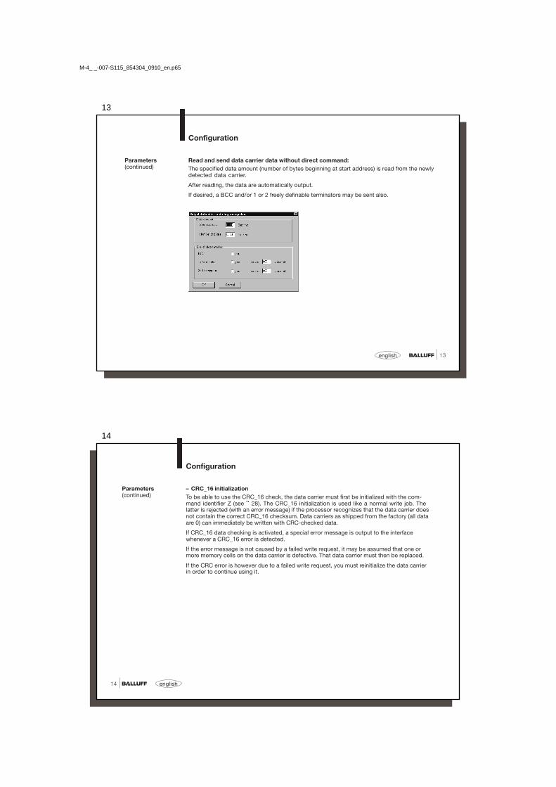
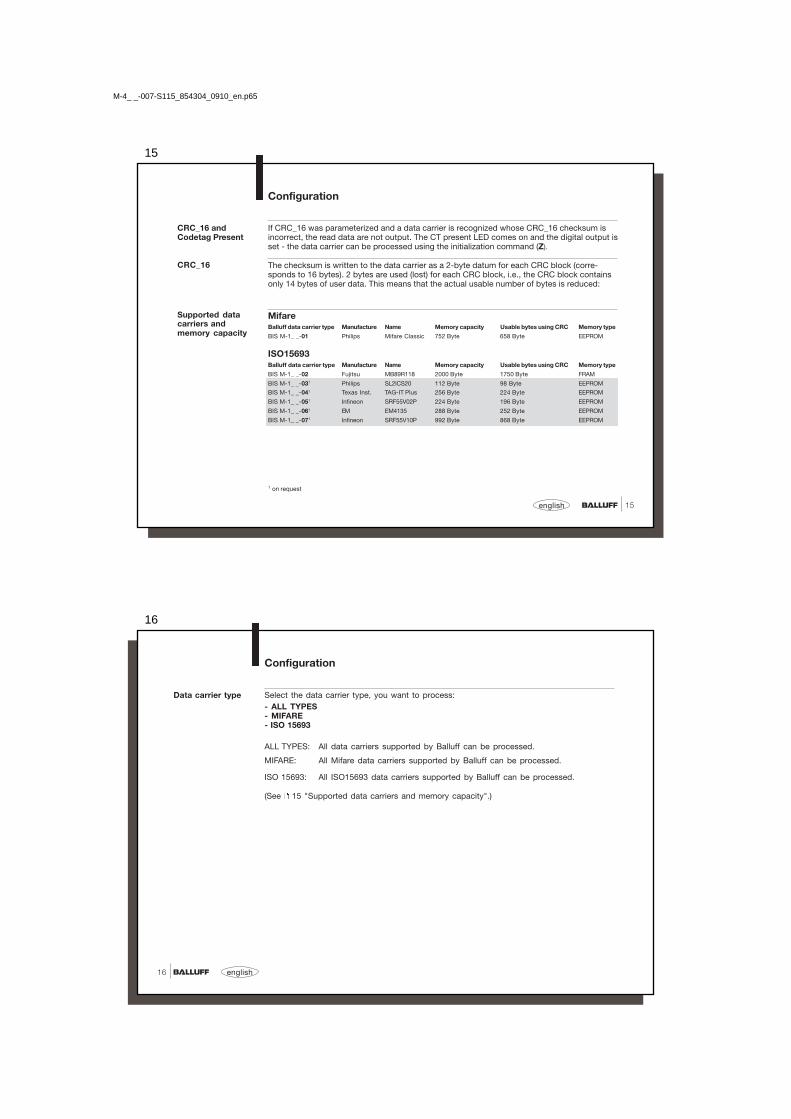
Read and send data carrier data without direct command:The specified data amount (number of bytes beginning at start address) is read from the newlydetected data carrier.
After reading, the data are automatically output.
If desired, a BCC and/or 1 or 2 freely definable terminators may be sent also.
M-4_ _-007-S115_854304_0910_en.p65
14
english14
Parameters(continued)
Configuration
– CRC_16 initializationTo be able to use the CRC_16 check, the data carrier must first be initialized with the com-mand identifier Z (see 28). The CRC_16 initialization is used like a normal write job. Thelatter is rejected (with an error message) if the processor recognizes that the data carrier doesnot contain the correct CRC_16 checksum. Data carriers as shipped from the factory (all dataare 0) can immediately be written with CRC-checked data.
If CRC_16 data checking is activated, a special error message is output to the interfacewhenever a CRC_16 error is detected.
If the error message is not caused by a failed write request, it may be assumed that one ormore memory cells on the data carrier is defective. That data carrier must then be replaced.
If the CRC error is however due to a failed write request, you must reinitialize the data carrierin order to continue using it.
15
15english
Configuration
If CRC_16 was parameterized and a data carrier is recognized whose CRC_16 checksum isincorrect, the read data are not output. The CT present LED comes on and the digital output isset - the data carrier can be processed using the initialization command (Z).
The checksum is written to the data carrier as a 2-byte datum for each CRC block (corre-sponds to 16 bytes). 2 bytes are used (lost) for each CRC block, i.e., the CRC block containsonly 14 bytes of user data. This means that the actual usable number of bytes is reduced:
CRC_16 andCodetag Present
CRC_16
MifareBalluff data carrier type Manufacture Name Memory capacity Usable bytes using CRC Memory type
BIS M-1_ _-01 Philips Mifare Classic 752 Byte 658 Byte EEPROM
ISO15693Balluff data carrier type Manufacture Name Memory capacity Usable bytes using CRC Memory type
BIS M-1_ _-02 Fujitsu MB89R118 2000 Byte 1750 Byte FRAM
BIS M-1_ _-031 Philips SL2ICS20 112 Byte 98 Byte EEPROM
BIS M-1_ _-041 Texas Inst. TAG-IT Plus 256 Byte 224 Byte EEPROM
BIS M-1_ _-051 Infineon SRF55V02P 224 Byte 196 Byte EEPROM
BIS M-1_ _-061 EM EM4135 288 Byte 252 Byte EEPROM
BIS M-1_ _-071 Infineon SRF55V10P 992 Byte 868 Byte EEPROM
Supported datacarriers andmemory capacity
1 on request
M-4_ _-007-S115_854304_0910_en.p65
16
english16
Configuration
Select the data carrier type, you want to process:- ALL TYPES- MIFARE- ISO 15693
ALL TYPES: All data carriers supported by Balluff can be processed.
MIFARE: All Mifare data carriers supported by Balluff can be processed.
ISO 15693: All ISO15693 data carriers supported by Balluff can be processed.
(See 15 "Supported data carriers and memory capacity".)
Data carrier type

17
17english
The preceding sections describe basic telegram sequence, and configuration and wiring ofthe interfaces. What now follows is information about the proper construction of the telegramsthemselves.
Specific telegrams exist in the BIS M Identification System for particular tasks. Theyalways begin with the command which is associated with the telegram type.
'L' Read the data carrier with 2-byte reservation
'P' Write to the data carrier with 2-byte reservation
'C' Write a constant value to the data carrier with read/write select with
2-byte reservation
'R' Read the data carrier
'W' Write to the data carrier
'Q' Restart the processor (acknowledge)
'Z' Initialize CRC_16 data check
'U' Read data carrier ID and output with status byte.
Please note:– Continuous querying on the interface is not permitted!
Telegram types withtheir associatedcommands(ASCII characters)
Programming Information
M-4_ _-007-S115_854304_0910_en.p65
18
english18
Telegram Contents Start address and The start address (A3, A2, A1, A0) and the number of bytes to sendno. of bytes (L3, L2, L1, L0) are sent in decimal as ASCII characters. For the start
address, the range 0000 to "memory capacity -1" can be used, and forthe number of bytes 0001 to "memory capacity".A3 ... L0 represent one ASCII character each.Please note: Start address + number of bytes may not exceed
1024 bytes.
Reserved The commands 'L' (read data carrier with L-command), 'P' (write todata carrier with P-command), 'C' (write to the data carrier withC-command) and 'Z' (initialize CRC_16 data check) cause the 2 bytesgiven after the address and the number of 8 bytes to be read/written tobe reserved with '1'.
Acknowledge The acknowledgement <ACK> '0' is sent by the Identification System ifthe serially transmitted characters were recognized as correct and thereis a data carrier in the active zone of a read/write head. In the 'R'command, the <ACK> '0' is only sent if the data is ready for transmission.<NAK> + Error No.' is sent if an error was recognized or if there is nodata carrier in the active zone of a read/write head.
Start <STX> starts the data transmission.
Transmitted The data are transmitted code transparent (no data conversion).Bytes
Programming Information

19
19english
The BCC block check is formed as an EXOR of the serially transmitted binary characters ofthe telegram block. Example: Read 128 bytes starting at address 13.The command line without BCC is: 'L 0013 0128 11'. The BCC is formed:
'L = 0100 1100 EXOR0 = 0011 0000 EXOR0 = 0011 0000 EXOR1 = 0011 0001 EXOR3 = 0011 0011 EXOR0 = 0011 0000 EXOR1 = 0011 0001 EXOR2 = 0011 0010 EXOR8 = 0011 1000 EXOR1 = 0011 0010 EXOR
1' = 0011 0000 EXORBlock check result: BCC = 0100 0101 = 'E'
If necessary the finish using block check BCC can be replaced with a special ASCII character.This is:– Carriage Return 'CR'
For hosts which always require a terminator character, this must always be included in thetelegrams. Available are:
– Carriage Return 'CR' or– Line Feed with Carriage Return 'LF CR'.
The various protocol variants are represented on the following .See also: Configuration starting on 8.
BCC Block Check
Variants for finishwith BCC,Terminator
Programming Information
M-4_ _-007-S115_854304_0910_en.p65
20
english20
Description ofVarious ProtocolVariants
Programming Information
The respective positions for the additional terminator are shown in the tables in italics.
Reference is now made to the command string 'L 0013 0128 11 E' with 'E' as BCC (seepreceding ). This command string is here shown in its possible variants; also shown arethe various forms of acknowledgement with and without terminator:
Command line from Acknowledge from BIS Acknowledge from BIShost system to BIS for correct reception for incorrect reception
with BCCbut no terminator No terminator No terminator'L 0013 0128 11 E' <ACK> '0' <NAK> '1'
with 'CR' instead of BCC,no terminator No terminator No terminator'L 0013 0128 11 CR' <ACK> '0' <NAK> '1'
no BCC,with terminator 'CR' with terminator 'CR' with terminator 'CR''L 0013 0128 11 CR' <ACK> '0 CR' <NAK> '1 CR'
no BCC,with terminator 'LF CR' with terminator 'LF CR' with terminator 'LF CR''L 0013 0128 11 LF CR' <ACK> '0 LF CR' <NAK> '1 LF CR'
For <NAK> with error number a '1' was used here (no data carrier present) as an error ex-ample.

21
21english
Values inside apostrophes represent the respective character(s) in ASCII code.
1) The command 'Quit' is not permitted at this point.2) Instead of block check BCC, depending on protocol variant either Carriage Return 'CR' or LIne Feed with Carriage Return may be used.3) <ACK> '0' is returned as acknowledgement if there is no error, or <NAK> + Error No. if an error occurs.4) For protocol variants which always require a terminator, either 'CR' or 'LF CR' must be inserted here.5) The number of bytes to send may not exceed 1024 bytes.
Programming Information
Read from data carrier with command LWrite to data carrier with command P
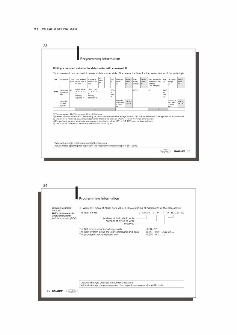
Task Data Flow Com-mand
Start addressof first byte tobe sent
Number ofbytes to besent
re-serv-ed
End2)
Acknow-ledge3)
Termi-nator4)
Starttrans-mission
Termi-nator4)
Data (from startaddress to startaddress+ no. of bytes)
End2)
Acknow-ledge3)
Termi-nator4)
Readfrom hostsystem toBIS
'L'A3 A2 A1 A0'0 0 0 0'tomemorycapacity -1
L3 L2 L1 L0'0 0 0 1'tomemorycapacity 5)
'1' '1'BCCorsee2)
<STX> 'CR' or'LF CR'
from BISto hostsystem
<ACK>'0'or <NAK>+ Error-No.
'CR' or'LF CR'
D1 D2 D3 ... DnBCCorsee2)
1) 1)
Writefrom hostsystem toBIS
'P'A3 A2 A1 A0'0 0 0 0'tomemorycapacity -1
L3 L3 L1 L0'0 0 0 1'to'memorycapacity 5)
'1' '1'BCCorsee2)
<STX> D1 D2 D3 ... DnBCCorsee2)
from BISto hostsystem
<ACK>'0'or <NAK>+ Error-No.
'CR' or'LF CR'
<ACK>'0'or <NAK>+ Error-No.
'CR' or'LF CR'
1) 1)
M-4_ _-007-S115_854304_0910_en.p65
22
english22
-> Read 10 bytes starting at address 50 of the data carrier.
The host sends 'L 0 0 5 0 0 0 1 0 1 1 H' BCC (48Hex)
Address of first byte to readNumber of bytes to read
reserved
The BIS processor acknowledges with <ACK> '0'The host system gives the start command <STX>The BIS processor provides the data from the data carrier 1 2 3 4 5 6 7 8 9 0 '1' BCC (31Hex)
-> Write 5 bytes starting at address 100 of the data carrier.
The host sends 'P 0 1 0 0 0 0 0 5 1 1 L' BCC (54Hex)
Address of first byte to writeNumber of bytes to write
reserved
The BIS processor acknowledges with <ACK> '0'The host system gives the start command and data <STX> 1 2 3 4 5 '3' BCC (33Hex)The processor acknowledges with <ACK> '0'
Values inside apostrophes represent the respective character(s) in ASCII code.
Telegram examplefor 21:Write to data carrierwith command Pwith block check (BCC)
Programming Information
Telegram examplefor 21:Read from datacarrier withcommand Lwith block check (BCC)
23
23english
Programming Information
Writing a constant value in the data carrier with command C
This command can be used to erase a data carrier data. One saves the time for the transmission of the write byte.
Data within angle brackets are control characters.Values inside apostrophes represent the respective character(s) in ASCII code.
1) The command 'Quit' is not permitted at this point.2) Instead of block check BCC, depending on protocol variant either Carriage Return 'CR' or LIne Feed with Carriage Return may be used.3) <ACK> '0' is returned as acknowledgement if there is no error, or <NAK> + 'Error No.' if an error occurs.4) For protocol variants which always require a terminator, either 'CR' or 'LF CR' must be inserted here.5) The number of bytes to send may not exceed 1024 bytes.
Task Data Flow Com-mand
Start addressof first byte tobe sent
Number ofbytes to besent
re-serv-ed
End2)
Acknow-ledge3)
Termi-nator4)
Starttrans-mission
Termi-nator4)
Data (from startaddress to startaddress+ no. of bytes)
End2)
Acknow-ledge3)
Termi-nator4)
Writefrom hostsystem toBIS
'C'A3 A2 A1 A0'0 0 0 0'tomemorycapacity -1
L3 L3 L1 L0'0 0 0 1'tomemorycapacitity 5)
'1' '1'BCCorsee2)
<STX> D BCCorsee2)
from BISto hostsystem
<ACK>'0'or <NAK>+ Error-No.
'CR' or'LF CR'
<ACK>'0'or <NAK>+ Error-No.
'CR' or'LF CR'
1) 1)
M-4_ _-007-S115_854304_0910_en.p65
24
english24
Programming Information
-> Write 101 bytes of ASCII data value 0 (30Hex) starting at address 20 of the data carrier.
The host sends 'C 0 0 2 0 0 1 0 1 1 1 A' BCC (41Hex)
Address of first byte to writeNumber of bytes to write
reserved
The BIS processor acknowledges with <ACK> '0'The host system gives the start command and data <STX> '0 2' BCC (32Hex)The processor acknowledges with <ACK> '0'
Data within angle brackets are control characters.Values inside apostrophes represent the respective character(s) in ASCII code.
Telegram examplefor 23:Write to data carrierwith command Cwith block check (BCC)

25
25english
Programming Information
Read from Data carrier, Write to Data carrier
Values inside apostrophes represent the respective character(s) in ASCII code.
1) The command 'Quit' is not permitted at this point.2) Instead of block check BCC, depending on protocol variant either Carriage Return 'CR' or LIne Feed with Carriage Return may be used.3) <ACK> '0' is returned as acknowledgement if there is no error, or <NAK> + Error No. if an error occurs.4) For protocol variants which always require a terminator, either 'CR' or 'LF CR' must be inserted here.5) The number of bytes to send may not exceed 1024 bytes.
Task Data Flow Com-mand
Start addressof first byte tosend
Number ofbytes tosend
End2)
Acknow-ledge3)
Termi-nator4)
Starttrans-mission
Termi-nator4)
Data (from startaddress to startaddress+ no. of bytes)
End2)
Acknow-ledge3)
Termi-nator4)
Readfrom hostsystem toBIS
'R' A3 A2 A1 A0'0 0 0 0'tomemorycapacity -1
L3 L3 L1 L0'0 0 0 1'tomemorycapacity 5)
BCCorsee2)
<STX> 'CR' or'LF CR'
from BISto hostsystem
<ACK>'0'or <NAK>+ Error-No.
'CR' or'LF CR'
D1 D2 D3 ... Dn BCCorsee2)
1)
Write from hostsystem toBIS
'W'A3 A2 A1 A0'0 0 0 0'tomemorycapacity -1
L3 L3 L1 L0'0 0 0 1'tomemorycapacity 5)
BCCorsee2)
<STX> D1 D2 D3 ... Dn BCCorsee2)
from BISto hostsystem
<ACK>'0'or <NAK>+ Error-No.
'CR' or'LF CR'
<ACK>'0'or <NAK>+ Error-No.
'CR' or'LF CR'
1) 1)
M-4_ _-007-S115_854304_0910_en.p65
26
english26
Programming Information
Read from Data carrier: -> Read 10 bytes starting at address 50.The host sends 'R 0 0 5 0 0 0 1 0 V' BCC (56Hex)
Address of first byte to readNumber of bytes to read
The BIS processor acknowledges with <ACK> '0'The host gives the start command <STX>The BIS processor provides the data
from the data carrier 1 2 3 4 5 6 7 8 9 0 'SOH' BCC (01Hex)
Write to Data carrier: -> Write 5 bytes starting at address 100.The host system sends 'W 0 1 0 0 0 0 0 5 S' BCC (53Hex)The BIS processor acknowledges with <ACK> '0'The host sends the data <STX> 1 2 3 4 5 '3' BCC (33Hex)The BIS processor acknowledges with <ACK> '0'
Telegram examplefor 25:Read from Datacarrierwith block check (BCC)
The 'R' and 'W' commands represent a subtype of the 'L' and 'P' commands.
Values inside apostrophes represent the respective character(s) in ASCII code.
Telegram examplefor 25:Write to Data carrierwith block check (BCC)
27
27english
Restart theProcessor (Quit)
Programming Information
Values inside apostrophes represent the respective character(s) in ASCII code.
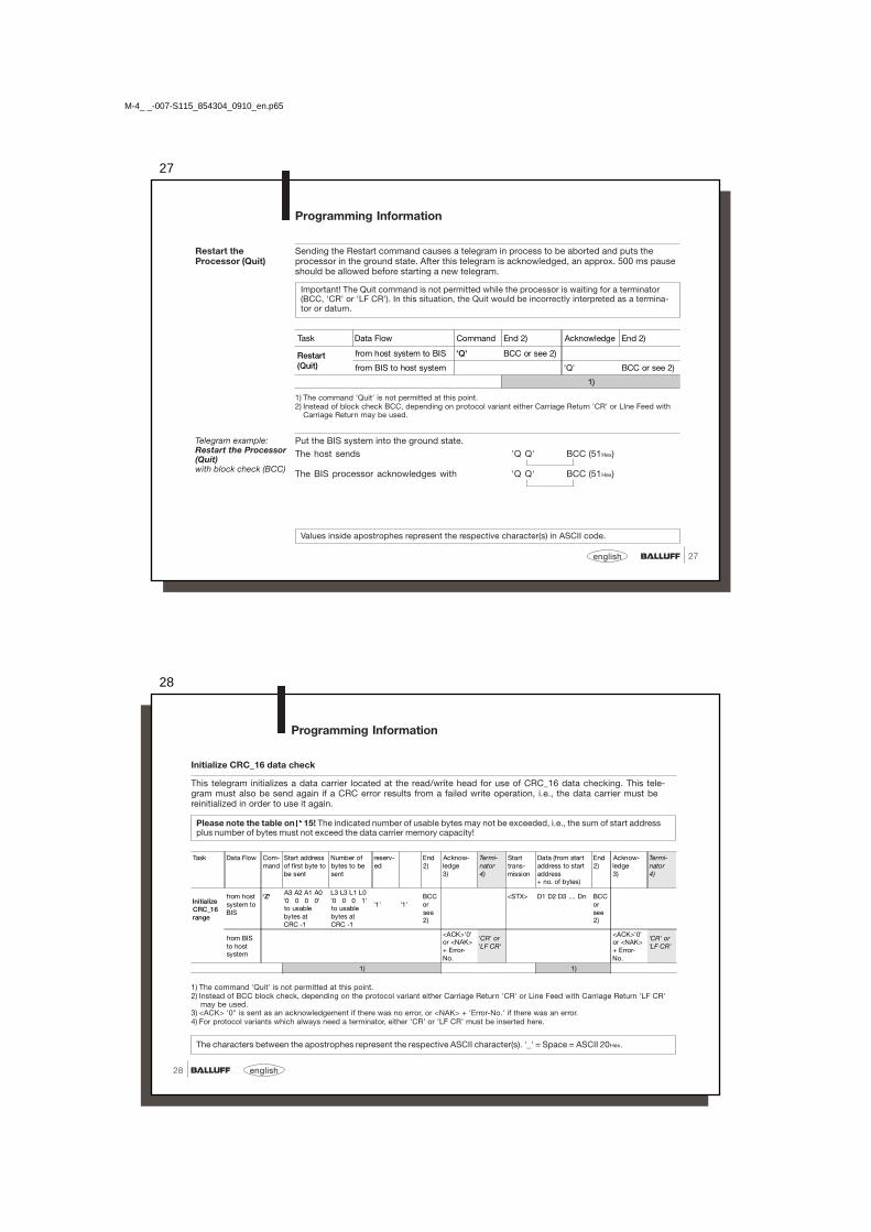
Sending the Restart command causes a telegram in process to be aborted and puts theprocessor in the ground state. After this telegram is acknowledged, an approx. 500 ms pauseshould be allowed before starting a new telegram.
Important! The Quit command is not permitted while the processor is waiting for a terminator(BCC, 'CR' or 'LF CR'). In this situation, the Quit would be incorrectly interpreted as a termina-tor or datum.
1) The command 'Quit' is not permitted at this point.2) Instead of block check BCC, depending on protocol variant either Carriage Return 'CR' or LIne Feed with
Carriage Return may be used.
Put the BIS system into the ground state.The host sends 'Q Q' BCC (51Hex)
The BIS processor acknowledges with 'Q Q' BCC (51Hex)
Telegram example:Restart the Processor(Quit)with block check (BCC)
Task Data Flow Command End 2) Acknowledge End 2)
Restart(Quit)
from host system to BIS 'Q' BCC or see 2)
from BIS to host system 'Q' BCC or see 2)
1)
M-4_ _-007-S115_854304_0910_en.p65
28
english28
Initialize CRC_16 data check
This telegram initializes a data carrier located at the read/write head for use of CRC_16 data checking. This tele-gram must also be send again if a CRC error results from a failed write operation, i.e., the data carrier must bereinitialized in order to use it again.
Please note the table on 15! The indicated number of usable bytes may not be exceeded, i.e., the sum of start addressplus number of bytes must not exceed the data carrier memory capacity!
1) The command 'Quit' is not permitted at this point.2) Instead of BCC block check, depending on the protocol variant either Carriage Return 'CR' or Line Feed with Carriage Return 'LF CR'
may be used.3) <ACK> '0" is sent as an acknowledgement if there was no error, or <NAK> + 'Error-No.' if there was an error.4) For protocol variants which always need a terminator, either 'CR' or 'LF CR' must be inserted here.
The characters between the apostrophes represent the respective ASCII character(s). '_' = Space = ASCII 20Hex.
Programming Information
Task Data Flow Com-mand
Start addressof first byte tobe sent
Number ofbytes to besent
reserv-ed
End2)
Acknow-ledge3)
Termi-nator4)
Starttrans-mission
Data (from startaddress to startaddress+ no. of bytes)
End2)
Acknow-ledge3)
Termi-nator4)
InitializeCRC_16range
from hostsystem toBIS
'Z'A3 A2 A1 A0'0 0 0 0'to usablebytes atCRC -1
L3 L3 L1 L0'0 0 0 1'to usablebytes atCRC -1
'1' '1'BCCorsee2)
<STX> D1 D2 D3 .... Dn BCCorsee2)
from BISto hostsystem
<ACK>'0'or <NAK>+ Error-No.
'CR' or'LF CR'
<ACK>'0'or <NAK>+ Error-No.
'CR' or'LF CR'
1) 1)

29
29english
With the telegram the status byte (Tag Present), data carrier type and data carrier ID ofdata carriers are read and sent. In contrast to the standard command, here the reply is notan <ACK> or <NAK>, but rather a fixed data telegram.
Task Data Flow Command End 2) Status message End 2)
Check StatusMessage
From host system to BIS 'U' BCCor see 2)
From BIS to host system S1 Type1 ID1 BCCor see 2)
1)
1) The Command 'Quit' is not permitted at this point.2) Instead of BCC block check, depending on the protocol variant either Carriage Return 'CR' or Line Feedwith Carriage Return 'LF CR' may be used.
S1 = Status byte ('1' no data carrier; '0' data carrier)Typ1 = Number of the data carrier type (see 15 "Supported data carriers and memory
capacity")ID1 = ID of the data carrier type is 8 bytes long (at Mifare 4 Byte + 4 Byte '0Hex')
The host sends 'U U' BCC (55Hex)
The BIS processor acknowledges with '0�123400005' BCC (35Hex) if a data carrier wasrecognized
The BIS processor acknowledges with '1xxxxxxxxx1' BCC (31Hex) if no data carrierwas recognized(x = 'NUL')
Values inside apostrophes represent the respective character(s) in ASCII code.
Querystatus byte,data carrier type,data carrier ID
Programming Information
Telegram example:Query status byte,data carrier type anddata carrier ID
M-4_ _-007-S115_854304_0910_en.p65
30
english30
Error Numbers The BIS M-4_ _ always outputs an error number. The meaning of these error numbers isindicated in the following table.
Error Numbers
No. Error Description Effect
1 No data carrier present Telegram aborted,processor goes into ground state.
2 Read error Read telegram aborted,processor goes into ground state.Possible read error:- data carrier removed- Key false
4 Write error Write telegram aborted,processor goes into groundstate.Possible write error:- data carrier removed- Key false
CAUTION: An aborted writecould cause new data to bewritten to the data carrierwhich may be incomplete! *)
6 Interface error Processor goes into ground state.(parity or stop bit error)
7 Telegram format error Processor goes into ground state. Possible format errors:- Command is not 'L', 'P', 'C', 'R', 'W', 'Z' or 'U'.- Start address or number of bytes exceed permissible range
*) Note: If a CRC data check is used, error message “E” could result if error 4 was not cleared.

31
31english
Error Numbers(continued)
Error Numbers
No. Error Description Effect
8 BCC error, the trans-mitted BCC is wrong
Telegram is aborted,processor goes into ground state.
D CT error Bad CT signal,processor goes into ground state.
E CRC error: the CRC on thedata carrier is wrong. *)
Telegram aborted,processor goes into ground state.
*) Note: If a CRC data check is used, error message “E” could result if in the preceding commanderror 4 was reported.
M-4_ _-007-S115_854304_0910_en.p65
32
english32
Read/Write Times
All data are typical values. Deviations are possible depending on the application and combinationof read/write head and data carrier!The data apply to static operation, no CRC_16 data checking.
☞
Variations in the ms range are possible.Electrical interference may increase the read/write times.☞
Read times
Write times
Data carrier with each 16 bytes/block BIS M-1_ _-01 BIS M-1_ _-02Time for data carrier recognition/serial ID < 20 ms < 30 msRead bytes 0 to 15 < 20 ms < 30 msFor each additional 16 bytes add another < 10 ms < 15 ms
Data carrier with each 16 bytes/block BIS M-1_ _-01 BIS M-1_ _-02Time for data carrier recognition/serial ID < 20 ms < 30 msWrite bytes 0 to 15 < 40 ms < 65 msFor each additional 16 bytes add another < 30 ms < 45 ms

33
33english
BIS M-4_ _Installation
Installing theBIS M-4_ _,permissibledistances
When installing two BIS M-400 on a metal base, there is normally no mutual interference. Ifa metal frame is located in an unfavorable location, problems may result when reading outthe data carriers. In this case the read distance will be reduced to 80 % of the maximumvalue.Testing is recommended in critical applications !
Distance from data carrier to data carrier
Metal frame
Minimum distance from read head to read head:BIS M-400-007-00_-... => min. 20 cmBIS M-401-007-001-... => min. 60 cmBIS M-451-007-001-... => min. 60 cm
BIS M-101-01/LBIS M-108-02/LBIS M-110-02/LBIS M-111-02/L
BIS M-102-01/LBIS M-112-02/L
BIS M-105-01/ABIS M-122-02/A
BIS M-120-01/L BIS M-150-02/ABIS M-151-02/A
BIS M-400-007-00_-.. > 10 cm > 15 cm > 10 cm - -
BIS M-401-007-001-.. > 20 cm > 20 cm - > 25 cm -
BIS M-451-007-001-.. - - - - > 25 cm
M-4_ _-007-S115_854304_0910_en.p65
34
english34
Cle
ar z
one
a
M3
0x1
.5
Data carrier Active surface
Tightening torque max. 40 Nm
M1
2x1
36
13
83
50 10
Clear zone c Clear zone b
BIS M-400-007-001-_ _-S115Installation
Installation andpermissibledistances

35
35english
BIS M-400-007-001-_ _-S115Installation
Characteristic databy data carrier
Speed in m/s
read
min. distance 9 10 3,5 3,5 9 8 9 14
DT BIS M-... 101-01/L 102-01/L 105-01/A 105-02/A 108-02/L 110-02/L 111-02/L 112-02/L
ID No. 2.4 3.3 1.25 0.93 1.6 1.33 1.6 2.4
No. of bytes 16 1.65 2.2 0.8 0.55 1 0.76 1 1.3
32 1.5 1.8 0.7 0.42 0.8 0.65 0.8 1
48 1.28 1.58 0.5 0.38 0.6 0.5 0.6 0.86
64 1.1 1.4 0.4 0.3 0.5 0.43 0.5 0.7
write
min. distance 9 10 3.5 3.5 9 8 9 14
No. of bytes 16 1.05 1.45 0.52 0.27 0.7 0.5 0.7 0.9
32 0.73 1.1 0.38 0.19 0.45 0.33 0.45 0.6
48 0.58 0.8 0.2 0.15 0.36 0.23 0.36 0.48
64 0.48 0.65 0.15 0.12 0.28 0.17 0.28 0.38
Characteristicdata by datacarrier (installedin clear zone)
at v = 0 (static condition) Clear zone
Dis-tance(mm)
Center axis offset at a distance of:(mm)
a b c
5 15 20 30 35
BIS M-101-01/L 0-20 ±14 ±10 ±5 - - 100 30 50
BIS M-102-01/L 0-28 ±20 ±20 ±15 - - 150 30 50
BIS M-105-01/A 0-7 ±7 - - - - 100 20 20
BIS M-105-02/A 0-11 ±8 - - - - 100 20 20
BIS M-108-02/L 0-28 ±16 ±14 ±14 - - 100 30 25
BIS M-110-02/L 0-20 ±12 ±8 ±5 - - 100 30 25
BIS M-111-02/L 0-28 ±16 ±14 ±14 - - 100 30 25
BIS M-112-02/L 0-38 ±22 ±20 ±20 ±16 ±10 150 30 50
(Data carrier is flush installed)
BIS M-108-02/L 0-16 ±10 ±6 - - - 100 30 -
M-4_ _-007-S115_854304_0910_en.p65
36
english36
BIS M-401-007-001-_ _-S115Installation
Installation andpermissibledistances

37
37english
BIS M-401-007-001-_ _-S115Installation
Characteristicdata by datacarrier (installedin clear zone)
at v = 0 (static condition) Clear zone
Dis-tance(mm)
Center axis offset at a distance of:(mm)
a b c20 30 40 50 60
BIS M-101-01/L 0-28 ±15 - - - - 200 70 50
BIS M-102-01/L 0-45 ±30 ±24 ±15 - - 200 70 50
BIS M-120-01/L 0 - 50x ±40 ±40 ±28 ±4 -
250 70 80y ±30 ±28 ±18 ±4 -
BIS M-108-02/L 0-40 ±25 ±20 ±15 - - 200 50 70
BIS M-110-02/L 0-30 ±20 ±10 - - - 200 50 70
BIS M-111-02/L 0-40 ±25 ±20 ±15 - - 200 50 70
BIS M-112-02/L 20-60 - ±35 ±35 ±25 ±25 200 50 70
Characteristic databy data carrier
Speed in m/s
read
min. distance 9 14 15 10 9 12 20
DT BIS M-... 101-01/L 102-01/L 120-01/L 108-02/L 110-02/L 111-02/L 112-02/L
ID No. 4.1 4.5 4.8 3.2 2.6 3.2 4.3
No. of bytes 16 2.7 3.8 4.2 1.88 1.4 1.88 2.6
32 2.28 3 3.9 1.56 1.13 1.56 2.3
48 1.76 2.25 3.25 1.25 0.85 1.25 1.8
64 1.5 1.9 3 0.98 0.65 0.98 1.5
write
min. distance 9 14 15 10 9 12 20
No. of bytes 16 1.55 2.2 3.1 1.25 0.85 1.25 1.65
32 1.34 1.78 2.25 0.84 0.55 0.84 1.08
48 1 1.3 1.75 0.7 0.38 0.7 0.88
64 0.93 1 1.53 0.5 0.25 0.5 0.78
M-4_ _-007-S115_854304_0910_en.p65
38
english38
BIS M-400-007-002-_ _-S115Installation
Installation andpermissibledistances
Cle
ar z
one
a
Data carrier Active surface
Tightening torque
max. 40 Nm
Clear zone c Clear zone b
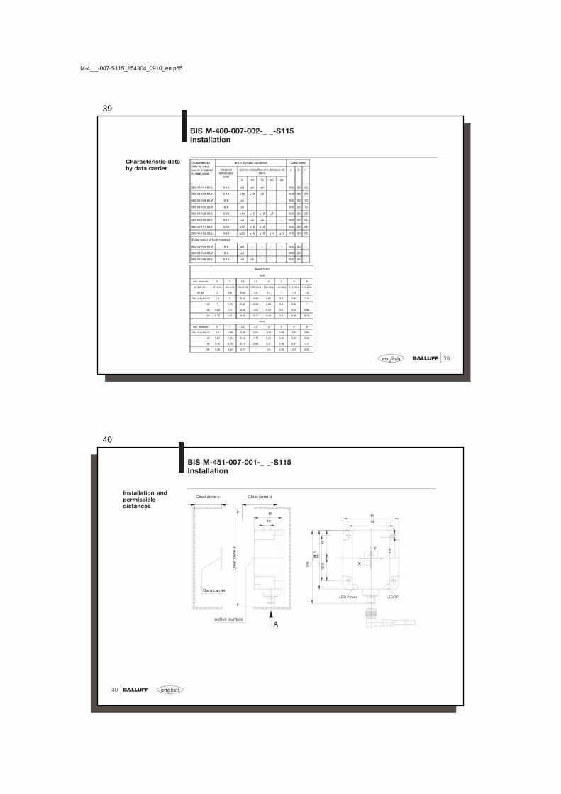
39
39english
Characteristic databy data carrier
Characteristicdata by datacarrier (installedin clear zone)
at v = 0 (static condition) Clear zone
Distance(mm) read/
write
Center axis offset at a distance of:(mm)
a b c
5 10 15 20 25
BIS M-101-01/L 0-15 ±9 ±6 ±4 - - 100 30 25
BIS M-102-01/L 0-18 ±16 ±12 ±8 - - 150 30 50
BIS M-105-01/A 0-6 ±4 - - - - 100 20 10
BIS M-105-02/A 0-9 ±6 - - - - 100 20 10
BIS M-108-02/L 0-20 ±14 ±12 ±10 ±7 - 100 30 25
BIS M-110-02/L 0-15 ±8 ±6 ±4 - - 100 30 25
BIS M-111-02/L 0-20 ±12 ±10 ±10 - - 100 30 25
BIS M-112-02/L 0-28 ±20 ±18 ±18 ±16 ±12 150 30 50
(Data carrier is flush installed)
BIS M-105-01/A 0-5 ±2 - - - - 100 20 -
BIS M-105-02/A 0-5 ±2 - - - - 100 20 -
BIS M-108-02/L 0-12 ±8 ±6 - - - 100 30 -
Speed in m/s
read
min. distance 6 7 3,5 3,5 6 5 6 8
DT BIS M-... 101-01/L 102-01/L 105-01/A 105-02/A 108-02/L 110-02/L 111-02/L 112-02/L
ID No. 2 2.6 0.85 0.6 1.3 1 1.3 1.8
No. of bytes 16 1.3 2 0.54 0.38 0.87 0.7 0.87 1.15
32 1 1.75 0.48 0.28 0.66 0.5 0.66 1
48 0.88 1.4 0.38 0.21 0.52 0.4 0.52 0.88
64 0.78 1.3 0.33 0.17 0.48 0.3 0.48 0.73
write
min. distance 6 7 3.5 3.5 6 5 6 8
No. of bytes 16 0.9 1.38 0.38 0.25 0.51 0.38 0.51 0.82
32 0.62 1.05 0.24 0.11 0.33 0.25 0.33 0.58
48 0.44 0.78 0.19 0.08 0.27 0.18 0.27 0.4
64 0.38 0.62 0.11 - 0.2 0.15 0.2 0.32
BIS M-400-007-002-_ _-S115Installation
M-4_ _-007-S115_854304_0910_en.p65
40
english40
Installation andpermissibledistances
BIS M-451-007-001-_ _-S115Installation
Data carrier
Cle
ar z
one
a
Active surface
Clear zone c Clear zone b
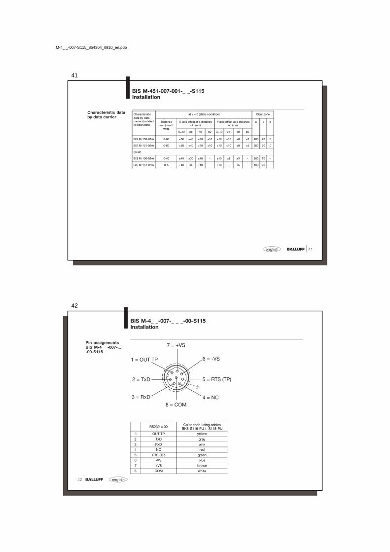
41
41english
BIS M-451-007-001-_ _-S115Installation
Characteristic databy data carrier
Characteristicdata by datacarrier (installedin clear zone)
at v = 0 (static condition) Clear zone
Distance(mm) read/
write
X-axis offset at a distanceof: (mm)
Y-axis offset at a distanceof: (mm)
a b c
0...10 25 40 50 0...10 25 40 50
BIS M-150-02/A 0-60 ±50 ±40 ±30 ±10 ±10 ±10 ±8 ±5 200 70 0
BIS M-151-02/A 0-60 ±50 ±40 ±30 ±10 ±10 ±10 ±8 ±5 200 70 0
(in air)
BIS M-150-02/A 0-40 ±40 ±30 ±10 - ±10 ±8 ±5 - 200 70 -
BIS M-151-02/A 0-5 ±40 ±30 ±10 - ±10 ±8 ±5 - 100 20 -
M-4_ _-007-S115_854304_0910_en.p65
42
english42
BIS M-4_ _-007-_ _ _-00-S115Installation
Pin assignmentsBIS M-4_ _-007-...-00-S115
RS232 = 00 Color code using cablesBKS-S116-PU / -S115-PU
1 OUT TP yellow
2 TxD gray
3 RxD pink
4 NC red
5 RTS (TP) green
6 -VS blue
7 +VS brown
8 COM white
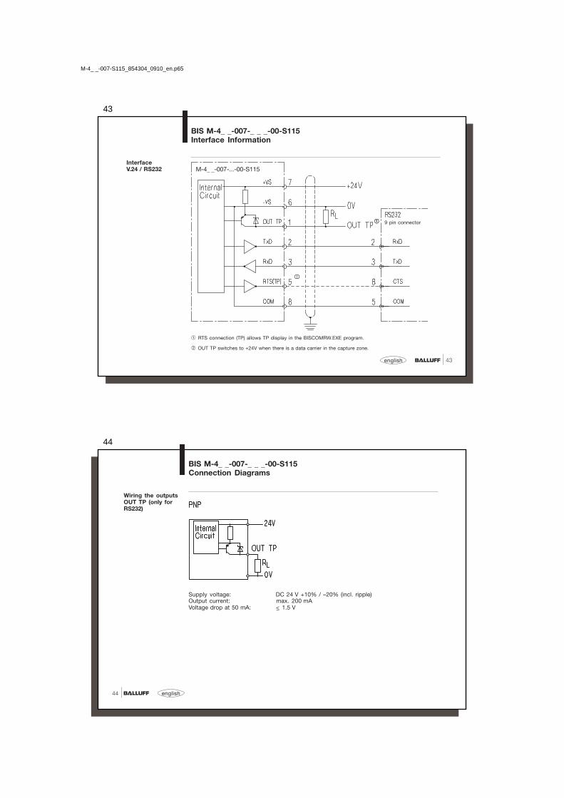
43
43english
BIS M-4_ _-007-_ _ _-00-S115Interface Information
InterfaceV.24 / RS232
➀ RTS connection (TP) allows TP display in the BISCOMRW.EXE program.
➁ OUT TP switches to +24V when there is a data carrier in the capture zone.
9 pin connector
M-4_ _-007-...-00-S115
M-4_ _-007-S115_854304_0910_en.p65
44
english44
BIS M-4_ _-007-_ _ _-00-S115Connection Diagrams
Wiring the outputsOUT TP (only forRS232)
Supply voltage: DC 24 V +10% / –20% (incl. ripple)Output current: max. 200 mAVoltage drop at 50 mA: < 1.5 V

45
45english
BIS M-4_ _-007-_ _ _-02-S115Installation
Pin assignmentsBIS M-4_ _-007-...-02-S115
RS422 = 00 Color code using cablesBKS-S116-PU / -S115-PU
1 OUT TP yellow
2 TxD gray
3 RxD pink
4 NC red
5 RTS (TP) green
6 -VS blue
7 +VS brown
8 COM white
M-4_ _-007-S115_854304_0910_en.p65
46
english46
InterfaceRS4224-wirespoint-to-point
BIS M-4_ _-007-_ _ _-02-S115Interface Information
M-4_ _-007-...-02-S115
* For the power supply and the RS422 interface a galvanic isolation is recommended! Twisted pair cable data links.
1) Termination
1)

47
47english
BIS M-4_ _Technical Data
General data Housing M-400-... M-401-...CuZn nickel-plated plastic (PBT)
Ambient temperature 0 °C to +70 °C
Enclosure rating IP 67
Supply voltage VS
DC 24 V +10 % / –20 % (incl. ripple)LPS Class 2
Current consumption ≤ 50 mA with no load
Power LED greenTag Present (TP) LED yellow
Temperature range
Enclosure rating
Supply voltage
LED functionindicator
This product was developed and produced considering the claimedEuropean standards and guidelines.
Control No 3TLJFile No E227256
Process Control Equipment
CE Declaration ofConformity anduser safety
☞ You can separately request a Declaration of Conformity.
Further safety measures you can find in chapter Safety (see 4).
M-4_ _-007-S115_854304_0910_en.p65
48
english48
BIS M-4_ _Ordering Information
Part Numbers
Balluff Identification System
Series M
Hardware type4_ _ = Processor
400 = M30 housing401 = Maxisensor451 = Maxisensor for data carrier on metal
Software type007 = Balluff-Protocol
Hardware version001 = Coil002 = M18 read/write head
Interface00 = RS23202 = RS422 (4-wires, point-to-point)
ModuleS115 = M12 8-pole female
BIS M-4_ _-007-00_-0_-S115

49
49english
BIS M-4_ _Ordering Information
Accessories(optional, notincluded in scope ofdelivery)
Type Part No.
Mating connector without cable BKS-S115-00
Cable (Pin assignments see 40) BKS-S116-PU-..Cable (Pin assignments see 40) BKS-S115-PU-..
Cable is available in various standard lengths:2 m, 5 m, 10 m, 15 m, 20 m, 25 m
Example: BKS-S115-PU-02 Part number for 2 m cableBKS-S116-PU-15 Part number for 15 m cable
For BIS M-4_ _-007-00_-0_-S115 and a baud rate of 19.200 cable length max. 15 m 9.600 cable length max. 20 m☞
M-4_ _-007-S115_854304_0910_en.p65
50
english50
Symbols / Abbreviations
DC Current
Limited Power Source Class 2
Function ground
ESD Symbol
LPS
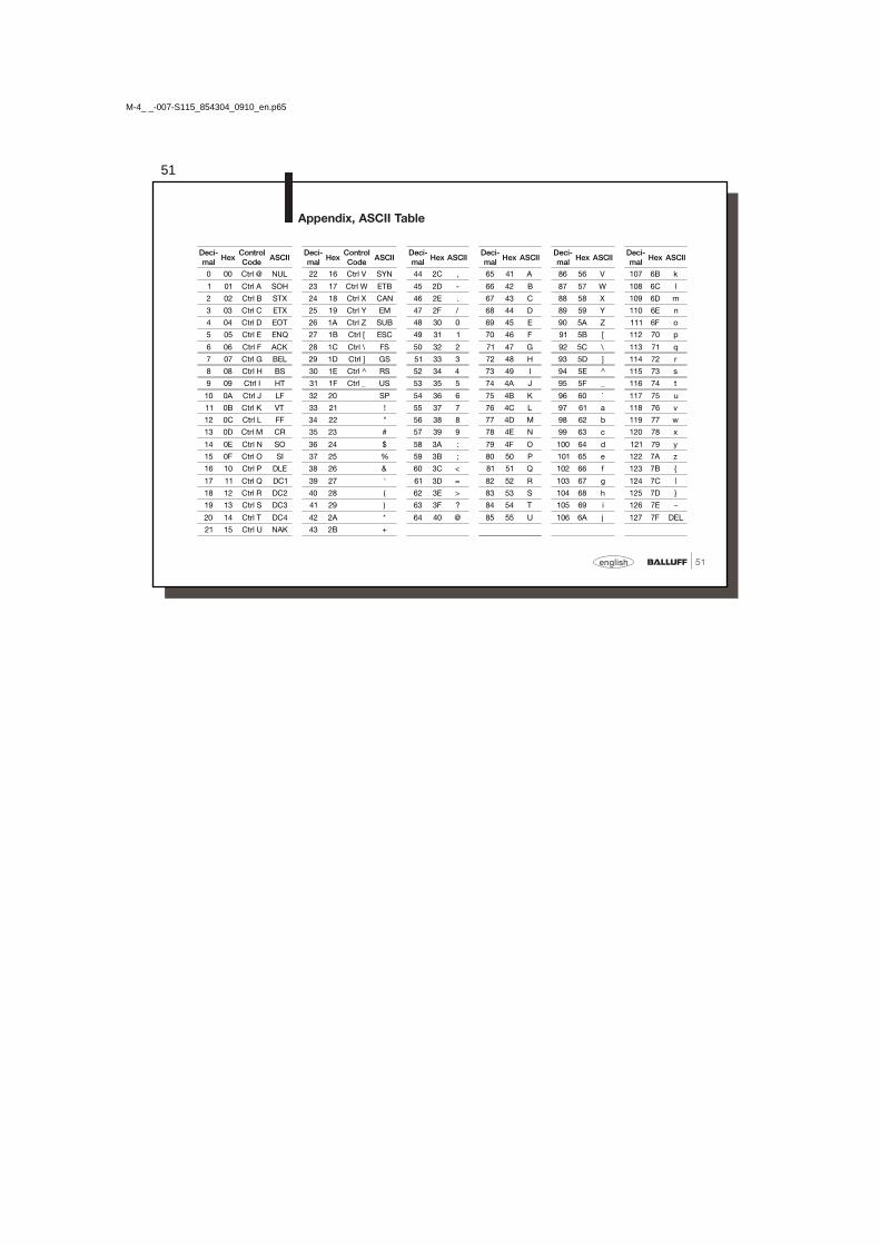
51
51english
Appendix, ASCII Table
Deci-mal
HexControlCode
ASCIIDeci-mal
HexControlCode
ASCIIDeci-mal
Hex ASCIIDeci-mal
Hex ASCIIDeci-mal
Hex ASCIIDeci-mal
Hex ASCII
0 00 Ctrl @ NUL 22 16 Ctrl V SYN 44 2C , 65 41 A 86 56 V 107 6B k
1 01 Ctrl A SOH 23 17 Ctrl W ETB 45 2D - 66 42 B 87 57 W 108 6C l
2 02 Ctrl B STX 24 18 Ctrl X CAN 46 2E . 67 43 C 88 58 X 109 6D m
3 03 Ctrl C ETX 25 19 Ctrl Y EM 47 2F / 68 44 D 89 59 Y 110 6E n
4 04 Ctrl D EOT 26 1A Ctrl Z SUB 48 30 0 69 45 E 90 5A Z 111 6F o
5 05 Ctrl E ENQ 27 1B Ctrl [ ESC 49 31 1 70 46 F 91 5B [ 112 70 p
6 06 Ctrl F ACK 28 1C Ctrl \ FS 50 32 2 71 47 G 92 5C \ 113 71 q
7 07 Ctrl G BEL 29 1D Ctrl ] GS 51 33 3 72 48 H 93 5D ] 114 72 r
8 08 Ctrl H BS 30 1E Ctrl ^ RS 52 34 4 73 49 I 94 5E ^ 115 73 s
9 09 Ctrl I HT 31 1F Ctrl _ US 53 35 5 74 4A J 95 5F _ 116 74 t
10 0A Ctrl J LF 32 20 SP 54 36 6 75 4B K 96 60 ` 117 75 u
11 0B Ctrl K VT 33 21 ! 55 37 7 76 4C L 97 61 a 118 76 v
12 0C Ctrl L FF 34 22 " 56 38 8 77 4D M 98 62 b 119 77 w
13 0D Ctrl M CR 35 23 # 57 39 9 78 4E N 99 63 c 120 78 x
14 0E Ctrl N SO 36 24 $ 58 3A : 79 4F O 100 64 d 121 79 y
15 0F Ctrl O SI 37 25 % 59 3B ; 80 50 P 101 65 e 122 7A z
16 10 Ctrl P DLE 38 26 & 60 3C < 81 51 Q 102 66 f 123 7B {
17 11 Ctrl Q DC1 39 27 ' 61 3D = 82 52 R 103 67 g 124 7C |18 12 Ctrl R DC2 40 28 ( 62 3E > 83 53 S 104 68 h 125 7D }
19 13 Ctrl S DC3 41 29 ) 63 3F ? 84 54 T 105 69 i 126 7E ~
20 14 Ctrl T DC4 42 2A * 64 40 @ 85 55 U 106 6A j 127 7F DEL
21 15 Ctrl U NAK 43 2B +
M-4_ _-007-S115_854304_0910_en.p65