Embed Size (px)
Citation preview
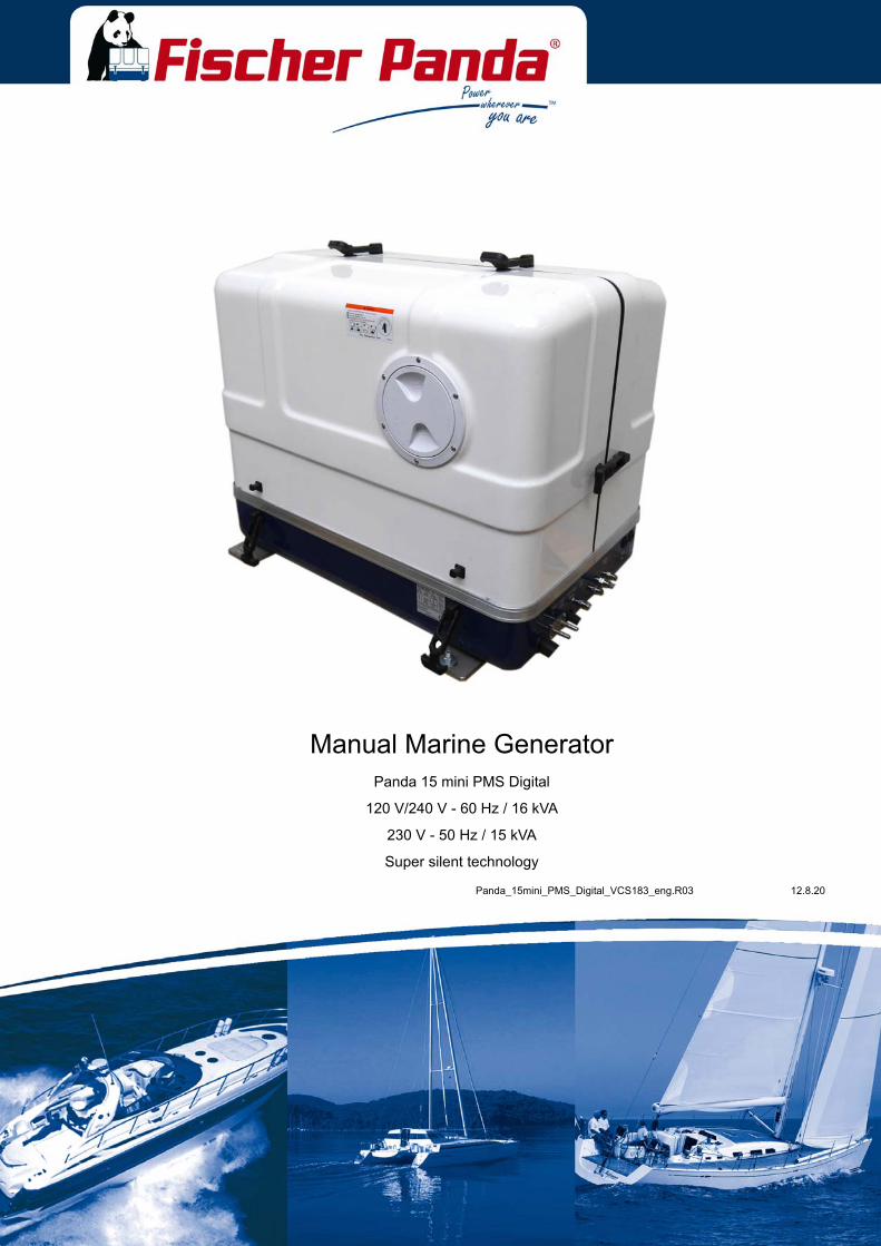
Panda_15mini_PMS_Digital_VCS183_eng.R03 12.8.20
Manual Marine GeneratorPanda 15 mini PMS Digital
120 V/240 V - 60 Hz / 16 kVA
230 V - 50 Hz / 15 kVA
Super silent technology
Fischer Panda GmbHOtto‐Hahn‐Str. 40D‐33104 PaderbornGermany
Tel.Fax.HotlineEmailWeb
:::::
+49 (0)5254 9202‐0+49 (0)5254 9202‐550+49 (0)5254 9202‐[email protected]
Current revision status
Erstellt durch / created by
Fischer Panda GmbH - Leiter Technische Dokumentation
Otto-Hahn-Str. 40
33104 Paderborn - Germany
Tel.: +49 (0) 5254-9202-0
email: [email protected]
web: www.fischerpanda.de
Copyright
Duplication and change of the manual is permitted only in consultation with the manufacturer!
Fischer Panda GmbH, 33104 Paderborn, reserves all rights regarding text and graphics. Details are given to thebest of our knowledge. No liability is accepted for correctness. Technical modifications for improving the productwithout previous notice may be undertaken without notice. Before installation, it must be ensured that the pictures,diagrams and related material are applicable to the genset supplied. Enquiries must be made in case of doubt.
DocumentActual: Panda_15mini_PMS_Digital_VCS183_eng.R03_12.8.20
Replace: Panda_15mini_PMS_Digital_VCS183_eng.R02_27.6.19
Revision PageHandbuch neu erstellt
240 V eingepflegt
230 V/50Hz eingepflegt
12.8.20 Inhalt/Contens Seite/Page 3
Inhalt / ContensCurrent revision status................................................................................................................................ ....... 2
1 General Instructions and Regulations .................................................................................................. ..... 101.1 Safety first!...................................................................................................................................... .... 10
1.2 Tools ............................................................................................................................................... .... 12
1.3 Manufacturer declaration in accordance with the Machinery Directive 2006/42/EC ...................... ..... 14
1.4 Customer registration and guarantee ............................................................................................. .... 141.4.1 Technical support ........................................................................................................... .... 141.4.2 Caution, important information for start-up! .................................................................... .... 14
1.5 Safety Instructions - Safety First! ................................................................................................... ..... 151.5.1 Safe operation ................................................................................................................ .... 151.5.2 Observe safety instructions! ........................................................................................... .... 151.5.3 Personal protective clothing (PPE) ................................................................................. .... 151.5.4 Cleanliness ensures safety ............................................................................................. .... 151.5.5 Safe handling of fuels and lubricants .............................................................................. ..... 161.5.6 Exhaust fumes and fire protection .................................................................................. .... 161.5.7 Safety precautions against burns and battery explosions .............................................. ..... 171.5.8 Protect your hands and body from rotating parts! .......................................................... .... 171.5.9 Anti-freeze and disposal of fluids .................................................................................... .... 171.5.10 Implementation of safety inspections and maintenance ................................................. ..... 18
1.6 Warning and instruction signs......................................................................................................... .... 181.6.1 Special instructions and hazards of generators .............................................................. .... 18
1.6.1.1 Protective conductor and potential equalisation:.............................................. ..... 191.6.1.2 Protective conductor for Panda AC generators:............................................... .... 191.6.1.3 Switch off all loads while working on the generator ......................................... .... 191.6.1.4 Potential equalisation for Panda AGT DC generators...................................... .... 191.6.1.5 Safety instructions concerning cables.............................................................. ..... 20
1.6.2 General safety instructions for handling batteries .......................................................... .... 20
2 In case of Emergency First Aid / Im Notfall - Erste Hilfe ..................................................................... ..... 212.1 WHEN AN ADULT STOPS BREATHING ...................................................................................... ..... 22
3 Basics ...................................................................................................................................................... ..... 233.1 Intended use of the machine .......................................................................................................... .... 23
3.1.1 Purpose of the manual and description of the definitions trained person/operator/user .... 233.1.1.1 Trained persons ............................................................................................... .... 23
3.1.2 Operator ......................................................................................................................... .... 233.1.2.1 User.................................................................................................................. .... 23
3.2 Panda Transport Box...................................................................................................................... .... 243.2.1 Bolted Fischer Panda Transport Box .............................................................................. .... 243.2.2 Fischer Panda Transport Box with metal tab closure ..................................................... .... 24
3.3 Transport and Loading/Unloading .................................................................................................. .... 243.3.1 Transporting the generator ............................................................................................. .... 243.3.2 Loading/unloading of the generator ................................................................................ .... 24
3.4 Scope of delivery ............................................................................................................................ .... 253.4.1 Asynchronous Generator: ............................................................................................... .... 253.4.2 Opening the MPL sound insulation capsule ................................................................... ..... 273.4.3 Opening the GFK sound insulation capsule ................................................................... .... 28
3.5 Special maintenance notes and arrangements at long periods of stand still time or shutdown ..... .... 283.5.1 Reference note for the starter battery at a long-term standstill ...................................... .... 29
Seite/Page 4 Inhalt/Contens 12.8.20
Inhalt / Contens3.5.2 Arrangements at a short-term standstill .......................................................................... .... 293.5.3 Arrangements at a medium-term standstill / winter storage ........................................... .... 29
3.5.3.1 Arrangements for conservation: ....................................................................... .... 293.5.3.2 Arrangements for deconservation after a medium-term standstill (3 to 6 months). 30
3.5.4 Arrangements at a long-term standstill / shutdown ......................................................... .... 313.5.4.1 Arrangements for conservation: ....................................................................... .... 313.5.4.2 Arrangements after a long-term standstill (shutdown) / recommissioning (more than 6
months): ........................................................................................................... .... 32
4 The Panda Generator .............................................................................................................................. ..... 334.1 Type plate at the Generator ............................................................................................................ .... 33
4.2 Description of the Generator ........................................................................................................... .... 344.2.1 Right Side View .............................................................................................................. .... 344.2.2 Left Side View ................................................................................................................. .... 354.2.3 Front View ....................................................................................................................... .... 364.2.4 Back View ....................................................................................................................... .... 37
4.3 Details of functional units ................................................................................................................ .... 384.3.1 Remote control panel ...................................................................................................... .... 384.3.2 Fuel System - Schema ................................................................................................... .... 404.3.3 Sensors and switches for operating surveillance ............................................................ .... 41
4.4 Operation instructions .................................................................................................................... ..... 444.4.1 Preliminary remark .......................................................................................................... .... 444.4.2 Daily routine checks before starting ................................................................................ .... 44
5 Generator operation instruction ............................................................................................................ ..... 475.1 Personal requirements.................................................................................................................... .... 47
5.1.1 Hazard notes for the operation ....................................................................................... .... 47
5.2 General operating instruction.......................................................................................................... .... 475.2.1 Operation at low temperatures ....................................................................................... .... 47
5.2.1.1 Pre-heating the diesel motor ............................................................................ .... 485.2.1.2 Tips regarding starter battery ........................................................................... .... 48
5.2.2 Light load operation and engine idle ............................................................................... .... 485.2.2.1 The soot of the generator is due to the fact that:.............................................. .... 485.2.2.2 To prevent the soot of the generator following steps should be observed: ...... .... 48
5.2.3 Generator load for a longer period and overload ............................................................ .... 485.2.4 Protection conductor: ...................................................................................................... .... 495.2.5 Operating control system on the Fischer Panda generator ............................................ .... 49
5.3 Instructions for capacitors - not present at all models..................................................................... .... 49
5.4 Checks before start, starting and stopping the generator ............................................................... .... 49
6 Installation Instructions.......................................................................................................................... ..... 516.1 Personal requirements.................................................................................................................... .... 51
6.1.1 Hazard notes for the installation ..................................................................................... .... 51
6.2 Place of installation ......................................................................................................................... .... 536.2.1 Preliminary remark .......................................................................................................... .... 536.2.2 Preparing the base - placement ...................................................................................... .... 536.2.3 Advice for optimal sound insulation ................................................................................ .... 54
6.3 Generator Connections................................................................................................................... .... 54
6.4 Installation of the cooling system - raw water ................................................................................. .... 556.4.1 General information ........................................................................................................ .... 556.4.2 Installation of the through hull fitting in Yachts - scheme ................................................ .... 55
12.8.20 Inhalt/Contens Seite/Page 5
Inhalt / Contens6.4.3 Quality of the raw water sucking in line .......................................................................... .... 556.4.4 Generator installation above waterline ........................................................................... .... 566.4.5 Generator installation below waterline ............................................................................ .... 56
6.4.5.1 Raw water installation scheme......................................................................... .... 57
6.5 Installation of the water cooled exhaust system ............................................................................ ..... 586.5.1 Installation of the standard exhaust system ................................................................... .... 58
6.6 .Installation of the waterlock ........................................................................................................... .... 586.6.1 Possible cause for water in the exhaust hose ................................................................ .... 59
6.6.1.1 Possible cause: exhaust hose.......................................................................... .... 596.6.1.2 Possible cause: cooling water hose ................................................................. .... 59
6.6.2 Installation area of the waterlock .................................................................................... .... 596.6.3 The volume of the waterlock ........................................................................................... .... 60
6.6.3.1 Ideal position of the waterlock.......................................................................... .... 606.6.3.2 Example of the installation of the waterlock off-center and possible effects: ... .... 62
6.7 Exhaust / water separator............................................................................................................... .... 63
6.8 Installation exhaust water separator ............................................................................................... .... 64
6.9 Fuel system installation .................................................................................................................. .... 656.9.1 The following items need to be installed: ........................................................................ .... 656.9.2 Connection of the fuel lines at the tank .......................................................................... .... 666.9.3 Position of the pre-filter with water separator ................................................................. .... 67
6.10 Generator DC system installation ................................................................................................... .... 676.10.1 Connection of the starter battery block ........................................................................... .... 676.10.2 How to connect two 12 V batteries to a 24 V battery bank ............................................. .... 716.10.3 Connection of the remote control panel - see separate control panel manual ............... .... 72
6.11 Generator AC System Installation .................................................................................................. .... 726.11.1 Capacitors mounted inside the sound isolation cover .................................................... .... 726.11.2 AC-Control box ............................................................................................................... .... 726.11.3 Connection to the AC on-board power supply ................................................................ .... 74
6.11.3.1 Protective conductor ........................................................................................ .... 746.11.3.2 Electrical fuse................................................................................................... .... 746.11.3.3 Disconnector - power source selector (three way cam switch) ........................ .... 75
6.12 Special recommendations .............................................................................................................. .... 756.12.1 Water sensor .................................................................................................................. .... 75
6.13 Instructions on prevention of galvanic corrosion............................................................................. .... 756.13.1 Instructions and measures on prevention of galvanic corrosion ..................................... .... 76
6.14 Insulation test.................................................................................................................................. .... 76
6.15 Set into operation............................................................................................................................ .... 76
7 Maintenance Instructions....................................................................................................................... ..... 777.1 Personal requirements.................................................................................................................... .... 77
7.1.1 Hazard notes for the maintenance ................................................................................. .... 77
7.2 Environmental protection ................................................................................................................ .... 79
7.3 Maintenance interval....................................................................................................................... .... 79
7.4 General maintenance instructions .................................................................................................. .... 797.4.1 Checks before each start ................................................................................................ .... 797.4.2 Check of Hoses and Rubber Parts in the sound insulated capsule ................................ .... 80
7.5 Oil Change Intervals ....................................................................................................................... .... 80
7.6 Checking oil-level............................................................................................................................ .... 80
12.8.20 Inhalt/Contens Seite/Page 6
Inhalt / Contens7.6.1 Refilling oil ...................................................................................................................... .... 817.6.2 After the oil level check and refilling the oil ..................................................................... .... 82
7.7 Replacement of engine oil and engine oil filter ............................................................................... .... 827.7.1 After the oil change ........................................................................................................ .... 84
7.8 Verifying the starter battery and (if necessary) the battery bank .................................................... .... 857.8.1 Battery ............................................................................................................................ .... 85
7.8.1.1 Check battery and cable connections .............................................................. .... 857.8.1.2 Check electrolyte level ..................................................................................... .... 857.8.1.3 Check electrolyte density ................................................................................. ..... 86
7.9 Checking the water separator in the fuel supply ............................................................................ ..... 877.9.1 Replace the air filter mat ................................................................................................. .... 877.9.2 Alternative replacement of the air filter mat with pull out holder ..................................... .... 887.9.3 Alternative replacement of the air filter at housing with snap fasteners ......................... ..... 907.9.4 Ventilation of the coolant circuit / freshwater .................................................................. .... 917.9.5 V-belt replacement for the internal cooling water pump ................................................. .... 93
7.10 The raw water circuit ...................................................................................................................... ..... 957.10.1 Clean raw water filter ...................................................................................................... .... 95
7.11 Causes with frequent impeller waste .............................................................................................. .... 957.11.1 Replacement of the impeller ........................................................................................... ..... 96
7.12 Check and discharge the capacitors............................................................................................... .... 97
8 Generator Faults ..................................................................................................................................... ... 1018.1 Personal requirements.................................................................................................................... .. 101
8.2 Hazard notes for this chapter.......................................................................................................... .. 101
8.3 Tools and Measuring Instruments .................................................................................................. .. 102
8.4 Troubleshooting Table and Flowchart ........................................................................................... ... 1038.4.1 Generator output voltage too low ................................................................................... .. 1038.4.2 Generator voltage too high ............................................................................................. .. 1038.4.3 Generator voltage fluctuates .......................................................................................... .. 1038.4.4 Generator not able to start electric motor ....................................................................... .. 1038.4.5 Diesel motor fails to start ................................................................................................ .. 1038.4.6 Starter is turning motor, but fails to start ......................................................................... .. 1038.4.7 Motor does not achieve enough speed during starting process ..................................... .. 1048.4.8 Motor runs unsteady ....................................................................................................... .. 1048.4.9 Motor speed drops .......................................................................................................... .. 1048.4.10 Motor runs in off position ................................................................................................ .. 1048.4.11 Motor stops by itself ........................................................................................................ .. 1048.4.12 Sooty, black exhaust ...................................................................................................... .. 1058.4.13 Generator must be shut off immediately if: ..................................................................... .. 105
8.5 Versions of the generator power terminal box ............................................................................... ... 106
8.6 Overloading the generator .............................................................................................................. .. 1088.6.1 Monitoring the Generator Voltage .................................................................................. ... 1098.6.2 Automatic voltage monitoring and auto-shut down ......................................................... .. 109
8.6.2.1 Checking the electrical connections to the capacitors ..................................... .. 1098.6.3 Check the Generator Voltage ......................................................................................... .. 1098.6.4 Measuring the Ohm Resistance of the Generator Windings .......................................... .. 1108.6.5 Check the Windings for Short circuit .............................................................................. .. 1108.6.6 Measuring the Inductive Resistance ............................................................................... ... 111
8.7 Generator provides no voltage ....................................................................................................... .. 111
12.8.20 Inhalt/Contens Seite/Page 7
Inhalt / Contens8.7.1 Rotor Magnetism Loss and „Re-magnetising“ ................................................................ .. 111
8.8 Engine Starting Problems .............................................................................................................. ... 1128.8.1 Electric Fuel Solenoid Valve .......................................................................................... .. 1128.8.2 Re-start with Failure Bypass Switch ............................................................................... .. 1128.8.3 Lifting solenoid for motor stop - optional ......................................................................... .. 113
8.9 Check and discharge the capacitors............................................................................................... .. 114
8.10 Troubleshooting Table .................................................................................................................... .. 115
9 Tables....................................................................................................................................................... ... 1179.1 Technical Data................................................................................................................................ .. 117
9.2 Rated current .................................................................................................................................. .. 117
9.3 Cable cross section ........................................................................................................................ .. 118
9.4 Fuel................................................................................................................................................. .. 118
9.5 Engine oil ........................................................................................................................................ .. 1189.5.1 Engine oil classification .................................................................................................. .. 118
9.5.1.1 Operating range: .............................................................................................. .. 1189.5.1.2 Quality of oil: .................................................................................................... .. 118
9.6 Coolant specifications..................................................................................................................... .. 1199.6.1 Coolant mixture ratio ...................................................................................................... .. 120

Seite/Page 8 Kapitel/Chapter 1: 12.8.20
Leere Seite / Intentionally blank
12.8.20 Kapitel/Chapter 1: - Seite/Page 9
Dear Customer,
Thank you for purchasing a Fischer Panda Generator and choosing Fischer Panda as your partner for mobile poweron board. With your generator, you now have the means to produce your own power – wherever you are - andexperience even greater independence. Not only do you have a Fischer Panda generator on board, you also haveworldwide support from the Fischer Panda Team. Please take the time to read this and find how we can support youfurther.
Installation Approval and Warranty
Every generator has a worldwide warranty. You can apply for this warranty through your dealer when the installationis approved. If you have purchased an extended warranty, please ensure that it is kept in a safe place and that thedealer has your current address. Consult your dealer about warranty options especially if you have purchased aused generator. He will be able to advise about authorised Fischer Panda Services worldwide.
Service and Support
To ensure that your generator operates reliably, regular maintenance checks and tasks as specified in this manualmust be carried out. Fischer Panda can supply Service Kits which are ideal for regular servicing tasks. We onlysupply the highest quality components which are guaranteed to be the RIGHT parts for your generator. Service“Plus” Kits are also available and ideal for longer trips where more than one service interval may be required.
If you require assistance – please contact your Fischer Panda Dealer. Please do not attempt to undertake any repairwork yourself, as this may affect your generator warranty. Your dealer will also be able to assist in finding yournearest Fischer Panda service station. Your nearest service station can also be found in our Global Service Networkwhich can be downloaded from our homepage.
Product Registration
Please take the time to register your Fischer Panda Generator on our website at
http://www.fischerpanda.de/mypanda
By registering, you will ensure that you will be kept up to date on any technical upgrades or specific information onthe operation or servicing of your generator. We can even let you know about new Fischer Panda products –especially helpful if you are planning to upgrade or expand your installation at a later date.
Fischer Panda Quality - Tried and Tested
DIN-certified according DIN ISO 9001
Thank you for purchasing a Fischer Panda Generator.
Your Fischer Panda Team
General Instructions and Regulations
Seite/Page 10 - Kapitel/Chapter 1: General Instructions and Regulations 12.8.20
1. General Instructions and Regulations
1.1 Safety first!
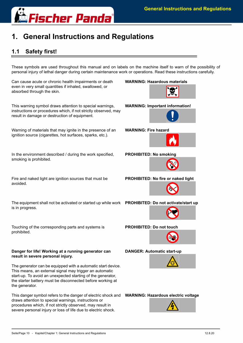
These symbols are used throughout this manual and on labels on the machine itself to warn of the possibility ofpersonal injury of lethal danger during certain maintenance work or operations. Read these instructions carefully.
WARNING: Hazardous materials Can cause acute or chronic health impairments or death even in very small quantities if inhaled, swallowed, or absorbed through the skin.
WARNING: Important information! This warning symbol draws attention to special warnings, instructions or procedures which, if not strictly observed, may result in damage or destruction of equipment.
WARNING: Fire hazard Warning of materials that may ignite in the presence of an ignition source (cigarettes, hot surfaces, sparks, etc.).
PROHIBITED: No smoking In the environment described / during the work specified, smoking is prohibited.
PROHIBITED: No fire or naked light Fire and naked light are ignition sources that must be avoided.
PROHIBITED: Do not activate/start up The equipment shall not be activated or started up while work is in progress.
PROHIBITED: Do not touch Touching of the corresponding parts and systems is prohibited.
DANGER: Automatic start-up Danger for life! Working at a running generator can result in severe personal injury.
The generator can be equipped with a automatic start device. This means, an external signal may trigger an automatic start-up. To avoid an unexpected starting of the generator, the starter battery must be disconnected before working at the generator.
WARNING: Hazardous electric voltage This danger symbol refers to the danger of electric shock and draws attention to special warnings, instructions or procedures which, if not strictly observed, may result in severe personal injury or loss of life due to electric shock.
General Instructions and Regulations
12.8.20 Kapitel/Chapter 1: General Instructions and Regulations - Seite/Page 11
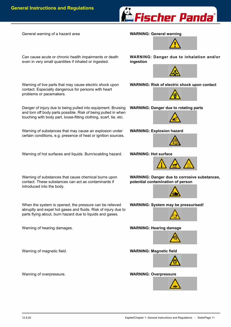
WARNING: General warning General warning of a hazard area
WARNING: Danger due to inhalation and/oringestion
Can cause acute or chronic health impairments or death even in very small quantities if inhaled or ingested.
WARNING: Risk of electric shock upon contactWarning of live parts that may cause electric shock upon contact. Especially dangerous for persons with heart problems or pacemakers.
WARNING: Danger due to rotating parts Danger of injury due to being pulled into equipment. Bruising and torn off body parts possible. Risk of being pulled in when touching with body part, loose-fitting clothing, scarf, tie, etc.
WARNING: Explosion hazard Warning of substances that may cause an explosion under certain conditions, e.g. presence of heat or ignition sources.
WARNING: Hot surface Warning of hot surfaces and liquids. Burn/scalding hazard.
WARNING: Danger due to corrosive substances,potential contamination of person
Warning of substances that cause chemical burns upon contact. These substances can act as contaminants if introduced into the body.
WARNING: System may be pressurised! When the system is opened, the pressure can be relieved abruptly and expel hot gases and fluids. Risk of injury due to parts flying about, burn hazard due to liquids and gases.
WARNING: Hearing damageWarning of hearing damages.
WARNING: Magnetic fieldWarning of magnetic field.
WARNING: OverpressureWarning of overpressure.
General Instructions and Regulations
Seite/Page 12 - Kapitel/Chapter 1: General Instructions and Regulations 12.8.20
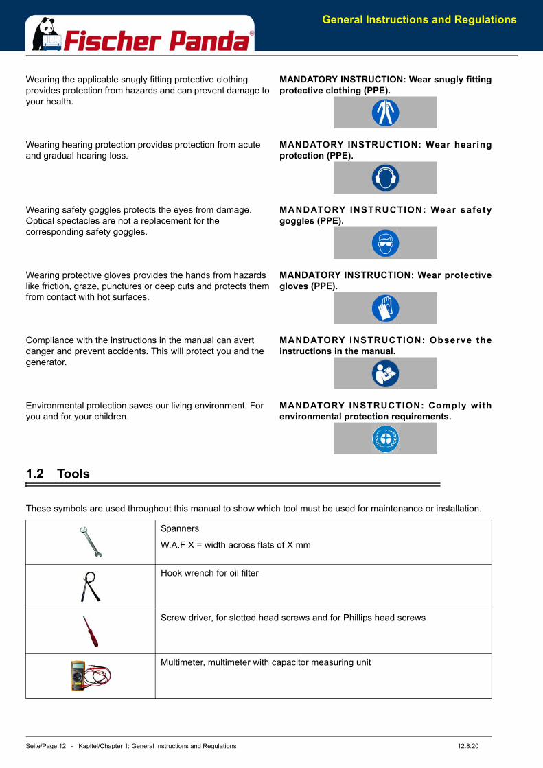
MANDATORY INSTRUCTION: Wear snugly fittingprotective clothing (PPE).
Wearing the applicable snugly fitting protective clothing provides protection from hazards and can prevent damage to your health.
MANDATORY INSTRUCTION: Wear hearingprotection (PPE).
Wearing hearing protection provides protection from acute and gradual hearing loss.
MANDATORY INSTRUCTION: Wear safetygoggles (PPE).
Wearing safety goggles protects the eyes from damage. Optical spectacles are not a replacement for the corresponding safety goggles.
MANDATORY INSTRUCTION: Wear protectivegloves (PPE).
Wearing protective gloves provides the hands from hazards like friction, graze, punctures or deep cuts and protects them from contact with hot surfaces.
MANDATORY INSTRUCTION: Observe theinstructions in the manual.
Compliance with the instructions in the manual can avert danger and prevent accidents. This will protect you and the generator.
MANDATORY INSTRUCTION: Comply withenvironmental protection requirements.
Environmental protection saves our living environment. For you and for your children.
1.2 Tools
These symbols are used throughout this manual to show which tool must be used for maintenance or installation.
Spanners
W.A.F X = width across flats of X mm
Hook wrench for oil filter
Screw driver, for slotted head screws and for Phillips head screws
Multimeter, multimeter with capacitor measuring unit

General Instructions and Regulations
12.8.20 Kapitel/Chapter 1: General Instructions and Regulations - Seite/Page 13
Socket wrench set
Hexagon socket wrench set
Clamp-on ammeter (DC for synchronous generators; AC for asynchronousgenerators)
Torque wrench
General Instructions and Regulations
Seite/Page 14 - Kapitel/Chapter 1: General Instructions and Regulations 12.8.20
1.3 Manufacturer declaration in accordance with the Machinery Directive 2006/42/EC
Manufacturer declaration in accordance with the Machinery Directive 2006/42/EC
The generator was designed in such a way that all assemblies correspond with the CE guidelines. If MachineryDirective 2006/42/EC is applied, then it is forbidden to start the generator until it has been ascertained that thesystem into which the generator is to be integrated also complies with the Machinery Directive 2006/42/EC. Thisincludes the exhaust system, cooling system and electrical installations.
The evaluation of “protection against contact“ must be carried out when installed, in conjunction with the respectivesystem. This also includes correct electrical connections, a safe ground wire connection, foreign body and humidityprotection, protection against moisture due to excessive condensation, as well as overheating through appropriateand inappropriate use of the equipment in its installed state. The responsibility for implementing these measures lieswith those who undertake the installation of the generator in the final system.
1.4 Customer registration and guarantee
Use the advantages of registering your product:
• you will receive a Guarantee Certificate after approval of your installation data
• you will receive extended product information that may be relevant to safety.
• You will receive free upgrades as necessary.
Additional advantages:
Based on your complete data record, Fischer Panda technicians can provide you with fast assistance, since 90 % ofthe disturbances result from defects in the periphery.
Problems due to installation errors can be recognized in advance.
1.4.1 Technical support
Technical Support via the Internet: [email protected]
1.4.2 Caution, important information for start-up!
1. The commissioning log shall be filled in immediately after initial operation and shall be confirmed by signature.2. The commissioning log must be received by Fischer Panda GmbH at Paderborn within 4 weeks of initial
operation.3. After receiving the commissioning log, Fischer Panda will make out the official guarantee certificate and send it to
the customer.4. If warranty claims are made, the document with the guarantee certification must be submitted.
If the above requirements are not or only partly fulfilled, the warranty claim shall become void.
General Instructions and Regulations
12.8.20 Kapitel/Chapter 1: General Instructions and Regulations - Seite/Page 15
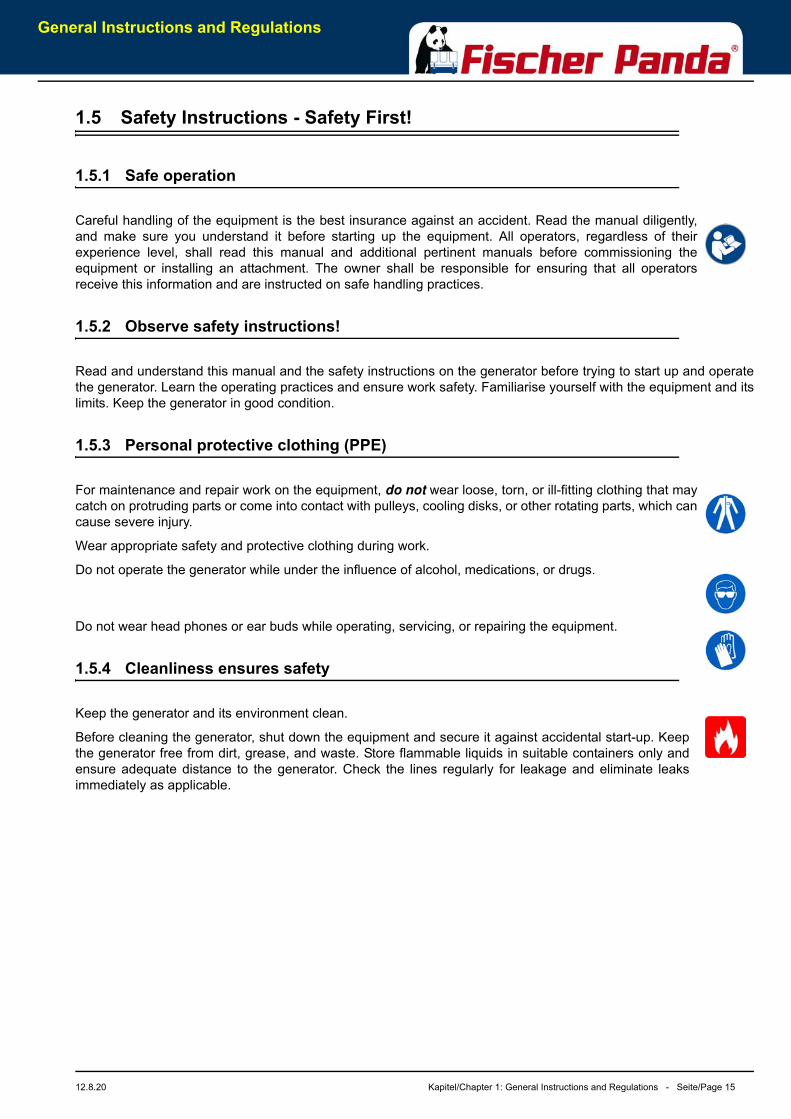
1.5 Safety Instructions - Safety First!
1.5.1 Safe operation
Careful handling of the equipment is the best insurance against an accident. Read the manual diligently,and make sure you understand it before starting up the equipment. All operators, regardless of theirexperience level, shall read this manual and additional pertinent manuals before commissioning theequipment or installing an attachment. The owner shall be responsible for ensuring that all operatorsreceive this information and are instructed on safe handling practices.
1.5.2 Observe safety instructions!
Read and understand this manual and the safety instructions on the generator before trying to start up and operatethe generator. Learn the operating practices and ensure work safety. Familiarise yourself with the equipment and itslimits. Keep the generator in good condition.
1.5.3 Personal protective clothing (PPE)
For maintenance and repair work on the equipment, do not wear loose, torn, or ill-fitting clothing that maycatch on protruding parts or come into contact with pulleys, cooling disks, or other rotating parts, which cancause severe injury.
Wear appropriate safety and protective clothing during work.
Do not operate the generator while under the influence of alcohol, medications, or drugs.
Do not wear head phones or ear buds while operating, servicing, or repairing the equipment.
1.5.4 Cleanliness ensures safety
Keep the generator and its environment clean.
Before cleaning the generator, shut down the equipment and secure it against accidental start-up. Keepthe generator free from dirt, grease, and waste. Store flammable liquids in suitable containers only andensure adequate distance to the generator. Check the lines regularly for leakage and eliminate leaksimmediately as applicable.
General Instructions and Regulations
Seite/Page 16 - Kapitel/Chapter 1: General Instructions and Regulations 12.8.20
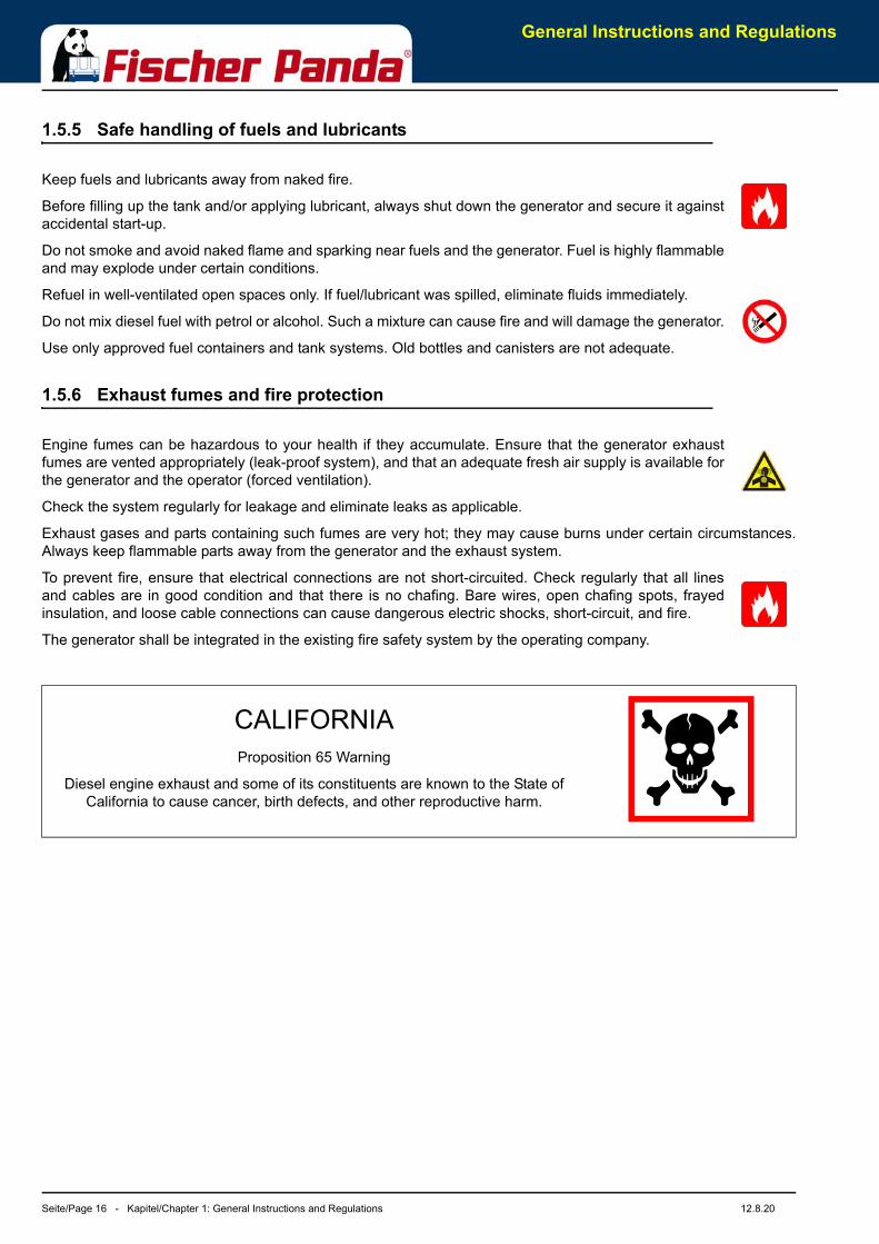
1.5.5 Safe handling of fuels and lubricants
Keep fuels and lubricants away from naked fire.
Before filling up the tank and/or applying lubricant, always shut down the generator and secure it againstaccidental start-up.
Do not smoke and avoid naked flame and sparking near fuels and the generator. Fuel is highly flammableand may explode under certain conditions.
Refuel in well-ventilated open spaces only. If fuel/lubricant was spilled, eliminate fluids immediately.
Do not mix diesel fuel with petrol or alcohol. Such a mixture can cause fire and will damage the generator.
Use only approved fuel containers and tank systems. Old bottles and canisters are not adequate.
1.5.6 Exhaust fumes and fire protection
Engine fumes can be hazardous to your health if they accumulate. Ensure that the generator exhaustfumes are vented appropriately (leak-proof system), and that an adequate fresh air supply is available forthe generator and the operator (forced ventilation).
Check the system regularly for leakage and eliminate leaks as applicable.
Exhaust gases and parts containing such fumes are very hot; they may cause burns under certain circumstances.Always keep flammable parts away from the generator and the exhaust system.
To prevent fire, ensure that electrical connections are not short-circuited. Check regularly that all linesand cables are in good condition and that there is no chafing. Bare wires, open chafing spots, frayedinsulation, and loose cable connections can cause dangerous electric shocks, short-circuit, and fire.
The generator shall be integrated in the existing fire safety system by the operating company.
CALIFORNIAProposition 65 Warning
Diesel engine exhaust and some of its constituents are known to the State of California to cause cancer, birth defects, and other reproductive harm.
General Instructions and Regulations
12.8.20 Kapitel/Chapter 1: General Instructions and Regulations - Seite/Page 17
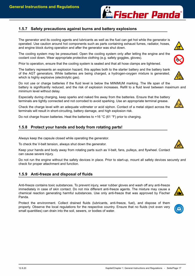
1.5.7 Safety precautions against burns and battery explosions
The generator and its cooling agents and lubricants as well as the fuel can get hot while the generator isoperated. Use caution around hot components such as parts containing exhaust fumes, radiator, hoses,and engine block during operation and after the generator was shut down.
The cooling system may be pressurised. Open the cooling system only after letting the engine and thecoolant cool down. Wear appropriate protective clothing (e.g. safety goggles, gloves).
Prior to operation, ensure that the cooling system is sealed and that all hose clamps are tightened.
The battery represents an explosion hazard, this applies both to the starter battery and the battery bankof the AGT generators. While batteries are being charged, a hydrogen-oxygen mixture is generated,which is highly explosive (electrolytic gas).
Do not use or charge batteries if the fluid level is below the MINIMUM marking. The life span of thebattery is significantly reduced, and the risk of explosion increases. Refill to a fluid level between maximum andminimum level without delay.
Especially during charging, keep sparks and naked fire away from the batteries. Ensure that the batteryterminals are tightly connected and not corroded to avoid sparking. Use an appropriate terminal grease.
Check the charge level with an adequate voltmeter or acid siphon. Contact of a metal object across theterminals will result in short-circuiting, battery damage, and high explosion risk.
Do not charge frozen batteries. Heat the batteries to +16 °C (61 °F) prior to charging.
1.5.8 Protect your hands and body from rotating parts!
Always keep the capsule closed while operating the generator.
To check the V-belt tension, always shut down the generator.
Keep your hands and body away from rotating parts such as V-belt, fans, pulleys, and flywheel. Contactcan cause severe injury.
Do not run the engine without the safety devices in place. Prior to start-up, mount all safety devices securely andcheck for proper attachment and function.
1.5.9 Anti-freeze and disposal of fluids
Anti-freeze contains toxic substances. To prevent injury, wear rubber gloves and wash off any anti-freezeimmediately in case of skin contact. Do not mix different anti-freeze agents. The mixture may cause achemical reaction generating harmful substances. Use only anti-freeze that was approved by FischerPanda.
Protect the environment. Collect drained fluids (lubricants, anti-freeze, fuel), and dispose of themproperly. Observe the local regulations for the respective country. Ensure that no fluids (not even verysmall quantities) can drain into the soil, sewers, or bodies of water.
General Instructions and Regulations
Seite/Page 18 - Kapitel/Chapter 1: General Instructions and Regulations 12.8.20
1.5.10 Implementation of safety inspections and maintenance
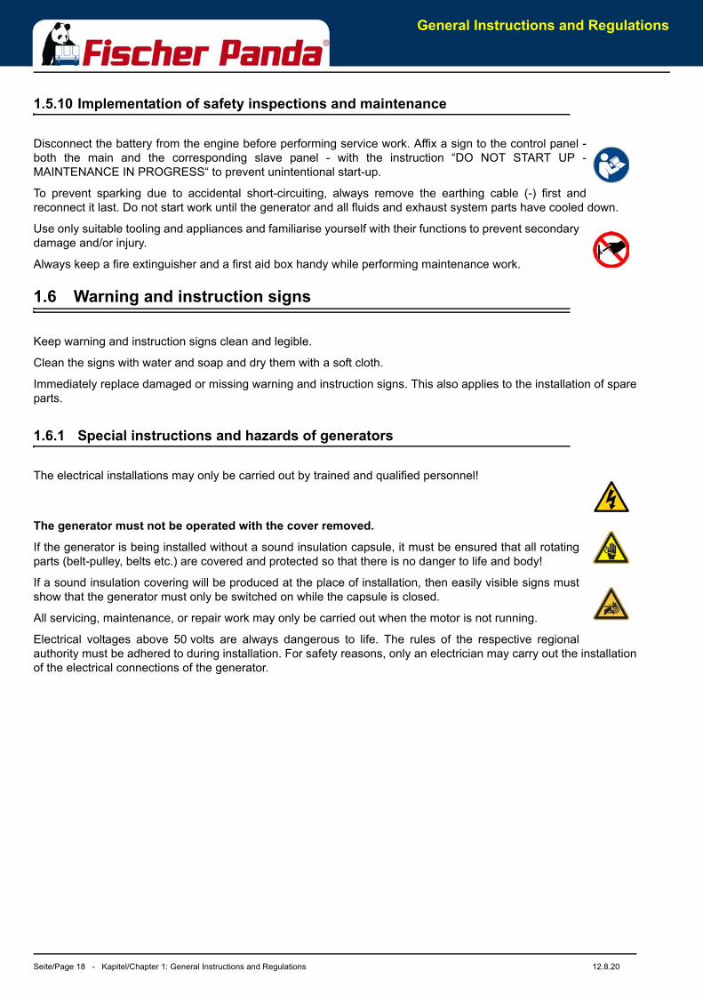
Disconnect the battery from the engine before performing service work. Affix a sign to the control panel -both the main and the corresponding slave panel - with the instruction “DO NOT START UP -MAINTENANCE IN PROGRESS“ to prevent unintentional start-up.
To prevent sparking due to accidental short-circuiting, always remove the earthing cable (-) first andreconnect it last. Do not start work until the generator and all fluids and exhaust system parts have cooled down.
Use only suitable tooling and appliances and familiarise yourself with their functions to prevent secondarydamage and/or injury.
Always keep a fire extinguisher and a first aid box handy while performing maintenance work.
1.6 Warning and instruction signs
Keep warning and instruction signs clean and legible.
Clean the signs with water and soap and dry them with a soft cloth.
Immediately replace damaged or missing warning and instruction signs. This also applies to the installation of spareparts.
1.6.1 Special instructions and hazards of generators
The electrical installations may only be carried out by trained and qualified personnel!
The generator must not be operated with the cover removed.
If the generator is being installed without a sound insulation capsule, it must be ensured that all rotatingparts (belt-pulley, belts etc.) are covered and protected so that there is no danger to life and body!
If a sound insulation covering will be produced at the place of installation, then easily visible signs mustshow that the generator must only be switched on while the capsule is closed.
All servicing, maintenance, or repair work may only be carried out when the motor is not running.
Electrical voltages above 50 volts are always dangerous to life. The rules of the respective regionalauthority must be adhered to during installation. For safety reasons, only an electrician may carry out the installationof the electrical connections of the generator.

General Instructions and Regulations
12.8.20 Kapitel/Chapter 1: General Instructions and Regulations - Seite/Page 19
1.6.1.1 Protective conductor and potential equalisation:
Electric voltage above 50 V may be life-threatening. Fort this reason systems are grounded with a protectiveconductor. In connection with a RCD the current supply will be disconnected in case of a failure.
Appropriate safety precautions like the RCD and corresponding fuses have to be provided by the customerto guarantee a save operation of the generator.
1.6.1.2 Protective conductor for Panda AC generators:
The generator is earthed“ as a standard (centre and ground are interconnected in the generator terminalbox by a shunt). This is a basic first-level safety measure, which offers protection as long as no othermeasures are installed. Above all, it is designed for delivery and a possible test run.
This „neutralisation“ (Protective Earthing Neutral - PEN) is only effective if all parts of the electricalsystem are jointly „earthed“ to a common potential. The shunt can be removed if this is necessary for technicalreasons and another protective system has been set up instead.
While the generator is being operated, the full voltage is applied to the AC control box, as well.Therefore, it is essential to ensure that the control box is closed and secured against touch whilethe generator is running.
The battery must always be disconnected if work on the generator or electrical system is to becarried out, so that the generator cannot be started up unintentionally.
1.6.1.3 Switch off all loads while working on the generator
All loads must be disconnected prior to working on the generator to avoid damage to the devices. In addition, thesemiconductor relays in the AC control box must be disconnected in order to avoid the booster capacitors beingactivated during set-up. The negative terminal of the battery must be disconnected.
Capacitors are required to run the generator. These have two varying functions:
A) The working capacitors
B) The booster capacitors
Both groups are located in a separate AC control box.
Capacitors store electrical energy. High voltages may remain across the capacitor contacts even after they havebeen disconnected from the mains. As a safety precaution, do not touch the contacts. If the capacitors must bereplaced or inspected, the contacts shall be short-circuited by connecting an electrical conductor to dischargepotentially remaining potential differences.
If the generator is switched off normally, the working capacitors are automatically discharged via the winding of thegenerator. The booster capacitors are discharged by means of internal discharge resistors.
For safety reasons, all capacitors must be discharged through short-circuiting before work is carried out on the ACcontrol box.
1.6.1.4 Potential equalisation for Panda AGT DC generators
For further information specific to your generator, see the chapter installation.
General Instructions and Regulations
Seite/Page 20 - Kapitel/Chapter 1: General Instructions and Regulations 12.8.20
1.6.1.5 Safety instructions concerning cables
Cable types
It is recommended to use cables that are in compliance with the standard UL 1426 (BC-5W2) with type 3 (ABYCsection E-11).
Cable cross-section
The cable shall be selected taking into account the amperage, cable type, and conductor length (from the positivepower source connection to the electrical device and back to the negative power source connection).
Cable installation
It is recommended to install a self-draining cable conduit classified as V-2 or higher in compliance with UL 94 in thearea of the cable guide inside the capsule. It must be ensured that the cable guide is not routed along hot surfacessuch as the exhaust manifold or the engine oil drain screw but instead is installed free from any influence due tofriction and crushing.
1.6.2 General safety instructions for handling batteries
These instructions shall apply in addition to the instructions of the battery manufacturer:
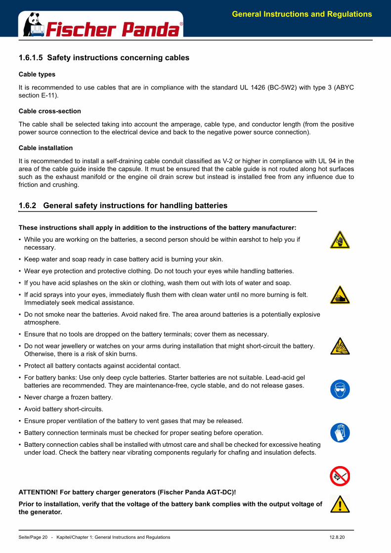
• While you are working on the batteries, a second person should be within earshot to help you if necessary.
• Keep water and soap ready in case battery acid is burning your skin.
• Wear eye protection and protective clothing. Do not touch your eyes while handling batteries.
• If you have acid splashes on the skin or clothing, wash them out with lots of water and soap.
• If acid sprays into your eyes, immediately flush them with clean water until no more burning is felt. Immediately seek medical assistance.
• Do not smoke near the batteries. Avoid naked fire. The area around batteries is a potentially explosive atmosphere.
• Ensure that no tools are dropped on the battery terminals; cover them as necessary.
• Do not wear jewellery or watches on your arms during installation that might short-circuit the battery. Otherwise, there is a risk of skin burns.
• Protect all battery contacts against accidental contact.
• For battery banks: Use only deep cycle batteries. Starter batteries are not suitable. Lead-acid gel batteries are recommended. They are maintenance-free, cycle stable, and do not release gases.
• Never charge a frozen battery.
• Avoid battery short-circuits.
• Ensure proper ventilation of the battery to vent gases that may be released.
• Battery connection terminals must be checked for proper seating before operation.
• Battery connection cables shall be installed with utmost care and shall be checked for excessive heating under load. Check the battery near vibrating components regularly for chafing and insulation defects.
ATTENTION! For battery charger generators (Fischer Panda AGT-DC)!
Prior to installation, verify that the voltage of the battery bank complies with the output voltage ofthe generator.
In case of Emergency First Aid / Im Notfall - Erste Hilfe
12.8.20 Kapitel/Chapter 2: In case of Emergency First Aid / Im Notfall - Erste Hilfe - Seite/Page 21
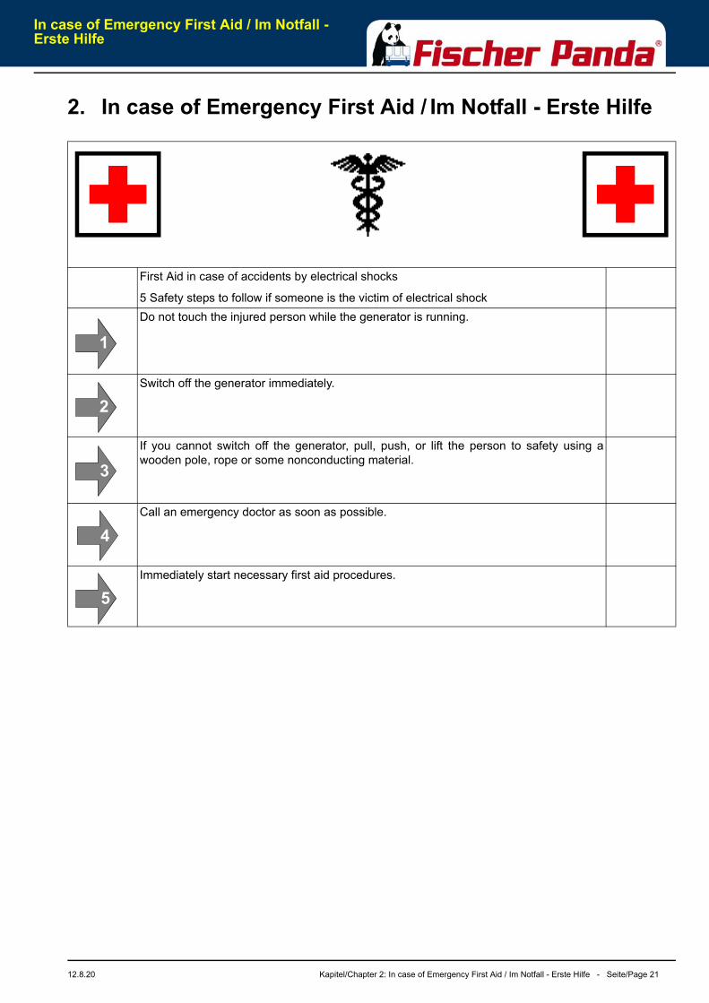
2. In case of Emergency First Aid / Im Notfall - Erste Hilfe
First Aid in case of accidents by electrical shocks
5 Safety steps to follow if someone is the victim of electrical shockDo not touch the injured person while the generator is running.
Switch off the generator immediately.
If you cannot switch off the generator, pull, push, or lift the person to safety using awooden pole, rope or some nonconducting material.
Call an emergency doctor as soon as possible.
Immediately start necessary first aid procedures.
11
12
13
14
15
In case of Emergency First Aid / Im Notfall -Erste Hilfe
Seite/Page 22 - Kapitel/Chapter 2: In case of Emergency First Aid / Im Notfall - Erste Hilfe 12.8.20
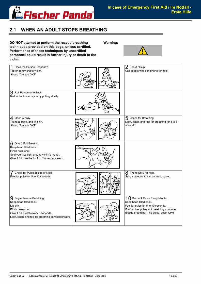
2.1 WHEN AN ADULT STOPS BREATHING
Warning:DO NOT attempt to perform the rescue breathing techniques provided on this page, unless certified. Performance of these techniques by uncertified personnel could result in further injury or death to the victim.
1 Does the Person Respond?Tap or gently shake victim.Shout, “Are you OK?“
2 Shout, “Help!“Call people who can phone for help.
3 Roll Person onto Back.Roll victim towards you by pulling slowly.
4 Open Airway.Tilt head back, and lift chin.Shout, “Are you OK?“
5 Check for Breathing.Look, listen, and feel for breathing for 3 to 5 seconds.
6 Give 2 Full Breaths.Keep head tilted back.Pinch nose shut.Seal your lips tight around victim's mouth.Give 2 full breaths for 1 to 1½ seconds each.
7 Check for Pulse at side of Neck.Feel for pulse for 5 to 10 seconds.
8 Phone EMS for Help.Send someone to call an ambulance.
9 Begin Rescue Breathing.Keep head tilted back.Lift chin.Pinch nose shut.Give 1 full breath every 5 seconds.Look, listen, and feel for breathing between breaths.
10 Recheck Pulse Every Minute.Keep head tilted back.Feel for pulse for 5 to 10 seconds.If victim has pulse, not breathing, continue rescue breathing. If no pulse, begin CPR.
Basics
12.8.20 Kapitel/Chapter 3: Basics - Seite/Page 23
3. Basics
3.1 Intended use of the machine
The machine is only for use as an fixed installed electric generator in following applications:
• motor vehicles
• trailers and mobile containers
• inland water vessels/river boats
• ocean-going vessels
The power should produced and supplied in the on-board grid for off grid use only. Other or further use is not
intended.
For the intended use, the designated limits of the machine and all safety related parameter must be respected. The
limits of the machine should not be exceeded.
3.1.1 Purpose of the manual and description of the definitions trained person/operator/user
This manual is work instruction and operation instruction for the owner and user of Fischer Panda generators.
The manual is the base and the guideline for the correct installation and maintenance of Fischer Panda Generators.
The manual does not substitute the technical evaluation and should be used as an example guide only.
The installation must be undertaken and proved by a suitable qualified/trained person and may in accordance withthe law as required by the country and special situation.
3.1.1.1 Trained persons
Trained persons for the mechanical components are motor mechanics or persons with similar educationand training.
Trained persons for the electrical components are electricians or persons with similar education andtraining.
After the Installation, the trained person must instruct the owner for operation and maintenance of thegenerator. This must include the hazards of the generator use.
3.1.2 Operator
The operator is the for the operation of the generator responsible person.
After the installation, the operator must be instructed for the operation ad maintenance of the generator. This mustinclude the hazards during operation of the generator and a instruction for the maintenance.
The operator must read and follow the manual and must respect the hazard notes and safety instructions.
3.1.2.1 User
Users are persons, established by the operator, to operate the generator.
The operator must assure that the user read and understand the manual and that all hazard notes and safetyinstructions are respected. The user must be instructed by the operator regarding his activity at the generator.
Basics
Seite/Page 24 - Kapitel/Chapter 3: Basics 12.8.20
3.2 Panda Transport Box
3.2.1 Bolted Fischer Panda Transport Box
1. Remove the bolts for cover / sidewalls2. Remove the cover3. Remove the loose accessories4. Remove the bolts for sidewalls / floor pallet5. Remove the sidewalls6. Open the generator attachment
3.2.2 Fischer Panda Transport Box with metal tab closure
1. Bend up the metal tab closures on the transport box lid.2. Remove the cover3. Remove the loose 4. Bend open the metal tab closures on the transport box bottom.5. Remove the sidewalls6. Open the generator attachment
3.3 Transport and Loading/Unloading
3.3.1 Transporting the generator
• The generator must always be upright for transport.
• For transport, the Fischer Panda Transport Box shall be used for the generator. The generator shall be securely attached to the bottom of the box.
• For loading/unloading, an adequate industrial truck shall be used.
• Depending on the transport distance (e.g. air cargo), the generator fluids (coolant, engine oil, fuel) may have to be drained. The corresponding instructions and warnings must be fitted to the transport packaging.
3.3.2 Loading/unloading of the generator
For loading/unloading the generator, appropriate ring eye bolts shall be installed in the holes in the support rails. Theload bearing capacity of each ring eye bolt must at least equal the generator weight.
Basics
12.8.20 Kapitel/Chapter 3: Basics - Seite/Page 25
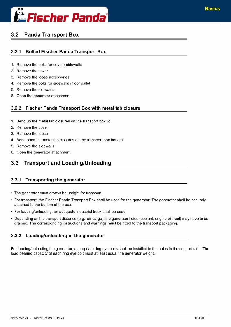
Fig. 3.3-1: Lifting yoke (example)An adequate lifting yoke shall be used for transport/loading
3.4 Scope of delivery
The Fischer Panda PMS generator system contains following components:
3.4.1 Asynchronous Generator:
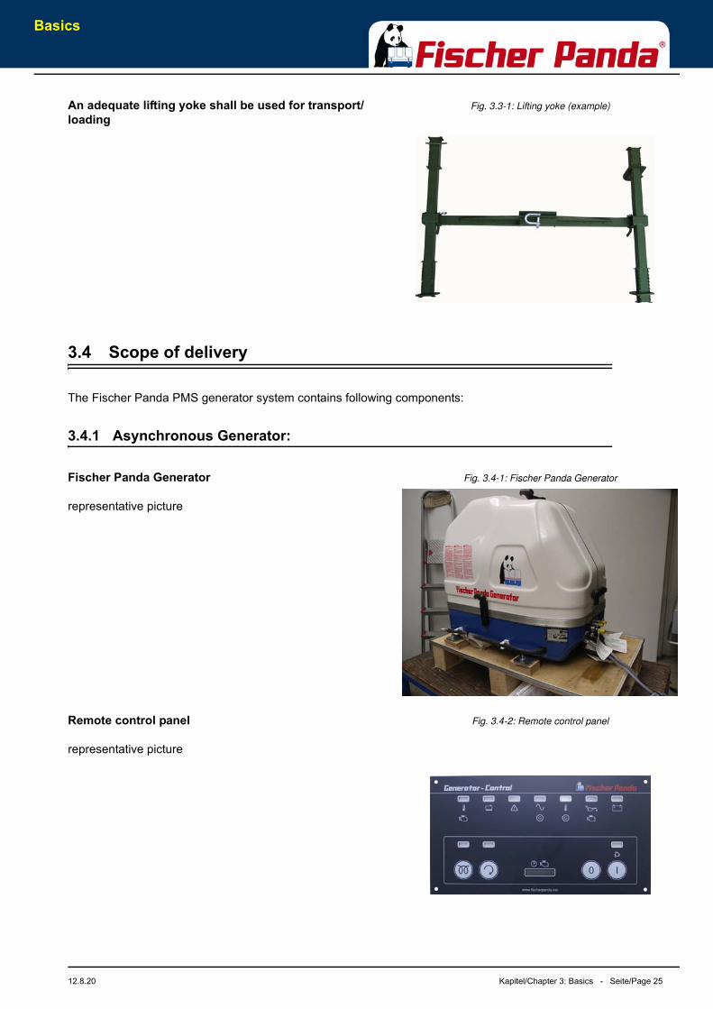
Fig. 3.4-1: Fischer Panda GeneratorFischer Panda Generator
representative picture
Fig. 3.4-2: Remote control panelRemote control panel
representative picture
Basics
Seite/Page 26 - Kapitel/Chapter 3: Basics 12.8.20
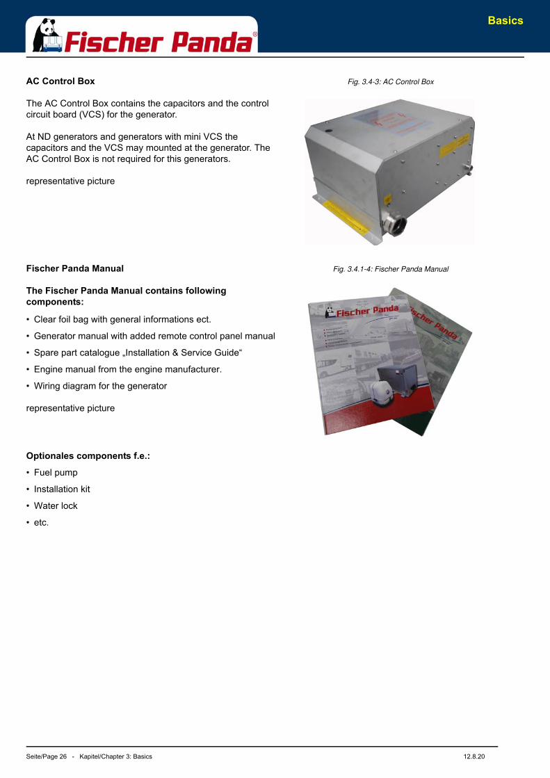
Fig. 3.4-3: AC Control BoxAC Control Box
The AC Control Box contains the capacitors and the control circuit board (VCS) for the generator.
At ND generators and generators with mini VCS the capacitors and the VCS may mounted at the generator. The AC Control Box is not required for this generators.
representative picture
Fig. 3.4.1-4: Fischer Panda ManualFischer Panda Manual
The Fischer Panda Manual contains following components:
• Clear foil bag with general informations ect.
• Generator manual with added remote control panel manual
• Spare part catalogue „Installation & Service Guide“
• Engine manual from the engine manufacturer.
• Wiring diagram for the generator
representative picture
Optionales components f.e.:
• Fuel pump
• Installation kit
• Water lock
• etc.
Basics
12.8.20 Kapitel/Chapter 3: Basics - Seite/Page 27
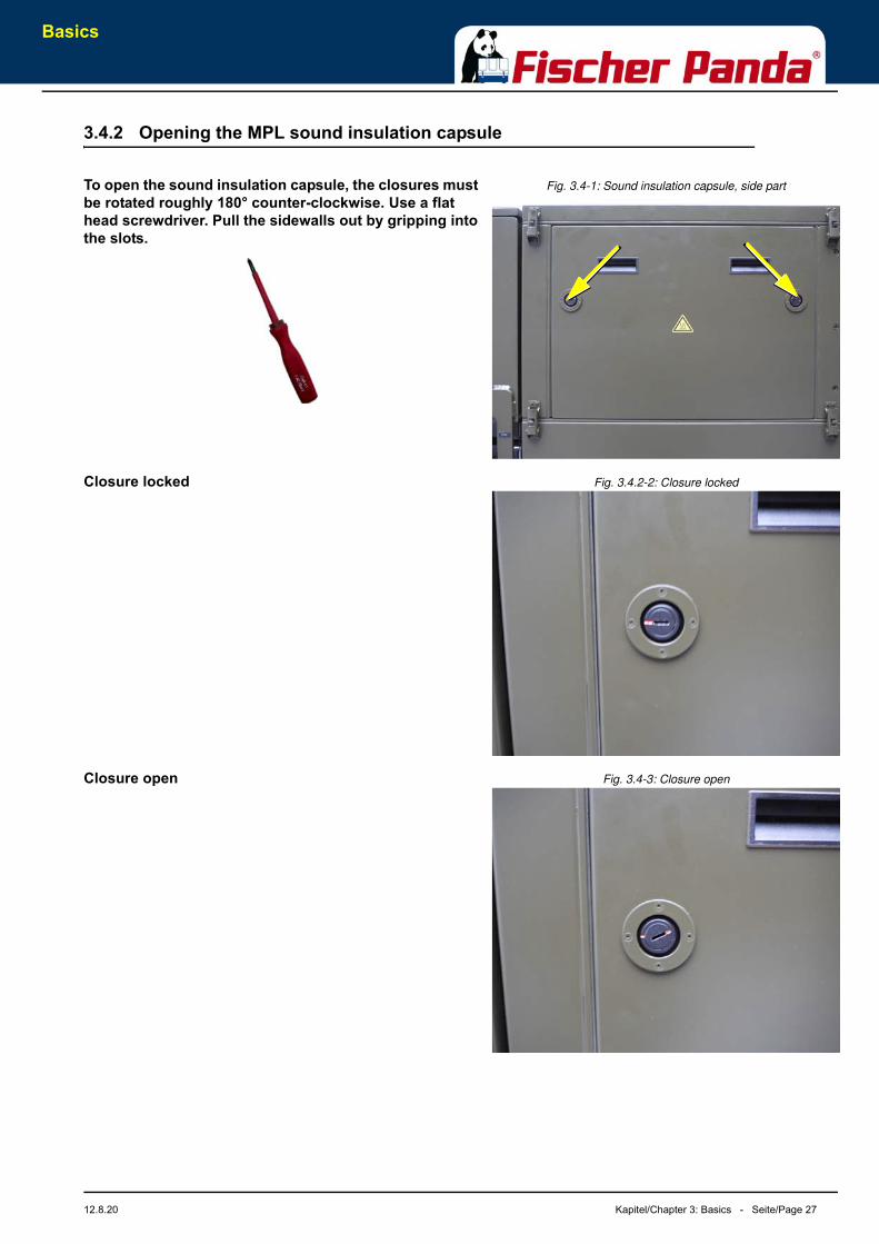
3.4.2 Opening the MPL sound insulation capsule
Fig. 3.4-1: Sound insulation capsule, side partTo open the sound insulation capsule, the closures must be rotated roughly 180° counter-clockwise. Use a flat head screwdriver. Pull the sidewalls out by gripping into the slots.
Fig. 3.4.2-2: Closure lockedClosure locked
Fig. 3.4-3: Closure openClosure open
Basics
Seite/Page 28 - Kapitel/Chapter 3: Basics 12.8.20
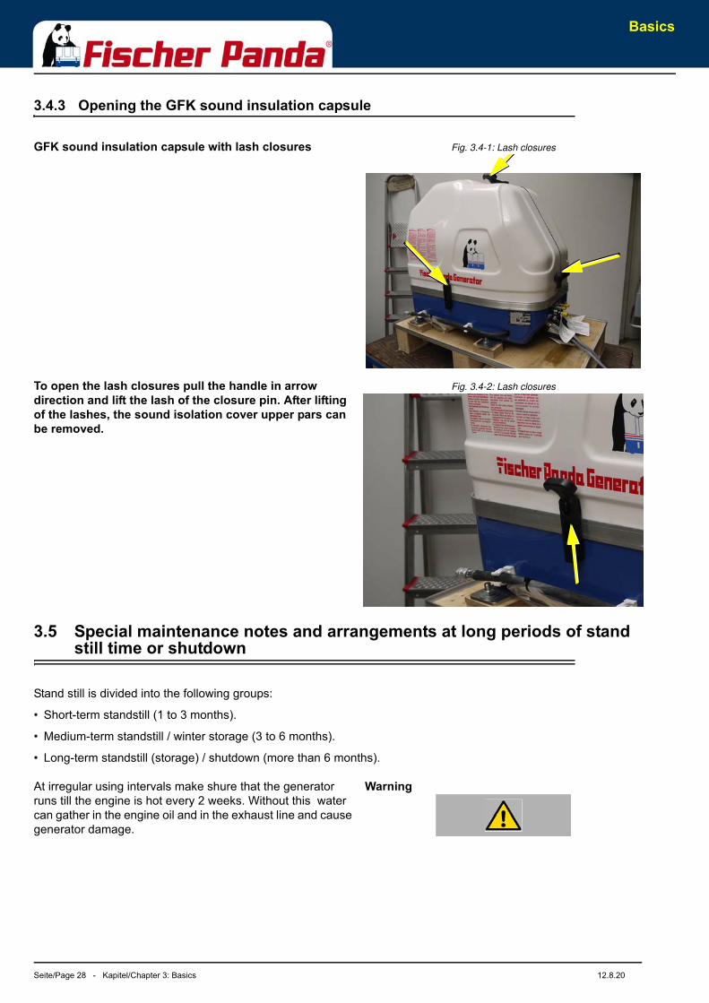
3.4.3 Opening the GFK sound insulation capsule
Fig. 3.4-1: Lash closuresGFK sound insulation capsule with lash closures
Fig. 3.4-2: Lash closuresTo open the lash closures pull the handle in arrow direction and lift the lash of the closure pin. After lifting of the lashes, the sound isolation cover upper pars can be removed.
3.5 Special maintenance notes and arrangements at long periods of stand still time or shutdown
Stand still is divided into the following groups:
• Short-term standstill (1 to 3 months).
• Medium-term standstill / winter storage (3 to 6 months).
• Long-term standstill (storage) / shutdown (more than 6 months).
WarningAt irregular using intervals make shure that the generator runs till the engine is hot every 2 weeks. Without this water can gather in the engine oil and in the exhaust line and cause generator damage.
Basics
12.8.20 Kapitel/Chapter 3: Basics - Seite/Page 29
3.5.1 Reference note for the starter battery at a long-term standstill
Notice: Starter batteries
Self-discharge of batteries is a physical and chemical process and cannot even be avoid by disconnecting the battery.
• Disconnect the battery from the generator at a long-term standstill.
• Charge the battery on a regular basis. Follow the notes of the battery manufacturer.
Before charging the battery, check the acid level according to the type of battery and refill each cell with distilledwater up to the marking if necessary.
Today’s starter batteries are normally maintenance-free.
Deep discharge may damage the battery and may be useless afterwards.
Keep the battery clean and dry. Continuously clean the battery terminals (+ and -) and clamps and lubricate with anacid-free and acid-resistant grease. Make sure there is a good contact of the clamp connections when assembling. Ifvoltage is approx. below 1,95 Volt, the cell should not decline the open-circuit voltage of the battery. This equatesapprox. 2,1 V / cell open-circuit voltage when battery is fully charged.
For a 12 V battery applies 11,7 V lower open-circuit voltage (battery flat) - conservation charging 13,2 V.
For a 24 V battery applies 23,4 V lower open-circuit voltage (battery flat) - conservation charging 26,4 V.
These data relate to a battery temperature of 20-25 °C. Consider the specifications of the battery manufacturer.
Notice: Fischer Panda recommendation:
• Install a battery main switch and turn it to the off-position. (Disrupt the battery circuit)
• Install a sufficient fuse in the positive battery line close to the battery
• Check contacts for corrosion on a regular basis.
3.5.2 Arrangements at a short-term standstill
Short-term standstill (1 to 3 months)
• Measure the charge of battery via the open-circuit voltage
• At stand still >7 days - disconnect the battery (e.g. put battery main switch to 0)
• Drain the waterlock. Disconnect the exhaust line between waterlock and generator. Close the exhaust line of the generator.
• Within 2-3 months - let the engine run for at least 10 min
• Fill fuel tank to 100% (level to full).
3.5.3 Arrangements at a medium-term standstill / winter storage
Medium-term stand still (3 to 6 months)
3.5.3.1 Arrangements for conservation:
• Check the charge of battery and recharge approximately every 3 months if necessary. Consider the specifications of the battery manufacturer.
Basics
Seite/Page 30 - Kapitel/Chapter 3: Basics 12.8.20
• Check anti-freeze protection of the cooling water and refill if applicable.
The anti-freeze protection should not be older than 2 years. The content of the anti-freeze protection should bebetween 40% and 60% to ensure corrosion protection in the cooling water circuit; Refill anti-freeze if necessary.
If cooling water will be drained, for example after a conservation of the engine, no water should remain within theengine during the stand still. At the control unit a correspondent note „NO COOLING WATER“ has to be placed.
• Drain engine oil as required. Refill engine with conservation oil up to maximum at the oil dip stick.
• Drain diesel fuel from tank and refill with conservation mixture (90% diesel and 10% conservation oil - up to max).
Let engine run for 10 min.
• Remove v-belt as required and store packed at a dry place. Protect from UV radiation.
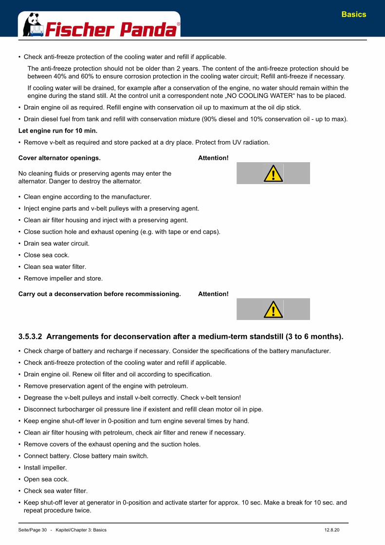
Attention!Cover alternator openings.
No cleaning fluids or preserving agents may enter the alternator. Danger to destroy the alternator.
• Clean engine according to the manufacturer.
• Inject engine parts and v-belt pulleys with a preserving agent.
• Clean air filter housing and inject with a preserving agent.
• Close suction hole and exhaust opening (e.g. with tape or end caps).
• Drain sea water circuit.
• Close sea cock.
• Clean sea water filter.
• Remove impeller and store.
Attention!Carry out a deconservation before recommissioning.
3.5.3.2 Arrangements for deconservation after a medium-term standstill (3 to 6 months).
• Check charge of battery and recharge if necessary. Consider the specifications of the battery manufacturer.
• Check anti-freeze protection of the cooling water and refill if applicable.
• Drain engine oil. Renew oil filter and oil according to specification.
• Remove preservation agent of the engine with petroleum.
• Degrease the v-belt pulleys and install v-belt correctly. Check v-belt tension!
• Disconnect turbocharger oil pressure line if existent and refill clean motor oil in pipe.
• Keep engine shut-off lever in 0-position and turn engine several times by hand.
• Clean air filter housing with petroleum, check air filter and renew if necessary.
• Remove covers of the exhaust opening and the suction holes.
• Connect battery. Close battery main switch.
• Install impeller.
• Open sea cock.
• Check sea water filter.
• Keep shut-off lever at generator in 0-position and activate starter for approx. 10 sec. Make a break for 10 sec. and repeat procedure twice.
Basics
12.8.20 Kapitel/Chapter 3: Basics - Seite/Page 31
• Visual inspection of the generator according to initial operation and start generator.
3.5.4 Arrangements at a long-term standstill / shutdown
Standstill (more than 6 months)
3.5.4.1 Arrangements for conservation:
• Check the charge of battery and recharge approximately every 3 months if necessary. Consider the specifications of the battery manufacturer.
• Check anti-freeze protection of the cooling water and refill if applicable.
The anti-freeze protection should not be older than 2 years. The content of the anti-freeze protection should bebetween 40% and 60% to ensure corrosion protection in the cooling water circuit; Refill anti-freeze if necessary.
If cooling water will be drained, for example after a conservation of the engine, no water should remain within theengine during the stand still. At the control unit a correspondent note „NO COOLING WATER“ has to be placed.
• Drain engine oil as required. Refill engine with conservation oil up to maximum at the oil dip stick.
• Drain diesel fuel from tank and refill with conservation mixture (90% diesel and 10% conservation oil - up to max).
Let engine run for 10 min.
• Remove v-belt as required and store packed at a dry place. Protect from UV radiation
• Disconnect battery.Sprinkle terminals with acid-free grease.
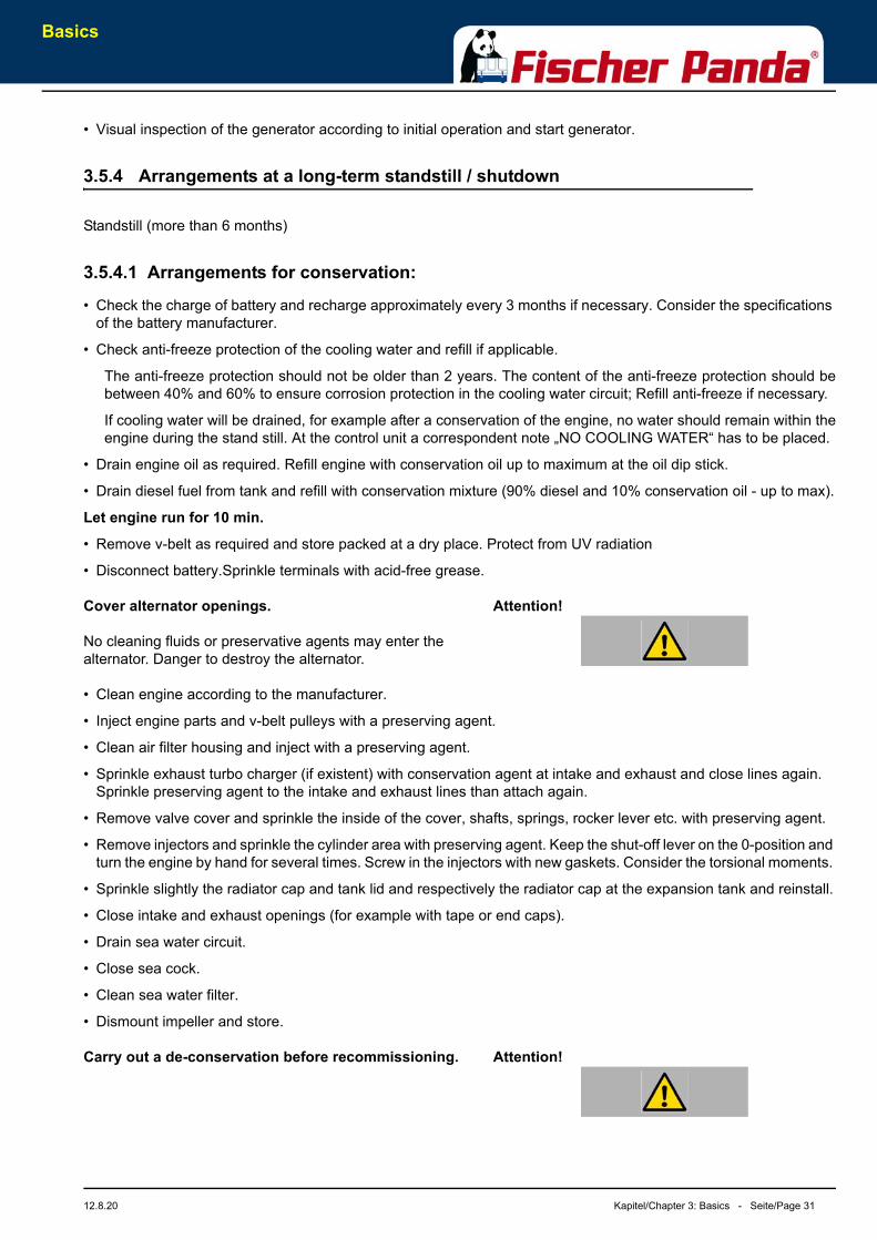
Attention!Cover alternator openings.
No cleaning fluids or preservative agents may enter the alternator. Danger to destroy the alternator.
• Clean engine according to the manufacturer.
• Inject engine parts and v-belt pulleys with a preserving agent.
• Clean air filter housing and inject with a preserving agent.
• Sprinkle exhaust turbo charger (if existent) with conservation agent at intake and exhaust and close lines again. Sprinkle preserving agent to the intake and exhaust lines than attach again.
• Remove valve cover and sprinkle the inside of the cover, shafts, springs, rocker lever etc. with preserving agent.
• Remove injectors and sprinkle the cylinder area with preserving agent. Keep the shut-off lever on the 0-position and turn the engine by hand for several times. Screw in the injectors with new gaskets. Consider the torsional moments.
• Sprinkle slightly the radiator cap and tank lid and respectively the radiator cap at the expansion tank and reinstall.
• Close intake and exhaust openings (for example with tape or end caps).
• Drain sea water circuit.
• Close sea cock.
• Clean sea water filter.
• Dismount impeller and store.
Attention!Carry out a de-conservation before recommissioning.
Basics
Seite/Page 32 - Kapitel/Chapter 3: Basics 12.8.20
3.5.4.2 Arrangements after a long-term standstill (shutdown) / recommissioning (more than 6 months):
• Check the charge of battery and recharge if necessary. Consider the specifications of the battery manufacturer.
• Check anti-freeze protection and level of the cooling water and refill if applicable.
• Drain engine oil. Renew oil filter and oil according specification.
• Remove preservation agent of the engine with petroleum.
• Degrease the v-belt pulleys and install v-belt correctly. Check v-belt tension!
• Disconnect turbocharger oil pressure line if existent and refill clean motor oil in pipe.
• Keep engine shut-off lever in 0-position and turn engine several times by hand.
• Clean air filter housing with petroleum, check air filter and renew if necessary.
• Remove covers of the exhaust opening and the suction holes.
• Connect battery. Close battery main switch.
• Install impeller.
• Open sea cock.
• Check sea water filter.
• Keep shut-off lever at generator in 0-position and activate starter for approx. 10 sec. Make a break for 10 sec. and repeat procedure twice.
• Visual inspection of the generator according to initial operation and start generator.
Notice: Fischer Panda recommendation:
After a long-term standstill a complete 150 h inspection according to inspection schedule should be carried out.
The Panda Generator
12.8.20 Kapitel/Chapter 4: The Panda Generator - Seite/Page 33
4. The Panda Generator
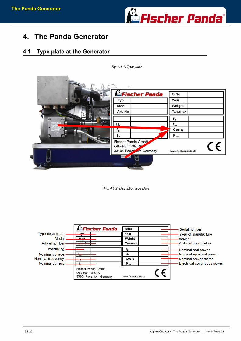
4.1 Type plate at the Generator
Fig. 4.1-1: Type plate
Fig. 4.1-2: Discription type plate
The Panda Generator
Seite/Page 34 - Kapitel/Chapter 4: The Panda Generator 12.8.20
4.2 Description of the Generator
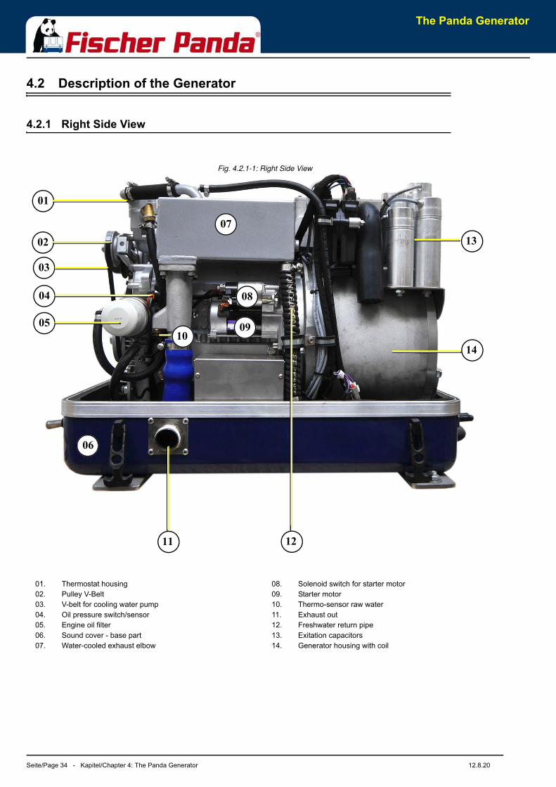
4.2.1 Right Side View
Fig. 4.2.1-1: Right Side View
08
02
03
06
09
12
07
05
01
11
14
13
10
04
01. Thermostat housing02. Pulley V-Belt03. V-belt for cooling water pump04. Oil pressure switch/sensor05. Engine oil filter06. Sound cover - base part07. Water-cooled exhaust elbow
08. Solenoid switch for starter motor09. Starter motor10. Thermo-sensor raw water11. Exhaust out12. Freshwater return pipe13. Exitation capacitors14. Generator housing with coil
The Panda Generator
12.8.20 Kapitel/Chapter 4: The Panda Generator - Seite/Page 35
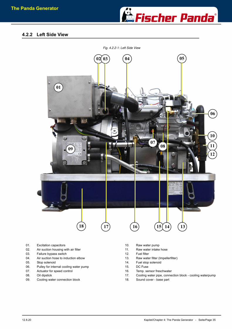
4.2.2 Left Side View
Fig. 4.2.2-1: Left Side View
09
15
06
10
0402
01
18 16 13
0807
14
03 05
11
12
17
01. Excitation capacitors02. Air suction housing with air filter03. Failure bypass switch04. Air suction hose to induction elbow05. Stop solenoid06. Pulley for internal cooling water pump07. Actuator for speed control08. Oil dipstick09. Cooling water connection block
10. Raw water pump11. Raw water intake hose12. Fuel filter13. Raw water filter (Impellerfilter)14. Fuel stop solenoid15. DC Fuse16. Temp. sensor freschwater17. Cooling water pipe, connection block - cooling waterpump18. Sound cover - base part
The Panda Generator
Seite/Page 36 - Kapitel/Chapter 4: The Panda Generator 12.8.20
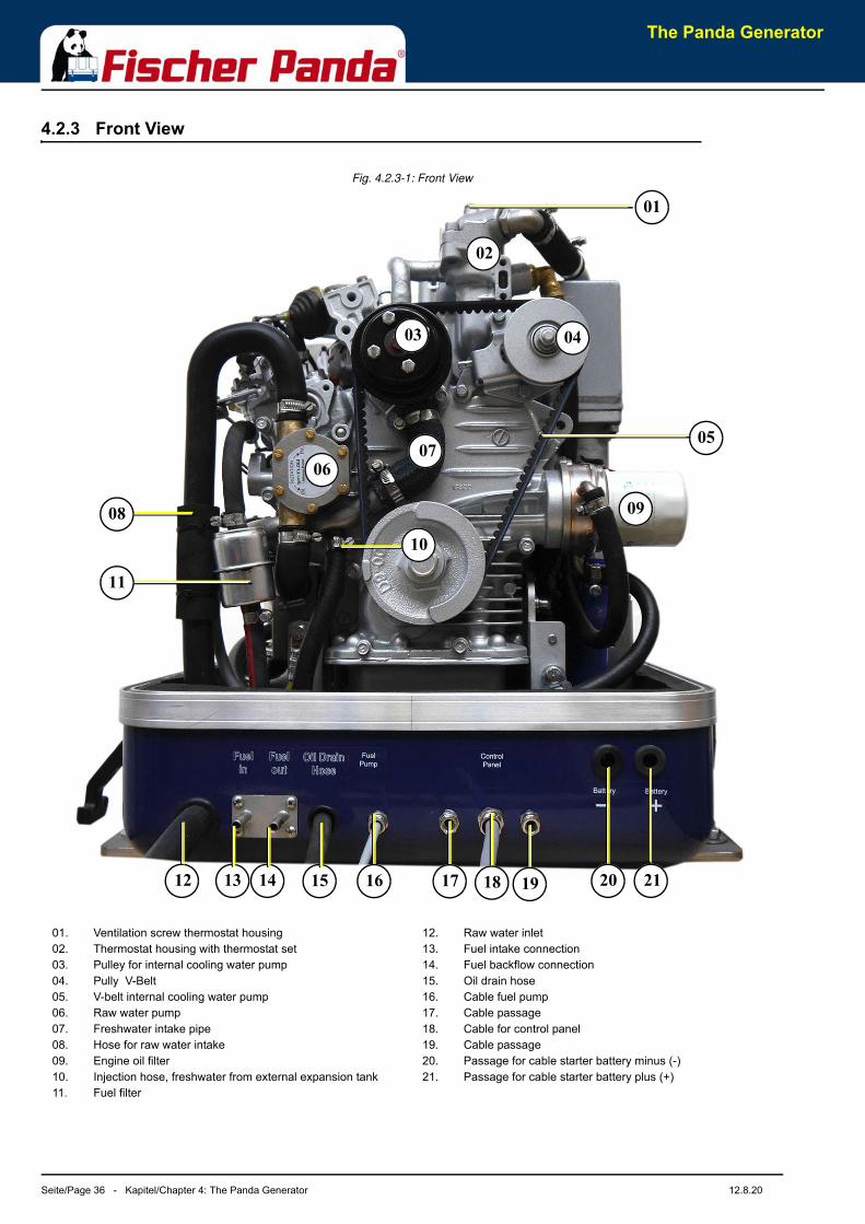
4.2.3 Front View
Fig. 4.2.3-1: Front View
01
12 2113 14 20
03
06
02
04
09
07
08
05
1615
10
11
17 18 19
01. Ventilation screw thermostat housing02. Thermostat housing with thermostat set03. Pulley for internal cooling water pump04. Pully V-Belt05. V-belt internal cooling water pump06. Raw water pump07. Freshwater intake pipe08. Hose for raw water intake09. Engine oil filter10. Injection hose, freshwater from external expansion tank11. Fuel filter
12. Raw water inlet13. Fuel intake connection14. Fuel backflow connection15. Oil drain hose16. Cable fuel pump17. Cable passage18. Cable for control panel19. Cable passage20. Passage for cable starter battery minus (-) 21. Passage for cable starter battery plus (+)
The Panda Generator
12.8.20 Kapitel/Chapter 4: The Panda Generator - Seite/Page 37
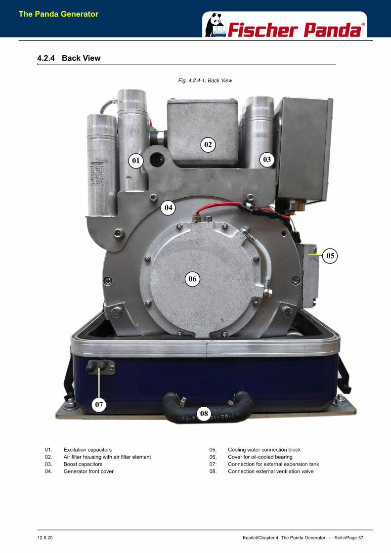
4.2.4 Back View
Fig. 4.2.4-1: Back View
04
06
03
05
02
08
01
07
01. Excitation capacitors02. Air filter housing with air filter element03. Boost capacitors 04. Generator front cover
05. Cooling water connection block06. Cover for oil-cooled bearing07: Connection for external expension tank08. Connection external ventilation valve

The Panda Generator
Seite/Page 38 - Kapitel/Chapter 4: The Panda Generator 12.8.20
4.3 Details of functional units
4.3.1 Remote control panel
The remote control panel is equipped with some new monitoring functions, which increases the operational safety ofthe generator. A failure message is shown over contacts which are normaly closed. If a connection is intermittedtriggers this a failure message.
Fig. 4.3.1-1: Remote control panel
02
01
03 04 05 06
01. Digital display02. S1 Button „ON/OFF“ „Stand by“03. S2 Button „Alarm mute / Program level“
04. S3 Button „Screen shift“05. S4 Button „rpm Shift n1/n2“06. S5 Button „Generator run/stop / Select Save“
The Panda Generator
12.8.20 Kapitel/Chapter 4: The Panda Generator - Seite/Page 39
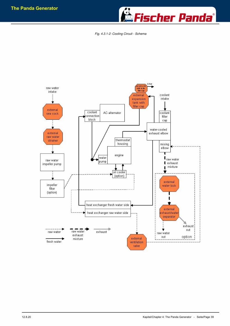
Fig. 4.3.1-2: Cooling Circuit - Schema
The Panda Generator
Seite/Page 40 - Kapitel/Chapter 4: The Panda Generator 12.8.20
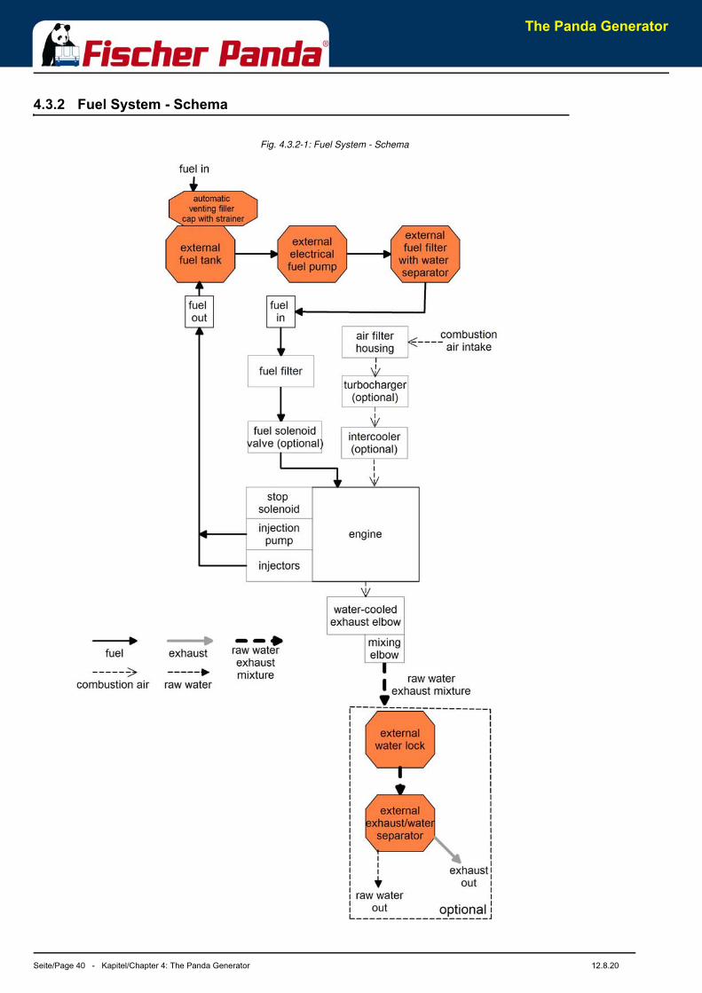
4.3.2 Fuel System - Schema
Fig. 4.3.2-1: Fuel System - Schema
The Panda Generator
12.8.20 Kapitel/Chapter 4: The Panda Generator - Seite/Page 41
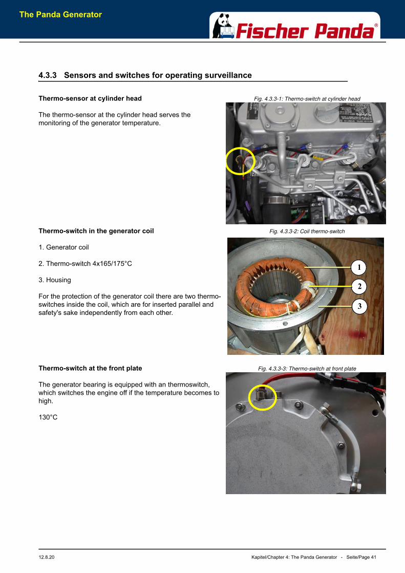
4.3.3 Sensors and switches for operating surveillance
Fig. 4.3.3-1: Thermo-switch at cylinder headThermo-sensor at cylinder head
The thermo-sensor at the cylinder head serves the monitoring of the generator temperature.
Fig. 4.3.3-2: Coil thermo-switchThermo-switch in the generator coil
1. Generator coil
2. Thermo-switch 4x165/175°C
3. Housing
For the protection of the generator coil there are two thermo-switches inside the coil, which are for inserted parallel and safety's sake independently from each other.
Fig. 4.3.3-3: Thermo-switch at front plateThermo-switch at the front plate
The generator bearing is equipped with an thermoswitch, which switches the engine off if the temperature becomes to high.
130°C
1
3
2
The Panda Generator
Seite/Page 42 - Kapitel/Chapter 4: The Panda Generator 12.8.20
Fig. 4.3.3-4: Thermo-sensor mixing elboeThermo-sensor mixing elbow
Fig. 4.3.3-5: Thermo-sensor water inThermo-sensor water in
Thermo-sensor exhaust
Thermo-sensor fresh water in
Thermo-sensor fresh water out
Fig. 4.3.3-6: Oil pressure sensorOil pressure sensor
In order to be able to monitore the lubricating oil system, an oil pressure sensor is built into the system. The Oil Circuit - Schema
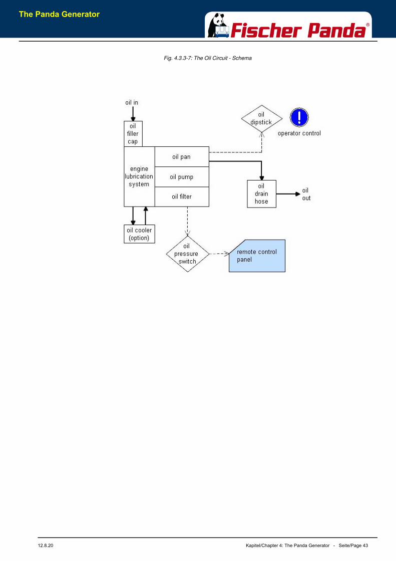
The Panda Generator
12.8.20 Kapitel/Chapter 4: The Panda Generator - Seite/Page 43
Fig. 4.3.3-7: The Oil Circuit - Schema
The Panda Generator
Seite/Page 44 - Kapitel/Chapter 4: The Panda Generator 12.8.20
4.4 Operation instructions
4.4.1 Preliminary remark
Tips regarding Starter BatteryFischer Panda recommends normal starter battery use. If a genset is required for extreme winter conditions, then the starter battery capacity should be doubled. It is recommended that the starter battery be regularly charged by a suitable battery-charging device (i.e., at least every 2 Months). A correctly charged starter battery is necessary for low temperatures.
4.4.2 Daily routine checks before starting
1. Oil Level Control (ideal level: MAX).
ATTENTION! OIL PRESSURE CONTROL!True, the diesel motor automatically switches off when there is a lack of oil, but it is very damaging for the motor, if the oil level drops to the lowest limit.
Air can be sucked in suddenly when the boat rocks in heavy seas, if the oil level is at a minimum. This affects the grease in the bearings. It is therefore necessary to check the oil level daily before initially running the generator. The oil level must be topped up to the maximum level, if the level drops below the mark between maximum und minimum levels.
The oil level of the oil cooled bearing must be checked before every start - see flow glas at the generator front cover. Service interval 1000hrs.
2. State of Cooling Water.The external compensation tank should be filled up to a maximum of in a cold state. It is very important that largeexpansion area remains above the cooling water level.
3. Open Sea Cock for Cooling Water Intake.For safety reasons, the seacock must be closed after the generator has been switched off. It should be re-opened before starting the generator.
4. Check Raw Water Filter.The raw water filter must be regularly checked and cleaned. The impeller fatigue increases, if residual affects theraw water intake.
5. Check all Hose Connections and Hose Clamps are Leakage.Leaks at hose connections must be immediately repaired, especially the raw water impeller pump. It is certainlypossible that the raw water impeller pump will produce leaks, depending upon the situation. (This can be causedby sand particles in the raw water etc.) In this case, immediately exchange the pump, because the drippingwater will be sprayed by the belt pulley into the sound insulated casing and can quickly cause corrosion.
6. Check all electrical Lead Terminal Contacts are Firm.This is especially the case with the temperature switch contacts, which automatically switch off the generator incase of faults. There is only safety if these systems are regularly checked, and these systems will protect thegenerator, when there is a fault.
The Panda Generator
12.8.20 Kapitel/Chapter 4: The Panda Generator - Seite/Page 45
7. Check the Motor and Generator Mounting Screws are Tight.The mounting screws must be checked regularly to ensure the generator is safe. A visual check of these screwsmust be made, when the oil level is checked.
8. Switch the Land Electricity/Generator Switch to Zero before Starting or Switch Off all the load.The generator should only be started when all the load have been switched off. The excitation of the generatorwill be suppressed, if the generator is switched off with load connected, left for a while, or switched on with extraload, thus reducing the residual magnetism necessary for excitation of the generator to a minimum. In certaincircumstances, this can lead to the generator being re-excitated by means of a DC source. If the generator doesnot excitate itself when starting, then excitation by means of DC must be carried out again.
9. Check the Automatic Controls Functions and Oil Pressure.Removing a cable end from the monitoring switch carries out this control test. The generator should thenautomatically switch off. Please adhere to the inspection timetable (see Checklist in the appendix)..

Seite/Page 46 Kapitel/Chapter 4: The Panda Generator 12.8.20
Leere Seite / Intentionally blank
The Panda Generator
Generator operation instruction
12.8.20 Kapitel/Chapter 5: Generator operation instruction - Seite/Page 47
5. Generator operation instruction
5.1 Personal requirements
Only instructed persons are allowed to run the generator. Instructed Persons has read the manual of the generatorand all ancillary components and external equipment. He must be acquaint with the specific risks and safetyinstructions.
Only persons who are expected to perform their tasks reliably are permitted as personnel. Persons whose reactioncapability is impaired, e.g. through drugs, alcohol or medication are not permitted.
When selecting the personnel, the stipulations regarding age and occupation applying at the location must beobserved.
5.1.1 Hazard notes for the operation
Notice!Please note the safety first instructions in front of this manual.
Warning! Automatic startDanger for life! - The generator can be equipped with a automatic start device. This means the generator can be started by an external signal.
To avoid an unexpected starting of the generator, the starter battery must be disconnected before start working at the generator.
Attention! Danger to lifeRotating parts inside of the generator
Do not run the generator with removed sound cover. If it is necessary to test the generator without sound cover, pay special attention. Never do this work alone. Do all service, maintenance and repair with engine stopped.
Attention! Danger to Life - High voltageDanger for Life. Improper handling, operation, installation and maintenance can result in severe personal injury and/or material damage.
Electrical voltages above 48 volts (battery chargers greater than 36 volts) are always dangerous to life). The rules of the respective regional authority must be adhered to. Only an electrician may carry out installation of the electrical connections for safety reasons.
5.2 General operating instruction
5.2.1 Operation at low temperatures
The Generator can be started at temperatures down to - 20 °C, therefor the operation fluids like fuel, cooling water,lubricant oil ect. must be suitable for this temperatures. These should be checked before start. Cold start spray ect.are not allowed to use, or the warranty will be lost.
Generator operation instruction
Seite/Page 48 - Kapitel/Chapter 5: Generator operation instruction 12.8.20
5.2.1.1 Pre-heating the diesel motor
Pre-champer diesel engines are equipped with a quick glow plug. The maximum pre glow time should not exceed 20sec. At 20 °C or more the pre glow time should be about 5-6 sec. Below 20 °C the pre glow time should beincreased.
Note!If the operation fluids have been drained and then filled with cold weather fluids, always run the generator for 10 minutes to ensure the new fuel is present throughout the system.
5.2.1.2 Tips regarding starter battery
Fischer Panda recommends normal starter battery use. If an genset is required for extreme winter conditions, thenthe starter battery capacity should be doubled. It is recommended that the starter battery be regularly charged by asuitable battery-charging device (i.e., at least every 2 months). A correctly charged starter battery is necessary forlow temperatures.
5.2.2 Light load operation and engine idle
If an engine is operated on a load less than 25-30 % of its rated output, the soot of the generator will be observedwhich may give cause for concern. The usual results of this operation are heavier than normal lubricating oilconsumption, and oil leaks from the air and exhaust manifolds. This condition is particularly evident on standbygenerator set applications.
5.2.2.1 The soot of the generator is due to the fact that:
The cylinder temperatures are too low to ensure complete burning of all the fuel delivered.
A further result is that of abnormal carbon build-up on the valves, piston crowns and exhaust ports. Fuel dilution ofthe lubricating oil will also occur.
5.2.2.2 To prevent the soot of the generator following steps should be observed:
Running on light load should be avoided or reduced to the minimum period.
In a period of 50 operation hours the engine or generator set should be run on full load for four hours, to burn offaccumulations of carbon in the engine and exhaust system. This may require the use of a 'dummy load'. The loadshould be built up gradually from 30 % to 100 % within 3 hours and hold at 100 % for one hour.
5.2.3 Generator load for a longer period and overload
Ensure the generator is not overloaded. Overloading occurs when the electrical load is higher than the generatorcan provide. If this occur for a longer period, the engine may be damaged. Overloading may cause rough running,high oil and fuel consumption, increased emissions.
For a long engine life, the long therm load should not exceed 80 % of the nominal load. Long therm load is the loadover several hours. It is harmless for the generator to deliver full nominal power for 2-3 hours.
The hole conception of the Fischer Panda generator make sure, that the full power operation at extreme conditionwill not increase the engine temperatures over. Please note that the emissions of the generator also increase at fullpower operation.
Generator operation instruction
12.8.20 Kapitel/Chapter 5: Generator operation instruction - Seite/Page 49
5.2.4 Protection conductor:
The standard Panda generator is grounded. The 3-phase connection (delta) centre point is bridged to earth in theAC output terminal box (mounted on the generator). This is the initial earth safety point and is sufficient to ensuresafe operation however only as long as no other system is installed. This system is adapted to enable test running ofthe generator before delivery.
The bridge to ground (PEN) is only effective when all components in the electrical system share a common ground.The bridge to ground can be removed and reconnected to another ground system if required for other safety stan-dards.
Full voltage connections are mounted in the electrical cabinet. It must be ensured that the electrical cabinet is secu-red and closed while the generator is running.
The starter battery cable should be disconnected when work is being done on either the generator or the electricalsystem in order to prevent accidental starting of the generator.
5.2.5 Operating control system on the Fischer Panda generator
Fischer Panda generators are equipped with various sensors/temperatures switches. The combustion engine isfurther equipped with a oil pressure control switch, which switches the motor off, if the oil pressure sinks to a particu-lar level.
5.3 Instructions for capacitors - not present at all models
Caution!Danger to Life - High voltage
Do not touch the capacitor contact terminals!
The generator's electrical system requires two different groups of capacitors:
A) The booster capacitors
B) The operating capacitors
Both types are mounted in the electrical cabinet. (At some models direct on the generator)
Capacitors store an electrical charge. It is possible that even after they have been disconnected stored energy is stillheld. Therefore it is essential that the connectors are not touched.
Should it be necessary to check or test the capacitors, they should be shorted out by using an insulated screw driver.
The operating capacitors are automatically discharged when the generator is stopped in the normal way. The boo-ster capacitors will be discharged through internal resistors.
For safety however, the capacitors have to be discharged (short circuited) prior to carrying out any work on the AC-Control box.
5.4 Checks before start, starting and stopping the generator
See remote control panel data sheet/manual
Note:The instructions and regulations of the remote control panel data sheet/manual must be respected.
Respect the safety instruction in front of this manual.

Seite/Page 50 Kapitel/Chapter 5: Generator operation instruction 12.8.20
Leere Seite / Intentionally blank
Generator operation instruction
Installation Instructions
12.8.20 Kapitel/Chapter 6: Installation Instructions - Seite/Page 51
6. Installation Instructions
Attention! Adapt system correctly.All connections (hoses, wires etc.) and installation instructions are designed and suited for “standard” installation situations.
In situations where Fischer Panda has no detailed information concerning certain installation requirements (such as vehicle specifications, maximum vehicle speed - and all other conditions concerning special operating situations) the installation instructions should be used as an example guide only. The installation must be undertaken and proved by a suitable qualified/trained person and should be in accordance with the law as required by the country and special situation.
Damages caused by faulty or incorrect installation are not covered by the warranty.
6.1 Personal requirements
The described installation must be done by a technical trained person or a Fischer Panda service point.
6.1.1 Hazard notes for the installation
Notice!Follow the general safety instruction at the front of this manual.
.Warning! Automatic startDANGER TO LIFE! - Incorrect handling may lead to health damage and to death.
Always disconnect the battery bank (first negative terminal than positive terminal) before you work at the generator or the electric system of the generator so that the generator may not be started unintentionally.
Warning! Risk of injuryImproper installation can result in severe personal injuries or material damage. Therefore:
• Always undertake installation work when the generator is switched off.
• Ensure there is sufficient installation clearance before start working.
• Ensure tidiness and cleanliness at the workplace. Loose components and tools lying around or on top of each other are sources of accidents.
• Only perform installation work using commercially available tools and special tools. Incorrect or damaged tools can result injuries.
Installation Instructions
Seite/Page 52 - Kapitel/Chapter 6: Installation Instructions 12.8.20
Warning! Danger of fire Oil and fuel vapours can ignite at contact with ignition sources. Therefore:
• No open flames during work on the generator.
• Do not smoke.
• Remove oil and fuel residues from the generator and floor.
Danger! Danger of poisoningContact with engine oil, antifreeze and fuel can result in damage to health. Therefore:
• Avoid skin contact with engine oil, fuel and antifreeze.
• Remove oil and fuel splashes and antifreeze from the skin immediately.
• Do not inhale oil and fuel vapours.
Attention! Danger to Life - High voltageDANGER TO LIFE! - Improper handling can result in severe personal injury and death.
Electrical voltages above 60 volts (battery chargers greater
than 36 volts) are always dangerous to life. The rules of the
respective regional authority must be adhered to. Only an
electrician may carry out installation of the electrical
connections for safety reasons.
Warning! Hot surface/materialGenerator, oil and antifreeze can be hot during/after operation. Risk of severe burns!
During operation an over pressure in the cooling system may be established.
Warning! Danger of chemical burnsBatteries contain corrosive acids and bases.
Improper handling can lead to heating of the batteries and bursts. Corrosive acids and bases may leak. Under bad conditions it may lead to an explosion.
Consider the instructions of the battery manufacturer.
Instruction! Personal protective equipmentnecessary
During installation/maintenance personal protective equipment is required to minimize the health hazards:
• Protective clothing
• Safety boots
• Protective gloves
• Ear defender
• Safety glasses
Attention! Disconnect all load.Disconnect all load during the work at the generator to avoid damages at the load.
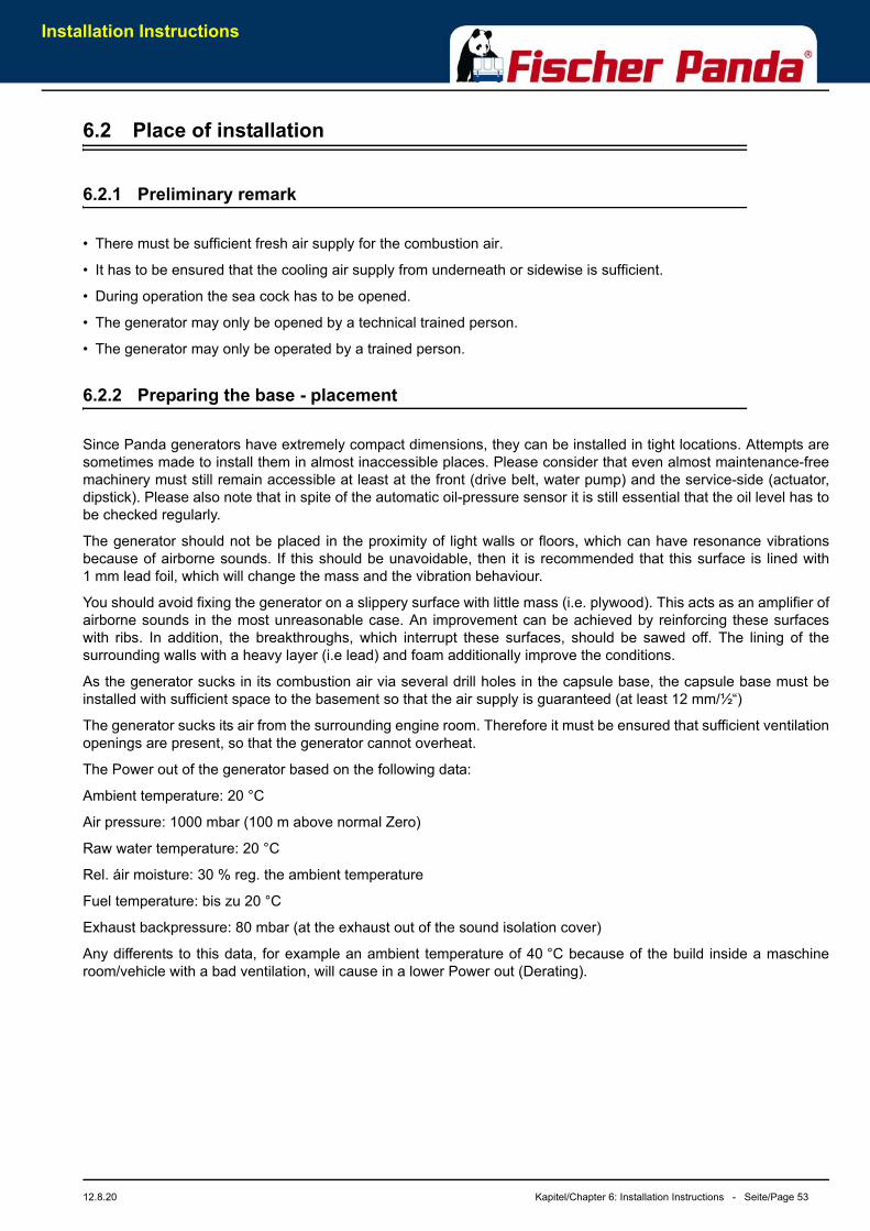
Installation Instructions
12.8.20 Kapitel/Chapter 6: Installation Instructions - Seite/Page 53
6.2 Place of installation
6.2.1 Preliminary remark
• There must be sufficient fresh air supply for the combustion air.
• It has to be ensured that the cooling air supply from underneath or sidewise is sufficient.
• During operation the sea cock has to be opened.
• The generator may only be opened by a technical trained person.
• The generator may only be operated by a trained person.
6.2.2 Preparing the base - placement
Since Panda generators have extremely compact dimensions, they can be installed in tight locations. Attempts aresometimes made to install them in almost inaccessible places. Please consider that even almost maintenance-freemachinery must still remain accessible at least at the front (drive belt, water pump) and the service-side (actuator,dipstick). Please also note that in spite of the automatic oil-pressure sensor it is still essential that the oil level has tobe checked regularly.
The generator should not be placed in the proximity of light walls or floors, which can have resonance vibrationsbecause of airborne sounds. If this should be unavoidable, then it is recommended that this surface is lined with1 mm lead foil, which will change the mass and the vibration behaviour.
You should avoid fixing the generator on a slippery surface with little mass (i.e. plywood). This acts as an amplifier ofairborne sounds in the most unreasonable case. An improvement can be achieved by reinforcing these surfaceswith ribs. In addition, the breakthroughs, which interrupt these surfaces, should be sawed off. The lining of thesurrounding walls with a heavy layer (i.e lead) and foam additionally improve the conditions.
As the generator sucks in its combustion air via several drill holes in the capsule base, the capsule base must beinstalled with sufficient space to the basement so that the air supply is guaranteed (at least 12 mm/½“)
The generator sucks its air from the surrounding engine room. Therefore it must be ensured that sufficient ventilationopenings are present, so that the generator cannot overheat.
The Power out of the generator based on the following data:
Ambient temperature: 20 °C
Air pressure: 1000 mbar (100 m above normal Zero)
Raw water temperature: 20 °C
Rel. áir moisture: 30 % reg. the ambient temperature
Fuel temperature: bis zu 20 °C
Exhaust backpressure: 80 mbar (at the exhaust out of the sound isolation cover)
Any differents to this data, for example an ambient temperature of 40 °C because of the build inside a maschineroom/vehicle with a bad ventilation, will cause in a lower Power out (Derating).
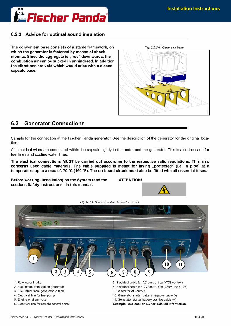
Installation Instructions
Seite/Page 54 - Kapitel/Chapter 6: Installation Instructions 12.8.20
6.2.3 Advice for optimal sound insulation
Fig. 6.2.3-1: Generator baseThe convenient base consists of a stable framework, on which the generator is fastened by means of shock-mounts. Since the aggregate is „free“ downwards, the combustion air can be sucked in unhindered. In addition the vibrations are void which would arise with a closed capsule base.
6.3 Generator Connections
Sample for the connection at the Fischer Panda generator. See the description of the generator for the original loca-tion.
All electrical wires are connected within the capsule tightly to the motor and the generator. This is also the case forfuel lines and cooling water lines.
The electrical connections MUST be carried out according to the respective valid regulations. This alsoconcerns used cable materials. The cable supplied is meant for laying „protected“ (i.e. in pipe) at atemperature up to a max of. 70 °C (160 °F). The on-board circuit must also be fitted with all essential fuses.
ATTENTION! Before working (installation) on the System read the section „Safety Instructions“ in this manual.
Fig. 6.3-1: Connection at the Generator - sample
1
2 3 4 5 6 7 8 910 11
1. Raw water intake2. Fuel intake from tank to generator3. Fuel return from generator to tank4. Electrical line for fuel pump5. Engine oil drain hose6. Electrical line for remote control panel
7. Electrical cable for AC control box (VCS-control)8. Electrical cable for AC control box (230V und 400V)9. Generator AC-output10. Generator starter battery negative cable (-) 11. Generator starter battery positive cable (+) Example - see section 5.2 for detailed information
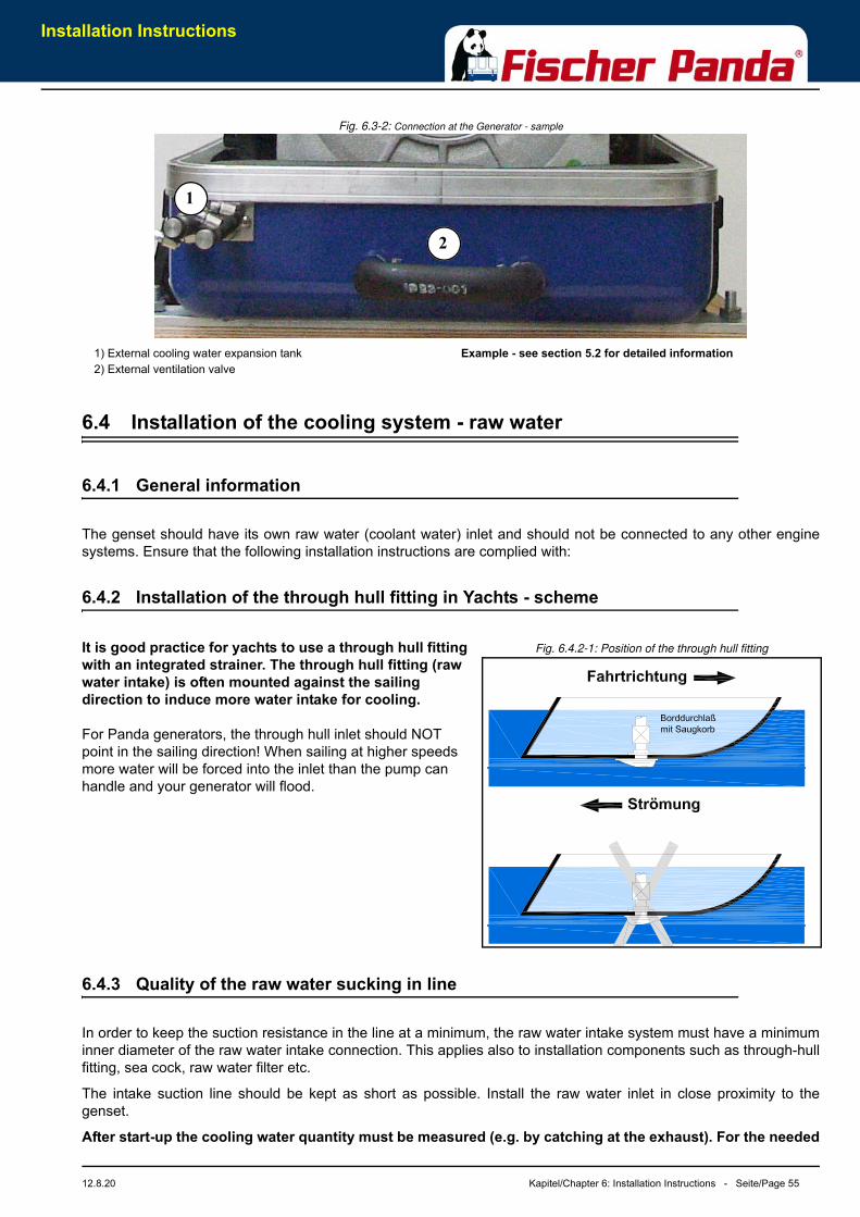
Installation Instructions
12.8.20 Kapitel/Chapter 6: Installation Instructions - Seite/Page 55
Fig. 6.3-2: Connection at the Generator - sample
6.4 Installation of the cooling system - raw water
6.4.1 General information
The genset should have its own raw water (coolant water) inlet and should not be connected to any other enginesystems. Ensure that the following installation instructions are complied with:
6.4.2 Installation of the through hull fitting in Yachts - scheme
Fig. 6.4.2-1: Position of the through hull fitting It is good practice for yachts to use a through hull fitting with an integrated strainer. The through hull fitting (raw water intake) is often mounted against the sailing direction to induce more water intake for cooling.
For Panda generators, the through hull inlet should NOT point in the sailing direction! When sailing at higher speeds more water will be forced into the inlet than the pump can handle and your generator will flood.
6.4.3 Quality of the raw water sucking in line
In order to keep the suction resistance in the line at a minimum, the raw water intake system must have a minimuminner diameter of the raw water intake connection. This applies also to installation components such as through-hullfitting, sea cock, raw water filter etc.
The intake suction line should be kept as short as possible. Install the raw water inlet in close proximity to thegenset.
After start-up the cooling water quantity must be measured (e.g. by catching at the exhaust). For the needed
1
2
1) External cooling water expansion tank2) External ventilation valve
Example - see section 5.2 for detailed information
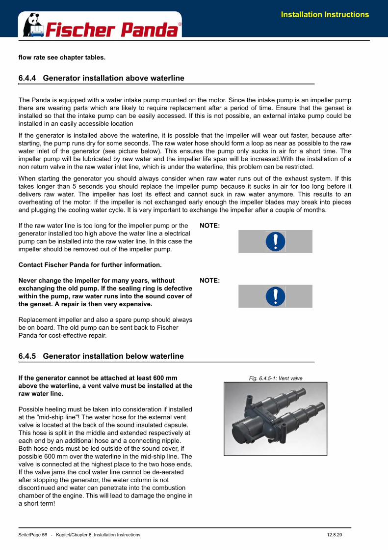
Installation Instructions
Seite/Page 56 - Kapitel/Chapter 6: Installation Instructions 12.8.20
flow rate see chapter tables.
6.4.4 Generator installation above waterline
The Panda is equipped with a water intake pump mounted on the motor. Since the intake pump is an impeller pumpthere are wearing parts which are likely to require replacement after a period of time. Ensure that the genset isinstalled so that the intake pump can be easily accessed. If this is not possible, an external intake pump could beinstalled in an easily accessible location
If the generator is installed above the waterline, it is possible that the impeller will wear out faster, because afterstarting, the pump runs dry for some seconds. The raw water hose should form a loop as near as possible to the rawwater inlet of the generator (see picture below). This ensures the pump only sucks in air for a short time. Theimpeller pump will be lubricated by raw water and the impeller life span will be increased.With the installation of anon return valve in the raw water inlet line, which is under the waterline, this problem can be restricted.
When starting the generator you should always consider when raw water runs out of the exhaust system. If thistakes longer than 5 seconds you should replace the impeller pump because it sucks in air for too long before itdelivers raw water. The impeller has lost its effect and cannot suck in raw water anymore. This results to anoverheating of the motor. If the impeller is not exchanged early enough the impeller blades may break into piecesand plugging the cooling water cycle. It is very important to exchange the impeller after a couple of months.
NOTE:If the raw water line is too long for the impeller pump or the generator installed too high above the water line a electrical pump can be installed into the raw water line. In this case the impeller should be removed out of the impeller pump.
Contact Fischer Panda for further information.
NOTE:Never change the impeller for many years, without exchanging the old pump. If the sealing ring is defective within the pump, raw water runs into the sound cover of the genset. A repair is then very expensive.
Replacement impeller and also a spare pump should always be on board. The old pump can be sent back to Fischer Panda for cost-effective repair.
6.4.5 Generator installation below waterline
Fig. 6.4.5-1: Vent valveIf the generator cannot be attached at least 600 mm above the waterline, a vent valve must be installed at the raw water line.
Possible heeling must be taken into consideration if installed at the "mid-ship line"! The water hose for the external vent valve is located at the back of the sound insulated capsule. This hose is split in the middle and extended respectively at each end by an additional hose and a connecting nipple. Both hose ends must be led outside of the sound cover, if possible 600 mm over the waterline in the mid-ship line. The valve is connected at the highest place to the two hose ends. If the valve jams the cool water line cannot be de-aerated after stopping the generator, the water column is not discontinued and water can penetrate into the combustion chamber of the engine. This will lead to damage the engine in a short term!
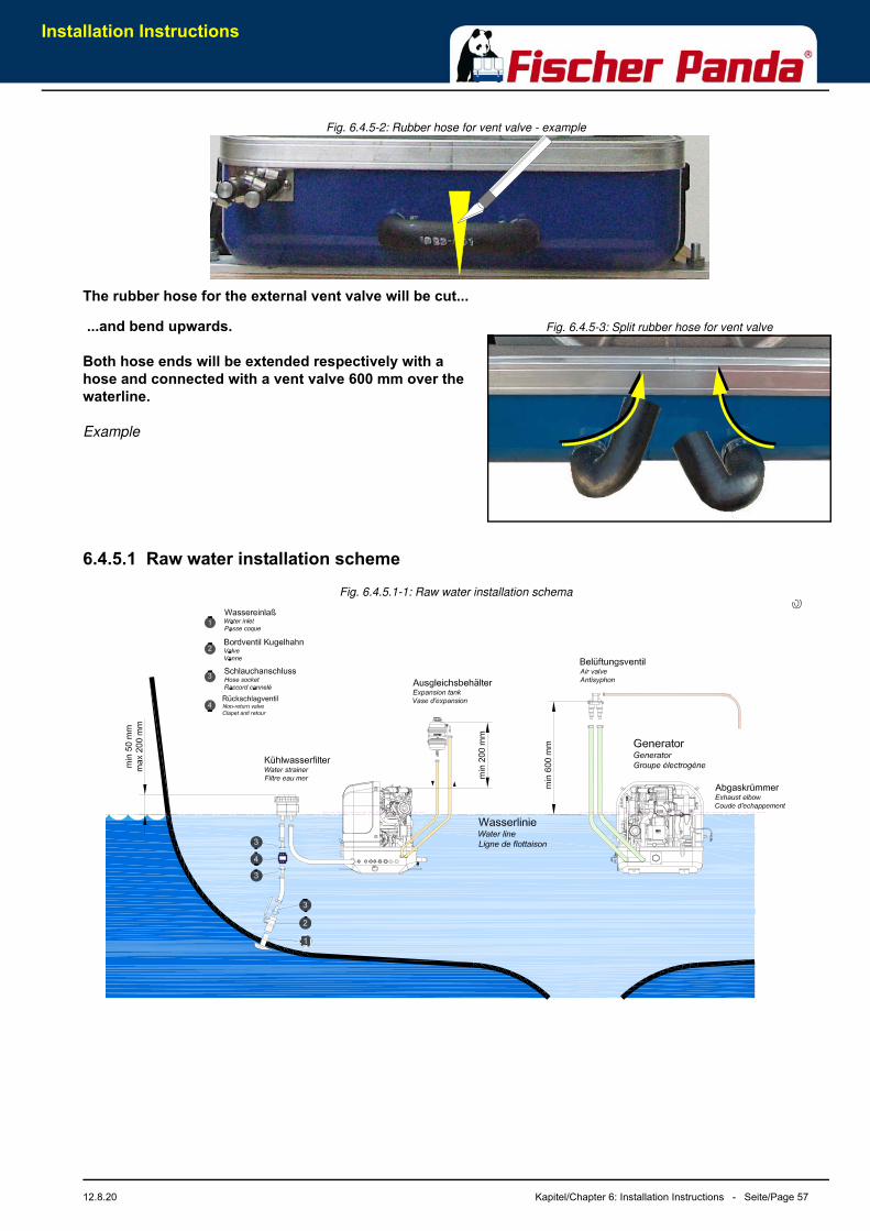
Installation Instructions
12.8.20 Kapitel/Chapter 6: Installation Instructions - Seite/Page 57
Fig. 6.4.5-2: Rubber hose for vent valve - example
The rubber hose for the external vent valve will be cut...
Fig. 6.4.5-3: Split rubber hose for vent valve ...and bend upwards.
Both hose ends will be extended respectively with a hose and connected with a vent valve 600 mm over the waterline.
Example
6.4.5.1 Raw water installation schemeFig. 6.4.5.1-1: Raw water installation schema
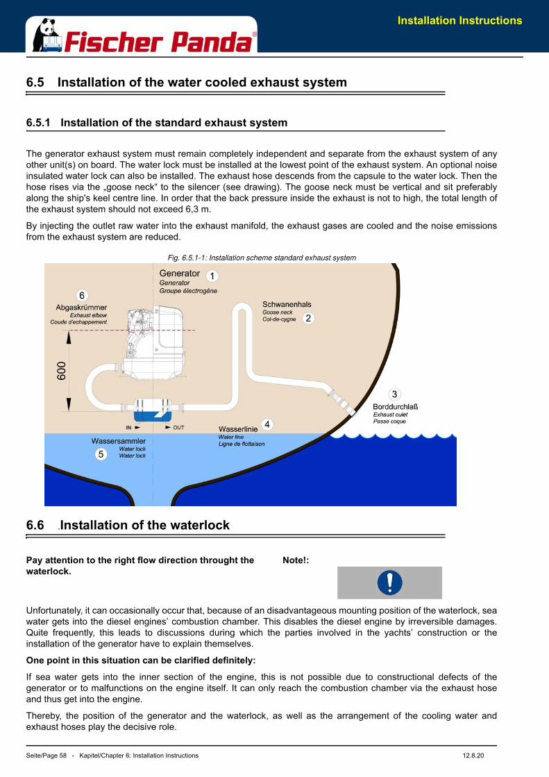
Installation Instructions
Seite/Page 58 - Kapitel/Chapter 6: Installation Instructions 12.8.20
6.5 Installation of the water cooled exhaust system
6.5.1 Installation of the standard exhaust system
The generator exhaust system must remain completely independent and separate from the exhaust system of anyother unit(s) on board. The water lock must be installed at the lowest point of the exhaust system. An optional noiseinsulated water lock can also be installed. The exhaust hose descends from the capsule to the water lock. Then thehose rises via the „goose neck“ to the silencer (see drawing). The goose neck must be vertical and sit preferablyalong the ship's keel centre line. In order that the back pressure inside the exhaust is not to high, the total length ofthe exhaust system should not exceed 6,3 m.
By injecting the outlet raw water into the exhaust manifold, the exhaust gases are cooled and the noise emissionsfrom the exhaust system are reduced.
Fig. 6.5.1-1: Installation scheme standard exhaust system
6.6 .Installation of the waterlock
Note!:Pay attention to the right flow direction throught the waterlock.
Unfortunately, it can occasionally occur that, because of an disadvantageous mounting position of the waterlock, seawater gets into the diesel engines’ combustion chamber. This disables the diesel engine by irreversible damages.Quite frequently, this leads to discussions during which the parties involved in the yachts’ construction or theinstallation of the generator have to explain themselves.
One point in this situation can be clarified definitely:
If sea water gets into the inner section of the engine, this is not possible due to constructional defects of thegenerator or to malfunctions on the engine itself. It can only reach the combustion chamber via the exhaust hoseand thus get into the engine.
Thereby, the position of the generator and the waterlock, as well as the arrangement of the cooling water andexhaust hoses play the decisive role.
Installation Instructions
12.8.20 Kapitel/Chapter 6: Installation Instructions - Seite/Page 59
If the waterlock is arranged in an unfavourable position, the cooling water flowing back in the exhaust hose can riseso high, that it reaches the exhaust stack. Since at least one discharge valve is always open when the engine is shutoff, the sea water has free access to the combustion chamber. By capillary action, this sea water then flows past thecocks and even reaches the engine oil in that way. (In fact, a surprisingly high oil level is a first indication of anupcoming catastrophe).
If an usual high oil level can be detected and/or the oil is of a greyish colour, the engine must not be usedanymore. This is a certain sign for cooling water that got into the oil pan. If the engine is started under theseconditions, the water and the oil are mixed into an emulsion. The oil will quickly become so viscous that onewill have to call it a paste. In this phase the fine oil hoses are blocked and a few moments later the machinegets destroyed because of insufficient lubrication. Before this happens, an immediate oil change should bemade. Since the water can only reach the engine via the combustion chamber, it can be assumed that thecompression rings will start to corrode. These effects have to be discussed with an engine expert. It willcertainly be reasonable to immediately inject plenty penetrating oil through the intake stack and to slowlyturn the engine with the starter motor.
The cooling water can reach the exhaust area via the exhaust hose as well as via the cooling water feed.
6.6.1 Possible cause for water in the exhaust hose
6.6.1.1 Possible cause: exhaust hose
If the cause is the exhaust hose itself, the following points are to be checked at the hose:
a) Position of the waterlock is too high. The water reaches the exhaust hose.
b) Position of the waterlock is too far away from the middle of the generator. The water reaches the exhaust hose intilted position.
c) The waterlock is too small relating to the length of the exhaust hose.
6.6.1.2 Possible cause: cooling water hose
If the generator is not clearly installed 600 mm over the water line, the cooling water feed must be equipped with a„venting valve“ which is at least led out 600 mm over the water line. (This position must also be assured in everytilted position. Therefore, the venting valve should be located in the ships’ center line, so that it cannot move in tiltedposition).
a) Position of the venting valve is too low. The water flows into the exhaust area when the ship is tilted.
b) Position of the venting valve is too far from the ships’ center line. The water reaches the exhaust area when theship is tilted.
c) The venting valve does not work, because it jams or it is clotted. (The venting valve’s function needs to bechecked regularly.)
As it consistently happens that functioning risks are not realised during the laying of the exhaust hose, the followingexplanations refer explicitly to the exhaust hose. Here, the location, the size and the position of the „waterlock“ playa very decisive role:
6.6.2 Installation area of the waterlock
Concerning a water-cooled exhaust system, it must be regarded that - under no circumstances - cooling water fromthe exhaust hose can get into the exhaust elbow area at the engine. If this happens, the cooling water can get intothe combustion chamber via an open discharge valve. This would lead to irreparable damage at the engine.
In addition to that, one has to reckon with possible tilted positions of sailing yachts, which makes the position of thewaterlock even more important. In general one could say that:
The deeper the waterlock is located underneath the generator, the better the protection from entering water into thecombustion chamber.
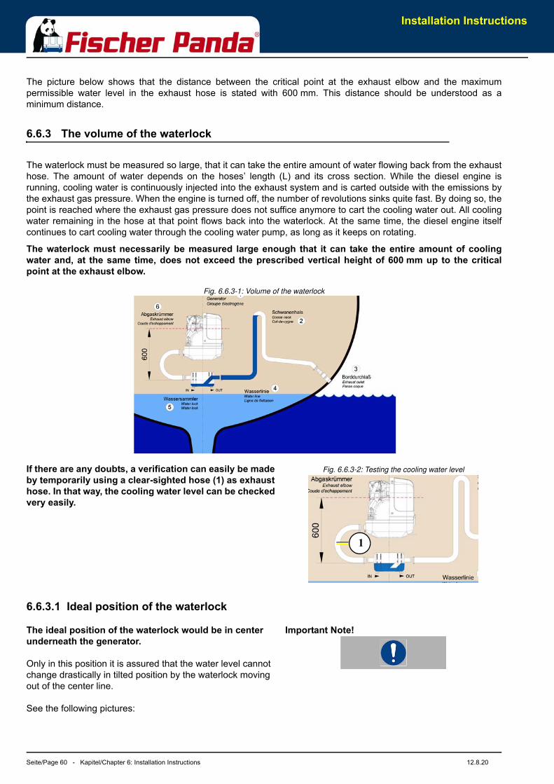
Installation Instructions
Seite/Page 60 - Kapitel/Chapter 6: Installation Instructions 12.8.20
The picture below shows that the distance between the critical point at the exhaust elbow and the maximumpermissible water level in the exhaust hose is stated with 600 mm. This distance should be understood as aminimum distance.
6.6.3 The volume of the waterlock
The waterlock must be measured so large, that it can take the entire amount of water flowing back from the exhausthose. The amount of water depends on the hoses’ length (L) and its cross section. While the diesel engine isrunning, cooling water is continuously injected into the exhaust system and is carted outside with the emissions bythe exhaust gas pressure. When the engine is turned off, the number of revolutions sinks quite fast. By doing so, thepoint is reached where the exhaust gas pressure does not suffice anymore to cart the cooling water out. All coolingwater remaining in the hose at that point flows back into the waterlock. At the same time, the diesel engine itselfcontinues to cart cooling water through the cooling water pump, as long as it keeps on rotating.
The waterlock must necessarily be measured large enough that it can take the entire amount of coolingwater and, at the same time, does not exceed the prescribed vertical height of 600 mm up to the criticalpoint at the exhaust elbow.
Fig. 6.6.3-1: Volume of the waterlock
Fig. 6.6.3-2: Testing the cooling water levelIf there are any doubts, a verification can easily be made by temporarily using a clear-sighted hose (1) as exhaust hose. In that way, the cooling water level can be checked very easily.
6.6.3.1 Ideal position of the waterlock
Important Note!The ideal position of the waterlock would be in center underneath the generator.
Only in this position it is assured that the water level cannot change drastically in tilted position by the waterlock moving out of the center line.
See the following pictures:
1
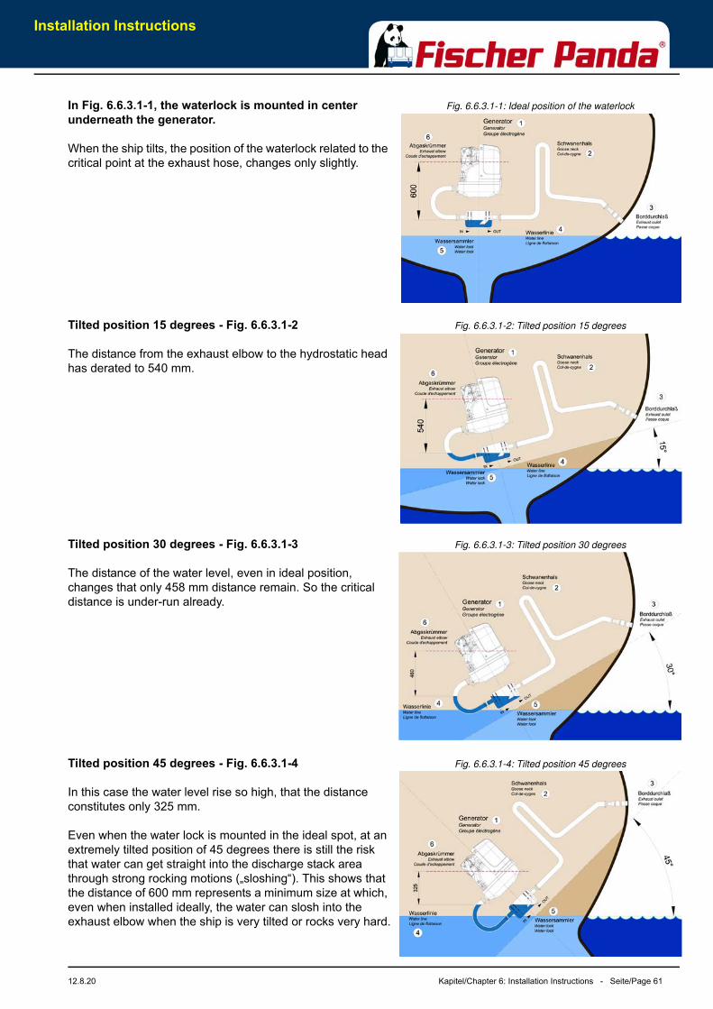
Installation Instructions
12.8.20 Kapitel/Chapter 6: Installation Instructions - Seite/Page 61
Fig. 6.6.3.1-1: Ideal position of the waterlockIn Fig. 6.6.3.1-1, the waterlock is mounted in center underneath the generator.
When the ship tilts, the position of the waterlock related to the critical point at the exhaust hose, changes only slightly.
Fig. 6.6.3.1-2: Tilted position 15 degreesTilted position 15 degrees - Fig. 6.6.3.1-2
The distance from the exhaust elbow to the hydrostatic head has derated to 540 mm.
Fig. 6.6.3.1-3: Tilted position 30 degreesTilted position 30 degrees - Fig. 6.6.3.1-3
The distance of the water level, even in ideal position, changes that only 458 mm distance remain. So the critical distance is under-run already.
Fig. 6.6.3.1-4: Tilted position 45 degreesTilted position 45 degrees - Fig. 6.6.3.1-4
In this case the water level rise so high, that the distance constitutes only 325 mm.
Even when the water lock is mounted in the ideal spot, at an extremely tilted position of 45 degrees there is still the risk that water can get straight into the discharge stack area through strong rocking motions („sloshing“). This shows that the distance of 600 mm represents a minimum size at which, even when installed ideally, the water can slosh into the exhaust elbow when the ship is very tilted or rocks very hard.
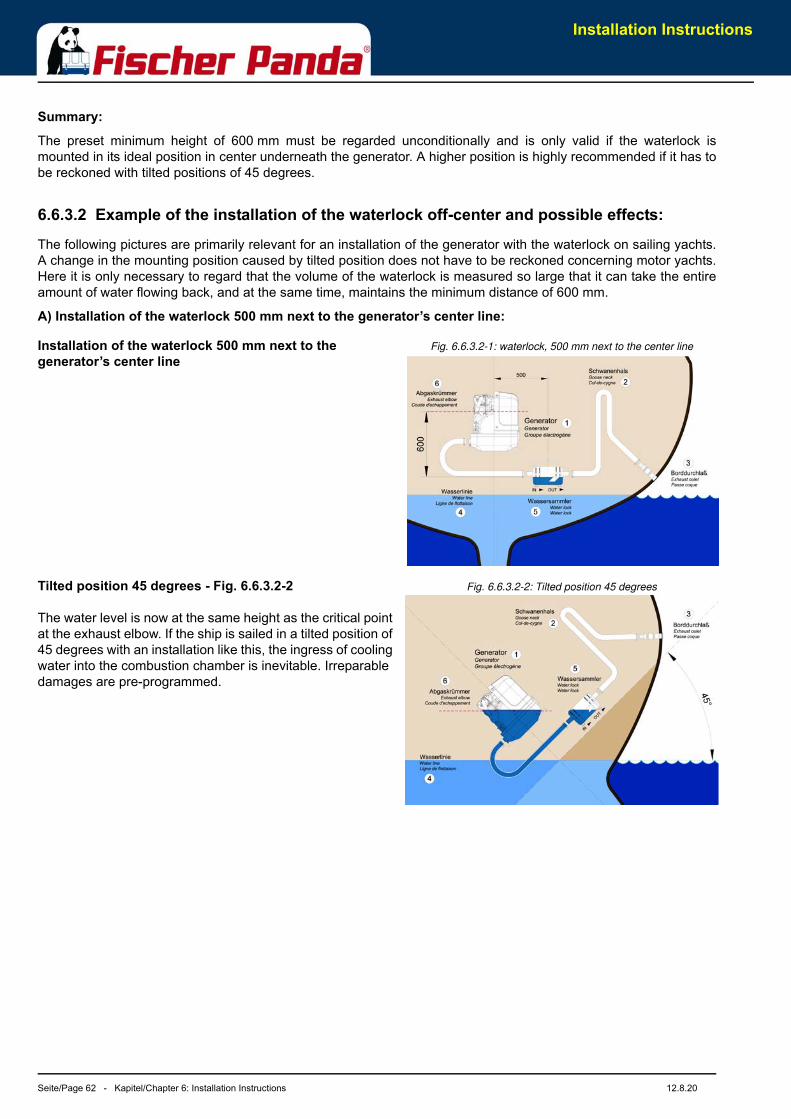
Installation Instructions
Seite/Page 62 - Kapitel/Chapter 6: Installation Instructions 12.8.20
Summary:
The preset minimum height of 600 mm must be regarded unconditionally and is only valid if the waterlock ismounted in its ideal position in center underneath the generator. A higher position is highly recommended if it has tobe reckoned with tilted positions of 45 degrees.
6.6.3.2 Example of the installation of the waterlock off-center and possible effects:
The following pictures are primarily relevant for an installation of the generator with the waterlock on sailing yachts.A change in the mounting position caused by tilted position does not have to be reckoned concerning motor yachts.Here it is only necessary to regard that the volume of the waterlock is measured so large that it can take the entireamount of water flowing back, and at the same time, maintains the minimum distance of 600 mm.
A) Installation of the waterlock 500 mm next to the generator’s center line:
Fig. 6.6.3.2-1: waterlock, 500 mm next to the center lineInstallation of the waterlock 500 mm next to the generator’s center line
Fig. 6.6.3.2-2: Tilted position 45 degreesTilted position 45 degrees - Fig. 6.6.3.2-2
The water level is now at the same height as the critical point at the exhaust elbow. If the ship is sailed in a tilted position of 45 degrees with an installation like this, the ingress of cooling water into the combustion chamber is inevitable. Irreparable damages are pre-programmed.
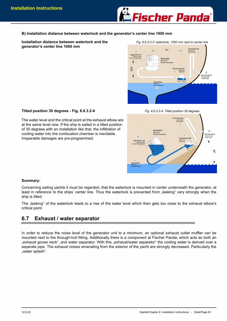
Installation Instructions
12.8.20 Kapitel/Chapter 6: Installation Instructions - Seite/Page 63
B) Installation distance between waterlock and the generator’s center line 1000 mm
Fig. 6.6.3.2-3: waterlock, 1000 mm next to center lineInstallation distance between waterlock and the generator’s center line 1000 mm
Fig. 6.6.3.2-4: Tilted position 30 degreesTilted position 30 degrees - Fig. 6.6.3.2-4
The water level and the critical point at the exhaust elbow are at the same level now. If the ship is sailed in a tilted position of 30 degrees with an installation like that, the infiltration of cooling water into the combustion chamber is inevitable. Irreparable damages are pre-programmed.
Summary:
Concerning sailing yachts it must be regarded, that the waterlock is mounted in center underneath the generator, atleast in reference to the ships’ center line. Thus the waterlock is prevented from „leaking“ very strongly when theship is tilted.
The „leaking“ of the waterlock leads to a rise of the water level which then gets too close to the exhaust elbow’scritical point.
6.7 Exhaust / water separator
In order to reduce the noise level of the generator unit to a minimum, an optional exhaust outlet muffler can bemounted next to the through-hull fitting. Additionally there is a component at Fischer Panda, which acts as both an„exhaust goose neck“, and water separator. With this „exhaust/water separator“ the cooling water is derived over aseparate pipe. The exhaust noises emanating from the exterior of the yacht are strongly decreased. Particularly the„water splash“.
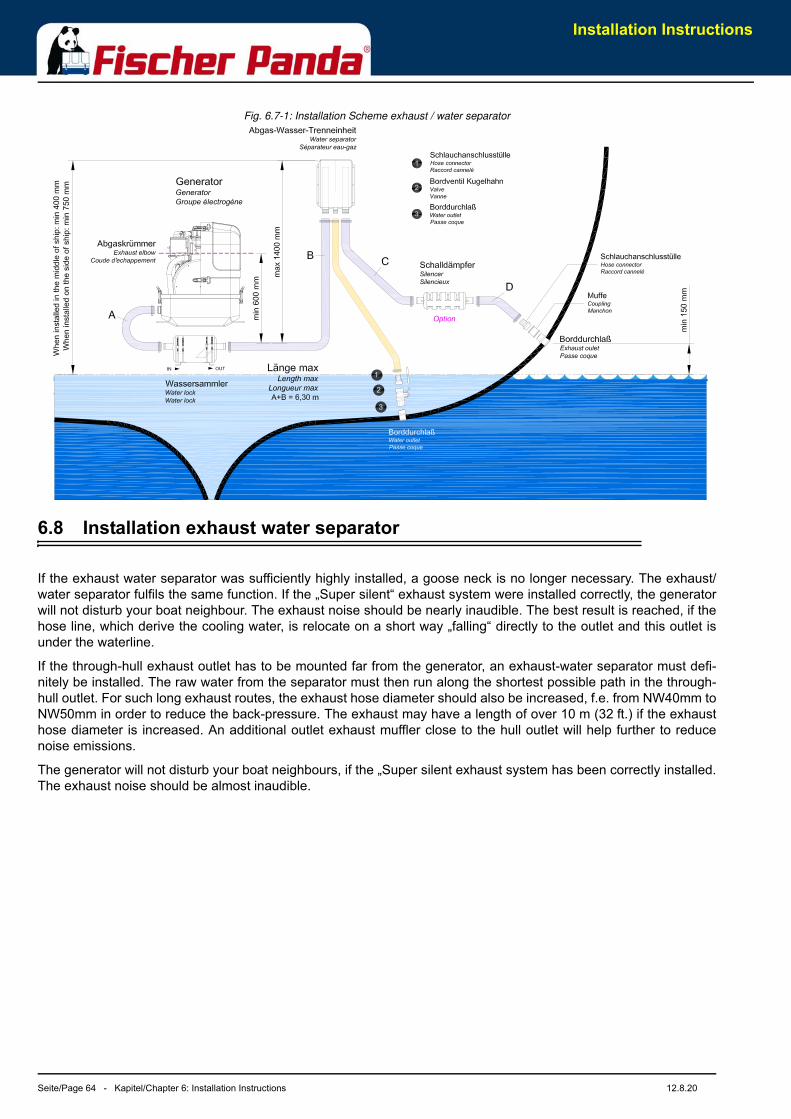
Installation Instructions
Seite/Page 64 - Kapitel/Chapter 6: Installation Instructions 12.8.20
Fig. 6.7-1: Installation Scheme exhaust / water separator
6.8 Installation exhaust water separator
If the exhaust water separator was sufficiently highly installed, a goose neck is no longer necessary. The exhaust/water separator fulfils the same function. If the „Super silent“ exhaust system were installed correctly, the generatorwill not disturb your boat neighbour. The exhaust noise should be nearly inaudible. The best result is reached, if thehose line, which derive the cooling water, is relocate on a short way „falling“ directly to the outlet and this outlet isunder the waterline.
If the through-hull exhaust outlet has to be mounted far from the generator, an exhaust-water separator must defi-nitely be installed. The raw water from the separator must then run along the shortest possible path in the through-hull outlet. For such long exhaust routes, the exhaust hose diameter should also be increased, f.e. from NW40mm toNW50mm in order to reduce the back-pressure. The exhaust may have a length of over 10 m (32 ft.) if the exhausthose diameter is increased. An additional outlet exhaust muffler close to the hull outlet will help further to reducenoise emissions.
The generator will not disturb your boat neighbours, if the „Super silent exhaust system has been correctly installed.The exhaust noise should be almost inaudible.
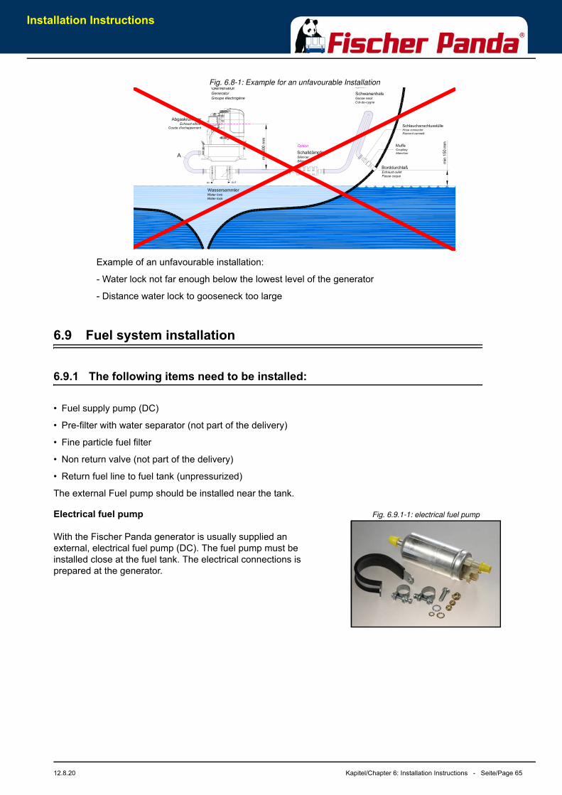
Installation Instructions
12.8.20 Kapitel/Chapter 6: Installation Instructions - Seite/Page 65
Fig. 6.8-1: Example for an unfavourable Installation
6.9 Fuel system installation
6.9.1 The following items need to be installed:
• Fuel supply pump (DC)
• Pre-filter with water separator (not part of the delivery)
• Fine particle fuel filter
• Non return valve (not part of the delivery)
• Return fuel line to fuel tank (unpressurized)
The external Fuel pump should be installed near the tank.
Fig. 6.9.1-1: electrical fuel pumpElectrical fuel pump
With the Fischer Panda generator is usually supplied an external, electrical fuel pump (DC). The fuel pump must be installed close at the fuel tank. The electrical connections is prepared at the generator.
Example of an unfavourable installation:
- Water lock not far enough below the lowest level of the generator
- Distance water lock to gooseneck too large
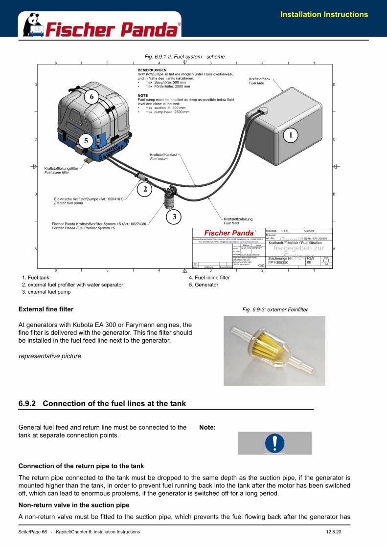
Installation Instructions
Seite/Page 66 - Kapitel/Chapter 6: Installation Instructions 12.8.20
Fig. 6.9.1-2: Fuel system - scheme
Fig. 6.9-3: externer FeinfilterExternal fine filter
At generators with Kubota EA 300 or Farymann engines, the fine filter is delivered with the generator. This fine filter should be installed in the fuel feed line next to the generator.
representative picture
6.9.2 Connection of the fuel lines at the tank
Note:General fuel feed and return line must be connected to the tank at separate connection points.
Connection of the return pipe to the tank
The return pipe connected to the tank must be dropped to the same depth as the suction pipe, if the generator ismounted higher than the tank, in order to prevent fuel running back into the tank after the motor has been switchedoff, which can lead to enormous problems, if the generator is switched off for a long period.
Non-return valve in the suction pipe
A non-return valve must be fitted to the suction pipe, which prevents the fuel flowing back after the generator has
1
1
2
2
3
3
4
4
5
5
6
6
A A
B B
C C
D D
Zeichnungs Nr.FP1-305390
Material:
Geprüft undfreigegeben zur
Fertigung
Kraftstoff-Filtration / Fuel filtration
REV00
Fischer Panda GmbH Otto-Hahn-Str. 40 D-33104 Paderborn Tel.: 05254/9202-0
Fax (05254) 9202-550 [email protected] www.fischerpanda.de
ckriener
1 : 6,5�
Fischer Panda
Allgemeintoleranzen nach DIN ISO 2768-mK
07.07.2020
Schutzvermerk nach DIN 34 beachten !
sbergmann24.06.2020
Gewicht:
Art.-Nr.:
Bearbeiter
letzte Freigabe
Datum
erste Freigabe:
Name
A31 / 1
Maßstab:
Blatt
-
3D-Nr.: FP1-305390
00
Zust. Änderung Datum Name
Fischer Panda Kraftstoffvorfilter-System 1S (Art.: 0027439)Fischer Panda Fuel Prefilter System 1S
Elektrische Kraftstoffpumpe (Art.: 0004101)Electric fuel pump
KraftstoffleitungsfilterFuel inline filter
KraftstofftankFuel tank
KraftstoffrücklaufFuel return
KraftstoffzuleitungFuel feed
BEMERKUNGEN
Kraftstoffpumpe so tief wie möglich unter Flüssigkeitsniveau und in Nähe des Tanks installieren:• max. Saughöhe: 500 mm• max. Förderhöhe: 2500 mm
NOTE
Fuel pump must be installed as deep as possible below fluid level and close to the tank:• max. suction lift: 500 mm• max. pump head: 2500 mm
5
2
3
1
6
1. Fuel tank2. external fuel prefilter with water separator 3. external fuel pump
4. Fuel inline filter5. Generator
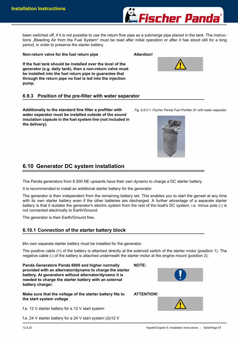
Installation Instructions
12.8.20 Kapitel/Chapter 6: Installation Instructions - Seite/Page 67
been switched off, if it is not possible to use the return flow pipe as a submerge pipe placed in the tank. The instruc-tions „Bleeding Air from the Fuel System“ must be read after initial operation or after it has stood still for a longperiod, in order to preserve the starter battery.
Attention!Non-return valve for the fuel return pipe
If the fuel tank should be installed over the level of the generator (e.g. daily tank), then a non-return valve must be installed into the fuel return pipe to guarantee that through the return pipe no fuel is led into the injection pump.
6.9.3 Position of the pre-filter with water separator
Fig. 6.9.3-1: Fischer Panda Fuel Prefilter S1 with water separatorAdditionally to the standard fine filter a prefilter with water separator must be installed outside of the sound insulation capsule in the fuel system line (not included in the delivery).
6.10 Generator DC system installation
The Panda generators from 6.500 NE upwards have their own dynamo to charge a DC starter battery.
It is recommended to install an additional starter battery for the generator.
The generator is then independent from the remaining battery set. This enables you to start the genset at any timewith its own starter battery even if the other batteries are discharged. A further advantage of a separate starterbattery is that it isolates the generator's electric system from the rest of the boat's DC system, i.e. minus pole (-) isnot connected electrically to Earth/Ground.
The generator is then Earth/Ground free.
6.10.1 Connection of the starter battery block
IAn own separate starter battery must be installed for the generator.
The positive cable (+) of the battery is attached directly at the solenoid switch of the starter motor (position 1). Thenegative cable (-) of the battery is attached underneath the starter motor at the engine mount (position 2).
NOTE:Panda Generators Panda 6000 and higher normally provided with an alternator/dynamo to charge the starter battery. At generators without alternator/dynamo it is needed to charge the starter battery with an external battery charger.
ATTENTION!Make sure that the voltage of the starter battery fits to the start system voltage
f.e. 12 V starter battery for a 12 V start system
f.e. 24 V starter battery for a 24 V start system (2x12 V
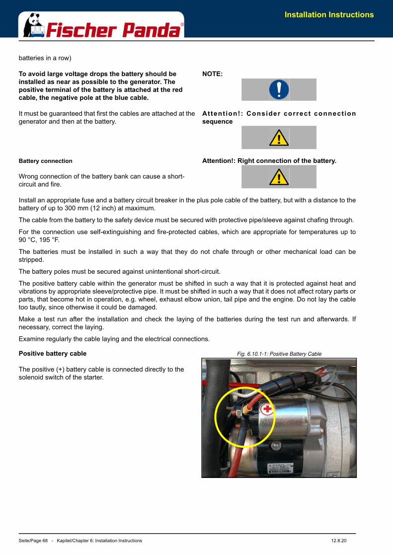
Installation Instructions
Seite/Page 68 - Kapitel/Chapter 6: Installation Instructions 12.8.20
batteries in a row)
NOTE:To avoid large voltage drops the battery should be installed as near as possible to the generator. The positive terminal of the battery is attached at the red cable, the negative pole at the blue cable.
Attent ion!: Consider correct connect ionsequence
It must be guaranteed that first the cables are attached at the generator and then at the battery.
Attention!: Right connection of the battery.Battery connection
Wrong connection of the battery bank can cause a short-circuit and fire.
Install an appropriate fuse and a battery circuit breaker in the plus pole cable of the battery, but with a distance to thebattery of up to 300 mm (12 inch) at maximum.
The cable from the battery to the safety device must be secured with protective pipe/sleeve against chafing through.
For the connection use self-extinguishing and fire-protected cables, which are appropriate for temperatures up to90 °C, 195 °F.
The batteries must be installed in such a way that they do not chafe through or other mechanical load can bestripped.
The battery poles must be secured against unintentional short-circuit.
The positive battery cable within the generator must be shifted in such a way that it is protected against heat andvibrations by appropriate sleeve/protective pipe. It must be shifted in such a way that it does not affect rotary parts orparts, that become hot in operation, e.g. wheel, exhaust elbow union, tail pipe and the engine. Do not lay the cabletoo tautly, since otherwise it could be damaged.
Make a test run after the installation and check the laying of the batteries during the test run and afterwards. Ifnecessary, correct the laying.
Examine regularly the cable laying and the electrical connections.
Fig. 6.10.1-1: Positive Battery Cable Positive battery cable
The positive (+) battery cable is connected directly to the solenoid switch of the starter.
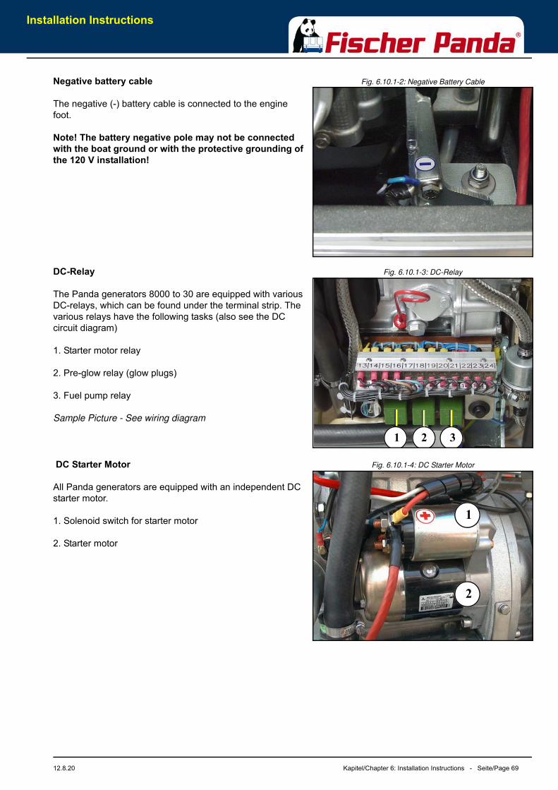
Installation Instructions
12.8.20 Kapitel/Chapter 6: Installation Instructions - Seite/Page 69
Fig. 6.10.1-2: Negative Battery CableNegative battery cable
The negative (-) battery cable is connected to the engine foot.
Note! The battery negative pole may not be connected with the boat ground or with the protective grounding of the 120 V installation!
Fig. 6.10.1-3: DC-RelayDC-Relay
The Panda generators 8000 to 30 are equipped with various DC-relays, which can be found under the terminal strip. The various relays have the following tasks (also see the DC circuit diagram)
1. Starter motor relay
2. Pre-glow relay (glow plugs)
3. Fuel pump relay
Sample Picture - See wiring diagram
Fig. 6.10.1-4: DC Starter Motor DC Starter Motor
All Panda generators are equipped with an independent DC starter motor.
1. Solenoid switch for starter motor
2. Starter motor
1 2 3
1
2
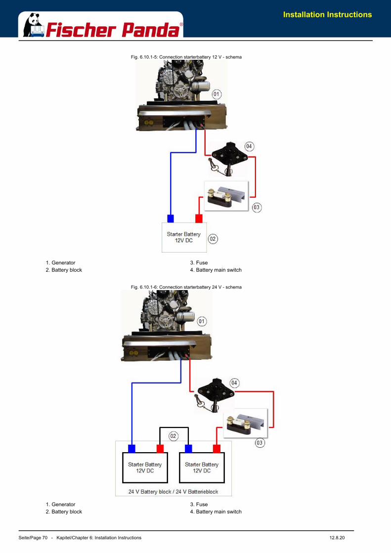
Installation Instructions
Seite/Page 70 - Kapitel/Chapter 6: Installation Instructions 12.8.20
Fig. 6.10.1-5: Connection starterbattery 12 V - schema
Fig. 6.10.1-6: Connection starterbattery 24 V - schema
1. Generator2. Battery block
3. Fuse4. Battery main switch
1. Generator2. Battery block
3. Fuse4. Battery main switch
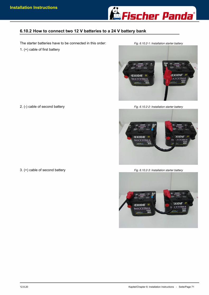
Installation Instructions
12.8.20 Kapitel/Chapter 6: Installation Instructions - Seite/Page 71
6.10.2 How to connect two 12 V batteries to a 24 V battery bank
Fig. 6.10.2-1: Installation starter batteryThe starter batteries have to be connected in this order:
1. (+) cable of first battery
Fig. 6.10.2-2: Installation starter battery2. (-) cable of second battery
Fig. 6.10.2-3: Installation starter battery3. (+) cable of second battery
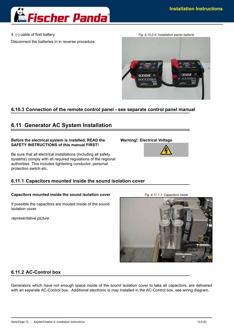
Installation Instructions
Seite/Page 72 - Kapitel/Chapter 6: Installation Instructions 12.8.20
Fig. 6.10.2-4: Installation starter batterie4. (-) cable of first battery
Disconnect the batteries in in reverse procedure.
6.10.3 Connection of the remote control panel - see separate control panel manual
6.11 Generator AC System Installation
Warning!: Electrical Voltage Before the electrical system is installed, READ the SAFETY INSTRUCTIONS of this manual FIRST!
Be sure that all electrical installations (including all safety systems) comply with all required regulations of the regional authorities. This includes lightening conductor, personal protection switch etc.
6.11.1 Capacitors mounted inside the sound isolation cover
Fig. 6.11.1-1: Capacitors inside Capacitors mounted inside the sound isolation cover
If possible the capacitors are mouted inside of the sound isolation cover.
representative picture
6.11.2 AC-Control box
Generators which have not enough space inside of the sound isolation cover to take all capacitors, are deliveredwith an separate AC-Control box. Additional electronic is may installed in the AC-Control box, see wiring diagram.
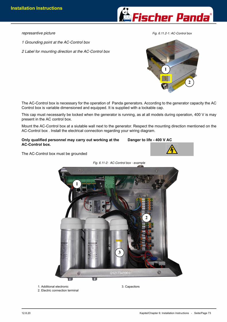
Installation Instructions
12.8.20 Kapitel/Chapter 6: Installation Instructions - Seite/Page 73
Fig. 6.11.2-1: AC-Control boxrepresantive picture
1 Grounding point at the AC-Control box
2 Label for mounting direction at the AC-Control box
The AC-Control box is necessary for the operation of Panda generators. According to the generator capacity the ACControl box is variable dimensioned and equipped. It is supplied with a lockable cap.
This cap must necessarily be locked when the generator is running, as at all models during operation, 400 V is maypresent in the AC control box.
Mount the AC-Control box at a siutable wall next to the generator. Respect the mounting direction mentioned on theAC-Control box . Install the electrical connection regarding your wiring diagram.
Danger to life - 400 V ACOnly qualified personnel may carry out working at the AC-Control box.
The AC-Control box must be grounded
Fig. 6.11-2: AC-Control box - example
2
1
3
2
1
1. Additional electronic2. Electric connection terminal
3. Capacitors
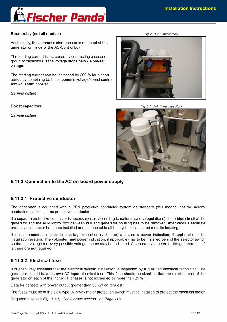
Installation Instructions
Seite/Page 74 - Kapitel/Chapter 6: Installation Instructions 12.8.20
Fig. 6.11.2-3: Boost relayBoost relay (not all models)
Additionally, the automatic start booster is mounted at the generator or inside of the AC-Control box.
The starting current is increased by connecting a second group of capacitors, if the voltage drops below a pre-set voltage.
The starting current can be increased by 300 % for a short period by combining both components voltage/speed control and ASB start booster.
Sample picture
Fig. 6.11.2-4: Boost capacitorsBoost capacitors
Sample picture
6.11.3 Connection to the AC on-board power supply
6.11.3.1 Protective conductor
The generator is equipped with a PEN protective conductor system as standard (this means that the neutralconductor is also used as protective conductor).
If a separate protective conductor is necessary (i. e. according to national safety regulations), the bridge circuit at thegenerator and the AC-Control box between null and generator housing has to be removed. Afterwards a separateprotective conductor has to be installed and connected to all the system’s attached metallic housings.
It is recommended to provide a voltage indication (voltmeter) and also a power indication, if applicable, in theinstallation system. The voltmeter (and power indication, if applicable) has to be installed behind the selector switchso that the voltage for every possible voltage source may be indicated. A separate voltmeter for the generator itself,is therefore not required.
6.11.3.2 Electrical fuse
It is absolutely essential that the electrical system installation is inspected by a qualified electrical technician. Thegenerator should have its own AC input electrical fuse. This fuse should be sized so that the rated current of thegenerator on each of the individual phases is not exceeded by more than 25 %.
Data for gensets with power output greater than 30 kW on request!
The fuses must be of the slow type. A 3-way motor protection switch must be installed to protect the electrical motor.
Required fuse see Fig. 9.3-1, “Cable cross section,” on Page 118
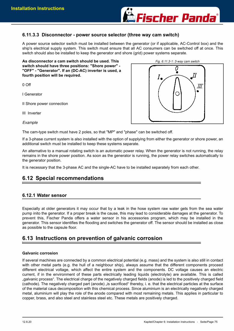
Installation Instructions
12.8.20 Kapitel/Chapter 6: Installation Instructions - Seite/Page 75
6.11.3.3 Disconnector - power source selector (three way cam switch)
A power source selector switch must be installed between the generator (or if applicable, AC-Control box) and theship's electrical supply system. This switch must ensure that all AC consumers can be switched off at once. Thisswitch should also be installed to keep the generator and shore (grid) power systems separate.
Fig. 6.11.3-1: 3-way cam switchAs disconnector a cam switch should be used. This switch should have three positions: "Shore power" - "OFF" - "Generator". If an (DC-AC) inverter is used, a fourth position will be required.
0 Off
I Generator
II Shore power connection
III Inverter
Example
The cam-type switch must have 2 poles, so that "MP" and "phase" can be switched off.
If a 3-phase current system is also installed with the option of supplying from either the generator or shore power, anadditional switch must be installed to keep these systems separate.
An alternative to a manual rotating switch is an automatic power relay. When the generator is not running, the relayremains in the shore power position. As soon as the generator is running, the power relay switches automatically tothe generator position.
It is necessary that the 3-phase AC and the single-AC have to be installed separately from each other.
6.12 Special recommendations
6.12.1 Water sensor
Especially at older generators it may occur that by a leak in the hose system raw water gets from the sea waterpump inito the generator. If a proper break is the cause, this may lead to considerable damages at the generator. Toprevent this, Fischer Panda offers a water sensor in his accessories program, which may be installed in thegenerator. This sensor identifies the flooding and switches the generator off. The sensor should be installed as closeas possible to the capsule floor.
6.13 Instructions on prevention of galvanic corrosion
Galvanic corrosion
If several machines are connected by a common electrical potential (e.g. mass) and the system is also still in contactwith other metal parts (e.g. the hull of a neighbour ship), always assume that the different components proceeddifferent electrical voltage, which affect the entire system and the components. DC voltage causes an electriccurrent, if in the environment of these parts electrically leading liquids (electrolyte) are available. This is called„galvanic process“. The electrical charge of the negatively charged fields (anode) is led to the positively charged field(cathode). The negatively charged part (anode) „is sacrificed“ thereby, i. e. that the electrical particles at the surfaceof the material caus decomposition with this chemical process. Since aluminium is an electrically negatively chargedmetal, aluminium will play the role of the anode compared with most remaining metals. This applies in particular tocopper, brass, and also steel and stainless steel etc. These metals are positively charged.
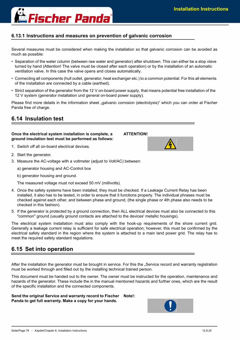
Installation Instructions
Seite/Page 76 - Kapitel/Chapter 6: Installation Instructions 12.8.20
6.13.1 Instructions and measures on prevention of galvanic corrosion
Several measures must be considered when making the installation so that galvanic corrosion can be avoided asmuch as possible:
• Separation of the water column (between raw water and generator) after shutdown. This can either be a stop vlave turned by hand (Attention! The valve must be closed after each operation) or by the installation of an automatic ventilation valve. In this case the valve opens and closes automatically.
• Connecting all components (hull outlet, generator, heat exchanger etc.) to a common potential. For this all elements of the installation are connected by a cable (earthed).
• Strict separation of the generator from the 12 V on-board power supply, that means potential free installation of the 12 V system (generator installation und general on-board power supply).
Please find more details in the information sheet „galvanic corrosion (electrolysis)“ which you can order at FischerPanda free of charge.
6.14 Insulation test
ATTENTION!Once the electrical system installation is complete, a ground insulation test must be performed as follows:
1. Switch off all on-board electrical devices.
2. Start the generator.3. Measure the AC-voltage with a voltmeter (adjust to Volt/AC) between:
a) generator housing and AC-Control box
b) generator housing and ground.
The measured voltage must not exceed 50 mV (millivolts).
4. Once the safety systems have been installed, they must be checked. If a Leakage Current Relay has been installed, it also has to be tested, in order to ensure that it functions properly. The individual phrases must be checked against each other, and between phase and ground, (the single phase or 4th phase also needs to be checked in this fashion).
5. If the generator is protected by a ground connection, then ALL electrical devices must also be connected to this "common" ground (usually ground contacts are attached to the devices' metallic housings).
The electrical system installation must also comply with the hook-up requirements of the shore current grid.Generally a leakage current relay is sufficient for safe electrical operation; however, this must be confirmed by theelectrical safety standard in the region where the system is attached to a main land power grid. The relay has tomeet the required safety standard regulations.
6.15 Set into operation
After the installation the generator must be brought in service. For this the „Service record and warranty registrationmust be worked through and filled out by the installing technical trained person.
This document must be handed out to the owner. The owner must be instructed for the operation, maintenance andhazards of the generator. These include the in the manual mentioned hazards and further ones, which are the resultof the specific installation and the connected components.
Note!:Send the original Service and warranty record to Fischer Panda to get full warranty. Make a copy for your hands.
Maintenance Instructions
12.8.20 Kapitel/Chapter 7: Maintenance Instructions - Seite/Page 77
7. Maintenance Instructions
7.1 Personal requirements
The maintenance described here can be carried out by the operator unless otherwise indicated.
Further maintenance work may only be carried out by specially trained specialist personnel or authorized repairers(Fischer Panda Service Points). This is especially true for work on the valve setting, diesel injection system and forengine repair.
Attention!The work described here can be taken as a guide. Since Fischer Panda does not know the exact installation and storage conditions, the work instructions and materials must be adapted by a local specialist. Damages caused by improper maintenance / repair are not covered by the warranty.
7.1.1 Hazard notes for the maintenance
Note!Follow the general safety instruction at the front of this manual.
Warning! Automatic startDanger for life! - The generator can be equipped with a automatic start device. This means the generator can be started by an external signal. To avoid an unexpected starting of the generator, the starter battery must be disconnected before start working at the generator.
Warning! Risk of injuryWorking at a running generator can result in severe personal injury. Therefore before starting work at the generator:
Make sure that the generator is stopped and the starter battery is disconnected to guarantee that the generator cannot be inadvertently started.
Do not run the generator with removed sound isolation cover
Warning! Risk of injuryImproper installation/maintenance can result in severe personal injuries or material damage.
• Always undertake installation/maintenance work when the generator is switched off.
• Ensure there is sufficient installation clearance before start working.
• Ensure tidiness and cleanliness at the workplace. Loose components and tools lying around or on top of each other are sources of accidents.
• Only perform installation work using commercially available tools and special tools. incorrect or damaged tools can result injuries.
Maintenance Instructions
Seite/Page 78 - Kapitel/Chapter 7: Maintenance Instructions 12.8.20
Warning!: Danger of fire Oil and fuel vapours can ignite on contact with ignition sources. Therefore:
• No open flames during work on the generator.
• Do not smoke.
• Remove oil and fuel residues from the generator and floor.
Danger! Danger of poisoningContact with engine oil, antifreeze and fuel can result in damage to health. Therefor:
• Avoid skin contact with engine oil, fuel and antifreeze.
• Remove oil and fuel splashes and antifreeze from the skin immediately.
• Do not inhale oil and fuel vapours.
Attention! Danger to Life - High voltageDanger for Life. Improper handling, operation, installa-tion and maintenance can result in severe personal injury and/or material damage.
Electrical voltages above 60 volts are always dangerous to life). The rules of the respective regional authority must be adhered to. Only an electrician may carry out installation of the electrical connections for safety reasons.
Warning! Hot surface/materialGenerator, oil and antifreeze can be hot during/after operation. Risk of severe burns.
Instruction! Personal protective equipmentnecessary.
During Installation/maintenance personal protective equipment is required to minimize the health hazards.
• Protective clothing
• safety boots
• protective gloves
• Ear defender
• safety glasses
Attention! disconnect all loadDisconnect all load during the work at the generator to avoid damages at the load.
Warning!Batteries contains acid or alkalis.
Improper handling can result in battery explosion and leakage. Acid or alkalis can run out. An explosion of the battery is possible.
See the operation and safety instruction from your battery
manufacturer.
Batteries contain corrosive acids and lyes.
Improper handling can cause the batteries to heat up and burst. Corrosive acid/lye may leak. Under unfavorable conditions, the battery may explode.

Maintenance Instructions
12.8.20 Kapitel/Chapter 7: Maintenance Instructions - Seite/Page 79
Observe the instructions from your battery manufacturer.
WARNING: System may be pressurised! The different liquid systems (Cooling System, Fuel system etc. may pressurised after operation. When the system is opened, the pressure can be relieved abruptly and expel hot gases and fluids. Risk of injury due to parts flying about, burn hazard due to liquids and gases.
7.2 Environmental protection
Environmental protection!Danger to the environment due to mishandling!
Significant environmental damage can occur, particularly for incorrect disposal, if environmentally hazardous operating materials are mishandled. Therefore:
• Always observe the instructions mentioned below.
• Take immediate action if environmentally hazardous materials reach the environment. Inform the responsible local authorities about the damage in the case of doubt.
The disposal must be performed by a specialist disposal company.
7.3 Maintenance interval
For the maintenance interval, please see the „General information for PMS generators“ which are attached to thismanual.
At generator with dynamic operation hours (f.e. Generators with iControl2 system) the maintenance interval can maybe extended.
Note:With the dynamic operation hours the service interval can be raised up to 30 % (200 h max.). Make sure that the dynamic operation hours are not reset accidently between the service interval.
7.4 General maintenance instructions
7.4.1 Checks before each start
• Oil level
• Leaks in the Cooling system
• Visual check for any changes, leaks in the oil drain system, v-belt, cable connections, hose clips, air filter, fuel lines
Once a month
• Grease/oil the servo motor - Trapezoid thread-spindle
Maintenance Instructions
Seite/Page 80 - Kapitel/Chapter 7: Maintenance Instructions 12.8.20
Maintenance intervals - see separate data sheet
7.4.2 Check of Hoses and Rubber Parts in the sound insulated capsule
Check all hoses and hose connections for good condition. The rubber hoses are very sensitive to environmentalinfluences. They wear out quickly in an environment of dry air, oil and fuel vapours, and high temperatures.The hoses must be checked regularly for elasticity. There are operating situations, when hoses must be renewedonce a year.
Additionally to usual tasks of maintenance (oil level check, oil filter control etc.) further maintenance activities are tobe accomplished for marine generators, such as control of the sacrificial anode (cooling water connection block) andthe front seal cover at the generator.
7.5 Oil Change Intervals
The first oil change is to be accomplished after a period of operation from 35 to 50 hours. Afterwards the oil is to bechanged after 150 hours. For this, the oil SAE30 for temperatures over 20°C and SAE20 for temperatures between5°C and 20°C is to be used. At temperatures under 5°C oil of the viscosity SAE10W or 10W-30 is prescribed.
For filling quantity, see „Technical Data“ at page 107.
7.6 Checking oil-level
You require:
paper towels / cloth for the oil dipstick
The generator must be placed at level.
• with vehicular generators: Place the vehicle on a levelled surface.
• with PSC generators: Place the generator on a levelled surface.
• with marine generators: Measure the oil-level when the ship is not lop-sided.
Run the generator for about 10 minutes to ensure that the engine is warm. Wait for 3 minutes, so the oil can flowback into the oil pan.
Caution: Burn hazard!Generator and coolant can be hot during and after operating.
Wear personal protective equipment. (Gloves, protective goggles, protective clothing and safety shoes)
• Assure generator against accidental start.
• Open the generator casing.
• Pull the oil dipstick out of the check rail.
• Clean oil dipstick.
• Put the oil dipstick back into the check rail and wait for 10 seconds.
• Pull the oil dipstick out of the check rail and read off the oil-level at the lower end of the stick.
Maintenance Instructions
12.8.20 Kapitel/Chapter 7: Maintenance Instructions - Seite/Page 81
Fig. 7.6-1: Oil dipstick - SampleOil dipstick
The oil-level is to be checked by means of the oil dipstick. The prescribed filling level must not cross the „Max“-mark.
We recommend an oil-level of 2/3.
Sample picture
Fig. 7.6-2: Oil dipstickOil dipstick EA 300 Engine
The oil-level is to be checked by means of the oil dipstick. The prescribed filling level must not cross the „Max“-mark.
We recommend an oil-level of 2/3.
Sample picture
Oil should be refilled, if the oil-level is under 1/3 between the minimum and the maximum mark.
Fischer Panda recommends an oil-level of 2/3 between the minimum and the maximum mark.
If the oil-level is under the MIN-mark, check how many operating hours went by since the last oil change, by meansof your service manual or an existing oil change tag. - with operating hours between 50 and 150 hours it is onlynecessary to refill oil. See „Refilling oil“ on page 2.
• with 150 operating hours or more the oil should be changed (See your generators’ service table)
• if the oil-level is under the minimum mark by less than 50h, there might be a technical problem! In that case, we recommend going to a shop or a Fischer Panda service point.
• if the oil is cloudy or even „creamy“, coolant might have mixed with the oil. See a garage or a Fischer Panda service point immediately.
7.6.1 Refilling oil
You require:
Engine oil
1. Check oil-level as described under section 7.6, “Checking oil-level,” on page 80.2. Oil dipstick is pulled out of the check rail.3. Open the oil filler cap.4. Fill in oil (approx. 1/2 litre) and wait for about 2 min. so this it can flow into the oil pan.5. Wipe off the oil dipstick and put it into the check rail.6. Pull the oil dipstick out of the check rail and check the oil-level. See section 7.6, “Checking oil-level,” on page 80.
2/3 Suggestion
Oil Max.Oil Min.
Oil Max.Oil Min.
2/3 Suggestion
Maintenance Instructions
Seite/Page 82 - Kapitel/Chapter 7: Maintenance Instructions 12.8.20
If oil-level is still too low (under 2/3): repeat steps 4-6.
7.6.2 After the oil level check and refilling the oil
• Put the oil dipstick back into the check rail.
• Close the oil filling cap.
• Remove potential oil stains and splashes from the generator and surroundings.
• Close the generator casing.
• Remove lock against accidental generator start.
7.7 Replacement of engine oil and engine oil filter
You require:
- Engine oil. See attachment.
- New oil filter (not with generators with EA300engines)
- Sealing for oil drain screw
- Personal protective gear
- Container to collect used oil (heat resistant andof sufficient size)
- Open-ended wrench for oil drain screw
- Paper towels and cloth
- Oil filter wrench
- Oil resistant mat, so prevent used oil fromgetting into underground water
The generator must be placed at level.
• with vehicular generators: Place the vehicle on a levelled surface.
• with PSC generators: Place the generator on a levelled surface.
• with marine generators: Change the oil when the ship is not lop-sided.
Run the generator for about 10 minutes to ensure that the engine is warm.
Wait for 3 minutes, so the oil can flow back into the oil pan.
Caution: Burn hazard!Generator and coolant can be hot during and after operating.
Wear personal protective equipment. (Gloves, protective goggles, protective clothing and safety shoes)
1. Prepare generator.- Assure generator against accidental start.
- Open the generator casing.
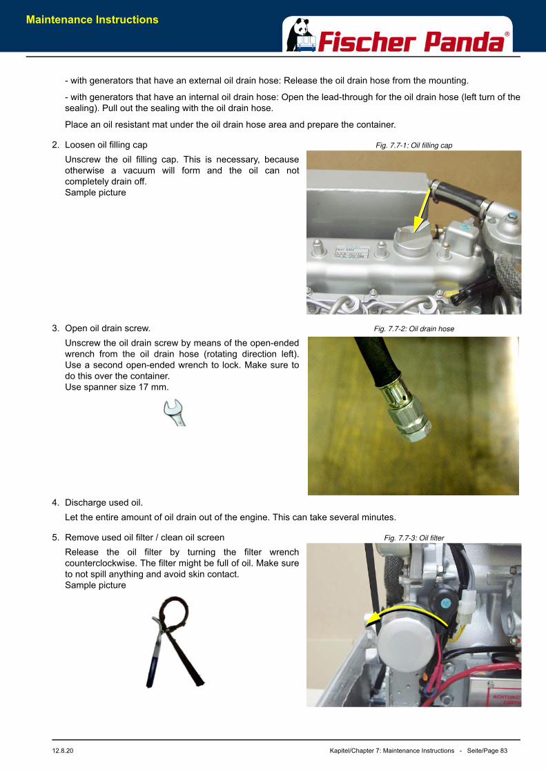
Maintenance Instructions
12.8.20 Kapitel/Chapter 7: Maintenance Instructions - Seite/Page 83
- with generators that have an external oil drain hose: Release the oil drain hose from the mounting.
- with generators that have an internal oil drain hose: Open the lead-through for the oil drain hose (left turn of thesealing). Pull out the sealing with the oil drain hose.
Place an oil resistant mat under the oil drain hose area and prepare the container.
Fig. 7.7-1: Oil filling cap2. Loosen oil filling capUnscrew the oil filling cap. This is necessary, becauseotherwise a vacuum will form and the oil can notcompletely drain off.Sample picture
Fig. 7.7-2: Oil drain hose3. Open oil drain screw.Unscrew the oil drain screw by means of the open-endedwrench from the oil drain hose (rotating direction left).Use a second open-ended wrench to lock. Make sure todo this over the container.Use spanner size 17 mm.
4. Discharge used oil.Let the entire amount of oil drain out of the engine. This can take several minutes.
Fig. 7.7-3: Oil filter5. Remove used oil filter / clean oil screenRelease the oil filter by turning the filter wrenchcounterclockwise. The filter might be full of oil. Make sureto not spill anything and avoid skin contact.Sample picture
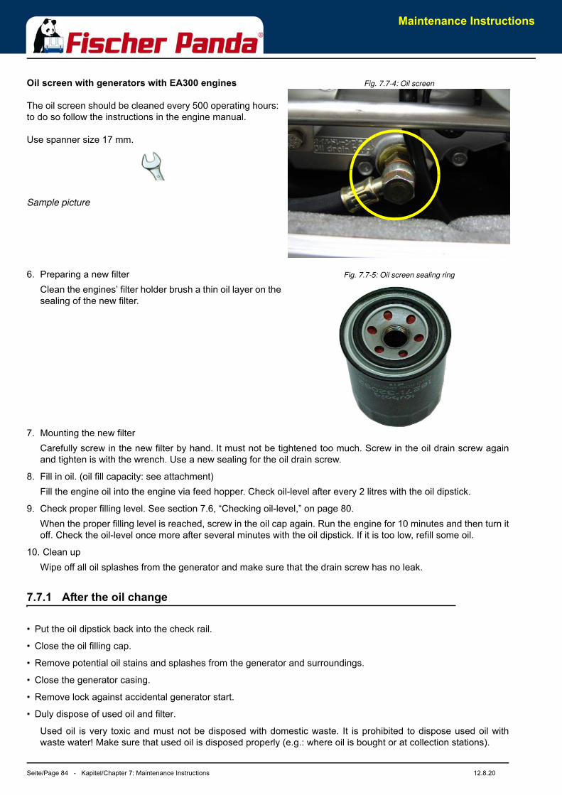
Maintenance Instructions
Seite/Page 84 - Kapitel/Chapter 7: Maintenance Instructions 12.8.20
Fig. 7.7-4: Oil screenOil screen with generators with EA300 engines
The oil screen should be cleaned every 500 operating hours: to do so follow the instructions in the engine manual.
Use spanner size 17 mm.
Sample picture
Fig. 7.7-5: Oil screen sealing ring6. Preparing a new filterClean the engines’ filter holder brush a thin oil layer on thesealing of the new filter.
7. Mounting the new filterCarefully screw in the new filter by hand. It must not be tightened too much. Screw in the oil drain screw againand tighten is with the wrench. Use a new sealing for the oil drain screw.
8. Fill in oil. (oil fill capacity: see attachment)Fill the engine oil into the engine via feed hopper. Check oil-level after every 2 litres with the oil dipstick.
9. Check proper filling level. See section 7.6, “Checking oil-level,” on page 80.When the proper filling level is reached, screw in the oil cap again. Run the engine for 10 minutes and then turn itoff. Check the oil-level once more after several minutes with the oil dipstick. If it is too low, refill some oil.
10. Clean upWipe off all oil splashes from the generator and make sure that the drain screw has no leak.
7.7.1 After the oil change
• Put the oil dipstick back into the check rail.
• Close the oil filling cap.
• Remove potential oil stains and splashes from the generator and surroundings.
• Close the generator casing.
• Remove lock against accidental generator start.
• Duly dispose of used oil and filter.
Used oil is very toxic and must not be disposed with domestic waste. It is prohibited to dispose used oil withwaste water! Make sure that used oil is disposed properly (e.g.: where oil is bought or at collection stations).
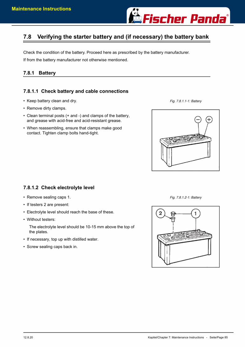
Maintenance Instructions
12.8.20 Kapitel/Chapter 7: Maintenance Instructions - Seite/Page 85
7.8 Verifying the starter battery and (if necessary) the battery bank
Check the condition of the battery. Proceed here as prescribed by the battery manufacturer.
If from the battery manufacturer not otherwise mentioned.
7.8.1 Battery
7.8.1.1 Check battery and cable connections
Fig. 7.8.1.1-1: Battery• Keep battery clean and dry.
• Remove dirty clamps.
• Clean terminal posts (+ and -) and clamps of the battery, and grease with acid-free and acid-resistant grease.
• When reassembling, ensure that clamps make good contact. Tighten clamp bolts hand-tight.
7.8.1.2 Check electrolyte level
Fig. 7.8.1.2-1: Battery• Remove sealing caps 1.
• If testers 2 are present:
• Electrolyte level should reach the base of these.
• Without testers:
The electrolyte level should be 10-15 mm above the top ofthe plates.
• If necessary, top up with distilled water.
• Screw sealing caps back in.
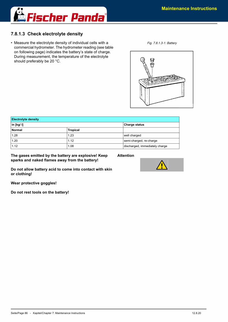
Maintenance Instructions
Seite/Page 86 - Kapitel/Chapter 7: Maintenance Instructions 12.8.20
7.8.1.3 Check electrolyte density
Fig. 7.8.1.3-1: Battery• Measure the electrolyte density of individual cells with a commercial hydrometer. The hydrometer reading (see table on following page) indicates the battery’s state of charge. During measurement, the temperature of the electrolyte should preferably be 20 °C.
AttentionThe gases emitted by the battery are explosive! Keep sparks and naked flames away from the battery!
Do not allow battery acid to come into contact with skin or clothing!
Wear protective goggles!
Do not rest tools on the battery!
Electrolyte densityin [kg/ l] Charge statusNormal Tropical1.28 1.23 well charged
1.20 1.12 semi-charged, re-charge
1.12 1.08 discharged, immediately charge
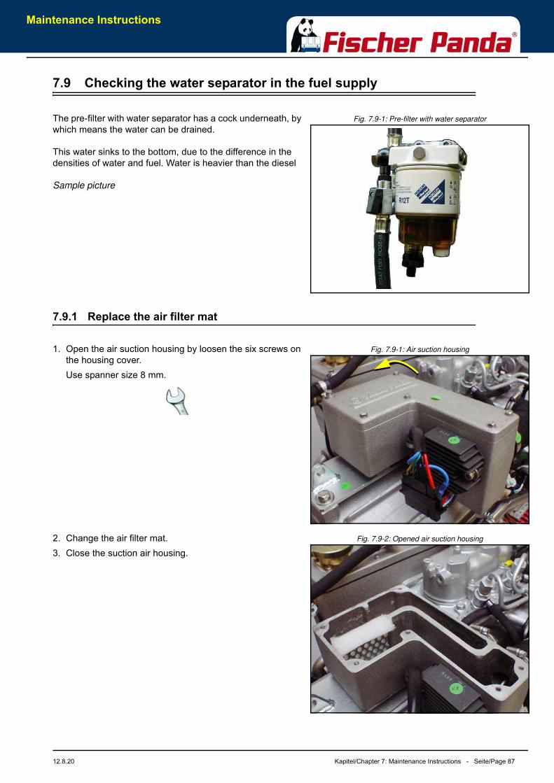
Maintenance Instructions
12.8.20 Kapitel/Chapter 7: Maintenance Instructions - Seite/Page 87
7.9 Checking the water separator in the fuel supply
Fig. 7.9-1: Pre-filter with water separatorThe pre-filter with water separator has a cock underneath, by which means the water can be drained.
This water sinks to the bottom, due to the difference in the densities of water and fuel. Water is heavier than the diesel
Sample picture
7.9.1 Replace the air filter mat
Fig. 7.9-1: Air suction housing1. Open the air suction housing by loosen the six screws on the housing cover.Use spanner size 8 mm.
Fig. 7.9-2: Opened air suction housing2. Change the air filter mat.3. Close the suction air housing.
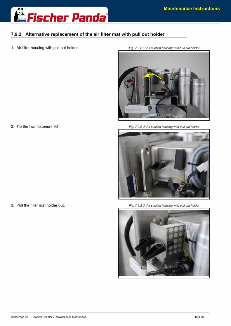
Maintenance Instructions
Seite/Page 88 - Kapitel/Chapter 7: Maintenance Instructions 12.8.20
7.9.2 Alternative replacement of the air filter mat with pull out holder
Fig. 7.9.2-1: Air suction housing with pull out holder 1. Air filter housing with pull out holder.
Fig. 7.9.2-2: Air suction housing with pull out holder 2. Tip the two fasteners 90°.
Fig. 7.9.2-3: Air suction housing with pull out holder 3. Pull the filter mat holder out.

Maintenance Instructions
12.8.20 Kapitel/Chapter 7: Maintenance Instructions - Seite/Page 89
Fig. 7.9.2-4: Air suction housing with pull out holder 4. Replace the air filter mat.5. Re-assembly in reversed order.
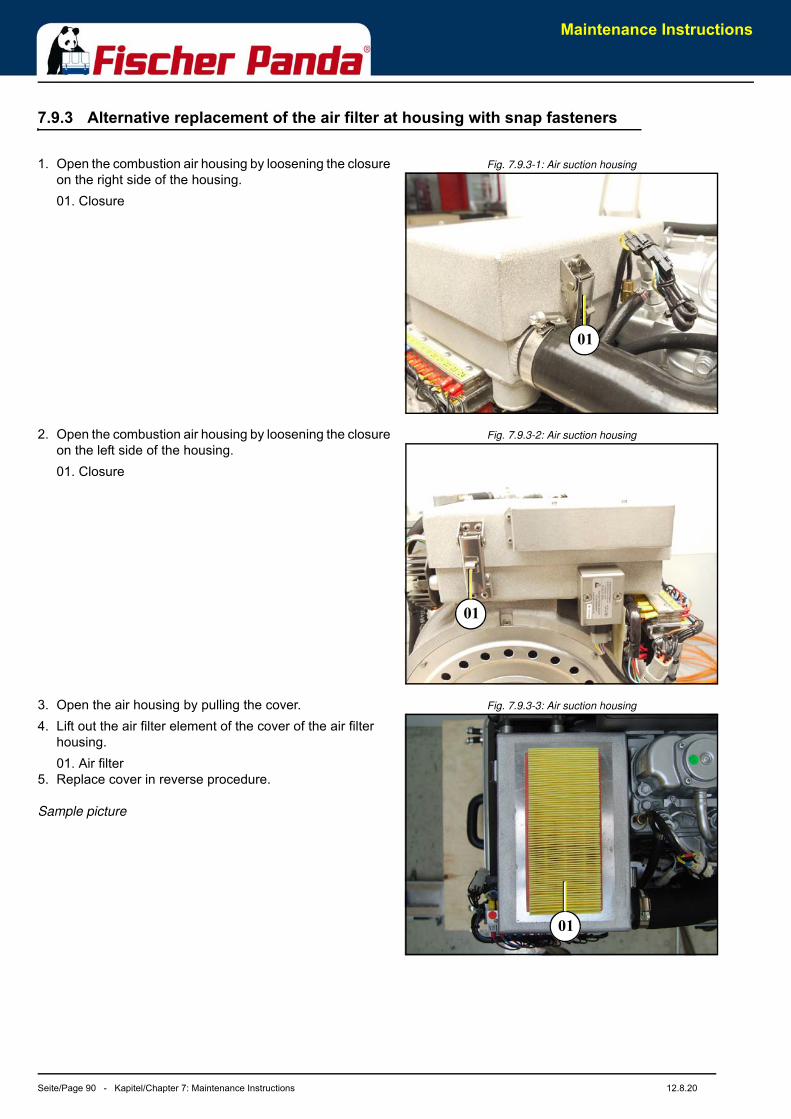
Maintenance Instructions
Seite/Page 90 - Kapitel/Chapter 7: Maintenance Instructions 12.8.20
7.9.3 Alternative replacement of the air filter at housing with snap fasteners
Fig. 7.9.3-1: Air suction housing1. Open the combustion air housing by loosening the closure on the right side of the housing.01. Closure
Fig. 7.9.3-2: Air suction housing2. Open the combustion air housing by loosening the closure on the left side of the housing.01. Closure
Fig. 7.9.3-3: Air suction housing3. Open the air housing by pulling the cover.4. Lift out the air filter element of the cover of the air filter
housing.01. Air filter
5. Replace cover in reverse procedure.
Sample picture
01
01
01
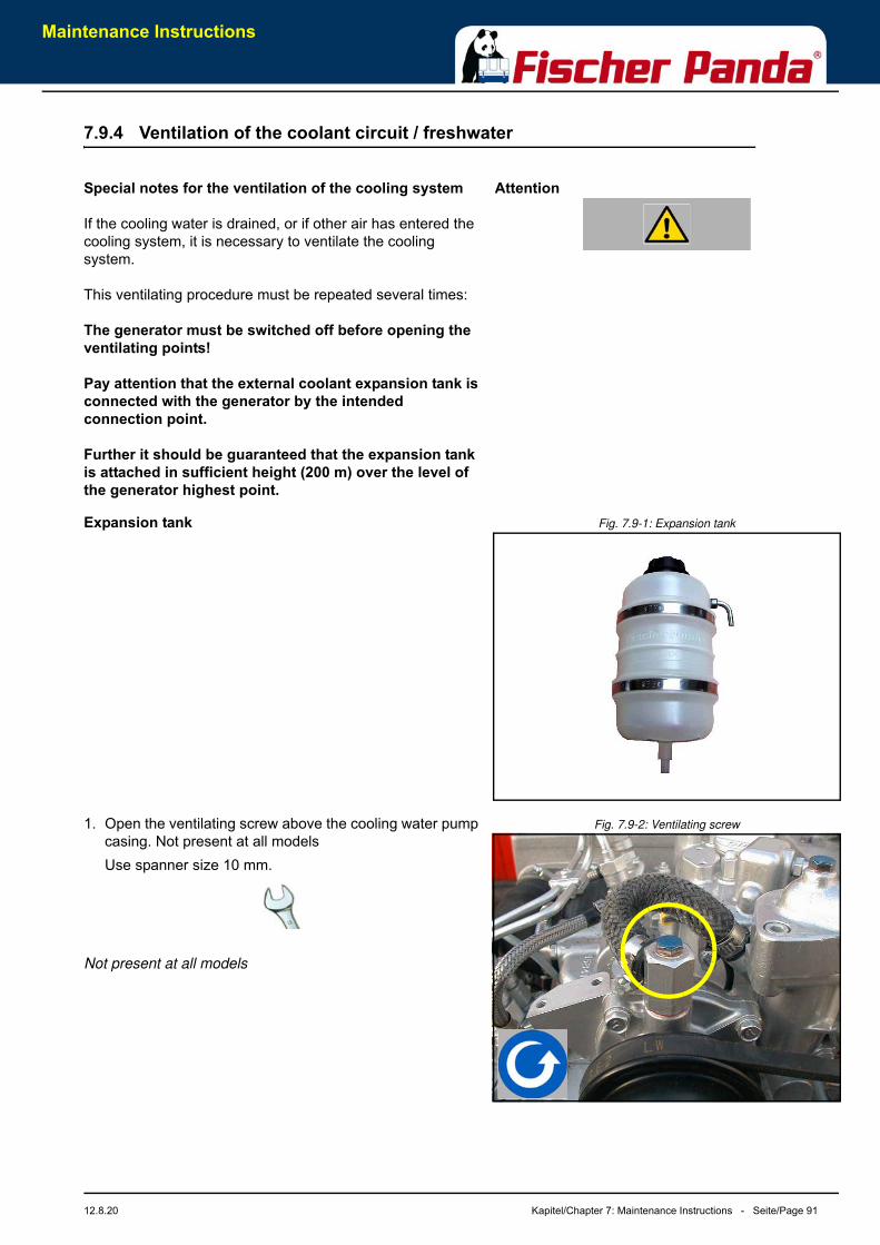
Maintenance Instructions
12.8.20 Kapitel/Chapter 7: Maintenance Instructions - Seite/Page 91
7.9.4 Ventilation of the coolant circuit / freshwater
AttentionSpecial notes for the ventilation of the cooling system
If the cooling water is drained, or if other air has entered the cooling system, it is necessary to ventilate the cooling system.
This ventilating procedure must be repeated several times:
The generator must be switched off before opening the ventilating points!
Pay attention that the external coolant expansion tank is connected with the generator by the intended connection point.
Further it should be guaranteed that the expansion tank is attached in sufficient height (200 m) over the level of the generator highest point.
Fig. 7.9-1: Expansion tankExpansion tank
Fig. 7.9-2: Ventilating screw1. Open the ventilating screw above the cooling water pump casing. Not present at all modelsUse spanner size 10 mm.
Not present at all models
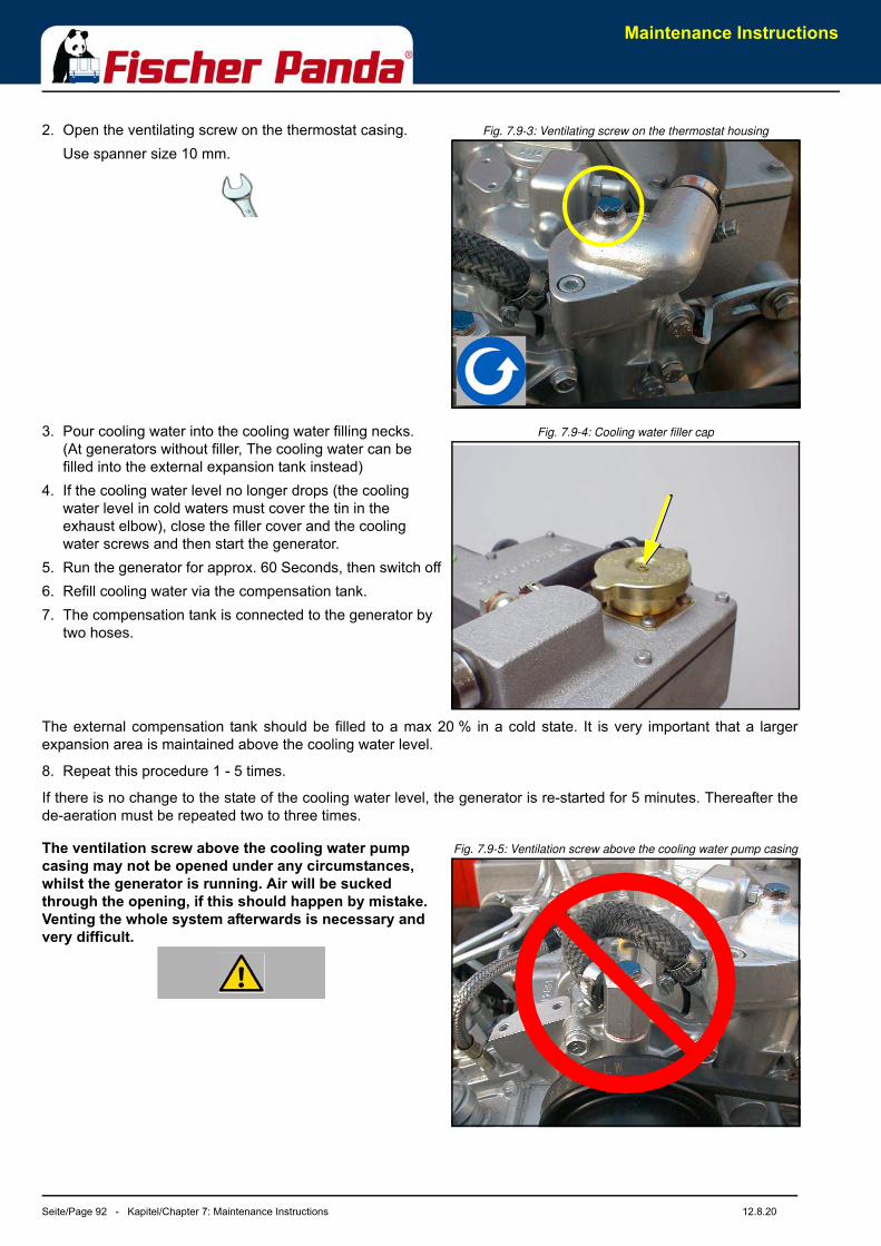
Maintenance Instructions
Seite/Page 92 - Kapitel/Chapter 7: Maintenance Instructions 12.8.20
Fig. 7.9-3: Ventilating screw on the thermostat housing2. Open the ventilating screw on the thermostat casing.Use spanner size 10 mm.
Fig. 7.9-4: Cooling water filler cap3. Pour cooling water into the cooling water filling necks. (At generators without filler, The cooling water can be filled into the external expansion tank instead)
4. If the cooling water level no longer drops (the cooling water level in cold waters must cover the tin in the exhaust elbow), close the filler cover and the cooling water screws and then start the generator.
5. Run the generator for approx. 60 Seconds, then switch off6. Refill cooling water via the compensation tank.7. The compensation tank is connected to the generator by
two hoses.
The external compensation tank should be filled to a max 20 % in a cold state. It is very important that a largerexpansion area is maintained above the cooling water level.
8. Repeat this procedure 1 - 5 times.
If there is no change to the state of the cooling water level, the generator is re-started for 5 minutes. Thereafter thede-aeration must be repeated two to three times.
Fig. 7.9-5: Ventilation screw above the cooling water pump casingThe ventilation screw above the cooling water pump casing may not be opened under any circumstances, whilst the generator is running. Air will be sucked through the opening, if this should happen by mistake. Venting the whole system afterwards is necessary and very difficult.
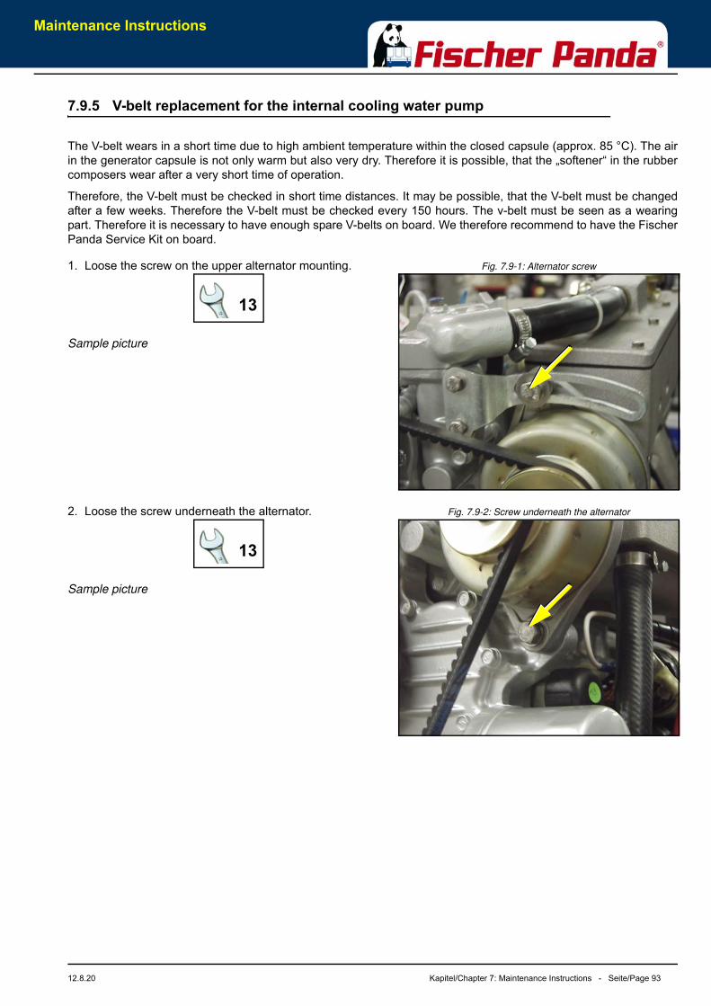
Maintenance Instructions
12.8.20 Kapitel/Chapter 7: Maintenance Instructions - Seite/Page 93
7.9.5 V-belt replacement for the internal cooling water pump
The V-belt wears in a short time due to high ambient temperature within the closed capsule (approx. 85 °C). The airin the generator capsule is not only warm but also very dry. Therefore it is possible, that the „softener“ in the rubbercomposers wear after a very short time of operation.
Therefore, the V-belt must be checked in short time distances. It may be possible, that the V-belt must be changedafter a few weeks. Therefore the V-belt must be checked every 150 hours. The v-belt must be seen as a wearingpart. Therefore it is necessary to have enough spare V-belts on board. We therefore recommend to have the FischerPanda Service Kit on board.
Fig. 7.9-1: Alternator screw1. Loose the screw on the upper alternator mounting.
Sample picture
Fig. 7.9-2: Screw underneath the alternator2. Loose the screw underneath the alternator.
Sample picture
13
13
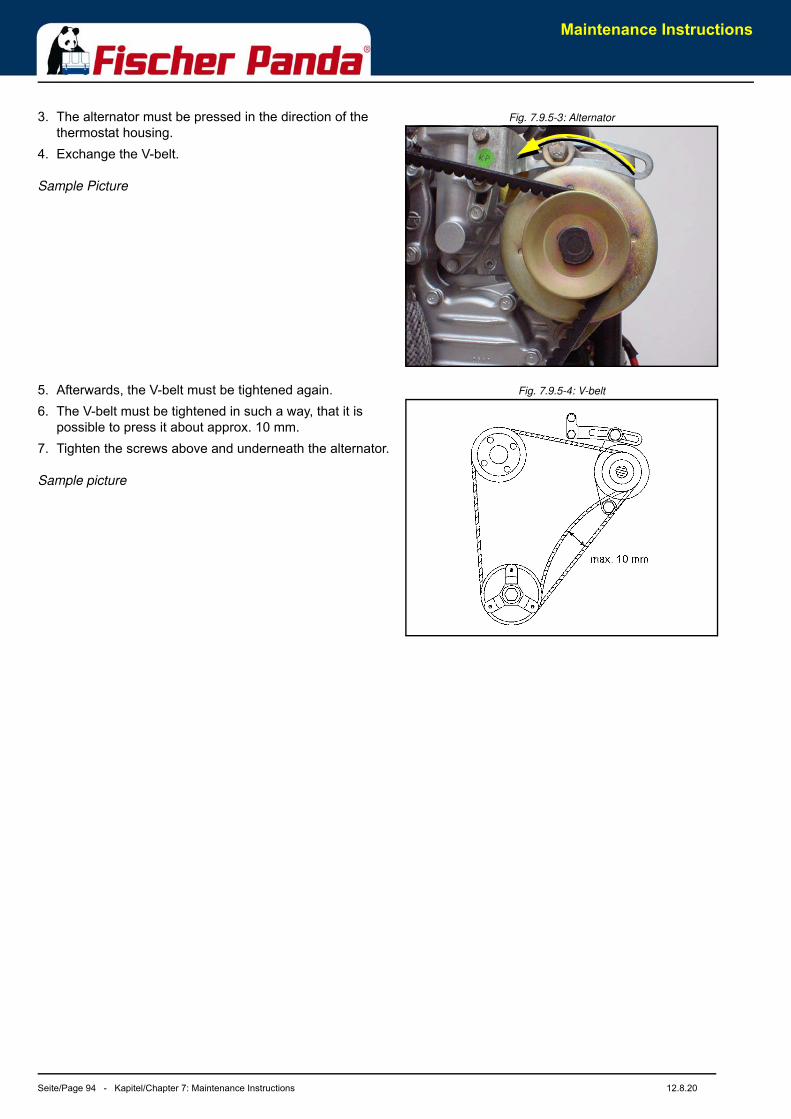
Maintenance Instructions
Seite/Page 94 - Kapitel/Chapter 7: Maintenance Instructions 12.8.20
Fig. 7.9.5-3: Alternator3. The alternator must be pressed in the direction of the thermostat housing.
4. Exchange the V-belt.
Sample Picture
Fig. 7.9.5-4: V-belt5. Afterwards, the V-belt must be tightened again.6. The V-belt must be tightened in such a way, that it is
possible to press it about approx. 10 mm.7. Tighten the screws above and underneath the alternator.
Sample picture
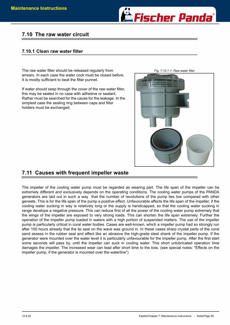
Maintenance Instructions
12.8.20 Kapitel/Chapter 7: Maintenance Instructions - Seite/Page 95
7.10 The raw water circuit
7.10.1 Clean raw water filter
Fig. 7.10.1-1: Raw water filterThe raw water filter should be released regularly from arrears. In each case the water cock must be closed before. It is mostly sufficient to beat the filter punnet.
If water should seep through the cover of the raw water filter, this may be sealed in no case with adhesive or sealant. Rather must be searched for the cause for the leakage. In the simplest case the sealing ring between caps and filter holders must be exchanged.
7.11 Causes with frequent impeller waste
The impeller of the cooling water pump must be regarded as wearing part. The life span of the impeller can beextremely different and exclusively depends on the operating conditions. The cooling water pumps of the PANDAgenerators are laid out in such a way that the number of revolutions of the pump lies low compared with othergensets. This is for the life span of the pump a positive effect. Unfavourable affects the life span of the impeller, if thecooling water sucking in way is relatively long or the supply is handicapped, so that the cooling water sucking inrange develops a negative pressure. This can reduce first of all the power of the cooling water pump extremely thatthe wings of the impeller are exposed to very strong loads. This can shorten the life span extremely. Further theoperation of the impeller pump loaded in waters with a high portion of suspended matters. The use of the impellerpump is particularly critical in coral water bodies. Cases are well-known, which a impeller pump had so strongly runafter 100 hours already that the lip seal on the wave was ground in. In these cases sharp crystal parts of the coralsand assess in the rubber seal and affect like an abrasive the high-grade steel shank of the impeller pump. If thegenerator were mounted over the water level it is particularly unfavourable for the impeller pump. After the first startsome seconds will pass by, until the impeller can suck in cooling water. This short unlubricated operation timedamages the impeller. The increased wear can lead after short time to the loss. (see special notes: "Effects on theimpeller pump, if the generator is mounted over the waterline")
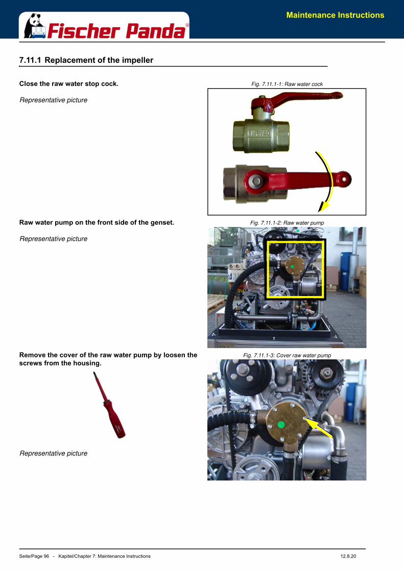
Maintenance Instructions
Seite/Page 96 - Kapitel/Chapter 7: Maintenance Instructions 12.8.20
7.11.1 Replacement of the impeller
Fig. 7.11.1-1: Raw water cockClose the raw water stop cock.
Representative picture
Fig. 7.11.1-2: Raw water pumpRaw water pump on the front side of the genset.
Representative picture
Fig. 7.11.1-3: Cover raw water pumpRemove the cover of the raw water pump by loosen the screws from the housing.
Representative picture

Maintenance Instructions
12.8.20 Kapitel/Chapter 7: Maintenance Instructions - Seite/Page 97
Fig. 7.11.1-4: Impeller pump
Pull to the impeller with a multigrip pliers of the wave.
Mark the impeller, to make sure that these is used in the correct position at re-installation.
Representative picture
Fig. 7.11.1-5: ImpellerCheck to the impeller for damage and replace it if necessary.
Before the reinsertion into the housing the impeller should have been lubricated with glycerin or with a non-mineral oil based lubricant e.g. silicone spray.
The impeller is attached to the pump wave (if the old impeller is used, pay attention to the before attached marking).
Representative picture
Fig. 7.11.1-6: GasketFastening the cover and use a new seal.
Representative picture
7.12 Check and discharge the capacitors
Attention!:NEVER check the capacitors whilst the generator motor is running! Charged capacitors can be lethal. Do not contact the capacitors with bare fingers or non-insulated metallic objects! In order to test the capacitors, the terminal lead wires have to be disconnected using pliers or a screwdriver with insulated handle(s). Once the wires
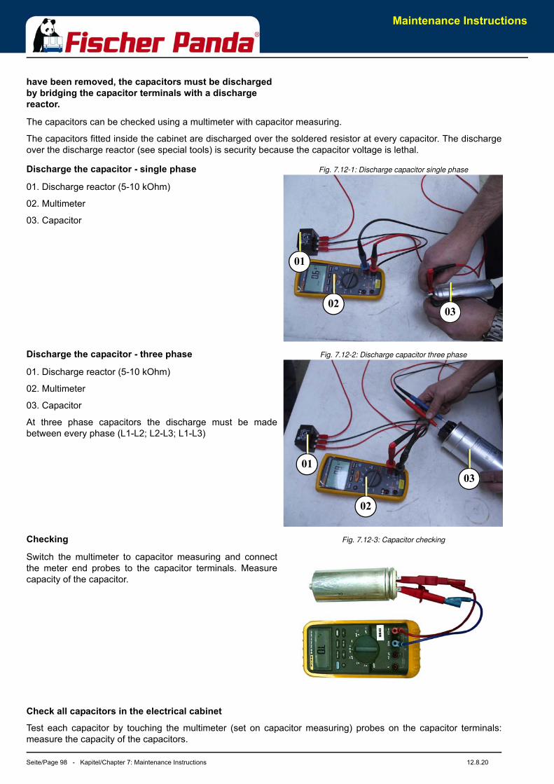
Maintenance Instructions
Seite/Page 98 - Kapitel/Chapter 7: Maintenance Instructions 12.8.20
have been removed, the capacitors must be discharged by bridging the capacitor terminals with a discharge reactor.
The capacitors can be checked using a multimeter with capacitor measuring.
The capacitors fitted inside the cabinet are discharged over the soldered resistor at every capacitor. The dischargeover the discharge reactor (see special tools) is security because the capacitor voltage is lethal.
Fig. 7.12-1: Discharge capacitor single phaseDischarge the capacitor - single phase
01. Discharge reactor (5-10 kOhm)
02. Multimeter
03. Capacitor
Fig. 7.12-2: Discharge capacitor three phaseDischarge the capacitor - three phase
01. Discharge reactor (5-10 kOhm)
02. Multimeter
03. Capacitor
At three phase capacitors the discharge must be madebetween every phase (L1-L2; L2-L3; L1-L3)
Fig. 7.12-3: Capacitor checkingChecking
Switch the multimeter to capacitor measuring and connectthe meter end probes to the capacitor terminals. Measurecapacity of the capacitor.
Check all capacitors in the electrical cabinet
Test each capacitor by touching the multimeter (set on capacitor measuring) probes on the capacitor terminals:measure the capacity of the capacitors.
0302
01
03
02
01

Maintenance Instructions
12.8.20 Kapitel/Chapter 7: Maintenance Instructions - Seite/Page 99
The capacitors should not be removed from the electrical cabinet before the check is made.
Checking the electrical connections to the Capacitor
It must be ensured that the electrical connections to the capacitor are always tight fitting. Loose connections withtransitional resistance can mean that the contact surfaces will become heated externally. This can lead to fasterdeterioration of the capacitors.

Maintenance Instructions
Seite/Page 100 - Kapitel/Chapter 7: Maintenance Instructions 12.8.20
Leere Seite / Intentionally blank
Generator Faults
12.8.20 Kapitel/Chapter 8: Generator Faults - Seite/Page 101
8. Generator Faults
8.1 Personal requirements
The work described here, unless otherwise indicated, are performed by the operator.
Any further repair work may be performed only by specially trained personnel or by authorized repair shops (FischerPanda service points). This is especially for working on the valve timing, fuel injection system and the engine repair.
8.2 Hazard notes for this chapter
Note!:see “Safety first!” on Page 10.
Also consider the general safety instructions at the first pages of this manual.
Warning!: Automatic startDanger for life! - The generator can be equipped with a automatic start device. This means the generator can be started by an external signal. To avoid an unexpected starting of the generator, the starter battery must be disconnected before start working at the generator.
Warning!: Risk of injuryWorking at a running generator can result in severe personal injury. Therefore before starting work at the generator:
Make sure that the generator is stopped and the starter battery is disconnected to guarantee that the generator cannot be inadvertently started.
Do not run the generator with removed sound isolation cover.
Warning!: Risk of injuryImproper installation/maintenance can result in severe personal injuries or material damage.
• Always undertake installation/maintenance work when the generator is switched off.
• Ensure there is sufficient installation clearance before start working.
• Ensure tidiness and cleanliness at the workplace. Loose components and tools lying around or on top of each other are sources of accidents.
• Only perform installation work using commercially available tools and special tools. incorrect or damaged tools can result injuries.
Warning!: Danger of fireOil and fuel vapours can ignite on contact with ignition sources. Therefore:
• No open flames during work on the generator.
• Do not smoke.
• Remove oil and fuel residues from the generator and floor.
Generator Faults
Seite/Page 102 - Kapitel/Chapter 8: Generator Faults 12.8.20
Danger!: Danger of poisoningContact with engine oil, antifreeze and fuel can result in damage to health. Therefor:
• Avoid skin contact with engine oil, fuel and antifreeze.
• Remove oil and fuel splashes and antifreeze from the skin immediately.
• Do not inhale oil and fuel vapours.
ATTENTION!: Danger to Life - High voltageDanger for Life. Improper handling, operation, installation and maintenance can result in severe personal injury and/or material damage.
Electrical voltages above 48 volts (battery chargers greater than 36 volts) are always dangerous to life). The rules of the respective regional authority must be adhered to. Only an electrician may carry out installation of the electrical connections for safety reasons.
Warning!: Hot surface/materialGenerator, oil and antifreeze can be hot during/after operation. Risk of severe burns.
Instruction!: Personal protective equipmentnecessary.
During Installation/maintenance personal protective equipment is required to minimize the health hazards.
• Protective clothing
• safety boots
• protective gloves
• Ear defender
• safety glasses
Attention!: Disconnect all loadDisconnect all load during the work at the generator to avoid damages at the load.
8.3 Tools and Measuring Instruments
In order to be able to manage disturbances while driving, the following tools and measuring instrumentsshould belong to the equipment kept on board:
• Multimeter for voltage (AC), frequency and resistance
• Measuring instrument for inductance
• Measuring instrument for capacity
• Current absorbing clamps
• Thermometer (ideal is a infra-red thermometer)
• Pressure device (pincer) for coolant circuit
Generator Faults
12.8.20 Kapitel/Chapter 8: Generator Faults - Seite/Page 103
8.4 Troubleshooting Table and Flowchart
8.4.1 Generator output voltage too low
8.4.2 Generator voltage too high
8.4.3 Generator voltage fluctuates
8.4.4 Generator not able to start electric motor
8.4.5 Diesel motor fails to start
8.4.6 Starter is turning motor, but fails to start
Cause SolutionGenerator is overloaded. Reduce the electrical load (switch off load)
Motor is not reaching the rated rpm. Refer to „motor faults“ section.
Defective capacitor(s). Check capacitors and replace if necessary.
Cause SolutionOver-energizing due to wrong capacitors. Check capacitors type and replace if necessary.
Cause Solution1. Disturbances on the electrical system/user side.2. Motor disturbances.
1. Check if electrical load is fluctuating.2. Refer to section: „Motor runs irregular“.
Cause SolutionIf the generator is unable to supply enough power to start an electric motor 1-phase, it is usually because the motor draws too much current during starting process.
Check the motor's current draw required for starting (switch to 3-phase, if possible). This could be remedied by providing stronger capacitors or installing an optional „Easy Start Booster Set“.Enquire at your nearest Panda dealer or directly at the manufacturer.
Cause SolutionStarter battery switched „OFF“. Check position of battery switch and switch „ON“ (if installed).
Starter battery voltage insufficient (battery too weak). Inspect battery terminals and cables for a good electrical connection (Inspect against corrosion, tattered wires, etc.).
Starting current disrupted. During the normal starting process, the battery voltage drops to 11 V with a fully charged battery. If the voltage does not drop during starting, the electrical connection is faulty. If the battery voltage drops lower than 11 V, then the battery has been discharged.
Cause SolutionFuel pump not working. Check fuel-filter and pump: clean if necessary.
Lack of fuel. Check fuel supply.
Glow-plugs not working correctly. Check glow plugs and heating time.
Too much air in fuel lines. Test fuel system for leakage. Bleed air from fuel system (refer to section „Bleeding Air from Fuel System“).
Fuel-filter blocked. Replace fuel filter.
Generator Faults
Seite/Page 104 - Kapitel/Chapter 8: Generator Faults 12.8.20
8.4.7 Motor does not achieve enough speed during starting process
8.4.8 Motor runs unsteady
8.4.9 Motor speed drops
8.4.10 Motor runs in off position
8.4.11 Motor stops by itself
Cause SolutionStarter battery voltage insufficient. Check battery.
Damaged bearing(s) piston (seized). Repairs need to be carried out by Kubota-Service. (refer to Kubota motor-manual)
Cooling water in combustion chamber. 1. Turn generator „OFF“ at control panel.2. Remove the glow plug (see Kubota-manual).3. Rotate the motor by hand carefully.4. Check if there is water in the oil and change both oil and filter if necessary.5. Determine cause for excess water in the combustion chamber. The excess water can be caused by a defective air vent in the cooling water system, which should be checked and cleaned, or replaced if faulty.
Cause SolutionDisruption in the area of the injection systems’ automatic advance. Repair / Check the automatic advance via the motor service.
Air in the fuel system. Ventilate the fuel system.
Cause SolutionLack of fuel Check fuel supply system:
- fuel filter, renew if necessary- check fuel pump- check fuel lines (bleed if necessary)
Lack of intake air. Check air intake paths.Check and clean air filter (and intake muffler if installed).
Generator overloaded by too many load. Reduce the electrical load (switch off load).
Generator overloaded by over-energizing. Check that the proper capacitor type is installed and that they are connected correctly.
Defective generator (windings, bearings, or other). Generator must be sent to manufacturer for repair of damaged bearings or winding.
Damaged engine. Repair of bearing damage, etc., by Kubota-Service.
Cause SolutionFuel inlet solenoid valve or throttle shut solenoid is not switching off. Check wire connections to solenoid. Check valve functions as in the
„Fuel Solenoid Valve“ or in the throttle shut off solenoid sections. Replace if necessary.
Cause SolutionLack of fuel. Check fuel supply system.
Excess heat in cooling system (thermo switch tripped)-lack of cooling water. Is indicated on the remote control panel.
Check cooling water system flow: water pump, inlet water filter, extra heat exchanger coolant flow.
Generator Faults
12.8.20 Kapitel/Chapter 8: Generator Faults - Seite/Page 105
8.4.12 Sooty, black exhaust
8.4.13 Generator must be shut off immediately if:
Lack of oil pressure sensor tripped). Is indicated on the remote control panel.
Check oil-level and if necessary top up.Check motor's oil-pressure and have repaired by Kubota-Service if necessary.
Cause SolutionGenerator is overloaded. Check electrical load and switch off unnecessary load.
Insufficient intake air. Check intake air filter; clean if necessary.
Fuel injector faulty. Replace injector.
Valve clearance incorrect. Readjust valve clearance to correct value (refer to Farymann-manual).
Poor fuel quality. Use better quality diesel (recommended: 2-D Diesel).
Poor combustion. Incorrect AFR (air/fuel ratio) due to motor timing adjustment. Have motor serviced by Kubota.
Cause Solution- motor rpm suddenly rises or drops- unusual noise comes from genset- exhaust colour suddenly becomes dark- leakage in the cooling water system.
Refer to respective section of manual and if necessary, have repaired by Kubota-Service, or Panda representative.
Cause Solution
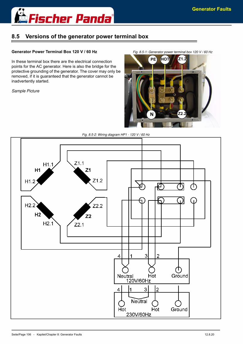
Generator Faults
Seite/Page 106 - Kapitel/Chapter 8: Generator Faults 12.8.20
8.5 Versions of the generator power terminal box
Fig. 8.5-1: Generator power terminal box 120 V / 60 HzGenerator Power Terminal Box 120 V / 60 Hz
In these terminal box there are the electrical connection points for the AC generator. Here is also the bridge for the protective grounding of the generator. The cover may only be removed, if it is guaranteed that the generator cannot be inadvertently started.
Sample Picture
Fig. 8.5-2: Wiring diagram HP1 - 120 V / 60 Hz
PE Z1.2
N
HOT
Z2.2
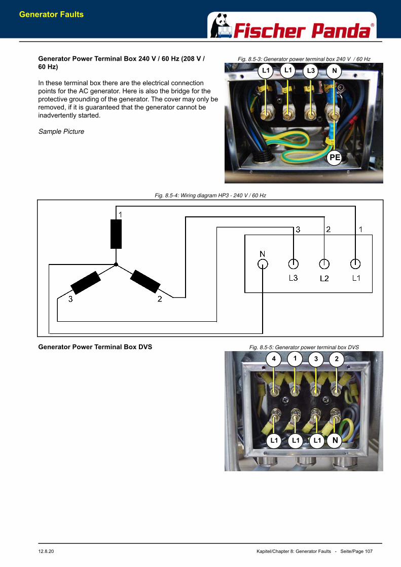
Generator Faults
12.8.20 Kapitel/Chapter 8: Generator Faults - Seite/Page 107
Fig. 8.5-3: Generator power terminal box 240 V / 60 HzGenerator Power Terminal Box 240 V / 60 Hz (208 V / 60 Hz)
In these terminal box there are the electrical connection points for the AC generator. Here is also the bridge for the protective grounding of the generator. The cover may only be removed, if it is guaranteed that the generator cannot be inadvertently started.
Sample Picture
Fig. 8.5-4: Wiring diagram HP3 - 240 V / 60 Hz
Fig. 8.5-5: Generator power terminal box DVSGenerator Power Terminal Box DVS
L1 L3
PE
L1 N
4 3
N
1 2
L1 L1 L1
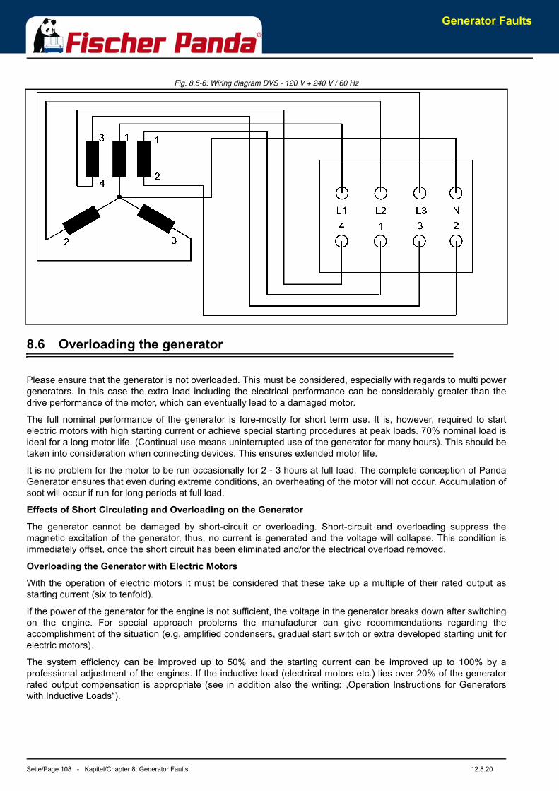
Generator Faults
Seite/Page 108 - Kapitel/Chapter 8: Generator Faults 12.8.20
Fig. 8.5-6: Wiring diagram DVS - 120 V + 240 V / 60 Hz
8.6 Overloading the generator
Please ensure that the generator is not overloaded. This must be considered, especially with regards to multi powergenerators. In this case the extra load including the electrical performance can be considerably greater than thedrive performance of the motor, which can eventually lead to a damaged motor.
The full nominal performance of the generator is fore-mostly for short term use. It is, however, required to startelectric motors with high starting current or achieve special starting procedures at peak loads. 70% nominal load isideal for a long motor life. (Continual use means uninterrupted use of the generator for many hours). This should betaken into consideration when connecting devices. This ensures extended motor life.
It is no problem for the motor to be run occasionally for 2 - 3 hours at full load. The complete conception of PandaGenerator ensures that even during extreme conditions, an overheating of the motor will not occur. Accumulation ofsoot will occur if run for long periods at full load.
Effects of Short Circulating and Overloading on the Generator
The generator cannot be damaged by short-circuit or overloading. Short-circuit and overloading suppress themagnetic excitation of the generator, thus, no current is generated and the voltage will collapse. This condition isimmediately offset, once the short circuit has been eliminated and/or the electrical overload removed.
Overloading the Generator with Electric Motors
With the operation of electric motors it must be considered that these take up a multiple of their rated output asstarting current (six to tenfold).
If the power of the generator for the engine is not sufficient, the voltage in the generator breaks down after switchingon the engine. For special approach problems the manufacturer can give recommendations regarding theaccomplishment of the situation (e.g. amplified condensers, gradual start switch or extra developed starting unit forelectric motors).
The system efficiency can be improved up to 50% and the starting current can be improved up to 100% by aprofessional adjustment of the engines. If the inductive load (electrical motors etc.) lies over 20% of the generatorrated output compensation is appropriate (see in addition also the writing: „Operation Instructions for Generatorswith Inductive Loads“).
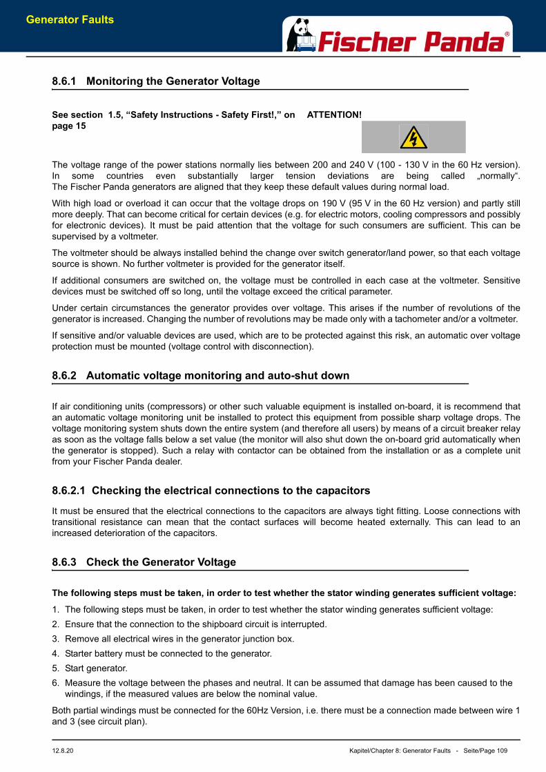
Generator Faults
12.8.20 Kapitel/Chapter 8: Generator Faults - Seite/Page 109
8.6.1 Monitoring the Generator Voltage
ATTENTION!See section 1.5, “Safety Instructions - Safety First!,” on page 15
The voltage range of the power stations normally lies between 200 and 240 V (100 - 130 V in the 60 Hz version).In some countries even substantially larger tension deviations are being called „normally“.The Fischer Panda generators are aligned that they keep these default values during normal load.
With high load or overload it can occur that the voltage drops on 190 V (95 V in the 60 Hz version) and partly stillmore deeply. That can become critical for certain devices (e.g. for electric motors, cooling compressors and possiblyfor electronic devices). It must be paid attention that the voltage for such consumers are sufficient. This can besupervised by a voltmeter.
The voltmeter should be always installed behind the change over switch generator/land power, so that each voltagesource is shown. No further voltmeter is provided for the generator itself.
If additional consumers are switched on, the voltage must be controlled in each case at the voltmeter. Sensitivedevices must be switched off so long, until the voltage exceed the critical parameter.
Under certain circumstances the generator provides over voltage. This arises if the number of revolutions of thegenerator is increased. Changing the number of revolutions may be made only with a tachometer and/or a voltmeter.
If sensitive and/or valuable devices are used, which are to be protected against this risk, an automatic over voltageprotection must be mounted (voltage control with disconnection).
8.6.2 Automatic voltage monitoring and auto-shut down
If air conditioning units (compressors) or other such valuable equipment is installed on-board, it is recommend thatan automatic voltage monitoring unit be installed to protect this equipment from possible sharp voltage drops. Thevoltage monitoring system shuts down the entire system (and therefore all users) by means of a circuit breaker relayas soon as the voltage falls below a set value (the monitor will also shut down the on-board grid automatically whenthe generator is stopped). Such a relay with contactor can be obtained from the installation or as a complete unitfrom your Fischer Panda dealer.
8.6.2.1 Checking the electrical connections to the capacitors
It must be ensured that the electrical connections to the capacitors are always tight fitting. Loose connections withtransitional resistance can mean that the contact surfaces will become heated externally. This can lead to anincreased deterioration of the capacitors.
8.6.3 Check the Generator Voltage
The following steps must be taken, in order to test whether the stator winding generates sufficient voltage:
1. The following steps must be taken, in order to test whether the stator winding generates sufficient voltage:2. Ensure that the connection to the shipboard circuit is interrupted.3. Remove all electrical wires in the generator junction box.4. Starter battery must be connected to the generator.5. Start generator.6. Measure the voltage between the phases and neutral. It can be assumed that damage has been caused to the
windings, if the measured values are below the nominal value.
Both partial windings must be connected for the 60Hz Version, i.e. there must be a connection made between wire 1and 3 (see circuit plan).
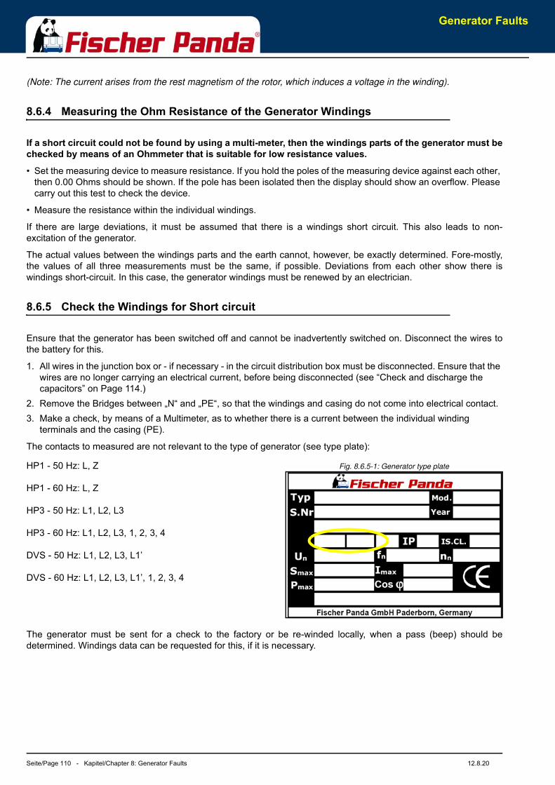
Generator Faults
Seite/Page 110 - Kapitel/Chapter 8: Generator Faults 12.8.20
(Note: The current arises from the rest magnetism of the rotor, which induces a voltage in the winding).
8.6.4 Measuring the Ohm Resistance of the Generator Windings
If a short circuit could not be found by using a multi-meter, then the windings parts of the generator must bechecked by means of an Ohmmeter that is suitable for low resistance values.
• Set the measuring device to measure resistance. If you hold the poles of the measuring device against each other, then 0.00 Ohms should be shown. If the pole has been isolated then the display should show an overflow. Please carry out this test to check the device.
• Measure the resistance within the individual windings.
If there are large deviations, it must be assumed that there is a windings short circuit. This also leads to non-excitation of the generator.
The actual values between the windings parts and the earth cannot, however, be exactly determined. Fore-mostly,the values of all three measurements must be the same, if possible. Deviations from each other show there iswindings short-circuit. In this case, the generator windings must be renewed by an electrician.
8.6.5 Check the Windings for Short circuit
Ensure that the generator has been switched off and cannot be inadvertently switched on. Disconnect the wires tothe battery for this.
1. All wires in the junction box or - if necessary - in the circuit distribution box must be disconnected. Ensure that the wires are no longer carrying an electrical current, before being disconnected (see “Check and discharge the capacitors” on Page 114.)
2. Remove the Bridges between „N“ and „PE“, so that the windings and casing do not come into electrical contact.3. Make a check, by means of a Multimeter, as to whether there is a current between the individual winding
terminals and the casing (PE).
The contacts to measured are not relevant to the type of generator (see type plate):
Fig. 8.6.5-1: Generator type plateHP1 - 50 Hz: L, Z
HP1 - 60 Hz: L, Z
HP3 - 50 Hz: L1, L2, L3
HP3 - 60 Hz: L1, L2, L3, 1, 2, 3, 4
DVS - 50 Hz: L1, L2, L3, L1’
DVS - 60 Hz: L1, L2, L3, L1’, 1, 2, 3, 4
The generator must be sent for a check to the factory or be re-winded locally, when a pass (beep) should bedetermined. Windings data can be requested for this, if it is necessary.
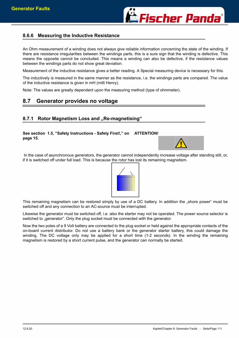
Generator Faults
12.8.20 Kapitel/Chapter 8: Generator Faults - Seite/Page 111
8.6.6 Measuring the Inductive Resistance
An Ohm measurement of a winding does not always give reliable information concerning the state of the winding. Ifthere are resistance irregularities between the windings parts, this is a sure sign that the winding is defective. Thismeans the opposite cannot be concluded. This means a winding can also be defective, if the resistance valuesbetween the windings parts do not show great deviation.
Measurement of the inductive resistance gives a better reading. A Special measuring device is necessary for this.
The inductively is measured in the same manner as the resistance, i.e. the windings parts are compared. The valueof the inductive resistance is given in mH (milli Henry).
Note: The values are greatly dependent upon the measuring method (type of ohmmeter).
8.7 Generator provides no voltage
8.7.1 Rotor Magnetism Loss and „Re-magnetising“
ATTENTION!See section 1.5, “Safety Instructions - Safety First!,” on page 15.
In the case of asynchronous generators, the generator cannot independently increase voltage after standing still, or,if it is switched off under full load. This is because the rotor has lost its remaining magnetism.
This remaining magnetism can be restored simply by use of a DC battery. In addition the „shore power“ must beswitched off and any connection to an AC-source must be interrupted.
Likewise the generator must be switched off, i.e. also the starter may not be operated. The power source selector isswitched to „generator“. Only the plug socket must be connected with the generator.
Now the two poles of a 9 Volt battery are connected to the plug socket or held against the appropriate contacts of theon-board current distributor. Do not use a battery bank or the generator starter battery, this could damage thewinding. The DC voltage only may be applied for a short time (1-2 seconds). In the winding the remainingmagnetism is restored by a short current pulse, and the generator can normally be started.
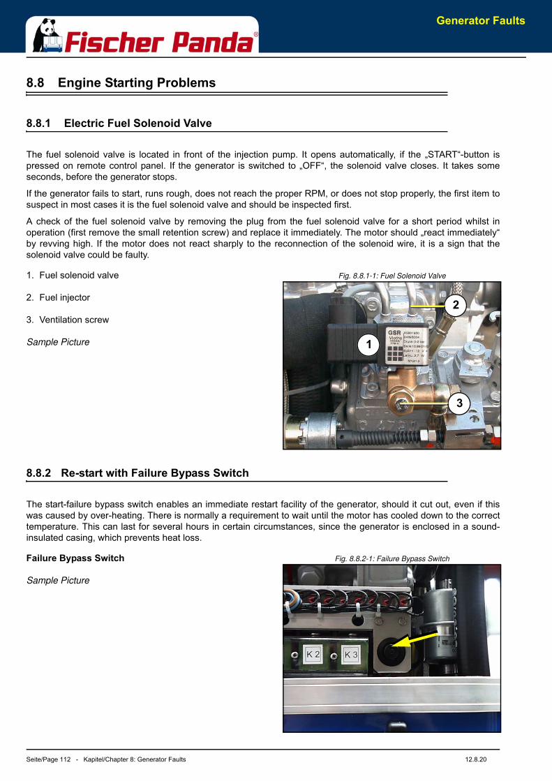
Generator Faults
Seite/Page 112 - Kapitel/Chapter 8: Generator Faults 12.8.20
8.8 Engine Starting Problems
8.8.1 Electric Fuel Solenoid Valve
The fuel solenoid valve is located in front of the injection pump. It opens automatically, if the „START“-button ispressed on remote control panel. If the generator is switched to „OFF“, the solenoid valve closes. It takes someseconds, before the generator stops.
If the generator fails to start, runs rough, does not reach the proper RPM, or does not stop properly, the first item tosuspect in most cases it is the fuel solenoid valve and should be inspected first.
A check of the fuel solenoid valve by removing the plug from the fuel solenoid valve for a short period whilst inoperation (first remove the small retention screw) and replace it immediately. The motor should „react immediately“by revving high. If the motor does not react sharply to the reconnection of the solenoid wire, it is a sign that thesolenoid valve could be faulty.
Fig. 8.8.1-1: Fuel Solenoid Valve1. Fuel solenoid valve
2. Fuel injector
3. Ventilation screw
Sample Picture
8.8.2 Re-start with Failure Bypass Switch
The start-failure bypass switch enables an immediate restart facility of the generator, should it cut out, even if thiswas caused by over-heating. There is normally a requirement to wait until the motor has cooled down to the correcttemperature. This can last for several hours in certain circumstances, since the generator is enclosed in a sound-insulated casing, which prevents heat loss.
Fig. 8.8.2-1: Failure Bypass SwitchFailure Bypass Switch
Sample Picture
1
2
3
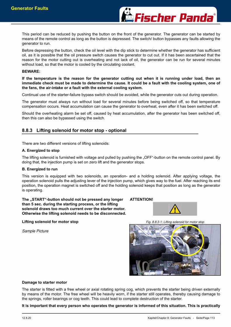
Generator Faults
12.8.20 Kapitel/Chapter 8: Generator Faults - Seite/Page 113
This period can be reduced by pushing the button on the front of the generator. The generator can be started bymeans of the remote control as long as the button is depressed. The switch/ button bypasses any faults allowing thegenerator to run.
Before depressing the button, check the oil level with the dip stick to determine whether the generator has sufficientoil, as it is possible that the oil pressure switch causes the generator to cut out. If it has been ascertained that thereason for the motor cutting out is overheating and not lack of oil, the generator can be run for several minuteswithout load, so that the motor is cooled by the circulating coolant.
BEWARE:
If the temperature is the reason for the generator cutting out when it is running under load, then animmediate check must be made to determine the cause. It could be a fault with the cooling system, one ofthe fans, the air-intake or a fault with the external cooling system.
Continual use of the starter-failure bypass switch should be avoided, while the generator cuts out during operation.
The generator must always run without load for several minutes before being switched off, so that temperaturecompensation occurs. Heat accumulation can cause the generator to overheat, even after it has been switched off.
Should the overheating alarm be set off, caused by heat accumulation, after the generator has been switched off,then this can also be bypassed using the switch.
8.8.3 Lifting solenoid for motor stop - optional
There are two different versions of lifting solenoids:
A. Energized to stop
The lifting solenoid is furnished with voltage and pulled by pushing the „OFF“-button on the remote control panel. Bydoing that, the injection pump is set on zero lift and the generator stops.
B. Energized to run
This version is equipped with two solenoids, an operation- and a holding solenoid. After applying voltage, theoperation solenoid pulls the adjusting lever of the injection pump, which gives way to the fuel. After reaching its endposition, the operation magnet is switched off and the holding solenoid keeps that position as long as the generatoris operating.
ATTENTION!The „START“-button should not be pressed any longer than 5 sec. during the starting process, or the lifting solenoid draws too much current over the starter motor. Otherwise the lifting solenoid needs to be disconnected.
Fig. 8.8.3-1: Lifting solenoid for motor stopLifting solenoid for motor stop
Sample Picture
Damage to starter motor
The starter is fitted with a free wheel or axial rotating spring cog, which prevents the starter being driven externallyby means of the motor. The free wheel will be heavily worn, if the starter still operates, thereby causing damage tothe springs, roller bearings or cog teeth. This could lead to complete destruction of the starter.
It is important that every person who operates the generator is informed of this situation. This is practically
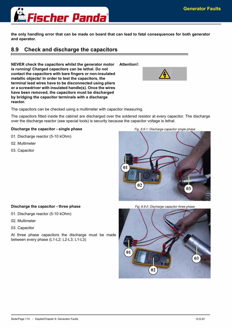
Generator Faults
Seite/Page 114 - Kapitel/Chapter 8: Generator Faults 12.8.20
the only handling error that can be made on board that can lead to fatal consequences for both generatorand operator.
8.9 Check and discharge the capacitors
Attention!:NEVER check the capacitors whilst the generator motor is running! Charged capacitors can be lethal. Do not contact the capacitors with bare fingers or non-insulated metallic objects! In order to test the capacitors, the terminal lead wires have to be disconnected using pliers or a screwdriver with insulated handle(s). Once the wires have been removed, the capacitors must be discharged by bridging the capacitor terminals with a discharge reactor.
The capacitors can be checked using a multimeter with capacitor measuring.
The capacitors fitted inside the cabinet are discharged over the soldered resistor at every capacitor. The dischargeover the discharge reactor (see special tools) is security because the capacitor voltage is lethal.
Fig. 8.9-1: Discharge capacitor single phaseDischarge the capacitor - single phase
01. Discharge reactor (5-10 kOhm)
02. Multimeter
03. Capacitor
Fig. 8.9-2: Discharge capacitor three phaseDischarge the capacitor - three phase
01. Discharge reactor (5-10 kOhm)
02. Multimeter
03. Capacitor
At three phase capacitors the discharge must be madebetween every phase (L1-L2; L2-L3; L1-L3)
0302
01
03
02
01
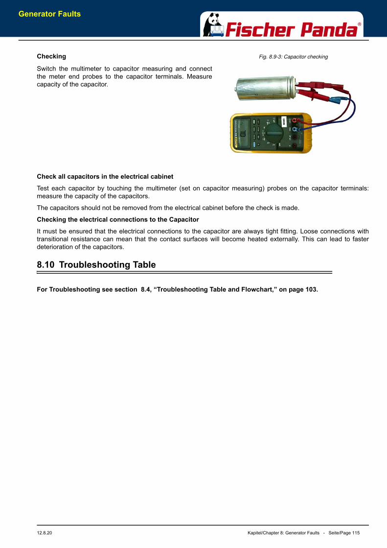
Generator Faults
12.8.20 Kapitel/Chapter 8: Generator Faults - Seite/Page 115
Fig. 8.9-3: Capacitor checkingChecking
Switch the multimeter to capacitor measuring and connectthe meter end probes to the capacitor terminals. Measurecapacity of the capacitor.
Check all capacitors in the electrical cabinet
Test each capacitor by touching the multimeter (set on capacitor measuring) probes on the capacitor terminals:measure the capacity of the capacitors.
The capacitors should not be removed from the electrical cabinet before the check is made.
Checking the electrical connections to the Capacitor
It must be ensured that the electrical connections to the capacitor are always tight fitting. Loose connections withtransitional resistance can mean that the contact surfaces will become heated externally. This can lead to fasterdeterioration of the capacitors.
8.10 Troubleshooting Table
For Troubleshooting see section 8.4, “Troubleshooting Table and Flowchart,” on page 103.

Seite/Page 116 Kapitel/Chapter 8: Generator Faults 12.8.20
Leere Seite / Intentionally blank
Generator Faults
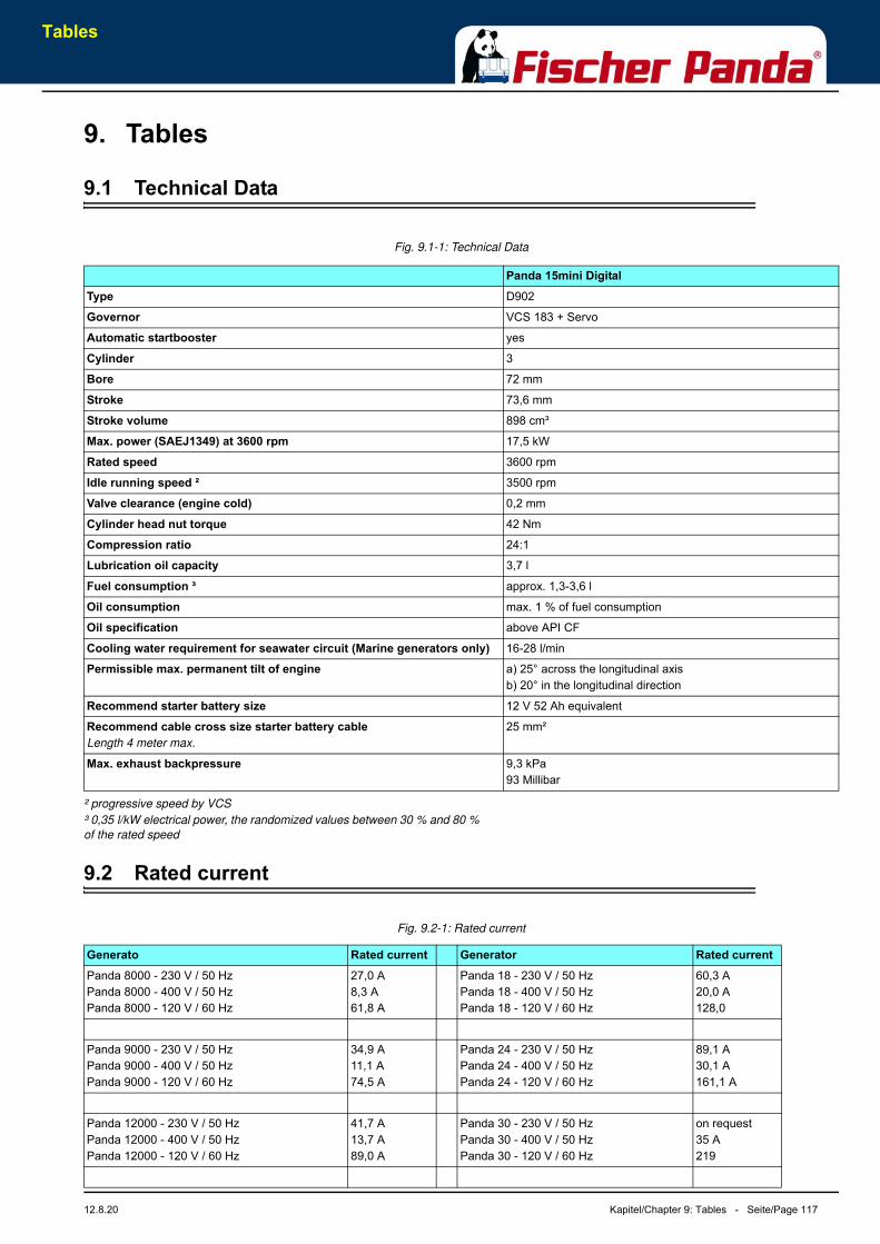
Tables
12.8.20 Kapitel/Chapter 9: Tables - Seite/Page 117
9. Tables
9.1 Technical Data
Fig. 9.1-1: Technical Data
² progressive speed by VCS
³ 0,35 l/kW electrical power, the randomized values between 30 % and 80 %
of the rated speed
9.2 Rated current
Fig. 9.2-1: Rated current
Panda 15mini DigitalType D902
Governor VCS 183 + Servo
Automatic startbooster yes
Cylinder 3
Bore 72 mm
Stroke 73,6 mm
Stroke volume 898 cm³
Max. power (SAEJ1349) at 3600 rpm 17,5 kW
Rated speed 3600 rpm
Idle running speed ² 3500 rpm
Valve clearance (engine cold) 0,2 mm
Cylinder head nut torque 42 Nm
Compression ratio 24:1
Lubrication oil capacity 3,7 l
Fuel consumption ³ approx. 1,3-3,6 l
Oil consumption max. 1 % of fuel consumption
Oil specification above API CF
Cooling water requirement for seawater circuit (Marine generators only) 16-28 l/min
Permissible max. permanent tilt of engine a) 25° across the longitudinal axisb) 20° in the longitudinal direction
Recommend starter battery size 12 V 52 Ah equivalent
Recommend cable cross size starter battery cableLength 4 meter max.
25 mm²
Max. exhaust backpressure 9,3 kPa93 Millibar
Generato Rated current Generator Rated currentPanda 8000 - 230 V / 50 HzPanda 8000 - 400 V / 50 Hz Panda 8000 - 120 V / 60 Hz
27,0 A8,3 A61,8 A
Panda 18 - 230 V / 50 HzPanda 18 - 400 V / 50 HzPanda 18 - 120 V / 60 Hz
60,3 A20,0 A128,0
Panda 9000 - 230 V / 50 Hz Panda 9000 - 400 V / 50 Hz Panda 9000 - 120 V / 60 Hz
34,9 A11,1 A74,5 A
Panda 24 - 230 V / 50 HzPanda 24 - 400 V / 50 HzPanda 24 - 120 V / 60 Hz
89,1 A30,1 A161,1 A
Panda 12000 - 230 V / 50 Hz Panda 12000 - 400 V / 50 Hz Panda 12000 - 120 V / 60 Hz
41,7 A13,7 A89,0 A
Panda 30 - 230 V / 50 HzPanda 30 - 400 V / 50 HzPanda 30 - 120 V / 60 Hz
on request35 A219
Tables
Seite/Page 118 - Kapitel/Chapter 9: Tables 12.8.20
Other Generator typs on request!
9.3 Cable cross section
Fig. 9.3-1: Cable cross section
9.4 Fuel
Use a clean Diesel fuel oil according to DIN590:1999 or better. For Generators with common rail or particle filter useDIN590:2009 or better.
Do not use alternative fuel, because its quality is unknown or it may be inferior in quality. Kerosene, which is very lowin cetane rating, adversely effects the engine.
9.5 Engine oil
9.5.1 Engine oil classification
9.5.1.1 Operating range:
The operating range of an engine oil is determined by SAE class. „SAE“ is for the union of American auto engineers(Society of Automotives Engineers).
The SAE class of an engine oil only informs over the viscosity of the oil (larger number = more viscous, smallernumber = more highly liquidly) e.g. to 0W, 10W, 15W, 20, 30, 40. The first number shows the liquid of the oil withcold weather, the second number refers to the fluidity with heat. Complete yearly oils have usually SAE classes ofSAE 10W-40, SAE 15W-40 etc.
9.5.1.2 Quality of oil:
The quality of an engine oil is specified by the API standard („American Petroleum Institutes“).
The API designation is to be found on each engine oil bundle. The first letter is always a C.
API C for diesel engines
The second letter is for the quality of the oil. The more highly the letter in the alphabet, the better the quality.
API C for diesel engine
Examples for diesel engine oil:
API CC Engine oil for small demands
Panda 14000 - 230 V / 50 Hz Panda 14000 - 400 V / 50 Hz Panda 14000 - 120 V / 60 Hz
48,0 A15,2 A112,7 A
length 1 - 3 m 4 - 6 m 7 - 10 m 11 - 15 m 16 - 20 m16 mm² 70 A 63 A 55 A 48 A 42 A
25 mm² 112 A 100 A 88 A 75 A 63 A
35 mm² 145 A 130 A 110 A 100 A 90 A
50 mm² 225 A 200 A 175 A 150 A 125 A
70 mm² 275 A 250 A 225 A 195 A 170 A
95 mm² 340 A 300 A 280 A 260 A 220 A
Generato Rated current Generator Rated current
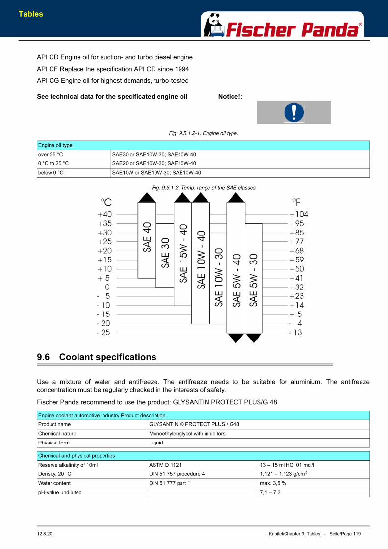
Tables
12.8.20 Kapitel/Chapter 9: Tables - Seite/Page 119
API CD Engine oil for suction- and turbo diesel engine
API CF Replace the specification API CD since 1994
API CG Engine oil for highest demands, turbo-tested
Notice!:See technical data for the specificated engine oil
Fig. 9.5.1.2-1: Engine oil type.
Fig. 9.5.1-2: Temp. range of the SAE classes
9.6 Coolant specifications
Use a mixture of water and antifreeze. The antifreeze needs to be suitable for aluminium. The antifreezeconcentration must be regularly checked in the interests of safety.
Fischer Panda recommend to use the product: GLYSANTIN PROTECT PLUS/G 48
Engine oil type
over 25 °C SAE30 or SAE10W-30; SAE10W-40
0 °C to 25 °C SAE20 or SAE10W-30; SAE10W-40
below 0 °C SAE10W or SAE10W-30; SAE10W-40
Engine coolant automotive industry Product description
Product name GLYSANTIN ® PROTECT PLUS / G48
Chemical nature Monoethylenglycol with inhibitors
Physical form Liquid
Chemical and physical properties
Reserve alkalinity of 10ml ASTM D 1121 13 – 15 ml HCl 01 mol/l
Density, 20 °C DIN 51 757 procedure 4 1,121 – 1,123 g/cm3
Water content DIN 51 777 part 1 max. 3,5 %
pH-value undiluted 7,1 – 7,3

Tables
Seite/Page 120 - Kapitel/Chapter 9: Tables 12.8.20
9.6.1 Coolant mixture ratio
Water/antifreeze Temperature70:30 -20 °C
65:35 -25 °C
60:40 -30 °C
55:45 -35 °C
50:50 -40 °C
User Manual Digital control system for generators
Document release 002/ February 2020
FISCHER PANDA GENERATORS, INC.
351 S Andrews Avenue Pompano Beach, Florida 33069
Toll-free (800) 508-6494 - Phone (954) 462-2800 - Fax (954) 462-2801
E-Mail: [email protected] -Web Site: www.fischerpanda.com

Generator control system
Based on VCS183
DS_VCS183 Page 1
Rev. 06 www.fischerpanda.com ©Fischer Panda generators Inc.
Contents Scope of this document ................................................................................................................................ 3
System components ...................................................................................................................................... 3
Control system VCS183 ............................................................................................................................. 3
Current sensing device CT186 ................................................................................................................... 3
Booster control device BC177C006 .......................................................................................................... 3
Control panel GP178 ................................................................................................................................. 4
Connection block KL188 ............................................................................................................................ 4
Connection harness .................................................................................................................................. 4
Environmental specifications, physical data ............................................................................................. 5
Main control unit VCS183 ............................................................................................................................. 6
Hardware overview ............................................................................................................................... 6
USB connectivity ................................................................................................................................... 7
Functional description .......................................................................................................................... 7
Data logging ............................................................................................................................................ 16
Periodic and alarm data logging ......................................................................................................... 16
Fast data logging ................................................................................................................................. 17
Maintaining cumulative data and service history ................................................................................... 18
Warning and alarm messages ................................................................................................................. 18
Program data in the VCS ......................................................................................................................... 20
Current sensing device CT186 ..................................................................................................................... 24
Selecting the desired output ................................................................................................................... 24
Interfacing to communication, sensing and auxiliary inputs .................................................................. 25
Communication interface ................................................................................................................... 25
Sensing inputs ..................................................................................................................................... 26
Auxiliary connection ............................................................................................................................... 26
Optical status indication ......................................................................................................................... 26
Control panel GP178 ................................................................................................................................... 28
User interface.......................................................................................................................................... 28
Interface description ............................................................................................................................... 28
Operating the control system via control panel GP178 .............................................................................. 32
Powering up the control system ............................................................................................................. 32
Generator control system
Based on VCS183
DS_VCS183 Page 2
Rev. 06 www.fischerpanda.com ©Fischer Panda generators Inc.
Acoustic alarm ..................................................................................................................................... 33
Starting and stopping the generator....................................................................................................... 33
Advanced selections / data menu ........................................................................................................... 34
Program VCS ........................................................................................................................................... 37
Entering numerical values ................................................................................................................... 37
Navigating through programing pages ............................................................................................... 37
Selecting / altering program data ....................................................................................................... 38
Program panel ......................................................................................................................................... 38
Program date/time ................................................................................................................................. 38
Connection block KL188 and connection harness ...................................................................................... 40

Generator control system
Based on VCS183
DS_VCS183 Page 3
Rev. 06 www.fischerpanda.com ©Fischer Panda generators Inc.
Scope of this document This document covers technical data and basic user interface description for electronic generator
control system VCS183. It covers all components of the control system and details installation and
operation instructions.
System components The complete control system is intended to be operated on asynchronous generators equipped with
pressure / temperature sensing devices as specified / detailed in this document. System components
need to be wired as per Fischer Panda Inc. wiring diagram D00037 (see attachments to this document).
Basically, the control system is made of the components listed below:
Control system VCS183
This is the core component of the control system, performing
all monitoring and control functions. It communicates with
other components using CAN serial data link.
Further this device stores al programing data as well as log
data retrieved while during operation.
Current sensing device CT186 or CT195
This is the current sensing device with some auxiliary inputs.
Basic task of this device is to monitor generator output
voltage, output current and power factor. It also serves as the
main load connection point and allows the user to configure
the generator for either 120/240V output or for 120V only
output. Additional analog data is collected by this device; see
brief device description for details. Board type CT186 is made
for generators up to output power 12kVA, while CT195 is for generators with output power up to 15KVA
Booster control device BC177C006
This device provides additional excitation to cope with high
load surges. It operates completely independent and thus is
not covered by this datasheet. For detailed information refer to
product document DS_BC177C006.
Figure 1 VCS183
Figure 2 CT186
Figure 3 BC177C006
Generator control system
Based on VCS183
DS_VCS183 Page 4
Rev. 06 www.fischerpanda.com ©Fischer Panda generators Inc.
Control panel GP178
This device serves as a user interface to the entire control
system. Up to 8 control panels may be connected to the system
to allow access / operation of the system from different
locations. Furthermore, the control panel allows remote control
of the generator either via dedicated I/O lines for start/stop
and status feedback or via NMEA2000 network. Connection
details for NMEA2000 network are not part of this document.
Connection block KL196
This component joins the sensors and actors placed on the
generator to the control systems components. It also is the
distribution point of DC (battery) power to the various consumers
inside and outside the generator capsule. It is thus also the point
that provides circuit protection (fuses).
Connection harness
This is the harness installed on the generator, joining signals from/to sensors/actors, providing data link
between above mentioned components and connecting the alternator output to the power output
connection point.
All electrical connections between system components is by means of secured plugs, securing
mechanism is either retaining nuts/bolts or plastic latches. Connector types are chosen in a way that
makes miss-plugging impossible. Number of pins, pin spacing, pin arrangement or other interlocking
mechanism will allow just one way of interconnecting components. Wherever similar signals are used on
different plugs such unambiguous matching may not be ensured. In these cases, it is however safe to
plug in connectors in random order without compromising system functionality.
Figure 4 GP178
Figure 5 KL196
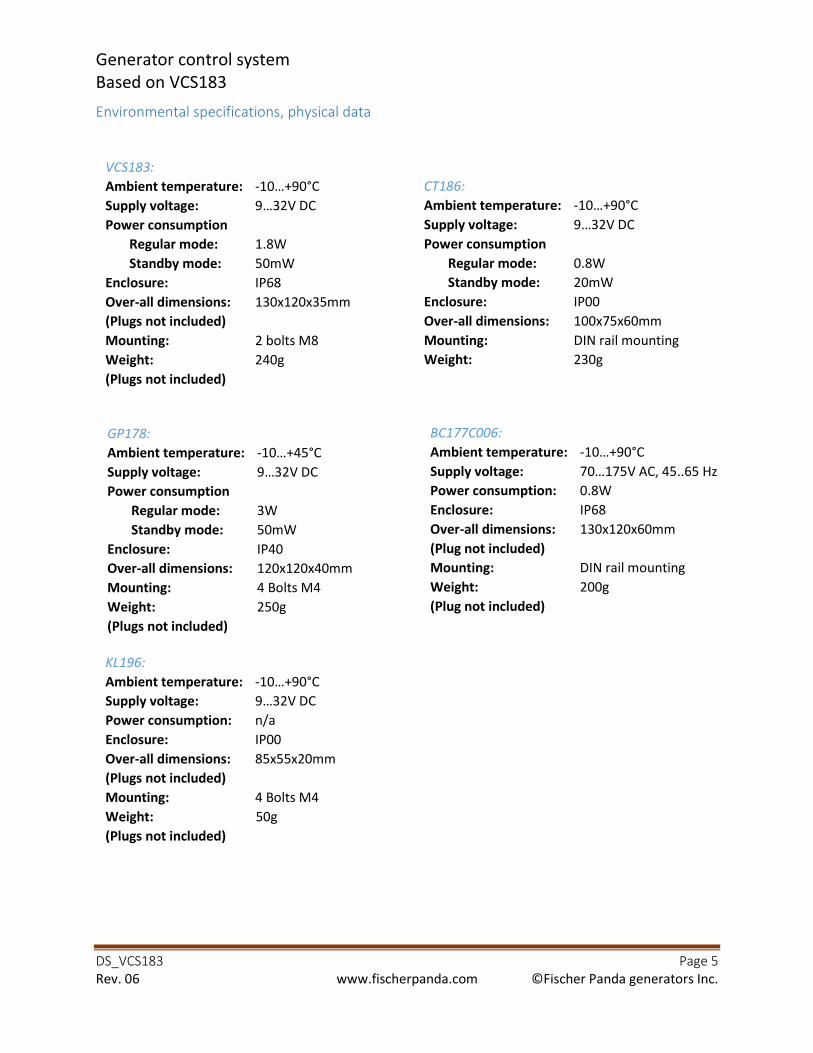
Generator control system
Based on VCS183
DS_VCS183 Page 5
Rev. 06 www.fischerpanda.com ©Fischer Panda generators Inc.
Environmental specifications, physical data
VCS183:
Ambient temperature: -10…+90°C
Supply voltage: 9…32V DC
Power consumption
Regular mode: 1.8W
Standby mode: 50mW
Enclosure: IP68
Over-all dimensions: 130x120x35mm
(Plugs not included)
Mounting: 2 bolts M8
Weight: 240g
(Plugs not included)
CT186:
Ambient temperature: -10…+90°C
Supply voltage: 9…32V DC
Power consumption
Regular mode: 0.8W
Standby mode: 20mW
Enclosure: IP00
Over-all dimensions: 100x75x60mm
Mounting: DIN rail mounting
Weight: 230g
GP178:
Ambient temperature: -10…+45°C
Supply voltage: 9…32V DC
Power consumption
Regular mode: 3W
Standby mode: 50mW
Enclosure: IP40
Over-all dimensions: 120x120x40mm
Mounting: 4 Bolts M4
Weight: 250g
(Plugs not included)
BC177C006:
Ambient temperature: -10…+90°C
Supply voltage: 70…175V AC, 45..65 Hz
Power consumption: 0.8W
Enclosure: IP68
Over-all dimensions: 130x120x60mm
(Plug not included)
Mounting: DIN rail mounting
Weight: 200g
(Plug not included)
KL196:
Ambient temperature: -10…+90°C
Supply voltage: 9…32V DC
Power consumption: n/a
Enclosure: IP00
Over-all dimensions: 85x55x20mm
(Plugs not included)
Mounting: 4 Bolts M4
Weight: 50g
(Plugs not included)
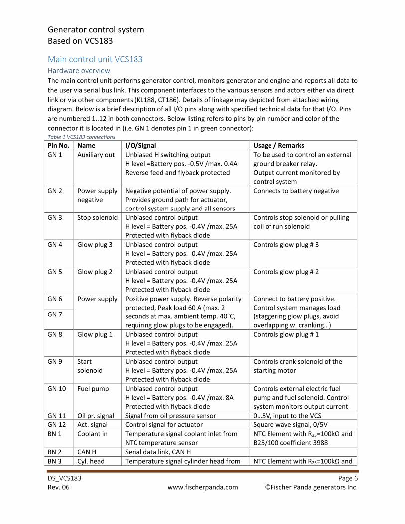
Generator control system
Based on VCS183
DS_VCS183 Page 6
Rev. 06 www.fischerpanda.com ©Fischer Panda generators Inc.
Main control unit VCS183
Hardware overview
The main control unit performs generator control, monitors generator and engine and reports all data to
the user via serial bus link. This component interfaces to the various sensors and actors either via direct
link or via other components (KL188, CT186). Details of linkage may depicted from attached wiring
diagram. Below is a brief description of all I/O pins along with specified technical data for that I/O. Pins
are numbered 1..12 in both connectors. Below listing refers to pins by pin number and color of the
connector it is located in (i.e. GN 1 denotes pin 1 in green connector):
Table 1 VCS183 connections
Pin No. Name I/O/Signal Usage / Remarks
GN 1 Auxiliary out Unbiased H switching output
H level =Battery pos. -0.5V /max. 0.4A
Reverse feed and flyback protected
To be used to control an external
ground breaker relay.
Output current monitored by
control system
GN 2 Power supply
negative
Negative potential of power supply.
Provides ground path for actuator,
control system supply and all sensors
Connects to battery negative
GN 3 Stop solenoid Unbiased control output
H level = Battery pos. -0.4V /max. 25A
Protected with flyback diode
Controls stop solenoid or pulling
coil of run solenoid
GN 4 Glow plug 3 Unbiased control output
H level = Battery pos. -0.4V /max. 25A
Protected with flyback diode
Controls glow plug # 3
GN 5 Glow plug 2 Unbiased control output
H level = Battery pos. -0.4V /max. 25A
Protected with flyback diode
Controls glow plug # 2
GN 6 Power supply Positive power supply. Reverse polarity
protected, Peak load 60 A (max. 2
seconds at max. ambient temp. 40°C,
requiring glow plugs to be engaged).
Connect to battery positive.
Control system manages load
(staggering glow plugs, avoid
overlapping w. cranking…) GN 7
GN 8 Glow plug 1 Unbiased control output
H level = Battery pos. -0.4V /max. 25A
Protected with flyback diode
Controls glow plug # 1
GN 9 Start
solenoid
Unbiased control output
H level = Battery pos. -0.4V /max. 25A
Protected with flyback diode
Controls crank solenoid of the
starting motor
GN 10 Fuel pump Unbiased control output
H level = Battery pos. -0.4V /max. 8A
Protected with flyback diode
Controls external electric fuel
pump and fuel solenoid. Control
system monitors output current
GN 11 Oil pr. signal Signal from oil pressure sensor 0…5V, input to the VCS
GN 12 Act. signal Control signal for actuator Square wave signal, 0/5V
BN 1 Coolant in Temperature signal coolant inlet from
NTC temperature sensor
NTC Element with R25=100kΩ and B25/100 coefficient 3988
BN 2 CAN H Serial data link, CAN H
BN 3 Cyl. head Temperature signal cylinder head from NTC Element with R25=100kΩ and
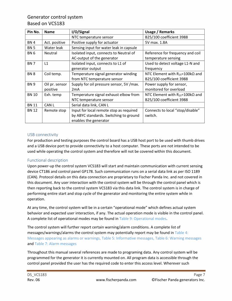
Generator control system
Based on VCS183
DS_VCS183 Page 7
Rev. 06 www.fischerpanda.com ©Fischer Panda generators Inc.
Pin No. Name I/O/Signal Usage / Remarks
NTC temperature sensor B25/100 coefficient 3988
BN 4 Act. positive Positive supply for actuator 5V max. 1.8A
BN 5 Water leak Sensing input for water leak in capsule
BN 6 Neutral Isolated input, connects to Neutral of
AC-output of the generator
Reference for frequency and coil
temperature sensing
BN 7 L1 Isolated input, connects to L1 of
generator output
Used to detect voltage L1-N and
frequency
BN 8 Coil temp. Temperature signal generator winding
from NTC temperature sensor
NTC Element with R25=100kΩ and B25/100 coefficient 3988
BN 9 Oil pr. sensor
positive
Supply for oil pressure sensor, 5V /max.
2mA
Power supply for sensor,
monitored for overload
BN 10 Exh. temp Temperature signal exhaust elbow from
NTC temperature sensor
NTC Element with R25=100kΩ and B25/100 coefficient 3988
BN 11 CAN L Serial data link, CAN L
BN 12 Remote stop Input for local remote stop as required
by ABYC standards. Switching to ground
enables the generator
Connects to local “stop/disable” switch.
USB connectivity
For production and testing purposes the control board has a USB host port to be used with thumb drives
and a USB device port to provide connectivity to a host computer. These ports are not intended to be
used while operating the control system and therefore will not be covered within this document.
Functional description
Upon power-up the control system VCS183 will start and maintain communication with current sensing
device CT186 and control panel GP178. Such communication runs on a serial data link as per ISO 1189
(CAN). Protocol details on this data connection are proprietary to Fischer Panda Inc. and not covered in
this document. Any user interaction with the control system will be through the control panel which is
then reporting back to the control system VCS183 via this data link. The control system is in charge of
performing entire start and stop cycle of the generator and monitoring the entire system while in
operation.
At any time, the control system will be in a certain “operational mode” which defines actual system
behavior and expected user interaction, if any. The actual operation mode is visible in the control panel.
A complete list of operational modes may be found in Table 9: Operational modes.
The control system will further report certain warning/alarm conditions. A complete list of
messages/warnings/alarms the control system may potentially report may be found in Table 4:
Messages appearing as alarms or warnings, Table 5: Informative messages, Table 6: Warning messages
and Table 7: Alarm messages
Throughout this manual several references are made to programing data. Any control system will be
programmed for the generator it is currently mounted on. All program data is accessible through the
control panel provided the user has the required code to enter this access level. Wherever such

Generator control system
Based on VCS183
DS_VCS183 Page 8
Rev. 06 www.fischerpanda.com ©Fischer Panda generators Inc.
reference to programing data is made it will be marked with “Pxx” referencing to parameter xx out of
Table 8: Programing parameters:
It should be noted that any sensing input (digital or analog) that is disabled in the programing data of
the VCS will cause the control system to assume that sensor reporting “non-critical” status, regardless of actual (true) sensor data. Sensors may be individually enabled or disabled (P62 and P63).
Functional description
Minimum configuration
A “complete system” is considered to have as a minimum configuration one control system VCS183, one
current sensing device CT186, one connection board KL188 and at least one panel GP178. It is further
assumed to be wired as per wiring diagram D00037, be connected to a charged battery and have good
fuses on board KL196.
Powering up the control system
The control system may be in one of the below 3 modes:
• Not powered at all (Battery power disconnected): It will obviously not work in this mode
• Low power mode: VCS183 and CT186 are in hibernating mode, total current draw is below
10mA
• Fully on: All components fully operational
After turning battery power on the control system will first enter “Fully On” mode but then, without any further user interaction within approx. 25sec, will transition to low power mode.
Transitioning between Fully On and Low Power mode is under user control either locally or via remote
input.
• Local: Button S1 on the control panel faceplate will toggle between these 2 modes
• Remote: Via terminal J1 pin 5 on the control panel (Control panel GP178)
Current sensing device CT186xxx
With a faulty current sensing device connected, monitoring functionality is restricted and generator
operation is considered emergency operation; output power and output current cannot be sensed and
therefore this emergency operation poses the risk of overloading the generator. The only limiting factor
that provides some protection against overloading the generator is the coil temperature. For this reason
such emergency operation shall be restricted to an absolute minimum and the user is required to
contact Fischer Panda Service immediately.
Operational status of the current sensing device is indicated by 2 LEDs. For details see Optical status
indication.
Transitioning from low power mode to regular operational mode
A control system wired as described above (whether CT186xxx or CT195xxx is functional or not) will
power up immediately after applying battery power. It will then check data communication on the CAN
Generator control system
Based on VCS183
DS_VCS183 Page 9
Rev. 06 www.fischerpanda.com ©Fischer Panda generators Inc.
bus. If the control system does not detect valid data from a control panel within a certain time frame it
will enter low power mode.
If the control panel does detect current sensing device CTxxx to be connected and working, but control
system VCS183xxx is not, then it will report this error and power down. The generator cannot be
operated without VCS183xxx.
If it detects control system VCS183xxx but no current sensing device CTxxx then again the panel will
report this status and will enter emergency operation mode as described above.
Now the control system will perform some self-checks including actuator test (moving the fuel rack at
slow pace from minimum position to maximum position). Depending on the outcome of these testing
the control system may be in either one of below mentioned modes:
• No faults pending
• Minor faults pending
• Major faults pending
If at least one major fault was detected the generator will not start; receiving a start request from the
panel will be ignored. Major faults are indicated in inverse printing on the control panel (light characters
on dark background).
Note that a missing current sensing device is not a major fault but rather needs to be considered an
emergency operation mode.
While the engine is stopped some temperature readings will be ignored. This is to avoid cases where a
start request will be denied because of residual heat from the engine led to a temporarily overheating. It
may be safely be assumed that once the generator is running and coolant is flowing those temperatures
will decrease into safe area of operation. If they do not then the control system will shut down for an
emergency condition.
Other more obvious emergency stop criteria that are invalidated while the generator is stopped are low
oil pressure, low AC frequency and low AC voltage; all of these will read 0 while the generator is not
running without triggering a major fault.
After transitioning from standby mode into regular mode the operational mode will be “Generator
stopped”. Temperature and I/O monitoring will continue while in this operational mode and may
allow/deny engine start. Engine start will be denied if either one of the parameters CA0, CA2 to CA4,
CA11 to CA15, or any of the STxx is pending (see Table 4: Messages appearing as alarms or warnings and
Table 7: Alarm messages).
Staring the generator
Whenever the control system receives a start request from the panel it will perform the engine start as
described below. Any major fault that arises during this period will cause the start process to be
abandoned and depending on when this fault aroused the control system will either revert into stop
mode with pending major faults or it will transition into “unacknowledged alarms pending” mode. This
mode is described in more detail in this manual, see Unacknowledged alarms pending.
Generator control system
Based on VCS183
DS_VCS183 Page 10
Rev. 06 www.fischerpanda.com ©Fischer Panda generators Inc.
Preparing to start
Upon a start request the control system will check engine temperature and based on this reading it will
calculate whether preheating is required or not and if so, then for how long. The operational mode now
is “preparing to start”. If the auxiliary output is configured to drive a ground breaker and it is not
reported to be in permanent short-circuit (MW13, Table 6: Warning messages) the control system will
turn on the ground breaker output. After giving it some time to close it will either engage glow plugs at a
certain rate (one every 0.5sec to avoid exceeding max. permissible supply current) for the required
preheating time or, if engine temperature reading indicated that preheating is not required, it will
directly transition into cranking mode.
Cranking
After preheating the engine as required and running the fuel pump for minimum 1sec. the control
system will place the fuel rack into programmed value for start position (P60, Table 8: Programing
parameters:) and engage the cranking solenoid. It will constantly monitor the frequency of the AC
output to detect whether the engine did start. If no frequency is detected for the first 2 seconds of
cranking the control system will keep cranking but at the same time gradually increase the fuel supply by
moving the fuel rack towards maximum. It will not exceed the programmed value for max. fuel rack
position while cranking (P61, Table 8: Programing parameters:). It will now further also check oil
pressure as an additional criterion to detect engine start.
Cranking period ends either if total cranking time reaches programmed maximum cranking time (P09) or
if engine start was detected. In either case the cranking solenoid and the ground breaker output will be
disengaged. If engine start was detected, the fuel pump output will be left on; if the auxiliary output was
configured to drive the raw water valve it will now turn on and allow raw water flow into the heat
exchanger. Whether a start attempt was successful or not, it will in either case increase the internal
counter of the control system that counts the total number of starts.
Unsuccessful start attempts
If engine start could not be detected the control system will stop the fuel pump, report a failed start
attempt and transition to operational mode “unacknowledged alarms pending”. This mode is described
in more detail in this manual, see Unacknowledged alarms pending.
A total of 4 consecutive unsuccessful engine starts will cause the system to deny any further start
attempts. This condition must under no circumstances be ignored and reset by just power-cycling the
control system. It points to a serious problem with potential catastrophic implications, leading to a total
generator loss! Users are strongly advised to contact Fischer Panda for further advice if ever ending up in
this situation! The control panel will report such status.
No AC signal but oil pressure detected
If engine start was detected by oil pressure rising but no frequency signal being present the control
system will place the fuel rack to position as under P61 and enter operational mode “Waiting for AC voltage”. In this operational mode all but “AC voltage low” limits (P12 and P13) will be monitored. The control system will stay in this mode until it either reads AC voltage (either from the CT board or on its
own input) or until it receives a command form the panel to stop the generator. Once voltage is
detected (either source, VCS183 or CT186) while in this mode the control system will transition into
operational mode “running”, or “warm-up”, whichever is applicable.
Generator control system
Based on VCS183
DS_VCS183 Page 11
Rev. 06 www.fischerpanda.com ©Fischer Panda generators Inc.
Regular engine start detected
If regular engine start was detected (frequency above threshold) then the control system will transition
into operational mode “idling”. From this point on for a certain time the oil pressure will not be monitored for shutdown threshold (P40, P46) and for a (different) time period the same is true for
parameters temperatures as under P35, P37-P39, P41, and P43-P46. Throughout entire idling mode AC
voltage and AC frequency will not be monitored against low limits (P12, P13,P16). At any time, the
exhaust temperature sensor will be monitored for absolute maximum value (P69) to comply with ABYC
standards.
While in operational mode “idling” the control system will regulate the engine based on speed, target is
idle speed (P00). If the fuel rack is misadjusted the controller may not be able to bring the engine to this
speed as it will never try to position the fuel rack outside the initially calibrated limits (Warning and
alarm messages)
Generator idling
Idling period will end at any time if the control system detects AC voltage to be within 15% of nominal
AC voltage (P02). In such case the operational mode is transferred to “warming up”. It will also end after the total idling period has elapsed (P09). The controller will now advance the fuel rack to bring engine
speed to nominal speed (P01) and will now expect the voltage to increase above 85% of nominal AC
voltage (P02). Once this has occurred the operational mode will transition to “warming up”. Engine
speed is from now on and throughout all subsequent operational modes (until manual or automatic
shutdown) no longer controlled by actual speed but based on actual AC voltage.
Warming up
While in this operational mode the control system will check for time-out for monitoring oil pressure for
shutdown threshold (P40, P46) and for time-out for monitoring temperatures as under P35, P37-P39,
P41, and P43-P46. Once the respective timer times out the according monitoring will be enabled. After
both timers time out operational status transfers to “running”
Running the generator
As described above the system cycles through several modes of operation, total time for such sequence
though is usually just a couple of seconds and basically depends on parameter P08, idling time. Once the
generator is in running mode, load may be applied and it will perform speed regulation and monitoring
using all enabled sensors. If the control system detects a situation that requires any of the CAxx or STxx
messages to be activated an emergency generator stop will be initiated. In such case the actual
operating data will be logged to int the alarm data log memory and then the stop sequence begins. For
data logging details see Table 2: Log data set. Emergency stop follows the same pattern as a regular
stop, the only difference being the final status and data logging. After a regular stop the operational
mode will transition to “stop mode” and no data logging occurs, while it will transition to operational
mode “unacknowledged alarms pending” in case of an emergency shutdown and will log shutdown
data.
Most of the analog inputs that are monitored against some programmable thresholds also have a delay
time associated. If no delay time is programmable then the control system uses a predefined delay time
of either 0.2sec or 0.5sec, as appropriate for that input. In order for a certain warning or shutdown to be
triggered the control system needs to read that input in critical status continuously for the programmed
delay time. This is to avoid random shutdowns based on spurious fluctuations.
Generator control system
Based on VCS183
DS_VCS183 Page 12
Rev. 06 www.fischerpanda.com ©Fischer Panda generators Inc.
Failed actuator
With no control over the actuator the control system will be able to run the generator in emergency
mode only. Faulty actuator is reported on the panel. In such case and with request to immediately run
the generator the user needs to adjust the actuator to about 80% of total throttle and fix it in this
position by external means (zip-tie or wire). Now the generator may be started and with the control
system knowing it has no control over the actuator it will immediately transition into operational mode
warm-up. It will further never attempt to control engine speed with a faulty actuator. It is the user’s
responsibility to keep adjusting the engine speed in a way that will keep the voltage between shutdown
limits or the control system will stop the generator because of output voltage outside specified limits.
Other functionality is not impacted in this mode of operation.
Reading the generator winding temperature
The sensor for generator winding temperature is physically placed inside the winding, thus surrounded
by conductors with high voltage. The entire concept of control system VCS183 is to keep AC and DC
voltages completely isolated - even in critical condition. Neutral output of the generator and battery
negative are joined (both connected to the engine frame) but this is outside the control system and
safety of the control system won’t rely on it. For this reason, the coil temperature sensor has common
ground with the AC sensing input but is completely isolated from DC supply. Because of this and some
technical requirements the control system is not able to read coil temperatures less than 40°C. Thus, the
control system will consider the coil temperature to be in safe operating area if the generator is not
running and also if neither “coolant in temperature” nor “cylinder head temperature” reads above 80°C.
If none of these conditions are true and the control system is still not able to read coil temperature then
it will report the coil temperature sensor to be missing (MW11).
Reading all other temperature sensors
All remaining temperature sensors will be monitored continuously. The control system will detect any
shorted or not connected temperature sensor and will report this. As per ABYC requirements
temperature sensor on exhaust elbow is mandatory as well as “engine temperature” sensor.
Temperature sensors for “coolant in” and “cylinder head” may both be considered engine temperature
sensors, thus if at least one of these two is in working condition then ABYC requirements are satisfied. If,
however none of these is working then this is considered missing a crucial sensor and an alarm message
will be triggered (ST12, Table 7: Alarm messages).
Any temperature sensor may be disabled; access to this level of settings is password-protected. If
disabled then the corresponding temperature will not be monitored; sensor status (reading or disabled
or broken) will be logged.
If exhaust elbow temperature sensor is disabled then temperature monitoring is obviously not available
but the control system will assume it is not supposed to report missing temperature sensor. Disabling
this sensor is not recommended unless the generator is required to run despite other safety
considerations.
If cylinder head temperature sensor and coolant inlet temperature sensor are both enabled then at least
one needs to report valid reading or the control system will detect a major fault since it has no way to
read engine temperature.

Generator control system
Based on VCS183
DS_VCS183 Page 13
Rev. 06 www.fischerpanda.com ©Fischer Panda generators Inc.
If just one of above 2 sensors is enabled then valid readings form that sensor is mandatory. Receiving
invalid readings (i.e. sensor disconnected or short-circuited) again is interpreted as major fault (has no
way to read engine temperature).
If both temperature sensors, cylinder head and coolant inlet, are disabled then the control system will
consider this to be an intended emergency operation as both sensors did fail but operation of the
generator being required even at the risk of total loss of the generator. As with exhaust elbow
temperature sensor such operation shall be restricted to real emergency cases only
Reading oil pressure
The control system reads oil pressure by means of an analog oil pressure sensor. Supply for this sensor is
provided by the control system. VCS183 will monitor total power consumption of the sensor and will
also check oil pressure for plausibility to detect any potential fault of the oil pressure sensor. Faulty oil
pressure sensor will lead to an emergency engine stop. The oil pressure sensor may be disabled in
generator configuration; access to this level of settings is password-protected. As with temperature
sensors, the status of the oil pressure sensor will be logged. ABYC requires the engine oil pressure to be
monitored, thus disabling the oil pressure sensor shall be limited to real emergency situations.
Implications on ABYC requirements
Monitoring oil pressure, exhaust elbow and engine temperature are crucial for save engine operation.
Disabling any of these sensor input comes with the risk of generator damage or total loss in case of an
over-temperature / low oil pressure.
It is strongly recommended not to disable any sensors unless for emergencies. Continuous operation with
disabled sensor not only is opposing ABYC standards but also bears the risk of generator loss.
Running the generator without current sensing device
CT 186 is not crucial to generator operation. If at any time connectivity to this device is lost the control
system will keep the generator running and regulate engine speed based on its own readings. Some
restrictions however do apply and for this reason operating the generator without current sensing
device is considered to be emergency operation.
Without CT186 the control system does not know the actual output load. Thus, it cannot detect an
overload or over-current situation. Overload monitoring is now entirely relying on the coil temperature
sensing.
With no current sensing device available, neither fuel level nor alternator bearing temperature reading
is available. The latter one is an input that would indicate problems with the alternator bearing, thus
running the generator without this being monitored puts at risk the entire backend.
The control system VCS183 will immediately detect whether the current sensing device is attached or
not. It will further compare voltage and frequency reading as received from the current sensing device
with its own sensing. If it detects a too high deviation it will consider the current sensing device to be in
improper working condition and will ignore any AC readings. It will then behave as if there was no
current sensing device connected, with the exception of tank level sensor and alternator bearing sensor
still being evaluated.
Generator control system
Based on VCS183
DS_VCS183 Page 14
Rev. 06 www.fischerpanda.com ©Fischer Panda generators Inc.
Cumulative data
While the generator is running the control system will keep track of total operating time, operating time
since last start, total energy produced and energy produced since last start. These cumulative data along
with the total number of engine starts allow an estimation of average generator load and average
generator operating time between two starts. Whenever running without working CT186 energy is
logged to be zero.
Initiating generator stop
Any emergency shutdown will initiate a generator stop. If the stop was requested by the panel and the
VCS has the “Cooldown” option enabled (P62) then it will transition to operating mode “cooldown”. The control system will not enter cooling down mode if it detects the generator is loaded with 25% or more
of its nominal power. In such case it will assume the user requests an immediate stop and will skip
cooldown phase.
Cooling down
While in cooldown mode the control system will maintain all regulation and monitoring tasks unchanged
as compared to regular running mode. It will exit cooldown mode and transition to shutting down mode
if one of below conditions becomes true:
• Cylinder head temperature drops to cooling down temp. threshold (P58) or below
• Maximum cooling down time (P59) elapsed
• The panel is sending another stop request. This will be interpreted as an immediate stop
demand, regardless of cooldown status.
Stopping the generator
Once generator stop is initiated monitoring is reduced to same criteria as in stop mode (Warning and
alarm messages). If the auxiliary output is configured as ground breaker then the control system will first
turn on the ground breaker output – provided it is not marked permanently shorted to ground. After
giving it some time to activate the relay the control system will turn off power to the fuel pump and
activate the stop solenoid, if it is configured as energized to stop (P62). It will now keep the stop
solenoid output active for minimum 2 seconds and then for another 6 seconds or until engine speed
decayed below threshold, whichever comes first.
If engine speed does not decrease within maximum stop time (8sec) then the control system will turn
off power to the stop solenoid anyway. This is because obviously the stop solenoid is misaligned or
damaged and thus will not stop the engine anyway; it would be at risk of overheating if kept powered
for longer time. In such case the operational status transfers to “cannot stop engine” and stop procedure now will only occur because fuel supply gets cut-out by the fuel solenoid which works parallel
to the fuel pump.
After reading engine speed below run threshold the control system will change operational mode either
to “stop mode” if this was a regular engine stop (requested by the panel) or to “unacknowledged alarms pending” if this was an emergency stop. Not detecting speed signal for a certain time is reported as
“unexpected engine stop” but will also end up in operational mode “unacknowledged alarms pending”.
Generator control system
Based on VCS183
DS_VCS183 Page 15
Rev. 06 www.fischerpanda.com ©Fischer Panda generators Inc.
Unacknowledged alarms pending
In this operational mode the control system will keep reporting alarm messages that were active while
the stop was initiated, even if the cause for that alarm is no longer active. This is to allow the user to see
what caused the shutdown. System monitoring functionality in this mode is similar to the one described
under “stop mode” (Warning and alarm messages).
All control outputs will be turned off, including power supply to the actuator. This will cause the fuel
rack to be retracted to lowest speed position by the spring inside the injection pump.
To leave this operational status the control panel needs to issue a stop command. This will cause all
alarm messages –except those still active- to be cleared and the control system will now finally revert to
regular stop mode.

Generator control system
Based on VCS183
DS_VCS183 Page 16
Rev. 06 www.fischerpanda.com ©Fischer Panda generators Inc.
Data logging
Periodic and alarm data logging
During regular operation the control system will log one data set every 10 minutes or right before
initiating an emergency shutdown. These data sets are referred to as log memory (periodic logging) and
alarm memory (logged prior to an emergency-shutdown). Each memory has the capacity for a total of
150 such events. After logging event No. 150, the next log data will overwrite the first one, and so on.
Thus, always the last 150 events of each kind are available to the user via the panel. This allows a total of
1500 minutes (25 hours) of generator operation to be tracked.
Whether logging was initiated by regular (periodic) request or due to an alarm, the data that is logged is
always the same and listed below Table 2: Log data set.
Table 2: Log data set
Data Unit
Control variable referencing generator control state machine. Internal usage only n/a
Status feedback from VCS, as in byte stfeedback. Internal usage only n/a
USB communication status n/a
CAN communication status n/a
Voltage L1-N, as sensed by the current sensing device 0.1V
Voltage L2-N, as sensed by the current sensing device 0.1V
Voltage L1-L2, as sensed by the current sensing device 0.1V
Current on Leg 1, as sensed by the current sensing device 0.1A
Current on Leg 2, as sensed by the current sensing device 0.1A
Frequency sensed by the current sensing device 0.1Hz
Active output power, calculated by the current sensing device 100W
Relative output power 0.1%
Power factor 0.001
Generator frequency sensed by VCS183 0.1Hz
Voltage L1-N, sensed by VCS183 0.1V
Battery voltage 10mV
Temperature coolant in 1°C
Current sensed on ground breaker output 0.01A
Cylinder head temperature 1°C
Exhaust elbow temperature 1°C
Coil temperature 1°C
Current sensing device temperature (average, 2 sensors in different locations) 1°C
Temperature on VCS183 control board 1°C
Alternator bearing temperature 1°C
Oil pressure 0.1bar
Relative tank content 1%
Engine speed 1rpm
Actuator voltage 10mV
Actuator current 10mA
Fuel pump current 10mA
Water leak ADC output n/a
Operating time since last start 1min
Total el. Energy since last start 0.1kWh
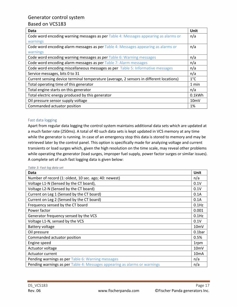
Generator control system
Based on VCS183
DS_VCS183 Page 17
Rev. 06 www.fischerpanda.com ©Fischer Panda generators Inc.
Data Unit
Code word encoding warning messages as per Table 4: Messages appearing as alarms or
warnings
n/a
Code word encoding alarm messages as per Table 4: Messages appearing as alarms or
warnings
n/a
Code word encoding warning messages as per Table 6: Warning messages n/a
Code word encoding alarm messages as per Table 7: Alarm messages n/a
Code word encoding miscellaneous messages as per Table 5: Informative messages n/a
Service messages, bits 0 to 31 n/a
Current sensing device terminal temperature (average, 2 sensors in different locations) 1°C
Total operating time of this generator 1 min
Total engine starts on this generator n/a
Total electric energy produced by this generator 0.1kWh
Oil pressure sensor supply voltage 10mV
Commanded actuator position 1%
Fast data logging
Apart from regular data logging the control system maintains additional data sets which are updated at
a much faster rate (250ms). A total of 40 such data sets is kept updated in VCS memory at any time
while the generator is running. In case of an emergency stop this data is stored to memory and may be
retrieved later by the control panel. This option is specifically made for analyzing voltage and current
transients or load surges which, given the high resolution on the time scale, may reveal other problems
while operating the generator (load surges, improper fuel supply, power factor surges or similar issues).
A complete set of such fast logging data is given below:
Table 3: Fast log data set
Data Unit
Number of record (1: oldest, 10 sec. ago; 40: newest) n/a
Voltage L1-N (Sensed by the CT board), 0.1V
Voltage L2-N (Sensed by the CT board) 0.1V
Current on Leg 1 (Sensed by the CT board) 0.1A
Current on Leg 2 (Sensed by the CT board) 0.1A
Frequency sensed by the CT board 0.1Hz
Power factor 0.001
Generator frequency sensed by the VCS 0.1Hz
Voltage L1-N, sensed by the VCS 0.1V
Battery voltage 10mV
Oil pressure 0.1bar
Commanded actuator position 0.5%
Engine speed 1rpm
Actuator voltage 10mV
Actuator current 10mA
Pending warnings as per Table 6: Warning messages n/a
Pending warnings as per Table 4: Messages appearing as alarms or warnings n/a
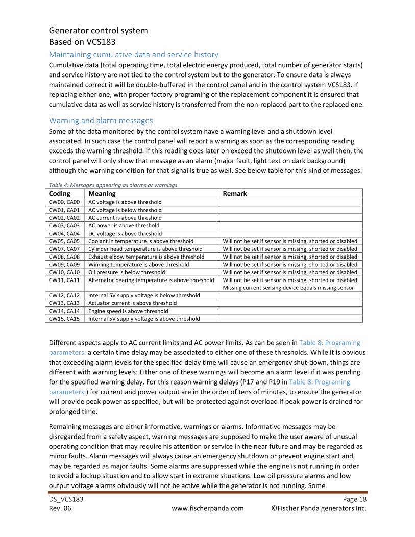
Generator control system
Based on VCS183
DS_VCS183 Page 18
Rev. 06 www.fischerpanda.com ©Fischer Panda generators Inc.
Maintaining cumulative data and service history
Cumulative data (total operating time, total electric energy produced, total number of generator starts)
and service history are not tied to the control system but to the generator. To ensure data is always
maintained correct it will be double-buffered in the control panel and in the control system VCS183. If
replacing either one, with proper factory programing of the replacement component it is ensured that
cumulative data as well as service history is transferred from the non-replaced part to the replaced one.
Warning and alarm messages
Some of the data monitored by the control system have a warning level and a shutdown level
associated. In such case the control panel will report a warning as soon as the corresponding reading
exceeds the warning threshold. If this reading does later on exceed the shutdown level as well then, the
control panel will only show that message as an alarm (major fault, light text on dark background)
although the warning condition for that signal is true as well. See below table for this kind of messages:
Table 4: Messages appearing as alarms or warnings
Coding Meaning Remark CW00, CA00 AC voltage is above threshold
CW01, CA01 AC voltage is below threshold
CW02, CA02 AC current is above threshold
CW03, CA03 AC power is above threshold
CW04, CA04 DC voltage is above threshold
CW05, CA05 Coolant in temperature is above threshold Will not be set if sensor is missing, shorted or disabled
CW07, CA07 Cylinder head temperature is above threshold Will not be set if sensor is missing, shorted or disabled
CW08, CA08 Exhaust elbow temperature is above threshold Will not be set if sensor is missing, shorted or disabled
CW09, CA09 Winding temperature is above threshold Will not be set if sensor is missing, shorted or disabled
CW10, CA10 Oil pressure is below threshold Will not be set if sensor is missing, shorted or disabled
CW11, CA11 Alternator bearing temperature is above threshold Will not be set if sensor is missing, shorted or disabled
Missing current sensing device equals missing sensor
CW12, CA12 Internal 5V supply voltage is below threshold
CW13, CA13 Actuator current is above threshold
CW14, CA14 Engine speed is above threshold
CW15, CA15 Internal 5V supply voltage is above threshold
Different aspects apply to AC current limits and AC power limits. As can be seen in Table 8: Programing
parameters: a certain time delay may be associated to either one of these thresholds. While it is obvious
that exceeding alarm levels for the specified delay time will cause an emergency shut-down, things are
different with warning levels: Either one of these warnings will become an alarm level if it was pending
for the specified warning delay. For this reason warning delays (P17 and P19 in Table 8: Programing
parameters:) for current and power output are in the order of tens of minutes, to ensure the generator
will provide peak power as specified, but will be protected against overload if peak power is drained for
prolonged time.
Remaining messages are either informative, warnings or alarms. Informative messages may be
disregarded from a safety aspect, warning messages are supposed to make the user aware of unusual
operating condition that may require his attention or service in the near future and may be regarded as
minor faults. Alarm messages will always cause an emergency shutdown or prevent engine start and
may be regarded as major faults. Some alarms are suppressed while the engine is not running in order
to avoid a lockup situation and to allow start in extreme situations. Low oil pressure alarms and low
output voltage alarms obviously will not be active while the generator is not running. Some
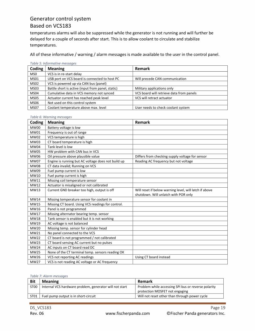
Generator control system
Based on VCS183
DS_VCS183 Page 19
Rev. 06 www.fischerpanda.com ©Fischer Panda generators Inc.
temperatures alarms will also be suppressed while the generator is not running and will further be
delayed for a couple of seconds after start. This is to allow coolant to circulate and stabilize
temperatures.
All of these informative / warning / alarm messages is made available to the user in the control panel.
Table 5: Informative messages
Coding Meaning Remark MS0 VCS is in re-start delay
MS01 USB port on VCS board is connected to host PC Will precede CAN communication
MS02 VCS is powered up via CAN bus (panel)
MS03 Battle short is active (input from panel, static) Military applications only
MS04 Cumulative data in VCS memory not synced VCS board will retrieve data from panels
MS05 Actuator current has reached peak level VCS will retract actuator
MS06 Not used on this control system
MS07 Coolant temperature above max. level User needs to check coolant system
Table 6: Warning messages
Coding Meaning Remark MW00 Battery voltage is low
MW01 Frequency is out of range
MW02 VCS temperature is high
MW03 CT board temperature is high
MW04 Tank level is low
MW05 HW problem with CAN bus in VCS
MW06 Oil pressure above plausible value Differs from checking supply voltage for sensor
MW07 Engine is running but AC voltage does not build up Reading AC frequency but not voltage
MW08 CT data invalid; Running on VCS
MW09 Fuel pump current is low
MW10 Fuel pump current is high
MW11 Missing coil temperature sensor
MW12 Actuator is misaligned or not calibrated
MW13 Current GND breaker too high, output is off Will reset if below warning level, will latch if above
shutdown. Will unlatch with POR only
MW14 Missing temperature sensor for coolant in
MW15 Missing CT board. Using VCS readings for control.
MW16 Panel is not programmed
MW17 Missing alternator bearing temp. sensor
MW18 Tank sensor is enabled but it is not working
MW19 AC voltage is not balanced
MW20 Missing temp. sensor for cylinder head
MW21 No panel connected to the VCS
MW22 CT board is not programmed / not calibrated
MW23 CT board sensing AC current but no pulses
MW24 AC inputs on CT board read DC
MW25 None of the CT terminal temp. sensors reading OK
MW26 VCS not reporting AC readings Using CT board instead
MW27 VCS is not reading AC voltage or AC frequency
Table 7: Alarm messages
Bit Meaning Remark ST00 Internal VCS hardware problem, generator will not start Problem while accessing SPI bus or reverse polarity
protection MOSFET not engaging
ST01 Fuel pump output is in short-circuit Will not reset other than through power cycle
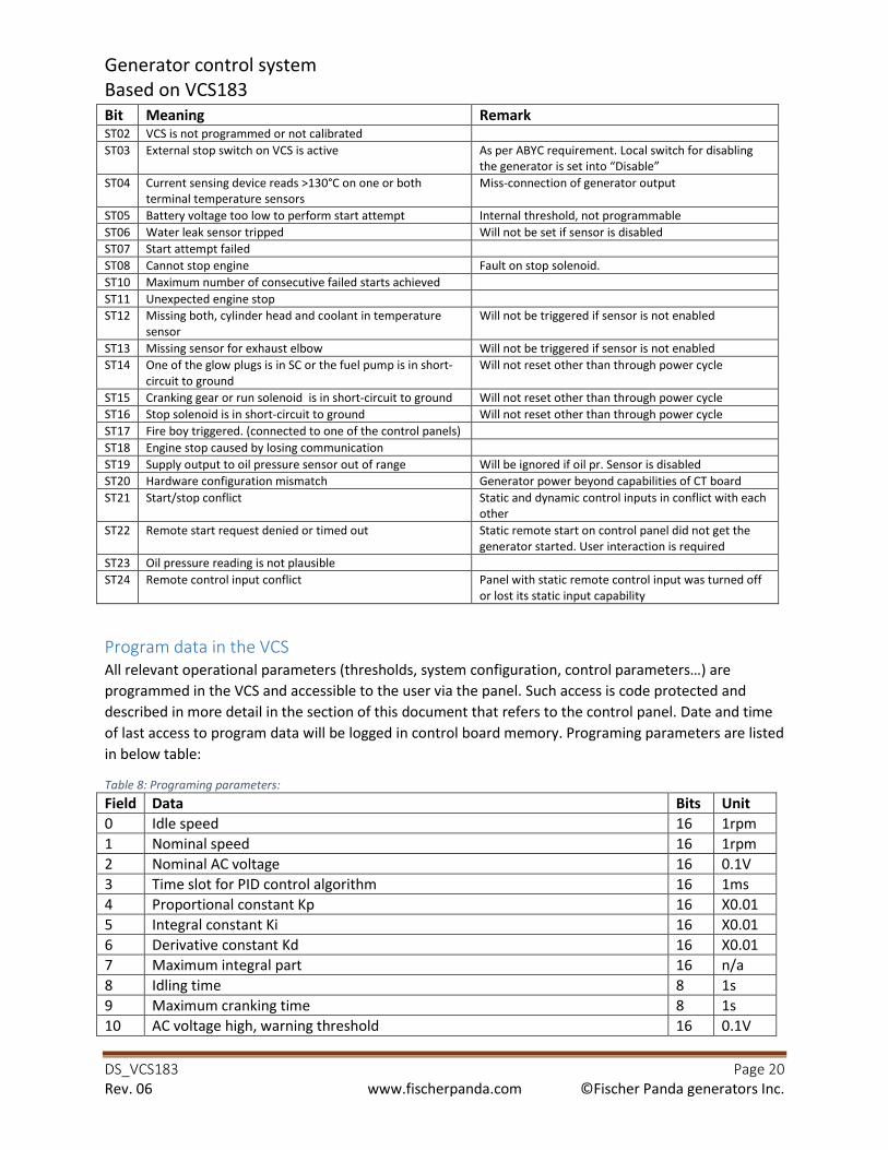
Generator control system
Based on VCS183
DS_VCS183 Page 20
Rev. 06 www.fischerpanda.com ©Fischer Panda generators Inc.
Bit Meaning Remark ST02 VCS is not programmed or not calibrated
ST03 External stop switch on VCS is active As per ABYC requirement. Local switch for disabling
the generator is set into “Disable”
ST04 Current sensing device reads >130°C on one or both
terminal temperature sensors
Miss-connection of generator output
ST05 Battery voltage too low to perform start attempt Internal threshold, not programmable
ST06 Water leak sensor tripped Will not be set if sensor is disabled
ST07 Start attempt failed
ST08 Cannot stop engine Fault on stop solenoid.
ST10 Maximum number of consecutive failed starts achieved
ST11 Unexpected engine stop
ST12 Missing both, cylinder head and coolant in temperature
sensor
Will not be triggered if sensor is not enabled
ST13 Missing sensor for exhaust elbow Will not be triggered if sensor is not enabled
ST14 One of the glow plugs is in SC or the fuel pump is in short-
circuit to ground
Will not reset other than through power cycle
ST15 Cranking gear or run solenoid is in short-circuit to ground Will not reset other than through power cycle
ST16 Stop solenoid is in short-circuit to ground Will not reset other than through power cycle
ST17 Fire boy triggered. (connected to one of the control panels)
ST18 Engine stop caused by losing communication
ST19 Supply output to oil pressure sensor out of range Will be ignored if oil pr. Sensor is disabled
ST20 Hardware configuration mismatch Generator power beyond capabilities of CT board
ST21 Start/stop conflict Static and dynamic control inputs in conflict with each
other
ST22 Remote start request denied or timed out Static remote start on control panel did not get the
generator started. User interaction is required
ST23 Oil pressure reading is not plausible
ST24 Remote control input conflict Panel with static remote control input was turned off
or lost its static input capability
Program data in the VCS
All relevant operational parameters (thresholds, system configuration, control parameters…) are programmed in the VCS and accessible to the user via the panel. Such access is code protected and
described in more detail in the section of this document that refers to the control panel. Date and time
of last access to program data will be logged in control board memory. Programing parameters are listed
in below table:
Table 8: Programing parameters:
Field Data Bits Unit
0 Idle speed 16 1rpm
1 Nominal speed 16 1rpm
2 Nominal AC voltage 16 0.1V
3 Time slot for PID control algorithm 16 1ms
4 Proportional constant Kp 16 X0.01
5 Integral constant Ki 16 X0.01
6 Derivative constant Kd 16 X0.01
7 Maximum integral part 16 n/a
8 Idling time 8 1s
9 Maximum cranking time 8 1s
10 AC voltage high, warning threshold 16 0.1V
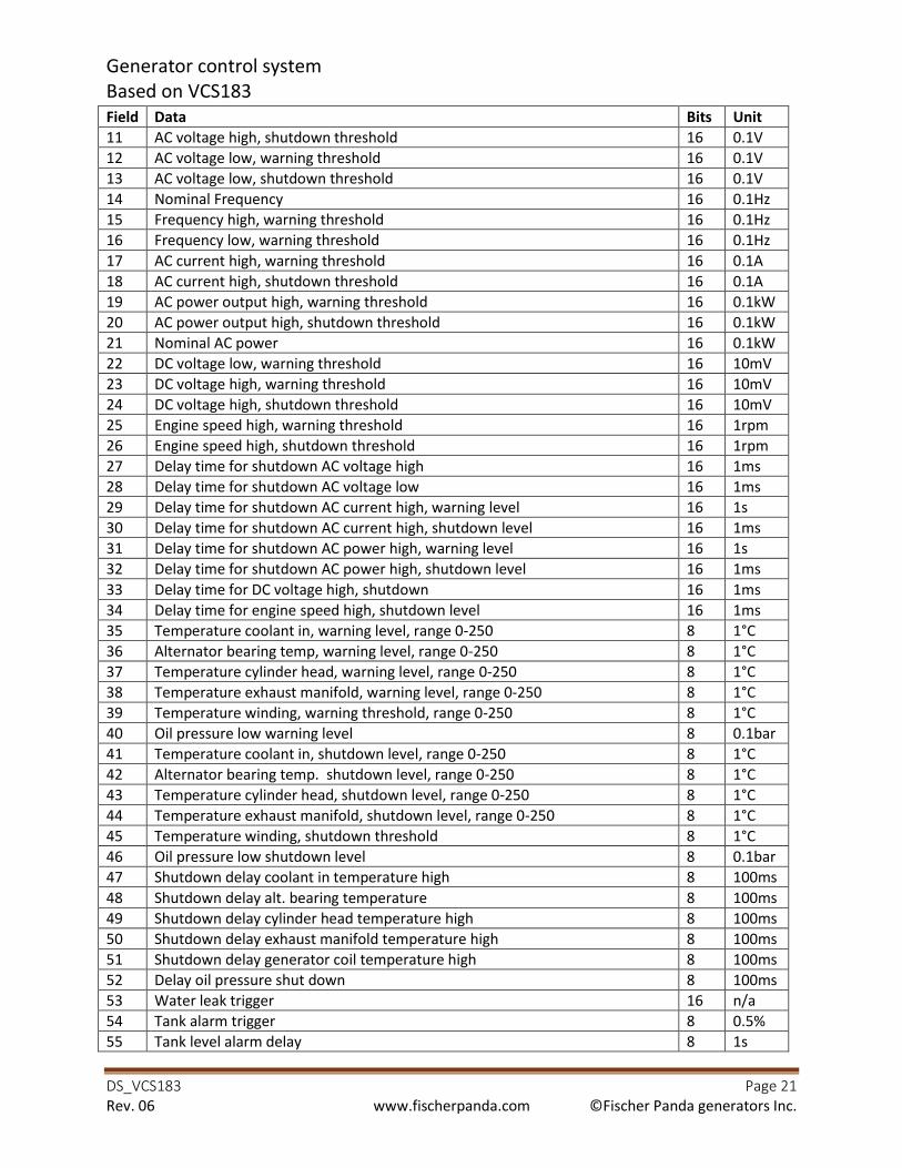
Generator control system
Based on VCS183
DS_VCS183 Page 21
Rev. 06 www.fischerpanda.com ©Fischer Panda generators Inc.
Field Data Bits Unit
11 AC voltage high, shutdown threshold 16 0.1V
12 AC voltage low, warning threshold 16 0.1V
13 AC voltage low, shutdown threshold 16 0.1V
14 Nominal Frequency 16 0.1Hz
15 Frequency high, warning threshold 16 0.1Hz
16 Frequency low, warning threshold 16 0.1Hz
17 AC current high, warning threshold 16 0.1A
18 AC current high, shutdown threshold 16 0.1A
19 AC power output high, warning threshold 16 0.1kW
20 AC power output high, shutdown threshold 16 0.1kW
21 Nominal AC power 16 0.1kW
22 DC voltage low, warning threshold 16 10mV
23 DC voltage high, warning threshold 16 10mV
24 DC voltage high, shutdown threshold 16 10mV
25 Engine speed high, warning threshold 16 1rpm
26 Engine speed high, shutdown threshold 16 1rpm
27 Delay time for shutdown AC voltage high 16 1ms
28 Delay time for shutdown AC voltage low 16 1ms
29 Delay time for shutdown AC current high, warning level 16 1s
30 Delay time for shutdown AC current high, shutdown level 16 1ms
31 Delay time for shutdown AC power high, warning level 16 1s
32 Delay time for shutdown AC power high, shutdown level 16 1ms
33 Delay time for DC voltage high, shutdown 16 1ms
34 Delay time for engine speed high, shutdown level 16 1ms
35 Temperature coolant in, warning level, range 0-250 8 1°C
36 Alternator bearing temp, warning level, range 0-250 8 1°C
37 Temperature cylinder head, warning level, range 0-250 8 1°C
38 Temperature exhaust manifold, warning level, range 0-250 8 1°C
39 Temperature winding, warning threshold, range 0-250 8 1°C
40 Oil pressure low warning level 8 0.1bar
41 Temperature coolant in, shutdown level, range 0-250 8 1°C
42 Alternator bearing temp. shutdown level, range 0-250 8 1°C
43 Temperature cylinder head, shutdown level, range 0-250 8 1°C
44 Temperature exhaust manifold, shutdown level, range 0-250 8 1°C
45 Temperature winding, shutdown threshold 8 1°C
46 Oil pressure low shutdown level 8 0.1bar
47 Shutdown delay coolant in temperature high 8 100ms
48 Shutdown delay alt. bearing temperature 8 100ms
49 Shutdown delay cylinder head temperature high 8 100ms
50 Shutdown delay exhaust manifold temperature high 8 100ms
51 Shutdown delay generator coil temperature high 8 100ms
52 Delay oil pressure shut down 8 100ms
53 Water leak trigger 16 n/a
54 Tank alarm trigger 8 0.5%
55 Tank level alarm delay 8 1s

Generator control system
Based on VCS183
DS_VCS183 Page 22
Rev. 06 www.fischerpanda.com ©Fischer Panda generators Inc.
Field Data Bits Unit
56 Resistance at full tank 16 1Ω
57 Resistance at empty tank 16 1Ω
58 Cooling down temperature threshold (Cyl. Head) 8 1K (a)
59 Cooling down time threshold 8 1 min
60 Act position for cranking 8 1%
61 Max. actuator position while cranking / idling 8 1%
62 Generator configuration bits 32 n/a
63 Sensor configuration bits 32 n/a
64 Maximum plausible oil pressure 8 0.1bar
65 Poles 8 n/a
66 Current on gnd bk output, warning 8 10mA
67 Current on gnd bk output, shutdown 8 10mA
68 Delay shutdown max-current on gnd bk output 8 100ms
69 Absolute max. exhaust temp. during warm-up 8 1°C
70 Fuel priming time 8 1s
71 Absolute maximum cylinder head temperature threshold 8 1°C
72 Service notifications enabled in VCS 32 n/a
73 Actual time / date ** 32 RTC
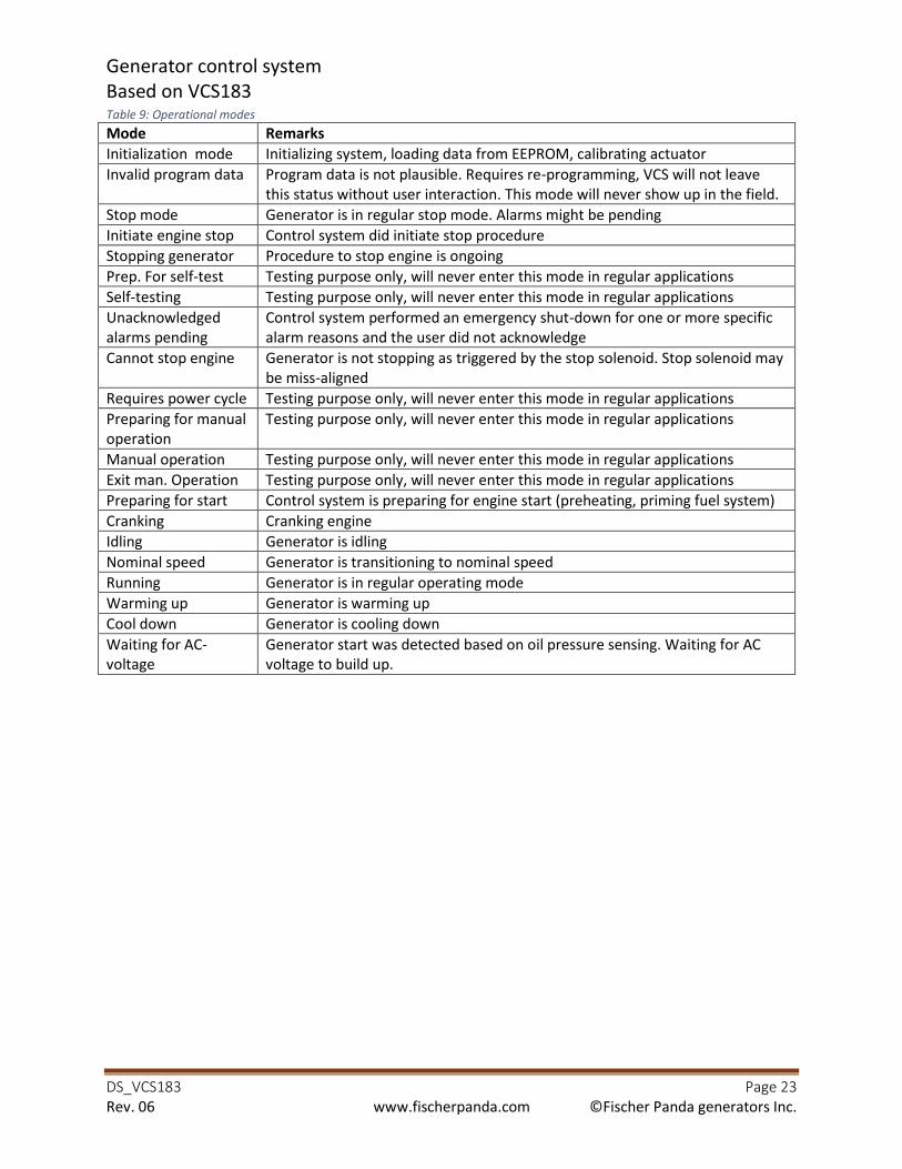
Generator control system
Based on VCS183
DS_VCS183 Page 23
Rev. 06 www.fischerpanda.com ©Fischer Panda generators Inc.
Table 9: Operational modes
Mode Remarks
Initialization mode Initializing system, loading data from EEPROM, calibrating actuator
Invalid program data Program data is not plausible. Requires re-programming, VCS will not leave
this status without user interaction. This mode will never show up in the field.
Stop mode Generator is in regular stop mode. Alarms might be pending
Initiate engine stop Control system did initiate stop procedure
Stopping generator Procedure to stop engine is ongoing
Prep. For self-test Testing purpose only, will never enter this mode in regular applications
Self-testing Testing purpose only, will never enter this mode in regular applications
Unacknowledged
alarms pending
Control system performed an emergency shut-down for one or more specific
alarm reasons and the user did not acknowledge
Cannot stop engine Generator is not stopping as triggered by the stop solenoid. Stop solenoid may
be miss-aligned
Requires power cycle Testing purpose only, will never enter this mode in regular applications
Preparing for manual
operation
Testing purpose only, will never enter this mode in regular applications
Manual operation Testing purpose only, will never enter this mode in regular applications
Exit man. Operation Testing purpose only, will never enter this mode in regular applications
Preparing for start Control system is preparing for engine start (preheating, priming fuel system)
Cranking Cranking engine
Idling Generator is idling
Nominal speed Generator is transitioning to nominal speed
Running Generator is in regular operating mode
Warming up Generator is warming up
Cool down Generator is cooling down
Waiting for AC-
voltage
Generator start was detected based on oil pressure sensing. Waiting for AC
voltage to build up.

Generator control system
Based on VCS183
DS_VCS183 Page 24
Rev. 06 www.fischerpanda.com ©Fischer Panda generators Inc.
Current sensing device CT186 or CT195 The current sensing device serves as a sensing device for output current, voltage, frequency and power
factor but also provides the linkage between the alternator output cables and the power output where
generator power is made available to the user.
Selecting the desired output
Fischer Panda generators for commercial domestic applications will always provide two outputs of
nominal 120V/60Hz each. Connection cables coming from these coils are labelled H1.1/H1.2 and
H2.1/H2.2. Depending on the way these outputs are connected the power provided to the user is either
120V only or 120/240V. Generators will be supplied in requested configuration but may be re-
configured in the field.
Alternator coils and power output both connect to terminal J3 on the current sensing device. For either
configuration the connection of the alternator coils H1.1/H1.2 and H2.1H2.2 is indicated on the PC
board of the current sensing device:
Figure6: Terminal J3 on CT186
For 120V/240 configuration:
• Control board VCS183 needs to be programmed for 120/240V configuration. See Program VCS.
Alternator coils need to be selected to be in series.
• Generator coils need to be connected as indicated in Figure6: Terminal J3 on CT186.
• For generators with nominal output power 12kVA or higher:
o Make sure connector J6 on CT 196 is not jumped. See Figure 7: Terminal J6 on CT186
Figure 7: Terminal J6 on CT186
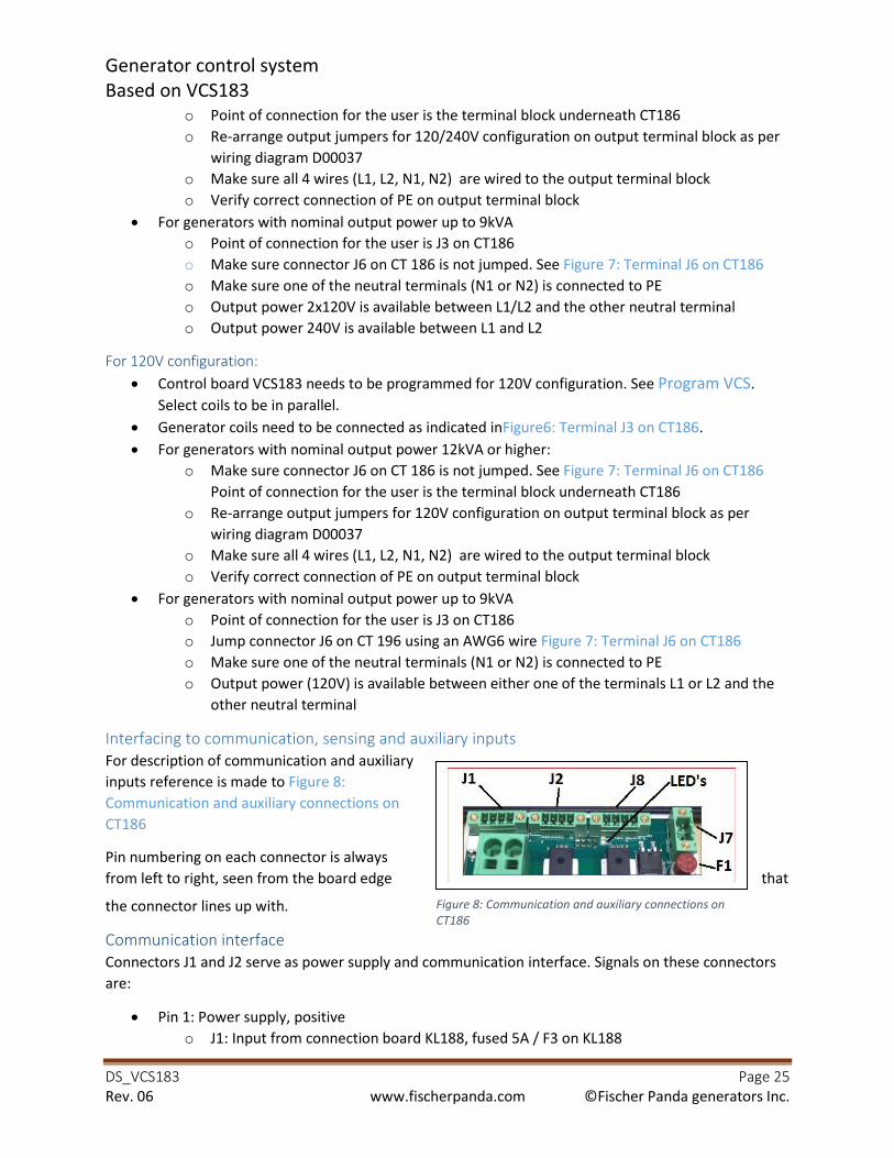
Generator control system
Based on VCS183
DS_VCS183 Page 25
Rev. 06 www.fischerpanda.com ©Fischer Panda generators Inc.
o Point of connection for the user is the terminal block underneath CT186
o Re-arrange output jumpers for 120/240V configuration on output terminal block as per
wiring diagram D00037
o Make sure all 4 wires (L1, L2, N1, N2) are wired to the output terminal block
o Verify correct connection of PE on output terminal block
• For generators with nominal output power up to 9kVA
o Point of connection for the user is J3 on CT186
o Make sure connector J6 on CT 186 is not jumped. See Figure 7: Terminal J6 on CT186
o Make sure one of the neutral terminals (N1 or N2) is connected to PE
o Output power 2x120V is available between L1/L2 and the other neutral terminal
o Output power 240V is available between L1 and L2
For 120V configuration:
• Control board VCS183 needs to be programmed for 120V configuration. See Program VCS.
Select coils to be in parallel.
• Generator coils need to be connected as indicated inFigure6: Terminal J3 on CT186.
• For generators with nominal output power 12kVA or higher:
o Make sure connector J6 on CT 186 is not jumped. See Figure 7: Terminal J6 on CT186
Point of connection for the user is the terminal block underneath CT186
o Re-arrange output jumpers for 120V configuration on output terminal block as per
wiring diagram D00037
o Make sure all 4 wires (L1, L2, N1, N2) are wired to the output terminal block
o Verify correct connection of PE on output terminal block
• For generators with nominal output power up to 9kVA
o Point of connection for the user is J3 on CT186
o Jump connector J6 on CT 196 using an AWG6 wire Figure 7: Terminal J6 on CT186
o Make sure one of the neutral terminals (N1 or N2) is connected to PE
o Output power (120V) is available between either one of the terminals L1 or L2 and the
other neutral terminal
Interfacing to communication, sensing and auxiliary inputs
For description of communication and auxiliary
inputs reference is made to Figure 8:
Communication and auxiliary connections on
CT186
Pin numbering on each connector is always
from left to right, seen from the board edge that
the connector lines up with.
Communication interface
Connectors J1 and J2 serve as power supply and communication interface. Signals on these connectors
are:
• Pin 1: Power supply, positive
o J1: Input from connection board KL188, fused 5A / F3 on KL188
Figure 8: Communication and auxiliary connections on
CT186

Generator control system
Based on VCS183
DS_VCS183 Page 26
Rev. 06 www.fischerpanda.com ©Fischer Panda generators Inc.
o J2: Power supply towards control panels
• Pin 2: Power supply negative.
• Pin 3: Serial data link CAN-H
• Pin 4: Serial data link CAN-L
Connectors and mating plugs are identical and thus may accidentally plugged in reversed. This does not
create any functional problem at all, pins are internally connected on the PC board anyway. No other
device must be connected to any of these connectors, these are solely intended for communication and
power distribution between components of the generator control system.
Sensing inputs
CT186 is sensing the temperature on the alternator bearing and fuel level. NTC temperature sensor for
alternator bearing comes with generators with nominal output power 12kVA and higher; it is not
required for generators with lower nominal output power. Fuel level sensor is supposed to be a linear
resistive sensor with below specifications. It is not part of Fischer Panda scope of supply. Sensors
connect to J8 as below:
• Pin 1: Resistive fuel level sensor, resistance range 30Ω … 5000Ω
• Pin 2: Reference (ground) for fuel level sensor
• Pin 3: Temperature sensor for alternator bearing. NTC Element with R25=100kΩ and B25/100
coefficient 3988, is installed on generators requiring this to be monitored
• Pin 4: Reference (ground) for temperature sensor.
The connector as well as the mating plug have different pin spacing as compared to communication
interface, thus preventing miss-plugging.
Temperature sensing is the same as described for control board VCS18; CT186 will detect if the sensor is
missing or short-circuited. It will report sensor status as well as actual temperature reading to VCS183
for further processing.
Tank level sensing assumes a linear dependence between resistance and fuel level. Thus by
programming resistance at full tank and resistance at empty tank (Table 8: Programing parameters:, P56
and P57) the control system will calculate the slope of the tank sensor and will provide tank level data
based on sensor readings. Whether the slope is positive or negative (i.e. resistance at empty tank
greater than at full tank or the other way around) is of no importance, the only restriction is the two
resistances must not be the same and must both be within above mentioned range.
As with temperature sensors, the control system will monitor the tank level sensor if it is enabled and
will report if it provides readings out of range.
Auxiliary connection
CT186 also does supply power to the battery charger (always 120V/60Hz, regardless of generator
configuration). This power supply is made available at connector F7 and is fused by barrel fuse F1, 4A
slow-blowing characteristic.
Optical status indication
CT186 provides a status feedback via a red and green LED. Blinking pattern of these LED’s is an indication on actual operating mode:

Generator control system
Based on VCS183
DS_VCS183 Page 27
Rev. 06 www.fischerpanda.com ©Fischer Panda generators Inc.
• Both LED’s off: CT186 is in low power mode. Will transition to regular operation mode once it receives valid communication data from VCS183.
• Red LED flashing short (On 25ms, off 4seconds): CT186 detected some hardware problems and
will connect to the CAN bus in listen only mode. It will not be visible to any other CAN nodes on
the bus (emergency operating mode, see Current sensing device CT186xxx.
• Red LED steady on: CT186 was unable to gain connection to VCS183. It will try to find this
connection for approx. 10 seconds and will then transition to low power mode if not successful.
• Red LED is blinking: CT186 is reading DC on at least one input (voltage or current). This is
considered a major fault.
• Red and green LED’s blinking in alternating pattern: Critical status, may be triggered by either
one of below mentioned conditions:
o AC readings (current or voltage) are out of permissible range for CT186.
o CT186 is reading AC current but cannot detect signal for power factor.
o CT Board temperature is outside permissible range.
o CT terminal temperature is critical (above 100°C).
• Green LED is blinking: one or more of below minor faults was detected:
o CT186 was not programmed.
o Tank sensor is enabled and reports open loop or short-circuit.
o Temperature sensor for alternator bearing is enabled and reports open loop or short-
circuit.
• Green LED is steady on: No faults detected.
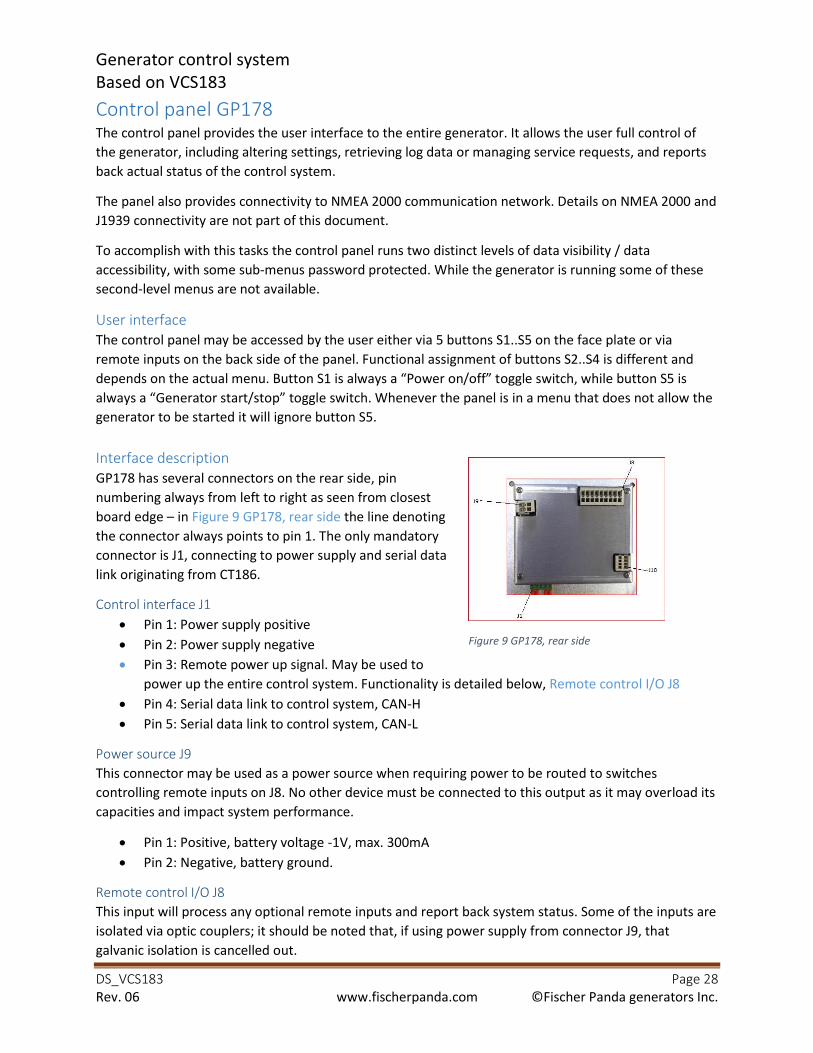
Generator control system
Based on VCS183
DS_VCS183 Page 28
Rev. 06 www.fischerpanda.com ©Fischer Panda generators Inc.
Control panel GP178 The control panel provides the user interface to the entire generator. It allows the user full control of
the generator, including altering settings, retrieving log data or managing service requests, and reports
back actual status of the control system.
The panel also provides connectivity to NMEA 2000 communication network. Details on NMEA 2000 and
J1939 connectivity are not part of this document.
To accomplish with this tasks the control panel runs two distinct levels of data visibility / data
accessibility, with some sub-menus password protected. While the generator is running some of these
second-level menus are not available.
User interface
The control panel may be accessed by the user either via 5 buttons S1..S5 on the face plate or via
remote inputs on the back side of the panel. Functional assignment of buttons S2..S4 is different and
depends on the actual menu. Button S1 is always a “Power on/off” toggle switch, while button S5 is
always a “Generator start/stop” toggle switch. Whenever the panel is in a menu that does not allow the
generator to be started it will ignore button S5.
Interface description
GP178 has several connectors on the rear side, pin
numbering always from left to right as seen from closest
board edge – in Figure 9 GP178, rear side the line denoting
the connector always points to pin 1. The only mandatory
connector is J1, connecting to power supply and serial data
link originating from CT186.
Control interface J1
• Pin 1: Power supply positive
• Pin 2: Power supply negative
• Pin 3: Remote power up signal. May be used to
power up the entire control system. Functionality is detailed below, Remote control I/O J8
• Pin 4: Serial data link to control system, CAN-H
• Pin 5: Serial data link to control system, CAN-L
Power source J9
This connector may be used as a power source when requiring power to be routed to switches
controlling remote inputs on J8. No other device must be connected to this output as it may overload its
capacities and impact system performance.
• Pin 1: Positive, battery voltage -1V, max. 300mA
• Pin 2: Negative, battery ground.
Remote control I/O J8
This input will process any optional remote inputs and report back system status. Some of the inputs are
isolated via optic couplers; it should be noted that, if using power supply from connector J9, that
galvanic isolation is cancelled out.
Figure 9 GP178, rear side
Generator control system
Based on VCS183
DS_VCS183 Page 29
Rev. 06 www.fischerpanda.com ©Fischer Panda generators Inc.
• Pin 1: Ground (reference) for optically isolated inputs
• Pin 2: Optical isolated input “Combat override” (Military applications only)
• Pin 3: Optical isolated input “Remote start”
• Pin 4: Optical isolated input “Fire boy”
• Pin 5: Remote power up, internally connected to J1 / pin 3
• Pins 6 and 7: Relay contacts “Alarm”
• Pins 8 and 9: Relay contacts “Status”
NMEA 2000 connector J10
Pin functionality as well as hardware restrictions for these pins is according to NMEA2000 status. Pin
assignment is as listed below:
• Pin 1: Net S
• Pin 2: Net C
• Pin 3: Net H
• Pin 4: Net L
Panels are available with frame and back cover internally connected to power supply negative or with
isolated frame/back cover. In the latter case there still is a connection between supply ground and panel
frame for AC signals across a capacitive path. Seen from a DC standpoint the frame is isolated from
supply ground in such case and may be considered screen for NMEA2000 bus.
I/O hardware requirements / ratings
Optically isolated inputs are intended to provide signal isolation but certainly not safety isolation! When
using optically isolated inputs these are the requirements – all voltage levels to be understood as
referenced to J8/pin1:
• Permissible input voltage range: -1 .. +32V
• Minimum voltage required to detect logic “H”: +9V
• Maximum voltage that may pass as logic level “L”: +2.5V
• Resistive load presented to driving circuit: >1.8kΩ
• Capacitive load presented to driving circuit: <1200pF
Remote power up on J1/pin 3 is internally connected to remote power up on J8/5. Voltage level on this
pin is defined with reference to panel supply voltage (J1/pin 2):
• Permissible input voltage range: -1 .. +supply voltage
• Resistive load presented to driving circuit: >15kΩ
• Capacitive load presented to driving circuit: <500pF
If optical isolation is not required then power output as provided on J9 may be used to drive remote
control inputs and remote start – the latter one never providing optical isolation. J9 will provide enough
power to drive at a maximum all 3 optically isolated inputs and the remote power-up.
Status output and alarm output are mechanical contacts, rated max. 28V/max. 0.8mA resistive load.
Contacts have internal self-resetting over-current-protection.
Generator control system
Based on VCS183
DS_VCS183 Page 30
Rev. 06 www.fischerpanda.com ©Fischer Panda generators Inc.
Basic functional definitions
NMEA communication is not covered in this manual, a detailed interface description is available upon
request. The digital inputs and digital outputs with electrical specifications / ratings as described in
previous paragraph will work as described below:
Digital outputs:
Relay contacts on output “Alarms” will be closed if and as long as the control system reports any
major fault and open in any other condition.
Relay contacts “Status” will be closed if the generator is running and open when it is not running.
Digital inputs
Static versus dynamic inputs:
Digital inputs may work as static inputs or as dynamic inputs.
A static input is reporting its current status all the time, i.e. the input is either active or not active.
This input type requires a switch with 2 distinct positions (open/close); the input will always read
and report the actual switch status.
A dynamic input (or edge-triggered input) will report any transition on the input as would be the
case if a button was connected to that input. A positive (rising) edge will be detected if the button
was depressed and a negative (falling) edge when it is released. As is common in most applications
the negative edge (releasing the button) is the one that will trigger the desired activity. The
minimum time between rising edge and falling edge is required to be 5ms. No maximum time is
associated with this type of input, i.e. the panel will wait an indefinite time for a negative edge after
a positive one was detected.
Input configuration
Digital inputs “Fire boy” and “Combat override” are always static. Digital inputs “remote power up” and “remote start” may be configured as static or dynamic. Such configuration is part of the VCS
programming. Inputs cannot be individually configured, i.e. “remote power up” and “remote start” are both either static or both dynamic.
Implications when using digital inputs in static mode
Having multiple panels connected to one control system and panels have their inputs configured for
static operation will almost certainly cause conflict situation (one input may command the generator to
start while the other one commands it to stop). To avoid such conflict the control system will only allow
usage of one panel if it is configured for static input. If it detects more than one panel connected then an
error message will be issued and the generator cannot be operated.
Input “Fire boy” connects to the fire boy system of the boat and will report the status of this input to the
control system. If the control system is programmed to process this input then, if the input is in alarm
condition (i.e. open switch) the control system will interpret this as a major fault and will display the text
message that was programmed for this incident. If more than one panel is connected to the control
system then the fire boy input of all panels will be logically ANDed; the control system will report the fire
boy message if any panel has this input in alarm condition.
Input “Combat override”: This input is designed for military applications only and not covered in this
manual.
Generator control system
Based on VCS183
DS_VCS183 Page 31
Rev. 06 www.fischerpanda.com ©Fischer Panda generators Inc.
Input “remote power up” in dynamic configuration: In this configuration the button connected to the
remote power up input may be thought of as a button parallel to panel button S1. Each falling edge on
that input will toggle system status from “on” to “off “and vice versa.
Input “remote power up” in static configuration: In this configuration will power up if the input is active
and it will power down if it is not active. The control system may though be powered on or off by simply
clicking button S1 on the panel faceplate. If the system was already powered up via button S1 by the
time the remote input becomes active the system will behave as if it was powered up by this input:
• If that input becomes inactive, the control system will power down
• If button S1 is clicked with the remote power up input still active the panel will detect this
conflict situation and will prompt the user to turn off the remote power up input in order to
power down.
Input “Remote start” in dynamic configuration: In this configuration each transition from logic level H
(active) to logic level L (not active) on the remote input will toggle actual generator status (“On => Off” or “Off => On”). The input may be thought of as a regular button input parallel to panel button S5.
Input “Remote start” in static configuration: In this configuration the generator will start and stay
running if the input is active and it will turn off if the input becomes inactive. Several implications come
with this configuration:
• Whether cool-down mode is enabled or disabled in the VCS programming will be disregarded.
The generator will never enter cool-down mode.
• If the generator was started via the NMEA input or by clicking button S5 on the panel faceplate
and then, while it is running, the remote start input becomes active, then form that time on the
control system will behave as if the generator was started via static remote start input.
• If the generator was started by remote static input and then shuts down because of an
emergency event or by user interaction via button S5 or NMEA input then the generator will
shut down. The control system will detect this conflict situation (shut down requested while
remote static input still active and requesting the generator to run) and report it via the control
panel with the message “Start stop conflict”. To resolve this the user needs to de-activate the
remote start input.
• If the generator was requested to start via remote start input but cannot start because of a
pending shutdown alarm or if the start does not succeed then the control system will end up in
a similar conflict situation as mentioned in previous paragraph. The same resolution applies.

Generator control system
Based on VCS183
DS_VCS183 Page 32
Rev. 06 www.fischerpanda.com ©Fischer Panda generators Inc.
Operating the control system via control panel GP178 Subsequent operational description will assume a fully functional control system was installed.
Whenever description is based on exceptional conditions it will be mentioned explicitly.
Powering up the control system
The control system may be powered up either by operating it from a
USB port as simple USB device (not covered in this manual) or from
the panel. Powering up from the panel is either by clicking button S1
on the panel faceplate or by remote power up as explained in Basic
functional definitions. Either power up mode will cause VCS183 and
CT186 to transition from standby mode into regular operating mode
and start communicating with each other. The green LED on top of
button S1 will light up, the panel will first show its identification data
and then transfer to basic mode display page 1.
Basic mode display pages show data as can be seen in Figure 11 basic
mode, display page 1 to Figure 13basic mode, display page 3:
• Page 1:
o Engine speed
o Frequency of AC output
o AC output voltage
o AC output current
o Total active power
o Total apparent power
o Power factor
o Fuel level
• Page 2:
o Cylinder head temperature
o Exhaust temperature
o Gen. winding temperature
o Coolant inlet temperature
o Alternator bearing temperature
o Engine oil pressure
• Page 3:
o Total operating time
o Relative power output as sliding bar
o Generator serial number
o Total el. energy produced by this generator
o Total amounts of engine starts
Data is maintained up to date on all pages, the user may cycle through pages by clicking button S3.
Across all these pages the bottom line is reserved to display pending messages or minor faults (regular
display mode) or major faults (light text on dark background). While in basic display mode some minor
Figure 10Panel identification data
Figure 11 basic mode, display page 1
Figure 12 basic mode, display page 2
Figure 13basic mode, display page 3
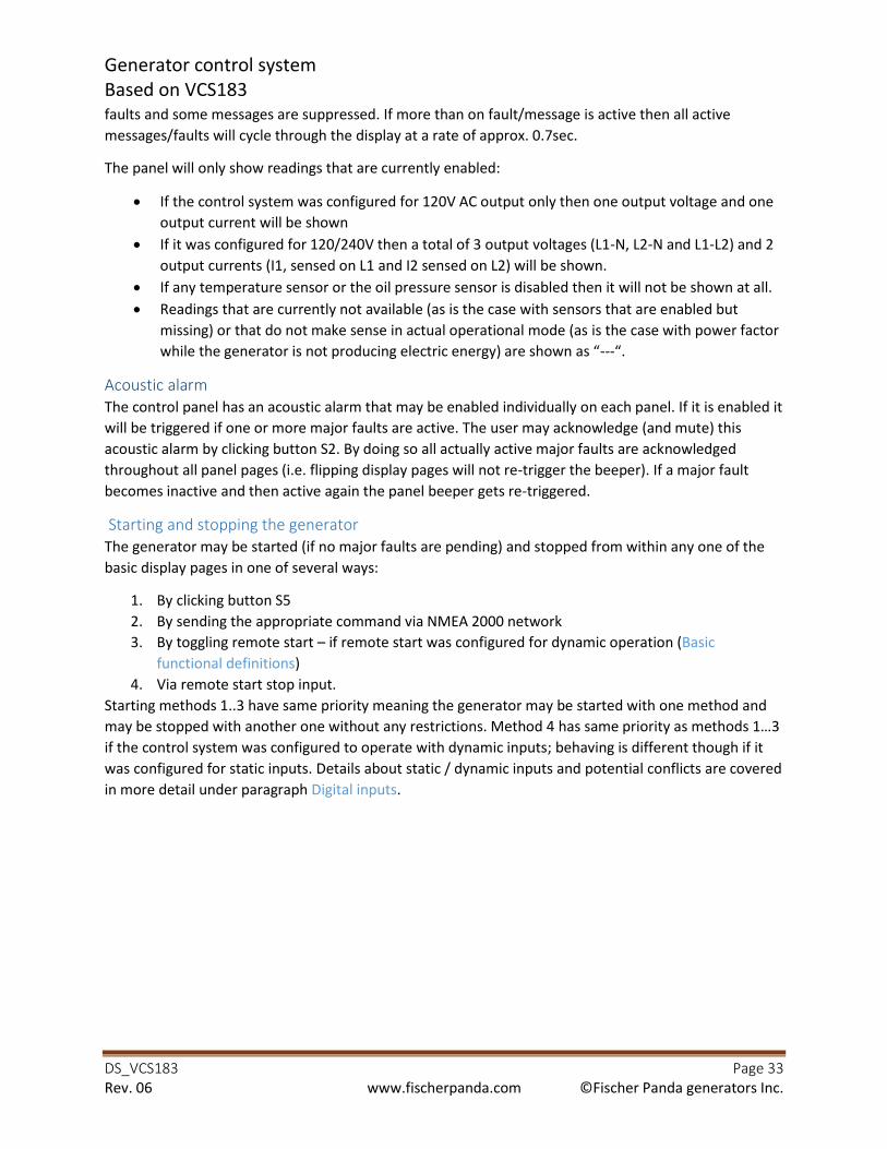
Generator control system
Based on VCS183
DS_VCS183 Page 33
Rev. 06 www.fischerpanda.com ©Fischer Panda generators Inc.
faults and some messages are suppressed. If more than on fault/message is active then all active
messages/faults will cycle through the display at a rate of approx. 0.7sec.
The panel will only show readings that are currently enabled:
• If the control system was configured for 120V AC output only then one output voltage and one
output current will be shown
• If it was configured for 120/240V then a total of 3 output voltages (L1-N, L2-N and L1-L2) and 2
output currents (I1, sensed on L1 and I2 sensed on L2) will be shown.
• If any temperature sensor or the oil pressure sensor is disabled then it will not be shown at all.
• Readings that are currently not available (as is the case with sensors that are enabled but
missing) or that do not make sense in actual operational mode (as is the case with power factor
while the generator is not producing electric energy) are shown as “---“.
Acoustic alarm
The control panel has an acoustic alarm that may be enabled individually on each panel. If it is enabled it
will be triggered if one or more major faults are active. The user may acknowledge (and mute) this
acoustic alarm by clicking button S2. By doing so all actually active major faults are acknowledged
throughout all panel pages (i.e. flipping display pages will not re-trigger the beeper). If a major fault
becomes inactive and then active again the panel beeper gets re-triggered.
Starting and stopping the generator
The generator may be started (if no major faults are pending) and stopped from within any one of the
basic display pages in one of several ways:
1. By clicking button S5
2. By sending the appropriate command via NMEA 2000 network
3. By toggling remote start – if remote start was configured for dynamic operation (Basic
functional definitions)
4. Via remote start stop input.
Starting methods 1..3 have same priority meaning the generator may be started with one method and
may be stopped with another one without any restrictions. Method 4 has same priority as methods 1…3 if the control system was configured to operate with dynamic inputs; behaving is different though if it
was configured for static inputs. Details about static / dynamic inputs and potential conflicts are covered
in more detail under paragraph Digital inputs.

Generator control system
Based on VCS183
DS_VCS183 Page 34
Rev. 06 www.fischerpanda.com ©Fischer Panda generators Inc.
Advanced selections / data menu
The panel gives access to additional data as well as panel and VCS
settings and configurations from within the advanced selections
/data menu. To enter this menu the user needs to press and hold
down button S2, then press button S3, and finally release both
buttons at the same time.
Whenever the generator is running there is no access to altering
any settings, neither the ones stored in the VCS nor panel
settings. In such case, selecting advanced selections / data menu
will transition immediately into the “View more data” menu; see Figure 17: Selection View more data
With the generator not running the advanced selections menu
will be displayed.
Navigating through advanced selection menus and sub-menus
Throughout advanced selection menu as well as in all sub-menus
navigation between menus will always follow the below pattern:
• Selection bar may be moved by clicking S3,as is indicated
in bottom line (“S3: next”) • Currently highlighted item may be selected by clicking S4,
as indicated in bottom line (“S4: select”) • Selecting “Return to normal” will always jump back into
basic display mode, page 1
Structure of sub-menus is depicted in Figure 14: Advanced menu,
page 1, Figure 15: Advanced menu, page 2 and Figure 16: Advanced menu, page 3 and briefly described
below:
View more data
Top line of this menu will always show actual operational status, bottom line is again reserved for
faults/message display while remaining 3 lines are used to cycle through additional display data listed
below. Cycling time again is approx. 0.7 sec., cycling process may be halted/re-started by clicking S4. To
exit this menu the user needs to click S3.
Data available in menu “View more data”
1. Frequency as sensed by the CT board
2. Temperature CT186, main CPU control board
3. Temperature terminals of CT186
4. Temperature on VCS183 control board
5. Temperature inside control panel
6. Actuator voltage
7. Actuator current
Figure 14: Advanced menu, page 1
Figure 15: Advanced menu, page 2
Figure 16: Advanced menu, page 3
Figure 17: Selection View more data
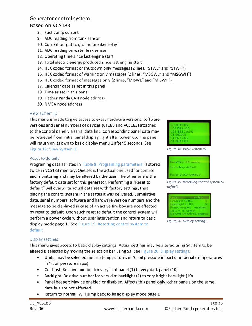
Generator control system
Based on VCS183
DS_VCS183 Page 35
Rev. 06 www.fischerpanda.com ©Fischer Panda generators Inc.
8. Fuel pump current
9. ADC reading from tank sensor
10. Current output to ground breaker relay
11. ADC reading on water leak sensor
12. Operating time since last engine start
13. Total electric energy produced since last engine start
14. HEX coded format of shutdown only messages (2 lines, “STWL” and “STWH”) 15. HEX coded format of warning only messages (2 lines, “MSGWL” and “MSGWH”) 16. HEX coded format of messages only (2 lines, “MISWL” and “MISWH”) 17. Calendar date as set in this panel
18. Time as set in this panel
19. Fischer Panda CAN node address
20. NMEA node address
View system ID
This menu is made to give access to exact hardware versions, software
versions and serial numbers of devices (CT186 and VCS183) attached
to the control panel via serial data link. Corresponding panel data may
be retrieved from initial panel display right after power up. The panel
will return on its own to basic display menu 1 after 5 seconds. See
Figure 18: View System ID
Reset to default
Programing data as listed in Table 8: Programing parameters: is stored
twice in VCS183 memory. One set is the actual one used for control
and monitoring and may be altered by the user. The other one is the
factory default data set for this generator. Performing a “Reset to
default” will overwrite actual data set with factory settings, thus
placing the control system in the status it was delivered. Cumulative
data, serial numbers, software and hardware version numbers and the
message to be displayed in case of an active fire boy are not affected
by reset to default. Upon such reset to default the control system will
perform a power cycle without user intervention and return to basic
display mode page 1. See Figure 19: Resetting control system to
default
Display settings
This menu gives access to basic display settings. Actual settings may be altered using S4, item to be
altered is selected by moving the selection bar using S3. See Figure 20: Display settings.
• Units: may be selected metric (temperatures in °C, oil pressure in bar) or imperial (temperatures
in °F, oil pressure in psi)
• Contrast: Relative number for very light panel (1) to very dark panel (10)
• Backlight: Relative number for very dim backlight (1) to very bright backlight (10)
• Panel beeper: May be enabled or disabled. Affects this panel only, other panels on the same
data bus are not affected.
• Return to normal: Will jump back to basic display mode page 1
Figure 18: View System ID
Figure 19: Resetting control system to
default
Figure 20: Display settings
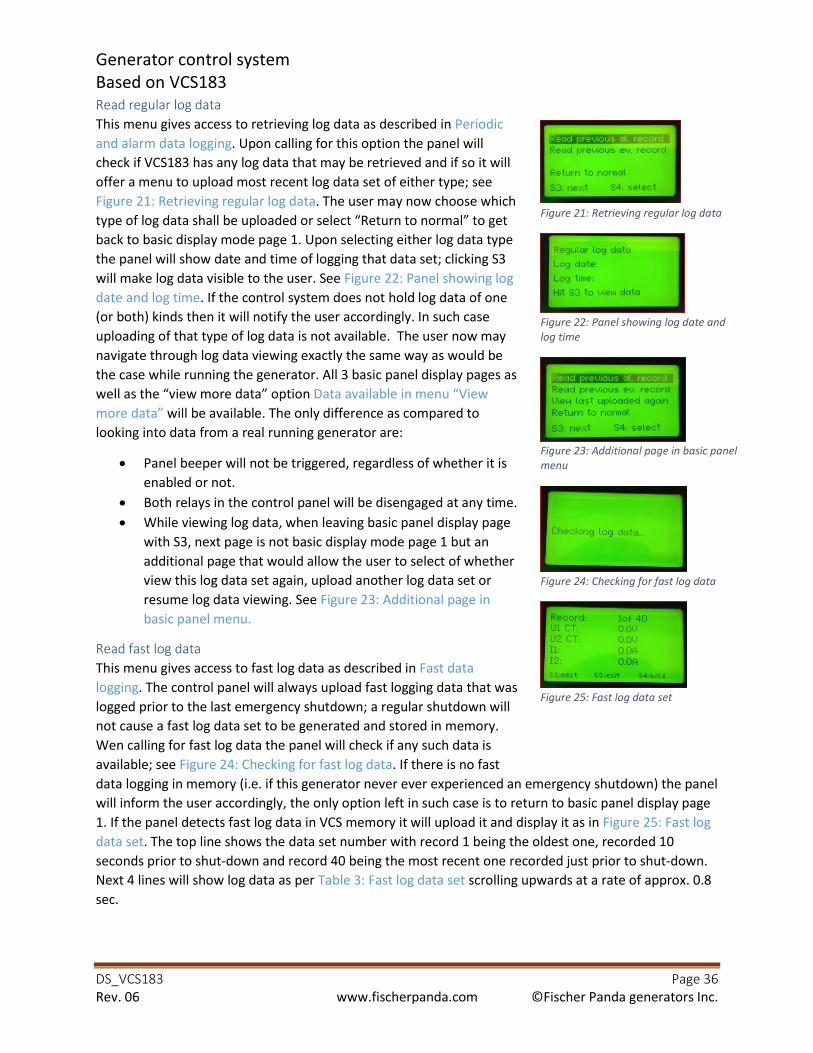
Generator control system
Based on VCS183
DS_VCS183 Page 36
Rev. 06 www.fischerpanda.com ©Fischer Panda generators Inc.
Read regular log data
This menu gives access to retrieving log data as described in Periodic
and alarm data logging. Upon calling for this option the panel will
check if VCS183 has any log data that may be retrieved and if so it will
offer a menu to upload most recent log data set of either type; see
Figure 21: Retrieving regular log data. The user may now choose which
type of log data shall be uploaded or select “Return to normal” to get back to basic display mode page 1. Upon selecting either log data type
the panel will show date and time of logging that data set; clicking S3
will make log data visible to the user. See Figure 22: Panel showing log
date and log time. If the control system does not hold log data of one
(or both) kinds then it will notify the user accordingly. In such case
uploading of that type of log data is not available. The user now may
navigate through log data viewing exactly the same way as would be
the case while running the generator. All 3 basic panel display pages as
well as the “view more data” option Data available in menu “View more data” will be available. The only difference as compared to
looking into data from a real running generator are:
• Panel beeper will not be triggered, regardless of whether it is
enabled or not.
• Both relays in the control panel will be disengaged at any time.
• While viewing log data, when leaving basic panel display page
with S3, next page is not basic display mode page 1 but an
additional page that would allow the user to select of whether
view this log data set again, upload another log data set or
resume log data viewing. See Figure 23: Additional page in
basic panel menu.
Read fast log data
This menu gives access to fast log data as described in Fast data
logging. The control panel will always upload fast logging data that was
logged prior to the last emergency shutdown; a regular shutdown will
not cause a fast log data set to be generated and stored in memory.
Wen calling for fast log data the panel will check if any such data is
available; see Figure 24: Checking for fast log data. If there is no fast
data logging in memory (i.e. if this generator never ever experienced an emergency shutdown) the panel
will inform the user accordingly, the only option left in such case is to return to basic panel display page
1. If the panel detects fast log data in VCS memory it will upload it and display it as in Figure 25: Fast log
data set. The top line shows the data set number with record 1 being the oldest one, recorded 10
seconds prior to shut-down and record 40 being the most recent one recorded just prior to shut-down.
Next 4 lines will show log data as per Table 3: Fast log data set scrolling upwards at a rate of approx. 0.8
sec.
Figure 21: Retrieving regular log data
Figure 22: Panel showing log date and
log time
Figure 23: Additional page in basic panel
menu
Figure 24: Checking for fast log data
Figure 25: Fast log data set

Generator control system
Based on VCS183
DS_VCS183 Page 37
Rev. 06 www.fischerpanda.com ©Fischer Panda generators Inc.
The user may at any time hold/re-enable automatic scrolling by clicking S4. S2 will show next fast data
record. To exit from fast data log viewing the user needs to click S3. These options are also shown in
bottom line of fast log data page (Figure 25: Fast log data set.
Option not implemented
This is left for future development. Selecting this menu will cause the control panel to jump back to
basic display mode page 1.
Program VCS
This menu gives access to program data as listed in Table 8: Programing
parameters: It should be noted that cumulative data (total operating
time, total energy produced, total engine starts) as well as some
constants (serial numbers of any component including generator and
message that is to be displayed if the fire boy gets activated) are not
accessible through the control panel. These may be only altered /
programmed using USB connection to the control system and will
require special software (beyond the scope of this manual).
Programing option is password protected to make the user aware that
any modifications that are applied after this password wall may have
serious implications on generator behavior. Date and time of last
(re)programming of the VCS is logged in VCS memory. The password to
access settings is 0815. The control system will accept max. 3 attempts
to enter a password, if none was successful it will power down. Upon
selecting programming option, the password menu will be displayed:
Figure 26: Password menu
Entering numerical values
Password as well as any other numerical value is entered into the panel
using buttons S2, S3 and S4:
• The blinking digit may be increased using S3. After increasing to
9 it will roll over to 0 after next increase.
• Clicking S2 will put the next digit in blinking mode.
• After adjusting all digits as required actual numerical value is
confirmed by clicking S4.
• Wherever decimal numbers are required to be entered the
decimal point will always be in fixed position. Clicking S2 will
however allow access to integer as well as fractional part of that number.
Navigating through programing pages
All but last programing page offers menu option “Next page”. Selecting this option will open next programming page (Figure 27: Prog. Page, numerical values, Figure 28: Prog. Page, discrete values). Last
programming page just offers the option to save data to VCS or not (Figure 29: Last programing page).
Selecting “no” will return to first programming page and allows a review of all program data. Selecting
yes will transfer newly programmed data into VCS183 and then power-cycle the control system.
Figure 26: Password menu
Figure 27: Prog. Page, numerical values
Figure 28: Prog. Page, discrete values
Figure 29: Last programing page

Generator control system
Based on VCS183
DS_VCS183 Page 38
Rev. 06 www.fischerpanda.com ©Fischer Panda generators Inc.
Selecting / altering program data
In order to alter a particular parameter, it first needs to be located; navigating through program data
pages will eventually show the parameter that is requested to be modified. Inside its programming page
the desired parameter is selected by:
• First moving the selection bar using S3 until that parameter is highlighted
• Then clicking S4 to confirm this parameter is going to be programmed.
Once selected, that parameter will either start blinking least significant digit if it is a numerical
parameter, or the entire parameter will blink if it is a parameter that may be altered between a defined
number of options (as would be “enabled / disabled”).
Numerical values may be adjusted as described above (Entering numerical values). The panel will check
any numerical value against certain limits and will not accept it if it does not match. If recently entered
value was found outside limits the panel will, after that value was entered by clicking S4, immediately
enter blinking mode again, asking for new entry. For parameters with pre-selectable options these
options may be circled around by clicking S3. After adjusting to the desired option this needs to be
confirmed by clicking S4.
Once a parameter has been altered it will stop blinking. Selection bar now may be moved to another
parameter or to “Next page” option to continue with programing.
Whatever modifications are applied to the control system it should be noted that at first these are all
temporarily just stored in the control panel. Continuing to last programing page and selecting data to be
saved to VCS will finally cause actual parameters in the VCS to be overwritten. After programing data
into its memory the control system will perform a power-cycle without any user intervention.
While in programming mode the entire system may be powered down at any time. In such case data in
the control system will not be modified, any parameters modified in this programming round will be
lost.
Program panel
Unlike Display settings this menu addresses more basic panel
functions. It allows the user to enable/disable fire boy input and
to select some NMEA specific settings.
After programming both limes the panel will jump back to basic
display page 1.
Program date/time
Control panel GP178 has a battery-backed RTC keeping track of
calendar date/time. This time is retrieved by the VCS to track
date and time of logging. As with “Program panel” menu, lines to be programmed are not selectable but need to either be
accepted (S4) or altered the same way as numerical values get
altered (S2/S3). Once “Minutes” was updated the control panel will jump back to basic display page 1.
Some restrictions /clarifications are mentioned below:
Figure 30: Program panel
Figure 31: Program date and time
Generator control system
Based on VCS183
DS_VCS183 Page 39
Rev. 06 www.fischerpanda.com ©Fischer Panda generators Inc.
• Hours need to be entered in military format; no a.m. / p.m. is supported.
• There is no way to set seconds; the internal time counter keeps running, whenever new time
has been altered just date, hours and minutes will be updated.
• If connected to a NMEA 2000 data network and the panel detects a device sending actual
calendar date and time (PGN 126992) the panel will assume that PGN to be accurate and will
update its own RTC. This is to cover for time zone transitions or summer/winter-time. The panel
will not broadcast PGN 126992.
• Running more than one panel in parallel:
o In this kind of applications, panels will detect each other and manage to gain equal
priority to the data bus. The panel with lowest numerical combination of serial number
and software version will be assigned internally address 32.
o Panels will sync their clock to the one of panel with address 32.
o If panel at address 32 is not programmed to a valid time/date or if it ran out of battery
the one at the next higher address will be used to sync up to.
o If a panel is connected to an NMEA2000 network then that panel’s date/time-settings
will supersede any other panel.
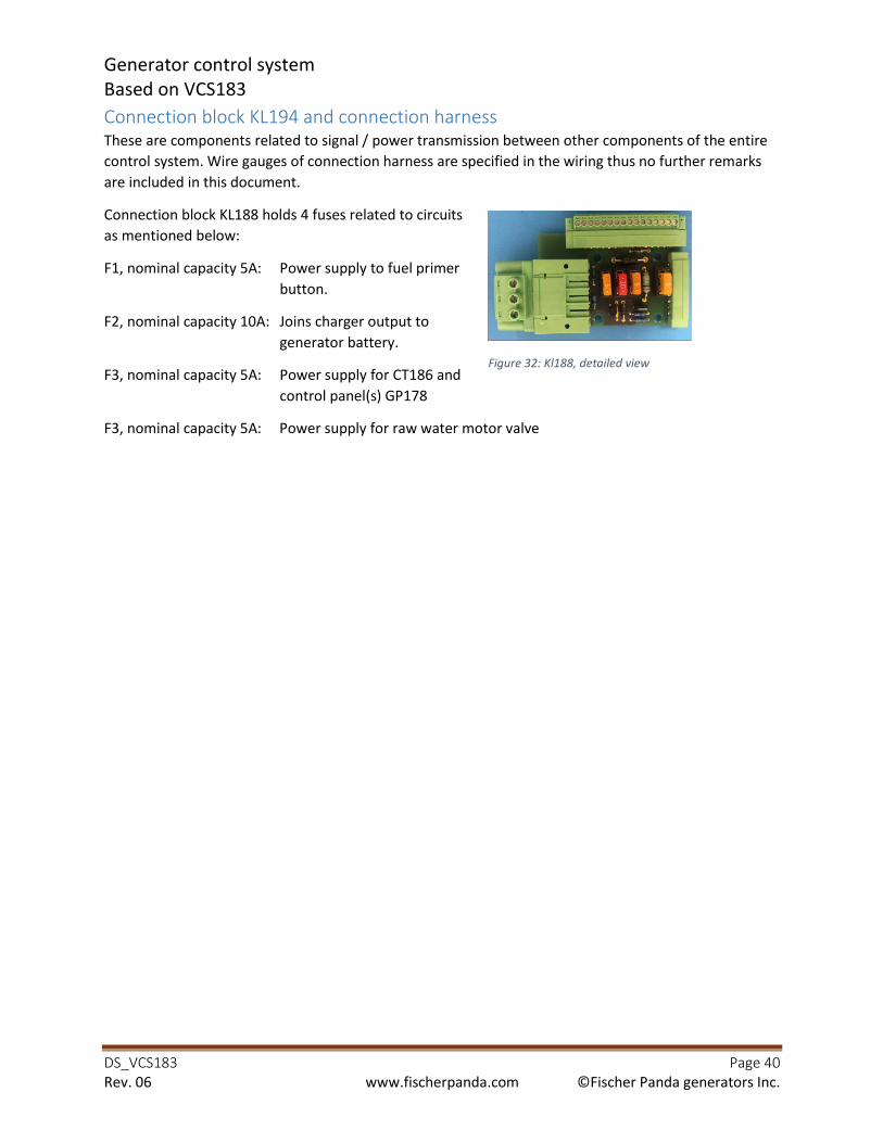
Generator control system
Based on VCS183
DS_VCS183 Page 40
Rev. 06 www.fischerpanda.com ©Fischer Panda generators Inc.
Connection block KL194 and connection harness These are components related to signal / power transmission between other components of the entire
control system. Wire gauges of connection harness are specified in the wiring thus no further remarks
are included in this document.
Connection block KL188 holds 4 fuses related to circuits
as mentioned below:
F1, nominal capacity 5A: Power supply to fuel primer
button.
F2, nominal capacity 10A: Joins charger output to
generator battery.
F3, nominal capacity 5A: Power supply for CT186 and
control panel(s) GP178
F3, nominal capacity 5A: Power supply for raw water motor valve
Figure 32: Kl188, detailed view
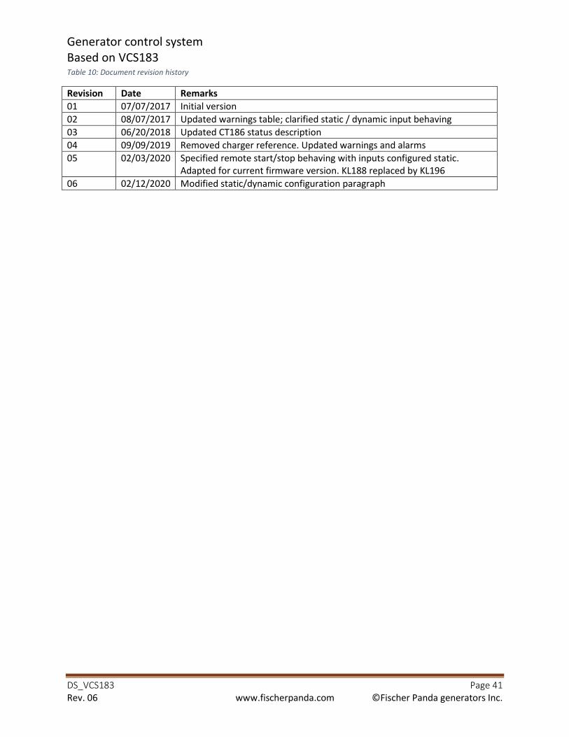
Generator control system
Based on VCS183
DS_VCS183 Page 41
Rev. 06 www.fischerpanda.com ©Fischer Panda generators Inc.
Table 10: Document revision history
Revision Date Remarks
01 07/07/2017 Initial version
02 08/07/2017 Updated warnings table; clarified static / dynamic input behaving
03 06/20/2018 Updated CT186 status description
04 09/09/2019 Removed charger reference. Updated warnings and alarms
05 02/03/2020 Specified remote start/stop behaving with inputs configured static.
Adapted for current firmware version. KL188 replaced by KL196
06 02/12/2020 Modified static/dynamic configuration paragraph