Embed Size (px)
Citation preview
Linearzylinder
Pneumatic Cylinder
Vérins pneumatiques
Maschinen-Elemente und Druck-Antriebe
MEDAN 2003_hz 10.09.2003 12:30 Uhr Seite U-1
Zu diesem KatalogDas Programm der MEDAN-Kolbenstangenlosen Zylinder wird ständig erweitert – der Katalog entspricht dem aktuellen Entwicklungsstand.In den Tabellen sind bereits Positionen der Baureihe PL50 eingearbeitet worden, da diese Zylindergröße als nächste Programmerweiterungansteht. Die hierbei angegebenen Maße entsprechen aber bereits der Realität.
Da die MEDAN GMBH ständig nach den modernsten Arbeitsmethoden fertigen, prüfen und verbessern läßt, behält sich diese zum Zweckeder Weiterentwicklung ausdrücklich das Recht auf Änderung vor.Die Veröffentlichung dieses Kataloges erfolgt ohne Gewähr für eventuelle Druckfehler oder Irrtümer. Mit Erscheinen dieses Kataloges verlie-ren alle bisherigen Kataloge ihre Gültigkeit.
About this catalogueThe program of the MEDAN cylinder is in a steady development – this catalogue is corresponding to the present developing situation.Some of the dimensions of PL50 are shown in the charts already since this cylinder is next to be launched into the market.The dimensions are to be seen as the actual ones by now.
MEDAN GMBH is committed to a very high standard of manufacturing, inspection, testing and improving. Therefore we reserve the right tomake occasional changes. The publishing of this catalogue goes along without any obligations in regards of any misprints or mistakes. Allprevious catalogues loose their legal validity.
Ce catalogueLa gamme de vérins sans tige „MEDAN“ se trouve en constante évolution.Ce catalogue reflète les nouvelles générations developpées. Ainsi, vous trouverez dans les tableaux les cotes principales des sériesPL50 qui seront livrables prochainement.
Comme la MEDAN GMBH fabrique, contrôle et améliore en permanence ses produits selon les procédés les plus modernes, elle se réserveexpressément le droit de changer de se produits afin de les faire évoluer.Ce catalogue annulé la validité des catalogues précédents.
© MEDAN GmbH, Auf der Bühl 6, 72658 Bempflingen. All rights Sept. 2003
Änderung und Irrtum auf allen Seiten vorbehalten / Alterations and errors reserved on all pages / Document non contractuel
Medan_hz04.qxd 10.09.2003 16:06 Uhr Seite U2
D
E
C
B
A
1
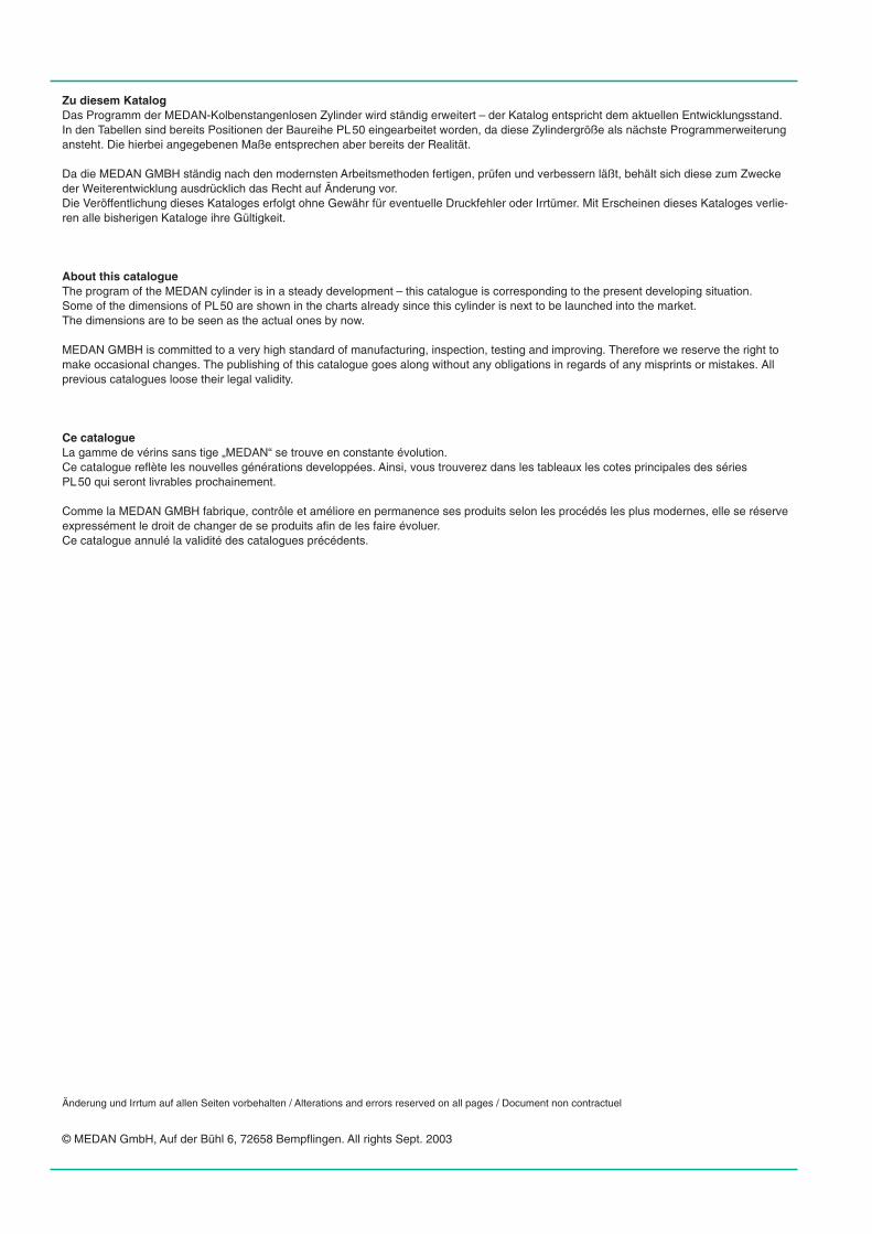
Inhaltsverzeichnis – Contents – Table des matieres
Druckluftzylinder – PL + PLF- kolbenstangenlos / Pneumatic cylinder – PL + PLF- rodless /
Vérin pneumatique – Série PL + PLF- sans tige
Vorstellung / Introduction / PrésentationTechnische Daten / Technical Datas / Caractéristiques techniquesZylinderbefestigungen / Cylinder mountings / Fixations
Lastbefestigungen / Load mountings / Portes-charges
Sensoren / Sensors / Détecteurs
Druckluftzylinder – DUO 96 / Pneumatic cylinder – DUO 96 / Vérin pneumatique – DUO 96
Vorstellung / Introduction / Présentation
Technische Daten / Technical Datas / Caractéristiques techniques
Zylinderbefestigungen / Cylinder mountings / Fixations
Gleitwagen-System – Gliding carriage-system – Système avec un chariot à patins
Technische Beschreibung / Technical description / Description technique
PLG
Linearführung – Linear Guide – Guidage linéaire
Technische Beschreibung / Technical description / Description technique
PLK
Bestellinformationen – Ordering instructions – Informations pour commander
Zubehör / Accessories / Accessoires
A
B
C
D
E
Medan_hz04.qxd 10.09.2003 16:06 Uhr Seite 1
Zylinderschnitt – Cylinder section – Construction
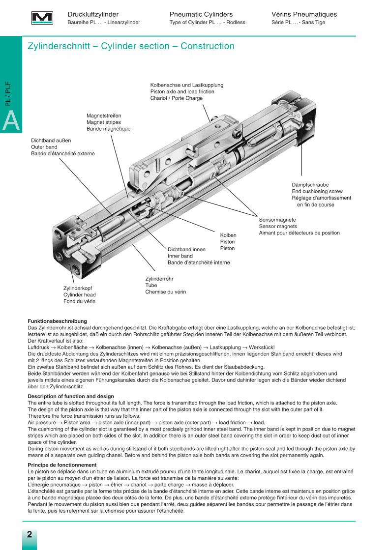
FunktionsbeschreibungDas Zylinderrohr ist achsial durchgehend geschlitzt. Die Kraftabgabe erfolgt über eine Lastkupplung, welche an der Kolbenachse befestigt ist;letztere ist so ausgebildet, daß ein durch den Rohrschlitz geführter Steg den inneren Teil der Kolbenachse mit dem äußeren Teil verbindet.Der Kraftverlauf ist also:Luftdruck → Kolbenfläche → Kolbenachse (innen) → Kolbenachse (außen) → Lastkupplung → Werkstück!Die druckfeste Abdichtung des Zylinderschlitzes wird mit einem präzisionsgeschliffenen, innen liegenden Stahlband erreicht; dieses wird mit 2 längs des Schlitzes verlaufenden Magnetstreifen in Position gehalten.Ein zweites Stahlband befindet sich außen auf dem Schlitz des Rohres. Es dient der Staubabdeckung.Beide Stahlbänder werden während der Kolbenfahrt genauso wie bei Stillstand hinter der Kolbendichtung vom Schlitz abgehoben undjeweils mittels eines eigenen Führungskanales durch die Kolbenachse geleitet. Davor und dahinter legen sich die Bänder wieder dichtendüber den Zylinderschlitz.
Description of function and designThe entire tube is slotted throughout its full length. The force is transmitted through the load friction, which is attached to the piston axle. The design of the piston axle is that way that the inner part of the piston axle is connected through the slot with the outer part of it.Therefore the force transmission runs as follows:Air pressure → Piston area → piston axle (inner part) → piston axle (outer part) → load friction → load.The cushioning of the cylinder slot is garanteed by a most precisely grinded inner steel band. The inner band is kept in position due to magnetstripes which are placed on both sides of the slot. In addition there is an outer steel band covering the slot in order to keep dust out of innerspace of the cylinder.During piston movement as well as during stillstand of it both steelbands are lifted right after the piston seal and led through the piston axle bymeans of a separate own guiding chanel. Before and behind the piston axle both bands are covering the slot permanently again.
Principe de fonctionnementLe piston se déplace dans un tube en aluminium extrudé pourvu d’une fente longitudinale. Le chariot, auquel est fixée la charge, est entraînépar le piston au moyen d’un étrier de liaison. La force est transmise de la manière suivante:L’énergie pneumatique → piston → étrier → chariot → porte charge → masse à déplacer.L’étanchéité est garantie par la forme très précise de la bande d’étanchéité interne en acier. Cette bande interne est maintenue en position grâceà une bande magnétique placée des deux côtés de la fente. De plus, une bande d’étanchéité externe protège l’intérieur du vérin des impuretés.Pendant le mouvement du piston aussi bien que pendant l’arrêt, deux guides séparent les bandes pour permettre le passage de l’étrier dansla fente, puis les referment sur la chemise pour assurer l’étanchéité.
22
Kolbenachse und LastkupplungPiston axle and load frictionChariot / Porte Charge
MagnetstreifenMagnet stripesBande magnétique
Dichtband außenOuter bandBande d’étanchéité externe
ZylinderkopfCylinder headFond du vérin
Dichtband innenInner bandBande d’étanchéité interne
SensormagneteSensor magnetsAimant pour détecteurs de position
DämpfschraubeEnd cushioning screwRéglage d’amortissement
en fin de course
KolbenPistonPiston
ZylinderrohrTubeChemise du vérin
Druckluftzylinder Pneumatic Cylinders Vérins PneumatiquesBaureihe PL … - Linearzylinder Type of Cylinder PL … - Rodless Série PL …- Sans Tige
A
PL
/ PLF
Medan_hz04.qxd 10.09.2003 16:07 Uhr Seite 2
3
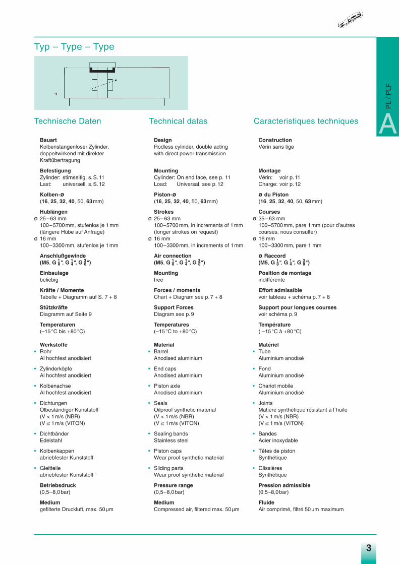
Technische Daten
BauartKolbenstangenloser Zylinder, doppeltwirkend mit direkter Kraftübertragung
BefestigungZylinder: stirnseitig, s.S.11Last: universell, s.S.12
Kolben-ø(16, 25, 32, 40, 50, 63mm)
Hublängenø 25– 63 mm
100–5700mm, stufenlos je 1mm(längere Hübe auf Anfrage)
ø 16 mm100–3300mm, stufenlos je 1mm
Anschlußgewinde(M5, G 1
8", G 14", G 3
8")
Einbaulagebeliebig
Kräfte / MomenteTabelle + Diagramm auf S. 7 + 8
StützkräfteDiagramm auf Seite 9
Temperaturen(–15°C bis +80°C)
Werkstoffe• Rohr
Al hochfest anodisiert
• ZylinderköpfeAl hochfest anodisiert
• KolbenachseAl hochfest anodisiert
• DichtungenÖlbeständiger Kunststoff(V < 1m/s (NBR)(V p 1m/s (VITON)
• DichtbänderEdelstahl
• Kolbenkappenabriebfester Kunststoff
• Gleitteileabriebfester Kunststoff
Betriebsdruck(0,5–8,0bar)
Mediumgefilterte Druckluft, max. 50µm
Technical datas
DesignRodless cylinder, double acting with direct power transmission
MountingCylinder: On end face, see p. 11Load: Universal, see p.12
Piston-ø(16, 25, 32, 40, 50, 63mm)
Strokesø 25– 63 mm
100–5700mm, in increments of 1mm(longer strokes on request)
ø 16 mm100–3300mm, in increments of 1mm
Air connection(M5, G 1
8", G 14", G 3
8")
Mountingfree
Forces / momentsChart + Diagram see p.7 + 8
Support ForcesDiagram see p.9
Temperatures(–15°C to +80°C)
Material• Barrel
Anodised aluminium
• End capsAnodised aluminium
• Piston axleAnodised aluminium
• SealsOilproof synthetic material(V < 1m/s (NBR)(V p 1m/s (VITON)
• Sealing bandsStainless steel
• Piston capsWear proof synthetic material
• Sliding partsWear proof synthetic material
Pressure range(0,5–8,0bar)
MediumCompressed air, filtered max. 50µm
Caracteristiques techniques
ConstructionVérin sans tige
MontageVérin: voir p.11Charge: voir p.12
ø du Piston(16, 25, 32, 40, 50, 63mm)
Coursesø 25– 63 mm
100–5700mm, pare 1mm (pour d’autrescourses, nous consulter)
ø 16 mm100–3300mm, pare 1 mm
ø Raccord(M5, G 1
8", G 14", G 3
8")
Position de montageindifférente
Effort admissiblevoir tableau + schéma p.7 + 8
Support pour longues coursesvoir schéma p.9
Température( –15°C à +80°C)
Matériel• Tube
Aluminium anodisé
• FondAluminium anodisé
• Chariot mobileAluminium anodisé
• JointsMatière synthétique résistant à l`huile(V < 1m/s (NBR)(V p 1m/s (VITON)
• BandesAcier inoxydable
• Têtes de pistonSynthétique
• GlissièresSynthétique
Pression admissible(0,5–8,0bar)
FluideAir comprimé, filtré 50µm maximum
Typ – Type – Type
A
PL
/ PLF
Medan_hz04.qxd 10.09.2003 16:07 Uhr Seite 3
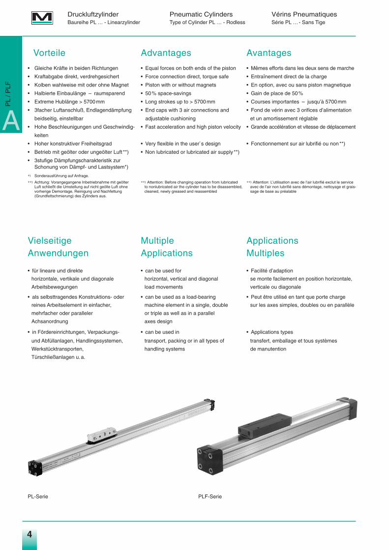
Vorteile Advantages Avantages
• Gleiche Kräfte in beiden Richtungen • Equal forces on both ends of the piston • Mêmes efforts dans les deux sens de marche
• Kraftabgabe direkt, verdrehgesichert • Force connection direct, torque safe • Entraînement direct de la charge
• Kolben wahlweise mit oder ohne Magnet • Piston with or without magnets • En option, avec ou sans piston magnetique
• Halbierte Einbaulänge – raumsparend • 50% space-savings • Gain de place de 50%
• Extreme Hublänge > 5700mm • Long strokes up to > 5700mm • Courses importantes – jusqu’à 5700mm
• 3facher Luftanschluß, Endlagendämpfung • End caps with 3 air connections and • Fond de vérin avec 3 orifices d’alimentation
beidseitig, einstellbar adjustable cushioning et un amortissement réglable
• Hohe Beschleunigungen und Geschwindig- • Fast acceleration and high piston velocity • Grande accélération et vitesse de déplacement
keiten
• Hoher konstruktiver Freiheitsgrad • Very flexible in the user`s design • Fonctionnement sur air lubrifié ou non**)
• Betrieb mit geölter oder ungeölter Luft **) • Non lubricated or lubricated air supply **)
• 3stufige Dämpfungscharakteristik zur Schonung von Dämpf- und Lastsystem*)
∗) Sonderausführung auf Anfrage.
∗∗) Achtung: Vorangegangene Inbetriebnahme mit geölter ∗∗) Attention: Before changing operation from lubricated ∗∗) Attention: L’utilisation avec de l’air lubrifié exclut le service Luft schließt die Umstellung auf nicht geölte Luft ohne to nonlubricated air the cylinder has to be disassembled, avec de l’air non lubrifié sans démontage, nettoyage et grais-vorherige Demontage, Reinigung und Nachfettung cleaned, newly greased and reassembled sage de base au préalable(Grundfettschmierung) des Zylinders aus.
Vielseitige Multiple ApplicationsAnwendungen Applications Multiples
• für lineare und direkte • can be used for • Facilité d’adaption
horizontale, vertikale und diagonale horizontal, vertical and diagonal se monte facilement en position horizontale,
Arbeitsbewegungen load movements verticale ou diagonale
• als selbsttragendes Konstruktions- oder • can be used as a load-bearing • Peut être utilisé en tant que porte charge
reines Arbeitselement in einfacher, machine element in a single, double sur les axes simples, doubles ou en parallèle
mehrfacher oder paralleler or triple as well as in a parallel
Achsanordnung axes design
• in Fördereinrichtungen, Verpackungs- • can be used in • Applications types
und Abfüllanlagen, Handlingssystemen, transport, packing or in all types of transfert, emballage et tous systèmes
Werkstücktransporten, handling systems de manutention
Türschließanlagen u.a.
44
Druckluftzylinder Pneumatic Cylinders Vérins PneumatiquesBaureihe PL … - Linearzylinder Type of Cylinder PL … - Rodless Série PL …- Sans Tige
A
PL
/ PLF
PLF-SeriePL-Serie
Medan_hz04.qxd 10.09.2003 16:07 Uhr Seite 4
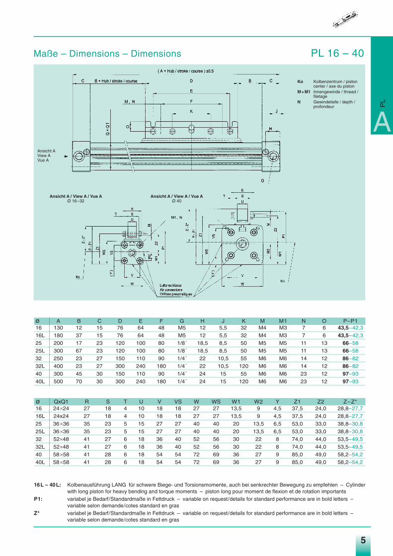
Maße – Dimensions – Dimensions PL 16 – 40
5
Ko Kolbenzentrum / pistoncenter / axe du piston
M+M1 Innengewinde / thread /filetage
N Gewindetiefe / depth /profondeur
Ansicht A / View A / Vue AØ 16–32
Ansicht A / View A / Vue AØ 40
A
PL
Ansicht AView AVue A
ø A B C D E F G H J K M M1 N O P–P116 130 12 15 76 64 48 M5 12 5,5 32 M4 M3 7 6 43,5–42,3
16L 180 37 15 76 64 48 M5 12 5,5 32 M4 M3 7 6 43,5–42,3
25 200 17 23 120 100 80 1/8´ 18,5 8,5 50 M5 M5 11 13 66–58
25L 300 67 23 120 100 80 1/8´ 18,5 8,5 50 M5 M5 11 13 66–58
32 250 23 27 150 110 90 1/4´ 22 10,5 55 M6 M6 14 12 86–82
32L 400 23 27 300 240 180 1/4´ 22 10,5 120 M6 M6 14 12 86–82
40 300 45 30 150 110 90 1/4´ 24 15 55 M6 M6 23 12 97–93
40L 500 70 30 300 240 180 1/4´ 24 15 120 M6 M6 23 12 97–93
ø QxQ1 R S T U V VS W WS W1 W2 Y Z1 Z2 Z–Z*16 24q24 27 18 4 10 18 18 27 27 13,5 9 4,5 37,5 24,0 28,8–27,716L 24x24 27 18 4 10 18 18 27 27 13,5 9 4,5 37,5 24,0 28,8–27,725 36q36 35 23 5 15 27 27 40 40 20 13,5 6,5 53,0 33,0 38,8–30,825L 36q36 35 23 5 15 27 27 40 40 20 13,5 6,5 53,0 33,0 38,8–30,832 52q48 41 27 6 18 36 40 52 56 30 22 8 74,0 44,0 53,5–49,532L 52q48 41 27 6 18 36 40 52 56 30 22 8 74,0 44,0 53,5–49,540 58q58 41 28 6 18 54 54 72 69 36 27 9 85,0 49,0 58,2–54,240L 58q58 41 28 6 18 54 54 72 69 36 27 9 85,0 49,0 58,2–54,2
16L – 40L: Kolbenausführung LANG für schwere Biege- und Torsionsmomente, auch bei senkrechter Bewegung zu empfehlen – Cylinderwith long piston for heavy bending and torque moments – piston long pour moment de flexion et de rotation importants
P1: variabel je Bedarf/Standardmaße in Fettdruck – variable on request/details for standard performance are in bold letters –variable selon demande/cotes standard en gras
Z* variabel je Bedarf/Standardmaße in Fettdruck – variable on request/details for standard performance are in bold letters –variable selon demande/cotes standard en gras
Medan_hz04.qxd 10.09.2003 16:07 Uhr Seite 5
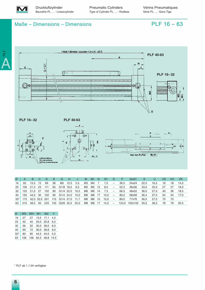
Ø A B C D E G H J M M1 N N1 O P QxQ1 S U VS VH VK
16 65 15,5 15 69 36 M5 12,0 5,5 M3 M4 7 7,0 – 36,5 24x24 22,0 16,5 18 18 14,0
25 100 21,5 23 111 65 G1/8 18,5 8,5 M5 M5 12 8,0 – 52,5 36x36 33,0 25,0 27 27 19,0
32 125 21,0 27 152 90 G1/4 22,0 10,5 M6 M6 14 7,5 – 66,5 48x52 36,0 27,0 40 36 18,5
40 150 44,0 30 152 90 G1/4 24,0 15,0 M6 M6 17 10,0 – 80,0 58x58 36,4 27,0 54 54 17,0
50* 175 42,0 33,0 201 110 G1/4 27,0 11,7 M6 M6 15 10,0 – 89,0 77x76 56,0 27,0 70 70
63 215 48,5 50 233 155 G3/8 42,5 25,0 M8 M8 17 14,0 – 123,0 102x102 50,0 36,0 78 78 30,5
Druckluftzylinder Pneumatic Cylinders Vérins PneumatiquesBaureihe PL … - Linearzylinder Type of Cylinder PL … - Rodless Série PL …- Sans Tige
6
Maße – Dimensions – Dimensions PLF 16 – 63
A
PLF
PLF 16– 32
PLF 40-63
PLF 16– 32 PLF 40-63
Ø WS WH W1 W2 Y
16 27 27 13,5 17,1 4,5
25 40 40 20,0 25,8 6,5
32 56 52 30,0 39,0 8,0
40 69 72 36,0 48,8 9,0
50* 80 80 44,5 44,5 5,0
63 106 106 62,5 48,8 14,5
* PLF ab 1.1.04 verfügbar
Medan_hz04.qxd 10.09.2003 16:07 Uhr Seite 6
7
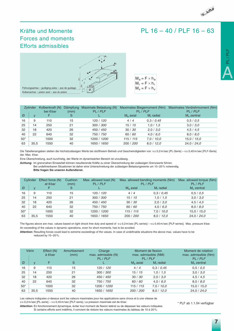
Ma = F q haMr = F q hrMv = F q hv
A
Kräfte und Momente PL 16 – 40 / PLF 16 – 63Forces and momentsEfforts admissibles
PL
/ PLF
Führungsachse – guidiging axles – axe de guidage
Kolbenachse – piston axel – axe du piston
Zylinder Kolbenkraft (N) Dämpfung Maximale Belastung (N) Maximales Biegemoment (Nm) Maximales Verdrehmoment (Nm)bei 6bar (mm) PL / PLF PL / PLF PL / PLF
Ø y F S L Ma axial Mr radial Mv zentral
16 9 110 15 120 / 120 4 / 4 0,3 / 0,45 0,5 / 0,5
25 14 250 21 300 / 300 15 / 15 1,0 / 1,5 3,0 / 3,0
32 18 420 26 450 / 450 30 / 30 2,0 / 3,0 4,5 / 4,5
40 22 640 32 750 / 750 60 / 60 4,0 / 6,0 8,0 / 8,0
50* 1000 32 1200 / 1200 115 / 115 7,0 / 10,0 15,0 / 15,0
63 35,5 1550 40 1650 / 1650 200 / 200 8,0 / 12,0 24,0 / 24,0
Die Tabellenangaben stellen die höchstzulässigen Werte bei stoßfreiem Betrieb und Geschwindigkeiten von vP 0,2m/sec [PL-Serie] – vP 0,45m/sec [PLF-Serie]dar. Max. 6bar.
Eine Überschreitung, auch kurzfristig, der Werte im dynamisierten Bereich ist unzulässig.
Achtung: Im grenznahen Einsatzfall können resultierende Kräfte zu einer Überschreitung der zulässigen Grenzwerte führen.Bei undefinierbaren Situationen ist daher eine Unterschreitung der zulässigen Belastungswerte um 10–20% notwendig.Bitte fragen Sie unseren Außendienst.
Vérin Effect (N) Amortissment Charge Moment de flexion Moment de rotationà 6bar (mm) max. admissble (N) max. admissible (NM) max. admissible (Nm)
PL / PLF PL / PLF PL / PLFØ y F S L Ma axial Mr radial Mv zentral
16 9 110 15 120 / 120 4 / 4 0,3 / 0,45 0,5 / 0,5
25 14 250 21 300 / 300 15 / 15 1,0 / 1,5 3,0 / 3,0
32 18 420 26 450 / 450 30 / 30 2,0 / 3,0 4,5 / 4,5
40 22 640 32 750 / 750 60 / 60 4,0 / 6,0 8,0 / 8,0
50* 1000 32 1200 / 1200 115 / 115 7,0 / 10,0 15,0 / 15,0
63 35,5 1550 40 1650 / 1650 200 / 200 8,0 / 12,0 24,0 / 24,0
Les valeurs indiquées ci-dessus sont les valeurs maximales pour les applications sans chocs et à une vitesse de vP 0,2m/sec [PL-serie] – vP 0,45m/sec [PLF-serie]. La pression maximale est de 6bar.
Attention: En fonctionnement dynamique, éviter tout moment de flexion latéral ou de dépasser les valeurs indiquées.Si certains efforts sont indéfinis, il convient de réduire les valeurs maximales du tableau de 10 à 20%.
Cylinder Effect force (N) Cushion Max. allowed load (N) Max. allowed bending moments (Nm) Max. allowed torque (Nm)at 6bar (mm) PL / PLF PL / PLF PL / PLF
Ø y F S L Ma axial Mr radial Mv zentral
16 9 110 15 120 / 120 4 / 4 0,3 / 0,45 0,5 / 0,5
25 14 250 21 300 / 300 15 / 15 1,0 / 1,5 3,0 / 3,0
32 18 420 26 450 / 450 30 / 30 2,0 / 3,0 4,5 / 4,5
40 22 640 32 750 / 750 60 / 60 4,0 / 6,0 8,0 / 8,0
50* 1000 32 1200 / 1200 115 / 115 7,0 / 10,0 15,0 / 15,0
63 35,5 1550 40 1650 / 1650 200 / 200 8,0 / 12,0 24,0 / 24,0
The figures above are max. values based on light shock free duty and speed of vP 0,2m/sec [PL-series] – vP 0,45m/sec [PLF-series]. Max. pressure 6bar.
An exceeding of the values in dynamic operations, even for short moments, has to be avoided.
Attention: Resulting forces could lead to extreme exceedings of the values. In case of undefinable situations the above max. values have to be reduced by 10–20%.
* PLF ab 1.1.04 verfügbar
Medan_hz04.qxd 10.09.2003 16:07 Uhr Seite 7
88
Druckluftzylinder Pneumatic Cylinders Vérins PneumatiquesBaureihe PL … - Linearzylinder Type of Cylinder PL … - Rodless Série PL …- Sans Tige
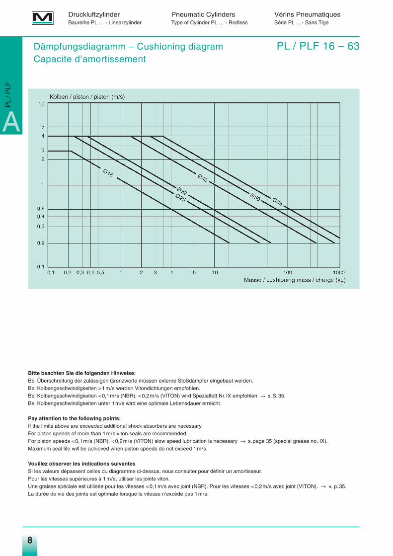
Bitte beachten Sie die folgenden Hinweise:Bei Überschreitung der zulässigen Grenzwerte müssen externe Stoßdämpfer eingebaut werden.Bei Kolbengeschwindigkeiten >1m/s werden Vitondichtungen empfohlen.Bei Kolbengeschwindigkeiten <0,1m/s (NBR), <0,2m/s (VITON) wird Spezialfett Nr. IX empfohlen → s.S.35.Bei Kolbengeschwindigkeiten unter 1m/s wird eine optimale Lebensdauer erreicht.
Pay attention to the following points:If the limits above are exceeded additional shock absorbers are necessary.For piston speeds of more than 1m/s viton seals are recommended.For piston speeds <0,1m/s (NBR), <0,2m/s (VITON) slow speed lubrication is necessary → s.page 35 (special grease no. IX).Maximum seal life will be achieved when piston speeds do not exceed 1m/s.
Vouillez observer les indications suivantesSi les valeurs dépassent celles du diagramme ci-dessus, nous consulter pour définir un amortisseur.Pour les vitesses supérieures à 1m/s, utiliser les joints viton.Une graisse spéciale est utilisée pour les vitesses <0,1m/s avec joint (NBR). Pour les vitesses <0,2m/s avec joint (VITON). → v. p.35.La durée de vie des joints est optimale lorsque la vitesse n’excède pas 1m/s.
Dämpfungsdiagramm – Cushioning diagram PL / PLF 16 – 63Capacite d’amortissement
A
PL
/ PLF
Medan_hz04.qxd 10.09.2003 16:08 Uhr Seite 8
9
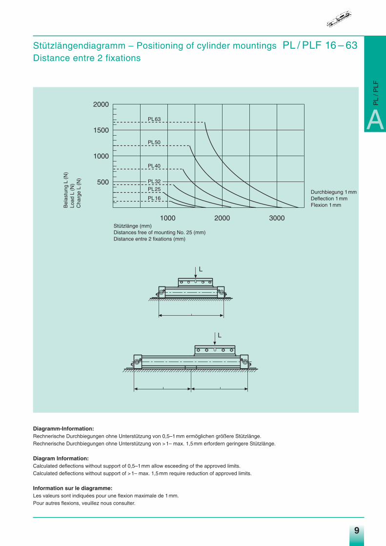
Stützlängendiagramm – Positioning of cylinder mountings PL / PLF 16 – 63Distance entre 2 fixations
Diagramm-Information:Rechnerische Durchbiegungen ohne Unterstützung von 0,5–1mm ermöglichen größere Stützlänge.Rechnerische Durchbiegungen ohne Unterstützung von >1– max. 1,5mm erfordern geringere Stützlänge.
Diagram Information:Calculated deflections without support of 0,5–1mm allow esceeding of the approved limits.Calculated deflections without support of >1– max. 1,5mm require reduction of approved limits.
Information sur le diagramme:Les valeurs sont indiquées pour une flexion maximale de 1mm.Pour autres flexions, veuillez nous consulter.
500
1000
1500
2000
1000 2000 3000
PL16
PL25
PL32
PL40
PL50
PL63
L
L
Stützlänge (mm)Distances free of mounting No. 25 (mm)Distance entre 2 fixations (mm)
Durchbiegung 1mmDeflection 1mmFlexion 1mmB
elas
tung
L(N
)Lo
ad L
(N)
Cha
rge
L(N
)
A
PL
/ PLF
Medan_hz04.qxd 10.09.2003 16:08 Uhr Seite 9
10
Druckluftzylinder Pneumatic Cylinders Vérins PneumatiquesBaureihe PL … - Linearzylinder Type of Cylinder PL … - Rodless Série PL …- Sans Tige
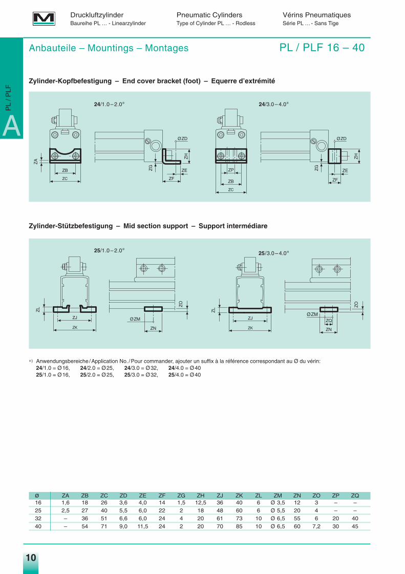
Anbauteile – Mountings – Montages PL / PLF 16 – 40
Zylinder-Kopfbefestigung – End cover bracket (foot) – Equerre d’extrémité
Zylinder-Stützbefestigung – Mid section support – Support intermédiare
∗) Anwendungsbereiche /Application No. /Pour commander, ajouter un suffix à la référence correspondant au Ø du vérin:24/1.0 = Ø16, 24/2.0 = Ø25, 24/3.0 = Ø32, 24/4.0 = Ø4025/1.0 = Ø16, 25/2.0 = Ø25, 25/3.0 = Ø32, 25/4.0 = Ø40
ø ZA ZB ZC ZD ZE ZF ZG ZH ZJ ZK ZL ZM ZN ZO ZP ZQ16 1,6 18 26 3,6 4,0 14 1,5 12,5 36 40 6 Ø 3,5 12 3 – –25 2,5 27 40 5,5 6,0 22 2 18 48 60 6 Ø 5,5 20 4 – –32 – 36 51 6,6 6,0 24 4 20 61 73 10 Ø 6,5 55 6 20 4040 – 54 71 9,0 11,5 24 2 20 70 85 10 Ø 6,5 60 7,2 30 45
ZC
ZB
ZA Z
H
ØZD
ZF
ZEZG
ZC
ZB
ZP
ZH
ØZD
ZF
ZEZG
ØZM
ZN
ZO
ZK
ZJ
ZL
ZK
ZJ
ZL
ØZM
ZN
ZO
ZQ
24/1.0 – 2.0∗ 24/3.0 – 4.0∗
25/3.0 – 4.0∗25/1.0 – 2.0∗
A
PL
/ PLF
Medan_hz04.qxd 10.09.2003 16:08 Uhr Seite 10
11
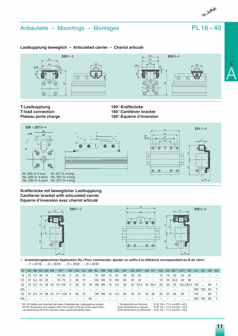
Anbauteile – Mountings – Montages PL 16 – 40
Lastkupplung beweglich – Articulated carrier – Chariot articulé
T-Lastkupplung 180°-KraftbrückeT-load connection 180°-Cantilever bracketPlateau porte charge 180°-Equerre d’inversion
Kraftbrücke mit beweglicher LastkupplungCantilever bracket with articulated carrierEquerre d’inversion avec chariot articulé
∗) Anwendungsbereiche /Application No. /Pour commander, ajouter un suffix à la référence correspondant au Ø du vérin:. . . /1 = Ø16; . . . /2 = Ø25; . . . /3 = Ø32; . . . /4 = Ø40
Ø KA KB KC KD KE KF* KG KH KJ KK KL KM KN KO KP KQ KR** KS KT KU KV KX** KY** KZ K1 K2 K3 K4
16 25 4,5 28 13 – 47–50 2 20 10 – 76 M4 10 64 48 32 30 – – 16 18 29 33 25 – – – –
25 37 5,5 42 20 – 72–75 3 30 16 – 120 M5 12 100 80 50 44 – – 19 24 43,5 50 36 – – – –
32 70 6,5 70 38 55 91–100 5 90 75 76 138 M6 16 110 90 55 53,5 45 58,5 20 33 93 102,3 80,5 150 – 80 7
32L – – – – – – – – – – – – – – – – – – – – – – – – 300 160 80 7
40 70 6,5 70 38 55 111–120 5 90 75 – 138 M6 16 110 90 55 61 45 66 20 37 83 90 – 150 – 80 7
40L – – – – – – – – – 60 – – – – – – – – – – – – – – 300 160 80 7
* KF-/KY-Maße sind innerhalb der freien Gabeltiefe der Lastkupplung variabel.KF/KY dimensions are variable within the length of the slot of the load friction.Les dimensions KF et KY peuvent varier suivant demande client.
KA
KC
ØKB
KD
KG
KF
KHKJ
KHKJ
KA
KC
∅KB
KD
KG
KF
KE
KU
KX
KR
KV
KL
KO
KP
KQ
KMKN tief
��
��
��
��
��
��
� � ��
��
��
��
��
225/1–2
226 + 227/3–4
225/3–4
231/1–4
235/1–2 235/3–4
A
PL
Nr. 226 /3–4 kurz Nr. 227 /3–4 langNo. 226 /3–4 short No. 227 /3–4 longNo. 226 /3–4 court No. 227 /3–4 long
** Sondermaße auf Wunsch Ø 32: KX = 71,5 und KR = 49,5Extra dimensions on request Ø 32: KX = 71,5 und KR = 49,5Extra dimensions sur démande Ø 32: KX = 71,5 und KR = 49,5
Medan_hz04.qxd 10.09.2003 16:08 Uhr Seite 11
12
Druckluftzylinder Pneumatic Cylinders Vérins PneumatiquesBaureihe PL … - Linearzylinder Type of Cylinder PL … - Rodless Série PL …- Sans Tige
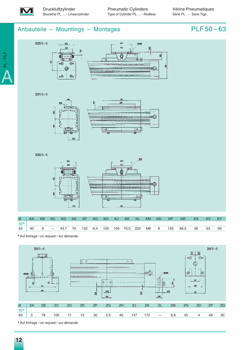
Anbauteile – Mountings – Montages PLF 50 – 63
225/5–6
25/5–6 24/5–6
231/5–6
235/5–6
ø KA KB KC KD KE KF KG KH KJ KK KL KM KN KP KR KS KV KY
50*63 90 9 – 43.7 70 152 6,4 120 100 70,5 220 M8 8 155 86,5 36 63 99
* Auf Anfrage / on request / sur démande
ø ZA ZB ZC ZD ZE ZF ZG ZH ZJ ZK ZL ZM ZN ZO ZP ZQ
50*63 5 78 105 11 15 30 2,5 40 147 172 — 6,6 45 4 48 30
* Auf Anfrage / on request / sur démande
A
PL
/ PLF
Medan_hz04.qxd 10.09.2003 16:08 Uhr Seite 12
13
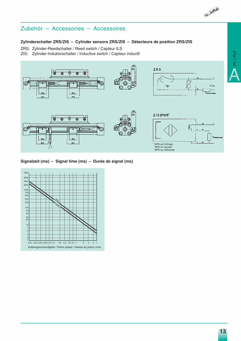
Zubehör – Accessories – Accessoires
Zylinderschalter ZRS/ZIS – Cylinder sensors ZRS/ZIS – Détecteurs de position ZRS/ZIS
ZRS: Zylinder-Reedschalter / Reed switch / Capteur ILSZIS: Zylinder-Induktivschalter / Inductive switch / Capteur inductif
Signalzeit (ms) – Signal time (ms) – Durée de signal (ms)
ZRSZIS
Kolbengeschwindigkeit / Piston speed / Vitesse du piston (m/s)
0,01 0,02 0,03 0,05 0,07 0,1 0,2 0,3 0,5 0,7 1 2 3 5 712
3
57
10
2030
5070
100
200
300
500750
1000
2000
3000
5000
7000
A
PL
/ PLF
* NPN auf AnfrageNPN on requestNPN sur démande
Medan_hz04.qxd 10.09.2003 16:08 Uhr Seite 13
14
Druckluftzylinder Pneumatic Cylinders Vérins PneumatiquesBaureihe PL … - Linearzylinder Type of Cylinder PL … - Rodless Série PL …- Sans Tige
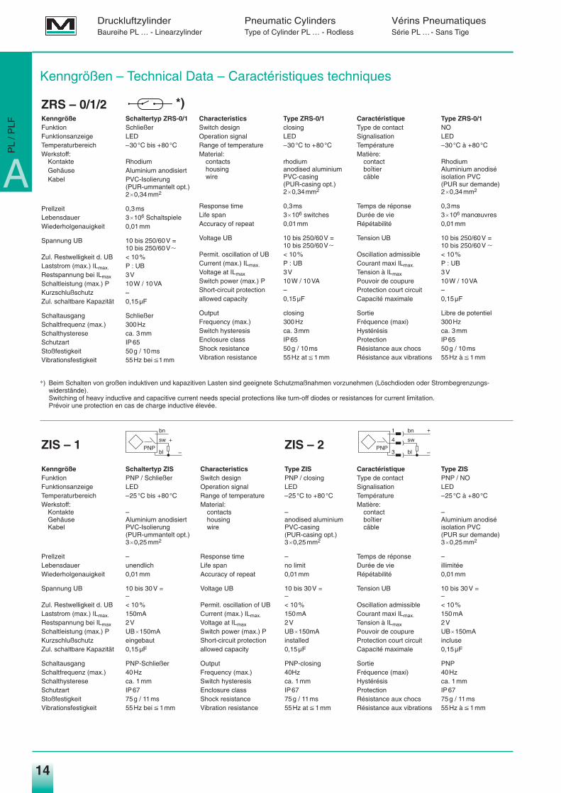
Kenngröße Schaltertyp ZRS-0/1Funktion SchließerFunktionsanzeige LEDTemperaturbereich –30°C bis +80°CWerkstoff:
Kontakte RhodiumGehäuse Aluminium anodisiertKabel PVC-Isolierung
(PUR-ummantelt opt.)2q0,34mm2
Prellzeit 0,3msLebensdauer 3q106 SchaltspieleWiederholgenauigkeit 0,01mm
Spannung UB 10 bis 250/60V =10 bis 250/60VZ
Zul. Restwelligkeit d. UB < 10%Laststrom (max.) ILmax. P : UBRestspannung bei ILmax 3VSchaltleistung (max.) P 10W / 10VAKurzschlußschutz –Zul. schaltbare Kapazität 0,15µF
Schaltausgang SchließerSchaltfrequenz (max.) 300HzSchalthysterese ca. 3mmSchutzart IP65Stoßfestigkeit 50g / 10msVibrationsfestigkeit 55Hz bei P1mm
Kenngrößen – Technical Data – Caractéristiques techniques
Characteristics Type ZRS-0/1Switch design closingOperation signal LEDRange of temperature –30°C to +80°CMaterial:
contacts rhodiumhousing anodised aluminiumwire PVC-casing
(PUR-casing opt.)2q0,34mm2
Response time 0,3msLife span 3q106 switchesAccuracy of repeat 0,01mm
Voltage UB 10 bis 250/60V =10 bis 250/60VZ
Permit. oscillation of UB < 10%Current (max.) ILmax. P : UBVoltage at ILmax 3VSwitch power (max.) P 10W / 10VAShort-circuit protection –allowed capacity 0,15µF
Output closingFrequency (max.) 300HzSwitch hysteresis ca. 3mmEnclosure class IP65Shock resistance 50g / 10msVibration resistance 55Hz at P 1mm
Caractéristique Type ZRS-0/1Type de contact NOSignalisation LEDTempérature –30°C à +80°CMatière:
contact Rhodiumboîtier Aluminium anodisécâble isolation PVC
(PUR sur demande)2q0,34mm2
Temps de réponse 0,3msDurée de vie 3q106 manœuvresRépétabilité 0,01mm
Tension UB 10 bis 250/60V =10 bis 250/60V Z
Oscillation admissible < 10%Courant maxi ILmax. P : UBTension à ILmax 3VPouvoir de coupure 10W / 10VAProtection court circuit –Capacité maximale 0,15µF
Sortie Libre de potentielFréquence (maxi) 300HzHystérésis ca. 3mmProtection IP65Résistance aux chocs 50g / 10msRésistance aux vibrations 55Hz à P 1mm
Kenngröße Schaltertyp ZISFunktion PNP / SchließerFunktionsanzeige LEDTemperaturbereich –25°C bis +80°CWerkstoff:
Kontakte –Gehäuse Aluminium anodisiertKabel PVC-Isolierung
(PUR-ummantelt opt.)3q0,25mm2
Prellzeit –Lebensdauer unendlichWiederholgenauigkeit 0,01mm
Spannung UB 10 bis 30V =–
Zul. Restwelligkeit d. UB < 10%Laststrom (max.) ILmax. 150mARestspannung bei ILmax 2VSchaltleistung (max.) P UBq150mAKurzschlußschutz eingebautZul. schaltbare Kapazität 0,15µF
Schaltausgang PNP-SchließerSchaltfrequenz (max.) 40HzSchalthysterese ca. 1mmSchutzart IP67Stoßfestigkeit 75g / 11msVibrationsfestigkeit 55Hz bei P 1mm
Characteristics Type ZISSwitch design PNP / closingOperation signal LEDRange of temperature –25°C to +80°CMaterial:
contacts –housing anodised aluminiumwire PVC-casing
(PUR-casing opt.)3q0,25mm2
Response time –Life span no limitAccuracy of repeat 0,01mm
Voltage UB 10 bis 30V =–
Permit. oscillation of UB < 10%Current (max.) ILmax. 150mAVoltage at ILmax 2VSwitch power (max.) P UBq150mAShort-circuit protection installedallowed capacity 0,15µF
Output PNP-closingFrequency (max.) 40HzSwitch hysteresis ca. 1mmEnclosure class IP67Shock resistance 75g / 11msVibration resistance 55Hz at P 1mm
Caractéristique Type ZISType de contact PNP / NOSignalisation LEDTempérature –25°C à +80°CMatière:
contact –boîtier Aluminium anodisécâble isolation PVC
(PUR sur demande)3q0,25mm2
Temps de réponse –Durée de vie illimitéeRépétabilité 0,01mm
Tension UB 10 bis 30V =–
Oscillation admissible < 10%Courant maxi ILmax. 150mATension à ILmax 2VPouvoir de coupure UBq150mAProtection court circuit incluseCapacité maximale 0,15µF
Sortie PNPFréquence (maxi) 40HzHystérésis ca. 1mmProtection IP67Résistance aux chocs 75g / 11msRésistance aux vibrations 55Hz à P 1mm
∗) Beim Schalten von großen induktiven und kapazitiven Lasten sind geeignete Schutzmaßnahmen vorzunehmen (Löschdioden oder Strombegrenzungs-widerstände).Switching of heavy inductive and capacitive current needs special protections like turn-off diodes or resistances for current limitation.Prévoir une protection en cas de charge inductive élevée.
A
PL
/ PLF
ZRS – 0/1/2
ZIS – 1 ZIS – 2
*)
PNPsw
bn
+
–blPNP
sw
bn)
)
)
+
–bl
4
1
3
Medan_hz04.qxd 10.09.2003 16:08 Uhr Seite 14
15
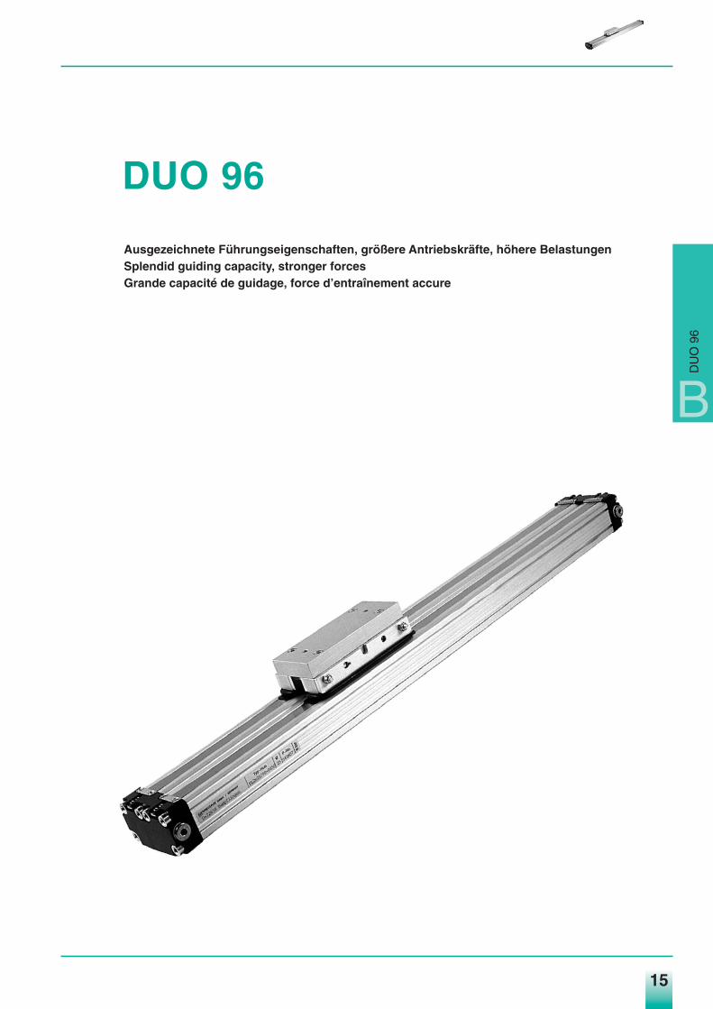
DUO 96
Ausgezeichnete Führungseigenschaften, größere Antriebskräfte, höhere BelastungenSplendid guiding capacity, stronger forcesGrande capacité de guidage, force d’entraînement accure
B
DU
O 9
6
Medan_hz04.qxd 10.09.2003 16:08 Uhr Seite 15
16
Druckluftzylinder Pneumatic Cylinders Vérins PneumatiquesDUO 96 DUO 96 DUO 96
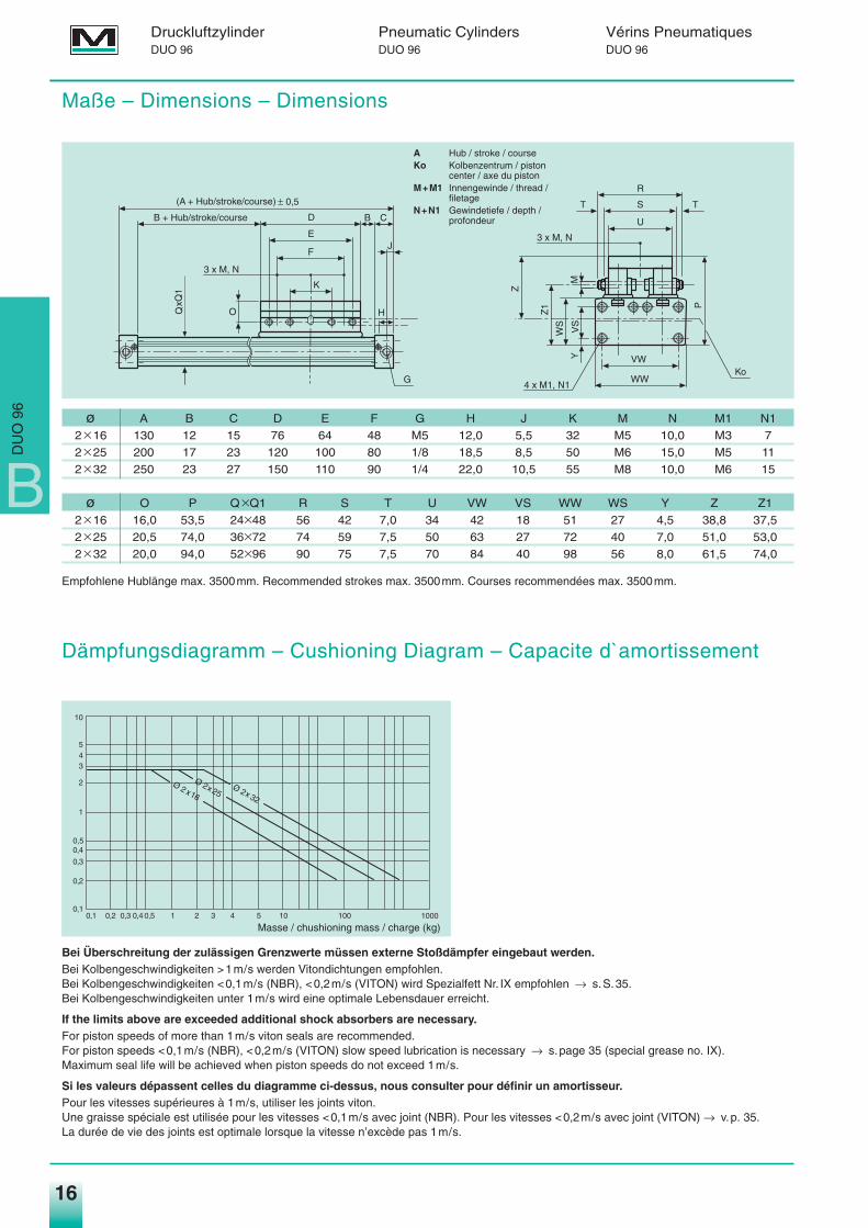
Maße – Dimensions – Dimensions
ø A B C D E F G H J K M N M1 N1
2q16 130 12 15 76 64 48 M5 12,0 5,5 32 M5 10,0 M3 7
2q25 200 17 23 120 100 80 1/8 18,5 8,5 50 M6 15,0 M5 11
2q32 250 23 27 150 110 90 1/4 22,0 10,5 55 M8 10,0 M6 15
ø O P QqQ1 R S T U VW VS WW WS Y Z Z1
2q16 16,0 53,5 24q48 56 42 7,0 34 42 18 51 27 4,5 38,8 37,5
2q25 20,5 74,0 36q72 74 59 7,5 50 63 27 72 40 7,0 51,0 53,0
2q32 20,0 94,0 52q96 90 75 7,5 70 84 40 98 56 8,0 61,5 74,0
Bei Überschreitung der zulässigen Grenzwerte müssen externe Stoßdämpfer eingebaut werden.Bei Kolbengeschwindigkeiten >1m/s werden Vitondichtungen empfohlen.Bei Kolbengeschwindigkeiten <0,1m/s (NBR), <0,2m/s (VITON) wird Spezialfett Nr. IX empfohlen → s.S.35.Bei Kolbengeschwindigkeiten unter 1m/s wird eine optimale Lebensdauer erreicht.
If the limits above are exceeded additional shock absorbers are necessary.For piston speeds of more than 1m/s viton seals are recommended.For piston speeds <0,1m/s (NBR), <0,2m/s (VITON) slow speed lubrication is necessary → s.page 35 (special grease no. IX).Maximum seal life will be achieved when piston speeds do not exceed 1m/s.
Si les valeurs dépassent celles du diagramme ci-dessus, nous consulter pour définir un amortisseur.Pour les vitesses supérieures à 1m/s, utiliser les joints viton.Une graisse spéciale est utilisée pour les vitesses <0,1m/s avec joint (NBR). Pour les vitesses <0,2m/s avec joint (VITON) → v.p. 35.La durée de vie des joints est optimale lorsque la vitesse n’excède pas 1m/s.
Empfohlene Hublänge max. 3500mm. Recommended strokes max. 3500mm. Courses recommendées max. 3500mm.
G
K
B CD
E
F
B + Hub/stroke/course
(A + Hub/stroke/course) ± 0,5
O
J
H
3 x M, N
QxQ
1
WW
VW
P
VS
Y
WS
Z1
M
R
S
U
Z
TT
3 x M, N
Ko4 x M1, N1
10
5 4 3
2
1
0,50,4
0,3
0,2
0,10,1 0,2 0,3 0,4 0,5 1 2 3 4 5 10 100 1000
Masse / chushioning mass / charge (kg)
Ø 2 x16
Ø 225
Ø 232
xx
A Hub / stroke / courseKo Kolbenzentrum / piston
center / axe du pistonM+M1 Innengewinde / thread /
filetageN+N1 Gewindetiefe / depth /
profondeur
Dämpfungsdiagramm – Cushioning Diagram – Capacite d`amortissement
B
DU
O 9
6
Medan_hz04.qxd 10.09.2003 16:08 Uhr Seite 16
17
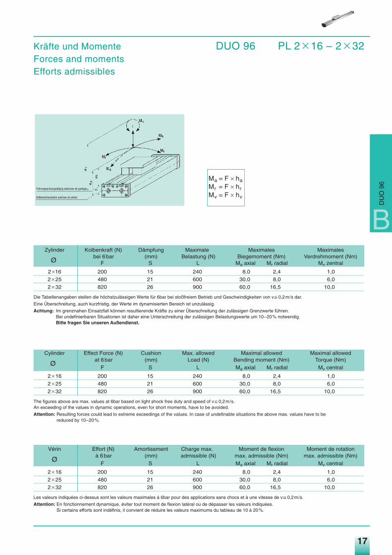
Kräfte und Momente DUO 96 PL 2q 16 – 2q 32Forces and momentsEfforts admissibles
Ma = F q haMr = F q hrMv = F q hv
Zylinder Kolbenkraft (N) Dämpfung Maximale Maximales Maximales
Øbei 6bar (mm) Belastung (N) Biegemoment (Nm) Verdrehmoment (Nm)
F S L Ma axial Mr radial Mv zentral
2q16 200 15 240 8,0 2,4 1,0
2q25 480 21 600 30,0 8,0 6,0
2q32 820 26 900 60,0 16,5 10,0
Die Tabellenangaben stellen die höchstzulässigen Werte für 6bar bei stoßfreiem Betrieb und Geschwindigkeiten von vP 0,2m/s dar.
Eine Überschreitung, auch kurzfristig, der Werte im dynamisierten Bereich ist unzulässig.
Achtung: Im grenznahen Einsatzfall können resultierende Kräfte zu einer Überschreitung der zulässigen Grenzwerte führen.Bei undefinierbaren Situationen ist daher eine Unterschreitung der zulässigen Belastungswerte um 10–20% notwendig.Bitte fragen Sie unseren Außendienst.
Cylinder Effect Force (N) Cushion Max. allowed Maximal allowed Maximal allowed
Øat 6bar (mm) Load (N) Bending moment (Nm) Torque (Nm)
F S L Ma axial Mr radial Mv central
2q16 200 15 240 8,0 2,4 1,0
2q25 480 21 600 30,0 8,0 6,0
2q32 820 26 900 60,0 16,5 10,0
The figures above are max. values at 6bar based on light shock free duty and speed of vP 0,2m/s.An exceeding of the values in dynamic operations, even for short moments, have to be avoided.
Attention: Resulting forces could lead to extreme exceedings of the values. In case of undefinable situations the above max. values have to be reduced by 10–20%.
Vérin Effort (N) Amortissment Charge max. Moment de flexion Moment de rotation
Øà 6bar (mm) admissible (N) max. admissible (Nm) max. admissible (Nm)
F S L Ma axial Mr radial Mv central
2q16 200 15 240 8,0 2,4 1,0
2q25 480 21 600 30,0 8,0 6,0
2q32 820 26 900 60,0 16,5 10,0
Les valeurs indiquées ci-dessus sont les valeurs maximales á 6bar pour des applications sans chocs et à une vitesse de vP 0,2m/s.
Attention: En fonctionnement dynamique, éviter tout moment de flexion latéral ou de dépasser les valeurs indiquées.Si certains efforts sont indéfinis, il convient de réduire les valeurs maximums du tableau de 10 à 20%.
Führungsachse/guidiging axles/axe de guidage
Kolbenachse/piston axel/axe du piston
B
DU
O 9
6
Medan_hz04.qxd 10.09.2003 16:08 Uhr Seite 17
18
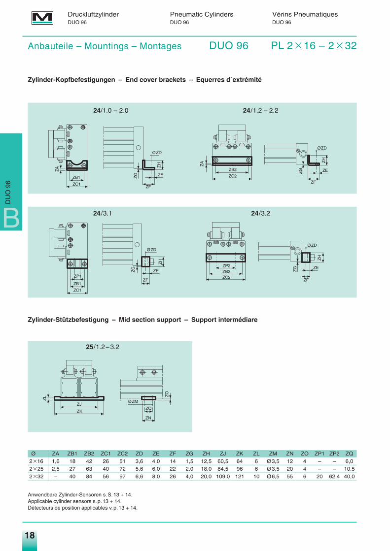
Anbauteile – Mountings – Montages DUO 96 PL 2q 16 – 2q 32
Zylinder-Kopfbefestigungen – End cover brackets – Equerres d`extrémité
24/1.2 – 2.2
24/3.1 24/3.2
Zylinder-Stützbefestigung – Mid section support – Support intermédiare
25/1.2–3.2
Ø ZA ZB1 ZB2 ZC1 ZC2 ZD ZE ZF ZG ZH ZJ ZK ZL ZM ZN ZO ZP1 ZP2 ZQ
2q16 1,6 18 42 26 51 3,6 4,0 14 1,5 12,5 60,5 64 6 Ø3,5 12 4 – – 6,0
2q25 2,5 27 63 40 72 5,6 6,0 22 2,0 18,0 84,5 96 6 Ø3,5 20 4 – – 10,5
2q32 – 40 84 56 97 6,6 8,0 26 4,0 20,0 109,0 121 10 Ø6,5 55 6 20 62,4 40,0
Anwendbare Zylinder-Sensoren s.S.13 + 14.Applicable cylinder sensors s.p.13 + 14.Détecteurs de position applicables v.p.13 + 14.
ZF
ZH
ØZD
ZEZG
ZA
ZC1
ZB1
ZH
ØZD
ZF
ZEZG
ZC2
ZB2
ZA
ZH
ØZD
ZF
ZEZG
ZC1
ZB1
ZP1
ØZM
ZN
ZO
ZQZK
ZJ
ZL
ZH
ØZD
ZF
ZE
ZG
ZC2ZB2ZP2
Druckluftzylinder Pneumatic Cylinders Vérins PneumatiquesDUO 96 DUO 96 DUO 96
24/1.0 – 2.0
B
DU
O 9
6
Medan_hz04.qxd 10.09.2003 16:08 Uhr Seite 18
19
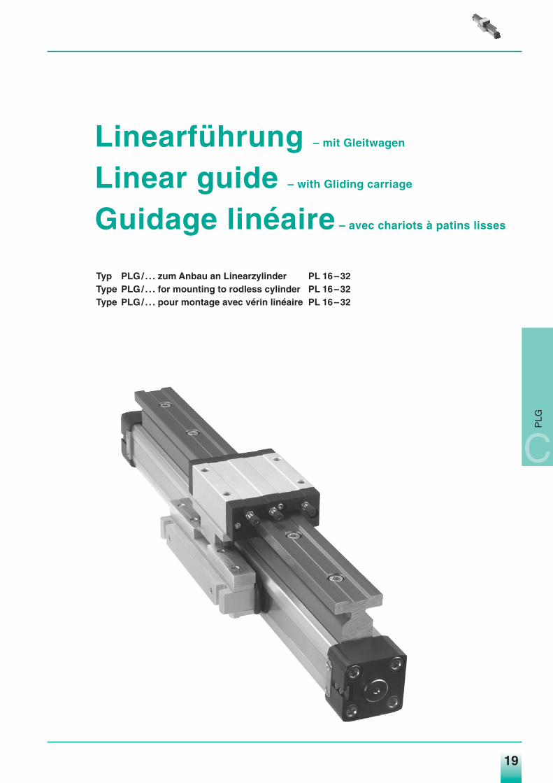
Linearführung – mit Gleitwagen
Linear guide – with Gliding carriage
Guidage linéaire – avec chariots à patins lisses
Typ PLG/ . . . zum Anbau an Linearzylinder PL 16–32Type PLG/ . . . for mounting to rodless cylinder PL 16–32Type PLG/ . . . pour montage avec vérin linéaire PL 16–32
C
PLG
Medan_hz04.qxd 10.09.2003 16:08 Uhr Seite 19
20
Linearführung Linear guide Guidage linéaire
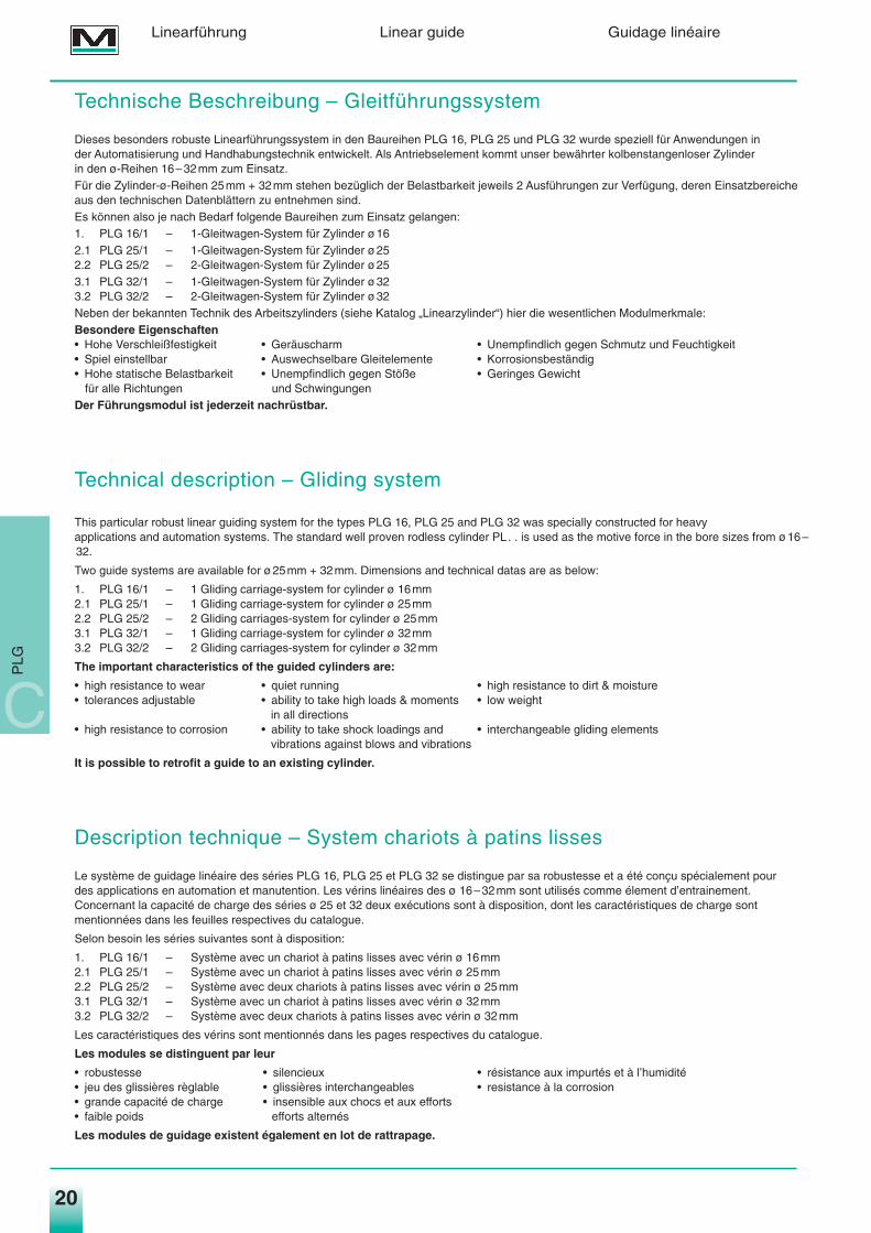
Technische Beschreibung – Gleitführungssystem
Dieses besonders robuste Linearführungssystem in den Baureihen PLG 16, PLG 25 und PLG 32 wurde speziell für Anwendungen in der Automatisierung und Handhabungstechnik entwickelt. Als Antriebselement kommt unser bewährter kolbenstangenloser Zylinder in den ø-Reihen 16–32mm zum Einsatz.Für die Zylinder-ø-Reihen 25mm + 32mm stehen bezüglich der Belastbarkeit jeweils 2 Ausführungen zur Verfügung, deren Einsatzbereicheaus den technischen Datenblättern zu entnehmen sind.Es können also je nach Bedarf folgende Baureihen zum Einsatz gelangen:1. PLG 16/1 – 1-Gleitwagen-System für Zylinder ø162.1 PLG 25/1 – 1-Gleitwagen-System für Zylinder ø252.2 PLG 25/2 – 2-Gleitwagen-System für Zylinder ø253.1 PLG 32/1 – 1-Gleitwagen-System für Zylinder ø323.2 PLG 32/2 – 2-Gleitwagen-System für Zylinder ø32Neben der bekannten Technik des Arbeitszylinders (siehe Katalog „Linearzylinder“) hier die wesentlichen Modulmerkmale:Besondere Eigenschaften• Hohe Verschleißfestigkeit • Geräuscharm • Unempfindlich gegen Schmutz und Feuchtigkeit• Spiel einstellbar • Auswechselbare Gleitelemente • Korrosionsbeständig• Hohe statische Belastbarkeit • Unempfindlich gegen Stöße • Geringes Gewicht
für alle Richtungen und SchwingungenDer Führungsmodul ist jederzeit nachrüstbar.
Technical description – Gliding system
This particular robust linear guiding system for the types PLG 16, PLG 25 and PLG 32 was specially constructed for heavy applications and automation systems. The standard well proven rodless cylinder PL . . is used as the motive force in the bore sizes from ø16–32.
Two guide systems are available for ø25mm + 32mm. Dimensions and technical datas are as below:
1. PLG 16/1 – 1 Gliding carriage-system for cylinder ø 16mm2.1 PLG 25/1 – 1 Gliding carriage-system for cylinder ø 25mm2.2 PLG 25/2 – 2 Gliding carriages-system for cylinder ø 25mm3.1 PLG 32/1 – 1 Gliding carriage-system for cylinder ø 32mm3.2 PLG 32/2 – 2 Gliding carriages-system for cylinder ø 32mm
The important characteristics of the guided cylinders are:
• high resistance to wear • quiet running • high resistance to dirt & moisture• tolerances adjustable • ability to take high loads & moments • low weight
in all directions• high resistance to corrosion • ability to take shock loadings and • interchangeable gliding elements
vibrations against blows and vibrations
It is possible to retrofit a guide to an existing cylinder.
Description technique – System chariots à patins lisses
Le système de guidage linéaire des séries PLG 16, PLG 25 et PLG 32 se distingue par sa robustesse et a été conçu spécialement pour des applications en automation et manutention. Les vérins linéaires des ø 16–32mm sont utilisés comme élement d’entrainement.Concernant la capacité de charge des séries ø 25 et 32 deux exécutions sont à disposition, dont les caractéristiques de charge sontmentionnées dans les feuilles respectives du catalogue.
Selon besoin les séries suivantes sont à disposition:
1. PLG 16/1 – Système avec un chariot à patins lisses avec vérin ø 16mm2.1 PLG 25/1 – Système avec un chariot à patins lisses avec vérin ø 25mm2.2 PLG 25/2 – Système avec deux chariots à patins lisses avec vérin ø 25mm3.1 PLG 32/1 – Système avec un chariot à patins lisses avec vérin ø 32mm3.2 PLG 32/2 – Système avec deux chariots à patins lisses avec vérin ø 32mm
Les caractéristiques des vérins sont mentionnés dans les pages respectives du catalogue.
Les modules se distinguent par leur
• robustesse • silencieux • résistance aux impurtés et à l’humidité• jeu des glissières règlable • glissières interchangeables • resistance à la corrosion• grande capacité de charge • insensible aux chocs et aux efforts• faible poids efforts alternés
Les modules de guidage existent également en lot de rattrapage.
C
PLG
Medan_hz04.qxd 10.09.2003 16:08 Uhr Seite 20
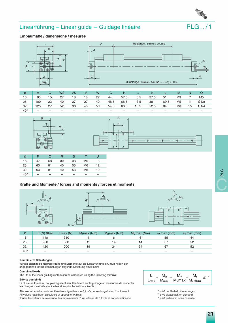
Linearführung – Linear guide – Guidage linéaire PLG . . / 1Einbaumaße / dimensions / mesures
Kräfte und Momente / forces and moments / forces et moments
Kombinierte BelastungenWirken gleichzeitig mehrere Kräfte und Momente auf die Linearführung ein, muß neben denangegebenen Maximalbelastungen folgende Gleichung erfüllt sein:
Combined loadsThe life of the linear guiding system can be calculated using the following formula:
Efforts combinésSi plusieurs forces ou couples agissent simultanément sur le guidage on s’assurera de respecterles charges maximales indiquées et en plus l’équation suivante:
Alle Werte beziehen sich auf Geschwindigkeiten von 0,2m/s bei wartungsfreiem Trockenlauf. * ø40 bei Bedarf bitte anfragen.All values have been calculated at speeds of 0,2m/s. * ø40 please ask on demand.Toutes les valeurs se réfèrent à des mouvements d’une vitesse de 0,2m/s et sans lubrification. * ø40 au besoin nous consulter.
21
ø A C WS VS V W G H J K L M N O
16 65 15 27 18 18 27 44 57.5 5.5 27.5 51 M3 7 M5
25 100 23 40 27 27 40 48.5 68.5 8.5 38 69.5 M5 11 G1/8
32 125 27 52 36 40 56 54.5 80.5 10.5 52.5 84 M6 15 G1/4
40* – – – – – – – – – – – – – –
ø F (N) 6bar Lmax (N) Mrmax (Nm) Mamax (Nm) Mvmax (Nm) sxmax (mm) symax (mm)
16 110 350 4 6 6 55 44
25 250 680 11 14 14 67 52
32 420 1000 19 24 24 67 52
40* – – – – – – –
ø P Q R S T U
16 47 68 30 38 M5 8
25 63 81 40 53 M6 12
32 63 81 40 53 M6 12
40* – – – – – –
C
PLG
L
K
VS
WS
HG
VW
O
J
A Hublänge / stroke / course
(Hublänge / stroke / course + 2�A) +- 0,5
C N
M
U
T
PS
Q
R
Mr
L
sx
6 bar
Ma
sy
Mv
L
L Ma Mv MrLmax Mmax Mvmax Msmax
P 1+ + +
Medan_hz04.qxd 10.09.2003 16:08 Uhr Seite 21
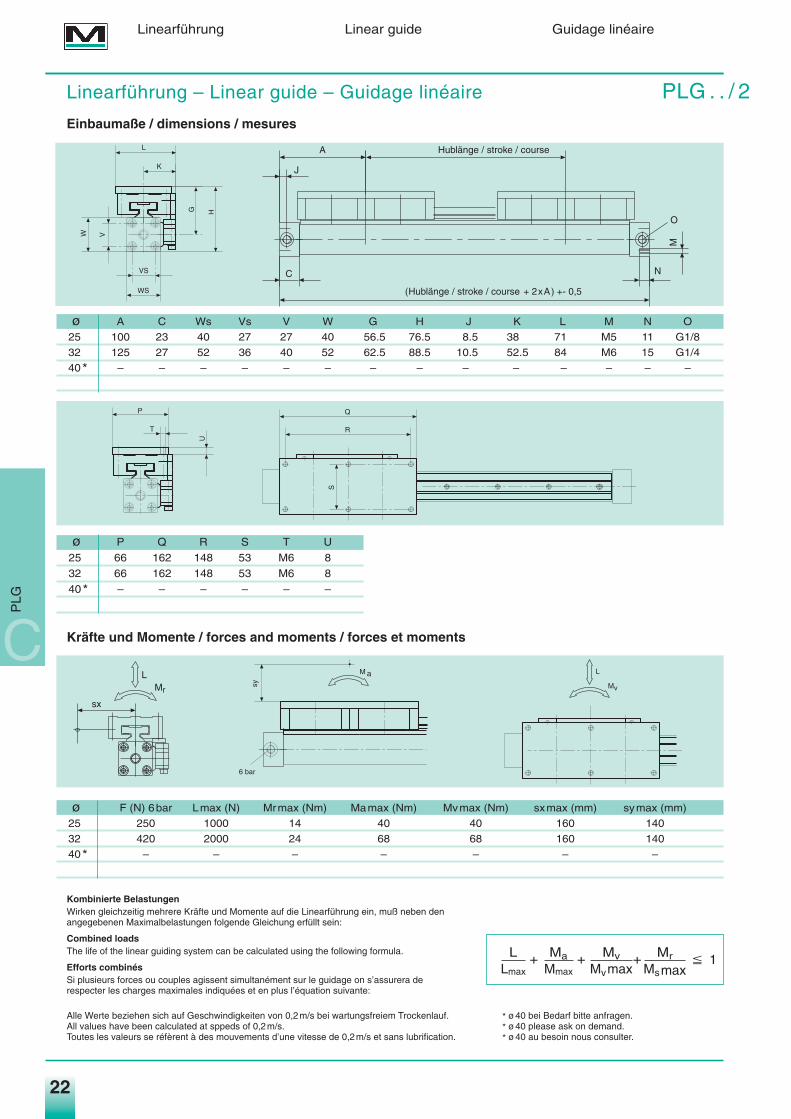
Linearführung – Linear guide – Guidage linéaire PLG . . / 2Einbaumaße / dimensions / mesures
Kräfte und Momente / forces and moments / forces et moments
Kombinierte BelastungenWirken gleichzeitig mehrere Kräfte und Momente auf die Linearführung ein, muß neben den angegebenen Maximalbelastungen folgende Gleichung erfüllt sein:
Combined loadsThe life of the linear guiding system can be calculated using the following formula.
Efforts combinésSi plusieurs forces ou couples agissent simultanément sur le guidage on s’assurera de respecter les charges maximales indiquées et en plus l’équation suivante:
Alle Werte beziehen sich auf Geschwindigkeiten von 0,2m/s bei wartungsfreiem Trockenlauf. * ø40 bei Bedarf bitte anfragen.All values have been calculated at sppeds of 0,2m/s. * ø40 please ask on demand.Toutes les valeurs se réfèrent à des mouvements d’une vitesse de 0,2m/s et sans lubrification. * ø40 au besoin nous consulter.
22
Linearführung Linear guide Guidage linéaire
W V
WS
VS
K
G H
L
��
�
��
M
6 bar
sy
L
Mv
T
U
P Q
R
S
O
M
NC
(Hublänge / stroke / course + 2xA) +- 0,5
Hublänge / stroke / courseA
J
ø A C Ws Vs V W G H J K L M N O
25 100 23 40 27 27 40 56.5 76.5 8.5 38 71 M5 11 G1/8
32 125 27 52 36 40 52 62.5 88.5 10.5 52.5 84 M6 15 G1/4
40* – – – – – – – – – – – – – –
ø F (N) 6bar Lmax (N) Mrmax (Nm) Mamax (Nm) Mvmax (Nm) sxmax (mm) symax (mm)
25 250 1000 14 40 40 160 140
32 420 2000 24 68 68 160 140
40* – – – – – – –
ø P Q R S T U
25 66 162 148 53 M6 8
32 66 162 148 53 M6 8
40* – – – – – –
L Ma Mv MrLmax Mmax Mvmax Msmax
P 1+ + +
a
C
PLG
Medan_hz04.qxd 10.09.2003 16:08 Uhr Seite 22
23
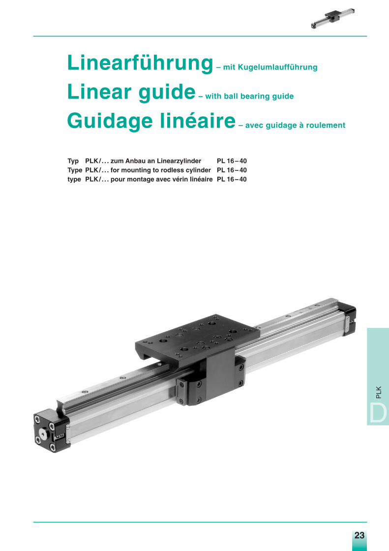
Linearführung – mit Kugelumlaufführung
Linear guide – with ball bearing guide
Guidage linéaire – avec guidage à roulement
Typ PLK/ . . . zum Anbau an Linearzylinder PL 16– 40Type PLK/ . . . for mounting to rodless cylinder PL 16– 40type PLK/ . . . pour montage avec vérin linéaire PL 16–40
PLK
D
Medan_hz04.qxd 10.09.2003 16:08 Uhr Seite 23

24
Technische Beschreibung – Kugelumlaufführung
Dieses hoch robuste Linearführungssystem in den Baureihen PLK 16, PLK 25, PLK 32 und PLK 40 wurde speziell für die AnwendungWerkzeugmaschinen und Industrierobotertechnik entwickelt. Als Antriebselement kommt unser bewährter kolbenstangenloser Zylinder in den Ø-Reihen 16–40mm zum Einsatz.
Neben der bereits bekannten Technik des linearen Arbeitszylinders (siehe PL-Serie) hier die wesentlichen Modulmerkmale.
Besondere Eigenschaften:• Hohe Tragzahl • Schmiernippel allseitig möglich• Hohe statische Belastbarkeit • Führungsschiene im Laufbahnbereich
für alle Richtungen gehärtet und allseitig geschliffen• Ruhiger, geschmeidiger Lauf • Kugeln aus Wälzlagerstahl• Robuste Kugelabdeckung • Problemlose Austauschbarkeit
Der Führungsmodul ist jederzeit nachrüstbar.
Technical description – ball bearing guide modul
This extremely robust linearsystem from the series PLK 16, PLK 25, PLK 32 and PLK 40 has been especially developed for use in themachine tool and robototics industries. The move force for this guide is our proven rodless cylinder PL 16–40.
Besides the proven technical aspects of our series rodles cylinder, the following are important performance characteristics.
Characteristics:• high loading characteristics • easy access to grease nipple• high static loading in all directions • hardened and grinded guiderail• quiet and smooth running • low friction bearing• robust bearing housing • easy interchangeability
The roller guide modul can be expanded.
Généralités – Guidage à roulement linéaire
Ce systéme de guidage linéaire, livrable pour les gammmes de fabrication PLK 16, PLK 25, PLK 32 et PLK 40 a été développé pour lesapplications dans la domaine de la machine outil et de la robotique.
Léntrainement de l´unité se fait par nos vérins linéaires standards (voir gamme PL).
Spécifications:• Capacité de charge dynamique élevée • Graisseurs univérsels• Caractéristiques statiques superieures à la normale • Rail en acier trempé et restifié• Silencieux • Rouleaux en acier haute qualité• Protéction des rouleaux robuste • Interchangeabilité facile
Construction modulaire et interchangéable avec d’autres modules.
Linearführung Linear guide Guidage linéaire
D
PLK
Medan_hz04.qxd 10.09.2003 16:08 Uhr Seite 24
1. Die angegebenen Momente (M.max) beziehen sich stets auf das Zentrum der Führungsschiene,wobei die Lastkraft (L) die Summe aller Einzellasten bezogen auf ihren gemeinsamenSchwerpunkt ist. Dieser kann sowohl innerhalb oder außerhalb der Schlittenfläche liegen.
2. Im Einzelfall kommt es in der Regel zu resultierden Belastungen des Wagen, welche in derBerechnung des Modules zu berücksichtigen sind. Bei der Größenauswahl des Modules sinddaher sowohl die Antriebskraft des Kolbens (F) als auch die Rollfähigkeit des Wagens sicherzustellen; letzteres geschieht mit folgender Berechnungsformel:
1. The above mentioned moments (Ma max, Mr max, Mv max) are related to the guide rail centre. The load force (L) is the summary of all single forces relatedto the common centre of the mass. The centre of the mass can be placed inside or outside the surface area of the carriage.
2. Normally the carriage would experience a dynamic load, which has to be considered with the calculation of needed piston force (F) and capacity of the ball-guided system. Use the following calculation formular:
1. Les moments indiqués se rapportent au centre du rail de guidage, ce qui nous rapelle que la force des charge (F) en resulte de toutes les charges partiellesen rapport de leur point de gravité commun. Celui-ci peut se trouver au dedans, aussi bien qu' á l'exterieur de la surface du chariot.
2. Si plusieur moments agissent simultanement sur le chariot, on s'assurera qu'ils sont pris en considération dans la calculation du module. Le choix du modulene dépend pas seulement de la force du piston, mais aussi de la capacité des rouleaux du chariot. Ceci se resume en fin de compte dans la formule suivante:
25
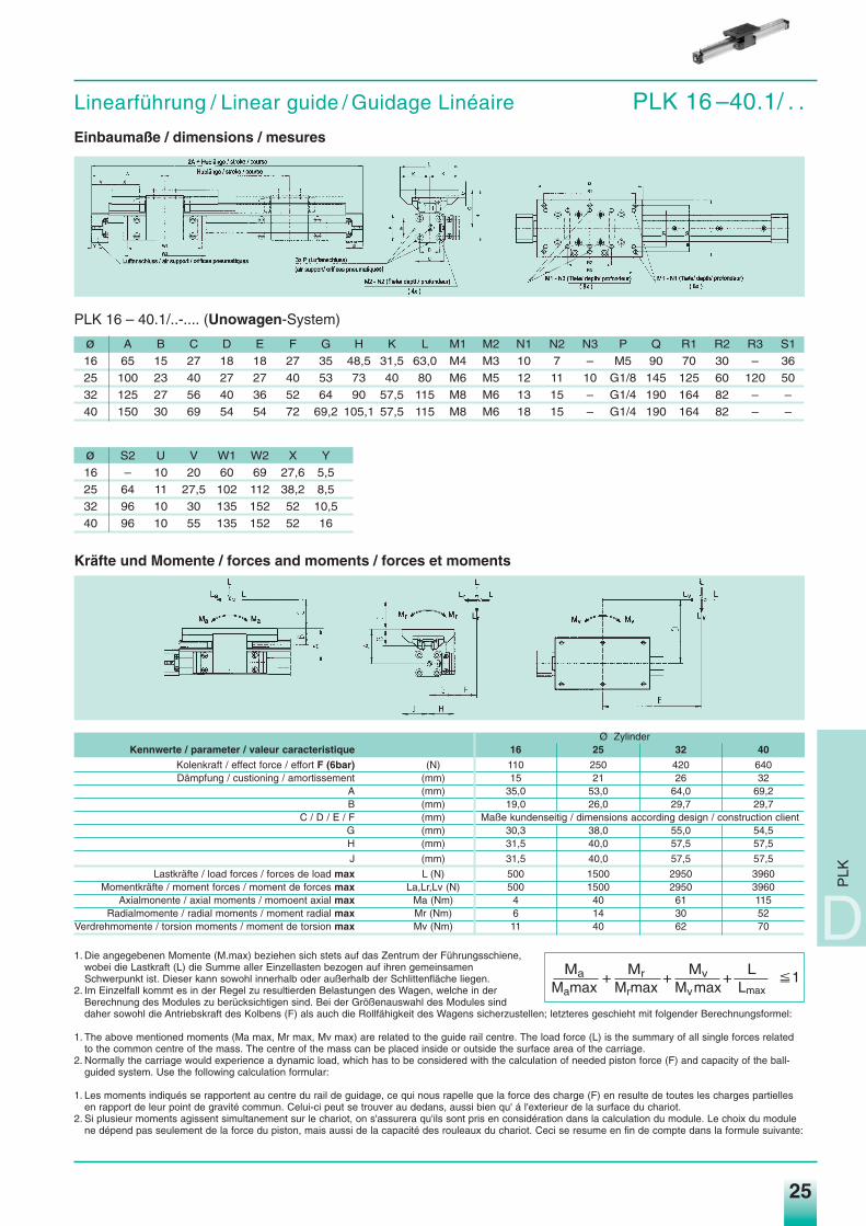
Linearführung / Linear guide / Guidage Linéaire PLK 16 –40.1/ . .Einbaumaße / dimensions / mesures
PLK 16 – 40.1/..-.... (Unowagen-System)
ø A B C D E F G H K L M1 M2 N1 N2 N3 P Q R1 R2 R3 S1
16 65 15 27 18 18 27 35 48,5 31,5 63,0 M4 M3 10 7 – M5 90 70 30 – 36
25 100 23 40 27 27 40 53 73 40 80 M6 M5 12 11 10 G1/8 145 125 60 120 50
32 125 27 56 40 36 52 64 90 57,5 115 M8 M6 13 15 – G1/4 190 164 82 – –
40 150 30 69 54 54 72 69,2 105,1 57,5 115 M8 M6 18 15 – G1/4 190 164 82 – –
ø S2 U V W1 W2 X Y
16 – 10 20 60 69 27,6 5,5
25 64 11 27,5 102 112 38,2 8,5
32 96 10 30 135 152 52 10,5
40 96 10 55 135 152 52 16
PLK
D
Ø ZylinderKennwerte / parameter / valeur caracteristique 16 25 32 40
Kolenkraft / effect force / effort F (6bar) (N) 110 250 420 640Dämpfung / custioning / amortissement (mm) 15 21 26 32
A (mm) 35,0 53,0 64,0 69,2B (mm) 19,0 26,0 29,7 29,7
C / D / E / F (mm) Maße kundenseitig / dimensions according design / construction clientG (mm) 30,3 38,0 55,0 54,5H (mm) 31,5 40,0 57,5 57,5
J (mm) 31,5 40,0 57,5 57,5
Lastkräfte / load forces / forces de load max L (N) 500 1500 2950 3960Momentkräfte / moment forces / moment de forces max La,Lr,Lv (N) 500 1500 2950 3960
Axialmonente / axial moments / momoent axial max Ma (Nm) 4 40 61 115Radialmomente / radial moments / moment radial max Mr (Nm) 6 14 30 52
Verdrehmomente / torsion moments / moment de torsion max Mv (Nm) 11 40 62 70
Ma Mr Mv LMamax Mrmax Mvmax Lmax
P 1+ + +
Kräfte und Momente / forces and moments / forces et moments
Medan_hz04.qxd 10.09.2003 16:09 Uhr Seite 25
26
Druckluftzylinder Pneumatic Cylinders Vérins PneumatiquesBaureihe PL … - Linearzylinder Type of Cylinder PL … - Rodless Série PL …- Sans Tige
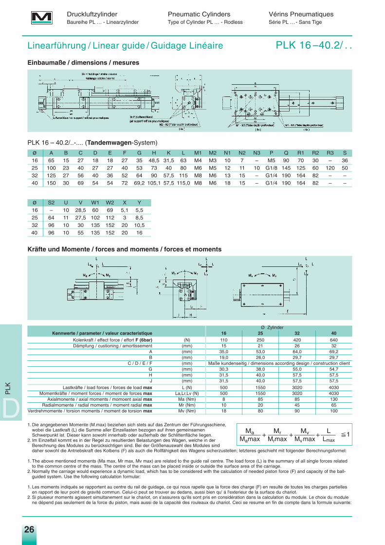
Linearführung / Linear guide / Guidage Linéaire PLK 16 –40.2/ . .
Einbaumaße / dimensions / mesures
PLK 16 – 40.2/..-.... (Tandemwagen-System)
ø A B C D E F G H K L M1 M2 N1 N2 N3 P Q R1 R2 R3 S
16 65 15 27 18 18 27 35 48,5 31,5 63 M4 M3 10 7 – M5 90 70 30 – 36
25 100 23 40 27 27 40 53 73 40 80 M6 M5 12 11 10 G1/8 145 125 60 120 50
32 125 27 56 40 36 52 64 90 57,5 115 M8 M6 13 15 – G1/4 190 164 82 – –
40 150 30 69 54 54 72 69,2 105,1 57,5 115,0 M8 M6 18 15 – G1/4 190 164 82 – –
ø S2 U V W1 W2 X Y
16 – 10 28,5 60 69 5,1 5,5
25 64 11 27,5 102 112 3 8,5
32 96 10 30 135 152 20 10,5
40 96 10 55 135 152 20 16
D
PLK
1. Die angegebenen Momente (M.max) beziehen sich stets auf das Zentrum der Führungsschiene,wobei die Lastkraft (L) die Summe aller Einzellasten bezogen auf ihren gemeinsamenSchwerpunkt ist. Dieser kann sowohl innerhalb oder außerhalb der Schlittenfläche liegen.
2. Im Einzelfall kommt es in der Regel zu resultierden Belastungen des Wagen, welche in derBerechnung des Modules zu berücksichtigen sind. Bei der Größenauswahl des Modules sinddaher sowohl die Antriebskraft des Kolbens (F) als auch die Rollfähigkeit des Wagens sicherzustellen; letzteres geschieht mit folgender Berechnungsformel:
1. The above mentioned moments (Ma max, Mr max, Mv max) are related to the guide rail centre. The load force (L) is the summary of all single forces relatedto the common centre of the mass. The centre of the mass can be placed inside or outside the surface area of the carriage.
2. Normally the carriage would experience a dynamic load, which has to be considered with the calculation of needed piston force (F) and capacity of the ball-guided system. Use the following calculation formular:
1. Les moments indiqués se rapportent au centre du rail de guidage, ce qui nous rapelle que la force des charge (F) en resulte de toutes les charges partiellesen rapport de leur point de gravité commun. Celui-ci peut se trouver au dedans, aussi bien qu' á l'exterieur de la surface du chariot.
2. Si plusieur moments agissent simultanement sur le chariot, on s'assurera qu'ils sont pris en considération dans la calculation du module. Le choix du modulene dépend pas seulement de la force du piston, mais aussi de la capacité des rouleaux du chariot. Ceci se resume en fin de compte dans la formule suivante:
Ø ZylinderKennwerte / parameter / valeur caracteristique 16 25 32 40
Kolenkraft / effect force / effort F (6bar) (N) 110 250 420 640Dämpfung / custioning / amortissement (mm) 15 21 26 32
A (mm) 35,0 53,0 64,0 69,2B (mm) 19,0 26,0 29,7 29,7
C / D / E / F (mm) Maße kundenseitig / dimensions according design / construction clientG (mm) 30,3 38,0 55,0 54,7H (mm) 31,5 40,0 57,5 57,5J (mm) 31,5 40,0 57,5 57,5
Lastkräfte / load forces / forces de load max L (N) 500 1550 3020 4030Momentkräfte / moment forces / moment de forces max La,Lr,Lv (N) 500 1550 3020 4030
Axialmonente / axial moments / momoent axial max Ma (Nm) 8 85 85 130Radialmomente / radial moments / moment radial max Mr (Nm) 10 20 45 65
Verdrehmomente / torsion moments / moment de torsion max Mv (Nm) 18 80 90 100
Ma Mr Mv LMamax Mrmax Mvmax Lmax
P 1+ + +
Kräfte und Momente / forces and moments / forces et moments
Medan_hz04.qxd 10.09.2003 16:09 Uhr Seite 26
27
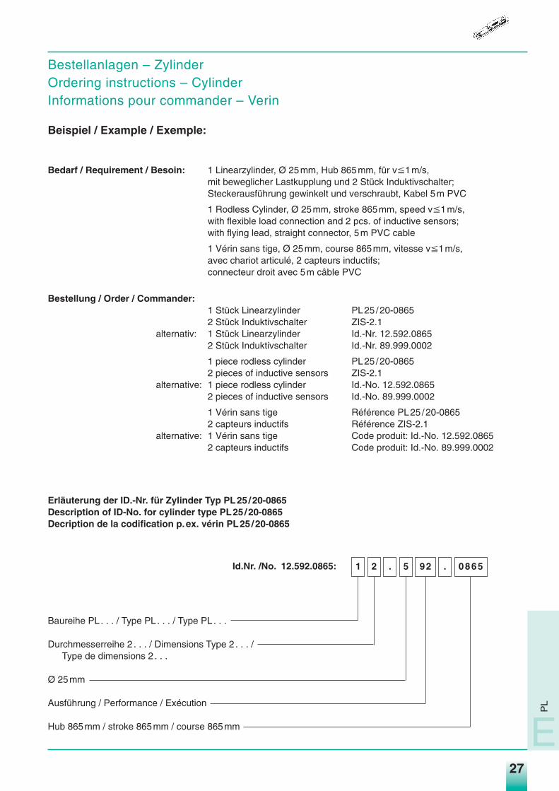
Bestellanlagen – ZylinderOrdering instructions – CylinderInformations pour commander – Verin
Beispiel / Example / Exemple:
Bedarf / Requirement / Besoin: 1 Linearzylinder, Ø 25mm, Hub 865mm, für vP1m/s,mit beweglicher Lastkupplung und 2 Stück Induktivschalter;Steckerausführung gewinkelt und verschraubt, Kabel 5m PVC
1 Rodless Cylinder, Ø 25mm, stroke 865mm, speed vP1m/s,with flexible load connection and 2 pcs. of inductive sensors;with flying lead, straight connector, 5m PVC cable
1 Vérin sans tige, Ø 25mm, course 865mm, vitesse vP1m/s,avec chariot articulé, 2 capteurs inductifs;connecteur droit avec 5m câble PVC
Bestellung / Order / Commander:1 Stück Linearzylinder PL25/20-08652 Stück Induktivschalter ZIS-2.1
alternativ: 1 Stück Linearzylinder Id.-Nr. 12.592.08652 Stück Induktivschalter Id.-Nr. 89.999.0002
1 piece rodless cylinder PL25/20-08652 pieces of inductive sensors ZIS-2.1
alternative: 1 piece rodless cylinder Id.-No. 12.592.08652 pieces of inductive sensors Id.-No. 89.999.0002
1 Vérin sans tige Référence PL25 /20-08652 capteurs inductifs Référence ZIS-2.1
alternative: 1 Vérin sans tige Code produit: Id.-No. 12.592.08652 capteurs inductifs Code produit: Id.-No. 89.999.0002
Erläuterung der ID.-Nr. für Zylinder Typ PL25/20-0865Description of ID-No. for cylinder type PL25/20-0865Decription de la codification p.ex. vérin PL25/20-0865
Id.Nr. /No. 12.592.0865:
Baureihe PL . . . / Type PL . . . / Type PL . . .
Durchmesserreihe 2 . . . / Dimensions Type 2 . . . /Type de dimensions 2 . . .
Ø 25mm
Ausführung / Performance / Exécution
Hub 865mm / stroke 865mm / course 865mm
0865.925.21
PL
E
Medan_hz04.qxd 10.09.2003 16:09 Uhr Seite 27
28
Druckluftzylinder Pneumatic Cylinders Vérins PneumatiquesBaureihe PL … - Linearzylinder Type of Cylinder PL … - Rodless Série PL …- Sans Tige
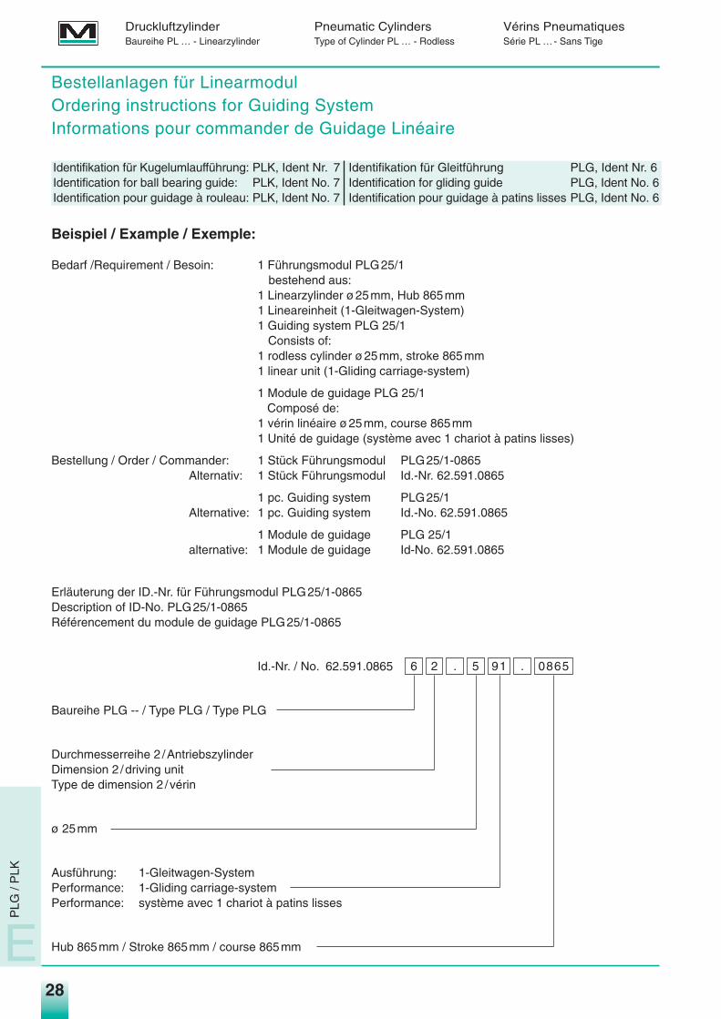
Bestellanlagen für LinearmodulOrdering instructions for Guiding SystemInformations pour commander de Guidage Linéaire
Identifikation für Kugelumlaufführung: PLK, Ident Nr. 7 Identifikation für Gleitführung PLG, Ident Nr. 6Identification for ball bearing guide: PLK, Ident No. 7 Identification for gliding guide PLG, Ident No. 6Identification pour guidage à rouleau: PLK, Ident No. 7 Identification pour guidage à patins lisses PLG, Ident No. 6
Beispiel / Example / Exemple:
Bedarf /Requirement / Besoin: 1 Führungsmodul PLG25/1bestehend aus:
1 Linearzylinder ø25mm, Hub 865mm1 Lineareinheit (1-Gleitwagen-System)1 Guiding system PLG 25/1
Consists of:1 rodless cylinder ø25mm, stroke 865mm 1 linear unit (1-Gliding carriage-system)
1 Module de guidage PLG 25/1Composé de:
1 vérin linéaire ø25mm, course 865mm1 Unité de guidage (système avec 1 chariot à patins lisses)
Bestellung / Order / Commander: 1 Stück Führungsmodul PLG25/1-0865Alternativ: 1 Stück Führungsmodul Id.-Nr. 62.591.0865
1 pc. Guiding system PLG25/1Alternative: 1 pc. Guiding system Id.-No. 62.591.0865
1 Module de guidage PLG 25/1alternative: 1 Module de guidage Id-No. 62.591.0865
Erläuterung der ID.-Nr. für Führungsmodul PLG25/1-0865Description of ID-No. PLG25/1-0865Référencement du module de guidage PLG25/1-0865
Id.-Nr. / No. 62.591.0865
Baureihe PLG -- / Type PLG / Type PLG
Durchmesserreihe 2 /AntriebszylinderDimension 2 /driving unitType de dimension 2 /vérin
ø 25mm
Ausführung: 1-Gleitwagen-SystemPerformance: 1-Gliding carriage-systemPerformance: système avec 1 chariot à patins lisses
Hub 865mm / Stroke 865mm / course 865mm
0865.915.26
E
PLG
/ P
LK
Medan_hz04.qxd 10.09.2003 16:09 Uhr Seite 28
29
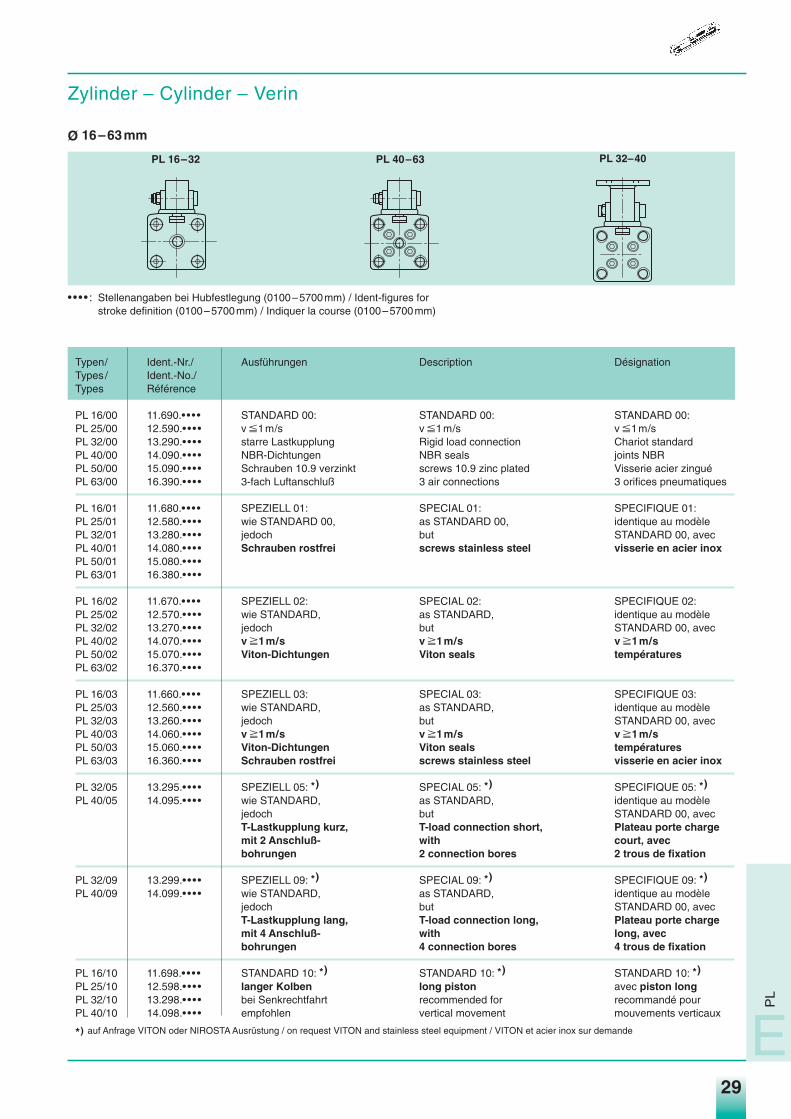
Zylinder – Cylinder – Verin
Ø 16–63mm
• • • • : Stellenangaben bei Hubfestlegung (0100–5700mm) / Ident-figures forstroke definition (0100–5700mm) / Indiquer la course (0100–5700mm)
Typen/ Ident.-Nr./ Ausführungen Description DésignationTypes / Ident.-No./Types Référence
PL 16/00 11.690.• • • • STANDARD 00: STANDARD 00: STANDARD 00:PL 25/00 12.590.• • • • v P1m/s v P1m/s v P1m/sPL 32/00 13.290.• • • • starre Lastkupplung Rigid load connection Chariot standardPL 40/00 14.090.• • • • NBR-Dichtungen NBR seals joints NBRPL 50/00 15.090.• • • • Schrauben 10.9 verzinkt screws 10.9 zinc plated Visserie acier zinguéPL 63/00 16.390.• • • • 3-fach Luftanschluß 3 air connections 3 orifices pneumatiques
PL 16/01 11.680.• • • • SPEZIELL 01: SPECIAL 01: SPECIFIQUE 01:PL 25/01 12.580.• • • • wie STANDARD 00, as STANDARD 00, identique au modèlePL 32/01 13.280.• • • • jedoch but STANDARD 00, avecPL 40/01 14.080.• • • • Schrauben rostfrei screws stainless steel visserie en acier inoxPL 50/01 15.080.• • • •PL 63/01 16.380.• • • •
PL 16/02 11.670.• • • • SPEZIELL 02: SPECIAL 02: SPECIFIQUE 02:PL 25/02 12.570.• • • • wie STANDARD, as STANDARD, identique au modèlePL 32/02 13.270.• • • • jedoch but STANDARD 00, avecPL 40/02 14.070.• • • • v p1m/s v p1m/s v p1m/sPL 50/02 15.070.• • • • Viton-Dichtungen Viton seals températuresPL 63/02 16.370.• • • •
PL 16/03 11.660.• • • • SPEZIELL 03: SPECIAL 03: SPECIFIQUE 03:PL 25/03 12.560.• • • • wie STANDARD, as STANDARD, identique au modèlePL 32/03 13.260.• • • • jedoch but STANDARD 00, avecPL 40/03 14.060.• • • • v p1m/s v p1m/s v p1m/sPL 50/03 15.060.• • • • Viton-Dichtungen Viton seals températuresPL 63/03 16.360.• • • • Schrauben rostfrei screws stainless steel visserie en acier inox
PL 32/05 13.295.• • • • SPEZIELL 05: *) SPECIAL 05: *) SPECIFIQUE 05: *)
PL 40/05 14.095.• • • • wie STANDARD, as STANDARD, identique au modèlejedoch but STANDARD 00, avecT-Lastkupplung kurz, T-load connection short, Plateau porte chargemit 2 Anschluß- with court, avecbohrungen 2 connection bores 2 trous de fixation
PL 32/09 13.299.• • • • SPEZIELL 09: *) SPECIAL 09: *) SPECIFIQUE 09: *)
PL 40/09 14.099.• • • • wie STANDARD, as STANDARD, identique au modèlejedoch but STANDARD 00, avecT-Lastkupplung lang, T-load connection long, Plateau porte chargemit 4 Anschluß- with long, avecbohrungen 4 connection bores 4 trous de fixation
PL 16/10 11.698.• • • • STANDARD 10: *) STANDARD 10: *) STANDARD 10: *)
PL 25/10 12.598.• • • • langer Kolben long piston avec piston longPL 32/10 13.298.• • • • bei Senkrechtfahrt recommended for recommandé pourPL 40/10 14.098.• • • • empfohlen vertical movement mouvements verticaux
*) auf Anfrage VITON oder NIROSTA Ausrüstung / on request VITON and stainless steel equipment / VITON et acier inox sur demande
PL 16–32 PL 40–63
PL
E
PL 32–40
Medan_hz04.qxd 10.09.2003 16:09 Uhr Seite 29
30
Druckluftzylinder Pneumatic Cylinders Vérins PneumatiquesBaureihe PL … - Linearzylinder Type of Cylinder PL … - Rodless Série PL …- Sans Tige
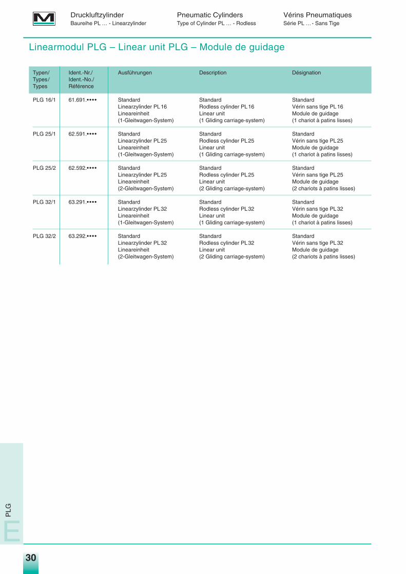
Linearmodul PLG – Linear unit PLG – Module de guidage
Typen/ Ident.-Nr./ Ausführungen Description DésignationTypes / Ident.-No./Types Référence
PLG 16/1 61.691.• • • • Standard Standard StandardLinearzylinder PL16 Rodless cylinder PL16 Vérin sans tige PL16Lineareinheit Linear unit Module de guidage(1-Gleitwagen-System) (1 Gliding carriage-system) (1 chariot à patins lisses)
PLG 25/1 62.591.• • • • Standard Standard StandardLinearzylinder PL25 Rodless cylinder PL25 Vérin sans tige PL25Lineareinheit Linear unit Module de guidage(1-Gleitwagen-System) (1 Gliding carriage-system) (1 chariot à patins lisses)
PLG 25/2 62.592.• • • • Standard Standard StandardLinearzylinder PL25 Rodless cylinder PL25 Vérin sans tige PL25Lineareinheit Linear unit Module de guidage(2-Gleitwagen-System) (2 Gliding carriage-system) (2 chariots à patins lisses)
PLG 32/1 63.291.• • • • Standard Standard StandardLinearzylinder PL32 Rodless cylinder PL32 Vérin sans tige PL32Lineareinheit Linear unit Module de guidage(1-Gleitwagen-System) (1 Gliding carriage-system) (1 chariot à patins lisses)
PLG 32/2 63.292.• • • • Standard Standard StandardLinearzylinder PL32 Rodless cylinder PL32 Vérin sans tige PL32Lineareinheit Linear unit Module de guidage(2-Gleitwagen-System) (2 Gliding carriage-system) (2 chariots à patins lisses)
E
PLG
Medan_hz04.qxd 10.09.2003 16:09 Uhr Seite 30
31
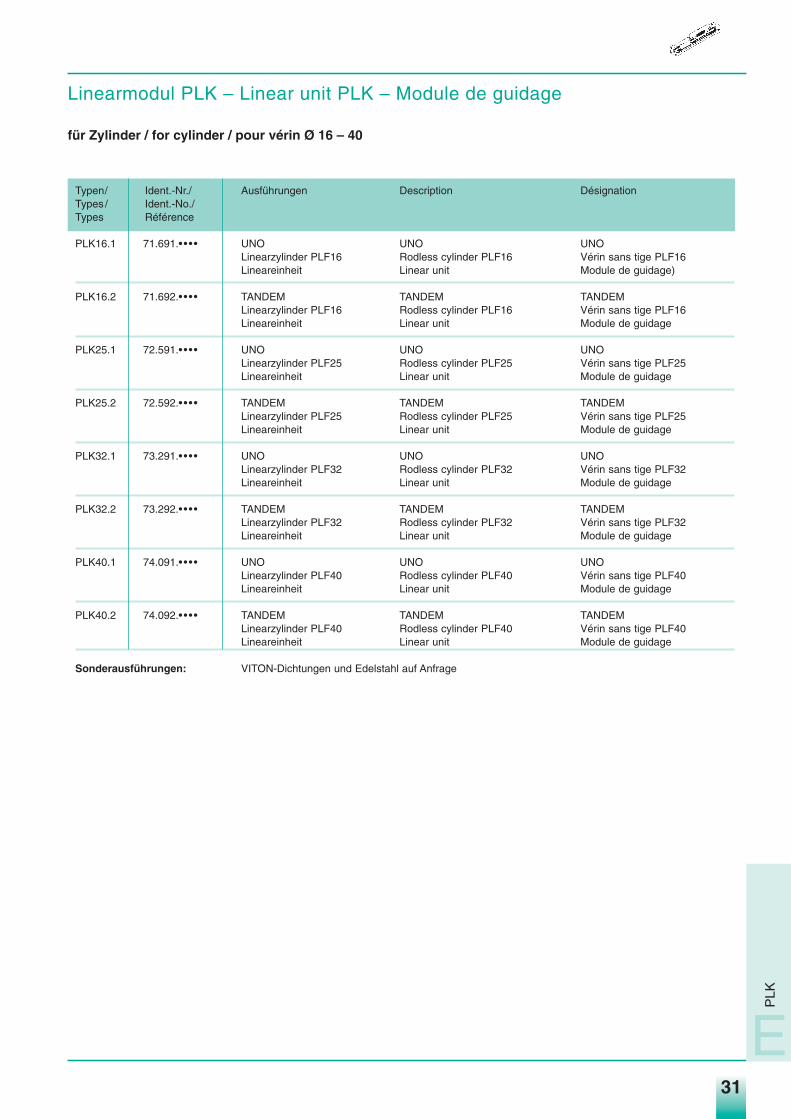
Linearmodul PLK – Linear unit PLK – Module de guidage
für Zylinder / for cylinder / pour vérin Ø 16 – 40
Typen/ Ident.-Nr./ Ausführungen Description DésignationTypes / Ident.-No./Types Référence
PLK16.1 71.691.• • • • UNO UNO UNOLinearzylinder PLF16 Rodless cylinder PLF16 Vérin sans tige PLF16Lineareinheit Linear unit Module de guidage)
PLK16.2 71.692.• • • • TANDEM TANDEM TANDEMLinearzylinder PLF16 Rodless cylinder PLF16 Vérin sans tige PLF16Lineareinheit Linear unit Module de guidage
PLK25.1 72.591.• • • • UNO UNO UNOLinearzylinder PLF25 Rodless cylinder PLF25 Vérin sans tige PLF25Lineareinheit Linear unit Module de guidage
PLK25.2 72.592.• • • • TANDEM TANDEM TANDEMLinearzylinder PLF25 Rodless cylinder PLF25 Vérin sans tige PLF25Lineareinheit Linear unit Module de guidage
PLK32.1 73.291.• • • • UNO UNO UNOLinearzylinder PLF32 Rodless cylinder PLF32 Vérin sans tige PLF32Lineareinheit Linear unit Module de guidage
PLK32.2 73.292.• • • • TANDEM TANDEM TANDEMLinearzylinder PLF32 Rodless cylinder PLF32 Vérin sans tige PLF32Lineareinheit Linear unit Module de guidage
PLK40.1 74.091.• • • • UNO UNO UNOLinearzylinder PLF40 Rodless cylinder PLF40 Vérin sans tige PLF40Lineareinheit Linear unit Module de guidage
PLK40.2 74.092.• • • • TANDEM TANDEM TANDEMLinearzylinder PLF40 Rodless cylinder PLF40 Vérin sans tige PLF40Lineareinheit Linear unit Module de guidage
Sonderausführungen: VITON-Dichtungen und Edelstahl auf Anfrage
PLK
E
Medan_hz04.qxd 10.09.2003 16:09 Uhr Seite 31
32
Druckluftzylinder Pneumatic Cylinders Vérins PneumatiquesBaureihe PL …-Linearzylinder Type of Cylinder PL …-Rodless Série PL …Sans Tige
E
PL
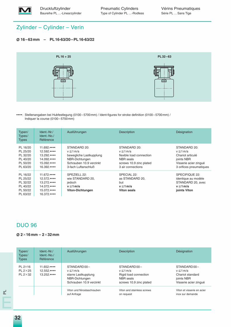
Zylinder – Cylinder – Verin
Ø 16–63mm – PL16-63/20–PL16-63/22
DUO 96
Ø 2q16mm – 2q32mm
• • • • : Stellenangaben bei Hubfestlegung (0100–5700mm) / Ident-figures for stroke definition (0100–5700mm) /Indiquer la course (0100–5700mm)
Typen/ Ident.-Nr./ Ausführungen Description DésignationTypes / Ident.-No./Types Référence
PL 16/20 11.692.• • • • STANDARD 20: STANDARD 20: STANDARD 20:PL 25/20 12.592.• • • • v P1m/s v P1m/s v P1m/sPL 32/20 13.292.• • • • bewegliche Lastkupplung flexible load connection Chariot articuléPL 40/20 14.092.• • • • NBR-Dichtungen NBR seals joints NBRPL 50/20 15.092.• • • • Schrauben 10.9 verzinkt screws 10.9 zinc plated Visserie acier zinguéPL 63/20 16.392.• • • • 3-fach Luftanschluß 3 air connections 3 orifices pneumatiques
PL 16/22 11.672.• • • • SPEZIELL 22: SPECIAL 22: SPECIFIQUE 22:PL 25/22 12.572.• • • • wie STANDARD 20, as STANDARD 20, identique au modèlePL 32/22 13.272.• • • • jedoch but STANDARD 20, avecPL 40/22 14.072.• • • • v p1m/s v p1m/s v p1m/sPL 50/22 15.072.• • • • Viton-Dichtungen Viton seals joints VitonPL 63/22 16.372.• • • •
Typen/ Ident.-Nr./ Ausführungen Description DésignationTypes / Ident.-No./Types Référence
PL 2q16 11.652.• • • • STANDARD00– STANDARD00– STANDARD00–PL 2q25 12.552.• • • • v P1m/s v P1m/s v P1m/sPL 2q32 13.252.• • • • starre Lastkupplung Rigid load connection Chariot standard
NBR-Dichtungen NBR seals joints NBRSchrauben 10.9 verzinkt screws 10.9 zinc plated Visserie acier zingué
Viton und Nirostaschrauben Viton and stainless screws Viton et visserie en acierauf Anfrage on request inox sur demande
PL16 + 25 PL32–63
Medan_hz04.qxd 10.09.2003 16:09 Uhr Seite 32
33
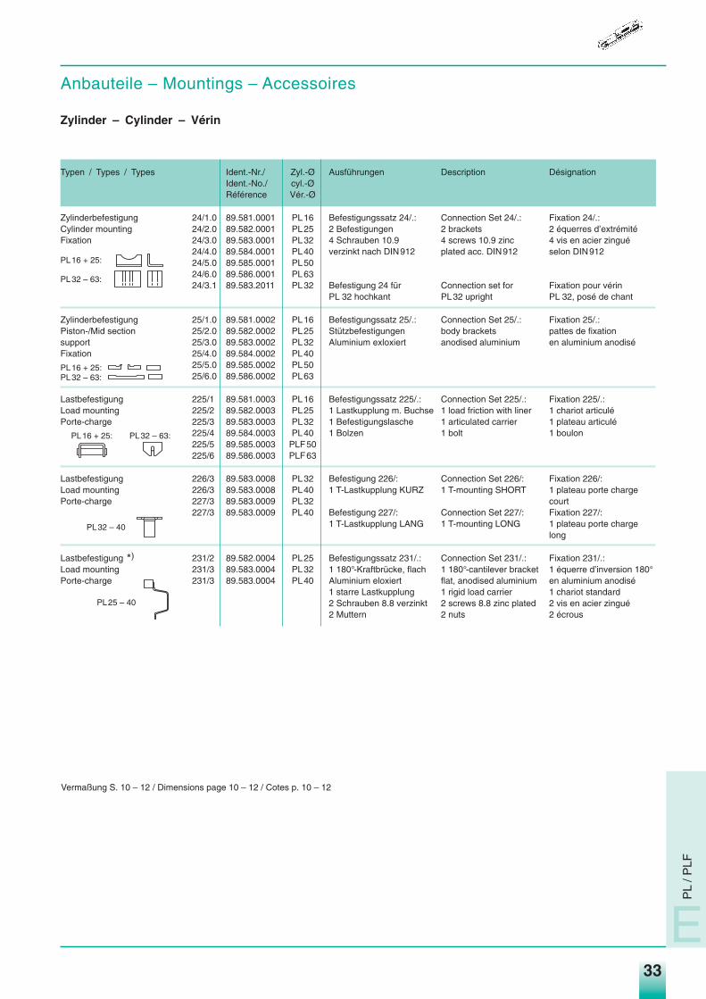
Anbauteile – Mountings – Accessoires
Zylinder – Cylinder – Vérin
Typen / Types / Types Ident.-Nr./ Zyl.-Ø Ausführungen Description DésignationIdent.-No./ cyl.-ØRéférence Vér.-Ø
Zylinderbefestigung 24/1.0 89.581.0001 PL16 Befestigungssatz 24/.: Connection Set 24/.: Fixation 24/.:Cylinder mounting 24/2.0 89.582.0001 PL25 2 Befestigungen 2 brackets 2 équerres d’extrémitéFixation 24/3.0 89.583.0001 PL32 4 Schrauben 10.9 4 screws 10.9 zinc 4 vis en acier zingué
24/4.0 89.584.0001 PL40 verzinkt nach DIN912 plated acc. DIN912 selon DIN91224/5.0 89.585.0001 PL5024/6.0 89.586.0001 PL6324/3.1 89.583.2011 PL32 Befestigung 24 für Connection set for Fixation pour vérin
PL 32 hochkant PL32 upright PL 32, posé de chant
Zylinderbefestigung 25/1.0 89.581.0002 PL16 Befestigungssatz 25/.: Connection Set 25/.: Fixation 25/.:Piston-/Mid section 25/2.0 89.582.0002 PL25 Stützbefestigungen body brackets pattes de fixationsupport 25/3.0 89.583.0002 PL32 Aluminium exloxiert anodised aluminium en aluminium anodiséFixation 25/4.0 89.584.0002 PL40
25/5.0 89.585.0002 PL5025/6.0 89.586.0002 PL63
Lastbefestigung 225/1 89.581.0003 PL16 Befestigungssatz 225/.: Connection Set 225/.: Fixation 225/.:Load mounting 225/2 89.582.0003 PL25 1 Lastkupplung m. Buchse 1 load friction with liner 1 chariot articuléPorte-charge 225/3 89.583.0003 PL32 1 Befestigungslasche 1 articulated carrier 1 plateau articulé
225/4 89.584.0003 PL40 1 Bolzen 1 bolt 1 boulon225/5 89.585.0003 PLF50225/6 89.586.0003 PLF63
Lastbefestigung 226/3 89.583.0008 PL32 Befestigung 226/: Connection Set 226/: Fixation 226/:Load mounting 226/3 89.583.0008 PL40 1 T-Lastkupplung KURZ 1 T-mounting SHORT 1 plateau porte chargePorte-charge 227/3 89.583.0009 PL32 court
227/3 89.583.0009 PL40 Befestigung 227/: Connection Set 227/: Fixation 227/:1 T-Lastkupplung LANG 1 T-mounting LONG 1 plateau porte charge
long
Lastbefestigung *) 231/2 89.582.0004 PL25 Befestigungssatz 231/.: Connection Set 231/.: Fixation 231/.:Load mounting 231/3 89.583.0004 PL32 1 180°-Kraftbrücke, flach 1 180°-cantilever bracket 1 équerre d’inversion 180°Porte-charge 231/3 89.583.0004 PL40 Aluminium eloxiert flat, anodised aluminium en aluminium anodisé
1 starre Lastkupplung 1 rigid load carrier 1 chariot standard2 Schrauben 8.8 verzinkt 2 screws 8.8 zinc plated 2 vis en acier zingué2 Muttern 2 nuts 2 écrous
PL16 + 25:
PL32 – 63:
PL16 + 25:
PL32 – 40
PL25 – 40
PL32 – 63:
PL16 + 25:PL32 – 63:
Vermaßung S. 10 – 12 / Dimensions page 10 – 12 / Cotes p. 10 – 12
PL
/ PLF
E
Medan_hz04.qxd 10.09.2003 16:09 Uhr Seite 33
34
Druckluftzylinder Pneumatic Cylinders Vérins PneumatiquesBaureihe PL … - Linearzylinder Type of Cylinder PL … - Rodless Série PL …- Sans Tige
E
DU
O 9
6
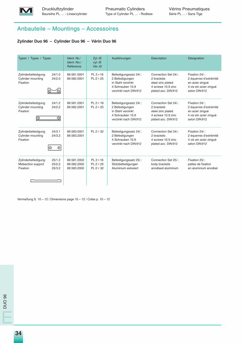
Anbauteile – Mountings – Accessoires
Zylinder Duo 96 – Cylinder Duo 96 – Vérin Duo 96
Typen / Types / Types Ident.-Nr./ Zyl.-Ø Ausführungen Description DésignationIdent.-No./ cyl.-ØRéférence Vér.-Ø
Zylinderbefestigung 24/1.0 89.581.0001 PL 2q16 Befestigungssatz 24/.: Connection Set 24/.: Fixation 24/.:Cylinder mounting 24/2.0 89.582.0001 PL 2q 25 2 Befestigungen 2 brackets 2 équerres d’extrémitéFixation in Stahl verzinkt steel zinc plated en acier zingué
4 Schrauben 10.9 4 screws 10.9 zinc 4 vis ein acier zinguéverzinkt nach DIN912 plated acc. DIN912 selon DIN912
Zylinderbefestigung 24/1.2 89.581.2001 PL 2q 16 Befestigungssatz 24/.: Connection Set 24/.: Fixation 24/.:Cylinder mounting 24/2.2 89.582.2001 PL 2q 25 2 Befestigungen 2 brackets 2 équerres d’extrémitéFixation in Stahl verzinkt steel zinc plated en acier zingué
4 Schrauben 10.9 4 screws 10.9 zinc 4 vis ein acier zinguéverzinkt nach DIN912 plated acc. DIN912 selon DIN912
Zylinderbefestigung 24/3.1 89.583.0001 PL 2q 32 Befestigungssatz 24/.: Connection Set 24/.: Fixation 24/.:Cylinder mounting 24/3.2 89.583.2001 2 Befestigungen 2 brackets 2 équerres d’extrémitéFixation 4 Schrauben 10.9 4 screws 10.9 zinc 4 vis ein acier zingué
verzinkt nach DIN912 plated acc. DIN912 selon DIN912
Zylinderbefestigung 25/1.2 89.581.2002 PL 2q16 Befestigungssatz 25/.: Connection Set 25/.: Fixation 25/.:Midsection support 25/2.2 89.582.2002 PL 2q 25 Stützbefestigungen body brackets pattes de fixationFixation 25/3.2 89.583.2002 PL 2q 32 Aluminium exloxiert anodised aluminium en aluminium anodisé
Vermaßung S. 10 – 12 / Dimensions page 10 – 12 / Cotes p. 10 – 12
Medan_hz04.qxd 10.09.2003 16:09 Uhr Seite 34
35
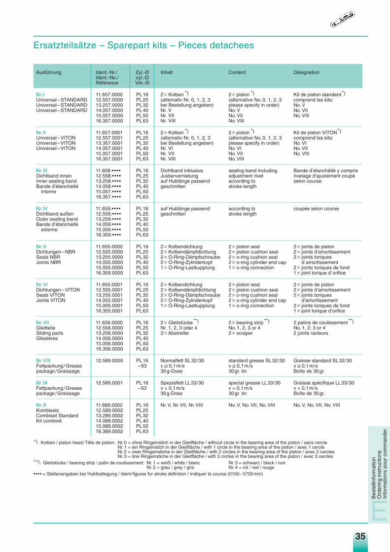
Ersatzteilsätze – Sparepart kits – Pieces detachees
Bes
telli
nfor
mat
ion
Ord
erin
g in
stru
ctio
nsIn
form
atio
ns p
our
com
man
der
E
Ausführung Ident.-Nr./ Zyl.-Ø Inhalt Content DésignationIdent.-No./ cyl.-ØRéférence Vér.-Ø
Nr. I 11.657.0000 PL16 2q Kolben *) 2q piston *) Kit de piston standard*)Universal–STANDARD 12.557.0000 PL25 (alternativ Nr. 0, 1, 2, 3 (alternative No.0, 1, 2, 3 comprend les kits:Universal–STANDARD 13.257.0000 PL32 bei Bestellung angeben) please specify in order) No.VUniversel–STANDARD 14.057.0000 PL40 Nr. V No.V No.VII
15.057.0000 PL50 Nr. VII No.VII No.VIII16.357.0000 PL63 Nr. VIII No.VIII
Nr. II 11.657.0001 PL16 2q Kolben *) 2q piston *) Kit de piston VITON*)Universal–VITON 12.557.0001 PL25 (alternativ Nr. 0, 1, 2, 3 (alternative No.0, 1, 2, 3 comprend les kits:Universal–VITON 13.357.0001 PL32 bei Bestellung angeben) please specify in order) No.VIUniversel–VITON 14.057.0001 PL40 Nr. VI No.VI No.VII
15.057.0001 PL50 Nr. VII No.VII No.VIII16.357.0001 PL63 Nr. VIII No.VIII
Nr. III 11.658.• • • • PL16 Dichtband inklusive sealing band including Bande d’étanchéité y comprisDichtband innen 12.558.• • • • PL25 Justiervernietung adjustment rivet rivetage d’ajustement coupéInner sealing band 13.258.• • • • PL32 auf Hublänge passend according to selon courseBande d’étanchéité 14.058.• • • • PL40 geschnitten stroke length
interne 15.057.• • • • PL5016.357.• • • • PL63
Nr. IV 11.659.• • • • PL16 auf Hublänge passend according to coupée selon courseDichtband außen 12.559.• • • • PL25 geschnitten stroke lengthOuter sealing band 13.259.• • • • PL32Bande d’étanchéité 14.059.• • • • PL40
externe 15.059.• • • • PL5016.359.• • • • PL63
Nr.V 11.655.0000 PL16 2q Kolbendichtung 2q piston seal 2q joints de pistonDichtungen–NBR 12.555.0000 PL25 2q Kolbendämpfdichtung 2q piston cushion seal 2q joints d’amortissementSeals NBR 13.255.0000 PL32 2q O-Ring-Dämpfschraube 2q o-ring cushion seal 2q joints toriques Joints NBR 14.055.0000 PL40 2q O-Ring-Zylinderkopf 2q o-ring cylinder end cap d`amortissement
15.055.0000 PL50 1q O-Ring-Lastkupplung 1q o-ring connection 2q joints toriques de fond16.359.0000 PL63 1q joint torique d`orifice
Nr.VI 11.655.0001 PL16 2q Kolbendichtung 2q piston seal 2q joints de pistonDichtungen–VITON 12.555.0001 PL25 2q Kolbendämpfdichtung 2q piston cushion seal 2q joints d’amortissementSeals VITON 13.255.0001 PL32 2q O-Ring-Dämpfschraube 2q o-ring cushion seal 2q joints toriquesJoints VITON 14.055.0001 PL40 2q O-Ring-Zylinderkopf 2q o-ring cylinder end cap d’amortissement
15.055.0001 PL50 1q O-Ring-Lastkupplung 1q o-ring connection 2q joints toriques de fond16.355.0001 PL63 1q joint torique d’orifice
Nr.VII 11.656.0000 PL16 2q Gleitstücke**) 2q bearing strip **) 2 patins de coulissement **)Gleitteile 12.556.0000 PL25 Nr. 1, 2, 3 oder 4 No.1, 2, 3 or 4 No.1, 2, 3 or 4Sliding parts 13.256.0000 PL32 2q Abstreifer 2q scraper 2 joints racleursGlissières 14.056.0000 PL40
15.056.0000 PL5016.356.0000 PL63
Nr.VIII 12.589.0000 PL16 Normalfett SL32/30 standard grease SL32/30 Graisse standard SL32/30Fettpackung /Grease –63 v p 0,1m/s v p 0,1m/s v p 0,1m/spackage /Graissage 30g-Dose 30gr. tin Boîte de 30gr.
Nr. IX 12.589.0001 PL16 Spezialfett LL33/30 special grease LL33/30 Graisse spécifique LL33/30Fettpackung /Grease –63 v < 0,1m/s v < 0,1m/s v < 0,1m/spackage /Graissage 30g-Dose 30gr. tin Boîte de 30gr.
Nr.X 11.689.0002 PL16 Nr.V, Nr.VII, Nr.VIII No.V, No.VII, No.VIII No.V, No.VII, No.VIIIKombisatz 12.589.0002 PL25Combiset Standard 13.289.0002 PL32Kit combiné 14.089.0002 PL40
15.089.0002 PL5016.389.0002 PL63
∗): Kolben / piston head /Tête de piston: Nr.0 = ohne Ringeinstich in der Gleitfläche / without circle in the bearing area of the piston / sans cercleNr.1 = ein Ringeinstich in der Gleitfläche / with 1 circle in the bearing area of the piston / avec 1 cercleNr.2 = zwei Ringeinstiche in der Gleitfläche / with 2 circles in the bearing area of the piston / avec 2 cerclesNr.3 = drei Ringeinstiche in der Gleitfläche / with 3 circles in the bearing area of the piston / avec 3 cercles
∗∗): Gleitstücke / bearing strip / patin de coulissement: Nr.1 = weiß / white / blanc Nr.3 = schwarz / black / noirNr.2 = grau / grey / gris Nr.4 = rot / red / rouge
• • • • = Stellenangaben bei Hubfestlegung / Ident-figures for stroke definition / indiquer la course (0100–5700mm)
Medan_hz04.qxd 10.09.2003 16:09 Uhr Seite 35
36
Druckluftzylinder Pneumatic Cylinders Vérins PneumatiquesBaureihe PL … - Linearzylinder Type of Cylinder PL … - Rodless Série PL …- Sans Tige
E
PL
/P
LF /
DU
O 9
6P
LG /
PLK
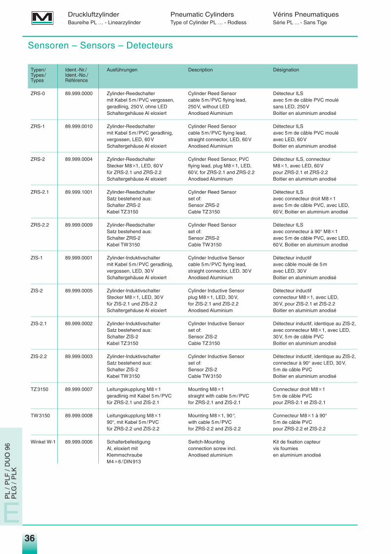
Sensoren – Sensors – Detecteurs
Typen/ Ident.-Nr./ Ausführungen Description DésignationTypes / Ident.-No./Types Référence
ZRS-0 89.999.0000 Zylinder-Reedschalter Cylinder Reed Sensor Détecteur ILSmit Kabel 5m/PVC vergossen, cable 5m/PVC flying lead, avec 5m de câble PVC moulégeradlinig, 250V, ohne LED 250V, without LED sans LED, 250VSchaltergehäuse Al eloxiert Anodised Aluminium Boitier en aluminium anodisé
ZRS-1 89.999.0010 Zylinder-Reedschalter Cylinder Reed Sensor Détecteur ILSmit Kabel 5m/PVC geradlinig, cable 5m/PVC flying lead, avec 5m de câble PVC moulévergossen, LED, 60V straight connector, LED, 60V avec LED, 60VSchaltergehäuse Al eloxiert Anodised Aluminium Boitier en aluminium anodisé
ZRS-2 89.999.0004 Zylinder-Reedschalter Cylinder Reed Sensor, PVC Détecteur ILS, connecteurStecker M8q1, LED, 60V flying lead, plug M8q1, LED, M8q1, avec LED, 60Vfür ZRS-2.1 und ZRS-2.2 60V, for ZRS-2.1 and ZRS-2.2 pour ZRS-2.1 et ZRS-2.2Schaltergehäuse Al eloxiert Anodised Aluminium Boitier en aluminium anodisé
ZRS-2.1 89.999.1001 Zylinder-Reedschalter Cylinder Reed Sensor Détecteur ILSSatz bestehend aus: set of: avec connecteur droit M8q1Schalter ZRS-2 Sensor ZRS-2 avec 5m de câble PVC, avec LED,Kabel TZ3150 Cable TZ3150 60V, Boitier en aluminium anodisé
ZRS-2.2 89.999.0009 Zylinder-Reedschalter Cylinder Reed Sensor Détecteur ILSSatz bestehend aus: set of: avec connecteur à 90° M8q1Schalter ZRS-2 Sensor ZRS-2 avec 5m de câble PVC, avec LED,Kabel TW3150 Cable TW3150 60V, Boitier en aluminium anodisé
ZIS-1 89.999.0001 Zylinder-Induktivschalter Cylinder Inductive Sensor Détecteur inductifmit Kabel 5m/PVC geradlinig, cable 5m/PVC flying lead, avec câble moulé de 5mvergossen, LED, 30V straight connector, LED, 30V avec LED, 30VSchaltergehäuse Al eloxiert Anodised Aluminium Boitier en aluminium anodisé
ZIS-2 89.999.0005 Zylinder-Induktivschalter Cylinder Inductive Sensor Détecteur inductifStecker M8q1, LED, 30V plug M8q1, LED, 30V, connecteur M8q1, avec LED,für ZIS-2.1 und ZIS-2.2 for ZIS-2.1 and ZIS-2.2 30V, pour ZIS-2.1 et ZIS-2.2Schaltergehäuse Al eloxiert Anodised Aluminium Boitier en aluminium anodisé
ZIS-2.1 89.999.0002 Zylinder-Induktivschalter Cylinder Inductive Sensor Détecteur inductif, identique au ZIS-2,Satz bestehend aus: set of: avec connecteur M8q1, avec LED,Schalter ZIS-2 Sensor ZIS-2 30V, 5m de câble PVCKabel TZ3150 Cable TZ3150 Boitier en aluminium anodisé
ZIS-2.2 89.999.0003 Zylinder-Induktivschalter Cylinder Inductive Sensor Détecteur inductif, identique au ZIS-2,Satz bestehend aus: set of: connecteur à 90° avec LED, 30V,Schalter ZIS-2 Sensor ZIS-2 5m de câble PVCKabel TW3150 Cable TW3150 Boitier en aluminium anodisé
TZ3150 89.999.0007 Leitungskupplung M8q1 Mounting M8q1 Connecteur droit M8q1geradlinig mit Kabel 5m/PVC straight with cable 5m/PVC 5m de câble PVCfür ZRS-2.1 und ZIS-2.1 for ZRS-2.1 and ZIS-2.1 pour ZRS-2.1 et ZIS-2.1
TW3150 89.999.0008 Leitungskupplung M8q1 Mounting M8q1, 90°, Connecteur M8q1 à 90°90°, mit Kabel 5m/PVC with cable 5m/PVC 5m de câble PVCfür ZRS-2.2 und ZIS-2.2 for ZRS-2.2 and ZIS-2.2 pour ZRS-2.2 et ZIS-2.2
Winkel W-1 89.999.0006 Schalterbefestigung Switch-Mounting Kit de fixation capteurAl, eloxiert mit connection screw incl. vis fourniesKlemmschraube Anodised aluminium en aluminium anodiséM4q6/DIN913
Medan_hz04.qxd 10.09.2003 16:09 Uhr Seite 36

Medan_hz04.qxd 11.09.2003 8:03 Uhr Seite U2

MEDAN International – Agents and distributors – Agents et distributeurs
DEUTSCHLAND ISBGERMANY Industrievertretung Siegfried BauerALLEMAGNE Moorenweiser Str. 33
D-82299 TürkenfeldTel.: +49 (0)81 93 82 62Fax: +49 (0)81 93 41 83EMail:ISB-Industrievertretung.Bauer@t-online.dewww.isb-industrievertretung.de
IBSIngenieurbüro für LinearantriebeHarald StegmannFlottkamp 46D - 24568 KaltenkirchenTel.: +49 (0)41 9115 63Fax: +49 (0)4 19 17 78 03EMail: [email protected]
Technischer Handel SchenkIm Grund 5D - 34613 SchwalmstadtTel.: +49 (0)66 91 57 44Fax: +49 (0)6 69 17 21 56EMail: [email protected]
IndustrievertretungDirk RönnfeldtLindpaintnerstraße 86D - 70195 StuttgartTel.: +49 (0)711 69 47 00Fax: +49 (0)711 69 60 470Mobil: 0175 54 24 576EMail: [email protected]
Rossbach & Sonnenhol GmbHHohe Steinert 3158509 LüdenscheidTel.: +49 (0)23 51 6 72 69-0Fax: +49 (0)23 51 6 72 69-26Internet: www.rossbach-sonnenhol.de
BENELUX ALFA Techniek B.V.Rondebeltweg 32NL - 1329 BB AlmereTel.: +31 (0)36 5387333Fax: +31 (0)36 5387344EMail: [email protected]
DÄNEMARK Fritz Schur Teknik ASDENMARK Sydmarken 46DANEMARK DK - 2860 Søborg
Tel.: +45 (0)70 20 16 16Fax: +45 (0)70 20 16 15http://www.pneumatik.dk
ENGLAND MATARA UK Ltd.GREAT BRITAIN Bishops Leys Business ParkANGLETERRE Woodmanscote
Cheltenham/Glos. GL52 4QHTel.: +44 (0)1242 679191Fax: +44 (0)1242679196Email: [email protected]
FINNLAND Knorring OY ABFINLAND Kavaarmokuja 6FINLANDE SF - 00380 Helsinki
Tel.: +35 (0)56041Fax: +35 (0) 5652463
FRANKREICH Groupe Delta Equipment SAFRANCE 17–19 rue Fernand Drouilly
F - 92252 La Garenne ColombesTel.: +33 (1)42421144Fax: +33 (1)42421116EMail: [email protected]
ÖSTERREICH Verkaufsbüro f. ÖsterreichAUSTRIA der MEDAN GmbHAUTRICHE Kengelscheiben 27
A - 6173 OberperfussTel.: +43 (0)5 12 36 12 31Fax: +43 (0)5 12 39 70 52EMail: [email protected]
SYSTEC Dienstleistungs-GmbHFiecht Au 11A - 6135 VompTel.: +43 (0) 5242 71348Fax: +43 (0) 5242 71348 14eMail: officesystec.at
ITALIEN ITECA SNCITALY I - 25020 Flero (BS)
Via Rinaldini 62Tel.: +39 030 2761 630Fax: +39 030 2563 095
SCHWEIZ STEFISASWITZERLAND 30, chemin l`ArzelierSUISSE CH - 1071 Chexbres
Tel.: +41 (0)219 464044Fax: +41 (0)219 464045EMail: [email protected]
WOELFEL AGQuellenweg 11/PF42CH-4912 AarwangenTel.: +41 (0) 62 922 48 88Fax: +41 (0) 62 922 63 70EMail: [email protected]
SPANIEN COMERCIAL LEKU-ONA S.L.SPAIN Poligono Industrial Arriaga, 9ESPAGNE Apartado 41
E-20870 ELGOIBAR – GuipúzcoaTel.: +34 943 743 450Fax: +34 943 743 462EMail: [email protected]
IRAN Sherkate Tolid Lavazan MadarPneumatic Hydraulic Badran Co.139, Forsate Shirazi St.North Navvab Ave.Tehran 14197Tel.: +98 (0) 21 69 22 170Fax: +98 (0) 21 69 29 004EMail: [email protected]
KOREA KPSCOREA (Korea Pneumatic Systems Co.)COREE RM 206, Saehan Venture
World 113–15, Shi Heung-Dong,Seoul /KoreaTel.: +822 2 6175008Fax: +822 2 6175009EMail: [email protected]
SINGAPUR Kanto Palmer SystemsSINGAPORE 315 Outram RoadSINGAPOUR #02–06 Tan Boon Liat Building
Singapore 169 074Tel.: +656 2270396Fax: +656 2274441EMail: [email protected]
THAILAND T.V.P. Valve & Pneumatic Co. Ltd.THAILANDE 7/157 MOO 11 Ramindra Road
Kannayao Bangkok 10230 ThailandTel.: +662 9485040-4Fax: +662 9485045
D - 72658 Bempflingen Tel.: +49 (0) 7123 32402Auf dem Brühl 6 Fax: +49 (0) 7123 36580Internet: medan-gmbh.com e-mail: [email protected] 2
000
/09/
02
K7_MEDAN U4_hz 11.09.2003 8:01 Uhr Seite U-4