Embed Size (px)
Citation preview
Partner for Performance
DE|EN 10.2017
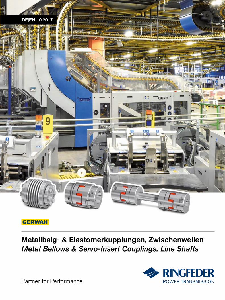
Metallbalg- & Elastomerkupplungen, ZwischenwellenMetal Bellows & Servo-Insert Couplings, Line Shafts
GE
RW
AH
ME
TALL
BA
LG-
& E
LAS
TOM
ER
KU
PP
LUN
GE
N,
ZW
ISC
HE
NW
ELL
EN
· M
ETA
L B
EL
LOW
S &
SE
RV
O-I
NS
ER
T C
OU
PL
ING
S, L
INE
SH
AF
TS ·
DE
|EN
10
|20
17

Mars Rover: Courtesy NASA/JPL-Caltech
Willkommen beim Systemlieferant rund um den Antriebsstrang
RINGFEDER POWER TRANSMISSION
Wir sagen, was wir meinen und wir meinen, was wir sagen.
Wir sehen die Dinge aus der Sicht unserer Kunden.
Wir nehmen Rücksicht auf unsere Mitarbeiter und deren Familien sowie auf unsere Umwelt und Gesellschaft.
RINGFEDER POWER TRANSMISSION ist weltweit Marktführer in Nischenmärkten der Antriebstechnik und aufgrund seiner kun-denspezifischen, anwendungsorientierten Lösungen geschätzt, die den Kunden einen herausragenden und störungsfreien Betrieb sichern.
Unter unseren starken Markennamen RINGFEDER, TSCHAN, HENFEL und GERWAH bieten wir Spannverbindungen, Kupplun-gen, Lagergehäuse und Dämpfungstechnik für den Erstausrüster,
aber auch den Endkunden an. Unter der Marke ECOLOC bieten wir verlässliche Produkte von der Stange.
Kunden beraten wir nicht nur kompetent mit über 90 Jahren Erfahrung, sondern entwickeln zusammen mit Ihnen innovative Ideen. Mit unserem Anspruch als Partner for Performance.
Rund um den Antriebsstrang versprechen wir
Ausgezeichnetes Know-how für unsere anspruchsvollen Kunden
Bestes Kosten-Nutzen-Verhältnis
Kurze Reaktionszeiten und hohe Produktverfügbarkeit
2

Welcome to your system supplier for every aspect of power transmission
We not only provide competent advice to our customers on the basis of our 90 years of experience but also develop innovative ideas in cooperation with them. This is part of our aspiration to be a Partner for Performance.
Around the power transmission we promise
Excellent know-how for our challenging customers
Best cost-benefit ratio
Short reaction times and a high product availability
RINGFEDER POWER TRANSMISSION
We say what we mean and mean what we say.
We see things from our customers‘ perspective.
We are considerate of our employees and their families as well as our environment and the society.
RINGFEDER POWER TRANSMISSION is the global market leader in the niche markets of drive technology and is well regarded for its customer-specific, application-oriented solutions that ensure excel-lent and failure-free operation for its clients.
We offer locking devices, couplings, bearing housings and damp-ing technology for OEMs but also for the final customer under our strong brand names RINGFEDER, TSCHAN, HENFEL and GERWAH. Our brand ECOLOC supplies reliable products off the shelf.
3
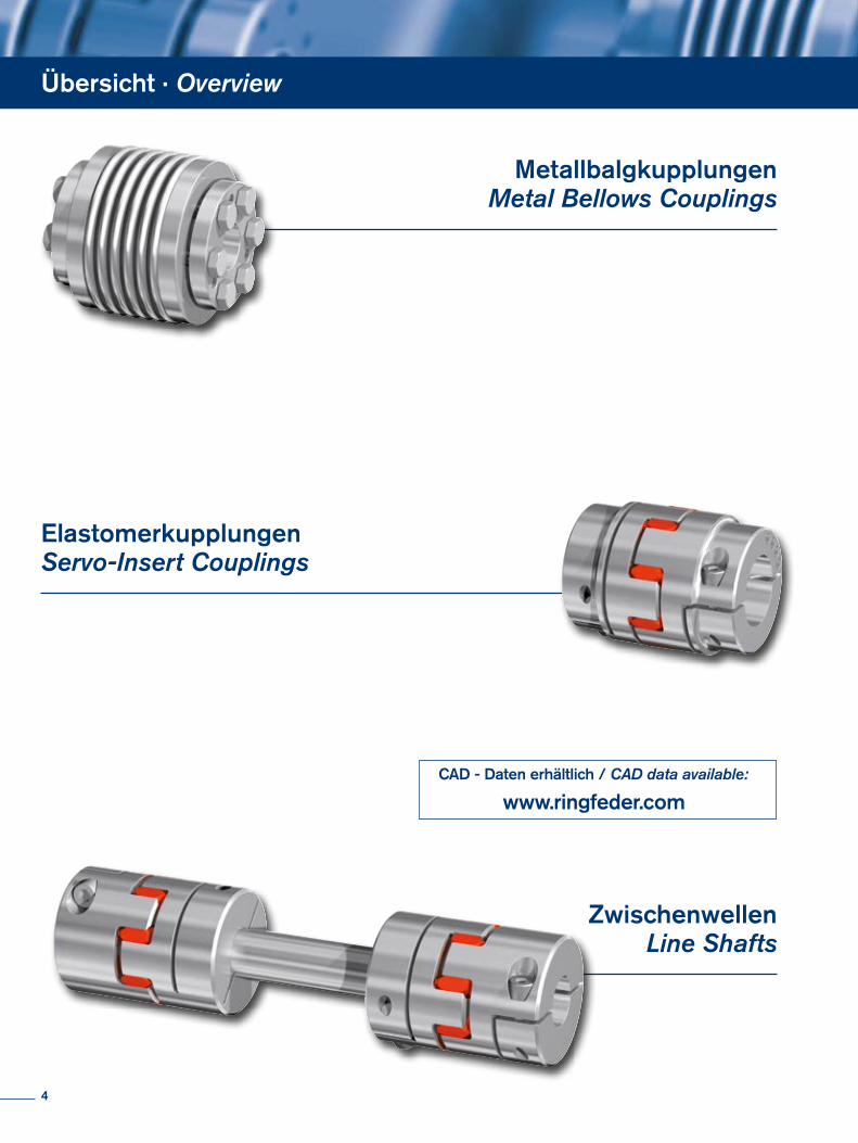
Übersicht · Overview
Metallbalgkupplungen Metal Bellows Couplings
ElastomerkupplungenServo-Insert Couplings
ZwischenwellenLine Shafts
CAD - Daten erhältlich / CAD data available:
www.ringfeder.com
4
Inhalt · Content
02 Imageseiten Pages Corporate Image
04 Übersicht · Overview
05 Inhalt · Content
Metallbalgkupplungen Metal Bellows Couplings
06 Grundlagen · Basics08 Produktübersicht · Product Overview10 GERWAH® EKN12 GERWAH® DKN14 GERWAH® DKN/S 16 GERWAH® PKA 18 GERWAH® PKB20 GERWAH® PKN22 GERWAH® AKN24 GERWAH® AKN-H26 GERWAH® AKD28 GERWAH® AKD-H30 GERWAH® AK32 GERWAH® CKN34 Technische Hinweise · Technical Information
Elastomerkupplungen Servo-Insert Couplings
38 Grundlagen · Basics41 Produktübersicht · Product Overview42 GERWAH® GWE 510244 GERWAH® GWE 5103
46 GERWAH® GWE 5103.148 GERWAH® GWE 510750 GERWAH® GWE 510452 GERWAH® GWE 510654 GERWAH® GWE 511256 Technische Hinweise · Technical Information Zwischenwellen · Line Shafts
58 Grundlagen · Basics61 Produktübersicht · Product Overview62 GERWAH® GWZ 5104.164 GERWAH® GWZ 5106.166 GERWAH® GWZ 511668 GERWAH® GWZ 5106 Montageanleitungen Mounting Instructions
70 Metallbalgkupplungen Metal Bellows Couplings72 Elastomerkupplungen Servo-Insert Couplings 75 Zwischenwellen · Line Shafts78 Biegekritische Drehzahlen Critical bending speeds
80 Fax-Anfrage · Fax Inquiry
82 Lieferprogramm · Product Range RINGFEDER POWER TRANSMISSION
Alle technischen Daten und Hin weise sind unverbindlich. Rechts ansprüche können daraus nicht abgeleitet werden. Der Anwender ist grundsätzlich verpflichtet zu prüfen, ob die dar-gestellten Produkte seinen Anforderungen genügen. Änderungen, die dem technischen Fortschritt dienen, behalten wir uns jederzeit vor. Mit Erscheinen dieses Kataloges werden alle älteren Prospekte und Fragebögen zu den gezeigten Produkten ungültig.
All technical details and information are non-binding and cannot be used as a basis for legal claims. The user is obligated to determine whether the represented products meet his requirements. We reserve the right at all times to carry out modifications in the interests of technical progress. Upon the issue of this catalogue all previous brochures and questionnaires on the products displayed are no longer valid.
5
Metallbalgkupplungen Grundlagen
Spielfreie Metallbalgkupplungen
Characteristics of Metal Bellows Couplings:
Backlash-free transmission of torque
High torsional stiffness, precision of transmission of rotational angle
Different torsional stiffness
Compact design, low moment of inertia
Metal bellows made of stainless steel
Simple and safe assembly
Compensation of radial, axial and angular misalignment
Free of wear, maintenance-free, no downtimes
Not sensitive to temperatures between -30 °C and +100 °C
Nominal torques between 0,1 – 5000 Nm
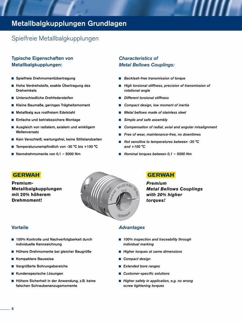
Typische Eigenschaften von Metallbalgkupplungen:
Spielfreie Drehmomentübertragung
Hohe Verdrehsteife, exakte Übertragung des Drehwinkels
Unterschiedliche Drehfedersteifen
Kleine Baumaße, geringes Trägheitsmoment
Metallbalg aus rostfreiem Edelstahl
Einfache und betriebssichere Montage
Ausgleich von radialem, axialem und winkligem Wellenversatz
Kein Verschleiß, wartungsfrei, keine Stillstandzeiten
Temperaturunempfindlich von -30 °C bis +100 °C
Nenndrehmomente von 0,1 – 5000 Nm
Vorteile
100% Kontrolle und Nachverfolgbarkeit durch individuelle Kennzeichnung
Höhere Drehmomente bei gleicher Baugröße
Kompaktere Bauweise
Vergrößerte Bohrungsbereiche
Kundenspezische Lösungen
Höhere Sicherheit in der Anwendung, z.B. keine falschen Schraubenanzugsmomente
Advantages
100% inspection and traceability through individual marking
Higher torques at same dimensions
Compact design
Extended bore ranges
Customer-specific solutions
Higher safety in application, e.g. no wrong screw tightening torques
Premium- Metallbalgkupplungen mit 20% höherem Drehmoment!
Premium Metal Bellows Couplings with 20% higher torques!
6
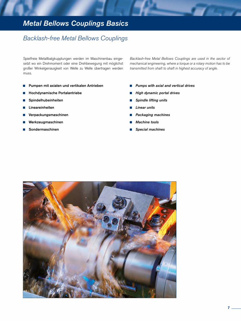
Metal Bellows Couplings Basics
Spielfreie Metallbalgkupplungen werden im Maschinenbau einge-setzt wo ein Drehmoment oder eine Drehbewegung mit möglichst großer Winkelgenauigkeit von Welle zu Welle übertragen werden muss.
Backlash-free Metal Bellows Couplings are used in the sector of mechanical engineering, where a torque or a rotary motion has to be transmitted from shaft to shaft in highest accuracy of angle.
Pumpen mit axialen und vertikalen Antrieben
Hochdynamische Portalantriebe
Spindelhubeinheiten
Lineareinheiten
Verpackungsmaschinen
Werkzeugmaschinen
Sondermaschinen
Pumps with axial and vertical drives
High dynamic portal drives
Spindle lifting units
Linear units
Packaging machines
Machine tools
Special machines
Backlash-free Metal Bellows Couplings
7
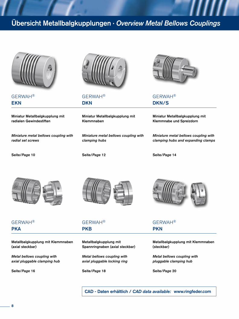
GERWAH® EKN
Miniatur Metallbalgkupplung mit radialen Gewindestiften
Miniature metal bellows coupling with radial set screws
Seite/Page 10
GERWAH® DKN
Miniatur Metallbalgkupplung mit Klemmnaben
Miniature metal bellows coupling with clamping hubs
Seite/Page 12
GERWAH® DKN/S
Miniatur Metallbalgkupplung mit Klemmnabe und Spreizdorn
Miniature metal bellows coupling with clamping hubs and expanding clamps
Seite/Page 14
GERWAH® PKN
Metallbalgkupplung mit Klemmnaben (steckbar)
Metal bellows coupling with pluggable clamping hub
Seite/Page 20
Übersicht Metallbalgkupplungen · Overview Metal Bellows Couplings
GERWAH® PKA
Metallbalgkupplung mit Klemmnaben (axial steckbar)
Metal bellows coupling with axial pluggable clamping hub
Seite/Page 16
GERWAH® PKB
Metallbalgkupplung mit Spannringnaben (axial steckbar)
Metal bellows coupling with axial pluggable locking ring
Seite/Page 18
CAD - Daten erhältlich / CAD data available: www.ringfeder.com
8
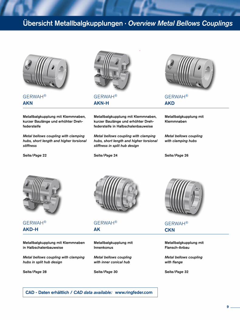
GERWAH® AKN
Metallbalgkupplung mit Klemmnaben, kurzer Baulänge und erhöhter Dreh-federsteife
Metal bellows coupling with clamping hubs, short length and higher torsional stiffness
Seite/Page 22
GERWAH® AKD
Metallbalgkupplung mit Klemmnaben
Metal bellows coupling with clamping hubs
Seite/Page 26
GERWAH® AK
Metallbalgkupplung mit Innenkonus
Metal bellows coupling with inner conical hub
Seite/Page 30
GERWAH® CKN
Metallbalgkupplung mit Flansch-Anbau
Metal bellows coupling with flange
Seite/Page 32
GERWAH® AKN-H
Metallbalgkupplung mit Klemmnaben, kurzer Baulänge und erhöhter Dreh-federsteife in Halbschalenbauweise
Metal bellows coupling with clamping hubs, short length and higher torsional stiffness in split hub design
Seite/Page 24
GERWAH® AKD-H
Metallbalgkupplung mit Klemmnaben in Halbschalenbauweise
Metal bellows coupling with clamping hubs in split hub design
Seite/Page 28
Übersicht Metallbalgkupplungen · Overview Metal Bellows Couplings
CAD - Daten erhältlich / CAD data available: www.ringfeder.com
9
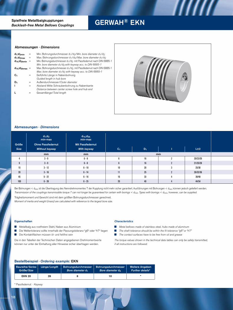
Spielfreie MetallbalgkupplungenBacklash-free Metal Bellows Couplings GERWAH® EKN
Abmessungen · Dimensions
Trägheitsmoment und Gewicht sind mit dem größten Bohrungsdurchmesser gerechnet. Moment of inertia and weight (mass) are calculated with reference to the largest bore size.
Abmessungen · Dimensions
Bestellbeispiel · Ordering example: EKN
Baureihe/SeriesGröße/Size
Länge/Length Bohrungsdurchmesser Bore diameter d1
Bohrungsdurchmesser Bore diameter d2
Weitere AngabenFurther details*
EKN 20 26 6 10 *
* Passfedernut · Keyway
Eigenschaften
Metallbalg aus rostfreiem Stahl, Naben aus Aluminium Die Wellentoleranz sollte innerhalb der Passungstoleranz “g6“ oder “h7“ liegen Die Kontaktflächen müssen öl- und fettfrei sein
Die in den Tabellen der Technischen Daten angegebenen Drehmomentwerte können nur unter der Einhaltung aller Hinweise sicher übertragen werden.
Characteristics
Metal bellows made of stainless steel, hubs made of aluminum The shaft tolerance should be within the fit tolerance “g6” or “h7” The contact surfaces have to be free from oil and grease
The torque values shown in the technical data tables can only be safely transmitted, if all instructions are followed.
d1;d2min = Min. Bohrungsdurchmesser d1/d2/Min. bore diameter d1/d2 d1;d2max = Max. Bohrungsdurchmesser d1/d2/Max. bore diameter d1/d2d1k;d2kmin = Min. Bohrungsdurchmesser d1/d2 mit Passfedernut nach DIN 6885-1 Min. bore diameter d1/d2 with keyway acc. to DIN 6885-1d1k;d2kmax = Max. Bohrungsdurchmesser d1/d2 mit Passfedernut nach DIN 6885-1 Max. bore diameter d1/d2 with keyway acc. to DIN 6885-1 C1 = Geführte Länge in Nabenbohrung Guided length in hub bore D1 = Außendurchmesser/Outer diameter l = Abstand Mitte Schraubenbohrung zu Nabenkante Distance between center screw hole and hub end L = Gesamtlänge/Total length
Bei Bohrungen < dmin ist die Übertragung des Nenndrehmomentes T der Kupplung nicht mehr sicher garantiert. Ausführungen mit Bohrungen < dmin können jedoch geliefert werden. Transmission of the couplings transmissible torque T can not longer be guaranteed for certain with borings < dmin. Types with borings < dmin, however, can be supplied.
d1;d2min-max
d1k;d2kmin-max
Größe Ohne Passfedernut Mit Passfedernut
Size Without keyway With keyway C1 D1 I L±2
mm mm mm
4 3 - 9 6 - 8 6 16 2 20/23/26
9 3 - 9 6 - 8 6 16 2 21/25/28
15 3 - 12 6 - 10 10 20 3 25/30
20 3 - 16 6 - 14 11 25 2 26/32/36
45 6 - 22 6 - 16 16 33 4 39/48
100 6 - 28 6 - 25 20 40 4 44/54
10
DG1 ISO 4029
120°
d 2
d1
I
C1
L±2
D1
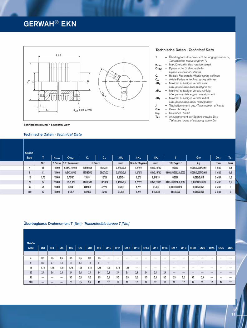
Schnittdarstellung / Sectional view
Technische Daten · Technical Data
T = Übertragbares Drehmoment bei angegebenem TA Transmissible torque at given TAnmax = Max. Drehzahl/Max. rotation speedCTdyn = Dynamische Drehfedersteife Dynamic torsional stiffness Cr = Radiale Federsteife/Radial spring stiffnessCa = Axiale Federsteife/Axial spring stiffness ∆Ka = Maximal zulässiger Versatz axial Max. permissible axial misalignment ∆Kw = Maximal zulässiger Versatz winklig Max. permissible angular misalignment ∆Kr = Maximal zulässiger Versatz radial Max. permissible radial misalignment J = Trägheitsmoment ges./Total moment of inertia Gw = Gewicht/Weight DG1 = Gewinde/Thread TA1 = Anzugsmoment der Spannschraube DG1 Tightened torque of clamping screw DG1
Technische Daten · Technical Data
Übertragbares Drehmoment T [Nm] · Transmissible torque T [Nm]
GERWAH® EKN
Größe
Size Ø3 Ø4 Ø5 Ø6 Ø7 Ø8 Ø9 Ø10 Ø11 Ø12 Ø13 Ø14 Ø15 Ø16 Ø17 Ø18 Ø20 Ø22 Ø24 Ø26 Ø28
4 0,5 0,5 0,5 0,5 0,5 0,5 0,5 --- --- --- --- --- --- --- --- --- --- --- --- --- ---
9 0,9 0,7 1,1 1,1 1,1 1,1 1,1 --- --- --- --- --- --- --- --- --- --- --- --- --- ---
15 1,75 1,75 1,75 1,75 1,75 1,75 1,75 1,75 1,75 1,75 --- --- --- --- --- --- --- --- --- --- ---
20 2,4 2,4 2,4 2,4 2,4 2,4 2,4 2,4 2,4 2,4 2,4 2,4 2,4 2,4 --- --- --- --- --- --- ---
45 --- --- --- 5,5 5,5 5,5 5,5 5,5 5,5 5,5 5,5 5,5 5,5 5,5 5,5 5,5 5,5 5,5 --- --- ---
100 --- --- --- 7,3 8,5 9,7 11 12 12 12 12 12 12 12 12 12 12 12 12 12 12
d1;d2min-max
d1k;d2kmin-max
Größe Ohne Passfedernut Mit Passfedernut
Size Without keyway With keyway C1 D1 I L±2
mm mm mm
4 3 - 9 6 - 8 6 16 2 20/23/26
9 3 - 9 6 - 8 6 16 2 21/25/28
15 3 - 12 6 - 10 10 20 3 25/30
20 3 - 16 6 - 14 11 25 2 26/32/36
45 6 - 22 6 - 16 16 33 4 39/48
100 6 - 28 6 - 25 20 40 4 44/54
Größe
Size T nmax CTdyn Cr Ca ∆Ka ∆Kw ∆Kr J Gw DG1 TA1
Nm 1/min 103 Nm/rad N/mm mm Grad/Degree mm 10-3kgm2 kg mm Nm
4 0,5 15000 0,25/0,19/0,15 128/54/26 18/13/11 0,2/0,3/0,4 1,2/2/2 0,1/0,15/0,2 0,0002 0,005/0,006/0,007 1 x M3 0,5
9 1,1 15000 0,5/0,38/0,3 187/82/42 36/27/22 0,2/0,3/0,4 1,2/2/2 0,1/0,15/0,2 0,0002/0,0002/0,0003 0,006/0,007/0,008 1 x M3 0,5
15 1,75 15000 0,75/0,7 139/81 12/23 0,25/0,4 1,2/2 0,1/0,15 0,0008 0,012/0,014 2 x M4 1,5
20 2,4 15000 1,5/1,3/1 147/96/46 18/14/9 0,3/0,4/0,5 1,2/2/2 0,1/0,2/0,25 0,0014/0,0016/0,0017 0,016/0,018/0,02 2 x M3 1,5
45 5,5 15000 6,5/4 444/108 47/29 0,3/0,5 1,2/2 0,1/0,2 0,0068/0,0073 0,048/0,052 2 x M6 3
100 12 15000 8,1/6,7 361/193 46/34 0,4/0,5 1,2/2 0,15/0,25 0,02/0,022 0,048/0,058 2 x M6 3
11
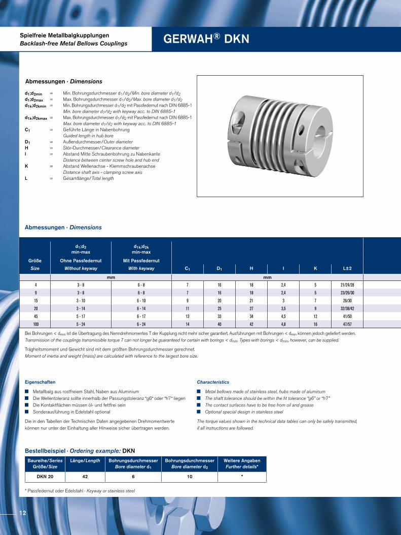
Spielfreie MetallbalgkupplungenBacklash-free Metal Bellows Couplings GERWAH® DKN
Abmessungen · Dimensions
Abmessungen · Dimensions
Trägheitsmoment und Gewicht sind mit dem größten Bohrungsdurchmesser gerechnet. Moment of inertia and weight (mass) are calculated with reference to the largest bore size.
Bestellbeispiel · Ordering example: DKN
Baureihe/SeriesGröße/Size
Länge/Length Bohrungsdurchmesser Bore diameter d1
BohrungsdurchmesserBore diameter d2
Weitere AngabenFurther details*
DKN 20 42 6 10 *
* Passfedernut oder Edelstahl · Keyway or stainless steel
Eigenschaften
Metallbalg aus rostfreiem Stahl, Naben aus Aluminium Die Wellentoleranz sollte innerhalb der Passungstoleranz “g6“ oder “h7“ liegen Die Kontaktflächen müssen öl- und fettfrei sein Sonderausführung in Edelstahl optional
Die in den Tabellen der Technischen Daten angegebenen Drehmomentwerte können nur unter der Einhaltung aller Hinweise sicher übertragen werden.
Characteristics
Metal bellows made of stainless steel, hubs made of aluminum The shaft tolerance should be within the fit tolerance “g6” or “h7” The contact surfaces have to be free from oil and grease Optional special design in stainless steel
The torque values shown in the technical data tables can only be safely transmitted, if all instructions are followed.
d1;d2min = Min. Bohrungsdurchmesser d1/d2/Min. bore diameter d1/d2 d1;d2max = Max. Bohrungsdurchmesser d1/d2/Max. bore diameter d1/d2d1k;d2kmin = Min. Bohrungsdurchmesser d1/d2 mit Passfedernut nach DIN 6885-1 Min. bore diameter d1/d2 with keyway acc. to DIN 6885-1d1k;d2kmax = Max. Bohrungsdurchmesser d1/d2 mit Passfedernut nach DIN 6885-1 Max. bore diameter d1/d2 with keyway acc. to DIN 6885-1 C1 = Geführte Länge in Nabenbohrung Guided length in hub bore D1 = Außendurchmesser/Outer diameter H = Stör-Durchmesser/Clearance diameter l = Abstand Mitte Schraubenbohrung zu Nabenkante Distance between center screw hole and hub end K = Abstand Wellenachse - Klemmschraubenachse Distance shaft axis - clamping screw axis L = Gesamtlänge/Total length
Bei Bohrungen < dmin ist die Übertragung des Nenndrehmomentes T der Kupplung nicht mehr sicher garantiert. Ausführungen mit Bohrungen < dmin können jedoch geliefert werden. Transmission of the couplings transmissible torque T can not longer be guaranteed for certain with borings < dmin. Types with borings < dmin, however, can be supplied.
d1;d2min-max
d1k;d2kmin-max
Größe Ohne Passfedernut Mit Passfedernut
Size Without keyway With keyway C1 D1 H I K L±2
mm mm
4 3 - 8 6 - 8 7 16 18 2,4 5 21/24/28
9 3 - 8 6 - 8 7 16 18 2,4 5 23/26/30
15 3 - 10 6 - 10 9 20 21 3 7 26/30
20 3 - 14 6 - 14 11 25 27 3,5 9 32/38/42
45 5 - 17 6 - 17 13 33 34 4,5 12 41/50
100 5 - 24 6 - 24 14 40 42 4,8 16 47/57
12
DG1 ISO 4762
d 1 d 2
I
L±2
C1
H
K
D1
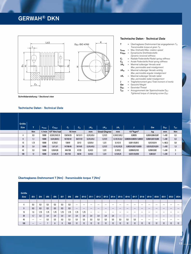
Schnittdarstellung / Sectional view
Technische Daten · Technical Data
Technische Daten · Technical Data
Übertragbares Drehmoment T [Nm] · Transmissible torque T [Nm]
T = Übertragbares Drehmoment bei angegebenem TA Transmissible torque at given TAnmax = Max. Drehzahl/Max. rotation speedCTdyn = Dynamische Drehfedersteife Dynamic torsional stiffness Cr = Radiale Federsteife/Radial spring stiffnessCa = Axiale Federsteife/Axial spring stiffness ∆Ka = Maximal zulässiger Versatz axial Max. permissible axial misalignment ∆Kw = Maximal zulässiger Versatz winklig Max. permissible angular misalignment ∆Kr = Maximal zulässiger Versatz radial Max. permissible radial misalignment J = Trägheitsmoment ges./Total moment of inertia Gw = Gewicht/Weight DG1 = Gewinde/Thread TA1 = Anzugsmoment der Spannschraube DG1 Tightened torque of clamping screw DG1
GERWAH® DKN
Größe
Size Ø3 Ø4 Ø5 Ø6 Ø7 Ø8 Ø9 Ø10 Ø11 Ø12 Ø13 Ø14 Ø15 Ø16 Ø17 Ø18 Ø19 Ø20 Ø21 Ø22 Ø24
4 0,5 0,5 0,5 0,5 0,5 0,5 --- --- --- --- --- --- --- --- --- --- --- --- --- --- ---
9 0,5 0,5 0,5 0,5 0,5 0,5 --- --- --- --- --- --- --- --- --- --- --- --- --- --- ---
15 1,5 1,75 1,75 1,75 1,75 1,75 1,75 1,75 --- --- --- --- --- --- --- --- --- --- --- --- ---
20 1,7 2,3 2,4 2,4 2,4 2,4 2,4 2,4 2,4 2,4 2,4 2,4 --- --- --- --- --- --- --- --- ---
45 --- --- 5,5 5,5 5,5 5,5 5,5 5,5 5,5 5,5 5,5 5,5 5,5 5,5 5,5 --- --- --- --- --- ---
100 --- --- 7 8 9 10,5 12 12 12 12 12 12 12 12 12 12 12 12 12 12 12
d1;d2min-max
d1k;d2kmin-max
Größe Ohne Passfedernut Mit Passfedernut
Size Without keyway With keyway C1 D1 H I K L±2
mm mm
4 3 - 8 6 - 8 7 16 18 2,4 5 21/24/28
9 3 - 8 6 - 8 7 16 18 2,4 5 23/26/30
15 3 - 10 6 - 10 9 20 21 3 7 26/30
20 3 - 14 6 - 14 11 25 27 3,5 9 32/38/42
45 5 - 17 6 - 17 13 33 34 4,5 12 41/50
100 5 - 24 6 - 24 14 40 42 4,8 16 47/57
Größe
Size T nmax CTdyn Cr Ca ∆Ka ∆Kw ∆Kr J Gw DG1 TA1
Nm 1/min 103 Nm/rad N/mm mm Grad/Degree mm 10-3kgm2 kg mm Nm
4 0,5 15000 0,25/0,19/0,15 128/54/26 18/13/11 0,2/0,3/0,4 1,2/2/2 0,10/0,15/0,2 0,00026 0,005/0,006/0,007 1 x M2 0,3
9 1,1 15000 0,5/0,38/0,3 187/82/42 36/27/22 0,2/0,3/0,4 1,2/2/2 0,1/0,15/,0,2 0,00026/0,00029/ 0,00032 0,006/0,007/0,008 1 x M2 0,3
15 1,75 15000 0,75/0,7 139/81 23/12 0,25/0,4 1,2/2 0,1/0,15 0,0011/0,0012 0,012/0,014 1 x M2,5 0,8
20 2,4 15000 1,5/1,3/1 147/96/46 18/14/9 0,3/0,4/0,5 1,2/2/2 0,1/0,2/0,25 0,0025/0,0027/0,0028 0,02/0,022/0,024 1 x M3 1,5
45 5,5 15000 6,50/4,00 444/108 47/29 0,3/0,5 1,2/2 0,10/0,2 0,0098/0,0103 0,058/0,062 1 x M4 3
100 12 15000 8,10/6,70 361/193 46/34 0,4/0,5 1,2/2 0,15/0,25 0,0231/0,0250 0,06/0,07 1 x M4 3
13
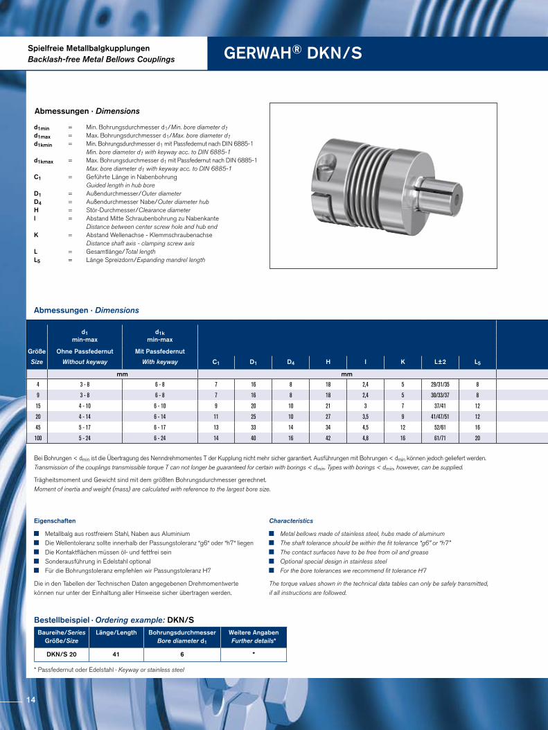
Spielfreie MetallbalgkupplungenBacklash-free Metal Bellows Couplings GERWAH® DKN/S
Abmessungen · Dimensions
Trägheitsmoment und Gewicht sind mit dem größten Bohrungsdurchmesser gerechnet.Moment of inertia and weight (mass) are calculated with reference to the largest bore size.
Abmessungen · Dimensions
Eigenschaften
Metallbalg aus rostfreiem Stahl, Naben aus Aluminium Die Wellentoleranz sollte innerhalb der Passungstoleranz “g6“ oder “h7“ liegen Die Kontaktflächen müssen öl- und fettfrei sein Sonderausführung in Edelstahl optional Für die Bohrungstoleranz empfehlen wir Passungstoleranz H7
Die in den Tabellen der Technischen Daten angegebenen Drehmomentwerte können nur unter der Einhaltung aller Hinweise sicher übertragen werden.
Characteristics
Metal bellows made of stainless steel, hubs made of aluminum The shaft tolerance should be within the fit tolerance “g6” or “h7” The contact surfaces have to be free from oil and grease Optional special design in stainless steel For the bore tolerances we recommend fit tolerance H7
The torque values shown in the technical data tables can only be safely transmitted, if all instructions are followed.
Bestellbeispiel · Ordering example: DKN/SBaureihe/Series
Größe/SizeLänge/Length Bohrungsdurchmesser
Bore diameter d1
Weitere AngabenFurther details*
DKN/S 20 41 6 *
* Passfedernut oder Edelstahl · Keyway or stainless steel
d1min = Min. Bohrungsdurchmesser d1/Min. bore diameter d1 d1max = Max. Bohrungsdurchmesser d1/Max. bore diameter d1 d1kmin = Min. Bohrungsdurchmesser d1 mit Passfedernut nach DIN 6885-1 Min. bore diameter d1 with keyway acc. to DIN 6885-1 d1kmax = Max. Bohrungsdurchmesser d1 mit Passfedernut nach DIN 6885-1 Max. bore diameter d1 with keyway acc. to DIN 6885-1C1 = Geführte Länge in Nabenbohrung Guided length in hub bore D1 = Außendurchmesser/Outer diameter D4 = Außendurchmesser Nabe/Outer diameter hub H = Stör-Durchmesser/Clearance diameter l = Abstand Mitte Schraubenbohrung zu Nabenkante Distance between center screw hole and hub end K = Abstand Wellenachse - Klemmschraubenachse Distance shaft axis - clamping screw axis L = Gesamtlänge/Total lengthL5 = Länge Spreizdorn/Expanding mandrel length
Bei Bohrungen < dmin ist die Übertragung des Nenndrehmomentes T der Kupplung nicht mehr sicher garantiert. Ausführungen mit Bohrungen < dmin können jedoch geliefert werden. Transmission of the couplings transmissible torque T can not longer be guaranteed for certain with borings < dmin. Types with borings < dmin, however, can be supplied.
d1min-max
d1kmin-max
Größe Ohne Passfedernut Mit Passfedernut
Size Without keyway With keyway C1 D1 D4 H I K L±2 L5
mm mm
4 3 - 8 6 - 8 7 16 8 18 2,4 5 29/31/35 8
9 3 - 8 6 - 8 7 16 8 18 2,4 5 30/33/37 8
15 4 - 10 6 - 10 9 20 10 21 3 7 37/41 12
20 4 - 14 6 - 14 11 25 10 27 3,5 9 41/47/51 12
45 5 - 17 6 - 17 13 33 14 34 4,5 12 52/61 16
100 5 - 24 6 - 24 14 40 16 42 4,8 16 61/71 20
14
DG1ISO 4762
DG2ISO 4762
I
D4
D1
C1
d 1
K
HL±2
L5
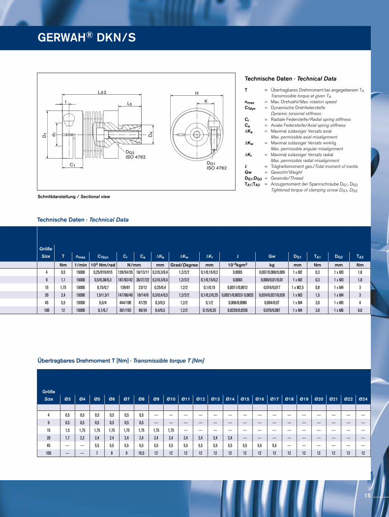
Schnittdarstellung / Sectional view
Technische Daten · Technical Data
Technische Daten · Technical Data
Übertragbares Drehmoment T [Nm] · Transmissible torque T [Nm]
T = Übertragbares Drehmoment bei angegebenem TA Transmissible torque at given TAnmax = Max. Drehzahl/Max. rotation speedCTdyn = Dynamische Drehfedersteife Dynamic torsional stiffness Cr = Radiale Federsteife/Radial spring stiffnessCa = Axiale Federsteife/Axial spring stiffness ∆Ka = Maximal zulässiger Versatz axial Max. permissible axial misalignment ∆Kw = Maximal zulässiger Versatz winklig Max. permissible angular misalignment ∆Kr = Maximal zulässiger Versatz radial Max. permissible radial misalignment J = Trägheitsmoment ges./Total moment of inertia Gw = Gewicht/Weight DG1;DG2 = Gewinde/Thread TA1;TA2 = Anzugsmoment der Spannschraube DG1, DG2 Tightened torque of clamping screw DG1, DG2
GERWAH® DKN/S
Größe
Size Ø3 Ø4 Ø5 Ø6 Ø7 Ø8 Ø9 Ø10 Ø11 Ø12 Ø13 Ø14 Ø15 Ø16 Ø17 Ø18 Ø19 Ø20 Ø21 Ø22 Ø24
4 0,5 0,5 0,5 0,5 0,5 0,5 --- --- --- --- --- --- --- --- --- --- --- --- --- --- ---
9 0,5 0,5 0,5 0,5 0,5 0,5 --- --- --- --- --- --- --- --- --- --- --- --- --- --- ---
15 1,5 1,75 1,75 1,75 1,75 1,75 1,75 1,75 --- --- --- --- --- --- --- --- --- --- --- --- ---
20 1,7 2,3 2,4 2,4 2,4 2,4 2,4 2,4 2,4 2,4 2,4 2,4 --- --- --- --- --- --- --- --- ---
45 --- --- 5,5 5,5 5,5 5,5 5,5 5,5 5,5 5,5 5,5 5,5 5,5 5,5 5,5 --- --- --- --- --- ---
100 --- --- 7 8 9 10,5 12 12 12 12 12 12 12 12 12 12 12 12 12 12 12
Größe
Size T nmax CTdyn Cr Ca ∆Ka ∆Kw ∆Kr J Gw DG1 TA1 DG2 TA2
Nm 1/min 103 Nm/rad N/mm mm Grad/Degree mm 10-3kgm2 kg mm Nm mm Nm
4 0,5 15000 0,25/019/015 128/54/26 18/13/11 0,2/0,3/0,4 1,2/2/2 0,1/0,15/0,2 0,0003 0,007/0,008/0,009 1 x M2 0,3 1 x M3 1,8
9 1,1 15000 0,5/0,38/0,3 187/82/42 36/27/22 0,2/0,3/0,4 1,2/2/2 0,1/0,15/0,2 0,0003 0,009/0,01/0,01 1 x M2 0,3 1 x M3 1,8
15 1,75 15000 0,75/0,7 139/81 23/12 0,25/0,4 1,2/2 0,1/0,15 0,0011/0,0012 0,016/0,017 1 x M2,5 0,8 1 x M4 3
20 2,4 15000 1,5/1,3/1 147/96/46 18/14/9 0,3/0,4/0,5 1,2/2/2 0,1/0,2/0,25 0,0021/0,0023/ 0,0025 0,024/0,027/0,028 1 x M3 1,5 1 x M4 3
45 5,5 15000 6,5/4 444/108 47/29 0,3/0,5 1,2/2 0,1/2 0,008/0,0086 0,064/0,07 1 x M4 3,0 1 x M5 4
100 12 15000 8,1/6,7 361/193 46/34 0,4/0,5 1,2/2 0,15/0,25 0,0229/0,0256 0,070/0,087 1 x M4 3,0 1 x M6 6,0
d1min-max
d1kmin-max
Größe Ohne Passfedernut Mit Passfedernut
Size Without keyway With keyway C1 D1 D4 H I K L±2 L5
mm mm
4 3 - 8 6 - 8 7 16 8 18 2,4 5 29/31/35 8
9 3 - 8 6 - 8 7 16 8 18 2,4 5 30/33/37 8
15 4 - 10 6 - 10 9 20 10 21 3 7 37/41 12
20 4 - 14 6 - 14 11 25 10 27 3,5 9 41/47/51 12
45 5 - 17 6 - 17 13 33 14 34 4,5 12 52/61 16
100 5 - 24 6 - 24 14 40 16 42 4,8 16 61/71 20
15
d1min-max
d2min-max
d1kmin-max
d2kmin-max
Größe Ohne Passfedernut
Without keyway
Ohne Passfedernut
Without keyway
Mit PassfedernutWith keyway
Mit PassfedernutWith keyway
Size C1 D1 H I L K L6 L7 V
mm mm mm mm mm
0,4 3 - 8 3 - 6 --- - --- --- - --- 7 16 17 2,4 26/28/32 5 20/22/26 5,5 0,4
0,9 3 - 8 3 - 6 --- - --- --- - --- 7 16 17 2,4 27/30/34 5 20/22/26 5,5 0,4
1,5 3 - 10 3 - 10 6 - 10 --- - --- 8,5 20 21,5 3 32/36 7 23/27 8 0,5
2 3 - 14 3 - 12 6 - 14 6 - 10 11 25 27 3,5 37/43/47 9 28/34/38 8 0,5
4,5 5 - 17 5 - 16 6 - 17 6 - 12 13 33 34,5 4,5 49/57 11,5 36/44 11,5 0,7
10 5 - 24 5 - 20 6 - 24 6 - 16 14 40 41,5 4,8 55/66 15,5 42/53 11 1,0
18 10 - 26 8 - 21 10 - 26 8 - 17 16,5 45 47 5,5 59/67 17,5 39/47 17,5 0,5 - 1,0
30 10 - 30 10 - 25 10 - 30 10 - 22 21 55 56,5 7,5 70/78 20 48/56 19 0,5 - 1,0
60 14 - 34 12 - 32 14 - 34 12 - 30 23,5 64 66,5 9 85/96 22,5 62,5/73,5 20 0,5 - 1,5
150 17 - 42 15 - 40 17 - 42 15 - 38 27,5 80 83 10 95/107 28 71/83 22 0,5 - 1,5
300 24 - 60 24 - 56 24 - 60 24 - 44 33 110 110 12,5 112/123 39 72/84 37,5 0,5 - 1,5
500 35 - 64 35 - 64 35 - 64 35 - 50 41 119 119 15 134/145 43 91/102 40,5 0,5 - 2,0
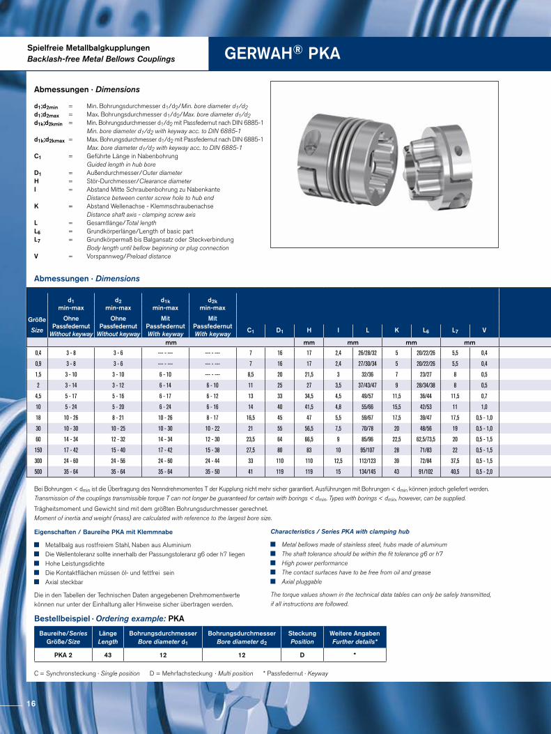
Spielfreie MetallbalgkupplungenBacklash-free Metal Bellows Couplings GERWAH® PKA
Abmessungen · Dimensions
Abmessungen · Dimensions
d1;d2min = Min. Bohrungsdurchmesser d1/d2/Min. bore diameter d1/d2 d1;d2max = Max. Bohrungsdurchmesser d1/d2/Max. bore diameter d1/d2d1k;d2kmin = Min. Bohrungsdurchmesser d1/d2 mit Passfedernut nach DIN 6885-1 Min. bore diameter d1/d2 with keyway acc. to DIN 6885-1d1k;d2kmax = Max. Bohrungsdurchmesser d1/d2 mit Passfedernut nach DIN 6885-1 Max. bore diameter d1/d2 with keyway acc. to DIN 6885-1 C1 = Geführte Länge in Nabenbohrung
Guided length in hub bore D1 = Außendurchmesser/Outer diameter H = Stör-Durchmesser/Clearance diameter I = Abstand Mitte Schraubenbohrung zu Nabenkante Distance between center screw hole to hub end K = Abstand Wellenachse - Klemmschraubenachse Distance shaft axis - clamping screw axis L = Gesamtlänge/Total lengthL6 = Grundkörperlänge/Length of basic part L7 = Grundkörpermaß bis Balgansatz oder Steckverbindung Body length until bellow beginning or plug connection V = Vorspannweg/Preload distance
Bestellbeispiel · Ordering example: PKA
Eigenschaften / Baureihe PKA mit Klemmnabe
Metallbalg aus rostfreiem Stahl, Naben aus Aluminium Die Wellentoleranz sollte innerhalb der Passungstoleranz g6 oder h7 liegen Hohe Leistungsdichte Die Kontaktflächen müssen öl- und fettfrei sein Axial steckbar
Die in den Tabellen der Technischen Daten angegebenen Drehmomentwerte können nur unter der Einhaltung aller Hinweise sicher übertragen werden.
Characteristics / Series PKA with clamping hub
Metal bellows made of stainless steel, hubs made of aluminum The shaft tolerance should be within the fit tolerance g6 or h7 High power performance The contact surfaces have to be free from oil and grease Axial pluggable
The torque values shown in the technical data tables can only be safely transmitted, if all instructions are followed.
Baureihe/SeriesGröße/Size
Länge Length
Bohrungsdurchmesser Bore diameter d1
Bohrungsdurchmesser Bore diameter d2
SteckungPosition
Weitere Angaben Further details*
PKA 2 43 12 12 D *
C = Synchronsteckung · Single position D = Mehrfachsteckung · Multi position * Passfedernut · Keyway
Trägheitsmoment und Gewicht sind mit dem größten Bohrungsdurchmesser gerechnet.Moment of inertia and weight (mass) are calculated with reference to the largest bore size.
Bei Bohrungen < dmin ist die Übertragung des Nenndrehmomentes T der Kupplung nicht mehr sicher garantiert. Ausführungen mit Bohrungen < dmin können jedoch geliefert werden. Transmission of the couplings transmissible torque T can not longer be guaranteed for certain with borings < dmin. Types with borings < dmin, however, can be supplied.
16
d1min-max
d2min-max
d1kmin-max
d2kmin-max
Größe Ohne Passfedernut
Without keyway
Ohne Passfedernut
Without keyway
Mit PassfedernutWith keyway
Mit PassfedernutWith keyway
Size C1 D1 H I L K L6 L7 V
mm mm mm mm mm
0,4 3 - 8 3 - 6 --- - --- --- - --- 7 16 17 2,4 26/28/32 5 20/22/26 5,5 0,4
0,9 3 - 8 3 - 6 --- - --- --- - --- 7 16 17 2,4 27/30/34 5 20/22/26 5,5 0,4
1,5 3 - 10 3 - 10 6 - 10 --- - --- 8,5 20 21,5 3 32/36 7 23/27 8 0,5
2 3 - 14 3 - 12 6 - 14 6 - 10 11 25 27 3,5 37/43/47 9 28/34/38 8 0,5
4,5 5 - 17 5 - 16 6 - 17 6 - 12 13 33 34,5 4,5 49/57 11,5 36/44 11,5 0,7
10 5 - 24 5 - 20 6 - 24 6 - 16 14 40 41,5 4,8 55/66 15,5 42/53 11 1,0
18 10 - 26 8 - 21 10 - 26 8 - 17 16,5 45 47 5,5 59/67 17,5 39/47 17,5 0,5 - 1,0
30 10 - 30 10 - 25 10 - 30 10 - 22 21 55 56,5 7,5 70/78 20 48/56 19 0,5 - 1,0
60 14 - 34 12 - 32 14 - 34 12 - 30 23,5 64 66,5 9 85/96 22,5 62,5/73,5 20 0,5 - 1,5
150 17 - 42 15 - 40 17 - 42 15 - 38 27,5 80 83 10 95/107 28 71/83 22 0,5 - 1,5
300 24 - 60 24 - 56 24 - 60 24 - 44 33 110 110 12,5 112/123 39 72/84 37,5 0,5 - 1,5
500 35 - 64 35 - 64 35 - 64 35 - 50 41 119 119 15 134/145 43 91/102 40,5 0,5 - 2,0
DIN 6885-1 optionalDG1
ISO 4762
IC1
L6
K
V
L7L±2
d 1 d 2
D1
H
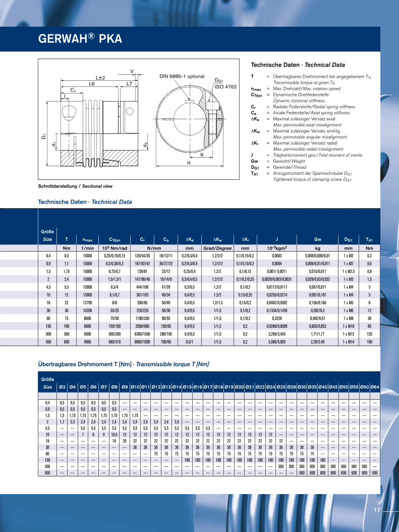
Technische Daten · Technical Data
GERWAH® PKA
Schnittdarstellung / Sectional view
Technische Daten · Technical Data
T = Übertragbares Drehmoment bei angegebenem TA Transmissible torque at given TAnmax = Max. Drehzahl/Max. rotation speed CTdyn = Dynamische Drehfedersteife Dynamic torsional stiffnessCr = Radiale Federsteife/Radial spring stiffnessCa = Axiale Federsteife/Axial spring stiffness ∆Ka = Maximal zulässiger Versatz axial Max. permissible axial misalignment ∆Kw = Maximal zulässiger Versatz winklig Max. permissible angular misalignment ∆Kr = Maximal zulässiger Versatz radial Max. permissible radial misalignment J = Trägheitsmoment ges./Total moment of inertia Gw = Gewicht/Weight DG1 = Gewinde/Thread TA1 = Anzugsmoment der Spannschraube DG1 Tightened torque of clamping screw DG1
Übertragbares Drehmoment T [Nm] · Transmissible torque T [Nm]
Größe
Size Ø3 Ø4 Ø5 Ø6 Ø7 Ø8 Ø9 Ø10 Ø11 Ø12 Ø13 Ø14 Ø15 Ø16 Ø17 Ø18 Ø19 Ø20 Ø21 Ø22 Ø24 Ø25 Ø28 Ø30 Ø35 Ø40 Ø45 Ø50 Ø55 Ø60 Ø64
0,4 0,5 0,5 0,5 0,5 0,5 0,5 --- --- --- --- --- --- --- --- --- --- --- --- --- --- --- --- --- --- --- --- --- --- --- --- ---0,9 0,5 0,5 0,5 0,5 0,5 0,5 --- --- --- --- --- --- --- --- --- --- --- --- --- --- --- --- --- --- --- --- --- --- --- --- ---1,5 1,5 1,75 1,75 1,75 1,75 1,75 1,75 1,75 --- --- --- --- --- --- --- --- --- --- --- --- --- --- --- --- --- --- --- --- --- --- ---2 1,7 2,3 2,4 2,4 2,4 2,4 2,4 2,4 2,4 2,4 2,4 2,4 --- --- --- --- --- --- --- --- --- --- --- --- --- --- --- --- --- --- ---
4,5 --- --- 5,5 5,5 5,5 5,5 5,5 5,5 5,5 5,5 5,5 5,5 5,5 5,5 5,5 --- --- --- --- --- --- --- --- --- --- --- --- --- --- --- ---10 --- --- 7 8 9 10,5 12 12 12 12 12 12 12 12 12 12 12 12 12 12 12 --- --- --- --- --- --- --- --- --- ---18 --- --- --- --- --- 18 20 22 22 22 22 22 22 22 22 22 22 22 22 22 22 22 --- --- --- --- --- --- --- --- ---30 --- --- --- --- --- --- --- 36 36 36 36 36 36 36 36 36 36 36 36 36 36 36 36 36 36 --- --- --- --- --- ---60 --- --- --- --- --- --- --- --- --- 75 75 75 75 75 75 75 75 75 75 75 75 75 75 75 75 --- --- --- --- --- ---150 --- --- --- --- --- --- --- --- --- --- --- --- 180 180 180 180 180 180 180 180 180 180 180 180 180 180 --- --- --- --- ---300 --- --- --- --- --- --- --- --- --- --- --- --- --- --- --- --- --- --- --- --- --- 360 360 360 360 360 360 360 360 360 ---500 --- --- --- --- --- --- --- --- --- --- --- --- --- --- --- --- --- --- --- --- --- --- --- 600 600 600 600 600 600 600 600
Größe
Size T nmax CTdyn Cr Ca ∆Ka ∆Kw ∆Kr J Gw DG1 TA1
Nm 1/min 103 Nm/rad N/mm mm Grad/Degree mm 10-3kgm2 kg mm Nm
0,4 0,5 15000 0,25/0,19/0,15 128/54/26 18/13/11 0,2/0,3/0,4 1,2/2/2 0,1/0,15/0,2 0,0003 0,008/0,009/0,01 1 x M2 0,3
0,9 1,1 15000 0,5/0,38/0,3 187/82/42 36/27/22 0,2/0,3/0,4 1,2/2/2 0,1/0,15/0,2 0,0004 0,009/0,01/0,011 1 x M2 0,6
1,5 1,75 15000 0,75/0,7 139/81 23/12 0,25/0,4 1,2/2 0,1/0,15 0,001/ 0,0011 0,015/0,017 1 x M2,5 0,8
2 2,4 15000 1,5/1,3/1 147/96/46 18/14/9 0,3/0,4/0,5 1,2/2/2 0,1/0,2/0,25 0,0028/0,003/0,0031 0,028/0,03/0,032 1 x M3 1,5
4,5 5,5 15000 6,5/4 444/108 47/29 0,3/0,5 1,2/2 0,1/0,2 0,0112/0,0117 0,067/0,071 1 x M4 3
10 12 15000 8,1/6,7 361/193 46/34 0,4/0,5 1,2/2 0,15/0,25 0,0255/0,0274 0,097/0,107 1 x M4 3
18 22 12700 8/6 200/85 50/40 0,4/0,5 1,2/1,5 0,15/0,2 0,0482/0,0582 0,156/0,166 1 x M5 6
30 36 10200 35/25 720/220 50/30 0,4/0,5 1/1,5 0,1/0,2 0,1334/0,1439 0,282/0,3 1 x M6 12
60 75 8600 75/50 1100/330 90/55 0,4/0,5 1/1,5 0,1/0,2 0,3228 0,482/0,51 1 x M8 30
150 180 6800 150/100 2000/600 150/85 0,4/0,5 1/1,5 0,2 0,8289/0,8589 0,803/0,853 1 x M10 85
300 360 5900 500/280 6300/1500 280/150 0,4/0,5 1/1,5 0,2 3,299/3,454 1,71/1,77 1 x M12 120
500 600 4900 680/310 8800/1000 100/85 0,5/1 1/1,5 0,2 5,585/5,855 2,39/2,49 1 x M14 190
17
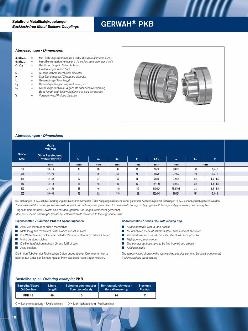
Spielfreie MetallbalgkupplungenBacklash-free Metal Bellows Couplings GERWAH® PKB
Abmessungen · Dimensions
Abmessungen · Dimensions
d1;d2min = Min. Bohrungsdurchmesser d1/d2/Min. bore diameter d1/d2 d1;d2max = Max. Bohrungsdurchmesser d1/d2/Max. bore diameter d1/d2C1;C2 = Geführte Länge in Nabenbohrung
Guided length in hub bore D1 = Außendurchmesser/Outer diameter H = Stör-Durchmesser/Clearance diameter L = Gesamtlänge/Total length L6 = Grundkörperlänge/Length of basic part L7 = Grundkörpermaß bis Balgansatz oder Steckverbindung Body length until bellow beginning or plug connection V = Vorspannweg/Preload distance
Bestellbeispiel · Ordering example: PKB
Eigenschaften / Baureihe PKB mit Spannringnaben
Axial von innen oder außen montierbar Metallbalg aus rostfreiem Stahl, Naben aus Aluminium Die Wellentoleranz sollte innerhalb der Passungstoleranz g6 oder h7 liegen Hohe Leistungsdichte Die Kontaktflächen müssen öl- und fettfrei sein Axial steckbar
Die in den Tabellen der Technischen Daten angegebenen Drehmomentwerte können nur unter der Einhaltung aller Hinweise sicher übertragen werden.
Characteristics / Series PKB with locking ring
Axial mountable from in- and outside Metal bellows made of stainless steel, hubs made of aluminum The shaft tolerance should be within the fit tolerance g6 or h7 High power performance The contact surfaces have to be free from oil and grease Axial pluggable
The torque values shown in the technical data tables can only be safely transmitted, if all instructions are followed.
Baureihe/SeriesGröße/Size
Länge Length
Bohrungsdurchmesser Bore diameter d1
Bohrungsdurchmesser Bore diameter d2
Steckung Position
PKB 18 58 10 16 C
C = Synchronsteckung · Single position D = Mehrfachsteckung · Multi position
Trägheitsmoment und Gewicht sind mit dem größten Bohrungsdurchmesser gerechnet.Moment of inertia and weight (mass) are calculated with reference to the largest bore size.
Bei Bohrungen < dmin ist die Übertragung des Nenndrehmomentes T der Kupplung nicht mehr sicher garantiert. Ausführungen mit Bohrungen < dmin können jedoch geliefert werden. Transmission of the couplings transmissible torque T can not longer be guaranteed for certain with borings < dmin. Types with borings < dmin, however, can be supplied.
d1;d2min-max
Größe Ohne PassfedernutWithout keywaySize C1 C2 D1 H L±2 L6 L7 V
mm mm mm mm mm mm mm mm
18 10 - 16 16 26 45 45 58/66 39/47 16,5 0,5 - 1
30 12 - 24 20 32 55 56 68/76 47/55 19 0,5 - 1
60 12 - 32 22 37 66 66 79/89 42/52 22 0,5 - 1,5
150 15 - 40 28 45 80 82 97/109 52/64 28 0,5 - 1,5
300 24 - 56 38 46 110 110 113/124 78,5/89,5 33 0,5 - 1,5
500 30 - 60 42 62 119 122 132/145 91/104 38,1 0,5 - 2
18
DG1
ISO 4762
C1
L7L6
C2 H
VL±2
d 2d 1
D1
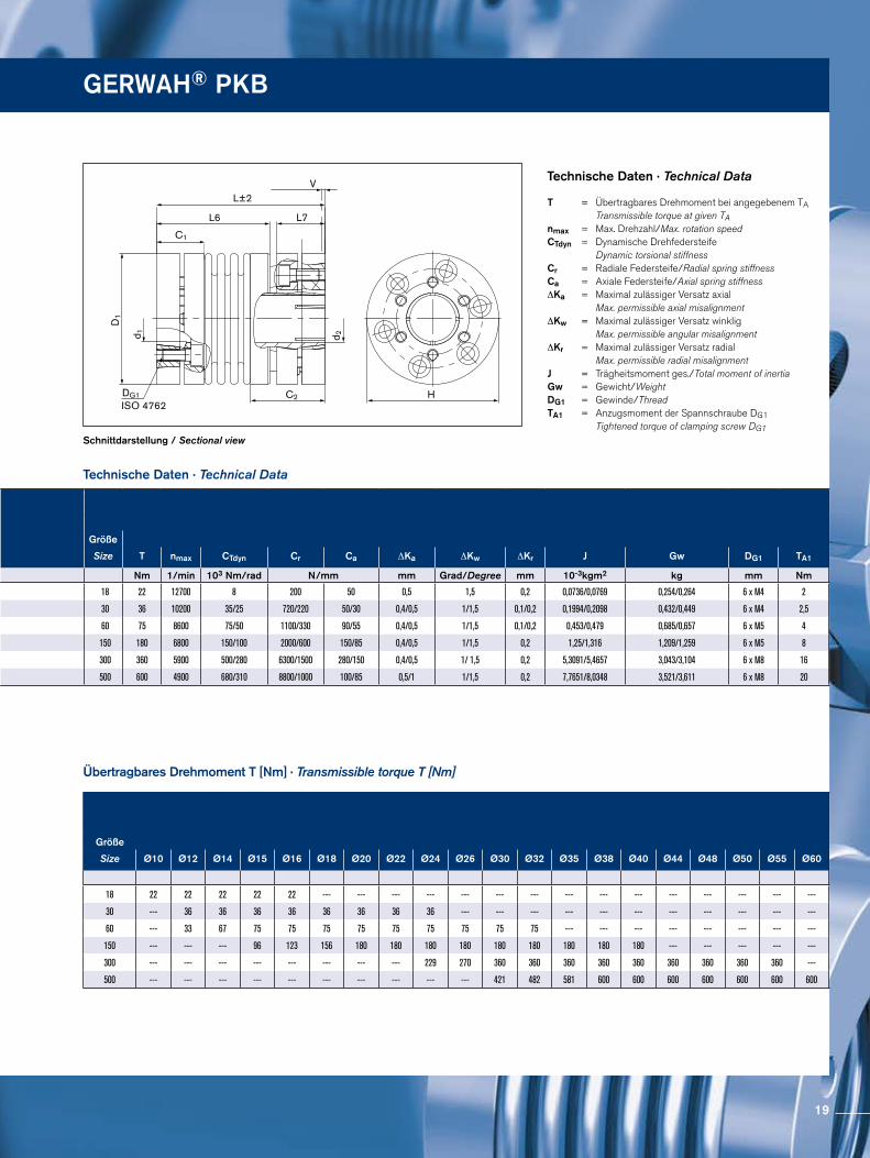
Technische Daten · Technical Data
GERWAH® PKB
Schnittdarstellung / Sectional view
Technische Daten · Technical Data
T = Übertragbares Drehmoment bei angegebenem TA Transmissible torque at given TAnmax = Max. Drehzahl/Max. rotation speed CTdyn = Dynamische Drehfedersteife Dynamic torsional stiffnessCr = Radiale Federsteife/Radial spring stiffnessCa = Axiale Federsteife/Axial spring stiffness ∆Ka = Maximal zulässiger Versatz axial Max. permissible axial misalignment ∆Kw = Maximal zulässiger Versatz winklig Max. permissible angular misalignment ∆Kr = Maximal zulässiger Versatz radial Max. permissible radial misalignment J = Trägheitsmoment ges./Total moment of inertia Gw = Gewicht/Weight DG1 = Gewinde/Thread TA1 = Anzugsmoment der Spannschraube DG1 Tightened torque of clamping screw DG1
Übertragbares Drehmoment T [Nm] · Transmissible torque T [Nm]
Größe
Size T nmax CTdyn Cr Ca ∆Ka ∆Kw ∆Kr J Gw DG1 TA1
Nm 1/min 103 Nm/rad N/mm mm Grad/Degree mm 10-3kgm2 kg mm Nm
18 22 12700 8 200 50 0,5 1,5 0,2 0,0736/0,0769 0,254/0,264 6 x M4 2
30 36 10200 35/25 720/220 50/30 0,4/0,5 1/1,5 0,1/0,2 0,1994/0,2098 0,432/0,449 6 x M4 2,5
60 75 8600 75/50 1100/330 90/55 0,4/0,5 1/1,5 0,1/0,2 0,453/0,479 0,685/0,657 6 x M5 4
150 180 6800 150/100 2000/600 150/85 0,4/0,5 1/1,5 0,2 1,25/1,316 1,209/1,259 6 x M5 8
300 360 5900 500/280 6300/1500 280/150 0,4/0,5 1/ 1,5 0,2 5,3091/5,4657 3,043/3,104 6 x M8 16
500 600 4900 680/310 8800/1000 100/85 0,5/1 1/1,5 0,2 7,7651/8,0348 3,521/3,611 6 x M8 20
d1;d2min-max
Größe Ohne PassfedernutWithout keywaySize C1 C2 D1 H L±2 L6 L7 V
mm mm mm mm mm mm mm mm
18 10 - 16 16 26 45 45 58/66 39/47 16,5 0,5 - 1
30 12 - 24 20 32 55 56 68/76 47/55 19 0,5 - 1
60 12 - 32 22 37 66 66 79/89 42/52 22 0,5 - 1,5
150 15 - 40 28 45 80 82 97/109 52/64 28 0,5 - 1,5
300 24 - 56 38 46 110 110 113/124 78,5/89,5 33 0,5 - 1,5
500 30 - 60 42 62 119 122 132/145 91/104 38,1 0,5 - 2
Größe
Size Ø10 Ø12 Ø14 Ø15 Ø16 Ø18 Ø20 Ø22 Ø24 Ø26 Ø30 Ø32 Ø35 Ø38 Ø40 Ø44 Ø48 Ø50 Ø55 Ø60
18 22 22 22 22 22 --- --- --- --- --- --- --- --- --- --- --- --- --- --- ---
30 --- 36 36 36 36 36 36 36 36 --- --- --- --- --- --- --- --- --- --- ---
60 --- 33 67 75 75 75 75 75 75 75 75 75 --- --- --- --- --- --- --- ---
150 --- --- --- 96 123 156 180 180 180 180 180 180 180 180 180 --- --- --- --- ---
300 --- --- --- --- --- --- --- --- 229 270 360 360 360 360 360 360 360 360 360 ---
500 --- --- --- --- --- --- --- --- --- --- 421 482 581 600 600 600 600 600 600 600
19
Spielfreie MetallbalgkupplungenBacklash-free Metal Bellows Couplings GERWAH® PKN
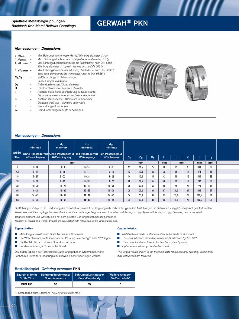
Abmessungen · Dimensions
Abmessungen · Dimensions
Bestellbeispiel · Ordering example: PKN
Baureihe/SeriesGröße/Size
Bohrungsdurchmesser Bore diameter d1
BohrungsdurchmesserBore diameter d2
Weitere AngabenFurther details*
PKN 150 30 35 *
* Passfedernut oder Edelstahl · Keyway or stainless steel
Eigenschaften
Metallbalg aus rostfreiem Stahl, Naben aus Aluminium Die Wellentoleranz sollte innerhalb der Passungstoleranz “g6“ oder “h7“ liegen Die Kontaktflächen müssen öl- und fettfrei sein Sonderausführung in Edelstahl optional
Die in den Tabellen der Technischen Daten angegebenen Drehmomentwerte können nur unter der Einhaltung aller Hinweise sicher übertragen werden.
Characteristics
Metal bellows made of stainless steel, hubs made of aluminum The shaft tolerance should be within the fit tolerance “g6” or “h7” The contact surfaces have to be free from oil and grease Optional special design in stainless steel
The torque values shown in the technical data tables can only be safely transmitted, if all instructions are followed.
d1;d2min = Min. Bohrungsdurchmesser d1/d2/Min. bore diameter d1/d2 d1;d2max = Max. Bohrungsdurchmesser d1/d2/Max. bore diameter d1/d2d1k;d2kmin = Min. Bohrungsdurchmesser d1/d2 mit Passfedernut nach DIN 6885-1 Min. bore diameter d1/d2 with keyway acc. to DIN 6885-1d1k;d2kmax = Max. Bohrungsdurchmesser mit d1/d2 Passfedernut nach DIN 6885-1 Max. bore diameter d1/d2 with keyway acc. to DIN 6885-1 C1;C2 = Geführte Länge in Nabenbohrung Guided length in hub bore D1 = Außendurchmesser/Outer diameter H = Stör-Durchmesser/Clearance diameterl = Abstand Mitte Schraubenbohrung zu Nabenkante Distance between center screw hole and hub endK = Abstand Wellenachse - Klemmschraubenachse Distance shaft axis - clamping screw axis L = Gesamtlänge/Total lengthL6 = Grundkörperlänge/Length of basic part
Trägheitsmoment und Gewicht sind mit dem größten Bohrungsdurchmesser gerechnet.Moment of inertia and weight (mass) are calculated with reference to the largest bore size.
Bei Bohrungen < dmin ist die Übertragung des Nenndrehmomentes T der Kupplung nicht mehr sicher garantiert. Ausführungen mit Bohrungen < dmin können jedoch geliefert werden. Transmission of the couplings transmissible torque T can not longer be guaranteed for certain with borings < dmin. Types with borings < dmin, however, can be supplied.
d1min-max
d2min-max
d1kmin-max
d2kmin-max
Größe Ohne PassfedernutWithout keyway
Ohne PassfedernutWithout keyway
Mit PassfedernutWith keyway
Mit PassfedernutWith keywaySize C1 C2 D1 H I K L L6
mm mm mm mm mm mm
2 3 - 14 3 - 9 6 - 14 6 - 9 11 11,5 25 28 3,5 9 39,0 26
4,5 6 - 17 6 - 16 6 - 17 6 - 16 13 13,0 33 35 4,5 12 47,5 33
10 6 - 24 6 - 22 6 - 24 6 - 22 14 13,0 40 42 4,8 16 53,5 39
18 8 - 26 8 - 22 8 - 26 8 - 22 20 18,5 45 48 6,0 18 70,5 50
30 10 - 30 10 - 28 10 - 30 10 - 28 25 22,0 55 56 7,5 20 72,0 48
60 10 - 35 10 - 30 10 - 35 10 - 30 29 29,0 66 67 10,0 24 88,5 57
80 14 - 42 14 - 42 14 - 42 14 - 42 34 33,0 80 85 12,0 28 102,5 67
150 14 - 42 14 - 42 14 - 42 14 - 42 34 33,0 80 85 12,0 28 102,5 67
20
DG1ISO 4762
- 2 (Größe/Size 2 - 10)- 2,5 (Größe/Size 18-150)
d 1
d 2D1
L
I
L6 C2
C1
K
H
Schnittdarstellung / Sectional view
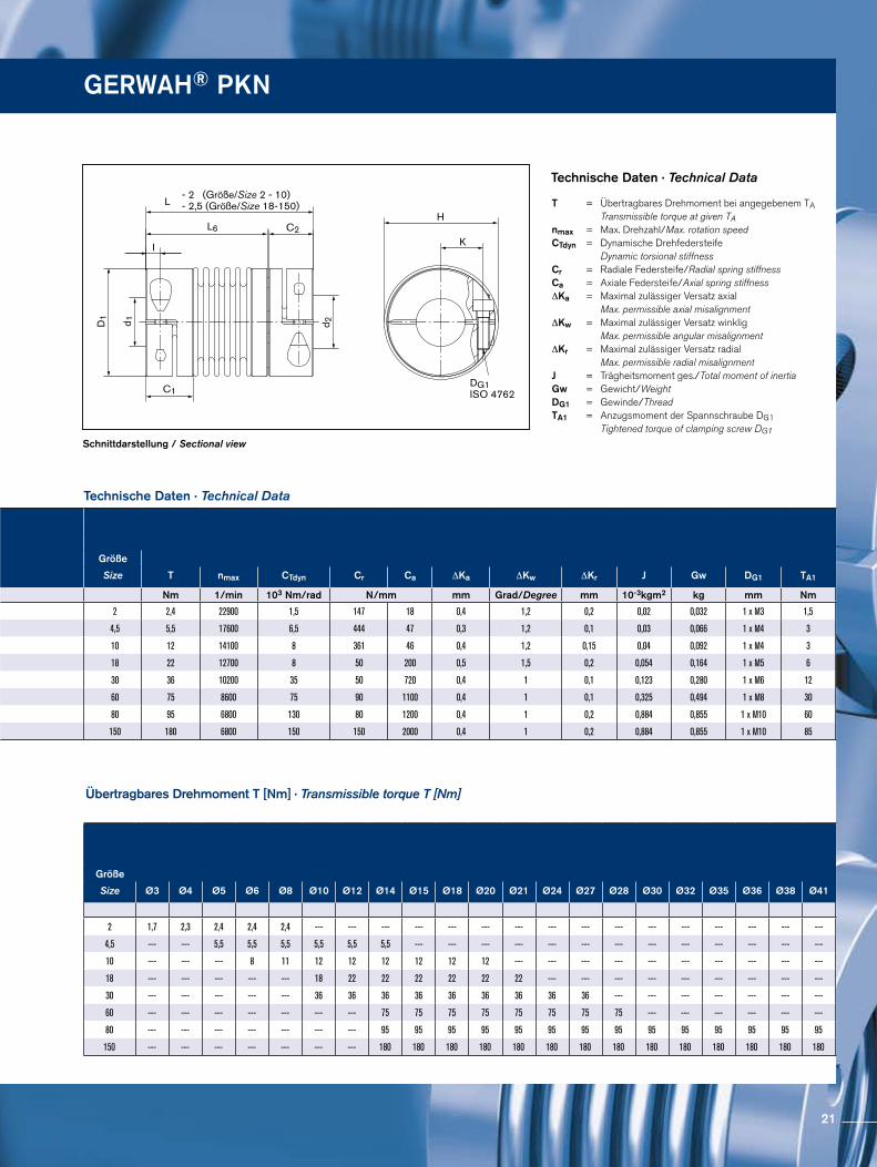
Technische Daten · Technical Data
Technische Daten · Technical Data
Übertragbares Drehmoment T [Nm] · Transmissible torque T [Nm]
T = Übertragbares Drehmoment bei angegebenem TA Transmissible torque at given TAnmax = Max. Drehzahl/Max. rotation speedCTdyn = Dynamische Drehfedersteife Dynamic torsional stiffness Cr = Radiale Federsteife/Radial spring stiffnessCa = Axiale Federsteife/Axial spring stiffness ∆Ka = Maximal zulässiger Versatz axial Max. permissible axial misalignment ∆Kw = Maximal zulässiger Versatz winklig Max. permissible angular misalignment ∆Kr = Maximal zulässiger Versatz radial Max. permissible radial misalignment J = Trägheitsmoment ges./Total moment of inertia Gw = Gewicht/Weight DG1 = Gewinde/Thread TA1 = Anzugsmoment der Spannschraube DG1 Tightened torque of clamping screw DG1
GERWAH® PKN
d1min-max
d2min-max
d1kmin-max
d2kmin-max
Größe Ohne PassfedernutWithout keyway
Ohne PassfedernutWithout keyway
Mit PassfedernutWith keyway
Mit PassfedernutWith keywaySize C1 C2 D1 H I K L L6
mm mm mm mm mm mm
2 3 - 14 3 - 9 6 - 14 6 - 9 11 11,5 25 28 3,5 9 39,0 26
4,5 6 - 17 6 - 16 6 - 17 6 - 16 13 13,0 33 35 4,5 12 47,5 33
10 6 - 24 6 - 22 6 - 24 6 - 22 14 13,0 40 42 4,8 16 53,5 39
18 8 - 26 8 - 22 8 - 26 8 - 22 20 18,5 45 48 6,0 18 70,5 50
30 10 - 30 10 - 28 10 - 30 10 - 28 25 22,0 55 56 7,5 20 72,0 48
60 10 - 35 10 - 30 10 - 35 10 - 30 29 29,0 66 67 10,0 24 88,5 57
80 14 - 42 14 - 42 14 - 42 14 - 42 34 33,0 80 85 12,0 28 102,5 67
150 14 - 42 14 - 42 14 - 42 14 - 42 34 33,0 80 85 12,0 28 102,5 67
Größe
Size T nmax CTdyn Cr Ca ∆Ka ∆Kw ∆Kr J Gw DG1 TA1
Nm 1/min 103 Nm/rad N/mm mm Grad/Degree mm 10-3kgm2 kg mm Nm
2 2,4 22900 1,5 147 18 0,4 1,2 0,2 0,02 0,032 1 x M3 1,5
4,5 5,5 17600 6,5 444 47 0,3 1,2 0,1 0,03 0,066 1 x M4 3
10 12 14100 8 361 46 0,4 1,2 0,15 0,04 0,092 1 x M4 3
18 22 12700 8 50 200 0,5 1,5 0,2 0,054 0,164 1 x M5 6
30 36 10200 35 50 720 0,4 1 0,1 0,123 0,280 1 x M6 12
60 75 8600 75 90 1100 0,4 1 0,1 0,325 0,494 1 x M8 30
80 95 6800 130 80 1200 0,4 1 0,2 0,884 0,855 1 x M10 60
150 180 6800 150 150 2000 0,4 1 0,2 0,884 0,855 1 x M10 85
Größe
Size Ø3 Ø4 Ø5 Ø6 Ø8 Ø10 Ø12 Ø14 Ø15 Ø18 Ø20 Ø21 Ø24 Ø27 Ø28 Ø30 Ø32 Ø35 Ø36 Ø38 Ø41
2 1,7 2,3 2,4 2,4 2,4 --- --- --- --- --- --- --- --- --- --- --- --- --- --- --- ---
4,5 --- --- 5,5 5,5 5,5 5,5 5,5 5,5 --- --- --- --- --- --- --- --- --- --- --- --- ---
10 --- --- --- 8 11 12 12 12 12 12 12 --- --- --- --- --- --- --- --- --- ---
18 --- --- --- --- --- 18 22 22 22 22 22 22 --- --- --- --- --- --- --- --- ---
30 --- --- --- --- --- 36 36 36 36 36 36 36 36 36 --- --- --- --- --- --- ---
60 --- --- --- --- --- --- --- 75 75 75 75 75 75 75 75 --- --- --- --- --- ---
80 --- --- --- --- --- --- --- 95 95 95 95 95 95 95 95 95 95 95 95 95 95
150 --- --- --- --- --- --- --- 180 180 180 180 180 180 180 180 180 180 180 180 180 180
21
Spielfreie MetallbalgkupplungenBacklash-free Metal Bellows Couplings GERWAH® AKN
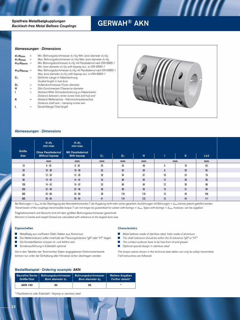
Abmessungen · Dimensions
Trägheitsmoment und Gewicht sind mit dem größten Bohrungsdurchmesser gerechnet.Moment of inertia and weight (mass) are calculated with reference to the largest bore size.
Abmessungen · Dimensions
Bestellbeispiel · Ordering example: AKN
Baureihe/SeriesGröße/Size
Bohrungsdurchmesser Bore diameter d1
BohrungsdurchmesserBore diameter d2
Weitere AngabenFurther details*
AKN 150 30 35 *
* Passfedernut oder Edelstahl · Keyway or stainless steel
Eigenschaften
Metallbalg aus rostfreiem Stahl, Naben aus Aluminium Die Wellentoleranz sollte innerhalb der Passungstoleranz “g6“ oder “h7“ liegen Die Kontaktflächen müssen öl- und fettfrei sein Sonderausführung in Edelstahl optional
Die in den Tabellen der Technischen Daten angegebenen Drehmomentwerte können nur unter der Einhaltung aller Hinweise sicher übertragen werden.
Characteristics
Metal bellows made of stainless steel, hubs made of aluminum The shaft tolerance should be within the fit tolerance “g6” or “h7” The contact surfaces have to be free from oil and grease Optional special design in stainless steel
The torque values shown in the technical data tables can only be safely transmitted, if all instructions are followed.
d1;d2min = Min. Bohrungsdurchmesser d1/d2/Min. bore diameter d1/d2 d1;d2max = Max. Bohrungsdurchmesser d1/d2/Max. bore diameter d1/d2d1k;d2kmin = Min. Bohrungsdurchmesser d1/d2 mit Passfedernut nach DIN 6885-1 Min. bore diameter d1/d2 with keyway acc. to DIN 6885-1d1k;d2kmax = Max. Bohrungsdurchmesser d1/d2 mit Passfedernut nach DIN 6885-1 Max. bore diameter d1/d2 with keyway acc. to DIN 6885-1 C1 = Geführte Länge in Nabenbohrung Guided length in hub bore D1 = Außendurchmesser/Outer diameter H = Stör-Durchmesser/Clearance diameterl = Abstand Mitte Schraubenbohrung zu Nabenkante Distance between center screw hole and hub end K = Abstand Wellenachse - Klemmschraubenachse Distance shaft axis - clamping screw axis L = Gesamtlänge/Total length
Bei Bohrungen < dmin ist die Übertragung des Nenndrehmomentes T der Kupplung nicht mehr sicher garantiert. Ausführungen mit Bohrungen < dmin können jedoch geliefert werden. Transmission of the couplings transmissible torque T can not longer be guaranteed for certain with borings < dmin. Types with borings < dmin, however, can be supplied.
d1;d2min-max
d1;d2min-max
Größe Ohne PassfedernutWithout keyway
Mit PassfedernutWith keywaySize C1 D1 H I K L±2
mm mm mm mm mm mm mm
18 8 - 26 8 - 26 20 45 48 6 18 63
30 10 - 30 10 - 30 25 55 56 8 20 65
60 12 - 35 12 - 35 29 64 67 10 24 78
80 14 - 42 14 - 42 33 80 84 12 28 90
150 14 - 42 14 - 42 33 80 84 12 28 90
200 22 - 46 22 - 46 38 90 93 13 31 99
300 24 - 60 24 - 60 38 110 110 13 39 104
500 35 - 64 35 - 64 41 119 122 15 43 111
Größe
Size T nmax CTdyn Cr Ca ∆Ka ∆Kw ∆Kr J Gw DG1 TA1
Nm 1/min 103 Nm/rad N/mm mm Grad/Degree mm 10-3kgm2 kg mm Nm
18 22 12700 8 200 50 0,5 1,5 0,2 0,05 0,133 1 x M5 6
30 36 10200 35 720 50 0,4 1 0,1 0,11 0,245 1 x M6 12
60 75 8600 75 1100 90 0,4 1 0,1 0,29 0,406 1 x M8 30
80 95 6800 130 1200 80 0,4 1 0,2 0,87 0,742 1 x M10 60
150 180 6800 150 2000 150 0,4 1 0,2 0,87 0,742 1 x M10 85
200 240 6300 170 2500 150 0,4 1 0,2 1,44 1,054 1 x M12 100
300 360 5900 500 6300 280 0,4 1 0,2 3 1,434 1 x M12 120
500 600 4900 680 8800 100 0,5 1 0,2 4,7 1,949 1 x M14 190
22
DG1 ISO 4762
d 1 d 2
I
L±2 K
H
C1
D1
Schnittdarstellung / Sectional view
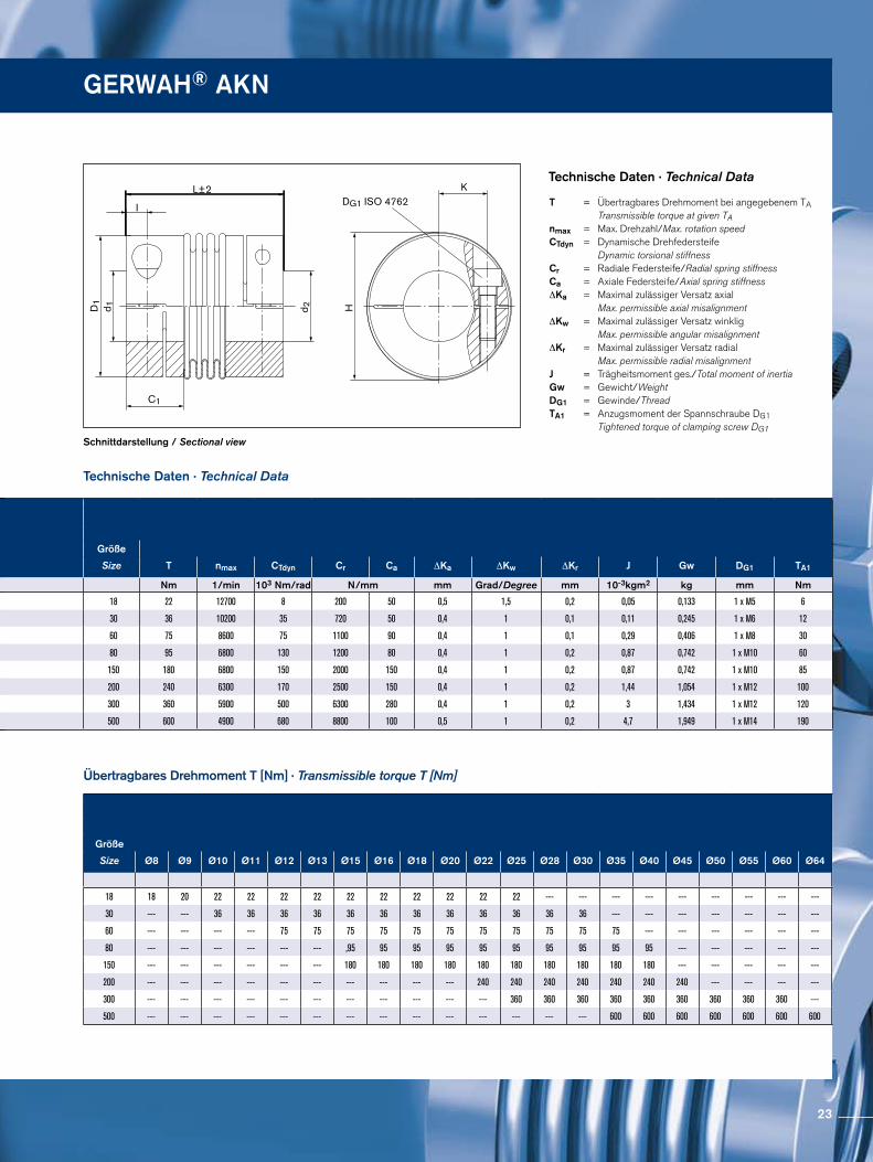
Technische Daten · Technical Data
Technische Daten · Technical Data
Übertragbares Drehmoment T [Nm] · Transmissible torque T [Nm]
T = Übertragbares Drehmoment bei angegebenem TA Transmissible torque at given TAnmax = Max. Drehzahl/Max. rotation speedCTdyn = Dynamische Drehfedersteife Dynamic torsional stiffness Cr = Radiale Federsteife/Radial spring stiffnessCa = Axiale Federsteife/Axial spring stiffness ∆Ka = Maximal zulässiger Versatz axial Max. permissible axial misalignment ∆Kw = Maximal zulässiger Versatz winklig Max. permissible angular misalignment ∆Kr = Maximal zulässiger Versatz radial Max. permissible radial misalignment J = Trägheitsmoment ges./Total moment of inertia Gw = Gewicht/Weight DG1 = Gewinde/Thread TA1 = Anzugsmoment der Spannschraube DG1 Tightened torque of clamping screw DG1
GERWAH® AKN
d1;d2min-max
d1;d2min-max
Größe Ohne PassfedernutWithout keyway
Mit PassfedernutWith keywaySize C1 D1 H I K L±2
mm mm mm mm mm mm mm
18 8 - 26 8 - 26 20 45 48 6 18 63
30 10 - 30 10 - 30 25 55 56 8 20 65
60 12 - 35 12 - 35 29 64 67 10 24 78
80 14 - 42 14 - 42 33 80 84 12 28 90
150 14 - 42 14 - 42 33 80 84 12 28 90
200 22 - 46 22 - 46 38 90 93 13 31 99
300 24 - 60 24 - 60 38 110 110 13 39 104
500 35 - 64 35 - 64 41 119 122 15 43 111
Größe
Size T nmax CTdyn Cr Ca ∆Ka ∆Kw ∆Kr J Gw DG1 TA1
Nm 1/min 103 Nm/rad N/mm mm Grad/Degree mm 10-3kgm2 kg mm Nm
18 22 12700 8 200 50 0,5 1,5 0,2 0,05 0,133 1 x M5 6
30 36 10200 35 720 50 0,4 1 0,1 0,11 0,245 1 x M6 12
60 75 8600 75 1100 90 0,4 1 0,1 0,29 0,406 1 x M8 30
80 95 6800 130 1200 80 0,4 1 0,2 0,87 0,742 1 x M10 60
150 180 6800 150 2000 150 0,4 1 0,2 0,87 0,742 1 x M10 85
200 240 6300 170 2500 150 0,4 1 0,2 1,44 1,054 1 x M12 100
300 360 5900 500 6300 280 0,4 1 0,2 3 1,434 1 x M12 120
500 600 4900 680 8800 100 0,5 1 0,2 4,7 1,949 1 x M14 190
Größe
Size Ø8 Ø9 Ø10 Ø11 Ø12 Ø13 Ø15 Ø16 Ø18 Ø20 Ø22 Ø25 Ø28 Ø30 Ø35 Ø40 Ø45 Ø50 Ø55 Ø60 Ø64
18 18 20 22 22 22 22 22 22 22 22 22 22 --- --- --- --- --- --- --- --- ---
30 --- --- 36 36 36 36 36 36 36 36 36 36 36 36 --- --- --- --- --- --- ---
60 --- --- --- --- 75 75 75 75 75 75 75 75 75 75 75 --- --- --- --- --- ---
80 --- --- --- --- --- --- ,95 95 95 95 95 95 95 95 95 95 --- --- --- --- ---
150 --- --- --- --- --- --- 180 180 180 180 180 180 180 180 180 180 --- --- --- --- ---
200 --- --- --- --- --- --- --- --- --- --- 240 240 240 240 240 240 240 --- --- --- ---
300 --- --- --- --- --- --- --- --- --- --- --- 360 360 360 360 360 360 360 360 360 ---
500 --- --- --- --- --- --- --- --- --- --- --- --- --- --- 600 600 600 600 600 600 600
23
Spielfreie MetallbalgkupplungenBacklash-free Metal Bellows Couplings GERWAH® AKN-H
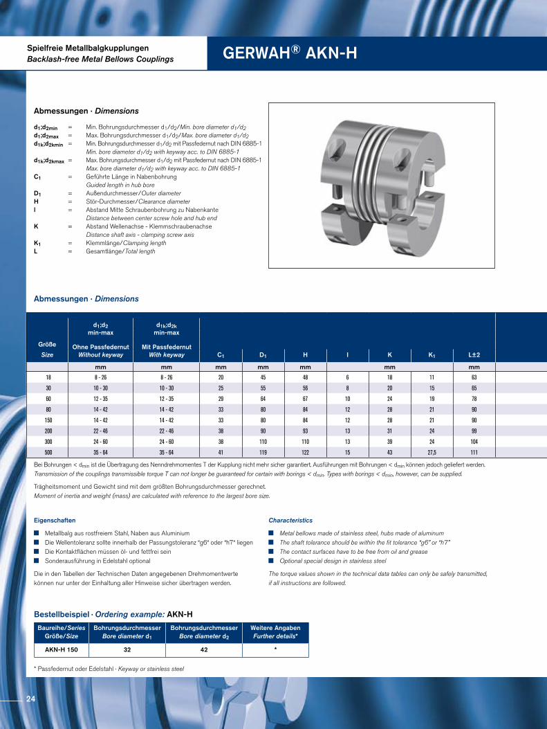
Abmessungen · Dimensions
Trägheitsmoment und Gewicht sind mit dem größten Bohrungsdurchmesser gerechnet.Moment of inertia and weight (mass) are calculated with reference to the largest bore size.
Abmessungen · Dimensions
Bestellbeispiel · Ordering example: AKN-H
Baureihe/SeriesGröße/Size
Bohrungsdurchmesser Bore diameter d1
BohrungsdurchmesserBore diameter d2
Weitere AngabenFurther details*
AKN-H 150 32 42 *
* Passfedernut oder Edelstahl · Keyway or stainless steel
Eigenschaften
Metallbalg aus rostfreiem Stahl, Naben aus Aluminium Die Wellentoleranz sollte innerhalb der Passungstoleranz “g6“ oder “h7“ liegen Die Kontaktflächen müssen öl- und fettfrei sein Sonderausführung in Edelstahl optional
Die in den Tabellen der Technischen Daten angegebenen Drehmomentwerte können nur unter der Einhaltung aller Hinweise sicher übertragen werden.
Characteristics
Metal bellows made of stainless steel, hubs made of aluminum The shaft tolerance should be within the fit tolerance “g6” or “h7” The contact surfaces have to be free from oil and grease Optional special design in stainless steel
The torque values shown in the technical data tables can only be safely transmitted, if all instructions are followed.
d1;d2min = Min. Bohrungsdurchmesser d1/d2/Min. bore diameter d1/d2 d1;d2max = Max. Bohrungsdurchmesser d1/d2/Max. bore diameter d1/d2 d1k;d2kmin = Min. Bohrungsdurchmesser d1/d2 mit Passfedernut nach DIN 6885-1 Min. bore diameter d1/d2 with keyway acc. to DIN 6885-1 d1k;d2kmax = Max. Bohrungsdurchmesser d1/d2 mit Passfedernut nach DIN 6885-1 Max. bore diameter d1/d2 with keyway acc. to DIN 6885-1 C1 = Geführte Länge in Nabenbohrung Guided length in hub boreD1 = Außendurchmesser/Outer diameterH = Stör-Durchmesser/Clearance diameterl = Abstand Mitte Schraubenbohrung zu Nabenkante Distance between center screw hole and hub end K = Abstand Wellenachse - Klemmschraubenachse Distance shaft axis - clamping screw axis K1 = Klemmlänge/Clamping length L = Gesamtlänge/Total length
Bei Bohrungen < dmin ist die Übertragung des Nenndrehmomentes T der Kupplung nicht mehr sicher garantiert. Ausführungen mit Bohrungen < dmin können jedoch geliefert werden. Transmission of the couplings transmissible torque T can not longer be guaranteed for certain with borings < dmin. Types with borings < dmin, however, can be supplied.
d1;d2min-max
d1k;d2kmin-max
Größe Ohne PassfedernutWithout keyway
Mit PassfedernutWith keywaySize C1 D1 H I K K1 L±2
mm mm mm mm mm mm mm
18 8 - 26 8 - 26 20 45 48 6 18 11 63
30 10 - 30 10 - 30 25 55 56 8 20 15 65
60 12 - 35 12 - 35 29 64 67 10 24 19 78
80 14 - 42 14 - 42 33 80 84 12 28 21 90
150 14 - 42 14 - 42 33 80 84 12 28 21 90
200 22 - 46 22 - 46 38 90 93 13 31 24 99
300 24 - 60 24 - 60 38 110 110 13 39 24 104
500 35 - 64 35 - 64 41 119 122 15 43 27,5 111
24
DG1ISO 4762
d 1 d 2
L±2
I
H
KC1
K1
D1
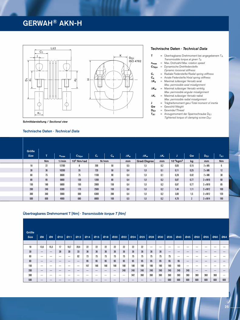
Schnittdarstellung / Sectional view
Technische Daten · Technical Data
Technische Daten · Technical Data
Übertragbares Drehmoment T [Nm] · Transmissible torque T [Nm]
T = Übertragbares Drehmoment bei angegebenem TA Transmissible torque at given TAnmax = Max. Drehzahl/Max. rotation speedCTdyn = Dynamische Drehfedersteife Dynamic torsional stiffness Cr = Radiale Federsteife/Radial spring stiffnessCa = Axiale Federsteife/Axial spring stiffness ∆Ka = Maximal zulässiger Versatz axial Max. permissible axial misalignment ∆Kw = Maximal zulässiger Versatz winklig Max. permissible angular misalignment ∆Kr = Maximal zulässiger Versatz radial Max. permissible radial misalignment J = Trägheitsmoment ges./Total moment of inertia Gw = Gewicht/Weight DG1 = Gewinde/Thread TA1 = Anzugsmoment der Spannschraube DG1 Tightened torque of clamping screw DG1
GERWAH® AKN-H
d1;d2min-max
d1k;d2kmin-max
Größe Ohne PassfedernutWithout keyway
Mit PassfedernutWith keywaySize C1 D1 H I K K1 L±2
mm mm mm mm mm mm mm
18 8 - 26 8 - 26 20 45 48 6 18 11 63
30 10 - 30 10 - 30 25 55 56 8 20 15 65
60 12 - 35 12 - 35 29 64 67 10 24 19 78
80 14 - 42 14 - 42 33 80 84 12 28 21 90
150 14 - 42 14 - 42 33 80 84 12 28 21 90
200 22 - 46 22 - 46 38 90 93 13 31 24 99
300 24 - 60 24 - 60 38 110 110 13 39 24 104
500 35 - 64 35 - 64 41 119 122 15 43 27,5 111
Größe
Size T nmax CTdyn Cr Ca ∆Ka ∆Kw ∆Kr J Gw DG1 TA1
Nm 1/min 103 Nm/rad N/mm mm Grad/Degree mm 10-3kgm2 kg mm Nm
18 22 12700 8 200 50 0,5 1,5 0,2 0,05 0,15 2 x M5 6
30 36 10200 35 720 50 0,4 1,0 0,1 0,11 0,25 2 x M6 12
60 75 8600 75 1100 90 0,4 1,0 0,1 0,29 0,42 2 x M8 30
80 95 6800 130 1200 80 0,4 1,0 0,2 0,87 0,77 2 x M10 60
150 180 6800 150 2000 150 0,4 1,0 0,2 0,87 0,77 2 x M10 85
200 240 6300 170 2500 150 0,4 1,0 0,2 1,44 1,11 2 x M12 100
300 360 5900 500 6300 280 0,4 1,0 0,2 3,00 1,5 2 x M12 120
500 600 4900 680 8800 100 0,5 1,0 0,2 4,70 2 2 x M14 190
Größe
Size Ø8 Ø9 Ø10 Ø11 Ø12 Ø14 Ø15 Ø18 Ø20 Ø22 Ø24 Ø25 Ø28 Ø30 Ø35 Ø40 Ø45 Ø50 Ø55 Ø60 Ø64
18 13,6 15,3 17 18,7 20,4 22 22 22 22 22 22 22 --- --- --- --- --- --- --- --- ---
30 --- --- 28 30 33 36 36 36 36 36 36 36 36 36 --- --- --- --- --- --- ---
60 --- --- --- --- 62 73 75 75 75 75 75 75 75 75 75 --- --- --- --- --- ---
80 --- --- --- --- --- 95 95 95 95 95 95 95 95 95 95 95 --- --- --- --- ---
150 --- --- --- --- --- 167 180 180 180 180 180 180 180 180 180 180 --- --- --- --- ---
200 --- --- --- --- --- --- --- --- --- 240 240 240 240 240 240 240 240 --- --- --- ---
300 --- --- --- --- --- --- --- --- --- --- 342 360 360 360 360 360 360 360 360 360 ---
500 --- --- --- --- --- --- --- --- --- --- --- --- --- --- 600 600 600 600 600 600 600
25
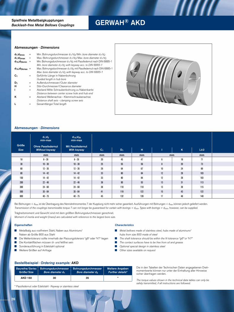
Spielfreie MetallbalgkupplungenBacklash-free Metal Bellows Couplings GERWAH® AKD
Abmessungen · Dimensions
Trägheitsmoment und Gewicht sind mit dem größten Bohrungsdurchmesser gerechnet.Moment of inertia and weight (mass) are calculated with reference to the largest bore size.
Abmessungen · Dimensions
Bestellbeispiel · Ordering example: AKD
Baureihe/SeriesGröße/Size
Bohrungsdurchmesser Bore diameter d1
BohrungsdurchmesserBore diameter d2
Weitere AngabenFurther details*
AKD 150 30 35 *
* Passfedernut oder Edelstahl · Keyway or stainless steel
Eigenschaften
Metallbalg aus rostfreiem Stahl, Naben aus Aluminium/ Naben ab Größe 800 aus Stahl
Die Wellentoleranz sollte innerhalb der Passungstoleranz “g6“ oder “h7“ liegen Die Kontaktflächen müssen öl- und fettfrei sein Sonderausführung in Edelstahl optional Weitere Größen auf Anfrage
Characteristics
Metal bellows made of stainless steel, hubs made of aluminum/ hubs from size 800 made of steel
The shaft tolerance should be within the fit tolerance “g6” or “h7” The contact surfaces have to be free from oil and grease Optional special design in stainless steel Other sizes available on request
Die in den Tabellen der Technischen Daten angegebenen Dreh-momentwerte können nur unter der Einhaltung aller Hinweise sicher übertragen werden.
The torque values shown in the technical data tables can only be safely transmitted, if all instructions are followed.
d1;d2min = Min. Bohrungsdurchmesser d1/d2/Min. bore diameter d1/d2 d1;d2max = Max. Bohrungsdurchmesser d1/d2/Max. bore diameter d1/d2d1k;d2kmin = Min. Bohrungsdurchmesser d1/d2 mit Passfedernut nach DIN 6885-1 Min. bore diameter d1/d2 with keyway acc. to DIN 6885-1d1k;d2kmax = Max. Bohrungsdurchmesser d1/d2 mit Passfedernut nach DIN 6885-1 Max. bore diameter d1/d2 with keyway acc. to DIN 6885-1C1 = Geführte Länge in Nabenbohrung Guided length in hub boreD1 = Außendurchmesser/Outer diameter H = Stör-Durchmesser/Clearance diameterl = Abstand Mitte Schraubenbohrung zu Nabenkante Distance between center screw hole and hub end K = Abstand Wellenachse - Klemmschraubenachse Distance shaft axis - clamping screw axis L = Gesamtlänge/Total length
Bei Bohrungen < dmin ist die Übertragung des Nenndrehmomentes T der Kupplung nicht mehr sicher garantiert. Ausführungen mit Bohrungen < dmin können jedoch geliefert werden. Transmission of the couplings transmissible torque T can not longer be guaranteed for certain with borings < dmin. Types with borings < dmin, however, can be supplied.
d1;d2min-max
d1k;d2kmin-max
Größe Ohne PassfedernutWithout keyway
Mit PassfedernutWith keywaySize C1 D1 H I K L±2
mm mm mm mm mm mm mm
18 8 - 26 8 - 26 20 45 47 6 18 71
30 10 - 30 10 - 30 25 55 56 8 20 73
60 12 - 35 12 - 35 29 64 67 10 24 89
80 14 - 42 14 - 42 33 80 84 12 28 103
150 14 - 42 14 - 42 33 80 84 12 28 103
200 22 - 46 22 - 46 38 90 93 13 31 113
300 24 - 60 24 - 60 38 110 110 13 39 115
500 35 - 64 35 - 64 41 119 122 15 43 122
800 40 - 75 40 - 75 45 132 139 17 48 140
26
DG1 ISO 4762
d 1 d 2
L±2 K
H
I
C1
D1
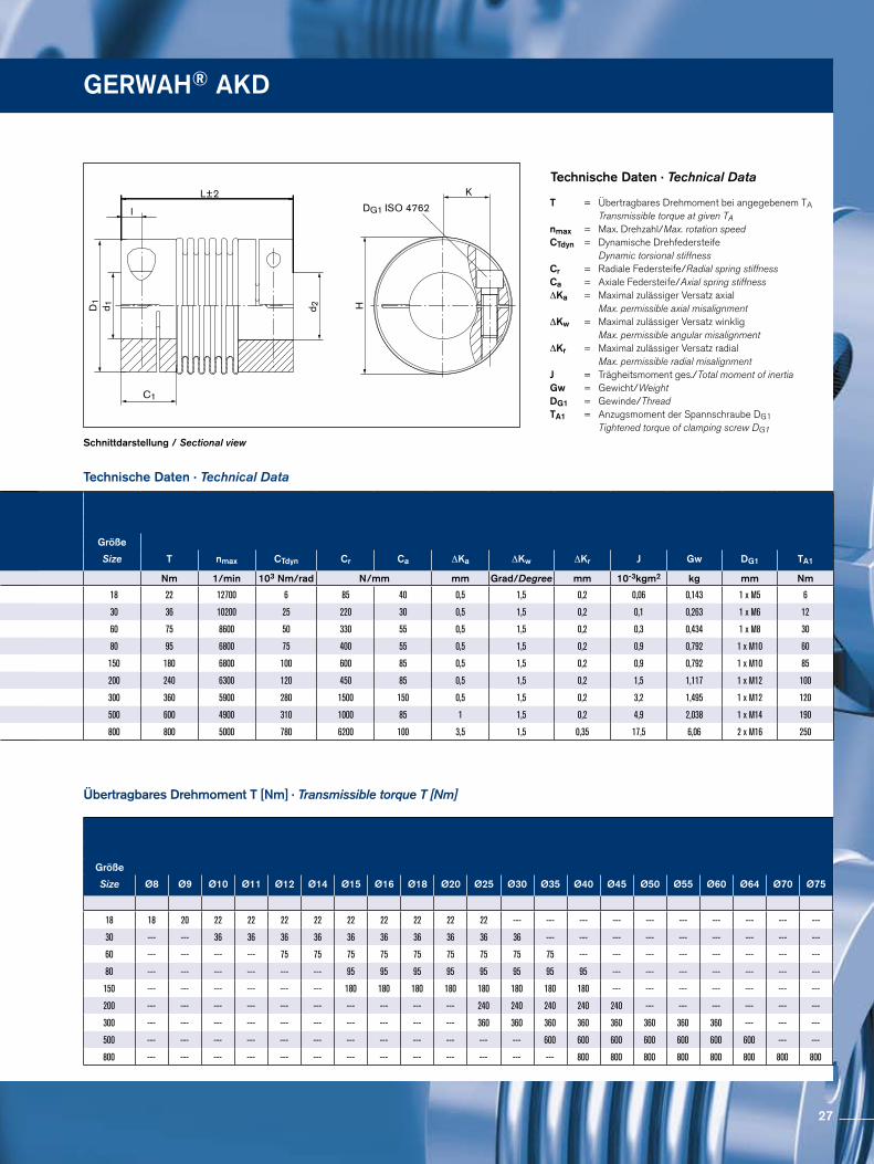
Schnittdarstellung / Sectional view
Technische Daten · Technical Data
Technische Daten · Technical Data
Übertragbares Drehmoment T [Nm] · Transmissible torque T [Nm]
T = Übertragbares Drehmoment bei angegebenem TA Transmissible torque at given TAnmax = Max. Drehzahl/Max. rotation speedCTdyn = Dynamische Drehfedersteife Dynamic torsional stiffness Cr = Radiale Federsteife/Radial spring stiffnessCa = Axiale Federsteife/Axial spring stiffness ∆Ka = Maximal zulässiger Versatz axial Max. permissible axial misalignment ∆Kw = Maximal zulässiger Versatz winklig Max. permissible angular misalignment ∆Kr = Maximal zulässiger Versatz radial Max. permissible radial misalignment J = Trägheitsmoment ges./Total moment of inertia Gw = Gewicht/Weight DG1 = Gewinde/Thread TA1 = Anzugsmoment der Spannschraube DG1 Tightened torque of clamping screw DG1
GERWAH® AKD
d1;d2min-max
d1k;d2kmin-max
Größe Ohne PassfedernutWithout keyway
Mit PassfedernutWith keywaySize C1 D1 H I K L±2
mm mm mm mm mm mm mm
18 8 - 26 8 - 26 20 45 47 6 18 71
30 10 - 30 10 - 30 25 55 56 8 20 73
60 12 - 35 12 - 35 29 64 67 10 24 89
80 14 - 42 14 - 42 33 80 84 12 28 103
150 14 - 42 14 - 42 33 80 84 12 28 103
200 22 - 46 22 - 46 38 90 93 13 31 113
300 24 - 60 24 - 60 38 110 110 13 39 115
500 35 - 64 35 - 64 41 119 122 15 43 122
800 40 - 75 40 - 75 45 132 139 17 48 140
Größe
Size T nmax CTdyn Cr Ca ∆Ka ∆Kw ∆Kr J Gw DG1 TA1
Nm 1/min 103 Nm/rad N/mm mm Grad/Degree mm 10-3kgm2 kg mm Nm
18 22 12700 6 85 40 0,5 1,5 0,2 0,06 0,143 1 x M5 6
30 36 10200 25 220 30 0,5 1,5 0,2 0,1 0,263 1 x M6 12
60 75 8600 50 330 55 0,5 1,5 0,2 0,3 0,434 1 x M8 30
80 95 6800 75 400 55 0,5 1,5 0,2 0,9 0,792 1 x M10 60
150 180 6800 100 600 85 0,5 1,5 0,2 0,9 0,792 1 x M10 85
200 240 6300 120 450 85 0,5 1,5 0,2 1,5 1,117 1 x M12 100
300 360 5900 280 1500 150 0,5 1,5 0,2 3,2 1,495 1 x M12 120
500 600 4900 310 1000 85 1 1,5 0,2 4,9 2,038 1 x M14 190
800 800 5000 780 6200 100 3,5 1,5 0,35 17,5 6,06 2 x M16 250
Größe
Size Ø8 Ø9 Ø10 Ø11 Ø12 Ø14 Ø15 Ø16 Ø18 Ø20 Ø25 Ø30 Ø35 Ø40 Ø45 Ø50 Ø55 Ø60 Ø64 Ø70 Ø75
18 18 20 22 22 22 22 22 22 22 22 22 --- --- --- --- --- --- --- --- --- ---
30 --- --- 36 36 36 36 36 36 36 36 36 36 --- --- --- --- --- --- --- --- ---
60 --- --- --- --- 75 75 75 75 75 75 75 75 75 --- --- --- --- --- --- --- ---
80 --- --- --- --- --- --- 95 95 95 95 95 95 95 95 --- --- --- --- --- --- ---
150 --- --- --- --- --- --- 180 180 180 180 180 180 180 180 --- --- --- --- --- --- ---
200 --- --- --- --- --- --- --- --- --- --- 240 240 240 240 240 --- --- --- --- --- ---
300 --- --- --- --- --- --- --- --- --- --- 360 360 360 360 360 360 360 360 --- --- ---
500 --- --- --- --- --- --- --- --- --- --- --- --- 600 600 600 600 600 600 600 --- ---
800 --- --- --- --- --- --- --- --- --- --- --- --- --- 800 800 800 800 800 800 800 800
27
Spielfreie MetallbalgkupplungenBacklash-free Metal Bellows Couplings GERWAH® AKD-H
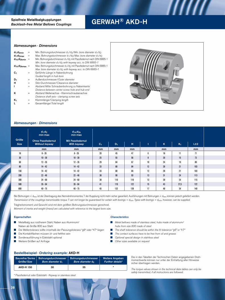
Abmessungen · Dimensions
Abmessungen · Dimensions
Bestellbeispiel · Ordering example: AKD-H
Baureihe/SeriesGröße/Size
Bohrungsdurchmesser Bore diameter d1
BohrungsdurchmesserBore diameter d2
Weitere AngabenFurther details*
AKD-H 150 30 35 *
* Passfedernut oder Edelstahl · Keyway or stainless steel
Eigenschaften
Metallbalg aus rostfreiem Stahl, Naben aus Aluminium/ Naben ab Größe 800 aus Stahl
Die Wellentoleranz sollte innerhalb der Passungstoleranz “g6“ oder “h7“ liegen Die Kontaktflächen müssen öl- und fettfrei sein Sonderausführung in Edelstahl optional Weitere Größen auf Anfrage
Characteristics
Metal bellows made of stainless steel, hubs made of aluminum/ hubs from size 800 made of steel
The shaft tolerance should be within the fit tolerance “g6” or “h7” The contact surfaces have to be free from oil and grease Optional special design in stainless steel Other sizes available on request
Die in den Tabellen der Technischen Daten angegebenen Dreh-momentwerte können nur unter der Einhaltung aller Hinweise sicher übertragen werden.
The torque values shown in the technical data tables can only be safely transmitted, if all instructions are followed.
d1;d2min = Min. Bohrungsdurchmesser d1/d2/Min. bore diameter d1/d2 d1;d2max = Max. Bohrungsdurchmesser d1/d2/Max. bore diameter d1/d2d1k;d2kmin = Min. Bohrungsdurchmesser d1/d2 mit Passfedernut nach DIN 6885-1 Min. bore diameter d1/d2 with keyway acc. to DIN 6885-1 d1k;d2kmax = Max. Bohrungsdurchmesser d1/d2 mit Passfedernut nach DIN 6885-1 Max. bore diameter d1/d2 with keyway acc. to DIN 6885-1 C1 = Geführte Länge in Nabenbohrung Guided length in hub bore D1 = Außendurchmesser/Outer diameter H = Stör-Durchmesser/Clearance diameter l = Abstand Mitte Schraubenbohrung zu Nabenkante Distance between center screw hole and hub end K = Abstand Wellenachse - Klemmschraubenachse Distance shaft axis - clamping screw axis K1 = Klemmlänge/Clamping length L = Gesamtlänge/Total length
Trägheitsmoment und Gewicht sind mit dem größten Bohrungsdurchmesser gerechnet.Moment of inertia and weight (mass) are calculated with reference to the largest bore size.
Bei Bohrungen < dmin ist die Übertragung des Nenndrehmomentes T der Kupplung nicht mehr sicher garantiert. Ausführungen mit Bohrungen < dmin können jedoch geliefert werden. Transmission of the couplings transmissible torque T can not longer be guaranteed for certain with borings < dmin. Types with borings < dmin, however, can be supplied.
d1;d2min-max
d1k;d2kmin-max
Größe Ohne PassfedernutWithout keyway
Mit PassfedernutWith keywaySize C1 D1 H I K K1 L±2
mm mm mm mm mm mm mm
18 8 - 26 8 - 26 20 45 47 6 18 11 71
30 10 - 30 10 - 30 25 55 56 8 20 15 73
60 12 - 35 12 - 35 29 64 67 10 24 19 89
80 14 - 42 14 - 42 33 80 84 12 28 21 103
150 14 - 42 14 - 42 33 80 84 12 28 21 103
200 22 - 46 22 - 46 38 90 93 13 31 24 113
300 24 - 60 24 - 60 38 110 110 13 39 24 115
500 35 - 64 35 - 64 41 119 122 15 43 27,5 122
800 40 - 75 40 - 75 45 132 139 17 48 34 140
28
DG1ISO 4762
d 1 d 2
L±2
I
H
KC1
K1
D1
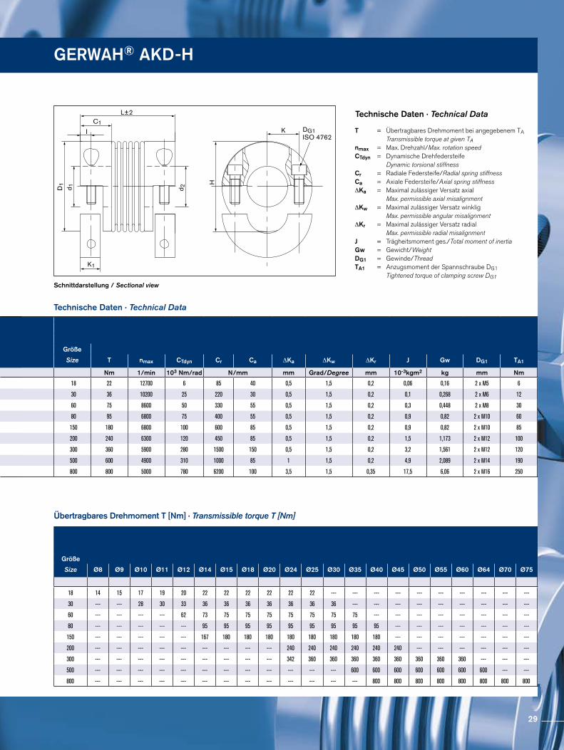
Schnittdarstellung / Sectional view
Technische Daten · Technical Data
Technische Daten · Technical Data
Übertragbares Drehmoment T [Nm] · Transmissible torque T [Nm]
T = Übertragbares Drehmoment bei angegebenem TA Transmissible torque at given TAnmax = Max. Drehzahl/Max. rotation speedCTdyn = Dynamische Drehfedersteife Dynamic torsional stiffness Cr = Radiale Federsteife/Radial spring stiffnessCa = Axiale Federsteife/Axial spring stiffness ∆Ka = Maximal zulässiger Versatz axial Max. permissible axial misalignment ∆Kw = Maximal zulässiger Versatz winklig Max. permissible angular misalignment ∆Kr = Maximal zulässiger Versatz radial Max. permissible radial misalignment J = Trägheitsmoment ges./Total moment of inertia Gw = Gewicht/Weight DG1 = Gewinde/Thread TA1 = Anzugsmoment der Spannschraube DG1 Tightened torque of clamping screw DG1
GERWAH® AKD-H
d1;d2min-max
d1k;d2kmin-max
Größe Ohne PassfedernutWithout keyway
Mit PassfedernutWith keywaySize C1 D1 H I K K1 L±2
mm mm mm mm mm mm mm
18 8 - 26 8 - 26 20 45 47 6 18 11 71
30 10 - 30 10 - 30 25 55 56 8 20 15 73
60 12 - 35 12 - 35 29 64 67 10 24 19 89
80 14 - 42 14 - 42 33 80 84 12 28 21 103
150 14 - 42 14 - 42 33 80 84 12 28 21 103
200 22 - 46 22 - 46 38 90 93 13 31 24 113
300 24 - 60 24 - 60 38 110 110 13 39 24 115
500 35 - 64 35 - 64 41 119 122 15 43 27,5 122
800 40 - 75 40 - 75 45 132 139 17 48 34 140
Größe
Size T nmax CTdyn Cr Ca ∆Ka ∆Kw ∆Kr J Gw DG1 TA1
Nm 1/min 103 Nm/rad N/mm mm Grad/Degree mm 10-3kgm2 kg mm Nm
18 22 12700 6 85 40 0,5 1,5 0,2 0,06 0,16 2 x M5 6
30 36 10200 25 220 30 0,5 1,5 0,2 0,1 0,268 2 x M6 12
60 75 8600 50 330 55 0,5 1,5 0,2 0,3 0,448 2 x M8 30
80 95 6800 75 400 55 0,5 1,5 0,2 0,9 0,82 2 x M10 60
150 180 6800 100 600 85 0,5 1,5 0,2 0,9 0,82 2 x M10 85
200 240 6300 120 450 85 0,5 1,5 0,2 1,5 1,173 2 x M12 100
300 360 5900 280 1500 150 0,5 1,5 0,2 3,2 1,561 2 x M12 120
500 600 4900 310 1000 85 1 1,5 0,2 4,9 2,089 2 x M14 190
800 800 5000 780 6200 100 3,5 1,5 0,35 17,5 6,06 2 x M16 250
Größe
Size Ø8 Ø9 Ø10 Ø11 Ø12 Ø14 Ø15 Ø18 Ø20 Ø24 Ø25 Ø30 Ø35 Ø40 Ø45 Ø50 Ø55 Ø60 Ø64 Ø70 Ø75
18 14 15 17 19 20 22 22 22 22 22 22 --- --- --- --- --- --- --- --- --- ---
30 --- --- 28 30 33 36 36 36 36 36 36 36 --- --- --- --- --- --- --- --- ---
60 --- --- --- --- 62 73 75 75 75 75 75 75 75 --- --- --- --- --- --- --- ---
80 --- --- --- --- --- 95 95 95 95 95 95 95 95 95 --- --- --- --- --- --- ---
150 --- --- --- --- --- 167 180 180 180 180 180 180 180 180 --- --- --- --- --- --- ---
200 --- --- --- --- --- --- --- --- --- 240 240 240 240 240 240 --- --- --- --- --- ---
300 --- --- --- --- --- --- --- --- --- 342 360 360 360 360 360 360 360 360 --- --- ---
500 --- --- --- --- --- --- --- --- --- --- --- --- 600 600 600 600 600 600 600 --- ---
800 --- --- --- --- --- --- --- --- --- --- --- --- --- 800 800 800 800 800 800 800 800
29
Spielfreie MetallbalgkupplungenBacklash-free Metal Bellows Couplings GERWAH® AK
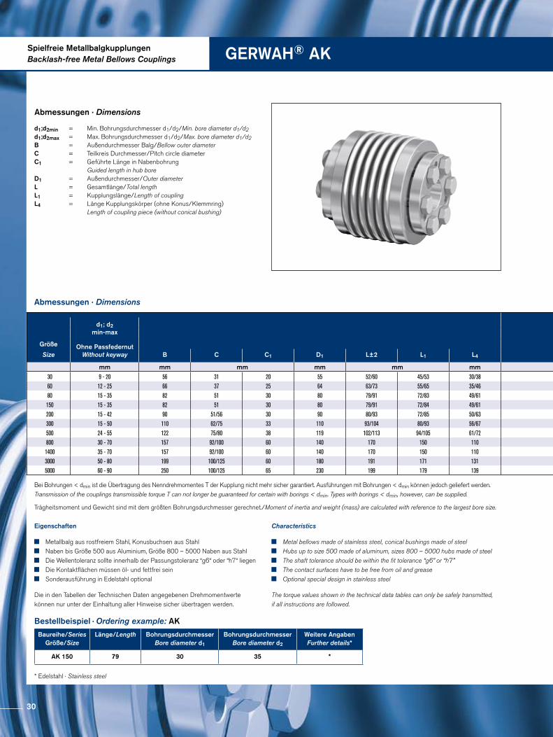
Abmessungen · Dimensions
Abmessungen · Dimensions
Trägheitsmoment und Gewicht sind mit dem größten Bohrungsdurchmesser gerechnet./Moment of inertia and weight (mass) are calculated with reference to the largest bore size.
Bestellbeispiel · Ordering example: AK
Baureihe/SeriesGröße/Size
Länge/Length Bohrungsdurchmesser Bore diameter d1
BohrungsdurchmesserBore diameter d2
Weitere AngabenFurther details*
AK 150 79 30 35 *
* Edelstahl · Stainless steel
Eigenschaften
Metallbalg aus rostfreiem Stahl, Konusbuchsen aus Stahl Naben bis Größe 500 aus Aluminium, Größe 800 – 5000 Naben aus Stahl Die Wellentoleranz sollte innerhalb der Passungstoleranz “g6“ oder “h7“ liegen Die Kontaktflächen müssen öl- und fettfrei sein Sonderausführung in Edelstahl optional
Die in den Tabellen der Technischen Daten angegebenen Drehmomentwerte können nur unter der Einhaltung aller Hinweise sicher übertragen werden.
Characteristics
Metal bellows made of stainless steel, conical bushings made of steel Hubs up to size 500 made of aluminum, sizes 800 – 5000 hubs made of steel The shaft tolerance should be within the fit tolerance “g6” or “h7” The contact surfaces have to be free from oil and grease Optional special design in stainless steel
The torque values shown in the technical data tables can only be safely transmitted, if all instructions are followed.
d1;d2min = Min. Bohrungsdurchmesser d1/d2/Min. bore diameter d1/d2 d1;d2max = Max. Bohrungsdurchmesser d1/d2/Max. bore diameter d1/d2B = Außendurchmesser Balg/Bellow outer diameter C = Teilkreis Durchmesser/Pitch circle diameter C1 = Geführte Länge in Nabenbohrung Guided length in hub bore D1 = Außendurchmesser/Outer diameter L = Gesamtlänge/Total lengthL1 = Kupplungslänge/Length of coupling L4 = Länge Kupplungskörper (ohne Konus/Klemmring) Length of coupling piece (without conical bushing)
Bei Bohrungen < dmin ist die Übertragung des Nenndrehmomentes T der Kupplung nicht mehr sicher garantiert. Ausführungen mit Bohrungen < dmin können jedoch geliefert werden. Transmission of the couplings transmissible torque T can not longer be guaranteed for certain with borings < dmin. Types with borings < dmin, however, can be supplied.
d1; d2min-max
Größe Ohne PassfedernutWithout keywaySize B C C1 D1 L±2 L1 L4
mm mm mm mm mm mm
30 9 - 20 56 31 20 55 52/60 45/53 30/3860 12 - 25 66 37 25 64 63/73 55/65 35/4680 15 - 35 82 51 30 80 79/91 72/83 49/61150 15 - 35 82 51 30 80 79/91 72/84 49/61200 15 - 42 90 51/56 30 90 80/93 72/85 50/63300 15 - 50 110 62/75 33 110 93/104 80/93 56/67500 24 - 55 122 75/80 38 119 102/113 94/105 61/72800 30 - 70 157 92/100 60 140 170 150 1101400 35 - 70 157 92/100 60 140 170 150 1103000 50 - 80 199 100/125 60 180 191 171 1315000 60 - 90 250 100/125 65 230 199 179 139
30
DG1 ISO 4017
d 1CB d 2 D1
L4C1L1
L±2
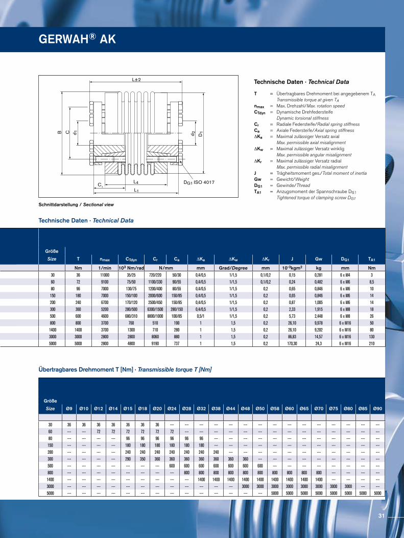
Schnittdarstellung / Sectional view
Technische Daten · Technical Data
Technische Daten · Technical Data
Übertragbares Drehmoment T [Nm] · Transmissible torque T [Nm]
T = Übertragbares Drehmoment bei angegebenem TA Transmissible torque at given TAnmax = Max. Drehzahl/Max. rotation speedCTdyn = Dynamische Drehfedersteife Dynamic torsional stiffness Cr = Radiale Federsteife/Radial spring stiffnessCa = Axiale Federsteife/Axial spring stiffness ∆Ka = Maximal zulässiger Versatz axial Max. permissible axial misalignment ∆Kw = Maximal zulässiger Versatz winklig Max. permissible angular misalignment ∆Kr = Maximal zulässiger Versatz radial Max. permissible radial misalignment J = Trägheitsmoment ges./Total moment of inertia Gw = Gewicht/Weight DG1 = Gewinde/Thread TA1 = Anzugsmoment der Spannschraube DG1 Tightened torque of clamping screw DG1
GERWAH® AK
d1; d2min-max
Größe Ohne PassfedernutWithout keywaySize B C C1 D1 L±2 L1 L4
mm mm mm mm mm mm
30 9 - 20 56 31 20 55 52/60 45/53 30/3860 12 - 25 66 37 25 64 63/73 55/65 35/4680 15 - 35 82 51 30 80 79/91 72/83 49/61150 15 - 35 82 51 30 80 79/91 72/84 49/61200 15 - 42 90 51/56 30 90 80/93 72/85 50/63300 15 - 50 110 62/75 33 110 93/104 80/93 56/67500 24 - 55 122 75/80 38 119 102/113 94/105 61/72800 30 - 70 157 92/100 60 140 170 150 1101400 35 - 70 157 92/100 60 140 170 150 1103000 50 - 80 199 100/125 60 180 191 171 1315000 60 - 90 250 100/125 65 230 199 179 139
Größe
Size T nmax CTdyn Cr Ca ∆Ka ∆Kw ∆Kr J Gw DG1 TA1
Nm 1/min 103 Nm/rad N/mm mm Grad/Degree mm 10-3kgm2 kg mm Nm
30 36 11000 35/25 720/220 50/30 0,4/0,5 1/1,5 0,1/0,2 0,15 0,281 6 x M4 360 72 9100 75/50 1100/330 90/55 0,4/0,5 1/1,5 0,1/0,2 0,24 0,482 6 x M6 8,580 96 7000 130/75 1200/400 80/55 0,4/0,5 1/1,5 0,2 0,65 0,846 6 x M6 10150 180 7000 150/100 2000/600 150/85 0,4/0,5 1/1,5 0,2 0,65 0,846 6 x M6 14200 240 6700 170/120 2500/450 150/85 0,4/0,5 1/1,5 0,2 0,87 1,005 6 x M6 14300 360 5200 280/500 6300/1500 280/150 0,4/0,5 1/1,5 0,2 2,33 1,915 6 x M8 18500 600 4600 680/310 8800/1000 100/85 0,5/1 1/1,5 0,2 5,73 2,448 6 x M8 26800 800 3700 760 510 190 1 1,5 0,2 26,10 9,978 6 x M16 501400 1400 3700 1300 710 280 1 1,5 0,2 26,10 9,202 6 x M16 803000 3000 2800 2800 8060 880 1 1,5 0,2 86,83 14,57 6 x M16 1305000 5000 2800 4800 9190 737 1 1,5 0,2 170,30 24,3 6 x M16 210
Größe
Size Ø9 Ø10 Ø12 Ø14 Ø15 Ø18 Ø20 Ø24 Ø28 Ø32 Ø38 Ø44 Ø48 Ø50 Ø58 Ø60 Ø65 Ø70 Ø75 Ø80 Ø85 Ø90
30 36 36 36 36 36 36 36 --- --- --- --- --- --- --- --- --- --- --- --- --- --- ---60 --- --- 72 72 72 72 72 72 --- --- --- --- --- --- --- --- --- --- --- --- --- ---80 --- --- --- --- 96 96 96 96 96 96 --- --- --- --- --- --- --- --- --- --- --- ---150 --- --- --- --- 180 180 180 180 180 180 --- --- --- --- --- --- --- --- --- --- --- ---200 --- --- --- --- 240 240 240 240 240 240 240 --- --- --- --- --- --- --- --- --- --- ---300 --- --- --- --- 290 350 360 360 360 360 360 360 360 --- --- --- --- --- --- --- --- ---500 --- --- --- --- --- --- --- 600 600 600 600 600 600 600 --- --- --- --- --- --- --- ---800 --- --- --- --- --- --- --- --- 800 800 800 800 800 800 800 800 800 800 --- --- --- ---1400 --- --- --- --- --- --- --- --- --- 1400 1400 1400 1400 1400 1400 1400 1400 1400 --- --- --- ---3000 --- --- --- --- --- --- --- --- --- --- --- --- 3000 3000 3000 3000 3000 3000 3000 3000 --- ---5000 --- --- --- --- --- --- --- --- --- --- --- --- --- --- 5000 5000 5000 5000 5000 5000 5000 5000
31
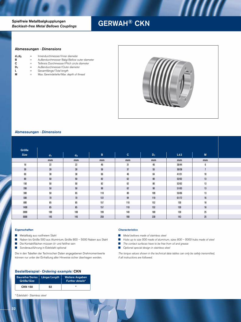
Spielfreie MetallbalgkupplungenBacklash-free Metal Bellows Couplings GERWAH® CKN
Abmessungen · Dimensions
Abmessungen · Dimensions
Bestellbeispiel · Ordering example: CKN
Baureihe/SeriesGröße/Size
Länge/Length Weitere AngabenFurther details*
CKN 150 52 *
* Edelstahl · Stainless steel
Eigenschaften
Metallbalg aus rostfreiem Stahl Naben bis Größe 500 aus Aluminium, Größe 800 – 5000 Naben aus Stahl Die Kontaktflächen müssen öl- und fettfrei sein Sonderausführung in Edelstahl optional
Die in den Tabellen der Technischen Daten angegebenen Drehmomentwerte können nur unter der Einhaltung aller Hinweise sicher übertragen werden.
Characteristics
Metal bellows made of stainless steel Hubs up to size 500 made of aluminum, sizes 800 – 5000 hubs made of steel The contact surfaces have to be free from oil and grease Optional special design in stainless steel
The torque values shown in the technical data tables can only be safely transmitted, if all instructions are followed.
d1;d2 = Innendurchmesser/Inner diameter B = Außendurchmesser Balg/Bellow outer diameter C = Teilkreis Durchmesser/Pitch circle diameter D1 = Außendurchmesser/Outer diameterL = Gesamtlänge/Total length M = Max. Gewindetiefe/Max. depth of thread
Größe
Size d1 d2 B C D1 L±2 M
mm mm mm mm mm mm mm
18 22 22 46 31 46 36/44 6
30 28 28 56 37 55 30/38 7
60 38 38 66 46 64 41/51 10
80 50 50 82 62 80 52/62 13
150 50 50 82 62 80 52/62 13
200 50 50 90 62 90 51/63 13
300 50 65 110 80 109 55/66 13
500 70 70 122 94 119 61/72 16
800 85 85 157 110 152 130 18
1400 85 85 157 110 152 130 18
3000 100 100 199 140 180 130 25
5000 145 145 250 190 230 143 25
32
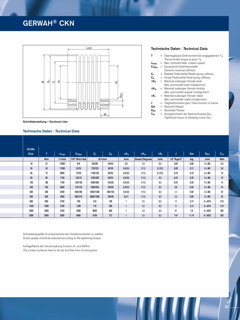
d 1CB d 2
DG
1
M
L±2 D
1
Schnittdarstellung / Sectional view
Technische Daten · Technical Data
Technische Daten · Technical Data
Schraubenqualität ist entsprechend den Anziehmomenten zu wählenScrew quality should be selected according to the tightening torque
Auflagefläche der Verschraubung trocken, öl- und fettfreiThe contact surfaces have to be dry and free from oil and grease
T = Übertragbares Drehmoment bei angegebenem TA Transmissible torque at given TAnmax = Max. Drehzahl/Max. rotation speedCTdyn = Dynamische Drehfedersteife Dynamic torsional stiffness Cr = Radiale Federsteife/Radial spring stiffnessCa = Axiale Federsteife/Axial spring stiffness ∆Ka = Maximal zulässiger Versatz axial Max. permissible axial misalignment ∆Kw = Maximal zulässiger Versatz winklig Max. permissible angular misalignment ∆Kr = Maximal zulässiger Versatz radial Max. permissible radial misalignment J = Trägheitsmoment ges./Total moment of inertia Gw = Gewicht/Weight DG1 = Gewinde/Thread TA1 = Anzugsmoment der Spannschraube DG1 Tightened torque of clamping screw DG1
GERWAH® CKN
Größe
Size d1 d2 B C D1 L±2 M
mm mm mm mm mm mm mm
18 22 22 46 31 46 36/44 6
30 28 28 56 37 55 30/38 7
60 38 38 66 46 64 41/51 10
80 50 50 82 62 80 52/62 13
150 50 50 82 62 80 52/62 13
200 50 50 90 62 90 51/63 13
300 50 65 110 80 109 55/66 13
500 70 70 122 94 119 61/72 16
800 85 85 157 110 152 130 18
1400 85 85 157 110 152 130 18
3000 100 100 199 140 180 130 25
5000 145 145 250 190 230 143 25
Größe
Size T nmax CTdyn Cr Ca ∆Ka ∆Kw ∆Kr J Gw DG1 TA1
Nm 1/min 103 Nm/rad N/mm mm Grad/Degree mm 10-3kgm2 kg mm Nm
18 22 13900 8/6 200/85 50/40 0,5 1,5 0,2 0,05 0,06 6 x M5 5,9
30 36 11000 35/25 720/220 50/30 0,4/0,5 1/1,5 0,1/0,2 0,09 0,12 6 x M5 5,9
60 75 9000 75/50 1100/330 90/55 0,4/0,5 1/1,5 0,1/0,2 0,16 0,19 6 x M6 10
80 96 7100 130/75 1200/400 80/55 0,4/0,5 1/1,5 0,2 0,43 0,36 6 x M6 10
150 180 7100 150/100 2000/600 150/85 0,4/0,5 1/1,5 0,2 0,43 0,36 6 x M6 15
200 240 6600 170/120 2500/450 150/85 0,4/0,5 1/1,5 0,2 0,8 0,48 6 x M6 18
300 360 5200 500/280 6300/1500 280/150 0,4/0,5 1/1,5 0,2 1,7 0,59 6 x M8 25
500 600 4600 680/310 8800/1000 100/85 0,5/1 1/1,5 0,2 2,3 0,88 6 x M8 36
800 960 3700 760 510 190 1 1,5 0,2 11 3,74 6 x M16 210
1400 1680 3700 1300 710 280 1 1,5 0,2 11 3,73 6 x M16 210
3000 3000 3700 2800 8060 880 1 1,5 0,2 47 7,8 6 x M20 365
5000 5000 3000 4800 9190 737 1 1,5 0,2 119 11,74 8 x M20 365
33
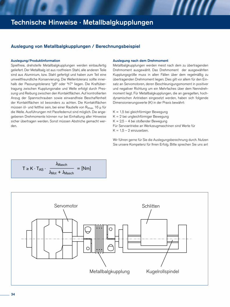
Technische Hinweise · Metallbalgkupplungen
Auslegung/ProduktinformationSpielfreie, drehsteife Metallbalgkupplungen werden einbaufertig geliefert. Der Metallbalg ist aus rostfreiem Stahl, alle anderen Teile sind aus Aluminium, bzw. Stahl gefertigt und haben zum Teil eine umweltfreundliche Konservierung. Die Wellentoleranz sollte inner-halb der Passungstoleranz “g6“ oder “h7“ liegen. Die Kraftüber-tragung zwischen Kupplungsnabe und Welle erfolgt durch Pres-sung und Reibung zwischen den Kontaktflächen. Auf kontrollierten Anzug der Spannschrauben sowie einwandfreie Beschaffenheit der Kontaktflächen ist besonders zu achten. Die Kontaktflächen müssen öl- und fettfrei sein, bei einer Rautiefe von Rtmax. 16 µ für die Welle. Ausführungen mit Passfedernut sind möglich. Die ange-gebenen Drehmomente können nur bei Einhaltung aller Hinweise sicher übertragen werden. Sonst müssen Abstriche gemacht wer-den.
Auslegung nach dem DrehmomentMetallbalgkupplungen werden meist nach dem zu übertragenden Drehmoment ausgewählt. Das Drehmoment der ausgewählten Kupplungsgröße muss in allen Fällen über dem regelmäßig zu übertragenden Drehmoment liegen. Dies gilt vor allem für den Ein-satz an Servomotoren, deren Beschleunigungsmoment in positiver und negativer Richtung um ein Mehrfaches über dem Nenndreh-moment liegt. Für Metallbalgkupplungen, die an geregelten, hoch-dynamischen Antrieben eingesetzt werden, haben sich folgende Dimensionierungswerte (K) in der Praxis bewährt:
K = 1,5 bei gleichförmiger BewegungK = 2 bei ungleichförmiger BewegungK = 2,5 – 4 bei stoßender BewegungFür Servoantriebe an Werkzeugmaschinen sind Werte für K = 1,5 – 2 einzusetzen.
Wir führen gerne für Sie die Auslegungsberechnung durch. Nutzen Sie unsere Kompetenz für Ihren Erfolg. Bitte sprechen Sie uns an!
Auslegung von Metallbalgkupplungen / Berechnungsbeispiel
Servomotor Schlitten
Metallbalgkupplung Kugelrollspindel
T ≥ K · TAS ·JMasch
JMot + JMasch= [Nm]
34
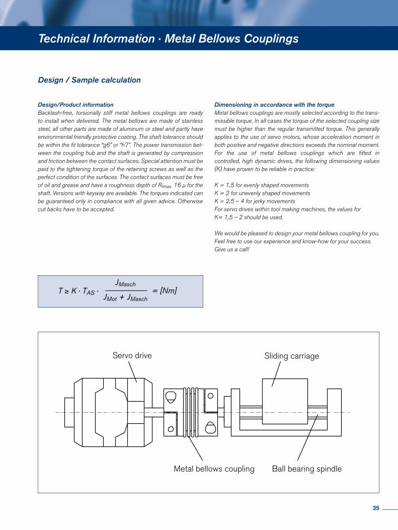
Technical Information · Metal Bellows Couplings
Design / Sample calculation
Design/Product information Backlash-free, torsionally stiff metal bellows couplings are ready to install when delivered. The metal bellows are made of stainless steel, all other parts are made of aluminum or steel and partly have environmental friendly protective coating. The shaft tolerance should be within the fit tolerance “g6” or “h7”. The power transmission bet-ween the coupling hub and the shaft is generated by compression and friction between the contact surfaces. Special attention must be paid to the tightening torque of the retaining screws as well as the perfect condition of the surfaces. The contact surfaces must be free of oil and grease and have a roughness depth of Rtmax. 16 µ for the shaft. Versions with keyway are available. The torques indicated can be guaranteed only in compliance with all given advice. Otherwise cut backs have to be accepted.
Dimensioning in accordance with the torqueMetal bellows couplings are mostly selected according to the trans-missible torque. In all cases the torque of the selected coupling size must be higher than the regular transmitted torque. This generally applies to the use of servo motors, whose acceleration moment in both positive and negative directions exceeds the nominal moment. For the use of metal bellows couplings which are fitted in controlled, high dynamic drives, the following dimensioning values (K) have proven to be reliable in practice:
K = 1,5 for evenly shaped movementsK = 2 for unevenly shaped movementsK = 2,5 – 4 for jerky movementsFor servo drives within tool making machines, the values forK= 1,5 – 2 should be used.
We would be pleased to design your metal bellows coupling for you. Feel free to use our experience and know-how for your success.Give us a call!
Servo drive Sliding carriage
Metal bellows coupling Ball bearing spindle
T ≥ K · TAS ·JMasch
JMot + JMasch= [Nm]
35
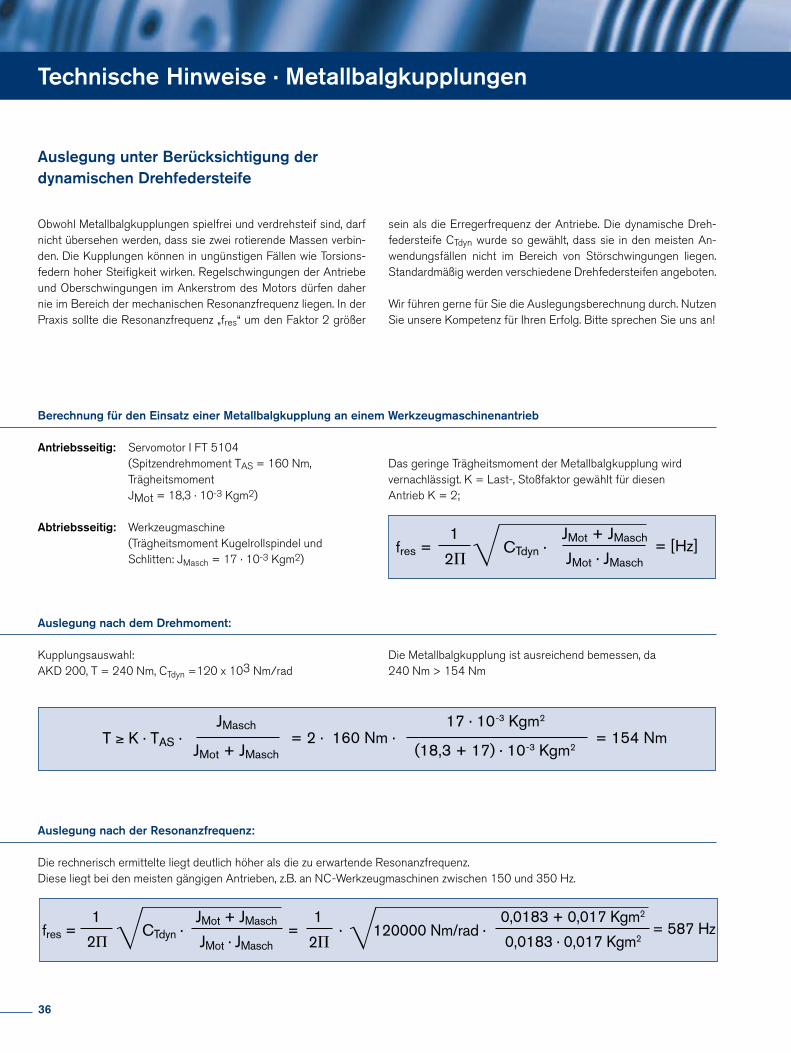
Antriebsseitig: Servomotor I FT 5104 (Spitzendrehmoment TAS = 160 Nm, Trägheitsmoment JMot = 18,3 · 10-3 Kgm2)
Abtriebsseitig: Werkzeugmaschine (Trägheitsmoment Kugelrollspindel und Schlitten: JMasch = 17 · 10-3 Kgm2)
Berechnung für den Einsatz einer Metallbalgkupplung an einem Werkzeugmaschinenantrieb
Auslegung nach dem Drehmoment:
Kupplungsauswahl: AKD 200, T = 240 Nm, CTdyn =120 x 103 Nm/rad
Technische Hinweise · Metallbalgkupplungen
Auslegung nach der Resonanzfrequenz:
Die rechnerisch ermittelte liegt deutlich höher als die zu erwartende Resonanzfrequenz.Diese liegt bei den meisten gängigen Antrieben, z.B. an NC-Werkzeugmaschinen zwischen 150 und 350 Hz.
Auslegung unter Berücksichtigung der dynamischen Drehfedersteife
Obwohl Metallbalgkupplungen spielfrei und verdrehsteif sind, darf nicht übersehen werden, dass sie zwei rotierende Massen verbin-den. Die Kupplungen können in ungünstigen Fällen wie Torsions-federn hoher Steifigkeit wirken. Regelschwingungen der Antriebe und Oberschwingungen im Ankerstrom des Motors dürfen daher nie im Bereich der mechanischen Resonanzfrequenz liegen. In der Praxis sollte die Resonanzfrequenz „fres“ um den Faktor 2 größer
Die Metallbalgkupplung ist ausreichend bemessen, da240 Nm > 154 Nm
sein als die Erregerfrequenz der Antriebe. Die dynamische Dreh-federsteife CTdyn wurde so gewählt, dass sie in den meisten An-wendungsfällen nicht im Bereich von Störschwingungen liegen. Standardmäßig werden verschiedene Drehfedersteifen angeboten.
Wir führen gerne für Sie die Auslegungsberechnung durch. Nutzen Sie unsere Kompetenz für Ihren Erfolg. Bitte sprechen Sie uns an!
Das geringe Trägheitsmoment der Metallbalgkupplung wird vernachlässigt. K = Last-, Stoßfaktor gewählt für diesen Antrieb K = 2;
fres =1
2P= [Hz]CTdyn ·
JMot + JMasch
JMot · JMasch
T ≥ K · TAS ·JMasch
JMot + JMasch= 2 · 160 Nm ·
17 · 10-3 Kgm2
(18,3 + 17) · 10-3 Kgm2= 154 Nm
fres =1
2PCTdyn ·
JMot + JMasch
JMot · JMasch=
1
2P· 120000 Nm/rad ·
0,0183 + 0,017 Kgm2
0,0183 · 0,017 Kgm2= 587 Hz
36
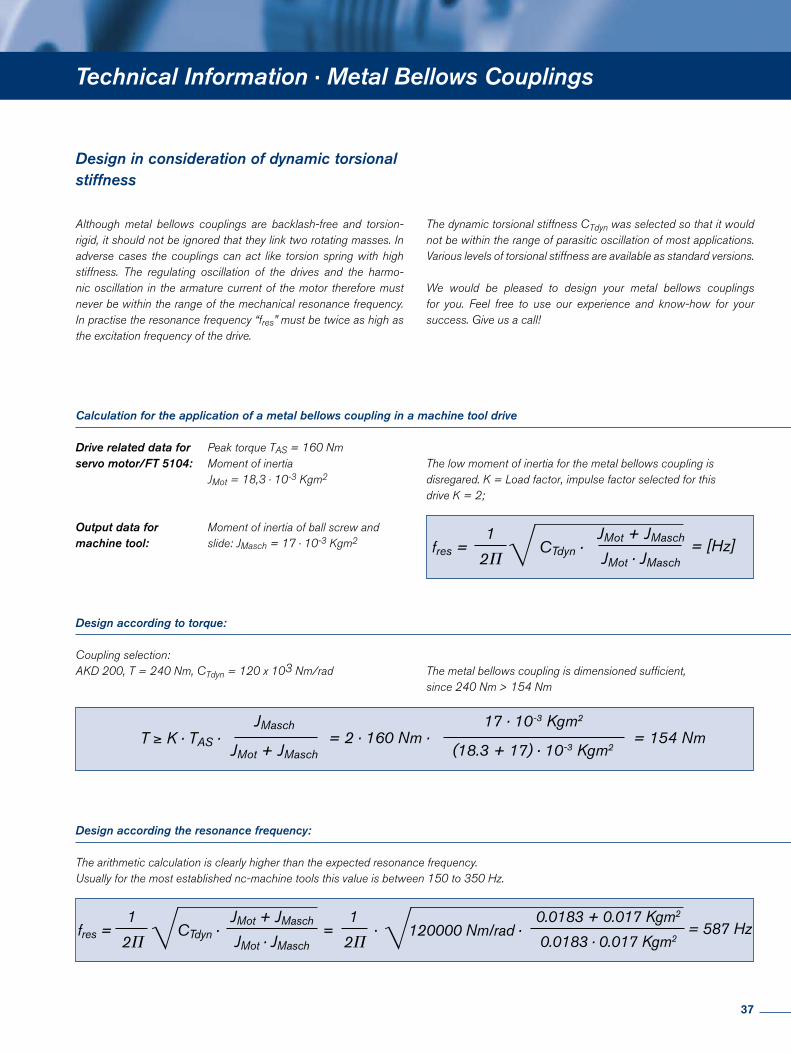
Technical Information · Metal Bellows Couplings
Drive related data for Peak torque TAS = 160 Nmservo motor/FT 5104: Moment of inertia JMot = 18,3 · 10-3 Kgm2
Output data for Moment of inertia of ball screw and machine tool: slide: JMasch = 17 · 10-3 Kgm2
Calculation for the application of a metal bellows coupling in a machine tool drive
Design according to torque:
Coupling selection: AKD 200, T = 240 Nm, CTdyn = 120 x 103 Nm/rad
Design according the resonance frequency:
The arithmetic calculation is clearly higher than the expected resonance frequency.Usually for the most established nc-machine tools this value is between 150 to 350 Hz.
Design in consideration of dynamic torsional stiffness
Although metal bellows couplings are backlash-free and torsion-rigid, it should not be ignored that they link two rotating masses. In adverse cases the couplings can act like torsion spring with high stiffness. The regulating oscillation of the drives and the harmo-nic oscillation in the armature current of the motor therefore must never be within the range of the mechanical resonance frequency. In practise the resonance frequency “fres” must be twice as high as the excitation frequency of the drive.
The dynamic torsional stiffness CTdyn was selected so that it would not be within the range of parasitic oscillation of most applications. Various levels of torsional stiffness are available as standard versions.
We would be pleased to design your metal bellows couplings for you. Feel free to use our experience and know-how for your success. Give us a call!
The low moment of inertia for the metal bellows coupling is disregared. K = Load factor, impulse factor selected for this drive K = 2;
The metal bellows coupling is dimensioned sufficient, since 240 Nm > 154 Nm
fres =1
2P= [Hz]CTdyn ·
JMot + JMasch
JMot · JMasch
T ≥ K · TAS ·JMasch
JMot + JMasch= 2 · 160 Nm ·
17 · 10-3 Kgm2
(18.3 + 17) · 10-3 Kgm2= 154 Nm
fres =1
2PCTdyn ·
JMot + JMasch
JMot · JMasch=
1
2P· 120000 Nm/rad ·
0.0183 + 0.017 Kgm2
0.0183 · 0.017 Kgm2= 587 Hz
37
Elastomerkupplungen Grundlagen · Servo-Insert Couplings Basics
Spielfreie Elastomerkupplungen werden im Maschinenbau einge-setzt, wo eine Schwingungsdämpfung gefordert wird und bevor-zugt steckbare Kupplungslösungen zum Einsatz kommen:
Spielfreie Elastomerkupplungen
Backlash-free Servo-Insert Couplings are used in mechanical engi-neering, where shock absorption is requested and pluggable coup-ling solutions are applied.
Zum Beispiel an:
Messantrieben
Präzisionsantrieben
Vorschubantrieben
Schleif- und Fräs-Spindeln
Werkzeugmaschinen
Verpackungsmaschinen
Robotertechnik
Transferzentren
Mehrspindelköpfen
Holzbearbeitungsmaschinen
Textilmaschinen
Fördertechnik
Lineartechnik
Mess- und Regeltechnik
Prüfstandsbau
Common Applications:
Encoder
Precision drives
Feed drives
Grinding and milling spindles
Machine tools
Packing machines
Robotics
Transfer lines
Multi-spindle heads
Wood processing equipment
Textile machinery
Conveying equipment
Linear motion
Measuring equipment and control technology
Test rigs
Besondere Eigenschaften
Spielfrei
Steckbar
Schwingungsdämpfend
Drehmomente von 0,5 – 650 Nm
Ausgleich von radialem, axialem, und winkligem Wellenversatz
Elektrisch isolierend
Special Features
Backlash-free
Pluggable
Vibration damping
Torques from 0,5 - 650 Nm
Compensation of radial, axial and angular misalignment
Electrically isolating
Backlash-free Servo-Insert Couplings
38
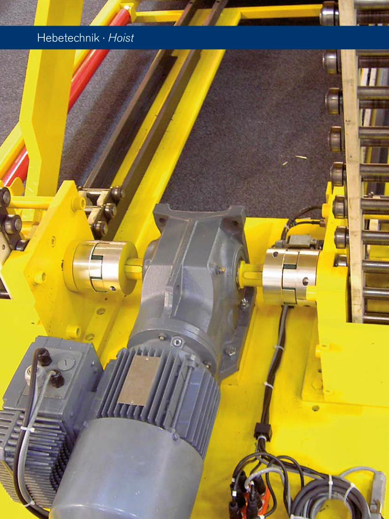
Hebetechnik · Hoist
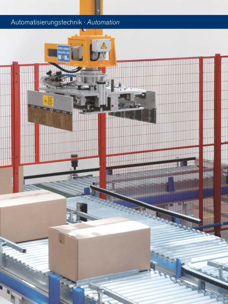
Automatisierungstechnik · Automation
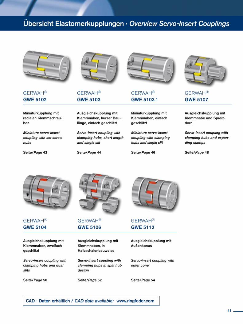
GERWAH® GWE 5102
Miniaturkupplung mit radialen Klemmschrau-ben
Miniature servo-insert coupling with set screw hubs
Seite/Page 42
GERWAH®
GWE 5103.1
Miniaturkupplung mit Klemmnaben, einfach geschlitzt
Miniature servo-insert coupling with clamping hubs and single slit
Seite/Page 46
GERWAH® GWE 5103
Ausgleichskupplung mit Klemmnaben, kurzer Bau-länge, einfach geschlitzt
Servo-insert coupling with clamping hubs, short length and single slit
Seite/Page 44
Übersicht Elastomerkupplungen · Overview Servo-Insert Couplings
GERWAH®
GWE 5104
Ausgleichskupplung mit Klemmnaben, zweifach geschlitzt Servo-insert coupling with clamping hubs and dual slits
Seite/Page 50
GERWAH® GWE 5106
Ausgleichskupplung mit Klemmnaben, in Halbschalenbauweise Servo-insert coupling with clamping hubs in split hub design
Seite/Page 52
GERWAH® GWE 5107
Ausgleichskupplung mit Klemmnabe und Spreiz-dorn
Servo-insert coupling with clamping hubs and expan-ding clamps
Seite/Page 48
GERWAH® GWE 5112
Ausgleichskupplung mit Außenkonus
Servo-insert coupling with outer cone
Seite/Page 54
41
CAD - Daten erhältlich / CAD data available: www.ringfeder.com
41
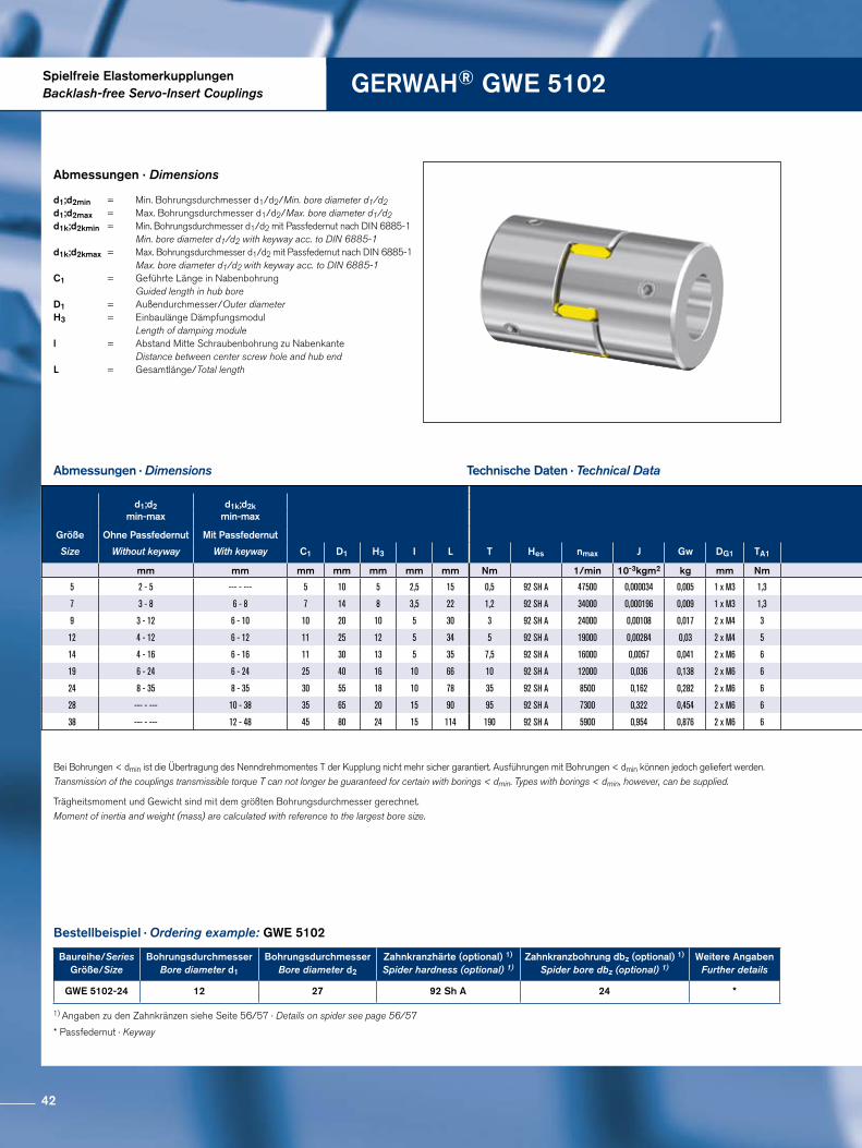
Spielfreie ElastomerkupplungenBacklash-free Servo-Insert Couplings GERWAH® GWE 5102
Abmessungen · Dimensions
Trägheitsmoment und Gewicht sind mit dem größten Bohrungsdurchmesser gerechnet.Moment of inertia and weight (mass) are calculated with reference to the largest bore size.
Abmessungen · Dimensions
Technische Daten · Technical Data
Bestellbeispiel · Ordering example: GWE 5102
d1;d2min = Min. Bohrungsdurchmesser d1/d2/Min. bore diameter d1/d2 d1;d2max = Max. Bohrungsdurchmesser d1/d2/Max. bore diameter d1/d2d1k;d2kmin = Min. Bohrungsdurchmesser d1/d2 mit Passfedernut nach DIN 6885-1 Min. bore diameter d1/d2 with keyway acc. to DIN 6885-1d1k;d2kmax = Max. Bohrungsdurchmesser d1/d2 mit Passfedernut nach DIN 6885-1 Max. bore diameter d1/d2 with keyway acc. to DIN 6885-1 C1 = Geführte Länge in Nabenbohrung Guided length in hub bore D1 = Außendurchmesser/Outer diameter H3 = Einbaulänge Dämpfungsmodul Length of damping module l = Abstand Mitte Schraubenbohrung zu Nabenkante Distance between center screw hole and hub end L = Gesamtlänge/Total length
Bei Bohrungen < dmin ist die Übertragung des Nenndrehmomentes T der Kupplung nicht mehr sicher garantiert. Ausführungen mit Bohrungen < dmin können jedoch geliefert werden. Transmission of the couplings transmissible torque T can not longer be guaranteed for certain with borings < dmin. Types with borings < dmin, however, can be supplied.
* Passfedernut · Keyway
1) Angaben zu den Zahnkränzen siehe Seite 56/57 · Details on spider see page 56/57
Baureihe/SeriesGröße/Size
Bohrungsdurchmesser Bore diameter d1
BohrungsdurchmesserBore diameter d2
Zahnkranzhärte (optional) 1)
Spider hardness (optional) 1)Zahnkranzbohrung dbz (optional) 1)
Spider bore dbz (optional) 1)Weitere Angaben
Further details
GWE 5102-24 12 27 92 Sh A 24 *
d1;d2min-max
d1k;d2kmin-max
Größe Ohne Passfedernut Mit Passfedernut
Size Without keyway With keyway C1 D1 H3 I L T Hes nmax J Gw DG1 TA1
mm mm mm mm mm mm mm Nm 1/min 10-3kgm2 kg mm Nm
5 2 - 5 --- - --- 5 10 5 2,5 15 0,5 92 SH A 47500 0,000034 0,005 1 x M3 1,3
7 3 - 8 6 - 8 7 14 8 3,5 22 1,2 92 SH A 34000 0,000196 0,009 1 x M3 1,3
9 3 - 12 6 - 10 10 20 10 5 30 3 92 SH A 24000 0,00108 0,017 2 x M4 3
12 4 - 12 6 - 12 11 25 12 5 34 5 92 SH A 19000 0,00284 0,03 2 x M4 5
14 4 - 16 6 - 16 11 30 13 5 35 7,5 92 SH A 16000 0,0057 0,041 2 x M6 6
19 6 - 24 6 - 24 25 40 16 10 66 10 92 SH A 12000 0,036 0,138 2 x M6 6
24 8 - 35 8 - 35 30 55 18 10 78 35 92 SH A 8500 0,162 0,282 2 x M6 6
28 --- - --- 10 - 38 35 65 20 15 90 95 92 SH A 7300 0,322 0,454 2 x M6 6
38 --- - --- 12 - 48 45 80 24 15 114 190 92 SH A 5900 0,954 0,876 2 x M6 6
42
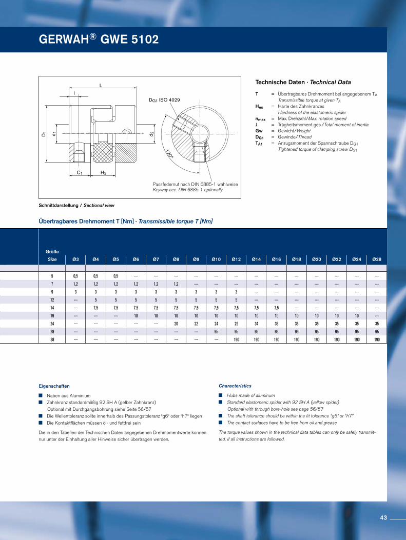
GERWAH® GWE 5102
Passfedernut nach DIN 6885-1 wahlweiseKeyway acc. DIN 6885-1 optionally
DG1 ISO 4029
d 1D1
d 2
C1
120°
L
I
H3
Schnittdarstellung / Sectional view
Übertragbares Drehmoment T [Nm] · Transmissible torque T [Nm]
Technische Daten · Technical Data
Eigenschaften
Naben aus Aluminium Zahnkranz standardmäßig 92 SH A (gelber Zahnkranz)
Optional mit Durchgangsbohrung siehe Seite 56/57 Die Wellentoleranz sollte innerhalb des Passungstoleranz “g6“ oder “h7“ liegen Die Kontaktflächen müssen öl- und fettfrei sein
Die in den Tabellen der Technischen Daten angegebenen Drehmomentwerte können nur unter der Einhaltung aller Hinweise sicher übertragen werden.
Characteristics
Hubs made of aluminum Standard elastomeric spider with 92 SH A (yellow spider)
Optional with through bore-hole see page 56/57 The shaft tolerance should be within the fit tolerance “g6” or “h7” The contact surfaces have to be free from oil and grease
The torque values shown in the technical data tables can only be safely transmit-ted, if all instructions are followed.
T = Übertragbares Drehmoment bei angegebenem TA Transmissible torque at given TAHes = Härte des Zahnkranzes Hardness of the elastomeric spider nmax = Max. Drehzahl/Max. rotation speed J = Trägheitsmoment ges./Total moment of inertia Gw = Gewicht/Weight DG1 = Gewinde/ThreadTA1 = Anzugsmoment der Spannschraube DG1 Tightened torque of clamping screw DG1
Größe
Size Ø3 Ø4 Ø5 Ø6 Ø7 Ø8 Ø9 Ø10 Ø12 Ø14 Ø16 Ø18 Ø20 Ø22 Ø24 Ø28
5 0,5 0,5 0,5 --- --- --- --- --- --- --- --- --- --- --- --- ---
7 1,2 1,2 1,2 1,2 1,2 1,2 --- --- --- --- --- --- --- --- --- ---
9 3 3 3 3 3 3 3 3 3 --- --- --- --- --- --- ---
12 --- 5 5 5 5 5 5 5 5 --- --- --- --- --- --- ---
14 --- 7,5 7,5 7,5 7,5 7,5 7,5 7,5 7,5 7,5 7,5 --- --- --- --- ---
19 --- --- --- 10 10 10 10 10 10 10 10 10 10 10 10 ---
24 --- --- --- --- --- 20 22 24 29 34 35 35 35 35 35 35
28 --- --- --- --- --- --- --- 95 95 95 95 95 95 95 95 95
38 --- --- --- --- --- --- --- --- 190 190 190 190 190 190 190 190
d1;d2min-max
d1k;d2kmin-max
Größe Ohne Passfedernut Mit Passfedernut
Size Without keyway With keyway C1 D1 H3 I L T Hes nmax J Gw DG1 TA1
mm mm mm mm mm mm mm Nm 1/min 10-3kgm2 kg mm Nm
5 2 - 5 --- - --- 5 10 5 2,5 15 0,5 92 SH A 47500 0,000034 0,005 1 x M3 1,3
7 3 - 8 6 - 8 7 14 8 3,5 22 1,2 92 SH A 34000 0,000196 0,009 1 x M3 1,3
9 3 - 12 6 - 10 10 20 10 5 30 3 92 SH A 24000 0,00108 0,017 2 x M4 3
12 4 - 12 6 - 12 11 25 12 5 34 5 92 SH A 19000 0,00284 0,03 2 x M4 5
14 4 - 16 6 - 16 11 30 13 5 35 7,5 92 SH A 16000 0,0057 0,041 2 x M6 6
19 6 - 24 6 - 24 25 40 16 10 66 10 92 SH A 12000 0,036 0,138 2 x M6 6
24 8 - 35 8 - 35 30 55 18 10 78 35 92 SH A 8500 0,162 0,282 2 x M6 6
28 --- - --- 10 - 38 35 65 20 15 90 95 92 SH A 7300 0,322 0,454 2 x M6 6
38 --- - --- 12 - 48 45 80 24 15 114 190 92 SH A 5900 0,954 0,876 2 x M6 6
43
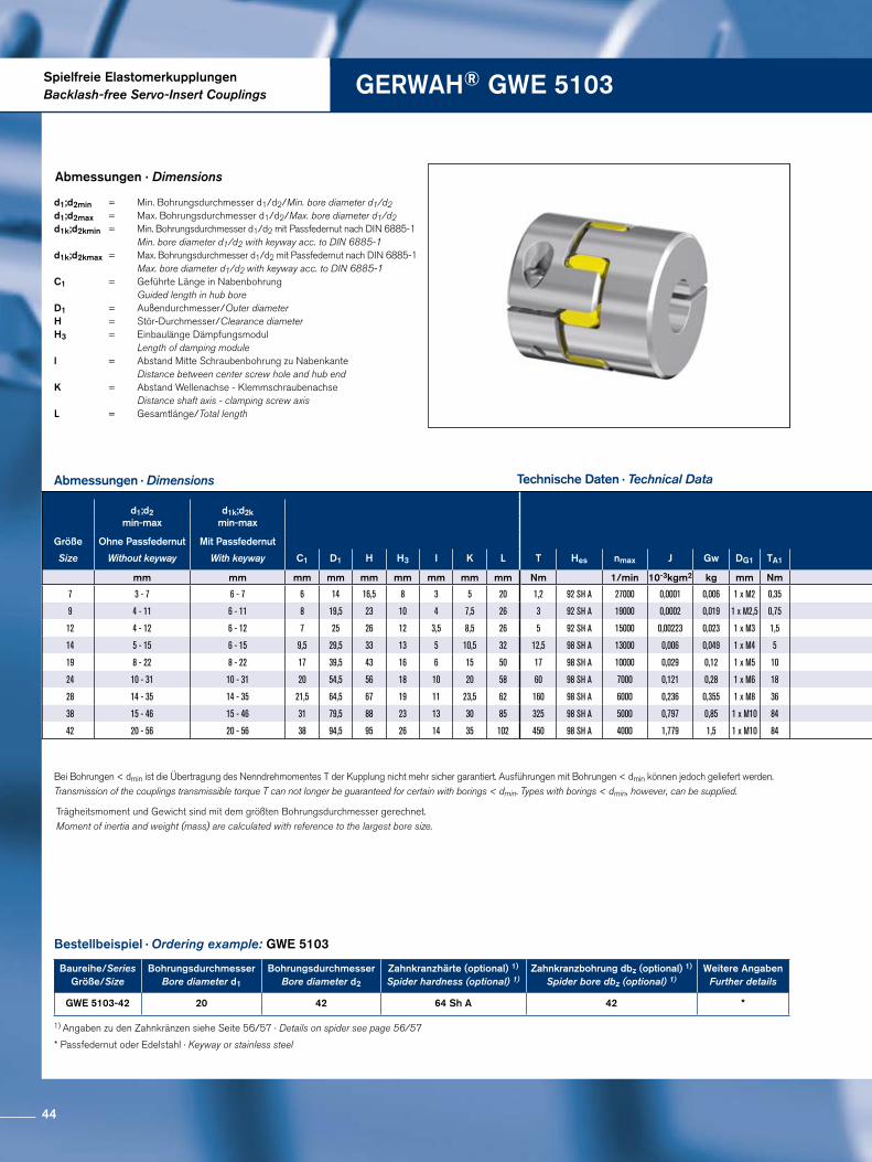
Spielfreie ElastomerkupplungenBacklash-free Servo-Insert Couplings GERWAH® GWE 5103
Abmessungen · Dimensions
Abmessungen · Dimensions
Technische Daten · Technical Data
Trägheitsmoment und Gewicht sind mit dem größten Bohrungsdurchmesser gerechnet.Moment of inertia and weight (mass) are calculated with reference to the largest bore size.
Bestellbeispiel · Ordering example: GWE 5103
d1;d2min = Min. Bohrungsdurchmesser d1/d2/Min. bore diameter d1/d2 d1;d2max = Max. Bohrungsdurchmesser d1/d2/Max. bore diameter d1/d2d1k;d2kmin = Min. Bohrungsdurchmesser d1/d2 mit Passfedernut nach DIN 6885-1 Min. bore diameter d1/d2 with keyway acc. to DIN 6885-1d1k;d2kmax = Max. Bohrungsdurchmesser d1/d2 mit Passfedernut nach DIN 6885-1 Max. bore diameter d1/d2 with keyway acc. to DIN 6885-1C1 = Geführte Länge in Nabenbohrung Guided length in hub bore D1 = Außendurchmesser/Outer diameter H = Stör-Durchmesser/Clearance diameter H3 = Einbaulänge Dämpfungsmodul Length of damping module l = Abstand Mitte Schraubenbohrung zu Nabenkante Distance between center screw hole and hub end K = Abstand Wellenachse - Klemmschraubenachse Distance shaft axis - clamping screw axis L = Gesamtlänge/Total length
Bei Bohrungen < dmin ist die Übertragung des Nenndrehmomentes T der Kupplung nicht mehr sicher garantiert. Ausführungen mit Bohrungen < dmin können jedoch geliefert werden. Transmission of the couplings transmissible torque T can not longer be guaranteed for certain with borings < dmin. Types with borings < dmin, however, can be supplied.
* Passfedernut oder Edelstahl · Keyway or stainless steel
1) Angaben zu den Zahnkränzen siehe Seite 56/57 · Details on spider see page 56/57
Baureihe/SeriesGröße/Size
Bohrungsdurchmesser Bore diameter d1
BohrungsdurchmesserBore diameter d2
Zahnkranzhärte (optional) 1)
Spider hardness (optional) 1)Zahnkranzbohrung dbz (optional) 1)
Spider bore dbz (optional) 1)Weitere Angaben
Further details
GWE 5103-42 20 42 64 Sh A 42 *
d1;d2min-max
d1k;d2kmin-max
Größe Ohne Passfedernut Mit Passfedernut
Size Without keyway With keyway C1 D1 H H3 I K L T Hes nmax J Gw DG1 TA1
mm mm mm mm mm mm mm mm mm Nm 1/min 10-3kgm2 kg mm Nm
7 3 - 7 6 - 7 6 14 16,5 8 3 5 20 1,2 92 SH A 27000 0,0001 0,006 1 x M2 0,35
9 4 - 11 6 - 11 8 19,5 23 10 4 7,5 26 3 92 SH A 19000 0,0002 0,019 1 x M2,5 0,75
12 4 - 12 6 - 12 7 25 26 12 3,5 8,5 26 5 92 SH A 15000 0,00223 0,023 1 x M3 1,5
14 5 - 15 6 - 15 9,5 29,5 33 13 5 10,5 32 12,5 98 SH A 13000 0,006 0,049 1 x M4 5
19 8 - 22 8 - 22 17 39,5 43 16 6 15 50 17 98 SH A 10000 0,029 0,12 1 x M5 10
24 10 - 31 10 - 31 20 54,5 56 18 10 20 58 60 98 SH A 7000 0,121 0,28 1 x M6 18
28 14 - 35 14 - 35 21,5 64,5 67 19 11 23,5 62 160 98 SH A 6000 0,236 0,355 1 x M8 36
38 15 - 46 15 - 46 31 79,5 88 23 13 30 85 325 98 SH A 5000 0,797 0,85 1 x M10 84
42 20 - 56 20 - 56 38 94,5 95 26 14 35 102 450 98 SH A 4000 1,779 1,5 1 x M10 84
44
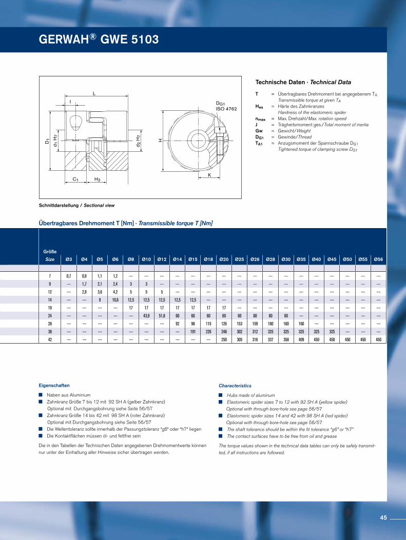
GERWAH® GWE 5103
DG1ISO 4762
H
I
L
C1
d 1 H
7
d 2 H
7
D1
KH3
Schnittdarstellung / Sectional view
Übertragbares Drehmoment T [Nm] · Transmissible torque T [Nm]
Technische Daten · Technical Data
Eigenschaften
Naben aus Aluminium Zahnkranz Größe 7 bis 12 mit 92 SH A (gelber Zahnkranz)
Optional mit Durchgangsbohrung siehe Seite 56/57 Zahnkranz Größe 14 bis 42 mit 98 SH A (roter Zahnkranz)
Optional mit Durchgangsbohrung siehe Seite 56/57 Die Wellentoleranz sollte innerhalb der Passungstoleranz “g6“ oder “h7“ liegen Die Kontaktflächen müssen öl- und fettfrei sein
Die in den Tabellen der Technischen Daten angegebenen Drehmomentwerte können nur unter der Einhaltung aller Hinweise sicher übertragen werden.
Characteristics
Hubs made of aluminum Elastomeric spider sizes 7 to 12 with 92 SH A (yellow spider)
Optional with through bore-hole see page 56/57 Elastomeric spider sizes 14 and 42 with 98 SH A (red spider)
Optional with through bore-hole see page 56/57 The shaft tolerance should be within the fit tolerance “g6” or “h7” The contact surfaces have to be free from oil and grease
The torque values shown in the technical data tables can only be safely transmit-ted, if all instructions are followed.
T = Übertragbares Drehmoment bei angegebenem TA Transmissible torque at given TAHes = Härte des Zahnkranzes Hardness of the elastomeric spider nmax = Max. Drehzahl/Max. rotation speed J = Trägheitsmoment ges./Total moment of inertia Gw = Gewicht/Weight DG1 = Gewinde/Thread TA1 = Anzugsmoment der Spannschraube DG1 Tightened torque of clamping screw DG1
Größe
Size Ø3 Ø4 Ø5 Ø6 Ø8 Ø10 Ø12 Ø14 Ø15 Ø18 Ø20 Ø25 Ø26 Ø28 Ø30 Ø35 Ø40 Ø45 Ø50 Ø55 Ø56
7 0,7 0,9 1,1 1,2 --- --- --- --- --- --- --- --- --- --- --- --- --- --- --- --- ---
9 --- 1,7 2,1 2,4 3 3 --- --- --- --- --- --- --- --- --- --- --- --- --- --- ---
12 --- 2,9 3,6 4,2 5 5 5 --- --- --- --- --- --- --- --- --- --- --- --- --- ---
14 --- --- 9 10,6 12,5 12,5 12,5 12,5 12,5 --- --- --- --- --- --- --- --- --- --- --- ---
19 --- --- --- --- 17 17 17 17 17 17 17 --- --- --- --- --- --- --- --- --- ---
24 --- --- --- --- --- 43,9 51,8 60 60 60 60 60 60 60 60 --- --- --- --- --- ---
28 --- --- --- --- --- --- --- 92 98 115 126 153 159 160 160 160 --- --- --- --- ---
38 --- --- --- --- --- --- --- --- 191 226 248 302 312 325 325 325 325 325 --- --- ---
42 --- --- --- --- --- --- --- --- --- --- 250 305 316 337 358 409 450 450 450 450 450
d1;d2min-max
d1k;d2kmin-max
Größe Ohne Passfedernut Mit Passfedernut
Size Without keyway With keyway C1 D1 H H3 I K L T Hes nmax J Gw DG1 TA1
mm mm mm mm mm mm mm mm mm Nm 1/min 10-3kgm2 kg mm Nm
7 3 - 7 6 - 7 6 14 16,5 8 3 5 20 1,2 92 SH A 27000 0,0001 0,006 1 x M2 0,35
9 4 - 11 6 - 11 8 19,5 23 10 4 7,5 26 3 92 SH A 19000 0,0002 0,019 1 x M2,5 0,75
12 4 - 12 6 - 12 7 25 26 12 3,5 8,5 26 5 92 SH A 15000 0,00223 0,023 1 x M3 1,5
14 5 - 15 6 - 15 9,5 29,5 33 13 5 10,5 32 12,5 98 SH A 13000 0,006 0,049 1 x M4 5
19 8 - 22 8 - 22 17 39,5 43 16 6 15 50 17 98 SH A 10000 0,029 0,12 1 x M5 10
24 10 - 31 10 - 31 20 54,5 56 18 10 20 58 60 98 SH A 7000 0,121 0,28 1 x M6 18
28 14 - 35 14 - 35 21,5 64,5 67 19 11 23,5 62 160 98 SH A 6000 0,236 0,355 1 x M8 36
38 15 - 46 15 - 46 31 79,5 88 23 13 30 85 325 98 SH A 5000 0,797 0,85 1 x M10 84
42 20 - 56 20 - 56 38 94,5 95 26 14 35 102 450 98 SH A 4000 1,779 1,5 1 x M10 84
45
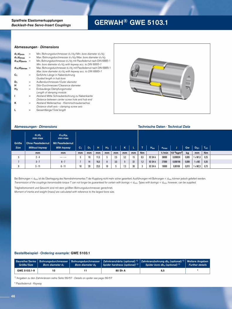
Spielfreie ElastomerkupplungenBacklash-free Servo-Insert Couplings GERWAH® GWE 5103.1
Abmessungen · Dimensions
Trägheitsmoment und Gewicht sind mit dem größten Bohrungsdurchmesser gerechnet.Moment of inertia and weight (mass) are calculated with reference to the largest bore size.
Technische Daten · Technical Data
Abmessungen · Dimensions
Bestellbeispiel · Ordering example: GWE 5103.1
d1;d2min = Min. Bohrungsdurchmesser d1/d2/Min. bore diameter d1/d2 d1;d2max = Max. Bohrungsdurchmesser d1/d2/Max. bore diameter d1/d2d1k;d2kmin = Min. Bohrungsdurchmesser d1/d2 mit Passfedernut nach DIN 6885-1 Min. bore diameter d1/d2 with keyway acc. to DIN 6885-1d1k;d2kmax = Max. Bohrungsdurchmesser d1/d2 mit Passfedernut nach DIN 6885-1 Max. bore diameter d1/d2 with keyway acc. to DIN 6885-1C1 = Geführte Länge in Nabenbohrung Guided length in hub bore D1 = Außendurchmesser/Outer diameterH = Stör-Durchmesser/Clearance diameter H3 = Einbaulänge Dämpfungsmodul Length of damping modulel = Abstand Mitte Schraubenbohrung zu Nabenkante Distance between center screw hole and hub end K = Abstand Wellenachse - Klemmschraubenachse Distance shaft axis - clamping screw axis L = Gesamtlänge/Total length
Bei Bohrungen < dmin ist die Übertragung des Nenndrehmomentes T der Kupplung nicht mehr sicher garantiert. Ausführungen mit Bohrungen < dmin können jedoch geliefert werden. Transmission of the couplings transmissible torque T can not longer be guaranteed for certain with borings < dmin. Types with borings < dmin, however, can be supplied.
* Passfedernut · Keyway
1) Angaben zu den Zahnkränzen siehe Seite 56/57 · Details on spider see page 56/57
Baureihe/SeriesGröße/Size
Bohrungsdurchmesser Bore diameter d1
BohrungsdurchmesserBore diameter d2
Zahnkranzhärte (optional) 1)
Spider hardness (optional) 1)Zahnkranzbohrung dbz (optional) 1)
Spider bore dbz (optional) 1)Weitere Angaben
Further details
GWE 5103.1-9 10 11 80 Sh A 6,5 *
d1;d2min-max
d1k;d2kmin-max
Größe Ohne Passfedernut Mit Passfedernut
Size Without keyway With keyway C1 D1 H H3 I K L T Hes nmax J Gw DG1 TA1
mm mm mm mm mm mm mm mm mm Nm 1/min 10-3kgm2 kg mm Nm
5 2 - 4 --- - --- 5 10 11,5 5 2,5 3,2 15 0,5 92 SH A 38000 0,000034 0,005 1 x M1,6 0,25
7 3 - 7 6 - 7 7 14 16,5 8 3,5 5 22 1,2 92 SH A 27000 0,000196 0,009 1 x M2 0,35
9 3 - 11 6 - 11 10 20 23,5 10 5 7,3 30 3 92 SH A 19000 0,00108 0,015 1 x M2,5 0,75
46
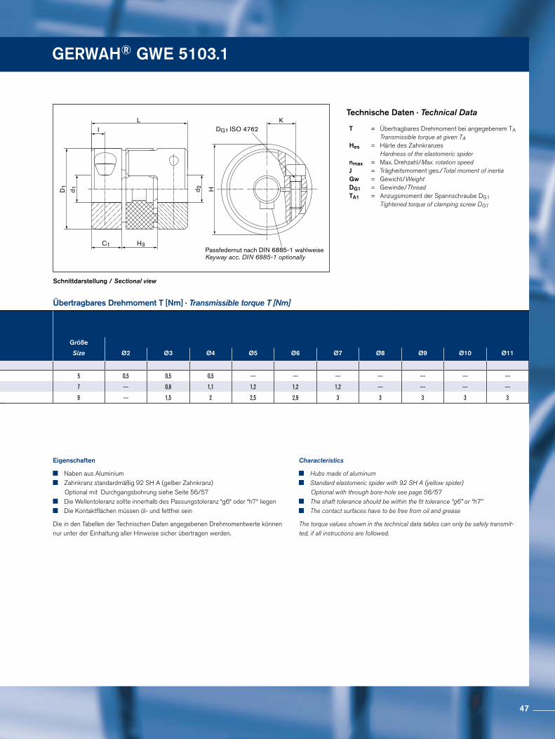
GERWAH® GWE 5103.1
Passfedernut nach DIN 6885-1 wahlweiseKeyway acc. DIN 6885-1 optionally
IL
C1 H3
D1
d 1 d 2
K
H
DG1 ISO 4762
Schnittdarstellung / Sectional view
Übertragbares Drehmoment T [Nm] · Transmissible torque T [Nm]
Technische Daten · Technical Data
Eigenschaften
Naben aus Aluminium Zahnkranz standardmäßig 92 SH A (gelber Zahnkranz)
Optional mit Durchgangsbohrung siehe Seite 56/57 Die Wellentoleranz sollte innerhalb des Passungstoleranz “g6“ oder “h7“ liegen Die Kontaktflächen müssen öl- und fettfrei sein
Die in den Tabellen der Technischen Daten angegebenen Drehmomentwerte können nur unter der Einhaltung aller Hinweise sicher übertragen werden.
Characteristics
Hubs made of aluminum Standard elastomeric spider with 92 SH A (yellow spider)
Optional with through bore-hole see page 56/57 The shaft tolerance should be within the fit tolerance “g6” or “h7” The contact surfaces have to be free from oil and grease
The torque values shown in the technical data tables can only be safely transmit-ted, if all instructions are followed.
T = Übertragbares Drehmoment bei angegebenem TA Transmissible torque at given TAHes = Härte des Zahnkranzes Hardness of the elastomeric spider nmax = Max. Drehzahl/Max. rotation speed J = Trägheitsmoment ges./Total moment of inertia Gw = Gewicht/Weight DG1 = Gewinde/Thread TA1 = Anzugsmoment der Spannschraube DG1 Tightened torque of clamping screw DG1
Größe
Size Ø2 Ø3 Ø4 Ø5 Ø6 Ø7 Ø8 Ø9 Ø10 Ø11
5 0,5 0,5 0,5 --- --- --- --- --- --- ---
7 --- 0,8 1,1 1,2 1,2 1,2 --- --- --- ---
9 --- 1,5 2 2,5 2,9 3 3 3 3 3
d1;d2min-max
d1k;d2kmin-max
Größe Ohne Passfedernut Mit Passfedernut
Size Without keyway With keyway C1 D1 H H3 I K L T Hes nmax J Gw DG1 TA1
mm mm mm mm mm mm mm mm mm Nm 1/min 10-3kgm2 kg mm Nm
5 2 - 4 --- - --- 5 10 11,5 5 2,5 3,2 15 0,5 92 SH A 38000 0,000034 0,005 1 x M1,6 0,25
7 3 - 7 6 - 7 7 14 16,5 8 3,5 5 22 1,2 92 SH A 27000 0,000196 0,009 1 x M2 0,35
9 3 - 11 6 - 11 10 20 23,5 10 5 7,3 30 3 92 SH A 19000 0,00108 0,015 1 x M2,5 0,75
47

Spielfreie ElastomerkupplungenBacklash-free Servo-Insert Couplings GERWAH® GWE 5107
Abmessungen · Dimensions
Abmessungen · Dimensions
Technische Daten · Technical Data
Trägheitsmoment und Gewicht sind mit dem größten Bohrungsdurchmesser gerechnet.Moment of inertia and weight (mass) are calculated with reference to the largest bore size.
Bestellbeispiel · Ordering example: GWE 5107
d1min = Min. Bohrungsdurchmesser d1/Min. bore diameter d1 d1max = Max. Bohrungsdurchmesser d1/Max. bore diameter d1 d1kmin = Min. Bohrungsdurchmesser d1 mit Passfedernut nach DIN 6885-1 Min. bore diameter d1 with keyway acc. to DIN 6885-1 d1kmax = Max. Bohrungsdurchmesser d1 mit Passfedernut nach DIN 6885-1 Max. bore diameter d1 with keyway acc. to DIN 6885-1C1 = Geführte Länge in Nabenbohrung/Guided length in hub bore D1 = Außendurchmesser/Outer diameter D4min = Minimaler Außendurchmesser der Konusnabe Min. outer diameter of the cone hub D4max = Maximaler Außendurchmesser der Konusnabe Max. outer diameter of the cone hub H = Stör-Durchmesser/Clearance diameter H3 = Einbaulänge Dämpfungsmodul Length of damping module l = Abstand Mitte Schraubenbohrung zu Nabenkante Distance between center screw hole and hub end K = Abstand Wellenachse - Klemmschraubenachse Distance shaft axis - clamping screw axis L = Gesamtlänge/Total length L5 = Länge Spreizdorn/Expanding mandrel length
Bei Bohrungen < dmin ist die Übertragung des Nenndrehmomentes T der Kupplung nicht mehr sicher garantiert. Ausführungen mit Bohrungen < dmin können jedoch geliefert werden. Transmission of the couplings transmissible torque T can not longer be guaranteed for certain with borings < dmin. Types with borings < dmin, however, can be supplied.
* Passfedernut · Keyway
1) Angaben zu den Zahnkränzen siehe Seite 56/57 · Details on spider see page 56/57
Baureihe/SeriesGröße/Size
Bohrungsdurchmesser Bore diameter d1
BohrungsdurchmesserBore diameter d2
Zahnkranzhärte (optional) 1)
Spider hardness (optional) 1)Zahnkranzbohrung dbz (optional) 1)
Spider bore dbz (optional) 1)Weitere Angaben
Further details
GWE 5107-24 25 29 92 Sh A 24 *
d1min-max
d1kmin-max
Größe Ohne Passfedernut Mit Passfedernut D4
Size Without keyway With keyway C1 D1 min-max H H3 I K L L5 T nmax J Hes Gw DG1 TA1 DG2 TA2
mm mm mm mm mm mm mm mm mm mm mm Nm 1/min 10-3kgm2 kg mm Nm mm Nm
9 4 - 11 6 - 11 8 19,5 10 - 15 22,5 10 4 7,3 34 12 3 19000 0,002 92 SH A 0,04 1 x M2,5 0,75 1 x M4 4
12 4 - 12 6 - 12 7 25 10 - 15 26 12 3,5 8,5 38 12 5 15000 0,0046 92 SH A 0,063 1 x M3 1,5 1 x M4 4
14 5 - 15 6 - 15 9,5 29,5 13 - 25 33 13 5 10,5 48 20 12,5 13000 0,011 98 SH A 0,11 1 x M4 5 1 x M5 9
19 8 - 22 8 - 22 17 39,5 14 - 30 43 16 6 15 65 25 17 10000 0,045 98 SH A 0,26 1 x M5 10 1 x M6 12
24 10 - 31 10 - 31 20 54,5 23 - 36 56 18 10 20 73 27 60 7000 0,164 98 SH A 0,51 1 x M6 18 1 x M8 32
28 14 - 35 14 - 35 21,5 64,5 26 - 42 67 19 11 23,5 83 32 160 6000 0,373 98 SH A 0,83 1 x M8 43 1 x M10 60
48
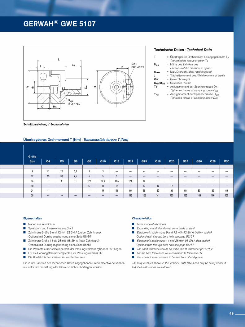
GERWAH® GWE 5107 GERWAH® GWE 5107
DG1ISO 4762
DG2 ISO 4762
I
C1
D1
H
K
d 1 D4
H3
L
L5
Schnittdarstellung / Sectional view
Übertragbares Drehmoment T [Nm] · Transmissible torque T [Nm]
Technische Daten · Technical Data
Eigenschaften
Naben aus Aluminium Spreizdorn und Innenkonus aus Stahl Zahnkranz Größe 9 und 12 mit 92 SH A (gelber Zahnkranz)
Optional mit Durchgangsbohrung siehe Seite 56/57 Zahnkranz Größe 14 bis 28 mit 98 SH A (roter Zahnkranz)
Optional mit Durchgangsbohrung siehe Seite 56/57 Die Wellentoleranz sollte innerhalb der Passungstoleranz “g6“ oder “h7“ liegen Für die Bohrungstoleranz empfehlen wir Passungstoleranz H7 Die Kontaktflächen müssen öl- und fettfrei sein
Die in den Tabellen der Technischen Daten angegebenen Drehmomentwerte können nur unter der Einhaltung aller Hinweise sicher übertragen werden.
Characteristics
Hubs made of aluminum Expanding mandrel and inner cone made of steel Elastomeric spider sizes 9 and 12 with 92 SH A (yellow spider)
Optional with through bore hole see page 56/57 Elastomeric spider sizes 14 and 28 with 98 SH A (red spider)
Optional with through bore hole see page 56/57 The shaft tolerance should be within the fit tolerance “g6” or “h7” For the bore tolerances we recommend fit tolerance H7 The contact surfaces have to be free from oil and grease
The torque values shown in the technical data tables can only be safely transmit-ted, if all instructions are followed.
T = Übertragbares Drehmoment bei angegebenem TA Transmissible torque at given TAHes = Härte des Zahnkranzes Hardness of the elastomeric spider nmax = Max. Drehzahl/Max. rotation speed J = Trägheitsmoment ges./Total moment of inertia Gw = Gewicht/Weight DG1;DG2 = Gewinde/Thread TA1 = Anzugsmoment der Spannschraube DG1 Tightened torque of clamping screw DG1 TA2 = Anzugsmoment der Spannschraube DG2 Tightened torque of clamping screw DG2
Größe
Size Ø4 Ø5 Ø6 Ø8 Ø10 Ø12 Ø14 Ø15 Ø18 Ø20 Ø25 Ø26 Ø28 Ø30
9 1,7 2,1 2,4 3 3 --- --- --- --- --- --- --- --- ---
12 2,9 3,6 4,5 5 5 5 --- --- --- --- --- --- --- ---
14 --- 9 11 12,5 12,5 12,5 12,5 13 --- --- --- --- --- ---
19 --- --- --- 17 17 17 17 17 17 17 --- --- --- ---
24 --- --- --- --- 44 52 60 60 60 60 60 60 60 60
28 --- --- --- --- --- --- 113 120 141 155 160 160 160 160
d1min-max
d1kmin-max
Größe Ohne Passfedernut Mit Passfedernut D4
Size Without keyway With keyway C1 D1 min-max H H3 I K L L5 T nmax J Hes Gw DG1 TA1 DG2 TA2
mm mm mm mm mm mm mm mm mm mm mm Nm 1/min 10-3kgm2 kg mm Nm mm Nm
9 4 - 11 6 - 11 8 19,5 10 - 15 22,5 10 4 7,3 34 12 3 19000 0,002 92 SH A 0,04 1 x M2,5 0,75 1 x M4 4
12 4 - 12 6 - 12 7 25 10 - 15 26 12 3,5 8,5 38 12 5 15000 0,0046 92 SH A 0,063 1 x M3 1,5 1 x M4 4
14 5 - 15 6 - 15 9,5 29,5 13 - 25 33 13 5 10,5 48 20 12,5 13000 0,011 98 SH A 0,11 1 x M4 5 1 x M5 9
19 8 - 22 8 - 22 17 39,5 14 - 30 43 16 6 15 65 25 17 10000 0,045 98 SH A 0,26 1 x M5 10 1 x M6 12
24 10 - 31 10 - 31 20 54,5 23 - 36 56 18 10 20 73 27 60 7000 0,164 98 SH A 0,51 1 x M6 18 1 x M8 32
28 14 - 35 14 - 35 21,5 64,5 26 - 42 67 19 11 23,5 83 32 160 6000 0,373 98 SH A 0,83 1 x M8 43 1 x M10 60
49
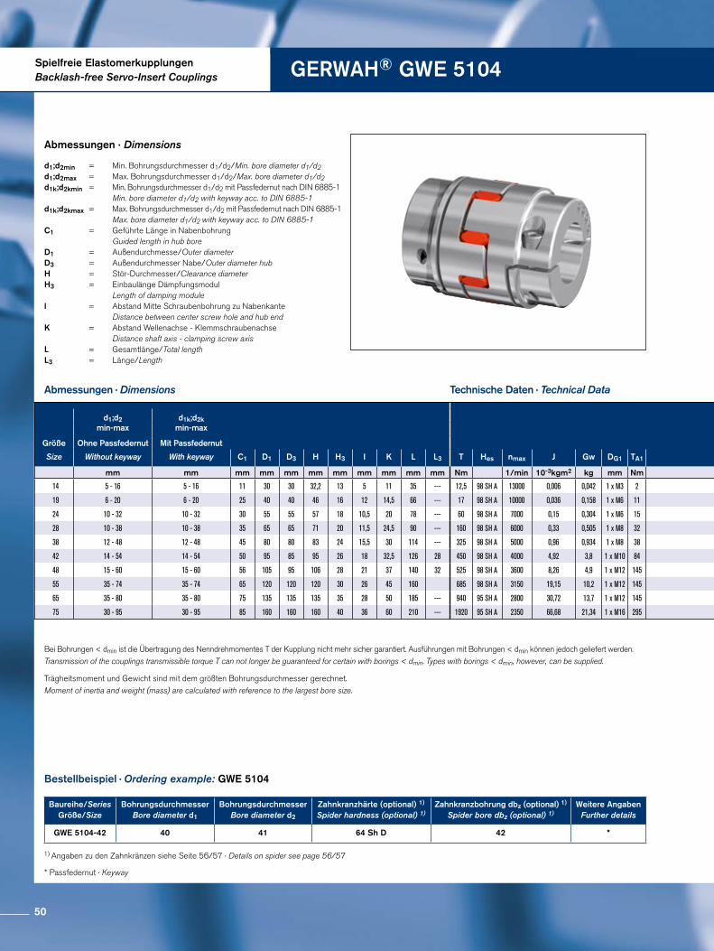
Spielfreie ElastomerkupplungenBacklash-free Servo-Insert Couplings GERWAH® GWE 5104
Abmessungen · Dimensions
Trägheitsmoment und Gewicht sind mit dem größten Bohrungsdurchmesser gerechnet.Moment of inertia and weight (mass) are calculated with reference to the largest bore size.
Technische Daten · Technical Data
Abmessungen · Dimensions
Bestellbeispiel · Ordering example: GWE 5104
d1;d2min = Min. Bohrungsdurchmesser d1/d2/Min. bore diameter d1/d2 d1;d2max = Max. Bohrungsdurchmesser d1/d2/Max. bore diameter d1/d2d1k;d2kmin = Min. Bohrungsdurchmesser d1/d2 mit Passfedernut nach DIN 6885-1 Min. bore diameter d1/d2 with keyway acc. to DIN 6885-1d1k;d2kmax = Max. Bohrungsdurchmesser d1/d2 mit Passfedernut nach DIN 6885-1 Max. bore diameter d1/d2 with keyway acc. to DIN 6885-1 C1 = Geführte Länge in Nabenbohrung Guided length in hub bore D1 = Außendurchmesse/Outer diameter D3 = Außendurchmesser Nabe/Outer diameter hub H = Stör-Durchmesser/Clearance diameter H3 = Einbaulänge Dämpfungsmodul Length of damping module l = Abstand Mitte Schraubenbohrung zu Nabenkante Distance between center screw hole and hub end K = Abstand Wellenachse - Klemmschraubenachse Distance shaft axis - clamping screw axis L = Gesamtlänge/Total length L3 = Länge/Length
Bei Bohrungen < dmin ist die Übertragung des Nenndrehmomentes T der Kupplung nicht mehr sicher garantiert. Ausführungen mit Bohrungen < dmin können jedoch geliefert werden. Transmission of the couplings transmissible torque T can not longer be guaranteed for certain with borings < dmin. Types with borings < dmin, however, can be supplied.
* Passfedernut · Keyway
1) Angaben zu den Zahnkränzen siehe Seite 56/57 · Details on spider see page 56/57
Baureihe/SeriesGröße/Size
Bohrungsdurchmesser Bore diameter d1
BohrungsdurchmesserBore diameter d2
Zahnkranzhärte (optional) 1)
Spider hardness (optional) 1)Zahnkranzbohrung dbz (optional) 1)
Spider bore dbz (optional) 1)Weitere Angaben
Further details
GWE 5104-42 40 41 64 Sh D 42 *
d1;d2min-max
d1k;d2kmin-max
Größe Ohne Passfedernut Mit Passfedernut
Size Without keyway With keyway C1 D1 D3 H H3 I K L L3 T Hes nmax J Gw DG1 TA1
mm mm mm mm mm mm mm mm mm mm mm Nm 1/min 10-3kgm2 kg mm Nm
14 5 - 16 5 - 16 11 30 30 32,2 13 5 11 35 --- 12,5 98 SH A 13000 0,006 0,042 1 x M3 2
19 6 - 20 6 - 20 25 40 40 46 16 12 14,5 66 --- 17 98 SH A 10000 0,036 0,158 1 x M6 11
24 10 - 32 10 - 32 30 55 55 57 18 10,5 20 78 --- 60 98 SH A 7000 0,15 0,304 1 x M6 15
28 10 - 38 10 - 38 35 65 65 71 20 11,5 24,5 90 --- 160 98 SH A 6000 0,33 0,505 1 x M8 32
38 12 - 48 12 - 48 45 80 80 83 24 15,5 30 114 --- 325 98 SH A 5000 0,96 0,934 1 x M8 38
42 14 - 54 14 - 54 50 95 85 95 26 18 32,5 126 28 450 98 SH A 4000 4,92 3,8 1 x M10 84
48 15 - 60 15 - 60 56 105 95 106 28 21 37 140 32 525 98 SH A 3600 8,26 4,9 1 x M12 145
55 35 - 74 35 - 74 65 120 120 120 30 26 45 160 685 98 SH A 3150 19,15 10,2 1 x M12 145
65 35 - 80 35 - 80 75 135 135 135 35 28 50 185 --- 940 95 SH A 2800 30,72 13,7 1 x M12 145
75 30 - 95 30 - 95 85 160 160 160 40 36 60 210 --- 1920 95 SH A 2350 66,68 21,34 1 x M16 295
50
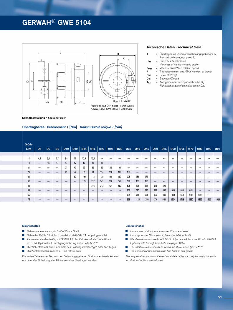
GERWAH® GWE 5104
DG1 ISO 4762
Passfedernut DIN 6885-1 wahlweiseKeyway acc. DIN 6885-1 optionally
L
C1
d 1D1
D3
IK
d 2
H
L3H3
Schnittdarstellung / Sectional view
Übertragbares Drehmoment T [Nm] · Transmissible torque T [Nm]
Technische Daten · Technical Data
Eigenschaften
Naben aus Aluminium, ab Größe 55 aus Stahl Naben bis Größe 19 einfach geschlitzt, ab Größe 24 doppelt geschlitzt Zahnkranz standardmäßig mit 98 SH A (roter Zahnkranz), ab Größe 65 mit
95 SH A. Optional mit Durchgangsbohrung siehe Seite 56/57 Die Wellentoleranz sollte innerhalb des Passungstoleranz “g6“ oder “h7“ liegen Die Kontaktflächen müssen öl- und fettfrei sein
Die in den Tabellen der Technischen Daten angegebenen Drehmomentwerte können nur unter der Einhaltung aller Hinweise sicher übertragen werden.
Characteristics
Hubs made of aluminum from size 55 made of steel Hubs up to size 19 simple slit, from size 24 double slit Standard elastomeric spider with 98 SH A (red spider), from size 65 with 95 SH A
Optional with through bore-hole see page 56/57 The shaft tolerance should be within the fit tolerance “g6” or “h7” The contact surfaces have to be free from oil and grease
The torque values shown in the technical data tables can only be safely transmit-ted, if all instructions are followed.
T = Übertragbares Drehmoment bei angegebenem TA Transmissible torque at given TA Hes = Härte des Zahnkranzes Hardness of the elastomeric spidernmax = Max. Drehzahl/Max. rotation speed J = Trägheitsmoment ges./Total moment of inertia Gw = Gewicht/Weight DG1 = Gewinde/Thread TA1 = Anzugsmoment der Spannschraube DG1 Tightened torque of clamping screw DG1
Größe
Size Ø5 Ø6 Ø8 Ø10 Ø12 Ø14 Ø16 Ø20 Ø25 Ø30 Ø35 Ø40 Ø45 Ø50 Ø55 Ø60 Ø65 Ø70 Ø80 Ø90 Ø95
14 4,8 6,0 7,7 9,4 11 12,5 12,5 --- --- --- --- --- --- --- --- --- --- --- --- --- ---
19 --- 16 17 17 17 17 17 17 --- --- --- --- --- --- --- --- --- --- --- --- ---
24 --- --- --- 37 43 50 56 60 60 60 --- --- --- --- --- --- --- --- --- --- ---
28 --- --- --- 61 72 83 94 114 138 160 160 --- --- --- --- --- --- --- --- --- ---
38 --- --- --- --- 87 100 113 138 168 197 225 251 277 --- --- --- --- --- --- --- ---
42 --- --- --- --- --- 174 197 242 296 348 398 450 450 --- --- --- --- --- --- --- ---
48 --- --- --- --- --- --- 276 343 424 502 525 525 525 525 525 --- --- --- --- --- ---
55 --- --- --- --- --- --- --- --- --- --- 630 685 685 685 685 685 685 685 --- --- ---
65 --- --- --- --- --- --- --- --- --- --- 634 714 791 866 940 940 940 940 940 --- ---
75 --- --- --- --- --- --- --- --- --- --- 998 1125 1250 1370 1489 1604 1718 1830 1920 1920 1920
d1;d2min-max
d1k;d2kmin-max
Größe Ohne Passfedernut Mit Passfedernut
Size Without keyway With keyway C1 D1 D3 H H3 I K L L3 T Hes nmax J Gw DG1 TA1
mm mm mm mm mm mm mm mm mm mm mm Nm 1/min 10-3kgm2 kg mm Nm
14 5 - 16 5 - 16 11 30 30 32,2 13 5 11 35 --- 12,5 98 SH A 13000 0,006 0,042 1 x M3 2
19 6 - 20 6 - 20 25 40 40 46 16 12 14,5 66 --- 17 98 SH A 10000 0,036 0,158 1 x M6 11
24 10 - 32 10 - 32 30 55 55 57 18 10,5 20 78 --- 60 98 SH A 7000 0,15 0,304 1 x M6 15
28 10 - 38 10 - 38 35 65 65 71 20 11,5 24,5 90 --- 160 98 SH A 6000 0,33 0,505 1 x M8 32
38 12 - 48 12 - 48 45 80 80 83 24 15,5 30 114 --- 325 98 SH A 5000 0,96 0,934 1 x M8 38
42 14 - 54 14 - 54 50 95 85 95 26 18 32,5 126 28 450 98 SH A 4000 4,92 3,8 1 x M10 84
48 15 - 60 15 - 60 56 105 95 106 28 21 37 140 32 525 98 SH A 3600 8,26 4,9 1 x M12 145
55 35 - 74 35 - 74 65 120 120 120 30 26 45 160 685 98 SH A 3150 19,15 10,2 1 x M12 145
65 35 - 80 35 - 80 75 135 135 135 35 28 50 185 --- 940 95 SH A 2800 30,72 13,7 1 x M12 145
75 30 - 95 30 - 95 85 160 160 160 40 36 60 210 --- 1920 95 SH A 2350 66,68 21,34 1 x M16 295
51

Spielfreie ElastomerkupplungenBacklash-free Servo-Insert Couplings GERWAH® GWE 5106
Abmessungen · Dimensions
Trägheitsmoment und Gewicht sind mit dem größten Bohrungsdurchmesser gerechnet.Moment of inertia and weight (mass) are calculated with reference to the largest bore size.
Technische Daten · Technical Data
Abmessungen · Dimensions
Bestellbeispiel · Ordering example: GWE 5106
* Passfedernut · Keyway
d1;d2min = Min. Bohrungsdurchmesser d1/d2/Min. bore diameter d1/d2 d1;d2max = Max. Bohrungsdurchmesser d1/d2/Max. bore diameter d1/d2d1k;d2kmin = Min. Bohrungsdurchmesser d1/d2 mit Passfedernut nach DIN 6885-1 Min. bore diameter d1/d2 with keyway acc. to DIN 6885-1d1k;d2kmax = Max. Bohrungsdurchmesser d1/d2 mit Passfedernut nach DIN 6885-1 Max. bore diameter d1/d2 with keyway acc. to DIN 6885-1 C1 = Geführte Länge in Nabenbohrung Guided length in hub bore D1 = Außendurchmesser/Outer diameter D3 = Außendurchmesser Nabe/Outer diameter hub H = Stör-Durchmesser/Clearance diameter H3 = Einbaulänge Dämpfungsmodul Length of damping module l = Abstand Mitte Schraubenbohrung zu Nabenkante Distance between center screw hole and hub end K = Abstand Wellenachse - Klemmschraubenachse Distance shaft axis - clamping screw axis K1 = Klemmlänge/Clamping length L = Gesamtlänge/Total lengthL3 = Länge/Length
Bei Bohrungen < dmin ist die Übertragung des Nenndrehmomentes T der Kupplung nicht mehr sicher garantiert. Ausführungen mit Bohrungen < dmin können jedoch geliefert werden. Transmission of the couplings transmissible torque T can not longer be guaranteed for certain with borings < dmin. Types with borings < dmin, however, can be supplied.
1) Angaben zu den Zahnkränzen siehe Seite 56/57 · Details on spider see page 56/57
Baureihe/SeriesGröße/Size
Bohrungsdurchmesser Bore diameter d1
BohrungsdurchmesserBore diameter d2
Zahnkranzhärte (optional) 1)
Spider hardness (optional) 1)Zahnkranzbohrung dbz (optional) 1)
Spider bore dbz (optional) 1)Weitere Angaben
Further details
GWE 5106-42 40 41 92 Sh A 42 *
d1;d2min-max
d1k;d2kmin-max
Größe Ohne Passfedernut Mit Passfedernut
Size Without keyway With keyway C1 D1 D3 H H3 I K K1 L L3 T Hes nmax J Gw DG1 TA1
mm mm mm mm mm mm mm mm mm mm mm mm Nm 1/min 10-3kgm2 kg mm Nm
14 5 - 16 5 - 16 11 30 --- 32,5 13 5 11 8 35 --- 12,5 98 SH A 13000 0,006 0,042 2 x M3 2
19 6 - 20 6 - 20 25 40 --- 46 16 7 14,5 12 66 --- 17 98 SH A 10000 0,036 0,158 2 x M6 11
24 10 - 32 10 - 32 30 55 --- 57 18 10,5 20 19 78 --- 60 98 SH A 7000 0,15 0,304 2 x M6 15
28 10 - 38 10 - 38 35 65 --- 71 20 11,5 24,5 21,5 90 --- 160 98 SH A 6000 0,33 0,505 2 x M8 32
38 12 - 48 12 - 48 45 80 --- 83 24 15,5 30 31 114 --- 325 98 SH A 5000 0,96 0,934 2 x M8 38
42 14 - 54 14 - 54 50 95 85 95 26 18 32,5 32 126 28 450 98 SH A 4000 4,92 3,8 2 x M10 84
48 15 - 60 15 - 60 56 105 95 106 28 21 36 38 140 32 525 98 SH A 3600 8,26 4,9 2 x M12 145
55 35 - 74 35 - 74 65 120 --- 120 30 26 45 46,5 160 --- 685 98 SH A 3150 19,15 10,2 2 x M12 145
65 35 - 80 35 - 80 75 135 --- 135 35 28 50 52 185 --- 940 95 SH A 2800 30,72 13,7 2 x M12 145
75 30 - 95 30 - 95 85 160 --- 160 40 36 60 65,5 210 --- 1920 95 SH A 2350 66,68 21,34 2 x M16 295
52
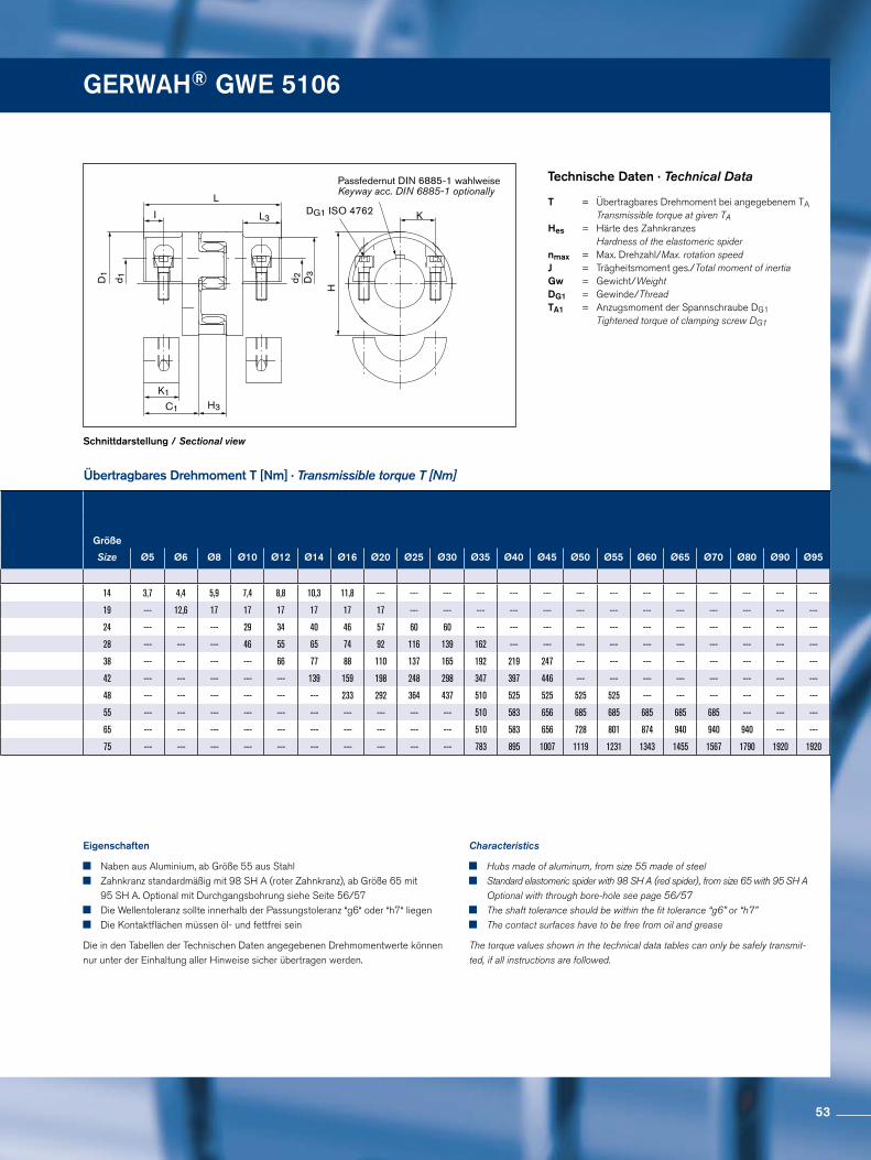
GERWAH® GWE 5106
Passfedernut DIN 6885-1 wahlweiseKeyway acc. DIN 6885-1 optionally
DG1 ISO 4762
D1
d 1
L
I
C1 H3
d 2
K
H
D3
L3
K1
Schnittdarstellung / Sectional view
Übertragbares Drehmoment T [Nm] · Transmissible torque T [Nm]
Technische Daten · Technical Data
Eigenschaften
Naben aus Aluminium, ab Größe 55 aus Stahl Zahnkranz standardmäßig mit 98 SH A (roter Zahnkranz), ab Größe 65 mit
95 SH A. Optional mit Durchgangsbohrung siehe Seite 56/57 Die Wellentoleranz sollte innerhalb der Passungstoleranz “g6“ oder “h7“ liegen Die Kontaktflächen müssen öl- und fettfrei sein
Die in den Tabellen der Technischen Daten angegebenen Drehmomentwerte können nur unter der Einhaltung aller Hinweise sicher übertragen werden.
Characteristics
Hubs made of aluminum, from size 55 made of steel Standard elastomeric spider with 98 SH A (red spider), from size 65 with 95 SH A
Optional with through bore-hole see page 56/57 The shaft tolerance should be within the fit tolerance “g6” or “h7” The contact surfaces have to be free from oil and grease
The torque values shown in the technical data tables can only be safely transmit-ted, if all instructions are followed.
T = Übertragbares Drehmoment bei angegebenem TA Transmissible torque at given TAHes = Härte des Zahnkranzes Hardness of the elastomeric spider nmax = Max. Drehzahl/Max. rotation speed J = Trägheitsmoment ges./Total moment of inertia Gw = Gewicht/Weight DG1 = Gewinde/Thread TA1 = Anzugsmoment der Spannschraube DG1 Tightened torque of clamping screw DG1
Größe
Size Ø5 Ø6 Ø8 Ø10 Ø12 Ø14 Ø16 Ø20 Ø25 Ø30 Ø35 Ø40 Ø45 Ø50 Ø55 Ø60 Ø65 Ø70 Ø80 Ø90 Ø95
14 3,7 4,4 5,9 7,4 8,8 10,3 11,8 --- --- --- --- --- --- --- --- --- --- --- --- --- ---
19 --- 12,6 17 17 17 17 17 17 --- --- --- --- --- --- --- --- --- --- --- --- ---
24 --- --- --- 29 34 40 46 57 60 60 --- --- --- --- --- --- --- --- --- --- ---
28 --- --- --- 46 55 65 74 92 116 139 162 --- --- --- --- --- --- --- --- --- ---
38 --- --- --- --- 66 77 88 110 137 165 192 219 247 --- --- --- --- --- --- --- ---
42 --- --- --- --- --- 139 159 198 248 298 347 397 446 --- --- --- --- --- --- --- ---
48 --- --- --- --- --- --- 233 292 364 437 510 525 525 525 525 --- --- --- --- --- ---
55 --- --- --- --- --- --- --- --- --- --- 510 583 656 685 685 685 685 685 --- --- ---
65 --- --- --- --- --- --- --- --- --- --- 510 583 656 728 801 874 940 940 940 --- ---
75 --- --- --- --- --- --- --- --- --- --- 783 895 1007 1119 1231 1343 1455 1567 1790 1920 1920
53
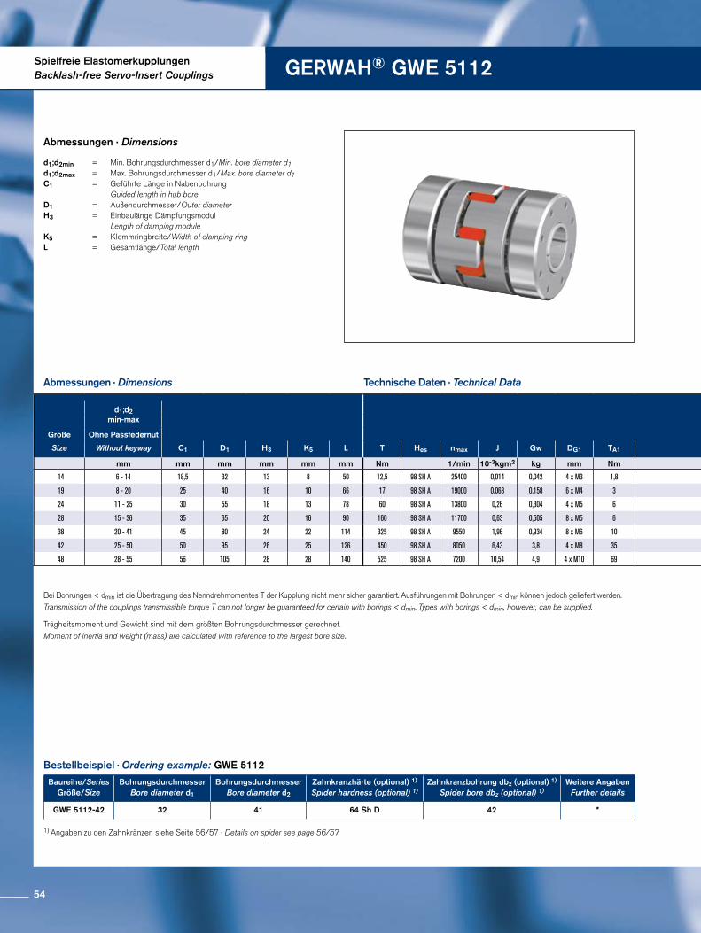
Spielfreie ElastomerkupplungenBacklash-free Servo-Insert Couplings GERWAH® GWE 5112
Abmessungen · Dimensions
Trägheitsmoment und Gewicht sind mit dem größten Bohrungsdurchmesser gerechnet.Moment of inertia and weight (mass) are calculated with reference to the largest bore size.
1) Angaben zu den Zahnkränzen siehe Seite 56/57 · Details on spider see page 56/57
Abmessungen · Dimensions
Technische Daten · Technical Data
Bestellbeispiel · Ordering example: GWE 5112
Baureihe/SeriesGröße/Size
Bohrungsdurchmesser Bore diameter d1
BohrungsdurchmesserBore diameter d2
Zahnkranzhärte (optional) 1)
Spider hardness (optional) 1)Zahnkranzbohrung dbz (optional) 1)
Spider bore dbz (optional) 1)Weitere Angaben
Further details
GWE 5112-42 32 41 64 Sh D 42 *
d1;d2min = Min. Bohrungsdurchmesser d1/Min. bore diameter d1 d1;d2max = Max. Bohrungsdurchmesser d1/Max. bore diameter d1C1 = Geführte Länge in Nabenbohrung Guided length in hub bore D1 = Außendurchmesser/Outer diameter H3 = Einbaulänge Dämpfungsmodul Length of damping module K5 = Klemmringbreite/Width of clamping ring L = Gesamtlänge/Total length
Bei Bohrungen < dmin ist die Übertragung des Nenndrehmomentes T der Kupplung nicht mehr sicher garantiert. Ausführungen mit Bohrungen < dmin können jedoch geliefert werden. Transmission of the couplings transmissible torque T can not longer be guaranteed for certain with borings < dmin. Types with borings < dmin, however, can be supplied.
d1;d2min-max
Größe Ohne Passfedernut
Size Without keyway C1 D1 H3 K5 L T Hes nmax J Gw DG1 TA1
mm mm mm mm mm mm Nm 1/min 10-3kgm2 kg mm Nm
14 6 - 14 18,5 32 13 8 50 12,5 98 SH A 25400 0,014 0,042 4 x M3 1,8
19 8 - 20 25 40 16 10 66 17 98 SH A 19000 0,063 0,158 6 x M4 3
24 11 - 25 30 55 18 13 78 60 98 SH A 13800 0,26 0,304 4 x M5 6
28 15 - 36 35 65 20 16 90 160 98 SH A 11700 0,63 0,505 8 x M5 6
38 20 - 41 45 80 24 22 114 325 98 SH A 9550 1,96 0,934 8 x M6 10
42 25 - 50 50 95 26 25 126 450 98 SH A 8050 6,43 3,8 4 x M8 35
48 28 - 55 56 105 28 28 140 525 98 SH A 7200 10,54 4,9 4 x M10 69
54
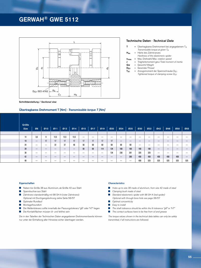
GERWAH® GWE 5112 GERWAH® GWE 5112
DG1 ISO 4762
d 1D1
d 2
K5
H3C1
L
Schnittdarstellung / Sectional view
Übertragbares Drehmoment T [Nm] · Transmissible torque T [Nm]
Technische Daten · Technical Data
Eigenschaften
Naben bis Größe 38 aus Aluminium, ab Größe 42 aus Stahl Spannbuchse aus Stahl Zahnkranz standardmäßig mit 98 SH A (roter Zahnkranz)
Optional mit Durchgangsbohrung siehe Seite 56/57 Optimaler Rundlauf Montagefreundlich Die Wellentoleranz sollte innerhalb der Passungstoleranz “g6“ oder “h7“ liegen Die Kontaktflächen müssen öl- und fettfrei sein
Die in den Tabellen der Technischen Daten angegebenen Drehmomentwerte können nur unter der Einhaltung aller Hinweise sicher übertragen werden.
Characteristics
Hubs up to size 38 made of aluminum, from size 42 made of steel Clamping bush made of steel Standard elastomeric spider with 98 SH A (red spider)
Optional with through bore-hole see page 56/57 Optimal concentricity Easy to install The shaft tolerance should be within the fit tolerance “g6” or “h7” The contact surfaces have to be free from oil and grease
The torque values shown in the technical data tables can only be safely transmitted, if all instructions are followed.
T = Übertragbares Drehmoment bei angegebenem TA Transmissible torque at given TAHes = Härte des Zahnkranzes Hardness of the elastomeric spider nmax = Max. Drehzahl/Max. rotation speed J = Trägheitsmoment ges./Total moment of inertia Gw = Gewicht/Weight DG1 = Gewinde/Thread TA1 = Anzugsmoment der Spannschraube DG1 Tightened torque of clamping screw DG1
d1;d2min-max
Größe Ohne Passfedernut
Size Without keyway C1 D1 H3 K5 L T Hes nmax J Gw DG1 TA1
mm mm mm mm mm mm Nm 1/min 10-3kgm2 kg mm Nm
14 6 - 14 18,5 32 13 8 50 12,5 98 SH A 25400 0,014 0,042 4 x M3 1,8
19 8 - 20 25 40 16 10 66 17 98 SH A 19000 0,063 0,158 6 x M4 3
24 11 - 25 30 55 18 13 78 60 98 SH A 13800 0,26 0,304 4 x M5 6
28 15 - 36 35 65 20 16 90 160 98 SH A 11700 0,63 0,505 8 x M5 6
38 20 - 41 45 80 24 22 114 325 98 SH A 9550 1,96 0,934 8 x M6 10
42 25 - 50 50 95 26 25 126 450 98 SH A 8050 6,43 3,8 4 x M8 35
48 28 - 55 56 105 28 28 140 525 98 SH A 7200 10,54 4,9 4 x M10 69
Größe
Size Ø6 Ø10 Ø11 Ø13 Ø14 Ø15 Ø17 Ø19 Ø20 Ø24 Ø25 Ø30 Ø32 Ø42 Ø48 Ø50 Ø55
14 3,6 9 12,5 12,5 12,5 --- --- --- --- --- --- --- --- --- --- --- ---
19 --- 17 17 17 17 17 17 17 17 --- --- --- --- --- --- --- ---
24 --- --- 22 37 46 56 60 60 60 60 60 --- --- --- --- --- ---
28 --- --- --- --- --- 56 68 114 134 160 160 160 160 --- --- --- ---
38 --- --- --- --- --- --- --- --- 134 230 261 325 325 --- --- --- ---
42 --- --- --- --- --- --- --- --- --- --- 260 450 450 450 450 450 ---
48 --- --- --- --- --- --- --- --- --- --- --- 450 525 525 525 525 525
55
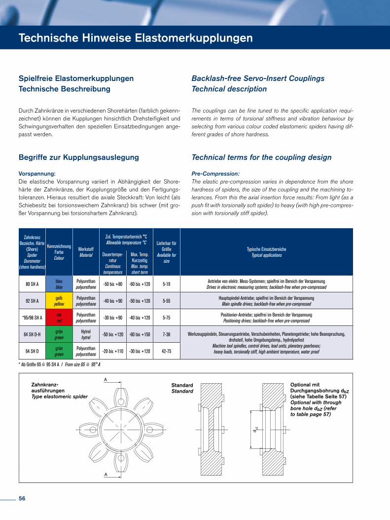
Technische Hinweise Elastomerkupplungen
Durch Zahnkränze in verschiedenen Shorehärten (farblich gekenn-zeichnet) können die Kupplungen hinsichtlich Drehsteifigkeit und Schwingungsverhalten den speziellen Einsatzbedingungen ange-passt werden.
Begriffe zur Kupplungsauslegung
Vorspannung: Die elastische Vorspannung variiert in Abhängigkeit der Shore-härte der Zahnkränze, der Kupplungsgröße und den Fertigungs-toleranzen. Hieraus resultiert die axiale Steckkraft: Von leicht (als Schiebesitz bei torsionsweichem Zahnkranz) bis schwer (mit gro-ßer Vorspannung bei torsionshartem Zahnkranz).
The couplings can be fine tuned to the specific application requi-rements in terms of torsional stiffness and vibration behaviour by selecting from various colour coded elastomeric spiders having dif-ferent grades of shore hardness.
Technical terms for the coupling design
Pre-Compression: The elastic pre-compression varies in dependence from the shore hardness of spiders, the size of the coupling and the machining to-lerances. From this the axial insertion force results: From light (as a push fit with torsionally soft spider) to heavy (with high pre-compres-sion with torsionally stiff spider).
Spielfreie Elastomerkupplungen Technische Beschreibung
Backlash-free Servo-Insert Couplings Technical description
Zahnkranz Bezeichn. Härte
(Shore)Spider
Durometer(shore hardness)
Kennzeichnung FarbeColour
WerkstoffMaterial
Zul. Temperaturbereich °CAllowable temperature °C Lieferbar für
GrößeAvailable for
size
Typische EinsatzbereicheTypical applicationsDauertempe-
raturContinous
temperature
Max. Temp. KurzzeitigMax. temp.short term
80 SH A blaublue
Polyurethanpolyurethane -50 bis +80 -60 bis +120 5-19 Antriebe von elektr. Mess-Systemen; spielfrei im Bereich der Vorspannung
Drives in electronic measuring systems; backlash-free when pre-compressed
92 SH A gelbyellow
Polyurethanpolyurethane -40 bis +90 -50 bis +120 5-55 Hauptspindel-Antriebe; spielfrei im Bereich der Vorspannung
Main spindle drives; backlash-free when pre-compressed
*95/98 SH A rotred
Polyurethanpolyurethane -30 bis +90 -40 bis +120 5-75 Positionier-Antriebe; spielfrei im Bereich der Vorspannung
Positioning drives; backlash-free when pre-compressed
64 SH D-H grüngreen
Hytrelhytrel -50 bis +120 -60 bis +150 7-38 Werkzeugspindeln, Steuerungsantriebe, Vorschubeinheiten, Planetengetriebe; hohe Beanspruchung,
drehsteif, hohe Umgebungstemp., hydrolysefestMachine tool spindles, control drives, lead units, planetary gearboxes; heavy loads, torsionally stiff, high ambient temperature, water proof64 SH D grün
greenPolyurethanpolyurethane -20 bis +110 -30 bis +120 42-75
* Ab Größe 65 95 SH A / From size 65 95° A
A
A
d bZ
Zahnkranz-ausführungenType elastomeric spider
StandardStandard
Optional mit Durchgangsbohrung dbZ (siehe Tabelle Seite 57)Optional with through bore hole dbZ (refer to table page 57)
* Ab Größe 65 95 SH A / From size 65 95° A
56
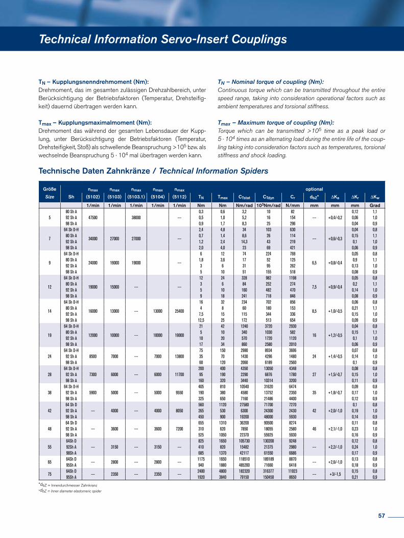
Technical Information Servo-Insert Couplings
Technische Daten Zahnkränze / Technical Information Spiders
TN – Kupplungsnenndrehmoment (Nm): Drehmoment, das im gesamten zulässigen Drehzahlbereich, unter Berücksichtigung der Betriebsfaktoren (Temperatur, Drehsteifig-keit) dauernd übertragen werden kann.
Tmax – Kupplungsmaximalmoment (Nm): Drehmoment das während der gesamten Lebensdauer der Kupp-lung, unter Berücksichtigung der Betriebsfaktoren (Temperatur, Drehsteifigkeit, Stoß) als schwellende Beanspruchung >105 bzw. als wechselnde Beanspruchung 5 · 104 mal übertragen werden kann.
*dbZ = Innendurchmesser Zahnkranz
*dbZ = Inner diameter elastomeric spider
TN – Nominal torque of coupling (Nm): Continuous torque which can be transmitted throughout the entire speed range, taking into consideration operational factors such as ambient temperatures and torsional stiffness.
Tmax – Maximum torque of coupling (Nm): Torque which can be transmitted >105 time as a peak load or 5 · 104 times as an alternating load during the entire life of the coup-ling taking into consideration factors such as temperatures, torsional stiffness and shock loading.
Größe nmax nmax nmax nmax nmax optional
Size Sh (5102) (5103) (5103.1) (5104) (5112) TN Tmax CTstat CTdyn Cr dbZ* ∆Ka ∆Kr ∆Kw
1/min 1/min 1/min 1/min 1/min Nm Nm Nm/rad 103Nm/rad N/mm mm mm mm Grad
580 Sh A
47500 38000 ---0,3 0,6 3,2 10 82
--- +0,4/-0,20,12 1,1
92 Sh A 0,5 1,0 5,2 16 154 0,06 1,098 Sh A 0,9 1,7 8,3 25 296 0,04 0,9
7
64 Sh D-H
34000 27000 27000 ---
2,4 4,8 34 103 630
--- +0,6/-0,3
0,04 0,880 Sh A 0,7 1,4 8,6 26 114 0,15 1,192 Sh A 1,2 2,4 14,3 43 219 0,1 1,098 Sh A 2,0 4,0 23 69 421 0,06 0,9
9
64 Sh D-H
24000 19000 19000 ---
6 12 74 224 769
6,5 +0,8/-0,4
0,05 0,880 Sh A 1,8 3,6 17 52 125 0,9 1,192 Sh A 3 6 31 95 262 0,13 1,098 Sh A 5 10 51 155 518 0,08 0,9
12
64 Sh D-H
19000 15000 --- ---
12 24 328 982 1198
7,5 +0,9/-0,4
0,05 0,880 Sh A 3 6 84 252 274 0,2 1,192 Sh A 5 10 160 482 470 0,14 1,098 Sh A 9 18 241 718 846 0,08 0,9
14
64 Sh D-H
16000 13000 --- 13000 25400
16 32 234 702 856
8,5 +1,0/-0,5
0,06 0,880 Sh A 4 8 60 180 153 0,21 1,192 Sh A 7,5 15 115 344 336 0,15 1,098 Sh A 12,5 25 172 513 654 0,09 0,9
19
64 Sh D-H
12000 10000 --- 10000 19000
21 42 1240 3720 2930
16 +1,2/-0,5
0,04 0,880 Sh A 5 10 340 1030 582 0,15 1,192 Sh A 10 20 570 1720 1120 0,1 1,098 Sh A 17 34 860 2580 2010 0,06 0,9
2464 Sh D-H
8500 7000 --- 7000 1380075 150 2980 8934 3696
24 +1,4/-0,50,07 0,8
92 Sh A 35 70 1430 4296 1480 0,14 1,098 Sh A 60 120 2060 6189 2560 0,1 0,9
2864 Sh D-H
7300 6000 --- 6000 11700200 400 4350 13050 4348
27 +1,5/-0,70,08 0,8
92 Sh A 95 190 2290 6876 1780 0,15 1,098 Sh A 160 320 3440 10314 3200 0,11 0,9
3864 Sh D-H
5900 5000 --- 5000 9550405 810 10540 31620 6474
35 +1,8/-0,70,09 0,8
92 Sh A 190 380 4580 13752 2350 0,17 1,098 Sh A 325 650 7160 21486 4400 0,12 0,9
4264 Sh D
--- 4000 --- 4000 8050560 1120 27580 71700 7270
42 +2,0/-1,00,1 0,8
92 Sh A 265 530 6300 24300 2430 0,19 1,098 Sh A 450 900 19200 48000 5930 0,14 0,9
4864 Sh D
--- 3600 --- 3600 7200655 1310 36200 90500 8274
46 +2,1/-1,00,11 0,8
92 Sh A 310 620 7850 18055 2580 0,23 1,098 Sh A 525 1050 22370 55925 5930 0,16 0,9
5564Sh D
--- 3150 --- 3150 ---825 1650 105730 130200 9248
--- +2,2/-1,00,12 0,8
92Sh A 410 820 15482 21375 2980 0,24 1,098Sh A 685 1370 42117 61550 6686 0,17 0,9
6564Sh D
--- 2800 --- 2800 ---1175 1650 118510 189189 8870
--- +2,6/-1,00,13 0,8
95Sh A 940 1880 485200 71660 6418 0,18 0,9
7564Sh D
--- 2350 --- 2350 ---2400 4800 182320 316377 11923
--- +3/-1,50,15 0,8
95Sh A 1920 3840 79150 150450 8650 0,21 0,9
57
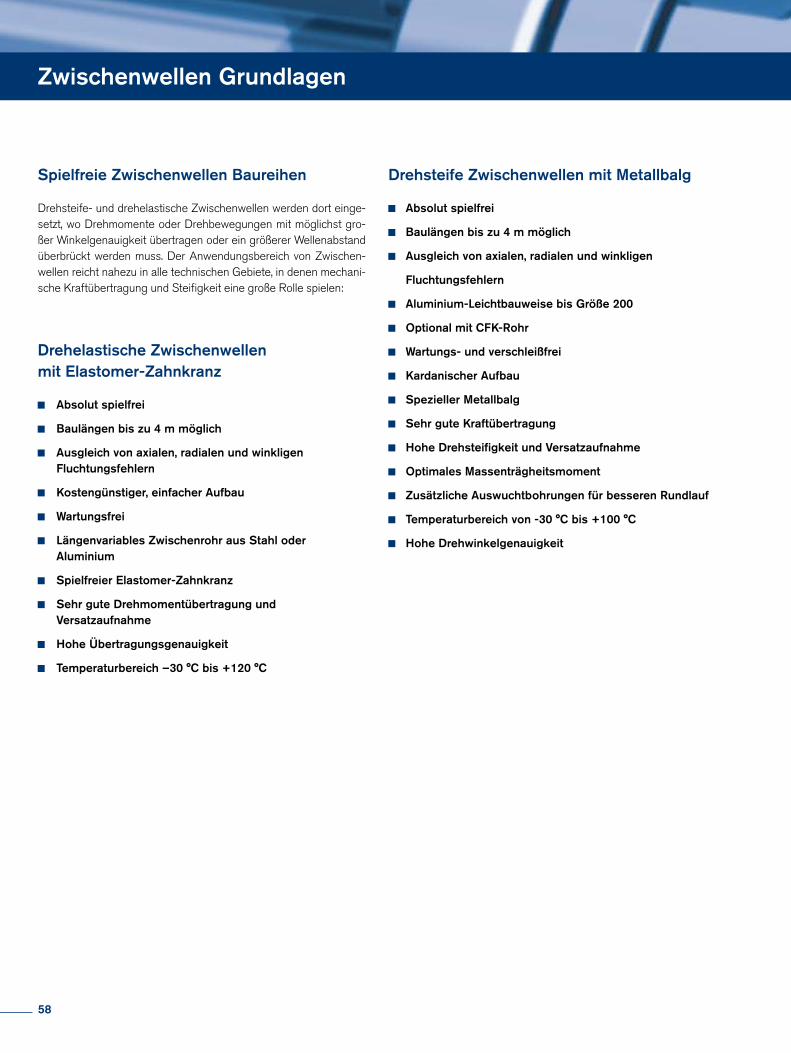
Zwischenwellen Grundlagen
Drehsteife- und drehelastische Zwischenwellen werden dort einge-setzt, wo Drehmomente oder Drehbewegungen mit möglichst gro-ßer Winkelgenauigkeit übertragen oder ein größerer Wellenabstand überbrückt werden muss. Der Anwendungsbereich von Zwischen-wellen reicht nahezu in alle technischen Gebiete, in denen mechani-sche Kraftübertragung und Steifigkeit eine große Rolle spielen:
Drehelastische Zwischenwellen mit Elastomer-Zahnkranz
Absolut spielfrei
Baulängen bis zu 4 m möglich
Ausgleich von axialen, radialen und winkligen Fluchtungsfehlern
Kostengünstiger, einfacher Aufbau
Wartungsfrei
Längenvariables Zwischenrohr aus Stahl oder Aluminium
Spielfreier Elastomer-Zahnkranz
Sehr gute Drehmomentübertragung und Versatzaufnahme
Hohe Übertragungsgenauigkeit
Temperaturbereich –30 °C bis +120 °C
Drehsteife Zwischenwellen mit Metallbalg
Absolut spielfrei
Baulängen bis zu 4 m möglich
Ausgleich von axialen, radialen und winkligen
Fluchtungsfehlern
Aluminium-Leichtbauweise bis Größe 200
Optional mit CFK-Rohr
Wartungs- und verschleißfrei
Kardanischer Aufbau
Spezieller Metallbalg
Sehr gute Kraftübertragung
Hohe Drehsteifigkeit und Versatzaufnahme
Optimales Massenträgheitsmoment
Zusätzliche Auswuchtbohrungen für besseren Rundlauf
Temperaturbereich von -30 °C bis +100 °C
Hohe Drehwinkelgenauigkeit
Spielfreie Zwischenwellen Baureihen
58
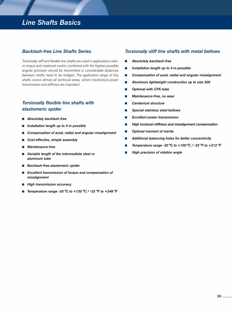
Line Shafts Basics
Backlash-free Line Shafts Series
Torsionally stiff and flexible line shafts are used in applications whe-re torque and rotational motion combined with the highest possible angular precision should be transmitted or considerable distances between shafts need to be bridged. The application range of line shafts covers almost all technical areas, where mechanical power transmission and stiffness are important:
Torsionally flexible line shafts with elastomeric spider
Absolutely backlash-free
Installation length up to 4 m possible
Compensation of axial, radial and angular misalignment
Cost-effective, simple assembly
Maintenance-free
Variable length of the intermediate steel or aluminum tube
Backlash-free elastomeric spider
Excellent transmission of torque and compensation of misalignment
High transmission accuracy
Temperature range -30 °C to +120 °C / -22 °F to +248 °F
Torsionally stiff line shafts with metal bellows
Absolutely backlash-free
Installation length up to 4 m possible
Compensation of axial, radial and angular misalignment
Aluminum lightweight construction up to size 200
Optional with CFK-tube
Maintenance-free, no wear
Cardanical structure
Special stainless steel bellows
Excellent power transmission
High torsional stiffness and misalignment compensation
Optimal moment of inertia
Additional balancing holes for better concentricity
Temperature range -30 °C to +100 °C / -22 °F to +212 °F
High precision of rotation angle
59
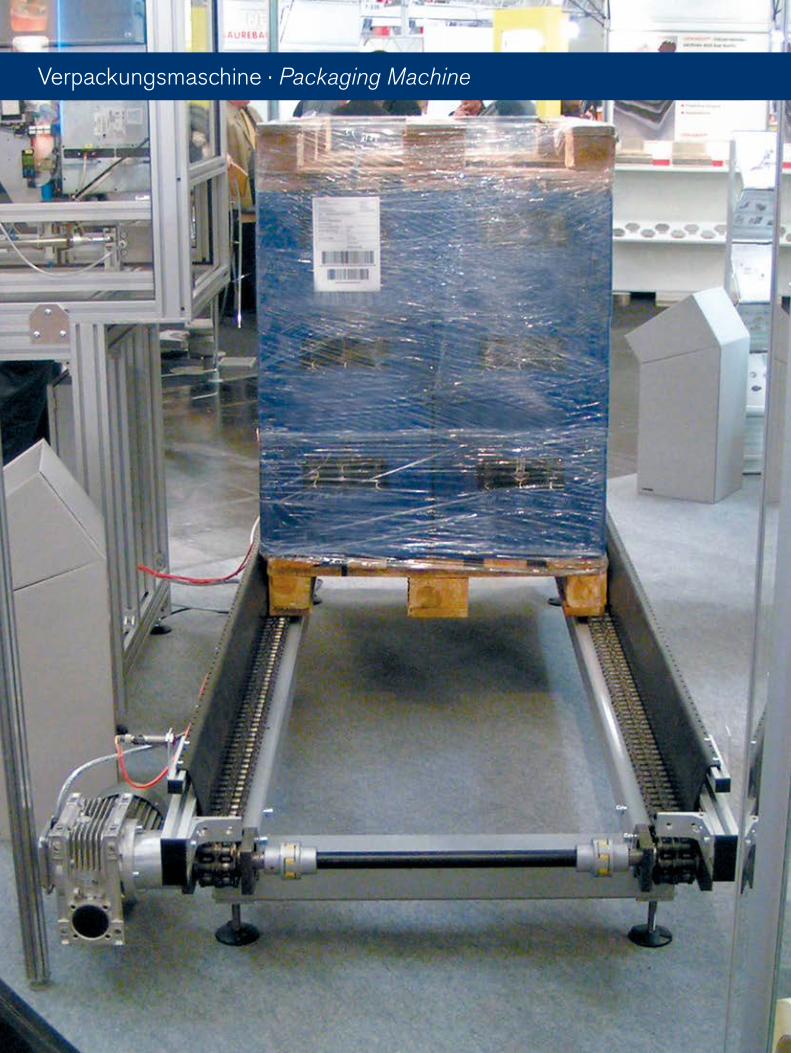
Verpackungsmaschine · Packaging Machine
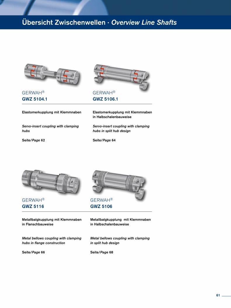
GERWAH®
GWZ 5104.1
Elastomerkupplung mit Klemmnaben
Servo-insert coupling with clamping hubs
Seite/Page 62
GERWAH®
GWZ 5106.1
Elastomerkupplung mit Klemmnabenin Halbschalenbauweise
Servo-insert coupling with clampinghubs in split hub design
Seite/Page 64
GERWAH®
GWZ 5116
Metallbalgkupplung mit Klemmnabenin Flanschbauweise
Metal bellows coupling with clampinghubs in flange construction
Seite/Page 66
GERWAH®
GWZ 5106
Metallbalgkupplung mit Klemmnaben in Halbschalenbauweise
Metal bellows coupling with clamping in split hub design
Seite/Page 68
Übersicht Zwischenwellen · Overview Line Shafts
61
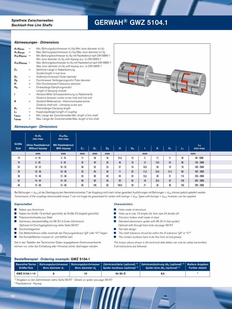
Spielfreie ZwischenwellenBacklash-free Line Shafts GERWAH® GWZ 5104.1
Abmessungen · Dimensions
Abmessungen · Dimensions
Bestellbeispiel · Ordering example: GWZ 5104.1
* Passfedernut · Keyway
Eigenschaften
Naben aus Aluminium Naben bis Größe 19 einfach geschlitzt, ab Größe 24 doppelt geschlitzt Präzisionshohlwelle aus Stahl Zahnkranz standardmäßig mit 98 SH A (roter Zahnkranz)
Optional mit Durchgangsbohrung siehe Seite 56/57 Durchschlagsicher Die Wellentoleranz sollte innerhalb der Passungstoleranz “g6“ oder “h7“ liegen Die Kontaktflächen müssen öl- und fettfrei sein
Die in den Tabellen der Technischen Daten angegebenen Drehmomentwerte können nur unter der Einhaltung aller Hinweise sicher übertragen werden.
Characteristics
Hubs made of aluminum Hubs up to size 19 simple slit, from size 24 double slit Precision hollow shaft made of steel Standard elastomeric spider with 98 SH A (red spider)
Optional with through bore-hole see page 56/57 Fail-safe design The shaft tolerance should be within the fit tolerance “g6” or “h7” The contact surfaces have to be free from oil and grease
The torque values shown in the technical data tables can only be safely transmitted, if all instructions are followed.
d1;d2min = Min. Bohrungsdurchmesser d1/d2/Min. bore diameter d1/d2 d1;d2max = Max. Bohrungsdurchmesser d1/d2/Max. bore diameter d1/d2 d1k;d2kmin = Min. Bohrungsdurchmesser d1/d2 mit Passfedernut nach DIN 6885-1 Min. bore diameter d1/d2 with keyway acc. to DIN 6885-1d1k;d2kmax = Max. Bohrungsdurchmesser d1/d2 mit Passfedernut nach DIN 6885-1 Max. bore diameter d1/d2 with keyway acc. to DIN 6885-1 C1 = Geführte Länge in Nabenbohrung Guided length in hub bore D1 = Außendurchmesser/Outer diameter D5 = Durchmesser Verlängerungsrohr/Tube diameter H = Stör-Durchmesser/Clearance diameter H3 = Einbaulänge Dämpfungsmodul Length of damping module l = Abstand Mitte Schraubenbohrung zu Nabenkante Distance between center screw hole and hub end K = Abstand Wellenachse - Klemmschraubenachse Distance shaft axis - clamping screw axis K1 = Klemmlänge/Clamping length L1 = Kupplungslänge/Length of coupling L3min = Min. Länge der Zwischenwelle/Min. length of line shaft L3max = Max. Länge der Zwischenwelle/Max. length of line shaft
Bei Bohrungen < dmin ist die Übertragung des Nenndrehmomentes T der Kupplung nicht mehr sicher garantiert. Ausführungen mit Bohrungen < dmin können jedoch geliefert werden. Transmission of the couplings transmissible torque T can not longer be guaranteed for certain with borings < dmin. Types with borings < dmin, however, can be supplied.
1) Angaben zu den Zahnkränzen siehe Seite 56/57 · Details on spider see page 56/57
Baureihe/SeriesGröße/Size
Bohrungsdurchmesser Bore diameter d1
BohrungsdurchmesserBore diameter d2
Zahnkranzhärte (optional) 1)
Spider hardness (optional) 1)Zahnkranzbohrung dbz (optional) 1)
Spider bore dbz (optional) 1)Weitere Angaben
Further details
GWZ 5104.1-14 8 10 64 Sh D 8,5 *
d1;d2min-max
d1k;d2kmin-max
Größe Ohne PassfedernutWithout keyway
Mit PassfedernutWith keyway
L3min-maxSize C1 D1 D5 H H3 I K K1 L1
mm mm mm mm mm mm mm
14 5 - 16 5 - 16 11 30 16 31,6 13 5 11 11 35 80 - 2000
19 6 - 20 6 - 20 25 40 20 46 16 12 14,5 25 66 135 - 2000
24 10 - 32 10 - 32 30 55 25 57 18 10,5 20 19 78 160 - 2000
28 10 - 38 10 - 38 35 65 30 71 20 11,5 24,5 21,5 90 185 - 2000
38 12 - 48 12 - 48 45 80 40 83 24 15,5 30 31 114 230 - 2000
42 14 - 54 14 - 54 50 95 40 95 26 18 32,5 32 126 255 - 2000
48 15 - 60 15 - 60 56 105 50 104,5 28 21 36 38 140 290 - 2000
62
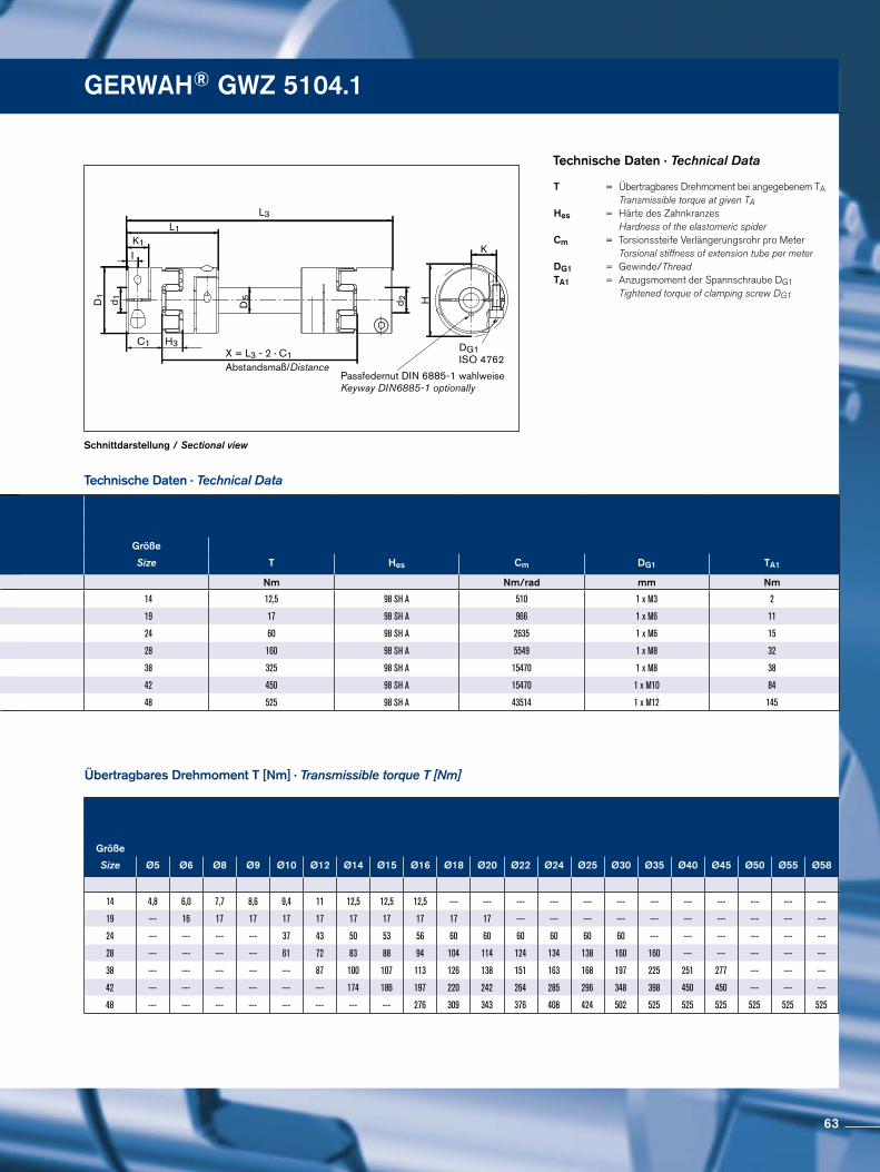
DG1ISO 4762
Passfedernut DIN 6885-1 wahlweiseKeyway DIN6885-1 optionally
I
L1
L3
C1X = L3 - 2 · C1Abstandsmaß/Distance
H
KD
5d 1D1
d 2
K1
H3
Schnittdarstellung / Sectional view
Technische Daten · Technical Data
Technische Daten · Technical Data
Übertragbares Drehmoment T [Nm] · Transmissible torque T [Nm]
T = Übertragbares Drehmoment bei angegebenem TA Transmissible torque at given TA Hes = Härte des Zahnkranzes Hardness of the elastomeric spiderCm = Torsionssteife Verlängerungsrohr pro Meter Torsional stiffness of extension tube per meter DG1 = Gewinde/Thread TA1 = Anzugsmoment der Spannschraube DG1 Tightened torque of clamping screw DG1
GERWAH® GWZ 5104.1
d1;d2min-max
d1k;d2kmin-max
Größe Ohne PassfedernutWithout keyway
Mit PassfedernutWith keyway
L3min-maxSize C1 D1 D5 H H3 I K K1 L1
mm mm mm mm mm mm mm
14 5 - 16 5 - 16 11 30 16 31,6 13 5 11 11 35 80 - 2000
19 6 - 20 6 - 20 25 40 20 46 16 12 14,5 25 66 135 - 2000
24 10 - 32 10 - 32 30 55 25 57 18 10,5 20 19 78 160 - 2000
28 10 - 38 10 - 38 35 65 30 71 20 11,5 24,5 21,5 90 185 - 2000
38 12 - 48 12 - 48 45 80 40 83 24 15,5 30 31 114 230 - 2000
42 14 - 54 14 - 54 50 95 40 95 26 18 32,5 32 126 255 - 2000
48 15 - 60 15 - 60 56 105 50 104,5 28 21 36 38 140 290 - 2000
Größe
Size Ø5 Ø6 Ø8 Ø9 Ø10 Ø12 Ø14 Ø15 Ø16 Ø18 Ø20 Ø22 Ø24 Ø25 Ø30 Ø35 Ø40 Ø45 Ø50 Ø55 Ø58
14 4,8 6,0 7,7 8,6 9,4 11 12,5 12,5 12,5 --- --- --- --- --- --- --- --- --- --- --- ---
19 --- 16 17 17 17 17 17 17 17 17 17 --- --- --- --- --- --- --- --- --- ---
24 --- --- --- --- 37 43 50 53 56 60 60 60 60 60 60 --- --- --- --- --- ---
28 --- --- --- --- 61 72 83 88 94 104 114 124 134 138 160 160 --- --- --- --- ---
38 --- --- --- --- --- 87 100 107 113 126 138 151 163 168 197 225 251 277 --- --- ---
42 --- --- --- --- --- --- 174 186 197 220 242 264 285 296 348 398 450 450 --- --- ---
48 --- --- --- --- --- --- --- --- 276 309 343 376 408 424 502 525 525 525 525 525 525
Größe
Size T Hes Cm DG1 TA1
Nm Nm/rad mm Nm
14 12,5 98 SH A 510 1 x M3 2
19 17 98 SH A 966 1 x M6 11
24 60 98 SH A 2635 1 x M6 15
28 160 98 SH A 5549 1 x M8 32
38 325 98 SH A 15470 1 x M8 38
42 450 98 SH A 15470 1 x M10 84
48 525 98 SH A 43514 1 x M12 145
63
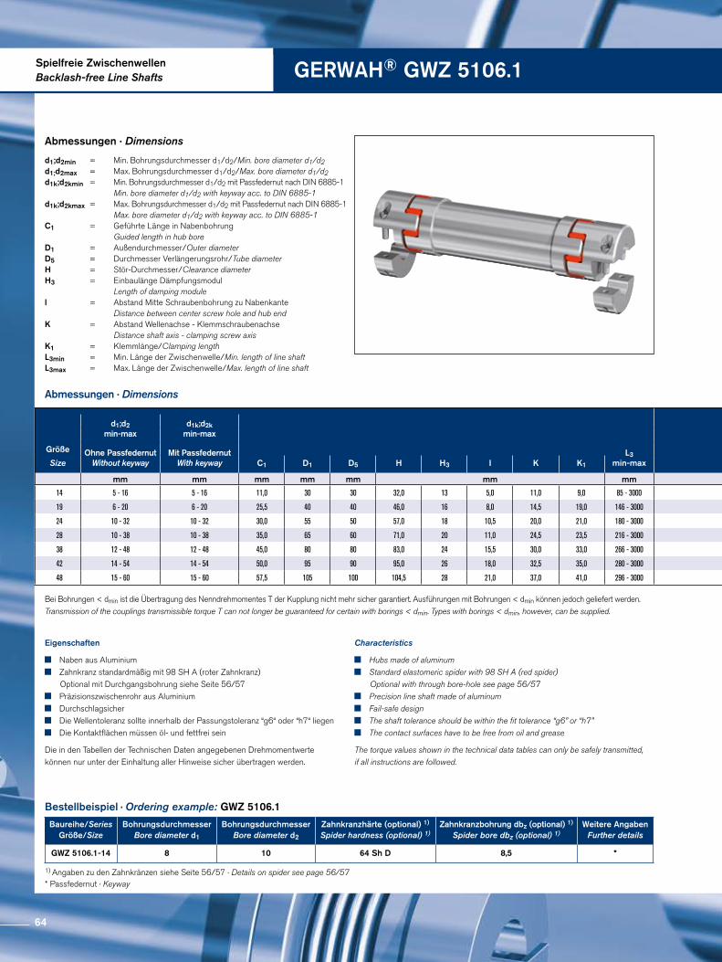
Spielfreie ZwischenwellenBacklash-free Line Shafts GERWAH® GWZ 5106.1
Abmessungen · Dimensions
Abmessungen · Dimensions
Bestellbeispiel · Ordering example: GWZ 5106.1
Eigenschaften
Naben aus Aluminium Zahnkranz standardmäßig mit 98 SH A (roter Zahnkranz)
Optional mit Durchgangsbohrung siehe Seite 56/57 Präzisionszwischenrohr aus Aluminium Durchschlagsicher Die Wellentoleranz sollte innerhalb der Passungstoleranz “g6“ oder “h7“ liegen Die Kontaktflächen müssen öl- und fettfrei sein
Die in den Tabellen der Technischen Daten angegebenen Drehmomentwerte können nur unter der Einhaltung aller Hinweise sicher übertragen werden.
Characteristics
Hubs made of aluminum Standard elastomeric spider with 98 SH A (red spider)
Optional with through bore-hole see page 56/57 Precision line shaft made of aluminum Fail-safe design The shaft tolerance should be within the fit tolerance “g6” or “h7” The contact surfaces have to be free from oil and grease
The torque values shown in the technical data tables can only be safely transmitted, if all instructions are followed.
d1;d2min = Min. Bohrungsdurchmesser d1/d2/Min. bore diameter d1/d2 d1;d2max = Max. Bohrungsdurchmesser d1/d2/Max. bore diameter d1/d2 d1k;d2kmin = Min. Bohrungsdurchmesser d1/d2 mit Passfedernut nach DIN 6885-1 Min. bore diameter d1/d2 with keyway acc. to DIN 6885-1d1k;d2kmax = Max. Bohrungsdurchmesser d1/d2 mit Passfedernut nach DIN 6885-1 Max. bore diameter d1/d2 with keyway acc. to DIN 6885-1 C1 = Geführte Länge in Nabenbohrung Guided length in hub bore D1 = Außendurchmesser/Outer diameter D5 = Durchmesser Verlängerungsrohr/Tube diameter H = Stör-Durchmesser/Clearance diameter H3 = Einbaulänge Dämpfungsmodul Length of damping module l = Abstand Mitte Schraubenbohrung zu Nabenkante Distance between center screw hole and hub end K = Abstand Wellenachse - Klemmschraubenachse Distance shaft axis - clamping screw axis K1 = Klemmlänge/Clamping length L3min = Min. Länge der Zwischenwelle/Min. length of line shaft L3max = Max. Länge der Zwischenwelle/Max. length of line shaft
Bei Bohrungen < dmin ist die Übertragung des Nenndrehmomentes T der Kupplung nicht mehr sicher garantiert. Ausführungen mit Bohrungen < dmin können jedoch geliefert werden. Transmission of the couplings transmissible torque T can not longer be guaranteed for certain with borings < dmin. Types with borings < dmin, however, can be supplied.
* Passfedernut · Keyway
1) Angaben zu den Zahnkränzen siehe Seite 56/57 · Details on spider see page 56/57
Baureihe/SeriesGröße/Size
Bohrungsdurchmesser Bore diameter d1
BohrungsdurchmesserBore diameter d2
Zahnkranzhärte (optional) 1)
Spider hardness (optional) 1)Zahnkranzbohrung dbz (optional) 1)
Spider bore dbz (optional) 1)Weitere Angaben
Further details
GWZ 5106.1-14 8 10 64 Sh D 8,5 *
d1;d2min-max
d1k;d2kmin-max
Größe Ohne PassfedernutWithout keyway
Mit PassfedernutWith keyway
L3min-maxSize C1 D1 D5 H H3 I K K1
mm mm mm mm mm mm mm
14 5 - 16 5 - 16 11,0 30 30 32,0 13 5,0 11,0 9,0 85 - 3000
19 6 - 20 6 - 20 25,5 40 40 46,0 16 8,0 14,5 19,0 146 - 3000
24 10 - 32 10 - 32 30,0 55 50 57,0 18 10,5 20,0 21,0 180 - 3000
28 10 - 38 10 - 38 35,0 65 60 71,0 20 11,0 24,5 23,5 216 - 3000
38 12 - 48 12 - 48 45,0 80 80 83,0 24 15,5 30,0 33,0 266 - 3000
42 14 - 54 14 - 54 50,0 95 90 95,0 26 18,0 32,5 35,0 280 - 3000
48 15 - 60 15 - 60 57,5 105 100 104,5 28 21,0 37,0 41,0 296 - 3000
64
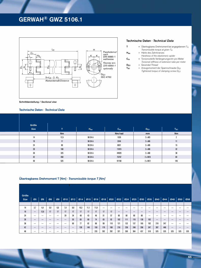
Passfedernut‘nach DIN 6885-1 wahlweise
Keyway acc. DIN 6885-1 optionally
DG1ISO 4762
K
H
d 2d 1
IC1
H3
L3
K
D1
D 5
K1
X=L3 - 2 · K1Abstandsmaß/Distance
Schnittdarstellung / Sectional view
Technische Daten · Technical Data
Übertragbares Drehmoment T [Nm] · Transmissible torque T [Nm]
Technische Daten · Technical Data
T = Übertragbares Drehmoment bei angegebenem TA Transmissible torque at given TAHes = Härte des Zahnkranzes Hardness of the elastomeric spider Cm = Torsionssteife Verlängerungsrohr pro Meter Torsional stiffness of extension tube per meter DG1 = Gewinde/Thread TA1 = Anzugsmoment der Spannschraube DG1 Tightened torque of clamping screw DG1
GERWAH® GWZ 5106.1
d1;d2min-max
d1k;d2kmin-max
Größe Ohne PassfedernutWithout keyway
Mit PassfedernutWith keyway
L3min-maxSize C1 D1 D5 H H3 I K K1
mm mm mm mm mm mm mm
14 5 - 16 5 - 16 11,0 30 30 32,0 13 5,0 11,0 9,0 85 - 3000
19 6 - 20 6 - 20 25,5 40 40 46,0 16 8,0 14,5 19,0 146 - 3000
24 10 - 32 10 - 32 30,0 55 50 57,0 18 10,5 20,0 21,0 180 - 3000
28 10 - 38 10 - 38 35,0 65 60 71,0 20 11,0 24,5 23,5 216 - 3000
38 12 - 48 12 - 48 45,0 80 80 83,0 24 15,5 30,0 33,0 266 - 3000
42 14 - 54 14 - 54 50,0 95 90 95,0 26 18,0 32,5 35,0 280 - 3000
48 15 - 60 15 - 60 57,5 105 100 104,5 28 21,0 37,0 41,0 296 - 3000
Größe
Size Ø5 Ø6 Ø8 Ø9 Ø10 Ø12 Ø14 Ø15 Ø16 Ø18 Ø20 Ø22 Ø24 Ø25 Ø30 Ø35 Ø40 Ø44 Ø48 Ø50 Ø58
14 3,7 4,4 5,9 6,6 7,4 8,8 10,3 11,1 11,8 --- --- --- --- --- --- --- --- --- --- --- ---
19 --- 12,6 17 17 17 17 17 17 17 17 17 --- --- --- --- --- --- --- --- --- ---
24 --- --- --- --- 29 34 40 43 46 51 57 60 60 60 60 --- --- --- --- --- ---
28 --- --- --- --- --- 55 65 69 74 83 92 102 111 116 139 162 --- --- --- --- ---
38 --- --- --- --- --- 66 77 82 88 99 110 121 132 137 165 192 219 247 --- --- ---
42 --- --- --- --- --- --- 139 149 159 179 198 218 238 248 298 347 397 446 --- --- ---
48 --- --- --- --- --- --- --- --- 233 262 292 321 350 364 437 510 525 525 525 525 525
Größe
Size T Hes Cm DG1 TA1
Nm Nm/rad mm Nm
14 12,5 98 SH A 1526 2 x M3 2
19 17 98 SH A 3244 2 x M6 11
24 60 98 SH A 6631 2 x M6 15
28 160 98 SH A 11815 2 x M8 32
38 325 98 SH A 44929 2 x M8 38
42 450 98 SH A 75797 2 x M10 84
48 525 98 SH A 91158 2 x M12 145
65
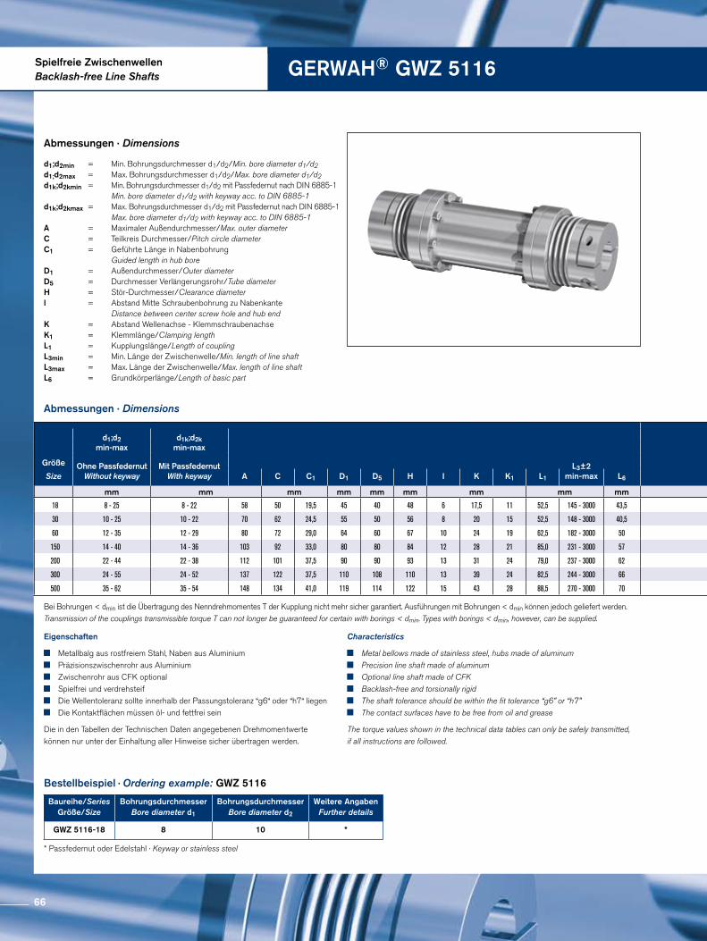
Spielfreie ZwischenwellenBacklash-free Line Shafts GERWAH® GWZ 5116
Abmessungen · Dimensions
Abmessungen · Dimensions
Bestellbeispiel · Ordering example: GWZ 5116
* Passfedernut oder Edelstahl · Keyway or stainless steel
Eigenschaften
Metallbalg aus rostfreiem Stahl, Naben aus Aluminium Präzisionszwischenrohr aus Aluminium Zwischenrohr aus CFK optional Spielfrei und verdrehsteif Die Wellentoleranz sollte innerhalb der Passungstoleranz “g6“ oder “h7“ liegen Die Kontaktflächen müssen öl- und fettfrei sein
Die in den Tabellen der Technischen Daten angegebenen Drehmomentwerte können nur unter der Einhaltung aller Hinweise sicher übertragen werden.
Characteristics
Metal bellows made of stainless steel, hubs made of aluminum Precision line shaft made of aluminum Optional line shaft made of CFK Backlash-free and torsionally rigid The shaft tolerance should be within the fit tolerance “g6” or “h7” The contact surfaces have to be free from oil and grease
The torque values shown in the technical data tables can only be safely transmitted, if all instructions are followed.
d1;d2min = Min. Bohrungsdurchmesser d1/d2/Min. bore diameter d1/d2 d1;d2max = Max. Bohrungsdurchmesser d1/d2/Max. bore diameter d1/d2 d1k;d2kmin = Min. Bohrungsdurchmesser d1/d2 mit Passfedernut nach DIN 6885-1 Min. bore diameter d1/d2 with keyway acc. to DIN 6885-1d1k;d2kmax = Max. Bohrungsdurchmesser d1/d2 mit Passfedernut nach DIN 6885-1 Max. bore diameter d1/d2 with keyway acc. to DIN 6885-1 A = Maximaler Außendurchmesser/Max. outer diameter C = Teilkreis Durchmesser/Pitch circle diameter C1 = Geführte Länge in Nabenbohrung Guided length in hub bore D1 = Außendurchmesser/Outer diameter D5 = Durchmesser Verlängerungsrohr/Tube diameter H = Stör-Durchmesser/Clearance diameter l = Abstand Mitte Schraubenbohrung zu Nabenkante Distance between center screw hole and hub end K = Abstand Wellenachse - Klemmschraubenachse K1 = Klemmlänge/Clamping length L1 = Kupplungslänge/Length of coupling L3min = Min. Länge der Zwischenwelle/Min. length of line shaft L3max = Max. Länge der Zwischenwelle/Max. length of line shaft L6 = Grundkörperlänge/Length of basic part
Bei Bohrungen < dmin ist die Übertragung des Nenndrehmomentes T der Kupplung nicht mehr sicher garantiert. Ausführungen mit Bohrungen < dmin können jedoch geliefert werden. Transmission of the couplings transmissible torque T can not longer be guaranteed for certain with borings < dmin. Types with borings < dmin, however, can be supplied.
Baureihe/SeriesGröße/Size
Bohrungsdurchmesser Bore diameter d1
BohrungsdurchmesserBore diameter d2
Weitere AngabenFurther details
GWZ 5116-18 8 10 *
d1;d2min-max
d1k;d2kmin-max
Größe Ohne PassfedernutWithout keyway
Mit PassfedernutWith keyway
L3±2min-maxSize A C C1 D1 D5 H I K K1 L1 L6
mm mm mm mm mm mm mm mm mm
18 8 - 25 8 - 22 58 50 19,5 45 40 48 6 17,5 11 52,5 145 - 3000 43,5
30 10 - 25 10 - 22 70 62 24,5 55 50 56 8 20 15 52,5 148 - 3000 40,5
60 12 - 35 12 - 29 80 72 29,0 64 60 67 10 24 19 62,5 182 - 3000 50
150 14 - 40 14 - 36 103 92 33,0 80 80 84 12 28 21 85,0 231 - 3000 57
200 22 - 44 22 - 38 112 101 37,5 90 90 93 13 31 24 79,0 237 - 3000 62
300 24 - 55 24 - 52 137 122 37,5 110 108 110 13 39 24 82,5 244 - 3000 66
500 35 - 62 35 - 54 148 134 41,0 119 114 122 15 43 28 88,5 270 - 3000 70
66
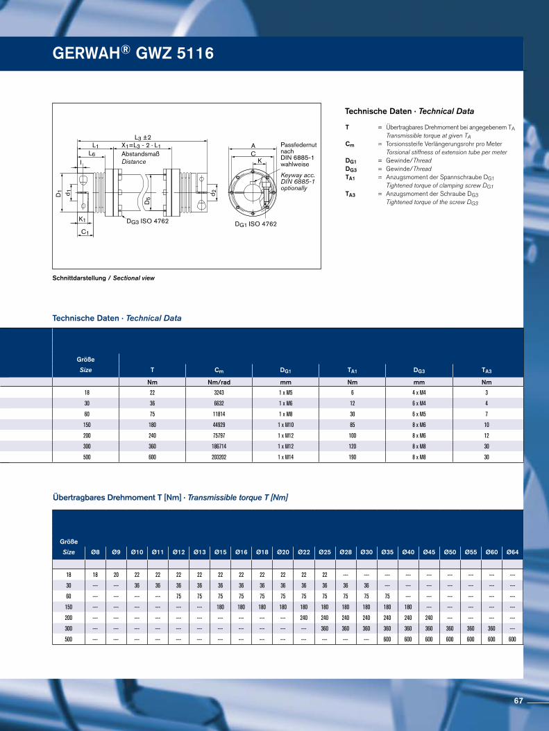
Passfedernutnach DIN 6885-1 wahlweise
Keyway acc. DIN 6885-1 optionally
DG1 ISO 4762DG3 ISO 4762
KCA
IL6
L1 X1=L3 - 2 · L1AbstandsmaßDistance
L3 ±2
K1
C1
D5
d 1 d 2D1
Schnittdarstellung / Sectional view
Technische Daten · Technical Data
Technische Daten · Technical Data
T = Übertragbares Drehmoment bei angegebenem TA Transmissible torque at given TA Cm = Torsionssteife Verlängerungsrohr pro Meter Torsional stiffness of extension tube per meter DG1 = Gewinde/ThreadDG3 = Gewinde/ThreadTA1 = Anzugsmoment der Spannschraube DG1 Tightened torque of clamping screw DG1 TA3 = Anzugsmoment der Schraube DG3 Tightened torque of the screw DG3
Übertragbares Drehmoment T [Nm] · Transmissible torque T [Nm]
GERWAH® GWZ 5116
d1;d2min-max
d1k;d2kmin-max
Größe Ohne PassfedernutWithout keyway
Mit PassfedernutWith keyway
L3±2min-maxSize A C C1 D1 D5 H I K K1 L1 L6
mm mm mm mm mm mm mm mm mm
18 8 - 25 8 - 22 58 50 19,5 45 40 48 6 17,5 11 52,5 145 - 3000 43,5
30 10 - 25 10 - 22 70 62 24,5 55 50 56 8 20 15 52,5 148 - 3000 40,5
60 12 - 35 12 - 29 80 72 29,0 64 60 67 10 24 19 62,5 182 - 3000 50
150 14 - 40 14 - 36 103 92 33,0 80 80 84 12 28 21 85,0 231 - 3000 57
200 22 - 44 22 - 38 112 101 37,5 90 90 93 13 31 24 79,0 237 - 3000 62
300 24 - 55 24 - 52 137 122 37,5 110 108 110 13 39 24 82,5 244 - 3000 66
500 35 - 62 35 - 54 148 134 41,0 119 114 122 15 43 28 88,5 270 - 3000 70
Größe
Size Ø8 Ø9 Ø10 Ø11 Ø12 Ø13 Ø15 Ø16 Ø18 Ø20 Ø22 Ø25 Ø28 Ø30 Ø35 Ø40 Ø45 Ø50 Ø55 Ø60 Ø64
18 18 20 22 22 22 22 22 22 22 22 22 22 --- --- --- --- --- --- --- --- ---
30 --- --- 36 36 36 36 36 36 36 36 36 36 36 36 --- --- --- --- --- --- ---
60 --- --- --- --- 75 75 75 75 75 75 75 75 75 75 75 --- --- --- --- --- ---
150 --- --- --- --- --- --- 180 180 180 180 180 180 180 180 180 180 --- --- --- --- ---
200 --- --- --- --- --- --- --- --- --- --- 240 240 240 240 240 240 240 --- --- --- ---
300 --- --- --- --- --- --- --- --- --- --- --- 360 360 360 360 360 360 360 360 360 ---
500 --- --- --- --- --- --- --- --- --- --- --- --- --- --- 600 600 600 600 600 600 600
Größe
Size T Cm DG1 TA1 DG3 TA3
Nm Nm/rad mm Nm mm Nm
18 22 3243 1 x M5 6 4 x M4 3
30 36 6632 1 x M6 12 6 x M4 4
60 75 11814 1 x M8 30 6 x M5 7
150 180 44929 1 x M10 85 8 x M6 10
200 240 75797 1 x M12 100 8 x M6 12
300 360 186714 1 x M12 120 8 x M8 30
500 600 203202 1 x M14 190 8 x M8 30
67
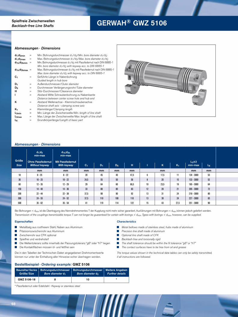
Spielfreie ZwischenwellenBacklash-free Line Shafts GERWAH® GWZ 5106
Abmessungen · Dimensions
Abmessungen · Dimensions
Bestellbeispiel · Ordering example: GWZ 5106
* Passfedernut oder Edelstahl · Keyway or stainless steel
Eigenschaften
Metallbalg aus rostfreiem Stahl, Naben aus Aluminium Präzisionszwischenrohr aus Aluminium Zwischenrohr aus CFK optional Spielfrei und verdrehsteif Die Wellentoleranz sollte innerhalb der Passungstoleranz “g6“ oder “h7“ liegen Die Kontaktflächen müssen öl- und fettfrei sein
Die in den Tabellen der Technischen Daten angegebenen Drehmomentwerte können nur unter der Einhaltung aller Hinweise sicher übertragen werden.
Characteristics
Metal bellows made of stainless steel, hubs made of aluminum Precision line shaft made of aluminum Optional line shaft made of CFK Backlash-free and torsionally rigid The shaft tolerance should be within the fit tolerance “g6” or “h7” The contact surfaces have to be free from oil and grease
The torque values shown in the technical data tables can only be safely transmitted, if all instructions are followed.
d1;d2min = Min. Bohrungsdurchmesser d1/d2/Min. bore diameter d1/d2 d1;d2max = Max. Bohrungsdurchmesser d1/d2/Max. bore diameter d1/d2 d1k;d2kmin = Min. Bohrungsdurchmesser d1/d2 mit Passfedernut nach DIN 6885-1 Min. bore diameter d1/d2 with keyway acc. to DIN 6885-1d1k;d2kmax = Max. Bohrungsdurchmesser d1/d2 mit Passfedernut nach DIN 6885-1 Max. bore diameter d1/d2 with keyway acc. to DIN 6885-1 C1 = Geführte Länge in Nabenbohrung Guided length in hub bore D1 = Außendurchmesser/Outer diameter D5 = Durchmesser Verlängerungsrohr/Tube diameter H = Stör-Durchmesser/Clearance diameter l = Abstand Mitte Schraubenbohrung zu Nabenkante Distance between center screw hole and hub end K = Abstand Wellenachse - Klemmschraubenachse Distance shaft axis - clamping screw axis K1 = Klemmlänge/Clamping length L3min = Min. Länge der Zwischenwelle/Min. length of line shaft L3max = Max. Länge der Zwischenwelle/Max. length of line shaft L6 = Grundkörperlänge/Length of basic part
Bei Bohrungen < dmin ist die Übertragung des Nenndrehmomentes T der Kupplung nicht mehr sicher garantiert. Ausführungen mit Bohrungen < dmin können jedoch geliefert werden. Transmission of the couplings transmissible torque T can not longer be guaranteed for certain with borings < dmin. Types with borings < dmin, however, can be supplied.
Baureihe/SeriesGröße/Size
Bohrungsdurchmesser Bore diameter d1
BohrungsdurchmesserBore diameter d2
Weitere AngabenFurther details
GWZ 5106-18 8 10 *
d1;d2min-max
d1k;d2kmin-max
Größe Ohne PassfedernutWithout keyway
Mit PassfedernutWith keyway
L3±2min-maxSize C1 D1 D5 H I K K1 L6
mm mm mm mm mm mm mm mm mm
18 8 - 25 8 - 22 20 45 40 47,5 6 17,5 11 134 - 3000 53
30 10 - 25 10 - 22 24,5 55 50 56 8 20 15 133 - 3000 52
60 12 - 35 12 - 29 29 64 60 66,5 10 23,5 19 165 - 3000 64
150 14 - 40 14 - 36 33 80 80 83 12 28 21 205 - 3000 72
200 22 - 44 22 - 38 37,5 90 90 92 13 31 24 218 - 3000 80
300 24 - 55 24 - 52 37,5 110 100 110 13 39 24 227 - 3000 83
500 35 - 62 35 - 54 41 119 114 122 15 43 27,5 251 - 3000 90
68
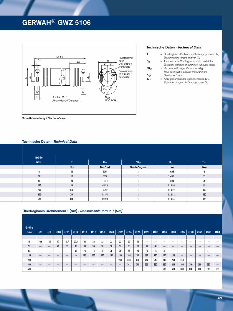
DG1ISO 4762
Passfedernut nach DIN 6885-1 wahlweise
Keyway acc. DIN 6885-1 optionally
KH
d 1
d 2
I
L3 ±2
K1
KD
5
C1
D1
L6
X = L3 - 2 · K1Abstandsmaß/Distance
Schnittdarstellung / Sectional view
Technische Daten · Technical Data
Technische Daten · Technical Data
Übertragbares Drehmoment T [Nm] · Transmissible torque T [Nm]
T = Übertragbares Drehmoment bei angegebenem TA Transmissible torque at given TACm = Torsionssteife Verlängerungsrohr pro Meter Torsional stiffness of extension tube per meter ∆Kw = Maximal zulässiger Versatz winklig Max. permissible angular misalignment DG1 = Gewinde/Thread TA1 = Anzugsmoment der Spannschraube DG1 Tightened torque of clamping screw DG1
GERWAH® GWZ 5106
d1;d2min-max
d1k;d2kmin-max
Größe Ohne PassfedernutWithout keyway
Mit PassfedernutWith keyway
L3±2min-maxSize C1 D1 D5 H I K K1 L6
mm mm mm mm mm mm mm mm mm
18 8 - 25 8 - 22 20 45 40 47,5 6 17,5 11 134 - 3000 53
30 10 - 25 10 - 22 24,5 55 50 56 8 20 15 133 - 3000 52
60 12 - 35 12 - 29 29 64 60 66,5 10 23,5 19 165 - 3000 64
150 14 - 40 14 - 36 33 80 80 83 12 28 21 205 - 3000 72
200 22 - 44 22 - 38 37,5 90 90 92 13 31 24 218 - 3000 80
300 24 - 55 24 - 52 37,5 110 100 110 13 39 24 227 - 3000 83
500 35 - 62 35 - 54 41 119 114 122 15 43 27,5 251 - 3000 90
Größe
Size Ø8 Ø9 Ø10 Ø11 Ø12 Ø14 Ø15 Ø18 Ø20 Ø22 Ø24 Ø25 Ø28 Ø30 Ø35 Ø40 Ø45 Ø50 Ø55 Ø60 Ø64
18 13,6 15,3 17 18,7 20,4 22 22 22 22 22 22 22 --- --- --- --- --- --- --- --- ---
30 --- --- 28 30 33 36 36 36 36 36 36 36 36 36 --- --- --- --- --- --- ---
60 --- --- --- --- 62 73 75 75 75 75 75 75 75 75 75 --- --- --- --- --- ---
150 --- --- --- --- --- 167 180 180 180 180 180 180 180 180 180 180 --- --- --- --- ---
200 --- --- --- --- --- --- --- --- --- 240 240 240 240 240 240 240 240 --- --- --- ---
300 --- --- --- --- --- --- --- --- --- --- 342 360 360 360 360 360 360 360 360 360 ---
500 --- --- --- --- --- --- --- --- --- --- --- --- --- --- 600 600 600 600 600 600 600
Größe
Size T Cm ∆Kw DG1 TA1
Nm Nm/rad Grad/Degree mm Nm
18 22 3244 1 1 x M5 6
30 36 6632 1 1 x M6 12
60 75 11814 1 1 x M8 30
150 180 49929 1 1 x M10 85
200 240 75797 1 1 x M12 100
300 360 91158 1 1 x M12 120
500 600 203202 1 1 x M14 190
69
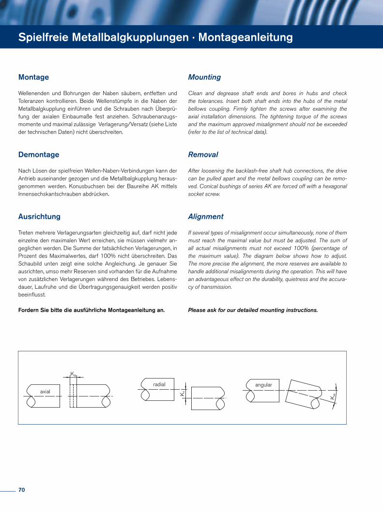
Spielfreie Metallbalgkupplungen · Montageanleitung
Montage
Wellenenden und Bohrungen der Naben säubern, entfetten und Toleranzen kontrollieren. Beide Wellenstümpfe in die Naben der Metallbalgkupplung einführen und die Schrauben nach Überprü-fung der axialen Einbaumaße fest anziehen. Schraubenanzugs- momente und maximal zulässige Verlagerung/Versatz (siehe Liste der technischen Daten) nicht überschreiten.
Demontage
Nach Lösen der spielfreien Wellen-Naben-Verbindungen kann der Antrieb auseinander gezogen und die Metallbalgkupplung heraus-genommen werden. Konusbuchsen bei der Baureihe AK mittels Innensechskantschrauben abdrücken.
Ausrichtung
Treten mehrere Verlagerungsarten gleichzeitig auf, darf nicht jede einzelne den maximalen Wert erreichen, sie müssen vielmehr an-geglichen werden. Die Summe der tatsächlichen Verlagerungen, in Prozent des Maximalwertes, darf 100% nicht überschreiten. Das Schaubild unten zeigt eine solche Angleichung. Je genauer Sie ausrichten, umso mehr Reserven sind vorhanden für die Aufnahme von zusätzlichen Verlagerungen während des Betriebes. Lebens-dauer, Laufruhe und die Übertragungsgenauigkeit werden positiv beeinflusst.
Fordern Sie bitte die ausführliche Montageanleitung an.
Mounting
Clean and degrease shaft ends and bores in hubs and check the tolerances. Insert both shaft ends into the hubs of the metal bellows coupling. Firmly tighten the screws after examining the axial installation dimensions. The tightening torque of the screws and the maximum approved misalignment should not be exceeded (refer to the list of technical data).
Removal
After loosening the backlash-free shaft hub connections, the drive can be pulled apart and the metal bellows coupling can be remo-ved. Conical bushings of series AK are forced off with a hexagonal socket screw.
Alignment
If several types of misalignment occur simultaneously, none of them must reach the maximal value but must be adjusted. The sum of all actual misalignments must not exceed 100% (percentage of the maximum value). The diagram below shows how to adjust. The more precise the alignment, the more reserves are available to handle additional misalignments during the operation. This will have an advantageous effect on the durability, quietness and the accura-cy of transmission.
Please ask for our detailed mounting instructions.
Ka
Kr
Kw
axialradial angular
Ka
Kr
Kw
axialradial angular
Ka
Kr
Kw
axialradial angular
70
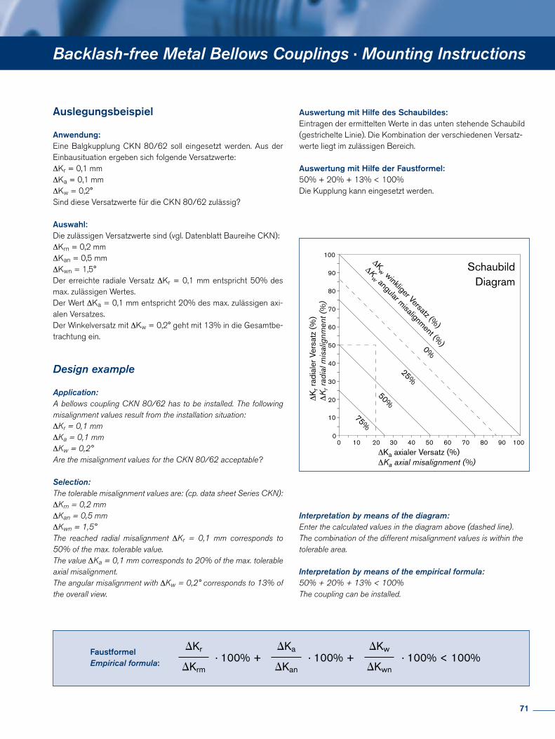
Backlash-free Metal Bellows Couplings · Mounting Instructions
Anwendung:Eine Balgkupplung CKN 80/62 soll eingesetzt werden. Aus der Einbausituation ergeben sich folgende Versatzwerte:∆Kr = 0,1 mm∆Ka = 0,1 mm∆Kw = 0,2°Sind diese Versatzwerte für die CKN 80/62 zulässig?
Auswahl:Die zulässigen Versatzwerte sind (vgl. Datenblatt Baureihe CKN):∆Krn = 0,2 mm∆Kan = 0,5 mm∆Kwn = 1,5°Der erreichte radiale Versatz ∆Kr = 0,1 mm entspricht 50% des max. zulässigen Wertes. Der Wert ∆Ka = 0,1 mm entspricht 20% des max. zulässigen axi-alen Versatzes. Der Winkelversatz mit ∆Kw = 0,2° geht mit 13% in die Gesamtbe-trachtung ein.
Auslegungsbeispiel Auswertung mit Hilfe des Schaubildes:Eintragen der ermittelten Werte in das unten stehende Schaubild(gestrichelte Linie). Die Kombination der verschiedenen Versatz-werte liegt im zulässigen Bereich.
Auswertung mit Hilfe der Faustformel:50% + 20% + 13% < 100%Die Kupplung kann eingesetzt werden.
Interpretation by means of the diagram:Enter the calculated values in the diagram above (dashed line). The combination of the different misalignment values is within the tolerable area.
Interpretation by means of the empirical formula:50% + 20% + 13% < 100%The coupling can be installed.
Application:A bellows coupling CKN 80/62 has to be installed. The following misalignment values result from the installation situation:∆Kr = 0,1 mm∆Ka = 0,1 mm∆Kw = 0,2°Are the misalignment values for the CKN 80/62 acceptable?
Selection:The tolerable misalignment values are: (cp. data sheet Series CKN):∆Krn = 0,2 mm∆Kan = 0,5 mm∆Kwn = 1,5°The reached radial misalignment ∆Kr = 0,1 mm corresponds to 50% of the max. tolerable value. The value ∆Ka = 0,1 mm corresponds to 20% of the max. tolerable axial misalignment. The angular misalignment with ∆Kw = 0,2° corresponds to 13% of the overall view.
Design example
100
90
80
70
60
50
40
30
20
10
01009080706050403020100
ΔKa axialer Versatz (%)ΔKa axial misalignment (%)
ΔKw winkliger Versatz (%
)
ΔKw angular misalignment (%
)
ΔK
r rad
iale
r Ver
satz
(%)
ΔK
r rad
ial m
isal
ignm
ent (
%)
SchaubildDiagram
0%
25%
50%
75%
· 100% +DKr
DKrm
DKa
DKan· 100% +
DKw
DKwn· 100% < 100%
FaustformelEmpirical formula:
71
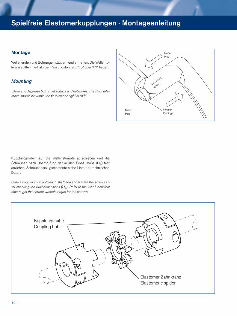
Spielfreie Elastomerkupplungen · Montageanleitung
Montage
Wellenenden und Bohrungen säubern und entfetten. Die Wellento-leranz sollte innerhalb der Passungstoleranz “g6“ oder “h7“ liegen.
Mounting
Clean and degrease both shaft surface and hub bores. The shaft tole-rance should be within the fit tolerance “g6” or “h7”.
KupplungsnabeCoupling hub
Elastomer ZahnkranzElastomeric spider
NoppenBurtings
Zahnkranz
Spider
NabeHub
NabeHub
Kupplungsnaben auf die Wellenstümpfe aufschieben und die Schrauben nach Überprüfung der axialen Einbaumaße (H3) fest anziehen. Schraubenanzugsmomente siehe Liste der technischen Daten.
Slide a coupling hub onto each shaft end and tighten the screws af-ter checking the axial dimensions (H3). Refer to the list of technical data to get the correct wrench torque for the screws.
72

Elastomer-Zahnkränze in eine Nabe eindrücken. Die Eindrückkraft kann durch leichtes Einfetten mit PU-verträglichen Schmierstoffen, z.B. Vaseline, verringert werden. Die Zähne am Elastomer sind zur besseren Montage abgeschrägt und die Klauen der Nabe abge-rundet. Die Noppen, seitlich abwechselnd an den Zähnen, begüns-tigen die Montage und vermeiden einen zu engen Einbau. Nun die zweite Kupplungsnabe eindrücken. Spaltmaße einhalten, damit der Elastomer-Zahnkranz axial nicht verspannt wird. Eine längere Le-bensdauer und die elektrische Isolierung sind somit gewährleistet.
Firmly press the elastomeric spider into one of the two hubs. A PU compatible grease such as Vaseline may be applied to ease assem-bly. The edges of the spider and the jaws of the coupling hubs are both chamfered for an easier or – if applicable - blind assembly The burlings sidewise alternate on the edges, ease the assembly and prevent from an too tight installation. Now push in the second hub. Always keep within the clearance, so that the elastomeric spi-der will not be tensed up axial. Therefore a longer durability and electrical isolation will be guaranteed.
WICHTIG: Bei Anwendungen mit dynamischer Belastung
Bei Anwendungen mit hoher Dynamik (häufiges Beschleunigen, Drehrichtungsumkehr) oder hoher Stoßbelastung (Verwendung z.B. in Pressen und Schreddern) wird empfohlen, die Auslegung und Auswahl der geeigneten Kupplung mit Unterstützung des Engineering-Teams durchzuführen.
IMPORTANT: For application with high dynamics
For application with high dynamics (frequent acceleration and reversion of rotating) or high impact load (applications like pres-ses and shredder) we recommend to use the support of the Engineering-Team in doing the dimensioning and choosing the ap-propriated coupling.
Backlash-free Servo-insert Couplings · Mounting Instructions
ZahnkranzSpider
Elastische VerformungElastic deformation
Nabe Hub
Nabe Hub
E
Nabe Hub
Nabe Hub
ZahnkranzSpider
73
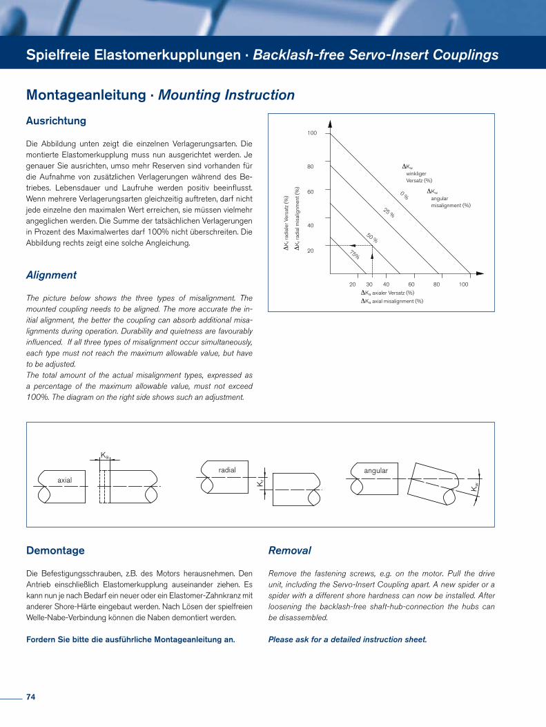
Spielfreie Elastomerkupplungen · Backlash-free Servo-Insert Couplings
Montageanleitung · Mounting Instruction
Ausrichtung
Die Abbildung unten zeigt die einzelnen Verlagerungsarten. Die montierte Elastomerkupplung muss nun ausgerichtet werden. Je genauer Sie ausrichten, umso mehr Reserven sind vorhanden für die Aufnahme von zusätzlichen Verlagerungen während des Be-triebes. Lebensdauer und Laufruhe werden positiv beeinflusst. Wenn mehrere Verlagerungsarten gleichzeitig auftreten, darf nicht jede einzelne den maximalen Wert erreichen, sie müssen vielmehr angeglichen werden. Die Summe der tatsächlichen Verlagerungen in Prozent des Maximalwertes darf 100% nicht überschreiten. Die Abbildung rechts zeigt eine solche Angleichung.
Alignment
The picture below shows the three types of misalignment. The mounted coupling needs to be aligned. The more accurate the in-itial alignment, the better the coupling can absorb additional misa-lignments during operation. Durability and quietness are favourably influenced. If all three types of misalignment occur simultaneously, each type must not reach the maximum allowable value, but have to be adjusted. The total amount of the actual misalignment types, expressed as a percentage of the maximum allowable value, must not exceed 100%. The diagram on the right side shows such an adjustment.
20
40
60
80
100
20 30 40 60 80 100
Kr r
adia
l mis
alig
nmen
t (%
)Ka axialer Versatz (%)
Kw
winkligerVersatz (%)
Kr r
adia
ler V
ersa
tz (%
)
Kw
angularmisalignment (%)
0 %
25 %
50 %
75%
Δ
Δ
ΔΔ
Ka axial misalignment (%)ΔΔ
Ka
Kr
Kw
axialradial angular
Ka
Kr
Kw
axialradial angular
Ka
Kr
Kw
axialradial angular
Demontage
Die Befestigungsschrauben, z.B. des Motors herausnehmen. Den Antrieb einschließlich Elastomerkupplung auseinander ziehen. Es kann nun je nach Bedarf ein neuer oder ein Elastomer-Zahnkranz mit anderer Shore-Härte eingebaut werden. Nach Lösen der spielfreien Welle-Nabe-Verbindung können die Naben demontiert werden.
Fordern Sie bitte die ausführliche Montageanleitung an.
Removal
Remove the fastening screws, e.g. on the motor. Pull the drive unit, including the Servo-Insert Coupling apart. A new spider or a spider with a different shore hardness can now be installed. After loosening the backlash-free shaft-hub-connection the hubs can be disassembled.
Please ask for a detailed instruction sheet.
74
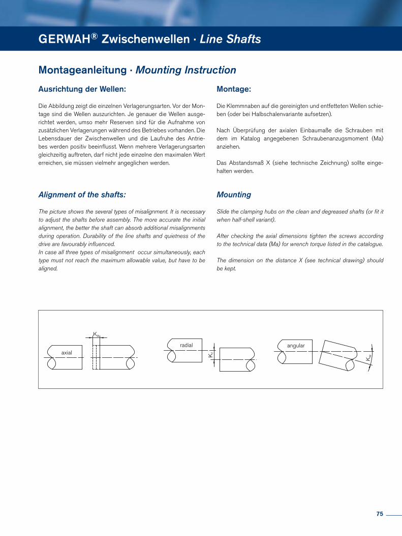
Spielfreie Elastomerkupplungen · Backlash-free Servo-Insert Couplings
Montageanleitung · Mounting Instruction Montageanleitung · Mounting Instruction
GERWAH® Zwischenwellen · Line Shafts
Ausrichtung der Wellen:
Die Abbildung zeigt die einzelnen Verlagerungsarten. Vor der Mon-tage sind die Wellen auszurichten. Je genauer die Wellen ausge-richtet werden, umso mehr Reserven sind für die Aufnahme von zusätzlichen Verlagerungen während des Betriebes vorhanden. Die Lebensdauer der Zwischenwellen und die Laufruhe des Antrie-bes werden positiv beeinflusst. Wenn mehrere Verlagerungsarten gleichzeitig auftreten, darf nicht jede einzelne den maximalen Wert erreichen, sie müssen vielmehr angeglichen werden.
Alignment of the shafts:
The picture shows the several types of misalignment. It is necessary to adjust the shafts before assembly. The more accurate the initial alignment, the better the shaft can absorb additional misalignments during operation. Durability of the line shafts and quietness of the drive are favourably influenced. In case all three types of misalignment occur simultaneously, each type must not reach the maximum allowable value, but have to be aligned.
Montage:
Die Klemmnaben auf die gereinigten und entfetteten Wellen schie-ben (oder bei Halbschalenvariante aufsetzen).
Nach Überprüfung der axialen Einbaumaße die Schrauben mit dem im Katalog angegebenen Schraubenanzugsmoment (Ma) anziehen.
Das Abstandsmaß X (siehe technische Zeichnung) sollte einge-halten werden.
Mounting
Slide the clamping hubs on the clean and degreased shafts (or fit it when half-shell variant).
After checking the axial dimensions tighten the screws according to the technical data (Ma) for wrench torque listed in the catalogue.
The dimension on the distance X (see technical drawing) should be kept.
Ka
Kr
Kw
axialradial angular
Ka
Kr
Kw
axialradial angular
Ka
Kr
Kw
axialradial angular
75
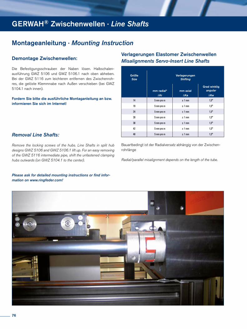
Demontage Zwischenwellen:
Die Befestigungsschrauben der Naben lösen. Halbschalen-ausführung GWZ 5106 und GWZ 5106.1 nach oben abheben. Bei der GWZ 5116 zum leichteren entfernen des Zwischenroh-res, die gelöste Klemmnabe nach Außen verschieben (bei GWZ 5104.1 nach innen).
Fordern Sie bitte die ausführliche Montaganleitung an bzw. informieren Sie sich im Internet!
Removal Line Shafts:
Remove the locking screws of the hubs. Line Shafts in split hub designs GWZ 5106 and GWZ 5106.1 lift up. For an easy removing of the GWZ 5116 intermediate pipe, shift the unfastened clamping hubs outwards (on GWZ 5104.1 to the center).
Please ask for detailed mounting instructions or find infor-mation on www.ringfeder.com!
Bauartbedingt ist der Radialversatz abhängig von der Zwischen-rohrlänge
Radial/parallel misalignment depends on the length of the tube.
Verlagerungen Elastomer ZwischenwellenMisalignments Servo-Insert Line Shafts
GrößeSize
VerlagerungenShifting
Grad winkligangular mm radial* mm axial
∆Kr ∆Ka ∆Kw
14 5 mm pro m ± 1 mm 1,5°
19 5 mm pro m ± 1 mm 1,5°
24 5 mm pro m ± 1 mm 1,5°
28 5 mm pro m ± 1 mm 1,5°
38 5 mm pro m ± 1 mm 1,5°
42 5 mm pro m ± 1 mm 1,5°
48 5 mm pro m ± 1 mm 1,5°
GERWAH® Zwischenwellen · Line Shafts
Montageanleitung · Mounting Instruction
76
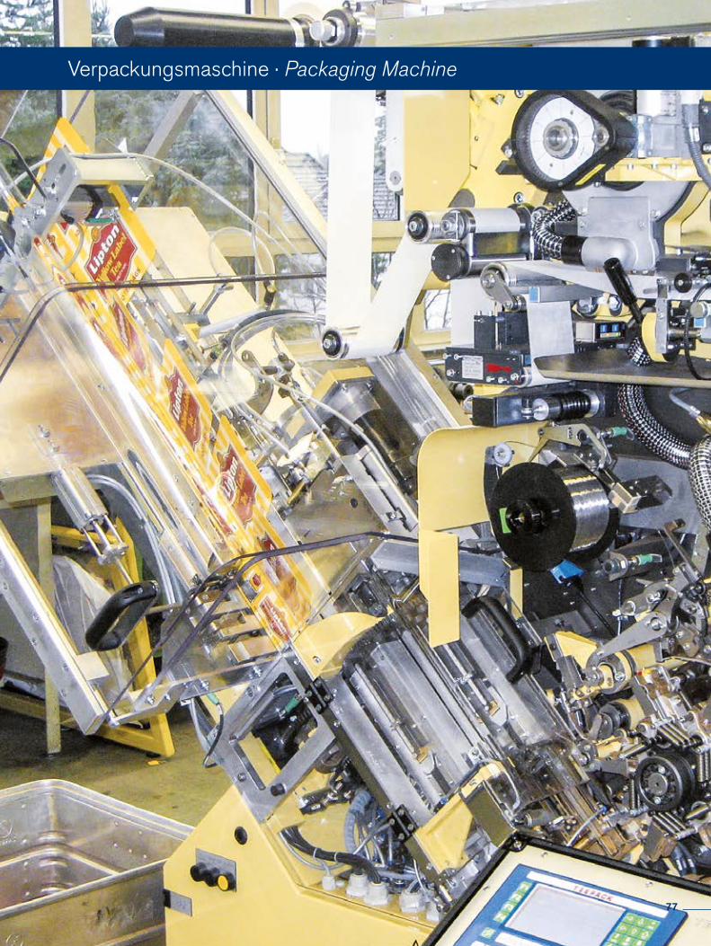
Verpackungsmaschine · Packaging Machine
77
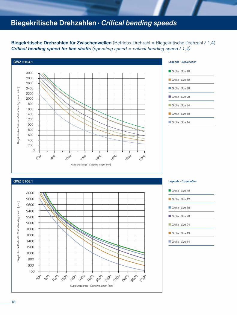
200
400
600
800
1000
1200
1400
1600
1800
2000
2200
2400
2600
2800
3000
0
Kupplungslänge · Coupling length [mm]
Bie
gekr
itisc
he D
rehz
ahl ·
Crit
ical
ben
ding
spe
ed
[min
-1]
Größe · Size 48
Größe · Size 42
Größe · Size 38
Größe · Size 28
Größe · Size 24
Größe · Size 19
Größe · Size 14
600800
10001200
14001600
18002000
600
600
400
800
1000
1200
1400
1600
1800
2000
2200
2400
2600
2800
3000
8001000
12001400
16001800
20002200
24002600
28003000
Bie
gekr
itisc
he D
rehz
ahl ·
Crit
ical
ben
ding
spe
ed
[min
-1]
Kupplungslänge · Coupling length [mm]
Größe · Size 48
Größe · Size 42
Größe · Size 38
Größe · Size 28
Größe · Size 24
Größe · Size 19
Größe · Size 14
600
200
400
600
800
1000
1200
1400
1600
1800
2000
2200
2400
2600
2800
3000
0
800 1000 1200 1400 1600 1800 2000
Kupplungslänge · Coupling length [mm]
Bie
gekr
itisc
he D
rehz
ahl ·
Crit
ical
ben
ding
spe
ed [
min
-1]
Größe · Size 14
Größe · Size 19
Größe · Size 24
Größe · Size 28
Größe · Size 38
Größe · Size 42
Größe · Size 48
600
200
400
600
800
1000
1200
1400
1600
1800
2000
2200
2400
2600
2800
3000
0
800 1000 1200 1400 1600 1800 2000
Kupplungslänge · Coupling length [mm]
Bie
gekr
itisc
he D
rehz
ahl ·
Crit
ical
ben
ding
spe
ed [
min
-1]
Größe · Size 14
Größe · Size 19
Größe · Size 24
Größe · Size 28
Größe · Size 38
Größe · Size 42
Größe · Size 48
Legende · Explanation
Legende · Explanation
GWZ 5104.1
GWZ 5106.1
Biegekritische Drehzahlen · Critical bending speeds
Biegekritische Drehzahlen für Zwischenwellen (Betriebs-Drehzahl = Biegekritische Drehzahl / 1,4)Critical bending speed for line shafts (operating speed = critical bending speed / 1,4)
78
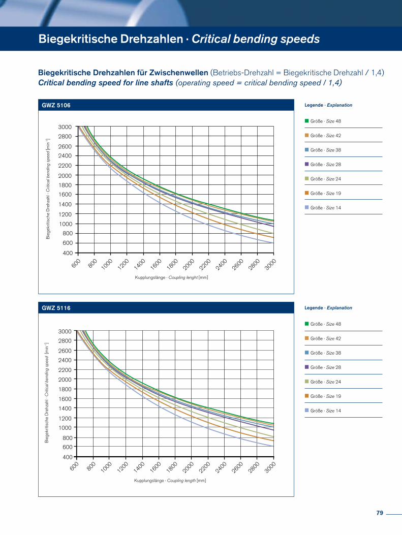
600800
10001200
14001600
18002000
22002400
26002800
3000
600
400
800
1000
1200
1400
1600
1800
2000
2200
2400
2600
2800
3000
Bie
gekr
itisc
he D
rehz
ahl ·
Crit
ical
ben
ding
spe
ed [m
in-1
]
Kupplungslänge · Coupling lenght [mm]
Größe · Size 500
Größe · Size 300
Größe · Size 200
Größe · Size 150
Größe · Size 60
Größe · Size 30
Größe · Size 18
600
200
400
600
800
1000
1200
1400
1600
1800
2000
2200
2400
2600
2800
3000
0
800 1000 1200 1400 1600 1800 2000
Kupplungslänge · Coupling length [mm]
Bie
gekr
itisc
he D
rehz
ahl ·
Crit
ical
ben
ding
spe
ed [
min
-1]
Größe · Size 14
Größe · Size 19
Größe · Size 24
Größe · Size 28
Größe · Size 38
Größe · Size 42
Größe · Size 48
600
200
400
600
800
1000
1200
1400
1600
1800
2000
2200
2400
2600
2800
3000
0
800 1000 1200 1400 1600 1800 2000
Kupplungslänge · Coupling length [mm]
Bie
gekr
itisc
he D
rehz
ahl ·
Crit
ical
ben
ding
spe
ed [
min
-1]
Größe · Size 14
Größe · Size 19
Größe · Size 24
Größe · Size 28
Größe · Size 38
Größe · Size 42
Größe · Size 48
Legende · Explanation
600800
10001200
14001600
18002000
22002400
26002800
3000
600
400
800
1000
1200
1400
1600
1800
2000
2200
2400
2600
2800
3000
Bie
gekr
itisc
he D
rehz
ahl ·
Crit
ical
ben
ding
spe
ed [
min
-1]
Kupplungslänge · Coupling length [mm]
Größe · Size 500
Größe · Size 300
Größe · Size 200
Größe · Size 150
Größe · Size 60
Größe · Size 30
Größe · Size 18
Legende · Explanation
GWZ 5106
GWZ 5116
Biegekritische Drehzahlen · Critical bending speeds
Biegekritische Drehzahlen für Zwischenwellen (Betriebs-Drehzahl = Biegekritische Drehzahl / 1,4)Critical bending speed for line shafts (operating speed = critical bending speed / 1,4)
79
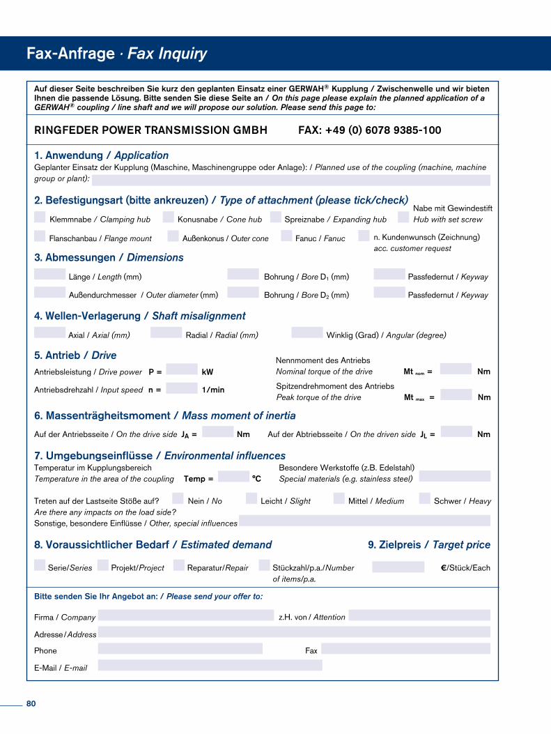
Auf dieser Seite beschreiben Sie kurz den geplanten Einsatz einer GERWAH® Kupplung / Zwischenwelle und wir bieten Ihnen die passende Lösung. Bitte senden Sie diese Seite an / On this page please explain the planned application of a GERWAH® coupling / line shaft and we will propose our solution. Please send this page to:
3. Abmessungen / Dimensions
Länge / Length (mm) Bohrung / Bore D1 (mm) Passfedernut / Keyway
4. Wellen-Verlagerung / Shaft misalignment
Axial / Axial (mm) Radial / Radial (mm) Winklig (Grad) / Angular (degree)
2. Befestigungsart (bitte ankreuzen) / Type of attachment (please tick/check)
Klemmnabe / Clamping hub Nabe mit Gewindestift Hub with set screwSpreiznabe / Expanding hub
Flanschanbau / Flange mount
Konusnabe / Cone hub
Bitte senden Sie Ihr Angebot an: / Please send your offer to:
8. Voraussichtlicher Bedarf / Estimated demand
Serie/Series Projekt/Project Reparatur/Repair Stückzahl/p.a./Number of items/p.a.
Nein / No Leicht / Slight Mittel / Medium Schwer / HeavyTreten auf der Lastseite Stöße auf? Are there any impacts on the load side?
Firma / Company
Adresse / Address
Phone
E-Mail / E-mail
Fax
z.H. von / Attention
7. Umgebungseinflüsse / Environmental influencesTemperatur im Kupplungsbereich Temperature in the area of the coupling
Besondere Werkstoffe (z.B. Edelstahl) Special materials (e.g. stainless steel)Temp = °C
9. Zielpreis / Target price
€/Stück/Each
6. Massenträgheitsmoment / Mass moment of inertia
Auf der Antriebsseite / On the drive side Auf der Abtriebsseite / On the driven side JA = Nm JL = Nm
1. Anwendung / ApplicationGeplanter Einsatz der Kupplung (Maschine, Maschinengruppe oder Anlage): / Planned use of the coupling (machine, machine group or plant):
Antriebsleistung / Drive power P = kW
Antriebsdrehzahl / Input speed n = 1/min
Nennmoment des AntriebsNominal torque of the drive Mt nom = Nm
Mt maxx =Spitzendrehmoment des AntriebsPeak torque of the drive Nm
5. Antrieb / Drive
Sonstige, besondere Einflüsse / Other, special influences
Außenkonus / Outer cone Fanuc / Fanuc n. Kundenwunsch (Zeichnung)acc. customer request
Außendurchmesser / Outer diameter (mm) Bohrung / Bore D2 (mm) Passfedernut / Keyway
RINGFEDER POWER TRANSMISSION GMBH FAX: +49 (0) 6078 9385-100
Fax-Anfrage · Fax Inquiry
80
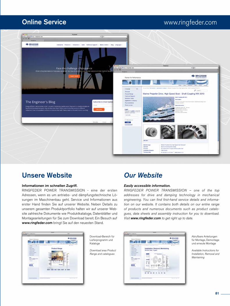
www.ringfeder.com
Unsere WebsiteInformationen im schnellen Zugriff. RINGFEDER POWER TRANSMISSION - eine der ersten Adressen, wenn es um antriebs- und dämpfungstechnische Lö-sungen im Maschinenbau geht. Service und Informationen aus erster Hand finden Sie auf unserer Website. Neben Details zu unserem gesamten Produktportfolio halten wir auf unserer Web-site zahlreiche Dokumente wie Produktkataloge, Datenblätter und Montageanleitungen für Sie zum Download bereit. Ein Besuch auf www.ringfeder.com bringt Sie auf den neuesten Stand.
Abrufbare Anleitungen für Montage, Demontage und erneute Montage
Available Instructions for Installation, Removal and Maintaining
Our WebsiteEasily accessible information. RINGFEDER POWER TRANSMISSION – one of the top addresses for drive and damping technology in mechanical engineering. You can find first-hand service details and informa-tion on our website. It contains both details on our entire range of products and numerous documents such as product catalo-gues, data sheets and assembly instruction for you to download. Visit www.ringfeder.com to get right up to date.
Download-Bereich für Lieferprogramm und Kataloge
Download area Product Range and catalogues
Online Service
81
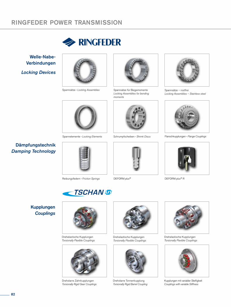
Welle-Nabe-Verbindungen
Locking Devices
Spannsätze · Locking Assemblies
Spannelemente · Locking Elements
DämpfungstechnikDamping Technology
Spannsätze – rostfreiLocking Assemblies – Stainless steel
Spannsätze für BiegemomenteLocking Assemblies for bending moments
Schrumpfscheiben · Shrink Discs
Reibungsfedern · Friction Springs DEFORM plus® RDEFORM plus®
Flanschkupplungen · Flange Couplings
RINGFEDER POWER TRANSMISSION
KupplungenCouplings
Drehelastische KupplungenTorsionally Flexible Couplings
Drehelastische KupplungenTorsionally Flexible Couplings
Drehelastische KupplungenTorsionally Flexible Couplings
Drehstarre Zahnkupplungen Torsionally Rigid Gear Couplings
Drehstarre Tonnenkupplung Torsionally Rigid Barrel Coupling
Kupplungen mit variabler Steifi gkeitCouplings with variable Stiffness
KupplungenCouplings
Elastomerkupplungen Servo-Insert Couplings
MetallbalgkupplungenMetal Bellows Couplings
Zwischenwellen · Line Shafts
Torsionssteife LamellenkupplungenTorsionally Rigid Disc Couplings
Partner for Performance
KupplungenCouplings
LagergehäuseBearing Housings
Flexible Kupplungen Henfl exFlexible Couplings Henfl ex
Lagergehäuse · Bearing Housings
Hydrodynamische Kupplungen mit varia-bler DrehzahlHydrodynamic Couplings with variable speed
Hydrodynamische Kupplungen Henfl uidHydrodynamic Couplings Henfl uid
Hinweis: HENFEL Produkte sind nur in Südamerika und in ausgewählten Märkten erhältlich.Remark: HENFEL products are only available in South America and selected markets.
82
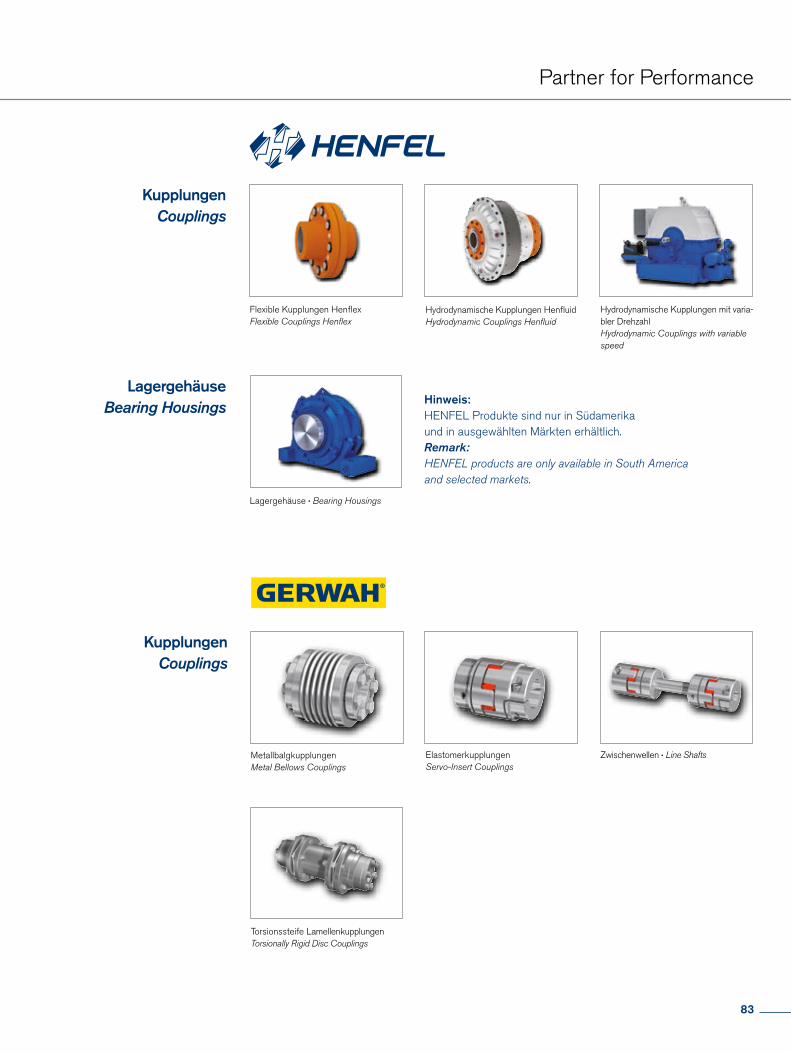
KupplungenCouplings
Elastomerkupplungen Servo-Insert Couplings
MetallbalgkupplungenMetal Bellows Couplings
Zwischenwellen · Line Shafts
Torsionssteife LamellenkupplungenTorsionally Rigid Disc Couplings
Partner for Performance
KupplungenCouplings
LagergehäuseBearing Housings
Flexible Kupplungen Henfl exFlexible Couplings Henfl ex
Lagergehäuse · Bearing Housings
Hydrodynamische Kupplungen mit varia-bler DrehzahlHydrodynamic Couplings with variable speed
Hydrodynamische Kupplungen Henfl uidHydrodynamic Couplings Henfl uid
Hinweis: HENFEL Produkte sind nur in Südamerika und in ausgewählten Märkten erhältlich.Remark: HENFEL products are only available in South America and selected markets.
83
Partner for Performancewww.ringfeder.com
RINGFEDER POWER TRANSMISSION GMBHWerner-Heisenberg-Straße 18, D-64823 Groß-Umstadt, Germany · Phone: +49 (0) 6078 9385-0 · Fax: +49 (0) 6078 9385-100 E-mail: [email protected]
RINGFEDER POWER TRANSMISSION TSCHAN GMBHZweibrücker Straße 104, D-66538 Neunkirchen, Germany · Phone: +49 (0) 6821 866-0 · Fax: +49 (0) 6821 866-4111 E-mail: [email protected]
RINGFEDER POWER TRANSMISSION USA CORPORATION165 Carver Avenue, Westwood, NJ 07675, USA · Toll Free: +1 888 746-4333 · Phone: +1 201 666 3320 · Fax: +1 201 664 6053 E-mail: [email protected]
HENFEL INDÚSTRIA METALÚRGICA LTDA.Av. Major Hilário Tavares Pinheiro, 3447 · Cer 14871 300 · Jaboticabal - SP - Brazil · Phone: +55 16 3209-3422 Fax: +55 16 3202-3563 · E-mail: [email protected]
RINGFEDER POWER TRANSMISSION INDIA PRIVATE LIMITEDPlot No. 4, Door No. 220, Mount - Poonamallee Road, Kattupakkam, Chennai – 600 056, IndiaPhone: +91 (0) 44-2679 1411 · Fax: +91 (0) 44-2679 1422 · E-mail: [email protected]
KUNSHAN RINGFEDER POWER TRANSMISSION COMPANY LIMITEDNo. 10 Dexin Road, Zhangpu Town 215321, Kunshan, ChinaPhone: +86 (0) 512-5745-3960 · Fax: +86 (0) 512-5745-3961 · E-mail: [email protected]