Embed Size (px)
Citation preview
Montage- und Bedienungsanleitung
Funk-Wandtaster 2fach:HM-PB-2-WM55
Installation and Operating Manual
Radio push button 2 channel:HM-PB-2-WM55
Seite 4-23
Page 24-41
2
1. Ausgabe Deutsch, 08/2011 Dokumentation © 2011 eQ-3 Ltd., Hong KongAlle Rechte vorbehalten. Ohne schriftliche Zustimmung des Herausgebers darf dieses Handbuch auch nicht auszugsweise in irgendeiner Form reproduziert werden oder unter Verwendung elektronischer, mechanischer oder chemischer Verfahren vervielfältigt oder verarbeitet werden.Es ist möglich, dass das vorliegende Handbuch noch drucktechnische Mängel oder Druckfehler aufweist. Die Angaben in diesem Handbuch werden jedoch regelmäßig überprüft und Korrekturen in der nächsten Ausgabe vorgenommen. Für Fehler technischer oder drucktechnischer Art und ihre Folgen übernehmen wir keine Haftung.Alle Warenzeichen und Schutzrechte werden aner-kannt.Printed in Hong KongÄnderungen im Sinne des technischen Fortschritts können ohne Vorankündigung vorgenommen werden.
099464 / V 1.0
3
Inhaltsverzeichnis
1. Hinweise zu dieser Anleitung . . . . . . . . . . . . . . 62. Gefahrenhinweise . . . . . . . . . . . . . . . . . . . . . . 63. Funktion . . . . . . . . . . . . . . . . . . . . . . . . . . . . . . 74. Allgemeine Systeminformation
zu HomeMatic . . . . . . . . . . . . . . . . . . . . . . . . . 95. Allgemeine Hinweise zum Funkbetrieb . . . . . . 96. Montage . . . . . . . . . . . . . . . . . . . . . . . . . . . . . 116.1. Lieferumfang . . . . . . . . . . . . . . . . . . . . . . . . . 116.2. Klebestreifen-Montage . . . . . . . . . . . . . . . . . . 126.3. Schraub-Montage. . . . . . . . . . . . . . . . . . . . . . 136.4. Montage in Mehrfachkombinationen . . . . . . . 147. Inbetriebnahme . . . . . . . . . . . . . . . . . . . . . . . 157.1. Batterien einlegen (wechseln) . . . . . . . . . . . . 157.2. Anlernen. . . . . . . . . . . . . . . . . . . . . . . . . . . . . 167.3. Geräte-LED - Blinkfolgen und
Sendeverhalten . . . . . . . . . . . . . . . . . . . . . . . 207.4. Zurücksetzen in den Auslieferungs-zustand. . 218. Wartung und Reinigung . . . . . . . . . . . . . . . . . 229. Technische Eigenschaften . . . . . . . . . . . . . . . 23
4
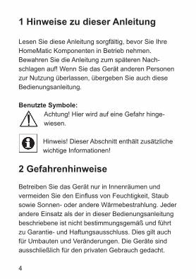
1 Hinweise zu dieser Anleitung
Lesen Sie diese Anleitung sorgfältig, bevor Sie Ihre HomeMatic Komponenten in Betrieb nehmen. Bewahren Sie die Anleitung zum späteren Nach-schlagen auf! Wenn Sie das Gerät anderen Personen zur Nutzung überlassen, übergeben Sie auch diese Bedienungsanleitung.
Benutzte Symbole:Achtung! Hier wird auf eine Gefahr hinge-wiesen.
Hinweis! Dieser Abschnitt enthält zusätzliche wichtige Informationen!
2 Gefahrenhinweise
Betreiben Sie das Gerät nur in Innenräumen und vermeiden Sie den Einfluss von Feuchtigkeit, Staub sowie Sonnen- oder andere Wärmebestrahlung. Jeder andere Einsatz als der in dieser Bedienungsanleitung beschriebene ist nicht bestimmungsgemäß und führt zu Garantie- und Haftungsausschluss. Dies gilt auch für Umbauten und Veränderungen. Die Geräte sind ausschließlich für den privaten Gebrauch gedacht.
5
Öffnen Sie das Gerät nicht, es enthält keine durch den Anwender zu wartenden Teile. Im Fehlerfall schicken Sie das Gerät an den Service.
3 Funktion
HomeMatic Wandtaster dienen der Ansteuerung von Empfängern, an die sie angelernt sind. Dabei können an eine Taste eine oder mehrere Komponenten ange-lernt werden, um diese dann gemeinsam anzuspre-chen. Damit lassen sich mehrere Aktionen mit einem einzigen Tastendruck ausführen.
Der HomeMatic Wandtaster ist batteriebetrieben und bietet deshalb eine hohe Flexibilität bei der Montage und Wahl des Montageortes. Installation und Demontage gestalten sich durch Schrauben oder Kleben auf unterschiedlichen Untergründen wie Mauerwerk, Möbeln, Fliesen oder Glas sehr einfach. Ein Stemmen oder Schlitzen von Mauerwerk ist nicht erforderlich. Die Wandmontage kann im mitgelieferten Rahmen erfolgen. Zusätzlich ist es auch möglich, den HomeMatic Wandtaster in bestehende Schalterserien zu integrieren (siehe Abschnitt 6.4).
6
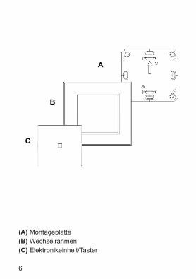
(A) Montageplatte(B) Wechselrahmen(C) Elektronikeinheit/Taster
C
A
B
7
4 Allgemeine Systeminformation zu HomeMatic
Dieses Gerät ist Teil des HomeMatic Haussteuer-systems und arbeitet mit dem bidirektionalen BidCoS® Funkprotokoll. Alle Geräte werden mit einer Standardkonfiguration ausgeliefert. Darüber hinaus ist die Funktion des Gerätes über ein Programmiergerät und Software konfigurierbar. Welcher weitergehende Funktionsum-fang sich damit ergibt, und welche Zusatzfunktionen sich im HomeMatic System im Zusammenspiel mit weiteren Komponenten ergeben, entnehmen Sie bitte der gesonderten Konfigurationsanleitung oder dem HomeMatic Systemhandbuch. Alle technischen Dokumente und Updates finden Sie stets aktuell unter www.homematic.com.
8
5 Allgemeine Hinweise zum Funkbetrieb
Die Funk-Übertragung wird auf einem nicht exklusiven Übertragungsweg realisiert, weshalb Störungen nicht ausgeschlossen
werden können. Weitere Störeinflüsse können u.a. durch Schaltvorgänge, Elektromotoren oder auch defekte Elektrogeräte hervorgerufen werden.
Die Reichweite in Gebäuden kann stark von der im Freifeld abweichen. Außer der Sendeleistung und den Empfangseigenschaften der Empfänger spielen Umwelteinflüsse wie Luftfeuchtigkeit neben baulichen Gegebenheiten vor Ort eine wichtige Rolle.
Hiermit erklärt die eQ-3 Entwicklung GmbH, dass sich dieses Gerät in Übereinstimmung mit den grund-legenden Anforderungen und den anderen relevanten Vorschriften der Richtlinie 1999/5/EG befindet.Die vollständige Konformitätserklärung finden Sie unter www.homematic.com.
9
6 Montage
6.1 Lieferumfang
Wandtaster zusammengebaut• Montageplatte• Wechselrahmen• Elektronikeinheit mit aufgesetzter Einfachwippe
(Taster)
Zubehör• Klebestreifen zur Wandmontage• 2 Stück Holzschrauben 3,0 x 30 mm• 2 Stück Dübel 5 mm• 2 LR03-Batterien (Micro/AAA/LR03)
Sie können den HomeMatic Wandtaster entweder an eine Wand schrauben oder kleben. Der Wandtaster lässt sich bequem in den mitgelieferten Rahmen oder in eine bestehende Schalterserie (Auflistung der kompatiblen Schalterserien siehe Abschnitt 6.4) integrieren.
10
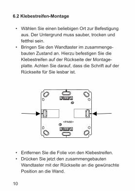
6.2 Klebestreifen-Montage
• Wählen Sie einen beliebigen Ort zur Befestigung aus. Der Untergrund muss sauber, trocken und fettfrei sein.
• Bringen Sie den Wandtaster im zusammenge-bauten Zustand an. Hierzu befestigen Sie die Klebestreifen auf der Rückseite der Montage-platte. Achten Sie darauf, dass die Schrift auf der Rückseite für Sie lesbar ist.
• Entfernen Sie die Folie von den Klebestreifen.• Drücken Sie jetzt den zusammengebauten
Wandtaster mit der Rückseite an die gewünschte Position an die Wand.
<PA66>
11
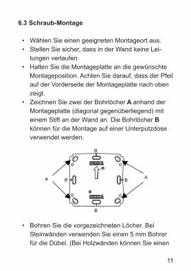
6.3 Schraub-Montage
• Wählen Sie einen geeigneten Montageort aus.• Stellen Sie sicher, dass in der Wand keine Lei-
tungen verlaufen. • Halten Sie die Montageplatte an die gewünschte
Montageposition. Achten Sie darauf, dass der Pfeil auf der Vorderseite der Montageplatte nach oben zeigt.
• Zeichnen Sie zwei der Bohrlöcher A anhand der Montageplatte (diagonal gegenüberliegend) mit einem Stift an der Wand an. Die Bohrlöcher B können für die Montage auf einer Unterputzdose verwendet werden.
• Bohren Sie die vorgezeichneten Löcher. Bei Steinwänden verwenden Sie einen 5 mm Bohrer für die Dübel. (Bei Holzwänden können Sie einen
B
B
B A
A
B
12
1,5 mm Bohrer verwenden, um das Eindrehen der Schrauben zu erleichtern.)
• Montieren Sie die Montageplatte durch Eindrehen der mitgelieferten Schrauben und Dübel.
• Bringen Sie nun den Wechselrahmen auf der Montageplatte an.
• Setzen Sie anschließend den Taster ein. Achten Sie darauf, dass die Pfeile auf der Rückseite nach oben zeigen und die Klammern der Montageplatte in die Öffnungen der Elektronikeinheit rasten.
6.4 Montage in Mehrfachkombinationen
Sie können den Wandtaster sowohl mit dem mit-gelieferten Rahmen, als auch mit Rahmen anderer Hersteller verwenden oder die Elektronikeinheit in einen Mehrfachrahmen integrieren. In beiden Fällen ist sowohl eine Klebestreifen-, als auch eine Schraub-Montage möglich. Bei der Montage in Mehrfachkombi-nationen ist darauf zu achten, dass die Montageplatte des Wandtasters bündig neben bereits befestigte Montageplatten/Tragringe angebracht und daran ausgerichtet wird.
13
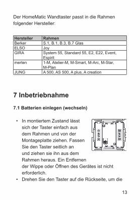
Der HomeMatic Wandtaster passt in die Rahmen folgender Hersteller:
7 Inbetriebnahme
7.1 Batterien einlegen (wechseln)
• In montiertem Zustand lässt sich der Taster einfach aus dem Rahmen und von der Montageplatte ziehen. Fassen Sie den Taster seitlich an und ziehen sie ihn aus dem Rahmen heraus. Ein Entfernen der Wippe oder Öffnen des Gerätes ist nicht erforderlich.
• Drehen Sie den Taster auf die Rückseite, um die
Hersteller RahmenBerker S.1, B.1, B.3, B.7 GlasELSO JoyGIRA System 55, Standard 55, E2, E22, Event,
Espiritmerten 1-M, Atelier-M, M-Smart, M-Arc, M-Star,
M-PlanJUNG A 500, AS 500, A plus, A creation
14
Batterien einzulegen bzw. sie zu entnehmen.• Nach Entnahme der Batterien sollten ca. 10
Sekunden gewartet werden.• Legen Sie 2 LR03 Batterien (Micro/AAA) polungs-
richtig gemäß Markierung in die Batteriefächer ein.• Setzen Sie den Taster wieder in den Rahmen.
Normale Batterien dürfen niemals aufgeladen werden. Batterien nicht ins Feuer werfen! Batterien nicht kurzschließen! Es besteht Explosionsgefahr!
Verbrauchte Batterien gehören nicht in den Hausmüll! Entsorgen Sie diese in Ihrer örtlichen Batteriesammelstelle!
7.2 Anlernen
Damit Funk-Komponenten miteinander kommunizieren können, müssen diese aneinander angelernt sein. Um HomeMatic Aktoren mit dem Wandtaster bedienen zu können, gehen Sie wie folgt vor:
Der Wandtaster unterstützt drei verschiedene Modi:
15
• Anlernmodus (Anlernen von HomeMatic Kompo-nenten)
• Konfigurationsmodus (zum Ändern von Parame-tern der Wandtaster)
• Bedienmodus (Normalfall)
Zum Anlernen müssen beide zu verknüpfenden Geräte in den Anlernmodus gebracht werden. Wie Sie den anzulernenden Aktor in den Anlernmodus versetzen, entnehmen Sie bitte der entsprechenden Bedienungs-anleitung des Gerätes.
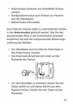
• Der Wandtaster wird mit Hilfe der Anlerntaste in den Anlernmodus versetzt.
• Die Anlerntaste A befindet sich direkt auf der Rückseite des Tasters.
• Um die Anlerntaste zu erreichen, fassen Sie den Taster seitlich an und ziehen Sie ihn aus dem Rahmen heraus. Drehen Sie den Taster auf die Rückseite.
A
16
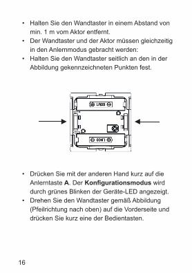
• Halten Sie den Wandtaster in einem Abstand von min. 1 m vom Aktor entfernt.
• Der Wandtaster und der Aktor müssen gleichzeitig in den Anlernmodus gebracht werden:
• Halten Sie den Wandtaster seitlich an den in der Abbildung gekennzeichneten Punkten fest.
• Drücken Sie mit der anderen Hand kurz auf die Anlerntaste A. Der Konfigurationsmodus wird durch grünes Blinken der Geräte-LED angezeigt.
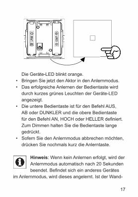
• Drehen Sie den Wandtaster gemäß Abbildung (Pfeilrichtung nach oben) auf die Vorderseite und drücken Sie kurz eine der Bedientasten.
17
Die Geräte-LED blinkt orange.
• Bringen Sie jetzt den Aktor in den Anlernmodus. • Das erfolgreiche Anlernen der Bedientaste wird
durch kurzes grünes Leuchten der Geräte-LED angezeigt.
• Die untere Bedientaste ist für den Befehl AUS, AB oder DUNKLER und die obere Bedientaste für den Befehl AN, HOCH oder HELLER definiert. Zum Dimmen halten Sie die Bedientaste lange gedrückt.
• Sofern Sie den Anlernmodus abbrechen möchten, drücken Sie nochmals kurz die Anlerntaste.
Hinweis: Wenn kein Anlernen erfolgt, wird der Anlernmodus automatisch nach 20 Sekunden beendet. Befindet sich ein anderes Gerätes
im Anlernmodus, wird dieses angelernt. Ist der Wand-
18
taster bereits an eine Zentrale angelernt und damit für direktes Anlernen gesperrt, kann er zwar wie oben beschrieben in den Konfigurationsmodus gebracht werden, nach Drücken einer Bedientaste leuchtet die Geräte-LED jedoch für 2 Sekunden rot auf. Es ist kein direktes Anlernen möglich!
Im Bedienmodus stehen nach dem Anlernen einfache Bedienfunktionen zur Verfügung. Die 2 Tasten auf der gemeinsamen Wippe können durch kurzen Tasten-druck nach oben ( ) bzw. nach unten ( ) gesteuert werden, wobei Tastendruck nach oben ( ) AN, HOCH oder HELLER und Tastendruck nach unten ( ) AUS, AB oder DUNKLER bedeutet. Schaltaktoren und Dimmer können dann AN/AUS geschaltet werden, bzw. langer Tastendruck führt zum Dimmen oder Jalousieaktoren fahren rauf bzw. runter.
7.3 Geräte-LED - Blinkfolgen und Sendeverhalten
Die Blinkfolge der Geräte-LED hat unterschiedliche Bedeutungen:
19
Blinkfolge BedeutungMind. 2s grüne Geräte-LED Anlernen erfolgreich2s rote Geräte-LED Anlernen fehlgeschlagenOranges Blinken Nur Wandtaster im AnlernmodusKurzes oranges Blinken und 2s rot oder grün (je nach Erfolg)
Anderes Gerät im Anlernmodus und Wandtaster in den Anlern-modus gebracht
Kurzes oranges/kurzes grünes Blinken
Signal wird gesendet/bestätigt
Wandtaster im Konfigurati-onsmodusund bei Tastenbetätigungrotes Aufleuchten
Wandtaster bereits anZentrale angelernt unddamit gegen direktes Anlernen gesperrt
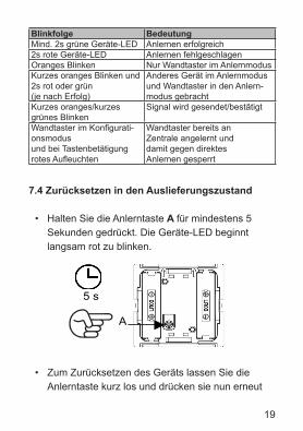
7.4 Zurücksetzen in den Auslieferungszustand
• Halten Sie die Anlerntaste A für mindestens 5 Sekunden gedrückt. Die Geräte-LED beginnt langsam rot zu blinken.
• Zum Zurücksetzen des Geräts lassen Sie die Anlerntaste kurz los und drücken sie nun erneut
A
5 s
20
für mindestens 5 Sekunden. • Die Geräte-LED beginnt nun während des Drü-
ckens schneller rot zu blinken. • Loslassen schließt den Rücksetzvorgang ab.
Zur Bestätigung des Zurücksetzens leuchtet die Geräte-LED für etwa 3 Sekunden dauerhaft rot auf.
• Sofern Sie das Zurücksetzen abbrechen möchten, können Sie dies mit einem kurzen erneuten Tastendruck auf die Anlerntaste tun oder Sie warten 15 Sekunden. In beiden Fällen stoppt das langsame rote Blinken.
Mögliche Fehlermeldungen:Beginnt die Geräte-LED nach 5 Sekunden Drücken nicht zu blinken, sondern leuchtet
dauerhaft auf, kann das Gerät nicht zurückgesetzt werden! In diesem Falle ist die Verschlüsselung mit einem vom Auslieferungsschlüssel verschiedenen System-Sicherheitsschlüssel aktiv. Um das Gerät zurückzusetzen, müssen Sie die Konfigurationssoft-ware der Zentrale zum Zurücksetzen benutzen! Der Vorgang ist in der Anleitung zur Zentralen-Software beschrieben. (Dieser Fehler kann nur auftreten, wenn Sie eine Zentrale besitzen und das Gerät an diese Zentrale angelernt haben.)
21
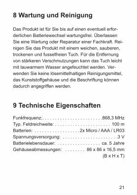
8 Wartung und Reinigung
Das Produkt ist für Sie bis auf einen eventuell erfor-derlichen Batteriewechsel wartungsfrei. Überlassen Sie eine Wartung oder Reparatur einer Fachkraft. Rei-nigen Sie das Produkt mit einem weichen, sauberen, trockenen und fusselfreien Tuch. Für die Entfernung von stärkeren Verschmutzungen kann das Tuch leicht mit lauwarmem Wasser angefeuchtet werden. Ver-wenden Sie keine lösemittelhaltigen Reinigungsmittel, das Kunststoffgehäuse und die Beschriftung können dadurch angegriffen werden.
9 Technische Eigenschaften
Funkfrequenz:. . . . . . . . . . . . . . . . . . . . . . . .868,3 MHzTyp. Feldreichweite: . . . . . . . . . . . . . . . . . . . . . . 100 mBatterien: . . . . . . . . . . . . . . . . . .2x Micro / AAA / LR03Spannungsversorgung: . . . . . . . . . . . . . . . . . . . . . .3 VBatterielebensdauer: . . . . . . . . . . . . . . . . . ca. 5 JahreGehäuseabmessungen: . . . . . . . . 86 x 86 x 16,5 mm . . . . . . . . . . . . . . . . . . . . . . . . . . . . . .(B x H x T)
22
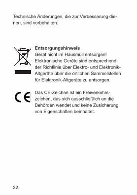
Technische Änderungen, die zur Verbesserung die-nen, sind vorbehalten.
EntsorgungshinweisGerät nicht im Hausmüll entsorgen! Elektronische Geräte sind entsprechend der Richtlinie über Elektro- und Elektronik-Altgeräte über die örtlichen Sammelstellen für Elektronik-Altgeräte zu entsorgen.
Das CE-Zeichen ist ein Freiverkehrs-zeichen, das sich ausschließlich an die Behörden wendet und keine Zusicherung von Eigenschaften beinhaltet.
23
Table of Contents
1. Information concerning these instructions . . . 262. Hazard information. . . . . . . . . . . . . . . . . . . . . 263. Function . . . . . . . . . . . . . . . . . . . . . . . . . . . . . 274. General system information on HomeMatic . . 295. General information on radio operation . . . . . 296. Installation . . . . . . . . . . . . . . . . . . . . . . . . . . . 306.1. Scope of delivery . . . . . . . . . . . . . . . . . . . . . . 306.2. Adhesive strip mounting. . . . . . . . . . . . . . . . . 316.3. Screw mounting . . . . . . . . . . . . . . . . . . . . . . . 326.4. Installation in multiple combinations. . . . . . . . 337. Start up. . . . . . . . . . . . . . . . . . . . . . . . . . . . . . 347.1. Inserting (changing) batteries. . . . . . . . . . . . . 347.2. Teaching. . . . . . . . . . . . . . . . . . . . . . . . . . . . . 357.3. LED flashing sequences and
transmission behaviour . . . . . . . . . . . . . . . . . 397.4. Resetting to factory status . . . . . . . . . . . . . . . 408. Maintenance and cleaning . . . . . . . . . . . . . . . 419. Technical specifications . . . . . . . . . . . . . . . . . 42
24
1. English edition 08/2011Documentation © 2011 eQ-3 Ltd., Hong KongAll rights reserved. No parts of this manual may be reproduced or processed in any form using electronic, mechanical or chemical processes in part or in full without the prior explicit written permission of the publisher.It is quite possible that this manual has printingerrors or defects. The details provided in this manual are checked regularly and corrections are done in the next edition. We do not assume any liability for techni-cal or printing errors.All registered trade marks and copyrights are acknowledged.Printed in Hong KongWe reserve the right to make changes due to technical advancements without prior notice. 099464 / V 1.0
25
1 Information concerning these instructions
Read these instructions carefully before beginningoperation with your HomeMatic components. Keepthe instructions handy for later consultation!Please hand-over the operating manual as wellwhen you hand-over the device to other personsfor use.
Symbols used:
Note! This indicates a hazard.
Note! This section contains additional impor-tant information!
2 Hazard information
This device is to be operated indoors only and keep away from the influences of humidity, dust and suns-hine or other radiating heat sources. Using the push button for any purpose other than that described in this operating manual does not fall within the scope of intended use and shall invalidate any warranty or liabi-
26
lity. This also applies to any conversion or modification work. This device is intended for private use only.
Do not open the device. It does not contain any parts to be maintained by the user. If an error occurs, please send back the device to the customer service.
3 Function
HomeMatic push buttons are used to control the recei-vers that they are taught to work with. A single button can be taught to work with one or more components and address them all simultaneously. That means that pressing a single button can execute many different tasks.
The HomeMatic push button is battery-operated. Therefore, the mounting location can flexibly be selected.
The HomeMatic push button is mounted and removed very easily using screws or adhesive strips. It is com-patible with a number of different surfaces including furniture, brick walls, tiles or glass. Walls do not have
27
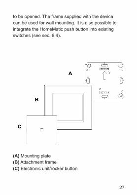
to be opened. The frame supplied with the device can be used for wall mounting. It is also possible to integrate the HomeMatic push button into existing switches (see sec. 6.4).
(A) Mounting plate(B) Attachment frame(C) Electronic unit/rocker button
C
A
B
28
4 General system information on HomeMatic
This device is a part of the HomeMatic home control system and works with the bidirectional BidCoS® wireless protocol.All devices are delivered in a standard configuration. The functionality of the device can also be configured with a programming device and software. The other resulting functionality and the additional functions that result in the HomeMatic system in cooperation with other components can be found in the separate configuration instructions or the HomeMatic System Manual.All current technical documents and updates are provi-ded under www.HomeMatic.com.
5 General information on radio operation
The radio transmission is on a non-exclusive trans-mission path which means that there is a possibility of interference occurring. Other interfering sources can be caused by switching operations, electrical motors or defective electrical devices.
29
The range of transmission within buildingscan greatly deviate from open air distances. Besides the transmitting power and the
reception characteristics of the receiver, environmental influences such as humidity in the vicinity and local structures also play an important role.
Hereby, eQ-3 Entwicklung GmbH declares that this device conforms with the essential requirements and other installation site as desired conforming with the relevant regulations of directive 1999/5/EG.The full declaration of conformity is provided underwww.HomeMatic.com.
6 Installation
6.1 Scope of delivery
Push button assembled:• Mounting plate• Attachment frame• Electronic unit with rocker button
Accessories:• Adhesive strips for wall mount• 2 wood screws 3.0 x 30 mm

30
• 2 wall anchors 5 mm• 2 LR03 batteries (micro/AAA/LR03)
You can either use screws or adhesive strips to mount the HomeMatic push button to a wall in the frame supplied or integrate it into an existing switch (see sec. 6.4 for suitable switches).
6.2 Adhesive strip mounting
• Choose a site for installation. The surface on which you are mounting the push button must be clean, dry and greaseless.
• For mounting of the assembled push button, attach the adhesive strips to the back side of the mounting plate. You should be able to read the letters on the back side (according to figure).
<PA66>
31
• Remove the protective film from the adhesive strip.• Press the assembled push button with the back
side to the wall in the position where it should subsequently be attached.
6.3 Screw mounting
• Choose a site for installation. • Make sure that electrical lines in the wall will not
be damaged.• Position the mounting plate on the desired site on
the wall. Make sure that the arrow on the mounting plate is pointing upwards.
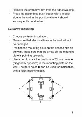
• Use a pen to mark the positions of 2 bore holes A (diagonally opposite) in the mounting plate on the wall. The bore holes B can be used for installation with a flush-mounting box.
B
B
B A
A
B
32
• If you are working with a stone wall, drill the mar-ked two 5 mm holes and insert the plugs supplied. If you are working with a wooden wall, you can pre-drill 1.5 mm holes to make screws easier to insert.
• Use the screws and plugs supplied to fasten the mounting plate to the wall.
• Next, hold the frame in front of the mounting plate.• Attach the push button. Make sure that the arrows
on the back side point upwards and that the clips on the mounting plate latch into the openings on the electronic unit.
6.4 Installation in multiple combinations
You can mount the push button with the attachment frame provided or use it with frames of other manuf-acturers as well as integrate the electronic unit into a multi-gang frame. In both cases, mounting with adhe-sive strips and screws is possible. For mounting with multiple combinations, make sure that the mounting plate of the push button is seamlessly aligned to the already fixed mounting plate/retaining ring. The HomeMatic push button is designed to fit into frames supplied by the following manufacturers:
33
7 Start up
7.1 Inserting (changing) batteries
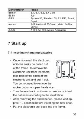
• Once mounted, the electronic unit can easily be pulled out of the frame. To remove the electronic unit from the frame, take hold of the sides of the electronic unit and pull it out. You do not need to remove the rocker button or open the device.
• Turn the electronic unit over to remove or insert the batteries according to the illustration.
• After removing the old batteries, please wait ap-prox. 10 seconds before inserting the new ones.
• Put the electronic unit back into the frame.
Manufacturer FrameBerker S.1, B.1, B.3, B.7 GlasELSO JoyGIRA System 55, Standard 55, E2, E22, Event,
Espiritmerten 1-M, Atelier-M, M-Smart, M-Arc, M-Star,
M-PlanJUNG A 500, AS 500, A plus, A creation
34
Never recharge standard batteries. Doing so will present a risk of explosion. Do not throw the batteries into a fire. Do not short-circuit batteries.
Used batteries should not be disposed of with regular domestic waste. Instead, take them to your local battery disposal point.
7.2 Teaching
To enable radio components to communicate, they need to be taught-in to one another. To control the HomeMatic actuators with the push button, proceed as follows:
The push button supports three different modes: • Teach mode (teaching HomeMatic components)• Configuration mode (for changing push button
parameters)• Operation mode (normal operation)
Teaching requires that both devices to be connected are put into teach mode. Please see the correspon-ding manual of the actuator for instructions how to put
35
the device into teach mode.
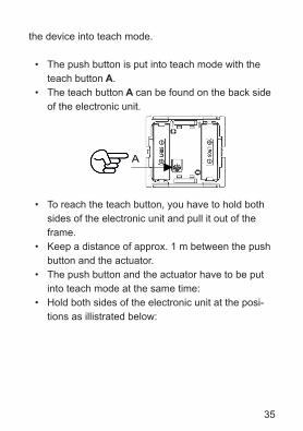
• The push button is put into teach mode with the teach button A.
• The teach button A can be found on the back side of the electronic unit.
• To reach the teach button, you have to hold both sides of the electronic unit and pull it out of the frame.
• Keep a distance of approx. 1 m between the push button and the actuator.
• The push button and the actuator have to be put into teach mode at the same time:
• Hold both sides of the electronic unit at the posi-tions as illistrated below:
A
36
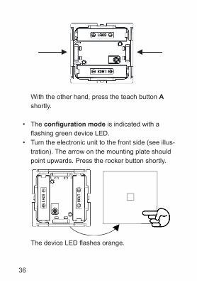
With the other hand, press the teach button A shortly.
• The configuration mode is indicated with a flashing green device LED.
• Turn the electronic unit to the front side (see illus-tration). The arrow on the mounting plate should point upwards. Press the rocker button shortly. The device LED flashes orange.
37
• Now, the actuator has to be put into teach mode.• If teaching of rocker buttons is successful, it is
indicated with an illuminated green LED. • The lower rocker button is defined for the
instructions OFF, DOWN or DARKER and the upper rocker button for the instructions ON, UP or BRIGHTER. Dimming occurs by holding the button pressed.
• If you want to exit configuration mode, press the teach button again.
Note: If no teaching occurs, teach mode is automatically ended after 20 seconds. If another device is in teach mode, this is taught.
If the push button is already taught for a center and therefore is blocked for direct training, it can still be put in configuration mode as described above, the device LED is illuminated in red for 2 seconds after pressing an operating button however. Direct teaching is not possible!
After teaching, in the operation mode simple ope-rating functions are available. The 2 buttons (on a common rocker) can be controlled by pressing ( ) up or down ( ) shortly. Pressing up ( ) triggers the functions ON, UP or BRIGHTER, pressing down
38
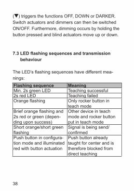
( ) triggers the functions OFF, DOWN or DARKER. Switch actuators and dimmers can then be switched ON/OFF. Furthermore, dimming occurs by holding the button pressed and blind actuators move up or down.
7.3 LED flashing sequences and transmission behaviour
The LED’s flashing sequences have different mea-nings:Flashing sequence MeaningMin. 2s green LED Teaching successful2s red LED Teaching failedOrange flashing Only rocker button in
teach modeBrief orange flashing and 2s red or green (depen-ding upon success)
Other device in teach mode and rocker button put in teach mode
Short orange/short green flashing
Signal is being send/confirmed
Push button in configura-tion mode and illuminated red with button actuation
Push button already taught for center and is therefore blocked from direct teaching
39
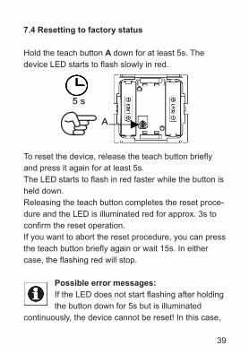
7.4 Resetting to factory status
Hold the teach button A down for at least 5s. The device LED starts to flash slowly in red.
To reset the device, release the teach button briefly and press it again for at least 5s. The LED starts to flash in red faster while the button is held down.Releasing the teach button completes the reset proce-dure and the LED is illuminated red for approx. 3s to confirm the reset operation.If you want to abort the reset procedure, you can press the teach button briefly again or wait 15s. In either case, the flashing red will stop.
Possible error messages:If the LED does not start flashing after holding the button down for 5s but is illuminated
continuously, the device cannot be reset! In this case,
A
5 s
40
the encoding is active using a system security key that differs from the key delivered with the system. In order to reset the device, you must use the configuration software of the center for resetting! The procedure is described in the center software instructions. (This error can occur only if you have a center and have taught the device for this center.)
8 Maintenance and cleaning
This product is maintenance-free besides possibly requiring a battery change. Maintenance or repairs are only to be done by trained professionals. Clean the products using a soft, clean, dry and lint-free cloth. To remove heavier contamination, make cloth damp with lukewarm water. Cleaning agents that contain solvents are not to be used because they can harm the plastic housing and the labels.
41
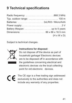
9 Technical specifications
Radio frequency: . . . . . . . . . . . . . . . . . . . . .868.3 MHzTyp. outdoor range: . . . . . . . . . . . . . . . . . . . . . . 100 mBatteries: . . . . . . . . . . . . . . . . . . . 2xLR03 / Micro/AAAPower supply: . . . . . . . . . . . . . . . . . . . . . . . . . . . . . .3 VBattery lifespan: . . . . . . . . . . . . . . . . . . . . up to 5 yearsDimensions: . . . . . . . . . . . . . . . . . . 86 x 86 x 16.5 mm . . . . . . . . . . . . . . . . . . . . . . . . . . . . . (H x W x D)
Subject to technical changes.
Instructions for disposal:Do not dispose off the device as part of household garbage! Electronic devices are to be disposed off in accordance with the guidelines concerning electrical and electronic devices via the local collecting point for old electronic devices.
The CE sign is a free trading sign addressed exclusively to the authorities and does not include any warranty of any properties.
42
eQ-3 AG Maiburger Straße 29 D-26789 Leerwww.eQ-3.com