Embed Size (px)
Citation preview
A
B
C
E
D
F
M
L
K
xS
RT
G
H
K
G
HN
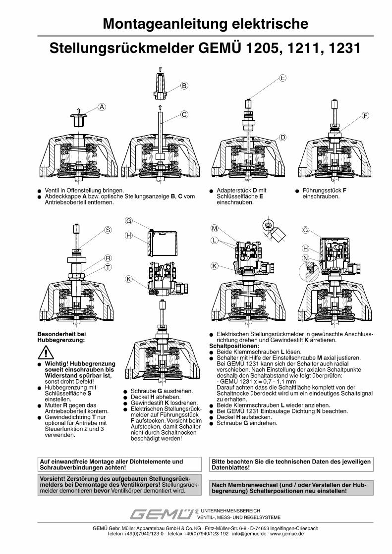
Montageanleitung elektrische
� Ventil in Offenstellung bringen. � Abdeckkappe A bzw. optische Stellungsanzeige B, C vom
Antriebsoberteil entfernen.
� Elektrischen Stellungsrückmelder in gewünschte Anschluss-richtung drehen und Gewindestift K arretieren.
Schaltpositionen: � Beide Klemmschrauben L lösen. � Schalter mit Hilfe der Einstellschraube M axial justieren.
Bei GEMÜ 1231 kann sich der Schalter auch radial verschieben. Nach Einstellung der axialen Schaltpunkte deshalb den Schaltabstand wie folgt überprüfen:- GEMÜ 1231 x = 0,7 - 1,1 mmDarauf achten dass die Schaltfläche komplett von der Schaltnocke überdeckt wird um ein eindeutiges Schaltsignal zu erhalten.
� Beide Klemmschrauben L wieder anziehen. � Bei GEMÜ 1231 Einbaulage Dichtung N beachten. � Deckel H aufstecken. � Schraube G eindrehen.
� Adapterstück D mit Schlüsselfläche E einschrauben.
� Führungsstück F einschrauben.
Besonderheit bei Hubbegrenzung:
� Wichtig! Hubbegrenzung soweit einschrauben bis Widerstand spürbar ist, sonst droht Defekt!
� Hubbegrenzung mit Schlüsselfläche S einstellen.
� Mutter R gegen das Antriebsoberteil kontern.
� Gewindedichtring T nur optional für Antriebe mit Steuerfunktion 2 und 3 verwenden.
� Schraube G ausdrehen. � Deckel H abheben. � Gewindestift K losdrehen. � Elektrischen Stellungsrück-
melder auf Führungsstück F aufstecken. Vorsicht beim Aufstecken, damit Schalter nicht durch Schaltnocken beschädigt werden!
Bitte beachten Sie die technischen Daten des jeweiligen Datenblattes!
Nach Membranwechsel (und / oder Verstellen der Hub-begrenzung) Schalterpositionen neu einstellen!
GEMÜ Gebr. Müller Apparatebau GmbH & Co. KG · Fritz-Müller-Str. 6-8 · D-74653 Ingelfi ngen-CriesbachTelefon +49(0)7940/123-0 · Telefax +49(0)7940/123-192 · [email protected] · www.gemue.de
UNTERNEHMENSBEREICHVENTIL-, MESS- UND REGELSYSTEME
Vorsicht! Zerstörung des aufgebauten Stellungsrück-melders bei Demontage des Ventilkörpers! Stellungsrück-melder demontieren bevor Ventilkörper demontiert wird.
Stellungsrückmelder GEMÜ 1205, 1211, 1231
Auf einwandfreie Montage aller Dichtelemente und Schraubverbindungen achten!
EG-Herstellererklärung gemäß Richtlinie 94/9/EG
Wir, die Firma GEMÜ Gebr. Müller GmbH & Co. KG Fritz-Müller-Straße 6-8 D-74653 Ingelfi ngen
erklären, dass unten aufgeführte Komponenten die Anforderungen der Richtlinie 94/9/EG bestimmungsgemäßen Verwendung in explosionsgefährdeten Bereichen erfüllen.
Benennung der Komponenten - Typenbezeichnung:
Anbausatz für Stellungsrückmelder GEMÜ 1205Kennzeichnung: 1205S01Z...AT
Anbausatz für Stellungsrückmelder GEMÜ 1211Kennzeichnung: 1211S01Z...AT
Anbausatz für Stellungsrückmelder GEMÜ 1231Kennzeichnung: 1231S01Z...AT
Gesamt: keine ZündgefahrErläuterungen: Zündgefahrbewertung in Baumusterprüfung der Stellungsrückmelder enthalten; nur mit Original GEMÜ-Produkten einsetzbar
Die grundlegenden Sicherheits- und Gesundheitsanforderungen werden erfüllt durch Übereinstimmung mit einer oder mehreren der nachfolgend genannten Normen in deren Zuständigkeit die oben genannten Produkte fallen:EN 1127-1:2007 EN 13463-1:2009 EN 13463-5:2003Dokumentation hinterlegt unter 211/06 bzw. IB-09-4-004 bei IBExU, Institut für Sicherheits-technik GmbH.
Ingelfi ngen, 24.02.2011
Leo ReilandQualitätssicherung
UNTERNEHMENSBEREICHVENTIL-, MESS- UND REGELSYSTEME
GEMÜ Gebr. Müller Apparatebau GmbH & Co. KGPostfach 30 Telefon: 0 79 40 / 123-0 Kommanditgesellschaft Komplementärin GEMÜ Gebr. Müller GmbH74665 Ingelfingen Telefax: 0 79 40 / 123-192 Sitz 74653 Ingelfingen Sitz 74653 IngelfingenFritz-Müller-Straße 6-8 e-mail: [email protected] Registergericht: Registergericht Schwäbisch Hall HRB 215 K74653 Ingelfingen http://www.gemue.de Schwäbisch Hall HRA 394 K Geschäftsführer: Fritz Müller, Stephan Müller
A
B
C
E
D
F
M
L
K
xS
RT
G
H
K
G
HN
Assembly instruction for electrical position
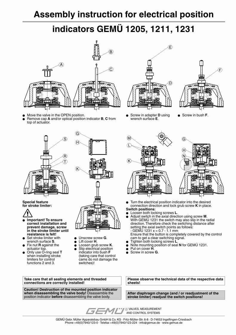
� Move the valve in the OPEN position. � Remove cap A and/or optical position indicator B, C from
top of actuator.
� Turn the electrical position indicator into the desired connection direction and lock grub screw K in place.
Switch positions: � Loosen both locking screws L. � Adjust switch in the axial direction using screw M.
With GEMÜ 1231 the switch may also slip in the radial direction. Therefore check the switching distance after setting the axial switch points as follows:- GEMÜ 1231 x = 0.7 - 1.1 mmEnsure that the button is completely covered by the control cam to get a clear switching signal.
� Tighten both locking screws L. � Note mounting position of seal N for GEMÜ 1231. � Put on cover H. � Screw in screw G.
� Screw in adapter D using wrench surface E.
� Screw in bush F.
Special feature for stroke limiter:
� Important! To ensure correct installation and prevent damage, screw in the stroke limiter until resistance is felt!
� Set stroke limiter with wrench surface S.
� Fix nut R against the actuator top.
� Only use O-ring seal T when installing stroke limiters for control functions 2 and 3.
� Unscrew screw G. � Lift cover H. � Loosen grub screw K. � Slip electrical position
indicator into bush F (taking care that control cams do not damage the switches)!
GEMÜ Gebr. Müller Apparatebau GmbH & Co. KG · Fritz-Müller-Str. 6-8 · D-74653 Ingelfi ngen-CriesbachPhone +49(0)7940/123-0 · Telefax +49(0)7940/123-224 · [email protected] · www.gemue.de
VALVES, MEASUREMENTAND CONTROL SYSTEMS
Please observe the technical data of the respective data sheets!
After diaphragm change (and / or readjustment of the stroke limiter) readjust the switch positions!
Caution! Destruction of the mounted position indicator when disassembling the valve body! Disassemble the position indicator before disassembling the valve body.
indicators GEMÜ 1205, 1211, 1231
Take care that all sealing elements and threaded connections are correctly installed!
EC Manufacturer’s declaration according to Directive 94/9/EC
Hereby we, GEMÜ Gebr. Müller GmbH & Co. KG Fritz-Müller-Straße 6-8 D-74653 Ingelfi ngen
declare that the components listed below comply with the requirements of directive 94/9/EC for intended use in potentially explosive areas.
Description of the components - product type:
Mounting kit for electrical position indicator GEMÜ 1205Identifi cation: 1205S01Z...AT
Mounting kit for electrical position indicator GEMÜ 1211Identifi cation: 1211S01Z...AT
Mounting kit for electrical position indicator GEMÜ 1231Identifi cation: 1231S01Z...AT
Total: No ignition hazardExplanations: Ignition hazard assessment is included in type examination of the electrical position indicators; only suitable for use with original GEMÜ products
The Essential Safety and Health Requirements are met by compliance with one or several of the standards listed below that are applicable for the above mentioned products:EN 1127-1:2007 EN 13463-1:2009 EN 13463-5:2003Documentation stored under 211/06 or IB-09-4-004 with IBExU, Institut für Sicherheitstechnik GmbH.
Ingelfi ngen, 24 February 2011
Leo ReilandQuality Assurance
VALVES, MEASUREMENT AND CONTROL SYSTEMS
GEMÜ Gebr. Müller Apparatebau GmbH & Co. KGPostfach 30 Telefon: 0 79 40 / 123-0 Kommanditgesellschaft Komplementärin GEMÜ Gebr. Müller GmbH74665 Ingelfingen Telefax: 0 79 40 / 123-192 Sitz 74653 Ingelfingen Sitz 74653 IngelfingenFritz-Müller-Straße 6-8 e-mail: [email protected] Registergericht: Registergericht Schwäbisch Hall HRB 215 K74653 Ingelfingen http://www.gemue.de Schwäbisch Hall HRA 394 K Geschäftsführer: Fritz Müller, Stephan Müller
A
B
C
E
D
F
M
L
K
xS
RT
G
H
K
G
HN
Notice de montage des indicateurs électriques
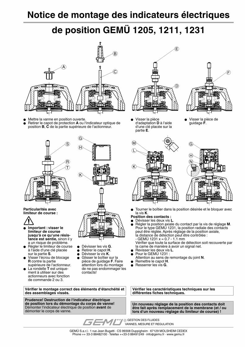
� Mettre la vanne en position ouverte. � Retirer le capot de protection A ou l‘indicateur optique de
position B, C de la partie supérieure de l‘actionneur.
� Tourner le boîtier dans la position désirée et le bloquer avec la vis K.
Position des contacts : � Dévisser les deux vis L. � Régler la position axiale du contact par la vis de réglage M.
Pour le type GEMÜ 1231, la position radiale des contacts peut être réglée. Après réglage de la position axiale, la distance de détection peut être contrôlée :- GEMÜ 1231 x = 0.7 - 1.1 mmVérifier que toute la surface de détection soit recouverte par la came de manière à avoir un signal net.
� Revisser les deux vis L. � Pour le GEMÜ 1231 :
Attention au sens de remontage du joint N. � Remettre le capot H. � Resserrer les vis G.
� Visser la pièce d‘adaptation D à l‘aide d‘une clé placée sur la partie E.
� Visser la pièce de guidage F.
Particularités avec limiteur de course :
� Important : visser le limiteur de course jusqu‘à ce qu‘une résis-tance est sentie, sinon il y a un risque de problème.
� Régler le limiteur de course à l‘aide d‘une clé placée sur la partie S.
� Visser l‘écrou de blocage R contre la partie supérieure de l‘actionneur.
� La rondelle T est unique-ment à utiliser sur des actionneurs avec fonction de commande 2 ou 3.
� Dévisser les vis G. � Retirer le capot H. � Dévisser la vis K. � Glisser le boîtier sur la
pièce de guidage F. Faire attention lors du montage de ne pas endommager les contacts!
Un nouveau réglage de la position des contacts doit être fait après remplacement de la membrane (et / ou lors d‘un nouveau réglage du limiteur de course) !
GEMÜ S.a.r.l.· 1 rue Jean Bugatti · CS 99308 Duppigheim · 67129 MOLSHEIM CEDEXPhone ++ 33-3 88482100 · Telefax ++33-3 88491249 · [email protected] · www.gemu.fr
GESTION DES FLUIDESVANNES, MESURE ET REGULATION
Vérifi er les caractéristiques techniques sur les diff érentes fi ches techniques.
Prudence! Destruction de l‘indicateur électrique de position lors du démontage du corps de vanne! Démonter l‘indicateur électrique de position avant de démonter le corps de vanne.
de position GEMÜ 1205, 1211, 1231
Vérifi er le montage correct des éléments d‘étanchéité et des assemblages vissés.
Déclaration du fabricant CE suivant la directive 94/9/CE
Nous, la société GEMÜ Gebr. Müller GmbH & Co. KG Fritz-Müller-Straße 6-8 D-74653 Ingelfi ngen
déclarons que les composants détaillés ci-dessous remplissent les exigences de la directive 94/9/CE pour une utilisation conforme en atmosphères explosibles.
Désignation des composants - types :
Kit d‘adaptation pour indicateur électrique de position GEMÜ 1205Marquage : 1205S01Z...AT
Kit d‘adaptation pour indicateur électrique de position GEMÜ 1211Marquage : 1211S01Z...AT Kit d‘adaptation pour indicateur électrique de position GEMÜ 1231Marquage : 1231S01Z...AT
Ensemble : pas de danger d‘infl ammationExplications : Évaluation du danger d‘infl ammation contenue dans l‘examen de type de l‘indicateur électrique de position ; utilisable uniquement avec les produits d‘origine GEMÜ.
Les exigences essentielles de sécurité et de santé sont remplies par la correspondance avec une ou plusieurs des normes suivantes auxquelles les produits mentionnés ci-dessus sont soumis :EN 1127-1:2007 EN 13463-1:2009 EN 13463-5:2003Documentation déposée sous 211/06 ou IB-09-4-004 chez IBExU, Institut für Sicherheits-technik GmbH.
Ingelfi ngen, 24/02/2011
Leo ReilandAssurance qualité
GESTION DES FLUIDESVANNES, MESURE ET REGULATION
GEMÜ Gebr. Müller Apparatebau GmbH & Co. KGPostfach 30 Telefon: 0 79 40 / 123-0 Kommanditgesellschaft Komplementärin GEMÜ Gebr. Müller GmbH74665 Ingelfingen Telefax: 0 79 40 / 123-192 Sitz 74653 Ingelfingen Sitz 74653 IngelfingenFritz-Müller-Straße 6-8 e-mail: [email protected] Registergericht: Registergericht Schwäbisch Hall HRB 215 K74653 Ingelfingen http://www.gemue.de Schwäbisch Hall HRA 394 K Geschäftsführer: Fritz Müller, Stephan Müller
A
B
C
E
D
F
M
L
K
xS
RT
G
H
K
G
HN
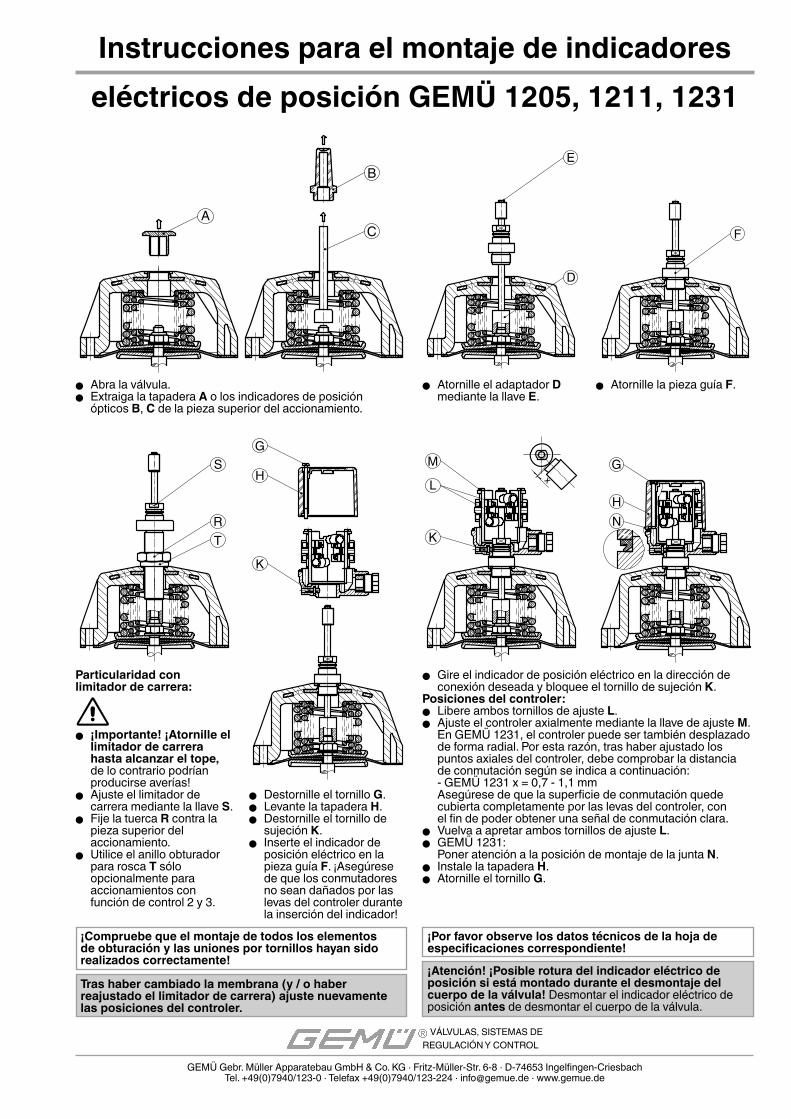
� Abra la válvula. � Extraiga la tapadera A o los indicadores de posición
ópticos B, C de la pieza superior del accionamiento.
� Gire el indicador de posición eléctrico en la dirección de conexión deseada y bloquee el tornillo de sujeción K.
Posiciones del controler: � Libere ambos tornillos de ajuste L. � Ajuste el controler axialmente mediante la llave de ajuste M.
En GEMÜ 1231, el controler puede ser también desplazado de forma radial. Por esta razón, tras haber ajustado los puntos axiales del controler, debe comprobar la distancia de conmutación según se indica a continuación:- GEMÜ 1231 x = 0,7 - 1,1 mmAsegúrese de que la superficie de conmutación quede cubierta completamente por las levas del controler, con el fin de poder obtener una señal de conmutación clara.
� Vuelva a apretar ambos tornillos de ajuste L. � GEMÜ 1231:
Poner atención a la posición de montaje de la junta N. � Instale la tapadera H. � Atornille el tornillo G.
� Atornille el adaptador D mediante la llave E.
� Atornille la pieza guía F.
Particularidad con limitador de carrera:
� ¡Importante! ¡Atornille el limitador de carrera hasta alcanzar el tope, de lo contrario podrían producirse averías!
� Ajuste el limitador de carrera mediante la llave S.
� Fije la tuerca R contra la pieza superior del accionamiento.
� Utilice el anillo obturador para rosca T sólo opcionalmente para accionamientos con función de control 2 y 3.
� Destornille el tornillo G. � Levante la tapadera H. � Destornille el tornillo de
sujeción K. � Inserte el indicador de
posición eléctrico en la pieza guía F. ¡Asegúrese de que los conmutadores no sean dañados por las levas del controler durante la inserción del indicador!
Instrucciones para el montaje de indicadores
Tras haber cambiado la membrana (y / o haber reajustado el limitador de carrera) ajuste nuevamente las posiciones del controler.
GEMÜ Gebr. Müller Apparatebau GmbH & Co. KG · Fritz-Müller-Str. 6-8 · D-74653 Ingelfi ngen-CriesbachTel. +49(0)7940/123-0 · Telefax +49(0)7940/123-224 · [email protected] · www.gemue.de
VÁLVULAS, SISTEMAS DEREGULACIÓN Y CONTROL
¡Por favor observe los datos técnicos de la hoja de especifi caciones correspondiente!
¡Atención! ¡Posible rotura del indicador eléctrico de posición si está montado durante el desmontaje del cuerpo de la válvula! Desmontar el indicador eléctrico de posición antes de desmontar el cuerpo de la válvula.
eléctricos de posición GEMÜ 1205, 1211, 1231
¡Compruebe que el montaje de todos los elementos de obturación y las uniones por tornillos hayan sido realizados correctamente!
Ände
rung
en v
orbe
halte
n · S
ubje
ct to
alte
ratio
n · S
ujet
à m
odifi c
atio
n · R
eser
vado
el d
erec
ho a
mod
ifi cac
ione
s · 0
4/20
11 ·
8836
6412
Declaración del fabricante CE conforme a la directiva 94/9/CE
Nosotros, la empresa GEMÜ Gebr. Müller GmbH & Co. KG Fritz-Müller-Straße 6-8 D-74653 Ingelfi ngen
declaramos que los componentes que se detallan a continuación cumplen los requisitos contemplados en la directiva 94/9/CE sobre la utilización conforme al uso previsto en atmósferas potencialmente explosivas.
Denominación de los componentes, designación del tipo:
Kit de montaje para indicador eléctrico de posición GEMÜ 1205Marcado: 1205S01Z...AT
Kit de montaje para indicador eléctrico de posición GEMÜ 1211Marcado: 1211S01Z...AT
Kit de montaje para indicador eléctrico de posición GEMÜ 1231Marcado: 1231S01Z...AT
Totalidad: sin peligro de propagación de llamasNotas explicativas: La evaluación de peligro de propagación de llamas se incluye en el examen de tipo del indicador eléctrico de posición; sólo se puede utilizar en combinación con productos originales de GEMÜ
Se cumplen los requisitos fundamentales en materia de seguridad y sanitaria al ser deconformidad con una o varias de las siguientes normas en cuya competencia recaen losproductos anteriormente mencionados:EN 1127-1:2007 EN 13463-1:2009 EN 13463-5:2003La documentación ha sido aportada con referencia 211/06 y/o IB-09-4-004 al instituto IBExU, Institut für Sicherheitstechnik GmbH.
En Ingelfi ngen, a 24/02/2011
Leo ReilandControl de Calidad
VÁLVULAS, SISTEMAS DEREGULACIÓN Y CONTROL
GEMÜ Gebr. Müller Apparatebau GmbH & Co. KGPostfach 30 Telefon: 0 79 40 / 123-0 Kommanditgesellschaft Komplementärin GEMÜ Gebr. Müller GmbH74665 Ingelfingen Telefax: 0 79 40 / 123-192 Sitz 74653 Ingelfingen Sitz 74653 IngelfingenFritz-Müller-Straße 6-8 e-mail: [email protected] Registergericht: Registergericht Schwäbisch Hall HRB 215 K74653 Ingelfingen http://www.gemue.de Schwäbisch Hall HRA 394 K Geschäftsführer: Fritz Müller, Stephan Müller