Embed Size (px)
Citation preview
Montageanleitung / Installation instructions Loewe WM 54
Seite 2 - Connect 37/ 42
Connect 32
Seite 10 - Individual 32 / 40
1
/
240 - 33519 000 11 - 2007
Montageanleitung
Wandhalter WM54 , Connect 37/ 42
Wandhalter WM56 , Connect 32
Sicherheitshinweise
Die Montage sollte nur von Fachpersonal vorgenommen
werden.
Loewe übernimmt keine Haftung für Schäden, die bei nicht
fachgerechter Montage entstehen.
Montieren Sie Ihr Gerät so, dass es z.B. von spielenden
Kindern nicht beschädigt werden kann und für diese keine
Gefahr darstellt.
Verlegen Sie die Anschlußleitungen so, dass diese keine
Stolpergefahren darstellen.
Wandhalter (und geeignet Adapter), sind nur für die Montage
an senkrechten Wänden ausgelegt. Sie dürfen nur hierfür
verwendet werden.
Greifen Sie, oder weitere Personen, nicht in den Bereich der
le (Halteschienen) am an der Wand montierten
TV-Gerät. Es besteht dort Quetschgefahr.
Des weiteren haben die Sicherheitshinweise für unsere TV-
Geräte auch hier Gültigkeit.
Montage
Die Tragfähigkeit der Wand und die Befestigung des
Wandhalters liegen in Ihrer Verantwortung.
unterschiedlichen Befestigungsarten haben wir kein
Befestigungsmaterial beigelegt.
Besorgen Sie sich das für Ihre Wand geeignete
Befestigungsmaterial im Fachhandel.
Ziehen Sie gegebenenfalls einen Bausachkundigen zu Rate.
Vergewissern Sie sich, dass im Bereich der Bohrungen keine
Leitungen / Rohre liegen.
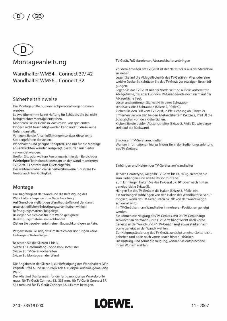
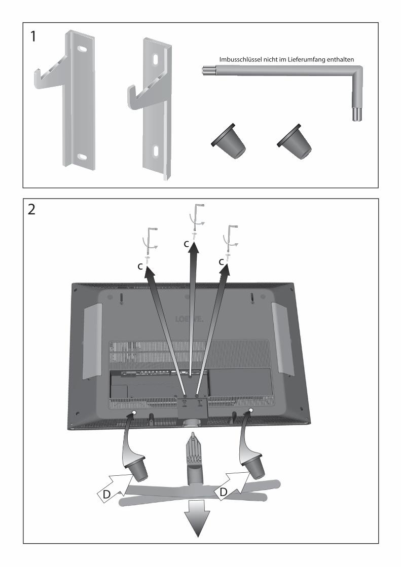
Beachten Sie die Skizzen 1 bis 3.
Skizze 1 : Lieferumfang - ohne Imbusschlüssel
Skizze 2 : TV-Gerät vorbereiten
Skizze 3 : Montage an der Wand
Die Angaben in der Skizze 3, zur Befestigung des Wandhalters (Win-
l Pfeil A und B), stützen sich als Beispiel auf eine gemauerte
Wand.
le
muss für TV-Gerät Connect 32, 333 mm, für TV-Gerät Connect 37,
533 mm und für TV-Gerät Connect 42, 543 mm betragen.
TV-Gerät, Fuß abnehmen, Abstandshalter anbringen
Vor dem Arbeiten am TV-Gerät ist der Netzstecker aus der Steckdose
zu ziehen.
äche für das TV-Gerät ein Vlies oder eine
weiche Decke. So schützen Sie das TV-Gerät vor etwaigen Beschädi-
gungen.
Legen Sie das TV-Gerät mit der Vorderseite so auf die vorbereitete
äche, dass der Fuß vom TV-Gerät gerade noch nicht auf der
äche liegt.
Lösen und entfernen Sie, mit Hilfe eines Schrauben-
schlüssels, die 3 Schrauben (Skizze 2, Pfeile C).
Ziehen Sie den Fuß vom TV-Gerät, in Pfeilrichtung ab (Skizze 2).
Entfernen Sie von den beiden Abstandshaltern (Skizze 2, Pfeil D) die
ächen.
Kleben Sie die beiden Abstandshalter (Skizze 2, Pfeile D), wie darge-
stellt auf die Rückwand.
Stecker am TV-Gerät anschließen
nden Sie in der Bedienungsanleitung
des TV-Gerätes.
Einhängen und Neigen des TV-Gerätes am Wandhalter
Je nach Gerätetype, wiegt Ihr TV-Gerät bis ca. 30 kg. Nehmen Sie
zum Einhängen eine zweite Person zur Hilfe.
Zum Einhängen halten Sie das TV-Gerät ca. 30° oben nach hinten
geneigt (siehe Skizze 3).
Hängen Sie das TV-Gerät in die Haken (Skizze 3, Pfeile) ein.
Ein Aushängen (Abhängen von den Haken des Wandhalters) ist nur
möglich, wenn das TV-Gerät unten ca. 30° von der Wand wegge-
schwenkt wird.
Ihr TV-Gerät kann am Wandhalter in mehreren Positionen geneigt
werden.
Sie können die Neigung des TV-Gerätes, mit 0° (TV-Gerät hängt
senkrecht an der Wand), 2,0° (TV-Gerät hängt leicht nach vorne
geneigt an der Wand) und 4° (TV-Gerät hängt etwas stärker nach
vorne geneigt an der Wand), wählen.
Zur Neigungsänderung das TV-Gerät, zunächst an einer Seite, leicht
anheben und oben nach vorne (nach hinten) drücken.
Die Rastung, und somit die Neigung, können Sie entsprechend
Ihrem Wunsch wählen.
1
D D
c
cc
2
Imbusschlüssel nicht im Lieferumfang enthalten
120 mm A
Bxx
x m
m
6 mm
x 6
0 mm
10 m
m x
60
mm
6,6 mm x 12mm x 1,6mm
Bxx
x m
m
xyx
mm
297 m
m (C
onnect
32)
497 m
m (C
onnect
37)
507 m
m (C
onnect
42)
333 m
m (C
onnect
32)
533 m
m (C
onnect
37)
543 m
m (C
onnect
42)
Ober
kante
TV
-Ger
ät
Bove
nka
nt
van
het
tv-
toes
tel
Top e
dge
Tv s
et
Prolo
ngac
ión
línea
bord
e su
per
ior
del
tele
viso
r
Connect 32 = 60 mmConnect 37 = 93 mm
Connect 42 = 155 mm
3
WM
54
, A
rt.
65
49
8,
Co
nnect
37
/ 4
2W
M 5
6,
Art
. 6
74
85
, C
onnect
32
Prin
ted
in G
erm
any
11.0
7 K
B
Änd
erung
en v
orb
ehal
ten.
Co
n r
iser
va d
i mo
di�
che.
Wijz
igin
gen
vo
orb
eho
ud
en.
Sub
ject
to
mo
di�
cati
ons
Mo
di�
cati
ons
rese
rvée
.R
eser
vad
o e
l dre
cho
a m
od
i� ca
cio
nes
.
Installation instructions
Wall holder WM54, Connect 37/ 42
Wall holder WM56, Connect 32
Safety Instructions
ed personnel.
Loewe will accept no liability for damages caused by
improper installation.
Install your set so that it cannot be damaged, for example, by
children playing and does not pose a danger to them either.
Lay the connecting cables so that there is no danger of
tripping over them.
The wall holder (and suitable adapter) are only designed for
les (mounting
rails) of the TV hung on the wall. There is a danger of
crushing.
In addition, the safety instructions for our TVs also apply
here.
Assembly
The load capacity of the wall and the fastening of the wall
mount are your responsibility.
Because of the wide variety of building materials for walls
and the di�erent types of fastenings for them, we have not
enclosed any fastening material with the TV set.
Procure suitable fastening material for your wall from your
dealer.
Ask a building expert if in doubt.
Make sure there are no cables / pipes in the area of the holes.
See the sketches 1 to 3.
Sketch 1: Scope of delivery - without Allen Wrench
Sketch 2: Preparing the TV sett
Sketch 3: Wall mounting
les
must be 333 mm for the Connect 32 TV set and 533 mm for the
Connect 37 TV set and 543 mm for the Connect 42 TV set.
TV set, remove foot, mount spacer
Pull the mains plug out of the power socket before handling the TV.
Lay a piece of felt or a soft blanket down where you want to put
down the TV set. This protects it from being damaged.
Place the TV set screen down on the prepared surface so that the
foot of the TV protrudes just over the protective underlay (felt,
blanket).
Loosen and remove the 3 screws (sketch 2, arrows C) with a scre-
wdriver.
Pull the foot o� the TV in the direction of the arrow (sketch 2).
Remove the protective foil from the adhesive areas of the two
spacers (sketch 2, arrow D).
Stick the two spacers (sketch 2, arrow D) onto the rear panel as
illustrated.
Connect the plug to the TV set
Hanging in and tilting the TV set in the wall holder
Depending on the type of set, your TV can weigh up to about 30kg.
Ask someone to help you hang in the TV set.
To hang in, hold the TV set tilted back about 30° at the top (see
sketch 3).
Hang the TV set into the hooks (sketch 4, arrows).
It can only be removed (unhooked from the hooks of the wall hol-
der) when the TV set is pulled away from the wall at the bottom by
about 30°.
Your TV set can be tilted to several positions on the wall mount.
You can select the tilt of the TV screen with 0° (TV set hanging
vertically on the wall), 2.0° (TV set hanging on the wall tilted slightly
forward) and 4° (TV set hanging on the wall tilted slightly further
forward).
push forward (back) at the top.
You can select the catch and thus the angle as you wish.
1
/
/
/
240 - 32680 002 01 - 2007
Montageanleitung Wandhalter WM54 Individual 32 / 40
Sicherheitshinweise
Die Montage sollte nur von Fachpersonal vorgenommen
werden.
Loewe übernimmt keine Haftung für Schäden, die bei nicht
fachgerechter Montage entstehen.
Montieren Sie Ihr Gerät so, dass es z.B. von spielenden
Kindern nicht beschädigt werden kann.
Verlegen Sie die Anschlußleitungen so, dass diese keine
Stolpergefahren darstellen.
Wandhalter(und geeignet Adapter), sind nur für die Montage
an senkrechten Wänden ausgelegt. Sie dürfen nur hierfür
verwendet wer-den.
Greifen Sie, oder weitere Personen, nicht in den Bereich der
TV-Gerät. Es besteht dort Quetschgefahr.
Des weiteren haben die Sicherheitshinweise für unsere TV-
Geräte auch hier Gültigkeit.
Montage
Die Tragfähigkeit der Wand und die Befestigung des
Wandhalters liegen in Ihrer Verantwortung.
Besorgen Sie sich das für Ihre Wand geeignete
Befestigungsmaterial im Fachhandel.
Ziehen Sie gegebenenfalls einen Bausachkundigen zu Rate.
Vergewissern Sie sich, dass im Bereich der Bohrungen keine
Leitungen / Rohre liegen.
Beachten Sie die Skizzen 1 bis 4 auf den Seiten 7 und 8.
Skizze 1 : Lieferumfang - ohne Imbusschlüssel
Skizze 2 : TV-Gerät vorbereiten
Skizze 3 : Anschluß TV-Gerät
Skizze 4 : Montage an der Wand
Die Angaben in der Skizze 4, zur Befestigung des Wandhalters (Win-
le
muss 383mm betragen.
TV-Gerät, Fuß abnehmen, Abstandshalter anbringen
Vor dem Arbeiten am TV-Gerät ist der Netzstecker aus der Steckdose
zu ziehen.
weiche Decke. So schützen Sie das TV-Gerät vor etwaigen Beschädi-
gungen.
Legen Sie das TV-Gerät mit der Vorderseite so auf die vorbereitete
äche liegt.
Lösen und entfernen Sie, mit Hilfe eines Schrauben-
schlüssels, die 4 Schrauben (Skizze 2, Pfeile C).
Ziehen Sie den Fuß vom TV-Gerät, in Pfeilrichtung ab (Skizze 2).
Entfernen Sie von einem der beiden Abstandshalter (Skizze 2, Pfeil
äche.
Der zweite Abstandshalter wird für das TV-Gerät „Individual“ nicht
benötigt.
Kleben Sie den Abstandshalter (Skizze 2 / 3, Pfeile D), wie dargestellt
auf die Rückwand.
Stecker am TV-Gerät anschließen
dargestellt.
Skizze 3
Pfeil a1 = Anschlussbuchsen für Antenne / Sat
Pfeile a2 = AV 1 Stecker / AV 2 Stecker
Pfeil a3 = Netzanschluss
Fixierung der Kabel
Kleben Sie den erforderlichen Kabelclip an der in Skizze 3, Pfeil K
angegebenen Stelle am TV-Gerät an . Kabelclip ist nicht enthalten.
Einhängen des TV-Gerätes am Wandhalter
Je nach Gerätetype, wiegt Ihr TV-Gerät bis ca. 40 kg.
Zum Einhängen halten Sie das TV-Gerät ca. 30° oben nach hinten
geneigt (siehe Skizze 4).
Hängen Sie das TV-Gerät in die Haken (Skizze 4, Pfeile) ein.
Ein Aushängen (Abhängen von den Haken des Wandhalters) ist nur
möglich, wenn das TV-Gerät unten ca. 30° von der Wand wegge-
schwenkt wird.
Hinweis
Bedienungsanleitung des TV-Gerätes.
D
CC
CC
1
2
Imbusschlüssel nicht im Lieferumfang enthalten
D
a1 a2 a3
K1
20
mm
A
B 383 mm
347 mm
8 m
m x
70
mm
12 mm x 60 mm
9 m
m x
16m
m x
1,6
mm
Indiv
. 3
2 =
96
mm
Indiv
. 4
0 =
15
8 m
m
Oberkante TV-Gerät Linea prolungata - bordo superiore apparecchio TV Bovenkant van het tv-toestel
Top edge Tv setLa ligne prolongée l’arête supérieure du téléviseur
Prolongación línea borde superior deltelevisor
WM 54
Printed in Germany 0107
Änderungen vorbehalten.Con riserva di modi� che.Wijzigingen voorbehouden.Subject to modi� cationsModi� cations reservée.Reservado el drecho a modi� caciones.
3
4
Installation instructions Wall holder WM54 Individual 32 / 40
Safety notes
ed person.
Loewe will accept no liability for damage resulting from
improper assembly.
Install your set so that it cannot be damaged, for example, by
children playing.
Lay the connecting cables so that no-one can stumble or trip
over them.
The wall holder (and suitable adapter) are only designed for
les (mounting
rails) of the TV hung on the wall. There is a danger of
crushing.
In addition the safety instructions of our TV sets also apply
here.
Assembly
The load capacity of the wall and the fastening of the wall
holder are your responsibility.
Buy the appropriate fastening material for your wall at a
hardware store.
Consult a building expert if necessary.
Make sure there are no electric cables or pipes where you are
drilling the holes.
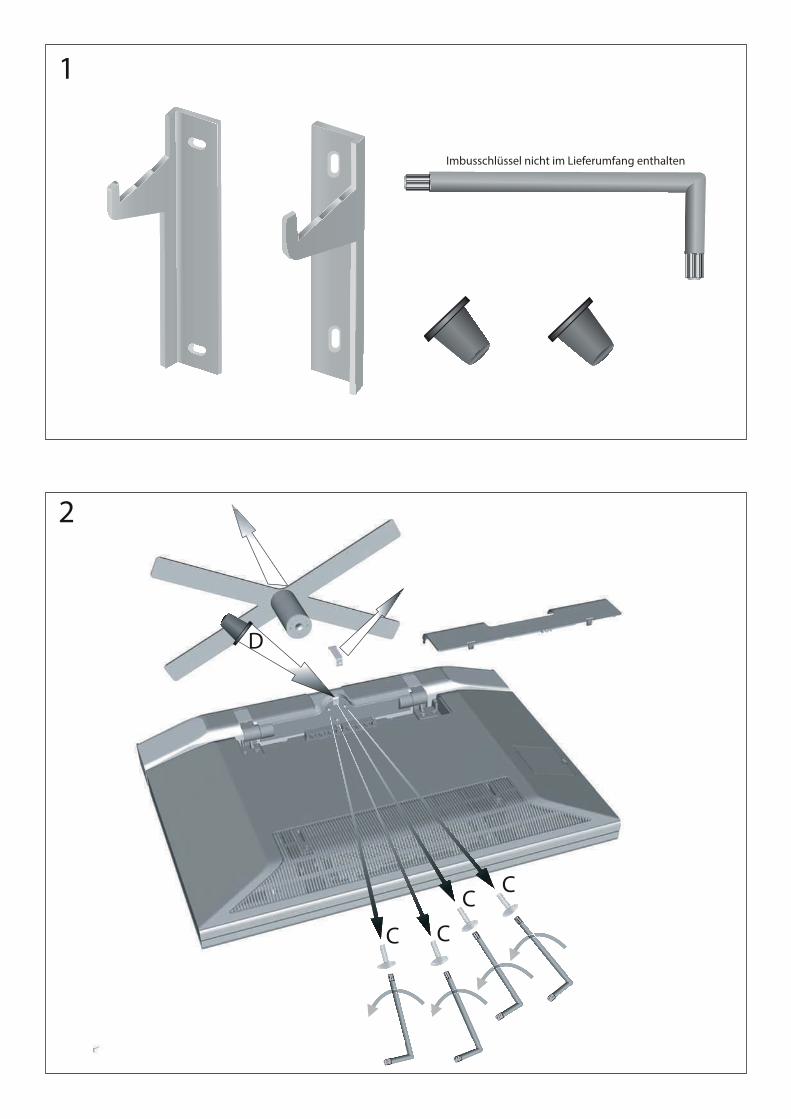
See the sketches 1 to 4.
Sketch 1: Scope of delivery - without Allen Wrench
Sketch 2: Preparing the TV set
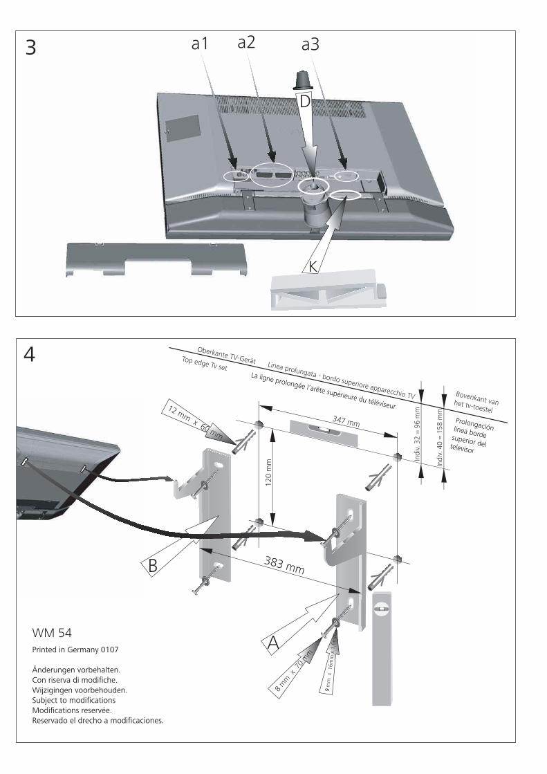
Sketch 3: Connection of the TV set
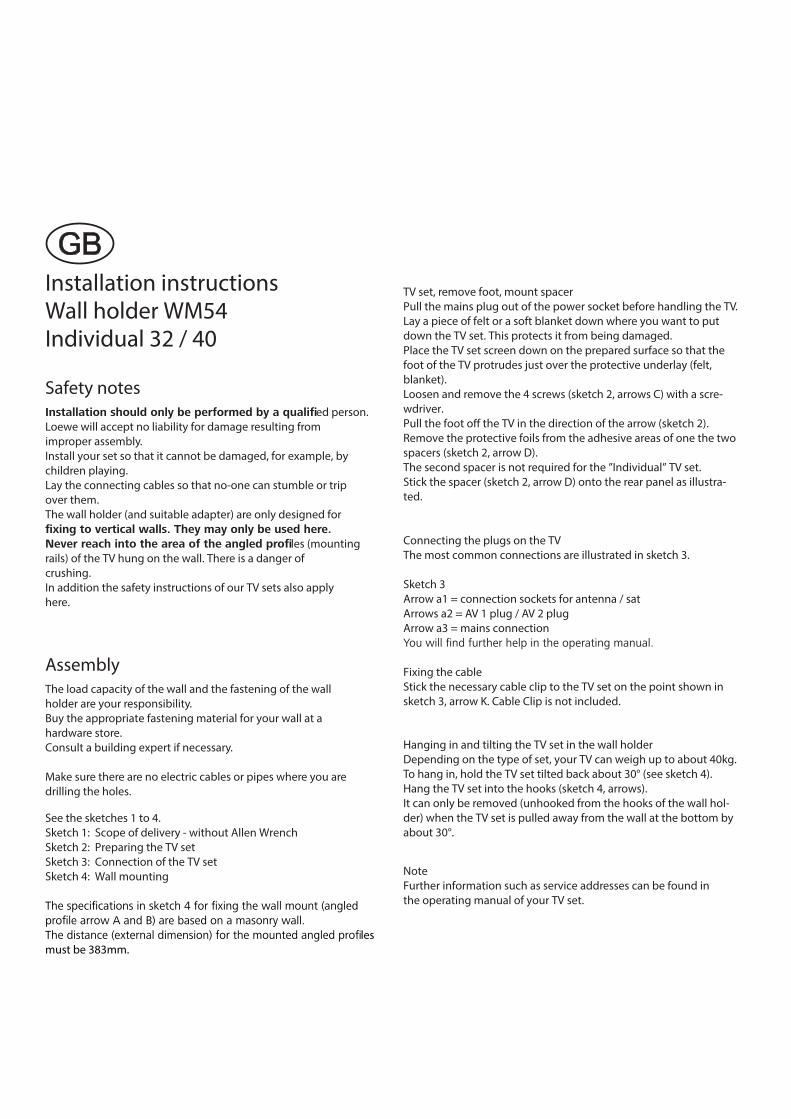
Sketch 4: Wall mounting
les
must be 383mm.
TV set, remove foot, mount spacer
Pull the mains plug out of the power socket before handling the TV.
Lay a piece of felt or a soft blanket down where you want to put
down the TV set. This protects it from being damaged.
Place the TV set screen down on the prepared surface so that the
foot of the TV protrudes just over the protective underlay (felt,
blanket).
Loosen and remove the 4 screws (sketch 2, arrows C) with a scre-
wdriver.
Pull the foot o� the TV in the direction of the arrow (sketch 2).
Remove the protective foils from the adhesive areas of one the two
spacers (sketch 2, arrow D).
The second spacer is not required for the ”Individual” TV set.
Stick the spacer (sketch 2, arrow D) onto the rear panel as illustra-
ted.
Connecting the plugs on the TV
The most common connections are illustrated in sketch 3.
Sketch 3
Arrow a1 = connection sockets for antenna / sat
Arrows a2 = AV 1 plug / AV 2 plug
Arrow a3 = mains connection
Fixing the cable
Stick the necessary cable clip to the TV set on the point shown in
sketch 3, arrow K. Cable Clip is not included.
Hanging in and tilting the TV set in the wall holder
Depending on the type of set, your TV can weigh up to about 40kg.
To hang in, hold the TV set tilted back about 30° (see sketch 4).
Hang the TV set into the hooks (sketch 4, arrows).
It can only be removed (unhooked from the hooks of the wall hol-
der) when the TV set is pulled away from the wall at the bottom by
about 30°.
Note
Further information such as service addresses can be found in
the operating manual of your TV set.