Embed Size (px)
Citation preview
This work has been digitalized and published in 2013 by Verlag Zeitschrift für Naturforschung in cooperation with the Max Planck Society for the Advancement of Science under a Creative Commons Attribution4.0 International License.
Dieses Werk wurde im Jahr 2013 vom Verlag Zeitschrift für Naturforschungin Zusammenarbeit mit der Max-Planck-Gesellschaft zur Förderung derWissenschaften e.V. digitalisiert und unter folgender Lizenz veröffentlicht:Creative Commons Namensnennung 4.0 Lizenz.
Multiple Diffraction of X-Rays
Roberto Colella
Department of Physics, Purdue University, West Lafayette, Indiana 47907 U.S.A.
Z. Naturforsch. 3 7 a , 4 3 7 - 4 4 7 (1982); received January 22, 1982
Dedicated to Professor Dr. G. Hildebrandt on the occasion of his 60th birthday
The phenomenon of n-beam diffraction ( n > 2) is discussed with particular attention being devoted to the Bragg case of diffraction. The general method of solution is outlined, and some applications to specific situations are discussed. These include experiments in which strong quasi-monochromatic phonon beams are excited in a crystal using the Acousto-Electric effect, phase determination using the concept of „Virtual Bragg Scattering", and high resolution Bragg reflec-tion topographs. In all cases the agreement between theory and experiment has been found excellent.
1. Introduction
Several years ago I had an opportunity of sharing an office at Cornell University with Professor Hilde-brandt (we were both associated, at that time, with Professor Batterman's laboratory) and through sev-eral conversations we had at that time I became acquainted with the problems of w-beam dynamical theory. As a result of this contact, I developed an interest in %-beam dynamical diffraction, did some of m y own research in this area during the ensuing years, and it seems fitting now to dedicate this article to Professor Hildebrandt on the occasion of his sixtieth birthday.
Propagation of x-ray photons in a crastal is en-tirely analogous to propagation of electron waves, commonly described as "Bloch waves" . I t is shown in electron band theory, using Bloch theorem, that the electron wrave function in a crystal can always be expressed as a superposition of plane waves:
W k { r ) = E } C 1 e ^ k + G ^ r (1.1)
where k is the electron wave vector, and Gj are reciprocal lattice vectors. A convenient w a y of look-ing at (1.1) is to consider k as the wave vector of an electron that has entered the crystal from an out-side vacuum region, and subsequently gives rise to an infinite number of plane waves by Bragg reflec-tions. In this sense diffraction theory is the analog of band theory. The diffraction problem is, however, simpler because the geometry is well defined. The incident beam is usually monochromatic and well
Reprint requests to Prof. R . Colella, Department o f Phys-ics, Purdue Universitv, West Lafayette, Indiana 47907, U.S.A.
collimated, characterized b y a wave vector ko, which becomes k after refraction at the entrance surface of the crystal. The E w a l d construction im-mediately tells us how m a n y plane waves are im-portant in the crystal, which enables us to reduce the number of unknown amplitudes C/s in E q . (1.1) to a small number, typical ly two, three, sometimes four (in the x-ray case). This is not the case for the general problem of electron band theory, in which all possible values of k must be taken into account, with the consequence that a large number of C/s must be determined.
In the x-ray case an equation similar to (1.1) is used, except that vector waves are used instead of scalar waves:
®{r) = ZJDjei(k+G>)-r, (1.2)
where D(r) is the displacement vector inside the crystal. The expansion (1.2) for vector waves was proposed long before Eq. (1.1) b y E w a l d [1], and for this reason the plane waves appearing in Eq. (1.2) are sometimes called " E w a l d Avaves", in analogy with Bloch waves.
Another important difference between diffraction theory and band theory is that in the former a crystal is assumed to be finite, limited b y one or more well-defined surfaces. The beams of physical significance are the incident and the diffracted beams. Therefore boundary conditions are to be specified and satisfied. Basically, two geometries are normally used in diffraction experiments. The Laue geometry (or Laue case) is such t h a t incident and diffracted beams are not associated with the same surface. In most cases the crystal is in the
0340-4811 / 82 / 0500-451 $ 01.30/0. - Please order a reprint rather than making your own copy.
438
form of a slab dividing the vacuum space into two separate regions. In the Laue case incident and diffracted beams propagate in different regions.
In the Bragg geometry (or Bragg case) incident and diffracted beams propagate in the same vac-uum region. In most cases the crystal is thick enough that no beam emerges from the exit surface, so that the crystal can be considered infinite for any prac-tical purpose.
A lot of attention has been devoted in the past to multi-beam cases in the Laue case. This interest was motivated b y the discovery [2] that anomalous transmission of x-rays (the Borrmann effect) was enhanced in some cases when three or four beams are simultaneously excited, that is to say, when three or four reciprocal lattice points lie simultane-ously on the E w a l d sphere in reciprocal space. Pro-fessor Hildebrandt made a complete study of this phenomenon [3], and explained it by examining the detailed form of the electric field intensity between lattice planes in a multi-beam situation.
The work to be described in this article will mostly be concerned with the Bragg case, which had not been considered by previous investigators. The main motivation for this choice was that it seemed desirable to be able to interpret a Renninger plot [4] much in the same w a y as ordinary two-beam dynam-ical theory allows one to interpret rocking curves from perfect crystals in any conceivable situation. The real reason behind all this is the fact that in multi-beam diffraction the relative phases between the various structure factors involved are not lost, and therefore the Renninger plot contains phase information.
Another area of diffraction physics in which n-beam dynamical diffraction has application is the field of interactions between x-ray photons and phonons. It is not convenient to use thermal phonons for this purpose, because they are diffuse in frequency and wave vectors. It is preferable instead to increase the phonon population of spe-cific branches and frequencies and study the sep-arate effects of well characterized phonon branches. One convenient technique makes use of acousto-electric (A.E.) phonon amplification. Since how-ever the frequencies of typical A . E . phonons are of the order of 109 Hz, quite often phonon satellites partially overlap with Bragg peaks. I t is therefore necessary to use an w-beam dynamical approach for interpreting the experimental results.
R. Colella • Multiple Diffraction of X-Rays
Recently, a new mechanism of Bragg scattering has been found to be operational in %-beam experi-ments. I t has been called "Virtual Bragg Scatter-ing", because it involves Bragg reflections that cor-respond to nodes far removed from the Ewald sphere and do not conserve energy. It has been shown that Virtual Bragg Scattering can be utilized for phase determinations even in the case of mosaic crystals.
Finally, we will show that multiple reflections can be the origin of unexpected features in Bragg reflection topographs, and that a proper theoretical treatment of w-beam diffraction is needed for ex-plaining these features.
2. General Solution of the n-Beam Diffraction Problem
The general solution is obtained in a two-step process. Firstly, a set of linear equations is set up for determining the amplitudes DG in (1.2). A pre-ferred direction is introduced, corresponding to the normal of the crystal surface, on which the incident beam is impinging. Only the tangential component of k is determined. The normal component yo will be determined b y a determinantal equation. The set of linear equations for DG are the well known dy-namical equations, obtained after insertion in Max-well equations of the expansion (1.2), with the crys-tal polarizability also being expanded into a Fourier series. The following equation is obtained:
[*5/|8f - (1 - v0)]Dt
- f ' jifi-j(ui • Dj] ut - Dj] = 0 , (2.1) i
where &o= l /A , = tpi is the Fourier com-ponent of the polarizability per unit volume (times 4n) associated with the node G i , and U{ = ßi//?f [5]. Since all D / s are normal to ß/, only two com-ponents of D j need to be specified. The total num-ber of unknown amplitudes is therefore 2 n. A t this point an important approximation is introduced in standard dynamical theory. The first factor in brackets of (2.1) is written as (tpo — 2 di) where <5f - f 1 is the refractive index for the i-beam. This is pos-sible because ko and ßi differ b y a few parts in 1 0 - 5 . Since all di can be related b y linear equations, this procedure consists in linearizing the dynamical equa-tions with respect to the variable whose eigenvalues are sought. While this approximation is ordinarily legitimate in absence of beams grazing the surface,
439 R. Colella • Multiple Diffraction of X-Rays
which seldom happens in the two beam cases, it is not permissible anyt ime one of the excited beams is parallel to the surface, which is not infrequent in ?i-beam diffraction. Furthermore, the linearization procedure reduces the number of wave fields from 4 n to 2n, which gives rise to problems in satisfying the boundary conditions. The determinantal equa-tion generated by E q . (2.1) gives rise to 4n wave fields.
The second step toward a general solution of the %-diffraction problem consists in establishing the boundary conditions on both surfaces simultane-ously, for all crystal and vacuum beams. The bound-ary conditions are written for the tangential com-ponents of E and H, and for the normal components of D and B. Considering the interdependence of some of the equations, a total of four scalar equa-tions is obtained for each beam. The number of equations generated b y the boundary conditions (4n) therefore is equal to the number of Ewald waves inside the crystal. The strength of each Ewald wave can therefore be determined b y solving the boundary conditions. In this w a y all vacuum am-plitudes are evaluated and the intensities of all beams can be calculated. The details of the pro-cedure for determining the 4 n eigenvalues and for solving the boundary conditions have been describ-ed previously [6], and will not be repeated here.
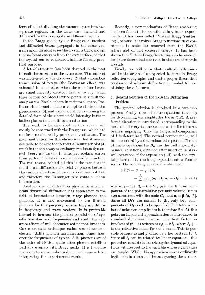
A computer program has been developed for per-forming all the computations, in which n, the num-ber of beams, can be any value ^ 2. I t is sometimes advantageous to use this program even in the two beam case, because it can handle correctly the situation of grazing incident or diffracted beams, to which the standard approximations, such as those, for example, used b y Zachariasen in his book [7], are not applicable. The program has been tested against experiment in various ways. For example, the intensities of some "Umweganregung" peaks associated with the (222) reflection in germanium have been calculated and found in agreement with the experimental values within 4 — 5 % [6]. In Fig. 1 we show the plot of the Ge-222 integrated intensity (with respect to 6, the angle of incidence), using Cu-Ka, as a function of the azimuthal angle cp. Note that the range Acp, within which three-beam ex-citation is appreciable, amounts, for the Umweg-anregung 2 2 2 - 1 1 3 peak, to 22.8 seconds. The 2 2 2 - 1 1 3 is the strongest peak in the 222 Renninger plot of germanium. In Fig. 2 we show two rocking
Fig. 1. Calculated integrated intensity of the 222 reflection as a function of the azimuthal angle. Each point o f this profile represents an integration of the crystal reflectivity with respect to 0, angle of incidence. The tails tend asymp-totically to the " t r u e " 222 value, which is a negligible fraction of the peak value. The abscissa A cp = 0 corresponds to full excitation o f the 113 simultaneous reflection, as ob-tained from a kinematic calculation.
curves, at different azimuthal angles cp. Note that the peak reflectivity is generally in excess of 50%. Finally in Fig. 3 wre showr a double crystal rocking curve obtained with both crystals set for simultane-ous excitation of the (222) and (113). In this ex-periment the vertical divergence [8] of the beam between the two crystals is in the range of 20 to 25 seconds of arc. The agreement between theory and experiment is excellent except in correspon-dence of the maximum peak. I t wras found later that the crystals used in this experiment were not really perfect, which m a y explain the lack of agree-ment in the peak region.
Fig. 2. Computed profiles o f three-beam reflectivities vs angle of incidence, for two different values of the azimuthal angle. Acp = 0 corresponds to full excitation of the 113 simultaneous reflection. The abscissa 0 = 0 corresponds to the Bragg angle, without refraction correction, for the " t rue " 222.
Fig. 3. Double-crystal rocking curve of the 222-113 three-beam reflec-tion, using the anti-parallel arrangement. Both crystals are set for the 222, their azimuths being adjusted for simultaneous excitation of the 113.
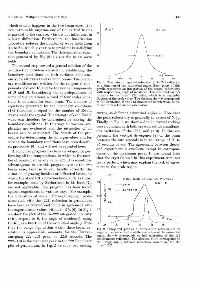
Fig. 4. Double-crystal 004 rocking curve of InSb single crystal, in presence (right-hand side) and absence (left-hand side) of acousto-electric phonons, at 77 °K. Note the presence of second and, perhaps, third order satellites. Peak x-ray intensity was 2000 counts/sec. Carrier concentration = 5 x 10¹³ electrons/cm3 . Mobility = 6 X 105 cm 2 V - 1 sec - 1 . Applied electric field: 23.8 V/cm. B — 5 K Gauss.
THIN LINE-PHONONS OFF THICK LINE-PHONONS ON
-20 -10 0 10 20 SECONDS OF ARC FROM PEAK
CENTER
Fig. 6. Experimental results for the (004) thin crystal Laue trans-mission forward diffracted beam. The crystal is tilted around the diffraction vector so that the [110] axis forms an angle of 60° with the diffraction plane. Carrier concentration: 8 X 10¹³ electrons/cm3 . Mobility: 7.0 X 10^ cm 2 y - i sec"1 . Applied electric field: 10.3 V/cm. # = 3.0 K Gauss. Thickness: 0.312 mm. / / 0 *efr^3 .8 .
Fig. 5. Same as Fig. 4 except : carrier concentration: 3.5 X 10¹⁴ elec-trons/cm3 . Mobility: 5 X 105 cm 2 V - 1 sec - 1 .
441 R. Colella • Multiple Diffraction of X-Rays
3. Multiple Diffraction Effects from Non-Equilibrium Phonons
One of the interesting problems still open in dif-fraction physics is the mechanism of interaction between x-ray photons and phonons. For a thermal distribution of phonons it has been shown theoret-ically [9] and experimentally [10] that the same dynamical theory for a non-vibrating crystal holds, provided the scattering factors involved jhki are multiplied b y their own Debye-Waller factors e~M. This is obtained in a situation in which the phonons are total ly incoherent, randomly polarized, of rela-t ively weak intensity, and span a continuous and broad range of wave vectors, both in magnitude and direction. It is not clear that the same rule applies to highly coherent, intense and monochro-matic phonon beams. A convenient technique for studying this problem makes use of the Acousto-Electric (A.E.) effect, for amplifying thermal pho-nons of selected modes and frequencies [11]. A piezo-electric crystal (in our case, InSb, which can be grown almost dislocations-free) is cut in the form of a long and thin bar, typical ly parallel to [110], and an electric field of a few tens of volts/cm is established parallel to [110]. Under suitable con-ditions, an intense phonon beam is generated with q vector parallel to [110] and polarized along 001. (This is called " F a s t Transverse [110] Acoustic Mode", or br ie f ly : F T [110].) The frequency of the phonons is determined b y the carrier concentration, temperature and other parameters [11]. Since the A . E . phonons are almost monochromatic, satellite reflections are generated at positions G ± l q , where G is any reciprocal lattice vector, I is any integer, positive or negative, and q is the phonon wave vector. Since the ratio qjG is typically of the order of IO - 4 , the satellite reflections are very close to the Bragg reflections, and high resolution is needed in order to see these satellites. Preliminary results in reflection (Bragg case) and in transmission (Laue case) have been published a few years ago (Refs. [12] and [13] respectively). Figures 4 and 5 show two Bragg diffraction profiles for two different frequen-cies. I t is clear, particularly in Fig. 4, that there are wide angular ranges in which both satellites and Bragg peak are simultaneously excited. It is also clear that the satellite peak intensities are compar-able to that of the Bragg peak, which makes kinematic theory, upon which the standard theory of Thermal Diffuse Scattering is based [14], unap-
plicable to this case. Figure 6 shows an experiment with the Laue transmission geometry, in the thin crystal region (fit ^ 3.8). In this case two "dips" , marked b y arrows in the figure, are observed at 6 values at which satellites would be observed in the Bragg case. A diffraction theory applicable to these experiments must necessarily be a dynamical theory. Such a theory has been developed b y Koehler, Möhling and Peibst [15]. In this theory phonons are introduced at the outset. For a single phonon the following set of equations is obtained:
(lc* - ßl) Du - J Vi-i Ji-p (2 GM • U) ip
•[(frrDJp)flii-fiDSp\ = 0 (3.1)
which is very similar to the standard dynamical equations (2.1) except for the fact that each (3.1) is associated with two indices instead of one, i and I, which identify a particular node in reciprocal space and the order number of a given satellite, respec-tively.
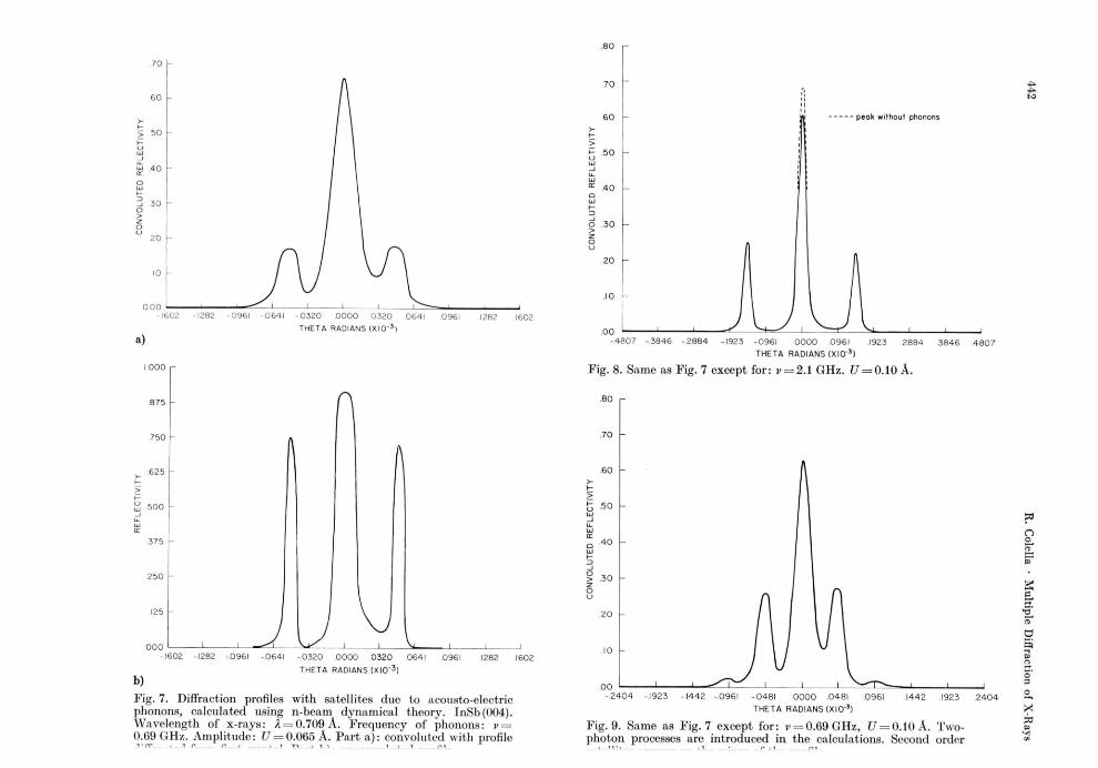
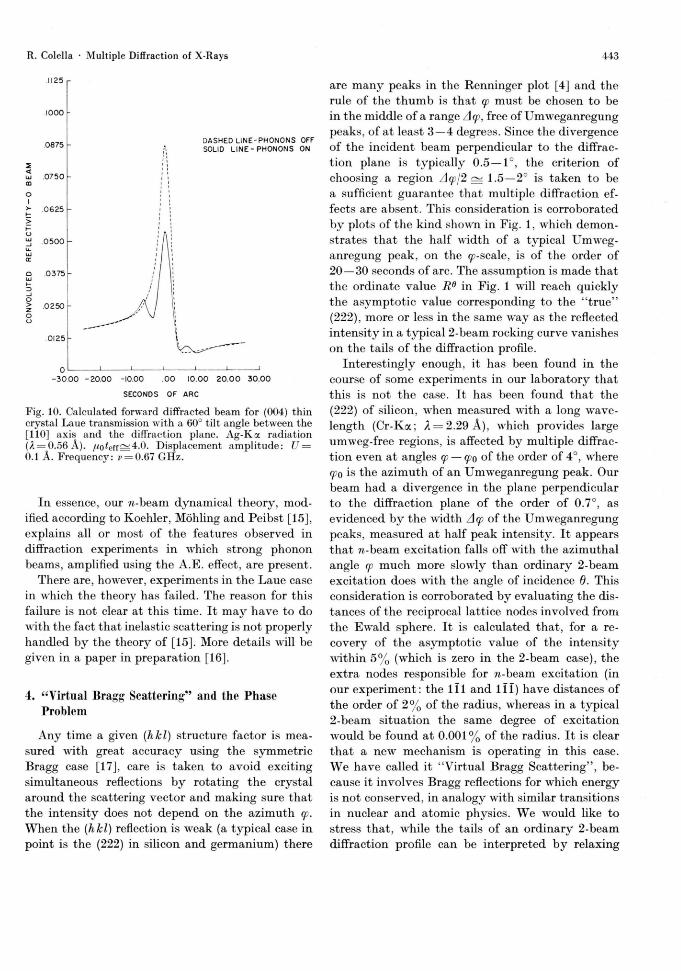
J i - p are the Bessel functions of integer order and U is the lattice displacement amplitude of the pho-non. The system of Eqs. (3.1) can be solved using the same procedure outlined in Sect. 2 in order to calculate diffraction profiles. Our computer program has been modified accordingly, and some of the results are described below. The amplitude of the phonon waves is introduced as a parameter in the argument of the Bessel functions. Figures 7 and 8 show two calculated profiles, for low and high fre-quency phonons, respectively. Only first order sat-ellites are introduced in the calculations. I t is clear that the basic features of the experimental profiles are correctly reproduced. Note, in Fig. 7, the asym-metry between left and right satellites, also visible in the experiment (Figure 4). This asymmetry has to do with the different values of dynamical ab-sorption operating on the wings of the Bragg peak, which are associated with different wave fields. Figure 9 shows the effect of introducing in the cal-culations second order satellites, which are visible in many of the experimental profiles.
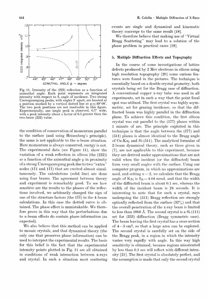
Our computer program can also be used to cal-culate diffracted intensities in the Laue case, after minor modifications. Once the boundary conditions are solved, the intensities of all the vacuum waves can be calculated. A n example in given in Fig. 10, in which wiggles are observed is correspondence of the "dips" observed in the experiment (Figure 6).
.70 H
1602 -1282
a)
n
L. -1602 -1282 - .0961 - .0641 - 0 3 2 0 . 0 0 0 0 0 3 2 0 .0641
THETA RADIANS (X IO" 3 )
b)
Fig. 7. Diffraction profiles with satellites due to acousto-electric phonons, calculated using n-beam dynamical theory. inSb(004). Wavelength of x-rays: X = 0.709 Ä. Frequency of phonons: v — 0.69 GHz. Amplitude: t/ = 0 .065Ä. Part a): convoluted with profile
- 0 9 6 1 - 0 6 4 1 - 0 3 2 0 . 0 0 0 0 0 3 2 0 .0641 0961
T H E T A R A D I A N S ( X I O " 3 )
.1282 .1602
peak without phonons
- 4 8 0 7 - 3 8 4 6 - 2 8 8 4 -1923 - 0 9 6 1 0 0 0 0 .0961 .1923 . 2 8 8 4 . 3 8 4 6 . 4 8 0 7
THETA RADIANS (XIO"3 )
Fig. 8. Same as Fig. 7 except for: v = 2.1 GHz. £7 = 0.10 Ä.
. 8 0
> . 3 0
00 - . 2 4 0 4 - 1 9 2 3 - 1 4 4 2 - .0961 - 0 4 8 1 0 0 0 0 0 4 8 1
T H E T A RADIANS (XIO"3 )
1 4 4 2 1923
Fig. 9. Same as Fig. 7 except for: v = 0.69 GHz, t/ = 0 .10Ä. Two-photon processes are introduced in the calculations. Second order
443 R. Colella • Multiple Diffraction of X-Rays
^ . 0 5 0 0
.0375
.0250
DASHED LINE-PHONONS OFF SOLID L I N E - P H O N O N S ON
- 3 0 0 0 - 2 0 . 0 0 -10.00 . 0 0 10.00 2 0 . 0 0 3 0 . 0 0
SECONDS OF ARC
Fig. 10. Calculated forward diffracted beam for (004) thin crystal Laue transmission with a 60° tilt angle between the [110] axis and the diffraction plane. A g - K a radiation (A = 0 .56Ä) . /<o^eff==4.0. Displacement amplitude: U = 0.1 A. Frequency: e = 0.67 GHz.
In essence, our w-beam dynamical theory, mod-ified according to Koehler, Molding and Peibst [15], explains all or most of the features observed in diffraction experiments in which strong phonon beams, amplified using the A.E. effect, are present.
There are, howrever, experiments in the Laue case in which the theory has failed. The reason for this failure is not clear at this time. It may have to do with the fact that inelastic scattering is not properly handled by the theory of [15]. More details will be given in a paper in preparation [16].
4. "Virtual Bragg Scattering" and the Phase Problem
Any time a given (hkl) structure factor is mea-sured wdth great accuracy using the symmetric Bragg case [17], care is taken to avoid exciting simultaneous reflections b y rotating the crystal around the scattering vector and making sure that the intensity does not depend on the azimuth cp. When the (hkl) reflection is weak (a typical case in point is the (222) in silicon and germanium) there
are many peaks in the Renninger plot [4] and the rule of the thumb is that cp must be chosen to be in the middle of a range Acp, free of Umweganregung peaks, of at least 3—4 degress. Since the divergence of the incident beam perpendicular to the diffrac-tion plane is typically 0.5—1°, the criterion of choosing a region Acpj2^ 1.5—2° is taken to be a sufficient guarantee that multiple diffraction ef-fects are absent. This consideration is corroborated by plots of the kind shown in Fig. 1, which demon-strates that the half width of a typical Umweg-anregung peak, on the «p-scale, is of the order of 20—30 seconds of arc. The assumption is made that the ordinate value R e in Fig. 1 will reach quickly the asymptotic value corresponding to the " true" (222), more or less in the same way as the reflected intensity in a typical 2-beam rocking curve vanishes on the tails of the diffraction profile.
Interestingly enough, it has been found in the course of some experiments in our laboratory that this is not the case. It has been found that the (222) of silicon, when measured with a long wave-length (Cr-Ka; X = 2.29 A), which provides large umweg-free regions, is affected by multiple diffrac-tion even at angles cp — cpo of the order of 4°, where cpo is the azimuth of an Umweganregung peak. Our beam had a divergence in the plane perpendicular to the diffraction plane of the order of 0.7°, as evidenced b y the width Acp of the Umweganregung peaks, measured at half peak intensity. It appears that w-beam excitation falls off with the azimuthal angle cp much more slowly than ordinary 2-beam excitation does with the angle of incidence 0. This consideration is corroborated by evaluating the dis-tances of the reciprocal lattice nodes involved from the Ewrald sphere. It is calculated that, for a re-covery of the asymptotic value of the intensity within 5 % (which is zero in the 2-beam case), the extra nodes responsible for w-beam excitation (in our experiment: the 111 and 111) have distances of the order of 2 % of the radius, whereas in a typical 2-beam situation the same degree of excitation would be found at 0.001% of the radius. It is clear that a new mechanism is operating in this case. W e have called it "Virtual Bragg Scattering", be-cause it involves Bragg reflections for wrhich energy is not conserved, in analogy with similar transitions in nuclear and atomic physics. We would like to stress that, while the tails of an ordinary 2-beam diffraction profile can be interpreted b y relaxing
444
1.21— T 1 1 1 1 n 1 r i \ I \
\ \
o> I / CU \ I—I X C V x — I / w .8" N \ El / CM x
\ i \ I
7 I I I I I I LI I I 44° 45° 46° 47° 48° 49° 50° 51°
AZIMUTHAL ANGLE </> - degrees
Fig. 11. Intensity o f the (222) reflection as a function of azimuthal angle. Each point represents an integrated intensity with respect to 0, angle of incidence. T w o strong Umweganregung peaks, with angles 3' apart, are located at a position marked by a vertical dotted line at y ~ 4 9 ° 0 8 / . The two peak positions are not resolvable in this figure. Experimentally, one single peak is observed, 0.7° wide, with a peak intensity about a factor of 6.5 greater than the two-beam (222) value.
the condition of conservation of momentum parallel to the surface (and using Heisenberg's principle), the same is not applicable to the w-beam situation. Here momentum is always conserved, energy is not. The experimental data (see Figure 11), show the variation of a wreak reflection in silicon (the (222)) as a function of the azimuthal angle cp in proximity of a strong Umweganregung peak due to two " e x t r a " nodes (111 and 111) that are excited almost simul-taneously. The calculations (solid line) are done using four beams. The agreement between theor3r
and experiment is remarkably good. To see how sensitive are the results to the phases of the reflec-tions involved, we arbitrarily changed the sign of one of the structure factors (the 111) in the 4-beam calculations. In this case the dotted curve is ob-tained. The phase effect is unmistakable. W e there-fore prove in this w a y that the perturbations due to n-beam effects do contain phase information (as expected).
W e also believe that this method can be applied to mosaic crystals, and that dynamical theory (the only one that preserves phase information) can be used to interpret the experimental results. The basis for this belief is the fact t h a t the experimental intensity points plotted in Fig. 11 are all obtained in conditions of weak interaction between x-rays and crystal. In such a situation most scattering
R. Colella • Multiple Diffraction of X-Rays
events are single and dynamical and kinematic theory converge to the same result [18].
W e therefore believe that making use of "Virtual Bragg Scattering" m a y lead to a solution of the phase problem in practical cases [19].
5. Multiple Diffraction Effects and Topography
In the course of some investigations of lattice defects produced b y 2 Mev electrons in silicon using high resolution topography [20] some curious fea-tures were found in the pictures. The technique is essentially based on a double crystal geometry, both crystals being set for the Bragg case of diffraction. A conventional copper x-ray tube was used in all experiments, set in such a w a y t h a t the point focal spot was utilized. The first crystal was highly asym-metric, set for grazing incidence, so that the dif-fracted beam was highly parallel in the diffraction plane. To achieve this condition, the first silicon crystal was cut parallel to the (577) planes within 1 minute of arc. The principle exploited in this technique is that the angle between the (577) and (511) planes is almost identical to the Bragg angle of C u - K a i and Si-(511). The analytical formulae of 2-beam dynamical theory, such as those given in [7], are not applicable to this experiment, because they are derived under approximations that are not valid wrhen the incident (or the diffracted) beam form very small angles with the surface. Using our computer program, in which no approximations are used, and setting n = 2, we calculate that the Bragg angle of K a i is 0B = 4.04 mrad. and that the width of the diffracted beam is about 0.1 sec, whereas the width of the incident beam is 24 seconds. I t is interesting to note that for such a crystal, rays undergoing the (511) Bragg reflection are strongly optically reflected from the surface (32%) and that the overall penetration of the x-ray beam is limited to less than 1000 Ä . The second crystal is a S i - ( l l l ) set for (333) diffraction (Bragg symmetric case). The beam leaving the first crystal has a cross section of 4 — 5 cm2, so t h a t a large area can be explored. The second crystal is carefully set on the side of the Bragg peak, in a region in which the intensity varies very rapidly with angle. In this way high sensitivity is obtained, because regions misoriented by less than 0.1 sec will reflect with different inten-sity [21]. The first crystal is absolutely perfect, and the assumption is made that only the second crystal
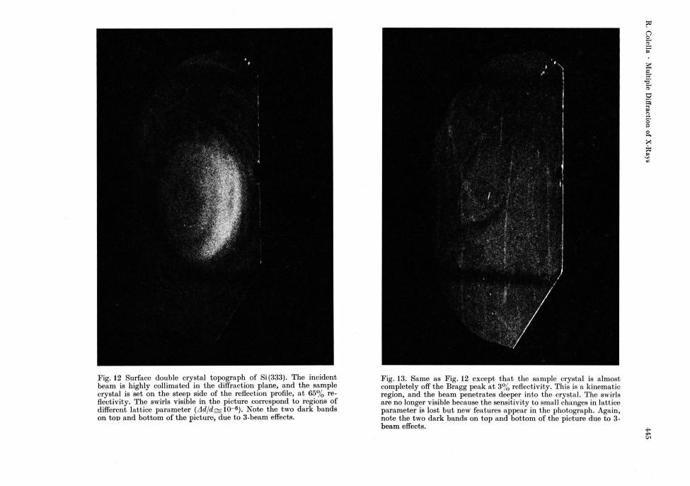
Fig. 12 Surface double crystal topograph of Si(333). The incident beam is highly collimated in the diffraction plane, and the sample crystal is set on the steep side of the reflection profile, at 6 5 % re-flectivity. The swirls visible in the picture correspond to regions of different lattice parameter ( A d / d ^ IO - 6) . Note the two dark bands on top and bottom of the picture, due to 3-beam effects.
Fig. 13. Same as Fig. 12 except that the sample crystal is almost completely off the Bragg peak at 3 % reflectivity. This is a kinematic region, and the beam penetrates deeper into the crystal. The swirls are no longer visible because the sensitivity to small changes in lattice parameter is lost but new features appear in the photograph. Again, note the two dark bands on top and bottom of the picture due to 3-beam effects. ^
446 R. Colella • Multiple Diffraction of X-Rays
may exhibit imperfections. Figures 12 and 13 show two examples of topographs obtained by this tech-nique. W e do not want to discuss the various fea-tures visible in these photographs. This is done elsewhere [20]. W e want to concentrate our atten-tion on the two dark bands running parallel on the top and bottom part of each photograph. I t was noticed that all topographs, of very different crys-tals, had these dark bands. It was also found that the same dark bands would appear on films placed between first and second crystal. The presence of these bands seemed to be an intrinsic feature of the experimental technique independent of the partic-ular choice of the first crystal, of the particular technique used for fastening the first crystal to its holder, etc.
It was conjectured that these bands might be due to multiple reflection effects.
It was verified that the width of the bands cor-responds to the height of the focal spot, measured along a direction perpendicular to the diffraction plane. It would appear that for two particular val-ues of the vertical [8] divergence angle cp the reflec-t iv i ty of the (511) becomes close to zero. The first crystal is cut asymmetrically, therefore the azi-muthal angle cp of the diffraction plane around the
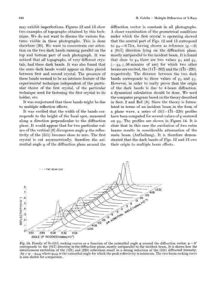
diffraction vector is constant in all photographs. A closer examination of the geometrical conditions under which the first crystal is operating showed that the central part of Figs. 12 and 13 correspond to 9?o = 0.7571, having chosen as reference (cp = 0) a [Oil] direction lying on the diffraction plane, mostly antiparallel to the incident beam. It is found that close to cpo there are two values cp\ and cpi. ( = <fo ± 56 minutes of arc) for which two other beams are excited, the (113-202) and the (131-220). respectively. The distance between the two dark bands corresponds to these values of cpi and cpi • However, in order to really prove that the origin of the dark bands is due to 4-beam diffraction, a dynamical calculation should be done. We used the computer program based on the theory described in Sect. 2 and Ref. [6]. Since the theory is formu-lated in terms of an incident beam in the form of a plane wave, a series of ( 5 1 1 - 1 3 1 - 2 2 0 ) profiles have been computed for several values of cp centered on cpi. The profiles are shown in Figure 14. It is clear that in this case the excitation of two extra beams results in considerable attenuation of the main beam (Aufhellung). I t is therefore demon-strated that the dark bands of Figs. 12 and 13 owe their origin to multiple beam effects.
Fig. 14. Family of Si-(511) rocking curves as a function of the azimuthal angle q> around the diffraction vector. cp = 0° corresponds to the [Oi l ] direction in the diffraction plane, mostly antiparallel to the incident beam. It is shown how the simultaneous excitation of the (131) and (220) reflections result in a strong reduction of the (511) diffracted intensity. Acp = cp — ipmin where 99min is the azimuthal angle for which the peak reflectivity is minimum. The two-beam rocking curve is also shown for comparison.
TWO BEAM CASE
3 .60 3 .84 4 . 0 8 4 . 3 2 4 5 6
ANGLE OF INCIDENCE (radians,xlO"3)
- 1 , 6 3 2
447 R. Colella • Multiple Diffraction of X-Rays
6. Conclusions
A - b e a m d i f f r a c t i o n is o r d i n a r i l y c o n s i d e r e d a n u i -
s a n c e i n s t r u c t u r a l c r y s t a l l o g r a p h y b e c a u s e i t i n t r o -
d u c e s u n c o n t r o l l a b l e p e r t u r b a t i o n s in m e a s u r i n g
i n t e n s i t i e s . C o n d i t i o n s a r e t h e r e f o r e c a r e f u l l y c h o s e n
i n o r d e r t o a v o i d m u l t i p l e r e f l e c t i o n s . W e d e s c r i b e
i n t h i s p a p e r a n u m b e r o f s i t u a t i o n s i n w h i c h
n - b e a m d i f f r a c t i o n h a s a n i n t e r e s t i n i t s o w n r i g h t ,
s u c h a s : i) t h e p h a s e p r o b l e m a n d t h e n e w c o n c e p t
o f " V i r t u a l B r a g g S c a t t e r i n g " ; ii) d i f f r a c t i o n e x -
p e r i m e n t s i n w h i c h i n t e n s e n o n - e q u i l i b r i u m a c o u s t i c
p h o n o n s a r e p r e s e n t i n t h e c r y s t a l ; i i i) B r a g g c a s e
d i f f r a c t i o n t o p o g r a p h s . A g e n e r a l m e t h o d o f s o l u t i o n
i s o u t l i n e d a n d f o u n d t o c o r r e c t l y i n t e r p r e t t h e e x -
p e r i m e n t a l r e s u l t s i n a l l c a s e s .
[1] P . P . E w a l d , Ann. d. Physik 49, 117 (1916); 49, 1 (1916); 54, 519 (1917).
[2] G. Borrmann and W . H a r t w i g , Z. Krist, 121, 401 (1965).
[3] G. Hildebrandt, Phys. Stat. Sol. 24, 245 (1967). [4] A Renninger plot is a plot of Run vs cp, where Rhki
is the intensity of a weak reflection, typically the 222 in diamond, silicon, or germanium, observed in the symmetric Bragg case, i.e., with the surface parallel to the (111) planes, as a function of <p, the azimuthal angle for rotations around the [111] direction.
[5] The dash (') in front of the summation symbol indi-cates that the term with i — j is omitted.
[6] R . Colella, Acta Cryst. A 30, 413 (1974). [7] W . H. Zachariasen, Theory of X - R a y Diffraction in
Crystals, John WTiley, New York 1945. [8] "Vert i ca l " means perpendicular to the diffraction
plane. [9] Y . H. Ohtsuki, J. Phys. Soc. Japan 19, 2285 (1964).
[10] B. W . Batterman, Phys. Rev . 126, 1461 (1962); 127, 686 (1962); 134A, 1354 (1964). B. Okkerse, Philips Res. Repts. 17, 464 (1962).
[11] See, for example, Semiconductor Physics, b y K . Seeger, Sect. 7 h ; Springer Verlag, Berlin 1973.
[12] S. D. Leroux, R . Colella, and R , Bray, Phys. Rev . Letters 35, 230 (1975).
7. Acknowledgements
T h e w o r k d e s c r i b e d i n t h i s p a p e r is t h e r e s u l t o f
t h e a u t h o r ' s c o l l a b o r a t i o n w i t h s e v e r a l p e o p l e , w i t h -
o u t w h o m m o s t o f t h e w o r k w o u l d n o t e x i s t . T h e
l i s t i n c l u d e s f o r m e r g r a d u a t e s t u d e n t s (S. D . L e r o u x ,
L . D . C h a p m a n , R . D . Y o d e r ) a n d m y c o l l e a g u e s
P r o f e s s o r R . B r a y ( f o r S e c t . 2) a n d P r o f e s s o r A .
O v e r h a u s e r ( f o r S e c t . 4) . T h a n k s a r e d u e t o P r o -
f e s s o r R . B u s c h e r t a n d D . K a u f f m a n a t G o s h e n
C o l l e g e w h o m a d e a v a i l a b l e t h e i r u n p u b l i s h e d re-
s u l t s . F i n a n c i a l s u p p o r t f r o m t h e N a t i o n a l S c i e n c e
F o u n d a t i o n , G r a n t D M R - 8 1 0 8 3 3 7 a n d t h e M a t e r i a l s
R e s e a r c h L a b o r a t o r y f u n d e d b y t h e N a t i o n a l S c i -
e n c e F o u n d a t i o n , G r a n t D M R 8 0 - 2 0 2 4 9 , i s g r a t e -
f u l l y a c k n o w l e d g e d .
[13] S. D. Leroux, R . Colella, and R . Bray, Phys. Rev. Letters 37, 1056 (1976).
[14] B. E. Warren, X - R a y Diffraction, Addison Wesley, 1969, Chapter 11.
[15] R . Köhler, W . Möhling, and H. Peibst, phys. stat. sol. 41, 75 (1970); 61(b) , 173 (1974).
[16] D. L. Chapman, R . Colella, and R . Bray, in prepara-tion.
[17] This discussion does not need to be restricted to the symmetric Bragg case.
[18] See, for example, discussion given for the Bragg case in a paper by P. H. Hirsch and G. N. Ramachandran, Acta Cryst. 3, 187 (1950).
[19] An ingenuous technique for obtaining an extensive set o f experimental data on n-beam interactions in per-fect and mosaic crystals has been recently proposed b y Jagodzinski (Ref. [22]), using a photographic method called "Noromosic technique". The method is however qualitative, and does not lend itself to quanti-tative evaluations.
[20] D. S. Kauffman, Ph. D . Thesis, in preparation (un-published). Supervised b y Prof. R . Buschert, Goshen College, Goshen, Indiana 46526.
[21] U. Bonse, Direct Observation of Imperfections in Crystals, edited by J. B. Newkirk and J. W . Wernick, Interscience Publishers, 1962.
[22] H. Jagodzinski, Acta Cryst. A 36, 104 (1980).
![Dynamical Diffraction Theoryjuser.fz-juelich.de/record/136248/files/J©ơl_0797_Dederichs.pdf · called "dynamical theory", which has been extended further by Bethe [4] for the case](https://img.pdfslide.org/doc/110x75/5f5c9be42c04a27d9e334ebf/dynamical-diffraction-l0797dederichspdf-called-dynamical-theory.jpg)