Embed Size (px)
Citation preview
Ausgabe / Issue: 2017-03 Technische Änderungen vorbehalten / R
eserve technical changes
1/5
Absperrorgane Shut off valvesNG 32-125, SAE 11/4-5”, ND 16
Absperrorgane für die Saugleitung Shut off valves for suction lines
Mit einem den Nennweiten entsprechendem freien Durchgang.With free passage according to the nominal width.
NG 32-125 SAE 11/4-5” ND 16
Zul. Betriebsdruck: 16,0 bar - Überdruck 0,7 bar - Unterdruck 4,0 bar - Differenzdruck
bei geschl. Absperrorgan
Perm. operat. pressure: 232 psi - over pressure 10 psi - under pressure 58 psi - difference pressure when shut valve is closed
Ausgabe / Issue: 2017-03 Technische Änderungen vorbehalten / R
eserve technical changes
2/5
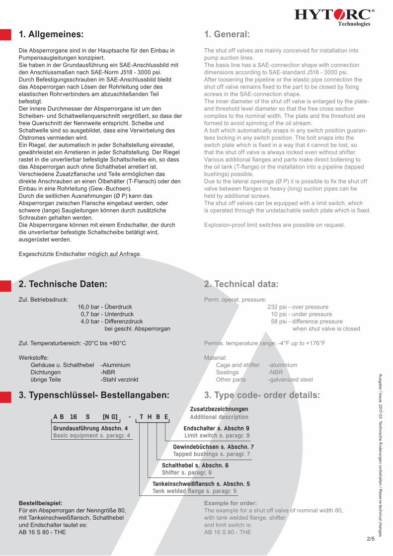
1. Allgemeines:Die Absperrorgane sind in der Hauptsache für den Einbau inPumpensaugleitungen konzipiert.Sie haben in der Grundausführung ein SAE-Anschlussbild mitden Anschlussmaßen nach SAE-Norm J518 - 3000 psi.Durch Befestigungsschrauben im SAE-Anschlussbild bleibtdas Absperrorgan nach Lösen der Rohrleitung oder deselastischen Rohrverbinders am abzuschließenden Teilbefestigt.Der innere Durchmesser der Absperrorgane ist um denScheiben- und Schaltwellenquerschnitt vergrößert, so dass derfreie Querschnitt der Nennweite entspricht. Scheibe undSchaltwelle sind so ausgebildet, dass eine Verwirbelung desÖlstromes vermieden wird.Ein Riegel, der automatisch in jeder Schaltstellung einrastet,gewährleistet ein Arretieren in jeder Schaltstellung. Der Riegelrastet in die unverlierbar befestigte Schaltscheibe ein, so dassdas Absperrorgan auch ohne Schalthebel arretiert ist.Verschiedene Zusatzflansche und Teile ermöglichen dasdirekte Anschrauben an einen Ölbehälter (T-Flansch) oder denEinbau in eine Rohrleitung (Gew.-Buchsen).Durch die seitlichen Ausnehmungen (Ø P) kann dasAbsperrorgan zwischen Flansche eingebaut werden, oderschwere (lange) Saugleitungen können durch zusätzlicheSchrauben gehalten werden.Die Absperrorgane können mit einem Endschalter, der durchdie unverlierbar befestigte Schaltscheibe betätigt wird,ausgerüstet werden.
Exgeschützte Endschalter möglich auf Anfrage.
2. Technische Daten:Zul. Betriebsdruck: 16,0 bar - Überdruck 0,7 bar - Unterdruck 4,0 bar - Differenzdruck
bei geschl. Absperrorgan
Zul. Temperaturbereich: -20°C bis +80°C
Werkstoffe: Gehäuse u. Schalthebel -Aluminium Dichtungen -NBR übrige Teile -Stahl verzinkt
3. Typenschlüssel- Bestellangaben:
Bestellbeispiel:Für ein Absperrorgan der Nenngröße 80,mit Tankeinschweißflansch, Schalthebelund Endschalter lautet es:AB 16 S 80 - THE
1. General:The shut off valves are mainly conceived for installation intopump suction lines.The basis line has a SAE-connection shape with connectiondimensions according to SAE-standard J518 - 3000 psi.After loosening the pipeline or the elastic pipe connection theshut off valve remains fixed to the part to be closed by fixingscrews in the SAE-connection shape.The inner diameter of the shut off valve is enlarged by the plate- and threshold level diameter so that the free cross sectioncomplies to the nominal width. The plate and the threshold areformed to avoid spinning of the oil stream.A bolt which automatically snaps in any switch position guaran-tees locking in any switch position. The bolt snaps into theswitch plate which is fixed in a way that it cannot be lost, sothat the shut off valve is always locked even without shifter.Various additional flanges and parts make direct boltening tothe oil tank (T-flange) or the installation into a pipeline (tappedbushings) possible.Due to the lateral openings (Ø P) it is possible to fix the shut offvalve between flanges or heavy (long) suction pipes can beheld by additional screws.The shut off valves can be equipped with a limit switch, whichis operated through the undetachable switch plate which is fixed.
Explosion-proof limit switches are possible on request.
2. Technical data:Perm. operat. pressure: 232 psi - over pressure 10 psi - under pressure 58 psi - difference pressure when shut valve is closed
Permis. temperature range: -4°F up to +176°F
Material: Cage and shifter -aluminium Sealings -NBR Other parts -galvanized steel
3. Type code- order details:
Example for order:The example for a shut off valve of nominal width 80,with tank welded flange, shifterand limit switch is:AB 16 S 80 - THE
Ausgabe / Issue: 2017-03 Technische Änderungen vorbehalten / R
eserve technical changes
3/5
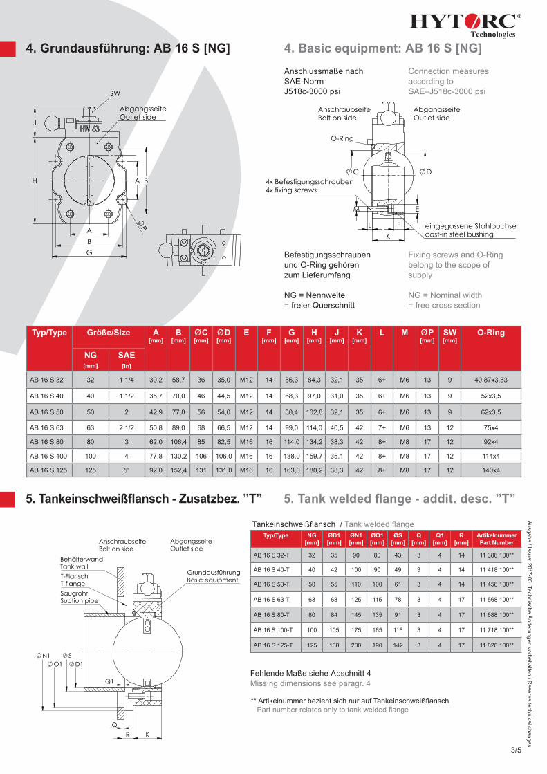
4. Grundausführung: AB 16 S [NG] 4. Basic equipment: AB 16 S [NG]
5. Tankeinschweißfl ansch - Zusatzbez. ”T” 5. Tank welded fl ange - addit. desc. ”T”
Typ/Type Größe/Size A[mm]
B[mm]
ØC[mm]
ØD[mm]
E F [mm]
G[mm]
H[mm]
J[mm]
K[mm]
L M ØP[mm]
SW[mm]
O-Ring
NG [mm]
SAE[in]
AB 16 S 32 32 1 1/4 30,2 58,7 36 35,0 M12 14 56,3 84,3 32,1 35 6+ M6 13 9 40,87x3,53
AB 16 S 40 40 1 1/2 35,7 70,0 46 44,5 M12 14 68,3 97,0 31,0 35 6+ M6 13 9 52x3,5
AB 16 S 50 50 2 42,9 77,8 56 54,0 M12 14 80,4 102,8 32,1 35 6+ M6 13 9 62x3,5
AB 16 S 63 63 2 1/2 50,8 89,0 68 66,5 M12 14 99,0 114,0 40,5 42 7+ M6 13 12 75x4
AB 16 S 80 80 3 62,0 106,4 85 82,5 M16 16 114,0 134,2 38,3 42 8+ M8 17 12 92x4
AB 16 S 100 100 4 77,8 130,2 106 106,0 M16 16 138,0 159,7 35,1 42 8+ M8 17 12 114x4
AB 16 S 125 125 5" 92,0 152,4 131 131,0 M16 16 163,0 180,2 38,3 42 8+ M8 17 12 140x4
Typ/Type NG [mm]
ØD1 [mm]
ØN1 [mm]
ØO1 [mm]
ØS [mm]
Q [mm]
Q1 [mm]
R [mm]
ArtikelnummerPart Number
AB 16 S 32-T 32 35 90 80 43 3 4 14 11 388 100**
AB 16 S 40-T 40 42 100 90 49 3 4 14 11 418 100**
AB 16 S 50-T 50 55 110 100 61 3 4 14 11 458 100**
AB 16 S 63-T 63 68 125 115 78 3 4 17 11 568 100**
AB 16 S 80-T 80 84 145 135 91 3 4 17 11 688 100**
AB 16 S 100-T 100 105 175 165 116 3 4 17 11 718 100**
AB 16 S 125-T 125 130 200 190 142 3 4 17 11 828 100**
Fehlende Maße siehe Abschnitt 4Missing dimensions see paragr. 4
B A
A B
H
J
N
G
P
AbgangsseiteOutlet side
SW
M
L K
C D
E
F eingegossene Stahlbuchsecast-in steel bushing
4x Befestigungsschrauben4x fixing screws
O-Ring
AnschraubseiteBolt on side
AbgangsseiteOutlet side
A3Größe
0.6 kg
Blatt
AB16 S-63Absperrorgan
1:2
1/1
Wien26.06.2015
11 560 000
Norm:Geänd.:
Gepr.:
NameDatumBearb.:
AbmaßePaßmaß
Für diese Zeichnungbehalten wir uns alle
Rechte vor.( DIN 34 )
FreimaßtoleranzenISO 2768 mK
Gewicht: Maßstab:Werkstoff:
÷6
±0,1
>6÷30
±0,2
>30÷120
±0,3
>120÷400
±0,5
>400÷1000
±0,8 ±1,2
>1000÷2000
Hydraulik GmbHAm Leveloh 15bD-45549 Sprockhövel
Anschlussmaße nach SAE-NormJ518c-3000 psi
Connection measures according to SAE–J518c-3000 psi
Befestigungsschraubenund O-Ring gehörenzum Lieferumfang
NG = Nennweite= freier Querschnitt
Fixing screws and O-Ringbelong to the scope ofsupply
NG = Nominal width= free cross section
A
A
K
N1 O1
R Q
D1 S
Q1
Schnitt A-AGrundausführungBasic equipment
AbgangsseiteOutlet side
BehälterwandTank wall
SaugrohrSuction pipe
T-FlanschT-flange
AnschraubseiteBolt on side
>1000÷2000
±1,2±0,8
>400÷1000
±0,5
>120÷400
±0,3
>30÷120
±0,2
>6÷30
±0,1
÷6
Werkstoff: Maßstab:
Hydraulik GmbHAm Leveloh 15bD-45549 Sprockhövel
Gewicht:
ISO 2768 mKFreimaßtoleranzen
Für diese Zeichnungbehalten wir uns alle
Rechte vor.( DIN 34 )
Paßmaß Abmaße
Bearb.:Datum Name
Gepr.:
Geänd.:Norm:
1/1
1:2
Blatt
2.9
GrößeA4
Tankeinschweißfl ansch / Tank welded fl ange
** Artikelnummer bezieht sich nur auf Tankeinschweißfl ansch Part number relates only to tank welded fl ange
V
U
J
H
AnschraubseiteBolt on side
AbgangsseiteOutlet side
zu / closed= 90°
>1000÷2000
±1,2±0,8
>400÷1000
±0,5
>120÷400
±0,3
>30÷120
±0,2
>6÷30
±0,1
÷6
Werkstoff: Maßstab:
Hydraulik GmbHAm Leveloh 15bD-45549 Sprockhövel
Gewicht:
ISO 2768 mKFreimaßtoleranzen
Für diese Zeichnungbehalten wir uns alle
Rechte vor.( DIN 34 )
Paßmaß Abmaße
Bearb.:Datum Name
Gepr.:
Geänd.:Norm:
1/1
1:2
Blatt
1.5
GrößeA4
Ausgabe / Issue: 2017-03 Technische Änderungen vorbehalten / R
eserve technical changes
4/5
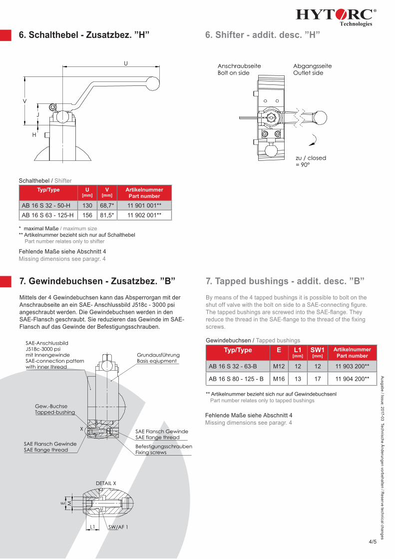
6. Schalthebel - Zusatzbez. ”H” 6. Shifter - addit. desc. ”H”
Typ/Type U [mm]
V [mm]
ArtikelnummerPart number
AB 16 S 32 - 50-H 130 68,7* 11 901 001**AB 16 S 63 - 125-H 156 81,5* 11 902 001**
* maximal Maße / maximum size** Artikelnummer bezieht sich nur auf Schalthebel Part number relates only to shifter
Fehlende Maße siehe Abschnitt 4Missing dimensions see paragr. 4
7. Gewindebuchsen - Zusatzbez. ”B”Mittels der 4 Gewindebuchsen kann das Absperrorgan mit der Anschraubseite an ein SAE- Anschlussbild J518c - 3000 psi angeschraubt werden. Die Gewindebuchsen werden in den SAE-Flansch geschraubt. Sie reduzieren das Gewinde im SAE-Flansch auf das Gewinde der Befestigungsschrauben.
7. Tapped bushings - addit. desc. ”B”By means of the 4 tapped bushings it is possible to bolt on the shut off valve with the bolt on side to a SAE-connecting fi gure.The tapped bushings are screwed into the SAE-fl ange. They reduce the thread in the SAE-fl ange to the thread of the fi xing screws.
Typ/Type E L1 [mm]
SW1 [mm]
ArtikelnummerPart number
AB 16 S 32 - 63-B M12 12 12 11 903 200**
AB 16 S 80 - 125 - B M16 13 17 11 904 200**
** Artikelnummer bezieht sich nur auf Gewindebuchsenl Part number relates only to tapped bushings
Fehlende Maße siehe Abschnitt 4Missing dimensions see paragr. 4
X SAE Flansch GewindeSAE flange thread
BefestigungsschraubenFixing screws
Gew.-BuchseTapped-bushing
SAE Flansch GewindeSAE flange thread
SAE-AnschlussbildJ518c-3000 psimit InnengewindeSAE-connection patternwith inner thread
GrundausführungBasis eqiupment
E
M
L1
DETAIL X
SW/AF 1
>1000÷2000
±1,2±0,8
>400÷1000
±0,5
>120÷400
±0,3
>30÷120
±0,2
>6÷30
±0,1
÷6
Werkstoff: Maßstab:
Hydraulik GmbHAm Leveloh 15bD-45549Sprockhövel
Gewicht:
ISO 2768 mKFreimaßtoleranzen
Für diese Zeichnungbehalten wir uns alle
Rechte vor.( DIN 34 )
Paßmaß Abmaße
Bearb.:Datum Name
Gepr.:
Geänd.:Norm:
1/1
1:2
Blatt
0.7
GrößeA4
Schalthebel / Shifter
Gewindebuchsen / Tapped bushings
D-45549 Sprockhövel • Kleinbeckstraße 3-17Telefon (02324) 9077-0 • Telefax (02324) [email protected] • www.hytorc-technologies.de
Ausgabe / Issue: 2017-03 Technische Änderungen vorbehalten / R
eserve technical changes
5/5
1123
1224
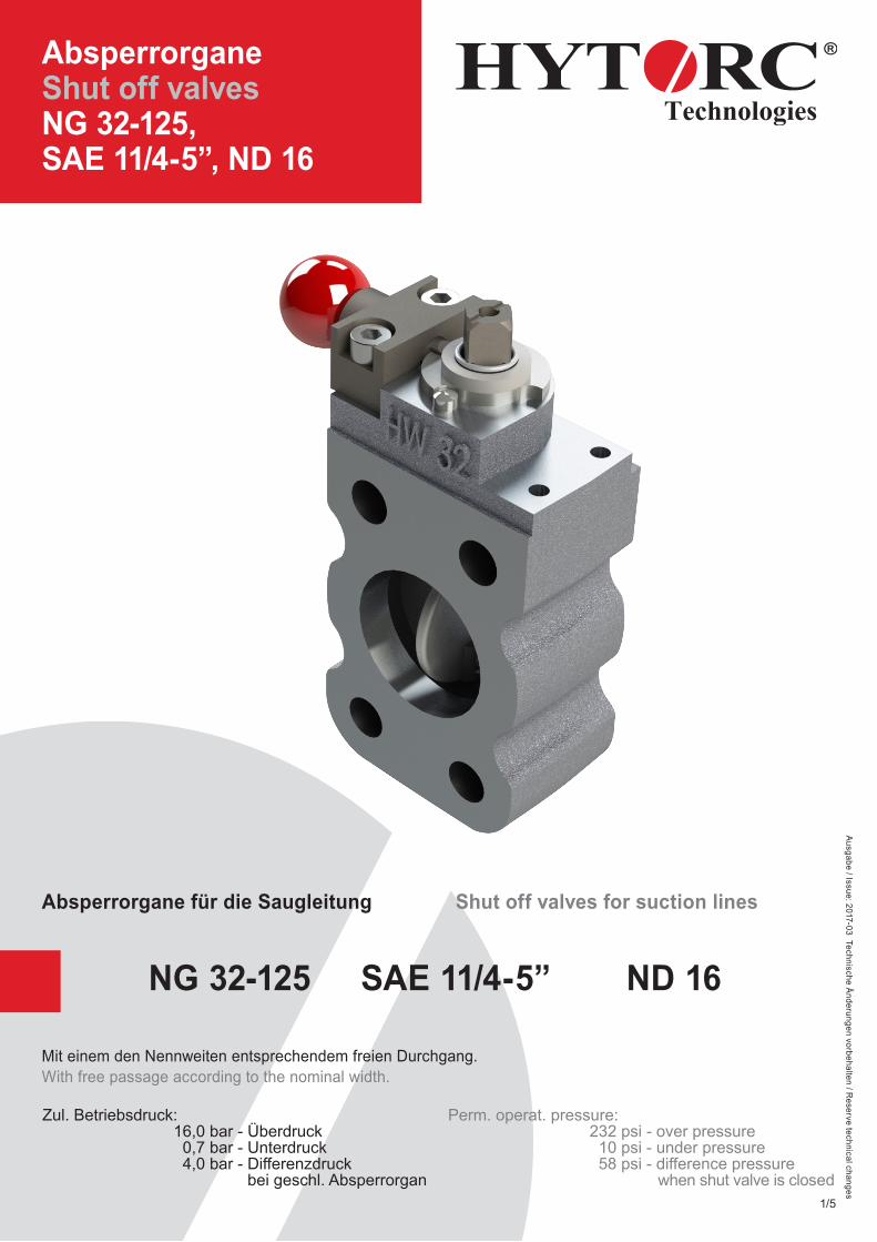
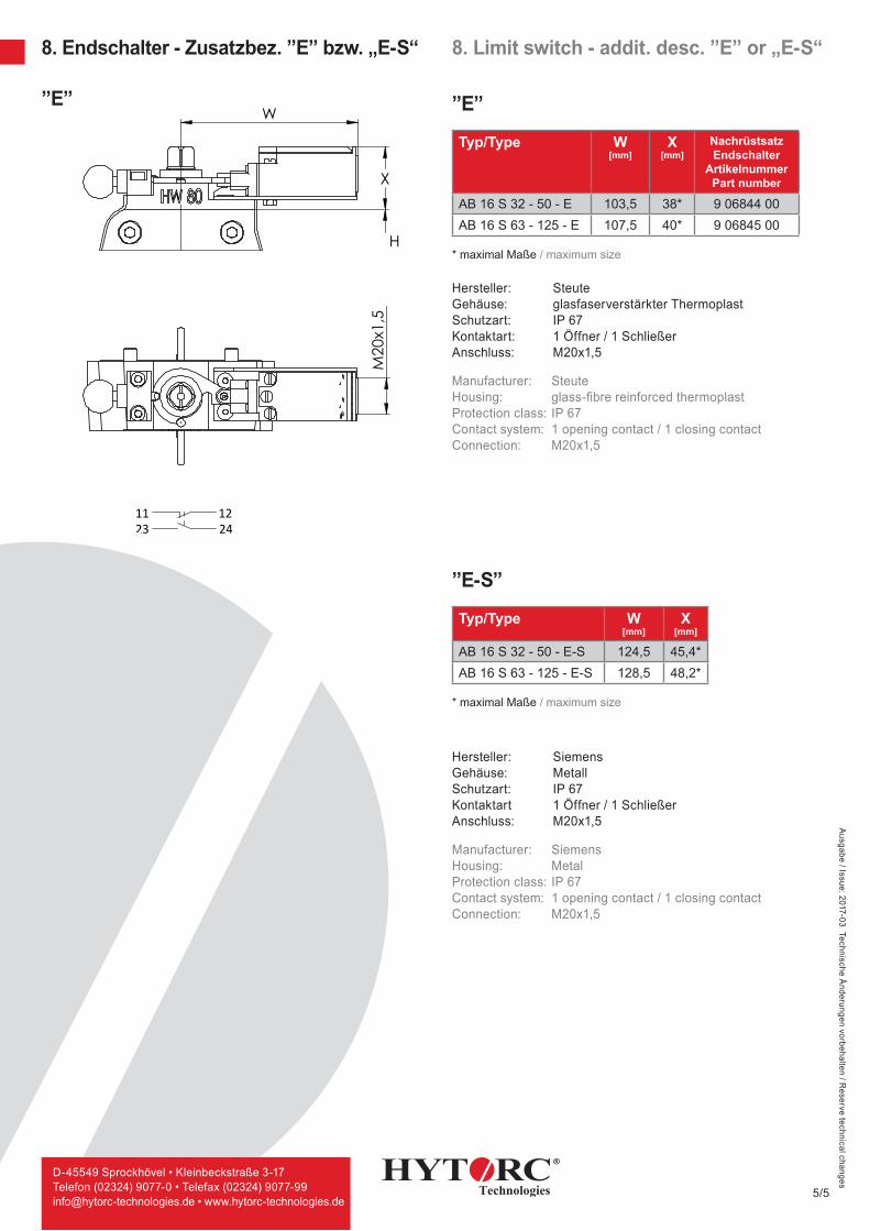
8. Endschalter - Zusatzbez. ”E” bzw. „E-S“ 8. Limit switch - addit. desc. ”E” or „E-S“
X
W
H
M20
x1,5
>1000÷2000
±1,2±0,8
>400÷1000
±0,5
>120÷400
±0,3
>30÷120
±0,2
>6÷30
±0,1
÷6
Werkstoff: Maßstab:
Hydraulik GmbHAm Leveloh 15bD-45549 Sprockhövel
Gewicht:
ISO 2768 mKFreimaßtoleranzen
Für diese Zeichnungbehalten wir uns alle
Rechte vor.( DIN 34 )
Paßmaß Abmaße
Bearb.:Datum Name
Gepr.:
Geänd.:Norm:
11 680 002
30.07.2015 Küsters
1/1
1:2
Absperrorgan AB16 S-80
Blatt
0.7 kg
GrößeA4
Typ/Type W [mm]
X[mm]
NachrüstsatzEndschalter
ArtikelnummerPart number
AB 16 S 32 - 50 - E 103,5 38* 9 06844 00AB 16 S 63 - 125 - E 107,5 40* 9 06845 00
* maximal Maße / maximum size
Hersteller: Steute Gehäuse: glasfaserverstärkter ThermoplastSchutzart: IP 67 Kontaktart: 1 Öffner / 1 SchließerAnschluss: M20x1,5
Manufacturer: SteuteHousing: glass-fi bre reinforced thermoplastProtection class: IP 67Contact system: 1 opening contact / 1 closing contactConnection: M20x1,5
Typ/Type W[mm]
X[mm]
AB 16 S 32 - 50 - E-S 124,5 45,4*AB 16 S 63 - 125 - E-S 128,5 48,2*
* maximal Maße / maximum size
Hersteller: Siemens Gehäuse: Metall Schutzart: IP 67 Kontaktart 1 Öffner / 1 Schließer Anschluss: M20x1,5
Manufacturer: SiemensHousing: MetalProtection class: IP 67Contact system: 1 opening contact / 1 closing contactConnection: M20x1,5
”E”
”E-S”
”E”