Embed Size (px)
Citation preview
AntriebsModulActuatorModuleAM 4000
HANDBUCHUSER MANUAL
2
PowerFuse (T 4AH)
230V AC
6
5
4
3
2
1
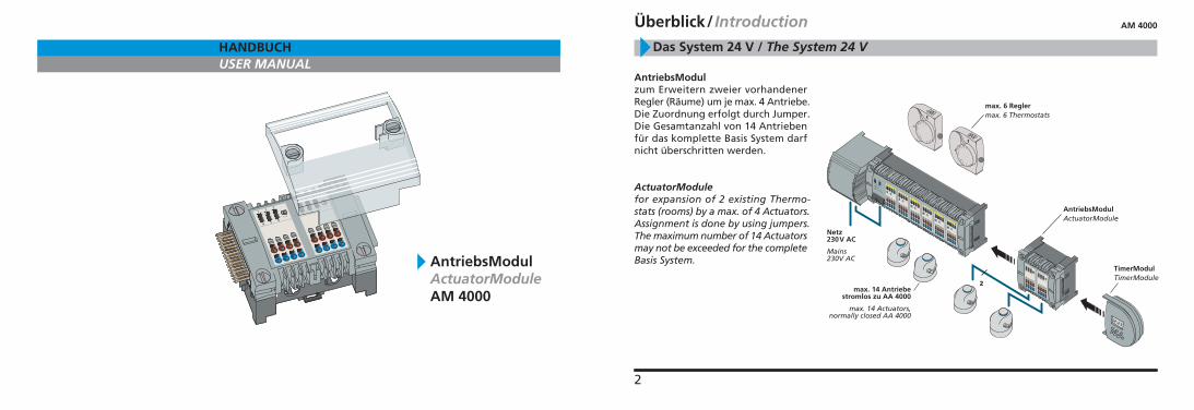
Das System 24 V / The System 24 V
AntriebsModulzum Erweitern zweier vorhandenerRegler (Räume) um je max. 4 Antriebe.Die Zuordnung erfolgt durch Jumper.Die Gesamtanzahl von 14 Antriebenfür das komplette Basis System darfnicht überschritten werden.
ActuatorModulefor expansion of 2 existing Thermo-stats (rooms) by a max. of 4 Actuators.Assignment is done by using jumpers.The maximum number of 14 Actuatorsmay not be exceeded for the completeBasis System.
Überblick/ Introduction
AntriebsModulActuatorModule
Netz230V AC
Mains230V AC
max. 6 Reglermax. 6 Thermostats
max. 14 Antriebestromlos zu AA 4000
max. 14 Actuators,normally closed AA 4000
TimerModulTimerModule
2
AM 4000
4
Leitungen so in die Zugentlastungeindrücken, dass die Ummantelungmit der Oberkante abschließt.
Press wires into the cable grip sothat the sheath is flush with the topedge.
Leitungsenden in die Steck-/Klemm-anschlüsse einstecken. Farbige Kenn-zeichnung beachten.
Simply insert the wire into theSpring Clamp Terminals. Observethe color coding of the connections.
Maximal 14 Antriebe können insge-samt an die Basis angeschlossen wer-den.Diese Anzahl darf auch bei Verwen-dung eines AntriebsModuls odereines ReglerModuls nicht überschrit-ten werden.
Possibility to connect up to a maxi-mum of 14 Actuators to the Basis,even if the system is expanded bythe ActuatorModule or by the Ther-mostatModule.
Anschluss der Antriebe / Connecting the Actuators
AM 4000
3
OPEN
1
2
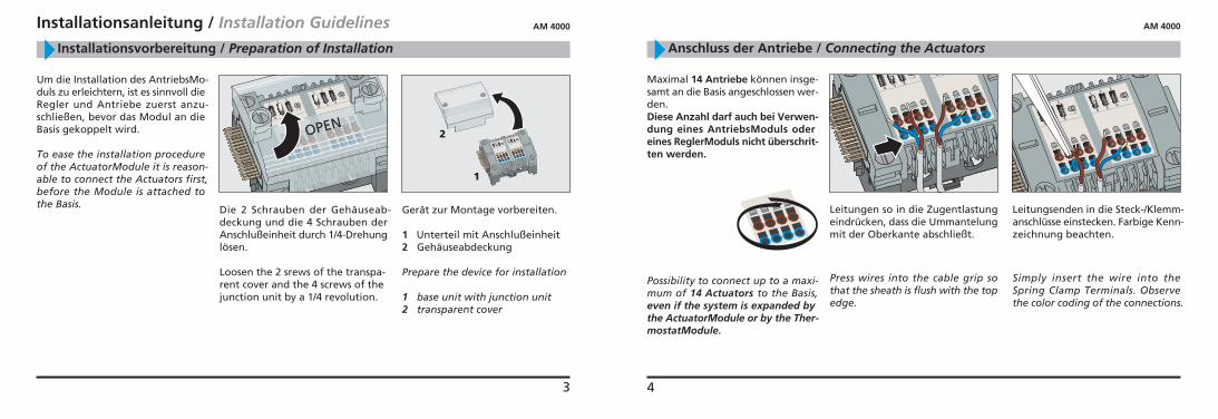
Die 2 Schrauben der Gehäuseab-deckung und die 4 Schrauben derAnschlußeinheit durch 1/4-Drehunglösen.
Loosen the 2 srews of the transpa-rent cover and the 4 screws of thejunction unit by a 1/4 revolution.
Um die Installation des AntriebsMo-duls zu erleichtern, ist es sinnvoll dieRegler und Antriebe zuerst anzu-schließen, bevor das Modul an dieBasis gekoppelt wird.
To ease the installation procedureof the ActuatorModule it is reason-able to connect the Actuators first,before the Module is attached tothe Basis. Gerät zur Montage vorbereiten.
1 Unterteil mit Anschlußeinheit2 Gehäuseabdeckung
Prepare the device for installation
1 base unit with junction unit2 transparent cover
Installationsvorbereitung / Preparation of Installation
Installationsanleitung / Installation Guidelines AM 4000
6
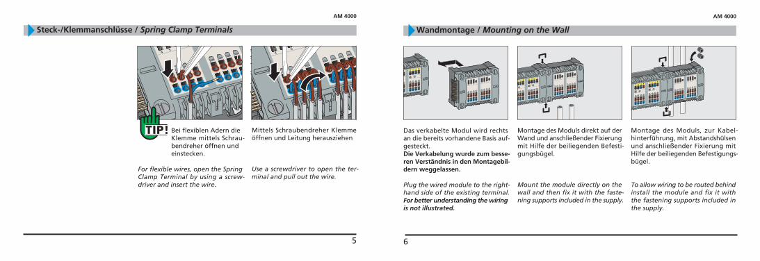
Das verkabelte Modul wird rechtsan die bereits vorhandene Basis auf-gesteckt.Die Verkabelung wurde zum besse-ren Verständnis in den Montagebil-dern weggelassen.
Plug the wired module to the right-hand side of the existing terminal.For better understanding the wiringis not illustrated.
Montage des Moduls direkt auf derWand und anschließender Fixierungmit Hilfe der beiliegenden Befesti-gungsbügel.
Mount the module directly on thewall and then fix it with the faste-ning supports included in the supply.
Montage des Moduls, zur Kabel-hinterführung, mit Abstandshülsenund anschließender Fixierung mitHilfe der beiliegenden Befestigungs-bügel.
To allow wiring to be routed behindinstall the module and fix it withthe fastening supports included inthe supply.
Wandmontage / Mounting on the Wall
AM 4000
5
Bei flexiblen Adern die Klemme mittels Schrau-bendreher öffnen undeinstecken.
For flexible wires, open the SpringClamp Terminal by using a screw-driver and insert the wire.
Steck-/Klemmanschlüsse / Spring Clamp Terminals
Mittels Schraubendreher Klemmeöffnen und Leitung herausziehen
Use a screwdriver to open the ter-minal and pull out the wire.
AM 4000
8
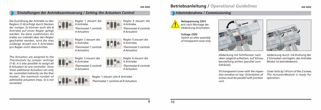
Bild 2Fig. 2
Bild 1Fig. 1
Erweiterung durchAM 4000, PL 4000,TM 1000 möglich
Extension possible byAM 4000, PL 4000,TM 1000If the ActuatorModule is
directly connected to thebase unit, all channels are
available(fig. 1). If, however, thebase unit is already extended by aThermostatModule, the heatingzones 2 and 3 of the ActuatorMo-dule cannot be extended (fig. 2),since these channels are also usedby the thermostats of the Thermo-statModule.
Wird das AntriebsModuldirekt an die Basis angekop-pelt sind alle Kanäle verfüg-
bar (Bild 1). Ist die Basis jedoch miteinem ReglerModul erweitert , sinddie Räume 2 und 3 am AntriebsMo-dul nicht erweiterbar (Bild 2), dadiese Kanäle von den Reglern desReglerModuls mit benutzt werden.
Geräte-Kombinationen / Module Combination
AM 4000
7
2
3
1
231
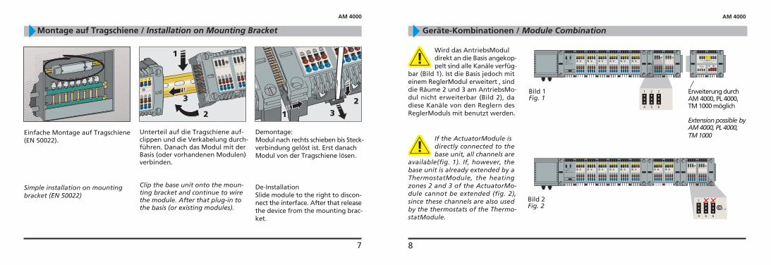
Einfache Montage auf Tragschiene(EN 50022).
Simple installation on mountingbracket (EN 50022)
Demontage:Modul nach rechts schieben bis Steck-verbindung gelöst ist. Erst danachModul von der Tragschiene lösen.
De-InstallationSlide module to the right to discon-nect the interface. After that releasethe device from the mounting brac-ket.
Montage auf Tragschiene / Installation on Mounting Bracket
Unterteil auf die Tragschiene auf-clippen und die Verkabelung durch-führen. Danach das Modul mit derBasis (oder vorhandenen Modulen)verbinden.
Clip the base unit onto the moun-ting bracket and continue to wirethe module. After that plug-in tothe basis (or existing modules).
AM 4000
9
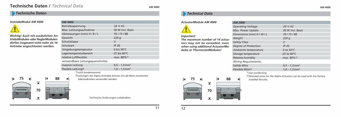
Die Zuordnung der Antriebe zu denReglern (1-6) erfolgt durch Steckender Jumper. Es können auch alle 8Antriebe auf einen Regler gelegtwerden. Da diese zusätzlichen An-triebe nur indirekt über den Reglergeschaltet werden, wird die max.zulässige Anzahl von 5 Antriebenpro Regler nicht überschritten.
The Actuators are assigned to theThermostats by jumper settings(1-6). It is also possible to assign all8 Actuators to one controller. Sincethese additional Actuators can onlybe controlled indirectly via the ther-mostat , the maximum number ofadmissible actuators (max. 5) is notexceeded.
Einstellungen der Antriebsansteuerung / Setting the Actuators Control
AM 4000
Regler 2 steuert die4 Antriebe
Thermostat 1 controls4 Actuators
Regler 1 steuert die4 Antriebe
Thermostat 1 controls4 Actuators
Regler 1 steuert alle 8 Antriebe
Thermostat 1 controls all 8 Actuators
Regler 5 steuert die4 Antriebe
Thermostat 5 controls4 Actuators
Regler 4 steuert die4 Antriebe
Thermostat 4 controls4 Actuators
Regler 6 steuert die4 Antriebe
Thermostat 6 controls4 Actuators
Regler 3 steuert die4 Antriebe
Thermostat 3 controls4 Actuators
10
Betriebsanleitung / Operational Guidelines
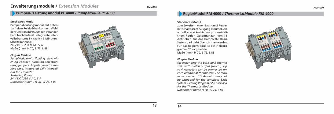
Abdeckung mit Sichtfenster nachoben zeigend aufsetzen, auf Schrau-benstellung achten (parallel zumGehäuse).
Fit transparent cover with the inspec-tion window on top. Orientation ofscrews must be parallel with junctionunit.
Inbetriebnahme / Commissioning
Netzspannung 230Verst nach Montage derAbdeckung einschalten.
Voltage 230VSwitch on after assemblyof transparent cover only.
AM 4000
Abdeckung durch 1/4-Drehung der2 Schrauben verriegeln, das Antriebs-Modul ist betriebsbereit.
Cover locks by 1/4 turn of the 2 screws.The ActuatorModule is ready foroperation.
11
AM 4000Betriebsspannung 24 V ACMax. Leistungsaufnahme 50 W incl. BasisAbmessungen (mm) H / B / L 70 / 75 / 88Gewicht 220 gSchutzklasse ��Schutzart IP 20Umgebungstemperatur 0 bis 50°CLagertemperaturbereich -25 bis 60°Crelative Luftfeuchte max. 80%1)
verwendbare Leitungsquerschnitte:massive Leitung 0,5 – 1,5mm2
flexible Leitung2) 1,0 – 1,5mm2
1)nicht kondensierend2)Leitungen der Alpha-Antriebe können mit ab Werk montierten
Aderendhülsen verwendet werden.
Technische Änderungen vorbehalten.
70
8875
AntriebsModul AM 4000
Wichtig! Auch mit zusätzlichen An-triebsModulen oder ReglerModulendürfen insgesamt nicht mehr als 14Antriebe angeschlossen werden.
Technische Daten / Technical Data
Technische Daten
AM 4000
12
AM 2000Operating Voltage 24 V ACMax. Power Uptake 50 W incl. BasisDimensions (mm) H / W / L 70 / 75 / 88Weight 220 gSafety Class ��Degree of Protection IP 20Ambiente temperature 0 to 50°CStorage temperature -25 to 60°CRelative humidity max. 80%1)
Wiring Requirements:Solide Wire 0,5 – 1,5mm2
Flexible Wire2) 1,0 – 1,5mm2
1)non-condensing2)Stranded wires for the Alpha-Actuators can be used with the factory
installed ferrules.
70
8875
ActuatorModule AM 4000
Important:The maximum number of 14 actua-tors may not be exceeded, evenwhen using additional ActuatorMo-dules or ThermostatModules!
Technical Data
AM 4000
13
Erweiterungsmodule / Extension Modules
Steckbares ModulPumpen-/Leistungsmodul mit poten-tialfreiem Relais-Schaltkontakt. Wahlder Funktion durch Jumper. Veränder-bare Nachlaufzeit. Integrierte Inter-vallschaltung 1 x täglich 5 Minuten.Schaltspannung:24 V DC / 230 V AC, 5 AMaße (mm): H 70, B 75, L 88
Plug-in ModulePumpModule with floating relay swit-ching contact. Function selectionusing jumpers. Adjustable extra run-ning time. Integrated daily intervallrun for 5 minutes.Switching Power:24 V DC / 230 V AC, 5 ADimensions (mm): H 70, W 75, L 88
Pumpen-/Leistungsmodul PL 4000 / PumpModule PL 4000
AM 4000
14
ReglerModul RM 4000 / ThermostatModule RM 4000
Steckbares Modulzum Erweitern einer Basis um 2 Reglermit schaltbarem Ausgang (Räume). An-schluß von 4 Antrieben pro zusätzli-chem Regler. Gesamtanzahl von 14Antrieben für das komplette Basis-System darf nicht überschritten werden.Für das ReglerModul ist das Heizpro-gramm C2 vorgesehen.Maße (mm): H 70, B 75, L 88
Plug-in Modulefor expanding the Basis by 2 thermo-stats with switch output (rooms). Upto 4 Actuators can be connected foreach additional thermostat. The maxi-mum number of 14 Actuators may notbe exceeded for the complete BasisSystem. Heating Program C2 is providedfor the ThermostatModule.Dimensions (mm): H 70, W 75, L 88
AM 4000
Basis Systemübersicht / Basis System Overview
Basis 230V/24V / Basis 230V/24V Basis 0-10V / Basis 0-10V
Basis Funk / Basis RC
8-D
51-5
0-01
8R
ev. 1
.8
15
ok
MenuRes
1 2 3 4 5 6 7
12 15 18 21 24
9
6
3
0
21
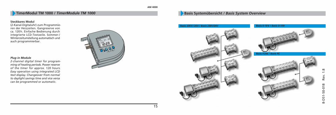
Steckbares Modul(2-Kanal-Digitaluhr) zum Programmie-ren der Heizzeiten. Gangreserve vonca. 120 h. Einfache Bedienung durchintegrierte LCD-Textzeile. Sommer-/Winterzeitumstellung automatisch undauch programmierbar.
Plug-in Module2-channel digital timer for program-ming of heating periods. Power reserveof the timer for approx. 120 hours.Easy operation using integrated LCDtext display. Changeover from normalto daylight savings time and vice versacan be programmed or automatic.
TimerModul TM 1000 / TimerModule TM 1000
AM 4000


![Handbuch der Fertigungstechnik / [Bd. 1] / Handbuch Urformen · Inhaltsverzeichnis VorwortderBandherausgeber V DieHerausgeber XXV Autorenverzeichnis XXVII I Urformen von Metallen](https://img.pdfslide.org/doc/110x75/5e4d0eb3e863f428380f831c/handbuch-der-fertigungstechnik-bd-1-handbuch-urformen-inhaltsverzeichnis.jpg)