Embed Size (px)
Citation preview
OOnneebbooxx –– IIMMXX5533 IInnssttaallllaattiioonn
aanndd TTeesstt PPrroocceedduurree MMaannuuaall
VVeerrssiioonn 11..22..66
Redpine Signals, Inc. Proprietary and confidential Page 1
Onebox™ - IMX53
Installation and Test Procedure Manual
Version 1.2.6
May’2012
Redpine Signals, Inc. 2107 N. First Street, #680
San Jose, CA 95131.
Tel: (408) 748-3385
Fax: (408) 705-2019
Email: [email protected]
Website: www.redpinesignals.com

OOnneebbooxx –– IIMMXX5533 IInnssttaallllaattiioonn
aanndd TTeesstt PPrroocceedduurree MMaannuuaall
VVeerrssiioonn 11..22..66
Redpine Signals, Inc. Proprietary and confidential Page 2
Disclaimer:
The information in this document pertains to information related to Redpine Signals
Inc. products. This information is provided as a service to our customers, and may
be used for information purposes only.
Redpine assumes no liabilities or responsibilities for errors or omissions in this
document. This document may be changed at any time at Redpine‟s sole discretion
without any prior notice to anyone. Redpine is not committed to updating these
documents in the future.
Copyright 2008 Redpine Signals, Inc. All rights reserved.
OOnneebbooxx –– IIMMXX5533 IInnssttaallllaattiioonn
aanndd TTeesstt PPrroocceedduurree MMaannuuaall
VVeerrssiioonn 11..22..66
Redpine Signals, Inc. Proprietary and confidential Page 3
Table of Contents
1 Introduction ........................................................................ 4
2 Onebox Driver – Setup requirements ................................... 5 2.1 Hardware Requirements ....................................................... 5
3 IMX53 Quick Start Procedure .............................................. 5 3.1 Kernel image in this Release ................................................. 5 3.2 Release Contents .................................................................. 5 3.3 Requirements for using a Linux Host to set up an SD/MMC card 5
4 Flashing Procedures ............................................................ 6 4.1 Flashing the Boot loader ....................................................... 6 4.2 Flashing the Kernel ............................................................... 6 4.3 Flashing the rootfs ................................................................ 7 4.4 Create the ext3 file system ................................................... 7 4.5 Copy the target file system to the partition: ......................... 7
5 Onebox Configuration Utility ............................................... 8 5.1 Starting HTTP Utility ............................................................. 8 5.2 Hyperterminal settings (optional): ....................................... 8 5.3 Device mode settings ............................................................ 8
6 Access Point settings ........................................................... 8 6.1 Configuring WLAN Radio Settings ......................................... 9 6.2 Configuring WLAN Advanced Radio Settings ....................... 10 6.3 Configuring AP/VAP settings .............................................. 10 6.4 Adding Parameters in AP/VAP creation .............................. 11 6.5 Security Mode: .................................................................... 12
7 Station settings ................................................................. 16 7.1 Station configuration .......................................................... 17 7.2 Connecting to a Network with Hidden SSID ........................ 18
8 Wifi- Direct settings ........................................................... 19 8.1 Starting P2P device as Autonomous GO: ............................. 20 8.2 P2P scan ............................................................................. 21
9 LAN settings ...................................................................... 22
10 WPS Settings ................................................................... 23
11 ACL settings .................................................................... 24
12 Statistics ......................................................................... 26 12.1 Acess Point statistics .......................................................... 26 12.2 Station Statistics ................................................................. 26 12.3 Autorate Statistics .............................................................. 27

Redpine Signals, Inc. Proprietary and Confidential
1 Introduction
This document describes the test procedure for configuring Onebox in various device
modes like Access Point, Station, Wi-Fi Direct. Please follow the instructions in the
document to copy image into SD memory card and to start OneBox on imx53-
START-R board.
Redpine Signals, Inc. Proprietary and Confidential Page 5
OOnneebbooxx ––IIMMXX5533 IInnssttaallllaattiioonn
aanndd TTeesstt PPrroocceedduurree MMaannuuaall
VVeerrssiioonn 11..22..66
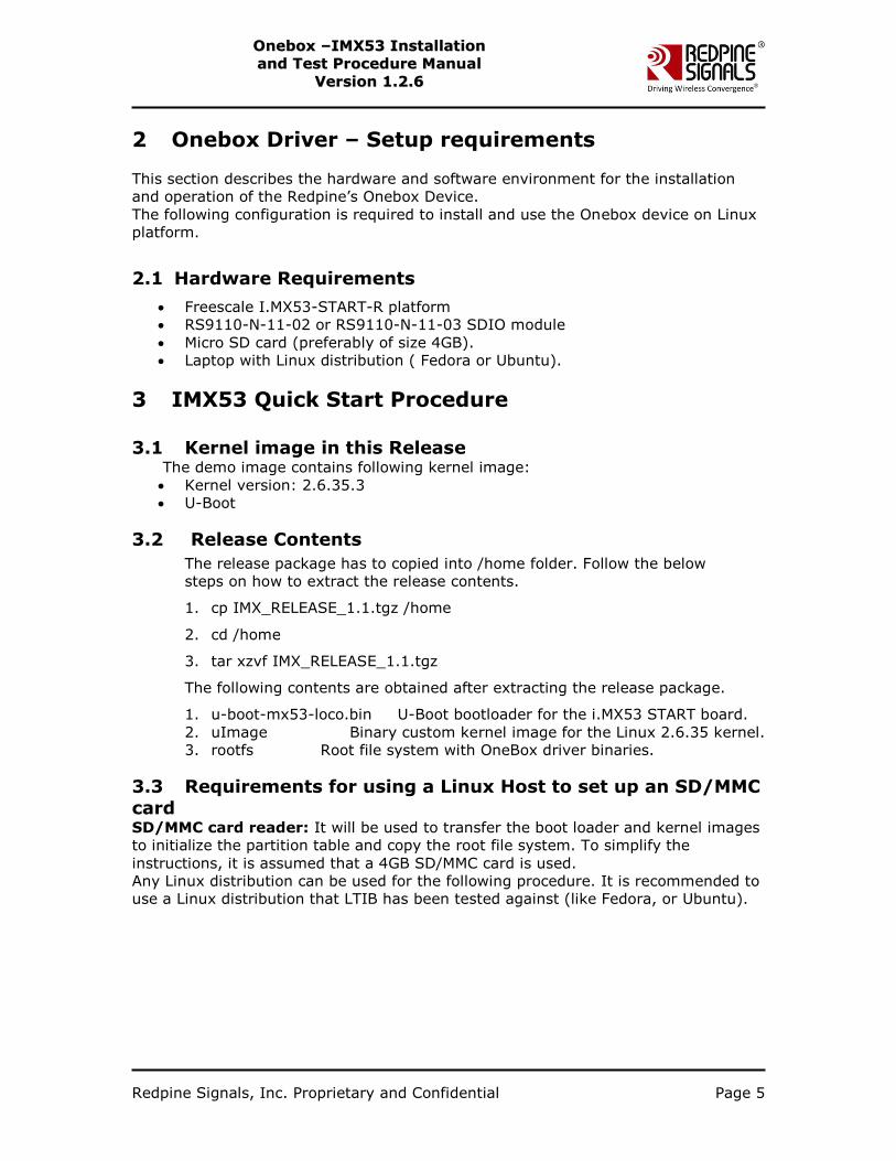
2 Onebox Driver – Setup requirements
This section describes the hardware and software environment for the installation
and operation of the Redpine‟s Onebox Device.
The following configuration is required to install and use the Onebox device on Linux
platform.
2.1 Hardware Requirements
Freescale I.MX53-START-R platform
RS9110-N-11-02 or RS9110-N-11-03 SDIO module
Micro SD card (preferably of size 4GB).
Laptop with Linux distribution ( Fedora or Ubuntu).
3 IMX53 Quick Start Procedure 3.1 Kernel image in this Release The demo image contains following kernel image:
Kernel version: 2.6.35.3
U-Boot
3.2 Release Contents
The release package has to copied into /home folder. Follow the below
steps on how to extract the release contents.
1. cp IMX_RELEASE_1.1.tgz /home
2. cd /home
3. tar xzvf IMX_RELEASE_1.1.tgz
The following contents are obtained after extracting the release package.
1. u-boot-mx53-loco.bin U-Boot bootloader for the i.MX53 START board.
2. uImage Binary custom kernel image for the Linux 2.6.35 kernel.
3. rootfs Root file system with OneBox driver binaries.
3.3 Requirements for using a Linux Host to set up an SD/MMC
card SD/MMC card reader: It will be used to transfer the boot loader and kernel images
to initialize the partition table and copy the root file system. To simplify the
instructions, it is assumed that a 4GB SD/MMC card is used.
Any Linux distribution can be used for the following procedure. It is recommended to
use a Linux distribution that LTIB has been tested against (like Fedora, or Ubuntu).
Redpine Signals, Inc. Proprietary and Confidential Page 6
OOnneebbooxx ––IIMMXX5533 IInnssttaallllaattiioonn
aanndd TTeesstt PPrroocceedduurree MMaannuuaall
VVeerrssiioonn 11..22..66
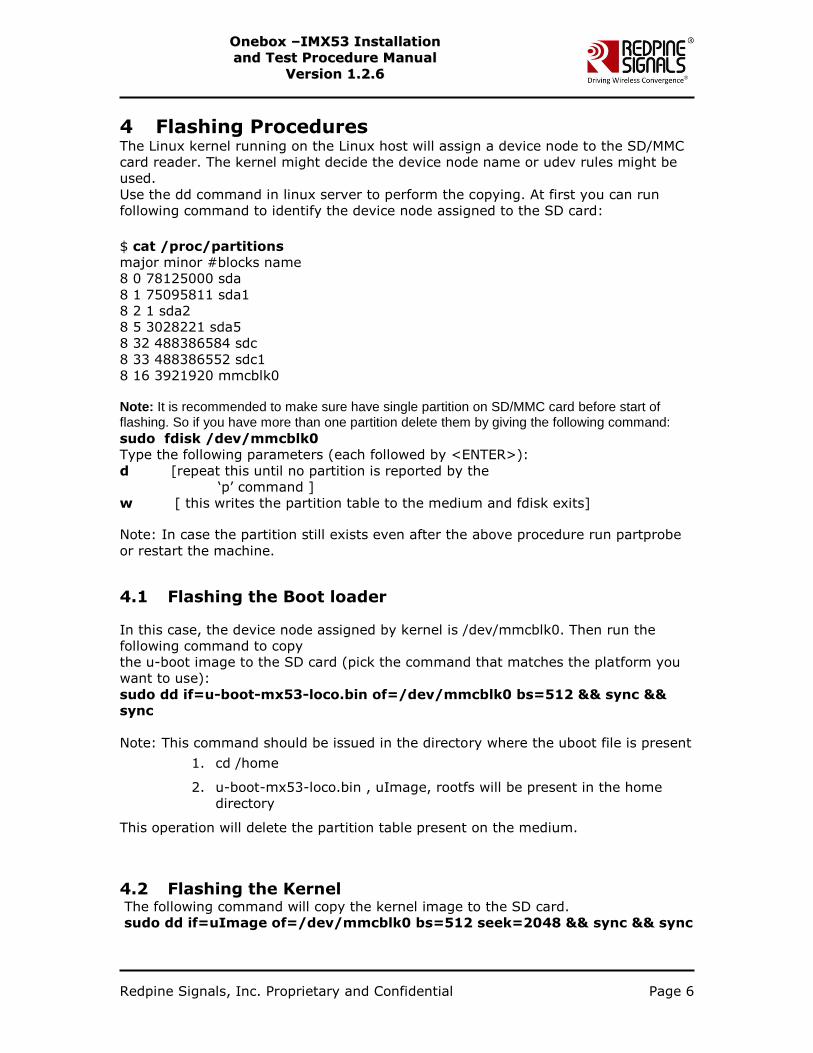
4 Flashing Procedures The Linux kernel running on the Linux host will assign a device node to the SD/MMC
card reader. The kernel might decide the device node name or udev rules might be
used.
Use the dd command in linux server to perform the copying. At first you can run
following command to identify the device node assigned to the SD card:
$ cat /proc/partitions
major minor #blocks name
8 0 78125000 sda
8 1 75095811 sda1
8 2 1 sda2
8 5 3028221 sda5
8 32 488386584 sdc
8 33 488386552 sdc1
8 16 3921920 mmcblk0
Note: It is recommended to make sure have single partition on SD/MMC card before start of flashing. So if you have more than one partition delete them by giving the following command:
sudo fdisk /dev/mmcblk0
Type the following parameters (each followed by <ENTER>):
d [repeat this until no partition is reported by the
„p‟ command ]
w [ this writes the partition table to the medium and fdisk exits]
Note: In case the partition still exists even after the above procedure run partprobe
or restart the machine.
4.1 Flashing the Boot loader
In this case, the device node assigned by kernel is /dev/mmcblk0. Then run the
following command to copy
the u-boot image to the SD card (pick the command that matches the platform you
want to use):
sudo dd if=u-boot-mx53-loco.bin of=/dev/mmcblk0 bs=512 && sync &&
sync
Note: This command should be issued in the directory where the uboot file is present
1. cd /home
2. u-boot-mx53-loco.bin , uImage, rootfs will be present in the home
directory
This operation will delete the partition table present on the medium.
4.2 Flashing the Kernel The following command will copy the kernel image to the SD card.
sudo dd if=uImage of=/dev/mmcblk0 bs=512 seek=2048 && sync && sync
Redpine Signals, Inc. Proprietary and Confidential Page 7
OOnneebbooxx ––IIMMXX5533 IInnssttaallllaattiioonn
aanndd TTeesstt PPrroocceedduurree MMaannuuaall
VVeerrssiioonn 11..22..66
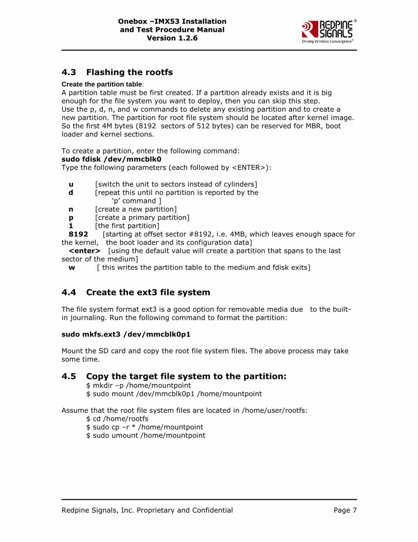
4.3 Flashing the rootfs
Create the partition table:
A partition table must be first created. If a partition already exists and it is big
enough for the file system you want to deploy, then you can skip this step.
Use the p, d, n, and w commands to delete any existing partition and to create a
new partition. The partition for root file system should be located after kernel image.
So the first 4M bytes (8192 sectors of 512 bytes) can be reserved for MBR, boot
loader and kernel sections.
To create a partition, enter the following command:
sudo fdisk /dev/mmcblk0
Type the following parameters (each followed by <ENTER>):
u [switch the unit to sectors instead of cylinders]
d [repeat this until no partition is reported by the
„p‟ command ]
n [create a new partition]
p [create a primary partition]
1 [the first partition]
8192 [starting at offset sector #8192, i.e. 4MB, which leaves enough space for
the kernel, the boot loader and its configuration data]
<enter> [using the default value will create a partition that spans to the last
sector of the medium]
w [ this writes the partition table to the medium and fdisk exits]
4.4 Create the ext3 file system
The file system format ext3 is a good option for removable media due to the built-
in journaling. Run the following command to format the partition:
sudo mkfs.ext3 /dev/mmcblk0p1
Mount the SD card and copy the root file system files. The above process may take
some time.
4.5 Copy the target file system to the partition: $ mkdir –p /home/mountpoint
$ sudo mount /dev/mmcblk0p1 /home/mountpoint
Assume that the root file system files are located in /home/user/rootfs:
$ cd /home/rootfs
$ sudo cp –r * /home/mountpoint
$ sudo umount /home/mountpoint
Redpine Signals, Inc. Proprietary and Confidential Page 8
OOnneebbooxx ––IIMMXX5533 IInnssttaallllaattiioonn
aanndd TTeesstt PPrroocceedduurree MMaannuuaall
VVeerrssiioonn 11..22..66
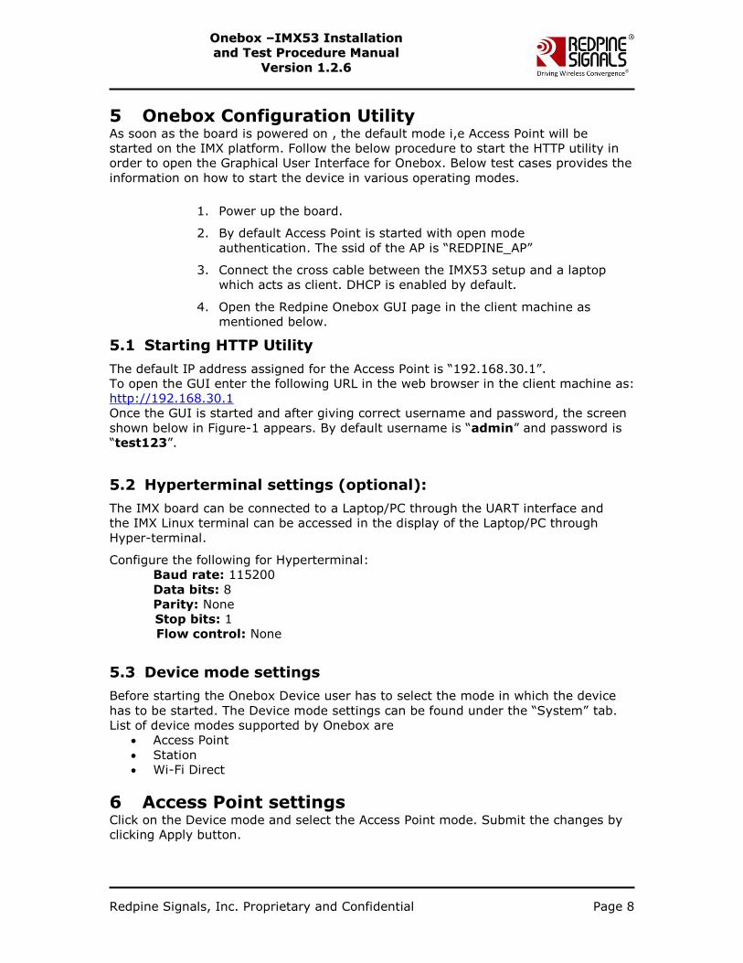
5 Onebox Configuration Utility As soon as the board is powered on , the default mode i,e Access Point will be
started on the IMX platform. Follow the below procedure to start the HTTP utility in
order to open the Graphical User Interface for Onebox. Below test cases provides the
information on how to start the device in various operating modes.
1. Power up the board.
2. By default Access Point is started with open mode
authentication. The ssid of the AP is “REDPINE_AP”
3. Connect the cross cable between the IMX53 setup and a laptop
which acts as client. DHCP is enabled by default.
4. Open the Redpine Onebox GUI page in the client machine as
mentioned below.
5.1 Starting HTTP Utility
The default IP address assigned for the Access Point is “192.168.30.1”.
To open the GUI enter the following URL in the web browser in the client machine as:
http://192.168.30.1
Once the GUI is started and after giving correct username and password, the screen
shown below in Figure-1 appears. By default username is “admin” and password is
“test123”.
5.2 Hyperterminal settings (optional):
The IMX board can be connected to a Laptop/PC through the UART interface and
the IMX Linux terminal can be accessed in the display of the Laptop/PC through
Hyper-terminal.
Configure the following for Hyperterminal:
Baud rate: 115200
Data bits: 8
Parity: None
Stop bits: 1
Flow control: None
5.3 Device mode settings
Before starting the Onebox Device user has to select the mode in which the device
has to be started. The Device mode settings can be found under the “System” tab.
List of device modes supported by Onebox are
Access Point
Station
Wi-Fi Direct
6 Access Point settings Click on the Device mode and select the Access Point mode. Submit the changes by
clicking Apply button.
Redpine Signals, Inc. Proprietary and Confidential Page 9
OOnneebbooxx ––IIMMXX5533 IInnssttaallllaattiioonn
aanndd TTeesstt PPrroocceedduurree MMaannuuaall
VVeerrssiioonn 11..22..66
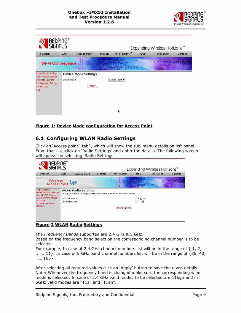
Figure 1: Device Mode configuration for Access Point
6.1 Configuring WLAN Radio Settings
Click on „Access point` tab`, which will show the sub-menu details on left panel.
From that list, click on „Radio Settings‟ and enter the details. The following screen
will appear on selecting „Radio Settings‟.
Figure 2 WLAN Radio Settings
The Frequency Bands supported are 2.4 GHz & 5 GHz.
Based on the frequency band selection the corresponding channel number is to be
selected.
For example, In case of 2.4 GHz channel numbers list will be in the range of { 1, 2,
..….. 11}. In case of 5 GHz band channel numbers list will be in the range of {36, 40,
…… 165}
After selecting all required values click on „Apply‟ button to save the given details.
Note: Whenever the frequency band is changed make sure the corresponding wlan
mode is selected. In case of 2.4 GHz valid modes to be selected are 11bgn and in
5GHz valid modes are “11a” and “11an”.

Redpine Signals, Inc. Proprietary and Confidential Page 10
OOnneebbooxx ––IIMMXX5533 IInnssttaallllaattiioonn
aanndd TTeesstt PPrroocceedduurree MMaannuuaall
VVeerrssiioonn 11..22..66
6.2 Configuring WLAN Advanced Radio Settings
Click on „Access Point‟ button, which will show the sub-menu details on left panel.
From that list, click on „Advanced Radio Settings‟ and enter the details. The following
screen will appear on selecting „Advanced Radio Settings‟:
Figure 3Wireless Advanced Radio Settings
Beacon Interval is to be selected in milliseconds and is to be in the range 10 to 1000.
DTIM interval is to be in number of beacons and is to be in the range 1 to 255.
RTS protection is disabled. So the value of RTS threshold is 2304 by default.
Transmit Fragmentation is also disabled. So the value of Fragmentation threshold is
2304 by default. After selecting all proper required values click on „Apply‟ button to
save the given details.
6.3 Configuring AP/VAP settings
Click on „Access Point‟ button, which will show the sub-menu details on left panel.
Click on „Main AP/VAP Settings‟ from the given list. The following screen will appear
on selecting „ Main AP/VAP Settings‟:
Redpine Signals, Inc. Proprietary and Confidential Page 11
OOnneebbooxx ––IIMMXX5533 IInnssttaallllaattiioonn
aanndd TTeesstt PPrroocceedduurree MMaannuuaall
VVeerrssiioonn 11..22..66
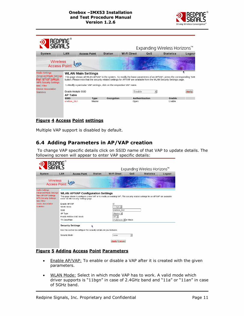
Figure 4 Access Point settings
Multiple VAP support is disabled by default.
6.4 Adding Parameters in AP/VAP creation
To change VAP specific details click on SSID name of that VAP to update details. The
following screen will appear to enter VAP specific details:
Figure 5 Adding Access Point Parameters
Enable AP/VAP: To enable or disable a VAP after it is created with the given
parameters.
WLAN Mode: Select in which mode VAP has to work. A valid mode which
driver supports is “11bgn” in case of 2.4GHz band and “11a” or “11an” in case
of 5GHz band.
Redpine Signals, Inc. Proprietary and Confidential Page 12
OOnneebbooxx ––IIMMXX5533 IInnssttaallllaattiioonn
aanndd TTeesstt PPrroocceedduurree MMaannuuaall
VVeerrssiioonn 11..22..66
SSID: A valid string is accepted as SSID, for example TESTING_VAP1,
VAP_000.
AP Type: The type in which VAP will work, available type in this release is
„Master‟.
Tx Data Rate: Based upon the mode selected the Tx date rates will be shown
in the drop down list. For “11n” supported rates are mcs-0 to mcs-7, for
“11bg” supported rates are 1, 2, 5.5, 11, 6, 9, 12, 18, 24, 36, 48, 54 and for
“11bgn” all above rates are supported. If user wants to choose auto rate
then “FullyAuto” option needs to be selected.
In case of Dual band the “11a” rates supported are same as the “11g” rates.
For 11AN mode all “11N” and “11a” rates are supported.
6.5 Security Mode:
In this release the supported security modes are WEP,WPA,WPA2.
WEP-64 Security mode: In case of WEP-64 bit encryption the below steps needs to
be followed.
Select WEP mode in the security mode field
Select wep64 in the encryption field.
Select the type of the keys whether it is HEX or ASCII
Fill the key ids and select apply button. In the WEP-64 security method ,if the
key type is hex then the key length is of 10 digits. In case of ASCII key length
is of 5 characters.
Redpine Signals, Inc. Proprietary and Confidential Page 13
OOnneebbooxx ––IIMMXX5533 IInnssttaallllaattiioonn
aanndd TTeesstt PPrroocceedduurree MMaannuuaall
VVeerrssiioonn 11..22..66
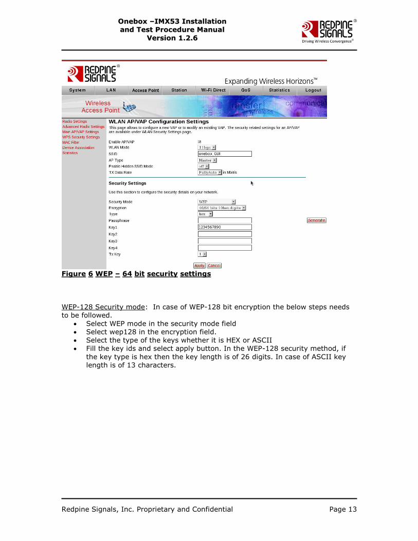
Figure 6 WEP – 64 bit security settings
WEP-128 Security mode: In case of WEP-128 bit encryption the below steps needs
to be followed.
Select WEP mode in the security mode field
Select wep128 in the encryption field.
Select the type of the keys whether it is HEX or ASCII
Fill the key ids and select apply button. In the WEP-128 security method, if
the key type is hex then the key length is of 26 digits. In case of ASCII key
length is of 13 characters.
Redpine Signals, Inc. Proprietary and Confidential Page 14
OOnneebbooxx ––IIMMXX5533 IInnssttaallllaattiioonn
aanndd TTeesstt PPrroocceedduurree MMaannuuaall
VVeerrssiioonn 11..22..66
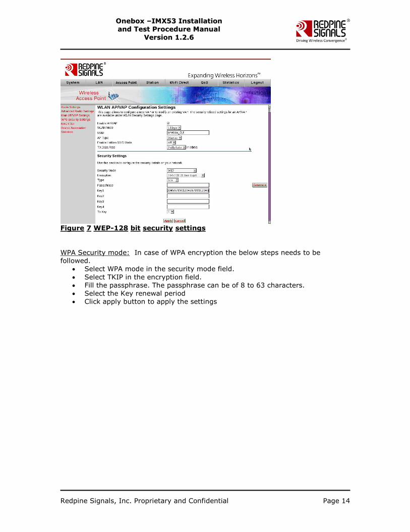
Figure 7 WEP-128 bit security settings
WPA Security mode: In case of WPA encryption the below steps needs to be
followed.
Select WPA mode in the security mode field.
Select TKIP in the encryption field.
Fill the passphrase. The passphrase can be of 8 to 63 characters.
Select the Key renewal period
Click apply button to apply the settings
Redpine Signals, Inc. Proprietary and Confidential Page 15
OOnneebbooxx ––IIMMXX5533 IInnssttaallllaattiioonn
aanndd TTeesstt PPrroocceedduurree MMaannuuaall
VVeerrssiioonn 11..22..66
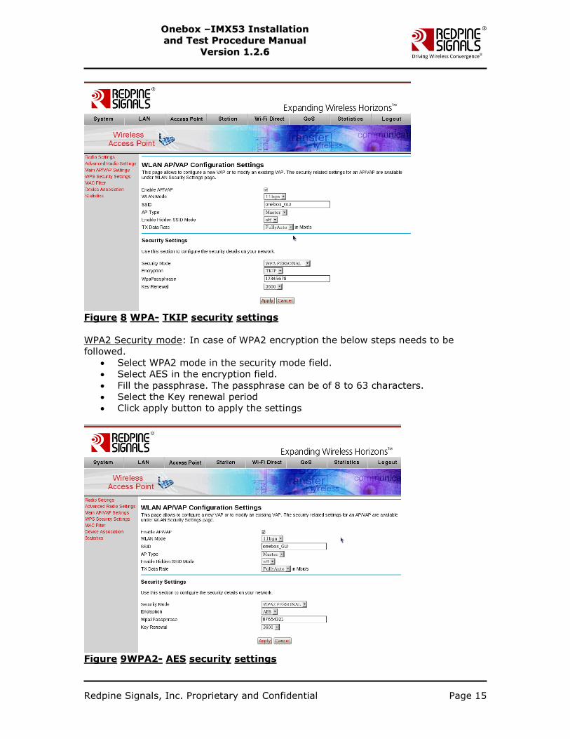
Figure 8 WPA- TKIP security settings
WPA2 Security mode: In case of WPA2 encryption the below steps needs to be
followed.
Select WPA2 mode in the security mode field.
Select AES in the encryption field.
Fill the passphrase. The passphrase can be of 8 to 63 characters.
Select the Key renewal period
Click apply button to apply the settings
Figure 9WPA2- AES security settings
Redpine Signals, Inc. Proprietary and Confidential Page 16
OOnneebbooxx ––IIMMXX5533 IInnssttaallllaattiioonn
aanndd TTeesstt PPrroocceedduurree MMaannuuaall
VVeerrssiioonn 11..22..66
After applying the changes go to the System tab and press “Apply” button under
“device mode settings” to apply the changes done for the access point mode (Refer
to Figure 1).
Note: In case if the users apply‟s the changes immediately after selecting the device
mode, AP mode gets started with the previous effected values.
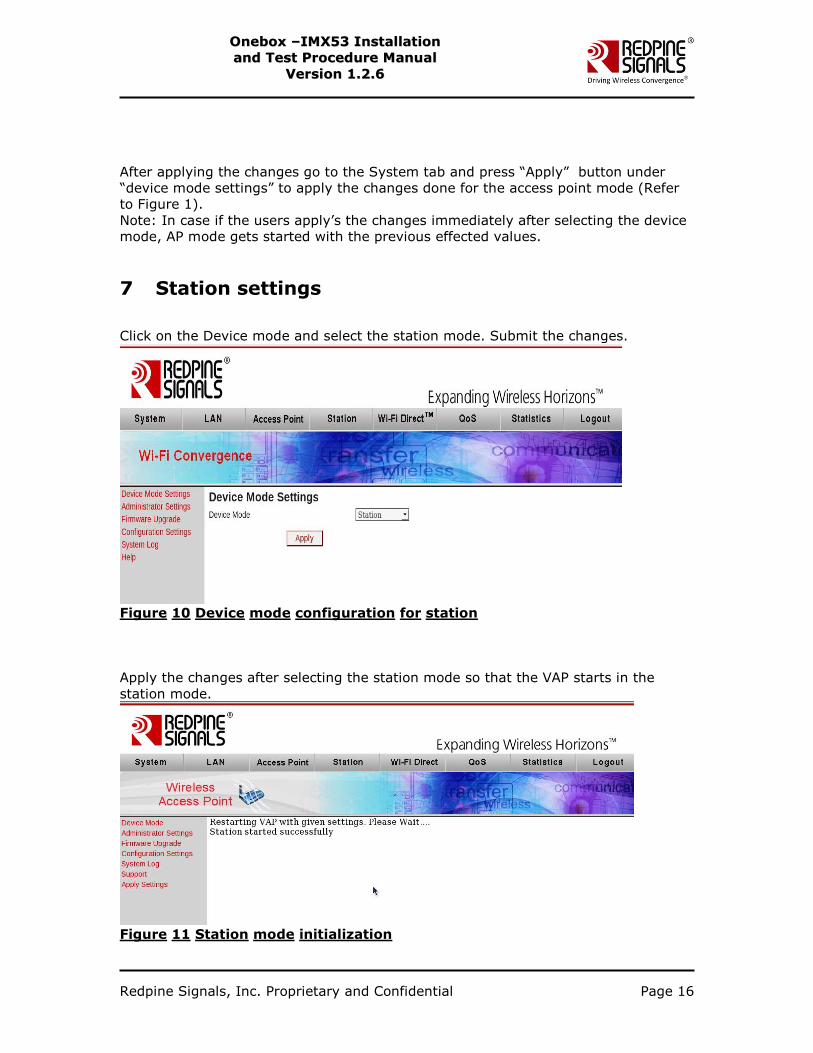
7 Station settings
Click on the Device mode and select the station mode. Submit the changes.
Figure 10 Device mode configuration for station
Apply the changes after selecting the station mode so that the VAP starts in the
station mode.
Figure 11 Station mode initialization
Redpine Signals, Inc. Proprietary and Confidential Page 17
OOnneebbooxx ––IIMMXX5533 IInnssttaallllaattiioonn
aanndd TTeesstt PPrroocceedduurree MMaannuuaall
VVeerrssiioonn 11..22..66
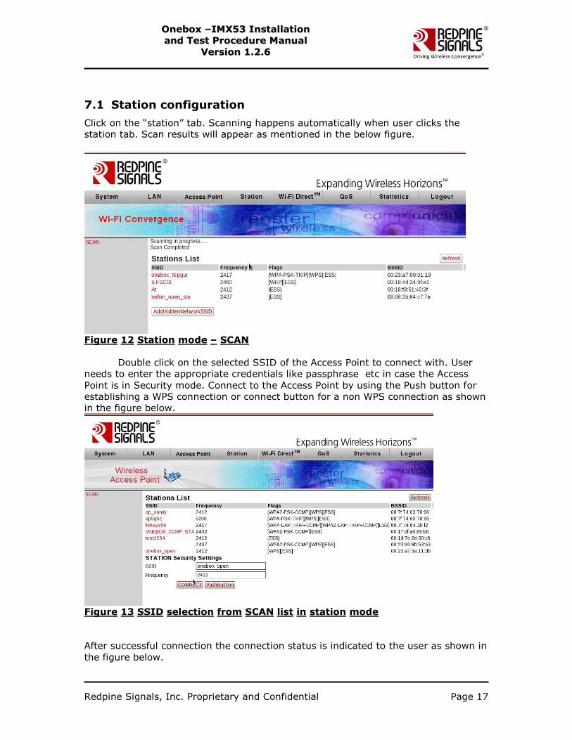
7.1 Station configuration
Click on the “station” tab. Scanning happens automatically when user clicks the
station tab. Scan results will appear as mentioned in the below figure.
Figure 12 Station mode – SCAN
Double click on the selected SSID of the Access Point to connect with. User
needs to enter the appropriate credentials like passphrase etc in case the Access
Point is in Security mode. Connect to the Access Point by using the Push button for
establishing a WPS connection or connect button for a non WPS connection as shown
in the figure below.
Figure 13 SSID selection from SCAN list in station mode
After successful connection the connection status is indicated to the user as shown in
the figure below.
Redpine Signals, Inc. Proprietary and Confidential Page 18
OOnneebbooxx ––IIMMXX5533 IInnssttaallllaattiioonn
aanndd TTeesstt PPrroocceedduurree MMaannuuaall
VVeerrssiioonn 11..22..66
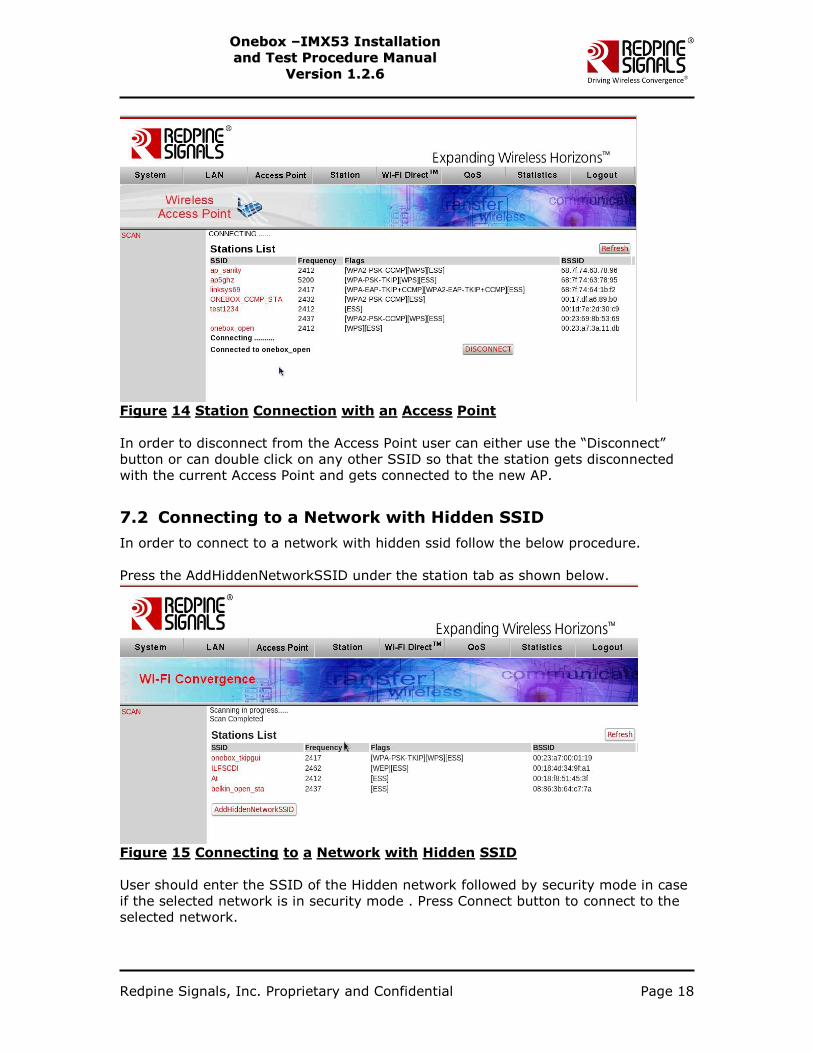
Figure 14 Station Connection with an Access Point
In order to disconnect from the Access Point user can either use the “Disconnect”
button or can double click on any other SSID so that the station gets disconnected
with the current Access Point and gets connected to the new AP.
7.2 Connecting to a Network with Hidden SSID
In order to connect to a network with hidden ssid follow the below procedure.
Press the AddHiddenNetworkSSID under the station tab as shown below.
Figure 15 Connecting to a Network with Hidden SSID
User should enter the SSID of the Hidden network followed by security mode in case
if the selected network is in security mode . Press Connect button to connect to the
selected network.
Redpine Signals, Inc. Proprietary and Confidential Page 19
OOnneebbooxx ––IIMMXX5533 IInnssttaallllaattiioonn
aanndd TTeesstt PPrroocceedduurree MMaannuuaall
VVeerrssiioonn 11..22..66
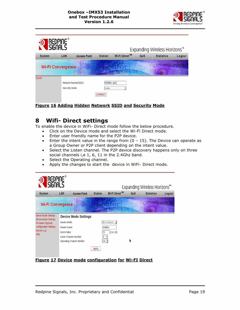
Figure 16 Adding Hidden Network SSID and Security Mode
8 Wifi- Direct settings To enable the device in WiFi- Direct mode follow the below procedure.
Click on the Device mode and select the Wi-Fi Direct mode.
Enter user friendly name for the P2P device.
Enter the intent value in the range from (0 – 15). The Device can operate as
a Group Owner or P2P client depending on the intent value.
Select the Listen channel. The P2P device discovery happens only on three
social channels i,e 1, 6, 11 in the 2.4Ghz band.
Select the Operating channel.
Apply the changes to start the device in WiFi- Direct mode.
Figure 17 Device mode configuration for Wi-FI Direct
Redpine Signals, Inc. Proprietary and Confidential Page 20
OOnneebbooxx ––IIMMXX5533 IInnssttaallllaattiioonn
aanndd TTeesstt PPrroocceedduurree MMaannuuaall
VVeerrssiioonn 11..22..66
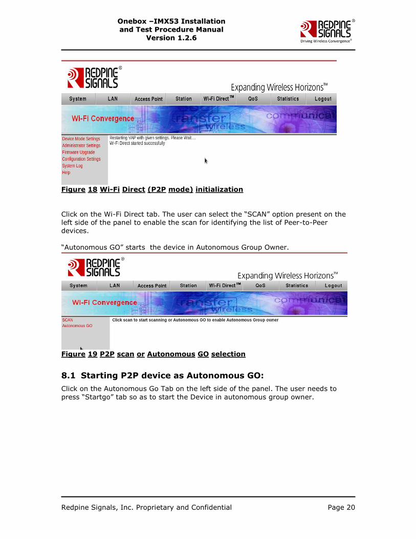
Figure 18 Wi-Fi Direct (P2P mode) initialization
Click on the Wi-Fi Direct tab. The user can select the “SCAN” option present on the
left side of the panel to enable the scan for identifying the list of Peer-to-Peer
devices.
“Autonomous GO” starts the device in Autonomous Group Owner.
Figure 19 P2P scan or Autonomous GO selection
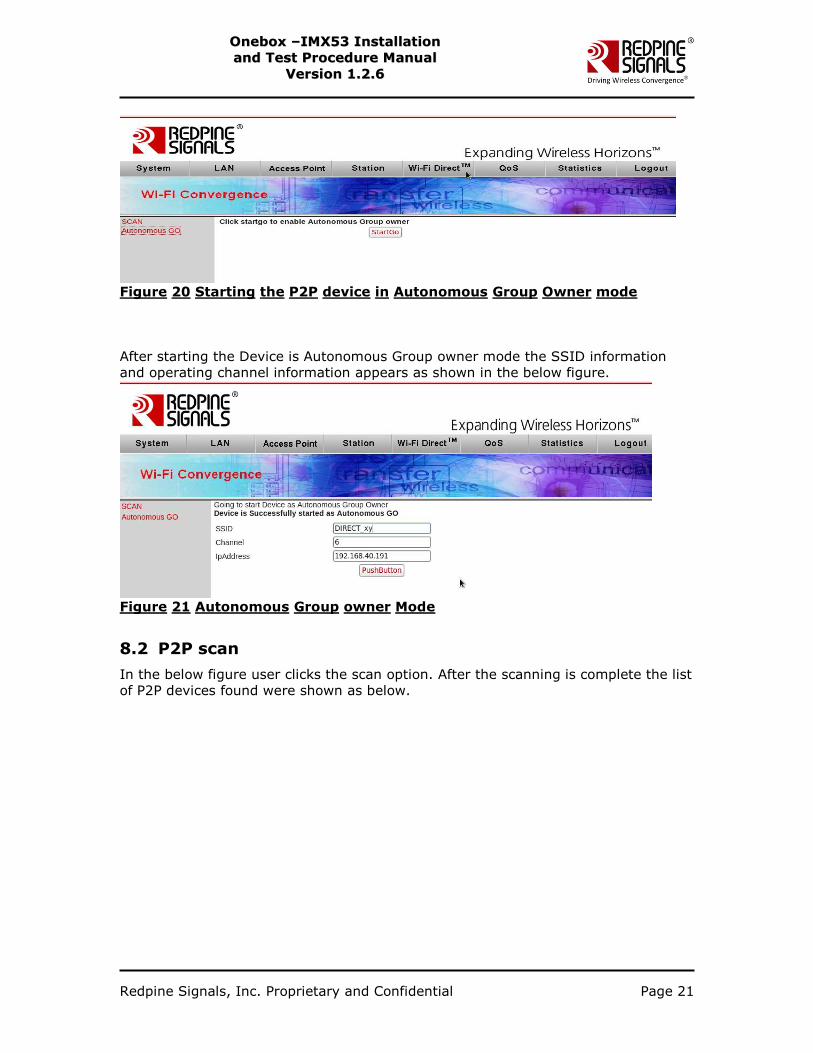
8.1 Starting P2P device as Autonomous GO:
Click on the Autonomous Go Tab on the left side of the panel. The user needs to
press “Startgo” tab so as to start the Device in autonomous group owner.
Redpine Signals, Inc. Proprietary and Confidential Page 21
OOnneebbooxx ––IIMMXX5533 IInnssttaallllaattiioonn
aanndd TTeesstt PPrroocceedduurree MMaannuuaall
VVeerrssiioonn 11..22..66
Figure 20 Starting the P2P device in Autonomous Group Owner mode
After starting the Device is Autonomous Group owner mode the SSID information
and operating channel information appears as shown in the below figure.
Figure 21 Autonomous Group owner Mode
8.2 P2P scan
In the below figure user clicks the scan option. After the scanning is complete the list
of P2P devices found were shown as below.
Redpine Signals, Inc. Proprietary and Confidential Page 22
OOnneebbooxx ––IIMMXX5533 IInnssttaallllaattiioonn
aanndd TTeesstt PPrroocceedduurree MMaannuuaall
VVeerrssiioonn 11..22..66
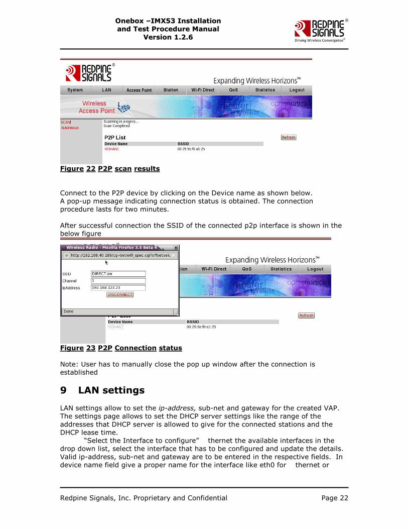
Figure 22 P2P scan results
Connect to the P2P device by clicking on the Device name as shown below.
A pop-up message indicating connection status is obtained. The connection
procedure lasts for two minutes.
After successful connection the SSID of the connected p2p interface is shown in the
below figure
Figure 23 P2P Connection status
Note: User has to manually close the pop up window after the connection is
established
9 LAN settings
LAN settings allow to set the ip-address, sub-net and gateway for the created VAP.
The settings page allows to set the DHCP server settings like the range of the
addresses that DHCP server is allowed to give for the connected stations and the
DHCP lease time.
“Select the Interface to configure” thernet the available interfaces in the
drop down list, select the interface that has to be configured and update the details.
Valid ip-address, sub-net and gateway are to be entered in the respective fields. In
device name field give a proper name for the interface like eth0 for thernet or
Redpine Signals, Inc. Proprietary and Confidential Page 23
OOnneebbooxx ––IIMMXX5533 IInnssttaallllaattiioonn
aanndd TTeesstt PPrroocceedduurree MMaannuuaall
VVeerrssiioonn 11..22..66
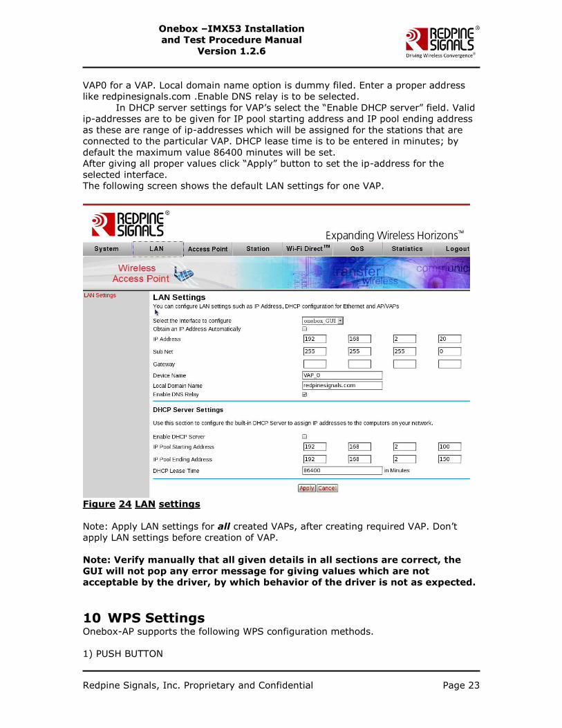
VAP0 for a VAP. Local domain name option is dummy filed. Enter a proper address
like redpinesignals.com .Enable DNS relay is to be selected.
In DHCP server settings for VAP‟s select the “Enable DHCP server” field. Valid
ip-addresses are to be given for IP pool starting address and IP pool ending address
as these are range of ip-addresses which will be assigned for the stations that are
connected to the particular VAP. DHCP lease time is to be entered in minutes; by
default the maximum value 86400 minutes will be set.
After giving all proper values click “Apply” button to set the ip-address for the
selected interface.
The following screen shows the default LAN settings for one VAP.
Figure 24 LAN settings
Note: Apply LAN settings for all created VAPs, after creating required VAP. Don‟t
apply LAN settings before creation of VAP.
Note: Verify manually that all given details in all sections are correct, the
GUI will not pop any error message for giving values which are not
acceptable by the driver, by which behavior of the driver is not as expected.
10 WPS Settings Onebox-AP supports the following WPS configuration methods.
1) PUSH BUTTON
Redpine Signals, Inc. Proprietary and Confidential Page 24
OOnneebbooxx ––IIMMXX5533 IInnssttaallllaattiioonn
aanndd TTeesstt PPrroocceedduurree MMaannuuaall
VVeerrssiioonn 11..22..66
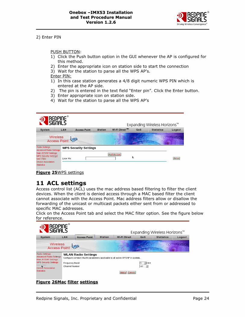
2) Enter PIN
PUSH BUTTON:
1) Click the Push button option in the GUI whenever the AP is configured for
this method.
2) Enter the appropriate icon on station side to start the connection
3) Wait for the station to parse all the WPS AP‟s.
Enter PIN:
1) In this case station generates a 4/8 digit numeric WPS PIN which is
entered at the AP side.
2) The pin is entered in the text field “Enter pin”. Click the Enter button.
3) Enter appropriate icon on station side.
4) Wait for the station to parse all the WPS AP‟s
Figure 25WPS settings
11 ACL settings Access control list (ACL) uses the mac address based filtering to filter the client
devices. When the client is denied access through a MAC based filter the client
cannot associate with the Access Point. Mac address filters allow or disallow the
forwarding of the unicast or multicast packets either sent from or addressed to
specific MAC addresses.
Click on the Access Point tab and select the MAC filter option. See the figure below
for reference.
Figure 26Mac filter settings
Redpine Signals, Inc. Proprietary and Confidential Page 25
OOnneebbooxx ––IIMMXX5533 IInnssttaallllaattiioonn
aanndd TTeesstt PPrroocceedduurree MMaannuuaall
VVeerrssiioonn 11..22..66
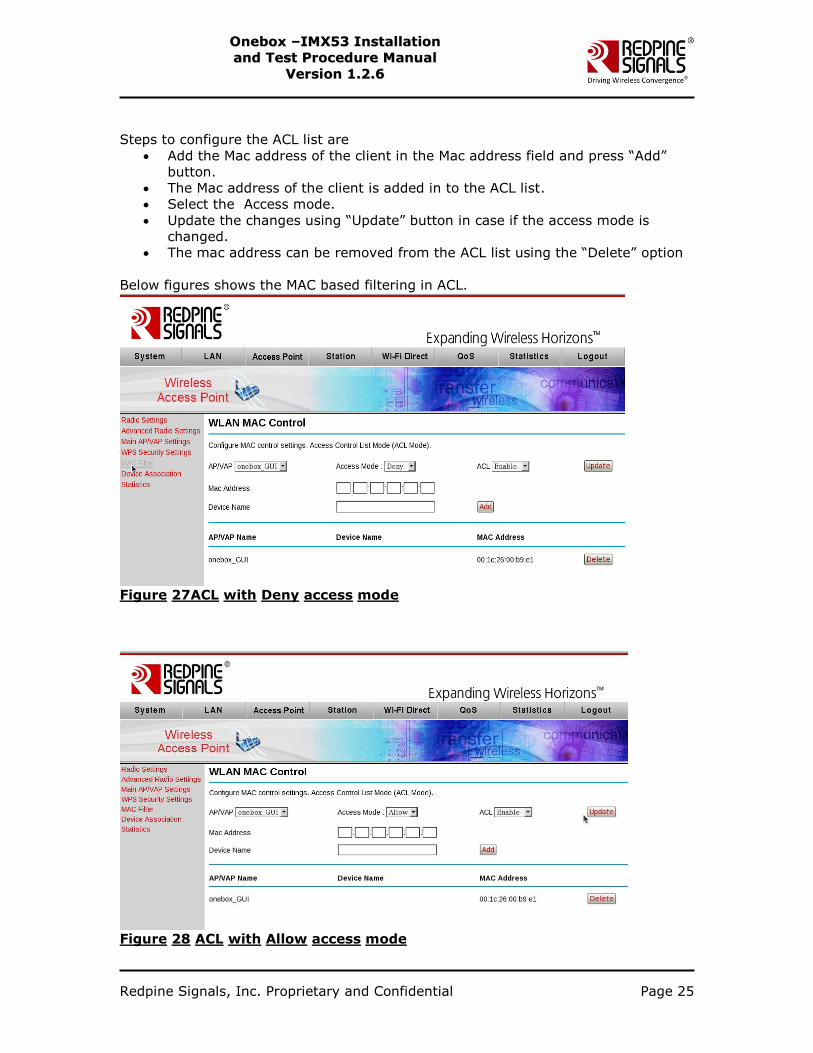
Steps to configure the ACL list are
Add the Mac address of the client in the Mac address field and press “Add”
button.
The Mac address of the client is added in to the ACL list.
Select the Access mode.
Update the changes using “Update” button in case if the access mode is
changed.
The mac address can be removed from the ACL list using the “Delete” option
Below figures shows the MAC based filtering in ACL.
Figure 27ACL with Deny access mode
Figure 28 ACL with Allow access mode

Redpine Signals, Inc. Proprietary and Confidential Page 26
OOnneebbooxx ––IIMMXX5533 IInnssttaallllaattiioonn
aanndd TTeesstt PPrroocceedduurree MMaannuuaall
VVeerrssiioonn 11..22..66
12 Statistics The information related to Access Point statistics, Station Statistics as well as
Autorate statistics can be obtained under the Statistics tab.
12.1 Acess Point statistics
Click on the AP statistics if the device is in Access Point mode. The information
related to data, management packets as well as Buffer Full / Empty information can
be obtained through these statistics. Refer to the below figure for Access Point
statistics
Figure 29 Access Point statistics
12.2 Station Statistics
Click on the station statistics and select the Mac address of the connected Station.
Click “submit” to apply the changes. Refer to the figure below.
Redpine Signals, Inc. Proprietary and Confidential Page 27
OOnneebbooxx ––IIMMXX5533 IInnssttaallllaattiioonn
aanndd TTeesstt PPrroocceedduurree MMaannuuaall
VVeerrssiioonn 11..22..66
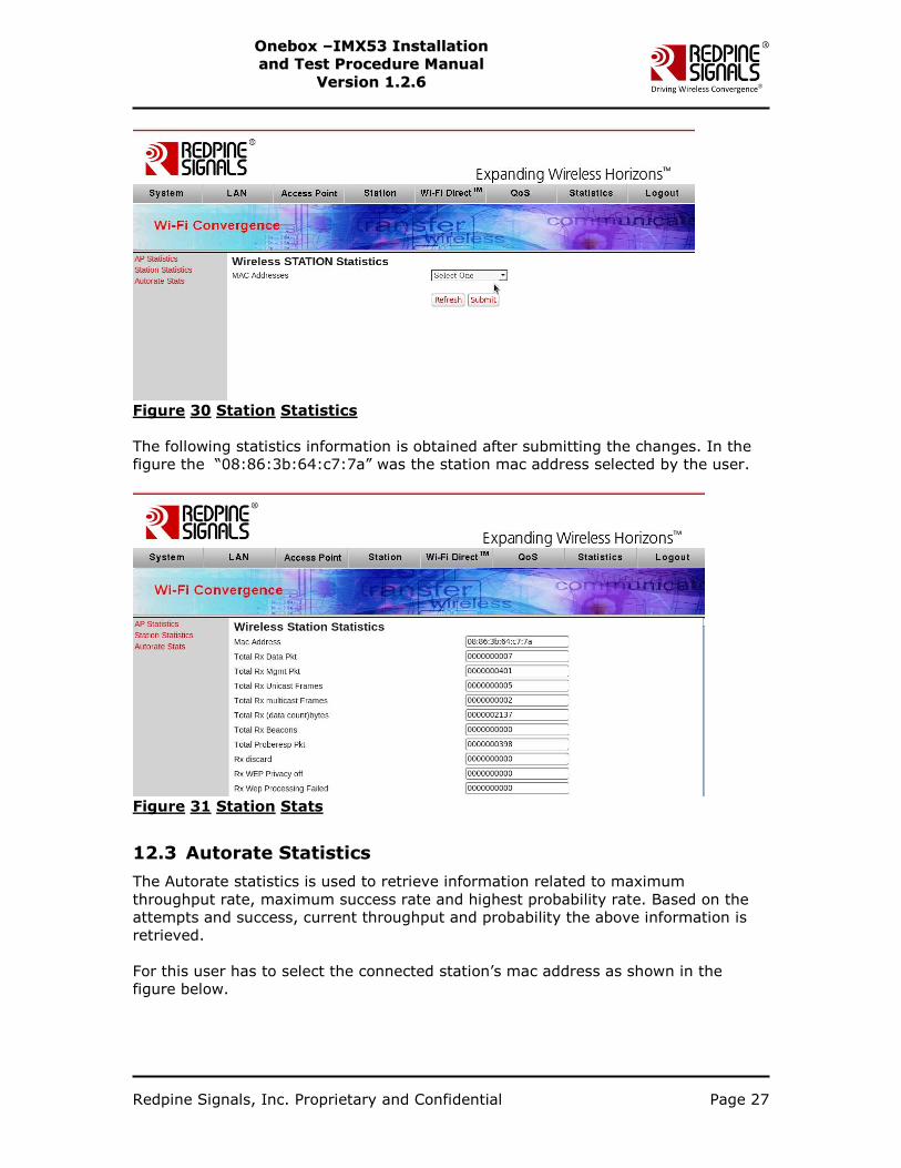
Figure 30 Station Statistics
The following statistics information is obtained after submitting the changes. In the
figure the “08:86:3b:64:c7:7a” was the station mac address selected by the user.
Figure 31 Station Stats
12.3 Autorate Statistics
The Autorate statistics is used to retrieve information related to maximum
throughput rate, maximum success rate and highest probability rate. Based on the
attempts and success, current throughput and probability the above information is
retrieved.
For this user has to select the connected station‟s mac address as shown in the
figure below.
Redpine Signals, Inc. Proprietary and Confidential Page 28
OOnneebbooxx ––IIMMXX5533 IInnssttaallllaattiioonn
aanndd TTeesstt PPrroocceedduurree MMaannuuaall
VVeerrssiioonn 11..22..66
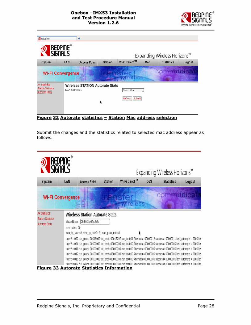
Figure 32 Autorate statistics – Station Mac address selection
Submit the changes and the statistics related to selected mac address appear as
follows.
Figure 33 Autorate Statistics Information


![Linux Kernel Driver Tutorial - [email protected]](https://img.pdfslide.org/doc/110x75/613d285f736caf36b759ffb2/linux-kernel-driver-tutorial-emailprotected.jpg)