Embed Size (px)
Citation preview
Wilhelm Guth Ventiltechnik GmbH & Co. KG Horstring 16, D-76829 Landau
Tel.: +49 (0) 6341/5105-0, FAX: +49 (0) 6341/5105-85 www.guthventiltechnik.de
Version 07/2014-English
- 1 -
Operating and Maintenance
Instructions
Mixers Replaceable RA models
• RA 45 • RA 110 • RA 300 • RA 25/100
Wilhelm Guth Ventiltechnik GmbH & Co. KG Horstring 16, D-76829 Landau
Tel.: +49 (0) 6341/5105-0, FAX: +49 (0) 6341/5105-85 www.guthventiltechnik.de
Version 07/2014-English
- 2 -
Contents
1.0 Notes for the user __________________________________- 4 -
1.1 Proper usage ___________________________________________ - 4 -
1.2 Notes on the guarantee___________________________________ - 4 -
1.3 Safety instructions_______________________________________ - 4 -
1.4 Hazard warnings ________________________________________ - 5 -
1.5 Safety tests ____________________________________________ - 6 -
1.6 Standards _____________________________________________ - 7 -
1.7 Warning symbols________________________________________ - 8 -
2.0 Technical information _______________________________- 9 -
2.1 General description ______________________________________ - 9 -
2.2 Design of the mixer_____________________________________ - 10 -
2.3 Variants ______________________________________________ - 10 -
2.3.1 Mixer types ___________________________________________ - 11 -
2.3.2 Types of propeller ______________________________________ - 12 -
2.3.3 Accessories ___________________________________________ - 12 -
2.3.4 Support pedestal _______________________________________ - 13 -
3.0 Electrical connection _______________________________- 14 -
3.1 Connection diagram_____________________________________ - 15 -
3.2 Operating voltages _____________________________________ - 15 -
4.0 Functional description ______________________________- 16 -
5.0 Commissioning ___________________________________- 17 -
5.1 Checking the direction of rotation of the motor________________ - 17 -
5.2 Assembling the agitator shaft _____________________________ - 17 -
5.3 Connection to the container fitting _________________________ - 18 -
5.4 Releasing the container fitting_____________________________ - 18 -
6.0 Cleaning_________________________________________- 19 -
7.0 Maintenance and repair _____________________________- 20 -
7.1 Replacing the seals _____________________________________ - 21 -
7.2 Mixer designation ______________________________________ - 22 -
8.0 Malfunctions _____________________________________- 22 -
Wilhelm Guth Ventiltechnik GmbH & Co. KG Horstring 16, D-76829 Landau
Tel.: +49 (0) 6341/5105-0, FAX: +49 (0) 6341/5105-85 www.guthventiltechnik.de
Version 07/2014-English
- 3 -
9.0 Transport and packaging____________________________- 23 -
10.0 Disposal _________________________________________- 23 -
11.0 Declaration of Conformity____________________________- 24 -
Index of Tables Table 1: Mixer design_________________________________________ - 10 - Table 2: Mixer types _________________________________________ - 11 - Table 3: Overlying support pedestal _____________________________ - 13 - Table 4: Suspended support pedestal ____________________________ - 13 - Table 5: Minimum requirements for the cable and plug ______________ - 14 - Table 6: Operating voltages____________________________________ - 15 - Table 7: Malfunctions_________________________________________ - 22 -
Index of Figures Fig. 1: Mixer design __________________________________________ - 10 - Fig. 2: Mixer types___________________________________________ - 11 - Fig. 3: Propeller types ________________________________________ - 12 - Fig. 4: Accessories___________________________________________ - 12 - Fig. 5: Support pedestal ______________________________________ - 13 - Fig. 6: Connection diagram ____________________________________ - 15 - Fig. 7: Assembly ____________________________________________ - 17 - Fig. 8: Replacing the seals_____________________________________ - 21 - Fig. 9: Declaration of Conformity________________________________ - 24 - Availability and Completeness
• These operating instructions constitute part of the valve delivery and must be kept available so that they can be referred to by authorised personnel at any time.
• No sections may be removed from these instructions. Should the operating instructions or individual pages be missing, they must be replaced at once.
Change Service This documentation is subject to the Change Service of Guth Ventiltechnik GmbH & Co. KG. Changes may be made to this documentation without notice of such changes being given.
Copyright This documentation contains information that is protected by copyright. It may only be used in connection with the use of the valve.
Manufacturer / Supplier
Wilhelm Guth Ventiltechnik GmbH & Co. KG Horstring 16, D-76829 Landau Tel.: +49(0) 6341/5105-0; Fax: +49(0) 6341/5105-85 Internet: www.guthventiltechnik.de
Wilhelm Guth Ventiltechnik GmbH & Co. KG Horstring 16, D-76829 Landau
Tel.: +49 (0) 6341/5105-0, FAX: +49 (0) 6341/5105-85 www.guthventiltechnik.de
Version 07/2014-English
- 4 -
1.0 Notes for the user Please read this handbook carefully before you begin with the assembly of, commissioning of or any other work connected with this mixer.
1.1 Proper usage
GUTH mixers are designed and constructed solely for commercial and industrial use. They are used for mixing, stirring, distribution and homogenising purposes. The mixer must be attached to the container by using appropriate fittings. The attachment and the container must be designed to withstand the forces that occur. Stirring solid materials and materials with a relatively high viscosity is considered as predictable and improper use of the mixer. Do not use the mixer in a hazardous area!
1.2 Notes on the guarantee
All obligations arising in connection with the guarantee are contained in the General Terms and Conditions of Wilhelm Guth Ventiltechnik GmbH & Co. KG.
1.3 Safety instructions • The mixer may only be fitted and operated by a trained person. Based on the definition laid down in EN 60204-1.Trained person:
A person who is taught by a qualified employee about the tasks entrusted to him/her and the possible hazards caused as a result of improper conduct and if necessary trained and who has learnt about the necessary protective equipment and protective measures.
• The mixer may only be fitted and commissioned by qualified personnel. Based on the definition laid down in EN 60204-1. Qualified personnel: A person who, on the basis of his or her specialist training, has acquired knowledge and experience as well as knowledge of the relevant standards and can evaluate the work entrusted to him or her and any possible hazards.
• The mixer may only be used for approved purposes. • The GUTH company shall accept no liability for damage and operational malfunctions resulting from failure to observe these instructions.
• Technical modifications resulting in deviations from the illustrations and information contained in these instructions may be made without prior notice being given.
• The mixer may only be fitted and commissioned in accordance with these operating instructions.
Wilhelm Guth Ventiltechnik GmbH & Co. KG Horstring 16, D-76829 Landau
Tel.: +49 (0) 6341/5105-0, FAX: +49 (0) 6341/5105-85 www.guthventiltechnik.de
Version 07/2014-English
- 5 -
• The manufacturing process did not take account of safety precautions in respect of external fire.
• The mixer may only be converted or modified after consulting with the GUTH company.
• The original replacement parts supplied by the GUTH company serve the purpose of ensuring safety. Should other parts be used, the GUTH company shall accept no responsibility whatsoever for any damage that may result.
• The mixer may only be disassembled when it is not connected to a voltage supply or under pressure.
• Prior to repair and maintenance operations, the product line must be depressurised and free of fluid product. Product residues and cleaning agents must be removed as well.
• Mixers that come into contact with hazardous media must be decontaminated.
• Never touch the mixer when hot liquids are being processed or the sterilization process is underway.
• Never touch the rotating parts of the mixer. • If hot or cold parts represent hazards, then these parts must be shielded against the possibility of persons coming into contact with them by the plant operator.
• The mixer must always be rendered pressureless during all assembly and disassembly work.
The mixer may only be operated when it is in perfect working order. In addition to the documentation, instructions on the following also apply:
• Internal plant working and safety instructions • National regulations in the country of implementation • Generally accepted safety regulations • Accident prevention regulations
1.4 Hazard warnings
• The electrical connecting cable must be laid in a position where nobody can trip over it!
• Only assemble or disassemble the mixer when the mains plug has been pulled out.
• Please ensure that the container fittings are connected correctly to the filled container when using the mixer.
• Close the container fitting before disassembling the mixer. • Pay attention to ensure that you collect or divert the product liquid that is
produced when employing or removing the mixer. • Avoid knocking over the electrical connecting cable.
Wilhelm Guth Ventiltechnik GmbH & Co. KG Horstring 16, D-76829 Landau
Tel.: +49 (0) 6341/5105-0, FAX: +49 (0) 6341/5105-85 www.guthventiltechnik.de
Version 07/2014-English
- 6 -
• Please ensure that the electrical connecting cable does not cause an injury. • Pay attention to the clockwise field of rotation when configuring the three-phase current of the motor. Otherwise two phases of the connecting cable must be exchanged by qualified electricians.
Failure to observe the specified hazard warnings may pose a risk to persons as well as the environment, mixer and plant. Specifically, failure to observe the warnings may cause the following hazards to arise:
• the failure of important functions of the mixer and the plant. • the failure of prescribed methods for maintenance and repairs. • hazards to persons caused by electrical, mechanical or chemical agents. • environmental hazards on account of leakage of hazardous substances.
1.5 Safety tests Safety tests "carried out by the manufacturer in the factory".
Safety tests according to DIN EN 60 204-1
• Continuous connection of the protective conductor system. • Insulation resistance tests. • Voltage tests. • Protection from residual voltages. • Functional tests. • The functions of the electrical equipment, especially those which relate to safety and protective measures.
Wilhelm Guth Ventiltechnik GmbH & Co. KG Horstring 16, D-76829 Landau
Tel.: +49 (0) 6341/5105-0, FAX: +49 (0) 6341/5105-85 www.guthventiltechnik.de
Version 07/2014-English
- 7 -
1.6 Standards The following directives are adhered to:
• 2006/42/EC (Machinery Directive) • 2006/95/EC (Low Voltage Directive) • 2004/108/EC (Electromagnetic compatibility)
Harmonised standards applied:
• DIN EN 60034-1; VDE 0530-1:2011-02:2011-02 (Rotating electrical machines - Part 1: Rating and performance) • DIN EN 60204-1; VDE 0113-1:2011-01:2011-01 (Safety of machinery - Electrical equipment of machines - Part 1: General requirements) • DIN EN 60034-9, VDE 0530-9:2008-01:2008-01 (Rotating electrical machines - Part 9: Noise limits) • EN ISO 12100:2011-03 (Safety of machinery - General principles for design - Risk assessment and risk mitigation) • DIN EN ISO 13857 (Safety of machinery - Safety distances to prevent danger zones being reached by the upper and lower limbs) • DIN EN 614-1:2009-06 (Safety of machinery - Ergonomic design principles - Part 1: Concepts and general principles) • DIN EN 1037:2008-11 (Safety of machinery - Prevention of unexpected start-up) • DIN EN 60204-1; VDE 0113-1:2011-01:2011-01 (Safety of machinery - Electrical equipment of machines - Part 1: General requirements) • DIN EN 61000-4-2; VDE 0847-4-2:2009-12:2009-12 (Electromagnetic compatibility (EMC) - Part 4-2: Test and measurement methods - Testing the immunity to the discharge of static electricity) • 3 GSGV / 9 GSGV (German Equipment Safety Act Machinery Ordinance)
Wilhelm Guth Ventiltechnik GmbH & Co. KG Horstring 16, D-76829 Landau
Tel.: +49 (0) 6341/5105-0, FAX: +49 (0) 6341/5105-85 www.guthventiltechnik.de
Version 07/2014-English
- 8 -
Note
Warning
Danger
Caution
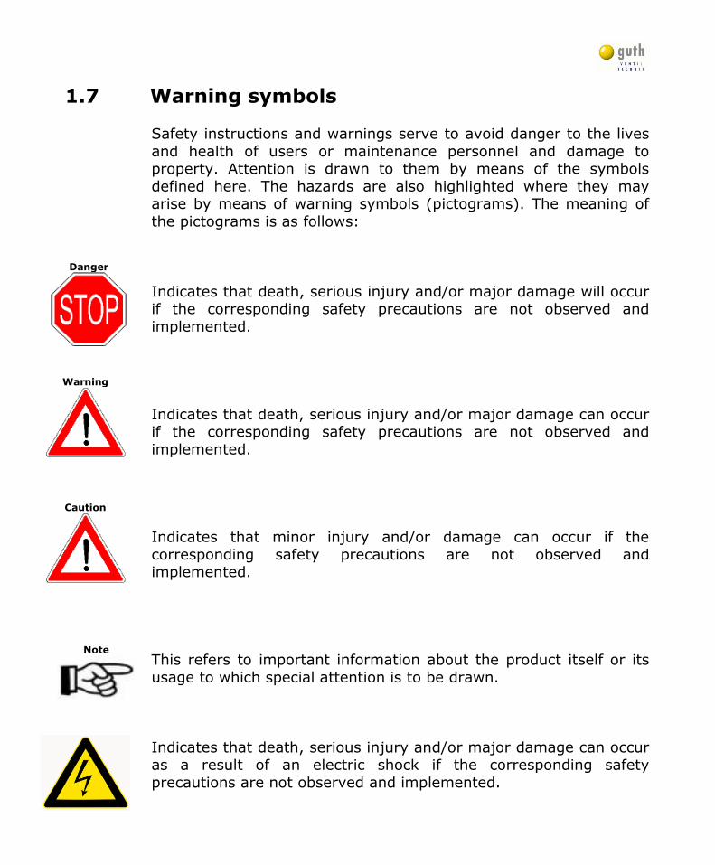
1.7 Warning symbols
Safety instructions and warnings serve to avoid danger to the lives and health of users or maintenance personnel and damage to property. Attention is drawn to them by means of the symbols defined here. The hazards are also highlighted where they may arise by means of warning symbols (pictograms). The meaning of the pictograms is as follows:
Indicates that death, serious injury and/or major damage will occur if the corresponding safety precautions are not observed and implemented.
Indicates that death, serious injury and/or major damage can occur if the corresponding safety precautions are not observed and implemented.
Indicates that minor injury and/or damage can occur if the corresponding safety precautions are not observed and implemented.
This refers to important information about the product itself or its usage to which special attention is to be drawn. Indicates that death, serious injury and/or major damage can occur as a result of an electric shock if the corresponding safety precautions are not observed and implemented.
Wilhelm Guth Ventiltechnik GmbH & Co. KG Horstring 16, D-76829 Landau
Tel.: +49 (0) 6341/5105-0, FAX: +49 (0) 6341/5105-85 www.guthventiltechnik.de
Version 07/2014-English
- 9 -
2.0 Technical information
2.1 General description Fields of application:
• Stirring of liquid to prevent the suspended substances and solids from settling and stirring the wine yeast for biological acid reduction.
• Preparing uniform liquid mixtures also using different specific weights. • Clarifying and homogenising the liquid during the diluting procedure. • Mixing liquids with solid or gaseous products e.g. for distributing fining
agents, sulphurous acid or carbonic acid. • Emulsifying sterile products and homogenised distillates • Accelerating reactions and dissolving processes such as e.g. influencing
fermentation by dissolving sugar and sugar solutions. • Enhancing the efficiency of the impact of heat and cold, e.g. equal liquid interspersion for cooling procedures. • Activating the weak fermentation yeasts.
Product-specific data: Viscosity >20 baumé =36.34 Brix (in accordance with a 36% 1.2°Engler = 4 centipoise sugar solution at 20°C) Temperature range
Mixer from -20°C to 120°C (product-specific, seal-specific) Pressure range
Mixer -pressureless(Standard) -max. 10 bar (Pressure may only be applied with a specific agitator shaft and flange housing fastener! Please consult with Guth.) Ambient conditions: Noise level <70 dB(A) Protection class:
Mixer IP 54
Wilhelm Guth Ventiltechnik GmbH & Co. KG Horstring 16, D-76829 Landau
Tel.: +49 (0) 6341/5105-0, FAX: +49 (0) 6341/5105-85 www.guthventiltechnik.de
Version 07/2014-English
- 10 -
5.6
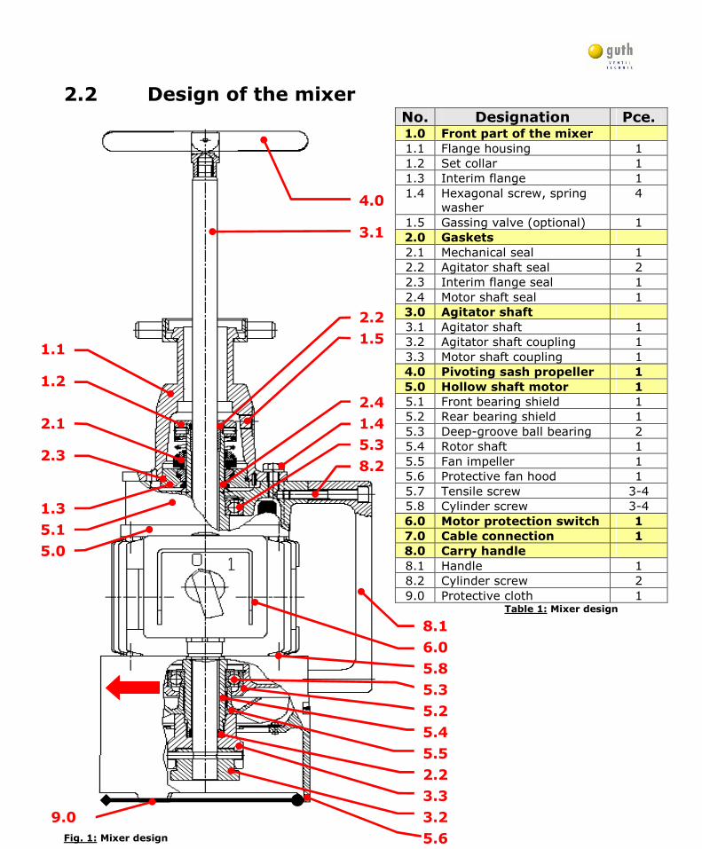
2.2 Design of the mixer
Fig. 1: Mixer design
No. Designation Pce. 1.0 Front part of the mixer
1.1 Flange housing 1 1.2 Set collar 1 1.3 Interim flange 1 1.4 Hexagonal screw, spring
washer 4
1.5 Gassing valve (optional) 1 2.0 Gaskets
2.1 Mechanical seal 1 2.2 Agitator shaft seal 2 2.3 Interim flange seal 1 2.4 Motor shaft seal 1 3.0 Agitator shaft
3.1 Agitator shaft 1 3.2 Agitator shaft coupling 1 3.3 Motor shaft coupling 1 4.0 Pivoting sash propeller 1
5.0 Hollow shaft motor 1
5.1 Front bearing shield 1 5.2 Rear bearing shield 1 5.3 Deep-groove ball bearing 2 5.4 Rotor shaft 1 5.5 Fan impeller 1 5.6 Protective fan hood 1 5.7 Tensile screw 3-4 5.8 Cylinder screw 3-4 6.0 Motor protection switch 1
7.0 Cable connection 1
8.0 Carry handle
8.1 Handle 1 8.2 Cylinder screw 2 9.0 Protective cloth 1 Table 1: Mixer design
8.1
6.0
8.2
5.8
5.3
5.5
5.2
2.2
3.3
3.2
5.4
5.3
1.3
2.3
1.4
1.5
3.1
2.4
2.2
4.0
5.1
2.1
5.0
1.2
1.1
9.0
Wilhelm Guth Ventiltechnik GmbH & Co. KG Horstring 16, D-76829 Landau
Tel.: +49 (0) 6341/5105-0, FAX: +49 (0) 6341/5105-85 www.guthventiltechnik.de
Version 07/2014-English
- 11 -
Caution
2.3 Variants
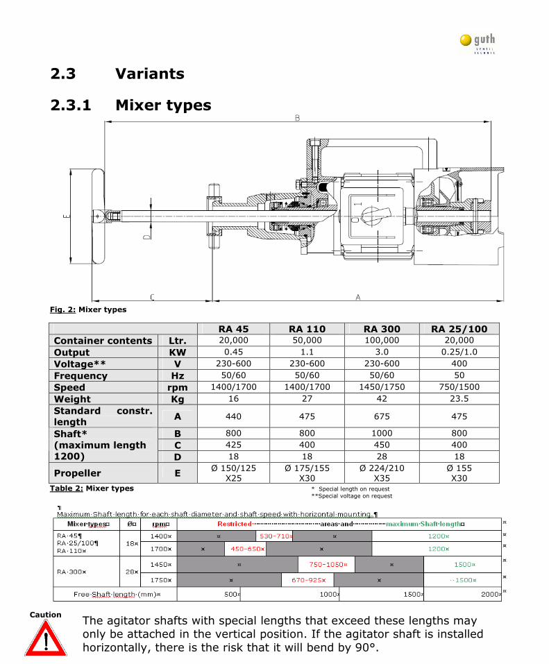
2.3.1 Mixer types
Fig. 2: Mixer types
RA 45 RA 110 RA 300 RA 25/100
Container contents Ltr. 20,000 50,000 100,000 20,000
Output KW 0.45 1.1 3.0 0.25/1.0
Voltage** V 230-600 230-600 230-600 400
Frequency Hz 50/60 50/60 50/60 50
Speed rpm 1400/1700 1400/1700 1450/1750 750/1500
Weight Kg 16 27 42 23.5
Standard constr.
length A 440 475 675 475
B 800 800 1000 800
C 425 400 450 400 Shaft*
(maximum length
1200) D 18 18 28 18
Propeller E Ø 150/125
X25 Ø 175/155
X30 Ø 224/210
X35 Ø 155 X30
Table 2: Mixer types * Special length on request **Special voltage on request
The agitator shafts with special lengths that exceed these lengths may only be attached in the vertical position. If the agitator shaft is installed horizontally, there is the risk that it will bend by 90°.
Wilhelm Guth Ventiltechnik GmbH & Co. KG Horstring 16, D-76829 Landau
Tel.: +49 (0) 6341/5105-0, FAX: +49 (0) 6341/5105-85 www.guthventiltechnik.de
Version 07/2014-English
- 12 -
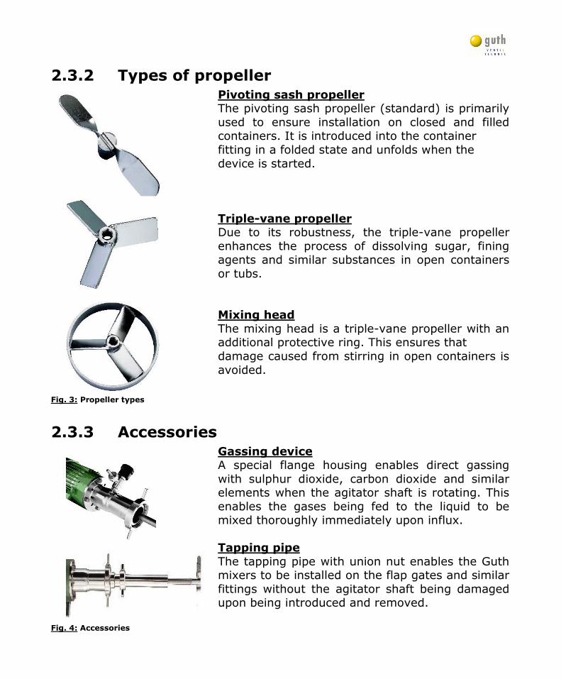
2.3.2 Types of propeller
Pivoting sash propeller The pivoting sash propeller (standard) is primarily used to ensure installation on closed and filled containers. It is introduced into the container fitting in a folded state and unfolds when the device is started. Triple-vane propeller Due to its robustness, the triple-vane propeller enhances the process of dissolving sugar, fining agents and similar substances in open containers or tubs. Mixing head
The mixing head is a triple-vane propeller with an additional protective ring. This ensures that damage caused from stirring in open containers is avoided.
Fig. 3: Propeller types
2.3.3 Accessories
Gassing device A special flange housing enables direct gassing with sulphur dioxide, carbon dioxide and similar elements when the agitator shaft is rotating. This enables the gases being fed to the liquid to be mixed thoroughly immediately upon influx. Tapping pipe
The tapping pipe with union nut enables the Guth mixers to be installed on the flap gates and similar fittings without the agitator shaft being damaged upon being introduced and removed. Fig. 4: Accessories
Wilhelm Guth Ventiltechnik GmbH & Co. KG Horstring 16, D-76829 Landau
Tel.: +49 (0) 6341/5105-0, FAX: +49 (0) 6341/5105-85 www.guthventiltechnik.de
Version 07/2014-English
- 13 -
Note
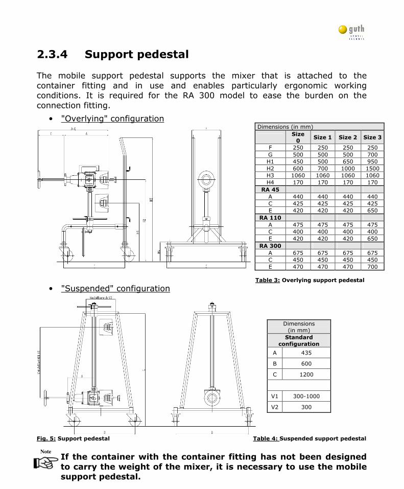
2.3.4 Support pedestal The mobile support pedestal supports the mixer that is attached to the container fitting and in use and enables particularly ergonomic working conditions. It is required for the RA 300 model to ease the burden on the connection fitting.
• "Overlying" configuration
Table 3: Overlying support pedestal
• "Suspended" configuration
Fig. 5: Support pedestal Table 4: Suspended support pedestal
If the container with the container fitting has not been designed
to carry the weight of the mixer, it is necessary to use the mobile support pedestal.
Dimensions (in mm)
Size 0
Size 1 Size 2 Size 3
F 250 250 250 250 G 500 500 500 700 H1 450 500 650 950 H2 600 700 1000 1500 H3 1060 1060 1060 1060 H4 170 170 170 170
RA 45 A 440 440 440 440 C 425 425 425 425 E 420 420 420 650
RA 110 A 475 475 475 475 C 400 400 400 400 E 420 420 420 650
RA 300 A 675 675 675 675 C 450 450 450 450 E 470 470 470 700
Dimensions (in mm) Standard
configuration
A 435
B 600
C 1200
V1 300-1000
V2 300
Wilhelm Guth Ventiltechnik GmbH & Co. KG Horstring 16, D-76829 Landau
Tel.: +49 (0) 6341/5105-0, FAX: +49 (0) 6341/5105-85 www.guthventiltechnik.de
Version 07/2014-English
- 14 -
Note
Danger
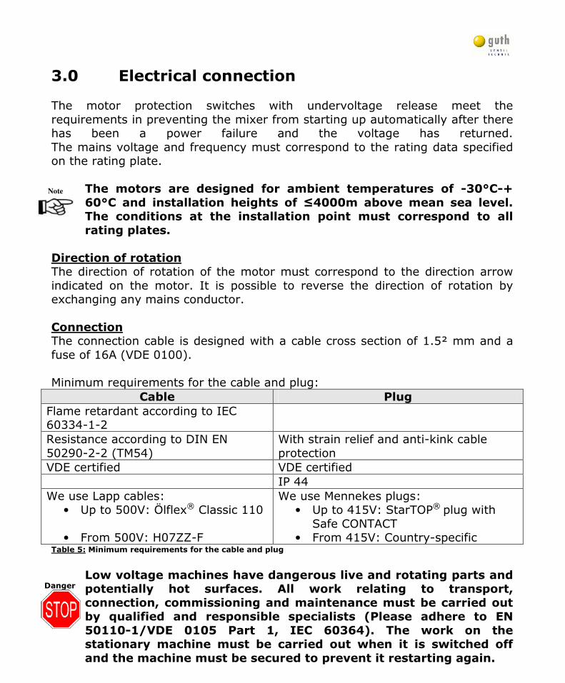
3.0 Electrical connection The motor protection switches with undervoltage release meet the requirements in preventing the mixer from starting up automatically after there has been a power failure and the voltage has returned. The mains voltage and frequency must correspond to the rating data specified on the rating plate. The motors are designed for ambient temperatures of -30°C-+
60°C and installation heights of ≤4000m above mean sea level. The conditions at the installation point must correspond to all
rating plates. Direction of rotation The direction of rotation of the motor must correspond to the direction arrow indicated on the motor. It is possible to reverse the direction of rotation by exchanging any mains conductor. Connection The connection cable is designed with a cable cross section of 1.5² mm and a fuse of 16A (VDE 0100). Minimum requirements for the cable and plug:
Cable Plug
Flame retardant according to IEC 60334-1-2
Resistance according to DIN EN 50290-2-2 (TM54)
With strain relief and anti-kink cable protection
VDE certified VDE certified IP 44 We use Lapp cables:
• Up to 500V: Ölflex® Classic 110 • From 500V: H07ZZ-F
We use Mennekes plugs: • Up to 415V: StarTOP® plug with
Safe CONTACT • From 415V: Country-specific
Table 5: Minimum requirements for the cable and plug
Low voltage machines have dangerous live and rotating parts and potentially hot surfaces. All work relating to transport,
connection, commissioning and maintenance must be carried out by qualified and responsible specialists (Please adhere to EN
50110-1/VDE 0105 Part 1, IEC 60364). The work on the stationary machine must be carried out when it is switched off
and the machine must be secured to prevent it restarting again.
Wilhelm Guth Ventiltechnik GmbH & Co. KG Horstring 16, D-76829 Landau
Tel.: +49 (0) 6341/5105-0, FAX: +49 (0) 6341/5105-85 www.guthventiltechnik.de
Version 07/2014-English
- 15 -
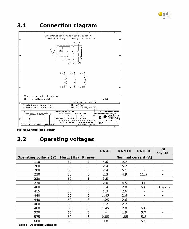
3.1 Connection diagram
Fig. 6: Connection diagram
3.2 Operating voltages
RA 45 RA 110 RA 300
RA
25/100
Operating voltage (V) Hertz (Hz) Phases Nominal current (A)
110 60 3 4.6 9.7 - - 200 50 3 2.4 5.2 - - 208 60 3 2.4 5.1 - - 230 50 3 2.3 4.9 11.5 - 230 60 1 3.5 - - - 230 60 3 2.0 4.5 11 - 400 50 3 1.4 2.8 6.6 1.05/2.5 415 50 3 1.3 2.6 - - 440 50 3 1.45 2.6 - - 440 60 3 1.25 2.6 - - 460 60 3 1.2 2.7 - - 480 60 3 1.45 2.8 6.8 - 550 60 3 - 1.9 5.7 - 575 60 3 0.85 1.85 5.8 - 600 60 3 0.8 - 5.5 -
Table 6: Operating voltages
Wilhelm Guth Ventiltechnik GmbH & Co. KG Horstring 16, D-76829 Landau
Tel.: +49 (0) 6341/5105-0, FAX: +49 (0) 6341/5105-85 www.guthventiltechnik.de
Version 07/2014-English
- 16 -
Note
Note
Caution
Caution
Caution
4.0 Functional description
The RA mixer was designed for mixing and stirring liquids in containers in the food sector. The mixer is put into operation using a start switch fitted on the side of the motor that has an undervoltage release. When switching on or switching off the device, a minimum
quantity of the fluid product will escape. It is important to ensure that the fluid product is fed away securely!
The undervoltage release prevents the risk caused by a sudden start-up in the event of an unintended power connection. This is
achieved by the machine becoming fully-functional again after the triggered switch is actuated.
It is not permitted to switch on the device without attaching it to
the container and snapping in the agitator shaft coupling! (Risk of injury or damage to the agitator vane, etc.)
All metal components that come into contact with the product were made from stainless steel.
The mixer is connected to the filled container • by the corresponding container fitting • angle seat valve • straight-through valve • sluice gate
and the flap gate.
The retractable agitator shaft can be attached to the front of the container and the propeller can be inserted into the medium without causing a loss of liquid or pressure. The special bearing of the agitator shaft in the hollow shaft of the electric motor ensures that the mixer operates quietly and without vibrating. The mechanical seal will operate without malfunctioning if subjected to a load of up to 10 bar over the long-term. Caution! Pressure may only be applied with a specific agitator shaft and
flange housing fastener.
Please note that a special mechanical seal is required when the mixture is stirred aggressively.
Wilhelm Guth Ventiltechnik GmbH & Co. KG Horstring 16, D-76829 Landau
Tel.: +49 (0) 6341/5105-0, FAX: +49 (0) 6341/5105-85 www.guthventiltechnik.de
Version 07/2014-English
- 17 -
Note
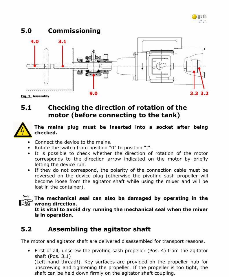
5.0 Commissioning
Fig. 7: Assembly
5.1 Checking the direction of rotation of the
motor (before connecting to the tank) The mains plug must be inserted into a socket after being checked.
• Connect the device to the mains. • Rotate the switch from position "0" to position "I". • It is possible to check whether the direction of rotation of the motor
corresponds to the direction arrow indicated on the motor by briefly letting the device run.
• If they do not correspond, the polarity of the connection cable must be reversed on the device plug (otherwise the pivoting sash propeller will become loose from the agitator shaft while using the mixer and will be lost in the container).
The mechanical seal can also be damaged by operating in the
wrong direction. It is vital to avoid dry running the mechanical seal when the mixer
is in operation.
5.2 Assembling the agitator shaft The motor and agitator shaft are delivered disassembled for transport reasons.
• First of all, unscrew the pivoting sash propeller (Pos. 4) from the agitator shaft (Pos. 3.1)
(Left-hand thread!). Key surfaces are provided on the propeller hub for unscrewing and tightening the propeller. If the propeller is too tight, the shaft can be held down firmly on the agitator shaft coupling.
9.0 3.2 3.3
3.1 4.0
Wilhelm Guth Ventiltechnik GmbH & Co. KG Horstring 16, D-76829 Landau
Tel.: +49 (0) 6341/5105-0, FAX: +49 (0) 6341/5105-85 www.guthventiltechnik.de
Version 07/2014-English
- 18 -
Note
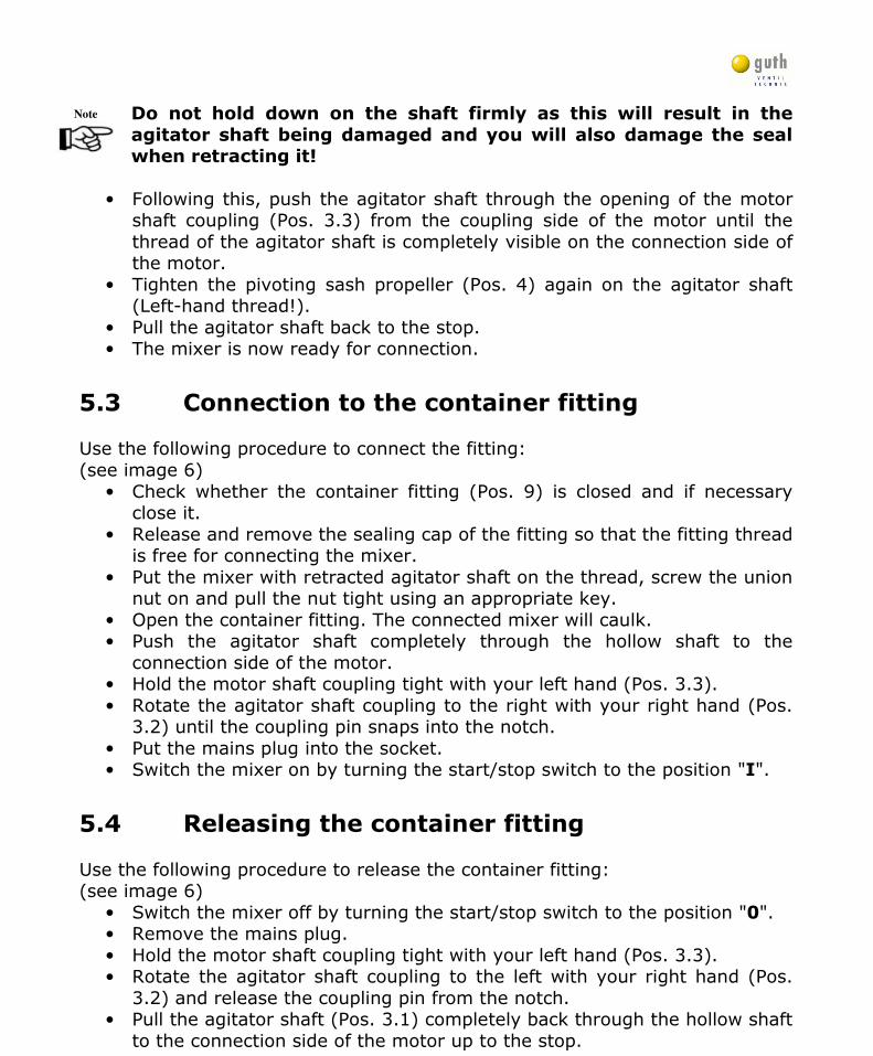
Do not hold down on the shaft firmly as this will result in the
agitator shaft being damaged and you will also damage the seal when retracting it!
• Following this, push the agitator shaft through the opening of the motor
shaft coupling (Pos. 3.3) from the coupling side of the motor until the thread of the agitator shaft is completely visible on the connection side of the motor.
• Tighten the pivoting sash propeller (Pos. 4) again on the agitator shaft (Left-hand thread!).
• Pull the agitator shaft back to the stop. • The mixer is now ready for connection.
5.3 Connection to the container fitting Use the following procedure to connect the fitting: (see image 6)
• Check whether the container fitting (Pos. 9) is closed and if necessary close it.
• Release and remove the sealing cap of the fitting so that the fitting thread is free for connecting the mixer.
• Put the mixer with retracted agitator shaft on the thread, screw the union nut on and pull the nut tight using an appropriate key.
• Open the container fitting. The connected mixer will caulk. • Push the agitator shaft completely through the hollow shaft to the
connection side of the motor. • Hold the motor shaft coupling tight with your left hand (Pos. 3.3). • Rotate the agitator shaft coupling to the right with your right hand (Pos.
3.2) until the coupling pin snaps into the notch. • Put the mains plug into the socket. • Switch the mixer on by turning the start/stop switch to the position "I".
5.4 Releasing the container fitting Use the following procedure to release the container fitting: (see image 6)
• Switch the mixer off by turning the start/stop switch to the position "0". • Remove the mains plug. • Hold the motor shaft coupling tight with your left hand (Pos. 3.3). • Rotate the agitator shaft coupling to the left with your right hand (Pos.
3.2) and release the coupling pin from the notch. • Pull the agitator shaft (Pos. 3.1) completely back through the hollow shaft
to the connection side of the motor up to the stop.
Wilhelm Guth Ventiltechnik GmbH & Co. KG Horstring 16, D-76829 Landau
Tel.: +49 (0) 6341/5105-0, FAX: +49 (0) 6341/5105-85 www.guthventiltechnik.de
Version 07/2014-English
- 19 -
Note
Warning
• Close the container fitting. • Unscrew the union nut using an appropriate key and remove the mixer.
6.0 Cleaning Before cleaning, maintenance and repair work, the following switch-off procedure is to be maintained without fail:
• Ensure that the mixer is disconnected from the mains. (Switch off the start/stop switch and remove the mains plug.) • Close the product inlet. (Block the container fitting.) • Disassemble the mixer. In case of non-compliance, this can endanger life and limb of the personnel!
Daily cleaning (Quick cleaning)
Only clean using water between the individual working intervals. Do not use a cleaning agent as this will require thorough rinsing. Complete cleaning
A complete cleaning procedure must be carried out every six months along with the container cleaning with the system at a standstill. If cleaning agents or cleaning tools are used other than those recommended or if the device is mishandled, the guarantee for
the resulting damage will lapse! No special cleaning agent is required for cleaning stainless steel parts. Use alcohol or steam in the event of a disinfection.
Wilhelm Guth Ventiltechnik GmbH & Co. KG Horstring 16, D-76829 Landau
Tel.: +49 (0) 6341/5105-0, FAX: +49 (0) 6341/5105-85 www.guthventiltechnik.de
Version 07/2014-English
- 20 -
Note
Note
Caution
Note
Note
Warning
Cleaning agents that contain sodium hydroxide or other high
alkaline agents with chlorine, bromine, iodine or fluorine additions, potassium oxide, chlorine-based products, ammonium
compounds, quaternary hydrochloric or hydrofluoric acid must not
be used, as these agents corrode the stainless steel surface.
The flange housing with the thread connection is disassembled and cleaned once a year.
Please pay attention to the instructions on the safety data sheets
of the cleaning agent manufacturer. The instructions must be adhered to. The customer must provide evidence that the cleaning
agent has been applied correctly.
Use a scrubbing or synthetic brush to clean the stainless steel parts.
7.0 Maintenance and repair All work on the stationary machine must be carried out by qualified specialist personnel when it is switched off and secured
to prevent it from restarting again. Check if the machine is free of voltage!
GUTH mixers are maintenance-free. The agitator shaft, pivoting sash propeller and the connection side of the mixer must be cleaned or rinsed with water after use. It is then recommended to grease the agitator shaft with suitable grease.
We would like to point out that spare parts and accessories that
we have supplied are not checked and approved by us either. The installation and/or the use of these products may therefore under
certain circumstances have a negative effect on the design properties of the mixer.
When carrying out cleaning and maintenance work, electrical
components such as motors, switches, etc. must not be sprayed
directly!
Maintenance intervals:
Practical maintenance intervals can only be determined empirically by the user as they depend on the conditions of
operation involving, for instance, hours of use per day, switching frequency, type and temperature of the product, type and
temperature of the cleaning agent, surrounding conditions.
Wilhelm Guth Ventiltechnik GmbH & Co. KG Horstring 16, D-76829 Landau
Tel.: +49 (0) 6341/5105-0, FAX: +49 (0) 6341/5105-85 www.guthventiltechnik.de
Version 07/2014-English
- 21 -
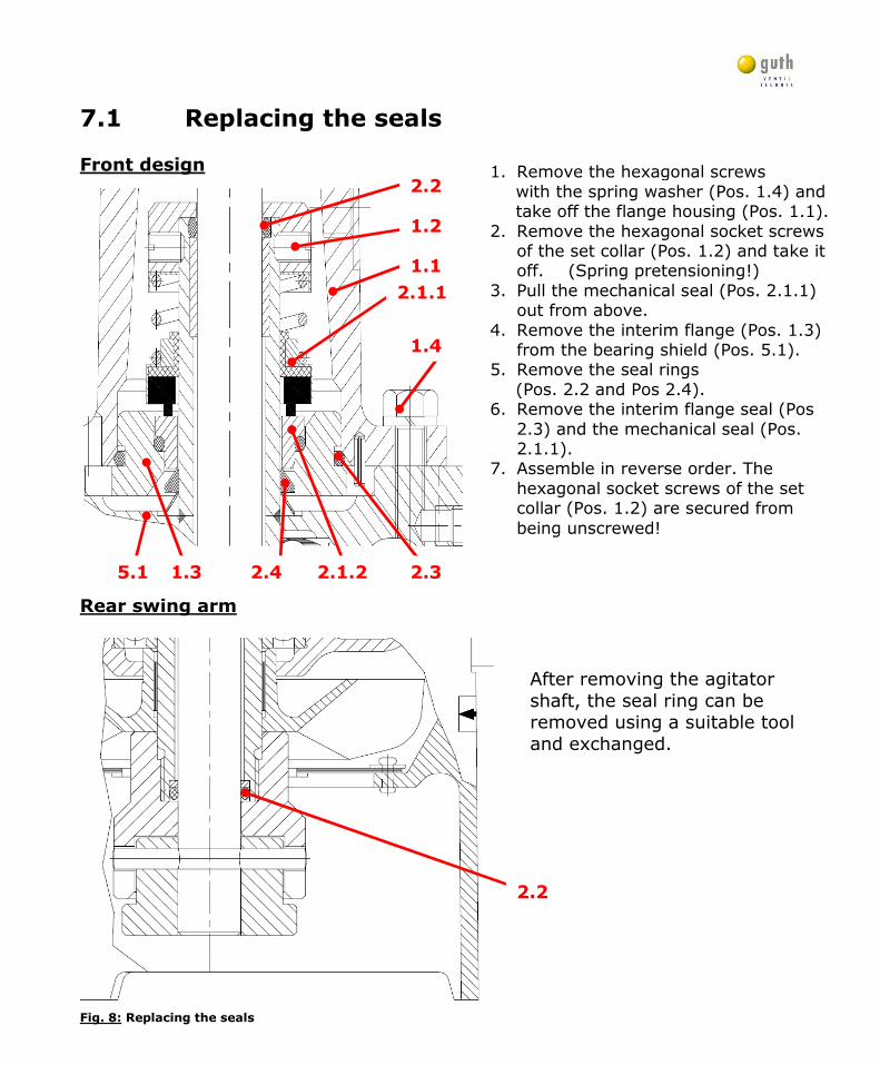
1. Remove the hexagonal screws with the spring washer (Pos. 1.4) and take off the flange housing (Pos. 1.1). 2. Remove the hexagonal socket screws
of the set collar (Pos. 1.2) and take it off. (Spring pretensioning!)
3. Pull the mechanical seal (Pos. 2.1.1) out from above.
4. Remove the interim flange (Pos. 1.3) from the bearing shield (Pos. 5.1).
5. Remove the seal rings (Pos. 2.2 and Pos 2.4). 6. Remove the interim flange seal (Pos
2.3) and the mechanical seal (Pos. 2.1.1).
7. Assemble in reverse order. The hexagonal socket screws of the set collar (Pos. 1.2) are secured from being unscrewed!
7.1 Replacing the seals Front design
Rear swing arm
Fig. 8: Replacing the seals
After removing the agitator shaft, the seal ring can be removed using a suitable tool and exchanged.
2.1.1
1.2
2.2
1.4
2.1.2 2.3 2.4
2.2
1.3 5.1
1.1
Wilhelm Guth Ventiltechnik GmbH & Co. KG Horstring 16, D-76829 Landau
Tel.: +49 (0) 6341/5105-0, FAX: +49 (0) 6341/5105-85 www.guthventiltechnik.de
Version 07/2014-English
- 22 -
Note
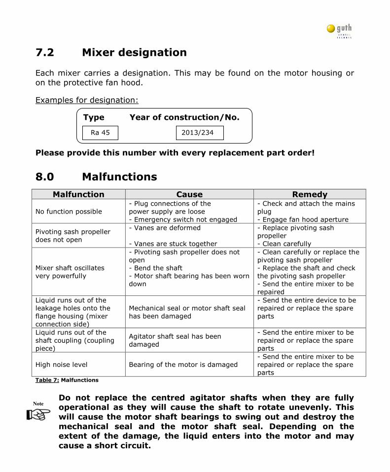
7.2 Mixer designation Each mixer carries a designation. This may be found on the motor housing or on the protective fan hood.
Examples for designation:
Please provide this number with every replacement part order!
8.0 Malfunctions
Malfunction Cause Remedy
No function possible - Plug connections of the power supply are loose - Emergency switch not engaged
- Check and attach the mains plug - Engage fan hood aperture
Pivoting sash propeller does not open
- Vanes are deformed - Vanes are stuck together
- Replace pivoting sash propeller - Clean carefully
Mixer shaft oscillates very powerfully
- Pivoting sash propeller does not open - Bend the shaft - Motor shaft bearing has been worn down
- Clean carefully or replace the pivoting sash propeller - Replace the shaft and check the pivoting sash propeller - Send the entire mixer to be repaired
Liquid runs out of the leakage holes onto the flange housing (mixer connection side)
Mechanical seal or motor shaft seal has been damaged
- Send the entire device to be repaired or replace the spare parts
Liquid runs out of the shaft coupling (coupling piece)
Agitator shaft seal has been damaged
- Send the entire mixer to be repaired or replace the spare parts
High noise level Bearing of the motor is damaged - Send the entire mixer to be repaired or replace the spare parts
Table 7: Malfunctions
Do not replace the centred agitator shafts when they are fully operational as they will cause the shaft to rotate unevenly. This
will cause the motor shaft bearings to swing out and destroy the
mechanical seal and the motor shaft seal. Depending on the extent of the damage, the liquid enters into the motor and may
cause a short circuit.
Type Year of construction/No.
2013/234 Ra 45
Wilhelm Guth Ventiltechnik GmbH & Co. KG Horstring 16, D-76829 Landau
Tel.: +49 (0) 6341/5105-0, FAX: +49 (0) 6341/5105-85 www.guthventiltechnik.de
Version 07/2014-English
- 23 -
9.0 Transport and packaging Prior to transport, the mixers are carefully checked and packed. However, the possibility of damage during transport cannot be excluded.
Unpacking:
Remove the protective caps (if present) and any remaining packaging.
Receiving inspection: Check the received mixer against the delivery note to ensure that no parts are missing!
If damage is discovered: Check the delivery for damage (visual inspection)!
In case of complaint: If the delivery has been damaged in transit:
• Get in touch immediately with the last shipper! • Keep the packaging (in case the shipper wishes to inspect it or for
returning the goods).
Packaging for returning goods: If possible, use the original packaging material.
• If queries arise in connection with packaging and transport safety please contact GUTH Ventiltechnik GmbH & Co. KG.
Storage in open air: Storage in the open air is not permitted.
Storage in closed spaces: Storage conditions:
• Temperature 0 °C to 30 °C • Humidity (air) < 60%
10.0 Disposal
The mixer is made mainly of steel (with the exception of electrical components and seals). They are to be disposed of according to locally valid environmental protection regulations. Cleaning agents must be disposed of in accordance with local regulations and the manufacturers' instructions on the safety data sheets.
Wilhelm Guth Ventiltechnik GmbH & Co. KG Horstring 16, D-76829 Landau
Tel.: +49 (0) 6341/5105-0, FAX: +49 (0) 6341/5105-85 www.guthventiltechnik.de
Version 07/2014-English
- 24 -
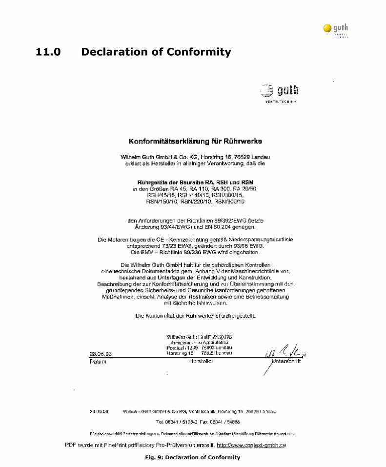
11.0 Declaration of Conformity
Fig. 9: Declaration of Conformity