Embed Size (px)
Citation preview
Operating Instructions
iTEMP® TMT80
BA00292R/09/c4/13.1271113686Version 1.00
; Temperaturkopftransmitter
< Temperature head transmitter
= Transmetteur de température
Û Trasmettitore di temperatura da testa
TMT80
atur: -40 bis +85 °C (-40 to +185 °F)
oranschlusskopf Form B nach DIN EN 50446
ungen
t darf nur von einem Netzteil mit energiebegrenz-
10-1 gespeist werden: ’SELV or Class 2 circuit’
°F)
g; connection head Form B accord. to DIN EN
ly be powered by a power supply that operates
ant energy limited circuit: ’SELV or Class 2 circuit’
ssible :)
terrain; tête de raccordement forme B selon
ions
eil doit obligatoirement être alimenté par une
CEI 61010-1 : ’SELV or Class 2 circuit’
po; testa di connessione Form B secondo DIN
un limite
deve essere alimentata da un alimentatore con
forme alla norma IEC 61010-1: ’SELV o da un
2
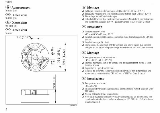
; Abmessungenin mm (in)
< Dimensionsin mm (in)
= Dimensionsen mm (in)
Û Dimensioniin mm
A0013791
; Montage Zulässige Umgebungstemper
Einbauort: Feldgehäuse; Sens
Einbaulage: keine Einschränk
Sicherheitshinweise: Das Gerä
tem Stromkreis nach IEC 610
< Installation
Ambient temperature:-40 to +85 °C (-40 to +185
Installation area: Field housin
50446
Installation angle: No limit
Safety notes: The unit must on
using an IEC 61010-1 compli
= Montage
Température ambiante admi
-40 à +85 °C (-40 à +185 °F
Point de montage : boîtier de
DIN EN 50446
Implantation : pas de restrict
Conseils de sécurité : l'appar
alimentation stabilisée selon
Û Installazione
Temperatura ambiente:-40...+85 °C
Installazione: custodia da cam
EN 50446
Angolo di installazione: ness
Note sulla sicurezza: l'unità
circuito elettrico limitato con
circuito Classe 2’
TMT80
3
EN 50446 Form B, direkte Montage auf Mes-
hrung (Mittelloch 7 mm)
Feldgehäuse
chiene nach IEC 60715 (TH35)
EN 50446 form B, direct installation onto insert
hole 7 mm / 0.28")
field housing
-hat rail as per IEC 60715 (TH35)
on DIN EN 50446 Forme B, montage direct sur
le (perçage médian 7 mm)
ier de terrain
filé selon CEI 60715 (TH35)
IN EN 50446 form B, installazione diretta su
(foro centrale 7 mm)
odia in campo
guida top-hat secondo IEC 60715 (TH35)
A0008035
A B
C
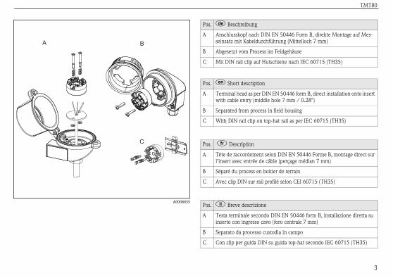
Pos. ; Beschreibung
A Anschlusskopf nach DIN
seinsatz mit Kabeldurchfü
B Abgesetzt vom Prozess im
C Mit DIN rail clip auf Huts
Pos. < Short description
A Terminal head as per DIN
with cable entry (middle
B Separated from process in
C With DIN rail clip on top
Pos. = Description
A Tête de raccordement sel
l’insert avec entrée de câb
B Séparé du process en boit
C Avec clip DIN sur rail pro
Pos. Û Breve descrizione
A Testa terminale secondo D
inserto con ingresso cavo
B Separato da processo cust
C Con clip per guida DIN su
TMT80
h Feldgehäuse ist zu beachten: Schirmung der l 4…20 mA) und Schirmung der Sensoran-e Potenzial haben! Bei Einsatz von geerdeten chirmung der 4…20 mA Ausgangsleitung ßen elektromagnetischen Feldern wird eine
t niederohmiger Anbindung am rs empfohlen.
gng the head transmitter remotely in a field
20 mA signal output must have the same ensor connections! When using earthed ther-tput 4…20 mA cable is recommended. In
netic fields screening of all cables with a low itter housing is recommended.
potentielaré en boîtier de terrain, prière de noter : de sortie 4…20 mA) et le blindage côté cap-entiel. Lors de l'utilisation de thermocouples sortie 4…20 mA est recommandé. Pour les nétiques importants, il est conseillé de
s les lignes avec liaison à basse impédance au
i potenzialee l'installazione remota di un trasmettitore mpo: la schermatura. La schermatura A deve avere lo stesso potenziale dello del sensore. Si consiglia di schermare il cavo zzano termocoppie messe a terra. In impianti ci, è consigliabile effettuare la schermatura di e alla custodia del trasmettitore tramite col-
4
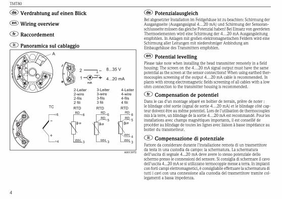
; Verdrahtung auf einen Blick
< Wiring overview
= Raccordement
Û Panoramica sul cablaggio
A0013972
; PotenzialausgleicBei abgesetzter Installation imAusgangsseite (Ausgangssignaschlussseite müssen das gleichThermoelementen wird eine Sempfohlen. In Anlagen mit groSchirmung aller Leitungen miEinbaugehäuse des Transmitte
< Potential levellinPlease take note when installihousing: The screen on the 4…potential as the screen at the smocouples screening of the ouplants with strong electromagohm connection to the transm
= Compensation deDans le cas d'un montage séple blindage côté sortie (signal teur doivent être au même potmis à la terre, un blindage de lainstallations avec champs magprocéder au blindage de touteboitier du transmetteur.
Û Compensazione dFattore da considerare durantda testa in una custodia da cadell'uscita di segnale 4...20 mschermo presso le connessionidell'uscita 4...20 mA se si utilicon forti campi elettromagnetitutti i cavi con una connessionlegamenti a bassa impedenza.
8...35 V
4...20 mA1
2
4
6
TC
2-Leiter2-wire2-fils2 fili
3-Leiter3-wire3-fils3 fili
4-Leiter4-wire4-fils4 fili
3
56
RTD
34
56
RTD
3
6
RTD
A
RD RD RD
RDRD
WH WH WHWH
TMT80
5
one using the ReadWin® 2000 PC soft-
accessory (see page 7).
is only possible when the device is con-
connected (see ’Accessories’ on page 7),
(e.g. measured error) are not observed.
ation disconnect the connection via the
head transmitter and PC.
he structure of the PC-Configurationteractive menu operation:
0 operating instructions please read the
ained in the ReadWin® 2000 software.
e
n mode (2-, 3- or 4-wire connection)
°F)
ent range limits (depends on sensor)
tion resistance (0 to 20 wire connection
ition reaction ( 3.6 mA or; if setting is 21.0 mA, a output signal
is guaranteed)
to +9.9 K)
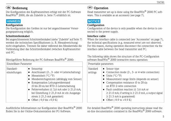
; Bedienung
Die Konfiguration des Kopftransmitters erfolgt mit der PC-Software
ReadWin® 2000, die als Zubehör (s. Seite 7) erhältlich ist.
Konfiguration
Die Konfiguration des Gerätes ist nur bei angeschlossener Versor-
gungsspannung möglich.
Schnittstellenkabel
Bei angeschlossenem Schnittstellenkabel (siehe ’Zubehör’ auf Seite 7)
werden die technischen Spezifikationen (z. B. Messabweichung)
nicht eingehalten. Trennen Sie daher während des Messbetriebs die
Verbindung über das Schnittstellenkabel zwischen Kopftransmitter
und PC.
Menügeführte Bedienung der PC-Software ReadWin® 2000:
Ausführliche Informationen zur Konfiguration über ReadWin® 2000
finden Sie in der Online-Dokumentation der PC-Software.
< Operation
Head transmitter set-up is d
ware. This is available as an
Configuration
Configuration of the device
nected to the power supply.
Interface cable
When the interface cable is
the technical specifications
For this reason, during oper
interface cable between the
The following table shows t
software ReadWin® 2000 in
For detailed ReadWin® 200
on-line documentation cont
Einstellbare Parameter
Standard-einstellungen
• Sensortyp
• Anschlussart (2-, 3- oder 4-Leiterschaltung)
• Messeinheit (°C/°F)
• Messbereichsgrenzen (abhängig vom Sensor)
• Kompensation Leitungswiderstand (0 bis 20 bei RTD 2-Leiterschaltung
• Fehlerverhalten ( 3,6 mA oder 21,0 mA;
bei Einstellung 21,0 mA ist ein Ausgangs-
strom 21,5 mA garantiert)
• Offset (-9,9 bis +9,9 K)
Presettable parameters
Standard
settings
• Sensor typ
• Connectio
• Units (°C/
• Measurem
• Compensa
on RTD 2-
• Fault cond
21.0 mA
21.5 mA
• Offset (-9.9
TMT80
ettitore da testa è effettuata mediante il
2000. Disponibile come accessorio
itivo è possibile solo quando è alimentato.
è collegato (vedere "Accessori" a
che (es. errore di misura) non sono rispet-
ante il funzionamento scollegare la con-
rfaccia tra il trasmettitore da testa e il PC.
a struttura del menu interattivo del er PC ReadWin® 2000:
nto dettagliate su ReadWin® 2000
online contenuta nel software.
ensore
di connessione (2, 3 o 4 fili)
C/°F)
l campo di misura (a seconda del sensore)
sazione della resistenza (0...20 su
ione bifilare RTD
alla condizione di errore ( 3,6 mA
21,0 mA; se l'impostazione è 21,0 mA,
le di uscita 21,5 mA è garantito)
9,9...+9,9 K)
6
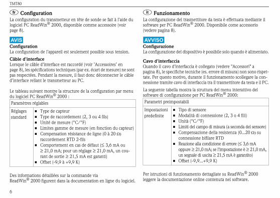
= Configuration
La configuration du transmetteur en tête de sonde se fait à l'aide du
logiciel PC ReadWin® 2000, disponible comme accessoire (voir
page 8).
Configuration
La configuration de l'appareil est seulement possible sous tension.
Câble d'interface
Lorsque le câble d'interface est raccordé (voir ’Accessoires’ en
page 8), les spécifications techniques (par ex. écart de mesure) ne sont
pas respectées. Pendant la mesure, il faut donc déconnecter le câble
d'interface reliant le transmetteur au PC.
Le tableau suivant montre la structure de la configuration par menu
du logiciel PC ReadWin® 2000 :
Des informations détaillées sur la commande via ReadWin® 2000 figurent dans la documentation en ligne du logiciel.
Û Funzionamento
La configurazione del trasm
software per PC ReadWin®
(vedere pagina 8).
Configurazione
La configurazione del dispos
Cavo d'interfaccia
Quando il cavo d'interfaccia
pagina 8), le specifiche tecni
tate. Per questo motivo, dur
nessione tramite cavo di inte
La seguente tabella mostra l
software di configurazione p
Per istruzioni di funzioname
leggere la documentazione
Paramètres réglables
Réglages standard
• Type de capteur
• Type de raccordement (2, 3 ou 4 fils)
• Unité de mesure (°C/°F)
• Limites gamme de mesure (en fonction du capteur)
• Compensation résistance de ligne (0 à 20 raccordement RTD 2-fils
• Comportement en cas de défaut ( 3,6 mA ou 21,0 mA; pour un réglage 21,0 mA, un cou-
rant de sortie 21,5 mA est garanti)
• Offset (-9,9 à +9,9 K)
Parametri preimpostabili
Impostazioni predefinite
• Tipo di s
• Modalità
• Unità (°
• Limiti de
• Compen
conness
• Reazione
oppure un segna
• Offset (-
TMT80
7
unting, DIN rail clip as per IEC 60715
6
r Endress+Hauser head transmitter,
x
s, 6 springs, 10 circlips)2
C-interface cable (USB-port)3
oftware ReadWin® 2000 and PC serial
A
e downloaded free of charge from the
ing address:eadwin
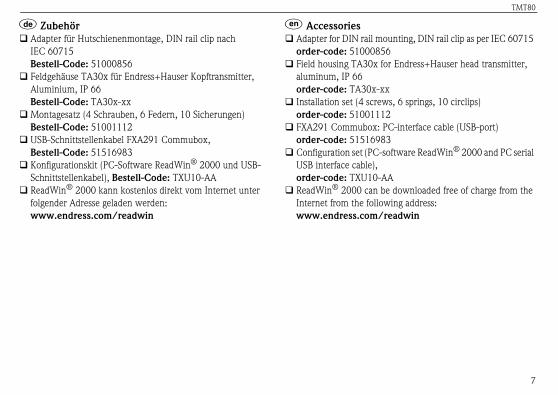
; Zubehör
Adapter für Hutschienenmontage, DIN rail clip nach IEC 60715 Bestell-Code: 51000856
Feldgehäuse TA30x für Endress+Hauser Kopftransmitter,
Aluminium, IP 66Bestell-Code: TA30x-xx
Montagesatz (4 Schrauben, 6 Federn, 10 Sicherungen)Bestell-Code: 51001112
USB-Schnittstellenkabel FXA291 Commubox,Bestell-Code: 51516983
Konfigurationskit (PC-Software ReadWin® 2000 und USB-
Schnittstellenkabel), Bestell-Code: TXU10-AA
ReadWin® 2000 kann kostenlos direkt vom Internet unter
folgender Adresse geladen werden:www.endress.com/readwin
< Accessories
Adapter for DIN rail mo
order-code: 5100085
Field housing TA30x fo
aluminum, IP 66order-code: TA30x-x
Installation set (4 screw
order-code: 5100111
FXA291 Commubox: P
order-code: 5151698
Configuration set (PC-s
USB interface cable), order-code: TXU10-A
ReadWin® 2000 can b
Internet from the follow
www.endress.com/r
TMT80
io su guida DIN, clip della guida DIN
00856
30x per trasmettitore da testa
inio, IP 660x-xx
iti, 6 molle, 10 rondelle elastiche)01112
avo interfaccia-PC16983
oftware per PC ReadWin® 2000 e
riale PC) 10-AA
tuitamente ReadWin® 2000 dal
: eadwin
8
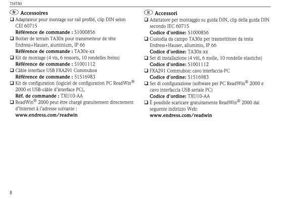
= Accessoires
Adaptateur pour montage sur rail profilé, clip DIN selon CEI 60715Référence de commande : 51000856
Boitier de terrain TA30x pour transmetteur de têteEndress+Hauser, aluminium, IP 66Référence de commande : TA30x-xx
Kit de montage (4 vis, 6 ressorts, 10 rondelles freins)Référence de commande : 51001112
Câble interface USB FXA291 CommuboxRéférence de commande : 51516983
Kit de configuration (logiciel de configuration PC ReadWin®
2000 et USB-câble d’interface PC), Réf. de commande : TXU10-AA
ReadWin® 2000 peut être chargé gratuitement directement
d’Internet à l’adresse suivante :www.endress.com/readwin
Û Accessori
Adattatore per montagg
secondo IEC 60715 Codice d'ordine: 510
Custodia da campo TA
Endress+Hauser, allum
Codice d'ordine: TA3
Set di installazione (4 v
Codice d'ordine: 510
FXA291 Commubox: c
Codice d'ordine: 515
Set di configurazione (s
cavo interfaccia USB se
Codice d'ordine: TXU
È possibile scaricare gra
seguente indirizzo Web
www.endress.com/r
TMT80
9
; Ergänzende Dokumentation
Weitere technische Daten:
Technische Information iTEMP® TMT80 (TI153R/09/de)
< Supplementary documentation
Further technical data:
Technical information iTEMP® TMT80 (TI153R/09/en)
= Documentation complémentaire
D'autres données techniques :
Technical information iTEMP® TMT80(TI153R/14/fr)
Û Documentazione supplementare
Dati tecnici addizionali:
Informazioni tecniche iTEMP® TMT80 (TI153R/09/en)

TMT80
10

TMT80
11
BA00292R/09/c4/13.12 Mat.-Nr. 71113686 FM9