Embed Size (px)
Citation preview
ThyssenKrupp Aufzugswerke�A Companyof�ThyssenKrupp
Elevator
ThyssenKrupp�Aufzugswerke�GmbHA Company�of�ThyssenKrupp�ElevatorBernhäuser�Straße�4573765�Neuhausen�a.�d.�F.GermanyTelefon:�+49�(0)�71�58�12-0Telefax:�+49�(0)�71�58�12-25�85e-mail:�[email protected]
Operating�ManualFrequency�Inverter�MFC�20/21
MFC�30/31Part�2 Commissioning,�Parameters
Imprint
All rights reserved
© Copyright by: THYSSENKRUPP AUFZUGSWERKE GMBH Postfach 23 03 70, D-70623 Stuttgart
Printed in Germany
This operating manual – including excerpts – may only be reprinted or otherwise copied with the express approval in writing of ThyssenKrupp Aufzugswerke.
Any form of duplication, dissemination or storage on data media in any form that is not authorised by THYSSENKRUPP AUFZUGSWERKE GMBH represents a violation of prevailing copyright law and shall lead to legal proceedings. We expressly reserve the right to make changes of a technical nature for the purpose of improvement or to enhance the safety standard - even without a separate announcement.
Issuing party responsible for the content:
THYSSENKRUPP AUFZUGSWERKE GMBH
Preface
We are very glad that you have decided in favour of a quality product made by the THYSSENKRUPP AUFZUGSWERKE company.
This operating manual will help you to get to know our products and to make use of their proper deployment options. Important safety and hazard warnings help you to operate our products safely and in line with accepted technical principles.
The right to make changes of a technical nature is reserved.
Frequency inverter MFC 20/21 and MFC 30/31
ThyssenKrupp AufzugswerkeOperating Manual
Content
MFC 20_31_ENU TEIL2.W2K 3
Content
1 Parameters................................................................................................................................ 1-1 1.1 General....................................................................................................................................... 1-1 1.2 Operation.................................................................................................................................... 1-2 1.2.1 Displaying and changing the parameters................................................................................... 1-2 1.2.2 Display parameters .................................................................................................................... 1-4 1.2.3 Saving the changed parameters in the EPROM........................................................................ 1-4 1.2.4 All parameters to factory settings............................................................................................... 1-5 1.2.5 Individual parameters on the factory settings ............................................................................ 1-5 1.3 Fault stack .................................................................................................................................. 1-6 1.3.1 Displaying the fault stack ........................................................................................................... 1-6 1.3.2 Deleting the fault stack............................................................................................................... 1-6 1.3.3 Closing the fault stack display.................................................................................................... 1-6 1.3.4 Fault description ......................................................................................................................... 1-7 1.4 Parameters................................................................................................................................. 1-8 1.4.1 Changeable parameters............................................................................................................. 1-8 1.4.2 Display parameters .................................................................................................................. 1-28 1.5 Switching sequence diagram ................................................................................................... 1-30
2 Commissioning ........................................................................................................................ 2-1 2.1 Safety instructions...................................................................................................................... 2-1 2.2 Notes on operation..................................................................................................................... 2-2 2.3 Notes: before switching on for the first time............................................................................... 2-2 2.4 Check of the visual displays in the event of faults ..................................................................... 2-3 2.5 Input of installation-specific values............................................................................................. 2-3 2.6 Check of the functional capability of the drives.......................................................................... 2-4 2.7 Optimisation of the drive ............................................................................................................ 2-4 2.8 Notes on measurements and settings ....................................................................................... 2-7 2.8.1 LED and measuring points on the TMI computer board ............................................................ 2-7 2.8.2 Diagram for determining the minimum jerk ................................................................................ 2-8 2.8.3 Diagram for determining the minimum permitted floor-to-floor distances .................................. 2-9
3 Short run device....................................................................................................................... 3-1 3.1 General....................................................................................................................................... 3-1 3.2 Settings ...................................................................................................................................... 3-2
ThyssenKrupp AufzugswerkeOperating Manual
Frequency inverterMFC 20/21 and
MFC 30/31
Content
4 MFC 20_31_ENU TEIL2.W2K
4 Modernisation........................................................................................................................... 4-1 4.1 General....................................................................................................................................... 4-1 4.2 Modernisation with encoder mounting on motor shaft ............................................................... 4-1 4.3 Configuration .............................................................................................................................. 4-2 4.4 Settings for motor adaptation ..................................................................................................... 4-3 4.5 Settings for synchronous motors................................................................................................ 4-6 4.6 Commissioning........................................................................................................................... 4-6
5 DCP interface............................................................................................................................ 5-1 5.1 Preface ....................................................................................................................................... 5-1 5.1.1 Installation .................................................................................................................................. 5-1 5.1.2 Assignment of the speeds and designations ............................................................................. 5-2 5.1.3 Parameters only for DCP04 ....................................................................................................... 5-3 5.1.4 Safety function TIMEOUT control .............................................................................................. 5-4 5.1.5 Stopping accuracy with DCP04 operation ................................................................................. 5-4
6 Test instructions ...................................................................................................................... 6-1 6.1 Travel contactors........................................................................................................................ 6-1 6.2 Brake contactor .......................................................................................................................... 6-2 6.3 Brake feedback .......................................................................................................................... 6-3
7 Appendix ................................................................................................................................... 7-1 7.1 Setting values 0-30 .................................................................................................................... 7-1 7.2 Setting values 31 - 160 .............................................................................................................. 7-2 7.3 Quick reference.......................................................................................................................... 7-3
8 Index .......................................................................................................................................... 8-5
9 Revision service....................................................................................................................... 9-1
Frequency inverter MFC 20/21 and MFC 30/31
ThyssenKrupp AufzugswerkeOperating Manual
Parameters - General
MFC 20_31_ENU TEIL2.W2K 1-1
1 Parameters
1.1 General
The program enables parameter changes in a defined memory section. The permitted number range of each parameter is monitored during input and limited accordingly. A distinction is made between changeable parameters (e.g. maximum speed, direction of rotation or control device parameters) and the display parameters that show various operating values (e.g. current speed, current reference value, etc.).
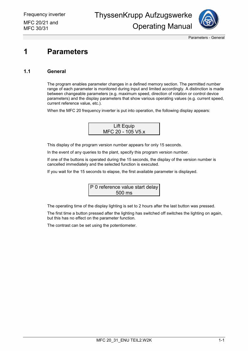
When the MFC 20 frequency inverter is put into operation, the following display appears:
Lift Equip MFC 20 - 105 V5.x
This display of the program version number appears for only 15 seconds.
In the event of any queries to the plant, specify this program version number.
If one of the buttons is operated during the 15 seconds, the display of the version number is cancelled immediately and the selected function is executed.
If you wait for the 15 seconds to elapse, the first available parameter is displayed.
P 0 reference value start delay500 ms
The operating time of the display lighting is set to 2 hours after the last button was pressed.
The first time a button pressed after the lighting has switched off switches the lighting on again, but this has no effect on the parameter function.
The contrast can be set using the potentiometer.
ThyssenKrupp Aufzugswerke Operating Manual
Frequency inverterMFC 20/21 and
MFC 30/31
Parameters - Operation
1-2 MFC 20_31_ENU TEIL2.W2K
1.2 Operation
The parameter entry permits the following functions:
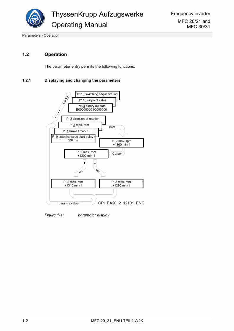
1.2.1 Displaying and changing the parameters
CPI_BA20_2_12101_ENG
P110 switching sequence ind.
P116 setpoint value
P104 binary outputsB00000000 00000000
P 3 direction of rotation
P 2 max. rpm
P 1 brake timeout
P 0 setpoint value start delay500 ms
P 2 max. rpm+1300 min-1
P 2 max. rpm+1300 min-1
key key
P 2 max. rpm+1310 min-1
P 2 max. rpm+1290 min-1
param. / value
P/W
Cursor
Figure 1-1: parameter display
Frequency inverter MFC 20/21 and MFC 30/31
ThyssenKrupp AufzugswerkeOperating Manual
Parameters - Operation
MFC 20_31_ENU TEIL2.W2K 1-3
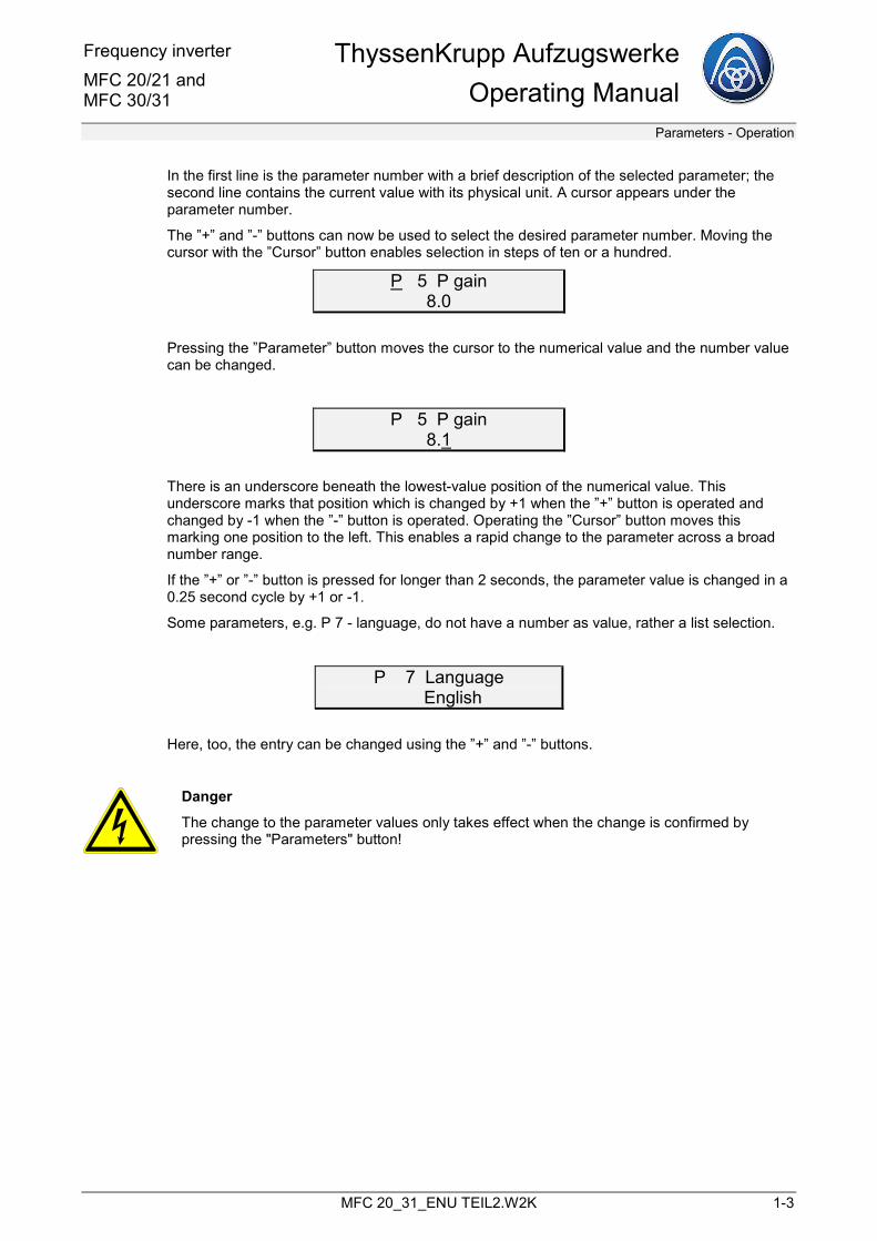
In the first line is the parameter number with a brief description of the selected parameter; the second line contains the current value with its physical unit. A cursor appears under the parameter number.
The ”+” and ”-” buttons can now be used to select the desired parameter number. Moving the cursor with the ”Cursor” button enables selection in steps of ten or a hundred.
P 5 P gain 8.0
Pressing the ”Parameter” button moves the cursor to the numerical value and the number value can be changed.
P 5 P gain 8.1
There is an underscore beneath the lowest-value position of the numerical value. This underscore marks that position which is changed by +1 when the ”+” button is operated and changed by -1 when the ”-” button is operated. Operating the ”Cursor” button moves this marking one position to the left. This enables a rapid change to the parameter across a broad number range.
If the ”+” or ”-” button is pressed for longer than 2 seconds, the parameter value is changed in a 0.25 second cycle by +1 or -1.
Some parameters, e.g. P 7 - language, do not have a number as value, rather a list selection.
P 7 Language � English
Here, too, the entry can be changed using the ”+” and ”-” buttons.
Danger
The change to the parameter values only takes effect when the change is confirmed by pressing the "Parameters" button!
ThyssenKrupp Aufzugswerke Operating Manual
Frequency inverterMFC 20/21 and
MFC 30/31
Parameters - Operation
1-4 MFC 20_31_ENU TEIL2.W2K
1.2.2 Display parameters
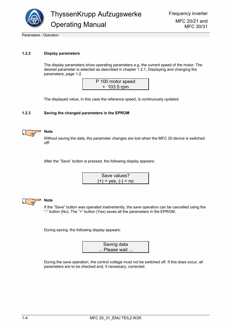
The display parameters show operating parameters e.g. the current speed of the motor. The desired parameter is selected as described in chapter 1.2.1, Displaying and changing the parameters, page 1-2.
P 100 motor speed + 103.5 rpm
The displayed value, in this case the reference speed, is continuously updated.
1.2.3 Saving the changed parameters in the EPROM
Note
Without saving the data, the parameter changes are lost when the MFC 20 device is switched off!
After the ”Save” button is pressed, the following display appears:
Save values? (+) = yes, (-) = no
Note
If the ”Save” button was operated inadvertently, the save operation can be cancelled using the ”-” button (No). The ”+” button (Yes) saves all the parameters in the EPROM.
During saving, the following display appears:
Saving data ... Please wait ...
During the save operation, the control voltage must not be switched off. If this does occur, all parameters are to be checked and, if necessary, corrected.
Frequency inverter MFC 20/21 and MFC 30/31
ThyssenKrupp AufzugswerkeOperating Manual
Parameters - Operation
MFC 20_31_ENU TEIL2.W2K 1-5
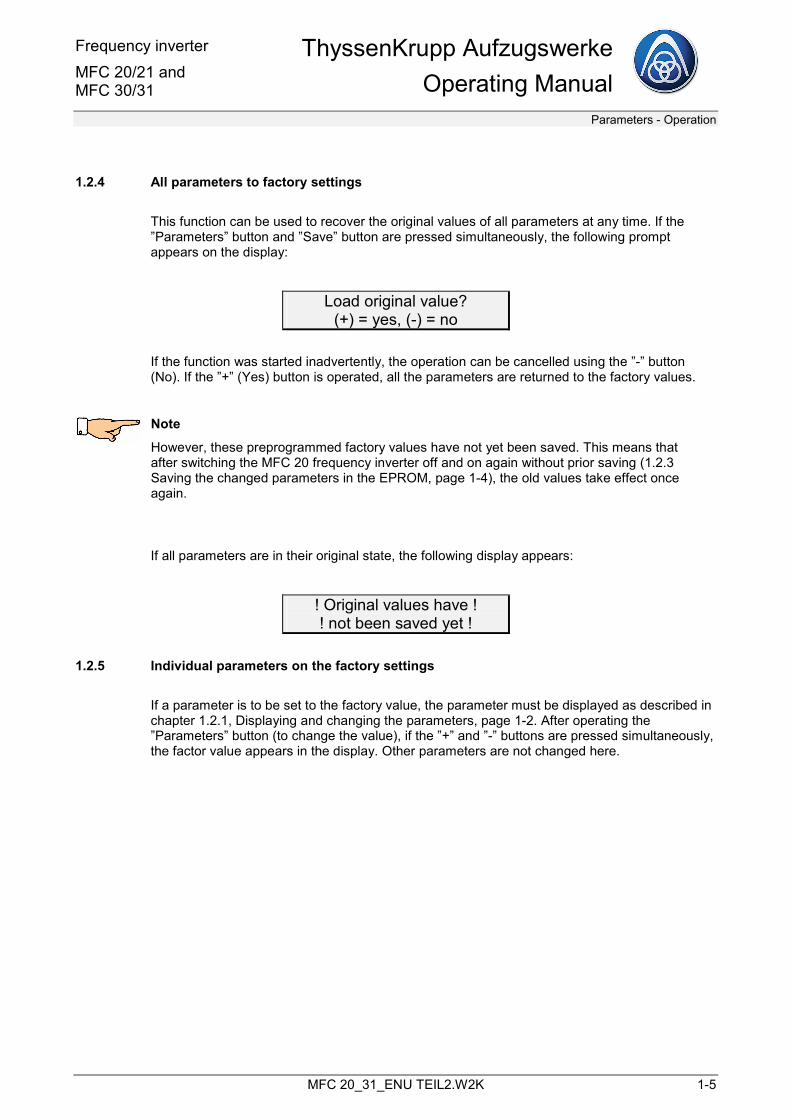
1.2.4 All parameters to factory settings
This function can be used to recover the original values of all parameters at any time. If the ”Parameters” button and ”Save” button are pressed simultaneously, the following prompt appears on the display:
Load original value? (+) = yes, (-) = no
If the function was started inadvertently, the operation can be cancelled using the ”-” button (No). If the ”+” (Yes) button is operated, all the parameters are returned to the factory values.
Note
However, these preprogrammed factory values have not yet been saved. This means that after switching the MFC 20 frequency inverter off and on again without prior saving (1.2.3 Saving the changed parameters in the EPROM, page 1-4), the old values take effect once again.
If all parameters are in their original state, the following display appears:
! Original values have ! ! not been saved yet !
1.2.5 Individual parameters on the factory settings
If a parameter is to be set to the factory value, the parameter must be displayed as described in chapter 1.2.1, Displaying and changing the parameters, page 1-2. After operating the ”Parameters” button (to change the value), if the ”+” and ”-” buttons are pressed simultaneously, the factor value appears in the display. Other parameters are not changed here.
ThyssenKrupp Aufzugswerke Operating Manual
Frequency inverterMFC 20/21 and
MFC 30/31
Parameters - Fault stack
1-6 MFC 20_31_ENU TEIL2.W2K
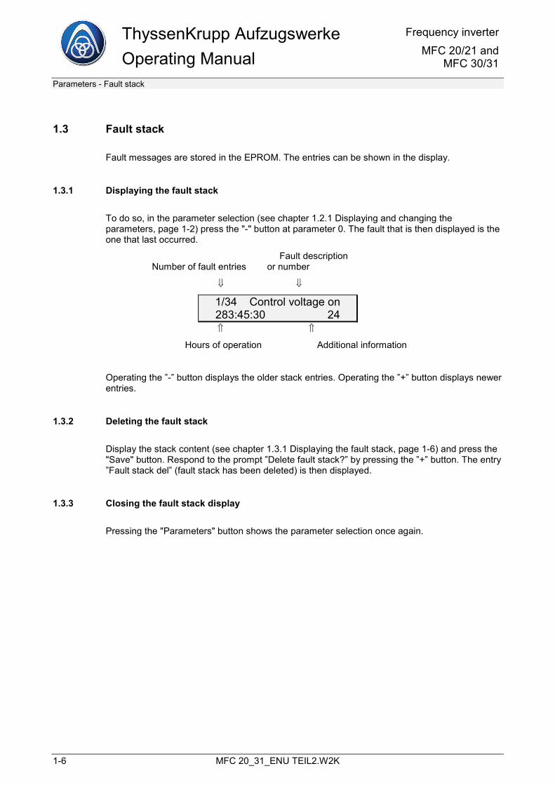
1.3 Fault stack
Fault messages are stored in the EPROM. The entries can be shown in the display.
1.3.1 Displaying the fault stack
To do so, in the parameter selection (see chapter 1.2.1 Displaying and changing the parameters, page 1-2) press the "-" button at parameter 0. The fault that is then displayed is the one that last occurred.
Fault description Number of fault entries or number
⇓ ⇓
1/34 Control voltage on 283:45:30 24 ⇑ ⇑
Hours of operation Additional information
Operating the ”-” button displays the older stack entries. Operating the ”+” button displays newer entries.
1.3.2 Deleting the fault stack
Display the stack content (see chapter 1.3.1 Displaying the fault stack, page 1-6) and press the "Save" button. Respond to the prompt ”Delete fault stack?” by pressing the ”+” button. The entry ”Fault stack del” (fault stack has been deleted) is then displayed.
1.3.3 Closing the fault stack display
Pressing the "Parameters" button shows the parameter selection once again.
Frequency inverter MFC 20/21 and MFC 30/31
ThyssenKrupp AufzugswerkeOperating Manual
Parameters - Fault stack
MFC 20_31_ENU TEIL2.W2K 1-7
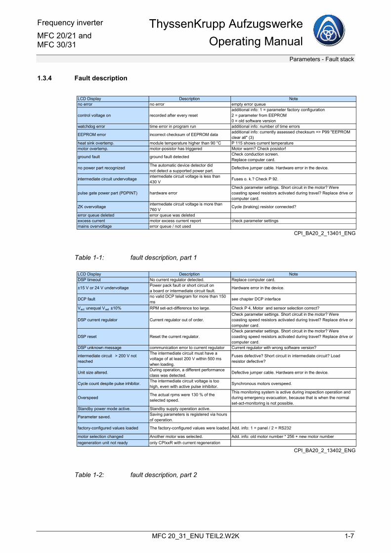
1.3.4 Fault description
LCD Display Description Noteno error no error empty error queue
control voltage on recorded after every reset additional info: 1 = parameter factory configuration2 = parameter from EEPROM0 = old software version
watchdog error time error in program run additional info: number of time errors
EEPROM error incorrect checksum of EEPROM data additional info: currently assessed checksum => P99 "EEPROM clear all" (3)
heat sink overtemp. module temperature higher than 90 °C P 115 shows current temperaturemotor overtemp. motor-posistor has triggered Motor warm? Check posistor!
ground fault ground fault detected Check conduction screen.Replace computer card.
no power part recognized The automatic device detector didnot detect a supported power part.
Defective jumper cable. Hardware error in the device.
intermediate circuit undervoltage intermediate circuit voltage is less than 430 V
Fuses o. k.? Check P 92.
pulse gate power part (PDPINT) hardware errorCheck parameter settings. Short circuit in the motor? Were coasting speed resistors activated during travel? Replace drive or computer card.
ZK overvoltage intermediate circuit voltage is more than 760 V
Cycle (braking) resistor connected?
error queue deleted error queue was deletedexcess current motor excess current report check parameter settingsmains overvoltage error queue / not used
CPI_BA20_2_13401_ENG
Table 1-1: fault description, part 1
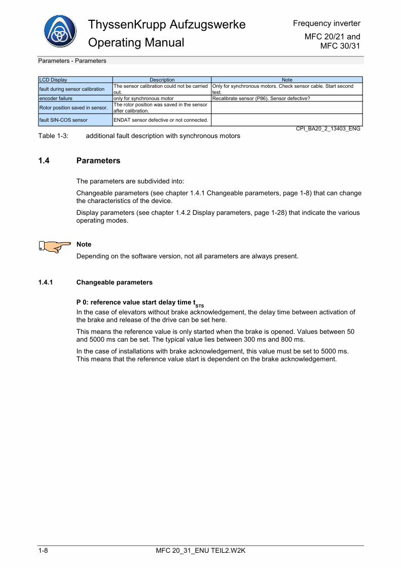
LCD Display Description NoteDSP timeout No current regulator detected. Replace computer card.
±15 V or 24 V undervoltage Power pack fault or short circuit ona board or intermediate circuit fault.
Hardware error in the device.
DCP fault no valid DCP telegram for more than 150 ms
see chapter DCP interface
Vact unequal Vset ±10% RPM set-act-difference too large. Check P 4, Motor and sensor selection correct?
DSP current regulator Current regulator out of order.Check parameter settings. Short circuit in the motor? Were coasting speed resistors activated during travel? Replace drive or computer card.
DSP reset Reset the current regulator.Check parameter settings. Short circuit in the motor? Were coasting speed resistors activated during travel? Replace drive or computer card.
DSP unknown message communication error to current regulator Current regulator with wrong software version?
intermediate circuit > 200 V not reached
The intermediate circuit must have a voltage of at least 200 V within 500 ms when loading.
Fuses defective? Short circuit in intermediate circuit? Load resistor defective?
Unit size altered. During operation, a different performance class was detected.
Defective jumper cable. Hardware error in the device.
Cycle count despite pulse inhibitor. The intermediate circuit voltage is too high, even with active pulse inhibitor.
Synchronous motors overspeed.
OverspeedThe actual rpms were 130 % of the selected speed.
This monitoring system is active during inspection operation and during emergency evacuation, because that is when the normal set-act-monitoring is not possible.
Standby power mode active. Standby supply operation active.
Parameter saved. Saving parameters is registered via hours of operation.
factory-configured values loaded The factory-configured values were loaded. Add. info: 1 = panel / 2 = RS232
motor selection changed Another motor was selected. Add. info: old motor number * 256 + new motor numberregeneration unit not ready only CPIxxR with current regeneration
CPI_BA20_2_13402_ENG
Table 1-2: fault description, part 2
ThyssenKrupp Aufzugswerke Operating Manual
Frequency inverterMFC 20/21 and
MFC 30/31
Parameters - Parameters
1-8 MFC 20_31_ENU TEIL2.W2K
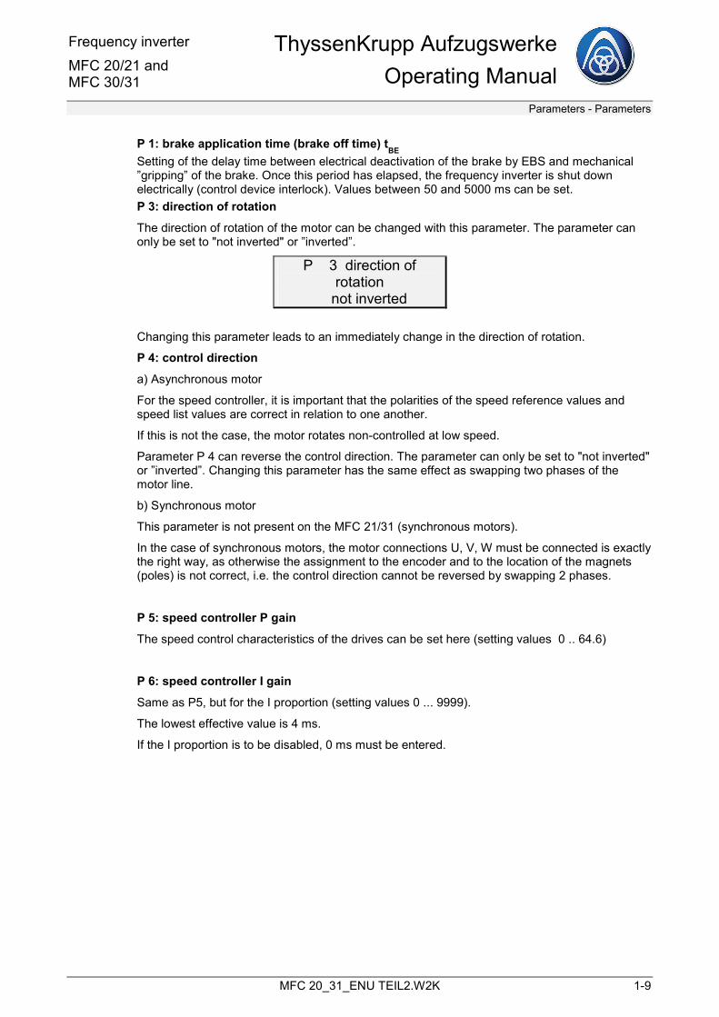
LCD Display Description Note
fault during sensor calibration The sensor calibration could not be carried out.
Only for synchronous motors. Check sensor cable. Start second test.
encoder failure only for synchronous motor Recalibrate sensor (P86). Sensor defective?
Rotor position saved in sensor. The rotor position was saved in the sensor after calibration.
fault SIN-COS sensor ENDAT sensor defective or not connected.
CPI_BA20_2_13403_ENGTable 1-3: additional fault description with synchronous motors
1.4 Parameters
The parameters are subdivided into:
Changeable parameters (see chapter 1.4.1 Changeable parameters, page 1-8) that can change the characteristics of the device.
Display parameters (see chapter 1.4.2 Display parameters, page 1-28) that indicate the various operating modes.
Note
Depending on the software version, not all parameters are always present.
1.4.1 Changeable parameters
P 0: reference value start delay time tSTS
In the case of elevators without brake acknowledgement, the delay time between activation of the brake and release of the drive can be set here.
This means the reference value is only started when the brake is opened. Values between 50 and 5000 ms can be set. The typical value lies between 300 ms and 800 ms.
In the case of installations with brake acknowledgement, this value must be set to 5000 ms. This means that the reference value start is dependent on the brake acknowledgement.
Frequency inverter MFC 20/21 and MFC 30/31
ThyssenKrupp AufzugswerkeOperating Manual
Parameters - Parameters
MFC 20_31_ENU TEIL2.W2K 1-9
P 1: brake application time (brake off time) tBE
Setting of the delay time between electrical deactivation of the brake by EBS and mechanical ”gripping” of the brake. Once this period has elapsed, the frequency inverter is shut down electrically (control device interlock). Values between 50 and 5000 ms can be set. P 3: direction of rotation
The direction of rotation of the motor can be changed with this parameter. The parameter can only be set to "not inverted" or ”inverted”.
P 3 direction of rotation
� not inverted
Changing this parameter leads to an immediately change in the direction of rotation.
P 4: control direction
a) Asynchronous motor
For the speed controller, it is important that the polarities of the speed reference values and speed list values are correct in relation to one another.
If this is not the case, the motor rotates non-controlled at low speed.
Parameter P 4 can reverse the control direction. The parameter can only be set to "not inverted" or ”inverted”. Changing this parameter has the same effect as swapping two phases of the motor line.
b) Synchronous motor
This parameter is not present on the MFC 21/31 (synchronous motors).
In the case of synchronous motors, the motor connections U, V, W must be connected is exactly the right way, as otherwise the assignment to the encoder and to the location of the magnets (poles) is not correct, i.e. the control direction cannot be reversed by swapping 2 phases.
P 5: speed controller P gain
The speed control characteristics of the drives can be set here (setting values 0 .. 64.6)
P 6: speed controller I gain
Same as P5, but for the I proportion (setting values 0 ... 9999).
The lowest effective value is 4 ms.
If the I proportion is to be disabled, 0 ms must be entered.
ThyssenKrupp Aufzugswerke Operating Manual
Frequency inverterMFC 20/21 and
MFC 30/31
Parameters - Parameters
1-10 MFC 20_31_ENU TEIL2.W2K
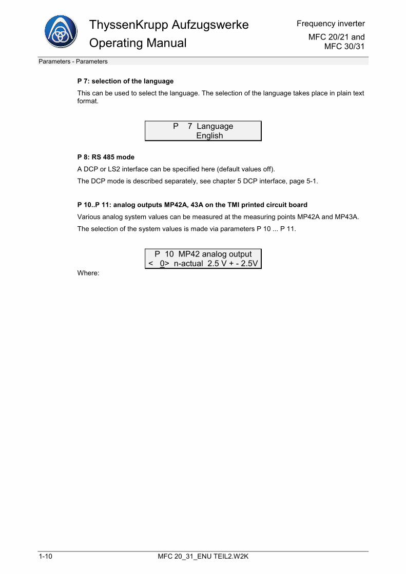
P 7: selection of the language
This can be used to select the language. The selection of the language takes place in plain text format.
P 7 Language � English
P 8: RS 485 mode
A DCP or LS2 interface can be specified here (default values off).
The DCP mode is described separately, see chapter 5 DCP interface, page 5-1.
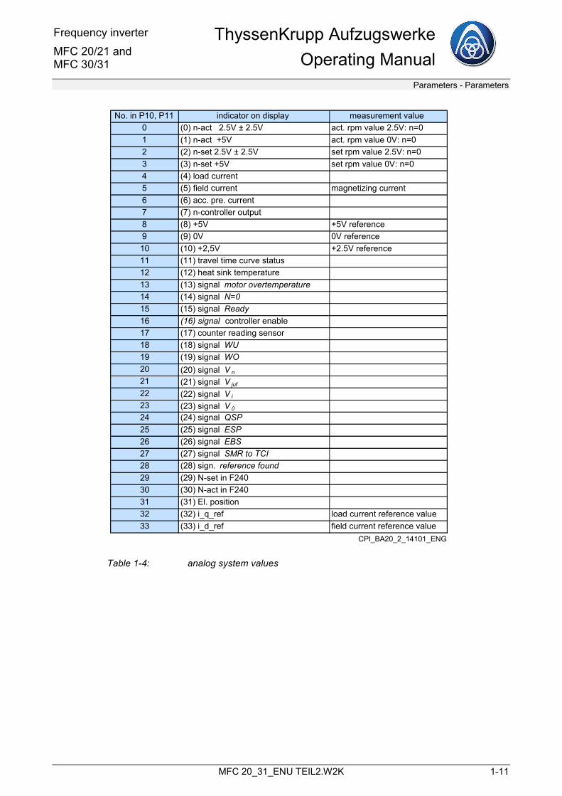
P 10..P 11: analog outputs MP42A, 43A on the TMI printed circuit board
Various analog system values can be measured at the measuring points MP42A and MP43A.
The selection of the system values is made via parameters P 10 ... P 11.
P 10 MP42 analog output < 0> n-actual 2.5 V + - 2.5V
Where:
Frequency inverter MFC 20/21 and MFC 30/31
ThyssenKrupp AufzugswerkeOperating Manual
Parameters - Parameters
MFC 20_31_ENU TEIL2.W2K 1-11
No. in P10, P11 indicator on display measurement value0 (0) n-act 2.5V ± 2.5V act. rpm value 2.5V: n=01 (1) n-act +5V act. rpm value 0V: n=02 (2) n-set 2.5V ± 2.5V set rpm value 2.5V: n=03 (3) n-set +5V set rpm value 0V: n=04 (4) load current5 (5) field current magnetizing current6 (6) acc. pre. current7 (7) n-controller output8 (8) +5V +5V reference9 (9) 0V 0V reference10 (10) +2,5V +2.5V reference11 (11) travel time curve status12 (12) heat sink temperature13 (13) signal motor overtemperature14 (14) signal N=015 (15) signal Ready16 (16) signal controller enable17 (17) counter reading sensor18 (18) signal WU19 (19) signal WO20 (20) signal V n
21 (21) signal V juf
22 (22) signal V i
23 (23) signal V 0
24 (24) signal QSP25 (25) signal ESP26 (26) signal EBS27 (27) signal SMR to TCI28 (28) sign. reference found29 (29) N-set in F24030 (30) N-act in F24031 (31) El. position32 (32) i_q_ref load current reference value33 (33) i_d_ref field current reference value
CPI_BA20_2_14101_ENG
Table 1-4: analog system values
ThyssenKrupp Aufzugswerke Operating Manual
Frequency inverterMFC 20/21 and
MFC 30/31
Parameters - Parameters
1-12 MFC 20_31_ENU TEIL2.W2K
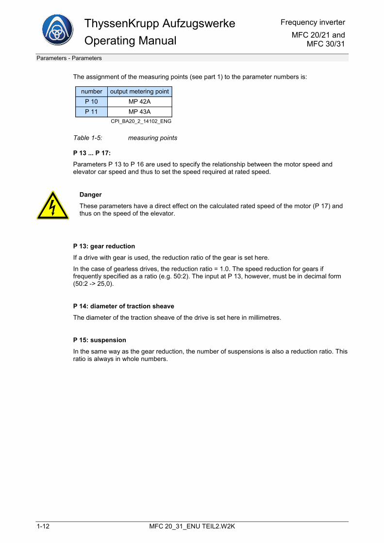
The assignment of the measuring points (see part 1) to the parameter numbers is:
number output metering pointP 10 MP 42AP 11 MP 43A
CPI_BA20_2_14102_ENG
Table 1-5: measuring points
P 13 ... P 17:
Parameters P 13 to P 16 are used to specify the relationship between the motor speed and elevator car speed and thus to set the speed required at rated speed.
Danger
These parameters have a direct effect on the calculated rated speed of the motor (P 17) and thus on the speed of the elevator.
P 13: gear reduction
If a drive with gear is used, the reduction ratio of the gear is set here.
In the case of gearless drives, the reduction ratio = 1.0. The speed reduction for gears if frequently specified as a ratio (e.g. 50:2). The input at P 13, however, must be in decimal form (50:2 -> 25,0).
P 14: diameter of traction sheave
The diameter of the traction sheave of the drive is set here in millimetres.
P 15: suspension
In the same way as the gear reduction, the number of suspensions is also a reduction ratio. This ratio is always in whole numbers.
Frequency inverter MFC 20/21 and MFC 30/31
ThyssenKrupp AufzugswerkeOperating Manual
Parameters - Parameters
MFC 20_31_ENU TEIL2.W2K 1-13
P 17: calculated maximum speed n rated
The values of the parameters P 13 to P 16 are used to automatically calculate and display the required maximum speed of the motor.
P 18: threshold for N=0
If the speed set here is undershot, the end of the run has been reached. The EBS relay de-energises (printed circuit board TIC/X1 , terminals 1a and 2a).
P 19: acceleration change (jerk)
Set the desired acceleration change (jerk) in [m/s³].
P 20: acceleration
Set the desired acceleration / deceleration in [m/s2].
P 21: acceleration pre-control on/off
If the drive tends to overshoot or undershoot, the travel quality can be improved by enabling the acceleration pre-control.
This applies above all to gearless drives.
P 22: acceleration pre-control gain
To assess the right setting of the acceleration pre-control, the actual speed value (P 10 to ”0”) should be measured at measuring point 42A and the n-controller output (P 11 to ”7”) should be measured at measuring point 43A.
Note
P 21 = "Off" (pre-control off)
ThyssenKrupp Aufzugswerke Operating Manual
Frequency inverterMFC 20/21 and
MFC 30/31
Parameters - Parameters
1-14 MFC 20_31_ENU TEIL2.W2K
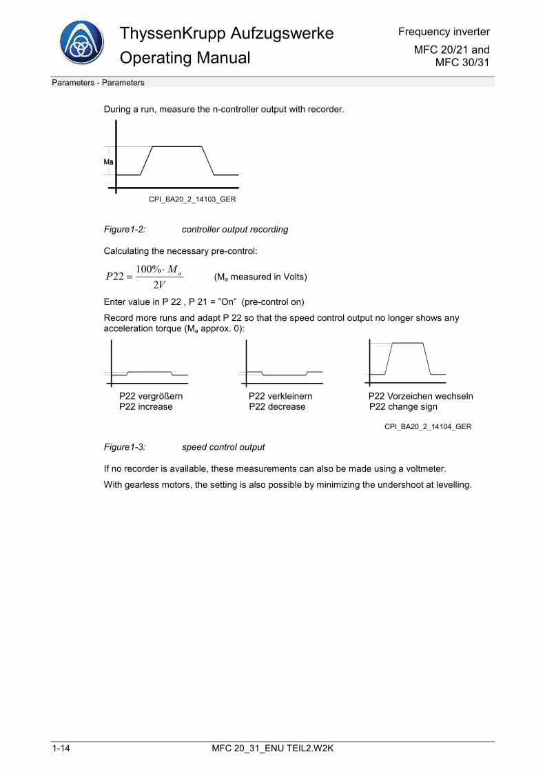
During a run, measure the n-controller output with recorder.
CPI_BA20_2_14103_GER
Figure1-2: controller output recording
Calculating the necessary pre-control:
VMP a
2%100
22⋅
= (Ma measured in Volts)
Enter value in P 22 , P 21 = ”On” (pre-control on)
Record more runs and adapt P 22 so that the speed control output no longer shows any acceleration torque (Ma approx. 0):
P22 vergrößern P22 verkleinern P22 Vorzeichen wechselnP22 increase P22 decrease P22 change sign
CPI_BA20_2_14104_GER
Figure1-3: speed control output
If no recorder is available, these measurements can also be made using a voltmeter.
With gearless motors, the setting is also possible by minimizing the undershoot at levelling.
Frequency inverter MFC 20/21 and MFC 30/31
ThyssenKrupp AufzugswerkeOperating Manual
Parameters - Parameters
MFC 20_31_ENU TEIL2.W2K 1-15
Parameter for speed setting
• The selection of one of the five “main speeds” is made at the inputs at connector X1 of the TIC printed circuit board.
• With simultaneous selection of vi or v0
and another main speed, the following applies:
the inspection speed vi is dominant, i.e. as soon as vi is selected, the other speeds are ignored. the levelling speed v
0can always be selected; it only takes effect if no other speed remains
active.
• With a currently selected speed, monitoring of the reference-actual value variance is carried out ("tolerance band monitoring"). If this deviation is too great, an emergency stop is initiated.
• At inspection speed Vi and emergency operation speed V3, however, an emergency stop is only initiated if the amount of the actual value is greater than 130% of the target value in each case.
• For all travel curve sections (acceleration, deceleration, lower and upper roundings), the same acceleration and jerk value applies.
• The stopping distance from withdrawal of the levelling speed v0 to "Electrical Halt" (speed zero) depends only on the value v0 and the set jerk value of the running characteristic curve. The parameter of this stopping distance cannot be set separately. Example: v0 = 0.1 m/s, jerk = 0.8 m/s³ -> stopping distance: 35 mm.
• The short run function is only possible for the rated speed vrated.
• The levelling speed v0 is typically selected as 0.1 m/s; with lower values of v0, the "levelling duration" can become very high.
ThyssenKrupp Aufzugswerke Operating Manual
Frequency inverterMFC 20/21 and
MFC 30/31
Parameters - Parameters
1-16 MFC 20_31_ENU TEIL2.W2K
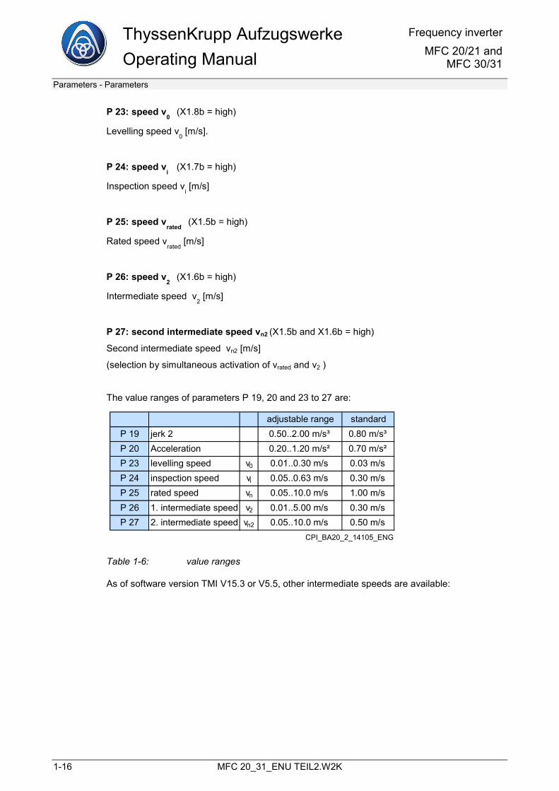
P 23: speed v0
(X1.8b = high)
Levelling speed v0
[m/s].
P 24: speed vi
(X1.7b = high)
Inspection speed vi[m/s]
P 25: speed vrated
(X1.5b = high)
Rated speed vrated
[m/s]
P 26: speed v2
(X1.6b = high)
Intermediate speed v2
[m/s]
P 27: second intermediate speed vn2 (X1.5b and X1.6b = high)
Second intermediate speed vn2 [m/s]
(selection by simultaneous activation of vrated and v2 )
The value ranges of parameters P 19, 20 and 23 to 27 are:
adjustable range standardP 19 jerk 2 0.50..2.00 m/s³ 0.80 m/s³P 20 Acceleration 0.20..1.20 m/s² 0.70 m/s²P 23 levelling speed v0 0.01..0.30 m/s 0.03 m/sP 24 inspection speed vi 0.05..0.63 m/s 0.30 m/sP 25 rated speed vn 0.05..10.0 m/s 1.00 m/sP 26 1. intermediate speed v2 0.01..5.00 m/s 0.30 m/sP 27 2. intermediate speed vn2 0.05..10.0 m/s 0.50 m/s
CPI_BA20_2_14105_ENG
Table 1-6: value ranges
As of software version TMI V15.3 or V5.5, other intermediate speeds are available:
Frequency inverter MFC 20/21 and MFC 30/31
ThyssenKrupp AufzugswerkeOperating Manual
Parameters - Parameters
MFC 20_31_ENU TEIL2.W2K 1-17
P 28: speed v3
Speed for emergency operation v3 [m/s]
To enable this parameter, "emergency power" must be selected either at parameter P 48 or P 49. Only then is parameter P 28 visible.
The corresponding input signal X1.11a (with P 48) or X1.9b (with P 49) must have a +24 V signal.
P 29 to P 32:
To enable this parameter, "intermediate speed" must be selected either at parameter P 48 or P 49. Only then are parameters P 29 ... P 32 visible.
The corresponding input signal X1.11a (with P 48) or X1.9b (with P 49) must have a +24 V signal.
Here, too, with simultaneous selection of vi or v0
and another intermediate speed, the following applies:
• the inspection speed vi is dominant, i.e. as soon as vi is selected, the other speeds are ignored.
• The levelling speed v0
can always be selected; it only takes effect if no other speed remains active.
P 29: speed v4
(X1.5b = low and X1.6b = low)
Intermediate speed v4
[m/s].
P 30: speed v5
(X1.5b = high and X1.6b = low)
Intermediate speed v5
[m/s]
P 31: speed v6
(X1.5b = low and X1.6b = high)
Intermediate speed v6
[m/s]
P 32: speed v7
(X1.5b = high and X1.6b = high)
Intermediate speed v7
[m/s]
The value ranges of the parameters P 28 to P 32 are:
ThyssenKrupp Aufzugswerke Operating Manual
Frequency inverterMFC 20/21 and
MFC 30/31
Parameters - Parameters
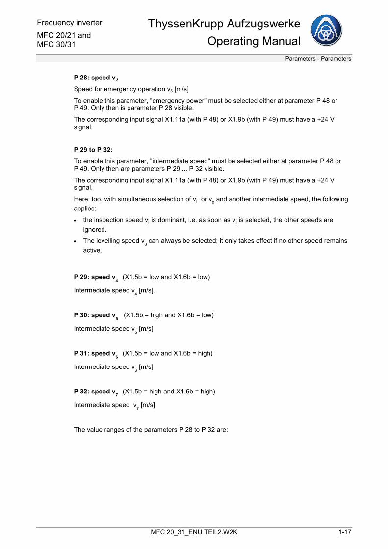
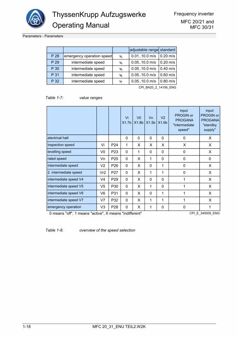
1-18 MFC 20_31_ENU TEIL2.W2K
adjustable range standardP 28 emergency operation speed v3 0.01..10.0 m/s 0.20 m/sP 29 intermediate speed v4 0.05..10.0 m/s 0.20 m/sP 30 intermediate speed v5 0.05..10.0 m/s 0.40 m/sP 31 intermediate speed v6 0.05..10.0 m/s 0.60 m/sP 32 intermediate speed v7 0.05..10.0 m/s 0.80 m/s
CPI_BA20_2_14106_ENG
Table 1-7: value ranges
ViX1.7b
V0X1.8b
VnX1.5b
V2X1.6b
input PROGIN or PROGANA
"intermediatespeed"
inputPROGIN or PROGANA"standby supply"
electrical halt 0 0 0 0 0 X
inspection speed Vi P24 1 X X X X X
levelling speed V0 P23 0 1 0 0 0 X
rated speed Vn P25 0 X 1 0 0 0
intermediate speed V2 P26 0 X 0 1 0 X
2. intermediate speed Vr2 P27 0 X 1 1 0 X
intermediate speed V4 V4 P29 0 X 0 0 1 X
intermediate speed V5 V5 P30 0 X 1 0 1 X
intermediate speed V6 V6 P31 0 X 0 1 1 X
intermediate speed V7 V7 P32 0 X 1 1 1 X
emergency operation V3 P28 0 X 1 0 0 10 means "off", 1 means "active", X means "indifferent" CPI_E_340009_ENG
Table 1-8: overview of the speed selection
Frequency inverter MFC 20/21 and MFC 30/31
ThyssenKrupp AufzugswerkeOperating Manual
Parameters - Parameters
MFC 20_31_ENU TEIL2.W2K 1-19
P 37: threshold v < 0.3
The speed can be set in the range 0.15 ... 0.3 m/s. If the set speed is reached, the contact closes on the TIC printed circuit board / terminals 11b and 12b.
The set threshold is provided with a hysteresis of ± 1% of vrated.
P 38: short run computer
Switching the short run computer on / off
P 39: correction of short run distance
Description, see chapter 3, Short run device, page 3-1.
P 40: motor selection
The motor concerned is selected here.
The motor type can be read on the motor type plate.
This motor type is to be selected here.
If not present, then enter "non-ThyssenKrupp motor", see chapter 4 Modernisation , page 4-1.
P 42: output PROGOUT3 (only with MFC 30/31)
Default: (contactor control)
Selection: see below
P 43: output PROGOUT2 (only with MFC 30/31)
Default: (ready)
Selection: (brake feedback QBK12)
The elevator control system must monitor the signal change of the <brake feedback QBK 12>.
If the signal does not change the level, there is a fault in the brake circuit. The elevator control system must then initiate corresponding measures, e.g. shut down the elevator system.
Monitoring only the brake feedback in the converter does not conform with our safety concept.
Note
If the brake feedback is selected and an additional "ready" signal is required, this can only be output as a 24 V signal on another output.
If necessary, an external 230 V conversion relay must then be used.
ThyssenKrupp Aufzugswerke Operating Manual
Frequency inverterMFC 20/21 and
MFC 30/31
Parameters - Parameters
1-20 MFC 20_31_ENU TEIL2.W2K
P 44: speed threshold PROGOUT
possible setting v < 0.0 ... vrated
Selection: see below
P 45: output PROGOUT
Default: (v < P 44)
Selection: see below
P 46: output PROGOUT1
Default: (motor overtemperature)
Selection: see below
P 47: output v < 0.3
Default: (v < 0.3 m/s)
Selection: see below
On (P 42 with MFC 30/31), P 45, P 46 and P 47, the following signals can be output (if negative numbers are selected, the signals are inverted):
(no activation) (device overtemperature)
(ESP travel contactor activation) (ready)
(EBS brake control) (contactor control)
( n=0) (collective fault signal)
(v < 0.3 m/s) (temperature > P 161)
(v<P 44) (direction of rotation up)
(motor overtemperature) (direction of rotation down)
P 48: Input Progana ("analog in")
Default: (emergency power 220 V)
Selection: (input not used) , (LMS ± 10 V) , (emergency power 220 V), (intermediate speed)
Frequency inverter MFC 20/21 and MFC 30/31
ThyssenKrupp AufzugswerkeOperating Manual
Parameters - Parameters
MFC 20_31_ENU TEIL2.W2K 1-21
P 49: input Progin
Default: (load measurement FM)
Selection: (input not used) , (load measurement FM), (emergency power 220 V) , (intermediate speed)
Improvement of the startup characteristics with asynchronous motors with the help of load measurement device LMS 1
Reverse rotation of an elevator car on opening the brake can be reduced by specifying an initial torque.
This is specified either with the help of a load measurement device LMS 1 or it can be specified only for a single certain load state if no load measurement device is available.
P 50: load weighing device (Off/On) "load measurement"
Switching the load pre-control on / off
a) without load measurement
This specification is then only optimal for one load state.
If no load measurement device is present, P 50 can be used to switch the load specification on and a fixed value can be entered at P 54.
In P 48 and P 49, do not enable "LMS" (i.e. do not select <1>).
Bear in mind that the values in P 51 and P 52 must not be the same, as the internal calculation is performed with the formula [(P 51 - P 52) x P 54].
Recommended: P 51 = 0, P 52 = 45% (default value)
b) with load measurement LMS 1
In the case of load measurement with analog signal: set P 48 to <1> LMS +- 10 V (use input PROGANA)
In the case of load measurement with frequency signal: set P 49 to <1> load measurement FM (use input PROGIN)
ThyssenKrupp Aufzugswerke Operating Manual
Frequency inverterMFC 20/21 and
MFC 30/31
Parameters - Parameters
1-22 MFC 20_31_ENU TEIL2.W2K
P 51: current value / load measurement "measured value of load measurement device"
The current elevator car load condition in % of the rated load is displayed here.
(with load compensation of the elevator car, usually approx. 45%).
Note A requirement is that the load measurement device LMS 1 has been correctly adjusted in advance.
P 52: value LMS 1/load compensation "input value for load compensation"
The load state for load compensation must be entered here. This can be determined experimentally as follows:
1. Set up load compensation
(elevator car must not coast away with brake opened)
2. In P 51, read the current value of the LMS 1
3. Enter the value in P 52 or enter a value based on experience, e.g. 45% means that the counterweight is 45% of the rated load.
P 53: adopt load current "calculate gain load measurement from load current"
During constant running with electrical recall (e.g. empty up or down), the current load current is displayed.
By pressing the ”+” or ”- ” button during this constant run, the load specification gain is calculated internally from this current value.
The value in P 54 is overwritten.
P 54: load specification gain "load measurement gain"
The value (with prefix) of the gain calculated via P 53 is specified here. Any fine calibration that might be necessary can be performed here.
Improving the startup characteristics with synchronous motors with the help of the position control
P 55: position controller gain (without load measurement) (only with synchronous)
The startup characteristics of synchronous gearless drives is improved in such a way that the converter no longer needs to be fed a load measurement signal from a sensor. To achieve this, the high-resolution position signal from the sine / cosine encoder is used.
Frequency inverter MFC 20/21 and MFC 30/31
ThyssenKrupp AufzugswerkeOperating Manual
Parameters - Parameters
MFC 20_31_ENU TEIL2.W2K 1-23
A position-controller algorithm replaces the pre-control signal previously obtained from the load sensor: directly after impulse enabling and opening of the brake, the position controller holds the elevator car in its current financial position. Parameter P 55 can be used to set the gain of the intervention. The position controller is disabled at the start of the running characteristic curve and control is handed over to the speed controller.
Preparation:
TMI board: EPROM version as of V5.5b, FLASH - program as of F030701.
P 0 = 280 ms Correct reference value start delay
P 50 = Off Disable load measurement
P 55 = 5 (start value) Enable gain for position controller start
Setting:
With an empty elevator car and start from the top stop downwards, P 55 is set in such a way that there is no reverse rotation; where possible, select low values. Check the selected setting for the startup characteristics in the other direction of travel and adjust P 55 in such a way that, where possible, there is no starting jerk. Values of P 55 = 0...100.0 can be selected. "0" means position controller off.
Note
Existing installations can be retrofitted. The replacement of overload sensors is not possible with this method. Recording the states “occupied”, “misuse” and “no load” is not possible.
Reference: P 205 / P 206.
For the following parameters P 60 to P 81 and P 97, see also chapter 4 Modernisation , page 4-1 or chapter 5 DCP interface, page 5-1.
a) Parameters for asynchronous motor and P 40 "non-ThyssenKrupp motor"
P 60: motor rated frequency
Details from motor type plate
P 61: motor rated voltage
Details from motor type plate
P 62: motor rated speed
Details from motor type plate
P 63: rated motor current
Details from motor type plate
ThyssenKrupp Aufzugswerke Operating Manual
Frequency inverterMFC 20/21 and
MFC 30/31
Parameters - Parameters
1-24 MFC 20_31_ENU TEIL2.W2K
P 64: motor cos(phi)
Details from motor type plate
P 65: calculated rotor time constant (Tr)
calculated from the above values
P 66: calculated no-load current (Id)
calculated from the above values
P 67: reference rotor time constant (Tr)
Input of the value from P 65
P 68: reference no-load current (Id)
Input of the value from P 66
P 76: motor voltage actual value (EMK)
Display of motor voltage
b) Parameters for synchronous motor and P 40 "non-ThyssenKrupp motor"
P 62: motor rated speed
Details from motor type plate
P 97: number of pole pairs
Display or input of the number of pole pairs for synchronous motors
c) Parameters with DCP interface
P 72: distance with v = const
P 73: v0 creep distance
P 74: traction sheave calculated
P 75: gain for stop position controller
Frequency inverter MFC 20/21 and MFC 30/31
ThyssenKrupp AufzugswerkeOperating Manual
Parameters - Parameters
MFC 20_31_ENU TEIL2.W2K 1-25
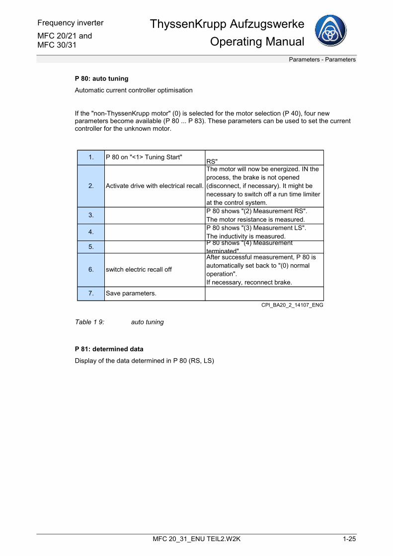
P 80: auto tuning
Automatic current controller optimisation
If the "non-ThyssenKrupp motor" (0) is selected for the motor selection (P 40), four new parameters become available (P 80 ... P 83). These parameters can be used to set the current controller for the unknown motor.
1. P 80 on "<1> Tuning Start"RS"
2. Activate drive with electrical recall.
The motor will now be energized. IN the process, the brake is not opened (disconnect, if necessary). It might be necessary to switch off a run time limiter at the control system.
3. P 80 shows "(2) Measurement RS".The motor resistance is measured.
4. P 80 shows "(3) Measurement LS".The inductivity is measured.
5. P 80 shows "(4) Measurement terminated".
6. switch electric recall off
After successful measurement, P 80 is automatically set back to "(0) normal operation".If necessary, reconnect brake.
7. Save parameters.
CPI_BA20_2_14107_ENG
Table 1 9: auto tuning
P 81: determined data
Display of the data determined in P 80 (RS, LS)
ThyssenKrupp Aufzugswerke Operating Manual
Frequency inverterMFC 20/21 and
MFC 30/31
Parameters - Parameters
1-26 MFC 20_31_ENU TEIL2.W2K
P 86: encoder adjustment (only for synchronous motors, MFC 21-xx, MFC 31-xx)
As the incremental encoder (absolute sine-cosine-encoder) on the synchronous machine not only determines the speed (impulses per motor revolution) but also the absolute location of the rotor, an additional encoder adjustment must be carried out after replacement of the incremental encoder.
The encoder does not have to be aligned manually. It is sufficient when it is mounted in a fixed position. After carrying out the encoder adjustment (aligning the rotor), the calibration takes place by saving in the EEPROM of the encoder. The data is retained even after the supply voltage is switched off.
Preparation:
• Set up load compensation in the elevator system. If there is no load compensation, the encoder could be incorrectly adjusted.
• Set the elevator system to electrical recall
• Check whether “2048 ENDAT” is selected in P 96
Execution:
• Set P 86 “operation mode motor” from <0> normal operation to <1> align rotor. The ready LED goes out for a few seconds because a reset is carried out.
• After the ready LED lights up again, wait approx. 2 seconds for the initialisation.
• Initiate recall operation up or down (impulse enabling for the converter). The brake opens. A motor current is set and this aligns the rotor (minor self-aligning rotational movement). Wait until the rotor comes to a standstill.
• Either release the recall switch and allow the brake to engage or - better - keep the recall switch pressed and use your other hand to initiate the next step (only release the recall switch when the ready LED goes out and the brake engages).
• Set P 86 “operation mode motor” from <1> align rotor to <2> save reference.
• P 86 “operation mode motor” automatically switches back to <0> normal operation after a few seconds. The ready LED goes out for a few seconds because a reset is carried out. This concludes the adjustment operation.
• Check entry in the fault (event) stack: “encoder successfully calibrated”.
• Switch off the recall operation
Frequency inverter MFC 20/21 and MFC 30/31
ThyssenKrupp AufzugswerkeOperating Manual
Parameters - Parameters
MFC 20_31_ENU TEIL2.W2K 1-27
Warning
P 92: discharge DC circui
Before working on the frequency inverters or motor connections, the DC circuit must be discharged in the interests of safety (see part 1).
This function parameter displays the intermediate circuit voltage in Volts. Simultaneously pressing the ”+” and ”-” buttons starts a function that activates the chopper resistor in cycles and thus discharges the DC circuit capacitor. The discharge operation can be accelerated if the P/W button is pressed at the same time.
Discharging the DC circuit only works if the signal ”QSP” = 0, i.e. the mains contactor has de-energised and the brake resistor is not defective. On installations where the contactors are not positioned between the mains and frequency inverter rather between the motor and frequency inverter, the power supply must be switched off before discharging the DC circuit. However, the control voltage must remain on until the DC circuit has been discharged.
P 96: number of encoder marks
The selection of the number of encoder marks is made here.
The number of marks of the deployed encoder can be read off in the vicinity of the encoder on the motor casing.
If unknown, the number of encoder marks can be determined as described in parameter P 105.
P 97: number of pole pairs (only for synchronous motors)
Display or input of the number of pole pairs for synchronous motors
P 150: brake on/off for test (only on MFC 30/31)
This parameter can be used to test the brake contactor in accordance with Operating Manual MFC 30/31, Part 1.
The default value is <off>.
For safety reasons, the change to <on> for the test cannot be saved; it is reset for the next run.
P 160: max. output current
Limitation of the maximum output current
Specification in % related to "overload current for 10 s", see chapter "Technical type data"
ThyssenKrupp Aufzugswerke Operating Manual
Frequency inverterMFC 20/21 and
MFC 30/31
Parameters - Parameters
1-28 MFC 20_31_ENU TEIL2.W2K
P 161: switching temperature
If the heat sink temperature exceeds the temperature entered in P 161, this can be switched at one of the programmable outputs. P 45, 46 or 47 is set to "temperature > P 161". This means, for example, that the cabinet fan can be activated without additional temperature control. The switch hysteresis is 5°C.
1.4.2 Display parameters
These display parameters cannot be changed. The values of these parameters are continuously recalculated and displayed by the device.
P 100: motor speed
Display of the current motor speed in rpm.
P 101: actual speed
The current actual speed of the elevator is displayed in m/s.
The display is only correct if the entries of parameters P 13, P 14 and P 15 are correct!
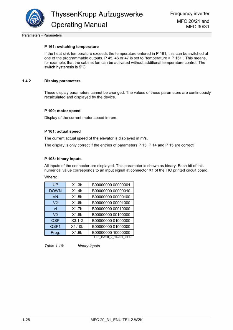
P 103: binary inputs
All inputs of the connector are displayed. This parameter is shown as binary. Each bit of this numerical value corresponds to an input signal at connector X1 of the TIC printed circuit board.
Where:
UP X1.3b B00000000 00000001DOWN X1.4b B00000000 00000010
VN X1.5b B00000000 00000100V2 X1.6b B00000000 00001000vI X1.7b B00000000 00010000V0 X1.8b B00000000 00100000
QSP X3.1-2 B00000000 01000000QSP1 X1.10b B00000000 01000000Prog. X1.9b B00000000 10000000
CPI_BA20_2_14201_GER
Table 1 10: binary inputs
Frequency inverter MFC 20/21 and MFC 30/31
ThyssenKrupp AufzugswerkeOperating Manual
Parameters - Parameters
MFC 20_31_ENU TEIL2.W2K 1-29
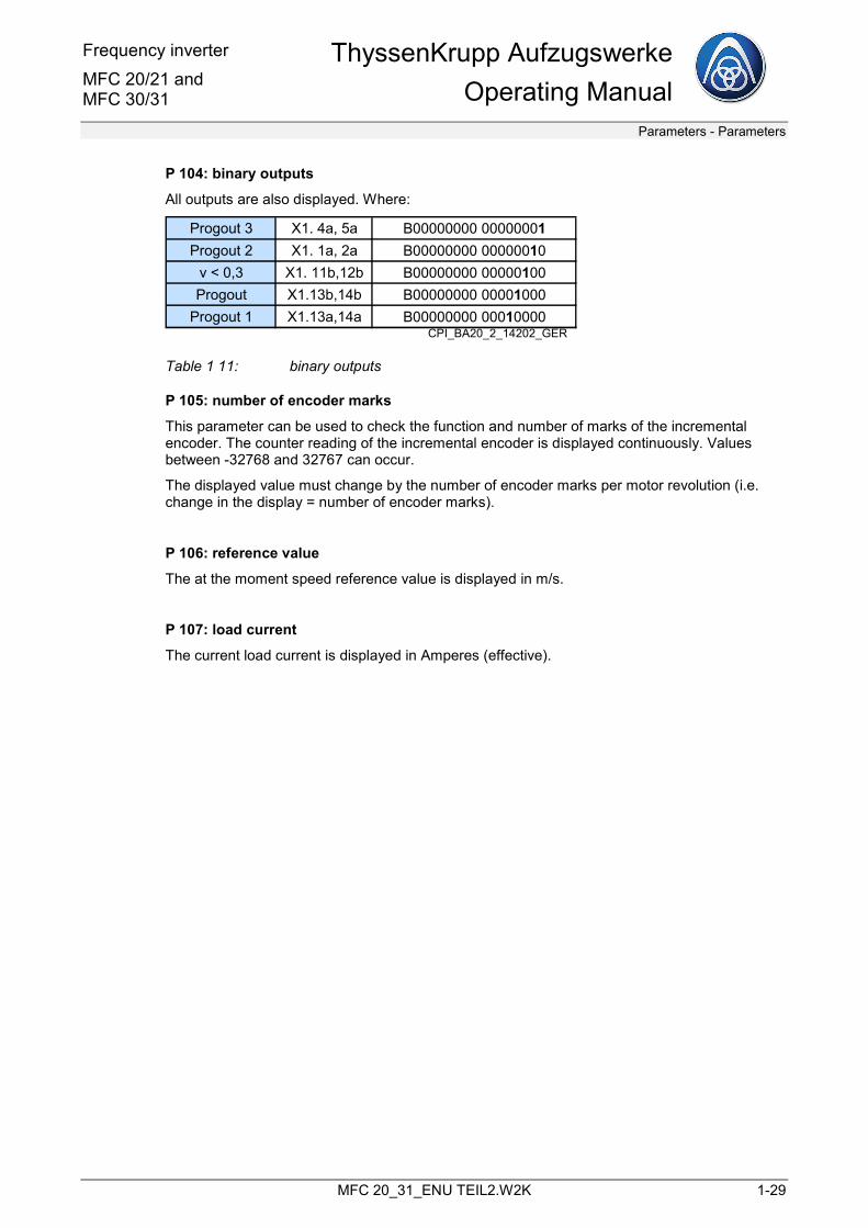
P 104: binary outputs
All outputs are also displayed. Where:
Progout 3 X1. 4a, 5a B00000000 00000001Progout 2 X1. 1a, 2a B00000000 00000010
v < 0,3 X1. 11b,12b B00000000 00000100Progout X1.13b,14b B00000000 00001000
Progout 1 X1.13a,14a B00000000 00010000CPI_BA20_2_14202_GER
Table 1 11: binary outputs
P 105: number of encoder marks
This parameter can be used to check the function and number of marks of the incremental encoder. The counter reading of the incremental encoder is displayed continuously. Values between -32768 and 32767 can occur.
The displayed value must change by the number of encoder marks per motor revolution (i.e. change in the display = number of encoder marks).
P 106: reference value
The at the moment speed reference value is displayed in m/s.
P 107: load current
The current load current is displayed in Amperes (effective).
ThyssenKrupp Aufzugswerke Operating Manual
Frequency inverterMFC 20/21 and
MFC 30/31
Parameters - Switching sequence diagram
1-30 MFC 20_31_ENU TEIL2.W2K
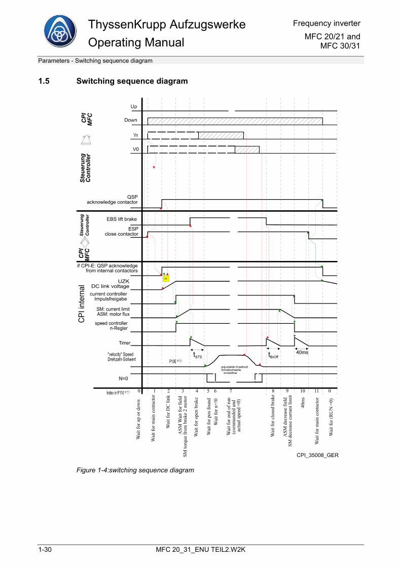
1.5 Switching sequence diagram
if CPI-E: QSP acknowledge from internal contactors
QSP acknowledge contactor
ESP close contactor
EBS lift brake
Figure 1-4:switching sequence diagram
Frequency inverter MFC 20/21 and MFC 30/31
ThyssenKrupp AufzugswerkeOperating Manual
Parameters - Switching sequence diagram
MFC 20_31_ENU TEIL2.W2K 1-31
P 110: switching sequence index
The digits specified in this parameter correspond to the digits parameter in the bottom row of the switching sequence diagram and they indicate the current switching state in the frequency inverter.
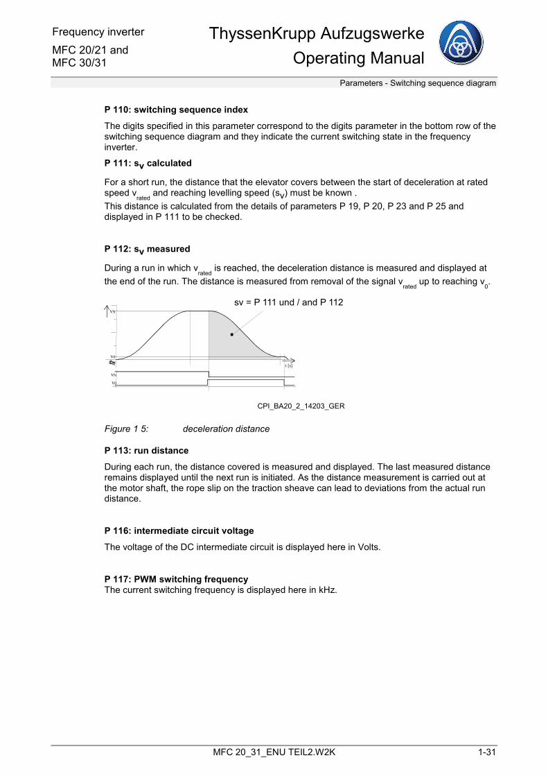
P 111: sv calculated
For a short run, the distance that the elevator covers between the start of deceleration at rated speed v
rated and reaching levelling speed (sv) must be known .
This distance is calculated from the details of parameters P 19, P 20, P 23 and P 25 and displayed in P 111 to be checked.
P 112: sv measured
During a run in which vrated
is reached, the deceleration distance is measured and displayed at the end of the run. The distance is measured from removal of the signal v
rated up to reaching v
0.
v0
vN
t [s]
vN
v0
sv = P 111 und / and P 112
CPI_BA20_2_14203_GER
Figure 1 5: deceleration distance
P 113: run distance
During each run, the distance covered is measured and displayed. The last measured distance remains displayed until the next run is initiated. As the distance measurement is carried out at the motor shaft, the rope slip on the traction sheave can lead to deviations from the actual run distance.
P 116: intermediate circuit voltage
The voltage of the DC intermediate circuit is displayed here in Volts.
P 117: PWM switching frequency The current switching frequency is displayed here in kHz.
ThyssenKrupp Aufzugswerke Operating Manual
Frequency inverterMFC 20/21 and
MFC 30/31
Parameters - Switching sequence diagram
1-32 MFC 20_31_ENU TEIL2.W2K
P 120: system information Alternating display of:
• – emergency power mode active (only of emergency power is active)
• – operating mode (TIS1, TIS2, TIA, TIC, TIV, TIS3, DCP) E.g. TIC
• – device type E.g. MFC 20-12
• – software version for C167 (EPROM) and version date E.g. V15.4e 13. 4.2004
• – F240 flash version in the format Fjjmmdd E.g. F040212
P 205: P gain at start
P 206: I gain at start
These parameters can be used to specify separate P gains and I gains of the speed controller for the start. This can reduce reverse rotation on opening the brake.
These values apply until the brake is opened. Thereafter, as before, the values from P 5 or P 6 are used.
Recommended is P 205 > P 5 and P 206 < P 6. If the values 0 are entered (factory setting), only the values entered in P5 or P6 apply (as before).
Frequency inverter MFC 20/21 and MFC 30/31
ThyssenKrupp AufzugswerkeOperating Manual
Commissioning - Safety instructions
MFC 20_31_ENU TEIL2.W2K 2-1
2 Commissioning
2.1 Safety instructions
A) Qualified personnel
Work on the MFC 20 frequency inverters may only be carried out by trained persons.
These persons must comply with the relevant accident prevention regulations and be aware of the dangers of electrical current.
B) Work on the frequency inverter
To work on the frequency inverter (except for setting up procedures using the operating keyboard) or the motor, the following measures are required:
• shut down
• secure against reactivation
• determine that there is no voltage
C) Determining there is no voltage
Particular attention is to be paid to the fact that even after the mains voltage has been switched off there can still be electrical energy in the device (capacitor charge).
This applies in particular in the case of a defective device.
For this reason, a check for residual voltage must be carried out before starting any work on the frequency inverter.
To check for residual voltage, a suitable multimeter (at least 800 V direct current) can be used to directly measure the intermediate circuit voltage at terminal block X1, terminals 22 and 23.
• on the MFC 20/21 at terminal block X1, terminals 22 and 23.
• on the MFC 30-10 cannot be measured from the outside
• on the MFC 30-15, 32, 48, 60 at the terminals X1.5 (+) and 6 (-)
• on the MFC 20-50R, 100R at the terminals LT/X1.5 (+) and 6 (-)
ThyssenKrupp Aufzugswerke Operating Manual
Frequency inverterMFC 20/21 and
MFC 30/31
Commissioning - Notes on operation
2-2 MFC 20_31_ENU TEIL2.W2K
Note
Set the measuring instrument to the direct current range (DC)!
Work on an opened device with applied intermediate circuit voltage (approx. 700 V DC) is only to be performed in exceptional cases and only with the greatest caution.
Here, particular attention is to be paid to the fact that the intermediate circuit voltage has a fixed potential relationship to the mains voltage and to the protective earth.
2.2 Notes on operation
Note
The frequency inverters contain components that are subject to electrostatic risks. Before performing service work on the frequency inverters (e.g. replacement of printed circuit boards), the service personnel must eliminate static charges by touching an earthed metallic surface.
Warning
In the event of incorrect assignment of the frequency inverter to the motor, the frequency inverter or the motor can be damaged.
Frequently cyclical switching on and off of the frequency inverter can lead to an overload of the internal charging resistors. This is to avoided by allowing the corresponding breaks.
2.3 Notes: before switching on for the first time
• Check the wiring to the frequency inverter and to the motor (including incremental encoder)
• Check the electromagnetic compatibility of the earthing of the cable screens
• Check of the correct protective earthing of all assemblies (frequency inverter, motor, housing and brake resistor)
• Check of the mains voltage
• The brake must operable and correctly set
• If necessary, lead the elevator car with a half load (load compensation)
Frequency inverter MFC 20/21 and MFC 30/31
ThyssenKrupp AufzugswerkeOperating Manual
Commissioning - Check of the visual displays in the event of faults
MFC 20_31_ENU TEIL2.W2K 2-3
2.4 Check of the visual displays in the event of faults
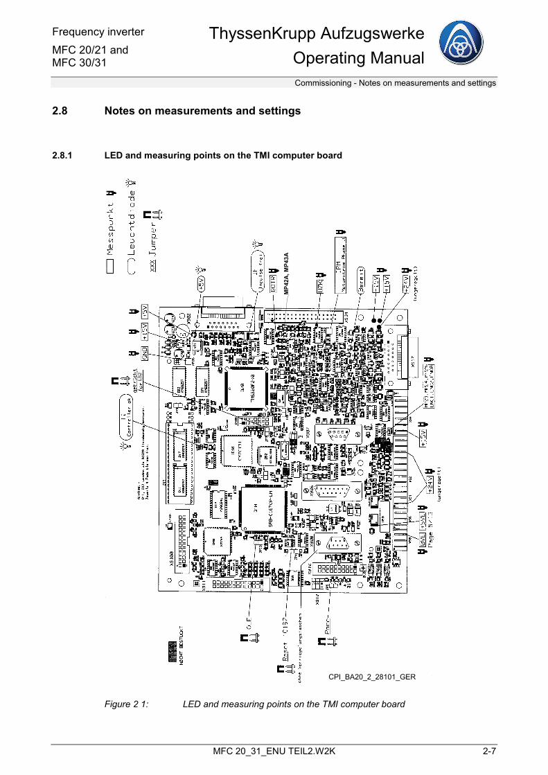
If the drive does not function properly, after removing the front cover (see Operating Manual Part 1) the following functions can be checked by means of light emitting diodes on the TMI circuit board, see chapter 2.8.1 LED and measuring points on the TMI computer board, page 2-7:
With the device ready for operation, the following light emitting diodes must light up:
H 40 (yellow) TI ...................... computer OK
H 7 (red) + 5 V ................. supply voltage + 5 V present
H 1 (red) BE ..................... no fault, frequency inverter ready for operation
Additionally during run:
H 99 (red) IF ...................... impulse enabling
The light emitting diodes can be recognised by the fitting labels on the TMI computer board.
2.5 Input of installation-specific values
The installation specific-values must be entered using the LCD display and the button pad on the TPT assembly, see chapter 1 Parameters, page 1-1:
• Motor type P 40
• Number of encoder marks P 96
• Acceleration change (jerk) P 19 [m/s³]
• Acceleration P 20 [m/s²]
• Levelling speed vo P 23 [m/s]
• Inspection speed vi P 24 [m/s]
• Rated speed vrated P 25 [m/s]
• Intermediate speed v2 P 26 [m/s]
• 2nd intermediate speed vn2 P 27 [m/s]
• Emergency operation v3 P 28 [m/s]
• Intermediate speed v4 P 29 [m/s]
• Intermediate speed v5 P 30 [m/s]
• Intermediate speed v6 P 31 [m/s]
• Intermediate speed v7 P 32 [m/s]
ThyssenKrupp Aufzugswerke Operating Manual
Frequency inverterMFC 20/21 and
MFC 30/31
Commissioning - Check of the functional capability of the drives
2-4 MFC 20_31_ENU TEIL2.W2K
2.6 Check of the functional capability of the drives
Specify the inspection speed vi in upward or downward direction.
The drive must move in the corresponding direction with the desired inspection speed.
If the drive moves at the right speed but in the wrong direction, use parameter P 3 "direction of rotation" to invert the direction.
If the drive is not smooth or does not move at the right speed,
a) for asynchronous motors use parameter P 4 "control direction" to invert the control direction.
b) for synchronous motors perform an encoder adjustment (see P 86).
If the inspection speed is not reached despite changing the control direction, check whether the incremental encoder is correctly inserted and/or the number of encoder marks is correct, see chapter 1.4.2 , page 1-28.
2.7 Optimisation of the drive
A) Speed controller
The parameters P 5 "speed controller P gain" (default value 8) and P 6 "speed controller I gain" (default value 50 ms) are available to optimise the speed actual value running characteristic curve.
Perform this optimisation step by step.
If necessary, set the ”I gain” right down to ”0” and the ”P gain” until the drive runs without any tendency to rock.
Note
It should be borne in mind that with the ”I gain" setting equal to "0” a sustained deviation in the actual speed occurs depending on the load direction, i.e. under certain circumstances the drive cannot accelerate in the load direction or even drifts in the wrong direction.
The ”P gain” should have a safety clearance to the above tendency to rock (approx. factor 2 smaller). For normal operation, an ”I gain” not equal to ”0” is to be set again.
Frequency inverter MFC 20/21 and MFC 30/31
ThyssenKrupp AufzugswerkeOperating Manual
Commissioning - Optimisation of the drive
MFC 20_31_ENU TEIL2.W2K 2-5
Experience has shown that the given default values (P = 8 and I = 50 ms for asynchronous and P = 2 and I = 70 ms for synchronous) already result in very good travel quality.
To assess the running characteristic curve, a recorder can be connected to MP 42A or MP 43A of the TMI printed circuit board. The common reference point is MP 26 or the housing of the frequency inverter.
The selection of the measurement signals available at these display outputs is made using the parameters P 10 or P 11, see chapter 1 Parameters, page 1-1.
Example: with the value "0" in P 10, the speed actual value with prefix is displayed at MP 42A.
For minimizing reverse rotation on opening the brake at start, a higher P proportion (P 205) and a "faster" J proportion (P 206) can be specified.
B) Run at rated speed
To optimise the rated travel, the acceleration and acceleration change (jerk) can be changed with the parameters P 19 and P 20.
Note
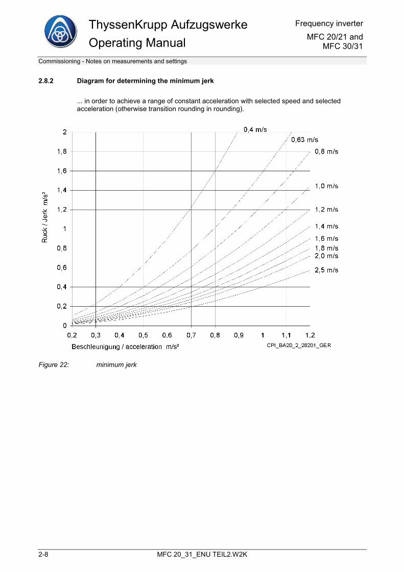
Important here is that, in accordance with the selected acceleration, a minimum jerk is to be set (see chapter 2.8.2 Diagram for determining the minimum jerkpage 2-8), as otherwise there is no range of constant acceleration.
Important here is that the floor-to-floor distance is greater than the total of the acceleration and deceleration distance from rated speed (see chapter 2.8.3 Diagram for determining the minimum permitted floor-to-floor distances, page 2-9).
In the case of floor-to-floor runs, this achieves the rated speed.
C) Short run
A short run is when the floor-to-floor distance is less than the total of the acceleration and deceleration distance from rated speed, but greater than the deceleration distance from rated speed.
In the case of floor-to-floor runs, this does not achieve the rated speed.
Procedure for activation of the short run (see chapter 3 Short run device, page 3-1).
ThyssenKrupp Aufzugswerke Operating Manual
Frequency inverterMFC 20/21 and
MFC 30/31
Commissioning - Optimisation of the drive
2-6 MFC 20_31_ENU TEIL2.W2K
D) Load specification
If the elevator car moves away after opening the brake, this can be reduced by specifying an initial torque, see chapter 1.1 General, Changeable parameters, page 1-1, P 50 to P 54.
If the load measurement device LMS 1 is used, the optimal initial torque can be specified.
If there is no load measurement, the start can also be optimised for a certain load state.
E) Acceleration pre-control
If the drive tends to overshoot, this can be optimised by activating the acceleration pre-control, see chapter 1.1 General, Changeable parameters, page 1-1, P 21 and P 22.
Frequency inverter MFC 20/21 and MFC 30/31
ThyssenKrupp AufzugswerkeOperating ManualCommissioning - Notes on measurements and settings
MFC 20_31_ENU TEIL2.W2K 2-7
2.8 Notes on measurements and settings
2.8.1 LED and measuring points on the TMI computer board
MP4
2A,M
P43A
MP4
3A
CPI_BA20_2_28101_GER
Figure 2 1: LED and measuring points on the TMI computer board
ThyssenKrupp Aufzugswerke Operating Manual
Frequency inverterMFC 20/21 and
MFC 30/31
Commissioning - Notes on measurements and settings
2-8 MFC 20_31_ENU TEIL2.W2K
2.8.2 Diagram for determining the minimum jerk
... in order to achieve a range of constant acceleration with selected speed and selected acceleration (otherwise transition rounding in rounding).
Figure 22: minimum jerk
Frequency inverter MFC 20/21 and MFC 30/31
ThyssenKrupp AufzugswerkeOperating ManualCommissioning - Notes on measurements and settings
MFC 20_31_ENU TEIL2.W2K 2-9
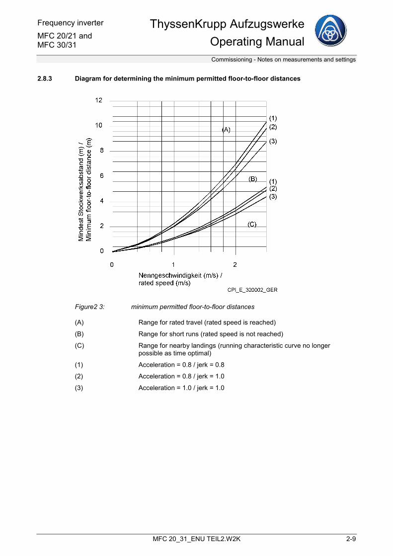
2.8.3 Diagram for determining the minimum permitted floor-to-floor distances
Figure2 3: minimum permitted floor-to-floor distances
(A) Range for rated travel (rated speed is reached)
(B) Range for short runs (rated speed is not reached)
(C) Range for nearby landings (running characteristic curve no longer possible as time optimal)
(1) Acceleration = 0.8 / jerk = 0.8
(2) Acceleration = 0.8 / jerk = 1.0
(3) Acceleration = 1.0 / jerk = 1.0

Frequency inverter MFC 20/21 and MFC 30/31
ThyssenKrupp AufzugswerkeOperating Manual
Short run device
MFC 20_31_ENU TEIL2.W2K 3-1
3 Short run device
3.1 General
A short run is when the floor-to-floor distance is shorter than the total of the acceleration and deceleration distance for rated speed. In the case of these runs, this does not achieve the rated speed. To reach the stop, the elevator would have to move at levelling speed for a longer period of time.
The built-in short run device detects this state and automatically extends the acceleration phase of the run. This means that no creepage or only very short creepage occurs (switching delay or rope slip).
Note
For the short run device to function properly, the elevator specifications must be correctly set.
These are:
• P 13 gear ratio
• P 14 diameter of traction sheave
• P 15 suspension
• P 19 jerk
• P 20 acceleration
• P 23 speed v0
• P 25 speed vN
These parameters are used to calculate the deceleration distance from vN
and display it in parameter P 111. For each normal run (v
Nis reached), the deceleration distance is measured
and displayed in P 112. This measured distance, however, is not taken into account in the short run computing.
A special form of the short run is the short run with "sharper rounding" (see figure 3 3). This is the case when the deceleration point is reached during the upper rounding of the acceleration phase. If the deceleration takes place with the set jerk, the deceleration distance is too great. The landing is overrun. To avoid this, the elevator is run with a "sharper rounding", i.e. with greater jerk.
ThyssenKrupp Aufzugswerke Operating Manual
Frequency inverterMFC 20/21 and
MFC 30/31
Short run device - Settings
3-2 MFC 20_31_ENU TEIL2.W2K
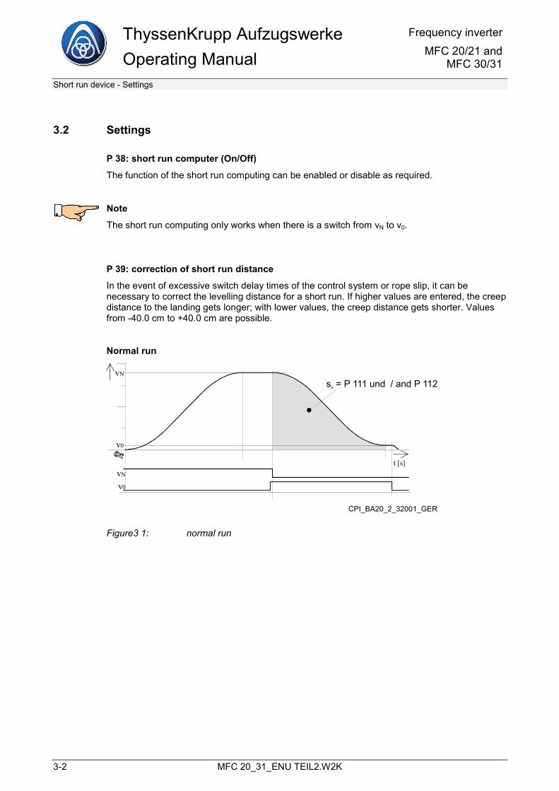
3.2 Settings
P 38: short run computer (On/Off)
The function of the short run computing can be enabled or disable as required.
Note
The short run computing only works when there is a switch from vN to v0.
P 39: correction of short run distance
In the event of excessive switch delay times of the control system or rope slip, it can be necessary to correct the levelling distance for a short run. If higher values are entered, the creep distance to the landing gets longer; with lower values, the creep distance gets shorter. Values from -40.0 cm to +40.0 cm are possible.
Normal run
v0
vN
t [s]vN
v0
s = P 111 und / and P 112v
CPI_BA20_2_32001_GER
Figure3 1: normal run
Frequency inverter MFC 20/21 and MFC 30/31
ThyssenKrupp AufzugswerkeOperating Manual
Short run device
MFC 20_31_ENU TEIL2.W2K 3-3
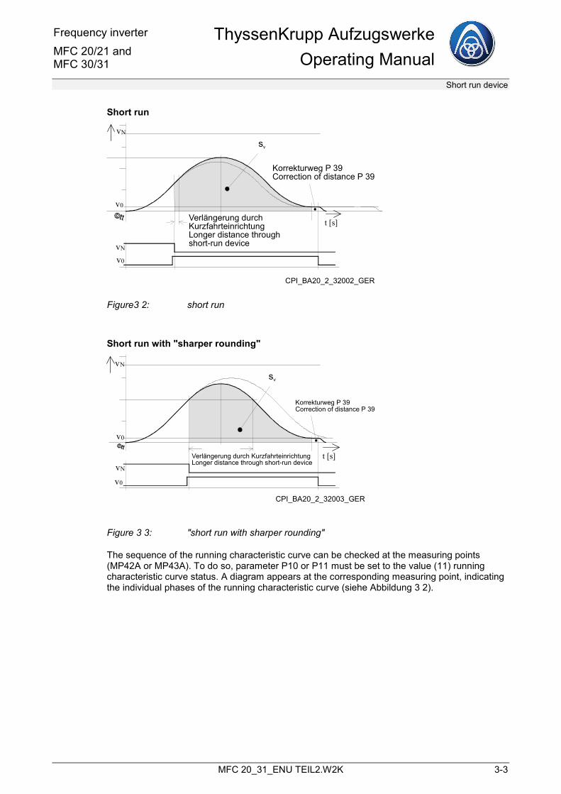
Short run
vN
v0
t [s]
vN
v0
sv
Korrekturweg P 39Correction of distance P 39
Verlängerung durchKurzfahrteinrichtung Longer distance throughshort-run device
CPI_BA20_2_32002_GER
Figure3 2: short run
Short run with "sharper rounding"
vN
v0
v0
vN
t [s]
sv
Korrekturweg P 39Correction of distance P 39
Verlängerung durch Kurzfahrteinrichtung Longer distance through short-run device
CPI_BA20_2_32003_GER
Figure 3 3: "short run with sharper rounding"
The sequence of the running characteristic curve can be checked at the measuring points (MP42A or MP43A). To do so, parameter P10 or P11 must be set to the value (11) running characteristic curve status. A diagram appears at the corresponding measuring point, indicating the individual phases of the running characteristic curve (siehe Abbildung 3 2).
ThyssenKrupp Aufzugswerke Operating Manual
Frequency inverterMFC 20/21 and
MFC 30/31
Short run device - Settings
3-4 MFC 20_31_ENU TEIL2.W2K
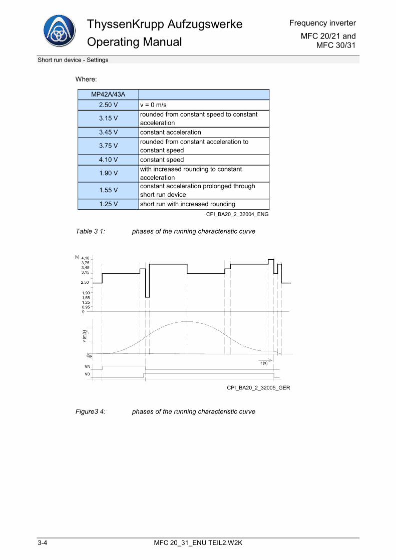
Where:
MP42A/43A2.50 V v = 0 m/s
3.15 V rounded from constant speed to constant acceleration
3.45 V constant acceleration
3.75 V rounded from constant acceleration to constant speed
4.10 V constant speed
1.90 V with increased rounding to constantacceleration
1.55 V constant acceleration prolonged throughshort run device
1.25 V short run with increased roundingCPI_BA20_2_32004_ENG
Table 3 1: phases of the running characteristic curve
4,103,753,453,15
0,951,251,551,90
2,50
CPI_BA20_2_32005_GER
Figure3 4: phases of the running characteristic curve
Frequency inverter MFC 20/21 and MFC 30/31
ThyssenKrupp AufzugswerkeOperating Manual
Modernisation
MFC 20_31_ENU TEIL2.W2K 4-1
4 Modernisation
4.1 General
This frequency inverter (MFC 20 or MFC 30) can also be used in the case of modernisation of elevator systems with non-ThyssenKrupp motors. These motors can be single-speed or pole changing.
Vector regulation is also used here.
The maximum recommended speed is 1.6 m/s.
The rest of this description provides the necessary information for the modernisation.
4.2 Modernisation with encoder mounting on motor shaft
The regulation of "traditional" elevator motors with a frequency inverter provides the following advantages:
• Energy reduction by up to 50% (this is not a promised value, as the energy reduction depends on many influences, e.g. the type of installation, amount of runs, etc.).
• No 300-Hz ripple as in the case of operation with 3-phase AC controller
• No modulation noise in the motor as in the case of frequency inverters with lower clock frequency.
To ensure that configuration for the modernisation is as easy as possible, the following specifications have been made:
• Operation of single-speed or pole changing motors as well as frequency inverter motors or standard motors is possible
• Motors should have class of insulation F; a converter output choke is used to reduce the coil stress
• The flywheel mass should be reduced to a maximum of 1/3 of the original value or removed completely. If the flywheel mass cannot be reduced, for example in the case of external-rotor motors, the acceleration value of the installation is to be selected in such a way that the maximum output current of the converter is adequate.
• If possible, the encoder must be torsion-proof and mounted on the centre of the motor shaft. The encoder must deliver push-pull TTL signals with 5 V supply voltage. The assembly is to be designed, e.g., in the same way as the Wachendorff pulse generators with part number 00 990 14 030.
• The minimum landing-to-landing distance is control-dependent; with an "internal" converter running characteristic curve, the minimum landing-to-landing distances apply, see chapter 2.8.3, Diagram for determining the minimum permitted floor-to-floor distances, page 2-9.
ThyssenKrupp Aufzugswerke Operating Manual
Frequency inverterMFC 20/21 and
MFC 30/31
Modernisation - Configuration
4-2 MFC 20_31_ENU TEIL2.W2K
Note
The assignment of the frequency inverter to the motor should be selected accordingly so that the output current for the motor rated and motor starting current still has a reserve. A proposal for the configuration can be found below.
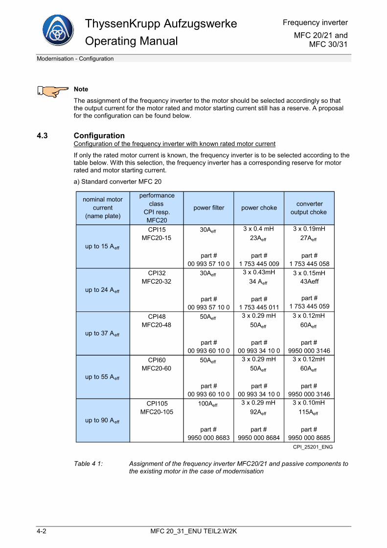
4.3 Configuration Configuration of the frequency inverter with known rated motor current
If only the rated motor current is known, the frequency inverter is to be selected according to the table below. With this selection, the frequency inverter has a corresponding reserve for motor rated and motor starting current.
a) Standard converter MFC 20
nominal motor current
(name plate)
performance class
CPI resp. MFC20
power filter power choke converteroutput choke
up to 15 Aeff
CPI15MFC20-15
30Aeff
part #00 993 57 10 0
3 x 0.4 mH23Aeff
part #1 753 445 009
3 x 0.19mH27Aeff
part #1 753 445 058
up to 24 Aeff
CPI32MFC20-32
30Aeff
part #00 993 57 10 0
3 x 0.43mH34 Aeff
part #1 753 445 011
3 x 0.15mH43Aeff
part #1 753 445 059
up to 37 Aeff
CPI48MFC20-48
50Aeff
part #00 993 60 10 0
3 x 0.29 mH50Aeff
part #00 993 34 10 0
3 x 0.12mH60Aeff
part #9950 000 3146
up to 55 Aeff
CPI60MFC20-60
50Aeff
part #00 993 60 10 0
3 x 0.29 mH50Aeff
part #00 993 34 10 0
3 x 0.12mH60Aeff
part #9950 000 3146
up to 90 Aeff
CPI105MFC20-105
100Aeff
part #9950 000 8683
3 x 0.29 mH92Aeff
part #9950 000 8684
3 x 0.10mH115Aeff
part #9950 000 8685
CPI_25201_ENG
Table 4 1: Assignment of the frequency inverter MFC20/21 and passive components to the existing motor in the case of modernisation
Frequency inverter MFC 20/21 and MFC 30/31
ThyssenKrupp AufzugswerkeOperating Manual
Modernisation
MFC 20_31_ENU TEIL2.W2K 4-3
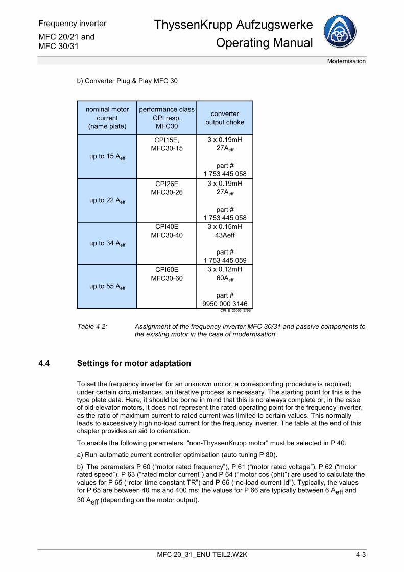
b) Converter Plug & Play MFC 30
nominal motor current
(name plate)
performance classCPI resp. MFC30
converteroutput choke
up to 15 Aeff
CPI15E,MFC30-15
3 x 0.19mH27Aeff
part #1 753 445 058
up to 22 Aeff
CPI26EMFC30-26
3 x 0.19mH27Aeff
part #1 753 445 058
up to 34 Aeff
CPI40EMFC30-40
3 x 0.15mH43Aeff
part #1 753 445 059
up to 55 Aeff
CPI60EMFC30-60
3 x 0.12mH60Aeff
part #9950 000 3146
CPI_E_25003_ENG
Table 4 2: Assignment of the frequency inverter MFC 30/31 and passive components to the existing motor in the case of modernisation
4.4 Settings for motor adaptation
To set the frequency inverter for an unknown motor, a corresponding procedure is required; under certain circumstances, an iterative process is necessary. The starting point for this is the type plate data. Here, it should be borne in mind that this is no always complete or, in the case of old elevator motors, it does not represent the rated operating point for the frequency inverter, as the ratio of maximum current to rated current was limited to certain values. This normally leads to excessively high no-load current for the frequency inverter. The table at the end of this chapter provides an aid to orientation.
To enable the following parameters, "non-ThyssenKrupp motor" must be selected in P 40.
a) Run automatic current controller optimisation (auto tuning P 80).
b) The parameters P 60 (“motor rated frequency”), P 61 (“motor rated voltage”), P 62 (“motor rated speed”), P 63 (“rated motor current”) and P 64 (“motor cos (phi)”) are used to calculate the values for P 65 (“rotor time constant TR”) and P 66 (“no-load current Id”). Typically, the values for P 65 are between 40 ms and 400 ms; the values for P 66 are typically between 6 Aeff and 30 Aeff (depending on the motor output).
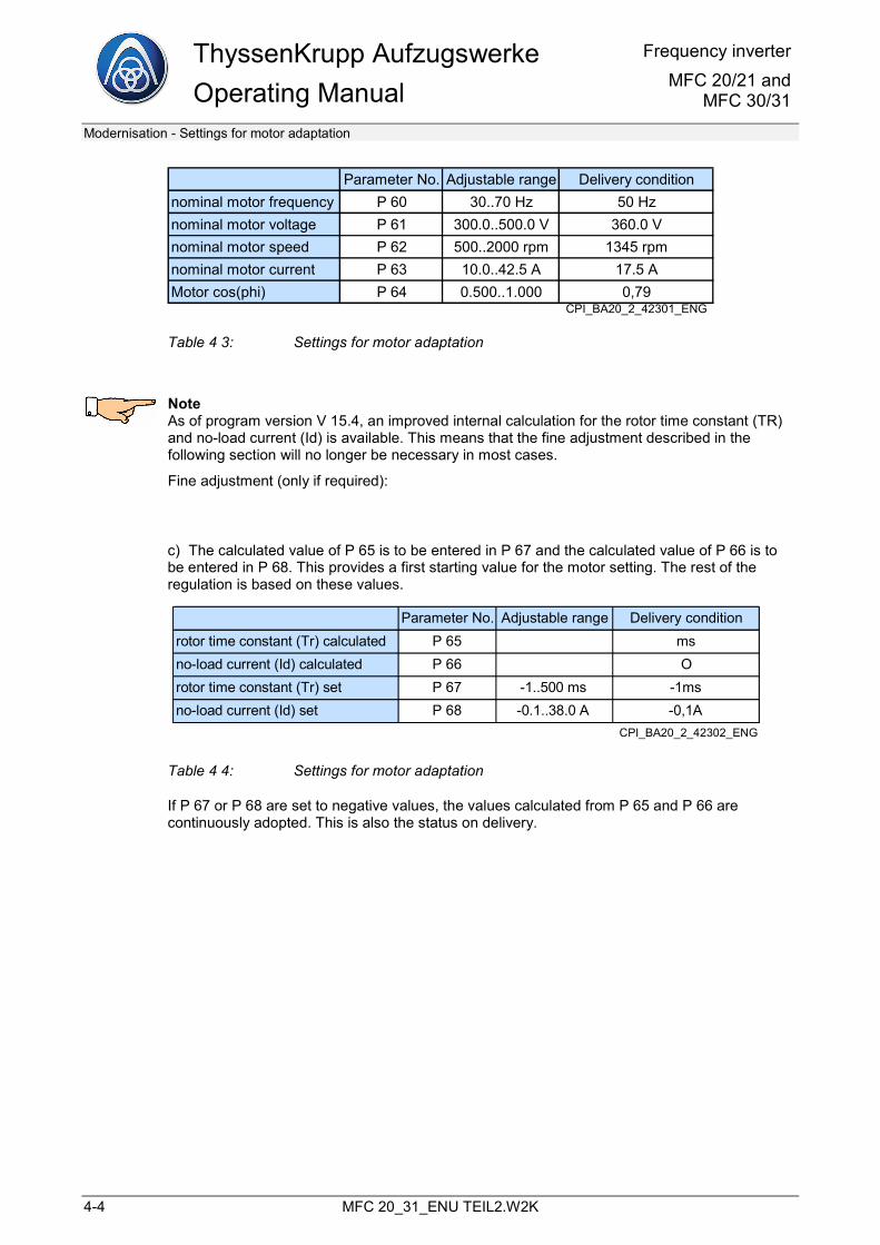
ThyssenKrupp Aufzugswerke Operating Manual
Frequency inverterMFC 20/21 and
MFC 30/31
Modernisation - Settings for motor adaptation
4-4 MFC 20_31_ENU TEIL2.W2K
Parameter No. Adjustable range Delivery conditionnominal motor frequency P 60 30..70 Hz 50 Hznominal motor voltage P 61 300.0..500.0 V 360.0 Vnominal motor speed P 62 500..2000 rpm 1345 rpmnominal motor current P 63 10.0..42.5 A 17.5 AMotor cos(phi) P 64 0.500..1.000 0,79
CPI_BA20_2_42301_ENG
Table 4 3: Settings for motor adaptation
Note As of program version V 15.4, an improved internal calculation for the rotor time constant (TR) and no-load current (Id) is available. This means that the fine adjustment described in the following section will no longer be necessary in most cases.
Fine adjustment (only if required):
c) The calculated value of P 65 is to be entered in P 67 and the calculated value of P 66 is to be entered in P 68. This provides a first starting value for the motor setting. The rest of the regulation is based on these values.
Parameter No. Adjustable range Delivery conditionrotor time constant (Tr) calculated P 65 msno-load current (Id) calculated P 66 Orotor time constant (Tr) set P 67 -1..500 ms -1msno-load current (Id) set P 68 -0.1..38.0 A -0,1A
CPI_BA20_2_42302_ENG
Table 4 4: Settings for motor adaptation
If P 67 or P 68 are set to negative values, the values calculated from P 65 and P 66 are continuously adopted. This is also the status on delivery.
Frequency inverter MFC 20/21 and MFC 30/31
ThyssenKrupp AufzugswerkeOperating Manual
Modernisation
MFC 20_31_ENU TEIL2.W2K 4-5
d) These default settings provide a certain basic setting for the motor. The elevator is to be balanced out, where possible, so that only the no-load current flows (load current < 5% of the maximum current) at constant speed (e.g. electrical recall). If this is the case, a travel at rated speed should be carried out. Here, a tolerance band fault can occur on acceleration; if necessary, disable this monitoring or otherwise set a lower acceleration value.
The actual motor voltage value appears in the top right of parameter P 68 (and also P 67). This value should be around 270 to 300 V at rated travel. If this is not the case, the motor voltage can be reduced by lowering the value of P 68 (no-load current Id) (usually, the motor voltage that sets in with the no-load current from the type data will be too high). The motor voltage should be around 270 to 300 V in UP and DOWN direction.
If there is not sufficient torque for the acceleration phase, the rotor time constant TR in P 67 must be increased or reduced. Here, the value can be changed in steps of 25%.
e) The elevator is now to be operated with the elevator car empty, followed by a motor run under load in the DOWN direction and a braking run in the UP direction. In the DOWN direction, the motor voltage should rise by approximately the slip value of the motor, i.e. approx. 30 V to 50 V; in the UP direction, the motor voltage should fall by a lower value (approx. 10 V to 30 V). If this is not the case, the value of the rotor time constant TR in P 67 must be changed in steps of 25%. This setting should be made with the motor warm (not with a very cold or very hot motor).
f) The setting of the speed controller is also to be checked:
The I proportion of the speed controller is to be set to 0 and the P proportion is to be increased until rocking or humming of the motor occurs. The P proportion is then to be cut by half.
The I proportion is to be selected in the range from approx. 10 ms to 100 ms, depending on the overshoot in the running characteristic curve.
The pre-control of the speed controller with the help of the acceleration pre-control (P 21 and P 22) additionally improves the travel quality.
The running performance is to be tested with no load, half load and full load.
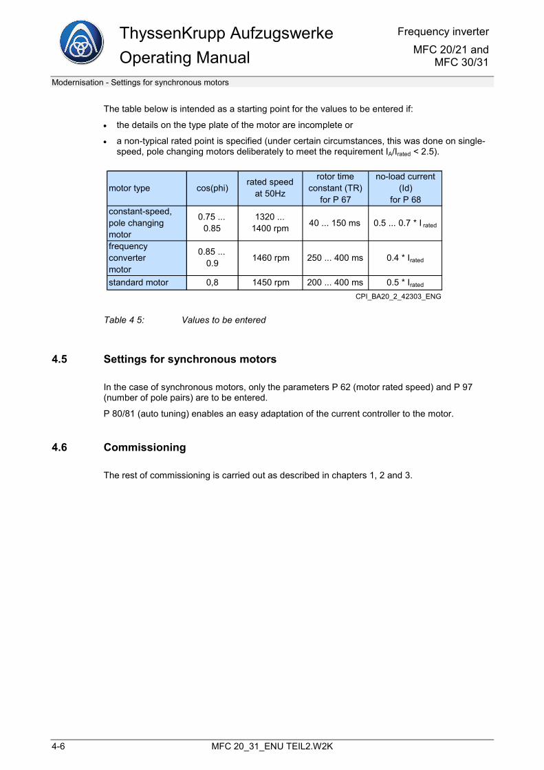
ThyssenKrupp Aufzugswerke Operating Manual
Frequency inverterMFC 20/21 and
MFC 30/31
Modernisation - Settings for synchronous motors
4-6 MFC 20_31_ENU TEIL2.W2K
The table below is intended as a starting point for the values to be entered if:
• the details on the type plate of the motor are incomplete or
• a non-typical rated point is specified (under certain circumstances, this was done on single-speed, pole changing motors deliberately to meet the requirement IA/Irated < 2.5).
motor type cos(phi)rated speed
at 50Hz
rotor timeconstant (TR)
for P 67
no-load current (Id)
for P 68constant-speed,pole changing motor
0.75 ... 0.85
1320 ...1400 rpm 40 ... 150 ms 0.5 ... 0.7 * I rated
frequency convertermotor
0.85 ... 0.9 1460 rpm 250 ... 400 ms 0.4 * Irated
standard motor 0,8 1450 rpm 200 ... 400 ms 0.5 * Irated
CPI_BA20_2_42303_ENG
Table 4 5: Values to be entered
4.5 Settings for synchronous motors
In the case of synchronous motors, only the parameters P 62 (motor rated speed) and P 97 (number of pole pairs) are to be entered.
P 80/81 (auto tuning) enables an easy adaptation of the current controller to the motor.
4.6 Commissioning
The rest of commissioning is carried out as described in chapters 1, 2 and 3.
Frequency inverter MFC 20/21 and MFC 30/31
ThyssenKrupp AufzugswerkeOperating Manual
DCP interface
MFC 20_31_ENU TEIL2.W2K 5-1
5 DCP interface
5.1 Preface
To activate the DCP interface, <DCP01>, < DCP03> or < DCP04> must be selected in P 8.
DCP03 and DCP04 are serial data bus protocols that connect the converter to the elevator control system. The RS485 interface (connection X90) is used. The protocol was specified by the company Kollmorgen. Detailed information on the protocol specification can be obtained from Kollmorgen Steuerungstechnik GmbH, Cologne. Email: [email protected] From the converter side, DCP04 is currently configured for a maximum running speed of 6 m/s. If greater speeds are required, consult the manufacturer. If greater speeds are required, consult the manufacturer.
5.1.1 Installation
The RS485 interface of the converter must be connected to the control system. Connector X90 is to be used, with the assignment 1=signal B, 2=signal A, 3=reference earth RS485. It is recommended to use a twisted, shielded line. Where possible, the control cabinet of the control system should be plane-connected, e.g. connected by a copper band with the housing of the converter. In this case, it is recommended to apply the screening of the DCP connection to both sides of the housing.
On MFC 20 devices, the converter must be notified when the travel contactors have energised. Unfortunately, the contactor acknowledgement is not integrated in the DCP telegram traffic. For this reason, the signal must be wired in the same way as for conventional activation (input QSP1, terminal X1-10b).
On MFC 30... devices, the travel contactors and contactor acknowledgements are already integrated. So that the elevator control system can perform its monitoring tasks in accordance with EN81, the relay output ("contactor control" terminal X1-4a, 5a) is available.
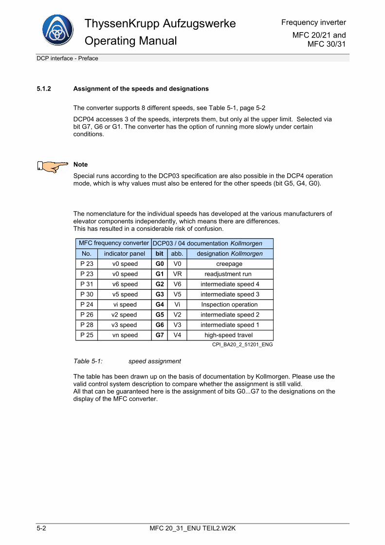
ThyssenKrupp Aufzugswerke Operating Manual
Frequency inverterMFC 20/21 and
MFC 30/31
DCP interface - Preface
5-2 MFC 20_31_ENU TEIL2.W2K
5.1.2 Assignment of the speeds and designations
The converter supports 8 different speeds, see Table 5-1, page 5-2
DCP04 accesses 3 of the speeds, interprets them, but only al the upper limit. Selected via bit G7, G6 or G1. The converter has the option of running more slowly under certain conditions.
Note
Special runs according to the DCP03 specification are also possible in the DCP4 operation mode, which is why values must also be entered for the other speeds (bit G5, G4, G0).
The nomenclature for the individual speeds has developed at the various manufacturers of elevator components independently, which means there are differences. This has resulted in a considerable risk of confusion.
DCP03 / 04 documentation KollmorgenNo. indicator panel bit abb. designation KollmorgenP 23 v0 speed G0 V0 creepage P 23 v0 speed G1 VR readjustment run P 31 v6 speed G2 V6 intermediate speed 4P 30 v5 speed G3 V5 intermediate speed 3P 24 vi speed G4 Vi Inspection operation P 26 v2 speed G5 V2 intermediate speed 2P 28 v3 speed G6 V3 intermediate speed 1P 25 vn speed G7 V4 high-speed travel
MFC frequency converter
CPI_BA20_2_51201_ENG
Table 5-1: speed assignment
The table has been drawn up on the basis of documentation by Kollmorgen. Please use the valid control system description to compare whether the assignment is still valid. All that can be guaranteed here is the assignment of bits G0...G7 to the designations on the display of the MFC converter.
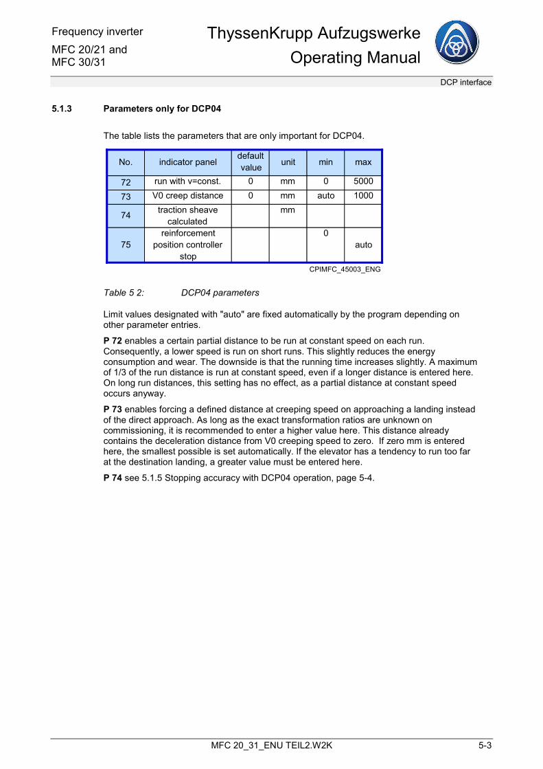
Frequency inverter MFC 20/21 and MFC 30/31
ThyssenKrupp AufzugswerkeOperating Manual
DCP interface
MFC 20_31_ENU TEIL2.W2K 5-3
5.1.3 Parameters only for DCP04
The table lists the parameters that are only important for DCP04.
72 run with v=const. 0 mm 0 5000
73 V0 creep distance 0 mm auto 1000
74 traction sheave calculated
mm
75reinforcement
position controller stop
0auto
unit min maxNo. indicator paneldefault value
CPIMFC_45003_ENG
Table 5 2: DCP04 parameters
Limit values designated with "auto" are fixed automatically by the program depending on other parameter entries.
P 72 enables a certain partial distance to be run at constant speed on each run. Consequently, a lower speed is run on short runs. This slightly reduces the energy consumption and wear. The downside is that the running time increases slightly. A maximum of 1/3 of the run distance is run at constant speed, even if a longer distance is entered here. On long run distances, this setting has no effect, as a partial distance at constant speed occurs anyway.
P 73 enables forcing a defined distance at creeping speed on approaching a landing instead of the direct approach. As long as the exact transformation ratios are unknown on commissioning, it is recommended to enter a higher value here. This distance already contains the deceleration distance from V0 creeping speed to zero. If zero mm is entered here, the smallest possible is set automatically. If the elevator has a tendency to run too far at the destination landing, a greater value must be entered here.
P 74 see 5.1.5 Stopping accuracy with DCP04 operation, page 5-4.
ThyssenKrupp Aufzugswerke Operating Manual
Frequency inverterMFC 20/21 and
MFC 30/31
DCP interface - Preface
5-4 MFC 20_31_ENU TEIL2.W2K
P 75 stop position controller gain The running characteristic curve is calculated from the set parameters for speed, acceleration and jerk during almost the entire run distance and passed onto the speed controller. During the last millimetres before reaching the stop position, this strategy changes. A position controller uses the distance to the exact stop position to determine the reference values for the speed controller in such a way that the elevator comes to a standstill at virtually exactly the position specified by the DCP control system. The gain of this controller is set using P75. If an unpleasant jerk is noticeable on stopping, first set the creep distance (P 73) to a higher value, e.g. 50…100mm. Then P75 can be set in such a way that stopping is soft and pleasant. Once a setting has been found that leads to both good stopping accuracy and soft stopping, P 73 can be reset to a low value.
5.1.4 Safety function TIMEOUT control
If no valid DCP telegram arrives at the converter for longer than 150 ms, the converter executes an emergency stop if the elevator is currently running. The event and fault stack of the converter then contains the entry: "DCP fault" and the number of DCP telegrams with incorrect checksum received since switching on. Furthermore, the corresponding status of the operating hour meter appears for each stack entry.
Emergency stop means: block impulses, open travel contactors and close mechanical brake.
5.1.5 Stopping accuracy with DCP04 operation
With DCP04 operation, particular care is required when entering the gear ratio, suspension ratio and diameter of traction sheave. Even minor inaccuracies in the diameter of traction sheave lead to inadequate stopping accuracy. The running speed on the display of the control system compared with the display of the converter, parameter P 101 "actual speed" must match during the run. If the exact diameter of traction sheave is unknown, the converter offers a mathematically determined diameter after each run on P 74 "traction sheave calculated". This is calculated from the travel information of the control system and the encoder information of the drive. However, the calculation result is falsified by rope slip and rounding errors. In order to obtain a meaningful result, a number of runs must be executed over a number of floors. The might be that P 74 shows zero mm if runs from or to the lowest landing are executed. Then, simply execute runs between two other landings and then read off P 74. If the same or almost the same value has been read a number of times on P 74, this can then be entered at P 14 "traction sheave".
As a general principle, the drive tends to run too fast and too far if the input value at P 14 "traction sheave" is too low. If the input value is too high, the drive tends towards a slow approach path and slow running speed.
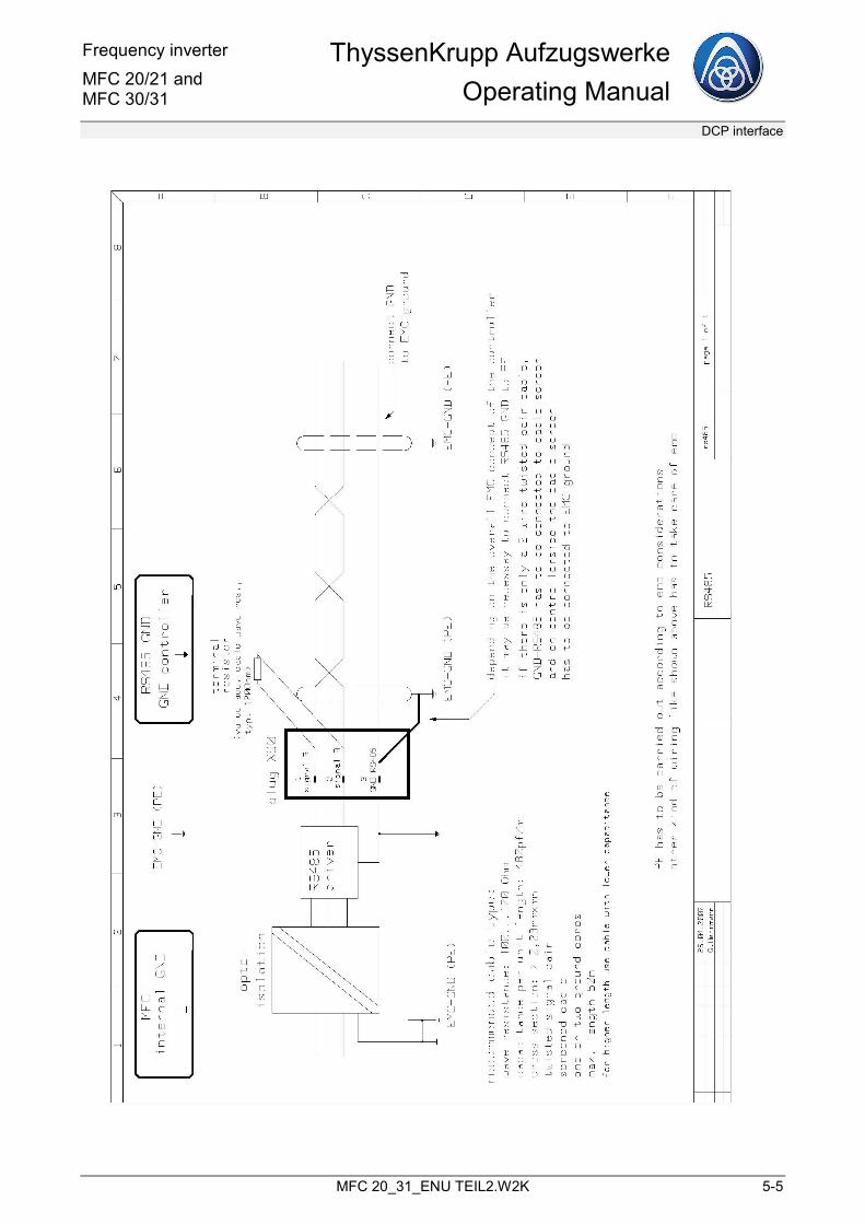
Frequency inverter MFC 20/21 and MFC 30/31
ThyssenKrupp AufzugswerkeOperating Manual
DCP interface
MFC 20_31_ENU TEIL2.W2K 5-5
ThyssenKrupp Aufzugswerke Operating Manual
Frequency inverterMFC 20/21 and
MFC 30/31
DCP interface - Preface
5-6 MFC 20_31_ENU TEIL2.W2K
Frequency inverter MFC 20/21 and MFC 30/31
ThyssenKrupp AufzugswerkeOperating Manual
Test instructions
MFC 20_31_ENU TEIL2.W2K 6-1
6 Test instructions Test instructions for the function of the travel and brake contactors as well as monitoring the brake feedback (only on MFC 30/31 or MFC20-50R and MFC20-100R).
6.1 Travel contactors
The two travel contactors K06 and K06.1 (or the relay contactors K01 and K01.1) must be checked for "dropout after end of run".
Note
The testing cable used in the following is to be connected to one side at the terminals described below; the other side is to be equipped with an insulated probe tip where the probe tip only becomes free during the measuring operation.
Danger to life: 230 V mains voltage
Test sequence:
1. with MFC 30/10, 15, 26. 40, 60
a) Connect the testing cable to terminal X524.1 (travel contactor K06). Start the elevator run. During the run, connect the probe tip with X516.1. ® The elevator car travels to the next stop and comes to a stand still.
b) Connect the testing cable to terminal X524.2 (travel contactor K06.2). Start the elevator run. During the run, connect the probe tip with X516.1. ® The elevator car travels to the next stop and comes to a stand still.
c) Remove the testing cable.
2. for MFC 20/50R, 100R
Remove the front cover of the control section (lower part of the frequency inverter).
a) Connect the testing cable to terminal X517.4 (travel contactor K06 or relay contactor K01). Start the elevator run. During the run, connect the probe tip with X516.1. ® The elevator car travels to the next stop and comes to a stand still.
b) Connect the testing cable to terminal X517.6 (travel contactor K06.1 or relay contactor K01). Start the elevator run. During the run, connect the probe tip with X516.1. ® The elevator car travels to the next stop and comes to a stand still.
c) Remove the testing cable.
ThyssenKrupp Aufzugswerke Operating Manual
Frequency inverterMFC 20/21 and
MFC 30/31
Test instructions - Brake contactor
6-2 MFC 20_31_ENU TEIL2.W2K
6.2 Brake contactor
Switching off the electromechanical brakes by two independent switching devices must be checked.
Note
Two testing cables (as described above) are required.
Danger
Danger to life: 230 V mains voltage
Place the elevator car in the middle of the shaft with an unbalanced load state.
Change parameter P 150 to "on" (brake continuously activated).
Test sequence:
1. with MFC 30/10, 15, 26. 40, 60
1. Connect the testing cable to terminal X524.1.
2. Connect the testing cable to terminal X524.2.
a) Connect the probe tip of the 1st testing cable to terminal X512.3. ® The elevator car must not move.
b) Connect the probe tip of the 2nd testing cable to terminal X512.3. ® The elevator car must not move.
c) Connect the probe tips of the 1st and 2nd testing cables to terminal X512.3.
Frequency inverter MFC 20/21 and MFC 30/31
ThyssenKrupp AufzugswerkeOperating Manual
Test instructions
MFC 20_31_ENU TEIL2.W2K 6-3
Danger
Elevator car moves with open brake (non-controlled) through the shaft.
® Remove the probe tips immediately.
Switch off the control voltage.
Remove the testing cable.
2. for MFC 20/50R, 100R
1. Connect the testing cable to terminal X517.4.
2. Connect the testing cable to terminal X517.6.
a) Connect the probe tip of the 1st testing cable to terminal X512.3. ® The elevator car must not move.
b) Connect the probe tip of the 2nd testing cable to terminal X512.3. ® The elevator car must not move.
c) Connect the probe tips of the 1st and 2nd testing cables to terminal X512.3.
Danger
Elevator car moves with open brake (non-controlled) through the shaft.
® Remove the probe tips immediately.
Switch off the control voltage.
Remove the testing cable.
6.3 Brake feedback
The brake feedback (brakes open or closed) is not monitored by the frequency inverter.
The elevator control has to ensure that opening the brake before and during an elevator run is monitored.

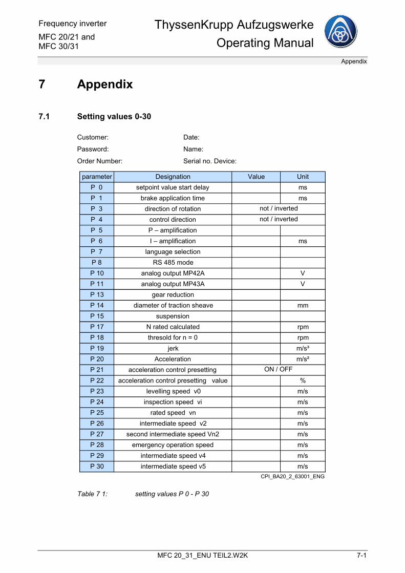
Frequency inverter MFC 20/21 and MFC 30/31
ThyssenKrupp AufzugswerkeOperating Manual
Appendix
MFC 20_31_ENU TEIL2.W2K 7-1
7 Appendix
7.1 Setting values 0-30
Customer: Date:
Password: Name:
Order Number: Serial no. Device:
parameter Designation Value UnitP 0 setpoint value start delay msP 1 brake application time msP 3 direction of rotationP 4 control directionP 5 P – amplificationP 6 I – amplification msP 7 language selectionP 8 RS 485 modeP 10 analog output MP42A VP 11 analog output MP43A VP 13 gear reductionP 14 diameter of traction sheave mmP 15 suspensionP 17 N rated calculated rpmP 18 thresold for n = 0 rpmP 19 jerk m/s³P 20 Acceleration m/s²P 21 acceleration control presettingP 22 acceleration control presetting value %P 23 levelling speed v0 m/sP 24 inspection speed vi m/sP 25 rated speed vn m/sP 26 intermediate speed v2 m/sP 27 second intermediate speed Vn2 m/sP 28 emergency operation speed m/sP 29 intermediate speed v4 m/sP 30 intermediate speed v5 m/s
not / invertednot / inverted
ON / OFF
CPI_BA20_2_63001_ENG
Table 7 1: setting values P 0 - P 30
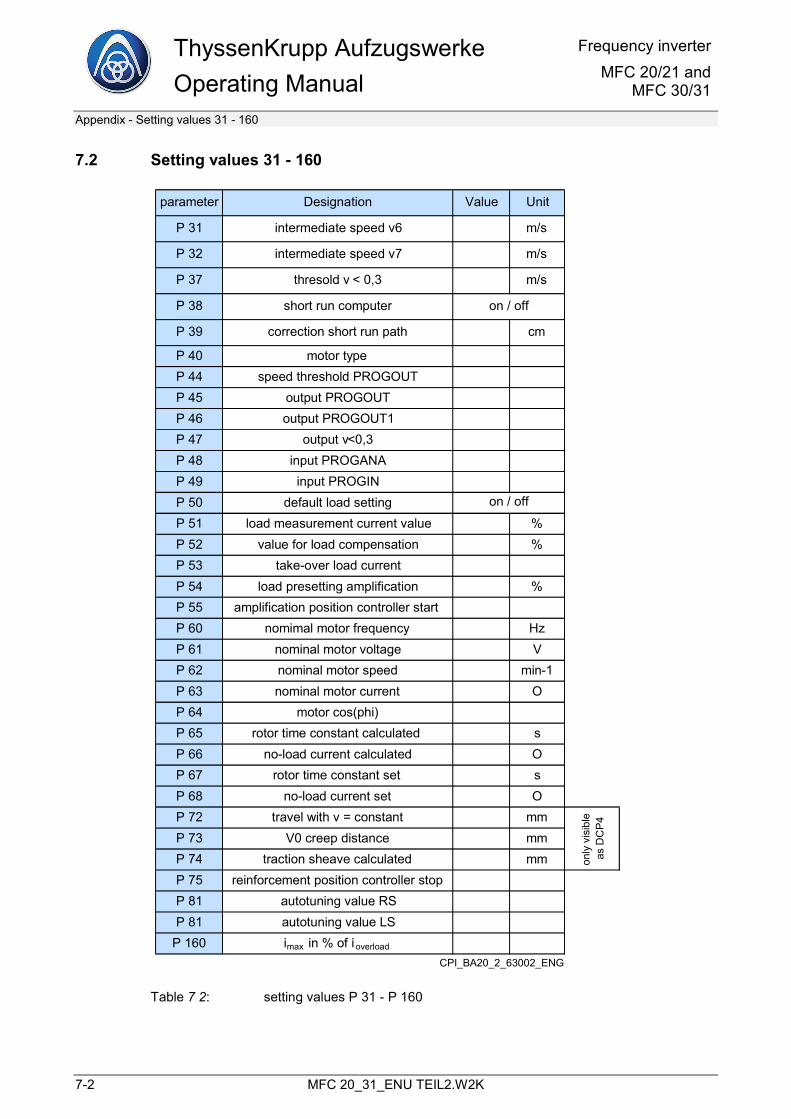
ThyssenKrupp Aufzugswerke Operating Manual
Frequency inverterMFC 20/21 and
MFC 30/31
Appendix - Setting values 31 - 160
7-2 MFC 20_31_ENU TEIL2.W2K
7.2 Setting values 31 - 160
parameter Designation Value Unit
P 31 intermediate speed v6 m/s
P 32 intermediate speed v7 m/s
P 37 thresold v < 0,3 m/s
P 38 short run computer
P 39 correction short run path cm
P 40 motor typeP 44 speed threshold PROGOUTP 45 output PROGOUTP 46 output PROGOUT1P 47 output v<0,3P 48 input PROGANAP 49 input PROGINP 50 default load settingP 51 load measurement current value %P 52 value for load compensation %P 53 take-over load currentP 54 load presetting amplification %P 55 amplification position controller startP 60 nomimal motor frequency HzP 61 nominal motor voltage VP 62 nominal motor speed min-1P 63 nominal motor current OP 64 motor cos(phi)P 65 rotor time constant calculated sP 66 no-load current calculated OP 67 rotor time constant set sP 68 no-load current set OP 72 travel with v = constant mmP 73 V0 creep distance mmP 74 traction sheave calculated mmP 75 reinforcement position controller stopP 81 autotuning value RSP 81 autotuning value LS
P 160 imax in % of i overload
on / off
on / off
only
visi
ble
asD
CP4
CPI_BA20_2_63002_ENG
Table 7 2: setting values P 31 - P 160
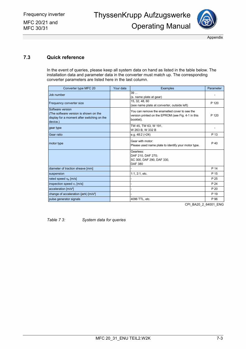
Frequency inverter MFC 20/21 and MFC 30/31
ThyssenKrupp AufzugswerkeOperating Manual
Appendix
MFC 20_31_ENU TEIL2.W2K 7-3
7.3 Quick reference
In the event of queries, please keep all system data on hand as listed in the table below. The installation data and parameter data in the converter must match up. The corresponding converter parameters are listed here in the last column.
Converter type MFC 20 Your data Examples Parameter
Job number 39 ...(s. name plate at gear)
-
Frequency converter size 15, 32, 48, 60(see name plate at converter, outside left)
P 120
Software version(The software version is shown on the display for a moment after switching on the device.)
You can remove the enamelled cover to see the version printed on the EPROM (see Fig. 4-1 in this booklet).
P 120
gear type TW 45, TW 63, W 191,W 263 B, W 332 B
-
Gear ratio e.g. 48:2 (=24) P 13
motor typeGear with motor:Please used name plate to identify your motor type. P 40
Gearless:DAF 210, DAF 270;SC 300, DAF 290, DAF 330,DAF 380
diameter of traction sheave [mm] - P 14suspension 1:1, 2:1, etc. P 15rated speed vN [m/s] - P 25inspection speed vI [m/s] - P 24acceleration [m/s²] - P 20change of acceleration (jerk) [m/s³] - P 19pulse generator signals 4096 TTL, etc. P 96
CPI_BA20_2_64001_ENG
Table 7 3: System data for queries

Frequency inverter MFC 20/21 and MFC 30/31
ThyssenKrupp AufzugswerkeOperating Manual
Index
MFC 20_31_ENU TEIL2.W2K 8-5
8 Index Minimum permitted floor-to-floor distances 2-9 Parameters
changeable 1-8
Display parameters 1-28 Revision service 9-1

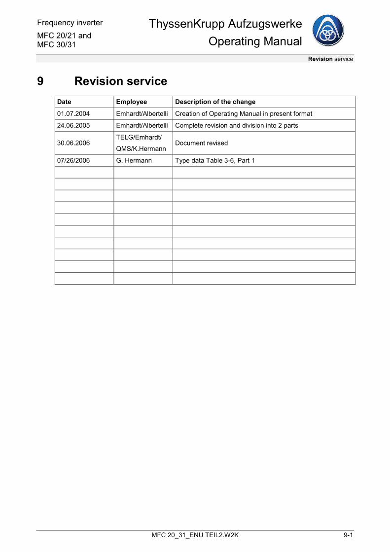
Frequency inverter MFC 20/21 and MFC 30/31
ThyssenKrupp AufzugswerkeOperating Manual
Revision service
MFC 20_31_ENU TEIL2.W2K 9-1
9 Revision service Date Employee Description of the change
01.07.2004 Emhardt/Albertelli Creation of Operating Manual in present format
24.06.2005 Emhardt/Albertelli Complete revision and division into 2 parts
30.06.2006 TELG/Emhardt/
QMS/K.Hermann Document revised
07/26/2006 G. Hermann Type data Table 3-6, Part 1