Embed Size (px)
Citation preview
1
Descrizione Description Beschreibung Description
1.0 Introduzione Introduction Einführung Introduction 22.0 Caratteristiche Specifications Konstruktions-Merkmale Caractéristiques 33.0 Forme costruttive Versions Bauformen Formes de construction 44.0 Simbologia e unità di misura Symbols and units of measure Verwendete Symbole und Begriffe Symboles et unités de mesure 65.0 Coppia in uscita Output torque Abtriebsdrehmoment Couple de sortie 86.0 Potenza Power Leistung Puissance 87.0 Potenza termica Thermal power Thermische Grenzleistung Puissance thermique 98.0 Rendimento Efficiency Wirkungsgrad Rendement 109.0 Rapporto di riduzione Reduction ratio Übersetzung Rapport de réduction 1010.0 Velocità angolare Angular speed Drehzahl Vitesse angulaire 1011.0 Fattore di servizio Service factor Betriebsfaktor Facteur de service 1112.0 Fattore di durata Life factor Dauerfaktor Facteur de durée 1113.0 Scelta Selection Auswahl Sélection 1114.0 Verifiche Verification Prüfungen Vérifications 1415.0 Scelta del motore Motor selection Wahl des Motors Choix du moteur 1616.0 Installazione Installation Installation Installation 1817.0 Manutenzione Maintenance Wartung Entretien 2018.0 Stoccaggio Storage Lagerung Stockage 2019.0 Condizioni di fornitura Conditions of supply Lieferbedingungen Conditions de livraison 2120.0 Designazione Designation Bezeichnung Désignation 2221.0 Posizioni di montaggio Mounting positions Einbaulagen Positions de montage 2422.0 Lubrificazione Lubrication Schmierung Lubrification 2423.0 Tabelle dati tecnici riduttori e
dimensioniGearbox selection charts andDimensions
Getriebeauswahltabellen undAbmessungen
Tableaux des caractéristiques tech-niques réducteurs et dimensions
29
24.0 Freni idraulici negativi a dischimultipli
Negative multidisc brakes Hydraulisch belüfteteLamellenbremsen
Freins hydrauliques négatifs 190
25.0 Entrate per motori idraulici Inputs for hydraulic motors Antriebe für hydraulische Motoren Entrées pour moteurs hydrauliques 19126.0 Motori idraulici MG MG Hydraulic motors MG Hydraulikmotoren Moteurs hydrauliques MG 20127.0 Simbologia e unità di misura Symbols and units of measure Verwendete Symbole und Einheiten Symboles et unités de mesure 20228.0 Caratteristiche tecniche Technical features Technische Eigenschaften Caractéristiques techniques 20229.0 Designazione Designation Bezeichnung Désignation 20430.0 Scelta Displacement selection Auswahl Choix 20531.0 Verifiche Verification Überprüfungen Vérifications 20532.0 Dati tecnici motori MG Technical data Mg motors MG Motorauswahltabellen Caracteristiques techniques moteurs MG 20633.0 Dimensioni motori MG Dimensions MG motors Abmessungen Motoren MG Dimensions Moteurs MG 20734.0 Dati tecnici freni Brake technical data Tecnische datenbremse Donnée techniques freins 20835.0 Installazione Installation Installation Installation 20836.0 Sistemi ausiliari di raffreddamento Supplementary cooling systems Hilfskülsysteme Systemes auxiliaires de
refroidissement 212
ParagrafoHeadingAbschnittParagraphe
PaginaPageSeitePage
RevisionsRefer to page 286 for the cataloguerevision index.Visit www.bonfiglioli.com to search forcatalogues with up-to-date revisions.
ÄnderungenDas Revisionsverzeichnis des Katalogswird auf Seite 286 wiedergegeben. Aufunserer Website www.bonfiglioli.comwerden die Kataloge in ihrer letzten,überarbeiteten Version angeboten.
RévisionsLe sommaire de révision du catalogueest indiqué à la page 286.Sur le site www.bonfiglioli.com des ca-talogues avec les dernières révisionssont disponibles.
RevisioniL’indice di revisione del catalogo è ri-portato a pag. 286.Al sito www.bonfiglioli.com sono di-sponibili i cataloghi con le revisioniaggiornate.
M1 Programma di produzione Production Planning Produktionsprogramm Programme de production 217M2 Normative Reference standards Normen Normes 217M3 Tolleranze Tolerances Toleranzen Tolerances 219M4 Senso di rotazione Direction of rotation Drehrichtung Sens de rotation 220M5 Cuscinetti Bearings Lager Roulements 220M6 Operatività standard Standard operation Standardversorgung Conditiones operatives 221M7 Funzionamento a 60 Hz 60 Hz operation Betrieb bei a 60 Hz Fonctionnement a 60 Hz 222M8 Alimentazione da inverter Inverter control Frequenzumrichterbetrieb Alimentation par variateur 226M9 Tipo di servizio Type of duty Betriebsarten Type de service 227M10 Morsettiera motore Terminal box Motorklemmenkasten Bornier moteur 229M11 Forme costruttive Design version Bauformen Formes de construction 230M12 Ventilazione Ventilation Kühlung Ventilation 231M13 Designazione motore Motor designation Motorbezeichnung Designation moteur 234M14 Varianti e opzioni Variants and options Optionen Variantes et options 235M15 Grado di protezione Degree of protection Schutzart Degre de protection 236M16 Classe di isolamento Insulation class Isolationsklasse Classes d’isolation 238M17 Protezioni termiche Thermal protective devices Thermische Wicklungsschutzeinricht Protections thermiques 239M18 Dispositivi di retroazione Feedback units Encoder / Inkrementalgeber Dispositifs de retroaction 240M19 Riscaldatori anticondensa Anti-condensation heaters Wicklungsheizung Rechauffeurs anticondensation 242M20 Tropicalizzazione Tropicalization Tropenschutz Tropicalisation 242M21 Esecuzioni albero motore Rotor shaft configurations Option der rotorwelle Executions arbre rotor 242M22 Equilibratura rotore Rotor balancing Rotorauswuchtung Equilibrage du rotor 243M23 Protezioni meccaniche esterne External mechanical protections Mechanische Schutzvorrichtunge Protections mecaniques exterieures 244M24 Motori asincroni autofrenanti Asynchronous brake motors Drehstrombremsmotoren Moteurs frein asynchrones 245
M25 Motori autofrenanti in C.C.,tipo BN_FD
DC brake motorstype BN_FD
Wechselstrom-Bremsmotorenmit G.S.– Bremse Typ BN_ FD
Moteurs frein en C.C., typeBN_FD 251
M26 Motori autofrenanti in C.A.,tipo BN_FA
AC brake motorstype BN_FA
Wechselstrom-Bremsmotorenmit W.S.– Bremse Typ BN_ FA Moteurs frein en C.A., type BN_FA 257
M27 Motori autofrenanti in C.A., tipoBN_BA
AC brake motorstype BN_BA
Wechselstrom-Bremsmotorenmit W.S.– Bremse Typ BN_ BA Moteurs frein en C.A., type BN_BA 261
M28 Dati tecnici motori Motor rating charts Motorenauswahl Tabellen Données techniques des moteurs 265M29 Dimensioni Dimensions Abmessungen Dimensions 277
2
1.0 INTRODUZIONE 1.0 INTRODUCTION 1.0 EINFÜHRUNG 1.0 INTRODUCTION
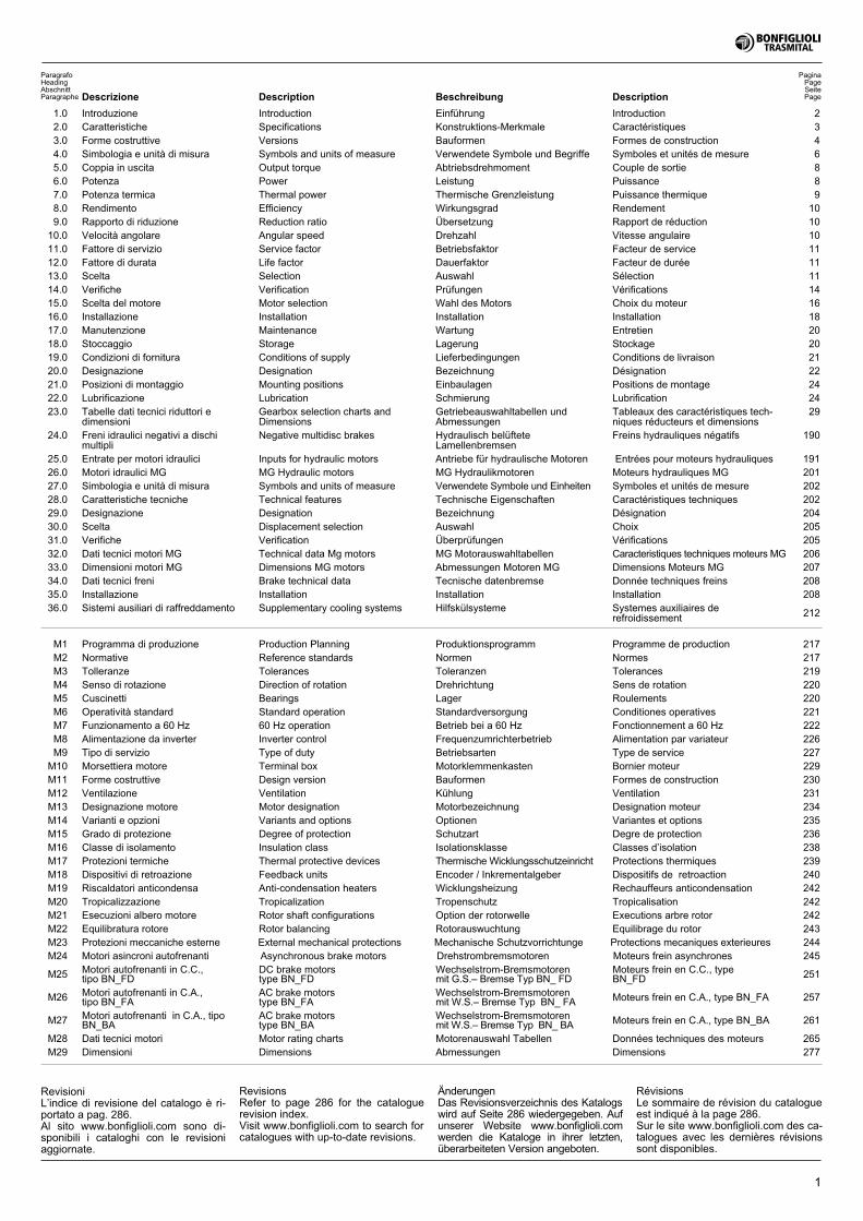
This catalogue presents TRAS-MITAL BONFIGLIOLI’s range ofSeries 300 modular planetarygearboxes.
The range has been expandedand integrated with new sizes,technical improvements and en-hanced modularity right throughto the larger sizes. This featuresignifies greater flexibility in inter-nal production to ensure quickavailability of products in thesizes and types requested eitherdirectly from the company or fromthe many affiliates belonging tothe BONFIGLIOLI sales networkin various countries around theworld.
The gearboxes are tested in con-formity with the followingstandards:
ISO DP 6336 for gearsISO 281 for bearings
Avec ce catalogue TRASMITALBONFIGLIOLI présente sa gam-me de réducteurs épicycloïdauxmodulaires série 300.
Elle a été développée et enrichiequant à la disponibilité de nouvel-les tailles, l’apport d’améliorationstechniques aussi bien qu’àl’extension de la modularité glo-bale jusqu’aux tailles supérieures.Cette caractéristique de construc-tion se traduit dans une flexibilitéproductive interne plus importan-te, dans la possibilité d’obtenir,sous de courts délais, les produitsayant les tailles et les exécutionsnécessaires, tant de manière di-recte de l’entreprise, qu’à traversles nombreuses filiales apparte-nant à l’organisation de venteBONFIGLIOLI, établies dans plu-sieurs pays du monde.
Les réducteurs sont vérifiés selonles normes suivantes:
ISO DP 6336 pour les engrenagesISO 281 pour les roulements
In questo catalogo la TRASMITALBONFIGLIOLI presenta la suagamma di riduttori epicicloidalimodulari serie 300.
Questa serie è stata ampliata edarricchita di nuove grandezze di-sponibili, miglioramenti tecnici ap-portati e dall’ estensione dellamodularità totale fino alle gran-dezze superiori. Tale caratteristi-ca costruttiva si traduce in unamigliore flessibilità produttiva in-terna, nella possibilità di avere intempi brevi prodotti nelle gran-dezze ed esecuzioni richieste, siadirettamente dall’azienda che dal-le filiali appartenenti alla organiz-zazione di vendita BONFIGLIOLIlocalizzate in numerosi paesi delmondo.
I riduttori sono verificati secondo iseguenti standard:
ISO DP 6336 per gli ingranaggiISO 281 per i cuscinetti
In diesem Katalog stellt dieTRASMITAL BONFIGLIOLI seineAngebotsreihe an modularen Pla-netengetrieben der Serie 300 vor.
Diese Serie wurde weiter ausge-baut und durch neue, nun zurVerfügung stehende Baugrößenbereichert. Darüber hinaus wur-den hier technische Verbesserun-gen angetragen und die Ge-samtmodularität bis zu den obe-ren Baugrößen hin erweitert. Die-se Konstruktionsmerkmale lassensich in eine bessere Flexibilitätder internen Produktivität, in dieMöglichkeit schnell Produkte inden gewünschten Größen undAusführungen, sowohl direkt vonder Firma selbst, als auch übereine der zahlreichen, zur Organi-sation der BONFIGLIOLI gehö-renden Filialen, die in ebensozahlreichen und weltweit verbrei-teten Ländern erhalten zu kön-nen, übersetzen.
Die Getriebe werden den folgen-den Normen gemäß geprüft:
ISO DP 6336 für ZahnräderISO 281 für Lager
3
2.0 CARACTERISTIQUES
La série 300 est une gamme deréducteurs épicycloïdaux polyva-lents, qui peuvent être actionnéspar des moteurs hydrauliques etélectriques.Les principales caractéristiques sont:
� 16 tailles� couples en sortie jusqu’à
540.000 Nm� puissances transmissibles jus-
qu’à 450 kW� rapports de 1:3,5 à .3000
� construction modulaire� exécution:
- linéaire- angulaire (premier étage réali-sé avec couple conique)
� de 1 à 4 étages de réduction
� versions en sortie pour assem-blage avec bride, patte, oupendulaire
� arbres de sortie: avec cla-vette; cannelés; femelle can-nelés; creux cylindriques pourassemblage pendulaire avecfrette de serrage
� raccordements à l’entrée pourles moteurs suivants:moteurs électriques, selon CEIforme B5moteurs hydrauliques desmarques principales et confor-mes à SAE J744C
� arbres rapides d’entrée� motoréducteurs avec :
- moteurs électriques CEI- moteurs hydrauliques orbitauxTRASMITAL MG
� freins hydrauliques négatifs destationnement pour commandeavec moteurs hydrauliques
� accessoires pour arbre desortie:- brides- pignons- barres cannelées- joints d’accouplement à friction
D’autres caractéristiques deconstruction sont :
– rapport de couple transmis-sible élevé / dimensions d’en-combrement
– capacité élevée à supporterles charges radiales et axialessur les arbres de sortie, grâceà l’utilisation, sur les versionsH., de roulements à rouleauxconiques
– rendements élevé
– raccordements entre les orga-nes intérieurs par le biais deprofils cannelés, et non pas declavettes
– étages de réduction avecporte-planétaires flottants pourobtenir la maxime répartitiondes charges dans le train d’en-grenages épicycloïdaux
– carter en fonte G.S.
2.0 CARATTERISTICHE
La serie 300 è una gamma di ri-duttori epicicloidali multimpiegoazionabili da motori idraulici edelettrici.Le caratteristiche di base sono:
� 16 grandezze� coppie in uscita fino a 540.000
Nm� potenze trasmissibili fino a
450 kW� rapporti da 1:3.5 a 3000
� costruzione modulare� esecuzione:
- in linea- angolare (con primo stadiorealizzato con coppia conicaGleason)
� da 1 a 4 stadi di riduzione
� versioni in uscita per montag-gio con flangia, con piede,pendolare.
� alberi in uscita: con linguetta,scanalati, femmina scanalati,cavi cilindrici per montaggiopendolare con giunto ad attri-to.
� predisposizioni motore in en-trata per:motori elettrici, secondo IECforma B5motori idraulici dei principalicostruttori e secondoSAE J744C
� alberi veloci in entrata� motoriduttori con:
- motori elettrici IEC- motori idraulici orbitaliTRASMITAL MG
� freni idraulici negativi di stazio-namento per utilizzo con mo-tori idraulici
� accessori per alberi uscita:-flange-pignoni-barre scanalate-giunti ad attrito
Altre caratteristiche costruttivesono:
– elevato rapporto coppia tra-smissibile/dimensionid’ingombro
– elevata capacità a sopportarecarichi radiali e assiali sugli al-beri di uscita grazie all’utilizzo,sulle versioni H, di cuscinetti arulli conici
– elevati rendimenti
– collegamenti fra gli organi in-terni tramite profili scanalati,non utilizzo di linguette
– stadi di riduzione con portapla-netari flottanti per ottenere lamassima ripartizione dei cari-chi fra gli ingranaggi planetari
– carcasse in ghisa sferoidale.
2.0 SPECIFICATIONS
The 300 series consist of a rangeof multi-purpose planetary gear-boxes that can be operated by ei-ther hydraulic or electric motors.Basic features are:
� 16 sizes� output torque up to 540,000
Nm� transmissible power up to 450
kW� ratios from 3.5:1 to 3000:1
� modular design� versions:
- in-line- right angle (first stage withbevel gear pair Gleason)
� reduction stages ranging from1 to 4
� with flange-mounted, foot-mounted and shaft-mountedoutput
� output shafts with keyway,splined, splined hollow shafts,hollow shafts for shaft-mount-ing with shrink disc
� input adaptors for:electric motors to IEC stan-dards design B5hydraulic motors by majormanufacturers and accordingto SAE J744C
� high speed shafts� gearmotors with:
- electric motors IEC- hydraulic orbital motors byTRASMITAL MG
� negative hydraulic parkingbrakes for operation by hy-draulic motors
� output shaft accessories:- flanges- pinions- splined bars- shrink discs
More design features:
– high ratio of transmissibletorque to overall dimensions
– high radial and axial load ca-pacity of output shafts thanks totapered roller bearings fitted onthe H versions
– high efficiency
– inner parts are connected us-ing grooved sections insteadof tabs
– planetary gears of reductionstages mounted to floatingholders to ensure maximumload distribution among plane-tary gears
– housing made of spheroidalcast iron.
2.0 KONSTRUKTIONS-MERKMALE
Die Serie 300 ist eine Reihe anvielseitig einsetzbaren Planeten-getrieben, die von Hydraulik-oder Elektromotoren angetriebenwerden können.Ihre Gundmerkmale sind:
� 16 Baugrößen� Abtriebsdrehmomente bis zu
540.000 Nm� Antriebsleistungen bis zu 450
kW� Übersetzungsverhältnisse von
1:3,5 bis 3000� Modularbauweise� Ausführung:
- linear- auf Winkel (erste Stufe mitKegelradpaarung realisiert)
� von 1 bis 4 Untersetzungstu-fen
� Abtriebsversionen für Montagemit Flansch, mit Fuß, in Auf-steckversion)
� Abtriebswellen: mit Passfe-der, Vielkeil, Vielkeilhohlwelle,zylindrischer Hohlwelle fürSchrumpfscheibenmontage.
� Vorbereitet für Antriebsmotor:Elektromotoren, gemäß IECForm B5Hydraulikmotoren der bedeu-tensten Hersteller und gemäßSAE J744C
� Schnelle Wellen am Antrieb� Getriebemotoren mit:
Elektromotoren IECorbitale Hydraulikmotoren derTRASMITAL MG
� hydraulische Abstellbremsen fürSteuerung durch Hydraulikmo-toren
� Zubehör für Abtriebswellen:- Flanschen- Ritzel- Keilstäbe- Schrumpfscheiben
Andere Konstruktionsmerkmalelassen sich folgendermaßen zu-sammenfassen:
– hohes übertragbares Drehmo-ment/Verhältnis zu den Aus-senmaßen
– Hohe Aufnahmekapazität vonRadial- und Axiallasten an denAbtriebswellen dank einesEinsatzes, bei den VersionenH, von Kegelrollenlagern
– hohe Wirkungsgrade
– Verbindungen zwischen deninneren Organen mittels Nut-profilen, es werden keinePassfedern verwendet
– Untersetzungstufen mit schwimmenden Planetenradträgerzur Belastungsverteilung aufdie Planetenrädern
– Gehäuse aus Sphäroguss.
4
3.0 FORMECOSTRUTTIVE
3.0 VERSIONS 3.0 BAUFORMEN 3.0 FORMES DECONSTRUCTION
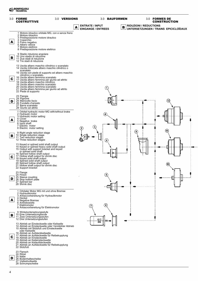
1 Motore idraulico orbitale MG, con e senza freno2 Motore idraulico3 Predisposizione motore idraulico4 Coperchio5 Freno negativo6 Albero veloce7 Motore elettrico8 Predisposizione motore elettrico
9 Stadio riduzione angolare10 Uno stadio di riduzione11 Due stadi di riduzione12 Tre stadi di riduzione
13 Uscita albero maschio cilindrico o scanalato14 Uscita rinforzata albero maschio cilindrico o
scanalato15 Uscita con piede di supporto ed albero maschio
cilindrico o scanalato.16 Uscita albero femmina scanalato17 Uscita albero femmina per giunto ad attrito18 Uscita albero maschio cilindrico19 Uscita albero maschio scanalato20 Uscita albero femmina scanalato21 Uscita albero femmina per giunto ad attrito22 Piede di supporto
23 Flangia24 Pignone25 Manicotto liscio26 Fondello d’arresto27 Barra scanalata28 Giunto ad attrito
1 Orbitaler Motor MG mit und ohne Bremse2 Hydraulikmotor3 Anbauvorbereitung für Hydraulikmotor4 Deckel5 Negative Bremse6 Antriebswelle7 Elektromotor8 Anbauvorbereitung für Elektromotor
9 Winkeluntersetzungsstufe10 Eine Untersetzungssrufe11 Zwei Untersetzungsstufen12 Drei Untersetzungsstufen
13 Abtrieb an Einsteckwelle oder Keilwelle14 Abtrieb an Einsteckwelle oder Verstärkter Abtrieb15 Abtrieb mit Stützfuß und Einsteckwelle
oder Keilwelle16 Abtrieb an Aufsteckkeilwelle17 Abtrieb an Aufsteckwelle für Reibekupplung18 Abtrieb an Einsteckwelle19 Abtrieb an Keileinsteckwelle20 Abtrieb an Keilaufsteckwelle21 Abtrieb an Aufsteckwelle für Reibekupplung22 Stützfuß
23 Flansch24 Ritzel25 Nabe26 Bodenhaltescheibe27 Vielkeilvollwelle28 Schrumpscheibe
1 Orbital hydraulic motor MG with/without brake2 Hydraulic motor3 Hydraulic motor setting4 Cover5 Negative brake6 Input shaft7 Electric motor8 Electric motor setting
9 Right angle reduction stage10 Single reduction stage11 Two reduction stages12 Three reduction stages
13 Keyed or splined solid shaft output14 Keyed or splined heavy solid shaft output15 Output with support bracket and keyed
or splined solid shaft16 Splined hollow shaft output17 Hollow shaft output for shrink disc18 Keyed solid shaft output19 Splined solid shaft output20 Splined hollow shaft output21 Hollow shaft output for shrink disc22 Support bracket
23 Flange24 Pinion25 Sleeve coupling26 Stop bottom plate27 Splined bar28 Shrink disc
ENTRATE / INPUTEINGANGE / ENTREES
RIDUZIONI / REDUCTIONSUNTERSETZUNGEN / TRAINS EPICICLOÏDAUX
C
B
A B
D
A
C
B
D
A
C
B
D
A
5
3.0 FORMECOSTRUTTIVE
3.0 VERSIONS 3.0 BAUFORMEN 3.0 FORMES DECONSTRUCTION
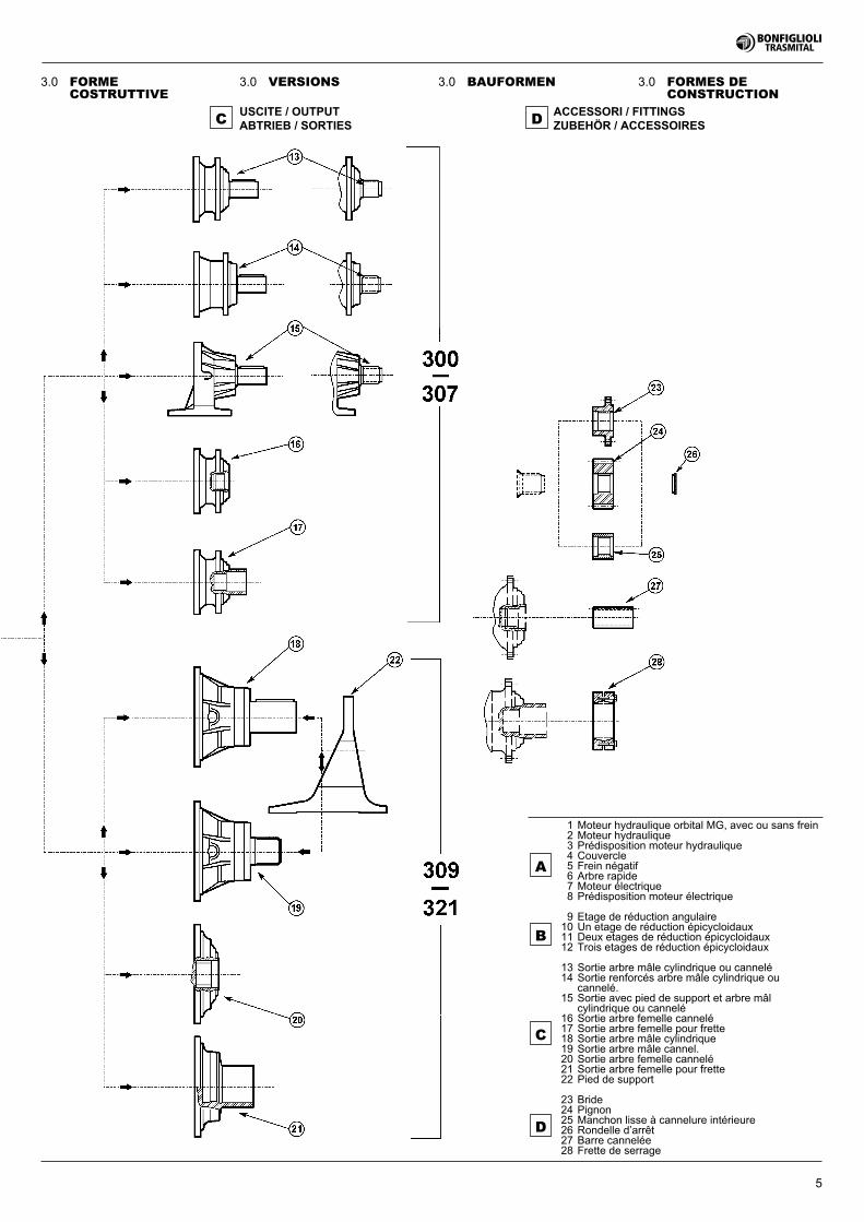
ACCESSORI / FITTINGSZUBEHÖR / ACCESSOIRES
USCITE / OUTPUTABTRIEB / SORTIESC D
1 Moteur hydraulique orbital MG, avec ou sans frein2 Moteur hydraulique3 Prédisposition moteur hydraulique4 Couvercle5 Frein négatif6 Arbre rapide7 Moteur électrique8 Prédisposition moteur électrique
9 Etage de réduction angulaire10 Un etage de réduction épicycloidaux11 Deux etages de réduction épicycloidaux12 Trois etages de réduction épicycloidaux
13 Sortie arbre mâle cylindrique ou cannelé14 Sortie renforcés arbre mâle cylindrique ou
cannelé.15 Sortie avec pied de support et arbre mâl
cylindrique ou cannelé16 Sortie arbre femelle cannelé17 Sortie arbre femelle pour frette18 Sortie arbre mâle cylindrique19 Sortie arbre mâle cannel.20 Sortie arbre femelle cannelé21 Sortie arbre femelle pour frette22 Pied de support
23 Bride24 Pignon25 Manchon lisse à cannelure intérieure26 Rondelle d’arrêt27 Barre cannelée28 Frette de serrage
C
B
D
A
6
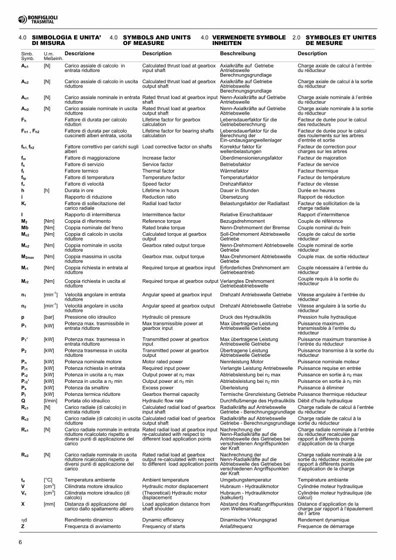
4.0 SIMBOLOGIA E UNITA’DI MISURA
Simb.Symb.
U.m.Meßeinh.
Descrizione Description Beschreibung Description
Ac1 [N] Carico assiale di calcolo inentrata riduttore
Calculated thrust load at gearboxinput shaft
Axialkräfte auf GetriebeAntriebswelleBerechnungsgrundlage
Charge axiale de calcul à l’entréedu réducteur
Ac2 [N] Carico assiale di calcolo in uscitariduttore
Calculated thrust load at gearboxoutput shaft
Axialkräfte auf GetriebeAbtriebswelleBerechnungsgrundlage
Charge axiale de calcul à la sortiedu réducteur
An1 [N] Carico assiale nominale in entratariduttore
Rated thrust load at gearbox inputshaft
Nenn-Axialkräfte auf GetriebeAntriebswelle
Charge axiale nominale à l’entréedu réducteur
An2 [N] Carico assiale nominale in uscitariduttore
Rated thrust load at gearboxoutput shaft
Nenn-Axialkräfte auf GetriebeAbtriebswelle
Charge axiale nominale à la sortiedu réducteur
Fh Fattore di durata per calcoloriduttori
Lifetime factor for gearboxcalculation
Lebensdauerfaktor für dieGetriebeberechnung
Facteur de durée pour le calculdes reducteurs
Fh1 , Fh2 Fattore di durata per calcolocuscinetti alberi entrata, uscita
Lifetime factor for bearing shaftscalculation
Lebensdauerfaktor für dieBerechnung derEin-undausgangwellenlager
Facteur de durée pour le calculdes roulements sur les arbresd’entrée et sortie
fh1, fh2 Fattore correttivo per carichi suglialberi
Load corrective factor on shafts Korrektur faktor fürwellenbelastungen
Facteur de correction pourcharges sur les arbres
fm Fattore di maggiorazione Increase factor Überdimensionierungsfaktor Facteur de majorationfs Fattore di servizio Service factor Betriebsfaktor Facteur de serviceft Fattore termico Thermal factor Wärmefaktor Facteur thermiqueftp Fattore di temperatura Temperature factor Temperaturfaktor Facteur de températurefv Fattore di velocità Speed factor Drehzahlfaktor Facteur de vitesseh [h] Durata in ore Lifetime in hours Dauer in Stunden Durée en heuresi Rapporto di riduzione Reduction ratio Übersetzung Rapport de réductionKr Fattore di sollecitazione del
carico radialeRadial load factor Belastungsfaktor der Radiallast Facteur de sollicitation de la
charge radialeI Rapporto di intermittenza Intermittence factor Relative Einschaltdauer Rapport d’intermittenceM2 [Nm] Coppia di riferimento Reference torque Bezugsdrehmoment Couple de référenceMb [Nm] Coppia nominale del freno Rated brake torque Nenn-Drehmoment der Bremse Couple nominal du freinMc2 [Nm] Coppia di calcolo in uscita
riduttoreCalculated torque at gearboxoutput
Soll-Drehmoment AbtriebswelleGetriebe
Couple de calcul de sortieréducteur
Mn2 [Nm] Coppia nominale in uscitariduttore
Gearbox rated output torque Nenn-Drehmoment AbtriebswelleGetriebe
Couple nominal de sortieréducteur
M2max [Nm] Coppia massima in uscitariduttore
Gearbox max. output torque Max-Drehmoment AbtriebswelleGetriebe
Couple max. de sortie réducteur
Mr1 [Nm] Coppia richiesta in entrata alriduttore
Required torque at gearbox input Erforderliches Drehmoment amGetriebeantrieb
Couple nécessaire à l’entrée duréducteur
Mr2 [Nm] Coppia richiesta in uscita alriduttore
Required torque at gearbox output Verlangtes DrehmomentGetriebeabtriebswelle
Couple requis à la sortie duréducteur
n1 [min-1] Velocità angolare in entratariduttore
Angular speed at gearbox input Drehzahl Antriebswelle Getriebe Vitesse angulaire à l’entrée duréducteur
n2 [min-1] Velocità angolare in uscitariduttore
Angular speed at gearbox output Drehzahl Abtriebswelle Getriebe Vitesse angulaire à la sortie duréducteur
p [bar] Pressione olio idraulico Hydraulic oil pressure Druck des Hydrauliköls Pression huile hydraulique
P1 [kW] Potenza max. trasmissibile inentrata riduttore
Max transmissible power atgearbox input
Max übertragene LeistungAntriebswelle Getriebe
Puissance maximumtransmissible à l’entrée duréducteur
P1‘ [kW] Potenza max. trasmessa inentrata riduttore
Transmitted power at gearboxinput
Max übertragene LeistungAntriebswelle Getriebe
Puissance maximum transmise àl’entrée du réducteur
P2 [kW] Potenza trasmessa in uscitariduttore
Transmitted power at gearboxoutput
Übertragene LeistungAbtriebswelle Getriebe
Puissance transmise à la sortie duréducteur
Pn [kW] Potenza nominale motore Motor rated power Nennleistung Motor Puissance nominale moteurPr1 [kW] Potenza richiesta in entrata Required input power Verlangte Leistung Antriebswelle Puissance requise en entréePr2 [kW] Potenza in uscita a n2 max Output power at n2 max Abtriebsleistung bei n2 max Puissance en sortie à n2 maxPr2‘ [kW] Potenza in uscita a n2 min Output power at n2 min Abtriebsleistung bei n2 min Puissance en sortie à n2 minPs [kW] Potenza da smaltire Excess power Überleistung Puissance à éliminerPt [kW] Potenza termica riduttore Gearbox thermal capacity Termische Grenzleistung Getriebe Puissance thermique réducteurQ [l/min] Portata olio idraulico Hydraulic flow rate Durchflußmenge des Hydrauliköls Débit d’huile hydrauliqueRc1 [N] Carico radiale (di calcolo) in
entrata riduttoreCalculated radial load of gearboxinput shaft
Radialkräfte auf AntriebswelleGetriebe - Berechnungsgrundlage
Charge radiale de calcul à l’entréedu réducteur
Rc2 [N] Carico radiale (di calcolo) in uscitariduttore
Calculated radial load of gearboxoutput shaft
Radialkräfte auf AbtriebswelleGetriebe - Berechnungsgrundlage
Charge radiale de calcul à lasortie du réducteur
Rx1 [N] Carico radiale nominale in entratariduttore ricalcolato rispetto adiversi punti di applicazione delcarico
Rated radial load at gearbox inputre-calculated with respect todifferent load application points
Nachrechnung derNenn-Radialkräfte auf dieAntriebswelle des Getriebes beiverschiedenen Angriffspunktender Kraft
Charge radiale nominale à l’entréedu réducteur recalculée parrapport à différents pointsd’application de la charge
Rx2 [N] Carico radiale nominale in uscitariduttore ricalcolato rispetto adiversi punti di applicazione delcarico
Rated radial load at gearboxoutput re-calculated with respectto different load application points
Nachrechnung derNenn-Radialkräfte auf dieAbtriebswelle des Getriebes beiverschiedenen Angriffspunktender Kraft
Charge radiale nominale à lasortie du réducteur recalculée parrapport à différents pointsd’application de la charge
ta [°C] Temperatura ambiente Ambient temperature Umgebungstemperatur Température ambianteV [cm3] Cilindrata motore idraulico Hydraulic motor displacement Hubraum - Hydraulikmotor Cylindrée moteur hydrauliqueVc [cm3] Cilindrata motore idraulico (di
calcolo)(Theoretical) Hydraulic motordisplacement
Hubraum - Hydraulikmotor(kalkuliert)
Cylindrée moteur hydraulique (decalcul)
X [mm] Distanza di applicazione delcarico dallo spallamento albero
Load application distance fromshaft shoulder
Abstand des Kraftangriffspunktesvom Wellenansatz
Distance d’application de lacharge par rapport à l’épaulementde l’ arbre
�d Rendimento dinamico Dynamic efficiency Dinamische Virkungsgrad Rendement dynamiqueZ Frequenza di avviamento Frequency of starts Anlaßfrequenz Frequence de démarrage
4.0 SYMBOLS AND UNITSOF MEASURE
4.0 VERWENDETE SYMBOLEINHEITEN
2.0 SYMBOLES ET UNITESDE MESURE

7
Cover for standard input flanging.
Die durch die schwarze Farbehervorgehobenen Teile, stellendie Antriesseiten der Getriebedar.
Symbol referring to weight ofgearboxes.
This symbol identifies referencepage number.
Symbol für das Gewicht der Ge-triebe.
In diesem Symbol wird eine Num-mer angegeben, die für die ent-sprechende Bezugsseite steht.
Symbole se référant aux poidsdes réducteurs.
Cette image comporte un chiffrereprésentsant le numéro de pagede référence.
Simbolo riferito ai pesi dei ridutto-ri.
Negative multidisc brake.
Inline units.
Right angle units.
Hydraulic motor connection.
Negative Lamellenbremse. Frein multidisques négatif.Freno negativo a dischi multipli.
Eingangsflansch für Hydraulikmo-tor.
Adaptation pour moteur hydrau-lique.
Predisposizione motore idraulico.
Koaxialgetriebe.
Winkelgetriebe.
Exécution coaxiale.
Exécution angulaire.
Esecuzione in linea.
Esecuzione angolare.
Deckel für Antriebsflansche,Standardausführung.
Couvercle pour bridage d’ uneentrée standard.
Coperchio per flangiatura in in-gresso standard.
Le colonne contrassegnate daquesto simbolo indicano i numeridi pagina dove sono riportate ledimensioni.
Columns marked with this symbolindicate the reference pageshowing dimensions.
Die mit diesem Symbol gekenn-zeichneten Spalten geben dieNummern der Seiten mit denMaßangaben.
Les colonnes portant ce symboleindiquent les numéros de pageoù sont mentionnées les dimen-sions.
Questo simbolo riporta un nume-ro che rappresenta il numero dipagina di riferimento.
Durch diese Symbole werden dieMontage punkte für die Zubehör-teile hervorgehoben.
Das an eine Nummer gebundeneSchlüsselsymbol steht für denAnzugsmoment der Schraubender Reibeverbindung.
Le parti in nero di questi simbolievidenziano la collocazione delleentrate dei riduttori.
Questi simboli evidenziano il pun-to di montaggio degli accessori.
Il simbolo della chiave associatoad un numero indica la coppia diserraggio delle viti del giunto adattrito.
Les parties noires de ces imagesmontrent l’emplacement des en-trées des réducteurs.
Ces images montrent la positionde montage des accessoires.
L’image de la clé associée à unnuméro signale le couple de ser-rage des vis du joint à frottement.
These symbols identify the posi-tion of gearbox input (black-filledareas).
These symbols identify themounting positions of accesso-ries.
The number associated with thewrench symbol indicates thetightening torque for friction cou-pling screws.

8
5.0 COPPIA IN USCITA
5.1 Coppia di riferimentoM2 [Nm]
È un valore di coppia in uscita in-dicativo per una rapida individua-zione della classe di prestazionedi ogni grandezza base di ridutto-re.
5.2 Coppia nominaleMn2 [Nm]
È la coppia nominale trasmissibi-le in uscita dal riduttore con cari-co continuo uniforme, fattore diservizio fs=1, per diversi valori fis-sati del fattore di durata (n2 • h).I valori di Mn2 sono verificati se-condo i seguenti standard:ISO DP 6336 per gli ingranaggiISO 281 per i cuscinetti.
5.3 Coppia massimaM2max [Nm]
È il valore di coppia in uscita sop-portabile sopportabile dal ridutto-re in condizioni statiche o forte-mente intermittenti.(Inteso come coppia di punta dicarico istantaneo o come coppiadi avviamento sotto carico).
5.4 Coppia richiestaMr2 [Nm]
Rappresenta la coppia richiestadall’applicazione e dovrà sempreessere uguale o inferiore allacoppia in uscita nominale Mn2del riduttore scelto.
5.5 Coppia di calcoloMc2 [Nm]
È il valore di coppia da utilizzareper la selezione del riduttore con-siderando la coppia richiesta Mr2e il fattore di servizio fs (tab. A3)ed è dato dalla formula:
I paragrafi che seguono riportanouna serie di informazioni suglielementi indispensabili per lascelta e il corretto utilizzo deimotoriduttori.
GENERAL INFORMATION ALLGEMEINE INFORMATIONEN INFORMATIONS GENERALESINFORMAZIONI GENERALI
The following paragraphs containinformation on essential elementsfor selection and correct use ofgearmotors.
5.0 OUTPUT TORQUE
5.1 Reference torqueM2 [Nm]
Indicative output torque to easilyestablish the performance classfor each gearbox basic size.
5.2 Nominal torqueMn2 [Nm]
Torque transmitted at output atuniform continuous load, servicefactor fs=1 for different fixed val-ues of the life factor (n2 • h).The Mn2 values are tested inconformity with the followingstandars:ISO DP 6336 for reduction unitsISO 281 for bearings.
5.3 Maximun torqueM2max [Nm
It is the output torque that the re-duction unit can withstand instatic or highly intermittent condi-tions. (It is considered as instan-taneous load peak torque orstarting torque under load).
5.4 Required torqueMr2 [Nm]
This is the torque correspondingto application requirements. Itmust always be equal to or lessthan rated output torque Mn2 ofthe selected gearbox.
5.5 Calculated torqueMc2 [Nm]
Torque value to be used for se-lecting the gearbox, consideringrequired torque Mr2 and servicefactor fs (tab. A3), and is obtainedby formula:
Die folgenden Abschnitte enthal-ten eine Reihe von Informationenüber die Aspekte, die im Hinblickauf die Wahl und dem sachgemä-ßen Betrieb von Getriebemotorenunbedingt zu berücksichtigen sind.
Les paragraphes qui suivent pré-sentent une série d’informationssur les éléments indispensablespour le choix et l’utilisation cor-recte des motoréducteurs.
5.0 COUPLE EN SORTIE
5.1 Couple de référenceM2 [Nm]
Est une valeur de couple ensortie indicative pour une identifi-cation rapide de la classe de per-formance pour chaque taille debase de réducteur.
5.2 Couple nominalMn2 [Nm]
Est le couple nominal transmis-sible à la sortie du réducteur avecune charge uniforme et continue,facteur de service fs=1, pour diffé-rentes valeurs fixées du facteurde durée (n2 • h).Les valeurs de Mn2 sont vérifiéesselon les normes suivantes:ISO DP 6336 pour les engrenagesISO 281 pour les roulements.
5.3 Couple maximalM2max [Nm]
C’est la valeur de couple ensortie que le réducteur peut sup-porter dans des conditions stati-ques ou de forte intermittence(considérée en tant que couplede pointe de charge instantanéeou couple de démarrage encharge).
5.4 Couple requisMr2 [Nm]
Il représente le couple requis parl’ application et devra toujoursêtre inférieur ou égal au coupleen sortie nominal Mn2 du réduc-teur choisi.
5.5 Couple de calculMc2 [Nm]
C’est la valeur de couple à utiliserpour la sélection du réducteur enconsidérant le couple requis Mr2et le facteur de service fs (tab.A3); elle résulte de la formule sui-vante:
5.0 ABTRIEBSMOMENT
5.1 BezugsdrehmomentM2 [Nm]
Ist ein indikativer Wert eines Ab-triebdrehmoments, der einschnelles Auffinden der Lei-stungsklasse jeder Getriebe-grundbaugröße ermöglicht.
5.2 NenndrehmomentMn2 [Nm]
Ist das vom Getriebe am Abtriebübertragbare Nenndrehmomentbei einer gleichmäßigen Dauer-belastung, Betriebsfaktor fs = 1,für verschiedene festgelegteWerte des Dauerfaktors (n2 • h).Die Werte Mn2 werden den fol-genden Normen gemäß geprüft:ISO DP 6336 für ZahnräderISO 281 für Lager.
5.3 Maximales DrehmomentM2max [Nm]
Stellt den Wert des Abtriebdreh-moments dar, mit dem das Ge-triebe in statischen oder Bedin-gungen mit häufigen Schaltungenbelastet werden kann. (Wird alsaugenblicklicher Spitzendrehmo-ment oder als Anlaßdrehmomentunter Last verstanden).
5.4 Verlangtes DrehmomentMr2 [Nm]
Dies ist das von der Anwendungverlangte Drehmoment, das stetskleiner oder gleich dem Nenn-Ab-triebsmoment Mn2 des gewähl-ten Getriebes sein muß.
5.5 Soll-DrehmomentMc2 [Nm]
Ist der Drehmomentenwert, derfür die Wahl des getriebemotorsunter Berücksichtigung des erfor-derlichen Drehmoments Mr2 unddes Betriebsfaktors fs (tab. A3)verwendet wird. Er wird von fol-gender Formel gegeben:
6.0 POTENZA
6.1 Potenza in entrataP1 [kW]
La potenza P1 indicata nelle ta-belle dati tecnici di ogni grandez-za di riduttore, è quella trasmissi-bile in entrata in maniera intermit-tente o continua alle seguenticondizioni:
Velocità in ingresso n1Durata teorica 1000 hFattore di servizio fs=1
6.0 POWER
6.1 Input rated powerP1 [kW]
Power P1 indicated in the specifi-cation tables for each gearboxsize is either the intermittent orcontinuous power which can betransmitted at the gearbox inputunder the following conditions:
input speed n1theoretical duration 1000 hservice factor fs=1
6.0 LEISTUNG
6.1 Leistung AntriebswelleP1 [kW]
P1 Die in den Tabellen der techni-schen Daten für jede Getriebegrö-ße angegebene Leistung P1 ent-spricht der Leistung, die unter denfolgenden Bedingungen im An-trieb kontinuierlich oder im Schalt-betrieb übertragbar ist:
Antriebsdrehzahl n1Theoretische Dauer: 1000 stundenBetriebsfaktor fs=1
6.0 PUISSANCE
6.1 Puissance en entréeP1 [kW]
Comme indiqué aux tableaux desdonnées tecniques, pour chaquetaille de réducteur, la puissanceP1 est transmissible en entrée demanière intermittente ou continueaux conditions suivantes:
vitesse d'entrée n1durée théorique 1000 heuresfacteur de service fs=1
dove Mn2 è il valore corrisponden-te al fattore di durata (n2 • h) ca-ratteristico dell’applicazione.
où Mn2 représente la valeur cor-respondant au facteur de durée(n2 • h) caractéristique de l’appli-cation.
wo Mn2 der Wert ist, der demDauerfaktor (n2 • h) entspricht,der für die Applikationsart charak-teristisch ist.
where Mn2 is the value for thespecific application taking intoconsideration the life factor (n2 • h).
Mc2 = Mr2 • fs < Mn2 (1)
9
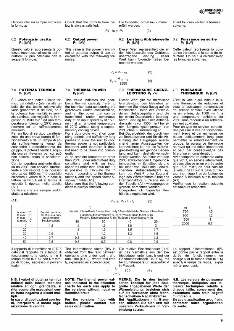
7.0 POTENZA TERMICAPt [kW]
È il valore che indica il limite ter-mico del riduttore (riferirsi alle ta-belle dei dati tecnici relative allevarie grandezze di riduttori) ed èla potenza trasmissibile in servi-zio continuo con velocità n1 in in-gresso di 1500 min-1 ad una tem-peratura ambiente di 20°C senzaricorrere ad un raffreddamentoausiliario.Per un tipo di servizio caratteriz-zato da una breve durata di fun-zionamento e da un tempo di so-sta sufficientemente lungo daconsentire il raffreddamento delgruppo, la potenza termica acqui-sta scarsa rilevanza per cui puònon essere tenuta in considera-zione.Con temperatura ambiente diver-sa da 20°C, con servizio intermit-tente e con velocità n1 in ingressodiversa da 1500 min-1 è possibilecalcolare il valore di Pt in base alfattore termico ft ed al fattore divelocità fv riportati nella tabella(A1).Verificare che sia sempre soddi-sfatta la relazione.
ft
ta max. [°C]ta max. [°C]ta max. [°C]ta maxi. [°C]
Servizio continuoContinuous dutyDauerbetriebService continu
Servizio intermittente / Intermittent duty / Aussetzbetrieb / Service intermittentRapporto di intermittenza % (I) / Cyclic duration factor % (I)Relative Einschaltdauer % (I) / Rapport d’intermittence % (l)
80 60 40 2010 1.2 1.3 1.6 1.8 220 1 1.1 1.3 1.5 1.730 0.9 1 1.2 1.3 1.540 0.7 0.8 0.9 1 1.250 0.5 0.6 0.7 0.8 0.9
(A1)
6.2 Potenza in uscitaP2 [kW]
Questo valore rappresenta la po-tenza trasmessa all’uscita del ri-duttore. Si può calcolare con leseguenti formule:
6.2 Output powerP2 [kW]
This value is the power transmit-ted at gearbox output. It can becalculated with the following for-mulas:
7.0 THERMAL POWERPt [kW]
This value indicates the gear-box’s thermal capacity (refer tothe technical data concerning thegearboxes under consideration)and is the power that can betransmitted under continuousduty at an input speed n1 of 1500min-1 at an ambient temperatureof 20°C without using a supple-mentary cooling device.For a duty cycle with short oper-ating periods and sufficiently longpauses to allow the unit to cool,thermal power is not particularlyimportant and therefore it doesnot need to be taken into consid-eration.At an ambient temperature otherthan 20°C under intermittent dutyconditions and with an inputspeed n1 other than 1500 min-1 itis possible to calculate the Ptvalue according to the thermalfactor ft and the speed factor fv,shown in table (A1).Make sure that the following con-dition is always satisfied.
6.2 Leistung AbtriebswelleP2 [kW]
Dieser Wert repräsentiert die ander Abtriebswelle des Getriebesübertragene Leistung. DieserWert kann folgendermaßen be-rechnet werden:
6.2 Puissance en sortieP2 [kW]
Cette valeur représente la puis-sance transmise à la sortie du ré-ducteur. On peut la calculer avecles formules suivantes:
I =t f
f rt t�
• 100 (6)
PM n
9550r2
22
�•
(4)
P2 = P1 • �d (3)
Il rapporto di intermittenza (I)% èdato dal rapporto fra il tempo difunzionamento a carico tf e iltempo totale (tf + tr), con tr = tem-po di riposo, espresso in percen-tuale:
The intermittance factor (I)% isobtained from the ratio betweenoperating time under load tf andtotal time (tf + tr), where rest timetr, expressed as a percentage:
Die relative Einschaltdauer (l) %ist das Verhältnis aus der Be-triebsdauer unter Last tf und derGesamtbetriebszeit (tf + tr), mittr= Ruhetemperatur, ausgedrücktin Prozent:
Le rapport d’intermittence (l)%est donné par le rapport entre ladurée de fonctionnement encharge tf et le temps total (tf + tr)avec tr = temps de repos, expri-mé en pour cent:
Pr1 � Pt • ft • fv (5)
N.B. I valori di potenza termicaindicati nelle tabelle tecnicherelative ad ogni grandezza, siriferiscono alle esecuzioni sen-za freno negativo a dischi mul-tipli.In caso di applicazioni con fre-ni, interpellare la nostra orga-nizzazione di vendita.
7.0 THERMISCHE GRENZ-LEISTUNG Pt [kW]
Dieser Wert gibt die thermischeGrenzleistung des Getriebes an(nehmen Sie hierzu Bezug auf dietechnischen Daten der verschie-denen Getriebegrößen) und diebei einem Dauerbetrieb übertrag-baren Leistung bei einer Antriebs-drehzahl n1 von 1500 min-1 bei ei-ner Umgebungstemperatur von20°C ohne Zusatzkühlung an.Bei Dauerbetrieb, der durch kur-ze Betriebszeiten und für die Ab-kühlung der Baugruppe ausrei-chend lange Aussetzzeiten ge-kennzeichnet ist, hat die Wärme-grenzleistung nur geringe Bedeu-tung und kann deshalb vernach-lässigt werden. Bei einer von den20°C abweichenden Umgebungs-temperatur, im Schaltbetrieb undbei einer von 1500 min-1 abwei-chenden Antriebsdrehzahl n1,kann der Wert Pt unter Zugrund-lage des Wärmefaktors ft und desDrehzahlfaktors fv, Werte die inder Tabelle (A1) wiedergegebenwerden, berechnet werden.Überprüfen, ob folgendes Ver-hältnis eingehalten wird.
7.0 PUISSANCETHERMIQUE Pt [kW]
C’est la valeur qui indique la li-mite thermique du réducteur etc’est la puissance transmissibleen service continu avec vitessen1 en entrée, de 1500 min-1, àune température ambiante de20°C sans recourir à un refroidis-sement auxiliaire.Pour un type de service caracté-risé par une durée de fonctionne-ment brève et par un temps depause suffisamment long pourpermettre le refroidissement dugroupe, la puissance thermiquene revet qu’une faible importanceet peut par conséquent,ne pasêtre prise en considération.Avec température ambiente autreque 20°C, en service intermittent,et avec vitesse n1 en entrée autreque 1500 min-1, on peut calculerla valeur de Pt sur la base du fac-teur thermique ft et du facteur devitesse fv indiqués sur le tableau(A1).Vérifier que la relation suivanteest toujours respectée.
NOTE: The thermal power val-ues indicated in the selectioncharts for each size apply tothe versions without negativemultidisc brake.
For the versions fitted withbrakes, please contact oursales organization.
MERKE: Die in den techni-schen Tabellen für jede Bau-größe angegebenen Werte derWärmeleistung, beziehen sichauf die Versionen ohne Mehr-fachscheiben- Negativbremse.Bei Applikationen mit Brem-sen, müssen Sie sich erst mitunserem Verkaufsnetz in Ver-bindung setzen.
N.B. Les valeurs de puissancethermique, indiquées aux ta-bleaux techniques relatifs àchaque taille, concernent desexécutions sans frein négatifmultidisque.En cas d’application avec frein,contacter notre organisationde vente.
n1 fv
750 1.5950 1.21500 12000 0.7
Occorre che sia sempre verificatala formula:
Check that the formula here be-low is always satisfied:
Die folgende Formel muß immererfüllt werden:
Il faut toujours vérifier la formulesuivante:
P1‘ • fs � P1 (2)
10
10.0 VELOCITÀ ANGOLARE
10.1 Velocità in entratan1 [min-1]
È la velocità del motore di azio-namento nel caso in cui questosia collegato direttamente in asseal riduttore. Oppure quella risul-tante sempre dal motore e daeventuali rapporti di trasmissionenel caso di azionamento indiretto,ad esempio con cinghie.
La velocità in ingresso non devemai superare i valori indicati nelletabelle dati tecnici dei riduttori.
Per funzionamento in continuo inapplicazioni industriali è racco-mandabile non superare la velo-cità di 1750 min-1.
10.2 Velocità in uscitan2 [min-1]
È in funzione della velocità in en-trata n1 e del rapporto di riduzio-ne i secondo la relazione:
8.0 RENDIMENTO
8.1 Rendimentodinamico �d
È dato dal rapporto fra la potenzain uscita P2 e quella in entrata P1secondo la relazione:
8.0 EFFICIENCY
8.1 Dynamic efficiency �d
Obtained from the ratio of outputpower P2 to input power P1 ac-cording to the following equation:
Its value is a function of thetrasmitted power, the speed, thereduction ratio and oil tempera-ture and viscosity.The maximum efficiency valuesare shown in the table (A2) be-low.
10.0 ANGULAR SPEED
10.1 Input speedn1 [min -1]
Refers to the speed of motor ifmotor is directly connected togearbox. In the case of an indi-rect drive, this value is the speedof the motor divided by the trans-mission ratio of the indirect driveaccessory (belt, chain, etc.).
Input speed should exceed thevalues indicated in the tables ongearbox technical features.
As for continuous operation in in-dustrial applications, we recom-mend that speed of 1750 min-1 benever exceeded.
10.2 Output speedn2 [min-1]
Calculated from input speed n1and transmission ratio i accordingto the following equation:
8.0 WIRKUNGSGRAD
8.1 DynamischerWirkungsgrad �d
Er ist gegeben durch das Verhält-nis der Abtriebsleistung P2 zurAntriebsleistung P1:
Sein Wert hängt von der übertragenen Leistung, der Drehzahl,dem Übersetzungsverhältnis undder Temperatur, darüber hinausvon der Öltemperatur ab.Die Werte des max. Wirkungs-grads werden in der in Folge an-geführten Tabelle (A2) angege-ben.
10.0 DREHZAHL
10.1 Drehzahl Antriebswellen1 [min -1]
Ist die Geschwindigkeit des An-triebsmotors, wenn dieser direktauf Achse mit dem Getriebe ver-bunden ist. Kann aber auch dieGeschwindigkiet darstellen, diesich immer aus dem Motor undaus eventuellen Übersetzungs-verhältnissen im Fall eines indi-rekten Antriebs ergibt, z.B. bei ei-nem Riemenantrieb.
Die Antriebsgeschwindigkeit darfdie in den Tabellen der Getriebeangebenen Werte nie überschrei-ten.
Bei einem Dauerbetrieb im indu-striellen Einsatz wird empfohlen,die Geschwindigkeit von 1750min-1 nicht zu überschreiten.
10.2 Abtriebsdrehzahln2 [min-1]
Sie ist abhängig von der An-triebsdrehzahl n1 und der Über-setzung i nach folgender Glei-chung:
8.0 RENDEMENT
8.1 Rendementdynamique �d
Il est donné par le rapport entrela puissance en sortie P2 et celleen entrée P1:
Sa valeur dépend de la puis-sance transmise, de la vitesse,du rapport et de la température,ainsi que viscosité, de l’huile.Les valeurs max. de rendementsont indiquées sur le tableau (A2)suivant.
10.0 VITESSE ANGULAIRE
10.1 Vitesse d’ entréen1 [min-1]
C’est la vitesse du moteur d’en-traînement, au cas où celui-ci se-rait directement accouplé au ré-ducteur de manière axiale. Oubien la vitesse débouchant tou-jours du moteur, et des rapportsde transmission éventuels, encas d’entraînement indirect parexemple par courroies.
La vitesse en entrée ne doit ja-mais dépasser les valeurs indi-quées aux tableaux des donnéestechniques des réducteurs.
En cas de fonctionnement encontinu pour des applications in-dustrielles, on préconise de nepas dépasser la vitesse de 750min-1.
10.2 Vitesse en sortien2 [min-1]
Elle varie en fonction de la vi-tesse d’entrée n1 et du rapport dereduction i selon l’équation:
n2 �n
i1 (9)
�d =P
P2
1
(7)
i =n
n1
2
(8)
(A2)
N° stadi / N° stages / Anz. Stufen / Nombre d’étages de réductionL1 L2 - R2 L3 - R3 L4 - R40.97 0.94 0.91 0.88
9.0 RAPPORTO DIRIDUZIONE i
È il rapporto fra la velocitàd’entrata e d’uscita del riduttore.
9.0 REDUCTION RATIO i
This is the ratio of gearbox inputspeed to gearbox output speed.
9.0 ÜBERSETZUNG i
Ist das Verhältnis zwischen An-triebs- und Abtriebsdrehzahl desGetriebes.
9.0 RAPPORT DEREDUCTION i
Est le rapport entre la vitessed’entrée et de sortie du réduc-teur.
Il suo valore dipende dalla poten-za trasmessa, dalla velocità, dalrapporto, dalla temperatura e dal-la viscosità dell’olio.I valori max. di rendimento sonoriportati nella tabella (A2) se-guente.
11
12.0 LIFE FACTOR(Fh1, Fh2)
Factor resulting by multiplying an-gular speed at input (n1) or output(n2) by actual operating workinghours h, break times excluded.
(A3)
12.0 DAUERFAKTOR(Fh1, Fh2)
Ist ein vom Ergebnis aus derDrehzahl im Antrieb n1 oder amAbtrieb n2 für die effektiven Be-triebsstunden h, die Stillstands-zeiten ausgenommen, abgeleite-ter Faktor.
12.0 FACTEUR DEDUREE (Fh1, Fh2)
C’est un facteur découlant du ré-sultat de la vitesse angulaire enentrée n1 ou en sortie n2 mul-tipliée par les heures de serviceeffectif h, le temps d’arrêté toutexclus.
12.0 FATTORE DIDURATA (Fh1, Fh2)
È un fattore derivato dal prodottodella velocità angolare in entratan1 o in uscita n2 per le ore di ef-fettivo funzionamento h, esclusi itempi di sosta.
Fattori di servizio / Service factors / Betriebsfaktoren / Facteurs de service
Natura del caricoType of loadBelastungsartNature de la charge
Tipo di azionamentoType of drive unitAntriebsartType d’entrainement
N° avviamenti /hNumber of starts/hourSchaltungen/Std.N.bre démarrages/h
16 32 63 125 250
UniformeUniform loadGleichmäßigUniforme
Mot, elettrico / Electric motor / Elektromotor / Moteur electriqueMot. idraulico / Hydraulic motor / Hydraulikmotor / Mot. hydrauliqueMot. endotermico / Endothermic engine / Endotermischer Motor /Moteur endothermique
1.001.001.25
1.101.00—
1.151.10—
1.251.15—
1.401.20—
Variabile con urti moderatiModerate shock loadVariable mit mäßigen StößenVariable avec chocs modérés
Mot, elettrico / Electric motor / Elektromotor / Moteur electriqueMot. idraulico / Hydraulic motor / Hydraulikmotor / Mot. hydrauliqueMot. endotermico / Endothermic engine / Endotermischer Motor /Moteur endothermique
1.101.001.50
1.151.00—
1.201.10—
1.401.20—
1.601.30—
Variabile con urti fortiHeavy shock loadVariable mit starken StößenVariable avec chocs fort
Mot, elettrico / Electric motor / Elektromotor / Moteur electriqueMot. idraulico / Hydraulic motor / Hydraulikmotor / Mot. hydrauliqueMot. endotermico / Endothermic engine / Endotermischer Motor /Moteur endothermique
1.201.102.00
1.301.20—
1.401.25—
1.601.35—
1.801.50—
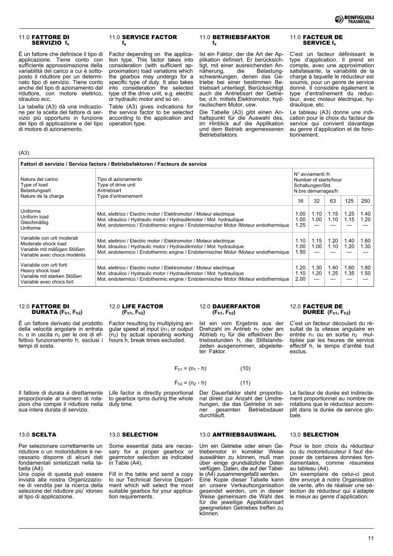
11.0 SERVICE FACTORfs
Factor depending on the applica-tion type. This factor takes intoconsideration (with sufficient ap-proximation) load variations whichthe gearbox may undergo for aspecific type of duty. It also takesinto consideration the selectedtype of the drive unit, e.g. electricor hydraulic motor and so on.
Table (A3) gives indications forthe service factor to be selectedaccording to the application andoperation type.
11.0 BETRIEBSFAKTORfs
Ist ein Faktor, der die Art der Ap-plikation definiert. Er berücksich-tigt, mit einer ausreichenden An-näherung, die Belastung-schwankungen, denen das Ge-triebe bei einer bestimmen Be-triebsart unterliegt. Berücksichtigtauch die Antriebsart der Getrie-be, d.h. mittels Elektromotor, hyd-raulischem Motor, usw.
Die Tabelle (A3) gibt einen An-haltspunkt für die Auswahl des,im Hinblick auf die Applikationund dem Betrieb angemessenenBetriebsfaktors.
11.0 FACTEUR DESERVICE fs
C’est un facteur définissant letype d’application. Il prend encompte, avec une approximationsatisfaisante, la variabilité de lacharge à laquelle le réducteur estsoumis, pour un genre de servicedonné. Il considère également letype d’entraînement du réduc-teur, avec moteur électrique, hy-draulique, etc.
Le tableau (A3) donne une indi-cation pour le choix du facteur deservice qui convient davantageau genre d’application et de fonc-tionnement.
11.0 FATTORE DISERVIZIO fs
È un fattore che definisce il tipo diapplicazione. Tiene conto consufficiente approssimazione dellavariabilità del carico a cui è sotto-posto il riduttore per un determi-nato tipo di servizio. Tiene contoanche del tipo di azionamento delriduttore, con motore elettrico,idraulico ecc.
La tabella (A3) dà una indicazio-ne per la scelta del fattore di ser-vizio più opportuno in funzionedel tipo di applicazione e del tipodi motore di azionamento.
13.0 SCELTA
Per selezionare correttamente unriduttore o un motoriduttore è ne-cessario disporre di alcuni datifondamentali sintetizzati nella ta-bella (A4).Una copia di questa può essereinviata alla nostra Organizzazio-ne di vendita per la ricerca dellaselezione del riduttore più’ idoneoal tipo di applicazione.
13.0 ANTRIEBSAUSWAHL
Um ein Getriebe oder einen Ge-triebemotor in korrekter Weiseauswählen zu können, muß manüber einige grundsätzliche Datenverfügen. Daten, die auf der Tabel-le (A4) zusammengefaßt werden.Eine Kopie dieser Tabelle kannan unsere Verkaufsorganisationgesendet werden, um in dieserWeise gemeinsam die Wahl desfür die jeweilige Applikationsartgeeignetsten Getriebes treffen zukönnen.
13.0 SELECTION
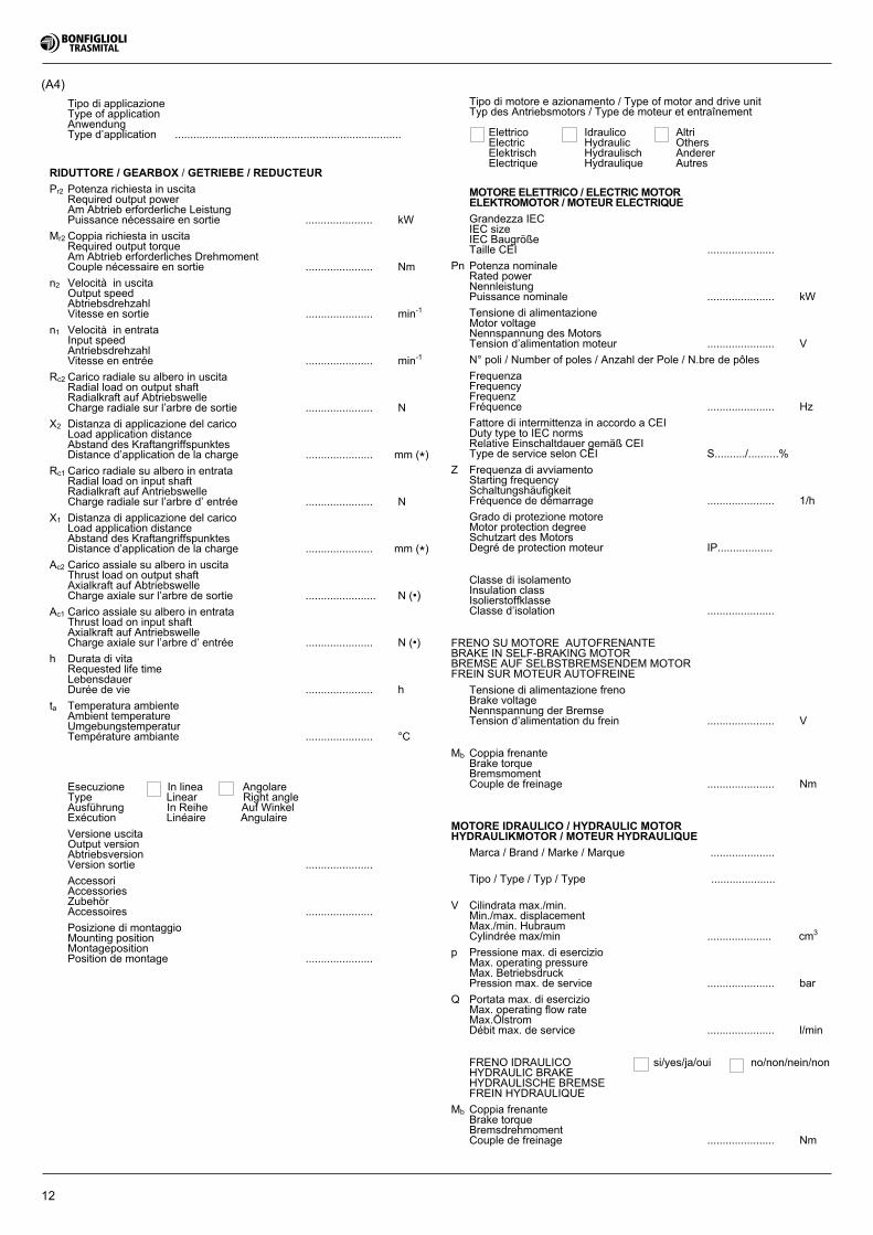
Some essential data are neces-sary for a proper gearbox orgearmotor selection as indicatedin Table (A4).
Fill in the table and send a copyto our Technical Service Depart-ment which will select the mostsuitable gearbox for your applica-tion requirements.
13.0 SELECTION
Pour le bon choix du réducteurou du motoréducuteur il faut dis-poser de certaines données fon-damentales, comme résuméesau tableau (A4).Un exemplaire de celui-ci peutêtre envoyé à notre Organisationde vente, afin de réaliser une sé-lection de réducteur qui s’adaptele mieux au genre d’application.
Il fattore di durata è direttamenteproporzionale al numero di rota-zioni che compie il riduttore nellasua intera durata di servizio.
Life factor is directly proportionalto gearbox rpms during the wholeduty time.
Der Dauerfaktor steht proportio-nal direkt zur Anzahl der Umdre-hungen, die das Getriebe in sei-ner gesamten Betriebsdauerdurchläuft.
Le facteur de durée est indirecte-ment proportionnel au nombre derotations que le réducteur accom-plit dans la durée de service glo-bale.
Fh2 = (n2 . h) (11)
Fh1 = (n1 . h) (10)
12
Tipo di applicazioneType of applicationAnwendungType d’application ..........................................................................
RIDUTTORE / GEARBOX / GETRIEBE / REDUCTEUR
Pr2 Potenza richiesta in uscitaRequired output powerAm Abtrieb erforderliche LeistungPuissance nécessaire en sortie ...................... kW
Mr2 Coppia richiesta in uscitaRequired output torqueAm Abtrieb erforderliches DrehmomentCouple nécessaire en sortie ...................... Nm
n2 Velocità in uscitaOutput speedAbtriebsdrehzahlVitesse en sortie ...................... min-1
n1 Velocità in entrataInput speedAntriebsdrehzahlVitesse en entrée ...................... min-1
Rc2 Carico radiale su albero in uscitaRadial load on output shaftRadialkraft auf AbtriebswelleCharge radiale sur l’arbre de sortie ...................... N
X2 Distanza di applicazione del caricoLoad application distanceAbstand des KraftangriffspunktesDistance d’application de la charge ...................... mm (*)
Rc1 Carico radiale su albero in entrataRadial load on input shaftRadialkraft auf AntriebswelleCharge radiale sur l’arbre d’ entrée ...................... N
X1 Distanza di applicazione del caricoLoad application distanceAbstand des KraftangriffspunktesDistance d’application de la charge ...................... mm (*)
Ac2 Carico assiale su albero in uscitaThrust load on output shaftAxialkraft auf AbtriebswelleCharge axiale sur l’arbre de sortie ....................... N (•)
Ac1 Carico assiale su albero in entrataThrust load on input shaftAxialkraft auf AntriebswelleCharge axiale sur l’arbre d’ entrée ...................... N (•)
h Durata di vitaRequested life timeLebensdauerDurée de vie ...................... h
ta Temperatura ambienteAmbient temperatureUmgebungstemperaturTempérature ambiante ...................... °C
Tipo di motore e azionamento / Type of motor and drive unitTyp des Antriebsmotors / Type de moteur et entraînement
Elettrico Idraulico AltriElectric Hydraulic OthersElektrisch Hydraulisch AndererElectrique Hydraulique Autres
MOTORE ELETTRICO / ELECTRIC MOTORELEKTROMOTOR / MOTEUR ELECTRIQUE
Grandezza IECIEC sizeIEC BaugrößeTaille CEI ......................
Pn Potenza nominaleRated powerNennleistungPuissance nominale ...................... kW
Tensione di alimentazioneMotor voltageNennspannung des MotorsTension d’alimentation moteur ...................... V
N° poli / Number of poles / Anzahl der Pole / N.bre de pôles
FrequenzaFrequencyFrequenzFréquence ...................... Hz
Fattore di intermittenza in accordo a CEIDuty type to IEC normsRelative Einschaltdauer gemäß CEIType de service selon CEI S........../..........%
Z Frequenza di avviamentoStarting frequencySchaltungshäufigkeitFréquence de démarrage ...................... 1/h
Grado di protezione motoreMotor protection degreeSchutzart des MotorsDegré de protection moteur IP..................
Classe di isolamentoInsulation classIsolierstoffklasseClasse d’isolation ......................
FRENO SU MOTORE AUTOFRENANTEBRAKE IN SELF-BRAKING MOTORBREMSE AUF SELBSTBREMSENDEM MOTORFREIN SUR MOTEUR AUTOFREINE
Tensione di alimentazione frenoBrake voltageNennspannung der BremseTension d’alimentation du frein ...................... V
Mb Coppia frenanteBrake torqueBremsmomentCouple de freinage ...................... Nm
MOTORE IDRAULICO / HYDRAULIC MOTORHYDRAULIKMOTOR / MOTEUR HYDRAULIQUE
Marca / Brand / Marke / Marque .....................
Tipo / Type / Typ / Type .....................
V Cilindrata max./min.Min./max. displacementMax./min. HubraumCylindrée max/min ..................... cm3
p Pressione max. di esercizioMax. operating pressureMax. BetriebsdruckPression max. de service ...................... bar
Q Portata max. di esercizioMax. operating flow rateMax.ÖlstromDébit max. de service ...................... l/min
FRENO IDRAULICO si/yes/ja/oui no/non/nein/nonHYDRAULIC BRAKEHYDRAULISCHE BREMSEFREIN HYDRAULIQUE
Mb Coppia frenanteBrake torqueBremsdrehmomentCouple de freinage ...................... Nm
Esecuzione In linea AngolareType Linear Right angleAusführung In Reihe Auf WinkelExécution Linéaire Angulaire
Versione uscitaOutput versionAbtriebsversionVersion sortie ......................
AccessoriAccessoriesZubehörAccessoires ......................
Posizione di montaggioMounting positionMontagepositionPosition de montage ......................
(A4)
13
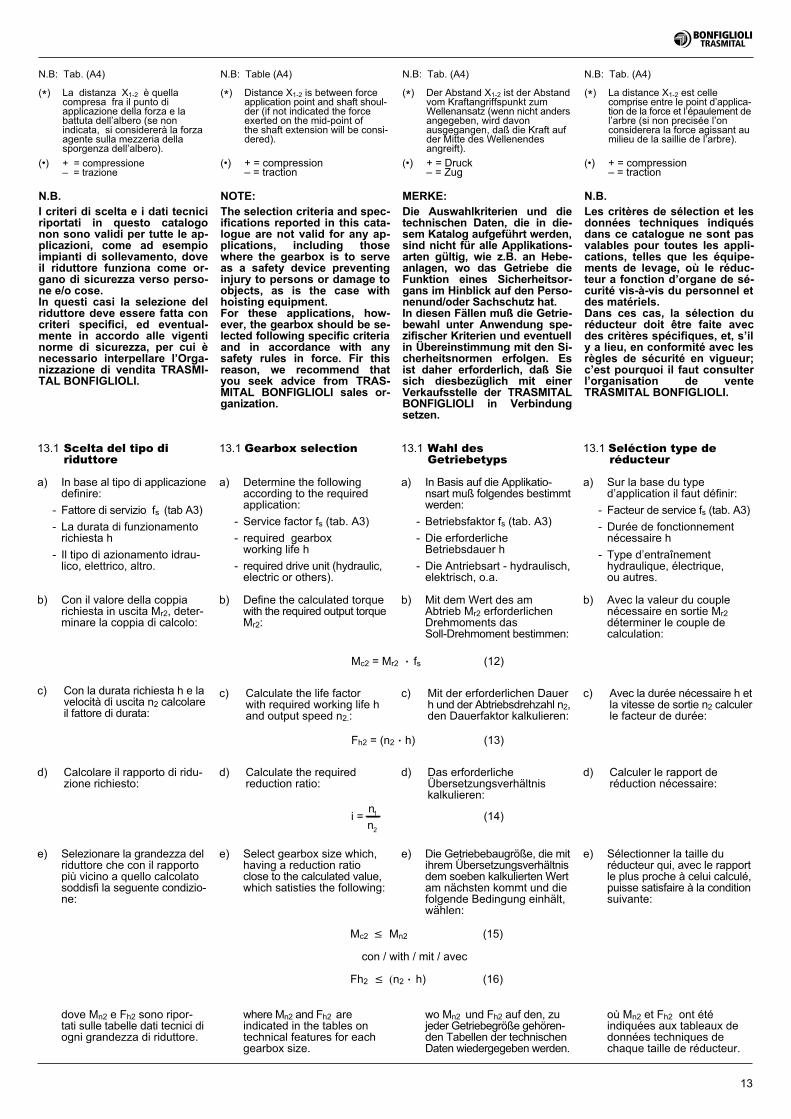
(*) La distanza X1-2 è quellacompresa fra il punto diapplicazione della forza e labattuta dell’albero (se nonindicata, si considererà la forzaagente sulla mezzeria dellasporgenza dell’albero).
(•) + = compressione– = trazione
(*) Der Abstand X1-2 ist der Abstandvom Kraftangriffspunkt zumWellenansatz (wenn nicht andersangegeben, wird davonausgegangen, daß die Kraft aufder Mitte des Wellenendesangreift).
(•) + = Druck– = Zug
(*) Distance X1-2 is between forceapplication point and shaft shoul-der (if not indicated the forceexerted on the mid-point ofthe shaft extension will be consi-dered).
(•) + = compression– = traction
(*) La distance X1-2 est cellecomprise entre le point d’applica-tion de la force et l’épaulement del’arbre (si non precisée l’onconsiderera la force agissant aumilieu de la saillie de l’arbre).
(•) + = compression– = traction
N.B: Table (A4) N.B: Tab. (A4) N.B: Tab. (A4)N.B: Tab. (A4)
13.1 Gearbox selection
a) Determine the followingaccording to the requiredapplication:
- Service factor fs (tab. A3)
- required gearboxworking life h
- required drive unit (hydraulic,electric or others).
b) Define the calculated torquewith the required output torqueMr2:
13.1 Wahl desGetriebetyps
a) In Basis auf die Applikatio-nsart muß folgendes bestimmtwerden:
- Betriebsfaktor fs (tab. A3)
- Die erforderlicheBetriebsdauer h
- Die Antriebsart - hydraulisch,elektrisch, o.a.
b) Mit dem Wert des amAbtrieb Mr2 erforderlichenDrehmoments dasSoll-Drehmoment bestimmen:
13.1 Seléction type deréducteur
a) Sur la base du typed’application il faut définir:
- Facteur de service fs (tab. A3)
- Durée de fonctionnementnécessaire h
- Type d’entraînementhydraulique, électrique,ou autres.
b) Avec la valeur du couplenécessaire en sortie Mr2déterminer le couple decalculation:
13.1 Scelta del tipo diriduttore
a) In base al tipo di applicazionedefinire:
- Fattore di servizio fs (tab A3)
- La durata di funzionamentorichiesta h
- Il tipo di azionamento idrau-lico, elettrico, altro.
b) Con il valore della coppiarichiesta in uscita Mr2, deter-minare la coppia di calcolo:
c) Calculate the life factorwith required working life hand output speed n2.:
d) Calculate the requiredreduction ratio:
Mc2 = Mr2 . fs (12)
Mc2 � Mn2 (15)
con / with / mit / avec
Fh2 � �n2 . h) (16)
e) Select gearbox size which,having a reduction ratioclose to the calculated value,which satisties the following:
i =n
n1
2
(14)
where Mn2 and Fh2 areindicated in the tables ontechnical features for eachgearbox size.
c) Mit der erforderlichen Dauerh und der Abtriebsdrehzahl n2,den Dauerfaktor kalkulieren:
c) Avec la durée nécessaire h etla vitesse de sortie n2 calculerle facteur de durée:
c) Con la durata richiesta h e lavelocità di uscita n2 calcolareil fattore di durata:
d) Das erforderlicheÜbersetzungsverhältniskalkulieren:
d) Calculer le rapport deréduction nécessaire:
d) Calcolare il rapporto di ridu-zione richiesto:
Fh2 = (n2 . h) (13)
e) Die Getriebebaugröße, die mitihrem Übersetzungsverhältnisdem soeben kalkulierten Wertam nächsten kommt und diefolgende Bedingung einhält,wählen:
e) Sélectionner la taille duréducteur qui, avec le rapportle plus proche à celui calculé,puisse satisfaire à la conditionsuivante:
e) Selezionare la grandezza delriduttore che con il rapportopiù vicino a quello calcolatosoddisfi la seguente condizio-ne:
wo Mn2 und Fh2 auf den, zujeder Getriebegröße gehören-den Tabellen der technischenDaten wiedergegeben werden.
où Mn2 et Fh2 ont étéindiquées aux tableaux dedonnées techniques dechaque taille de réducteur.
dove Mn2 e Fh2 sono ripor-tati sulle tabelle dati tecnici diogni grandezza di riduttore.
N.B.I criteri di scelta e i dati tecniciriportati in questo catalogonon sono validi per tutte le ap-plicazioni, come ad esempioimpianti di sollevamento, doveil riduttore funziona come or-gano di sicurezza verso perso-ne e/o cose.In questi casi la selezione delriduttore deve essere fatta concriteri specifici, ed eventual-mente in accordo alle vigentinorme di sicurezza, per cui ènecessario interpellare l’Orga-nizzazione di vendita TRASMI-TAL BONFIGLIOLI.
NOTE:The selection criteria and spec-ifications reported in this cata-logue are not valid for any ap-plications, including thosewhere the gearbox is to serveas a safety device preventinginjury to persons or damage toobjects, as is the case withhoisting equipment.For these applications, how-ever, the gearbox should be se-lected following specific criteriaand in accordance with anysafety rules in force. Fir thisreason, we recommend thatyou seek advice from TRAS-MITAL BONFIGLIOLI sales or-ganization.
MERKE:Die Auswahlkriterien und dietechnischen Daten, die in die-sem Katalog aufgeführt werden,sind nicht für alle Applikations-arten gültig, wie z.B. an Hebe-anlagen, wo das Getriebe dieFunktion eines Sicherheitsor-gans im Hinblick auf den Perso-nenund/oder Sachschutz hat.In diesen Fällen muß die Getrie-bewahl unter Anwendung spe-zifischer Kriterien und eventuellin Übereinstimmung mit den Si-cherheitsnormen erfolgen. Esist daher erforderlich, daß Siesich diesbezüglich mit einerVerkaufsstelle der TRASMITALBONFIGLIOLI in Verbindungsetzen.
N.B.Les critères de sélection et lesdonnées techniques indiquésdans ce catalogue ne sont pasvalables pour toutes les appli-cations, telles que les équipe-ments de levage, où le réduc-teur a fonction d’organe de sé-curité vis-à-vis du personnel etdes matériels.Dans ces cas, la sélection duréducteur doit être faite avecdes critères spécifiques, et, s’ily a lieu, en conformité avec lesrègles de sécurité en vigueur;c’est pourquoi il faut consulterl’organisation de venteTRASMITAL BONFIGLIOLI.
14
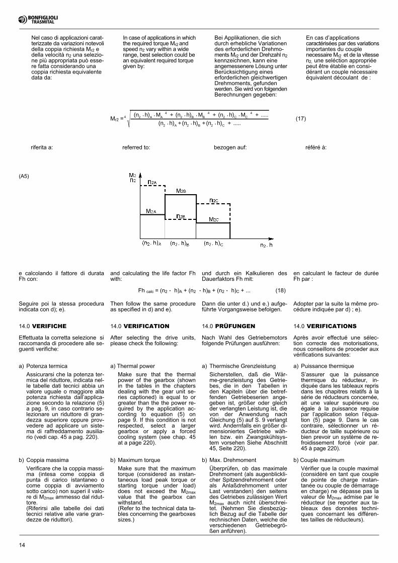
Fh calc = (n2 . h)A + (n2 . h)B + (n2 . h)C + ... (18)
Dann die unter d.) und e.) aufge-führte Vorgangsweise befolgen.
und durch ein Kalkulieren desDauerfaktors Fh mit:
Adopter par la suite la même pro-cédure indiquée par d) ; e).
en calculant le facteur de duréeFh par :
Seguire poi la stessa proceduraindicata con d); e).
e calcolando il fattore di durataFh con:
Then follow the same procedureas specified in d) and e).
and calculating the life factor Fhwith:
(A5)
referred to: bezogen auf: référé à:riferita a:
14.0 VERIFICHE
Effettuata la corretta selezione siraccomanda di procedere alle se-guenti verifiche:
a) Potenza termica
Assicurarsi che la potenza ter-mica del riduttore, indicata nel-le tabelle dati tecnici abbia unvalore uguale o maggiore allapotenza richiesta dall’applica-zione secondo la relazione (5)a pag. 9, in caso contrario se-lezionare un riduttore di gran-dezza superiore oppure prov-vedere ad applicare un siste-ma di raffreddamento ausilia-rio (vedi cap. 45 a pag. 220).
14.0 VERIFICATION
After selecting the drive units,please check the following:
a) Thermal power
Make sure that the thermalpower of the gearbox (shownin the tables in the chaptersdealing with the gear unit se-ries captioned) is equal to orgreater than the the power re-quired by the application ac-cording to equation (5) onpage 9. If this condition is notrespected, select a largergearbox or apply a forcedcooling system (see chap. 45at a page 220).
14.0 PRÜFUNGEN
Nach Wahl des Getriebemotorsfolgende Prüfungen ausführen:
a) Thermische Grenzleistung
Sicherstellen, daß die Wär-me-grenzleistung des Getrie-bes, die in den Tabellen inden Kapiteln über die betref-fenden Getriebeserien ange-geben ist, größer oder gleichder verlangten Leistung ist, dievon der Anwendung nachGleichung (5) auf S. 9 verlangtwird. Andernfalls ein größer di-mensioniertes Getriebe wäh-len bzw. ein Zwangskühlsys-tem vorsehen Siehe Abschnitt45, Seite 220).
14.0 VERIFICATIONS
Après avoir effectué une sélec-tion correcte des motorisations,nous conseillons de proceder auxvérifications suivantes:
a) Puissance thermique
S’assurer que la puissancethermique du réducteur, in-diquée dans les tableaux reprisdans les chapitres relatifs à lasérie de réducteurs concernée,ait une valeur supérieure ouégale à la puissance requisepar l’application selon l’équa-tion (5) page 9. Dans le cascontraire, sélectionner un ré-ducteur de taille supérieure oubien prevoir un système de re-froidissement forcé (voir par.45 à page 220).
b) Coppia massima
Verificare che la coppia massi-ma (intesa come coppia dipunta di carico istantaneo ocome coppia di avviamentosotto carico) non superi il valo-re di M2max ammesso dal ridut-tore.(Riferirsi alle tabelle dei datitecnici relative alle varie gran-dezze de riduttori).
b) Maximum torque
Make sure that the maximumtorque (considered as instan-taneous load peak torque orstarting torque under load)does not exceed the M2maxvalue that the gearbox canwithstand.(Refer to the technical data ta-bles concerning the gearboxessizes.)
b) Max. Drehmoment
Überprüfen, ob das maximaleDrehmoment (als augenblickli-cher Spitzendrehmoment oderals Anlaßdrehmoment unterLast verstanden) den seitensdes Getriebes zulässigen WertM2max auch nicht überschrei-tet. (Nehmen Sie diesbezüg-lich Bezug auf die Tabelle derrechnischen Daten, welche dieverschiedenen Getriebegrö-ßen anführen).
b) Couple maximum
Vérifier que la couple maximal(considéré en tant que couplede pointe de charge instan-tanée ou couple de démarrageen charge) ne dépasse pas lavaleur de M2max admise par leréducteur (se reporter aux ta-bleaux des données techni-ques concernant les différen-tes tailles de réducteurs).
In case of applications in whichthe required torque Mr2 andspeed n2 vary within a widerange, best selection could bean equivalent required torquegiven by:
Bei Applikationen, die sichdurch erhebliche Variationendes erforderlichen Drehmo-ments Mr2 und der Drehzahl n2kennzeichnen, kann eineangemessenere Lösung unterBerücksichtigung eineserforderlichen gleichwertigenDrehmoments, gefundenwerden. Sie wird von folgendenBerechnungen gegeben:
En cas d’applicationscaractérisées par des variationsimportantes du couplenecessaire Mr2 et de la vitessen2, une seléction appropriéepeut être établie en consi-dérant un couple nécessaireéquivalent découlant de :
Nel caso di applicazioni carat-terizzate da variazioni notevolidella coppia richiesta Mr2 edella velocità n2 una selezio-ne più appropriata può esse-re fatta considerando unacoppia richiesta equivalentedata da:
Mr2 =4 2 A A
42 B B
42 C C
4
2 A
(n h) M + (n h) M + (n h) M + .....
(n h) +
• • • • • •
• (n h) +(n h) + .....2 B 2 C• •
(17)
15
Rc1-2 =2000 M K• •c1-2 2
d(19)
où:
Mc1-2 Est le couple de calculationen entrée et sortie (Nm)
d Est le diamètre de l’organemonté sur l’arbre: (mm)poulie, engrenage, coronnede chaîne
Kr Est le facteur de contraintepour charge radiale avecles valeurs suivantes :Pignon à chaîne 1Engrenage 1.25Poulie de courroie 1.5-2.5
dove:
Mc1-2 Coppia di calcolo in entratae uscita (Nm)
d Diametro dell’organo monta-to sull’albero: (mm)puleggia, ingranaggio, coro-na per catena
Kr Fattore di sollecitazione percarico radiale con i seguentivalori:Corona per catena 1Ingranaggio 1.25Puleggia per cinghia 1.5-2.5
in which:
Mc1-2 Input and output calculatedtorque (Nm)
d Diameter of the part fittedonto the shaft (mm)pulley, gear or chain crown
Kr Stress factor for radialload with following values
Chain crown 1Gear 1.25Belt pulley 1.5-2.5
wo:
Mc1-2 Berechnungsdrehmomentim Antrieb und Abtrieb (Nm)
d Durchmesser des auf dieWelle montierten Organs (mm)Riemenscheibe, Zahnrad,Kettenkranz
Kr Beanspruchungsfaktor fürRadialkraft mit denfolgenden Werten:Kettenkranz 1Zahnrad 1.25Riemenscheibe fürRiemen 1.5-2.5
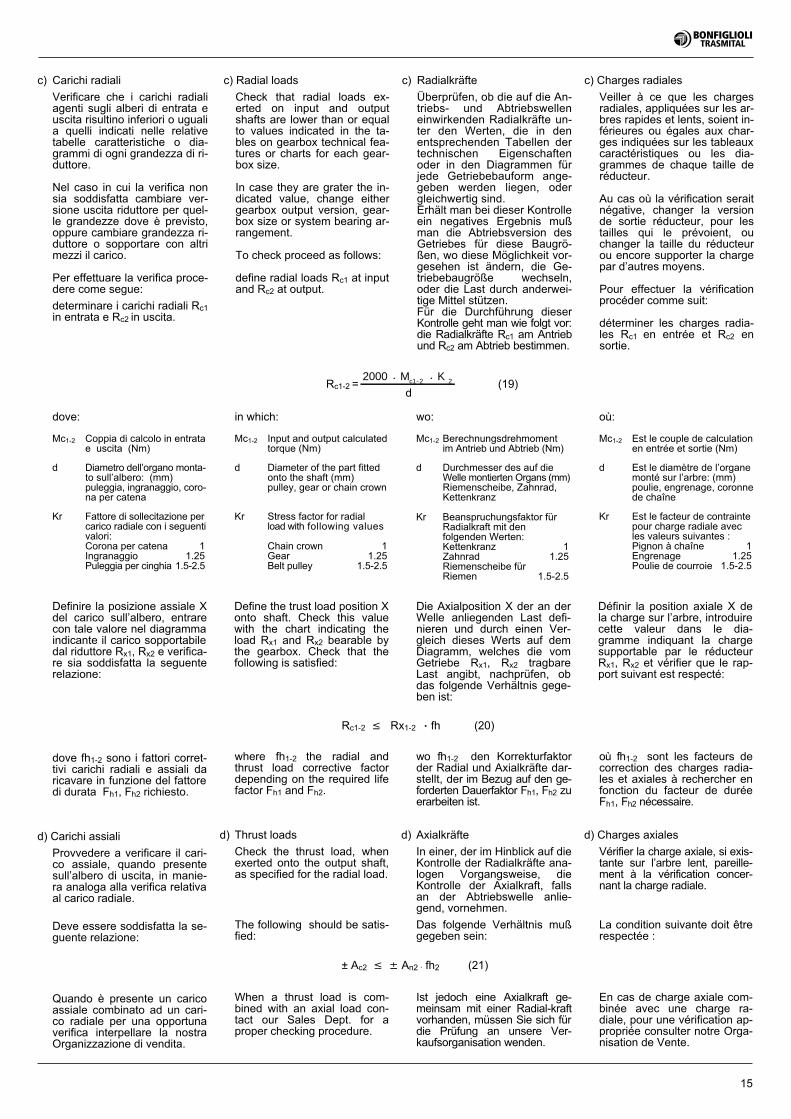
Definire la posizione assiale Xdel carico sull’albero, entrarecon tale valore nel diagrammaindicante il carico sopportabiledal riduttore Rx1, Rx2 e verifica-re sia soddisfatta la seguenterelazione:
dove fh1-2 sono i fattori corret-tivi carichi radiali e assiali daricavare in funzione del fattoredi durata Fh1, Fh2 richiesto.
d) Carichi assiali
Provvedere a verificare il cari-co assiale, quando presentesull’albero di uscita, in manie-ra analoga alla verifica relativaal carico radiale.
Deve essere soddisfatta la se-guente relazione:
Quando è presente un caricoassiale combinato ad un cari-co radiale per una opportunaverifica interpellare la nostraOrganizzazione di vendita.
Définir la position axiale X dela charge sur l’arbre, introduirecette valeur dans le dia-gramme indiquant la chargesupportable par le réducteurRx1, Rx2 et vérifier que le rap-port suivant est respecté:
wo fh1-2 den Korrekturfaktorder Radial und Axialkräfte dar-stellt, der im Bezug auf den ge-forderten Dauerfaktor Fh1, Fh2 zuerarbeiten ist.
d) Axialkräfte
In einer, der im Hinblick auf dieKontrolle der Radialkräfte ana-logen Vorgangsweise, dieKontrolle der Axialkraft, fallsan der Abtriebswelle anlie-gend, vornehmen.
Das folgende Verhältnis mußgegeben sein:
Ist jedoch eine Axialkraft ge-meinsam mit einer Radial-kraftvorhanden, müssen Sie sich fürdie Prüfung an unsere Ver-kaufsorganisation wenden.
où fh1-2 sont les facteurs decorrection des charges radia-les et axiales à rechercher enfonction du facteur de duréeFh1, Fh2 nécessaire.
d) Charges axiales
Vérifier la charge axiale, si exis-tante sur l’arbre lent, pareille-ment à la vérification concer-nant la charge radiale.
La condition suivante doit êtrerespectée :
En cas de charge axiale com-binée avec une charge ra-diale, pour une vérification ap-propriée consulter notre Orga-nisation de Vente.
Define the trust load position Xonto shaft. Check this valuewith the chart indicating theload Rx1 and Rx2 bearable bythe gearbox. Check that thefollowing is satisfied:
± Ac2 � � An2 . fh2 (21)
where fh1-2 the radial andthrust load corrective factordepending on the required lifefactor Fh1 and Fh2.
d) Thrust loads
Check the thrust load, whenexerted onto the output shaft,as specified for the radial load.
The following should be satis-fied:
When a thrust load is com-bined with an axial load con-tact our Sales Dept. for aproper checking procedure.
Rc1-2 � Rx1-2 . fh (20)
Die Axialposition X der an derWelle anliegenden Last defi-nieren und durch einen Ver-gleich dieses Werts auf demDiagramm, welches die vomGetriebe Rx1, Rx2 tragbareLast angibt, nachprüfen, obdas folgende Verhältnis gege-ben ist:
c) Radial loads
Check that radial loads ex-erted on input and outputshafts are lower than or equalto values indicated in the ta-bles on gearbox technical fea-tures or charts for each gear-box size.
In case they are grater the in-dicated value, change eithergearbox output version, gear-box size or system bearing ar-rangement.
To check proceed as follows:
define radial loads Rc1 at inputand Rc2 at output.
c) Radialkräfte
Überprüfen, ob die auf die An-triebs- und Abtriebswelleneinwirkenden Radialkräfte un-ter den Werten, die in denentsprechenden Tabellen dertechnischen Eigenschaftenoder in den Diagrammen fürjede Getriebebauform ange-geben werden liegen, odergleichwertig sind.Erhält man bei dieser Kontrolleein negatives Ergebnis mußman die Abtriebsversion desGetriebes für diese Baugrö-ßen, wo diese Möglichkeit vor-gesehen ist ändern, die Ge-triebebaugröße wechseln,oder die Last durch anderwei-tige Mittel stützen.Für die Durchführung dieserKontrolle geht man wie folgt vor:die Radialkräfte Rc1 am Antriebund Rc2 am Abtrieb bestimmen.
c) Charges radiales
Veiller à ce que les chargesradiales, appliquées sur les ar-bres rapides et lents, soient in-férieures ou égales aux char-ges indiquées sur les tableauxcaractéristiques ou les dia-grammes de chaque taille deréducteur.
Au cas où la vérification seraitnégative, changer la versionde sortie réducteur, pour lestailles qui le prévoient, ouchanger la taille du réducteurou encore supporter la chargepar d’autres moyens.
Pour effectuer la vérificationprocéder comme suit:
déterminer les charges radia-les Rc1 en entrée et Rc2 ensortie.
c) Carichi radiali
Verificare che i carichi radialiagenti sugli alberi di entrata euscita risultino inferiori o ugualia quelli indicati nelle relativetabelle caratteristiche o dia-grammi di ogni grandezza di ri-duttore.
Nel caso in cui la verifica nonsia soddisfatta cambiare ver-sione uscita riduttore per quel-le grandezze dove è previsto,oppure cambiare grandezza ri-duttore o sopportare con altrimezzi il carico.
Per effettuare la verifica proce-dere come segue:
determinare i carichi radiali Rc1in entrata e Rc2 in uscita.
16
15.0 SCELTA DEL MOTORE
Motore elettrico
a) Dalla coppia Mr2, conoscendon2 e il rendimento dinamico �d ,ricavare la potenza in entrata:
15.0 WAHL DES MOTOR
Elektromotor
a) Da man n2 und dendynamischen Wirkungsgrad �dkennt, kann man aus demDrehmoment Mr2 nun dieAntriebsleistung errechnen:
PM nr2 2
d
•
r1 ��9550 •
[kW] (22)
Die Tabelle (A2), Seite 10,führt die Werte des Wirkungs-grads �d im Bezug auf die ver-schiedenen Untersetzungsstu-fen der Getriebe der Serie 300auf.
15.0 CHOIX DU MOTEUR
Moteur électrique
a) En connaissance de n2 et de �drendement dynamique, calculerla puissance à l’entrée au cou-ple Mr2:
Le tableau (A2) à la page 10montre les valeurs de rende-ment �d concernant les diffé-rents étages de réduction desréducteurs série 300.
15.0 HOW TO SELECT THEMOTOR
Electric motor
a) n2 and dynamic efficiency �dare known, calculate input powerbased on torque Mr2 as follows:
Table (A2) on page 10 reportsthe values of efficiency �d re-lated to the different reductionstages of the gearboxes of se-ries 300.
b) Selezionare nelle tabelle datitecnici motori una grandezzacon potenza nominale tale dasoddisfare:
Preferibilmente scegliere motoria 4 poli o superiori.
b) In den Tabellen mit den tech-nischen Motordaten eine Grö-ße mit einer solchen Nennlei-stung wählen, welche die fol-gende Anforderung befriedigt:
b) Sélectionner au tableau don-nées techniques des moteursune taille avec puissance no-minale capable de satisfaire à:
4-pole motors and over shouldbe preferred.
Vorzugsweise sollten jedochMotoren mit 4 oder mehr Po-len ausgewählt werden.
Choisir de préférence des mo-teurs à 4 pôles ou supérieurs.
b) Look up the motor selectioncharts and select a size withsuch rated power to satisfy thiscondition:
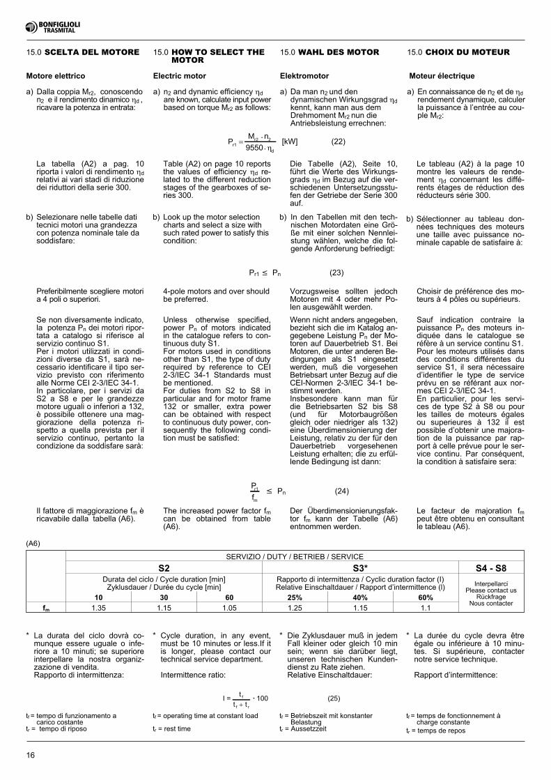
Se non diversamente indicato,la potenza Pn dei motori ripor-tata a catalogo si riferisce alservizio continuo S1.Per i motori utilizzati in condi-zioni diverse da S1, sarà ne-cessario identificare il tipo ser-vizio previsto con riferimentoalle Norme CEI 2-3/IEC 34-1.In particolare, per i servizi daS2 a S8 e per le grandezzemotore uguali o inferiori a 132,è possibile ottenere una mag-giorazione della potenza ri-spetto a quella prevista per ilservizio continuo, pertanto lacondizione da soddisfare sarà:
Il fattore di maggiorazione fm èricavabile dalla tabella (A6).
P
fr1
m
� Pn (24)
Unless otherwise specified,power Pn of motors indicatedin the catalogue refers to con-tinuous duty S1.For motors used in conditionsother than S1, the type of dutyrequired by reference to CEI2-3/IEC 34-1 Standards mustbe mentioned.For duties from S2 to S8 inparticular and for motor frame132 or smaller, extra powercan be obtained with respectto continuous duty power, con-sequently the following condi-tion must be satisfied:
The increased power factor fmcan be obtained from table(A6).
Wenn nicht anders angegeben,bezieht sich die im Katalog an-gegebene Leistung Pn der Mo-toren auf Dauerbetrieb S1. BeiMotoren, die unter anderen Be-dingungen als S1 eingesetztwerden, muß die vorgesehenBetriebsart unter Bezug auf dieCEI-Normen 2-3/IEC 34-1 be-stimmt werden.Insbesondere kann man fürdie Betriebsarten S2 bis S8(und für Motorbaugrößengleich oder niedriger als 132)eine Überdimensionierung derLeistung, relativ zu der für denDauerbetrieb vorgesehenenLeistung erhalten; die zu erfül-lende Bedingung ist dann:
Der Überdimensionierungsfak-tor fm kann der Tabelle (A6)entnommen werden.
Sauf indication contraire lapuissance Pn des moteurs in-diquée dans le catalogue seréfère à un service continu S1.Pour les moteurs utilisés dansdes conditions différentes duservice S1, il sera nécessaired’identifier le type de serviceprévu en se référant aux nor-mes CEI 2-3/IEC 34-1.En particulier, pour les servi-ces de type S2 à S8 ou pourles tailles de moteurs égalesou superieures à 132 il estpossible d’obtenir une majora-tion de la puissance par rap-port à celle prévue pour le ser-vice continu. Par conséquent,la condition à satisfaire sera:
Le facteur de majoration fmpeut être obtenu en consultantle tableau (A6).
Pr1 � Pn (23)
SERVIZIO / DUTY / BETRIEB / SERVICE
S2 S3* S4 - S8Durata del ciclo / Cycle duration [min]Zyklusdauer / Durée du cycle [min]
Rapporto di intermittenza / Cyclic duration factor (I)Relative Einschaltdauer / Rapport d’intermittence (l) Interpellarci
Please contact usRückfrage
Nous contacter10 30 60 25% 40% 60%
fm 1.35 1.15 1.05 1.25 1.15 1.1
(A6)
* La durata del ciclo dovrà co-munque essere uguale o infe-riore a 10 minuti; se superioreinterpellare la nostra organiz-zazione di vendita.Rapporto di intermittenza:
tf = tempo di funzionamento acarico costante
tr = tempo di riposo
La tabella (A2) a pag. 10riporta i valori di rendimento �drelativi ai vari stadi di riduzionedei riduttori della serie 300.
I =t
t tf
f r�
• 100 (25)
* Cycle duration, in any event,must be 10 minutes or less.If itis longer, please contact ourtechnical service department.
Intermittence ratio:
* Die Zyklusdauer muß in jedemFall kleiner oder gleich 10 minsein; wenn sie darüber liegt,unseren technischen Kunden-dienst zu Rate ziehen.Relative Einschaltdauer:
* La durée du cycle devra êtreégale ou inférieure à 10 minu-tes. Si supérieure, contacternotre service technique.
Rapport d’intermittence:
tf = Betriebszeit mit konstanterBelastung
tr = Aussetzzeit
tf = operating time at constant load
tr = rest time
tf = temps de fonctionnement àcharge constante
tr = temps de repos
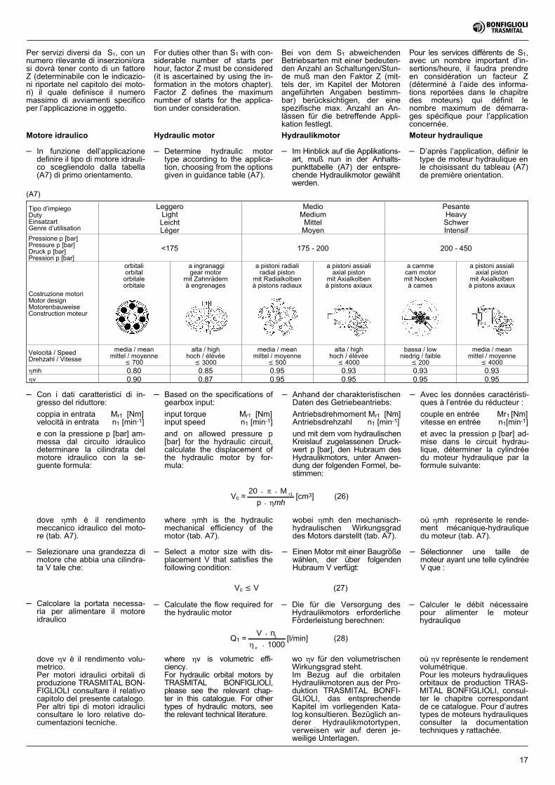
17
Tipo d’impiegoDutyEinsatzartGenre d’utilisation
LeggeroLightLeichtLéger
MedioMediumMittelMoyen
PesanteHeavySchwerIntensif
Pressione p [bar]Pressure p [bar]Druck p [bar]Pression p [bar]
<175 175 - 200 200 - 450
Costruzione motoriMotor designMotorenbauweiseConstruction moteur
orbitaliorbitalorbitaleorbitale
a ingranaggigear motor
mit Zahnrädernà engrenages
a pistoni radialiradial piston
mit Radialkolbenà pistons radiaux
a pistoni assialiaxial piston
mit Axialkolbenà pistons axiaux
a cammecam motormit Nockenà cames
a pistoni assialiaxial piston
mit Axialkolbenà pistons axiaux
Velocità / SpeedDrehzahl / Vitesse
media / meanmittel / moyenne
� 700
alta / highhoch / élévée
� 3000
media / meanmittel / moyenne
� 500
alta / highhoch / élévée
� 4000
bassa / lowniedrig / faible
� 200
media / meanmittel / moyenne
� 4000�mh 0.80 0.85 0.95 0.93 0.93 0.93�v 0.90 0.87 0.95 0.95 0.95 0.95
(A7)
Hydraulic motor
– Determine hydraulic motortype according to the applica-tion, choosing from the optionsgiven in guidance table (A7).
Hydraulikmotor
– Im Hinblick auf die Applikations-art, muß nun in der Anhalts-punkttabelle (A7) der entspre-chende Hydraulikmotor gewähltwerden.
Moteur hydraulique
– D’après l’application, définir letype de moteur hydraulique enle choisissant du tableau (A7)de première orientation.
Motore idraulico
– In funzione dell’applicazionedefinire il tipo di motore idrauli-co scegliendolo dalla tabella(A7) di primo orientamento.
Per servizi diversi da S1, con unnumero rilevante di inserzioni/orasi dovrà tener conto di un fattoreZ (determinabile con le indicazio-ni riportate nel capitolo dei moto-ri) il quale definisce il numeromassimo di avviamenti specificoper l’applicazione in oggetto.
Pour les services différents de S1,avec un nombre important d’in-sertions/heure, il faudra prendreen considération un facteur Z(déterminé à l’aide des informa-tions reportées dans le chapitredes moteurs) qui définit lenombre maximum de démarra-ges spécifique pour l’applicationconcernée.
For duties other than S1 with con-siderable number of starts perhour, factor Z must be considered(it is ascertained by using the in-formation in the motors chapter).Factor Z defines the maximumnumber of starts for the applica-tion under consideration.
Bei von dem S1 abweichendenBetriebsarten mit einer bedeuten-den Anzahl an Schaltungen/Stun-de muß man den Faktor Z (mit-tels der, im Kapitel der Motorenangeführten Angaben bestimm-bar) berücksichtigen, der einespezifische max. Anzahl an An-lässen für die betreffende Appli-kation festlegt.
– Con i dati caratteristici di in-gresso del riduttore:
coppia in entrata Mr1 [Nm]velocità in entrata n1 [min-1]
e con la pressione p [bar] am-messa dal circuito idraulicodeterminare la cilindrata delmotore idraulico con la se-guente formula:
dove �mh è il rendimentomeccanico idraulico del moto-re (tab. A7).
– Selezionare una grandezza dimotore che abbia una cilindra-ta V tale che:
– Based on the specifications ofgearbox input:
input torque Mr1 [Nm]input speed n1 [min-1]
and on allowed pressure p[bar] for the hydraulic circuit,calculate the displacement ofthe hydraulic motor by for-mula:
where �mh is the hydraulicmechanical efficiency of themotor (tab. A7).
– Select a motor size with dis-placement V that satisfies thefollowing condition:
Vc =20 M• • r1�
�p • mh[cm3] (26)
– Anhand der charakteristischenDaten des Getriebeantriebs:
Antriebsdrehmoment Mr1 [Nm]Antriebsdrehzahl n1 [min-1]
und mit dem vom hydraulischenKreislauf zugelassenen Druck-wert p [bar], den Hubraum desHydraulikmotors, unter Anwen-dung der folgenden Formel, be-stimmen:
wobei �mh den mechanisch-hydraulischen Wirkungsgraddes Motors darstellt (tab. A7).
– Einen Motor mit einer Baugrößewählen, der über folgendenHubraum V verfügt:
– Avec les données caractéristi-ques à l’entrée du réducteur :
couple en entrée Mr1 [Nm]vitesse en entrée n1[min-1]
et avec la pression p [bar] ad-mise dans le circuit hydrau-lique, déterminer la cylindréedu moteur hydraulique par laformule suivante:
où �mh représente le rende-ment mécanique-hydrauliquedu moteur (tab. A7).
– Sélectionner une taille demoteur ayant une telle cylindréeV que :
Vc � V (27)
– Calcolare la portata necessa-ria per alimentare il motoreidraulico
dove �v è il rendimento volu-metrico.Per motori idraulici orbitali diproduzione TRASMITAL BON-FIGLIOLI consultare il relativocapitolo del presente catalogo.Per altri tipi di motori idrauliciconsultare le loro relative do-cumentazioni tecniche.
– Calculate the flow required forthe hydraulic motor
Q1 =V n• 1
� v • 1000[l/min] (28)
wo �v für den volumetrischenWirkungsgrad steht.Im Bezug auf die orbitalenHydraulikmotoren aus der Pro-duktion TRASMITAL BONFI-GLIOLI, das entsprechendeKapitel im vorliegenden Kata-log konsultieren. Bezüglich an-derer Hydraulikmotortypen,verweisen wir auf deren je-weilige Unterlagen.
où �v représente le rendementvolumétrique.Pour les moteurs hydrauliquesorbitaux de production TRAS-MITAL BONFIGLIOLI, consul-ter le chapitre correspondantde ce catalogue. Pour d’autrestypes de moteurs hydrauliquesconsulter la documentationtechniques y rattachée.
where �v is volumetric effi-ciency.For hydraulic orbital motors byTRASMITAL BONFIGLIOLI,please see the relevant chap-ter in this catalogue. For othertypes of hydraulic motors, seethe relevant technical literature.
– Calculer le débit nécessairepour alimenter le moteurhydraulique
– Die für die Versorgung desHydraulikmotors erforderlicheFörderleistung berechnen:
18
16.0 INSTALLATION
Observing a few rules for correctinstallation is essential to the reli-able and proper operation of thegearbox or gear motor.The rules set out here are in-tended as a preliminary guide toselecting gearbox or gear motor.For effective and proper installa-tion, follow the instructions givenin the Installation, use and main-tenance manual for the gear-boxes of series 300 availablefrom our Sales Organization.
Following is a brief outline of in-stallation rules:
a) Fastening:– Place gearbox on a surface
providing adequate rigidity.Mating surfaces should bemachined and flat.
– Mating surfaces must bewithin definite geometric toler-ances (see manual). This isespecially true of flange-mounted gearboxes withsplined hollow shafts.
– In applications that involvehigh radial loads at the outputend, flange mounting is rec-ommended for some gearboxsizes as this mounting makesuse of the double pilot diame-ters provided on these gear-boxes. See section “Loads onshafts” for the different gear-box sizes.
– Make sure the gearbox is suit-able for the required mountingposition (check with table A8on page 24).
– Use screws of resistanceclass 8.8 and over to securethe gearbox. Torque upscrews to the figures indicatedin the relevant tables.With transmitted output torquegreater than or equal to 70%of the indicated M2maxtorque, and with frequentmovement reversals, usescrews with minimum resis-tance 10.9.Some gearbox sizes can befastened using either screwsor pins. If a pin is used, thelength of pin seated in theframe the gearbox is being in-stalled to should be at least1.5 times pin diameter.
16.0 INSTALLATION
Im Hinblick auf die Zuverlässig-keit und eine gute Betriebsweisedes Getriebes oder des Getriebe-motors ist es besonders wichtig,für deren korrekten Einbau Kennt-nis über einige Richtlinien zu ha-ben.Die hier in Folge angeführtenNormen sind eine erste Anleitungfür die Auswahl des Getriebesoder des Getriebemotors.Um eine effektive und korrekt er-folgte Installation zu erhalten, mußman sich an das Anleitungs- undInstandhaltungshandbuch der Ge-triebe der Serie 300 halten. Die-ses Handbuch ist bei unserer Ver-kaufsorganisation erhältlich.
Wir möchten Ihnen hier nur kurzdie zu befolgenden Normen an-führen:
a) Befestigung:– Das Getriebe auf einer ausrei-
chend starken Stuktur mit fla-chen und mittels Werkzeugma-schinen bearbeitenen Pas-sungsflächen ablegen.
– Die Passungsflächen, beson-ders für die mit Flansch undKeilabtriebswellen montiertenGetriebe, müssen innerhalbbestimmter geometrischer To-leranzen liegen (siehe Hand-buch).
– Bei einigen Baugrößen, beiApplikationen mit hoher aufdem Abtrieb einwirkender Ra-dialkraft, wird die Montagewei-se mit Flansch empfohlen, wo-durch die doppelten Zentrier-durchmesser, mit denen dieGetriebe ausgestattet sind,verwendet werden können. ImBezug auf die unterschiedli-chen Baugrößen der Getriebe,siehe Abschnitt “Auf Welleneinwirkende Kräfte ”.
– Unter Bezugnahme auf die Ta-belle (A8) prüfen auf Seite 24,ob das Getriebe auch für dieerforderliche Montagestellunggeeignet ist.
– Das Getriebe mit Schraubender Widerstandsklasse 8.8oder einer höheren Klasse be-festigen, dabei auf die in denjeweiligen Tabellen angegebe-nen Anzugsmomente bringen.Für zu übertragene Maximal-drehmomente, die höher als70% des angegebenen WertsM2max oder diesem Prozent-satz gleich kommen und imFall von häufigen Schaltungensind Schnecken aus der Klas-se der min. Widerstandsgrads10.9 zu verwenden.Einige Getriebebaugrößen se-hen ausser der Befestigungdurch die Schrauben, auchStifte vor. Dazu die Stifte, mitdenen die Getriebe ausgestat-tet sind, über eine Länge vonmindestens gleich 1,5 desWerts ihres Durchmesser, indie Stuktur einstecken, auf diedas Getriebe installiert werdensoll.
16.0 INSTALLATION
Il est très important pour la fiabili-té et le bon fonctionnement du ré-ducteur ou motoréducteur, derespecter certaines règles pourson installation correcte.Les règles indiquées n’ontqu’une valeur indicative orienta-tion pour le choix du réducteurou motoréducteur. Pour effec-tuer la parfaite installation défi-nitive, respecter les consignesd’installation, utilisation et entre-tien des réducteurs de la série300, qui peuvent être livréespar notre Organisation de Vente.
Voici brièvement les règles qu’ilfaut suivre:
a) Fixation:– Faire en sorte que le réducteur
repose sur un bâti suffisam-ment rigide avec des surfacesd’accouplement planes et usi-nées à la machine-outil.
– Les surfaces d’accouplement,spécialement pour les réduc-teurs avec bride d’assemblageet arbres de sortie femelle can-nelés, doivent respecter des to-lérances géométriques bien pré-cises (voir catalogue).
– Pour certaines tailles deréducteur, dans des applica-tions avec des chargesradiales élevées à la sortie, onpréconise un montage avecbride, afin d’utiliser le doublesdiamètres de centrage, dontces réducteurs sont pourvus.Se reporter à la section“Charges sur les arbres” pourles différentes tailles deréducteurs.
– Veiller à ce que le réducteurconvienne à la position demontage nécessaire, ainsi qu’autableau (A8) à la page 24, lemontre.
– Fixer le réducteur avec des visd’un degré de résistance 8.8ou supérieur en les serrantaux valeurs de couple deserrage indiquées sur les ta-bleaux correspondants.Pour des couples maximauxtransmis plus importants ouéquivalents à 70% du coupleM2max indiqué, et en casd’inversions fréquentes dumouvement, utiliser des visdans une classe minimale derésistance 10.9.Certaines tailles de réducteursprévoient une fixation tant parvis que par goupilles.Introduire les goupilles, livréesavec les réducteurs, dans lebâti sur lequel le réducteursera installé pour unelongueur au moins égale à 1,5de la valeur de leur diamètre.
16.0 INSTALLAZIONE
È molto importante per l’affidabilitàe il buon funzionamento del ridut-tore o motoriduttore rispettare alcu-ne norme per la sua corretta instal-lazione.Le norme qui riportate hanno va-lore per una prima indicazioneper la installazione del riduttore omotoriduttore.Per provvedere ad una effettiva ecorretta installazione attenersi alManuale di installazione uso emanutenzione dei riduttori dellaserie 300 fornibile dalla nostraOrganizzazione di Vendita.
Riportiamo in breve le norme daseguire:
a) Fissaggio:– Appoggiare il riduttore a una
struttura sufficientemente rigi-da, con superfici di accoppia-mento piane lavorate di mac-china utensile.
– Le superfici di accoppiamento,specialmente per riduttorimontati con flangia e con albe-ri in uscita femmina scanalati,devono risultare entro precisetolleranze geometriche (vedimanuale).
– Per alcune grandezze diriduttori, in applicazioni conelevati carichi radiali in uscita,è raccomandato il montaggioa flangia eseguito perutilizzare i doppi diametri dicentraggio di cui tali riduttorisono provvisti. Vedi parte“Carichi sugli alberi” per le di-verse grandezze di riduttori.
– Verificare che il riduttore siaprevisto per la posizione dimontaggio richiesta come illu-strato nella tabella (A8) a pag.24.
– Fissare il riduttore con viti diclasse di resistenza 8.8 osuperiore serrandole ai valoridi coppia di serraggio indicatinelle relative tabelle.Per coppie massimetrasmesse maggiori od ugualial 70% della coppia M2maxindicata e con frequentiinversioni del moto, utilizzareviti in classe minima diresistenza 10.9.Alcune grandezze di riduttoriprevedono oltre il fissaggiocon viti, anche spine. Inserirele spine di cui i riduttori sonoprovvisti, nella struttura sullaquale il riduttore vieneinstallato per una lunghezzaalmeno pari a 1,5 il valore delloro diametro.
19
b) Connections– Secure the connection parts to
gearbox input and output. Donot tap them with hammers orsimilar tools. To insert theseparts, use the service screwsand threaded holes providedon the shafts. Be sure to cleanoff any grease or protectantsfrom the shafts before fittingany connection parts.
– Fitting hydraulic motors.Be careful of the O ring be-tween motor flange and gear-box input flange when assem-bling. Install the hydraulic mo-tor before filling lube oil intothe gearbox.
– Connecting the hydraulic brake.The hydraulic circuit shouldbe such to ensure that brakeis released instants beforegearbox starts and appliedafter gearbox has stopped.Check that pressure in thehydraulic line for brake re-lease is at zero whenevergearbox is stopped.
– Direction of rotationMotors are connected to thesuitable electric or hydrauliccircuit according to their direc-tion of rotation. When perform-ing these connections, bear inmind that all gearboxes,whether in the in-line or rightangle design, have the samedirection of rotation both at in-put and output. For more de-tails of the connection of elec-tric and hydraulic motors, seerelevant sections in this cata-logue on page 191.
c) Painting– Use paints compatible with the
primer applied to the gearbox,see supply conditions on page21.Before painting, protect theseal rings installed on theshafts.Contact with paint may deteri-orate the seals with subse-quent oil leakage.
d) Lubrication– Before start-up, fill the gear-
box with the recommendedlube oil (see lubrication onpage 25) up to correct level.Level is checked through thesuitable plug or sight glassprovided on each gearbox de-pending on designated mount-ing position.
b) Raccordements– Fixer les éléments de raccor-
dement en entrée et en sortiedu réducteur. N’utilisez pas demarteaux, ni d’outils afin defrapper. Pour l’introduction desorganes, utiliser les vis corres-pondantes et les trous tarau-dés existant sur les arbres.Avant le montage des élé-ments de raccordement,prendre soin de nettoyer les ar-bres, en éliminant, si besoinest, les graisses ou agents pro-tecteurs.
– Montage des moteurs hydrau-liques.Prendre soin de monter le jointtorique entre la bride moteur etla bride à l’entrée du réducteur.Installer le moteur hydrauliqueavant de mettre l’huile lubrifiantdans le réducteur.
– Utiliser un circuit hydrauliqueassurant une ouverture dufrein juste avant le démarragedu motoréducteur et une fer-meture après sa mise à l’arrêt.Veiller à ce que, lors des pha-ses d’arrêt du motoréducteur,le circuit hydraulique d’ouver-ture frein soit totalement dé-pressurisé.
– Sens de rotation.Lors d’un raccordement demoteurs au circuit électriqueou hydraulique, en fonction deleurs sens de rotation, il fauttenir compte que tous les ré-ducteurs, en exécution alignéeaussi bien qu’angulaire, aientdes sens de rotation concor-dants en entrée et en sortie.Pour d’autres indicationsconcernant les raccordementsdes moteurs électriques et hy-drauliques, voir les sectionss’y rattachant de ce catalogueà la page 191.
c) Peinture– Utiliser des peintures compati-
bles avec la couche de fonddéjà existant sur les réduc-teurs, se reporter aux condi-tions de livraison à la page 21.En cours de peinture, protégerles bagues à lévres des ar-bres.La peinture peut les séchertrop et des fuites d’huile peu-vent en découler.
d) Lubrification– Avant la mise en service,
remplir le réducteur avecl’huile lubrifiante conseillée(voir lubrification à la page 25)jusqu’à atteindre le niveauprévu par rapport à la positionde montage établie vérifier àtravers le bouchon, ou niveauvisible, dont chaque réducteurest équipé.
b) Collegamenti– Fissare gli organi di collega-
mento in entrata ed uscita alriduttore evitando di batterecon martello o equivalenti. Uti-lizzare per l’inserimento degliorgani viti di servizio e i fori fi-lettati presenti negli alberi. Pri-ma di montare gli organi dicollegamento avere cura dipulire gli alberi eliminandograssi o protettivi eventual-mente presenti.
– Montaggio motori idraulici.Avere cura nel montaggiodell’O-ring di tenuta fra flangiamotore e flangia in ingresso ri-duttore. Montare il motoreidraulico prima di mettere l’oliolubrificante nel riduttore.
– Collegamento freno idraulico.Utilizzare un circuito idraulicoche assicuri l’apertura del fre-no immediatamente prima del-la partenza del motoriduttore ela chiusura dopo che questosia arrestato. Verificare chedurante le fasi di motoriduttorefermo la pressione nella lineaidraulica di apertura freno siazero.
– Versi di rotazione.Nei collegamenti dei motori alcircuito elettrico o idraulico infunzione dei loro versi di rota-zione, tenere presente che tut-ti i riduttori, sia in esecuzionein linea che angolare hannoversi di rotazione concordi fraentrata e uscita. Per altre indi-cazioni relative ai collegamentidi motori elettrici e idraulicivedi le parti specifiche su que-sto catalogo pag. 191.
c) Verniciatura– Utilizzare vernici compatibili
con la vernice di fondo pre-sente sui riduttori, vedi condi-zioni di fornitura pag.21.Durante la verniciatura proteg-gere gli anelli di tenuta pre-sente sugli alberi.La vernice li può fare essicca-re causando perdite d’olio.
d) Lubrificazione– Prima della messa in funzione
riempire il riduttore d’olio lubri-ficante del tipo raccomandato(vedi lubrificazione a pag. 25)fino al raggiungimento del pre-visto livello verificabiledall’apposito tappo o livello vi-sivo di cui ogni riduttore èprovvisto in relazione alla po-sizione di montaggio stabilita.
b) Anschlüsse– Die Anschlußteile zum Getrie-
beantrieb und -abtrieb befesti-gen, dabei ein Einklopfen mit-tels Hammer oder ähnlichenGegenständen vermeiden.Beim Einführen der Teile sindServiceschrauben und die aufden Wellen vorhandenen Ge-windebohrungen zu verwen-den. Vor dem Montieren derVerbindungsteile müssen dieWellen durch eine entspre-chende Reinigung von Fettund eventuell vorhandenenSchutzmitteln befreit werden.
– Montage der Hydraulikmotore.Der Montage des O-Dichtringszwischen dem Motorflanschund dem Antriebsflansch amGetriebe muß besondere Auf-merksamkeit zugewendet wer-den. Vor dem Einfüllen desSchmieröls in das Getriebe, istder Motor zu montieren.
– Anschluß der hydraulischenBremse Hierbei ist ein Hydrau-likkreislauf zu verwenden, der ei-ne unmittelbare Öffnung derBremse, noch vor dem Anlaufdes Getriebemotors und nachdessen Halt, eine Schließung si-chern kann. Es ist zu überprü-fen, daß während der Phasen, indenen der Getriebemotor still-steht, der Druck in der hydrauli-schen Leitung für die Bremsöff-nungsfunktion gleich Null ist.
– DrehrichtungenDie Drehrichtung an der Ab-triebswelle ist bei allen Getrie-ben, sowohl bei linear alsauch bei Winkelgetrieben,gleich mit der Eingangsdreh-richtung des Hydro-oder Elek-tromotors. Im Bezug auf weite-re Anleitungen für die An-schlüsse von Elektro- undHydraulikmotoren, verweisenwir auf die entsprechendenAbschnitte in diesem Katalog.Siehe dazu Seite 191.
c) Lackierung– Es müssen Lackarten verwen-
det werden, die mit der bereitsam Getriebe verwendetenGrundierung kompatibel sind.Siehe dazu auch die Seite 21angeführten Lieferbedingungen.Während des Lackiervorgangssind die auf der Welle angeord-neten Dichtringe in angemesse-ner Weise zu schützen.Der Lack kann zum Austrock-nen dieser Ringe führen, wasletztendlich zu Ölverlusten füh-ren würde.
d) Schmierung– Vor der Inbetriebnahme muß
das Getriebe solange mit demempfohlenen Schmieröl (siehe“Schmierung” auf Seite 25)gefüllt werden, bis der vorge-sehene Ölpegel erreicht wur-de. Dieser Pegel ist über denentsprechenden Verschlußoder über das Schauauge,über welches jedes Getriebe jenach festgelegten Montages-tellung verfügt, feeststellbar.
20
18.0 STOCCAGGIO
Il corretto stoccaggio dei prodottiricevuti richiede l’esecuzione del-le seguenti attività:
a) Escludere aree all’aperto, zoneesposte alle intemperie o coneccessiva umidità.
b) Interporre sempre tra il pavi-mento ed i prodotti, pianali li-gnei o di altra natura, atti adimpedire il diretto contatto colsuolo.
c) Per periodi di stoccaggio supe-riori ai 60 giorni, le superfici in-teressate agli accoppiamentiquali flange, alberi e giunti, de-vono essere protette con ido-neo prodotto antiossidante (Mo-bilarma 248 od equivalente).
d) Per periodi di stoccaggio previ-sti superiori ai 6 mesi, i prodot-ti devono essere oggetto delleseguenti attività:
d1)Ricoprire le parti lavorateesterne e quelle di accoppia-mento con grasso atto ad evi-tare ossidazioni.
d2)Posizionare i riduttori con iltappo di sfiato nella posizionepiù alta e riempirli di olio.I riduttori, prima del loro utiliz-zo, dovranno essere riempiticon la corretta quantità e tipodi lubrificante previsto.
18.0 STORAGE
Observe the following instructionsto ensure correct storage of deliv-ered products:
a) Do not store outdoors, in areasexposed to weather or with ex-cessive humidity.
b) Always place boards in woodor other material between floorand products, to avoid directcontact with the floor.
c) For storage periods of over 60days, all machined surfacessuch as flanges, shafts andcouplings must be protectedwith a suitable anti-oxidationproduct (Mobilarma 248 orequivalent product).
d) The following measures mustbe taken in respect of prod-ucts for which the expectedstorage period exceeds 6months:
d1)Cover outer machined partsand mating parts with greaseto avoid oxidation.
d2)Position the gearboxes withthe breather plug up and fillthem with oil.Before use, the gearboxesshould be filled with the properamount of lubricant of the rec-ommended type.
18.0 LAGERUNG
Die korrekte Lagerung der Antrie-be erfordert folgende Vorkehrun-gen:
a) Die Produkte nicht im Freienlagern und nicht in Räumen,die der Witterung ausgesetztsind, oder eine hohe Feuchtig-keit aufweisen.
b) Die Produkte nie direkt aufdem Boden, sondern auf Un-terlagen aus Holz oder einemanderen Material lagern.
c) Bei Lagerzeiten von mehr als60 Tagen die Oberflächen fürdie Verbindung, wie Flansche,Wellen oder Kupplungen miteinem geeigneten Oxida-tions-schutzmittel behandeln(Mobilarma 248 oder ein äqui-valentes Mittel).
d) Bei Lagerzeiten von mehr als 6Monaten müssen folgendeVorkehrungen getroffen wer-den:
d1)Die bearbeiteten Außenteileund die Passflächen mit Oxyda-tionschutzfett abdecken.
d2)Die Getriebe mit der Entlüf-tungsschraube in die oberstePosition ausgerichtet montie-ren, dann mit Öl auffüllen.Die Getriebe müssen vor ih-rem Einsatz mit der richtigenMenge des vorgesehenenSchmiermittels aufgefüllt wer-den.
18.0 STOCKAGE
Un stockage correct des produitsreçus nécessite de respecter lesrègles suivantes:
a) Exclure les zones à ciel ouvert,les zones exposées aux in-tempéries ou avec humiditéexcessive.
b) Interposer dans tous les casentre le plancher et les pro-duits des planches de bois oudes supports d’autre natureempêchant le contact directavec le sol.
c) Pour les périodes de stockagesupérieures à 60 jours, les sur-faces concernées par les liai-sons telles que les brides, lesarbres et les accouplementsdoivent être protégées avec unproduit antioxydant spécial (Mo-bilarma 248 ou équivalent).
d) Pour les périodes de stockageprévues supérieures à 6 mois,les produits doivent être objetdes contrôles suivants:
d1)Recouvrir les parties extérieu-res usinées et les élémentsd’accouplement avec de lagraisse contre l’oxydation.
d2)Positionner les réducteursavec le bouchon reniflard leplus haut possible et les rem-plir d’huile.Avant utilisation, les réduc-teurs doivent être remplis de laquantité et du type de lubrifiantpréconisés.
17.0 MANUTENZIONE
Controllare il serraggio dei bullonidopo 50 ore di lavoro.
Effettuare il primo cambio olio cir-ca dopo 100 � 150 ore di lavoro.Successivamente effettuare ilcambio ogni 2000 � 3000 ore aseconda degli impieghi o almenouna volta all’anno.
È buona norma comunque con-trollare il livello una volta al meseper funzionamento intermittente opiù frequentamente per funziona-mento in continuo e aggiungereolio se necessario.
17.0 MAINTENANCE
Check the tightness of mountingbolts after the initial 50 hours ofoperation.
Change the oil first after 100 �
150 hours operation.Subsequently, change the oil ev-ery 2000 � 3000 hours operationdepending on application.Alternatively change oil once ayear.
Check the oil level in the gearboxevery month and top up as nec-essary.
17.0 WARTUNG
Schrauben nach 50 Betriebsstun-den auf festen Sitz prüfen .
Ersten Ölwechsel nach zirka 100� 150 Betriebsstunden durchführen.Anschließend alle 2000 - 3000oder mindestens einmal jährlicheinen Ölwechsel durchführen (jenach Einsatzbereich).
Es sollte jedoch bei Aussetzbe-trieb einmal monatlich und beiDauerbetrieb häufiger der Öl-stand kontrolliert werden.Falls notwendig, Öl nachfüllen.
17.0 ENTRETIEN
Controler le serrage des vis etboulons, aprés 50 heures de tra-vail.
Effectuer la première vidange dulubrifiant, aprés 100 � �50 heuresde travail. Ultérieurement, effec-tuer une vidange toutes les 2000� 3000 heures, selont les applica-tions, ou au minimum une fois paran.
Toutefois, il est conseillé de con-troler le niveau d’huile une foispar mois, en cas de fonctionne-ment intermittent, plus souvent encas de service continu, et de fairel’appoint si nécessaire.
21
19.0 CONDIZIONI DIFORNITURA
I riduttori vengono forniti comesegue:
a) già predisposti per essere in-stallati nella posizione di mon-taggio come definito in fase diordine;
b) senza olio lubrificante ed in-ternamente protetti con unfilm d’olio usato per il col-laudo finale;
c) verniciati con vernice di fondoantiossidante all’acqua di colo-re grigio (tipo Idrayon Pri-mer-Ral 7042/C441).Le superfici di accoppiamentonon sono verniciate.La verniciatura finale è a curadel cliente;
d) collaudati secondo specificheinterne;
e) appositamente imballati;
f) provvisti di dadi e bulloni permontaggio motori elettrici ver-sione IEC o motori idraulici.
19.0 CONDITIONS DELIVRAISON
Les réducteurs sont livrés commesuit:
a) déjà adaptés pour l’installationdans la position d’assemblagedéfinie en cours de com-mande;
b) sans huile lubrifiante et pro-tégés à l’intérieur avec unfilm d’huile utilisée lors del’essai final;
c) peints avec une couche defond de protection antioxydantà l’eau, de coloris gris (typeidrayon Primer-Ral 7042/C441).Les surfaces d’accouplementne sont pas peintes.La peinture de finition doit êtreréalisée par le client;
d) essayés d’après les spécifica-tions internes;
e) dûment emballés;
f) pourvus d’écrous et de bou-lons pour l’assemblage auxmoteurs électriques, versionCEI, ou moteurs hydrauli-ques.
19.0 SUPPLY CONDITIONS
Gearboxes are supplied as fol-lows:
a) ready for installation in the mo-unting position specified on or-der;
b) dry; inner parts are protec-ted by a film of the oil usedfor final testing;
c) painted with antioxidant waterprimer in the colour grey (typeIdrayon Primer-Ral 7042/C441).Mating surfaces are notpainted.Final coat is to be applied bythe Customer;
d) tested to in-house specifica-tions;
e) suitably packed;
f) complete with mounting nutsand bolts for IEC electric mo-tors or hydraulic motors.
19.0 LIEFERBEDINGUNGEN
Die Getriebe werden wie folgtgeliefert:
a) bereits für die Installation inder Einbaulage gemäß Auftragbereit;
b) ohne Schmieröl und innen miteinem Öl, das für die Endab-nahmeprüfung verwendetwurde, überzogen;
c) mit einer grauen, vor Oxyda-tion durch Wasser schützen-den Grundlackierung überzo-gen (Typ Idrayon Primer Ral7042/C441).Die Verbindungsflächen sindnicht lackiert;Die Endlackierung geht zuLasten des Kunden;
d) gemäß werksinterner Spezifi-kationen geprüft.;
e) in angemessener Weise ver-packt;
f) mit Muttern und Schrauben fürdie Montage an Elektromoto-ren der Version IEC oder Hyd-raulikmotoren ausgestattet.
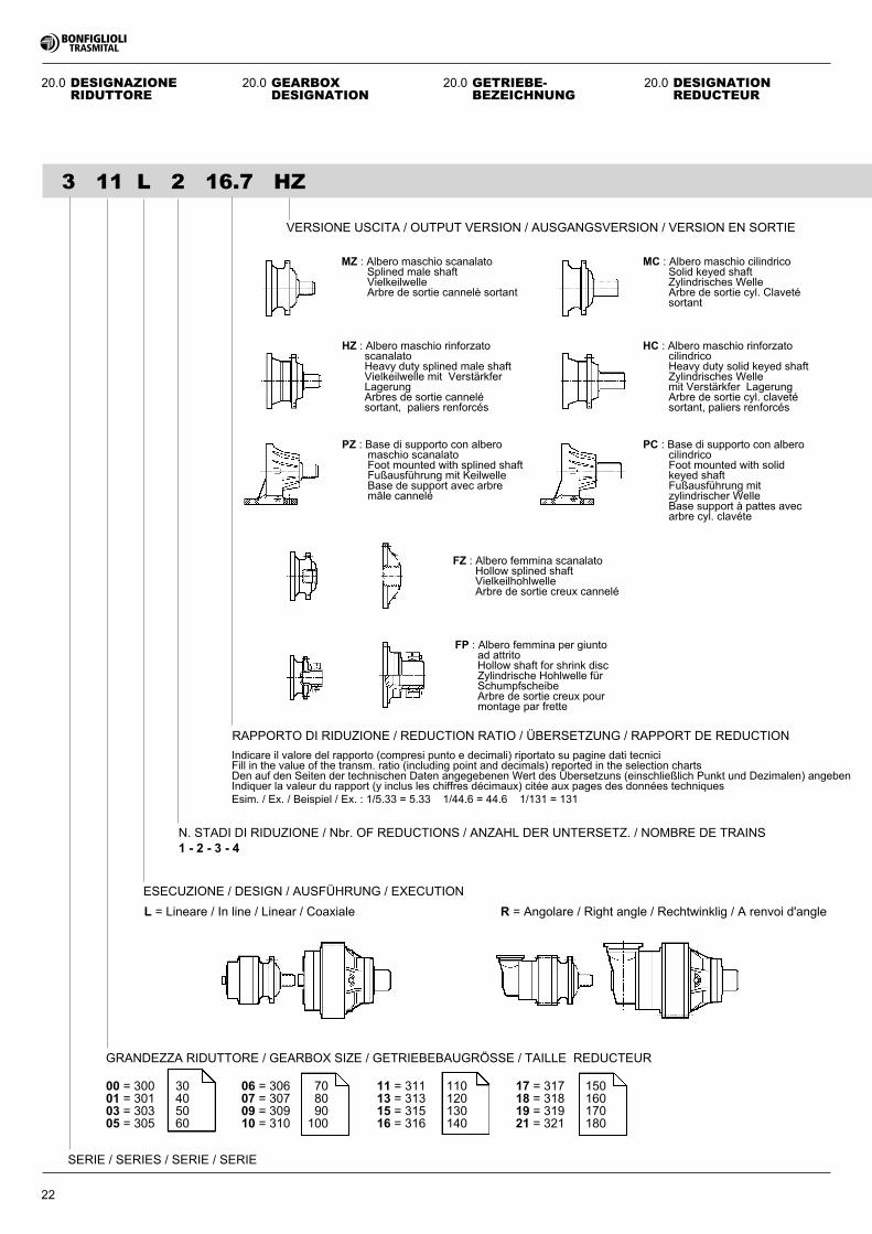
22
3 11 L 2 16.7 HZ
RAPPORTO DI RIDUZIONE / REDUCTION RATIO / ÜBERSETZUNG / RAPPORT DE REDUCTION
VERSIONE USCITA / OUTPUT VERSION / AUSGANGSVERSION / VERSION EN SORTIE
SERIE / SERIES / SERIE / SERIE
20.0 GETRIEBE-BEZEICHNUNG
20.0 DESIGNAZIONERIDUTTORE
20.0 DESIGNATIONREDUCTEUR
20.0 GEARBOXDESIGNATION
L = Lineare / In line / Linear / Coaxiale R = Angolare / Right angle / Rechtwinklig / A renvoi d'angle
ESECUZIONE / DESIGN / AUSFÜHRUNG / EXECUTION
N. STADI DI RIDUZIONE / Nbr. OF REDUCTIONS / ANZAHL DER UNTERSETZ. / NOMBRE DE TRAINS1 - 2 - 3 - 4
Indicare il valore del rapporto (compresi punto e decimali) riportato su pagine dati tecniciFill in the value of the transm. ratio (including point and decimals) reported in the selection chartsDen auf den Seiten der technischen Daten angegebenen Wert des Übersetzuns (einschließlich Punkt und Dezimalen) angebenIndiquer la valeur du rapport (y inclus les chiffres décimaux) citée aux pages des données techniquesEsim. / Ex. / Beispiel / Ex. : 1/5.33 = 5.33 1/44.6 = 44.6 1/131 = 131
HZ : Albero maschio rinforzatoscanalatoHeavy duty splined male shaftVielkeilwelle mit VerstärkferLagerungArbres de sortie cannelésortant, paliers renforcés
HC : Albero maschio rinforzatocilindricoHeavy duty solid keyed shaftZylindrisches Wellemit Verstärkfer LagerungArbre de sortie cyl. clavetésortant, paliers renforcés
PC : Base di supporto con alberocilindricoFoot mounted with solidkeyed shaftFußausführung mitzylindrischer WelleBase support à pattes avecarbre cyl. clavéte
MZ : Albero maschio scanalatoSplined male shaftVielkeilwelleArbre de sortie cannelè sortant
MC : Albero maschio cilindricoSolid keyed shaftZylindrisches WelleArbre de sortie cyl. Clavetésortant
FZ : Albero femmina scanalatoHollow splined shaftVielkeilhohlwelleArbre de sortie creux cannelé
FP : Albero femmina per giuntoad attritoHollow shaft for shrink discZylindrische Hohlwelle fürSchumpfscheibeArbre de sortie creux pourmontage par frette
PZ : Base di supporto con alberomaschio scanalatoFoot mounted with splined shaftFußausführung mit KeilwelleBase de support avec arbremâle cannelé
GRANDEZZA RIDUTTORE / GEARBOX SIZE / GETRIEBEBAUGRÖSSE / TAILLE REDUCTEUR
00 = 300 30 06 = 306 70 11 = 311 110 17 = 317 15001 = 301 40 07 = 307 80 13 = 313 120 18 = 318 16003 = 303 50 09 = 309 90 15 = 315 130 19 = 319 17005 = 305 60 10 = 310 100 16 = 316 140 21 = 321 180
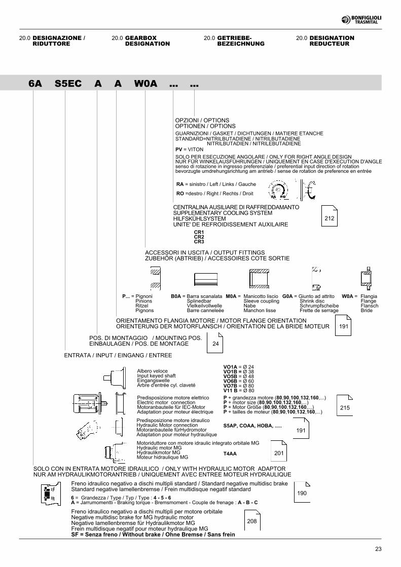
23
6A S5EC A A W0A ... ...
CENTRALINA AUSILIARE DI RAFFREDDAMANTOSUPPLEMENTARY COOLING SYSTEMHILFSKÜHLSYSTEMUNITE' DE REFROIDISSEMENT AUXILAIRE
ENTRATA / INPUT / EINGANG / ENTREE
Freno idraulico negativo a dischi multipli per motore orbitaleNegative multidisc brake for MG hydraulic motorNegative lamellenbremse für Hydraulikmotor MGFrein multidisque negatif pour moteur hydraulique MGSF = Senza freno / Without brake / Ohne Bremse / Sans frein
Predisposizione motore elettricoElectric motor connectionMotoranbauteile für IEC-MotorAdaptation pour moteur électrique
Predisposizione motore idraulicoHydraulic Motor connectionMotoranbauteile fürHydromotorAdaptation pour moteur hydraulique
STANDARD=NITRILBUTADIENE / NITRILBUTADIENENITRILBUTADIEN / NITRILEBUTADIENE
G0A = Giunto ad attritoShrink discSchrumpfscheibeFrette de serrage
W0A = FlangiaFlangeFlanschBride
B0A = Barra scanalataSplinedbarVlelkeilvollwelleBarre canneleée
M0A = Manicotto liscioSleeve couplingNabeManchon lisse
Motoriduttore con motore idraulic integrato orbitale MGHydraulic motor MGHydraulikmotor MGMoteur hidraulique MG
Albero veloceInput keyed shaftEingangswelleArbre d'entrée cyl. claveté
VO1A = Ø 24VO1B = Ø 38VO5B = Ø 48VO6B = Ø 60VO7B = Ø 80V11 B = Ø 80
SOLO PER ESECUZIONE ANGOLARE / ONLY FOR RIGHT ANGLE DESIGNNUR FÜR WINKELAUSFÜHRUNGEN / UNIQUEMENT EN CASE D'EXECUTION D'ANGLEsenso di rotazione in ingresso preferenziale / preferential input direction of rotationbevorzugte umdrehungsrichtung am antrieb / sense de rotation de preference en entrée
P + grandezza motore (80,90,100,132,160,...)P + motor size (80,90,100,132,160,...)P + Motor Größe (80,90,100,132,160,...)P + tailles de moteur (80,90,100,132,160,...)
SOLO CON IN ENTRATA MOTORE IDRAULICO / ONLY WITH HYDRAULIC MOTOR ADAPTORNUR AM HYDRAULIKMOTORANTRIEB / UNIQUEMENT AVEC ENTREE MOTEUR HYDRAULIQUE
Freno idraulico negativo a dischi multipli standard / Standard negative multidisc brakeStandard negative lamellenbremse / Frein multidisque negatif standard
6 = Grandezza / Type / Typ / Type : 4 - 5 - 6A = Jarrumomentti - Braking torque - Bremsmoment - Couple de frenage : A - B - C
ACCESSORI IN USCITA / OUTPUT FITTINGSZUBEHÖR (ABTRIEB) / ACCESSOIRES COTE SORTIE
T4AA
OPZIONI / OPTIONSOPTIONEN / OPTIONS
CR1CR2CR3
P... = PignoniPinionsRitzelPignons
GUARNIZIONI / GASKET / DICHTUNGEN / MATIERE ETANCHE
PV = VITON
RO =destro / Right / Rechts / Droit
RA = sinistro / Left / Links / Gauche
201
190
208
191
212
ORIENTAMENTO FLANGIA MOTORE / MOTOR FLANGE ORIENTATIONORIENTERUNG DER MOTORFLANSCH / ORIENTATION DE LA BRIDE MOTEUR 191
POS. DI MONTAGGIO / MOUNTING POS.EINBAULAGEN / POS. DE MONTAGE 24
20.0 GETRIEBE-BEZEICHNUNG
20.0 DESIGNATIONREDUCTEUR
20.0 GEARBOXDESIGNATION
S5AP, COAA, HOBA, .....
20.0 DESIGNAZIONE /RIDUTTORE
215
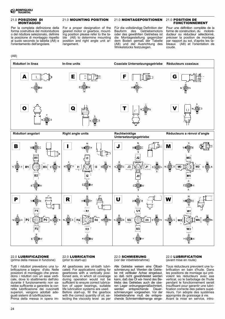
24
21.0 MONTAGEPOSITIONEN21.0 POSIZIONI DIMONTAGGIO
21.0 POSITION DEFONCTIONNEMENT
21.0 MOUNTING POSITION
(A8)
For a proper designation of thegeared motor or gearbox, mount-ing position please refer to the ta-ble (A8) to determine mountingposition and right angle unit ar-rangement.
Für die vollständige Definition derBauform des Getriebemotorsoder des gewählten Getriebes istdie Montagestellung gegenüberdem Boden gemaß der Tabelle(A8) und der Ausrichtung desWinkelstücks festzulegen.
Pour une définition complète de laforme de construction, du motoré-ducteur ou réducteur sélectionné,préciser la position de montagepar rapport au sol, d'après les ta-bleaux (A8) et l'orientation decoude.
Per la completa definizione dellaforma costruttiva del motoriduttoreo del riduttore selezionato, definirela posizione di montaggio rispettoal suolo secondo la tabella (A8) el'orientamento dell'angolare.
22.0 LUBRIFICAZIONE(prima della messa in funzione)
Tutti i riduttori prevedono una lu-brificazione a bagno d'olio. Nelleposizioni di montaggio che preve-dono i riduttori con un asse verti-cale, dove lo sbattimento dell'oliodurante il funzionamento non sa-rebbe sufficente a garantire la cor-retta lubrificazione dei cuscinettisuperiori, vengono adottati ade-guati sistemi di lubrificazione.Prima della messa in opera im-
22.0 SCHMIERUNG(vor der inbetriebnahme)
Alle Getriebe weisen eine Ölbad-schmierung auf. Werden die Getrie-be mit vertikaler Achse eingebaut,so daß nicht gewährleistet werdenkann, daß das Öl wä- hrend des Be-triebs des Getriebes auch die obe-ren Lager ordnungsgemäßschmiert,werden entsprechende Dauer-schmierungen vorgesehen. Vor derInbetriebnahme muß die entspre-chende Schmiermittelmenge einge-
22.0 LUBRIFICATION(avant mise en route)
Tous réducteurs prevoient une lu-brification en bain d'huile. Dansles positions de montage qui pré-voient les réducteurs avec axevertical, où le barbotage de l'huilependant le fonctionnement seraitinsuffisant pour garantir une lubri-fication correcte des paliers supé-rieurs, l'on adopte des systèmesappropriés de graissage à vie.Avant la mise en service, intro-
22.0 LUBRICATION(prior to start-up)
All gearboxes are oil-bath lubri-cated. For applications calling forgearboxes with a vertically posi-tioned axis, in which oil coverageduring operation would not besufficient to ensure correct lubrica-tion of upper bearings, suitablelife lubrication systems are used.Before start-up, fill the gearboxwith the correct quantity of oil, se-lecting the viscosity level as per
� � � �
� � � �
�
�
�
�
�
Riduttori in linea In-line units Coaxiale Untersetzungsgetriebe Réducteurs coaxiaux
Réducteurs a rénvoi d’angleRechtwinkligeUntersetzungsgetriebe
Right angle unitsRiduttori angolari
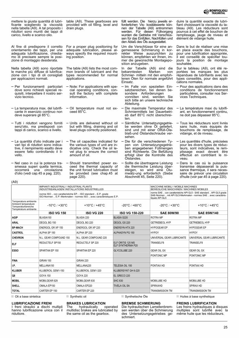
25
For a proper plug positioning foradequate lubrication, please al-ways specify the required mount-ing position.
The table (A9) lists the most com-mon brands of lubricant and thetypes recommended for normalapplications.
– Note: For applications with spe-cial operating conditions, con-sult the factory with completeinformation.
– Oil temperature must not ex-ceed 85°C.
– Units are delivered without oilbut with filling, draining and oillevel plugs correctly positioned.
– The oil capacities indicated forthe various types of unit are in-dicative only. Check the oil le-vel plug to ensure the correctamount of oil.
– Should transmitted power ex-ceed the thermal capacity ofthe unit forced lubrication mustbe provided (see chap.45 atpage 220).
Um die Verschlüsse für eine an-gemessene Schmierung in kor-rekter Weise auszurichten zukönnen, empfehlen wir Ihnen, im-mer die gewünschte Montagepo-sition anzugeben.
In der Tabelle (A9) sind diebekanntesten Marken vonSchmier- mitteln mit den empfoh-lenen Ölen für normale angeführtEinsatz.
– Im Falle von speziellen Ein-satzbereichen, bei denen be-sondere Anforderungenvonnöten sind, wenden Siesich bitte an unsere technischeAbteilung.
– Die maximale Temperatur desSchmiermittels bei Dauerbetri-eb darf 85°C nicht überschrei-ten.
– Sämtliche Untersetzungsgetrie-be werden ohne Öl geliefert,sind und mit einer Ölfüll-Öla-blaß-und Ölstandschraube ver-sehen.
– Die für die verschiedenen Ty-pen von Untersetzungsgetrie-ben angegebenen Füllmengensind Richtwerte. Die Befüllungerfolgt über die Kontrolle desÖlstandes.
– Sollte die übertragene Leistungdie thermische Leistung über-steigen, so wird eine Ölu-mwälz-ung erforderlich (SiebeAbschmitt 45, Seite 220).
Dans le but de réaliser une miseen place exacte des bouchons,pour une lubrification appropriée,il est conseillé de spécifier tou-jours la position de montagesouhaitée.
Sur le tableau (A9), ont été re-portées les marques les plusrépandues de lubrifiants avec lestypes conseillés, pour des appli-cations normales.
– Pour des applications dans desconditions de fonctionnementparticuliéres, consulter nos Ser-vices Techniques.
– La température maxi du lubrifi-ant, en fonctionnement continu,ne doit pas dépasser 85°C.
– Tous les réducteurs sont livréssans huile, mais équipés debouchons de remplissage, devidange, et de niveau.
– Les quantités d'huile, préciséespour les divers types de réduc-teurs, sont indicatives, le rem-plissage exact devant êtreeffectué en contrôlant le ni-veau.
– Dans le cas où la puissancetransmise dépasserait la puis-sance thermique, il sera neces-saire de prévoir une circulationd'huile (voir par.45 à page 220).
Al fine di predisporre il correttoorientamento dei tappi, per unaadeguata lubrificazione, chiedia-mo di precisare sempre la posi-zione di montaggio desiderata.
Nella tabella (A9) sono riportatele marche più diffuse di lubrifica-zione con i tipi di oli consigliatiper applicazioni normali.
– Per funzionamenti particolaridove sono richiesti speciali re-quisiti, interpellare il nostro ser-vizio tecnico.
– La temperatura max. del lubrifi-cante in esercizio continuo nondeve superare gli 85°C.
– Tutti i riduttori vengono fornitisenz'olio, ma predisposti contappi di carico, scarico e livello.
– La quantità d'olio indicate per ivari tipi di riduttori sono indica-tive, il riempimento esatto deveessere fatto controllando il li-vello.
– Nel caso in cui la potenza tra-smessa superi quella termica,occorrerà una circolazioned'olio (vedi cap.45 a pag. 220).
(A9)IMPIANTI INDUSTRIALI / INDUSTRIAL PLANTSINDUSTRIEANLAGEN/ INSTALLATIONS INDUSTRIELLES
MACCHINE MOBILI / MOBILE MACHINESBEWEGLICHE MASCHINEN / MACHINES MOBILES
norme ISO .. con caratteristiche EP. - ISO standard .. E.P. gradeISO-Normen .. E.P.-Merkmalen - normes ISO .. avec caractéristiques E.P.
norme SAE .. con caratteristiche API GL5 - SAE standard .. API GL5 gradeSAE-Normen .. mit API GL5-Merkmalen - normes SAE .. avec caractéris-tiques API GL5
Temperatura ambienteAmbient temperatureTemperaturbereicheTempérature ambiante
-10°C / +30°C +10°C / +45°C -20°C / +60°C -20°C / +30°C +10°C / +45°C
ISO VG 150 ISO VG 220 ISO VG 150-220 SAE 80W/90 SAE 85W/140
AGIP BLASIA150 BLASIA 220 BLASIA S220 ROTRA MP ROTRA MP
ARAL DEGOL BG 150 DEGOL BG 220 DEGOL GS 220 GETRIEBEOL HYP GETRIEBEOL HYP
BP-MACH ENERGOL GR XP 150 ENERGOL GR XP 220 ENERSYN HTX 220 HYPOGEAR EP HYPOGEAR EP
CASTROL ALPHA SP 150 ALPHA SP 220 ALPHASYN PG 150 HYPOY HYPOY
CHEVRON N.L. GEAR COMPOUND 150 N.L. GEAR COMPOUND 220 UNIVERSAL GEAR LUBRICANTE UNIVERSAL GEAR LUBRICANTE
ELFREDUCTELF SP150 REDUCTELF SP 220 ELF ORITIS 125 MS
ELF SYNTHERMA P20
TRANSELF8 TRANSELF8
ESSO SPARTAN EP 150 SPARTAN EP 220 GLYCOLUBE 220 GEAR OIL GX GEAR OIL GX
PONTONIC MP PONTONIC MP
FINA GIRAN 150 GIRAN 220
I.P. MELLANA150 MELLANA220 TELESIA OIL 150 PONTIAX HD PONTIAX HD
KLUBER KLUBEROIL GEM1-150 KLUBEROIL GEM1-320 KLUBERSYNT GH 6-220
Q8 GOYA 150 GOYA 220 EL GRECO 220
MOBIL MOBILGEAR 629 MOBILGEAR 630 SHC 630 MOBILUBE HD MOBILUBE HD
SHELL OMALA EP150 OMALA EP220 TIVELA OIL SA SPIRAXHD SPIRAX HD
TOTAL CARTER EP 150 CARTER EP 220 TRANSMISSION TM TRANSMISSION TM
Huiles à base synthetiqueSynthetic oil Synthetische ÖleOli a base sintetica
BRAKES LUBRICATIONThe hydraulically operatedmultidisc brakes are lubricated bythe same oil as the gearbox.
BREMSE SCHMIERUNGDie hydraulischen Lamellenbrem-sen werden über die Schmierungdes Untersetzungsgetriebes ge-schmiert.
FREINS LUBRIFICATIONLes freins hydrauliques à disquesmultiples sont lubrifié avec lamême huile que les réducteurs.
LUBRIFICAZIONE FRENII freni idraulici a dischi multiplihanno lubrificazione unica con ilriduttore.
mettere la giusta quantità di lubri-ficante scegliendo la viscositànella tabella (A9). A tal proposito iriduttori sono muniti dei tappi dicarico, livello e scarico olio.
table (A9). These gearboxes areprovided with oil filling, level anddrain plugs.
füllt werden. Die hierzu jeweils er-forderlichen Vis- kositätswerte kön-nen der Tabelle (A9) entnommenwerden. Für diesen Füllvorgangwurden die Getriebe mit Verschlüs-sen für das Einfüllen, Nachfüllen undden Ablaß des Öls ausgestattet.
duire la quantité exacte de lubri-fiant choisissant la viscosité du ta-bleau (A9). Les réducteurs sontpourvus à cet effet de bouchon deremplissage, jauge de niveau etélément de vidange huile.
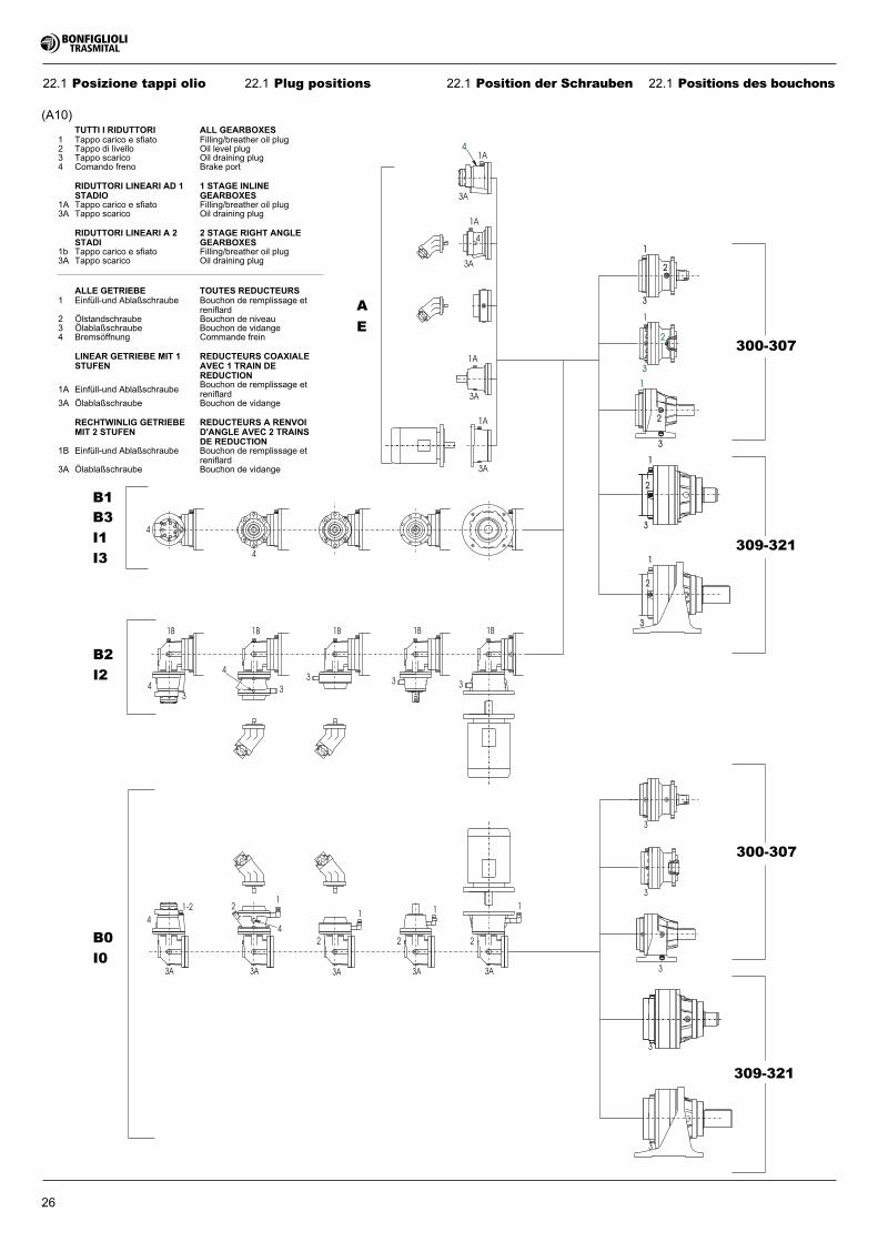
1A
1A
3A
3A
1
2
3
1
2
3
3
3
2
3
2
1
3
1
1A
3A
4
1
2
3
3
1A
3A
4
1
22
12
2
1
4
1
3
3
33
3
3
1B 1B1B1B1B
1-2
3
4
4
4
4
4
3A 3A 3A 3A3A
309-321
300-307
309-321
E
A
I3
I1
B3
B1
I2
B2
I0
B0
300-307
26
22.1 Plug positions 22.1 Position der Schrauben 22.1 Positions des bouchons22.1 Posizione tappi olio
(A10)TUTTI I RIDUTTORI ALL GEARBOXES
1 Tappo carico e sfiato Filling/breather oil plug2 Tappo di livello Oil level plug3 Tappo scarico Oil draining plug4 Comando freno Brake port
RIDUTTORI LINEARI AD 1STADIO
1 STAGE INLINEGEARBOXES
1A Tappo carico e sfiato Filling/breather oil plug3A Tappo scarico Oil draining plug
RIDUTTORI LINEARI A 2STADI
2 STAGE RIGHT ANGLEGEARBOXES
1b Tappo carico e sfiato Filling/breather oil plug3A Tappo scarico Oil draining plug
ALLE GETRIEBE TOUTES REDUCTEURS1 Einfüll-und Ablaßschraube Bouchon de remplissage et
reniflard2 Ölstandschraube Bouchon de niveau3 Ölablaßschraube Bouchon de vidange4 Bremsöffnung Commande frein
LINEAR GETRIEBE MIT 1STUFEN
REDUCTEURS COAXIALEAVEC 1 TRAIN DEREDUCTION
1A Einfüll-und AblaßschraubeBouchon de remplissage etreniflard
3A Ölablaßschraube Bouchon de vidange
RECHTWINLIG GETRIEBEMIT 2 STUFEN
REDUCTEURS A RENVOID'ANGLE AVEC 2 TRAINSDE REDUCTION
1B Einfüll-und Ablaßschraube Bouchon de remplissage etreniflard
3A Ölablaßschraube Bouchon de vidange
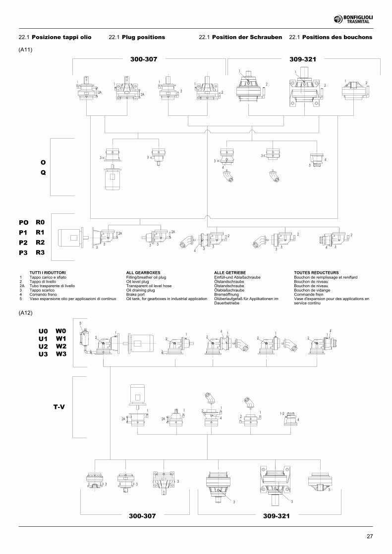
11
2222
2
3 3
T-V
U3
U2
U1
U0
W3
W2
W1
W0
5
309-321300-307
33
33
4
2 2
11
1
2A2A
1
309-321300-307
3
Q
O
P3
P2
P1
PO
R3
R2
R1
R0
4
1
2A
12
4
1
2A
1
2
33
3
1-2
4
3333
2A2A
22
3 3
33 3
2
44
1 111
14 4
12
22
3
27
TUTTI I RIDUTTORI ALL GEARBOXES ALLE GETRIEBE TOUTES REDUCTEURS1 Tappo carico e sfiato Filling/breather oil plug Einfüll-und Ablaßschraube Bouchon de remplissage et reniflard2 Tappo di livello Oil level plug Ölstandschraube Bouchon de niveau2A Tubo trasparente di livello Transparent oil level hose Ölstandschraube Bouchon de niveau3 Tappo scarico Oil draining plug Ölablaßschraube Bouchon de vidange4 Comando freno Brake port Bremsöffnung Commande frein5 Vaso espansione olio per applicazioni di continuo Oil tank, for gearboxes in industrial application Olüberlaufgefaß für Applikationen im
DauerbetriebeVase d'expansion pour des applications enservice continu
22.1 Plug positions 22.1 Position der Schrauben 22.1 Positions des bouchons
(A12)
(A11)
22.1 Posizione tappi olio
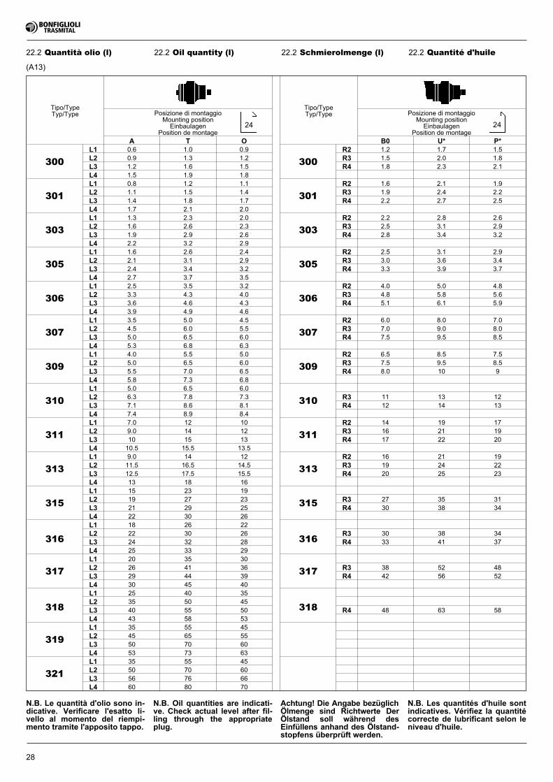
28
22.2 Schmierolmenge (l) 22.2 Quantité d'huile
Tipo/TypeTyp/Type
Tipo/TypeTyp/TypePosizione di montaggio
Mounting positionEinbaulagen
Position de montage
Posizione di montaggioMounting position
EinbaulagenPosition de montage
A T O B0 U* P*
300
L1 0.6 1.0 0.9
300
R2 1.2 1.7 1.5
L2 0.9 1.3 1.2 R3 1.5 2.0 1.8
L3 1.2 1.6 1.5 R4 1.8 2.3 2.1
L4 1.5 1.9 1.8
301
L1 0.8 1.2 1.1
301
R2 1.6 2.1 1.9
L2 1.1 1.5 1.4 R3 1.9 2.4 2.2
L3 1.4 1.8 1.7 R4 2.2 2.7 2.5
L4 1.7 2.1 2.0
303
L1 1.3 2.3 2.0
303
R2 2.2 2.8 2.6
L2 1.6 2.6 2.3 R3 2.5 3.1 2.9
L3 1.9 2.9 2.6 R4 2.8 3.4 3.2
L4 2.2 3.2 2.9
305
L1 1.6 2.6 2.4
305
R2 2.5 3.1 2.9
L2 2.1 3.1 2.9 R3 3.0 3.6 3.4
L3 2.4 3.4 3.2 R4 3.3 3.9 3.7
L4 2.7 3.7 3.5
306
L1 2.5 3.5 3.2
306
R2 4.0 5.0 4.8
L2 3.3 4.3 4.0 R3 4.8 5.8 5.6
L3 3.6 4.6 4.3 R4 5.1 6.1 5.9
L4 3.9 4.9 4.6
307
L1 3.5 5.0 4.5
307
R2 6.0 8.0 7.0
L2 4.5 6.0 5.5 R3 7.0 9.0 8.0
L3 5.0 6.5 6.0 R4 7.5 9.5 8.5
L4 5.3 6.8 6.3
309
L1 4.0 5.5 5.0
309
R2 6.5 8.5 7.5
L2 5.0 6.5 6.0 R3 7.5 9.5 8.5
L3 5.5 7.0 6.5 R4 8.0 10 9
L4 5.8 7.3 6.8
310
L1 5.0 6.5 6.0
310L2 6.3 7.8 7.3 R3 11 13 12
L3 7.1 8.6 8.1 R4 12 14 13
L4 7.4 8.9 8.4
311
L1 7.0 12 10
311
R2 14 19 17
L2 9.0 14 12 R3 16 21 19
L3 10 15 13 R4 17 22 20
L4 10.5 15.5 13.5
313
L1 9.0 14 12
313
R2 16 21 19
L2 11.5 16.5 14.5 R3 19 24 22
L3 12.5 17.5 15.5 R4 20 25 23
L4 13 18 16
315
L1 15 23 19
315L2 19 27 23 R3 27 35 31
L3 21 29 25 R4 30 38 34
L4 22 30 26
316
L1 18 26 22
316L2 22 30 26 R3 30 38 34
L3 24 32 28 R4 33 41 37
L4 25 33 29
317
L1 20 35 30
317L2 26 41 36 R3 38 52 48
L3 29 44 39 R4 42 56 52
L4 30 45 40
318
L1 25 40 35
318L2 35 50 45
L3 40 55 50 R4 48 63 58
L4 43 58 53
319
L1 35 55 45
L2 45 65 55
L3 50 70 60
L4 53 73 63
321
L1 35 55 45
L2 50 70 60
L3 56 76 66
L4 60 80 70
N.B. Oil quantities are indicati-ve. Check actual level after fil-ling through the appropriateplug.
Achtung! Die Angabe bezüglichÖlmenge sind Richtwerte DerÖlstand soll während desEinfüllens anhand des Ölstand-stopfens überprüft werden.
N.B. Les quantités d'huile sontindicatives. Vérifiez la quantitécorrecte de lubrificant selon leniveau d'huile.
N.B. Le quantità d'olio sono in-dicative. Verificare l'esatto li-vello al momento del riempi-mento tramite l'apposito tappo.
(A13)
24
22.2 Oil quantity (l)
24
22.2 Quantità olio (l)
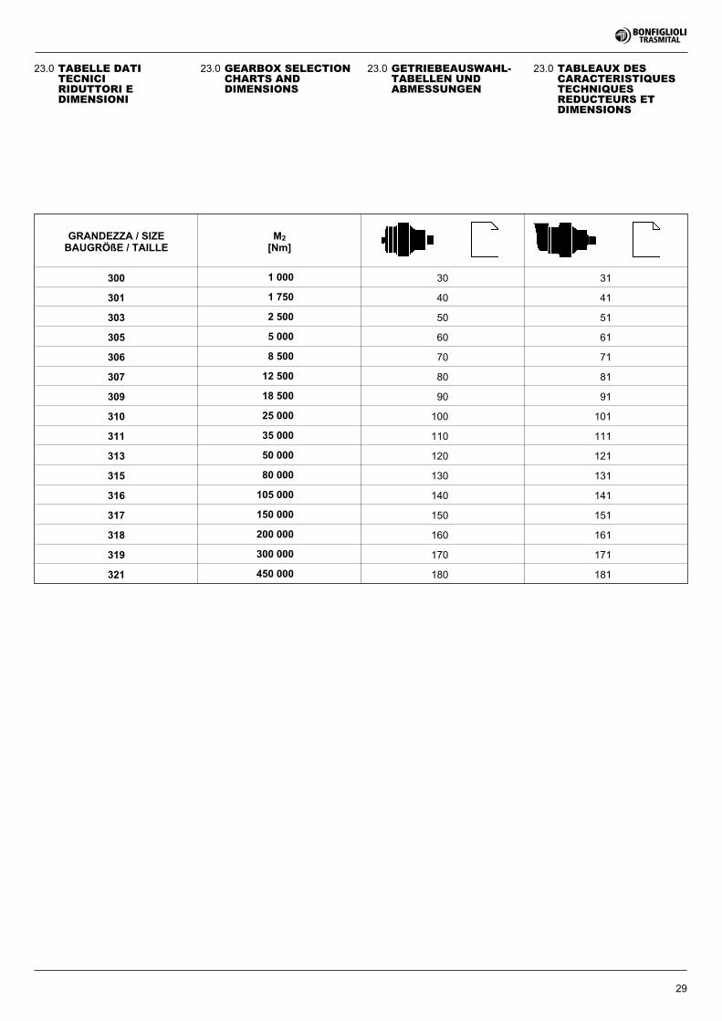
29
23.0 GEARBOX SELECTIONCHARTS ANDDIMENSIONS
23.0 GETRIEBEAUSWAHL-TABELLEN UNDABMESSUNGEN
23.0 TABLEAUX DESCARACTERISTIQUESTECHNIQUESREDUCTEURS ETDIMENSIONS
23.0 TABELLE DATITECNICIRIDUTTORI EDIMENSIONI
GRANDEZZA / SIZEBAUGRÖßE / TAILLE
M2
[Nm]
300 1 000 30 31
301 1 750 40 41
303 2 500 50 51
305 5 000 60 61
306 8 500 70 71
307 12 500 80 81
309 18 500 90 91
310 25 000 100 101
311 35 000 110 111
313 50 000 120 121
315 80 000 130 131
316 105 000 140 141
317 150 000 150 151
318 200 000 160 161
319 300 000 170 171
321 450 000 180 181
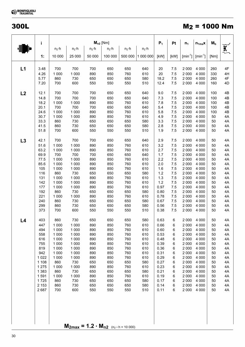
30
300L M2 = 1000 Nm
i Mn2 [Nm] P1 Pt n1 n1max Mb
n2·h n2·h n2·h n2·h n2·h n2·h
1: 10 000 25 000 50 000 100 000 500 000 1 000 000 [kW] [kW] [min-1] [min-1] [Nm]
(n2 • h = 10 000)M2max = 1.2 • Mn2
L1 3.48 700 700 700 650 650 640 20 7.5 2 000 4 000 260 4F
4.26 1 000 1 000 890 850 760 610 20 7.5 2 000 4 000 330 4H5.77 860 730 650 650 650 580 18.2 7.5 2 000 4 000 260 4F7.20 700 600 550 550 550 510 12.4 7.5 2 000 4 000 160 4D
L2 12.1 700 700 700 650 650 640 9.0 7.5 2 000 4 000 100 4B
14.8 700 700 700 650 650 640 7.3 7.5 2 000 4 000 100 4B18.2 1 000 1 000 890 850 760 610 7.8 7.5 2 000 4 000 100 4B20.1 700 700 700 650 650 640 5.4 7.5 2 000 4 000 100 4B24.6 1 000 1 000 890 850 760 610 5.8 7.5 2 000 4 000 100 4B30.7 1 000 1 000 890 850 760 610 4.9 7.5 2 000 4 000 50 4A33.3 860 730 650 650 650 580 3.3 7.5 2 000 4 000 50 4A41.5 860 730 650 650 650 580 2.8 7.5 2 000 4 000 50 4A51.8 700 600 550 550 550 510 1.9 7.5 2 000 4 000 50 4A
L3 42.1 700 700 700 650 650 640 2.9 7.5 2 000 4 000 50 4A
51.6 1 000 1 000 890 850 760 610 3.2 7.5 2 000 4 000 50 4A63.2 1 000 1 000 890 850 760 610 2.7 7.5 2 000 4 000 50 4A69.9 700 700 700 650 650 640 1.7 7.5 2 000 4 000 50 4A77.5 1 000 1 000 890 850 760 610 2.2 7.5 2 000 4 000 50 4A85.6 1 000 1 000 890 850 760 610 2.0 7.5 2 000 4 000 50 4A105 1 000 1 000 890 850 760 610 1.6 7.5 2 000 4 000 50 4A116 860 730 650 650 650 580 1.2 7.5 2 000 4 000 50 4A131 1 000 1 000 890 850 760 610 1.3 7.5 2 000 4 000 50 4A142 1 000 1 000 890 850 760 610 1.2 7.5 2 000 4 000 50 4A177 1 000 1 000 890 850 760 610 0.97 7.5 2 000 4 000 50 4A192 860 730 650 650 650 580 0.80 7.5 2 000 4 000 50 4A221 1 000 1 000 890 850 760 610 0.78 7.5 2 000 4 000 50 4A240 860 730 650 650 650 580 0.67 7.5 2 000 4 000 50 4A299 860 730 650 650 650 580 0.56 7.5 2 000 4 000 50 4A373 700 600 550 550 550 510 0.38 7.5 2 000 4 000 50 4A
L4 403 860 730 650 650 650 580 0.63 6 2 000 4 000 50 4A
447 1 000 1 000 890 850 760 610 0.66 6 2 000 4 000 50 4A494 1 000 1 000 890 850 760 610 0.60 6 2 000 4 000 50 4A558 1 000 1 000 890 850 760 610 0.53 6 2 000 4 000 50 4A616 1 000 1 000 890 850 760 610 0.48 6 2 000 4 000 50 4A755 1 000 1 000 890 850 760 610 0.39 6 2 000 4 000 50 4A819 1 000 1 000 890 850 760 610 0.36 6 2 000 4 000 50 4A942 1 000 1 000 890 850 760 610 0.31 6 2 000 4 000 50 4A1 022 1 000 1 000 890 850 760 610 0.29 6 2 000 4 000 50 4A1 108 860 730 650 650 650 580 0.27 6 2 000 4 000 50 4A1 275 1 000 1 000 890 850 760 610 0.23 6 2 000 4 000 50 4A1 383 860 730 650 650 650 580 0.21 6 2 000 4 000 50 4A1 591 1 000 1 000 890 850 760 610 0.19 6 2 000 4 000 50 4A1 725 860 730 650 650 650 580 0.17 6 2 000 4 000 50 4A2 153 860 730 650 650 650 580 0.14 6 2 000 4 000 50 4A2 687 700 600 550 550 550 510 0.11 6 2 000 4 000 50 4A
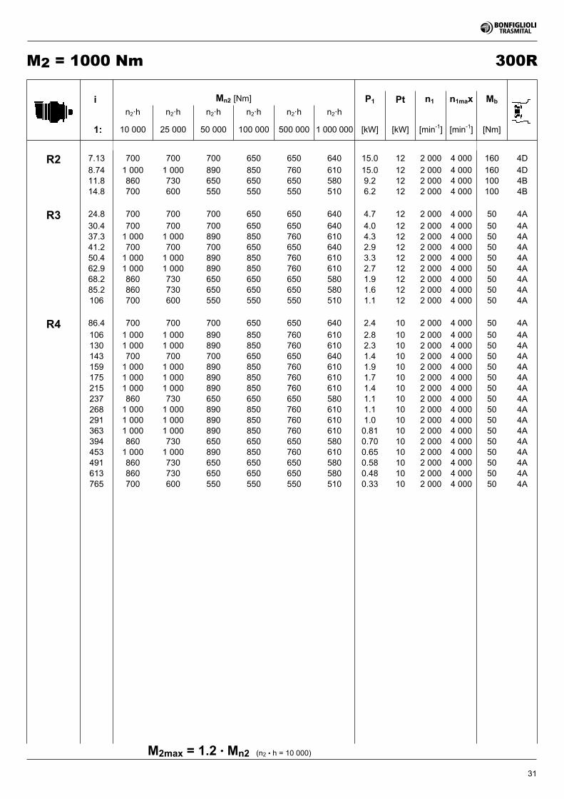
31
300RM2 = 1000 Nm
(n2 • h = 10 000)M2max = 1.2 • Mn2
i Mn2 [Nm] P1 Pt n1 n1max Mb
n2·h n2·h n2·h n2·h n2·h n2·h
1: 10 000 25 000 50 000 100 000 500 000 1 000 000 [kW] [kW] [min-1] [min-1] [Nm]
R2 7.13 700 700 700 650 650 640 15.0 12 2 000 4 000 160 4D
8.74 1 000 1 000 890 850 760 610 15.0 12 2 000 4 000 160 4D11.8 860 730 650 650 650 580 9.2 12 2 000 4 000 100 4B14.8 700 600 550 550 550 510 6.2 12 2 000 4 000 100 4B
R3 24.8 700 700 700 650 650 640 4.7 12 2 000 4 000 50 4A
30.4 700 700 700 650 650 640 4.0 12 2 000 4 000 50 4A37.3 1 000 1 000 890 850 760 610 4.3 12 2 000 4 000 50 4A41.2 700 700 700 650 650 640 2.9 12 2 000 4 000 50 4A50.4 1 000 1 000 890 850 760 610 3.3 12 2 000 4 000 50 4A62.9 1 000 1 000 890 850 760 610 2.7 12 2 000 4 000 50 4A68.2 860 730 650 650 650 580 1.9 12 2 000 4 000 50 4A85.2 860 730 650 650 650 580 1.6 12 2 000 4 000 50 4A106 700 600 550 550 550 510 1.1 12 2 000 4 000 50 4A
R4 86.4 700 700 700 650 650 640 2.4 10 2 000 4 000 50 4A
106 1 000 1 000 890 850 760 610 2.8 10 2 000 4 000 50 4A130 1 000 1 000 890 850 760 610 2.3 10 2 000 4 000 50 4A143 700 700 700 650 650 640 1.4 10 2 000 4 000 50 4A159 1 000 1 000 890 850 760 610 1.9 10 2 000 4 000 50 4A175 1 000 1 000 890 850 760 610 1.7 10 2 000 4 000 50 4A215 1 000 1 000 890 850 760 610 1.4 10 2 000 4 000 50 4A237 860 730 650 650 650 580 1.1 10 2 000 4 000 50 4A268 1 000 1 000 890 850 760 610 1.1 10 2 000 4 000 50 4A291 1 000 1 000 890 850 760 610 1.0 10 2 000 4 000 50 4A363 1 000 1 000 890 850 760 610 0.81 10 2 000 4 000 50 4A394 860 730 650 650 650 580 0.70 10 2 000 4 000 50 4A453 1 000 1 000 890 850 760 610 0.65 10 2 000 4 000 50 4A491 860 730 650 650 650 580 0.58 10 2 000 4 000 50 4A613 860 730 650 650 650 580 0.48 10 2 000 4 000 50 4A765 700 600 550 550 550 510 0.33 10 2 000 4 000 50 4A
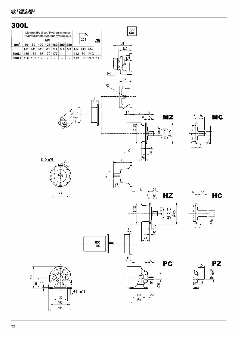
32
IECB5
300LMotore idraulico / Hydraulic motorHydraulikmotor/Moteur hydraulique
MG
cm3 50 80 100 125 160 200 250
M1 M1 M1 M1 M1 M1 M1 M2 M3 M4
300L1 156 162 166 170 177 - - 113 60 1/4G 14
300L2 156 162 166 - - - - 113 60 1/4G 14
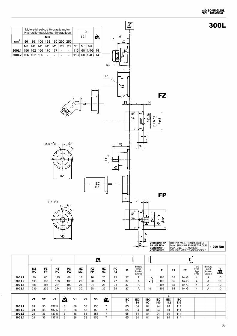
33
IECB5
300L
L
MZMC
FZFP
HZHC
PCPZ
MZMC
FZFP
HZHC
PCPZ C
EntrataInputAntriebEntrée
I F F1 F2TipoTypeTypType
EntrataInputAntriebEntrée
300 L1 80 80 115 86 18 16 20 23 37 A 105 65 1/4 G 4 A 10300 L2 133 133 168 139 22 20 24 27 37 A 105 65 1/4 G 4 A 10300 L3 186 186 221 192 26 24 28 31 37 A 105 65 1/4 G 4 A 10300 L4 239 239 274 245 30 28 32 35 37 A 191 105 65 1/4 G 4 A 10
V1 V2 V3 V1 V2 V3E
IEC71
IEC80
IEC90
IEC100
IEC112
IEC132
300 L1 24 36 137.5 6 38 58 158 7 65 84 84 94 94 114300 L2 24 36 137.5 6 38 58 158 7 65 84 84 94 94 114300 L3 24 36 137.5 6 38 58 158 7 65 84 84 94 94 114300 L4 24 36 137.5 6 38 58 158 7 65 84 84 94 94 114
VERSIONE FPFP VERSIONVERSION FPVERSION FP
COPPIA MAX. TRASMISSIBILEMAX. TRANSMISSIBLE TORQUEMAX. ÜBERTR. MOMENTCOUPLE MAX. TRANSMISSIBLE
1 200 Nm
Motore idraulico / Hydraulic motorHydraulikmotor/Moteur hydraulique
MG
cm3 50 80 100 125 160 200 250
M1 M1 M1 M1 M1 M1 M1 M2 M3 M4
300L1 156 162 166 170 177 - - 113 60 1/4G 14
300L2 156 162 166 - - - - 113 60 1/4G 14
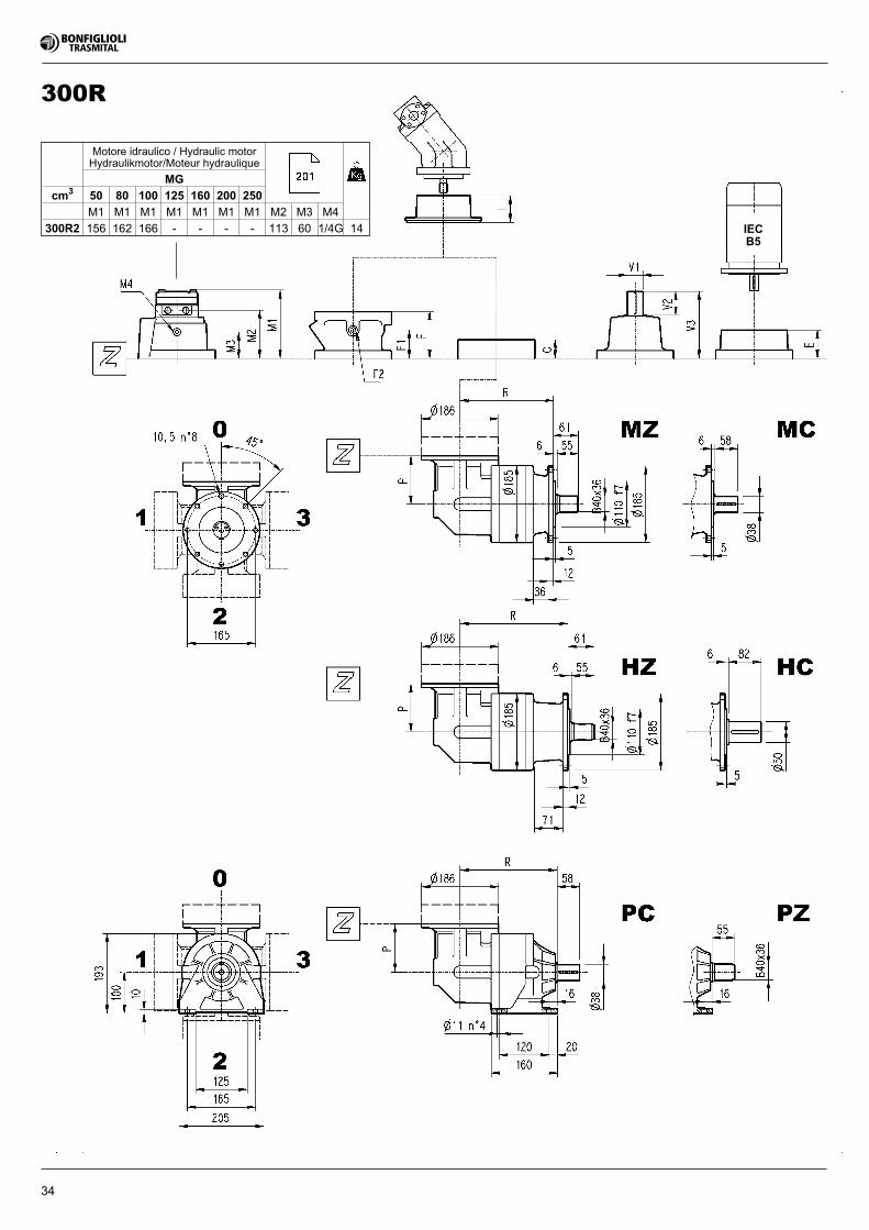
34
IECB5
300R
Motore idraulico / Hydraulic motorHydraulikmotor/Moteur hydraulique
MG
cm3 50 80 100 125 160 200 250
M1 M1 M1 M1 M1 M1 M1 M2 M3 M4
300R2 156 162 166 - - - - 113 60 1/4G 14
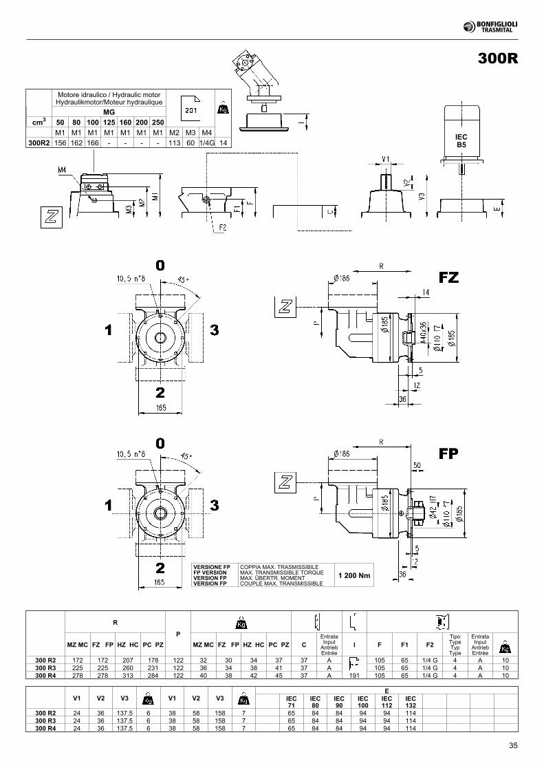
35
IECB5
300R
R
P
MZ MC FZ FP HZ HC PC PZ MZ MC FZ FP HZ HC PC PZ CEntrataInputAntriebEntrée
I F F1 F2TipoTypeTypType
EntrataInputAntriebEntrée
300 R2 172 172 207 178 122 32 30 34 37 37 A 105 65 1/4 G 4 A 10300 R3 225 225 260 231 122 36 34 38 41 37 A 105 65 1/4 G 4 A 10300 R4 278 278 313 284 122 40 38 42 45 37 A 191 105 65 1/4 G 4 A 10
V1 V2 V3 V1 V2 V3E
IEC71
IEC80
IEC90
IEC100
IEC112
IEC132
300 R2 24 36 137.5 6 38 58 158 7 65 84 84 94 94 114300 R3 24 36 137.5 6 38 58 158 7 65 84 84 94 94 114300 R4 24 36 137.5 6 38 58 158 7 65 84 84 94 94 114
VERSIONE FPFP VERSIONVERSION FPVERSION FP
COPPIA MAX. TRASMISSIBILEMAX. TRANSMISSIBLE TORQUEMAX. ÜBERTR. MOMENTCOUPLE MAX. TRANSMISSIBLE
1 200 Nm
Motore idraulico / Hydraulic motorHydraulikmotor/Moteur hydraulique
MG
cm3 50 80 100 125 160 200 250
M1 M1 M1 M1 M1 M1 M1 M2 M3 M4
300R2 156 162 166 - - - - 113 60 1/4G 14
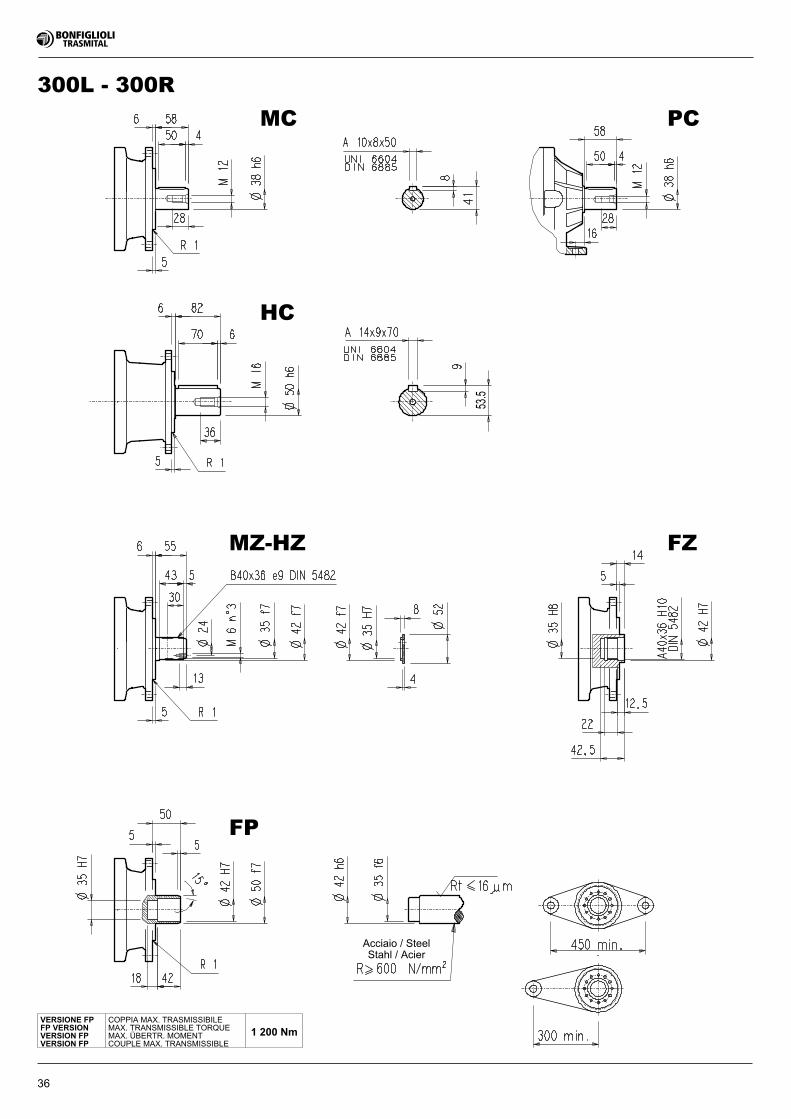
36
MC
HC
MZ-HZ
FP
PC
FZ
53.5
300L - 300R
VERSIONE FPFP VERSIONVERSION FPVERSION FP
COPPIA MAX. TRASMISSIBILEMAX. TRANSMISSIBLE TORQUEMAX. ÜBERTR. MOMENTCOUPLE MAX. TRANSMISSIBLE
1 200 Nm
Acciaio / SteelStahl / Acier
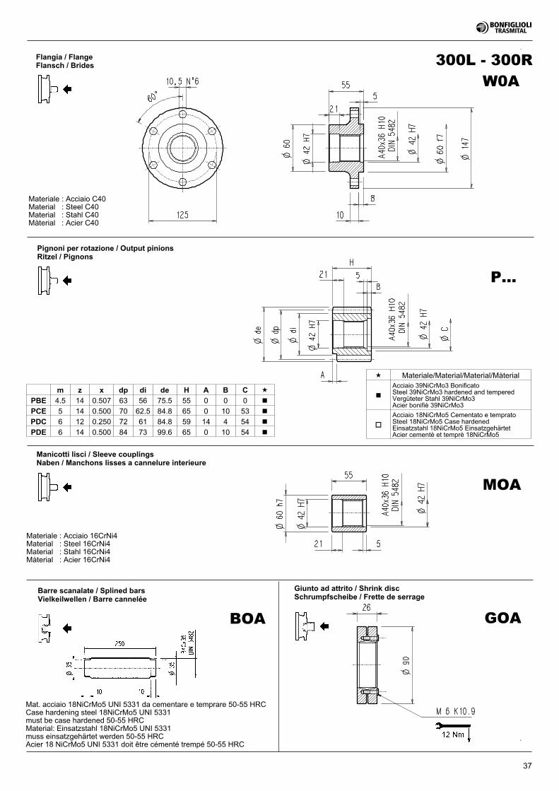
37
300L - 300RFlangia / FlangeFlansch / Brides
Materiale : Acciaio C40Material : Steel C40Material : Stahl C40Màterial : Acier C40
Pignoni per rotazione / Output pinionsRitzel / Pignons
Manicotti lisci / Sleeve couplingsNaben / Manchons lisses a cannelure interieure
Materiale : Acciaio 16CrNi4Material : Steel 16CrNi4Material : Stahl 16CrNi4Màterial : Acier 16CrNi4
Barre scanalate / Splined barsVielkeilwellen / Barre cannelée
Giunto ad attrito / Shrink discSchrumpfscheibe / Frette de serrage
P...
MOA
BOA
� Materiale/Material/Material/Màterial
�
Acciaio 39NiCrMo3 BonificatoSteel 39NiCrMo3 hardened and temperedVergüteter Stahl 39NiCrMo3Acier bonifiè 39NiCrMo3
�
Acciaio 18NiCrMo5 Cementato e tempratoSteel 18NiCrMo5 Case hardenedEinsatzstahl 18NiCrMo5 EinsatzgehärtetAcier cementè et temprè 18NiCrMo5
m z x dp di de H A B C �
PBE 4.5 14 0.507 63 56 75.5 55 0 0 0 �
PCE 5 14 0.500 70 62.5 84.8 65 0 10 53 �
PDC 6 12 0.250 72 61 84.8 59 14 4 54 �
PDE 6 14 0.500 84 73 99.6 65 0 10 54 �
Mat. acciaio 18NiCrMo5 UNI 5331 da cementare e temprare 50-55 HRCCase hardening steel 18NiCrMo5 UNI 5331must be case hardened 50-55 HRCMaterial: Einsatzstahl 18NiCrMo5 UNI 5331muss einsatzgehärtet werden 50-55 HRCAcier 18 NiCrMo5 UNI 5331 doit être cémenté trempé 50-55 HRC
GOA
W0A
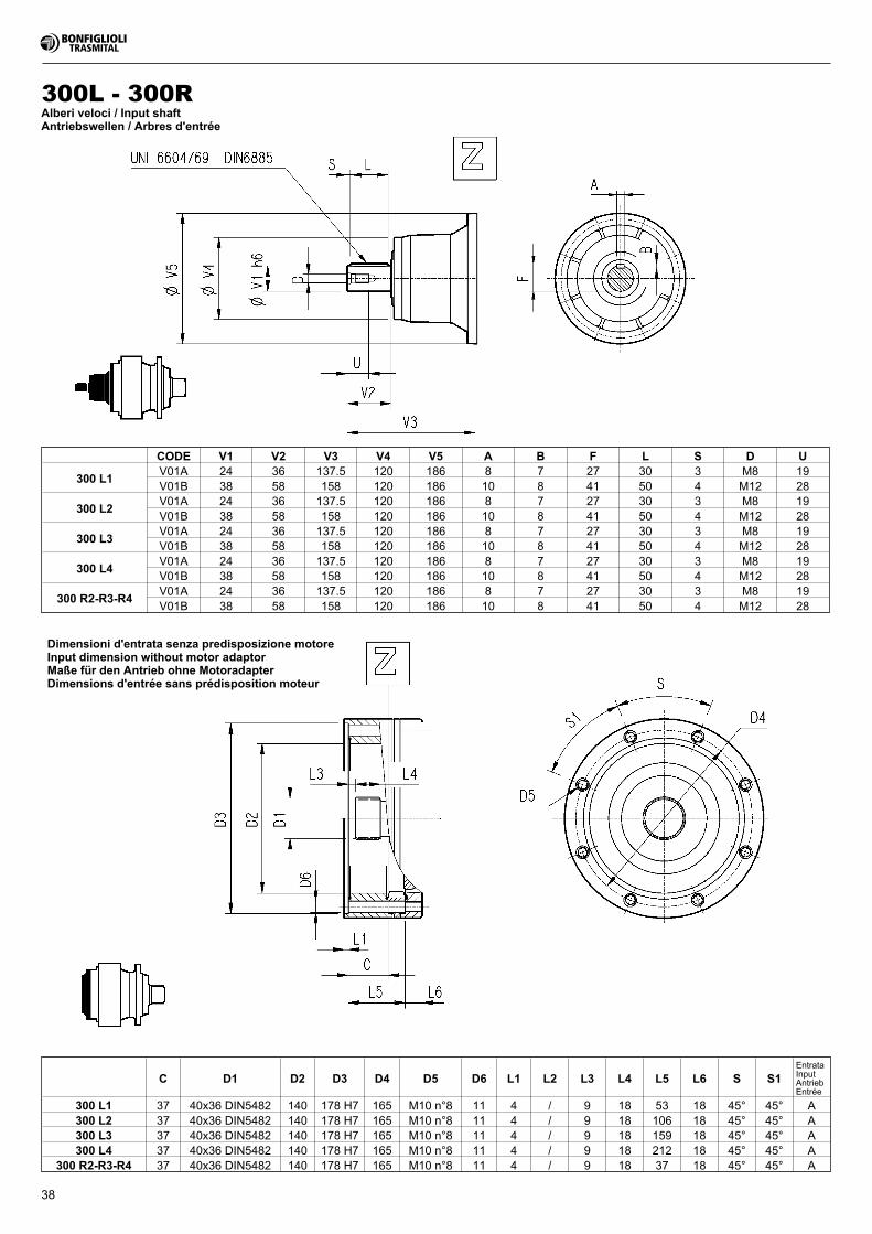
38
Alberi veloci / Input shaftAntriebswellen / Arbres d'entrée
Dimensioni d'entrata senza predisposizione motoreInput dimension without motor adaptorMaße für den Antrieb ohne MotoradapterDimensions d'entrée sans prédisposition moteur
300L - 300R
C D1 D2 D3 D4 D5 D6 L1 L2 L3 L4 L5 L6 S S1EntrataInputAntriebEntrée
300 L1 37 40x36 DIN5482 140 178 H7 165 M10 n°8 11 4 / 9 18 53 18 45° 45° A300 L2 37 40x36 DIN5482 140 178 H7 165 M10 n°8 11 4 / 9 18 106 18 45° 45° A300 L3 37 40x36 DIN5482 140 178 H7 165 M10 n°8 11 4 / 9 18 159 18 45° 45° A300 L4 37 40x36 DIN5482 140 178 H7 165 M10 n°8 11 4 / 9 18 212 18 45° 45° A
300 R2-R3-R4 37 40x36 DIN5482 140 178 H7 165 M10 n°8 11 4 / 9 18 37 18 45° 45° A
CODE V1 V2 V3 V4 V5 A B F L S D U
300 L1V01A 24 36 137.5 120 186 8 7 27 30 3 M8 19V01B 38 58 158 120 186 10 8 41 50 4 M12 28
300 L2V01A 24 36 137.5 120 186 8 7 27 30 3 M8 19V01B 38 58 158 120 186 10 8 41 50 4 M12 28
300 L3V01A 24 36 137.5 120 186 8 7 27 30 3 M8 19V01B 38 58 158 120 186 10 8 41 50 4 M12 28
300 L4V01A 24 36 137.5 120 186 8 7 27 30 3 M8 19V01B 38 58 158 120 186 10 8 41 50 4 M12 28
300 R2-R3-R4V01A 24 36 137.5 120 186 8 7 27 30 3 M8 19V01B 38 58 158 120 186 10 8 41 50 4 M12 28
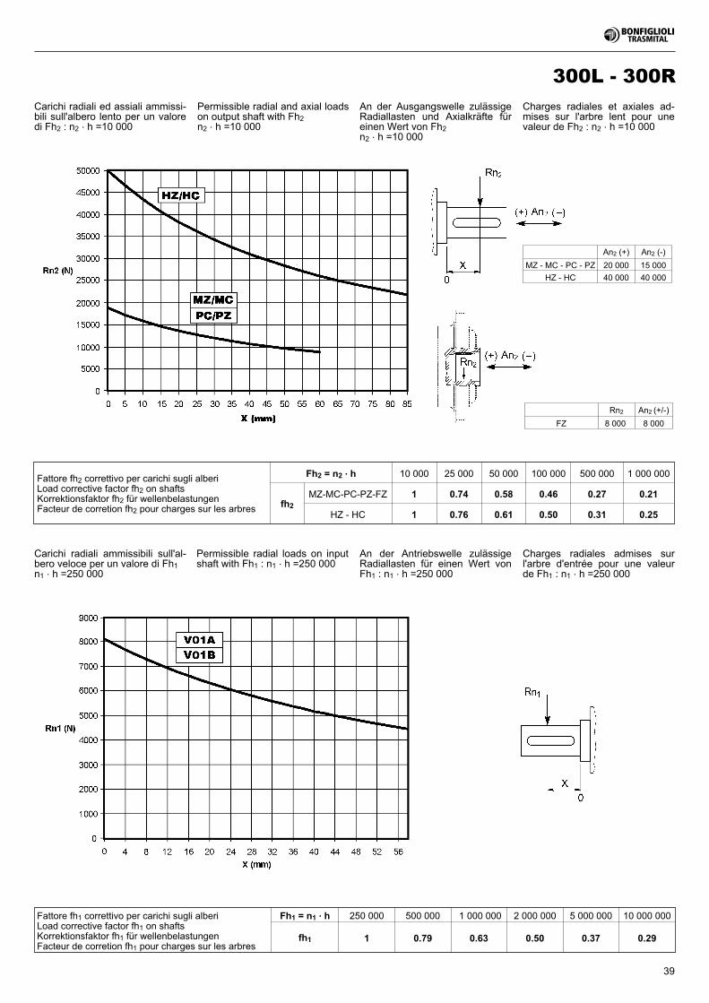
39
300L - 300R
Fattore fh1 correttivo per carichi sugli alberiLoad corrective factor fh1 on shaftsKorrektionsfaktor fh1 für wellenbelastungenFacteur de corretion fh1 pour charges sur les arbres
Fh1 = n1 . h 250 000 500 000 1 000 000 2 000 000 5 000 000 10 000 000
fh1 1 0.79 0.63 0.50 0.37 0.29
Fattore fh2 correttivo per carichi sugli alberiLoad corrective factor fh2 on shaftsKorrektionsfaktor fh2 für wellenbelastungenFacteur de corretion fh2 pour charges sur les arbres
Fh2 = n2 . h 10 000 25 000 50 000 100 000 500 000 1 000 000
fh2
MZ-MC-PC-PZ-FZ 1 0.74 0.58 0.46 0.27 0.21
HZ - HC 1 0.76 0.61 0.50 0.31 0.25
Carichi radiali ammissibili sull'al-bero veloce per un valore di Fh1n1 . h =250 000
Carichi radiali ed assiali ammissi-bili sull'albero lento per un valoredi Fh2 : n2 . h =10 000
Rn2 An2 (+/-)
FZ 8 000 8 000
An2 (+) An2 (-)
MZ - MC - PC - PZ 20 000 15 000
HZ - HC 40 000 40 000
Permissible radial and axial loadson output shaft with Fh2n2 . h =10 000
An der Ausgangswelle zulässigeRadiallasten und Axialkräfte füreinen Wert von Fh2n2 . h =10 000
Charges radiales et axiales ad-mises sur l'arbre lent pour unevaleur de Fh2 : n2 . h =10 000
Permissible radial loads on inputshaft with Fh1 : n1 . h =250 000
An der Antriebswelle zulässigeRadiallasten für einen Wert vonFh1 : n1 . h =250 000
Charges radiales admises surl'arbre d'entrée pour une valeurde Fh1 : n1 . h =250 000
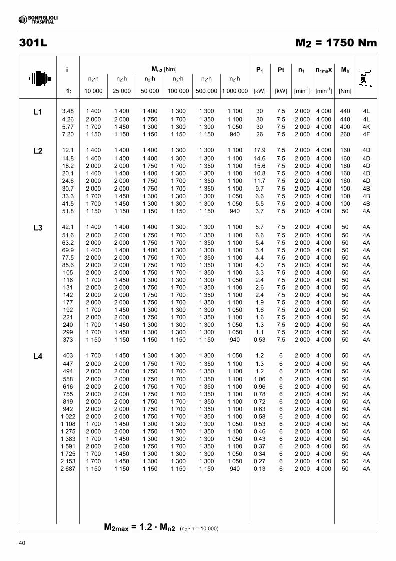
40
301L M2 = 1750 Nm
(n2 • h = 10 000)M2max = 1.2 • Mn2
i Mn2 [Nm] P1 Pt n1 n1max Mb
n2·h n2·h n2·h n2·h n2·h n2·h
1: 10 000 25 000 50 000 100 000 500 000 1 000 000 [kW] [kW] [min-1] [min-1] [Nm]
L1 3.48 1 400 1 400 1 400 1 300 1 300 1 100 30 7.5 2 000 4 000 440 4L
4.26 2 000 2 000 1 750 1 700 1 350 1 100 30 7.5 2 000 4 000 440 4L5.77 1 700 1 450 1 300 1 300 1 300 1 050 30 7.5 2 000 4 000 400 4K7.20 1 150 1 150 1 150 1 150 1 150 940 26 7.5 2 000 4 000 260 4F
L2 12.1 1 400 1 400 1 400 1 300 1 300 1 100 17.9 7.5 2 000 4 000 160 4D
14.8 1 400 1 400 1 400 1 300 1 300 1 100 14.6 7.5 2 000 4 000 160 4D18.2 2 000 2 000 1 750 1 700 1 350 1 100 15.6 7.5 2 000 4 000 160 4D20.1 1 400 1 400 1 400 1 300 1 300 1 100 10.8 7.5 2 000 4 000 160 4D24.6 2 000 2 000 1 750 1 700 1 350 1 100 11.7 7.5 2 000 4 000 160 4D30.7 2 000 2 000 1 750 1 700 1 350 1 100 9.7 7.5 2 000 4 000 100 4B33.3 1 700 1 450 1 300 1 300 1 300 1 050 6.6 7.5 2 000 4 000 100 4B41.5 1 700 1 450 1 300 1 300 1 300 1 050 5.5 7.5 2 000 4 000 100 4B51.8 1 150 1 150 1 150 1 150 1 150 940 3.7 7.5 2 000 4 000 50 4A
L3 42.1 1 400 1 400 1 400 1 300 1 300 1 100 5.7 7.5 2 000 4 000 50 4A
51.6 2 000 2 000 1 750 1 700 1 350 1 100 6.6 7.5 2 000 4 000 50 4A63.2 2 000 2 000 1 750 1 700 1 350 1 100 5.4 7.5 2 000 4 000 50 4A69.9 1 400 1 400 1 400 1 300 1 300 1 100 3.4 7.5 2 000 4 000 50 4A77.5 2 000 2 000 1 750 1 700 1 350 1 100 4.4 7.5 2 000 4 000 50 4A85.6 2 000 2 000 1 750 1 700 1 350 1 100 4.0 7.5 2 000 4 000 50 4A105 2 000 2 000 1 750 1 700 1 350 1 100 3.3 7.5 2 000 4 000 50 4A116 1 700 1 450 1 300 1 300 1 300 1 050 2.4 7.5 2 000 4 000 50 4A131 2 000 2 000 1 750 1 700 1 350 1 100 2.6 7.5 2 000 4 000 50 4A142 2 000 2 000 1 750 1 700 1 350 1 100 2.4 7.5 2 000 4 000 50 4A177 2 000 2 000 1 750 1 700 1 350 1 100 1.9 7.5 2 000 4 000 50 4A192 1 700 1 450 1 300 1 300 1 300 1 050 1.6 7.5 2 000 4 000 50 4A221 2 000 2 000 1 750 1 700 1 350 1 100 1.6 7.5 2 000 4 000 50 4A240 1 700 1 450 1 300 1 300 1 300 1 050 1.3 7.5 2 000 4 000 50 4A299 1 700 1 450 1 300 1 300 1 300 1 050 1.1 7.5 2 000 4 000 50 4A373 1 150 1 150 1 150 1 150 1 150 940 0.53 7.5 2 000 4 000 50 4A
L4 403 1 700 1 450 1 300 1 300 1 300 1 050 1.2 6 2 000 4 000 50 4A
447 2 000 2 000 1 750 1 700 1 350 1 100 1.3 6 2 000 4 000 50 4A494 2 000 2 000 1 750 1 700 1 350 1 100 1.2 6 2 000 4 000 50 4A558 2 000 2 000 1 750 1 700 1 350 1 100 1.06 6 2 000 4 000 50 4A616 2 000 2 000 1 750 1 700 1 350 1 100 0.96 6 2 000 4 000 50 4A755 2 000 2 000 1 750 1 700 1 350 1 100 0.78 6 2 000 4 000 50 4A819 2 000 2 000 1 750 1 700 1 350 1 100 0.72 6 2 000 4 000 50 4A942 2 000 2 000 1 750 1 700 1 350 1 100 0.63 6 2 000 4 000 50 4A1 022 2 000 2 000 1 750 1 700 1 350 1 100 0.58 6 2 000 4 000 50 4A1 108 1 700 1 450 1 300 1 300 1 300 1 050 0.53 6 2 000 4 000 50 4A1 275 2 000 2 000 1 750 1 700 1 350 1 100 0.46 6 2 000 4 000 50 4A1 383 1 700 1 450 1 300 1 300 1 300 1 050 0.43 6 2 000 4 000 50 4A1 591 2 000 2 000 1 750 1 700 1 350 1 100 0.37 6 2 000 4 000 50 4A1 725 1 700 1 450 1 300 1 300 1 300 1 050 0.34 6 2 000 4 000 50 4A2 153 1 700 1 450 1 300 1 300 1 300 1 050 0.27 6 2 000 4 000 50 4A2 687 1 150 1 150 1 150 1 150 1 150 940 0.13 6 2 000 4 000 50 4A
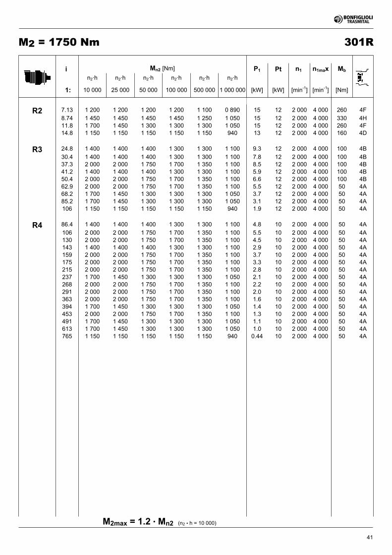
41
301RM2 = 1750 Nm
(n2 • h = 10 000)M2max = 1.2 • Mn2
i Mn2 [Nm] P1 Pt n1 n1max Mb
n2·h n2·h n2·h n2·h n2·h n2·h
1: 10 000 25 000 50 000 100 000 500 000 1 000 000 [kW] [kW] [min-1] [min-1] [Nm]
R2 7.13 1 200 1 200 1 200 1 200 1 100 0 890 15 12 2 000 4 000 260 4F
8.74 1 450 1 450 1 450 1 450 1 250 1 050 15 12 2 000 4 000 330 4H11.8 1 700 1 450 1 300 1 300 1 300 1 050 15 12 2 000 4 000 260 4F14.8 1 150 1 150 1 150 1 150 1 150 940 13 12 2 000 4 000 160 4D
R3 24.8 1 400 1 400 1 400 1 300 1 300 1 100 9.3 12 2 000 4 000 100 4B
30.4 1 400 1 400 1 400 1 300 1 300 1 100 7.8 12 2 000 4 000 100 4B37.3 2 000 2 000 1 750 1 700 1 350 1 100 8.5 12 2 000 4 000 100 4B41.2 1 400 1 400 1 400 1 300 1 300 1 100 5.9 12 2 000 4 000 100 4B50.4 2 000 2 000 1 750 1 700 1 350 1 100 6.6 12 2 000 4 000 100 4B62.9 2 000 2 000 1 750 1 700 1 350 1 100 5.5 12 2 000 4 000 50 4A68.2 1 700 1 450 1 300 1 300 1 300 1 050 3.7 12 2 000 4 000 50 4A85.2 1 700 1 450 1 300 1 300 1 300 1 050 3.1 12 2 000 4 000 50 4A106 1 150 1 150 1 150 1 150 1 150 940 1.9 12 2 000 4 000 50 4A
R4 86.4 1 400 1 400 1 400 1 300 1 300 1 100 4.8 10 2 000 4 000 50 4A
106 2 000 2 000 1 750 1 700 1 350 1 100 5.5 10 2 000 4 000 50 4A130 2 000 2 000 1 750 1 700 1 350 1 100 4.5 10 2 000 4 000 50 4A143 1 400 1 400 1 400 1 300 1 300 1 100 2.9 10 2 000 4 000 50 4A159 2 000 2 000 1 750 1 700 1 350 1 100 3.7 10 2 000 4 000 50 4A175 2 000 2 000 1 750 1 700 1 350 1 100 3.3 10 2 000 4 000 50 4A215 2 000 2 000 1 750 1 700 1 350 1 100 2.8 10 2 000 4 000 50 4A237 1 700 1 450 1 300 1 300 1 300 1 050 2.1 10 2 000 4 000 50 4A268 2 000 2 000 1 750 1 700 1 350 1 100 2.2 10 2 000 4 000 50 4A291 2 000 2 000 1 750 1 700 1 350 1 100 2.0 10 2 000 4 000 50 4A363 2 000 2 000 1 750 1 700 1 350 1 100 1.6 10 2 000 4 000 50 4A394 1 700 1 450 1 300 1 300 1 300 1 050 1.4 10 2 000 4 000 50 4A453 2 000 2 000 1 750 1 700 1 350 1 100 1.3 10 2 000 4 000 50 4A491 1 700 1 450 1 300 1 300 1 300 1 050 1.1 10 2 000 4 000 50 4A613 1 700 1 450 1 300 1 300 1 300 1 050 1.0 10 2 000 4 000 50 4A765 1 150 1 150 1 150 1 150 1 150 940 0.44 10 2 000 4 000 50 4A
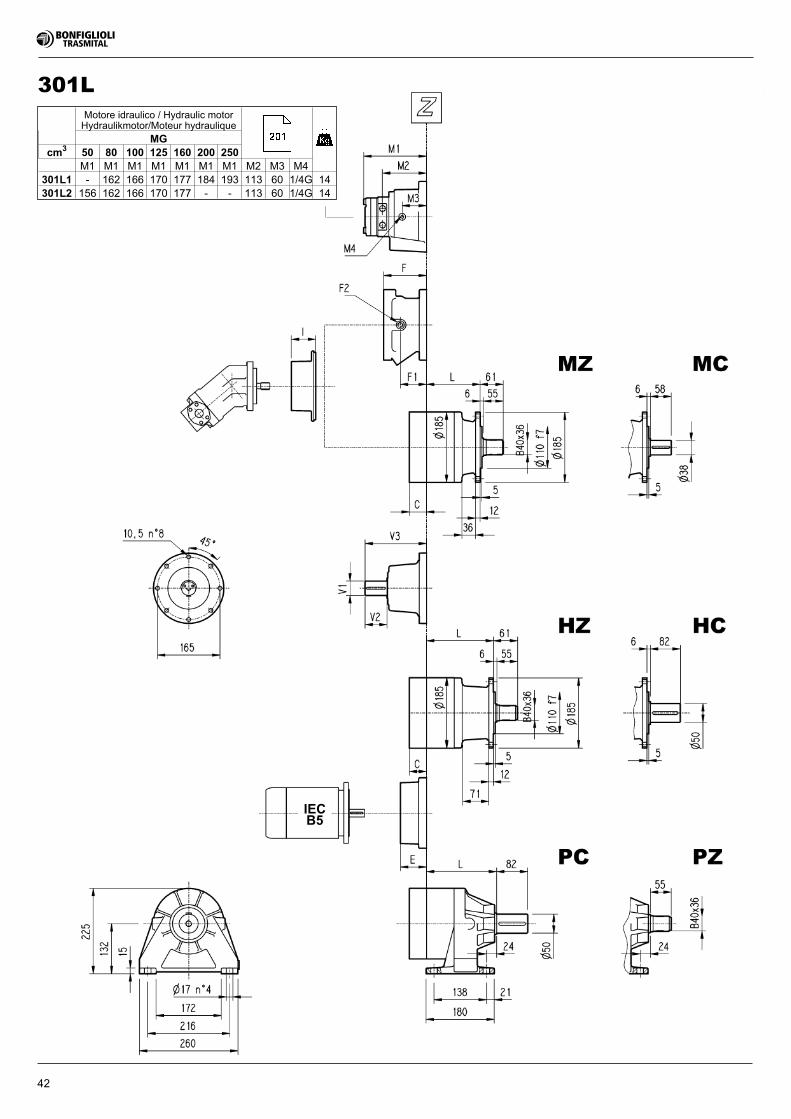
42
Motore idraulico / Hydraulic motorHydraulikmotor/Moteur hydraulique
MGcm3 50 80 100 125 160 200 250
M1 M1 M1 M1 M1 M1 M1 M2 M3 M4301L1 - 162 166 170 177 184 193 113 60 1/4G 14301L2 156 162 166 170 177 - - 113 60 1/4G 14
301L
IECB5
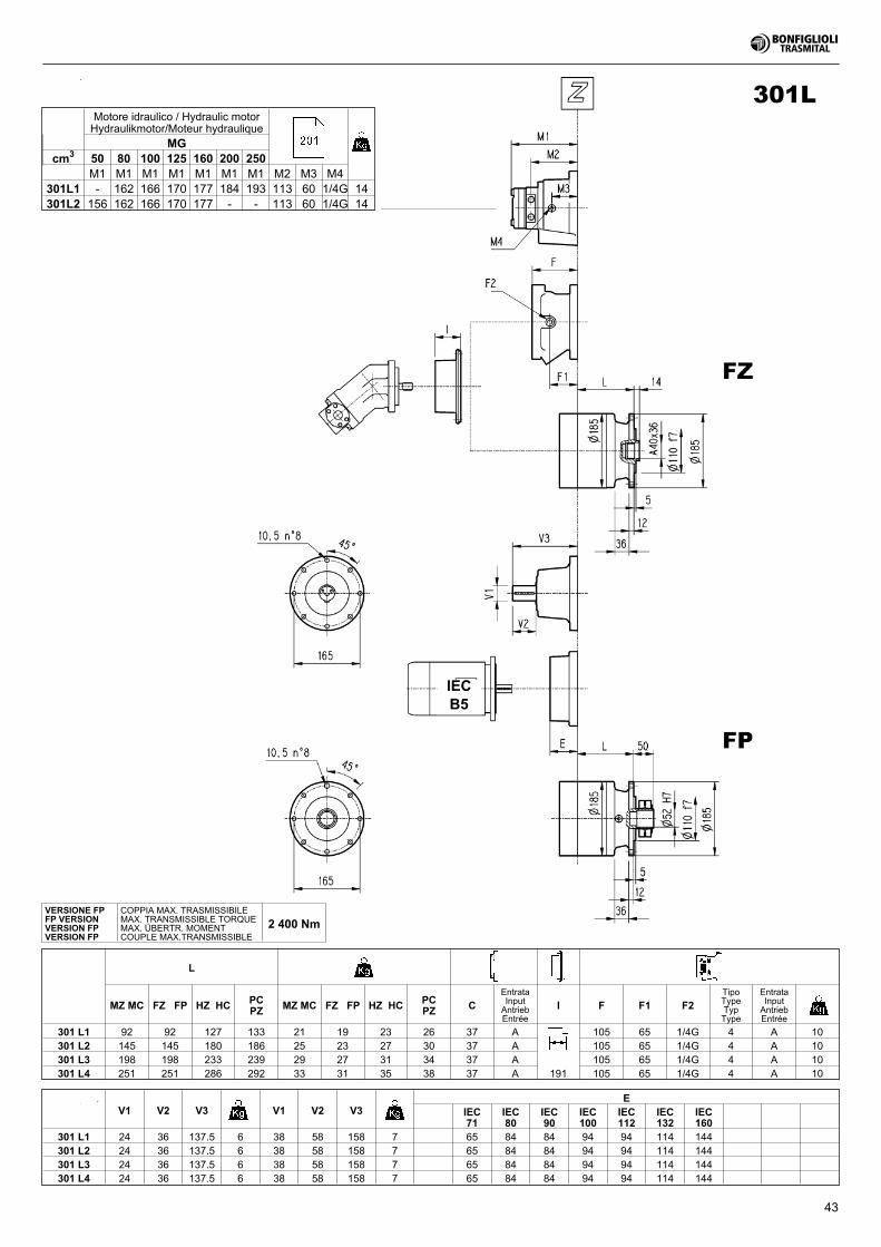
43
IECB5
L
MZ MC FZ FP HZ HC PCPZ MZ MC FZ FP HZ HC PC
PZ CEntrataInputAntriebEntrée
I F F1 F2TipoTypeTypType
EntrataInputAntriebEntrée
301 L1 92 92 127 133 21 19 23 26 37 A 105 65 1/4G 4 A 10301 L2 145 145 180 186 25 23 27 30 37 A 105 65 1/4G 4 A 10301 L3 198 198 233 239 29 27 31 34 37 A 105 65 1/4G 4 A 10301 L4 251 251 286 292 33 31 35 38 37 A 191 105 65 1/4G 4 A 10
V1 V2 V3 V1 V2 V3E
IEC71
IEC80
IEC90
IEC100
IEC112
IEC132
IEC160
301 L1 24 36 137.5 6 38 58 158 7 65 84 84 94 94 114 144301 L2 24 36 137.5 6 38 58 158 7 65 84 84 94 94 114 144301 L3 24 36 137.5 6 38 58 158 7 65 84 84 94 94 114 144301 L4 24 36 137.5 6 38 58 158 7 65 84 84 94 94 114 144
VERSIONE FPFP VERSIONVERSION FPVERSION FP
COPPIA MAX. TRASMISSIBILEMAX. TRANSMISSIBLE TORQUEMAX. ÜBERTR. MOMENTCOUPLE MAX.TRANSMISSIBLE
2 400 Nm
Motore idraulico / Hydraulic motorHydraulikmotor/Moteur hydraulique
MGcm3 50 80 100 125 160 200 250
M1 M1 M1 M1 M1 M1 M1 M2 M3 M4301L1 - 162 166 170 177 184 193 113 60 1/4G 14301L2 156 162 166 170 177 - - 113 60 1/4G 14
301L
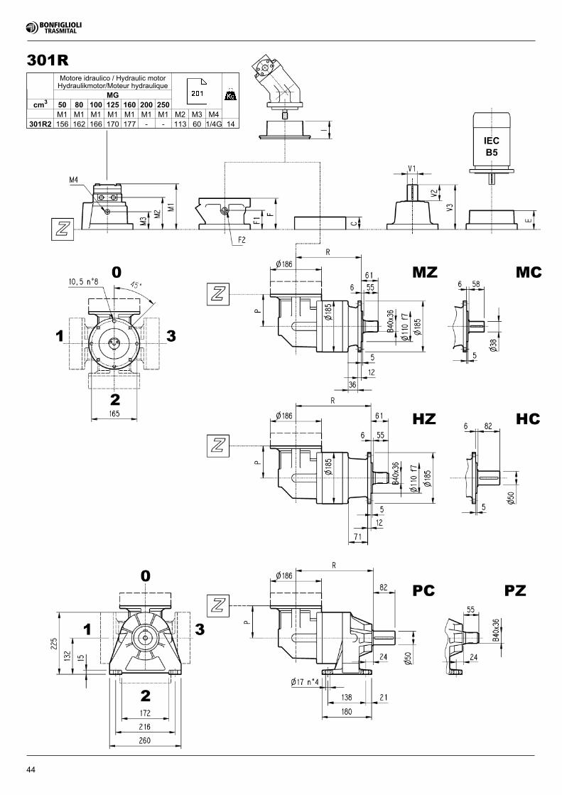
44
IECB5
Motore idraulico / Hydraulic motorHydraulikmotor/Moteur hydraulique
MGcm3 50 80 100 125 160 200 250
M1 M1 M1 M1 M1 M1 M1 M2 M3 M4301R2 156 162 166 170 177 - - 113 60 1/4G 14
301R
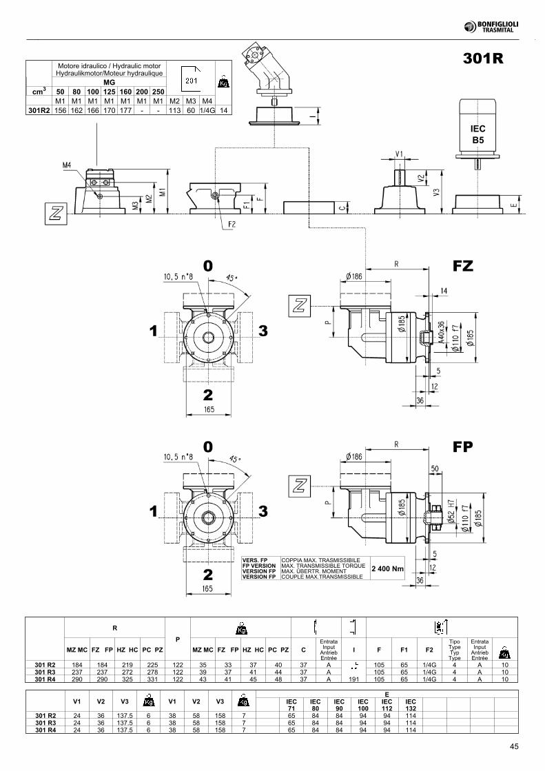
45
R
P
MZ MC FZ FP HZ HC PC PZ MZ MC FZ FP HZ HC PC PZ CEntrataInputAntriebEntrée
I F F1 F2TipoTypeTypType
EntrataInputAntriebEntrée
301 R2 184 184 219 225 122 35 33 37 40 37 A 105 65 1/4G 4 A 10301 R3 237 237 272 278 122 39 37 41 44 37 A 105 65 1/4G 4 A 10301 R4 290 290 325 331 122 43 41 45 48 37 A 191 105 65 1/4G 4 A 10
V1 V2 V3 V1 V2 V3E
IEC71
IEC80
IEC90
IEC100
IEC112
IEC132
301 R2 24 36 137.5 6 38 58 158 7 65 84 84 94 94 114301 R3 24 36 137.5 6 38 58 158 7 65 84 84 94 94 114301 R4 24 36 137.5 6 38 58 158 7 65 84 84 94 94 114
VERS. FPFP VERSIONVERSION FPVERSION FP
COPPIA MAX. TRASMISSIBILEMAX. TRANSMISSIBLE TORQUEMAX. ÜBERTR. MOMENTCOUPLE MAX.TRANSMISSIBLE
2 400 Nm
Motore idraulico / Hydraulic motorHydraulikmotor/Moteur hydraulique
MGcm3 50 80 100 125 160 200 250
M1 M1 M1 M1 M1 M1 M1 M2 M3 M4301R2 156 162 166 170 177 - - 113 60 1/4G 14
301R
IECB5
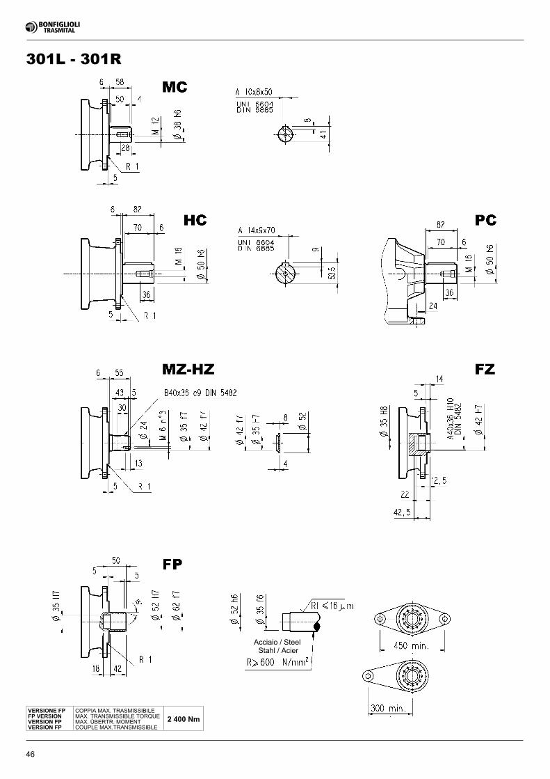
46
301L - 301R
Acciaio / SteelStahl / Acier
VERSIONE FPFP VERSIONVERSION FPVERSION FP
COPPIA MAX. TRASMISSIBILEMAX. TRANSMISSIBLE TORQUEMAX. ÜBERTR. MOMENTCOUPLE MAX.TRANSMISSIBLE
2 400 Nm

47
301L - 301R
m z x dp di de H A B C �
PBE 4.5 14 0.507 63 56 75.5 55 0 0 0 �
PCE 5 14 0.500 70 62.5 84.8 65 0 10 53 �
PDC 6 12 0.250 72 61 84.8 59 14 4 54 �
PDE 6 14 0.500 84 73 99.6 65 0 10 54 �
Flangia / FlangeFlansch / Brides
Materiale : Acciaio C40Material : Steel C40Material : Stahl C40Màterial : Acier C40
Pignoni per rotazione / Output pinionsRitzel / Pignons
Manicotti lisci / Sleeve couplingsNaben / Manchons lisses a cannelure interieure
Materiale : Acciaio 16CrNi4Material : Steel 16CrNi4Material : Stahl 16CrNi4Màterial : Acier 16CrNi4
Barre scanalate / Splined barsVielkeilwellen / Barre cannelée
Giunto ad attrito / Shrink discSchrumpfscheibe / Frette de serrage
MOA
GOABOA
� Materiale/Material/Material/Màterial
�
Acciaio 39NiCrMo3 BonificatoSteel 39NiCrMo3 hardened and temperedVergüteter Stahl 39NiCrMo3Acier bonifiè 39NiCrMo3
�
Acciaio 18NiCrMo5 Cementato e tempratoSteel 18NiCrMo5 Case hardenedEinsatzstahl 18NiCrMo5 EinsatzgehärtetAcier cementè et temprè 18NiCrMo5
P...
Mat. acciaio 18NiCrMo5 UNI 5331 da cementare e temprare 50-55 HRCCase hardening steel 18NiCrMo5 UNI 5331must be case hardened 50-55 HRCMaterial: Einsatzstahl 18NiCrMo5 UNI 5331muss einsatzgehärtet werden 50-55 HRCAcier 18 NiCrMo5 UNI 5331 doit être cémenté trempé 50-55 HRC
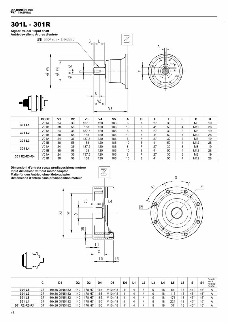
48
Dimensioni d'entrata senza predisposizione motoreInput dimension without motor adaptorMaße für den Antrieb ohne MotoradapterDimensions d'entrée sans prédisposition moteur
C D1 D2 D3 D4 D5 D6 L1 L2 L3 L4 L5 L6 S S1EntrataInputAntriebEntrée
301 L1 37 40x36 DIN5482 140 178 H7 165 M10 n°8 11 4 / 9 18 65 18 45° 45° A301 L2 37 40x36 DIN5482 140 178 H7 165 M10 n°8 11 4 / 9 18 118 18 45° 45° A301 L3 37 40x36 DIN5482 140 178 H7 165 M10 n°8 11 4 / 9 18 171 18 45° 45° A301 L4 37 40x36 DIN5482 140 178 H7 165 M10 n°8 11 4 / 9 18 224 18 45° 45° A
301 R2-R3-R4 37 40x36 DIN5482 140 178 H7 165 M10 n°8 11 4 / 9 18 37 18 45° 45° A
CODE V1 V2 V3 V4 V5 A B F L S D U
301 L1V01A 24 36 137.5 120 186 8 7 27 30 3 M8 19V01B 38 58 158 120 186 10 8 41 50 4 M12 28
301 L2V01A 24 36 137.5 120 186 8 7 27 30 3 M8 19V01B 38 58 158 120 186 10 8 41 50 4 M12 28
301 L3V01A 24 36 137.5 120 186 8 7 27 30 3 M8 19V01B 38 58 158 120 186 10 8 41 50 4 M12 28
301 L4V01A 24 36 137.5 120 186 8 7 27 30 3 M8 19V01B 38 58 158 120 186 10 8 41 50 4 M12 28
301 R2-R3-R4V01A 24 36 137.5 120 186 8 7 27 30 3 M8 19V01B 38 58 158 120 186 10 8 41 50 4 M12 28
301L - 301RAlgberi veloci / Input shaftAntriebswellen / Arbres d'entrée
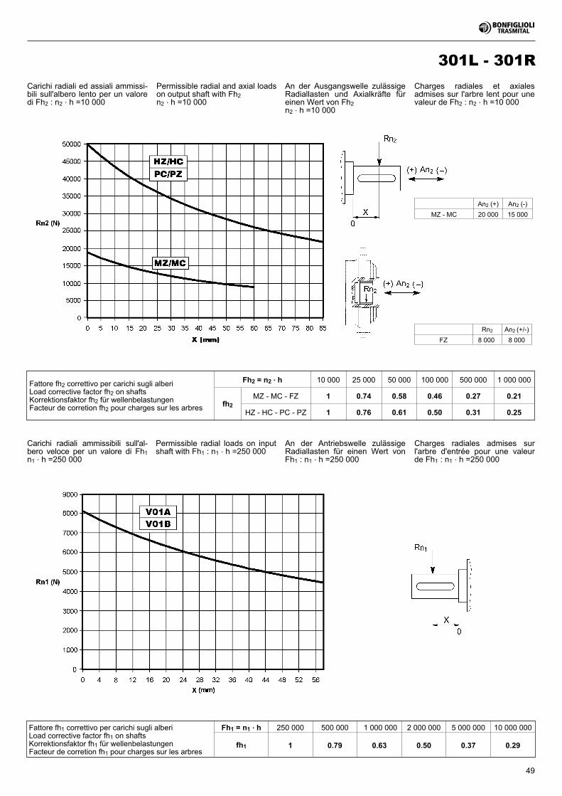
49
Fattore fh1 correttivo per carichi sugli alberiLoad corrective factor fh1 on shaftsKorrektionsfaktor fh1 für wellenbelastungenFacteur de corretion fh1 pour charges sur les arbres
Fh1 = n1 . h 250 000 500 000 1 000 000 2 000 000 5 000 000 10 000 000
fh1 1 0.79 0.63 0.50 0.37 0.29
Rn2 An2 (+/-)
FZ 8 000 8 000
An2 (+) An2 (-)
MZ - MC 20 000 15 000
Fattore fh2 correttivo per carichi sugli alberiLoad corrective factor fh2 on shaftsKorrektionsfaktor fh2 für wellenbelastungenFacteur de corretion fh2 pour charges sur les arbres
Fh2 = n2 . h 10 000 25 000 50 000 100 000 500 000 1 000 000
fh2
MZ - MC - FZ 1 0.74 0.58 0.46 0.27 0.21
HZ - HC - PC - PZ 1 0.76 0.61 0.50 0.31 0.25
Carichi radiali ammissibili sull'al-bero veloce per un valore di Fh1n1 . h =250 000
Carichi radiali ed assiali ammissi-bili sull'albero lento per un valoredi Fh2 : n2 . h =10 000
Permissible radial and axial loadson output shaft with Fh2n2 . h =10 000
An der Ausgangswelle zulässigeRadiallasten und Axialkräfte füreinen Wert von Fh2n2 . h =10 000
Charges radiales et axialesadmises sur l'arbre lent pour unevaleur de Fh2 : n2 . h =10 000
Permissible radial loads on inputshaft with Fh1 : n1 . h =250 000
An der Antriebswelle zulässigeRadiallasten für einen Wert vonFh1 : n1 . h =250 000
Charges radiales admises surl'arbre d'entrée pour une valeurde Fh1 : n1 . h =250 000
301L - 301R
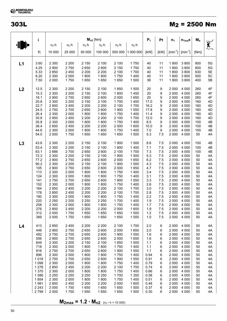
50
303L M2 = 2500 Nm
(n2 • h = 10 000)M2max = 1.2 • Mn2
i Mn2 [Nm] P1 Pt n1 n1max Mb
n2·h n2·h n2·h n2·h n2·h n2·h
1: 10 000 25 000 50 000 100 000 500 000 1 000 000 [kW] [kW] [min-1] [min-1] [Nm]
L1 3.60 2 300 2 200 2 150 2 100 2 100 1 750 40 11 1 800 3 800 800 5G4.25 2 900 2 750 2 650 2 600 2 150 1 750 40 11 1 800 3 800 800 5G5.33 2 850 2 450 2 200 2 200 2 100 1 700 40 11 1 800 3 800 630 5E6.20 2 300 2 000 1 800 1 800 1 750 1 400 40 11 1 800 3 800 500 5C7.50 2 000 1 750 1 650 1 650 1 650 1 500 36 11 1 800 3 800 400 5B
L2 12.5 2 300 2 200 2 150 2 100 1 850 1 500 20 9 2 000 4 000 260 4F15.3 2 300 2 200 2 150 2 100 1 800 1 450 20 9 2 000 4 000 260 4F18.1 2 900 2 750 2 650 2 600 2 000 1 650 20 9 2 000 4 000 260 4F20.8 2 300 2 200 2 150 2 100 1 700 1 400 17.0 9 2 000 4 000 160 4D22.7 2 850 2 450 2 200 2 200 2 100 1 700 16.2 9 2 000 4 000 160 4D24.5 2 750 2 700 2 650 2 600 1 900 1 550 17.8 9 2 000 4 000 160 4D26.4 2 300 2 000 1 800 1 800 1 750 1 400 11.4 9 2 000 4 000 160 4D30.8 2 850 2 450 2 200 2 200 2 100 1 700 12.0 9 2 000 4 000 160 4D35.8 2 300 2 000 1 800 1 800 1 750 1 400 8.5 9 2 000 4 000 100 4B38.4 2 850 2 450 2 200 2 200 2 000 1 600 10.0 9 2 000 4 000 100 4B44.6 2 300 2 000 1 800 1 800 1 750 1 400 7.0 9 2 000 4 000 100 4B54.0 2 000 1 750 1 650 1 650 1 650 1 500 5.3 7.5 2 000 4 000 50 4A
L3 43.6 2 300 2 200 2 150 2 100 1 900 1 500 8.6 7.5 2 000 4 000 100 4B53.4 2 300 2 200 2 150 2 100 1 800 1 450 7.1 7.5 2 000 4 000 100 4B63.1 2 886 2 700 2 650 2 600 2 100 1 700 7.3 7.5 2 000 4 000 100 4B72.3 2 300 2 200 2 150 2 100 1 900 1 500 5.3 7.5 2 000 4 000 50 4A77.2 2 900 2 750 2 650 2 600 2 000 1 650 6.2 7.5 2 000 4 000 50 4A90.2 2 300 2 200 2 150 2 100 1 900 1 500 4.3 7.5 2 000 4 000 50 4A105 2 900 2 750 2 650 2 600 2 000 1 650 4.7 7.5 2 000 4 000 50 4A113 2 300 2 000 1 800 1 800 1 750 1 400 3.4 7.5 2 000 4 000 50 4A124 2 300 2 000 1 800 1 800 1 750 1 400 3.1 7.5 2 000 4 000 50 4A141 2 750 2 700 2 650 2 600 1 900 1 550 3.3 7.5 2 000 4 000 50 4A152 2 300 2 000 1 800 1 800 1 750 1 400 2.6 7.5 2 000 4 000 50 4A164 2 850 2 450 2 200 2 200 2 100 1 700 3.0 7.5 2 000 4 000 50 4A178 2 850 2 450 2 200 2 200 2 100 1 700 2.8 7.5 2 000 4 000 50 4A190 2 300 2 000 1 800 1 800 1 750 1 400 2.2 7.5 2 000 4 000 50 4A220 2 250 2 200 2 250 2 250 1 700 1 400 1.9 7.5 2 000 4 000 50 4A258 2 300 2 000 1 800 1 800 1 750 1 400 1.7 7.5 2 000 4 000 50 4A276 2 850 2 450 2 200 2 200 2 000 1 600 1.9 7.5 2 000 4 000 50 4A312 2 000 1 750 1 650 1 650 1 650 1 500 1.2 7.5 2 000 4 000 50 4A389 2 000 1 750 1 650 1 650 1 650 1 500 1.0 7.5 2 000 4 000 50 4A
L4 413 2 850 2 450 2 200 2 200 2 100 1 700 2.0 6 2 000 4 000 50 4A446 2 900 2 750 2 650 2 600 2 000 1 650 2.0 6 2 000 4 000 50 4A492 2 750 2 700 2 650 2 600 1 900 1 550 1.6 6 2 000 4 000 50 4A556 2 900 2 750 2 650 2 600 2 000 1 650 1.6 6 2 000 4 000 50 4A649 2 300 2 200 2 150 2 100 1 850 1 500 1.1 6 2 000 4 000 50 4A718 2 300 2 000 1 800 1 800 1 750 1 400 1.1 6 2 000 4 000 50 4A816 2 750 2 700 2 650 2 600 1 900 1 550 1.1 6 2 000 4 000 50 4A896 2 300 2 000 1 800 1 800 1 750 1 400 0.94 6 2 000 4 000 50 4A1 018 2 750 2 700 2 650 2 600 1 900 1 550 0.91 6 2 000 4 000 50 4A1 098 2 300 2 000 1 800 1 800 1 750 1 400 0.79 6 2 000 4 000 50 4A1 278 2 850 2 450 2 200 2 200 2 100 1 700 0.74 6 2 000 4 000 50 4A1 370 2 300 2 000 1 800 1 800 1 750 1 400 0.66 6 2 000 4 000 50 4A1 586 2 250 2 250 2 250 2 250 1 700 1 350 0.58 6 2 000 4 000 50 4A1 854 2 300 2 000 1 800 1 800 1 750 1 400 0.51 6 2 000 4 000 50 4A1 991 2 850 2 450 2 200 2 200 2 000 1 600 0.48 6 2 000 4 000 50 4A2 243 2 000 1 750 1 650 1 650 1 650 1 500 0.37 6 2 000 4 000 50 4A2 799 2 000 1 750 1 650 1 650 1 650 1 500 0.30 6 2 000 4 000 50 4A
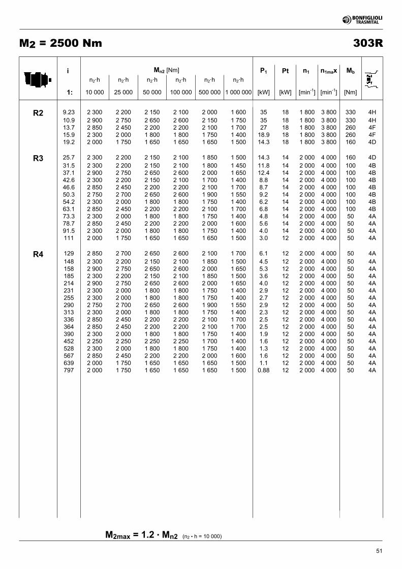
51
303RM2 = 2500 Nm
(n2 • h = 10 000)M2max = 1.2 • Mn2
i Mn2 [Nm] P1 Pt n1 n1max Mb
n2·h n2·h n2·h n2·h n2·h n2·h
1: 10 000 25 000 50 000 100 000 500 000 1 000 000 [kW] [kW] [min-1] [min-1] [Nm]
R2 9.23 2 300 2 200 2 150 2 100 2 000 1 600 35 18 1 800 3 800 330 4H10.9 2 900 2 750 2 650 2 600 2 150 1 750 35 18 1 800 3 800 330 4H13.7 2 850 2 450 2 200 2 200 2 100 1 700 27 18 1 800 3 800 260 4F15.9 2 300 2 000 1 800 1 800 1 750 1 400 18.9 18 1 800 3 800 260 4F19.2 2 000 1 750 1 650 1 650 1 650 1 500 14.3 18 1 800 3 800 160 4D
R3 25.7 2 300 2 200 2 150 2 100 1 850 1 500 14.3 14 2 000 4 000 160 4D31.5 2 300 2 200 2 150 2 100 1 800 1 450 11.8 14 2 000 4 000 100 4B37.1 2 900 2 750 2 650 2 600 2 000 1 650 12.4 14 2 000 4 000 100 4B42.6 2 300 2 200 2 150 2 100 1 700 1 400 8.8 14 2 000 4 000 100 4B46.6 2 850 2 450 2 200 2 200 2 100 1 700 8.7 14 2 000 4 000 100 4B50.3 2 750 2 700 2 650 2 600 1 900 1 550 9.2 14 2 000 4 000 100 4B54.2 2 300 2 000 1 800 1 800 1 750 1 400 6.2 14 2 000 4 000 100 4B63.1 2 850 2 450 2 200 2 200 2 100 1 700 6.8 14 2 000 4 000 100 4B73.3 2 300 2 000 1 800 1 800 1 750 1 400 4.8 14 2 000 4 000 50 4A78.7 2 850 2 450 2 200 2 200 2 000 1 600 5.6 14 2 000 4 000 50 4A91.5 2 300 2 000 1 800 1 800 1 750 1 400 4.0 14 2 000 4 000 50 4A111 2 000 1 750 1 650 1 650 1 650 1 500 3.0 12 2 000 4 000 50 4A
R4 129 2 850 2 700 2 650 2 600 2 100 1 700 6.1 12 2 000 4 000 50 4A148 2 300 2 200 2 150 2 100 1 850 1 500 4.5 12 2 000 4 000 50 4A158 2 900 2 750 2 650 2 600 2 000 1 650 5.3 12 2 000 4 000 50 4A185 2 300 2 200 2 150 2 100 1 850 1 500 3.6 12 2 000 4 000 50 4A214 2 900 2 750 2 650 2 600 2 000 1 650 4.0 12 2 000 4 000 50 4A231 2 300 2 000 1 800 1 800 1 750 1 400 2.9 12 2 000 4 000 50 4A255 2 300 2 000 1 800 1 800 1 750 1 400 2.7 12 2 000 4 000 50 4A290 2 750 2 700 2 650 2 600 1 900 1 550 2.9 12 2 000 4 000 50 4A313 2 300 2 000 1 800 1 800 1 750 1 400 2.3 12 2 000 4 000 50 4A336 2 850 2 450 2 200 2 200 2 100 1 700 2.5 12 2 000 4 000 50 4A364 2 850 2 450 2 200 2 200 2 100 1 700 2.5 12 2 000 4 000 50 4A390 2 300 2 000 1 800 1 800 1 750 1 400 1.9 12 2 000 4 000 50 4A452 2 250 2 250 2 250 2 250 1 700 1 400 1.6 12 2 000 4 000 50 4A528 2 300 2 000 1 800 1 800 1 750 1 400 1.3 12 2 000 4 000 50 4A567 2 850 2 450 2 200 2 200 2 000 1 600 1.6 12 2 000 4 000 50 4A639 2 000 1 750 1 650 1 650 1 650 1 500 1.1 12 2 000 4 000 50 4A797 2 000 1 750 1 650 1 650 1 650 1 500 0.88 12 2 000 4 000 50 4A
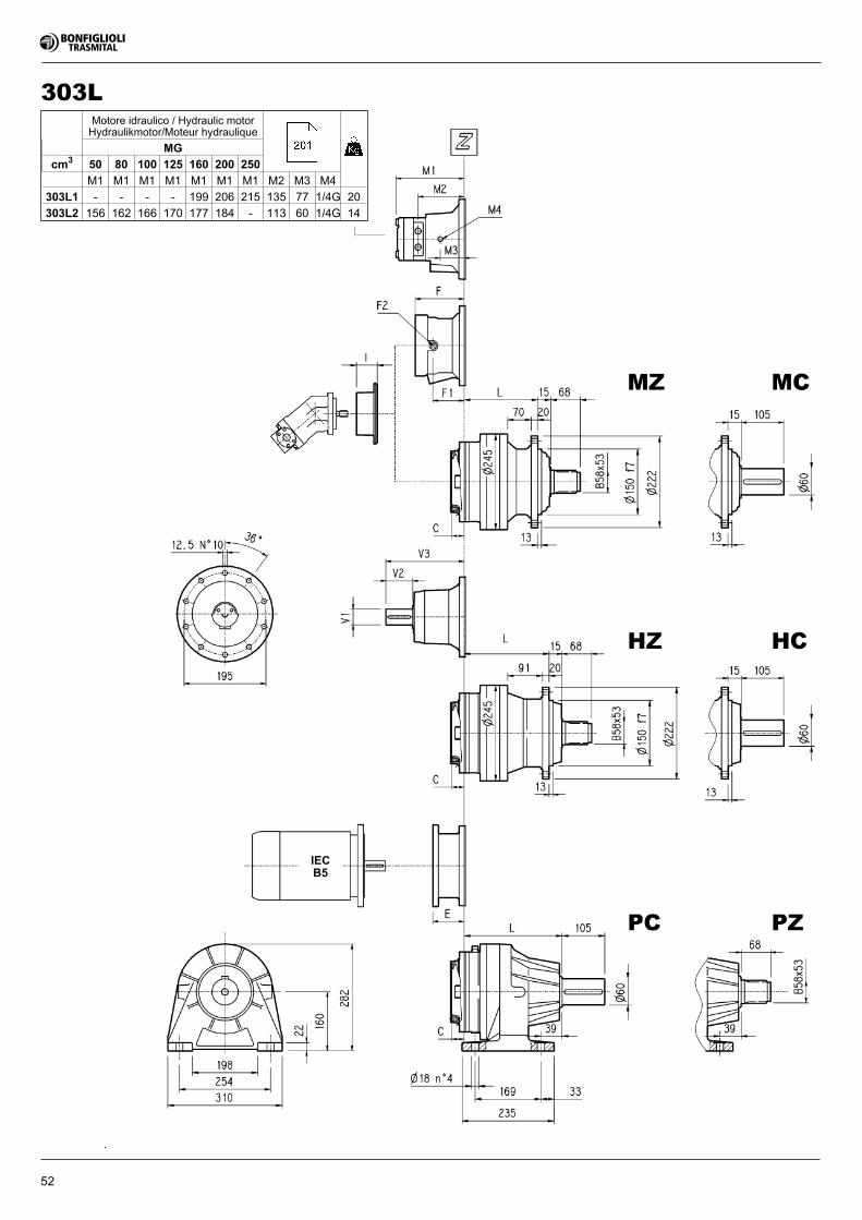
52
IECB5
303LMotore idraulico / Hydraulic motorHydraulikmotor/Moteur hydraulique
MG
cm3 50 80 100 125 160 200 250
M1 M1 M1 M1 M1 M1 M1 M2 M3 M4
303L1 - - - - 199 206 215 135 77 1/4G 20
303L2 156 162 166 170 177 184 - 113 60 1/4G 14
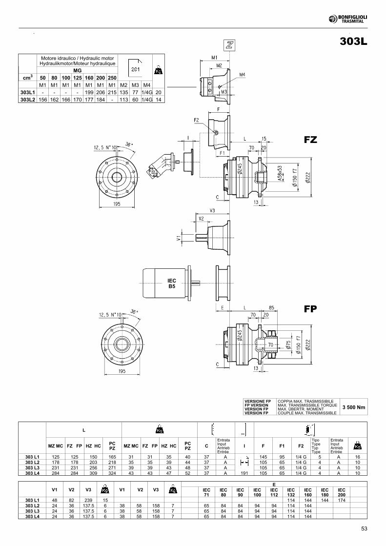
53
IECB5
303L
L
MZ MC FZ FP HZ HC PCPZ MZ MC FZ FP HZ HC PC
PZ CEntrataInputAntriebEntrée
I F F1 F2TipoTypeTypType
EntrataInputAntriebEntrée
303 L1 125 125 150 165 31 31 35 40 37 A 145 95 1/4 G 5 A 16303 L2 178 178 203 218 35 35 39 44 37 A 105 65 1/4 G 4 A 10303 L3 231 231 256 271 39 39 43 48 37 A 105 65 1/4 G 4 A 10303 L4 284 284 309 324 43 43 47 52 37 A 191 105 65 1/4 G 4 A 10
V1 V2 V3 V1 V2 V3E
IEC71
IEC80
IEC90
IEC100
IEC112
IEC132
IEC160
IEC180
IEC200
303 L1 48 82 239 15 114 144 144 174303 L2 24 36 137.5 6 38 58 158 7 65 84 84 94 94 114 144303 L3 24 36 137.5 6 38 58 158 7 65 84 84 94 94 114 144303 L4 24 36 137.5 6 38 58 158 7 65 84 84 94 94 114 144
VERSIONE FPFP VERSIONVERSION FPVERSION FP
COPPIA MAX. TRASMISSIBILEMAX. TRANSMISSIBLE TORQUEMAX. ÜBERTR. MOMENTCOUPLE MAX. TRANSMISSIBLE
3 500 Nm
Motore idraulico / Hydraulic motorHydraulikmotor/Moteur hydraulique
MG
cm3 50 80 100 125 160 200 250
M1 M1 M1 M1 M1 M1 M1 M2 M3 M4
303L1 - - - - 199 206 215 135 77 1/4G 20
303L2 156 162 166 170 177 184 - 113 60 1/4G 14
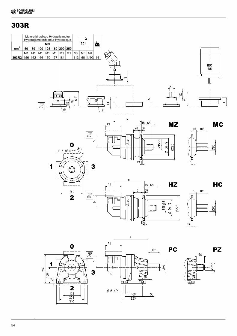
54
IECB5
303R
Motore idraulico / Hydraulic motorHydraulikmotor/Moteur Hydraulique
MG
cm3 50 80 100 125 160 200 250
M1 M1 M1 M1 M1 M1 M1 M2 M3 M4
303R2 156 162 166 170 177 184 - 113 60 1/4G 14
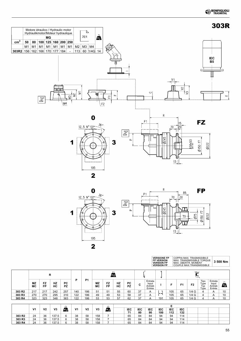
55
IECB5
303R
R
P P1MZMC
FZFP
HZHC
PCPZ
MZMC
FZFP
HZHC
PCPZ C
EntrataInputAntriebEntrée
I F F1 F2TipoTypeTypType
EntrataInputAntriebEntrée
303 R2 217 217 242 257 140 186 51 51 55 60 37 A 105 65 1/4 G 4 A 10303 R3 270 270 295 310 122 186 49 49 53 58 37 A 105 65 1/4 G 4 A 10303 R4 323 323 348 363 122 186 53 53 57 62 37 A 191 105 65 1/4 G 4 A 10
V1 V2 V3 V1 V2 V3E
IEC71
IEC80
IEC90
IEC100
IEC112
IEC132
303 R2 24 36 137.5 6 38 58 158 7 65 84 84 94 94 114303 R3 24 36 137.5 6 38 58 158 7 65 84 84 94 94 114303 R4 24 36 137.5 6 38 58 158 7 65 84 84 94 94 114
VERSIONE FPFP VERSIONVERSION FPVERSION FP
COPPIA MAX. TRASMISSIBILEMAX. TRANSMISSIBLE TORQUEMAX. ÜBERTR. MOMENTCOUPLE MAX.TRANSMISSIBLE
3 500 Nm
Motore idraulico / Hydraulic motorHydraulikmotor/Moteur hydraulique
MG
cm3 50 80 100 125 160 200 250
M1 M1 M1 M1 M1 M1 M1 M2 M3 M4
303R2 156 162 166 170 177 184 - 113 60 1/4G 14
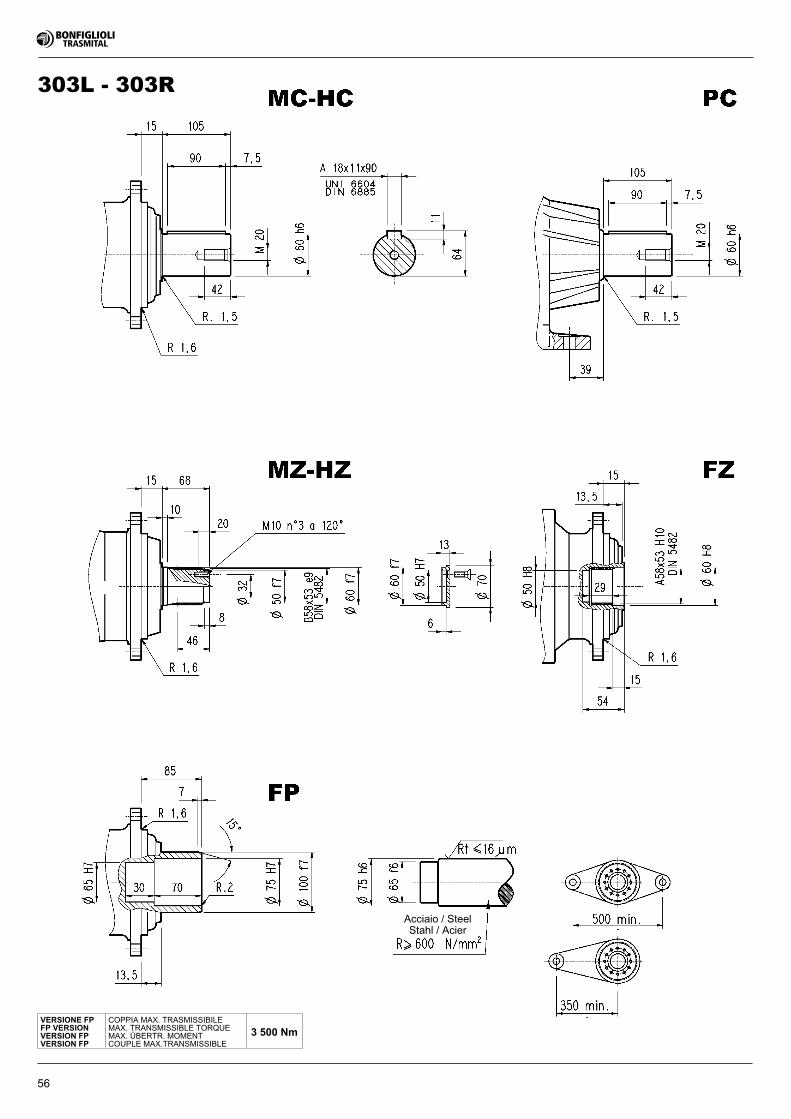
56
303L - 303R
VERSIONE FPFP VERSIONVERSION FPVERSION FP
COPPIA MAX. TRASMISSIBILEMAX. TRANSMISSIBLE TORQUEMAX. ÜBERTR. MOMENTCOUPLE MAX.TRANSMISSIBLE
3 500 Nm
Acciaio / SteelStahl / Acier
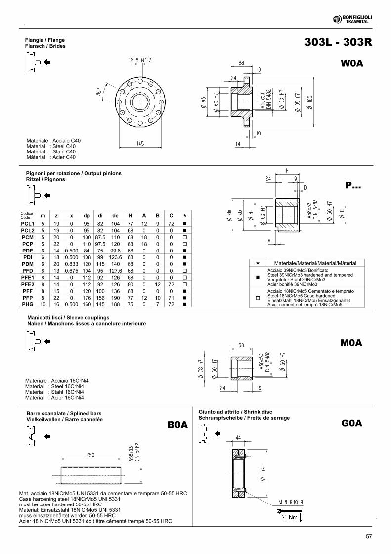
57
Flangia / FlangeFlansch / Brides
Pignoni per rotazione / Output pinionsRitzel / Pignons
Manicotti lisci / Sleeve couplingsNaben / Manchons lisses a cannelure interieure
Giunto ad attrito / Shrink discSchrumpfscheibe / Frette de serrage
Barre scanalate / Splined barsVielkeilwellen / Barre cannelée
Mat. acciaio 18NiCrMo5 UNI 5331 da cementare e temprare 50-55 HRCCase hardening steel 18NiCrMo5 UNI 5331must be case hardened 50-55 HRCMaterial: Einsatzstahl 18NiCrMo5 UNI 5331muss einsatzgehärtet werden 50-55 HRCAcier 18 NiCrMo5 UNI 5331 doit être cémenté trempé 50-55 HRC
303L - 303R
CodiceCode m z x dp di de H A B C �
PCL1 5 19 0 95 82 104 77 12 9 72 �
PCL2 5 19 0 95 82 104 68 0 0 0 �
PCM 5 20 0 100 87.5 110 68 18 0 0 �
PCP 5 22 0 110 97.5 120 68 18 0 0 �
PDE 6 14 0.500 84 75 99.6 68 0 0 0 �
PDI 6 18 0.500 108 99 123.6 68 0 0 0 �
PDM 6 20 0.833 120 115 140 68 0 0 0 �
PFD 8 13 0.675 104 95 127.6 68 0 0 0 �
PFE1 8 14 0 112 92 126 68 0 0 0 �
PFE2 8 14 0 112 92 126 80 0 12 72 �
PFF 8 15 0 120 100 136 68 0 0 0 �
PFP 8 22 0 176 156 190 77 12 10 71 �
PHG 10 16 0.500 160 145 188 75 0 7 72 �
P...
M0A
G0AB0A
W0A
Materiale : Acciaio C40Material : Steel C40Material : Stahl C40Màterial : Acier C40
Materiale : Acciaio 16CrNi4Material : Steel 16CrNi4Material : Stahl 16CrNi4Màterial : Acier 16CrNi4
� Materiale/Material/Material/Màterial
�
Acciaio 39NiCrMo3 BonificatoSteel 39NiCrMo3 hardened and temperedVergüteter Stahl 39NiCrMo3Acier bonifiè 39NiCrMo3
�
Acciaio 18NiCrMo5 Cementato e tempratoSteel 18NiCrMo5 Case hardenedEinsatzstahl 18NiCrMo5 EinsatzgehärtetAcier cementè et temprè 18NiCrMo5
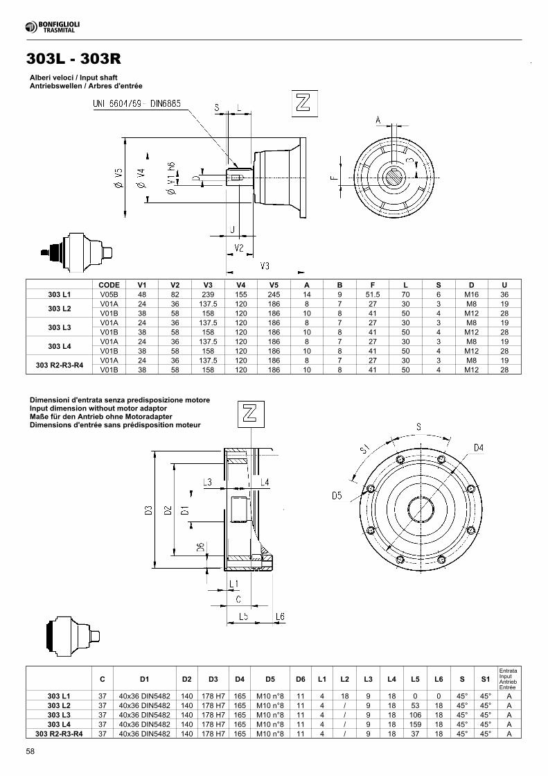
58
Alberi veloci / Input shaftAntriebswellen / Arbres d'entrée
Dimensioni d'entrata senza predisposizione motoreInput dimension without motor adaptorMaße für den Antrieb ohne MotoradapterDimensions d'entrée sans prédisposition moteur
303L - 303R
C D1 D2 D3 D4 D5 D6 L1 L2 L3 L4 L5 L6 S S1EntrataInputAntriebEntrée
303 L1 37 40x36 DIN5482 140 178 H7 165 M10 n°8 11 4 18 9 18 0 0 45° 45° A303 L2 37 40x36 DIN5482 140 178 H7 165 M10 n°8 11 4 / 9 18 53 18 45° 45° A303 L3 37 40x36 DIN5482 140 178 H7 165 M10 n°8 11 4 / 9 18 106 18 45° 45° A303 L4 37 40x36 DIN5482 140 178 H7 165 M10 n°8 11 4 / 9 18 159 18 45° 45° A
303 R2-R3-R4 37 40x36 DIN5482 140 178 H7 165 M10 n°8 11 4 / 9 18 37 18 45° 45° A
CODE V1 V2 V3 V4 V5 A B F L S D U303 L1 V05B 48 82 239 155 245 14 9 51.5 70 6 M16 36
303 L2V01A 24 36 137.5 120 186 8 7 27 30 3 M8 19V01B 38 58 158 120 186 10 8 41 50 4 M12 28
303 L3V01A 24 36 137.5 120 186 8 7 27 30 3 M8 19V01B 38 58 158 120 186 10 8 41 50 4 M12 28
303 L4V01A 24 36 137.5 120 186 8 7 27 30 3 M8 19V01B 38 58 158 120 186 10 8 41 50 4 M12 28
303 R2-R3-R4V01A 24 36 137.5 120 186 8 7 27 30 3 M8 19V01B 38 58 158 120 186 10 8 41 50 4 M12 28
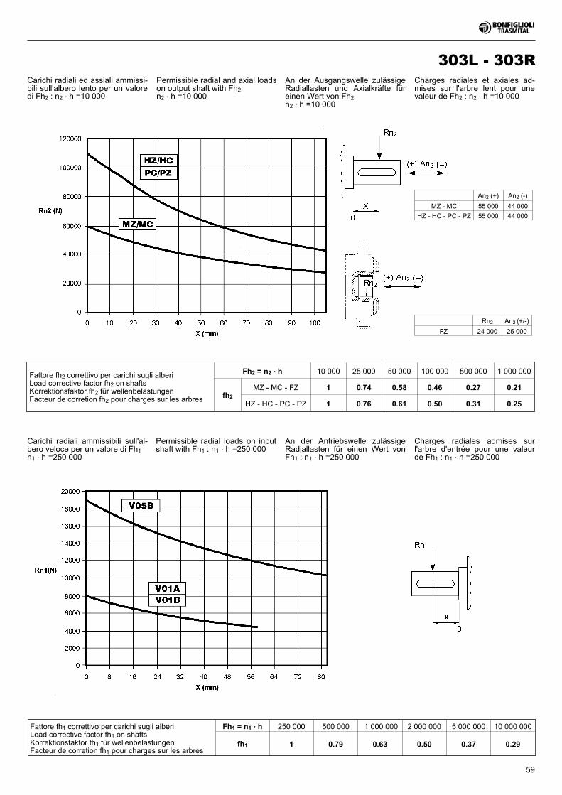
59
303L - 303R
Fattore fh1 correttivo per carichi sugli alberiLoad corrective factor fh1 on shaftsKorrektionsfaktor fh1 für wellenbelastungenFacteur de corretion fh1 pour charges sur les arbres
Fh1 = n1 . h 250 000 500 000 1 000 000 2 000 000 5 000 000 10 000 000
fh1 1 0.79 0.63 0.50 0.37 0.29
Fattore fh2 correttivo per carichi sugli alberiLoad corrective factor fh2 on shaftsKorrektionsfaktor fh2 für wellenbelastungenFacteur de corretion fh2 pour charges sur les arbres
Fh2 = n2 . h 10 000 25 000 50 000 100 000 500 000 1 000 000
fh2
MZ - MC - FZ 1 0.74 0.58 0.46 0.27 0.21
HZ - HC - PC - PZ 1 0.76 0.61 0.50 0.31 0.25
Rn2 An2 (+/-)
FZ 24 000 25 000
An2 (+) An2 (-)
MZ - MC 55 000 44 000
HZ - HC - PC - PZ 55 000 44 000
Carichi radiali ammissibili sull'al-bero veloce per un valore di Fh1n1 . h =250 000
Carichi radiali ed assiali ammissi-bili sull'albero lento per un valoredi Fh2 : n2 . h =10 000
Permissible radial and axial loadson output shaft with Fh2n2 . h =10 000
An der Ausgangswelle zulässigeRadiallasten und Axialkräfte füreinen Wert von Fh2n2 . h =10 000
Charges radiales et axiales ad-mises sur l'arbre lent pour unevaleur de Fh2 : n2 . h =10 000
Permissible radial loads on inputshaft with Fh1 : n1 . h =250 000
An der Antriebswelle zulässigeRadiallasten für einen Wert vonFh1 : n1 . h =250 000
Charges radiales admises surl'arbre d'entrée pour une valeurde Fh1 : n1 . h =250 000
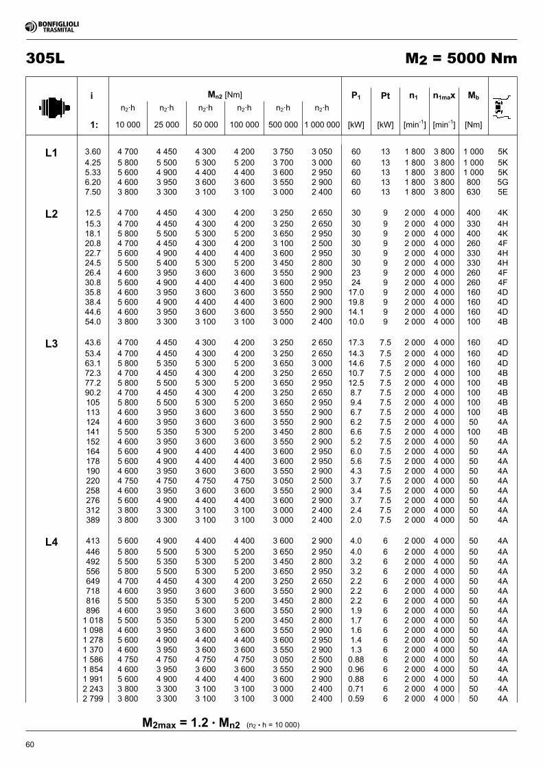
60
305L M2 = 5000 Nm
(n2 • h = 10 000)M2max = 1.2 • Mn2
i Mn2 [Nm] P1 Pt n1 n1max Mb
n2·h n2·h n2·h n2·h n2·h n2·h
1: 10 000 25 000 50 000 100 000 500 000 1 000 000 [kW] [kW] [min-1] [min-1] [Nm]
L1 3.60 4 700 4 450 4 300 4 200 3 750 3 050 60 13 1 800 3 800 1 000 5K4.25 5 800 5 500 5 300 5 200 3 700 3 000 60 13 1 800 3 800 1 000 5K5.33 5 600 4 900 4 400 4 400 3 600 2 950 60 13 1 800 3 800 1 000 5K6.20 4 600 3 950 3 600 3 600 3 550 2 900 60 13 1 800 3 800 800 5G7.50 3 800 3 300 3 100 3 100 3 000 2 400 60 13 1 800 3 800 630 5E
L2 12.5 4 700 4 450 4 300 4 200 3 250 2 650 30 9 2 000 4 000 400 4K15.3 4 700 4 450 4 300 4 200 3 250 2 650 30 9 2 000 4 000 330 4H18.1 5 800 5 500 5 300 5 200 3 650 2 950 30 9 2 000 4 000 400 4K20.8 4 700 4 450 4 300 4 200 3 100 2 500 30 9 2 000 4 000 260 4F22.7 5 600 4 900 4 400 4 400 3 600 2 950 30 9 2 000 4 000 330 4H24.5 5 500 5 400 5 300 5 200 3 450 2 800 30 9 2 000 4 000 330 4H26.4 4 600 3 950 3 600 3 600 3 550 2 900 23 9 2 000 4 000 260 4F30.8 5 600 4 900 4 400 4 400 3 600 2 950 24 9 2 000 4 000 260 4F35.8 4 600 3 950 3 600 3 600 3 550 2 900 17.0 9 2 000 4 000 160 4D38.4 5 600 4 900 4 400 4 400 3 600 2 900 19.8 9 2 000 4 000 160 4D44.6 4 600 3 950 3 600 3 600 3 550 2 900 14.1 9 2 000 4 000 160 4D54.0 3 800 3 300 3 100 3 100 3 000 2 400 10.0 9 2 000 4 000 100 4B
L3 43.6 4 700 4 450 4 300 4 200 3 250 2 650 17.3 7.5 2 000 4 000 160 4D53.4 4 700 4 450 4 300 4 200 3 250 2 650 14.3 7.5 2 000 4 000 160 4D63.1 5 800 5 350 5 300 5 200 3 650 3 000 14.6 7.5 2 000 4 000 160 4D72.3 4 700 4 450 4 300 4 200 3 250 2 650 10.7 7.5 2 000 4 000 100 4B77.2 5 800 5 500 5 300 5 200 3 650 2 950 12.5 7.5 2 000 4 000 100 4B90.2 4 700 4 450 4 300 4 200 3 250 2 650 8.7 7.5 2 000 4 000 100 4B105 5 800 5 500 5 300 5 200 3 650 2 950 9.4 7.5 2 000 4 000 100 4B113 4 600 3 950 3 600 3 600 3 550 2 900 6.7 7.5 2 000 4 000 100 4B124 4 600 3 950 3 600 3 600 3 550 2 900 6.2 7.5 2 000 4 000 50 4A141 5 500 5 350 5 300 5 200 3 450 2 800 6.6 7.5 2 000 4 000 100 4B152 4 600 3 950 3 600 3 600 3 550 2 900 5.2 7.5 2 000 4 000 50 4A164 5 600 4 900 4 400 4 400 3 600 2 950 6.0 7.5 2 000 4 000 50 4A178 5 600 4 900 4 400 4 400 3 600 2 950 5.6 7.5 2 000 4 000 50 4A190 4 600 3 950 3 600 3 600 3 550 2 900 4.3 7.5 2 000 4 000 50 4A220 4 750 4 750 4 750 4 750 3 050 2 500 3.7 7.5 2 000 4 000 50 4A258 4 600 3 950 3 600 3 600 3 550 2 900 3.4 7.5 2 000 4 000 50 4A276 5 600 4 900 4 400 4 400 3 600 2 900 3.7 7.5 2 000 4 000 50 4A312 3 800 3 300 3 100 3 100 3 000 2 400 2.4 7.5 2 000 4 000 50 4A389 3 800 3 300 3 100 3 100 3 000 2 400 2.0 7.5 2 000 4 000 50 4A
L4 413 5 600 4 900 4 400 4 400 3 600 2 900 4.0 6 2 000 4 000 50 4A446 5 800 5 500 5 300 5 200 3 650 2 950 4.0 6 2 000 4 000 50 4A492 5 500 5 350 5 300 5 200 3 450 2 800 3.2 6 2 000 4 000 50 4A556 5 800 5 500 5 300 5 200 3 650 2 950 3.2 6 2 000 4 000 50 4A649 4 700 4 450 4 300 4 200 3 250 2 650 2.2 6 2 000 4 000 50 4A718 4 600 3 950 3 600 3 600 3 550 2 900 2.2 6 2 000 4 000 50 4A816 5 500 5 350 5 300 5 200 3 450 2 800 2.2 6 2 000 4 000 50 4A896 4 600 3 950 3 600 3 600 3 550 2 900 1.9 6 2 000 4 000 50 4A1 018 5 500 5 350 5 300 5 200 3 450 2 800 1.7 6 2 000 4 000 50 4A1 098 4 600 3 950 3 600 3 600 3 550 2 900 1.6 6 2 000 4 000 50 4A1 278 5 600 4 900 4 400 4 400 3 600 2 950 1.4 6 2 000 4 000 50 4A1 370 4 600 3 950 3 600 3 600 3 550 2 900 1.3 6 2 000 4 000 50 4A1 586 4 750 4 750 4 750 4 750 3 050 2 500 0.88 6 2 000 4 000 50 4A1 854 4 600 3 950 3 600 3 600 3 550 2 900 0.96 6 2 000 4 000 50 4A1 991 5 600 4 900 4 400 4 400 3 600 2 900 0.88 6 2 000 4 000 50 4A2 243 3 800 3 300 3 100 3 100 3 000 2 400 0.71 6 2 000 4 000 50 4A2 799 3 800 3 300 3 100 3 100 3 000 2 400 0.59 6 2 000 4 000 50 4A
![Description 560 328 en 0909a [748 998]...Beschneiden: Oben: 61,5 mm Unten: 61,5 mm Links: 43,5 mm Rechts: 43,5 mm Controller Description PLC interface Type CMXR-C1 Description](https://img.pdfslide.org/doc/110x75/5f3084f3c4dfb644f164adba/description-560-328-en-0909a-748-998-beschneiden-oben-615-mm-unten-615.jpg)

![Description 560 328 en 0909a [748 998]€¦ · Beschneiden: Oben: 61,5 mm Unten: 61,5 mm Links: 43,5 mm Rechts: 43,5 mm Controller Description PLC interface Type CMXR-C1 Description](https://img.pdfslide.org/doc/110x75/5f3084f4c4dfb644f164adbd/description-560-328-en-0909a-748-998-beschneiden-oben-615-mm-unten-615-mm.jpg)