Embed Size (px)
Citation preview
PCRP21-BFS4
PCRP21
Technische DatenOutputen Spannung
StromAuflösung Siehe Spezifikation OutputMessrate Bis zu 1 kHz, abhängig von der MesslängeLinearität Messlängen >500 mm: L10 = ±0,10 % vom Bereich
L02 = ±0,02 % vom BereichMesslängen ≤500 mm: L10 = ±0,5 mm
L02MM = ±0,2 mmWiederholgenauigkeit ±3 µmGehäusematerial AlMgSi1 / Zn / V4ASchutzart IP64 (nur mit Gegenstecker)Schockbelastung EN 60068-2-27:2010, 50 g/11 ms, 100 SchocksVibration EN 60068-2-6:2008, 20 g 10 Hz-2 kHz, 10 ZyklenElektrischer Anschluss Stecker M12, 8-polig / Kabel 2 mEMV, Temperatur Siehe Spezifikation Output
SpecificationsOutput Voltage
CurrentResolution Refer to output specificationSampling rate Up to 1 kHz, depending on the measurement rangeLinearity Ranges >500 mm: L10 = ±0.10 % f.s.
L02 = ±0.02 % f.s.Ranges ≤500 mm: L10 = ±0.5 mm
L02MM = ±0.2 mmRepeatability ±3 µmHousing material AlMgSi1 / Zn / V4AProtection class IP64 (with mating connector only)Shock EN 60068-2-27:2010, 50 g 11 ms, 100 shocksVibration EN 60068-2-6:2008, 20 g 10 Hz-2 kHz, 10 cyclesConnection Connector M12, 8 pin / cable 2 mEMC, temperature Refer to output specification
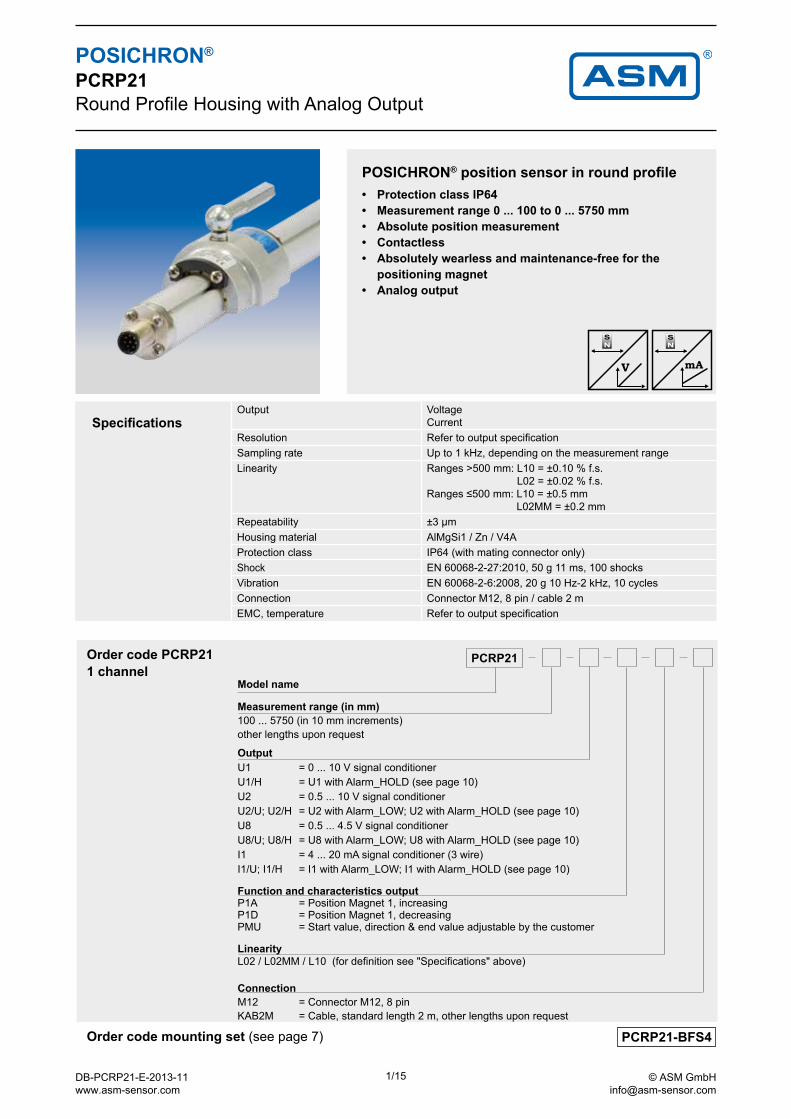
POSICHRON® position sensor in round profile• Protection class IP64• Measurement range 0 ... 100 to 0 ... 5750 mm• Absolute position measurement• Contactless• Absolutely wearless and maintenance-free for the
positioning magnet• Analog output
Order code mounting set (see page 7)
POSICHRON® PCRP21Round Profile Housing with Analog Output
1 channel Order code PCRP21
Model name
Measurement range (in mm)100 ... 5750 (in 10 mm increments)other lengths upon request
OutputU1 = 0 ... 10 V signal conditionerU1/H = U1 with Alarm_HOLD (see page 10)U2 = 0.5 ... 10 V signal conditionerU2/U; U2/H = U2 with Alarm_LOW; U2 with Alarm_HOLD (see page 10)U8 = 0.5 ... 4.5 V signal conditionerU8/U; U8/H = U8 with Alarm_LOW; U8 with Alarm_HOLD (see page 10)I1 = 4 ... 20 mA signal conditioner (3 wire)I1/U; I1/H = I1 with Alarm_LOW; I1 with Alarm_HOLD (see page 10)
Function and characteristics output P1A = Position Magnet 1, increasing P1D = Position Magnet 1, decreasing PMU = Start value, direction & end value adjustable by the customer
LinearityL02 / L02MM / L10 (for definition see "Specifications" above)
ConnectionM12 = Connector M12, 8 pinKAB2M = Cable, standard length 2 m, other lengths upon request
DB-PCRP21-E-2013-11 www.asm-sensor.com
1/15 © ASM GmbH [email protected]
KAB-...M-M12/8F/G-LITZE
PCRP21
PCMAG ...
Order code mating connecting cable (see page 14)
Order code position magnets (see page 7)
POSICHRON® PCRP21Round Profile Housing with Analog Output
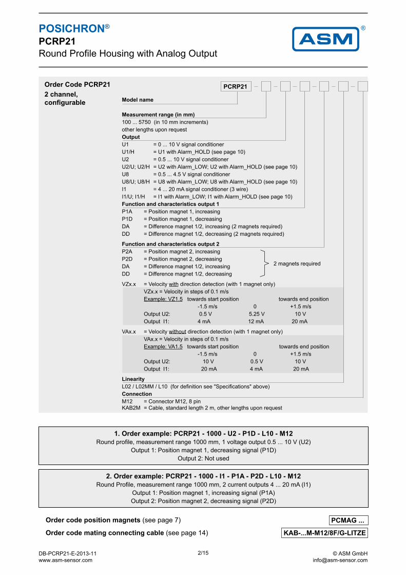
2. Order example: PCRP21 - 1000 - I1 - P1A - P2D - L10 - M12Round Profile, measurement range 1000 mm, 2 current outputs 4 ... 20 mA (I1)
Output 1: Position magnet 1, increasing signal (P1A)Output 2: Position magnet 2, decreasing signal (P2D)
1. Order example: PCRP21 - 1000 - U2 - P1D - L10 - M12Round profile, measurement range 1000 mm, 1 voltage output 0.5 ... 10 V (U2)
Output 1: Position magnet 1, decreasing signal (P1D)Output 2: Not used
Order Code PCRP21
Model name
Measurement range (in mm)100 ... 5750 (in 10 mm increments)other lengths upon requestOutputU1 = 0 ... 10 V signal conditionerU1/H = U1 with Alarm_HOLD (see page 10)U2 = 0.5 ... 10 V signal conditionerU2/U; U2/H = U2 with Alarm_LOW; U2 with Alarm_HOLD (see page 10)U8 = 0.5 ... 4.5 V signal conditionerU8/U; U8/H = U8 with Alarm_LOW; U8 with Alarm_HOLD (see page 10)I1 = 4 ... 20 mA signal conditioner (3 wire)I1/U; I1/H = I1 with Alarm_LOW; I1 with Alarm_HOLD (see page 10)Function and characteristics output 1P1A = Position magnet 1, increasingP1D = Position magnet 1, decreasingDA = Difference magnet 1/2, increasing (2 magnets required)DD = Difference magnet 1/2, decreasing (2 magnets required)
Function and characteristics output 2 P2A = Position magnet 2, increasingP2D = Position magnet 2, decreasingDA = Difference magnet 1/2, increasingDD = Difference magnet 1/2, decreasing
VZx.x = Velocity with direction detection (with 1 magnet only) VZx.x = Velocity in steps of 0.1 m/s Example: VZ1.5 towards start position towards end position -1.5 m/s 0 +1.5 m/s Output U2: 0.5 V 5.25 V 10 V Output I1: 4 mA 12 mA 20 mA
VAx.x = Velocity without direction detection (with 1 magnet only) VAx.x = Velocity in steps of 0.1 m/s Example: VA1.5 towards start position towards end position -1.5 m/s 0 +1.5 m/s Output U2: 10 V 0.5 V 10 V Output I1: 20 mA 4 mA 20 mA
LinearityL02 / L02MM / L10 (for definition see "Specifications" above)ConnectionM12 = Connector M12, 8 pinKAB2M = Cable, standard length 2 m, other lengths upon request
2 channel,configurable
2 magnets required
DB-PCRP21-E-2013-11 www.asm-sensor.com
2/15 © ASM GmbH [email protected]
/ / PCRP21 / /
PCMAG ...
PCRP21-BFS4
KAB-...M-M12/8F/G-LITZE
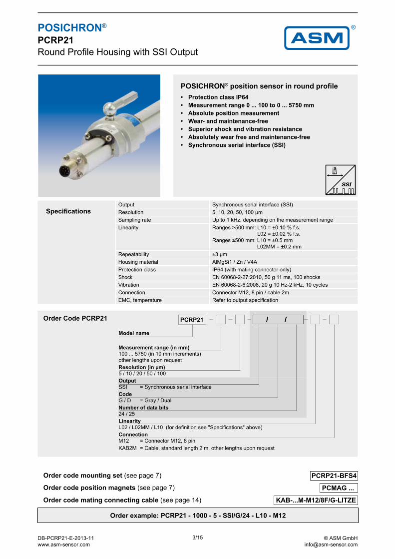
SpecificationsOutput Synchronous serial interface (SSI)Resolution 5, 10, 20, 50, 100 µmSampling rate Up to 1 kHz, depending on the measurement rangeLinearity Ranges >500 mm: L10 = ±0.10 % f.s.
L02 = ±0.02 % f.s.Ranges ≤500 mm: L10 = ±0.5 mm
L02MM = ±0.2 mmRepeatability ±3 µmHousing material AlMgSi1 / Zn / V4AProtection class IP64 (with mating connector only)Shock EN 60068-2-27:2010, 50 g 11 ms, 100 shocksVibration EN 60068-2-6:2008, 20 g 10 Hz-2 kHz, 10 cyclesConnection Connector M12, 8 pin / cable 2mEMC, temperature Refer to output specification
POSICHRON® position sensor in round profile• Protection class IP64• Measurement range 0 ... 100 to 0 ... 5750 mm• Absolute position measurement• Wear- and maintenance-free• Superior shock and vibration resistance• Absolutely wear free and maintenance-free• Synchronous serial interface (SSI)
Order code mating connecting cable (see page 14)
Order code position magnets (see page 7)
Order code mounting set (see page 7)
Order example: PCRP21 - 1000 - 5 - SSI/G/24 - L10 - M12
POSICHRON® PCRP21Round Profile Housing with SSI Output
Order Code PCRP21
Model name
Measurement range (in mm)100 ... 5750 (in 10 mm increments)other lengths upon requestResolution (in µm)5 / 10 / 20 / 50 / 100OutputSSI = Synchronous serial interfaceCodeG / D = Gray / DualNumber of data bits24 / 25LinearityL02 / L02MM / L10 (for definition see "Specifications" above)ConnectionM12 = Connector M12, 8 pinKAB2M = Cable, standard length 2 m, other lengths upon request
DB-PCRP21-E-2013-11 www.asm-sensor.com
3/15 © ASM GmbH [email protected]
PCMAG ...
PCRP21-BFS4
KAB-...M-M12/5F/G-M12/5M/G - CAN
PCRP21
POSICHRON® PCRP21Round Profile Housing with CAN Output
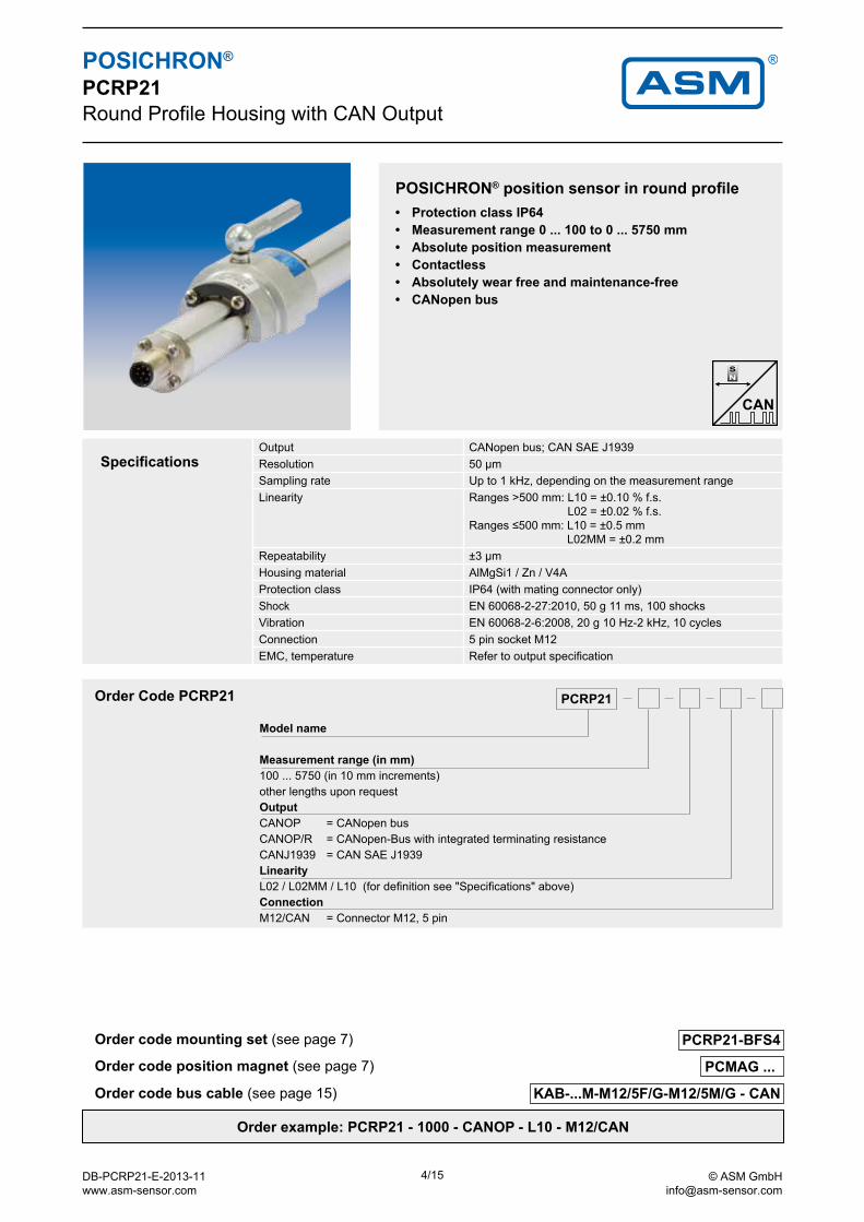
SpecificationsOutput CANopen bus; CAN SAE J1939Resolution 50 µmSampling rate Up to 1 kHz, depending on the measurement rangeLinearity Ranges >500 mm: L10 = ±0.10 % f.s.
L02 = ±0.02 % f.s.Ranges ≤500 mm: L10 = ±0.5 mm
L02MM = ±0.2 mmRepeatability ±3 µmHousing material AlMgSi1 / Zn / V4AProtection class IP64 (with mating connector only)Shock EN 60068-2-27:2010, 50 g 11 ms, 100 shocksVibration EN 60068-2-6:2008, 20 g 10 Hz-2 kHz, 10 cyclesConnection 5 pin socket M12EMC, temperature Refer to output specification
POSICHRON® position sensor in round profile• Protection class IP64• Measurement range 0 ... 100 to 0 ... 5750 mm• Absolute position measurement• Contactless• Absolutely wear free and maintenance-free• CANopen bus
Order code bus cable (see page 15)
Order code position magnet (see page 7)
Order code mounting set (see page 7)
Order example: PCRP21 - 1000 - CANOP - L10 - M12/CAN
Order Code PCRP21
Model name
Measurement range (in mm)100 ... 5750 (in 10 mm increments)other lengths upon requestOutputCANOP = CANopen busCANOP/R = CANopen-Bus with integrated terminating resistanceCANJ1939 = CAN SAE J1939LinearityL02 / L02MM / L10 (for definition see "Specifications" above)ConnectionM12/CAN = Connector M12, 5 pin
DB-PCRP21-E-2013-11 www.asm-sensor.com
4/15 © ASM GmbH [email protected]
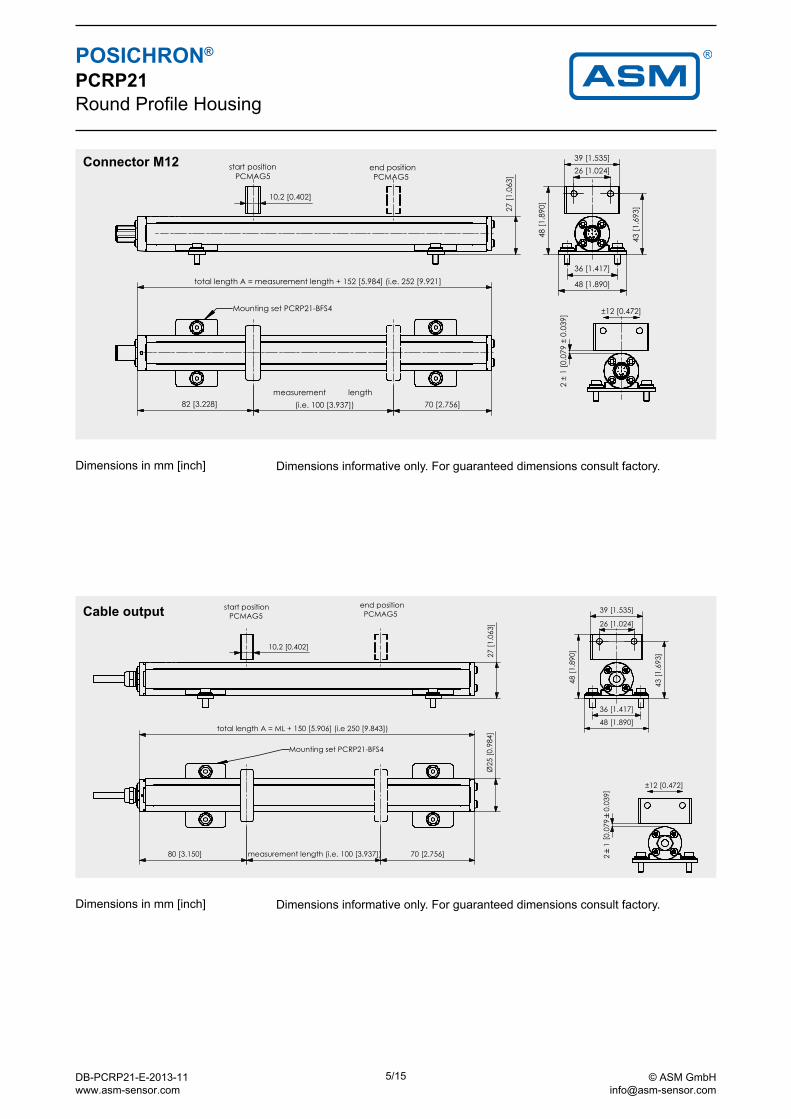
POSICHRON® PCRP21Round Profile Housing
Connector M12
Cable output
Status Änderungen Datum Name
Datum NameGezeichnet
Kontrolliert
Norm
ASMAUTOMATIONSENSORIKMESSTECHNIK
ASM GmbHAm Bleichbach 18-22D-85452 MoosinningTel.: 08123/986-0
Allgemeintoleranzen Maßstab BMC:
Benennung
Werkstoff, HalbzeugCT:
Zeichnungsnummer / Datei Blatt
Nicht bemaßteWerkstückkantenDIN 6784
-0,1-0,2
+0,1+0,2
121431_PCRP21-ML(100-5750)-M12_001_KMZ.idw
18.12.2003 ScF
1
A4
ISO1:2
Masszeichnung
2768-mH
PCRP21-ML(100-5750)-M12
Zeichnung ist Eigentum der Firma ASM, Vervielfältigung nur mit GenehmigungSchutzvermerk nach DIN 34 beachten © Copyright by ASM GmbH
82 [3.228]
10,2 [0.402]
36 [1.417]
48 [1.890]
43 [1
.693
]
48 [1
.890
]
26 [1.024]39 [1.535]
PCMAG5 PCMAG5
Maße in mm [inch]
2 ±
1 [0
.079
± 0
.039
]
27 [1
.063
]
70 [2.756]
12 [0.472]±
start position end position
Mounting set PCRP21-BFS4
measurement length(i.e. 100 [3.937])
total length A = measurement length + 152 [5.984] (i.e. 252 [9.921]
Status Änderungen Datum Name
Datum NameGezeichnet
Kontrolliert
Norm
ASMAUTOMATIONSENSORIKMESSTECHNIK
ASM GmbHAm Bleichbach 18-22D-85452 MoosinningTel.: 08123/986-0
Allgemeintoleranzen Maßstab BMC:
Benennung
Werkstoff, HalbzeugCT:
Zeichnungsnummer / Datei Blatt
Nicht bemaßteWerkstückkantenDIN 6784
-0,1-0,2
+0,1+0,2
121431_PCRP21-ML(100-5750)-KAB_006_DMZ.idw
22.07.2004 ScF
1
A4
ISO1:2
Masszeichnung
2768-mH
PCRP21-ML(100-5750)-KAB
Zeichnung ist Eigentum der Firma ASM, Vervielfältigung nur mit GenehmigungSchutzvermerk nach DIN 34 beachten © Copyright by ASM GmbH
80 [3.150]
10,2 [0.402]
36 [1.417]
48 [1.890]
43 [1
.693
]
48 [1
.890
]
26 [1.024]
39 [1.535]PCMAG5 PCMAG5
250 [9.843])
25 [0
.984
]Ø
100 [3.937]) 70 [2.756] 2`
10.
079`
0.03
9[
]
12 [0.472]±
27 [1
.063
]
start position end position
total length A = ML + 150 [5.906] (i.e
Mounting set PCRP21-BFS4
measurement length (i.e.
Dimensions informative only. For guaranteed dimensions consult factory.Dimensions in mm [inch]
Dimensions informative only. For guaranteed dimensions consult factory.Dimensions in mm [inch]
DB-PCRP21-E-2013-11 www.asm-sensor.com
5/15 © ASM GmbH [email protected]
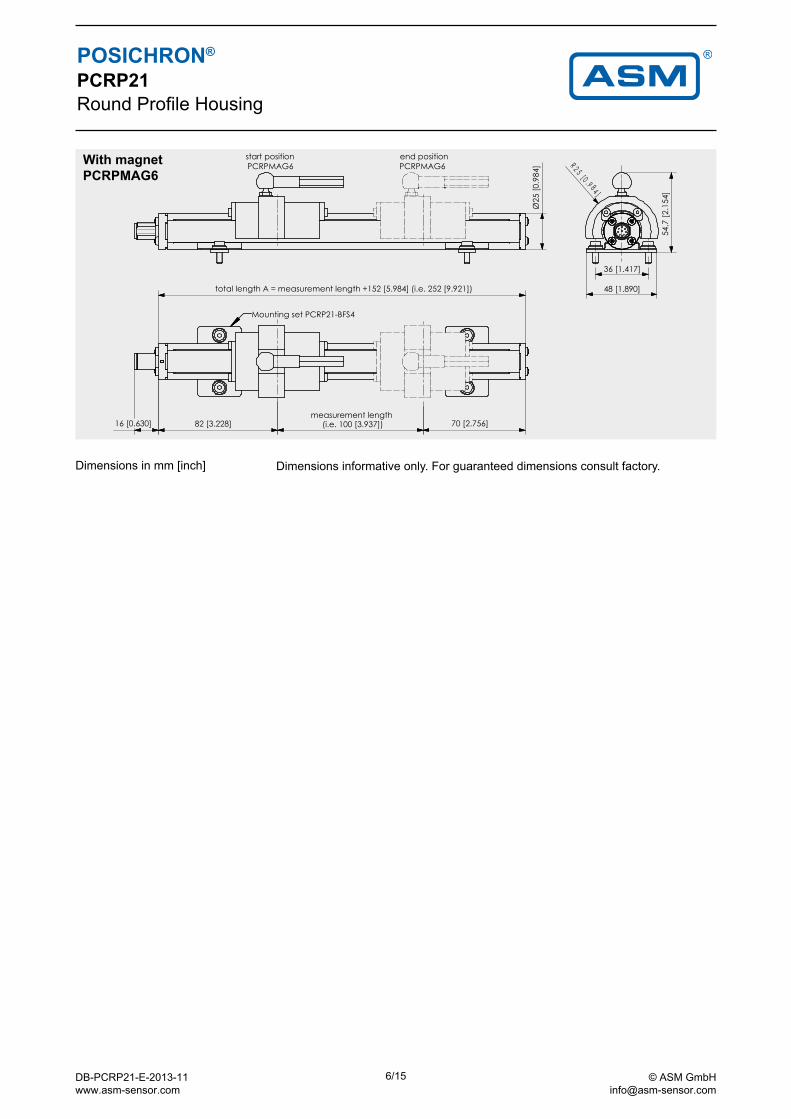
With magnet PCRPMAG6
POSICHRON® PCRP21Round Profile Housing
82 [3.228]measurement length
(i.e. 100 [3.937]) 70 [2.756]16 [0.630]
total length A = measurement length +152 [5.984] (i.e. 252 [9.921])
25 [0
.984
]Ø
36 [1.417]
48 [1.890]
54,7
[2.1
54]
R 2 5 [ 0 . 9 84 ]
Mounting set PCRP21-BFS4
start positionPCRPMAG6
end positionPCRPMAG6
Dimensions informative only. For guaranteed dimensions consult factory.Dimensions in mm [inch]
DB-PCRP21-E-2013-11 www.asm-sensor.com
6/15 © ASM GmbH [email protected]
50 [1.969]Ø8 [.315]
Mit eingesetztem Magnet
45[1
.780
]
34[1
.327
]
5[.1
97]
M5
25 [.984]Ø58 [2.283]
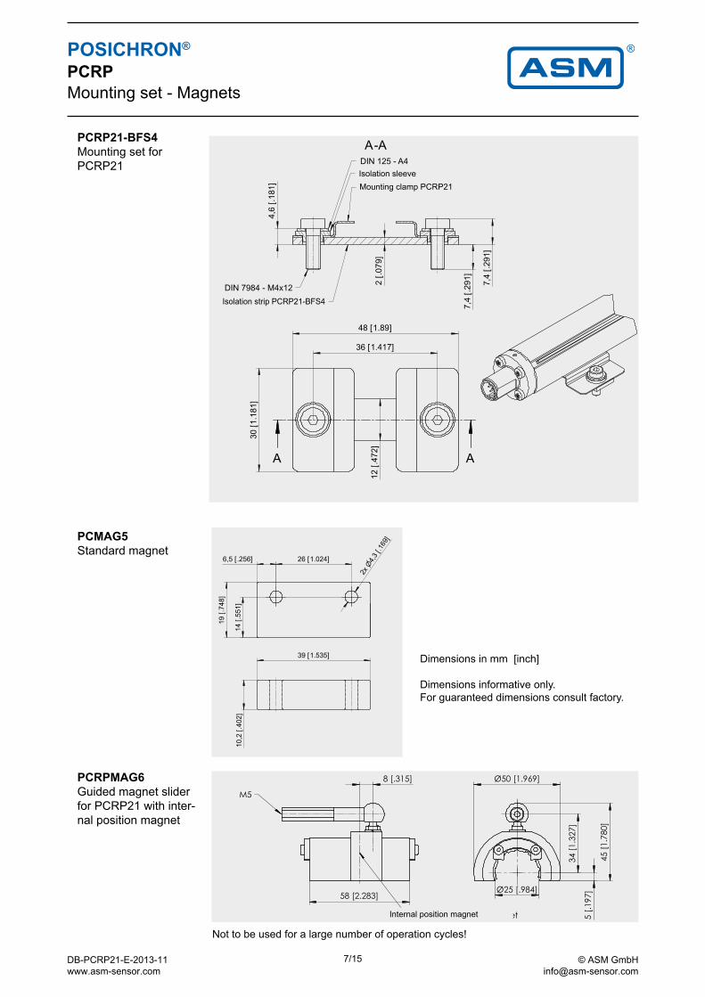
PCRP21-BFS4Mounting set for PCRP21
Mounting clamp PCRP21Isolation sleeve
Isolation strip PCRP21-BFS4
Not to be used for a large number of operation cycles!
PCMAG5 Standard magnet
PCRPMAG6 Guided magnet slider for PCRP21 with inter-nal position magnet
POSICHRON® PCRPMounting set - Magnets
Dimensions in mm [inch]
Dimensions informative only.For guaranteed dimensions consult factory.
Internal position magnet
DB-PCRP21-E-2013-11 www.asm-sensor.com
7/15 © ASM GmbH [email protected]
I1
U1,U2, U8
POSICHRON® Output Specification U2, U8 and I1 Configurable, 1 or 2 channels
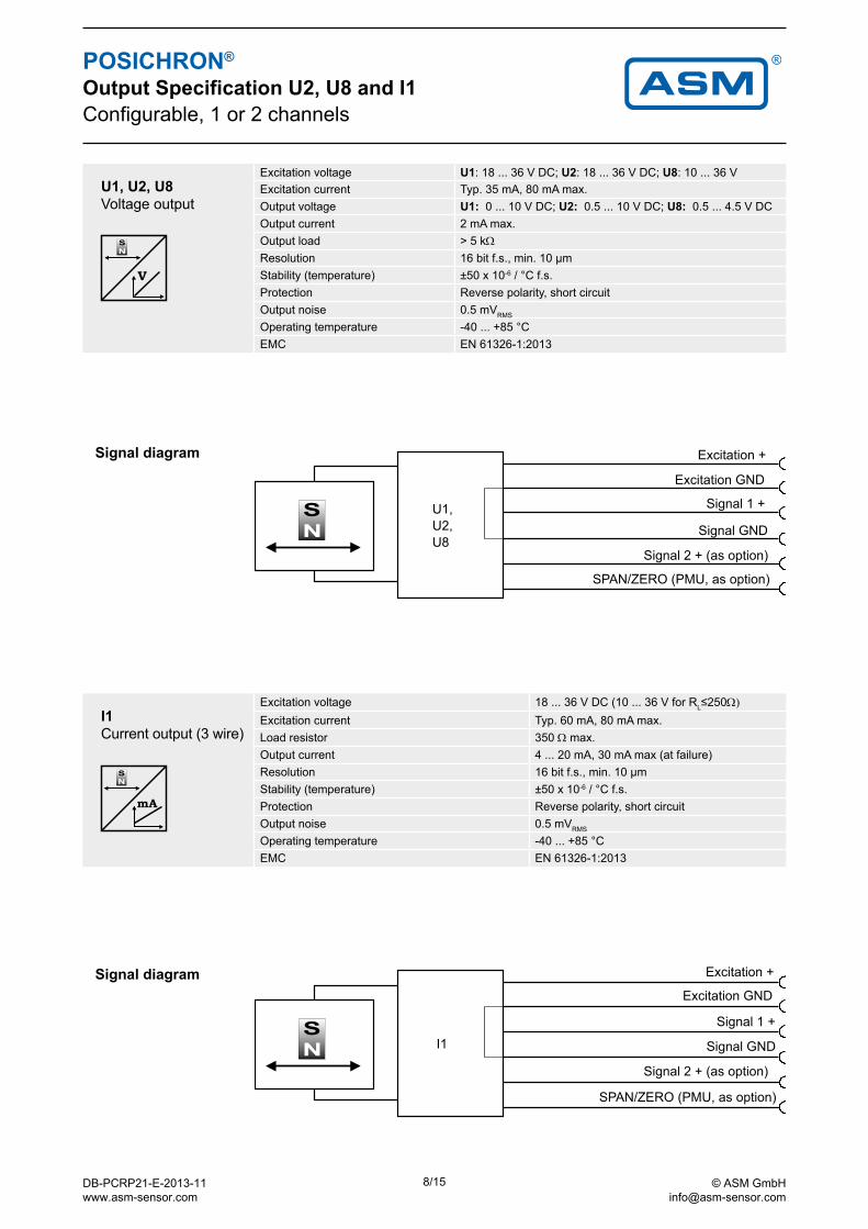
U1, U2, U8Voltage output
Excitation voltage U1: 18 ... 36 V DC; U2: 18 ... 36 V DC; U8: 10 ... 36 VExcitation current Typ. 35 mA, 80 mA max.Output voltage U1: 0 ... 10 V DC; U2: 0.5 ... 10 V DC; U8: 0.5 ... 4.5 V DCOutput current 2 mA max.Output load > 5 kΩ Resolution 16 bit f.s., min. 10 µmStability (temperature) ±50 x 10-6 / °C f.s.Protection Reverse polarity, short circuitOutput noise 0.5 mVRMS
Operating temperature -40 ... +85 °CEMC EN 61326-1:2013
Excitation +
Excitation GND
Signal 1 +
Signal GND
Signal diagram
Excitation +
Excitation GND
Signal 1 +
Signal GND
I1Current output (3 wire)
Excitation voltage 18 ... 36 V DC (10 ... 36 V for RL≤250Ω)
Excitation current Typ. 60 mA, 80 mA max.Load resistor 350 Ω max.Output current 4 ... 20 mA, 30 mA max (at failure)Resolution 16 bit f.s., min. 10 µmStability (temperature) ±50 x 10-6 / °C f.s.Protection Reverse polarity, short circuitOutput noise 0.5 mVRMS
Operating temperature -40 ... +85 °CEMC EN 61326-1:2013
SPAN/ZERO (PMU, as option)
Signal 2 + (as option)
SPAN/ZERO (PMU, as option)
Signal 2 + (as option)
Signal diagram
Signal diagram
DB-PCRP21-E-2013-11 www.asm-sensor.com
8/15 © ASM GmbH [email protected]
POSICHRON® Output Specification U2, U8 and I1 Configurable, 1 or 2 channels
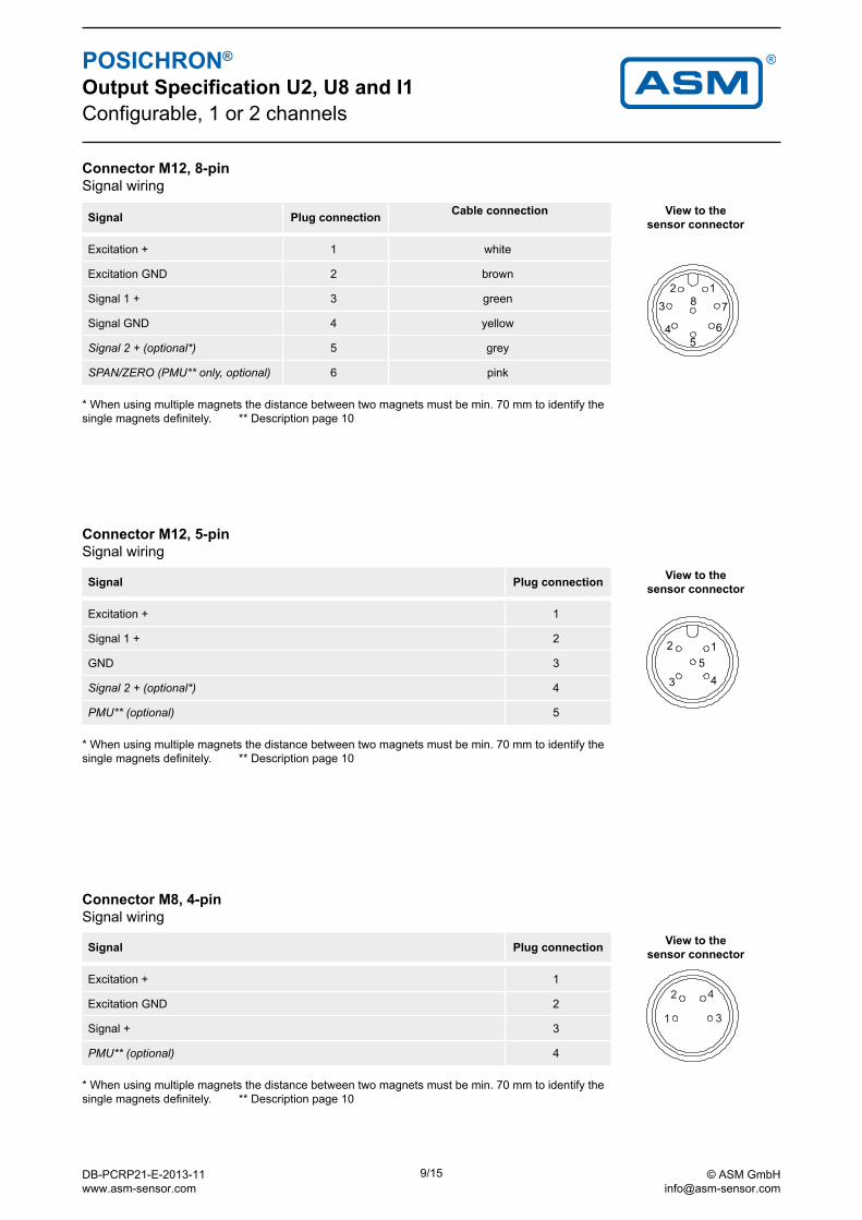
Signal Plug connection Cable connection View to the sensor connector
Excitation + 1 white
Excitation GND 2 brown
Signal 1 + 3 green
Signal GND 4 yellow
Signal 2 + (optional*) 5 grey
SPAN/ZERO (PMU** only, optional) 6 pink
Connector M12, 8-pin Signal wiring
* When using multiple magnets the distance between two magnets must be min. 70 mm to identify the single magnets definitely. ** Description page 10
Signal Plug connection View to the sensor connector
Excitation + 1
Signal 1 + 2
GND 3
Signal 2 + (optional*) 4
PMU** (optional) 5
Connector M12, 5-pin Signal wiring
* When using multiple magnets the distance between two magnets must be min. 70 mm to identify the single magnets definitely. ** Description page 10
Signal Plug connection View to the sensor connector
Excitation + 1
Excitation GND 2
Signal + 3
PMU** (optional) 4
Connector M8, 4-pin Signal wiring
* When using multiple magnets the distance between two magnets must be min. 70 mm to identify the single magnets definitely. ** Description page 10
DB-PCRP21-E-2013-11 www.asm-sensor.com
9/15 © ASM GmbH [email protected]
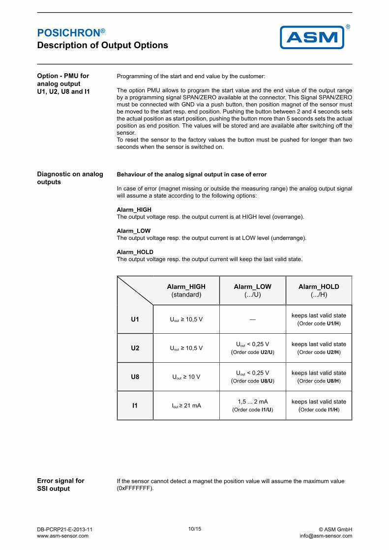
Option - PMU for analog output U1, U2, U8 and I1
Programming of the start and end value by the customer:
The option PMU allows to program the start value and the end value of the output range by a programming signal SPAN/ZERO available at the connector. This Signal SPAN/ZERO must be connected with GND via a push button, then position magnet of the sensor must be moved to the start resp. end position. Pushing the button between 2 and 4 seconds sets the actual position as start position, pushing the button more than 5 seconds sets the actual position as end position. The values will be stored and are available after switching off the sensor.To reset the sensor to the factory values the button must be pushed for longer than two seconds when the sensor is switched on.
POSICHRON® Description of Output Options
Diagnostic on analogoutputs
Error signal for SSI output
If the sensor cannot detect a magnet the position value will assume the maximum value (0xFFFFFFF).
Alarm_HIGH(standard)
Alarm_LOW (.../U)
Alarm_HOLD (.../H)
U1 Uout ≥ 10,5 V —keeps last valid state
(Order code U1/H)
U2 Uout ≥ 10,5 VUout < 0,25 V
(Order code U2/U)keeps last valid state
(Order code U2/H)
U8 Uout ≥ 10 VUout < 0,25 V
(Order code U8/U)keeps last valid state
(Order code U8/H)
I1 Iout ≥ 21 mA1,5 ... 2 mA
(Order code I1/U)keeps last valid state
(Order code I1/H)
Behaviour of the analog signal output in case of error
In case of error (magnet missing or outside the measuring range) the analog output signal will assume a state according to the following options:
Alarm_HIGHThe output voltage resp. the output current is at HIGH level (overrange).
Alarm_LOW The output voltage resp. the output current is at LOW level (underrange).
Alarm_HOLD The output voltage resp. the output current will keep the last valid state.
DB-PCRP21-E-2013-11 www.asm-sensor.com
10/15 © ASM GmbH [email protected]
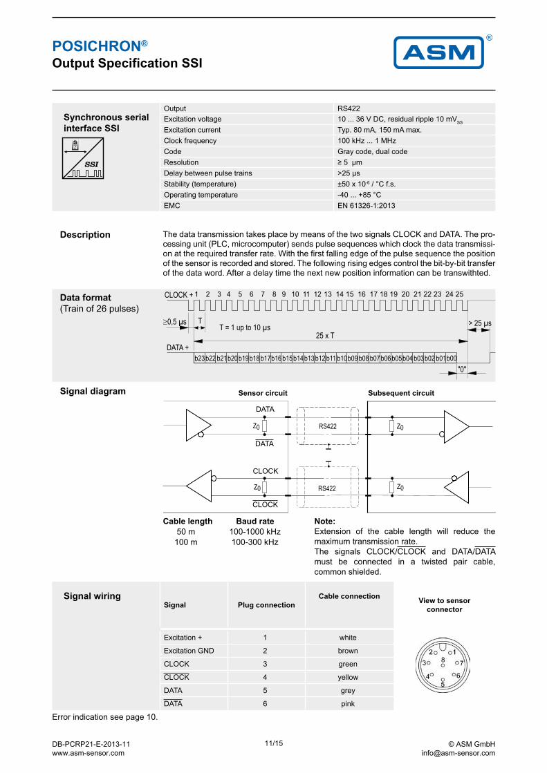
POSICHRON® Output Specification SSI
Description The data transmission takes place by means of the two signals CLOCK and DATA. The pro-cessing unit (PLC, microcomputer) sends pulse sequences which clock the data transmissi-on at the required transfer rate. With the first falling edge of the pulse sequence the position of the sensor is recorded and stored. The following rising edges control the bit-by-bit transfer of the data word. After a delay time the next new position information can be transwithted.
Data format (Train of 26 pulses)
Synchronous serial interface SSI
Output RS422Excitation voltage 10 ... 36 V DC, residual ripple 10 mVSS
Excitation current Typ. 80 mA, 150 mA max.Clock frequency 100 kHz ... 1 MHzCode Gray code, dual codeResolution ≥ 5 µmDelay between pulse trains >25 µsStability (temperature) ±50 x 10-6 / °C f.s.Operating temperature -40 ... +85 °C EMC EN 61326-1:2013
Sensor circuit Subsequent circuit
Cable length Baud rate 50 m 100-1000 kHz 100 m 100-300 kHz
Note:Extension of the cable length will reduce the maximum transmission rate.The signals CLOCK/CLOCK and DATA/DATA must be connected in a twisted pair cable, common shielded.
CLOCK
CLOCK
DATA
DATA
Signal diagram
Error indication see page 10.
Signal wiring Signal Plug connection
Cable connection View to sensorconnector
Excitation + 1 white
Excitation GND 2 brown
CLOCK 3 green
CLOCK 4 yellow
DATA 5 grey
DATA 6 pink
DB-PCRP21-E-2013-11 www.asm-sensor.com
11/15 © ASM GmbH [email protected]
View to sensor connector
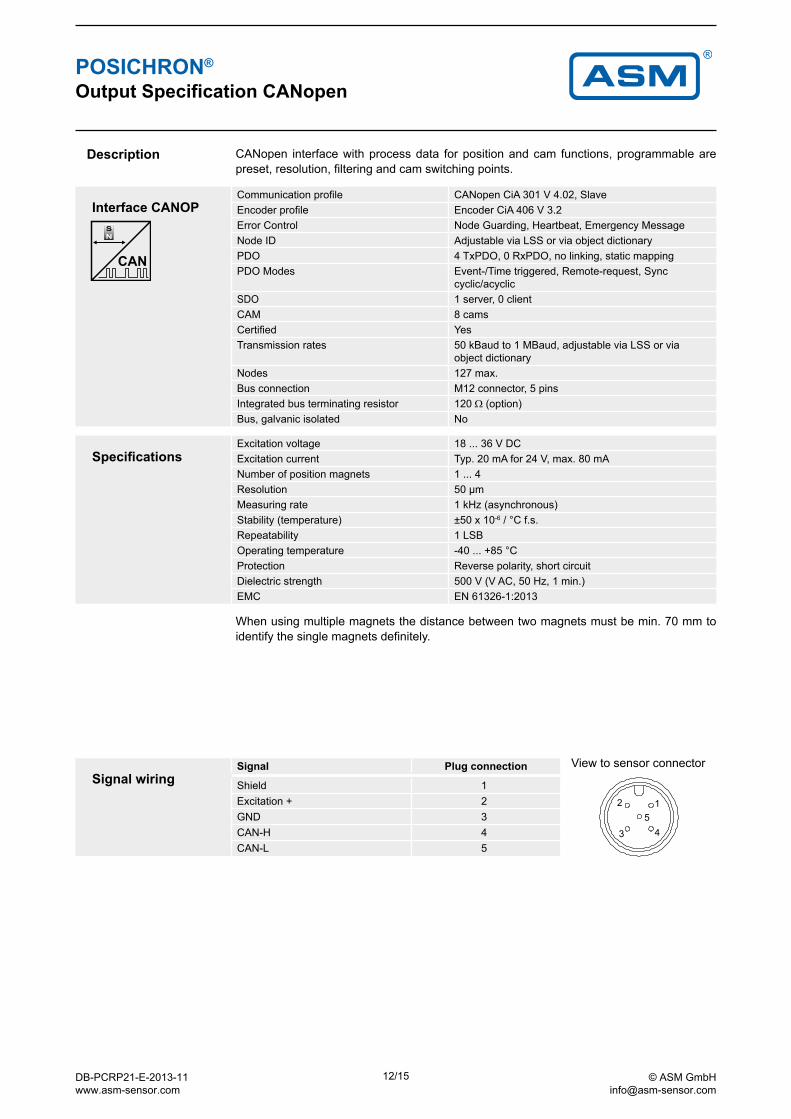
POSICHRON® Output Specification CANopen
Interface CANOPCommunication profile CANopen CiA 301 V 4.02, SlaveEncoder profile Encoder CiA 406 V 3.2Error Control Node Guarding, Heartbeat, Emergency MessageNode ID Adjustable via LSS or via object dictionaryPDO 4 TxPDO, 0 RxPDO, no linking, static mappingPDO Modes Event-/Time triggered, Remote-request, Sync
cyclic/acyclicSDO 1 server, 0 clientCAM 8 camsCertified YesTransmission rates 50 kBaud to 1 MBaud, adjustable via LSS or via
object dictionaryNodes 127 max.Bus connection M12 connector, 5 pinsIntegrated bus terminating resistor 120 Ω (option)Bus, galvanic isolated No
Description CANopen interface with process data for position and cam functions, programmable are preset, resolution, filtering and cam switching points.
SpecificationsExcitation voltage 18 ... 36 V DCExcitation current Typ. 20 mA for 24 V, max. 80 mANumber of position magnets 1 ... 4Resolution 50 µmMeasuring rate 1 kHz (asynchronous)Stability (temperature) ±50 x 10-6 / °C f.s.Repeatability 1 LSBOperating temperature -40 ... +85 °CProtection Reverse polarity, short circuitDielectric strength 500 V (V AC, 50 Hz, 1 min.)EMC EN 61326-1:2013
Signal wiringSignal Plug connection
Shield 1Excitation + 2GND 3CAN-H 4CAN-L 5
When using multiple magnets the distance between two magnets must be min. 70 mm to identify the single magnets definitely.
DB-PCRP21-E-2013-11 www.asm-sensor.com
12/15 © ASM GmbH [email protected]
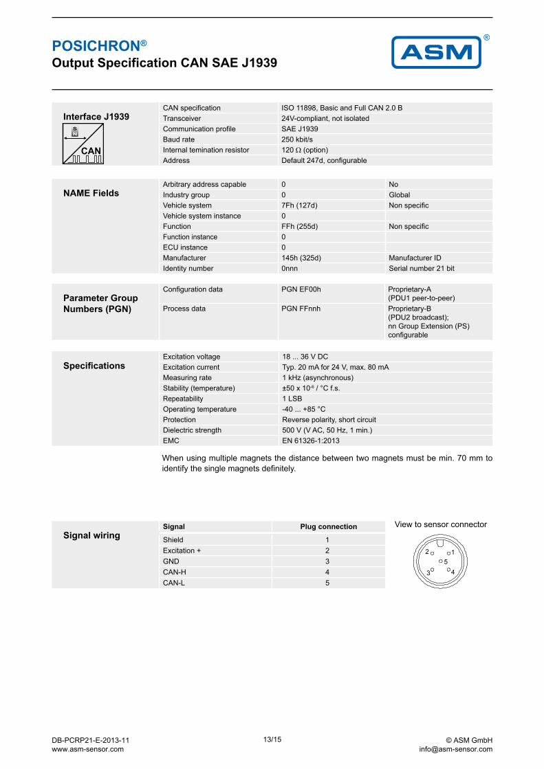
POSICHRON® Output Specification CAN SAE J1939
Interface J1939CAN specification ISO 11898, Basic and Full CAN 2.0 BTransceiver 24V-compliant, not isolatedCommunication profile SAE J1939Baud rate 250 kbit/sInternal temination resistor 120 Ω (option)Address Default 247d, configurable
SpecificationsExcitation voltage 18 ... 36 V DCExcitation current Typ. 20 mA for 24 V, max. 80 mAMeasuring rate 1 kHz (asynchronous)Stability (temperature) ±50 x 10-6 / °C f.s.Repeatability 1 LSBOperating temperature -40 ... +85 °CProtection Reverse polarity, short circuitDielectric strength 500 V (V AC, 50 Hz, 1 min.)EMC EN 61326-1:2013
Signal wiringSignal Plug connection
Shield 1Excitation + 2GND 3CAN-H 4CAN-L 5
NAME FieldsArbitrary address capable 0 NoIndustry group 0 GlobalVehicle system 7Fh (127d) Non specificVehicle system instance 0Function FFh (255d) Non specificFunction instance 0ECU instance 0Manufacturer 145h (325d) Manufacturer IDIdentity number 0nnn Serial number 21 bit
Parameter Group Numbers (PGN)
Configuration data PGN EF00h Proprietary-A (PDU1 peer-to-peer)
Process data PGN FFnnh Proprietary-B (PDU2 broadcast); nn Group Extension (PS) configurable
View to sensor connector
When using multiple magnets the distance between two magnets must be min. 70 mm to identify the single magnets definitely.
DB-PCRP21-E-2013-11 www.asm-sensor.com
13/15 © ASM GmbH [email protected]
KAB - XM - M12/8F/W - LITZEKAB - XM - M12/8F/W/69K - LITZEIP69K:
KAB - XM - M12/5F/G/69K - LITZEKAB - XM - M12/5F/G - LITZE
KAB - XM - M12/5F/W/69K - LITZEKAB - XM - M12/5F/W - LITZE
KAB - XM - M12/8F/G - LITZEKAB - XM - M12/8F/G/69K - LITZEIP69K:
IP69K:
IP69K:
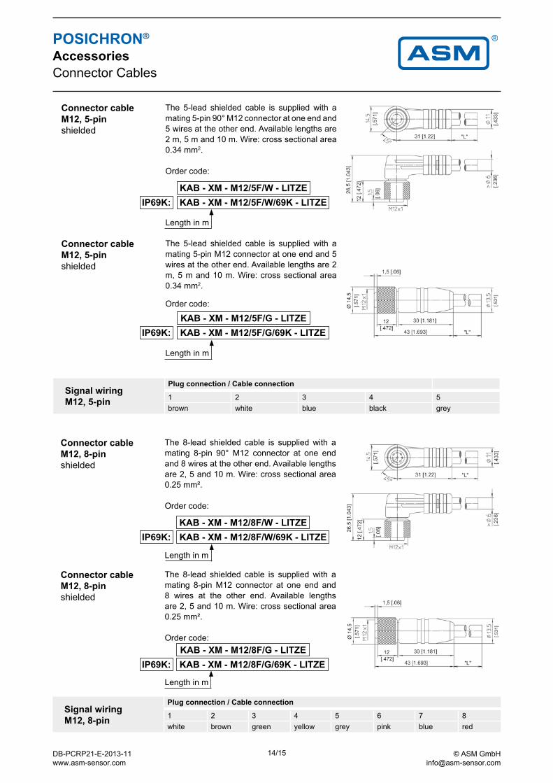
POSICHRON® Accessories Connector Cables
Connector cableM12, 8-pinshielded
The 8-lead shielded cable is supplied with a mating 8-pin 90° M12 connector at one end and 8 wires at the other end. Available lengths are 2, 5 and 10 m. Wire: cross sectional area 0.25 mm².
Order code:
Length in m
Signal wiringM12, 8-pin
Plug connection / Cable connection
1 2 3 4 5 6 7 8white brown green yellow grey pink blue red
Connector cableM12, 8-pinshielded
The 8-lead shielded cable is supplied with a mating 8-pin M12 connector at one end and 8 wires at the other end. Available lengths are 2, 5 and 10 m. Wire: cross sectional area 0.25 mm².
Order code:
Length in m
Connector cableM12, 5-pinshielded
The 5-lead shielded cable is supplied with a mating 5-pin 90° M12 connector at one end and 5 wires at the other end. Available lengths are 2 m, 5 m and 10 m. Wire: cross sectional area 0.34 mm2.
Order code:
Length in m
Connector cableM12, 5-pinshielded
The 5-lead shielded cable is supplied with a mating 5-pin M12 connector at one end and 5 wires at the other end. Available lengths are 2 m, 5 m and 10 m. Wire: cross sectional area 0.34 mm2.
Order code:
Length in m
Signal wiring M12, 5-pin
Plug connection / Cable connection
1 2 3 4 5brown white blue black grey
DB-PCRP21-E-2013-11 www.asm-sensor.com
14/15 © ASM GmbH [email protected]
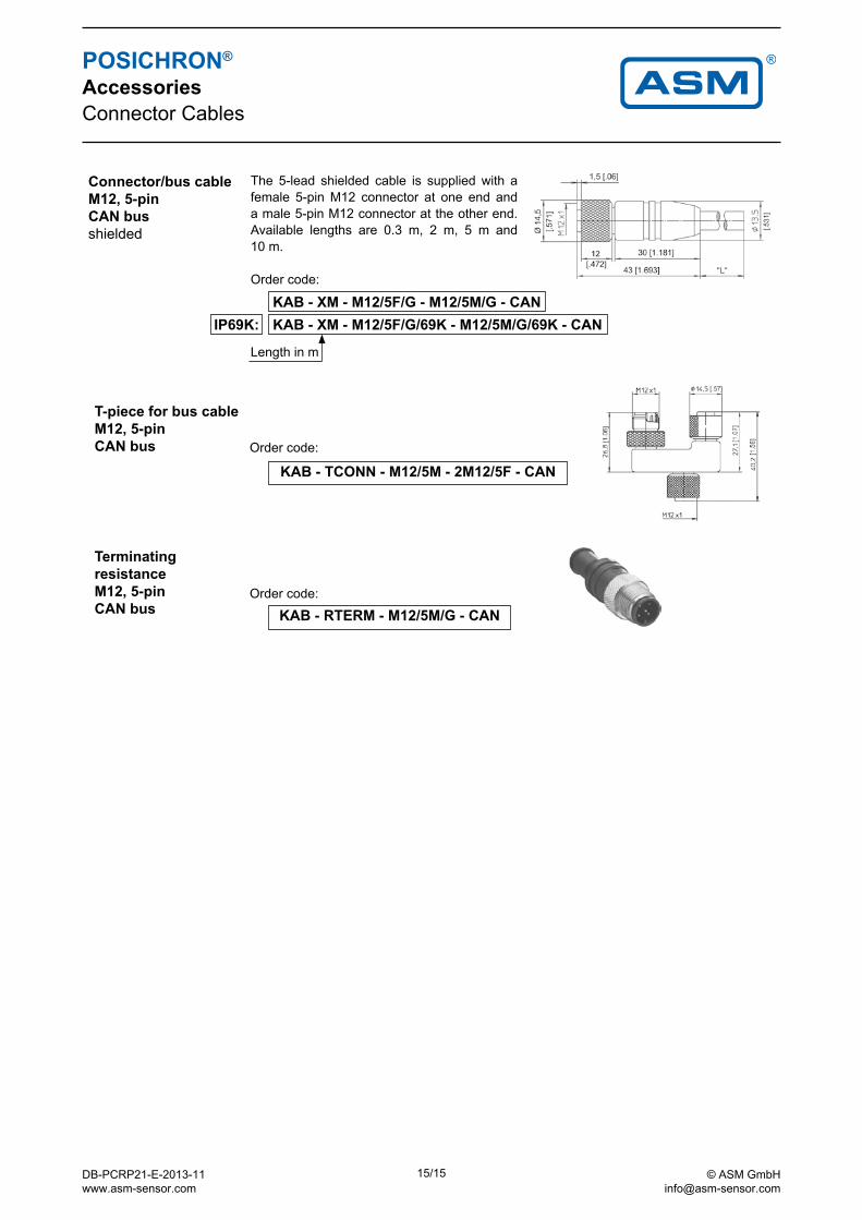
KAB - XM - M12/5F/G - M12/5M/G - CAN KAB - XM - M12/5F/G/69K - M12/5M/G/69K - CANIP69K:
KAB - TCONN - M12/5M - 2M12/5F - CAN
KAB - RTERM - M12/5M/G - CAN
POSICHRON® Accessories Connector Cables
Connector/bus cableM12, 5-pin CAN busshielded
The 5-lead shielded cable is supplied with a female 5-pin M12 connector at one end and a male 5-pin M12 connector at the other end. Available lengths are 0.3 m, 2 m, 5 m and 10 m.
Order code:
Length in m
Terminating resistance M12, 5-pin CAN bus
T-piece for bus cable M12, 5-pin CAN bus Order code:
Order code:
DB-PCRP21-E-2013-11 www.asm-sensor.com
15/15 © ASM GmbH [email protected]