Embed Size (px)
Citation preview

perfekt in form und funktion
Power Circuit Breaker
ME10
ed.15-01 CIRCUIT BREAKERLEISTUNGSSCHALTERINTERRUTTORE APERTO
MANUALHANDBUCHMANUALE
GB DE IT
WARNUNG
Während des Betriebes ist das in diesem Handbuch beschriebene Gerät an hohe, potenziell gefährliche Spannungen angeschlossen.
Aus Leistungsschaltern können zudem beim Ausschalten hoher Ströme, besonders bei Kurzschlüssen, heiße und ionisierte Gase austreten.
Montage, Inbetriebnahme, Wartung, Änderung und Nachrüstung dieser Geräte dürfen deshalb nur von qualifiziertem Fachpersonal unter Befolgung der einschlägigen Sicherheitsvorschriften ausgeführt werden.
Leistungsschalter müssen während ihres Betriebes mit dazugehörigen Abdeckungen versehen sein und / oder in Gehäusen oder Schaltschränken unter Berücksichtigung der Sicherheitsabstände eingebaut sein.
Die Nichtbeachtung dieser Erfordernisse kann hohe Sachschäden und / oder schwere Körperverletzungen zur Folge haben.
AVVERTENZA
Durante il funzionamento, l'apparecchio descritto in questo manuale è collegato a tensioni elevate e potenzialmente pericolose.
Quando l'interruttore commuta correnti elevate, soprattutto correnti di corto circuito, possono essere generati gas caldi e ionizzati.
Solo il personale qualificato è autorizzato ad installare, mettere in servizio, mantenere o modificare il dispositivo, in conformità alle norme di sicurezza.
L'Interruttore deve essere equipaggiato con coperture adeguate e/o essere installato in quadri adatti, tenendo conto delle distanze di sicurezza necessarie.
Il mancato rispetto di tali requisiti può causare danni a cose e/o lesioni gravi alle persone.
Caution! Important Requirements! Achtung! Wichtige Forderungen! Attenzione! Requisiti importanti!
WARNING
During operation the device described in this manual is connected to high and potentially dangerous voltages.
When the circuit breaker is switching high currents, especially short-circuit currents, hot and ionized gas may be emitted.
Only qualified personnel are allowed to install, commission, maintain or modify this device in accordance with relevant safety requirements.
The Circuit Breaker must be equipped with the appropriate covers and/or be installed in a suitable enclosure or panel taking the required safety clearances into account.
Non Compliance with these requirements could result in damage to property and/or severe injury to personnel.
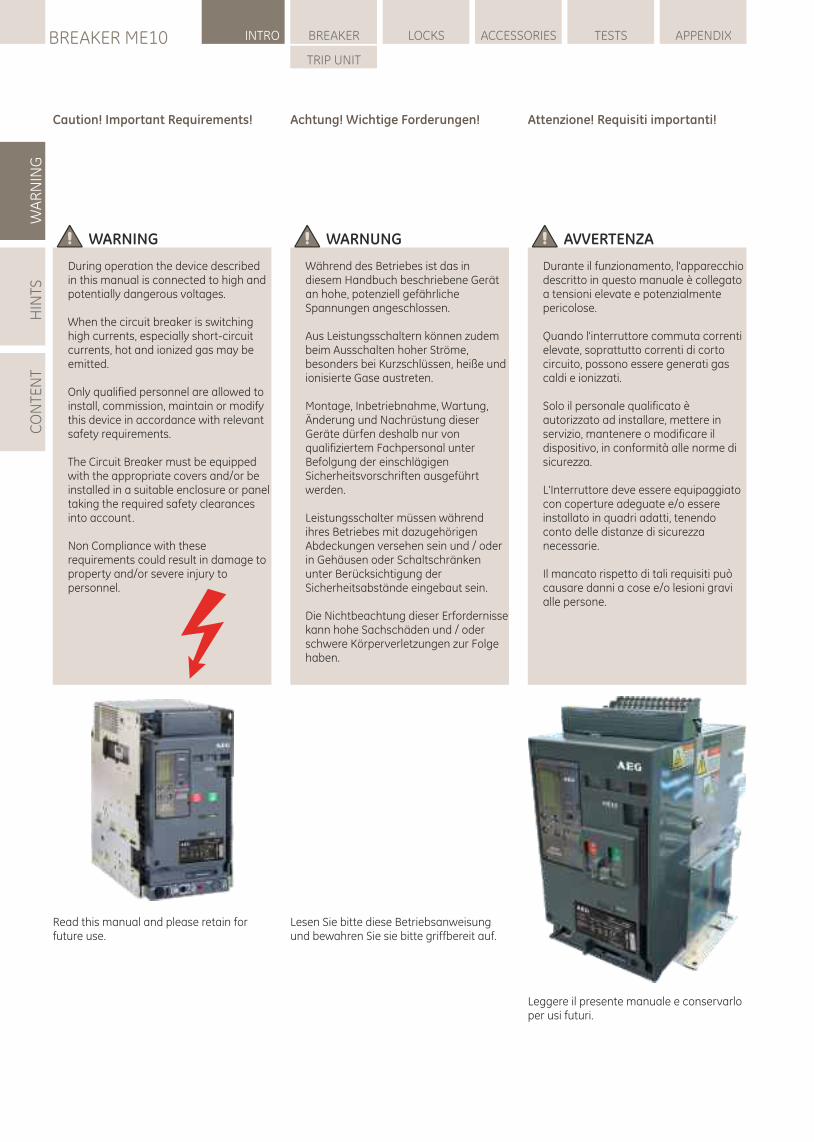
Lesen Sie bitte diese Betriebsanweisung und bewahren Sie sie bitte griffbereit auf.
Read this manual and please retain for future use.
Leggere il presente manuale e conservarlo per usi futuri.
WA
RN
ING
HIN
TSC
ON
TEN
TLOCKSBREAKER ME10 INTRO BREAKER ACCESSORIES TESTS APPENDIX
TRIP UNIT
1.0 ALLGEMEINE INFORMATION
Installations-, Betriebs- und Wartungs-Handbuch
ME10 Leistungsschalter
GEFÄHRDUNGSKATEGORIENDie folgenden wichtigen, hervorgehoben Informationen in diesem Dokument warnen vor möglichen Gefahren oder machen auf besondere Verfahrenweisen aufmerksam.Lesen Sie alle Anweisungen aufmerksam durch und machen Sie sich mit dem Gerät vertraut, bevor Sie versuchen es zu installieren, zu betreiben oder Service- und Wartungsarbeiten an dieser Ausrüstung vorzunehmen.
1.0 GENERAL INFORMATION
Installation, Operation and Maintenance Manual
ME10 Power Circuit Breaker
HAZARD CATEGORIESThe following important highlighted information appears throughout this document to warn of potential hazards or to call attention to information that clarifies a procedure.Carefully read all instructions and become familiar with the devices before trying to install, operate, service or maintain this equipment.
CAUTION: Failure to comply with these instructions may result in product damage.
NOTICE: An aid meant to assist the user in performing the set task. Please retain for future use.
TRADEMARKSME10ME10 TU
WARRANTYThis document is based on information available at the time of its publication.While efforts have been made to ensure accuracy, the information contained herein does not cover all details or variations in hardware and software, nor does it provide for every possible contingency in connection with installation, operation, and maintenance.Features may be described herein that are not present in all hardware and software systems.
AEG assumes no obligation of notice to holders of this document with respect to changes subsequently made.
AEG makes no representation or warranty, expressed, implied, or statutory, with respect to, and assumes no responsibility for the accuracy, completeness, sufficiency, or usefulness of the information contained herein.
No warrantees of merchantability or fitness for purpose shall apply.
Contact your local sales office if further information is required concerning any aspect of ME10 Circuit breaker operation or maintenance.
VORSICHT: Die Nichteinhaltung dieser Anweisungen kann zu Schäden am Produkt führen.
HINWEIS: Zeigt wichtige Informationen zur Hilfe und Klarstellung der Angaben.
SCHUTZMARKENME10ME10 TU
GARANTIEDieses Dokument basiert auf zum Zeitpunkt der Veröffentlichung verfügbaren Informationen.Es wurden alle Anstrengungen zur Vollständigkeit des Handbuchs unternommen, trotzdem kann die hierin enthaltene Information sich nicht auf alle Details oder Variationen in Hard- und Software oder auf alle im Zusammenhang mit Installation, Betrieb und Wartung auftretenden Möglichkeiten beziehen.Außerdem können hier Funktionen beschrieben sein, die nicht in dem vorliegenden Hard- oder Software-System vorhanden sind.
AEG übernimmt keine Verpflichtung zur Mitteilung an die Inhaber dieses Dokuments in Bezug auf Veränderungen.
AEG macht keine Zusicherungen oder Garantien und übernimmt keine Verantwortung für die Richtigkeit, Vollständigkeit oder Nützlichkeit der hierin enthaltenen Informationen.
Es gibt keine Gewährleistungen der Marktgängigkeit oder Eignung für einen bestimmten Zweck.
Wenden Sie sich bitte an Ihr Verkaufsbüro vor Ort, falls Sie weitere Informationen zu Aspekten des ME10-Leistungsschalter in Betrieb oder Wartung benötigen.
ATTENZIONE: Il mancato rispetto di queste istruzioni può causare danni al prodotto.
AVVISO: Ausilio destinato ad assistere l'utente nello svolgimento dei propri compiti. Si prega di conservare per uso futuro.
MARCHIME10ME10 TU
GARANZIAQuesto documento si basa sulle informazioni disponibili al momento della pubblicazione. Pur essendo stati intrapresi tutti gli sforzi possibili per garantirne l'accuratezza, le informazioni contenute nel presente documento non coprono tutti i possibili dettagli o le variazioni a livello hardware e software, né coprono tutte le possibili casistiche relative a installazione, funzionamento e manutenzione.Nel presente documento possono essere descritte caratteristiche non presenti in tutti i sistemi hardware e software.
AEG non si assume alcun obbligo di comunicare ai possessori di questo documento le modifiche apportate successivamente.
AEG non rilascia alcuna dichiarazione o garanzia - espressa, implicita o legale - circa le informazioni contenute nel presente documento, né si assume alcuna responsabilità sulla loro accuratezza, la loro completezza, la loro esaustività o la loro utilità.
Non si applica alcuna garanzia di commerciabilità o di pertinenza d'uso.
Per ulteriori informazioni riguardanti qualsiasi aspetto del funzionamento o della manutenzione dell'interruttore ME10, contattare l'ufficio vendite locale.
DANGER | GEFAHR | PERICOLOIndicates a hazardous situation which, if not avoided, could result in death or serious injury.
Zeigt an, dass eine vermeidbare, gefährliche Situation entstehen kann, die zum Tod oder zu schweren Verletzungen führen kann.
Indica una situazione pericolosa che, se non evitata, può causare morte o lesioni serie.
1.0 INFORMAZIONI GENERALI
Manuale di installazione, uso e manutenzione
Interruttore aperto ME10
CATEGORIE DI RISCHIOLe importanti informazioni descritte di seguito in questo documento e opportunamente evidenziate, intendono segnalare rischi o richiamare l'attenzione su dettagli che chiariscono una procedura. Leggere attentamente tutte le istruzioni e familiarizzare con i dispositivi prima di cercare di installare, far funzionare o effettuare manutenzioni sugli apparecchi.
BREAKER ME10INTRO
HIN
TS
1.0
1.0-01
LOCKSBREAKER ME10 INTRO BREAKER ACCESSORIES TESTS APPENDIX
TRIP UNIT
INHALTSVERZEICHNIS
1.0 - ALLGEMEINE INFORMATIONEN--------------------------------------------------------1.1.0 Einführung
QualitätssicherungCheckliste GeräteoptionenProduktserien- & KatalognummerMaßeinheiten
1.1.1 Kurzbeschreibung1.1.2 Eigenschaften und Merkmale1.1.3 Lagerung1.1.4 Leistungsschild Beschreibung1.1.5 Werkzeuge, benötigt für die Montage
--------------------------------------------------------1.2 - PRODUKTSPEZIFIKATIONEN
- Tabellen
--------------------------------------------------------1.3 - INSTALLATION
1.3.1 Heben- und MontageVerwendung des Hebeadapters
1.3.2 Leistungsschalter für FesteinbauMontage
1.3.3 Leistungsschalter für AusfahrtechnikMontageAusbau aus dem EinschubträgerEinbau in den Einschubträger
1.3.4 Standard Busverbindungenvon Fest- und/oder Einschubtechnik
1.3.5 HilfstrennblöckeLagebeschreibungVerwendungTabelle -- AnschlussschemaTabelle -- Geräteanschlüsse Block A - C
--------------------------------------------------------1.4 - BETRIEB
1.4.1 Energiespeicherung in der Schaltermechanik
ManuellElektrisch
1.4.2 Betriebsstellungen Schalter1.4.3 Leistungsschalter Einschaltung1.4.4 Leistungsschalter Ausschaltung1.4.5 Leistungsschalter Entnahme1.4.6 Leistungsschalter Einbau/Einschub1.4.7 Betriebsstellungen des Einschubträgers
--------------------------------------------------------2.0 - AUSLÖSEEINHEIT Allgemeine Information
2.1 Produktbeschreibung2.2 Betrieb2.3 LCD Display-Betriebseinstellungen
2.5 Auslösekurven2.6 ...2.7 Montagehinweise2.8 Anschlussschema2.9 Fehlersuche2.10 Katalognummern Code Auslöser--------------------------------------------------------
CONTENT
1.0 - GENERAL INFORMATION--------------------------------------------------------1.1.0 Introduction
Quality AssuranceOptions Check SheetProduct Serial & Catalogue NumberMeasurement Units
1.1.1 Short Product Description1.1.2 Features and Characteristics1.1.3 Storage1.1.4 Rating label description1.1.5 Tools Needed for Installation
--------------------------------------------------------1.2 - PRODUCT SPECIFICATIONS
- Tables
--------------------------------------------------------1.3 - INSTALLATION
1.3.1 Lifting and Mounting Using Lifting Beams1.3.2 Fixed-Pattern Circuit Breaker Installation1.3.3 Drawout Pattern Circuit Breaker Installation Removal from Cassette Mounting in Cassette1.3.4 Standard Bus connection of Fixed AND/OR Drawout pattern. 1.3.5 Secondary Disconnect Terminal Blocks Location Use Table -- General schematics Table -- Definition of connected devices to Block A - C
--------------------------------------------------------1.4 - OPERATION
1.4.1 Charging of Main Springs Manually Electrically
1.4.2 Sequence of breaker operation1.4.3 Circuit breaker closing operation1.4.4 Circuit breaker opening operation1.4.5 Circuit breaker Withdrawal1.4.6 Circuit breaker Insertion/Cassette1.4.7 Sequence of operation cassette
--------------------------------------------------------2.0 - TRIP UNIT General Information
2.1 Product description2.2 Operation2.3 LCD Screen /Operating Modes
2.5 Time current curves2.6 ...2.7 Installation2.8 Connection scheme2.9 Troubleshooting2.10 Catalogue code build--------------------------------------------------------
CONTENUTO
1.0 - INFORMAZIONI GENERALI--------------------------------------------------------1.1.0 Introduzione Garanzia di qualità Scheda verifica opzioni Descrizione codice catalogo Numero di serie del prodotto & del catalogo1.1.1 Breve descrizione del prodotto1.1.2 Funzioni e caratteristiche1.1.3 Stoccaggio1.1.4 Descrizione dati di targa1.1.5 Attrezzature necessarie per
l'installazione--------------------------------------------------------1.2 - SPECIFICHE DI PRODOTTO - Tabelle
--------------------------------------------------------1.3 - INSTALLAZIONE
1.3.1 Sollevamento e montaggio Uso dei bracci di sollevamento1.3.2 Interruttore in esecuzione fissa Installazione1.3.3 Interruttore in esecuzione estraibile Installazione Rimozione dalla parte fissa Montaggio nella parte fissa1.3.4 Connessioni standard Versioni in esecuzione fissa e/o estraibile. 1.3.5 Morsettiere dei circuiti ausiliari Posizione Uso Tabella -- Schemi generali Tabella -- Definizione dei dispositivi
collegati a Morsettiera A - C
--------------------------------------------------------1.4 - FUNZIONAMENTO
1.4.1 Carica delle molle principali Manuale Elettrica1.4.2 Sequenza di funzionamento
dell'interruttore1.4.3 Chiusura dell'interruttore1.4.4 Apertura dell'interruttore1.4.5 Estrazione dell'interruttore1.4.6 Inserimento dell'interruttore/parte fissa1.4.7 Sequenza di manovra della parte fissa
--------------------------------------------------------2.0 - RELÈ DI PROTEZIONE Informazioni generali
2.1 Descrizione del prodotto2.2 Funzionamento2.3 Modalità schermo LCD
2.5 Curve di intervento2.6 ...2.7 Installazione2.8 Schema di connessione2.9 Risoluzione dei problemi2.10 Struttura codici catalogo--------------------------------------------------------
1.0-02
BREAKER ME10INTRO
CO
NTE
NT
1
3.0 - CHIUSURE E INTERBLOCCHI
3.1 Pannello anteriore interruttore - Lucchettaggio di sicurezza interruttore - Chiusura di sicurezza interruttore - Lucchettaggio pulsante3.2 Parte fissa interruttore in esecuzione
estraibile - Lucchettaggio serrande - Lucchettaggio accesso maniglia di manovra - Lucchettaggio guide di supporto - Chiusura di sicurezza parte fissa - Interblocco interruttore in esecuzione
estraibile - Sistema di prevenzione inserimento errato
(interblocco) - Interblocco porta 3.2.1 Apertura forzata serrande 3.2.2 Blocco serranda isolamento3.3 Interblocco di più interruttori - interblocco 1 di 2 & 3 - interblocco 2 di 3 & 3 con priorità3.4 Interblocco di rete3.5 Tabelle opzioni di blocco--------------------------------------------------------4.0 - DESCRIZIONE ACCESSORI Informazioni generali
4.1 Sganciatori/bobine 4.2 Motore di ricarica molle 4.3 Contatti 4.4 Accessori d'installazione 4.5 Altri accessori 4.6 Parti di ricambio
--------------------------------------------------------5.0 - MANUTENZIONE, VERIFICA E
RISOLUZIONE DEI PROBLEMI
5.1 Manutenzione - Programma di ispezione5.2 Procedura di pulizia - Ispezione contatti d'arco - Ispezione meccanismi principali interruttore5.3 Controllo parte fissa5.4 Controllo usura contatto 5.5 Controllo contatti di sezionamento
(versione in esecuzione estraibile)5.6 Controllo morsetti di alimentazione e
sbarre5.7 Lubrificazione5.8 Verifica - Verifica Relè di Protezione5.9 Risoluzione dei problemi
--------------------------------------------------------6.0 - APPENDICE
6.1 Descrizione codice catalogo6.2 Dimensioni6.3 Post-vendita
3.0 - LOCKS AND INTERLOCKS
3.1 Breaker front Fascia- Breaker Security Padlocking- Breaker Security Keylocking- Pushbutton Padlocking
3.2 Drawout Breaker Cassette- Shutter Security Padlocking- Racking handle access Padlocking- Support Slides Padlocking- Cassette Security Keylocking- Standard Drawout Breaker Interlock- Mis insertion device (Interlock)- Door interlock
3.2.1 Shutter force open feature 3.2.2 Isolation Shutter Locking3.3 Interlocking of Multiple Breakers
- 1 of 2 breaker interlock- 1 of 3 breaker interlock- 2 of 3 breaker interlock- 2 of 3 breaker interlock with priority
3.4 Network Interlock3.5 Tables Locking options
--------------------------------------------------------4.0 - ACCESSORIES DESCRIPTION
General Information
4.1 Releases / Coils4.2 Electrical Charging Motor4.3 Contacts4.4 Installation parts4.5 Other Accessories4.6 Spare parts
--------------------------------------------------------5.0 - MAINTENANCE, TESTING AND TROUBLESHOOTING
5.1 Maintenance- Inspection Schedule
5.2 Cleaning Procedure- Arcing Contacts Inspection- Circuit Breaker Main Mechanism Inspection
5.3 Cassette Inspection5.4 Contact wear Inspection5.5 Isolating Contacts (Drawout Type) Inspection5.6 Power Terminals and Busbar Inspection5.7 Lubrication5.8 Testing
- Trip Unit Testing5.9 Troubleshooting
--------------------------------------------------------6.0 - APPENDIX
6.1 Catalogue number description6.2 Dimension6.3 Service
3.0 - SCHLÖSSER UND VERRIEGELUNGEN
3.1 Leistungsschalter Frontplatte- Verriegelung mit Vorhängeschlössern- Leistungsschalter Schlüsselsperren- Drucktaster-Sperrung
3.2 Ausfahrtechnik Einschubträger- Sicherheitsblenden Verriegelung- Einfahrkurbel Einsteckloch-Verriegelung- Schienensperrung mit Vorhängeschloss- Einschubträger Schlüsselsperren- Standard Einschub-Schalterverriegelung- Verwechslungsschutz- Türverriegelung
3.2.1 Schutzblenden Öffnungsvorrichtung 3.2.2 Schutzblenden Verriegelung3.3 Schalter zu Schalter Verriegelung
- 1 von 2 Leistungsschalter-Verriegelung - 1 von 3 Leistungsschalter-Verriegelung - 2 von 3 Leistungsschalter-Verriegelung - 2 von 3 Schalter-Verriegelung mit Vorrang
3.4 Network Interlock3.5 Tabelle Verriegelungsarten
--------------------------------------------------------4.0 - ZUBEHÖRBESCHREIBUNG
Allgemeine Informationen
4.1 Module / Betrieb4.2 Motorantrieb4.3 Kontakte / Schalter4.4 Montagezubehör4.5 Weiteres Zubehör4.6 Ersatzteile
--------------------------------------------------------5.0 - WARTUNG, PRÜFUNG UND FEHLERSUCHE
5.1 Wartung- Inspektions-Ablaufplan
5.2 Reinigungsvorgänge- Lichtbogenkontakte Inspektion- Leistungsschaltermechanik-Hauptinspektion
5.3 Einschubträger-Inspektion5.4 Kontaktverschleiß-Inspektion5.5 Trennkontakte (Einschub) Inspektion5.6 Hauptanschlüsse und Sammelschienen- Inspektion5.7 Schmierung5.8 Tests
- Auslöseeinheiten-Test5.9 Fehlersuche
--------------------------------------------------------6.0 - ANHANG
6.1 Katalognummer Beschreibung6.2 Abmessungen6.3 Service
1.0-03
LOCKSBREAKER ME10 INTRO BREAKER ACCESSORIES TESTS APPENDIX
TRIP UNIT
Inhaltsverzeichnis:
1.1.0 EinführungQualitätssicherungCheckliste GeräteoptionenProdukt-SeriennummerMaßeinheiten
1.1.1 Kurzbeschreibung1.1.2 Eigenschaften und Merkmale1.1.3 Lagerung1.1.4 Leistungsschild Beschreibung1.1.5 Werkzeuge, benötigt für die Installation
Content:
1.1.0 IntroductionQuality AssuranceOptions Check SheetProduct Serial NumberMeasurement Units
1.1.1 Short Product Description1.1.2 Features and Characteristics1.1.3 Storage1.1.4 Rating label description1.1.5 Tools Needed for Installation
Contenuto:
1.1.0 Introduzione Garanzia di qualità Scheda verifica opzioni Numero di serie del prodotto Unità di misura1.1.1 Breve descrizione del prodotto1.1.2 Funzioni e caratteristiche1.1.3 Stoccaggio1.1.4 Descrizione dati di targa1.1.5 Attrezzature necessarie per l'installazione
1.1-00
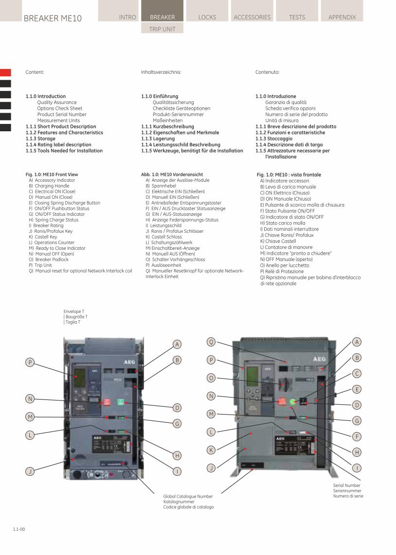
Fig. 1.0: ME10 Front ViewA) Accessory IndicatorB) Charging HandleC) Electrical ON (Close)D) Manual ON (Close)E) Closing Spring Discharge ButtonF) ON/OFF Pushbutton StatusG) ON/OFF Status IndicatorH) Spring Charge StatusI) Breaker RatingJ) Ronis/Profalux KeyK) Castell KeyL) Operations CounterM) Ready to Close IndicatorN) Manual OFF (Open)O) Breaker PadlockP) Trip UnitQ) Manual reset for optional Network Interlock coil
Fig. 1.0: ME10 : vista frontaleA) Indicatore accessoriB) Leva di carica manualeC) ON Elettrico (Chiuso)D) ON Manuale (Chiuso)E) Pulsante di scarico molla di chiusuraF) Stato Pulsante ON/OFFG) Indicatore di stato ON/OFFH) Stato carico mollaI) Dati nominali interruttoreJ) Chiave Ronis/ ProfaluxK) Chiave CastellL) Contatore di manovreM) Indicatore "pronto a chiudere"N) OFF Manuale (aperto)O) Anello per lucchetto P) Relè di ProtezioneQ) Ripristino manuale per bobina d'interblocco di rete opzionale
Abb. 1.0: ME10 VorderansichtA) Anzeige der Auslöse-ModuleB) SpannhebelC) Elektrische EIN (Schließen)D) Manuell EIN (Schließen)E) Antriebsfeder EntspannungstasterF) EIN / AUS Drucktaster StatusanzeigeG) EIN / AUS-StatusanzeigeH) Anzeige Federspannungs-StatusI) LeistungsschildJ) Ronis / Profalux SchlösserK) Castell SchlossL) SchaltungszählwerkM) Einschaltbereit-AnzeigeN) Manuell AUS (Öffnen)O) Schalter VorhängeschlossP) AuslöseeinheitQ) Manueller Resetknopf für optionale Network-Interlock Einheit
A
B
E
G
C
F
D
H
IJ
K
L
M
N
O
P
Q
Global Catalogue NumberKatalognummerCodice globale di catalogo
Serial NumberSeriennummerNumero di serie
J
L
M
N
P
A
B
G
D
H
I
Envelope T | Baugröße T| Taglia T
BREAKER ME10BREAKER
INTR
O
1.11.1 INTRODUZIONE
Garanzia di qualitàTutte gli interruttori ME10 sono stati progettati e realizzati secondo i più elevati standard tecnici.AEG utilizza procedure rigorose che garantiscono il rispetto delle norme tecniche, mantenendo contemporaneamente i massimi livelli di qualità dei prodotti.
Scheda verifica opzioniOgni interruttore è corredato da una scheda di controllo che elenca tutti i dati nominali e gli accessori opzionali inclusi nell'interruttore, nella parte fissa e nel Relè di Protezione (se ordinati)
Descrizione codice di catalogo vedere Appendice
Numero di serie del prodotto & codice di catalogoQuando si comunica con AEG in merito a qualsiasi aspetto relativo a questo dispositivo, si prega di citare il numero di serie e il codice globale di catalogo. Il numero di serie è univoco per ogni dispositivo; il codice di catalogo fornisce tutti i dati tecnici e di configurazione. -- Sul lato superiore di una staffe di montaggio.-- Sul lato sinistro (visto dal davanti) della parte frontale.
1.1.1 Breve descrizione del prodottoL'interruttore aperto ME10 è un interruttore automatico progettato per soddisfare le norme ANSI, UL e IEC. Questo manuale è dedicato in modo specifico ai progetti conformi alla norma IEC/EN 60947; per altre norme contattateci.
Il dispositivo è progettato per l'utilizzo in reti con tensioni fino a 1000 VAC o a 750 VDC e per essere totalmente selettivo con gli altri interruttori ME10 e MM/MC di AEG.
Il prodotto è disponibile in versioni a 3 o 4 poli e in tre taglie e può essere utilizzato per correnti nominali da 80 fino a 6400 ampere.
Come interruttore, ME10 può essere equipaggiato con quattro diversi tipi di Relè di Protezione elettronica - ciascuno dotato della medesima interfaccia universale e di schermo LCD.
È disponibile anche in versione non automatica (sezionatore - senza Relè di Protezione). Sia l'interruttore che il sezionatore sono disponibili in esecuzione fissa o estraibile.
I dispositivi ME10 offrono una combinazione tra alto potere di interruzione e tenuta alle correnti di breve durata e possono essere utilizzati come interruttori generali o sezionatori di rete.
1.1.2 Funzioni e caratteristiche Funzioni standard e opzionali
Corrente nominale di breve durata:Fino a 100 kA per 1 secondo Potere di interruzione:Fino a 150 kA a 440 V e 100 kA a 690 V
Corrente nominaleI dispositivi hanno una corrente nominale del 100% fino a una temperatura ambiente di 50 °C in aria libera.
1.1-01
1.1 INTRODUCTION
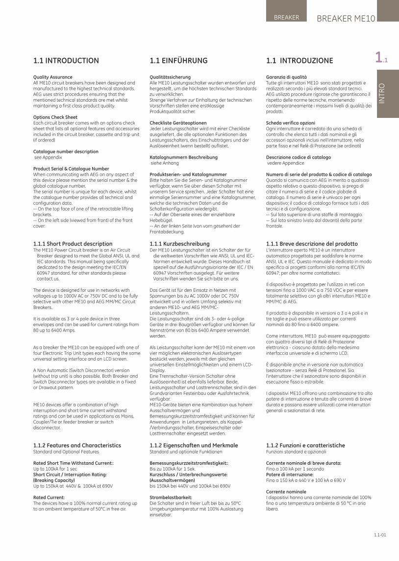
Quality AssuranceAll ME10 circuit breakers have been designed and manufactured to the highest technical standards.AEG uses strict procedures ensuring that the mentioned technical standards are met whilst maintaining a first class product quality.
Options Check SheetEach circuit breaker comes with an options check sheet that lists all optional features and accessories included in the circuit breaker, cassette and trip unit (if ordered)
Catalogue number description see Appendix
Product Serial & Catalogue NumberWhen communicating with AEG on any aspect of this device please mention the serial number & the global catalogue number.The serial number is unique for each device, whilst the catalogue number provides all technical and configuration data. -- On the top face of one of the retractable lifting brackets.-- On the left side (viewed from front) of the front cover.
1.1.1 Short Product descriptionThe ME10 Power Circuit breaker is an Air Circuit
Breaker designed to meet the Global ANSI, UL and IEC standards. This manual being specifically dedicated to the design meeting the IEC/EN 60947 standard, for other standards please contact us.
The device is designed for use in networks with voltages up to 1000V AC or 750V DC and to be fully selective with other ME10 and AEG MM/MC Circuit Breakers.
It is available as 3 or 4 pole device in three envelopes and can be used for current ratings from 80 up to 6400 Amps.
As a breaker the ME10 can be equipped with one of four Electronic Trip Unit types each having the same universal setting interface and an LCD screen.
A Non Automatic (Switch Disconnector) version (without trip unit) is also possible. Both Breaker and Switch Disconnector types are available in a Fixed or Drawout pattern.
ME10 devices offer a combination of high interruption and short time current withstand ratings and can be used in applications as Mains, Coupler/Tie or feeder breaker or switch disconnector.
1.1.2 Features and Characteristics Standard and Optional Features
Rated Short Time Withstand Current::Up to 100kA for 1 sec Short Circuit / Interruption Rating:(Breaking Capacity) Up to 150kA at 440V & 100kA at 690V
Rated Current:The devices have a 100% normal current rating up to an ambient temperature of 50°C in free air.
1.1 EINFÜHRUNG
QualitätssicherungAlle ME10 Leistungsschalter wurden entworfen und hergestellt , um die höchsten technischen Standards zu verwirklichen.Strenge Verfahren zur Einhaltung der technischen Vorschriften stellen eine erstklassige Produktqualität sicher.
Checkliste GeräteoptionenJeder Leistungsschalter wird mit einer Checkliste ausgeliefert, die alle optionalen Funktionen des Leistungsschalters, des Einschubträgers und der Auslöseeinheit (wenn bestellt) auflistet.
Katalognummern Beschreibung siehe Anhang
Produktserien- und KatalognummerBitte halten Sie die Serien- und Katalognummer verfügbar, wenn Sie über diesen Schalter mit unserem Service sprechen. Jeder Schalter hat eine einmalige Seriennummer und eine Katalognummer, welche die technischen Daten und die Schalterkonfiguration wiedergibt. -- Auf der Oberseite eines der einziehbare Hebebügel.-- An der linken Seite (von vorn gesehen) der Frontabdeckung.
1.1.1 KurzbeschreibungDer ME10 Leistungschalter ist ein Schalter der für
die weltweiten Vorschriften wie ANSI, UL und IEC-Normen entwickelt wurde. Dieses Handbuch ist speziell auf die Ausführungsvariante der IEC / EN 60947 Vorschriften ausgelegt. Für weitere Vorschriften wenden Sie sich bitte an uns.
Das Gerät ist für den Einsatz in Netzen mit Spannungen bis zu AC 1000V oder DC 750V entwickelt und in vollem Umfang selektiv mit anderen ME10- und AEG MM/MC-Leistungsschaltern.Die Leistungsschalter sind als 3- oder 4-polige Geräte in drei Baugrößen verfügbar und können für Nennströme von 80 bis 6400 Ampere verwendet werden.
Als Leistungsschalter kann der ME10 mit einem von vier möglichen elektronischen Auslösertypen bestückt werden, jeweils mit den gleichen universellen Einstellmöglichkeiten und einem LCD-Display.Eine Trennschalter-Version (Schalter ohne Auslöseeinheit) ist ebenfalls lieferbar. Beide, Leistungsschalter und Lasttrennschalter, sind in den Grundvarianten Festeinbau oder Ausfahrtechnik verfügbar.ME10-Geräte bieten eine Kombination aus hohem Ausschaltvermögen und Bemessungskurzzeitstromfestigkeit und können für Anwendungen in Leitungsnetzen, als Koppel-/Verbindungsschalter, Einspeiseschalter oder Lasttrennschalter eingesetzt werden.
1.1.2 Eigenschaften und MerkmaleStandard und optionale Funktionen
Bemessungskurzzeitstromfestigkeit::Bis zu 100kA für 1 Sek.Kurzschluss / Unterbrechungswerte:(Ausschaltvermögen)bis 150kA bei 440V und 100kA bei 690V
Strombelastbarkeit:Die Schalter sind in freier Luft bei bis zu 50ºC Umgebungstemperatur mit 100% Auslastung einsetzbar.
LOCKSBREAKER ME10 INTRO BREAKER ACCESSORIES TESTS APPENDIX
TRIP UNIT
INTR
OS
PE
CIF
ICA
TIO
NIN
STA
LLA
TIO
NO
PE
RA
TIO
NTR
IP U
NIT
Connessione alimentazioneI dispositivi ME10 possono essere alimentati dai morsetti superiori o inferiori.
Meccanismo accumulo energiaL'interruttore ME10 utilizza un meccanismo di accumulo di energia che può essere caricato manualmente o elettricamente. Per la ricarica manuale viene utilizzata la leva di carica manuale; può essere aggiunto un motore di carica per le molle, dotato di un contatto di indicazione. Il tempo di chiusura del dispositivo è inferiore a cinque mezzi cicli.La chiusura e l'apertura possono essere avviate in remoto o attraverso i pulsanti frontali. Un ciclo O-C-O è possibile senza ricarica. Il meccanismo di funzionamento dell'interruttore è a sgancio libero ed è dotato di un sistema di antichiusura integrato.Accessori & Relè di Protezione montati in fabbrica o installabili sul campo:Gli accessori comuni agli interruttori di tutte le taglie sono disponibili in due differenti versioni.-- 1. montati in fabbrica-- 2. installabili sul campo, forniti con tuttii necessari collegamenti e accessori di fissaggio.
Bobine / Sganciatori
ME10 taglie 1, 2 e 3 ha quattro alloggiamenti dove inserire le bobine.Da sinistra a destra: il primo accetta una bobina a lancio di corrente (ST1 o SST1) o una bobina di reset (RRC). Il secondo una bobina di minima tensione (UVR1). Il terzo una bobina di chiusura (CC) o una bobina di chiusura a comando (CCC). Il quarto ospita una seconda bobina a lancio di corrente o di minima tensione (ST2, SST2, o UVR2).
ME10 taglia T ha tre alloggiamenti dove inserire le bobine.Da sinistra a destra: il primo accetta una bobina a lancio di corrente (ST o SST). Il secondo una bobina di chiusura (CC) o una bobina di chiusura a comando (CCC), Il terzo una bobina di minima tensione (UVR).La bobina a lancio di corrente è disponibile in versione continuamente alimentata (ST) o alimentata impulsivamente (SST); la bobina di reset (RRC) solo come continuamente alimentata.Le bobine di minima hanno un ritardo fino a 50ms (*) mentre un modulo esterno di ritardo (TDM) è avere disponibile per ritardi maggiori.Entrembe le bobine di chiusura sono dotate di un sistema di antichiusura integrato.Sulle taglie 1, 2 e 3 un indicatore di stato opzionale è disponibile per le bobine RRC, ST, CC e UVR. Questi possono essere riportati all'esterno attraverso le opzioni di comunicazione del Relè di Protezione e/o attraverso la morsettiera dei circuiti ausiliari.
(*) Alcune varianti senza ritardo sono disponibili su richiesta.
Interblocco di reteME10 solo per Taglia 1, 2 e 3Sostituendo una bobina di sgancio a lancio di corrente (ST) e una bobina di minima tensione (UVR), questo dispositivo opzionale blocca l'interruttore elettricamente e meccanicamente.Stato contatto rete/interruttore:L'indicazione OPEN/CLOSED, ON/OFF è riportata sulla copertura anteriore.Motore di ricarica molle:Gruppo motore/trasmissione, facilmente accessibile. Pulsante di chiusura elettrica:Situato sulla copertura anteriore; chiude elettricamente l'interruttore.
1.1-02
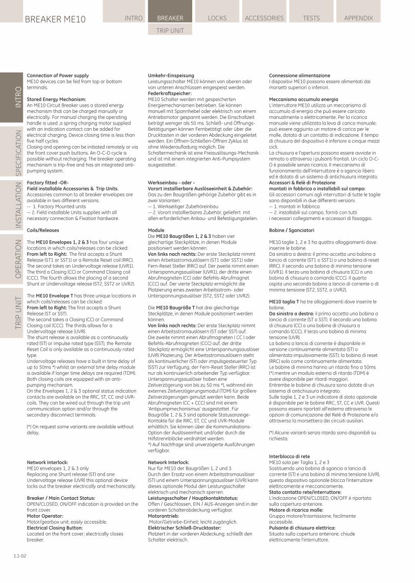
Connection of Power supplyME10 devices can be fed from top or bottom terminals.
Stored Energy Mechanism:An ME10 Circuit Breaker uses a stored energy mechanism that can be charged manually or electrically. For manual charging the operating handle is used ,a spring charging motor supplied with an indication contact can be added for electrical charging. Device closing time is less than five half cycles.Closing and opening can be initiated remotely or via the front cover push buttons. An O-C-O cycle is possible without recharging. The breaker operating mechanism is trip-free and has an integrated anti-pumping system.
Factory fitted -OR-Field installable Accessories & Trip Units.Accessories common to all breaker envelopes are available in two different versions.-- 1. Factory Mounted units-- 2. Field installable Units supplies with allnecessary connection & Fixation hardware.
Coils/Releases
The ME10 Envelopes 1, 2 & 3 has four unique locations in which coils/releases can be clicked:From left to Right: The first accepts a Shunt Release (ST1 or SST1) or a Remote Reset coil (RRC). The second takes an Undervoltage release (UVR1). The third a Closing (CC) or Command Closing coil (CCC). The fourth allows the placing of a second Shunt or Undervoltage release (ST2, SST2 or UVR2).
The ME10 Envelope T has three unique locations in which coils/releases can be clicked:From left to Right: The first accepts a Shunt Release (ST or SST).The second takes a Closing (CC) or Command Closing coil (CCC). The thirds allows for a Undervoltage release (UVR).The shunt release is available as a continuously rated (ST) or impulse rated type (SST), the Remote Reset Coil is only available as a continuously rated type.Undervoltage releases have a built in time delay of up to 50ms *) whilst an external time delay module is available if longer time delays are required (TDM). Both closing coils are equipped with an anti-pumping mechanism.On the Envelopes 1, 2 & 3 optional status indication contacts are available on the RRC, ST, CC and UVR-coils. They can be wired out through the trip unit communication option and/or through the secondary disconnect terminals.
(*) On request some variants are available without delay.
Network Interlock:ME10 envelopes 1, 2 & 3 onlyReplacing one Shunt release (ST) and one Undervoltage release (UVR) this optional device locks out the breaker electrically and mechanically.
Breaker / Main Contact Status:OPEN/CLOSED, ON/OFF indication is provided on the front cover.Motor Operator:Motor/gearbox unit; easily accessible. Electrical Closing Button:Located on the front cover; electrically closes breaker.
Umkehr-EinspeisungLeistungsschalter ME10 können von oberen oder von unteren Anschlüssen eingespeist werden.Federkraftspeicher:ME10 Schalter werden mit gespeicherten Energiemechanismen betrieben. Sie können manuell mit Spannhebel oder elektrisch von einem Antriebsmotor gespannt werden. Die Einschaltzeit beträgt weniger als 50 ms. Schließ- und Öffnungs-Betätigungen können Fernbetätigt oder über die Drucktasten in der vorderen Abdeckung eingeleitet werden. Ein Öffnen-Schließen-Öffnen Zyklus ist ohne Wiederaufladung möglich. Die Schaltermechanik ist eine Freiauslösungs-Mechanik und ist mit einem integrierten Anti-Pumpsystem ausgestattet.
Werkseinbau - oder -Vorort installierbare Auslöseeinheit & Zubehör:Das zu den Baugrößen gehörige Zubehör gibt es in zwei Varianten:-- 1. Werkseitiger Zubehöreinbau-- 2. Vorort installierbares Zubehör, geliefert mit allen erforderlichen Anbau- und Befestigungsteilen.
ModuleDie ME10 Baugrößen 1, 2 & 3 haben vier gleichartige Steckplätze, in denen Module positioniert werden können:Von links nach rechts: Der erste Steckplatz nimmt einen Arbeitsstromauslösern (ST1 oder SST1) oder Fern-Reset Steller (RRC) auf. Der zweite nimmt einen Unterspannungsauslöser (UVR1), der dritte einen Abrufmagneten (CC) oder Befehls-Abrufmagnet (CCC) auf. Der vierte Steckplatz ermöglicht die Platzierung eines zweiten Arbeitsstrom- oder Unterspannungsauslöser (ST2, SST2 oder UVR2).
Die ME10 Baugröße T hat drei gleichartige Steckplätze, in denen Module positioniert werden können.Von links nach rechts: Der erste Steckplatz nimmt einen Arbeitsstromauslösern (ST oder SST) auf. Die zweite nimmt einen Abrufmagneten ( CC ) oder Befehls-Abrufmagneten (CCC) auf, der dritte Steckplatz ermöglicht eine Unterspannungsauslöser (UVR) Plazierung. Der Arbeitsstromauslösern steht als kontinuierlicher (ST) oder impulsgesteuerter Typ (SST) zur Verfügung, der Fern-Reset Steller (RRC) ist nur als kontinuierlich arbeitender Typ verfügbar. Unterspannungsauslöser haben eine Zeitverzögerung von bis zu 50 ms *), während ein externes Zeitverzögerungsmodul (TDM) für größere Zeitverzögerungen genutzt werden kann. Beide Abrufmagneten (CC + CCC) sind mit einem 'Antipumpmechanismus' ausgestattet. Für Baugröße 1, 2 & 3 sind optionale Statusanzeige-Kontakte für die RRC, ST, CC und UVR-Module erhältlich. Sie können über die Kommunikations-Option der Auslöseeinheit und/oder durch die Hilfstrennblöcke verdrahtet werden.*) Auf Nachfrage sind unverzögerte Ausführungen verfügbar.
Network Interlock:Nur für ME10 der Baugrößen 1, 2 und 3.Durch den Ersatz von einem Arbeitsstromauslöser (ST) und einem Unterspannungsauslöser (UVR) kann dieses optionale Modul den Leistungsschalter elektrisch und mechanisch sperren.Leistungsschalter / Hauptkontaktstatus:Offen / Geschlossen, EIN / AUS-Anzeigen sind in der vorderen Schalterabdeckung verfügbar.Motorantrieb: Motor/Getriebe-Einheit; leicht zugänglich.Elektrischer Schließ-Drucktaster:Platziert in der vorderen Abdeckung; schließt den Schalter elektrisch.
BREAKER ME10BREAKER
INTR
O
1.1
Staffe di montaggioPer facilitare il montaggio di un ME10 in taglia 1 o 2 in esecuzione fissa sono disponibili degli opportuni kit . Questi sono raccomandati in caso fosse utilizzato un interruttore aperto dotato di morsetti di connessione ad accesso anteriore.
Modalità di connessioneSono disponibili dei kit di connessione per adattare la modalità di connessione standard dell'interruttore ad esecuzione fissa (orizzontale posteriore) a quella anteriore o verticale posteriore. Le parti fisse delle esecuzioni estraibili sono fornite con connettori universali posteriori, orizzontali o verticali, o con connessioni dedicate orizzontali posteriori o attacchi frontali.
Contatti ausiliariTaglia T:-- contatti di potenza 3NA & 3NC (default) -- di potenza, 4NA & 4NC Taglie 1, 2 e 3:-- contatti di potenza 3NA & 3NC (default) -- di potenza, 8NA & 8NC – di potenza, 3NA & 3NC + contatti di segnale 2NO & 2NC – di potenza, 4NA & 4NC + di segnale 4NA & 4NCInterblocchiFunzione di interblocco standard Interruttore in esecuzione estraibileLe parti fisse e la parte mobile del dispositivo sono equipaggiate con un interblocco che impedisce la chiusura dell'interruttore a meno che non sia in posizione TEST o CONNECT.Quando i contatti principali dell'interruttore sono chiusi, un secondo interblocco evita l'inserimento della maniglia di manovra nell'apertura della parte fissa. Indicatori di stato dell'interruttore:Gli indicatori standard includono: -- indicatore di stato dell'interruttore, che mostra la condizione dei contatti principali (OPEN, CLOSED). -- stato delle molle di chiusura, che indica "molla carica" o scarica (CHARGED o DISCHARGED)-- indicatore di "pronto a chiudere", che fornisce un'indicazione visibile di disponibilità per la chiusura.-- indicatore di posizione, che indica se l'interruttore è in posizione inserito-test-estratto (CONNECT, TEST o DISCONNECT). -- L'interruttore include anche un contatto che fornisce l'indicazione dello stato del contatto principale.Sistema di prevenzione inserimento erratoUn sistema opzionale di prevenzione inserimento errato impedisce l'errato accoppiamento tra interruttore e parte fissa.Questo evita:a) l'inserimento di un interruttore con caratteristiche nominali inferiori in una parte fissa con caratteristiche nominali superiorib) l'inserimento di una interruttore con caratteristiche nominali superiori in una parte fissa con caratteristiche nominali inferiori. Porta passante:Il meccanismo di manovra dell'interruttore è accessibile attraverso la porta anteriore e permette di scollegare/ estrarre l'interruttore in modo sicuro senza aprire la porta, evitando di esporre il personale a parti sotto tensione durante il processo.
Dispositivi di blocco con lucchettoME10: Taglie 1,2 e 3Gi interruttori aperti sono equipaggiati con diversi dispositivi lucchettabili sia in esecuzione fissa che estraibile. E' possibile, tramite un lucchetto di 5-8mm, permettere il blocco in posizione di OFF dell'interruttore.
1.1-03
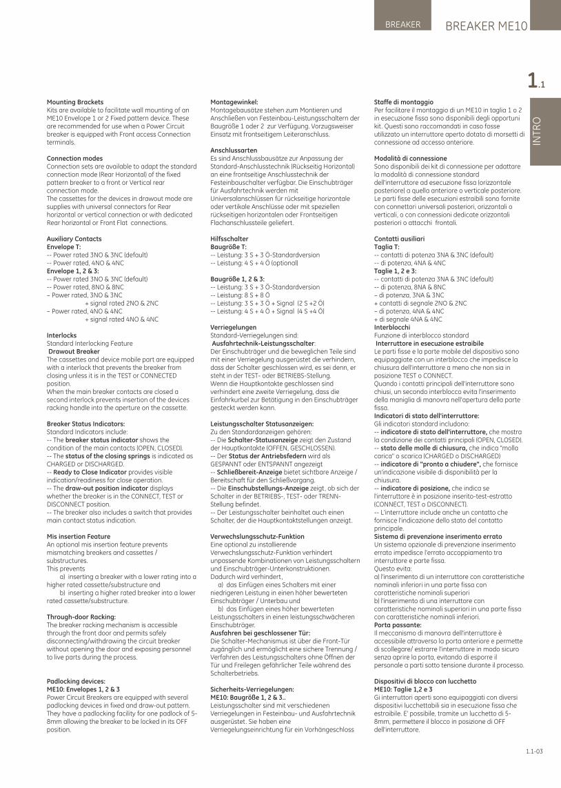
Mounting BracketsKits are available to facilitate wall mounting of an ME10 Envelope 1 or 2 Fixed pattern device. These are recommended for use when a Power Circuit breaker is equipped with Front access Connection terminals.
Connection modesConnection sets are available to adapt the standard connection mode (Rear Horizontal) of the fixed pattern breaker to a front or Vertical rear connection mode. The cassettes for the devices in drawout mode are supplies with universal connectors for Rear horizontal or vertical connection or with dedicated Rear horizontal or Front Flat connections.
Auxiliary ContactsEnvelope T:-- Power rated 3NO & 3NC (default) -- Power rated, 4NO & 4NC Envelope 1, 2 & 3:-- Power rated 3NO & 3NC (default) -- Power rated, 8NO & 8NC – Power rated, 3NO & 3NC + signal rated 2NO & 2NC – Power rated, 4NO & 4NC + signal rated 4NO & 4NC
InterlocksStandard Interlocking Feature Drawout BreakerThe cassettes and device mobile part are equipped with a interlock that prevents the breaker from closing unless it is in the TEST or CONNECTED position.When the main breaker contacts are closed a second interlock prevents insertion of the devices racking handle into the aperture on the cassette.
Breaker Status Indicators:Standard Indicators include: -- The breaker status indicator shows the condition of the main contacts (OPEN, CLOSED). -- The status of the closing springs is indicated as CHARGED or DISCHARGED.-- Ready to Close Indicator provides visible indication/readiness for close operation.-- The draw-out position indicator displays whether the breaker is in the CONNECT, TEST or DISCONNECT position. -- The breaker also includes a switch that provides main contact status indication.
Mis insertion FeatureAn optional mis insertion feature prevents mismatching breakers and cassettes / substructures.This prevents a) inserting a breaker with a lower rating into a higher rated cassette/substructure and b) inserting a higher rated breaker into a lower rated cassette/substructure.
Through-door Racking:The breaker racking mechanism is accessible through the front door and permits safely disconnecting/withdrawing the circuit breaker without opening the door and exposing personnel to live parts during the process.
Padlocking devices:ME10: Envelopes 1, 2 & 3Power Circuit Breakers are equipped with several padlocking devices in fixed and draw-out pattern. They have a padlocking facility for one padlock of 5-8mm allowing the breaker to be locked in its OFF position.
Montagewinkel:Montagebausätze stehen zum Montieren und Anschließen von Festeinbau-Leistungsschaltern der Baugröße 1 oder 2 zur Verfügung. Vorzugsweiser Einsatz mit frontseitigem Leiteranschluss.
AnschlussartenEs sind Anschlussbausätze zur Anpassung der Standard-Anschlusstechnik (Rückseitig Horizontal) an eine frontseitige Anschlusstechnik der Festeinbauschalter verfügbar. Die Einschubträger für Ausfahrtechnik werden mit Universalanschlüssen für rückseitige horizontale oder vertikale Anschlüsse oder mit speziellen rückseitigen horizontalen oder Frontseitigen Flachanschlussteile geliefert.
HilfsschalterBaugröße T:-- Leistung: 3 S + 3 Ö-Standardversion-- Leistung: 4 S + 4 Ö (optional)
Baugröße 1, 2 & 3:-- Leistung: 3 S + 3 Ö-Standardversion-- Leistung: 8 S + 8 Ö-- Leistung: 3 S + 3 Ö + Signal (2 S +2 Ö)-- Leistung: 4 S + 4 Ö + Signal (4 S +4 Ö)
VerriegelungenStandard-Verriegelungen sind: Ausfahrtechnik-Leistungsschalter: Der Einschubträger und die beweglichen Teile sind mit einer Verriegelung ausgerüstet die verhindern, dass der Schalter geschlossen wird, es sei denn, er steht in der TEST- oder BETRIEBS-Stellung. Wenn die Hauptkontakte geschlossen sind verhindert eine zweite Verriegelung, dass die Einfahrkurbel zur Betätigung in den Einschubträger gesteckt werden kann.
Leistungsschalter Statusanzeigen: Zu den Standardanzeigen gehören:-- Die Schalter-Statusanzeige zeigt den Zustand der Hauptkontakte (OFFEN, GESCHLOSSEN).-- Der Status der Antriebsfedern wird als GESPANNT oder ENTSPANNT angezeigt-- Schließbereit-Anzeige bietet sichtbare Anzeige / Bereitschaft für den Schließvorgang.-- Die Einschubstellungs-Anzeige zeigt, ob sich der Schalter in der BETRIEBS-, TEST- oder TRENN-Stellung befindet.-- Der Leistungsschalter beinhaltet auch einen Schalter, der die Hauptkontaktstellungen anzeigt.
Verwechslungsschutz-FunktionEine optional zu installierende Verwechslungsschutz-Funktion verhindert unpassende Kombinationen von Leistungsschaltern und Einschubträger-Unterkonstruktionen.Dadurch wird verhindert, a) das Einfügen eines Schalters mit einer niedrigeren Leistung in einen höher bewerteten Einschubträger / Unterbau und b) das Einfügen eines höher bewerteten Leistungsschalters in einen leistungsschwächeren Einschubträger.Ausfahren bei geschlossener Tür:Die Schalter-Mechanismus ist über die Front-Tür zugänglich und ermöglicht eine sichere Trennung / Verfahren des Leistungsschalters ohne Öffnen der Tür und Freilegen gefährlicher Teile während des Schalterbetriebs.
Sicherheits-Verriegelungen:ME10: Baugröße 1, 2 & 3..Leistungsschalter sind mit verschiedenen Verriegelungen in Festeinbau- und Ausfahrtechnik ausgerüstet. Sie haben eine Verriegelungseinrichtung für ein Vorhängeschloss
LOCKSBREAKER ME10 INTRO BREAKER ACCESSORIES TESTS APPENDIX
TRIP UNIT
INTR
OS
PE
CIF
ICA
TIO
NIN
STA
LLA
TIO
NO
PE
RA
TIO
NTR
IP U
NIT
ME10: Taglia TGi interruttori aperti sono equipaggiati con diversi dispositivi lucchettabili sia in esecuzione fissa che estraibile. L'interruttore può essere equipaggiato con un blocco lucchettabile che previene l'accesso ad entrambi i pulsanti di ON e OFF. E' posto nella parte frontale dell'interruttore e permette anche il blocco in posizione OFF, tramite un lucchetto di 5-9,5 mm.Un secondo blocco è disponibile come accessorio, e permette il blocco lucchetto e/o il blocco chiave di bloccare l'interruttore in OFF.
ME10: Tutte le parte fissa La parte fissa in dotazione con gli interruttori in esecuzione estraibile, dispone di tre staffe per un massimo di 3 lucchetti da 5-8 mm Taglia T: 5-9,5 mm)..Due di queste sono sulla parte anteriore della parte fissa e possono essere utilizzate per bloccare le serrande in posizione chiusa e/o per chiudere e bloccare l'apertura della maniglia di manovra.La terza si trova nelle guide di supporto estraibili dell'interruttore e può essere utilizzata per bloccare l'assieme interruttore-telaio in posizione di sezionamento.
Equipaggiamento di blocco con lucchetto per pulsante anteriore: ME10: Solo per Taglia 1, 2 & 3..Per impedire l'accesso non autorizzato ai pulsanti sia di ON sia di OFF, sulla parte anteriore degli interruttori è applicabile una copertura lucchettabile da fissare al panello anteriore dell'interruttore.È possibile utilizzare 1 lucchetto da 5-8 mm.
Meccanismo di chiusura a chiavePer la Taglia T i meccanismi di bloccaggio sono disponibile sia sull'interruttore che sulla parte fissa, permettendo l'uso di serrature Ronis o Profalux. Il dispositivo sulla parte frontale dell'interruttore può accettare una serratura Ronis o Profalux e/o un lucchetto che permette il bloccaggio del dispositivo in posizione OFF. Per le Taglie 1, 2 e 3, più kit sono disponibili permettendo l'uso di serrature Ronis, Profalux o Castell. Sia l'interruttore che le parti fisse possono essere dotate di queste strutture. L'interruttore può accettare meccanismi che consentano l'utilizzo di fino a quattro serrature Ronis o Profalux o una serratura Castell per bloccare il dispositivo in posizione OFF. La parte fissa accetta solo meccanismi che consentano l'uso di Ronis e / o Profalux che possono essere utilizzati per la posizione dell'interruttore e/o il bloccaggio delle serrande.
SerrandeTutte le parti fisse sono dotate di serrande di sicurezza bloccabili che isolano le parti attive.
Contatti di indicazione di posizione della parte fissaQuesto dispositivo opzionale per parte fissa, consente di riportare in locale o in remoto lo stato dell'interruttore (CONNECT, TEST, DISCONNECT). (Sono disponibili dei set di 3 o 6 contatti unipolari di scambio).
Traversa di sollevamento e adattatoreSono disponibili come opzione per facilitare la movimentazione degli interruttori. Il tipo standard è adatto per la gestione di interruttori in taglia 1 e 2; un apposito adattatore consente di utilizzare lo stesso dispositivo per gestire la taglia 3.
1.1-04
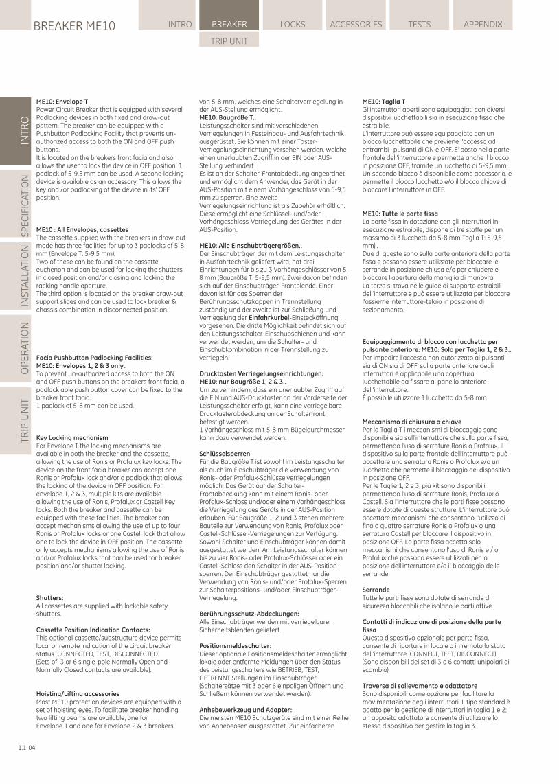
ME10: Envelope TPower Circuit Breaker that is equipped with several Padlocking devices in both fixed and draw-out pattern. The breaker can be equipped with a Pushbutton Padlocking Facility that prevents un-authorized access to both the ON and OFF push buttons.It is located on the breakers front facia and also allows the user to lock the device in OFF position: 1 padlock of 5-9.5 mm can be used. A second locking device is available as an accessory. This allows the key and /or padlocking of the device in its' OFF position.
ME10 : All Envelopes, cassettes The cassette supplied with the breakers in draw-out mode has three facilities for up to 3 padlocks of 5-8 mm (Envelope T: 5-9,5 mm).Two of these can be found on the cassette euchenon and can be used for locking the shutters in closed position and/or closing and locking the racking handle aperture.The third option is located on the breaker draw-out support slides and can be used to lock breaker & chassis combination in disconnected position.
Facia Pushbutton Padlocking Facilities:ME10: Envelopes 1, 2 & 3 only..To prevent un-authorized access to both the ON and OFF push buttons on the breakers front facia, a padlock able push button cover can be fixed to the breaker front facia.1 padlock of 5-8 mm can be used.
Key Locking mechanismFor Envelope T the locking mechanisms are available in both the breaker and the cassette, allowing the use of Ronis or Profalux key locks. The device on the front facia breaker can accept one Ronis or Profalux lock and/or a padlock that allows the locking of the device in OFF position. For envelope 1, 2 & 3, multiple kits are available allowing the use of Ronis, Profalux or Castell Key locks. Both the breaker and cassette can be equipped with these facilities. The breaker can accept mechanisms allowing the use of up to four Ronis or Profalux locks or one Castell lock that allow one to lock the device in OFF position. The cassette only accepts mechanisms allowing the use of Ronis and/or Profalux locks that can be used for breaker position and/or shutter locking.
Shutters:All cassettes are supplied with lockable safety shutters.
Cassette Position Indication Contacts:This optional cassette/substructure device permits local or remote indication of the circuit breaker status CONNECTED, TEST, DISCONNECTED.(Sets of 3 or 6 single-pole Normally Open and Normally Closed contacts are available).
Hoisting/Lifting accessoriesMost ME10 protection devices are equipped with a set of hoisting eyes. To facilitate breaker handling two lifting beams are available, one for Envelope 1 and one for Envelope 2 & 3 breakers.
von 5-8 mm, welches eine Schalterverriegelung in der AUS-Stellung ermöglicht.ME10: Baugröße T..Leistungsschalter sind mit verschiedenen Verriegelungen in Festeinbau- und Ausfahrtechnik ausgerüstet. Sie können mit einer Taster-Verriegelungseinrichtung versehen werden, welche einen unerlaubten Zugriff in der EIN oder AUS-Stellung verhindert. Es ist an der Schalter-Frontabdeckung angeordnet und ermöglicht dem Anwender, das Gerät in der AUS-Position mit einem Vorhängeschloss von 5-9,5 mm zu sperren. Eine zweite Verriegelungseinrichtung ist als Zubehör erhältlich. Diese ermöglicht eine Schlüssel- und/oder Vorhängeschloss-Verriegelung des Gerätes in der AUS-Position.
ME10: Alle Einschubträgergrößen..Der Einschubträger, der mit dem Leistungsschalter in Ausfahrtechnik geliefert wird, hat drei Einrichtungen für bis zu 3 Vorhängeschlösser von 5-8 mm (Baugröße T: 5-9,5 mm). Zwei davon befinden sich auf der Einschubträger-Frontblende. Einer davon ist für das Sperren der Berührungsschutzkappen in Trennstellung zuständig und der zweite ist zur Schließung und Verriegelung der Einfahrkurbel-Einstecköffnung vorgesehen. Die dritte Möglichkeit befindet sich auf den Leistungsschalter-Einschubschienen und kann verwendet werden, um die Schalter- und Einschubkombination in der Trennstellung zu verriegeln.
Drucktasten Verriegelungseinrichtungen:ME10: nur Baugröße 1, 2 & 3..Um zu verhindern, dass ein unerlaubter Zugriff auf die EIN und AUS-Drucktaster an der Vorderseite der Leistungsschalter erfolgt, kann eine verriegelbare Drucktasterabdeckung an der Schalterfront befestigt werden.1 Vorhängeschloss mit 5-8 mm Bügeldurchmesser kann dazu verwendet werden.
SchlüsselsperrenFür die Baugröße T ist sowohl im Leistungsschalter als auch im Einschubträger die Verwendung von Ronis- oder Profalux-Schlüsselverriegelungen möglich. Das Gerät auf der Schalter-Frontabdeckung kann mit einem Ronis- oder Profalux-Schloss und/oder einem Vorhängeschloss die Verriegelung des Geräts in der AUS-Position erlauben. Für Baugröße 1, 2 und 3 stehen mehrere Bauteile zur Verwendung von Ronis, Profalux oder Castell-Schlüssel-Verriegelungen zur Verfügung. Sowohl Schalter und Einschubträger können damit ausgestattet werden. Am Leistungsschalter können bis zu vier Ronis- oder Profalux-Schlösser oder ein Castell-Schloss den Schalter in der AUS-Position sperren. Der Einschubträger gestattet nur die Verwendung von Ronis- und/oder Profalux-Sperren zur Schalterpositions- und/oder Einschubträger-Verriegelung.
Berührungsschutz-Abdeckungen:Alle Einschubträger werden mit verriegelbaren Sicherheitsblenden geliefert.
Positionsmeldeschalter:Dieser optionale Positionsmeldeschalter ermöglicht lokale oder entfernte Meldungen über den Status des Leistungsschalters wie BETRIEB, TEST, GETRENNT Stellungen im Einschubträger. (Schaltersätze mit 3 oder 6 einpoligen Öffnern und Schließern können verwendet werden).
Anhebewerkzeug und Adapter:Die meisten ME10 Schutzgeräte sind mit einer Reihe von Anhebeösen ausgestattet. Zur einfacheren
BREAKER ME10BREAKER
INTR
O
1.1
Le traverse di sollevamento permettono l'uso di attrezzature di sollevamento standard. Per la Taglia T la traversa è fornita con ogni dispositivo.
Coperture IP54:ME10 Taglia 1, 2 & 3 solamenteOgni interruttore ME10 viene fornito con un telaio porta che assicura al dispositivo installato un grado di protezione IP40. Opzionalmente, è disponibile un rivestimento supplementare che assicura un grado di protezione IP54.
Contatore di manovre:Fornisce la registrazione locale del numero totale di manovre complete di chiusura dell'interruttore.
Dispositivi di interblocco cavi:Questi dispositivi sono disponibili per gli interruttori in esecuzione fissa e/o estraibile. Essi consentono l'interblocco di due o tre interruttori. Ogni dispositivo è composto da due parti: un meccanismo di interblocco montato in fabbrica e due o più cavi disponibili separatamente.
Contatto di "sganciato relè":Contatto di scambio che, una volta montato sull'interruttore, segnala l'intervento di una delle sue funzioni di protezione (Relè di Protezione elettronica). E' possibile, tramite un lucchetto di 5-8mm, permettere il blocco in posizione di OFF dell'interruttore.Un'interfaccia sulla parte anteriore del Relè di Protezione permette il ripristino manuale o automatico degli interruttori. Il contatto di "sganciato relè" cambierà in modo permanente la propria posizione solo quando il Relè di Protezione è in modalità manuale. Nelle Taglie 1, 2 e 3 è possibile resettare a distanza tramite la Bobina di reset.Il Relè di Protezione dispone di una funzione (motivo dell'intervento e registro eventi) che permette all'utente di stabilire la ragione dell'intervento dell'interruttore.
Contati di "molla carica" e "pronto a chiudere»Un interruttore con meccanismo di carica elettrica può essere dotato di uno o due contatti di segnalazione.
Il contatto di "molla carica" svolge semplicemente la funzione indicata e viene fornito con il meccanismo a motore standard.
Il contatto di "pronto a chiudere" sostituisce opzionalmente il contatto di "molla carica".
Esso cambia stato solo quando sono soddisfatte le seguenti condizioni:- L'interruttore è aperto- Le molle di chiusura sono cariche- L'interruttore non è bloccato/interbloccato in posizione aperta- Non vi è alcun ordine di chiusura permanente- Non vi è alcun ordine di apertura permanenteEntrambi i contatti sono in configurazione 1NA.
1.1.3 StoccaggioRiporre interruttori e parti fisse in un luogo pulito e asciutto e nella loro confezione originale.
1.1-05
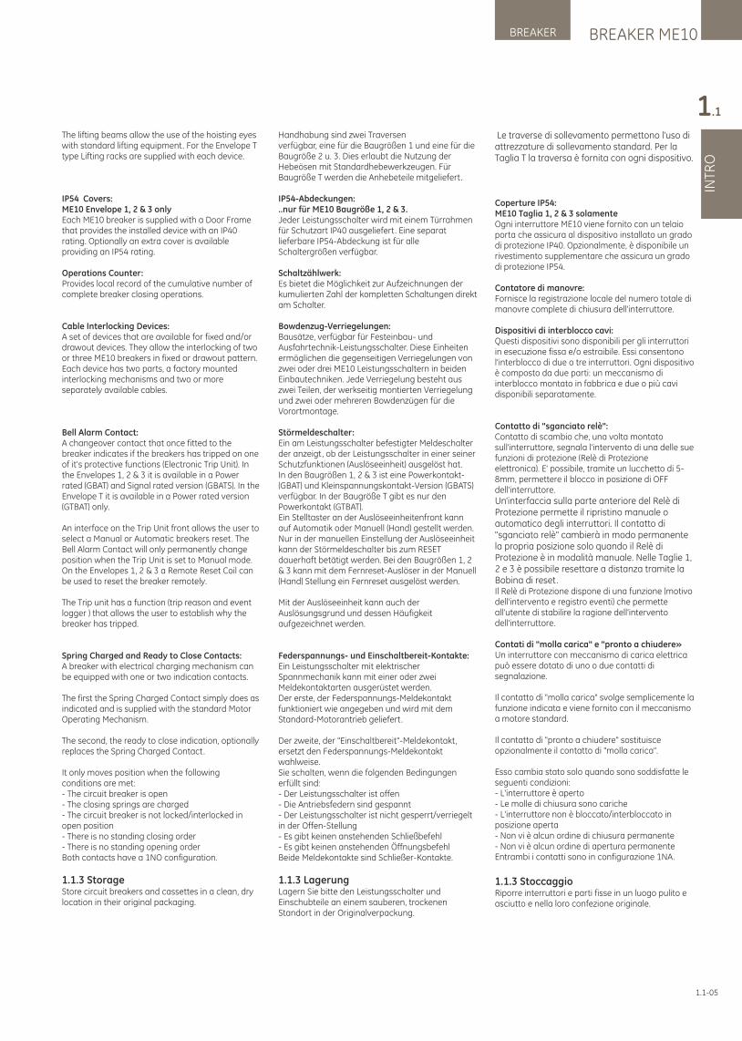
The lifting beams allow the use of the hoisting eyes with standard lifting equipment. For the Envelope T type Lifting racks are supplied with each device.
IP54 Covers:ME10 Envelope 1, 2 & 3 onlyEach ME10 breaker is supplied with a Door Frame that provides the installed device with an IP40 rating. Optionally an extra cover is available providing an IP54 rating.
Operations Counter:Provides local record of the cumulative number of complete breaker closing operations.
Cable Interlocking Devices:A set of devices that are available for fixed and/or drawout devices. They allow the interlocking of two or three ME10 breakers in fixed or drawout pattern. Each device has two parts, a factory mounted interlocking mechanisms and two or more separately available cables.
Bell Alarm Contact:A changeover contact that once fitted to the breaker indicates if the breakers has tripped on one of it's protective functions (Electronic Trip Unit). In the Envelopes 1, 2 & 3 it is available in a Power rated (GBAT) and Signal rated version (GBATS). In the Envelope T it is available in a Power rated version (GTBAT) only.
An interface on the Trip Unit front allows the user to select a Manual or Automatic breakers reset. The Bell Alarm Contact will only permanently change position when the Trip Unit is set to Manual mode. On the Envelopes 1, 2 & 3 a Remote Reset Coil can be used to reset the breaker remotely.
The Trip unit has a function (trip reason and event logger ) that allows the user to establish why the breaker has tripped.
Spring Charged and Ready to Close Contacts:A breaker with electrical charging mechanism can be equipped with one or two indication contacts.
The first the Spring Charged Contact simply does as indicated and is supplied with the standard Motor Operating Mechanism.
The second, the ready to close indication, optionally replaces the Spring Charged Contact.
It only moves position when the following conditions are met:- The circuit breaker is open- The closing springs are charged- The circuit breaker is not locked/interlocked in open position- There is no standing closing order- There is no standing opening orderBoth contacts have a 1NO configuration.
1.1.3 StorageStore circuit breakers and cassettes in a clean, dry location in their original packaging.
Handhabung sind zwei Traversen verfügbar, eine für die Baugrößen 1 und eine für die Baugröße 2 u. 3. Dies erlaubt die Nutzung der Hebeösen mit Standardhebewerkzeugen. Für Baugröße T werden die Anhebeteile mitgeliefert.
IP54-Abdeckungen:..nur für ME10 Baugröße 1, 2 & 3.Jeder Leistungsschalter wird mit einem Türrahmen für Schutzart IP40 ausgeliefert. Eine separat lieferbare IP54-Abdeckung ist für alle Schaltergrößen verfügbar.
Schaltzählwerk:Es bietet die Möglichkeit zur Aufzeichnungen der kumulierten Zahl der kompletten Schaltungen direkt am Schalter.
Bowdenzug-Verriegelungen:Bausätze, verfügbar für Festeinbau- und Ausfahrtechnik-Leistungsschalter. Diese Einheiten ermöglichen die gegenseitigen Verriegelungen von zwei oder drei ME10 Leistungsschaltern in beiden Einbautechniken. Jede Verriegelung besteht aus zwei Teilen, der werkseitig montierten Verriegelung und zwei oder mehreren Bowdenzügen für die Vorortmontage.
Störmeldeschalter:Ein am Leistungsschalter befestigter Meldeschalter der anzeigt, ob der Leistungsschalter in einer seiner Schutzfunktionen (Auslöseeinheit) ausgelöst hat.In den Baugrößen 1, 2 & 3 ist eine Powerkontakt- (GBAT) und Kleinspannungskontakt-Version (GBATS) verfügbar. In der Baugröße T gibt es nur den Powerkontakt (GTBAT).Ein Stelltaster an der Auslöseeinheitenfront kann auf Automatik oder Manuell (Hand) gestellt werden. Nur in der manuellen Einstellung der Auslöseeinheit kann der Störmeldeschalter bis zum RESET dauerhaft betätigt werden. Bei den Baugrößen 1, 2 & 3 kann mit dem Fernreset-Auslöser in der Manuell (Hand) Stellung ein Fernreset ausgelöst werden.
Mit der Auslöseeinheit kann auch der Auslösungsgrund und dessen Häufigkeit aufgezeichnet werden.
Federspannungs- und Einschaltbereit-Kontakte:Ein Leistungsschalter mit elektrischer Spannmechanik kann mit einer oder zwei Meldekontaktarten ausgerüstet werden.Der erste, der Federspannungs-Meldekontakt funktioniert wie angegeben und wird mit dem Standard-Motorantrieb geliefert.
Der zweite, der "Einschaltbereit"-Meldekontakt, ersetzt den Federspannungs-Meldekontakt wahlweise.Sie schalten, wenn die folgenden Bedingungen erfüllt sind: - Der Leistungsschalter ist offen - Die Antriebsfedern sind gespannt - Der Leistungsschalter ist nicht gesperrt/verriegelt in der Offen-Stellung - Es gibt keinen anstehenden Schließbefehl - Es gibt keinen anstehenden Öffnungsbefehl Beide Meldekontakte sind Schließer-Kontakte.
1.1.3 LagerungLagern Sie bitte den Leistungsschalter und Einschubteile an einem sauberen, trockenen Standort in der Originalverpackung.
LOCKSBREAKER ME10 INTRO BREAKER ACCESSORIES TESTS APPENDIX
TRIP UNIT
INTR
OS
PE
CIF
ICA
TIO
NIN
STA
LLA
TIO
NO
PE
RA
TIO
NTR
IP U
NIT
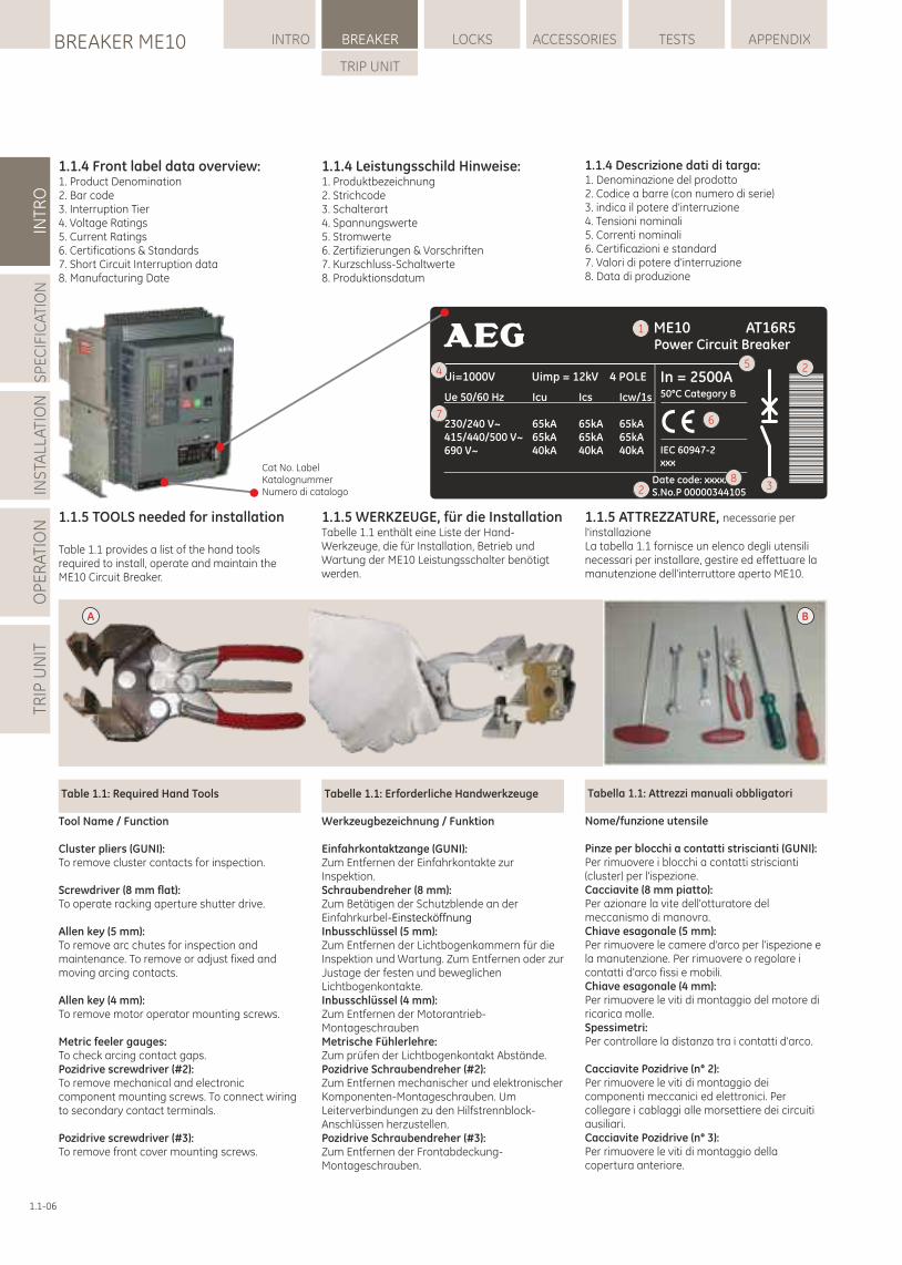
1.1.5 TOOLS needed for installation
Table 1.1 provides a list of the hand tools required to install, operate and maintain the ME10 Circuit Breaker.
1.1.5 WERKZEUGE, für die InstallationTabelle 1.1 enthält eine Liste der Hand-Werkzeuge, die für Installation, Betrieb und Wartung der ME10 Leistungsschalter benötigt werden.
Table 1.1: Required Hand Tools
Tool Name / Function
Cluster pliers (GUNI):To remove cluster contacts for inspection.
Screwdriver (8 mm flat):To operate racking aperture shutter drive.
Allen key (5 mm):To remove arc chutes for inspection and maintenance. To remove or adjust fixed and moving arcing contacts.
Allen key (4 mm):To remove motor operator mounting screws.
Metric feeler gauges:To check arcing contact gaps.Pozidrive screwdriver (#2):To remove mechanical and electronic component mounting screws. To connect wiring to secondary contact terminals.
Pozidrive screwdriver (#3):To remove front cover mounting screws.
Tabelle 1.1: Erforderliche Handwerkzeuge
Werkzeugbezeichnung / Funktion
Einfahrkontaktzange (GUNI):Zum Entfernen der Einfahrkontakte zur Inspektion.Schraubendreher (8 mm):Zum Betätigen der Schutzblende an der Einfahrkurbel-EinstecköffnungInbusschlüssel (5 mm):Zum Entfernen der Lichtbogenkammern für die Inspektion und Wartung. Zum Entfernen oder zur Justage der festen und beweglichen Lichtbogenkontakte.Inbusschlüssel (4 mm):Zum Entfernen der Motorantrieb-MontageschraubenMetrische Fühlerlehre:Zum prüfen der Lichtbogenkontakt Abstände.Pozidrive Schraubendreher (#2):Zum Entfernen mechanischer und elektronischer Komponenten-Montageschrauben. Um Leiterverbindungen zu den Hilfstrennblock-Anschlüssen herzustellen.Pozidrive Schraubendreher (#3):Zum Entfernen der Frontabdeckung-Montageschrauben.
1.1.5 ATTREZZATURE, necessarie per l'installazioneLa tabella 1.1 fornisce un elenco degli utensili necessari per installare, gestire ed effettuare la manutenzione dell'interruttore aperto ME10.
1.1-06
1.1.4 Descrizione dati di targa:1. Denominazione del prodotto2. Codice a barre (con numero di serie)3. indica il potere d'interruzione4. Tensioni nominali5. Correnti nominali6. Certificazioni e standard7. Valori di potere d'interruzione8. Data di produzione
1.1.4 Front label data overview:1. Product Denomination2. Bar code3. Interruption Tier4. Voltage Ratings5. Current Ratings6. Certifications & Standards7. Short Circuit Interruption data8. Manufacturing Date
1.1.4 Leistungsschild Hinweise:1. Produktbezeichnung2. Strichcode3. Schalterart4. Spannungswerte5. Stromwerte6. Zertifizierungen & Vorschriften7. Kurzschluss-Schaltwerte8. Produktionsdatum
Tabella 1.1: Attrezzi manuali obbligatori
Nome/funzione utensile
Pinze per blocchi a contatti striscianti (GUNI):Per rimuovere i blocchi a contatti striscianti (cluster) per l'ispezione.Cacciavite (8 mm piatto):Per azionare la vite dell'otturatore del meccanismo di manovra.Chiave esagonale (5 mm):Per rimuovere le camere d'arco per l'ispezione e la manutenzione. Per rimuovere o regolare i contatti d'arco fissi e mobili.Chiave esagonale (4 mm):Per rimuovere le viti di montaggio del motore di ricarica molle.Spessimetri:Per controllare la distanza tra i contatti d'arco.
Cacciavite Pozidrive (n° 2):Per rimuovere le viti di montaggio dei componenti meccanici ed elettronici. Per collegare i cablaggi alle morsettiere dei circuiti ausiliari.Cacciavite Pozidrive (n° 3):Per rimuovere le viti di montaggio della copertura anteriore.
BA
1
2
3
45
67
82
Cat No. LabelKatalognummerNumero di catalogo
BREAKER ME10BREAKER
INTR
O
1.1
1.1-07
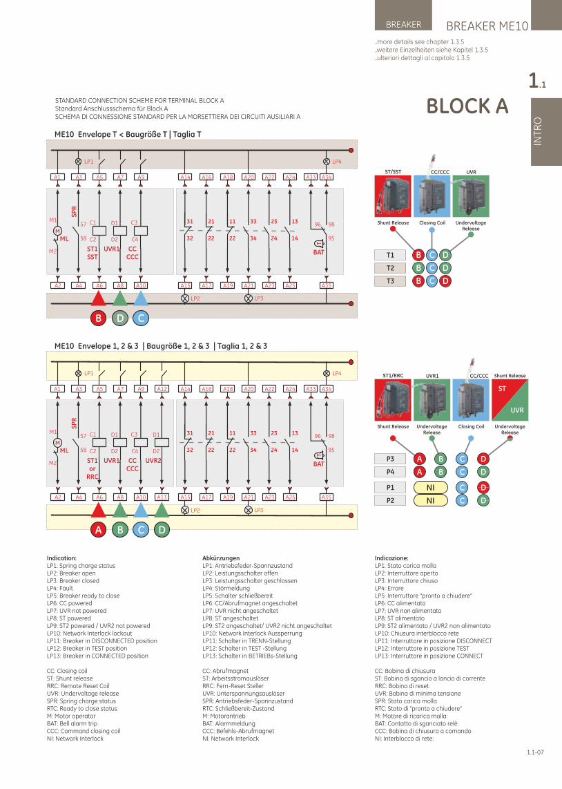
AbkürzungenLP1: Antriebsfeder-SpannzustandLP2: Leistungsschalter offenLP3: Leistungsschalter geschlossenLP4: StörmeldungLP5: Schalter schließbereitLP6: CC/Abrufmagnet angeschaltetLP7: UVR nicht angeschaltetLP8: ST angeschaltetLP9: ST2 angeschaltet/ UVR2 nicht angeschaltetLP10: Network Interlock AussperrungLP11: Schalter in TRENN-StellungLP12: Schalter in TEST -StellungLP13: Schalter in BETRIEBs-Stellung
CC: AbrufmagnetST: ArbeitsstromauslöserRRC: Fern-Reset StellerUVR: UnterspannungsauslöserSPR: Antriebsfeder-SpannzustandRTC: Schließbereit-ZustandM: MotorantriebBAT: AlarmmeldungCCC: Befehls-AbrufmagnetNI: Network Interlock
Indication:LP1: Spring charge statusLP2: Breaker openLP3: Breaker closedLP4: FaultLP5: Breaker ready to closeLP6: CC poweredLP7: UVR not poweredLP8: ST poweredLP9: ST2 powered / UVR2 not poweredLP10: Network Interlock lockoutLP11: Breaker in DISCONNECTED positionLP12: Breaker in TEST positionLP13: Breaker in CONNECTED position
CC: Closing coilST: Shunt releaseRRC: Remote Reset CoilUVR: Undervoltage releaseSPR: Spring charge statusRTC: Ready to close statusM: Motor operatorBAT: Bell alarm tripCCC: Command closing coilNI: Network Interlock
BLOCK A
A2
A1
M
ML
M1
M2
LP1
A4
A3
SP
R
58
57
ME10 Envelope T < Baugröße T | Taglia T
A6
A5
C1
C2
ST1SST
B
A10
A9
C4
C3
CCCCC
C
A8
A7
UVR1
D1
D2
D
LP2
A15
A14
32
31
A17
A16
22
21
A19
A18
22
11
A23
A22
24
23
A25
A24
14
13
LP3
A21
A20
34
33
LP4
A35
A34
95
98
T
BAT
A33
96 UndervoltageRelease
Closing CoilShunt Release
T1
T2
T3
DCB
DCB
DCB
ST/SST CC/CCC UVR
A2
A1
M
ML
M1
M2
LP1
A4
A3
SP
R
58
57
ME10 Envelope 1, 2 & 3 | Baugröße 1, 2 & 3 | Taglia 1, 2 & 3
A6
A5
C1
C2
ST1or
RRC
A
A10
A9
C4
C3
CCCCC
C
A8
A7
UVR1
D1
D2
B
A13
A12
UVR2
D1
D2
LP2
A15
A14
32
31
A17
A16
22
21
A19
A18
22
11
A23
A22
24
23
A25
A24
14
13
LP3
A21
A20
34
33
LP4
A35
A34
95
98
T
BAT
A33
96
D
NIP1
P2 NI
C D
C D
UndervoltageRelease
UVR1ST1/RRC
Shunt Release Closing Coil
CC/CCC
P3
P4
A B C D
C DA B
UndervoltageRelease
UVR
ST
Shunt Release
STANDARD CONNECTION SCHEME FOR TERMINAL BLOCK AStandard Anschlussschema für Block ASCHEMA DI CONNESSIONE STANDARD PER LA MORSETTIERA DEI CIRCUITI AUSILIARI A
..more details see chapter 1.3.5
..weitere Einzelheiten siehe Kapitel 1.3.5
..ulteriori dettagli al capitolo 1.3.5
Indicazione:LP1: Stato carica mollaLP2: Interruttore apertoLP3: Interruttore chiusoLP4: ErroreLP5: Interruttore "pronto a chiudere”LP6: CC alimentataLP7: UVR non alimentatoLP8: ST alimentatoLP9: ST2 alimentato / UVR2 non alimentatoLP10: Chiusura interblocco reteLP11: Interruttore in posizione DISCONNECTLP12: Interruttore in posizione TESTLP13: Interruttore in posizione CONNECT
CC: Bobina di chiusuraST: Bobina di sgancio a lancio di correnteRRC: Bobina di resetUVR: Bobina di minima tensioneSPR: Stato carica mollaRTC: Stato di "pronto a chiudere”M: Motore di ricarica molla:BAT: Contatto di sganciato relè:CCC: Bobina di chiusura a comandoNI: Interblocco di rete:
LOCKSBREAKER ME10 INTRO BREAKER ACCESSORIES TESTS APPENDIX
TRIP UNIT
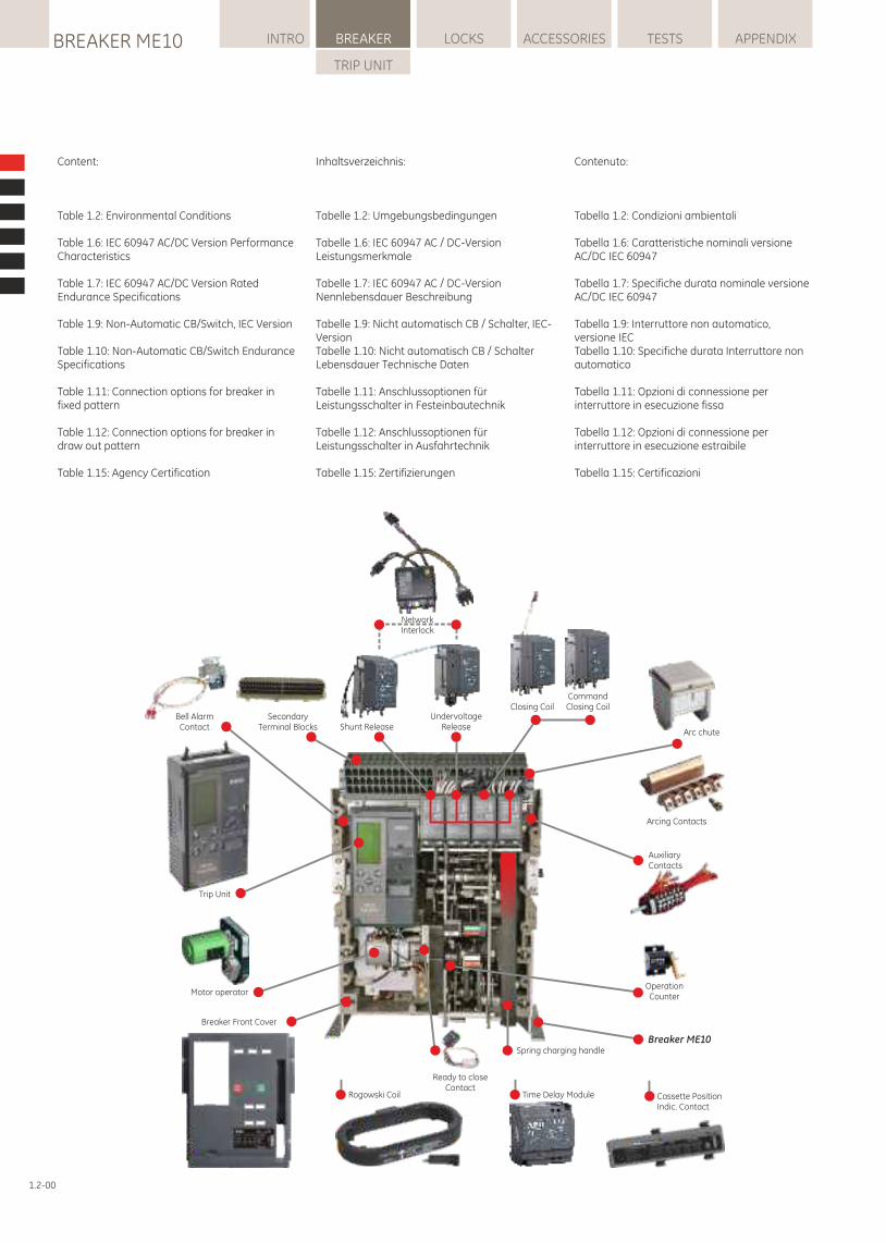
Content:
Table 1.2: Environmental Conditions
Table 1.6: IEC 60947 AC/DC Version Performance Characteristics
Table 1.7: IEC 60947 AC/DC Version Rated Endurance Specifications
Table 1.9: Non-Automatic CB/Switch, IEC Version
Table 1.10: Non-Automatic CB/Switch Endurance Specifications
Table 1.11: Connection options for breaker in fixed pattern
Table 1.12: Connection options for breaker in draw out pattern
Table 1.15: Agency Certification
Inhaltsverzeichnis:
Tabelle 1.2: Umgebungsbedingungen
Tabelle 1.6: IEC 60947 AC / DC-Version Leistungsmerkmale
Tabelle 1.7: IEC 60947 AC / DC-Version Nennlebensdauer Beschreibung
Tabelle 1.9: Nicht automatisch CB / Schalter, IEC-VersionTabelle 1.10: Nicht automatisch CB / Schalter Lebensdauer Technische Daten
Tabelle 1.11: Anschlussoptionen für Leistungsschalter in Festeinbautechnik
Tabelle 1.12: Anschlussoptionen für Leistungsschalter in Ausfahrtechnik
Tabelle 1.15: Zertifizierungen
Contenuto:
Tabella 1.2: Condizioni ambientali
Tabella 1.6: Caratteristiche nominali versione AC/DC IEC 60947
Tabella 1.7: Specifiche durata nominale versione AC/DC IEC 60947
Tabella 1.9: Interruttore non automatico, versione IECTabella 1.10: Specifiche durata Interruttore non automatico
Tabella 1.11: Opzioni di connessione per interruttore in esecuzione fissa
Tabella 1.12: Opzioni di connessione per interruttore in esecuzione estraibile
Tabella 1.15: Certificazioni
1.2-00
Trip Unit
Operation Counter
Spring charging handle
UndervoltageReleaseShunt Release
Motor operator
Bell AlarmContact
AuxiliaryContacts
Ready to closeContact
Time Delay ModuleRogowski Coil Cassette PositionIndic. Contact
SecondaryTerminal Blocks
NetworkInterlock
CommandClosing CoilClosing Coil
Arcing Contacts
Arc chute
Breaker ME10
Breaker Front Cover
BREAKER ME10BREAKER
SP
EC
IFIC
ATI
ON
1.2
1.2-01
WARNUNG:
Stellen Sie sicher, dass nur qualifiziertes Personal die Installationen, den Betrieb und die Wartung der elektrischen Geräte vornimmt.
WARNING:
Ensure only qualified personnel install, operate, service and maintain all electrical equipment.
AVVERTENZA:
Assicurarsi che l'installazione, l'utilizzo e la manutenzione di tutte le apparecchiature elettriche siano effettuate solo da personale qualificato.
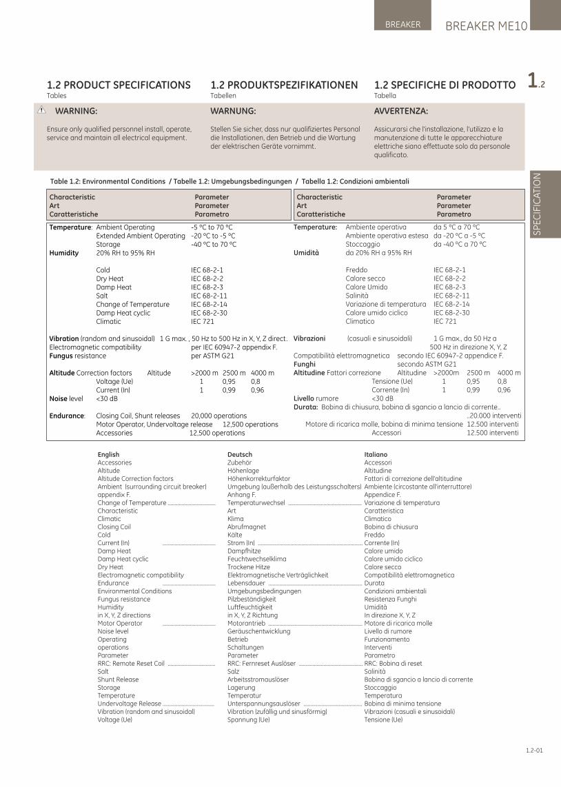
1.2 PRODUCT SPECIFICATIONSTables
1.2 PRODUKTSPEZIFIKATIONENTabellen
1.2 SPECIFICHE DI PRODOTTOTabella
Table 1.2: Environmental Conditions / Tabelle 1.2: Umgebungsbedingungen / Tabella 1.2: Condizioni ambientali
CharacteristicArtCaratteristiche
ParameterParameterParametro
Temperature: Ambient Operating -5 ºC to 70 ºC Extended Ambient Operating -20 ºC to -5 ºC Storage -40 ºC to 70 ºCHumidity 20% RH to 95% RH Cold IEC 68-2-1 Dry Heat IEC 68-2-2 Damp Heat IEC 68-2-3 Salt IEC 68-2-11 Change of Temperature IEC 68-2-14 Damp Heat cyclic IEC 68-2-30 Climatic IEC 721
Vibration (random and sinusoidal) 1 G max. , 50 Hz to 500 Hz in X, Y, Z direct.Electromagnetic compatibility per IEC 60947-2 appendix F.Fungus resistance per ASTM G21
Altitude Correction factors Altitude >2000 m 2500 m 4000 m Voltage (Ue) 1 0,95 0,8 Current (In) 1 0,99 0,96Noise level <30 dB
Endurance: Closing Coil, Shunt releases 20,000 operations Motor Operator, Undervoltage release 12,500 operations Accessories 12,500 operations
Temperature: Ambiente operativa da 5 ºC a 70 ºC Ambiente operativa estesa da -20 ºC a -5 ºC Stoccaggio da -40 ºC a 70 ºCUmidità da 20% RH a 95% RH
Freddo IEC 68-2-1 Calore secco IEC 68-2-2 Calore Umido IEC 68-2-3 Salinità IEC 68-2-11 Variazione di temperatura IEC 68-2-14 Calore umido ciclico IEC 68-2-30 Climatico IEC 721
Vibrazioni (casuali e sinusoidali) 1 G max., da 50 Hz a 500 Hz in direzione X, Y, ZCompatibilità elettromagnetica secondo IEC 60947-2 appendice F.Funghi secondo ASTM G21Altitudine Fattori correzione Altitudine >2000m 2500 m 4000 m Tensione (Ue) 1 0,95 0,8 Corrente (In) 1 0,99 0,96Livello rumore <30 dBDurata: Bobina di chiusura, bobina di sgancio a lancio di corrente .. ..20.000 interventi Motore di ricarica molle, bobina di minima tensione 12.500 interventi Accessori 12.500 interventi
ParameterParameterParametro
CharacteristicArtCaratteristiche
English DeutschAccessories Zubehör Altitude Höhenlage Altitude Correction factors Höhenkorrekturfaktor Ambient (surrounding circuit breaker) Umgebung (außerhalb des Leistungsschalters)appendix F. Anhang F. Change of Temperature ................................... Temperaturwechsel ......................................................Characteristic Art Climatic Klima Closing Coil Abrufmagnet Cold Kälte Current (In) ....................................... Strom (In) .............................................................................Damp Heat Dampfhitze Damp Heat cyclic Feuchtwechselklima Dry Heat Trockene Hitze Electromagnetic compatibility Elektromagnetische VerträglichkeitEndurance ....................................... Lebensdauer .....................................................................Environmental Conditions Umgebungsbedingungen Fungus resistance Pilzbeständigkeit Humidity Luftfeuchtigkeit in X, Y, Z directions in X, Y, Z Richtung Motor Operator ....................................... Motorantrieb .....................................................................Noise level GeräuschentwicklungOperating Betrieb operations Schaltungen Parameter Parameter RRC: Remote Reset Coil ................................... RRC: Fernreset Auslöser ...............................................Salt Salz Shunt Release Arbeitsstromauslöser Storage Lagerung Temperature Temperatur Undervoltage Release ...................................... Unterspannungsauslöser ...........................................Vibration (random and sinusoidal) Vibration (zufällig und sinusförmig)Voltage (Ue) Spannung (Ue)
ItalianoAccessoriAltitudineFattori di correzione dell'altitudineAmbiente (circostante all'interruttore)Appendice F.Variazione di temperaturaCaratteristica Climatico Bobina di chiusuraFreddoCorrente (In) Calore umidoCalore umido ciclicoCalore secco Compatibilità elettromagneticaDurataCondizioni ambientaliResistenza FunghiUmiditàIn direzione X, Y, ZMotore di ricarica molleLivello di rumore Funzionamento InterventiParametro RRC: Bobina di reset SalinitàBobina di sgancio a lancio di correnteStoccaggioTemperaturaBobina di minima tensioneVibrazioni (casuali e sinusoidali)Tensione (Ue)
INTR
OS
PE
CIF
ICA
TIO
NIN
STA
LLA
TIO
NO
PE
RA
TIO
NTR
IP U
NIT
LOCKSBREAKER ME10 INTRO BREAKER ACCESSORIES TESTS APPENDIX
TRIP UNIT
1.2-02
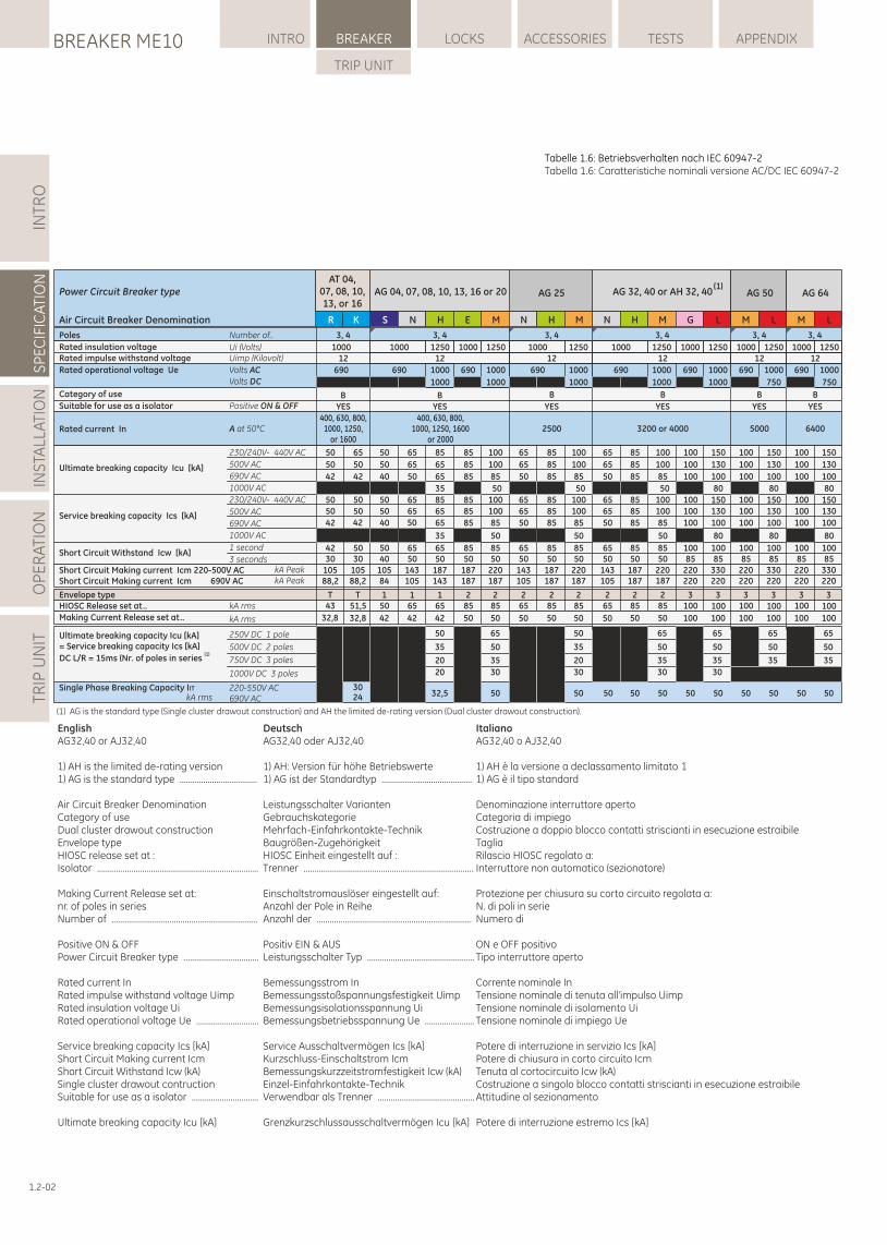
Tabelle 1.6: Betriebsverhalten nach IEC 60947-2 Tabella 1.6: Caratteristiche nominali versione AC/DC IEC 60947-2
English DeutschAG32,40 or AJ32,40 AG32,40 oder AJ32,40
1) AH is the limited de-rating version 1) AH: Version für höhe Betriebswerte1) AG is the standard type .................................... 1) AG ist der Standardtyp ..........................................
Air Circuit Breaker Denomination Leistungsschalter VariantenCategory of use GebrauchskategorieDual cluster drawout construction Mehrfach-Einfahrkontakte-TechnikEnvelope type Baugrößen-ZugehörigkeitHIOSC release set at : HIOSC Einheit eingestellt auf :Isolator ........................................................................... Trenner ...............................................................................
Making Current Release set at: Einschaltstromauslöser eingestellt auf:nr. of poles in series Anzahl der Pole in ReiheNumber of .................................................................... Anzahl der ........................................................................
Positive ON & OFF Positiv EIN & AUSPower Circuit Breaker type ................................... Leistungsschalter Typ ..................................................
Rated current In Bemessungsstrom InRated impulse withstand voltage Uimp Bemessungsstoßspannungsfestigkeit UimpRated insulation voltage Ui Bemessungsisolationsspannung UiRated operational voltage Ue ............................. Bemessungsbetriebsspannung Ue .......................
Service breaking capacity Ics [kA] Service Ausschaltvermögen Ics [kA]Short Circuit Making current Icm Kurzschluss-Einschaltstrom IcmShort Circuit Withstand Icw (kA) Bemessungskurzzeitstromfestigkeit Icw (kA)Single cluster drawout contruction Einzel-Einfahrkontakte-TechnikSuitable for use as a isolator ............................... Verwendbar als Trenner .............................................
Ultimate breaking capacity Icu [kA] Grenzkurzschlussausschaltvermögen Icu [kA]
ItalianoAG32,40 o AJ32,40
1) AH è la versione a declassamento limitato 11) AG è il tipo standard
Denominazione interruttore apertoCategoria di impiegoCostruzione a doppio blocco contatti striscianti in esecuzione estraibileTagliaRilascio HIOSC regolato a:Interruttore non automatico (sezionatore)
Protezione per chiusura su corto circuito regolata a:N. di poli in serieNumero di
ON e OFF positivoTipo interruttore aperto
Corrente nominale InTensione nominale di tenuta all'impulso UimpTensione nominale di isolamento UiTensione nominale di impiego Ue
Potere di interruzione in servizio Ics [kA]Potere di chiusura in corto circuito IcmTenuta al cortocircuito Icw (kA)Costruzione a singolo blocco contatti striscianti in esecuzione estraibileAttitudine al sezionamento
Potere di interruzione estremo Ics [kA]
Single Phase Breaking Capacity IIT 220-550V AC690V AC
Power Circuit Breaker type
Air Circuit Breaker Denomination
Poles
Rated insulation voltageRated impulse withstand voltage
Rated operational voltage Ue
Category of use
Suitable for use as a isolator
Rated current In
Ultimate breaking capacity Icu [kA]
Service breaking capacity Ics [kA]
Short Circuit Withstand Icw [kA]
Short Circuit Making current Icm 220-500V AC
Envelope typeHIOSC Release set at..
Making Current Release set at..
Number of..
Ui (Volts)Uimp (Kilovolt)
Volts DC
Positive ON & OFF
A at 50°C
230/240V- 440V AC
500V AC
690V AC
1000V AC
230/240V- 440V AC
500V AC
690V AC
1000V AC
1 second
3 secondskA Peak
kA rms
kA rms
250V DC 1 pole
500V DC 2 poles
750V DC 3 poles
Ultimate breaking capacity Icu [kA]= Service breaking capacity Ics [kA]
(1)DC L/R = 15ms (Nr. of poles in series
Volts AC
(1) AG is the standard type (Single cluster drawout construction) and AH the limited de-rating version (Dual cluster drawout construction).
1000V DC 3 poles
Short Circuit Making current Icm 690V AC kA Peak
AT 04,07, 08, 10, 13, or 16
1000
32,5 50 5050 50 50 5050 50 50 50 50
AG 04, 07, 08, 10, 13, 16 or 20 AG 25 AG 32, 40 or AH 32, 40(1)
AG 50 AG 64
S N N NH H HE M M M G M ML L L
3, 4 3, 4 3, 4 3, 4 3, 4
1000 1250 1000 1250 1000 1250 1000 1250 1000 1250 1000 1250 1000 125012 12 12 12 12
690 1000 690 1000 690 1000 690 1000 690 1000 690 1000 690 1000
1000 1000 1000 1000 1000 750 750
B B B B B
YES YES YES YES YES
400, 630, 800, 1000, 1250, 1600
or 20002500 3200 or 4000 5000 6400
50
50
40
5050
40
5040
105
150
42
65
65
50
6565
50
6550
143
165
42
85
65
65
8565
65
6550
187
165
42
85
85
85
8585
85
8550
187
285
50
65
65
50
6565
50
6550
143
265
50
85
85
85
8585
85
8550
187
285
50
50
35
20
65
50
35
50
35
20
65
50
35
65
50
35
65
50
35
65
50
35
35
35
50
100
100
85
100100
85
8550
220
285
50
50
150
130
100
150130
100
10085
330
3100
100
80
80
50
100
100
85
100100
85
8550
220
285
50
50
50
100
100
85
100100
85
8550
220
285
50
50
100
100
100
100100
100
10085
220
3100
100
100
100
100
100100
100
10085
220
3100
100
65
65
50
6565
50
6550
143
265
50
85
85
85
8585
85
8550
187
285
50
100
100
100
100100
100
10085
220
3100
100
150
130
100
150130
100
10085
330
3100
100
80
80
150
130
100
150130
100
10085
330
3100
100
80
80
20 30 30 30 30
84 105 143 187 105 187187 220187 187 220 220105 187 220 220 220
R K
3, 4
12
690
BYES
50
50
42
65
50
42
5050
42
4230
105
T43
32,8
88,2
5050
42
5030
105
T51,5
32,8
88,2
kA rms 2430
400, 630, 800,1000, 1250,
or 1600
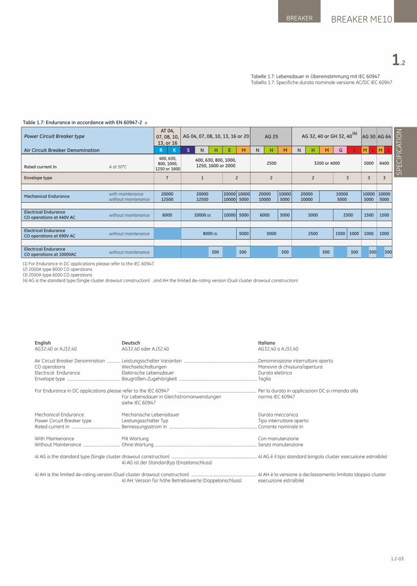
1.2-03
Tabelle 1.7: Lebensdauer in Übereinstimmung mit IEC 60947Tabella 1.7: Specifiche durata nominale versione AC/DC IEC 60947
BREAKER ME10BREAKER
SP
EC
IFIC
ATI
ON
1.2
English DeutschAG32,40 or AJ32,40 AG32,40 oder AJ32,40
Air Circuit Breaker Denomination ............. Leistungsschalter Varianten .........................................................................CO operations WechselschaltungenElectrical Endurance Elektrische LebensdauerEnvelope type .................................................... Baugrößen-Zugehörigkeit .............................................................................
For Endurance in DC applications please refer to the IEC 60947 ............................................................................. Für Lebensdauer in Gleichstromanwendungen siehe IEC 60947
Mechanical Endurance Mechanische LebensdauerPower Circuit Breaker type Leistungsschalter TypRated current In ................................................ Bemessungsstrom In .......................................................................................
With Maintenance Mit WartungWithout Maintenance .................................... Ohne Wartung .....................................................................................................
4) AG is the standard type (Single cluster drawout construction) .................................................................................... 4) AG ist der Standardtyp (Einzelanschluss) 4) AH is the limited de-rating version (Dual cluster drawout construction) ................................................................. 4) AH: Version für höhe Betriebswerte (Doppelanschluss)
ItalianoAG32,40 o AJ32,40
Denominazione interruttore apertoManovre di chiusura/aperturaDurata elettricaTaglia
Per la durata in applicazioni DC si rimanda allanorma IEC 60947
Durata meccanicaTipo interruttore apertoCorrente nominale In
Con manutenzioneSenza manutenzione
4) AG è il tipo standard (singolo cluster esecuzione estraibile)
4) AH è la versione a declassamento limitato (doppio cluster esecuzione estraibile)
Electrical EnduranceCO operations at 1000VAC without maintenance
Electrical EnduranceCO operations at 440V AC without maintenance
Electrical EnduranceCO operations at 690V AC without maintenance
Envelope type
Mechanical Endurancewith maintenancewithout maintenance
Power Circuit Breaker type
Air Circuit Breaker Denomination
Table 1.7: Endurance in accordance with EN 60947-2 1)
Rated current In A at 50°C
(1) For Endurance in DC applications please refer to the IEC 60947.(2) 2000A type 8000 CO operations(3) 2000A type 6000 CO operations(4) AG is the standard type (Single cluster drawout construction) ..and AH the limited de-rating version (Dual cluster drawout construction)
R K
500 300500 500 500 500
10000 (2) 10000 5000 6000 5000 5000 2500 1500
8000 (3) 5000 5000 2500 1500 1000
1 2 2 3 32
2000012500
2000010000
100005000
2000010000
100005000
2000010000
100005000
100005000
AG 04, 07, 08, 10, 13, 16 or 20 AG 25 AG 32, 40 or GH 32, 40(4)
AG 50
S N N NH H HE M M M G L
400, 630, 800, 1000, 1250, 1600 or 2000
2500 3200 or 4000 6400
AG 64
M L
5000
3
100005000
1500
1000
AT 04, 07, 08, 10,13, or 16
1000
400, 630, 800, 1000,
1250 or 1600
T
2000012500
6000
M L
500
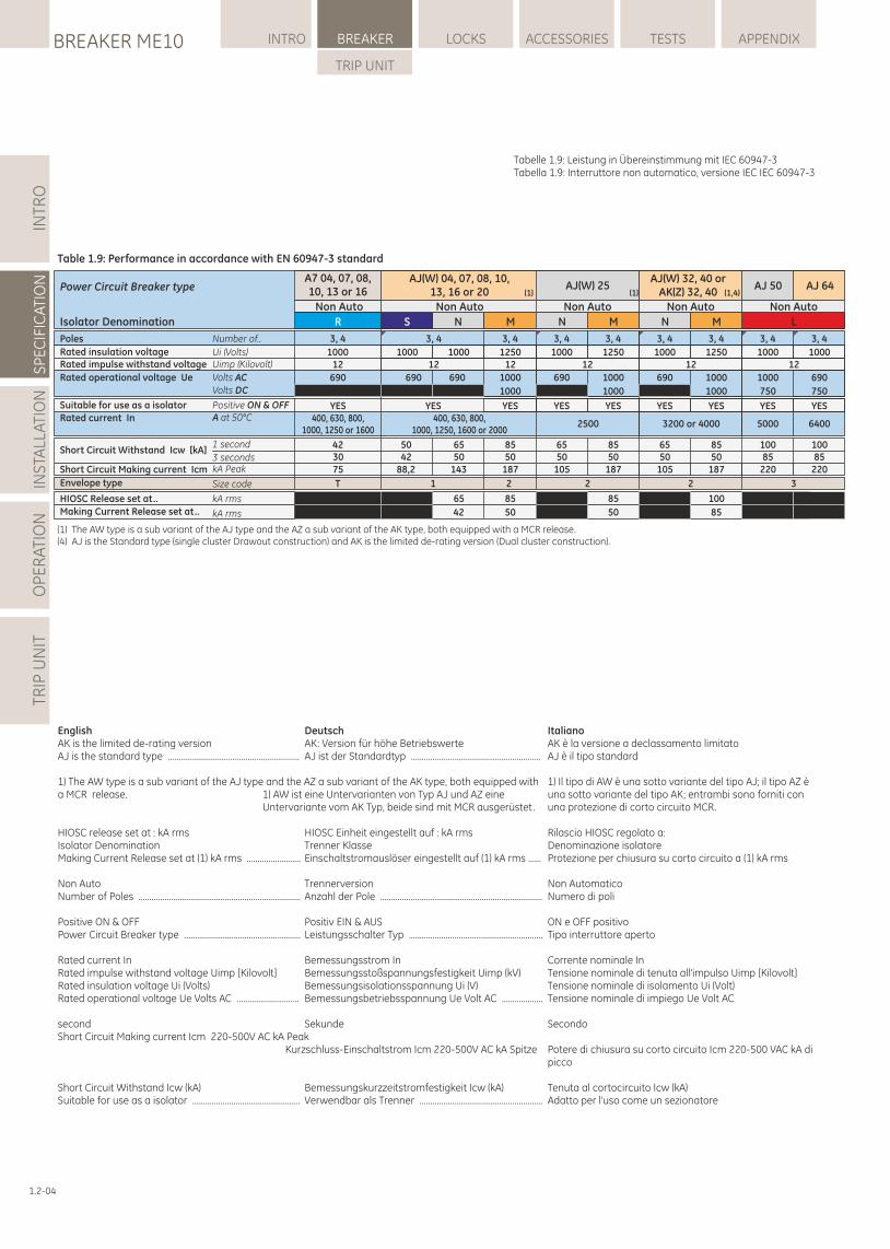
1.2-04
Tabelle 1.9: Leistung in Übereinstimmung mit IEC 60947-3Tabella 1.9: Interruttore non automatico, versione IEC IEC 60947-3
INTR
OS
PE
CIF
ICA
TIO
NIN
STA
LLA
TIO
NO
PE
RA
TIO
NTR
IP U
NIT
LOCKSBREAKER ME10 INTRO BREAKER ACCESSORIES TESTS APPENDIX
TRIP UNIT
English DeutschAK is the limited de-rating version AK: Version für höhe BetriebswerteAJ is the standard type ............................................................. AJ ist der Standardtyp ............................................................
1) The AW type is a sub variant of the AJ type and the AZ a sub variant of the AK type, both equipped with a MCR release. 1) AW ist eine Untervarianten von Typ AJ und AZ eine Untervariante vom AK Typ, beide sind mit MCR ausgerüstet. HIOSC release set at : kA rms HIOSC Einheit eingestellt auf : kA rmsIsolator Denomination Trenner KlasseMaking Current Release set at (1) kA rms ......................... Einschaltstromauslöser eingestellt auf (1) kA rms ......
Non Auto TrennerversionNumber of Poles ........................................................................... Anzahl der Pole ...........................................................................
Positive ON & OFF Positiv EIN & AUSPower Circuit Breaker type ...................................................... Leistungsschalter Typ ..............................................................
Rated current In Bemessungsstrom InRated impulse withstand voltage Uimp [Kilovolt] Bemessungsstoßspannungsfestigkeit Uimp (kV) Rated insulation voltage Ui (Volts) Bemessungsisolationsspannung Ui (V)Rated operational voltage Ue Volts AC ............................. Bemessungsbetriebsspannung Ue Volt AC ...................
second SekundeShort Circuit Making current Icm 220-500V AC kA Peak Kurzschluss-Einschaltstrom Icm 220-500V AC kA Spitze
Short Circuit Withstand Icw (kA) Bemessungskurzzeitstromfestigkeit Icw (kA)Suitable for use as a isolator .................................................. Verwendbar als Trenner .........................................................
ItalianoAK è la versione a declassamento limitatoAJ è il tipo standard
1) Il tipo di AW è una sotto variante del tipo AJ; il tipo AZ è una sotto variante del tipo AK; entrambi sono forniti con una protezione di corto circuito MCR.
Rilascio HIOSC regolato a:Denominazione isolatoreProtezione per chiusura su corto circuito a (1) kA rms
Non AutomaticoNumero di poli
ON e OFF positivoTipo interruttore aperto
Corrente nominale InTensione nominale di tenuta all'impulso Uimp [Kilovolt]Tensione nominale di isolamento Ui (Volt)Tensione nominale di impiego Ue Volt AC
Secondo
Potere di chiusura su corto circuito Icm 220-500 VAC kA di picco
Tenuta al cortocircuito Icw (kA)Adatto per l'uso come un sezionatore
Power Circuit Breaker type
Isolator Denomination
Table 1.9: Performance in accordance with EN 60947-3 standard
Poles
Rated insulation voltageRated impulse withstand voltage
Rated operational voltage Ue
Suitable for use as a isolator
Rated current In
Short Circuit Withstand Icw [kA]
Short Circuit Making current Icm
Number of..
Ui (Volts)Uimp (Kilovolt)
Volts DC
Positive ON & OFFA at 50°C
1 second
3 secondskA Peak
Volts AC
(1) The AW type is a sub variant of the AJ type and the AZ a sub variant of the AK type, both equipped with a MCR release.(4) AJ is the Standard type (single cluster Drawout construction) and AK is the limited de-rating version (Dual cluster construction).
AJ(W) 04, 07, 08, 10, 13, 16 or 20
S N M
3, 4
1000 1000 125012
690 690 1000
1000
YES400, 630, 800,
1000, 1250, 1600 or 2000
5042
88,2
6550
143
8550
187
Non Auto
3, 4
12
YES
AJ 50
L
3, 4
1000 100012
1000 690
750
YES
5000
10085
220
10085
220
Non Auto
3, 4
YES
AJ 64
750
6400
AJ(W) 32, 40 or AK(Z) 32, 40
N M
3, 4
1000 1250
690 1000
1000
YES
3200 or 4000
6550
105
8550
187
Non Auto
3, 4
12
YES
(1,4)AJ(W) 25
N M
3, 4
1000 125012
690 1000
1000
YES
2500
6550
105
8550
187
Non Auto
3, 4
YES
Non Auto
A7 04, 07, 08,10, 13 or 16
R
3, 4
100012
690
YES400, 630, 800,
1000, 1250 or 1600
423075
HIOSC Release set at..
Making Current Release set at..
kA rms
kA rms
65
42
85
50
100
85
85
50
(1)(1)
32221TEnvelope type Size code
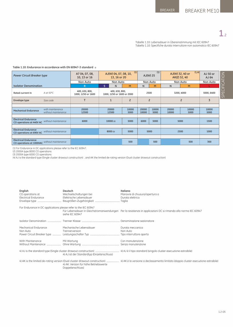
1.2-05
Tabelle 1.10: Lebensdauer in Übereinstimmung mit IEC 60947Tabella 1.10: Specifiche durata Interruttore non automatico IEC 60947
BREAKER ME10BREAKER
SP
EC
IFIC
ATI
ON
1.2
English DeutschCO operations at Wechselschaltungen beiElectrical Endurance Elektrische LebensdauerEnvelope type .......................................... Baugrößen-Zugehörigkeit ............................................
For Endurance in DC applications please refer to the IEC 60947 Für Lebensdauer in Gleichstromanwendungen siehe IEC 60947
Isolator Denomination ........................ Trenner Klasse ...................................................................
Mechanical Endurance Mechanische LebensdauerNon Auto TrennerversionPower Circuit Breaker type ............... Leistungsschalter Typ ....................................................
With Maintenance Mit WartungWithout Maintenance ......................... Ohne Wartung ..................................................................
4) AJ is the standard type (Single cluster drawout construction) .......................................... 4) AJ ist der Standardtyp (Einzelanschluss) 4) AK is the limited de-rating version (Dual cluster drawout construction) ...................... 4) AK: Version für höhe Betriebswerte Doppelanschluss)
ItalianoManovre di chiusura/apertura a Durata elettricaTaglia
Per la resistenza in applicazioni DC si rimanda alla norma IEC 60947
Denominazione sezionatore
Durata meccanicaNon Auto Tipo interruttore aperto
Con manutenzioneSenza manutenzione
4) AJ è il tipo standard (singolo cluster esecuzione estraibile)
4) AK è la versione a declassamento limitato (doppio cluster esecuzione estraibile)
Electrical EnduranceCO operations at 1000VAC without maintenance
Electrical EnduranceCO operations at 440V AC without maintenance
Electrical EnduranceCO operations at 690V AC without maintenance
Mechanical Endurancewith maintenancewithout maintenance
(1) For Endurance in DC applications please refer to the IEC 60947.(2) 2000A type 8000 CO operations(3) 2000A type 6000 CO operations(4) AJ is the standard type (Single cluster drawout construction) ..and AK the limited de-rating version (Dual cluster drawout construction)
Envelope type
Power Circuit Breaker type
Isolator Denomination
Table 1.10: Endurance in accordance with EN 60947-3 standard 1)
300500 500 500
10000 (2) 5000 6000 5000 5000 1500
8000 (3) 5000 5000 2500 1000
2000012500
100005000
2000010000
100005000
2000010000
100005000
100005000
1 2 2 32
AJ(W) 04, 07, 08, 10, 13, 16 or 20
AJ(W) 25AJ(W) 32, 40 or
AK(Z) 32, 40
(1,4)AJ 50 or
AJ 64
(1)(1)A7 04, 07, 08,10, 13 or 16
S N N NM M M LR
Rated current In400, 630, 800,
1000, 1250 or 1600400, 630, 800,
1000, 1250 or 1600 or 2000
T
2500 3200, 4000 5000, 6400
Non Auto Non Auto Non Auto Non AutoNon Auto
6000
2000012500
A at 50°C
Size code
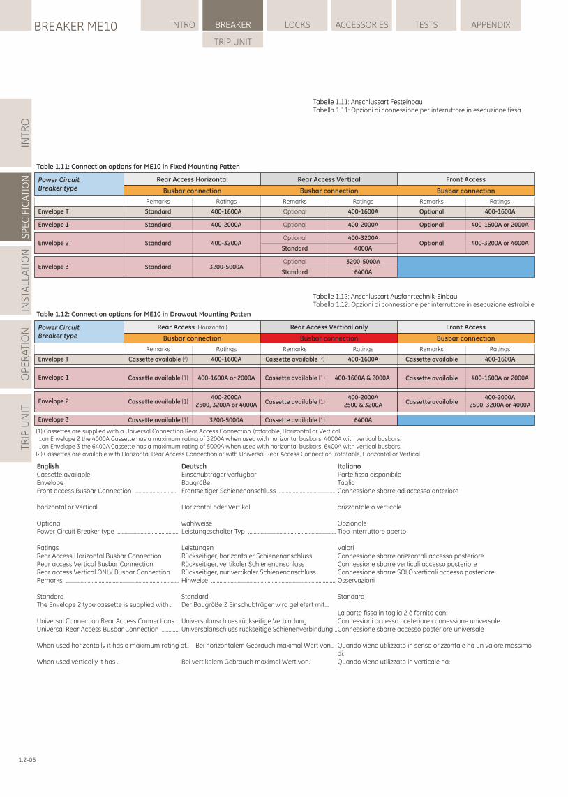
1.2-06
Tabelle 1.11: Anschlussart FesteinbauTabella 1.11: Opzioni di connessione per interruttore in esecuzione fissa
INTR
OS
PE
CIF
ICA
TIO
NIN
STA
LLA
TIO
NO
PE
RA
TIO
NTR
IP U
NIT
LOCKSBREAKER ME10 INTRO BREAKER ACCESSORIES TESTS APPENDIX
TRIP UNIT
Tabelle 1.12: Anschlussart Ausfahrtechnik-EinbauTabella 1.12: Opzioni di connessione per interruttore in esecuzione estraibile
English DeutschCassette available Einschubträger verfügbarEnvelope BaugrößeFront access Busbar Connection ............................... Frontseitiger Schienenanschluss .........................................
horizontal or Vertical Horizontal oder Vertikal
Optional wahlweisePower Circuit Breaker type ............................................ Leistungsschalter Typ ................................................................
Ratings LeistungenRear Access Horizontal Busbar Connection Rückseitiger, horizontaler SchienenanschlussRear access Vertical Busbar Connection Rückseitiger, vertikaler SchienenanschlussRear access Vertical ONLY Busbar Connection Rückseitiger, nur vertikaler SchienenanschlussRemarks .................................................................................. Hinweise ...........................................................................................
Standard StandardThe Envelope 2 type cassette is supplied with .. Der Baugröße 2 Einschubträger wird geliefert mit...
Universal Connection Rear Access Connections Universalanschluss rückseitige VerbindungUniversal Rear Access Busbar Connection ............. Universalanschluss rückseitige Schienenverbindung ..
When used horizontally it has a maximum rating of.. Bei horizontalem Gebrauch maximal Wert von..
When used vertically it has .. Bei vertikalem Gebrauch maximal Wert von..
ItalianoParte fissa disponibile TagliaConnessione sbarre ad accesso anteriore
orizzontale o verticale
Opzionale Tipo interruttore aperto
Valori Connessione sbarre orizzontali accesso posteriore Connessione sbarre verticali accesso posteriore Connessione sbarre SOLO verticali accesso posteriore Osservazioni
Standard
La parte fissa in taglia 2 è fornita con:Connessioni accesso posteriore connessione universaleConnessione sbarre accesso posteriore universale
Quando viene utilizzato in senso orizzontale ha un valore massimo di: Quando viene utilizzato in verticale ha:
Envelope 1 400-2000A Optional 400-2000A 400-1600A or 2000AOptionalStandard
Envelope 2 400-3200AOptional 400-3200A
400-3200A or 4000AOptionalStandardStandard 4000A
Envelope 3 3200-5000AOptional 3200-5000A
StandardStandard 6400A
Power Circuit Breaker type
Table 1.11: Connection options for ME10 in Fixed Mounting Patten
Rear Access Horizontal
Busbar connection
Rear Access Vertical
Busbar connection
Front Access
Busbar connection
Remarks Ratings Remarks Ratings Remarks Ratings
Envelope T 400-1600A Optional 400-1600A 400-1600AOptionalStandard
Envelope 3
Envelope 1 400-1600A or 2000A
Envelope 2
Power Circuit Breaker type
Table 1.12: Connection options for ME10 in Drawout Mounting Patten
Rear Access (Horizontal)
Busbar connection
Rear Access Vertical only
Busbar connection
Front Access
Busbar connection
Remarks Ratings Remarks Ratings Remarks Ratings
(1) Cassettes are supplied with a Universal Connection Rear Access Connection..(rotatable, Horizontal or Vertical ..on Envelope 2 the 4000A Cassette has a maximum rating of 3200A when used with horizontal busbars; 4000A with vertical busbars. ..on Envelope 3 the 6400A Cassette has a maximum rating of 5000A when used with horizontal busbars; 6400A with vertical busbars.(2) Cassettes are available with Horizontal Rear Access Connection or with Universal Rear Access Connection (rotatable, Horizontal or Vertical
400-2000A2500, 3200A or 4000A
400-2000A2500, 3200A or 4000A
3200-5000A
400-1600A or 2000A
Envelope T 400-1600A 400-1600A 400-1600ACassette available (²)
Cassette available (1)
Cassette available (1)
Cassette available (1)
Cassette available (²) Cassette available
Cassette available
Cassette available400-2000A
2500 & 3200A
400-1600A & 2000ACassette available (1)
Cassette available (1)
6400ACassette available (1)
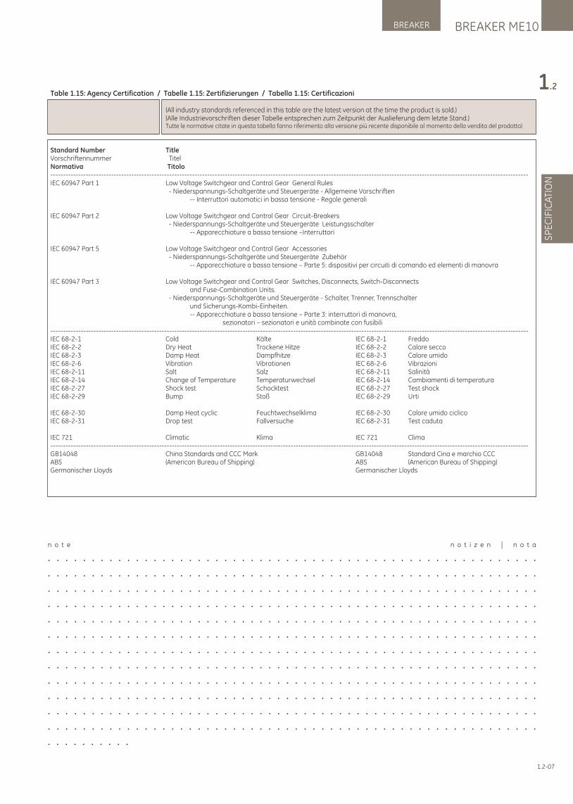
BREAKER ME10BREAKER
SP
EC
IFIC
ATI
ON
1.2Table 1.15: Agency Certification / Tabelle 1.15: Zertifizierungen / Tabella 1.15: Certificazioni
(All industry standards referenced in this table are the latest version at the time the product is sold.) (Alle Industrievorschriften dieser Tabelle entsprechen zum Zeitpunkt der Auslieferung dem letzte Stand.) Tutte le normative citate in questa tabella fanno riferimento alla versione più recente disponibile al momento della vendita del prodotto)
Standard Number TitleVorschriftennummer TitelNormativa Titolo---------------------------------------------------------------------------------------------------------------------------------------------------------------------------------------------IEC 60947 Part 1 Low Voltage Switchgear and Control Gear General Rules - Niederspannungs-Schaltgeräte und Steuergeräte - Allgemeine Vorschriften -- Interruttori automatici in bassa tensione - Regole generali
IEC 60947 Part 2 Low Voltage Switchgear and Control Gear Circuit-Breakers - Niederspannungs-Schaltgeräte und Steuergeräte Leistungsschalter -- Apparecchiature a bassa tensione –Interruttori
IEC 60947 Part 5 Low Voltage Switchgear and Control Gear Accessories - Niederspannungs-Schaltgeräte und Steuergeräte Zubehör -- Apparecchiature a bassa tensione – Parte 5: dispositivi per circuiti di comando ed elementi di manovra
IEC 60947 Part 3 Low Voltage Switchgear and Control Gear Switches, Disconnects, Switch-Disconnects and Fuse-Combination Units. - Niederspannungs-Schaltgeräte und Steuergeräte - Schalter, Trenner, Trennschalter und Sicherungs-Kombi-Einheiten. -- Apparecchiature a bassa tensione – Parte 3: interruttori di manovra, sezionatori – sezionatori e unità combinate con fusibili---------------------------------------------------------------------------------------------------------------------------------------------------------------------------------------------IEC 68-2-1 Cold Kälte IEC 68-2-1 FreddoIEC 68-2-2 Dry Heat Trockene Hitze IEC 68-2-2 Calore seccoIEC 68-2-3 Damp Heat Dampfhitze IEC 68-2-3 Calore umidoIEC 68-2-6 Vibration Vibrationen IEC 68-2-6 VibrazioniIEC 68-2-11 Salt Salz IEC 68-2-11 SalinitàIEC 68-2-14 Change of Temperature Temperaturwechsel IEC 68-2-14 Cambiamenti di temperaturaIEC 68-2-27 Shock test Schocktest IEC 68-2-27 Test shockIEC 68-2-29 Bump Stoß IEC 68-2-29 Urti
IEC 68-2-30 Damp Heat cyclic Feuchtwechselklima IEC 68-2-30 Calore umido ciclico IEC 68-2-31 Drop test Fallversuche IEC 68-2-31 Test caduta
IEC 721 Climatic Klima IEC 721 Clima---------------------------------------------------------------------------------------------------------------------------------------------------------------------------------------------GB14048 China Standards and CCC Mark GB14048 Standard Cina e marchio CCCABS (American Bureau of Shipping) ABS (American Bureau of Shipping)Germanischer Lloyds Germanischer Lloyds
n o t e n o t i z e n | n o t a
. . . . . . . . . . . . . . . . . . . . . . . . . . . . . . . . . . . . . . . . . . . . . . . . . . . . . . . .
. . . . . . . . . . . . . . . . . . . . . . . . . . . . . . . . . . . . . . . . . . . . . . . . . . . . . . . .
. . . . . . . . . . . . . . . . . . . . . . . . . . . . . . . . . . . . . . . . . . . . . . . . . . . . . . . .
. . . . . . . . . . . . . . . . . . . . . . . . . . . . . . . . . . . . . . . . . . . . . . . . . . . . . . . .
. . . . . . . . . . . . . . . . . . . . . . . . . . . . . . . . . . . . . . . . . . . . . . . . . . . . . . . .
. . . . . . . . . . . . . . . . . . . . . . . . . . . . . . . . . . . . . . . . . . . . . . . . . . . . . . . .
. . . . . . . . . . . . . . . . . . . . . . . . . . . . . . . . . . . . . . . . . . . . . . . . . . . . . . . .
. . . . . . . . . . . . . . . . . . . . . . . . . . . . . . . . . . . . . . . . . . . . . . . . . . . . . . . .
. . . . . . . . . . . . . . . . . . . . . . . . . . . . . . . . . . . . . . . . . . . . . . . . . . . . . . . .
. . . . . . . . . . . . . . . . . . . . . . . . . . . . . . . . . . . . . . . . . . . . . . . . . . . . . . . .
. . . . . . . . . . . . . . . . . . . . . . . . . . . . . . . . . . . . . . . . . . . . . . . . . . . . . . . .
. . . . . . . . . . . . . . . . . . . . . . . . . . . . . . . . . . . . . . . . . . . . . . . . . . . . . . . .
. . . . . . . . . .
1.2-07
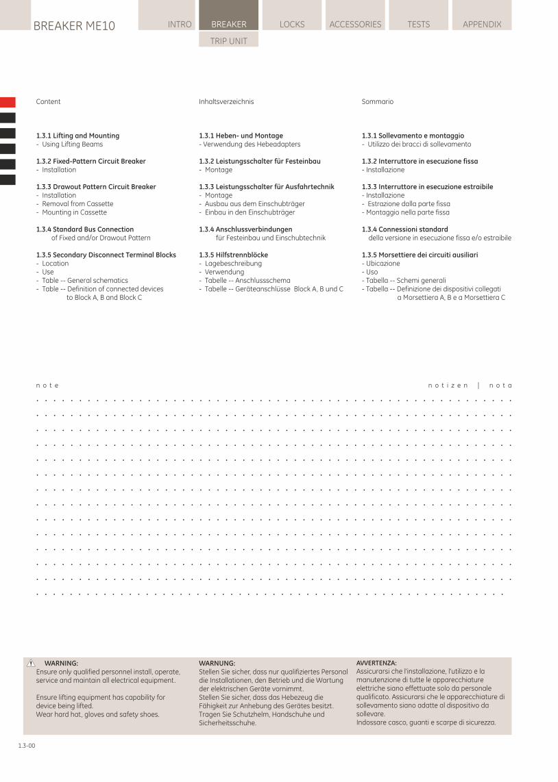
LOCKSBREAKER ME10 INTRO BREAKER ACCESSORIES TESTS APPENDIX
TRIP UNIT
Sommario
1.3.1 Sollevamento e montaggio- Utilizzo dei bracci di sollevamento
1.3.2 Interruttore in esecuzione fissa- Installazione
1.3.3 Interruttore in esecuzione estraibile- Installazione- Estrazione dalla parte fissa- Montaggio nella parte fissa
1.3.4 Connessioni standard della versione in esecuzione fissa e/o estraibile
1.3.5 Morsettiere dei circuiti ausiliari- Ubicazione- Uso- Tabella -- Schemi generali- Tabella -- Definizione dei dispositivi collegati a Morsettiera A, B e a Morsettiera C
WARNUNG:Stellen Sie sicher, dass nur qualifiziertes Personal die Installationen, den Betrieb und die Wartung der elektrischen Geräte vornimmt.Stellen Sie sicher, dass das Hebezeug die Fähigkeit zur Anhebung des Gerätes besitzt.Tragen Sie Schutzhelm, Handschuhe und Sicherheitsschuhe.
WARNING: Ensure only qualified personnel install, operate, service and maintain all electrical equipment.
Ensure lifting equipment has capability for device being lifted.Wear hard hat, gloves and safety shoes.
AVVERTENZA: Assicurarsi che l'installazione, l'utilizzo e la manutenzione di tutte le apparecchiature elettriche siano effettuate solo da personale qualificato. Assicurarsi che le apparecchiature di sollevamento siano adatte al dispositivo da sollevare.Indossare casco, guanti e scarpe di sicurezza.
n o t e n o t i z e n | n o t a
. . . . . . . . . . . . . . . . . . . . . . . . . . . . . . . . . . . . . . . . . . . . . . . . . . . . . . . .
. . . . . . . . . . . . . . . . . . . . . . . . . . . . . . . . . . . . . . . . . . . . . . . . . . . . . . . .
. . . . . . . . . . . . . . . . . . . . . . . . . . . . . . . . . . . . . . . . . . . . . . . . . . . . . . . .
. . . . . . . . . . . . . . . . . . . . . . . . . . . . . . . . . . . . . . . . . . . . . . . . . . . . . . . .
. . . . . . . . . . . . . . . . . . . . . . . . . . . . . . . . . . . . . . . . . . . . . . . . . . . . . . . .
. . . . . . . . . . . . . . . . . . . . . . . . . . . . . . . . . . . . . . . . . . . . . . . . . . . . . . . .
. . . . . . . . . . . . . . . . . . . . . . . . . . . . . . . . . . . . . . . . . . . . . . . . . . . . . . . .
. . . . . . . . . . . . . . . . . . . . . . . . . . . . . . . . . . . . . . . . . . . . . . . . . . . . . . . .
. . . . . . . . . . . . . . . . . . . . . . . . . . . . . . . . . . . . . . . . . . . . . . . . . . . . . . . .
. . . . . . . . . . . . . . . . . . . . . . . . . . . . . . . . . . . . . . . . . . . . . . . . . . . . . . . .
. . . . . . . . . . . . . . . . . . . . . . . . . . . . . . . . . . . . . . . . . . . . . . . . . . . . . . . .
. . . . . . . . . . . . . . . . . . . . . . . . . . . . . . . . . . . . . . . . . . . . . . . . . . . . . . . .
. . . . . . . . . . . . . . . . . . . . . . . . . . . . . . . . . . . . . . . . . . . . . . . . . . . . . . . .
. . . . . . . . . . . . . . . . . . . . . . . . . . . . . . . . . . . . . . . . . . . . . . . . . . . . . . . .
1.3-00
Content
1.3.1 Lifting and Mounting- Using Lifting Beams
1.3.2 Fixed-Pattern Circuit Breaker- Installation
1.3.3 Drawout Pattern Circuit Breaker- Installation- Removal from Cassette- Mounting in Cassette
1.3.4 Standard Bus Connection of Fixed and/or Drawout Pattern
1.3.5 Secondary Disconnect Terminal Blocks- Location- Use- Table -- General schematics- Table -- Definition of connected devices to Block A, B and Block C
Inhaltsverzeichnis
1.3.1 Heben- und Montage- Verwendung des Hebeadapters
1.3.2 Leistungsschalter für Festeinbau- Montage
1.3.3 Leistungsschalter für Ausfahrtechnik- Montage- Ausbau aus dem Einschubträger- Einbau in den Einschubträger
1.3.4 Anschlussverbindungen für Festeinbau und Einschubtechnik
1.3.5 Hilfstrennblöcke- Lagebeschreibung- Verwendung- Tabelle -- Anschlussschema- Tabelle -- Geräteanschlüsse Block A, B und C
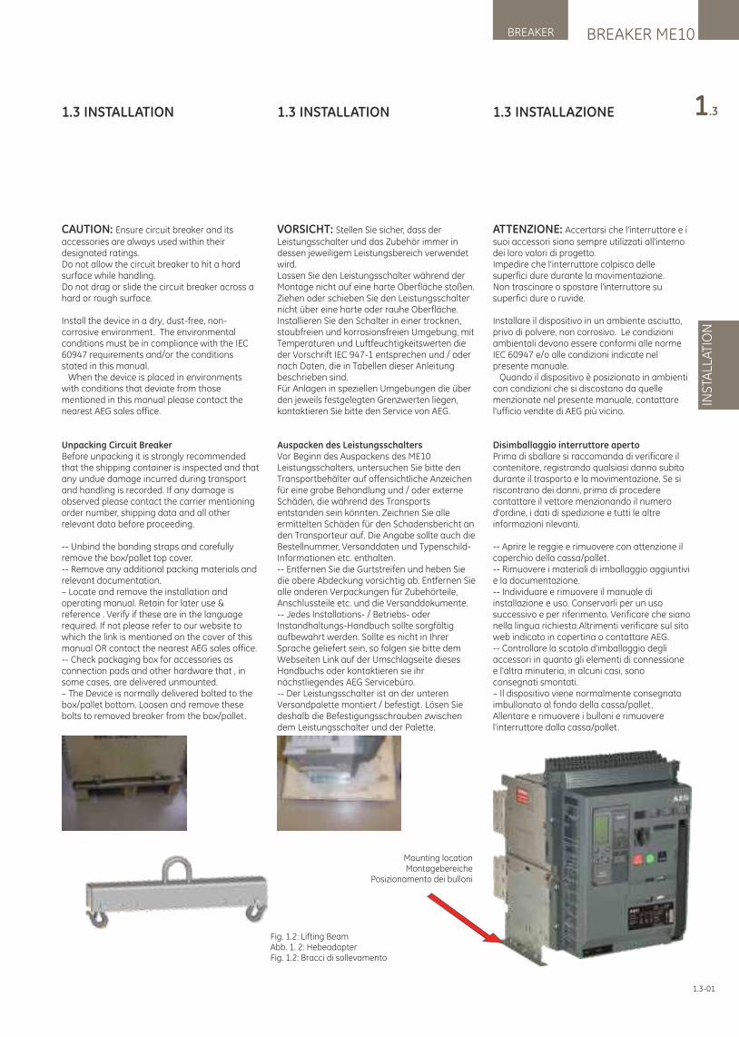
1.3 INSTALLAZIONE
ATTENZIONE: Accertarsi che l'interruttore e i suoi accessori siano sempre utilizzati all'interno dei loro valori di progetto.Impedire che l'interruttore colpisca delle superfici dure durante la movimentazione.Non trascinare o spostare l'interruttore su superfici dure o ruvide.
Installare il dispositivo in un ambiente asciutto, privo di polvere, non corrosivo. Le condizioni ambientali devono essere conformi alle norme IEC 60947 e/o alle condizioni indicate nel presente manuale. Quando il dispositivo è posizionato in ambienti con condizioni che si discostano da quelle menzionate nel presente manuale, contattare l'ufficio vendite di AEG più vicino.
Disimballaggio interruttore apertoPrima di sballare si raccomanda di verificare il contenitore, registrando qualsiasi danno subito durante il trasporto e la movimentazione. Se si riscontrano dei danni, prima di procedere contattare il vettore menzionando il numero d'ordine, i dati di spedizione e tutti le altre informazioni rilevanti.
-- Aprire le reggie e rimuovere con attenzione il coperchio della cassa/pallet.-- Rimuovere i materiali di imballaggio aggiuntivi e la documentazione.-- Individuare e rimuovere il manuale di installazione e uso. Conservarli per un uso successivo e per riferimento. Verificare che siano nella lingua richiesta.Altrimenti verificare sul sito web indicato in copertina o contattare AEG.-- Controllare la scatola d'imballaggio degli accessori in quanto gli elementi di connessione e l'altra minuteria, in alcuni casi, sono consegnati smontati. – Il dispositivo viene normalmente consegnato imbullonato al fondo della cassa/pallet. Allentare e rimuovere i bulloni e rimuovere l'interruttore dalla cassa/pallet.
BREAKER ME10BREAKER
INS
TALL
ATI
ON
1.3
1.3-01
Mounting locationMontagebereiche
Posizionamento dei bulloni
Fig. 1.2: Lifting BeamAbb. 1. 2: HebeadapterFig. 1.2: Bracci di sollevamento
1.3 INSTALLATION
CAUTION: Ensure circuit breaker and its accessories are always used within their designated ratings.Do not allow the circuit breaker to hit a hard surface while handling.Do not drag or slide the circuit breaker across a hard or rough surface.
Install the device in a dry, dust-free, non-corrosive environment. The environmental conditions must be in compliance with the IEC 60947 requirements and/or the conditions stated in this manual. When the device is placed in environments with conditions that deviate from those mentioned in this manual please contact the nearest AEG sales office.
Unpacking Circuit BreakerBefore unpacking it is strongly recommended that the shipping container is inspected and that any undue damage incurred during transport and handling is recorded. If any damage is observed please contact the carrier mentioning order number, shipping data and all other relevant data before proceeding.
-- Unbind the banding straps and carefully remove the box/pallet top cover.-- Remove any additional packing materials and relevant documentation.– Locate and remove the installation and operating manual. Retain for later use & reference . Verify if these are in the language required. If not please refer to our website to which the link is mentioned on the cover of this manual OR contact the nearest AEG sales office.-- Check packaging box for accessories as connection pads and other hardware that , in some cases, are delivered unmounted. – The Device is normally delivered bolted to the box/pallet bottom. Loosen and remove these bolts to removed breaker from the box/pallet.
1.3 INSTALLATION
VORSICHT: Stellen Sie sicher, dass der Leistungsschalter und das Zubehör immer in dessen jeweiligem Leistungsbereich verwendet wird.Lassen Sie den Leistungsschalter während der Montage nicht auf eine harte Oberfläche stoßen.Ziehen oder schieben Sie den Leistungsschalter nicht über eine harte oder rauhe Oberfläche.Installieren Sie den Schalter in einer trocknen, staubfreien und korrosionsfreien Umgebung, mit Temperaturen und Luftfeuchtigkeitswerten die der Vorschrift IEC 947-1 entsprechen und / oder nach Daten, die in Tabellen dieser Anleitung beschrieben sind.Für Anlagen in speziellen Umgebungen die über den jeweils festgelegten Grenzwerten liegen, kontaktieren Sie bitte den Service von AEG.
Auspacken des LeistungsschaltersVor Beginn des Auspackens des ME10 Leistungsschalters, untersuchen Sie bitte den Transportbehälter auf offensichtliche Anzeichen für eine grobe Behandlung und / oder externe Schäden, die während des Transports entstanden sein könnten. Zeichnen Sie alle ermittelten Schäden für den Schadensbericht an den Transporteur auf. Die Angabe sollte auch die Bestellnummer, Versanddaten und Typenschild-Informationen etc. enthalten.-- Entfernen Sie die Gurtstreifen und heben Sie die obere Abdeckung vorsichtig ab. Entfernen Sie alle anderen Verpackungen für Zubehörteile, Anschlussteile etc. und die Versanddokumente.-- Jedes Installations- / Betriebs- oder Instandhaltungs-Handbuch sollte sorgfältig aufbewahrt werden. Sollte es nicht in Ihrer Sprache geliefert sein, so folgen sie bitte dem Webseiten Link auf der Umschlagseite dieses Handbuchs oder kontaktieren sie ihr nächstliegendes AEG Servicebüro.-- Der Leistungsschalter ist an der unteren Versandpalette montiert / befestigt. Lösen Sie deshalb die Befestigungsschrauben zwischen dem Leistungsschalter und der Palette.
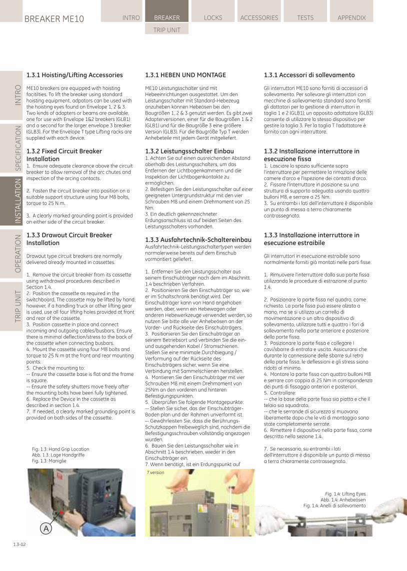
INTR
OS
PE
CIF
ICA
TIO
NIN
STA
LLAT
ION
OP
ER
ATI
ON
TRIP
UN
ITLOCKSBREAKER ME10 INTRO BREAKER ACCESSORIES TESTS APPENDIX
TRIP UNIT
1.3.1 Accessori di sollevamento
Gli interruttori ME10 sono forniti di accessori di sollevamento. Per sollevare gli interruttori con mecchine di sollevamento standard sono forniti gli dattatori per la gestione di interruttori in taglia 1 e 2 (GLB1); un apposito adattatore (GLB3) consente di utilizzare lo stesso dispositivo per gestire la taglia 3. Per la taglia T l'adattatore è fornito con ogni interruttore.
1.3.2 Installazione interruttore in esecuzione fissa1. Lasciare lo spazio sufficiente sopra l'interruttore per permettere la rimozione delle camere d'arco e l'ispezione dei contatti d'arco.2. Fissare l'interruttore in posizione su una struttura di supporto adeguata usando quattro bulloni M8, e serrare a 25 Nm.3. Su entrambi i lati dell'interruttore è disponibile un punto di messa a terra chiaramente contrassegnato.
1.3.3 Installazione interruttore in esecuzione estraibile
Gli interruttori in esecuzione estraibile sono normalmente forniti già montati nelle parti fisse.
1. Rimuovere l'interruttore dalla sua parte fissa utilizzando le procedure di estrazione al punto 1.4.
2. Posizionare la parte fissa nel quadro, come richiesto. La parte fissa può essere alzata a mano, ma se si utilizza un carrello di movimentazione o un altro dispositivo di sollevamento, utilizzare tutti e quattro i fori di sollevamento nella parte anteriore e posteriore della parte fissa.3. Posizionare la parte fissa e collegare I cavi/sbarre di entrata e uscita. Assicurarsi che durante la connessione delle sbarre sul retro della parte fissa, le deflessioni e gli stress siano ridotti al minimo.4. Montare la parte fissa con quattro bulloni M8 e serrare con coppia di 25 Nm in corrispondenza dei punti di fissaggio anteriori e posteriori.5. Controllare:-- che la base della parte fissa sia piatta e che il telaio sia squadrato.-- che le serrande di sicurezza si muovano liberamente dopo che le viti di montaggio sono state completamente serrate.6. Rimettere il dispositivo nella parte fissa, come descritto nella sezione 1.4.
7. Se necessario, su entrambi i lati dell'interruttore è disponibile un punto di messa a terra chiaramente contrassegnato.
1.3-02
1.3.1 HEBEN UND MONTAGE
ME10 Leistungsschalter sind mit Hebeeinrichtungen ausgestattet. Um den Leistungsschalter mit Standard-Hebezeug anzuheben können Hebeösen bei den Baugrößen 1, 2 & 3 genutzt werden. Es gibt zwei Adapterversionen, einer für die Baugrößen 1 & 2 (GLB1) und für die Baugröße 3 eine größere Version (GLB3). Für die Baugröße Typ T werden Anhebeteile mit jedem Gerät mitgeliefert.
1.3.2 Leistungsschalter Einbau1. Achten Sie auf einen ausreichenden Abstand oberhalb des Leistungsschalters, um das Entfernen der Lichtbogenkammern und die Inspektion der Lichtbogenkontakte zu ermöglichen.2. Befestigen Sie den Leistungsschalter auf einer geeigneten Untergrundstruktur mit den vier Schrauben M8 und einem Drehmoment von 25 Nm.3. Ein deutlich gekennzeichneter Erdungsanschluss ist auf beiden Seiten des Leistungsschalters vorhanden.
1.3.3 Ausfahrtechnik-SchaltereinbauAusfahrtechnik-Leistungsschaltertypen werden normalerweise bereits auf dem Einschub vormontiert geliefert.
1. Entfernen Sie den Leistungsschalter aus seinem Einschubträger nach dem im Abschnitt 1.4 beschrieben Verfahren.2. Positionieren Sie den Einschubträger so, wie er im Schaltschrank benötigt wird. Der Einschubträger kann von Hand angehoben werden, aber, wenn ein Hebewagen oder anderen Hebewerkzeuge verwendet werden, so nutzen Sie bitte alle vier Anhebeösen an der Vorder- und Rückseite des Einschubträgers.3. Positionieren Sie den Einschubträger an seinem Betriebsort und verbinden Sie die ein- und ausgehenden Kabel / Stromschienen. Stellen Sie eine minimale Durchbiegung / Verformung auf der Rückseite des Einschubträgers sicher, wenn Sie eine Verbindung mit Sammelschienen herstellen.4. Montieren Sie den Einschubträger mit vier Schrauben M8 mit einem Drehmoment von 25Nm an den vorderen und hinteren Befestigungspunkten.5. Überprüfen Sie folgende Montagepunkte:-- Stellen Sie sicher, das der Einschubträger-Boden plan und der Rahmen unverformt ist.-- Gewährleisten Sie, dass die Berührungs-Schutzkappen freibeweglich sind, nachdem die Befestigungsschrauben vollständig angezogen wurden.6. Bauen Sie den Leistungsschalter wie in Abschnitt 1.4 beschrieben, wieder in den Einschubträger ein.7. Wenn benötigt, ist ein Erdungspunkt auf
1.3.1 Hoisting/Lifting Accessories
ME10 breakers are equipped with hoisting facitilties. To lift the breaker using standard hoisting equipment, adpators can be used with the hoisting eyes found on Envelope 1, 2 & 3. Two kinds of adapters or beams are available, one for use with Envelope 1&2 breakers (GLB1) and a second for the larger envelope 3 breaker (GLB3). For the Envelope T type Lifting racks are supplied with each device.
1.3.2 Fixed Circuit Breaker Installation1. Ensure adequate clearance above the circuit breaker to allow removal of the arc chutes and inspection of the arcing contacts.
2. Fasten the circuit breaker into position on a suitable support structure using four M8 bolts, torque to 25 N m.
3. A clearly marked grounding point is provided on either side of the circuit breaker.
1.3.3 Drawout Circuit BreakerInstallation
Drawout type circuit breakers are normally delivered already mounted in cassettes.
1. Remove the circuit breaker from its cassette using withdrawal procedures described in Section 1.4.2. Position the cassette as required in the switchboard. The cassette may be lifted by hand; however, if a handling truck or other lifting gear is used, use all four lifting holes provided at front and rear of the cassette.3. Position cassette in place and connect incoming and outgoing cables/busbars. Ensure there is minimal deflection/stress to the back of the cassette when connecting busbars.4. Mount the cassette using four M8 bolts and torque to 25 N m at the front and rear mounting points.5. Check the mounting to:-- Ensure the cassette base is flat and the frame is square.-- Ensure the safety shutters move freely after the mounting bolts have been fully tightened.6. Replace the Device in the cassette as described in section 1.4.7. If needed, a clearly marked grounding point is provided on both sides of the cassette.
Fig. 1.4: Lifting EyesAbb. 1.4: Anhebeösen
Fig. 1.4: Anelli di sollevamento
T version
A
Fig. 1.3: Hand Grip LocationAbb. 1.3: Lage HandgriffeFig. 1.3: Maniglie
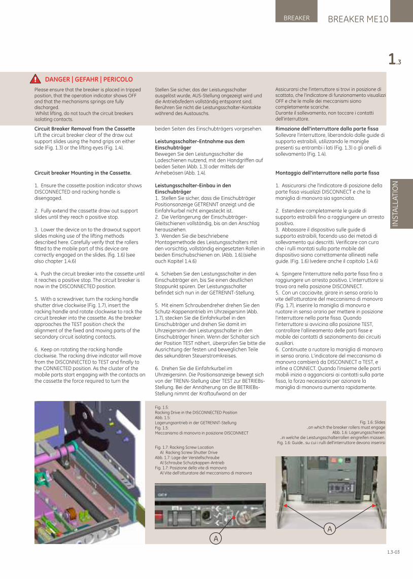
Rimozione dell'interruttore dalla parte fissaSollevare l'interruttore, liberandolo dalle guide di supporto estraibili, utilizzando le maniglie presenti su entrambi i lati (Fig. 1.3) o gli anelli di sollevamento (Fig. 1.4).
Montaggio dell'interruttore nella parte fissa
1. Assicurarsi che l'indicatore di posizione della parte fissa visualizzi DISCONNECT e che la maniglia di manovra sia sganciata.
2. Estendere completamente le guide di supporto estraibili fino a raggiungere un arresto positivo.3. Abbassare il dispositivo sulle guide di supporto estraibili, facendo uso dei metodi di sollevamento qui descritti. Verificare con cura che i rulli montati sulla parte mobile del dispositivo siano correttamente allineati nelle guide. (Fig. 1.6) (vedere anche il capitolo 1.4.6)
4. Spingere l'interruttore nella parte fissa fino a raggiungere un arresto positivo. L'interruttore si trova ora nella posizione DISCONNECT.5. Con un cacciavite, girare in senso orario la vite dell'otturatore del meccanismo di manovra (Fig. 1.7), inserire la maniglia di manovra e ruotare in senso orario per mettere in posizione l'interruttore nella parte fissa. Quando l'interruttore si avvicina alla posizione TEST, controllare l'allineamento delle parti fisse e mobile dei contatti di sezionamento dei circuiti ausiliari.6. Continuate a ruotare la maniglia di manovra in senso orario. L'indicatore del meccanismo di manovra cambierà da DISCONNECT a TEST, e infine a CONNECT. Quando l'insieme delle parti mobili inizia a agganciarsi ai contatti sulla parte fissa, la forza necessaria per azionare la maniglia di manovra aumenta rapidamente.
Fig. 1.6: Slides..on which the breaker rollers must engage
Abb. 1.6: Lagerungsschienen..in welche die Leistungsschalterrollen eingreifen müssen.
Fig. 1.6: Guide.. su cui i rulli dell'interruttore devono inserirsiFig. 1.7: Racking Screw Location A) Racking Screw Shutter DriveAbb. 1.7: Lage der Verstellschraube A) Schraube Schutzkappen-AntriebFig. 1.7: Posizione della vite di manovra A) Vite dell'otturatore del meccanismo di manovra
Fig. 1.5:Racking Drive in the DISCONNECTED PositionAbb. 1.5:Lagerungsantrieb in der GETRENNT-StellungFig. 1.5:Meccanismo di manovra in posizione DISCONNECT
AA
Stellen Sie sicher, das der Leistungsschalter ausgelöst wurde, AUS-Stellung angezeigt wird und die Antriebsfedern vollständig entspannt sind.Berühren Sie nicht die Leistungsschalter-Kontakte während des Austauschs.
Please ensure that the breaker is placed in tripped position, that the operation indicator shows OFF and that the mechanisms springs are fully discharged. Whilst lifting, do not touch the circuit breakers isolating contacts.
DANGER | GEFAHR | PERICOLO
Assicurarsi che l'interruttore si trovi in posizione di scattato, che l'indicatore di funzionamento visualizzi OFF e che le molle dei meccanismi siano completamente scariche. Durante il sollevamento, non toccare i contatti dell'interruttore.
BREAKER ME10BREAKER
INS
TALL
ATI
ON
1.3
1.3-03
Circuit Breaker Removal from the CassetteLift the circuit breaker clear of the draw out support slides using the hand grips on either side (Fig. 1.3) or the lifting eyes (Fig. 1.4).
Circuit breaker Mounting in the Cassette.
1. Ensure the cassette position indicator shows DISCONNECTED and racking handle is disengaged.
2. Fully extend the cassette draw out support slides until they reach a positive stop.
3. Lower the device on to the drawout support slides making use of the lifting methods described here. Carefully verify that the rollers fitted to the mobile part of this device are correctly engaged on the slides. (fig. 1.6) (see also chapter 1.4.6)
4. Push the circuit breaker into the cassette until it reaches a positive stop. The circuit breaker is now in the DISCONNECTED position.
5. With a screwdriver, turn the racking handle shutter drive clockwise (Fig. 1.7), insert the racking handle and rotate clockwise to rack the circuit breaker into the cassette. As the breaker approaches the TEST position check the alignment of the fixed and moving parts of the secondary circuit isolating contacts.
6. Keep on rotating the racking handle clockwise. The racking drive indicator will move from the DISCONNECTED to TEST and finally to the CONNECTED position. As the cluster of the mobile parts start engaging with the contacts on the cassette the force required to turn the
beiden Seiten des Einschubträgers vorgesehen.
Leistungsschalter-Entnahme aus dem EinschubträgerBewegen Sie den Leistungsschalter die Ladeschienen nutzend, mit den Handgriffen auf beiden Seiten (Abb. 1.3) oder mittels der Anhebeösen (Abb. 1.4).
Leistungsschalter-Einbau in den Einschubträger1. Stellen Sie sicher, dass die Einschubträger Positionsanzeige GETRENNT anzeigt und die Einfahrkurbel nicht eingesteckt ist.2. Die Verlängerung der Einschubträger-Gleitschienen vollständig, bis an den Anschlag herausziehen.3. Wenden Sie die beschriebene Montagemethode des Leistungsschalters mit den vorsichtig, vollständig eingesetzten Rollen in beiden Einschubschienen an. (Abb. 1.6).(siehe auch Kapitel 1.4.6)
4. Schieben Sie den Leistungsschalter in den Einschubträger ein, bis Sie einen deutlichen Stoppunkt spüren. Der Leistungsschalter befindet sich nun in der GETRENNT-Stellung.
5. Mit einem Schraubendreher drehen Sie den Schutz-Kappenantrieb im Uhrzeigersinn (Abb. 1.7), stecken Sie die Einfahrkurbel in den Einschubträger und drehen Sie damit im Uhrzeigersinn den Leistungsschalter in den Einschubträger hinein. Wenn der Schalter sich der Position TEST nähert, überprüfen Sie bitte die Ausrichtung der festen und beweglichen Teile des sekundären Steuerstromkreises.
6. Drehen Sie die Einfahrkurbel im Uhrzeigersinn. Die Positionsanzeige bewegt sich von der TRENN-Stellung über TEST zur BETRIEBs-Stellung. Bei der Annäherung an die BETRIEBs-Stellung nimmt der Kraftaufwand an der
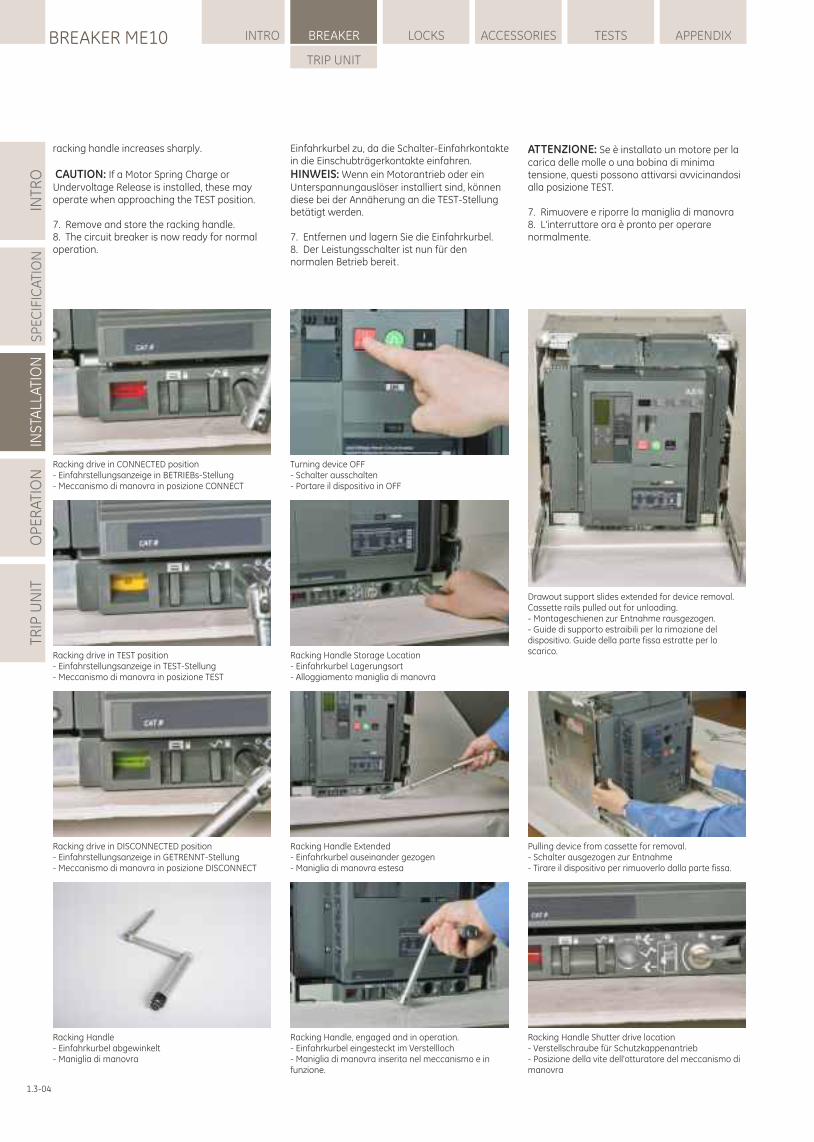
Racking drive in CONNECTED position- Einfahrstellungsanzeige in BETRIEBs-Stellung- Meccanismo di manovra in posizione CONNECT
Racking drive in TEST position- Einfahrstellungsanzeige in TEST-Stellung- Meccanismo di manovra in posizione TEST
Racking drive in DISCONNECTED position- Einfahrstellungsanzeige in GETRENNT-Stellung- Meccanismo di manovra in posizione DISCONNECT
Turning device OFF- Schalter ausschalten- Portare il dispositivo in OFF
Racking Handle Storage Location- Einfahrkurbel Lagerungsort- Alloggiamento maniglia di manovra
Racking Handle Extended- Einfahrkurbel auseinander gezogen- Maniglia di manovra estesa
Racking Handle, engaged and in operation.- Einfahrkurbel eingesteckt im Verstellloch- Maniglia di manovra inserita nel meccanismo e in funzione.
Racking Handle Shutter drive location- Verstellschraube für Schutzkappenantrieb- Posizione della vite dell'otturatore del meccanismo di manovra
Drawout support slides extended for device removal. Cassette rails pulled out for unloading.- Montageschienen zur Entnahme rausgezogen.- Guide di supporto estraibili per la rimozione del dispositivo. Guide della parte fissa estratte per lo scarico.
Pulling device from cassette for removal.- Schalter ausgezogen zur Entnahme- Tirare il dispositivo per rimuoverlo dalla parte fissa.
Racking Handle- Einfahrkurbel abgewinkelt- Maniglia di manovra
INTR
OS
PE
CIF
ICA
TIO
NIN
STA
LLAT
ION
OP
ER
ATI
ON
TRIP
UN
ITLOCKSBREAKER ME10 INTRO BREAKER ACCESSORIES TESTS APPENDIX
TRIP UNIT
1.3-04
ATTENZIONE: Se è installato un motore per la carica delle molle o una bobina di minima tensione, questi possono attivarsi avvicinandosi alla posizione TEST.
7. Rimuovere e riporre la maniglia di manovra8. L'interruttore ora è pronto per operare normalmente.
racking handle increases sharply.
CAUTION: If a Motor Spring Charge or Undervoltage Release is installed, these may operate when approaching the TEST position.
7. Remove and store the racking handle.8. The circuit breaker is now ready for normal operation.
Einfahrkurbel zu, da die Schalter-Einfahrkontakte in die Einschubträgerkontakte einfahren.
HINWEIS: Wenn ein Motorantrieb oder ein Unterspannungauslöser installiert sind, können diese bei der Annäherung an die TEST-Stellung betätigt werden.
7. Entfernen und lagern Sie die Einfahrkurbel.8. Der Leistungsschalter ist nun für den normalen Betrieb bereit.
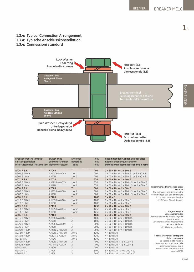
BREAKER ME10BREAKER
INS
TALL
ATI
ON
1.3
1.3-05
Breaker terminalLeistungsschalter-SchieneTerminale dell'interruttore
Customer busAnlagen-SchieneSbarre
Customer busAnlagen-SchieneSbarre
Hex Nut (8.8)SchraubenmutterDado esagonale (8.8)
Hex Bolt (8.8)AnschlussschraubeVite esagonale (8.8)
Lock WasherFederring
Rondella di sicurezza
Plain Washer (Heavy duty)Unterlegscheibe
Rondella piana (heavy duty)
1.3.4: Typical Connection Arrangement1.3.4: Typische Anschlusskonstellation1.3.4: Connessioni standard
Recommended Connection Cross sections
The adjacent table indicates the recommended bus bar dimensions
to be used in connecting the
ME10 Power Circuit Breaker.
Vorgeschlagene Leiterquerschnitte:
Die nebenstehende Tabelle zeigt die vorgeschlagenen
Schienenanschluss-Querschnitte der verschiedenen
ME10 Leistungsschalter.
Sezioni trasversali consigliate delle connessioni
La tabella a lato indica le dimensioni raccomandate delle
sbarre da utilizzare per la connessione dell'interruttore
aperto ME10
Breaker type 'Automatic' Switch Type Envelope In (A) Recommended Copper Bus Bar sizesLeistungsschalter Leistungstrenner Baugröße In (A) KupferschienenquerschnitteInterruttore tipo 'Automatico' Tipo interruttore Taglia In (A) Dimensioni raccomandate sbarre in rame--------------------------------------------------------------------------------------------------------------------------------------------------AT04, R & K A704R T 400 1 x 30 x 10 or 2 x 30 x 5AG04, S N & H AJ04S & AW04N 1 or 2 400 1 x 40 x 10 or 1 x 80 x 5 or 2 x 40 x 5AG04 E & M AJ04H 1 or 2 400 1 x 40 x 10 or 1 x 80 x 5 or 2 x 40 x 5AT07, R & K A707R T 630 1 x 40 x 10 or 2 x 40 x 5AG07, S N & H AJ07S & AW07N 1 or 2 630 1 x 50 x 10 or 1 x 100 x 5 or 2 x 50 x 5AG07 E & M AJ07H 1 or 2 630 1 x 50 x 10 or 1 x 100 x 5 or 2 x 50 x 5AT08, R & K A708R T 800 1 x 50 x 10 or 2 x 50 x 5AG08, S N & H AJ08S & AW08N 1 or 2 800 1 x 50 x 10 or 1 x 100 x 5 or 2 x 50 x 5AG08 E & M AJ08H 1 or 2 800 1 x 50 x 10 or 1 x 100 x 5 or 2 x 50 x 5AT10, R & K A710R T 1000 3 x 40 x 5AG10, S N & H AJ10S & AW10N 1 or 2 1000 1 x 60 x 10 or 2 x 60 x 5AG10 E & M AJ10H 1 or 2 1000 1 x 60 x 10 or 2 x 60 x 5AT13, R & K A713R T 1250 2 x 40 x 10 or 4 x 40 x 5AG13, S N & H AJ13S & AW13N 1 or 2 1250 2 x 40 x 10 or 2 x 80 x 5AG13 E & M AJ13H 1 or 2 1250 2 x 40 x 10 or 2 x 80 x 5AT16, R & K A716R T 1600 2 x 50 x 10 or 4 x 50 x 5AG16, S N & H AJ16S & AW16N 1 1600 2 x 50 x 10 or 2 x 100 x 5AG16 E & M AJ16H 2 1600 2 x 50 x 10 or 2 x 100 x 5AG20, S N & H AJ20S & AW20N 1 2000 3 x 50 x 10 or 3 x 100 x 5AG20 E & M AJ20H 2 2000 3 x 50 x 10 or 3 x 100 x 5AG25N, H & M AJ25N & AW25H 2 2500 4 x 50 x 10 or 4 x 100 x 5AG32N, H & M AJ32N & AW32H 2 or 3 3200 4 x 100 x 10AH32N, H & M AK32N & AZ32H 2 or 3 3200 4 x 100 x 10AG32G & L AJ32G 2 or 3 3200 4 x 100 x 10AG40N, H & M AJ40N & AW40H 2 4000 4 x 100 x 10 + 1 x 100 x 5AH40N, H & M AK40N & AZ40H 2 4000 4 x 100 x 10 + 1 x 100 x 5AG40G & L AJ40G 3 4000 4 x 100 x 10AG50M & L CJ50L 3 5000 5 x 120 x 10 or 6 x 100 x 10AG64M & L CJ64L 3 6400 7 x 120 x 10 or 8 x 100 x 10
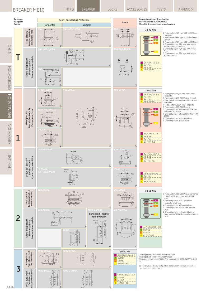
INTR
OS
PE
CIF
ICA
TIO
NIN
STA
LLAT
ION
OP
ER
ATI
ON
TRIP
UN
ITLOCKSBREAKER ME10 INTRO BREAKER ACCESSORIES TESTS APPENDIX
1.3-06
20
65
30
25
R6.5
A 3x M10x60 - 8.8
B 6x M10
C 6x M10
D 3x M10 - 8.81
38-42 Nm
2x M10 x 60 -8.8B 4x M10 C 4x M10 D 2x M10 -8.8
A
1)
2)
3)
5)4)
50
29
25
17 R6.5
Ø 1315
34
.53
1
50
13 1
7
65
27,518,75
15,5
65
2222Ø 12
11
17
65
30
25R6.5
17
S 400-1600A
N&H 400-1600A
S 400-1600A
6)
15
3025
17.5
R6.558
S 2000AN&H 400-2000A
2 holesØ 12
58
15
31
17
8
7)
2x M10 x 60 -8.8B 4x M10 C 4x M10 D 2x M10 -8.8
A
8)
9)
65
2222Ø 12
11
17
A 3x M10x60 - 8.8
B 6x M10
C 6x M10
D 3x M10 - 8.8
400-2000A 400-2000A
2000A
400-1600A
2000A
Fixe
d p
att
ern
Fest
ein
ba
ute
chn
ikE
secu
zio
ne
fis
sa
Dra
w-o
ut
pa
tte
rnE
infa
hrt
ech
nik
Ese
cuzi
on
e e
stra
ibile
13 25 25 25
4 holesØ 13
14
25
25
25
13
13
15
90
4 holes Ø 13
A 4x M12x60/90 - 8.8
B 8x M12
C 8x M12
D 4x M12 - 8.8
2
50-60 Nm
1)
3)
2)
5)
400-3200A
4)6)
95
10 25 25 25Ø 13
17
12.5 25 25 25 Ø 13
100
17
100
12.5 25 25 25
Ø 12
20
58
4 holesØ 13
13
12
25
25
25
13
3200 & 4000A
4000A
Enhanced Thermalrated version
400 & 4000A
400-4000A 400-4000A
Fixe
d p
att
ern
Fest
ein
ba
ute
chn
ikE
secu
zio
ne
fis
sa
Dra
w-o
ut
pa
tte
rnE
infa
hrt
ech
nik
Ese
cuzi
on
e e
stra
ibile
A 4x M12x60/90 - 8.8
B 8x M12
C 8x M12
D 4x M12 - 8.8
3
50-60 Nm
1)
3)
2)
4000-5000A 4000 & 6400A
88
30 3014
17
Ø 13A 3x M12x60/80 - 8.8
B 6x M12
C 6x M12
D 3x M12 - 8.818
12
0
25
25
25
Ø 13
4000-5000A 4000-6400A
51
18
Ø 13
25
25
25
3)
51
18
Ø 13
25
25
25
Fixe
d p
att
ern
Fest
ein
ba
ute
chn
ikE
secu
zio
ne
fis
sa
Dra
w-o
ut
pa
tte
rnE
infa
hrt
ech
nik
Ese
cuzi
on
e e
stra
ibile
25.022.0
R5.5TYP
R5.5TYP
45.0
17.0
25.0
22.0
22
25
20R5.5TYP
1725
44
22
35
25
22
R5.5TYP
17
44.0
R5.5TYP
44 2225
17
Fixe
d p
att
ern
Fest
ein
ba
ute
chn
ikE
secu
zio
ne
fis
sa
T
38-42 Nm
Dra
w-o
ut
pa
tte
rnE
infa
hrt
ech
nik
Ese
cuzi
on
e e
stra
ibile
2x M10 x 60 -8.8B 4x M10 C 4x M10 D 2x M10 -8.8
A
1) 2) 3)
4)
5)6)
R&K
R&K 400-1600AR&K R&K
R&K 400-1600AR&K 400-1600A
Horizontal VerticalFront
Rear | Rückseitig | Posteriore Connection modes & applicationAnschlussarten & AusführungModalità di connessione e applicazione
A
B
C
D
EnvelopeBaugrößeTaglia
1) Fixed pattern R&K type 400-1600A Rear Horizontal
2) Fixed pattern R&K type 400-1600A Rear Vertical
3) Fixed pattern R&K type 400-1600A Front4) Drawout pattern R&K type 400-1600A
Rear Horizontal or Vertical5) Drawout pattern R&K type 400-1600A
Front6) Drawout pattern R&K type 400-1600A
Rear Horizontal
1) Fixed pattern S type 400-1600A Rear Horizontal
2) Fixed pattern 400-2000A Rear Vertical3) Fixed pattern N&H type 400-1600A Rear
Horizontal4) Fixed pattern 2000A Rear Horizontal5) Fixed pattern 400-2000A Front6) Drawout pattern S type 400-1600A Rear
Horizontal or Vertical7) Drawout pattern S type 2000A, N&H 400-
2000A 8) Drawout pattern 400-1600A Front9) Drawout pattern 2000A Front
1) Fixed pattern 400-4000A Rear Horizontal or Vertical2) Fixed pattern 400-4000A Front
3) Drawout pattern 400-3200A Rear Horizontal or Vertical
4) Drawout pattern 400-4000A Front5) Drawout pattern 4000A Rear Vertical
ONLY6) Drawout pattern -enhanced thermal
rated version 3200A & 4000A Rear Vertical ONLY
1) Fixed pattern 4000-5000A Rear Horizontal2) Fixed pattern 4000-6400A Rear Vertical3) Drawout pattern 4000-5000A Rear Horizontal or 4000-6400A Vertical
(1)
(1) The envelope 3 draw-out pattern construction has two connection pads per connection point.
A
B
C
D
A
B
C
D
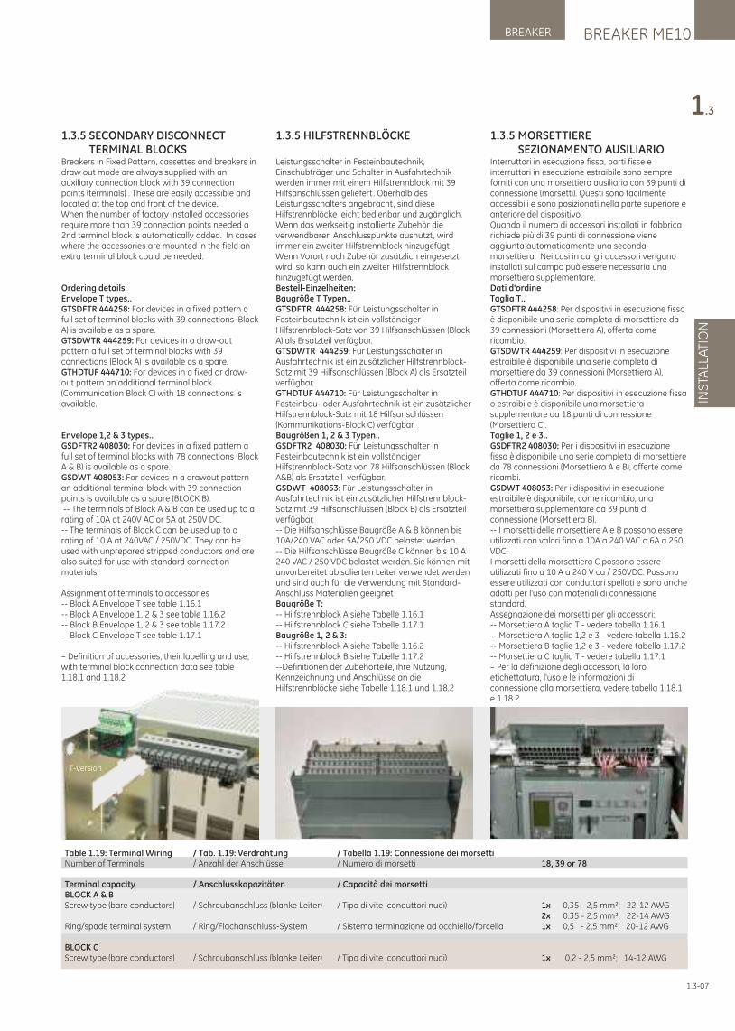
BREAKER ME10BREAKER
INS
TALL
ATI
ON
1.3
1.3.5 MORSETTIERE SEZIONAMENTO AUSILIARIOInterruttori in esecuzione fissa, parti fisse e interruttori in esecuzione estraibile sono sempre forniti con una morsettiera ausiliaria con 39 punti di connessione (morsetti). Questi sono facilmente accessibili e sono posizionati nella parte superiore e anteriore del dispositivo. Quando il numero di accessori installati in fabbrica richiede più di 39 punti di connessione viene aggiunta automaticamente una seconda morsettiera. Nei casi in cui gli accessori vengano installati sul campo può essere necessaria una morsettiera supplementare.Dati d'ordineTaglia T..GTSDFTR 444258: Per dispositivi in esecuzione fissa è disponibile una serie completa di morsettiere da 39 connessioni (Morsettiera A), offerta come ricambio. GTSDWTR 444259: Per dispositivi in esecuzione estraibile è disponibile una serie completa di morsettiere da 39 connessioni (Morsettiera A), offerta come ricambio. GTHDTUF 444710: Per dispositivi in esecuzione fissa o estraibile è disponibile una morsettiera supplementare da 18 punti di connessione (Morsettiera C).Taglie 1, 2 e 3..GSDFTR2 408030: Per i dispositivi in esecuzione fissa è disponibile una serie completa di morsettiere da 78 connessioni (Morsettiera A e B), offerte come ricambi.GSDWT 408053: Per i dispositivi in esecuzione estraibile è disponibile, come ricambio, una morsettiera supplementare da 39 punti di connessione (Morsettiera B).-- I morsetti delle morsettiere A e B possono essere utilizzati con valori fino a 10A a 240 VAC o 6A a 250 VDC. I morsetti della morsettiera C possono essere utilizzati fino a 10 A a 240 V ca / 250VDC. Possono essere utilizzati con conduttori spellati e sono anche adatti per l'uso con materiali di connessione standard.Assegnazione dei morsetti per gli accessori:-- Morsettiera A taglia T - vedere tabella 1.16.1-- Morsettiera A taglie 1,2 e 3 - vedere tabella 1.16.2-- Morsettiera B taglie 1,2 e 3 - vedere tabella 1.17.2-- Morsettiera C taglia T - vedere tabella 1.17.1– Per la definizione degli accessori, la loro etichettatura, l'uso e le informazioni diconnessione alla morsettiera, vedere tabella 1.18.1 e 1.18.2
T-version
1.3.5 SECONDARY DISCONNECT TERMINAL BLOCKSBreakers in Fixed Pattern, cassettes and breakers in draw out mode are always supplied with an auxiliary connection block with 39 connection points (terminals) . These are easily accessible and located at the top and front of the device. When the number of factory installed accessories require more than 39 connection points needed a 2nd terminal block is automatically added. In cases where the accessories are mounted in the field an extra terminal block could be needed.
Ordering details:Envelope T types..GTSDFTR 444258: For devices in a fixed pattern a full set of terminal blocks with 39 connections (Block A) is available as a spare.GTSDWTR 444259: For devices in a draw-out pattern a full set of terminal blocks with 39 connections (Block A) is available as a spare.GTHDTUF 444710: For devices in a fixed or draw-out pattern an additional terminal block (Communication Block C) with 18 connections is available.
Envelope 1,2 & 3 types..GSDFTR2 408030: For devices in a fixed pattern a full set of terminal blocks with 78 connections (Block A & B) is available as a spare.GSDWT 408053: For devices in a drawout pattern an additional terminal block with 39 connection points is available as a spare (BLOCK B). -- The terminals of Block A & B can be used up to a rating of 10A at 240V AC or 5A at 250V DC. -- The terminals of Block C can be used up to arating of 10 A at 240VAC / 250VDC. They can be used with unprepared stripped conductors and are also suited for use with standard connection materials.
Assignment of terminals to accessories-- Block A Envelope T see table 1.16.1-- Block A Envelope 1, 2 & 3 see table 1.16.2-- Block B Envelope 1, 2 & 3 see table 1.17.2-- Block C Envelope T see table 1.17.1
– Definition of accessories, their labelling and use, with terminal block connection data see table 1.18.1 and 1.18.2
1.3.5 HILFSTRENNBLÖCKE
Leistungsschalter in Festeinbautechnik, Einschubträger und Schalter in Ausfahrtechnik werden immer mit einem Hilfstrennblock mit 39 Hilfsanschlüssen geliefert. Oberhalb des Leistungsschalters angebracht, sind diese Hilfstrennblöcke leicht bedienbar und zugänglich.Wenn das werkseitig installierte Zubehör die verwendbaren Anschlusspunkte ausnutzt, wird immer ein zweiter Hilfstrennblock hinzugefügt. Wenn Vorort noch Zubehör zusätzlich eingesetzt wird, so kann auch ein zweiter Hilfstrennblock hinzugefügt werden.Bestell-Einzelheiten:Baugröße T Typen..GTSDFTR 444258: Für Leistungsschalter in Festeinbautechnik ist ein vollständiger Hilfstrennblock-Satz von 39 Hilfsanschlüssen (Block A) als Ersatzteil verfügbar.GTSDWTR 444259: Für Leistungsschalter in Ausfahrtechnik ist ein zusätzlicher Hilfstrennblock-Satz mit 39 Hilfsanschlüssen (Block A) als Ersatzteil verfügbar.GTHDTUF 444710: Für Leistungsschalter in Festeinbau- oder Ausfahrtechnik ist ein zusätzlicher Hilfstrennblock-Satz mit 18 Hilfsanschlüssen (Kommunikations-Block C) verfügbar.Baugrößen 1, 2 & 3 Typen..GSDFTR2 408030: Für Leistungsschalter in Festeinbautechnik ist ein vollständiger Hilfstrennblock-Satz von 78 Hilfsanschlüssen (Block A&B) als Ersatzteil verfügbar.GSDWT 408053: Für Leistungsschalter in Ausfahrtechnik ist ein zusätzlicher Hilfstrennblock-Satz mit 39 Hilfsanschlüssen (Block B) als Ersatzteil verfügbar.-- Die Hilfsanschlüsse Baugröße A & B können bis 10A/240 VAC oder 5A/250 VDC belastet werden.-- Die Hilfsanschlüsse Baugröße C können bis 10 A240 VAC / 250 VDC belastet werden. Sie können mitunvorbereitet abisolierten Leiter verwendet werdenund sind auch für die Verwendung mit Standard-Anschluss Materialien geeignet.Baugröße T:-- Hilfstrennblock A siehe Tabelle 1.16.1-- Hilfstrennblock C siehe Tabelle 1.17.1Baugröße 1, 2 & 3:-- Hilfstrennblock A siehe Tabelle 1.16.2-- Hilfstrennblock B siehe Tabelle 1.17.2--Definitionen der Zubehörteile, ihre Nutzung, Kennzeichnung und Anschlüsse an die Hilfstrennblöcke siehe Tabelle 1.18.1 und 1.18.2
Table 1.19: Terminal Wiring / Tab. 1.19: Verdrahtung / Tabella 1.19: Connessione dei morsetti Number of Terminals / Anzahl der Anschlüsse / Numero di morsetti 18, 39 or 78
Terminal capacity / Anschlusskapazitäten / Capacità dei morsetti BLOCK A & BScrew type (bare conductors) / Schraubanschluss (blanke Leiter) / Tipo di vite (conduttori nudi) 1x 0,35 - 2,5 mm²; 22-12 AWG 2x 0.35 - 2.5 mm²; 22-14 AWGRing/spade terminal system / Ring/Flachanschluss-System / Sistema terminazione ad occhiello/forcella 1x 0,5 - 2,5 mm²; 20-12 AWG
BLOCK CScrew type (bare conductors) / Schraubanschluss (blanke Leiter) / Tipo di vite (conduttori nudi) 1x 0,2 - 2,5 mm²; 14-12 AWG
1.3-07
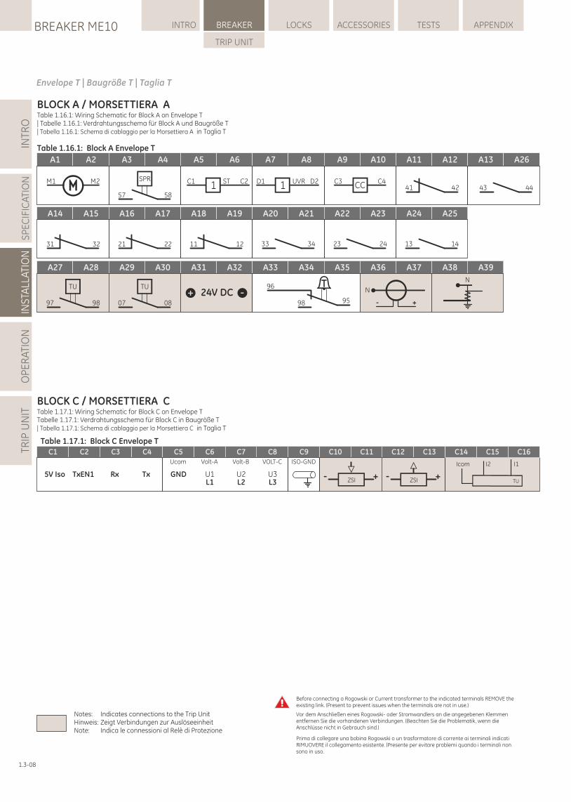
INTR
OS
PE
CIF
ICA
TIO
NIN
STA
LLAT
ION
OP
ER
ATI
ON
TRIP
UN
ITLOCKSBREAKER ME10 INTRO BREAKER ACCESSORIES TESTS APPENDIX
TRIP UNIT
1.3-08
BLOCK A / AMORSETTIERA Table 1.16.1: Wiring Schematic for Block A on Envelope T | Tabelle 1.16.1: Verdrahtungsschema für Block A und Baugröße T| Tabella 1.16.1: Schema di cablaggio per la Morsettiera A in Taglia T
A1 A2 A3 A4 A5 A6 A7 A8 A9 A10 A11 A12 A13
M1 M2 SPR
57 58
C1 ST C21 C3 C4CCD1 UVR D21
A14 A15 A16 A17 A18 A19 A20 A21 A22 A23 A24 A25
31 32 21 22 11 12 33 34 23 24 13 14
A27 A28 A29 A30 A31 A32 A33 A34 A35 A36 A37 A39A38
TU
97 98
TU
07 08
96
98 95
N
- +
N
43 4441 42
A26
Table 1.16.1: Block A Envelope T
Table 1.17.1: Block C Envelope T
BLOCK C / MORSETTIERA CTable 1.17.1: Wiring Schematic for Block C on Envelope TTabelle 1.17.1: Verdrahtungsschema für Block C in Baugröße T| Tabella 1.17.1: Schema di cablaggio per la Morsettiera C in Taglia T
Envelope T | Baugröße T | Taglia T
C1 C2 C3 C4
TxEN1 Rx Tx5V Iso
C12 C13
ZSI- +
C10 C11
ZSI- +
C14 C15 C16
TU
I1I2Icom
C9ISO-GND
C8C5 C6 C7
GND U1 U2 U3
Ucom Volt-A Volt-B VOLT-C
L1 L2 L3
Vor dem Anschließen eines Rogowski- oder Stromwandlers an die angegebenen Klemmen entfernen Sie die vorhandenen Verbindungen. (Beachten Sie die Problematik, wenn die Anschlüsse nicht in Gebrauch sind.)
Before connecting a Rogowski or Current transformer to the indicated terminals REMOVE the existing link. (Present to prevent issues when the terminals are not in use.)
Prima di collegare una bobina Rogowski o un trasformatore di corrente ai terminali indicati RIMUOVERE il collegamento esistente. (Presente per evitare problemi quando i terminali non sono in uso.
Notes: Indicates connections to the Trip UnitHinweis: Zeigt Verbindungen zur AuslöseeinheitNote: Indica le connessioni al Relè di Protezione
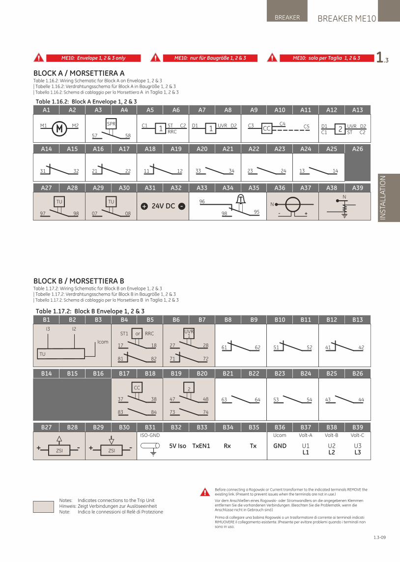
ME10: Envelope 1, 2 & 3 only ME10: nur für Baugröße 1, 2 & 3 ME10: solo per Taglia 1, 2 & 3
Table 1.17.2: Block B Envelope 1, 2 & 3
BLOCK B / BMORSETTIERATable 1.17.2: Wiring Schematic for Block B on Envelope 1, 2 & 3 | Tabelle 1.17.2: Verdrahtungsschema für Block B in Baugröße 1, 2 & 3 | Tabella 1.17.2: Schema di cablaggio per la Morsettiera B in Taglia 1, 2 & 3
A1 A2 A3 A4 A5 A6 A7 A8 A9 A10 A11 A12 A13
M1 M2 SPR
57 58
D1C1
UVR D2ST C22
C1 ST C2RRC1 C3 C4
CC C5D1 UVR D21
A26A14 A15 A16 A17 A18 A19 A20 A21 A22 A23 A24 A25
31 32 21 22 11 12 33 34 23 24 13 14
A27 A28 A29 A30 A31 A32 A33 A34 A35 A36 A37 A39A38
TU
97 98
TU
07 08
96
98 95
N
- +
N
Table 1.16.2: Block A Envelope 1, 2 & 3
BLOCK A / MORSETTIERA ATable 1.16.2: Wiring Schematic for Block A on Envelope 1, 2 & 3 | Tabelle 1.16.2: Verdrahtungsschema für Block A in Baugröße 1, 2 & 3| Tabella 1.16.2: Schema di cablaggio per la Morsettiera A in Taglia 1, 2 & 3
1.3-09
B1 B2 B3 B4 B5 B6 B7 B8 B9 B10 B11 B12 B13
ST1 or RRC
17 18
81 82
UVR1
27 28
71 72TU
I3 I2
Icom61 62 51 52 41 42
B26B17 B18 B19 B20 B21 B22 B23 B24 B25
63 64 53 54 43 44
CC
37 38
83 84
2
47 48
73 74
B27 B28 B29 B30
ZSI+ - ZSI+ -
B14 B15 B16
B31 B32 B33 B34 B35
TxEN1 Rx Tx5V Iso
ISO-GND
B39B36 B37 B38
GND U1 U2 U3
Volt-A Volt-B Volt-C
L1 L2 L3
Ucom
Vor dem Anschließen eines Rogowski- oder Stromwandlers an die angegebenen Klemmen entfernen Sie die vorhandenen Verbindungen. (Beachten Sie die Problematik, wenn die Anschlüsse nicht in Gebrauch sind.)
Before connecting a Rogowski or Current transformer to the indicated terminals REMOVE the existing link. (Present to prevent issues when the terminals are not in use.)
Prima di collegare una bobina Rogowski o un trasformatore di corrente ai terminali indicati RIMUOVERE il collegamento esistente. (Presente per evitare problemi quando i terminali non sono in uso.
Notes: Indicates connections to the Trip UnitHinweis: Zeigt Verbindungen zur AuslöseeinheitNote: Indica le connessioni al Relè di Protezione
BREAKER ME10BREAKER
INS
TALL
ATI
ON
1.3
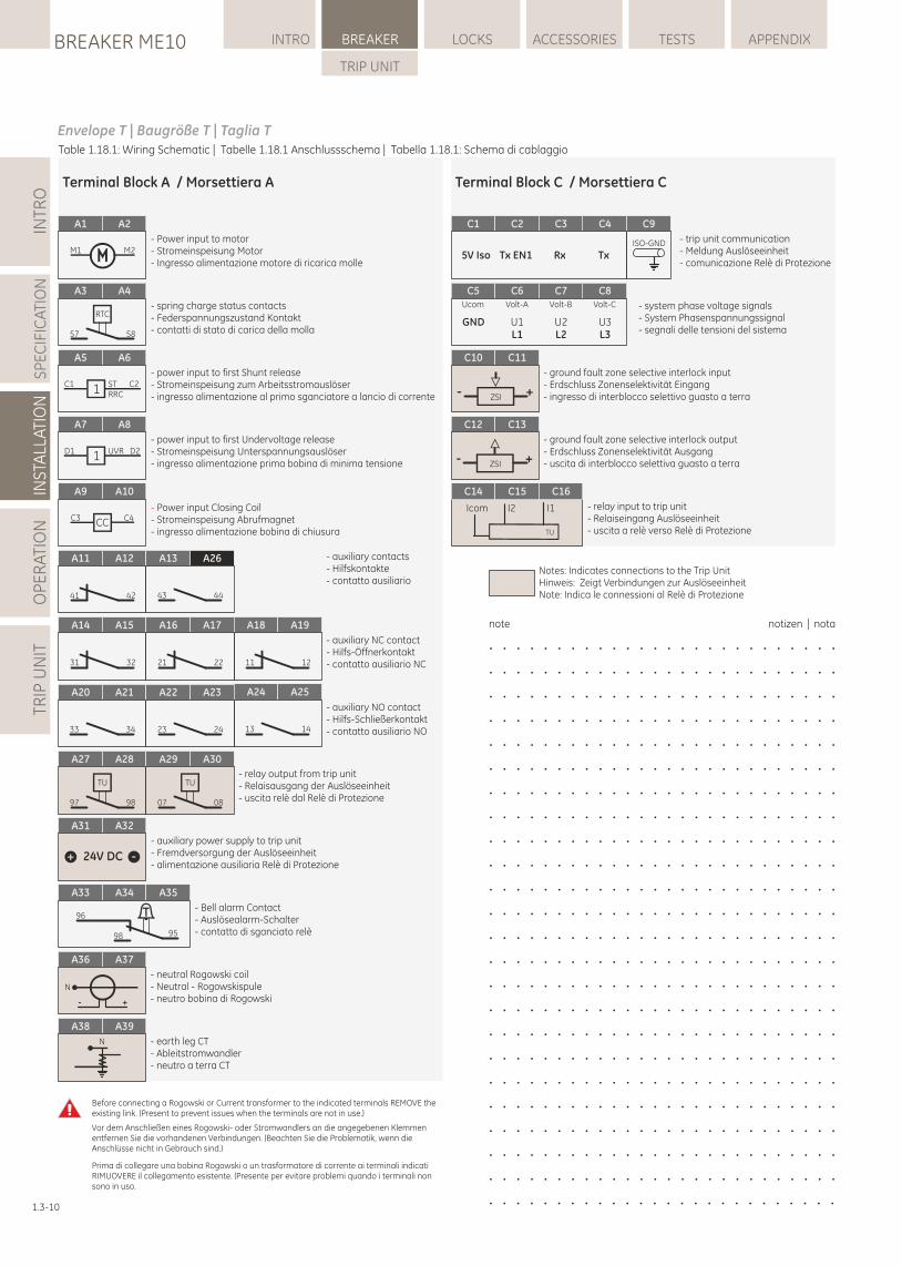
INTR
OS
PE
CIF
ICA
TIO
NIN
STA
LLAT
ION
OP
ER
ATI
ON
TRIP
UN
ITLOCKSBREAKER ME10 INTRO BREAKER ACCESSORIES TESTS APPENDIX
TRIP UNIT
1.3-10
Table 1.18.1: Wiring Schematic | Tabelle 1.18.1 Anschlussschema | Tabella 1.18.1: Schema di cablaggio
Notes: Indicates connections to the Trip UnitHinweis: Zeigt Verbindungen zur AuslöseeinheitNote: Indica le connessioni al Relè di Protezione
note notizen | nota
. . . . . . . . . . . . . . . . . . . . . . . . . .
. . . . . . . . . . . . . . . . . . . . . . . . . .
. . . . . . . . . . . . . . . . . . . . . . . . . .
. . . . . . . . . . . . . . . . . . . . . . . . . .
. . . . . . . . . . . . . . . . . . . . . . . . . .
. . . . . . . . . . . . . . . . . . . . . . . . . .
. . . . . . . . . . . . . . . . . . . . . . . . . .
. . . . . . . . . . . . . . . . . . . . . . . . . .
. . . . . . . . . . . . . . . . . . . . . . . . . .
. . . . . . . . . . . . . . . . . . . . . . . . . .
. . . . . . . . . . . . . . . . . . . . . . . . . .
. . . . . . . . . . . . . . . . . . . . . . . . . .
. . . . . . . . . . . . . . . . . . . . . . . . . .
. . . . . . . . . . . . . . . . . . . . . . . . . .
. . . . . . . . . . . . . . . . . . . . . . . . . .
. . . . . . . . . . . . . . . . . . . . . . . . . .
. . . . . . . . . . . . . . . . . . . . . . . . . .
. . . . . . . . . . . . . . . . . . . . . . . . . .
. . . . . . . . . . . . . . . . . . . . . . . . . .
. . . . . . . . . . . . . . . . . . . . . . . . . .
. . . . . . . . . . . . . . . . . . . . . . . . . .
. . . . . . . . . . . . . . . . . . . . . . . . . .
. . . . . . . . . . . . . . . . . . . . . . . . . .
. . . . . . . . . . . . . . . . . . . . . . . . . .
Terminal Block A / Morsettiera A
A7 A8
D1 UVR D21
- power input to first Undervoltage release- Stromeinspeisung Unterspannungsauslöser- ingresso alimentazione prima bobina di minima tensione
A5 A6
C1 ST C2RRC1
- power input to first Shunt release- Stromeinspeisung zum Arbeitsstromauslöser- ingresso alimentazione al primo sganciatore a lancio di corrente
A1 A2
M1 M2- Power input to motor- Stromeinspeisung Motor- Ingresso alimentazione motore di ricarica molle
A3 A4
RTC
57 58
- spring charge status contacts - Federspannungszustand Kontakt - contatti di stato di carica della molla
A9 A10
C3 C4CC
- Power input Closing Coil- Stromeinspeisung Abrufmagnet- ingresso alimentazione bobina di chiusura
A27 A28
TU
97 98
A29 A30
TU
07 08
- relay output from trip unit- Relaisausgang der Auslöseeinheit- uscita relè dal Relè di Protezione
A31 A32
- auxiliary power supply to trip unit- Fremdversorgung der Auslöseeinheit- alimentazione ausiliaria Relè di Protezione
A33 A34 A35
96
98 95
- Bell alarm Contact- Auslösealarm-Schalter- contatto di sganciato relè
A36 A37
N
- +
- neutral Rogowski coil- Neutral - Rogowskispule- neutro bobina di Rogowski
A39A38
N - earth leg CT- Ableitstromwandler- neutro a terra CT
A14 A15
31 32
A16 A17
21 22
A18 A19
11 12
- auxiliary NC contact- Hilfs-Öffnerkontakt- contatto ausiliario NC
A20 A21
33 34
A22 A23
23 24
A24 A25
13 14
- auxiliary NO contact- Hilfs-Schließerkontakt- contatto ausiliario NO
A11 A12
41 42
- auxiliary contacts- Hilfskontakte- contatto ausiliario
A13 A26
43 44
Envelope T | Baugröße T | Taglia T
Terminal Block C / Morsettiera C
- trip unit communication- Meldung Auslöseeinheit- comunicazione Relè di Protezione
- system phase voltage signals- System Phasenspannungssignal- segnali delle tensioni del sistema
- ground fault zone selective interlock output- Erdschluss Zonenselektivität Ausgang- uscita di interblocco selettiva guasto a terra
C12 C13
ZSI- +
- relay input to trip unit- Relaiseingang Auslöseeinheit- uscita a relè verso Relè di Protezione
C14 C15 C16
TU
I1I2Icom
- ground fault zone selective interlock input- Erdschluss Zonenselektivität Eingang- ingresso di interblocco selettivo guasto a terra
C10 C11
ZSI- +
C1 C2 C3 C4
Tx EN1 Rx Tx5V Iso
C9
ISO-GND
C8C5 C6 C7
GND U1 U2 U3
Volt-AUcom Volt-B Volt-C
L1 L2 L3
Vor dem Anschließen eines Rogowski- oder Stromwandlers an die angegebenen Klemmen entfernen Sie die vorhandenen Verbindungen. (Beachten Sie die Problematik, wenn die Anschlüsse nicht in Gebrauch sind.)
Before connecting a Rogowski or Current transformer to the indicated terminals REMOVE the existing link. (Present to prevent issues when the terminals are not in use.)
Prima di collegare una bobina Rogowski o un trasformatore di corrente ai terminali indicati RIMUOVERE il collegamento esistente. (Presente per evitare problemi quando i terminali non sono in uso.
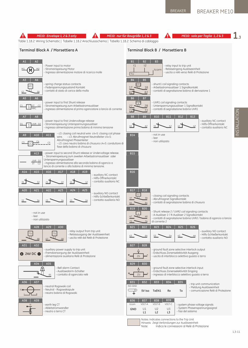
1.3-11
Table 1.18.2: Wiring Schematic | Tabelle 1.18.2 Anschlussschema | Tabella 1.18.2: Schema di cablaggio
A7 A8
D1 UVR D21
A5 A6
C1 ST C2RRC1
A1 A2
M1 M2
A3 A4
RTC
57 58
A13
UVR D2ST C2
A9 A10 A11
C3 C4CC C5
A14 A15
31 32
A16 A17
21 22
A18 A19
11 12
A20 A21
33 34
A22 A23
23 24
A24 A25
13 14
A28
TU
98
A29 A30
TU
07 08
- relay output from trip unit- Relaisausgang der Auslöseeinheit- uscita relè dal Relè di Protezione
A31 A32
- auxiliary power supply to trip unit- Fremdversorgung der Auslöseeinheit- alimentazione ausiliaria Relè di Protezione
A34 A35
95
- Bell alarm Contact- Auslösealarm-Schalter- contatto di sganciato relè
A36 A37
N
- +
- neutral Rogowski coil- Neutral - Rogowskispule- neutro bobina di Rogowski
A39A38
N - earth leg CT- Ableitstromwandler- neutro a terra CT
Terminal Block A / Morsettiera A
Notes: Indicates connections to the Trip UnitHinweis: Zeigt Verbindungen zur AuslöseeinheitNote: Indica le connessioni al Relè di Protezione
ME10: Envelope 1, 2 & 3 only ME10: nur für Baugröße 1, 2 & 3 ME10: solo per Taglia 1, 2 & 3
B4 B5
ST117 18
81 82
B8 B9
61 62
B10 B11
51 52
B12 B13
41 42
B21 B22
63 64
B23 B24
53 54
B26B25
43 44
B14
B15
B17 B18
CC
37 38
83 84
B19 B20
2
47 48
73 74
B6 B7UVR
1
27 28
71 72
B27 B28
ZSI+ -
B29 B30
ZSI+ -
B16
B1 B2 B3
TU
I1 I2
Icom
Terminal Block B / Morsettiera B
B31 B32 B33 B34
TxEN1 Rx Tx
B35
5V Iso
ISO-GND
GND
B36 B37 B38
U1 U2 U3
B39
L1 L2 L3
VOLT-CVOLT-BVOLT-AUcom
- power input to first Undervoltage release- Stromeinspeisung Unterspannungsauslöser- ingresso alimentazione prima bobina di minima tensione
- power input to first Shunt release- Stromeinspeisung zum Arbeitsstromauslöser- ingresso alimentazione al primo sganciatore a lancio di corrente
- Power input to motor- Stromeinspeisung Motor- Ingresso alimentazione motore di ricarica molle
- spring charge status contacts - Federspannungszustand Kontakt - contatti di stato di carica della molla
- c3: closing coil neutral wire c4+5: closing coil phase wire. - c3: Abrufmagnet Neutralleiter c4+5: Abrufmagnet Phasenleiter- c3: cavo neutro bobina di chiusura c4+5: conduttore di fase della bobina di chiusura
- power input to second Shunt release or Undervoltage release. - Stromeinspeisung zum zweiten Arbeitsstromauslöser oder Unterspannungsauslöser- ingresso alimentazione alla seconda bobina di sgancio a lancio di corrente o alla bobina di minima tensione.
- auxiliary NC contact- Hilfs-Öffnerkontakt- contatto ausiliario NC
- auxiliary NO contact- Hilfs-Schließerkontakt- contatto ausiliario NO
- not in use- leer- non utilizzato
- relay input to trip unit- Relaiseingang Auslöseeinheit- uscita a relè verso Relè di Protezione
- auxiliary NC contact- Hilfs-Öffnerkontakt- contatto ausiliario NC
- auxiliary NO contact- Hilfs-Schließerkontakt- contatto ausiliario NO
- trip unit communication- Meldung Auslöseeinheit- comunicazione Relè di Protezione
- system phase voltage signals- System Phasenspannungssignal- fasi del sistema
- closing coil signaling contacts - Abrufmagnet Signalkontakt- contatti di segnalazione bobina di chiusura
- shunt1 coil signaling contacts- Arbeitsstromauslöser 1 Signalkontakt- contatti di segnalazione bobina di derivazione 1
- Shunt release 2 / UVR2 coil signaling contacts- A-Auslöser 2 / R-Auslöser 2 Signalkontakt- contatti di segnalazione bobina UVR2 / bobina di sgancio a lancio di corrente 2
- UVR1 coil signaling contacts- Unterspannungsauslöser 1 Signalkontakt- contatti di segnalazione bobina UVR1
- ground fault zone selective interlock output- Erdschluss Zonenselektivität Ausgang- uscita di interblocco selettiva guasto a terra
- ground fault zone selective interlock input- Erdschluss Zonenselektivität Eingang- ingresso di interblocco selettivo guasto a terra
- not in use- leer- non utilizzato
BREAKER ME10BREAKER
INS
TALL
ATI
ON
1.3
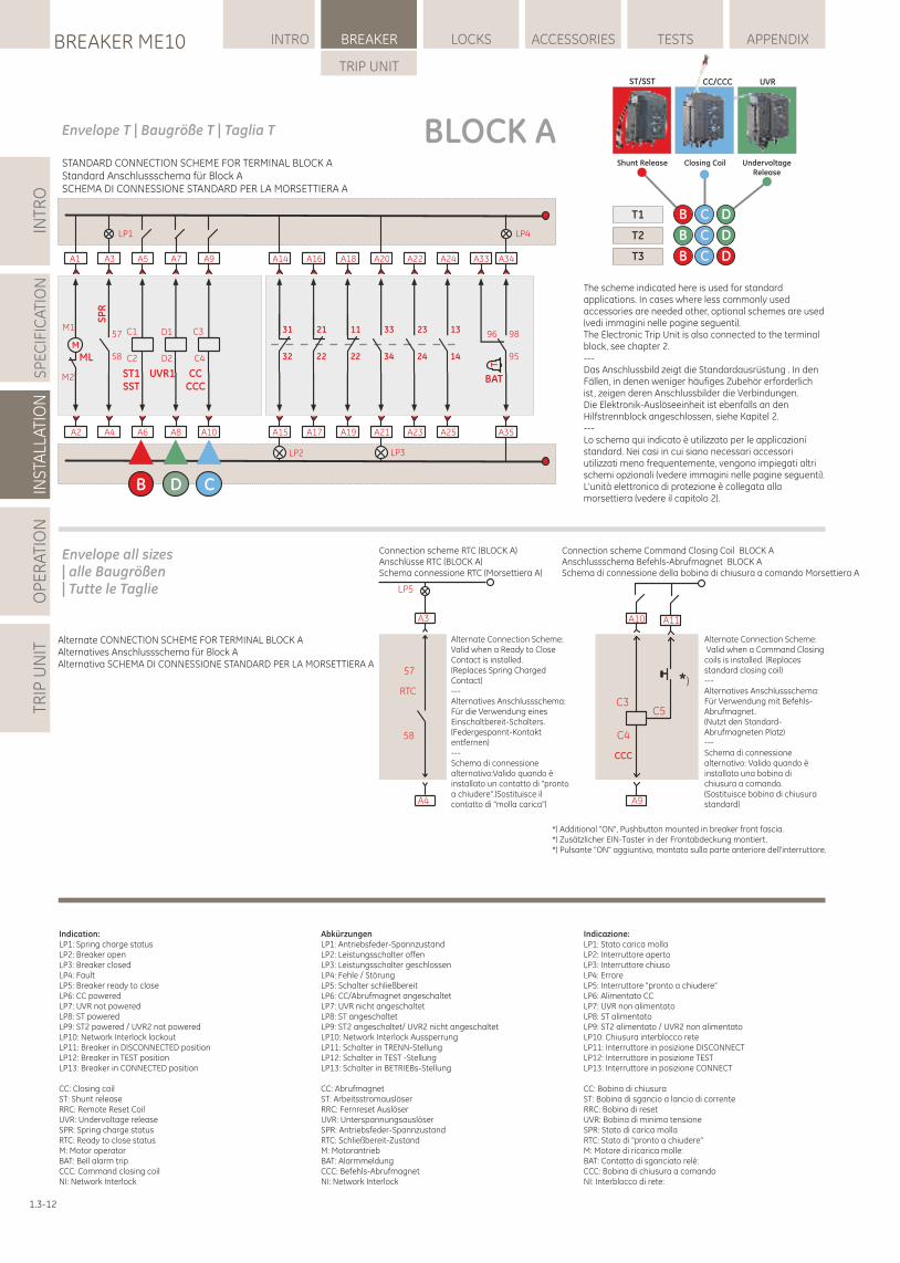
INTR
OS
PE
CIF
ICA
TIO
NIN
STA
LLAT
ION
OP
ER
ATI
ON
TRIP
UN
ITLOCKSBREAKER ME10 INTRO BREAKER ACCESSORIES TESTS APPENDIX
TRIP UNIT
1.3-12
BLOCK AEnvelope T | Baugröße T | Taglia T
A2
A1
M
ML
M1
M2
LP1
A4
A3
SP
R
58
57
A6
A5
C1
C2
ST1SST
B
A10
A9
C4
C3
CCCCC
C
A8
A7
UVR1
D1
D2
D
LP2
A15
A14
32
31
A17
A16
22
21
A19
A18
22
11
A23
A22
24
23
A25
A24
14
13
LP3
A21
A20
34
33
LP4
A35
A34
95
98
T
BAT
A33
96
UndervoltageRelease
Closing CoilShunt Release
T1
T2
T3
DCB
DCB
DCB
ST/SST CC/CCC UVR
STANDARD CONNECTION SCHEME FOR TERMINAL BLOCK AStandard Anschlussschema für Block ASCHEMA DI CONNESSIONE STANDARD PER LA MORSETTIERA A
Indicazione:LP1: Stato carica mollaLP2: Interruttore apertoLP3: Interruttore chiusoLP4: ErroreLP5: Interruttore "pronto a chiudere”LP6: Alimentato CCLP7: UVR non alimentatoLP8: ST alimentatoLP9: ST2 alimentato / UVR2 non alimentatoLP10: Chiusura interblocco reteLP11: Interruttore in posizione DISCONNECTLP12: Interruttore in posizione TESTLP13: Interruttore in posizione CONNECT
CC: Bobina di chiusuraST: Bobina di sgancio a lancio di correnteRRC: Bobina di resetUVR: Bobina di minima tensioneSPR: Stato di carica mollaRTC: Stato di "pronto a chiudere”M: Motore di ricarica molle:BAT: Contatto di sganciato relè:CCC: Bobina di chiusura a comandoNI: Interblocco di rete:
Connection scheme Command Closing Coil BLOCK AAnschlussschema Befehls-Abrufmagnet BLOCK ASchema di connessione della bobina di chiusura a comando Morsettiera A
Alternate Connection Scheme: Valid when a Command Closing coils is installed. (Replaces standard closing coil)---Alternatives Anschlussschema:Für Verwendung mit Befehls-Abrufmagnet.(Nutzt den Standard-Abrufmagneten Platz)---Schema di connessione alternativo: Valido quando è installata una bobina di chiusura a comando. (Sostituisce bobina di chiusura standard)
Connection scheme RTC (BLOCK A)Anschlüsse RTC (BLOCK A)Schema connessione RTC (Morsettiera A)
A3
A4
RTC
58
57
LP5
Alternate Connection Scheme:Valid when a Ready to Close Contact is installed.(Replaces Spring Charged Contact)---Alternatives Anschlussschema:Für die Verwendung eines Einschaltbereit-Schalters.(Federgespannt-Kontakt entfernen)---Schema di connessione alternativo:Valido quando è installato un contatto di "pronto a chiudere".(Sostituisce il contatto di "molla carica") A9
CCC
A10 A11
C4
C5C3
*)
*) Additional "ON", Pushbutton mounted in breaker front fascia.*) Zusätzlicher EIN-Taster in der Frontabdeckung montiert.*) Pulsante "ON" aggiuntivo, montato sulla parte anteriore dell'interruttore.
Indication:LP1: Spring charge statusLP2: Breaker openLP3: Breaker closedLP4: FaultLP5: Breaker ready to closeLP6: CC poweredLP7: UVR not poweredLP8: ST poweredLP9: ST2 powered / UVR2 not poweredLP10: Network Interlock lockoutLP11: Breaker in DISCONNECTED positionLP12: Breaker in TEST positionLP13: Breaker in CONNECTED position
CC: Closing coilST: Shunt releaseRRC: Remote Reset CoilUVR: Undervoltage releaseSPR: Spring charge statusRTC: Ready to close statusM: Motor operatorBAT: Bell alarm tripCCC: Command closing coilNI: Network Interlock
AbkürzungenLP1: Antriebsfeder-SpannzustandLP2: Leistungsschalter offenLP3: Leistungsschalter geschlossenLP4: Fehle / StörungLP5: Schalter schließbereitLP6: CC/Abrufmagnet angeschaltetLP7: UVR nicht angeschaltetLP8: ST angeschaltetLP9: ST2 angeschaltet/ UVR2 nicht angeschaltetLP10: Network Interlock AussperrungLP11: Schalter in TRENN-StellungLP12: Schalter in TEST -StellungLP13: Schalter in BETRIEBs-Stellung
CC: AbrufmagnetST: ArbeitsstromauslöserRRC: Fernreset AuslöserUVR: UnterspannungsauslöserSPR: Antriebsfeder-SpannzustandRTC: Schließbereit-ZustandM: MotorantriebBAT: AlarmmeldungCCC: Befehls-AbrufmagnetNI: Network Interlock
Alternate CONNECTION SCHEME FOR TERMINAL BLOCK AAlternatives Anschlussschema für Block AAlternativa SCHEMA DI CONNESSIONE STANDARD PER LA MORSETTIERA A
Envelope all sizes| alle Baugrößen| Tutte le Taglie
The scheme indicated here is used for standard applications. In cases where less commonly used accessories are needed other, optional schemes are used (vedi immagini nelle pagine seguenti).The Electronic Trip Unit is also connected to the terminal block, see chapter 2.---Das Anschlussbild zeigt die Standardausrüstung . In den Fällen, in denen weniger häufiges Zubehör erforderlich ist, zeigen deren Anschlussbilder die Verbindungen.Die Elektronik-Auslöseeinheit ist ebenfalls an den Hilfstrennblock angeschlossen, siehe Kapitel 2.---Lo schema qui indicato è utilizzato per le applicazioni standard. Nei casi in cui siano necessari accessori utilizzati meno frequentemente, vengono impiegati altri schemi opzionali (vedere immagini nelle pagine seguenti).L'unità elettronica di protezione è collegata alla morsettiera (vedere il capitolo 2).
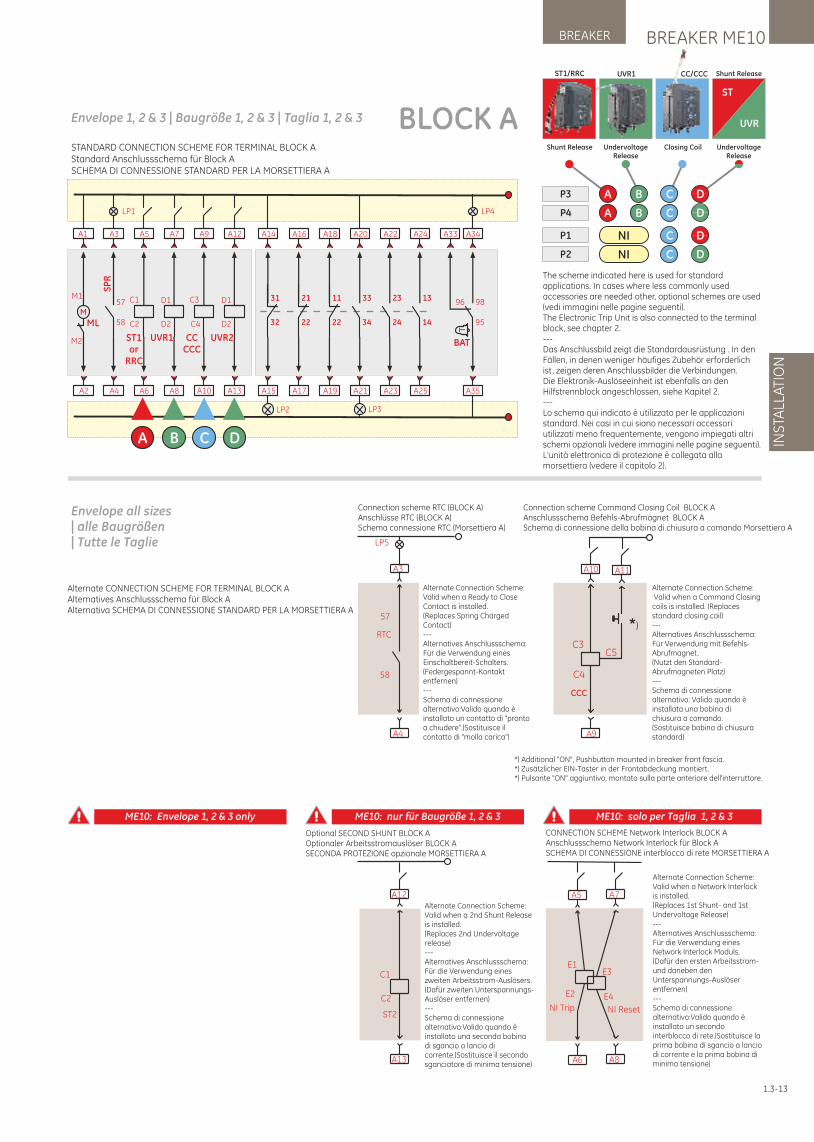
BREAKER ME10BREAKER
INS
TALL
ATI
ON
A12
A13
ST2
C1
C2
Optional SECOND SHUNT BLOCK AOptionaler Arbeitsstromauslöser BLOCK ASECONDA PROTEZIONE opzionale MORSETTIERA A
Alternate Connection Scheme:Valid when a 2nd Shunt Release is installed.(Replaces 2nd Undervoltage release)---Alternatives Anschlussschema:Für die Verwendung eines zweiten Arbeitsstrom-Auslösers.(Dafür zweiten Unterspannungs-Auslöser entfernen)---Schema di connessione alternativo:Valido quando è installato una seconda bobina di sgancio a lancio di corrente.(Sostituisce il secondo sganciatore di minima tensione)
CONNECTION SCHEME Network Interlock BLOCK AAnschlussschema Network Interlock für Block ASCHEMA DI CONNESSIONE interblocco di rete MORSETTIERA A
A7
A8
E1
E2
A5
A6
E4
E3
NI Trip NI Reset
Alternate Connection Scheme:Valid when a Network Interlock is installed.(Replaces 1st Shunt- and 1st Undervoltage Release)---Alternatives Anschlussschema:Für die Verwendung eines Network Interlock Moduls.(Dafür den ersten Arbeitsstrom- und daneben den Unterspannungs-Auslöser entfernen)---Schema di connessione alternativo:Valido quando è installato un secondo interblocco di rete.(Sostituisce la prima bobina di sgancio a lancio di corrente e la prima bobina di minima tensione)
Connection scheme Command Closing Coil BLOCK AAnschlussschema Befehls-Abrufmagnet BLOCK ASchema di connessione della bobina di chiusura a comando Morsettiera A
Alternate Connection Scheme: Valid when a Command Closing coils is installed. (Replaces standard closing coil)---Alternatives Anschlussschema:Für Verwendung mit Befehls-Abrufmagnet.(Nutzt den Standard-Abrufmagneten Platz)---Schema di connessione alternativo: Valido quando è installata una bobina di chiusura a comando. (Sostituisce bobina di chiusura standard)
Connection scheme RTC (BLOCK A)Anschlüsse RTC (BLOCK A)Schema connessione RTC (Morsettiera A)
A3
A4
RTC
58
57
LP5
Alternate Connection Scheme:Valid when a Ready to Close Contact is installed.(Replaces Spring Charged Contact)---Alternatives Anschlussschema:Für die Verwendung eines Einschaltbereit-Schalters.(Federgespannt-Kontakt entfernen)---Schema di connessione alternativo:Valido quando è installato un contatto di "pronto a chiudere".(Sostituisce il contatto di "molla carica") A9
CCC
A10 A11
C4
C5C3
*)
*) Additional "ON", Pushbutton mounted in breaker front fascia.*) Zusätzlicher EIN-Taster in der Frontabdeckung montiert.*) Pulsante "ON" aggiuntivo, montato sulla parte anteriore dell'interruttore.
Alternate CONNECTION SCHEME FOR TERMINAL BLOCK AAlternatives Anschlussschema für Block AAlternativa SCHEMA DI CONNESSIONE STANDARD PER LA MORSETTIERA A
Envelope all sizes| alle Baugrößen| Tutte le Taglie
ME10: Envelope 1, 2 & 3 only ME10: nur für Baugröße 1, 2 & 3 ME10: solo per Taglia 1, 2 & 3
A2
A1
M
ML
M1
M2
LP1
A4
A3
SP
R
58
57
A6
A5
C1
C2
ST1or
RRC
A
A10
A9
C4
C3
CCCCC
C
A8
A7
UVR1
D1
D2
B
A13
A12
UVR2
D1
D2
LP2
A15
A14
32
31
A17
A16
22
21
A19
A18
22
11
A23
A22
24
23
A25
A24
14
13
LP3
A21
A20
34
33
LP4
A35
A34
95
98
T
BAT
A33
96
D
BLOCK AEnvelope 1, 2 & 3 | Baugröße 1, 2 & 3 | Taglia 1, 2 & 3
NIP1
P2 NI
C D
C D
UndervoltageRelease
UVR1ST1/RRC
Shunt Release Closing Coil
CC/CCC
P3
P4
A B C D
C DA B
UndervoltageRelease
UVR
ST
Shunt Release
STANDARD CONNECTION SCHEME FOR TERMINAL BLOCK AStandard Anschlussschema für Block ASCHEMA DI CONNESSIONE STANDARD PER LA MORSETTIERA A
1.3-13
The scheme indicated here is used for standard applications. In cases where less commonly used accessories are needed other, optional schemes are used (vedi immagini nelle pagine seguenti).The Electronic Trip Unit is also connected to the terminal block, see chapter 2.---Das Anschlussbild zeigt die Standardausrüstung . In den Fällen, in denen weniger häufiges Zubehör erforderlich ist, zeigen deren Anschlussbilder die Verbindungen.Die Elektronik-Auslöseeinheit ist ebenfalls an den Hilfstrennblock angeschlossen, siehe Kapitel 2.---Lo schema qui indicato è utilizzato per le applicazioni standard. Nei casi in cui siano necessari accessori utilizzati meno frequentemente, vengono impiegati altri schemi opzionali (vedere immagini nelle pagine seguenti). L'unità elettronica di protezione è collegata alla morsettiera (vedere il capitolo 2).
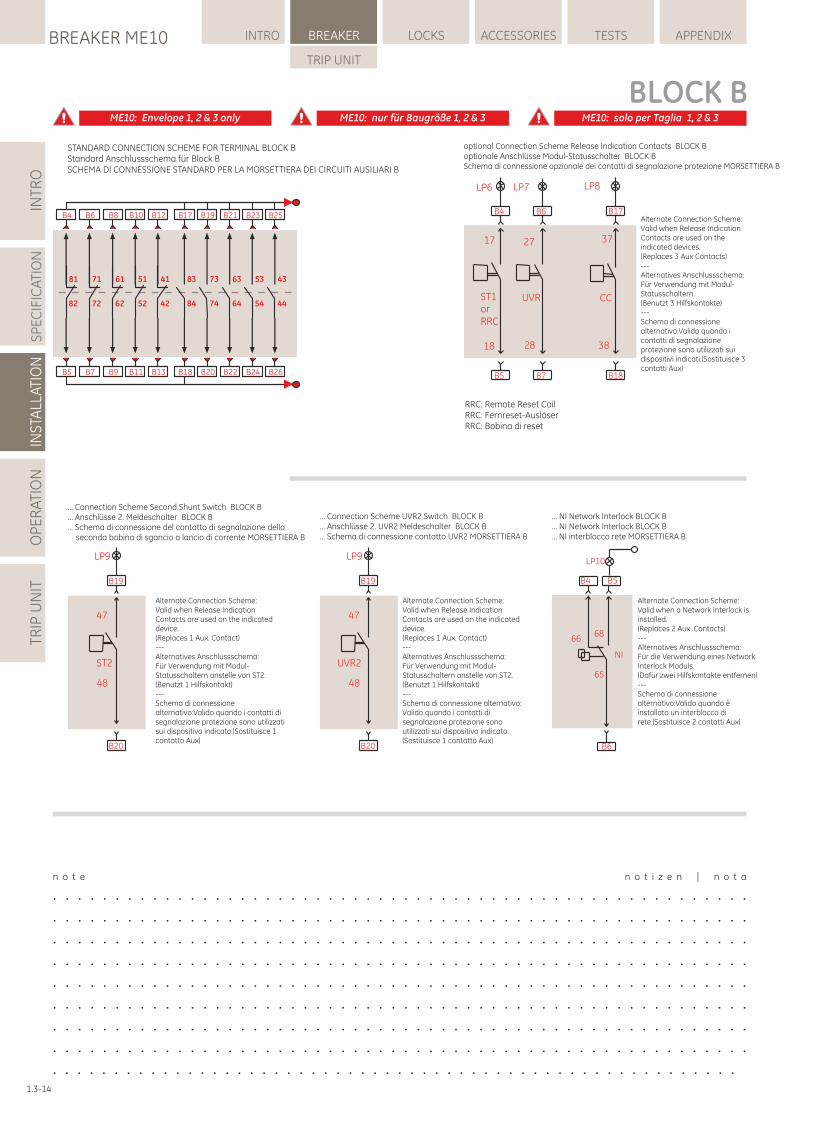
INTR
OS
PE
CIF
ICA
TIO
NIN
STA
LLAT
ION
OP
ER
ATI
ON
TRIP
UN
ITLOCKSBREAKER ME10 INTRO BREAKER ACCESSORIES TESTS APPENDIX
TRIP UNIT
optional Connection Scheme Release Indication Contacts BLOCK Boptionale Anschlüsse Modul-Statusschalter BLOCK BSchema di connessione opzionale dei contatti di segnalazione protezione MORSETTIERA B
Alternate Connection Scheme:Valid when Release Indication Contacts are used on the indicated devices.(Replaces 3 Aux Contacts)---Alternatives Anschlussschema:Für Verwendung mit Modul-Statusschaltern.(Benutzt 3 Hilfskontakte)---Schema di connessione alternativo:Valido quando i contatti di segnalazione protezione sono utilizzati sui dispositivi indicati.(Sostituisce 3 contatti Aux)
... NI Network Interlock BLOCK B
... NI Network Interlock BLOCK B… NI interblocco rete MORSETTIERA B
B4
B6
NI
LP10
B5
65
6668
Alternate Connection Scheme:Valid when a Network Interlock is installed.(Replaces 2 Aux. Contacts)---Alternatives Anschlussschema:Für die Verwendung eines Network Interlock Moduls.(Dafür zwei Hilfskontakte entfernen)---Schema di connessione alternativo:Valido quando è installato un interblocco di rete.(Sostituisce 2 contatti Aux)
... Connection Scheme Second Shunt Switch BLOCK B
... Anschlüsse 2. Meldeschalter BLOCK B… Schema di connessione del contatto di segnalazione della seconda bobina di sgancio a lancio di corrente MORSETTIERA B
B19
B20
LP9
ST2
48
47
Alternate Connection Scheme:Valid when Release Indication Contacts are used on the indicated device.(Replaces 1 Aux. Contact)---Alternatives Anschlussschema:Für Verwendung mit Modul-Statusschaltern anstelle von ST2.(Benutzt 1 Hilfskontakt)---Schema di connessione alternativo:Valido quando i contatti di segnalazione protezione sono utilizzati sui dispositivo indicato.(Sostituisce 1 contatto Aux)
... Connection Scheme UVR2 Switch BLOCK B
... Anschlüsse 2. UVR2 Meldeschalter BLOCK B… Schema di connessione contatto UVR2 MORSETTIERA B
B19
B20
LP9
UVR2
48
47
Alternate Connection Scheme:Valid when Release Indication Contacts are used on the indicated device.(Replaces 1 Aux. Contact)---Alternatives Anschlussschema:Für Verwendung mit Modul-Statusschaltern anstelle von ST2.(Benutzt 1 Hilfskontakt)---Schema di connessione alternativo:Valido quando i contatti di segnalazione protezione sono utilizzati sui dispositivo indicato.(Sostituisce 1 contatto Aux)
B4 B6
B5 B7
B17
B18
18
LP8LP6 LP7
17
CCUVRST1orRRC
28
27
38
37
RRC: Remote Reset CoilRRC: Fernreset-AuslöserRRC: Bobina di reset
STANDARD CONNECTION SCHEME FOR TERMINAL BLOCK BStandard Anschlussschema für Block BSCHEMA DI CONNESSIONE STANDARD PER LA MORSETTIERA DEI CIRCUITI AUSILIARI B
ME10: Envelope 1, 2 & 3 only ME10: nur für Baugröße 1, 2 & 3 ME10: solo per Taglia 1, 2 & 3
n o t e n o t i z e n | n o t a
. . . . . . . . . . . . . . . . . . . . . . . . . . . . . . . . . . . . . . . . . . . . . . . . . . . . . . . .
. . . . . . . . . . . . . . . . . . . . . . . . . . . . . . . . . . . . . . . . . . . . . . . . . . . . . . . .
. . . . . . . . . . . . . . . . . . . . . . . . . . . . . . . . . . . . . . . . . . . . . . . . . . . . . . . .
. . . . . . . . . . . . . . . . . . . . . . . . . . . . . . . . . . . . . . . . . . . . . . . . . . . . . . . .
. . . . . . . . . . . . . . . . . . . . . . . . . . . . . . . . . . . . . . . . . . . . . . . . . . . . . . . .
. . . . . . . . . . . . . . . . . . . . . . . . . . . . . . . . . . . . . . . . . . . . . . . . . . . . . . . .
. . . . . . . . . . . . . . . . . . . . . . . . . . . . . . . . . . . . . . . . . . . . . . . . . . . . . . . .
. . . . . . . . . . . . . . . . . . . . . . . . . . . . . . . . . . . . . . . . . . . . . . . . . . . . . . . .
. . . . . . . . . . . . . . . . . . . . . . . . . . . . . . . . . . . . . . . . . . . . . . . . . . . . . . . .
B5
B4
82
81
B7
B6
72
71
B9
B8
62
61
B18
B17
84
83
B11
B10
52
51
B13
B12
42
41
B20
B19
74
73
B22
B21
64
63
B24
B23
54
53
B26
B25
44
43
BLOCK B
1.3-14
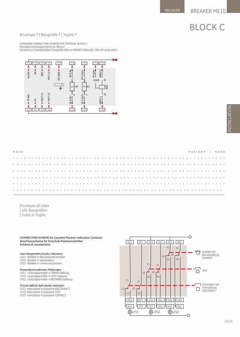
STANDARD CONNECTION SCHEME FOR TERMINAL BLOCK CStandard Anschlussschema für Block CSCHEMA DI CONNESSIONE STANDARD PER LA MORSETTIERA DEI CIRCUITI AUSILIARI C
BREAKER ME10BREAKER
INS
TALL
ATI
ON
1.3-15
User designated circuits; indicatorsLP11: Breaker in disconnected positionLP12: Breaker in test positionLP13: Breaker in connected position
Anwenderstromkreise; MeldungenLP11: Leistungsschalter in TRENN-StellungLP12: Leistungsschalter in TEST-StellungLP13: Leistungsschalter in BETRIEBS-Stellung
Circuiti definiti dall'utente; indicatoriLP11: Interruttore in posizione DISCONNECTLP12: Interruttore in posizione TESTLP13: Interruttore in posizione CONNECT
CONNECTION SCHEME for Cassette Position Indication ContactsAnschlussschema für Einschub-PositionsschalterSchema di connessione
D11 D21
D14 D24
D12 D22
D31 D41 D51 D61
D34 D44 D54 D64
D32 D42 D52 D62
LP11 LP12 LP13
11
12
14
21
22
24
31
32
34
41
42
44
51
5254
61
62
64
CONNECTEDBetriebsstellungCONNECT
TEST
DISCONNECTEDTrennstellungDISCONNECT
BLOCK C
n o t e n o t i z e n | n o t a
. . . . . . . . . . . . . . . . . . . . . . . . . . . . . . . . . . . . . . . . . . . . . . . . . . . . . . . . . .
. . . . . . . . . . . . . . . . . . . . . . . . . . . . . . . . . . . . . . . . . . . . . . . . . . . . . . . . . .
. . . . . . . . . . . . . . . . . . . . . . . . . . . . . . . . . . . . . . . . . . . . . . . . . . . . . . . . . .
. . . . . . . . . . . . . . . . . . . . . . . . . . . . . . . . . . . . . . . . . . . . . . . . . . . . . . . . . .
. . . . . . . . . . . . . . . . . . . . . . . . . . . . . . . . . . . . . . . . . . . . . . . . . . . . . . . . . .
. . . . . . . . . . . . . . . . . . . . . . . . . . . . . . . . . . . . . . . . . . . . . . . . . . . . . . . . . .
Envelope T | Baugröße T | Taglia T
C2
C1
C4
C3
C6
C5
C11
C10
C8
C7 C9
C13
C12
ZSI
-
+
ZSI
-
+
C14
C16
C15
TU
I1
I2Icom
5V
-IS
O RX
GN
D
VO
LT-L
2
ISO
-GN
D
GF
Z I
N-
GF
Z I
N+
GF
Z O
UT
-G
F Z
OU
T+
IP C
OM
INP
UT
1IN
PU
T 2
VO
LT-L
1
VO
LT-L
3
TX
TX
EN
1
Envelope all sizes| alle Baugrößen| Tutte le Taglie
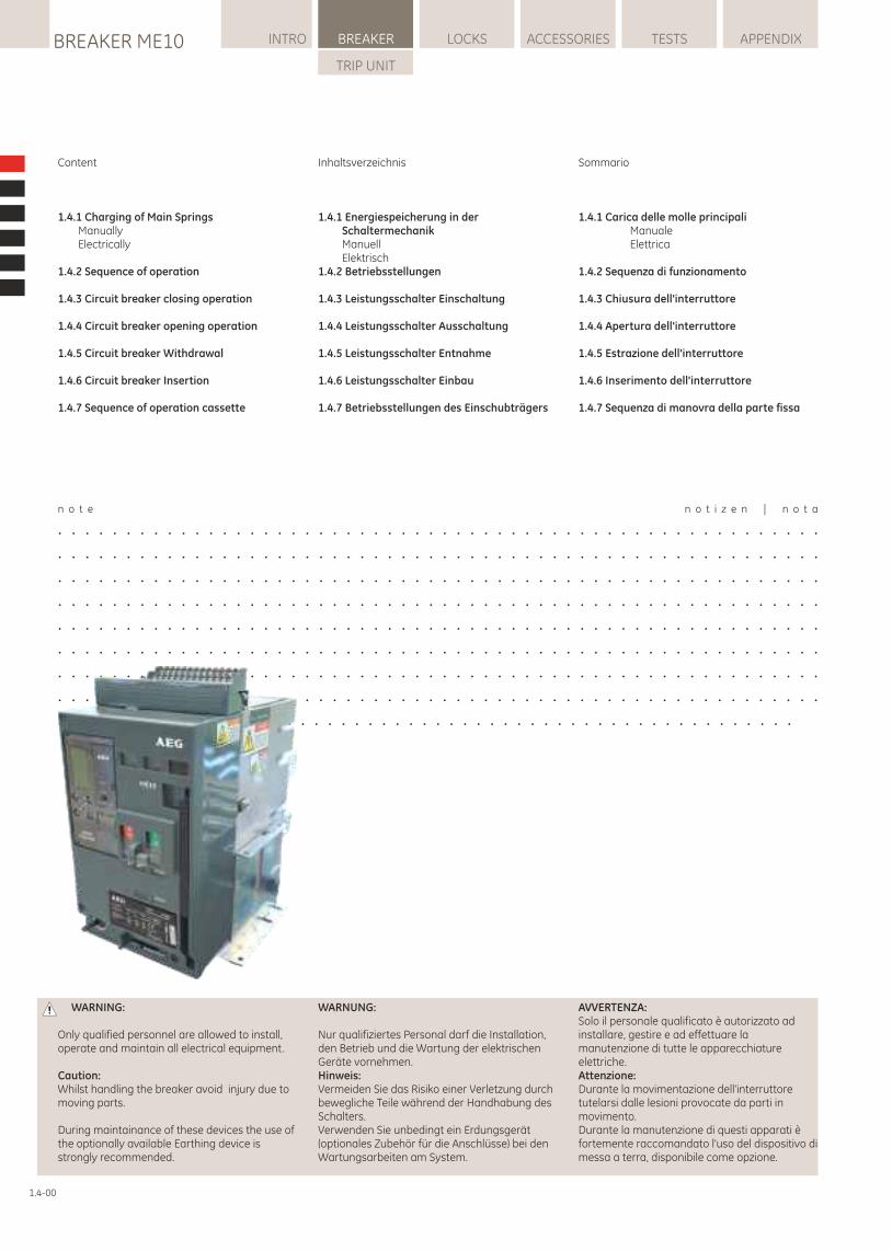
n o t e n o t i z e n | n o t a
. . . . . . . . . . . . . . . . . . . . . . . . . . . . . . . . . . . . . . . . . . . . . . . . . . . . . . . .
. . . . . . . . . . . . . . . . . . . . . . . . . . . . . . . . . . . . . . . . . . . . . . . . . . . . . . . .
. . . . . . . . . . . . . . . . . . . . . . . . . . . . . . . . . . . . . . . . . . . . . . . . . . . . . . . .
. . . . . . . . . . . . . . . . . . . . . . . . . . . . . . . . . . . . . . . . . . . . . . . . . . . . . . . .
. . . . . . . . . . . . . . . . . . . . . . . . . . . . . . . . . . . . . . . . . . . . . . . . . . . . . . . .
. . . . . . . . . . . . . . . . . . . . . . . . . . . . . . . . . . . . . . . . . . . . . . . . . . . . . . . .
. . . . . . . . . . . . . . . . . . . . . . . . . . . . . . . . . . . . . . . . . . . . . . . . . . . . . . . .
. . . . . . . . . . . . . . . . . . . . . . . . . . . . . . . . . . . . . . . . . . . . . . . . . . . . . . . .
. . . . . . . . . . . . . . . . . . . . . . . . . . . . . . . . . . . . . . . . . . . . . . . . . . . . . . .
Content
1.4.1 Charging of Main Springs Manually Electrically
1.4.2 Sequence of operation
1.4.3 Circuit breaker closing operation
1.4.4 Circuit breaker opening operation
1.4.5 Circuit breaker Withdrawal
1.4.6 Circuit breaker Insertion
1.4.7 Sequence of operation cassette
Inhaltsverzeichnis
1.4.1 Energiespeicherung in der Schaltermechanik Manuell Elektrisch1.4.2 Betriebsstellungen
1.4.3 Leistungsschalter Einschaltung
1.4.4 Leistungsschalter Ausschaltung
1.4.5 Leistungsschalter Entnahme
1.4.6 Leistungsschalter Einbau
1.4.7 Betriebsstellungen des Einschubträgers
Sommario
1.4.1 Carica delle molle principali Manuale Elettrica
1.4.2 Sequenza di funzionamento
1.4.3 Chiusura dell'interruttore
1.4.4 Apertura dell'interruttore
1.4.5 Estrazione dell'interruttore
1.4.6 Inserimento dell'interruttore
1.4.7 Sequenza di manovra della parte fissa
WARNUNG:
Nur qualifiziertes Personal darf die Installation, den Betrieb und die Wartung der elektrischen Geräte vornehmen.Hinweis: Vermeiden Sie das Risiko einer Verletzung durch bewegliche Teile während der Handhabung des Schalters.Verwenden Sie unbedingt ein Erdungsgerät (optionales Zubehör für die Anschlüsse) bei den Wartungsarbeiten am System.
WARNING:
Only qualified personnel are allowed to install, operate and maintain all electrical equipment.
Caution:Whilst handling the breaker avoid injury due to moving parts.
During maintainance of these devices the use of the optionally available Earthing device is strongly recommended.
AVVERTENZA:Solo il personale qualificato è autorizzato ad installare, gestire e ad effettuare la manutenzione di tutte le apparecchiature elettriche.Attenzione:Durante la movimentazione dell'interruttore tutelarsi dalle lesioni provocate da parti in movimento. Durante la manutenzione di questi apparati è fortemente raccomandato l'uso del dispositivo di messa a terra, disponibile come opzione.
LOCKSBREAKER ME10 INTRO BREAKER ACCESSORIES TESTS APPENDIX
TRIP UNIT
1.4-00
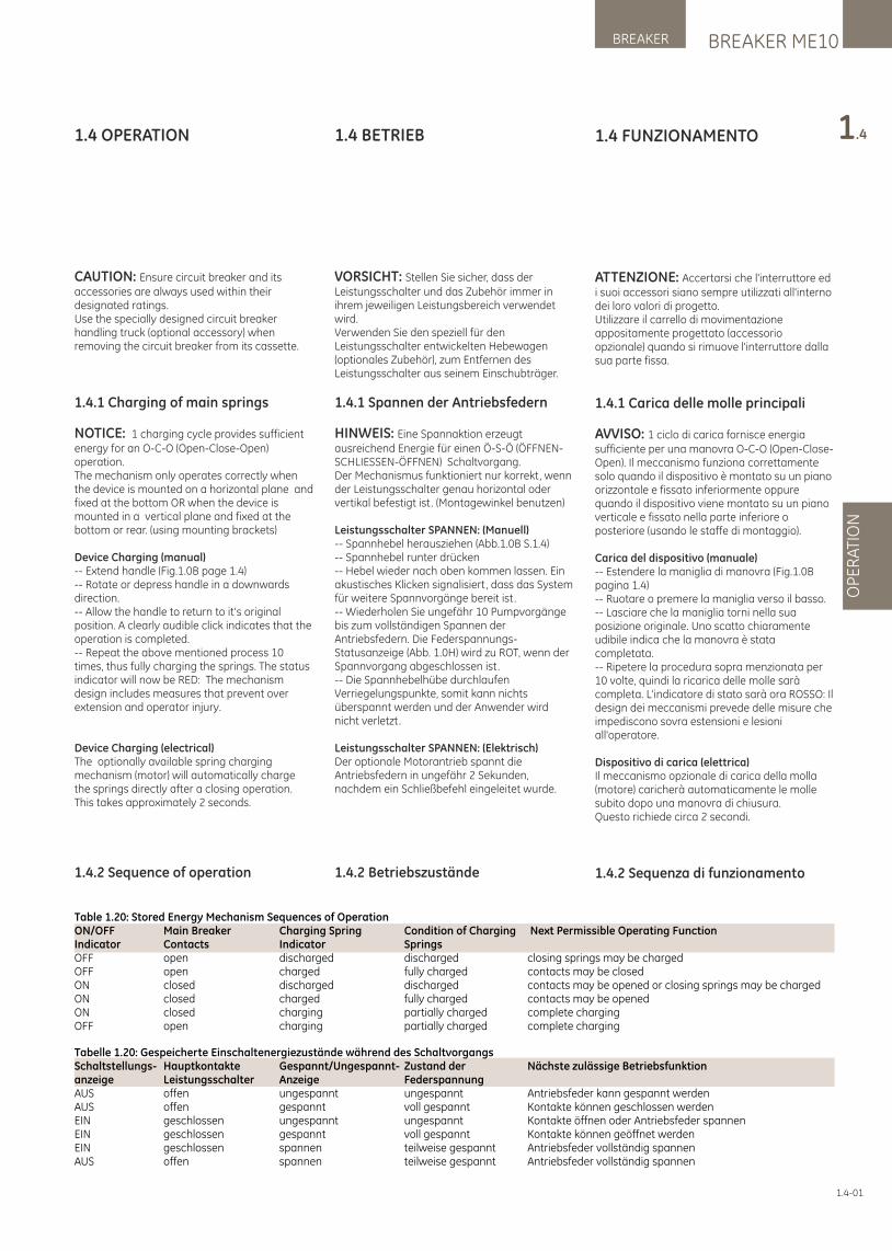
1.4 BETRIEB
VORSICHT: Stellen Sie sicher, dass der Leistungsschalter und das Zubehör immer in ihrem jeweiligen Leistungsbereich verwendet wird.Verwenden Sie den speziell für den Leistungsschalter entwickelten Hebewagen (optionales Zubehör), zum Entfernen des Leistungsschalter aus seinem Einschubträger.
1.4.1 Spannen der Antriebsfedern
HINWEIS: Eine Spannaktion erzeugt ausreichend Energie für einen Ö-S-Ö (ÖFFNEN-SCHLIESSEN-ÖFFNEN) Schaltvorgang.Der Mechanismus funktioniert nur korrekt, wenn der Leistungsschalter genau horizontal oder vertikal befestigt ist. (Montagewinkel benutzen)
Leistungsschalter SPANNEN: (Manuell)-- Spannhebel herausziehen (Abb.1.0B S.1.4)-- Spannhebel runter drücken-- Hebel wieder nach oben kommen lassen. Ein akustisches Klicken signalisiert, dass das System für weitere Spannvorgänge bereit ist.-- Wiederholen Sie ungefähr 10 Pumpvorgänge bis zum vollständigen Spannen der Antriebsfedern. Die Federspannungs-Statusanzeige (Abb. 1.0H) wird zu ROT, wenn der Spannvorgang abgeschlossen ist.-- Die Spannhebelhübe durchlaufen Verriegelungspunkte, somit kann nichts überspannt werden und der Anwender wird nicht verletzt.
Leistungsschalter SPANNEN: (Elektrisch)Der optionale Motorantrieb spannt die Antriebsfedern in ungefähr 2 Sekunden, nachdem ein Schließbefehl eingeleitet wurde.
1.4.2 Betriebszustände
1.4 OPERATION
CAUTION: Ensure circuit breaker and its accessories are always used within their designated ratings.Use the specially designed circuit breaker handling truck (optional accessory) when removing the circuit breaker from its cassette.
1.4.1 Charging of main springs
NOTICE: 1 charging cycle provides sufficient energy for an O-C-O (Open-Close-Open) operation.The mechanism only operates correctly when the device is mounted on a horizontal plane and fixed at the bottom OR when the device is mounted in a vertical plane and fixed at the bottom or rear. (using mounting brackets)
Device Charging (manual)-- Extend handle (Fig.1.0B page 1.4)-- Rotate or depress handle in a downwards direction.-- Allow the handle to return to it's original position. A clearly audible click indicates that the operation is completed.-- Repeat the above mentioned process 10 times, thus fully charging the springs. The status indicator will now be RED: The mechanism design includes measures that prevent over extension and operator injury.
Device Charging (electrical)The optionally available spring charging mechanism (motor) will automatically charge the springs directly after a closing operation.This takes approximately 2 seconds.
1.4.2 Sequence of operation
BREAKER ME10BREAKER
OP
ER
ATI
ON
1.41.4 FUNZIONAMENTO
ATTENZIONE: Accertarsi che l'interruttore ed i suoi accessori siano sempre utilizzati all'interno dei loro valori di progetto.Utilizzare il carrello di movimentazione appositamente progettato (accessorio opzionale) quando si rimuove l'interruttore dalla sua parte fissa.
1.4.1 Carica delle molle principali
AVVISO: 1 ciclo di carica fornisce energia sufficiente per una manovra O-C-O (Open-Close-Open). Il meccanismo funziona correttamente solo quando il dispositivo è montato su un piano orizzontale e fissato inferiormente oppure quando il dispositivo viene montato su un piano verticale e fissato nella parte inferiore o posteriore (usando le staffe di montaggio).
Carica del dispositivo (manuale)-- Estendere la maniglia di manovra (Fig.1.0B pagina 1.4)-- Ruotare o premere la maniglia verso il basso.-- Lasciare che la maniglia torni nella sua posizione originale. Uno scatto chiaramente udibile indica che la manovra è stata completata.-- Ripetere la procedura sopra menzionata per 10 volte, quindi la ricarica delle molle sarà completa. L'indicatore di stato sarà ora ROSSO: Il design dei meccanismi prevede delle misure che impediscono sovra estensioni e lesioni all'operatore.
Dispositivo di carica (elettrica)Il meccanismo opzionale di carica della molla (motore) caricherà automaticamente le molle subito dopo una manovra di chiusura.Questo richiede circa 2 secondi.
1.4.2 Sequenza di funzionamento
Table 1.20: Stored Energy Mechanism Sequences of OperationON/OFF Main Breaker Charging Spring Condition of Charging Next Permissible Operating FunctionIndicator Contacts Indicator Springs OFF open discharged discharged closing springs may be chargedOFF open charged fully charged contacts may be closedON closed discharged discharged contacts may be opened or closing springs may be chargedON closed charged fully charged contacts may be openedON closed charging partially charged complete chargingOFF open charging partially charged complete charging
Tabelle 1.20: Gespeicherte Einschaltenergiezustände während des SchaltvorgangsSchaltstellungs- Hauptkontakte Gespannt/Ungespannt- Zustand der Nächste zulässige Betriebsfunktionanzeige Leistungsschalter Anzeige FederspannungAUS offen ungespannt ungespannt Antriebsfeder kann gespannt werdenAUS offen gespannt voll gespannt Kontakte können geschlossen werdenEIN geschlossen ungespannt ungespannt Kontakte öffnen oder Antriebsfeder spannenEIN geschlossen gespannt voll gespannt Kontakte können geöffnet werdenEIN geschlossen spannen teilweise gespannt Antriebsfeder vollständig spannenAUS offen spannen teilweise gespannt Antriebsfeder vollständig spannen
1.4-01
1.4.3 CIRCUIT BREAKER CLOSING OPERATION1. The circuit breaker can be closed, if:
- The OFF button is not depressed.- The Trip Unit is installed.- No pending ON command is present- The network interlock if installed is reset.
- If installed, the Undervoltage release (s) are energized.- No local keylocks or in- or external breaker interlocks are set to PREVENT the user from switching ON.- The cassette racking handle is not inserted.- The Trip Unit reset button is not protruding from the front cover.- The circuit breaker is not positioned anywhere between CONNECTED, TEST and DISCONNECTED.---If any of the above conditions are NOT met the device is prevented from closing.---
2. Closing the DeviceUp to four different ways (A-D) of closing the breaker are available:
-- A. Manual ClosingDepressing the 'ON' pushbutton located on the breaker front facia. (Fig.1.0D page 1-4)
-- B. Remote Electrical ClosingWhen an electrical charging device is used a standard Closing Coil can be used to switch the breaker 'ON'. This coil must be energized via the secondary terminals.
-- C. Local Electrical ClosingWhen an electrical charging device is used a Command Closing Coil can be used to switch the breaker 'ON'.The device is operated by a extra pushbutton located on the breaker front facia. This coil needs a power supply and can also be accessed through the Trip Unit communication bus.
-- D. Closing through Communication busWhen an electrical charging device and Command Closing Coil are present the breaker can be switched on through the communication bus offered on several GT Trip Unit versions. The coil must be connected to an independent power supply.
NOTICE: If a motorized Spring Charging Unit is installed, the springs will be automatically charged as soon as the closing operation is initialized.
INTR
OS
PE
CIF
ICA
TIO
NIN
STA
LLAT
ION
OP
ER
ATI
ON
TRIP
UN
ITLOCKSBREAKER ME10 INTRO BREAKER ACCESSORIES TESTS APPENDIX
TRIP UNIT
1.4.3 Leistungsschalter Einschaltung
1. Der Leistungsschalter kann geschlossen werden, wenn:- Die AUS-Taste ist nicht gedrückt.- Die Auslöseeinheit installiert ist.- Kein Einschaltkommando ansteht.- Die Network Interlock Einheit, falls installiert, wurde zurückgesetzt (Reset).- Die Unterspannungsauslöser, falls welche installiert wurden, sind erregt.- Keine Schlüsselsperren oder andere direkte mechanische Verriegelungen am Schalter in Funktion sind.- Die Einfahrkurbel nicht eingesteckt ist.- Die Auslöseeinheiten Reset-Taste nicht aus der vorderen Abdeckung heraussteht.- ..er niemals zwischen den Stellungen BETRIEB, TEST oder GETRENNT positioniert ist.---Falls einer der obigen Punkte nicht eingehalten wurde, kann der Schalter nicht geschlossen werden.---2. Einschalten des LeistungsschaltersEs gibt 4 Möglichkeiten (A-D) zur Schließung der Leistungsschalter, wenn die oben beschriebenen Bedingungen erfüllt sind:
-- A. Manuelle EinschaltungDie manuelle Schließung wird durch Drücken der EIN-Drucktaste (Abb. 1.0D, Seite 1-4) eingeleitet.-- B. Elektrische Fern-EinschaltungWenn ein elektrisches Antriebssystem benutzt wird, kann der Standard-Abrufmagnet (Modul), zum Einschalten des Leistungsschalters verwendet werden. Dieses Modul benötigt zu diesem Zweck eine Fremdversorgung über die Hilfstrennblöcke.-- C. Elektrische Einschaltung am SchalterWenn ein elektrisches Antriebssystem benutzt wird, kann ein Befehls-Abrufmagnet den Leistungsschalter über einen extra installierten Drucktaster in der Frontabdeckung EIN-schalten. Dieses Modul benötigt zu diesem Zweck eine Fremdversorgung über die Hilfstrennblöcke und kann auch durch die Auslöseeinheiten BUS-Kommunikation betätigt werden.-- D. Einschalten über KommunikationsmittelWenn ein elektrisches Antriebssystem und ein Befehls-Abrufmagnet im Leistungsschalter eingebaut sind, kann der Leistungsschalter über das in einer speziellen GT-Auslöseeinheiten Version angebotene Kommunikations-Bussystem angesteuert werden. Das Modul benötigt zu diesem Zweck eine Fremdversorgung.
HINWEIS: Wenn ein Motorantrieb (elektr. Federspann-System) installiert ist, werden die Federn automatisch gespannt, sobald der Schließvorgang begonnen wird.
Tabella 1.20: Sequenza di funzionamento del meccanismo di accumulo energiaON/OFF Contatti interruttore principale Indicatore carica molle Condizione di carica molle Funzione operativa successiva permessaIndicatore Contatti Indicatore Molle OFF aperti scariche scariche le molle di chiusura possono essere caricateOFF aperti cariche totalmente cariche i contatti possono essere chiusiON chiusi scariche scariche i contatti possono essere aperti o le molle di chiusura possono essere caricateON chiusi cariche totalmente cariche i contatti possono essere apertiON chiusi cariche parzialmente cariche completare la caricaOFF aperti cariche parzialmente cariche completare la carica
1.4-02
1.4.3 CHIUSURA DELL'INTERRUTTORE
1. L'interruttore può essere chiuso, se:
- Il pulsante OFF non è premuto.- Il Relè di Protezione è installato.- Non sono presenti comandi di ON pendenti- L'interblocco di rete, se installato, è resettato.- Se installata, la bobina di minima tensione è alimentata.- Non ci sono serrature locali o interblocchi interni o esterni impostati per IMPEDIRE all'utente di commutare l'interruttore in ON.- La maniglia di manovra della parte fissa non è inserita.- Il pulsante di reset del Relè di Protezione non sporge dalla parte anteriore.- L'interruttore non è posizionato in un punto intermedio tra CONNECT, TEST e DISCONNECT.---Se una qualsiasi di queste condizioni non è rispettata, al dispositivo viene impedita la chiusura.---2. Chiusura del dispositivoSono disponibili fino a quattro diverse modalità (A-D) di chiusura dell'interruttore:
– A. Chiusura manualePremere il pulsante 'ON' posto sul pannello anteriore dell'interruttore. (Fig.1.0D pagina 1-4)
-- B. Chiusura elettrica da remotoQuando si utilizza un comando di carica elettrico può essere impiegata una bobina di chiusura standard per commutare l'interruttore su 'ON'. Questa bobina deve essere alimentata tramite i morsetti ausiliari.
-- B. Chiusura elettrica in localeQuando si utilizza un dispositivo di carica elettrico può essere impiegata una bobina di chiusura a comando per commutare l'interruttore su 'ON'.Il dispositivo è azionato da un pulsante aggiuntivo situato sul pannello anteriore dell'interruttore. Questa bobina necessita di un'alimentazione: ad essa si può accedere anche attraverso il bus di comunicazione del Relè di Protezione.
-- D. Chiusura tramite Bus di comunicazioneQuando sono presenti un dispositivo di carica elettrico e una bobina di chiusura a comando, l'interruttore può essere attivato tramite il bus di comunicazione offerto in diverse versioni del Relè di Protezione GT. La bobina deve essere collegata ad un alimentatore indipendente.
AVVISO: Se è installato un'unità motorizzata di carica molla, le molle saranno caricate automaticamente non appena la manovra di chiusura viene inizializzata.
1.4.4 Apertura dell'interruttore
AVVISO: Se il dispositivo è un interruttore, esso interverrà AUTOMATICAMENTE in caso di anomalie che possono portare a superare i parametri impostati o installati sui dispositivi di protezione.
(Relè di Protezione elettronica tipo GT).Vi sono vari modi per aprire l'interruttore.ManualmenteL'interruttore si aprirà utilizzando il pulsante di OFF (Fig. 1.0N).Bobine di sgancio a lancio di correntePer aprire l'interruttore possono essere installate 1 o 2 bobine di sgancio a lancio di corrente. Le bobine di sgancio a lancio di corrente devono essere alimentate tramite il sezionatore ausiliario (morsetti).Bobina di minima tensionePossono essere installate 1 o 2 bobine di minima tensione che apriranno l'interruttore una volta che la loro alimentazione scende al di sotto di un certo livello.
Dispositivo di Interblocco di Rete (NI)Il dispositivo di interblocco di rete blocca l'interruttore in posizione OFF elettricamente e meccanicamente. Quando questo dispositivo riceve un impulso, tutte le funzionalità locali dell'interruttore vengono disabilitate, tranne l'intervento del dispositivo in caso di un qualsiasi guasto di sovracorrente.Alla ricezione di un secondo impulso, viene ripristinato il funzionamento normale. La presenza dell'alimentazione di rete non influenza il blocco e/o il ripristino di questo dispositivo. Ogni dispositivo prevede un pulsante di reset locale cui è possibile accedere solo dopo la rimozione della copertura dell'interruttore.Questo dispositivo ha un volume pari a due protezioni (bobina di sgancio a lancio di corrente/ bobina di minima tensione)
1.4.5 Estrazione dell'interruttorePreparazione- Connessione a terra del trasformatore di corrente Quando si usa questo dispositivo in uno schema di protezione da guasto a terra con ritorno a massa, il ramo di terra del trasformatore di corrente sarà un circuito aperto se l'interruttore è estratto dalla sua parte fissa. In determinate circostanze, la corrente può fluire ancora verso massa, dando origine ad una elevata tensione indotta sui morsetti ausiliari del trasformatore di corrente.
In tali condizioni, verificare l'installazione nella parte fissa di un Interruttore di Guida (vedere paragrafo 4.4) per consentire il cortocircuito dei morsetti ausiliari del trasformatore di corrente quando l'interruttore è estratto.
- Motore di ricarica molleSe è installato un comando motorizzato per la carica delle molle, portare l'interruttore in posizione di sezionamento, quindi chiudere e fare scattare l'interruttore per scaricare le molle di chiusura.
1.4.4 Circuit Breaker Opening OperationNOTICE: If the device is a breaker it will always AUTOMATICALLY Trip on closing or being exposed to faults that exceed the values set or installed on the installed protective devices.(GT type Electronic Trip Unit).
There are multiple means to open the breaker.ManuallyUsing the off Pushbutton (Fig. 1.0N) will open the breaker.
Standard Shunt Release or Remote Reset Coil1 or 2 Shunt releases can be installed to open the breaker. For this the shunt releases must be energized via the secondary disconnect (terminals). A Remote Reset Coil can be used the same a manner as a standard shunt release. Only one of these releases can be mounted (Replacing the Standard shunt release ST1)
Undervoltage release1 or 2 undervoltage releases can be installed and will open the breaker once their power supply drops below a certain level.Standard Undervoltage releases have a built in time delay of up to 50 ms whilst, on request some variants are available without delay.
Network Interlock Device (NI)The Network Interlock Device locks the breaker in OFF position electrically and mechanically. When this device receives a pulse all local breaker functionality is disabled except the tripping of the device on any over current fault.On the receipt of a 2nd pulse normal operation is re-instated. The presence of mains power does not effect the locking and/or reinstatement of this device. Each device has a local RESET button that only can be accessed after breaker cover removal.It has the volume of two releases (Shunt / Undervoltage coil).
1.4.5 Circuit Breaker WithdrawalPreparation- Earth Leg Current transformerWhen using this device is used in a source ground return Earth fault scheme (As used for standby earthfault), the earth leg current transformer will be open circuited when the circuit breaker is withdrawn from its cassette. Under certain circumstances, the current may still flow in the ground giving rise to a high induced voltage at the current transformer secondary terminals.Under such conditions, ensure a Carriage Switch is installed in the cassette (see Section 4.4) to allow short circuiting of the current transformer secondary terminals when the circuit breaker is withdrawn.
- Motor operatorIf a motorized spring charging unit is installed rack the breaker to the disconnect position, then close and trip the breaker to discharge the closing springs.Otherwise the motor will recharge the springs automatically.
1.4.4 Leistungsschalter Ausschalten
HINWEIS: Wenn das eingesetzte Gerät ein Leistungsschalter ist, wird er nach der Einschaltung immer AUTOMATISCH auslösen, wenn die voreingestellten Werte der installierten Auslöse- und Schutzeinrichtungen (GT Typen Auslöseeinheit) überschritten werden.
Es gibt mehrere Möglichkeiten, um die Leistungsschalter auszuschalten.Von HandMit dem AUS-Taster (Abb. 1.0N) wird der Leistungsschalter geöffnet.Arbeitsstromauslöser (A-Auslöser)1 oder 2 Arbeitsstromauslöser können installiert werden, um die Leistungsschalter auszuschalten. Dazu müssen die A-Auslöser mit Fremdspannung über den Hilfstrennblock versorgt werden. Ein Fernreset Auslöser (RRC) kann in gleicher Weise wie ein A-Auslöser eingebaut werden. Der A-Auslöser (ST1) Platz wird dann durch den RRC ersetzt.Unterspannungsauslöser (U-Auslöser)1 oder 2 U-Auslöser können installiert werden, die den Leistungsschalter öffnen, wenn die Versorgungsspannung unter ein bestimmtes Niveau fällt . Standard U-Auslöser haben eine Zeitverzögerung bis zu 50 ms, auf Anfrage sind einige Varianten auch unverzögert erhältlich.
Network Interlock (NI)Das Network Interlock Zubehör sperrt den Leistungsschalter in der AUS-Stellung elektrisch und mechanisch. Wenn dieses Gerät einen Impuls erhält, sind alle lokalen Schalterfunktionen abgeschaltet, außer der Auslösefunktion bei jeder Art von Überstromfehlern. Nach Eingang eines zweiten Impulses wird der Ausgangszustand wieder hergestellt . Die Präsenz der Netzspannung hat keine Auswirkungen auf die Sperrung und/oder die Wiederherstellung des Ausgangszustandes. Jedes Gerät hat eine direkte Rückstelltaste, die nur nach Entfernung der Schalterabdeckung ausgelöst werden kann. Das NI benötigt die linken 2 Modulplätze eines A-und eines U-Auslösers.
1.4.5 Schalter-AusfahrtechnikVorbereitung- ErdschlussstromwandlerBei Verwendung dieses Gerätes als Erdschlussfehlerschutzsystem (nach Erdschluss-Schutzart (Typ SEF)) wird, wenn der Leistungsschalter aus dem Einschubträger gezogen wird, der Ableitstromwandler offen betrieben. Unter bestimmten Umständen kann dann möglicherweise noch Strom fließen und es kann zu einer hohen induzierte Spannung an den Stromwandlerklemmen führen.
Unter solchen Bedingungen, stellen Sie bitte sicher, dass ein Positionsmeldeschalter in dem Einschubträger installiert ist (siehe Abschnitt 4.4), um das Kurzschließen der sekundären Stromwandler Anschlussstellen zu erlauben, wenn der Leistungsschalter herausgezogen wird.
- MotorantriebWenn eine motorisierte Antriebsfeder-Spanneinrichtung installiert ist, bringen Sie den Schalter in die TRENN-Stellung. Schließen und
DANGER | GEFAHR | PERICOLO
Ensure the circuit breaker has been tripped, indicating OFF, and the main springs are fully discharged.
Stellen Sie sicher, das der Leistungsschalter ausgelöst wurde, AUS angezeigt wird und die Antriebsfeder vollständig entspannt ist.
Assicurarsi che l'interruttore sia intervenuto, indicando OFF, e le molle principali siano completamente scariche.
BREAKER ME10BREAKER
OP
ER
ATI
ON
1.4
1.4-03
INTR
OS
PE
CIF
ICA
TIO
NIN
STA
LLAT
ION
OP
ER
ATI
ON
TRIP
UN
ITLOCKSBREAKER ME10 INTRO BREAKER ACCESSORIES TESTS APPENDIX
TRIP UNIT
lösen Sie dann den Schalter aus um die Antriebsfedern zu entlasten.Anderenfalls wird der Motor die Federn wieder spannen.--- Entfernen Sie alle Vorhängeschlösser vom Einschubträger.--- Stellen Sie sicher, dass die Schaltschranktür geschlossen ist.
Betrieb:1. Entnehmen Sie die Einfahrkurbel aus ihrem Lagerort (Abb. 1.9).2. Ziehen Sie die Einfahrkurbel auseinander und klappen Sie die Einfahrkurbelverlängerung aus (Abb. 1.10).3. Schalten Sie den Leistungsschalter aus. Eine Sicherheitsvorrichtung sorgt dafür, dass die Einschubblende nicht geöffnet werden kann, während das Gerät nicht in seiner AUS-Position steht.4. Öffnen Sie die Blende vollständig mit einem normalen Schraubendreher (siehe Abb.. 1,11)5. Stecken Sie den Griff ein und drehen Sie ihn gegen den Uhrzeigersinn. Dies führt dazu, dass die Positionsanzeige und der Schalter, von der BETRIEBS- über die TEST- in die TRENN-Stellung bewegt wird.
HINWEIS: Wenn die Einfahrkurbel in den Einfahrkurbelschacht eingesteckt ist, kann der Leistungsschalter nicht in jeder Stellung zwischen BETRIEB und TRENNUNG betrieben werden. Beim Entfernen der Einfahrkurbel wird die Einfahrkurbel-Steckloch-Schutzkappe automatisch zurückgesetzt.6. Aus der Position GETRENNT erreicht man durch weiteres Drehen der Einfahrkurbel gegen den Uhrzeigersinn eine spürbare Rastung.
HINWEIS: Stellen Sie sicher, dass die Antriebsfeder vollständig entspannt ist (Federspannungs-Anzeige muss ENTSPANNT anzeigen), bevor Sie versuchen die GETRENNT-Stellung zu verlassen.7. Der Leistungsschalter befindet sich nun in der Wartungsstellung (Abb. 1.12).In dieser Stellung kann die Schaltschranktür geöffnet werden und die Mittel zum Anheben können an den Anhebeösen befestigt werden, die links und rechts im oberen Schalterbereich angeordnet sind...siehe Tabelle 1.21
1.4.6 Leistungsschalter einschiebenVorbereitung:-- Entferne Einschubschienenverriegelungen.-- Entferne Einschubträgerverriegelungen.-- Deaktivieren Sie alle Einschubträger-Schlosssperren.1. Setzen Sie den Leistungsschalter auf die voll ausgefahrenen Ladeschienen und achten Sie auf den korrekten Eingriff der Rollen (Abb. 1.12)2. Entfernen Sie alle Hebefunktionen des Schalters.3. Schieben Sie den Leistungsschalter in den Einschubträger durch Druck auf die Vorderfront (links und rechts im oberen Bereich), bis zum Anschlag.4 Schließen Sie die Schaltschranktür.5. Stecken Sie die Einfahrkurbel (Punkt 1-4) wieder ein.6. Durch Drehen der Einfahrkurbel im Uhrzeigersinn bewegt sich der Schalter. Er kann aus der GETRENNT- über die TEST-Stellung in die
— Remove any padlocks from the racking panel.--- Ensure the cabinet/panel door is closed.
Operation:1. Remove the racking handle from its storage location (Fig. 1.9).2. Pull out the torque bar from inside the handle and extend the grip arm (Fig. 1.10).3. Turn the ME10 device OFF. A safety device ensures that the racking aperture shutter cannot be opened whilst the device is NOT in it's OFF position.4. Open the racking aperture shutter fully using a flat screwdriver (see Fig. 1.11).5. Insert the racking handle and rotate it in a counter clockwise direction. This will cause the position indicator and device to move from the CONNECTED to the TEST and DISCONNECTED position.
NOTICE: When the racking handle is inserted in the racking shaft, the circuit breaker cannot be operated in any position between CONNECTED and DISCONNECTED.Removing the handle automatically resets the racking handle shutter.
6. From the DISCONNECTED position, continue turning the racking handle anti-clockwise until reaching a positive stop.
NOTICE: Ensure that the closing springs are fully discharged (spring charge indicator should show 'Discharged') before attempting to withdraw from the DISCONNECTED position.
7. The circuit breaker is now in the maintenance position (Fig. 1.12).
In this position the cabinet/panel door can be opened and means for lifting can be attached to the lifting hooks which can be pulled out from the left and right top of the breaker..see Table 1.21
1.4.6 Circuit breaker insertionPreparation:-- Remove padlocks from the draw out support slides.-- Remove all other padlocks from the cassette.-- Deactivate any cassette keylocks.
1. Carefully place the breaker on the fully extended draw out support slides, taking care that the rollers are correctly engaged. (Fig.1.12)2. Remove any still attached lifting means from the device.3. Push the breaker into the cassette by applying pressure to the front fascia (left and right top area) until the motion comes to an end.4. Close the cabinet/panel door.5. Prepare the cassette and racking handle as mentioned above (point 1 through 4) and insert the handle into it's aperture.6. Rotating the racking handle clockwise moves the breaker in. It can be moved from the
In caso contrario, il motore ricaricherà automaticamente le molle.--- Rimuovere eventuali lucchetti dal pannello di manovra.--- Assicurarsi che la porta del quadro/pannello sia chiusa.
Funzionamento:1. Estrarre la maniglia di manovra dall'alloggiamento (Fig. 1.9).2. Estrarre la barra di torsione dalla maniglia ed estendere il braccio di presa (Fig. 1.10).3. Portare il dispositivo ME10 in OFF. Un dispositivo di sicurezza assicura che l'otturatore del meccanismo di manovra non possa essere aperto se il dispositivo non è in posizione OFF.4. Aprire completamente l'otturatore del meccanismo di manovra con un cacciavite piatto (vedi Fig. 1.11).5. Inserire la maniglia di manovra e ruotare in senso antiorario. Questo farà sì che indicatore di posizione e dispositivo passino dalla posizione CONNECT a TEST quindi a DISCONNECT.
AVVISO: Quando la maniglia di manovra viene inserita nella sede del meccanismo di manovra, l'interruttore non può essere utilizzato in nessuna posizione tra CONNECT e DISCONNECT.La rimozione della maniglia ripristina automaticamente l'otturatore.6. Dalla posizione DISCONNECT, continuare a girare la maniglia di manovra in senso antiorario fino a raggiungere un arresto positivo.
AVVISO: Verificare che le molle di chiusura siano completamente scariche (l'indicatore di carica della molla deve mostrare 'Scarico') prima di tentare di estrarre l'interruttore dalla posizione DISCONNECT.7. L'interruttore si trova ora in posizione di manutenzione (Fig. 1.12).
In questa posizione, la porta dell'armadio /pannello può essere aperta ed è possibile agganciare le attrezzature di sollevamento ai ganci di sollevamento, i quali possono essere estratti dalla parte superiore sinistra e destra dell'interruttore. ..vedere Tabella 1.21
1.4.6 Inserimento dell'interruttorePreparazione:-- Rimuovere lucchetti dalle guide di supporto estraibili.-- Rimuovere tutti gli altri lucchetti dalla parte fissa.-- Aprire tutte le serrature della parte fissa.1. Posizionare con cura l'interruttore sulle guide di supporto estratte in posizione estesa, avendo cura che i rulli siano fissati correttamente. (Fig.1.12)2. Rimuovere tutti gli ausili di sollevamento ancora eventualmente agganciati al dispositivo.3. Spingere l'interruttore nella parte fissa facendo pressione sull'area frontale (in alto a sinistra e a destra). Spingere fino in fondo.4. Chiudere la porta del quadro/pannello.5. Preparare la parte fissa e la maniglia di manovra come indicato sopra (punti da 1 a 4) e inserire la maniglia nella sua apertura di manovra.6. La rotazione della maniglia di manovra in senso orario provoca l'inserimento dell'interruttore. L'interruttore può essere portato dalla posizione DISCONNECT alla posizione di
1.4-04
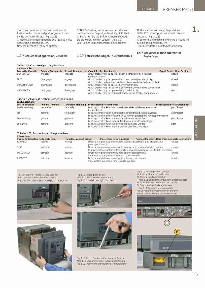
BREAKER ME10BREAKER
OP
ER
ATI
ON
1.4
Fig. 1.9: Racking Handle Storage LocationAbb. 1.9: Einschubeinfahrkurbel Lagerort
Fig. 1.9: Alloggiamento maniglia di manovra
Fig. 1.10: Racking Handle useAbb. 1.10: Einfahrkurbel VerwendungFig. 1.10: Uso della maniglia di manovra
Fig. 1.12: Circuit Breaker in Maintenance PositionAbb. 1.12: Leistungsschalter in WartungsstellungFig. 1.12: Interruttore in posizione di Manutenzione
B
A
Fig. 1.11: Racking Screw LocationA) Racking Shutter screw locationB) Racking position indication-- Abb. 1.11: Lage der Schraube am EinschubträgerA) Schutzkappenantrieb-VerstellschraubeB) Einschubträger Stellungsanzeige-- Fig. 1.11: Posizione vite di manovraA) Vite otturatore meccanismo di manovraB) Indicazione della posizione di manovra
disconnect position to the test position and further to the connected position, as indicated by the position indicator (Fig. 1.11B).7. Remove the racking handle and replace it into its storage location (Fig. 1.9).Now the breaker is ready to operate.
1.4.7 Sequence of operation: Cassette
BETRIEBs-Stellung verfahren werden. Wie von der Stellungsanzeige signalisiert (Fig. 1.11B) wird.7. Entfernen Sie die Einfahrkurbel und stecken Sie die Kurbel in ihren Lagerort (Abb. 1.9)Jetzt ist der Leistungsschalter betriebsbereit.
1.4.7 Betriebsstellungen: Ausfahrtechnik
Table 1.21: Cassette Operating PositionsCircuit Breaker Pos. in the Cassette Primary Disconnects Second. Disconnects Circuit Breaker Functionality Circuit Breaker Door PositionCONNECTED engaged engaged circuit breaker may be operated both mechanically or electrically closed ready for serviceTEST disengaged engaged circuit breaker may be operated both mechanically or electrically closed circuit breaker and control circuit operations may be tested and verifiedDISCONNECTED disengaged disengaged circuit breaker may be operated only mechanically closed circuit breaker may not be removed from the circuit breaker compartmentWITHDRAWN disengaged disengaged circuit breaker may be operated only mechanically open circuit breaker may be removed from the circuit breaker compartment
Tabelle 1.21: Ausfahrtechnik BetriebspositionenLeistungsschalterPos. im Einschub Primäre Trennung Sekundäre Trennung Leistungsschalterfunktionen Leistungsschalter TürpositionenBetriebsstellung verbunden verbunden Leistungsschalter kann mechanisch oder elektrisch betrieben werden. geschlossen BetriebsbereitTEST getrennt verbunden Leistungsschalter kann mechanisch oder elektrisch betrieben werden. geschlossen Leistungsschalter und Hilfsstromkreise können getestet und nachgeprüft werden.Trennstellung getrennt getrennt Leistungsschalter kann nur mechanisch betrieben werden. geschlossen Leistungsschalter kann nicht entfernt werden vom EinschubträgerEntnahme getrennt getrennt Leistungsschalter kann nur mechanisch betrieben werden. offen Leistungsschalter kann entfernt werden vom Einschubträger
Tabella 1.21: Posizioni operative parte fissaInterruttore Pos. dell'interruttore nella parte fissa Morsettiera circuiti primari Morsettiera circuiti ausiliari Funzionalità interruttore Posizione porta interruttoreCONNECT inserita inserita l'interruttore può essere manovrato sia meccanicamente sia elettricamente chiusa pronto per il servizioTEST estratta inserita l'interruttore può essere manovrato sia meccanicamente sia elettricamente chiusa le attività dell'interruttore e del circuito di controllo possono essere testate e verificateDISCONNECT estratta estratta l'interruttore può essere manovrato solo meccanicamente chiusa L'interruttore non può essere rimosso dalla sua sedeESTRATTO estratta estratta l'interruttore può essere manovrato solo meccanicamente aperta L'interruttore può essere rimosso dalla sua sede
1.4-05
TEST e successivamente alla posizione CONNECT, come riportato sull'indicatore di posizione (Fig. 1.11B).7. Estrarre la maniglia di manovra e riporla nel suo alloggiamento (Fig. 1.9).Ora l'interruttore è pronto per funzionare.
1.4.7 Sequenza di funzionamento: Parte fissa
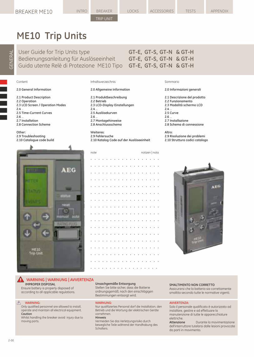
LOCKSBREAKER ME10 INTRO BREAKER ACCESSORIES TESTS APPENDIX
TRIP UNIT
GE
NE
RA
L
Content
2.0 General Information
2.1 Product Description2.2 Operation2.3 LCD Screen / Operation Modes2.4 ...2.5 Time-Current Curves2.6 ...2.7 Installation2.8 Connection Scheme
Other:2.9 Troubleshooting2.10 Catalogue code build
Inhaltsverzeichnis
2.0 Allgemeine Information
2.1 Produktbeschreibung2.2 Betrieb2.3 LCD-Display Einstellungen2.4 ...2.5 Auslösekurven2.6 ...2.7 Montagehinweise2.8 Anschlussschema
Weiteres:2.9 Fehlersuche2.10 Katalog Code auf der Auslöseeinheit
Sommario
2.0 Informazioni generali
2.1 Descrizione del prodotto2.2 Funzionamento2.3 Modalità schermo LCD2.4 ...2.5 Curve2.6 ...2.7 Installazione2.8 Schema di connessione
Altro:2.9 Risoluzione dei problemi2.10 Struttura codici catalogo
note notizen | nota
. . . . . . . . . . . . . . . . . .
. . . . . . . . . . . . . . . . . .
. . . . . . . . . . . . . . . . . .
. . . . . . . . . . . . . . . . . .
. . . . . . . . . . . . . . . . . .
. . . . . . . . . . . . . . . . . .
. . . . . . . . . . . . . . . . . .
. . . . . . . . . . . . . . . . . .
. . . . . . . . . . . . . . . . . .
. . . . . . . . . . . . . . . . . .
. . . . . . . . . . . . . . . . . .
. . . . . . . . . . . . . . . . . .
. . . . . . . . . . . . . . . . . .
. . . . . . . . . . . . . . . . . .
. . . . . . . . . . . . . . . . . .
. . . . . . . . . . . . . . . . . .
. . . . . . . . . . . . . . . . . .
WARNUNG:Nur qualifiziertes Personal darf die Installation, den Betrieb und die Wartung der elektrischen Geräte vornehmen.HinweisVermeiden Sie das Verletzungsrisiko durch bewegliche Teile während der Handhabung des Schalters.
WARNING: Only qualified personnel are allowed to install, operate and maintain all electrical equipment. CautionWhilst handling the breaker avoid injury due to moving parts.
AVVERTENZA: Solo il personale qualificato è autorizzato ad installare, gestire e ad effettuare la manutenzione di tutte le apparecchiature elettriche. Attenzione Durante la movimentazione dell'interruttore tutelarsi dalle lesioni provocate da parti in movimento.
WARNING | WARNUNG | AVVERTENZAUnsachgemäße EntsorgungStellen Sie bitte sicher, dass die Batterie ordnungsgemäß, nach den einschlägigen Bestimmungen entsorgt wird.
IMPROPER DISPOSALEnsure battery is properly disposed of according to all applicable regulations.
SMALTIMENTO NON CORRETTOAssicurarsi che la batteria sia correttamente smaltita secondo tutte le normative vigenti.
2-00
ME10 Trip Units
User Guide for Trip Units type GT-E, GT-S, GT-N & GT-HBedienungsanleitung für Auslöseeinheit GT-E, GT-S, GT-N & GT-HGuida utente Relè di Protezione ME10 Tipo GT-E, GT-S, GT-N & GT-H
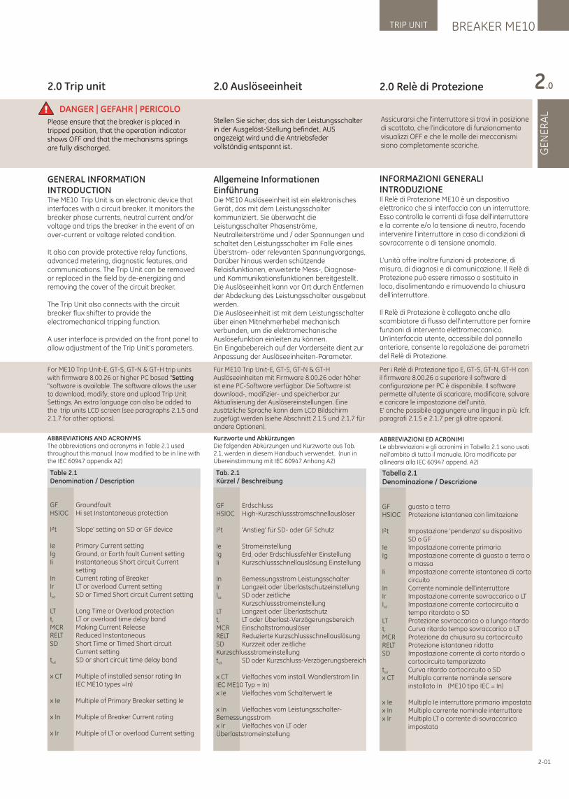
Kurzworte und AbkürzungenDie folgenden Abkürzungen und Kurzworte aus Tab. 2.1, werden in diesem Handbuch verwendet. (nun in Übereinstimmung mit IEC 60947 Anhang A2)
2.0 Relè di Protezione
INFORMAZIONI GENERALIINTRODUZIONEIl Relè di Protezione ME10 è un dispositivo elettronico che si interfaccia con un interruttore. Esso controlla le correnti di fase dell'interruttore e la corrente e/o la tensione di neutro, facendo intervenire l'interruttore in caso di condizioni di sovracorrente o di tensione anomala.
L'unità offre inoltre funzioni di protezione, di misura, di diagnosi e di comunicazione. Il Relè di Protezione può essere rimosso o sostituito in loco, disalimentando e rimuovendo la chiusura dell'interruttore.
Il Relè di Protezione è collegato anche allo scambiatore di flusso dell'interruttore per fornire funzioni di intervento elettromeccanico. Un'interfaccia utente, accessibile dal pannello anteriore, consente la regolazione dei parametri del Relè di Protezione.
2.0 Trip unit
GENERAL INFORMATIONINTRODUCTIONThe ME10 Trip Unit is an electronic device that interfaces with a circuit breaker. It monitors the breaker phase currents, neutral current and/or voltage and trips the breaker in the event of an over-current or voltage related condition.
It also can provide protective relay functions, advanced metering, diagnostic features, and communications. The Trip Unit can be removed or replaced in the field by de-energizing and removing the cover of the circuit breaker.
The Trip Unit also connects with the circuit breaker flux shifter to provide the electromechanical tripping function.
A user interface is provided on the front panel to allow adjustment of the Trip Unit’s parameters.
2.0 Auslöseeinheit
Allgemeine InformationenEinführung Die ME10 Auslöseeinheit ist ein elektronisches Gerät, das mit dem Leistungsschalter kommuniziert. Sie überwacht die Leistungsschalter Phasenströme, Neutralleiterströme und / oder Spannungen und schaltet den Leistungsschalter im Falle eines Überstrom- oder relevanten Spannungvorgangs.Darüber hinaus werden schützende Relaisfunktionen, erweiterte Mess-, Diagnose- und Kommunikationsfunktionen bereitgestellt .Die Auslöseeinheit kann vor Ort durch Entfernen der Abdeckung des Leistungsschalter ausgebaut werden. Die Auslöseeinheit ist mit dem Leistungsschalter über einen Mitnehmerhebel mechanisch verbunden, um die elektromechanische Auslösefunktion einleiten zu können. Ein Eingabebereich auf der Vorderseite dient zur Anpassung der Auslöseeinheiten-Parameter.
DANGER | GEFAHR | PERICOLOStellen Sie sicher, das sich der Leistungsschalter in der Ausgelöst-Stellung befindet, AUS angezeigt wird und die Antriebsfeder vollständig entspannt ist.
Please ensure that the breaker is placed in tripped position, that the operation indicator shows OFF and that the mechanisms springs are fully discharged.
Assicurarsi che l'interruttore si trovi in posizione di scattato, che l'indicatore di funzionamento visualizzi OFF e che le molle dei meccanismi siano completamente scariche.
2-01
Table 2.1Denomination / Description
GF GroundfaultHSIOC Hi set Instantaneous protection
I²t 'Slope' setting on SD or GF device
Ie Primary Current settingIg Ground, or Earth fault Current settingIi Instantaneous Short circuit Current settingIn Current rating of BreakerIr LT or overload Current settingI SD or Timed Short circuit Current settingsd
LT Long Time or Overload protectiont LT or overload time delay bandr
MCR Making Current ReleaseRELT Reduced InstantaneousSD Short Time or Timed Short circuit Current settingt SD or short circuit time delay bandsd
x CT Multiple of installed sensor rating (In IEC ME10 types =In)
x Ie Multiple of Primary Breaker setting Ie
x In Multiple of Breaker Current rating
x Ir Multiple of LT or overload Current setting
Tab. 2.1Kürzel / Beschreibung
GF ErdschlussHSIOC High-Kurzschlussstromschnellauslöser
I²t 'Anstieg' für SD- oder GF Schutz
Ie StromeinstellungIg Erd, oder Erdschlussfehler EinstellungIi Kurzschlussschnellauslösung Einstellung
In Bemessungsstrom LeistungsschalterIr Langzeit oder ÜberlastschutzeinstellungI SD oder zeitlichesd
KurzschlussstromeinstellungLT Langzeit oder Überlastschutzt LT oder Überlast-Verzögerungsbereichr
MCR EinschaltstromauslöserRELT Reduzierte KurzschlussschnellauslösungSD Kurzzeit oder zeitliche Kurzschlussstromeinstellungt SD oder Kurzschluss-Verzögerungsbereichsd
x CT Vielfaches vom install. Wandlerstrom (In IEC ME10 Typ = In)x Ie Vielfaches vom Schalterwert Ie
x In Vielfaches vom Leistungsschalter- Bemessungsstromx Ir Vielfaches von LT oder Überlaststromeinstellung
Tabella 2.1Denominazione / Descrizione
GF guasto a terraHSIOC Protezione istantanea con limitazione
I²t Impostazione 'pendenza' su dispositivo SD o GFIe Impostazione corrente primariaIg Impostazione corrente di guasto a terra o a massaIi Impostazione corrente istantanea di corto circuitoIn Corrente nominale dell'interruttoreIr Impostazione corrente sovraccarico o LTI Impostazione corrente cortocircuito a sd
tempo ritardato o SD LT Protezione sovraccarico o a lungo ritardot Curva ritardo tempo sovraccarico o LTr
MCR Protezione da chiusura su cortocircuitoRELT Protezione istantanea ridottaSD Impostazione corrente di corto ritardo o cortocircuito temporizzatot Curva ritardo cortocircuito o SDsd
x CT Multiplo corrente nominale sensore installato In (ME10 tipo IEC = In)
x Ie Multiplo Ie interruttore primario impostatax In Multiplo corrente nominale interruttorex Ir Multiplo LT o corrente di sovraccarico impostata
BREAKER ME10TRIP UNIT
GE
NE
RA
L
2.0
ABBREVIATIONS AND ACRONYMSThe abbreviations and acronyms in Table 2.1 used throughout this manual. (now modified to be in line with the IEC 60947 appendix A2)
For ME10 Trip Unit-E, GT-S, GT-N & GT-H trip units with firmware 8.00.26 or higher PC based "Setting "software is available. The software allows the user to download, modify, store and upload Trip Unit Settings. An extra language can also be added to the trip units LCD screen (see paragraphs 2.1.5 and 2.1.7 for other options).
Für ME10 Trip Unit-E, GT-S, GT-N & GT-H Auslöseeinheiten mit Firmware 8.00.26 oder höher ist eine PC-Software verfügbar. Die Software ist download-, modifizier- und speicherbar zur Aktualisierung der Auslösereinstellungen. Eine zusätzliche Sprache kann dem LCD Bildschirm zugefügt werden (siehe Abschnitt 2.1.5 und 2.1.7 für andere Optionen).
Per i Relè di Protezione tipo E, GT-S, GT-N, GT-H con il firmware 8.00.26 o superiore il software di configurazione per PC è disponibile. Il software permette all'utente di scaricare, modificare, salvare e caricare le impostazione dell'unità. E' anche possibile aggiungere una lingua in più (cfr. paragrafi 2.1.5 e 2.1.7 per gli altre opzioni).
ABBREVIAZIONI ED ACRONIMILe abbreviazioni e gli acronimi in Tabella 2.1 sono usatinell'ambito di tutto il manuale. (Ora modificate perallinearsi alla IEC 60947 append. A2)
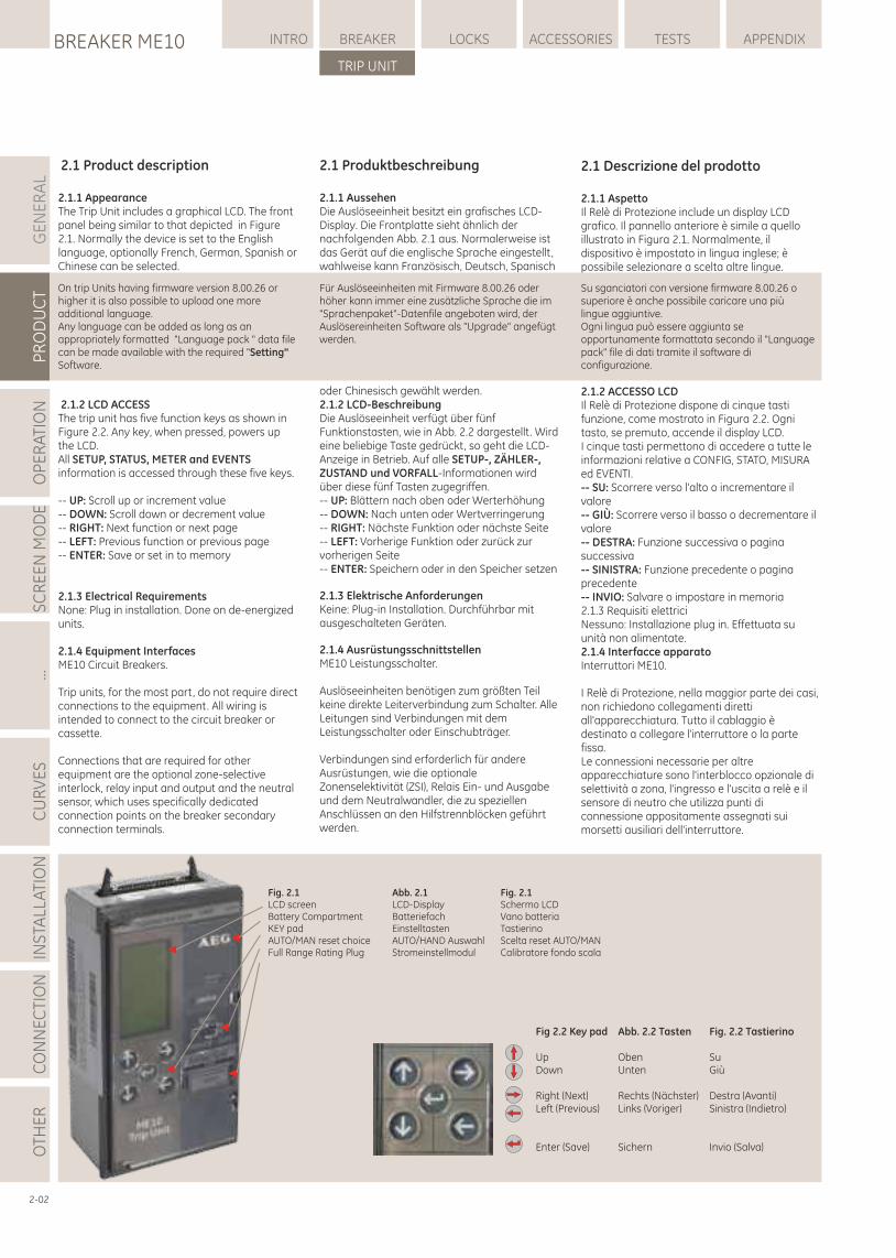
2.1 Product description
2.1.1 AppearanceThe Trip Unit includes a graphical LCD. The front panel being similar to that depicted in Figure 2.1. Normally the device is set to the English language, optionally French, German, Spanish or Chinese can be selected.
2.1.2 LCD ACCESSThe trip unit has five function keys as shown in Figure 2.2. Any key, when pressed, powers up the LCD.All SETUP, STATUS, METER and EVENTS information is accessed through these five keys.
-- UP: Scroll up or increment value-- DOWN: Scroll down or decrement value-- RIGHT: Next function or next page-- LEFT: Previous function or previous page-- ENTER: Save or set in to memory
2.1.3 Electrical RequirementsNone: Plug in installation. Done on de-energized units.
2.1.4 Equipment InterfacesME10 Circuit Breakers.
Trip units, for the most part, do not require direct connections to the equipment. All wiring is intended to connect to the circuit breaker or cassette.
Connections that are required for other equipment are the optional zone-selective interlock, relay input and output and the neutral sensor, which uses specifically dedicated connection points on the breaker secondary connection terminals.
2.1 Produktbeschreibung
2.1.1 Aussehen Die Auslöseeinheit besitzt ein grafisches LCD-Display. Die Frontplatte sieht ähnlich der nachfolgenden Abb. 2.1 aus. Normalerweise ist das Gerät auf die englische Sprache eingestellt, wahlweise kann Französisch, Deutsch, Spanisch
oder Chinesisch gewählt werden.2.1.2 LCD-BeschreibungDie Auslöseeinheit verfügt über fünf Funktionstasten, wie in Abb. 2.2 dargestellt . Wird eine beliebige Taste gedrückt, so geht die LCD-Anzeige in Betrieb. Auf alle SETUP-, ZÄHLER-, ZUSTAND und VORFALL-Informationen wird über diese fünf Tasten zugegriffen. -- UP: Blättern nach oben oder Werterhöhung-- DOWN: Nach unten oder Wertverringerung-- RIGHT: Nächste Funktion oder nächste Seite -- LEFT: Vorherige Funktion oder zurück zur vorherigen Seite -- ENTER: Speichern oder in den Speicher setzen
2.1.3 Elektrische Anforderungen Keine: Plug-in Installation. Durchführbar mit ausgeschalteten Geräten.
2.1.4 AusrüstungsschnittstellenME10 Leistungsschalter.
Auslöseeinheiten benötigen zum größten Teil keine direkte Leiterverbindung zum Schalter. Alle Leitungen sind Verbindungen mit dem Leistungsschalter oder Einschubträger.
Verbindungen sind erforderlich für andere Ausrüstungen, wie die optionale Zonenselektivität (ZSI), Relais Ein- und Ausgabe und dem Neutralwandler, die zu speziellen Anschlüssen an den Hilfstrennblöcken geführt werden.
GE
NE
RA
LP
RO
DU
CT
OP
ER
ATI
ON
SC
RE
EN
MO
DE
...C
UR
VE
SIN
STA
LLA
TIO
NC
ON
NE
CTI
ON
LOCKSBREAKER ME10 INTRO BREAKER ACCESSORIES TESTS APPENDIX
TRIP UNIT
OTH
ER
2.1 Descrizione del prodotto
2.1.1 AspettoIl Relè di Protezione include un display LCD grafico. Il pannello anteriore è simile a quello illustrato in Figura 2.1. Normalmente, il dispositivo è impostato in lingua inglese; è possibile selezionare a scelta altre lingue.
2.1.2 ACCESSO LCDIl Relè di Protezione dispone di cinque tasti funzione, come mostrato in Figura 2.2. Ogni tasto, se premuto, accende il display LCD.I cinque tasti permettono di accedere a tutte le informazioni relative a CONFIG, STATO, MISURA ed EVENTI.-- SU: Scorrere verso l'alto o incrementare il valore-- GIÙ: Scorrere verso il basso o decrementare il valore-- DESTRA: Funzione successiva o pagina successiva-- SINISTRA: Funzione precedente o pagina precedente-- INVIO: Salvare o impostare in memoria2.1.3 Requisiti elettriciNessuno: Installazione plug in. Effettuata su unità non alimentate.2.1.4 Interfacce apparatoInterruttori ME10.
I Relè di Protezione, nella maggior parte dei casi, non richiedono collegamenti diretti all'apparecchiatura. Tutto il cablaggio è destinato a collegare l'interruttore o la parte fissa. Le connessioni necessarie per altre apparecchiature sono l'interblocco opzionale di selettività a zona, l'ingresso e l'uscita a relè e il sensore di neutro che utilizza punti di connessione appositamente assegnati sui morsetti ausiliari dell'interruttore.
2-02
On trip Units having firmware version 8.00.26 or higher it is also possible to upload one more additional language.Any language can be added as long as an appropriately formatted "Language pack " data file can be made available with the required "Setting" Software.
Für Auslöseeinheiten mit Firmware 8.00.26 oder höher kann immer eine zusätzliche Sprache die im "Sprachenpaket"-Datenfile angeboten wird, der Auslösereinheiten Software als "Upgrade" angefügt werden.
Su sganciatori con versione firmware 8.00.26 o superiore è anche possibile caricare una più lingue aggiuntive. Ogni lingua può essere aggiunta se opportunamente formattata secondo il "Language pack" file di dati tramite il software di configurazione.
Fig. 2.1 Abb. 2.1LCD screen LCD-DisplayBattery Compartment BatteriefachKEY pad EinstelltastenAUTO/MAN reset choice AUTO/HAND AuswahlFull Range Rating Plug Stromeinstellmodul
Fig. 2.1Schermo LCDVano batteriaTastierinoScelta reset AUTO/MAN Calibratore fondo scala
Fig 2.2 Key pad Abb. 2.2 Tasten
Up ObenDown Unten
Right (Next) Rechts (Nächster)Left (Previous) Links (Voriger)
Enter (Save) Sichern
Fig. 2.2 Tastierino
SuGiù
Destra (Avanti)Sinistra (Indietro)
Invio (Salva)
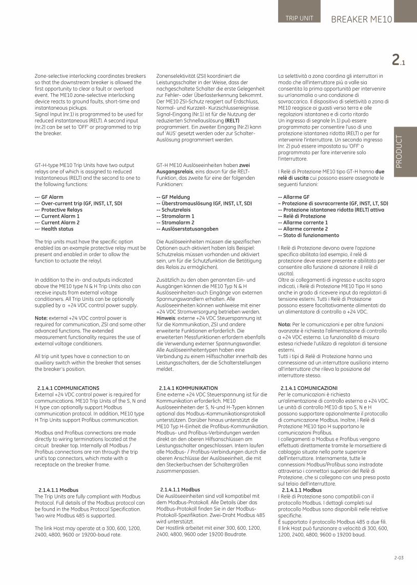
BREAKER ME10TRIP UNIT
PR
OD
UC
T
2.1
2-03
La selettività a zona coordina gli interruttori in modo che all'interruttore più a valle sia consentita la prima opportunità per intervenire su un'anomalia o una condizione di sovraccarico. Il dispositivo di selettività a zona di ME10 reagisce ai guasti verso terra e alle regolazioni istantanea e di corto ritardoUn ingresso di segnale (n.1) può essere programmato per consentire l'uso di una protezione istantanea ridotta (RELT) o per far intervenire l'interruttore. Un secondo ingresso (nr. 2) può essere impostata su 'OFF' o programmato per fare intervenire solo l'interruttore.
I Relè di Protezione ME10 tipo GT-H hanno due relè di uscita cui possono essere assegnate le seguenti funzioni:
-- Allarme GF – Protezione di sovracorrente (GF, INST, LT, SD)-- Protezione istantanea ridotta (RELT) attiva-- Relè di Protezione-- Allarme corrente 1-- Allarme corrente 2-- Stato di funzionamento
I Relè di Protezione devono avere l'opzione specifica abilitata (ad esempio, il relè di protezione deve essere presente e abilitato per consentire alla funzione di azionare il relè di uscita).Oltre ai collegamenti di ingresso e uscita sopra indicati, i Relè di Protezione ME10 Tipo H sono anche in grado di ricevere input da regolatori di tensione esterni. Tutti i Relè di Protezione possono essere facoltativamente alimentati da un alimentatore di controllo a +24 VDC.
Nota: Per le comunicazioni e per altre funzioni avanzate è richiesta l'alimentazione di controllo a +24 VDC esterna. La funzionalità di misura estesa richiede l'utilizzo di regolatori di tensione esterni.Tutti i tipi di Relè di Protezione hanno una connessione ad un interruttore ausiliario interno all'interruttore che rileva la posizione del interruttore stesso.
2.1.4.1 COMUNICAZIONIPer le comunicazioni è richiesta un'alimentazione di controllo esterna a +24 VDC. Le unità di controllo ME10 di tipo S, N e H possono supportare opzionalmente il protocollo di comunicazione Modbus. Inoltre, i Relè di Protezione ME10 tipo H supportano le comunicazioni Profibus.I collegamenti a Modbus e Profibus vengono effettuati direttamente tramite le morsettiere di cablaggio situate nella parte superiore dell'interruttore. Internamente, tutte le connessioni Modbus/Profibus sono instradate attraverso i connettori superiori del Relè di Protezione, che si collegano con una presa posta sul telaio dell'interruttore. 2.1.4.1.1 ModbusI Relè di Protezione sono compatibili con il protocollo Modbus. I dettagli completi sul protocollo Modbus sono disponibili nelle relative specifiche.È supportato il protocollo Modbus 485 a due fili.Il link Host può funzionare a velocità di 300, 600, 1200, 2400, 4800, 9600 o 19200 baud.
Zone-selective interlocking coordinates breakers so that the downstream breaker is allowed the first opportunity to clear a fault or overload event. The ME10 zone-selective interlocking device reacts to ground faults, short-time and instantaneous pickups.Signal Input (nr.1) is programmed to be used for reduced instantaneous (RELT). A second input (nr.2) can be set to 'OFF' or programmed to trip the breaker.
GT-H-type ME10 Trip Units have two output relays one of which is assigned to reduced Instantaneous (RELT) and the second to one to the following functions:
--· GF Alarm--· Over-current trip (GF, INST, LT, SD)--· Protective Relays--· Current Alarm 1--· Current Alarm 2--· Health status
The trip units must have the specific option enabled (as an example protective relay must be present and enabled in order to allow the function to actuate the relay).
In addition to the in- and outputs indicated above the ME10 type N & H Trip Units also can receive inputs from external voltage conditioners. All Trip Units can be optionally supplied by a +24 VDC control power supply.
Note: external +24 VDC control power is required for communication, ZSI and some other advanced functions. The extended measurement functionality requires the use of external voltage conditioners.
All trip unit types have a connection to an auxiliary switch within the breaker that senses the breaker’s position.
2.1.4.1 COMMUNICATIONSExternal +24 VDC control power is required for communications. ME10 Trip Units of the S, N and H type can optionally support Modbus communication protocol. In addition, ME10 type H Trip Units support Profibus communication.
Modbus and Profibus connections are made directly to wiring terminations located at the circuit breaker top. Internally all Modbus / Profibus connections are ran through the trip unit’s top connectors, which mate with a receptacle on the breaker frame.
2.1.4.1.1 ModbusThe Trip Units are fully compliant with Modbus Protocol. Full details of the Modbus protocol can be found in the Modbus Protocol Specification.Two wire Modbus 485 is supported.
The link Host may operate at a 300, 600, 1200, 2400, 4800, 9600 or 19200-baud rate.
Zonenselektivität (ZSI) koordiniert die Leistungsschalter in der Weise, dass der nachgeschaltete Schalter die erste Gelegenheit zur Fehler- oder Überlasterkennung bekommt. Der ME10 ZSI-Schutz reagiert auf Erdschluss, Normal- und Kurzzeit- Kurzschlussereignisse.Signal-Eingang (Nr.1) ist für die Nutzung der reduzierten Schnellauslösung (RELT) programmiert. Ein zweiter Eingang (Nr.2) kann auf ‘AUS’ gesetzt werden oder zur Schalter-Auslösung programmiert werden.
GT-H ME10 Auslöseeinheiten haben zwei Ausgangsrelais, eins davon für die RELT-Funktion, das zweite für eine der folgenden Funktionen:
-- GF Meldung-- Überstromauslösung (GF, INST, LT, SD)-- Schutzrelais-- Stromalarm 1-- Stromalarm 2-- Auslöserstatusangaben
Die Auslöseeinheiten müssen die spezifischen Optionen auch aktiviert haben (als Beispiel: Schutzrelais müssen vorhanden und aktiviert sein, um für die Schutzfunktion die Betätigung des Relais zu ermöglichen).
Zusätzlich zu den oben genannten Ein- und Ausgängen können die ME10 Typ N & H Auslöseeinheiten auch Eingänge von externen Spannungswandlern erhalten. Alle Auslöseeinheiten können wahlweise mit einer +24 VDC Stromversorgung betrieben werden. Hinweis: externe +24 VDC Steuerspannung ist für die Kommunikation, ZSI und andere erweiterte Funktionen erforderlich. Die erweiterten Messfunktionen erfordern ebenfalls die Verwendung externer Spannungswandler.Alle Auslöseeinheitentypen haben eine Verbindung zu einem Hilfsschalter innerhalb des Leistungsschalters, der die Schalterstellungen meldet.
2.1.4.1 KOMMUNIKATIONEine externe +24 VDC Steuerspannung ist für die Kommunikation erforderlich. ME10 Auslöseeinheiten der S, N-und H-Typen können optional das Modbus-Kommunikationsprotokoll unterstützen. Darüber hinaus unterstützt die ME10 Typ H-Einheit die Profibus-Kommunikation. Modbus- und Profibus-Verbindungen werden direkt an den oberen Hilfsanschlüssen am Leistungsschalter angeschlossen. Intern laufen alle Modbus- / Profibus-Verbindungen durch die oberen Anschlüsse der Auslöseeinheit, die mit den Steckerbuchsen der Schaltergrößen zusammenpassen.
2.1.4.1.1 Modbus Die Auslöseeinheiten sind voll kompatibel mit dem Modbus-Protokoll. Alle Details über das Modbus-Protokoll finden Sie in der Modbus-Protokoll-Spezifikation. Zwei-Draht Modbus 485 wird unterstützt. Der Hostlink arbeitet mit einer 300, 600, 1200, 2400, 4800, 9600 oder 19200 Baudrate.
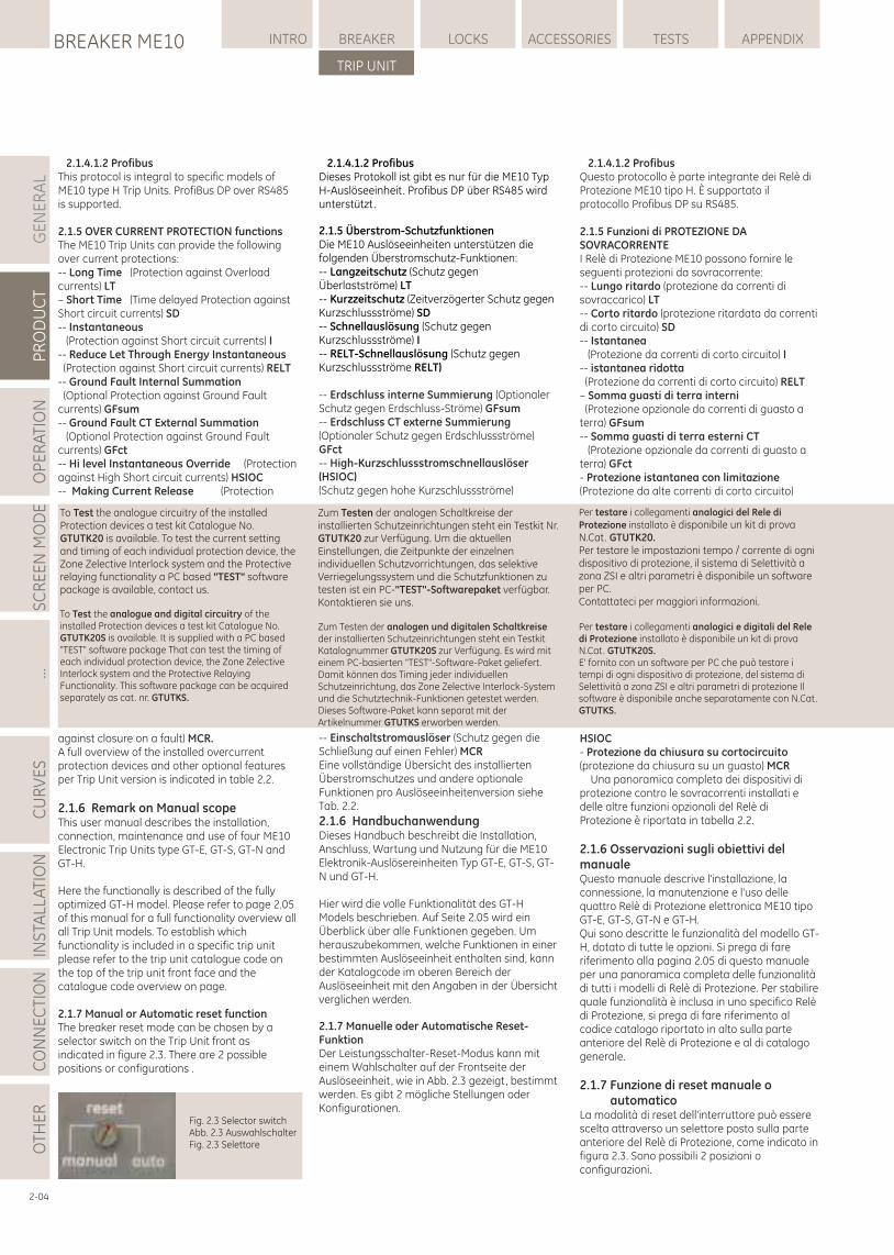
2.1.4.1.2 ProfibusThis protocol is integral to specific models of ME10 type H Trip Units. ProfiBus DP over RS485 is supported.
2.1.5 OVER CURRENT PROTECTION functionsThe ME10 Trip Units can provide the following over current protections:-- Long Time (Protection against Overload currents) LT– Short Time (Time delayed Protection against Short circuit currents) SD-- Instantaneous (Protection against Short circuit currents) I-- Reduce Let Through Energy Instantaneous (Protection against Short circuit currents) RELT-- Ground Fault Internal Summation (Optional Protection against Ground Fault currents) GFsum-- Ground Fault CT External Summation (Optional Protection against Ground Fault currents) GFct-- Hi level Instantaneous Override (Protection against High Short circuit currents) HSIOC-- Making Current Release (Protection
against closure on a fault) MCR.A full overview of the installed overcurrent protection devices and other optional features per Trip Unit version is indicated in table 2.2.
2.1.6 Remark on Manual scopeThis user manual describes the installation, connection, maintenance and use of four ME10 Electronic Trip Units type GT-E, GT-S, GT-N and GT-H.
Here the functionally is described of the fully optimized GT-H model. Please refer to page 2.05 of this manual for a full functionality overview all all Trip Unit models. To establish which functionality is included in a specific trip unit please refer to the trip unit catalogue code on the top of the trip unit front face and the catalogue code overview on page.
2.1.7 Manual or Automatic reset functionThe breaker reset mode can be chosen by a selector switch on the Trip Unit front as indicated in figure 2.3. There are 2 possible positions or configurations .
2.1.4.1.2 Profibus Dieses Protokoll ist gibt es nur für die ME10 Typ H-Auslöseeinheit. Profibus DP über RS485 wird unterstützt.
2.1.5 Überstrom-Schutzfunktionen Die ME10 Auslöseeinheiten unterstützen die folgenden Überstromschutz-Funktionen: -- Langzeitschutz (Schutz gegen Überlastströme) LT -- Kurzzeitschutz (Zeitverzögerter Schutz gegen Kurzschlussströme) SD -- Schnellauslösung (Schutz gegen Kurzschlussströme) I -- RELT-Schnellauslösung (Schutz gegen Kurzschlussströme RELT)
-- Erdschluss interne Summierung (Optionaler Schutz gegen Erdschluss-Ströme) GFsum -- Erdschluss CT externe Summierung (Optionaler Schutz gegen Erdschlussströme) GFct -- High-Kurzschlussstromschnellauslöser (HSIOC)(Schutz gegen hohe Kurzschlussströme)
-- Einschaltstromauslöser (Schutz gegen die Schließung auf einen Fehler) MCREine vollständige Übersicht des installierten Überstromschutzes und andere optionale Funktionen pro Auslöseeinheitenversion siehe Tab. 2.2.
2.1.6 HandbuchanwendungDieses Handbuch beschreibt die Installation, Anschluss, Wartung und Nutzung für die ME10 Elektronik-Auslösereinheiten Typ GT-E, GT-S, GT-N und GT-H.
Hier wird die volle Funktionalität des GT-H Models beschrieben. Auf Seite 2.05 wird ein Überblick über alle Funktionen gegeben. Um herauszubekommen, welche Funktionen in einer bestimmten Auslöseeinheit enthalten sind, kann der Katalogcode im oberen Bereich der Auslöseeinheit mit den Angaben in der Übersicht verglichen werden.
2.1.7 Manuelle oder Automatische Reset-Funktion Der Leistungsschalter-Reset-Modus kann mit einem Wahlschalter auf der Frontseite der Auslöseeinheit, wie in Abb. 2.3 gezeigt, bestimmt werden. Es gibt 2 mögliche Stellungen oder Konfigurationen.
GE
NE
RA
LP
RO
DU
CT
OP
ER
ATI
ON
SC
RE
EN
MO
DE
...C
UR
VE
SIN
STA
LLA
TIO
NC
ON
NE
CTI
ON
LOCKSBREAKER ME10 INTRO BREAKER ACCESSORIES TESTS APPENDIX
TRIP UNIT
OTH
ER
Fig. 2.3 Selector switchAbb. 2.3 AuswahlschalterFig. 2.3 Selettore
2-04
2.1.4.1.2 ProfibusQuesto protocollo è parte integrante dei Relè di Protezione ME10 tipo H. È supportato il protocollo Profibus DP su RS485.
2.1.5 Funzioni di PROTEZIONE DA SOVRACORRENTEI Relè di Protezione ME10 possono fornire le seguenti protezioni da sovracorrente:-- Lungo ritardo (protezione da correnti di sovraccarico) LT-- Corto ritardo (protezione ritardata da correnti di corto circuito) SD-- Istantanea (Protezione da correnti di corto circuito) I-- istantanea ridotta (Protezione da correnti di corto circuito) RELT– Somma guasti di terra interni (Protezione opzionale da correnti di guasto a terra) GFsum-- Somma guasti di terra esterni CT (Protezione opzionale da correnti di guasto a terra) GFct- Protezione istantanea con limitazione (Protezione da alte correnti di corto circuito)
HSIOC- Protezione da chiusura su cortocircuito (protezione da chiusura su un guasto) MCR Una panoramica completa dei dispositivi di protezione contro le sovracorrenti installati e delle altre funzioni opzionali del Relè di Protezione è riportata in tabella 2.2.
2.1.6 Osservazioni sugli obiettivi del manualeQuesto manuale descrive l'installazione, la connessione, la manutenzione e l'uso delle quattro Relè di Protezione elettronica ME10 tipo GT-E, GT-S, GT-N e GT-H.Qui sono descritte le funzionalità del modello GT-H, dotato di tutte le opzioni. Si prega di fare riferimento alla pagina 2.05 di questo manuale per una panoramica completa delle funzionalità di tutti i modelli di Relè di Protezione. Per stabilire quale funzionalità è inclusa in uno specifico Relè di Protezione, si prega di fare riferimento al codice catalogo riportato in alto sulla parte anteriore del Relè di Protezione e al di catalogo generale.
2.1.7 Funzione di reset manuale o automaticoLa modalità di reset dell'interruttore può essere scelta attraverso un selettore posto sulla parte anteriore del Relè di Protezione, come indicato in figura 2.3. Sono possibili 2 posizioni o configurazioni.
To Test the analogue circuitry of the installed Protection devices a test kit Catalogue No. GTUTK20 is available. To test the current setting and timing of each individual protection device, the Zone Zelective Interlock system and the Protective relaying functionality a PC based "TEST" software package is available, contact us.
To Test the analogue and digital circuitry of the installed Protection devices a test kit Catalogue No. GTUTK20S is available. It is supplied with a PC based "TEST" software package That can test the timing of each individual protection device, the Zone Zelective Interlock system and the Protective Relaying Functionality. This software package can be acquired separately as cat. nr. GTUTKS.
Per testare i collegamenti analogici del Rele di Protezione installato è disponibile un kit di prova N.Cat. GTUTK20. Per testare le impostazioni tempo / corrente di ogni dispositivo di protezione, il sistema di Selettività a zona ZSI e altri parametri è disponibile un software per PC.Contattateci per maggiori informazioni.
Per testare i collegamenti analogici e digitali del Rele di Protezione installato è disponibile un kit di prova N.Cat. GTUTK20S. E' fornito con un software per PC che può testare i tempi di ogni dispositivo di protezione, del sistema di Selettività a zona ZSI e altri parametri di protezione Il software è disponibile anche separatamente con N.Cat. GTUTKS.
Zum Testen der analogen Schaltkreise der installierten Schutzeinrichtungen steht ein Testkit Nr. GTUTK20 zur Verfügung. Um die aktuellen Einstellungen, die Zeitpunkte der einzelnen individuellen Schutzvorrichtungen, das selektive Verriegelungssystem und die Schutzfunktionen zu testen ist ein PC-"TEST"-Softwarepaket verfügbar. Kontaktieren sie uns.
Zum Testen der analogen und digitalen Schaltkreise der installierten Schutzeinrichtungen steht ein Testkit Katalognummer GTUTK20S zur Verfügung. Es wird mit einem PC-basierten "TEST"-Software-Paket geliefert. Damit können das Timing jeder individuellen Schutzeinrichtung, das Zone Zelective Interlock-System und die Schutztechnik-Funktionen getestet werden. Dieses Software-Paket kann separat mit der Artikelnummer GTUTKS erworben werden.
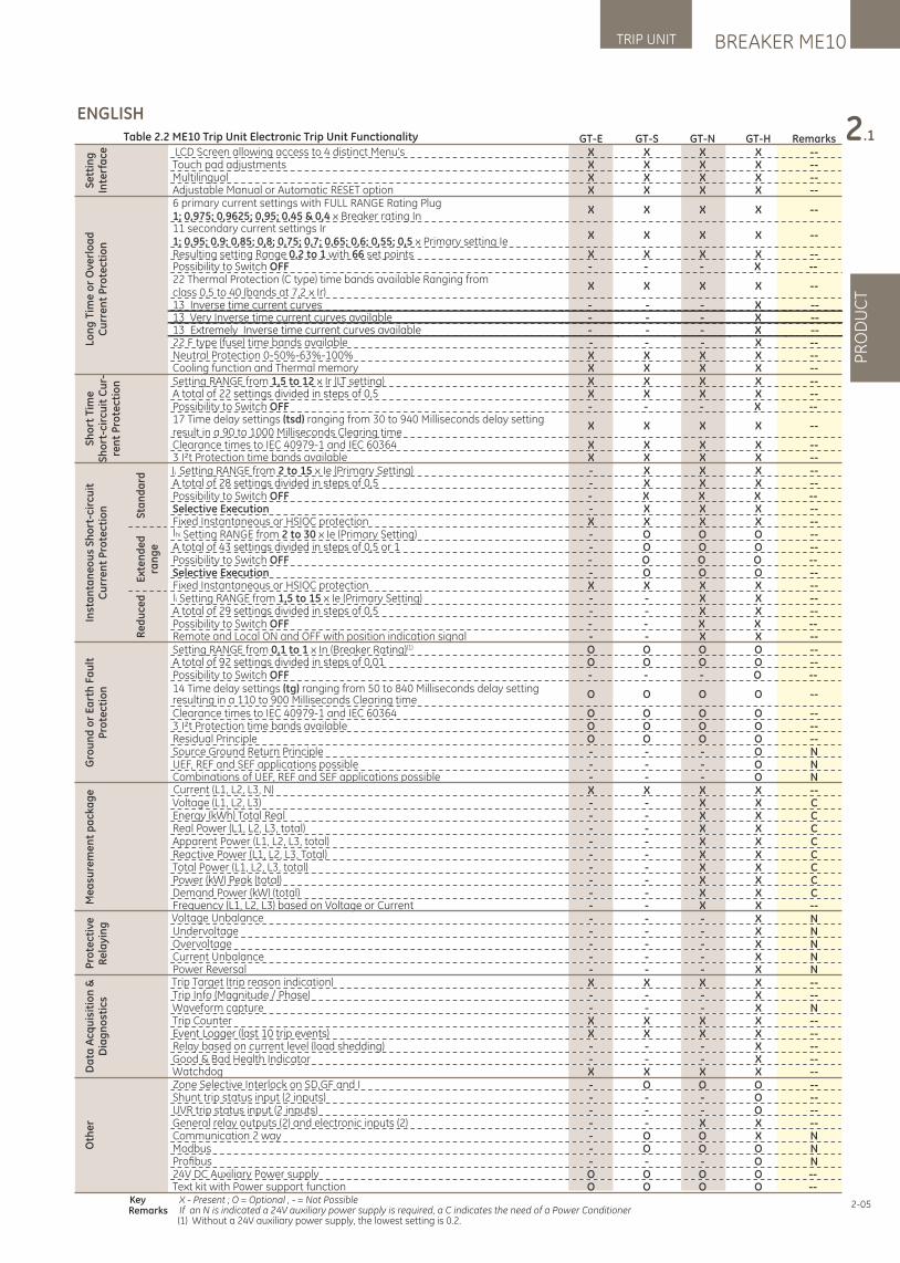
BREAKER ME10TRIP UNIT
PR
OD
UC
T
2.1
2-05
ENGLISHTable 2.2 ME10 Trip Unit Electronic Trip Unit Functionality GT-E GT-S GT-N GT-H Remarks
Key X - Present ; O = Optional , - = Not PossibleRemarks If an N is indicated a 24V auxiliary power supply is required, a C indicates the need of a Power Conditioner
(1) Without a 24V auxiliary power supply, the lowest setting is 0.2.
Se
ttin
g
Inte
rfa
ce LCD Screen allowing access to 4 distinct Menu’s X X X X --Touch pad adjustments X X X X --Multilingual X X X X --Adjustable Manual or Automatic RESET option X X X X --
Lon
g T
ime
or
Ov
erl
oa
d
Cu
rre
nt
Pro
tect
ion
6 primary current settings with FULL RANGE Rating Plug 1; 0,975; 0,9625; 0,95; 0,45 & 0,4 x Breaker rating In
X X X X --
11 secondary current settings Ir 1; 0,95; 0,9; 0,85; 0,8; 0,75; 0,7; 0,65; 0,6; 0,55; 0,5 x Primary setting Ie
X X X X --
Resulting setting Range 0,2 to 1 with 66 set points X X X X --
22 Thermal Protection (C type) time bands available Ranging from class 0,5 to 40 (bands at 7,2 x Ir)
X X X X --
22 F type (fuse) time bands available - - - X --Neutral Protection 0-50%-63%-100% X X X X --Cooling function and Thermal memory X X X X --
Sh
ort
Tim
e
Sh
ort
-cir
cuit
Cu
r-re
nt
Pro
tect
ion Setting RANGE from 1,5 to 12 x Ir (LT setting) X X X X --
A total of 22 settings divided in steps of 0,5 X X X X --Possibility to Switch OFF - - - X --17 Time delay settings (tsd) ranging from 30 to 940 Milliseconds delay setting result in a 90 to 1000 Milliseconds Clearing time
X X X X --
Clearance times to IEC 40979-1 and IEC 60364 X X X X --3 I²t Protection time bands available X X X X --
Inst
an
tan
eo
us
Sh
ort
-cir
cuit
C
urr
en
t P
rote
ctio
n
Sta
nd
ard
Ii
Setting RANGE from 2 to 15 x Ie (Primary Setting) - X X X --A total of 28 settings divided in steps of 0,5 - X X X --Possibility to Switch OFF - X X X --Selective Execution - X X X --Fixed Instantaneous or HSIOC protection X X X X --
Ext
en
de
d
ran
ge
Ihi Setting RANGE from 2 to 30 x Ie (Primary Setting) - O O O --A total of 43 settings divided in steps of 0,5 or 1 - O O O --Possibility to Switch OFF - O O O --Selective Execution - O O O --Fixed Instantaneous or HSIOC protection X X X X --
Re
du
ced
Ii
Setting RANGE from 1,5 to 15 x Ie (Primary Setting) - - X X --A total of 29 settings divided in steps of 0,5 - - X X --Possibility to Switch OFF - - X X --Remote and Local ON and OFF with position indication signal - - X X --
Gro
un
d o
r E
art
h F
au
lt
Pro
tect
ion
Setting RANGE from (1)0,1 to 1 x In (Breaker Rating) O O O O --A total of 92 settings divided in steps of 0,01 O O O O --Possibility to Switch OFF - - - O --14 Time delay settings (tg) ranging from 50 to 840 Milliseconds delay setting resulting in a 110 to 900 Milliseconds Clearing time
O O O O --
Clearance times to IEC 40979-1 and IEC 60364 O O O O --3 I²t Protection time bands available O O O O --Residual Principle O O O O --Source Ground Return Principle - - - O NUEF, REF and SEF applications possible - - - O NCombinations of UEF, REF and SEF applications possible - - - O N
Me
asu
rem
en
t p
ack
ag
e Current (L1, L2, L3, N) X X X X --Voltage (L1, L2, L3) - - X X CEnergy (kWh) Total Real - - X X CReal Power (L1, L2, L3, total) - - X X CApparent Power (L1, L2, L3, total) - - X X CReactive Power (L1, L2, L3, Total) - - X X CTotal Power (L1, L2, L3, total) - - X X CPower (kW) Peak (total) - - X X CDemand Power (kW) (total) - - X X CFrequency (L1, L2, L3) based on Voltage or Current - - X X --
Pro
tect
ive
R
ela
yin
g
Voltage Unbalance - - - X NUndervoltage - - - X NOvervoltage - - - X NCurrent Unbalance - - - X NPower Reversal - - - X N
Da
ta A
cqu
isit
ion
&
Dia
gn
ost
ics
Trip Target (trip reason indication) X X X X --Trip Info (Magnitude / Phase) - - - X --Waveform capture - - - X NTrip Counter X X X X --Event Logger (last 10 trip events) X X X X --Relay based on current level (load shedding) - - - X --Good & Bad Health Indicator - - - X --Watchdog X X X X --
Oth
er
Zone Selective Interlock on SD, GF and I - O O O --Shunt trip status input (2 inputs) - - - O --UVR trip status input (2 inputs) - - - O --General relay outputs (2) and electronic inputs (2) - - X X --Communication 2 way - O O X NModbus - O O O NProfi bus - - - O N24V DC Auxiliary Power supply O O O O --Text kit with Power support function O O O O --
13 Inverse time current curves13 Very Inverse time current curves available13 Extremely Inverse time current curves available
- - - X --- - - X --- - - X --
Possibility to Switch OFF - - - X --
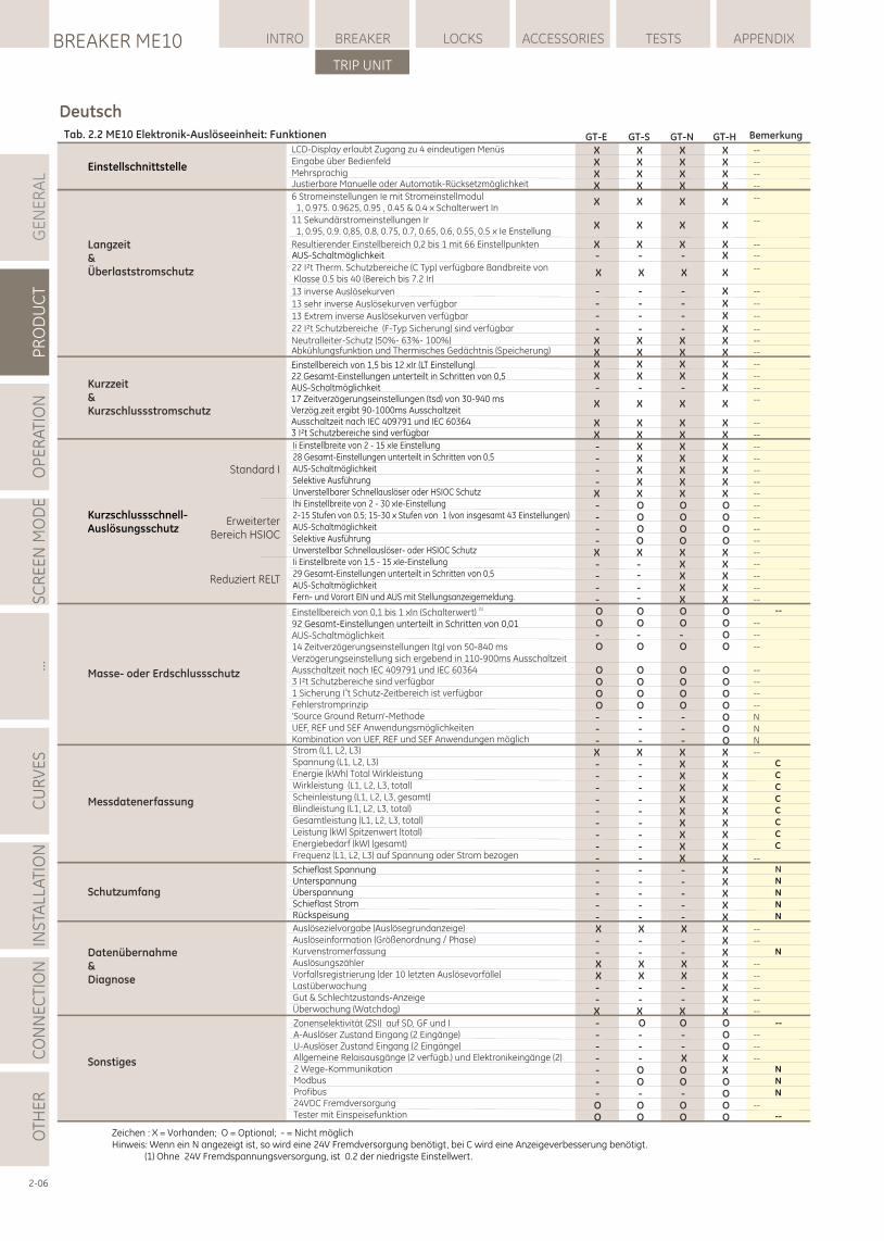
GE
NE
RA
LP
RO
DU
CT
OP
ER
ATI
ON
SC
RE
EN
MO
DE
...C
UR
VE
SIN
STA
LLA
TIO
NC
ON
NE
CTI
ON
LOCKSBREAKER ME10 INTRO BREAKER ACCESSORIES TESTS APPENDIX
TRIP UNIT
OTH
ER
2-06
DeutschTab. 2.2 ME10 Elektronik-Auslöseeinheit: Funktionen GT-E GT-S GT-N GT-H Bemerkung
LCD-Display erlaubt Zugang zu 4 eindeutigen Menüs X X X X --Eingabe über Bedienfeld X X X X --Mehrsprachig X X X X --Justierbare Manuelle oder Automatik-Rücksetzmöglichkeit X X X X --
Resultierender Einstellbereich 0,2 bis 1 mit 66 Einstellpunkten X X X X --
--
--
--X X X X
X X X X
X X XX6 Stromeinstellungen Ie mit Stromeinstellmodul 1, 0.975. 0.9625, 0.95 , 0.45 & 0.4 x Schalterwert In11 Sekundärstromeinstellungen Ir 1, 0.95, 0.9. 0,85, 0.8, 0.75, 0.7, 0.65, 0.6, 0.55, 0.5 x Ie Enstellung
22 I²t Therm. Schutzbereiche (C Typ) verfügbare Bandbreite von Klasse 0.5 bis 40 (Bereich bis 7.2 Ir)
Einstellschnittstelle
Langzeit&Überlaststromschutz
C
C
C
C
C
C
C
C
N
N
N
N
N
N
N
N
--
22 I²t Schutzbereiche (F-Typ Sicherung) sind verfügbar - - - X --
Neutralleiter-Schutz (50%- 63%- 100%) X X X X --Abkühlungsfunktion und Thermisches Gedächtnis (Speicherung) X X X X --
X X X X --
X X X X --
- - - X --
X X X X --
X X X X --
- X X X --
- X X X --
- X X X --
- X X X --
X X X X --
- O O O --
- O O O --
- O O O --
- O O --
X X X X --
- X X --
- X X --
- X X --
- X X --
O O O O --
O O O O --
- - - O --
O O O O --
O O O O --
O O O O --
O O O O --
O O O O --
- - - O N
- - - O N
- - - O N
X X X X --
- - X X- - X X- - X X- - X X- - X X- - X X- - X X- - X X- - X X --
- - - X N
- - - X- - - X- - - X- - - XX X X X --
- - - X --
- - - XX X X X --
X X X X --
- - - X --
- - - X --
X X X X --
- O O O- - - O --
- - - O --
- - X X --
- O O X- O O O- - - OO O O O --
O O O O
--X X X X
Kurzzeit&Kurzschlussstromschutz
Kurzschlussschnell-Auslösungsschutz
Standard I
ErweiterterBereich HSIOC
Reduziert RELT
Masse- oder Erdschlussschutz
Messdatenerfassung
Schutzumfang
Datenübernahme&Diagnose
Sonstiges
O
----
--
Einstellbereich von 1,5 bis 12 xIr (LT Einstellung) 22 Gesamt-Einstellungen unterteilt in Schritten von 0,5AUS-Schaltmöglichkeit 17 Zeitverzögerungseinstellungen (tsd) von 30-940 msVerzög.zeit ergibt 90-1000ms Ausschaltzeit Ausschaltzeit nach IEC 409791 und IEC 60364 3 I²t Schutzbereiche sind verfügbar
Ii Einstellbreite von 2 - 15 xIe Einstellung28 Gesamt-Einstellungen unterteilt in Schritten von 0,5AUS-SchaltmöglichkeitSelektive AusführungUnverstellbarer Schnellauslöser oder HSIOC SchutzIhi Einstellbreite von 2 - 30 xIe-Einstellung2-15 Stufen von 0.5; 15-30 x Stufen von 1 (von insgesamt 43 Einstellungen)AUS-SchaltmöglichkeitSelektive AusführungUnverstellbar Schnellauslöser- oder HSIOC SchutzIi Einstellbreite von 1,5 - 15 xIe-Einstellung29 Gesamt-Einstellungen unterteilt in Schritten von 0,5AUS-SchaltmöglichkeitFern- und Vorort EIN und AUS mit Stellungsanzeigemeldung.
(1)Einstellbereich von 0,1 bis 1 xIn (Schalterwert) 92 Gesamt-Einstellungen unterteilt in Schritten von 0,01AUS-Schaltmöglichkeit14 Zeitverzögerungseinstellungen (tg) von 50-840 msVerzögerungseinstellung sich ergebend in 110-900ms AusschaltzeitAusschaltzeit nach IEC 409791 und IEC 603643 I²t Schutzbereiche sind verfügbar
41 Sicherung I t Schutz-Zeitbereich ist verfügbarFehlerstromprinzip'Source Ground Return'-MethodeUEF, REF und SEF AnwendungsmöglichkeitenKombination von UEF, REF und SEF Anwendungen möglichStrom (L1, L2, L3)Spannung (L1, L2, L3)Energie (kWh) Total WirkleistungWirkleistung (L1, L2, L3, total)Scheinleistung (L1, L2, L3, gesamt)Blindleistung (L1, L2, L3, total)Gesamtleistung (L1, L2, L3, total)Leistung (kW) Spitzenwert (total)Energiebedarf (kW) (gesamt)Frequenz (L1, L2, L3) auf Spannung oder Strom bezogen
Schieflast SpannungUnterspannungÜberspannungSchieflast StromRückspeisung
Auslösezielvorgabe (Auslösegrundanzeige)Auslöseinformation (Größenordnung / Phase)KurvenstromerfassungAuslösungszählerVorfallsregistrierung (der 10 letzten Auslösevorfälle)LastüberwachungGut & Schlechtzustands-AnzeigeÜberwachung (Watchdog)
Zonenselektivität (ZSI) auf SD, GF und IA-Auslöser Zustand Eingang (2 Eingänge)U-Auslöser Zustand Eingang (2 Eingänge)Allgemeine Relaisausgänge (2 verfügb.) und Elektronikeingänge (2)2 Wege-KommunikationModbusProfibus 24VDC FremdversorgungTester mit Einspeisefunktion
Zeichen : X = Vorhanden; O = Optional; - = Nicht möglichHinweis: Wenn ein N angezeigt ist, so wird eine 24V Fremdversorgung benötigt, bei C wird eine Anzeigeverbesserung benötigt. (1) Ohne 24V Fremdspannungsversorgung, ist 0.2 der niedrigste Einstellwert.
13 inverse Auslösekurven
- - - X --
- - - X --
- - - X --
13 sehr inverse Auslösekurven verfügbar
13 Extrem inverse Auslösekurven verfügbar
AUS-Schaltmöglichkeit - - - X --
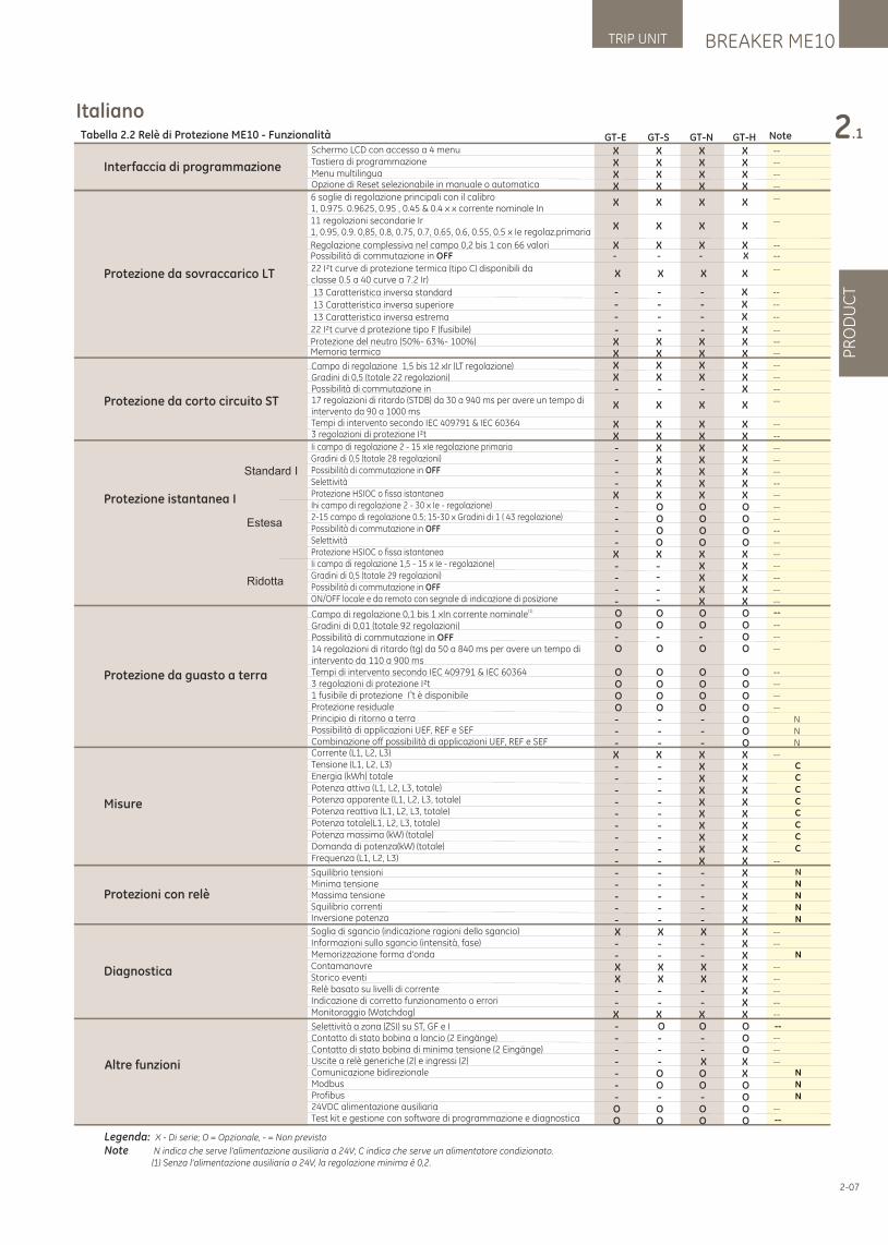
BREAKER ME10TRIP UNIT
PR
OD
UC
T
2.1
2-07
ItalianoTabella 2.2 Relè di Protezione ME10 - Funzionalità
Legenda: X - Di serie; O = Opzionale, - = Non previsto
Note N indica che serve l'alimentazione ausiliaria a 24V; C indica che serve un alimentatore condizionato. (1) Senza l'alimentazione ausiliaria a 24V, la regolazione minima è 0,2.
GT-E GT-S GT-N GT-H Note
X X X X --
X X X X --
X X X X --
Schermo LCD con accesso a 4 menuTastiera di programmazioneMenu multilinguaOpzione di Reset selezionabile in manuale o automatica X X X X --
X X X X --
--
--
--X X X X
X X X X
X X XX
Interfaccia di programmazione
Protezione da sovraccarico LT
C
C
C
C
C
C
C
C
N
N
N
N
N
N
N
N
--
- - - X --
X X X X --
X X X X --
X X X X --
X X X X --
- - - X --
X X X X --
X X X X --
- X X X --
- X X X --
- X X X --
- X X X --
X X X X --
- O O O --
- O O O --
- O O O --
- O O --
X X X X --
- X X --
- X X --
- X X --
- X X --
O O O O --
O O O O --
- - - O --
O O O O --
O O O O --
O O O O --
O O O O --
O O O O --
- - - O N
- - - O N
- - - O N
X X X X --
- - X X- - X X- - X X- - X X- - X X- - X X- - X X- - X X- - X X --
- - - X N
- - - X- - - X- - - X- - - XX X X X --
- - - X --
- - - XX X X X --
X X X X --
- - - X --
- - - X --
X X X X --
- O O O- - - O --
- - - O --
- - X X --
- O O X- O O O- - - OO O O O --
O O O O
--X X X XProtezione da corto circuito ST
Protezione istantanea I
Standard I
Estesa
Ridotta
Protezione da guasto a terra
Misure
Protezioni con relè
Diagnostica
Altre funzioni
O
----
--
Campo di regolazione 1,5 bis 12 xIr (LT regolazione)Gradini di 0,5 (totale 22 regolazioni)Possibilità di commutazione in17 regolazioni di ritardo (STDB) da 30 a 940 ms per avere un tempo diintervento da 90 a 1000 ms Tempi di intervento secondo IEC 409791 & IEC 60364 3 regolazioni di protezione I²t
Ii campo di regolazione 2 - 15 xIe regolazione primariaGradini di 0,5 (totale 28 regolazioni)Possibilità di commutazione in OFFSelettivitàProtezione HSIOC o fissa istantaneaIhi campo di regolazione 2 - 30 x Ie - regolazione)2-15 campo di regolazione 0.5; 15-30 x Gradini di 1 ( 43 regolazione)Possibilità di commutazione in OFFSelettivitàProtezione HSIOC o fissa istantaneaIi campo di regolazione 1,5 - 15 x Ie - regolazione)Gradini di 0,5 (totale 29 regolazioni)Possibilità di commutazione in OFFON/OFF locale e da remoto con segnale di indicazione di posizione
(1)Campo di regolazione 0,1 bis 1 xIn corrente nominaleGradini di 0,01 (totale 92 regolazioni)Possibilità di commutazione in OFF14 regolazioni di ritardo (tg) da 50 a 840 ms per avere un tempo diintervento da 110 a 900 msTempi di intervento secondo IEC 409791 & IEC 60364 3 regolazioni di protezione I²t
41 fusibile di protezione I t è disponibileProtezione residualePrincipio di ritorno a terraPossibilità di applicazioni UEF, REF e SEFCombinazione off possibilità di applicazioni UEF, REF e SEFCorrente (L1, L2, L3)Tensione (L1, L2, L3)Energia (kWh) totalePotenza attiva (L1, L2, L3, totale)Potenza apparente (L1, L2, L3, totale)Potenza reattiva (L1, L2, L3, totale)Potenza totale(L1, L2, L3, totale)Potenza massima (kW) (totale)Domanda di potenza(kW) (totale)Frequenza (L1, L2, L3)
Squilibrio tensioniMinima tensioneMassima tensioneSquilibrio correntiInversione potenza
Soglia di sgancio (indicazione ragioni dello sgancio)Informazioni sullo sgancio (intensità, fase)Memorizzazione forma d'ondaContamanovreStorico eventiRelè basato su livelli di correnteIndicazione di corretto funzionamento o erroriMonitoraggio (Watchdog)
Selettività a zona (ZSI) su ST, GF e IContatto di stato bobina a lancio (2 Eingänge)Contatto di stato bobina di minima tensione (2 Eingänge)Uscite a relè generiche (2) e ingressi (2)Comunicazione bidirezionaleModbusProfibus 24VDC alimentazione ausiliariaTest kit e gestione con software di programmazione e diagnostica
Regolazione complessiva nel campo 0,2 bis 1 con 66 valori
6 soglie di regolazione principali con il calibro1, 0.975. 0.9625, 0.95 , 0.45 & 0.4 x x corrente nominale In11 regolazioni secondarie Ir1, 0.95, 0.9. 0,85, 0.8, 0.75, 0.7, 0.65, 0.6, 0.55, 0.5 x Ie regolaz.primaria
22 I²t curve di protezione termica (tipo C) disponibili da classe 0.5 a 40 curve a 7.2 Ir)
22 I²t curve d protezione tipo F (fusibile)Protezione del neutro (50%- 63%- 100%)Memoria termica
13 Caratteristica inversa standard
- - - X --
- - - X --
- - - X --
13 Caratteristica inversa superiore
13 Caratteristica inversa estrema
Possibilità di commutazione in OFF - - - X --
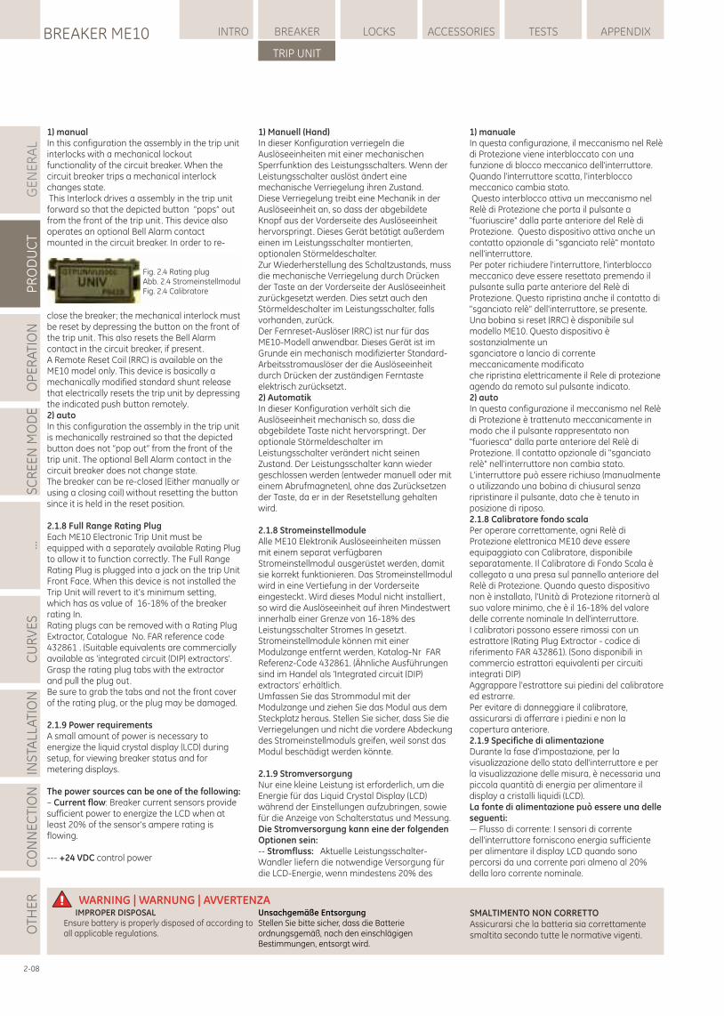
1) manualIn this configuration the assembly in the trip unit interlocks with a mechanical lockout functionality of the circuit breaker. When the circuit breaker trips a mechanical interlock changes state. This Interlock drives a assembly in the trip unit forward so that the depicted button “pops” out from the front of the trip unit. This device also operates an optional Bell Alarm contact mounted in the circuit breaker. In order to re-
close the breaker; the mechanical interlock must be reset by depressing the button on the front of the trip unit. This also resets the Bell Alarm contact in the circuit breaker, if present.A Remote Reset Coil (RRC) is available on the ME10 model only. This device is basically a mechanically modified standard shunt release that electrically resets the trip unit by depressing the indicated push button remotely.2) autoIn this configuration the assembly in the trip unit is mechanically restrained so that the depicted button does not “pop out” from the front of the trip unit. The optional Bell Alarm contact in the circuit breaker does not change state.The breaker can be re-closed (Either manually or using a closing coil) without resetting the button since it is held in the reset position.
2.1.8 Full Range Rating PlugEach ME10 Electronic Trip Unit must be equipped with a separately available Rating Plug to allow it to function correctly. The Full Range Rating Plug is plugged into a jack on the trip Unit Front Face. When this device is not installed the Trip Unit will revert to it's minimum setting, which has as value of 16-18% of the breaker rating In.Rating plugs can be removed with a Rating Plug Extractor, Catalogue No. FAR reference code 432861 . (Suitable equivalents are commercially available as 'integrated circuit (DIP) extractors'. Grasp the rating plug tabs with the extractor and pull the plug out.Be sure to grab the tabs and not the front cover of the rating plug, or the plug may be damaged.
2.1.9 Power requirementsA small amount of power is necessary to energize the liquid crystal display (LCD) during setup, for viewing breaker status and for metering displays.
The power sources can be one of the following:– Current flow: Breaker current sensors provide sufficient power to energize the LCD when at least 20% of the sensor's ampere rating is flowing.
--- +24 VDC control power
GE
NE
RA
LP
RO
DU
CT
OP
ER
ATI
ON
SC
RE
EN
MO
DE
...C
UR
VE
SIN
STA
LLA
TIO
NC
ON
NE
CTI
ON
LOCKSBREAKER ME10 INTRO BREAKER ACCESSORIES TESTS APPENDIX
TRIP UNIT
OTH
ER WARNING | WARNUNG | AVVERTENZA
Unsachgemäße EntsorgungStellen Sie bitte sicher, dass die Batterie ordnungsgemäß, nach den einschlägigen Bestimmungen, entsorgt wird.
IMPROPER DISPOSALEnsure battery is properly disposed of according to all applicable regulations.
SMALTIMENTO NON CORRETTOAssicurarsi che la batteria sia correttamente smaltita secondo tutte le normative vigenti.
Fig. 2.4 Rating plugAbb. 2.4 StromeinstellmodulFig. 2.4 Calibratore
2-08
1) manualeIn questa configurazione, il meccanismo nel Relè di Protezione viene interbloccato con una funzione di blocco meccanico dell'interruttore. Quando l'interruttore scatta, l'interblocco meccanico cambia stato. Questo interblocco attiva un meccanismo nel Relè di Protezione che porta il pulsante a "fuoriuscire" dalla parte anteriore del Relè di Protezione. Questo dispositivo attiva anche un contatto opzionale di "sganciato relè" montato nell'interruttore.Per poter richiudere l'interruttore, l'interblocco meccanico deve essere resettato premendo il pulsante sulla parte anteriore del Relè di Protezione. Questo ripristina anche il contatto di "sganciato relè" dell'interruttore, se presente. Una bobina si reset (RRC) è disponibile sul modello ME10. Questo dispositivo è sostanzialmente un sganciatore a lancio di corrente meccanicamente modificato che ripristina elettricamente il Rele di protezione agendo da remoto sul pulsante indicato.2) autoIn questa configurazione il meccanismo nel Relè di Protezione è trattenuto meccanicamente in modo che il pulsante rappresentato non "fuoriesca" dalla parte anteriore del Relè di Protezione. Il contatto opzionale di "sganciato relè" nell'interruttore non cambia stato.L'interruttore può essere richiuso (manualmente o utilizzando una bobina di chiusura) senza ripristinare il pulsante, dato che è tenuto in posizione di riposo.2.1.8 Calibratore fondo scalaPer operare correttamente, ogni Relè di Protezione elettronica ME10 deve essere equipaggiato con Calibratore, disponibile separatamente. Il Calibratore di Fondo Scala è collegato a una presa sul pannello anteriore del Relè di Protezione. Quando questo dispositivo non è installato, l'Unità di Protezione ritornerà al suo valore minimo, che è il 16-18% del valore delle corrente nominale In dell'interruttore.I calibratori possono essere rimossi con un estrattore (Rating Plug Extractor - codice di riferimento FAR 432861). (Sono disponibili in commercio estrattori equivalenti per circuiti integrati DIP) Aggrappare l'estrattore sui piedini del calibratore ed estrarre.Per evitare di danneggiare il calibratore, assicurarsi di afferrare i piedini e non la copertura anteriore.2.1.9 Specifiche di alimentazioneDurante la fase d'impostazione, per la visualizzazione dello stato dell'interruttore e per la visualizzazione delle misura, è necessaria una piccola quantità di energia per alimentare il display a cristalli liquidi (LCD).La fonte di alimentazione può essere una delle seguenti:— Flusso di corrente: I sensori di corrente dell'interruttore forniscono energia sufficiente per alimentare il display LCD quando sono percorsi da una corrente pari almeno al 20% della loro corrente nominale.
1) Manuell (Hand)In dieser Konfiguration verriegeln die Auslöseeinheiten mit einer mechanischen Sperrfunktion des Leistungsschalters. Wenn der Leistungsschalter auslöst ändert eine mechanische Verriegelung ihren Zustand.Diese Verriegelung treibt eine Mechanik in der Auslöseeinheit an, so dass der abgebildete Knopf aus der Vorderseite des Auslöseeinheit hervorspringt. Dieses Gerät betätigt außerdem einen im Leistungsschalter montierten, optionalen Störmeldeschalter.Zur Wiederherstellung des Schaltzustands, muss die mechanische Verriegelung durch Drücken der Taste an der Vorderseite der Auslöseeinheit zurückgesetzt werden. Dies setzt auch den Störmeldeschalter im Leistungsschalter, falls vorhanden, zurück. Der Fernreset-Auslöser (RRC) ist nur für das ME10-Modell anwendbar. Dieses Gerät ist im Grunde ein mechanisch modifizierter Standard-Arbeitsstromauslöser der die Auslöseeinheit durch Drücken der zuständigen Ferntaste elektrisch zurücksetzt.2) AutomatikIn dieser Konfiguration verhält sich die Auslöseeinheit mechanisch so, dass die abgebildete Taste nicht hervorspringt. Der optionale Störmeldeschalter im Leistungsschalter verändert nicht seinen Zustand. Der Leistungsschalter kann wieder geschlossen werden (entweder manuell oder mit einem Abrufmagneten), ohne das Zurücksetzen der Taste, da er in der Resetstellung gehalten wird.
2.1.8 StromeinstellmoduleAlle ME10 Elektronik Auslöseeinheiten müssen mit einem separat verfügbaren Stromeinstellmodul ausgerüstet werden, damit sie korrekt funktionieren. Das Stromeinstellmodul wird in eine Vertiefung in der Vorderseite eingesteckt. Wird dieses Modul nicht installiert, so wird die Auslöseeinheit auf ihren Mindestwert innerhalb einer Grenze von 16-18% des Leistungsschalter Stromes In gesetzt. Stromeinstellmodule können mit einer Modulzange entfernt werden, Katalog-Nr FAR Referenz-Code 432861. (Ähnliche Ausführungen sind im Handel als 'Integrated circuit (DIP) extractors' erhältlich. Umfassen Sie das Strommodul mit der Modulzange und ziehen Sie das Modul aus dem Steckplatz heraus. Stellen Sie sicher, dass Sie die Verriegelungen und nicht die vordere Abdeckung des Stromeinstellmoduls greifen, weil sonst das Modul beschädigt werden könnte.
2.1.9 StromversorgungNur eine kleine Leistung ist erforderlich, um die Energie für das Liquid Crystal Display (LCD) während der Einstellungen aufzubringen, sowie für die Anzeige von Schalterstatus und Messung.Die Stromversorgung kann eine der folgenden Optionen sein:-- Stromfluss: Aktuelle Leistungsschalter-Wandler liefern die notwendige Versorgung für die LCD-Energie, wenn mindestens 20% des
BREAKER ME10TRIP UNIT
PR
OD
UC
T
2.1
2-09
— Tensione di controllo +24 VDC--- Alimentazione batteria interna: Alimenta l'unità temporaneamente quando si preme un qualsiasi comando sulla tastiera. L'alimentazione dalla batteria si disattiva automaticamente trascorsi 20 secondi dall'ultima pressione di un tasto. L'alimentazione della batteria è disabilitata quando i sensori di corrente non rilevano alcuna corrente.- Il Kit di Test (N° di catalogo GTUTK20, codice di riferimento 407999) dispone di una batteria interna supplementare che può essere utilizzata per alimentare il Relè di Protezione quando la carica della batteria interna non è presente. Il dispositivo dispone anche di un alimentatore di controllo interno a 24 VDC che può essere alimentato tramite un normale collegamento di rete.Per le comunicazioni, le Unità di Protezione ME10 richiedono un'alimentazione di controllo esterna a +24 VDC.
2.1.9.1 BatteriaINFORMAZIONI DI CARATTERE GENERALE SULLA BATTERIAIl Relè di Protezione dispone di una batteria montata nel pannello anteriore. Quando la batteria è presente, l'utente può visualizzare i dati sul display LCD e leggere o programmare il Relè di Protezione attraverso la tastiera. La batteria permette anche all'utente di visualizzare i dati, modificare le impostazioni e gestire la memoria termica.La batteria non consente il normale funzionamento del Relè di Protezione. Ciò significa che quando il Relè di Protezione è alimentato a batteria, la protezione da sovracorrenti, gli allarmi, i relè, eccetera non sono funzionanti. Quando alimentato a batteria, il Relè di Protezione si spegne automaticamente dopo 20 secondi. Questo permette di massimizzare la durata della batteria.
FUNZIONE DELLA BATTERIALa pressione di un tasto qualsiasi sul pannello anteriore del Relè di Protezione, attiva l'alimentazione dell'unità attraverso la sua batteria interna. L'alimentazione dalla batteria viene mantenuta per 20 secondi dopo aver premuto l'ultimo tasto.Questa modalità ad auto-alimentazione consente di impostare il Relè di Protezione o di visualizzare le impostazioni di intervento quando l'interruttore è privo di tensione e non è disponibile un alimentatore di controllo esterno.Con l'alimentazione a batteria, possono essere eseguite tutte le normali funzioni legate a configurazione, misura e stato.
OsservazioniPer temperature superiori a 40 °C, per alimentare il Relè di Protezione può essere necessario tenere premuto un qualsiasi tasto fino a 5 secondi.SostituzioneSostituire la batteria se il Relè di Protezione non si accende quando viene premuto un tasto qualsiasi. Sollevare il coperchio del vano batteria sulla parte anteriore del Relè di Protezione per accedere alla batteria al litio 1/2 AA da 3,6.- Sostituti adatti sono la batteria TADIRAN TLL-5902/S o la batteria SANYO CR14250SE, comunemente disponibili nei negozi di elettricità o presso i distributori di materiale industriale.
— Internal battery power: Powers the unit temporarily when any keypad key is pressed. Battery power automatically turns off 20 sec after the last keypad press. The battery power supply is disabled when any current is sensed through the current sensors.
- Test kits Catalogue No. GTUTK20 and GTUTK20S have a extra internal battery that can be used to power the trip unit when internal battery power is not present. The device also has an integrated 24 VDC control power supply that allows the tester to be powered via a standard mains connection.
The ME10 Trip Units require external +24 VDC control power for communication.
2.1.9.1 BatteryGENERAL BATTERY INFORMATIONThe trip unit has a front panel mounted battery. When the battery is present, the user can view data on the LCD and read or program the trip unit via the keypads. The battery allows the user to display data, change set points and provide thermal memory.The battery does not allow normal trip unit operation; i.e. over current protection, alarms, relays, etc., are not functional when the trip unit is powered from the battery. The trip unit will automatically shut off after 20 sec when battery powered, this to maximize battery life.
BATTERY FUNCTIONPressing any key on the face of the trip unit powers the unit from its internal battery. Battery power is maintained for 20 sec after the last key is pressed.This self-powered mode allows setting up the trip unit or viewing trip targets when the breaker is de-energized and external control power is unavailable.All normal setup, meter, and status functions can be performed with battery power.
RemarkFor temperatures above 40°C, any key may have to be held down for up to 5 sec for the trip unit to be powered.
ReplacementReplace the battery if it does not power up the trip unit when any key is pressed.Lift the battery cover on the front of the trip unit to expose the 3.6 V ½ AA lithium cell.
– A suitable replacement is TADIRAN part number TLL-5902/S or SANYO part number CR14250SE which are commonly available from most electrical stores or industrial distributors.
Wandlerstroms fließt. --- +24 VDC Steuerspannung--- Interner Batteriebetrieb: Versorgt die Einheit vorübergehend, nur wenn eine Taste gedrückt wird. Die Batterie-Stromversorgung wird automatisch nach 20 Sek. deaktiviert, nachdem die letzte Tastenbetätigung vorgenommen wurde. Die Batterie-Stromversorgung ist deaktiviert, wenn irgendein Strom durch die Wandler fließt.
- Die Tester, Katalog-Nr GTUTK20 and GTUTK20S, verfügen über eine zusätzliche interne Batterie und kann verwendet werden, um die Auslöseeinheit, wenn deren interne Batteriespannung nicht ausreicht, zu versorgen. Das Gerät verfügt außerdem über eine eingebaute 24VDC-Stromversorgung, die über einen Standard-Netzanschluss aufgeladen werden kann.
Die ME10 Auslöseeinheiten erfordern eine externe +24 VDC Versorgung für die Kommunikation.
2.1.9.1 BatterieAllgemeine Batterie-InformationenDie Auslöseeinheit verfügt über eine im Frontfenster montierte Batterie. Wenn die Batterie vorhanden ist, kann der Nutzer Daten anzuzeigen und lesen, oder über die Tastatur die Auslöseeinheit programmieren. Die Batterie ermöglicht es dem Benutzer, Daten anzuzeigen, sie zu ändern und thermische Grenzwerte zu setzen.Die Batterie erlaubt keinen normalen Auslöseeinheiten Betrieb, d.h. Überstromschutz-, Alarm-, Relaisfunktionen, etc., sind nicht funktionsfähig, während die Auslöseeinheit von der Batterie gespeist wird. Die Auslöseeinheit schaltet sich bei Batteriebetrieb automatisch nach 20 Sek. zur Maximierung der Batterielaufzeit aus.
Batterie FunktionDas Drücken einer beliebigen Taste auf der Frontseite der Auslöseeinheit führt zur Inbetriebnahme der internen Batterie. Die Batterieenergie wird für 20 Sekunden nach dem letzten Tastendruck bereitgestellt .Dieser Selbstversorgungsmodus erlaubt die Einstellung der Auslöseeinheit oder das Anzeigen von Auslösewerten, auch wenn der Leistungsschalter deaktiviert ist und keine externe Spannungsversorgung verfügbar ist. Alle normalen Einrichtungen, Mess- und Statusfunktionen können mit Batteriebetrieb durchgeführt werden.
BemerkungBei Temperaturen über 40°C muss eine beliebige Taste bis zu 5 Sekunden gehalten werden, damit die Auslöseeinheit einschaltet.
AustauschErsetzen Sie die Batterie, wenn ein Tastendruck nicht zum Einschalten der Auslöseeinheit führt.Heben Sie den Batteriedeckel auf der Vorderseite der Auslöseeinheit an, um an die 3,6 V 1/2 AA Lithium-Batteriezelle zugelangen.
-- Ein geeigneter Ersatz ist TADIRAN Teilenummer TLL5902 / S oder SANYO Teilenummer CR14250SE, welche in den meisten Elektrogeschäften verfügbar sein sollten.
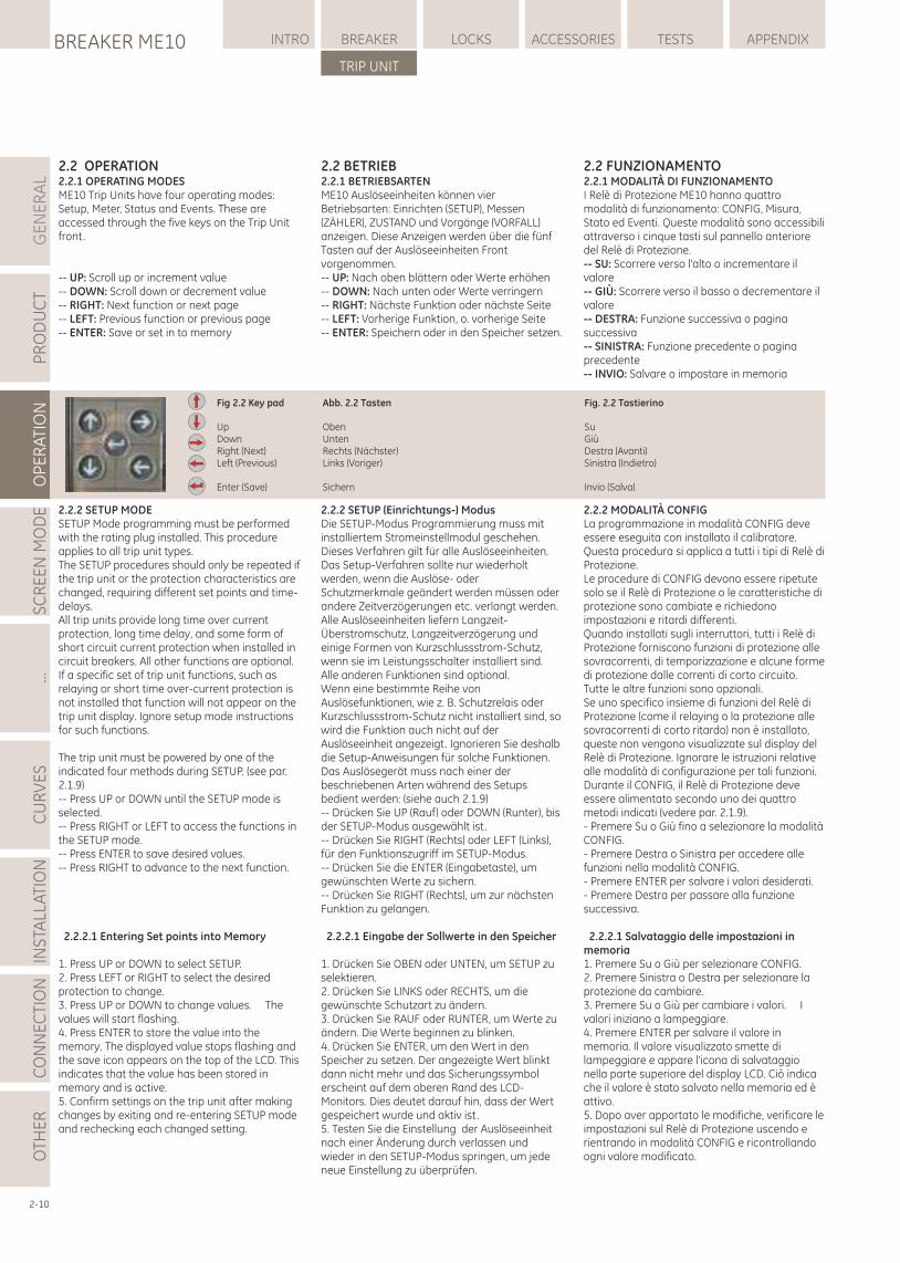
2.2 OPERATION2.2.1 OPERATING MODESME10 Trip Units have four operating modes: Setup, Meter, Status and Events. These are accessed through the five keys on the Trip Unit front.
-- UP: Scroll up or increment value-- DOWN: Scroll down or decrement value-- RIGHT: Next function or next page-- LEFT: Previous function or previous page-- ENTER: Save or set in to memory
2.2.2 SETUP MODESETUP Mode programming must be performed with the rating plug installed. This procedure applies to all trip unit types.The SETUP procedures should only be repeated if the trip unit or the protection characteristics are changed, requiring different set points and time-delays.All trip units provide long time over current protection, long time delay, and some form of short circuit current protection when installed in circuit breakers. All other functions are optional.If a specific set of trip unit functions, such as relaying or short time over-current protection is not installed that function will not appear on the trip unit display. Ignore setup mode instructions for such functions.
The trip unit must be powered by one of the indicated four methods during SETUP. (see par. 2.1.9)-- Press UP or DOWN until the SETUP mode is selected.-- Press RIGHT or LEFT to access the functions in the SETUP mode.-- Press ENTER to save desired values.-- Press RIGHT to advance to the next function.
2.2.2.1 Entering Set points into Memory
1. Press UP or DOWN to select SETUP.2. Press LEFT or RIGHT to select the desired protection to change.3. Press UP or DOWN to change values. The values will start flashing.4. Press ENTER to store the value into the memory. The displayed value stops flashing and the save icon appears on the top of the LCD. This indicates that the value has been stored in memory and is active.5. Confirm settings on the trip unit after making changes by exiting and re-entering SETUP mode and rechecking each changed setting.
2.2 BETRIEB2.2.1 BETRIEBSARTENME10 Auslöseeinheiten können vier Betriebsarten: Einrichten (SETUP), Messen (ZÄHLER), ZUSTAND und Vorgänge (VORFALL) anzeigen. Diese Anzeigen werden über die fünf Tasten auf der Auslöseeinheiten Front vorgenommen.-- UP: Nach oben blättern oder Werte erhöhen -- DOWN: Nach unten oder Werte verringern-- RIGHT: Nächste Funktion oder nächste Seite-- LEFT: Vorherige Funktion, o. vorherige Seite-- ENTER: Speichern oder in den Speicher setzen.
2.2.2 SETUP (Einrichtungs-) Modus Die SETUP-Modus Programmierung muss mit installiertem Stromeinstellmodul geschehen. Dieses Verfahren gilt für alle Auslöseeinheiten. Das Setup-Verfahren sollte nur wiederholt werden, wenn die Auslöse- oder Schutzmerkmale geändert werden müssen oder andere Zeitverzögerungen etc. verlangt werden. Alle Auslöseeinheiten liefern Langzeit-Überstromschutz, Langzeitverzögerung und einige Formen von Kurzschlussstrom-Schutz, wenn sie im Leistungsschalter installiert sind.Alle anderen Funktionen sind optional. Wenn eine bestimmte Reihe von Auslösefunktionen, wie z. B. Schutzrelais oder Kurzschlussstrom-Schutz nicht installiert sind, so wird die Funktion auch nicht auf der Auslöseeinheit angezeigt. Ignorieren Sie deshalb die Setup-Anweisungen für solche Funktionen. Das Auslösegerät muss nach einer der beschriebenen Arten während des Setups bedient werden: (siehe auch 2.1.9) -- Drücken Sie UP (Rauf) oder DOWN (Runter), bis der SETUP-Modus ausgewählt ist. -- Drücken Sie RIGHT (Rechts) oder LEFT (Links), für den Funktionszugriff im SETUP-Modus. -- Drücken Sie die ENTER (Eingabetaste), um gewünschten Werte zu sichern.-- Drücken Sie RIGHT (Rechts), um zur nächsten Funktion zu gelangen.
2.2.2.1 Eingabe der Sollwerte in den Speicher
1. Drücken Sie OBEN oder UNTEN, um SETUP zu selektieren. 2. Drücken Sie LINKS oder RECHTS, um die gewünschte Schutzart zu ändern. 3. Drücken Sie RAUF oder RUNTER, um Werte zu ändern. Die Werte beginnen zu blinken.4. Drücken Sie ENTER, um den Wert in den Speicher zu setzen. Der angezeigte Wert blinkt dann nicht mehr und das Sicherungssymbol erscheint auf dem oberen Rand des LCD-Monitors. Dies deutet darauf hin, dass der Wert gespeichert wurde und aktiv ist.5. Testen Sie die Einstellung der Auslöseeinheit nach einer Änderung durch verlassen und wieder in den SETUP-Modus springen, um jede neue Einstellung zu überprüfen.
GE
NE
RA
LP
RO
DU
CT
OP
ER
ATI
ON
SC
RE
EN
MO
DE
...C
UR
VE
SIN
STA
LLA
TIO
NC
ON
NE
CTI
ON
LOCKSBREAKER ME10 INTRO BREAKER ACCESSORIES TESTS APPENDIX
TRIP UNIT
OTH
ER
2-10
2.2 FUNZIONAMENTO2.2.1 MODALITÀ DI FUNZIONAMENTOI Relè di Protezione ME10 hanno quattro modalità di funzionamento: CONFIG, Misura, Stato ed Eventi. Queste modalità sono accessibili attraverso i cinque tasti sul pannello anteriore del Relè di Protezione.-- SU: Scorrere verso l'alto o incrementare il valore-- GIÙ: Scorrere verso il basso o decrementare il valore-- DESTRA: Funzione successiva o pagina successiva-- SINISTRA: Funzione precedente o pagina precedente-- INVIO: Salvare o impostare in memoria
2.2.2 MODALITÀ CONFIGLa programmazione in modalità CONFIG deve essere eseguita con installato il calibratore. Questa procedura si applica a tutti i tipi di Relè di Protezione.Le procedure di CONFIG devono essere ripetute solo se il Relè di Protezione o le caratteristiche di protezione sono cambiate e richiedono impostazioni e ritardi differenti.Quando installati sugli interruttori, tutti i Relè di Protezione forniscono funzioni di protezione alle sovracorrenti, di temporizzazione e alcune forme di protezione dalle correnti di corto circuito. Tutte le altre funzioni sono opzionali.Se uno specifico insieme di funzioni del Relè di Protezione (come il relaying o la protezione alle sovracorrenti di corto ritardo) non è installato, queste non vengono visualizzate sul display del Relè di Protezione. Ignorare le istruzioni relative alle modalità di configurazione per tali funzioni. Durante il CONFIG, il Relè di Protezione deve essere alimentato secondo uno dei quattro metodi indicati (vedere par. 2.1.9).- Premere Su o Giù fino a selezionare la modalità CONFIG.- Premere Destra o Sinistra per accedere alle funzioni nella modalità CONFIG.- Premere ENTER per salvare i valori desiderati.- Premere Destra per passare alla funzione successiva.
2.2.2.1 Salvataggio delle impostazioni in memoria1. Premere Su o Giù per selezionare CONFIG.2. Premere Sinistra o Destra per selezionare la protezione da cambiare.3. Premere Su o Giù per cambiare i valori. I valori iniziano a lampeggiare.4. Premere ENTER per salvare il valore in memoria. Il valore visualizzato smette di lampeggiare e appare l'icona di salvataggio nella parte superiore del display LCD. Ciò indica che il valore è stato salvato nella memoria ed è attivo.5. Dopo aver apportato le modifiche, verificare le impostazioni sul Relè di Protezione uscendo e rientrando in modalità CONFIG e ricontrollando ogni valore modificato.
Fig 2.2 Key pad Abb. 2.2 Tasten
Up ObenDown UntenRight (Next) Rechts (Nächster)Left (Previous) Links (Voriger)
Enter (Save) Sichern
Fig. 2.2 Tastierino
SuGiùDestra (Avanti)Sinistra (Indietro)
Invio (Salva)
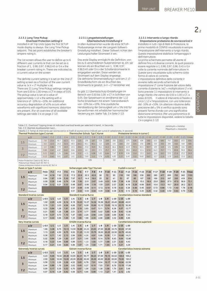
BREAKER ME10TRIP UNIT
OP
ER
ATI
ON
2.2
2-11
2.2.3.1 Intervento a lungo ritardo (Impostazione protezione da sovraccarico) IrInstallata in tutti i tipi di Relè di Protezione, la prima modalità di CONFIG visualizzata è sempre l'impostazione dell'intervento a lungo ritardo. Questa impostazione stabilisce l'amperaggio Ir dell'interruttore.La prima schermata permette all'utente di definire fino a 6 diverse correnti, le quali possono essere regolate a 1, 0,98, 0,97, 0,96, 0,45 o 0,4 volte la corrente nominale dell'interruttore In. Queste sono visualizzate sullo schermo sotto forma di valore di corrente. L'impostazione definitiva della corrente Ir avviene nella seconda schermata di impostazione LT come frazione del valore della corrente d'utente Ie. (xLT = moltiplicatore LT x Ie).Sono previste 11 impostazioni di intervento a lungo ritardo che vanno da 0,50 a 1,00 x CT, a passi di 0,05. Il valore di intervento è fissato a circa 1,12 x l'impostazione, con una tolleranza dal -10% al +10%. Un ulteriore riduzione della precisione del ± 5% si verifica quando sono presenti forme d'onda con una significativa distorsione armonica. (Per una panoramica di tutte le impostazioni disponibili, vedere la tabella 2.4 a pagina 2-12)
Table 2.3 : Overload Tripping times at indicated overload levels per selected tr band , in Seconds.Tab. 2.3: Überlast-Auslösezeiten (sec)...Tabella 2.3: Tempi di intervento per sovraccarico ai livelli di sovraccarico indicati per curva tr selezionata, in secondi.
Motor Protection Class to IEC 947-4Motorschutz-Klasse nach IEC 947-4Classe protezione motore a norma IEC 947-4
Cmin C-2 C-3 C-4 C-5 C-6 C-7 C-8 C-9 C-10 C-11 C-12 C-13 C-14 C-15 C-16 C-17 C-18 C-19 C-20 C-21 Cmax
Maximum 7.8 23.4 46.7 62.3 93.4 125 156 187 218 249 280 311 374 436 498 560 623 685 747 810 872 934
Minimum 4.0 12.0 24.0 32.0 48.0 64.1 80.1 96.1 112 128 144 160 192 224 256 288 320 352 384 416 448 480
Maximum 1.3 3.86 7.73 10.3 15.5 20.6 25.8 30.9 36.1 41.2 46.4 51.5 61.8 72.1 82.4 92.7 103 113 124 134 144 155
Minimum 0.80 2.41 4.82 6.43 9.64 12.9 16.1 19.3 22.5 25.7 28.9 32.1 38.6 45.0 51.4 57.8 64.3 70.7 77.1 83.6 90.0 96.4
Maximum 0.21 0.62 1.24 1.66 2.49 3.32 4.15 4.98 5.81 6.64 7.47 8.30 9.96 11.6 13.3 14.9 16.6 18.3 19.9 21.6 23.2 24.9
Minimum 0.13 0.40 0.81 1.07 1.61 2.15 2.69 3.22 3.76 4.30 4.83 5.37 6.45 7.52 8.60 9.67 10.7 11.8 12.9 14.0 15.0 16.1
4010b 10 20 30
x Ir
1.5
3
7.2
Fmin F-2 F-3 F-4 F-5 F-6 F-7 F-8 F-9 F-10 F-11 F-12 F-13 F-14 F-15 F-16 F-17 F-18 F-19 F-20 F-21 Fmax
Maximum 1.44 4.19 7.62 11.9 17.2 23.9 32.3 42.8 56 72 93 118 150 190 239 302 380 477 600 752 942 1153
Minimum 0.64 1.87 3.39 5.30 7.67 10.7 14.4 19.0 25 32 41 53 67 85 107 135 169 213 267 335 419 514
Maximum 0.09 0.26 0.48 0.74 1.08 1.50 2.01 2.67 3.49 4.51 5.80 7.39 9.39 11.9 15.0 18.9 23.8 29.9 37.5 47.0 58.9 72.1
Minimum 0.04 0.12 0.21 0.33 0.48 0.67 0.90 1.19 1.55 2.01 2.57 3.29 4.18 5.29 6.68 8.41 10.6 13.3 16.7 20.9 26.2 32.1
Maximum 0.07 0.08 0.09 0.11 0.12 0.14 0.18 0.22 0.28 0.36 0.45 0.57 0.72 0.90 1.13 1.42 1.78 2.18
Minimum 0.01 0.02 0.03 0.04 0.05 0.06 0.08 0.10 0.13 0.16 0.20 0.25 0.32 0.40 0.50 0.63 0.79 1.03
x Ir
1.5
3
7.2
Thermal Protection type C curves Thermischer Schutz Typ C Kurve Protezione termica in curva C
Fuses or type F curves Sicherungen oder Typ F Kurven Fusibili o curva F
Standard Inverse curves Standard inverse Kurve Caratteristica inversa standard
Very Inverse curves Erhöht inverse Kurve Caratteristica inversa superiore
Extremely Inverse curves Extrem inverse Kurve Caratteristica inversa estrema
L-0.5 L-1 L-2 L-3 L-4 L-5 L-6 L-7 L-8 L-9 L-10 L-15 L-20
Maximum 1,02 2,05 4,09 6,14 8,18 10,23 12,27 14,32 16,36 18,41 20,45 30,68 40,91
Minimum
Maximum
Minimum
Maximum
Minimum
x Ir
1.5
3
7.2
0,76 1,51 3,03 4,54 6,06 7,57 9,09 10,60 12,12 13,63 15,15 22,72 30,30
0,32 0,64 1,28 1,91 2,55 3,19 3,83 4,47 5,11 5,74 6,38 12,77
0,31 0,63 1,26 1,88 2,51 3,14 3,77 4,40 5,02 5,65 6,28 12,56
0,18 0,37 0,73 1,10 1,47 1,83 2,20 2,56 2,93 3,30 3,66 7,33
0,17 0,33 0,66 1,00 1,33 1,66 1,99 2,33 2,66 2,99 3,32 6,65
9,57
9,42
5,49
4,99
L-0.5 L-1 L-2 L-3 L-4 L-5 L-6 L-7 L-8 L-9 L-10 L-15 L-20
Maximum 1,69 3,38 6,75 10,13 13,50 16,88 20,25 23,63 27,00 30,38 33,75 50,63 67,50
Minimum
Maximum
Minimum
Maximum
Minimum
x Ir
1.5
3
7.2
1,13 2,25 4,50 6,75 9,00 11,25 13,50 15,75 18,00 20,25 22,50 33,75 45,00
0,36 0,71 1,42 2,13 2,84 3,55 4,26 4,97 5,68 6,39 7,11 14,21
0,32 0,64 1,29 1,93 2,57 3,21 3,86 4,50 5,14 5,79 6,43 12,86
0,18 0,22 0,44 0,66 0,89 1,11 1,33 1,55 1,77 1,99 2,21 4,43
0,17 0,21 0,43 0,64 0,86 1,07 1,29 1,50 1,71 1,93 2,14 4,29
10,66
9,64
3,32
3,21
L-0.5 L-1 L-2 L-3 L-4 L-5 L-6 L-7 L-8 L-9 L-10 L-15 L-20
Maximum 4,23 8,46 16,92 25,38 33,85 42,31 50,77 59,23 67,69 76,15 84,62 126,9 169,2
Minimum
Maximum
Minimum
Maximum
Minimum
x Ir
1.5
3
7.2
2,50 5,00 10,00 15,00 20,00 25,00 30,00 35,00 40,00 45,00 50,00 75,00 100,0
0,56 1,13 2,26 3,39 4,52 5,65 6,78 7,91 9,04 10,17 11,30 22,59
0,44 0,88 1,76 2,64 3,52 4,40 5,27 6,15 7,03 7,91 8,79 17,58
0,09 0,17 0,35 0,52 0,70 0,87 1,04 1,22 1,39 1,56 1,74 3,48
0,07 0,14 0,28 0,42 0,56 0,71 0,85 0,99 1,13 1,27 1,41 2,82
16,94
13,19
2,61
2,12
minimum = minimoMaximum = massimo
2.2.3.1 Long Time Pickup (Overload Protection setting) IrInstalled in all Trip Units types the first SETUP mode display is always the Long Time Pickup setpoint. This set point establishes the breaker's ampere rating Ir.
The 1st screen allows the user to define up to 6 different user currents Ie that can be set as a fraction of 1, 0.98, 0.97, 0.96,0.45 or 0.4 x the breaker current rating In. These are indicated as a current value on the screen
The definite current setting Ir is set on the 2nd LT setting screen as a fraction of the user current value Ie. (x Ir = LT multiplier x Ie).There are 11 Long Time Pickup settings ranging from are 0.50 to 1.00 times x CT in steps of 0.05.The pickup value is set at a value of approximately 1.12 x the setting with a tolerance of -10% to +10%. An additional accuracy degradation of ±5% occurs when waveforms with significant harmonic distortion are present. (For an overview of all available settings see table 2.4 on page 2-12)
2.2.3.1 Langzeiteinstellungen (Überlastschutz Einstellung) Ir In allen Auslöserarten wurde als erste SETUP-Modusanzeige immer die Langzeit-Sollwert-Einstellung installiert. Dieser Sollwert richtet den Leistungsschalter Stromwert Ir ein.
Das erste Display ermöglicht die Definition, von bis zu 6 verschiedenen Nutzerströmen Ie, d.h. sie können als ein Bruchteil von 1, 0,98, 0,97, 0.96,0.45 oder 0,4 x der Schalterstromwerte In eingegeben werden. Diese werden als Stromwert auf dem Display angezeigt.Die definierte Stromeinstellung Ir wird am 2. LT-Einstellbildschirm als ein Bruchteil des Stromwerts Ie gesetzt. (x Ir = LT Verstärker xIe).
Es gibt 11 Überlastschutz-Einstellungen im Bereich von 0,50 bis 1,00 x CT in Schritten von 0,05. Der Spitzenwert ist annähernd der 1,12 fache Einstellwert mit einem Toleranzbereich von -10% bis +10%. Eine zusätzliche Herabsetzung der Genauigkeit um ± 5% tritt für Kurvenformen mit erheblicher harmonischer Verzerrung ein. (siehe Tab. 2.4 Seite 2-12)
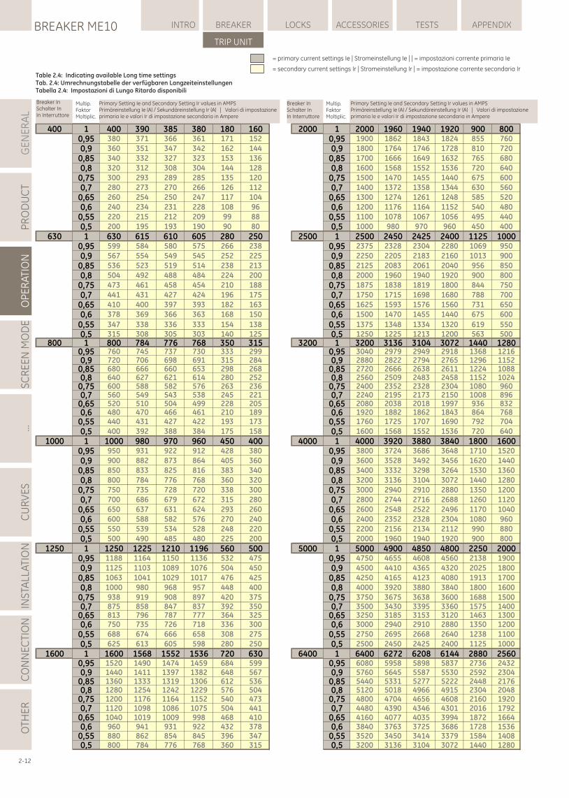
2-12
400 1 400 390 385 380 180 160 2000 1 2000 1960 1940 1920 900 8000,95 380 371 366 361 171 152 0,95 1900 1862 1843 1824 855 760
0,9 360 351 347 342 162 144 0,9 1800 1764 1746 1728 810 720
0,85 340 332 327 323 153 136 0,85 1700 1666 1649 1632 765 680
0,8 320 312 308 304 144 128 0,8 1600 1568 1552 1536 720 640
0,75 300 293 289 285 135 120 0,75 1500 1470 1455 1440 675 600
0,7 280 273 270 266 126 112 0,7 1400 1372 1358 1344 630 560
0,65 260 254 250 247 117 104 0,65 1300 1274 1261 1248 585 520
0,6 240 234 231 228 108 96 0,6 1200 1176 1164 1152 540 480
0,55 220 215 212 209 99 88 0,55 1100 1078 1067 1056 495 440
0,5 200 195 193 190 90 80 0,5 1000 980 970 960 450 400
630 1 630 615 610 605 280 250 2500 1 2500 2450 2425 2400 1125 10000,95 599 584 580 575 266 238 0,95 2375 2328 2304 2280 1069 950
0,9 567 554 549 545 252 225 0,9 2250 2205 2183 2160 1013 900
0,85 536 523 519 514 238 213 0,85 2125 2083 2061 2040 956 850
0,8 504 492 488 484 224 200 0,8 2000 1960 1940 1920 900 800
0,75 473 461 458 454 210 188 0,75 1875 1838 1819 1800 844 750
0,7 441 431 427 424 196 175 0,7 1750 1715 1698 1680 788 700
0,65 410 400 397 393 182 163 0,65 1625 1593 1576 1560 731 650
0,6 378 369 366 363 168 150 0,6 1500 1470 1455 1440 675 600
0,55 347 338 336 333 154 138 0,55 1375 1348 1334 1320 619 5500,5 315 308 305 303 140 125 0,5 1250 1225 1213 1200 563 500
800 1 800 784 776 768 350 315 3200 1 3200 3136 3104 3072 1440 12800,95 760 745 737 730 333 299 0,95 3040 2979 2949 2918 1368 12160,9 720 706 698 691 315 284 0,9 2880 2822 2794 2765 1296 1152
0,85 680 666 660 653 298 268 0,85 2720 2666 2638 2611 1224 10880,8 640 627 621 614 280 252 0,8 2560 2509 2483 2458 1152 1024
0,75 600 588 582 576 263 236 0,75 2400 2352 2328 2304 1080 9600,7 560 549 543 538 245 221 0,7 2240 2195 2173 2150 1008 896
0,65 520 510 504 499 228 205 0,65 2080 2038 2018 1997 936 8320,6 480 470 466 461 210 189 0,6 1920 1882 1862 1843 864 768
0,55 440 431 427 422 193 173 0,55 1760 1725 1707 1690 792 704
0,5 400 392 388 384 175 158 0,5 1600 1568 1552 1536 720 640
1000 1 1000 980 970 960 450 400 4000 1 4000 3920 3880 3840 1800 16000,95 950 931 922 912 428 380 0,95 3800 3724 3686 3648 1710 1520
0,9 900 882 873 864 405 360 0,9 3600 3528 3492 3456 1620 1440
0,85 850 833 825 816 383 340 0,85 3400 3332 3298 3264 1530 1360
0,8 800 784 776 768 360 320 0,8 3200 3136 3104 3072 1440 1280
0,75 750 735 728 720 338 300 0,75 3000 2940 2910 2880 1350 1200
0,7 700 686 679 672 315 280 0,7 2800 2744 2716 2688 1260 1120
0,65 650 637 631 624 293 260 0,65 2600 2548 2522 2496 1170 1040
0,6 600 588 582 576 270 240 0,6 2400 2352 2328 2304 1080 960
0,55 550 539 534 528 248 220 0,55 2200 2156 2134 2112 990 880
0,5 500 490 485 480 225 200 0,5 2000 1960 1940 1920 900 800
1250 1 1250 1225 1210 1196 560 500 5000 1 5000 4900 4850 4800 2250 20000,95 1188 1164 1150 1136 532 475 0,95 4750 4655 4608 4560 2138 1900
0,9 1125 1103 1089 1076 504 450 0,9 4500 4410 4365 4320 2025 1800
0,85 1063 1041 1029 1017 476 425 0,85 4250 4165 4123 4080 1913 1700
0,8 1000 980 968 957 448 400 0,8 4000 3920 3880 3840 1800 1600
0,75 938 919 908 897 420 375 0,75 3750 3675 3638 3600 1688 15000,7 875 858 847 837 392 350 0,7 3500 3430 3395 3360 1575 1400
0,65 813 796 787 777 364 325 0,65 3250 3185 3153 3120 1463 13000,6 750 735 726 718 336 300 0,6 3000 2940 2910 2880 1350 1200
0,55 688 674 666 658 308 275 0,55 2750 2695 2668 2640 1238 1100
0,5 625 613 605 598 280 250 0,5 2500 2450 2425 2400 1125 1000
1600 1 1600 1568 1552 1536 720 630 6400 1 6400 6272 6208 6144 2880 25600,95 1520 1490 1474 1459 684 599 0,95 6080 5958 5898 5837 2736 24320,9 1440 1411 1397 1382 648 567 0,9 5760 5645 5587 5530 2592 2304
0,85 1360 1333 1319 1306 612 536 0,85 5440 5331 5277 5222 2448 21760,8 1280 1254 1242 1229 576 504 0,8 5120 5018 4966 4915 2304 2048
0,75 1200 1176 1164 1152 540 473 0,75 4800 4704 4656 4608 2160 19200,7 1120 1098 1086 1075 504 441 0,7 4480 4390 4346 4301 2016 1792
0,65 1040 1019 1009 998 468 410 0,65 4160 4077 4035 3994 1872 16640,6 960 941 931 922 432 378 0,6 3840 3763 3725 3686 1728 1536
0,55 880 862 854 845 396 347 0,55 3520 3450 3414 3379 1584 14080,5 800 784 776 768 360 315 0,5 3200 3136 3104 3072 1440 1280
Primary Setting Ie and Secondary Setting Ir values in AMPSPrimäreinstellung Ie (A) / Sekundäreinstellung Ir (A) | Valori di impostazione primaria Ie e valori Ir di impostazione secondaria in Ampere
Primary Setting Ie and Secondary Setting Ir values in AMPSPrimäreinstellung Ie (A) / Sekundäreinstellung Ir (A) | Valori di impostazione primaria Ie e valori Ir di impostazione secondaria in Ampere
Multip.FaktorMoltiplic.
Table 2.4: Indicating available Long time settingsTab. 2.4: Umrechnungstabelle der verfügbaren LangzeiteinstellungenTabella 2.4: Impostazioni di Lungo Ritardo disponibili
= primary current settings Ie | Stromeinstellung Ie | | = impostazioni corrente primaria Ie
= secondary current settings Ir | Stromeinstellung Ir | = impostazione corrente secondaria Ir
Breaker InSchalter InIn Interruttore
Breaker InSchalter InIn Interruttore
Multip.FaktorMoltiplic.
GE
NE
RA
LP
RO
DU
CT
OP
ER
ATI
ON
SC
RE
EN
MO
DE
...C
UR
VE
SIN
STA
LLA
TIO
NC
ON
NE
CTI
ON
LOCKSBREAKER ME10 INTRO BREAKER ACCESSORIES TESTS APPENDIX
TRIP UNIT
OTH
ER
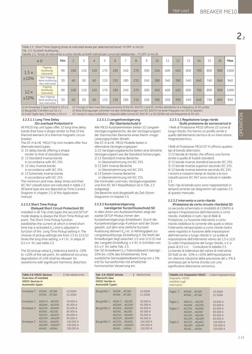
BREAKER ME10TRIP UNIT
OP
ER
ATI
ON
2.2
Tabella 2.6: Dispositivi HSIOC | Valori impostati (rms)
Dispositivi HSIOCinstallati sugliinterruttori:
Taglia T: AT04R ... AT16R 43.000A AT04K ... AT16K 51.500A
Taglia 1 AG04 S ... AG20S 50.000 A AG04N ... AG20N 65.000 ATaglia 2 AG25N ... AG40N 65.000 A AG04E ... AG20E 85.000 A AG25H ... AG40H 85.000 A AG25M ... AG40M 85.000 ATaglia 3 AG32G ... AG40G 100.000 A AG40M ... AG64M 100.000 A AG40L ... AG64L 100.000 A
2-13
2.2.3.1.1 Regolazione lungo riardo (Sulla protezione da sovraccarico) tr I Relè di Protezione ME10 offrono 22 curve di lungo ritardo che hanno un profilo simile a quello dell'elemento termico di un interruttore magnetotermico.
I Relè di Protezione ME10 GT-H offrono quattro tipi di banda alternativi: 1) 22 bande di ritardo che offrono una forma simile a quella di fusibili standard. 2) 13 bande inverse standard secondo IEC 255. 3) 13 bande inverse superiori secondo IEC 255. 4) 13 bande inverse estreme secondo IEC 255. I minimi e massimi tempi di ritardo e la loro classificazione IEC 947 sono indicati in tabella 2.3. Tutti i tipi di banda sono sono rappresentati in tempo/corrente nei diagrammi nel capitolo 2.5 di questo manuale.
2.2.3.2 Intervento a corto ritardo (Protezione da corto circuito ritardata) SDLa seconda schermata in modalità di CONFIG è sempre l'impostazione dell'intervento a corto ritardo, installata in tutti i tipi di Relè di Protezione, La funzione intervento a corto ritardo stabilisce la corrente alla quale si attiva l'intervento temporizzato a corto ritardo (Isd) e viene regolata in funzione delle impostazioni dell'intervento a lungo ritardo Ir. Le scelte di impostazione dell'intervento vanno da 1,5 a 12,0 (1) volte l'impostazione del lungo ritardo, x Ir, a passi di 0,5 x Ir. Consultare la tabella 2.5.La banda di tolleranza del valore di intervento SD (Isd) va da -10% a +10% dell'impostazione. Un ulteriore riduzione della precisione del ± 5% è ammessa per le forme d'onda con una significativa distorsione armonica.
Table 2.5 : Short Time tripping times at indicated levels per selected tsd band -I²t OFF. in ms (2)Tab. 2.5: Kurzzeit-Auslösung...Tabella 2.5: Tempi di intervento a corto ritardo ai livelli indicati per curva tsd selezionata - I²t OFF. in ms (2)
740 840 940340 390 540 640180 210 240 280
800 900 1000
30 40 50 60 110 130
400 450 600 700240 270 300 340
840 940
12 x
±10%
90 100 110 120 170 190
390 540 640 740210 240 280 340
900 1000
Non TrippingKeine AuslösungNon intervento
30 40 50 60 110 130 180
450 600 700 800270 300 340 400
Max
1.5 x
±10%
TrippingAuslösungIntervento
90 100 110 120 170 190 240
13 14 15 169 10 11 12 x Ir Min 2 3 4 5 6 7 8
(1) On Envelope 3 type limited to 10 x Ir. (2) Timings in Red meet the requirements of the IEC 60479-1 and IEC 60364 standards at a frequency of 50 cycles.(1) Baugröße 3 limitiert auf 10 x Ir. (2) Rote Eintragungen stimmen mit den Anforderungen von IEC 60479 mit einer Frequenz von 50 Hz überein.(1) Sulla Taglia tipo 3 limitato a 10 x Ir. (2) I tempi in rosso soddisfano i requisiti delle norme IEC 60479-1 e IEC 60364 ad una frequenza di 50 cicli.
Non TrippingKeine AuslösungNon intervento
TrippingAuslösungIntervento
2.2.3.1.1 Long Time Delay (On overload Protection) trAll ME10 trip unit types offer 22 long time delay bands that have a shape similar to that of the thermal element of a thermal magnetic circuit breaker.The GT-H & HE ME10 Trip Unit models offer four alternate band types:1) 22 delay bands offering a shape similar to that of standard fuses.2) 13 Standard Inverse bands in accordance with IEC 255.3) 13 Very Inverse bands in accordance with IEC 255.4) 13 Extremely inverse bands in accordance with IEC 255.The minimum and max. delay times and their IEC 947 classification are indicated in table 2.3.All band type are are depicted as Time Current Diagram in chapter 2.5 of this Application manual.
2.2.3.2 Short Time Pickup (Delayed Short Circuit Protection) SDInstalled in all Trip Units types the second SETUP mode display is always the Short Time Pickup set point. The Short Time Pickup function establishes the current at which a timed short time trip is activated (I ) and is adjusted in sd
function of the Long Time Pickup setting Ir. The choices of pickup settings are from 1.5 to 12.0 (1) times the long time setting, x Ir ( Ir) , in steps of 0.5 x Ir (Ir). see table 2.5.
The SD pickup value (I ) tolerance band is -10% sd
to +10% of the set point. An additional accuracy degradation of ±5% shall be allowed for waveforms with significant harmonic distortion.
2.2.3.1.1 Langzeitverzögerung (für Überlastschutz) tr Alle ME10 Auslöseeinheiten bieten 22 Langzeit-Verzögerungsbereiche, die der Verzögerungsart der thermischen Elemente eines therm.-magn. Leistungsschalter ähneln.Die GT-H & HE ME10 Modelle bieten 4 alternative Verzögerungstypen:1) 22 Verzögerungsbereiche bieten eine ähnliche Verzögerungsart wie die Standard-Sicherungen.2) 13 Standard Inverse Bereiche in Übereinstimmung mit IEC 255.3) 13 Sehr Inverse Bereiche in Übereinstimmung mit IEC 255.4) 13 Extrem inverse Bereiche in Übereinstimmung mit IEC 255.Die minimalen und max. Verzögerungszeiten und ihre IEC 947 Klassifikation ist in Tab. 2.3 aufgezeigt.Die Bereiche sind dargestellt als Zeit-Strom-Diagramm im Kapitel 2.5.
2.2.3.2 Kurzzeitverzögerung (verzögerter Kurzschlussschutz) SDIn allen Arten von Auslöseeinheiten zeigt der zweite SETUP-Modus immer den Kurzzeitverzögerungs-Einstellwert. Durch die Kurzzeitverzögerungs-Funktion wird der Strom gesetzt, auf dem eine zeitliche Kurzzeit-Auslösung aktiviert (I ) ist, in Abhängigkeit zur sd
Langzeitauslösungs-Einstellung Ir. Die Wahl der Einstellungen liegt zwischen 1,5 und 12,0 (1) mal der Langzeit-Einstellung, x Ir (Ir), in Schritten von 0,5 x Ir (Ir). siehe Tab. 2.5.Der SD Einstellwert (I )-Toleranzbereich beträgt -sd
10% bis +10% des Einstellwertes. Eine zusätzliche Genauigkeitsabweichung von ± 5% tritt für Kurvenformen mit erheblicher harmonischer Verzerrung ein.
Table 2.6: HSIOC devices | Set values (rms)Overview of installed HSIOC devices inAutomatic types:
Envelope T: AT04R ... AT16R 43.000A AT04K ... AT16K 51.500A
Envelope 1: AG04 S ... AG20S 50.000 A AG04N ... AG20N 65.000 AEnvelope 2: AG25N ... AG40N 65.000 A AG04E ... AG20E 85.000 A AG25H ... AG40H 85.000 A AG25M ... AG40M 85.000 AEnvelope 3: AG32G ... AG40G 100.000 A AG40M ... AG64M 100.000 A AG40L ... AG64L 100.000 A
Tab. 2.6: HSIOC Schutz | Werte (rms)Übersicht überHSIOC Geräte inAutomatik Typen:
Baugröße T: AT04R ... AT16R 43.000A AT04K ... AT16K 51.500A
Baugröße 1: AG04 S ... AG20S 50.000 A AG04N ... AG20N 65.000 ABaugröße 2: AG25N ... AG40N 65.000 A AG04E ... AG20E 85.000 A AG25H ... AG40H 85.000 A AG25M ... AG40M 85.000 ABaugröße 3: AG32G ... AG40G 100.000 A AG40M ... AG64M 100.000 A AG40L ... AG64L 100.000 A
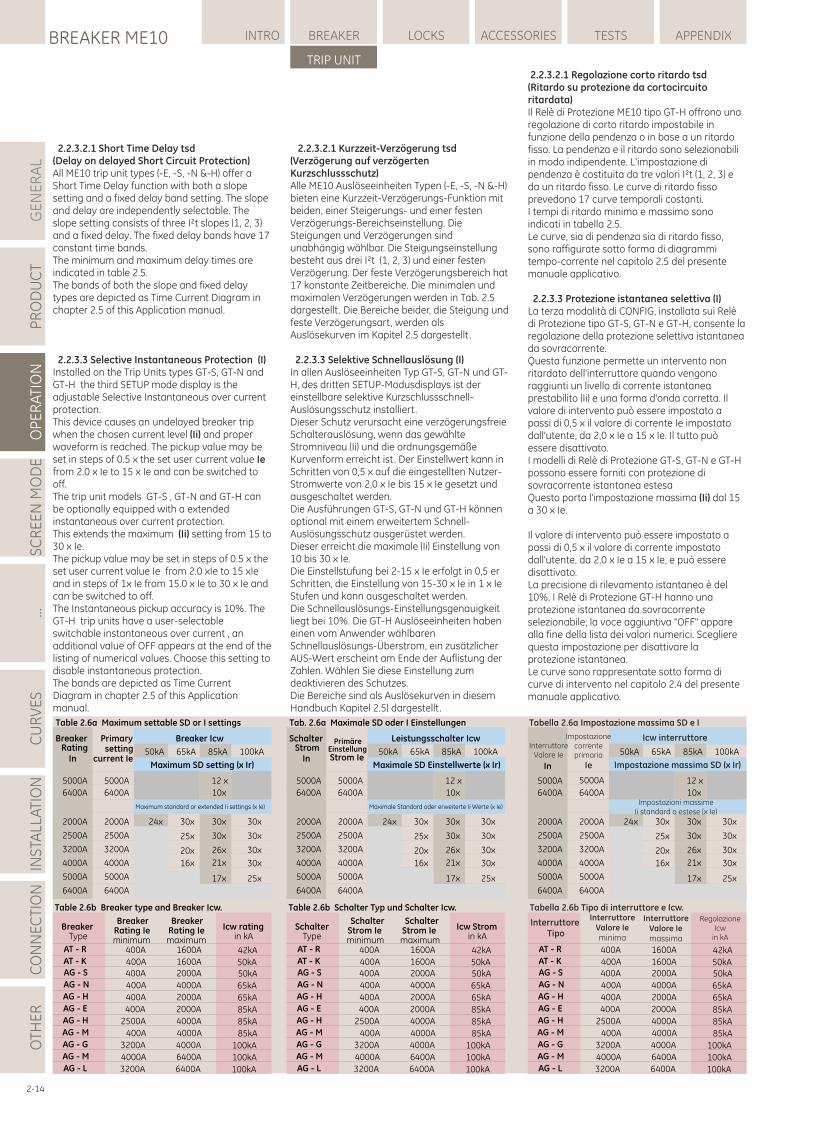
GE
NE
RA
LP
RO
DU
CT
OP
ER
ATI
ON
SC
RE
EN
MO
DE
...C
UR
VE
SIN
STA
LLA
TIO
NC
ON
NE
CTI
ON
LOCKSBREAKER ME10 INTRO BREAKER ACCESSORIES TESTS APPENDIX
TRIP UNIT
OTH
ER
2.2.3.2.1 Regolazione corto ritardo tsd(Ritardo su protezione da cortocircuito ritardata)Il Relè di Protezione ME10 tipo GT-H offrono una regolazione di corto ritardo impostabile in funzione della pendenza o in base a un ritardo fisso. La pendenza e il ritardo sono selezionabili in modo indipendente. L'impostazione di pendenza è costituita da tre valori I²t (1, 2, 3) e da un ritardo fisso. Le curve di ritardo fisso prevedono 17 curve temporali costanti.I tempi di ritardo minimo e massimo sono indicati in tabella 2.5.Le curve, sia di pendenza sia di ritardo fisso, sono raffigurate sotto forma di diagrammi tempo-corrente nel capitolo 2.5 del presente manuale applicativo.
2.2.3.3 Protezione istantanea selettiva (I)La terza modalità di CONFIG, installata sui Relè di Protezione tipo GT-S, GT-N e GT-H, consente la regolazione della protezione selettiva istantanea da sovracorrente. Questa funzione permette un intervento non ritardato dell'interruttore quando vengono raggiunti un livello di corrente istantanea prestabilito (Ii) e una forma d'onda corretta. Il valore di intervento può essere impostato a passi di 0,5 x il valore di corrente Ie impostato dall'utente, da 2,0 x Ie a 15 x Ie. Il tutto può essere disattivato.I modelli di Relè di Protezione GT-S, GT-N e GT-H possono essere forniti con protezione di sovracorrente istantanea estesaQuesto porta l'impostazione massima (Ii) dal 15 a 30 x Ie.
Il valore di intervento può essere impostato a passi di 0,5 x il valore di corrente impostato dall'utente, da 2,0 x Ie a 15 x Ie, e può essere disattivato.La precisione di rilevamento istantaneo è del 10%. I Relè di Protezione GT-H hanno una protezione istantanea da sovracorrente selezionabile; la voce aggiuntiva "OFF" appare alla fine della lista dei valori numerici. Scegliere questa impostazione per disattivare la protezione istantanea.Le curve sono rappresentate sotto forma di curve di intervento nel capitolo 2.4 del presente manuale applicativo.
2-14
Table 2.6a Maximum settable SD or I settings
50kA
24x
65kA
30x
25x
20x
16x
85kA
12 x
10x
30x
30x
26x
21x
17x
100kA
30x
30x
30x
30x
25x
5000A
6400A
2000A
2500A
3200A
4000A
5000A
6400A
Breaker Rating
In
5000A
6400A
2000A
2500A
3200A
4000A
5000A
6400A
Primary setting
current Ie
Breaker Icw
Maximum SD setting (x Ir)
Maximum standard or extended Ii settings (x Ie)
Tab. 2.6a Maximale SD oder I Einstellungen
50kA
24x
65kA
30x
25x
20x
16x
85kA
12 x
10x
30x
30x
26x
21x
17x
100kA
30x
30x
30x
30x
25x
5000A
6400A
2000A
2500A
3200A
4000A
5000A
6400A
SchalterStrom
In
5000A
6400A
2000A
2500A
3200A
4000A
5000A
6400A
PrimäreEinstellungStrom Ie
Leistungsschalter Icw
Maximale SD Einstellwerte (x Ir)
Maximale Standard oder erweiterte Ii Werte (x Ie)
Tabella 2.6a Impostazione massima SD e I
50kA
24x
65kA
30x
25x
20x
16x
85kA
12 x
10x
30x
30x
26x
21x
17x
100kA
30x
30x
30x
30x
25x
5000A
6400A
2000A
2500A
3200A
4000A
5000A
6400A
Interruttore Valore Ie
In
5000A
6400A
2000A
2500A
3200A
4000A
5000A
6400A
Impostazionecorrente primaria
Ie
Icw interruttore
Impostazione massima SD (x Ir)
Impostazioni massimeIi standard o estese (x Ie)
2.2.3.2.1 Short Time Delay tsd(Delay on delayed Short Circuit Protection)All ME10 trip unit types (-E, -S, -N &-H) offer a Short Time Delay function with both a slope setting and a fixed delay band setting. The slope and delay are independently selectable. The slope setting consists of three I²t slopes (1, 2, 3) and a fixed delay. The fixed delay bands have 17 constant time bands.The minimum and maximum delay times are indicated in table 2.5.The bands of both the slope and fixed delay types are depicted as Time Current Diagram in chapter 2.5 of this Application manual.
2.2.3.3 Selective Instantaneous Protection (I)Installed on the Trip Units types GT-S, GT-N and GT-H the third SETUP mode display is the adjustable Selective Instantaneous over current protection. This device causes an undelayed breaker trip when the chosen current level (Ii) and proper waveform is reached. The pickup value may be set in steps of 0.5 x the set user current value Ie from 2.0 x Ie to 15 x Ie and can be switched to off.The trip unit models GT-S , GT-N and GT-H can be optionally equipped with a extended instantaneous over current protection.This extends the maximum (Ii) setting from 15 to 30 x Ie.The pickup value may be set in steps of 0.5 x the set user current value Ie from 2.0 xIe to 15 xIe and in steps of 1x Ie from 15.0 x Ie to 30 x Ie and can be switched to off.The Instantaneous pickup accuracy is 10%. The GT-H trip units have a user-selectable switchable instantaneous over current , an additional value of OFF appears at the end of the listing of numerical values. Choose this setting to disable instantaneous protection.The bands are depicted as Time Current Diagram in chapter 2.5 of this Application manual.
2.2.3.2.1 Kurzzeit-Verzögerung tsd(Verzögerung auf verzögerten Kurzschlussschutz)Alle ME10 Auslöseeinheiten Typen (-E, -S, -N &-H) bieten eine Kurzzeit-Verzögerungs-Funktion mit beiden, einer Steigerungs- und einer festen Verzögerungs-Bereichseinstellung. Die Steigungen und Verzögerungen sind unabhängig wählbar. Die Steigungseinstellung besteht aus drei I²t (1, 2, 3) und einer festen Verzögerung. Der feste Verzögerungsbereich hat 17 konstante Zeitbereiche. Die minimalen und maximalen Verzögerungen werden in Tab. 2.5 dargestellt . Die Bereiche beider, die Steigung und feste Verzögerungsart, werden als Auslösekurven im Kapitel 2.5 dargestellt .
2.2.3.3 Selektive Schnellauslösung (I) In allen Auslöseeinheiten Typ GT-S, GT-N und GT-H, des dritten SETUP-Modusdisplays ist der einstellbare selektive Kurzschlussschnell-Auslösungsschutz installiert. Dieser Schutz verursacht eine verzögerungsfreie Schalterauslösung, wenn das gewählte Stromniveau (Ii) und die ordnungsgemäße Kurvenform erreicht ist. Der Einstellwert kann in Schritten von 0,5 x auf die eingestellten Nutzer-Stromwerte von 2,0 x Ie bis 15 x Ie gesetzt und ausgeschaltet werden. Die Ausführungen GT-S, GT-N und GT-H können optional mit einem erweitertem Schnell-Auslösungsschutz ausgerüstet werden.Dieser erreicht die maximale (Ii) Einstellung von 10 bis 30 x Ie.Die Einstellstufung bei 2-15 x Ie erfolgt in 0,5 er Schritten, die Einstellung von 15-30 x Ie in 1 x Ie Stufen und kann ausgeschaltet werden.Die Schnellauslösungs-Einstellungsgenauigkeit liegt bei 10%. Die GT-H Auslöseeinheiten haben einen vom Anwender wählbaren Schnellauslösungs-Überstrom, ein zusätzlicher AUS-Wert erscheint am Ende der Auflistung der Zahlen. Wählen Sie diese Einstellung zum deaktivieren des Schutzes. Die Bereiche sind als Auslösekurven in diesem Handbuch Kapitel 2.5) dargestellt .
Table 2.6b Breaker type and Breaker Icw.
Breaker Type
Breaker Rating Ie minimum
Breaker Rating Ie maximum
Icw rating in kA
AG - S 400A 2000A 50kAAG - N 400A 4000A 65kAAG - H 400A 2000A 65kAAG - E 400A 2000A 85kAAG - H 2500A 4000A 85kAAG - M 400A 4000A 85kAAG - G 3200A 4000A 100kAAG - M 4000A 6400A 100kAAG - L 3200A 6400A 100kA
AT - R 400A 1600A 42kAAT - K 400A 1600A 50kA
Table 2.6b Schalter Typ und Schalter Icw.
SchalterType
SchalterStrom Ie minimum
SchalterStrom Ie maximum
Icw Stromin kA
AG - S 400A 2000A 50kAAG - N 400A 4000A 65kAAG - H 400A 2000A 65kAAG - E 400A 2000A 85kAAG - H 2500A 4000A 85kAAG - M 400A 4000A 85kAAG - G 3200A 4000A 100kAAG - M 4000A 6400A 100kAAG - L 3200A 6400A 100kA
AT - R 400A 1600A 42kAAT - K 400A 1600A 50kA
Tabella 2.6b Tipo di interruttore e Icw.
AG - S 400A 2000A 50kAAG - N 400A 4000A 65kAAG - H 400A 2000A 65kAAG - E 400A 2000A 85kAAG - H 2500A 4000A 85kAAG - M 400A 4000A 85kAAG - G 3200A 4000A 100kAAG - M 4000A 6400A 100kAAG - L 3200A 6400A 100kA
AT - R 400A 1600A 42kAAT - K 400A 1600A 50kA
Interruttore Tipo
InterruttoreValore Ie minima
InterruttoreValore Ie massima
RegolazioneIcw
in kA
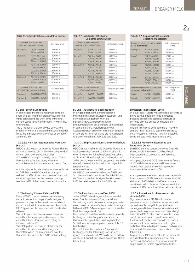
BREAKER ME10TRIP UNIT
OP
ER
ATI
ON
2.2
2-15
Limitazioni impostazioni SD e IIn alcuni casi, il valore massimo della corrente di breve durata e della corrente istantanea possono eccedere la capacità di tenuta di corrente di breve durata ammissibile per l'interruttore. I Relè di Protezione della gamma GT rilevano sempre l'interruttore su cui sono installati e, dove necessario, limitano i valori impostabili, come indicato nelle tabelle 2.6a e 2.6b.
2.2.3.3.1 Protezione istantanea con limitazione (HSIOC)Lo HSIOC è anche conosciuto come Override Pickup. I Relè di Protezione utilizzati negli interruttori ME10 prevedono un intervento istantaneo:-- l'impostazione HSIOC è normalmente fissata al 107% della corrente Icw dell'interruttore quando la protezione selettiva regolabile istantanea è impostata su ON.
- se la protezione selettiva istantanea regolabile è impostata su OFF l'intervento nominale HSIOC si riduce al 98% della Icw dell'interruttore e, considerando la tolleranza, l'intervento minimo avviene al 91% del valore di Icw dell'interruttore.
2.2.3.4 Protezione da chiusura su corto circuito (MCR)Ogni interruttore ME10 TU utilizza una protezione contro la chiusura su corto circuito appositamente progettata per evitare di danneggiare l'interruttore quando si chiude in presenza di un guasto. In alcuni casi anche gli interruttori ME10 di tipo non automatico sono dotati anche di questo tipo di protezione.Il valore della protezione contro la chiusura su corto circuito varia in funzione della taglia dell'interruttore ed è legato ai valori di chiusura e di tenuta dell'interruttore, come indicato nella tabella 2.7La protezione MCR viene attivata nel momento in cui l'interruttore si chiude e per sei cicli successivi. Quando i sei cicli sono esauriti, la soglia passa sul valore di protezione HSIOC.
SD and I setting LimitationsIn some cases the stated maximum settable Short time current and instantaneous current value can exceed the Short Time withstand current capabilities of the breaker in which they are installed. The GT range of trip unit always detects the breaker in which it is installed and where needed limits the indicated settable values as per table 2.6a and 2.6b.
2.2.3.3.1 High Set Instantaneous Protection (HSIOC)HSIOC is also Known as Override Pickup. The trip units used in ME10 circuit breakers are provided with an override instantaneous trip:-- The HSIOC setting is normally set at 107% of the circuit breaker Icw rating when the adjustable selective instantaneous is set to ON.
-- If the adjustable selective instantaneous is set to OFF then the HSIOC nominal pick up is reduced to 98% of the circuit breaker’s Icw and, considering tolerance, the minimum pickup reacts at 91% of the circuit breaker’s Icw value.
2.2.3.4 Making Current Release (MCR)Every ME10 TU circuit breaker uses a making current release that is specifically designed to prevent damage to the circuit breaker when it closed on a fault. In some cases non Automatic ME10 types are also equipped with this kind of release.The making current release value varies per circuit breaker envelope and is related to the circuit breaker’s close and latch rating as indicated in table 2.7The MCR pickup is activated at the time the circuit breaker closes and for six cycles thereafter. When the six cycles are over, the threshold changes to the HSIOC pickup setting.
SD und I (Kurzschluss) BegrenzungenIn einigen Fällen kann der angegebene maximale einstellbare Kurzschlussstrom- und Schnellauslösungsstrom-Wert die Bemessungskurzzeitstromfestigkeit-Einsatzmöglichkeit des Schalters überschreiten, in dem der Schutz installiert ist. Die GT-Auslöseeinheiten erkennen immer den Schalter, in dem sie installiert sind und die notwendigen Grenzwerte nach den Tab. 2.6a und 2.6b.
2.2.3.3.1 High-Kurzschlussstromschnellschutz(HSIOC) HSIOC ist auch bekannt als 'Override Pickup'. Die Auslöseeinheiten der ME10 Schalter sind mit einer 'Erweiterten Schnellauslösung' versehen:-- Die HSIOC Einstellung ist normalerweise auf 107% des Schalter Icw-Wertes gesetzt, wenn die einstellbare selektive Schnellauslösung auf EIN gesetzt wurde.-- Wurde sie jedoch auf AUS gestellt , dann ist der HSIOC nominale Einstellwert auf 98% des Schalter Icw’s reduziert. Unter Berücksichtigung der Toleranz, ist der niedrigste Reaktionswert 91% des Leistungsschalter Icw’s Wertes.
2.2.3.4 Einschaltstromauslöser (MCR) Jeder ME10 TU-Leistungsschalter verwendet einen Einschaltstromauslöser, speziell zur Vermeidung von Schäden am Leistungsschalter, wenn dieser auf einen Fehler schaltet. In einigen Fällen sind ME10-Trennertypen auch mit solchen Modulen ausgerüstet. Die Einschaltstromauslöser Werte variieren je nach Leistungsschalter-Baugröße und stehen im Zusammenhang mit dem Leistungsschalter Schließ- und Verriegelungswert, wie in Tab. 2.7 beschrieben. Der MCR-Einstellwert ist zum Zeitpunkt der Leistungsschalter Schließung und für sechs Zyklen danach aktiviert. Wenn die sechs Zyklen vorbei sind, ändert der Schwellenwert zur HSIOC Einstellung.
Table 2.7: Installed MCR devices and their settings
Overview of installed MRC
devices in Automatic types :Set value (rms)
Envelope 1 AG04S to AG20S 42,000 A
AG04N to AG20N 50,000 A
AG04H to AG20H 65,000 A
Envelope 2 AG25N to AG40N 65,000 A
AG04E to AG20E 85,000 A
AG25H to AG40H 85,000 A
AG25M to AG40M 85,000 A
Envelope 3 AG32G to AG40G 100,000 A
AG40M to AG64M 100,000 A
AG40L to AG64L 100,000 A
Envelope T AT04R to AT16R 32,000 A
AT04K to AT16K 36,000 A
Envelope 1 GW04N to GW20N 65,000 A
Envelope 2 GW04M to GW40M 85,000 A
Overview of installed MRC
devices in Non Automatic types :Set value (rms)
Tab. 2.7: Installierte MCR-Geräte und deren Einstellungen
Übersicht installierte MRC
Geräte in Automatik-Typen:Einstellwerte (rms)
Baugröße 1 AG04S ... AG20S 42,000 A
AG04N ... AG20N 50,000 A
AG04H ... AG20H 65,000 A
Baugröße 2 AG25N ... AG40N 65,000 A
AG04E ... AG20E 85,000 A
AG25H ... AG40H 85,000 A
AG25M ... AG40M 85,000 A
Baugröße 3 AG32G ... AG40G 100,000 A
AG40M ... AG64M 100,000 A
AG40L ... AG64L 100,000 A
Baugröße 1 GW04N ... GW20N 65,000 A
Baugröße 2 GW04M ... GW40M 85,000 A
Übersicht installierte MRC
inTrennerversionen:Einstellwerte (rms)
Baugröße T AT04R ... AT16R 32,000 A
AT04K ... AT16K 36,000 A
Tabella 2.7: Dispositivi MCR installati e relative impostazioni
Taglia 1 AG04S ...AG20S 42,000 A
AG04N ...AG20N 50,000 A
AG04H ...AG20H 65,000 A
Taglia 2 AG25N ...AG40N 65,000 A
AG04E ...AG20E 85,000 A
AG25H ...AG40H 85,000 A
AG25M ...AG40M 85,000 A
Taglia 3 AG32G ...AG40G 100,000 A
AG40M ...AG64M 100,000 A
AG40L ...AG64L 100,000 A
Taglia 1 AW04N ...AW20N 65,000 A
Taglia 2 AW04M ...AW40M 85,000 A
Panoramica protezioni MCR installate
sui tipi automatici:Valore impostato
(rms)
Panoramica protezioni MCR installate
sui tipi non automatici:Valore impostato
(rms)
Envelope T AT04R to AT16R 32,000 A
AT04K to AT16K 36,000 A
GE
NE
RA
LP
RO
DU
CT
OP
ER
ATI
ON
SC
RE
EN
MO
DE
...C
UR
VE
SIN
STA
LLA
TIO
NC
ON
NE
CTI
ON
LOCKSBREAKER ME10 INTRO BREAKER ACCESSORIES TESTS APPENDIX
TRIP UNIT
OTH
ER
2-16
2.2.3.5 Protezione istantanea ridotta (RELT)II Relè di protezione tipo GT-N e GT-H sono dotati di una protezione istantanea ridotta (RELT). L'INPUT 1 è assegnato a questo dispositivo, che può essere attivato con un segnale a 24 VDC o AC.La funzione RELT offre una funzione di intervento istantaneo più veloce, che può essere utilizzata nei casi in cui sia temporaneamente richiesta una protezione più rapida e più sensibile dai cortocircuiti. Il dispositivo è impostato separatamente ed ha una soglia di intervento che può essere impostata a incrementi di 0,5 x il valore di corrente impostato dall'utente Ie, su un intervallo da 1,5 x Ie a 15 x Ie (limitato a un massimo di 13 x Ie sul modello a 6400A).Per consentire l'utilizzo della funzione RELT, assicurarsi che sia impostata su ON nel menù di configurazione. A questo dispositivo viene automaticamente assegnata l'uscita relè 1, consentendo l'indicazione dello stato in REMOTO.
2.2.3.6 Protezione da guasto a terra (GF)Tutti i Relè di Protezione di tipo GT-E, S, N e H possono essere opzionalmente dotati di un dispositivo di protezione di guasto a terra residuale. I Relè di Protezione tipo GT-H possono opzionalmente essere dotati di un set di due protezioni di guasto a terra come indicato di seguito:-- GFsum: che opera in base al principio della corrente differenziale.-- GFct: che opera in base al principio di ritorno a terra.Protezione di guasto a terra GFsumIl dispositivo utilizza i sensori Rogowski interni dell'interruttore per misurare e sommare le intensità di fasi e neutro. Quando in un interruttore a 3 poli viene scelta l'opzione di guasto a terra, nella maggior parte delle applicazioni (4 fili) è necessario un quarto sensore esterno. La distanza tra l'interruttore e il sensore esterno deve essere limitata a 10 metri.
Quando il dispositivo rileva una corrente, il Relè di protezione ME10 fa intervenire l'interruttore scollegando quindi il circuito o, opzionalmente, producendo un segnale di allarme.La banda di tolleranza della protezione GF è il 15% della corrente impostata (Ig). Le soglie di intervento di guasto a terra sono impostate come multipli di x CT (CT = In dell'interruttore) a passi di 0,01 x CT. Senza un'alimentazione ausiliaria, il campo di regolazione è limitato da 0,2 a 1 xCT. Quando è collegata un'alimentazione di controllo a +24 VDC, il campo di regolazione aumenta da 0,1 a 1 x Ict. (= In dell'interruttore ME10)
Protezione da guasto a terra GFctQuesto dispositivo prevede uno schema di protezione di guasto a terra alternativo (detto anche “Source Ground return") in cui la corrente del neutro è misurata da un quarto sensore (di neutro) posizionato nel punto di messa a terra dell'impianto. Questa opzione richiede l'uso di una tensione ausiliaria di 24 VDC, mentre il Relè i Protezione elettronica deve avere l'opzione di ingresso CT 'attiva'.Un TA di collegamento a terra deve essere posizionato nelle immediate vicinanze dell'interruttore mentre un TA di isolamento deve
2.2.3.5 Reduced Energy Let-Through Instantaneous Protection (RELT)The trip unit types GT-N and GT-H are provided with a Reduced Let Through Instantaneous function (RELT) . INPUT 1 is assigned to this device that can be activated with a 24V DC or AC signal.
The RELT function provides a faster instantaneous trip function that may be used in cases where a faster and more sensitive protection against short circuits is required temporarily. The device is set separately and has a pickup value that can be set in steps of 0.5 x the set user current value Ie with a range of 1,5 xIe to 15 xIe. (limited to a maximum 13 x Ie on the 6400A type).
To allow the use of the RELT function please assure that it is set to ON in the set up menu. Relay output one is automatically assigned to this device allowing a REMOTE status indication of the device (ON or OFF).
2.2.3.6 Ground Fault Protection (GF)All GT-E, S, N and H type trip units can be optionally equipped with a Residual Ground Fault Protection device . The GT-H trip unit types can optionally be equipped with a set of two ground fault devices as follows:-- GFsum :That operates on the Residual Current device principle.-- GFct :That operates on the Source Ground Return principle.
The GFsum Ground Fault ProtectionThe device utilizes the internal Rogowski sensors in the circuit breaker to measure and to residually sum all phase and neutral currents. When the groundfault option is chosen on a 3 pole breaker an additional 4th external sensor is required for most applications (4 wire). The distance between the circuit breaker and the external sensor is limited to 10 metres. (33 f)
When the device detects a fault current the ME10 trip unit trips the associated Circuit breaker thus disconnecting the circuit or , optionally, produces an alarm signal.
The GF pickup value tolerance band is 15% of the set current (Ig). The ground fault pickup settings are set as multiples of x CT (CT=In of the circuit breaker) in steps of 0.01 x CT.
Without an auxiliary supply the setting range is limited to 0.2 to 1 xCT. When a +24V DC control voltage supply is connected the setting range is increased to 0.1 to 1 x Ict. (= In of the ME10 Breaker)
GFct Ground Fault ProtectionThis device is an alternative earth fault protection scheme in which the Neutral Current is measured by a 4th, or neutral sensor placed at the earthing point of the system.
This option requires the use of an auxiliary supply of 24VDC and the Electronic Trip Unit must have the option CT input 'active'.An Earth leg CT needs to be placed in the near vicinity of the breaker and an interposing CT needs to be mounted in the breaker. When the
2.2.3.5 RELT-Schutz (reduzierter Schnellschutz)Die ME10 Auslöseeinheit Typ GT-N und GT-H bieten eine 'Reduced Energy Let-Through Instantaneous Protection' RELT-Funktion.Eingang 1 ist dieser Funktion zugeordnet und wird über ein 24 VDC oder AC Signal aktiviert.
Die RELT-Funktion bietet eine schnellere Schnellauslösungsfunktion, die verwendet werden kann, wenn ein schnellerer und empfindlicherer Schutz gegen Kurzschlüsse vorübergehend erforderlich ist.Das Gerät ist getrennt einstellbar und hat einen Einstellwert, der in Schritten von 0,5 x auf den gesetzten Nutzerstromwert Ie mit einer Bandbreite von 1,5 xIe bis 15 xIe gestellt werden kann.(beschränkt auf max. 13 xIe für den 6400A Typ). Um die Verwendung der RELT-Funktion zu nutzen, muss sie im SETUP-Menü auf EIN gestellt werden. Relaisausgang 1 wird automatisch zur Fernstatus-Anzeige der RELT-Funktion (AUS oder EIN) auf diesen Schutz gesetzt.
2.2.3.6 Erdschlussschutz (GF) Alle GT-E, -S, -N und -H-Auslöseeinheiten können optional mit Erdschlussschutz ausgerüstet werden. Der GT-H Typ kann optional mit zwei Erdschlussschutz-Prinzipien ausgerüstet werden:
-- GFsum: Funktioniert nach dem Fehlerstrom-Prinzip.-- GFct: Funktioniert nach dem Source Ground Return Prinzip.
Das Fehlerstrom-Prinzip (GFsum) Der Schutz nutzt die internen Rogowski-Wandler im Schalter zum Messen und zum Summieren aller übrigbleibenden Phasen- und Neutralströme. Wenn die Erdschluss-Option mit einem 3-poligen Leistungsschalter gewählt wird, ist ein zusätzlicher 4ter externen Wandler für die meisten Anwendungen (4-Draht) erforderlich. Der Abstand zwischen dem Leistungsschalter und dem externen Wandler ist auf 10 Meter begrenzt.Wenn das Gerät einen Fehlerstrom erkennt, löst die ME10 Auslöseeinheit den entsprechenden Leistungsschalter zur Schaltkreistrennung oder optional zur Signalerzeugung aus. Der GF Einstellwert-Toleranzbereich ist 15% des eingestellten Stroms (Ig). Die Erdschluss-Einstellwerte sind als Vielfaches von xCT (CT = In des Leistungsschalters) in Schritten von 0,01 xCT einstellbar.Ohne Hilfsspannung ist der Einstellbereich auf 0,2 bis 1 xCT begrenzt. Wenn eine +24VDC-Spannungsversorgung angeschlossen ist, erhöht sich der Einstellbereich auf 0,1 bis 1 x Ict.(= In des ME10 Leistungsschalters)
GFct ErdschlussschutzDieser Schutz ist ein alternatives Erdschlussschutzschema, in dem der Neutralleiterstrom in einem Vierten oder Neutralwandler, am Systemerdungspunkt, gemessen wird.Diese Option erfordert die Verwendung einer Hilfsspannung von 24VDC und die Elektronik-Auslöseeinheit die Einstellung: Wandler (CT)-Eingang 'aktiv'. Ein Erdschlussstromwandler muss in der Nähe des Schalters und ein Zwischenstromwandler im Leistungsschalter
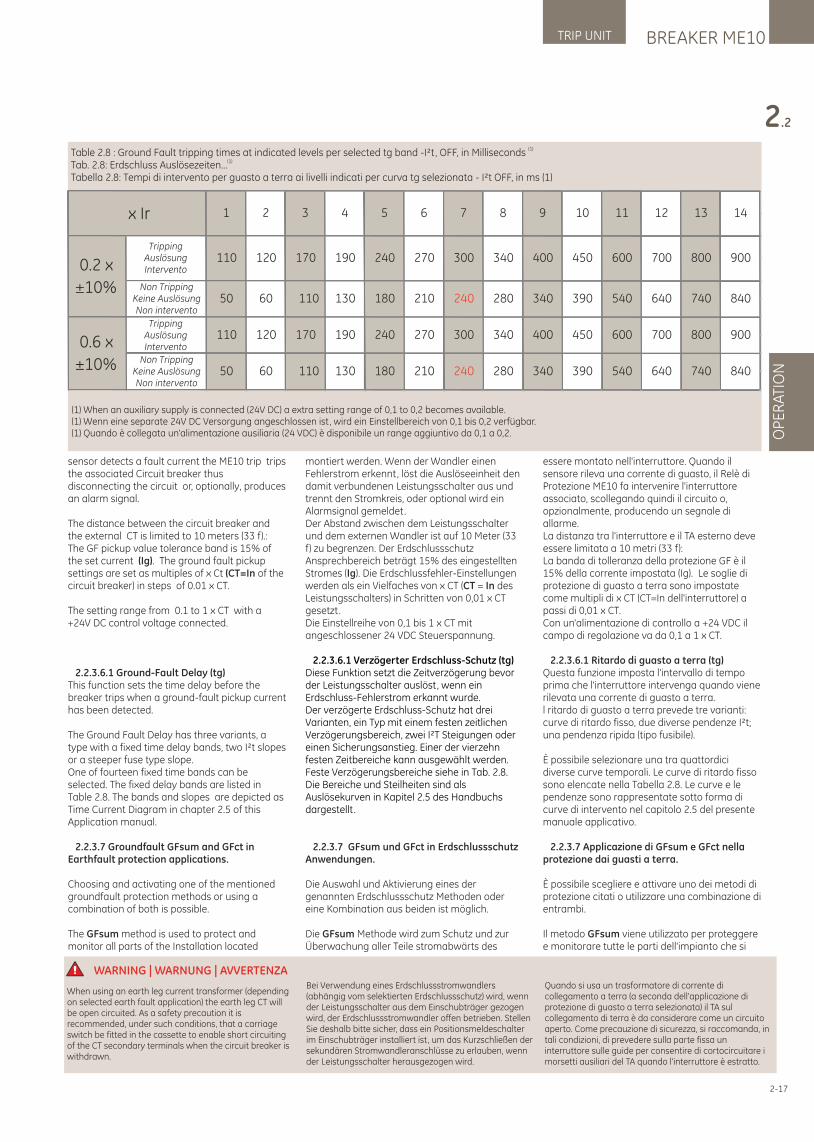
BREAKER ME10TRIP UNIT
OP
ER
ATI
ON
2.2
2-17
essere montato nell'interruttore. Quando il sensore rileva una corrente di guasto, il Relè di Protezione ME10 fa intervenire l'interruttore associato, scollegando quindi il circuito o, opzionalmente, producendo un segnale di allarme.La distanza tra l'interruttore e il TA esterno deve essere limitata a 10 metri (33 f):La banda di tolleranza della protezione GF è il 15% della corrente impostata (Ig). Le soglie di protezione di guasto a terra sono impostate come multipli di x CT (CT=In dell'interruttore) a passi di 0,01 x CT. Con un'alimentazione di controllo a +24 VDC il campo di regolazione va da 0,1 a 1 x CT.
2.2.3.6.1 Ritardo di guasto a terra (tg)Questa funzione imposta l'intervallo di tempo prima che l'interruttore intervenga quando viene rilevata una corrente di guasto a terra.l ritardo di guasto a terra prevede tre varianti: curve di ritardo fisso, due diverse pendenze I²t; una pendenza ripida (tipo fusibile).
È possibile selezionare una tra quattordici diverse curve temporali. Le curve di ritardo fisso sono elencate nella Tabella 2.8. Le curve e le pendenze sono rappresentate sotto forma di curve di intervento nel capitolo 2.5 del presente manuale applicativo.
2.2.3.7 Applicazione di GFsum e GFct nella protezione dai guasti a terra.
È possibile scegliere e attivare uno dei metodi di protezione citati o utilizzare una combinazione di entrambi.
Il metodo GFsum viene utilizzato per proteggere e monitorare tutte le parti dell'impianto che si
(1)Table 2.8 : Ground Fault tripping times at indicated levels per selected tg band -I²t, OFF, in Milliseconds (1)Tab. 2.8: Erdschluss Auslösezeiten...
Tabella 2.8: Tempi di intervento per guasto a terra ai livelli indicati per curva tg selezionata - I²t OFF, in ms (1)
540 640 740 840
600 700 800 900
240 280 340 390110 130 180 210
300 340 400 450170 190 240 2700.6 x
±10%
110 120
50 60
540 640 740 840240 280 340 390110 130 180 210
600 700 800 900300 340 400 450170 190 240 2700.2 x
±10%
110 120
50 60
11 12 13 147 8 9 10 x Ir 1 2 3 4 5 6
(1) When an auxiliary supply is connected (24V DC) a extra setting range of 0,1 to 0,2 becomes available. (1) Wenn eine separate 24V DC Versorgung angeschlossen ist, wird ein Einstellbereich von 0,1 bis 0,2 verfügbar.(1) Quando è collegata un'alimentazione ausiliaria (24 VDC) è disponibile un range aggiuntivo da 0,1 a 0,2.
WARNING | WARNUNG | AVVERTENZABei Verwendung eines Erdschlussstromwandlers (abhängig vom selektierten Erdschlussschutz) wird, wenn der Leistungsschalter aus dem Einschubträger gezogen wird, der Erdschlussstromwandler offen betrieben. Stellen Sie deshalb bitte sicher, dass ein Positionsmeldeschalter im Einschubträger installiert ist, um das Kurzschließen der sekundären Stromwandleranschlüsse zu erlauben, wenn der Leistungsschalter herausgezogen wird.
When using an earth leg current transformer (depending on selected earth fault application) the earth leg CT will be open circuited. As a safety precaution it is recommended, under such conditions, that a carriage switch be fitted in the cassette to enable short circuiting of the CT secondary terminals when the circuit breaker is withdrawn.
Quando si usa un trasformatore di corrente di collegamento a terra (a seconda dell'applicazione di protezione di guasto a terra selezionata) il TA sul collegamento di terra è da considerare come un circuito aperto. Come precauzione di sicurezza, si raccomanda, in tali condizioni, di prevedere sulla parte fissa un interruttore sulle guide per consentire di cortocircuitare i morsetti ausiliari del TA quando l'interruttore è estratto.
TrippingAuslösungIntervento
Non TrippingKeine AuslösungNon intervento
TrippingAuslösungIntervento
Non TrippingKeine AuslösungNon intervento
sensor detects a fault current the ME10 trip trips the associated Circuit breaker thus disconnecting the circuit or, optionally, produces an alarm signal.
The distance between the circuit breaker and the external CT is limited to 10 meters (33 f).:The GF pickup value tolerance band is 15% of the set current (Ig). The ground fault pickup settings are set as multiples of x Ct (CT=In of the circuit breaker) in steps of 0.01 x CT.
The setting range from 0.1 to 1 x CT with a +24V DC control voltage connected.
2.2.3.6.1 Ground-Fault Delay (tg)This function sets the time delay before the breaker trips when a ground-fault pickup current has been detected.
The Ground Fault Delay has three variants, a type with a fixed time delay bands, two I²t slopes or a steeper fuse type slope.One of fourteen fixed time bands can be selected. The fixed delay bands are listed in Table 2.8. The bands and slopes are depicted as Time Current Diagram in chapter 2.5 of this Application manual.
2.2.3.7 Groundfault GFsum and GFct in Earthfault protection applications.
Choosing and activating one of the mentioned groundfault protection methods or using a combination of both is possible.
The GFsum method is used to protect and monitor all parts of the Installation located
montiert werden. Wenn der Wandler einen Fehlerstrom erkennt, löst die Auslöseeinheit den damit verbundenen Leistungsschalter aus und trennt den Stromkreis, oder optional wird ein Alarmsignal gemeldet.Der Abstand zwischen dem Leistungsschalter und dem externen Wandler ist auf 10 Meter (33 f) zu begrenzen. Der Erdschlussschutz Ansprechbereich beträgt 15% des eingestellten Stromes (Ig). Die Erdschlussfehler-Einstellungen werden als ein Vielfaches von x CT (CT = In des Leistungsschalters) in Schritten von 0,01 x CT gesetzt.Die Einstellreihe von 0,1 bis 1 x CT mit angeschlossener 24 VDC Steuerspannung.
2.2.3.6.1 Verzögerter Erdschluss-Schutz (tg)Diese Funktion setzt die Zeitverzögerung bevor der Leistungsschalter auslöst, wenn ein Erdschluss-Fehlerstrom erkannt wurde. Der verzögerte Erdschluss-Schutz hat drei Varianten, ein Typ mit einem festen zeitlichen Verzögerungsbereich, zwei I²T Steigungen oder einen Sicherungsanstieg. Einer der vierzehn festen Zeitbereiche kann ausgewählt werden. Feste Verzögerungsbereiche siehe in Tab. 2.8. Die Bereiche und Steilheiten sind als Auslösekurven in Kapitel 2.5 des Handbuchs dargestellt .
2.2.3.7 GFsum und GFct in Erdschlussschutz Anwendungen.
Die Auswahl und Aktivierung eines der genannten Erdschlussschutz Methoden oder eine Kombination aus beiden ist möglich.
Die GFsum Methode wird zum Schutz und zur Überwachung aller Teile stromabwärts des
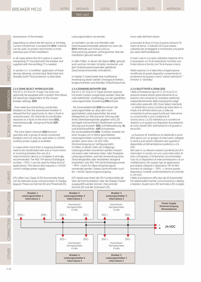
GE
NE
RA
LP
RO
DU
CT
OP
ER
ATI
ON
SC
RE
EN
MO
DE
...C
UR
VE
SIN
STA
LLA
TIO
NC
ON
NE
CTI
ON
LOCKSBREAKER ME10 INTRO BREAKER ACCESSORIES TESTS APPENDIX
TRIP UNIT
OTH
ER
2-18
trova valle dell'interruttore.
A seconda di dove si trova il quarto sensore TA (ramo di terra) , il metodo GFct può essere utilizzato per proteggere e monitorare una parte più vasta dell'installazione.
In tutti i casi in cui viene utilizzata l'opzione GFct, è necessario un TA di isolamento montato con l'interruttore e fornito con TA di messa a terra.
INella sezione 2.4 è descritta un'applicazione modificata di questi dispositivi consentendo la protezione da guasto a terra "senza restrizioni"," limitata" e "standby".
2.2.4 SELETTIVITÀ A ZONA (ZSI)I Relè di Protezione tipo GT-S, GT-N & GT-H possono essere dotati opzionalmente di un sistema che consente la completa selettività, indipendentemente dalle impostazioni degli interruttori prescelti. (ZSI: Zone Select Interlock) La selettività a zona coordina gli interruttori in modo che all'interruttore più a valle sia consentita la prima opportunità per intervenire su un'anomalia o una condizione di sovraccarico. La ZSI interblocca e coordina le reazioni a un guasto sui dispositivi di protezione di corto ritardo (SD), istantanea (I) e di guasto a terra (GF).
La funzione di 'Interblocco di selettività a zona' (ZSI) opera con un gruppo di interruttori collegati in serie e può essere utilizzata solo quando è disponibile un'alimentazione ausiliaria a +24 VDC.Nel caso in cui devono essere coordinati più di 4 interruttori in uscita con uno o più interruttori di rete o d'ingresso, è fortemente raccomandato l'uso di un dispositivo di interconnessione o di un moltiplicatore. Per questo tipo di applicazioni può essere utilizzato il dispositivo TIM di AEG (numero di catalogo -- TIM1 --). Anche questo dispositivo richiede un'alimentazione di controllo a +24 VDC.Il Relè di protezione offre due tipi di funzionalità ZSI selezionabili tramite comunicazione o display e tastiera. Questi sono ZSI Normale e ZSI a soglia
Breaker 1Leistungsschalter 1
Interruttore 1
ZSIN + ZSIN -
Power SupplyStromversorgung
Alimentazione
+- 24 VDC
Breaker 2Leistungsschalter 2
Interruttore 2
ZSO + ZSO -
DownstreamNachgeschaltet
A valle
Breaker 3Leistungsschalter 3
Interruttore 3
ZSO + ZSO -
Breaker 4Leistungsschalter 4
Interruttore 4
ZSO + ZSO -
Breaker 5Leistungsschalter 5
Interruttore 5
ZSO + ZSO -
DownstreamNachgeschaltet
A valle
DownstreamNachgeschaltet
A valle
DownstreamNachgeschaltet
A valle
downstream of the breaker.
Depending on where the 4th sensor or Earthleg Current transformer is located the GFct method can be used to protect and monitor a more extensive part of the installation.
In all cases where the GFct option is used an interposing CT mounted with the breaker and supplied with the earthleg CT is needed.
In section 2.4 a modified application of these devices allowing ,Unrestricted, Restricted and Standby Earth Fault protection is described.
2.2.4 ZONE SELECT INTERLOCK (ZSI)The GT-S, GT-N & GT-H type Trip Units can optionally be equipped with a system that allows full selectivity independent of the chosen breaker settings. (ZSI)
Zone-selective interlocking coordinates breakers so that the downstream breaker is allowed the first opportunity to clear a fault or overload event. ZSI interlocks & coordinates reactions to a fault on the short-time (SD), instantaneous (I), and ground faults (GF) devices.
The Zone Select Interlock (ZSI) function operates with a group of series-connected breakers and can only be used when a +24VDC auxiliary power supply is available.
In cases when more than 4 outgoing breakers need to be coordinated with one or more mains or incoming breakers the use of a interconnection device or multiplier is strongly recommended. The AEG TIM device (Catalogue number --TIM1--) can be used for these kind of applications. This device also requires a +24VDC control voltage power supply.
GTU offers two Types of ZSI functionality those can be selected using communication or Display keypad. These are Normal ZSI and Threshold ZSI.
Leistungsschalters verwendet.
Je nachdem, wo der 4.te Wandler oder Erdschlussstromwandler platziert ist, kann die GFct Methode zum Schutz und zur Überwachung weiterer umfangreicher Teile der Installation genutzt werden.
In allen Fällen, in denen die Option GFct genutzt wird, wird ein mit dem Schalter montierter und dem Erdschlussstromwandler gelieferter Zwischenstromwandler erforderlich.
In Kapitel 2.4 beschreibt eine modifizierte Anwendung dieser Geräte 'Uneingeschränkten, eingeschränkten und Standby'-Erdschlussschutz.
2.2.4 ZONENSELEKTIVITÄT (ZSI)Die GT-S, GT-N & GT-H Typen können optional mit einem System ausgerüstet werden, dass die volle Selektivität, unabhängig von der gewählten Leistungsschalter-Einstellung (ZSI) erlaubt.
Die Zonenselektivität (ZSI) koordiniert die Leistungsschalter so, dass dem nach-geschalteten Leistungsschalter die erste Gelegenheit zur Klärung einer Störung oder eines Überlastereignisses gegeben wird. ZSI verriegelt und koordiniert Reaktionen auf eine Störung aus Kurzzeit- (SD), Schnellauslösung- (I), und Erdschlussfehler- (GF) Schutzarten. Die Zonenselektivität (ZSI) -Funktion arbeitet mit einer Gruppe von in Reihe geschalteten Leistungsschaltern und kann nur verwendet werden, wenn eine +24 VDC Hilfs-Stromversorgung zur Verfügung steht. In Fällen, in denen mehr als 4 Abgangs-Leistungsschalter koordiniert werden müssen mit einem oder mehreren Netz- oder Einspeise-Leistungsschaltern, wird die Verwendung eines Zwischengerätes oder Verstärkers dringend empfohlen. Das AEG TIM-Gerät (Katalognummer --TIM1--) kann für diese Anwendungsart verwendet werden. Dieses Gerät erfordert auch ein +24VDC Spannungsversorgung.
GTU bietet zwei Arten der ZSI-Funktionalität die über die Kommunikation oder die Display-Tasten ausgewählt werden können. Dies sind der Normal-ZSI und der Grenzwert-ZSI.
BREAKER ME10TRIP UNIT
OP
ER
ATI
ON
2.2
ZSI normale:Alla ricezione di un ingresso ZSI, un interruttore a monte non utilizzerà le impostazioni standard relative a pendenza e curva di ritardo ZSI SD e/o ZSI GF.Esso utilizzerà automaticamente un secondo set di valori che l'utente può impostare individualmente per quando ZSI è ON. Quando l'ingresso ZSI viene annullato, l'interruttore ritornerà alle sue impostazioni standard.
Le curve di ritardo sia ZSI SD sia ZSI GF vengono impostate in modo indipendente una dall'altra utilizzando le stesse curve e opzioni della protezione standard.
Quando riceve un ingresso ZSI, un interruttore a monte ritarda temporaneamente l'intervento della sua protezione istantanea (I) finché il guasto non viene eliminato dal dispositivo a valle.ZSI a Soglia:La ZSI a Soglia fornisce un coordinamento avanzato dove l'interruttore a valle invia il segnale di output ZSI all'interruttore a monte dell'interruttore ad una predefinita SD / soglia istantanea . Questa soglia predefinita viene chiamata "Soglia di blocco" ed è inferiore all'impostazione limite effettiva dell'interruttore.Quando un ingresso ZSI è ricevuto, un interruttore a monte sposterà le SD / soglie istantaneead un livello superiore predefinito . Questa livello maggiore SD / soglia di intervento istantaneo è chiamata "Soglia di ritenzione" ed è superiore all'effettivo valore impostato al fine di permettere a valle di eliminare l'errore .Inoltre l'interruttore invierà un segnale ZSI output per segnalare all'interruttore successivo a monte non appena ricevuto il segnale di ingresso ZSI .L'interruttore a monte non utilizza il ritardo standard SD ZSI e l'impostazione pendenza. Userà autameticamente un secondo set di impostazioni che l'utente può impostare individualmente per l'uso quando ZSI è ON .Quando l'ingresso ZSI viene annullato l'interruttore torna alle sue impostazioni di intervento e ritardo standard.Quando un ingresso ZSI ha ricevuto un interruttore a monte sarà temporaneamente ritardato il suo intervento sul Istantanea del dispositivo (I) finché il guasto non viene eliminato dal dispositivo a valle.
Test ZSI: l'uscita ZSI può essere impostata allo stato attivo utilizzando la funzione di test ZSI. Lo ZSI output andrà in stato attivo per 30 secondi quando selezionato. Il Test ZSI può essere eseguita selezionando l'opzione Test ZSI sulla schermata ZSI del display o tramite comunicazione.
2.2.5.1 IngressiIl Relè di Protezione GT-H ha due ingressi assegnabili che permettono di gestire due funzionalità principali:-- Protezione istantanea ridotta (RELT)-- Intervento dell'interruttoreRipristinare i contatti di uscita la Tabella 2.9 mostra una panoramica della loro funzionalità mostrate sul display LCD.Gli ingressi sono collegati tramite morsetti appositamente assegnati, situati sulla
2-19
Normal ZSI:When a ZSI input is received an upstream breaker will not use the standard SD ZSI and/or GF ZSI delay band and slope setting.
It will automatically use a 2nd set of settings that the user can individually set for use when ZSI is ON. When the ZSI input is cancelled the breaker will revert to it's standard setting.
Both the SD ZSI as the GF ZSI Delay Bands are set independently using the same bands and options as the standard device. The downstream device settings must be <= to that of the upstream device.
When a ZSI input received an upstream breaker will temporarily delay it's tripping on the Instantaneous (I) device until the fault is cleared by the downstream device.
Threshold ZSI:Threshold ZSI provides advanced coordination wherein downstream breaker sends ZSI output signal to upstream breaker at a predefined ST / Instantaneous threshold level. This predefined threshold is called blocking threshold and is less than actual pickup threshold setting of the breaker.
When a ZSI input is received an upstream breaker will shift ST / Instantaneous thresholds higher to a predefined level. This higher shifted ST / Instantaneous pickup threshold is called restrained threshold and is higher than actual set value to allow downstream to clear the fault. In addition the breaker will send ZSI out put signal to next upstream breaker as soon as it received ZSI input signal.
The upstream breaker will not use the standard ST ZSI delay band and slope setting. It will automatically use a 2nd set of settings that the user can individually set for use when ZSI is ON. When the ZSI input is cancelled the breaker will revert to it's standard pickup and delay setting.
When a ZSI input received an upstream breaker will temporarily delay it's tripping on the Instantaneous (I) device until the fault is cleared by the downstream device.
ZSI Test:ZSI output can be set to active state using ZSI test feature. ZSI out put will go to active state for 30 seconds when selected. ZSI tests can be performed by selecting ZSI test option on ZSI screen using display or by using communication.
2.2.5.1 InputsThe GT-H trip unit has two assignable Inputs that allow for three main functionalities:-- Reduced Energy Let-Through (RELT)-- Trip the breaker– Reset the Output contacts
Table 2.9 provides an overview of their functionality as indicated on the LCD display.The inputs are connected via specifically assigned points located on the standard
Normal-ZSI:Wenn ein ZSI-Eingang empfangen wird, wird ein vorgeschalteter Leistungsschalter nicht die Standard-SD ZSI und / oder GF ZSI Verzögerungsbereichs- und Steilheit-Einstellung nutzen. Es wird automatisch in eine 2. Einstellung übergehen, die der Benutzer speziell setzen kann, wenn ZSI auf EIN gestellt ist. Wenn der ZSI-Eingang storniert wird, wird der Schalter wieder auf die Standard-Einstellungen gesetzt. Sowohl der SD-ZSI- als auch der GF-ZSI-Verzögerungsbereich sind unabhängig einstellbar und nutzen die gleichen Bereiche und Optionen wie der Standardschutz. Die nachgeschalteten Schaltereinstellungen müssen <= denen des vorgeschalteten Schalters sein.Wenn ein ZSI-Eingang einen vorgeschalteten Leistungsschalter erreicht, wird vorübergehend die Auslösung auf dem Schnellauslösungsschutz (I) verzögert, bis die Störung von dem nachgeschalteten Schutz geklärt wurde.Grenzwert-ZSI:Der Grenzwert-ZSI bietet erweiterte Abstimmungen, worin ein nachgeschalteter Leistungsschalter ein ZSI Signal zum vorgelagerten Leistungsschalter auf einen vordefinierten SD / Unverzögerten Grenzwert aussendet. Dieser vordefinierte Grenzwert ist ein Blockadegrenzwert und ist geringer als die tatsächliche Grenzwerteinstellung des Schalters.Wenn ein ZSI-Eingang eingeht, wird ein vorgeschalteter Leistungsschalter den SD / Unverzögerten Grenzwert höher zu einem bestimmten Niveau verschieben. Dieser hochverschobene ST /Unverzögerte Grenzwert , hier genannt Rückhaltegrenzwert, ist höher als der tatsächliche Einstellwert und ermöglicht so den Fehler nachgeschaltet zu beheben. Außerdem wird der Schalter ein ZSI-Ausgangssignal zum nächsten vorgeschalteten Leistungsschalter senden, sobald ein ZSI-Eingang empfangen wird. Der vorgeschaltete Schalter wird nicht die Standard-SD ZSI Verzögerungs- und die Steilheiteinstellung anwenden. Es wird automatisch eine zweite Einstellung genutzt, die der Benutzer individuell wählen kann, wenn ZSI ON (EIN) ist. Wenn der ZSI Eingang storniert wird, wird der Schalter wieder in die Standard-Auslöseverzögerungs-Einstellung versetzt. Wenn ein ZSI-Eingang einen vorgeschalteten Leistungsschalter erreicht, wird vorübergehend die Auslösung auf dem Schnellauslösungsschutz (I) verzögert, bis die Störung von dem nachgeschalteten Schutz geklärt wurde.ZSI Test:Der ZSI-Ausgang kann mit der ZSI-Testfunktion aktiviert werden. Der ZSI-Status wird für 30 Sekunden ausgegeben, wenn er ausgewählt wird. ZSI-Tests können durch die Anwahl des ZSI-Tests auf dem Bildschirm mittels ZSI-Display oder über die Kommunikation durchgeführt werden. 2.2.5.1 EingängeDie GT-H Auslöseeinheit hat zwei zuweisbare Eingänge für die drei wichtigsten Funktionen: -- 'Reduced Energy Let-Through' (RELT-Schutz)-- Auslösung des Leistungsschalters-- Rückstellung der Ausgabekontakte
Tabelle 2.9 bietet einen Überblick der auf dem LCD-Display angezeigten Funktionalitäten.Die Eingänge werden über spezielle Anschlüsse im Hilfstrennblock (oben im Leistungsschalter)
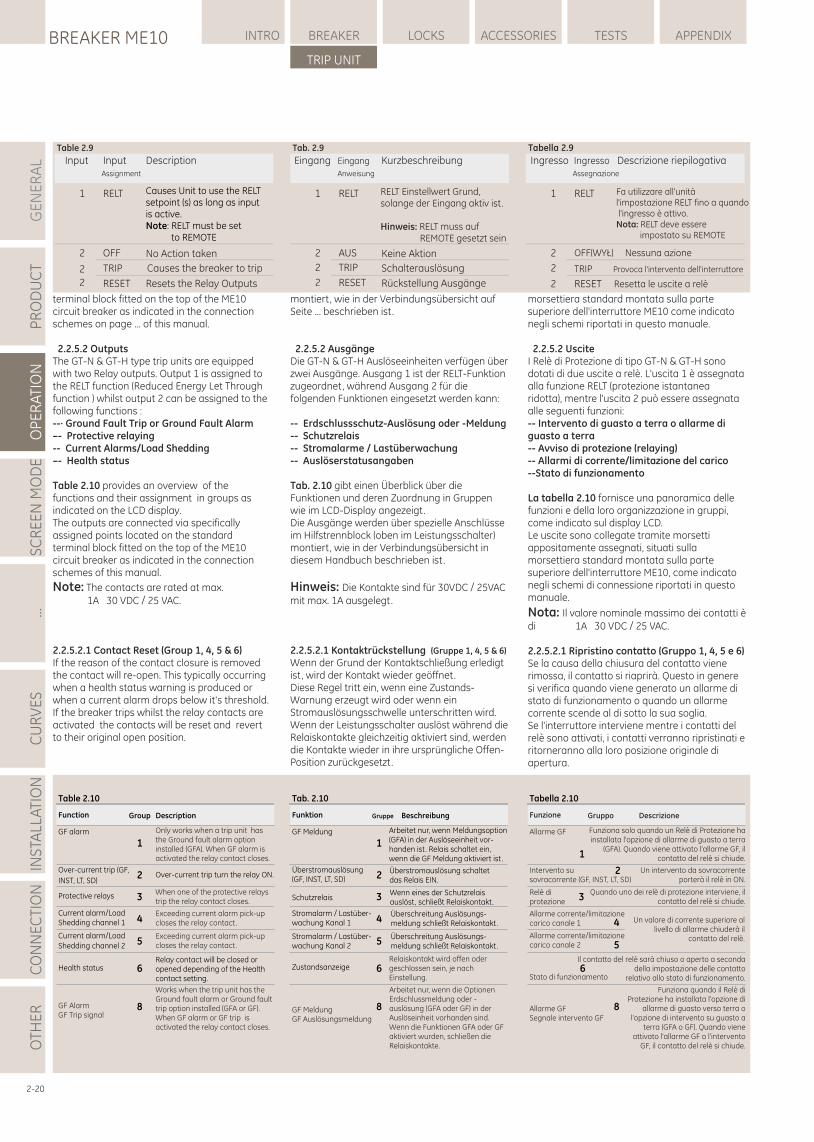
GE
NE
RA
LP
RO
DU
CT
OP
ER
ATI
ON
SC
RE
EN
MO
DE
...C
UR
VE
SIN
STA
LLA
TIO
NC
ON
NE
CTI
ON
LOCKSBREAKER ME10 INTRO BREAKER ACCESSORIES TESTS APPENDIX
TRIP UNIT
OTH
ER
morsettiera standard montata sulla parte superiore dell'interruttore ME10 come indicato negli schemi riportati in questo manuale.
2.2.5.2 Uscite I Relè di Protezione di tipo GT-N & GT-H sono dotati di due uscite a relè. L'uscita 1 è assegnata alla funzione RELT (protezione istantanea ridotta), mentre l'uscita 2 può essere assegnata alle seguenti funzioni:-- Intervento di guasto a terra o allarme di guasto a terra-- Avviso di protezione (relaying)-- Allarmi di corrente/limitazione del carico--Stato di funzionamento
La tabella 2.10 fornisce una panoramica delle funzioni e della loro organizzazione in gruppi, come indicato sul display LCD.Le uscite sono collegate tramite morsetti appositamente assegnati, situati sulla morsettiera standard montata sulla parte superiore dell'interruttore ME10, come indicato negli schemi di connessione riportati in questo manuale.
Nota: Il valore nominale massimo dei contatti è di 1A 30 VDC / 25 VAC.
2.2.5.2.1 Ripristino contatto (Gruppo 1, 4, 5 e 6)Se la causa della chiusura del contatto viene rimossa, il contatto si riaprirà. Questo in genere si verifica quando viene generato un allarme di stato di funzionamento o quando un allarme corrente scende al di sotto la sua soglia.Se l'interruttore interviene mentre i contatti del relè sono attivati, i contatti verranno ripristinati e ritorneranno alla loro posizione originale di apertura.
2-20
Table 2.10
Only works when a trip unit has the Ground fault alarm option installed (GFA). When GF alarm is activated the relay contact closes.
Over-current trip turn the relay ON.
When one of the protective relays trip the relay contact closes.
Exceeding current alarm pick-up closes the relay contact.
Relay contact will be closed or opened depending of the Health contact setting.
GF alarm
Over-current trip (GF,
INST, LT, SD)
Group DescriptionFunction
Protective relays
Current alarm/Load Shedding channel 1
Current alarm/Load
Shedding channel 2
Health status
Exceeding current alarm pick-up closes the relay contact.
1
2
3
4
5
6
8
Works when the trip unit has the Ground fault alarm or Ground fault trip option installed (GFA or GF). When GF alarm or GF trip is activated the relay contact closes.
GF AlarmGF Trip signal
Tab. 2.10
Beschreibung
Arbeitet nur, wenn Meldungsoption (GFA) in der Auslöseeinheit vor-handen ist. Relais schaltet ein, wenn die GF Meldung aktiviert ist.
Überstromauslösung schaltet das Relais EIN.
Wenn eines der Schutzrelais auslöst, schließt Relaiskontakt.
Überschreitung Auslösungs-meldung schließt Relaiskontakt.
Relaiskontakt wird offen oder geschlossen sein, je nach Einstellung.
GF Meldung
Überstromauslösung (GF, INST, LT, SD)
Funktion
Schutzrelais
Stromalarm / Lastüber-wachung Kanal 1
Zustandsanzeige
Stromalarm / Lastüber-wachung Kanal 2
Gruppe
GF MeldungGF Auslösungsmeldung
Arbeitet nur, wenn die Optionen Erdschlussmeldung oder -auslösung (GFA oder GF) in der Auslöseinheit vorhanden sind. Wenn die Funktionen GFA oder GF aktiviert wurden, schließen die Relaiskontakte.
Überschreitung Auslösungs-meldung schließt Relaiskontakt.
1
2
3
4
5
6
8
Tabella 2.10
Gruppo Descrizione
Un intervento da sovracorrente porterà il relè in ON.
Il contatto del relè sarà chiuso o aperto a seconda della impostazione delle contatto
relativo allo stato di funzionamento.
Allarme GF
Intervento su sovracorrente (GF, INST, LT, SD)
Funzione
Relè di protezione
Allarme corrente/limitazione carico canale 1
Stato di funzionamento
Allarme corrente/limitazione carico canale 2
Allarme GFSegnale intervento GF
Funziona quando il Relè di Protezione ha installata l'opzione di
allarme di guasto verso terra o l'opzione di intervento su guasto a
terra (GFA o GF). Quando viene attivato l'allarme GF o l'intervento
GF, il contatto del relè si chiude.
Funziona solo quando un Relè di Protezione ha installata l'opzione di allarme di guasto a terra
(GFA). Quando viene attivato l'allarme GF, il contatto del relè si chiude.
Quando uno dei relè di protezione interviene, il contatto del relè si chiude.
Un valore di corrente superiore al livello di allarme chiuderà il
contatto del relè.
1
2
3
4
5
6
8
Table 2.9
InputAssignment
Description
1 RELT
Input
OFF No Action taken2
Causes Unit to use the RELTsetpoint (s) as long as inputis active.Note: RELT must be set to REMOTE
Tab. 2.9
Eingang
Anweisung
Kurzbeschreibung
1 RELT
Eingang
AUS Keine Aktion2
RELT Einstellwert Grund, solange der Eingang aktiv ist.
Hinweis: RELT muss auf REMOTE gesetzt sein
Tabella 2.9
Assegnazione
Descrizione riepilogativa
1 RELT
Ingresso
2
Fa utilizzare all'unitàl'impostazione RELT fino a quando l'ingresso è attivo.Nota: RELT deve essere impostato su REMOTE
Ingresso
OFF(WYŁ) Nessuna azione
TRIP Causes the breaker to trip2
2 RESET Resets the Relay Outputs
TRIP Schalterauslösung2
2 RESET Rückstellung Ausgänge
TRIP Provoca l'intervento dell'interruttore2
2 RESET Resetta le uscite a relè
terminal block fitted on the top of the ME10 circuit breaker as indicated in the connection schemes on page ... of this manual.
2.2.5.2 Outputs The GT-N & GT-H type trip units are equipped with two Relay outputs. Output 1 is assigned to the RELT function (Reduced Energy Let Through function ) whilst output 2 can be assigned to the following functions :--· Ground Fault Trip or Ground Fault Alarm–- Protective relaying-- Current Alarms/Load Shedding–- Health status
Table 2.10 provides an overview of the functions and their assignment in groups as indicated on the LCD display.The outputs are connected via specifically assigned points located on the standard terminal block fitted on the top of the ME10 circuit breaker as indicated in the connection schemes of this manual.
Note: The contacts are rated at max. 1A 30 VDC / 25 VAC.
2.2.5.2.1 Contact Reset (Group 1, 4, 5 & 6)If the reason of the contact closure is removed the contact will re-open. This typically occurring when a health status warning is produced or when a current alarm drops below it's threshold.If the breaker trips whilst the relay contacts are activated the contacts will be reset and revert to their original open position.
montiert, wie in der Verbindungsübersicht auf Seite ... beschrieben ist.
2.2.5.2 Ausgänge Die GT-N & GT-H Auslöseeinheiten verfügen über zwei Ausgänge. Ausgang 1 ist der RELT-Funktion zugeordnet, während Ausgang 2 für die folgenden Funktionen eingesetzt werden kann:
-- Erdschlussschutz-Auslösung oder -Meldung-- Schutzrelais-- Stromalarme / Lastüberwachung-- Auslöserstatusangaben
Tab. 2.10 gibt einen Überblick über die Funktionen und deren Zuordnung in Gruppen wie im LCD-Display angezeigt.Die Ausgänge werden über spezielle Anschlüsse im Hilfstrennblock (oben im Leistungsschalter) montiert, wie in der Verbindungsübersicht in diesem Handbuch beschrieben ist.
Hinweis: Die Kontakte sind für 30VDC / 25VAC mit max. 1A ausgelegt.
2.2.5.2.1 Kontaktrückstellung (Gruppe 1, 4, 5 & 6)
Wenn der Grund der Kontaktschließung erledigt ist, wird der Kontakt wieder geöffnet.Diese Regel tritt ein, wenn eine Zustands-Warnung erzeugt wird oder wenn ein Stromauslösungsschwelle unterschritten wird.Wenn der Leistungsschalter auslöst während die Relaiskontakte gleichzeitig aktiviert sind, werden die Kontakte wieder in ihre ursprüngliche Offen-Position zurückgesetzt.
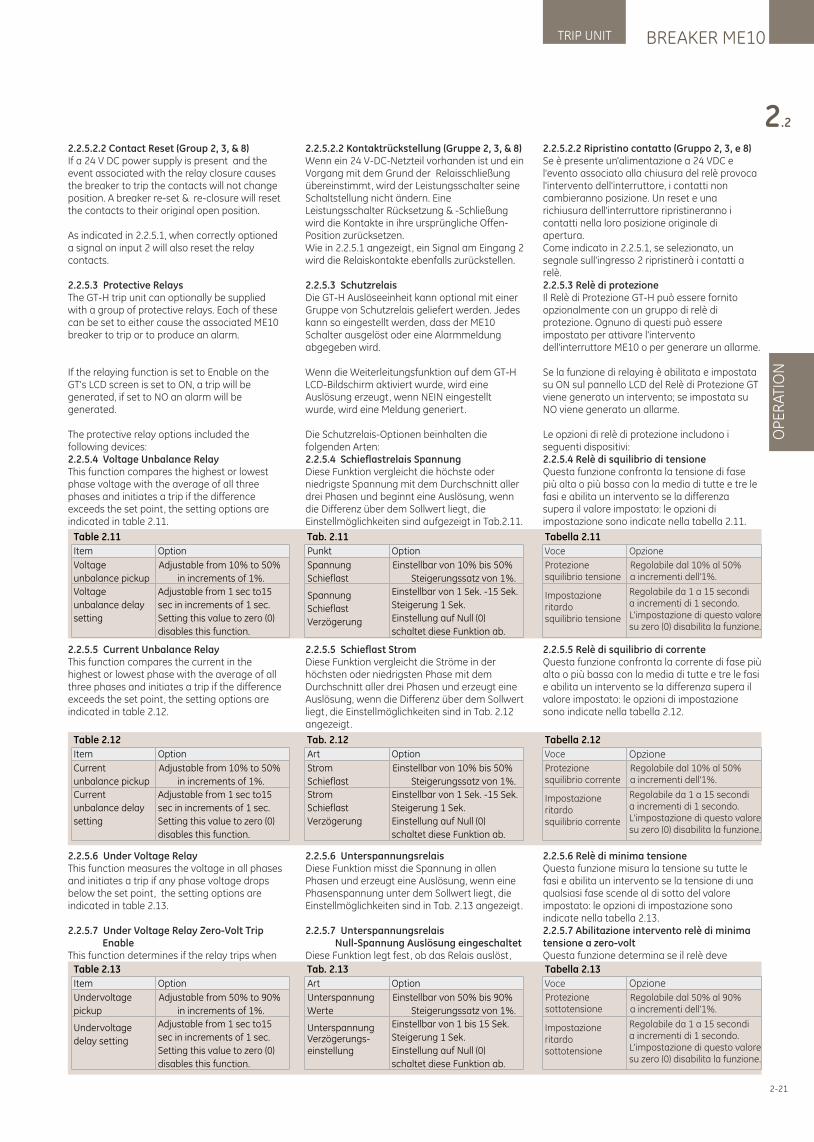
2.2.5.2.2 Contact Reset (Group 2, 3, & 8)If a 24 V DC power supply is present and the event associated with the relay closure causes the breaker to trip the contacts will not change position. A breaker re-set & re-closure will reset the contacts to their original open position.
As indicated in 2.2.5.1, when correctly optioned a signal on input 2 will also reset the relay contacts.
2.2.5.3 Protective RelaysThe GT-H trip unit can optionally be supplied with a group of protective relays. Each of these can be set to either cause the associated ME10 breaker to trip or to produce an alarm.
If the relaying function is set to Enable on the GT's LCD screen is set to ON, a trip will be generated, if set to NO an alarm will be generated.
The protective relay options included the following devices:2.2.5.4 Voltage Unbalance RelayThis function compares the highest or lowest phase voltage with the average of all three phases and initiates a trip if the difference exceeds the set point, the setting options are indicated in table 2.11.
2.2.5.5 Current Unbalance RelayThis function compares the current in the highest or lowest phase with the average of all three phases and initiates a trip if the difference exceeds the set point, the setting options are indicated in table 2.12.
2.2.5.6 Under Voltage RelayThis function measures the voltage in all phases and initiates a trip if any phase voltage drops below the set point, the setting options are indicated in table 2.13.
2.2.5.7 Under Voltage Relay Zero-Volt Trip EnableThis function determines if the relay trips when
2.2.5.2.2 Kontaktrückstellung (Gruppe 2, 3, & 8)Wenn ein 24 V-DC-Netzteil vorhanden ist und ein Vorgang mit dem Grund der Relaisschließung übereinstimmt, wird der Leistungsschalter seine Schaltstellung nicht ändern. Eine Leistungsschalter Rücksetzung & -Schließung wird die Kontakte in ihre ursprüngliche Offen-Position zurücksetzen.Wie in 2.2.5.1 angezeigt, ein Signal am Eingang 2 wird die Relaiskontakte ebenfalls zurückstellen.
2.2.5.3 SchutzrelaisDie GT-H Auslöseeinheit kann optional mit einer Gruppe von Schutzrelais geliefert werden. Jedes kann so eingestellt werden, dass der ME10 Schalter ausgelöst oder eine Alarmmeldung abgegeben wird.
Wenn die Weiterleitungsfunktion auf dem GT-H LCD-Bildschirm aktiviert wurde, wird eine Auslösung erzeugt, wenn NEIN eingestellt wurde, wird eine Meldung generiert.
Die Schutzrelais-Optionen beinhalten die folgenden Arten:2.2.5.4 Schieflastrelais SpannungDiese Funktion vergleicht die höchste oder niedrigste Spannung mit dem Durchschnitt aller drei Phasen und beginnt eine Auslösung, wenn die Differenz über dem Sollwert liegt, die Einstellmöglichkeiten sind aufgezeigt in Tab.2.11.
2.2.5.5 Schieflast StromDiese Funktion vergleicht die Ströme in der höchsten oder niedrigsten Phase mit dem Durchschnitt aller drei Phasen und erzeugt eine Auslösung, wenn die Differenz über dem Sollwert liegt, die Einstellmöglichkeiten sind in Tab. 2.12 angezeigt.
2.2.5.6 UnterspannungsrelaisDiese Funktion misst die Spannung in allen Phasen und erzeugt eine Auslösung, wenn eine Phasenspannung unter dem Sollwert liegt, die Einstellmöglichkeiten sind in Tab. 2.13 angezeigt.
2.2.5.7 Unterspannungsrelais Null-Spannung Auslösung eingeschaltetDiese Funktion legt fest, ob das Relais auslöst,
BREAKER ME10TRIP UNIT
OP
ER
ATI
ON
2.2
2.2.5.2.2 Ripristino contatto (Gruppo 2, 3, e 8)Se è presente un'alimentazione a 24 VDC e l'evento associato alla chiusura del relè provoca l'intervento dell'interruttore, i contatti non cambieranno posizione. Un reset e una richiusura dell'interruttore ripristineranno i contatti nella loro posizione originale di apertura. Come indicato in 2.2.5.1, se selezionato, un segnale sull'ingresso 2 ripristinerà i contatti a relè. 2.2.5.3 Relè di protezioneIl Relè di Protezione GT-H può essere fornito opzionalmente con un gruppo di relè di protezione. Ognuno di questi può essere impostato per attivare l'intervento dell'interruttore ME10 o per generare un allarme.
Se la funzione di relaying è abilitata e impostata su ON sul pannello LCD del Relè di Protezione GT viene generato un intervento; se impostata su NO viene generato un allarme.
Le opzioni di relè di protezione includono i seguenti dispositivi:2.2.5.4 Relè di squilibrio di tensioneQuesta funzione confronta la tensione di fase più alta o più bassa con la media di tutte e tre le fasi e abilita un intervento se la differenza supera il valore impostato: le opzioni di impostazione sono indicate nella tabella 2.11.
2.2.5.5 Relè di squilibrio di correnteQuesta funzione confronta la corrente di fase più alta o più bassa con la media di tutte e tre le fasi e abilita un intervento se la differenza supera il valore impostato: le opzioni di impostazione sono indicate nella tabella 2.12.
2.2.5.6 Relè di minima tensioneQuesta funzione misura la tensione su tutte le fasi e abilita un intervento se la tensione di una qualsiasi fase scende al di sotto del valore impostato: le opzioni di impostazione sono indicate nella tabella 2.13.2.2.5.7 Abilitazione intervento relè di minima tensione a zero-voltQuesta funzione determina se il relè deve
2-21
Table 2.11
Option
Adjustable from 10% to 50%
in increments of 1%.
Adjustable from 1 sec to15
sec in increments of 1 sec.
Setting this value to zero (0)
disables this function.
Item
Voltage
unbalance pickup
Voltage
unbalance delay
setting
Tab. 2.11
Option
Einstellbar von 10% bis 50%
Steigerungssatz von 1%.
Einstellbar von 1 Sek. -15 Sek.
Steigerung 1 Sek.
Einstellung auf Null (0)
schaltet diese Funktion ab.
Punkt
Spannung
Schieflast
Spannung
Schieflast
Verzögerung
Tabella 2.11
Opzione
Regolabile dal 10% al 50% a incrementi dell'1%.
Regolabile da 1 a 15 secondi a incrementi di 1 secondo. L'impostazione di questo valoresu zero (0) disabilita la funzione.
Voce
Protezione squilibrio tensione
Impostazione ritardo squilibrio tensione
Table 2.12
Option
Adjustable from 10% to 50%
in increments of 1%.
Adjustable from 1 sec to15
sec in increments of 1 sec.
Setting this value to zero (0)
disables this function.
Item
Current
unbalance pickup
Current
unbalance delay
setting
Tab. 2.12
Option
Einstellbar von 10% bis 50%
Steigerungssatz von 1%.
Einstellbar von 1 Sek. -15 Sek.
Steigerung 1 Sek.
Einstellung auf Null (0)
schaltet diese Funktion ab.
Art
Strom
Schieflast
Strom
Schieflast
Verzögerung
Tabella 2.12
Opzione
Regolabile dal 10% al 50% a incrementi dell'1%.
Regolabile da 1 a 15 secondi a incrementi di 1 secondo. L'impostazione di questo valoresu zero (0) disabilita la funzione.
Voce
Protezionesquilibrio corrente
Impostazioneritardo squilibrio corrente
Table 2.13
Option
Adjustable from 50% to 90%
in increments of 1%.
Adjustable from 1 sec to15
sec in increments of 1 sec.
Setting this value to zero (0)
disables this function.
Item
Undervoltage
pickup
Undervoltage
delay setting
Tab. 2.13
Option
Einstellbar von 50% bis 90%
Steigerungssatz von 1%.
Einstellbar von 1 bis 15 Sek.
Steigerung 1 Sek.
Einstellung auf Null (0)
schaltet diese Funktion ab.
Art
Unterspannung
Werte
UnterspannungVerzögerungs-einstellung
Tabella 2.13
Opzione
Regolabile dal 50% al 90% a incrementi dell'1%.
Regolabile da 1 a 15 secondi a incrementi di 1 secondo. L'impostazione di questo valoresu zero (0) disabilita la funzione.
Voce
Protezionesottotensione
Impostazione ritardosottotensione
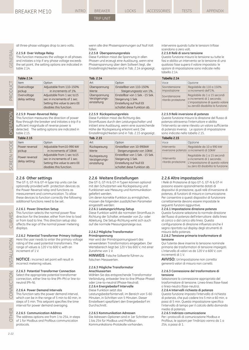
all three-phase voltages drop to zero volts.
2.2.5.8 Over Voltage RelayThis function measures the voltage in all phases and initiates a trip if any phase voltage exceeds the set point, the setting options are indicated in table 2.14.
2.2.5.9 Power-Reversal RelayThis function measures the direction of power flow through the breaker and initiates a trip if a sufficient magnitude of reverse power is detected. The setting options are indicated in table 2.15.
2.2.6 Other settingsThe GT-S, GT-N & GT-H type trip units can be optionally provided with protection devices as the Power Reversal relay and functions as measurement and communication. To allow these devices to function correctly the following additional functions need to be set.
2.2.6.1 Power Direction SetupThis function selects the normal power flow direction for the breaker, either from line to load or from load to line. This direction setup also affects the sign of the normal power metering displays.
2.2.6.2 Potential Transformer Primary VoltageHere the user needs to enter the primary voltage rating of the used potential transformers. The range of values is 120 V to 600 V, with an increment of 1 V.
NOTICE : Incorrect set point will result in incorrect metering values.
2.2.6.3 Potential Transformer ConnectionSelect the appropriate potential transformer connection, either line-to-line (Ph-Ph) or line-to-neutral (Ph-N).
2.2.6.4 Power Demand IntervalsThis function sets the power demand interval, which can be in the range of 5 min to 60 min, in steps of 5 min. This setpoint specifies the time interval for power demand averaging.
2.2.6.5 Communication AddressThe address options are from 1 to 254, in steps of 1 for Modbus and Profibus communication protocols.
wenn alle drei Phasenspannungen auf Null Volt fallen.2.2.5.8 ÜberspannungsrelaisDiese Funktion misst die Spannung in allen Phasen und erzeugt eine Auslösung, wenn eine Phasenspannung über dem Sollwert liegt, die Einstellmöglichkeiten sind in Tab. 2.14 angezeigt.
2.2.5.9 RückspeisungsrelaisDiese Funktion misst die Richtung des Stromflusses durch den Leistungsschalter und initiiert eine Auslösung, wenn eine ausreichende Höhe der Rückspeisung erkannt wird. Die Einstellmöglichkeiten sind in Tab. 2.15 angezeigt.
2.2.6 Weitere EinstellungenDie GT-S, GT-N & GT-H Typen können optional mit den Schutzarten wie Rückspeisung und Funktionen wie Messung und Kommunikation geliefert werden. Um deren korrekte Funktion zu ermöglichen, müssen die folgenden zusätzlichen Parameter eingestellt werden:2.2.6.1 Leistungsrichtung-SetupDiese Funktion wählt die normalen Stromfluss in Richtung der Schalter, entweder von Zu- oder Ableitung. Die Setup-Richtung wirkt sich auch auf die normale Messungsanzeige aus.
2.2.6.2 Mögliche Transformator PrimärspannungHier wird der Primärspannungswert des verwendeten Transformators eingegeben. Der Wertebereich liegt bei 120 V bis 600 V, mit einer Zunahme von 1 V.
HINWEIS: Falsche Sollwerte führen zu falschen Messwerten.
2.2.6.3 Mögliche Transformator AnschlussartenWählen Sie das entsprechende Transformator Verbindung, entweder line-to-line (Phase-Phase) oder Line-to-neutral (Phase-Neutral). 2.2.6.4 Energiebedarf IntervalleDiese Funktion setzt das Leistungsbedarfsintervall, im Bereich von 5-60 Minuten, in Schritten von 5 Minuten. Dieser Einstellwert spezifiziert den Energiebedarf im Durchschnitt.
2.2.6.5 Kommunikation AdressenDie Adressen-Optionen sind in 1er Schritten von 1 bis 254 für Modbus und Profibus-Kommunikations-Protokolle vorhanden.
GE
NE
RA
LP
RO
DU
CT
OP
ER
ATI
ON
SC
RE
EN
MO
DE
...C
UR
VE
SIN
STA
LLA
TIO
NC
ON
NE
CTI
ON
LOCKSBREAKER ME10 INTRO BREAKER ACCESSORIES TESTS APPENDIX
TRIP UNIT
OTH
ER
intervenire quando tutte le tensioni trifase scendono a zero volt.2.2.5.8 Relè di sovra tensioneQuesta funzione misura la tensione su tutte le fasi e abilita un intervento se la tensione di una qualsiasi fase supera il valore impostato: le opzioni di impostazione sono indicate nella tabella 2.14.
2.2.5.9 Relè inversione di potenzaQuesta funzione misura la direzione del flusso di potenza attraverso l'interruttore e abilita l'intervento se viene rilevato un valore sufficiente di potenza inversa. Le opzioni di impostazione sono indicate nella tabella 2.15.
2.2.6 Altre impostazioniI Relè di Protezione di tipo GT-S, GT-N & GT-H possono essere opzionalmente dotati di dispositivi di protezione, quali relè d'inversione di potenza, di funzioni di misura e comunicazione. Per consentire a questi dispositivi di funzionare correttamente devono essere impostate le seguenti funzioni aggiuntive. 2.2.6.1 Impostazione direzione potenzaQuesta funzione seleziona la normale direzione del flusso di potenza dell'interruttore: dalla linea al carico o dal carico alla linea. Questa configurazione di direzione influenza anche il segno riportato sul display degli strumenti di misura della potenza.2.2.6.2 Tensione primaria trasformatore di tensioneQui l'utente deve inserire la tensione nominale primaria dei trasformatori di tensione impiegati. L'intervallo di valori va da 120 V a 600 V, con incrementi di 1 V.
AVVISO: Un'impostazione non corretta genererà valori di misura non corretti.
2.2.6.3 Connessione del trasformatore di tensioneSelezionare la connessione appropriata del trasformatore di tensione. Linea-linea (fase-fase) o linea-neutro (fase-neutro).2.2.6.4 Intervalli richiesta di potenzaQuesta funzione imposta l'intervallo di richiesta di potenza, che può cadere tra 5 min e 60 min, a passi di 5 min. Questa impostazione specifica l'intervallo di tempo per il calcolo della domanda media di potenza.2.2.6.5 Indirizzo comunicazione Per i protocolli di comunicazione Modbus e Profibus, le opzioni per l'indirizzo vanno da 1 a 254, a passi di 1.
2-22
Table 2.14
Option
Adjustable from 110-150%
in increments of 1%.
Adjustable from 1 sec to15
sec in increments of 1 sec.
Setting this value to zero (0)
disables this function.
Item
Overvoltage
pickup
Overvoltage
delay setting:
Tab. 2.14
Option
Einstellbar von 110-150%
Steigerungssatz von 1%.
Einstellbar von 1 Sek. -15 Sek.
Steigerung 1 Sek.
Einstellung auf Null (0)
schaltet diese Funktion ab.
Art
Überspannung
Werte
ÜberspannungVerzögerungs-einstellung
Tabella 2.14
Opzione
Regolabile da 110 a 150% a incrementi dell'1%.
Regolabile da 1 a 15 secondi a incrementi di 1 secondo. L'impostazione di questo valoresu zero(0) disabilita la funzione.
Voce
SovratensioneImpostazione
Sovratensioneritardo protezione:
Table 2.15
Option
Adjustable from10-990 kW
in increments of 10kW.
Adjustable from 1 sec to15
sec in increments of 1 sec.
Setting this value to zero (0)
disables this function.
Item
Power reversal
pickup
Power reversal
delay setting:
Tab. 2.15
Option
Einstellbar von 10-990kW
Steigerungssatz von 10kW.
Einstellbar von 1 Sek. -15 Sek.
Steigerung 1 Sek.
Einstellung auf Null (0)
schaltet diese Funktion ab.
Art
Rückspeisung
Werte
RückspeisungVerzögerungs-einstellung
Tabella 2.15
Opzione
Regolabile da 10 a 990 kWa incrementi di 10kW
Regolabile da 1 a 15 secondi a incrementi di 1 secondo. L'impostazione di questo valoresu zero (0) disabilita la funzione.
Voce
Interventoinversione potenza
Interventoritardo protezione:
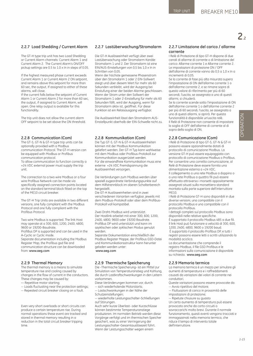
BREAKER ME10TRIP UNIT
OP
ER
ATI
ON
2.2
2.2.7 Limitazione del carico / allarme correnteI Relè di Protezione di tipo GT-H dispone di due canali di allarme di corrente o di limitazione del carico: Allarme corrente 1 e Allarme corrente 2. Le impostazioni di protezione ON / OFF dell'allarme di corrente vanno da 0,5 a 1,0 x In a incrementi di 0,05.Se la corrente di fase più alta misurata supera l'impostazione di ON dell'allarme corrente 1 o dell'allarme corrente 2, e se rimane sopra di questo valore di riferimento per più di 60 secondi, l'uscita, se assegnata a uno di questi allarmi, si chiuderà.Se la corrente scende sotto l'impostazione di ON dell'allarme corrente 1 o dell'allarme corrente 2 per più di 60 secondi, l'uscita, se assegnata a uno di questi allarmi, si aprirà. Per questa funzionalità è disponibile un'uscita relè. Il Relè di Protezione non consente di impostare la soglia di OFF dell'allarme di corrente al di sopra della soglia di ON.
2.2.8 Comunicazione (Com)I Relè di Protezione di tipo GT-S, GT-N & GT-H possono essere opzionalmente dotati di protocollo di comunicazione Modbus. La versione GT-H può essere equipaggiata con protocollo di comunicazione Modbus o Profibus.Per consentire una corretta comunicazione, al Relè di Protezione deve essere fornita una alimentazione esterna a +24 VDC.Il collegamento a una rete Modbus a doppino o a una rete Profibus a quattro fili può essere effettuata attraverso i morsetti appositamente assegnati situati sulla morsettiera standard montata sulla parte superiore dell'interruttore ME10.I Relè di Protezione GT-H sono disponibili in due diverse versioni, una compatibile con il protocollo Modbus e una compatibile con il protocollo Profibus. I dettagli completi sul protocollo Modbus sono disponibili nelle relative specifiche.È supportato il protocollo Modbus 485 a due fili.Il link Host può funzionare a velocità di 300, 600, 1200, 2400, 4800, 9600 o 19200 baud. È supportato il protocollo Profibus DP, e tutti i registri possono essere letti o scritti utilizzando la modalità aciclica. La documentazione che comprende il registro Modbus, il file GSD Profibus e le informazioni sulla comunicazione è disponibile su richiesta. www.aeg.com
2.2.9 Memoria termicaLa memoria termica è un mezzo per simulare gli aumenti di temperatura e i raffreddamenti causati da variazioni dei valori di corrente nei conduttori.Queste variazioni possono essere provocate da:-- Avvio ripetitivo del motore;-- Fluttuazioni di carico in prossimità delle impostazioni di protezione;-- Ripetute chiusure su guastoUn certo aumento di temperatura può essere provocato anche da corto circuiti o sovraccarichi molto brevi. Durante il normale funzionamento, questi eventi vengono tracciati e immagazzinati nella memoria termica, che riduce il tempo di intervento totale dell'interruttore.
2-23
2.2.7 Load Shedding / Current Alarm
The GT-H type trip unit has two Load Shedding or Current Alarm channels: Current Alarm 1 and Current Alarm 2. The Current Alarm’s ON/OFF pickup settings are 0.5 to 1.0 x In in steps of 0.05.
If the highest measured phase current exceeds Current Alarm 1 or Current Alarm 2 ON setpoint, and remains above this setpoint for more than 60 sec, the output, If assigned to either of these alarms, will close.If the current falls below the setpoint of Current Alarm 1 or Current Alarm 2 for more than 60 sec, the output, if assigned to Current Alarm, will open. One relay output is available for this functionality.
The trip unit does not allow the current alarm OFF setpoint to be set above the ON threshold.
2.2.8 Communication (Com)The GT-S, GT-N & GT-H type trip units can be optionally provided with a Modbus communication Protocol. The GT-H version can be equipped with Modbus or Profibus communication protocol.To allow communication to function correctly a +24 VDC external power must supply the trip unit.
The connection to a two wire Modbus or a four wire Profibus Network can be made via specifically assigned connection points located on the standard terminal block fitted on the top of the ME10 circuit breaker.
The GT-H Trip Units are available in two different versions, one fully compliant with the Modbus Protocol and one fully compliant with the Profibus Protocol.
Two wire Modbus is supported. The link Host may operate at a 300, 600, 1200, 2400, 4800, 9600 or 19200-Baudrate. ProfiBus DP is supported and can be used in the A-Cyclic or Cyclic mode.Separate documentation including the Modbus Register Map, the Profibus gsd file and communication structure can be downloaded from: www.aeg.com
2.2.9 Thermal MemoryThe thermal memory is a means to simulate temperature rise and cooling caused by changes in the flow of current in the conductors.These changes may be caused by:–- Repetitive motor starting;-- Loads fluctuating near the protection settings;-- Repeated circuit breaker closing on a fault.
Even very short overloads or short circuits can produce a certain temperature rise. During normal operations these event are tracked and stored in thermal memory resulting in a reduction in the total circuit breaker tripping time.
2.2.7 Lastüberwachung/Stromalarm
Die GT-H Auslöseeinheit verfügt über zwei Lastüberwachung oder Stromalarm Kanäle: Stromalarm 1 und 2. Der Stromalarm ist eine EIN/AUS-Einstellungen von 0,5 bis 1,0 x In in Schritten von 0,05.Wenn der höchste gemessene Phasenstrom über den Stromalarm 1 oder 2 EIN-Sollwert steigt und über diesem Wert für mehr als 60 Sekunden verbleibt, wird der Ausgang bei Einstufung einer der beiden Alarme geschlossen. Wenn der Strom unter den Sollwert der Stromalarm 1 oder 2-Einstellung für mehr als 60 Sekunden fällt, wird der Ausgang, wenn für Stromalarm aktiv ist, geöffnet. Für diese Funktion ist ein Relaisausgang verfügbar.
Die Auslöseeinheit lässt den Stromalarm AUS-Einstellpunkt oberhalb der EIN-Schwelle nicht zu.
2.2.8 Kommunikation (Com) Die Typ GT-S, GT-N & GT-H Auslöseeinheiten können mit der Modbus Kommunikation geliefert werden. Der GT-H Typ kann wahlweise mit dem Modbus oder Profibus-Protokoll zur Kommunikation ausgerüstet werden. Für die einwandfreie Kommunikation muss eine externe +24 VDC Fremdspannung die Auslöseeinheit versorgen.
Die Verbindungen zum Modbus werden über speziell zugeordnete Verbindungspunkte auf dem Hilfstrennblock im oberen Schalterbereich hergestellt . Die GT-H Auslöseeinheiten sind in zwei verschiedenen Varianten verfügbar, jeweils mit dem Modbus-Protokoll oder aber dem Profibus-Protokoll voll kompatibel.
Zwei Draht-Modbus wird unterstützt. Der Hostlink arbeitet mit einer 300, 600, 1200, 2400, 4800, 9600 oder 19200 Baudrate. ProfiBus DP wird unterstützt und kann im azyklischen oder zyklischen Modus genutzt werden.Separate Dokumentation einschließlich der Modbus Register Mappe, der Profibus GSD-Datei und Kommunikationsstruktur kann herunter geladen werden unter: www.aeg.com
2.2.9 Thermische SpeicherungDie -Thermische Speicherung- ist ein Mittel zur Simulation von Temperaturanstieg und Kühlung, die durch Lastkraftschwankungen in den Leitern vorkommen. Diese Veränderungen kommen vor, durch: -- sich wiederholende Motorstarts; -- Lastschwankungen in der Nähe der Schutzeinstellungen; -- wiederholte Leistungsschalter-Schließungen auf Störungen. Auch sehr kurze Überlast- oder Kurzschlüsse können bestimmte Temperaturanstiege produzieren. Im normalen Betrieb werden diese Vorgänge verfolgt und im thermischen Speicher gesichert, was zu einer Verringerung der Leistungsschalter-Gesamtauslösezeit führt.Wenn der Leistungsschalter wegen einem
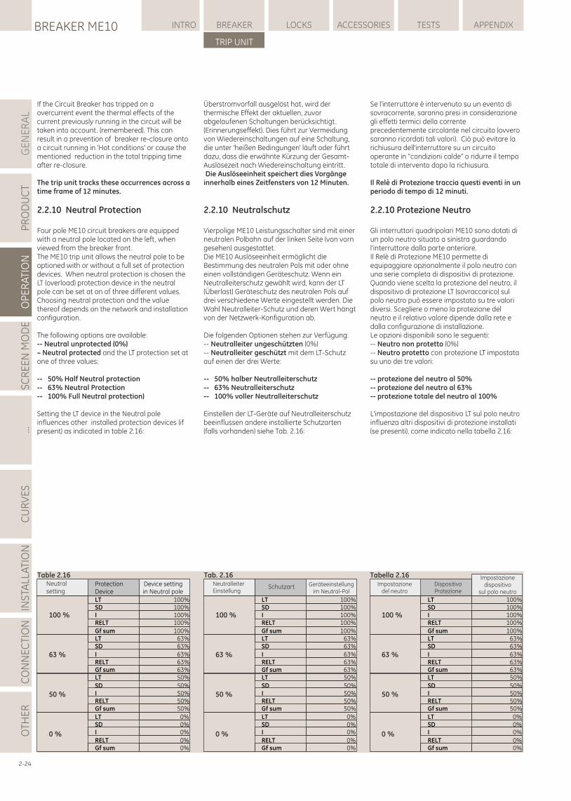
GE
NE
RA
LP
RO
DU
CT
OP
ER
ATI
ON
SC
RE
EN
MO
DE
...C
UR
VE
SIN
STA
LLA
TIO
NC
ON
NE
CTI
ON
LOCKSBREAKER ME10 INTRO BREAKER ACCESSORIES TESTS APPENDIX
TRIP UNIT
OTH
ER
ProtectionDevice
LTSDIRELT
Gf sumLTSD
IRELTGf sumLT
SDIRELTGf sum
LTSDI
RELTGf sum
Device settingin Neutral pole
100%100%100%100%
100%63%63%
63%63%63%50%
50%50%50%50%
0%0%0%
0%0%
Table 2.16Neutralsetting
100 %
63 %
50 %
0 %
LTSDIRELT
Gf sumLTSD
IRELTGf sumLT
SDIRELTGf sum
LTSDI
RELTGf sum
Geräteeinstellungim Neutral-Pol
100%100%100%100%
100%63%63%
63%63%63%50%
50%50%50%50%
0%0%0%
0%0%
Tab. 2.16NeutralleiterEinstellung
100 %
63 %
50 %
0 %
Schutzart DispositivoProtezione
LTSDIRELT
Gf sumLTSD
IRELTGf sumLT
SDIRELTGf sum
LTSDI
RELTGf sum
Impostazionedispositivo
sul polo neutro
100%100%100%100%
100%63%63%
63%63%63%50%
50%50%50%50%
0%0%0%
0%0%
Tabella 2.16Impostazione
del neutro
100 %
63 %
50 %
0 %
Se l'interruttore è intervenuto su un evento di sovracorrente, saranno presi in considerazione gli effetti termici della corrente precedentemente circolante nel circuito (ovvero saranno ricordati tali valori). Ciò può evitare la richiusura dell'interruttore su un circuito operante in "condizioni calde" o ridurre il tempo totale di intervento dopo la richiusura.
Il Relè di Protezione traccia questi eventi in un periodo di tempo di 12 minuti.
2.2.10 Protezione Neutro
Gli interruttori quadripolari ME10 sono dotati di un polo neutro situato a sinistra guardando l'interruttore dalla parte anteriore. Il Relè di Protezione ME10 permette di equipaggiare opzionalmente il polo neutro con una serie completa di dispositivi di protezione. Quando viene scelta la protezione del neutro, il dispositivo di protezione LT (sovraccarico) sul polo neutro può essere impostato su tre valori diversi. Scegliere o meno la protezione del neutro e il relativo valore dipende dalla rete e dalla configurazione di installazione.Le opzioni disponibili sono le seguenti:-- Neutro non protetto (0%)-- Neutro protetto con protezione LT impostata su uno dei tre valori:
-- protezione del neutro al 50%-- protezione del neutro al 63%-- protezione totale del neutro al 100%
L'impostazione del dispositivo LT sul polo neutro influenza altri dispositivi di protezione installati (se presenti), come indicato nella tabella 2.16:
2-24
If the Circuit Breaker has tripped on a overcurrent event the thermal effects of the current previously running in the circuit will be taken into account. (remembered). This can result in a prevention of breaker re-closure onto a circuit running in 'Hot conditions' or cause the mentioned reduction in the total tripping time after re-closure.
The trip unit tracks these occurrences across a time frame of 12 minutes.
2.2.10 Neutral Protection
Four pole ME10 circuit breakers are equipped with a neutral pole located on the left, when viewed from the breaker front. The ME10 trip unit allows the neutral pole to be optioned with or without a full set of protection devices. When neutral protection is chosen the LT (overload) protection device in the neutral pole can be set at on of three different values. Choosing neutral protection and the value thereof depends on the network and installation configuration.
The following options are available:-- Neutral unprotected (0%)– Neutral protected and the LT protection set at one of three values:
-- 50% Half Neutral protection-- 63% Neutral Protection-- 100% Full Neutral protection)
Setting the LT device in the Neutral pole influences other installed protection devices (if present) as indicated in table 2.16:
Überstromvorfall ausgelöst hat, wird der thermische Effekt der aktuellen, zuvor abgelaufenen Schaltungen berücksichtigt. (Erinnerungseffekt). Dies führt zur Vermeidung von Wiedereinschaltungen auf eine Schaltung, die unter 'heißen Bedingungen' läuft oder führt dazu, dass die erwähnte Kürzung der Gesamt-Auslösezeit nach Wiedereinschaltung eintritt. Die Auslöseeinheit speichert dies Vorgänge innerhalb eines Zeitfensters von 12 Minuten.
2.2.10 Neutralschutz
Vierpolige ME10 Leistungsschalter sind mit einer neutralen Polbahn auf der linken Seite (von vorn gesehen) ausgestattet. Die ME10 Auslöseeinheit ermöglicht die Bestimmung des neutralen Pols mit oder ohne einen vollständigen Geräteschutz. Wenn ein Neutralleiterschutz gewählt wird, kann der LT (Überlast) Geräteschutz des neutralen Pols auf drei verschiedene Werte eingestellt werden. Die Wahl Neutralleiter-Schutz und deren Wert hängt von der Netzwerk-Konfiguration ab.
Die folgenden Optionen stehen zur Verfügung: -- Neutralleiter ungeschützten (0%) -- Neutralleiter geschützt mit dem LT-Schutz auf einen der drei Werte:
-- 50% halber Neutralleiterschutz-- 63% Neutralleiterschutz -- 100% voller Neutralleiterschutz
Einstellen der LT-Geräte auf Neutralleiterschutz beeinflussen andere installierte Schutzarten (falls vorhanden) siehe Tab. 2.16:
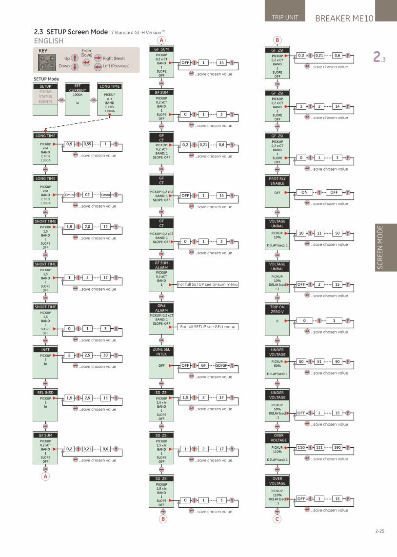
LONG TIME
PICKUPx Ie
BANDC MIN1.000A
SETCURRENT
1000A
Ie
SETUPMETER
STATUS
EVENTS
2-25
BREAKER ME10TRIP UNIT
SC
RE
EN
MO
DE
2.3
ENGLISH
(2)2.3 SETUP Screen Mode / Standard GT-H Version
Up
Down
Right (Next)
Left (Previous)
Enter(Save)
KEY
LONG TIME
PICKUPx Ie
BANDC MIN1.000A
0,5 0,55 1
...save chosen value
LONG TIME
PICKUPx Ie
BANDC MIN1.000A
SHORT TIME
PICKUP1,5
BAND1
SLOPEOFF
SHORT TIME
PICKUP1,5
BAND1
SLOPEOFF
SHORT TIME
PICKUP1,5
BAND1
SLOPEOFF
0 1 3
INST
PICKUP2Ie
REL INSD
PICKUP2Ie
Cmin C2 Cmax
...save chosen value
1,5 2,0 12
...save chosen value
1 2 17
...save chosen value
...save chosen value
2 2,5 30
...save chosen value
1,5 2,5 15
...save chosen value
SETUP Mode
A
GF SUM
PICKUP0,2 xCTBAND
1SLOPE
OFF
0,2 0,21 0,6
...save chosen value
C
GF ZSI
PICKUP0,2 x CTBAND
1SLOPE
OFF
1 2 14
...save chosen value
GF ZSI
PICKUP0,2 x CTBAND
1SLOPE
OFF
0,2 0,21 0,6
...save chosen value
B
GF ZSI
PICKUP0,2 x CTBAND
1SLOPE
OFF0 1 3
...save chosen value
PROT RLYENABLE
OFF ON
...save chosen value
OFF
VOLTAGEUNBAL
PICKUP:10%
DELAY (sec): 1
10 11 50
...save chosen value
VOLTAGEUNBAL
PICKUP:10%
DELAY (sec): 1
OFF 2 15
...save chosen value
TRIP ONZERO V
0 0
...save chosen value
1
UNDERVOLTAGE
PICKUP:50%
DELAY (sec): 1
50 51 90
...save chosen value
UNDERVOLTAGE
PICKUP:50%
DELAY (sec): 1
OFF 1 15
...save chosen value
OVERVOLTAGE
PICKUP:110%
DELAY (sec): 1
110 111 190
...save chosen value
OVERVOLTAGE
PICKUP:110%
DELAY (sec): 1
OFF 1 15
...save chosen value
B
SD ZSI
PICKUP1,5 x IrBAND
1SLOPE
OFF
1,5 2 17
...save chosen value
SD ZSI
PICKUP1,5 x IrBAND
1SLOPE
OFF
1 2 17
...save chosen value
GF SUM
PICKUP0,2 xCTBAND
1SLOPE
OFF0 1 3
...save chosen value
SD ZSI
PICKUP1,5 x IrBAND
1SLOPE
OFF
0 1 3
...save chosen value
GFCT
PICKUP: 0,2 xCTBAND: 1
SLOPE: OFF
0,2 0,21 0,6
...save chosen value
GFCT
PICKUP: 0,2 xCTBAND: 1
SLOPE: OFFOFF 1 14
...save chosen value
GFCT
PICKUP: 0,2 xCTBAND: 1
SLOPE: OFF 0 1 3
...save chosen value
GF SUMALARMPICKUP0,2 xCTBAND
1 For full SETUP see GFsum menu
GFctALARM
PICKUP: 0,2 xCTBAND: 1
SLOPE: OFFFor full SETUP see GFct menu
ZONE SELINTLK
OFF OFF GF SD/GF
...save chosen value
A
GF SUM
PICKUP0,2 x CTBAND
1SLOPE
OFF
OFF 1 14
...save chosen value
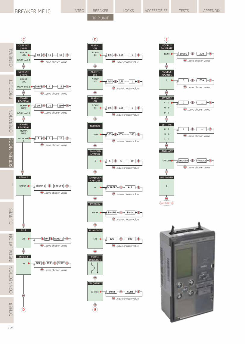
GE
NE
RA
LP
RO
DU
CT
OP
ER
ATI
ON
SC
RE
EN
MO
DE
...C
UR
VE
SIN
STA
LLA
TIO
NC
ON
NE
CTI
ON
LOCKSBREAKER ME10 INTRO BREAKER ACCESSORIES TESTS APPENDIX
TRIP UNIT
OTH
ER
2-26
E
D
PT CONN
PH-PH PH-PH
...save chosen value
PH-N
PT VOLTAGE
120 120
...save chosen value
600
ALARM1ON
PICKUP0,5 0,5 0,55 1
...save chosen value
ALARM1OFF
PICKUP0,5 0,5 0,55 1
...save chosen value
ALARM2ON
PICKUP0,5 0,5 0,55 1
...save chosen value
NEUTRAL
100% 50% 63% 100
...save chosen value
PWR DMDINTERVAL
5 5 6 60
...save chosen value
WAVEFORMCAPTURE
-- DISABLE
...save chosen value
ALL
POWERDIRECTION
FREQUENCY
50 cycles 50Hz
...save chosen value
60Hz
E
MODBUSBAUDRATE
19200 19200
...save chosen value
300
MODBUSADDRESS
1 0
...save chosen value
254
PASSWORD
0
Back to SETUP
LANGUAGE
ENGLISH ENGLISH
...save chosen value
FRANCAIS
SET DATE
Y 0
M 0
D 0
SET DATE
Y 0
M 0
D 0
0
...save chosen value
...
0
...save chosen value
...
SET TIME
H 0
M 0
S 0
POWERREVERSAL
1 2 15
...save chosen value
PICKUP:10kW
DELAY (sec):1
RELAY 2
GROUP 1 GROUP 1
...save chosen value
GROUP 8
RELT
OFF
...save chosen value
REMOTEON
CURRENTUNBAL
PICKUP10%
DELAY (sec): 1
10 11 50
...save chosen value
C
CURRENTUNBAL
POWERREVERSAL
PICKUP:10kW
DELAY (sec): 1
10 20 990
...save chosen value
PICKUP10%
DELAY (sec): 1 OFF 1 15
...save chosen value
D
INPUT 2
OFF OFF TRIP
...save chosen value
RESET
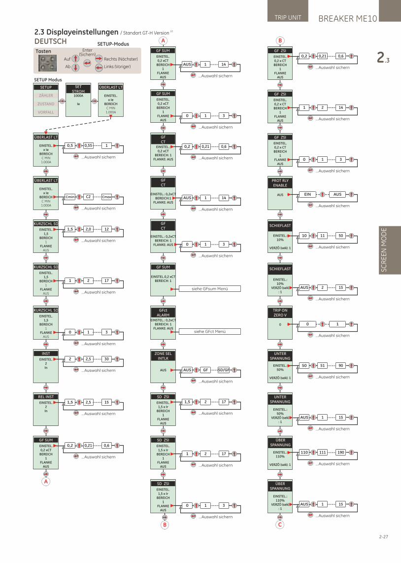
BREAKER ME10TRIP UNIT
SC
RE
EN
MO
DE
2.3
SETUP-ModusDEUTSCH
(2)2.3 Displayeinstellungen / Standart GT-H Version
Auf
Ab
Rechts (Nächster)
Links (Voriger)
Enter(Sichern)
Tasten
SETUP
ZÄHLER
ZUSTAND
VORFALL
ÜBERLAST LT
EINSTEL.x Ie
BEREICHC MIN1.000A
SETSTROM1000A
Ie
ÜBERLAST LT
EINSTEL.x Ie
BEREICHC MIN1.000A
0,5 0,55 1
...Auswahl sichern
ÜBERLAST LT
EINSTEL.x Ie
BEREICHC MIN1.000A
KURZSCHL SD
EINSTEL.1,5
BEREICH1
FLANKEAUS
KURZSCHL SD
EINSTEL.1,5
BEREICH1
FLANKEAUS
KURZSCHL SD
EINSTEL.1,5
BEREICH1
FLANKEAUS
0 1 3
INST
EINSTEL.2In
REL INST
EINSTEL.2In
GF SUM
EINSTEL.0,2 xCT
BEREICH1
FLANKEAUS
Cmin C2 Cmax
...Auswahl sichern
1,5 2,0 12
...Auswahl sichern
1 2 17
...Auswahl sichern
...Auswahl sichern
2 2,5 30
...Auswahl sichern
1,5 2,5 15
...Auswahl sichern
0,2 0,21 0,6
...Auswahl sichern
SETUP Modus
A
C
GF ZSI
EINSTEL.0,2 x CTBEREICH
1FLANKE
AUS
1 2 14
...Auswahl sichern
GF ZSI
EINSTEL.0,2 x CTBEREICH
1FLANKE
AUS
0,2 0,21 0,6
...Auswahl sichern
B
GF ZSI
EINSTEL.0,2 x CTBEREICH
1FLANKE
AUS0 1 3
...Auswahl sichern
PROT RLYENABLE
AUS EIN
...Auswahl sichern
AUS
SCHIEFLAST
EINSTEL.:10%
VERZÖ (sek): 1
10 11 50
...Auswahl sichern
SCHIEFLAST
EINSTEL.:10%
VERZÖ (sek): 1
AUS 2 15
...Auswahl sichern
TRIP ONZERO V
0 0
...Auswahl sichern
1
UNTERSPANNUNG
EINSTEL.:50%
VERZÖ (sek): 1
50 51 90
...Auswahl sichern
UNTERSPANNUNG
EINSTEL.:50%
VERZÖ (sek): 1
AUS 1 15
...Auswahl sichern
ÜBERSPANNUNG
EINSTEL.:110%
VERZÖ (sek): 1
110 111 190
...Auswahl sichern
ÜBERSPANNUNG
EINSTEL.:110%
VERZÖ (sek): 1
AUS 1 15
...Auswahl sichern
2-27
B
GF SUM
EINSTEL.0,2 xCT
BEREICH1
FLANKEAUS
0 1 3
...Auswahl sichern
SD ZSI
EINSTEL.1,5 x Ir
BEREICH1
FLANKEAUS
0 1 3
...Auswahl sichern
GFCT
EINSTEL.: 0,2 xCT
BEREICH: 1FLANKE: AUS
0,2 0,21 0,6
...Auswahl sichern
GFCT
EINSTEL.: 0,2xCTBEREICH:1
FLANKE: AUSAUS 1 14
...Auswahl sichern
GFCT
EINSTEL.: 0,2xCTBEREICH: 1
FLANKE: AUS 0 1 3
...Auswahl sichern
SD ZSI
EINSTEL.1,5 x Ir
BEREICH1
FLANKEAUS
1,5 2 17
...Auswahl sichern
SD ZSI
EINSTEL.1,5 x Ir
BEREICH1
FLANKEAUS
1 2 17
...Auswahl sichern
GF SUM
EINSTEL.0,2 xCTBEREICH: 1
siehe GFsum Menü
GFctALARM
EINSTEL.: 0,2xCTBEREICH: 1
FLANKE: AUSsiehe GFct Menü
ZONE SELINTLK
AUS AUS GF SD/GF
...Auswahl sichern
GF SUM
EINSTEL.0,2 xCT
BEREICH1
FLANKEAUS
AUS 1 14
...Auswahl sichern
A
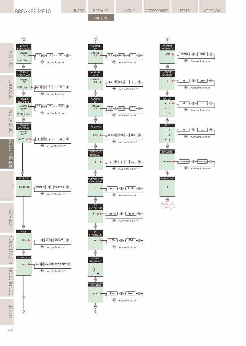
GE
NE
RA
LP
RO
DU
CT
OP
ER
ATI
ON
SC
RE
EN
MO
DE
...C
UR
VE
SIN
STA
LLA
TIO
NC
ON
NE
CTI
ON
LOCKSBREAKER ME10 INTRO BREAKER ACCESSORIES TESTS APPENDIX
TRIP UNIT
OTH
ER
2-28
E
D
PTANSCHLUSS
PH-PH PH-PH
...Auswahl sichern
PH-N
PTSPANNUNG
120 120
...Auswahl sichern
600
ALARM1EIN
EINSTEL.0,5 0,5 0,55 1
...Auswahl sichern
ALARM1AUS
EINSTEL.0,5 0,5 0,55 1
...Auswahl sichern
ALARM2EIN
EINSTEL.0,5 0,5 0,55 1
...Auswahl sichern
NEUTRAL
100% 50% 63% 100
...Auswahl sichern
PWR DMDINTERVAL
5 5 6 60
...Auswahl sichern
KURVENFORMERFASSUNG
-- aus
...Auswahl sichern
ALLE
POWERRICHTUNG
FREQUENZ
50 Hz 50Hz
...Auswahl sichern
60Hz
E
MODBUSBAUDRATE
19200 19200
...Auswahl sichern
300
MODBUSADRESSE
1 0
...Auswahl sichern
254
PASSWORD
0
Zurück zum SETUP
SPRACHE
ENGLISH ENGLISH
...Auswahl sichern
FRANCAIS
SET DATE
Y 0
M 0
D 0
DATUM
Y 0
M 0
D 0
0
...Auswahl sichern
...
0
...Auswahl sichern
...
ZEIT
H 0
M 0
S 0
STROMSCHIEFLAST
EINSTEL.10%
VERZÖ (sek): 1
10 11 50
...Auswahl sichern
C
STROMSCHIEFLAST
POWERREVERSAL
EINSTEL.:10kW
VERZÖ (sek): 1
10 20 990
...Auswahl sichern
EINSTEL.10%
VERZÖ (sek): 1 AUS 1 15
...Auswahl sichern
POWERREVERSAL
1 2 15
...Auswahl sichern
EINSTEL.:10kW
VERZÖ (sek):1
RELAIS 2
GRUPPE 1 GRUPPE 1
...Auswahl sichern
GRUPPE 8
RELT
AUS
...Auswahl sichern
REMOTEON
D
EINGANG 2
AUS AUS AUSGELÖST
...Auswahl sichern
RESET
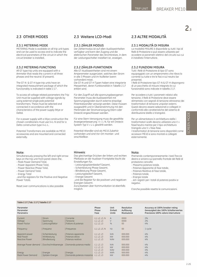
BREAKER ME10TRIP UNIT
SC
RE
EN
MO
DE
2.3
2-29
2.3 OTHER MODES
2.3.1 METERING MODEMETERING Mode is available on all trip unit types and can be used to access and to indicate the electrical parameters of the circuit in which the circuit breaker is installed..
2.3.2 METERING FUNCTIONSAll GT type trip units are equipped with a Ammeter that reads the current in all three phases and the neutral. (if present).
The GT-N & GT-H type trip units have an integrated measurement package of which the functionality is indicated in table 2.17 .
To access all voltage related parameters the Trip Unit must be supplied with voltage signals by using external single pole potential transformers. These must be selected and connected in accordance with the characteristics of the power supply (Wye or Delta).
For a power supply with a Wye construction the chosen conditioners must use V=L-N and for a Delta construction type V=L-L.
Potential Transformers are available as ME10 accessories and are mounted and connected externally.
Note: Simultaneously pressing the left and right arrow keys on the trip unit front panel clears the..- Peak Power Demand Total,- Power Apparent Phase Total,- Power Reactive Phase Total,- Power Demand Total,- Energy Total..and the registers for the Positive and Negative Power Totals.
Reset over communications is also possible.
2.3 Weitere LCD-Modi
2.3.1 ZÄHLER MODUS Der Zählermodus ist auf allen Auslöseeinheiten verfügbar und kann den Zugang und die elektrischen Parameter des Stromkreises, in dem der Leistungsschalter installiert ist, anzeigen.
2.3.2 ZÄHLER-FUNKTIONENAlle GT-Auslöseeinheiten sind mit einem Amperemeter ausgerüstet, welches den Strom in alle 3 Phasen und im Nullleiter (wenn vorhanden) misst.Die GT-N und GT-H Typen haben eine integrierte Messeinheit, deren Funktionalität in Tabelle 2.17 erklärt wird.
Für den Zugriff auf alle spannungsbezogenen Parameter muss die Auslöseeinheit mit Spannungssignalen durch externe einpolige Potentialwandler versorgt werden. Diese müssen ausgewählt und in Übereinstimmung mit den Merkmalen der Stromversorgung (Stern oder Dreieck) angeschlossen werden.
Für eine Stern-Versorgung muss die gewählte Anzeigeverbesserung V = L-N, für ein Dreieck-System Typ V = L-L gewählt werden.
Potential-Wandler sind als ME10 Zubehör vorhanden und sind Vor-Ort montier- und anschließbar.
Hinweis:Das gleichzeitige Drücken der linken und rechten Pfeiltaste an der Auslöser-Frontplatte löscht die Einstellungen für..- Leistungsspitzenbedarf Gesamt,- Scheinleistung Phase Gesamt,- Blindleistung Phase Gesamt,- Leistungsbedarf Gesamt,- Energie Gesamt..und die Register für die positiven und negativen Energien Gesamt.Zurücksetzen über Kommunikation ist ebenfalls möglich.
2.3 ALTRE MODALITÀ
2.3.1 MODALITÀ DI MISURALa modalità MISURE è disponibile su tutti i tipi di Relè di Protezione e può essere utilizzata per accedere ai parametri elettrici del circuito sui cui è installato l'interruttore.
2.3.2 FUNZIONI MISURATutti i Relè di Protezione di tipo GT sono equipaggiati con un amperometro che rileva la corrente su tutte e tre le fasi e sul neutro (se presente).I Relè di Protezione tipo GT-N & GT-H dispongono di un pacchetto di misure integrato le cui funzionalità sono indicate in tabella 2.17.
Per accedere a tutti i parametri relativi alla tensione, il Relè di Protezione deve essere alimentato con segnali di tensione attraverso dei trasformatori di tensione unipolari esterni. Questi devono essere selezionati e collegati in conformità alle caratteristiche del sistema di distribuzione (stella o triangolo).
Per un alimentatore in architettura stella i trasformatori scelti devono utilizzare una V = fase/neutro mentre per il tipo architettura triangolo una V = fase-fase. I trasformatori di tensione sono disponibili come accessori ME10 e sono montati e collegati esternamente.
Nota: Premendo contemporaneamente i tasti freccia destra e sinistra sul pannello frontale del Relè di protezione cancella: - Massima potenza totale, - Potenza Apparente di fase totale, - Potenza Reattiva di fase totale, - Potenza totale, - Energia totale .. ed i registri per i totali di potenza positivi e negativi.
E'anche possibile resetta le comunicazioni.
Table 2.17 | Tab. 2.17 | Tabella 2.17
Parameter Phase Unit Resolution Accuracy at 100% breaker ratingParameter Phase Einheit Auflösung Genauigkeit des 100% SchalterwertesParametro Fase Unità Risoluzione Precisione 100% valore interruttore
Current | Strom | Corrente L1, L2, L3, N A 0000 2%Voltage | Spannung | Tensione L1, L2, L3 V 0000 2%Power Factor | Leistungsfaktor | Fattore di potenza L1, L2, L3 % 00 4%
Frequency | Frequenz | Frequenza L1, L2, L3, N Hz 00 1 cycle
Apparent power | Scheinleistung | Potenza apparente L1, L2, L3 kVA 000.000 4%Real Power | Wirkleistung | Potenza attiva L1, L2, L3 kW 000.000 4%Reactive Power | Blindleistung | Potenza reattiva L1, L2, L3 kVAr 000.000 4%
Average Power demand | Durchschnittsenergie | Domanda potenza media L1, L2, L3 kVA 000.000 4% L1, L2, L3 kW 000.000 4% L1, L2, L3 kVAr 000.000 4%Energy | Energie | Energia L1, L2, L3 kWh 000.000 4%Peak Power Demand | Spitzen-Energie | Domanda potenza massima L1, L2, L3 kW 000.000 4%
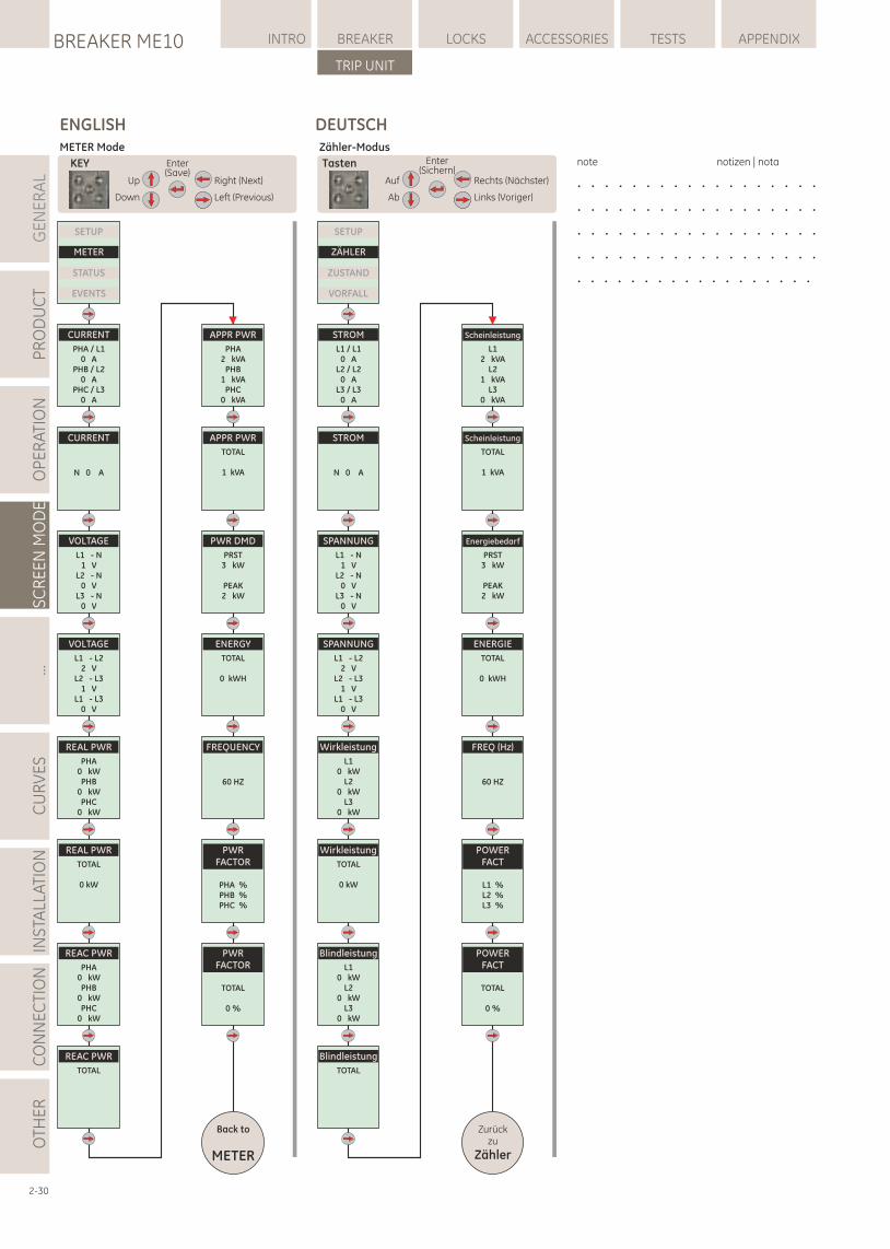
GE
NE
RA
LP
RO
DU
CT
OP
ER
ATI
ON
SC
RE
EN
MO
DE
...C
UR
VE
SIN
STA
LLA
TIO
NC
ON
NE
CTI
ON
LOCKSBREAKER ME10 INTRO BREAKER ACCESSORIES TESTS APPENDIX
TRIP UNIT
OTH
ER
2-30
ENGLISH
Up
Down
Right (Next)
Left (Previous)
Enter(Save)
KEY
SETUP
METER
STATUS
EVENTS
CURRENT
PHA / L10 A
PHB / L20 A
PHC / L30 A
CURRENT
N 0 A
VOLTAGE
L1 - N1 V
L2 - N0 V
L3 - N0 V
VOLTAGE
L1 - L22 V
L2 - L31 V
L1 - L30 V
REAL PWR
PHA0 kWPHB
0 kWPHC
0 kW
REAL PWR
TOTAL
0 kW
REAC PWR
PHA0 kWPHB
0 kWPHC
0 kW
REAC PWR
TOTAL
APPR PWR
PHA2 kVA
PHB1 kVA
PHC0 kVA
APPR PWR
TOTAL
1 kVA
PWR DMD
PRST3 kW
PEAK2 kW
ENERGY
TOTAL
0 kWH
FREQUENCY
60 HZ
PWRFACTOR
PHA %PHB %PHC %
PWRFACTOR
TOTAL
0 %
Back to
METER
METER Mode
DEUTSCH
Auf
Ab
Rechts (Nächster)
Links (Voriger)
Enter(Sichern)
Tasten
Zähler-Modus
SETUP
ZÄHLER
ZUSTAND
VORFALL
STROM
L1 / L10 A
L2 / L20 A
L3 / L30 A
STROM
N 0 A
SPANNUNG
L1 - N1 V
L2 - N0 V
L3 - N0 V
SPANNUNG
L1 - L22 V
L2 - L31 V
L1 - L30 V
Wirkleistung
L10 kW
L20 kW
L30 kW
Wirkleistung
TOTAL
0 kW
Blindleistung
L10 kW
L20 kW
L30 kW
Blindleistung
TOTAL
Scheinleistung
L12 kVA
L21 kVA
L30 kVA
Scheinleistung
TOTAL
1 kVA
Energiebedarf
PRST3 kW
PEAK2 kW
ENERGIE
TOTAL
0 kWH
FREQ (Hz)
60 HZ
POWERFACT
L1 %L2 %L3 %
POWERFACT
TOTAL
0 %
Zurückzu
Zähler
note notizen | nota
. . . . . . . . . . . . . . . . . .
. . . . . . . . . . . . . . . . . .
. . . . . . . . . . . . . . . . . .
. . . . . . . . . . . . . . . . . .
. . . . . . . . . . . . . . . . . .
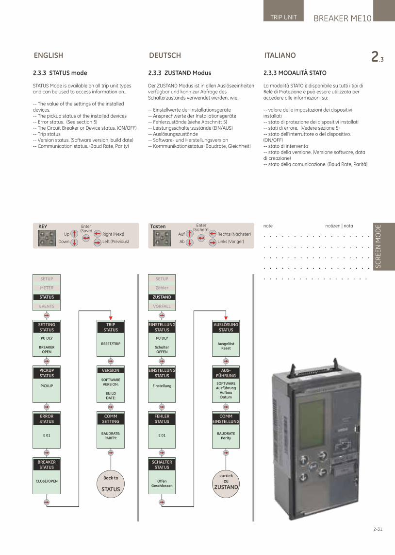
BREAKER ME10TRIP UNIT
SC
RE
EN
MO
DE
2.3
2-31
ENGLISH
Up
Down
Right (Next)
Left (Previous)
Enter(Save)
KEY
SETUP
METER
STATUS
EVENTS
SETTINGSTATUS
PU DLY
BREAKEROPEN
PICKUPSTATUS
PICKUP
ERRORSTATUS
E 01
TRIPSTATUS
RESET/TRIP
VERSION
SOFTWAREVERSION:
BUILDDATE:
COMMSETTING
BAUDRATE:PARITY:
Back to
STATUS
BREAKERSTATUS
CLOSE/OPEN
2.3.3 STATUS mode
STATUS Mode is available on all trip unit types and can be used to access information on..
-- The value of the settings of the installed devices.-- The pickup status of the installed devices-- Error status. (See section 5)-- The Circuit Breaker or Device status. (ON/OFF)-- Trip status-- Version status. (Software version, build date)-- Communication status. (Baud Rate, Parity)
2.3.3 ZUSTAND Modus
Der ZUSTAND Modus ist in allen Auslöseeinheiten verfügbar und kann zur Abfrage des Schalterzustands verwendet werden, wie..
-- Einstellwerte der Installationsgeräte-- Ansprechwerte der Installationsgeräte-- Fehlerzustände (siehe Abschnitt 5)-- Leistungsschalterzustände (EIN/AUS)-- Auslösungszustände-- Software- und Herstellungsversion-- Kommunikationsstatus (Baudrate, Gleichheit)
SETUP
Zähler
ZUSTAND
VORFALL
EINSTELLUNGSTATUS
PU DLY
Schalter OFFEN
EINSTELLUNGSTATUS
Einstellung
FEHLERSTATUS
E 01
AUSLÖSUNGSTATUS
AusgelöstReset
AUS-FÜHRUNG
SOFTWAREAusführung
AufbauDatum
COMMEINSTELLUNG
BAUDRATEParity
zurückzu
ZUSTAND
SCHALTERSTATUS
OffenGeschlossen
DEUTSCH
Auf
Ab
Rechts (Nächster)
Links (Voriger)
Enter(Sichern)
Tasten
2.3.3 MODALITÀ STATO
La modalità STATO è disponibile su tutti i tipi di Relè di Protezione e può essere utilizzata per accedere alle informazioni su:
-- valore delle impostazioni dei dispositivi installati-- stato di protezione dei dispositivi installati-- stati di errore. (Vedere sezione 5)-- stato dell'interruttore o del dispositivo. (ON/OFF)-- stato di intervento-- stato della versione. (Versione software, data di creazione)-- stato della comunicazione. (Baud Rate, Parità)
note notizen | nota
. . . . . . . . . . . . . . . . . .
. . . . . . . . . . . . . . . . . .
. . . . . . . . . . . . . . . . . .
. . . . . . . . . . . . . . . . . .
. . . . . . . . . . . . . . . . . .
ITALIANO
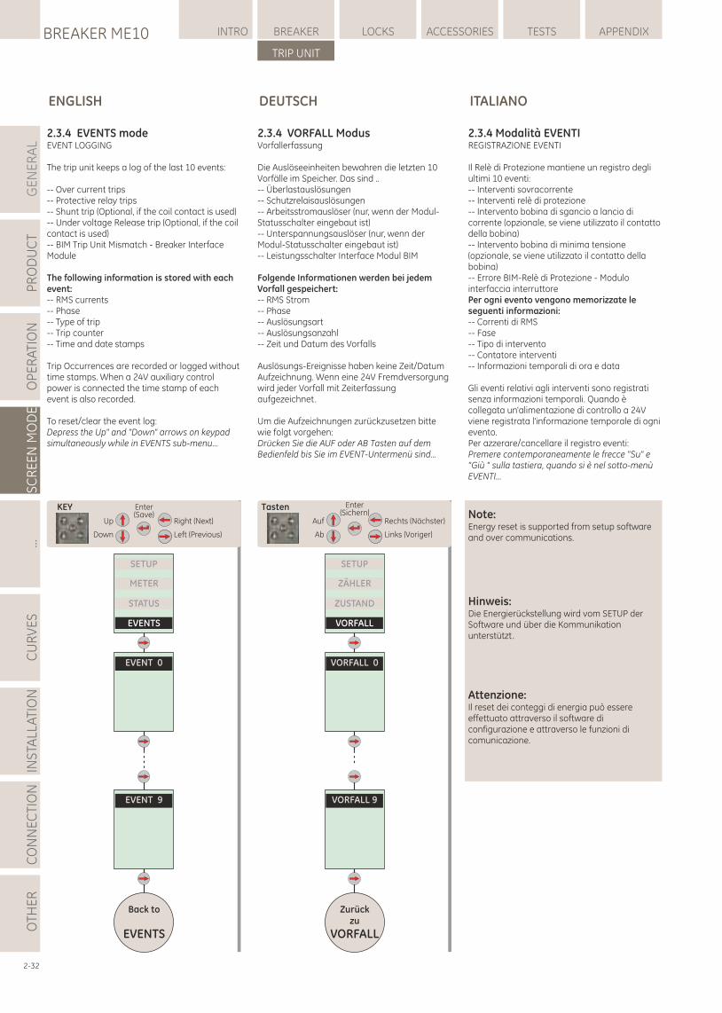
GE
NE
RA
LP
RO
DU
CT
OP
ER
ATI
ON
SC
RE
EN
MO
DE
...C
UR
VE
SIN
STA
LLA
TIO
NC
ON
NE
CTI
ON
LOCKSBREAKER ME10 INTRO BREAKER ACCESSORIES TESTS APPENDIX
TRIP UNIT
OTH
ER
2-32
ENGLISH
2.3.4 EVENTS modeEVENT LOGGING
The trip unit keeps a log of the last 10 events:
-- Over current trips-- Protective relay trips-- Shunt trip (Optional, if the coil contact is used)-- Under voltage Release trip (Optional, if the coil contact is used)-- BIM Trip Unit Mismatch - Breaker Interface Module
The following information is stored with each event:-- RMS currents-- Phase-- Type of trip-- Trip counter-- Time and date stamps
Trip Occurrences are recorded or logged without time stamps. When a 24V auxiliary control power is connected the time stamp of each event is also recorded.
To reset/clear the event log:Depress the Up" and "Down" arrows on keypad simultaneously while in EVENTS sub-menu...
2.3.4 VORFALL ModusVorfallerfassung
Die Auslöseeinheiten bewahren die letzten 10 Vorfälle im Speicher. Das sind ..-- Überlastauslösungen-- Schutzrelaisauslösungen-- Arbeitsstromauslöser (nur, wenn der Modul-Statusschalter eingebaut ist)-- Unterspannungsauslöser (nur, wenn der Modul-Statusschalter eingebaut ist)-- Leistungsschalter Interface Modul BIM
Folgende Informationen werden bei jedem Vorfall gespeichert:-- RMS Strom-- Phase-- Auslösungsart-- Auslösungsanzahl-- Zeit und Datum des Vorfalls
Auslösungs-Ereignisse haben keine Zeit/Datum Aufzeichnung. Wenn eine 24V Fremdversorgung wird jeder Vorfall mit Zeiterfassung aufgezeichnet.
Um die Aufzeichnungen zurückzusetzen bitte wie folgt vorgehen:Drücken Sie die AUF oder AB Tasten auf dem Bedienfeld bis Sie im EVENT-Untermenü sind...
DEUTSCH
Up
Down
Right (Next)
Left (Previous)
Enter(Save)
KEY
SETUP
METER
STATUS
EVENTS
EVENT 0
Back to
EVENTS
EVENT 9
2.3.4 Modalità EVENTIREGISTRAZIONE EVENTI
Il Relè di Protezione mantiene un registro degli ultimi 10 eventi:-- Interventi sovracorrente-- Interventi relè di protezione-- Intervento bobina di sgancio a lancio di corrente (opzionale, se viene utilizzato il contatto della bobina)-- Intervento bobina di minima tensione (opzionale, se viene utilizzato il contatto della bobina)-- Errore BIM-Relè di Protezione - Modulo interfaccia interruttorePer ogni evento vengono memorizzate le seguenti informazioni:-- Correnti di RMS-- Fase-- Tipo di intervento-- Contatore interventi-- Informazioni temporali di ora e data
Gli eventi relativi agli interventi sono registrati senza informazioni temporali. Quando è collegata un'alimentazione di controllo a 24V viene registrata l'informazione temporale di ogni evento.Per azzerare/cancellare il registro eventi:Premere contemporaneamente le frecce "Su" e "Giù " sulla tastiera, quando si è nel sotto-menù EVENTI...
Note:Energy reset is supported from setup software and over communications.
Hinweis:Die Energierückstellung wird vom SETUP der Software und über die Kommunikation unterstützt.
Attenzione: Il reset dei conteggi di energia può essere effettuato attraverso il software di configurazione e attraverso le funzioni di comunicazione.
Auf
Ab
Rechts (Nächster)
Links (Voriger)
Enter(Sichern)
Tasten
SETUP
ZÄHLER
ZUSTAND
VORFALL
VORFALL 0
Zurückzu
VORFALL
VORFALL 9
ITALIANO
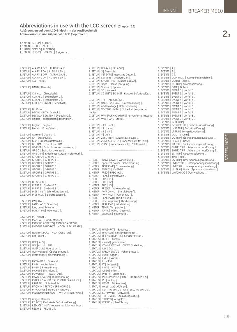
BREAKER ME10TRIP UNIT
SC
RE
EN
MO
DE
2.3
2-33
Abbreviations in use with the LCD screen (Chapter 2.3)
Abkürzungen auf dem LCD-Bildschirm der AuslöseeinheitAbbreviazioni in uso sul pannello LCD (capitolo 2.3)
5. EVENTS | A |..5. EVENTS | B |..5. EVENTS | C |..5. EVENTS | COM FAULT | Komunikationsfehler |..5. EVENTS | COUNT | Zahl |..5. EVENTS | CU TRIP | Stromauslösung |..5. EVENTS | DATE | Datum |..5. EVENTS | EVENT 0 | Vorfall 0 |..5. EVENTS | EVENT 1 | Vorfall 1 |..5. EVENTS | EVENT 2 | Vorfall 2 |..5. EVENTS | EVENT 3 | Vorfall 3 |..5. EVENTS | EVENT 4 | Vorfall 4 |..5. EVENTS | EVENT 5 | Vorfall 5 |..5. EVENTS | EVENT 6 | Vorfall 6 |..5. EVENTS | EVENT 7 | Vorfall 7 |..5. EVENTS | EVENT 8 | Vorfall 8 |..5. EVENTS | EVENT 9 | Vorfall 9 |..5. EVENTS | GFct TRIP |..5. EVENTS | GF SUM TRIP | Erdschlussauslösung |..5. EVENTS | INST TRIP | Sofortauslösung |..5. EVENTS | LT TRIP | Langzeitauslösung |..5. EVENTS | ODD | einzeln |..5. EVENTS | OV TRIP | Überspannungsauslösung |..5. EVENTS | PHASE | Phase |..5. EVENTS | PR TRIP | Rückspannungsauslösung |..5. EVENTS | SHNT1 TRIP | Arbeitsstromauslösung 1 |..5. EVENTS | SHNT2 TRIP | Arbeitsstromauslösung 2 |..5. EVENTS | SD TRIP | Kurzzeitauslösung |..5. EVENTS | TIME | Zeit |..5. EVENTS | UV TRIP | Unterspannungsauslösung |..5. EVENTS | UVR 2 TRIP | Unterspannungsauslösung |..5. EVENTS | UVR TRIP | Unterspannungsauslösung |..5. EVENTS | VU TRIP | Unsym.Spannungsauslösung |..5. EVENTS | WATCHDOG | Überwachung |..
1.a MAIN | SETUP | SETUP |..1.b MAIN | METER | ZÄHLER |..1.c MAIN | STATUS | ZUSTAND |..1.d MAIN | EVENTS | VORFALL | Ereignisse |..
-----------------------------------------------------------------
2. SETUP | ALARM 1 OFF | ALARM 1 AUS |..2. SETUP | ALARM 1 ON | ALARM 1 EIN |..2. SETUP | ALARM 2 OFF | ALARM 2 AUS |..2. SETUP | ALARM 2 ON | ALARM 2 EIN |..2. SETUP | ALL | Alles |..
2. SETUP | BAND | Bereich |..
2. SETUP | Chinese | Chinesisch |..2. SETUP | CUR AL 1 | Stromalarm 1 |..2. SETUP | CUR AL 2 | Stromalarm 2 |..2. SETUP | CURRENT UNBAL | Schieflast |..
2. SETUP | D | Datum |..2. SETUP | DELTA | DELTA | Dreieck |..2. SETUP | DELTAWYE SYSTEM | Dreiecksys. |..2. SETUP | disable | ausschalten | abschalten |..
2. SETUP | English | Englisch |..2. SETUP | French | Französisch |..
2. SETUP | German | Deutsch |..2. SETUP | GF | Erdschluss |..2. SETUP | GFct | Erdschlussstrom CT |..2. SETUP | GF SUM | Erdschluss SUM |..2. SETUP | GF-INST | Erdschlusssofortauslösung |..2. SETUP | GF-SD | Erdschluss-Kurzzeit |..2. SETUP | GF-SD-IN | Erdschluss-Kurzzeit-Sofortausl. |..2. SETUP | GROUP 0 | GRUPPE 0 |..2. SETUP | GROUP 1 | GRUPPE 1 |..2. SETUP | GROUP 2 | GRUPPE 2 |..2. SETUP | GROUP 3 | GRUPPE 3 |..2. SETUP | GROUP 4 | GRUPPE 4 |..2. SETUP | GROUP 5 | GRUPPE 5 |..2. SETUP | GROUP 6 | GRUPPE 6 |..
2. SETUP | H | Stunde |..2. SETUP | INPUT 1 | EINGANG 1 |..2. SETUP | INPUT 2 | EINGANG 2 |..2. SETUP | INST | INST | Schnellauslösung |..2. SETUP | INST FAULT | Sofortauslöser |..
2. SETUP | kW | KW |..2. SETUP | LANGUAGE | Sprache |..2. SETUP | long time | b-Kanal |..2. SETUP | LONG TIME | Überlast LT |..
2. SETUP | M | Monat |..2. SETUP | MANUAL | Hand / Manuell |..2. SETUP | MODBUS ADDRESS | MODBUS ADRESSE |..2. SETUP | MODBUS BAUDRATE | MODBUS BAUDRATE |..
2. SETUP | NEUTRAL POLE | NEUTRALLEITER |..2. SETUP | not | nicht |..
2. SETUP | OFF | AUS |..2. SETUP | OFF | out of | AUS |..2. SETUP | OVER CUR | Überstrom |..2. SETUP | Over Voltage | Überspannung |..2. SETUP | overvoltage | Überspannung |..
2. SETUP | PASSWORD | Passwort |..2. SETUP | PH-N | Neutralleiter |..2. SETUP | PH-PH | PHase-Phase |..2. SETUP | PICKUP | Einstellung |..2. SETUP | POWER DIR | POWER DIR |..2. SETUP | Power Reversal | Rückspannung |..2. SETUP | PROFIBUS ADDRESS | PROFIBUS ADRESSE |..2. SETUP | PROT REL | Schutzrelais |..2. SETUP | PT CONN | TRAFO VERBINDUNG |..2. SETUP | PT VOLTAGE | TRAFO SPANNUNG |..2. SETUP | PWR DMD INTERVAL | PWR DMT INTERVALL |
2. SETUP | range | Bereich |..2. SETUP | RE INST | Reduzierte Sofortauslösung |..2. SETUP | REDUCED INST | reduzierter Sofortauslöser |..2. SETUP | RELAY 1 | RELAIS 1 |..
2. SETUP | RELAY 2 | RELAIS 2 |..2. SETUP | S | Sekunde |..2. SETUP | SET DATE | gesetztes Datum |..2. SETUP | SET TIME | gesetzte Zeit |..2. SETUP | SHORT TIME | Kurzschluss SD |..2. SETUP | slope | Flanke | Steigung |..2. SETUP | Spanish | Spanisch |..2. SETUP | SD | Kurzzeit |..2. SETUP | SD-INST | SD-INST | Kurzzeit-Sofortauslös. |..
2. SETUP | TRIP | AUSGELÖST |..2. SETUP | UNDER VOLTAGE | Unterspannung |..2. SETUP | undervoltage | Unterspannung |..2. SETUP | VOLTAGE UNBAL | Schieflast | Asymetria napięć2. SETUP | WAVEFORM CAPTURE | Kurvenformerfassung 2. SETUP | WYE | WYE | Stern |..
2. SETUP | x CT | x CT |..2. SETUP | x In | x In |..2. SETUP | x Ir | x Ir |..2. SETUP | Y | Jahr |..2. SETUP | ZERO TRIP | Kurzzeitauslösung |..2. SETUP | ZONE SEL INTLK | Zonenselektivität (ZSI) |..2. SETUP | ZSI SD | Zonenselektivität (ZSI) Kurzzeit |..
-----------------------------------------------------------------
3. METER | active power | Wirkleistung |..3. METER | apparent power | Scheinleistung |..3. METER | APPR PWR | Scheinleistung |..3. METER | ENERGY | ENERGIE |..3. METER | FREQ | FREQ (Hz) |..3. METER | PEAK | Scheitelwert |..3. METER | PHA | L1 |..3. METER | PHB | L2 |..3. METER | PHC | L3 |..3. METER | PRESET | Voreinstellung |..3. METER | PWR DMND | Energiebedarf |..3. METER | PWR FACT | POWER FACT |..3. METER | REAC PWR | Blindleistung |..3. METER | reactive power | Blindleistung |..3. METER | REAL PWR | Wirkleistung |..3. METER | TEMP | Temperatur |..3. METER | TOTAL | TOTAL | Gesamt |..3. METER | VOLTAGE | Spannung |..
-----------------------------------------------------------------
4. STATUS | BAUD RATE | Baudrate |..4. STATUS | BREAKER | Leistungsschalter |..4. STATUS | BREAKER STATUS | Schalter Ststus |..4. STATUS | BUILD | Aufbau |..4. STATUS | closed | geschlossen |..4. STATUS | COMM SETTING | COMM Einstellung |..4. STATUS | DLY | DLV |..4. STATUS | ERROR STATUS | Fehler Status |..4. STATUS | even | sogar |..4. STATUS | EVEN | Vorfall |..4. STATUS | I | sofort |..4. STATUS | LT | Langzeit ||..4. STATUS | NONE | NICHT |..4. STATUS | OPEN | offen |..4. STATUS | PARITY | Gleichheit |..4. STATUS | PICKUP STATUS | EINSTELLUNG STATUS |..4. STATUS | PU | Pickup |..4. STATUS | RESET | Rücksetzen |..4. STATUS | reset | zurückführen |..4. STATUS | SETTING STATUS | EINSTELLUNG STATUS |..4. STATUS | SOFTWARE | Software |..4. STATUS | TRIP STATUS | Auslösungstatus |..4. STATUS | TRIPPED | Ausgelöst |..4. STATUS | VERSION | Ausführung |..
-----------------------------------------------------------------
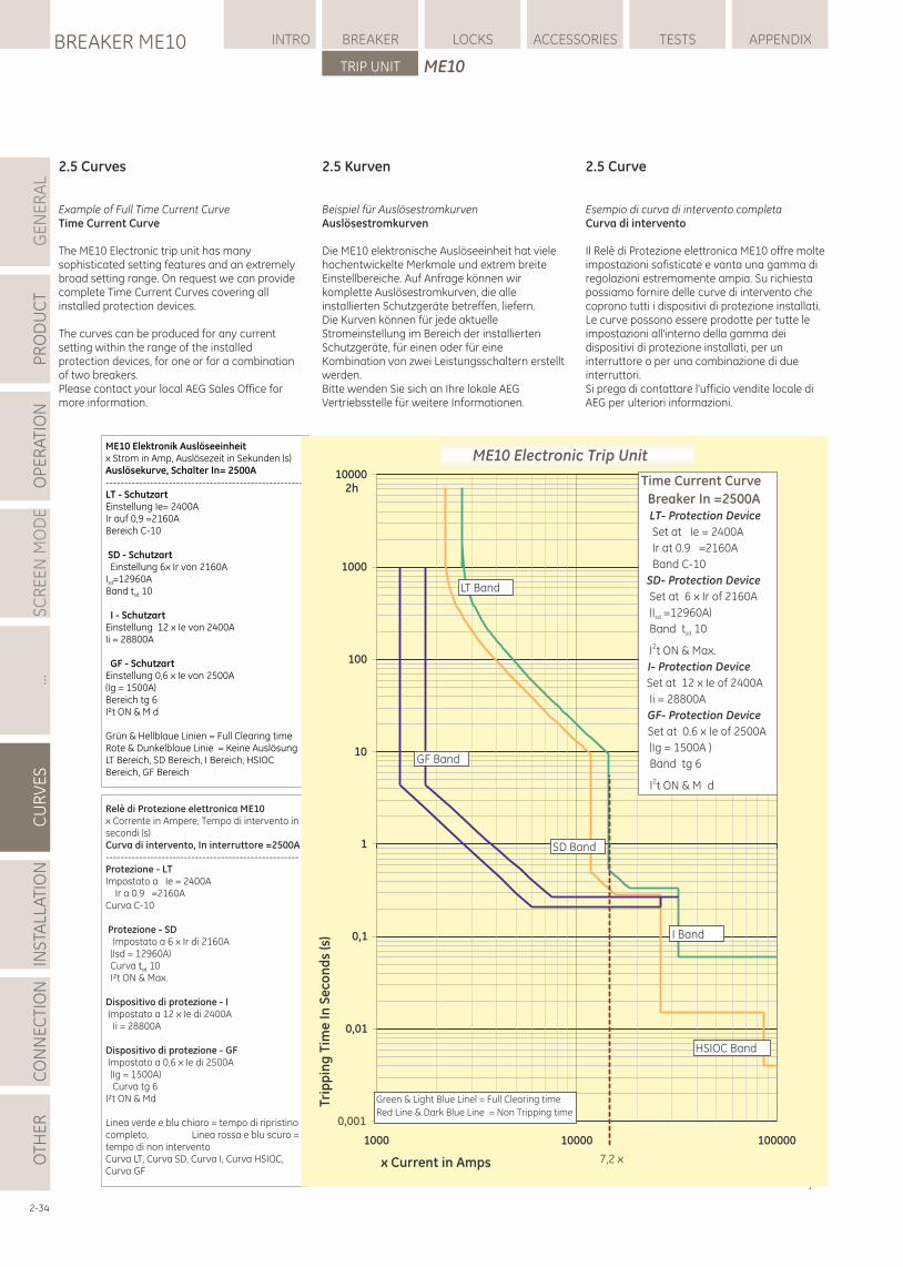
2-34
2.5 Curves
Example of Full Time Current CurveTime Current Curve
The ME10 Electronic trip unit has many sophisticated setting features and an extremely broad setting range. On request we can provide complete Time Current Curves covering all installed protection devices.
The curves can be produced for any current setting within the range of the installed protection devices, for one or for a combination of two breakers.Please contact your local AEG Sales Office for more information.
2.5 Kurven
Beispiel für AuslösestromkurvenAuslösestromkurven
Die ME10 elektronische Auslöseeinheit hat viele hochentwickelte Merkmale und extrem breite Einstellbereiche. Auf Anfrage können wir komplette Auslösestromkurven, die alle installierten Schutzgeräte betreffen, liefern.Die Kurven können für jede aktuelle Stromeinstellung im Bereich der installierten Schutzgeräte, für einen oder für eine Kombination von zwei Leistungsschaltern erstellt werden.Bitte wenden Sie sich an Ihre lokale AEG Vertriebsstelle für weitere Informationen.
ME10 Elektronik Auslöseeinheitx Strom in Amp, Auslösezeit in Sekunden (s) Auslösekurve, Schalter In= 2500A-----------------------------------------------------LT - Schutzart Einstellung Ie= 2400AIr auf 0,9 =2160ABereich C-10
SD - Schutzart Einstellung 6x Ir von 2160AI =12960Asd
Band t 10sd
I - SchutzartEinstellung 12 x Ie von 2400AIi = 28800A
GF - SchutzartEinstellung 0,6 x Ie von 2500A(Ig = 1500A)Bereich tg 6I²t ON & M d
Grün & Hellblaue Linien = Full Clearing timeRote & Dunkelblaue Linie = Keine AuslösungLT Bereich, SD Bereich, I Bereich, HSIOC Bereich, GF Bereich
Relè di Protezione elettronica ME10 x Corrente in Ampere, Tempo di intervento in secondi (s)Curva di intervento, In interruttore =2500A----------------------------------------------------Protezione - LT Impostato a Ie = 2400A Ir a 0.9 =2160ACurva C-10
Protezione - SD Impostato a 6 x Ir di 2160A (Isd = 12960A) Curva 10t sd
I²t ON & Max.
Dispositivo di protezione - I Impostato a 12 x Ie di 2400A Ii = 28800A
Dispositivo di protezione - GF Impostato a 0,6 x Ie di 2500A (Ig = 1500A) Curva tg 6I²t ON & Md
Linea verde e blu chiaro = tempo di ripristino completo, Linea rossa e blu scuro = tempo di non interventoCurva LT, Curva SD, Curva I, Curva HSIOC, Curva GF
2.5 Curve
Esempio di curva di intervento completaCurva di intervento
Il Relè di Protezione elettronica ME10 offre molte impostazioni sofisticate e vanta una gamma di regolazioni estremamente ampia. Su richiesta possiamo fornire delle curve di intervento che coprono tutti i dispositivi di protezione installati.Le curve possono essere prodotte per tutte le impostazioni all'interno della gamma dei dispositivi di protezione installati, per un interruttore o per una combinazione di due interruttori.Si prega di contattare l'ufficio vendite locale di AEG per ulteriori informazioni.
GE
NE
RA
LP
RO
DU
CT
OP
ER
ATI
ON
SC
RE
EN
MO
DE
...C
UR
VE
SIN
STA
LLA
TIO
NC
ON
NE
CTI
ON
LOCKSBREAKER ME10 INTRO BREAKER ACCESSORIES TESTS APPENDIX
TRIP UNIT
OTH
ER
ME10
]
0,01
0,1
1
10
100
1000
10000
000001000010001
x Current in Amps
Trip
pin
g T
ime
In
Se
con
ds
(s)
Time Current Curve
Breaker In =2500A LT- Protection Device
Set at Ie = 2400A
Ir at 0.9 =2160A
Band C-10
SD- Protection Device
Set at 6 x Ir of 2160A
(I =12960A)sd
Band t 10sd
I2t ON & Max.
I- Protection Device
Set at 12 x Ie of 2400A
Ii = 28800A
GF- Protection Device
Set at 0.6 x Ie of 2500A
(Ig = 1500A )
Band tg 6
2I t ON & M d
2h
7,2 x
Green & Light Blue Linel = Full Clearing time
Red Line & Dark Blue Line = Non Tripping time
LT Band
SD Band
I Band
HSIOC Band
GF Band
ME10 Electronic Trip Unit
0,001
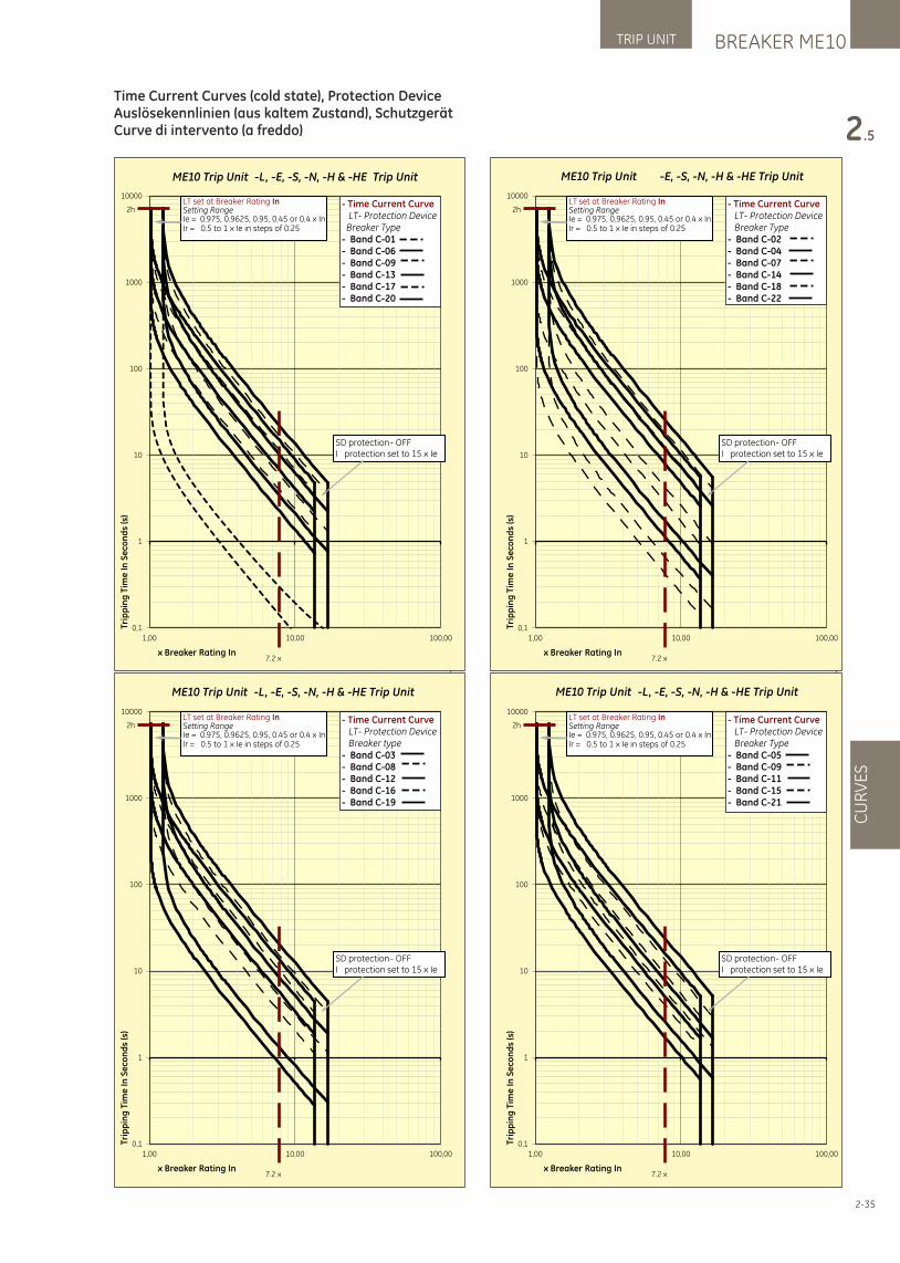
2-35
Time Current Curves (cold state), Protection DeviceAuslösekennlinien (aus kaltem Zustand), SchutzgerätCurve di intervento (a freddo)
]
0,1
1
10
100
1000
10000
1,00 10,00
100,00
Trip
pin
g T
ime
In S
eco
nd
s (s
)
x Breaker Rating In
ME10 Trip Unit -L, -E, -S, -N, -H & -HE Trip Unit
- Time Current CurveLT- Protection Device
Breaker Type- Band C-01 - Band C-06 - Band C-09 - Band C-13 - Band C-17 - Band C-20
2h
7.2 x
SD protection -
OFF
I protection set to 15 x Ie
LT set at Breaker Rating InSetting Range Ie = 0.975, 0.9625, 0.95, 0.45 or 0.4 x InIr = 0.5 to 1 x Ie in steps of 0.25
]
0,1
1
10
100
1000
10000
1,00
10,00 100,00
Trip
pin
g T
ime
In S
eco
nd
s (s
)
x Breaker Rating In
ME10 Trip Unit -E, -S, -N, -H & -HE Trip Unit
- Time Current CurveLT- Protection DeviceBreaker Type
- Band C-02 - Band C-04 - Band C-07 - Band C-14 - Band C-18 - Band C-22
2h
7.2 x
SD protection - OFFI protection set to 15 x Ie
LT set at Breaker Rating InSetting Range Ie = 0.975, 0.9625, 0.95, 0.45 or 0.4 x InIr = 0.5 to 1 x Ie in steps of 0.25
0,1
1
10
100
1000
10000
1,00 10,00 100,00
Trip
pin
g T
ime
In S
eco
nd
s (s
)
x Breaker Rating In
ME10 Trip Unit -L, -E, -S, -N, -H & -HE Trip Unit -
Time Current Curve
LT-
Protection Device
Breaker type
-
Band C-03
-
Band C-08
-
Band C-12
-
Band C-16
-
Band C-19
2h
7.2 x
SD protection - OFFI protection set to 15 x Ie
LT set at Breaker Rating InSetting Range Ie = 0.975, 0.9625, 0.95, 0.45 or 0.4 x In
Ir = 0.5 to 1 x Ie in steps of 0.25
0,1
1
10
100
1000
10000
1,00 10,00 100,00
Trip
pin
g T
ime
In S
eco
nd
s (s
)
x Breaker Rating In
ME10 Trip Unit -L, -E, -S, -N, -H & -HE Trip Unit
- Time Current CurveLT- Protection DeviceBreaker Type
- Band C-05 - Band C-09 - Band C-11 - Band C-15 - Band C-21
2h
7.2 x
SD protection - OFFI protection set to 15 x Ie
LT set at Breaker Rating InSetting Range
Ie = 0.975, 0.9625, 0.95, 0.45 or 0.4 x InIr = 0.5 to 1 x Ie in steps of 0.25
BREAKER ME10TRIP UNIT
2.5
CU
RV
ES
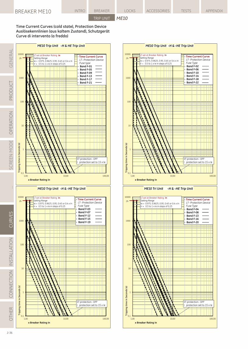
2-36
GE
NE
RA
LP
RO
DU
CT
OP
ER
ATI
ON
SC
RE
EN
MO
DE
...C
UR
VE
SIN
STA
LLA
TIO
NC
ON
NE
CTI
ON
LOCKSBREAKER ME10 INTRO BREAKER ACCESSORIES TESTS APPENDIX
TRIP UNIT
OTH
ER
ME10
Time Current Curves (cold state), Protection DeviceAuslösekennlinien (aus kaltem Zustand), SchutzgerätCurve di intervento (a freddo)
0,1
1
10
100
1000
10000
1,00 10,00 100,00
x Breaker Rating In
ME10 Trip Unit -H & HE Trip Unit
- Time Current CurveLT- Protection DeviceFuse type
- Band F-01 - Band F-05- Band F-09- Band F-13- Band F-17- Band F-21
2h
ST protection - OFFI protection set to 15 x Ie
LT set at Breaker Rating InSetting Range Ie = 0.975, 0.9625, 0.95, 0.45 or 0.4 x InIr = 0.5 to 1 x Ie in steps of 0.25
Trip
pin
g t
ime
in S
eco
nd
s (s
)
0,1
1
10
100
1000
10000
1,00 10,00 100,00
x Breaker Rating In
ME10 Trip Unit -H & -HE Trip Unit
- Time Current CurveLT- Protection DeviceFuse Type
- Band F-03 - Band F-07- Band F-12- Band F-15- Band F-19
2h
ST protection - OFFI protection set to 15 x Ie
LT set at Breaker Rating InSetting Range Ie = 0.975, 0.9625, 0.95, 0.45 or 0.4 x InIr = 0.5 to 1 x Ie in steps of 0.25
Tri
pp
ing
tim
e in
Se
con
ds
(s)
0,1
1
10
100
1000
10000
1,00 10,00 100,00
x Breaker Rating In
ME10 Trip Unit -H & -HE Trip Unit
- Time Current CurveLT- Protection DeviceFuse Type
- Band F-02 - Band F-06- Band F-10- Band F-14- Band F-18- Band F-22
2h
ST protection - OFFI protection set to 15 x Ie
LT set at Breaker Rating InSetting Range Ie = 0.975, 0.9625, 0.95, 0.45 or 0.4 x InIr = 0.5 to 1 x Ie in steps of 0.25
Trip
pin
g t
ime
in S
eco
nd
s (s
)
0,1
1
10
100
1000
10000
1,00 10,00 100,00
x Breaker Rating In
ME10 Tri Unit -H & -HE Trip Unit
- Time Current CurveLT- Protection DeviceFuse Type
- Band F-04 - Band F-08- Band F-13- Band F-16- Band F-20
2h
ST protection - OFFI protection set to 15 x Ie
LT set at Breaker Rating InSetting Range Ie = 0.975, 0.9625, 0.95, 0.45 or 0.4 x InIr = 0.5 to 1 x Ie in steps of 0.25
Tri
pp
ing
tim
e in
Se
con
ds
(s)

2-37
0,1
1
10
100
1000
10000
1,00 10,00
100,00
Trip
pin
g T
ime
In S
eco
nd
s (s
)
x Breaker Rating In
ME10 Trip Unit -H -Trip Unit
7.2 x
2hLT set at Breaker Rating InSetting Range Ie = 0.975, 0.9625, 0.95, 0.45 or 0.4 x InIr = 0.5 to 1 x Ie in steps of 0.25
7.2 x
2hLT set at Breaker Rating InSetting Range Ie = 0.975, 0.9625, 0.95, 0.45 or 0.4 x InIr = 0.5 to 1 x Ie in steps of 0.25
7.2 x
2hLT set at Breaker Rating InSetting Range Ie = 0.975, 0.9625, 0.95, 0.45 or 0.4 x InIr = 0.5 to 1 x Ie in steps of 0.25
7.2 x
2hLT set at Breaker Rating InSetting Range Ie = 0.975, 0.9625, 0.95, 0.45 or 0.4 x InIr = 0.5 to 1 x Ie in steps of 0.25
7.2 x
2hLT set at Breaker Rating InSetting Range Ie = 0.975, 0.9625, 0.95, 0.45 or 0.4 x InIr = 0.5 to 1 x Ie in steps of 0.25
7.2 x
2hLT set at Breaker Rating InSetting Range Ie = 0.975, 0.9625, 0.95, 0.45 or 0.4 x InIr = 0.5 to 1 x Ie in steps of 0.25
7.2 x
2hLT set at Breaker Rating InSetting Range Ie = 0.975, 0.9625, 0.95, 0.45 or 0.4 x InIr = 0.5 to 1 x Ie in steps of 0.25
7.2 x
2hLT set at Breaker Rating InSetting Range Ie = 0.975, 0.9625, 0.95, 0.45 or 0.4 x InIr = 0.5 to 1 x Ie in steps of 0.25
7.2 x
2hLT set at Breaker Rating InSetting Range Ie = 0.975, 0.9625, 0.95, 0.45 or 0.4 x InIr = 0.5 to 1 x Ie in steps of 0.25
7.2 x
2hLT set at Breaker Rating InSetting Range Ie = 0.975, 0.9625, 0.95, 0.45 or 0.4 x InIr = 0.5 to 1 x Ie in steps of 0.25
7.2 x
2hLT set at Breaker Rating InSetting Range Ie = 0.975, 0.9625, 0.95, 0.45 or 0.4 x InIr = 0.5 to 1 x Ie in steps of 0.25
7.2 x
2hLT set at Breaker Rating InSetting Range Ie = 0.975, 0.9625, 0.95, 0.45 or 0.4 x InIr = 0.5 to 1 x Ie in steps of 0.25
7.2 x
2hLT set at Breaker Rating InSetting Range Ie = 0.975, 0.9625, 0.95, 0.45 or 0.4 x InIr = 0.5 to 1 x Ie in steps of 0.25
7.2 x
2hLT set at Breaker Rating InSetting Range Ie = 0.975, 0.9625, 0.95, 0.45 or 0.4 x InIr = 0.5 to 1 x Ie in steps of 0.25
7.2 x
2hLT set at Breaker Rating InSetting Range Ie = 0.975, 0.9625, 0.95, 0.45 or 0.4 x InIr = 0.5 to 1 x Ie in steps of 0.25
7.2 x
2hLT set at Breaker Rating InSetting Range Ie = 0.975, 0.9625, 0.95, 0.45 or 0.4 x InIr = 0.5 to 1 x Ie in steps of 0.25
7.2 x
2hLT set at Breaker Rating InSetting Range Ie = 0.975, 0.9625, 0.95, 0.45 or 0.4 x InIr = 0.5 to 1 x Ie in steps of 0.25
7.2 x
2hLT set at Breaker Rating InSetting Range Ie = 0.975, 0.9625, 0.95, 0.45 or 0.4 x InIr = 0.5 to 1 x Ie in steps of 0.25
7.2 x
2hLT set at Breaker Rating InSetting Range Ie = 0.975, 0.9625, 0.95, 0.45 or 0.4 x InIr = 0.5 to 1 x Ie in steps of 0.25
7.2 x
2hLT set at Breaker Rating InSetting Range Ie = 0.975, 0.9625, 0.95, 0.45 or 0.4 x InIr = 0.5 to 1 x Ie in steps of 0.25
7.2 x
2hLT set at Breaker Rating InSetting Range Ie = 0.975, 0.9625, 0.95, 0.45 or 0.4 x InIr = 0.5 to 1 x Ie in steps of 0.25
7.2 x
2hLT set at Breaker Rating InSetting Range Ie = 0.975, 0.9625, 0.95, 0.45 or 0.4 x InIr = 0.5 to 1 x Ie in steps of 0.25
7.2 x
2hLT set at Breaker Rating InSetting Range Ie = 0.975, 0.9625, 0.95, 0.45 or 0.4 x InIr = 0.5 to 1 x Ie in steps of 0.25
7.2 x
2hLT set at Breaker Rating InSetting Range Ie = 0.975, 0.9625, 0.95, 0.45 or 0.4 x InIr = 0.5 to 1 x Ie in steps of 0.25
7.2 x
2hLT set at Breaker Rating InSetting Range Ie = 0.975, 0.9625, 0.95, 0.45 or 0.4 x InIr = 0.5 to 1 x Ie in steps of 0.25
7.2 x
2hLT set at Breaker Rating InSetting Range Ie = 0.975, 0.9625, 0.95, 0.45 or 0.4 x InIr = 0.5 to 1 x Ie in steps of 0.25
7.2 x
2hLT set at Breaker Rating InSetting Range Ie = 0.975, 0.9625, 0.95, 0.45 or 0.4 x InIr = 0.5 to 1 x Ie in steps of 0.25
7.2 x
2hLT set at Breaker Rating InSetting Range Ie = 0.975, 0.9625, 0.95, 0.45 or 0.4 x InIr = 0.5 to 1 x Ie in steps of 0.25
7.2 x
2hLT set at Breaker Rating InSetting Range Ie = 0.975, 0.9625, 0.95, 0.45 or 0.4 x InIr = 0.5 to 1 x Ie in steps of 0.25
7.2 x
2hLT set at Breaker Rating InSetting Range Ie = 0.975, 0.9625, 0.95, 0.45 or 0.4 x InIr = 0.5 to 1 x Ie in steps of 0.25
7.2 x
2hLT set at Breaker Rating InSetting Range Ie = 0.975, 0.9625, 0.95, 0.45 or 0.4 x InIr = 0.5 to 1 x Ie in steps of 0.25
7.2 x
2hLT set at Breaker Rating InSetting Range Ie = 0.975, 0.9625, 0.95, 0.45 or 0.4 x InIr = 0.5 to 1 x Ie in steps of 0.25
7.2 x
2hLT set at Breaker Rating InSetting Range Ie = 0.975, 0.9625, 0.95, 0.45 or 0.4 x InIr = 0.5 to 1 x Ie in steps of 0.25
7.2 x
2hLT set at Breaker Rating InSetting Range Ie = 0.975, 0.9625, 0.95, 0.45 or 0.4 x InIr = 0.5 to 1 x Ie in steps of 0.25
7.2 x
2hLT set at Breaker Rating InSetting Range Ie = 0.975, 0.9625, 0.95, 0.45 or 0.4 x InIr = 0.5 to 1 x Ie in steps of 0.25
7.2 x
2hLT set at Breaker Rating InSetting Range Ie = 0.975, 0.9625, 0.95, 0.45 or 0.4 x InIr = 0.5 to 1 x Ie in steps of 0.25
7.2 x
2hLT set at Breaker Rating InSetting Range Ie = 0.975, 0.9625, 0.95, 0.45 or 0.4 x InIr = 0.5 to 1 x Ie in steps of 0.25
7.2 x
2hLT set at Breaker Rating InSetting Range Ie = 0.975, 0.9625, 0.95, 0.45 or 0.4 x InIr = 0.5 to 1 x Ie in steps of 0.25
7.2 x
2hLT set at Breaker Rating InSetting Range Ie = 0.975, 0.9625, 0.95, 0.45 or 0.4 x InIr = 0.5 to 1 x Ie in steps of 0.25
7.2 x
2hLT set at Breaker Rating InSetting Range Ie = 0.975, 0.9625, 0.95, 0.45 or 0.4 x InIr = 0.5 to 1 x Ie in steps of 0.25
7.2 x
2hLT set at Breaker Rating InSetting Range Ie = 0.975, 0.9625, 0.95, 0.45 or 0.4 x InIr = 0.5 to 1 x Ie in steps of 0.25
7.2 x
2hLT set at Breaker Rating InSetting Range Ie = 0.975, 0.9625, 0.95, 0.45 or 0.4 x InIr = 0.5 to 1 x Ie in steps of 0.25
7.2 x
2hLT set at Breaker Rating InSetting Range Ie = 0.975, 0.9625, 0.95, 0.45 or 0.4 x InIr = 0.5 to 1 x Ie in steps of 0.25
7.2 x
2hLT set at Breaker Rating InSetting Range Ie = 0.975, 0.9625, 0.95, 0.45 or 0.4 x InIr = 0.5 to 1 x Ie in steps of 0.25
7.2 x
2hLT set at Breaker Rating InSetting Range Ie = 0.975, 0.9625, 0.95, 0.45 or 0.4 x InIr = 0.5 to 1 x Ie in steps of 0.25
7.2 x
2hLT set at Breaker Rating InSetting Range Ie = 0.975, 0.9625, 0.95, 0.45 or 0.4 x InIr = 0.5 to 1 x Ie in steps of 0.25
7.2 x
2hLT set at Breaker Rating InSetting Range Ie = 0.975, 0.9625, 0.95, 0.45 or 0.4 x InIr = 0.5 to 1 x Ie in steps of 0.25
7.2 x
2hLT set at Breaker Rating InSetting Range Ie = 0.975, 0.9625, 0.95, 0.45 or 0.4 x InIr = 0.5 to 1 x Ie in steps of 0.25
7.2 x
2hLT set at Breaker Rating InSetting Range Ie = 0.975, 0.9625, 0.95, 0.45 or 0.4 x InIr = 0.5 to 1 x Ie in steps of 0.25
7.2 x
2hLT set at Breaker Rating InSetting Range Ie = 0.975, 0.9625, 0.95, 0.45 or 0.4 x InIr = 0.5 to 1 x Ie in steps of 0.25
7.2 x
2hLT set at Breaker Rating InSetting Range Ie = 0.975, 0.9625, 0.95, 0.45 or 0.4 x InIr = 0.5 to 1 x Ie in steps of 0.25
7.2 x
2hLT set at Breaker Rating InSetting Range Ie = 0.975, 0.9625, 0.95, 0.45 or 0.4 x InIr = 0.5 to 1 x Ie in steps of 0.25
7.2 x
2hLT set at Breaker Rating InSetting Range Ie = 0.975, 0.9625, 0.95, 0.45 or 0.4 x InIr = 0.5 to 1 x Ie in steps of 0.25
7.2 x
2hLT set at Breaker Rating InSetting Range Ie = 0.975, 0.9625, 0.95, 0.45 or 0.4 x InIr = 0.5 to 1 x Ie in steps of 0.25
7.2 x
2hLT set at Breaker Rating InSetting Range Ie = 0.975, 0.9625, 0.95, 0.45 or 0.4 x InIr = 0.5 to 1 x Ie in steps of 0.25
7.2 x
2hLT set at Breaker Rating InSetting Range Ie = 0.975, 0.9625, 0.95, 0.45 or 0.4 x InIr = 0.5 to 1 x Ie in steps of 0.25
7.2 x
2hLT set at Breaker Rating InSetting Range Ie = 0.975, 0.9625, 0.95, 0.45 or 0.4 x InIr = 0.5 to 1 x Ie in steps of 0.25
7.2 x
2hLT set at Breaker Rating InSetting Range Ie = 0.975, 0.9625, 0.95, 0.45 or 0.4 x InIr = 0.5 to 1 x Ie in steps of 0.25
7.2 x
2hLT set at Breaker Rating InSetting Range Ie = 0.975, 0.9625, 0.95, 0.45 or 0.4 x InIr = 0.5 to 1 x Ie in steps of 0.25
7.2 x
2hLT set at Breaker Rating InSetting Range Ie = 0.975, 0.9625, 0.95, 0.45 or 0.4 x InIr = 0.5 to 1 x Ie in steps of 0.25
7.2 x
2hLT set at Breaker Rating InSetting Range Ie = 0.975, 0.9625, 0.95, 0.45 or 0.4 x InIr = 0.5 to 1 x Ie in steps of 0.25
7.2 x
2hLT set at Breaker Rating InSetting Range Ie = 0.975, 0.9625, 0.95, 0.45 or 0.4 x InIr = 0.5 to 1 x Ie in steps of 0.25
7.2 x
2hLT set at Breaker Rating InSetting Range Ie = 0.975, 0.9625, 0.95, 0.45 or 0.4 x InIr = 0.5 to 1 x Ie in steps of 0.25
- Time Current CurveLT- Protection DeviceStandard Inverse type
- Band L 00.5 - Band L 02- Band L 04- Band L 06- Band L 08 - Band L 10- Band L 20
7.2 x
2h
SD protection -
OFF
I protection set to 15 x Ie
LT set at Breaker Rating InSetting Range Ie = 0.975, 0.9625, 0.95, 0.45 or 0.4 x InIr = 0.5 to 1 x Ie in steps of 0.25
7.2 x
2hLT set at Breaker Rating InSetting Range Ie = 0.975, 0.9625, 0.95, 0.45 or 0.4 x InIr = 0.5 to 1 x Ie in steps of 0.25
7.2 x
2hLT set at Breaker Rating InSetting Range Ie = 0.975, 0.9625, 0.95, 0.45 or 0.4 x InIr = 0.5 to 1 x Ie in steps of 0.25
7.2 x
2hLT set at Breaker Rating InSetting Range Ie = 0.975, 0.9625, 0.95, 0.45 or 0.4 x InIr = 0.5 to 1 x Ie in steps of 0.25
7.2 x
2hLT set at Breaker Rating InSetting Range Ie = 0.975, 0.9625, 0.95, 0.45 or 0.4 x InIr = 0.5 to 1 x Ie in steps of 0.25
7.2 x
2hLT set at Breaker Rating InSetting Range Ie = 0.975, 0.9625, 0.95, 0.45 or 0.4 x InIr = 0.5 to 1 x Ie in steps of 0.25
7.2 x
2hLT set at Breaker Rating InSetting Range Ie = 0.975, 0.9625, 0.95, 0.45 or 0.4 x InIr = 0.5 to 1 x Ie in steps of 0.25
7.2 x
2hLT set at Breaker Rating InSetting Range Ie = 0.975, 0.9625, 0.95, 0.45 or 0.4 x InIr = 0.5 to 1 x Ie in steps of 0.25
7.2 x
2hLT set at Breaker Rating InSetting Range Ie = 0.975, 0.9625, 0.95, 0.45 or 0.4 x InIr = 0.5 to 1 x Ie in steps of 0.25
7.2 x
2hLT set at Breaker Rating InSetting Range Ie = 0.975, 0.9625, 0.95, 0.45 or 0.4 x InIr = 0.5 to 1 x Ie in steps of 0.25
7.2 x
2hLT set at Breaker Rating InSetting Range Ie = 0.975, 0.9625, 0.95, 0.45 or 0.4 x InIr = 0.5 to 1 x Ie in steps of 0.25
7.2 x
2hLT set at Breaker Rating InSetting Range Ie = 0.975, 0.9625, 0.95, 0.45 or 0.4 x InIr = 0.5 to 1 x Ie in steps of 0.25
7.2 x
2hLT set at Breaker Rating InSetting Range Ie = 0.975, 0.9625, 0.95, 0.45 or 0.4 x InIr = 0.5 to 1 x Ie in steps of 0.25
7.2 x
2hLT set at Breaker Rating InSetting Range Ie = 0.975, 0.9625, 0.95, 0.45 or 0.4 x InIr = 0.5 to 1 x Ie in steps of 0.25
7.2 x
2hLT set at Breaker Rating InSetting Range Ie = 0.975, 0.9625, 0.95, 0.45 or 0.4 x InIr = 0.5 to 1 x Ie in steps of 0.25
7.2 x
2hLT set at Breaker Rating InSetting Range Ie = 0.975, 0.9625, 0.95, 0.45 or 0.4 x InIr = 0.5 to 1 x Ie in steps of 0.25
7.2 x
2hLT set at Breaker Rating InSetting Range Ie = 0.975, 0.9625, 0.95, 0.45 or 0.4 x InIr = 0.5 to 1 x Ie in steps of 0.25
7.2 x
2hLT set at Breaker Rating InSetting Range Ie = 0.975, 0.9625, 0.95, 0.45 or 0.4 x InIr = 0.5 to 1 x Ie in steps of 0.25
7.2 x
2hLT set at Breaker Rating InSetting Range Ie = 0.975, 0.9625, 0.95, 0.45 or 0.4 x InIr = 0.5 to 1 x Ie in steps of 0.25
7.2 x
2hLT set at Breaker Rating InSetting Range Ie = 0.975, 0.9625, 0.95, 0.45 or 0.4 x InIr = 0.5 to 1 x Ie in steps of 0.25
7.2 x
2hLT set at Breaker Rating InSetting Range Ie = 0.975, 0.9625, 0.95, 0.45 or 0.4 x InIr = 0.5 to 1 x Ie in steps of 0.25
7.2 x
2hLT set at Breaker Rating InSetting Range Ie = 0.975, 0.9625, 0.95, 0.45 or 0.4 x InIr = 0.5 to 1 x Ie in steps of 0.25
7.2 x
2hLT set at Breaker Rating InSetting Range Ie = 0.975, 0.9625, 0.95, 0.45 or 0.4 x InIr = 0.5 to 1 x Ie in steps of 0.25
7.2 x
2hLT set at Breaker Rating InSetting Range Ie = 0.975, 0.9625, 0.95, 0.45 or 0.4 x InIr = 0.5 to 1 x Ie in steps of 0.25
7.2 x
2hLT set at Breaker Rating InSetting Range Ie = 0.975, 0.9625, 0.95, 0.45 or 0.4 x InIr = 0.5 to 1 x Ie in steps of 0.25
7.2 x
2hLT set at Breaker Rating InSetting Range Ie = 0.975, 0.9625, 0.95, 0.45 or 0.4 x InIr = 0.5 to 1 x Ie in steps of 0.25
7.2 x
2hLT set at Breaker Rating InSetting Range Ie = 0.975, 0.9625, 0.95, 0.45 or 0.4 x InIr = 0.5 to 1 x Ie in steps of 0.25
7.2 x
2hLT set at Breaker Rating InSetting Range Ie = 0.975, 0.9625, 0.95, 0.45 or 0.4 x InIr = 0.5 to 1 x Ie in steps of 0.25
7.2 x
2hLT set at Breaker Rating InSetting Range Ie = 0.975, 0.9625, 0.95, 0.45 or 0.4 x InIr = 0.5 to 1 x Ie in steps of 0.25
7.2 x
2hLT set at Breaker Rating InSetting Range Ie = 0.975, 0.9625, 0.95, 0.45 or 0.4 x InIr = 0.5 to 1 x Ie in steps of 0.25
7.2 x
2hLT set at Breaker Rating InSetting Range Ie = 0.975, 0.9625, 0.95, 0.45 or 0.4 x InIr = 0.5 to 1 x Ie in steps of 0.25
7.2 x
2hLT set at Breaker Rating InSetting Range Ie = 0.975, 0.9625, 0.95, 0.45 or 0.4 x InIr = 0.5 to 1 x Ie in steps of 0.25
7.2 x
2hLT set at Breaker Rating InSetting Range Ie = 0.975, 0.9625, 0.95, 0.45 or 0.4 x InIr = 0.5 to 1 x Ie in steps of 0.25
7.2 x
2hLT set at Breaker Rating InSetting Range Ie = 0.975, 0.9625, 0.95, 0.45 or 0.4 x InIr = 0.5 to 1 x Ie in steps of 0.25
7.2 x
2hLT set at Breaker Rating InSetting Range Ie = 0.975, 0.9625, 0.95, 0.45 or 0.4 x InIr = 0.5 to 1 x Ie in steps of 0.25
7.2 x
2hLT set at Breaker Rating InSetting Range Ie = 0.975, 0.9625, 0.95, 0.45 or 0.4 x InIr = 0.5 to 1 x Ie in steps of 0.25
7.2 x
2hLT set at Breaker Rating InSetting Range Ie = 0.975, 0.9625, 0.95, 0.45 or 0.4 x InIr = 0.5 to 1 x Ie in steps of 0.25
7.2 x
2hLT set at Breaker Rating InSetting Range Ie = 0.975, 0.9625, 0.95, 0.45 or 0.4 x InIr = 0.5 to 1 x Ie in steps of 0.25
7.2 x
2hLT set at Breaker Rating InSetting Range Ie = 0.975, 0.9625, 0.95, 0.45 or 0.4 x InIr = 0.5 to 1 x Ie in steps of 0.25
7.2 x
2hLT set at Breaker Rating InSetting Range Ie = 0.975, 0.9625, 0.95, 0.45 or 0.4 x InIr = 0.5 to 1 x Ie in steps of 0.25
7.2 x
2hLT set at Breaker Rating InSetting Range Ie = 0.975, 0.9625, 0.95, 0.45 or 0.4 x InIr = 0.5 to 1 x Ie in steps of 0.25
7.2 x
2hLT set at Breaker Rating InSetting Range Ie = 0.975, 0.9625, 0.95, 0.45 or 0.4 x InIr = 0.5 to 1 x Ie in steps of 0.25
7.2 x
2hLT set at Breaker Rating InSetting Range Ie = 0.975, 0.9625, 0.95, 0.45 or 0.4 x InIr = 0.5 to 1 x Ie in steps of 0.25
7.2 x
2hLT set at Breaker Rating InSetting Range Ie = 0.975, 0.9625, 0.95, 0.45 or 0.4 x InIr = 0.5 to 1 x Ie in steps of 0.25
7.2 x
2hLT set at Breaker Rating InSetting Range Ie = 0.975, 0.9625, 0.95, 0.45 or 0.4 x InIr = 0.5 to 1 x Ie in steps of 0.25
7.2 x
2hLT set at Breaker Rating InSetting Range Ie = 0.975, 0.9625, 0.95, 0.45 or 0.4 x InIr = 0.5 to 1 x Ie in steps of 0.25
7.2 x
2hLT set at Breaker Rating InSetting Range Ie = 0.975, 0.9625, 0.95, 0.45 or 0.4 x InIr = 0.5 to 1 x Ie in steps of 0.25
7.2 x
2hLT set at Breaker Rating InSetting Range Ie = 0.975, 0.9625, 0.95, 0.45 or 0.4 x InIr = 0.5 to 1 x Ie in steps of 0.25
7.2 x
2hLT set at Breaker Rating InSetting Range Ie = 0.975, 0.9625, 0.95, 0.45 or 0.4 x InIr = 0.5 to 1 x Ie in steps of 0.25
7.2 x
2hLT set at Breaker Rating InSetting Range Ie = 0.975, 0.9625, 0.95, 0.45 or 0.4 x InIr = 0.5 to 1 x Ie in steps of 0.25
7.2 x
2hLT set at Breaker Rating InSetting Range Ie = 0.975, 0.9625, 0.95, 0.45 or 0.4 x InIr = 0.5 to 1 x Ie in steps of 0.25
7.2 x
2hLT set at Breaker Rating InSetting Range Ie = 0.975, 0.9625, 0.95, 0.45 or 0.4 x InIr = 0.5 to 1 x Ie in steps of 0.25
7.2 x
2hLT set at Breaker Rating InSetting Range Ie = 0.975, 0.9625, 0.95, 0.45 or 0.4 x InIr = 0.5 to 1 x Ie in steps of 0.25
7.2 x
2hLT set at Breaker Rating InSetting Range Ie = 0.975, 0.9625, 0.95, 0.45 or 0.4 x InIr = 0.5 to 1 x Ie in steps of 0.25
7.2 x
2hLT set at Breaker Rating InSetting Range Ie = 0.975, 0.9625, 0.95, 0.45 or 0.4 x InIr = 0.5 to 1 x Ie in steps of 0.25
7.2 x
2hLT set at Breaker Rating InSetting Range Ie = 0.975, 0.9625, 0.95, 0.45 or 0.4 x InIr = 0.5 to 1 x Ie in steps of 0.25
7.2 x
2hLT set at Breaker Rating InSetting Range Ie = 0.975, 0.9625, 0.95, 0.45 or 0.4 x InIr = 0.5 to 1 x Ie in steps of 0.25
7.2 x
2hLT set at Breaker Rating InSetting Range Ie = 0.975, 0.9625, 0.95, 0.45 or 0.4 x InIr = 0.5 to 1 x Ie in steps of 0.25
7.2 x
2hLT set at Breaker Rating InSetting Range Ie = 0.975, 0.9625, 0.95, 0.45 or 0.4 x InIr = 0.5 to 1 x Ie in steps of 0.25
7.2 x
2hLT set at Breaker Rating InSetting Range Ie = 0.975, 0.9625, 0.95, 0.45 or 0.4 x InIr = 0.5 to 1 x Ie in steps of 0.25
7.2 x
2hLT set at Breaker Rating InSetting Range Ie = 0.975, 0.9625, 0.95, 0.45 or 0.4 x InIr = 0.5 to 1 x Ie in steps of 0.25
7.2 x
2hLT set at Breaker Rating InSetting Range Ie = 0.975, 0.9625, 0.95, 0.45 or 0.4 x InIr = 0.5 to 1 x Ie in steps of 0.25
7.2 x
2hLT set at Breaker Rating InSetting Range Ie = 0.975, 0.9625, 0.95, 0.45 or 0.4 x InIr = 0.5 to 1 x Ie in steps of 0.25
7.2 x
2hLT set at Breaker Rating InSetting Range Ie = 0.975, 0.9625, 0.95, 0.45 or 0.4 x InIr = 0.5 to 1 x Ie in steps of 0.25
7.2 x
2h
SD protection -
OFF
I protection set to 15 x Ie
LT set at Breaker Rating InSetting Range Ie = 0.975, 0.9625, 0.95, 0.45 or 0.4 x InIr = 0.5 to 1 x Ie in steps of 0.25
0,1
1
10
100
1000
10000
1,00
10,00 100,00
Trip
pin
g T
ime
In S
eco
nd
s (s
)
x Breaker Rating In
ME10 Trip Unit -H -Trip Unit
7.2 x
2hLT set at Breaker Rating InSetting Range Ie = 0.975, 0.9625, 0.95, 0.45 or 0.4 x InIr = 0.5 to 1 x Ie in steps of 0.25
7.2 x
2hLT set at Breaker Rating InSetting Range Ie = 0.975, 0.9625, 0.95, 0.45 or 0.4 x InIr = 0.5 to 1 x Ie in steps of 0.25
7.2 x
2hLT set at Breaker Rating InSetting Range Ie = 0.975, 0.9625, 0.95, 0.45 or 0.4 x InIr = 0.5 to 1 x Ie in steps of 0.25
7.2 x
2hLT set at Breaker Rating InSetting Range Ie = 0.975, 0.9625, 0.95, 0.45 or 0.4 x InIr = 0.5 to 1 x Ie in steps of 0.25
7.2 x
2hLT set at Breaker Rating InSetting Range Ie = 0.975, 0.9625, 0.95, 0.45 or 0.4 x InIr = 0.5 to 1 x Ie in steps of 0.25
7.2 x
2hLT set at Breaker Rating InSetting Range Ie = 0.975, 0.9625, 0.95, 0.45 or 0.4 x InIr = 0.5 to 1 x Ie in steps of 0.25
7.2 x
2hLT set at Breaker Rating InSetting Range Ie = 0.975, 0.9625, 0.95, 0.45 or 0.4 x InIr = 0.5 to 1 x Ie in steps of 0.25
7.2 x
2hLT set at Breaker Rating InSetting Range Ie = 0.975, 0.9625, 0.95, 0.45 or 0.4 x InIr = 0.5 to 1 x Ie in steps of 0.25
7.2 x
2hLT set at Breaker Rating InSetting Range Ie = 0.975, 0.9625, 0.95, 0.45 or 0.4 x InIr = 0.5 to 1 x Ie in steps of 0.25
7.2 x
2hLT set at Breaker Rating InSetting Range Ie = 0.975, 0.9625, 0.95, 0.45 or 0.4 x InIr = 0.5 to 1 x Ie in steps of 0.25
7.2 x
2hLT set at Breaker Rating InSetting Range Ie = 0.975, 0.9625, 0.95, 0.45 or 0.4 x InIr = 0.5 to 1 x Ie in steps of 0.25
7.2 x
2hLT set at Breaker Rating InSetting Range Ie = 0.975, 0.9625, 0.95, 0.45 or 0.4 x InIr = 0.5 to 1 x Ie in steps of 0.25
7.2 x
2hLT set at Breaker Rating InSetting Range Ie = 0.975, 0.9625, 0.95, 0.45 or 0.4 x InIr = 0.5 to 1 x Ie in steps of 0.25
7.2 x
2hLT set at Breaker Rating InSetting Range Ie = 0.975, 0.9625, 0.95, 0.45 or 0.4 x InIr = 0.5 to 1 x Ie in steps of 0.25
7.2 x
2hLT set at Breaker Rating InSetting Range Ie = 0.975, 0.9625, 0.95, 0.45 or 0.4 x InIr = 0.5 to 1 x Ie in steps of 0.25
7.2 x
2hLT set at Breaker Rating InSetting Range Ie = 0.975, 0.9625, 0.95, 0.45 or 0.4 x InIr = 0.5 to 1 x Ie in steps of 0.25
7.2 x
2hLT set at Breaker Rating InSetting Range Ie = 0.975, 0.9625, 0.95, 0.45 or 0.4 x InIr = 0.5 to 1 x Ie in steps of 0.25
7.2 x
2hLT set at Breaker Rating InSetting Range Ie = 0.975, 0.9625, 0.95, 0.45 or 0.4 x InIr = 0.5 to 1 x Ie in steps of 0.25
7.2 x
2hLT set at Breaker Rating InSetting Range Ie = 0.975, 0.9625, 0.95, 0.45 or 0.4 x InIr = 0.5 to 1 x Ie in steps of 0.25
7.2 x
2hLT set at Breaker Rating InSetting Range Ie = 0.975, 0.9625, 0.95, 0.45 or 0.4 x InIr = 0.5 to 1 x Ie in steps of 0.25
7.2 x
2hLT set at Breaker Rating InSetting Range Ie = 0.975, 0.9625, 0.95, 0.45 or 0.4 x InIr = 0.5 to 1 x Ie in steps of 0.25
7.2 x
2hLT set at Breaker Rating InSetting Range Ie = 0.975, 0.9625, 0.95, 0.45 or 0.4 x InIr = 0.5 to 1 x Ie in steps of 0.25
7.2 x
2hLT set at Breaker Rating InSetting Range Ie = 0.975, 0.9625, 0.95, 0.45 or 0.4 x InIr = 0.5 to 1 x Ie in steps of 0.25
7.2 x
2hLT set at Breaker Rating InSetting Range Ie = 0.975, 0.9625, 0.95, 0.45 or 0.4 x InIr = 0.5 to 1 x Ie in steps of 0.25
7.2 x
2hLT set at Breaker Rating InSetting Range Ie = 0.975, 0.9625, 0.95, 0.45 or 0.4 x InIr = 0.5 to 1 x Ie in steps of 0.25
7.2 x
2hLT set at Breaker Rating InSetting Range Ie = 0.975, 0.9625, 0.95, 0.45 or 0.4 x InIr = 0.5 to 1 x Ie in steps of 0.25
7.2 x
2hLT set at Breaker Rating InSetting Range Ie = 0.975, 0.9625, 0.95, 0.45 or 0.4 x InIr = 0.5 to 1 x Ie in steps of 0.25
7.2 x
2hLT set at Breaker Rating InSetting Range Ie = 0.975, 0.9625, 0.95, 0.45 or 0.4 x InIr = 0.5 to 1 x Ie in steps of 0.25
7.2 x
2hLT set at Breaker Rating InSetting Range Ie = 0.975, 0.9625, 0.95, 0.45 or 0.4 x InIr = 0.5 to 1 x Ie in steps of 0.25
7.2 x
2hLT set at Breaker Rating InSetting Range Ie = 0.975, 0.9625, 0.95, 0.45 or 0.4 x InIr = 0.5 to 1 x Ie in steps of 0.25
7.2 x
2hLT set at Breaker Rating InSetting Range Ie = 0.975, 0.9625, 0.95, 0.45 or 0.4 x InIr = 0.5 to 1 x Ie in steps of 0.25
7.2 x
2hLT set at Breaker Rating InSetting Range Ie = 0.975, 0.9625, 0.95, 0.45 or 0.4 x InIr = 0.5 to 1 x Ie in steps of 0.25
7.2 x
2hLT set at Breaker Rating InSetting Range Ie = 0.975, 0.9625, 0.95, 0.45 or 0.4 x InIr = 0.5 to 1 x Ie in steps of 0.25
7.2 x
2hLT set at Breaker Rating InSetting Range Ie = 0.975, 0.9625, 0.95, 0.45 or 0.4 x InIr = 0.5 to 1 x Ie in steps of 0.25
7.2 x
2hLT set at Breaker Rating InSetting Range Ie = 0.975, 0.9625, 0.95, 0.45 or 0.4 x InIr = 0.5 to 1 x Ie in steps of 0.25
7.2 x
2hLT set at Breaker Rating InSetting Range Ie = 0.975, 0.9625, 0.95, 0.45 or 0.4 x InIr = 0.5 to 1 x Ie in steps of 0.25
7.2 x
2hLT set at Breaker Rating InSetting Range Ie = 0.975, 0.9625, 0.95, 0.45 or 0.4 x InIr = 0.5 to 1 x Ie in steps of 0.25
7.2 x
2hLT set at Breaker Rating InSetting Range Ie = 0.975, 0.9625, 0.95, 0.45 or 0.4 x InIr = 0.5 to 1 x Ie in steps of 0.25
7.2 x
2hLT set at Breaker Rating InSetting Range Ie = 0.975, 0.9625, 0.95, 0.45 or 0.4 x InIr = 0.5 to 1 x Ie in steps of 0.25
7.2 x
2hLT set at Breaker Rating InSetting Range Ie = 0.975, 0.9625, 0.95, 0.45 or 0.4 x InIr = 0.5 to 1 x Ie in steps of 0.25
7.2 x
2hLT set at Breaker Rating InSetting Range Ie = 0.975, 0.9625, 0.95, 0.45 or 0.4 x InIr = 0.5 to 1 x Ie in steps of 0.25
7.2 x
2hLT set at Breaker Rating InSetting Range Ie = 0.975, 0.9625, 0.95, 0.45 or 0.4 x InIr = 0.5 to 1 x Ie in steps of 0.25
7.2 x
2hLT set at Breaker Rating InSetting Range Ie = 0.975, 0.9625, 0.95, 0.45 or 0.4 x InIr = 0.5 to 1 x Ie in steps of 0.25
7.2 x
2hLT set at Breaker Rating InSetting Range Ie = 0.975, 0.9625, 0.95, 0.45 or 0.4 x InIr = 0.5 to 1 x Ie in steps of 0.25
7.2 x
2hLT set at Breaker Rating InSetting Range Ie = 0.975, 0.9625, 0.95, 0.45 or 0.4 x InIr = 0.5 to 1 x Ie in steps of 0.25
7.2 x
2hLT set at Breaker Rating InSetting Range Ie = 0.975, 0.9625, 0.95, 0.45 or 0.4 x InIr = 0.5 to 1 x Ie in steps of 0.25
7.2 x
2hLT set at Breaker Rating InSetting Range Ie = 0.975, 0.9625, 0.95, 0.45 or 0.4 x InIr = 0.5 to 1 x Ie in steps of 0.25
7.2 x
2hLT set at Breaker Rating InSetting Range Ie = 0.975, 0.9625, 0.95, 0.45 or 0.4 x InIr = 0.5 to 1 x Ie in steps of 0.25
7.2 x
2hLT set at Breaker Rating InSetting Range Ie = 0.975, 0.9625, 0.95, 0.45 or 0.4 x InIr = 0.5 to 1 x Ie in steps of 0.25
7.2 x
2hLT set at Breaker Rating InSetting Range Ie = 0.975, 0.9625, 0.95, 0.45 or 0.4 x InIr = 0.5 to 1 x Ie in steps of 0.25
7.2 x
2hLT set at Breaker Rating InSetting Range Ie = 0.975, 0.9625, 0.95, 0.45 or 0.4 x InIr = 0.5 to 1 x Ie in steps of 0.25
7.2 x
2hLT set at Breaker Rating InSetting Range Ie = 0.975, 0.9625, 0.95, 0.45 or 0.4 x InIr = 0.5 to 1 x Ie in steps of 0.25
7.2 x
2hLT set at Breaker Rating InSetting Range Ie = 0.975, 0.9625, 0.95, 0.45 or 0.4 x InIr = 0.5 to 1 x Ie in steps of 0.25
7.2 x
2hLT set at Breaker Rating InSetting Range Ie = 0.975, 0.9625, 0.95, 0.45 or 0.4 x InIr = 0.5 to 1 x Ie in steps of 0.25
7.2 x
2hLT set at Breaker Rating InSetting Range Ie = 0.975, 0.9625, 0.95, 0.45 or 0.4 x InIr = 0.5 to 1 x Ie in steps of 0.25
7.2 x
2hLT set at Breaker Rating InSetting Range Ie = 0.975, 0.9625, 0.95, 0.45 or 0.4 x InIr = 0.5 to 1 x Ie in steps of 0.25
7.2 x
2hLT set at Breaker Rating InSetting Range Ie = 0.975, 0.9625, 0.95, 0.45 or 0.4 x InIr = 0.5 to 1 x Ie in steps of 0.25
7.2 x
2hLT set at Breaker Rating InSetting Range Ie = 0.975, 0.9625, 0.95, 0.45 or 0.4 x InIr = 0.5 to 1 x Ie in steps of 0.25
7.2 x
2hLT set at Breaker Rating InSetting Range Ie = 0.975, 0.9625, 0.95, 0.45 or 0.4 x InIr = 0.5 to 1 x Ie in steps of 0.25
7.2 x
2hLT set at Breaker Rating InSetting Range Ie = 0.975, 0.9625, 0.95, 0.45 or 0.4 x InIr = 0.5 to 1 x Ie in steps of 0.25
7.2 x
2hLT set at Breaker Rating InSetting Range Ie = 0.975, 0.9625, 0.95, 0.45 or 0.4 x InIr = 0.5 to 1 x Ie in steps of 0.25
7.2 x
2hLT set at Breaker Rating InSetting Range Ie = 0.975, 0.9625, 0.95, 0.45 or 0.4 x InIr = 0.5 to 1 x Ie in steps of 0.25
7.2 x
2hLT set at Breaker Rating InSetting Range Ie = 0.975, 0.9625, 0.95, 0.45 or 0.4 x InIr = 0.5 to 1 x Ie in steps of 0.25
- Time Current CurveLT- Protection DeviceStandard Inverse type
- Band L 01 - Band L 03- Band L 05- Band L 07- Band L 09 - Band L 15
7.2 x
2h
SD protection - OFFI protection set to 15 x Ie
LT set at Breaker Rating InSetting Range Ie = 0.975, 0.9625, 0.95, 0.45 or 0.4 x InIr = 0.5 to 1 x Ie in steps of 0.25
0,1
1
10
100
1000
10000
1,00 10,00 100,00
Trip
pin
g T
ime
In S
eco
nd
s (s
)
x Breaker Rating In
ME10 Trip Unit -H -Trip Unit
7.2 x
2hLT set at Breaker Rating InSetting Range Ie = 0.975, 0.9625, 0.95, 0.45 or 0.4 x In
Ir = 0.5 to 1 x Ie in steps of 0.25
7.2 x
2hLT set at Breaker Rating InSetting Range Ie = 0.975, 0.9625, 0.95, 0.45 or 0.4 x In
Ir = 0.5 to 1 x Ie in steps of 0.25
7.2 x
2hLT set at Breaker Rating InSetting Range Ie = 0.975, 0.9625, 0.95, 0.45 or 0.4 x In
Ir = 0.5 to 1 x Ie in steps of 0.25
7.2 x
2hLT set at Breaker Rating InSetting Range Ie = 0.975, 0.9625, 0.95, 0.45 or 0.4 x In
Ir = 0.5 to 1 x Ie in steps of 0.25
7.2 x
2hLT set at Breaker Rating InSetting Range Ie = 0.975, 0.9625, 0.95, 0.45 or 0.4 x In
Ir = 0.5 to 1 x Ie in steps of 0.25
7.2 x
2hLT set at Breaker Rating InSetting Range Ie = 0.975, 0.9625, 0.95, 0.45 or 0.4 x In
Ir = 0.5 to 1 x Ie in steps of 0.25
7.2 x
2hLT set at Breaker Rating InSetting Range Ie = 0.975, 0.9625, 0.95, 0.45 or 0.4 x In
Ir = 0.5 to 1 x Ie in steps of 0.25
7.2 x
2hLT set at Breaker Rating InSetting Range Ie = 0.975, 0.9625, 0.95, 0.45 or 0.4 x In
Ir = 0.5 to 1 x Ie in steps of 0.25
7.2 x
2hLT set at Breaker Rating InSetting Range Ie = 0.975, 0.9625, 0.95, 0.45 or 0.4 x In
Ir = 0.5 to 1 x Ie in steps of 0.25
7.2 x
2hLT set at Breaker Rating InSetting Range Ie = 0.975, 0.9625, 0.95, 0.45 or 0.4 x In
Ir = 0.5 to 1 x Ie in steps of 0.25
7.2 x
2hLT set at Breaker Rating InSetting Range Ie = 0.975, 0.9625, 0.95, 0.45 or 0.4 x In
Ir = 0.5 to 1 x Ie in steps of 0.25
7.2 x
2hLT set at Breaker Rating InSetting Range Ie = 0.975, 0.9625, 0.95, 0.45 or 0.4 x In
Ir = 0.5 to 1 x Ie in steps of 0.25
7.2 x
2hLT set at Breaker Rating InSetting Range Ie = 0.975, 0.9625, 0.95, 0.45 or 0.4 x In
Ir = 0.5 to 1 x Ie in steps of 0.25
7.2 x
2hLT set at Breaker Rating InSetting Range Ie = 0.975, 0.9625, 0.95, 0.45 or 0.4 x In
Ir = 0.5 to 1 x Ie in steps of 0.25
7.2 x
2hLT set at Breaker Rating InSetting Range Ie = 0.975, 0.9625, 0.95, 0.45 or 0.4 x In
Ir = 0.5 to 1 x Ie in steps of 0.25
7.2 x
2hLT set at Breaker Rating InSetting Range Ie = 0.975, 0.9625, 0.95, 0.45 or 0.4 x In
Ir = 0.5 to 1 x Ie in steps of 0.25
7.2 x
2hLT set at Breaker Rating InSetting Range Ie = 0.975, 0.9625, 0.95, 0.45 or 0.4 x In
Ir = 0.5 to 1 x Ie in steps of 0.25
7.2 x
2hLT set at Breaker Rating InSetting Range Ie = 0.975, 0.9625, 0.95, 0.45 or 0.4 x In
Ir = 0.5 to 1 x Ie in steps of 0.25
7.2 x
2hLT set at Breaker Rating InSetting Range Ie = 0.975, 0.9625, 0.95, 0.45 or 0.4 x In
Ir = 0.5 to 1 x Ie in steps of 0.25
7.2 x
2hLT set at Breaker Rating InSetting Range Ie = 0.975, 0.9625, 0.95, 0.45 or 0.4 x In
Ir = 0.5 to 1 x Ie in steps of 0.25
7.2 x
2hLT set at Breaker Rating InSetting Range Ie = 0.975, 0.9625, 0.95, 0.45 or 0.4 x In
Ir = 0.5 to 1 x Ie in steps of 0.25
7.2 x
2hLT set at Breaker Rating InSetting Range Ie = 0.975, 0.9625, 0.95, 0.45 or 0.4 x In
Ir = 0.5 to 1 x Ie in steps of 0.25
7.2 x
2hLT set at Breaker Rating InSetting Range Ie = 0.975, 0.9625, 0.95, 0.45 or 0.4 x In
Ir = 0.5 to 1 x Ie in steps of 0.25
7.2 x
2hLT set at Breaker Rating InSetting Range Ie = 0.975, 0.9625, 0.95, 0.45 or 0.4 x In
Ir = 0.5 to 1 x Ie in steps of 0.25
7.2 x
2hLT set at Breaker Rating InSetting Range Ie = 0.975, 0.9625, 0.95, 0.45 or 0.4 x In
Ir = 0.5 to 1 x Ie in steps of 0.25
7.2 x
2hLT set at Breaker Rating InSetting Range Ie = 0.975, 0.9625, 0.95, 0.45 or 0.4 x In
Ir = 0.5 to 1 x Ie in steps of 0.25
7.2 x
2hLT set at Breaker Rating InSetting Range Ie = 0.975, 0.9625, 0.95, 0.45 or 0.4 x In
Ir = 0.5 to 1 x Ie in steps of 0.25
7.2 x
2hLT set at Breaker Rating InSetting Range Ie = 0.975, 0.9625, 0.95, 0.45 or 0.4 x In
Ir = 0.5 to 1 x Ie in steps of 0.25
7.2 x
2hLT set at Breaker Rating InSetting Range Ie = 0.975, 0.9625, 0.95, 0.45 or 0.4 x In
Ir = 0.5 to 1 x Ie in steps of 0.25
7.2 x
2hLT set at Breaker Rating InSetting Range Ie = 0.975, 0.9625, 0.95, 0.45 or 0.4 x In
Ir = 0.5 to 1 x Ie in steps of 0.25
7.2 x
2hLT set at Breaker Rating InSetting Range Ie = 0.975, 0.9625, 0.95, 0.45 or 0.4 x In
Ir = 0.5 to 1 x Ie in steps of 0.25
7.2 x
2hLT set at Breaker Rating InSetting Range Ie = 0.975, 0.9625, 0.95, 0.45 or 0.4 x In
Ir = 0.5 to 1 x Ie in steps of 0.25
7.2 x
2hLT set at Breaker Rating InSetting Range Ie = 0.975, 0.9625, 0.95, 0.45 or 0.4 x In
Ir = 0.5 to 1 x Ie in steps of 0.25
7.2 x
2hLT set at Breaker Rating InSetting Range Ie = 0.975, 0.9625, 0.95, 0.45 or 0.4 x In
Ir = 0.5 to 1 x Ie in steps of 0.25
7.2 x
2hLT set at Breaker Rating InSetting Range Ie = 0.975, 0.9625, 0.95, 0.45 or 0.4 x In
Ir = 0.5 to 1 x Ie in steps of 0.25
7.2 x
2hLT set at Breaker Rating InSetting Range Ie = 0.975, 0.9625, 0.95, 0.45 or 0.4 x In
Ir = 0.5 to 1 x Ie in steps of 0.25
7.2 x
2hLT set at Breaker Rating InSetting Range Ie = 0.975, 0.9625, 0.95, 0.45 or 0.4 x In
Ir = 0.5 to 1 x Ie in steps of 0.25
7.2 x
2hLT set at Breaker Rating InSetting Range Ie = 0.975, 0.9625, 0.95, 0.45 or 0.4 x In
Ir = 0.5 to 1 x Ie in steps of 0.25
7.2 x
2hLT set at Breaker Rating InSetting Range Ie = 0.975, 0.9625, 0.95, 0.45 or 0.4 x In
Ir = 0.5 to 1 x Ie in steps of 0.25
7.2 x
2hLT set at Breaker Rating InSetting Range Ie = 0.975, 0.9625, 0.95, 0.45 or 0.4 x In
Ir = 0.5 to 1 x Ie in steps of 0.25
7.2 x
2hLT set at Breaker Rating InSetting Range Ie = 0.975, 0.9625, 0.95, 0.45 or 0.4 x In
Ir = 0.5 to 1 x Ie in steps of 0.25
7.2 x
2hLT set at Breaker Rating InSetting Range Ie = 0.975, 0.9625, 0.95, 0.45 or 0.4 x In
Ir = 0.5 to 1 x Ie in steps of 0.25
7.2 x
2hLT set at Breaker Rating InSetting Range Ie = 0.975, 0.9625, 0.95, 0.45 or 0.4 x In
Ir = 0.5 to 1 x Ie in steps of 0.25
7.2 x
2hLT set at Breaker Rating InSetting Range Ie = 0.975, 0.9625, 0.95, 0.45 or 0.4 x In
Ir = 0.5 to 1 x Ie in steps of 0.25
7.2 x
2hLT set at Breaker Rating InSetting Range Ie = 0.975, 0.9625, 0.95, 0.45 or 0.4 x In
Ir = 0.5 to 1 x Ie in steps of 0.25
7.2 x
2hLT set at Breaker Rating InSetting Range Ie = 0.975, 0.9625, 0.95, 0.45 or 0.4 x In
Ir = 0.5 to 1 x Ie in steps of 0.25
7.2 x
2hLT set at Breaker Rating InSetting Range Ie = 0.975, 0.9625, 0.95, 0.45 or 0.4 x In
Ir = 0.5 to 1 x Ie in steps of 0.25
7.2 x
2hLT set at Breaker Rating InSetting Range Ie = 0.975, 0.9625, 0.95, 0.45 or 0.4 x In
Ir = 0.5 to 1 x Ie in steps of 0.25
7.2 x
2hLT set at Breaker Rating InSetting Range Ie = 0.975, 0.9625, 0.95, 0.45 or 0.4 x In
Ir = 0.5 to 1 x Ie in steps of 0.25
7.2 x
2hLT set at Breaker Rating InSetting Range Ie = 0.975, 0.9625, 0.95, 0.45 or 0.4 x In
Ir = 0.5 to 1 x Ie in steps of 0.25
7.2 x
2hLT set at Breaker Rating InSetting Range Ie = 0.975, 0.9625, 0.95, 0.45 or 0.4 x In
Ir = 0.5 to 1 x Ie in steps of 0.25
7.2 x
2hLT set at Breaker Rating InSetting Range Ie = 0.975, 0.9625, 0.95, 0.45 or 0.4 x In
Ir = 0.5 to 1 x Ie in steps of 0.25
7.2 x
2hLT set at Breaker Rating InSetting Range Ie = 0.975, 0.9625, 0.95, 0.45 or 0.4 x In
Ir = 0.5 to 1 x Ie in steps of 0.25
7.2 x
2hLT set at Breaker Rating InSetting Range Ie = 0.975, 0.9625, 0.95, 0.45 or 0.4 x In
Ir = 0.5 to 1 x Ie in steps of 0.25
7.2 x
2hLT set at Breaker Rating InSetting Range Ie = 0.975, 0.9625, 0.95, 0.45 or 0.4 x In
Ir = 0.5 to 1 x Ie in steps of 0.25
7.2 x
2hLT set at Breaker Rating InSetting Range Ie = 0.975, 0.9625, 0.95, 0.45 or 0.4 x In
Ir = 0.5 to 1 x Ie in steps of 0.25
7.2 x
2hLT set at Breaker Rating InSetting Range Ie = 0.975, 0.9625, 0.95, 0.45 or 0.4 x In
Ir = 0.5 to 1 x Ie in steps of 0.25
7.2 x
2hLT set at Breaker Rating InSetting Range Ie = 0.975, 0.9625, 0.95, 0.45 or 0.4 x In
Ir = 0.5 to 1 x Ie in steps of 0.25
7.2 x
2hLT set at Breaker Rating InSetting Range Ie = 0.975, 0.9625, 0.95, 0.45 or 0.4 x In
Ir = 0.5 to 1 x Ie in steps of 0.25
7.2 x
2hLT set at Breaker Rating InSetting Range Ie = 0.975, 0.9625, 0.95, 0.45 or 0.4 x In
Ir = 0.5 to 1 x Ie in steps of 0.25
7.2 x
2hLT set at Breaker Rating InSetting Range Ie = 0.975, 0.9625, 0.95, 0.45 or 0.4 x In
Ir = 0.5 to 1 x Ie in steps of 0.25
7.2 x
2hLT set at Breaker Rating InSetting Range Ie = 0.975, 0.9625, 0.95, 0.45 or 0.4 x In
Ir = 0.5 to 1 x Ie in steps of 0.25
7.2 x
2hLT set at Breaker Rating InSetting Range Ie = 0.975, 0.9625, 0.95, 0.45 or 0.4 x In
Ir = 0.5 to 1 x Ie in steps of 0.25
-
Time Current Curve
LT-
Protection Device
Very Inverse type
-
Band L 00.5
-
Band L 02
-
Band L 04
-
Band L 06
-
Band L 08
-
Band L 10
-
Band L 20
7.2 x
2h
SD protection - OFFI protection set to 15 x Ie
LT set at Breaker Rating InSetting Range Ie = 0.975, 0.9625, 0.95, 0.45 or 0.4 x In
Ir = 0.5 to 1 x Ie in steps of 0.25
7.2 x
2hLT set at Breaker Rating InSetting Range Ie = 0.975, 0.9625, 0.95, 0.45 or 0.4 x In
Ir = 0.5 to 1 x Ie in steps of 0.25
7.2 x
2hLT set at Breaker Rating InSetting Range Ie = 0.975, 0.9625, 0.95, 0.45 or 0.4 x In
Ir = 0.5 to 1 x Ie in steps of 0.25
7.2 x
2hLT set at Breaker Rating InSetting Range Ie = 0.975, 0.9625, 0.95, 0.45 or 0.4 x In
Ir = 0.5 to 1 x Ie in steps of 0.25
7.2 x
2hLT set at Breaker Rating InSetting Range Ie = 0.975, 0.9625, 0.95, 0.45 or 0.4 x In
Ir = 0.5 to 1 x Ie in steps of 0.25
7.2 x
2hLT set at Breaker Rating InSetting Range Ie = 0.975, 0.9625, 0.95, 0.45 or 0.4 x In
Ir = 0.5 to 1 x Ie in steps of 0.25
7.2 x
2hLT set at Breaker Rating InSetting Range Ie = 0.975, 0.9625, 0.95, 0.45 or 0.4 x In
Ir = 0.5 to 1 x Ie in steps of 0.25
7.2 x
2hLT set at Breaker Rating InSetting Range Ie = 0.975, 0.9625, 0.95, 0.45 or 0.4 x In
Ir = 0.5 to 1 x Ie in steps of 0.25
7.2 x
2hLT set at Breaker Rating InSetting Range Ie = 0.975, 0.9625, 0.95, 0.45 or 0.4 x In
Ir = 0.5 to 1 x Ie in steps of 0.25
7.2 x
2hLT set at Breaker Rating InSetting Range Ie = 0.975, 0.9625, 0.95, 0.45 or 0.4 x In
Ir = 0.5 to 1 x Ie in steps of 0.25
7.2 x
2hLT set at Breaker Rating InSetting Range Ie = 0.975, 0.9625, 0.95, 0.45 or 0.4 x In
Ir = 0.5 to 1 x Ie in steps of 0.25
7.2 x
2hLT set at Breaker Rating InSetting Range Ie = 0.975, 0.9625, 0.95, 0.45 or 0.4 x In
Ir = 0.5 to 1 x Ie in steps of 0.25
7.2 x
2hLT set at Breaker Rating InSetting Range Ie = 0.975, 0.9625, 0.95, 0.45 or 0.4 x In
Ir = 0.5 to 1 x Ie in steps of 0.25
7.2 x
2hLT set at Breaker Rating InSetting Range Ie = 0.975, 0.9625, 0.95, 0.45 or 0.4 x In
Ir = 0.5 to 1 x Ie in steps of 0.25
7.2 x
2hLT set at Breaker Rating InSetting Range Ie = 0.975, 0.9625, 0.95, 0.45 or 0.4 x In
Ir = 0.5 to 1 x Ie in steps of 0.25
7.2 x
2hLT set at Breaker Rating InSetting Range Ie = 0.975, 0.9625, 0.95, 0.45 or 0.4 x In
Ir = 0.5 to 1 x Ie in steps of 0.25
7.2 x
2hLT set at Breaker Rating InSetting Range Ie = 0.975, 0.9625, 0.95, 0.45 or 0.4 x In
Ir = 0.5 to 1 x Ie in steps of 0.25
7.2 x
2hLT set at Breaker Rating InSetting Range Ie = 0.975, 0.9625, 0.95, 0.45 or 0.4 x In
Ir = 0.5 to 1 x Ie in steps of 0.25
7.2 x
2hLT set at Breaker Rating InSetting Range Ie = 0.975, 0.9625, 0.95, 0.45 or 0.4 x In
Ir = 0.5 to 1 x Ie in steps of 0.25
7.2 x
2hLT set at Breaker Rating InSetting Range Ie = 0.975, 0.9625, 0.95, 0.45 or 0.4 x In
Ir = 0.5 to 1 x Ie in steps of 0.25
7.2 x
2hLT set at Breaker Rating InSetting Range Ie = 0.975, 0.9625, 0.95, 0.45 or 0.4 x In
Ir = 0.5 to 1 x Ie in steps of 0.25
7.2 x
2hLT set at Breaker Rating InSetting Range Ie = 0.975, 0.9625, 0.95, 0.45 or 0.4 x In
Ir = 0.5 to 1 x Ie in steps of 0.25
7.2 x
2hLT set at Breaker Rating InSetting Range Ie = 0.975, 0.9625, 0.95, 0.45 or 0.4 x In
Ir = 0.5 to 1 x Ie in steps of 0.25
7.2 x
2hLT set at Breaker Rating InSetting Range Ie = 0.975, 0.9625, 0.95, 0.45 or 0.4 x In
Ir = 0.5 to 1 x Ie in steps of 0.25
7.2 x
2hLT set at Breaker Rating InSetting Range Ie = 0.975, 0.9625, 0.95, 0.45 or 0.4 x In
Ir = 0.5 to 1 x Ie in steps of 0.25
7.2 x
2hLT set at Breaker Rating InSetting Range Ie = 0.975, 0.9625, 0.95, 0.45 or 0.4 x In
Ir = 0.5 to 1 x Ie in steps of 0.25
7.2 x
2hLT set at Breaker Rating InSetting Range Ie = 0.975, 0.9625, 0.95, 0.45 or 0.4 x In
Ir = 0.5 to 1 x Ie in steps of 0.25
7.2 x
2hLT set at Breaker Rating InSetting Range Ie = 0.975, 0.9625, 0.95, 0.45 or 0.4 x In
Ir = 0.5 to 1 x Ie in steps of 0.25
7.2 x
2hLT set at Breaker Rating InSetting Range Ie = 0.975, 0.9625, 0.95, 0.45 or 0.4 x In
Ir = 0.5 to 1 x Ie in steps of 0.25
7.2 x
2hLT set at Breaker Rating InSetting Range Ie = 0.975, 0.9625, 0.95, 0.45 or 0.4 x In
Ir = 0.5 to 1 x Ie in steps of 0.25
7.2 x
2hLT set at Breaker Rating InSetting Range Ie = 0.975, 0.9625, 0.95, 0.45 or 0.4 x In
Ir = 0.5 to 1 x Ie in steps of 0.25
7.2 x
2hLT set at Breaker Rating InSetting Range Ie = 0.975, 0.9625, 0.95, 0.45 or 0.4 x In
Ir = 0.5 to 1 x Ie in steps of 0.25
7.2 x
2hLT set at Breaker Rating InSetting Range Ie = 0.975, 0.9625, 0.95, 0.45 or 0.4 x In
Ir = 0.5 to 1 x Ie in steps of 0.25
7.2 x
2hLT set at Breaker Rating InSetting Range Ie = 0.975, 0.9625, 0.95, 0.45 or 0.4 x In
Ir = 0.5 to 1 x Ie in steps of 0.25
7.2 x
2hLT set at Breaker Rating InSetting Range Ie = 0.975, 0.9625, 0.95, 0.45 or 0.4 x In
Ir = 0.5 to 1 x Ie in steps of 0.25
7.2 x
2hLT set at Breaker Rating InSetting Range Ie = 0.975, 0.9625, 0.95, 0.45 or 0.4 x In
Ir = 0.5 to 1 x Ie in steps of 0.25
7.2 x
2hLT set at Breaker Rating InSetting Range Ie = 0.975, 0.9625, 0.95, 0.45 or 0.4 x In
Ir = 0.5 to 1 x Ie in steps of 0.25
7.2 x
2hLT set at Breaker Rating InSetting Range Ie = 0.975, 0.9625, 0.95, 0.45 or 0.4 x In
Ir = 0.5 to 1 x Ie in steps of 0.25
7.2 x
2hLT set at Breaker Rating InSetting Range Ie = 0.975, 0.9625, 0.95, 0.45 or 0.4 x In
Ir = 0.5 to 1 x Ie in steps of 0.25
7.2 x
2hLT set at Breaker Rating InSetting Range Ie = 0.975, 0.9625, 0.95, 0.45 or 0.4 x In
Ir = 0.5 to 1 x Ie in steps of 0.25
7.2 x
2hLT set at Breaker Rating InSetting Range Ie = 0.975, 0.9625, 0.95, 0.45 or 0.4 x In
Ir = 0.5 to 1 x Ie in steps of 0.25
7.2 x
2hLT set at Breaker Rating InSetting Range Ie = 0.975, 0.9625, 0.95, 0.45 or 0.4 x In
Ir = 0.5 to 1 x Ie in steps of 0.25
7.2 x
2hLT set at Breaker Rating InSetting Range Ie = 0.975, 0.9625, 0.95, 0.45 or 0.4 x In
Ir = 0.5 to 1 x Ie in steps of 0.25
7.2 x
2hLT set at Breaker Rating InSetting Range Ie = 0.975, 0.9625, 0.95, 0.45 or 0.4 x In
Ir = 0.5 to 1 x Ie in steps of 0.25
7.2 x
2hLT set at Breaker Rating InSetting Range Ie = 0.975, 0.9625, 0.95, 0.45 or 0.4 x In
Ir = 0.5 to 1 x Ie in steps of 0.25
7.2 x
2hLT set at Breaker Rating InSetting Range Ie = 0.975, 0.9625, 0.95, 0.45 or 0.4 x In
Ir = 0.5 to 1 x Ie in steps of 0.25
7.2 x
2hLT set at Breaker Rating InSetting Range Ie = 0.975, 0.9625, 0.95, 0.45 or 0.4 x In
Ir = 0.5 to 1 x Ie in steps of 0.25
7.2 x
2hLT set at Breaker Rating InSetting Range Ie = 0.975, 0.9625, 0.95, 0.45 or 0.4 x In
Ir = 0.5 to 1 x Ie in steps of 0.25
7.2 x
2hLT set at Breaker Rating InSetting Range Ie = 0.975, 0.9625, 0.95, 0.45 or 0.4 x In
Ir = 0.5 to 1 x Ie in steps of 0.25
7.2 x
2hLT set at Breaker Rating InSetting Range Ie = 0.975, 0.9625, 0.95, 0.45 or 0.4 x In
Ir = 0.5 to 1 x Ie in steps of 0.25
7.2 x
2hLT set at Breaker Rating InSetting Range Ie = 0.975, 0.9625, 0.95, 0.45 or 0.4 x In
Ir = 0.5 to 1 x Ie in steps of 0.25
7.2 x
2hLT set at Breaker Rating InSetting Range Ie = 0.975, 0.9625, 0.95, 0.45 or 0.4 x In
Ir = 0.5 to 1 x Ie in steps of 0.25
7.2 x
2hLT set at Breaker Rating InSetting Range Ie = 0.975, 0.9625, 0.95, 0.45 or 0.4 x In
Ir = 0.5 to 1 x Ie in steps of 0.25
7.2 x
2hLT set at Breaker Rating InSetting Range Ie = 0.975, 0.9625, 0.95, 0.45 or 0.4 x In
Ir = 0.5 to 1 x Ie in steps of 0.25
7.2 x
2hLT set at Breaker Rating InSetting Range Ie = 0.975, 0.9625, 0.95, 0.45 or 0.4 x In
Ir = 0.5 to 1 x Ie in steps of 0.25
7.2 x
2hLT set at Breaker Rating InSetting Range Ie = 0.975, 0.9625, 0.95, 0.45 or 0.4 x In
Ir = 0.5 to 1 x Ie in steps of 0.25
7.2 x
2hLT set at Breaker Rating InSetting Range Ie = 0.975, 0.9625, 0.95, 0.45 or 0.4 x In
Ir = 0.5 to 1 x Ie in steps of 0.25
7.2 x
2hLT set at Breaker Rating InSetting Range Ie = 0.975, 0.9625, 0.95, 0.45 or 0.4 x In
Ir = 0.5 to 1 x Ie in steps of 0.25
7.2 x
2hLT set at Breaker Rating InSetting Range Ie = 0.975, 0.9625, 0.95, 0.45 or 0.4 x In
Ir = 0.5 to 1 x Ie in steps of 0.25
7.2 x
2hLT set at Breaker Rating InSetting Range Ie = 0.975, 0.9625, 0.95, 0.45 or 0.4 x In
Ir = 0.5 to 1 x Ie in steps of 0.25
7.2 x
2hLT set at Breaker Rating InSetting Range Ie = 0.975, 0.9625, 0.95, 0.45 or 0.4 x In
Ir = 0.5 to 1 x Ie in steps of 0.25
7.2 x
2hLT set at Breaker Rating InSetting Range Ie = 0.975, 0.9625, 0.95, 0.45 or 0.4 x In
Ir = 0.5 to 1 x Ie in steps of 0.25
7.2 x
2hLT set at Breaker Rating InSetting Range Ie = 0.975, 0.9625, 0.95, 0.45 or 0.4 x In
Ir = 0.5 to 1 x Ie in steps of 0.25
7.2 x
2hLT set at Breaker Rating InSetting Range Ie = 0.975, 0.9625, 0.95, 0.45 or 0.4 x In
Ir = 0.5 to 1 x Ie in steps of 0.25
7.2 x
2h
SD protection - OFFI protection set to 15 x Ie
LT set at Breaker Rating InSetting Range Ie = 0.975, 0.9625, 0.95, 0.45 or 0.4 x In
Ir = 0.5 to 1 x Ie in steps of 0.25
0,1
1
10
100
1000
10000
1,00 10,00 100,00
Trip
pin
g T
ime
In S
eco
nd
s (s
)
x Breaker Rating In
ME10 Trip Unit -H -Trip Units
7.2 x
2h
LT set at Breaker Rating InSetting Range
Ie = 0.975, 0.9625, 0.95, 0.45 or 0.4 x InIr = 0.5 to 1 x Ie in steps of 0.25
7.2 x
2h
LT set at Breaker Rating InSetting Range
Ie = 0.975, 0.9625, 0.95, 0.45 or 0.4 x InIr = 0.5 to 1 x Ie in steps of 0.25
7.2 x
2h
LT set at Breaker Rating InSetting Range
Ie = 0.975, 0.9625, 0.95, 0.45 or 0.4 x InIr = 0.5 to 1 x Ie in steps of 0.25
7.2 x
2h
LT set at Breaker Rating InSetting Range
Ie = 0.975, 0.9625, 0.95, 0.45 or 0.4 x InIr = 0.5 to 1 x Ie in steps of 0.25
7.2 x
2h
LT set at Breaker Rating InSetting Range
Ie = 0.975, 0.9625, 0.95, 0.45 or 0.4 x InIr = 0.5 to 1 x Ie in steps of 0.25
7.2 x
2h
LT set at Breaker Rating InSetting Range
Ie = 0.975, 0.9625, 0.95, 0.45 or 0.4 x InIr = 0.5 to 1 x Ie in steps of 0.25
7.2 x
2h
LT set at Breaker Rating InSetting Range
Ie = 0.975, 0.9625, 0.95, 0.45 or 0.4 x InIr = 0.5 to 1 x Ie in steps of 0.25
7.2 x
2h
LT set at Breaker Rating InSetting Range
Ie = 0.975, 0.9625, 0.95, 0.45 or 0.4 x InIr = 0.5 to 1 x Ie in steps of 0.25
7.2 x
2h
LT set at Breaker Rating InSetting Range
Ie = 0.975, 0.9625, 0.95, 0.45 or 0.4 x InIr = 0.5 to 1 x Ie in steps of 0.25
7.2 x
2h
LT set at Breaker Rating InSetting Range
Ie = 0.975, 0.9625, 0.95, 0.45 or 0.4 x InIr = 0.5 to 1 x Ie in steps of 0.25
7.2 x
2h
LT set at Breaker Rating InSetting Range
Ie = 0.975, 0.9625, 0.95, 0.45 or 0.4 x InIr = 0.5 to 1 x Ie in steps of 0.25
7.2 x
2h
LT set at Breaker Rating InSetting Range
Ie = 0.975, 0.9625, 0.95, 0.45 or 0.4 x InIr = 0.5 to 1 x Ie in steps of 0.25
7.2 x
2h
LT set at Breaker Rating InSetting Range
Ie = 0.975, 0.9625, 0.95, 0.45 or 0.4 x InIr = 0.5 to 1 x Ie in steps of 0.25
7.2 x
2h
LT set at Breaker Rating InSetting Range
Ie = 0.975, 0.9625, 0.95, 0.45 or 0.4 x InIr = 0.5 to 1 x Ie in steps of 0.25
7.2 x
2h
LT set at Breaker Rating InSetting Range
Ie = 0.975, 0.9625, 0.95, 0.45 or 0.4 x InIr = 0.5 to 1 x Ie in steps of 0.25
7.2 x
2h
LT set at Breaker Rating InSetting Range
Ie = 0.975, 0.9625, 0.95, 0.45 or 0.4 x InIr = 0.5 to 1 x Ie in steps of 0.25
7.2 x
2h
LT set at Breaker Rating InSetting Range
Ie = 0.975, 0.9625, 0.95, 0.45 or 0.4 x InIr = 0.5 to 1 x Ie in steps of 0.25
7.2 x
2h
LT set at Breaker Rating InSetting Range
Ie = 0.975, 0.9625, 0.95, 0.45 or 0.4 x InIr = 0.5 to 1 x Ie in steps of 0.25
7.2 x
2h
LT set at Breaker Rating InSetting Range
Ie = 0.975, 0.9625, 0.95, 0.45 or 0.4 x InIr = 0.5 to 1 x Ie in steps of 0.25
7.2 x
2h
LT set at Breaker Rating InSetting Range
Ie = 0.975, 0.9625, 0.95, 0.45 or 0.4 x InIr = 0.5 to 1 x Ie in steps of 0.25
7.2 x
2h
LT set at Breaker Rating InSetting Range
Ie = 0.975, 0.9625, 0.95, 0.45 or 0.4 x InIr = 0.5 to 1 x Ie in steps of 0.25
7.2 x
2h
LT set at Breaker Rating InSetting Range
Ie = 0.975, 0.9625, 0.95, 0.45 or 0.4 x InIr = 0.5 to 1 x Ie in steps of 0.25
7.2 x
2h
LT set at Breaker Rating InSetting Range
Ie = 0.975, 0.9625, 0.95, 0.45 or 0.4 x InIr = 0.5 to 1 x Ie in steps of 0.25
7.2 x
2h
LT set at Breaker Rating InSetting Range
Ie = 0.975, 0.9625, 0.95, 0.45 or 0.4 x InIr = 0.5 to 1 x Ie in steps of 0.25
7.2 x
2h
LT set at Breaker Rating InSetting Range
Ie = 0.975, 0.9625, 0.95, 0.45 or 0.4 x InIr = 0.5 to 1 x Ie in steps of 0.25
7.2 x
2h
LT set at Breaker Rating InSetting Range
Ie = 0.975, 0.9625, 0.95, 0.45 or 0.4 x InIr = 0.5 to 1 x Ie in steps of 0.25
7.2 x
2h
LT set at Breaker Rating InSetting Range
Ie = 0.975, 0.9625, 0.95, 0.45 or 0.4 x InIr = 0.5 to 1 x Ie in steps of 0.25
7.2 x
2h
LT set at Breaker Rating InSetting Range
Ie = 0.975, 0.9625, 0.95, 0.45 or 0.4 x InIr = 0.5 to 1 x Ie in steps of 0.25
7.2 x
2h
LT set at Breaker Rating InSetting Range
Ie = 0.975, 0.9625, 0.95, 0.45 or 0.4 x InIr = 0.5 to 1 x Ie in steps of 0.25
7.2 x
2h
LT set at Breaker Rating InSetting Range
Ie = 0.975, 0.9625, 0.95, 0.45 or 0.4 x InIr = 0.5 to 1 x Ie in steps of 0.25
7.2 x
2h
LT set at Breaker Rating InSetting Range
Ie = 0.975, 0.9625, 0.95, 0.45 or 0.4 x InIr = 0.5 to 1 x Ie in steps of 0.25
7.2 x
2h
LT set at Breaker Rating InSetting Range
Ie = 0.975, 0.9625, 0.95, 0.45 or 0.4 x InIr = 0.5 to 1 x Ie in steps of 0.25
7.2 x
2h
LT set at Breaker Rating InSetting Range
Ie = 0.975, 0.9625, 0.95, 0.45 or 0.4 x InIr = 0.5 to 1 x Ie in steps of 0.25
7.2 x
2h
LT set at Breaker Rating InSetting Range
Ie = 0.975, 0.9625, 0.95, 0.45 or 0.4 x InIr = 0.5 to 1 x Ie in steps of 0.25
7.2 x
2h
LT set at Breaker Rating InSetting Range
Ie = 0.975, 0.9625, 0.95, 0.45 or 0.4 x InIr = 0.5 to 1 x Ie in steps of 0.25
7.2 x
2h
LT set at Breaker Rating InSetting Range
Ie = 0.975, 0.9625, 0.95, 0.45 or 0.4 x InIr = 0.5 to 1 x Ie in steps of 0.25
7.2 x
2h
LT set at Breaker Rating InSetting Range
Ie = 0.975, 0.9625, 0.95, 0.45 or 0.4 x InIr = 0.5 to 1 x Ie in steps of 0.25
7.2 x
2h
LT set at Breaker Rating InSetting Range
Ie = 0.975, 0.9625, 0.95, 0.45 or 0.4 x InIr = 0.5 to 1 x Ie in steps of 0.25
7.2 x
2h
LT set at Breaker Rating InSetting Range
Ie = 0.975, 0.9625, 0.95, 0.45 or 0.4 x InIr = 0.5 to 1 x Ie in steps of 0.25
7.2 x
2h
LT set at Breaker Rating InSetting Range
Ie = 0.975, 0.9625, 0.95, 0.45 or 0.4 x InIr = 0.5 to 1 x Ie in steps of 0.25
7.2 x
2h
LT set at Breaker Rating InSetting Range
Ie = 0.975, 0.9625, 0.95, 0.45 or 0.4 x InIr = 0.5 to 1 x Ie in steps of 0.25
7.2 x
2h
LT set at Breaker Rating InSetting Range
Ie = 0.975, 0.9625, 0.95, 0.45 or 0.4 x InIr = 0.5 to 1 x Ie in steps of 0.25
7.2 x
2h
LT set at Breaker Rating InSetting Range
Ie = 0.975, 0.9625, 0.95, 0.45 or 0.4 x InIr = 0.5 to 1 x Ie in steps of 0.25
7.2 x
2h
LT set at Breaker Rating InSetting Range
Ie = 0.975, 0.9625, 0.95, 0.45 or 0.4 x InIr = 0.5 to 1 x Ie in steps of 0.25
7.2 x
2h
LT set at Breaker Rating InSetting Range
Ie = 0.975, 0.9625, 0.95, 0.45 or 0.4 x InIr = 0.5 to 1 x Ie in steps of 0.25
7.2 x
2h
LT set at Breaker Rating InSetting Range
Ie = 0.975, 0.9625, 0.95, 0.45 or 0.4 x InIr = 0.5 to 1 x Ie in steps of 0.25
7.2 x
2h
LT set at Breaker Rating InSetting Range
Ie = 0.975, 0.9625, 0.95, 0.45 or 0.4 x InIr = 0.5 to 1 x Ie in steps of 0.25
7.2 x
2h
LT set at Breaker Rating InSetting Range
Ie = 0.975, 0.9625, 0.95, 0.45 or 0.4 x InIr = 0.5 to 1 x Ie in steps of 0.25
7.2 x
2h
LT set at Breaker Rating InSetting Range
Ie = 0.975, 0.9625, 0.95, 0.45 or 0.4 x InIr = 0.5 to 1 x Ie in steps of 0.25
7.2 x
2h
LT set at Breaker Rating InSetting Range
Ie = 0.975, 0.9625, 0.95, 0.45 or 0.4 x InIr = 0.5 to 1 x Ie in steps of 0.25
7.2 x
2h
LT set at Breaker Rating InSetting Range
Ie = 0.975, 0.9625, 0.95, 0.45 or 0.4 x InIr = 0.5 to 1 x Ie in steps of 0.25
7.2 x
2h
LT set at Breaker Rating InSetting Range
Ie = 0.975, 0.9625, 0.95, 0.45 or 0.4 x InIr = 0.5 to 1 x Ie in steps of 0.25
7.2 x
2h
LT set at Breaker Rating InSetting Range
Ie = 0.975, 0.9625, 0.95, 0.45 or 0.4 x InIr = 0.5 to 1 x Ie in steps of 0.25
7.2 x
2h
LT set at Breaker Rating InSetting Range
Ie = 0.975, 0.9625, 0.95, 0.45 or 0.4 x InIr = 0.5 to 1 x Ie in steps of 0.25
7.2 x
2h
LT set at Breaker Rating InSetting Range
Ie = 0.975, 0.9625, 0.95, 0.45 or 0.4 x InIr = 0.5 to 1 x Ie in steps of 0.25
7.2 x
2h
LT set at Breaker Rating InSetting Range
Ie = 0.975, 0.9625, 0.95, 0.45 or 0.4 x InIr = 0.5 to 1 x Ie in steps of 0.25
7.2 x
2h
LT set at Breaker Rating InSetting Range
Ie = 0.975, 0.9625, 0.95, 0.45 or 0.4 x InIr = 0.5 to 1 x Ie in steps of 0.25
7.2 x
2h
LT set at Breaker Rating InSetting Range
Ie = 0.975, 0.9625, 0.95, 0.45 or 0.4 x InIr = 0.5 to 1 x Ie in steps of 0.25
7.2 x
2h
LT set at Breaker Rating InSetting Range
Ie = 0.975, 0.9625, 0.95, 0.45 or 0.4 x InIr = 0.5 to 1 x Ie in steps of 0.25
7.2 x
2h
LT set at Breaker Rating InSetting Range
Ie = 0.975, 0.9625, 0.95, 0.45 or 0.4 x InIr = 0.5 to 1 x Ie in steps of 0.25
7.2 x
2h
LT set at Breaker Rating InSetting Range
Ie = 0.975, 0.9625, 0.95, 0.45 or 0.4 x InIr = 0.5 to 1 x Ie in steps of 0.25
7.2 x
2h
LT set at Breaker Rating InSetting Range
Ie = 0.975, 0.9625, 0.95, 0.45 or 0.4 x InIr = 0.5 to 1 x Ie in steps of 0.25
7.2 x
2h
LT set at Breaker Rating InSetting Range
Ie = 0.975, 0.9625, 0.95, 0.45 or 0.4 x InIr = 0.5 to 1 x Ie in steps of 0.25
- Time Current CurveLT- Protection DeviceVery Inverse type
- Band L 01 - Band L 03- Band L 05- Band L 07- Band L 09 - Band L 15
7.2 x
2h
SD protection - OFFI protection set to 15 x Ie
LT set at Breaker Rating InSetting Range
Ie = 0.975, 0.9625, 0.95, 0.45 or 0.4 x InIr = 0.5 to 1 x Ie in steps of 0.25
BREAKER ME10TRIP UNIT
2.5
CU
RV
ES
Time Current Curves (cold state), Protection DeviceAuslösekennlinien (aus kaltem Zustand), SchutzgerätCurve di intervento (a freddo)
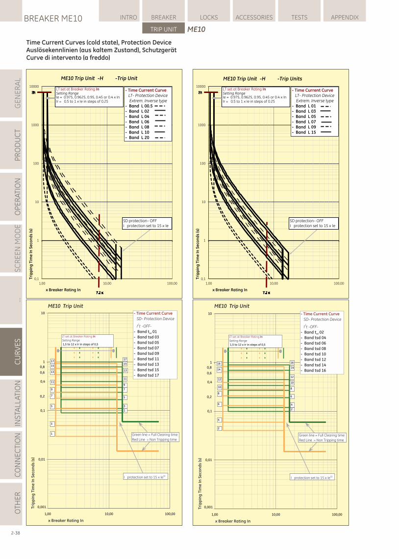
2-38
0,1
1
10
100
1000
10000
1,00 10,00 100,00
Trip
pin
g T
ime
In S
eco
nd
s (s
)
x Breaker Rating In
ME10 Trip Unit -H -Trip Unit
7.2 x
2hLT set at Breaker Rating InSetting Range Ie = 0.975, 0.9625, 0.95, 0.45 or 0.4 x InIr = 0.5 to 1 x Ie in steps of 0.25
7.2 x
2hLT set at Breaker Rating InSetting Range Ie = 0.975, 0.9625, 0.95, 0.45 or 0.4 x InIr = 0.5 to 1 x Ie in steps of 0.25
7.2 x
2hLT set at Breaker Rating InSetting Range Ie = 0.975, 0.9625, 0.95, 0.45 or 0.4 x InIr = 0.5 to 1 x Ie in steps of 0.25
7.2 x
2hLT set at Breaker Rating InSetting Range Ie = 0.975, 0.9625, 0.95, 0.45 or 0.4 x InIr = 0.5 to 1 x Ie in steps of 0.25
7.2 x
2hLT set at Breaker Rating InSetting Range Ie = 0.975, 0.9625, 0.95, 0.45 or 0.4 x InIr = 0.5 to 1 x Ie in steps of 0.25
7.2 x
2hLT set at Breaker Rating InSetting Range Ie = 0.975, 0.9625, 0.95, 0.45 or 0.4 x InIr = 0.5 to 1 x Ie in steps of 0.25
7.2 x
2hLT set at Breaker Rating InSetting Range Ie = 0.975, 0.9625, 0.95, 0.45 or 0.4 x InIr = 0.5 to 1 x Ie in steps of 0.25
7.2 x
2hLT set at Breaker Rating InSetting Range Ie = 0.975, 0.9625, 0.95, 0.45 or 0.4 x InIr = 0.5 to 1 x Ie in steps of 0.25
7.2 x
2hLT set at Breaker Rating InSetting Range Ie = 0.975, 0.9625, 0.95, 0.45 or 0.4 x InIr = 0.5 to 1 x Ie in steps of 0.25
7.2 x
2hLT set at Breaker Rating InSetting Range Ie = 0.975, 0.9625, 0.95, 0.45 or 0.4 x InIr = 0.5 to 1 x Ie in steps of 0.25
7.2 x
2hLT set at Breaker Rating InSetting Range Ie = 0.975, 0.9625, 0.95, 0.45 or 0.4 x InIr = 0.5 to 1 x Ie in steps of 0.25
7.2 x
2hLT set at Breaker Rating InSetting Range Ie = 0.975, 0.9625, 0.95, 0.45 or 0.4 x InIr = 0.5 to 1 x Ie in steps of 0.25
7.2 x
2hLT set at Breaker Rating InSetting Range Ie = 0.975, 0.9625, 0.95, 0.45 or 0.4 x InIr = 0.5 to 1 x Ie in steps of 0.25
7.2 x
2hLT set at Breaker Rating InSetting Range Ie = 0.975, 0.9625, 0.95, 0.45 or 0.4 x InIr = 0.5 to 1 x Ie in steps of 0.25
7.2 x
2hLT set at Breaker Rating InSetting Range Ie = 0.975, 0.9625, 0.95, 0.45 or 0.4 x InIr = 0.5 to 1 x Ie in steps of 0.25
7.2 x
2hLT set at Breaker Rating InSetting Range Ie = 0.975, 0.9625, 0.95, 0.45 or 0.4 x InIr = 0.5 to 1 x Ie in steps of 0.25
7.2 x
2hLT set at Breaker Rating InSetting Range Ie = 0.975, 0.9625, 0.95, 0.45 or 0.4 x InIr = 0.5 to 1 x Ie in steps of 0.25
7.2 x
2hLT set at Breaker Rating InSetting Range Ie = 0.975, 0.9625, 0.95, 0.45 or 0.4 x InIr = 0.5 to 1 x Ie in steps of 0.25
7.2 x
2hLT set at Breaker Rating InSetting Range Ie = 0.975, 0.9625, 0.95, 0.45 or 0.4 x InIr = 0.5 to 1 x Ie in steps of 0.25
7.2 x
2hLT set at Breaker Rating InSetting Range Ie = 0.975, 0.9625, 0.95, 0.45 or 0.4 x InIr = 0.5 to 1 x Ie in steps of 0.25
7.2 x
2hLT set at Breaker Rating InSetting Range Ie = 0.975, 0.9625, 0.95, 0.45 or 0.4 x InIr = 0.5 to 1 x Ie in steps of 0.25
7.2 x
2hLT set at Breaker Rating InSetting Range Ie = 0.975, 0.9625, 0.95, 0.45 or 0.4 x InIr = 0.5 to 1 x Ie in steps of 0.25
7.2 x
2hLT set at Breaker Rating InSetting Range Ie = 0.975, 0.9625, 0.95, 0.45 or 0.4 x InIr = 0.5 to 1 x Ie in steps of 0.25
7.2 x
2hLT set at Breaker Rating InSetting Range Ie = 0.975, 0.9625, 0.95, 0.45 or 0.4 x InIr = 0.5 to 1 x Ie in steps of 0.25
7.2 x
2hLT set at Breaker Rating InSetting Range Ie = 0.975, 0.9625, 0.95, 0.45 or 0.4 x InIr = 0.5 to 1 x Ie in steps of 0.25
7.2 x
2hLT set at Breaker Rating InSetting Range Ie = 0.975, 0.9625, 0.95, 0.45 or 0.4 x InIr = 0.5 to 1 x Ie in steps of 0.25
7.2 x
2hLT set at Breaker Rating InSetting Range Ie = 0.975, 0.9625, 0.95, 0.45 or 0.4 x InIr = 0.5 to 1 x Ie in steps of 0.25
7.2 x
2hLT set at Breaker Rating InSetting Range Ie = 0.975, 0.9625, 0.95, 0.45 or 0.4 x InIr = 0.5 to 1 x Ie in steps of 0.25
7.2 x
2hLT set at Breaker Rating InSetting Range Ie = 0.975, 0.9625, 0.95, 0.45 or 0.4 x InIr = 0.5 to 1 x Ie in steps of 0.25
7.2 x
2hLT set at Breaker Rating InSetting Range Ie = 0.975, 0.9625, 0.95, 0.45 or 0.4 x InIr = 0.5 to 1 x Ie in steps of 0.25
7.2 x
2hLT set at Breaker Rating InSetting Range Ie = 0.975, 0.9625, 0.95, 0.45 or 0.4 x InIr = 0.5 to 1 x Ie in steps of 0.25
7.2 x
2hLT set at Breaker Rating InSetting Range Ie = 0.975, 0.9625, 0.95, 0.45 or 0.4 x InIr = 0.5 to 1 x Ie in steps of 0.25
7.2 x
2hLT set at Breaker Rating InSetting Range Ie = 0.975, 0.9625, 0.95, 0.45 or 0.4 x InIr = 0.5 to 1 x Ie in steps of 0.25
7.2 x
2hLT set at Breaker Rating InSetting Range Ie = 0.975, 0.9625, 0.95, 0.45 or 0.4 x InIr = 0.5 to 1 x Ie in steps of 0.25
7.2 x
2hLT set at Breaker Rating InSetting Range Ie = 0.975, 0.9625, 0.95, 0.45 or 0.4 x InIr = 0.5 to 1 x Ie in steps of 0.25
7.2 x
2hLT set at Breaker Rating InSetting Range Ie = 0.975, 0.9625, 0.95, 0.45 or 0.4 x InIr = 0.5 to 1 x Ie in steps of 0.25
7.2 x
2hLT set at Breaker Rating InSetting Range Ie = 0.975, 0.9625, 0.95, 0.45 or 0.4 x InIr = 0.5 to 1 x Ie in steps of 0.25
7.2 x
2hLT set at Breaker Rating InSetting Range Ie = 0.975, 0.9625, 0.95, 0.45 or 0.4 x InIr = 0.5 to 1 x Ie in steps of 0.25
7.2 x
2hLT set at Breaker Rating InSetting Range Ie = 0.975, 0.9625, 0.95, 0.45 or 0.4 x InIr = 0.5 to 1 x Ie in steps of 0.25
7.2 x
2hLT set at Breaker Rating InSetting Range Ie = 0.975, 0.9625, 0.95, 0.45 or 0.4 x InIr = 0.5 to 1 x Ie in steps of 0.25
7.2 x
2hLT set at Breaker Rating InSetting Range Ie = 0.975, 0.9625, 0.95, 0.45 or 0.4 x InIr = 0.5 to 1 x Ie in steps of 0.25
7.2 x
2hLT set at Breaker Rating InSetting Range Ie = 0.975, 0.9625, 0.95, 0.45 or 0.4 x InIr = 0.5 to 1 x Ie in steps of 0.25
7.2 x
2hLT set at Breaker Rating InSetting Range Ie = 0.975, 0.9625, 0.95, 0.45 or 0.4 x InIr = 0.5 to 1 x Ie in steps of 0.25
7.2 x
2hLT set at Breaker Rating InSetting Range Ie = 0.975, 0.9625, 0.95, 0.45 or 0.4 x InIr = 0.5 to 1 x Ie in steps of 0.25
7.2 x
2hLT set at Breaker Rating InSetting Range Ie = 0.975, 0.9625, 0.95, 0.45 or 0.4 x InIr = 0.5 to 1 x Ie in steps of 0.25
7.2 x
2hLT set at Breaker Rating InSetting Range Ie = 0.975, 0.9625, 0.95, 0.45 or 0.4 x InIr = 0.5 to 1 x Ie in steps of 0.25
7.2 x
2hLT set at Breaker Rating InSetting Range Ie = 0.975, 0.9625, 0.95, 0.45 or 0.4 x InIr = 0.5 to 1 x Ie in steps of 0.25
7.2 x
2hLT set at Breaker Rating InSetting Range Ie = 0.975, 0.9625, 0.95, 0.45 or 0.4 x InIr = 0.5 to 1 x Ie in steps of 0.25
7.2 x
2hLT set at Breaker Rating InSetting Range Ie = 0.975, 0.9625, 0.95, 0.45 or 0.4 x InIr = 0.5 to 1 x Ie in steps of 0.25
7.2 x
2hLT set at Breaker Rating InSetting Range Ie = 0.975, 0.9625, 0.95, 0.45 or 0.4 x InIr = 0.5 to 1 x Ie in steps of 0.25
7.2 x
2hLT set at Breaker Rating InSetting Range Ie = 0.975, 0.9625, 0.95, 0.45 or 0.4 x InIr = 0.5 to 1 x Ie in steps of 0.25
7.2 x
2hLT set at Breaker Rating InSetting Range Ie = 0.975, 0.9625, 0.95, 0.45 or 0.4 x InIr = 0.5 to 1 x Ie in steps of 0.25
7.2 x
2hLT set at Breaker Rating InSetting Range Ie = 0.975, 0.9625, 0.95, 0.45 or 0.4 x InIr = 0.5 to 1 x Ie in steps of 0.25
7.2 x
2hLT set at Breaker Rating InSetting Range Ie = 0.975, 0.9625, 0.95, 0.45 or 0.4 x InIr = 0.5 to 1 x Ie in steps of 0.25
7.2 x
2hLT set at Breaker Rating InSetting Range Ie = 0.975, 0.9625, 0.95, 0.45 or 0.4 x InIr = 0.5 to 1 x Ie in steps of 0.25
7.2 x
2hLT set at Breaker Rating InSetting Range Ie = 0.975, 0.9625, 0.95, 0.45 or 0.4 x InIr = 0.5 to 1 x Ie in steps of 0.25
7.2 x
2hLT set at Breaker Rating InSetting Range Ie = 0.975, 0.9625, 0.95, 0.45 or 0.4 x InIr = 0.5 to 1 x Ie in steps of 0.25
7.2 x
2hLT set at Breaker Rating InSetting Range Ie = 0.975, 0.9625, 0.95, 0.45 or 0.4 x InIr = 0.5 to 1 x Ie in steps of 0.25
7.2 x
2hLT set at Breaker Rating InSetting Range Ie = 0.975, 0.9625, 0.95, 0.45 or 0.4 x InIr = 0.5 to 1 x Ie in steps of 0.25
7.2 x
2hLT set at Breaker Rating InSetting Range Ie = 0.975, 0.9625, 0.95, 0.45 or 0.4 x InIr = 0.5 to 1 x Ie in steps of 0.25
7.2 x
2hLT set at Breaker Rating InSetting Range Ie = 0.975, 0.9625, 0.95, 0.45 or 0.4 x InIr = 0.5 to 1 x Ie in steps of 0.25
7.2 x
2hLT set at Breaker Rating InSetting Range Ie = 0.975, 0.9625, 0.95, 0.45 or 0.4 x InIr = 0.5 to 1 x Ie in steps of 0.25
7.2 x
2hLT set at Breaker Rating InSetting Range Ie = 0.975, 0.9625, 0.95, 0.45 or 0.4 x InIr = 0.5 to 1 x Ie in steps of 0.25
- Time Current CurveLT- Protection DeviceExtrem. Inverse type
- Band L 00.5 - Band L 02- Band L 04- Band L 06- Band L 08 -
Band L 10
-
Band L 20
7.2 x
2h
SD protection -
OFF
I protection set to 15 x Ie
LT set at Breaker Rating InSetting Range Ie = 0.975, 0.9625, 0.95, 0.45 or 0.4 x InIr = 0.5 to 1 x Ie in steps of 0.25
7.2 x
2hLT set at Breaker Rating InSetting Range Ie = 0.975, 0.9625, 0.95, 0.45 or 0.4 x InIr = 0.5 to 1 x Ie in steps of 0.25
7.2 x
2hLT set at Breaker Rating InSetting Range Ie = 0.975, 0.9625, 0.95, 0.45 or 0.4 x InIr = 0.5 to 1 x Ie in steps of 0.25
7.2 x
2hLT set at Breaker Rating InSetting Range Ie = 0.975, 0.9625, 0.95, 0.45 or 0.4 x InIr = 0.5 to 1 x Ie in steps of 0.25
7.2 x
2hLT set at Breaker Rating InSetting Range Ie = 0.975, 0.9625, 0.95, 0.45 or 0.4 x InIr = 0.5 to 1 x Ie in steps of 0.25
7.2 x
2hLT set at Breaker Rating InSetting Range Ie = 0.975, 0.9625, 0.95, 0.45 or 0.4 x InIr = 0.5 to 1 x Ie in steps of 0.25
7.2 x
2hLT set at Breaker Rating InSetting Range Ie = 0.975, 0.9625, 0.95, 0.45 or 0.4 x InIr = 0.5 to 1 x Ie in steps of 0.25
7.2 x
2hLT set at Breaker Rating InSetting Range Ie = 0.975, 0.9625, 0.95, 0.45 or 0.4 x InIr = 0.5 to 1 x Ie in steps of 0.25
7.2 x
2hLT set at Breaker Rating InSetting Range Ie = 0.975, 0.9625, 0.95, 0.45 or 0.4 x InIr = 0.5 to 1 x Ie in steps of 0.25
7.2 x
2hLT set at Breaker Rating InSetting Range Ie = 0.975, 0.9625, 0.95, 0.45 or 0.4 x InIr = 0.5 to 1 x Ie in steps of 0.25
7.2 x
2hLT set at Breaker Rating InSetting Range Ie = 0.975, 0.9625, 0.95, 0.45 or 0.4 x InIr = 0.5 to 1 x Ie in steps of 0.25
7.2 x
2hLT set at Breaker Rating InSetting Range Ie = 0.975, 0.9625, 0.95, 0.45 or 0.4 x InIr = 0.5 to 1 x Ie in steps of 0.25
7.2 x
2hLT set at Breaker Rating InSetting Range Ie = 0.975, 0.9625, 0.95, 0.45 or 0.4 x InIr = 0.5 to 1 x Ie in steps of 0.25
7.2 x
2hLT set at Breaker Rating InSetting Range Ie = 0.975, 0.9625, 0.95, 0.45 or 0.4 x InIr = 0.5 to 1 x Ie in steps of 0.25
7.2 x
2hLT set at Breaker Rating InSetting Range Ie = 0.975, 0.9625, 0.95, 0.45 or 0.4 x InIr = 0.5 to 1 x Ie in steps of 0.25
7.2 x
2hLT set at Breaker Rating InSetting Range Ie = 0.975, 0.9625, 0.95, 0.45 or 0.4 x InIr = 0.5 to 1 x Ie in steps of 0.25
7.2 x
2hLT set at Breaker Rating InSetting Range Ie = 0.975, 0.9625, 0.95, 0.45 or 0.4 x InIr = 0.5 to 1 x Ie in steps of 0.25
7.2 x
2hLT set at Breaker Rating InSetting Range Ie = 0.975, 0.9625, 0.95, 0.45 or 0.4 x InIr = 0.5 to 1 x Ie in steps of 0.25
7.2 x
2hLT set at Breaker Rating InSetting Range Ie = 0.975, 0.9625, 0.95, 0.45 or 0.4 x InIr = 0.5 to 1 x Ie in steps of 0.25
7.2 x
2hLT set at Breaker Rating InSetting Range Ie = 0.975, 0.9625, 0.95, 0.45 or 0.4 x InIr = 0.5 to 1 x Ie in steps of 0.25
7.2 x
2hLT set at Breaker Rating InSetting Range Ie = 0.975, 0.9625, 0.95, 0.45 or 0.4 x InIr = 0.5 to 1 x Ie in steps of 0.25
7.2 x
2hLT set at Breaker Rating InSetting Range Ie = 0.975, 0.9625, 0.95, 0.45 or 0.4 x InIr = 0.5 to 1 x Ie in steps of 0.25
7.2 x
2hLT set at Breaker Rating InSetting Range Ie = 0.975, 0.9625, 0.95, 0.45 or 0.4 x InIr = 0.5 to 1 x Ie in steps of 0.25
7.2 x
2hLT set at Breaker Rating InSetting Range Ie = 0.975, 0.9625, 0.95, 0.45 or 0.4 x InIr = 0.5 to 1 x Ie in steps of 0.25
7.2 x
2hLT set at Breaker Rating InSetting Range Ie = 0.975, 0.9625, 0.95, 0.45 or 0.4 x InIr = 0.5 to 1 x Ie in steps of 0.25
7.2 x
2hLT set at Breaker Rating InSetting Range Ie = 0.975, 0.9625, 0.95, 0.45 or 0.4 x InIr = 0.5 to 1 x Ie in steps of 0.25
7.2 x
2hLT set at Breaker Rating InSetting Range Ie = 0.975, 0.9625, 0.95, 0.45 or 0.4 x InIr = 0.5 to 1 x Ie in steps of 0.25
7.2 x
2hLT set at Breaker Rating InSetting Range Ie = 0.975, 0.9625, 0.95, 0.45 or 0.4 x InIr = 0.5 to 1 x Ie in steps of 0.25
7.2 x
2hLT set at Breaker Rating InSetting Range Ie = 0.975, 0.9625, 0.95, 0.45 or 0.4 x InIr = 0.5 to 1 x Ie in steps of 0.25
7.2 x
2hLT set at Breaker Rating InSetting Range Ie = 0.975, 0.9625, 0.95, 0.45 or 0.4 x InIr = 0.5 to 1 x Ie in steps of 0.25
7.2 x
2hLT set at Breaker Rating InSetting Range Ie = 0.975, 0.9625, 0.95, 0.45 or 0.4 x InIr = 0.5 to 1 x Ie in steps of 0.25
7.2 x
2hLT set at Breaker Rating InSetting Range Ie = 0.975, 0.9625, 0.95, 0.45 or 0.4 x InIr = 0.5 to 1 x Ie in steps of 0.25
7.2 x
2hLT set at Breaker Rating InSetting Range Ie = 0.975, 0.9625, 0.95, 0.45 or 0.4 x InIr = 0.5 to 1 x Ie in steps of 0.25
7.2 x
2hLT set at Breaker Rating InSetting Range Ie = 0.975, 0.9625, 0.95, 0.45 or 0.4 x InIr = 0.5 to 1 x Ie in steps of 0.25
7.2 x
2hLT set at Breaker Rating InSetting Range Ie = 0.975, 0.9625, 0.95, 0.45 or 0.4 x InIr = 0.5 to 1 x Ie in steps of 0.25
7.2 x
2hLT set at Breaker Rating InSetting Range Ie = 0.975, 0.9625, 0.95, 0.45 or 0.4 x InIr = 0.5 to 1 x Ie in steps of 0.25
7.2 x
2hLT set at Breaker Rating InSetting Range Ie = 0.975, 0.9625, 0.95, 0.45 or 0.4 x InIr = 0.5 to 1 x Ie in steps of 0.25
7.2 x
2hLT set at Breaker Rating InSetting Range Ie = 0.975, 0.9625, 0.95, 0.45 or 0.4 x InIr = 0.5 to 1 x Ie in steps of 0.25
7.2 x
2hLT set at Breaker Rating InSetting Range Ie = 0.975, 0.9625, 0.95, 0.45 or 0.4 x InIr = 0.5 to 1 x Ie in steps of 0.25
7.2 x
2hLT set at Breaker Rating InSetting Range Ie = 0.975, 0.9625, 0.95, 0.45 or 0.4 x InIr = 0.5 to 1 x Ie in steps of 0.25
7.2 x
2hLT set at Breaker Rating InSetting Range Ie = 0.975, 0.9625, 0.95, 0.45 or 0.4 x InIr = 0.5 to 1 x Ie in steps of 0.25
7.2 x
2hLT set at Breaker Rating InSetting Range Ie = 0.975, 0.9625, 0.95, 0.45 or 0.4 x InIr = 0.5 to 1 x Ie in steps of 0.25
7.2 x
2hLT set at Breaker Rating InSetting Range Ie = 0.975, 0.9625, 0.95, 0.45 or 0.4 x InIr = 0.5 to 1 x Ie in steps of 0.25
7.2 x
2hLT set at Breaker Rating InSetting Range Ie = 0.975, 0.9625, 0.95, 0.45 or 0.4 x InIr = 0.5 to 1 x Ie in steps of 0.25
7.2 x
2hLT set at Breaker Rating InSetting Range Ie = 0.975, 0.9625, 0.95, 0.45 or 0.4 x InIr = 0.5 to 1 x Ie in steps of 0.25
7.2 x
2hLT set at Breaker Rating InSetting Range Ie = 0.975, 0.9625, 0.95, 0.45 or 0.4 x InIr = 0.5 to 1 x Ie in steps of 0.25
7.2 x
2hLT set at Breaker Rating InSetting Range Ie = 0.975, 0.9625, 0.95, 0.45 or 0.4 x InIr = 0.5 to 1 x Ie in steps of 0.25
7.2 x
2hLT set at Breaker Rating InSetting Range Ie = 0.975, 0.9625, 0.95, 0.45 or 0.4 x InIr = 0.5 to 1 x Ie in steps of 0.25
7.2 x
2hLT set at Breaker Rating InSetting Range Ie = 0.975, 0.9625, 0.95, 0.45 or 0.4 x InIr = 0.5 to 1 x Ie in steps of 0.25
7.2 x
2hLT set at Breaker Rating InSetting Range Ie = 0.975, 0.9625, 0.95, 0.45 or 0.4 x InIr = 0.5 to 1 x Ie in steps of 0.25
7.2 x
2hLT set at Breaker Rating InSetting Range Ie = 0.975, 0.9625, 0.95, 0.45 or 0.4 x InIr = 0.5 to 1 x Ie in steps of 0.25
7.2 x
2hLT set at Breaker Rating InSetting Range Ie = 0.975, 0.9625, 0.95, 0.45 or 0.4 x InIr = 0.5 to 1 x Ie in steps of 0.25
7.2 x
2hLT set at Breaker Rating InSetting Range Ie = 0.975, 0.9625, 0.95, 0.45 or 0.4 x InIr = 0.5 to 1 x Ie in steps of 0.25
7.2 x
2hLT set at Breaker Rating InSetting Range Ie = 0.975, 0.9625, 0.95, 0.45 or 0.4 x InIr = 0.5 to 1 x Ie in steps of 0.25
7.2 x
2hLT set at Breaker Rating InSetting Range Ie = 0.975, 0.9625, 0.95, 0.45 or 0.4 x InIr = 0.5 to 1 x Ie in steps of 0.25
7.2 x
2hLT set at Breaker Rating InSetting Range Ie = 0.975, 0.9625, 0.95, 0.45 or 0.4 x InIr = 0.5 to 1 x Ie in steps of 0.25
7.2 x
2hLT set at Breaker Rating InSetting Range Ie = 0.975, 0.9625, 0.95, 0.45 or 0.4 x InIr = 0.5 to 1 x Ie in steps of 0.25
7.2 x
2hLT set at Breaker Rating InSetting Range Ie = 0.975, 0.9625, 0.95, 0.45 or 0.4 x InIr = 0.5 to 1 x Ie in steps of 0.25
7.2 x
2hLT set at Breaker Rating InSetting Range Ie = 0.975, 0.9625, 0.95, 0.45 or 0.4 x InIr = 0.5 to 1 x Ie in steps of 0.25
7.2 x
2hLT set at Breaker Rating InSetting Range Ie = 0.975, 0.9625, 0.95, 0.45 or 0.4 x InIr = 0.5 to 1 x Ie in steps of 0.25
7.2 x
2hLT set at Breaker Rating InSetting Range Ie = 0.975, 0.9625, 0.95, 0.45 or 0.4 x InIr = 0.5 to 1 x Ie in steps of 0.25
7.2 x
2hLT set at Breaker Rating InSetting Range Ie = 0.975, 0.9625, 0.95, 0.45 or 0.4 x InIr = 0.5 to 1 x Ie in steps of 0.25
7.2 x
2hLT set at Breaker Rating InSetting Range Ie = 0.975, 0.9625, 0.95, 0.45 or 0.4 x InIr = 0.5 to 1 x Ie in steps of 0.25
7.2 x
2hLT set at Breaker Rating InSetting Range Ie = 0.975, 0.9625, 0.95, 0.45 or 0.4 x InIr = 0.5 to 1 x Ie in steps of 0.25
7.2 x
2h
SD protection -
OFF
I protection set to 15 x Ie
LT set at Breaker Rating InSetting Range Ie = 0.975, 0.9625, 0.95, 0.45 or 0.4 x InIr = 0.5 to 1 x Ie in steps of 0.25
0,1
1
10
100
1000
10000
1,00 10,00 100,00
Trip
pin
g T
ime
In S
eco
nd
s (s
)
x Breaker Rating In
ME10 Trip Unit -H -Trip Units
7.2 x
2hLT set at Breaker Rating InSetting Range Ie = 0.975, 0.9625, 0.95, 0.45 or 0.4 x InIr = 0.5 to 1 x Ie in steps of 0.25
7.2 x
2hLT set at Breaker Rating InSetting Range Ie = 0.975, 0.9625, 0.95, 0.45 or 0.4 x InIr = 0.5 to 1 x Ie in steps of 0.25
7.2 x
2hLT set at Breaker Rating InSetting Range Ie = 0.975, 0.9625, 0.95, 0.45 or 0.4 x InIr = 0.5 to 1 x Ie in steps of 0.25
7.2 x
2hLT set at Breaker Rating InSetting Range Ie = 0.975, 0.9625, 0.95, 0.45 or 0.4 x InIr = 0.5 to 1 x Ie in steps of 0.25
7.2 x
2hLT set at Breaker Rating InSetting Range Ie = 0.975, 0.9625, 0.95, 0.45 or 0.4 x InIr = 0.5 to 1 x Ie in steps of 0.25
7.2 x
2hLT set at Breaker Rating InSetting Range Ie = 0.975, 0.9625, 0.95, 0.45 or 0.4 x InIr = 0.5 to 1 x Ie in steps of 0.25
7.2 x
2hLT set at Breaker Rating InSetting Range Ie = 0.975, 0.9625, 0.95, 0.45 or 0.4 x InIr = 0.5 to 1 x Ie in steps of 0.25
7.2 x
2hLT set at Breaker Rating InSetting Range Ie = 0.975, 0.9625, 0.95, 0.45 or 0.4 x InIr = 0.5 to 1 x Ie in steps of 0.25
7.2 x
2hLT set at Breaker Rating InSetting Range Ie = 0.975, 0.9625, 0.95, 0.45 or 0.4 x InIr = 0.5 to 1 x Ie in steps of 0.25
7.2 x
2hLT set at Breaker Rating InSetting Range Ie = 0.975, 0.9625, 0.95, 0.45 or 0.4 x InIr = 0.5 to 1 x Ie in steps of 0.25
7.2 x
2hLT set at Breaker Rating InSetting Range Ie = 0.975, 0.9625, 0.95, 0.45 or 0.4 x InIr = 0.5 to 1 x Ie in steps of 0.25
7.2 x
2hLT set at Breaker Rating InSetting Range Ie = 0.975, 0.9625, 0.95, 0.45 or 0.4 x InIr = 0.5 to 1 x Ie in steps of 0.25
7.2 x
2hLT set at Breaker Rating InSetting Range Ie = 0.975, 0.9625, 0.95, 0.45 or 0.4 x InIr = 0.5 to 1 x Ie in steps of 0.25
7.2 x
2hLT set at Breaker Rating InSetting Range Ie = 0.975, 0.9625, 0.95, 0.45 or 0.4 x InIr = 0.5 to 1 x Ie in steps of 0.25
7.2 x
2hLT set at Breaker Rating InSetting Range Ie = 0.975, 0.9625, 0.95, 0.45 or 0.4 x InIr = 0.5 to 1 x Ie in steps of 0.25
7.2 x
2hLT set at Breaker Rating InSetting Range Ie = 0.975, 0.9625, 0.95, 0.45 or 0.4 x InIr = 0.5 to 1 x Ie in steps of 0.25
7.2 x
2hLT set at Breaker Rating InSetting Range Ie = 0.975, 0.9625, 0.95, 0.45 or 0.4 x InIr = 0.5 to 1 x Ie in steps of 0.25
7.2 x
2hLT set at Breaker Rating InSetting Range Ie = 0.975, 0.9625, 0.95, 0.45 or 0.4 x InIr = 0.5 to 1 x Ie in steps of 0.25
7.2 x
2hLT set at Breaker Rating InSetting Range Ie = 0.975, 0.9625, 0.95, 0.45 or 0.4 x InIr = 0.5 to 1 x Ie in steps of 0.25
7.2 x
2hLT set at Breaker Rating InSetting Range Ie = 0.975, 0.9625, 0.95, 0.45 or 0.4 x InIr = 0.5 to 1 x Ie in steps of 0.25
7.2 x
2hLT set at Breaker Rating InSetting Range Ie = 0.975, 0.9625, 0.95, 0.45 or 0.4 x InIr = 0.5 to 1 x Ie in steps of 0.25
7.2 x
2hLT set at Breaker Rating InSetting Range Ie = 0.975, 0.9625, 0.95, 0.45 or 0.4 x InIr = 0.5 to 1 x Ie in steps of 0.25
7.2 x
2hLT set at Breaker Rating InSetting Range Ie = 0.975, 0.9625, 0.95, 0.45 or 0.4 x InIr = 0.5 to 1 x Ie in steps of 0.25
7.2 x
2hLT set at Breaker Rating InSetting Range Ie = 0.975, 0.9625, 0.95, 0.45 or 0.4 x InIr = 0.5 to 1 x Ie in steps of 0.25
7.2 x
2hLT set at Breaker Rating InSetting Range Ie = 0.975, 0.9625, 0.95, 0.45 or 0.4 x InIr = 0.5 to 1 x Ie in steps of 0.25
7.2 x
2hLT set at Breaker Rating InSetting Range Ie = 0.975, 0.9625, 0.95, 0.45 or 0.4 x InIr = 0.5 to 1 x Ie in steps of 0.25
7.2 x
2hLT set at Breaker Rating InSetting Range Ie = 0.975, 0.9625, 0.95, 0.45 or 0.4 x InIr = 0.5 to 1 x Ie in steps of 0.25
7.2 x
2hLT set at Breaker Rating InSetting Range Ie = 0.975, 0.9625, 0.95, 0.45 or 0.4 x InIr = 0.5 to 1 x Ie in steps of 0.25
7.2 x
2hLT set at Breaker Rating InSetting Range Ie = 0.975, 0.9625, 0.95, 0.45 or 0.4 x InIr = 0.5 to 1 x Ie in steps of 0.25
7.2 x
2hLT set at Breaker Rating InSetting Range Ie = 0.975, 0.9625, 0.95, 0.45 or 0.4 x InIr = 0.5 to 1 x Ie in steps of 0.25
7.2 x
2hLT set at Breaker Rating InSetting Range Ie = 0.975, 0.9625, 0.95, 0.45 or 0.4 x InIr = 0.5 to 1 x Ie in steps of 0.25
7.2 x
2hLT set at Breaker Rating InSetting Range Ie = 0.975, 0.9625, 0.95, 0.45 or 0.4 x InIr = 0.5 to 1 x Ie in steps of 0.25
7.2 x
2hLT set at Breaker Rating InSetting Range Ie = 0.975, 0.9625, 0.95, 0.45 or 0.4 x InIr = 0.5 to 1 x Ie in steps of 0.25
7.2 x
2hLT set at Breaker Rating InSetting Range Ie = 0.975, 0.9625, 0.95, 0.45 or 0.4 x InIr = 0.5 to 1 x Ie in steps of 0.25
7.2 x
2hLT set at Breaker Rating InSetting Range Ie = 0.975, 0.9625, 0.95, 0.45 or 0.4 x InIr = 0.5 to 1 x Ie in steps of 0.25
7.2 x
2hLT set at Breaker Rating InSetting Range Ie = 0.975, 0.9625, 0.95, 0.45 or 0.4 x InIr = 0.5 to 1 x Ie in steps of 0.25
7.2 x
2hLT set at Breaker Rating InSetting Range Ie = 0.975, 0.9625, 0.95, 0.45 or 0.4 x InIr = 0.5 to 1 x Ie in steps of 0.25
7.2 x
2hLT set at Breaker Rating InSetting Range Ie = 0.975, 0.9625, 0.95, 0.45 or 0.4 x InIr = 0.5 to 1 x Ie in steps of 0.25
7.2 x
2hLT set at Breaker Rating InSetting Range Ie = 0.975, 0.9625, 0.95, 0.45 or 0.4 x InIr = 0.5 to 1 x Ie in steps of 0.25
7.2 x
2hLT set at Breaker Rating InSetting Range Ie = 0.975, 0.9625, 0.95, 0.45 or 0.4 x InIr = 0.5 to 1 x Ie in steps of 0.25
7.2 x
2hLT set at Breaker Rating InSetting Range Ie = 0.975, 0.9625, 0.95, 0.45 or 0.4 x InIr = 0.5 to 1 x Ie in steps of 0.25
7.2 x
2hLT set at Breaker Rating InSetting Range Ie = 0.975, 0.9625, 0.95, 0.45 or 0.4 x InIr = 0.5 to 1 x Ie in steps of 0.25
7.2 x
2hLT set at Breaker Rating InSetting Range Ie = 0.975, 0.9625, 0.95, 0.45 or 0.4 x InIr = 0.5 to 1 x Ie in steps of 0.25
7.2 x
2hLT set at Breaker Rating InSetting Range Ie = 0.975, 0.9625, 0.95, 0.45 or 0.4 x InIr = 0.5 to 1 x Ie in steps of 0.25
7.2 x
2hLT set at Breaker Rating InSetting Range Ie = 0.975, 0.9625, 0.95, 0.45 or 0.4 x InIr = 0.5 to 1 x Ie in steps of 0.25
7.2 x
2hLT set at Breaker Rating InSetting Range Ie = 0.975, 0.9625, 0.95, 0.45 or 0.4 x InIr = 0.5 to 1 x Ie in steps of 0.25
7.2 x
2hLT set at Breaker Rating InSetting Range Ie = 0.975, 0.9625, 0.95, 0.45 or 0.4 x InIr = 0.5 to 1 x Ie in steps of 0.25
7.2 x
2hLT set at Breaker Rating InSetting Range Ie = 0.975, 0.9625, 0.95, 0.45 or 0.4 x InIr = 0.5 to 1 x Ie in steps of 0.25
7.2 x
2hLT set at Breaker Rating InSetting Range Ie = 0.975, 0.9625, 0.95, 0.45 or 0.4 x InIr = 0.5 to 1 x Ie in steps of 0.25
7.2 x
2hLT set at Breaker Rating InSetting Range Ie = 0.975, 0.9625, 0.95, 0.45 or 0.4 x InIr = 0.5 to 1 x Ie in steps of 0.25
7.2 x
2hLT set at Breaker Rating InSetting Range Ie = 0.975, 0.9625, 0.95, 0.45 or 0.4 x InIr = 0.5 to 1 x Ie in steps of 0.25
7.2 x
2hLT set at Breaker Rating InSetting Range Ie = 0.975, 0.9625, 0.95, 0.45 or 0.4 x InIr = 0.5 to 1 x Ie in steps of 0.25
7.2 x
2hLT set at Breaker Rating InSetting Range Ie = 0.975, 0.9625, 0.95, 0.45 or 0.4 x InIr = 0.5 to 1 x Ie in steps of 0.25
7.2 x
2hLT set at Breaker Rating InSetting Range Ie = 0.975, 0.9625, 0.95, 0.45 or 0.4 x InIr = 0.5 to 1 x Ie in steps of 0.25
7.2 x
2hLT set at Breaker Rating InSetting Range Ie = 0.975, 0.9625, 0.95, 0.45 or 0.4 x InIr = 0.5 to 1 x Ie in steps of 0.25
7.2 x
2hLT set at Breaker Rating InSetting Range Ie = 0.975, 0.9625, 0.95, 0.45 or 0.4 x InIr = 0.5 to 1 x Ie in steps of 0.25
7.2 x
2hLT set at Breaker Rating InSetting Range Ie = 0.975, 0.9625, 0.95, 0.45 or 0.4 x InIr = 0.5 to 1 x Ie in steps of 0.25
7.2 x
2hLT set at Breaker Rating InSetting Range Ie = 0.975, 0.9625, 0.95, 0.45 or 0.4 x InIr = 0.5 to 1 x Ie in steps of 0.25
7.2 x
2hLT set at Breaker Rating InSetting Range Ie = 0.975, 0.9625, 0.95, 0.45 or 0.4 x InIr = 0.5 to 1 x Ie in steps of 0.25
7.2 x
2hLT set at Breaker Rating InSetting Range Ie = 0.975, 0.9625, 0.95, 0.45 or 0.4 x InIr = 0.5 to 1 x Ie in steps of 0.25
7.2 x
2hLT set at Breaker Rating InSetting Range Ie = 0.975, 0.9625, 0.95, 0.45 or 0.4 x InIr = 0.5 to 1 x Ie in steps of 0.25
7.2 x
2hLT set at Breaker Rating InSetting Range Ie = 0.975, 0.9625, 0.95, 0.45 or 0.4 x InIr = 0.5 to 1 x Ie in steps of 0.25
7.2 x
2hLT set at Breaker Rating InSetting Range Ie = 0.975, 0.9625, 0.95, 0.45 or 0.4 x InIr = 0.5 to 1 x Ie in steps of 0.25
- Time Current CurveLT- Protection DeviceExtrem. Inverse type
- Band L 01 - Band L 03- Band L 05- Band L 07- Band L 09 - Band L 15
7.2 x
2h
SD protection - OFFI protection set to 15 x Ie
LT set at Breaker Rating InSetting Range Ie = 0.975, 0.9625, 0.95, 0.45 or 0.4 x InIr = 0.5 to 1 x Ie in steps of 0.25
0,001
0,01
0,1
1
10
00,00100,0100,1
x Breaker Rating In
Trip
pin
g T
ime
In
Se
con
ds
(s)
- Time Current Curve
SD- Protection Device
2 I t -OFF-
- Band t 01 sd
- Band tsd 03
- Band tsd 05
- Band tsd 07
- Band tsd 09
- Band tsd 11
- Band tsd 13
- Band tsd 15
- Band tsd 17
I protection set to 15 x Ie(1)
1
17
15
3
5
7
9
11
13
5
1
3
7
9
11
13
15
17
Green line = Full Clearing time
Red Line = Non Tripping time
0,8
0,6
0,4
0,2
LT set at Breaker Rating In
Setting Range
1,5 to 12 x Ir in steps of 0,5
ME10 Trip Unit
0,001
0,01
0,1
1
10
00,00100,0100,1
x Breaker Rating In
Tri
pp
ing
Tim
e I
n S
eco
nd
s (s
)
- Time Current Curve
SD- Protection Device
2 I t -OFF-
- Band t 02 sd
- Band tsd 04
- Band tsd 06
- Band tsd 08
- Band tsd 10
- Band tsd 12
- Band tsd 14
- Band tsd 16
I protection set to 15 x Ie(1)
2
16
4
6
8
10
12
14
6
2
4
8
10
12
14
16
Green line = Full Clearing time
Red Line = Non Tripping time
0,8
0,6
0,4
0,2
LT set at Breaker Rating In
Setting Range
1,5 to 12 x Ir in steps of 0,5
ME10 Trip Unit
GE
NE
RA
LP
RO
DU
CT
OP
ER
ATI
ON
SC
RE
EN
MO
DE
...C
UR
VE
SIN
STA
LLA
TIO
NC
ON
NE
CTI
ON
LOCKSBREAKER ME10 INTRO BREAKER ACCESSORIES TESTS APPENDIX
TRIP UNIT
OTH
ER
ME10
Time Current Curves (cold state), Protection DeviceAuslösekennlinien (aus kaltem Zustand), SchutzgerätCurve di intervento (a freddo)
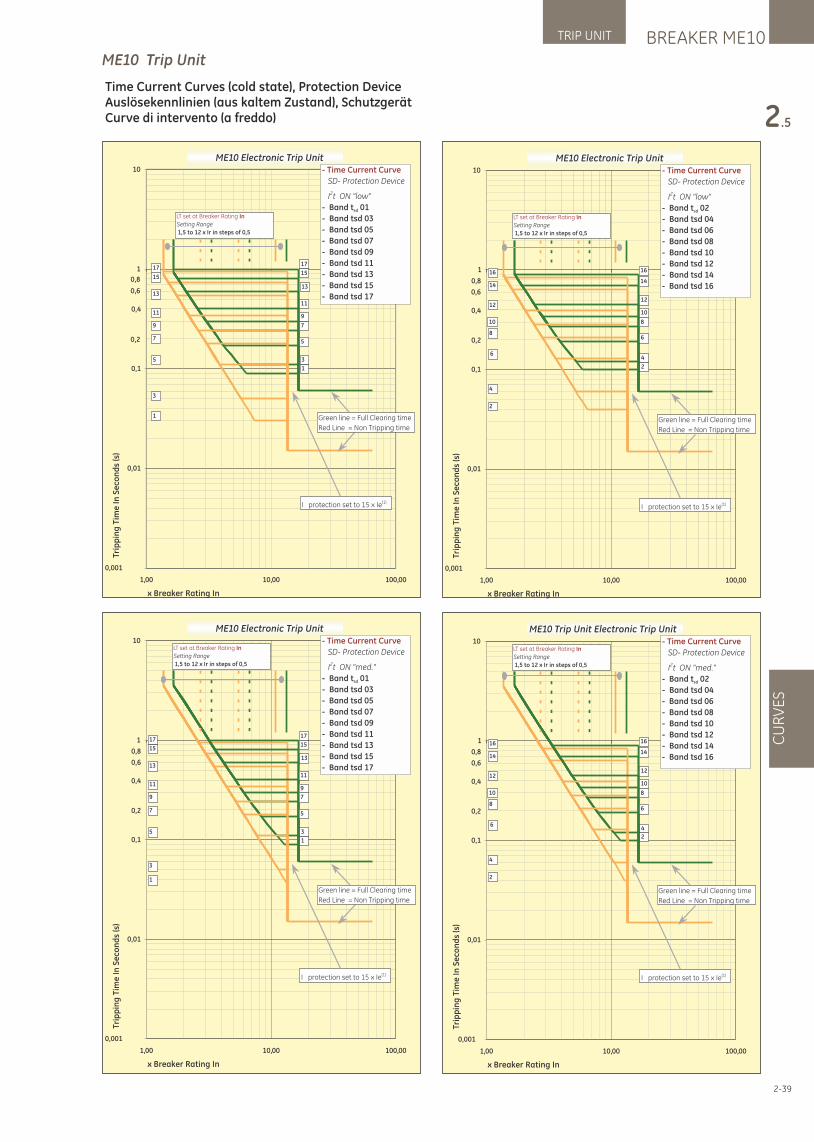
ME10 Electronic Trip Unit
0,001
0,01
0,1
1
10
00,00100,0100,1
x Breaker Rating In
Trip
pin
g T
ime
In
Se
con
ds
(s)
- Time Current Curve
SD- Protection Device
2 I t ON "low"
- Band t 01 sd
- Band tsd 03
- Band tsd 05
- Band tsd 07
- Band tsd 09
- Band tsd 11
- Band tsd 13
- Band tsd 15
- Band tsd 17
I protection set to 15 x Ie(1)
1
17
15
3
5
7
9
11
13
5
1
3
7
9
11
13
15
17
Green line = Full Clearing time
Red Line = Non Tripping time
0,8
0,6
0,4
0,2
LT set at Breaker Rating In
Setting Range
1,5 to 12 x Ir in steps of 0,5
ME10 Electronic Trip Unit
0,001
0,01
0,1
1
10
00,00100,0100,1
x Breaker Rating In
Tri
pp
ing
Tim
e I
n S
eco
nd
s (s
)
- Time Current Curve
SD- Protection Device
2 I t ON "low"
- Band t 02 sd
- Band tsd 04
- Band tsd 06
- Band tsd 08
- Band tsd 10
- Band tsd 12
- Band tsd 14
- Band tsd 16
I protection set to 15 x Ie(1)
2
16
4
6
8
10
12
14
6
2
4
8
10
12
14
16
Green line = Full Clearing time
Red Line = Non Tripping time
0,8
0,6
0,4
0,2
LT set at Breaker Rating In
Setting Range
1,5 to 12 x Ir in steps of 0,5
ME10 Electronic Trip Unit
0,001
0,01
0,1
1
10
00,00100,0100,1
x Breaker Rating In
Trip
pin
g T
ime
In
Se
con
ds
(s)
- Time Current Curve
SD- Protection Device
2 I t ON "med."
- Band t 01 sd
- Band tsd 03
- Band tsd 05
- Band tsd 07
- Band tsd 09
- Band tsd 11
- Band tsd 13
- Band tsd 15
- Band tsd 17
I protection set to 15 x Ie(1)
1
17
15
3
5
7
9
11
13
5
1
3
7
9
11
13
15
17
Green line = Full Clearing time
Red Line = Non Tripping time
0,8
0,6
0,4
0,2
LT set at Breaker Rating In
Setting Range
1,5 to 12 x Ir in steps of 0,5
ME10 Trip Unit Electronic Trip Unit
0,001
0,01
0,1
1
10
00,00100,0100,1
x Breaker Rating In
Tri
pp
ing
Tim
e I
n S
eco
nd
s (s
)
- Time Current Curve
SD- Protection Device
2 I t ON "med."
- Band t 02 sd
- Band tsd 04
- Band tsd 06
- Band tsd 08
- Band tsd 10
- Band tsd 12
- Band tsd 14
- Band tsd 16
I protection set to 15 x Ie(1)
2
16
4
6
8
10
12
14
6
2
4
8
10
12
14
16
Green line = Full Clearing time
Red Line = Non Tripping time
0,8
0,6
0,4
0,2
LT set at Breaker Rating In
Setting Range
1,5 to 12 x Ir in steps of 0,5
2-39
ME10 Trip Unit
BREAKER ME10TRIP UNIT
2.5
CU
RV
ES
Time Current Curves (cold state), Protection DeviceAuslösekennlinien (aus kaltem Zustand), SchutzgerätCurve di intervento (a freddo)
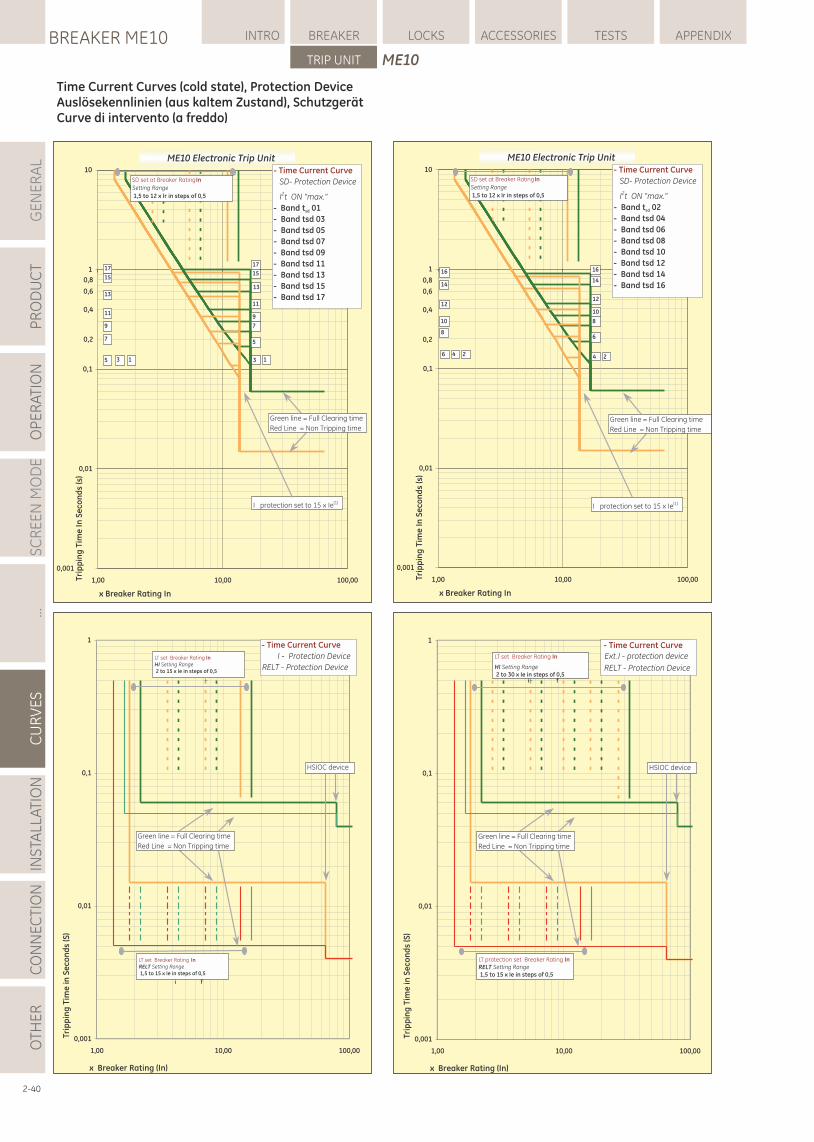
ME10 Electronic Trip Unit
0,001
0,01
0,1
1
10
00,00100,0100,1
x Breaker Rating In
Tri
pp
ing
Tim
e I
n S
eco
nd
s (s
)
- Time Current Curve
SD- Protection Device
2 I t ON "max."
- Band t 02 sd
- Band tsd 04
- Band tsd 06
- Band tsd 08
- Band tsd 10
- Band tsd 12
- Band tsd 14
- Band tsd 16
I protection set to 15 x Ie(1)
2
16
4
6
8
10
12
14
6 24
8
10
12
14
16
Green line = Full Clearing time
Red Line = Non Tripping time
0,8
0,6
0,4
0,2
SD set at Breaker Rating In
Setting Range
1,5 to 12 x Ir in steps of 0,5
ME10 Electronic Trip Unit
0,001
0,01
0,1
1
10
00,00100,0100,1
x Breaker Rating In
Tri
pp
ing
Tim
e I
n S
eco
nd
s (s
)
- Time Current Curve
SD- Protection Device
2 I t ON "max."
- Band t 01 sd
- Band tsd 03
- Band tsd 05
- Band tsd 07
- Band tsd 09
- Band tsd 11
- Band tsd 13
- Band tsd 15
- Band tsd 17
I protection set to 15 x Ie(1)
1
17
15
3
5
7
9
11
13
5 13
7
9
11
13
15
17
Green line = Full Clearing time
Red Line = Non Tripping time
0,8
0,6
0,4
0,2
SD set at Breaker Rating In
Setting Range
1,5 to 12 x Ir in steps of 0,5
0,001
0,01
0,1
1
00,00100,0100,1
x Breaker Rating (In)
Tri
pp
ing
Tim
e in
Se
con
ds
(S)
- Time Current Curve
Ext.I - protection device
RELT - Protection Device
i f
HSIOC device
Green line = Full Clearing time
Red Line = Non Tripping time
LT set Breaker Rating In
HI Setting Range
2 to 30 x Ie in steps of 0,5
LT protection set Breaker Rating InRELT Setting Range
1,5 to 15 x Ie in steps of 0,5
0,001
0,01
0,1
1
00,00100,0100,1
x Breaker Rating (In)
Tri
pp
ing
Tim
e in
Se
con
ds
(S)
- Time Current Curve
I - Protection Device
RELT - Protection Device
HSIOC device
i f
Green line = Full Clearing time
Red Line = Non Tripping time
LT set Breaker Rating InRELT Setting Range
1,5 to 15 x Ie in steps of 0,5
LT set Breaker Rating InHI Setting Range
2 to 15 x Ie in steps of 0,5
2-40
GE
NE
RA
LP
RO
DU
CT
OP
ER
ATI
ON
SC
RE
EN
MO
DE
...C
UR
VE
SIN
STA
LLA
TIO
NC
ON
NE
CTI
ON
LOCKSBREAKER ME10 INTRO BREAKER ACCESSORIES TESTS APPENDIX
TRIP UNIT
OTH
ER
ME10
Time Current Curves (cold state), Protection DeviceAuslösekennlinien (aus kaltem Zustand), SchutzgerätCurve di intervento (a freddo)
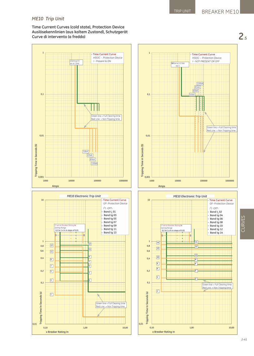
0,001
0,01
0,1
1
1000 10000 100000 1000000
Amps
Trip
pin
g T
ime
in S
eco
nd
s (S
)
- Time Current Curve
HSIOC - Protection Device
I - Present & ON
50kA
Green line = Full Clearing time
Red Line = Non Tripping time
65kA
85kA
100kA
I Setting On
set at 15kA
0,001
0,01
0,1
1
1000 10000 100000 1000000
Amps
Trip
pin
g T
ime
in S
eco
nd
s (S
)
- Time Current Curve
HSIOC - Protection Device
I - NOT PRESENT OR OFF
50kA
Green line = Full Clearing time
Red Line = Non Tripping time
65kA
85kA
100kA
SD Set at 12,5kA
tsd 1
ME10 Electronic Trip Unit
0,01
0,1
1
10
00,0100,101,0
x Breaker Rating In
Trip
pin
g T
ime
In
Se
con
ds
(s)
- Time Current Curve
GF- Protection Device
2 I t -OFF-
- Band t 01 g
- Band tg 03
- Band tg 05
- Band tg 07
- Band tg 09
- Band tg 11
- Band tg 13
1
3
5
7
9
11
13
5
1
3
7
9
11
130,8
0,6
0,4
0,2
LT set at Breaker Rating In
Setting Range
0,2 to 1 x In in steps of 0,01
Green line = Full Clearing time
Red Line = Non Tripping time
ME10 Electronic Trip Unit
0,01
0,1
1
10
00,0100,101,0
x Breaker Rating In
Tri
pp
ing
Tim
e I
n S
eco
nd
s (s
)
- Time Current Curve
GF- Protection Device
2 I t -OFF-
- Band t 02 g
- Band tg 04
- Band tg 06
- Band tg 08
- Band tg 10
- Band tg 12
- Band tg 14
2
4
6
8
10
12
14
6
2
4
8
10
12
14
0,8
0,6
0,4
0,2
LT set at Breaker Rating In
Setting Range
0,2 to 1 x In in steps of 0,01
Green line = Full Clearing time
Red Line = Non Tripping time
2-41
ME10 Trip Unit
BREAKER ME10TRIP UNIT
2.5
CU
RV
ES
Time Current Curves (cold state), Protection DeviceAuslösekennlinien (aus kaltem Zustand), SchutzgerätCurve di intervento (a freddo)
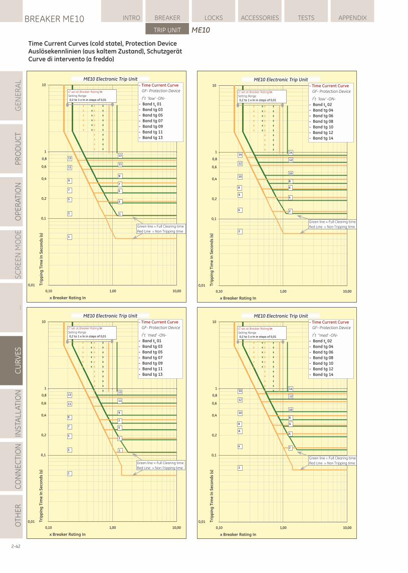
ME10 Electronic Trip Unit
0,01
0,1
1
10
00,0100,101,0
x Breaker Rating In
Trip
pin
g T
ime
In
Se
con
ds
(s)
- Time Current Curve
GF- Protection Device
2 I t 'low' -ON-
- Band t 02 g
- Band tg 04
- Band tg 06
- Band tg 08
- Band tg 10
- Band tg 12
- Band tg 14
10
2
4
6
8
12
14
6
2
4
8
10
12
14
Green line = Full Clearing time
Red Line = Non Tripping time
0,8
0,6
0,4
0,2
LT set at Breaker Rating In
Setting Range
0,2 to 1 x In in steps of 0,01
ME10 Electronic Trip Unit
0,01
0,1
1
10
00,0100,101,0
x Breaker Rating In
Tri
pp
ing
Tim
e I
n S
eco
nd
s (s
)
- Time Current Curve
GF- Protection Device
2 I t 'low' -ON-
- Band t 01 g
- Band tg 03
- Band tg 05
- Band tg 07
- Band tg 09
- Band tg 11
- Band tg 13
1
3
5
7
9
11
13
5
1
3
7
9
11
13
Green line = Full Clearing time
Red Line = Non Tripping time
0,8
0,6
0,4
0,2
LT set at Breaker Rating In
Setting Range
0,2 to 1 x In in steps of 0,01
ME10 Electronic Trip Unit
0,01
0,1
1
10
00,0100,101,0
x Breaker Rating In
Trip
pin
g T
ime
In
Se
con
ds
(s)
- Time Current Curve
GF- Protection Device
2 I t ''med' -ON-
- Band t 02 g
- Band tg 04
- Band tg 06
- Band tg 08
- Band tg 10
- Band tg 12
- Band tg 14
10
2
4
6
8
12
14
6
2
4
8
10
12
14
Green line = Full Clearing time
Red Line = Non Tripping time
0,8
0,6
0,4
0,2
LT set at Breaker Rating In
Setting Range
0,2 to 1 x In in steps of 0,01
ME10 Electronic Trip Unit
0,01
0,1
1
10
00,0100,101,0
x Breaker Rating In
Trip
pin
g T
ime
In
Se
con
ds
(s)
- Time Current Curve
GF- Protection Device
2 I t 'med' -ON-
- Band t 01 g
- Band tg 03
- Band tg 05
- Band tg 07
- Band tg 09
- Band tg 11
- Band tg 13
1
3
5
7
9
11
13
5
1
3
7
9
11
13
Green line = Full Clearing time
Red Line = Non Tripping time
0,8
0,6
0,4
0,2
LT set at Breaker Rating In
Setting Range
0,2 to 1 x In in steps of 0,01
2-42
GE
NE
RA
LP
RO
DU
CT
OP
ER
ATI
ON
SC
RE
EN
MO
DE
...C
UR
VE
SIN
STA
LLA
TIO
NC
ON
NE
CTI
ON
LOCKSBREAKER ME10 INTRO BREAKER ACCESSORIES TESTS APPENDIX
TRIP UNIT
OTH
ER
ME10
Time Current Curves (cold state), Protection DeviceAuslösekennlinien (aus kaltem Zustand), SchutzgerätCurve di intervento (a freddo)
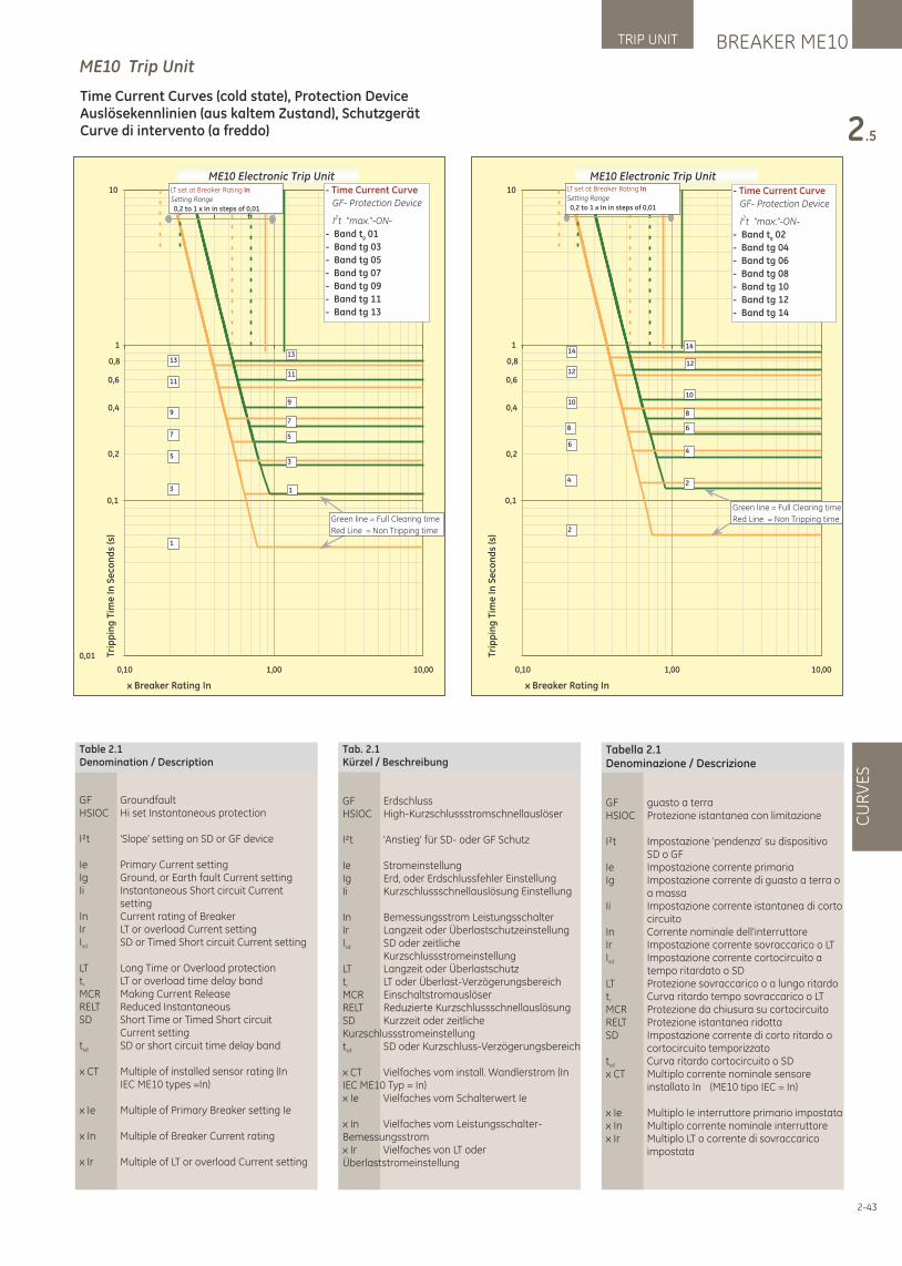
ME10 Electronic Trip Unit
0,01
0,1
1
10
00,0100,101,0
x Breaker Rating In
Trip
pin
g T
ime
In
Se
con
ds
(s)
- Time Current Curve
GF- Protection Device
2 I t “max.”-ON-
- Band t 01 g
- Band tg 03
- Band tg 05
- Band tg 07
- Band tg 09
- Band tg 11
- Band tg 13
1
3
5
7
9
11
13
5
1
3
7
9
11
13
Green line = Full Clearing time
Red Line = Non Tripping time
0,8
0,6
0,4
0,2
i f
LT set at Breaker Rating In
Setting Range
0,2 to 1 x In in steps of 0,01
ME10 Electronic Trip Unit
0,1
1
10
00,0100,101,0
x Breaker Rating In
Trip
pin
g T
ime
In
Se
con
ds
(s)
- Time Current Curve
GF- Protection Device
2 I t “max.”-ON-
- Band t 02 g
- Band tg 04
- Band tg 06
- Band tg 08
- Band tg 10
- Band tg 12
- Band tg 14
10
2
4
6
8
12
14
6
2
4
8
10
12
14
Green line = Full Clearing time
Red Line = Non Tripping time
0,8
0,6
0,4
0,2
LT set at Breaker Rating In
Setting Range
0,2 to 1 x In in steps of 0,01
2-43
BREAKER ME10TRIP UNIT
2.5
CU
RV
ES
ME10 Trip Unit
Time Current Curves (cold state), Protection DeviceAuslösekennlinien (aus kaltem Zustand), SchutzgerätCurve di intervento (a freddo)
Table 2.1Denomination / Description
GF GroundfaultHSIOC Hi set Instantaneous protection
I²t 'Slope' setting on SD or GF device
Ie Primary Current settingIg Ground, or Earth fault Current settingIi Instantaneous Short circuit Current settingIn Current rating of BreakerIr LT or overload Current settingI SD or Timed Short circuit Current settingsd
LT Long Time or Overload protectiont LT or overload time delay bandr
MCR Making Current ReleaseRELT Reduced InstantaneousSD Short Time or Timed Short circuit Current settingt SD or short circuit time delay bandsd
x CT Multiple of installed sensor rating (In IEC ME10 types =In)
x Ie Multiple of Primary Breaker setting Ie
x In Multiple of Breaker Current rating
x Ir Multiple of LT or overload Current setting
Tab. 2.1Kürzel / Beschreibung
GF ErdschlussHSIOC High-Kurzschlussstromschnellauslöser
I²t 'Anstieg' für SD- oder GF Schutz
Ie StromeinstellungIg Erd, oder Erdschlussfehler EinstellungIi Kurzschlussschnellauslösung Einstellung
In Bemessungsstrom LeistungsschalterIr Langzeit oder ÜberlastschutzeinstellungI SD oder zeitlichesd
KurzschlussstromeinstellungLT Langzeit oder Überlastschutzt LT oder Überlast-Verzögerungsbereichr
MCR EinschaltstromauslöserRELT Reduzierte KurzschlussschnellauslösungSD Kurzzeit oder zeitliche Kurzschlussstromeinstellungt SD oder Kurzschluss-Verzögerungsbereichsd
x CT Vielfaches vom install. Wandlerstrom (In IEC ME10 Typ = In)x Ie Vielfaches vom Schalterwert Ie
x In Vielfaches vom Leistungsschalter- Bemessungsstromx Ir Vielfaches von LT oder Überlaststromeinstellung
Tabella 2.1Denominazione / Descrizione
GF guasto a terraHSIOC Protezione istantanea con limitazione
I²t Impostazione 'pendenza' su dispositivo SD o GFIe Impostazione corrente primariaIg Impostazione corrente di guasto a terra o a massaIi Impostazione corrente istantanea di corto circuitoIn Corrente nominale dell'interruttoreIr Impostazione corrente sovraccarico o LTI Impostazione corrente cortocircuito a sd
tempo ritardato o SD LT Protezione sovraccarico o a lungo ritardot Curva ritardo tempo sovraccarico o LTr
MCR Protezione da chiusura su cortocircuitoRELT Protezione istantanea ridottaSD Impostazione corrente di corto ritardo o cortocircuito temporizzatot Curva ritardo cortocircuito o SDsd
x CT Multiplo corrente nominale sensore installato In (ME10 tipo IEC = In)
x Ie Multiplo Ie interruttore primario impostatax In Multiplo corrente nominale interruttorex Ir Multiplo LT o corrente di sovraccarico impostata
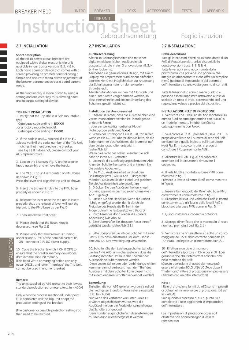
2-44
2.7 INSTALLATION
KurzbeschreibungAlle ME10 Leistungsschalter sind mit einer digitalen elektronischen Auslöseeinheit ausgestattet, die in vier Grundversionen E, S, N, & H verfügbar ist.Alle haben ein gemeinsames Design, mit einem Display mit Amperemeter und einem einfachen, exakten Menü mit Möglichkeiten zur Anpassung der Schalterparameter an den aktuellen Strombereich.Alle Menüfunktionen können mit 4 Einstell- und einer Enter-Taste vorgenommen werden, so dass eine schnelle und exakte Einstellung des Schalters gewährleistet ist.
Installation der Auslöseeinheit1. Stellen Sie sicher, dass die Auslöseeinheit eine Vorort-montierbare Version ist. (Katalogcode endet mit Rxxxx).. oder ein werkseitigmontiertes Modell (Katalogcode endet mit Fxxxx).2. Wenn der Katalogcode ein R... ist, fortsetzen, wenn es ein F... .. ist, überprüfen Sie bitte, ob die Seriennummer des Auslösers, der Nummer auf dem Leistungsschalter entspricht.(siehe Abb. E)Wenn dies nicht der Fall ist, wenden Sie sich bitte an Ihren AEG-Vertreter.3. Lösen sie die 6 Befestigungsschrauben (Abb. A) an der Schalterfrontseite und entfernen Sie die vordere Abdeckung.4. Die ME10 Auslöseeinheit wird auf den Basisträger [PMU] wie in Abb. B dargestellt montiert. Drücken Sie den Hebel und gleichen Sie die Auslöseeinheit wie gezeigt an.5. Drücken Sie den Auslöseeinheiten Knopf ordnungsgemäß in die Trägeraufnahme wie in Abb. C gezeigt.6. Lassen Sie den Hebel los, wenn die Einheit richtig eingefügt wurde, damit durch die Freigabe des Hebels die Einheit in der Trägeraufnahme festgesetzt wird (Abb. D)7. Installieren Sie dann wieder die vordere Abdeckung (wie Abb. A).8. Bitte überprüfen Sie, dass der Reset-Knopf gedrückt wurde. (siehe Abb. 2.1.)
9. Bitte überprüfen Sie, ob der Schalter mit einer Last > 15% des Nennstroms (In) läuft - sonst - eine 24V DC Stromversorgung verwenden.
10. Schalten Sie den Leistungsschalter (schalten Sie ihn AN & AUS) um sicherzustellen, dass die Leistungsschalter Daten in den Speicher der Auslöseeinheit übernommen werden.(Diese Lesen, Schreiben oder Verbindungs-Aktion kann nur einmal eintreten, nach der "Ehe" des Auslösers mit dem Schalter, kann dieser nicht mit einem anderen Schalter verwendet werden)
Bemerkung:Einheiten die von AEG geliefert wurden, sind auf die niedrigsten Standard-Parameter eingestellt. (z. B.. In = 400A)Nur wenn das Verfahren wie unter Punkt (9) erwähnt abgeschlossen wurde, wird die Auslöseeinheit an die Produktionseinstellungen des Schalters angepasst.(Dem Kunden zugängliche Schutzeinstellungen müssen dann wiederhergestellt werden.)
2.7 INSTALLATION
Short descriptionAll the ME10 power circuit breakers are equipped with a digital electronic trip unit available in four basics versions E, S, N & H.Each has a common design that comes with a screen providing an ammeter and following a simple and accurate menu driven adjustment of the breaker parameters across a board current range.
All the functionality is menu driven by using 4 setting and one enter key thus allowing a fast and accurate setting of device.
TRIP UNIT INSTALLATION1. Verify that the Trip Unit is a field mountable type (Catalogue code ending in RXXXX)..or a factory mounted model.. (Catalogue code ending in FXXXX).
2. If the code is an R... proceed, if it is an F.....please verify if the serial number of the Trip Unit matches that mentioned on the breaker. (see Fig E ) If it does not, please contact your AEG representative.
3. Loosen the 6 screws (Fig. A) on the breaker fascia assembly and remove the fascia.
4. The ME10 Trip unit is mounted on PMU base as shown in Fig. B.Press the lever and align the trip unit as shown.
5. Insert the trip unit knob into the PMU base properly as shown in Fig. C
6. Release the lever once the trip unit is insert properly, thus the release of lever will lock the trip unit to the PMU base as per Fig. D
7. Then install the front cover.
8. Please check that the Reset Knob is depressed. (see Fig. 2.1)
9. Please verify that the breaker is running under a load >15% of the nominal current (In) -OR- connect a 24V DC power supply.
10. Cycle the breaker (switch it ON & OFF) to ensure that the breaker memory downloads data into the Trip Unit memory.(This Read Write or marrying action can only occur ONCE , and after "marriage" the Trip Unit can not be used in another breaker)
Remark:Trip units supplied by AEG are set to their lowest standard production parameters. (e.g.. In = 400A)
Only when the process mentioned under point (9) is completed will the Trip Unit adapt the production settings of the breaker.
(The customer accessible protection settings do then need to be restored.)
Instruction sheetGebrauchsanleitung Foglio istruzioni
2.7 INSTALLAZIONE
Breve descrizioneTutti gli interruttori aperti ME10 sono dotati di un Relè di Protezione elettronica disponibile in quattro versioni base: E, S, N & H.Tutte le versioni sono accomunate dalla piattaforma, che prevede uno pannello che integra un amperometro e che offre un semplice menù guidato di impostazione dei parametri dell'interruttore su una vasta gamma di correnti.
Tutte le funzionalità sono a menù guidato e possono essere impostate attraverso 4 tasti di scelta e un tasto di invio, permettendo così una regolazione veloce e precisa del dispositivo.
INSTALLAZIONE RELE' DI PROTEZIONE1 . Verificare che il Relè sia del tipo montabile sul campo (Codice catalogo termina con Rxxxx ) o un modello montato in fabbrica (Codice catalogo termina con Fxxxx.
2 . Se il codice è un R. .. procedere , se è un F. .... si prega di verificare se il numero di serie del Relè corrisponde a quello indicato sull'interruttore (vedi Fig. E). In caso contrario , si prega di contattare il Rappresentante AEG .
3 . Allentare le 6 viti ( Fig. A) del coperchio anteriore dell'interruttore e rimuovere il coperchio.
4 . Il Relè ME10 è montato su base PMU come mostrato in fig . B.Premere la leva e allineare il relè come mostrato in figura.
5 . Inserire la manopola del Relè nella base PMU correttamente come mostrato in fig . C6 . Rilasciare la leva una volta che il relè è inserto correttamente, e al rilascio della leva il Relè si bloccherà alla base PMU come in Fig . D
7 . Quindi installare il coperchio anteriore.
8 . Si prega di verificare che la manopola di reset non resti premuta. ( vedi fig. 2.1 )
9 . Verificare che l'interruttore sia sotto un carico maggiore del 15 % della corrente nominale (In)- OPPURE- collegare un alimentatore 24V DC .
10 . Effettuare un ciclo di manovra dell'interruttore (portare in ON e poi in OFF) per garantire che che l'interruttore scarichi i dati nella memoria del Relè.(Questa operazione di accoppiamento può essere effettuata SOLO UNA VOLTA, e dopo il "matrimonio" il Relè di protezione non può essere utilizzato con un altro interruttore)
Nota :I Relè di protezione forniti da AEG sono impostati di dafault al minimo valore di protezione. (ad es . In = 400A).Solo quando il processo di cui al punto (9) è completato il Relè aggiornerà le impostazioni dell'interruttore .
( Le impostazioni di protezione accessibili all'utente non hanno bisogno di essere reimpostate)
LOCKSBREAKER ME10 INTRO BREAKER ACCESSORIES TESTS APPENDIX
TRIP UNIT
INS
TALL
ATI
ON
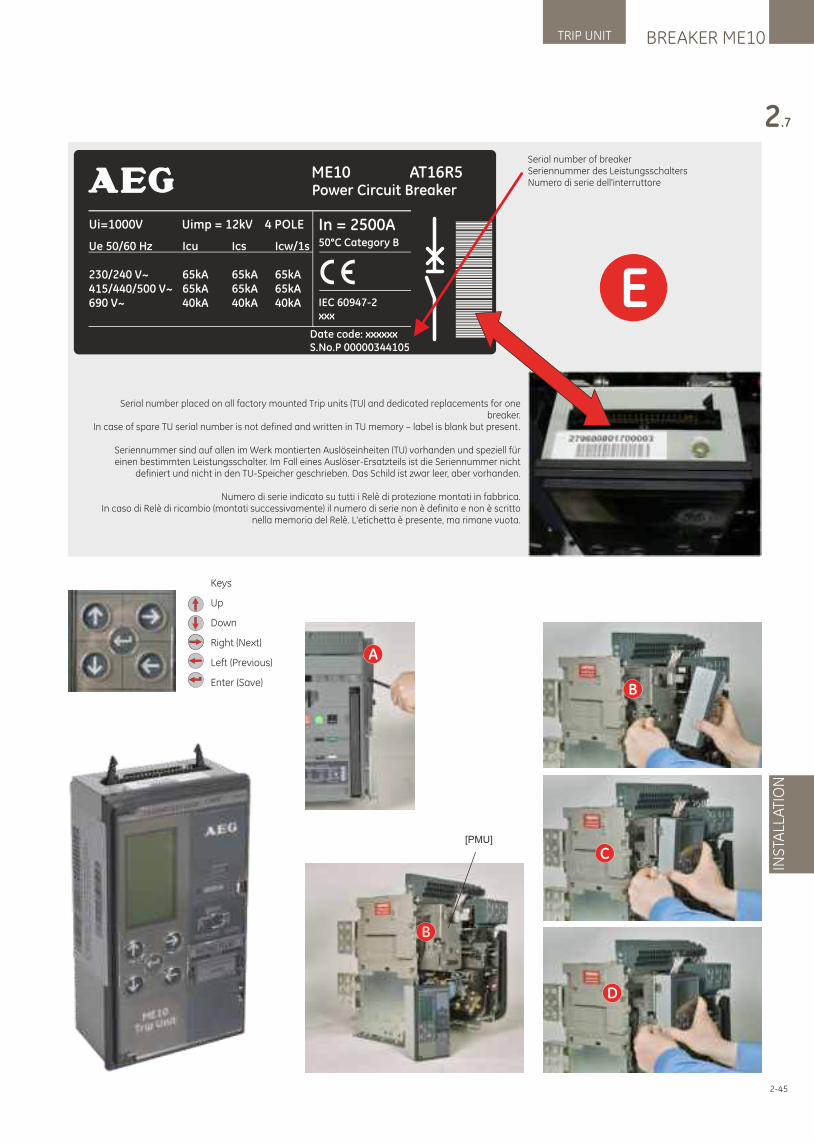
BREAKER ME10TRIP UNIT
INS
TALL
ATI
ON
2.7
2-45
Keys
Up
Down
Right (Next)
Left (Previous)
Enter (Save)
C
D
B
B
A
[PMU]
Serial number of breakerSeriennummer des LeistungsschaltersNumero di serie dell'interruttore
E
Serial number placed on all factory mounted Trip units (TU) and dedicated replacements for one breaker.
In case of spare TU serial number is not defined and written in TU memory – label is blank but present.
Seriennummer sind auf allen im Werk montierten Auslöseinheiten (TU) vorhanden und speziell für einen bestimmten Leistungsschalter. Im Fall eines Auslöser-Ersatzteils ist die Seriennummer nicht
definiert und nicht in den TU-Speicher geschrieben. Das Schild ist zwar leer, aber vorhanden.
Numero di serie indicato su tutti i Relè di protezione montati in fabbrica. In caso di Relè di ricambio (montati successivamente) il numero di serie non è definito e non è scritto
nella memoria del Relè. L'etichetta è presente, ma rimane vuota.
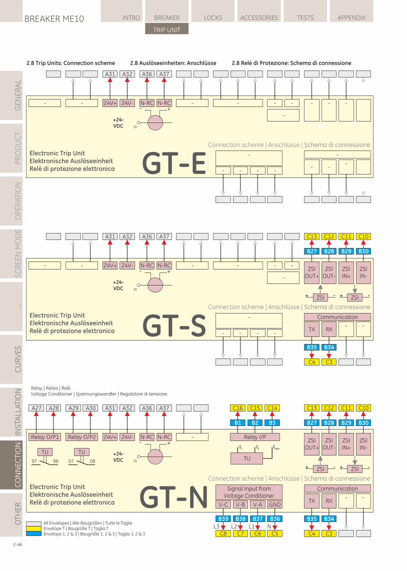
LOCKSBREAKER ME10 INTRO BREAKER ACCESSORIES TESTS APPENDIX
TRIP UNIT
GE
NE
RA
LP
RO
DU
CT
OP
ER
ATI
ON
SC
RE
EN
MO
DE
...C
UR
VE
SIN
STA
LLA
TIO
NC
ON
NE
CTI
ON
OTH
ER
2-46
- - -N-RC
A36 A37
N-RC
A31 A32
24V+ 24V- -
-
- - - - -
- --
-
- - - -
-
GT-E
+24-VDC
- +
N
-N-RC
A36 A37
N-RC
A31 A32
24V+ 24V-
GT-N
+24-VDC
- +
N
C8 C7 C6 C5
V-C V-B V-A GND
Signal Input fromVoltage Conditioner
L3 L2 L1 N
B39 B38 B37 B36
C4 C3
TX RX- -
Communication
B35 B34
ZSI+ - ZSI+ -
C13 C12 C11 C10
ZSIOUT+
ZSIOUT-
ZSIIN+
ZSIIN-
B27 B28 B29 B30
TU
I1 I2 Icom
C16 C15 C14
Relay I/P
B1 B2 B3
Relay O/P1
A27 A28
TU
97 98
Relay O/P2
A29 A30
TU
07 08
- - -N-RC
A36 A37
N-RC
A31 A32
24V+ 24V- -
-
- -
- - - -
-
GT-S
+24-VDC
- +
N
C4 C3
TX RX- -
Communication
B35 B34
ZSI+ - ZSI+ -
C13 C12 C11 C10
ZSIOUT+
ZSIOUT-
ZSIIN+
ZSIIN-
B27 B28 B29 B30
Electronic Trip UnitElektronische AuslöseeinheitRelè di protezione elettronica
Connection scheme | Anschlüsse | Schema di connessione
Electronic Trip UnitElektronische AuslöseeinheitRelè di protezione elettronica
Connection scheme | Anschlüsse | Schema di connessione
Electronic Trip UnitElektronische AuslöseeinheitRelè di protezione elettronica
Connection scheme | Anschlüsse | Schema di connessione
Relay | Relais | Relè Voltage Conditioner | Spannungswandler | Regolatore di tensione
2.8 Trip Units: Connection scheme 2.8 Auslöseeinheiten: Anschlüsse 2.8 Relè di Protezione: Schema di connessione
All Envelopes | Alle Baugrößen | Tutte le TaglieEnvelope T | Baugröße T | Taglia TEnvelope 1, 2 & 3 | Baugröße 1, 2 & 3 | Taglia 1, 2 & 3
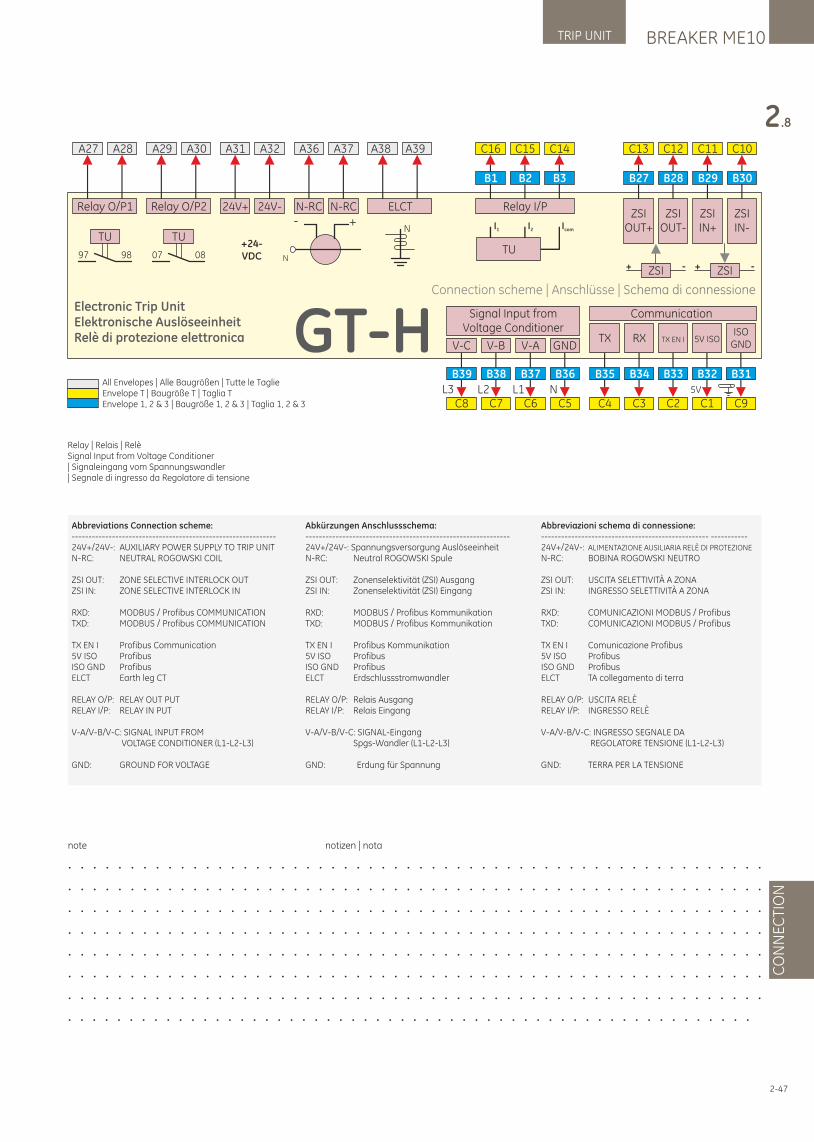
BREAKER ME10TRIP UNIT
CO
NN
EC
TIO
N
2.8
2-47
Abbreviations Connection scheme:-------------------------------------------------------------24V+/24V-: AUXILIARY POWER SUPPLY TO TRIP UNITN-RC: NEUTRAL ROGOWSKI COIL
ZSI OUT: ZONE SELECTIVE INTERLOCK OUTZSI IN: ZONE SELECTIVE INTERLOCK IN
RXD: MODBUS / Profibus COMMUNICATIONTXD: MODBUS / Profibus COMMUNICATION
TX EN I Profibus Communication5V ISO ProfibusISO GND ProfibusELCT Earth leg CT
RELAY O/P: RELAY OUT PUTRELAY I/P: RELAY IN PUT
V-A/V-B/V-C: SIGNAL INPUT FROM VOLTAGE CONDITIONER (L1-L2-L3)
GND: GROUND FOR VOLTAGE
Abkürzungen Anschlussschema:-------------------------------------------------------------24V+/24V-: Spannungsversorgung AuslöseeinheitN-RC: Neutral ROGOWSKI Spule
ZSI OUT: Zonenselektivität (ZSI) AusgangZSI IN: Zonenselektivität (ZSI) Eingang
RXD: MODBUS / Profibus KommunikationTXD: MODBUS / Profibus Kommunikation
TX EN I Profibus Kommunikation5V ISO ProfibusISO GND ProfibusELCT Erdschlussstromwandler
RELAY O/P: Relais AusgangRELAY I/P: Relais Eingang
V-A/V-B/V-C: SIGNAL-Eingang Spgs-Wandler (L1-L2-L3)
GND: Erdung für Spannung
Abbreviazioni schema di connessione:-------------------------------------------------- -----------24V+/24V-: ALIMENTAZIONE AUSILIARIA RELÈ DI PROTEZIONE
N-RC: BOBINA ROGOWSKI NEUTRO
ZSI OUT: USCITA SELETTIVITÀ A ZONAZSI IN: INGRESSO SELETTIVITÀ A ZONA
RXD: COMUNICAZIONI MODBUS / Profibus TXD: COMUNICAZIONI MODBUS / Profibus
TX EN I Comunicazione Profibus5V ISO ProfibusISO GND ProfibusELCT TA collegamento di terra
RELAY O/P: USCITA RELÈRELAY I/P: INGRESSO RELÈ
V-A/V-B/V-C: INGRESSO SEGNALE DA REGOLATORE TENSIONE (L1-L2-L3)
GND: TERRA PER LA TENSIONE
note notizen | nota
. . . . . . . . . . . . . . . . . . . . . . . . . . . . . . . . . . . . . . . . . . . . . . . . . . . . . . . .
. . . . . . . . . . . . . . . . . . . . . . . . . . . . . . . . . . . . . . . . . . . . . . . . . . . . . . . .
. . . . . . . . . . . . . . . . . . . . . . . . . . . . . . . . . . . . . . . . . . . . . . . . . . . . . . . .
. . . . . . . . . . . . . . . . . . . . . . . . . . . . . . . . . . . . . . . . . . . . . . . . . . . . . . . .
. . . . . . . . . . . . . . . . . . . . . . . . . . . . . . . . . . . . . . . . . . . . . . . . . . . . . . . .
. . . . . . . . . . . . . . . . . . . . . . . . . . . . . . . . . . . . . . . . . . . . . . . . . . . . . . . .
. . . . . . . . . . . . . . . . . . . . . . . . . . . . . . . . . . . . . . . . . . . . . . . . . . . . . . . .
. . . . . . . . . . . . . . . . . . . . . . . . . . . . . . . . . . . . . . . . . . . . . . . . . . . . . . . .
Relay | Relais | Relè Signal Input from Voltage Conditioner | Signaleingang vom Spannungswandler | Segnale di ingresso da Regolatore di tensione
A31 A32
24V+ 24V-
+24-VDC
N-RC
A36 A37
N-RC- +
N
Relay O/P1
A27 A28
TU
97 98
Relay O/P2
A29 A30
TU
07 08
ELCT
A38 A39
N
GT-HC8 C7 C6 C5
V-C V-B V-A GND
Signal Input fromVoltage Conditioner
L3 L2 L1 N
B39 B38 B37 B36
TX RX
Communication
TX EN I 5V ISO
C4 C3 C2 C1 C9
ISOGND
5V
B35 B34 B33 B32 B31
ZSI+ - ZSI+ -
C13 C12 C11 C10
ZSIOUT+
ZSIOUT-
ZSIIN+
ZSIIN-
B27 B28 B29 B30
TU
I1 I2 Icom
C16 C15 C14
Relay I/P
B1 B2 B3
Electronic Trip UnitElektronische AuslöseeinheitRelè di protezione elettronica
Connection scheme | Anschlüsse | Schema di connessione
All Envelopes | Alle Baugrößen | Tutte le TaglieEnvelope T | Baugröße T | Taglia TEnvelope 1, 2 & 3 | Baugröße 1, 2 & 3 | Taglia 1, 2 & 3
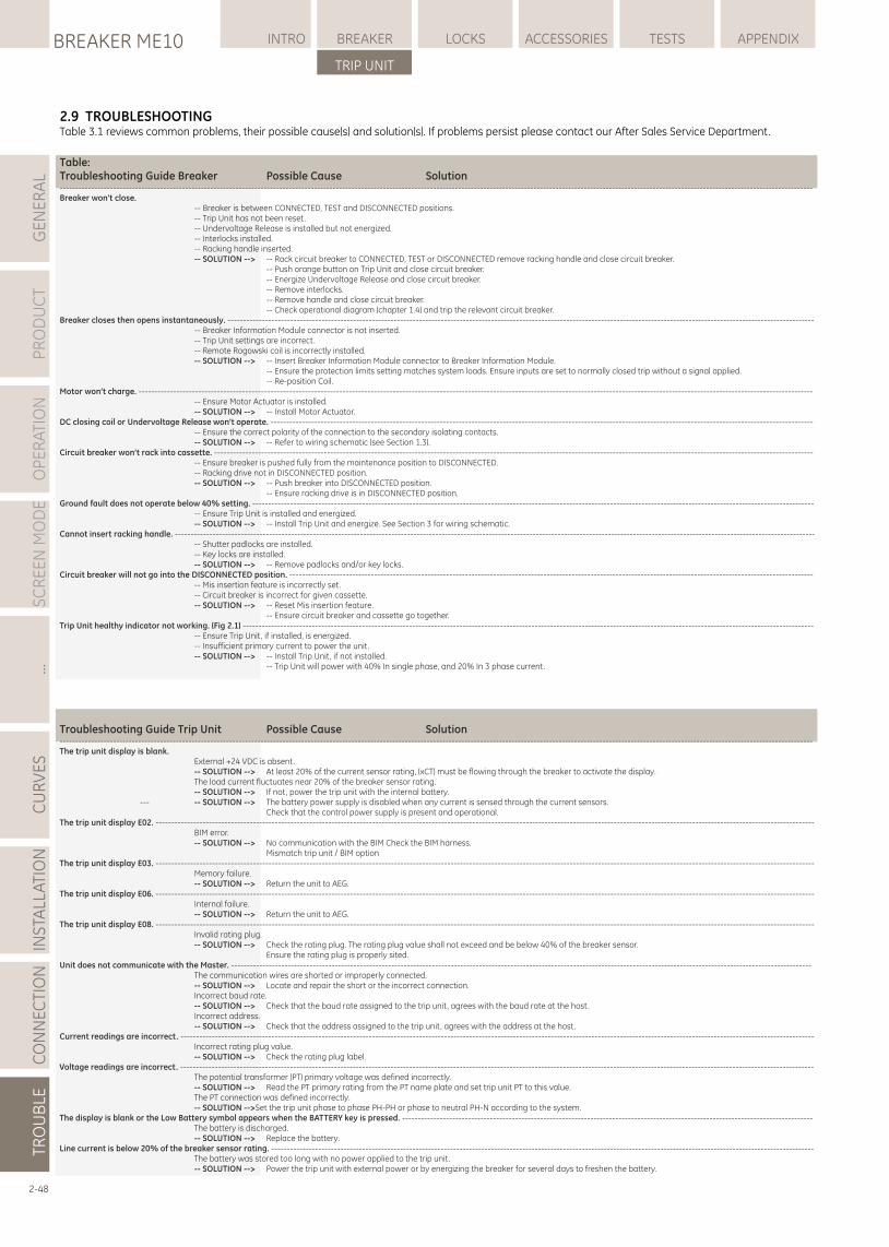
LOCKSBREAKER ME10 INTRO BREAKER ACCESSORIES TESTS APPENDIX
TRIP UNIT
GE
NE
RA
LP
RO
DU
CT
OP
ER
ATI
ON
SC
RE
EN
MO
DE
...C
UR
VE
SIN
STA
LLA
TIO
NC
ON
NE
CTI
ON
TRO
UB
LE
2.9 TROUBLESHOOTINGTable 3.1 reviews common problems, their possible cause(s) and solution(s). If problems persist please contact our After Sales Service Department.
2-48
Table:Troubleshooting Guide Breaker Possible Cause Solution------------------------------------------------------------------------------------------------------------------------------------------------------------------------------------------------------------------------------------------------Breaker won’t close. -- Breaker is between CONNECTED, TEST and DISCONNECTED positions. -- Trip Unit has not been reset. -- Undervoltage Release is installed but not energized. -- Interlocks installed. -- Racking handle inserted. -- SOLUTION --> -- Rack circuit breaker to CONNECTED, TEST or DISCONNECTED remove racking handle and close circuit breaker. -- Push orange button on Trip Unit and close circuit breaker. -- Energize Undervoltage Release and close circuit breaker. -- Remove interlocks. -- Remove handle and close circuit breaker. -- Check operational diagram (chapter 1.4) and trip the relevant circuit breaker.Breaker closes then opens instantaneously. ------------------------------------------------------------------------------------------------------------------------------------------------------------------------------------------- -- Breaker Information Module connector is not inserted. -- Trip Unit settings are incorrect. -- Remote Rogowski coil is incorrectly installed. -- SOLUTION --> -- Insert Breaker Information Module connector to Breaker Information Module. -- Ensure the protection limits setting matches system loads. Ensure inputs are set to normally closed trip without a signal applied. -- Re-position Coil.Motor won’t charge. ----------------------------------------------------------------------------------------------------------------------------------------------------------------------------------------------------------------------- -- Ensure Motor Actuator is installed. -- SOLUTION --> -- Install Motor Actuator.DC closing coil or Undervoltage Release won’t operate. ----------------------------------------------------------------------------------------------------------------------------------------------------------------------------- -- Ensure the correct polarity of the connection to the secondary isolating contacts. -- SOLUTION --> -- Refer to wiring schematic (see Section 1.3).Circuit breaker won’t rack into cassette. ----------------------------------------------------------------------------------------------------------------------------------------------------------------------------------------------- -- Ensure breaker is pushed fully from the maintenance position to DISCONNECTED. -- Racking drive not in DISCONNECTED position. -- SOLUTION --> -- Push breaker into DISCONNECTED position. -- Ensure racking drive is in DISCONNECTED position.Ground fault does not operate below 40% setting. ----------------------------------------------------------------------------------------------------------------------------------------------------------------------------------- -- Ensure Trip Unit is installed and energized. -- SOLUTION --> -- Install Trip Unit and energize. See Section 3 for wiring schematic.Cannot insert racking handle. ------------------------------------------------------------------------------------------------------------------------------------------------------------------------------------------------------------ -- Shutter padlocks are installed. -- Key locks are installed. -- SOLUTION --> -- Remove padlocks and/or key locks.Circuit breaker will not go into the DISCONNECTED position. ----------------------------------------------------------------------------------------------------------------------------------------------------------------------- -- Mis insertion feature is incorrectly set. -- Circuit breaker is incorrect for given cassette. -- SOLUTION --> -- Reset Mis insertion feature. -- Ensure circuit breaker and cassette go together.Trip Unit healthy indicator not working. (Fig 2.1) -------------------------------------------------------------------------------------------------------------------------------------------------------------------------------------- -- Ensure Trip Unit, if installed, is energized. -- Insufficient primary current to power the unit. -- SOLUTION --> -- Install Trip Unit, if not installed. -- Trip Unit will power with 40% In single phase, and 20% In 3 phase current.
Troubleshooting Guide Trip Unit Possible Cause Solution------------------------------------------------------------------------------------------------------------------------------------------------------------------------------------------------------------------------------------------------The trip unit display is blank. External +24 VDC is absent. -- SOLUTION --> At least 20% of the current sensor rating, (xCT) must be flowing through the breaker to activate the display. The load current fluctuates near 20% of the breaker sensor rating. -- SOLUTION --> If not, power the trip unit with the internal battery. --- -- SOLUTION --> The battery power supply is disabled when any current is sensed through the current sensors. Check that the control power supply is present and operational.The trip unit display E02. ------------------------------------------------------------------------------------------------------------------------------------------------------------------------------------------------------------------ BIM error. -- SOLUTION --> No communication with the BIM Check the BIM harness. Mismatch trip unit / BIM optionThe trip unit display E03. ------------------------------------------------------------------------------------------------------------------------------------------------------------------------------------------------------------------ Memory failure. -- SOLUTION --> Return the unit to AEG.The trip unit display E06. ------------------------------------------------------------------------------------------------------------------------------------------------------------------------------------------------------------------ Internal failure. -- SOLUTION --> Return the unit to AEG.The trip unit display E08. ------------------------------------------------------------------------------------------------------------------------------------------------------------------------------------------------------------------ Invalid rating plug. -- SOLUTION --> Check the rating plug. The rating plug value shall not exceed and be below 40% of the breaker sensor. Ensure the rating plug is properly sited.Unit does not communicate with the Master. ----------------------------------------------------------------------------------------------------------------------------------------------------------------------------------------- The communication wires are shorted or improperly connected. -- SOLUTION --> Locate and repair the short or the incorrect connection. Incorrect baud rate. -- SOLUTION --> Check that the baud rate assigned to the trip unit, agrees with the baud rate at the host. Incorrect address. -- SOLUTION --> Check that the address assigned to the trip unit, agrees with the address at the host.Current readings are incorrect. ---------------------------------------------------------------------------------------------------------------------------------------------------------------------------------------------------------- Incorrect rating plug value. -- SOLUTION --> Check the rating plug label.Voltage readings are incorrect. ---------------------------------------------------------------------------------------------------------------------------------------------------------------------------------------------------------- The potential transformer (PT) primary voltage was defined incorrectly. -- SOLUTION --> Read the PT primary rating from the PT name plate and set trip unit PT to this value. The PT connection was defined incorrectly. -- SOLUTION -->Set the trip unit phase to phase PH-PH or phase to neutral PH-N according to the system.The display is blank or the Low Battery symbol appears when the BATTERY key is pressed. ----------------------------------------------------------------------------------------------------------------------------------- The battery is discharged. -- SOLUTION --> Replace the battery.Line current is below 20% of the breaker sensor rating. ----------------------------------------------------------------------------------------------------------------------------------------------------------------------------- The battery was stored too long with no power applied to the trip unit. -- SOLUTION --> Power the trip unit with external power or by energizing the breaker for several days to freshen the battery.
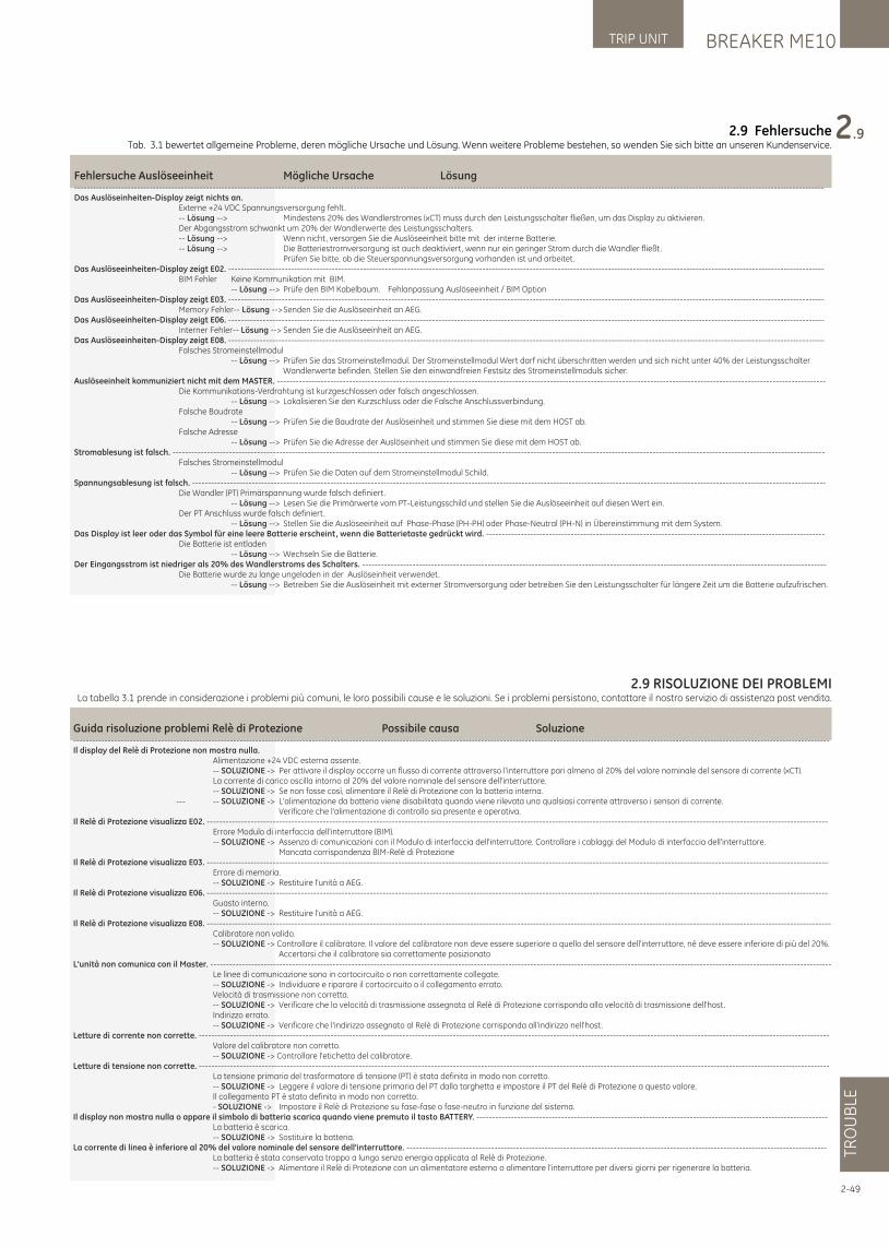
2.9 FehlersucheTab. 3.1 bewertet allgemeine Probleme, deren mögliche Ursache und Lösung. Wenn weitere Probleme bestehen, so wenden Sie sich bitte an unseren Kundenservice.
Fehlersuche Auslöseeinheit Mögliche Ursache Lösung-----------------------------------------------------------------------------------------------------------------------------------------------------------------------------------------------------------------------------------------------Das Auslöseinheiten-Display zeigt nichts an. Externe +24 VDC Spannungsversorgung fehlt. -- Lösung --> Mindestens 20% des Wandlerstromes (xCT) muss durch den Leistungsschalter fließen, um das Display zu aktivieren. Der Abgangsstrom schwankt um 20% der Wandlerwerte des Leistungsschalters. -- Lösung --> Wenn nicht, versorgen Sie die Auslöseeinheit bitte mit der interne Batterie. -- Lösung --> Die Batteriestromversorgung ist auch deaktiviert, wenn nur ein geringer Strom durch die Wandler fließt. Prüfen Sie bitte, ob die Steuerspannungsversorgung vorhanden ist und arbeitet.Das Auslöseeinheiten-Display zeigt E02. ---------------------------------------------------------------------------------------------------------------------------------------------------------------------------------------------- BIM Fehler Keine Kommunikation mit BIM. -- Lösung --> Prüfe den BIM Kabelbaum. Fehlanpassung Auslöseeinheit / BIM OptionDas Auslöseeinheiten-Display zeigt E03. ---------------------------------------------------------------------------------------------------------------------------------------------------------------------------------------------- Memory Fehler-- Lösung --> Senden Sie die Auslöseeinheit an AEG.Das Auslöseeinheiten-Display zeigt E06. ---------------------------------------------------------------------------------------------------------------------------------------------------------------------------------------------- Interner Fehler-- Lösung --> Senden Sie die Auslöseeinheit an AEG.Das Auslöseeinheiten-Display zeigt E08. ---------------------------------------------------------------------------------------------------------------------------------------------------------------------------------------------- Falsches Stromeinstellmodul -- Lösung --> Prüfen Sie das Stromeinstellmodul. Der Stromeinstellmodul Wert darf nicht überschritten werden und sich nicht unter 40% der Leistungsschalter Wandlerwerte befinden. Stellen Sie den einwandfreien Festsitz des Stromeinstellmoduls sicher.Auslöseeinheit kommuniziert nicht mit dem MASTER. ------------------------------------------------------------------------------------------------------------------------------------------------------------------------------- Die Kommunikations-Verdrahtung ist kurzgeschlossen oder falsch angeschlossen. -- Lösung --> Lokalisieren Sie den Kurzschluss oder die Falsche Anschlussverbindung. Falsche Baudrate -- Lösung --> Prüfen Sie die Baudrate der Auslöseinheit und stimmen Sie diese mit dem HOST ab. Falsche Adresse -- Lösung --> Prüfen Sie die Adresse der Auslöseinheit und stimmen Sie diese mit dem HOST ab.Stromablesung ist falsch. ---------------------------------------------------------------------------------------------------------------------------------------------------------------------------------------------------------------- Falsches Stromeinstellmodul -- Lösung --> Prüfen Sie die Daten auf dem Stromeinstellmodul Schild.Spannungsablesung ist falsch. ---------------------------------------------------------------------------------------------------------------------------------------------------------------------------------------------------------- Die Wandler (PT) Primärspannung wurde falsch definiert. -- Lösung --> Lesen Sie die Primärwerte vom PT-Leistungsschild und stellen Sie die Auslöseeinheit auf diesen Wert ein. Der PT Anschluss wurde falsch definiert. -- Lösung --> Stellen Sie die Auslöseeinheit auf Phase-Phase (PH-PH) oder Phase-Neutral (PH-N) in Übereinstimmung mit dem System.Das Display ist leer oder das Symbol für eine leere Batterie erscheint, wenn die Batterietaste gedrückt wird. ------------------------------------------------------------------------------------------------------------ Die Batterie ist entladen -- Lösung --> Wechseln Sie die Batterie.Der Eingangsstrom ist niedriger als 20% des Wandlerstroms des Schalters. ---------------------------------------------------------------------------------------------------------------------------------------------------- Die Batterie wurde zu lange ungeladen in der Auslöseinheit verwendet. -- Lösung --> Betreiben Sie die Auslöseinheit mit externer Stromversorgung oder betreiben Sie den Leistungsschalter für längere Zeit um die Batterie aufzufrischen.
BREAKER ME10TRIP UNIT
TRO
UB
LE
2.9
2-49
2.9 RISOLUZIONE DEI PROBLEMILa tabella 3.1 prende in considerazione i problemi più comuni, le loro possibili cause e le soluzioni. Se i problemi persistono, contattare il nostro servizio di assistenza post vendita.
Guida risoluzione problemi Relè di Protezione Possibile causa Soluzione-------------------------------------------------------------------------------------------------------------------------------------------------------------------------------------------------------------------------------------------------Il display del Relè di Protezione non mostra nulla. Alimentazione +24 VDC esterna assente. -- SOLUZIONE -> Per attivare il display occorre un flusso di corrente attraverso l'interruttore pari almeno al 20% del valore nominale del sensore di corrente (xCT). La corrente di carico oscilla intorno al 20% del valore nominale del sensore dell'interruttore. -- SOLUZIONE -> Se non fosse così, alimentare il Relè di Protezione con la batteria interna. --- -- SOLUZIONE -> L'alimentazione da batteria viene disabilitata quando viene rilevata una qualsiasi corrente attraverso i sensori di corrente. Verificare che l'alimentazione di controllo sia presente e operativa.Il Relè di Protezione visualizza E02. ------------------------------------------------------------------------------------------------------------------------------------------------------------------------------------------------------ Errore Modulo di interfaccia dell'interruttore (BIM). -- SOLUZIONE -> Assenza di comunicazioni con il Modulo di interfaccia dell'interruttore. Controllare i cablaggi del Modulo di interfaccia dell'interruttore. Mancata corrispondenza BIM-Relè di ProtezioneIl Relè di Protezione visualizza E03. ------------------------------------------------------------------------------------------------------------------------------------------------------------------------------------------------------ Errore di memoria. -- SOLUZIONE -> Restituire l'unità a AEG.Il Relè di Protezione visualizza E06. ------------------------------------------------------------------------------------------------------------------------------------------------------------------------------------------------------ Guasto interno. -- SOLUZIONE -> Restituire l'unità a AEG.Il Relè di Protezione visualizza E08. ------------------------------------------------------------------------------------------------------------------------------------------------------------------------------------------------------- Calibratore non valido. -- SOLUZIONE -> Controllare il calibratore. Il valore del calibratore non deve essere superiore a quello del sensore dell'interruttore, né deve essere inferiore di più del 20%. Accertarsi che il calibratore sia correttamente posizionatoL'unità non comunica con il Master. ------------------------------------------------------------------------------------------------------------------------------------------------------------------------------------------------------ Le linee di comunicazione sono in cortocircuito o non correttamente collegate. -- SOLUZIONE -> Individuare e riparare il cortocircuito o il collegamento errato. Velocità di trasmissione non corretta. -- SOLUZIONE -> Verificare che la velocità di trasmissione assegnata al Relè di Protezione corrisponda alla velocità di trasmissione dell'host. Indirizzo errato. -- SOLUZIONE -> Verificare che l'indirizzo assegnato al Relè di Protezione corrisponda all'indirizzo nell'host.Letture di corrente non corrette. --------------------------------------------------------------------------------------------------------------------------------------------------------------------------------------------------------- Valore del calibratore non corretto. -- SOLUZIONE -> Controllare l'etichetta del calibratore.Letture di tensione non corrette. --------------------------------------------------------------------------------------------------------------------------------------------------------------------------------------------------------- La tensione primaria del trasformatore di tensione (PT) è stata definita in modo non corretto. -- SOLUZIONE -> Leggere il valore di tensione primaria del PT dalla targhetta e impostare il PT del Relè di Protezione a questo valore. Il collegamento PT è stato definito in modo non corretto. - SOLUZIONE -> Impostare il Relè di Protezione su fase-fase o fase-neutro in funzione del sistema.Il display non mostra nulla o appare il simbolo di batteria scarica quando viene premuto il tasto BATTERY. ---------------------------------------------------------------------------------------------------------------- La batteria è scarica. -- SOLUZIONE -> Sostituire la batteria.La corrente di linea è inferiore al 20% del valore nominale del sensore dell'interruttore. -------------------------------------------------------------------------------------------------------------------------------------- La batteria è stata conservata troppo a lungo senza energia applicata al Relè di Protezione. -- SOLUZIONE -> Alimentare il Relè di Protezione con un alimentatore esterno o alimentare l'interruttore per diversi giorni per rigenerare la batteria.

perfect in form and function
OVERVIEWÜBERSICHTPANORAMICA
POWER CIRCUIT BREAKERME10
4.1.1 Shunt Release
4.1.2 Remote Reset Coil
4.1.3 Undervoltage Release
4.1.4 Time Delay Module
4.1.5 Closing Coil
4.1.6 Command Closing Coil
4.1.7 Network Interlock (NI)
4.2 Electrical Charging Motor
4.2.1 Ready to close Contact (RTC)
4.3.1 Auxiliary Contact
4.3.2 Release indication Contact
4.3.3 Bell alarm Contact
4.3.4 Cassette Position Indic. Contact
4.3.5 Secondary Terminal Blocks B & C
4.4.1 Operations Counter
4.4.10 IP54 Front fascia cover
4.4.12 Neutral sensor (Rogowski coil)
4.6.1 Breaker Arc Chutes
4.6.2 Breaker Arcing Contacts
Trip Unit
Operation Counter
Spring charging handle
UndervoltageReleaseShunt Release
Motor operator
Bell AlarmContact
AuxiliaryContacts
Ready to closeContact
Time Delay ModuleRogowski Coil Cassette PositionIndic. Contact
SecondaryTerminal Blocks
NetworkInterlock
CommandClosing CoilClosing Coil
Arcing Contacts
Arc chute
Breaker ME10
Breaker Front Cover
2-50
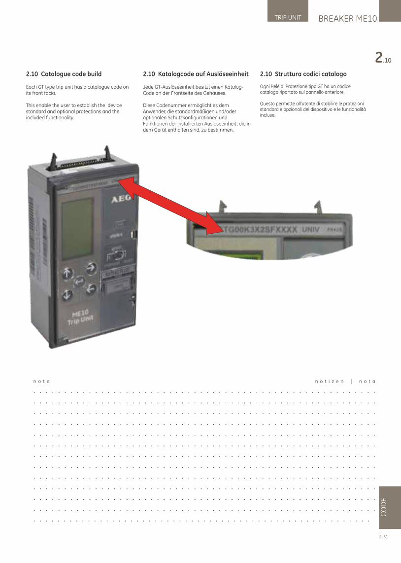
2.10 Catalogue code build
Each GT type trip unit has a catalogue code on its front facia.
This enable the user to establish the device standard and optional protections and the included functionality.
2.10 Katalogcode auf Auslöseeinheit
Jede GT-Auslöseeinheit besitzt einen Katalog-Code an der Frontseite des Gehäuses.
Diese Codenummer ermöglicht es dem Anwender, die standardmäßigen und/oder optionalen Schutzkonfigurationen und Funktionen der installierten Auslöseeinheit, die in dem Gerät enthalten sind, zu bestimmen.
2.10 Struttura codici catalogo
Ogni Relè di Protezione tipo GT ha un codice catalogo riportato sul pannello anteriore.
Questo permette all'utente di stabilire le protezioni standard e opzionali del dispositivo e le funzionalità incluse.
n o t e n o t i z e n | n o t a
. . . . . . . . . . . . . . . . . . . . . . . . . . . . . . . . . . . . . . . . . . . . . . . . . . . . . . . .
. . . . . . . . . . . . . . . . . . . . . . . . . . . . . . . . . . . . . . . . . . . . . . . . . . . . . . . .
. . . . . . . . . . . . . . . . . . . . . . . . . . . . . . . . . . . . . . . . . . . . . . . . . . . . . . . .
. . . . . . . . . . . . . . . . . . . . . . . . . . . . . . . . . . . . . . . . . . . . . . . . . . . . . . . .
. . . . . . . . . . . . . . . . . . . . . . . . . . . . . . . . . . . . . . . . . . . . . . . . . . . . . . . .
. . . . . . . . . . . . . . . . . . . . . . . . . . . . . . . . . . . . . . . . . . . . . . . . . . . . . . . .
. . . . . . . . . . . . . . . . . . . . . . . . . . . . . . . . . . . . . . . . . . . . . . . . . . . . . . . .
. . . . . . . . . . . . . . . . . . . . . . . . . . . . . . . . . . . . . . . . . . . . . . . . . . . . . . . .
. . . . . . . . . . . . . . . . . . . . . . . . . . . . . . . . . . . . . . . . . . . . . . . . . . . . . . . .
. . . . . . . . . . . . . . . . . . . . . . . . . . . . . . . . . . . . . . . . . . . . . . . . . . . . . . . .
. . . . . . . . . . . . . . . . . . . . . . . . . . . . . . . . . . . . . . . . . . . . . . . . . . . . . . . .
. . . . . . . . . . . . . . . . . . . . . . . . . . . . . . . . . . . . . . . . . . . . . . . . . . . . . . . .
. . . . . . . . . . . . . . . . . . . . . . . . . . . . . . . . . . . . . . . . . . . . . . . . . . . . . . . .
BREAKER ME10TRIP UNIT
CO
DE
2.10
2-51
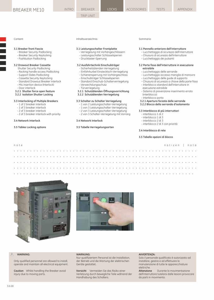
Content
3.1 Breaker front Fascia - Breaker Security Padlocking - Breaker Security Keylocking - Pushbutton Padlocking
3.2 Drawout Breaker Cassette Shutter Security Padlocking - Racking handle access Padlocking - Support Slides Padlocking - Cassette Security Keylocking - Standard Drawout Breaker Interlock - Mis insertion device (Interlock) - Door interlock 3.2.1 Shutter force open feature 3.2.2 Isolation Shutter Locking
3.3 Interlocking of Multiple Breakers - 1 of 2 breaker interlock - 1 of 3 breaker interlock - 2 of 3 breaker interlock - 2 of 3 breaker interlock with priority
3.4 Network Interlock
3.5 Tables Locking options
Inhaltsverzeichnis
3.1 Leistungsschalter Frontplatte - Verriegelung mit Vorhängeschlössern - Leistungsschalter Schlüsselsperren - Drucktaster-Sperrung
3.2 Ausfahrtechnik Einschubträger - Sicherheitsblenden Verriegelung - Einfahrkurbel Einsteckloch-Verriegelung - Schienensperrung mit Vorhängeschloss - Einschubträger Schlüsselsperren - Standard Einschub-Schalterverriegelung - Verwechslungsschutz - Türverriegelung 3.2.1 Schutzblenden Öffnungsvorrichtung 3.2.2 Schutzblenden Verriegelung
3.3 Schalter zu Schalter Verriegelung - 1 von 2 Leistungsschalter-Verriegelung - 1 von 3 Leistungsschalter-Verriegelung - 2 von 3 Leistungsschalter-Verriegelung - 2 von 3 Schalter-Verriegelung mit Vorrang
3.4 Network Interlock
3.5 Tabelle Verriegelungsarten
Sommario
3.1 Pannello anteriore dell'interruttore - Lucchettaggio di sicurezza dell'interruttore - Chiusura di sicurezza dell'interruttore - Lucchettaggio dei pulsanti
3.2 Parte fissa dell'interruttore in esecuzione estraibile
- Lucchettaggio delle serrande - Lucchettaggio accesso maniglia di manovra - Lucchettaggio delle guide di supporto - Chiusura di sicurezza a chiave della parte fissa - Interblocco standard dell'interruttore in
esecuzione estraibile - Sistema di prevenzione inserimento errato
(interblocco) - Interblocco porta 3.2.1 Apertura forzata delle serrande 3.2.2 Blocco della serranda d'isolamento
3.3 Interblocco di più interruttori - interblocco 1 di 2 - interblocco 1 di 3 - interblocco 2 di 3 - interblocco 2 di 3 con priorità
3.4 Interblocco di rete
3.5 Tabelle opzioni di blocco
WARNUNG:Nur qualifiziertem Personal ist die Installation, der Betrieb und die Wartung der elektrischen Geräte gestattet.
Vorsicht Vermeiden Sie das Risiko einer Verletzung durch bewegliche Teile während der Handhabung des Schalters.
WARNING:
Only qualified personnel are allowed to install, operate and maintain all electrical equipment.
Caution Whilst handling the Breaker avoid injury due to moving parts.
AVVERTENZA: Solo il personale qualificato è autorizzato ad installare, gestire e ad effettuare la manutenzione di tutte le apparecchiature elettriche. Attenzione Durante la movimentazione dell'interruttore tutelarsi dalle lesioni provocare da parti in movimento.
n o t e n o t i z e n | n o t a
. . . . . . . . . . . . . . . . . . . . . . . . . . . . . . . . . . . . . . . . . . . . . . . . . . . . . . . .
. . . . . . . . . . . . . . . . . . . . . . . . . . . . . . . . . . . . . . . . . . . . . . . . . . . . . . . .
. . . . . . . . . . . . . . . . . . . . . . . . . . . . . . . . . . . . . . . . . . . . . . . . . . . . . . . .
. . . . . . . . . . . . . . . . . . . . . . . . . . . . . . . . . . . . . . . . . . . . . . . . . . . . . . . .
. . . . . . . . . . . . . . . . . . . . . . . . . . . . . . . . . . . . . . . . . . . . . . . . . . . . . . . .
LOCKSBREAKER ME10 INTRO BREAKER ACCESSORIES TESTS APPENDIX
TRIP UNIT
3.0-00
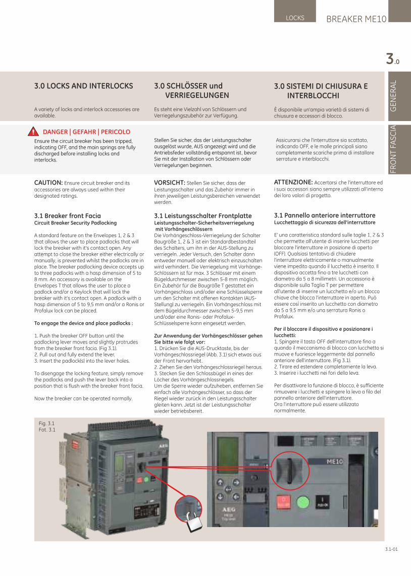
3.0 SCHLÖSSER und VERRIEGELUNGEN
Es steht eine Vielzahl von Schlössern und Verriegelungszubehör zur Verfügung.
VORSICHT: Stellen Sie sicher, dass der Leistungsschalter und das Zubehör immer in ihren jeweiligen Leistungsbereichen verwendet werden.
3.1 Leistungsschalter FrontplatteLeistungsschalter-Sicherheitsverriegelung mit VorhängeschlössernDie Vorhängeschloss-Verriegelung der Schalter Baugröße 1, 2 & 3 ist ein Standardbestandteil des Schalters, um ihn in der AUS-Stellung zu verriegeln. Jeder Versuch, den Schalter dann entweder manuell oder elektrisch einzuschalten wird verhindert. Die Verriegelung mit Vorhänge-Schlössern ist für max. 3 Schlösser mit einem Bügeldurchmesser zwischen 5-8 mm möglich.Ein Zubehör für die Baugröße T gestattet ein Vorhängeschloss und/oder eine Schlüsselsperre um den Schalter mit offenen Kontakten (AUS-Stellung) zu verriegeln. Ein Vorhängeschloss mit dem Bügeldurchmesser zwischen 5-9,5 mm und/oder eine Ronis- oder Profalux-Schlüsselsperre kann eingesetzt werden.
Zur Anwendung der Vorhängeschlösser gehen Sie bitte wie folgt vor: 1. Drücken Sie die AUS-Drucktaste, bis der Vorhängeschlossriegel (Abb. 3.1) sich etwas aus der Front hervorhebt.2. Ziehen Sie den Vorhängeschlossriegel heraus.3. Stecken Sie den Schlossbügel in eines der Löcher des Vorhängeschlossriegels.Um die Sperre wieder aufzuheben, entfernen Sie einfach alle Vorhängeschlösser, so dass der Riegel wieder zurück in den Leistungsschalter gleiten kann. Jetzt ist der Leistungsschalter wieder betriebsbereit.
3.0 LOCKS AND INTERLOCKS
A variety of locks and interlock accessories are available.
CAUTION: Ensure circuit breaker and its accessories are always used within their designated ratings.
3.1 Breaker front FaciaCircuit Breaker Security Padlocking
A standard feature on the Envelopes 1, 2 & 3 that allows the user to place padlocks that will lock the breaker with it's contact open. Any attempt to close the breaker either electrically or manually, is prevented whilst the padlocks are in place. The breaker padlocking device accepts up to three padlocks with a hasp dimension of 5 to 8 mm. An accessory is available on the Envelopes T that allows the user to place a padlock and/or a Keylock that will lock the breaker with it's contact open. A padlock with a hasp dimension of 5 to 9,5 mm and/or a Ronis or Profalux lock can be placed.
To engage the device and place padlocks :
1. Push the breaker OFF button until the padlocking lever moves and slightly protrudes from the breaker front facia. (Fig 3.1).2. Pull out and fully extend the lever. 3. Insert the padlock(s) into the lever holes.
To disengage the locking feature, simply remove the padlocks and push the lever back into a position that is flush with the breaker front facia.
Now the breaker can be operated normally.
3.0 SISTEMI DI CHIUSURA E INTERBLOCCHI
È disponibile un'ampia varietà di sistemi di chiusura e accessori di blocco.
ATTENZIONE: Accertarsi che l'interruttore ed i suoi accessori siano sempre utilizzati all'interno dei loro valori di progetto.
3.1 Pannello anteriore interruttoreLucchettaggio di sicurezza dell'interruttore
E' una caratteristica standard sulle taglie 1, 2 & 3 che permette all'utente di inserire lucchetti per bloccare l'interruttore in posizione di aperto (OFF). Qualsiasi tentativo di chiudere l'interruttore elettricamente o manualmente viene impedito quando il lucchetto è inserito. Il dispositivo accetta fino a tre lucchetti con diametro da 5 a 8 millimetri. Un accessorio è disponibile sulla Taglia T per permettere all'utente di inserire un lucchetto e/o un blocco chiave che blocca l'interruttore in aperto. Può essere così inserito un lucchetto con diametro da 5 a 9,5 mm e/o una serratura Ronis o Profalux.
Per il bloccare il dispositivo e posizionare i lucchetti:1. Spingere il tasto OFF dell'interruttore fino a quando il meccanismo di blocco con lucchetto si muove e fuoriesce leggermente dal pannello anteriore dell'interruttore. (Fig 3.1).2. Tirare ed estendere completamente la leva. 3. Inserire i lucchetti nei fori della leva.
Per disattivare la funzione di blocco, è sufficiente rimuovere i lucchetti e spingere la leva a filo del pannello anteriore dell'interruttore.Ora l'interruttore può essere utilizzato normalmente.
BREAKER ME10LOCKS
GE
NE
RA
L
3.0
FRO
NT
FAS
CIA
3.1-01
DANGER | GEFAHR | PERICOLOStellen Sie sicher, das der Leistungsschalter ausgelöst wurde, AUS angezeigt wird und die Antriebsfeder vollständig entspannt ist, bevor Sie mit der Installation von Schlössern oder Verriegelungen beginnen.
Ensure the circuit breaker has been tripped, indicating OFF, and the main springs are fully discharged before installing locks and interlocks.
Assicurarsi che l'interruttore sia scattato, indicando OFF, e le molle principali siano completamente scariche prima di installare serrature e interblocchi.
Fig. 3.1Fot. 3.1
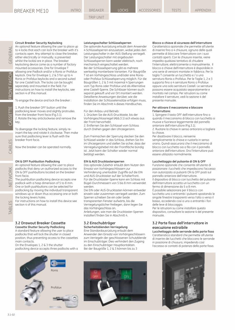
Blocco a chiave di sicurezza dell'interruttoreCaratteristica opzionale che permette all'utente di inserire fino a 4 chiusure, ognuna delle quali permette di bloccare l'interruttore con i suoi contatti aperti. Con le chiusure inserite, viene impedito qualsiasi tentativo di chiudere l'interruttore, elettricamente o manualmente. Il blocco a chiave dell'interruttore è disponibile in una serie di versioni montate in fabbrica. Per la taglia T consente un lucchetto e / o una serratura Ronis o Profalux. Per le Taglie 1, 2 e 3 supporta fino a 4 serrature Ronis o Profalux oppure una sola serratura Castell. Le serrature possono essere acquistato separatamente e montato nel campo. Per istruzioni su come installare il serrature, vedi la sezione 4 del presente manuale.
Per attivare il meccanismo e bloccare l'interruttore:1. Spingere il tasto OFF dell'interruttore fino a quando il meccanismo di blocco con lucchetto si muove e fuoriesce leggermente dal pannello anteriore dell'interruttore (Fig.3.1).2. Ruotare la chiave in senso antiorario e togliere la chiave.Per disattivare il blocco, reinserire semplicemente la chiave e ruotarla in senso orario. Quindi assicurarsi che il meccanismo di blocco con lucchetto sia a filo con il pannello anteriore dell'interruttore. Ora l'interruttore può essere utilizzato normalmente.
Lucchettaggio del pulsante di ON & OFFFunzione opzionale che consente all'utente di posizionare i lucchetti che impediscono l'accesso non autorizzato ai pulsanti ON & OFF posti sul pannello anteriore dell'interruttore.Il dispositivo di blocco con lucchetto del pulsante dell'interruttore accetta un lucchetto con un fermo di dimensione da 5 a 8 mm. È possibile selezionare per il blocco con lucchetto uno o entrambi i pulsanti spostando le singole finestre trasparenti verso l'alto o verso il basso, accedendo così a uno o entrambi i fori delle leve di bloccaggio. Per le istruzioni su come installare questo dispositivo, consultare la sezione 4 del presente manuale.
3.2 Parte fissa dell'interruttore in esecuzione estraibileLucchettaggio delle serrande della parte fissaCaratteristica standard che permette all'utente di inserire dei lucchetti che bloccano le serrande in posizione di chiusura, impedendo così l'accesso ai contatti di potenza della parte fissa.
LOCKSBREAKER ME10 INTRO BREAKER ACCESSORIES TESTS APPENDIX
TRIP UNIT
GE
NE
RA
LFR
ON
T FA
SC
IAC
AS
SE
TTE
CA
BLE
SN
ET
WO
RK
TAB
LES
3.1-02
Ronis
Profalux
Circuit Breaker Security KeylockingAn optional feature allowing the user to place up to 4 locks that each can lock the breaker with it's contacts open. Any attempt to close the breaker, either electrically or manually, is prevented whilst the lock(s) are in place. The breaker keylocking device come as a number of factory mounted accessories. One for Envelope T allowing one Padlock and/or a Ronis or Profalux keylock. One for Envelope 1, 2 & 3 for up to 4 Ronis or Profalux keylocks and a second suited for one Castell lock. The locks can be bought separately and mounted in the field. For instructions on how to install the keylocks, see section 4 of this manual.
To engage the device and lock the breaker :
1. Push the breaker OFF button until the padlocking lever moves and slightly protrudes from the breaker front facia (Fig.3.1).2. Rotate the key anticlockwise and remove the key.
To disengage the locking feature, simply re-insert the key and rotate it clockwise. Then make sure that padlocking lever is flush with the breaker front facia.
Now the breaker can be operated normally.
ON & OFF Pushbutton PadlockingAn optional feature allowing the user to place padlocks that deny un-authorized access to the ON & OFF pushbuttons located on the breaker front facia.The pushbutton padlocking device accepts one padlock with a hasp dimension of 5 to 8 mm. One or both pushbuttons can be selected for padlocking by moving the individual transparent windows up or down thus accessing one or both the locking levers holes. For instructions on how to install this device see section 4 of this manual.
3.2 Drawout Breaker CassetteCassette Shutter Security PadlockingA standard feature allowing the user to place padlocks that will lock the shutter in closed position, thus preventing access to the cassettes main contacts.On the Envelopes 1, 2 & 3 the shutter padlocking device accepts three padlocks with a
Leistungsschalter Schlüsselsperren Die optionale Ausrüstung erlaubt dem Anwender 4 Schlüsselsperren einzusetzen, wobei jedes den Leistungsschalter in der AUS-Stellung verriegelt. Der Leistungsschalter mit angebauten Schlüsselsperren kann weder elektrisch, noch mechanisch eingeschaltet werden.Bei der Schlüsselsperrung gibt es mehrere werkseitig montierbare Varianten. Für Baugröße T ist ein Vorhängeschloss und/oder eine Ronis- oder Profalux Schlüsselsperrung möglich. Für die Baugrößen 1, 2 & 3 mit maximal 4 Sperrungen vom Typ Ronis oder Profalux und als Alternative eine Castell-Sperre. Die Schlösser können auch separat gekauft und vor Ort montiert werden.Detaillierte Anweisungen darüber, wie die Installation der Schlüsseleinsätze erfolgen muss, finden Sie im Abschnitt 4 dieses Handbuches.
Für den Anbau und Betrieb: 1. Drücken Sie die AUS-Drucktaste, bis der Vorhängeschlossriegel (Abb.3.1) sich etwas aus der Front hervorhebt. 2. Entfernen Sie den Schlüssel vom Schloss durch Drehen gegen den Uhrzeigersinn.
Zum Freimachen der Sperrung stecken Sie den Schlüssel wieder in das Schloss, drehen Sie ihn im Uhrzeigersinn und stellen Sie sicher, dass der Verriegelungshebel mit der Frontfläche bündig ist. Jetzt kann der Schalter wieder normal betätigt werden.
EIN & AUS Drucktastersperren Das optionale Zubehör erlaubt dem Nutzer den Einsatz von Vorhängeschlössern zur Verhinderung unerlaubter Zugriffe auf die EIN und AUS-Drucktaster auf der Schalterfront.Für die Drucktaster-Sperre kann ein Schloss mit Bügel-Durchmessern von 5 bis 8 mm verwendet werden. Die EIN oder AUS-Drucktasten können entweder einzeln oder zusammen verriegelt werden. Zum Sperren schieben Sie ein oder beide transparenten Fenster aufwärts, bis die Verriegelungslöcher freiliegen, dann legen Sie das Vorhängeschloss an.Anleitungen, wie man die Drucktaster-Sperren installiert finden Sie in Abschnitt 4.
3.2 EinschubträgerSicherheitsblenden Verriegelung Eine Standardausrüstung erlaubt dem Anwender den Einsatz von Vorhängeschlössern zum Verriegeln der geschlossenen Schutzblende im Einschubträger. Dies verhindert den Zugang zu den Einschubträger Hauptkontakten.Bei der Baugröße 1, 2 & 3 können bis zu 3
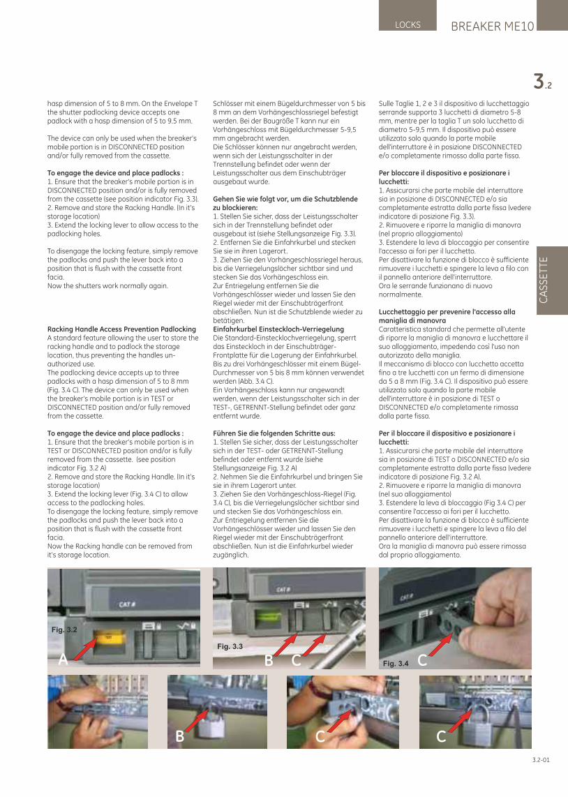
Sulle Taglie 1, 2 e 3 il dispositivo di lucchettaggio serrande supporta 3 lucchetti di diametro 5-8 mm, mentre per la taglia T un solo lucchetto di diametro 5-9,5 mm. Il dispositivo può essere utilizzato solo quando la parte mobile dell'interruttore è in posizione DISCONNECTED e/o completamente rimosso dalla parte fissa.
Per bloccare il dispositivo e posizionare i lucchetti:1. Assicurarsi che parte mobile del interruttore sia in posizione di DISCONNECTED e/o sia completamente estratta dalla parte fissa (vedere indicatore di posizione Fig. 3.3).2. Rimuovere e riporre la maniglia di manovra (nel proprio alloggiamento)3. Estendere la leva di bloccaggio per consentire l'accesso ai fori per il lucchetto.Per disattivare la funzione di blocco è sufficiente rimuovere i lucchetti e spingere la leva a filo con il pannello anteriore dell'interruttore.Ora le serrande funzionano di nuovo normalmente.
Lucchettaggio per prevenire l'accesso alla maniglia di manovraCaratteristica standard che permette all'utente di riporre la maniglia di manovra e lucchettare il suo alloggiamento, impedendo così l'uso non autorizzato della maniglia.Il meccanismo di blocco con lucchetto accetta fino a tre lucchetti con un fermo di dimensione da 5 a 8 mm (Fig. 3.4 C). Il dispositivo può essere utilizzato solo quando la parte mobile dell'interruttore è in posizione di TEST o DISCONNECTED e/o completamente rimossa dalla parte fissa.
Per il bloccare il dispositivo e posizionare i lucchetti:1. Assicurarsi che parte mobile del interruttore sia in posizione di TEST o DISCONNECTED e/o sia completamente estratta dalla parte fissa (vedere indicatore di posizione Fig. 3.2 A).2. Rimuovere e riporre la maniglia di manovra (nel suo alloggiamento)3. Estendere la leva di bloccaggio (Fig 3.4 C) per consentire l'accesso ai fori per il lucchetto.Per disattivare la funzione di blocco è sufficiente rimuovere i lucchetti e spingere la leva a filo del pannello anteriore dell'interruttore.Ora la maniglia di manovra può essere rimossa dal proprio alloggiamento.
BREAKER ME10LOCKS
CA
SS
ET
TE
3.2
3.2-01
A
Fig. 3.2
B CFig. 3.3
Fig. 3.4 C
C CB
hasp dimension of 5 to 8 mm. On the Envelope T the shutter padlocking device accepts one padlock with a hasp dimension of 5 to 9.5 mm.
The device can only be used when the breaker's mobile portion is in DISCONNECTED position and/or fully removed from the cassette.
To engage the device and place padlocks :1. Ensure that the breaker's mobile portion is in DISCONNECTED position and/or is fully removed from the cassette (see position indicator Fig. 3.3).2. Remove and store the Racking Handle. (In it's storage location)3. Extend the locking lever to allow access to the padlocking holes.
To disengage the locking feature, simply remove the padlocks and push the lever back into a position that is flush with the cassette front facia.Now the shutters work normally again.
Racking Handle Access Prevention PadlockingA standard feature allowing the user to store the racking handle and to padlock the storage location, thus preventing the handles un-authorized use.The padlocking device accepts up to three padlocks with a hasp dimension of 5 to 8 mm (Fig. 3.4 C). The device can only be used when the breaker's mobile portion is in TEST or DISCONNECTED position and/or fully removed from the cassette.
To engage the device and place padlocks :1. Ensure that the breaker's mobile portion is in TEST or DISCONNECTED position and/or is fully removed from the cassette. (see position indicator Fig. 3.2 A)2. Remove and store the Racking Handle. (In it's storage location)3. Extend the locking lever (Fig. 3.4 C) to allow access to the padlocking holes.To disengage the locking feature, simply remove the padlocks and push the lever back into a position that is flush with the cassette front facia.Now the Racking handle can be removed from it's storage location.
Schlösser mit einem Bügeldurchmesser von 5 bis 8 mm an dem Vorhängeschlossriegel befestigt werden. Bei der Baugröße T kann nur ein Vorhängeschloss mit Bügeldurchmesser 5-9,5 mm angebracht werden.Die Schlösser können nur angebracht werden, wenn sich der Leistungsschalter in der Trennstellung befindet oder wenn der Leistungsschalter aus dem Einschubträger ausgebaut wurde.
Gehen Sie wie folgt vor, um die Schutzblende zu blockieren: 1. Stellen Sie sicher, dass der Leistungsschalter sich in der Trennstellung befindet oder ausgebaut ist (siehe Stellungsanzeige Fig. 3.3).2. Entfernen Sie die Einfahrkurbel und stecken Sie sie in ihren Lagerort. 3. Ziehen Sie den Vorhängeschlossriegel heraus, bis die Verriegelungslöcher sichtbar sind und stecken Sie das Vorhängeschloss ein.Zur Entriegelung entfernen Sie die Vorhängeschlösser wieder und lassen Sie den Riegel wieder mit der Einschubträgerfront abschließen. Nun ist die Schutzblende wieder zu betätigen.Einfahrkurbel Einsteckloch-Verriegelung Die Standard-Einstecklochverriegelung, sperrt das Einsteckloch in der Einschubträger-Frontplatte für die Lagerung der Einfahrkurbel. Bis zu drei Vorhängeschlösser mit einem Bügel-Durchmesser von 5 bis 8 mm können verwendet werden (Abb. 3.4 C).Ein Vorhängeschloss kann nur angewandt werden, wenn der Leistungsschalter sich in der TEST-, GETRENNT-Stellung befindet oder ganz entfernt wurde.
Führen Sie die folgenden Schritte aus: 1. Stellen Sie sicher, dass der Leistungsschalter sich in der TEST- oder GETRENNT-Stellung befindet oder entfernt wurde (siehe Stellungsanzeige Fig. 3.2 A)2. Nehmen Sie die Einfahrkurbel und bringen Sie sie in ihrem Lagerort unter. 3. Ziehen Sie den Vorhängeschloss-Riegel (Fig. 3.4 C), bis die Verriegelungslöcher sichtbar sind und stecken Sie das Vorhängeschloss ein.Zur Entriegelung entfernen Sie die Vorhängeschlösser wieder und lassen Sie den Riegel wieder mit der Einschubträgerfront abschließen. Nun ist die Einfahrkurbel wieder zugänglich.

Lucchettaggio delle guide di supporto estraibiliCaratteristica standard che permette all'utente di posizionare dei lucchetti che impediscono l'inserimento della porzione mobile di un interruttore nella parte fissa. Il dispositivo di lucchettaggio è presente su entrambe le guide: ciascuna può accettare fino a tre lucchetti con un fermo di dimensione da 5 a 8 mm (vedere Fig. 3.5). Può essere utilizzato solo quando la porzione mobile dell'interruttore è in posizione di DISCONNECTED e completamente estratta dalla parte fissa.Per il bloccare il dispositivo e posizionare i lucchetti:1. Assicurarsi che parte mobile del interruttore sia in posizione di DISCONNECTED e sia completamente estratta dalla parte fissa.2. Spingere le guide all'interno della parte fissa.3. Posizionare i lucchetti.Per disattivare la funzione di blocco, è sufficiente rimuovere i lucchetti e ri-estendere le guide estraibili per permettere di nuovo il loro utilizzo.La porta dell'armadio può essere chiusa anche con il blocco con lucchetto inserito.
Non tentare di forzare l'estensione delle guide quando sono inseriti i lucchetti.
Chiusura di sicurezza a chiave della parte fissaFunzione opzionale che consente all'utente di inserire fino a 2 serrature: ciascuna può bloccare l'interruttore in posizione di TEST o DISCONNECTED (vedere Fig. 3.6). Con le serrature inserite, viene impedito qualsiasi tentativo di chiudere l'interruttore, elettricamente o manualmente. Viene anche impedito l'accesso all'alloggiamento della maniglia di manovra.Il dispositivo di chiusura a chiave della parte fissa è un accessorio montato in fabbrica. La taglia T accetta un blocco chiave sulla parte fissa, mentre le taglie 1, 2 e 3 può ospitare 2 blocchi chiave.E' possibile utilizzare serrature Ronis oppure Profalux, senza mischiarle.Le serrature possono essere acquistate separatamente e montate in loco. Le istruzioni relative all'installazione delle serrature sono riportate nella sezione 4 del presente manuale.
Per il bloccare il dispositivo e bloccare la parte fissa:1. Assicurarsi che parte mobile dell'interruttore sia in posizione di TEST o DISCONNECTED e che sia completamente rimossa dalla parte fissa.2. Rimuovere e riporre la maniglia di manovra (nel proprio alloggiamento)3. Ruotare una o entrambe le chiavi in senso antiorario e togliere le chiavi.Per disattivare il blocco, reinserire semplicemente la chiave e ruotarla in senso orario. Per sbloccare la funzione di blocco DEVONO essere presenti entrambe le chiavi.Per le istruzioni su come installare questo
LOCKSBREAKER ME10 INTRO BREAKER ACCESSORIES TESTS APPENDIX
TRIP UNIT
GE
NE
RA
LFR
ON
T FA
SC
IAC
AS
SE
TTE
CA
BLE
SN
ET
WO
RK
TAB
LES
3.2-02
Fig. 3.6
Fig. 3.5
A
Fig. 3.5A
Drawout Support Slides PadlockingA standard feature allowing the user to place padlocks that will prevent the insertion of a breaker's mobile portion into the cassette. The padlocking device is present on both slides and each can accept up to three padlocks with a hasp dimension of 5 to 8 mm (see Fig. 3.5). It can only be used when the breaker's mobile portion is in DISCONNECTED position and fully removed from the cassette.
To engage the device and place padlocks :
1. Ensure that the breaker's mobile portion is in DISCONNECTED position an is fully removed from the cassette.2. Push the slides back into the cassette.3. Place padlocks.
To disengage the locking feature, simply remove the padlocks and re-extend the drawout slides to allow their use again.The cabinet door can be closed with the padlocking feature engaged.
Do not attempt to forcefully extend the slides whilst padlocked.
Cassette Security KeylockingAn optional feature allowing the user to place up to 2 locks that each can lock the breaker in TEST or DISCONNECTED position (see Fig. 3.6). It is not possible to close the breaker, either electrically or manually whilst the lock's are engaged. Access to the racking handle storage location is also prevented.The cassette keylocking device is a factory mounted accessory. One lock can be placed in the Envelope T cassette, while up to two locks can be used in Envelope 1, 2 & 3 cassette.The device allows the uses of Ronis- or Profalux- Keylocks (cannot be mixed).
The locks can be bought separately and mounted in the field. For instructions on how to install the keylocks, see section 4 of this manual.
To engage the device and lock the cassette :1. Ensure that the breaker's mobile portion is in TEST or DISCONNECTED position and is fully removed from the cassette.2. Remove and store the Racking Handle. (In it's storage location)3. Rotate one or both keys anticlockwise and remove the key's).
To disengage the locking feature, simply re-insert the key and rotate it clockwise. Both keys MUST be present to disengage the locking feature.
Einschubträger SchienensperrungDer Einschubträger ist standardmäßig mit einer Funktion ausgestattet, die das Sperren der Montageschienen des Einschubträgers erlaubt. Dies macht es unmöglich, einen Leistungsschalter auf die Schienen im Einschubträger zu setzen. Bis zu 3 Schlösser mit einem Bügel-Durchmesser von 5 bis 8 mm können auf jeder Schiene angewendet werden (siehe Fig. 3.5). Der Leistungsschalter muss entfernt werden, um Zugang zur Verriegelung zu erhalten.Beachten Sie die folgenden Schritte zum Sperren:1. Entfernen Sie den Leistungsschalter vom Einschubträger in der GETRENNT-Stellung. 2. Schieben Sie die Schienen vollständig in den Einschubträger ein. 3. Jetzt setzen Sie die gewünschte Anzahl der Schlösser ein.Zur Entriegelung entfernen Sie die Vorhängeschlösser wieder und ziehen Sie die Schienen wieder raus.Mit den installierten Schlössern kann die Schaltschranktür geschlossen werden.
Wenden Sie keine Gewalt an, um die Schienen gegen die eingesteckten Schlösser aus dem Einschubträger zu ziehen.Einschubträger SchlüsselsperrenEine optionale Ausrüstung erlaubt dem Anwender 2 Schlüsselsperren einzubauen (siehe Fig. 3.6), wobei jede den Einschubträger in der TEST oder TRENN-Stellung sperrt. Weder elektrisch, noch von Hand kann der Schalter eingeschaltet werden, während die Sperren genutzt werden. Der Zugang zum Einfahrhebel-Lager ist ebenfalls gesperrt. Die Einschubträger Schlüsselsperren sind ein werkseitig montierbares Zubehör. Eine Einzelsperrung kann im Einschubträger Baugröße T, jedoch bis zu zwei in der Baugröße 1, 2 & 3 genutzt werden. Es können Ronis- oder Profalux-Sperren verwendet werden. Es ist nicht möglich verschiedene Schlüsselsperren in einem Einschubträger zu verwenden. Die Einsätze für die Schlüssel können extra zugekauft werden und Vorort montiert werden. Wie sie montiert werden ist in Kapitel 4 genauer beschrieben.
Durchführung der Sperrfunktion:1. Entfernen Sie den Leistungsschalter vom Einschubträger in der GETRENNT-Stellung. 2. Entfernen und lagern Sie den Einfahrhebel in seiner Lagerstelle im Einschubträger.3. Drehen Sie einen oder beide Schlüssel gegen den Uhrzeigersinn und entfernen Sie die Schlüssel..Zur Entriegelung stecken Sie die Schlüssel ein und drehen Sie sie im Uhrzeigersinn. Beide Schlüssel müssen zur Entsperrung vorhanden sein. Die Anleitung zur Montage ist in Kapitel 4 genauer beschrieben.
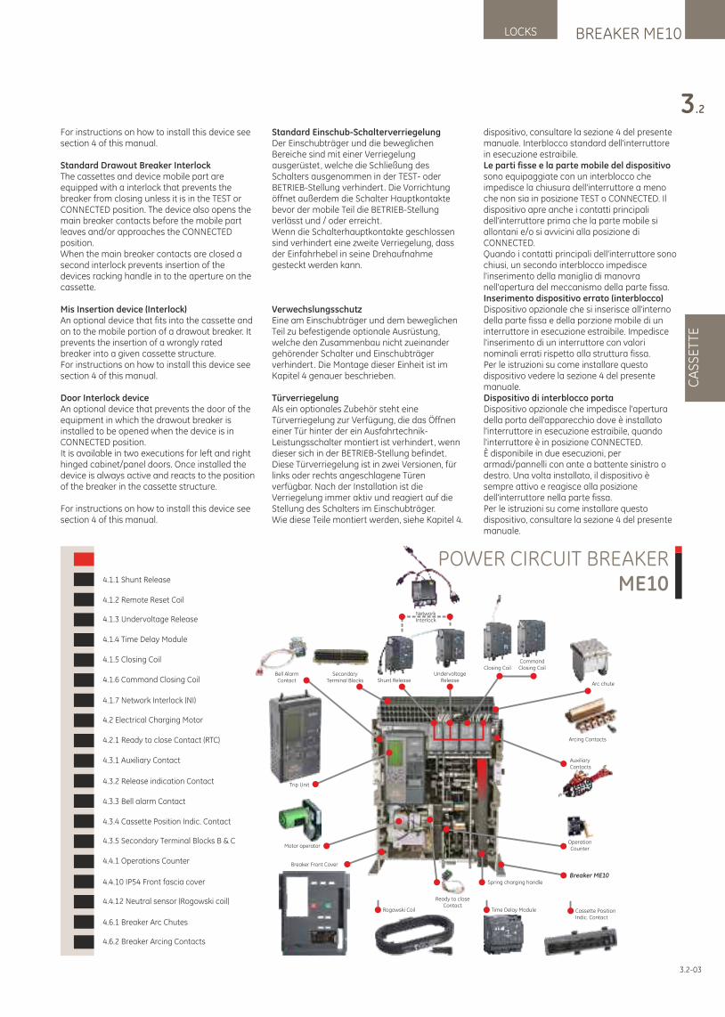
dispositivo, consultare la sezione 4 del presente manuale. Interblocco standard dell'interruttore in esecuzione estraibile.Le parti fisse e la parte mobile del dispositivo sono equipaggiate con un interblocco che impedisce la chiusura dell'interruttore a meno che non sia in posizione TEST o CONNECTED. Il dispositivo apre anche i contatti principali dell'interruttore prima che la parte mobile si allontani e/o si avvicini alla posizione di CONNECTED.Quando i contatti principali dell'interruttore sono chiusi, un secondo interblocco impedisce l'inserimento della maniglia di manovra nell'apertura del meccanismo della parte fissa.Inserimento dispositivo errato (interblocco)Dispositivo opzionale che si inserisce all'interno della parte fissa e della porzione mobile di un interruttore in esecuzione estraibile. Impedisce l'inserimento di un interruttore con valori nominali errati rispetto alla struttura fissa. Per le istruzioni su come installare questo dispositivo vedere la sezione 4 del presente manuale.Dispositivo di interblocco portaDispositivo opzionale che impedisce l'apertura della porta dell'apparecchio dove è installato l'interruttore in esecuzione estraibile, quando l'interruttore è in posizione CONNECTED.È disponibile in due esecuzioni, per armadi/pannelli con ante a battente sinistro o destro. Una volta installato, il dispositivo è sempre attivo e reagisce alla posizione dell'interruttore nella parte fissa.Per le istruzioni su come installare questo dispositivo, consultare la sezione 4 del presente manuale.
3.2-03
BREAKER ME10LOCKS
CA
SS
ET
TE
3.2
Trip Unit
Operation Counter
Spring charging handle
UndervoltageReleaseShunt Release
Motor operator
Bell AlarmContact
AuxiliaryContacts
Ready to closeContact
Time Delay ModuleRogowski Coil Cassette PositionIndic. Contact
SecondaryTerminal Blocks
NetworkInterlock
CommandClosing CoilClosing Coil
Arcing Contacts
Arc chute
Breaker ME10
Breaker Front Cover
POWER CIRCUIT BREAKERME104.1.1 Shunt Release
4.1.2 Remote Reset Coil
4.1.3 Undervoltage Release
4.1.4 Time Delay Module
4.1.5 Closing Coil
4.1.6 Command Closing Coil
4.1.7 Network Interlock (NI)
4.2 Electrical Charging Motor
4.2.1 Ready to close Contact (RTC)
4.3.1 Auxiliary Contact
4.3.2 Release indication Contact
4.3.3 Bell alarm Contact
4.3.4 Cassette Position Indic. Contact
4.3.5 Secondary Terminal Blocks B & C
4.4.1 Operations Counter
4.4.10 IP54 Front fascia cover
4.4.12 Neutral sensor (Rogowski coil)
4.6.1 Breaker Arc Chutes
4.6.2 Breaker Arcing Contacts
For instructions on how to install this device see section 4 of this manual.
Standard Drawout Breaker InterlockThe cassettes and device mobile part are equipped with a interlock that prevents the breaker from closing unless it is in the TEST or CONNECTED position. The device also opens the main breaker contacts before the mobile part leaves and/or approaches the CONNECTED position.When the main breaker contacts are closed a second interlock prevents insertion of the devices racking handle in to the aperture on the cassette.
Mis Insertion device (Interlock)An optional device that fits into the cassette and on to the mobile portion of a drawout breaker. It prevents the insertion of a wrongly rated breaker into a given cassette structure. For instructions on how to install this device see section 4 of this manual.
Door Interlock deviceAn optional device that prevents the door of the equipment in which the drawout breaker is installed to be opened when the device is in CONNECTED position.It is available in two executions for left and right hinged cabinet/panel doors. Once installed the device is always active and reacts to the position of the breaker in the cassette structure.
For instructions on how to install this device see section 4 of this manual.
Standard Einschub-SchalterverriegelungDer Einschubträger und die beweglichen Bereiche sind mit einer Verriegelung ausgerüstet, welche die Schließung des Schalters ausgenommen in der TEST- oder BETRIEB-Stellung verhindert. Die Vorrichtung öffnet außerdem die Schalter Hauptkontakte bevor der mobile Teil die BETRIEB-Stellung verlässt und / oder erreicht.Wenn die Schalterhauptkontakte geschlossen sind verhindert eine zweite Verriegelung, dass der Einfahrhebel in seine Drehaufnahme gesteckt werden kann.
VerwechslungsschutzEine am Einschubträger und dem beweglichen Teil zu befestigende optionale Ausrüstung, welche den Zusammenbau nicht zueinander gehörender Schalter und Einschubträger verhindert. Die Montage dieser Einheit ist im Kapitel 4 genauer beschrieben.
Türverriegelung Als ein optionales Zubehör steht eine Türverriegelung zur Verfügung, die das Öffnen einer Tür hinter der ein Ausfahrtechnik-Leistungsschalter montiert ist verhindert, wenn dieser sich in der BETRIEB-Stellung befindet.Diese Türverriegelung ist in zwei Versionen, für links oder rechts angeschlagene Türen verfügbar. Nach der Installation ist die Verriegelung immer aktiv und reagiert auf die Stellung des Schalters im Einschubträger. Wie diese Teile montiert werden, siehe Kapitel 4.
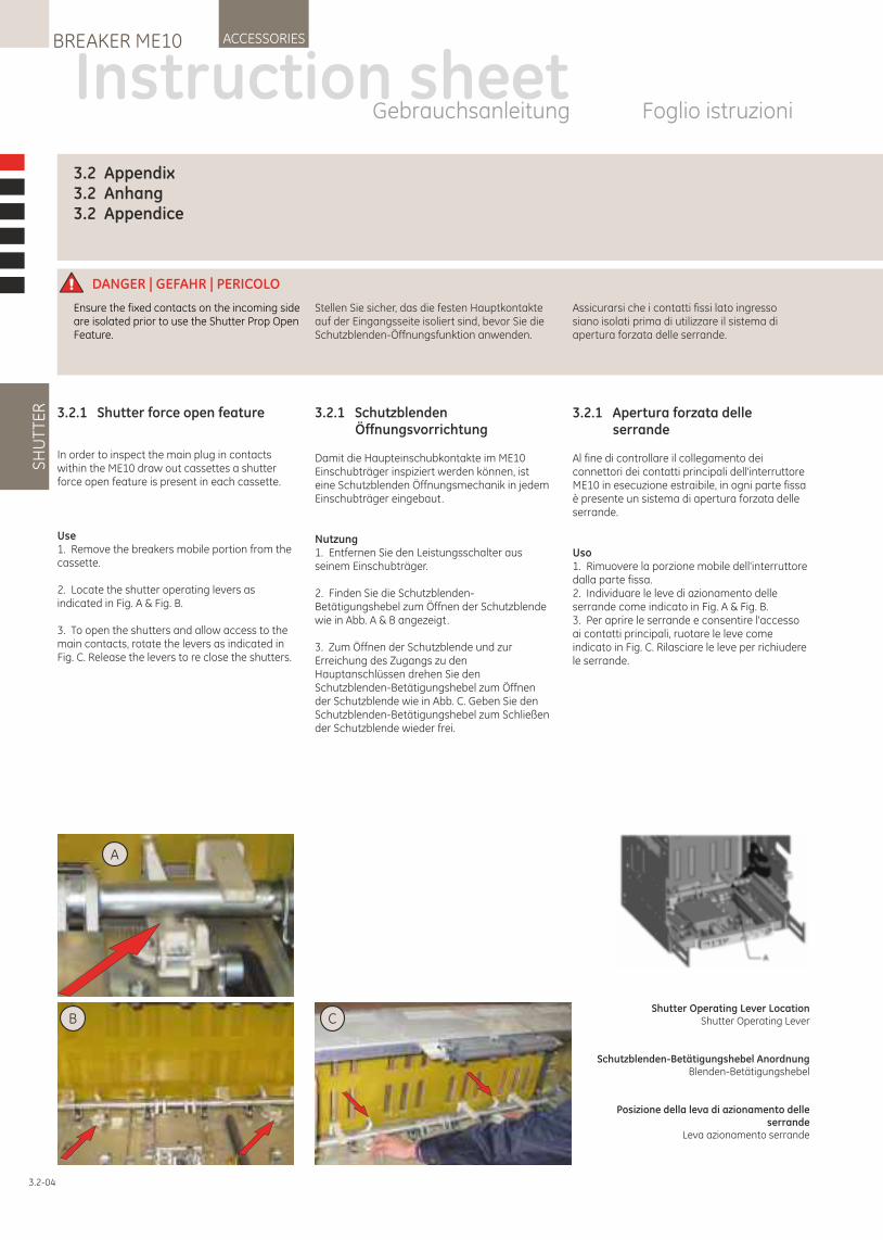
3.2.1 Schutzblenden Öffnungsvorrichtung
Damit die Haupteinschubkontakte im ME10 Einschubträger inspiziert werden können, ist eine Schutzblenden Öffnungsmechanik in jedem Einschubträger eingebaut.
Nutzung1. Entfernen Sie den Leistungsschalter aus seinem Einschubträger.
2. Finden Sie die Schutzblenden-Betätigungshebel zum Öffnen der Schutzblende wie in Abb. A & B angezeigt.
3. Zum Öffnen der Schutzblende und zur Erreichung des Zugangs zu den Hauptanschlüssen drehen Sie den Schutzblenden-Betätigungshebel zum Öffnen der Schutzblende wie in Abb. C. Geben Sie den Schutzblenden-Betätigungshebel zum Schließen der Schutzblende wieder frei.
3.2.1 Shutter force open feature
In order to inspect the main plug in contacts within the ME10 draw out cassettes a shutter force open feature is present in each cassette.
Use1. Remove the breakers mobile portion from the cassette.
2. Locate the shutter operating levers as indicated in Fig. A & Fig. B.
3. To open the shutters and allow access to the main contacts, rotate the levers as indicated in Fig. C. Release the levers to re close the shutters.
DANGER | GEFAHR | PERICOLO
Stellen Sie sicher, das die festen Hauptkontakte auf der Eingangsseite isoliert sind, bevor Sie die Schutzblenden-Öffnungsfunktion anwenden.
Ensure the fixed contacts on the incoming side are isolated prior to use the Shutter Prop Open Feature.
Assicurarsi che i contatti fissi lato ingresso siano isolati prima di utilizzare il sistema di apertura forzata delle serrande.
Instruction sheetGebrauchsanleitung Foglio istruzioni
SH
UT
TER
ACCESSORIESBREAKER ME10
3.2-04
Shutter Operating Lever LocationShutter Operating Lever
Schutzblenden-Betätigungshebel AnordnungBlenden-Betätigungshebel
Posizione della leva di azionamento delle serrande
Leva azionamento serrande
C
A
B
3.2 Appendix 3.2 Anhang3.2 Appendice
3.2.1 Apertura forzata delle serrande
Al fine di controllare il collegamento dei connettori dei contatti principali dell'interruttore ME10 in esecuzione estraibile, in ogni parte fissa è presente un sistema di apertura forzata delle serrande.
Uso1. Rimuovere la porzione mobile dell'interruttore dalla parte fissa.2. Individuare le leve di azionamento delle serrande come indicato in Fig. A & Fig. B.3. Per aprire le serrande e consentire l'accesso ai contatti principali, ruotare le leve come indicato in Fig. C. Rilasciare le leve per richiudere le serrande.
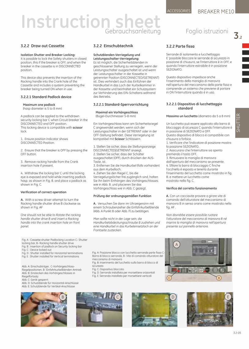
3.2.2 Einschubtechnik
Schutzblenden-Verriegelung und Leistungsschalter-Verriegelung:Es ist möglich, die Sicherheitsblenden in geschlossener Stellung zu verriegeln, wenn der Leistungsschalter ausgeschaltet ist und wenn der Leistungsschalter in der Kassette in getrennter Position (DISCONNECTED/GETRENNT) ist. Dies verhindert auch das Einführen der Handkurbel in das Loch der Kurbelkammer in der Kassette und beinhaltet ein Schutzsystem zur Verhinderung des EIN-Schaltens während des Betriebs.
3.2.2.1 Standard-Sperrvorrichtung
Maximal ein Vorhängeschloss (Bügel-Durchmesser 5-8 mm)
Ein Vorhängeschloss kann am Sicherheitsriegel C angewendet werden, wenn sich der Leistungsschalter in der GETRENNT oder in der OFF-Stellung befindet. Diese Verriegelung ist kompatibel mit Scissor Schlössern.
1. Stellen Sie sicher, dass die Stellungsanzeige DISCONNECTED|GETRENNT anzeigt.2. Stellen Sie sicher, dass der Schalter ausgeschaltet (OFF), durch drücken der AUS-Taste, ist.3. Entfernen Sie die Handkurbel (falls vorhanden) aus dem Kurbelloch.4. Ziehen Sie den Riegel C, bis die Verriegelungslöcher frei zugänglich sind, halten Sie ihn beim Einhängen des Vorhängeschlosses wie in Abb. B. und placieren Sie das Vorhängeschloss wie in Abb. C gezeigt.
Prüfung der ordnungsgemäßen Funktion
A. Versuchen Sie dann im Uhrzeigersinn miteinem Schraubenzieher die Einfahrkurbelblende(Abb. A Punkt B oder Abb. F) zu betätigen.
Man sollte nicht in der Lage sein, die Handkurbelabdeckungsschraube B zudrehen und eine Handkurbel in das Kurbeleinsetzloch an der Frontseite zustecken.
3.2.2 Draw out Cassette
Isolation Shutter and Breaker Locking:It is possible to lock the Safety shutters in closed position, this if the breaker is OFF, and when the breaker in the cassette is in DISCONNECTED position.
This device also prevents the insertion of the Racking handle into the Crank hole of the Cassette and includes a system preventing the breaker being turned ON when in use.
3.2.2.1 Standard Padlock device
Maximum one padlock (hasp diameter is 5 to 8 mm)
A padlock can be applied to the withdrawn security locking bar C when Circuit breaker in the DISCONNECTED and OFF position.This locking device is compatible with scissor lock.
1. Ensure position indicator shows DISCONNECTED Position.
2. Ensure that the breaker is OFF by pressing the OFF button.
3. Remove racking handle from the Crank insertion hole if present.
4. Withdraw the locking bar C until the locking eye is exposed and hold while inserting padlock hasp. as shown in Fig. B. and place a padlock as shown in Fig. C.
Verification of correct operation
A. With a screw driver attempt to turn the Racking handle shutter drive B clockwise as shown in Fig. AF
One should not be able to Rotate the racking handle shutter drive B and insert a Racking handle into the crank insertion hole on front panel.
3.2.2 Parte fissa
Serrande di isolamento e lucchettaggio E 'possibile bloccare le serrande di sicurezza in posizione di chiusura, se l'interruttore è in OFF, e quando l'interruttore estraibile è in posizione SEZIONATO.
Questo dispositivo impedisce anche l'inserimento della maniglia di manovra nell'apertura del meccanismo della parte fissa e comprende un sistema che previene di portare in ON l'interruttore quando è in uso.
3.2.2.1 Dispositivo di lucchettaggio standard
Massimo un lucchetto (diametro da 5 a 8 mm)
Un lucchetto può essere applicato alla barra di bloccaggio di sicurezza C quando l'interruttore è in posizione di SEZIONATO e OFF. Questo dispositivo di blocco è compatibile con chiusura a forbice.1. Verificare che l'indicatore di posizione mostra la posizione SEZIONATO. 2. Assicurarsi che l'interruttore sia spento premendo il tasto OFF. 3. Rimuovere la maniglia di manovra dall'apertura del meccanismo se presente. 4. Sfilare la barra di bloccaggio C finche l'occhiello è esposto e tenerla durante l'inserimento del lucchetto come mostrato in fig. B. e mettere un lucchetto come mostrato nella fig. C.
Verifica del corretto funzionamento
A. Con un cacciavite provare a girare vite di comando dell'otturatore del meccanismo di manovra B in senso orario come mostrato nella fig. AF .
Non dovrebbe essere possibile ruotare l'otturatore del meccanismo di manovra B né inserire la maniglia di manovra nell'apertura presente sul pannello anteriore.
Fig. A : Cassette shutter Padlocking Location C- Shutter locking bar, B- Racking handle shutter driveFig. B : Insertion of padlock on Security locking barFig. C : Device locked outFig. D : Shutter installed for Horizontal terminationsFig. E : Shutter installed for Vertical terminations
Abb. A: Einschubträger, C-Vorhängeschloss-Riegelpositionen, B- Einfahrkurbelblenden-AntriebAbb. B: Einstecken des Vorhängeschlosses in Riegelfortsatz Abb. C: Gerät gesperrtAbb. D: Schutzblende für Horizontal-AnschlüsseAbb. E: Schutzblende für Vertikal-Anschlüsse
C B
A
D
BREAKER ME10ACCESSORIES
3.2
SH
UT
TER
Instruction sheetGebrauchsanleitung Foglio istruzioni
3.2-05
ECB
Fig. A: Posizione blocco con lucchetto serranda parte fissa C-Barra di blocco serranda, B- Vite di comando otturatore del meccanismo di manovraFig. B: Inserimento del lucchetto sulla barra di blocco di sicurezzaFig. C: Dispositivo bloccatoFig. D: Serranda installata per morsettiere orizzontaliFig. E: Serranda installata per morsettiere verticali
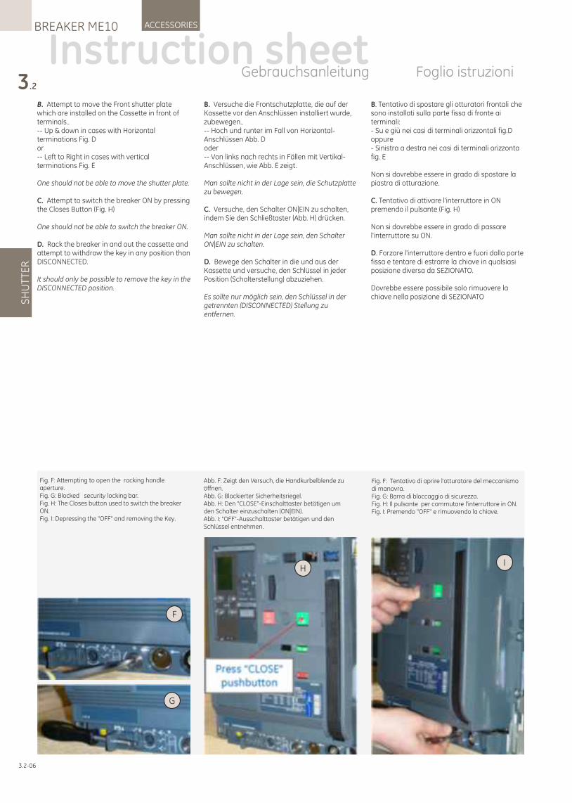
Instruction sheetGebrauchsanleitung Foglio istruzioni
3.2
SH
UT
TER
ACCESSORIESBREAKER ME10
3.2-06
B. Versuche die Frontschutzplatte, die auf der Kassette vor den Anschlüssen installiert wurde, zubewegen..-- Hoch und runter im Fall von Horizontal-Anschlüssen Abb. Doder-- Von links nach rechts in Fällen mit Vertikal-Anschlüssen, wie Abb. E zeigt.
Man sollte nicht in der Lage sein, die Schutzplatte zu bewegen.
C. Versuche, den Schalter ON|EIN zu schalten, indem Sie den Schließtaster (Abb. H) drücken.
Man sollte nicht in der Lage sein, den Schalter ON|EIN zu schalten.
D. Bewege den Schalter in die und aus der Kassette und versuche, den Schlüssel in jeder Position (Schalterstellung) abzuziehen.
Es sollte nur möglich sein, den Schlüssel in der getrennten (DISCONNECTED) Stellung zu entfernen.
B. Attempt to move the Front shutter plate which are installed on the Cassette in front of terminals..-- Up & down in cases with Horizontal terminations Fig. Dor-- Left to Right in cases with vertical terminations Fig. E
One should not be able to move the shutter plate.
C. Attempt to switch the breaker ON by pressing the Closes Button (Fig. H)
One should not be able to switch the breaker ON.
D. Rack the breaker in and out the cassette and attempt to withdraw the key in any position than DISCONNECTED.
It should only be possible to remove the key in the DISCONNECTED position.
B. Tentativo di spostare gli otturatori frontali che sono installati sulla parte fissa di fronte ai terminali:- Su e giù nei casi di terminali orizzontali fig.Doppure- Sinistra a destra nei casi di terminali orizzonta fig. E
Non si dovrebbe essere in grado di spostare la piastra di otturazione.
C. Tentativo di attivare l'interruttore in ON premendo il pulsante (Fig. H)
Non si dovrebbe essere in grado di passare l'interruttore su ON.
D. Forzare l'interruttore dentro e fuori dalla parte fissa e tentare di estrarre la chiave in qualsiasi posizione diversa da SEZIONATO.
Dovrebbe essere possibile solo rimuovere la chiave nella posizione di SEZIONATO
IH
G
F
Fig. F: Attempting to open the racking handle aperture.Fig. G: Blocked security locking bar.Fig. H: The Closes button used to switch the breaker ON.Fig. I: Depressing the "OFF" and removing the Key.
Fig. F: Tentativo di aprire l'otturatore del meccanismo di manovra. Fig. G: Barra di bloccaggio di sicurezza. Fig. H: Il pulsante per commutare l'interruttore in ON. Fig. I: Premendo "OFF" e rimuovendo la chiave.
Abb. F: Zeigt den Versuch, die Handkurbelblende zu öffnen.Abb. G: Blockierter Sicherheitsriegel.Abb. H: Den "CLOSE"-Einschalttaster betätigen um den Schalter einzuschalten (ON|EIN).Abb. I: "OFF"-Ausschalttaster betätigen und den Schlüssel entnehmen.
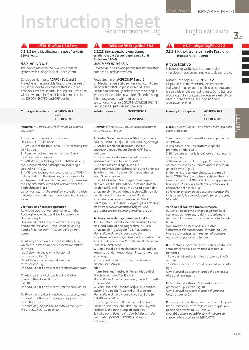
3.2.2.2 Extra kit allowing the use of a Ronis 1104B lock..
REPLACING KITThe device replaces the two lock cassette system with a single lock shutter system.
Catalogue Numbers: ACPRONSV 1 and 2 A mechanism is available that allows the use of a cylinder lock to lock the shutters in closed position. Here the security locking bar C must be withdrawn and the Circuit breaker must be in the DISCONNECTED and OFF position.
Remark : A Ronis 1104B lock must be ordered separately.
1. Ensure position indicator shows DISCONNECTED Position.2. Ensure that the breaker is OFF by pressing the OFF button.3. Remove racking handle from the Crank insertion hole if present.4. Withdraw the locking bar C until the locking eye is exposed and hold open by inserting a screwdriver (Fig G.)5. With blocked padlock lever, press the “OPEN” button and turn the Ronis key anticlockwise by 90 degrees, till it reaches the dead stop. Remove the key and remove the screwdriver from the padlock lever. (Fig. H)Lever must stay in the withdrawn position which indicates that both the shutters and breaker are locked.
Verification of correct operationA. With a screw driver attempt to turn the Racking handle shutter drive B clockwise a shown in Fig. F. One should not be able to rotate the racking handle shutter drive B and insert a Racking handle in to the crank insertion hole on front panel.
B. Attempt to move the Front shutter plate which are installed on the Cassette in front of terminals Up & down in cases with Horizontal terminations Fig. D)Or left to Right in cases with vertical terminations Fig. E) One should not be able to move the shutter plate.
C. Attempt to switch the breaker ON by pressing the Closes Button (Fig. H) One should not be able to switch the breaker ON
D. Rack the breaker in and out the cassette and attempt to withdraw the key in any position than DISCONNECTED.It should only be possible to remove the key in the DISCONNECTED position.
3.2.2.2 Eine zusätzliche Ausrüstung ermöglicht die Verwendung eines Ronis Schlosses 1104B..
WECHSELBAUSTEINUmwechseln des zwei Sperren-Kassettensystem durch ein Einzelsperrsystem.
Produktnummer: ACPRONSV 1 und 2Ein Mechanismus steht zur Verfügung, mit dem die Schutzabdeckungen in geschlossener Stellung mit einem Zylinderschlosses verriegelt werden können. Hierzu wird der Sicherheitsriegel C herausgezogen, während sich der Leistungsschalter in DISCONNECTED|GETRENNT und in der OFF|AUS Stellung befindet.
Hinweis: Ein Ronis 1104B Schloss muss immer extra bestellt werden.
1. Stellen Sie sicher, dass die Stellungsanzeige die DISCONNECTED|GETRENNT Stellung anzeigt.2. Stellen Sie sicher, dass der Schalter ausgeschaltet ist, indem Sie die OFF-Taste betätigen.3. Entfernen Sie die Handkurbel aus dem Kurbeleinsetzloch, falls vorhanden.4. Ziehen Sie den Riegel C, bis die Verriegelungslöcher sichtbar sind und halten sie ihn offen, indem Sie einen Schraubendreher (Abb. G.) einstecken.5. Mit blockiertem Vorhängeschlossriegel, drücken Sie die "OPEN|AUS"-Taste und drehen Sie den Schlüssel Ronis um 90 Grad gegen den Uhrzeigersinn bis zum Endanschlag. Ziehen Sie den Schlüssel ab und entfernen Sie den Schraubendreher aus dem Riegel (Abb. H).Der Riegel muss in der zurückgezogenen Position, die sowohl die Schutzabdeckungen- und Leistungsschalter-Sperrung anzeigt, bleiben.
Prüfung der ordnungsgemäßen FunktionA. Versuchen Sie mit einem Schraubendreher die Handkurbelabdeckungsschraube B im Uhrzeigersinn, gezeigt in Abb. F, zudrehen.Man sollte nicht in der Lage sein, die Handkurbelabdeckungsschraube B zudrehen und eine Handkurbel in das Kurbeleinsetzloch an der Frontseite zustecken.B. Versuche die Frontschutzplatte, die auf der Kassette vor den Anschlüssen installiert wurde, zubewegen..-- Hoch und runter im Fall von Horizontal-Anschlüssen Abb. Doder-- Von links nach rechts in Fällen mit Vertikal-Anschlüssen, wie Abb. E zeigt.Man sollte nicht in der Lage sein, die Schutzplatte zu bewegen.C. Versuche, den Schalter ON|EIN zu schalten, indem Sie den EIN-Taster (Abb. H) drücken.Man sollte nicht in der Lage sein, den Schalter ON|EIN zu schalten.D. Bewege den Schalter in die und aus der Kassette und versuche, den Schlüssel in jeder Position (Schalterstellung) abzuziehen.Es sollte nur möglich sein, den Schlüssel in der getrennten (DISCONNECTED) Stellung zu entfernen.
BREAKER ME10ACCESSORIES
3.2
SH
UT
TER
Instruction sheetGebrauchsanleitung Foglio istruzioni
3.2-07
3.2.2.2 Kit extra che permette l'uso di un Blocco Ronis 1104b
Kit sostitutivoIl dispositivo sostituisce il sistema a due interblocchi con un sistema a singola serratura.
Numeri Catalogo: ACPRONSV 1 e 2 Disponibile un meccanismo che consente l'utilizzo di una serratura a cilindro per bloccare le serrande in posizione di chiuso. Qui la barra di bloccaggio di sicurezza C deve essere estratta e l'interruttore deve essere in posizione di SEZIONATO e in OFF.
Nota: Il blocco Ronis 1104b deve essere ordinato separatamente.
1. Assicurarsi che l'interruttore sia in posizione di SEZIONATO. 2. Assicurarsi che l'interruttore è spento premendo il tasto OFF.3. Rimuovere la maniglia dal foro di inserimento se presente. 4. Sfilare la barra di bloccaggio C fino a che l'occhiello è esposto e tenere aperto inserendo un cacciavite (Fig G.) 5. Con la leva lucchetto bloccato, premere il tasto "OPEN" tasto e ruotare la chiave Ronis in senso antiorario di 90 gradi, fino a raggiungere il fine corsa. Rimuovere la chiave e rimuovere il cacciavite dalla leva. (Fig. H) La leva deve rimanere in posizione estratta che indica che sia le serrande che l'interruttore sono bloccati.
Verifica del corretto funzionamento A. Con un cacciavite provare a girare vite di comando dell'otturatore del meccanismo di manovra B in senso orario come mostrato nella fig. AF .Non dovrebbe essere possibile ruotare l'otturatore del meccanismo di manovra B né inserire la maniglia di manovra nell'apertura presente sul pannello anteriore.
B. Tentativo di spostare gli otturatori frontali che sono installati sulla parte fissa di fronte ai terminali:- Su e giù nei casi di terminali orizzontali fig.Doppure- Sinistra a destra nei casi di terminali orizzonta fig. E Non si dovrebbe essere in grado di spostare la piastra di otturazione.
C. Tentativo di attivare l'interruttore in ON premendo il pulsante (Fig. H) Non si dovrebbe essere in grado di passare l'interruttore su ON.
D. Forzare l'interruttore dentro e fuori dalla parte fissa e tentare di estrarre la chiave in qualsiasi posizione diversa da SEZIONATO. Dovrebbe essere possibile solo rimuovere la chiave nella posizione di SEZIONATO.
Catalogue Numbers: GCPRONSV 1 and GCPRONSV 2
Katalognummer: GCPRONSV 1 und GCPRONSV 2
Numery katalogowe: GCPRONSV 1 i GCPRONSV 2
ME10: Envelope 1, 2 & 3 only ME10: nur für Baugröße 1, 2 & 3 ME10: solo per Taglia 1, 2 & 3
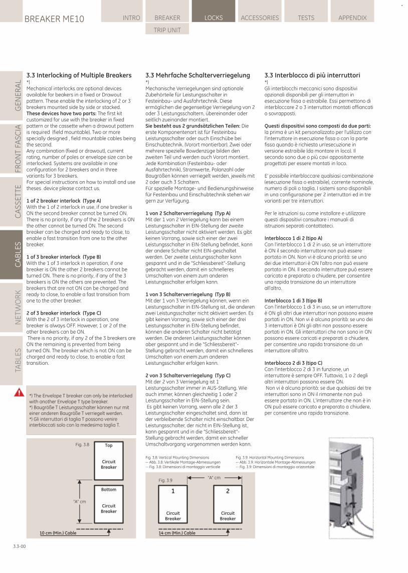
3.3 Interblocco di più interruttori*)Gli interblocchi meccanici sono dispositivi opzionali disponibili per gli interruttori in esecuzione fissa o estraibile. Essi permettono di interbloccare 2 o 3 interruttori montati affiancati o sovrapposti.
Questi dispositivi sono composti da due parti: la prima è un kit personalizzato per l'utilizzo con l'interruttore in esecuzione fissa o con la parte fissa quando è richiesta un'esecuzione in versione estraibile (da montare in loco). Il secondo sono due o più cavi appositamente progettati per essere montati in loco.
E' possibile interbloccare qualsiasi combinazione (esecuzione fissa o estraibile), corrente nominale, numero di poli o taglia. I sistemi sono disponibili in una configurazione per 2 interruttori ed in tre varianti per tre interruttori.
Per le istruzioni su come installare e utilizzare questi dispositivi consultare i manuali di istruzioni separati contattateci.
Interblocco 1 di 2 (tipo A)Con l'interblocco 1 di 2 in uso, se un interruttore è ON il secondo interruttore non può essere portato in ON. Non vi è alcuna priorità: se uno dei due interruttori è ON l'altro non può essere portato in ON. Il secondo interruttore può essere caricato e preparato a chiudere, per consentire una rapida transizione da un interruttore all'altro.
Interblocco 1 di 3 (tipo B)Con l'interblocco 1 di 3 in uso, se un interruttore è ON gli altri due interruttori non possono essere portati in ON. Non vi è alcuna priorità: se uno dei 3 interruttori è ON gli altri non possono essere portati in ON. Gli interruttori che non sono in ON possono essere caricati e preparati a chiudere, per consentire una rapida transizione da un interruttore all'altro.
Interblocco 2 di 3 (tipo C)Con l'interblocco 2 di 3 in funzione, un interruttore è sempre OFF. Tuttavia, 1 o 2 degli altri interruttori possono essere ON. Non vi è alcuna priorità: se due qualsiasi dei tre interruttori sono in ON il rimanente non può essere portato in ON. L'interruttore che non è in ON può essere caricato e preparato a chiudere, per consentire una rapida transizione.
LOCKSBREAKER ME10 INTRO BREAKER ACCESSORIES TESTS APPENDIX
TRIP UNIT
GE
NE
RA
LFR
ON
T FA
SC
IAC
AS
SE
TTE
CA
BLE
SN
ET
WO
RK
TAB
LES
3.3-00
14 cm (Min.) Cable
Fig. 3.9“A” cm
1
CircuitBreaker
2
CircuitBreaker
“A” cm
10 cm (Min.) Cable
Fig. 3.8
Bottom
CircuitBreaker
Top
CircuitBreaker
Fig. 3.8: Vertical Mounting Dimensions-- Abb. 3.8: Vertikale Montage-Abmessungen-- Fig. 3.8: Dimensioni di montaggio verticale
Fig. 3.9: Horizontal Mounting Dimensions-- Abb. 3.9: Horizontale Montage-Abmessungen-- Fig. 3.9: Dimensioni di montaggio orizzontale
3.3 Mehrfache Schalterverriegelung*)Mechanische Verriegelungen sind optionale Zubehörteile für Leistungsschalter in Festeinbau- und Ausfahrtechnik. Diese ermöglichen die gegenseitige Verriegelung von 2 oder 3 Leistungsschaltern, übereinander oder seitlich zueinander montiert. Sie besteht aus 2 grundsätzlichen Teilen: Die erste Komponentenart ist für Festeinbau Leistungsschalter oder auch Einschübe bei Einschubtechnik. (Vorort montierbar). Zwei oder mehrere spezielle Bowdenzüge bilden den zweiten Teil und werden auch Vorort montiert.Jede Kombination (Festeinbau- oder Ausfahrtechnik), Stromwerte, Polanzahl oder Baugrößen können verriegelt werden, jeweils mit 2 oder auch 3 Schaltern.Für spezielle Montage- und Bedienungshinweise für Festeinbau und Einschubtechnik stehen wir gern zur Verfügung.
1 von 2 Schalterverriegelung (Typ A)Mit der 1 von 2 Verriegelung kann bei einem Leistungsschalter in EIN-Stellung der zweite Leistungsschalter nicht aktiviert werden. Es gibt keinen Vorrang, sowie sich einer der zwei Leistungsschalter in EIN-Stellung befindet, kann der andere Schalter nicht EIN-geschaltet werden. Der zweite Leistungsschalter kann gespannt und in die "Schliessbereit"-Stellung gebracht werden, damit ein schnelleres Umschalten von einem zum anderen Leistungsschalter erfolgen kann.
1 von 3 Schalterverriegelung (Typ B)Mit der 1 von 3 Verriegelung können, wenn ein Leistungsschalter in EIN-Stellung ist, die anderen zwei Leistungsschalter nicht aktiviert werden. Es gibt keinen Vorrang, sowie sich einer der drei Leistungsschalter in EIN-Stellung befindet, können die anderen Schalter nicht betätigt werden. Die anderen Leistungsschalter können aber gespannt und in die "Schliessbereit"-Stellung gebracht werden, damit ein schnelleres Umschalten von einem zum anderen Leistungsschalter erfolgen kann.
2 von 3 Schalterverriegelung (Typ C)Mit der 2 von 3 Verriegelung ist 1 Leistungsschalter immer in AUS-Stellung. Wie auch immer, können gleichzeitig 1 oder 2 Leistungsschalter in EIN-Stellung sein. Es gibt keinen Vorrang, wenn alle 2 der 3 Leistungsschalter eingeschaltet sind, dann ist der verbleibende Schalter nicht einschaltbar. Der Leistungsschalter, der nicht in EIN-Stellung ist, kann gespannt und in die "Schliessbereit"-Stellung gebracht werden, damit ein schneller Umschaltvorgang vorgenommen werden kann.
3.3 Interlocking of Multiple Breakers*)Mechanical interlocks are optional devices available for beakers in a fixed or Drawout pattern. These enable the interlocking of 2 or 3 breakers mounted side by side or stacked. These devices have two parts: The first kit customized for use with the breaker in fixed pattern or the cassette when a drawout pattern is required (field mountable). Two or more specially designed , field mountable cables being the second.Any combination (fixed or drawout), current rating, number of poles or envelope size can be interlocked. Systems are available in one configuration for 2 breakers and in three variants for 3 breakers. For special instructions on how to install and use theses device please contact us.
1 of 2 breaker interlock (Type A)With the 1 of 2 interlock in use, if one breaker is ON the second breaker cannot be turned ON. There is no priority, if any of the 2 breakers is ON the other cannot be turned ON. The second breaker can be charged and ready to close, to enable a fast transition from one to the other breaker.
1 of 3 breaker interlock (Type B)With the 1 of 3 interlock in operation, if one breaker is ON the other 2 breakers cannot be turned ON. There is no priority, if any of the 3 breakers is ON the others are prevented. The breakers that are not ON can be charged and ready to close, to enable a fast transition from one to the other breaker.
2 of 3 breaker interlock (Type C)With the 2 of 3 interlock in operation, one breaker is always OFF. However, 1 or 2 of the other breakers can be ON. There is no priority, if any 2 of the 3 breakers are ON the remaining is prevented from being turned ON. The breaker which is not ON can be charged and ready to close, to enable a fast transition.
*) The Envelope T breaker can only be interlocked with another Envelope T type breaker.*) Baugröße T Leistungsschalter können nur mit einer anderen Baugröße T verriegelt werden.*) Gli interruttori di taglia T possono venire interbloccati solo con la medesima taglia T.
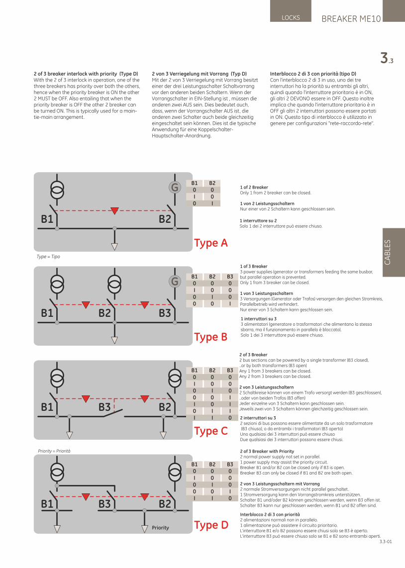
Interblocco 2 di 3 con priorità2 alimentazioni normali non in parallelo.1 alimentazione può assistere il circuito prioritario.L'interruttore B1 e/o B2 possono essere chiusi solo se B3 è aperto.L'interruttore B3 può essere chiuso solo se B1 e B2 sono entrambi aperti.
CA
BLE
S
BREAKER ME10LOCKS
3.3
3.3-01
2 of 3 breaker interlock with priority (Type D)With the 2 of 3 interlock in operation, one of the three breakers has priority over both the others, hence when the priority breaker is ON the other 2 MUST be OFF. Also entailing that when the priority breaker is OFF the other 2 breaker can be turned ON. This is typically used for a main-tie-main arrangement.
2 von 3 Verriegelung mit Vorrang (Typ D)Mit der 2 von 3 Verriegelung mit Vorrang besitzt einer der drei Leistungsschalter Schaltvorrang vor den anderen beiden Schaltern. Wenn der Vorrangschalter in EIN-Stellung ist , müssen die anderen zwei AUS sein. Dies bedeutet auch, dass, wenn der Vorrangschalter AUS ist, die anderen zwei Schalter auch beide gleichzeitig eingeschaltet sein können. Dies ist die typische Anwendung für eine Koppelschalter-Hauptschalter-Anordnung.
Interblocco 2 di 3 con priorità (tipo D)Con l'interblocco 2 di 3 in uso, uno dei tre interruttori ha la priorità su entrambi gli altri, quindi quando l'interruttore prioritario è in ON, gli altri 2 DEVONO essere in OFF. Questo inoltre implica che quando l'interruttore prioritario è in OFF gli altri 2 interruttori possono essere portati in ON. Questo tipo di interblocco è utilizzato in genere per configurazioni "rete-raccordo-rete".
2 of 3 Breaker with Priority2 normal power supply not set in parallel.1 power supply may assist the priority circuit.Breaker B1 and/or B2 can be closed only if B3 is open.Breaker B3 can only be closed if B1 and B2 are both open.
2 von 3 Leistungsschaltern mit Vorrang2 normale Stromversorgungen nicht parallel geschaltet.1 Stromversorgung kann den Vorrangstromkreis unterstützen.Schalter B1 und/oder B2 können geschlossen werden, wenn B3 offen ist.Schalter B3 kann nur geschlossen werden, wenn B1 und B2 offen sind.
Type B
G
B1 B3B2
B10I00
B200I0
B3000I
Type C
B1 B2B3
B10I00I0I
B200I00II
B3000III0
2 of 3 Breaker2 bus sections can be powered by a single transformer (B3 closed),..or by both transformers (B3 open)Any 1 from 3 breakers can be closed.Any 2 from 3 breakers can be closed.
2 von 3 Leistungsschaltern2 Schaltkreise können von einem Trafo versorgt werden (B3 geschlossen),..oder von beiden Trafos (B3 offen)Jeder einzelne von 3 Schaltern kann geschlossen sein.Jeweils zwei von 3 Schaltern können gleichzeitig geschlossen sein.
1 of 3 Breaker3 power supplies (generator or transformers feeding the same busbar,but parallel operation is prevented.Only 1 from 3 breaker can be closed.
1 von 3 Leistungsschaltern3 Versorgungen (Generator oder Trafos) versorgen den gleichen Stromkreis,Parallelbetrieb wird verhindert.Nur einer von 3 Schaltern kann geschlossen sein.
1 of 2 BreakerOnly 1 from 2 breaker can be closed.
1 von 2 LeistungsschalternNur einer von 2 Schaltern kann geschlossen sein.
2 interruttori su 32 sezioni di bus possono essere alimentate da un solo trasformatore (B3 chiuso), o da entrambi i trasformatori (B3 aperto)Uno qualsiasi dei 3 interruttori può essere chiusoDue qualsiasi dei 3 interruttori possono essere chiusi.
1 interruttori su 33 alimentatori (generatore o trasformatori che alimentano la stessa sbarra, ma il funzionamento in parallelo è bloccato).Solo 1 dei 3 interruttore può essere chiuso.
1 interruttore su 2Solo 1 dei 2 interruttore può essere chiuso.
Type A
G
B1 B2
B10I0
B200I
Type = Tipo
Type D
B1 B2B3
B10I00I
B200I0I
B3000I0
Priority
Priority = Priorità
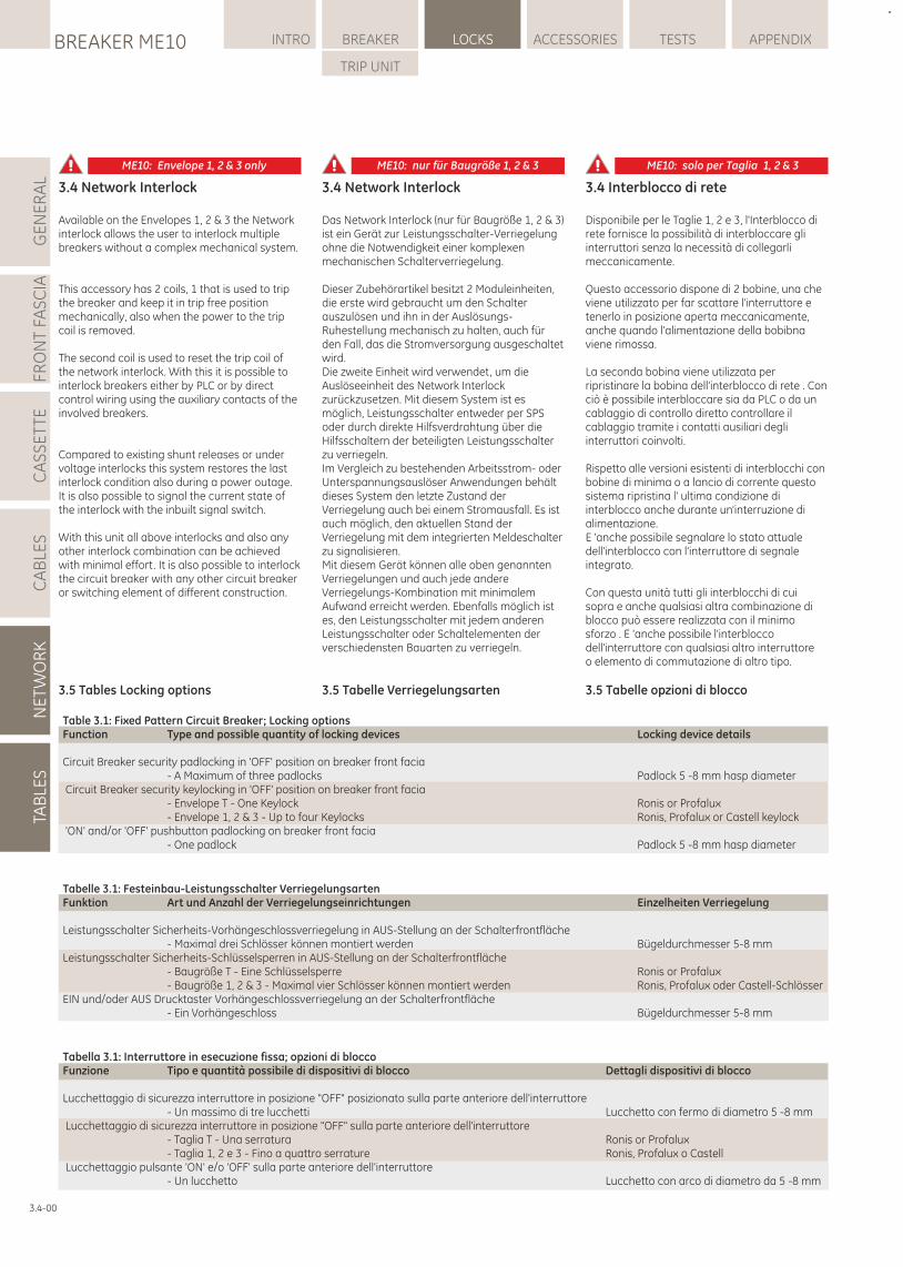
LOCKSBREAKER ME10 INTRO BREAKER ACCESSORIES TESTS APPENDIX
TRIP UNIT
GE
NE
RA
LFR
ON
T FA
SC
IAC
AS
SE
TTE
CA
BLE
SN
ET
WO
RK
TAB
LES
3.4-00
3.4 Interblocco di rete
Disponibile per le Taglie 1, 2 e 3, l'Interblocco di rete fornisce la possibilità di interbloccare gli interruttori senza la necessità di collegarli meccanicamente.
Questo accessorio dispone di 2 bobine, una che viene utilizzato per far scattare l'interruttore e tenerlo in posizione aperta meccanicamente, anche quando l'alimentazione della bobibna viene rimossa.
La seconda bobina viene utilizzata per ripristinare la bobina dell'interblocco di rete . Con ciò è possibile interbloccare sia da PLC o da un cablaggio di controllo diretto controllare il cablaggio tramite i contatti ausiliari degli interruttori coinvolti.
Rispetto alle versioni esistenti di interblocchi con bobine di minima o a lancio di corrente questo sistema ripristina l' ultima condizione di interblocco anche durante un'interruzione di alimentazione.E 'anche possibile segnalare lo stato attuale dell'interblocco con l'interruttore di segnale integrato.
Con questa unità tutti gli interblocchi di cui sopra e anche qualsiasi altra combinazione di blocco può essere realizzata con il minimo sforzo . E 'anche possibile l'interblocco dell'interruttore con qualsiasi altro interruttoreo elemento di commutazione di altro tipo.
3.5 Tabelle opzioni di blocco
ME10: Envelope 1, 2 & 3 only ME10: nur für Baugröße 1, 2 & 3 ME10: solo per Taglia 1, 2 & 3
3.4 Network Interlock
Available on the Envelopes 1, 2 & 3 the Network interlock allows the user to interlock multiple breakers without a complex mechanical system.
This accessory has 2 coils, 1 that is used to trip the breaker and keep it in trip free position mechanically, also when the power to the trip coil is removed.
The second coil is used to reset the trip coil of the network interlock. With this it is possible to interlock breakers either by PLC or by direct control wiring using the auxiliary contacts of the involved breakers.
Compared to existing shunt releases or under voltage interlocks this system restores the last interlock condition also during a power outage. It is also possible to signal the current state of the interlock with the inbuilt signal switch.
With this unit all above interlocks and also any other interlock combination can be achieved with minimal effort. It is also possible to interlock the circuit breaker with any other circuit breaker or switching element of different construction.
3.5 Tables Locking options
3.4 Network Interlock
Das Network Interlock (nur für Baugröße 1, 2 & 3) ist ein Gerät zur Leistungsschalter-Verriegelung ohne die Notwendigkeit einer komplexen mechanischen Schalterverriegelung.
Dieser Zubehörartikel besitzt 2 Moduleinheiten, die erste wird gebraucht um den Schalter auszulösen und ihn in der Auslösungs-Ruhestellung mechanisch zu halten, auch für den Fall, das die Stromversorgung ausgeschaltet wird.Die zweite Einheit wird verwendet, um die Auslöseeinheit des Network Interlock zurückzusetzen. Mit diesem System ist es möglich, Leistungsschalter entweder per SPS oder durch direkte Hilfsverdrahtung über die Hilfsschaltern der beteiligten Leistungsschalter zu verriegeln. Im Vergleich zu bestehenden Arbeitsstrom- oder Unterspannungsauslöser Anwendungen behält dieses System den letzte Zustand der Verriegelung auch bei einem Stromausfall. Es ist auch möglich, den aktuellen Stand der Verriegelung mit dem integrierten Meldeschalter zu signalisieren.Mit diesem Gerät können alle oben genannten Verriegelungen und auch jede andere Verriegelungs-Kombination mit minimalem Aufwand erreicht werden. Ebenfalls möglich ist es, den Leistungsschalter mit jedem anderen Leistungsschalter oder Schaltelementen der verschiedensten Bauarten zu verriegeln.
3.5 Tabelle Verriegelungsarten
Tabella 3.1: Interruttore in esecuzione fissa; opzioni di bloccoFunzione Tipo e quantità possibile di dispositivi di blocco Dettagli dispositivi di blocco
Lucchettaggio di sicurezza interruttore in posizione "OFF" posizionato sulla parte anteriore dell'interruttore - Un massimo di tre lucchetti Lucchetto con fermo di diametro 5 -8 mm Lucchettaggio di sicurezza interruttore in posizione "OFF" sulla parte anteriore dell'interruttore - Taglia T - Una serratura Ronis or Profalux - Taglia 1, 2 e 3 - Fino a quattro serrature Ronis, Profalux o Castell Lucchettaggio pulsante 'ON' e/o 'OFF' sulla parte anteriore dell'interruttore - Un lucchetto Lucchetto con arco di diametro da 5 -8 mm
Table 3.1: Fixed Pattern Circuit Breaker; Locking optionsFunction Type and possible quantity of locking devices Locking device details
Circuit Breaker security padlocking in 'OFF' position on breaker front facia - A Maximum of three padlocks Padlock 5 -8 mm hasp diameter Circuit Breaker security keylocking in 'OFF' position on breaker front facia - Envelope T - One Keylock Ronis or Profalux - Envelope 1, 2 & 3 - Up to four Keylocks Ronis, Profalux or Castell keylock 'ON' and/or 'OFF' pushbutton padlocking on breaker front facia - One padlock Padlock 5 -8 mm hasp diameter
Tabelle 3.1: Festeinbau-Leistungsschalter VerriegelungsartenFunktion Art und Anzahl der Verriegelungseinrichtungen Einzelheiten Verriegelung
Leistungsschalter Sicherheits-Vorhängeschlossverriegelung in AUS-Stellung an der Schalterfrontfläche - Maximal drei Schlösser können montiert werden Bügeldurchmesser 5-8 mmLeistungsschalter Sicherheits-Schlüsselsperren in AUS-Stellung an der Schalterfrontfläche - Baugröße T - Eine Schlüsselsperre Ronis or Profalux - Baugröße 1, 2 & 3 - Maximal vier Schlösser können montiert werden Ronis, Profalux oder Castell-SchlösserEIN und/oder AUS Drucktaster Vorhängeschlossverriegelung an der Schalterfrontfläche - Ein Vorhängeschloss Bügeldurchmesser 5-8 mm
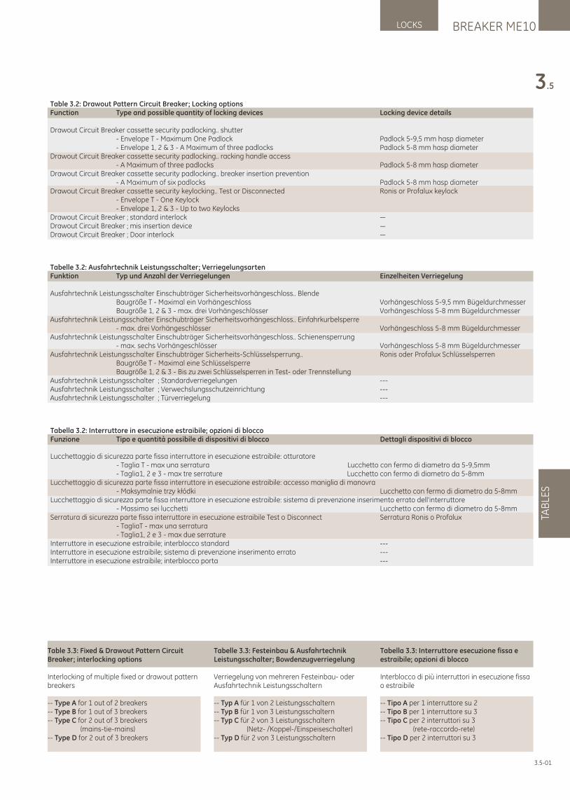
BREAKER ME10LOCKS
TAB
LES
3.5
3.5-01
Table 3.3: Fixed & Drawout Pattern Circuit Breaker; interlocking options
Interlocking of multiple fixed or drawout pattern breakers
-- Type A for 1 out of 2 breakers-- Type B for 1 out of 3 breakers-- Type C for 2 out of 3 breakers (mains-tie-mains)-- Type D for 2 out of 3 breakers
Tabelle 3.3: Festeinbau & Ausfahrtechnik Leistungsschalter; Bowdenzugverriegelung
Verriegelung von mehreren Festeinbau- oder Ausfahrtechnik Leistungsschaltern
-- Typ A für 1 von 2 Leistungsschaltern-- Typ B für 1 von 3 Leistungsschaltern-- Typ C für 2 von 3 Leistungsschaltern (Netz- /Koppel-/Einspeiseschalter)-- Typ D für 2 von 3 Leistungsschaltern
Tabella 3.3: Interruttore esecuzione fissa e estraibile; opzioni di blocco
Interblocco di più interruttori in esecuzione fissa o estraibile
-- Tipo A per 1 interruttore su 2 -- Tipo B per 1 interruttore su 3 -- Tipo C per 2 interruttori su 3 (rete-raccordo-rete)-- Tipo D per 2 interruttori su 3
Table 3.2: Drawout Pattern Circuit Breaker; Locking optionsFunction Type and possible quantity of locking devices Locking device details
Drawout Circuit Breaker cassette security padlocking.. shutter - Envelope T - Maximum One Padlock Padlock 5-9,5 mm hasp diameter - Envelope 1, 2 & 3 - A Maximum of three padlocks Padlock 5-8 mm hasp diameterDrawout Circuit Breaker cassette security padlocking.. racking handle access - A Maximum of three padlocks Padlock 5-8 mm hasp diameterDrawout Circuit Breaker cassette security padlocking.. breaker insertion prevention - A Maximum of six padlocks Padlock 5-8 mm hasp diameterDrawout Circuit Breaker cassette security keylocking.. Test or Disconnected Ronis or Profalux keylock - Envelope T - One Keylock - Envelope 1, 2 & 3 - Up to two KeylocksDrawout Circuit Breaker ; standard interlock —Drawout Circuit Breaker ; mis insertion device —Drawout Circuit Breaker ; Door interlock —
Tabelle 3.2: Ausfahrtechnik Leistungsschalter; VerriegelungsartenFunktion Typ und Anzahl der Verriegelungen Einzelheiten Verriegelung
Ausfahrtechnik Leistungsschalter Einschubträger Sicherheitsvorhängeschloss.. Blende Baugröße T - Maximal ein Vorhängeschloss Vorhängeschloss 5-9,5 mm Bügeldurchmesser Baugröße 1, 2 & 3 - max. drei Vorhängeschlösser Vorhängeschloss 5-8 mm BügeldurchmesserAusfahrtechnik Leistungsschalter Einschubträger Sicherheitsvorhängeschloss.. Einfahrkurbelsperre - max. drei Vorhängeschlösser Vorhängeschloss 5-8 mm BügeldurchmesserAusfahrtechnik Leistungsschalter Einschubträger Sicherheitsvorhängeschloss.. Schienensperrung - max. sechs Vorhängeschlösser Vorhängeschloss 5-8 mm BügeldurchmesserAusfahrtechnik Leistungsschalter Einschubträger Sicherheits-Schlüsselsperrung.. Ronis oder Profalux Schlüsselsperren Baugröße T - Maximal eine Schlüsselsperre Baugröße 1, 2 & 3 - Bis zu zwei Schlüsselsperren in Test- oder TrennstellungAusfahrtechnik Leistungsschalter ; Standardverriegelungen ---Ausfahrtechnik Leistungsschalter ; Verwechslungsschutzeinrichtung ---Ausfahrtechnik Leistungsschalter ; Türverriegelung ---
Tabella 3.2: Interruttore in esecuzione estraibile; opzioni di bloccoFunzione Tipo e quantità possibile di dispositivi di blocco Dettagli dispositivi di blocco
Lucchettaggio di sicurezza parte fissa interruttore in esecuzione estraibile: otturatore - Taglia T - max una serratura Lucchetto con fermo di diametro da 5-9,5mm - Taglia1, 2 e 3 - max tre serrature Lucchetto con fermo di diametro da 5-8mmLucchettaggio di sicurezza parte fissa interruttore in esecuzione estraibile: accesso maniglia di manovra - Maksymalnie trzy kłódki Lucchetto con fermo di diametro da 5-8mmLucchettaggio di sicurezza parte fissa interruttore in esecuzione estraibile: sistema di prevenzione inserimento errato dell'interruttore - Massimo sei lucchetti Lucchetto con fermo di diametro da 5-8mmSerratura di sicurezza parte fissa interruttore in esecuzione estraibile Test o Disconnect Serratura Ronis o Profalux - TagliaT - max una serratura - Taglia1, 2 e 3 - max due serratureInterruttore in esecuzione estraibile; interblocco standard ---Interruttore in esecuzione estraibile; sistema di prevenzione inserimento errato ---Interruttore in esecuzione estraibile; interblocco porta ---
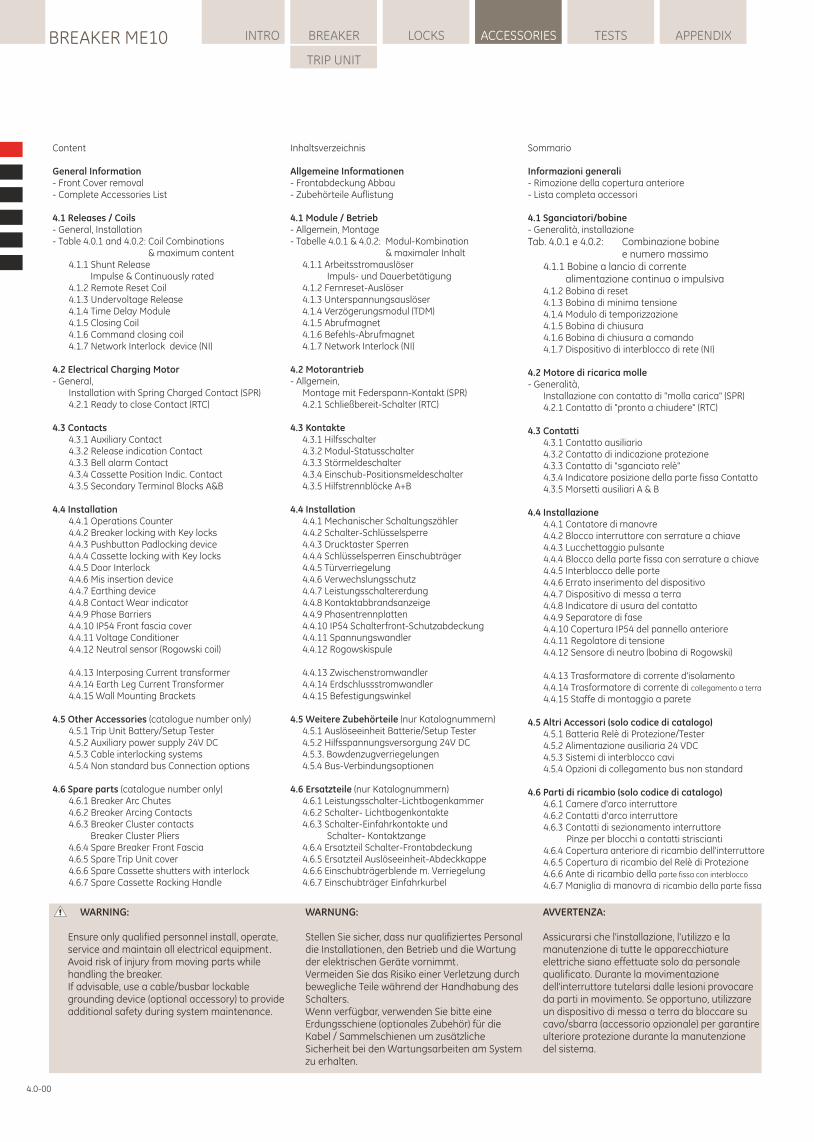
WARNUNG:
Stellen Sie sicher, dass nur qualifiziertes Personal die Installationen, den Betrieb und die Wartung der elektrischen Geräte vornimmt.Vermeiden Sie das Risiko einer Verletzung durch bewegliche Teile während der Handhabung des Schalters.Wenn verfügbar, verwenden Sie bitte eine Erdungsschiene (optionales Zubehör) für die Kabel / Sammelschienen um zusätzliche Sicherheit bei den Wartungsarbeiten am System zu erhalten.
WARNING:
Ensure only qualified personnel install, operate, service and maintain all electrical equipment.Avoid risk of injury from moving parts while handling the breaker.If advisable, use a cable/busbar lockable grounding device (optional accessory) to provide additional safety during system maintenance.
AVVERTENZA:
Assicurarsi che l'installazione, l'utilizzo e la manutenzione di tutte le apparecchiature elettriche siano effettuate solo da personale qualificato. Durante la movimentazione dell'interruttore tutelarsi dalle lesioni provocare da parti in movimento. Se opportuno, utilizzare un dispositivo di messa a terra da bloccare su cavo/sbarra (accessorio opzionale) per garantire ulteriore protezione durante la manutenzione del sistema.
LOCKSBREAKER ME10 INTRO BREAKER ACCESSORIES TESTS APPENDIX
TRIP UNIT
Sommario
Informazioni generali- Rimozione della copertura anteriore- Lista completa accessori
4.1 Sganciatori/bobine- Generalità, installazioneTab. 4.0.1 e 4.0.2: Combinazione bobine e numero massimo 4.1.1 Bobine a lancio di corrente alimentazione continua o impulsiva 4.1.2 Bobina di reset 4.1.3 Bobina di minima tensione 4.1.4 Modulo di temporizzazione 4.1.5 Bobina di chiusura 4.1.6 Bobina di chiusura a comando 4.1.7 Dispositivo di interblocco di rete (NI)
4.2 Motore di ricarica molle- Generalità, Installazione con contatto di "molla carica" (SPR) 4.2.1 Contatto di "pronto a chiudere" (RTC)
4.3 Contatti 4.3.1 Contatto ausiliario 4.3.2 Contatto di indicazione protezione 4.3.3 Contatto di "sganciato relè" 4.3.4 Indicatore posizione della parte fissa Contatto 4.3.5 Morsetti ausiliari A & B
4.4 Installazione 4.4.1 Contatore di manovre 4.4.2 Blocco interruttore con serrature a chiave 4.4.3 Lucchettaggio pulsante 4.4.4 Blocco della parte fissa con serrature a chiave 4.4.5 Interblocco delle porte 4.4.6 Errato inserimento del dispositivo 4.4.7 Dispositivo di messa a terra 4.4.8 Indicatore di usura del contatto 4.4.9 Separatore di fase 4.4.10 Copertura IP54 del pannello anteriore 4.4.11 Regolatore di tensione 4.4.12 Sensore di neutro (bobina di Rogowski)
4.4.13 Trasformatore di corrente d'isolamento 4.4.14 Trasformatore di corrente di collegamento a terra
4.4.15 Staffe di montaggio a parete
4.5 Altri Accessori (solo codice di catalogo) 4.5.1 Batteria Relè di Protezione/Tester 4.5.2 Alimentazione ausiliaria 24 VDC 4.5.3 Sistemi di interblocco cavi 4.5.4 Opzioni di collegamento bus non standard
4.6 Parti di ricambio (solo codice di catalogo) 4.6.1 Camere d'arco interruttore 4.6.2 Contatti d'arco interruttore 4.6.3 Contatti di sezionamento interruttore Pinze per blocchi a contatti striscianti 4.6.4 Copertura anteriore di ricambio dell'interruttore 4.6.5 Copertura di ricambio del Relè di Protezione 4.6.6 Ante di ricambio della parte fissa con interblocco
4.6.7 Maniglia di manovra di ricambio della parte fissa
4.0-00
Inhaltsverzeichnis
Allgemeine Informationen- Frontabdeckung Abbau- Zubehörteile Auflistung
4.1 Module / Betrieb- Allgemein, Montage- Tabelle 4.0.1 & 4.0.2: Modul-Kombination & maximaler Inhalt 4.1.1 Arbeitsstromauslöser Impuls- und Dauerbetätigung 4.1.2 Fernreset-Auslöser 4.1.3 Unterspannungsauslöser 4.1.4 Verzögerungsmodul (TDM) 4.1.5 Abrufmagnet 4.1.6 Befehls-Abrufmagnet 4.1.7 Network Interlock (NI)
4.2 Motorantrieb- Allgemein, Montage mit Federspann-Kontakt (SPR) 4.2.1 Schließbereit-Schalter (RTC)
4.3 Kontakte 4.3.1 Hilfsschalter 4.3.2 Modul-Statusschalter 4.3.3 Störmeldeschalter 4.3.4 Einschub-Positionsmeldeschalter 4.3.5 Hilfstrennblöcke A+B
4.4 Installation 4.4.1 Mechanischer Schaltungszähler 4.4.2 Schalter-Schlüsselsperre 4.4.3 Drucktaster Sperren 4.4.4 Schlüsselsperren Einschubträger 4.4.5 Türverriegelung 4.4.6 Verwechslungsschutz 4.4.7 Leistungsschaltererdung 4.4.8 Kontaktabbrandsanzeige 4.4.9 Phasentrennplatten 4.4.10 IP54 Schalterfront-Schutzabdeckung 4.4.11 Spannungswandler 4.4.12 Rogowskispule
4.4.13 Zwischenstromwandler 4.4.14 Erdschlussstromwandler 4.4.15 Befestigungswinkel
4.5 Weitere Zubehörteile (nur Katalognummern) 4.5.1 Auslöseeinheit Batterie/Setup Tester 4.5.2 Hilfsspannungsversorgung 24V DC 4.5.3. Bowdenzugverriegelungen 4.5.4 Bus-Verbindungsoptionen
4.6 Ersatzteile (nur Katalognummern) 4.6.1 Leistungsschalter-Lichtbogenkammer 4.6.2 Schalter- Lichtbogenkontakte 4.6.3 Schalter-Einfahrkontakte und Schalter- Kontaktzange 4.6.4 Ersatzteil Schalter-Frontabdeckung 4.6.5 Ersatzteil Auslöseeinheit-Abdeckkappe 4.6.6 Einschubträgerblende m. Verriegelung 4.6.7 Einschubträger Einfahrkurbel
Content
General Information- Front Cover removal- Complete Accessories List
4.1 Releases / Coils- General, Installation- Table 4.0.1 and 4.0.2: Coil Combinations & maximum content 4.1.1 Shunt Release Impulse & Continuously rated 4.1.2 Remote Reset Coil 4.1.3 Undervoltage Release 4.1.4 Time Delay Module 4.1.5 Closing Coil 4.1.6 Command closing coil 4.1.7 Network Interlock device (NI)
4.2 Electrical Charging Motor- General, Installation with Spring Charged Contact (SPR) 4.2.1 Ready to close Contact (RTC)
4.3 Contacts 4.3.1 Auxiliary Contact 4.3.2 Release indication Contact 4.3.3 Bell alarm Contact 4.3.4 Cassette Position Indic. Contact 4.3.5 Secondary Terminal Blocks A&B
4.4 Installation 4.4.1 Operations Counter 4.4.2 Breaker locking with Key locks 4.4.3 Pushbutton Padlocking device 4.4.4 Cassette locking with Key locks 4.4.5 Door Interlock 4.4.6 Mis insertion device 4.4.7 Earthing device 4.4.8 Contact Wear indicator 4.4.9 Phase Barriers 4.4.10 IP54 Front fascia cover 4.4.11 Voltage Conditioner 4.4.12 Neutral sensor (Rogowski coil)
4.4.13 Interposing Current transformer 4.4.14 Earth Leg Current Transformer 4.4.15 Wall Mounting Brackets
4.5 Other Accessories (catalogue number only) 4.5.1 Trip Unit Battery/Setup Tester 4.5.2 Auxiliary power supply 24V DC 4.5.3 Cable interlocking systems 4.5.4 Non standard bus Connection options
4.6 Spare parts (catalogue number only) 4.6.1 Breaker Arc Chutes 4.6.2 Breaker Arcing Contacts 4.6.3 Breaker Cluster contacts Breaker Cluster Pliers 4.6.4 Spare Breaker Front Fascia 4.6.5 Spare Trip Unit cover 4.6.6 Spare Cassette shutters with interlock 4.6.7 Spare Cassette Racking Handle
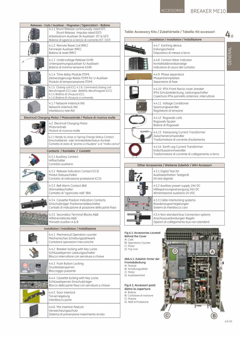
BREAKER ME10ACCESSORIES
GE
NE
RA
L
4.0
4.0-01
A
BC
D
Fig.4.1: Accessories Located Behind the CoverA) CoilsB) Operations CounterC) MotorD) Trip Unit
Abb.4.1: Zubehör hinter der FrontabdeckungA) ModuleB) SchaltungszählerC) MotorD) Auslöseeinheit
Fig.4.1: Accessori posti dietro la coperturaA) BobineB) Contatore di manovreC) MotoreD) Relè di Protezione
Table: Accessory Kits / Zubehörteile / Tabella: Kit accessori
4.5.2 Auxiliary power supply 24V DCHilfsspannungsversorgung 24V DCAlimentazione ausiliaria 24 VDC
4.5.3 Cable interlocking systemsBowdenzugverriegelungenSistemi di interblocco cavi
Other Accessories / Weiteres Zubehör / Altri Accessori
4.4.3 Push Button LockingDrucktastersperrenBloccaggio pulsante
4.4.1 Mechanical Operation counterMechanisches SchaltungszählwerkContatore operazioni meccaniche
4.4.2 Breaker locking with Key LocksSchlüsselsperren LeistungsschalterBlocco interruttore con serrature a chiave
4.4.5 Door InterlockTürverriegelungInterblocco porte
Installation / Installation / Installazione
4.4.4 Cassette locking with Key LocksSchlüsselsperren EinschubträgerBlocco della parte fissa con serrature a chiave
4.4.6 Mis insertion featureVerwechslungsschutzSistema di prevenzione inserimento errato
4.5.1 Digital Test KitAuslöseeinheiten TestgerätKit test digitale
4.5.4 Non standard bus Connection optionsAnschlussverbindungen RegelnOpzioni di collegamento bus non standard
4.4.7 Earthing deviceErdungsschieneDispositivo di messa a terra
4.4.8 Contact Wear IndicatorKontaktabbrandsanzeigeIndicatore di usura del contatto
4.4.12 Rogowski coilsRogowski SpulenBobine di Rogowski
4.4.10 IP54 Front fascia cover, breakerIP54 Schutzabdeckung, LeistungsschalterCopertura IP54 pannello anteriore, interruttore
IP54
...Installation / Installation / Installazione
4.4.9 Phase separatorsPhasentrennplattenSeparatore di fase
4.4.11 Voltage ConditionerSpannungswandlerRegolatore di tensione
4.4.14 Earth Leg Current TransformerErdschlussstromwandlerTrasformatore di corrente di collegamento a terra
4.4.13 Interposing Current TransformerZwischenstromwandlerTrasformatore di corrente d'isolamento
Contacts / Kontakte / Contatti
4.3.3 Bell Alarm Contact (BA)StörmeldeschalterContatto di "sganciato relè" (BA)
4.3.1 Auxiliary ContactHilfsschalterContatto ausiliario
4.3.4 Cassette Position Indication ContactsEinschubträger PositionsmeldeschalterContatti di indicazione di posizione della parte fissa
4.3.2 Release indication Contact (CCS)Modul-StatusschalterContatto di indicazione protezione (CCS)
4.3.5 Secondary Terminal Blocks A&BHilfstrennblöcke A&BMorsetti ausiliari A & B
4.2 Electrical Charging MotorMotorantriebMotore di ricarica molle
4.2.1 Ready to close or Spring Charge Status ContactEinschaltbereit- oder Antriebsfederstatus-KontaktContatto di stato di "pronto a chiudere" o di "molla carica"
Electrical Charging Motor / Motorantrieb / Motore di ricarica molle
Releases - Coils / Auslöser - Magneten / Sganciatori - Bobine
4.1.2 Remote Reset Coil (RRC)Fernreset-Auslöser (RRC)Bobina di reset (RRC)
4.1.3 Undervoltage Release (UVR)Unterspannungsauslöser (U-Auslöser)Bobina di minima tensione (UVR)
4.1.4 Time delay Module (TDM)Zeitverzögerungs Relais (TDM) für U-AuslöserModulo di temporizzazione (TDM)
4.1.5 Closing coil (CC), 4.1.6 Command closing coilAbrufmagnet (CC) oder Befehls-Abrufmagnet (CCC)4.1.5 Bobina di chiusura (CC), 4.1.6 Bobina di chiusura a comando
4.1.7 Network-Interlock (NI)Network-Interlock (NI)Interblocco rete (NI)
4.1.1 Shunt Release continuously rated (ST) Shunt Release Impulse rated (SST)Arbeitsstrom-Auslöser (A-Auslöser) (ST & SST)
i SST)Bobina di sgancio a lancio di corrente (ST
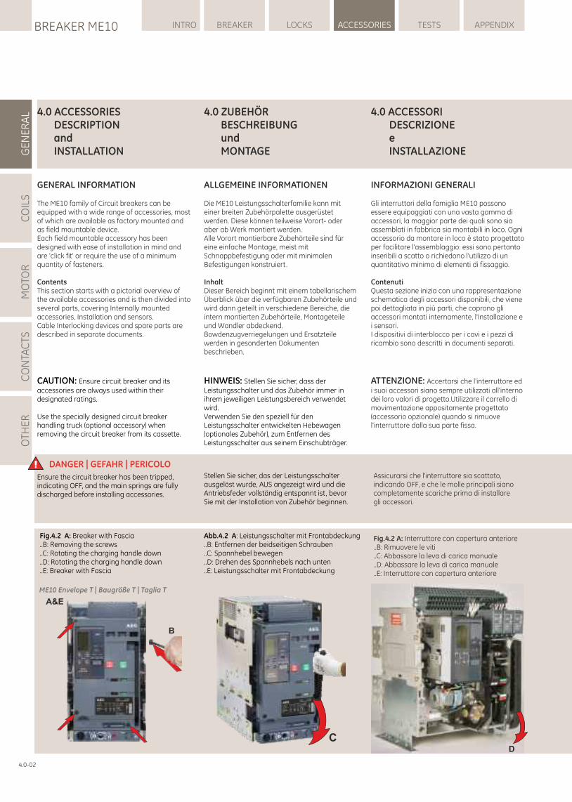
LOCKSBREAKER ME10 INTRO BREAKER ACCESSORIES TESTS APPENDIXG
EN
ER
AL
CO
ILS
MO
TOR
CO
NTA
CTS
OTH
ER
4.0-02
4.0 ACCESSORI DESCRIZIONE e INSTALLAZIONE
INFORMAZIONI GENERALI
Gli interruttori della famiglia ME10 possono essere equipaggiati con una vasta gamma di accessori, la maggior parte dei quali sono sia assemblati in fabbrica sia montabili in loco. Ogni accessorio da montare in loco è stato progettato per facilitare l'assemblaggio: essi sono pertanto inseribili a scatto o richiedono l'utilizzo di un quantitativo minimo di elementi di fissaggio.
ContenutiQuesta sezione inizia con una rappresentazione schematica degli accessori disponibili, che viene poi dettagliata in più parti, che coprono gli accessori montati internamente, l'Installazione e i sensori.I dispositivi di interblocco per i cavi e i pezzi di ricambio sono descritti in documenti separati.
4.0 ACCESSORIESDESCRIPTIONandINSTALLATION
GENERAL INFORMATION
The ME10 family of Circuit breakers can be equipped with a wide range of accessories, most of which are available as factory mounted and as field mountable device.Each field mountable accessory has been designed with ease of installation in mind and are 'click fit' or require the use of a minimum quantity of fasteners.
ContentsThis section starts with a pictorial overview of the available accessories and is then divided into several parts, covering Internally mounted accessories, Installation and sensors. Cable Interlocking devices and spare parts are described in separate documents.
4.0 ZUBEHÖRBESCHREIBUNGundMONTAGE
ALLGEMEINE INFORMATIONEN
Die ME10 Leistungsschalterfamilie kann mit einer breiten Zubehörpalette ausgerüstet werden. Diese können teilweise Vorort- oder aber ab Werk montiert werden.Alle Vorort montierbare Zubehörteile sind für eine einfache Montage, meist mit Schnappbefestigung oder mit minimalen Befestigungen konstruiert.
InhaltDieser Bereich beginnt mit einem tabellarischem Überblick über die verfügbaren Zubehörteile und wird dann geteilt in verschiedene Bereiche, die intern montierten Zubehörteile, Montageteile und Wandler abdeckend. Bowdenzugverriegelungen und Ersatzteile werden in gesonderten Dokumenten beschrieben.
DANGER | GEFAHR | PERICOLO Stellen Sie sicher, das der Leistungsschalter ausgelöst wurde, AUS angezeigt wird und die Antriebsfeder vollständig entspannt ist, bevor Sie mit der Installation von Zubehör beginnen.
Ensure the circuit breaker has been tripped, indicating OFF, and the main springs are fully discharged before installing accessories.
Assicurarsi che l'interruttore sia scattato, indicando OFF, e che le molle principali siano completamente scariche prima di installare gli accessori.
CAUTION: Ensure circuit breaker and its accessories are always used within their designated ratings.
Use the specially designed circuit breaker handling truck (optional accessory) when removing the circuit breaker from its cassette.
HINWEIS: Stellen Sie sicher, dass der Leistungsschalter und das Zubehör immer in ihrem jeweiligen Leistungsbereich verwendet wird.Verwenden Sie den speziell für den Leistungsschalter entwickelten Hebewagen (optionales Zubehör), zum Entfernen des Leistungsschalter aus seinem Einschubträger.
ATTENZIONE: Accertarsi che l'interruttore ed i suoi accessori siano sempre utilizzati all'interno dei loro valori di progetto.Utilizzare il carrello di movimentazione appositamente progettato (accessorio opzionale) quando si rimuove l'interruttore dalla sua parte fissa.
Fig.4.2 A: Breaker with Fascia..B: Removing the screws..C: Rotating the charging handle down..D: Rotating the charging handle down..E: Breaker with Fascia
Abb.4.2 A: Leistungsschalter mit Frontabdeckung..B: Entfernen der beidseitigen Schrauben..C: Spannhebel bewegen..D: Drehen des Spannhebels nach unten ..E: Leistungsschalter mit Frontabdeckung
D
A&E
B
ME10 Envelope T | Baugröße T | Taglia T
C
Fig.4.2 A: Interruttore con copertura anteriore..B: Rimuovere le viti..C: Abbassare la leva di carica manuale..D: Abbassare la leva di carica manuale..E: Interruttore con copertura anteriore
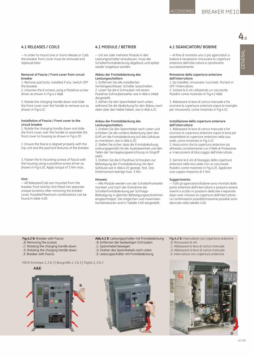
4.1 RELEASES / COILS
-- In order to mount one or more release or Coils the breaker front cover must be removed and replaced later.
Removal of Fascia / Front cover from circuit breaker1. Remove pad locks, installed if any. Switch OFF the breaker.2. Unscrew the 6 screws using a Pozidrive screw driver as shown in Fig.4.2 A&B.
3. Rotate the charging handle down and slide the front cover over the handle to remove out as shown in Fig.4.2C
Installation of Fascia / Front cover to the circuit breaker1. Rotate the charging handle down and slide the front cover over the handle to assemble the front cover to housing as shown in Fig.4.2D
2. Ensure the fascia is aligned properly with the trip unit and the pad lock features of the breaker.
3. Fasten the 6 mounting screws of fascia with the housing using a pozidrive screw driver as shown in Fig.4.2E. Apply torque of 3 Nm max..
Hint:-- All Releases/Coils are mounted from the breaker front and be click fitted into separate unique locations after removing the breaker cover. Possible/Maximum combinations can be found in table 4.00.
4.1 MODULE / BETRIEB
-- Um ein oder mehrere Module in den Leistungsschalter einzubauen, muss die Schalterfrontabdeckung abgebaut und später wieder angebaut werden.
Abbau der Frontabdeckung des Leistungsschalters1. Entfernen Sie alle installierten Vorhängeschlösser. Schalter ausschalten.2. Lösen Sie die 6 Schrauben mit einem Pozidrive-Schraubenzieher wie in Abb.4.2A&B dargestellt .3. Ziehen Sie den Spannhebel nach unten, während Sie die Abdeckung für den Abbau nach oben über den Hebel heben, wie in Abb.4.2C
Anbau der Frontabdeckung des Leistungsschalters1. Drehen Sie den Spannhebel nach unten und schieben Sie die vordere Abdeckung über den Griff um die Frontabdeckung auf das Gehäuse zu montieren, wie in Abb.4.2D 2. Stellen Sie sicher, dass die Frontabdeckung ordnungsgemäß mit der Auslöseeinheit und den Teilen der Verriegelungseinrichtung im Eingriff steht.3. Drehen Sie die 6 Pozidrive-Schrauben zur Befestigung der Frontabdeckung mit dem Gehäuse wie in Abb.4.2E gezeigt, fest. Das Drehmoment beträgt max. 3 Nm.
Hinweis:-- Alle Module werden von der Schalterfrontseite montiert und nach der Entnahme der Schalterfrontabdeckung per Schnapp-Befestigung in gleichen Befestigungsaufnahmen eingeschnappt. Die möglichen und maximalen Kombinationen sind in Tabelle 4.00 dargestellt .
BREAKER ME10ACCESSORIES
GE
NE
RA
L
4.0
4.1-01
4.1 SGANCIATORI/ BOBINE
-- Al fine di montare uno o più sganciatori o bobine è necessario rimuovere la copertura anteriore dell'interruttore e ripristinarla successivamente.
Rimozione della copertura anteriore dell'interruttore1. Se installati, rimuovere i lucchetti. Portare in OFF l'interruttore.2. Svitare le 6 viti utilizzando un cacciavite Pozidriv come mostrato in Fig.4.2 A&B.
3. Abbassare la leva di carica manuale e far scorrere la copertura anteriore sopra la maniglia per rimuoverla, come mostrato in Fig.4.2C
Installazione della copertura anteriore dell'interruttore1. Abbassare la leva di carica manuale e far scorrere la copertura anteriore sopra la leva per assemblare la coperture anteriore nella sua sede, come mostrato in Fig.4.2C2. Assicurarsi che la copertura anteriore sia allineata correttamente con il Relè di Protezione e i meccanismi di bloccaggio dell'interruttore.
3. Serrare le 6 viti di fissaggio della copertura anteriore nella loro sede con un cacciavite Pozidriv come mostrato in Fig.4.2E. Applicare una coppia massima di 3 Nm.
Suggerimento:-- Tutti gli sganciatori/bobine sono montati dalla parte anteriore dell'interruttore e possono essere inseriti a scatto in posizioni dedicate e separate dopo aver rimosso la copertura dell'interruttore. Le combinazioni possibili/massime possibili sono elencate nella tabella 4.00.
Fig.4.2 B: Breaker with Fascia..B: Removing the screws..C: Rotating the charging handle down..D: Rotating the charging handle down..E: Breaker with Fascia
Abb.4.2 B: Leistungsschalter mit Frontabdeckung..B: Entfernen der beidseitigen Schrauben..C: Spannhebel bewegen..D: Drehen des Spannhebels nach unten ..E: Leistungsschalter mit Frontabdeckung
A&E
ME10 Envelope 1, 2 & 3 | Baugröße 1, 2 & 3 | Taglia 1, 2 & 3
Fig.4.2 B: Interruttore con copertura anteriore..B: Rimuovere le viti..C: Abbassare la leva di carica manuale..D: Abbassare la leva di carica manuale..E: Interruttore con copertura anteriore
D
B
A
C
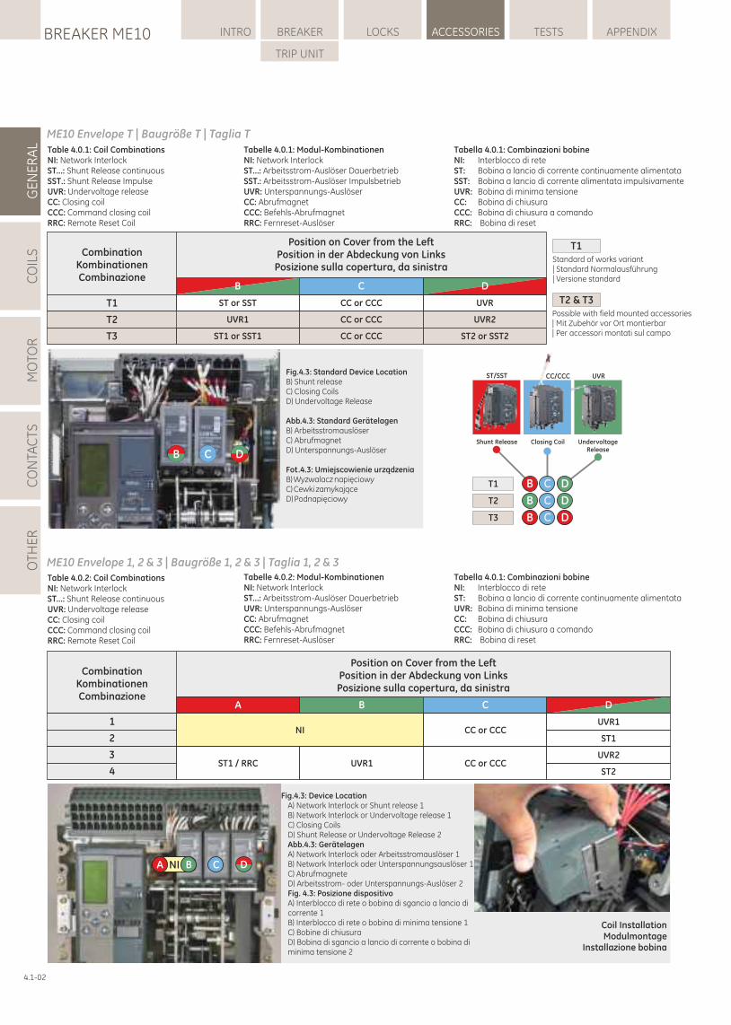
LOCKSBREAKER ME10 INTRO BREAKER ACCESSORIES TESTS APPENDIX
TRIP UNIT
GE
NE
RA
LC
OIL
SM
OTO
RC
ON
TAC
TSO
THE
R
4.1-02
Table 4.0.1: Coil CombinationsNI: Network InterlockST...: Shunt Release continuousSST.: Shunt Release ImpulseUVR: Undervoltage releaseCC: Closing coilCCC: Command closing coilRRC: Remote Reset Coil
ME10 Envelope T | Baugröße T | Taglia T
Fig.4.3: Standard Device LocationB) Shunt releaseC) Closing CoilsD) Undervoltage Release
Abb.4.3: Standard GerätelagenB) ArbeitsstromauslöserC) AbrufmagnetD) Unterspannungs-Auslöser
Fot.4.3: Umiejscowienie urządzenia B) Wyzwalacz napięciowyC) Cewki zamykające D) Podnapięciowy
CombinationKombinationenCombinazione
Position on Cover from the LeftPosition in der Abdeckung von LinksPosizione sulla copertura, da sinistra
A B C D
NI CC or CCCUVR1
ST1 / RRC UVR1ST2
1
2
3
4CC or CCC
ST1
UVR2
Table 4.0.2: Coil CombinationsNI: Network InterlockST...: Shunt Release continuousUVR: Undervoltage releaseCC: Closing coilCCC: Command closing coilRRC: Remote Reset Coil
Tabelle 4.0.2: Modul-KombinationenNI: Network InterlockST...: Arbeitsstrom-Auslöser DauerbetriebUVR: Unterspannungs-AuslöserCC: AbrufmagnetCCC: Befehls-AbrufmagnetRRC: Fernreset-Auslöser
ME10 Envelope 1, 2 & 3 | Baugröße 1, 2 & 3 | Taglia 1, 2 & 3
CombinationKombinationenCombinazione
Position on Cover from the LeftPosition in der Abdeckung von LinksPosizione sulla copertura, da sinistra
B
T1
T2
T3
D
UVR
UVR2
ST2 or SST2
C
CC or CCC
CC or CCC
CC or CCC
ST or SST
ST1 or SST1
UVR1
B C D
NIA B C D
UndervoltageRelease
Closing CoilShunt Release
T1
T2
T3
DCB
DCB
DCB
ST/SST CC/CCC UVR
Coil InstallationModulmontage
Installazione bobina
Fig.4.3: Device LocationA) Network Interlock or Shunt release 1B) Network Interlock or Undervoltage release 1C) Closing CoilsD) Shunt Release or Undervoltage Release 2Abb.4.3: GerätelagenA) Network Interlock oder Arbeitsstromauslöser 1B) Network Interlock oder Unterspannungsauslöser 1C) AbrufmagneteD) Arbeitsstrom- oder Unterspannungs-Auslöser 2Fig. 4.3: Posizione dispositivoA) Interblocco di rete o bobina di sgancio a lancio di corrente 1B) Interblocco di rete o bobina di minima tensione 1C) Bobine di chiusuraD) Bobina di sgancio a lancio di corrente o bobina di minima tensione 2
Tabelle 4.0.1: Modul-KombinationenNI: Network InterlockST...: Arbeitsstrom-Auslöser DauerbetriebSST.: Arbeitsstrom-Auslöser ImpulsbetriebUVR: Unterspannungs-AuslöserCC: AbrufmagnetCCC: Befehls-AbrufmagnetRRC: Fernreset-Auslöser
Tabella 4.0.1: Combinazioni bobineNI: Interblocco di reteST: Bobina a lancio di corrente continuamente alimentataSST: Bobina a lancio di corrente alimentata impulsivamenteUVR: Bobina di minima tensioneCC: Bobina di chiusuraCCC: Bobina di chiusura a comandoRRC: Bobina di reset
T1
T2 & T3Possible with field mounted accessories | Mit Zubehör vor Ort montierbar | Per accessori montati sul campo
Standard of works variant | Standard Normalausführung | Versione standard
Tabella 4.0.1: Combinazioni bobineNI: Interblocco di reteST: Bobina a lancio di corrente continuamente alimentataUVR: Bobina di minima tensioneCC: Bobina di chiusuraCCC: Bobina di chiusura a comandoRRC: Bobina di reset
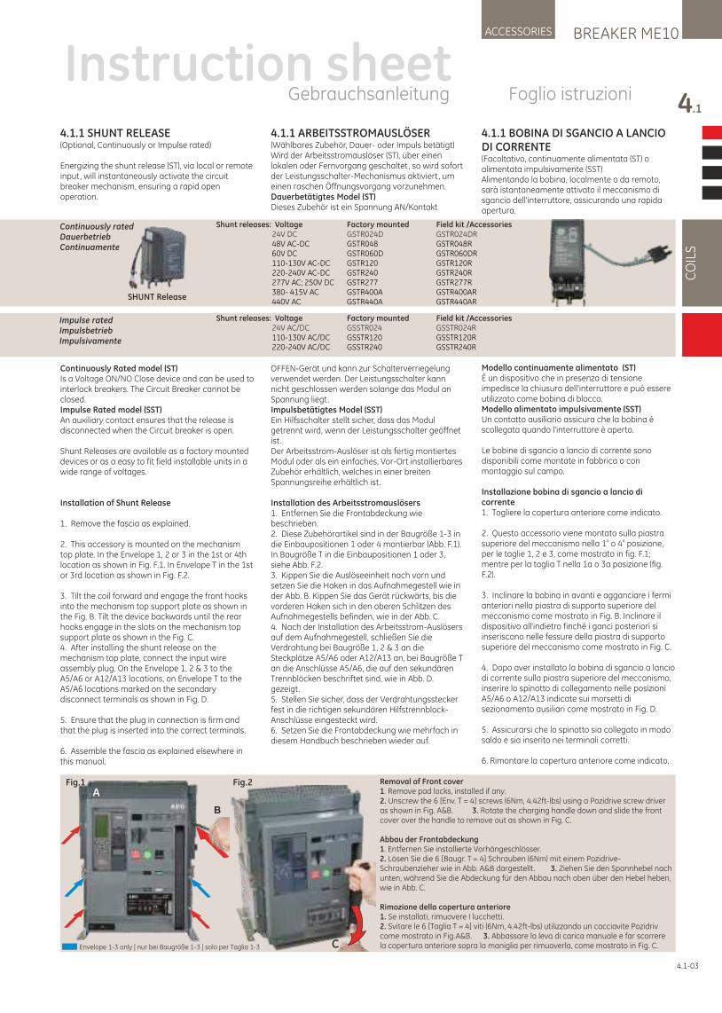
4.1.1 BOBINA DI SGANCIO A LANCIO DI CORRENTE(Facoltativo, continuamente alimentata (ST) o alimentata impulsivamente (SST) Alimentando la bobina, localmente o da remoto, sarà istantaneamente attivato il meccanismo di sgancio dell'interruttore, assicurando una rapida apertura.
Modello continuamente alimentato (ST) È un dispositivo che in presenza di tensione impedisce la chiusura dell'interruttore e può essere utilizzato come bobina di blocco. Modello alimentato impulsivamente (SST) Un contatto ausiliario assicura che la bobina è scollegata quando l'interruttore è aperto.
Le bobine di sgancio a lancio di corrente sono disponibili come montate in fabbrica o con montaggio sul campo.
Installazione bobina di sgancio a lancio di corrente1. Togliere la copertura anteriore come indicato.
2. Questo accessorio viene montato sulla piastra a asuperiore del meccanismo nella 1 o 4 posizione,
per le taglie 1, 2 e 3, come mostrato in fig. F.1; mentre per la taglia T nella 1a o 3a posizione (fig. F.2).
3. Inclinare la bobina in avanti e agganciare i fermi anteriori nella piastra di supporto superiore del meccanismo come mostrato in Fig. B. Inclinare il dispositivo all'indietro finché i ganci posteriori si inseriscono nelle fessure della piastra di supporto superiore del meccanismo come mostrato in Fig. C.
4. Dopo aver installato la bobina di sgancio a lancio di corrente sulla piastra superiore del meccanismo, inserire lo spinotto di collegamento nelle posizioni A5/A6 o A12/A13 indicate sui morsetti di sezionamento ausiliari come mostrato in Fig. D.
5. Assicurarsi che lo spinotto sia collegato in modo saldo e sia inserito nei terminali corretti.
6. Rimontare la copertura anteriore come indicato.
4.1.1 SHUNT RELEASE(Optional, Continuously or Impulse rated)
Energizing the shunt release (ST), via local or remote input, will instantaneously activate the circuit breaker mechanism, ensuring a rapid open operation.
Continuously Rated model (ST) Is a Voltage ON/NO Close device and can be used to interlock breakers. The Circuit Breaker cannot be closed. Impulse Rated model (SST)An auxiliary contact ensures that the release is disconnected when the Circuit breaker is open.
Shunt Releases are available as a factory mounted devices or as a easy to fit field installable units in a wide range of voltages.
Installation of Shunt Release
1. Remove the fascia as explained.
2. This accessory is mounted on the mechanism top plate. In the Envelope 1, 2 or 3 in the 1st or 4th location as shown in Fig. F.1. In Envelope T in the 1st or 3rd location as shown in Fig. F.2.
3. Tilt the coil forward and engage the front hooks into the mechanism top support plate as shown in the Fig. B. Tilt the device backwards until the rear hooks engage in the slots on the mechanism top support plate as shown in the Fig. C.4. After installing the shunt release on the mechanism top plate, connect the input wire assembly plug. On the Envelope 1, 2 & 3 to the A5/A6 or A12/A13 locations, on Envelope T to the A5/A6 locations marked on the secondary disconnect terminals as shown in Fig. D.
5. Ensure that the plug in connection is firm and that the plug is inserted into the correct terminals.
6. Assemble the fascia as explained elsewhere in this manual.
4.1.1 ARBEITSSTROMAUSLÖSER(Wählbares Zubehör, Dauer- oder Impuls betätigt)Wird der Arbeitsstromauslöser (ST), über einen lokalen oder Fernvorgang geschaltet, so wird sofort der Leistungsschalter-Mechanismus aktiviert, um einen raschen Öffnungsvorgang vorzunehmen. Dauerbetätigtes Model (ST)Dieses Zubehör ist ein Spannung AN/Kontakt
OFFEN-Gerät und kann zur Schalterverriegelung verwendet werden. Der Leistungsschalter kann nicht geschlossen werden solange das Modul an Spannung liegt.Impulsbetätigtes Model (SST)Ein Hilfsschalter stellt sicher, dass das Modul getrennt wird, wenn der Leistungsschalter geöffnet ist.Der Arbeitsstrom-Auslöser ist als fertig montiertes Modul oder als ein einfaches, Vor-Ort installierbares Zubehör erhältlich, welches in einer breiten Spannungsreihe erhältlich ist.
Installation des Arbeitsstromauslösers1. Entfernen Sie die Frontabdeckung wie beschrieben.2. Diese Zubehörartikel sind in der Baugröße 1-3 in die Einbaupositionen 1 oder 4 montierbar (Abb. F.1). In Baugröße T in die Einbaupositionen 1 oder 3, siehe Abb. F.2.3. Kippen Sie die Auslöseeinheit nach vorn und setzen Sie die Haken in das Aufnahmegestell wie in der Abb. B. Kippen Sie das Gerät rückwärts, bis die vorderen Haken sich in den oberen Schlitzen des Aufnahmegestells befinden, wie in der Abb. C.4. Nach der Installation des Arbeitsstrom-Auslösers auf dem Aufnahmegestell, schließen Sie die Verdrahtung bei Baugröße 1, 2 & 3 an die Steckplätze A5/A6 oder A12/A13 an, bei Baugröße T an die Anschlüsse A5/A6, die auf den sekundären Trennblöcken beschriftet sind, wie in Abb. D. gezeigt.5. Stellen Sie sicher, dass der Verdrahtungsstecker fest in die richtigen sekundären Hilfstrennblock-Anschlüsse eingesteckt wird.6. Setzen Sie die Frontabdeckung wie mehrfach in diesem Handbuch beschrieben wieder auf.
BREAKER ME10ACCESSORIES
4.1
CO
ILS
4.1-03
Instruction sheetGebrauchsanleitung Foglio istruzioni
A
Shunt releases: Voltage Factory mounted Field kit /Accessories 24V DC GSTR024D GSTR024DR 48V AC-DC GSTR048 GSTR048R 60V DC GSTR060D GSTR060DR 110-130V AC-DC GSTR120 GSTR120R 220-240V AC-DC GSTR240 GSTR240R 277V AC; 250V DC GSTR277 GSTR277R 380- 415V AC GSTR400A GSTR400AR 440V AC GSTR440A GSTR440AR
Shunt releases: Voltage Factory mounted Field kit /Accessories 24V AC/DC GSSTR024 GSSTR024R 110-130V AC/DC GSSTR120 GSSTR120R 220-240V AC/DC GSSTR240 GSSTR240R
Impulse ratedImpulsbetriebImpulsivamente
Continuously ratedDauerbetriebContinuamente
SHUNT Release
Fig.1 Fig.2
C
B
ARemoval of Front cover1. Remove pad locks, installed if any.2. Unscrew the 6 [Env. T = 4] screws (6Nm, 4.42ft-lbs) using a Pozidrive screw driver as shown in Fig. A&B. 3. Rotate the charging handle down and slide the front cover over the handle to remove out as shown in Fig. C.
Abbau der Frontabdeckung1. Entfernen Sie installierte Vorhängeschlösser.2. Lösen Sie die 6 [Baugr. T = 4] Schrauben (6Nm) mit einem Pozidrive-Schraubenzieher wie in Abb. A&B dargestellt . 3. Ziehen Sie den Spannhebel nach unten, während Sie die Abdeckung für den Abbau nach oben über den Hebel heben, wie in Abb. C.
Rimozione della copertura anteriore1. Se installati, rimuovere I lucchetti.2. Svitare le 6 [Taglia T = 4] viti (6Nm, 4.42ft-lbs) utilizzando un cacciavite Pozidriv come mostrato in Fig.A&B. 3. Abbassare la leva di carica manuale e far scorrere la copertura anteriore sopra la maniglia per rimuoverla, come mostrato in Fig. C.Envelope 1-3 only | nur bei Baugröße 1-3 | solo per Taglia 1-3
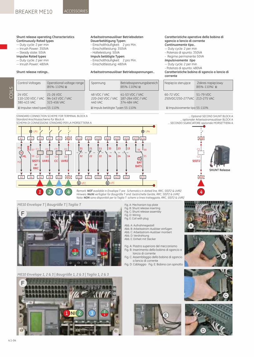
CO
ILS
ACCESSORIESBREAKER ME10
4.1-04
Shunt release operating CharacteristicsContinuously Rated types-- Duty cycle: 2 per min-- Inrush Power: 350VA-- Steady state: 50VAImpulse Rated types-- Duty cycle: 2 per min-- Inrush Power: 480VA
Shunt release ratings..
Arbeitsstromauslöser BetriebsdatenDauerbetätigung Typen:- Einschalthäufigkeit: 2 pro Min.- Einschaltleistung: 350VA- Halteleistung: 50VAImpuls betätigte Typen:- Einschalthäufigkeit: 2 pro Min.- Einschaltleistung: 480VA
Arbeitsstromauslöser Betriebsspannungen..
Control Voltages Operational voltage range Spannung Betriebsspannungsbereich Napięcia sterujące Zakres napięciowy (85%-110%) 1) (85%-110%) 1) (85%-110%) 1)
24 VDC 21-26 VDC 48 VDC / VAC 41-53 VDC / VAC 60-72 VDC 51-79 VDC110-130 VDC / VAC 94-143 VDC / VAC 220-240 VDC / VAC 187-264 VDC / VAC 250VDC/250-277VAC 213-275 VAC380-415 VAC 323-456 VAC 440 VAC 374-484 VAC
1) Impulse rated types 55-110% 1) Impuls betätigte Typen 55-110%
Fig. A: Mechanism top plateFig. B: Shunt release insertingFig. C: Shunt release assemblyFig. D: WiringFig. E: Coil with plug
Abb. A: AufnahmegestellAbb. B: Arbeitsstrom-Auslöser einfügenAbb. C: Arbeitsstrom-Auslöser montiertAbb. D: VerdrahtungAbb. E: Einheit mit Stecker
A
B
C
D
E
ME10 Envelope T | Baugröße T | Taglia T
F
321
12
F
NI1 2 3 12
ME10 Envelope 1, 2 & 3 | Baugröße 1, 2 & 3 | Taglia 1, 2 & 3
A2
A1
M
ML
M1
M2
LP1
A4
A3
SP
R
58
57
A6
A5
C1
C2
S(S)T1or
RRC
1
A10
A9
C4
C3
CC
3
A8
A7
UVR1
D1
D2
2
LP2
A15
A14
32
31
A17
A16
22
21
A19
A18
22
11
A23
A22
24
23
A25
A24
14
13
LP3
A21
A20
34
33
LP4
A35
A34
95
98
T
BATBATS
A33
96
A13
A12
UVR2
D1
D2
4 Remark: NOT available in Envelope T are: Schematics in dotted line, RRC, S(S)T2 & UVR2.Hinweis: Nicht verfügbar für Baugröße T sind: Gestrichelte Geräte, RRC, S(S)T2 & UVR2.Nota: NON sono disponibili per la Taglia T: schemi a linea tratteggiata, RRC, S(S)T2 & UVR2
S(S)T2
C1
C2
A13
4
A12
SHUNT Release
STANDARD CONNECTION SCHEME FOR TERMINAL BLOCK AStandard Anschlussschema für Block ASCHEMA DI CONNESSIONE STANDARD PER LA MORSETTIERA A
... Optional SECOND SHUNT BLOCK A... optionaler Arbeitsstromauslöser BLOCK A
... SECONDO SGANCIATORE opzionale MORSETTIERA A
Fig. A: Piastra superiore del meccanismoFig. B: Inserimento della bobina di sgancio a
lancio di correnteFig. C: Assemblaggio della bobina di sgancio
a lancio di correnteFig. D: Cablaggio Fig. E: Bobina con spinotto
Caratteristiche operative della bobina di sgancio a lancio di correnteContinuamente tipo..-- Duty cycle: 2 per min- Potenza di spunto: 350VA- Regime permanente 50VAImpulsivamente tipo-- Duty cycle: 2 per min- Potenza di spunto: 480VACaratteristiche bobina di sgancio a lancio di corrente
1) Impulsivamente tipo 55-110%
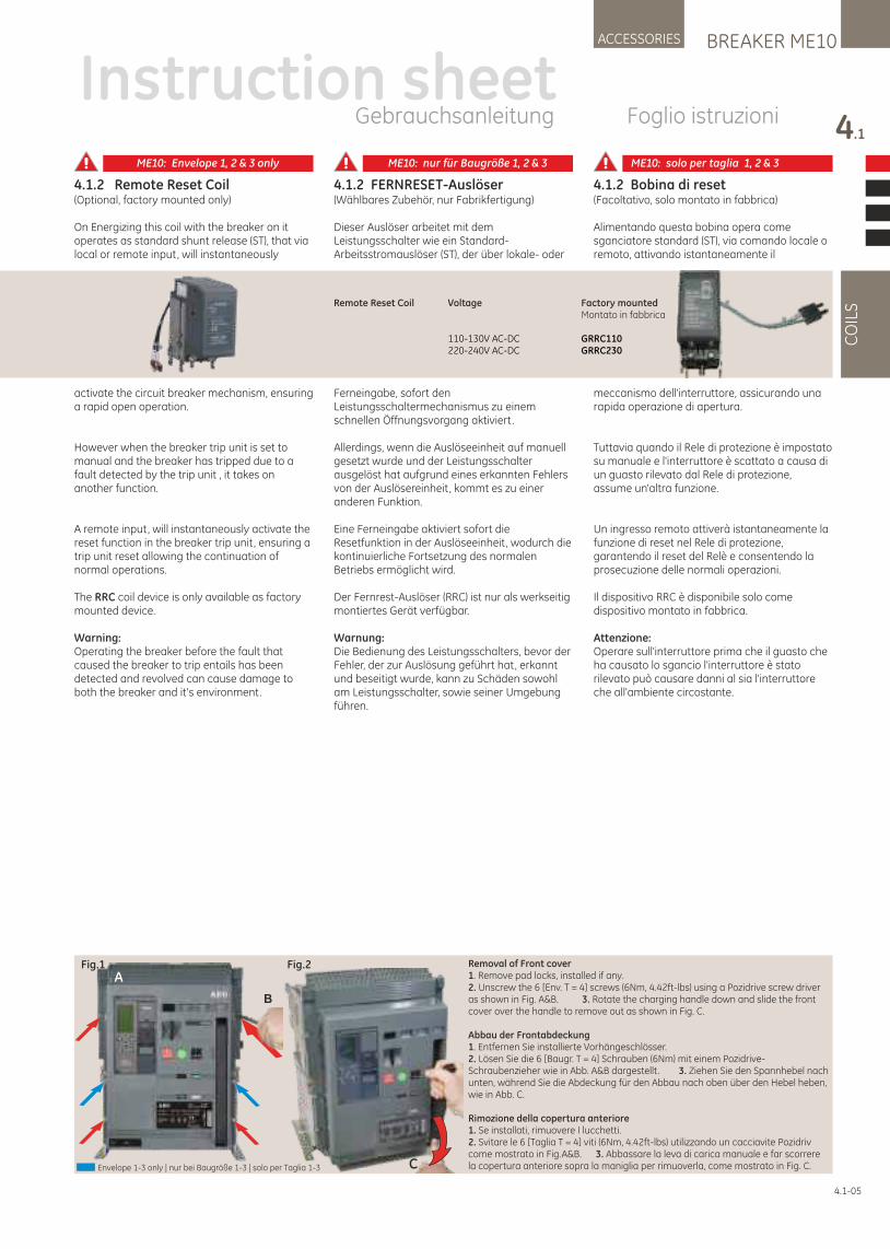
4.1.2 FERNRESET-Auslöser(Wählbares Zubehör, nur Fabrikfertigung)
Dieser Auslöser arbeitet mit dem Leistungsschalter wie ein Standard-Arbeitsstromauslöser (ST), der über lokale- oder
Ferneingabe, sofort den Leistungsschaltermechanismus zu einem schnellen Öffnungsvorgang aktiviert.
Allerdings, wenn die Auslöseeinheit auf manuell gesetzt wurde und der Leistungsschalter ausgelöst hat aufgrund eines erkannten Fehlers von der Auslösereinheit, kommt es zu einer anderen Funktion.
Eine Ferneingabe aktiviert sofort die Resetfunktion in der Auslöseeinheit, wodurch die kontinuierliche Fortsetzung des normalen Betriebs ermöglicht wird.
Der Fernrest-Auslöser (RRC) ist nur als werkseitig montiertes Gerät verfügbar.
Warnung:Die Bedienung des Leistungsschalters, bevor der Fehler, der zur Auslösung geführt hat, erkannt und beseitigt wurde, kann zu Schäden sowohl am Leistungsschalter, sowie seiner Umgebung führen.
4.1.2 Remote Reset Coil(Optional, factory mounted only)
On Energizing this coil with the breaker on it operates as standard shunt release (ST), that via local or remote input, will instantaneously
activate the circuit breaker mechanism, ensuring a rapid open operation.
However when the breaker trip unit is set to manual and the breaker has tripped due to a fault detected by the trip unit , it takes on another function.
A remote input, will instantaneously activate the reset function in the breaker trip unit, ensuring a trip unit reset allowing the continuation of normal operations.
The RRC coil device is only available as factory mounted device.
Warning:Operating the breaker before the fault that caused the breaker to trip entails has been detected and revolved can cause damage to both the breaker and it's environment.
4.1.2 Bobina di reset(Facoltativo, solo montato in fabbrica)
Alimentando questa bobina opera come sganciatore standard (ST), via comando locale o remoto, attivando istantaneamente il
meccanismo dell'interruttore, assicurando una rapida operazione di apertura.
Tuttavia quando il Rele di protezione è impostato su manuale e l'interruttore è scattato a causa di un guasto rilevato dal Rele di protezione, assume un'altra funzione.
Un ingresso remoto attiverà istantaneamente la funzione di reset nel Rele di protezione, garantendo il reset del Relè e consentendo la prosecuzione delle normali operazioni.
Il dispositivo RRC è disponibile solo come dispositivo montato in fabbrica.
Attenzione: Operare sull'interruttore prima che il guasto che ha causato lo sgancio l'interruttore è stato rilevato può causare danni al sia l'interruttore che all'ambiente circostante.
BREAKER ME10ACCESSORIES
4.1
CO
ILS
4.1-05
Instruction sheetGebrauchsanleitung Foglio istruzioni
Remote Reset Coil Voltage Factory mounted Montato in fabbrica
110-130V AC-DC GRRC110 220-240V AC-DC GRRC230
Fig.1 Fig.2
C
B
ARemoval of Front cover1. Remove pad locks, installed if any.2. Unscrew the 6 [Env. T = 4] screws (6Nm, 4.42ft-lbs) using a Pozidrive screw driver as shown in Fig. A&B. 3. Rotate the charging handle down and slide the front cover over the handle to remove out as shown in Fig. C.
Abbau der Frontabdeckung1. Entfernen Sie installierte Vorhängeschlösser.2. Lösen Sie die 6 [Baugr. T = 4] Schrauben (6Nm) mit einem Pozidrive-Schraubenzieher wie in Abb. A&B dargestellt . 3. Ziehen Sie den Spannhebel nach unten, während Sie die Abdeckung für den Abbau nach oben über den Hebel heben, wie in Abb. C.
Rimozione della copertura anteriore1. Se installati, rimuovere I lucchetti.2. Svitare le 6 [Taglia T = 4] viti (6Nm, 4.42ft-lbs) utilizzando un cacciavite Pozidriv come mostrato in Fig.A&B. 3. Abbassare la leva di carica manuale e far scorrere la copertura anteriore sopra la maniglia per rimuoverla, come mostrato in Fig. C.Envelope 1-3 only | nur bei Baugröße 1-3 | solo per Taglia 1-3
ME10: Envelope 1, 2 & 3 only ME10: nur für Baugröße 1, 2 & 3 ME10: solo per taglia 1, 2 & 3
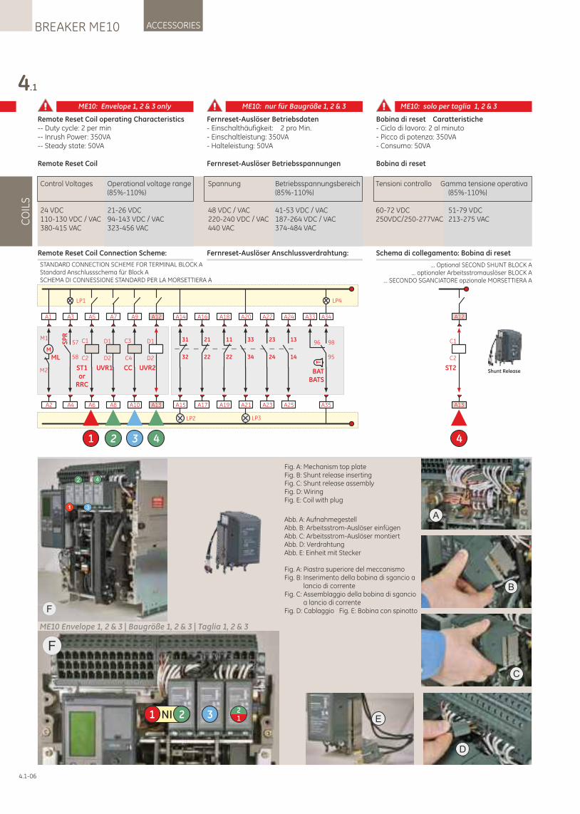
Remote Reset Coil operating Characteristics-- Duty cycle: 2 per min-- Inrush Power: 350VA-- Steady state: 50VA
Remote Reset Coil
Remote Reset Coil Connection Scheme:
Fernreset-Auslöser Betriebsdaten- Einschalthäufigkeit: 2 pro Min.- Einschaltleistung: 350VA- Halteleistung: 50VA
Fernreset-Auslöser Betriebsspannungen
Fernreset-Auslöser Anschlussverdrahtung:
4.1
CO
ILS
ACCESSORIESBREAKER ME10
4.1-06
Bobina di reset Caratteristiche - Ciclo di lavoro: 2 al minuto- Picco di potenza: 350VA - Consumo: 50VA
Bobina di reset
Schema di collegamento: Bobina di reset
Control Voltages Operational voltage range Spannung Betriebsspannungsbereich Tensioni controllo Gamma tensione operativa (85%-110%) (85%-110%) (85%-110%)
24 VDC 21-26 VDC 48 VDC / VAC 41-53 VDC / VAC 60-72 VDC 51-79 VDC110-130 VDC / VAC 94-143 VDC / VAC 220-240 VDC / VAC 187-264 VDC / VAC 250VDC/250-277VAC 213-275 VAC380-415 VAC 323-456 VAC 440 VAC 374-484 VAC
ME10: Envelope 1, 2 & 3 only ME10: nur für Baugröße 1, 2 & 3 ME10: solo per taglia 1, 2 & 3
A2
A1
M
ML
M1
M2
LP1
A4
A3
SP
R
58
57
A6
A5
C1
C2
ST1or
RRC
1
A10
A9
C4
C3
CC
A8
A7
UVR1
D1
D2
LP2
A15
A14
32
31
A17
A16
22
21
A19
A18
22
11
A23
A22
24
23
A25
A24
14
13
LP3
A21
A20
34
33
LP4
A35
A34
95
98
T
BATBATS
A33
96
A13
A12
UVR2
D1
D2
4
ST2
C1
C2
A13
4
A12
Shunt Release
32
... Optional SECOND SHUNT BLOCK A... optionaler Arbeitsstromauslöser BLOCK A
... SECONDO SGANCIATORE opzionale MORSETTIERA A
STANDARD CONNECTION SCHEME FOR TERMINAL BLOCK AStandard Anschlussschema für Block ASCHEMA DI CONNESSIONE STANDARD PER LA MORSETTIERA A
Fig. A: Mechanism top plateFig. B: Shunt release insertingFig. C: Shunt release assemblyFig. D: WiringFig. E: Coil with plug
Abb. A: AufnahmegestellAbb. B: Arbeitsstrom-Auslöser einfügenAbb. C: Arbeitsstrom-Auslöser montiertAbb. D: VerdrahtungAbb. E: Einheit mit Stecker
A
B
C
D
1
2
3
4
F
F
NI1 2 3 12
ME10 Envelope 1, 2 & 3 | Baugröße 1, 2 & 3 | Taglia 1, 2 & 3
Fig. A: Piastra superiore del meccanismoFig. B: Inserimento della bobina di sgancio a
lancio di correnteFig. C: Assemblaggio della bobina di sgancio
a lancio di correnteFig. D: Cablaggio Fig. E: Bobina con spinotto
E
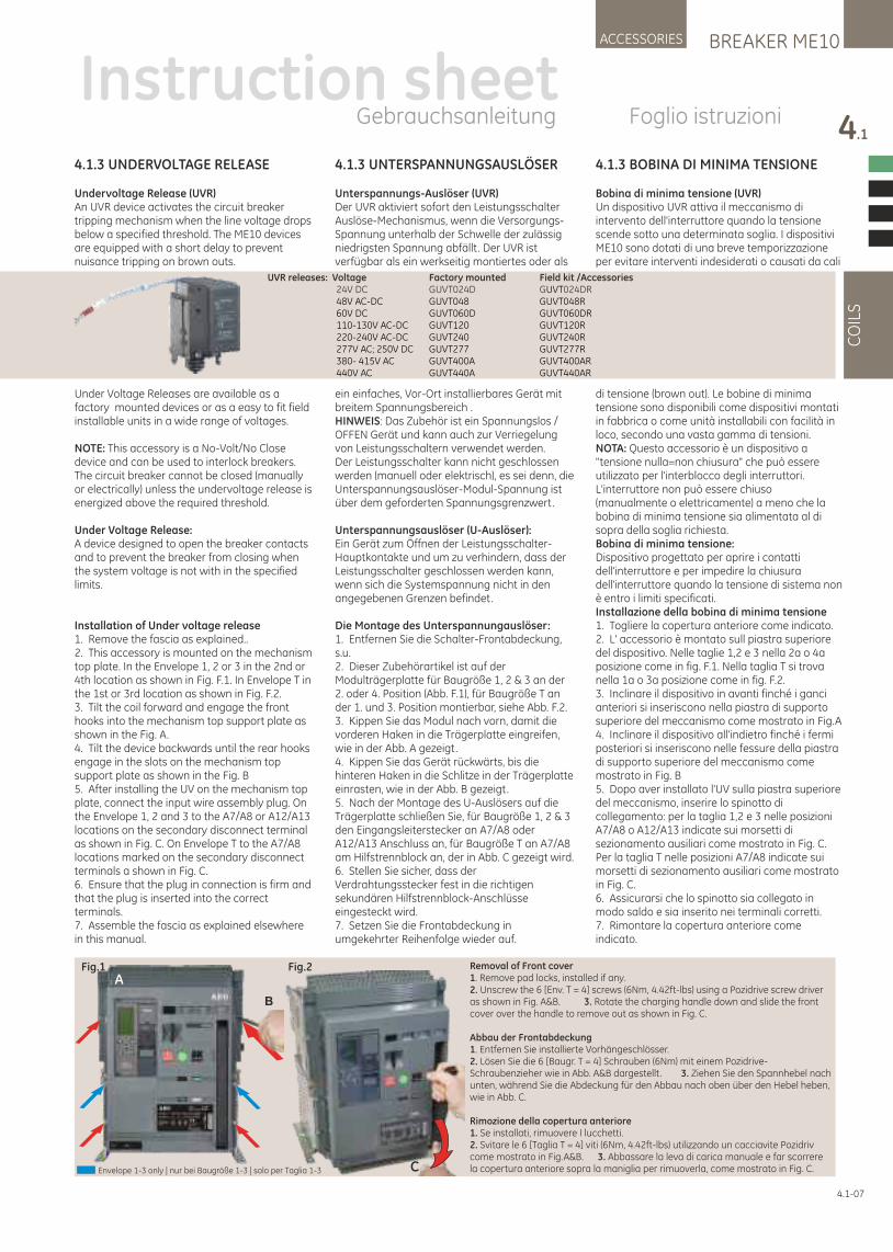
4.1.3 BOBINA DI MINIMA TENSIONE
Bobina di minima tensione (UVR)Un dispositivo UVR attiva il meccanismo di intervento dell'interruttore quando la tensione scende sotto una determinata soglia. I dispositivi ME10 sono dotati di una breve temporizzazione per evitare interventi indesiderati o causati da cali
di tensione (brown out). Le bobine di minima tensione sono disponibili come dispositivi montati in fabbrica o come unità installabili con facilità in loco, secondo una vasta gamma di tensioni.NOTA: Questo accessorio è un dispositivo a "tensione nulla=non chiusura" che può essere utilizzato per l'interblocco degli interruttori. L'interruttore non può essere chiuso (manualmente o elettricamente) a meno che la bobina di minima tensione sia alimentata al di sopra della soglia richiesta. Bobina di minima tensione:Dispositivo progettato per aprire i contatti dell'interruttore e per impedire la chiusura dell'interruttore quando la tensione di sistema non è entro i limiti specificati.Installazione della bobina di minima tensione1. Togliere la copertura anteriore come indicato.2. L' accessorio è montato sull piastra superiore del dispositivo. Nelle taglie 1,2 e 3 nella 2a o 4a posizione come in fig. F.1. Nella taglia T si trova nella 1a o 3a posizione come in fig. F.2.3. Inclinare il dispositivo in avanti finché i ganci anteriori si inseriscono nella piastra di supporto superiore del meccanismo come mostrato in Fig.A4. Inclinare il dispositivo all'indietro finché i fermi posteriori si inseriscono nelle fessure della piastra di supporto superiore del meccanismo come mostrato in Fig. B5. Dopo aver installato l'UV sulla piastra superiore del meccanismo, inserire lo spinotto di collegamento: per la taglia 1,2 e 3 nelle posizioni A7/A8 o A12/A13 indicate sui morsetti di sezionamento ausiliari come mostrato in Fig. C. Per la taglia T nelle posizioni A7/A8 indicate sui morsetti di sezionamento ausiliari come mostrato in Fig. C.6. Assicurarsi che lo spinotto sia collegato in modo saldo e sia inserito nei terminali corretti.7. Rimontare la copertura anteriore come indicato.
4.1.3 UNTERSPANNUNGSAUSLÖSER
Unterspannungs-Auslöser (UVR)Der UVR aktiviert sofort den Leistungsschalter Auslöse-Mechanismus, wenn die Versorgungs-Spannung unterhalb der Schwelle der zulässig niedrigsten Spannung abfällt. Der UVR ist verfügbar als ein werkseitig montiertes oder als
ein einfaches, Vor-Ort installierbares Gerät mit breitem Spannungsbereich .HINWEIS: Das Zubehör ist ein Spannungslos / OFFEN Gerät und kann auch zur Verriegelung von Leistungsschaltern verwendet werden.Der Leistungsschalter kann nicht geschlossen werden (manuell oder elektrisch), es sei denn, die Unterspannungsauslöser-Modul-Spannung ist über dem geforderten Spannungsgrenzwert.
Unterspannungsauslöser (U-Auslöser): Ein Gerät zum Öffnen der Leistungsschalter-Hauptkontakte und um zu verhindern, dass der Leistungsschalter geschlossen werden kann, wenn sich die Systemspannung nicht in den angegebenen Grenzen befindet.
Die Montage des Unterspannungauslöser:1. Entfernen Sie die Schalter-Frontabdeckung, s.u.2. Dieser Zubehörartikel ist auf der Modulträgerplatte für Baugröße 1, 2 & 3 an der 2. oder 4. Position (Abb. F.1), für Baugröße T an der 1. und 3. Position montierbar, siehe Abb. F.2.3. Kippen Sie das Modul nach vorn, damit die vorderen Haken in die Trägerplatte eingreifen, wie in der Abb. A gezeigt.4. Kippen Sie das Gerät rückwärts, bis die hinteren Haken in die Schlitze in der Trägerplatte einrasten, wie in der Abb. B gezeigt.5. Nach der Montage des U-Auslösers auf die Trägerplatte schließen Sie, für Baugröße 1, 2 & 3 den Eingangsleiterstecker an A7/A8 oder A12/A13 Anschluss an, für Baugröße T an A7/A8 am Hilfstrennblock an, der in Abb. C gezeigt wird.6. Stellen Sie sicher, dass der Verdrahtungsstecker fest in die richtigen sekundären Hilfstrennblock-Anschlüsse eingesteckt wird.7. Setzen Sie die Frontabdeckung in umgekehrter Reihenfolge wieder auf.
4.1-07
BREAKER ME10ACCESSORIES
4.1
CO
ILS
Instruction sheetGebrauchsanleitung Foglio istruzioni
UVR releases: Voltage Factory mounted Field kit /Accessories 24V DC GUVT024D G 024DRUVT 48V AC-DC GUVT048 GUVT048R 60V DC GUVT060D GUVT060DR 110-130V AC-DC GUVT120 GUVT120R 220-240V AC-DC GUVT240 GUVT240R 277V AC; 250V DC GUVT277 GUVT277R 380- 415V AC GUVT400A GUVT400AR 440V AC GUVT440A GUVT440AR
Fig.1 Fig.2
C
B
ARemoval of Front cover1. Remove pad locks, installed if any.2. Unscrew the 6 [Env. T = 4] screws (6Nm, 4.42ft-lbs) using a Pozidrive screw driver as shown in Fig. A&B. 3. Rotate the charging handle down and slide the front cover over the handle to remove out as shown in Fig. C.
Abbau der Frontabdeckung1. Entfernen Sie installierte Vorhängeschlösser.2. Lösen Sie die 6 [Baugr. T = 4] Schrauben (6Nm) mit einem Pozidrive-Schraubenzieher wie in Abb. A&B dargestellt . 3. Ziehen Sie den Spannhebel nach unten, während Sie die Abdeckung für den Abbau nach oben über den Hebel heben, wie in Abb. C.
Rimozione della copertura anteriore1. Se installati, rimuovere I lucchetti.2. Svitare le 6 [Taglia T = 4] viti (6Nm, 4.42ft-lbs) utilizzando un cacciavite Pozidriv come mostrato in Fig.A&B. 3. Abbassare la leva di carica manuale e far scorrere la copertura anteriore sopra la maniglia per rimuoverla, come mostrato in Fig. C.Envelope 1-3 only | nur bei Baugröße 1-3 | solo per Taglia 1-3
4.1.3 UNDERVOLTAGE RELEASE
Undervoltage Release (UVR) An UVR device activates the circuit breaker tripping mechanism when the line voltage drops below a specified threshold. The ME10 devices are equipped with a short delay to prevent nuisance tripping on brown outs.
Under Voltage Releases are available as a factory mounted devices or as a easy to fit field installable units in a wide range of voltages.
NOTE: This accessory is a No-Volt/No Close device and can be used to interlock breakers. The circuit breaker cannot be closed (manually or electrically) unless the undervoltage release is energized above the required threshold.
Under Voltage Release:A device designed to open the breaker contacts and to prevent the breaker from closing when the system voltage is not with in the specified limits.
Installation of Under voltage release1. Remove the fascia as explained..2. This accessory is mounted on the mechanism top plate. In the Envelope 1, 2 or 3 in the 2nd or 4th location as shown in Fig. F.1. In Envelope T in the 1st or 3rd location as shown in Fig. F.2.3. Tilt the coil forward and engage the front hooks into the mechanism top support plate as shown in the Fig. A.4. Tilt the device backwards until the rear hooks engage in the slots on the mechanism top support plate as shown in the Fig. B5. After installing the UV on the mechanism top plate, connect the input wire assembly plug. On the Envelope 1, 2 and 3 to the A7/A8 or A12/A13 locations on the secondary disconnect terminal as shown in Fig. C. On Envelope T to the A7/A8 locations marked on the secondary disconnect terminals a shown in Fig. C.6. Ensure that the plug in connection is firm and that the plug is inserted into the correct terminals.7. Assemble the fascia as explained elsewhere in this manual.
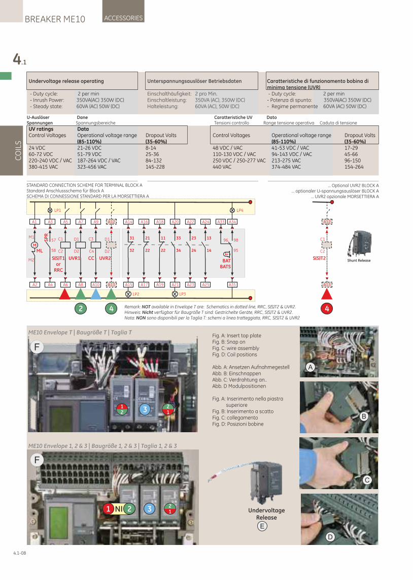
4.1
CO
ILS
ACCESSORIESBREAKER ME10
4.1-08
Undervoltage release operating
- Duty cycle: 2 per min - Inrush Power: 350VA(AC) 350W (DC) - Steady state: 60VA (AC) 50W (DC)
Unterspannungsauslöser Betriebsdaten
Einschalthäufigkeit: 2 pro Min.Einschaltleistung: 350VA (AC), 350W (DC)Halteleistung: 60VA (AC), 50W (DC)
Caratteristiche di funzionamento bobina di minima tensione (UVR) - Duty cycle: 2 per min - Potenza di spunto: 350VA(AC) 350W (DC) - Regime permanente 60VA (AC) 50W (DC)
UV ratings DataControl Voltages Operational voltage range Dropout Volts Control Voltages Operational voltage range Dropout Volts (85-110%) (35-60%) (85-110%) (35-60%)24 VDC 21-26 VDC 8-14 48 VDC / VAC 41-53 VDC / VAC 17-2960-72 VDC 51-79 VDC 25-36 110-130 VDC / VAC 94-143 VDC / VAC 45-66220-240 VDC / VAC 187-264 VDC / VAC 84-132 250 VDC / 250-277 VAC 213-275 VAC 96-150380-415 VAC 323-456 VAC 145-228 440 VAC 374-484 VAC 154-264
U-Auslöser DaneSpannungen Spannungsbereiche
Caratteristiche UV DatoTensioni controllo Range tensione operativa Caduta di tensione
STANDARD CONNECTION SCHEME FOR TERMINAL BLOCK AStandard Anschlussschema für Block ASCHEMA DI CONNESSIONE STANDARD PER LA MORSETTIERA A
... Optional UVR2 BLOCK A... optionaler U-spannungsauslöser BLOCK A
… UVR2 opzionale MORSETTIERA A
A2
A1
M
ML
M1
M2
LP1
A4
A3
SP
R
58
57
A6
A5
C1
C2
S(S)T1or
RRC
A10
A9
C4
C3
CC
A8
A7
UVR1
D1
D2
2
LP2
A15
A14
32
31
A17
A16
22
21
A19
A18
22
11
A23
A22
24
23
A25
A24
14
13
LP3
A21
A20
34
33
LP4
A35
A34
95
98
T
BATBATS
A33
96
A13
A12
UVR2
D1
D2
4 Remark: NOT available in Envelope T are: Schematics in dotted line, RRC, S(S)T2 & UVR2.Hinweis: Nicht verfügbar für Baugröße T sind: Gestrichelte Geräte, RRC, S(S)T2 & UVR2.Nota: NON sono disponibili per la Taglia T: schemi a linea tratteggiata, RRC, S(S)T2 & UVR2
S(S)T2
C1
C2
A13
4
A12
Shunt Release
A
B
C
D
F
NI1 2 3 12
ME10 Envelope 1, 2 & 3 | Baugröße 1, 2 & 3 | Taglia 1, 2 & 3
E
UndervoltageRelease
ME10 Envelope T | Baugröße T | Taglia T
F
321
12
Fig. A: Insert top plateFig. B: Snap onFig. C: wire assemblyFig. D: Coil positions
Abb. A: Ansetzen AufnahmegestellAbb. B: EinschnappenAbb. C: Verdrahtung an..Abb. D Modulpositionen
Fig. A: Inserimento nella piastra superiore
Fig. B: Inserimento a scattoFig. C: collegamentoFig. D: Posizioni bobine
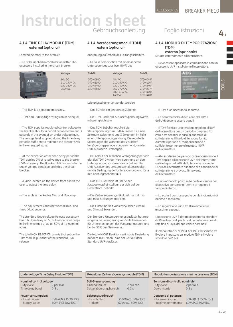
4.1.4 TIME DELAY MODULE (TDM) external (optional)
Located external to the breaker.
-- Must be applied in combination with a UVR accessory installed in the circuit breaker.
-- The TDM is a separate accessory.
-- TDM and UVR voltage ratings must be equal.
-- The TDM supplies regulated control voltage to the breaker UVR for a period between zero and 3 seconds in the event of an under voltage fault. The voltage level supplied during the time delay period is sufficient to maintain the breaker UVR in the energized state.
-- At the expiration of the time delay period the TDM applies 0% of rated voltage to the breaker UVR accessory. The Breaker UVR responds to the under voltage condition and trips the circuit breaker.
-- A knob located on the device front allows the user to adjust the time delay.
-- The scale is marked as Min. and Max. only.
-- The adjustment varies between 0 (min.) and three (Max.) seconds.
The standard Undervoltage Release accessory has a built in delay of 50 milliseconds for drops in the line voltage of up to 50% of it's nominal value.
The total NON REACTION time is that set on the TDM module plus that of the standard UVR release.
4.1.4 Verzögerungsmodul (TDM) extern (optional)
Anordnung außerhalb des Leitungsschalters.
-- Muss in Kombination mit einem inneren Unterspannungsauslöser (UVR) des
Leistungsschalter verwendet werden.
-- Das TDM ist ein getrenntes Zubehör.
-- Die TDM- und UVR-Auslöser Spannungswerte müssen gleich sein.
-- Das TDM-Zubehör reguliert die Steuerspannung zum UVR-Auslöser für einen Zeitraum zwischen 0 und 3 Sekunden im Falle einer Unterspannungsstörung. Die regulierte Spannungshöhe während der zeitlichen Verzögerungsperiode ist ausreichend, um den UVR-Auslöser zu versorgen.
-- Bei Ablauf der zeitlichen Verzögerungsperiode gibt das TDM 0 % der Nennspannung an den Unterspannungsauslöser des Schalters. Der UVR-Auslöser des Leistungsschalters reagiert auf die Bedingung der Unterspannung und löste den Leistungsschalter aus.
-- Das TDM-Zeitrelais ist über einen Justageknopf einstellbar, der sich auf der Gerätefront befindet.
-- Die Zeitverzögerungs-Skala ist nur mit min. und max. Stellungen markiert.
-- Die Einstellbarkeit variiert zwischen 0 (min.) und 3 (max.) Sekunden.
Der Standard Unterspannungsauslöser hat eine eingebaute Verzögerung von 50 Millisekunden für Unterbrechungen der Versorgungsspannung bei bis 50% der Nennwerte.
Die totale NICHT Reaktionszeit ist die Einstellung auf dem TDM-Modul, plus der Zeit auf dem Standard UVR-Auslöser.
4.1.4 MODULO DI TEMPORIZZAZIONE (TDM) esterno (opzionale)Situato esternamente all'interruttore.
-- Deve essere applicato in combinazione con un accessorio UVR installato nell'interruttore.
-- Il TDM è un accessorio separato.
-- Le caratteristiche di tensione del TDM e dell'UVR devono essere uguali.
-- Il TDM fornisce una tensione regolata all'UVR dell'interruttore per un periodo compreso fra zero e tre secondi in caso di anomalie di sottotensione. Il livello di tensione fornita durante il periodo di temporizzazione è sufficiente per tenere alimentato l'UVR dell'interruttore.
-- Alla scadenza del periodo di temporizzazione il TDM applica all'accessorio UVR dell'interruttore un livello pari allo 0% della tensione nominale. L'UVR dell'interruttore risponde alla condizione di sottotensione e provoca l'intervento dell'interruttore.
-- Una manopola posta sulla parte anteriore del dispositivo consente all'utente di regolare il tempo di ritardo.
-- La scala è contrassegnata con le indicazioni di minimo e massimo.
-- La regolazione varia tra 0 (minimo) e tre (massimo) secondi.
L'accessorio UVR è dotato di un ritardo standard di 50 millisecondi per le cadute della tensione di rete fino al 50% del suo valore nominale.
Il tempo totale di NON REAZIONE è la somma tra il valore impostata sul modulo TDM e il valore standard dell'UVR.
BREAKER ME10ACCESSORIES
4.1
CO
ILS
4.1-09
Voltage Cat-No
60V DC GTDM060D110-130V DC GTDM120D220-240V DC GTDM240D250V DC GTDM250D
Voltage Cat-No
48V AC GTDM048A110-130V AC GTDM120A220-240V AC GTDM240A250-277V AC GTDM277A380- 415V AC GTDM400A440V AC GTDM440A
Undervoltage Time Delay Module (TDM)
Nominal control voltage:Duty cycle: 2 per minTime delay band 0-3 s
Power consumption: - Inrush Power: 350VA(AC) 350W (DC) - Steady state: 60VA (AC) 50W (DC)
U-Auslöser Zeitverzögerungsmodule (TDM)
Soll-Steuerspannung:Einschaltdauer: 2 pro Min.Zeitverzögerungsbereich: 0-3 s
Leistungsverbrauch: - Einschalten: 350VA(AC) 350W (DC) - Halten: 60VA (AC) 50W (DC)
Modulo temporizzazione minima tensione (TDM)
Tensione di controllo nominale:Duty cycle: 2 per minCurva ritardo 0-3 s
Consumo di potenza:- Potenza di spunto: 350VA(AC) 350W (DC)- Regime permanente 60VA (AC) 50W (DC)
Instruction sheetGebrauchsanleitung Foglio istruzioni
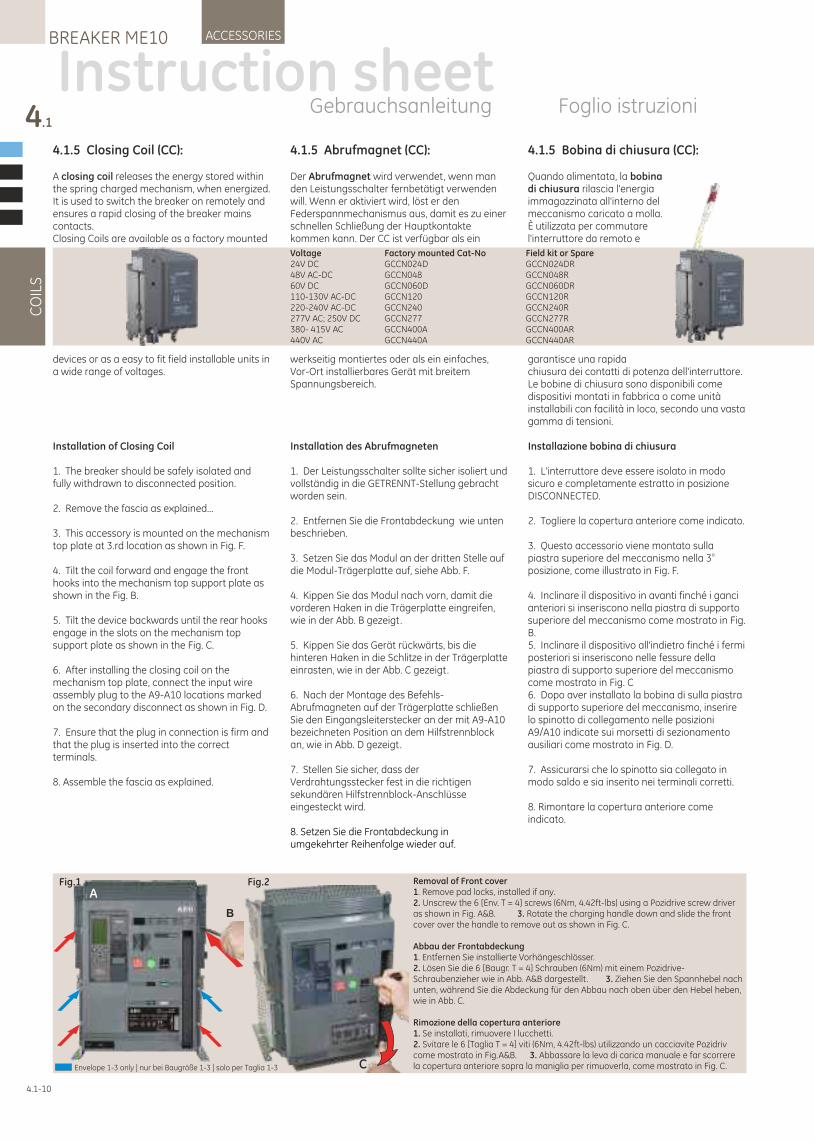
4.1.5 Bobina di chiusura (CC):
Quando alimentata, la bobina di chiusura rilascia l'energia immagazzinata all'interno del meccanismo caricato a molla. È utilizzata per commutare l'interruttore da remoto e
garantisce una rapida chiusura dei contatti di potenza dell'interruttore. Le bobine di chiusura sono disponibili come dispositivi montati in fabbrica o come unità installabili con facilità in loco, secondo una vasta gamma di tensioni.
Installazione bobina di chiusura
1. L'interruttore deve essere isolato in modo sicuro e completamente estratto in posizione DISCONNECTED.
2. Togliere la copertura anteriore come indicato.
3. Questo accessorio viene montato sulla apiastra superiore del meccanismo nella 3
posizione, come illustrato in Fig. F.
4. Inclinare il dispositivo in avanti finché i ganci anteriori si inseriscono nella piastra di supporto superiore del meccanismo come mostrato in Fig. B.5. Inclinare il dispositivo all'indietro finché i fermi posteriori si inseriscono nelle fessure della piastra di supporto superiore del meccanismo come mostrato in Fig. C6. Dopo aver installato la bobina di sulla piastra di supporto superiore del meccanismo, inserire lo spinotto di collegamento nelle posizioni A9/A10 indicate sui morsetti di sezionamento ausiliari come mostrato in Fig. D.
7. Assicurarsi che lo spinotto sia collegato in modo saldo e sia inserito nei terminali corretti.
8. Rimontare la copertura anteriore come indicato.
4.1.5 Closing Coil (CC):
A closing coil releases the energy stored within the spring charged mechanism, when energized. It is used to switch the breaker on remotely and ensures a rapid closing of the breaker mains contacts.Closing Coils are available as a factory mounted
devices or as a easy to fit field installable units in a wide range of voltages.
Installation of Closing Coil
1. The breaker should be safely isolated and fully withdrawn to disconnected position.
2. Remove the fascia as explained...
3. This accessory is mounted on the mechanism top plate at 3.rd location as shown in Fig. F.
4. Tilt the coil forward and engage the front hooks into the mechanism top support plate as shown in the Fig. B.
5. Tilt the device backwards until the rear hooks engage in the slots on the mechanism top support plate as shown in the Fig. C.
6. After installing the closing coil on the mechanism top plate, connect the input wire assembly plug to the A9-A10 locations marked on the secondary disconnect as shown in Fig. D.
7. Ensure that the plug in connection is firm and that the plug is inserted into the correct terminals.
8. Assemble the fascia as explained.
4.1.5 Abrufmagnet (CC):
Der Abrufmagnet wird verwendet, wenn man den Leistungsschalter fernbetätigt verwenden will. Wenn er aktiviert wird, löst er den Federspannmechanismus aus, damit es zu einer schnellen Schließung der Hauptkontakte kommen kann. Der CC ist verfügbar als ein
werkseitig montiertes oder als ein einfaches, Vor-Ort installierbares Gerät mit breitem Spannungsbereich.
Installation des Abrufmagneten
1. Der Leistungsschalter sollte sicher isoliert und vollständig in die GETRENNT-Stellung gebracht worden sein.
2. Entfernen Sie die Frontabdeckung wie unten beschrieben.
3. Setzen Sie das Modul an der dritten Stelle auf die Modul-Trägerplatte auf, siehe Abb. F.
4. Kippen Sie das Modul nach vorn, damit die vorderen Haken in die Trägerplatte eingreifen, wie in der Abb. B gezeigt.
5. Kippen Sie das Gerät rückwärts, bis die hinteren Haken in die Schlitze in der Trägerplatte einrasten, wie in der Abb. C gezeigt.
6. Nach der Montage des Befehls-Abrufmagneten auf der Trägerplatte schließen Sie den Eingangsleiterstecker an der mit A9-A10bezeichneten Position an dem Hilfstrennblock an, wie in Abb. D gezeigt.
7. Stellen Sie sicher, dass der Verdrahtungsstecker fest in die richtigen sekundären Hilfstrennblock-Anschlüsse eingesteckt wird.
8. Setzen Sie die Frontabdeckung in umgekehrter Reihenfolge wieder auf.
4.1
CO
ILS
ACCESSORIESBREAKER ME10
4.1-10
Instruction sheetGebrauchsanleitung Foglio istruzioni
Voltage Factory mounted Cat-No Field kit or Spare24V DC GCCN024D GCCN024DR48V AC-DC GCCN048 GCCN048R60V DC GCCN060D GCCN060DR110-130V AC-DC GCCN120 GCCN120R220-240V AC-DC GCCN240 GCCN240R277V AC; 250V DC GCCN277 GCCN277R380- 415V AC GCCN400A GCCN400AR440V AC GCCN440A GCCN440AR
Fig.1 Fig.2
C
B
ARemoval of Front cover1. Remove pad locks, installed if any.2. Unscrew the 6 [Env. T = 4] screws (6Nm, 4.42ft-lbs) using a Pozidrive screw driver as shown in Fig. A&B. 3. Rotate the charging handle down and slide the front cover over the handle to remove out as shown in Fig. C.
Abbau der Frontabdeckung1. Entfernen Sie installierte Vorhängeschlösser.2. Lösen Sie die 6 [Baugr. T = 4] Schrauben (6Nm) mit einem Pozidrive-Schraubenzieher wie in Abb. A&B dargestellt . 3. Ziehen Sie den Spannhebel nach unten, während Sie die Abdeckung für den Abbau nach oben über den Hebel heben, wie in Abb. C.
Rimozione della copertura anteriore1. Se installati, rimuovere I lucchetti.2. Svitare le 6 [Taglia T = 4] viti (6Nm, 4.42ft-lbs) utilizzando un cacciavite Pozidriv come mostrato in Fig.A&B. 3. Abbassare la leva di carica manuale e far scorrere la copertura anteriore sopra la maniglia per rimuoverla, come mostrato in Fig. C.Envelope 1-3 only | nur bei Baugröße 1-3 | solo per Taglia 1-3
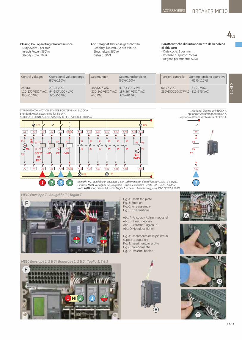
Control Voltages Operational voltage range Spannungen Spannungsbereiche Tensioni controllo Gamma tensione operativa (85%-110%) (85%-110%) (85%-110%)
24 VDC 21-26 VDC 48 VDC / VAC 41-53 VDC / VAC 60-72 VDC 51-79 VDC110-130 VDC / VAC 94-143 VDC / VAC 220-240 VDC / VAC 187-264 VDC / VAC 250VDC/250-277VAC 213-275 VAC380-415 VAC 323-456 VAC 440 VAC 374-484 VAC
BREAKER ME10ACCESSORIES
4.1
CO
ILS
4.1-11
Closing Coil operating Characteristics Duty cycle: 2 per min Inrush Power: 350VA Steady state: 50VA
Abrufmagnet Betriebseigenschaften Schaltzyklus, max.: 2 pro Minute Einschalten: 350VA Betrieb: 50VA
Caratteristiche di funzionamento della bobina di chiusura - Duty cycle: 2 per min - Potenza di spunto: 350VA - Regime permanente 50VA
A2
A1
M
ML
M1
M2
LP1
A4
A3
SP
R
58
57
A6
A5
C1
C2
S(S)T1or
RRC
1
A10
A9
C4
C3
CC
3
A8
A7
UVR1
D1
D2
2
LP2
A15
A14
32
31
A17
A16
22
21
A19
A18
22
11
A23
A22
24
23
A25
A24
14
13
LP3
A21
A20
34
33
LP4
A35
A34
95
98
T
BATBATS
A33
96
A13
A12
UVR2
D1
D2
4 Remark: NOT available in Envelope T are: Schematics in dotted line, RRC, S(S)T2 & UVR2.Hinweis: Nicht verfügbar für Baugröße T sind: Gestrichelte Geräte, RRC, S(S)T2 & UVR2.Nota: NON sono disponibili per la Taglia T: schemi a linea tratteggiata, RRC, S(S)T2 & UVR2
CC
C3
C4
A10
3
A9
... Optional Closing coil BLOCK A... optionaler Abrufmagnet BLOCK A
... opzionale Bobina di chiusura BLOCCO A
STANDARD CONNECTION SCHEME FOR TERMINAL BLOCK AStandard Anschlussschema für Block ASCHEMA DI CONNESSIONE STANDARD PER LA MORSETTIERA A
A
B
C
D
ME10 Envelope T | Baugröße T | Taglia T
F
NI1 2 3 12
ME10 Envelope 1, 2 & 3 | Baugröße 1, 2 & 3 | Taglia 1, 2 & 3
E
F
321
12
Fig. A: Insert top plateFig. B: Snap onFig. C: wire assemblyFig. D: Coil positions
Abb. A: Ansetzen AufnahmegestellAbb. B: EinschnappenAbb. C: Verdrahtung an CC..Abb. D Modulpositionen
Fig. A: Inserimento nella piastra di supporto superioreFig. B: Inserimento a scattoFig. C: collegamentoFig. D: Posizioni bobine
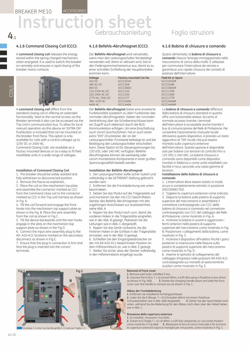
4.1.6 Bobina di chiusura a comando
Quano alimentata, la bobina di chiusura a comando rilascia l'energia immagazzinata nella meccanismo di carica della molla. È utilizzata per commutare l'interruttore da remoto e garantisce una rapida chiusura dei contatti di potenza dell'interruttore.
La bobina di chiusura a comando differisce dalla bobina di chiusura standard in quanto offre una funzionalità estesa. Accanto al normale accesso tramite i terminali dell'interruttore è accessibile anche tramite il bus di comunicazione del Relè di Protezione. Per consentire l'azionamento manuale locale attraverso questo dispositivo, è previsto un tasto aggiuntivo di "ON' locale che può essere montato sulla copertura anteriore dell'interruttore. Questa opzione è disponibile solo per bobine con tensioni di controllo fino a 125 VDC o 240 VAC. Le bobine chiusura a comando sono disponibili come dispositivi montati in fabbrica o come unità installabili con facilità in loco, secondo una vasta gamma di tensioni.Installazione della bobina di chiusura a comando 1. L'interruttore deve essere isolato in modo sicuro e completamente estratto in posizione DISCONNECTED.2. Togliere la copertura anteriore come indicato.3. Disporre la bobina sulla piastra di supporto superiore del meccanismo e assemblare il connettore contrassegnato con CCC della bobina di chiusura a comando nel connettore contrassegnato con CCC del cablaggio del Relè di Protezione, come mostrato in Fig. A.4. Inclinare la bobina in avanti e agganciare i fermi anteriori nella piastra di supporto superiore del meccanismo come mostrato in Fig. B. Posizionare i collegamenti dalla bobina, come mostrato in Fig. C.5. Inclinare il dispositivo all'indietro finché i ganci posteriori si inseriscono nelle fessure sulla piastra di supporto superiore del meccanismo come mostrato in Fig. D.6. Inserire lo spinotto di collegamento del cablaggio d'ingresso nelle posizioni A9-A10-A11 contrassegnate sui morsetti di sezionamento ausiliari come mostrato in Fig. E.
4.1.6 Command Closing Coil (CCC):
A command closing coil releases the energy stored within the spring charged mechanism, when energized. It is used to switch the breaker on remotely and ensures a rapid closing of the breaker mains contacts.
A command closing coil differs from the standard closing coil in offering an extended functionality. Next to the normal access via the Breaker terminals it also can be accessed via the Trip Unit's communication bus. To allow for local manual operation via this device an 'EXTRA ON' Pushbutton is included that can be mounted on the breaker front facia. This option is only available for coils with a control voltages up to 125V DC or 240V AC.Command Closing Coils are available as a factory mounted devices or as a easy to fit field installable units in a wide range of voltages.
Installation of Command Closing Coil1. The breaker should be safely isolated and fully withdrawn to disconnected position.2. Remove the fascia as explained...3. Place the coil on the mechanism top plate and assemble the connector marked as CCC from the Command close coil to the connector marked as CCC in the Trip unit harness as shown in Fig. A.4. Tilt the coil forward and engage the front hooks into the mechanism top support plate as shown in the Fig. B. Place the wire assembly from the coil as shown in Fig C.5. Tilt the device backwards until the rear hooks engage in the slots on the mechanism top support plate as shown in the Fig D.6. Connect the input wire assembly plug to the A9- A10-A11 locations marked on the secondary disconnect as shown in Fig E.7. Ensure that the plug in connection is firm and that the plug is inserted into the correct terminals.
4.1.6 Befehls-Abrufmagnet (CCC):
Der Befehls-Abrufmagnet wird verwendet, wenn man den Leistungsschalter fernbetätigt verwenden will. Wenn er aktiviert wird, löst er den Federspannmechanismus aus, damit es zu einer schnellen Schließung der Hauptkontakte kommen kann.
Der Befehls-Abrufmagnet bietet eine erweiterte Funktionalität zusätzlich zu allen Funktionen des normalen Abrufmagneten. Neben der normalen Verdrahtung über die Schalteranschlüsse kann ein Zugriff auch elektrisch durch die BUS-Kommunikation erfolgen. Um eine Einschaltung auch Vorort durchzuführen, hat er auch einen extra "EIN"-Drucktaster, der an der Leistungsschalter-Frontseite befestigt ist und bei Betätigung den Leistungsschalter einschalten kann. Diese Option ist für Steuerspannungen bis 130 VDC oder 240 VAC verfügbar. Befehls-Abrufmagnete können als werkseitig oder vorort-montierbare Komponente in einer großen Spannungsvielfalt bestellt werden.
Installation der Befehls-Abrufmagnet 1. Der Leistungsschalter sollte sicher isoliert und vollständig in die GETRENNT-Stellung gebracht worden sein.2. Entfernen Sie die Frontabdeckung wie unten beschrieben.3. Setzen Sie das Modul auf die Trägerplatte auf und montieren Sie den mit CCC beschrifteten Stecker des Befehls-Abrufmagneten mit den zugehörigen Anschlüssen zur Auslöseeinheit, siehe Abb. A.4. Kippen Sie das Modul nach vorn, damit die vorderen Haken in die Trägerplatte eingreifen, wie in der Abb. B gezeigt. Platzieren Sie die Leitungen wie in Abb. C dargestellt .5. Kippen Sie das Gerät rückwärts, bis die hinteren Haken in die Schlitze in der Trägerplatte einrasten, wie in der Abb. D gezeigt.6. Schließen Sie den Eingangsleiterstecker an der mit A9-A10-A11 bezeichneten Position an dem Hilfstrennblock an, wie in Abb. E gezeigt.7. Stellen Sie sicher, dass der Stecker vollständig in den Hilfstrennblock eingefügt wurde.
4.1
CO
ILS
ACCESSORIESBREAKER ME10
4.1-12
Instruction sheetGebrauchsanleitung Foglio istruzioni
Voltage Factory mounted Cat-No Field kit or Spare24V DC GCCC024D GCCC024DR48V AC-DC GCCC048 GCCC048R60V DC GCCC060D GCCC060DR110-130V AC-DC GCCC120 GCCC120R220-240V AC-DC GCCC240 GCCC240R277V AC; 250V DC GCCC277 GCCC277R380- 415V AC GCCC400A GCCC400AR440V AC GCCC440A GCCC440AR
Fig.1 Fig.2
C
B
ARemoval of Front cover1. Remove pad locks, installed if any.2. Unscrew the 6 [Env. T = 4] screws (6Nm, 4.42ft-lbs) using a Pozidrive screw driver as shown in Fig. A&B. 3. Rotate the charging handle down and slide the front cover over the handle to remove out as shown in Fig. C.
Abbau der Frontabdeckung1. Entfernen Sie installierte Vorhängeschlösser.2. Lösen Sie die 6 [Baugr. T = 4] Schrauben (6Nm) mit einem Pozidrive-Schraubenzieher wie in Abb. A&B dargestellt . 3. Ziehen Sie den Spannhebel nach unten, während Sie die Abdeckung für den Abbau nach oben über den Hebel heben, wie in Abb. C.
Rimozione della copertura anteriore1. Se installati, rimuovere I lucchetti.2. Svitare le 6 [Taglia T = 4] viti (6Nm, 4.42ft-lbs) utilizzando un cacciavite Pozidriv come mostrato in Fig.A&B. 3. Abbassare la leva di carica manuale e far scorrere la copertura anteriore sopra la maniglia per rimuoverla, come mostrato in Fig. C.Envelope 1-3 only | nur bei Baugröße 1-3 | solo per Taglia 1-3
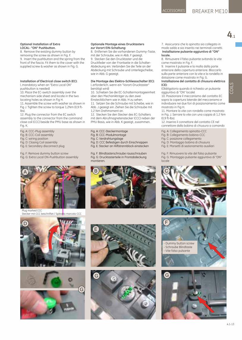
Optional Installation of Extra LOCAL- "ON" Pushbutton.8. Remove the existing dummy button by removing the screw as shown in Fig. F.9. Insert the pushbutton and the spring from the front of the fascia. Fit them to the cover with the supplied screw & washer as shown in Fig. G.
Installation of Electrical close switch (EC):(..mandatory when an "Extra Local ON" pushbutton is needed)10. Place the EC-switch assembly over the mechanism side sheet and locate in the two locating holes as shown in Fig H.11. Assemble the screw with washer as shown in Fig J. Tighten the screw to torque 1,2Nm (0,9 ft-lbs).12. Plug the connector from the EC switch assembly to the connector from the command close coil (CCC) beside the PMU base as shown in Fig. K.
Optionale Montage eines Drucktasterszur Vorort EIN-Schaltung:8. Entfernen Sie die vorhandenen Dummy-Taste, mit der Schraube, wie in Abb. F gezeigt.9. Stecken Sie den Drucktaster und die Druckfeder von der Frontseite in die Schalter-Abdeckung ein. Verbinden Sie die Teile an der Abdeckung mit Schraube und Unterlegscheibe, wie in Abb. G gezeigt.
Die Montage des Elektro-Schliessschalter (EC):(..erforderlich, wenn ein "Vorort-Drucktaster" benötigt wird)10. Schieben Sie die EC-Schaltermontageeinheit über den Mechanikträger zu den zwei Einstecklöchern wie in Abb. H zu sehen.11. Setzen Sie die Schraube mit Scheibe, wie in Abb. J gezeigt ein. Ziehen Sie die Schraube mit 1,2 Nm Drehmoment an.12. Stecken Sie den Stecker des EC-Schalters mit dem Abrufmagnetenstecker (CCC) neben der PMU Basis, wie in Abb. K gezeigt, zusammen.
BREAKER ME10ACCESSORIES
4.1
CO
ILS
4.1-13
7. Assicurarsi che lo spinotto sia collegato in modo saldo e sia inserito nei terminali corretti. Installazione pulsante aggiuntivo di "ON" locale.8. Rimuovere il falso pulsante svitando la vite come mostrato in Fig. F.9. Inserire il pulsante e la molla dalla parte anteriore della copertura anteriore. Bloccarlo sulla parte anteriore con la vite e la rondella in dotazione come mostrato in Fig. G.Installazione del contatto di chiusura elettrica (CE):(Obbligatorio quando è richiesto un pulsante aggiuntivo di "ON" locale)10. Posizionare il meccanismo del contatto EC sopra la copertura laterale del meccanismo e individuare nei due fori di posizionamento come mostrato in Fig H.11. Montare la vite con rondella come mostrato in Fig. J. Serrare la vite con una coppia di 1,2 Nm (0,9 ft-lbs).12. Inserire il connettore del contatto CE nel connettore dalla bobina di chiusura a comando
CA
Plug marked CCCStecker mit CCC beschriftet / Spinotto marcato CCC
B
ED
G
G
G
Fig. A: CCC-SteckermontageFig. B: CCC-ModulmontageFig. C: VerdrahtungslageFig. D: CCC Befestigen durch EinschnappenFig. E: Stecker an Hilfstrennblock einstecken
Fig. F: Blindtasterschraube rausschraubenFig. G: Drucktasterteile in Frontabdeckung montieren.
F
- Dummy button screw- Schraube Blindtaste- Vite falso pulsante
Fig. A: CCC-Plug assemblyFig. B: CCC-Coil assemblyFig. C: wiring positionFig. D: Closing Coil assemblyFig. E: Secondary disconnect plug
Fig. F: Remove dummy button screwFig. G: Extra Local ON-Pushbutton assembly
Fig. A: Collegamento spinotto-CCCFig. B: Collegamento bobina-CCCFig. C: posizione collegamentoFig. D: Montaggio bobina di chiusuraFig. E: Morsetti di sezionamento ausiliari
Fig. F: Rimuovere la vite del falso pulsanteFig. G: Montaggio pulsante aggiuntivo di "ON" locale
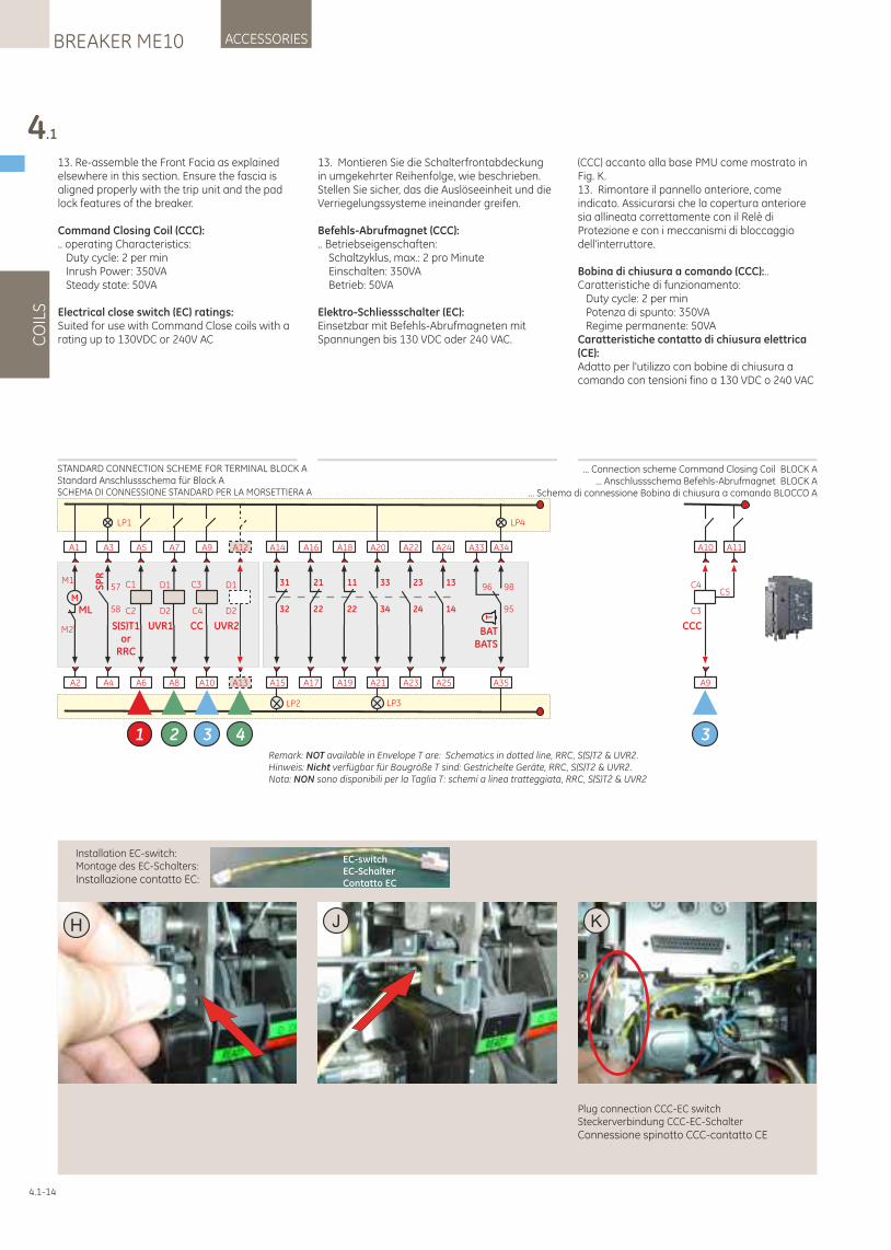
13. Re-assemble the Front Facia as explained elsewhere in this section. Ensure the fascia is aligned properly with the trip unit and the pad lock features of the breaker.
Command Closing Coil (CCC):.. operating Characteristics: Duty cycle: 2 per min Inrush Power: 350VA Steady state: 50VA
Electrical close switch (EC) ratings:Suited for use with Command Close coils with a rating up to 130VDC or 240V AC
13. Montieren Sie die Schalterfrontabdeckung in umgekehrter Reihenfolge, wie beschrieben. Stellen Sie sicher, das die Auslöseeinheit und die Verriegelungssysteme ineinander greifen.
Befehls-Abrufmagnet (CCC):.. Betriebseigenschaften: Schaltzyklus, max.: 2 pro Minute Einschalten: 350VA Betrieb: 50VA
Elektro-Schliessschalter (EC):Einsetzbar mit Befehls-Abrufmagneten mit Spannungen bis 130 VDC oder 240 VAC.
KH J
Installation EC-switch:Montage des EC-Schalters:Installazione contatto EC:
Plug connection CCC-EC switchSteckerverbindung CCC-EC-SchalterConnessione spinotto CCC-contatto CE
4.1
CO
ILS
ACCESSORIESBREAKER ME10
4.1-14
(CCC) accanto alla base PMU come mostrato in Fig. K.13. Rimontare il pannello anteriore, come indicato. Assicurarsi che la copertura anteriore sia allineata correttamente con il Relè di Protezione e con i meccanismi di bloccaggio dell'interruttore.
Bobina di chiusura a comando (CCC):.. Caratteristiche di funzionamento: Duty cycle: 2 per min Potenza di spunto: 350VA Regime permanente: 50VACaratteristiche contatto di chiusura elettrica (CE):Adatto per l'utilizzo con bobine di chiusura a comando con tensioni fino a 130 VDC o 240 VAC
EC-switchEC-SchalterContatto EC
A2
A1
M
ML
M1
M2
LP1
A4
A3
SP
R
58
57
A6
A5
C1
C2
S(S)T1or
RRC
1
A10
A9
C4
C3
CC
3
A8
A7
UVR1
D1
D2
2
LP2
A15
A14
32
31
A17
A16
22
21
A19
A18
22
11
A23
A22
24
23
A25
A24
14
13
LP3
A21
A20
34
33
LP4
A35
A34
95
98
T
BATBATS
A33
96
A13
A12
UVR2
D1
D2
4Remark: NOT available in Envelope T are: Schematics in dotted line, RRC, S(S)T2 & UVR2.Hinweis: Nicht verfügbar für Baugröße T sind: Gestrichelte Geräte, RRC, S(S)T2 & UVR2.Nota: NON sono disponibili per la Taglia T: schemi a linea tratteggiata, RRC, S(S)T2 & UVR2
CCC
C4
C3
A9
3
A10 A11
C5
STANDARD CONNECTION SCHEME FOR TERMINAL BLOCK AStandard Anschlussschema für Block ASCHEMA DI CONNESSIONE STANDARD PER LA MORSETTIERA A
... Connection scheme Command Closing Coil BLOCK A... Anschlussschema Befehls-Abrufmagnet BLOCK A
... Schema di connessione Bobina di chiusura a comando BLOCCO A
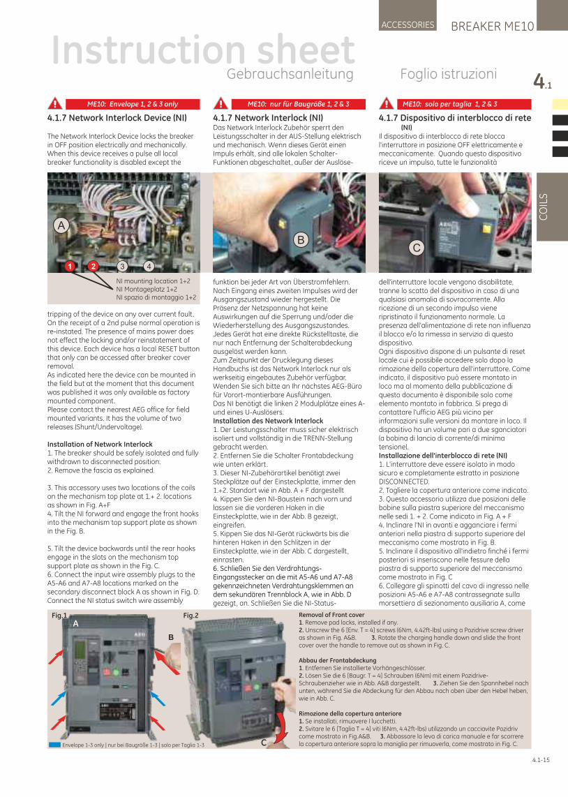
4.1.7 Network Interlock (NI)Das Network Interlock Zubehör sperrt den Leistungsschalter in der AUS-Stellung elektrisch und mechanisch. Wenn dieses Gerät einen Impuls erhält, sind alle lokalen Schalter-Funktionen abgeschaltet, außer der Auslöse-
funktion bei jeder Art von Überstromfehlern.Nach Eingang eines zweiten Impulses wird der Ausgangszustand wieder hergestellt . Die Präsenz der Netzspannung hat keine Auswirkungen auf die Sperrung und/oder die Wiederherstellung des Ausgangszustandes. Jedes Gerät hat eine direkte Rückstelltaste, die nur nach Entfernung der Schalterabdeckung ausgelöst werden kann.Zum Zeitpunkt der Drucklegung dieses Handbuchs ist das Network Interlock nur als werkseitig eingebautes Zubehör verfügbar. Wenden Sie sich bitte an Ihr nächstes AEG-Büro für Vorort-montierbare Ausführungen.Das NI benötigt die linken 2 Modulplätze eines A-und eines U-Auslösers.Installation des Network Interlock 1. Der Leistungsschalter muss sicher elektrisch isoliert und vollständig in die TRENN-Stellung gebracht werden. 2. Entfernen Sie die Schalter Frontabdeckung wie unten erklärt. 3. Dieser NI-Zubehörartikel benötigt zwei Steckplätze auf der Einsteckplatte, immer den 1.+2. Standort wie in Abb. A + F dargestellt4. Kippen Sie den NI-Baustein nach vorn und lassen sie die vorderen Haken in die Einsteckplatte, wie in der Abb. B gezeigt, eingreifen. 5. Kippen Sie das NI-Gerät rückwärts bis die hinteren Haken in den Schlitzen in der Einsteckplatte, wie in der Abb. C dargestellt , einrasten. 6. Schließen Sie den Verdrahtungs-Eingangsstecker an die mit A5-A6 und A7-A8 gekennzeichneten Verdrahtungsklemmen an dem sekundären Trennblock A, wie in Abb. D gezeigt, an. Schließen Sie die NI-Status-
4.1.7 Network Interlock Device (NI)
The Network Interlock Device locks the breaker in OFF position electrically and mechanically. When this device receives a pulse all local breaker functionality is disabled except the
tripping of the device on any over current fault. On the receipt of a 2nd pulse normal operation is re-instated. The presence of mains power does not effect the locking and/or reinstatement of this device. Each device has a local RESET button that only can be accessed after breaker cover removal. As indicated here the device can be mounted in the field but at the moment that this document was published it was only available as factory mounted component. Please contact the nearest AEG office for field mounted variants. It has the volume of two releases (Shunt/Undervoltage).
Installation of Network Interlock1. The breaker should be safely isolated and fully withdrawn to disconnected position. 2. Remove the fascia as explained.
3. This accessory uses two locations of the coils on the mechanism top plate at 1.+ 2. locations as shown in Fig. A+F4. Tilt the NI forward and engage the front hooks into the mechanism top support plate as shown in the Fig. B.
5. Tilt the device backwards until the rear hooks engage in the slots on the mechanism top support plate as shown in the Fig. C.6. Connect the input wire assembly plugs to the A5-A6 and A7-A8 locations marked on the secondary disconnect block A as shown in Fig. D. Connect the NI status switch wire assembly
4.1.7 Dispositivo di interblocco di rete (NI)Il dispositivo di interblocco di rete blocca l'interruttore in posizione OFF elettricamente e meccanicamente. Quando questo dispositivo riceve un impulso, tutte le funzionalità
dell'interruttore locale vengono disabilitate, tranne lo scatto del dispositivo in caso di una qualsiasi anomalia di sovracorrente. Alla ricezione di un secondo impulso viene ripristinato il funzionamento normale. La presenza dell'alimentazione di rete non influenza il blocco e/o la rimessa in servizio di questo dispositivo. Ogni dispositivo dispone di un pulsante di reset locale cui è possibile accedere solo dopo la rimozione della copertura dell'interruttore. Come indicato, il dispositivo può essere montato in loco ma al momento della pubblicazione di questo documento è disponibile solo come elemento montato in fabbrica. Si prega di contattare l'ufficio AEG più vicino per informazioni sulle versioni da montare in loco. Il dispositivo ha un volume pari a due sganciatori (a bobina di lancio di corrente/di minima tensione). Installazione dell'interblocco di rete (NI)1. L'interruttore deve essere isolato in modo sicuro e completamente estratto in posizione DISCONNECTED. 2. Togliere la copertura anteriore come indicato.3. Questo accessorio utilizza due posizioni delle bobine sulla piastra superiore del meccanismo nelle sedi 1. + 2. Come indicato in Fig. A + F4. Inclinare l'NI in avanti e agganciare i fermi anteriori nella piastra di supporto superiore del meccanismo come mostrato in Fig. B.5. Inclinare il dispositivo all'indietro finché i fermi posteriori si inseriscono nelle fessure della piastra di supporto superiore del meccanismo come mostrato in Fig. C6. Collegare gli spinotti del cavo di ingresso nelle posizioni A5-A6 e A7-A8 contrassegnate sulla morsettiera di sezionamento ausiliaria A, come
CB
1 2 3 4
NI mounting location 1+2NI Montageplatz 1+2NI spazio di montaggio 1+2
A
BREAKER ME10ACCESSORIES
4.1
CO
ILS
4.1-15
Instruction sheetGebrauchsanleitung Foglio istruzioni
Fig.1 Fig.2
C
B
ARemoval of Front cover1. Remove pad locks, installed if any.2. Unscrew the 6 [Env. T = 4] screws (6Nm, 4.42ft-lbs) using a Pozidrive screw driver as shown in Fig. A&B. 3. Rotate the charging handle down and slide the front cover over the handle to remove out as shown in Fig. C.
Abbau der Frontabdeckung1. Entfernen Sie installierte Vorhängeschlösser.2. Lösen Sie die 6 [Baugr. T = 4] Schrauben (6Nm) mit einem Pozidrive-Schraubenzieher wie in Abb. A&B dargestellt . 3. Ziehen Sie den Spannhebel nach unten, während Sie die Abdeckung für den Abbau nach oben über den Hebel heben, wie in Abb. C.
Rimozione della copertura anteriore1. Se installati, rimuovere I lucchetti.2. Svitare le 6 [Taglia T = 4] viti (6Nm, 4.42ft-lbs) utilizzando un cacciavite Pozidriv come mostrato in Fig.A&B. 3. Abbassare la leva di carica manuale e far scorrere la copertura anteriore sopra la maniglia per rimuoverla, come mostrato in Fig. C.Envelope 1-3 only | nur bei Baugröße 1-3 | solo per Taglia 1-3
ME10: Envelope 1, 2 & 3 only ME10: nur für Baugröße 1, 2 & 3 ME10: solo per taglia 1, 2 & 3
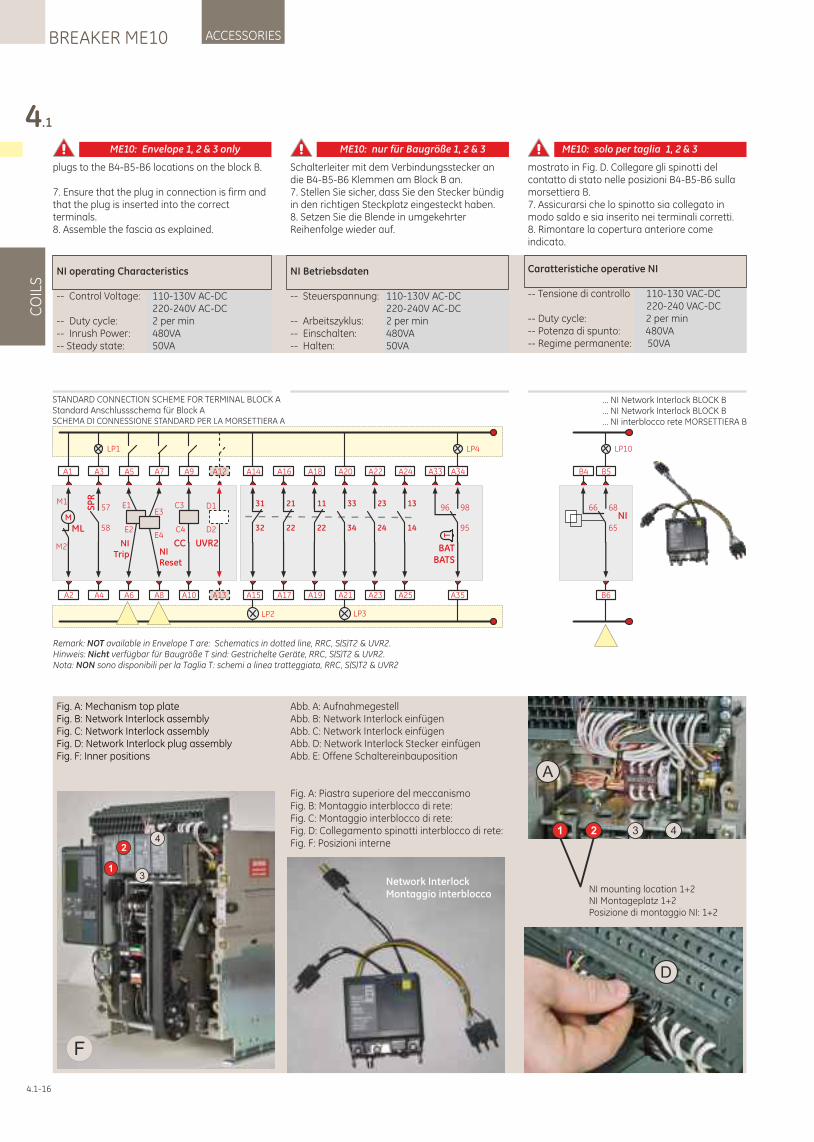
NI operating Characteristics
-- Control Voltage: 110-130V AC-DC 220-240V AC-DC-- Duty cycle: 2 per min-- Inrush Power: 480VA-- Steady state: 50VA
NI Betriebsdaten
-- Steuerspannung: 110-130V AC-DC 220-240V AC-DC-- Arbeitszyklus: 2 per min-- Einschalten: 480VA-- Halten: 50VA
Caratteristiche operative NI
-- Tensione di controllo 110-130 VAC-DC 220-240 VAC-DC-- Duty cycle: 2 per min-- Potenza di spunto: 480VA-- Regime permanente: 50VA
4.1
CO
ILS
ACCESSORIESBREAKER ME10
4.1-16
Fig. A: Mechanism top plateFig. B: Network Interlock assemblyFig. C: Network Interlock assemblyFig. D: Network Interlock plug assemblyFig. F: Inner positions
Abb. A: AufnahmegestellAbb. B: Network Interlock einfügenAbb. C: Network Interlock einfügenAbb. D: Network Interlock Stecker einfügenAbb. E: Offene Schaltereinbauposition
Fig. A: Piastra superiore del meccanismoFig. B: Montaggio interblocco di rete:Fig. C: Montaggio interblocco di rete:Fig. D: Collegamento spinotti interblocco di rete:Fig. F: Posizioni interne
1
2
3
4
F
1 2 3 4
NI mounting location 1+2NI Montageplatz 1+2Posizione di montaggio NI: 1+2
A
D
Network InterlockMontaggio interblocco
plugs to the B4-B5-B6 locations on the block B.
7. Ensure that the plug in connection is firm and that the plug is inserted into the correct terminals.8. Assemble the fascia as explained.
Schalterleiter mit dem Verbindungsstecker an die B4-B5-B6 Klemmen am Block B an. 7. Stellen Sie sicher, dass Sie den Stecker bündig in den richtigen Steckplatz eingesteckt haben.8. Setzen Sie die Blende in umgekehrter Reihenfolge wieder auf.
mostrato in Fig. D. Collegare gli spinotti del contatto di stato nelle posizioni B4-B5-B6 sulla morsettiera B.7. Assicurarsi che lo spinotto sia collegato in modo saldo e sia inserito nei terminali corretti.8. Rimontare la copertura anteriore come indicato.
A2
A1
M
ML
M1
M2
LP1
A4
A3
SP
R
58
57
A6
A5
E1
E2
NITrip
A10
A9
C4
C3
CC
A8
A7
NIReset
E3
E4
LP2
A15
A14
32
31
A17
A16
22
21
A19
A18
22
11
A23
A22
24
23
A25
A24
14
13
LP3
A21
A20
34
33
LP4
A35
A34
95
98
T
BATBATS
A33
96
A13
A12
UVR2
D1
D2
Remark: NOT available in Envelope T are: Schematics in dotted line, RRC, S(S)T2 & UVR2.Hinweis: Nicht verfügbar für Baugröße T sind: Gestrichelte Geräte, RRC, S(S)T2 & UVR2.Nota: NON sono disponibili per la Taglia T: schemi a linea tratteggiata, RRC, S(S)T2 & UVR2
LP10
B6
B5
65
68NI
B4
66
... NI Network Interlock BLOCK B
... NI Network Interlock BLOCK B… NI interblocco rete MORSETTIERA B
STANDARD CONNECTION SCHEME FOR TERMINAL BLOCK AStandard Anschlussschema für Block ASCHEMA DI CONNESSIONE STANDARD PER LA MORSETTIERA A
ME10: Envelope 1, 2 & 3 only ME10: nur für Baugröße 1, 2 & 3 ME10: solo per taglia 1, 2 & 3
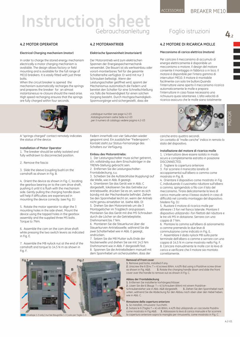
BREAKER ME10ACCESSORIES
4.2
MO
TOR
4.2 MOTORANTRIEB
Elektrische Spanneinheit (motorisiert)
Der Motorantrieb wird zum elektrischen Spannen der Energiespeichermechanik verwendet. Die Bauart ist als werkseinbau oder vorort-montierbares Teil für die gesamte Schalterreihe verfügbar. Er wird mit nur 3 Schrauben befestigt. Wenn der Leistungsschalter geöffnet wird, spannt der Mechanismus automatisch die Federn und bereitet den Schalter für eine Schnellschließung vor, falls die Notwendigkeit für einen solchen Vorgang besteht. Durch Hochgeschwindigkeit-Spannvorgänge wird sichergestellt , dass die
Federn innerhalb von vier Sekunden wieder gespannt sind. Ein zusätzlicher "Federspann"-Kontakt steht zur Status-Fernanzeige des Schalters zur Verfügung.
Einbau des Motorantriebs:1. Der Leistungsschalter muss sicher getrennt, d.h. vollständig aus dem Einschubträger in die TRENN-Stellung gebracht sein.2. Entfernen Sie die Leistungsschalter-Frontabdeckung, s.u.3. Schieben Sie die Aufsteckhülse (Kupplung) auf die Welle, wie in Abb. B gezeigt.4. Orientieren Sie das Gerät wie in Abb. C dargestellt , lokalisieren Sie das Getriebe zur Antriebswelle, drücken Sie es an, wenn es sich bündig mit der Mechanikseite befindet. Ziehen Sie den Spannhebel leicht an, wenn der Antrieb nicht genau einsetzbar ist. (siehe Abb. D)5. Drehen Sie den Motorantrieb um die 3 Montagelöcher im Tragblech anzupassen. Montieren Sie das Gerät mit drei M5 Schrauben durch die Löcher an die Getriebeplatte, Drehmoment bis 7 Nm.6. Montieren Sie die Steuerkurve über die Steuerkurven-Antriebswelle, während Sie die zwei Schalterhebel wie in Abb. E gezeigt, andrücken.7. Setzen Sie die M8 Mutter aufs Ende der Nockenwelle und drehen Sie sie mit 14,5 Nm Drehmoment wie in Abb. F dargestellt fest.8. Spannen Sie die Antriebsfedern manuell mit dem Spannhebel um sicherzustellen, dass der
4.2 MOTOR OPERATOR
Electrical Charging mechanism (motor)
In order to charge the stored energy mechanism electrically a motor charging mechanism is available. The design allows factory or field mounting and is available for the full range of ME10 breakers. It is easily fitted with just three bolts.When the circuit breaker is opened the mechanism automatically recharges the springs and prepares the breaker for an almost instantaneous re-closure should the need arise. High speed recharging ensures that the springs are fully charged within four seconds.
A “springs charged" contact remotely indicates the status of the device.
Installation of Motor Operator1. The breaker should be safely isolated and fully withdrawn to disconnected position.
2. Remove the fascia
3. Slide the sleeve (coupling bush) on the camshaft as shown in Fig. B.
4. Orient the device as shown in Fig. C, locating the gearbox bearing on to the cam drive shaft, pushing it until it is flush with the mechanism side. Gently pulling the charging handle down will help if difficulties are experienced in mounting the device correctly. (see Fig. D.)
5. Rotate the motor operator to align the 3 mounting holes in the side sheet. Mount the device using the tapped holes in the gearbox assembly and the supplied three M5 bolts . Torque to 7Nm.
6. Assemble the cam on the cam drive shaft while pressing the two switch levers as indicated in Fig. E.
7. Assemble the M8 nylock nut at the end of the camshaft and torque to 14.5 N m as shown in Fig. F.
4.2-01
4.2 MOTORE DI RICARICA MOLLE
Meccanismo di carica elettrica (motore)
Per caricare il meccanismo di accumulo di energia elettricamente è disponibile un meccanismo a motore. Il design del motore consente il montaggio in fabbrica o in loco. Il motore è disponibile per l'intera gamma di interruttori ME10. Il motore è montabile facilmente con solo tre bulloni.Quando l'interruttore viene aperto il meccanismo ricarica automaticamente le molle e prepara l'interruttore in caso fosse necessaria una richiusura quasi istantanea. L'alta velocità di ricarica assicura che le molle siano totalmente
cariche entro quattro secondi.Un contatto di "molle cariche" indica in remoto lo stato del dispositivo.
Installazione del motore di ricarica molle1. L'interruttore deve essere isolato in modo sicuro e completamente estratto in posizione DISCONNECTED.2. Togliere la copertura anteriore3. Far scorrere il manicotto (anello di accoppiamento) sull'albero a camma come mostrato in Fig. B.4. Orientare il dispositivo come mostrato in Fig. C, individuando il cuscinetto riduttore sull'albero a camma, spingendolo a filo con il lato del meccanismo. Tirare delicatamente la leva di carico manuale verso il basso aiuterà in caso di difficoltà nel corretto montaggio del dispositivo. (Vedere Fig. D.)5. Ruotare il motore di ricarica molle per allineare i 3 fori nel fianco laterale. Montare il dispositivo utilizzando i fori filettati del riduttore e le tre viti M5 in dotazione. Serrare con una coppia di 7 Nm.6. Montare la camma sull'albero di azionamento a camme premendo le due leve di commutazione come indicato in Fig. E.7. Assemblare il dado nylock M8 sulla parte terminale dell'albero a camme e serrare con una coppia di 14,5 N m come mostrato nella Fig. F. 8. Caricare manualmente le molle con la leva di carico e verificare che il motore sia montato correttamente.
Instruction sheetGebrauchsanleitung Foglio istruzioni
A..catalogue number see page 4.2-03..Katalognummern siehe Seite 4.2-03..per il numero di catalogo vedere pagina 4.2-03
Fig.1 Fig.2
C
B
ARemoval of Front cover1. Remove pad locks, installed if any.2. Unscrew the 6 [Env. T = 4] screws (6Nm, 4.42ft-lbs) using a Pozidrive screw driver as shown in Fig. A&B. 3. Rotate the charging handle down and slide the front cover over the handle to remove out as shown in Fig. C.
Abbau der Frontabdeckung1. Entfernen Sie installierte Vorhängeschlösser.2. Lösen Sie die 6 [Baugr. T = 4] Schrauben (6Nm) mit einem Pozidrive-Schraubenzieher wie in Abb. A&B dargestellt . 3. Ziehen Sie den Spannhebel nach unten, während Sie die Abdeckung für den Abbau nach oben über den Hebel heben, wie in Abb. C.
Rimozione della copertura anteriore1. Se installati, rimuovere I lucchetti.2. Svitare le 6 [Taglia T = 4] viti (6Nm, 4.42ft-lbs) utilizzando un cacciavite Pozidriv come mostrato in Fig.A&B. 3. Abbassare la leva di carica manuale e far scorrere la copertura anteriore sopra la maniglia per rimuoverla, come mostrato in Fig. C.Envelope 1-3 only | nur bei Baugröße 1-3 | solo per Taglia 1-3
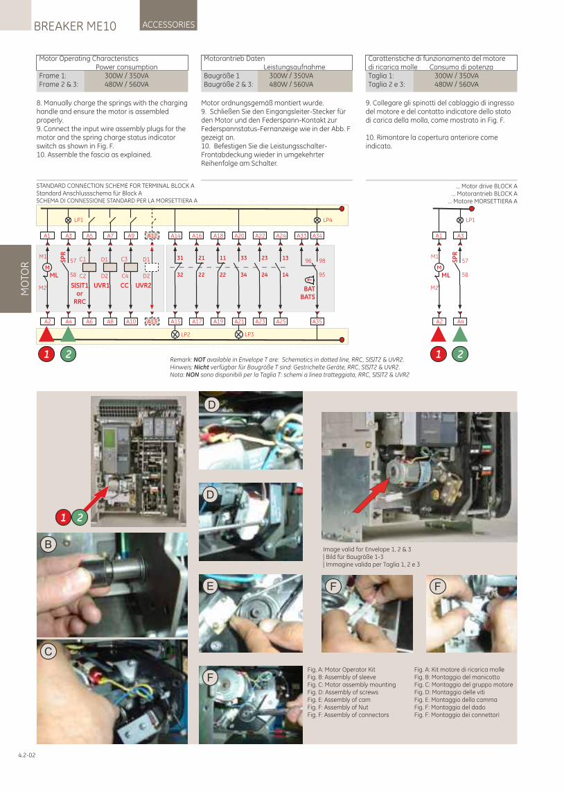
8. Manually charge the springs with the charging handle and ensure the motor is assembled properly.9. Connect the input wire assembly plugs for the motor and the spring charge status indicator switch as shown in Fig. F.10. Assemble the fascia as explained.
Motor ordnungsgemäß montiert wurde.9. Schließen Sie den Eingangsleiter-Stecker für den Motor und den Federspann-Kontakt zur Federspannstatus-Fernanzeige wie in der Abb. F gezeigt an.10. Befestigen Sie die Leistungsschalter-Frontabdeckung wieder in umgekehrter Reihenfolge am Schalter.
MO
TOR
ACCESSORIESBREAKER ME10
4.2-02
9. Collegare gli spinotti del cablaggio di ingresso del motore e del contatto indicatore dello stato di carica della molla, come mostrato in Fig. F.
10. Rimontare la copertura anteriore come indicato.
Motor Operating Characteristics Power consumptionFrame 1: 300W / 350VAFrame 2 & 3: 480W / 560VA
Motorantrieb Daten LeistungsaufnahmeBaugröße 1 300W / 350VABaugröße 2 & 3: 480W / 560VA
Caratteristiche di funzionamento del motore di ricarica molle Consumo di potenzaTaglia 1: 300W / 350VATaglia 2 e 3: 480W / 560VA
A6
A5
C1
C2
S(S)T1or
RRC
A10
A9
C4
C3
CC
A8
A7
UVR1
D1
D2
A2
A1
M
ML
M1
M2
LP1
A4
A3
SP
R
58
57
1 2
LP2
A15
A14
32
31
A17
A16
22
21
A19
A18
22
11
A23
A22
24
23
A25
A24
14
13
LP3
A21
A20
34
33
LP4
A35
A34
95
98
T
BATBATS
A33
96
A13
A12
UVR2
D1
D2
Remark: NOT available in Envelope T are: Schematics in dotted line, RRC, S(S)T2 & UVR2.Hinweis: Nicht verfügbar für Baugröße T sind: Gestrichelte Geräte, RRC, S(S)T2 & UVR2.Nota: NON sono disponibili per la Taglia T: schemi a linea tratteggiata, RRC, S(S)T2 & UVR2
A2
A1
M
ML
M1
M2
LP1
A4
A3
SP
R
58
57
1 2
STANDARD CONNECTION SCHEME FOR TERMINAL BLOCK AStandard Anschlussschema für Block ASCHEMA DI CONNESSIONE STANDARD PER LA MORSETTIERA A
... Motor drive BLOCK A... Motorantrieb BLOCK A
… Motore MORSETTIERA A
Fig. A: Motor Operator KitFig. B: Assembly of sleeveFig. C: Motor assembly mountingFig. D: Assembly of screwsFig. E: Assembly of camFig. F: Assembly of NutFig. F: Assembly of connectors
Fig. A: Kit motore di ricarica molleFig. B: Montaggio del manicottoFig. C: Montaggio del gruppo motore Fig. D: Montaggio delle vitiFig. E: Montaggio della cammaFig. F: Montaggio del dadoFig. F: Montaggio dei connettori
C
F F
B
D
F
D
E
1 2
Image valid for Envelope 1, 2 & 3 | Bild für Baugröße 1-3 | Immagine valida per Taglia 1, 2 e 3
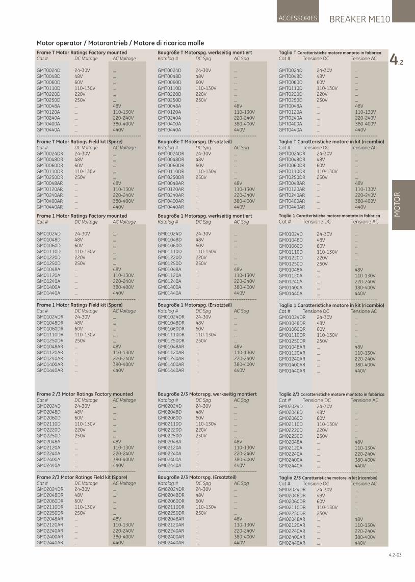
BREAKER ME10ACCESSORIES
4.2
MO
TOR
4.2-03
Frame 1 Motor Ratings Factory mountedCat # DC Voltage AC Voltage
GM01024D 24-30V ...GM01048D 48V ...GM01060D 60V ...GM01110D 110-130V ...GM01220D 220V ...GM01250D 250V ...GM01048A ... 48VGM01120A ... 110-130VGM01240A ... 220-240VGM01400A ... 380-400VGM01440A ... 440V------------------------------------------------------Frame 1 Motor Ratings Field kit (Spare)Cat # DC Voltage AC VoltageGM01024DR 24-30V ...GM01048DR 48V ...GM01060DR 60V ...GM01110DR 110-130V ...GM01250DR 250V ...GM01048AR ... 48VGM01120AR ... 110-130VGM01240AR ... 220-240VGM01400AR ... 380-400VGM01440AR ... 440V
Frame 2 /3 Motor Ratings Factory mountedCat # DC Voltage AC VoltageGM02024D 24-30V ...GM02048D 48V ...GM02060D 60V ...GM02110D 110-130V ...GM02220D 220V ...GM02250D 250V ...GM02048A ... 48VGM02120A ... 110-130VGM02240A ... 220-240VGM02400A ... 380-400VGM02440A ... 440V------------------------------------------------------Frame 2/3 Motor Ratings Field kit (Spare)Cat # DC Voltage AC VoltageGM02024DR 24-30V ...GM02048DR 48V ...GM02060DR 60V ...GM02110DR 110-130V ...GM02250DR 250V ...GM02048AR ... 48VGM02120AR ... 110-130VGM02240AR ... 220-240VGM02400AR ... 380-400VGM02440AR ... 440V
Baugröße 1 Motorspg. werkseitig montiertKatalog # DC Spg AC Spg
GM01024D 24-30V ...GM01048D 48V ...GM01060D 60V ...GM01110D 110-130V ...GM01220D 220V ...GM01250D 250V ...GM01048A ... 48VGM01120A ... 110-130VGM01240A ... 220-240VGM01400A ... 380-400VGM01440A ... 440V------------------------------------------------------Baugröße 1 Motorspg. (Ersatzteil)Katalog # DC Spg AC SpgGM01024DR 24-30V ...GM01048DR 48V ...GM01060DR 60V ...GM01110DR 110-130V ...GM01250DR 250V ...GM01048AR ... 48VGM01120AR ... 110-130VGM01240AR ... 220-240VGM01400AR ... 380-400VGM01440AR ... 440V
Baugröße 2/3 Motorspg. werkseitig montiertKatalog # DC Spg AC SpgGM02024D 24-30V ...GM02048D 48V ...GM02060D 60V ...GM02110D 110-130V ...GM02220D 220V ...GM02250D 250V ...GM02048A ... 48VGM02120A ... 110-130VGM02240A ... 220-240VGM02400A ... 380-400VGM02440A ... 440V------------------------------------------------------Baugröße 2/3 Motorspg. (Ersatzteil)Katalog # DC Spg AC SpgGM02024DR 24-30V ...GM02048DR 48V ...GM02060DR 60V ...GM02110DR 110-130V ...GM02250DR 250V ...GM02048AR ... 48VGM02120AR ... 110-130VGM02240AR ... 220-240VGM02400AR ... 380-400VGM02440AR ... 440V
Taglia 1 Caratteristiche motore montato in fabbrica
Cat # Tensione DC Tensione AC
GM01024D 24-30V ...GM01048D 48V ...GM01060D 60V ...GM01110D 110-130V ...GM01220D 220V ...GM01250D 250V ...GM01048A ... 48VGM01120A ... 110-130VGM01240A ... 220-240VGM01400A ... 380-400VGM01440A ... 440V------------------------------------------------------Taglia 1 Caratteristiche motore in kit (ricambio)Cat # Tensione DC Tensione ACGM01024DR 24-30V ...GM01048DR 48V ...GM01060DR 60V ...GM01110DR 110-130V ...GM01250DR 250V ...GM01048AR ... 48VGM01120AR ... 110-130VGM01240AR ... 220-240VGM01400AR ... 380-400VGM01440AR ... 440V
Taglia 2/3 Caratteristiche motore montato in fabbrica
Cat # Tensione DC Tensione ACGM02024D 24-30V ...GM02048D 48V ...GM02060D 60V ...GM02110D 110-130V ...GM02220D 220V ...GM02250D 250V ...GM02048A ... 48VGM02120A ... 110-130VGM02240A ... 220-240VGM02400A ... 380-400VGM02440A ... 440V------------------------------------------------------Taglia 2/3 Caratteristiche motore in kit (ricambio)
Cat # Tensione DC Tensione ACGM02024DR 24-30V ...GM02048DR 48V ...GM02060DR 60V ...GM02110DR 110-130V ...GM02250DR 250V ...GM02048AR ... 48VGM02120AR ... 110-130VGM02240AR ... 220-240VGM02400AR ... 380-400VGM02440AR ... 440V
Frame T Motor Ratings Factory mountedCat # DC Voltage AC Voltage
GMT0024D 24-30V ...GMT0048D 48V ...GMT0060D 60V ...GMT0110D 110-130V ...GMT0220D 220V ...GMT0250D 250V ...GMT0048A ... 48VGMT0120A ... 110-130VGMT0240A ... 220-240VGMT0400A ... 380-400VGMT0440A ... 440V---------------------------------------------------------Frame T Motor Ratings Field kit (Spare)Cat # DC Voltage AC VoltageGMT0024DR 24-30V ...GMT0048DR 48V ...GMT0060DR 60V ...GMT0110DR 110-130V ...GMT0250DR 250V ...GMT0048AR ... 48VGMT0120AR ... 110-130VGMT0240AR ... 220-240VGMT0400AR ... 380-400VGMT0440AR ... 440V
Baugröße T Motorspg. werkseitig montiertKatalog # DC Spg AC Spg
GMT0024D 24-30V ...GMT0048D 48V ...GMT0060D 60V ...GMT0110D 110-130V ...GMT0220D 220V ...GMT0250D 250V ...GMT0048A ... 48VGMT0120A ... 110-130VGMT0240A ... 220-240VGMT0400A ... 380-400VGMT0440A ... 440V------------------------------------------------------Baugröße T Motorspg. (Ersatzteil)Katalog # DC Spg AC SpgGMT0024DR 24-30V ...GMT0048DR 48V ...GMT0060DR 60V ...GMT0110DR 110-130V ...GMT0250DR 250V ...GMT0048AR ... 48VGMT0120AR ... 110-130VGMT0240AR ... 220-240VGMT0400AR ... 380-400VGMT0440AR ... 440V
Taglia T Caratteristiche motore montato in fabbrica
Cat # Tensione DC Tensione AC
GMT0024D 24-30V ...GMT0048D 48V ...GMT0060D 60V ...GMT0110D 110-130V ...GMT0220D 220V ...GMT0250D 250V ...GMT0048A ... 48VGMT0120A ... 110-130VGMT0240A ... 220-240VGMT0400A ... 380-400VGMT0440A ... 440V------------------------------------------------------Taglia T Caratteristiche motore in kit (ricambio)Cat # Tensione DC Tensione ACGMT0024DR 24-30V ...GMT0048DR 48V ...GMT0060DR 60V ...GMT0110DR 110-130V ...GMT0250DR 250V ...GMT0048AR ... 48VGMT0120AR ... 110-130VGMT0240AR ... 220-240VGMT0400AR ... 380-400VGMT0440AR ... 440V
Motor operator / Motorantrieb / Motore di ricarica molle
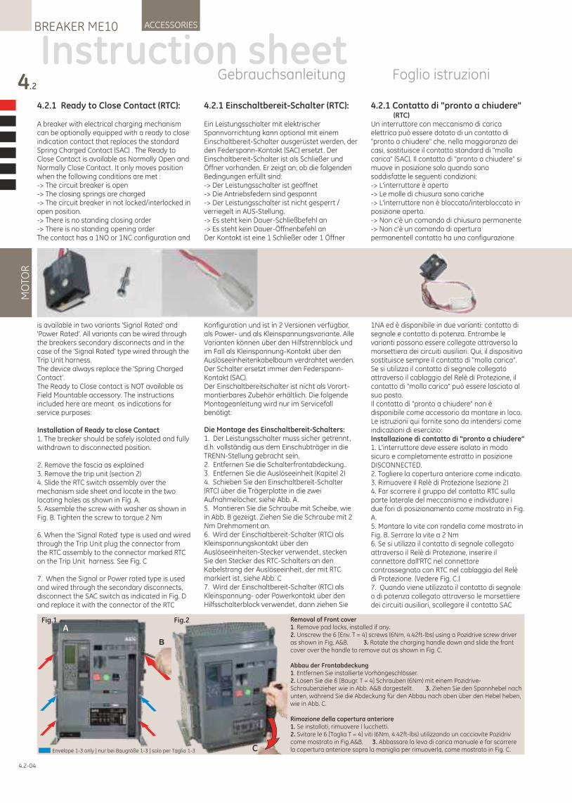
4.2.1 Einschaltbereit-Schalter (RTC):
Ein Leistungsschalter mit elektrischer Spannvorrichtung kann optional mit einem Einschaltbereit-Schalter ausgerüstet werden, der den Federspann-Kontakt (SAC) ersetzt. Der Einschaltbereit-Schalter ist als Schließer und Öffner vorhanden. Er zeigt an, ob die folgenden Bedingungen erfüllt sind:-> Der Leistungsschalter ist geöffnet-> Die Antriebsfedern sind gespannt-> Der Leistungsschalter ist nicht gesperrt / verriegelt in AUS-Stellung.-> Es steht kein Dauer-Schließbefehl an-> Es steht kein Dauer-Öffnenbefehl anDer Kontakt ist eine 1 Schließer oder 1 Öffner
Konfiguration und ist in 2 Versionen verfügbar, als Power- und als Kleinspannungsvariante. Alle Varianten können über den Hilfstrennblock und im Fall als Kleinspannung-Kontakt über den Auslöseeinheitenkabelbaum verdrahtet werden. Der Schalter ersetzt immer den Federspann-Kontakt (SAC).Der Einschaltbereitschalter ist nicht als Vorort-montierbares Zubehör erhältlich. Die folgende Montageanleitung wird nur im Servicefall benötigt:
Die Montage des Einschaltbereit-Schalters:1. Der Leistungsschalter muss sicher getrennt, d.h. vollständig aus dem Einschubträger in die TRENN-Stellung gebracht sein.2. Entfernen Sie die Schalterfrontabdeckung..3. Entfernen Sie die Auslöseeinheit (Kapitel 2)4. Schieben Sie den Einschaltbereit-Schalter (RTC) über die Trägerplatte in die zwei Aufnahmelöcher, siehe Abb. A.5. Montieren Sie die Schraube mit Scheibe, wie in Abb. B gezeigt. Ziehen Sie die Schraube mit 2 Nm Drehmoment an.6. Wird der Einschaltbereit-Schalter (RTC) als Kleinspannungskontakt über den Auslöseeinheiten-Stecker verwendet, stecken Sie den Stecker des RTC-Schalters an den Kabelstrang der Auslöseeinheit, der mit RTC markiert ist, siehe Abb. C7. Wird der Einschaltbereit-Schalter (RTC) als Kleinspannung- oder Powerkontakt über den Hilfsschalterblock verwendet, dann ziehen Sie
4.2.1 Ready to Close Contact (RTC):
A breaker with electrical charging mechanism can be optionally equipped with a ready to close indication contact that replaces the standard Spring Charged Contact (SAC) . The Ready to Close Contact is available as Normally Open and Normally Close Contact. It only moves position when the following conditions are met :-> The circuit breaker is open-> The closing springs are charged-> The circuit breaker in not locked/interlocked in open position.-> There is no standing closing order-> There is no standing opening orderThe contact has a 1NO or 1NC configuration and
is available in two variants 'Signal Rated' and 'Power Rated'. All variants can be wired through the breakers secondary disconnects and in the case of the 'Signal Rated' type wired through the Trip Unit harness.The device always replace the 'Spring Charged Contact'. The Ready to Close contact is NOT available as Field Mountable accessory. The instructions included here are meant as indications for service purposes:
Installation of Ready to close Contact1. The breaker should be safely isolated and fully withdrawn to disconnected position.
2. Remove the fascia as explained3. Remove the trip unit (section 2)4. Slide the RTC switch assembly over the mechanism side sheet and locate in the two locating holes as shown in Fig. A.5. Assemble the screw with washer as shown in Fig. B. Tighten the screw to torque 2 Nm
6. When the 'Signal Rated' type is used and wired through the Trip Unit plug the connector from the RTC assembly to the connector marked RTC on the Trip Unit harness. See Fig. C
7. When the Signal or Power rated type is used and wired through the secondary disconnects, disconnect the SAC switch as indicated in Fig. D and replace it with the connector of the RTC
4.2
MO
TOR
ACCESSORIESBREAKER ME10
4.2-04
4.2.1 Contatto di "pronto a chiudere" (RTC)Un interruttore con meccanismo di carica elettrica può essere dotato di un contatto di "pronto a chiudere" che, nella maggioranza dei casi, sostituisce il contatto standard di "molla carica" (SAC). Il contatto di "pronto a chiudere" si muove in posizione solo quando sono soddisfatte le seguenti condizioni:-> L'interruttore è aperto-> Le molle di chiusura sono cariche-> L'interruttore non è bloccato/interbloccato in posizione aperta.-> Non c'è un comando di chiusura permanente-> Non c'è un comando di apertura permanenteIl contatto ha una configurazione
1NA ed è disponibile in due varianti: contatto di segnale e contatto di potenza. Entrambe le varianti possono essere collegate attraverso la morsettiera dei circuiti ausiliari. Qui, il dispositivo sostituisce sempre il contatto di "molla carica". Se si utilizza il contatto di segnale collegato attraverso il cablaggio del Relè di Protezione, il contatto di "molla carica" può essere lasciato al suo posto.Il contatto di "pronto a chiudere" non è disponibile come accessorio da montare in loco. Le istruzioni qui fornite sono da intendersi come indicazioni di esercizio:Installazione di contatto di "pronto a chiudere“1. L'interruttore deve essere isolato in modo sicuro e completamente estratto in posizione DISCONNECTED.2. Togliere la copertura anteriore come indicato.3. Rimuovere il Relè di Protezione (sezione 2)4. Far scorrere il gruppo del contatto RTC sulla parte laterale del meccanismo e individuare i due fori di posizionamento come mostrato in Fig. A.5. Montare la vite con rondella come mostrato in Fig. B. Serrare la vite a 2 Nm6. Se si utilizza il contatto di segnale collegato attraverso il Relè di Protezione, inserire il connettore dall'RTC nel connettore contrassegnato con RTC nel cablaggio del Relè di Protezione. (Vedere Fig. C.)7. Quando viene utilizzato il contatto di segnale o di potenza collegato attraverso le morsettiere dei circuiti ausiliari, scollegare il contatto SAC
Instruction sheetGebrauchsanleitung Foglio istruzioni
Fig.1 Fig.2
C
B
ARemoval of Front cover1. Remove pad locks, installed if any.2. Unscrew the 6 [Env. T = 4] screws (6Nm, 4.42ft-lbs) using a Pozidrive screw driver as shown in Fig. A&B. 3. Rotate the charging handle down and slide the front cover over the handle to remove out as shown in Fig. C.
Abbau der Frontabdeckung1. Entfernen Sie installierte Vorhängeschlösser.2. Lösen Sie die 6 [Baugr. T = 4] Schrauben (6Nm) mit einem Pozidrive-Schraubenzieher wie in Abb. A&B dargestellt . 3. Ziehen Sie den Spannhebel nach unten, während Sie die Abdeckung für den Abbau nach oben über den Hebel heben, wie in Abb. C.
Rimozione della copertura anteriore1. Se installati, rimuovere I lucchetti.2. Svitare le 6 [Taglia T = 4] viti (6Nm, 4.42ft-lbs) utilizzando un cacciavite Pozidriv come mostrato in Fig.A&B. 3. Abbassare la leva di carica manuale e far scorrere la copertura anteriore sopra la maniglia per rimuoverla, come mostrato in Fig. C.Envelope 1-3 only | nur bei Baugröße 1-3 | solo per Taglia 1-3
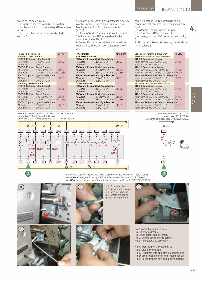
Fig. A: Assembly on mechanism Fig. B: Screw assembly Fig. C: Connector plug assemblyFig. D: Unplug spring charge contact Fig. E: Connector plug assembly
Fig. A: Montaggio sul meccanismo Fig. B: Vite di montaggio Fig. C: Collegamento spinotto di connessioneFig. D: Smontaggio contatto di "molla carica»Fig. E: Collegamento spinotto di connessione
DB
E
BREAKER ME10ACCESSORIES
4.2
MO
TOR
4.2-05
A
switch as indicated in Fig. E.8. Plug the connector from the RTC switch assembly with the plug marked as RTC as shown in Fig. E.9. Re-assemble the Trip Unit as indicated in section 2.
zuerst den Federspann-Kontaktstecker (SAC) wie in Abb. D gezeigt und ersetzen in durch den Anschluss vom RTC-Schalter, wie in Abb. E gezeigt.8. Stecken Sie den Stecker des Einschaltbereit-Schalters und den RTC-markierten Stecker zusammen, siehe Abb. E.9. Bauen Sie die Auslöseeinheit wieder wie im Kapitel 2 beschrieben in den Leistungsschalter ein.
RTC-Schalter Katalognr.SCHLIESSER-KontaktRTC zum Hilfstrennblock, SignalkontaktAC Werte 125VAC 0.1A GRTC2DC Werte 30VDC 0.1ARTC zum Hilfstrennblock, PowerkontaktAC Werte 120-250VAC 6A GRTC1DC Werte 125VDC 0.5A, 250VDC 0.25ARTC zur Auslöseeinheit, SignalkontaktAC Werte 125VAC 0.1A GRTC3DC Werte 30VDC 0.1AÖFFNER-KontaktRTC zum Hilfstrennblock, SignalkontaktAC Werte 125VAC 0.1A GRTC5DC Werte 30VDC 0.1ARTC zum Hilfstrennblock, PowerkontaktAC Werte 120-250VAC 6A GRTC4DC Werte 125VDC 0.5A, 250VDC 0.25ARTC zur Auslöseeinheit, SignalkontaktAC Werte 125VAC 0.1A GRTC6DC Werte 30VDC 0.1A
Ready To close switch Cat noNormally OPEN ContactRTC TO SD, Signal rated ContactAC Ratings 125VAC 0.1A GRTC2DC Ratings 30VDC 0.1ARTC TO SD, Power Rated ContactAC Ratings 120-250VAC 6A GRTC1DC Ratings 125VDC 0.5A, 250VDC 0.25ARTC TO Trip Unit, Signal rated ContactAC Ratings 125VAC 0.1A GRTC3DC Ratings 30VDC 0.1ANormally CLOSED ContactRTC TO SD, Signal rated ContactAC Ratings 125VAC 0.1A GRTC5DC Ratings 30VDC 0.1ARTC TO SD, Power Rated ContactAC Ratings 120-250VAC 6A GRTC4DC Ratings 125VDC 0.5A, 250VDC 0.25ARTC TO Trip Unit, Signal rated ContactAC Ratings 125VAC 0.1A GRTC6DC Ratings 30VDC 0.1A
Contatto di "pronto a chiudere" Nr Cat. NO contatto (contatti normalmente aperti)
RTC-SD, Contatto di segnaleValori nominali AC 125VAC 0.1A GRTC2Valori nominali DC 30VDC 0.1ARTC-SD, Contatto di potenzaValori nominali AC 120-250VAC 6A GRTC1Valori nominali DC 125VDC 0.5A, 250VDC 0.25ARTC-Relè di Protezione, Contatto di segnaleValori nominali AC 125VAC 0.1A GRTC3Valori nominali DC 30VDC 0.1ANC contatto (contatti normalmente chiusi )
RTC-SD, Contatto di segnaleValori nominali AC 125VAC 0.1A GRTC5Valori nominali DC 30VDC 0.1ARTC-SD, Contatto di potenzaValori nominali AC 120-250VAC 6A GRTC4Valori nominali DC 125VDC 0.5A, 250VDC 0.25ARTC-Relè di Protezione, Contatto di segnaleValori nominali AC 125VAC 0.1A GRTC6Valori nominali DC 30VDC 0.1A
come indicato in Fig. D e sostituirlo con il connettore del contatto RTC come indicato in Fig. E.8. Collegare il connettore dal gruppo dell'interruttore RTC con lo spinotto contrassegnato con RTC, come mostrato in Fig. E.9. Rimontare il Relè di Protezione, come indicato nella sezione 2.
C Fig. A: ZusammenbauFig. B: Schraubenmontage Fig. C: SteckverbindungFig. D: SteckverbindungFig. E: Steckverbindung
... Connection scheme RTC (BLOCK A)... Anschlüsse RTC (BLOCK A)
… Schema connessione RTC (MORSETTIERA A)
A6
A5
C1
C2
S(S)T1or
RRC
A10
A9
C4
C3
CC
A8
A7
UVR1
D1
D2
A2
A1
M
ML
M1
M2
LP1
A4
A3
SP
R
58
57
2
LP2
A15
A14
32
31
A17
A16
22
21
A19
A18
22
11
A23
A22
24
23
A25
A24
14
13
LP3
A21
A20
34
33
LP4
A35
A34
95
98
T
BATBATS
A33
96
A13
A12
UVR2
D1
D2
STANDARD CONNECTION SCHEME FOR TERMINAL BLOCK AStandard Anschlussschema für Block ASCHEMA DI CONNESSIONE STANDARD PER LA MORSETTIERA A
Remark: NOT available in Envelope T are: Schematics in dotted line, RRC, S(S)T2 & UVR2.Hinweis: Nicht verfügbar für Baugröße T sind: Gestrichelte Geräte, RRC, S(S)T2 & UVR2.Nota: NON sono disponibili per la Taglia T: schemi a linea tratteggiata, RRC, S(S)T2 & UVR2
oroderlub
LP5
A4
A3
SP
R
58
57
2
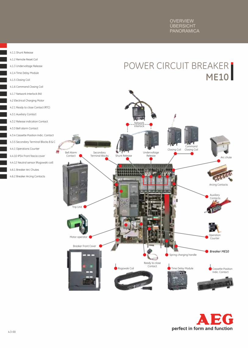
4.3-00perfect in form and function
POWER CIRCUIT BREAKERME10
4.1.1 Shunt Release
4.1.2 Remote Reset Coil
4.1.3 Undervoltage Release
4.1.4 Time Delay Module
4.1.5 Closing Coil
4.1.6 Command Closing Coil
4.1.7 Network Interlock (NI)
4.2 Electrical Charging Motor
4.2.1 Ready to close Contact (RTC)
4.3.1 Auxiliary Contact
4.3.2 Release indication Contact
4.3.3 Bell alarm Contact
4.3.4 Cassette Position Indic. Contact
4.3.5 Secondary Terminal Blocks B & C
4.4.1 Operations Counter
4.4.10 IP54 Front fascia cover
4.4.12 Neutral sensor (Rogowski coil)
4.6.1 Breaker Arc Chutes
4.6.2 Breaker Arcing Contacts
Trip Unit
Operation Counter
Spring charging handle
UndervoltageReleaseShunt Release
Motor operator
Bell AlarmContact
AuxiliaryContacts
Ready to closeContact
Time Delay ModuleRogowski Coil Cassette PositionIndic. Contact
SecondaryTerminal Blocks
NetworkInterlock
CommandClosing CoilClosing Coil
Arcing Contacts
Arc chute
Breaker ME10
Breaker Front Cover
OVERVIEWÜBERSICHTPANORAMICA
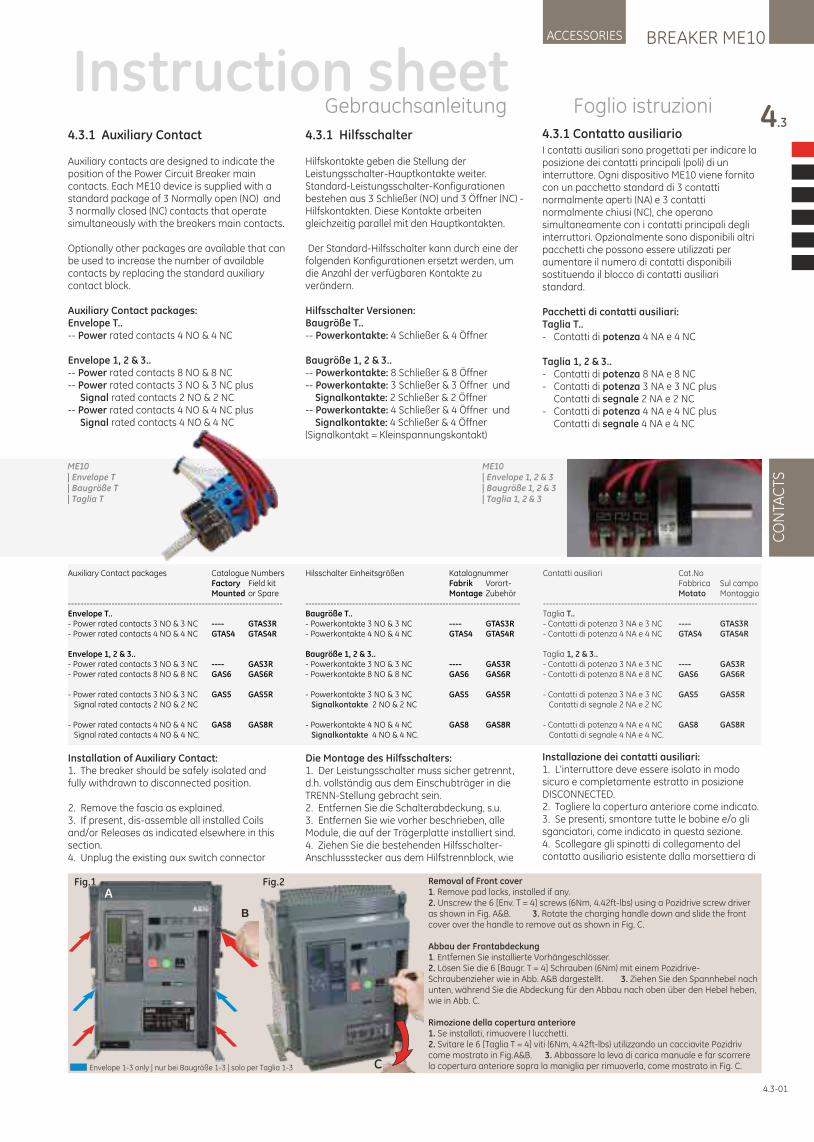
4.3.1 Auxiliary Contact
Auxiliary contacts are designed to indicate the position of the Power Circuit Breaker main contacts. Each ME10 device is supplied with a standard package of 3 Normally open (NO) and 3 normally closed (NC) contacts that operate simultaneously with the breakers main contacts.
Optionally other packages are available that can be used to increase the number of available contacts by replacing the standard auxiliary contact block.
Auxiliary Contact packages:Envelope T..-- Power rated contacts 4 NO & 4 NC
Envelope 1, 2 & 3..-- Power rated contacts 8 NO & 8 NC-- Power rated contacts 3 NO & 3 NC plus Signal rated contacts 2 NO & 2 NC-- Power rated contacts 4 NO & 4 NC plus Signal rated contacts 4 NO & 4 NC
Installation of Auxiliary Contact:1. The breaker should be safely isolated and fully withdrawn to disconnected position.
2. Remove the fascia as explained.3. If present, dis-assemble all installed Coils and/or Releases as indicated elsewhere in this section.4. Unplug the existing aux switch connector
4.3.1 Hilfsschalter
Hilfskontakte geben die Stellung der Leistungsschalter-Hauptkontakte weiter. Standard-Leistungsschalter-Konfigurationen bestehen aus 3 Schließer (NO) und 3 Öffner (NC) -Hilfskontakten. Diese Kontakte arbeiten gleichzeitig parallel mit den Hauptkontakten.
Der Standard-Hilfsschalter kann durch eine der folgenden Konfigurationen ersetzt werden, um die Anzahl der verfügbaren Kontakte zu verändern.
Hilfsschalter Versionen: Baugröße T..-- Powerkontakte: 4 Schließer & 4 Öffner
Baugröße 1, 2 & 3..-- Powerkontakte: 8 Schließer & 8 Öffner-- Powerkontakte: 3 Schließer & 3 Öffner und Signalkontakte: 2 Schließer & 2 Öffner-- Powerkontakte: 4 Schließer & 4 Öffner und Signalkontakte: 4 Schließer & 4 Öffner(Signalkontakt = Kleinspannungskontakt)
Die Montage des Hilfsschalters: 1. Der Leistungsschalter muss sicher getrennt, d.h. vollständig aus dem Einschubträger in die TRENN-Stellung gebracht sein.2. Entfernen Sie die Schalterabdeckung, s.u.3. Entfernen Sie wie vorher beschrieben, alle Module, die auf der Trägerplatte installiert sind.4. Ziehen Sie die bestehenden Hilfsschalter-Anschlussstecker aus dem Hilfstrennblock, wie
BREAKER ME10ACCESSORIES
4.3
CO
NTA
CTS
4.3.1 Contatto ausiliarioI contatti ausiliari sono progettati per indicare la posizione dei contatti principali (poli) di un interruttore. Ogni dispositivo ME10 viene fornito con un pacchetto standard di 3 contatti normalmente aperti (NA) e 3 contatti normalmente chiusi (NC), che operano simultaneamente con i contatti principali degli interruttori. Opzionalmente sono disponibili altri pacchetti che possono essere utilizzati per aumentare il numero di contatti disponibili sostituendo il blocco di contatti ausiliari standard.
Pacchetti di contatti ausiliari:Taglia T..- Contatti di potenza 4 NA e 4 NC
Taglia 1, 2 & 3..- Contatti di potenza 8 NA e 8 NC - Contatti di potenza 3 NA e 3 NC plus Contatti di segnale 2 NA e 2 NC- Contatti di potenza 4 NA e 4 NC plus Contatti di segnale 4 NA e 4 NC
Installazione dei contatti ausiliari:1. L'interruttore deve essere isolato in modo sicuro e completamente estratto in posizione DISCONNECTED.2. Togliere la copertura anteriore come indicato.3. Se presenti, smontare tutte le bobine e/o gli sganciatori, come indicato in questa sezione.4. Scollegare gli spinotti di collegamento del contatto ausiliario esistente dalla morsettiera di
4.3-01
Instruction sheetGebrauchsanleitung Foglio istruzioni
Fig.1 Fig.2
C
B
ARemoval of Front cover1. Remove pad locks, installed if any.2. Unscrew the 6 [Env. T = 4] screws (6Nm, 4.42ft-lbs) using a Pozidrive screw driver as shown in Fig. A&B. 3. Rotate the charging handle down and slide the front cover over the handle to remove out as shown in Fig. C.
Abbau der Frontabdeckung1. Entfernen Sie installierte Vorhängeschlösser.2. Lösen Sie die 6 [Baugr. T = 4] Schrauben (6Nm) mit einem Pozidrive-Schraubenzieher wie in Abb. A&B dargestellt . 3. Ziehen Sie den Spannhebel nach unten, während Sie die Abdeckung für den Abbau nach oben über den Hebel heben, wie in Abb. C.
Rimozione della copertura anteriore1. Se installati, rimuovere I lucchetti.2. Svitare le 6 [Taglia T = 4] viti (6Nm, 4.42ft-lbs) utilizzando un cacciavite Pozidriv come mostrato in Fig.A&B. 3. Abbassare la leva di carica manuale e far scorrere la copertura anteriore sopra la maniglia per rimuoverla, come mostrato in Fig. C.Envelope 1-3 only | nur bei Baugröße 1-3 | solo per Taglia 1-3
ME10 | Envelope T | Baugröße T | Taglia T
ME10 | Envelope 1, 2 & 3 | Baugröße 1, 2 & 3 | Taglia 1, 2 & 3
Auxiliary Contact packages Catalogue Numbers Factory Field kit Mounted or Spare---------------------------------------------------------------------Envelope T..- Power rated contacts 3 NO & 3 NC ---- GTAS3R- Power rated contacts 4 NO & 4 NC GTAS4 GTAS4R
Envelope 1, 2 & 3..- Power rated contacts 3 NO & 3 NC ---- GAS3R- Power rated contacts 8 NO & 8 NC GAS6 GAS6R
- Power rated contacts 3 NO & 3 NC GAS5 GAS5R Signal rated contacts 2 NO & 2 NC
- Power rated contacts 4 NO & 4 NC GAS8 GAS8R Signal rated contacts 4 NO & 4 NC.
Hilsschalter Einheitsgrößen Katalognummer Fabrik Vorort- Montage Zubehör---------------------------------------------------------------------Baugröße T..- Powerkontakte 3 NO & 3 NC ---- GTAS3R- Powerkontakte 4 NO & 4 NC GTAS4 GTAS4R
Baugröße 1, 2 & 3..- Powerkontakte 3 NO & 3 NC ---- GAS3R- Powerkontakte 8 NO & 8 NC GAS6 GAS6R
- Powerkontakte 3 NO & 3 NC GAS5 GAS5R 2 NO & 2 NCSignalkontakte
- Powerkontakte 4 NO & 4 NC GAS8 GAS8R 4 NO & 4 NC.Signalkontakte
Contatti ausiliari Cat.No Fabbrica Sul campo Motato Montaggio---------------------------------------------------------------------Taglia T..- Contatti di potenza 3 NA e 3 NC ---- GTAS3R- Contatti di potenza 4 NA e 4 NC GTAS4 GTAS4R
Taglia 1, 2 & 3..- Contatti di potenza 3 NA e 3 NC ---- GAS3R- Contatti di potenza 8 NA e 8 NC GAS6 GAS6R
- Contatti di potenza 3 NA e 3 NC GAS5 GAS5R Contatti di segnale 2 NA e 2 NC
- Contatti di potenza 4 NA e 4 NC GAS8 GAS8R Contatti di segnale 4 NA e 4 NC.
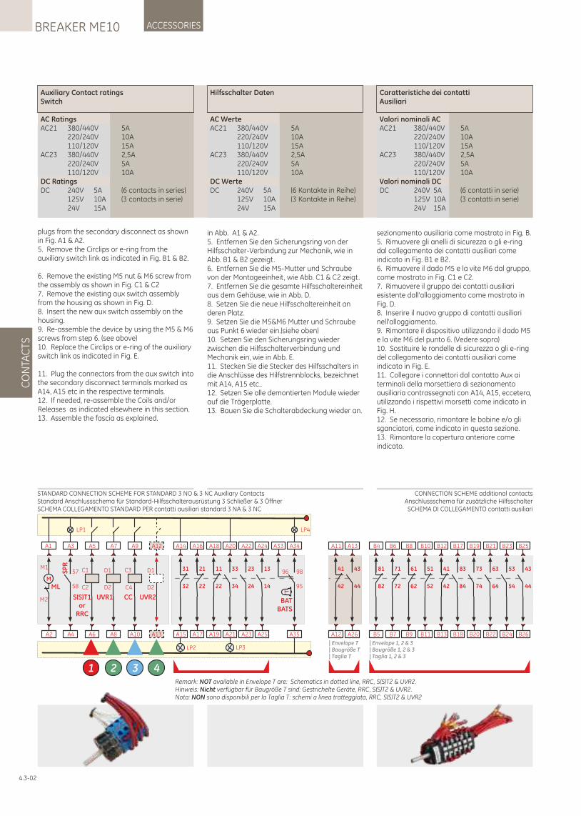
Auxiliary Contact ratingsSwitch
AC RatingsAC21 380/440V 5A 220/240V 10A 110/120V 15AAC23 380/440V 2,5A 220/240V 5A 110/120V 10ADC RatingsDC 240V 5A (6 contacts in series) 125V 10A (3 contacts in serie) 24V 15A
Hilfsschalter Daten
AC WerteAC21 380/440V 5A 220/240V 10A 110/120V 15AAC23 380/440V 2,5A 220/240V 5A 110/120V 10ADC WerteDC 240V 5A (6 Kontakte in Reihe) 125V 10A (3 Kontakte in Reihe) 24V 15A
Caratteristiche dei contattiAusiliari
Valori nominali ACAC21 380/440V 5A 220/240V 10A 110/120V 15AAC23 380/440V 2,5A 220/240V 5A 110/120V 10AValori nominali DCDC 240V 5A (6 contatti in serie) 125V 10A (3 contatti in serie) 24V 15A
plugs from the secondary disconnect as shown in Fig. A1 & A2.5. Remove the Circlips or e-ring from the auxiliary switch link as indicated in Fig. B1 & B2.
6. Remove the existing M5 nut & M6 screw from the assembly as shown in Fig. C1 & C27. Remove the existing aux switch assembly from the housing as shown in Fig. D.8. Insert the new aux switch assembly on the housing.9. Re-assemble the device by using the M5 & M6 screws from step 6. (see above)10. Replace the Circlips or e-ring of the auxiliary switch link as indicated in Fig. E.
11. Plug the connectors from the aux switch into the secondary disconnect terminals marked as A14, A15 etc in the respective terminals.12. If needed, re-assemble the Coils and/or Releases as indicated elsewhere in this section.13. Assemble the fascia as explained.
in Abb. A1 & A2.5. Entfernen Sie den Sicherungsring von der Hilfsschalter-Verbindung zur Mechanik, wie in Abb. B1 & B2 gezeigt.6. Entfernen Sie die M5-Mutter und Schraube von der Montageeinheit, wie Abb. C1 & C2 zeigt.7. Entfernen Sie die gesamte Hilfsschaltereinheit aus dem Gehäuse, wie in Abb. D.8. Setzen Sie die neue Hilfsschaltereinheit an deren Platz.9. Setzen Sie die M5&M6 Mutter und Schraube aus Punkt 6 wieder ein.(siehe oben)10. Setzen Sie den Sicherungsring wieder zwischen die Hilfsschalterverbindung und Mechanik ein, wie in Abb. E. 11. Stecken Sie die Stecker des Hilfsschalters in die Anschlüsse des Hilfstrennblocks, bezeichnet mit A14, A15 etc..12. Setzen Sie alle demontierten Module wieder auf die Trägerplatte.13. Bauen Sie die Schalterabdeckung wieder an.
sezionamento ausiliaria come mostrato in Fig. B.5. Rimuovere gli anelli di sicurezza o gli e-ring dal collegamento dei contatti ausiliari come indicato in Fig. B1 e B2.6. Rimuovere il dado M5 e la vite M6 dal gruppo, come mostrato in Fig. C1 e C2.7. Rimuovere il gruppo dei contatti ausiliari esistente dall'alloggiamento come mostrato in Fig. D.8. Inserire il nuovo gruppo di contatti ausiliari nell'alloggiamento.9. Rimontare il dispositivo utilizzando il dado M5 e la vite M6 del punto 6. (Vedere sopra)10. Sostituire le rondelle di sicurezza o gli e-ring del collegamento dei contatti ausiliari come indicato in Fig. E.11. Collegare i connettori dal contatto Aux ai terminali della morsettiera di sezionamento ausiliaria contrassegnati con A14, A15, eccetera, utilizzando i rispettivi morsetti come indicato in Fig. H.12. Se necessario, rimontare le bobine e/o gli sganciatori, come indicato in questa sezione.13. Rimontare la copertura anteriore come indicato.
CONNECTION SCHEME additional contactsAnschlussschema für zusätzliche HilfsschalterSCHEMA DI COLLEGAMENTO contatti ausiliari
STANDARD CONNECTION SCHEME FOR STANDARD 3 NO & 3 NC Auxiliary ContactsStandard Anschlussschema für Standard-Hilfsschalterausrüstung 3 Schließer & 3 ÖffnerSCHEMA COLLEGAMENTO STANDARD PER contatti ausiliari standard 3 NA & 3 NC
Remark: NOT available in Envelope T are: Schematics in dotted line, RRC, S(S)T2 & UVR2.Hinweis: Nicht verfügbar für Baugröße T sind: Gestrichelte Geräte, RRC, S(S)T2 & UVR2.Nota: NON sono disponibili per la Taglia T: schemi a linea tratteggiata, RRC, S(S)T2 & UVR2
A2
A1
M
ML
M1
M2
LP1
A4
A3
SP
R
58
57
A6
A5
C1
C2
S(S)T1or
RRC
1
A10
A9
C4
C3
CC
3
A8
A7
UVR1
D1
D2
2
LP2
A15
A14
32
31
A17
A16
22
21
A19
A18
22
11
A23
A22
24
23
A25
A24
14
13
LP3
A21
A20
34
33
LP4
A35
A34
95
98
T
BATBATS
A33
96
A13
A12
UVR2
D1
D2
4
B9
B8
62
61
B11
B10
52
51
B13
B12
42
41
B20
B19
74
73
B22
B21
64
63
B18
B17
84
83
B5
B4
82
81
B7
B6
72
71
B24
B23
54
53
B26
B25
44
43
| Envelope 1, 2 & 3 | Baugröße 1, 2 & 3 | Taglia 1, 2 & 3
A12
A11
42
41
A26
A13
44
43
| Envelope T | Baugröße T | Taglia T
CO
NTA
CTS
ACCESSORIESBREAKER ME10
4.3-02
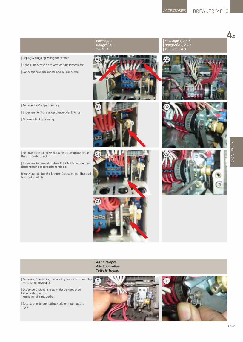
BREAKER ME10ACCESSORIES
4.3
CO
NTA
CTS
4.3-03
| Removing & replacing the existing aux switch assembly. (Valid for all Envelopes)
| Entfernen & wiedereinsetzen der vorhandenen Hilfsschaltergruppe (Gültig für alle Baugrößen)
| Sostituzione dei contatti aux esistenti (per tutte le Taglie)
ED
| Envelope T | Baugröße T | Taglia T
| Envelope 1, 2 & 3 | Baugröße 1, 2 & 3 | Taglia 1, 2 & 3
| All Envelopes| Alle Baugrößen | Tutte le Taglie..
A2| Unplug & plugging wiring connectors
| Ziehen und Stecken der Verdrahtungsanschlüsse
| Connessione e disconnessione dei connettori
A1
| Remove the Circlips or e-ring.
| Entfernen der Sicherungsscheibe oder E-Rings
| Rimovere le clips o e-ring
B2B1
| Remove the existing M5 nut & M6 screw to dismantle the aux. Switch block.
| Entfernen Sie die vorhandene M5 & M6 Schrauben zum demontieren des Hilfsschalterblocks.
Rimuovere il dado M5 e la vite M& esistenti per liberare il blocco di contatti
C3C1
C2
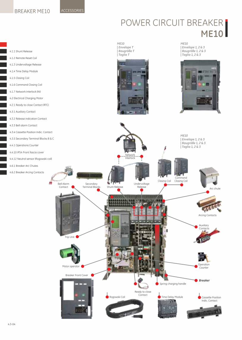
ACCESSORIESBREAKER ME10
4.3-04
ME10 | Envelope 1, 2 & 3 | Baugröße 1, 2 & 3 | Taglia 1, 2 & 3
ME10 | Envelope T| Baugröße T| Taglia T
Trip Unit
Operation Counter
Spring charging handle
UndervoltageReleaseShunt Release
Motor operator
Bell AlarmContact
AuxiliaryContacts
Ready to closeContact
Time Delay ModuleRogowski Coil Cassette PositionIndic. Contact
SecondaryTerminal Blocks
NetworkInterlock
CommandClosing CoilClosing Coil
Arcing Contacts
Arc chute
Breaker
Breaker Front Cover
ME10 | Envelope 1, 2 & 3 | Baugröße 1, 2 & 3 | Taglia 1, 2 & 3
4.1.1 Shunt Release
4.1.2 Remote Reset Coil
4.1.3 Undervoltage Release
4.1.4 Time Delay Module
4.1.5 Closing Coil
4.1.6 Command Closing Coil
4.1.7 Network Interlock (NI)
4.2 Electrical Charging Motor
4.2.1 Ready to close Contact (RTC)
4.3.1 Auxiliary Contact
4.3.2 Release indication Contact
4.3.3 Bell alarm Contact
4.3.4 Cassette Position Indic. Contact
4.3.5 Secondary Terminal Blocks B & C
4.4.1 Operations Counter
4.4.10 IP54 Front fascia cover
4.4.12 Neutral sensor (Rogowski coil)
4.6.1 Breaker Arc Chutes
4.6.2 Breaker Arcing Contacts
POWER CIRCUIT BREAKERME10
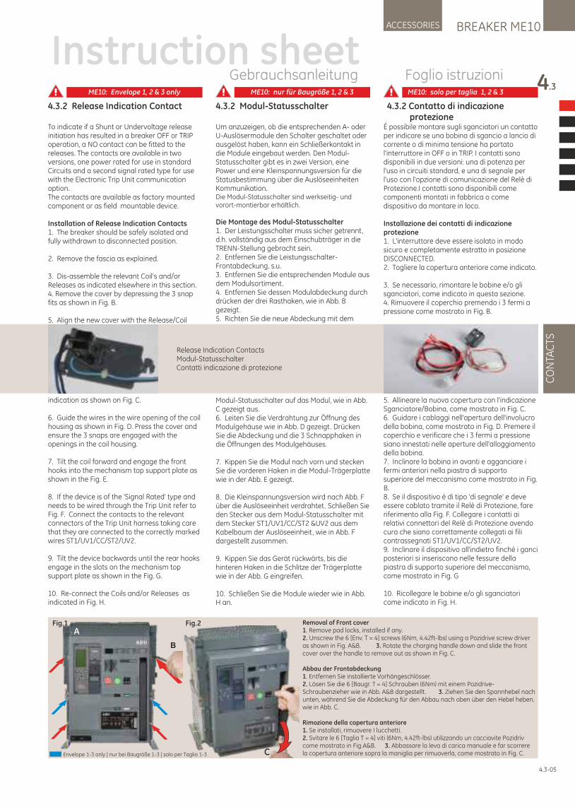
4.3.2 Modul-Statusschalter
Um anzuzeigen, ob die entsprechenden A- oder U-Auslösermodule den Schalter geschaltet oder ausgelöst haben, kann ein Schließerkontakt in die Module eingebaut werden. Den Modul-Statusschalter gibt es in zwei Version, eine Power und eine Kleinspannungsversion für die Statusbestimmung über die Auslöseeinheiten Kommunikation.Die Modul-Statusschalter sind werkseitig- und vorort-montierbar erhältlich.
Die Montage des Modul-Statusschalter1. Der Leistungsschalter muss sicher getrennt, d.h. vollständig aus dem Einschubträger in die TRENN-Stellung gebracht sein.2. Entfernen Sie die Leistungsschalter-Frontabdeckung, s.u.3. Entfernen Sie die entsprechenden Module aus dem Modulsortiment.4. Entfernen Sie dessen Modulabdeckung durch drücken der drei Rasthaken, wie in Abb. B gezeigt.5. Richten Sie die neue Abdeckung mit dem
Modul-Statusschalter auf das Modul, wie in Abb. C gezeigt aus.6. Leiten Sie die Verdrahtung zur Öffnung des Modulgehäuse wie in Abb. D gezeigt. Drücken Sie die Abdeckung und die 3 Schnapphaken in die Öffnungen des Modulgehäuses.
7. Kippen Sie die Modul nach vorn und stecken Sie die vorderen Haken in die Modul-Trägerplatte wie in der Abb. E gezeigt.
8. Die Kleinspannungsversion wird nach Abb. F über die Auslöseeinheit verdrahtet. Schließen Sie den Stecker aus dem Modul-Statusschalter mit dem Stecker ST1/UV1/CC/ST2 &UV2 aus dem Kabelbaum der Auslöseeinheit, wie in Abb. F dargestellt zusammen.
9. Kippen Sie das Gerät rückwärts, bis die hinteren Haken in die Schlitze der Trägerplatte wie in der Abb. G eingreifen.
10. Schließen Sie die Module wieder wie in Abb. H an.
4.3.2 Release Indication Contact
To indicate if a Shunt or Undervoltage release initiation has resulted in a breaker OFF or TRIP operation, a NO contact can be fitted to the releases. The contacts are available in two versions, one power rated for use in standard Circuits and a second signal rated type for use with the Electronic Trip Unit communication option.The contacts are available as factory mounted component or as field mountable device.
Installation of Release Indication Contacts1. The breaker should be safely isolated and fully withdrawn to disconnected position.
2. Remove the fascia as explained.
3. Dis-assemble the relevant Coil's and/or Releases as indicated elsewhere in this section.4. Remove the cover by depressing the 3 snap fits as shown in Fig. B.
5. Align the new cover with the Release/Coil
indication as shown on Fig. C.
6. Guide the wires in the wire opening of the coil housing as shown in Fig. D. Press the cover and ensure the 3 snaps are engaged with the openings in the coil housing.
7. Tilt the coil forward and engage the front hooks into the mechanism top support plate as shown in the Fig. E.
8. If the device is of the 'Signal Rated' type and needs to be wired through the Trip Unit refer to Fig. F. Connect the contacts to the relevant connectors of the Trip Unit harness taking care that they are connected to the correctly marked wires ST1/UV1/CC/ST2/UV2.
9. Tilt the device backwards until the rear hooks engage in the slots on the mechanism top support plate as shown in the Fig. G.
10. Re-connect the Coils and/or Releases as indicated in Fig. H.
4.3.2 Contatto di indicazione protezioneÈ possibile montare sugli sganciatori un contatto per indicare se una bobina di sgancio a lancio di corrente o di minima tensione ha portato l'interruttore in OFF o in TRIP. I contatti sono disponibili in due versioni: una di potenza per l'uso in circuiti standard, e una di segnale per l'uso con l'opzione di comunicazione del Relè di Protezione.I contatti sono disponibili come componenti montati in fabbrica o come dispositivo da montare in loco.
Installazione dei contatti di indicazione protezione1. L'interruttore deve essere isolato in modo sicuro e completamente estratto in posizione DISCONNECTED.2. Togliere la copertura anteriore come indicato.
3. Se necessario, rimontare le bobine e/o gli sganciatori, come indicato in questa sezione.4. Rimuovere il coperchio premendo i 3 fermi a pressione come mostrato in Fig. B.
5. Allineare la nuova copertura con l'indicazione Sganciatore/Bobina, come mostrato in Fig. C.6. Guidare i cablaggi nell'apertura dell'involucro della bobina, come mostrato in Fig. D. Premere il coperchio e verificare che i 3 fermi a pressione siano innestati nelle aperture dell'alloggiamento della bobina.7. Inclinare la bobina in avanti e agganciare i fermi anteriori nella piastra di supporto superiore del meccanismo come mostrato in Fig. B.8. Se il dispositivo è di tipo 'di segnale' e deve essere cablato tramite il Relè di Protezione, fare riferimento alla Fig. F. Collegare i contatti ai relativi connettori del Relè di Protezione avendo cura che siano correttamente collegati ai fili contrassegnati ST1/UV1/CC/ST2/UV2. 9. Inclinare il dispositivo all'indietro finché i ganci posteriori si inseriscono nelle fessure della piastra di supporto superiore del meccanismo, come mostrato in Fig. G
10. Ricollegare le bobine e/o gli sganciatori come indicato in Fig. H.
BREAKER ME10ACCESSORIES
4.3
CO
NTA
CTS
4.3-05
Instruction sheetGebrauchsanleitung Foglio istruzioni
Release Indication ContactsModul-StatusschalterContatti indicazione di protezione
Fig.1 Fig.2
C
B
ARemoval of Front cover1. Remove pad locks, installed if any.2. Unscrew the 6 [Env. T = 4] screws (6Nm, 4.42ft-lbs) using a Pozidrive screw driver as shown in Fig. A&B. 3. Rotate the charging handle down and slide the front cover over the handle to remove out as shown in Fig. C.
Abbau der Frontabdeckung1. Entfernen Sie installierte Vorhängeschlösser.2. Lösen Sie die 6 [Baugr. T = 4] Schrauben (6Nm) mit einem Pozidrive-Schraubenzieher wie in Abb. A&B dargestellt . 3. Ziehen Sie den Spannhebel nach unten, während Sie die Abdeckung für den Abbau nach oben über den Hebel heben, wie in Abb. C.
Rimozione della copertura anteriore1. Se installati, rimuovere I lucchetti.2. Svitare le 6 [Taglia T = 4] viti (6Nm, 4.42ft-lbs) utilizzando un cacciavite Pozidriv come mostrato in Fig.A&B. 3. Abbassare la leva di carica manuale e far scorrere la copertura anteriore sopra la maniglia per rimuoverla, come mostrato in Fig. C.Envelope 1-3 only | nur bei Baugröße 1-3 | solo per Taglia 1-3
ME10: Envelope 1, 2 & 3 only ME10: nur für Baugröße 1, 2 & 3 ME10: solo per taglia 1, 2 & 3
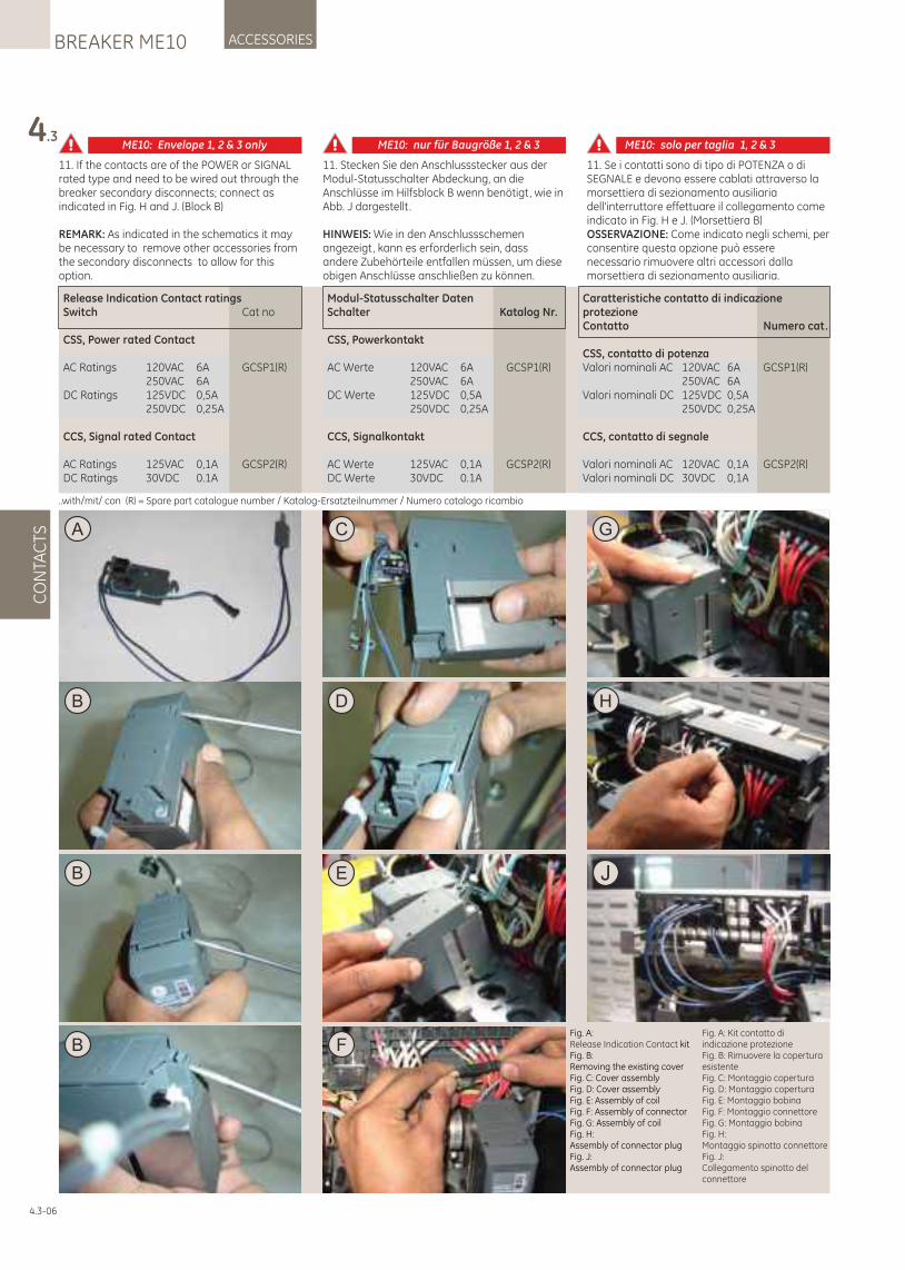
11. Stecken Sie den Anschlussstecker aus der Modul-Statusschalter Abdeckung, an die Anschlüsse im Hilfsblock B wenn benötigt, wie in Abb. J dargestellt .
HINWEIS: Wie in den Anschlussschemen angezeigt, kann es erforderlich sein, dass andere Zubehörteile entfallen müssen, um diese obigen Anschlüsse anschließen zu können.
11. If the contacts are of the POWER or SIGNAL rated type and need to be wired out through the breaker secondary disconnects; connect as indicated in Fig. H and J. (Block B)
REMARK: As indicated in the schematics it may be necessary to remove other accessories from the secondary disconnects to allow for this option.
Fig. A:Release Indication Contact kit Fig. B:Removing the existing coverFig. C: Cover assembly Fig. D: Cover assembly Fig. E: Assembly of coil Fig. F: Assembly of connector Fig. G: Assembly of coil Fig. H:Assembly of connector plug Fig. J:Assembly of connector plug
Fig. A: Kit contatto di indicazione protezione Fig. B: Rimuovere la copertura esistenteFig. C: Montaggio copertura Fig. D: Montaggio coperturaFig. E: Montaggio bobina Fig. F: Montaggio connettore Fig. G: Montaggio bobina Fig. H:Montaggio spinotto connettore Fig. J:Collegamento spinotto del connettore
C
D
E
G
H
B
B
4.3
CO
NTA
CTS
ACCESSORIESBREAKER ME10
4.3-06
A
J
F
B
11. Se i contatti sono di tipo di POTENZA o di SEGNALE e devono essere cablati attraverso la morsettiera di sezionamento ausiliaria dell'interruttore effettuare il collegamento come indicato in Fig. H e J. (Morsettiera B)OSSERVAZIONE: Come indicato negli schemi, per consentire questa opzione può essere necessario rimuovere altri accessori dalla morsettiera di sezionamento ausiliaria.
Release Indication Contact ratingsSwitch Cat no
CSS, Power rated Contact
AC Ratings 120VAC 6A GCSP1(R) 250VAC 6ADC Ratings 125VDC 0,5A 250VDC 0,25A
CCS, Signal rated Contact
AC Ratings 125VAC 0,1A GCSP2(R)DC Ratings 30VDC 0.1A
Modul-Statusschalter DatenSchalter Katalog Nr.
CSS, Powerkontakt
AC Werte 120VAC 6A GCSP1(R) 250VAC 6ADC Werte 125VDC 0,5A 250VDC 0,25A
CCS, Signalkontakt
AC Werte 125VAC 0,1A GCSP2(R)DC Werte 30VDC 0.1A
..with/mit/ con (R) = Spare part catalogue number / Katalog-Ersatzteilnummer / Numero catalogo ricambio
Caratteristiche contatto di indicazione protezioneContatto Numero cat.
CSS, contatto di potenzaValori nominali AC 120VAC 6A GCSP1(R) 250VAC 6AValori nominali DC 125VDC 0,5A 250VDC 0,25A
CCS, contatto di segnale
Valori nominali AC 120VAC 0,1A GCSP2(R)Valori nominali DC 30VDC 0,1A
ME10: Envelope 1, 2 & 3 only ME10: nur für Baugröße 1, 2 & 3 ME10: solo per taglia 1, 2 & 3
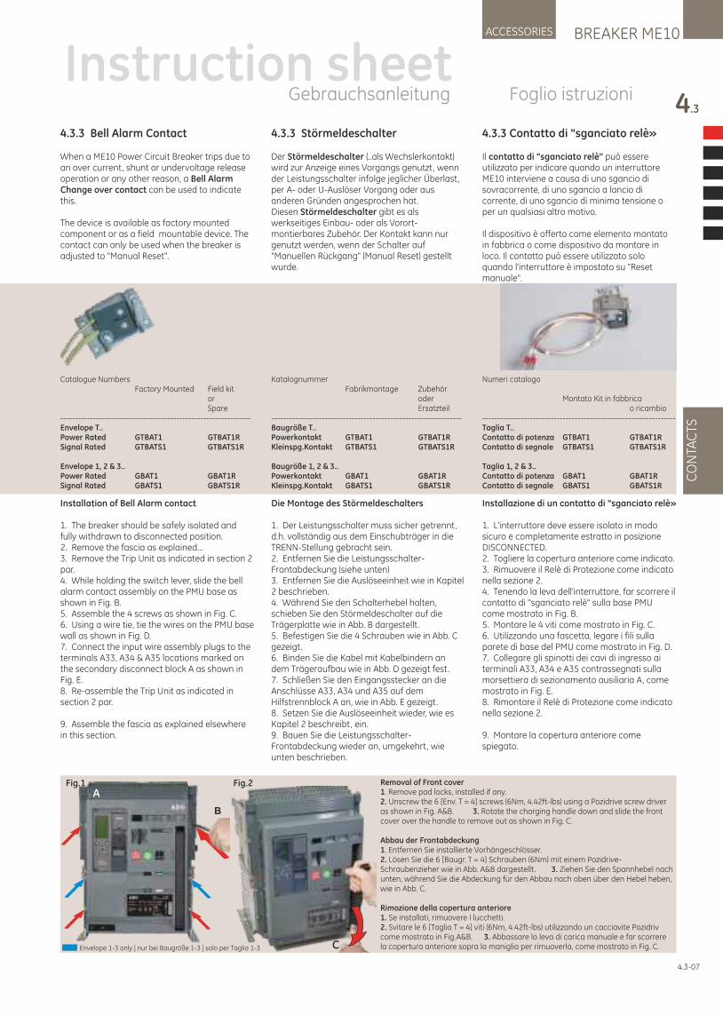
4.3.3 Störmeldeschalter
Der Störmeldeschalter (..als Wechslerkontakt) wird zur Anzeige eines Vorgangs genutzt, wenn der Leistungsschalter infolge jeglicher Überlast, per A- oder U-Auslöser Vorgang oder aus anderen Gründen angesprochen hat. Diesen Störmeldeschalter gibt es als werkseitiges Einbau- oder als Vorort-montierbares Zubehör. Der Kontakt kann nur genutzt werden, wenn der Schalter auf "Manuellen Rückgang" (Manual Reset) gestellt wurde.
Die Montage des Störmeldeschalters
1. Der Leistungsschalter muss sicher getrennt, d.h. vollständig aus dem Einschubträger in die TRENN-Stellung gebracht sein.2. Entfernen Sie die Leistungsschalter-Frontabdeckung (siehe unten)3. Entfernen Sie die Auslöseeinheit wie in Kapitel 2 beschrieben.4. Während Sie den Schalterhebel halten, schieben Sie den Störmeldeschalter auf die Trägerplatte wie in Abb. B dargestellt .5. Befestigen Sie die 4 Schrauben wie in Abb. C gezeigt.6. Binden Sie die Kabel mit Kabelbindern an dem Trägeraufbau wie in Abb. D gezeigt fest.7. Schließen Sie den Eingangsstecker an die Anschlüsse A33, A34 und A35 auf dem Hilfstrennblock A an, wie in Abb. E gezeigt.8. Setzen Sie die Auslöseeinheit wieder, wie es Kapitel 2 beschreibt, ein.9. Bauen Sie die Leistungsschalter-Frontabdeckung wieder an, umgekehrt, wie unten beschrieben.
4.3.3 Bell Alarm Contact
When a ME10 Power Circuit Breaker trips due to an over current, shunt or undervoltage release operation or any other reason, a Bell Alarm Change over contact can be used to indicate this.
The device is available as factory mounted component or as a field mountable device. The contact can only be used when the breaker is adjusted to "Manual Reset".
Installation of Bell Alarm contact
1. The breaker should be safely isolated and fully withdrawn to disconnected position. 2. Remove the fascia as explained...3. Remove the Trip Unit as indicated in section 2 par.4. While holding the switch lever, slide the bell alarm contact assembly on the PMU base as shown in Fig. B.5. Assemble the 4 screws as shown in Fig. C.6. Using a wire tie, tie the wires on the PMU base wall as shown in Fig. D.7. Connect the input wire assembly plugs to the terminals A33, A34 & A35 locations marked on the secondary disconnect block A as shown in Fig. E. 8. Re-assemble the Trip Unit as indicated in section 2 par.
9. Assemble the fascia as explained elsewhere in this section.
4.3.3 Contatto di "sganciato relè»
Il contatto di "sganciato relè" può essere utilizzato per indicare quando un interruttore ME10 interviene a causa di uno sgancio di sovracorrente, di uno sgancio a lancio di corrente, di uno sgancio di minima tensione o per un qualsiasi altro motivo.
Il dispositivo è offerto come elemento montato in fabbrica o come dispositivo da montare in loco. Il contatto può essere utilizzato solo quando l'interruttore è impostato su "Reset manuale".
Installazione di un contatto di "sganciato relè»
1. L'interruttore deve essere isolato in modo sicuro e completamente estratto in posizione DISCONNECTED. 2. Togliere la copertura anteriore come indicato.3. Rimuovere il Relè di Protezione come indicato nella sezione 2.4. Tenendo la leva dell'interruttore, far scorrere il contatto di "sganciato relè" sulla base PMU come mostrato in Fig. B.5. Montare le 4 viti come mostrato in Fig. C.6. Utilizzando una fascetta, legare i fili sulla parete di base del PMU come mostrato in Fig. D.7. Collegare gli spinotti dei cavi di ingresso ai terminali A33, A34 e A35 contrassegnati sulla morsettiera di sezionamento ausiliaria A, come mostrato in Fig. E.8. Rimontare il Relè di Protezione come indicato nella sezione 2.
9. Montare la copertura anteriore come spiegato.
BREAKER ME10ACCESSORIES
4.3
CO
NTA
CTS
4.3-07
Instruction sheetGebrauchsanleitung Foglio istruzioni
Fig.1 Fig.2
C
B
ARemoval of Front cover1. Remove pad locks, installed if any.2. Unscrew the 6 [Env. T = 4] screws (6Nm, 4.42ft-lbs) using a Pozidrive screw driver as shown in Fig. A&B. 3. Rotate the charging handle down and slide the front cover over the handle to remove out as shown in Fig. C.
Abbau der Frontabdeckung1. Entfernen Sie installierte Vorhängeschlösser.2. Lösen Sie die 6 [Baugr. T = 4] Schrauben (6Nm) mit einem Pozidrive-Schraubenzieher wie in Abb. A&B dargestellt . 3. Ziehen Sie den Spannhebel nach unten, während Sie die Abdeckung für den Abbau nach oben über den Hebel heben, wie in Abb. C.
Rimozione della copertura anteriore1. Se installati, rimuovere I lucchetti.2. Svitare le 6 [Taglia T = 4] viti (6Nm, 4.42ft-lbs) utilizzando un cacciavite Pozidriv come mostrato in Fig.A&B. 3. Abbassare la leva di carica manuale e far scorrere la copertura anteriore sopra la maniglia per rimuoverla, come mostrato in Fig. C.Envelope 1-3 only | nur bei Baugröße 1-3 | solo per Taglia 1-3
Catalogue Numbers Factory Mounted Field kit or Spare----------------------------------------------------------------Envelope T..Power Rated GTBAT1 GTBAT1RSignal Rated GTBATS1 GTBATS1R
Envelope 1, 2 & 3..Power Rated GBAT1 GBAT1RSignal Rated GBATS1 GBATS1R
Katalognummer Fabrikmontage Zubehör oder Ersatzteil----------------------------------------------------------------Baugröße T..Powerkontakt GTBAT1 GTBAT1RKleinspg.Kontakt GTBATS1 GTBATS1R
Baugröße 1, 2 & 3..Powerkontakt GBAT1 GBAT1RKleinspg.Kontakt GBATS1 GBATS1R
Numeri catalogo
Montato Kit in fabbrica o ricambio-----------------------------------------------------------------Taglia T..Contatto di potenza GTBAT1 GTBAT1RContatto di segnale GTBATS1 GTBATS1R
Taglia 1, 2 & 3..Contatto di potenza GBAT1 GBAT1RContatto di segnale GBATS1 GBATS1R
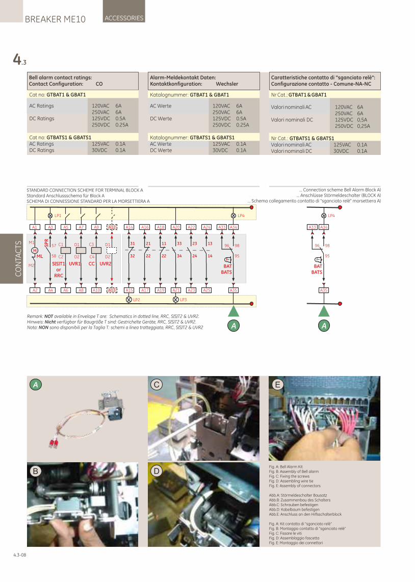
4.3
CO
NTA
CTS
ACCESSORIESBREAKER ME10
4.3-08
Alarm-Meldekontakt Daten:Kontaktkonfiguration: Wechsler
Caratteristiche contatto di "sganciato relè":Configurazione contatto - Comune-NA-NC
Bell alarm contact ratings:Contact Configuration: CO
Cat no: GTBAT1 & GBAT1
AC Ratings 120VAC 6A 250VAC 6ADC Ratings 125VDC 0.5A 250VDC 0.25A
Cat no: GTBATS1 & GBATS1AC Ratings 125VAC 0.1ADC Ratings 30VDC 0.1A
Katalognummer: GTBAT1 & GBAT1
AC Werte 120VAC 6A 250VAC 6ADC Werte 125VDC 0.5A 250VDC 0.25A
Katalognummer: GTBATS1 & GBATS1AC Werte 125VAC 0.1ADC Werte 30VDC 0.1A
Nr Cat.: GTBAT1 & GBAT1
Valori nominali AC 120VAC 6A 250VAC 6AValori nominali DC 125VDC 0,5A 250VDC 0,25A
Nr Cat.: GTBATS1 & GBATS1Valori nominali AC 125VAC 0.1AValori nominali DC 30VDC 0.1A
BFig. A: Bell Alarm KitFig. B: Assembly of Bell alarmFig. C: Fixing the screwsFig. D: Assembling wire tie Fig. E: Assembly of connectors
Abb.A: Störmeldeschalter BausatzAbb.B: Zusammenbau des SchaltersAbb.C: Schrauben befestigenAbb.D: Kabelbaum befestigenAbb.E: Anschluss an den Hilfsschalterblock
Fig. A: Kit contatto di "sganciato relè“Fig. B: Montaggio contatto di "sganciato relè“Fig. C: Fissare le vitiFig. D: Assemblaggio fascetta Fig. E: Montaggio dei connettori
C
D
EA
... Connection scheme Bell Alarm Block A)... Anschlüsse Störmeldeschalter (BLOCK A)
… Schema collegamento contatto di "sganciato relè" morsettiera A)
A6
A5
C1
C2
S(S)T1or
RRC
A10
A9
C4
C3
CC
A8
A7
UVR1
D1
D2
A2
A1
M
ML
M1
M2
LP1
A4
A3
SP
R
58
57
A
LP2
A15
A14
32
31
A17
A16
22
21
A19
A18
22
11
A23
A22
24
23
A25
A24
14
13
LP3
A21
A20
34
33
LP4
A35
A34
95
98
T
BATBATS
A33
96
A13
A12
UVR2
D1
D2
STANDARD CONNECTION SCHEME FOR TERMINAL BLOCK AStandard Anschlussschema für Block ASCHEMA DI CONNESSIONE STANDARD PER LA MORSETTIERA A
Remark: NOT available in Envelope T are: Schematics in dotted line, RRC, S(S)T2 & UVR2.Hinweis: Nicht verfügbar für Baugröße T sind: Gestrichelte Geräte, RRC, S(S)T2 & UVR2.Nota: NON sono disponibili per la Taglia T: schemi a linea tratteggiata, RRC, S(S)T2 & UVR2
LP4
A35
A34
95
98
T
BATBATS
A33
96
A
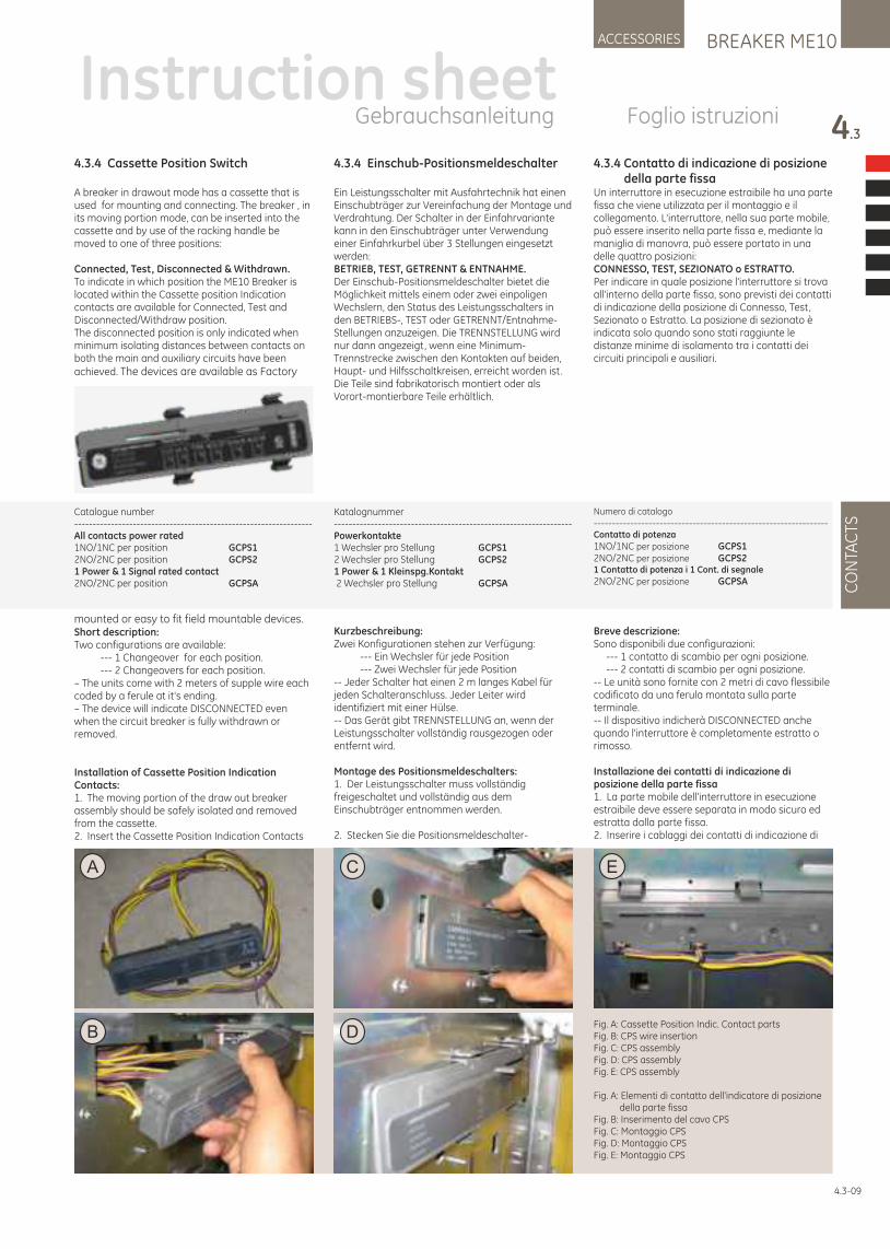
BREAKER ME10ACCESSORIES
4.3
CO
NTA
CTS
4.3-09
Fig. A: Cassette Position Indic. Contact partsFig. B: CPS wire insertionFig. C: CPS assemblyFig. D: CPS assemblyFig. E: CPS assembly
Fig. A: Elementi di contatto dell'indicatore di posizione della parte fissaFig. B: Inserimento del cavo CPSFig. C: Montaggio CPSFig. D: Montaggio CPSFig. E: Montaggio CPS
B
EA
D
C
4.3.4 Cassette Position Switch
A breaker in drawout mode has a cassette that is used for mounting and connecting. The breaker , in its moving portion mode, can be inserted into the cassette and by use of the racking handle be moved to one of three positions:
Connected, Test, Disconnected & Withdrawn. To indicate in which position the ME10 Breaker is located within the Cassette position Indication contacts are available for Connected, Test and Disconnected/Withdraw position. The disconnected position is only indicated when minimum isolating distances between contacts on both the main and auxiliary circuits have been achieved. The devices are available as Factory
mounted or easy to fit field mountable devices.Short description:Two configurations are available:
--- 1 Changeover for each position.--- 2 Changeovers for each position.
– The units come with 2 meters of supple wire each coded by a ferule at it's ending.– The device will indicate DISCONNECTED even when the circuit breaker is fully withdrawn or removed.
Installation of Cassette Position Indication Contacts:1. The moving portion of the draw out breaker assembly should be safely isolated and removed from the cassette.2. Insert the Cassette Position Indication Contacts
4.3.4 Einschub-Positionsmeldeschalter
Ein Leistungsschalter mit Ausfahrtechnik hat einen Einschubträger zur Vereinfachung der Montage und Verdrahtung. Der Schalter in der Einfahrvariante kann in den Einschubträger unter Verwendung einer Einfahrkurbel über 3 Stellungen eingesetzt werden:BETRIEB, TEST, GETRENNT & ENTNAHME.Der Einschub-Positionsmeldeschalter bietet die Möglichkeit mittels einem oder zwei einpoligen Wechslern, den Status des Leistungsschalters in den BETRIEBS-, TEST oder GETRENNT/Entnahme-Stellungen anzuzeigen. Die TRENNSTELLUNG wird nur dann angezeigt, wenn eine Minimum-Trennstrecke zwischen den Kontakten auf beiden, Haupt- und Hilfsschaltkreisen, erreicht worden ist. Die Teile sind fabrikatorisch montiert oder als Vorort-montierbare Teile erhältlich.
Kurzbeschreibung:Zwei Konfigurationen stehen zur Verfügung:
--- Ein Wechsler für jede Position--- Zwei Wechsler für jede Position
-- Jeder Schalter hat einen 2 m langes Kabel für jeden Schalteranschluss. Jeder Leiter wird identifiziert mit einer Hülse.-- Das Gerät gibt TRENNSTELLUNG an, wenn der Leistungsschalter vollständig rausgezogen oder entfernt wird.
Montage des Positionsmeldeschalters:1. Der Leistungsschalter muss vollständig freigeschaltet und vollständig aus dem Einschubträger entnommen werden.
2. Stecken Sie die Positionsmeldeschalter-
4.3.4 Contatto di indicazione di posizione della parte fissaUn interruttore in esecuzione estraibile ha una parte fissa che viene utilizzata per il montaggio e il collegamento. L'interruttore, nella sua parte mobile, può essere inserito nella parte fissa e, mediante la maniglia di manovra, può essere portato in una delle quattro posizioni:CONNESSO, TEST, SEZIONATO o ESTRATTO. Per indicare in quale posizione l'interruttore si trova all'interno della parte fissa, sono previsti dei contatti di indicazione della posizione di Connesso, Test, Sezionato o Estratto. La posizione di sezionato è indicata solo quando sono stati raggiunte le distanze minime di isolamento tra i contatti dei circuiti principali e ausiliari.
Breve descrizione:Sono disponibili due configurazioni: --- 1 contatto di scambio per ogni posizione. --- 2 contatti di scambio per ogni posizione.-- Le unità sono fornite con 2 metri di cavo flessibile codificato da una ferula montata sulla parte terminale.-- Il dispositivo indicherà DISCONNECTED anche quando l'interruttore è completamente estratto o rimosso.
Installazione dei contatti di indicazione di posizione della parte fissa1. La parte mobile dell'interruttore in esecuzione estraibile deve essere separata in modo sicuro ed estratta dalla parte fissa.2. Inserire i cablaggi dei contatti di indicazione di
Instruction sheetGebrauchsanleitung Foglio istruzioni
Catalogue number -----------------------------------------------------------------All contacts power rated1NO/1NC per position GCPS12NO/2NC per position GCPS21 Power & 1 Signal rated contact2NO/2NC per position GCPSA
Katalognummer -----------------------------------------------------------------Powerkontakte1 Wechsler pro Stellung GCPS12 Wechsler pro Stellung GCPS21 Power & 1 Kleinspg.Kontakt 2 Wechsler pro Stellung GCPSA
Numero di catalogo
----------------------------------------------------------------Contatto di potenza
1NO/1NC per posizione GCPS12NO/2NC per posizione GCPS21 Contatto di potenza i 1 Cont. di segnale
2NO/2NC per posizione GCPSA
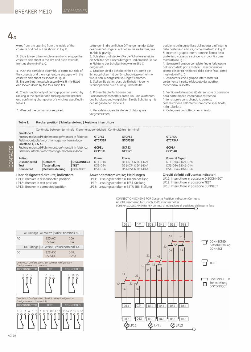
4.3
CO
NTA
CTS
ACCESSORIESBREAKER ME10
4.3-10
wires from the opening from the inside of the cassette and pull out as shown in Fig. B.
3. Slide & insert the switch assembly to engage the cassette side sheet in the slot and push towards front as shown in Fig. C.
4. Push the complete assembly to come out side of the cassette and the snap feature engages with the cassette side sheet as shown in Fig. D.5. Ensure that the switch assembly is firmly fitted and locked down by the four snap fits.
6. Check functionality of carriage position switch by racking in the breaker and racking out the breaker and confirming changeover of switch as specified in table 1.
7. Wire out the contacts as required.
DISCONNECTED TEST CONNECTED
1 2 3 13 14 157 8 9
One Switch Configuration / Ein Schalter KonfigurationConfigurazione a un contatto
DISCONNECTED TEST CONNECTED
1 2 3 4 5 6 7 8 9 10 11 12 13 14 15 16 17 18
Two Switch Configuration / Zwei Schalter KonfigurationConfigurazione a due contatti
Leitungen in die seitlichen Öffnungen an der Seite des Einschubträgers und ziehen Sie sie heraus, wie in Abb. B gezeigt.3. Schieben und stecken Sie die Schaltereinheit in die Schlitze des Einschubträgers und drücken Sie sie in Richtung der Schalterfront wie im Bild C dargestellt .4. Drücken Sie die Schaltereinheit an, damit die Schnapphaken mit der Einschubträgeraufnahme wie in Abb. D dargestellt in Eingriff kommen.5. Stellen Sie sicher, dass die Einheit mit den 4 Schnapphaken auch bündig und festsitzt.
6. Prüfen Sie die Funktionen des Positionsmeldeschalters durch Ein- und Ausfahren des Schalters und vergleichen Sie die Schaltung mit den Angaben der Tabelle 1..7. Vervollständigen Sie die Verdrahtung wie vorgeschrieben.
posizione della parte fissa dall'apertura all'interno della parte fissa e tirare, come mostrato in Fig. B.3. Inserire il gruppo interruttore nel fianco della parte fissa cassetta e spingerlo in avanti, come mostrato in Fig. C.4. Spingere il gruppo completo fino a farlo uscire dal fianco della parte mobile: il meccanismo a scatto si inserirà nel fianco della parte fissa, come mostrato in Fig. D.5. Assicurarsi che il gruppo interruttore sia saldamente inserito e bloccato dai quattro meccanismi a scatto.
6. Verificare la funzionalità del sensore di posizione della parte mobile inserendo e estraendo l'interruttore e controllando la corretta commutazione dell'interruttore come specificato nella tabella 1.7. Collegare i contatti come richiesto.
AC 120VAC 10A 250VAC 10A
AC Ratings | AC Werte | Valori nominali AC
DC 125VDC 0.5A 250VDC 0.25A
DC Ratings | DC Werte | Valori nominali DC
CONNECTION SCHEME FOR Cassette Position Indication ContactsAnschlussschema für Einschub-PositionsschalterSCHEMA COLLEGAMENTO PER contatti di indicazione di posizione della parte fissa
D11 D21
D14 D24
D12 D22
D31 D41 D51 D61
D34 D44 D54 D64
D32 D42 D52 D62
LP11 LP12 LP13
11
12
14
21
22
24
31
32
34
41
42
44
51
5254
61
62
64
CONNECTEDBetriebsstellungCONNECT
TEST
DISCONNECTEDTrennstellungDISCONNECT
Table 1: Breaker position | Schalterstellung | Posizione interruttore --------------------------------------------------------------------------------------------------------------------------------------------------------------- Continuity between terminals | Klemmenzugehörigkeit | Continuità tra i terminali Envelope T..Factory mounted/Fabrikmontage/montati in fabbrica GTCPS1 GTCPS2 GTCPSAField mountable/Vorortmontage/montare in loco GTCPS1R GTCPS2R GTCPSAREnvelope 1, 2 & 3..Factory mounted/Fabrikmontage/montati in fabbrica GCPS1 GCPS2 GCPSAField mountable/Vorortmontage/montare in loco GCPS1R GCPS2R GCPSAR
Rating Power Power Power & SignalDisconnected | Getrennt | DISCONNECT D11-D14 D11-D14 & D21-D24 D11-D14 & D21-D24Test | Teststellung | TEST D31-D34 D31-D34 & D41-D44 D31-D34 & D41-D44Connected | Betriebsstellung | CONNECT D51-D54 D51-D54 & D61-D64 D51-D54 & D61-D64
User designated circuits; indicatorsLP11: Breaker in disconnected positionLP12: Breaker in test positionLP13: Breaker in connected position
Anwenderstromkreise; MeldungenLP11: Leistungsschalter in TRENN-StellungLP12: Leistungsschalter in TEST-StellungLP13: Leistungsschalter in BETRIEBS-Stellung
Circuiti definiti dall'utente; indicatoriLP11: Interruttore in posizione DISCONNECTLP12: Interruttore in posizione TESTLP13: Interruttore in posizione CONNECT
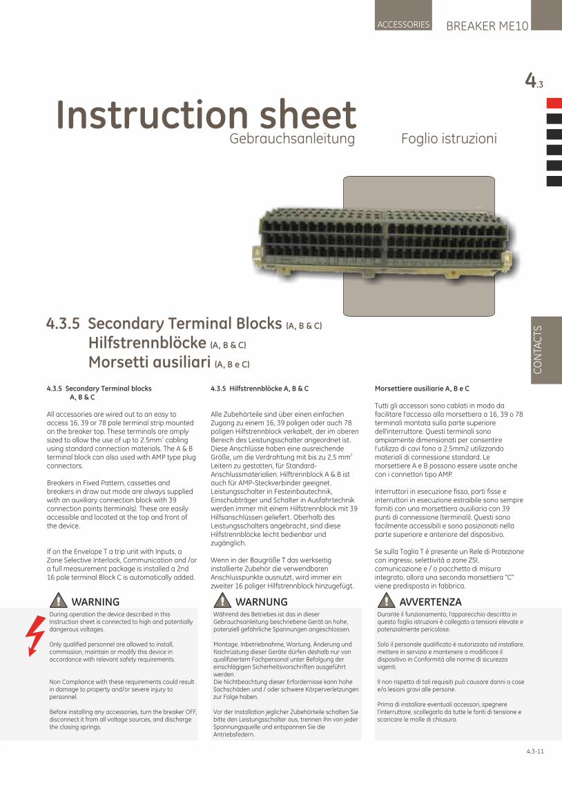
BREAKER ME10ACCESSORIES
4.3
CO
NTA
CTS
4.3-11
4.3.5 Secondary Terminal Blocks (A, B & C)
Hilfstrennblöcke (A, B & C)
Morsetti ausiliari (A, B e C)
WARNUNGWährend des Betriebes ist das in dieser Gebrauchsanleitung beschriebene Gerät an hohe, potenziell gefährliche Spannungen angeschlossen.
Montage, Inbetriebnahme, Wartung, Änderung und Nachrüstung dieser Geräte dürfen deshalb nur von qualifiziertem Fachpersonal unter Befolgung der einschlägigen Sicherheitsvorschriften ausgeführt werden.Die Nichtbeachtung dieser Erfordernisse kann hohe Sachschäden und / oder schwere Körperverletzungen zur Folge haben.
Vor der Installation jeglicher Zubehörteile schalten Sie bitte den Leistungsschalter aus, trennen ihn von jeder Spannungsquelle und entspannen Sie die Antriebsfedern.
AVVERTENZADurante il funzionamento, l'apparecchio descritto in questo foglio istruzioni è collegato a tensioni elevate e potenzialmente pericolose.
Solo il personale qualificato è autorizzato ad installare, mettere in servizio e mantenere o modificare il dispositivo in Conformità alle norme di sicurezza vigenti.
Il non rispetto di tali requisiti può causare danni a cose e/o lesioni gravi alle persone.
Prima di installare eventuali accessori, spegnere l'interruttore, scollegarlo da tutte le fonti di tensione e scaricare le molle di chiusura.
WARNINGDuring operation the device described in this Instruction sheet is connected to high and potentially dangerous voltages.
Only qualified personnel are allowed to install, commission, maintain or modify this device in accordance with relevant safety requirements.
Non Compliance with these requirements could result in damage to property and/or severe injury to personnel.
Before installing any accessories, turn the breaker OFF, disconnect it from all voltage sources, and discharge the closing springs.
4.3.5 Secondary Terminal blocks A, B & C
All accessories are wired out to an easy to access 16, 39 or 78 pole terminal strip mounted on the breaker top. These terminals are amply
2sized to allow the use of up to 2.5mm cabling using standard connection materials. The A & B terminal block can also used with AMP type plug connectors.
Breakers in Fixed Pattern, cassettes and breakers in draw out mode are always supplied with an auxiliary connection block with 39 connection points (terminals). These are easily accessible and located at the top and front of the device.
If on the Envelope T a trip unit with Inputs, a Zone Selective Interlock, Communication and /or a full measurement package is installed a 2nd 16 pole terminal Block C is automatically added.
4.3.5 Hilfstrennblöcke A, B & C
Alle Zubehörteile sind über einen einfachen Zugang zu einem 16, 39 poligen oder auch 78 poligen Hilfstrennblock verkabelt, der im oberen Bereich des Leistungsschalter angeordnet ist. Diese Anschlüsse haben eine ausreichende
2Größe, um die Verdrahtung mit bis zu 2,5 mm Leitern zu gestatten, für Standard-Anschlussmaterialien. Hilftrennblock A & B ist auch für AMP-Steckverbinder geeignet.Leistungsschalter in Festeinbautechnik, Einschubträger und Schalter in Ausfahrtechnik werden immer mit einem Hilfstrennblock mit 39 Hilfsanschlüssen geliefert. Oberhalb des Leistungsschalters angebracht, sind diese Hilfstrennblöcke leicht bedienbar und zugänglich.
Wenn in der Baugröße T das werkseitig installierte Zubehör die verwendbaren Anschlusspunkte ausnutzt, wird immer ein zweiter 16 poliger Hilfstrennblock hinzugefügt.
Morsettiere ausiliarie A, B e C
Tutti gli accessori sono cablati in modo da facilitare l'accesso alla morsettiera a 16, 39 o 78 terminali montata sulla parte superiore dell'interruttore. Questi terminali sono ampiamente dimensionati per consentire l'utilizzo di cavi fono a 2.5mm2 utilizzando materiali di connessione standard. Le morsettiere A e B possono essere usate anche con i connettori tipo AMP.
Interruttori in esecuzione fissa, parti fisse e interruttori in esecuzione estraibile sono sempre forniti con una morsettiera ausiliaria con 39 punti di connessione (terminali). Questi sono facilmente accessibili e sono posizionati nella parte superiore e anteriore del dispositivo.
Se sulla Taglia T è presente un Rele di Protezione con ingressi, selettività a zone ZSI, comunicazione e / o pacchetto di misura integrato, allora una seconda morsettiera "C" viene predisposta in fabbrica.
Instruction sheetGebrauchsanleitung Foglio istruzioni
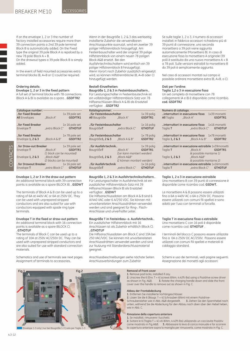
CO
NTA
CTS
ACCESSORIESBREAKER ME10
Se sulle taglie 1, 2 o 3, il numero di accessori installati in fabbrica accessori richiedono più di 39 punti di connessione, una seconda morsettiera a 39 poli viene aggiunta automaticamente (Morsettiera B). In caso di esecuzione fissa la morsettiera A originale (39 poli) è sostituita da una nuova morsettiera A + B a 78 poli. Sulle versioni estraibili la morsettiera B da 39 poli è semplicemente aggiunta. Nel caso di accessori montati sul campo è possibile ordinare morsettiere extra (B, A+B, o C).
Dati per l'ordine: Taglia 1,2 o 3 in esecuzione fissa Un set completo di morsettiere con 78 collegamenti (A e B) è disponibile come ricambio. cod. GSDFTR2
Taglia 1, 2 o 3 in esecuzione estraibile Una morsettiera B con 39 punti di connessione è disponibile come ricambio cod. GSDWT.
Le morsettiere A & B possono essere utilizzati fino a 6A a 440V AC o 6A a 250V DC. Possono essere utilizzati con comuni fili spellati e sono adatti per l'uso con terminali a forcella.
Taglia T in esecuzione fissa o estraibile Una morsettiera C con 16 poli è disponibile come ricambio cod. GTHDTUF .
I terminali del blocco C possono essere utilizzate fino a 0A a 250V DC AC/250V. Possono essere utilizzati con comuni fili spellati e materiali di cablaggio standard.
Schemi e uso dei terminali, vedi pagine seguenti. Assegnazione dei morsetti agli accessori:
4.3-12
Fig.1 Fig.2
C
B
ARemoval of Front cover1. Remove pad locks, installed if any.2. Unscrew the 6 [Env. T = 4] screws (6Nm, 4.42ft-lbs) using a Pozidrive screw driver as shown in Fig. A&B. 3. Rotate the charging handle down and slide the front cover over the handle to remove out as shown in Fig. C.
Abbau der Frontabdeckung1. Entfernen Sie installierte Vorhängeschlösser.2. Lösen Sie die 6 [Baugr. T = 4] Schrauben (6Nm) mit einem Pozidrive-Schraubenzieher wie in Abb. A&B dargestellt . 3. Ziehen Sie den Spannhebel nach unten, während Sie die Abdeckung für den Abbau nach oben über den Hebel heben, wie in Abb. C.
Rimozione della copertura anteriore1. Se installati, rimuovere I lucchetti.2. Svitare le 6 [Taglia T = 4] viti (6Nm, 4.42ft-lbs) utilizzando un cacciavite Pozidriv come mostrato in Fig.A&B. 3. Abbassare la leva di carica manuale e far scorrere la copertura anteriore sopra la maniglia per rimuoverla, come mostrato in Fig. C.Envelope 1-3 only | nur bei Baugröße 1-3 | solo per Taglia 1-3
If on the envelope 1, 2 or 3 the number of factory installed accessories require more than 39 connection points a 2nd 39 pole terminal Block B is automatically added. On the Fixed type the original 39 pole Block A is repalced by a new 78 pole Block A + B. On the drawout types a 39 pole Block B is simply added.
In the event of field mounted accessories extra terminal blocks (B, A+B or C) could be required.
Ordering details:Envelope 1, 2 or 3 in the fixed patternA full set of terminal blocks with 78 connections (Block A & B) is available as a spare. ..GSDFTR2
Envelope 1, 2 or 3 in the draw-out patternAn additional terminal block with 39 connection points is available as a spare (BLOCK B). ..GSDWT
The terminals of Block A & B can be used up to a rating of 6A at 440V AC or 6A at 250V DC. They can be used with unprepared stripped conductors and are also suited for use with conductors equipped with spade ring type terminals.
Envelope T in the fixed or draw-out patternAn additional terminal block with 16 connection points is available as a spare (BLOCK C). ..GTHDTUF The terminals of Block C can be used up to a rating of 10A at 250V AC/250V DC. They can be used with unprepared stripped conductors and are also suited for use with standard connection materials.
Schematics and use of terminals see next pages.Assignment of terminals to accessories..
Wenn in der Baugröße 1, 2 & 3 das werkseitig installierte Zubehör die verwendbaren Anschlusspunkte ausnutzt, wird ein zweiter 39 poliger Hilfstrennblock hinzugefügt. Am Festeinbauschalter wird der original 39 polige Hilfstrennblock von einem neuen 78 poligen Block A&B ersetzt. Bei den Ausfahrtechnikschaltern wird einfach ein 39 poliger Hilfstrennblock B hinzugefügt.Wenn Vorort noch Zubehör zusätzlich eingesetzt wird, so können Hilfstrennblöcke (B, A+B oder C) hinzugefügt werden.
Bestell-Einzelheiten:Baugröße 1, 2 & 3 in Festeinbauschaltern..Für Leistungsschalter in Festeinbautechnik ist ein vollständiger Hilfstrennblock-Satz von 78 Hilfsanschlüssen (Block A & B) als Ersatzteil verfügbar. ..GSDFTR2
Baugröße 1, 2 & 3 in Ausfahrtechnikschaltern..Für Leistungsschalter in Ausfahrtechnik ist ein zusätzlicher Hilfstrennblock-Satz mit 39 Hilfsanschlüssen (Block B) als Ersatzteil verfügbar. ..GSDWTDie Hilfsanschlussdaten am Block A & B sind 6 A/440 VAC oder 6 A/250 VDC. Sie können mit unvorbereiteten Anschlussdrähten verwendet werden und sind geeignet für Ring-, Flach-Anschlüsse und unverhüllte Leiter.
Baugröße T in Festeinbau- o. Ausfahrtechnik..Ein zusätzlicher Hilfstrennblock mit 16 Anschlüssen ist als Zubehör erhältlich (Block C). ..GTHDTUFDie Hilfsanschlussdaten am Block C sind 10A bei 250 VAC/VDC. Sie können mit unvorbereiteten Anschlussdrähten verwendet werden und sind zur Nutzung mit Standardanschlussmaterial geeignet.
Anschlussbeschreibungen siehe nächste Seiten.Anschlussverbindungen zum Zubehör
Catalogue number: -----------------------------------..for Fixed Breaker 1x 39 pole setAll Envelopes „Block A“ GSDFTR1
..for Fixed Breaker 1x 16 pole setEnvelope T „extra Block C“ GTHDTUF
..for Fixed Breaker 1x 78 pole setEnvelope 1, 2 & 3 „Block A & B“ GSDFTR2------------------------------------------------------------..for Draw-out Breaker 1x 39 pole setEnvelope T „Block A“ GSDFTR1 (1 block can be mounted)Envelope 1, 2 & 3 „Block A&B“ (2 blocks can be mounted)..for Drawout Breaker 1x 16 pole setEnvelope T „extra Block C“ GTHDTUF
Katalognummer: --------------------------------------..für Festeinbauschalter 1x 39 poligAll Baugröße „Block A“ GSDFTR1
..für Festeinbauschalter 1x 16 poligBaugrößeT „extra Block C“ GTHDTUF
..für Festeinbauschalter 1x 78 poligBaugröße1, 2 & 3 „Block A & B“ GSDFTR2------------------------------------------------------------..für Ausfahrtechnik.. 1x 39 poligBaugrößeT „Block A“ GSDFTR1 (1er kann montiert werden)Baugröße1, 2 & 3 „Block A&B“ (2 können montiert werden)..für Ausfahrtechnik 1x 16 poligBaugrößeT „extra Block C“ GTHDTUF
Numero di catalogo: ---------------------------------..interruttori in esecuzione fissa 1x39 morsettiAll Taglia „Block A“ GSDFTR1
..interruttori in esecuzione fissa 1x16 morsettiTaglia T „extra Block C“ GTHDTUF
..interruttori in esecuzione fissa 1x78 morsettiTaglia 1, 2 & 3 „Block A & B“ GSDFTR2------------------------------------------------------------..interruttori in esecuzione estraibile 1x39morsettiTaglia T „Block A“ GSDFTR1 (è possibile montarne 1)Taglia 1, 2 & 3 „Block A&B“ (è possibile montarne 2)..interruttori in esecuzione estraibile 1x16morsettiTaglia T „extra Block C“ GTHDTUF
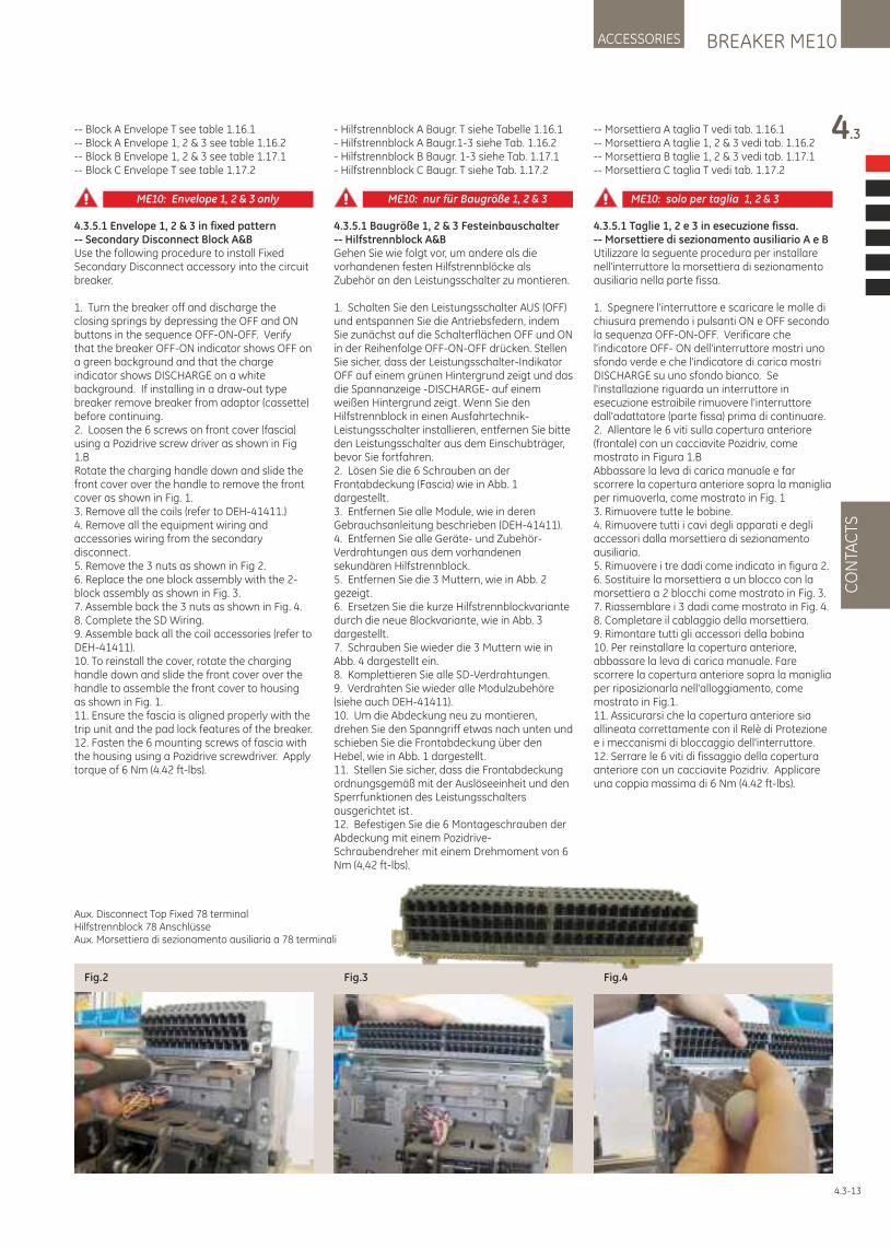
- Hilfstrennblock A Baugr. T siehe Tabelle 1.16.1- Hilfstrennblock A Baugr.1-3 siehe Tab. 1.16.2- Hilfstrennblock B Baugr. 1-3 siehe Tab. 1.17.1- Hilfstrennblock C Baugr. T siehe Tab. 1.17.2
4.3.5.1 Baugröße 1, 2 & 3 Festeinbauschalter-- Hilfstrennblock A&BGehen Sie wie folgt vor, um andere als die vorhandenen festen Hilfstrennblöcke als Zubehör an den Leistungsschalter zu montieren.
1. Schalten Sie den Leistungsschalter AUS (OFF) und entspannen Sie die Antriebsfedern, indem Sie zunächst auf die Schalterflächen OFF und ON in der Reihenfolge OFF-ON-OFF drücken. Stellen Sie sicher, dass der Leistungsschalter-Indikator OFF auf einem grünen Hintergrund zeigt und das die Spannanzeige -DISCHARGE- auf einem weißen Hintergrund zeigt. Wenn Sie den Hilfstrennblock in einen Ausfahrtechnik-Leistungsschalter installieren, entfernen Sie bitte den Leistungsschalter aus dem Einschubträger, bevor Sie fortfahren.2. Lösen Sie die 6 Schrauben an der Frontabdeckung (Fascia) wie in Abb. 1 dargestellt .3. Entfernen Sie alle Module, wie in deren Gebrauchsanleitung beschrieben (DEH-41411).4. Entfernen Sie alle Geräte- und Zubehör-Verdrahtungen aus dem vorhandenen sekundären Hilfstrennblock.5. Entfernen Sie die 3 Muttern, wie in Abb. 2 gezeigt.6. Ersetzen Sie die kurze Hilfstrennblockvariante durch die neue Blockvariante, wie in Abb. 3 dargestellt .7. Schrauben Sie wieder die 3 Muttern wie in Abb. 4 dargestellt ein.8. Komplettieren Sie alle SD-Verdrahtungen.9. Verdrahten Sie wieder alle Modulzubehöre (siehe auch DEH-41411).10. Um die Abdeckung neu zu montieren, drehen Sie den Spanngriff etwas nach unten und schieben Sie die Frontabdeckung über den Hebel, wie in Abb. 1 dargestellt .11. Stellen Sie sicher, dass die Frontabdeckung ordnungsgemäß mit der Auslöseeinheit und den Sperrfunktionen des Leistungsschalters ausgerichtet ist.12. Befestigen Sie die 6 Montageschrauben der Abdeckung mit einem Pozidrive-Schraubendreher mit einem Drehmoment von 6 Nm (4,42 ft-lbs).
-- Block A Envelope T see table 1.16.1-- Block A Envelope 1, 2 & 3 see table 1.16.2-- Block B Envelope 1, 2 & 3 see table 1.17.1-- Block C Envelope T see table 1.17.2
4.3.5.1 Envelope 1, 2 & 3 in fixed pattern-- Secondary Disconnect Block A&BUse the following procedure to install Fixed Secondary Disconnect accessory into the circuit breaker.
1. Turn the breaker off and discharge the closing springs by depressing the OFF and ON buttons in the sequence OFF-ON-OFF. Verify that the breaker OFF-ON indicator shows OFF on a green background and that the charge indicator shows DISCHARGE on a white background. If installing in a draw-out type breaker remove breaker from adaptor (cassette) before continuing.2. Loosen the 6 screws on front cover (fascia) using a Pozidrive screw driver as shown in Fig 1.BRotate the charging handle down and slide the front cover over the handle to remove the front cover as shown in Fig. 1.3. Remove all the coils (refer to DEH-41411.)4. Remove all the equipment wiring and accessories wiring from the secondary disconnect. 5. Remove the 3 nuts as shown in Fig 2.6. Replace the one block assembly with the 2-block assembly as shown in Fig. 3.7. Assemble back the 3 nuts as shown in Fig. 4.8. Complete the SD Wiring.9. Assemble back all the coil accessories (refer to DEH-41411).10. To reinstall the cover, rotate the charging handle down and slide the front cover over the handle to assemble the front cover to housing as shown in Fig. 1.11. Ensure the fascia is aligned properly with the trip unit and the pad lock features of the breaker.12. Fasten the 6 mounting screws of fascia with the housing using a Pozidrive screwdriver. Apply torque of 6 Nm (4.42 ft-lbs).
BREAKER ME10ACCESSORIES
4.3
CO
NTA
CTS
-- Morsettiera A taglia T vedi tab. 1.16.1-- Morsettiera A taglie 1, 2 & 3 vedi tab. 1.16.2-- Morsettiera B taglie 1, 2 & 3 vedi tab. 1.17.1-- Morsettiera C taglia T vedi tab. 1.17.2
4.3.5.1 Taglie 1, 2 e 3 in esecuzione fissa. -- Morsettiere di sezionamento ausiliario A e BUtilizzare la seguente procedura per installare nell'interruttore la morsettiera di sezionamento ausiliaria nella parte fissa.
1. Spegnere l'interruttore e scaricare le molle di chiusura premendo i pulsanti ON e OFF secondo la sequenza OFF-ON-OFF. Verificare che l'indicatore OFF- ON dell'interruttore mostri uno sfondo verde e che l'indicatore di carica mostri DISCHARGE su uno sfondo bianco. Se l'installazione riguarda un interruttore in esecuzione estraibile rimuovere l'interruttore dall'adattatore (parte fissa) prima di continuare.2. Allentare le 6 viti sulla copertura anteriore (frontale) con un cacciavite Pozidriv, come mostrato in Figura 1.BAbbassare la leva di carica manuale e far scorrere la copertura anteriore sopra la maniglia per rimuoverla, come mostrato in Fig. 13. Rimuovere tutte le bobine.4. Rimuovere tutti i cavi degli apparati e degli accessori dalla morsettiera di sezionamento ausiliaria. 5. Rimuovere i tre dadi come indicato in figura 2.6. Sostituire la morsettiera a un blocco con la morsettiera a 2 blocchi come mostrato in Fig. 3.7. Riassemblare i 3 dadi come mostrato in Fig. 4.8. Completare il cablaggio della morsettiera.9. Rimontare tutti gli accessori della bobina10. Per reinstallare la copertura anteriore, abbassare la leva di carica manuale. Fare scorrere la copertura anteriore sopra la maniglia per riposizionarla nell'alloggiamento, come mostrato in Fig.1.11. Assicurarsi che la copertura anteriore sia allineata correttamente con il Relè di Protezione e i meccanismi di bloccaggio dell'interruttore.12. Serrare le 6 viti di fissaggio della copertura anteriore con un cacciavite Pozidriv. Applicare una coppia massima di 6 Nm (4.42 ft-lbs).
Fig.2 Fig.3 Fig.4
4.3-13
Aux. Disconnect Top Fixed 78 terminalHilfstrennblock 78 AnschlüsseAux. Morsettiera di sezionamento ausiliaria a 78 terminali
ME10: Envelope 1, 2 & 3 only ME10: nur für Baugröße 1, 2 & 3 ME10: solo per taglia 1, 2 & 3
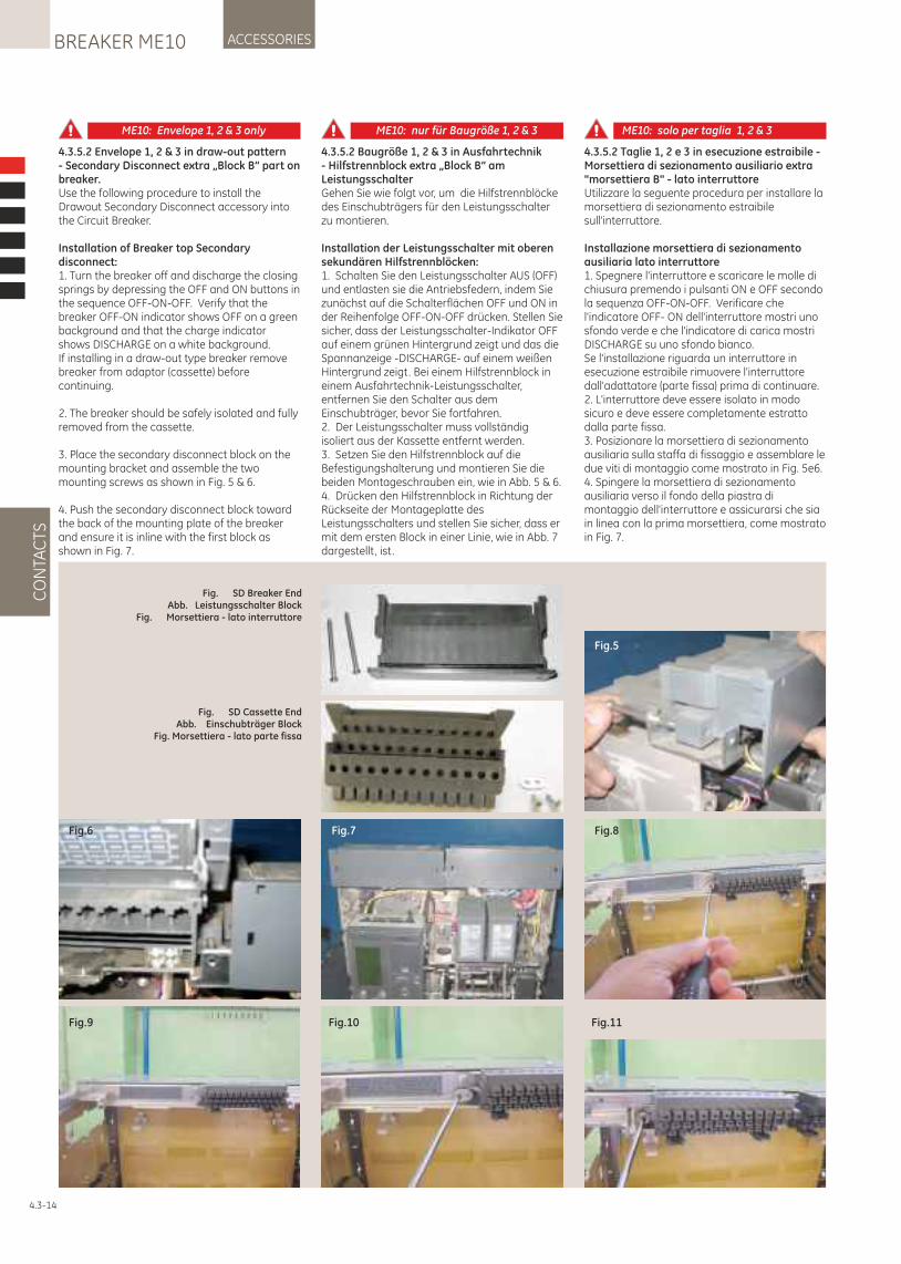
CO
NTA
CTS
ACCESSORIESBREAKER ME10
Fig. SD Breaker EndAbb. Leistungsschalter Block
Fig. Morsettiera - lato interruttore
Fig.6 Fig.7 Fig.8
Fig.9 Fig.10 Fig.11
Fig.5
Fig. SD Cassette EndAbb. Einschubträger Block
Fig. Morsettiera - lato parte fissa
4.3.5.2 Taglie 1, 2 e 3 in esecuzione estraibile - Morsettiera di sezionamento ausiliario extra "morsettiera B" - lato interruttoreUtilizzare la seguente procedura per installare la morsettiera di sezionamento estraibile sull'interruttore.
Installazione morsettiera di sezionamento ausiliaria lato interruttore1. Spegnere l'interruttore e scaricare le molle di chiusura premendo i pulsanti ON e OFF secondo la sequenza OFF-ON-OFF. Verificare che l'indicatore OFF- ON dell'interruttore mostri uno sfondo verde e che l'indicatore di carica mostri DISCHARGE su uno sfondo bianco.Se l'installazione riguarda un interruttore in esecuzione estraibile rimuovere l'interruttore dall'adattatore (parte fissa) prima di continuare.2. L'interruttore deve essere isolato in modo sicuro e deve essere completamente estratto dalla parte fissa.3. Posizionare la morsettiera di sezionamento ausiliaria sulla staffa di fissaggio e assemblare le due viti di montaggio come mostrato in Fig. 5e 6.4. Spingere la morsettiera di sezionamento ausiliaria verso il fondo della piastra di montaggio dell'interruttore e assicurarsi che sia in linea con la prima morsettiera, come mostrato in Fig. 7.
4.3-14
ME10: Envelope 1, 2 & 3 only ME10: nur für Baugröße 1, 2 & 3 ME10: solo per taglia 1, 2 & 3
4.3.5.2 Envelope 1, 2 & 3 in draw-out pattern- Secondary Disconnect extra „Block B“ part on breaker.Use the following procedure to install the Drawout Secondary Disconnect accessory into the Circuit Breaker.
Installation of Breaker top Secondary disconnect:1. Turn the breaker off and discharge the closing springs by depressing the OFF and ON buttons in the sequence OFF-ON-OFF. Verify that the breaker OFF-ON indicator shows OFF on a green background and that the charge indicator shows DISCHARGE on a white background.If installing in a draw-out type breaker remove breaker from adaptor (cassette) before continuing.
2. The breaker should be safely isolated and fully removed from the cassette.
3. Place the secondary disconnect block on the mounting bracket and assemble the two mounting screws as shown in Fig. 5 & 6.
4. Push the secondary disconnect block toward the back of the mounting plate of the breaker and ensure it is inline with the first block as shown in Fig. 7.
4.3.5.2 Baugröße 1, 2 & 3 in Ausfahrtechnik- Hilfstrennblock extra „Block B“ am LeistungsschalterGehen Sie wie folgt vor, um die Hilfstrennblöcke des Einschubträgers für den Leistungsschalter zu montieren.
Installation der Leistungsschalter mit oberen sekundären Hilfstrennblöcken:1. Schalten Sie den Leistungsschalter AUS (OFF) und entlasten sie die Antriebsfedern, indem Sie zunächst auf die Schalterflächen OFF und ON in der Reihenfolge OFF-ON-OFF drücken. Stellen Sie sicher, dass der Leistungsschalter-Indikator OFF auf einem grünen Hintergrund zeigt und das die Spannanzeige -DISCHARGE- auf einem weißen Hintergrund zeigt. Bei einem Hilfstrennblock in einem Ausfahrtechnik-Leistungsschalter, entfernen Sie den Schalter aus dem Einschubträger, bevor Sie fortfahren.2. Der Leistungsschalter muss vollständig isoliert aus der Kassette entfernt werden.3. Setzen Sie den Hilfstrennblock auf die Befestigungshalterung und montieren Sie die beiden Montageschrauben ein, wie in Abb. 5 & 6.4. Drücken den Hilfstrennblock in Richtung der Rückseite der Montageplatte des Leistungsschalters und stellen Sie sicher, dass er mit dem ersten Block in einer Linie, wie in Abb. 7 dargestellt , ist.
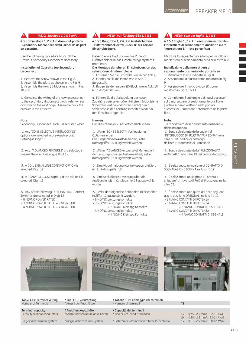
BREAKER ME10ACCESSORIES
CO
NTA
CTS
Table 1.19: Terminal Wiring / Tab. 1.19: Verdrahtung / Tabella 1.19: Cablaggio dei terminali Number of Terminals / Anzahl der Anschlüsse / Numero di terminali 78
Terminal capacity / Anschlusskapazitäten / Capacità dei terminali Screw type (bare conductors) / Schraubanschluss (blanke Leiter) / Tipo di vite (conduttori nudi) 1x 0,35 - 2,5 mm²; 22-12 AWG 2x 0.35 - 2.5 mm²; 22-14 AWGRing/spade terminal system / Ring/Flachanschluss-System / Sistema di terminazione a forcella/occhiello 1x 0,5 - 2,5 mm²; 20-12 AWG
4.3.5.3 Taglie 1, 2 e 3 in esecuzione estraibile - Morsettiera di sezionamento ausiliario extra "morsettiera B" - lato parte fissa
Utilizzare la seguente procedura per installare la morsettiera di sezionamento ausiliaria estraibile.
Installazione della morsettiera di sezionamento ausiliaria lato parte fissa1. Rimuovere la vite indicata in Fig. 8.2. Assemblare la piastra come mostrato in Fig. 9.3. Assemblare il nuovo blocco SD come mostrato in Fig. 10 & 11.
4. Completare il cablaggio dei nuovi accessori sulla morsettiera di sezionamento ausiliaria (vedere schema elettrico nella pagina successiva). Rimontare l'interruttore nella parte fissa.
Nota: La morsettiera di sezionamento ausiliaria è richiesta quando: 1. Sono selezionate della opzioni di "INTERBLOCCO DI SELETTIVITÀ A ZONA" nella cifra 18 del codice di catalogo dell'interruttore/Relè di Protezione.
2. Sono selezionate della "FUNZIONALITÀ AVANZATE" nella cifra 19 del codice di catalogo.
3. È selezionata un'opzione di CONTATTO DI SEGNALAZIONE BOBINA nella cifra 12.
4. È selezionato un segnale di "pronto a chiudere" attraverso il Relè di Protezione nella cifra 13.
5. È selezionata uno qualsiasi delle seguenti uscite ausiliarie OPZIONALI nella cifra 12. - 8 NA/NC CONTATTI DI POTENZA - 3 NA/NC CONTATTI DI POTENZA + 2 NA/NC CONTATTI DI SEGNALE - 4 NA/NC CONTATTI DI POTENZA + 4 NA/NC CONTATTI DI SEGNALE
4.3-15
4.3.5.3 Envelope 1, 2 & 3 in draw-out pattern- Secondary Disconnect extra „Block B“ as part on cassette.
Use the following procedure to install the Drawout Secondary Disconnect accessory.
Installation of Cassette top Secondary disconnect:
1. Remove the screw shown in the Fig. 8.2. Assemble the plate as shown in the Fig. 9.3. Assemble the new SD block as shown in Fig. 10 & 11.
4. Complete the wiring of the new accessories to the secondary disconnect block (refer wiring diagram on the next page). Assemble back the breaker in the cassette.
Note: Secondary Disconnect Block B is required when:
1. Any "ZONE SELECTIVE INTERLOCKING" options are selected in breaker/trip unit Catalogue Digit 18
2. Any "ADVANCED FEATURES" are selected in breaker/trip unit Catalogue Digit 19.
3. A COIL SIGNALLING CONTACT OPTION is selected, Digit 12
4. A READY TO CLOSE signal via the trip unit is selected, Digit 13
5. Any of the following OPTIONAL Aux. Contact Switches are selected in Digit 12 - 8 NO/NC POWER RATED - 3 NO/NC POWER RATED + 2 NO/NC HIFI - 4 NO/NC POWER RATED + 4 NO/NC HIFI
4.3.5.3 Baugröße 1, 2 & 3 in Ausfahrtechnik - Hilfstrennblock extra „Block B“ als Teil des Einschubträgers.
Gehen Sie wie folgt vor, um das Zubehör Hilfstrennblock in das Einschubträgersystem zu montieren.Die Montage der oberen Einschubversion des sekundären Hilfstrennblocks:1. Entfernen Sie die Schraube, wie in der Abb. 8.2. Montieren Sie die Platte, wie in Abb. 9 dargestellt .3. Bauen Sie den neuen SD-Block, wie in Abb. 10 & 11 dargestellt , an.
4. Führen Sie die Verkabelung der neuen Zubehöre zum sekundären Hilfstrennblock (siehe Schaltplan auf den nächsten Seiten) durch. Schieben Sie den Leistungsschalter wieder in den Einschubträger ein.
Hinweis:Der Hilfstrennblock B ist erforderlich, wenn:
1. Wenn "ZONE SELECTIV Verriegelungs-" Optionen in der Leistungsschalter/Auslöseeinheit, siehe Katalogziffer 18, ausgewählt wurden.
2. Wenn "ADVANCED (erweiterte) Merkmale“in der Leistungsschalter/Auslöseeinheit, siehe Katalogziffer 19, ausgewählt wurden.
3. Eine Modulmeldung-Kontaktoption aktiviert ist, lt . Katalogziffer 12
4. Eine Schließbereit-Meldung über die Auslöseeinheit lt . Katalogziffer 13 ausgewählt wurde.
5. Jeder der folgenden optionalen Hilfsschalter in Ziffer 12 ausgewählt wurden. - 8 NO/NC Leistungskontakte - 3 NO/NC Leistungskontakte + 2 NO/NC Kleinspg.Kontakte - 4 NO/NC Leistungskontakte + 4 NO/NC Kleinspg.Kontakte
ME10: Envelope 1, 2 & 3 only ME10: nur für Baugröße 1, 2 & 3 ME10: solo per taglia 1, 2 & 3
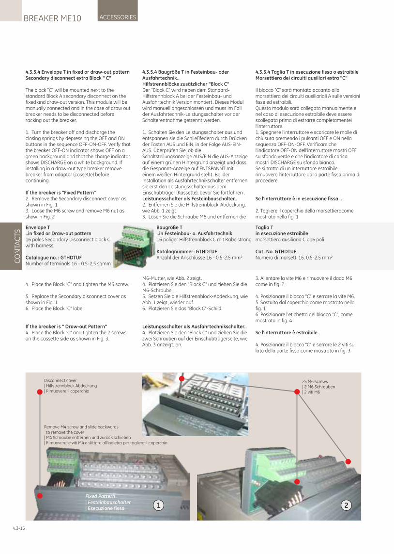
4.3.5.4 Taglia T in esecuzione fissa o estraibileMorsettiera dei circuiti ausiliari extra "C"
Il blocco "C" sarà montato accanto alla morsettiera dei circuiti ausiliariali A sulle versioni fisse ed estraibili. Questo modulo sarà collegato manualmente e nel caso di esecuzione estraibile deve essere scollegata prima di estrarre completamentei l'interruttore. 1. Spegnere l'interruttore e scaricare le molle di chiusura premendo i pulsanti OFF e ON nella sequenza OFF-ON-OFF. Verificare che l'indicatore OFF-ON dell'interruttore mostri OFF su sfondo verde e che l'indicatore di carica mostri DISCHARGE su sfondo bianco. Se si tratta di un interruttore estraibile, rimuovere l'interruttore dalla parte fissa prima di procedere.
Se l'interruttore è in esecuzione fissa ..
2. Togliere il coperchio della morsettieracome mostrato nella fig. 1
3. Allentare la vite M6 e rimuovere il dado M6 come in fig. 2
4. Posizionare il blocco "C" e serrare la vite M6. 5. Sostuito dal coperchio come mostrato nella fig. 1 6. Posizionare l'etichetta del blocco "C", come mostrato in fig. 4
Se l'interruttore è estraibile..
4. Posizionare il blocco "C" e serrare le 2 viti sul lato della parte fissa come mostrato in fig. 3
4.3.5.4 Envelope T in fixed or draw-out patternSecondary disconnect extra Block " C"
The block "C" will be mounted next to the standard Block A secondary disconnect on the fixed and draw-out version. This module will be manually connected and in the case of draw out breaker needs to be disconnected before racking out the breaker.
1. Turn the breaker off and discharge the closing springs by depressing the OFF and ON buttons in the sequence OFF-ON-OFF. Verify that the breaker OFF-ON indicator shows OFF on a green background and that the charge indicator shows DISCHARGE on a white background. If installing in a draw-out type breaker remove breaker from adaptor (cassette) before continuing.
If the breaker is "Fixed Pattern"2. Remove the Secondary disconnect cover as shown in Fig. 13. Loose the M6 screw and remove M6 nut as show in Fig. 2
4. Place the Block "C" and tighten the M6 screw.
5. Replace the Secondary disconnect cover as shown in Fig. 16. Place the Block "C" label.
If the breaker is " Draw-out Pattern"4. Place the Block "C" and tighten the 2 screws on the cassette side as shown in Fig. 3.
4.3.5.4 Baugröße T in Festeinbau- oder Ausfahrtechnik..Hilfstrennblöcke zusätzlicher "Block C"Der "Block C" wird neben dem Standard-Hilfstrennblock A bei der Festeinbau- und Ausfahrtechnik Version montiert. Dieses Modul wird manuell angeschlossen und muss im Fall der Ausfahrtechnik-Leistungsschalter vor der Schalterentnahme getrennt werden.
1. Schalten Sie den Leistungsschalter aus und entspannen sie die Schließfedern durch Drücken der Tasten AUS und EIN, in der Folge AUS-EIN-AUS. Überprüfen Sie, ob die Schaltstellungsanzeige AUS/EIN die AUS-Anzeige auf einem grünen Hintergrund anzeigt und dass die Gespannt-Anzeige auf ENTSPANNT mit einem weißen Hintergrund steht. Bei der Installation als Ausfahrtechnikschalter entfernen sie erst den Leistungsschalter aus dem Einschubträger (Kassette), bevor Sie fortfahren .Leistungsschalter als Festeinbauschalter.. 2. Entfernen Sie die Hilfstrennblock-Abdeckung, wie Abb. 1 zeigt.3. Lösen Sie die Schraube M6 und entfernen die
M6-Mutter, wie Abb. 2 zeigt.4. Platzieren Sie den "Block C" und ziehen Sie die M6-Schraube.5. Setzen Sie die Hilfstrennblock-Abdeckung, wie Abb. 1 zeigt, wieder auf.6. Platzieren Sie das "Block C"-Schild.
Leistungsschalter als Ausfahrtechnikschalter..4. Platzieren Sie den "Block C" und ziehen Sie die zwei Schrauben auf der Einschubträgerseite, wie Abb. 3 anzeigt, an.
Envelope T ..in fixed or Draw-out pattern16 poles Secondary Disconnect block C with harness.
Catalogue no. : GTHDTUFNumber of terminals 16 - 0.5-2.5 sqmm
Baugröße T ..in Festeinbau- o. Ausfahrtechnik16 poliger Hilfstrennblock C mit Kabelstrang.
Katalognummer: GTHDTUFAnzahl der Anschlüsse 16 - 0.5-2.5 mm²
Disconnect cover| Hilfstrennblock Abdeckung| Rimuovere il coperchio
1
Remove M4 screw and slide backwards to remove the cover| M4 Schraube entfernen und zurück schieben| Rimuovere le viti M4 e slittare all'indietro per togliere il coperchio
2
2x M6 screws| 2 M6 Schrauben| 2 viti M6
Fixed Pattern| Festeinbauschalter| Esecuzione fissa
4.3-16
CO
NTA
CTS
ACCESSORIESBREAKER ME10
Taglia Tin esecuzione estraibile morsettiera ausiliaria C a16 poli
Cat. No. GTHDTUFNumero di morsetti:16. 0.5-2.5 mm²
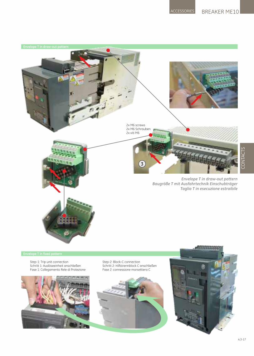
4.3-17
BREAKER ME10ACCESSORIES
CO
NTA
CTS
3
Envelope T in draw-out pattern
Envelope T in draw-out patternBaugröße T mit Ausfahrtechnik Einschubträger
Taglia T in esecuzione estraibile
2x M6 screws2x M6 Schrauben2x viti M6
Envelope T in fixed pattern
Step-1: Trip unit connectionSchritt 1: Auslöseeinheit anschließenFase 1: Collegamento Rele di Protezione
Step-2: Block-C connectionSchritt 2: Hilfstrennblock C anschließenFase 2: connessione morsettiera C
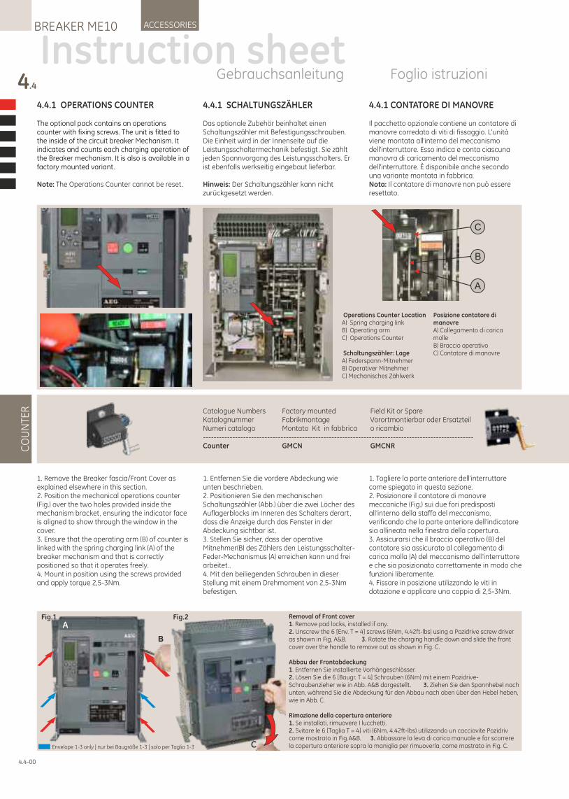
4.4.1 SCHALTUNGSZÄHLER
Das optionale Zubehör beinhaltet einen Schaltungszähler mit Befestigungsschrauben. Die Einheit wird in der Innenseite auf die Leistungsschaltermechanik befestigt. Sie zählt jeden Spannvorgang des Leistungsschalters. Er ist ebenfalls werkseitig eingebaut lieferbar.
Hinweis: Der Schaltungszähler kann nicht zurückgesetzt werden.
1. Entfernen Sie die vordere Abdeckung wie unten beschrieben.2. Positionieren Sie den mechanischen Schaltungszähler (Abb.) über die zwei Löcher des Auflagerblocks im Inneren des Schalters derart, dass die Anzeige durch das Fenster in der Abdeckung sichtbar ist.3. Stellen Sie sicher, dass der operative Mitnehmer(B) des Zählers den Leistungsschalter-Feder-Mechanismus (A) erreichen kann und frei arbeitet..4. Mit den beiliegenden Schrauben in dieser Stellung mit einem Drehmoment von 2,5-3Nm befestigen.
4.4.1 OPERATIONS COUNTER
The optional pack contains an operations counter with fixing screws. The unit is fitted to the inside of the circuit breaker Mechanism. It indicates and counts each charging operation of the Breaker mechanism. It is also is available in a factory mounted variant.
Note: The Operations Counter cannot be reset.
1. Remove the Breaker fascia/Front Cover as explained elsewhere in this section.2. Position the mechanical operations counter (Fig.) over the two holes provided inside the mechanism bracket, ensuring the indicator face is aligned to show through the window in the cover.3. Ensure that the operating arm (B) of counter is linked with the spring charging link (A) of the breaker mechanism and that is correctly positioned so that it operates freely.4. Mount in position using the screws provided and apply torque 2,5-3Nm.
4.4.1 CONTATORE DI MANOVRE
Il pacchetto opzionale contiene un contatore di manovre corredato di viti di fissaggio. L'unità viene montata all'interno del meccanismo dell'interruttore. Esso indica e conta ciascuna manovra di caricamento del meccanismo dell'interruttore. È disponibile anche secondo una variante montata in fabbrica.Nota: Il contatore di manovre non può essere resettato.
1. Togliere la parte anteriore dell'interruttore come spiegato in questa sezione.2. Posizionare il contatore di manovre meccaniche (Fig.) sui due fori predisposti all'interno della staffa del meccanismo, verificando che la parte anteriore dell'indicatore sia allineata nella finestra della copertura.3. Assicurarsi che il braccio operativo (B) del contatore sia assicurato al collegamento di carica molla (A) del meccanismo dell'interruttore e che sia posizionato correttamente in modo che funzioni liberamente.4. Fissare in posizione utilizzando le viti in dotazione e applicare una coppia di 2,5-3Nm.
4.4
CO
UN
TER
ACCESSORIESBREAKER ME10
Operations Counter LocationA) Spring charging linkB) Operating armC) Operations Counter
Schaltungszähler: LageA) Federspann-MitnehmerB) Operativer MitnehmerC) Mechanisches Zählwerk
Posizione contatore di manovreA) Collegamento di carica molleB) Braccio operativoC) Contatore di manovre
A
B
C
4.4-00
Catalogue Numbers Factory mounted Field Kit or SpareKatalognummer Fabrikmontage Vorortmontierbar oder ErsatzteilNumeri catalogo Montato Kit in fabbrica o ricambio-----------------------------------------------------------------------------------------------------Counter GMCN GMCNR
Instruction sheetGebrauchsanleitung Foglio istruzioni
Fig.1 Fig.2
C
B
ARemoval of Front cover1. Remove pad locks, installed if any.2. Unscrew the 6 [Env. T = 4] screws (6Nm, 4.42ft-lbs) using a Pozidrive screw driver as shown in Fig. A&B. 3. Rotate the charging handle down and slide the front cover over the handle to remove out as shown in Fig. C.
Abbau der Frontabdeckung1. Entfernen Sie installierte Vorhängeschlösser.2. Lösen Sie die 6 [Baugr. T = 4] Schrauben (6Nm) mit einem Pozidrive-Schraubenzieher wie in Abb. A&B dargestellt . 3. Ziehen Sie den Spannhebel nach unten, während Sie die Abdeckung für den Abbau nach oben über den Hebel heben, wie in Abb. C.
Rimozione della copertura anteriore1. Se installati, rimuovere I lucchetti.2. Svitare le 6 [Taglia T = 4] viti (6Nm, 4.42ft-lbs) utilizzando un cacciavite Pozidriv come mostrato in Fig.A&B. 3. Abbassare la leva di carica manuale e far scorrere la copertura anteriore sopra la maniglia per rimuoverla, come mostrato in Fig. C.Envelope 1-3 only | nur bei Baugröße 1-3 | solo per Taglia 1-3
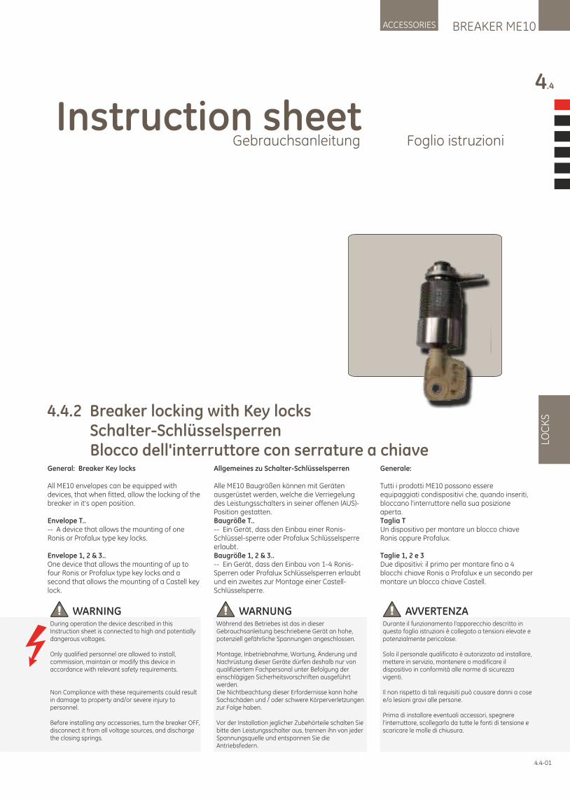
Instruction sheetGebrauchsanleitung Foglio istruzioni
BREAKER ME10ACCESSORIES
4.4
LOC
KS
4.4-01
4.4.2 Breaker locking with Key locks Schalter-Schlüsselsperren Blocco dell'interruttore con serrature a chiave
WARNUNGWährend des Betriebes ist das in dieser Gebrauchsanleitung beschriebene Gerät an hohe, potenziell gefährliche Spannungen angeschlossen.
Montage, Inbetriebnahme, Wartung, Änderung und Nachrüstung dieser Geräte dürfen deshalb nur von qualifiziertem Fachpersonal unter Befolgung der einschlägigen Sicherheitsvorschriften ausgeführt werden.Die Nichtbeachtung dieser Erfordernisse kann hohe Sachschäden und / oder schwere Körperverletzungen zur Folge haben.
Vor der Installation jeglicher Zubehörteile schalten Sie bitte den Leistungsschalter aus, trennen ihn von jeder Spannungsquelle und entspannen Sie die Antriebsfedern.
AVVERTENZADurante il funzionamento l'apparecchio descritto in questo foglio istruzioni è collegato a tensioni elevate e potenzialmente pericolose.
Solo il personale qualificato è autorizzato ad installare, mettere in servizio, mantenere o modificare il dispositivo in conformità alle norme di sicurezza vigenti.
Il non rispetto di tali requisiti può causare danni a cose e/o lesioni gravi alle persone.
Prima di installare eventuali accessori, spegnere l'interruttore, scollegarlo da tutte le fonti di tensione e scaricare le molle di chiusura.
WARNINGDuring operation the device described in this Instruction sheet is connected to high and potentially dangerous voltages.
Only qualified personnel are allowed to install, commission, maintain or modify this device in accordance with relevant safety requirements.
Non Compliance with these requirements could result in damage to property and/or severe injury to personnel.
Before installing any accessories, turn the breaker OFF, disconnect it from all voltage sources, and discharge the closing springs.
General: Breaker Key locks
All ME10 envelopes can be equipped with devices, that when fitted, allow the locking of the breaker in it's open position.
Envelope T..-- A device that allows the mounting of one Ronis or Profalux type key locks.
Envelope 1, 2 & 3..One device that allows the mounting of up to four Ronis or Profalux type key locks and a second that allows the mounting of a Castell key lock.
Allgemeines zu Schalter-Schlüsselsperren
Alle ME10 Baugrößen können mit Geräten ausgerüstet werden, welche die Verriegelung des Leistungsschalters in seiner offenen (AUS)-Position gestatten.Baugröße T..-- Ein Gerät, dass den Einbau einer Ronis-Schlüssel-sperre oder Profalux Schlüsselsperre erlaubt.Baugröße 1, 2 & 3..-- Ein Gerät, dass den Einbau von 1-4 Ronis-Sperren oder Profalux Schlüsselsperren erlaubt und ein zweites zur Montage einer Castell-Schlüsselsperre.
Generale:
Tutti i prodotti ME10 possono essere equipaggiati condispositivi che, quando inseriti, bloccano l'interruttore nella sua posizione aperta.Taglia TUn dispositivo per montare un blocco chiave Ronis oppure Profalux.
Taglie 1, 2 e 3Due dipositivi: il primo per montare fino a 4 blocchi chiave Ronis o Profalux e un secondo per montare un blocco chiave Castell.
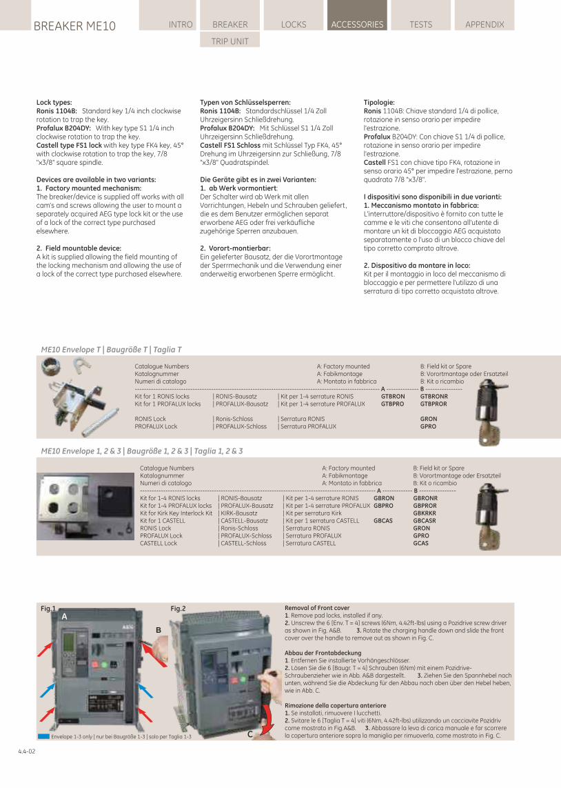
Catalogue Numbers A: Factory mounted B: Field kit or SpareKatalognummer A: Fabikmontage B: Vorortmantage oder ErsatzteilNumeri di catalogo A: Montato in fabbrica B: Kit o ricambio------------------------------------------------------------------------------------------------------ A ------------- B ----------------Kit for 1-4 RONIS locks | RONIS-Bausatz | Kit per 1-4 serrature RONIS GBRON GBRONRKit for 1-4 PROFALUX locks | PROFALUX-Bausatz | Kit per 1-4 serrature PROFALUX GBPRO GBPRORKit for Kirk Key Interlock Kit | KIRK-Bausatz | Kit per serratura Kirk GBKRKRKit for 1 CASTELL | CASTELL-Bausatz | Kit per 1 serratura CASTELL GBCAS GBCASRRONIS Lock | Ronis-Schloss | Serratura RONIS GRONPROFALUX Lock | PROFALUX-Schloss | Serratura PROFALUX GPROCASTELL Lock | CASTELL-Schloss | Serratura CASTELL GCAS
LOCKSBREAKER ME10 INTRO BREAKER ACCESSORIES TESTS APPENDIX
TRIP UNIT
4.4-02
Fig.1 Fig.2
C
B
ARemoval of Front cover1. Remove pad locks, installed if any.2. Unscrew the 6 [Env. T = 4] screws (6Nm, 4.42ft-lbs) using a Pozidrive screw driver as shown in Fig. A&B. 3. Rotate the charging handle down and slide the front cover over the handle to remove out as shown in Fig. C.
Abbau der Frontabdeckung1. Entfernen Sie installierte Vorhängeschlösser.2. Lösen Sie die 6 [Baugr. T = 4] Schrauben (6Nm) mit einem Pozidrive-Schraubenzieher wie in Abb. A&B dargestellt . 3. Ziehen Sie den Spannhebel nach unten, während Sie die Abdeckung für den Abbau nach oben über den Hebel heben, wie in Abb. C.
Rimozione della copertura anteriore1. Se installati, rimuovere I lucchetti.2. Svitare le 6 [Taglia T = 4] viti (6Nm, 4.42ft-lbs) utilizzando un cacciavite Pozidriv come mostrato in Fig.A&B. 3. Abbassare la leva di carica manuale e far scorrere la copertura anteriore sopra la maniglia per rimuoverla, come mostrato in Fig. C.Envelope 1-3 only | nur bei Baugröße 1-3 | solo per Taglia 1-3
Lock types:Ronis 1104B: Standard key 1/4 inch clockwise rotation to trap the key.Profalux B204DY: With key type S1 1/4 inch clockwise rotation to trap the key.Castell type FS1 lock with key type FK4 key, 45° with clockwise rotation to trap the key, 7/8 "x3/8" square spindle.
Devices are available in two variants:1. Factory mounted mechanism:The breaker/device is supplied off works with all cam's and screws allowing the user to mount a separately acquired AEG type lock kit or the use of a lock of the correct type purchased elsewhere.
2. Field mountable device:A kit is supplied allowing the field mounting of the locking mechanism and allowing the use of a lock of the correct type purchased elsewhere.
Typen von Schlüsselsperren:Ronis 1104B: Standardschlüssel 1/4 Zoll Uhrzeigersinn Schließdrehung.Profalux B204DY: Mit Schlüssel S1 1/4 Zoll Uhrzeigersinn Schließdrehung.Castell FS1 Schloss mit Schlüssel Typ FK4, 45° Drehung im Uhrzeigersinn zur Schließung, 7/8 "x3/8" Quadratspindel.
Die Geräte gibt es in zwei Varianten:1. ab Werk vormontiert:Der Schalter wird ab Werk mit allen Vorrichtungen, Hebeln und Schrauben geliefert, die es dem Benutzer ermöglichen separat erworbene AEG oder frei verkäufliche zugehörige Sperren anzubauen.
2. Vorort-montierbar:Ein gelieferter Bausatz, der die Vorortmontage der Sperrmechanik und die Verwendung einer anderweitig erworbenen Sperre ermöglicht.
ME10 Envelope 1, 2 & 3 | Baugröße 1, 2 & 3 | Taglia 1, 2 & 3
Catalogue Numbers A: Factory mounted B: Field kit or SpareKatalognummer A: Fabikmontage B: Vorortmantage oder ErsatzteilNumeri di catalogo A: Montato in fabbrica B: Kit o ricambio---------------------------------------------------------------------------------------------------------- A -------------- B ----------------Kit for 1 RONIS locks | RONIS-Bausatz | Kit per 1-4 serrature RONIS GTBRON GTBRONRKit for 1 PROFALUX locks | PROFALUX-Bausatz | Kit per 1-4 serrature PROFALUX GTBPRO GTBPROR
RONIS Lock | Ronis-Schloss | Serratura RONIS GRONPROFALUX Lock | PROFALUX-Schloss | Serratura PROFALUX GPRO
ME10 Envelope T | Baugröße T | Taglia T
Tipologie:Ronis 1104B: Chiave standard 1/4 di pollice, rotazione in senso orario per impedire l'estrazione.Profalux B204DY: Con chiave S1 1/4 di pollice, rotazione in senso orario per impedire l'estrazione.Castell FS1 con chiave tipo FK4, rotazione in senso orario 45° per impedire l'estrazione, perno quadrato 7/8 "x3/8".
I dispositivi sono disponibili in due varianti:1. Meccanismo montato in fabbrica:L'interruttore/dispositivo è fornito con tutte le camme e le viti che consentono all'utente di montare un kit di bloccaggio AEG acquistato separatamente o l'uso di un blocco chiave del tipo corretto comprato altrove.
2. Dispositivo da montare in loco:Kit per il montaggio in loco del meccanismo di bloccaggio e per permettere l'utilizzo di una serratura di tipo corretto acquistata altrove.
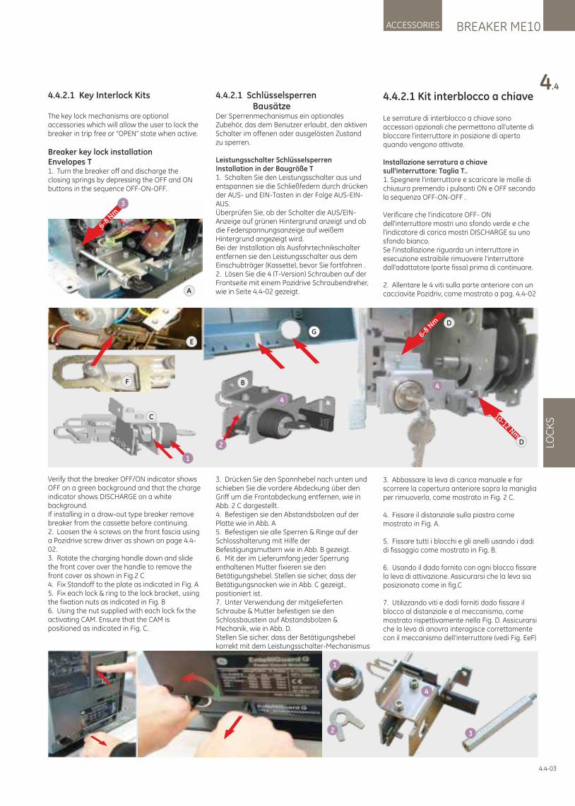
BREAKER ME10ACCESSORIES
4.4
LOC
KS
4.4-03
4.4.2.1 Kit interblocco a chiave
Le serrature di interblocco a chiave sono accessori opzionali che permettono all'utente di bloccare l'interruttore in posizione di aperto quando vengono attivate.
Installazione serratura a chiave sull'interruttore: Taglia T..1. Spegnere l'interruttore e scaricare le molle di chiusura premendo i pulsanti ON e OFF secondo la sequenza OFF-ON-OFF .
Verificare che l'indicatore OFF- ON dell'interruttore mostri uno sfondo verde e che l'indicatore di carica mostri DISCHARGE su uno sfondo bianco.Se l'installazione riguarda un interruttore in esecuzione estraibile rimuovere l'interruttore dall'adattatore (parte fissa) prima di continuare.
2. Allentare le 4 viti sulla parte anteriore con un cacciavite Pozidriv, come mostrato a pag. 4.4-02
3. Abbassare la leva di carica manuale e far scorrere la copertura anteriore sopra la maniglia per rimuoverla, come mostrato in Fig. 2 C.
4. Fissare il distanziale sulla piastra come mostrato in Fig. A.
5. Fissare tutti i blocchi e gli anelli usando i dadi di fissaggio come mostrato in Fig. B.
6. Usando il dado fornito con ogni blocco fissare la leva di attivazione. Assicurarsi che la leva sia posizionata come in fig.C
7. Utilizzando viti e dadi forniti dado fissare il blocco al distanziale e al meccanismo, come mostrato rispettivamente nella Fig. D. Assicurarsi che la leva di anovra interagisce correttamente con il meccanismo dell'interruttore (vedi Fig. EeF)
4.4.2.1 Key Interlock Kits
The key lock mechanisms are optional accessories which will allow the user to lock the breaker in trip free or "OPEN" state when active.
Breaker key lock installation Envelopes T1. Turn the breaker off and discharge the closing springs by depressing the OFF and ON buttons in the sequence OFF-ON-OFF.
Verify that the breaker OFF/ON indicator shows OFF on a green background and that the charge indicator shows DISCHARGE on a white background.If installing in a draw-out type breaker remove breaker from the cassette before continuing.2. Loosen the 4 screws on the front fascia using a Pozidrive screw driver as shown on page 4.4-02.3. Rotate the charging handle down and slide the front cover over the handle to remove the front cover as shown in Fig.2 C4. Fix Standoff to the plate as indicated in Fig. A5. Fix each lock & ring to the lock bracket, using the fixation nuts as indicated in Fig. B6. Using the nut supplied with each lock fix the activating CAM. Ensure that the CAM is positioned as indicated in Fig. C.
4.4.2.1 Schlüsselsperren BausätzeDer Sperrenmechanismus ein optionales Zubehör, das dem Benutzer erlaubt, den aktiven Schalter im offenen oder ausgelösten Zustand zu sperren.
Leistungsschalter Schlüsselsperren Installation in der Baugröße T1. Schalten Sie den Leistungsschalter aus und entspannen sie die Schließfedern durch drücken der AUS- und EIN-Tasten in der Folge AUS-EIN-AUS.Überprüfen Sie, ob der Schalter die AUS/EIN-Anzeige auf grünen Hintergrund anzeigt und ob die Federspannungsanzeige auf weißem Hintergrund angezeigt wird.Bei der Installation als Ausfahrtechnikschalter entfernen sie den Leistungsschalter aus dem Einschubträger (Kassette), bevor Sie fortfahren .2. Lösen Sie die 4 (T-Version) Schrauben auf der Frontseite mit einem Pozidrive Schraubendreher, wie in Seite 4.4-02 gezeigt.
3. Drücken Sie den Spannhebel nach unten und schieben Sie die vordere Abdeckung über den Griff um die Frontabdeckung entfernen, wie in Abb. 2 C dargestellt .4. Befestigen sie den Abstandsbolzen auf der Platte wie in Abb. A5. Befestigen sie alle Sperren & Ringe auf der Schlosshalterung mit Hilfe der Befestigungsmuttern wie in Abb. B gezeigt.6. Mit der im Lieferumfang jeder Sperrung enthaltenen Mutter fixieren sie den Betätigungshebel. Stellen sie sicher, dass der Betätigungsnocken wie in Abb. C gezeigt, positioniert ist.7. Unter Verwendung der mitgelieferten Schraube & Mutter befestigen sie den Schlossbaustein auf Abstandsbolzen & Mechanik, wie in Abb. D.Stellen Sie sicher, dass der Betätigungshebel korrekt mit dem Leistungsschalter-Mechanismus
A
6-8 N
m
3
1
10-12 Nm
6-8 N
m
4
4
2
B
E
D
D
F
C
G
1
2 3
4
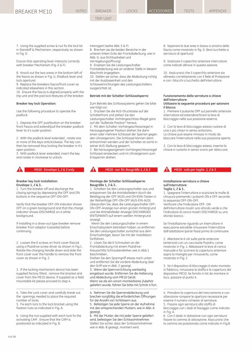
7. Using the supplied screw & nut fix the lock kit in Standoff & Mechanism, respectively as shown in Fig. D.
Ensure that operating lever interacts correctly with breaker Mechanism (Fig. E & F).
8. Knock out the two areas in the bottom left of the fascia as shown in Fig. G. (Padlock lever and lock aperture)9. Replace the breakers fascia/front cover as indicated elsewhere in this section.10. Ensure the fascia is aligned properly with the trip unit and the pad lock features of the breaker.
Breaker key lock Operation:
Use the following procedure to operate the padlock:
1. Depress the OFF pushbutton on the breaker front Fascia and extend/pull the breaker padlock lever to it's outer position.
2. With the padlock level extended , rotate one or more of the keys anticlockwise. The key can then be removed thus locking the breaker in it's open position.3. With padlock lever extended, insert the key and rotate in clockwise to unlock.
Breaker key lock installation:Envelope 1, 2 & 3..1. Turn the breaker off and discharge the closing springs by depressing the OFF and ON buttons in the sequence OFF-ON-OFF.
Verify that the breaker OFF-ON indicator shows OFF on a green background and that the charge indicator shows DISCHARGE on a white background.
If installing in a draw-out type breaker remove breaker from adaptor (cassette) before continuing.
2. Loosen the 6 screws on front cover (fascia) using a Pozidrive screw driver as shown in Fig.1.Rotate the charging handle down and slide the front cover over the handle to remove the front cover as shown in Fig. 2.
3. If the locking mechanism device has been supplied factory fitted , remove the bracket and cover from the ME10 device. If supplied as a field mountable kit please proceed to step 4.
---------------------------------------------------------4. Take the Lock cover and carefully break out the openings needed to place the required number of locks.5. Fix each lock to the lock bracket using the fixation nuts as indicated in Fig. A.
6. Using the nut supplied with each lock fix the activating CAM . Ensure that the CAM is positioned as indicated in Fig. B.
interagiert (siehe Abb. E & F).8. Brechen sie die beiden Bereiche in der unteren linken Ecke der Frontabdeckung, wie in Abb. G. aus (Schlosshebel und Verriegelungsöffnung)9. Ersetzen Sie die Leistungsschalter Frontabdeckung wie an anderer Stelle in diesem Abschnitt angegeben.10. Stellen sie sicher, dass die Abdeckung richtig mit der Auslöseeinheit und den Schlosseinrichtungen des Leistungsschalters ausgerichtet ist.
Betrieb mit der Schalter-Schlüsselsperre:
Zum Betrieb des Schlosssystems gehen Sie bitte wie folgt vor:1. Drücken Sie die AUS-Drucktaste auf der Schalterfront und ziehen Sie den Leistungsschalter Vorhängeschloss-Riegel ganz auf die "äußerste Position" heraus.2. Mit dem Schalter-Vorhängeschlossriegel in herausgezogener Position drehen Sie dann einen oder mehrere Schlüssel der Sperren gegen den Uhrzeigersinn. Die Schlüssel können dann entnommen werden und der Schalter ist somit in seiner AUS-Stellung gesperrt.3. Bei herausgezogenem Vorhängeschlossriegel Schlüssel einstecken und im Uhrzeigersinn zum Entsperren drehen.
Montage der Schalter-Schlüsselsperre:Baugröße 1, 2 & 3..1. Schalten Sie den Leistungsschalter aus und entspannen Sie die Antriebsfedern durch die Betätigung der OFF (AUS) und ON (EIN)-Tasten in der Reihenfolge OFF-ON-OFF (AUS-EIN-AUS). Überprüfen Sie, dass die Leistungsschalter OFF-ON-OFF-Anzeige nun einen grünen Hintergrund und die Antriebsfeder-Anzeige DISCHARGED (ENTSPANNT) auf einem weißen Hintergrund anzeigt. Wenn Sie den Leistungsschalter in einem Einschubsystem betrieben haben, so entfernen Sie den Leistungsschalter zunächst aus dem Einschubträger, bevor Sie mit der Installation fortfahren.2. Lösen Sie die 6 Schrauben an der Frontabdeckung mit einem Pozidrive-Kreuzschlitz Schraubendreher, wie in Abb.1 beschrieben.Drehen Sie den Spanngriff etwas nach unten und entfernen Sie die vordere Abdeckung über den Griff wie in Abb. 2 gezeigt. 3. Wenn die Sperrvorrichtung werkseitig eingebaut wurde: Entfernen Sie die Halterung und Abdeckung vom ME10 Gerät.Wenn sie als ein vorort-montierbares Zubehör geliefert wurde, fahren Sie bitte mit Schritt 4 fort.---------------------------------------------------------4. Nehmen Sie die Sperrenabdeckung und brechen sorgfältig die erforderlichen Öffnungen für die Anzahl von Schlössern aus.5. Befestigen Sie jede Sperre an der Aufnahme mit den entsprechenden Muttern, wie in Abb. A gezeigt.6. Mit der Mutter, die mit jeder Sperre geliefert wird, befestigen Sie den Schlossmitnehmer. Stellen Sie sicher, dass der Schlossmitnehmer wie in Abb. B gezeigt, montiert wird.
ME10: Envelope 1, 2 & 3 only ME10: nur für Baugröße 1, 2 & 3 ME10: solo per taglia 1, 2 & 3
8. Separare le due aree in basso a sinistra della fascia come mostrato in fig. G. (leva lucchetto e serratura di apertura)
9. Sostituire il coperchio anteriore interruttore come indicati altrove in questa sezione.
10. Assicurarsi che il coperchio anteriore sia allineato correttamente con il Rele di Protezione e con i blocchi a lucchetto dell'interruttore.
Funzionamento della serratura a chiave dell'interruttore:Utilizzare la seguente procedura per azionare il blocco:1. Premere il pulsante OFF sul pannello anteriore interruttore ed estendere/tirare la leva di bloccaggio nella sua posizione esterna.
2. Con la leva di bloccaggio estesa ruotare di una o più chiavi in senso antiorario.La chiave può essere rimossa in modo da bloccare l'interruttore nella sua posizione aperta.
3. Con la leva di bloccaggio estesa, inserire la chiave e ruotarla in senso orario per sbloccare.
Installazione serratura a chiave sull'interruttore:Taglia 1, 2 & 3..1. Spegnere l'interruttore e scaricare le molle di chiusura premendo i pulsanti ON e OFF secondo la sequenza OFF-ON-OFF.Verificare che l'indicatore OFF- ON dell'interruttore mostri uno sfondo verde e che l'indicatore di carica mostri DISCHARGE su uno sfondo bianco.
Se l'installazione riguarda un interruttore in esecuzione estraibile rimuovere l'interruttore dall'adattatore (parte fissa) prima di continuare.
2. Allentare le 6 viti sulla parte anteriore (anteriore) con un cacciavite Pozidriv, come mostrato in Fig. 1. Abbassare la leva di carica manuale e far scorrere la copertura anteriore sopra la maniglia per rimuoverla, come mostrato in Fig. 2
3. Se il dispositivo di bloccaggio è stato montato in fabbrica, rimuovere la staffa e la copertura dal dispositivo ME10. Se fornito in kit da montare in loco, passare al punto 4.
---------------------------------------------------------4. Prendere la copertura del meccanismo e con attenzione rompere le aperture necessarie per inserire il numero richiesto di serrature.5. Fissare ogni serratura alla staffa di bloccaggio con i dadi di fissaggio come indicato in Fig. A.6. Con il dado in dotazione con ogni serratura fissare la camma di attivazione. Assicurarsi che la camma sia posizionata come indicato in Fig.B.
LOCKSBREAKER ME10 INTRO BREAKER ACCESSORIES TESTS APPENDIX
TRIP UNIT
4.4-04
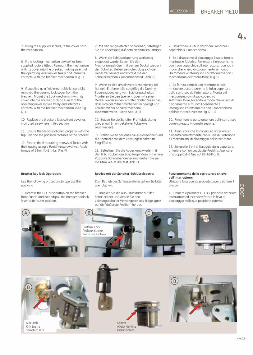
CA
B
SpacerAbstandshülseDistanziatore
B
Profalux LockProfalux SperreSerratura Profalux
Kirk LockKirk SperreSerratura Kirk
B
7. Using the supplied screws, fit the cover onto the mechanism.
8. If the locking mechanism device has been supplied factory fitted . Remount the mechanism with its cover into the breaker, making sure that the operating lever moves freely and interacts correctly with the breaker mechanism. (Fig. D)
9. If supplied as a field mountable kit carefully removed the dummy lock cover from the breaker . Mount the Lock mechanism with its cover into the breaker, making sure that the operating lever moves freely and interacts correctly with the breaker mechanism. (See Fig. D+E)
10. Replace the breakers fascia/front cover as indicated elsewhere in this section.
11. Ensure the fascia is aligned properly with the trip unit and the pad lock features of the breaker.
12. Fasten the 6 mounting screws of fascia with the housing using a Pozidrive screwdriver. Apply torque of 6 Nm (4.42ft-lbs) (Fig. F).
Breaker key lock Operation:
Use the following procedure to operate the padlock:
1. Depress the OFF pushbutton on the breaker front Fascia and extend/pull the breaker padlock lever to its' outer position.
7. Mit den mitgelieferten Schrauben, befestigen Sie die Abdeckung auf dem Mechanismusträger.
8. Wenn die Schlüsselsperrung werkseitig eingebaut wurde: Setzen Sie den Mechanismusträger mit seinem Deckel wieder in den Schalter. Stellen Sie sicher, dass sich die Hebel frei bewegt und korrekt mit der Schaltermechanik zusammenwirkt. (Abb. D)
9. Wenn es sich um ein vorort-montiertes Teil handelt: Entfernen Sie sorgfältig die Dummy-Sperrenabdeckung vom Leistungsschalter. Montieren Sie den Sperrenträger mit seinem Deckel wieder in den Schalter. Stellen Sie sicher, dass sich der Mitnehmerhebel frei bewegt und korrekt mit der Schaltermechanik zusammenwirkt. (Siehe Abb. D+E)
10. Setzen Sie die Schalter-Frontabdeckung wieder auf. (in umgekehrter Folge wie beschrieben).
11 Stellen Sie sicher, dass die Auslöseeinheit und die Sperrteile mit dem Leistungsschalter im Eingriff sind.
12. Befestigen Sie die Abdeckung wieder mit den 6 Schrauben am Schaltergehäuse mit einem Pozidrive Schraubendreher und drehen Sie sie mit 6Nm (4.42ft-lbs) fest (Abb. F).
Betrieb mit der Schalter-Schlüsselsperre:
Zum Betrieb des Schlosssystems gehen Sie bitte wie folgt vor:
1. Drücken Sie die AUS-Drucktaste auf der Schalterfront und ziehen Sie den Leistungsschalter Vorhängeschloss-Riegel ganz auf die "äußerste Position" heraus.
7. Utilizzando le viti in dotazione, montare il coperchio sul meccanismo.
8. Se il dispositivo di bloccaggio è stato fornito montato in fabbrica. Rimontare il meccanismo con il suo coperchio sull'interruttore, facendo in modo che la leva di azionamento si muova liberamente e interagisca correttamente con il meccanismo dell'interruttore. (Fig. D)
9. Se fornito come kit da montare in loco rimuovere accuratamente la falsa copertura della serratura dall'interruttore. Montare il meccanismo con il suo coperchio sull'interruttore, facendo in modo che la leva di azionamento si muova liberamente e interagisca correttamente con il meccanismo dell'interruttore. (Vedere Fig. D + E)
10. Rimontare la parte anteriore dell'interruttore come spiegato in questa sezione.
11. Assicurarsi che la copertura anteriore sia allineata correttamente con il Relè di Protezione e i meccanismi di bloccaggio dell'interruttore.
12. Serrare le 6 viti di fissaggio della copertura anteriore con un cacciavite Pozidriv. Applicare una coppia di 6 Nm (4.42ft-lb) (Fig. F).
Funzionamento della serratura a chiave dell'interruttore:Utilizzare la seguente procedura per azionare il blocco:
1. Premere il pulsante OFF sul pannello anteriore interruttore ed estendere/tirare la leva di bloccaggio nella sua posizione esterna.
BREAKER ME10ACCESSORIES
4.4
LOC
KS
4.4-05
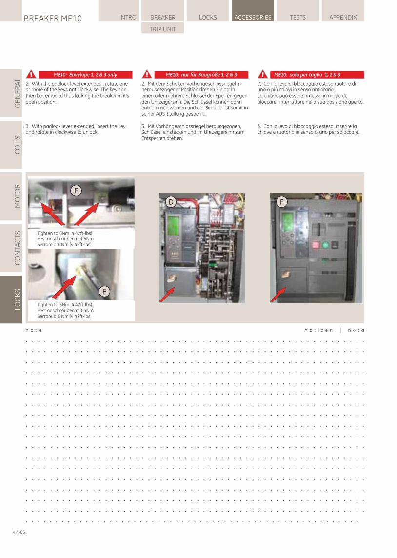
Tighten to 6Nm (4.42ft-lbs)Fest anschrauben mit 6NmSerrare a 6 Nm (4.42ft-lbs)
Tighten to 6Nm (4.42ft-lbs)Fest anschrauben mit 6NmSerrare a 6 Nm (4.42ft-lbs)
E
E
D F
LOCKSBREAKER ME10 INTRO BREAKER ACCESSORIES TESTS APPENDIX
TRIP UNIT
GE
NE
RA
LC
OIL
SM
OTO
RC
ON
TAC
TSLO
CK
S
ME10: Envelope 1, 2 & 3 only ME10: nur für Baugröße 1, 2 & 3 ME10: solo per taglia 1, 2 & 3
2. With the padlock level extended , rotate one or more of the keys anticlockwise. The key can then be removed thus locking the breaker in it's open position.
3. With padlock lever extended, insert the key and rotate in clockwise to unlock.
2. Mit dem Schalter-Vorhängeschlossriegel in herausgezogener Position drehen Sie dann einen oder mehrere Schlüssel der Sperren gegen den Uhrzeigersinn. Die Schlüssel können dann entnommen werden und der Schalter ist somit in seiner AUS-Stellung gesperrt.
3. Mit Vorhängeschlossriegel herausgezogen, Schlüssel einstecken und im Uhrzeigersinn zum Entsperren drehen.
2. Con la leva di bloccaggio estesa ruotare di una o più chiavi in senso antiorario.La chiave può essere rimossa in modo da bloccare l'interruttore nella sua posizione aperta.
3. Con la leva di bloccaggio estesa, inserire la chiave e ruotarla in senso orario per sbloccare.
n o t e n o t i z e n | n o t a
. . . . . . . . . . . . . . . . . . . . . . . . . . . . . . . . . . . . . . . . . . . . . . . . . . . . . . . .
. . . . . . . . . . . . . . . . . . . . . . . . . . . . . . . . . . . . . . . . . . . . . . . . . . . . . . . .
. . . . . . . . . . . . . . . . . . . . . . . . . . . . . . . . . . . . . . . . . . . . . . . . . . . . . . . .
. . . . . . . . . . . . . . . . . . . . . . . . . . . . . . . . . . . . . . . . . . . . . . . . . . . . . . . .
. . . . . . . . . . . . . . . . . . . . . . . . . . . . . . . . . . . . . . . . . . . . . . . . . . . . . . . .
. . . . . . . . . . . . . . . . . . . . . . . . . . . . . . . . . . . . . . . . . . . . . . . . . . . . . . . .
. . . . . . . . . . . . . . . . . . . . . . . . . . . . . . . . . . . . . . . . . . . . . . . . . . . . . . . .
. . . . . . . . . . . . . . . . . . . . . . . . . . . . . . . . . . . . . . . . . . . . . . . . . . . . . . . .
. . . . . . . . . . . . . . . . . . . . . . . . . . . . . . . . . . . . . . . . . . . . . . . . . . . . . . . .
. . . . . . . . . . . . . . . . . . . . . . . . . . . . . . . . . . . . . . . . . . . . . . . . . . . . . . . .
. . . . . . . . . . . . . . . . . . . . . . . . . . . . . . . . . . . . . . . . . . . . . . . . . . . . . . . .
. . . . . . . . . . . . . . . . . . . . . . . . . . . . . . . . . . . . . . . . . . . . . . . . . . . . . . . .
. . . . . . . . . . . . . . . . . . . . . . . . . . . . . . . . . . . . . . . . . . . . . . . . . . . . . . . .
. . . . . . . . . . . . . . . . . . . . . . . . . . . . . . . . . . . . . . . . . . . . . . . . . . . . . . . .
. . . . . . . . . . . . . . . . . . . . . . . . . . . . . . . . . . . . . . . . . . . . . . . . . . . . . . . .
. . . . . . . . . . . . . . . . . . . . . . . . . . . . . . . . . . . . . . . . . . . . . . . . . . . . . . . .
. . . . . . . . . . . . . . . . . . . . . . . . . . . . . . . . . . . . . . . . . . . . . . . . . . . . . . . .
. . . . . . . . . . . . . . . . . . . . . . . . . . . . . . . . . . . . . . . . . . . . . . . . . . . . . . . .4.4-06
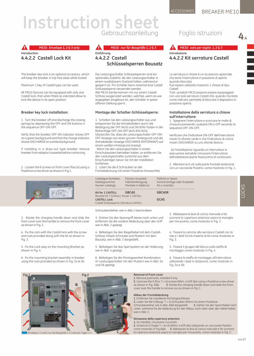
Introduction
4.4.2.2 Castell Lock Kit
The breaker key lock is an optional accessory, which will keep the breaker in trip free state while locked.
Maximum 1 key of Castell type can be used.
All ME10 Devices can be equipped with only one Castell lock, that when fitted as indicated allow to lock the device in its open position.
Einführung
4.4.2.2 Castell Schlüsselsperren Bausatz
Die Leistungsschalter Schlüsselsperren sind ein optionales Zubehör, die den Leistungsschalter in einem auslösbarem Zustand halten, während er gesperrt ist. Pro Schalter kann maximal eine Castell Schlüsselsperre verwendet werden. Alle ME10 Geräte können mit nur einem Castell Schloss ausgerüstet werden, welches, wenn es wie angegeben eingebaut ist, den Schalter in seiner offenen Stellung sperrt.
Introduzione
4.4.2.2 Kit serratura Castell
La serratura a chiave è un accessorio opzionale, che tiene l'interruttore in posizione di aperto quando bloccata.Può essere utilizzata massimo 1 chiave di tipo Castell.Tutti i prodotti ME10 possono essere equipaggiati con una sola serratura Castell che, quando montata come indicato, permette di bloccare il dispositivo in posizione aperta.
Breaker key lock installation:
1. Turn the breaker off and discharge the closing springs by depressing the OFF and ON buttons in the sequence OFF-ON-OFF.
Verify that the breaker OFF-ON indicator shows OFF on a green background and that the charge indicator shows DISCHARGE on a white background.
If installing in a draw-out type breaker remove breaker from adaptor (cassette) before continuing.
2. Loosen the 6 screws on front cover (fascia) using a Pozidrive screw driver as shown in Fig.1.
3. Rotate the charging handle down and slide the front cover over the handle to remove the front cover as shown in Fig. 2.
4. Fix the cam with the Castell lock with the screw and nuts provided along with the kit as shown in Fig. 3.
5. Fix the Lock assy on the mounting Bracket as shown in Fig. 4.
6. Fix the mounting bracket assembly in breaker using the nuts provided as shown in Fig. 5a & 5b.
Montage der Schalter-Schlüsselsperre:
1. Schalten Sie den Leistungsschalter aus und entspannen Sie die Antriebsfedern durch die Betätigung der OFF (AUS) und ON (EIN)-Tasten in der Reihenfolge OFF-ON-OFF (AUS-EIN-AUS). Überprüfen Sie, dass die Leistungsschalter OFF-ON-OFF-Anzeige nun einen grünen Hintergrund und die Antriebsfeder-Anzeige DISCHARGE (ENTSPANNT) auf einem weißen Hintergrund anzeigt. Wenn Sie den Leistungsschalter in einem Einschubsystem betrieben haben, so entfernen Sie den Leistungsschalter zunächst aus dem Einschubträger, bevor Sie mit der Installation fortfahren.2. Lösen Sie die 6 Schrauben an der Frontabdeckung mit einem Pozidrive-Kreuzschlitz
Schraubendreher, wie in Abb.1 beschrieben.
3. Drehen Sie den Spanngriff etwas nach unten und entfernen Sie die vordere Abdeckung über den Griff wie in Abb. 2 gezeigt.
4. Befestigen Sie den Riegelhebel mit dem Castell-Schloss mittels Schraube und Muttern mit dem Bausatz, wie in Abb. 3 dargestellt .
5. Befestigen Sie das Sperrsystem an der Halterung wie in Abb. 4 gezeigt.
6. Befestigen Sie die Montagewinkel-Kombination im Leistungsschalter mit den Muttern wie in Abb. 5a und 5b gezeigt.
Installazione della serratura a chiave sull'interruttore:1. Spegnere l'interruttore e scaricare le molle di chiusura premendo i pulsanti ON e OFF secondo la sequenza OFF-ON-OFF.
Verificare che l'indicatore ON-OFF dell'interruttore mostri lo sfondo verde e che l'indicatore di carica mostri DISCHARGE su uno sfondo bianco.
Se l'installazione riguarda un interruttore in esecuzione estraibile rimuovere l'interruttore dall'adattatore (parte fissa) prima di continuare.
2. Allentare le 6 viti sulla parte frontale (anteriore) con un cacciavite Pozidriv, come mostrato in Fig. 1.
3. Abbassare la leva di carica manuale e far scorrere la copertura anteriore sopra la maniglia per rimuoverla, come mostrato in Fig. 2.
4. Fissare la camma alla serratura Castell con la vite e i dadi forniti insieme al kit come mostrato in Fig. 3.
5. Fissare il gruppo del blocco sulla staffa di montaggio come mostrato in Fig. 4.
6. Fissare la staffa di montaggio all'interruttore utilizzando i dadi in dotazione, come mostrato in Fig. 5a e 5b.
Catalogue Numbers Factory mounted Field kit or SpareKatalognummer Fabrikanfertigung Vorortmontage oder ErsatzteilNumeri catalogo Montato in fabbrica Kit o ricambio-----------------------------------------------------------------------------------------------
Kit for 1 CASTELL GBCAS GBCASRBausatz für 1 Schloss | Kit per 1 CASTELL
CASTELL Lock GCASCastell Schlosssperre | Serratura CASTELL
BREAKER ME10ACCESSORIES
4.4
LOC
KS
Instruction sheetGebrauchsanleitung Foglio istruzioni
4.4-07
Fig.1 Fig.2
C
B
ARemoval of Front cover1. Remove pad locks, installed if any.2. Unscrew the 6 [Env. T = 4] screws (6Nm, 4.42ft-lbs) using a Pozidrive screw driver as shown in Fig. A&B. 3. Rotate the charging handle down and slide the front cover over the handle to remove out as shown in Fig. C.
Abbau der Frontabdeckung1. Entfernen Sie installierte Vorhängeschlösser.2. Lösen Sie die 6 [Baugr. T = 4] Schrauben (6Nm) mit einem Pozidrive-Schraubenzieher wie in Abb. A&B dargestellt . 3. Ziehen Sie den Spannhebel nach unten, während Sie die Abdeckung für den Abbau nach oben über den Hebel heben, wie in Abb. C.
Rimozione della copertura anteriore1. Se installati, rimuovere I lucchetti.2. Svitare le 6 [Taglia T = 4] viti (6Nm, 4.42ft-lbs) utilizzando un cacciavite Pozidriv come mostrato in Fig.A&B. 3. Abbassare la leva di carica manuale e far scorrere la copertura anteriore sopra la maniglia per rimuoverla, come mostrato in Fig. C.Envelope 1-3 only | nur bei Baugröße 1-3 | solo per Taglia 1-3
ME10: Envelope 1, 2 & 3 only ME10: nur für Baugröße 1, 2 & 3 ME10: solo per taglia 1, 2 & 3
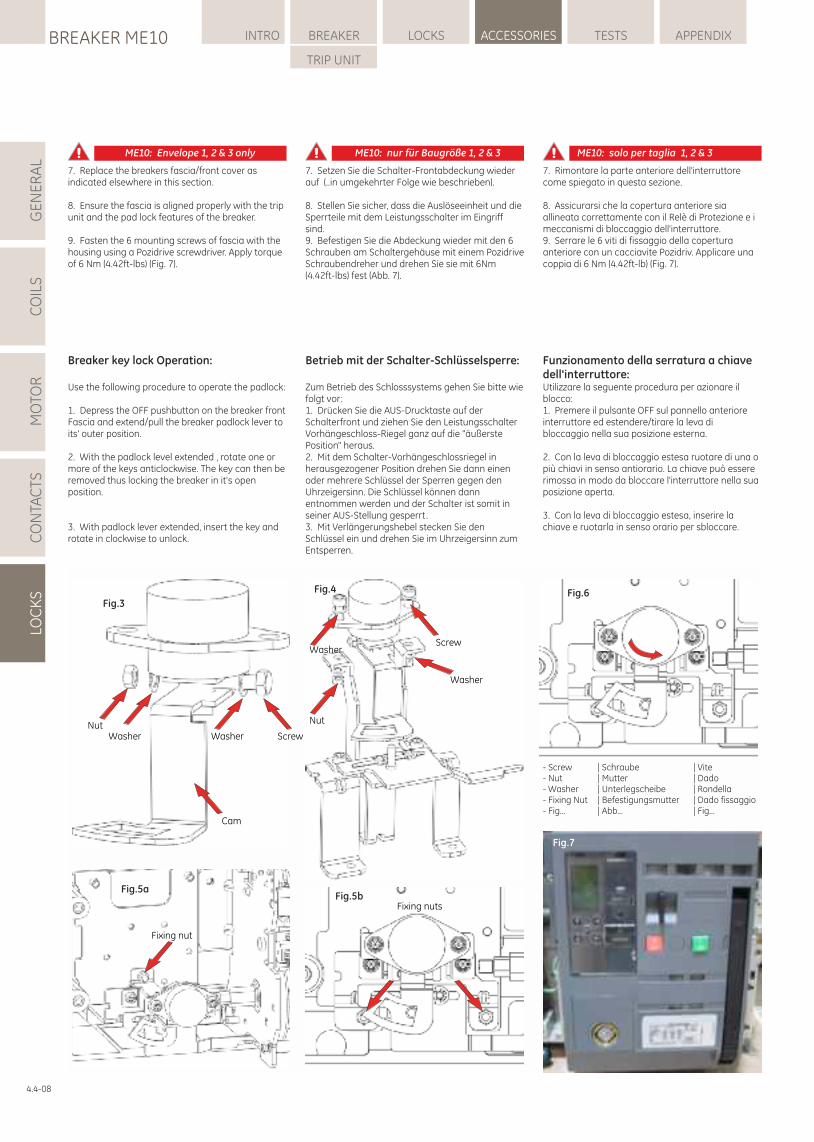
7. Setzen Sie die Schalter-Frontabdeckung wieder auf (..in umgekehrter Folge wie beschrieben).
8. Stellen Sie sicher, dass die Auslöseeinheit und die Sperrteile mit dem Leistungsschalter im Eingriff sind.9. Befestigen Sie die Abdeckung wieder mit den 6 Schrauben am Schaltergehäuse mit einem Pozidrive Schraubendreher und drehen Sie sie mit 6Nm (4.42ft-lbs) fest (Abb. 7).
7. Replace the breakers fascia/front cover as indicated elsewhere in this section.
8. Ensure the fascia is aligned properly with the trip unit and the pad lock features of the breaker.
9. Fasten the 6 mounting screws of fascia with the housing using a Pozidrive screwdriver. Apply torque of 6 Nm (4.42ft-lbs) (Fig. 7).
7. Rimontare la parte anteriore dell'interruttore come spiegato in questa sezione.
8. Assicurarsi che la copertura anteriore sia allineata correttamente con il Relè di Protezione e i meccanismi di bloccaggio dell'interruttore.9. Serrare le 6 viti di fissaggio della copertura anteriore con un cacciavite Pozidriv. Applicare una coppia di 6 Nm (4.42ft-lb) (Fig. 7).
Fig.7
Fig.6
WasherScrew
Nut
Washer
Fig.4
NutWasher Washer Screw
Cam
Fig.3
Fixing nutsFig.5b
Fixing nut
Fig.5a
- Screw | Schraube | Vite- Nut | Mutter | Dado- Washer | Unterlegscheibe | Rondella- Fixing Nut | Befestigungsmutter | Dado fissaggio - Fig... | Abb... | Fig...
Breaker key lock Operation:
Use the following procedure to operate the padlock:
1. Depress the OFF pushbutton on the breaker front Fascia and extend/pull the breaker padlock lever to its' outer position.
2. With the padlock level extended , rotate one or more of the keys anticlockwise. The key can then be removed thus locking the breaker in it's open position.
3. With padlock lever extended, insert the key and rotate in clockwise to unlock.
Betrieb mit der Schalter-Schlüsselsperre:
Zum Betrieb des Schlosssystems gehen Sie bitte wie folgt vor:1. Drücken Sie die AUS-Drucktaste auf der Schalterfront und ziehen Sie den Leistungsschalter Vorhängeschloss-Riegel ganz auf die "äußerste Position" heraus.2. Mit dem Schalter-Vorhängeschlossriegel in herausgezogener Position drehen Sie dann einen oder mehrere Schlüssel der Sperren gegen den Uhrzeigersinn. Die Schlüssel können dann entnommen werden und der Schalter ist somit in seiner AUS-Stellung gesperrt.3. Mit Verlängerungshebel stecken Sie den Schlüssel ein und drehen Sie im Uhrzeigersinn zum Entsperren.
Funzionamento della serratura a chiave dell'interruttore:Utilizzare la seguente procedura per azionare il blocco:1. Premere il pulsante OFF sul pannello anteriore interruttore ed estendere/tirare la leva di bloccaggio nella sua posizione esterna.
2. Con la leva di bloccaggio estesa ruotare di una o più chiavi in senso antiorario. La chiave può essere rimossa in modo da bloccare l'interruttore nella sua posizione aperta.
3. Con la leva di bloccaggio estesa, inserire la chiave e ruotarla in senso orario per sbloccare.
LOCKSBREAKER ME10 INTRO BREAKER ACCESSORIES TESTS APPENDIX
TRIP UNIT
GE
NE
RA
LC
OIL
SM
OTO
RC
ON
TAC
TSLO
CK
S
4.4-08
ME10: Envelope 1, 2 & 3 only ME10: nur für Baugröße 1, 2 & 3 ME10: solo per taglia 1, 2 & 3
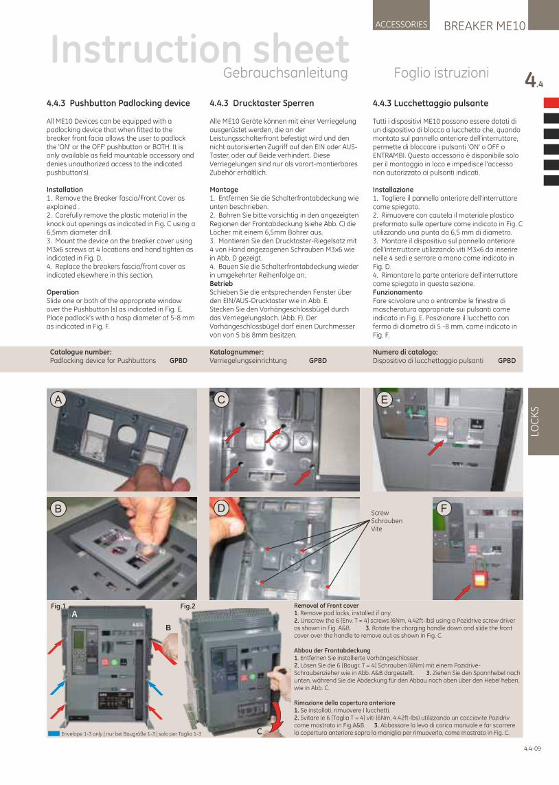
4.4.3 Pushbutton Padlocking device
All ME10 Devices can be equipped with a padlocking device that when fitted to the breaker front facia allows the user to padlock the 'ON' or the OFF' pushbutton or BOTH. It is only available as field mountable accessory and denies unauthorized access to the indicated pushbutton's).
Installation 1. Remove the Breaker fascia/Front Cover as explained .2. Carefully remove the plastic material in the knock out openings as indicated in Fig. C using a 6,5mm diameter drill.3. Mount the device on the breaker cover using M3x6 screws at 4 locations and hand tighten as indicated in Fig. D.4. Replace the breakers fascia/front cover as indicated elsewhere in this section.
OperationSlide one or both of the appropriate window over the Pushbutton (s) as indicated in Fig. E. Place padlock's with a hasp diameter of 5-8 mm as indicated in Fig. F.
Catalogue number: Padlocking device for Pushbuttons GPBD
4.4.3 Drucktaster Sperren
Alle ME10 Geräte können mit einer Verriegelung ausgerüstet werden, die an der Leistungsschalterfront befestigt wird und den nicht autorisierten Zugriff auf den EIN oder AUS-Taster, oder auf Beide verhindert. Diese Verriegelungen sind nur als vorort-montierbares Zubehör erhältlich.
Montage1. Entfernen Sie die Schalterfrontabdeckung wie unten beschrieben.2. Bohren Sie bitte vorsichtig in den angezeigten Regionen der Frontabdeckung (siehe Abb. C) die Löcher mit einem 6,5mm Bohrer aus.3. Montieren Sie den Drucktaster-Riegelsatz mit 4 von Hand angezogenen Schrauben M3x6 wie in Abb. D gezeigt.4. Bauen Sie die Schalterfrontabdeckung wieder in umgekehrter Reihenfolge an.BetriebSchieben Sie die entsprechenden Fenster über den EIN/AUS-Drucktaster wie in Abb. E.Stecken Sie den Vorhängeschlossbügel durch das Verriegelungsloch. (Abb. F). Der Vorhängeschlossbügel darf einen Durchmesser von von 5 bis 8mm besitzen.
Katalognummer:Verriegelungseinrichtung GPBD
4.4.3 Lucchettaggio pulsante
Tutti i dispositivi ME10 possono essere dotati di un dispositivo di blocco a lucchetto che, quando montato sul pannello anteriore dell'interruttore, permette di bloccare i pulsanti 'ON' o OFF o ENTRAMBI. Questo accessorio è disponibile solo per il montaggio in loco e impedisce l'accesso non autorizzato ai pulsanti indicati.
Installazione1. Togliere il pannello anteriore dell'interruttore come spiegato.2. Rimuovere con cautela il materiale plastico preformato sulle aperture come indicato in Fig. C utilizzando una punta da 6,5 mm di diametro.3. Montare il dispositivo sul pannello anteriore dell'interruttore utilizzando viti M3x6 da inserire nelle 4 sedi e serrare a mano come indicato in Fig. D.4. Rimontare la parte anteriore dell'interruttore come spiegato in questa sezione.FunzionamentoFare scivolare una o entrambe le finestre di mascheratura appropriate sui pulsanti come indicato in Fig. E. Posizionare il lucchetto con fermo di diametro di 5 -8 mm, come indicato in Fig. F.
Numero di catalogo:Dispositivo di lucchettaggio pulsanti GPBD
A
B D ScrewSchraubenVite
C E
F
4.4-09
Instruction sheetGebrauchsanleitung Foglio istruzioni
BREAKER ME10ACCESSORIES
4.4
LOC
KS
Fig.1 Fig.2
C
B
ARemoval of Front cover1. Remove pad locks, installed if any.2. Unscrew the 6 [Env. T = 4] screws (6Nm, 4.42ft-lbs) using a Pozidrive screw driver as shown in Fig. A&B. 3. Rotate the charging handle down and slide the front cover over the handle to remove out as shown in Fig. C.
Abbau der Frontabdeckung1. Entfernen Sie installierte Vorhängeschlösser.2. Lösen Sie die 6 [Baugr. T = 4] Schrauben (6Nm) mit einem Pozidrive-Schraubenzieher wie in Abb. A&B dargestellt . 3. Ziehen Sie den Spannhebel nach unten, während Sie die Abdeckung für den Abbau nach oben über den Hebel heben, wie in Abb. C.
Rimozione della copertura anteriore1. Se installati, rimuovere I lucchetti.2. Svitare le 6 [Taglia T = 4] viti (6Nm, 4.42ft-lbs) utilizzando un cacciavite Pozidriv come mostrato in Fig.A&B. 3. Abbassare la leva di carica manuale e far scorrere la copertura anteriore sopra la maniglia per rimuoverla, come mostrato in Fig. C.Envelope 1-3 only | nur bei Baugröße 1-3 | solo per Taglia 1-3
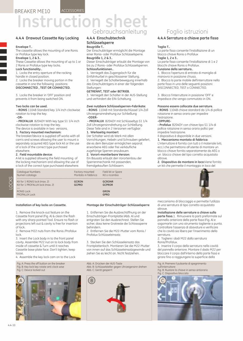
4.4.4 Einschubtechnik SchlüsselsperreBaugröße T..Der Einschubträger ermöglicht die Montage einer Ronis- oder Profalux Schlüsselsperre.Baugröße 1, 2 & 3..Dieser Einschubträger erlaubt die Montage von bis zu 2 Ronis- oder Profalux Schlüsselsperren.Schlossfunktionen..1. Verriegelt das Zugangsloch für die Einfahrkurbel in geschlossener Stellung.2. Verriegelt die Schalterbewegung innerhalb des Einschubträgers in einer der folgenden Stellungen:GETRENNT, TEST oder BETRIEB.3. Verriegelt den Schalter in der AUS-Stellung und verhindert die EIN-Schaltung.
Zwei nutzbare Schlüsselsperren-Fabrikate:- RONIS 1104B mit Standardschlüssel 1/4 Zoll Uhrzeigersinndrehung zur Schließung -ODER- - PROFALUX B204DY mit Schlüsseltyp S1 1/4 Zoll Uhrzeigersinndrehung zur Schließung.Diese Teile sind in 2 Versionen verfügbar:1. Werkseitig montiertDer Schalter wird ab Werk mit allen Vorrichtungen, Hebeln und Schrauben geliefert, die es dem Benutzer ermöglichen separat erworbene AEG oder frei verkäufliche zugehörige Sperren anzubauen.2. Vorort-montierbare Version:Ein Bausatz erlaubt den Vororteinbau der Sperrenmechanik mit passenden, fremdgekauften Schlössern.
Montage der Einschubträger-Schlüsselsperre
1. Entfernen Sie die Ausbrechöffnung an der Einschubträger-Frontplatte (Abb. A) und entgraten Sie den Ausbrechrest. Stellen Sie sicher, dass keine Gratreste die Schlosssperre behindern. 2. Entfernen Sie die M22-Mutter vom Ronis / Profalux Schlüsseleinsatz.
3. Stecken Sie den Schlüsseleinsatz das Frontplattenloch. Montieren Sie die M22-Mutter von innen auf das Schlüsseleinsatzgewinde und ziehen Sie es leicht an. Nicht festziehen.
4.4.4 Serratura a chiave parte fissa
Taglia T..La parte fissa consente l'installazione di un blocco chiave Ronis o ProfaluxTaglie 1, 2 e 3..La parte fissa consente l'installazione di 1 e 2 blocchi chiave Ronis o Profalux.Funzione della serratura..1. Blocca l'apertura di entrata di maniglia di manovra in posizione chiusa.2. Blocca la parte mobile dell'interruttore nella parte fissa in una delle seguenti posizioni:DISCONNECTED, TEST o CONNECTED.
3. Blocca l'interruttore in posizione 'OFF' e impedisce che venga commutato in ON.
Possono essere collocate due serrature.- RONIS 1104B chiave standard da 1/4 di pollice rotazione in senso orario per impedire l'estrazione. -OPPURE- - Profalux B204DY con chiave tipo S1 1/4 di pollice rotazione in senso orario pollici per impedire l'estrazione.Il dispositivo è disponibile in due versioni.1. Meccanismo montato di fabbrica:L'interruttore è fornito con tutt o il materiale (viti, ecc.) che permettono all'utente di montare un blocco chiave fornito separatamente da AEG o un blocco chiave del tipo corretto acquistato altrove.2. Dispositivo da montare in loco:Viene fornito un kit che permette il montaggio in loco del
meccanismo di bloccaggio e permette l'utilizzo di una serratura di tipo corretto acquistata altrove.Installazione delle serrature a chiave sulla parte fissa.1. Rimuovere la parti preformate sul pannello anteriore della parte fissa (Fig. A) e sagomarle con uno strumento tagliente a punta. Controllare l'assenza di sbavature e verificare che la cavità sia libera per l'inserimento della serratura.2. Togliere i dadi M22 dalla serratura Ronis/Profalux.3. Inserire il corpo della serratura nella cavità del pannello anteriore. Montare il dado M22 per bloccare il corpo dall'interno della parte fissa e girare fino a raggiungere la superficie della
4.4.4 Drawout Cassette Key Locking
Envelope T..The cassette allows the mounting of one Ronis or Profalux type key lock.Envelope 1, 2 & 3..These Cassette allows the mounting of up to 1 or 2 Ronis or Profalux type key locks.Lock functionality..1. Locks the entry aperture of the racking handle in closed position.2. Locks the breaker moving portion in the cassette in one the following positions:DISCONNECTED , TEST OR CONNECTED.
3. Locks the breaker in 'OFF' position and prevents it from being switched ON.
Two locks can be used. - RONIS 1104B Standard key 1/4 inch clockwise rotation to trap the key. -OR- - PROFALUX B204DY With key type S1 1/4 inch clockwise rotation to trap the key.The device is available in two versions.1. Factory mounted mechanism:The breaker/device is supplied off works with all cam's and screws allowing the user to mount a separately acquired AEG type lock kit or the use of a lock of the correct type purchased elsewhere.2. Field mountable device:A kit is supplied allowing the field mounting of the locking mechanism and allowing the use of a lock of the correct type purchased elsewhere.
Installation of key locks on Cassette.
1. Remove the knock-out feature on the Cassette front panel (Fig. A) & clean the flash with any sharp pointed Tool. Ensure no flash or projections left out & cavity is free for insertion of lock.2. Remove M22 nuts from the Ronis /Profalux lock.3. Insert the Lock body in to the front panel cavity. Assemble M22 nut on to lock body from inside of cassette & Turn until it reaches Cassette base plate face. Don't tighten, keep loose.4. Assemble the key lock cam on to the Lock
LOC
KS
ACCESSORIESBREAKER ME10
4.4-10
Catalogue Numbers Factory mounted Field kit or SpareNumeri catalogo Montato in fabbrica Kit o ricambio---------------------------------------------------------------------------------------------------------Kit for 1 RONIS lock (max. 2) GCRON GCRONRKit for 1 PROFALUX lock (max. 2) GCPRO GCPROR---RONIS Lock GRONPROFALUX Lock GPRO
BA C
Fig. A: Press the off button on the breakerFig. B: Key lock key rotate anti clock wiseFig. C: Device locked out
Abb. A: Drücken der AUS-TasteAbb. B: Schlüsselsteller gegen Uhrzeigersinn drehenAbb. C: Gerät gesperrt
Fig. A: Premere il pulsante di spegnimento sull'interruttoreFig. B: Ruotare la chiave in senso antiorarioFig. C: Dispositivo bloccato
Instruction sheetGebrauchsanleitung Foglio istruzioni
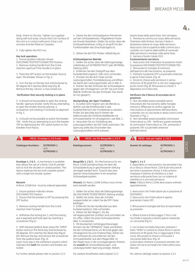
4.4-11
body. Orient on the slot. Tighten nut supplied along with lock body. Ensure that Cam Surface of the cam is in contact with pivot of key Lock actuator bracket fitted on Cassette.
5. Fully tighten the M22 nut.
Key lock operation.1. Ensure position indicator shows DISCONNECTED/TEST/CONNECTED Position.2. Remove racking handle from the Crank insertion aperture if the handle is in place.
3. Press the OFF button on the breaker facia & open the breaker. Shown in Fig. A.
4. Turn the key on the key lock anticlockwise by 90 degree till it reaches dead stop (Fig. B). Remove the key. Device is now locked out.
Verification that security locking is in place:
5. It should not be possible to open the racking handle aperture shutter. Verify this by attempting to open the shutter drive by placing a screwdriver and rotating it clockwise as depicted in Fig. C.
6. It should not be possible to switch the breaker 'ON'. Verify this by attempting to turn the breaker 'ON' by depressing the 'ON' switch button on the breakers front fascia.
4. Setzen Sie den Schlüsselsperre-Mitnehmer auf den Schlüsseleinsatz. Mitgelieferte Mutter am Einsatz festziehen. Stellen Sie sicher, dass der Schlüsselmitnehmer richtig im Eingriff mit den Funktionsteilen des Einschubträgers ist.
5. Ziehen Sie die M22-Mutter vollständig an.
Schlüsselsperren-Betrieb:1. Stellen Sie sicher, dass die Stellungsanzeige vollständig auf GETRENNT/TEST/ oder BETRIEBs-Stellung steht. 2. Entfernen Sie den Drehgriff aus dem Kurbeleinführungsloch, falls noch vorhanden.3. Drücken Sie die AUS-Taste auf der Leistungsschalter-Frontabdeckung und öffnen Sie damit den Leistungsschalter wie in Abb. A.4. Drehen Sie den Schlüssel der Schlüsselsperre gegen den Uhrzeigersinn um 90°, bis zum Ende (Abb.B). Entfernen Sie den Schlüssel. Das Gerät ist nun gesperrt.
Nachprüfung, der Sperr-Funktion:5. Es sollte nicht möglich sein die Blende zu drehen und die Einfahrkurbel in das Kurbeleinführloch der Frontblende zu stecken. Prüfen Sie dies bitte durch Drehen der Stellschraube der Einfahrkurbelblende mit Schraubendreher im Uhrzeigersinn, wie Abb. C.6. Versuchen Sie zur Schließung des Leistungsschalters die EIN-Taste zudrücken. Die Sperrung sollte das Einschalten des Leistungsschalters nicht zulassen.
piastra base della parte fissa. Non stringere.4. Montare la camma sul corpo della serratura. Orientare nella feritoia. Serrare il dado in dotazione insieme al corpo della serratura. Assicurarsi che la superficie della camma sia a contatto con il perno della staffa di comando della serratura e montato sulla parte fissa.5. Serrare a fondo il dado M22.Funzionamento serratura.1. Assicurarsi che l'indicatore di posizione mostri la posizione DISCONNECTED/TEST/CONNECTED.2. Rimuovere la maniglia di manovra dall'apertura del meccanismo, se presente3. Premere il pulsante OFF sul pannello anteriore e aprire l'interruttore. (Fig. A).4. Girare la chiave sulla serratura in senso antiorario di 90 gradi fino a che non raggiunge il punto morto (Fig. B). Rimuovere la chiave. Il dispositivo ora è bloccato.
Verificare che il blocco di sicurezza sia in posizione:5. Non dovrebbe essere possibile aprire l'otturatore del meccanismo della maniglia manovra. Effettuare la verifica agendo sul meccanismo di azionamento dell'otturatore, ruotando con un cacciavite in senso orario come illustrato in Fig. C.6. Non dovrebbe essere possibile commutare l'interruttore su 'ON'. Verificare questo tentando di commutare l'interruttore su 'ON', premendo il pulsante 'ON' sul pannello anteriore dell'interruttore.
BREAKER ME10ACCESSORIES
4.4
LOC
KS
Envelope 1, 2 & 3.. A mechanism is available that allows the use of a Ronis 1104 B cylinder lock to lock the shutters in closed position. This device replaces the two lock cassette system with a single lock shutter system.
Remark:A Ronis 1104B lock must be ordered separately.
1. Ensure position indicator shows DISCONNECTED Position.2. Ensure that the breaker is OFF by pressing the OFF button.
3. Remove racking handle from the Crank insertion hole if present.
4. Withdraw the locking bar C until the locking eye is exposed and hold open by inserting a screwdriver (Fig G.)
5. With blocked padlock lever, press the “OPEN” button and turn the Ronis key anticlockwise by 90 degrees, till it reaches the dead stop (figure 60). Remove the key and remove the screwdriver from the padlock lever. (Fig. H)Lever must stay in the withdrawn position which indicates that both the shutters and breaker are locked.
For further details please refer to section 3.2.2
Baugröße 1, 2 & 3.. Ein Mechanismus für ein Ronis 1104B Zylinderschloss mit dem die Schutzabdeckung in geschlossener Stellung verriegelt werden kann. Tauscht das zwei Sperren-Einschubsystem in ein einzelnes Schlüsselsperrsystem.
Hinweis: Ein Ronis 1104B Schloss muss immer extra bestellt werden.
1. Stellen Sie sicher, dass die Stellungsanzeige die DISCONNECTED|GETRENNT Stellung anzeigt.2. Stellen Sie sicher, dass der Schalter ausgeschaltet ist, indem Sie die OFF-Taste betätigen.3. Entfernen Sie die Handkurbel aus dem Kurbeleinsetzloch, falls vorhanden.4. Ziehen Sie den Riegel C, bis die Verriegelungslöcher sichtbar sind und halten sie ihn offen, indem Sie einen Schraubendreher (Abb. G.) einstecken.5. Mit blockiertem Vorhängeschlossriegel, drücken Sie die "OPEN|AUS"-Taste und drehen Sie den Schlüssel Ronis um 90 Grad gegen den Uhrzeigersinn bis zum Endanschlag. Ziehen Sie den Schlüssel ab und entfernen Sie den Schraubendreher aus dem Riegel (Abb. H).Der Riegel muss in der zurückgezogenen Position, die sowohl die Schutzabdeckungen- und Leistungsschalter-Sperrung anzeigt, bleiben.
Für weitere Einzelheiten siehe Kapitel 3.2.2
Taglie 1, 2 e 3E' disponibile un meccanismo che permette l'uso di un blocco chiave Ronis 1104 B per bloccare le serrante in posizione chiusa. Il meccanismo rimpiazza il sistema di interblocco a due serrature sulla parte fissa con un sistema di interblocco a una sola serratura.Nota: Il blocco Ronis 1104b deve essere ordinato separatamente.
1. Assicurarsi che l'interruttore sia in posizione di SEZIONATO. 2. Assicurarsi che l'interruttore è spento premendo il tasto OFF.
3. Rimuovere la maniglia dal foro di inserimento se presente.
4. Sfilare la barra di bloccaggio C fino a che l'occhiello è esposto e tenere aperto inserendo un cacciavite (Fig G.)
5. Con la leva lucchetto bloccato, premere il tasto "OPEN" e ruotare la chiave Ronis in senso antiorario di 90 gradi, fino a raggiungere il fine corsa. Rimuovere la chiave e rimuovere il cacciavite dalla leva. (Fig. H) La leva deve rimanere in posizione estratta che indica che sia le serrande che l'interruttore sono bloccati.
Per ulteriori dettagli vedere la sezione 3.2.2
Catalogue Numbers: GCPRONSV 1 and GCPRONSV 2
Katalognummer: GCPRONSV 1 und GCPRONSV 2
Numeri di catalogo: GCPRONSV 1 e GCPRONSV 2
ME10: Envelope 1, 2 & 3 only ME10: nur für Baugröße 1, 2 & 3 ME10: solo per taglia 1, 2 & 3
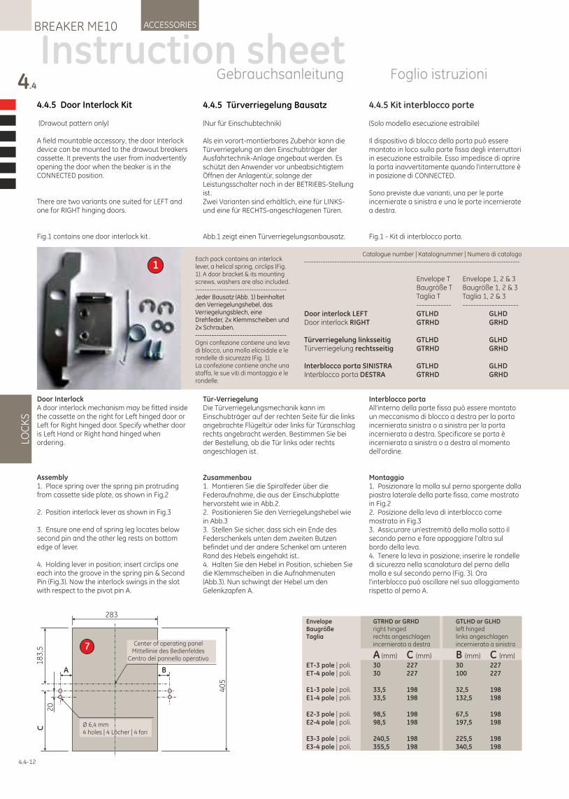
4.4.5 Door Interlock Kit
(Drawout pattern only)
A field mountable accessory, the door Interlock device can be mounted to the drawout breakers cassette. It prevents the user from inadvertently opening the door when the beaker is in the CONNECTED position.
There are two variants one suited for LEFT and one for RIGHT hinging doors.
Fig.1 contains one door interlock kit .
Door InterlockA door interlock mechanism may be fitted inside the cassette on the right for Left hinged door or Left for Right hinged door. Specify whether door is Left Hand or Right hand hinged when ordering.
Assembly 1. Place spring over the spring pin protruding from cassette side plate, as shown in Fig.2
2. Position interlock lever as shown in Fig.3
3. Ensure one end of spring leg locates below second pin and the other leg rests on bottom edge of lever.
4. Holding lever in position; insert circlips one each into the groove in the spring pin & Second Pin (Fig.3). Now the interlock swings in the slot with respect to the pivot pin A.
4.4.5 Türverriegelung Bausatz
(Nur für Einschubtechnik)
Als ein vorort-montierbares Zubehör kann die Türverriegelung an den Einschubträger der Ausfahrtechnik-Anlage angebaut werden. Es schützt den Anwender vor unbeabsichtigtem Öffnen der Anlagentür, solange der Leistungsschalter noch in der BETRIEBS-Stellung ist.Zwei Varianten sind erhältlich, eine für LINKS- und eine für RECHTS-angeschlagenen Türen.
Abb.1 zeigt einen Türverriegelungsanbausatz.
Tür-VerriegelungDie Türverriegelungsmechanik kann im Einschubträger auf der rechten Seite für die links angebrachte Flügeltür oder links für Türanschlag rechts angebracht werden. Bestimmen Sie bei der Bestellung, ob die Tür links oder rechts angeschlagen ist.
Zusammenbau1. Montieren Sie die Spiralfeder über die Federaufnahme, die aus der Einschubplatte hervorsteht wie in Abb.2.2. Positionieren Sie den Verriegelungshebel wie in Abb.33. Stellen Sie sicher, dass sich ein Ende des Federschenkels unten dem zweiten Butzen befindet und der andere Schenkel am unteren Rand des Hebels eingehakt ist.4. Halten Sie den Hebel in Position, schieben Sie die Klemmscheiben in die Aufnahmenuten (Abb.3). Nun schwingt der Hebel um den Gelenkzapfen A.
4.4.5 Kit interblocco porte
(Solo modello esecuzione estraibile)
Il dispositivo di blocco della porta può essere montato in loco sulla parte fissa degli interruttori in esecuzione estraibile. Esso impedisce di aprire la porta inavvertitamente quando l'interruttore è in posizione di CONNECTED.
Sono previste due varianti, una per le porte incernierate a sinistra e una le porte incernierate a destra.
Fig.1 - Kit di interblocco porta.
Interblocco portaAll'interno della parte fissa può essere montato un meccanismo di blocco a destra per la porta incernierata sinistra o a sinistra per la porta incernierata a destra. Specificare se porta è incernierata a sinistra o a destra al momento dell'ordine.
Montaggio 1. Posizionare la molla sul perno sporgente dalla piastra laterale della parte fissa, come mostrato in Fig.22. Posizione della leva di interblocco come mostrato in Fig.33. Assicurare un'estremità della molla sotto il secondo perno e fare appoggiare l'altra sul bordo della leva.4. Tenere la leva in posizione; inserire le rondelle di sicurezza nella scanalatura del perno della molla e sul secondo perno (Fig. 3). Ora l'interblocco può oscillare nel suo alloggiamento rispetto al perno A.
4.4
LOC
KS
ACCESSORIESBREAKER ME10
Instruction sheetGebrauchsanleitung Foglio istruzioni
4.4-12
Catalogue number | Katalognummer | Numero di catalogo --------------------------------------------------------------------------------------------
Envelope T Envelope 1, 2 & 3 Baugröße T Baugröße 1, 2 & 3 Taglia T Taglia 1, 2 & 3 ------------- ---------------------Door interlock LEFT GTLHD GLHDDoor interlock RIGHT GTRHD GRHD
Türverriegelung linksseitig GTLHD GLHDTürverriegelung rechtsseitig GTRHD GRHD
Interblocco porta SINISTRA GTLHD GLHDInterblocco porta DESTRA GTRHD GRHD
Each pack contains an interlock lever, a helical spring, circlips (Fig. 1). A door bracket & its mounting screws, washers are also included.---------------------------------------Jeder Bausatz (Abb. 1) beinhaltet den Verriegelungshebel, das Verriegelungsblech, eine Drehfeder, 2x Klemmscheiben und 2x Schrauben.---------------------------------------Ogni confezione contiene una leva di blocco, una molla elicoidale e le rondelle di sicurezza (Fig. 1). La confezione contiene anche una staffa, le sue viti di montaggio e le rondelle.
1
Envelope GTRHD or GRHD GTLHD or GLHDBaugröße right hinged left hingedTaglia rechts angeschlagen links angeschlagen incernierata a destra incernierata a sinistra
A (mm) C (mm) B (mm) C (mm) ET-3 pole | poli. 30 227 30 227ET-4 pole | poli. 30 227 100 227
E1-3 pole | poli. 33,5 198 32,5 198E1-4 pole | poli. 33,5 198 132,5 198
E2-3 pole | poli. 98,5 198 67,5 198E2-4 pole | poli. 98,5 198 197,5 198
E3-3 pole | poli. 240,5 198 22 ,5 1985 E3-4 pole | poli. 355,5 198 340,5 198
Center of operating panelMittellinie des Bedienfeldes
Centro del pannello operativo
Ø 6,4 mm4 holes | 4 Löcher | 4 fori
A B
C1
83
,5
20
283
40
5
7
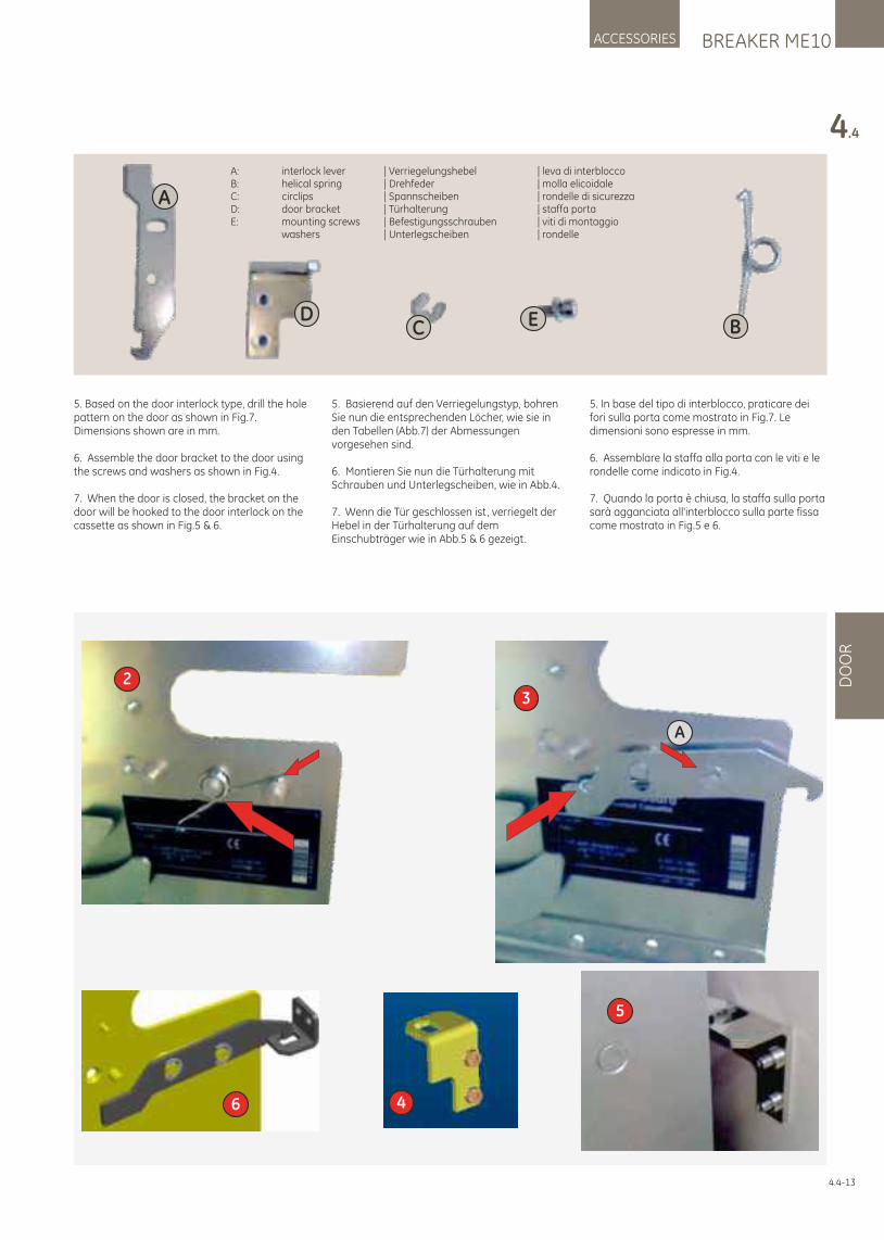
BREAKER ME10ACCESSORIES
4.4
DO
OR
4
5
6
23
A
A: interlock lever | Verriegelungshebel | leva di interblocco B: helical spring | Drehfeder | molla elicoidale C: circlips | Spannscheiben | rondelle di sicurezzaD: door bracket | Türhalterung | staffa portaE: mounting screws | Befestigungsschrauben | viti di montaggio washers | Unterlegscheiben | rondelle
A
BCD E
5. Based on the door interlock type, drill the hole pattern on the door as shown in Fig.7. Dimensions shown are in mm.
6. Assemble the door bracket to the door using the screws and washers as shown in Fig.4.
7. When the door is closed, the bracket on the door will be hooked to the door interlock on the cassette as shown in Fig.5 & 6.
5. Basierend auf den Verriegelungstyp, bohren Sie nun die entsprechenden Löcher, wie sie in den Tabellen (Abb.7) der Abmessungen vorgesehen sind.
6. Montieren Sie nun die Türhalterung mit Schrauben und Unterlegscheiben, wie in Abb.4.
7. Wenn die Tür geschlossen ist, verriegelt der Hebel in der Türhalterung auf dem Einschubträger wie in Abb.5 & 6 gezeigt.
5. In base del tipo di interblocco, praticare dei fori sulla porta come mostrato in Fig.7. Le dimensioni sono espresse in mm.
6. Assemblare la staffa alla porta con le viti e le rondelle come indicato in Fig.4.
7. Quando la porta è chiusa, la staffa sulla porta sarà agganciata all'interblocco sulla parte fissa come mostrato in Fig.5 e 6.
4.4-13
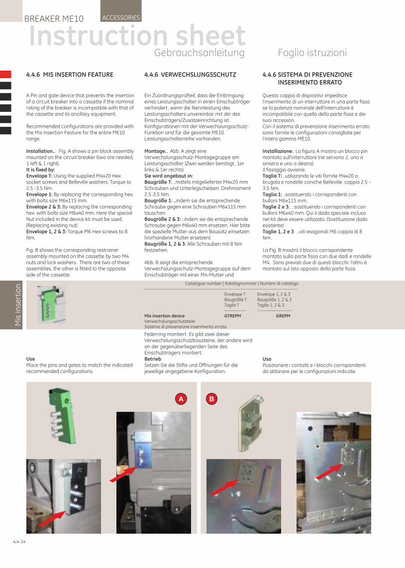
4.4.6 VERWECHSLUNGSSCHUTZ
Ein Zuordnungsprüfteil, dass die Einbringung eines Leistungsschalter in einen Einschubträger verhindert, wenn die Nennleistung des Leistungsschalters unvereinbar mit der des Einschubträgers/Zusatzeinrichtung ist.Konfigurationen mit der Verwechslungsschutz-Funktion sind für die gesamte ME10 Leistungsschalterreihe vorhanden.
Montage.. Abb. A zeigt eine Verwechslungsschutz-Montagegruppe am Leistungsschalter (Zwei werden benötigt, 1er links & 1er rechts).Sie wird angebaut in:Baugröße T: ..mittels mitgelieferter M4x20 mm Schrauben und Unterlegscheiben. Drehmoment 2,5-3,5 Nm.Baugröße 1: ..indem sie die entsprechende Schraube gegen eine Schrauben M6x115 mm tauschen.Baugröße 2 & 3: ..indem sie die entsprechende Schraube gegen M6x40 mm ersetzen. Hier bitte die spezielle Mutter aus dem Bausatz einsetzen (Vorhandene Mutter ersetzen). Baugröße 1, 2 & 3: Alle Schrauben mit 8 Nm festziehen.
Abb. B zeigt die entsprechende Verwechslungsschutz-Montagegruppe auf dem Einschubträger mit einer M4-Mutter und
Federring montiert. Es gibt zwei dieser Verwechslungsschutzbausteine, der andere wird an der gegenüberliegenden Seite des Einschubträgers montiert.BetriebSetzen Sie die Stifte und Öffnungen für die jeweilige angegebene Konfiguration.
4.4.6 MIS INSERTION FEATURE
A Pin and gate device that prevents the insertion of a circuit breaker into a cassette if the nominal rating of the breaker is incompatible with that of the cassette and its ancillary equipment.
Recommended configurations are provided with the Mis Insertion Feature for the entire ME10 range.
Installation.. Fig. A shows a pin block assembly mounted on the circuit breaker (two are needed, 1 left & 1 right). It is fixed by:Envelope T: Using the supplied M4x20 Hex socket screws and Belleville washers. Torque to 2.5 -3.5 Nm.Envelope 1: By replacing the corresponding hex. with bolts size M6x115 mm.Envelope 2 & 3: By replacing the corresponding hex. with bolts size M6x40 mm. Here the special Nut included in the device kit must be used. (Replacing existing nut)Envelope 1, 2 & 3: Torque M6 Hex screws to 8 Nm.
Fig. B shows the corresponding restrainer assembly mounted on the cassette by two M4 nuts and lock washers. There are two of these assemblies, the other is fitted to the opposite side of the cassette.
UsePlace the pins and gates to match the indicated recommended configurations.
Instruction sheetGebrauchsanleitung Foglio istruzioni
Mis
Inse
rtio
nACCESSORIESBREAKER ME10
4.4-14
4.4.6 SISTEMA DI PREVENZIONE INSERIMENTO ERRATO
Questa coppia di dispositivi impedisce l'inserimento di un interruttore in una parte fissa se la potenza nominale dell'interruttore è incompatibile con quella della parte fissa e dei suoi accessori.Con il sistema di prevenzione inserimento errato sono fornite le configurazioni consigliate per l'intera gamma ME10.
Installazione.. La figura A mostra un blocco pin montato sull'interruttore (ne servono 2, uno a sinistra e uno a destra). Il fissaggio avviene: Taglia T: ..utilizzando le viti fornite M4x20 a brugola e rondelle coniche Belleville. coppia 2.5 -3.5 Nm. Taglia 1: ..sostituendo i corrispondenti con bulloni M6x115 mm. Taglie 2 e 3: ..sostituendo i corrispondenti con bulloni M6x40 mm. Qui il dado speciale incluso nel kit deve essere utilizzato. (Sostituzione dado esistente) Taglie 1, 2 e 3: ..viti esagonali M6 coppia di 8 Nm.
La Fig. B mostra il blocco corrispondente montato sulla parte fissa con due dadi e rondelle M4. Sono previsti due di questi blocchi: l'altro è montato sul lato opposto della parte fissa.
UsoPosizionare i contatti e i blocchi corrispondenti da abbinare per le configurazioni indicate.
Catalogue number | Numero di catalogo Katalognummer | -------------------------------------------------------------------------------------------- Envelope T Envelope 1, 2 & 3 Baugröße T Baugröße 1, 2 & 3 Taglia T Taglia 1, 2 & 3 ------------- ---------------------Mis insertion device GTREPM GREPMVerwechslungsschutzteileSistema di prevenzione inserimento errato
BA
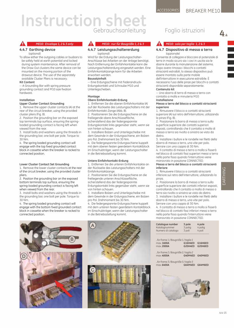
BREAKER ME10ACCESSORIES
4.4
EA
RTH
ING
4.4-15
4.4.7 Earthing device (optional)To allow either the outgoing cables or busbars to
be safely held at earth potential and locked during system maintenance. After removal of the Draw Out clusters the same device can be mounted on the moving portion of the drawout device. The use of the separately available Cluster Pliers is necessary.
Kit Content-- A Grounding Bar with spring pressure grounding contact and M10 size fixation hardware.
InstallationUpper Cluster Contact Grounding1. Remove the upper cluster contacts (A) at the rear of the circuit breaker, using the provided cluster pliers (Fig. B).2. Position the grounding bar on the exposed top terminals top surface, ensuring the spring-loaded grounding contact is facing left when viewed from the rear.3. Install bolts and washers using the threads in the grounding bar, one bolt per pole. Torque to 30 Nm.4. The spring loaded grounding contact will engage with the top fixed grounded contact block in cassette when the breaker is racked to connected position.
Lower Cluster Contact Set Grounding1. Remove the lower cluster contacts at the rear of the circuit breaker, using the provided cluster pliers.2. Position the grounding bar on the exposed bottom terminals top surface, ensuring the spring-loaded grounding contact is facing left when viewed from the rear.3. Install bolts and washers using the threads in the grounding bar, one bolt per pole. Torque to 30 Nm.4. The spring loaded grounding contact will engage with the bottom fixed grounded contact block in cassette when the breaker is racked to connected position.
4.4.7 Leistungsschaltererdung (optional)Wird für die Erdung der Leistungsschalter-Anschlüsse bei Arbeiten an der Anlage benötigt. Nach Entfernung der Einfahrkontakte kann die Leistungsschaltererdung eingesetzt werden. Eine Einfahrkontaktzange kann für die Arbeiten erworben werden.Bausatzinhalt-- Eine Erdungsschiene mit Federandruck-Erdungskontakt und Schraube M10 und Unterlegscheiben.
MontageObere Einfahrkontakt-Erdung1. Entfernen Sie die oberen Einfahrkontakte (A) auf der Rückseite des Leistungsschalters mit der Einfahrkontakt-Zange (Abb. B).2. Positionieren Sie die Erdungsschiene an die freiliegende obere Anschlüssefläche, sicherstellend das der federgespannte Erdungskontakt links gegenüber steht, wenn sie von hinten schauen.3. Installiere Bolzen und Unterlegscheibe mit dem Gewinde in der Erdungsschiene, ein Bolzen pro Pol. Drehmoment bis 30 Nm.4. Die federgespannte Erdungsschiene kuppelt mit dem oberen festen geerdetem Kontaktblock im Einschubträger, wenn der Leistungsschalter in die Betriebsstellung kommt.
Untere Einfahrkontakt-Erdung1. Entfernen Sie die unteren Einfahrkontakte an der Rückseite des Leistungsschalters mit der Einfahrkontaktzange.2. Positionieren Sie die Erdungsschiene an die freiliegende unteren Anschlüssefläche, sicherstellend das der federgespannte Erdungskontakt links gegenüber steht, wenn sie von hinten schauen.3. Installiere Bolzen und Unterlegscheibe mit dem Gewinde in der Erdungsschiene, ein Bolzen pro Pol. Drehmoment bis 30 Nm.4. Die federgespannte Erdungsschiene kuppelt mit dem unteren festen geerdetem Kontaktblock im Einschubträger, wenn der Leistungsschalter in die Betriebsstellung kommt.
4.4.7 Dispositivo di messa a terra (opzionale)Consente di collegare e bloccare al potenziale di terra in modo sicuro sia i cavi in uscita sia le sbarre durante la manutenzione del sistema. Dopo avere rimosso i blocchi a contatti striscianti estraibili, lo stesso dispositivo può essere montato sulla parte mobile dell'interruttore in esecuzione estraibile. È necessario l'uso delle pinze per blocchi a contatti striscianti disponibile separatamente. Contenuto kit-- Una sbarra di terra di messa a terra con contatto a molla e minuteria M10InstallazioneMessa a terra del blocco a contatti striscianti superiore1. Rimuovere il blocco a contatti striscianti superiore (A) sul retro dell'interruttore, utilizzando la pinza (Fig. B).2. Posizionare la barra di messa a terra sulla superficie superiore dei contatti superiori esposti, controllando che il contatto a molla di messa a terra sia rivolto a sinistra se visto da dietro.3. Installare i bulloni e le rondelle nei filetti della sbarra di messa a terra, una vite per polo. Serrare con una coppia di 30 Nm.4. Il contatto di messa a terra a molla si fisserà nel blocco di contatti fissi superiori messi a terra nella parte fissa quando l'interruttore viene manovrato in posizione CONNECTED.Messa a terra del blocco a contatti striscianti inferiore1. Rimuovere il blocco a contatti striscianti inferiore sul retro dell'interruttore, utilizzando la pinza.2. Posizionare la barra di messa a terra sulla superficie superiore dei contatti inferiori esposti, controllando che il contatto a molla di messa a terra sia rivolto a sinistra se visto da dietro.3. Installare i bulloni e le rondelle nei filetti della sbarra di messa a terra, una vite per polo. Serrare con una coppia di 30 Nm.4. Il contatto di messa a terra a molla si fisserà nel blocco di contatti fissi inferiori messi a terra nella parte fissa quando l'interruttore viene manovrato in posizione CONNECTED.
Instruction sheetGebrauchsanleitung Foglio istruzioni
A
C
D
Catalogue number 3 pole 4 poleKatalognummer 3 polig 4 poligNumero di catalogo 3 poli 4 poli-------------------------------------------------------
..for frame 1 / Baugröße 1 / taglia 1max. 1600A G16H4ED G16H6EDmax. 2000A G20H4ED G20H6ED
..for frame 2 / Baugröße 2 / taglia 2max. 4000A G40M4ED G40M6ED
..for frame 3 / Baugröße 3 / taglia 3max. 6400A G64M4ED G64M6ED
B
ME10: Envelope 1, 2 & 3 only ME10: nur für Baugröße 1, 2 & 3 ME10: solo per taglia 1, 2 & 3
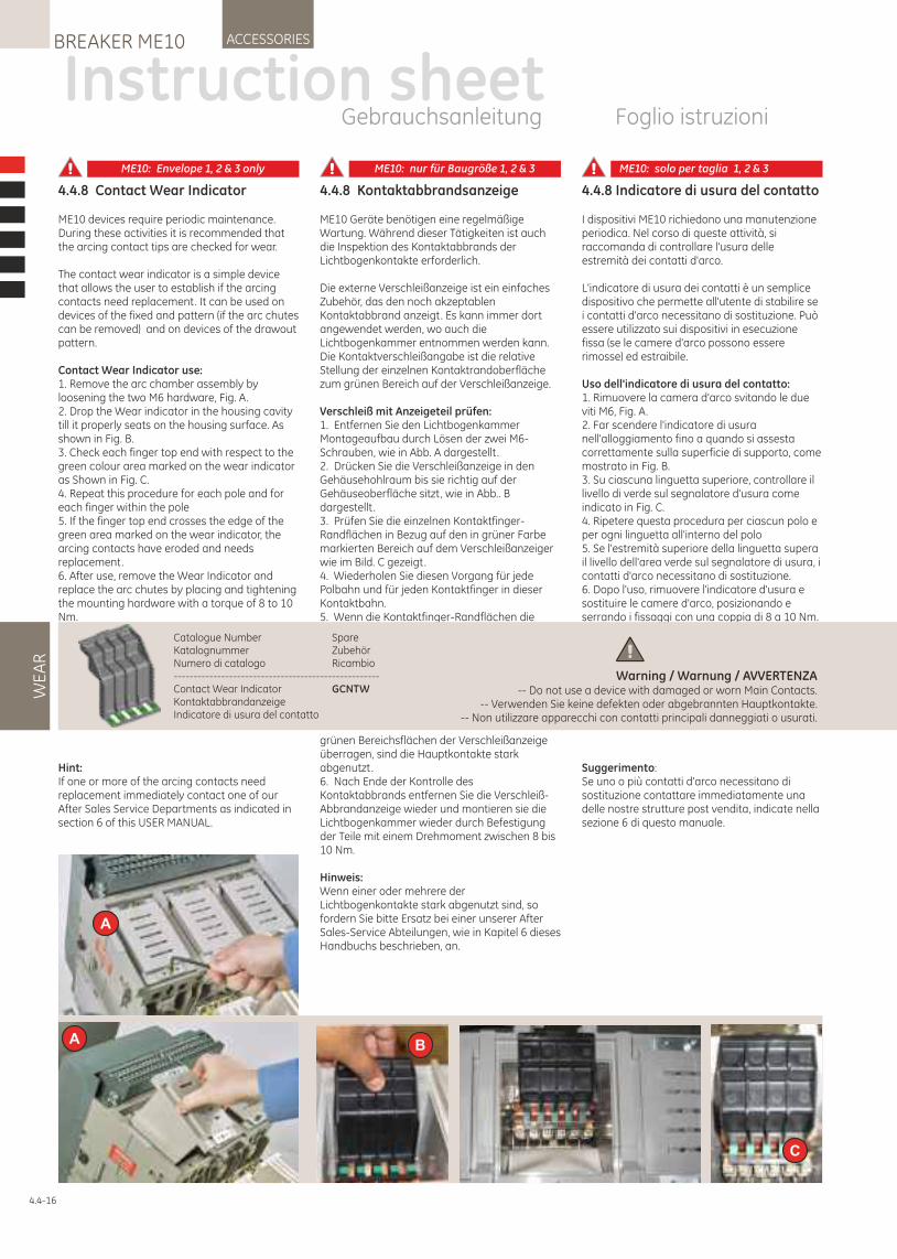
WE
AR
ACCESSORIESBREAKER ME10
4.4-16
4.4.8 Kontaktabbrandsanzeige
ME10 Geräte benötigen eine regelmäßige Wartung. Während dieser Tätigkeiten ist auch die Inspektion des Kontaktabbrands der Lichtbogenkontakte erforderlich.
Die externe Verschleißanzeige ist ein einfaches Zubehör, das den noch akzeptablen Kontaktabbrand anzeigt. Es kann immer dort angewendet werden, wo auch die Lichtbogenkammer entnommen werden kann.Die Kontaktverschleißangabe ist die relative Stellung der einzelnen Kontaktrandoberfläche zum grünen Bereich auf der Verschleißanzeige.
Verschleiß mit Anzeigeteil prüfen:1. Entfernen Sie den Lichtbogenkammer Montageaufbau durch Lösen der zwei M6-Schrauben, wie in Abb. A dargestellt .2. Drücken Sie die Verschleißanzeige in den Gehäusehohlraum bis sie richtig auf der Gehäuseoberfläche sitzt, wie in Abb.. B dargestellt .3. Prüfen Sie die einzelnen Kontaktfinger-Randflächen in Bezug auf den in grüner Farbe markierten Bereich auf dem Verschleißanzeiger wie im Bild. C gezeigt.4. Wiederholen Sie diesen Vorgang für jede Polbahn und für jeden Kontaktfinger in dieser Kontaktbahn.5. Wenn die Kontaktfinger-Randflächen die
grünen Bereichsflächen der Verschleißanzeige überragen, sind die Hauptkontakte stark abgenutzt.6. Nach Ende der Kontrolle des Kontaktabbrands entfernen Sie die Verschleiß-Abbrandanzeige wieder und montieren sie die Lichtbogenkammer wieder durch Befestigung der Teile mit einem Drehmoment zwischen 8 bis 10 Nm.
Hinweis:Wenn einer oder mehrere der Lichtbogenkontakte stark abgenutzt sind, so fordern Sie bitte Ersatz bei einer unserer After Sales-Service Abteilungen, wie in Kapitel 6 dieses Handbuchs beschrieben, an.
4.4.8 Contact Wear Indicator
ME10 devices require periodic maintenance. During these activities it is recommended that the arcing contact tips are checked for wear.
The contact wear indicator is a simple device that allows the user to establish if the arcing contacts need replacement. It can be used on devices of the fixed and pattern (if the arc chutes can be removed) and on devices of the drawout pattern.
Contact Wear Indicator use:1. Remove the arc chamber assembly by loosening the two M6 hardware, Fig. A.2. Drop the Wear indicator in the housing cavity till it properly seats on the housing surface. As shown in Fig. B.3. Check each finger top end with respect to the green colour area marked on the wear indicator as Shown in Fig. C.4. Repeat this procedure for each pole and for each finger within the pole5. If the finger top end crosses the edge of the green area marked on the wear indicator, the arcing contacts have eroded and needs replacement.6. After use, remove the Wear Indicator and replace the arc chutes by placing and tightening the mounting hardware with a torque of 8 to 10 Nm.
Hint:If one or more of the arcing contacts need replacement immediately contact one of our After Sales Service Departments as indicated in section 6 of this USER MANUAL.
4.4.8 Indicatore di usura del contatto
I dispositivi ME10 richiedono una manutenzione periodica. Nel corso di queste attività, si raccomanda di controllare l'usura delle estremità dei contatti d'arco.
L'indicatore di usura dei contatti è un semplice dispositivo che permette all'utente di stabilire se i contatti d'arco necessitano di sostituzione. Può essere utilizzato sui dispositivi in esecuzione fissa (se le camere d'arco possono essere rimosse) ed estraibile.
Uso dell'indicatore di usura del contatto:1. Rimuovere la camera d'arco svitando le due viti M6, Fig. A.2. Far scendere l'indicatore di usura nell'alloggiamento fino a quando si assesta correttamente sulla superficie di supporto, come mostrato in Fig. B.3. Su ciascuna linguetta superiore, controllare il livello di verde sul segnalatore d'usura come indicato in Fig. C.4. Ripetere questa procedura per ciascun polo e per ogni linguetta all'interno del polo5. Se l'estremità superiore della linguetta supera il livello dell'area verde sul segnalatore di usura, i contatti d'arco necessitano di sostituzione.6. Dopo l'uso, rimuovere l'indicatore d'usura e sostituire le camere d'arco, posizionando e serrando i fissaggi con una coppia di 8 a 10 Nm.
Suggerimento:Se uno o più contatti d'arco necessitano di sostituzione contattare immediatamente una delle nostre strutture post vendita, indicate nella sezione 6 di questo manuale.
A
A B
C
Instruction sheetGebrauchsanleitung Foglio istruzioni
Catalogue Number SpareKatalognummer ZubehörNumero di catalogo Ricambio----------------------------------------------------Contact Wear Indicator GCNTWKontaktabbrandanzeigeIndicatore di usura del contatto
Warning / Warnung / AVVERTENZA-- Do not use a device with damaged or worn Main Contacts.
-- Verwenden Sie keine defekten oder abgebrannten Hauptkontakte.-- Non utilizzare apparecchi con contatti principali danneggiati o usurati.
ME10: Envelope 1, 2 & 3 only ME10: nur für Baugröße 1, 2 & 3 ME10: solo per taglia 1, 2 & 3

4.4.9 Phasentrennplatten
Die Phasentrennplatten sind für Anwendungen mit einer Spannung (Ue) > 690V zu verwenden. Die Phasentrennplatten verhindern, dass externe Überschläge zwischen den Phasen vorkommen und fungieren somit als Isolator zwischen den jeweils benachbarten Phasen während der Lichtbogenentladung in einen Kurzschlusssituation.Es gibt 2 Phasentrennplatten Bausätze:Baugröße T: (ATJP)Bausätze mit 9 Trennplatten, 6 für die Festeinbauschalter und 3 für die Einschubtechnik Kassetten.Baugröße 1, 2 & 3: (AJP)Die Phasentrennplatten werden in 9 Bauarten geliefert, drei für die Baugrößen 1 & 2 für die Festeinbauversionen, drei für die Baugröße 3 der Festeinbauvarianten und drei Stück, die für alle Arten der Einschubtechnik eingesetzt werden können. Pro 3-poligem Schalter sind zwei Phasentrennplatten und pro 4-poligem Schalter drei Phasentrennplatten notwendig.
Verwenden Sie die folgenden Verfahren, um das Phasentrennplatten-Zubehör an dem Leistungsschalter zu installieren. 1. Beachten Sie den richtigen Phasentrennplattentyp: Abb.1 Für Baugröße 1&2 Festeinbauvarianten. Abb.2 Für Baugröße 3 Festeinbauvarianten. Abb.3 Für alle Einschübe in Einschubtechnik.
2. Montieren Sie zwei Stück der Phasentrennplatten für 3-polige Geräte und drei für 4-polige Geräte wie in Fig.4 und 5 dargestellt . 2.1 Für Festeinbauvarianten (Abb. 4): Verwenden Sie eine M5-Schraube, Federring und Unterlegscheibe. Ziehen Sie diese mit einem Drehmoment von 4 - 6 Nm fest. 2.2 Für Einschubtechnikvarianten (Abb. 5): Verwenden Sie zwei M6-Schrauben, Federringe und Unterlegscheiben. Ziehen Sie diese mit einem Drehmoment von 4 - 6 Nm fest.
4.4.9 Phase Barrier
The phase barriers are to be used for applications with a voltage (Ue) >690V. The barrier prevents external flashover between the phases and acts as an isolator between the two adjacent phases during venting in a short circuit situation.
There are two phase barrier kits:Envelope T: (ATJP)Kits of 9 barriers , six for the fixed version and three for the drawout cassettes.
Envelopes 1, 2 & 3: (AJP)Kits of 9, barriers three for the envelope 1 & 2 fixed version, three for the envelope 3 fixed version and 3 useable for all drawout cassette types. Per three pole device 2 barriers are needed and per four pole device 3.
Use the following procedure to install the Phase Barrier accessory onto the circuit breaker.
1. Identify correct Phase Barrier type:
Fig.1 For Envelope 1 & 2 fixed. Fig.2 For Envelope 3 fixed. Fig.3 For all Drawout Cassettes.
2. Assemble two pcs. of the phase barriers for 3 pole devices and 3 for 4 pole devices as shown in Fig.4 & 5.
2.1 For fixed types (Fig.4) : Use one M5 screw, flat and spring washer. Tighten to torque of 4 - 6 Nm at top end.
2.2 For drawout types (Fig.5) : Use two M6 screw, flat and spring washer. Tighten to torque of 4 - 6 Nm at top & bottom end.
.4.4.9 Separatore di fase
I separatori di fase devono essere utilizzati per applicazioni con tensione (Ue)> 690V.
La barriera impedisce flashover esterno tra le fasi e agisce come isolatore tra due fasi adiacenti durante lo sfiato in situazioni di corto circuito.
Ci sono due kit di separatori di fase:Taglia T: (GTJP)Kit di 9 separatori, 6 per l'esecuzione fissa e 3 per la parte fissa in esecuzione estraibile.
Taglie 1, 2 e 3: (GJP)Kit di 9 separatori, 3 per esecuzione fissa taglie 1 e 2, 3 per esecuzione fissa in taglia 3, e 3 per le esecuzioni estraibili di tutte le tre taglie. Per interruttori 3P servono 2 separatori, per 4P servono 3 separatori.
Utilizzare le seguenti procedure per installare le barriere di fase nell'interruttore.
1. Identificare il tipo corretto di barriera di fase.
Fig.1 Per taglia 1 & 2 in esecuzione fissa. Fig.2 Per taglia 3 in esecuzione fissa. Fig.3 Per tutte le versioni in esecuzione estraibile.
2. Assemblare i due elementi per le barriere di fase per i dispositivi a 3 poli e i tre elementi per i dispositivi a 4 poli come illustrato in Fig.4 & 5.
2.1 Per i tipi in esecuzione fissa (Fig.4): Usare una vite M5, una rondella piatta e una rondella a molla. Serrare con una coppia di 4 - 6 Nm.
2.2 Per i tipi in esecuzione fissa (Fig.4): Usare due viti M6, una rondella piatta e una rondella a molla. Serrare con una coppia di 4 - 6 Nm in alto e in basso.
Instruction sheetGebrauchsanleitung Foglio istruzioni
BREAKER ME10ACCESSORIES
4.4
Ph
ase
Ba
rrie
r
21 3
4 5
4.4-17
Part Catalogue Number SpareTeil Katalognummer ZubehörParte Numero catalogo Ricambio--------------------------------------- Envelope T ------------ 1, 2 & 3 ---------------- ( Baugröße | Taglia--------------------Phase Barrier GTJP GJP Set of 9 Phase SeparatorsPhasentrennplatten GTJP GJP Satz mit 9 PhasentrennplattenBarriera di fase GTJP GJP Set di 9 Separatori di fase
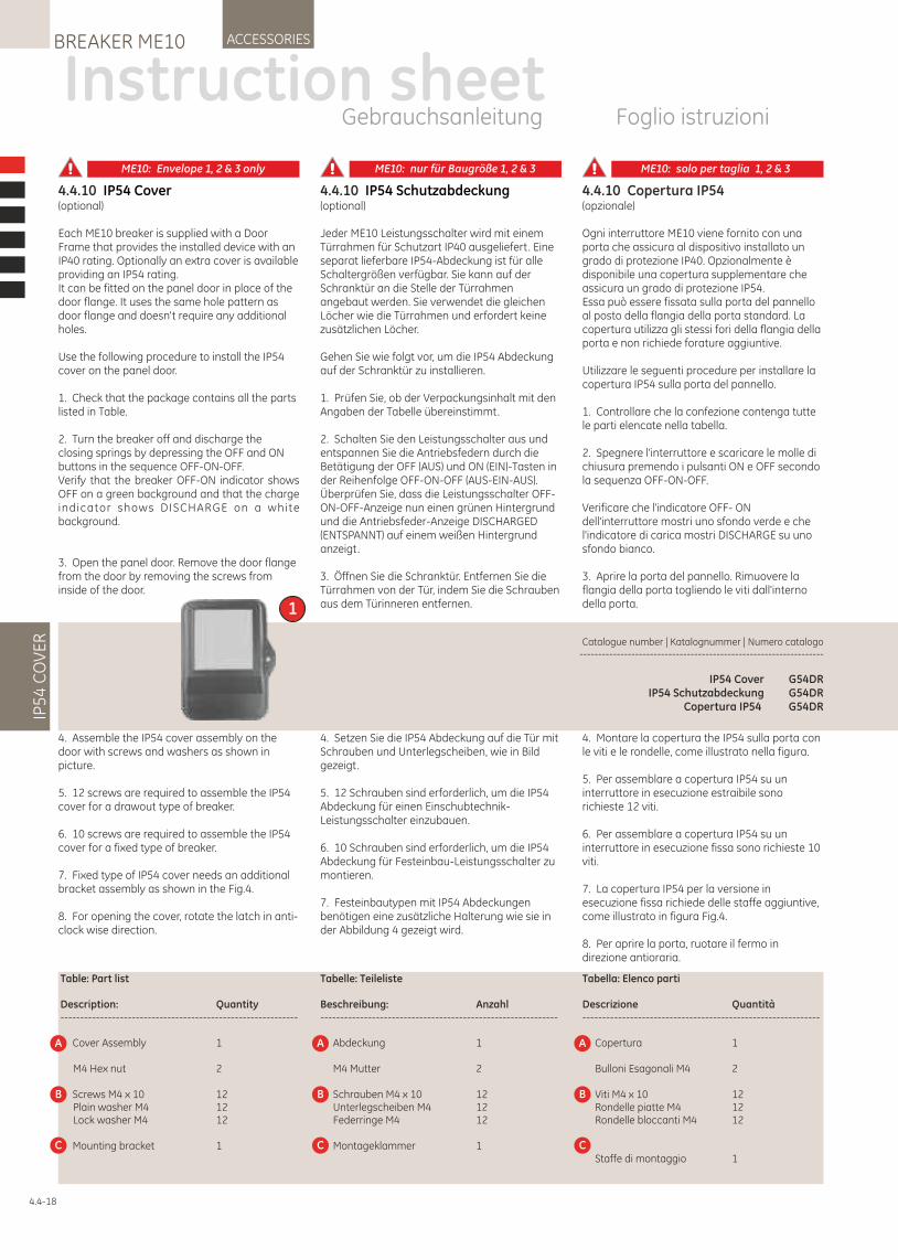
1
4.4.10 IP54 Cover(optional)
Each ME10 breaker is supplied with a Door Frame that provides the installed device with an IP40 rating. Optionally an extra cover is available providing an IP54 rating.It can be fitted on the panel door in place of the door flange. It uses the same hole pattern as door flange and doesn't require any additional holes.
Use the following procedure to install the IP54 cover on the panel door.
1. Check that the package contains all the parts listed in Table.
2. Turn the breaker off and discharge the closing springs by depressing the OFF and ON buttons in the sequence OFF-ON-OFF.Verify that the breaker OFF-ON indicator shows OFF on a green background and that the charge indicator shows DISCHARGE on a white background.
3. Open the panel door. Remove the door flange from the door by removing the screws from inside of the door.
4.4.10 IP54 Schutzabdeckung(optional)
Jeder ME10 Leistungsschalter wird mit einem Türrahmen für Schutzart IP40 ausgeliefert. Eine separat lieferbare IP54-Abdeckung ist für alle Schaltergrößen verfügbar. Sie kann auf der Schranktür an die Stelle der Türrahmen angebaut werden. Sie verwendet die gleichen Löcher wie die Türrahmen und erfordert keine zusätzlichen Löcher.
Gehen Sie wie folgt vor, um die IP54 Abdeckung auf der Schranktür zu installieren.
1. Prüfen Sie, ob der Verpackungsinhalt mit den Angaben der Tabelle übereinstimmt.
2. Schalten Sie den Leistungsschalter aus und entspannen Sie die Antriebsfedern durch die Betätigung der OFF (AUS) und ON (EIN)-Tasten in der Reihenfolge OFF-ON-OFF (AUS-EIN-AUS). Überprüfen Sie, dass die Leistungsschalter OFF-ON-OFF-Anzeige nun einen grünen Hintergrund und die Antriebsfeder-Anzeige DISCHARGED (ENTSPANNT) auf einem weißen Hintergrund anzeigt.
3. Öffnen Sie die Schranktür. Entfernen Sie die Türrahmen von der Tür, indem Sie die Schrauben aus dem Türinneren entfernen.
4.4.10 Copertura IP54(opzionale)
Ogni interruttore ME10 viene fornito con una porta che assicura al dispositivo installato un grado di protezione IP40. Opzionalmente è disponibile una copertura supplementare che assicura un grado di protezione IP54.Essa può essere fissata sulla porta del pannello al posto della flangia della porta standard. La copertura utilizza gli stessi fori della flangia della porta e non richiede forature aggiuntive.
Utilizzare le seguenti procedure per installare la copertura IP54 sulla porta del pannello.
1. Controllare che la confezione contenga tutte le parti elencate nella tabella.
2. Spegnere l'interruttore e scaricare le molle di chiusura premendo i pulsanti ON e OFF secondo la sequenza OFF-ON-OFF.
Verificare che l'indicatore OFF- ON dell'interruttore mostri uno sfondo verde e che l'indicatore di carica mostri DISCHARGE su uno sfondo bianco.
3. Aprire la porta del pannello. Rimuovere la flangia della porta togliendo le viti dall'interno della porta.
IP5
4 C
OV
ER
ACCESSORIESBREAKER ME10
Instruction sheetGebrauchsanleitung Foglio istruzioni
4.4-18
Catalogue number | Katalognummer | Numero catalogo ------------------------------------------------------------------
IP54 Cover G54DRIP54 Schutzabdeckung G54DR
Copertura IP54 G54DR
4. Assemble the IP54 cover assembly on the door with screws and washers as shown in picture.
5. 12 screws are required to assemble the IP54 cover for a drawout type of breaker.
6. 10 screws are required to assemble the IP54 cover for a fixed type of breaker.
7. Fixed type of IP54 cover needs an additional bracket assembly as shown in the Fig.4.
8. For opening the cover, rotate the latch in anti-clock wise direction.
4. Setzen Sie die IP54 Abdeckung auf die Tür mit Schrauben und Unterlegscheiben, wie in Bild gezeigt.
5. 12 Schrauben sind erforderlich, um die IP54 Abdeckung für einen Einschubtechnik-Leistungsschalter einzubauen.
6. 10 Schrauben sind erforderlich, um die IP54 Abdeckung für Festeinbau-Leistungsschalter zu montieren.
7. Festeinbautypen mit IP54 Abdeckungen benötigen eine zusätzliche Halterung wie sie in der Abbildung 4 gezeigt wird.
4. Montare la copertura the IP54 sulla porta con le viti e le rondelle, come illustrato nella figura.
5. Per assemblare a copertura IP54 su un interruttore in esecuzione estraibile sono richieste 12 viti.
6. Per assemblare a copertura IP54 su un interruttore in esecuzione fissa sono richieste 10 viti.
7. La copertura IP54 per la versione in esecuzione fissa richiede delle staffe aggiuntive, come illustrato in figura Fig.4.
8. Per aprire la porta, ruotare il fermo in direzione antioraria.
Table: Part list
Description: Quantity------------------------------------------------------------
Cover Assembly 1
M4 Hex nut 2
Screws M4 x 10 12 Plain washer M4 12 Lock washer M4 12
Mounting bracket 1
A
B
C
Tabelle: Teileliste
Beschreibung: Anzahl------------------------------------------------------------
Abdeckung 1
M4 Mutter 2
Schrauben M4 x 10 12 Unterlegscheiben M4 12 Federringe M4 12
Montageklammer 1
A
B
C
Tabella: Elenco parti
Descrizione Quantità------------------------------------------------------------
Copertura 1
Bulloni Esagonali M4 2
Viti M4 x 10 12 Rondelle piatte M4 12 Rondelle bloccanti M4 12
Staffe di montaggio 1
A
B
C
ME10: Envelope 1, 2 & 3 only ME10: nur für Baugröße 1, 2 & 3 ME10: solo per taglia 1, 2 & 3
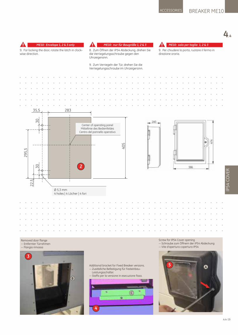
Additional bracket for Fixed Breaker versions.-- Zusätzliche Befestigung für Festeinbau- Leistungsschalter.-- Staffa per la versione in esecuzione fissa.
Removed door flange-- Entfernter Türrahmen-- Flangia rimossa
Screw for IP54 Cover opening-- Schraube zum Öffnern der IP54 Abdeckung-- Vite d'apertura copertura IP54
4
C
5A
3
B
BREAKER ME10ACCESSORIES
4.4
IP5
4 C
OV
ER
Center of operating panelMittellinie des Bedienfeldes
Centro del pannello operativo
Ø 5,3 mm4 holes | 4 Löcher | 4 fori
29
5,5
283
40
5
230
22
,5
30
35,5
4.4-19
9. For locking the door, rotate the latch in clock-wise direction.
8. Zum Öffnen der IP54 Abdeckung, drehen Sie die Verriegelungsschraube gegen den Uhrzeigersinn.
9. Zum Verriegeln der Tür, drehen Sie die Verriegelungsschraube im Uhrzeigersinn.
9. Per chiudere la porta, ruotare il fermo in direzione oraria.
ME10: Envelope 1, 2 & 3 only ME10: nur für Baugröße 1, 2 & 3 ME10: solo per taglia 1, 2 & 3
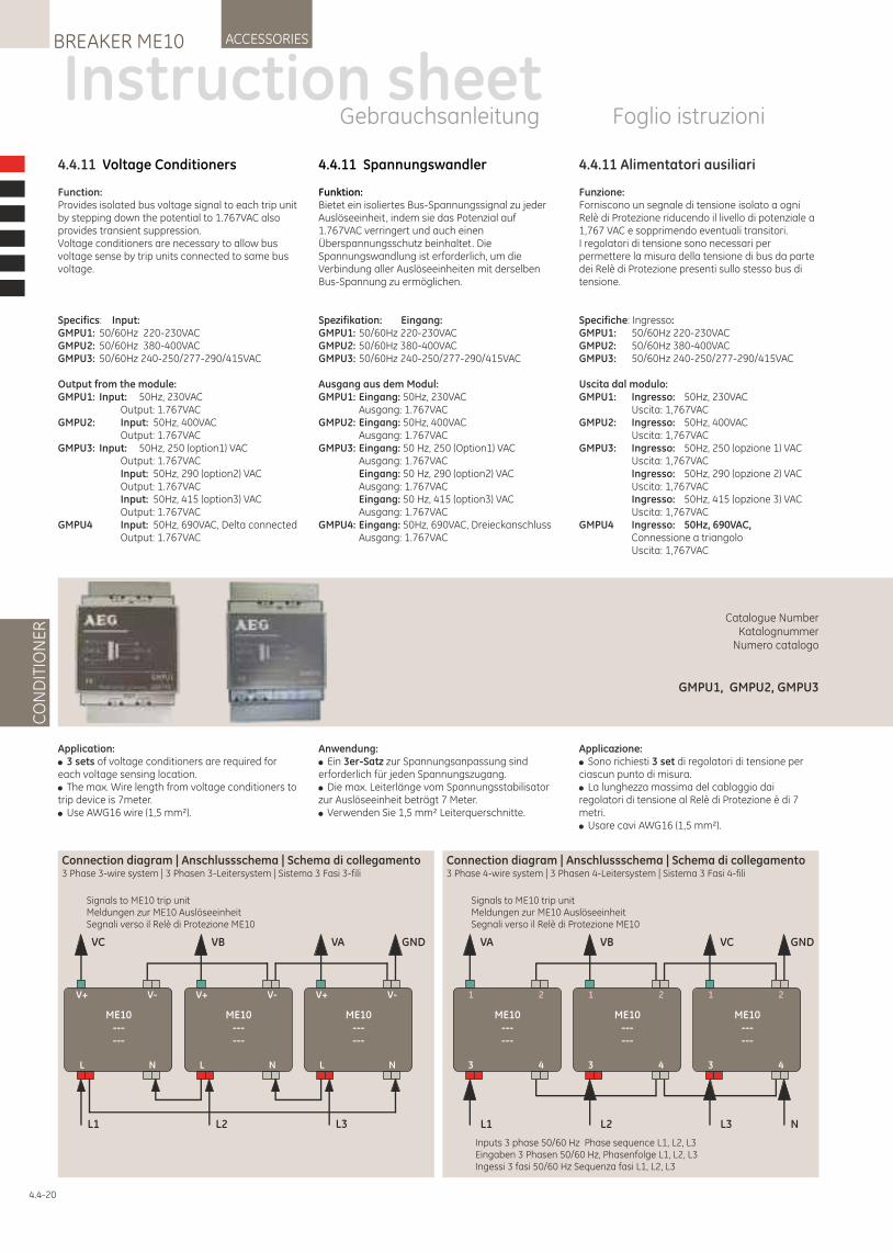
4.4.11 Voltage Conditioners
Function:Provides isolated bus voltage signal to each trip unit by stepping down the potential to 1.767VAC also provides transient suppression. Voltage conditioners are necessary to allow bus voltage sense by trip units connected to same bus voltage.
Specifics: Input:GMPU1: 50/60Hz 220-230VACGMPU2: 50/60Hz 380-400VACGMPU3: 50/60Hz 240-250/277-290/415VAC
Output from the module:GMPU1: Input: 50Hz, 230VAC Output: 1.767VACGMPU2: Input: 50Hz, 400VAC Output: 1.767VACGMPU3: Input: 50Hz, 250 (option1) VAC Output: 1.767VAC Input: 50Hz, 290 (option2) VAC Output: 1.767VAC Input: 50Hz, 415 (option3) VAC Output: 1.767VACGMPU4 Input: 50Hz, 690VAC, Delta connected Output: 1.767VAC
Application:! 3 sets of voltage conditioners are required for each voltage sensing location.! The max. Wire length from voltage conditioners to trip device is 7meter.! Use AWG16 wire (1,5 mm²).
4.4.11 Spannungswandler
Funktion:Bietet ein isoliertes Bus-Spannungssignal zu jeder Auslöseeinheit, indem sie das Potenzial auf 1.767VAC verringert und auch einen Überspannungsschutz beinhaltet. Die Spannungswandlung ist erforderlich, um die Verbindung aller Auslöseeinheiten mit derselben Bus-Spannung zu ermöglichen.
Spezifikation: Eingang: GMPU1: 50/60Hz 220-230VAC GMPU2: 50/60Hz 380-400VAC GMPU3: 50/60Hz 240-250/277-290/415VAC
Ausgang aus dem Modul: GMPU1: Eingang: 50Hz, 230VAC Ausgang: 1.767VAC GMPU2: Eingang: 50Hz, 400VAC Ausgang: 1.767VAC GMPU3: Eingang: 50 Hz, 250 (Option1) VAC Ausgang: 1.767VAC Eingang: 50 Hz, 290 (option2) VAC Ausgang: 1.767VAC Eingang: 50 Hz, 415 (option3) VAC Ausgang: 1.767VAC GMPU4: Eingang: 50Hz, 690VAC, Dreieckanschluss Ausgang: 1.767VAC
Anwendung: ! Ein 3er-Satz zur Spannungsanpassung sind erforderlich für jeden Spannungszugang. ! Die max. Leiterlänge vom Spannungsstabilisator zur Auslöseeinheit beträgt 7 Meter. ! Verwenden Sie 1,5 mm² Leiterquerschnitte.
4.4.11 Alimentatori ausiliari
Funzione:Forniscono un segnale di tensione isolato a ogni Relè di Protezione riducendo il livello di potenziale a 1,767 VAC e sopprimendo eventuali transitori.I regolatori di tensione sono necessari per permettere la misura della tensione di bus da parte dei Relè di Protezione presenti sullo stesso bus di tensione.
Specifiche: Ingresso:GMPU1: 50/60Hz 220-230VACGMPU2: 50/60Hz 380-400VACGMPU3: 50/60Hz 240-250/277-290/415VAC
Uscita dal modulo:GMPU1: Ingresso: 50Hz, 230VAC Uscita: 1,767VACGMPU2: Ingresso: 50Hz, 400VAC Uscita: 1,767VACGMPU3: Ingresso: 50Hz, 250 (opzione 1) VAC Uscita: 1,767VAC Ingresso: 50Hz, 290 (opzione 2) VAC Uscita: 1,767VAC Ingresso: 50Hz, 415 (opzione 3) VAC Uscita: 1,767VACGMPU4 Ingresso: 50Hz, 690VAC, Connessione a triangolo Uscita: 1,767VAC
Applicazione:! Sono richiesti 3 set di regolatori di tensione per ciascun punto di misura.! La lunghezza massima del cablaggio dai regolatori di tensione al Relè di Protezione è di 7 metri.! Usare cavi AWG16 (1,5 mm²).
CO
ND
ITIO
NE
RACCESSORIESBREAKER ME10
Instruction sheetGebrauchsanleitung Foglio istruzioni
Catalogue Number Katalognummer
Numero catalogo
GMPU1, GMPU2, GMPU3
4.4-20
Connection diagram | Anschlussschema | Schema di collegamento 3 Phase 3-wire system | 3 Phasen 3-Leitersystem | Sistema 3 Fasi 3-fili
V+ V-
L N
ME10------
V+ V-
L N
ME10------
V+ V-
L N
ME10------
VC VB VA GND
L1 L2 L3
Signals to ME10 trip unitMeldungen zur ME10 AuslöseeinheitSegnali verso il Relè di Protezione ME10
Connection diagram | Anschlussschema | Schema di collegamento 3 Phase 4-wire system | 3 Phasen 4-Leitersystem | Sistema 3 Fasi 4-fili
1 2
3 4
ME10------
1 2
3 4
ME10------
1 2
3 4
ME10------
VA VB VC GND
L1 L2 L3 N
Signals to ME10 trip unitMeldungen zur ME10 AuslöseeinheitSegnali verso il Relè di Protezione ME10
Inputs 3 phase 50/60 Hz Phase sequence L1, L2, L3Eingaben 3 Phasen 50/60 Hz, Phasenfolge L1, L2, L3Ingessi 3 fasi 50/60 Hz Sequenza fasi L1, L2, L3
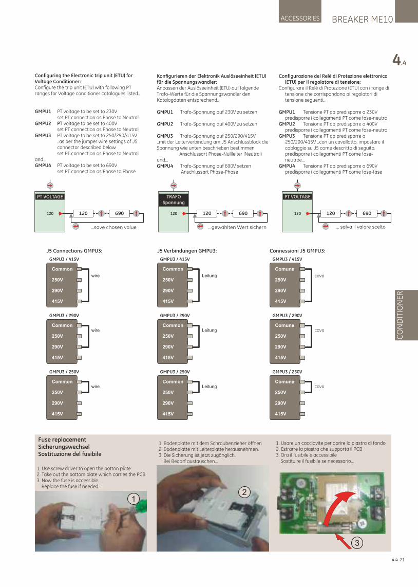
BREAKER ME10ACCESSORIES
4.4
CO
ND
ITIO
NE
R
Konfigurieren der Elektronik Auslöseeinheit (ETU) für die Spannungswandler:Anpassen der Auslöseeinheit (ETU) auf folgende Trafo-Werte für die Spannungswandler den Katalogdaten entsprechend..
GMPU1 Trafo-Spannung auf 230V zu setzen
GMPU2 Trafo-Spannung auf 400V zu setzen
GMPU3 Trafo-Spannung auf 250/290/415V..mit der Leiterverbindung am J5 Anschlussblock die Spannung wie unten beschrieben bestimmen Anschlussart Phase-Nullleiter (Neutral)und...GMPU4 Trafo-Spannung auf 690V setzen Anschlussart Phase-Phase
Common
250V
290V
415V
GMPU3 / 415V
Common
250V
290V
415V
GMPU3 / 290V
Common
250V
290V
415V
GMPU3 / 250V
J5 Connections GMPU3:
wire
wire
wire
Common
250V
290V
415V
GMPU3 / 415V
Common
250V
290V
415V
GMPU3 / 290V
Common
250V
290V
415V
GMPU3 / 250V
J5 Verbindungen GMPU3:
Leitung
Leitung
Leitung
Comune
250V
290V
415V
GMPU3 / 415V
Comune
250V
290V
415V
GMPU3 / 290V
Comune
250V
290V
415V
GMPU3 / 250V
Connessioni J5 GMPU3:
cavo
cavo
cavo
PT VOLTAGE
120 120
...save chosen value
690
TRAFOSpannung
120 120
...gewählten Wert sichern
690
PT VOLTAGE
120 120
... salva il valore scelto
690
Configurazione del Relè di Protezione elettronica (ETU) per il regolatore di tensione:
Configurare il Relè di Protezione (ETU) con i range di tensione che corrispondono ai regolatori di tensione seguenti..
GMPU1 Tensione PT da predisporre a 230V predisporre i collegamenti PT come fase-neutro
GMPU2 Tensione PT da predisporre a 400V predisporre i collegamenti PT come fase-neutro
GMPU3 Tensione PT da predisporre a 250/290/415V ..con un cavallotto, impostare il cablaggio su J5 come descritto di seguito. predisporre i collegamenti PT come fase-neutroe...
GMPU4 Tensione PT da predisporre a 690V predisporre i collegamenti PT come fase-fase
1. Use screw driver to open the botton plate2. Take out the bottom plate which carries the PCB3. Now the fuse is accessible. Replace the fuse if needed...
Fuse replacementSicherungswechselSostituzione del fusibile
1. Bodenplatte mit dem Schraubenzieher öffnen2. Bodenplatte mit Leiterplatte herausnehmen.3. Die Sicherung ist jetzt zugänglich. Bei Bedarf austauschen...
1. Usare un cacciavite per aprire la piastra di fondo2. Estrarre la piastra che supporta il PCB3. Ora il fusibile è accessibile Sostituire il fusibile se necessario...
12
3
4.4-21
Configuring the Electronic trip unit (ETU) for Voltage Conditioner:Configure the trip unit (ETU) with following PT ranges for Voltage conditioner catalogues listed..
GMPU1 PT voltage to be set to 230V set PT connection as Phase to NeutralGMPU2 PT voltage to be set to 400V set PT connection as Phase to NeutralGMPU3 PT voltage to be set to 250/290/415V ..as per the jumper wire settings of J5 connector described below. set PT connection as Phase to Neutraland...GMPU4 PT voltage to be set to 690V set PT connection as Phase to Phase
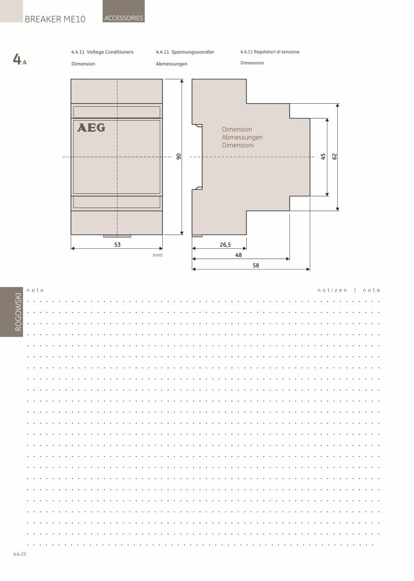
4.4
RO
GO
WS
KI
ACCESSORIESBREAKER ME10
4.4.11 Voltage Conditioners
Dimension
4.4.11 Spannungswandler
Abmessungen
4.4.11 Regolatori di tensione
Dimensioni
4.4-22
26,5
48
58
45
62
(mm)
DimensionAbmessungenDimensioni
53
90
n o t e n o t i z e n | n o t a
. . . . . . . . . . . . . . . . . . . . . . . . . . . . . . . . . . . . . . . . . . . . . . . . . . . . . . . .
. . . . . . . . . . . . . . . . . . . . . . . . . . . . . . . . . . . . . . . . . . . . . . . . . . . . . . . .
. . . . . . . . . . . . . . . . . . . . . . . . . . . . . . . . . . . . . . . . . . . . . . . . . . . . . . . .
. . . . . . . . . . . . . . . . . . . . . . . . . . . . . . . . . . . . . . . . . . . . . . . . . . . . . . . .
. . . . . . . . . . . . . . . . . . . . . . . . . . . . . . . . . . . . . . . . . . . . . . . . . . . . . . . .
. . . . . . . . . . . . . . . . . . . . . . . . . . . . . . . . . . . . . . . . . . . . . . . . . . . . . . . .
. . . . . . . . . . . . . . . . . . . . . . . . . . . . . . . . . . . . . . . . . . . . . . . . . . . . . . . .
. . . . . . . . . . . . . . . . . . . . . . . . . . . . . . . . . . . . . . . . . . . . . . . . . . . . . . . .
. . . . . . . . . . . . . . . . . . . . . . . . . . . . . . . . . . . . . . . . . . . . . . . . . . . . . . . .
. . . . . . . . . . . . . . . . . . . . . . . . . . . . . . . . . . . . . . . . . . . . . . . . . . . . . . . .
. . . . . . . . . . . . . . . . . . . . . . . . . . . . . . . . . . . . . . . . . . . . . . . . . . . . . . . .
. . . . . . . . . . . . . . . . . . . . . . . . . . . . . . . . . . . . . . . . . . . . . . . . . . . . . . . .
. . . . . . . . . . . . . . . . . . . . . . . . . . . . . . . . . . . . . . . . . . . . . . . . . . . . . . . .
. . . . . . . . . . . . . . . . . . . . . . . . . . . . . . . . . . . . . . . . . . . . . . . . . . . . . . . .
. . . . . . . . . . . . . . . . . . . . . . . . . . . . . . . . . . . . . . . . . . . . . . . . . . . . . . . .
. . . . . . . . . . . . . . . . . . . . . . . . . . . . . . . . . . . . . . . . . . . . . . . . . . . . . . . .
. . . . . . . . . . . . . . . . . . . . . . . . . . . . . . . . . . . . . . . . . . . . . . . . . . . . . . . .
. . . . . . . . . . . . . . . . . . . . . . . . . . . . . . . . . . . . . . . . . . . . . . . . . . . . . . . .
. . . . . . . . . . . . . . . . . . . . . . . . . . . . . . . . . . . . . . . . . . . . . . . . . . . . . . . .
. . . . . . . . . . . . . . . . . . . . . . . . . . . . . . . . . . . . . . . . . . . . . . . . . . . . . . . .
. . . . . . . . . . . . . . . . . . . . . . . . . . . . . . . . . . . . . . . . . . . . . . . . . . . . . . . .
. . . . . . . . . . . . . . . . . . . . . . . . . . . . . . . . . . . . . . . . . . . . . . . . . . . . . . . .
. . . . . . . . . . . . . . . . . . . . . . . . . . . . . . . . . . . . . . . . . . . . . . . . . . . . . . . .
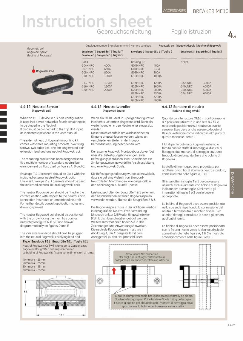
BREAKER ME10ACCESSORIES
4.4
RO
GO
WS
KI
4.4-23
Instruction sheetGebrauchsanleitung Foglio istruzioni
4.4.12 Sensore di neutro (Bobina di Rogowski)
Quando un interruttore ME10 in configurazione a 3 poli viene utilizzato in una rete a 4 fili, è necessario posizionare sul neutro un quarto sensore. Esso deve anche essere collegato al Relè di Protezione come indicato in altri punti di questo manuale utente.
Il kit di per la bobina di Rogowski esterna è fornito con tre staffe di montaggio, due viti di fissaggio, due morsetti di serraggio cavi, una trecciola di prolunga da 2m e una bobina di Rogowski.
Le staffe di montaggio sono progettate per adattarsi a vari tipi di sbarra di neutro standard, come illustrato nelle figure A, B e C.
Gli interruttori in taglia T e 1 devono essere utilizzati esclusivamente con bobine di Rogowski indicate per queste taglie. Similmente gli interruttori di taglia 2 e 3 con le bobine appropriate.
La bobina di Rogowski deve essere posizionata nella sua sede rispettando la connessione del neutro a terra (neutro a monte o a valle). Per ulteriori dettagli consultare le note e gli schemi applicativi forniti.
La bobina di Rogowski deve essere posizionata con la freccia rivolta verso la sbarra principale come illustrato nelle figure A, B & C e mostrato schematicamente nelle figure D ed E.
Neutral Rogowski Coil will clamp on to Copper sizesRogowski Baugröße 1 für KupferschienenLa bobina di Rogowski si fissa a varie dimensioni di rame.
40mm x 4 - 25mm50mm x 4 - 25mm60mm x 4 - 25mm70mm x 4 - 25mm
Arrow to face ACB connectionPfeil zeigt zum Leistungsschalteranschluss
Collegamento interruttore orientato con la freccia
Fix coil to clamp with cable ties (position coil centrally on clamp)Spulenbefestigung mit Kabelbindern (Spule mittig befestigen)
Fissare la bobina per chiuderla con i morsetti di serraggio cavo (posizionare la bobina centralmente sul morsetto)
Fig.A Envelope T&1 | Baugröße T&1 | Taglia T&1
58
110
4.4.12 Neutralwandler (Rogowski Spule)
Wenn ein ME10 Gerät in 3 poliger Konfiguration in einem 4 Leiternetz eingesetzt wird, kann ein vierter Wandler in den Neutralleiter eingesetzt werden.Dieser muss ebenfalls am Auslöseeinheiten Eingang angeschlossen werden, wie es an verschiedenen Stellen in der Haupt-Betriebsanweisung beschrieben wird.
Der externe Rogowski Montagebausatz verfügt über drei Befestigungshalterungen, zwei Befestigungsschrauben, zwei Kabelbinder, ein 2m lange zweipolige verdrillte Anschlussleitung und eine Rogowski Spule.
Die Befestigungshalterung wurde so entwickelt, dass sie auf eine Vielzahl von Standard-Neutralleiter Anordnungen, wie dargestellt in den Abbildungen A, B und C, passt.
Leistungsschalter der Baugröße T & 1 sollen mit den beschriebenen externen Rogowskispulen verwendet werden. Ebenso die Baugrößen 2 & 3.
Die Rogowskispule muss in der richtigen Position in Bezug auf die Neutral-Erde-Verbindung (Unbeschränkter (UEF) oder Eingeschränkter (REF) Erdschlussschutz) eingebaut werden. Weitere Informationen finden Sie in den Zeichnungen und Anwendungshinweisen.Die neutrale Rogowskispule muss wie in Abbildung A, B & C dargestellt mit dem Anzeigepfeil zu den Hauptanschlüssen
4.4.12 Neutral Sensor (Rogowski coil)
When an ME10 device in a 3 pole configuration is used in a 4 wire network a fourth sensor needs to be placed in the Neutral.It also must be connected to the Trip Unit input as indicated elsewhere in the User Manual.
The external neutral Rogowski mounting kit comes with three mounting brackets, two fixing screws, two cable ties, one 2m long twisted pair extension lead and one neutral Rogowski coil.
The mounting bracket has been designed so to fit a multiple number of standard neutral bar arrangement as illustrated on figures A, B and C.
Envelope T & 1 breakers should be used with the indicated external neutral Rogowski coils. Likewise Envelope 2 & 3 breakers should be used the indicated external neutral Rogowski coils.
The neutral Rogowski coil should be fitted in the correct location with respect to the neutral earth connection (restricted or unrestricted neutral). For further details consult application notes and drawings proved.
The neutral Rogowski coil should be positioned with the arrow facing the main bus bars as illustrated on figure A, B & C and shown diagrammatically on figures D and E.
The 2 m extension lead should next be plugged into the neutral Rogowski coil flying lead and
Catalogue number | Katalognummer | Numero catalogo Rogowski coil | Rogowskispule | Bobina di Rogowski
Envelope T | Baugröße T | Taglia TEnvelope 1 | Baugröße 1 | Taglia 1-------------------------------------------Cat #G04HNRC 400AG07HNRC 630AG08HNRC 800AG10HNRC 1000A
G13HNRC 1250AG16HNRC 1600AG20HNRC 2000A
Envelope 2 | Baugröße 2 | Taglia 2
-------------------------------------------Katalog Nr.G04MNRC 400AG07MNRC 630AG08MNRC 800AG10MNRC 1000A
G13MNRC 1250AG16MNRC 1600AG20MNRC 2000AG25MNRC 2500AG32MNRC 3200AG40MNRC 4000A
Envelope 3 | Baugröße 3 | Taglia 3
-------------------------------------------Nr kat
G32LNRC 3200AG40LNRC 4000AG50LNRC 5000AG64LNRC 6400A
Rogowski coilRogowski SpuleBobina di Rogowski
Rogowski Coil
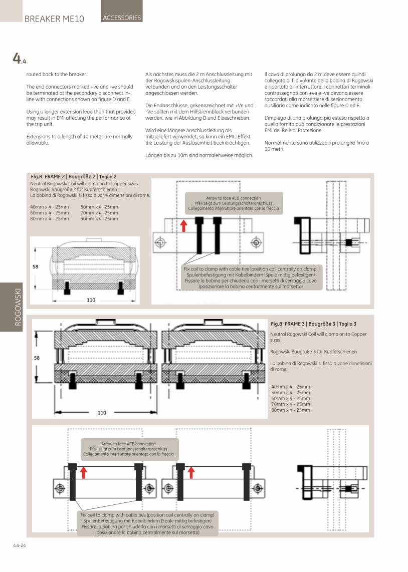
routed back to the breaker.
The end connectors marked +ve and -ve should be terminated at the secondary disconnect in-line with connections shown on figure D and E.
Using a longer extension lead than that provided may result in EMI affecting the performance of the trip unit.
Extensions to a length of 10 meter are normally allowable.
Als nächstes muss die 2 m Anschlussleitung mit der Rogowskispulen-Anschlussleitung verbunden und an den Leistungsschalter angeschlossen werden.
Die Endanschlüsse, gekennzeichnet mit +Ve und -Ve sollten mit dem Hilfstrennblock verbunden werden, wie in Abbildung D und E beschrieben.
Wird eine längere Anschlussleitung als mitgeliefert verwendet, so kann ein EMC-Effekt die Leistung der Auslöseinheit beeinträchtigen.
Längen bis zu 10m sind normalerweise möglich.
Il cavo di prolunga da 2 m deve essere quindi collegato al filo volante della bobina di Rogowski e riportato all'interruttore. I connettori terminali contrassegnati con +ve e -ve devono essere raccordati alla morsettiere di sezionamento ausiliaria come indicato nelle figure D ed E.
L'impiego di una prolunga più estesa rispetto a quella fornita può condizionare le prestazioni EMI del Relè di Protezione.
Normalmente sono utilizzabili prolunghe fino a 10 metri.
4.4
RO
GO
WS
KI
ACCESSORIESBREAKER ME10
4.4-24
Neutral Rogowski Coil will clamp on to Copper sizes.
Rogowski Baugröße 3 für Kupferschienen
La bobina di Rogowski si fissa a varie dimensioni di rame.
40mm x 4 - 25mm 50mm x 4 - 25mm 60mm x 4 - 25mm 70mm x 4 - 25mm 80mm x 4 - 25mm
Fig.B FRAME 3 | Baugröße 3 | Taglia 3
58
110
Fix coil to clamp with cable ties (position coil centrally on clamp)Spulenbefestigung mit Kabelbindern (Spule mittig befestigen)
Fissare la bobina per chiuderla con i morsetti di serraggio cavo (posizionare la bobina centralmente sul morsetto)
Arrow to face ACB connectionPfeil zeigt zum Leistungsschalteranschluss
Collegamento interruttore orientato con la freccia
Neutral Rogowski Coil will clamp on to Copper sizesRogowski Baugröße 2 für KupferschienenLa bobina di Rogowski si fissa a varie dimensioni di rame.
40mm x 4 - 25mm 50mm x 4 -25mm60mm x 4 - 25mm 70mm x 4 -25mm80mm x 4 - 25mm 90mm x 4 -25mm
Fig.B FRAME 2 | Baugröße 2 | Taglia 2
58
110
Fix coil to clamp with cable ties (position coil centrally on clamp)Spulenbefestigung mit Kabelbindern (Spule mittig befestigen)
Fissare la bobina per chiuderla con i morsetti di serraggio cavo (posizionare la bobina centralmente sul morsetto)
Arrow to face ACB connectionPfeil zeigt zum Leistungsschalteranschluss
Collegamento interruttore orientato con la freccia
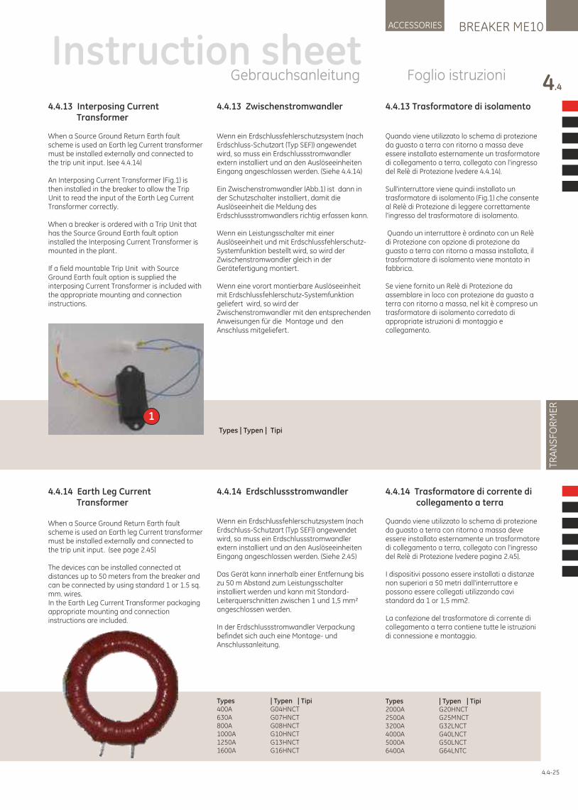
BREAKER ME10ACCESSORIES
4.4
TRA
NS
FOR
ME
R
4.4.13 Interposing Current Transformer
When a Source Ground Return Earth fault scheme is used an Earth leg Current transformer must be installed externally and connected to the trip unit input. (see 4.4.14)
An Interposing Current Transformer (Fig.1) is then installed in the breaker to allow the Trip Unit to read the input of the Earth Leg Current Transformer correctly.
When a breaker is ordered with a Trip Unit that has the Source Ground Earth fault option installed the Interposing Current Transformer is mounted in the plant.
If a field mountable Trip Unit with Source Ground Earth fault option is supplied the interposing Current Transformer is included with the appropriate mounting and connection instructions.
4.4.13 Zwischenstromwandler
Wenn ein Erdschlussfehlerschutzsystem (nach Erdschluss-Schutzart (Typ SEF)) angewendet wird, so muss ein Erdschlussstromwandler extern installiert und an den Auslöseeinheiten Eingang angeschlossen werden. (Siehe 4.4.14)
Ein Zwischenstromwandler (Abb.1) ist dann in der Schutzschalter installiert, damit die Auslöseeinheit die Meldung des Erdschlussstromwandlers richtig erfassen kann.
Wenn ein Leistungsschalter mit einer Auslöseeinheit und mit Erdschlussfehlerschutz-Systemfunktion bestellt wird, so wird der Zwischenstromwandler gleich in der Gerätefertigung montiert.
Wenn eine vorort montierbare Auslöseeinheit mit Erdschlussfehlerschutz-Systemfunktion geliefert wird, so wird der Zwischenstromwandler mit den entsprechenden Anweisungen für die Montage und den Anschluss mitgeliefert.
4.4.13 Trasformatore di isolamento
Quando viene utilizzato lo schema di protezione da guasto a terra con ritorno a massa deve essere installato esternamente un trasformatore di collegamento a terra, collegato con l'ingresso del Relè di Protezione (vedere 4.4.14).
Sull'interruttore viene quindi installato un trasformatore di isolamento (Fig.1) che consente al Relè di Protezione di leggere correttamente l'ingresso del trasformatore di isolamento.
Quando un interruttore è ordinato con un Relè di Protezione con opzione di protezione da guasto a terra con ritorno a massa installata, il trasformatore di isolamento viene montato in fabbrica. Se viene fornito un Relè di Protezione da assemblare in loco con protezione da guasto a terra con ritorno a massa, nel kit è compreso un trasformatore di isolamento corredato di appropriate istruzioni di montaggio e collegamento.
Instruction sheetGebrauchsanleitung Foglio istruzioni
1
4.4.14 Earth Leg Current Transformer
When a Source Ground Return Earth fault scheme is used an Earth leg Current transformer must be installed externally and connected to the trip unit input. (see page 2.45)
The devices can be installed connected at distances up to 50 meters from the breaker and can be connected by using standard 1 or 1.5 sq. mm. wires.In the Earth Leg Current Transformer packaging appropriate mounting and connection instructions are included.
4.4.14 Erdschlussstromwandler
Wenn ein Erdschlussfehlerschutzsystem (nach Erdschluss-Schutzart (Typ SEF)) angewendet wird, so muss ein Erdschlussstromwandler extern installiert und an den Auslöseeinheiten Eingang angeschlossen werden. (Siehe 2.45)
Das Gerät kann innerhalb einer Entfernung bis zu 50 m Abstand zum Leistungsschalter installiert werden und kann mit Standard-Leiterquerschnitten zwischen 1 und 1,5 mm² angeschlossen werden.
In der Erdschlussstromwandler Verpackung befindet sich auch eine Montage- und Anschlussanleitung.
4.4.14 Trasformatore di corrente di collegamento a terra
Quando viene utilizzato lo schema di protezione da guasto a terra con ritorno a massa deve essere installato esternamente un trasformatore di collegamento a terra, collegato con l'ingresso del Relè di Protezione (vedere pagina 2.45).
I dispositivi possono essere installati a distanze non superiori a 50 metri dall'interruttore e possono essere collegati utilizzando cavi standard da 1 or 1,5 mm2.
La confezione del trasformatore di corrente di collegamento a terra contiene tutte le istruzioni di connessione e montaggio.
Types | Typen | Tipi400A G04HNCT630A G07HNCT800A G08HNCT1000A G10HNCT1250A G13HNCT1600A G16HNCT
Types | Typen | Tipi2000A G20HNCT2500A G25MNCT3200A G32LNCT4000A G40LNCT5000A G50LNCT6400A G64LNTC
Types | Typen | Tipi
4.4-25
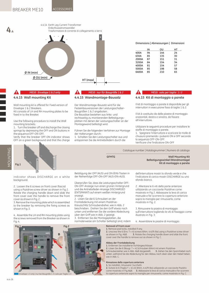
4.4.15 Wall mounting Kit
Wall mounting kit is offered for Fixed version of Envelope 1 & 2 Breakers.Kit consists of LH and RH mounting plates to be fixed in to the Breaker.
Use the following procedure to install the Wall mounting brackets.1. Turn the breaker off and discharge the closing springs by depressing the OFF and ON buttons in the sequence OFF-ON-OFF.Verify that the breaker OFF-ON indicator shows OFF on a green background and that the charge
indicator shows DISCHARGE on a white background.
2. Loosen the 6 screws on front cover (fascia) using a Pozidrive screw driver as shown in Fig 2.Rotate the charging handle down and slide the front cover over the handle to remove the front cover as shown in Fig. 2.3. Remove the mounting plate which is assembled to the breaker by removing the fixing screws as shown in Fig. 3.
4. Assemble the LH and RH mounting plate using the screws removed from the Breaker as shown in Fig. 4.
4.4.15 Wandmontage-Bausatz
Der Wandmontage-Bausatz wird für die Festeinbauversionen der Leistungsschalter-Baugrößen 1 & 2 angeboten. Die Bausätze bestehen aus links- und rechtsseitig zu montierenden Befestigungs-platten mit denen der Leistungsschalter an der Montagewand befestigt wird.
Führen Sie die folgenden Verfahren zur Montage der Halterungen durch:1. Schalten Sie den Leistungsschalter aus und entspannen Sie die Antriebsfedern durch die
Betätigung der OFF (AUS) und ON (EIN)-Tasten in der Reihenfolge OFF-ON-OFF (AUS-EIN-AUS).
Überprüfen Sie, dass die Leistungsschalter OFF-ON-OFF-Anzeige nun einen grünen Hintergrund und die Antriebsfeder-Anzeige DISCHARGED (ENTSPANNT) auf einem weißen Hintergrund anzeigt.2. Lösen Sie die 6 Schrauben an der Frontabdeckung mit einem Pozidrive-Kreuzschlitz Schraubendreher, wie in Abb. 2 beschrieben. Drehen Sie den Griff etwas nach unten und entfernen Sie die vordere Abdeckung über den Griff wie in Abb. 2 gezeigt.3. Entfernen Sie die Montageplatten, die normalerweise am Schalter befestigt sind, indem
4.4.15 Kit di montaggio a parete
Il kit di montaggio a parete è disponibile per gli interruttori in esecuzione fissa di taglia 1 & 2.
Il kit è costituito da delle piastre di montaggio orizzontali, destra e sinistra, da fissare all'interruttore.
Utilizzare le seguenti procedure per installare le staffe di montaggio a parete.1. Spegnere l'interruttore e scaricare le molle di chiusura premendo i pulsanti ON e OFF secondo la sequenza OFF-ON-OFF.Verificare che l'indicatore ON-OFF
dell'interruttore mostri lo sfondo verde e che l'indicatore di carica mostri DISCHARGE su uno sfondo bianco.
2. Allentare le 6 viti della parte anteriore utilizzando un cacciavite Pozidrive come mostrato in Fig 2. Abbassare la leva di carica manuale e far scorrere la copertura anteriore sopra la maniglia per rimuoverla, come mostrato in Fig. 2.
3. Rimuovere la piastra di montaggio sull'interruttore togliendo le viti di fissaggio come illustrato in Fig. 3.
4. Assemblare le piastre di montaggio
Catalogue number | Katalognummer | Numero di catalogo -------------------------------------------------------------------------------------GFMTG Wall Mounting Kit
Befestigungswinkel (Wandmontage)Kit di montaggio a pareteFig.1
4.4
MO
UN
TIN
GACCESSORIESBREAKER ME10
Ø IN (min)
Ø OU (min)HT (max)
Dimensions | Abmessungen | Dimensioni
IN OU HT .400A 94 144 24630A 85 135 302000A 87 151 313200A 84 154 344000A 81 154 575000A 85 198 586400A 85 210 65
4.4.14 Earth Leg Current Transformer Erdschlussstromwandler Trasformatore di corrente di collegamento a terra
4.4-26
Fig.1 Fig.2
C
B
ARemoval of Front cover1. Remove pad locks, installed if any.2. Unscrew the 6 [Env. T = 4] screws (6Nm, 4.42ft-lbs) using a Pozidrive screw driver as shown in Fig. A&B. 3. Rotate the charging handle down and slide the front cover over the handle to remove out as shown in Fig. C.
Abbau der Frontabdeckung1. Entfernen Sie installierte Vorhängeschlösser.2. Lösen Sie die 6 [Baugr. T = 4] Schrauben (6Nm) mit einem Pozidrive-Schraubenzieher wie in Abb. A&B dargestellt . 3. Ziehen Sie den Spannhebel nach unten, während Sie die Abdeckung für den Abbau nach oben über den Hebel heben, wie in Abb. C.
Rimozione della copertura anteriore1. Se installati, rimuovere I lucchetti.2. Svitare le 6 [Taglia T = 4] viti (6Nm, 4.42ft-lbs) utilizzando un cacciavite Pozidriv come mostrato in Fig.A&B. 3. Abbassare la leva di carica manuale e far scorrere la copertura anteriore sopra la maniglia per rimuoverla, come mostrato in Fig. C.Envelope 1-3 only | nur bei Baugröße 1-3 | solo per Taglia 1-3
ME10: Envelope 1 & 2 only ME10: nur für Baugröße 1 & 2 ME10: solo per taglia 1 i 2
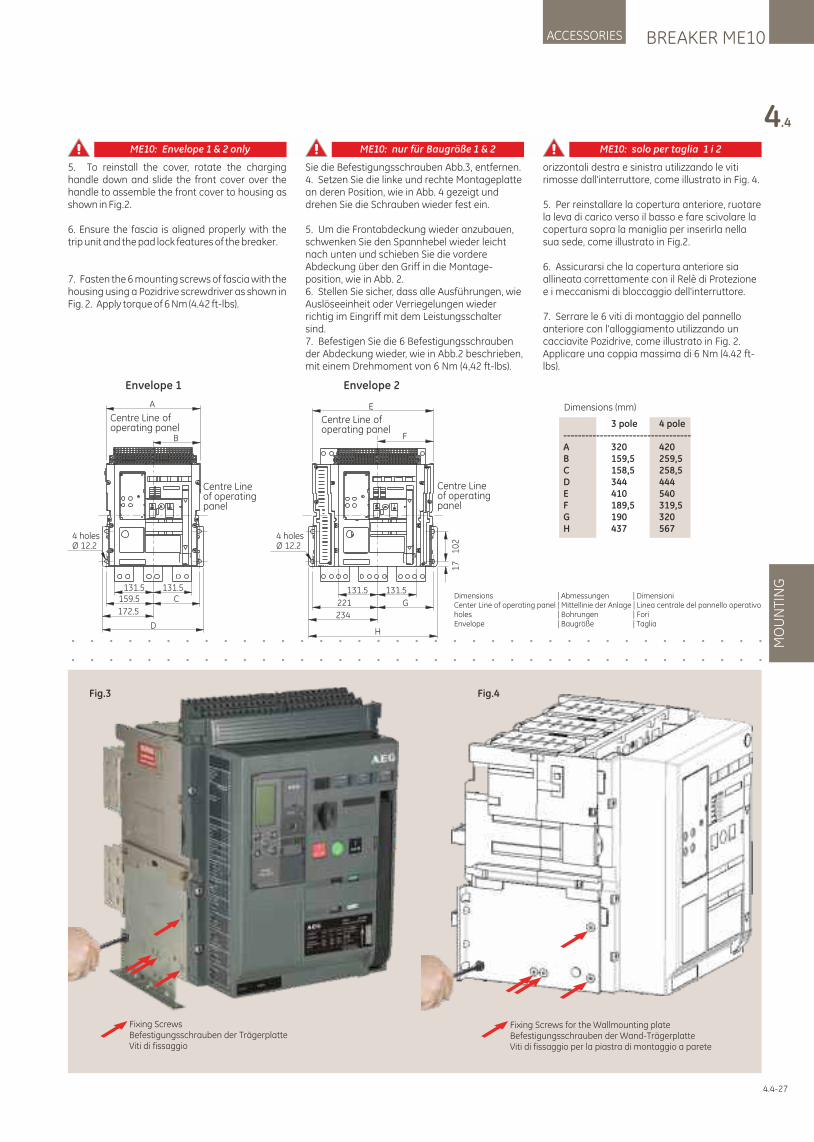
Fixing ScrewsBefestigungsschrauben der TrägerplatteViti di fissaggio
Fig.3
Fixing Screws for the Wallmounting plateBefestigungsschrauben der Wand-TrägerplatteViti di fissaggio per la piastra di montaggio a parete
Fig.4
BREAKER ME10ACCESSORIES
4.4
MO
UN
TIN
G
5. To reinstall the cover, rotate the charging handle down and slide the front cover over the handle to assemble the front cover to housing as shown in Fig.2.
6. Ensure the fascia is aligned properly with the trip unit and the pad lock features of the breaker.
7. Fasten the 6 mounting screws of fascia with the housing using a Pozidrive screwdriver as shown in Fig. 2. Apply torque of 6 Nm (4.42 ft-lbs).
Sie die Befestigungsschrauben Abb.3, entfernen. 4. Setzen Sie die linke und rechte Montageplatte an deren Position, wie in Abb. 4 gezeigt und drehen Sie die Schrauben wieder fest ein.
5. Um die Frontabdeckung wieder anzubauen, schwenken Sie den Spannhebel wieder leicht nach unten und schieben Sie die vordere Abdeckung über den Griff in die Montage-position, wie in Abb. 2.6. Stellen Sie sicher, dass alle Ausführungen, wie Auslöseeinheit oder Verriegelungen wieder richtig im Eingriff mit dem Leistungsschalter sind.7. Befestigen Sie die 6 Befestigungsschrauben der Abdeckung wieder, wie in Abb.2 beschrieben, mit einem Drehmoment von 6 Nm (4,42 ft-lbs).
orizzontali destra e sinistra utilizzando le viti rimosse dall'interruttore, come illustrato in Fig. 4.
5. Per reinstallare la copertura anteriore, ruotare la leva di carico verso il basso e fare scivolare la copertura sopra la maniglia per inserirla nella sua sede, come illustrato in Fig.2.
6. Assicurarsi che la copertura anteriore sia allineata correttamente con il Relè di Protezione e i meccanismi di bloccaggio dell'interruttore.
7. Serrare le 6 viti di montaggio del pannello anteriore con l'alloggiamento utilizzando un cacciavite Pozidrive, come illustrato in Fig. 2. Applicare una coppia massima di 6 Nm (4.42 ft-lbs).
4.4-27
Dimensions | Abmessungen | Dimensioni Center Line of operating panel | Mittellinie der Anlage | Linea centrale del pannello operativo holes | Bohrungen | ForiEnvelope | Baugröße | Taglia
Dimensions (mm)
3 pole 4 pole-----------------------------------A 320 420B 159,5 259,5C 158,5 258,5D 344 444E 410 540F 189,5 319,5G 190 320H 437 567
A
B
4 holesØ 12.2
131.5 131.5159.5
172.5
C
D
Centre Lineof operatingpanel
Centre Line of operating panel
E
4 holesØ 12.2
F
131.5 131.5
221 G
234
H
10
21
7
Centre Lineof operatingpanel
Centre Line of operating panel
Envelope 1 Envelope 2
ME10: Envelope 1 & 2 only ME10: nur für Baugröße 1 & 2 ME10: solo per taglia 1 i 2
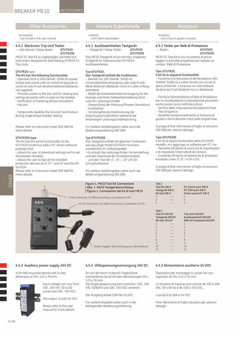
Other Accessories Weitere Zubehörteile Accessori
4.5-00
OTH
ER
ACCESSORIESBREAKER ME10
9-Pin Connector | 9-Stifte Anschluss | Connettore 9-Pin
15-Pin Connector | 15 Stifte Anschluss | Connettore 15-Pin
Power Supply | Stromversorgung | Alimentatore
Figure 1. ME10 Test Kit Connections | Abb. 1 ME10 Testgerätanschlüsse | Figura 1. Connessioni del kit di test ME10
Tab.1Test Kit DB-9 PC Comm port DB-9 Testgerät DB-9 PC COM port DB-9Kit test DB-9 Porta comm PC DB-9 2 ---- 2 3 ---- 3 5 ---- 5
Tab.2Test Kit HD15F Trip Unit HD15M Testgerät HD15F Auslöseeinheit HD15MKit test HD15F Relè di Protezione HD15M1 ---- 1 2 ---- 2 3 ---- 3 6 ---- 6 7 ---- 7 8 ---- 8 9 ---- 9 10 ---- 10 11 ---- 11
4.5.2 Auxiliary power supply 24V DC
A Din Rail mounted device with a case dimension of 29 x 115 x 76 mm.
Input voltage can vary from 100.. 240 VAC 50 or 60 cycles and 100.. 350 VDC.
The output is 0,6A 24 VDC.
Please refer to the user manual for more details.
4.5.2 Alimentatore ausiliario 24 VDC
Dispositivo per montaggio su guida Din con ingombro di 29 x 115 x 76 mm.
La tensione di ingresso può variare da 100 a 240 VAC, 50 o 60 Hz e da 100 a 350 VDC.
L'uscita è di 0,6A a 24 VDC.
Fare riferimento al foglio istruzioni per ulteriori dettagli.
4.5.2 Hilfsspannungsversorgung 24V DC
Ein auf die Norm-Hutprofil-Tragschiene montierbares Gerät mit den Abmessungen 29 x 115 x 76 mm.Die Eingangsspannung kann zwischen 100.. 240 VAC 50/60Hz und 100.. 350 VDC variieren.
Der Ausgang leistet 0,6A bei 24 VDC.
Für weitere Angaben siehe auch in der beiliegenden Bedienungsanleitung.
Accessories, ..not include in this user manual.
--------------------------------------------------------
4.5.1 Electronic Trip Unit Tester--- test device / Setup tester: GTUTK20 GTUTK20SME10 TU Test Kit is a lightweight, portable test instrument designed for field-testing of ME10 TU Trip Units.
GTUTK20 type..The Kit has the following functionality:- Operates from a 100-240VAC 50/60 Hz power socket and comes with an Universal plug set or works on two 9-volt alkaline batteries (batteries not supplied).- Provides power to the trip unit for viewing and setting set points with no load on the breaker.- Verification of metering (phase simulation)- trip test
- Temporarily disables the Ground Fault feature during single phase breaker testing.
Please refer to Instruction sheet DEE 689 for more details.
GTUTK20S typeThe Kit has the same functionality as the GTUTK20 model but adds a PC driven software package that:- allows the user to download settings and to set the breaker remotely,- allows the user to test all the installed protection devices as LT, ST, I and GF and the ZSI function.Please refer to Instruction sheet DEE 689 for more details.
Zubehör, ..nicht näher beschrieben.
--------------------------------------------------------
4.5.1 Auslöseeinheiten Testgerät--- Testgerät / Setup Tester: GTUTK20 GTUTK20SDas ME10-Testgerät ist ein leichtes, tragbares Prüfgerät für Feldversuche mit ME10-Auslöseeinheiten.
Typ GTUTK20..Das Testgerät enthält die Funktionen: - Betrieb mit 100-240VAC 50/60 Hz Universalsteckerversorgung oder zwei 9-Volt-Alkali-Batterien (Batterien nicht im Lieferumfang enthalten).- Bietet die Auslöseeinheitenversorgung für die Anzeige und deren Sollwerteeinstellung ohne Last am Leistungsschalter.- Überprüfung der Messung (Phasen-Simulation) - Auslösetest- Vorübergehende Deaktivierung der Erdschlussschutzfunktion während der einphasigen Leistungsschalterprüfung.
Für weitere Detailangaben siehe auch die Bedienungsanleitung DEE 689.
Typ GTUTK20S..Das Testgerät enthält die gleichen Funktionen wie das obige Model GTUTK20 mit einem zusätzlichen PC-Softwarepaket:- Es erlaubt die Leistungschalter Ferneinstellung und den Download der Einstellparameter,- und den Test der LT-, ST-, I, GF unf ZSI-Schutzfunktionen.
Für weitere Detailangaben siehe auch die Bedienungsanleitung DEE 689.
Accessori, ..non inclusi in questo manuale.
--------------------------------------------------------
4.5.1 Tester per Relè di Protezione --- Tester: GTUTK20 GTUTK20S ME10 TU Test Kit è uno strumento di prova leggero e portatile progettato per testare sul campo i Relè di Protezione.
Tipo GTUTK20..Il kit ha le seguenti funzionalità: - Funziona tramite presa di alimentazione 100-240VAC 50/60 Hz e viene fornito con un set di spine universali, o funziona con due batterie alcaline da 9 volt (batterie non in dotazione).
- Fornisce l'alimentazione al Rele di Protezione per la visualizzazione e impostazione parametri anche senza carico nell'interruttore. - Verifica della misurazione (simulazione fase) - Test di sgancio - Disabilita temporaneamente la funzione di guasto a terra durante il test sulla singola fase.
Si prega di fare riferimento al foglio di istruzioni DEE 689 per ulteriori dettagli.
Tipo GTUTK20S Il kit ha la stessa funzionalità della GTUTK20 modello, ma aggiunge un software per PC che: - Permette all'utente di scaricare le impostazioni e di impostare l'interruttore da remoto, - Consente all'utente di testare tte le protezioni installate come LT, ST, I e GF e ZSI.
Si prega di fare riferimento al foglio di istruzioni DEE 689 per ulteriori dettagli.
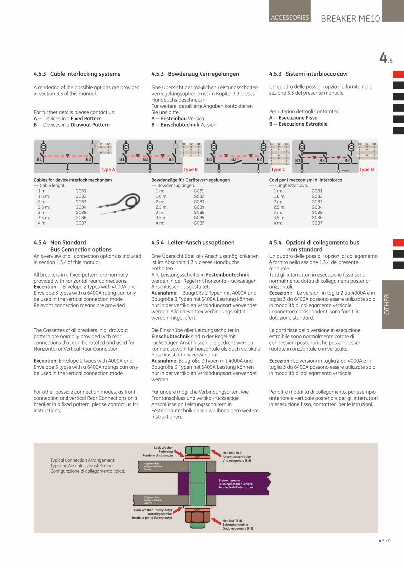
BREAKER ME10ACCESSORIES
4.5
OTH
ER
4.5.3 Cable Interlocking systems
A rendering of the possible options are provided in section 3.3 of this manual.
For further details please contact us:A -- Devices in a Fixed PatternB -- Devices in a Drawout Pattern
4.5.3 Sistemi interblocco cavi
Un quadro delle possibili opzioni è fornito nella sezione 3.3 del presente manuale.
Per ulteriori dettagli contatateci:A -- Esecuzione FissaB -- Esecuzione Estraibile
4.5.3 Bowdenzug Verriegelungen
Eine Übersicht der möglichen Leistungsschalter-Verriegelungsoptionen ist im Kapitel 3.3 dieses Handbuchs beschrieben.Für weitere, detaillierte Angaben kontaktieren Sie uns bitte.A -- Festeinbau VersionB -- Einschubtechnik Version
4.5.4 Non Standard Bus Connection optionsAn overview of all connection options is included in section 1.3.4 of this manual.
All breakers in a fixed pattern are normally provided with horizontal rear connections.Exception: Envelope 2 types with 4000A and Envelope 3 types with a 6400A rating can only be used in the vertical connection mode. Relevant connection means are provided.
The Cassettes of all breakers in a drawout pattern are normally provided with rear connections that can be rotated and used for Horizontal or Vertical Rear Connection.
Exception: Envelope 2 types with 4000A and Envelope 3 types with a 6400A ratings can only be used in the vertical connection mode.
For other possible connection modes, as front connection and vertical Rear Connections on a breaker in a fixed pattern, please contact us for instructions.
4.5.4 Opzioni di collegamento bus non standardUn quadro delle possibili opzioni di collegamento è fornito nella sezione 1.3.4 del presente manuale.Tutti gli interruttori in esecuzione fissa sono normalmente dotati di collegamenti posteriori orizzontali.Eccezioni: Le versioni in taglia 2 da 4000A e in taglia 3 da 6400A possono essere utilizzate solo in modalità di collegamento verticale.I connettori corrispondenti sono forniti in dotazione standard.
Le parti fisse della versione in esecuzione estraibile sono normalmente dotate di connessioni posteriori che possono esser ruotate in orizzontale o in verticale.
Eccezioni: Le versioni in taglia 2 da 4000A e in taglia 3 da 6400A possono essere utilizzate solo in modalità di collegamento verticale.
Per altre modalità di collegamento, per esempio anteriore e verticale posteriore per gli interruttori in esecuzione fissa, contattteci per le istruzioni.
4.5.4 Leiter-Anschlussoptionen
Eine Übersicht über alle Anschlussmöglichkeiten ist im Abschnitt 1.3.4 dieses Handbuchs enthalten.Alle Leistungsschalter in Festeinbautechnik werden in der Regel mit horizontal-rückseitigen Anschlüssen ausgestattet.Ausnahme: Baugröße 2 Typen mit 4000A und Baugröße 3 Typen mit 6400A Leistung können nur in der vertikalen Verbindungsart verwendet werden. Alle relevanten Verbindungsmittel werden mitgeliefert.
Die Einschübe aller Leistungsschalter in Einschubtechnik sind in der Regel mit rückseitigen Anschlüssen, die gedreht werden können, sowohl für horizontale als auch vertikale Anschlusstechnik verwendbar.Ausnahme: Baugröße 2 Typen mit 4000A und Baugröße 3 Typen mit 6400A Leistung können nur in der vertikalen Verbindungsart verwendet werden.
Für andere mögliche Verbindungsarten, wie Frontanschluss und vertikal-rückseitige Anschlüsse an Leistungsschaltern in Festeinbautechnik geben wir Ihnen gern weitere Instruktionen.
Breaker terminalLeistungsschalter-SchieneTerminale dell‘interruttore
Customer busAnlagen-SchieneSbarre
Customer busAnlagen-Schiene.Sbarre
Hex Nut (8.8)SchraubenmutterDado esagonale (8.8)
Hex Bolt (8.8)AnschlussschraubeVite esagonale (8.8)
Lock WasherFederring
Rondella di sicurezza
Plain Washer (Heavy duty)Unterlegscheibe
Rondella piana (heavy duty)
Typical Connection Arrangement:Typische Anschlusskonstellation:Configurazione di collegamento tipica:
Type A
G
B1 B2
B10I0
B200I
Type B
G
B1 B3B2
B10I00
B200I0
B3000I
Type C
B1 B2B3
B10I00I0I
B200I00II
B3000III0
B1 B2B3
Priority Type D
B10I00I
B200I0I
B3000I0
Cables for device Interlock mechanism --- Cable lenght.. 1 m: GCB1 1,6 m: GCB2 2 m: GCB3 2,5 m: GCB4 3 m: GCB5 3,5 m: GCB6 4 m: GCB7
Cavi per i meccanismi di interblocco --- Lunghezza cavo.. 1 m: GCB1 1,6 m: GCB2 2 m: GCB3 2,5 m: GCB4 3 m: GCB5 3,5 m: GCB6 4 m: GCB7
Bowdenzüge für Geräteverriegelungen --- Bowdenzuglängen.. 1 m: GCB1 1,6 m: GCB2 2 m: GCB3 2,5 m: GCB4 3 m: GCB5 3,5 m: GCB6 4 m: GCB7
4.5-01
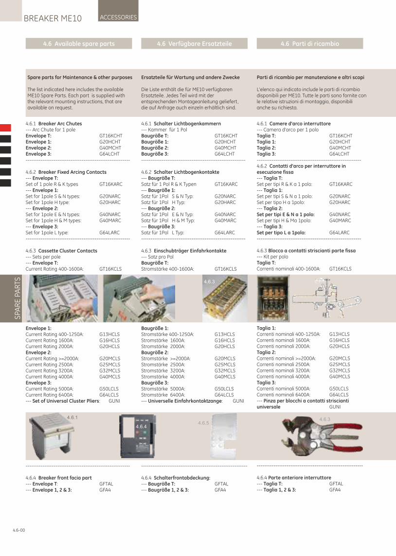
4.6.1 Camere d'arco interruttore--- Camera d'arco per 1 poloTaglia T: GT16KCHTTaglia 1: G20HCHTTaglia 2: G40MCHTTaglia 3: G64LCHT--------------------------------------------------------4.6.2 Contatti d'arco per interruttore in esecuzione fissa--- Taglia T:Set per tipi R & K a 1 polo: GT16KARC--- Taglia 1:Set per tipi S & N a 1 polo: G20NARCSet per tipo H a 1polo: G20HARC--- Taglia 2:Set per tipi E & N a 1 polo: G40NARCSet per tipi H & Ma 1polo: G40MARC--- Taglia 3:Set per tipo L a 1polo: G64LARC--------------------------------------------------------
4.6.3 Blocco a contatti striscianti parte fissa--- Kit per poloTaglia T:Correnti nominali 400-1600A: GT16KCLS
Taglia 1:Correnti nominali 400-1250A: G13HCLSCorrenti nominali 1600A: G16HCLSCorrenti nominali 2000A: G20HCLSTaglia 2:Correnti nominali >=2000A: G20MCLSCorrenti nominali 2500A: G25MCLSCorrenti nominali 3200A: G32MCLSCorrenti nominali 4000A: G40MCLSTaglia 3:Correnti nominali 5000A: G50LCLSCorrenti nominali 6400A: G64LCLS--- Pinza per blocchi a contatti striscianti universale GUNI
---------------------------------------------------------
4.6.4 Parte anteriore interruttore--- Taglia T: GFTAL--- Taglia 1, 2 & 3: GFA4
4.6 Available spare parts 4.6 Verfügbare Ersatzteile 4.6 Parti di ricambio
ACCESSORIESBREAKER ME10S
PAR
E P
AR
TS
4.6-00
Spare parts for Maintenance & other purposes
The list indicated here includes the available ME10 Spare Parts. Each part is supplied with the relevant mounting instructions, that are available on request.
Ersatzteile für Wartung und andere Zwecke
Die Liste enthält die für ME10 verfügbaren Ersatzteile. Jedes Teil wird mit der entsprechenden Montageanleitung geliefert, die auf Anfrage auch einzeln erhältlich sind.
Parti di ricambio per manutenzione e altri scopi
L'elenco qui indicato include le parti di ricambio disponibili per ME10. Tutte le parti sono fornite con le relative istruzioni di montaggio, disponibili anche su richiesta.
4.6.3
4.6.54.6.34.6.1
4.6.4
4.6.1 Schalter Lichtbogenkammern--- Kammer für 1 PolBaugröße T: GT16KCHTBaugröße 1: G20HCHTBaugröße 2: G40MCHTBaugröße 3: G64LCHT--------------------------------------------------------
4.6.2 Schalter Lichtbogenkontakte--- Baugröße T:Satz für 1 Pol R & K Typen GT16KARC--- Baugröße 1:Satz für 1Pol S & N Typ: G20NARCSatz für 1Pol H Typ: G20HARC--- Baugröße 2:Satz für 1Pol E & N Typ: G40NARCSatz für 1Pol H & M Typ: G40MARC--- Baugröße 3:Satz für 1Pol L Typ: G64LARC--------------------------------------------------------
4.6.3 Einschubträger Einfahrkontakte--- Satz pro PolBaugröße T:Stromstärke 400-1600A: GT16KCLS
Baugröße 1:Stromstärke 400-1250A: G13HCLSStromstärke 1600A: G16HCLSStromstärke 2000A: G20HCLSBaugröße 2:Stromstärke >=2000A: G20MCLSStromstärke 2500A: G25MCLSStromstärke 3200A: G32MCLSStromstärke 4000A: G40MCLSBaugröße 3:Stromstärke 5000A: G50LCLSStromstärke 6400A: G64LCLS--- Universelle Einfahrkontaktzange: GUNI
---------------------------------------------------------
4.6.4 Schalterfrontabdeckung:--- Baugröße T: GFTAL--- Baugröße 1, 2 & 3: GFA4
4.6.1 Breaker Arc Chutes--- Arc Chute for 1 poleEnvelope T: GT16KCHTEnvelope 1: G20HCHTEnvelope 2: G40MCHTEnvelope 3: G64LCHT--------------------------------------------------------
4.6.2 Breaker Fixed Arcing Contacts--- Envelope T:Set of 1 pole R & K types GT16KARC--- Envelope 1:Set for 1pole S & N types: G20NARCSet for 1pole H type: G20HARC--- Envelope 2:Set for 1pole E & N types: G40NARCSet for 1pole H & M types: G40MARC--- Envelope 3:Set for 1pole L type: G64LARC--------------------------------------------------------
4.6.3 Cassette Cluster Contacts--- Sets per pole--- Envelope T:Current Rating 400-1600A: GT16KCLS
Envelope 1:Current Rating 400-1250A: G13HCLSCurrent Rating 1600A: G16HCLSCurrent Rating 2000A: G20HCLSEnvelope 2:Current Rating >=2000A: G20MCLSCurrent Rating 2500A: G25MCLSCurrent Rating 3200A: G32MCLSCurrent Rating 4000A: G40MCLSEnvelope 3:Current Rating 5000A: G50LCLSCurrent Rating 6400A: G64LCLS--- Set of Universal Cluster Pliers: GUNI
--------------------------------------------------------
4.6.4 Breaker front facia part--- Envelope T: GFTAL--- Envelope 1, 2 & 3: GFA4
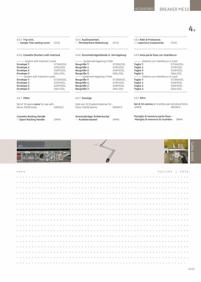
4.6-01
BREAKER ME10ACCESSORIES
4.6
SPA
RE
PA
RTS
n o t e n o t i z e n | n o t a
. . . . . . . . . . . . . . . . . . . . . . . . . . . . . . . . . . . . . . . . . . . . . . . . . . . . . . . .
. . . . . . . . . . . . . . . . . . . . . . . . . . . . . . . . . . . . . . . . . . . . . . . . . . . . . . . .
. . . . . . . . . . . . . . . . . . . . . . . . . . . . . . . . . . . . . . . . . . . . . . . . . . . . . . . .
. . . . . . . . . . . . . . . . . . . . . . . . . . . . . . . . . . . . . . . . . . . . . . . . . . . . . . . .
. . . . . . . . . . . . . . . . . . . . . . . . . . . . . . . . . . . . . . . . . . . . . . . . . . . . . . . .
. . . . . . . . . . . . . . . . . . . . . . . . . . . . . . . . . . . . . . . . . . . . . . . . . . . . . . . .
. . . . . . . . . . . . . . . . . . . . . . . . . . . . . . . . . . . . . . . . . . . . . . . . . . . . . . . .
. . . . . . . . . . . . . . . . . . . . . . . . . . . . . . . . . . . . . . . . . . . . . . . . . . . . . . . .
. . . . . . . . . . . . . . . . . . . . . . . . . . . . . . . . . . . . . . . . . . . . . . . . . . . . . . . .
. . . . . . . . . . . . . . . . . . . . . . . . . . . . . . . . . . . . . . . . . . . . . . . . . . . . . . . .
. . . . . . . . . . . . . . . . . . . . . . . . . . . . . . . . . . . . . . . . . . . . . . . . . . . . . . . .
. . . . . . . . . . . . . . . . . . . . . . . . . . . . . . . . . . . . . . . . . . . . . . . . . . . . . . . .
. . . . . . . . . . . . . . . . . . . . . . . . . . . . . . . . . . . . . . . . . . . . . . . . . . . . . . . .
. . . . . . . . . . . . . . . . . . . . . . . . . . . . . . . . . . . . . . . . . . . . . . . . . . . . . . . .
. . . . . . . . . . . . . . . . . . . . . . . . . . . . . . . . . . . . . . . . . . . . . . . . . . . . . . . .
. . . . . . . . . . . . . . . . . . . . . . . . . . . . . . . . . . . . . . . . . . . . . . . . . . . . . . . .
. . . . . . . . . . . . . . . . . . . . . . . . . . . . . . . . . . . . . . . . . . . . . . . . . . . . . . . .
4.6.7
--------------------------------------------------------4.6.5 Relè di Protezione.--- copertura trasparente: GTUS
--------------------------------------------------------
4.6.6 Ante parte fissa con interblocco
-------- Sistema con interblocco a 3 poliTaglia T: GT16N2SSLTaglia 1: G20H2SSLTaglia 2: G40M2SSLTaglia 3: G64L2SSL-------- Sistema con interblocco a 4 poliTaglia T: GT16N5SSLTaglia 1: G20H5SSLTaglia 2: G40M5SSLTaglia 3: G64L5SSL--------------------------------------------------------
4.6.7 Altro
Set di 10 di ricambio per serrature Ronis camme1004B: GRONCS
Maniglia di manovra parte fissa--- Maniglia di manovra di ricambio: GRHN
--------------------------------------------------------4.6.5 Trip Unit..--- tamper free sealing cover: GTUS
--------------------------------------------------------
4.6.6 Cassette Shutters with interlock
-------- System with Interlock 3 poleEnvelope T: GT16N2SSLEnvelope 1: G20H2SSLEnvelope 2: G40M2SSLEnvelope 3: G64L2SSL------- System with Interlock 4 poleEnvelope T: GT16N5SSLEnvelope 1: G20H5SSLEnvelope 2: G40M5SSLEnvelope 3: G64L5SSL--------------------------------------------------------
4.6.7 Other
Set of 10 spare cams for use with..Ronis 1004B locks: GRONCS
Cassette Racking Handle— Spare Racking Handle: GRHN
--------------------------------------------------------4.6.5 Auslöseeinheit..--- Plombierbare Abdeckung: GTUS
--------------------------------------------------------
4.6.6 Einschubträgerblende m. Verriegelung
-------- Systemverriegelung 3 PoleBaugröße T: GT16N2SSLBaugröße 1: G20H2SSLBaugröße 2: G40M2SSLBaugröße 3: G64L2SSL------- Systemverriegelung 4 PoleBaugröße T: GT16N5SSLBaugröße 1: G20H5SSLBaugröße 2: G40M5SSLBaugröße 3: G64L5SSL--------------------------------------------------------
4.6.7 Sonstige
Satz von 10 Ersatzmitnehmer für ..Ronis 1004B Sperre: GRONCS
Einschubträger Einfahrkurbel--- Kurbelersatzteil: GRHN
LOCKSBREAKER ME10 INTRO BREAKER ACCESSORIES TESTS APPENDIX
TRIP UNIT
Content
5.1 Maintenance - Inspection Schedule
5.2 Cleaning Procedure - Arcing Contacts Inspection - Circuit Breaker Main Mechanism Inspection
5.3 Cassette Inspection
5.4 Contact wear Inspection
5.5 Isolating Contacts (Drawout Type) Inspection
5.6 Power Terminals and Busbar Inspection
5.7 Lubrication
5.8 Testing - Trip Unit Testing
5.9 Troubleshooting - Table 5.1: Troubleshooting
Inhaltsverzeichnis
5.1 Wartung - Inspektions-Ablaufplan
5.2 Reinigungsvorgänge - Lichtbogenkontakte Inspektion - Leistungsschaltermechanik- Hauptinspektion
5.3 Einschubträger-Inspektion
5.4 Kontaktverschleiß-Inspektion
5.5 Trennkontakte (Einschub) Inspektion
5.6 Hauptanschlüsse und Sammelschienen- Inspektion
5.7 Schmierung
5.8 Tests - Auslöseeinheiten-Test
5.9 Fehlersuche - Tabelle 5.1: Fehlersuche und Behebung
Sommario
5.1 Manutenzione - Programma di ispezione
5.2 Procedura di pulizia - Ispezione contatti d'arco - Ispezione meccanismi principali interruttore
5.3 Controllo della parte fissa
5.4 Controllo usura del contatto
5.5 Controllo dei contatti di sezionamento (versione in esecuzione estraibile)
5.6 Controllo dei morsetti di alimentazione e sbarre
5.7 Lubrificazione
5.8 Verifica - Verifica Relè di Protezione
5.9 Risoluzione dei problemi - Tabella 5.1: Risoluzione dei problemi
n o t e n o t i z e n | n o t a
. . . . . . . . . . . . . . . . . . . . . . . . . . . . . . . . . . . . . . . . . . . . . . . . . . . . . . . .
. . . . . . . . . . . . . . . . . . . . . . . . . . . . . . . . . . . . . . . . . . . . . . . . . . . . . . . .
. . . . . . . . . . . . . . . . . . . . . . . . . . . . . . . . . . . . . . . . . . . . . . . . . . . . . . . .
. . . . . . . . . . . . . . . . . . . . . . . . . . . . . . . . . . . . . . . . . . . . . . . . . . . . . . . .
. . . . . . . . . . . . . . . . . . . . . . . . . . . . . . . . . . . . . . . . . . . . . . . . . . . . . . . .
. . . . . . . . . . . . . . . . . . . . . . . . . . . . . . . . . . . . . . . . . . . . . . . . . . .
WARNUNG:
Es ist nur qualifiziertem Personal erlaubt die Installation, den Betrieb und die Wartung der elektrischen Geräte vorzunehmen.
VorsichtVermeiden Sie das Risiko einer Verletzung durch bewegliche Teile während der Handhabung des Schalters.Während der Wartungsarbeit an diesen Geräten ist die Verwendung eines Erdungsgerätes (optionales Zubehör) dringend empfohlen.
WARNING:
Only qualified personnel are allowed to install, operate and maintain all electrical equipment.
CautionWhilst handling the breaker avoid injury due to moving parts.
During maintenance of these devices the use of the optionally available Earthing device is strongly recommended.
AVVERTENZA:
Solo il personale qualificato è autorizzato ad installare, gestire ed effettuare la manutenzione di tutte le apparecchiature elettriche.
AttenzioneDurante la movimentazione dell'interruttore tutelarsi dalle lesioni provocare da parti in movimento.Durante la manutenzione di questi dispositivi è fortemente raccomandato l'uso del dispositivo di messa a terra, disponibile come opzione.
5-00
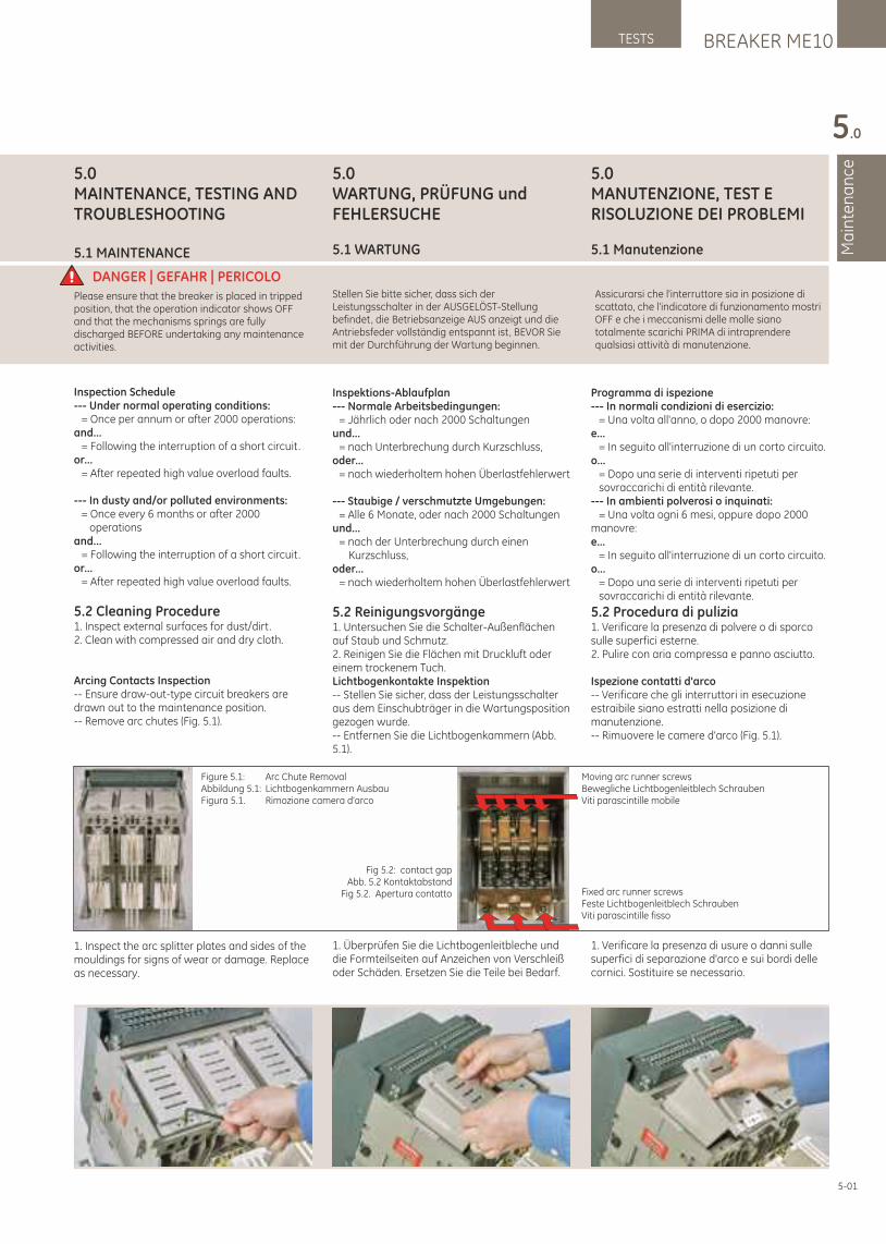
5.0MANUTENZIONE, TEST E RISOLUZIONE DEI PROBLEMI
5.1 Manutenzione
Programma di ispezione--- In normali condizioni di esercizio: = Una volta all'anno, o dopo 2000 manovre:e... = In seguito all'interruzione di un corto circuito.o... = Dopo una serie di interventi ripetuti per sovraccarichi di entità rilevante.--- In ambienti polverosi o inquinati: = Una volta ogni 6 mesi, oppure dopo 2000 manovre:e... = In seguito all'interruzione di un corto circuito.o... = Dopo una serie di interventi ripetuti per sovraccarichi di entità rilevante.
5.2 Procedura di pulizia1. Verificare la presenza di polvere o di sporco sulle superfici esterne.2. Pulire con aria compressa e panno asciutto.
Ispezione contatti d'arco-- Verificare che gli interruttori in esecuzione estraibile siano estratti nella posizione di manutenzione.-- Rimuovere le camere d'arco (Fig. 5.1).
1. Verificare la presenza di usure o danni sulle superfici di separazione d'arco e sui bordi delle cornici. Sostituire se necessario.
5.0WARTUNG, PRÜFUNG und FEHLERSUCHE
5.1 WARTUNG
Inspektions-Ablaufplan--- Normale Arbeitsbedingungen: = Jährlich oder nach 2000 Schaltungenund... = nach Unterbrechung durch Kurzschluss,oder... = nach wiederholtem hohen Überlastfehlerwert
--- Staubige / verschmutzte Umgebungen: = Alle 6 Monate, oder nach 2000 Schaltungenund... = nach der Unterbrechung durch einen Kurzschluss,oder... = nach wiederholtem hohen Überlastfehlerwert
5.2 Reinigungsvorgänge1. Untersuchen Sie die Schalter-Außenflächen auf Staub und Schmutz.2. Reinigen Sie die Flächen mit Druckluft oder einem trockenem Tuch.Lichtbogenkontakte Inspektion-- Stellen Sie sicher, dass der Leistungsschalter aus dem Einschubträger in die Wartungsposition gezogen wurde.-- Entfernen Sie die Lichtbogenkammern (Abb. 5.1).
1. Überprüfen Sie die Lichtbogenleitbleche und die Formteilseiten auf Anzeichen von Verschleiß oder Schäden. Ersetzen Sie die Teile bei Bedarf.
5.0MAINTENANCE, TESTING AND TROUBLESHOOTING
5.1 MAINTENANCE
Inspection Schedule--- Under normal operating conditions: = Once per annum or after 2000 operations:and... = Following the interruption of a short circuit.or... = After repeated high value overload faults.
--- In dusty and/or polluted environments: = Once every 6 months or after 2000 operationsand... = Following the interruption of a short circuit.or... = After repeated high value overload faults.
5.2 Cleaning Procedure1. Inspect external surfaces for dust/dirt.2. Clean with compressed air and dry cloth.
Arcing Contacts Inspection-- Ensure draw-out-type circuit breakers are drawn out to the maintenance position.-- Remove arc chutes (Fig. 5.1).
1. Inspect the arc splitter plates and sides of the mouldings for signs of wear or damage. Replace as necessary.
BREAKER ME10TESTS
Ma
inte
na
nce
5.0
5-01
DANGER | GEFAHR | PERICOLO Stellen Sie bitte sicher, dass sich der Leistungsschalter in der AUSGELÖST-Stellung befindet, die Betriebsanzeige AUS anzeigt und die Antriebsfeder vollständig entspannt ist, BEVOR Sie mit der Durchführung der Wartung beginnen.
Please ensure that the breaker is placed in tripped position, that the operation indicator shows OFF and that the mechanisms springs are fully discharged BEFORE undertaking any maintenance activities.
Assicurarsi che l'interruttore sia in posizione di scattato, che l'indicatore di funzionamento mostri OFF e che i meccanismi delle molle siano totalmente scarichi PRIMA di intraprendere qualsiasi attività di manutenzione.
Figure 5.1: Arc Chute RemovalAbbildung 5.1: Lichtbogenkammern AusbauFigura 5.1. Rimozione camera d'arco
Fig 5.2: contact gapAbb. 5.2 Kontaktabstand
Fig 5.2. Apertura contatto
Moving arc runner screwsBewegliche Lichtbogenleitblech SchraubenViti parascintille mobile
Fixed arc runner screwsFeste Lichtbogenleitblech SchraubenViti parascintille fisso
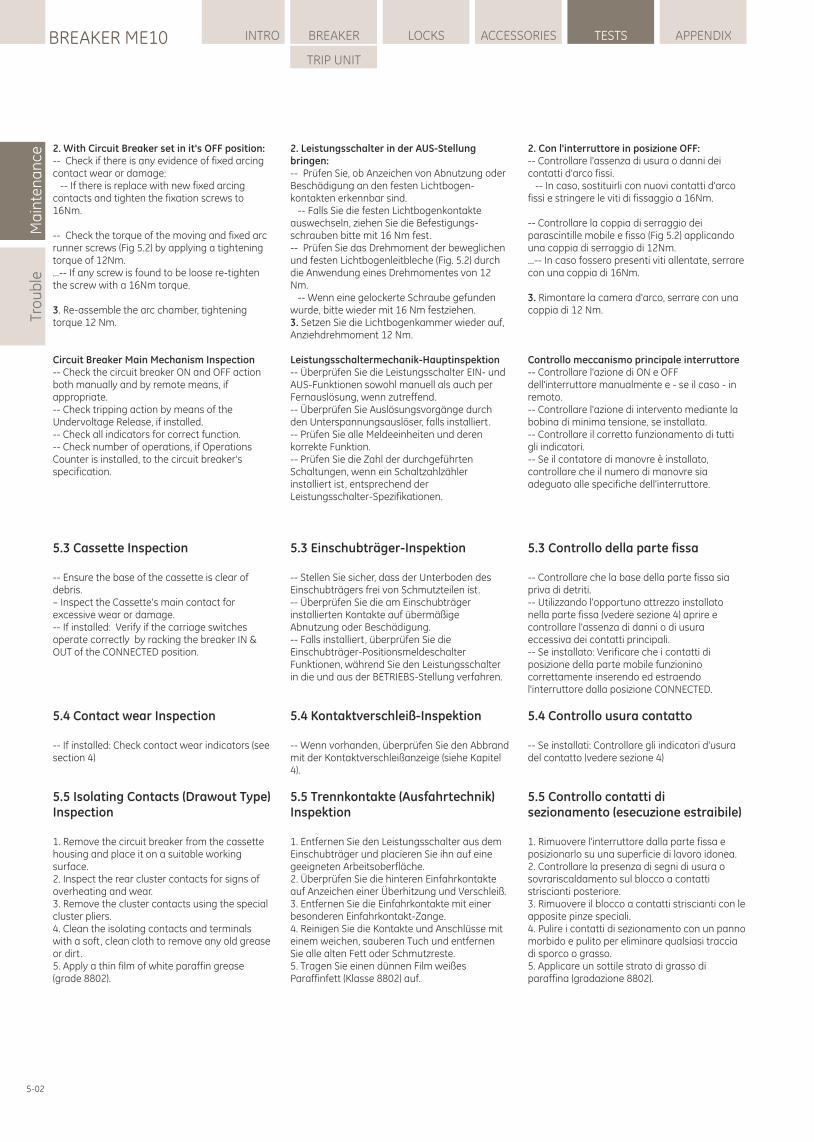
2. Con l'interruttore in posizione OFF:-- Controllare l'assenza di usura o danni dei contatti d'arco fissi. -- In caso, sostituirli con nuovi contatti d'arco fissi e stringere le viti di fissaggio a 16Nm.
-- Controllare la coppia di serraggio dei parascintille mobile e fisso (Fig 5.2) applicando una coppia di serraggio di 12Nm. ...-- In caso fossero presenti viti allentate, serrare con una coppia di 16Nm.
3. Rimontare la camera d'arco, serrare con una coppia di 12 Nm.
Controllo meccanismo principale interruttore-- Controllare l'azione di ON e OFF dell'interruttore manualmente e - se il caso - in remoto.-- Controllare l'azione di intervento mediante la bobina di minima tensione, se installata.-- Controllare il corretto funzionamento di tutti gli indicatori.-- Se il contatore di manovre è installato, controllare che il numero di manovre sia adeguato alle specifiche dell'interruttore.
5.3 Controllo della parte fissa
-- Controllare che la base della parte fissa sia priva di detriti.-- Utilizzando l'opportuno attrezzo installato nella parte fissa (vedere sezione 4) aprire e controllare l'assenza di danni o di usura eccessiva dei contatti principali.-- Se installato: Verificare che i contatti di posizione della parte mobile funzionino correttamente inserendo ed estraendo l'interruttore dalla posizione CONNECTED.
5.4 Controllo usura contatto
-- Se installati: Controllare gli indicatori d'usura del contatto (vedere sezione 4)
5.5 Controllo contatti di sezionamento (esecuzione estraibile)
1. Rimuovere l'interruttore dalla parte fissa e posizionarlo su una superficie di lavoro idonea.2. Controllare la presenza di segni di usura o sovrariscaldamento sul blocco a contatti striscianti posteriore.3. Rimuovere il blocco a contatti striscianti con le apposite pinze speciali.4. Pulire i contatti di sezionamento con un panno morbido e pulito per eliminare qualsiasi traccia di sporco o grasso.5. Applicare un sottile strato di grasso di paraffina (gradazione 8802).
2. Leistungsschalter in der AUS-Stellung bringen:-- Prüfen Sie, ob Anzeichen von Abnutzung oder Beschädigung an den festen Lichtbogen-kontakten erkennbar sind. -- Falls Sie die festen Lichtbogenkontakte auswechseln, ziehen Sie die Befestigungs-schrauben bitte mit 16 Nm fest.-- Prüfen Sie das Drehmoment der beweglichen und festen Lichtbogenleitbleche (Fig. 5.2) durch die Anwendung eines Drehmomentes von 12 Nm. -- Wenn eine gelockerte Schraube gefunden wurde, bitte wieder mit 16 Nm festziehen.3. Setzen Sie die Lichtbogenkammer wieder auf, Anziehdrehmoment 12 Nm.
Leistungsschaltermechanik-Hauptinspektion-- Überprüfen Sie die Leistungsschalter EIN- und AUS-Funktionen sowohl manuell als auch per Fernauslösung, wenn zutreffend.-- Überprüfen Sie Auslösungsvorgänge durch den Unterspannungsauslöser, falls installiert.-- Prüfen Sie alle Meldeeinheiten und deren korrekte Funktion.-- Prüfen Sie die Zahl der durchgeführten Schaltungen, wenn ein Schaltzahlzähler installiert ist, entsprechend der Leistungsschalter-Spezifikationen.
5.3 Einschubträger-Inspektion
-- Stellen Sie sicher, dass der Unterboden des Einschubträgers frei von Schmutzteilen ist.-- Überprüfen Sie die am Einschubträger installierten Kontakte auf übermäßige Abnutzung oder Beschädigung.-- Falls installiert, überprüfen Sie die Einschubträger-Positionsmeldeschalter Funktionen, während Sie den Leistungsschalter in die und aus der BETRIEBS-Stellung verfahren.
5.4 Kontaktverschleiß-Inspektion
-- Wenn vorhanden, überprüfen Sie den Abbrand mit der Kontaktverschleißanzeige (siehe Kapitel 4).
5.5 Trennkontakte (Ausfahrtechnik)Inspektion
1. Entfernen Sie den Leistungsschalter aus dem Einschubträger und placieren Sie ihn auf eine geeigneten Arbeitsoberfläche.2. Überprüfen Sie die hinteren Einfahrkontakte auf Anzeichen einer Überhitzung und Verschleiß.3. Entfernen Sie die Einfahrkontakte mit einer besonderen Einfahrkontakt-Zange.4. Reinigen Sie die Kontakte und Anschlüsse mit einem weichen, sauberen Tuch und entfernen Sie alle alten Fett oder Schmutzreste.5. Tragen Sie einen dünnen Film weißes Paraffinfett (Klasse 8802) auf.
2. With Circuit Breaker set in it's OFF position:-- Check if there is any evidence of fixed arcing contact wear or damage: -- If there is replace with new fixed arcing contacts and tighten the fixation screws to 16Nm.
-- Check the torque of the moving and fixed arc runner screws (Fig 5.2) by applying a tightening torque of 12Nm. ...-- If any screw is found to be loose re-tighten the screw with a 16Nm torque.
3. Re-assemble the arc chamber, tightening torque 12 Nm.
Circuit Breaker Main Mechanism Inspection-- Check the circuit breaker ON and OFF action both manually and by remote means, if appropriate.-- Check tripping action by means of the Undervoltage Release, if installed.-- Check all indicators for correct function.-- Check number of operations, if Operations Counter is installed, to the circuit breaker's specification.
5.3 Cassette Inspection
-- Ensure the base of the cassette is clear of debris.– Inspect the Cassette's main contact for excessive wear or damage.-- If installed: Verify if the carriage switches operate correctly by racking the breaker IN & OUT of the CONNECTED position.
5.4 Contact wear Inspection
-- If installed: Check contact wear indicators (see section 4)
5.5 Isolating Contacts (Drawout Type)Inspection
1. Remove the circuit breaker from the cassette housing and place it on a suitable working surface.2. Inspect the rear cluster contacts for signs of overheating and wear.3. Remove the cluster contacts using the special cluster pliers.4. Clean the isolating contacts and terminals with a soft, clean cloth to remove any old grease or dirt.5. Apply a thin film of white paraffin grease (grade 8802).
Ma
inte
na
nce
Tro
ub
leLOCKSBREAKER ME10 INTRO BREAKER ACCESSORIES TESTS APPENDIX
TRIP UNIT
5-02
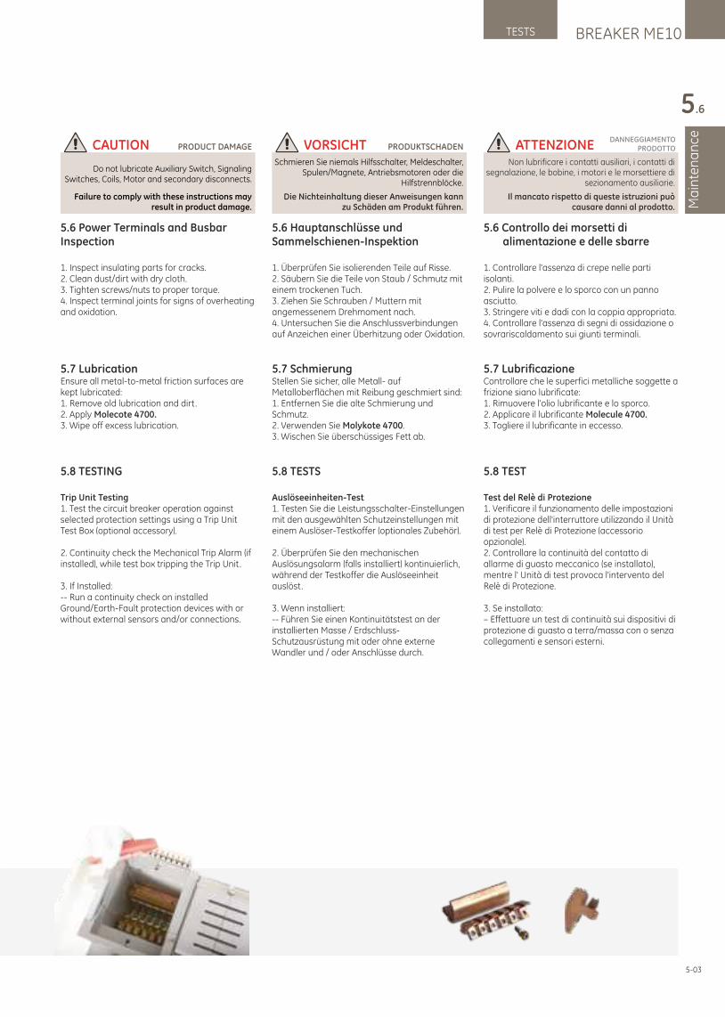
BREAKER ME10TESTS
Ma
inte
na
nce
5.6
5.6 Controllo dei morsetti di alimentazione e delle sbarre
1. Controllare l'assenza di crepe nelle parti isolanti.2. Pulire la polvere e lo sporco con un panno asciutto.3. Stringere viti e dadi con la coppia appropriata.4. Controllare l'assenza di segni di ossidazione o sovrariscaldamento sui giunti terminali.
5.7 LubrificazioneControllare che le superfici metalliche soggette a frizione siano lubrificate:1. Rimuovere l'olio lubrificante e lo sporco.2. Applicare il lubrificante Molecule 4700.3. Togliere il lubrificante in eccesso.
5.8 TEST
Test del Relè di Protezione1. Verificare il funzionamento delle impostazioni di protezione dell'interruttore utilizzando il Unità di test per Relè di Protezione (accessorio opzionale).2. Controllare la continuità del contatto di allarme di guasto meccanico (se installato), mentre l' Unità di test provoca l'intervento del Relè di Protezione.
3. Se installato:– Effettuare un test di continuità sui dispositivi di protezione di guasto a terra/massa con o senza collegamenti e sensori esterni.
5.6 Power Terminals and Busbar Inspection
1. Inspect insulating parts for cracks.2. Clean dust/dirt with dry cloth.3. Tighten screws/nuts to proper torque.4. Inspect terminal joints for signs of overheating and oxidation.
5.7 LubricationEnsure all metal-to-metal friction surfaces are kept lubricated:1. Remove old lubrication and dirt.2. Apply Molecote 4700.3. Wipe off excess lubrication.
5.8 TESTING
Trip Unit Testing1. Test the circuit breaker operation against selected protection settings using a Trip Unit Test Box (optional accessory).
2. Continuity check the Mechanical Trip Alarm (if installed), while test box tripping the Trip Unit.
3. If Installed:-- Run a continuity check on installed Ground/Earth-Fault protection devices with or without external sensors and/or connections.
5.6 Hauptanschlüsse und Sammelschienen-Inspektion
1. Überprüfen Sie isolierenden Teile auf Risse.2. Säubern Sie die Teile von Staub / Schmutz mit einem trockenen Tuch.3. Ziehen Sie Schrauben / Muttern mit angemessenem Drehmoment nach.4. Untersuchen Sie die Anschlussverbindungen auf Anzeichen einer Überhitzung oder Oxidation.
5.7 SchmierungStellen Sie sicher, alle Metall- auf Metalloberflächen mit Reibung geschmiert sind:1. Entfernen Sie die alte Schmierung und Schmutz.2. Verwenden Sie Molykote 4700.3. Wischen Sie überschüssiges Fett ab.
5.8 TESTS
Auslöseeinheiten-Test1. Testen Sie die Leistungsschalter-Einstellungen mit den ausgewählten Schutzeinstellungen mit einem Auslöser-Testkoffer (optionales Zubehör).
2. Überprüfen Sie den mechanischen Auslösungsalarm (falls installiert) kontinuierlich, während der Testkoffer die Auslöseeinheit auslöst.
3. Wenn installiert: -- Führen Sie einen Kontinuitätstest an der installierten Masse / Erdschluss-Schutzausrüstung mit oder ohne externe Wandler und / oder Anschlüsse durch.
VORSICHTSchmieren Sie niemals Hilfsschalter, Meldeschalter,
Spulen/Magnete, Antriebsmotoren oder die Hilfstrennblöcke.
PRODUKTSCHADEN
Die Nichteinhaltung dieser Anweisungen kann zu Schäden am Produkt führen.
CAUTION
Do not lubricate Auxiliary Switch, Signaling Switches, Coils, Motor and secondary disconnects.
PRODUCT DAMAGE
Failure to comply with these instructions may result in product damage.
ATTENZIONENon lubrificare i contatti ausiliari, i contatti di
segnalazione, le bobine, i motori e le morsettiere di sezionamento ausiliarie.
DANNEGGIAMENTOPRODOTTO
Il mancato rispetto di queste istruzioni può causare danni al prodotto.
5-03
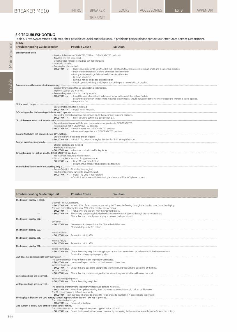
5-04
Ma
inte
na
nce
Tro
ub
leLOCKSBREAKER ME10 INTRO BREAKER ACCESSORIES TESTS APPENDIX
TRIP UNIT
5.9 TROUBLESHOOTINGTable 5.1 reviews common problems, their possible cause(s) and solution(s). If problems persist please contact our After Sales Service Department.
Table:Troubleshooting Guide Breaker Possible Cause Solution------------------------------------------------------------------------------------------------------------------------------------------------------------------------------------------------------------------------------------------------Breaker won’t close. -- Breaker is between CONNECTED, TEST and DISCONNECTED positions. -- Trip Unit has not been reset. -- Undervoltage Release is installed but not energized. -- Interlocks installed. -- Racking handle inserted. -- SOLUTION --> -- Rack circuit breaker to CONNECTED, TEST or DISCONNECTED remove racking handle and close circuit breaker. -- Push orange button on Trip Unit and close circuit breaker. -- Energize Undervoltage Release and close circuit breaker. -- Remove interlocks. -- Remove handle and close circuit breaker. -- Check operational diagram (chapter 1.4) and trip the relevant circuit breaker.Breaker closes then opens instantaneously. ------------------------------------------------------------------------------------------------------------------------------------------------------------------------------------------- -- Breaker Information Module connector is not inserted. -- Trip Unit settings are incorrect. -- Remote Rogowski coil is incorrectly installed. -- SOLUTION --> -- Insert Breaker Information Module connector to Breaker Information Module. -- Ensure the protection limits setting matches system loads. Ensure inputs are set to normally closed trip without a signal applied. -- Re-position Coil.Motor won’t charge. ----------------------------------------------------------------------------------------------------------------------------------------------------------------------------------------------------------------------- -- Ensure Motor Actuator is installed. -- SOLUTION --> -- Install Motor Actuator.DC closing coil or Undervoltage Release won’t operate. ----------------------------------------------------------------------------------------------------------------------------------------------------------------------------- -- Ensure the correct polarity of the connection to the secondary isolating contacts. -- SOLUTION --> -- Refer to wiring schematic (see Section 1.3).Circuit breaker won’t rack into cassette. ----------------------------------------------------------------------------------------------------------------------------------------------------------------------------------------------- -- Ensure breaker is pushed fully from the maintenance position to DISCONNECTED. -- Racking drive not in DISCONNECTED position. -- SOLUTION --> -- Push breaker into DISCONNECTED position. -- Ensure racking drive is in DISCONNECTED position.Ground fault does not operate below 40% setting. ----------------------------------------------------------------------------------------------------------------------------------------------------------------------------------- -- Ensure Trip Unit is installed and energized. -- SOLUTION --> -- Install Trip Unit and energize. See Section 3 for wiring schematic.Cannot insert racking handle. ------------------------------------------------------------------------------------------------------------------------------------------------------------------------------------------------------------ -- Shutter padlocks are installed. -- Key locks are installed. -- SOLUTION --> -- Remove padlocks and/or key locks.Circuit breaker will not go into the DISCONNECTED position. ----------------------------------------------------------------------------------------------------------------------------------------------------------------------- -- Mis insertion feature is incorrectly set. -- Circuit breaker is incorrect for given cassette. -- SOLUTION --> -- Reset Mis insertion feature. -- Ensure circuit breaker and cassette go together.Trip Unit healthy indicator not working. (Fig 2.1) -------------------------------------------------------------------------------------------------------------------------------------------------------------------------------------- -- Ensure Trip Unit, if installed, is energized. -- Insufficient primary current to power the unit. -- SOLUTION --> -- Install Trip Unit, if not installed. -- Trip Unit will power with 40% In single phase, and 20% In 3 phase current.
Troubleshooting Guide Trip Unit Possible Cause Solution------------------------------------------------------------------------------------------------------------------------------------------------------------------------------------------------------------------------------------------------The trip unit display is blank. External +24 VDC is absent. -- SOLUTION --> At least 20% of the current sensor rating, (xCT) must be flowing through the breaker to activate the display. The load current fluctuates near 20% of the breaker sensor rating. -- SOLUTION --> If not, power the trip unit with the internal battery. --- -- SOLUTION --> The battery power supply is disabled when any current is sensed through the current sensors. Check that the control power supply is present and operational.The trip unit display E02. ------------------------------------------------------------------------------------------------------------------------------------------------------------------------------------------------------------------ BIM error. -- SOLUTION --> No communication with the BIM Check the BIM harness. Mismatch trip unit / BIM optionThe trip unit display E03. ------------------------------------------------------------------------------------------------------------------------------------------------------------------------------------------------------------------ Memory failure. -- SOLUTION --> Return the unit to AEG.The trip unit display E06. ------------------------------------------------------------------------------------------------------------------------------------------------------------------------------------------------------------------ Internal failure. -- SOLUTION --> Return the unit to AEG.The trip unit display E08. ------------------------------------------------------------------------------------------------------------------------------------------------------------------------------------------------------------------ Invalid rating plug. -- SOLUTION --> Check the rating plug. The rating plug value shall not exceed and be below 40% of the breaker sensor. Ensure the rating plug is properly sited.Unit does not communicate with the Master. ----------------------------------------------------------------------------------------------------------------------------------------------------------------------------------------- The communication wires are shorted or improperly connected. -- SOLUTION --> Locate and repair the short or the incorrect connection. Incorrect baud rate. -- SOLUTION --> Check that the baud rate assigned to the trip unit, agrees with the baud rate at the host. Incorrect address. -- SOLUTION --> Check that the address assigned to the trip unit, agrees with the address at the host.Current readings are incorrect. ---------------------------------------------------------------------------------------------------------------------------------------------------------------------------------------------------------- Incorrect rating plug value. -- SOLUTION --> Check the rating plug label.Voltage readings are incorrect. ---------------------------------------------------------------------------------------------------------------------------------------------------------------------------------------------------------- The potential transformer (PT) primary voltage was defined incorrectly. -- SOLUTION --> Read the PT primary rating from the PT name plate and set trip unit PT to this value. The PT connection was defined incorrectly. -- SOLUTION -->Set the trip unit phase to phase PH-PH or phase to neutral PH-N according to the system.The display is blank or the Low Battery symbol appears when the BATTERY key is pressed. ----------------------------------------------------------------------------------------------------------------------------------- The battery is discharged. -- SOLUTION --> Replace the battery.Line current is below 20% of the breaker sensor rating. ----------------------------------------------------------------------------------------------------------------------------------------------------------------------------- The battery was stored too long with no power applied to the trip unit. -- SOLUTION --> Power the trip unit with external power or by energizing the breaker for several days to freshen the battery.
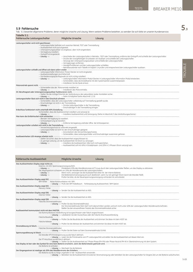
BREAKER ME10TESTS
TRO
UB
LE
5.9
5-05
5.9 FehlersucheTab. 5.1 bewertet allgemeine Probleme, deren mögliche Ursache und Lösung. Wenn weitere Probleme bestehen, so wenden Sie sich bitte an unseren Kundenservice.
Tabelle 5.1:Fehlersuche Leistungsschalter Mögliche Ursache Lösung-------------------------------------------------------------------------------------------------------------------------------------------------------------------------------------------------------------------------------------------------Leistungsschalter wird nicht geschlossen -- Leistungsschalter befindet sich zwischen Betrieb, TEST oder Trennstellung. -- Auslöseeinheit nicht zurückgesetzt. -- Unterspannungsauslöser ist eingebaut, aber nicht angetrieben. -- Verriegelung installiert. -- Drehgriff ist eingesteckt. -- Lösung --> -- Verschiebe den Leistungsschalter in Betriebs-, TEST oder Trennstellung, entferne den Drehgriff und schließe den Leistungsschalter. -- Drücke den orangefarbigen Drucktaster am Auslöser und schließe den Leistungsschalter. -- Versorge den Unterspannungsauslöser und schließe den Leistungsschalter. -- Verriegelungen entfernen. -- Handgriff entfernen und den Leistungsschalter schließen. -- Betriebszustände nach Tabelle im Kapitel 1.4 prüfen und entsprechend den Leistungsschalter auslösen.Leistungsschalter schließt und öffnet sich dann sofort wieder. -------------------------------------------------------------------------------------------------------------------------------------------------------------------- -- Leistungsschalter Information Modul-Stecker ist nicht eingesetzt. -- Auslösereinstellungen sind fehlerhaft. -- Fernbedienungsspule Rogowski ist nicht richtig installiert. -- Lösung --> -- Leistungsschalter Information Modul-Stecker in Leistungsschalter Information Modul einstecken. -- Sicherstellen, dass die Einstellwerte mit den Systemwerten zusammenpassen. -- Installieren Sie die Spule erneut.Motorantrieb spannt nicht. -------------------------------------------------------------------------------------------------------------------------------------------------------------------------------------------------------------- -- Sicherstellen das der Motorantrieb installiert ist -- Lösung --> -- Installieren des Motorantriebs.DC Abrufmagnet oder Unterspannungsauslöser funktionieren nicht. ------------------------------------------------------------------------------------------------------------------------------------------------------------ -- Stellen Sie die richtige Polarität der Verbindung zu den sekundären Isolier-Kontakten sicher. -- Lösung --> -- Siehe Schaltpläne (siehe Abschnitt 1.3.5).Leistungsschalter lässt sich nicht in den Einschub schieben. ---------------------------------------------------------------------------------------------------------------------------------------------------------------------- -- Sicherstellen, dass der Leistungsschalter vollständig auf Trennstellung gestellt wurde. -- Einschubträger ist nicht in der Trennstellung. -- Lösung --> -- Drücke Leistungsschalter in die Trennstellung. -- Einschubträger in die Trennstellung bringen.Erdschluss funktioniert nicht unterhalb 40% Einstellung.--------------------------------------------------------------------------------------------------------------------------------------------------------------------------- Sicherstellen, dass die Auslösereinheit installiert und versorgt ist. -- Lösung --> -- Installiere Auslösereinheit und Versorgung. (Siehe im Abschnitt 3 das Verdrahtungsschema.)Man kann die Einfahrkurbel nicht einstecken. ---------------------------------------------------------------------------------------------------------------------------------------------------------------------------------------- -- Blenden-Verriegelung ist installiert. -- Schlüsselsperrung ist installiert. -- Lösung --> -- Entferne Verriegelung und/oder öffne die Schlosssperren.Leistungsschalter schaltet sich nicht in die Trennstellung. ------------------------------------------------------------------------------------------------------------------------------------------------------------------------- -- Verwechslungsschutz ist unkorrekt eingestellt. -- Leistungsschalter ist nicht für den Einschubträger geeignet. -- Lösung --> -- Zurücksetzen des Verwechslungsschutzes. -- Sicherstellen, dass Leistungsschalter und Einschubträger zusammen gehören.Auslöseeinheiten LED-Anzeige arbeitet nicht. ---------------------------------------------------------------------------------------------------------------------------------------------------------------------------------------- -- Stellen Sie sicher, dass die Auslöseeinheit angeschlossen ist. -- Zu geringe Leistung, um die Auslöseeinheit mit Strom zu versorgen. -- Lösung --> -- Installiere die Auslöseeinheit, falls noch nicht geschehen. -- Auslöseeinheit soll mit 40% In Einzelphasen- und 20% In 3-Phasen-Strom versorgt sein.
Fehlersuche Auslöseeinheit Mögliche Ursache Lösung-----------------------------------------------------------------------------------------------------------------------------------------------------------------------------------------------------------------------------------------------Das Auslöseinheiten-Display zeigt nichts an. Externe +24 VDC Spannungsversorgung fehlt. -- Lösung --> Mindestens 20% des Wandlerstromes (xCT) muss durch den Leistungsschalter fließen, um das Display zu aktivieren. Der Abgangsstrom schwankt um 20% der Wandlerwerte des Leistungsschalters. -- Lösung --> Wenn nicht, versorgen Sie die Auslöseeinheit bitte mit der interne Batterie. -- Lösung --> Die Batteriestromversorgung ist auch deaktiviert, wenn nur ein geringer Strom durch die Wandler fließt. Prüfen Sie bitte, ob die Steuerspannungsversorgung vorhanden ist und arbeitet.Das Auslöseeinheiten-Display zeigt E02. ---------------------------------------------------------------------------------------------------------------------------------------------------------------------------------------------- BIM Fehler Keine Kommunikation mit BIM. -- Lösung --> Prüfe den BIM Kabelbaum. Fehlanpassung Auslöseeinheit / BIM OptionDas Auslöseeinheiten-Display zeigt E03. ---------------------------------------------------------------------------------------------------------------------------------------------------------------------------------------------- Memory Fehler -- Lösung --> Senden Sie die Auslöseeinheit an AEG.Das Auslöseeinheiten-Display zeigt E06. ---------------------------------------------------------------------------------------------------------------------------------------------------------------------------------------------- Interner Fehler -- Lösung --> Senden Sie die Auslöseeinheit an AEG.Das Auslöseeinheiten-Display zeigt E08. ---------------------------------------------------------------------------------------------------------------------------------------------------------------------------------------------- Falsches Stromeinstellmodul -- Lösung --> Prüfen Sie das Stromeinstellmodul. Der Stromeinstellmodul Wert darf nicht überschritten werden und sich nicht unter 40% der Leistungsschalter Wandlerwerte befinden. Stellen Sie den einwandfreien Festsitz des Stromeinstellmoduls sicher.Auslöseeinheit kommuniziert nicht mit dem MASTER. ------------------------------------------------------------------------------------------------------------------------------------------------------------------------------- Die Kommunikations-Verdrahtung ist kurzgeschlossen oder falsch angeschlossen. -- Lösung --> Lokalisieren Sie den Kurzschluss oder die Falsche Anschlussverbindung. Falsche Baudrate -- Lösung --> Prüfen Sie die Baudrate der Auslöseinheit und stimmen Sie diese mit dem HOST ab. Falsche Adresse -- Lösung --> Prüfen Sie die Adresse der Auslöseinheit und stimmen Sie diese mit dem HOST ab.Stromablesung ist falsch. ---------------------------------------------------------------------------------------------------------------------------------------------------------------------------------------------------------------- Falsches Stromeinstellmodul -- Lösung --> Prüfen Sie die Daten auf dem Stromeinstellmodul Schild.Spannungsablesung ist falsch. ---------------------------------------------------------------------------------------------------------------------------------------------------------------------------------------------------------- Die Wandler (PT) Primärspannung wurde falsch definiert. -- Lösung --> Lesen Sie die Primärwerte vom PT-Leistungsschild und stellen Sie die Auslöseeinheit auf diesen Wert ein. Der PT Anschluss wurde falsch definiert. -- Lösung --> Stellen Sie die Auslöseeinheit auf Phase-Phase (PH-PH) oder Phase-Neutral (PH-N) in Übereinstimmung mit dem System.Das Display ist leer oder das Symbol für eine leere Batterie erscheint, wenn die Batterietaste gedrückt wird. ------------------------------------------------------------------------------------------------------------ Die Batterie ist entladen -- Lösung --> Wechseln Sie die Batterie.Der Eingangsstrom ist niedriger als 20% des Wandlerstroms des Schalters. ---------------------------------------------------------------------------------------------------------------------------------------------------- Die Batterie wurde zu lange ungeladen in der Auslöseinheit verwendet. -- Lösung --> Betreiben Sie die Auslöseinheit mit externer Stromversorgung oder betreiben Sie den Leistungsschalter für längere Zeit um die Batterie aufzufrischen.
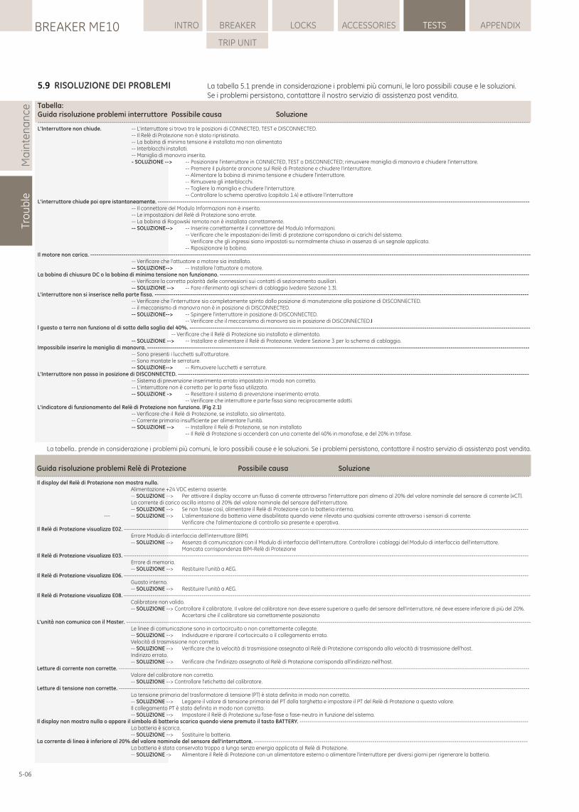
Ma
inte
na
nce
Tro
ub
leLOCKSBREAKER ME10 INTRO BREAKER ACCESSORIES TESTS APPENDIX
TRIP UNIT
5-06
5.9 RISOLUZIONE DEI PROBLEMI La tabella 5.1 prende in considerazione i problemi più comuni, le loro possibili cause e le soluzioni. Se i problemi persistono, contattare il nostro servizio di assistenza post vendita.
Tabella:Guida risoluzione problemi interruttore Possibile causa Soluzione-------------------------------------------------------------------------------------------------------------------------------------------------------------------------------------------------------------------------------------------------L'Interruttore non chiude. -- L'interruttore si trova tra le posizioni di CONNECTED, TEST e DISCONNECTED. -- Il Relè di Protezione non è stato ripristinato. -- La bobina di minima tensione è installata ma non alimentata -- Interblocchi installati. -- Maniglia di manovra inserita. - SOLUZIONE --> -- Posizionare l'interruttore in CONNECTED, TEST o DISCONNECTED; rimuovere maniglia di manovra e chiudere l'interruttore. -- Premere il pulsante arancione sul Relè di Protezione e chiudere l'interruttore. -- Alimentare la bobina di minima tensione e chiudere l'interruttore. -- Rimuovere gli interblocchi. -- Togliere la maniglia e chiudere l'interruttore. -- Controllare lo schema operativo (capitolo 1.4) e attivare l'interruttoreL'interruttore chiude poi apre istantaneamente. ----------------------------------------------------------------------------------------------------------------------------------------------------------------------------------- -- Il connettore del Modulo Informazioni non è inserito. -- Le impostazioni del Relè di Protezione sono errate. -- La bobina di Rogowski remota non è installata correttamente. -- SOLUZIONE--> -- Inserire correttamente il connettore del Modulo Informazioni. -- Verificare che le impostazioni dei limiti di protezione corrispondano ai carichi del sistema. Verificare che gli ingressi siano impostati su normalmente chiuso in assenza di un segnale applicato. -- Riposizionare la bobina.Il motore non carica. -------------------------------------------------------------------------------------------------------------------------------------------------------------------------------------------------------------------- -- Verificare che l'attuatore a motore sia installato. -- SOLUZIONE--> -- Installare l'attuatore a motore.La bobina di chiusura DC o la bobina di minima tensione non funzionano. ----------------------------------------------------------------------------------------------------------------------------------------------------- -- Verificare la corretta polarità delle connessioni sui contatti di sezionamento ausiliari. -- SOLUZIONE --> -- Fare riferimento agli schemi di cablaggio (vedere Sezione 1.3).L'interruttore non si inserisce nella parte fissa. ------------------------------------------------------------------------------------------------------------------------------------------------------------------------------------ -- Verificare che l'interruttore sia completamente spinto dalla posizione di manutenzione alla posizione di DISCONNECTED. -- il meccanismo di manovra non è in posizione di DISCONNECTED. -- SOLUZIONE--> -- Spingere l'interruttore in posizione di DISCONNECTED. -- Verificare che il meccanismo di manovra sia in posizione di DISCONNECTED.Il guasto a terra non funziona al di sotto della soglia del 40%. -------------------------------------------------------------------------------------------------------------------------------------------------------------------- -- Verificare che il Relè di Protezione sia installato e alimentato. -- SOLUZIONE --> -- Installare e alimentare il Relè di Protezione. Vedere Sezione 3 per lo schema di cablaggio.Impossibile inserire la maniglia di manovra. ---------------------------------------------------------------------------------------------------------------------------------------------------------------------------------------- -- Sono presenti i lucchetti sull'otturatore. -- Sono montate le serrature. -- SOLUZIONE--> -- Rimuovere lucchetti e serrature.L'Interruttore non passa in posizione di DISCONNECTED. ------------------------------------------------------------------------------------------------------------------------------------------------------------------------- -- Sistema di prevenzione inserimento errato impostato in modo non corretto. -- L'interruttore non è corretto per la parte fissa utilizzata. -- SOLUZIONE -> -- Resettare il sistema di prevenzione inserimento errato. -- Verificare che interruttore e parte fissa siano reciprocamente adatti.L'indicatore di funzionamento del Relè di Protezione non funziona. (Fig 2.1) -- Verificare che il Relè di Protezione, se installato, sia alimentato. -- Corrente primaria insufficiente per alimentare l'unità. -- SOLUZIONE --> -- Installare il Relè di Protezione, se non installato -- Il Relè di Protezione si accenderà con una corrente del 40% in monofase, e del 20% in trifase.
La tabella.. prende in considerazione i problemi più comuni, le loro possibili cause e le soluzioni. Se i problemi persistono, contattare il nostro servizio di assistenza post vendita.
Guida risoluzione problemi Relè di Protezione Possibile causa Soluzione-------------------------------------------------------------------------------------------------------------------------------------------------------------------------------------------------------------------------------------------------Il display del Relè di Protezione non mostra nulla. Alimentazione +24 VDC esterna assente. -- SOLUZIONE --> Per attivare il display occorre un flusso di corrente attraverso l'interruttore pari almeno al 20% del valore nominale del sensore di corrente (xCT). La corrente di carico oscilla intorno al 20% del valore nominale del sensore dell'interruttore. -- SOLUZIONE --> Se non fosse così, alimentare il Relè di Protezione con la batteria interna. --- -- SOLUZIONE --> L'alimentazione da batteria viene disabilitata quando viene rilevata una qualsiasi corrente attraverso i sensori di corrente. Verificare che l'alimentazione di controllo sia presente e operativa.Il Relè di Protezione visualizza E02. ------------------------------------------------------------------------------------------------------------------------------------------------------------------------------------------------------ Errore Modulo di interfaccia dell'interruttore (BIM). -- SOLUZIONE --> Assenza di comunicazioni con il Modulo di interfaccia dell'interruttore. Controllare i cablaggi del Modulo di interfaccia dell'interruttore. Mancata corrispondenza BIM-Relè di ProtezioneIl Relè di Protezione visualizza E03. ------------------------------------------------------------------------------------------------------------------------------------------------------------------------------------------------------ Errore di memoria. -- SOLUZIONE --> Restituire l'unità a AEG.Il Relè di Protezione visualizza E06. ------------------------------------------------------------------------------------------------------------------------------------------------------------------------------------------------------ Guasto interno. -- SOLUZIONE --> Restituire l'unità a AEG.Il Relè di Protezione visualizza E08. ------------------------------------------------------------------------------------------------------------------------------------------------------------------------------------------------------- Calibratore non valido. -- SOLUZIONE --> Controllare il calibratore. Il valore del calibratore non deve essere superiore a quello del sensore dell'interruttore, né deve essere inferiore di più del 20%. Accertarsi che il calibratore sia correttamente posizionatoL'unità non comunica con il Master. ------------------------------------------------------------------------------------------------------------------------------------------------------------------------------------------------------ Le linee di comunicazione sono in cortocircuito o non correttamente collegate. -- SOLUZIONE --> Individuare e riparare il cortocircuito o il collegamento errato. Velocità di trasmissione non corretta. -- SOLUZIONE --> Verificare che la velocità di trasmissione assegnata al Relè di Protezione corrisponda alla velocità di trasmissione dell'host. Indirizzo errato. -- SOLUZIONE --> Verificare che l'indirizzo assegnato al Relè di Protezione corrisponda all'indirizzo nell'host.Letture di corrente non corrette. --------------------------------------------------------------------------------------------------------------------------------------------------------------------------------------------------------- Valore del calibratore non corretto. -- SOLUZIONE --> Controllare l'etichetta del calibratore.Letture di tensione non corrette. --------------------------------------------------------------------------------------------------------------------------------------------------------------------------------------------------------- La tensione primaria del trasformatore di tensione (PT) è stata definita in modo non corretto. -- SOLUZIONE --> Leggere il valore di tensione primaria del PT dalla targhetta e impostare il PT del Relè di Protezione a questo valore. Il collegamento PT è stato definito in modo non corretto. -- SOLUZIONE --> Impostare il Relè di Protezione su fase-fase o fase-neutro in funzione del sistema.Il display non mostra nulla o appare il simbolo di batteria scarica quando viene premuto il tasto BATTERY. ---------------------------------------------------------------------------------------------------------------- La batteria è scarica. -- SOLUZIONE --> Sostituire la batteria.La corrente di linea è inferiore al 20% del valore nominale del sensore dell'interruttore. -------------------------------------------------------------------------------------------------------------------------------------- La batteria è stata conservata troppo a lungo senza energia applicata al Relè di Protezione. -- SOLUZIONE -> Alimentare il Relè di Protezione con un alimentatore esterno o alimentare l'interruttore per diversi giorni per rigenerare la batteria.

BREAKER ME10APPENDIX
6.0
CO
NTE
NT
6.0-01
Content
6.1 Catalogue number description
6.2 Dimensions
6.3 Service
Inhaltsverzeichnis
6.1 Katalognummer Beschreibung
6.2 Abmessungen
6.3 Service
Sommario
6.1 Descrizione codice catalogo
6.2 Dimensioni
6.3 Post-vendita
n o t e n o t i z e n | n o t a
. . . . . . . . . . . . . . . . . . . . . . . . . . . . . . . . . . . . . . . . . . . . . . . . . . . . . . . .
. . . . . . . . . . . . . . . . . . . . . . . . . . . . . . . . . . . . . . . . . . . . . . . . . . . . . . . .
. . . . . . . . . . . . . . . . . . . . . . . . . . . . . . . . . . . . . . . . . . . . . . . . . . . . . . . .
. . . . . . . . . . . . . . . . . . . . . . . . . . . . . . . . . . . . . . . . . . . . . . . . . . . . . . . .
. . . . . . . . . . . . . . . . . . . . . . . . . . . . . . . . . . . . . . . . . . . . . . . . . . . . . . . .
. . . . . . . . . . . . . . . . . . . . . . . . . . . . . . . . . . . . . . . . . . . . . . . . . . . . . . . .
. . . . . . . . . . . . . . . . . . . . . . . . . . . . . . . . . . . . . . . . . . . . . . . . . . . . . . . .
. . . . . . . . . . . . . . . . . . . . . . . . . . . . . . . . . . . . . . . . . . . . . . . . . . . . . . . .
. . . . . . . . . . . . . . . . . . . . . . . . . . . . . . . . . . . . . . . . . . . . . . . . . . . . . . . .
. . . . . . . . . . . . . . . . . . . . . . . . . . . . . . . . . . . . . . . . . . . . . . . . . . . . . . . .
. . . . . . . . . . . . . . . . . . . . . . . . . . . . . . . . . . . . . . . . . . . . . . . . . . . . . . . .
. . . . . . . . . . . . . . . . . . . . . . . . . . . . . . . . . . . . . . . . . . . . . . . . . . . . . . . .
. . . . . . . . . . . . . . . . . . . . . . . . . . . . . . . . . . . . . . . . . . . . . . . . . . . . . . . .
. . . . . . . . . . . . . . . . . . . . . . . . . . . . . . . . . . . . . . . . . . . . . . . . . . . . . . . .
. . . . . . . . . . . . . . . . . . . . . . . . . . . . . . . . . . . . . . . . . . . . . . . . . . . . . . . .
. . . . . . . . . . . . . . . . . . . . . . . . . . . . . . . . . . . . . . . . . . . . . . . . . . . . . . . .
. . . . . . . . . . . . . . . . . . . . . . . . . . . . . . . . . . . . . . . . . . . . . . . . . . . . . . . .
. . . . . . . . . . . . . . . . . . . . . . . . . . . . . . . . . . . . . . . . . . . . . . . . . . . . . . . .
. . . . . . . . . . . . . . . . . . . . . . . . . . . . . . . . . . . . . . . . . . . . . . . . . . . . . . . .
. . . . . . . . . . . . . . . . . . . . . . . . . . . . . . . . . . . . . . . . . . . . . . . . . . . . . . . .
. . . . . . . . . . . . . . . . . . . . . . . . . . . . . . . . . . . . . . . . . . . . . . . . . . . . . . . .
. . . . . . . . . . . . . . . . . . . . . . . . . . . . . . . . . . . . . . . . . . . . . . . . . . . . . . . .
. . . . . . . . . . . . . . . . . . . . . . . . . . . . . . . . . . . . . . . . . . . . . . . . . . . . . . . .
6.0 APPENDIX 6.0 ANHANG 6.0 APPENDICE
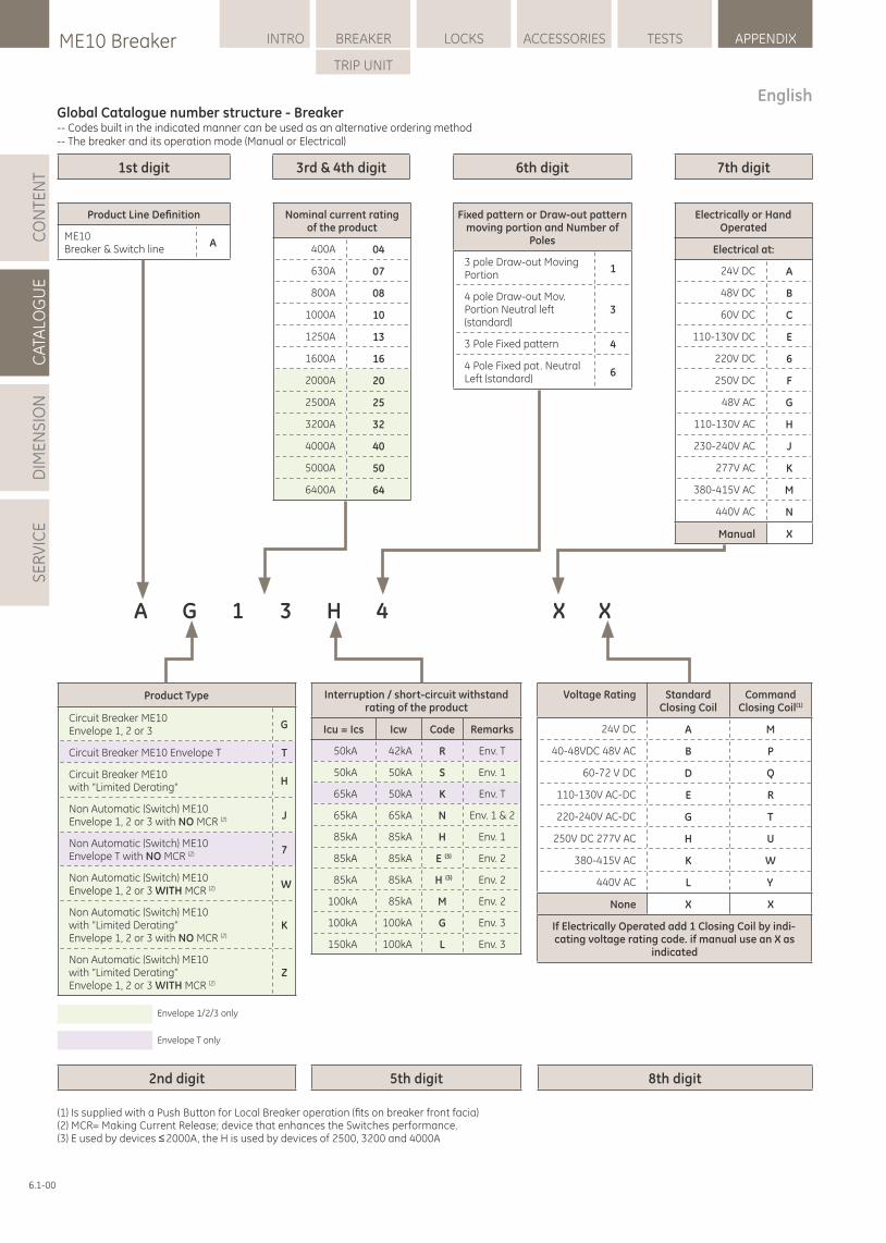
1st digit
2nd digit 5th digit 8th digit
3rd & 4th digit 6th digit 7th digit
Nominal current rating of the product
400A 04
630A 07
800A 08
1000A 10
1250A 13
1600A 16
2000A 20
2500A 25
3200A 32
4000A 40
5000A 50
6400A 64
Product Line Defi nition
ME10Breaker & Switch line
A
Fixed pattern or Draw-out pattern moving portion and Number of
Poles
3 pole Draw-out Moving Portion
1
4 pole Draw-out Mov.Portion Neutral left (standard)
3
3 Pole Fixed pattern 4
4 Pole Fixed pat. Neutral Left (standard)
6
Electrically or Hand Operated
Electrical at:
24V DC A
48V DC B
60V DC C
110-130V DC E
220V DC 6
250V DC F
48V AC G
110-130V AC H
230-240V AC J
277V AC K
380-415V AC M
440V AC N
Manual X
Product Type
Circuit Breaker ME10 Envelope 1, 2 or 3
G
Circuit Breaker ME10 Envelope T T
Circuit Breaker ME10 with “Limited Derating”
H
Non Automatic (Switch) ME10 J(2)Envelope 1, 2 or 3 with NO MCR
Non Automatic (Switch) ME10 7(2)Envelope T with NO MCR
Non Automatic (Switch) ME10 W(2)Envelope 1, 2 or 3 WITH MCR
Non Automatic (Switch) ME10 with “Limited Derating” K
(2)Envelope 1, 2 or 3 with NO MCR
Non Automatic (Switch) ME10 with “Limited Derating” Z
(2)Envelope 1, 2 or 3 WITH MCR
Interruption / short-circuit withstand rating of the product
Icu = Ics Icw Code Remarks
50kA 42kA R Env. T
50kA 50kA S Env. 1
65kA 50kA K Env. T
65kA 65kA N Env. 1 & 2
85kA 85kA H Env. 1
85kA 85kA E (3) Env. 2
85kA 85kA H (3) Env. 2
100kA 85kA M Env. 2
100kA 100kA G Env. 3
150kA 100kA L Env. 3
A G 1 3 H 4 X X
Voltage Rating Standard Closing Coil
Command (1)Closing Coil
24V DC A M
40-48VDC 48V AC B P
60-72 V DC D Q
110-130V AC-DC E R
220-240V AC-DC G T
250V DC 277V AC H U
380-415V AC K W
440V AC L Y
None X X
If Electrically Operated add 1 Closing Coil by indi-cating voltage rating code. if manual use an X as
indicated
(1) Is supplied with a Push Button for Local Breaker operation (fi ts on breaker front facia)(2) MCR= Making Current Release; device that enhances the Switches performance.(3) E used by devices ≤ 2000A, the H is used by devices of 2500, 3200 and 4000A
Envelope 1/2/3 only
Envelope T only
LOCKSME10 Breaker INTRO BREAKER ACCESSORIES TESTS APPENDIX
TRIP UNIT
CA
TALO
GU
ED
IME
NS
ION
SE
RV
ICE
CO
NTE
NT
6.1-00
EnglishGlobal Catalogue number structure - Breaker-- Codes built in the indicated manner can be used as an alternative ordering method-- The breaker and its operation mode (Manual or Electrical)
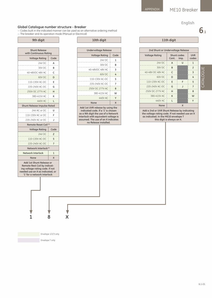
9th digit
Shunt Releasewith Continuous Rating
Voltage Rating Code
24V DC A
30V DC B
40-48VDC 48V AC C
60V DC D
110-130V AC-DC E
220-240V AC-DC G
250V DC 277V AC H
380-415V AC K
440V AC L
Shunt Release Impulse Rated
24V AC or DC U
110-130V AC or DC F
220-240V AC or DC J
(1)Remote Reset Coil
Voltage Rating Code
24V DC Z
110-130V AC-DC 5
220-240V AC-DC 7
(1)Network Interlock
Network Interlock 1
None X
Add 1st Shunt Release or Remote Rest Coil by indicat-
ing voltage rating code. if not needed use an X as indicated, or
‘1’ for a network Interlock
10th digit
Undervoltage Release
Voltage Rating Code
24V DC 1
30V DC B
40-48VDC 48V AC 3
60V DC 4
110-130V AC-DC 5
220-240V AC-DC 7
250V DC 277V AC 8
380-415V AC W
440V AC Y
None X
Add 1st UVR release by using the indicated code. If a ‘1’ is chosen
as a 9th digit the use of a Network Interlock with equivalent voltage is assumed. The use of an X indicates
no Release installed.
11th digit
2nd Shunt or Undervoltage Release
Voltage Rating Shunt codesCont. Imp.
UVR codes
24V DC A U 1
30V DC B 2
40-48V DC 48V AC C 3
60V DC D 4
110-130V AC-DC E F 5
220-240V AC-DC G J 7
250V DC 277V AC H 8
380-415V AC K W
440V AC L Y
None X
Add a 2nd or UVR Shunt Release by indicating the voltage rating code. If not needed use an X as indicated. In the ME10 envelope T
this digit is always an X.
1 8 X
Envelope 1/2/3 only
Envelope T only
ME10 BreakerAPPENDIX
6.1
CA
TALO
GU
E
6.1-01
Global Catalogue number structure - Breaker-- Codes built in the indicated manner can be used as an alternative ordering method-- The breaker and its operation mode (Manual or Electrical)
English
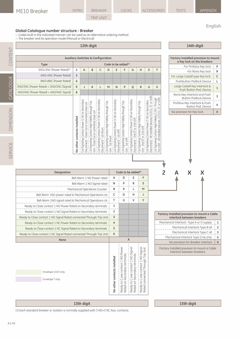
14th digit
15th digit13th digit
Factory Installed prevision to mount a Key lock on the breakers
For Profalux Key lock P
For Ronis Key lock R
For Large Castell type Key lock C
Pushbutton Padlock Device L
Large Castell Key Interlock & Push Button Pad. Device
1
Ronis Key Interlock and Push Button Padlock Device
3
Profalux Key Interlock & Push Button Pad. Device
4
No prevision for Key lock X
Factory Installed prevision to mount a Cable interlock between breakers
Mechanical Interlock -Type A or D supply 1
Mechanical Interlock Type B all 2
Mechanical Interlock Type C all 3
Mechanical Interlock Type D tie only 4
No prevision for Breaker interlock X
Factory Installed prevision to mount a Cable interlock between breakers.
X2 XA
Auxiliary Switches & Confi guration
Type Code to be added (1)
3NO+3NC (Power Rated) (1) 2 A B C D E F G H S T
4NO+4NC (Power Rated) 3
8NO+8NC (Power Rated) 4
J K L M N P Q R U V3NO/3NC (Power Rated) + 2NO/2NC (Signal) 6
4NO/4NC (Power Rated) + 4NO/4NC Signal) 8
No
oth
er
con
tact
s in
sta
lled
Coil
Sign
alin
g Co
ntac
t Pow
er (1
NO
on
Seco
ndar
y D
isco
nnec
t) - C
lose
Coi
l or c
omm
and
clos
e co
il
Coil
Sign
alin
g Co
ntac
t Hig
h Fi
delit
y th
roug
h Tr
ip
Uni
t - C
lose
Coi
l or c
omm
and
clos
e co
il
Coil
Sign
alin
g Co
ntac
t Pow
er (1
NO
on
Seco
ndar
y D
isco
nnec
t) - 1
st S
hunt
Coil
Sign
alin
g Co
ntac
t Hig
h Fi
delit
y th
roug
h Tr
ip
Uni
t - 1
st S
hunt
Coil
Sign
alin
g Co
ntac
t Pow
er (1
NO
on
Seco
ndar
y D
isco
nnec
t) - 1
st U
VR
Coil
Sign
alin
g Co
ntac
t Hig
h Fi
delit
y th
roug
h Tr
ip
Uni
t - 1
st U
VR
Coil
Sign
alin
g Co
ntac
t Pow
er (1
NO
on
Seco
ndar
y D
isco
nnec
t) - 2
nd S
T or
2nd
UVR
Coil
Sign
alin
g Co
ntac
t Hig
h Fi
delit
y th
roug
h Tr
ip
Uni
t - 2
nd S
T or
2nd
UVR
Coil
Sign
alin
g Co
ntac
t Pow
er (1
NO
on
Seco
ndar
y D
isco
nnec
t) - A
ll in
stal
led
devi
ces
CC/C
CC, S
T, o
r UVR
)
Coil
Sign
alin
g Co
ntac
t Hig
h Fi
delit
y (1
NO
-Thr
ough
Tr
ip U
nit)
- All
inst
alle
d de
vice
s. C
C/CC
C, S
T, o
r UVR
)
Designation Code to be added(1)
Bell Alarm 1 NO Power rated A D E F
Bell Alarm 1 NO Signal rated N P R S
Mechanical Operations Counter B K L M
Bell Alarm 1NO power rated & Mechanical Operations ctr. C G H J
Bell Alarm 1NO signal rated & Mechanical Operations ctr. T U V Y
Ready to Close contact 1 NO Power Rated on Secondary terminals 1
Ready to Close contact 1 NO Signal Rated on Secondary terminals 2
Ready to Close contact 1 NO Signal Rated connected Through Trip Unit 3
Ready to Close contact 1 NC Power Rated on Secondary terminals 4
Ready to Close contact 1 NC Signal Rated on Secondary terminals 5
Ready to Close contact 1 NC Signal Rated connected Through Trip Unit 6
None X
No
oth
er
con
tact
s in
sta
lled
Re
ad
y to
C.o
se c
on
tact
1 N
O P
ow
er
Ra
ted
on
Se
con
da
ry t
erm
ina
ls
Re
ad
y to
C.o
se c
on
tact
1 N
O S
Ign
al
Ra
ted
on
Se
con
da
ry t
erm
ina
ls
Re
ad
y to
C.o
se c
on
tact
1 N
O S
Ign
al
Ra
ted
co
nn
ect
ed
Th
rou
gh
Tri
p U
nit
12th digit
Envelope 1/2/3 only
Envelope T only
(1) Each standard breaker or Isolator is normally supplied with 3 NO+3 NC Aux. contacts.
6.1-02
EnglishGlobal Catalogue number structure - Breaker-- Codes built in the indicated manner can be used as an alternative ordering method-- The breaker and its operation mode (Manual or Electrical)
LOCKSME10 Breaker INTRO BREAKER ACCESSORIES TESTS APPENDIX
TRIP UNIT
CA
TALO
GU
ED
IME
NS
ION
SE
RV
ICE
CO
NTE
NT
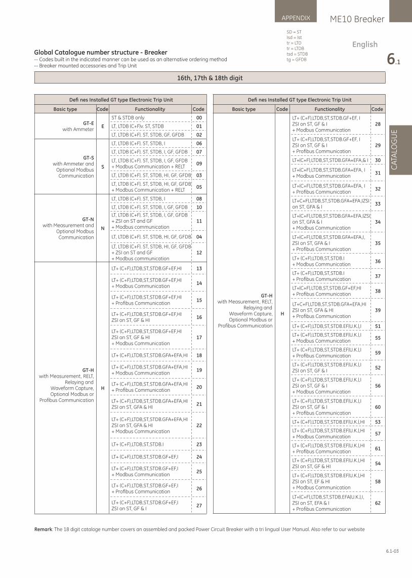
16th, 17th & 18th digit
Defi nes Installed GT type Electronic Trip Unit
Basic type Code Functionality Code
GT-Ewith Ammeter
E
ST & STDB only 00
LT, LTDB (C+F)v. ST, STDB 01
LT, LTDB (C+F). ST, STDB, GF, GFDB 02
GT-Swith Ammeter and
Optional ModbusCommunication
S
LT, LTDB (C+F). ST, STDB, I 06
LT, LTDB (C+F). ST, STDB, I, GF, GFDB 07
LT, LTDB (C+F). ST, STDB, I, GF, GFDB+ Modbus Communication + RELT
09
LT, LTDB (C+F). ST, STDB, HI, GF, GFDB 03
LT, LTDB (C+F). ST, STDB, HI, GF, GFDB+ Modbus Communication + RELT
05
GT-Nwith Measurement and
Optional ModbusCommunication
N
LT, LTDB (C+F). ST, STDB, I 08
LT, LTDB (C+F). ST, STDB, I, GF, GFDB 10
LT, LTDB (C+F). ST, STDB, I, GF, GFDB+ ZSI on ST and GF+ Modbus communication
11
LT, LTDB (C+F). ST, STDB, HI, GF, GFDB 04
LT, LTDB (C+F). ST, STDB, HI, GF, GFDB+ ZSI on ST and GF+ Modbus communication
12
GT-Hwith Measurement, RELT,
Relaying andWaveform Capture,Optional Modbus or
Profi bus Communication
H
LT+ (C+F),LTDB,ST,STDB.GF+EF,HI 13
LT+ (C+F),LTDB,ST,STDB.GF+EF,HI+ Modbus Communication
14
LT+ (C+F),LTDB,ST,STDB.GF+EF,HI+ Profi bus Communication
15
LT+ (C+F),LTDB,ST,STDB.GF+EF,HIZSI on ST, GF & HI
16
LT+ (C+F),LTDB,ST,STDB.GF+EF,HIZSI on ST, GF & HI+ Modbus Communication
17
LT+ (C+F),LTDB,ST,STDB.GFA+EFA,HI 18
LT+ (C+F),LTDB,ST,STDB.GFA+EFA,HI+ Modbus Communication
19
LT+ (C+F),LTDB,ST,STDB.GFA+EFA,HI+ Profi bus Communication
20
LT+ (C+F),LTDB,ST,STDB.GFA+EFA,HIZSI on ST, GFA & HI
21
LT+ (C+F),LTDB,ST,STDB.GFA+EFA,HIZSI on ST, GFA & HI+ Modbus Communication
22
LT+ (C+F),LTDB,ST,STDB.I 23
LT+ (C+F),LTDB,ST,STDB.GF+EF,I 24
LT+ (C+F),LTDB,ST,STDB.GF+EF,I+ Modbus Communication
25
LT+ (C+F),LTDB,ST,STDB.GF+EF,I+ Profi bus Communication
26
LT+ (C+F),LTDB,ST,STDB.GF+EF,IZSI on ST, GF & I
27
Defi nes Installed GT type Electronic Trip Unit
Basic type Code Functionality Code
GT-Hwith Measurement, RELT,
Relaying andWaveform Capture,Optional Modbus or
Profi bus Communication
H
LT+ (C+F),LTDB,ST,STDB.GF+EF, IZSI on ST, GF & I+ Modbus Communication
28
LT+ (C+F),LTDB,ST,STDB.GF+EF, IZSI on ST, GF & I+ Profi bus Communication
29
LT+(C+F),LTDB,ST,STDB.GFA+EFA,& I 30
LT+(C+F),LTDB,ST,STDB.GFA+EFA, I+ Modbus Communication
31
LT+(C+F),LTDB,ST,STDB.GFA+EFA, I+ Profi bus Communication
32
LT+C+F),LTDB,ST,STDB.GFA+EFA,IZSI on ST, GFA & I
33
LT+(C+F),LTDB,ST,STDB.GFA+EFA,IZSI on ST, GFA & I+ Modbus Communication
34
LT+(C+F),LTDB,ST,STDB.GFA+EFA,I, ZSI on ST, GFA & I+ Profi bus Communication
35
LT+ (C+F),LTDB,ST,STDB.I+ Modbus Communication
36
LT+ (C+F),LTDB,ST,STDB.I+ Profi bus Communication
37
LT+(C+F),LTDB,ST,STDB.GF+EF,HI+ Profi bus Communication
38
LT+C+F),LTDB,ST,STDB.GFA+EFA,HI ZSI on ST, GFA & HI+ Profi bus Communication
39
LT+ (C+F),LTDB,ST,STDB.EF(U.K.),I 51
LT+ (C+F),LTDB,ST,STDB.EF(U.K.),I+ Modbus Communication
55
LT+ (C+F),LTDB,ST,STDB.EF(U.K.),I+ Profi bus Communication
59
LT+ (C+F),LTDB,ST,STDB.EF(U.K.),IZSI on ST, GF & I
52
LT+ (C+F),LTDB,ST,STDB.EF(U.K.),IZSI on ST, GF & I+ Modbus Communication
56
LT+ (C+F),LTDB,ST,STDB.EF(U.K.),IZSI on ST, GF & I+ Profi bus Communication
60
LT+ (C+F),LTDB,ST,STDB.EF(U.K.),HI 53
LT+ (C+F),LTDB,ST,STDB.EF(U.K.),HI+ Modbus Communication
57
LT+ (C+F),LTDB,ST,STDB.EF(U.K.),HI+ Profi bus Communication
61
LT+ (C+F),LTDB,ST,STDB.EF(U.K.),HIZSI on ST, GF & HI
54
LT+ (C+F),LTDB,ST,STDB.EF(U.K.),HIZSI on ST, EF & HI+ Modbus Communication
58
LT+(C+F),LTDB,ST,STDB.EFA(U.K.),I, ZSI on ST, EFA & I+ Profi bus Communication
62
Remark: The 18 digit cataloge number covers an assembled and packed Power Circuit Breaker with a tri lingual User Manual. Also refer to our website
6.1-03
EnglishGlobal Catalogue number structure - Breaker-- Codes built in the indicated manner can be used as an alternative ordering method-- Breaker mounted accessories and Trip Unit
ME10 BreakerAPPENDIX
6.1
CA
TALO
GU
E
SD = STIsd = Isttr = LTDtr = LTDBtsd = STDBtg = GFDB
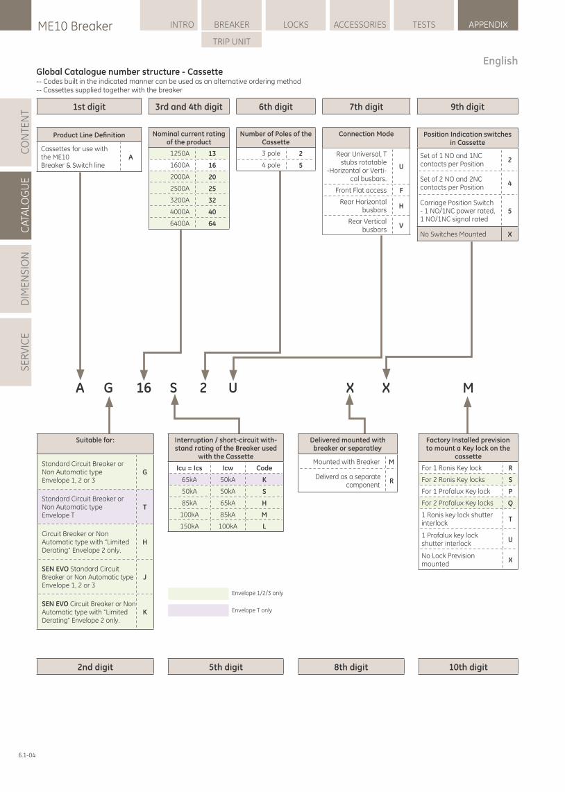
6th digit 7th digit 9th digit1st digit
2nd digit 5th digit 8th digit 10th digit
3rd and 4th digit
Factory Installed prevision to mount a Key lock on the
cassette
For 1 Ronis Key lock R
For 2 Ronis Key locks S
For 1 Profalux Key lock P
For 2 Profalux Key locks Q
1 Ronis key lock shutter interlock
T
1 Profalux key lockshutter interlock
U
No Lock Prevision mounted
A G 16 S 2 U
X
Nominal current rating of the product
1250A 13
1600A 16
2000A 20
2500A 25
3200A 32
4000A 40
6400A 64
Number of Poles of the Cassette
3 pole 2
4 pole 5
Connection Mode
Rear Universal, T stubs rotatable
-Horizontal or Verti-cal busbars.
U
Front Flat access F
Rear Horizontal busbars
H
Rear Vertical busbars
V
X X M
Position Indication switches in Cassette
Set of 1 NO and 1NC contacts per Position
2
Set of 2 NO and 2NC contacts per Position
4
Carriage Position Switch - 1 NO/1NC power rated, 1 NO/1NC signal rated
5
No Switches Mounted X
Interruption / short-circuit with-stand rating of the Breaker used
with the Cassette
Icu = Ics Icw Code
65kA 50kA K
50kA 50kA S
85kA 65kA H
100kA 85kA M
150kA 100kA L
Delivered mounted with breaker or separatley
Mounted with Breaker M
Deliverd as a separate component
R
Product Line Defi nition
Cassettes for use with the ME10 Breaker & Switch line
A
Suitable for:
Standard Circuit Breaker or Non Automatic typeEnvelope 1, 2 or 3
G
Standard Circuit Breaker or Non Automatic typeEnvelope T
T
Circuit Breaker or Non Automatic type with “Limited Derating” Envelope 2 only.
H
SEN EVO Standard Circuit Breaker or Non Automatic type Envelope 1, 2 or 3
J
SEN EVO Circuit Breaker or Non Automatic type with “Limited Derating” Envelope 2 only.
K
Envelope 1/2/3 only
Envelope T only
English
6.1-04
Global Catalogue number structure - Cassette-- Codes built in the indicated manner can be used as an alternative ordering method-- Cassettes supplied together with the breaker
LOCKSME10 Breaker INTRO BREAKER ACCESSORIES TESTS APPENDIX
TRIP UNIT
CA
TALO
GU
ED
IME
NS
ION
SE
RV
ICE
CO
NTE
NT
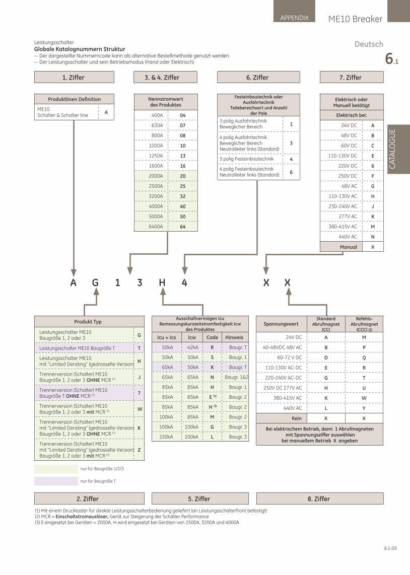
DeutschLeistungsschalter
Globale Katalognummern Struktur-- Der dargestellte Nummerncode kann als alternative Bestellmethode genutzt werden.-- Der Leistungsschalter und sein Betriebsmodus (Hand oder Elektrisch)
1. Ziffer
2. Ziffer 5. Ziffer 8. Ziffer
3. & 4. Ziffer 6. Ziffer 7. Ziffer
400A 04
630A 07
800A 08
1000A 10
1250A 13
1600A 16
2000A 20
2500A 25
3200A 32
4000A 40
5000A 50
6400A 64
Produktlinen Definition
ME10Schalter & Schalter line
A
Produkt Typ
Leistungsschalter ME10 Baugröße 1, 2 oder 3
G
Leistungsschalter ME10 Baugröße T T
Leistungsschalter ME10 mit “Limited Derating” (gedrosselte Version)
H
Trennerversion (Schalter) ME10 Baugröße 1, 2 oder 3 OHNE MCR (2) J
Trennerversion (Schalter) ME10 Baugröße T OHNE MCR (2) 7
Trennerversion (Schalter) ME10 Baugröße 1, 2 oder 3 mit MCR (2) W
Trennerversion (Schalter) ME10 mit “Limited Derating” (gedrosselte Version)Baugröße 1, 2 oder 3 OHNE MCR (2)
K
Trennerversion (Schalter) ME10 mit “Limited Derating” (gedrosselte Version)Baugröße 1, 2 oder 3 mit MCR (2)
Z
A G 1 3 H 4 X X
nur für Baugröße 1/2/3
nur für Baugröße T
Nennstromwert des Produktes
1
3
4
6
3 polig AusfahrtechnikBeweglicher Bereich
4 polig AusfahrtechnikBeweglicher BereichNeutralleiter links (Standard)
3 polig Festeinbautechnik
4 polig FesteinbautechnikNeutralleiter links (Standard)
Festeinbautechnik oder Ausfahrtechnik
Teilebereichsart und Anzahl der Pole
24V DC A
48V DC B
60V DC C
110-130V DC E
220V DC 6
250V DC F
48V AC G
110-130V AC H
230-240V AC J
277V AC K
380-415V AC M
440V AC N
Manual X
Elektrisch oderManuell betätigt
Elektrisch bei:
Icu = Ics Icw Code Hinweis
50kA 42kA R Baugr. T
50kA 50kA S Baugr. 1
65kA 50kA K Baugr. T
65kA 65kA N Baugr. 1&2
85kA 85kA H Baugr. 1
85kA 85kA E (3) Baugr. 2
85kA 85kA H (3) Baugr. 2
100kA 85kA M Baugr. 2
100kA 100kA G Baugr. 3
150kA 100kA L Baugr. 3
Ausschaltvermögen Icu Bemessungskurzzeitstromfestigkeit Icw
des Produktes
(1) Mit einem Drucktaster für direkte Leistungsschalterbedienung geliefert (an Leistungsschalterfront befestigt)(2) MCR = Einschaltstromauslöser, Gerät zur Steigerung der Schalter Performance(3) E eingesetzt bei Geräten = 2000A, H wird eingesetzt bei Geräten von 2500A, 3200A und 4000A
24V DC A M
40-48VDC 48V AC B P
60-72 V DC D Q
110-130V AC-DC E R
220-240V AC-DC G T
250V DC 277V AC H U
380-415V AC K W
440V AC L Y
Kein X X
Bei elektrischem Betrieb, dann 1 Abrufmagneten mit Spannungsziffer auswählen
bei manuellem Betrieb X angeben
StandardAbrufmagnet
(CC)
Befehls-Abrufmagnet
(CCC) (1)
Spannungswert
6.1-05
ME10 BreakerAPPENDIX
6.1
CA
TALO
GU
E
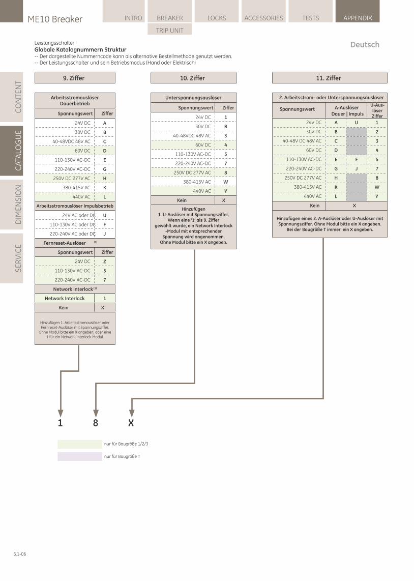
Leistungsschalter
Globale Katalognummern Struktur-- Der dargestellte Nummerncode kann als alternative Bestellmethode genutzt werden.-- Der Leistungsschalter und sein Betriebsmodus (Hand oder Elektrisch)
9. Ziffer
Spannungswert Ziffer
24V DC A
30V DC B
40-48VDC 48V AC C
60V DC D
110-130V AC-DC E
220-240V AC-DC G
250V DC 277V AC H
380-415V AC K
440V AC L
24V AC oder DC U
110-130V AC oder DC F
220-240V AC oder DC J
(1)
Spannungswert Ziffer
24V DC Z
110-130V AC-DC 5
220-240V AC-DC 7
(1)Network Interlock
Network Interlock 1
Kein X
10. Ziffer 11. Ziffer
1 8 X
nur für Baugröße 1/2/3
nur für Baugröße T
ArbeitsstromauslöserDauerbetrieb
Arbeitsstromauslöser Impulsbetrieb
Fernreset-Auslöser
Hinzufügen 1. Arbeitsstromauslöser oder Fernreset-Auslöser mit Spannungsziffer.
Ohne Modul bitte ein X angeben, oder eine 1 für ein Network Interlock Modul.
Spannungswert Ziffer
24V DC 1
30V DC B
40-48VDC 48V AC 3
60V DC 4
110-130V AC-DC 5
220-240V AC-DC 7
250V DC 277V AC 8
380-415V AC W
440V AC Y
Kein X
Unterspannungsauslöser
Hinzufügen 1. U-Auslöser mit Spannungsziffer.
Wenn eine ‘1’ als 9. Ziffergewählt wurde, ein Network Interlock
-Modul mit entsprechender Spannung wird angenommen.
Ohne Modul bitte ein X angeben.
24V DC A U 1
30V DC B 2
40-48V DC 48V AC C 3
60V DC D 4
110-130V AC-DC E F 5
220-240V AC-DC G J 7
250V DC 277V AC H 8
380-415V AC K W
440V AC L Y
Kein X
2. Arbeitsstrom- oder Unterspannungsauslöser
Spannungswert A-AuslöserDauer | Impuls
Hinzufügen eines 2. A-Auslöser oder U-Auslöser mit Spannungsziffer. Ohne Modul bitte ein X angeben.
Bei der Baugröße T immer ein X angeben.
U-Aus-löserZiffer
Deutsch
6.1-06
LOCKSME10 Breaker INTRO BREAKER ACCESSORIES TESTS APPENDIX
TRIP UNIT
CA
TALO
GU
ED
IME
NS
ION
SE
RV
ICE
CO
NTE
NT
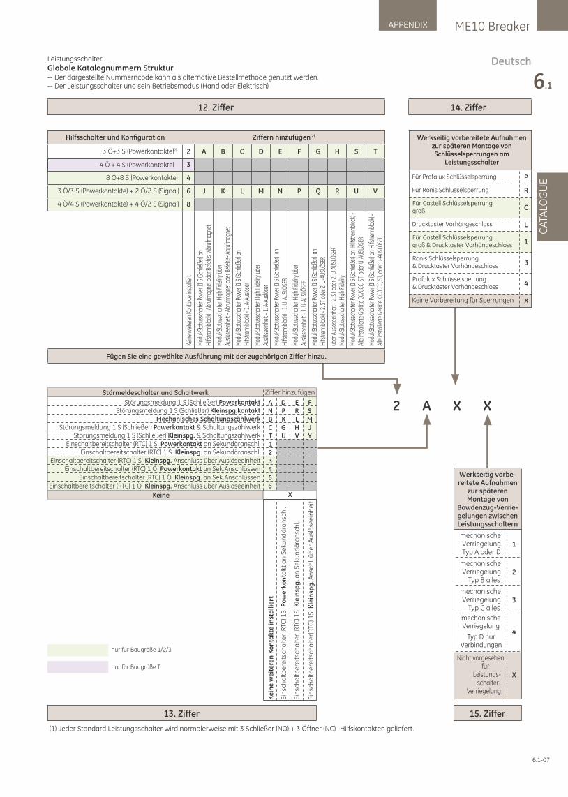
DeutschLeistungsschalter
Globale Katalognummern Struktur-- Der dargestellte Nummerncode kann als alternative Bestellmethode genutzt werden.-- Der Leistungsschalter und sein Betriebsmodus (Hand oder Elektrisch)
14. Ziffer
Werkseitig vorbe-reitete Aufnahmen
zur späterenMontage von
Bowdenzug-Verrie-gelungen zwischenLeistungsschaltern
mechanische VerriegelungTyp A oder D
1
mechanische Verriegelung
Typ B alles2
mechanische Verriegelung
Typ C alles3
4
Nicht vorgesehenfü r
Leistungs-schalter-
Verriegelung
X
Typ D nurVerbindungen
mechanischeVerriegelung
15. Ziffer13. Ziffer
X2 XA
12. Ziffer
nur für Baugröße 1/2/3
nur für Baugröße T
Ziffer hinzufügenStörmeldeschalter und Schaltwerk
Störungsmeldung 1 S (Schließer) Powerkontakt & Schaltungszählwerk
Einschaltbereitschalter (RTC) 1 S Powerkontakt an Sekundäranschl.
Einschaltbereitschalter (RTC) 1 S Kleinspg. Anschluss über AuslöseeinheitEinschaltbereitschalter (RTC) 1 Ö Powerkontakt an Sek.Anschlüssen
ANBCT123456
DPKGU
ERLHV
FSMJY
XKeine
Ke
ine
we
ite
ren
Ko
nta
kte
inst
alli
ert
Störungsmeldung 1 S (Schließer) PowerkontaktStörungsmeldung 1 S (Schließer) Kleinspg.kontakt
Mechanisches Schaltungszählwerk
Störungsmeldung 1 S (Schließer) Kleinspg. & Schaltungszählwerk
Einschaltbereitschalter (RTC) 1 S Kleinspg. an Sekundäranschl.
Einschaltbereitschalter (RTC) 1 Ö Kleinspg. an Sek.Anschlüssen
Einschaltbereitschalter (RTC) 1 Ö Kleinspg. Anschluss über Auslöseeinheit
Ein
sch
alt
be
reit
sch
alt
er
(RTC
) 1S
Po
we
rko
nta
kt a
n S
eku
nd
ära
nsc
hl.
Ein
sch
alt
be
reit
sch
alt
er
(RTC
) 1S
Kle
insp
g. a
n S
eku
nd
ära
nsc
hl.
Ein
sch
alt
be
reit
sch
alt
er(
RTC
) 1S
Kle
insp
g. A
nsc
hl.
üb
er
Au
slö
see
inh
eit
Hilfsschalter und Konfi guration Ziffern hinzufü gen(2)
3 Ö+3 S (Powerkontakte)(2) 2 A B C D E F G H S T
8 Ö+8 S (Powerkontakte) 4
3 Ö/3 S (Powerkontakte) + 2 Ö/2 S (Signal) 6 J K L M N P Q R U V
4 Ö/4 S (Powerkontakte) + 4 Ö/2 S (Signal) 8
Kein
e w
eiter
en K
onta
kte
inst
allie
rt
Mod
ul-S
tatu
ssch
alte
r Pow
er (1
S (S
chlie
ßer)
anHi
lfstre
nnbl
ock)
- Abr
ufm
agne
t ode
r Bef
ehls-
Abr
ufm
agne
t
Mod
ul-S
tatu
ssch
alte
r Hig
h Fid
elity
übe
rAu
slöse
einhe
it - A
bruf
mag
net o
der B
efeh
ls- A
bruf
mag
net
Mod
ul-S
tatu
ssch
alte
r Pow
er (1
S (S
chlie
ßer)
anHi
lfstre
nnbl
ock)
- 1. A
-Aus
löse
r
Mod
ul-S
tatu
ssch
alte
r Hig
h Fid
elity
übe
rAu
slöse
einhe
it - 1
. A-A
uslö
ser
Mod
ul-S
tatu
ssch
alte
r Pow
er (1
S (S
chlie
ßer)
an
Hilfs
trenn
bloc
k) - 1
. U-A
USLÖ
SER
Mod
ul-S
tatu
ssch
alte
r Hig
h Fid
elity
übe
rAu
slöse
einhe
it - 1
. U-A
USLÖ
SER
Mod
ul-S
tatu
ssch
alte
r Pow
er (1
S (S
chlie
ßer)
an
Hilfs
trenn
bloc
k) - 2
. ST o
der 2
. U-A
USLÖ
SER
über
Aus
löse
einhe
it - 2
. ST o
der 2
. U-A
USLÖ
SER
Mod
ul-S
tatu
ssch
alte
r Hig
h Fid
elity
Mod
ul-S
tatu
ssch
alte
r Pow
er (1
S (S
chlie
ßer)
an H
ilfstre
nnbl
ock)
- Al
le in
stal
lierte
Ger
äte
CC/C
CC, S
T, od
er U
-AUS
LÖSE
R
Mod
ul-S
tatu
ssch
alte
r Pow
er (1
S (S
chlie
ßer)
an H
ilfstre
nnbl
ock)
- Al
le in
stal
lierte
Ger
äte.
CC/C
CC, S
T, od
er U
-AUS
LÖSE
R
Fü gen Sie eine gewählte Ausfü hrung mit der zugehörigen Ziffer hinzu.
4 Ö + 4 S (Powerkontakte) 3
Werkseitig vorbereitete Aufnahmen zur späteren Montage von Schlüsselsperrungen am
Leistungsschalter
PFür Profalux Schlüsselsperrung
Für Ronis Schlüsselsperrung R
Für Castell Schlüsselsperrunggroß C
Drucktaster Vorhängeschloss L
Für Castell Schlüsselsperrunggroß & Drucktaster Vorhängeschloss 1
3Ronis Schlüsselsperrung& Drucktaster Vorhängeschloss
4Profalux Schlüsselsperrung& Drucktaster Vorhängeschloss
XKeine Vorbereitung für Sperrungen
6.1-07
ME10 BreakerAPPENDIX
6.1
CA
TALO
GU
E
(1) Jeder Standard Leistungsschalter wird normalerweise mit 3 Schließer (NO) + 3 Öffner (NC) -Hilfskontakten geliefert.
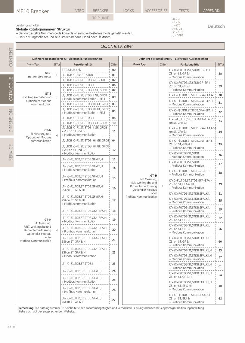
Leistungsschalter
Globale Katalognummern Struktur-- Der dargestellte Nummerncode kann als alternative Bestellmethode genutzt werden.-- Der Leistungsschalter und sein Betriebsmodus (Hand oder Elektrisch)
16., 17. & 18. Ziffer
GT-Emit Amperemeter
E
ST & STDB only 00
LT, LTDB (C+F)v. ST, STDB 01
LT, LTDB (C+F). ST, STDB, GF, GFDB 02
GT-Smit Amperemeter und
Optionaler ModbusKommunikation
S
LT, LTDB (C+F). ST, STDB, I 06
LT, LTDB (C+F). ST, STDB, I, GF, GFDB 07
LT, LTDB (C+F). ST, STDB, I, GF, GFDB+ Modbus Kommunikation + RELT
09
LT, LTDB (C+F). ST, STDB, HI, GF, GFDB 03
LT, LTDB (C+F). ST, STDB, HI, GF, GFDB+ Modbus Kommunikation + RELT
05
GT-Nmit Messung und
Optionaler ModbusKommunikation
N
LT, LTDB (C+F). ST, STDB, I 08
LT, LTDB (C+F). ST, STDB, I, GF, GFDB 10
LT, LTDB (C+F). ST, STDB, I, GF, GFDB+ ZSI on ST und GF+ Modbus Kommunikation
11
LT, LTDB (C+F). ST, STDB, HI, GF, GFDB 04
LT, LTDB (C+F). ST, STDB, HI, GF, GFDB+ ZSI on ST und GF+ Modbus Kommunikation
12
H
LT+ (C+F),LTDB,ST,STDB.GF+EF,HI 13
LT+ (C+F),LTDB,ST,STDB.GF+EF,HI+ Modbus Kommunikation
14
LT+ (C+F),LTDB,ST,STDB.GF+EF,HI+ Profi bus Kommunikation
15
LT+ (C+F),LTDB,ST,STDB.GF+EF,HIZSI on ST, GF & HI
16
LT+ (C+F),LTDB,ST,STDB.GF+EF,HIZSI on ST, GF & HI+ Modbus Kommunikation
17
LT+ (C+F),LTDB,ST,STDB.GFA+EFA,HI 18
LT+ (C+F),LTDB,ST,STDB.GFA+EFA,HI+ Modbus Kommunikation
19
LT+ (C+F),LTDB,ST,STDB.GFA+EFA,HI+ Profi bus Kommunikation
20
LT+ (C+F),LTDB,ST,STDB.GFA+EFA,HIZSI on ST, GFA & HI
21
LT+ (C+F),LTDB,ST,STDB.GFA+EFA,HIZSI on ST, GFA & HI+ Modbus Kommunikation
22
LT+ (C+F),LTDB,ST,STDB.I 23
LT+ (C+F),LTDB,ST,STDB.GF+EF,I 24
LT+ (C+F),LTDB,ST,STDB.GF+EF,I+ Modbus Kommunikation
25
LT+ (C+F),LTDB,ST,STDB.GF+EF,I+ Profi bus Kommunikation
26
LT+ (C+F),LTDB,ST,STDB.GF+EF,IZSI on ST, GF & I
27
H
LT+ (C+F),LTDB,ST,STDB.GF+EF, IZSI on ST, GF & I+ Modbus Kommunikation
28
LT+ (C+F),LTDB,ST,STDB.GF+EF, IZSI on ST, GF & I+ Profi bus Kommunikation
29
LT+(C+F),LTDB,ST,STDB.GFA+EFA,& I 30
LT+(C+F),LTDB,ST,STDB.GFA+EFA, I+ Modbus Kommunikation
31
LT+(C+F),LTDB,ST,STDB.GFA+EFA, I+ Profi bus Kommunikation
32
LT+C+F),LTDB,ST,STDB.GFA+EFA,IZSI on ST, GFA & I
33
LT+(C+F),LTDB,ST,STDB.GFA+EFA,IZSI on ST, GFA & I+ Modbus Kommunikation
34
LT+(C+F),LTDB,ST,STDB.GFA+EFA,I, ZSI on ST, GFA & I+ Profi bus Kommunikation
35
LT+ (C+F),LTDB,ST,STDB.I+ Modbus Kommunikation
36
LT+ (C+F),LTDB,ST,STDB.I+ Profi bus Kommunikation
37
LT+(C+F),LTDB,ST,STDB.GF+EF,HI+ Profi bus Kommunikation
38
LT+C+F),LTDB,ST,STDB.GFA+EFA,HI ZSI on ST, GFA & HI+ Profi bus Kommunikation
39
LT+ (C+F),LTDB,ST,STDB.EF(U.K.),I 51
LT+ (C+F),LTDB,ST,STDB.EF(U.K.),I+ Modbus Kommunikation
55
LT+ (C+F),LTDB,ST,STDB.EF(U.K.),I+ Profi bus Kommunikation
59
LT+ (C+F),LTDB,ST,STDB.EF(U.K.),IZSI on ST, GF & I
52
LT+ (C+F),LTDB,ST,STDB.EF(U.K.),IZSI on ST, GF & I+ Modbus Kommunikation
56
LT+ (C+F),LTDB,ST,STDB.EF(U.K.),IZSI on ST, GF & I+ Profi bus Kommunikation
60
LT+ (C+F),LTDB,ST,STDB.EF(U.K.),HI 53
LT+ (C+F),LTDB,ST,STDB.EF(U.K.),HI+ Modbus Kommunikation
57
LT+ (C+F),LTDB,ST,STDB.EF(U.K.),HI+ Profi bus Kommunikation
61
LT+ (C+F),LTDB,ST,STDB.EF(U.K.),HIZSI on ST, GF & HI
54
LT+ (C+F),LTDB,ST,STDB.EF(U.K.),HIZSI on ST, EF & HI+ Modbus Kommunikation
58
LT+(C+F),LTDB,ST,STDB.EFA(U.K.),I, ZSI on ST, EFA & I+ Profi bus Kommunikation
62
Basis Typ Ziffer Funktionalität Ziffer
Definiert die installierte GT-Elektronik Auslöseeinheit Definiert die installierte GT-Elektronik Auslöseeinheit
Basis Typ Ziffer Funktionalität Ziffer
GT-HMit Messung,
RELT, Weitergabe undKurvenfornerfassung
Optionaler Modbusoder
Profibus Kommunication
GT-HMit Messung,
RELT, Weitergabe undKurvenfornerfassung
Optionaler Modbusoder
Profibus Kommunication
Bemerkung: Die Katalognummer 18 beinhaltet einen zusammengefügten und verpackten Leistungsschalter mit 3-sprachiger Bedienungsanleitung. Siehe auch auf der entsprechenden Website..
6.1-08
LOCKSME10 Breaker INTRO BREAKER ACCESSORIES TESTS APPENDIX
TRIP UNIT
CA
TALO
GU
ED
IME
NS
ION
SE
RV
ICE
CO
NTE
NT
Deutsch
SD = STIsd = Isttr = LTDtr = LTDBtsd = STDBtg = GFDB
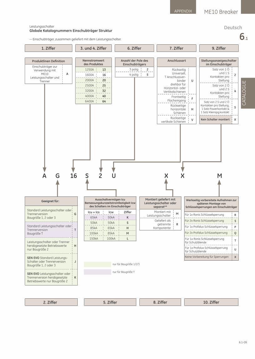
Leistungsschalter
Globale Katalognummern Einschubträger Struktur
-- Einschubträger, zusammen geliefert mit dem Leistungsschalter.
6. Ziffer 7. Ziffer 9. Ziffer1. Ziffer
2. Ziffer 5. Ziffer 8. Ziffer 10. Ziffer
3. und 4. Ziffer
A G 16 S 2 U
1250A 13
1600A 16
2000A 20
2500A 25
3200A 32
4000A 40
6400A 64
X X M
nur für Baugröße 1/2/3
nur für Baugröße T
Nennstromwert des Produktes
Anzahl der Pole desEinschubträgers
3 polig 2
4 polig 5
Anschlussart
Rü ckseitigUniversell,
T Anschlussver-binder
drehbar fü rHorizontal- oderVertikalschienen
U
FrontseitigFlacheingang
F
Rü ckseitigehorizontale
SchienenH
Rü ckseitigevertikale Schienen
V
Stellungsanzeigeschalter im Einschubträger
Satz von 1 Öund 1 S
Kontakten proStellung
2
Satz von 2 Öund 2 S
Kontakten proStellung
4
Kein Schalter montiert X
5
Satz von 2 S und 2 Ö Kontakten pro Stellung, 1 Satz Powerkontakt &
1 Satz Kleinspg.kontakt
Montiert geliefert mitLeistungsschalter oder
separat**
Montiert mitLeistungsschalter
M
Geliefert alsgetrennte
KomponenteR
A
Produktlinen Definition
Einschubträger zurVerwendung mit
ME10Leistungsschalter und
Trenner
Standard Leistungsschalter oder TrennerversionBaugröße 1, 2 oder 3
G
Standard Leistungsschalter oder TrennerversionBaugröße T
T
Leistungsschalter oder Trenner herabgesetzte Betriebswertenur Baugröße 2
H
SEN EVO Standard Leistungs-Schalter oder TrennerversionBaugröße 1, 2 oder 3
J
SEN EVO Leistungsschalter oderTrennerversion herabgesetzteBetriebswerte nur Baugröße 2
K
Geeignet für:
Icu = Ics Icw Ziffer
65kA 50kA K
50kA 50kA S
85kA 65kA H
100kA 85kA M
150kA 100kA L
Ausschaltvermögen Icu Bemessungskurzzeitstromfestigkeit Icw
des Schalters im Einschubträger
Werkseitig vorbereitete Aufnahmen zur späteren Montage von
Schlüsselsperrungen am Einschubträger
PFür 1x Profalux Schlüsselsperrung
Für 1x Ronis Schlüsselsperrung R
XKeine Vorbereitung für Sperrungen
Für 2x Ronis Schlüsselsperrung S
Für 2x Profalux Schlüsselsperrung Q
Für 1x Ronis Schlüsselsperrungfür Schutzblende
T
Für 1x Profalux Schlüsselsperrungfür Schutzblende
U
Deutsch
6.1-09
ME10 BreakerAPPENDIX
6.1
CA
TALO
GU
E
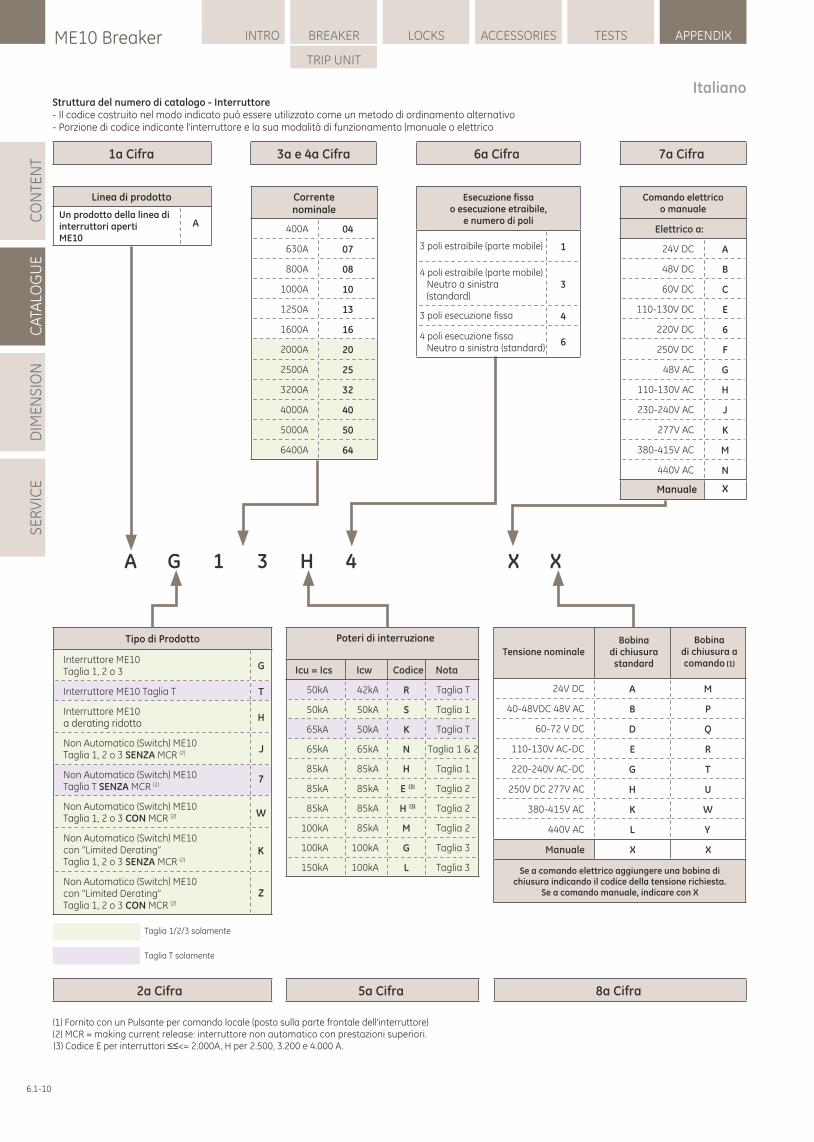
6.1-10
LOCKSME10 Breaker INTRO BREAKER ACCESSORIES TESTS APPENDIX
TRIP UNIT
CA
TALO
GU
ED
IME
NS
ION
SE
RV
ICE
CO
NTE
NT 1a Cifra
2a Cifra 5a Cifra 8a Cifra
3a e 4a Cifra 6a Cifra 7a Cifra
Correntenominale
400A 04
630A 07
800A 08
1000A 10
1250A 13
1600A 16
2000A 20
2500A 25
3200A 32
4000A 40
5000A 50
6400A 64
A
Esecuzione fissao esecuzione etraibile,
e numero di poli
1
3
4
6
Comando elettricoo manuale
Elettrico a:
24V DC A
48V DC B
60V DC C
110-130V DC E
220V DC 6
250V DC F
48V AC G
110-130V AC H
230-240V AC J
277V AC K
380-415V AC M
440V AC N
Tipo di Prodotto
Interruttore ME10 Taglia 1, 2 o 3
G
Interruttore ME10 Taglia T T
Interruttore ME10 a derating ridotto
H
Non Automatico (Switch) ME10 (2)Taglia 1, 2 o 3 SENZA MCR
Non Automatico (Switch) ME10 (2)Taglia T SENZA MCR
Non Automatico (Switch) ME10 (2)Taglia 1, 2 o 3 CON MCR
Non Automatico (Switch) ME10 con “Limited Derating”
(2)Taglia 1, 2 o 3 SENZA MCR
Non Automatico (Switch) ME10 con “Limited Derating”
(2)Taglia 1, 2 o 3 MCR CON
Poteri di interruzione
Icu = Ics Icw Codice Nota
50kA 42kA R Taglia T
50kA 50kA S Taglia 1
65kA 50kA K Taglia T
65kA 65kA N Taglia 1 & 2
85kA 85kA H Taglia 1
85kA 85kA E (3) Taglia 2
85kA 85kA H (3) Taglia 2
100kA 85kA M Taglia 2
100kA 100kA G Taglia 3
150kA 100kA L Taglia 3
A G 1 3 H 4 X X
Tensione nominaleBobina
di chiusurastandard
Taglia 1/2/3 solamente
Taglia T solamente
Italiano
24V DC A M
40-48VDC 48V AC B P
60-72 V DC D Q
110-130V AC-DC E R
220-240V AC-DC G T
250V DC 277V AC H U
380-415V AC K W
440V AC L Y
Manuale X X
3 poli estraibile (parte mobile)
4 poli estraibile (parte mobile)
3 poli esecuzione fissa
4 poli esecuzione fissa
Struttura del numero di catalogo - Interruttore- Il codice costruito nel modo indicato può essere utilizzato come un metodo di ordinamento alternativo- Porzione di codice indicante l'interruttore e la sua modalità di funzionamento (manuale o elettrico
Manuale X
J
7
W
K
Z
Bobinadi chiusura acomando (1)
Se a comando elettrico aggiungere una bobina dichiusura indicando il codice della tensione richiesta.
Se a comando manuale, indicare con X
Un prodotto della linea diinterruttori apertiME10
Neutro a sinistra(standard)
Neutro a sinistra (standard)
Linea di prodotto
(1) Fornito con un Pulsante per comando locale (posto sulla parte frontale dell'interruttore)(2) MCR = making current release: interruttore non automatico con prestazioni superiori.(3) Codice E per interruttori ≤≤<= 2.000A, H per 2.500, 3.200 e 4.000 A.
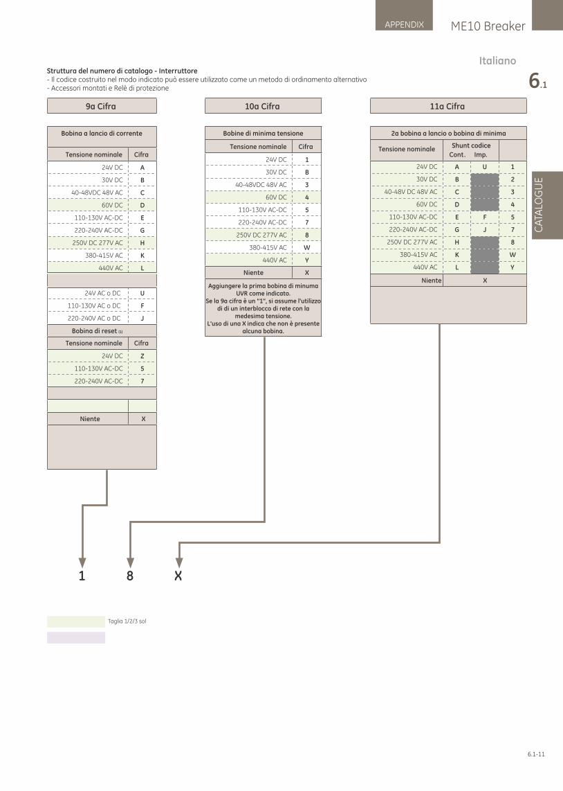
6.1-11
ME10 BreakerAPPENDIX
6.1
CA
TALO
GU
E
9a Cifra
Bobina a lancio di corrente
Tensione nominale Cifra
24V DC A
30V DC B
40-48VDC 48V AC C
60V DC D
110-130V AC-DC E
220-240V AC-DC G
250V DC 277V AC H
380-415V AC K
440V AC L
24V AC o DC U
110-130V AC o DC F
220-240V AC o DC J
Bobina di reset (1)
24V DC Z
110-130V AC-DC 5
220-240V AC-DC 7
Niente X
10a Cifra
Bobine di minima tensione
24V DC 1
30V DC B
40-48VDC 48V AC 3
60V DC 4
110-130V AC-DC 5
220-240V AC-DC 7
250V DC 277V AC 8
380-415V AC W
440V AC Y
Aggiungere la prima bobina di minumaUVR come indicato.
Se la 9a cifra è un "1", si assume l'utilizzodi di un interblocco di rete con la
medesima tensione.L'uso di una X indica che non è presente
alcuna bobina.
11a Cifra
2a bobina a lancio o bobina di minima
Tensione nominaleCont. Imp.
24V DC A U 1
30V DC B 2
40-48V DC 48V AC C 3
60V DC D 4
110-130V AC-DC E F 5
220-240V AC-DC G J 7
250V DC 277V AC H 8
380-415V AC K W
440V AC L Y
1 8 X
ItalianoStruttura del numero di catalogo - Interruttore- Il codice costruito nel modo indicato può essere utilizzato come un metodo di ordinamento alternativo- Accessori montati e Relè di protezione
Tensione nominale Cifra
Tensione nominale Cifra
Niente XNiente X
Shunt codice
Taglia 1/2/3 solamente
Taglia T solamente
Bobina a lancio alimentata impulsivamente
Interblocco di rete (1)
1interblocco di rete
Aggiungere la 1a bobina a lancio o bobina di reset indicando il
codice relativo alla tensione. Se non richiesto usare una X.,
o '1' per interblocco di rete.
Aggiungere una seconda bobina o UVR indicando il codice relativo alla tensione.
Se non richiesto usare una X. Per la Taglia T questa cifra è sempre X.
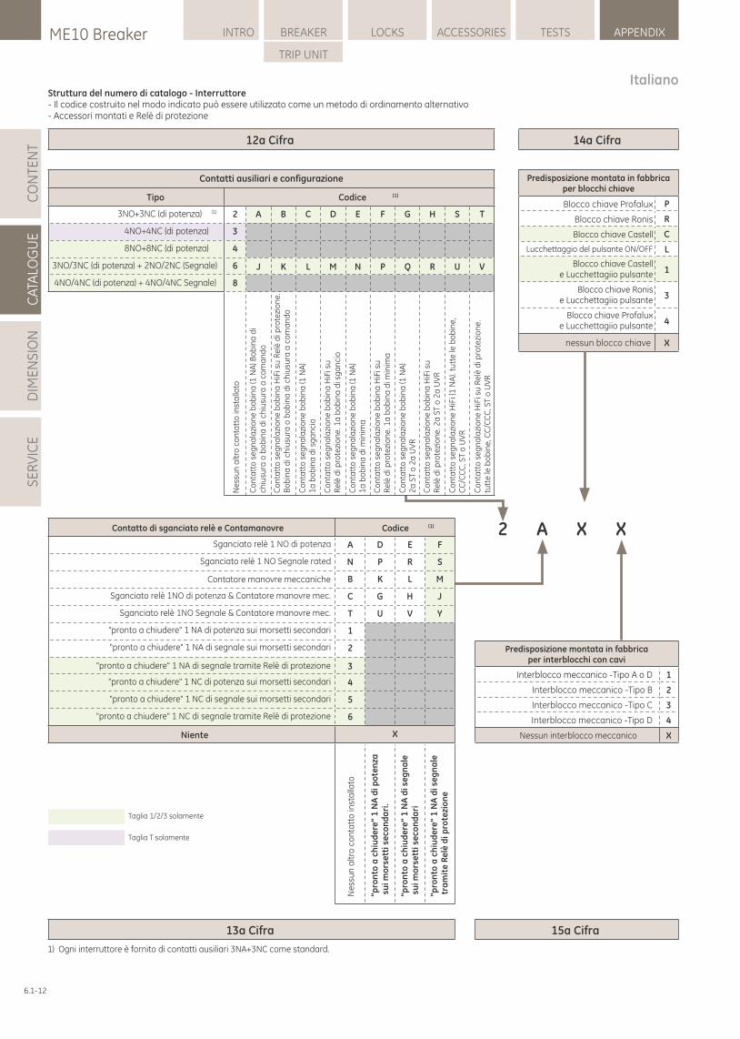
6.1-12
LOCKSME10 Breaker INTRO BREAKER ACCESSORIES TESTS APPENDIX
TRIP UNIT
CA
TALO
GU
ED
IME
NS
ION
SE
RV
ICE
CO
NTE
NT 14a Cifra
15a Cifra13a Cifra
Predisposizione montata in fabbricaper blocchi chiave
Blocco chiave Profalux P
Blocco chiave Ronis R
Blocco chiave Castell C
Lucchettaggio del pulsante ON/OFF L
1
3
4
nessun blocco chiave X
Predisposizione montata in fabbricaper interblocchi con cavi
Interblocco meccanico -Tipo A o D 1
Interblocco meccanico -Tipo B 2
Interblocco meccanico -Tipo C 3
Interblocco meccanico -Tipo D 4
Nessun interblocco meccanico X
X2 XA
12a Cifra
ItalianoStruttura del numero di catalogo - Interruttore- Il codice costruito nel modo indicato può essere utilizzato come un metodo di ordinamento alternativo- Accessori montati e Relè di protezione
Contatti ausiliari e configurazione
Tipo Codice (1)
3NO+3NC (di potenza) (1) 2 A B C D E F G H S T
4NO+4NC (di potenza) 3
8NO+8NC (di potenza) 4
J K L M N P Q R U V3NO/3NC (di potenza) + 2NO/2NC (Segnale) 6
4NO/4NC (di potenza) + 4NO/4NC Segnale) 8
Ne
ssu
n a
ltro
co
nta
tto
inst
alla
to
Co
nta
tto
se
gn
ala
zio
ne
bo
bin
a (1
NA
) Bo
bin
a d
ich
iusu
ra o
bo
bin
a d
i ch
iusu
ra a
co
ma
nd
o
Co
nta
tto
se
gn
ala
zio
ne
bo
bin
a H
iFi s
u R
elè
di p
rote
zio
ne
.B
ob
ina
di c
hiu
sura
o b
ob
ina
di c
hiu
sura
a c
om
an
do
Co
nta
tto
se
gn
ala
zio
ne
bo
bin
a (1
NA
)1
a b
ob
ina
di s
ga
nci
o
Co
nta
tto
se
gn
ala
zio
ne
bo
bin
a H
iFi s
uR
elè
di p
rote
zio
ne
. 1a
bo
bin
a d
i sg
an
cio
Co
nta
tto
se
gn
ala
zio
ne
bo
bin
a (1
NA
)1
a b
ob
ina
di m
inim
a
Co
nta
tto
se
gn
ala
zio
ne
bo
bin
a H
iFi s
uR
elè
di p
rote
zio
ne
. 1a
bo
bin
a d
i min
ima
Co
nta
tto
se
gn
ala
zio
ne
bo
bin
a (1
NA
)2
a S
T o
2a
UV
R
Co
nta
tto
se
gn
ala
zio
ne
bo
bin
a H
iFi s
uR
elè
di p
rote
zio
ne
. 2a
ST
o 2
a U
VR
Co
nta
tto
se
gn
ala
zio
ne
HiF
i (1
NA
). tu
tte
le b
ob
ine
,C
C/C
CC
, ST
o U
VR
Co
nta
tto
se
gn
ala
zio
ne
HiF
i su
Re
lè d
i pro
tezi
on
e.
tutt
e le
bo
bin
e, C
C/C
CC
, ST
o U
VR
Contatto di sganciato relè e Contamanovre
Sganciato relè 1 NO di potenza A D E F
Sganciato relè 1 NO Segnale rated N P R S
Contatore manovre meccaniche B K L M
Sganciato relè Contatore manovre mec 1NO di potenza & . C G H J
Sganciato relè Contatore manovre mec 1NO Segnale & . T U V Y
"pronto a chiudere" 1 NA di potenza sui morsetti secondari 1
"pronto a chiudere" 1 NA di segnale sui morsetti secondari 2
3
4
5
6
Niente X
Ne
ssu
n a
ltro
co
nta
tto
inst
alla
to
"pro
nto
a c
hiu
de
re"
1 N
A d
i po
ten
za s
ui m
ors
ett
i se
con
da
ri.
"pro
nto
a c
hiu
de
re"
1 N
A d
i se
gn
ale
su
i mo
rse
tti s
eco
nd
ari
"pro
nto
a c
hiu
de
re"
1 N
A d
i se
gn
ale
tra
mit
e R
elè
di p
rote
zio
ne
"pronto a chiudere" 1 NC di segnale tramite Relè di protezione
"pronto a chiudere" 1 NC di segnale sui morsetti secondari
"pronto a chiudere" 1 NC di potenza sui morsetti secondari
"pronto a chiudere" 1 NA di segnale tramite Relè di protezione
(1)Codice
Taglia 1/2/3 solamente
Taglia T solamente
1) Ogni interruttore è fornito di contatti ausiliari 3NA+3NC come standard.
Blocco chiave Castell e Lucchettagiio pulsante
Blocco chiave Ronis e Lucchettagiio pulsante
Blocco chiave Profalux e Lucchettagiio pulsante
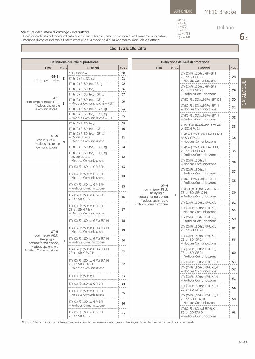
6.1-13
ME10 BreakerAPPENDIX
6.1
CA
TALO
GU
E
16a, 17a & 18a Cifra
Definizione del Relè di protezione
Tipo Codice Funcioni Codice
GT-Econ amperometro
E
SD & tsd solo 00
LT, tr (C+F)v. SD, tsd 01
LT, tr (C+F). SD, tsd, GF, tg 02
GT-Scon amperometer e
Modbus opzionaleComunicazione
S
LT, tr (C+F). SD, tsd, I 06
LT, tr (C+F). SD, tsd, I, GF, tg 07
LT, tr (C+F). SD, tsd, I, GF, tg+ Modbus Comunicazione + RELT
09
LT, tr (C+F). SD, tsd, HI, GF, tg 03
LT, tr (C+F). SD, tsd, HI, GF, tg+ Modbus Comunicazione + RELT
05
GT-Ncon misure e
Modbus opzionaleComunicazione
N
LT, tr (C+F). SD, tsd, I 08
LT, tr (C+F). SD, tsd, I, GF, tg 10
LT, tr (C+F). SD, tsd, I, GF, tg+ ZSI on SD e GF+ Modbus Comunicazione
11
LT, tr (C+F). SD, tsd, HI, GF, tg 04
LT, tr (C+F). SD, tsd, HI, GF, tg+ ZSI on SD e GF+ Modbus Comunicazione
12
H
LT+ (C+F),tr,SD,tsd.GF+EF,HI 13
LT+ (C+F),tr,SD,tsd.GF+EF,HI+ Modbus Comunicazione
14
LT+ (C+F),tr,SD,tsd.GF+EF,HI+ Profi bus Comunicazione
15
LT+ (C+F),tr,SD,tsd.GF+EF,HIZSI on SD, GF & HI
16
LT+ (C+F),tr,SD,tsd.GF+EF,HIZSI on SD, GF & HI+ Modbus Comunicazione
17
LT+ (C+F),tr,SD,tsd.GFA+EFA,HI 18
LT+ (C+F),tr,SD,tsd.GFA+EFA,HI+ Modbus Comunicazione
19
LT+ (C+F),tr,SD,tsd.GFA+EFA,HI+ Profi bus Comunicazione
20
LT+ (C+F),tr,SD,tsd.GFA+EFA,HIZSI on SD, GFA & HI
21
LT+ (C+F),tr,SD,tsd.GFA+EFA,HIZSI on SD, GFA & HI+ Modbus Comunicazione
22
LT+ (C+F),tr,SD,tsd.I 23
LT+ (C+F),tr,SD,tsd.GF+EF,I 24
LT+ (C+F),tr,SD,tsd.GF+EF,I+ Modbus Comunicazione
25
LT+ (C+F),tr,SD,tsd.GF+EF,I+ Profi bus Comunicazione
26
LT+ (C+F),tr,SD,tsd.GF+EF,IZSI on SD, GF & I
27
H
LT+ (C+F),tr,SD,tsd.GF+EF, IZSI on SD, GF & I+ Modbus Comunicazione
28
LT+ (C+F),tr,SD,tsd.GF+EF, IZSI on SD, GF & I+ Profi bus Comunicazione
29
LT+(C+F),tr,SD,tsd.GFA+EFA,& I 30
LT+(C+F),tr,SD,tsd.GFA+EFA, I+ Modbus Comunicazione
31
LT+(C+F),tr,SD,tsd.GFA+EFA, I+ Profi bus Comunicazione
32
LT+C+F),tr,SD,tsd.GFA+EFA,IZSI on SD, GFA & I
33
LT+(C+F),tr,SD,tsd.GFA+EFA,IZSI on SD, GFA & I+ Modbus Comunicazione
34
LT+(C+F),tr,SD,tsd.GFA+EFA,I, ZSI on SD, GFA & I+ Profi bus Comunicazione
35
LT+ (C+F),tr,SD,tsd.I+ Modbus Comunicazione
36
LT+ (C+F),tr,SD,tsd.I+ Profi bus Comunicazione
37
LT+(C+F),tr,SD,tsd.GF+EF,HI+ Profi bus Comunicazione
38
LT+C+F),tr,SD,tsd.GFA+EFA,HI ZSI on SD, GFA & HI+ Profi bus Comunicazione
39
LT+ (C+F),tr,SD,tsd.EF(U.K.),I 51
LT+ (C+F),tr,SD,tsd.EF(U.K.),I+ Modbus Comunicazione
55
LT+ (C+F),tr,SD,tsd.EF(U.K.),I+ Profi bus Comunicazione
59
LT+ (C+F),tr,SD,tsd.EF(U.K.),IZSI on SD, GF & I
52
LT+ (C+F),tr,SD,tsd.EF(U.K.),IZSI on SD, GF & I+ Modbus Comunicazione
56
LT+ (C+F),tr,SD,tsd.EF(U.K.),IZSI on SD, GF & I+ Profi bus Comunicazione
60
LT+ (C+F),tr,SD,tsd.EF(U.K.),HI 53
LT+ (C+F),tr,SD,tsd.EF(U.K.),HI+ Modbus Comunicazione
57
LT+ (C+F),tr,SD,tsd.EF(U.K.),HI+ Profi bus Comunicazione
61
LT+ (C+F),tr,SD,tsd.EF(U.K.),HIZSI on SD, GF & HI
54
LT+ (C+F),tr,SD,tsd.EF(U.K.),HIZSI on SD, EF & HI+ Modbus Comunicazione
58
LT+(C+F),tr,SD,tsd.EFA(U.K.),I, ZSI on SD, EFA & I+ Profi bus Comunicazione
62
ItalianoStruttura del numero di catalogo - Interruttore- Il codice costruito nel modo indicato può essere utilizzato come un metodo di ordinamento alternativo- Porzione di codice indicante l'interruttore e la sua modalità di funzionamento (manuale o elettrico
GT-Hcon misure, RELT,
Relaying ecattura forma d'onda,
Modbus opzionale oProfibus Comunicazione
Tipo Codice Funcioni Codice
Definizione del Relè di protezione
SD = STIsd = Isttr = LTDtr = LTDBtsd = STDBtg = GFDB
GT-Hcon misure, RELT,
Relaying ecattura forma d'onda,
Modbus opzionale oProfibus Comunicazione
Nota: la 18a cifra indica un interruttore confezionato con un manuale utente in tre lingue. Fare riferimento anche al nostro sito web.
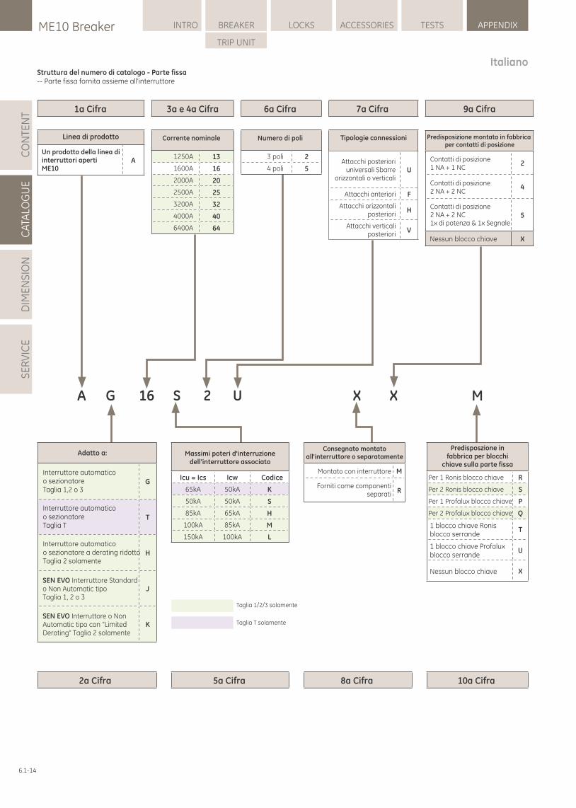
6.1-14
LOCKSME10 Breaker INTRO BREAKER ACCESSORIES TESTS APPENDIX
TRIP UNIT
CA
TALO
GU
ED
IME
NS
ION
SE
RV
ICE
CO
NTE
NT
ItalianoStruttura del numero di catalogo - Parte fissa-- Parte fissa fornita assieme all'interruttore
6a Cifra 7a Cifra 9a Cifra1a Cifra
2a Cifra 5a Cifra 8a Cifra 10a Cifra
3a e 4a Cifra
A G 16 S 2 U
Corrente nominale
1250A 13
1600A 16
2000A 20
2500A 25
3200A 32
4000A 40
6400A 64
Numero di poli
3 poli 2
4 poli 5
Tipologie connessioni
Attacchi posterioriuniversali Sbarre
orizzontali o verticaliU
Attacchi anteriori F
Attacchi orizzontaliposteriori
H
Attacchi verticaliposteriori
V
X X M
Massimi poteri d'interruzionedell'interruttore associato
Icu = Ics Icw Codice
65kA 50kA K
50kA 50kA S
85kA 65kA H
100kA 85kA M
150kA 100kA L
Un prodotto della linea diinterruttori apertiME10
A
Adatto a:
G
T
H
SEN EVO Interruttore Standardo Non Automatic tipo Taglia 1, 2 o 3
J
SEN EVO Interruttore o Non Automatic tipo con “Limited Derating” Taglia 2 solamente
K
Taglia 1/2/3 solamente
Taglia T solamente
Predisposizione montata in fabbrica per contatti di posizione
2
4
5
Nessun blocco chiave X
Contatti di posizione1 NA + 1 NC
Contatti di posizione2 NA + 2 NC
Contatti di posizione2 NA + 2 NC1x di potenza & 1x Segnale
Consegnato montatoall'interruttore o separatamente
Montato con interruttore M
RForniti come componenti
separati
Linea di prodotto
Interruttore automatico o sezionatore Taglia 1,2 o 3
Interruttore automatico o sezionatore Taglia T
Interruttore automatico o sezionatore a derating ridottoTaglia 2 solamente
Predisposzione in fabbrica per blocchi
chiave sulla parte fissa
Per 1 Ronis blocco chiave R
Per 2 Ronis blocco chiave S
Per 1 Profalux blocco chiave P
Per 2 Profalux blocco chiave Q
1 blocco chiave Ronis blocco serrande
T
U
Nessun blocco chiave X
1 blocco chiave Profalux blocco serrande

6.1-15
n o t e n o t i z e n | n o t a
. . . . . . . . . . . . . . . . . . . . . . . . . . . . . . . . . . . . . . . . . . . . . . . . . . . . . . . .
. . . . . . . . . . . . . . . . . . . . . . . . . . . . . . . . . . . . . . . . . . . . . . . . . . . . . . . .
. . . . . . . . . . . . . . . . . . . . . . . . . . . . . . . . . . . . . . . . . . . . . . . . . . . . . . . .
. . . . . . . . . . . . . . . . . . . . . . . . . . . . . . . . . . . . . . . . . . . . . . . . . . . . . . . .
. . . . . . . . . . . . . . . . . . . . . . . . . . . . . . . . . . . . . . . . . . . . . . . . . . . . . . . .
. . . . . . . . . . . . . . . . . . . . . . . . . . . . . . . . . . . . . . . . . . . . . . . . . . . . . . . .
. . . . . . . . . . . . . . . . . . . . . . . . . . . . . . . . . . . . . . . . . . . . . . . . . . . . . . . .
. . . . . . . . . . . . . . . . . . . . . . . . . . . . . . . . . . . . . . . . . . . . . . . . . . . . . . . .
. . . . . . . . . . . . . . . . . . . . . . . . . . . . . . . . . . . . . . . . . . . . . . . . . . . . . . . .
. . . . . . . . . . . . . . . . . . . . . . . . . . . . . . . . . . . . . . . . . . . . . . . . . . . . . . . .
. . . . . . . . . . . . . . . . . . . . . . . . . . . . . . . . . . . . . . . . . . . . . . . . . . . . . . . .
. . . . . . . . . . . . . . . . . . . . . . . . . . . . . . . . . . . . . . . . . . . . . . . . . . . . . . . .
. . . . . . . . . . . . . . . . . . . . . . . . . . . . . . . . . . . . . . . . . . . . . . . . . . . . . . . .
. . . . . . . . . . . . . . . . . . . . . . . . . . . . . . . . . . . . . . . . . . . . . . . . . . . . . . . .
. . . . . . . . . . . . . . . . . . . . . . . . . . . . . . . . . . . . . . . . . . . . . . . . . . . . . . . .
. . . . . . . . . . . . . . . . . . . . . . . . . . . . . . . . . . . . . . . . . . . . . . . . . . . . . . . .
. . . . . . . . . . . . . . . . . . . . . . . . . . . . . . . . . . . . . . . . . . . . . . . . . . . . . . . .
. . . . . . . . . . . . . . . . . . . . . . . . . . . . . . . . . . . . . . . . . . . . . . . . . . . . . . . .
. . . . . . . . . . . . . . . . . . . . . . . . . . . . . . . . . . . . . . . . . . . . . . . . . . . . . . . .
. . . . . . . . . . . . . . . . . . . . . . . . . . . . . . . . . . . . . . . . . . . . . . . . . . . . . . . .
. . . . . . . . . . . . . . . . . . . . . . . . . . . . . . . . . . . . . . . . . . . . . . . . . . . . . . . .
. . . . . . . . . . . . . . . . . . . . . . . . . . . . . . . . . . . . . . . . . . . . . . . . . . . . . . . .
. . . . . . . . . . . . . . . . . . . . . . . . . . . . . . . . . . . . . . . . . . . . . . . . . . . . . . . .
LOCKSBREAKER ME10 INTRO BREAKER ACCESSORIES TESTS APPENDIX
TRIP UNIT
DIM
EN
SIO
N
note notizen | nota
. . . . . . . . . . . . . . . . . .
. . . . . . . . . . . . . . . . . .
. . . . . . . . . . . . . . . . . .
. . . . . . . . . . . . . . . . . .
. . . . . . . . . . . . . . . . . .
. . . . . . . . . . . . . . . . . .
. . . . . . . . . . . . . . . . . .
. . . . . . . . . . . . . . . . . .
. . . . . . . . . . . . . . . . . .
. . . . . . . . . . . . . . . . . .
. . . . . . . . . . . . . . . . . .
. . . . . . . . . . . . . . . . . .
. . . . . . . . . . . . . . . . . .
. . . . . . . . . . . . . . . . . .
. . . . . . . . . . . . . . . . . .
. . . . . . . . . . . . . . . . . .
. . . . . . . . . . . . . . . . . .
. . . . . . . . . . . . . . . . . .
. . . . . . . . . . . . . . . . . .
. . . . . . . . . . . . . . . . . .
. . . . . . . . . . . . . . . . . .
. . . . . . . . . . . . . . . . . .
. . . . . . . . . . . . . . . . . .
6.2-00
Translation
Centre Line Connected Connection pads DIN Rail Disconnected Door cut out Draw out Front Connection Envelope External Power Supply Fixed front Connection Fixed Vertical Rear Connection
Front view Fully withdraw IP54 Flange drilling Mounting bracketsOnly Vertical Operating panel or Horizontal Side view Test Time delay Module Top view |
Remarks A- 6 mounting holes of ø 9,5 mm B- Clearence distance C- Please leave unobstructed; required for ventilation D- 1 hole M6 Left & Right for earthing
| Traduzione
| Linea centrale| Connected | Piazzole di connessione | Binario DIN | Disconnected | Ritaglio nella porta | Connessione anteriore tipo estraibile | Taglia | Alimentatore esterno | Connessione anteriore tipo fisso | Connessione posteriore verticale tipo fisso
| Vista anteriore | Totalmente estratto | Sagoma di foratura flangia IP54 | Staffe montaggio | Solo verticale | Pannello operativo | o orizzontale | Vista laterale | Verifica | Modulo temporizzazione | Vista dall'alto
| Osservazioni | A- 6 fori di montaggio da ø 9,5 mm | B- Distanza di sicurezza | C- Non ostruire; necessario per la ventilazione
| D- 1 foro M6 Sinistra & Destra per la messa a terra
| Übersetzung
| Mittellinie | Betriebsstellung | Anschlussschiene | DIN Tragschiene | Trennstellung | Türausschnitt | Ausfahrtechnik Frontanschluss | Baugröße | Externe Stromversorgung | Festeinbau Frontseitiger Anschluss | Festeinbau Vertikaler Rückseitiger Anschluss
| Vorderansicht | Voll herausgezogen | IP54 Abdeckung Bohrplan | Montagewinkel | nur Vertikal | Bedienfeld | oder Horizontal | Seitenansicht| Teststellung | Zeitverzögerungsmodul| Draufsicht
| Hinweise| A- 6 Montagelöcher ø 9,5 mm | B- Sicherheitsabstände| C- Bitte für Ventilationszwecke freilassen.
| D- 1 Loch M6 beidseitig zur Erdung
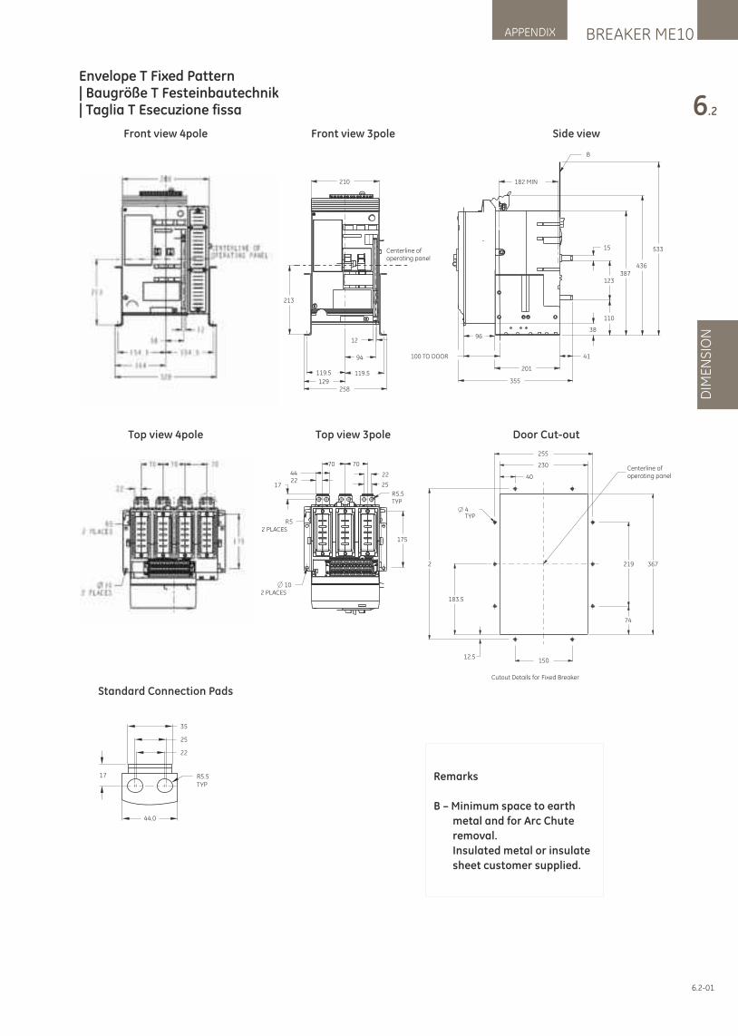
Envelope T Fixed Pattern | Baugröße T Festeinbautechnik | Taglia T Esecuzione fissa
328
280
213
12
58
164
154.5 154.5
Centerline ofoperating panel
17
44
22
70 70
175
RTYP
5.5
2 PLACES10
R2 PLACES
5
70.000
44.00025
22
110
123
15
38
387436
533
100 TO DOOR
355
201
182 MIN
41
96
B
258
210
213
94
119.5 119.5
129
12
Centerline ofoperating panel
172244
70 70
25
175
RTYP
5.5
2 PLACES10
R2 PLACES
5
22
255
230
40
4TYP
2
183.5
12.5150
74
219 367
Centerline ofoperating panel
Cutout Details for Fixed Breaker
Front view 3pole
Top view 3pole
Front view 4pole
Top view 4pole
Standard Connection Pads
Side view
Door Cut-out
Remarks
B – M inimum space to earth
metal and for Arc Chute
removal.
Insulated metal or insulate
sheet customer supplied.
35
25
22
R5.5TYP
17
44.0
6.2-01
BREAKER ME10APPENDIX
6.2
DIM
EN
SIO
N
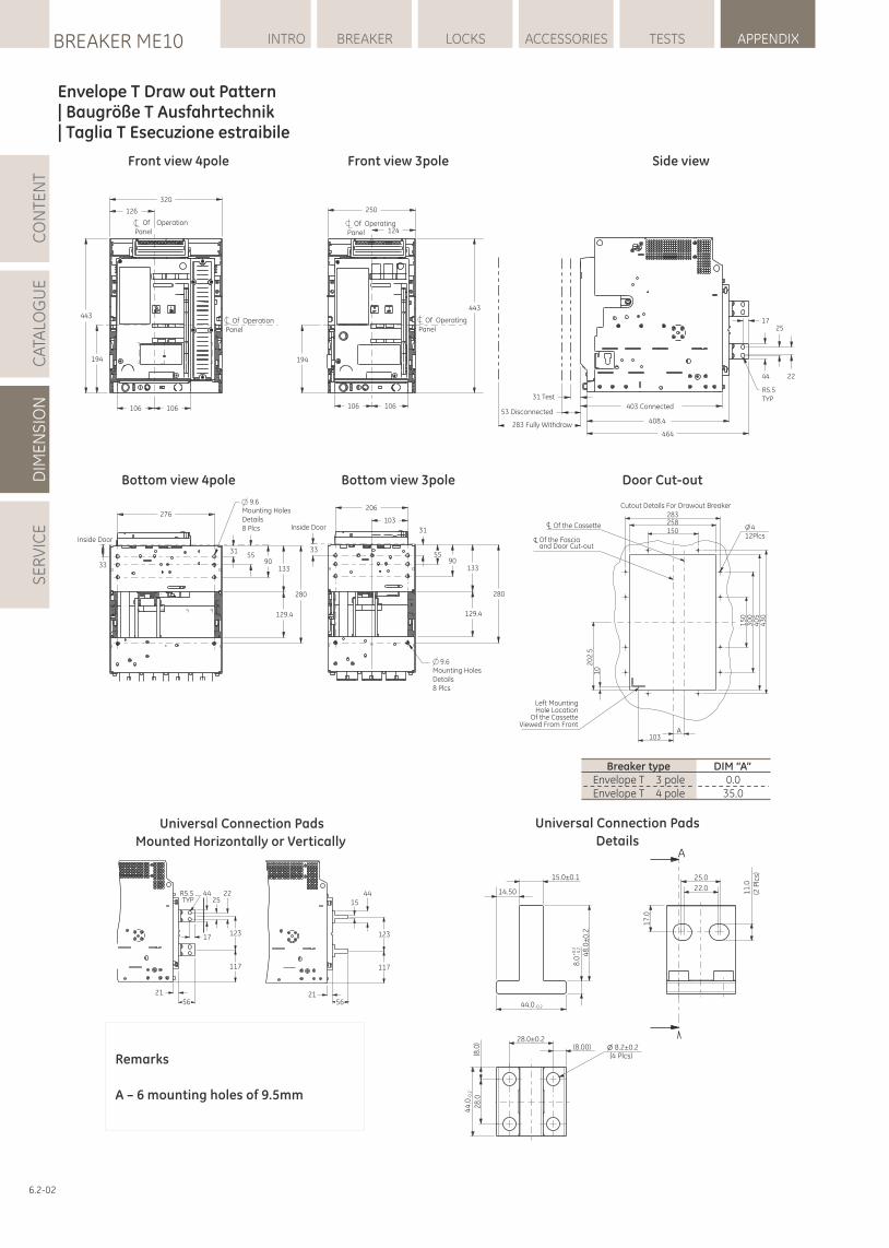
Envelope T Draw out Pattern | Baugröße T Ausfahrtechnik | Taglia T Esecuzione estraibile
Front view 3poleFront view 4pole
Universal Connection Pads
Mounted Horizontally or Vertically
Universal Connection Pads
Details
Side view
Remarks
A – 6 mounting holes of 9.5mm
R5.5TYP
44 2225
12317
117
2156
1544
123
117
5621
320
126
Of OperationPanel
443
194
106 106
Of OperationPanel
Of OperatingPanel
250
124
443
Of OperatingPanel
194
106 106
Mounting HolesDetails8 Plcs
Inside Door
276
9.6
3155
90133
280
129.4
33
Inside Door
33
206
103
31
5590
133
280
129.4
9.6Mounting HolesDetails8 Plcs
31 Test
53 Disconnected
283 Fully Withdraw464
408.4
403 Connected
R5.5TYP
44 22
1725
15
03
00
43
0
150
40
5
2584
12Plcs
20
2.5
10
103A
283Cutout Details For Drawout Breaker
Of the Cassette
Of the Fasciaand Door Cut-out
Left MountingHole Location
Of the CassetteViewed From Front
Bottom view 3poleBottom view 4pole Door Cut-out
15.0±0.1 25.0
22.014.50
44.0-0.2
8.0
+0
.2-
0.2
48
.0±
0.2
28.0±0.2
(8.0
)
(8.00) 8.2±0.2(4 Plcs)
44
.0-0
.2
28
.0
A
11
.0(2
Plc
s)
17
.0
Breaker type DIM “A”Envelope T 3 pole 0.0Envelope T 4 pole 35.0
6.2-02
LOCKSBREAKER ME10 INTRO BREAKER ACCESSORIES TESTS APPENDIXC
ATA
LOG
UE
DIM
EN
SIO
NS
ER
VIC
EC
ON
TEN
T
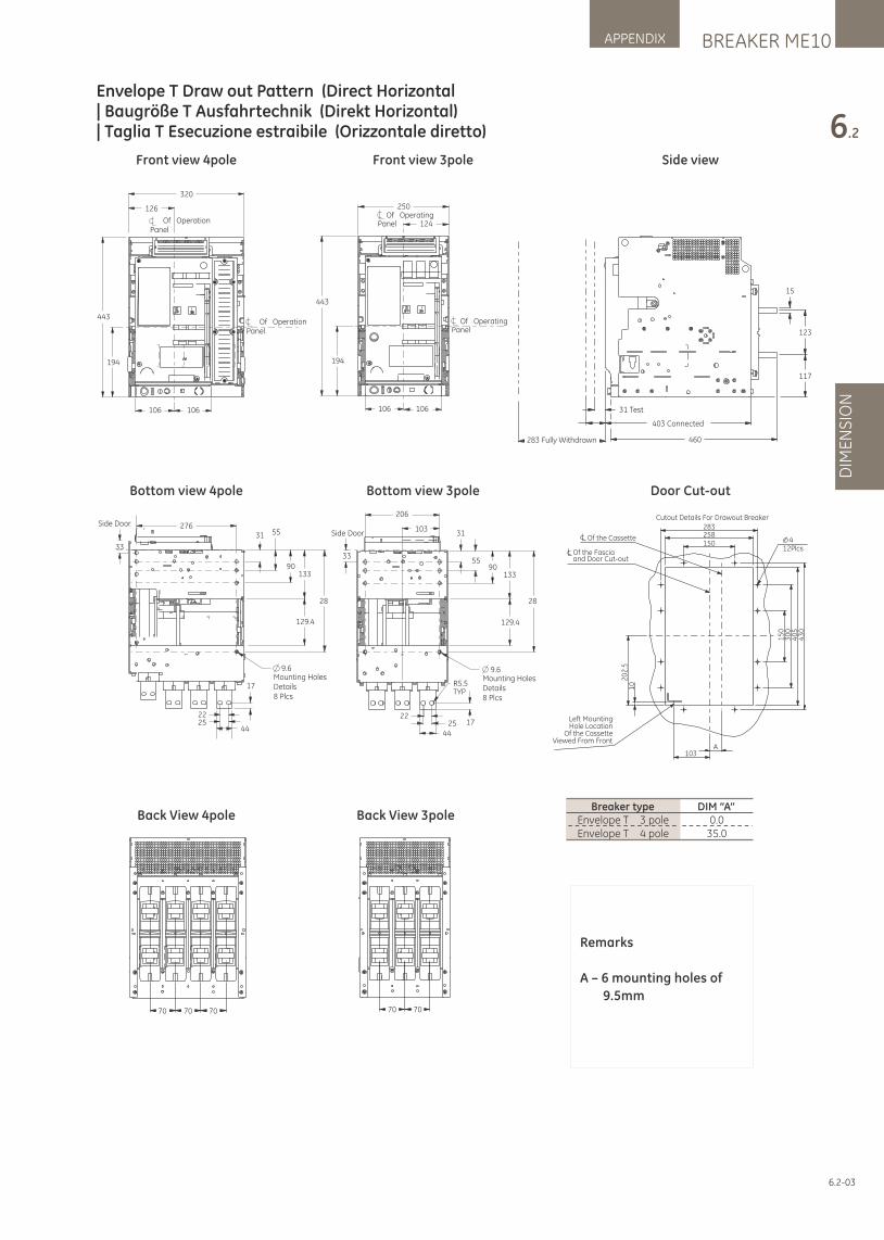
320
126
Of OperationPanel
Of OperationPanel
443
194
106 106
276Side Door
33
31 55
90133
28
129.4
9.6Mounting HolesDetails8 Plcs
17
442522
Of OperatingPanel
250
124
Of OperatingPanel
443
194
106 106
206
103Side Door
33
31
5590
133
28
129.4
9.6Mounting HolesDetails8 Plcs
R5.5TYP
172544
22
31 Test
283 Fully Withdrawn
15
123
117
403 Connected
460
70 70 70 70 70
15
03
00
43
0
150
40
5
2584
12Plcs
20
2.5
10
103A
283Cutout Details For Drawout Breaker
Of the Cassette
Of the Fasciaand Door Cut-out
Left MountingHole Location
Of the CassetteViewed From Front
Front view 3pole
Bottom view 3pole
Front view 4pole
Bottom view 4pole
Back View 4pole Back View 3pole
Side view
Door Cut-out
Remarks
A – 6 mounting holes of
9.5mm
Breaker type DIM “A”Envelope T 3 pole 0.0Envelope T 4 pole 35.0
6.2-03
BREAKER ME10APPENDIX
6.2
DIM
EN
SIO
N
Envelope T Draw out Pattern (Direct Horizontal| Baugröße T Ausfahrtechnik (Direkt Horizontal)| Taglia T Esecuzione estraibile (Orizzontale diretto)
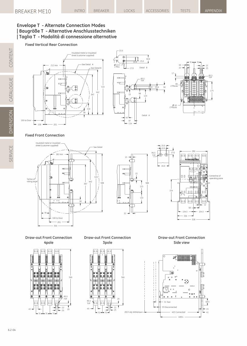
Centerline ofoperating pane
12
154.5
58
154.5
164
328
224
280
566
R5.5TYP
22
2520
707070
45
566
20
2225
7070
45
R5.5TYP
283 Fully Withdrawn
408.4
403 Connected
53 Disconnected
31 Test 68.5
15
41
Insulated metal or insulatedsheet (customer supplied)
Terline ofrating panel
182 min
See Detail
387442
533
588
38
78
100 to Door
201
355
32
110
123
588
15
15
R5.5TYP
45.0
17.0
25.0
22.0
Insulated metal or insulatedsheet (customer supplied)
212 min
100 to Door
108 201
38
110
387442
533
See Detail A
See Detail B
Detail A
Detail B
R5.5TYP
22.0 25.0 50
98123
15
40
97
114
17.0
11.02 Plcs
22.0 25.050.0
15.0
44
22
70 70
22
25
17
R52 Places
102 Places
R5.5TYP
175
Fixed Front Connection
Fixed Vertical Rear Connection
Draw-out Front Connection
4pole
Draw-out Front Connection
3pole
Draw-out Front Connection
Side view
6.2-04
LOCKSBREAKER ME10 INTRO BREAKER ACCESSORIES TESTS APPENDIXC
ATA
LOG
UE
DIM
EN
SIO
NS
ER
VIC
EC
ON
TEN
T
Envelope T - Alternate Connection Modes| Baugröße T - Alternative Anschlusstechniken| Taglia T - Modalità di connessione alternative
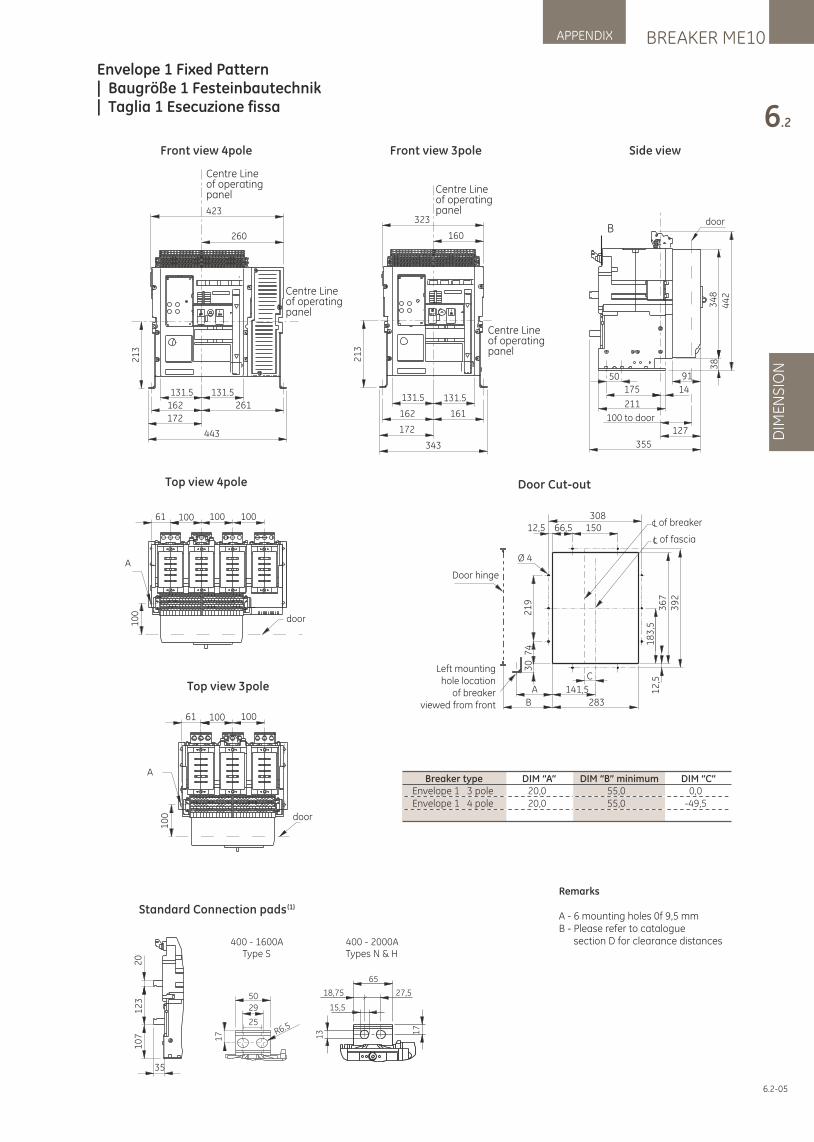
BREAKER ME10APPENDIX
6.2
DIM
EN
SIO
N
Envelope 1 Fixed Pattern | Baugröße 1 Festeinbautechnik | Taglia 1 Esecuzione fissa
323
160
131.5 131.5
162 161
172
343
21
3
Centre Line of operatingpanel
Centre Line of operatingpanel
door
50
34
83
84
42
175
91
211
100 to door
14
127
B
355
Front view 3pole
423
21
3
260
131.5 131.5
162
172
443
Centre Line of operatingpanel
Centre Line of operatingpanel
261
Front view 4pole
61 100 100 100
door10
0
A
Top view 4pole
61 100 100
door
10
0
A
Top view 3pole
Side view
Door Cut-out
of breaker
of fascia
Left mountinghole location
of breakerviewed from front
Door hinge
12,5 66,5 150308
Ø 4
A
B
141,5
283
C
30
74
21
9
39
23
67
18
3,5
12
,5
Breaker type DIM “A” DIM “B” minimum DIM “C”Envelope 1 3 pole 20,0 55,0 0,0Envelope 1 4 pole 20,0 55,0 -49,5
Remarks
A - 6 mounting holes 0f 9,5 mmB - Please refer to catalogue section D for clearance distances
20
12
31
07
35
Standard Connection pads (1)
13 1
7
65
27,518,75
15,5
400 - 2000ATypes N & H
400 - 1600AType S
50
29
25
17 R6.5
6.2-05
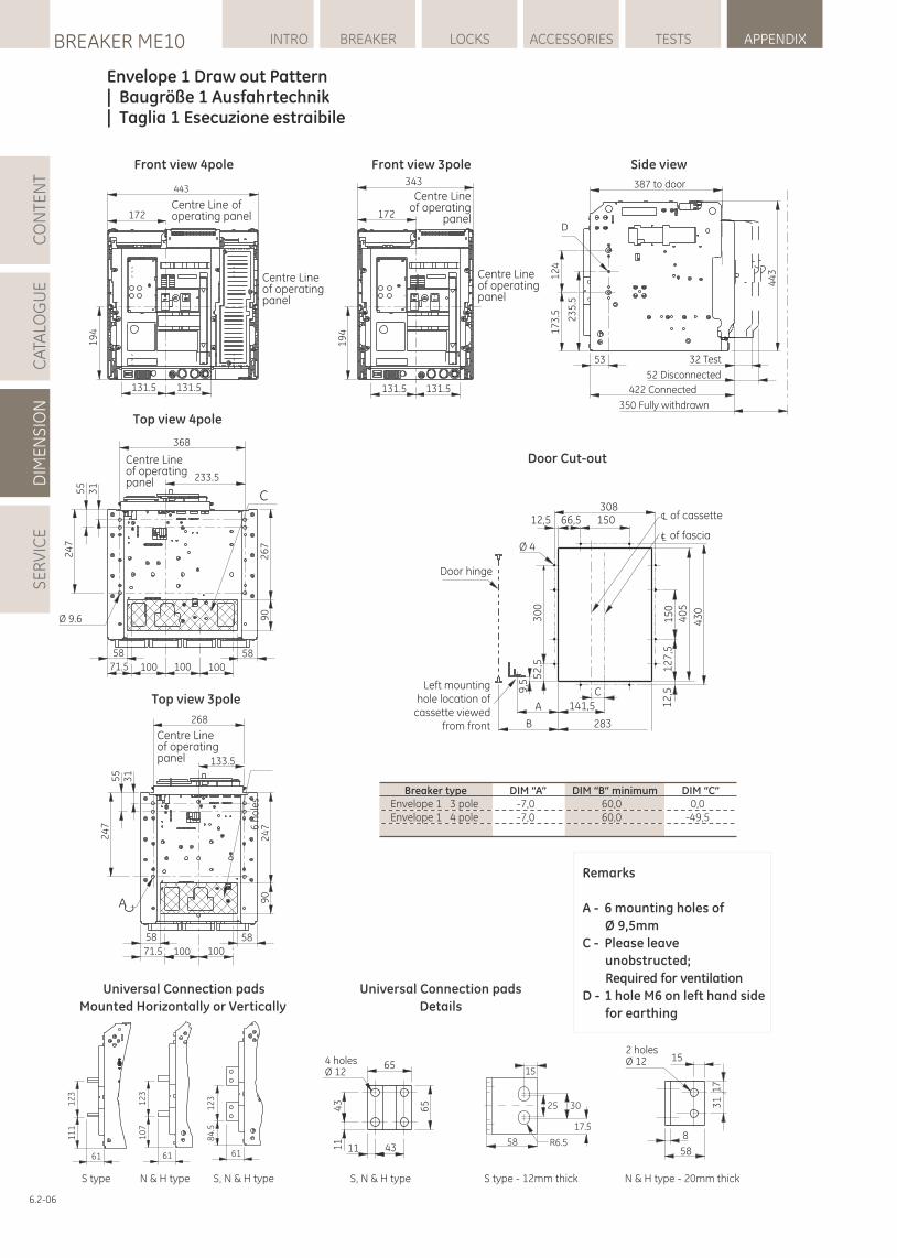
LOCKSBREAKER ME10 INTRO BREAKER ACCESSORIES TESTS APPENDIXC
ATA
LOG
UE
DIM
EN
SIO
NS
ER
VIC
EC
ON
TEN
T
Envelope 1 Draw out Pattern | Baugröße 1 Ausfahrtechnik | Taglia 1 Esecuzione estraibile
443
172
131.5 131.5
19
4
Centre Line of operating panel
Centre Line of operatingpanel
343
172
131.5 131.5
19
4
Centre Line of operatingpanel
Centre Lineof operating
panel
2 holesØ 12
58
15
31
17
8
15
3025
17.5
R6.558
4 holesØ 12
65
431111
43
65
61
10
71
23
61
11
11
23
61
12
38
4.5
Front view 4pole
368
C
100 100 100
233.5
5858
71.5
24
75
53
1
26
76
ho
les
90
Ø 9.6
Centre Lineof operatingpanel
Top view 4pole
Universal Connection pads
Mounted Horizontally or Vertically
Universal Connection pads
Details
Front view 3pole
268
A
133.5
100 10071.5
58 58
55
31
24
7
24
7
C
90
Centre Lineof operatingpanel
Top view 3pole
Side view
Door Cut-out
Remarks
A - 6 mounting holes of
Ø 9,5mm
C - Please leave
unobstructed;
Required for ventilation
D - 1 hole M6 on left hand side
for earthing
387 to door
D
32 Test
52 Disconnected
422 Connected
350 Fully withdrawn
53
12
41
73
.5 23
5.5
44
3
Breaker type DIM “A” DIM “B” minimum DIM “C”Envelope 1 3 pole -7,0 60,0 0,0Envelope 1 4 pole -7,0 60,0 -49,5
Left mountinghole location of
cassette viewedfrom front
A
B
141,5
283
C
Door hinge
of cassette
of fascia
12,5 66,5 150308
Ø 43
00
15
04
05
43
0
12
7,5
12
,5
52
,5
9,5
S type N & H type S, N & H type S, N & H type S type - 12mm thick N & H type - 20mm thick
6.2-06
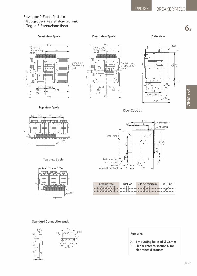
BREAKER ME10APPENDIX
6.2
DIM
EN
SIO
N
Envelope 2 Fixed Pattern | Baugröße 2 Festeinbautechnik | Taglia 2 Esecuzione fissa
410
190
191222
131.5131.5
234
436
21
3
Centre Line of operatingpanel
Centre Lineof operatingpanel
door
50
34
83
84
42
175
91
211
100 to door
14
127
B
355
35
10
71
23
20
95
10 25 25 25Ø 13
17
Standard Connection pads
Front view 3pole Side view
Door Cut-out
Remarks
A - 6 mounting holes of Ø 9,5mm
B - Please refer to section D for
clearance distances
Front view 4pole
76 130 130
door
A
Top view 3pole
Top view 4pole
A
76 130 130 130
door
540
319
321222
131.5131.5
234
566
21
3
Centre Line of operating
panel
Centre Lineof operatingpanel
Breaker type DIM “A” DIM “B” minimum DIM “C”Envelope 2 3 pole 80,0 115,0 15,5Envelope 2 4 pole 80,0 115,0 -49,5
of breaker
of fascia
Left mountinghole location
of breakerviewed from front
Door hinge
12,5 66,5 150308
Ø 4
A
B
141,5
283
C
30
74
21
9
39
23
67
18
3,5
12
,5
6.2-07
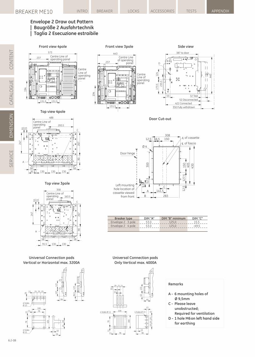
6.2-08
LOCKSBREAKER ME10 INTRO BREAKER ACCESSORIES TESTS APPENDIXC
ATA
LOG
UE
DIM
EN
SIO
NS
ER
VIC
EC
ON
TEN
T
Envelope 2 Draw out Pattern | Baugröße 2 Ausfahrtechnik | Taglia 2 Esecuzione estraibile
Front view 4pole
488
293.5
13058 58
130130
55
24
7
26
79
0
31
91.5
C
A
Centre Line of operatingpanel
Top view 4pole
Front view 3pole
24
75
53
1
26
79
0
358
130 13091.5
58 58
163.5
C
A
Centre Line of operatingpanel
Top view 3pole
Side view
Remarks
A - 6 mounting holes of
Ø 9,5mm
C - Please leave
unobstructed;
Required for ventilation
D - 1 hole M6 on left hand side
for earthing
Universal Connection pads
Vertical or Horizontal max. 3200A
12
31
07
64
12
38
4.5
6113 25 25 25
100
78
10
59
4 holesØ 13
4 holesØ 11
11
11
78 20
45
10
0
14
95
13
36
2
Universal Connection pads
Only Vertical max. 4000A
29 21 21
10
11
100
7811
11
78
10
0
25
25
25
13
13
15
90
4 holes Ø 11 4 holes Ø 13
443
131.5
19
4
13
1.5
237
Centre Line of operatingpanel
Centre Lineof operating
panel
387 to door
D
32 Test
52 Disconnected
422 Connected
350 Fully withdrawn
53
12
41
73
.5 23
5.5
44
3
573
131.5 131.5
237
19
4
Centre Line of operatingpanel
Centre Line of operating panel
Door Cut-out
Breaker type DIM “A” DIM “B” minimum DIM “C”Envelope 2 3 pole 53,0 125,0 15,5Envelope 2 4 pole 53,0 125,0 -49,5
Left mountinghole location of
cassette viewedfrom front
A
B
141,5
283
C
Door hinge
of cassette
of fascia
12,5 66,5 150308
Ø 43
00
15
04
05
43
0
12
7,5
12
,5
52
,5
9,5
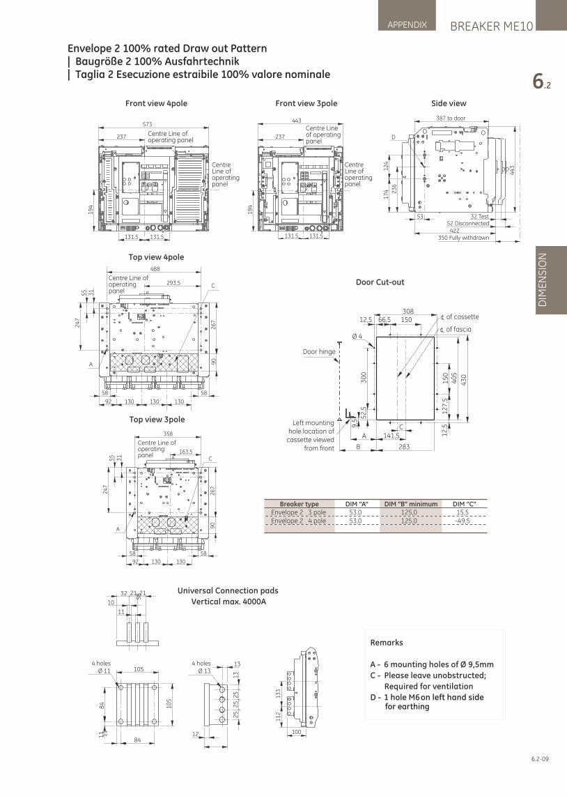
BREAKER ME10APPENDIX
6.2
DIM
EN
SIO
N
6.2-09
Envelope 2 100% rated Draw out Pattern | Baugröße 2 100% Ausfahrtechnik | Taglia 2 Esecuzione estraibile 100% valore nominale
131.5 131.5
443
237
19
4
Centre Line of operatingpanel
Centre Lineof operatingpanel
387 to door
D
32 Test52 Disconnected
422350 Fully withdrawn
53
12
41
74 23
6
44
3
100
13
31
12
84
84
58
4 holesØ 13
4 holesØ 11
13
1211 11
105
32 21 21
10
11
10
5
25
25
25
13
Universal Connection pads
Vertical max. 4000A
Front view 3pole
573
131.5 131.5
237
19
4
Centre Line of operatingpanel
Centre Line of operating panel
Front view 4pole
Top view 4pole
C
A
488
293.5
130 130 13092
58 58
24
75
5 31
26
79
0
Centre Line of operatingpanel
C
24
75
5
31
26
79
0
A
163.5
358
58 58
92 130 130
Centre Line of operatingpanel
Top view 3pole
Side view
Door Cut-out
Breaker type DIM “A” DIM “B” minimum DIM “C”Envelope 2 3 pole 53,0 125,0 15,5Envelope 2 4 pole 53,0 125,0 -49,5
Left mountinghole location of
cassette viewedfrom front
A
B
141,5
283
C
Door hinge
of cassette
of fascia
12,5 66,5 150308
Ø 4
30
0
15
04
05
43
0
12
7,5
12
,5
52
,5
9,5
Remarks
A - 6 mounting holes of Ø 9,5mm
C - Please leave unobstructed;
Required for ventilation
D - 1 hole M6 on left hand sidefor earthing
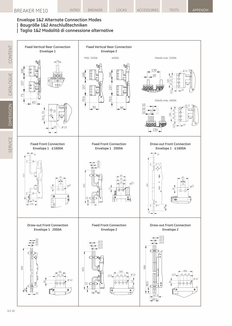
LOCKSBREAKER ME10 INTRO BREAKER ACCESSORIES TESTS APPENDIXC
ATA
LOG
UE
DIM
EN
SIO
NS
ER
VIC
EC
ON
TEN
T
6.2-10
Envelope 1&2 Alternate Connection Modes | Baugröße 1&2 Anschlußtechniken | Taglia 1&2 Modalità di connessione alternative
63
10
01
57
71
20
Ø 1315
34
.53
1 50
130
20
Ø 13
15
10
0
12
.52
52
52
5
101010
130
13
Ø 13
10
0
12
.52
52
52
5
Fixed Vertical Rear Connection
Envelope 1
70
.51
57
10
0
91 951
00
15
77
0.5
Fixed Vertical Rear Connection
Envelope 2
MAX. 3200A 4000A Details max. 3200A
Details max. 4000A
Fixed Front Connection
Envelope 1 ≤1600A
Fixed Front Connection
Envelope 1 2000A
Draw-out Front Connection
Envelope 1 ≤1600A
65
30
25R6.5
17
1010
10
96
45
31
3
13
10
56
5
68
20
65
30
25
R6.5
10
110
76
45
3
13
17
30
65
25
R6.5
101010
33
56
56
8
10
.5
20
65
22 22
Ø 12
Draw-out Front Connection
Envelope 1 2000A
12.512.5
12.5
96
45
31
3
12.512.512.5
67.5
100.5
56
66
8.5
12.5 25 25 25 Ø 13
100
17
100
12.5 25 25 25
Ø 12
20
Fixed Front Connection
Envelope 2
Draw-out Front Connection
Envelope 2
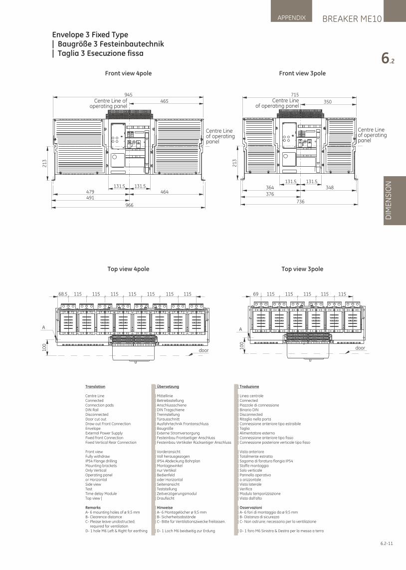
BREAKER ME10APPENDIX
6.2
DIM
EN
SIO
N
6.2-11
Envelope 3 Fixed Type | Baugröße 3 Festeinbautechnik | Taglia 3 Esecuzione fissa
945
465
131.5 131.5479 464
966
491
21
3
Centre Line ofoperating panel
Centre Line of operatingpanel
715
350
131.5 131.5364
376
736
348
21
3
Centre Line of operatingpanel
Centre Lineof operating panel
68.5 115 115 115 115 115 115 115
door10
0
A
69 115 115 115 115 115
door10
0
A
Front view 4pole
Top view 4pole
Front view 3pole
Top view 3pole
Translation
Centre Line Connected Connection pads DIN Rail Disconnected Door cut out Draw out Front Connection Envelope External Power Supply Fixed front Connection Fixed Vertical Rear Connection
Front view Fully withdraw IP54 Flange drilling Mounting bracketsOnly Vertical Operating panel or Horizontal Side view Test Time delay Module Top view |
Remarks A- 6 mounting holes of ø 9,5 mm B- Clearence distance C- Please leave unobstructed; required for ventilation D- 1 hole M6 Left & Right for earthing
| Übersetzung
| Mittellinie | Betriebsstellung | Anschlussschiene | DIN Tragschiene | Trennstellung | Türausschnitt | Ausfahrtechnik Frontanschluss | Baugröße | Externe Stromversorgung | Festeinbau Frontseitiger Anschluss | Festeinbau Vertikaler Rückseitiger Anschluss
| Vorderansicht | Voll herausgezogen | IP54 Abdeckung Bohrplan | Montagewinkel | nur Vertikal | Bedienfeld | oder Horizontal | Seitenansicht| Teststellung | Zeitverzögerungsmodul| Draufsicht
| Hinweise| A- 6 Montagelöcher ø 9,5 mm | B- Sicherheitsabstände| C- Bitte für Ventilationszwecke freilassen.
| D- 1 Loch M6 beidseitig zur Erdung
| Traduzione
| Linea centrale| Connected | Piazzole di connessione | Binario DIN | Disconnected | Ritaglio nella porta | Connessione anteriore tipo estraibile | Taglia | Alimentatore esterno | Connessione anteriore tipo fisso | Connessione posteriore verticale tipo fisso
| Vista anteriore | Totalmente estratto | Sagoma di foratura flangia IP54 | Staffe montaggio | Solo verticale | Pannello operativo | o orizzontale | Vista laterale | Verifica | Modulo temporizzazione | Vista dall'alto
| Osservazioni | A- 6 fori di montaggio da ø 9,5 mm | B- Distanza di sicurezza | C- Non ostruire; necessario per la ventilazione
| D- 1 foro M6 Sinistra & Destra per la messa a terra
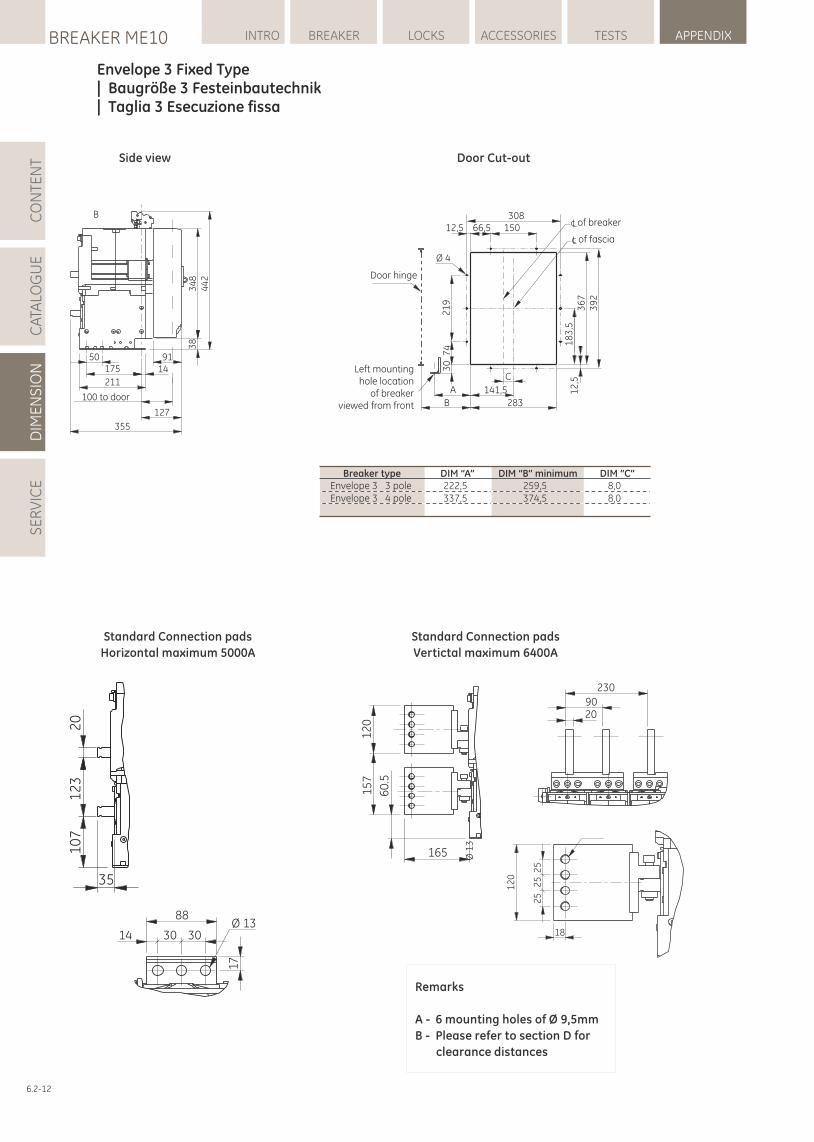
LOCKSBREAKER ME10 INTRO BREAKER ACCESSORIES TESTS APPENDIXC
ATA
LOG
UE
DIM
EN
SIO
NS
ER
VIC
EC
ON
TEN
T
6.2-12
Envelope 3 Fixed Type | Baugröße 3 Festeinbautechnik| Taglia 3 Esecuzione fissa
B
34
84
42
38
9114
127
50175
211
100 to door
355
Side view
35
20
12
31
07
88
30 3014
17
Ø 13
Standard Connection pads
Horizontal maximum 5000A
Door Cut-out
165
60
.5
12
01
57
18
12
0
25
25
Ø 1
3
25
230
9020
Standard Connection pads
Vertictal maximum 6400A
Remarks
A - 6 mounting holes of Ø 9,5mm
B - Please refer to section D for
clearance distances
Breaker type DIM “A” DIM “B” minimum DIM “C”Envelope 3 3 pole 222,5 259,5 8,0Envelope 3 4 pole 337,5 374,5 8,0
of breaker
of fascia
Left mountinghole location
of breakerviewed from front
Door hinge
12,5 66,5 150308
Ø 4
A
B
141,5
283
C
30
74
21
9
39
23
67
18
3,5
12
,5
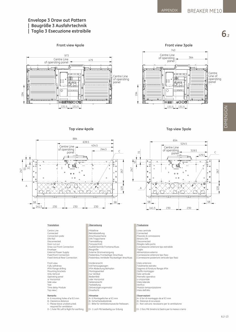
BREAKER ME10APPENDIX
6.2
DIM
EN
SIO
N
6.2-13
Envelope 3 Draw out Pattern | Baugröße 3 Ausfahrtechnik | Taglia 3 Esecuzione estraibile
131.5 131.5
19
4
973
479
Centre Line of operatingpanel
Centre Lineof operating panel
743
131.5 131.5
364
19
4
Centre Line of operatingpanel
Centre Lineof operating
panel
24
7 55 31
26
71
20
58 58
230230230141.5
C
A
884639.5
434.5
244.5
A
Centre Lineof operating
panel C
A
654524.5
319.5
230230141.5
58 58
129.5
26
71
20
31
55
24
7
Centre Lineof operating
panel
Front view 4pole
Top view 4pole
Front view 3pole
Top view 3pole
Translation
Centre Line Connected Connection pads DIN Rail Disconnected Door cut out Draw out Front Connection Envelope External Power Supply Fixed front Connection Fixed Vertical Rear Connection
Front view Fully withdraw IP54 Flange drilling Mounting bracketsOnly Vertical Operating panel or Horizontal Side view Test Time delay Module Top view |
Remarks A- 6 mounting holes of ø 9,5 mm B- Clearence distance C- Please leave unobstructed; required for ventilation D- 1 hole M6 Left & Right for earthing
| Übersetzung
| Mittellinie | Betriebsstellung | Anschlussschiene | DIN Tragschiene | Trennstellung | Türausschnitt | Ausfahrtechnik Frontanschluss | Baugröße | Externe Stromversorgung | Festeinbau Frontseitiger Anschluss | Festeinbau Vertikaler Rückseitiger Anschluss
| Vorderansicht | Voll herausgezogen | IP54 Abdeckung Bohrplan | Montagewinkel | nur Vertikal | Bedienfeld | oder Horizontal | Seitenansicht| Teststellung | Zeitverzögerungsmodul| Draufsicht
| Hinweise| A- 6 Montagelöcher ø 9,5 mm | B- Sicherheitsabstände| C- Bitte für Ventilationszwecke freilassen.
| D- 1 Loch M6 beidseitig zur Erdung
| Traduzione
| Linea centrale| Connected | Piazzole di connessione | Binario DIN | Disconnected | Ritaglio nella porta | Connessione anteriore tipo estraibile | Taglia | Alimentatore esterno | Connessione anteriore tipo fisso | Connessione posteriore verticale tipo fisso
| Vista anteriore | Totalmente estratto | Sagoma di foratura flangia IP54 | Staffe montaggio | Solo verticale | Pannello operativo | o orizzontale | Vista laterale | Verifica | Modulo temporizzazione | Vista dall'alto
| Osservazioni | A- 6 fori di montaggio da ø 9,5 mm | B- Distanza di sicurezza | C- Non ostruire; necessario per la ventilazione
| D- 1 foro M6 Sinistra & Destra per la messa a terra
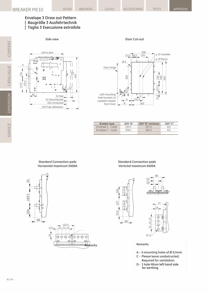
LOCKSBREAKER ME10 INTRO BREAKER ACCESSORIES TESTS APPENDIXC
ATA
LOG
UE
DIM
EN
SIO
NS
ER
VIC
EC
ON
TEN
T
6.2-14
Envelope 3 Draw out Pattern | Baugröße 3 Ausfahrtechnik | Taglia 3 Esecuzione estraibile
419 to door
D
44
312
41
73
.5
23
5.5
32 Test
52 Disconnected
454 Connected
350 Fully withdrawn
85
Side view
68
20
16
9.5
10
4
102.525 25 2512.5
Ø 1
3
18
Standard Connection pads
Horizontal maximum 5000A
Door Cut-out
68
10
01
57
70
.5
51
18
Ø 13
25
25
25
905520
Standard Connection pads
Vertictal maximum 6400A
Remarks
Breaker type DIM “A” DIM “B” minimum DIM “C”Envelope 3 3 pole 193,5 267,0 8,0Envelope 3 4 pole 308,5 382,0 8,0
Left mountinghole location of
cassette viewedfrom front
A
B
141,5
283
C
Door hinge
of cassette
of fascia
12,5 66,5 150308
Ø 4
30
0
15
04
05
43
0
12
7,5
12
,5
52
,5
9,5
Remarks
A - 6 mounting holes of Ø 9,5mm
C - Please leave unobstructed;
Required for ventilation
D - 1 hole M6 on left hand sidefor earthing
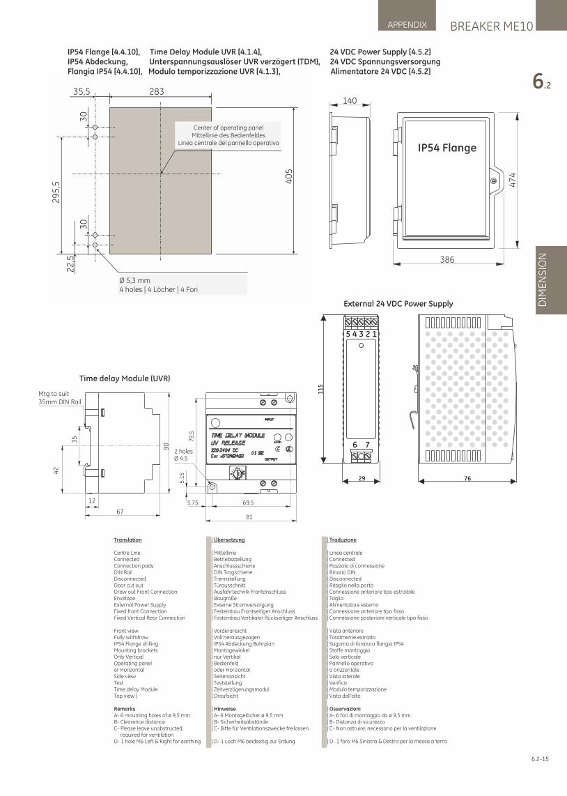
BREAKER ME10APPENDIX
6.2
DIM
EN
SIO
N
6.2-15
IP54 Flange [4.4.10], Time Delay Module UVR [4.1.4], 24 VDC Power Supply [4.5.2]IP54 Abdeckung, Unterspannungsauslöser UVR verzögert (TDM), 24 VDC SpannungsversorgungFlangia IP54 [4.4.10], Modulo temporizzazione UVR [4.1.3], Alimentatore 24 VDC [4.5.2]
Time delay Module (UVR)
2 holesØ 4.5
81
5.75 69.5
79
.5
5.1
5
Mtg to suit35mm DIN Rail
90
35
42
67
12
Center of operating panelMittellinie des Bedienfeldes
Linea centrale del pannello operativo
Ø 5,3 mm4 holes | 4 Löcher | 4 Fori
29
5,5
283
40
5
30
22
,5
30
35,5140
386
47
4
IP54 Flange
11
5
5 4 3 2 1
6 7
29 76
External 24 VDC Power Supply
Translation
Centre Line Connected Connection pads DIN Rail Disconnected Door cut out Draw out Front Connection Envelope External Power Supply Fixed front Connection Fixed Vertical Rear Connection
Front view Fully withdraw IP54 Flange drilling Mounting bracketsOnly Vertical Operating panel or Horizontal Side view Test Time delay Module Top view |
Remarks A- 6 mounting holes of ø 9,5 mm B- Clearence distance C- Please leave unobstructed; required for ventilation D- 1 hole M6 Left & Right for earthing
| Übersetzung
| Mittellinie | Betriebsstellung | Anschlussschiene | DIN Tragschiene | Trennstellung | Türausschnitt | Ausfahrtechnik Frontanschluss | Baugröße | Externe Stromversorgung | Festeinbau Frontseitiger Anschluss | Festeinbau Vertikaler Rückseitiger Anschluss
| Vorderansicht | Voll herausgezogen | IP54 Abdeckung Bohrplan | Montagewinkel | nur Vertikal | Bedienfeld | oder Horizontal | Seitenansicht| Teststellung | Zeitverzögerungsmodul| Draufsicht
| Hinweise| A- 6 Montagelöcher ø 9,5 mm | B- Sicherheitsabstände| C- Bitte für Ventilationszwecke freilassen.
| D- 1 Loch M6 beidseitig zur Erdung
| Traduzione
| Linea centrale| Connected | Piazzole di connessione | Binario DIN | Disconnected | Ritaglio nella porta | Connessione anteriore tipo estraibile | Taglia | Alimentatore esterno | Connessione anteriore tipo fisso | Connessione posteriore verticale tipo fisso
| Vista anteriore | Totalmente estratto | Sagoma di foratura flangia IP54 | Staffe montaggio | Solo verticale | Pannello operativo | o orizzontale | Vista laterale | Verifica | Modulo temporizzazione | Vista dall'alto
| Osservazioni | A- 6 fori di montaggio da ø 9,5 mm | B- Distanza di sicurezza | C- Non ostruire; necessario per la ventilazione
| D- 1 foro M6 Sinistra & Destra per la messa a terra
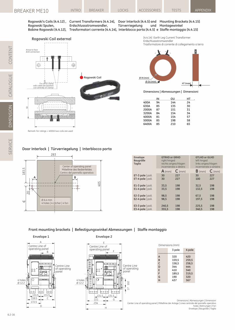
LOCKSBREAKER ME10 INTRO BREAKER ACCESSORIES TESTS APPENDIXC
ATA
LOG
UE
DIM
EN
SIO
NS
ER
VIC
EC
ON
TEN
T
6.2-16
Rogowski’s Coils [4.4.12] , Current Transformers [4.4.14], Door Interlock [4.4.5] and Mounting Brackets [4.4.15]Rogowski Spulen, Erdschlussstromwandler, Türverriegelung und MontagewinkelBobine Rogowski [4.4.12], Trasformatori corrente [4.4.14], Interblocco porta [4.4.5] e Staffe montaggio [4.4.15]
Dimensions | Abmessungen | Dimensioni Center Line of operating panel | Mittellinie der Anlage | Linea centrale del pannello operativo
holes | Bohrungen | ForiEnvelope | Baugröße | Taglia
Dimensions (mm)
3 pole 4 pole-----------------------------------A 320 420B 159,5 259,5C 158,5 258,5D 344 444E 410 540F 189,5 319,5G 190 320H 437 567
Front mounting brackets | Befestigungswinkel Abmessungen | Staffe montaggio
Ø IN (min)
Ø OU (min)HT (max)
Dimensions | Abmessungen | Dimensioni
IN OU HT .400A 94 144 24630A 85 135 302000A 87 151 313200A 84 154 344000A 81 154 575000A 85 198 586400A 85 210 65
[4.4.14] Earth Leg Current TransformerErdschlussstromwandlerTrasformatore di corrente di collegamento a terra
Rogowski Coil external
58
11
0
Arrow to faceACB connection
Fix coil to clampwith cable ties (positioncoil centrally on clamp)
Remark: for ratings > 4000A two coils are used
A
B
4 holesØ 12.2
131.5 131.5159.5
172.5
C
D
Centre Lineof operatingpanel
Centre Line of operating panel
E
4 holesØ 12.2
F
131.5 131.5
221 G
234
H
10
21
7
Centre Lineof operatingpanel
Centre Line of operating panel
Envelope 1 Envelope 2
Rogowski Coil
Door Interlock | Türverriegelung | Interblocco porta
Envelope GTRHD or GRHD GTLHD or GLHDBaugröße right hinged left hingedTaglia rechts angeschlagen links angeschlagen incernierata a destra incernierata a sinistra
A (mm) C (mm) B (mm) C (mm) ET-3 pole | poli. 30 227 30 227ET-4 pole | poli. 30 227 100 227
E1-3 pole | poli. 33,5 198 32,5 198E1-4 pole | poli. 33,5 198 132,5 198
E2-3 pole | poli. 98,5 198 67,5 198E2-4 pole | poli. 98,5 198 197,5 198
E3-3 pole | poli. 240,5 198 22 ,5 1985 E3-4 pole | poli. 355,5 198 340,5 198
Center of operating panelMittellinie des Bedienfeldes
Centro del pannello operativo
Ø 6,4 mm4 holes | 4 Löcher | 4 fori
A B
C1
83
,5
20
283
40
5
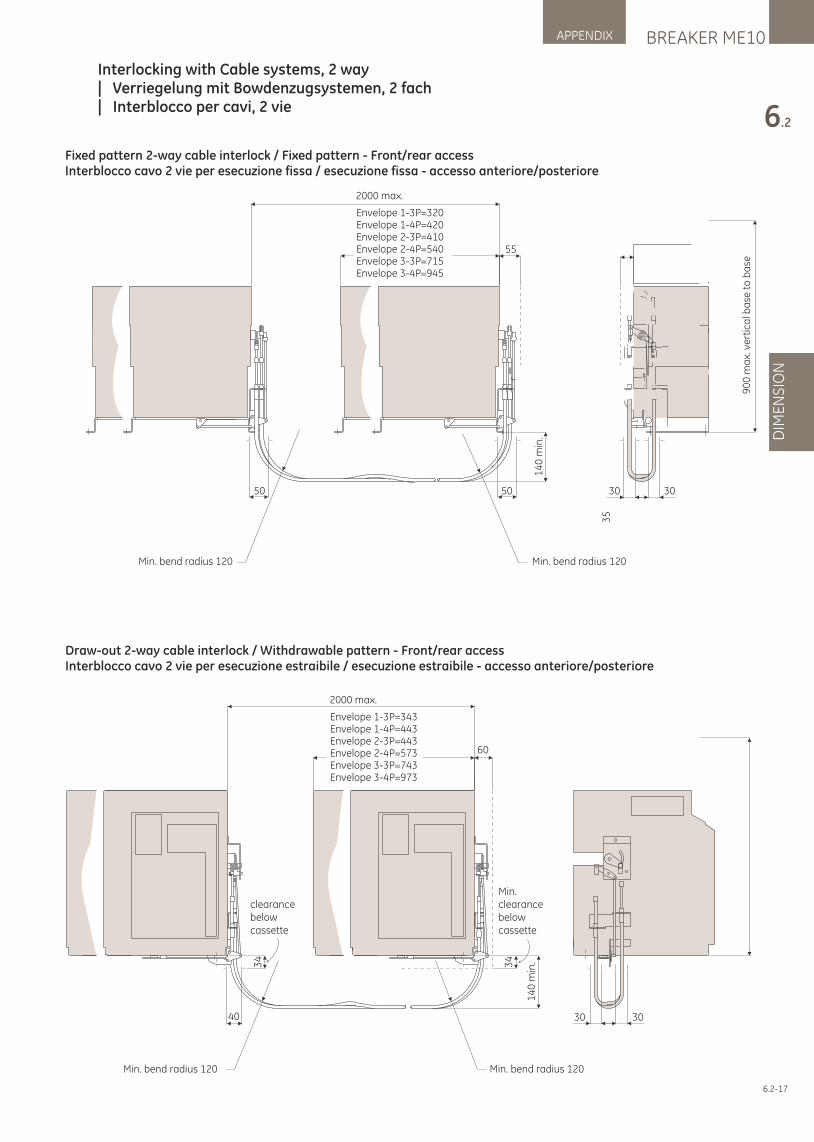
BREAKER ME10APPENDIX
6.2
DIM
EN
SIO
N
6.2-17
Interlocking with Cable systems, 2 way| Verriegelung mit Bowdenzugsystemen, 2 fach| Interblocco per cavi, 2 vie
2000 max.
Envelope 1-3P=320Envelope 1-4P=420Envelope 2-3P=410Envelope 2-4P=540Envelope 3-3P=715Envelope 3-4P=945
Min. bend radius 120 Min. bend radius 120
55
50 50 30 30
14
0 m
in.
35
90
0 m
ax.
ve
rtic
al b
ase
to
ba
se
40 30 30
34
34
2000 max.
Envelope 1-3P=343Envelope 1-4P=443Envelope 2-3P=443Envelope 2-4P=573Envelope 3-3P=743Envelope 3-4P=973
14
0 m
in.
60
Min. bend radius 120 Min. bend radius 120
clearancebelowcassette
Min.clearancebelowcassette
Fixed pattern 2-way cable interlock / Fixed pattern - Front/rear accessInterblocco cavo 2 vie per esecuzione fissa / esecuzione fissa - accesso anteriore/posteriore
Draw-out 2-way cable interlock / Withdrawable pattern - Front/rear accessInterblocco cavo 2 vie per esecuzione estraibile / esecuzione estraibile - accesso anteriore/posteriore
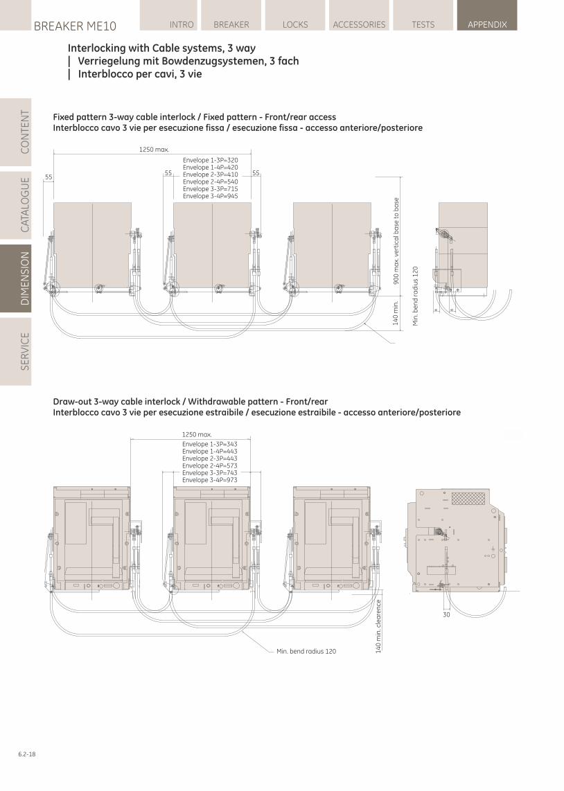
LOCKSBREAKER ME10 INTRO BREAKER ACCESSORIES TESTS APPENDIXC
ATA
LOG
UE
DIM
EN
SIO
NS
ER
VIC
EC
ON
TEN
T
6.2-18
Interlocking with Cable systems, 3 way| Verriegelung mit Bowdenzugsystemen, 3 fach| Interblocco per cavi, 3 vie
1250 max.
14
0 m
in.
Min
. be
nd
ra
diu
s 1
20
90
0 m
ax.
ve
rtic
al b
ase
to
ba
se
Envelope 1-3P=320Envelope 1-4P=420Envelope 2-3P=410Envelope 2-4P=540Envelope 3-3P=715Envelope 3-4P=945
5555 55
1250 max.
Envelope 1-3P=343Envelope 1-4P=443Envelope 2-3P=443Envelope 2-4P=573Envelope 3-3P=743Envelope 3-4P=973
14
0 m
in. c
lea
ren
ce
Min. bend radius 120
30
Fixed pattern 3-way cable interlock / Fixed pattern - Front/rear accessInterblocco cavo 3 vie per esecuzione fissa / esecuzione fissa - accesso anteriore/posteriore
Draw-out 3-way cable interlock / Withdrawable pattern - Front/rear Interblocco cavo 3 vie per esecuzione estraibile / esecuzione estraibile - accesso anteriore/posteriore
Manutenzione apparati in bassa tensione
Avete investito in apparecchiature a bassa tensione e fate affidamento sul loro funzionamento per proteggere i vostri processi critici. AEG offre servizi di qualità per garantire e prolungare la fruibilità di questa apparecchiatura. La manutenzione preventiva è un'importante attività che aiuta a rilevare i problemi prima che provochino dei guasti, consentendo di ridurre gli interventi e i tempi di fermo non programmati. Che siate una grande azienda con attività distribuite su più impianti o una piccola realtà con una sola sede, AEG vi permetterà di usufruire di un'offerta costante di servizi che vi consentirà di tenere la vostra attività aggiornata e sempre in esercizio.
Potrete contare sui team Field Service di AEG per tutte le vostre infrastrutture elettriche poiché siamo di casa in qualsiasi settore industriale; potrete anche fare leva sulla nostra specializzazione nelle soluzioni e nei servizi per l'infrastruttura elettrica.Allungare la vita delle apparecchiature di potenza
Nel settore della potenza, AEG offre un catalogo completo di servizi dedicati, comprendente:Servizi di intervento in loco e di emergenza• Assistenza di emergenza 24/7• Installazione • Messa in servizio, avvio • Pulizia, lubrificazione• Riparazione, aggiornamento, soluzioni di retrofit• Valutazione, ispezione, audit • Rappresentazione termografica Parti e riparazioni• Fornitura ricambi • Servizi di riparazione • Kit di retrofit per prodotti di generazione precedente• Sostituzione/resa prodotto • Noleggio apparecchiatureServizi su contratto• Contratti di manutenzione • Manutenzione preventiva • Servizi tecnici in loco • Gestione aggiornamenti • Gestione impianti e progetti• Consulenza e audit
Per ulteriori informazioni e per i dettagli sui riferimenti, contattare il nostro rappresentante locale o il team di servizi postvendita (pagina successiva).
Service for Low Voltage Equipment
You have invested in low voltage equipment and rely on your switchgear to protect your critical business processes.AEG offers you quality services to ensure and prolong the usability of this equipment. Preventive maintenance is a important activity which helps you find equipment problems before they cause failure, leaving you with fewer repairs and less unscheduled downtime.
Whether you are a large corporation with multiple sites or a small business owner with a single location, AEG will enable you to have a constant supply of services to keep your business up and running.
You can rely on AEG’s Field Service teams for all your electrical infrastructure, as we are at home in all industries, specialized in solutions and services for your electrical infrastructure.Extent the life of your Power Equipment.
AEG offers a comprehensive portfolio of power quality services including:On-Site & Emergency Services• 24/7 Emergency assistance• Installation • Commissioning, start-up • Cleaning, lubrication• Repair, upgrade, retrofit solutions• Assessment, inspection, audits • Thermo graphic imaging Parts and Repairs• Spare parts supply • Repair services • Retrofit kits for legacy products• Product replacement / return • Equipment rentalsContractual Services• Maintenance service contracts • Preventive maintenance • Resident technical services • Upgrade management • Project & site management• Consultancy and audits
For further information and contract details please contact your local sales representative or After Sales & Service team (next page).
Wartung von Niederspannungsanlagen
Sie haben in Niederspannungssysteme investiert und verlassen sich auf diese Schaltanlagen, um Ihre Energieversorgung zu gewährleisten. AEG bietet Ihnen Dienstleistungen, um den Betrieb dieser Anlagen zu optimieren und deren Nutzungsdauer zu verlängern. Präventive Wartung hilft Ihnen, Probleme in Ihren Anlagen bereits frühzeitig zu erkennen und zu beseitigen, bevor es zu Ausfällen kommt. Profitieren Sie von optimierten Stillstandszeiten und somit höherer Anlagenverfügbarkeit.Ob für Großunternehmen mit mehreren Betriebsstätten oder Kleinbetriebe an einem einzelnen Standort: AEG bietet Ihnen die richtigen Service-Leistungen, um Ihren Betrieb am Laufen zu halten.
Die Wartung Ihrer elektrischen Anlagen können Sie getrost den Service-Teams von AEG überlassen: Wir verfügen über Experten für alle Branchen und sind auf Lösungen und Dienstleistungen im Bereich der elektrischen Infrastruktur spezialisiert.
Verlängern Sie die Lebensdauer ihrer elektrischen AusrüstungVor-Ort- und Notfall-Service• Notfallhilfe rund um die Uhr• Installation• Inbetriebnahme• Reinigung und Inspektion• Reparatur, Aufrüstungen, Erweiterungen• Messungen und Prüfungen• Thermografische UntersuchungenTeile und Reparaturen• Lieferung von Ersatzteilen• Reparaturdienste• Nachrüst-Kits für vorhandene Produkte• Austausch/Rückgabe von Produkten• Anmietung von GerätenVertragsleistungen• Service-Verträge • Technische Dienstleistungen• Upgrade-Management • Projektmanagement• Beratung und Begutachtung
Wenn Sie weitere Informationen und Details zu Service-Verträgen erhalten möchten, wenden Sie sich an Ihren lokalen Vertriebsmitarbeiter oder das Service-Team (nächste Seite).
BREAKER ME10APPENDIX
SE
RV
ICE
perfekt in form und funktion

AEG Services
More information about AEG:www.aeg.com
perfekt in form und funktion