Embed Size (px)
Citation preview
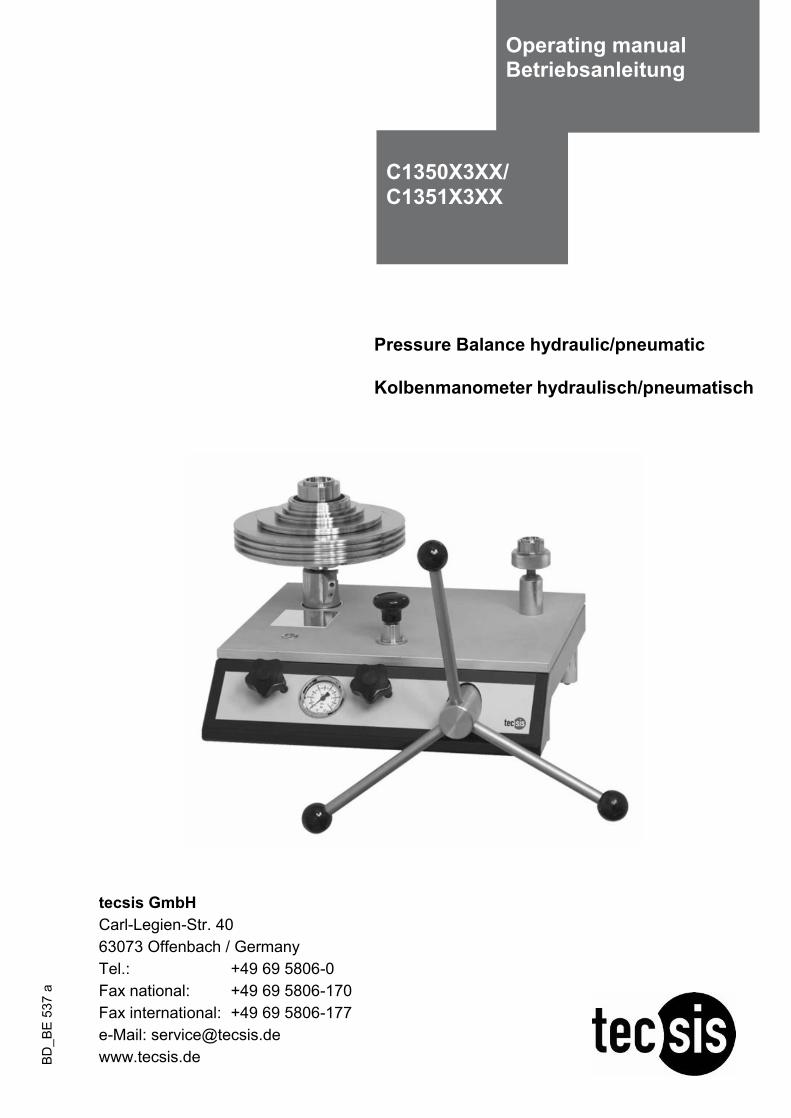
Pressure Balance hydraulic/pneumatic
Kolbenmanometer hydraulisch/pneumatisch
C1350X3XX/ C1351X3XX
Operating manual Betriebsanleitung
tecsis GmbH Carl-Legien-Str. 40 63073 Offenbach / Germany Tel.: +49 69 5806-0 Fax national: +49 69 5806-170 Fax international: +49 69 5806-177 e-Mail: [email protected] www.tecsis.de BD
_BE
537
a
Pressure Balance hydraulic/pneumatic GB C1350X3XX / C1351X3XX
Operating manual 2
Information This symbol provides you with information, notes and tips. Warning!
This symbol warns you against actions that can cause injury to people or damage to the instrument.
Operating Instructions Pressure Balance hydraulic/pneumatic Page 4 - 29
GB
Betriebsanleitung Kolbenmanometer hydraulisch/pneumatisch Seite 30 - 57 D
Pressure Balance hydraulic/pneumatic GB C1350X3XX / C1351X3XX
Operating manual 3
Content 1. General ............................................................................................................................................... 4 1.1 General Instructions .......................................................................................................................... 4 1.2 Safety Instructions ............................................................................................................................. 5 2. Product Description .......................................................................................................................... 6 2.1 General Product Information ............................................................................................................. 6 2.2 Basic principle of the Pressure Balance............................................................................................ 7 2.3 Factors at work .................................................................................................................................. 7 2.3.1 Local fluctuations in the gravity-value ............................................................................................ 7 2.3.2 Temperature (Piston/Cylinder) ....................................................................................................... 8 2.3.3 Ambient conditions ......................................................................................................................... 8 2.3.4 How the cross-sectional surface responds to pressure ................................................................. 9 2.4 Arrangement of control elements .................................................................................................... 10 3. Commissioning and Operation ...................................................................................................... 11 3.1 Preparation ...................................................................................................................................... 11 3.1.1 Setting up the Device ................................................................................................................... 11 3.1.2 Installing the ConTect System...................................................................................................... 12 3.1.3 Connecting the test specimen ...................................................................................................... 13 3.1.4 Venting the System (Hydraulic Design only) ................................................................................ 13 3.2 Operation......................................................................................................................................... 14 3.2.1 Weight Pieces............................................................................................................................... 14 3.2.2a Approaching the pressure value – hydraulic .............................................................................. 15 3.2.2b Approaching the pressure value – pneumatic............................................................................ 15 3.2.3 Pressure stable............................................................................................................................. 16 3.2.4 Next pressure level....................................................................................................................... 16 3.2.5 Releasing pressure – hydraulic and pneumatic ........................................................................... 17 3.3 Disassembly .................................................................................................................................... 17 4. Troubleshooting measures ............................................................................................................ 18 5. Maintenance and Care .................................................................................................................... 19 5.1 Cleaning .......................................................................................................................................... 19 5.1.1 Piston/Cylinder system................................................................................................................. 19 5.1.1.1 Hydraulic piston/cylinder system ............................................................................................... 19 5.1.1.2 Pneumatic piston/cylinder system ............................................................................................. 21 5.1.2 Weight Set .................................................................................................................................... 22 5.2 Wear Parts....................................................................................................................................... 22 5.3 Changing the Hydraulic Oil (Hydraulic Design only) ....................................................................... 22 5.3.1 Removing Hydraulic Oil ................................................................................................................ 22 5.3.2 Filling in of Hydraulic Oil ............................................................................................................... 23 5.3.3 Venting of the System (after Complete Filling only) ..................................................................... 23 5.4 Recalibration.................................................................................................................................... 24 6. Technical Data ................................................................................................................................. 25 7. Tables of masses............................................................................................................................. 27 7.1 Hydraulic models ............................................................................................................................. 27 7.2 Pneumatic models ........................................................................................................................... 28 8. Accessories ..................................................................................................................................... 29
Pressure Balance hydraulic/pneumatic GB C1350X3XX / C1351X3XX
Operating manual 4
1. General
1.1 General Instructions In the following chapters detailed information on the C1350X3XX/C1351X3XX pressure balance and its proper use can be found. Should you require further information, or should there be problems which are not dealt within detail in the operating instructions, please contact the address below: tecsis GmbH Carl-Legien-Str. 40 63073 Offenbach / Germany Tel.: +49 69 5806-0 Fax national: +49 69 5806-170 Fax international: +49 69 5806-177 e-Mail: [email protected] www.tecsis.de If nothing to the contrary is agreed, the pressure balance is calibrated in compliance with the currently valid body of international regulations and can be referred directly to a national standard. The warranty period for the pressure balance is 24 months according to the general terms of supply of ZVEI. The guarantee is void if the appliance is put to improper use or if the operating instructions are not observed or if an attempt is made to open the appliance or to release attachment parts or the tubing. We also point out that the content of these operating instructions neither forms part of an earlier or existing agreement, assurance or legal relationship nor is meant to change these. All obligations of tecsis GmBH result from the respective sales contract and the general business terms of tecsis GmbH. The devices described in this manual represent the latest state of the art in terms of their design, dimension and materials. We reserve the right to make changes to or replace materials without any obligation to give immediate notification. Duplication of this manual in whole or in part is prohibited.
Pressure Balance hydraulic/pneumatic GB C1350X3XX / C1351X3XX
Operating manual 5
1.2 Safety Instructions
Read these operating instructions carefully prior to operating the pressure balance C1350X3XX/C1351X3XX. Its trouble-free operation and reliability cannot be guaranteed unless the safety advise given in this manual is followed when using the device.
1. The system must only be operated by trained and authorised personnel who know the manual and
can work according to them. 2. Trouble-free operation and reliability of the device can only be guaranteed so long as the
conditions stated under "Setting up the device" are taken into consideration. 3. The C1350X3XX/C1351X3XX always has to be handled with the care required for a precision
instrument (protect from humidity, impacts and extreme temperatures). The device, the piston-cylinder-system and the mass-set must be handled with care (don't throw, hit, etc.) and protect them from contamination. By no means apply any force to the operating elements of the C1350X3XX/C1351X3XX.
4. If the device is moved from a cold to a warm environment, you should therefore ensure the device
temperature has adjusted to the ambient temperature before trying to put it into operation. 5. If the equipment is damaged and might no longer operate safely, then it should be taken out of use
and securely marked in such a way so that isn't used again. Operator safety may be at risk if:
• There is visible damage to the device • The device is not working as specified • The device has been stored under unsuitable conditions for an extended period of time.
If there is any doubt, please return the device to the manufacturer for repair or maintenance.
6. Customers must not attempt to alter or repair the device themselves. If the instrument is opened or
attachment parts or the tubing are released, its trouble-free operation and reliability is impaired and endangers the operator. Please return the device to the manufacturer for any repair or maintenance.
7. There must be used only the original sealings in the device. 8. Any operation not included in the following instructions or outside the specifications must not be
attempted.
Pressure Balance hydraulic/pneumatic GB C1350X3XX / C1351X3XX
Operating manual 6
2. Product Description
2.1 General Product Information Application Pressure balances are the most accurate instruments for the calibration of electronic or mechanical pressure measuring instruments. The direct measurement of pressure, according to its definition as a quotient of force and area, and the use of high-quality materials result in small uncertainties of measurement and an excellent long-term stability of five years. For these reasons pressure balances have already been used in calibration laboratories of industry, national institutes and research labs for many years. Due to the integrated pressure generation and the purely mechanical measuring principle the C1350X3XX/C1351X3XX is also ideally suited for on-site use as well as service and maintenance purposes. ConTect measuring system The patented concept for a customised C1350X3XX/C1351X3XX assembly enables to set up a compact complete system at a favourable price, consisting of an universal basement and the measuring systems. The high-quality sensitive piston cylinder systems are well protected in the ConTect housing. Fast and uncomplicated changes of the measuring range are possible without having to use any tools. The pneumatic piston cylinder systems are available for vacuum and pressure ranges from 2 bar up to 100 bar and the hydraulic systems are available for pressure ranges from 60 bar up to 1000 bar. The accuracy is 0.015 % (optional also 0.01 %) of reading. Functioning Depending on the measuring range of the device under test you can fit the instrument basement with the corresponding system. In order to generate the individual test points, the piston cylinder system is weighted with mass-loads, which are also calibrated and specially adapted to the respective application. The pressure is set via an integrated pump or, if an external pressure supply is available, via control valves. For fine adjustment an adjustable volume with precision spindle is available. The weight applied is proportional to the desired pressure and provided by using optimally graduated weights. As soon as the measuring system reaches equilibrium, there is a balance of forces between pressure and wheel weights. Due to the high-grade quality of the system this pressure remains stable over several minutes, so that for instance adjustments of your device under test can be carried out without any problems.
Pressure Balance hydraulic/pneumatic GB C1350X3XX / C1351X3XX
Operating manual 7
2.2 Basic principle of the Pressure Balance Their operating principle is based on the physical definition of pressure, the quotient of force and surface.
AreaForceessure =Pr
The key element of the pressure balance is a precision-manufactured piston/cylinder system with a precisely measured cross-sectional surface. To apply a pressure charge to the system, the piston is placed under a load with (calibrated) weight pieces. Each holding disk from the set of weights is identified by a nominal weight, which generates a pressure value in the system (assuming standard reference conditions). Each weight has a number and in the calibration certificate there is described the mass value to each weight with its resultant pressure value. The weights are chosen according to the desired pressure value. After that, the integrated spindle pump increases the pressure until the weights are in a floating state. 2.3 Factors at work The piston pressure gauge is calibrated to standard reference conditions when it leaves the factory (depending on customer specifications). If there are significant deviations between the application conditions and the defined reference conditions, appropriate corrections must be made. Following are the main factors that enter into play and must be considered.
These corrections can be made automatically with the CalibratorUnit (see accessories point 8)!
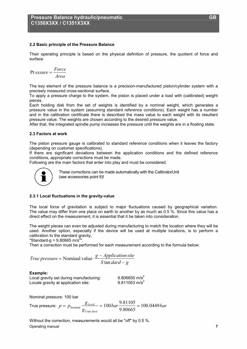
2.3.1 Local fluctuations in the gravity-value The local force of gravitation is subject to major fluctuations caused by geographical variation. The value may differ from one place on earth to another by as much as 0.5 %. Since this value has a direct effect on the measurement, it is essential that it be taken into consideration. The weight pieces can even be adjusted during manufacturing to match the location where they will be used. Another option, especially if the device will be used at multiple locations, is to perform a calibration to the standard gravity, "Standard-g = 9.80665 m/s2". Then a correction must be performed for each measurement according to the formula below:
gdardSsitenApplicatiogpressureTrue
−−
⋅=tan
valueNominal
Example: Local gravity set during manufacturing: 9.806650 m/s2
Locale gravity at application site: 9.811053 m/s2
Nominal pressure: 100 bar
True pressure: barbarg
gppdardS
Local 0449.10080665.981105.9100
tanNominal ===
Without the correction, measurements would all be "off" by 0.5 %.
Pressure Balance hydraulic/pneumatic GB C1350X3XX / C1351X3XX
Operating manual 8
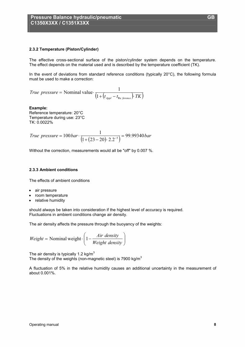
2.3.2 Temperature (Piston/Cylinder) The effective cross-sectional surface of the piston/cylinder system depends on the temperature. The effect depends on the material used and is described by the temperature coefficient (TK). In the event of deviations from standard reference conditions (typically 20°C), the following formula must be used to make a correction:
( )( )TKttpressureTrue
ferenceAppl ⋅−+⋅=
Re11 valueNominal
Example: Reference temperature: 20°C Temperature during use: 23°C TK: 0.0022%
( )( ) barbarpressureTrue 99340.992.220231
1100 5 =⋅−+
⋅= −
Without the correction, measurements would all be "off" by 0.007 %.
2.3.3 Ambient conditions The effects of ambient conditions • air pressure • room temperature • relative humidity should always be taken into consideration if the highest level of accuracy is required. Fluctuations in ambient conditions change air density. The air density affects the pressure through the buoyancy of the weights:
−⋅=
densityWeightdensityAirWeight 1 weightNominal
The air density is typically 1.2 kg/m3
The density of the weights (non-magnetic steel) is 7900 kg/m3 A fluctuation of 5% in the relative humidity causes an additional uncertainty in the measurement of about 0.001%.
Pressure Balance hydraulic/pneumatic GB C1350X3XX / C1351X3XX
Operating manual 9
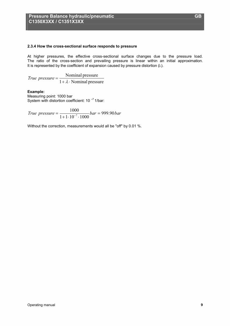
2.3.4 How the cross-sectional surface responds to pressure At higher pressures, the effective cross-sectional surface changes due to the pressure load. The ratio of the cross-section and prevailing pressure is linear within an initial approximation. It is represented by the coefficient of expansion caused by pressure distortion (λ).
pressure Nominal1pressure Nominal
⋅+=
λpressureTrue
Example: Measuring point: 1000 bar System with distortion coefficient: 10 –7 1/bar:
barbarpressureTrue 90.99910001011
10007 =
⋅⋅+= −
Without the correction, measurements would all be "off" by 0.01 %.
Pressure Balance hydraulic/pneumatic GB C1350X3XX / C1351X3XX
Operating manual 10
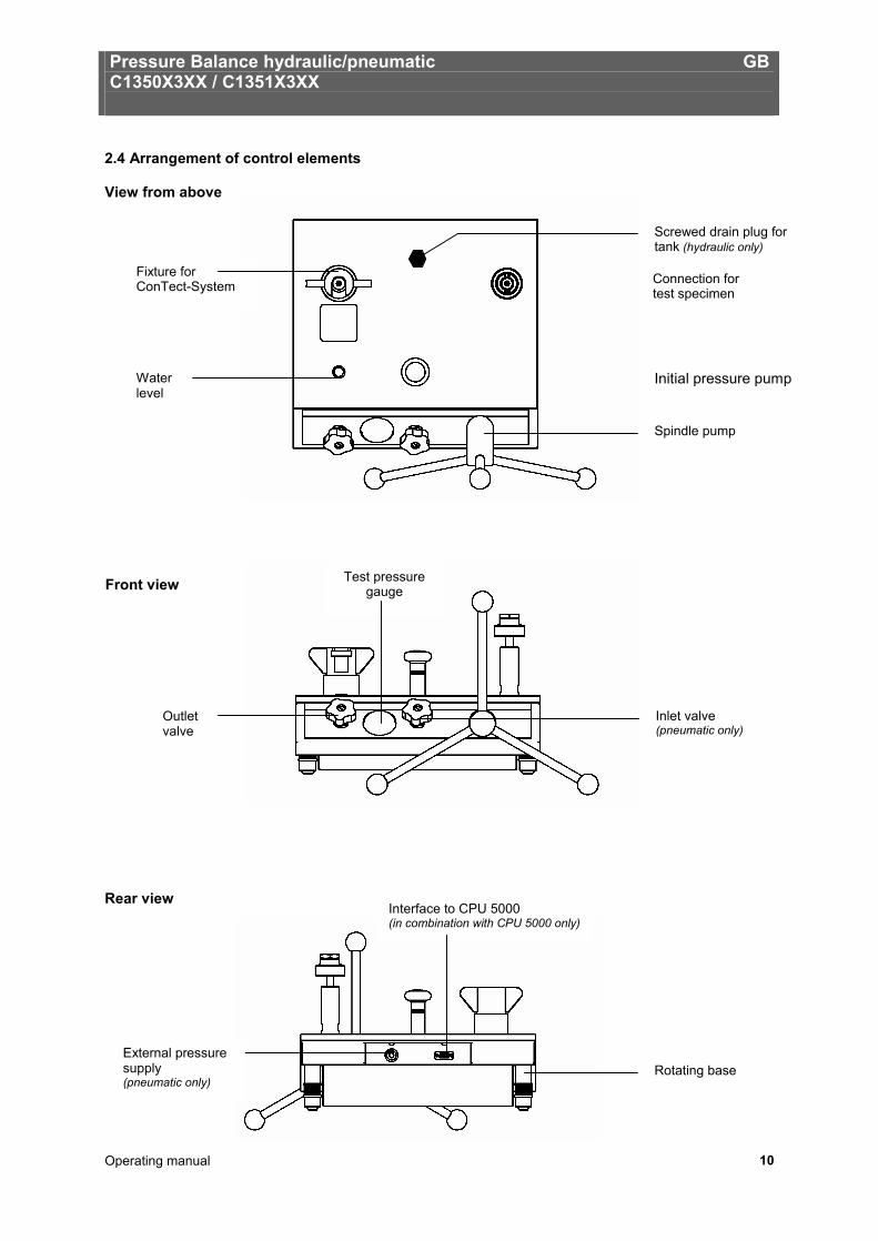
2.4 Arrangement of control elements View from above Rear view
Front view
Connection for test specimen
Initial pressure pump
Fixture for ConTect-System
Water level
Spindle pump
Screwed drain plug for tank (hydraulic only)
Inlet valve (pneumatic only)
Outlet valve
Test pressure gauge
Rotating base
Interface to CPU 5000 (in combination with CPU 5000 only)
External pressure supply (pneumatic only)
Pressure Balance hydraulic/pneumatic GB C1350X3XX / C1351X3XX
Operating manual 11
3. Commissioning and Operation
3.1 Preparation
3.1.1 Setting up the Device
• Set up the pressure balance on a solid surface. If it is not resting on a solid foundation or is subject to vibrations, measurements could be affected. This should be avoided.
• If no temperature control system is present, the device should at least not be placed near a heat
element or window. This will reduce drafts and warm air flows as much as possible. • The water level should be used to align the device. At this time, rough alignment can already be
performed without the ConTect system. Using the rotating feed, position the device so that it is horizontal.
• In the pneumatic design, an external compressed air supply can be connected.
Attention: The maximum supply pressure must not exceed 110% of the range of the device to be tested or ConTect system in use.
• Only dry, cleaned and particle-free gases (for example nitrogen 4.0 or synthetic air) may be used. • The oil container may need to be filled, or refilled in the hydraulic design (volume 250 ml). For this
purpose, the locking screw with the oil filling symbol on top of the basement must be opened. Special oil must be used for refilling (1 litre supplied, or available as accessory). The system must be vented before initial filling, or after a complete oil change. For this purpose, please proceed according to section 5.3.3.
• Place the star handle with knobs onto the spindle pump. Ensure that the spring-loaded thrust pad
engages into the star handle bushing.
• We recommend unscrewing the spindle pump completely when you start to record measurement values, (turning anticlockwise) to allow enough volume for measurements. The outlet valve must be opened during this process.
Pressure Balance hydraulic/pneumatic GB C1350X3XX / C1351X3XX
Operating manual 12
3.1.2 Installing the ConTect System
• The ConTect system that is used depends on the device to be tested. You should select a system with a comparable or higher range.
Example: Calibration of a 600-bar pressure gauge è 600 bar ConTect system Calibration of a 160-bar pressure gauge è 250 bar ConTect system
Before releasing the closure plug on the bottom of the device, make sure the system is not under pressure (open the outlet valve).
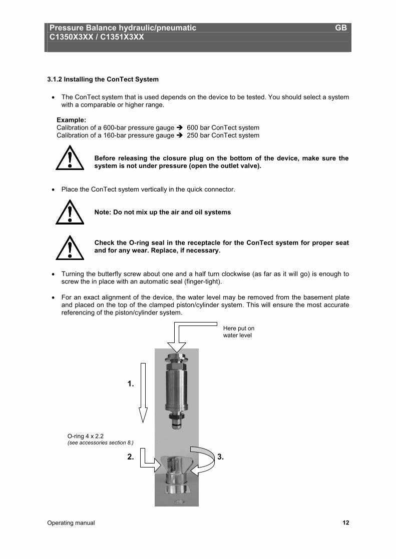
• Place the ConTect system vertically in the quick connector.
Note: Do not mix up the air and oil systems
Check the O-ring seal in the receptacle for the ConTect system for proper seat and for any wear. Replace, if necessary.
• Turning the butterfly screw about one and a half turn clockwise (as far as it will go) is enough to screw the in place with an automatic seal (finger-tight).
• For an exact alignment of the device, the water level may be removed from the basement plate
and placed on the top of the clamped piston/cylinder system. This will ensure the most accurate referencing of the piston/cylinder system.
O-ring 4 x 2.2 (see accessories section 8.)
3. 2.
1.
Here put on water level
Pressure Balance hydraulic/pneumatic GB C1350X3XX / C1351X3XX
Operating manual 13
3.1.3 Connecting the test specimen
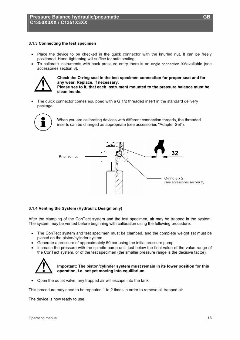
• Place the device to be checked in the quick connector with the knurled nut. It can be freely positioned. Hand-tightening will suffice for safe sealing.
• To calibrate instruments with back pressure entry there is an angle connection 90°available (see accessories section 8).
Check the O-ring seal in the test specimen connection for proper seat and for any wear. Replace, if necessary. Please see to it, that each instrument mounted to the pressure balance must be clean inside.
• The quick connector comes equipped with a G 1/2 threaded insert in the standard delivery
package.
When you are calibrating devices with different connection threads, the threaded inserts can be changed as appropriate (see accessories "Adapter Set").
3.1.4 Venting the System (Hydraulic Design only) After the clamping of the ConTect system and the test specimen, air may be trapped in the system. The system may be vented before beginning with calibration using the following procedure:
• The ConTect system and test specimen must be clamped, and the complete weight set must be placed on the piston/cylinder system.
• Generate a pressure of approximately 50 bar using the initial pressure pump • Increase the pressure with the spindle pump until just below the final value of the value range of
the ConTect system, or of the test specimen (the smaller pressure range is the decisive factor).
Important: The piston/cylinder system must remain in its lower position for this operation, i.e. not yet moving into equilibrium.
• Open the outlet valve, any trapped air will escape into the tank This procedure may need to be repeated 1 to 2 times in order to remove all trapped air. The device is now ready to use.
O-ring 8 x 2 (see accessories section 8.)
Knurled nut
Pressure Balance hydraulic/pneumatic GB C1350X3XX / C1351X3XX
Operating manual 14
3.2 Operation
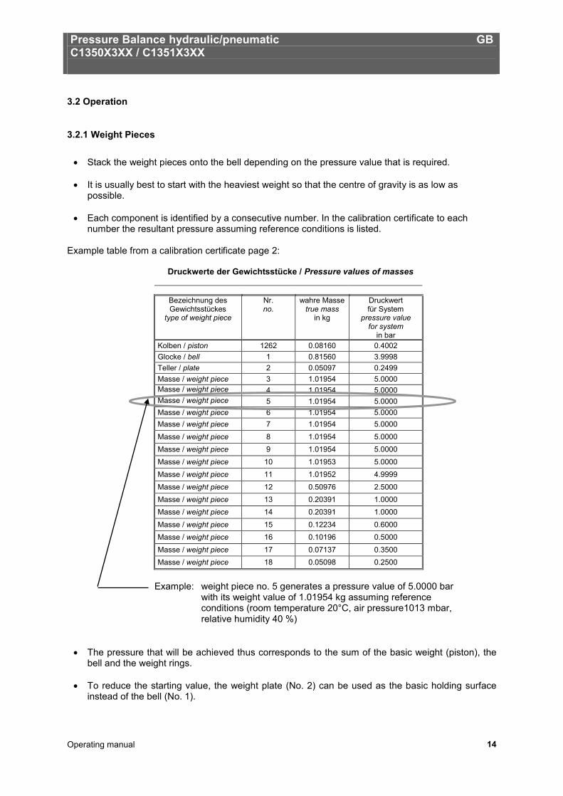
3.2.1 Weight Pieces
• Stack the weight pieces onto the bell depending on the pressure value that is required. • It is usually best to start with the heaviest weight so that the centre of gravity is as low as
possible. • Each component is identified by a consecutive number. In the calibration certificate to each
number the resultant pressure assuming reference conditions is listed. Example table from a calibration certificate page 2:
Druckwerte der Gewichtsstücke / Pressure values of masses
Bezeichnung des Gewichtsstückes
type of weight piece
Nr. no.
wahre Masse true mass
in kg
Druckwert für System
pressure value for system
in bar Kolben / piston 1262 0.08160 0.4002 Glocke / bell 1 0.81560 3.9998 Teller / plate 2 0.05097 0.2499 Masse / weight piece 3 1.01954 5.0000 Masse / weight piece 4 1.01954 5.0000 Masse / weight piece 5 1.01954 5.0000 Masse / weight piece 6 1.01954 5.0000 Masse / weight piece 7 1.01954 5.0000 Masse / weight piece 8 1.01954 5.0000 Masse / weight piece 9 1.01954 5.0000 Masse / weight piece 10 1.01953 5.0000 Masse / weight piece 11 1.01952 4.9999 Masse / weight piece 12 0.50976 2.5000 Masse / weight piece 13 0.20391 1.0000 Masse / weight piece 14 0.20391 1.0000 Masse / weight piece 15 0.12234 0.6000 Masse / weight piece 16 0.10196 0.5000 Masse / weight piece 17 0.07137 0.3500 Masse / weight piece 18 0.05098 0.2500
Example: weight piece no. 5 generates a pressure value of 5.0000 bar
with its weight value of 1.01954 kg assuming reference conditions (room temperature 20°C, air pressure1013 mbar, relative humidity 40 %)
• The pressure that will be achieved thus corresponds to the sum of the basic weight (piston), the
bell and the weight rings. • To reduce the starting value, the weight plate (No. 2) can be used as the basic holding surface
instead of the bell (No. 1).
Pressure Balance hydraulic/pneumatic GB C1350X3XX / C1351X3XX
Operating manual 15
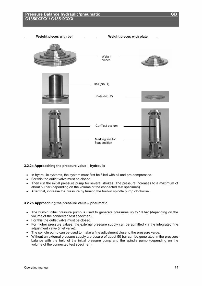
. Weight pieces with bell . . Weight pieces with plate ..
3.2.2a Approaching the pressure value – hydraulic
• In hydraulic systems, the system must first be filled with oil and pre-compressed. • For this the outlet valve must be closed. • Then run the initial pressure pump for several strokes. The pressure increases to a maximum of
about 50 bar (depending on the volume of the connected test specimen). • After that, increase the pressure by turning the built-in spindle pump clockwise.
3.2.2b Approaching the pressure value – pneumatic
• The built-in initial pressure pump is used to generate pressures up to 10 bar (depending on the volume of the connected test specimen).
• For this the outlet valve must be closed. • For higher pressure values, the external pressure supply can be admitted via the integrated fine
adjustment valve (inlet valve). • The spindle pump can be used to make a fine adjustment close to the pressure value. • Without an external pressure supply a pressure of about 50 bar can be generated in the pressure
balance with the help of the initial pressure pump and the spindle pump (depending on the volume of the connected test specimen).
ConTect system
Bell (No. 1)
Plate (No. 2)
Weight pieces
Marking line for float position
Pressure Balance hydraulic/pneumatic GB C1350X3XX / C1351X3XX
Operating manual 16
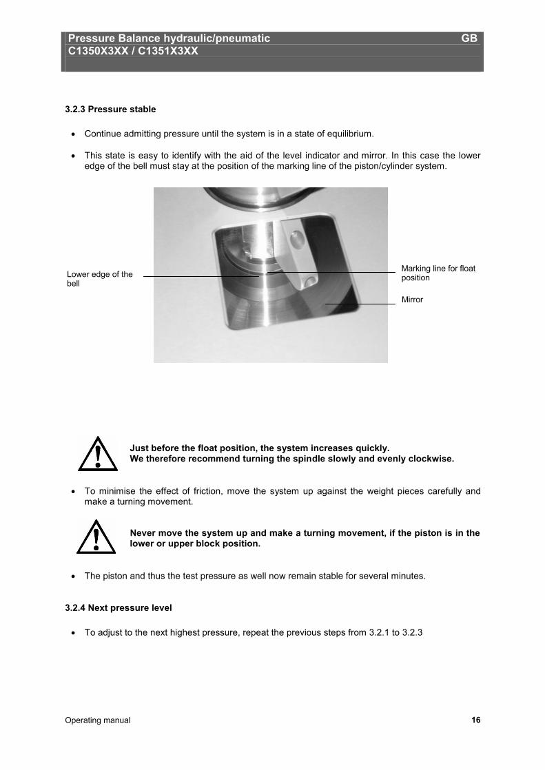
3.2.3 Pressure stable
• Continue admitting pressure until the system is in a state of equilibrium. • This state is easy to identify with the aid of the level indicator and mirror. In this case the lower
edge of the bell must stay at the position of the marking line of the piston/cylinder system.
Just before the float position, the system increases quickly. We therefore recommend turning the spindle slowly and evenly clockwise.
• To minimise the effect of friction, move the system up against the weight pieces carefully and make a turning movement.
Never move the system up and make a turning movement, if the piston is in the lower or upper block position.
• The piston and thus the test pressure as well now remain stable for several minutes.
3.2.4 Next pressure level
• To adjust to the next highest pressure, repeat the previous steps from 3.2.1 to 3.2.3
Marking line for float position
Mirror
Lower edge of the bell
Pressure Balance hydraulic/pneumatic GB C1350X3XX / C1351X3XX
Operating manual 17
3.2.5 Releasing pressure – hydraulic and pneumatic
• Turn the spindle pump anticlockwise to release pressure in the system. • If the pressure is close to the next test level, make the fine adjustment with the spindle wheel. • To release pressure more quickly or for venting, the fine adjustment valve can also be carefully
opened.
Attention: In this case the piston must stay in the lower position!
Caution: The piston is lowered very quickly just before equilibrium is achieved.
3.3 Disassembly
• After all pressure points have been recorded, close the inlet valve and open the outlet valve. • Now the test specimen can be removed from the quick clamp. • If there is another test specimen with the same measurement range, the ConTect system can
stay clamped in place. • Otherwise, we recommend removing the system by turning the butterfly screw anticlockwise and
then storing it in its protective container.
Do not disconnect the test specimen or the ConTect system until the pressure in the pressure balance has been completely released.
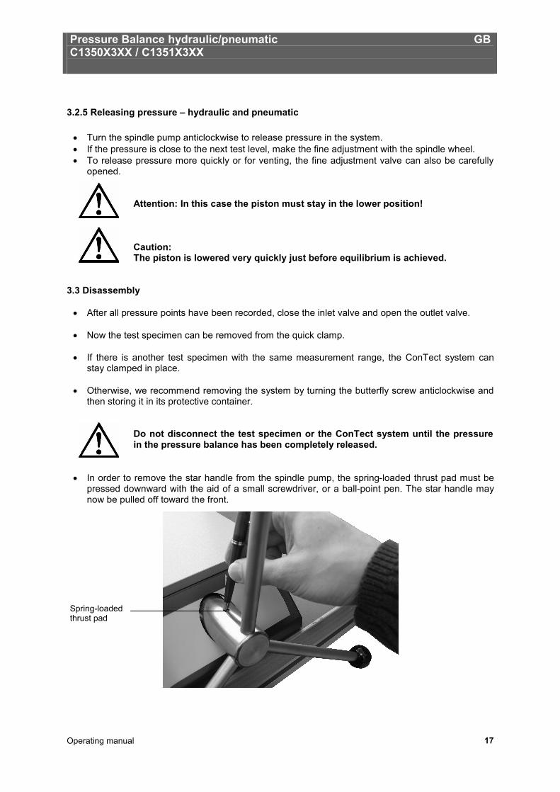
• In order to remove the star handle from the spindle pump, the spring-loaded thrust pad must be pressed downward with the aid of a small screwdriver, or a ball-point pen. The star handle may now be pulled off toward the front.
Spring-loaded thrust pad
Pressure Balance hydraulic/pneumatic GB C1350X3XX / C1351X3XX
Operating manual 18
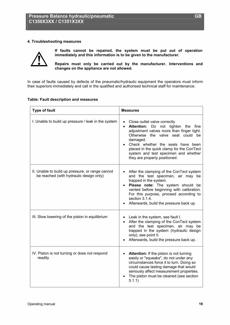
4. Troubleshooting measures
If faults cannot be repaired, the system must be put out of operation immediately and this information is to be given to the manufacturer. Repairs must only be carried out by the manufacturer. Interventions and changes on the appliance are not allowed.
In case of faults caused by defects of the pneumatic/hydraulic equipment the operators must inform their superiors immediately and call in the qualified and authorised technical staff for maintenance. Table: Fault description and measures
Type of fault Measures I. Unable to build up pressure / leak in the system
• Close outlet valve correctly • Attention: Do not tighten the fine
adjustment valves more than finger tight. Otherwise the valve seat could be damaged.
• Check whether the seals have been placed in the quick clamp for the ConTect system and test specimen and whether they are properly positioned.
II. Unable to build up pressure, or range cannot be reached (with hydraulic design only)
• After the clamping of the ConTect system
and the test specimen, air may be trapped in the system.
• Please note: The system should be vented before beginning with calibration. For this purpose, proceed according to section 3.1.4.
• Afterwards, build the pressure back up.
III. Slow lowering of the piston in equilibrium
• Leak in the system, see fault I. • After the clamping of the ConTect system
and the test specimen, air may be trapped in the system (hydraulic design only), see point II.
• Afterwards, build the pressure back up.
IV. Piston is not turning or does not respond readily
• Attention: If the piston is not turning
easily or "squeaks", do not under any circumstances force it to turn. Doing so could cause lasting damage that would seriously affect measurement properties.
• The piston must be cleaned (see section 5.1.1)
Pressure Balance hydraulic/pneumatic GB C1350X3XX / C1351X3XX
Operating manual 19
5. Maintenance and Care
5.1 Cleaning
5.1.1 Piston/Cylinder system We recommend you to clean the piston/cylinder systems after every use as needed. Poor sensitivity or short free turning duration are indications the system needs to be cleaned. To do this, remove the ConTect system from the base and disassemble it under consideration of the following references.
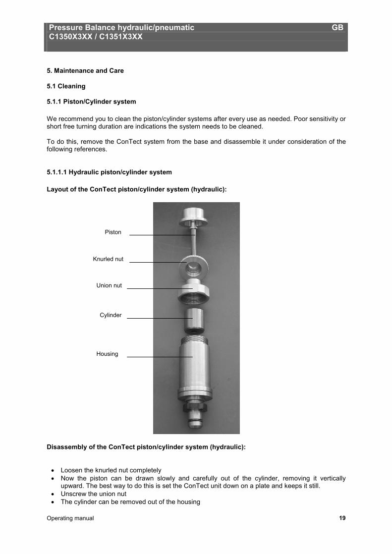
5.1.1.1 Hydraulic piston/cylinder system Layout of the ConTect piston/cylinder system (hydraulic): Disassembly of the ConTect piston/cylinder system (hydraulic):
• Loosen the knurled nut completely • Now the piston can be drawn slowly and carefully out of the cylinder, removing it vertically
upward. The best way to do this is set the ConTect unit down on a plate and keeps it still. • Unscrew the union nut • The cylinder can be removed out of the housing
Piston
Knurled nut
Union nut
Cylinder
Housing
Pressure Balance hydraulic/pneumatic GB C1350X3XX / C1351X3XX
Operating manual 20
Cleaning of the ConTect piston/cylinder system (hydraulic): There are a number of ways to clean the individual parts. It is recommended to wipe the parts with a dust-free, lint-free and soft wipe soaked in alcohol (e.g. ethyl alcohol), or to pull it through the cylinder, then drying them off with a dry, dust-free, lint-free and soft wipe.
Never touch the cleaned piston with your bare hands. The natural dermal-grease can cause a jamming of the piston/cylinder system.
Assembly of the ConTect piston/cylinder system (hydraulic): Put the parts together again in the opposite order.
• Insert the cylinder into the housing (slanted edge facing down) • Screw on the union nut • Place the system vertically on the plate and carefully insert the piston from above. The piston
should "fall" into the cylinder by its own weight. • Tighten the knurled nut again
Never press the piston forcibly into the cylinder. Otherwise it is damaged. The system is now ready to use again.
Pressure Balance hydraulic/pneumatic GB C1350X3XX / C1351X3XX
Operating manual 21
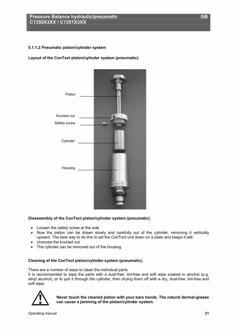
5.1.1.2 Pneumatic piston/cylinder system Layout of the ConTect piston/cylinder system (pneumatic): Disassembly of the ConTect piston/cylinder system (pneumatic):
• Loosen the safety screw at the side • Now the piston can be drawn slowly and carefully out of the cylinder, removing it vertically
upward. The best way to do this is set the ConTect unit down on a plate and keeps it still. • Unscrew the knurled nut • The cylinder can be removed out of the housing
Cleaning of the ConTect piston/cylinder system (pneumatic): There are a number of ways to clean the individual parts. It is recommended to wipe the parts with a dust-free, lint-free and soft wipe soaked in alcohol (e.g. ethyl alcohol), or to pull it through the cylinder, then drying them off with a dry, dust-free, lint-free and soft wipe.
Never touch the cleaned piston with your bare hands. The natural dermal-grease can cause a jamming of the piston/cylinder system.
Piston
Knurled nut
Safety screw
Cylinder
Housing
Pressure Balance hydraulic/pneumatic GB C1350X3XX / C1351X3XX
Operating manual 22
Assembly of the ConTect piston/cylinder system (pneumatic): Put the parts together again in the opposite order.
• Insert the cylinder into the housing (slanted edge facing down) • Screw on the knurled nut • Place the system vertically on the plate and carefully insert the piston from above. The piston
should "fall" into the cylinder by its own weight. • Tighten the safety screw at the side again
Never press the piston forcibly into the cylinder. Otherwise it is damaged. The system is now ready to use again.
5.1.2 Weight Set
• The weights should be handled with gloves. • If fingerprints or other impurities are found on the weight pieces in spite of this precaution, they
can be removed with alcohol (spirit). 5.2 Wear Parts O-rings in the ConTect retaining system and test specimen receptacles are subjected to wear. Both O-rings must be checked for proper seat and any wear before any calibrating is performed. If necessary, the O-rings must be replaced in regular intervals, or whenever necessary (see Accessories, section 8).
Important: Use original seals only. Seals having deviant measurements, or materials, or material grades, may cause damage to the device and test specimen, and pose a danger for the operator.
5.3 Changing the Hydraulic Oil (Hydraulic Design only) The hydraulic oil should be changed whenever visible contamination is present.
5.3.1 Removing Hydraulic Oil
• Open the locking screw with the oil filling symbol on top of the basement • Siphon the oil out of the tank, for example, by using a suitable nozzle • Small amounts of oil residue additionally may be siphoned off the connections with the receptacle
for the ConTect system and test specimen connection opened and with the outlet valve closed, by means of slowly turning in of the spindle pump
• Minute amounts of oil residue may remain in the piping
In case of severe contamination of the hydraulic oil, the complete cleaning of the piping and of all media-contacted individual components of the basement in a dismantled state may be advisable. This procedure may be performed by the manufacturer only.
Waste oil must be disposed of according to legal requirements. •
Pressure Balance hydraulic/pneumatic GB C1350X3XX / C1351X3XX
Operating manual 23
5.3.2 Filling in of Hydraulic Oil
• Turn in the spindle pump clockwise until it reaches the initial stop • Close the outlet valve • Open the locking screw with the oil filling symbol on top of the basement • Fill in special oil (1 litre supplied, or available as accessory) via the tank opening, until the fill level
reaches the thread of the tank opening (approximately 250ml). The fill level must always be observed.
• Twist out the spindle pump counter-clockwise until it reaches the rear stop. The filling medium is suctioned out of the tank into the system.
• Close the tank opening with the locking screw
5.3.3 Venting of the System (after Complete Filling only) After initial filling, or after a complete oil change, air may be trapped in the system. The system should be vented using the following procedure:
• The ConTect system and test specimen connections must be open • Close the outlet valve • Twist out the spindle pump counter-clockwise until it reaches the rear stop. • Carefully pump using the initial pressure pump, while continuously observing the filling medium in
the open ConTect system and test specimen connections. At this point, trapped air escapes toward the exterior by means of the formation of bubbles. The initial pressure pump must be actuated until air bubbles no longer appear.
• Any oil escaping in the open ConTect system and test specimen connections should be siphoned off, for example, with a nozzle.
Pressure Balance hydraulic/pneumatic GB C1350X3XX / C1351X3XX
Operating manual 24
5.4 Recalibration The recommended interval between recalibrations is 5 years. This is the recommendation of the German Calibration Service (DKD) This interval assumes the system and weights are handled carefully. If the system is in rough usage, we recommend shortening the interval to about three years. The pressure balance should be immediately maintained and recalibrated, if:
• the operating characteristics deteriorate (duration of free rotation, sink rate, sensitivity) • the weight pieces are damaged or corroded
For recalibration or if you have questions about the optimal recalibration cycle, the DKD lab would be happy to assist you: tecsis GmbH Carl-Legien-Str. 40 63073 Offenbach / Germany Tel.: +49 69 5806-0 Fax national: +49 69 5806-170 Fax international: +49 69 5806-177 e-Mail: [email protected] www.tecsis.de
Pressure Balance hydraulic/pneumatic GB C1350X3XX / C1351X3XX
Operating manual 25
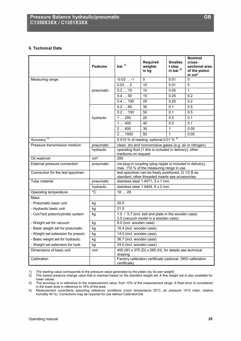
6. Technical Data
Features bar 1) Required weights in kg
Smallest step in bar 2)
Nominal cross-sectional area of the piston in cm²
Measuring range -0.03 … -1 5 0.01 5 0.03 … 2 10 0.01 5 pneumatic 0.2 … 10 10 0.05 1 0.4 … 50 10 0.25 0.2 0.4 … 100 20 0.25 0.2 0.2 … 60 30 0.1 0.5 0.2 … 100 50 0.1 0.5 hydraulic 1 … 250 25 0.5 0.1 1 … 400 40 0.5 0.1 2 … 600 30 1 0.05 2 … 1000 50 1 0.05 Accuracy 3) 0.015 % of reading, optional 0.01 % 4) Pressure transmission medium pneumatic clean, dry and noncorrosive gases (e.g. air or nitrogen) hydraulic operating fluid (1 litre is included in delivery), other
mediums on request Oil reservoir cm³ 250 External pressure connection pneumatic via plug-in coupling (plug nipple is included in delivery),
max. 110 % of the measuring range in use Connection for the test specimen test specimen can be freely positioned, G 1/2 B as
standard, other threaded inserts see accessories Tube material pneumatic stainless steel 1.4571, 3 x 1 mm hydraulic stainless steel 1.4404, 6 x 2 mm Operating temperature °C 18 … 28 Mass - Pneumatic basic unit kg 20.0 - Hydraulic basic unit kg 21.5 - ConTect piston/cylinder system kg 1.5 / 5.7 (incl. bell and plate in the wooden case)
2.5 (vacuum model in a wooden case) - Weight set for vacuum kg 8.0 (incl. wooden case) - Basic weight set for pneumatic kg 16.4 (incl. wooden case) - Weight set extension for pneum. kg 14.0 (incl. wooden case) - Basic weight set for hydraulic kg 36.7 (incl. wooden case) - Weight set extension for hydr. kg 24.0 (incl. wooden case) Dimensions of basic unit mm 400 (W) x 375 (D) x 265 (H), for details see technical
drawing Calibration Factory calibration certificate (optional: DKD calibration
certificate) 1) The starting value corresponds to the pressure value generated by the piston (by its own weight) 2) The lowest pressure change value that is reached based on the standard weight set. A fine weight set is also available for
lower values. 3) The accuracy is in reference to the measurement value, from 10% of the measurement range. A fixed error is considered
in the lower area in reference to 10% of the area. 4) Measurement uncertainty assuming reference conditions (room temperature 20°C, air pressure 1013 mbar, relative
humidity 40 %). Corrections may be required for use without CalibratorUnit.
Pressure Balance hydraulic/pneumatic GB C1350X3XX / C1351X3XX
Operating manual 26
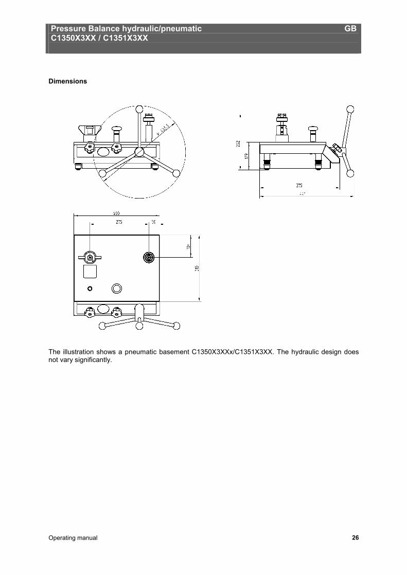
Dimensions The illustration shows a pneumatic basement C1350X3XXx/C1351X3XX. The hydraulic design does not vary significantly.
Pressure Balance hydraulic/pneumatic GB C1350X3XX / C1351X3XX
Operating manual 27
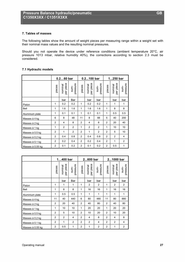
7. Tables of masses
The following tables show the amount of weight pieces per measuring range within a weight set with their nominal mass values and the resulting nominal pressures. Should you not operate the device under reference conditions (ambient temperature 20°C, air pressure 1013 mbar, relative humidity 40%), the corrections according to section 2.3 must be considered. 7.1 Hydraulic models
0.2…60 bar 0.2...100 bar 1...250 bar
piec
es
nom
inal
pe
r pie
ce
sum
-pr
essu
re
piec
es
nom
inal
pe
r pie
ce
sum
-pr
essu
re
piec
es
nom
inal
pe
r pie
ce
sum
-pr
essu
re
bar Bar bar bar bar bar Piston 1 0.2 0.2 1 0.2 0.2 1 1 1
Bell 1 1.6 1.6 1 1.6 1.6 1 8 8
Aluminium plate 1 0.1 0.1 1 0.1 0.1 1 0.5 0.5
Masses á 4 kg 6 8 48 11 8 88 5 40 200
Masses á 2 kg 2 4 8 2 4 8 2 20 40
Masses á 1 kg 1 2 2 1 2 2 1 10 10
Masses á 0.5 kg 2 1 2 2 1 2 2 5 10
Masses á 0.2 kg 2 0.4 0.8 2 0.4 0.8 2 2 4
Masses á 0.1 kg 2 0.2 0.4 2 0.2 0.4 2 1 2
Masses á 0.05 kg 2 0.1 0.2 2 0.1 0.2 2 0.5 1
1…400 bar 2...600 bar 2...1000 bar
piec
es
nom
inal
pe
r pie
ce
sum
-pr
essu
re
piec
es
nom
inal
pe
r pie
ce
sum
-pr
essu
re
piec
es
nom
inal
pe
r pie
ce
sum
-pr
essu
re
bar Bar bar bar bar bar
Piston 1 1 1 1 2 2 1 2 2
Bell 1 8 8 1 16 16 1 16 16
Aluminium plate 1 0.5 0.5 1 1 1 1 1 1
Masses á 4 kg 11 40 440 6 80 480 11 80 880
Masses á 2 kg 2 20 40 2 40 80 2 40 80
Masses á 1 kg 1 10 10 1 20 20 1 20 20
Masses á 0.5 kg 2 5 10 2 10 20 2 10 20
Masses á 0.2 kg 2 2 4 2 4 8 2 4 8
Masses á 0.1 kg 2 1 2 2 2 4 2 2 4
Masses á 0.05 kg 2 0.5 1 2 1 2 2 1 2
Pressure Balance hydraulic/pneumatic GB C1350X3XX / C1351X3XX
Operating manual 28
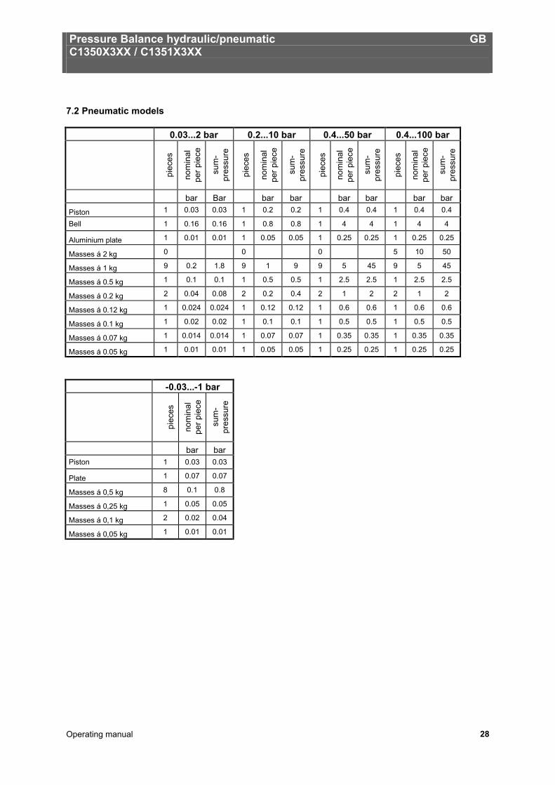
7.2 Pneumatic models 0.03...2 bar 0.2...10 bar 0.4...50 bar 0.4...100 bar
pi
eces
nom
inal
pe
r pie
ce
sum
-pr
essu
re
piec
es
nom
inal
pe
r pie
ce
sum
-pr
essu
re
piec
es
nom
inal
pe
r pie
ce
sum
-pr
essu
re
piec
es
nom
inal
pe
r pie
ce
sum
-pr
essu
re
bar Bar bar bar bar bar bar bar Piston 1 0.03 0.03 1 0.2 0.2 1 0.4 0.4 1 0.4 0.4
Bell 1 0.16 0.16 1 0.8 0.8 1 4 4 1 4 4
Aluminium plate 1 0.01 0.01 1 0.05 0.05 1 0.25 0.25 1 0.25 0.25
Masses á 2 kg 0 0 0 5 10 50
Masses á 1 kg 9 0.2 1.8 9 1 9 9 5 45 9 5 45
Masses á 0.5 kg 1 0.1 0.1 1 0.5 0.5 1 2.5 2.5 1 2.5 2.5
Masses á 0.2 kg 2 0.04 0.08 2 0.2 0.4 2 1 2 2 1 2
Masses á 0.12 kg 1 0.024 0.024 1 0.12 0.12 1 0.6 0.6 1 0.6 0.6
Masses á 0.1 kg 1 0.02 0.02 1 0.1 0.1 1 0.5 0.5 1 0.5 0.5
Masses á 0.07 kg 1 0.014 0.014 1 0.07 0.07 1 0.35 0.35 1 0.35 0.35
Masses á 0.05 kg 1 0.01 0.01 1 0.05 0.05 1 0.25 0.25 1 0.25 0.25
-0.03...-1 bar
piec
es
nom
inal
pe
r pie
ce
sum
-pr
essu
re
bar bar Piston 1 0.03 0.03
Plate 1 0.07 0.07
Masses á 0,5 kg 8 0.1 0.8
Masses á 0,25 kg 1 0.05 0.05
Masses á 0,1 kg 2 0.02 0.04
Masses á 0,05 kg 1 0.01 0.01
Pressure Balance hydraulic/pneumatic GB C1350X3XX / C1351X3XX
Operating manual 29
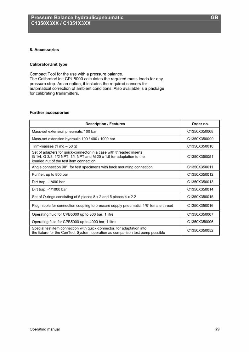
8. Accessories
CalibratorUnit type Compact Tool for the use with a pressure balance. The CalibratorUnit CPU5000 calculates the required mass-loads for any pressure step. As an option, it includes the required sensors for automatical correction of ambient conditions. Also available is a package for calibrating transmitters. Further accessories
Description / Features Order no.
Mass-set extension pneumatic 100 bar C1350X350008
Mass-set extension hydraulic 100 / 400 / 1000 bar C1350X350009
Trim-masses (1 mg – 50 g) C1350X350010 Set of adapters for quick-connector in a case with threaded inserts G 1/4, G 3/8, 1/2 NPT, 1/4 NPT and M 20 x 1.5 for adaptation to the knurled nut of the test item connection
C1350X350051
Angle connection 90°, for test specimens with back mounting connection C1350X350011
Purifier, up to 800 bar C1350X350012
Dirt trap, -1/400 bar C1350X350013
Dirt trap, -1/1000 bar C1350X350014
Set of O-rings consisting of 5 pieces 8 x 2 and 5 pieces 4 x 2.2 C1350X350015
Plug nipple for connection coupling to pressure supply pneumatic, 1/8“ female thread C1350X350016
Operating fluid for CPB5000 up to 300 bar, 1 litre C1350X350007
Operating fluid for CPB5000 up to 4000 bar, 1 litre C1350X350006
Special test item connection with quick-connector, for adaptation into the fixture for the ConTect-System, operation as comparison test pump possible C1350X350052

Kolbenmanometer hydraulisch/pneumatisch D C1350X3XX/ C1351X3XX
Betriebsanleitung 30
Information Dieses Zeichen gibt Ihnen Informationen, Hinweise oder Tipps. Warnung! Dieses Symbol warnt Sie vor Handlungen, die Schäden an Personen oder am Gerät verursachen können.
D
Kolbenmanometer hydraulisch/pneumatisch D C1350X3XX/ C1351X3XX
Betriebsanleitung 31
Inhalt 1. Allgemeines . ................................................................................................................................ 32 1.1 Allgemeine Hinweise . ............................................................................................................... 32 1.2 Sicherheitshinweise .................................................................................................................. 33 2. Produktbeschreibung . ................................................................................................................ 34 2.1 Allgemeine Produktinformationen . ......................................................................................... 34 2.2 Grundprinzip Kolbenmanometer . ............................................................................................ 35 2.3 Einflussfaktoren . ....................................................................................................................... 35 2.3.1 Lokale Fallbeschleunigung . .................................................................................................. 35 2.3.2 Temperatur (Kolben-Zylinder) . ............................................................................................. 36 2.3.3 Umgebungsbedingungen ...................................................................................................... 36 2.3.4 Druckabhängigkeit der Querschnittsfläche . ....................................................................... 37 2.4 Anordnung der Bedienelemente . ............................................................................................ 38 3. Inbetriebnahme und Betrieb . ..................................................................................................... 39 3.1 Vorbereitung . ............................................................................................................................. 39 3.1.1 Aufstellung des Gerätes ........................................................................................................ 39 3.1.2 Einbau des ConTect-Systems . ............................................................................................. 40 3.1.3 Anschluss des Prüflings . ...................................................................................................... 41 3.1.4 Entlüftung des Systems (nur Hydraulikausführung) . ........................................................ 41 3.2 Betrieb . .................................................................................................................................... 42 3.2.1 Masseauflagen . ...................................................................................................................... 42 3.2.2a Druckwert anfahren – Hydraulik . ........................................................................................ 43 3.2.2b Druckwert anfahren – Pneumatik . ...................................................................................... 43 3.2.3 Druck stabil ............................................................................................................................. 44 3.2.4 Nächste Druckstufe . .............................................................................................................. 44 3.2.5 Druck entlasten – Hydraulik und Pneumatik ....................................................................... 45 3.3 Abbau . ........................................................................................................................................ 45 4. Maßnahmen bei Störungen . ....................................................................................................... 46 5. Pflege und Wartung . ................................................................................................................... 47 5.1 Reinigung . ................................................................................................................................. 47 5.1.1 Kolben-Zylinder-System ........................................................................................................ 47 5.1.1.1 Hydraulisches Kolben-Zylinder-System . .......................................................................... 47 5.1.1.2 Pneumatisches Kolben-Zylinder-System . ........................................................................ 49 5.1.2 Massensatz . ............................................................................................................................ 50 5.2 Verschleißteile . .......................................................................................................................... 50 5.3 Austausch des Hydrauliköls (nur bei Hydraulikausführung) . .............................................. 50 5.3.1 Hydrauliköl entfernen . ........................................................................................................... 50 5.3.2 Hydrauliköl einfüllen .............................................................................................................. 51 5.3.3 Entlüftung des Systems (nur nach Komplettbefüllung) . ................................................... 51 5.4 Rekalibrierung . .......................................................................................................................... 52 6. Technische Daten . ...................................................................................................................... 53 7. Gewichtstabellen ......................................................................................................................... 55 7.1 Hydraulische Modelle . .............................................................................................................. 55 7.2 Pneumatische Modelle . ............................................................................................................ 56 8. Zubehör . .................................................................................................................................... 57
Kolbenmanometer hydraulisch/pneumatisch D C1350X3XX/ C1351X3XX
Betriebsanleitung 32
1. Allgemeines
1.1 Allgemeine Hinweise In den folgenden Kapiteln erhalten Sie nähere Informationen zum Kolbenmanometer C1350X3XX/C1351X3XXund seinen ordnungsgemäßen Einsatz. Sollten Sie weitere Informationen wünschen, oder treten besondere Probleme auf, die in der Betriebsanleitung nicht ausführlich behandelt werden, erhalten Sie Auskunft unter folgender Adresse: tecsis GmbH Carl-Legien-Str. 40 63073 Offenbach / Germany Tel.: +49 69 5806-0 Fax national: +49 69 5806-170 Fax international: +49 69 5806-177 e-Mail: [email protected] www.tecsis.de Das Kolbenmanometer ist, wenn nicht anders vereinbart, konform zu den aktuell gültigen internationalen Regelwerken kalibriert und direkt auf ein nationales Normal rückführbar. Die Gewährleistungszeit für das Kolbenmanometer beträgt 24 Monate nach den Allgemeinen Lieferbedingungen des ZVEI. Sämtliche Gewährleistungsansprüche verfallen, bei unsachgemäßer Handhabung bzw. bei Nichtbeachtung der Betriebsleitungen oder bei dem Versuch das Gerät zu öffnen bzw. Anbauteile oder die Verrohrung zu lösen. Außerdem weisen wir darauf hin, dass der Inhalt dieser Betriebsanleitung nicht Teil einer früheren oder bestehenden Vereinbarung, Zusage oder Rechtsverhältnisses ist oder diese abändern soll. Sämtliche Verpflichtungen der tecsis GmbH ergeben sich aus dem jeweiligen Kaufvertrag und den Allgemeinen Geschäftsbedingungen der tecsis GmbH. Die beschriebenen Geräte entsprechen in ihren Konstruktionen, Maßen und Werkstoffen dem derzeitigen Stand der Technik. Änderungen und den Austausch von Werkstoffen behalten wir uns vor, ohne den Zwang umgehend darauf hinzuweisen. Eine Vervielfältigung dieses Handbuches oder Teilen davon ist untersagt.
Kolbenmanometer hydraulisch/pneumatisch D C1350X3XX/ C1351X3XX
Betriebsanleitung 33
1.2 Sicherheitshinweise .
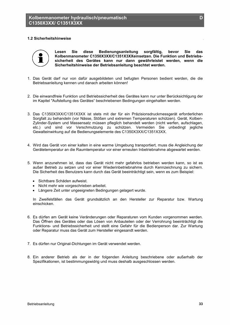
Lesen Sie diese Bedienungsanleitung sorgfältig, bevor Sie das Kolbenmanometer C1350X3XX/C1351X3XXeinsetzen. Die Funktion und Betriebs-sicherheit des Gerätes kann nur dann gewährleistet werden, wenn die Sicherheitshinweise der Betriebsanleitung beachtet werden.
1. Das Gerät darf nur von dafür ausgebildeten und befugten Personen bedient werden, die die
Betriebsanleitung kennen und danach arbeiten können! 2. Die einwandfreie Funktion und Betriebssicherheit des Gerätes kann nur unter Berücksichtigung der
im Kapitel "Aufstellung des Gerätes“ beschriebenen Bedingungen eingehalten werden. 3. Das C1350X3XX/C1351X3XX ist stets mit der für ein Präzisionsdruckmessgerät erforderlichen
Sorgfalt zu behandeln (vor Nässe, Stößen und extremen Temperaturen schützen). Gerät, Kolben-Zylinder-System und Massensatz müssen pfleglich behandelt werden (nicht werfen, aufschlagen, etc.) und sind vor Verschmutzung zu schützen. Vermeiden Sie unbedingt jegliche Gewalteinwirkung auf die Bedienungselemente des C1350X3XX/C1351X3XX.
4. Wird das Gerät von einer kalten in eine warme Umgebung transportiert, muss die Angleichung der
Gerätetemperatur an die Raumtemperatur vor einer erneuten Inbetriebnahme abgewartet werden. 5. Wenn anzunehmen ist, dass das Gerät nicht mehr gefahrlos betrieben werden kann, so ist es
außer Betrieb zu setzen und vor einer Wiederinbetriebnahme durch Kennzeichnung zu sichern. Die Sicherheit des Benutzers kann durch das Gerät beeinträchtigt sein, wenn es zum Beispiel:
• Sichtbare Schäden aufweist. • Nicht mehr wie vorgeschrieben arbeitet. • Längere Zeit unter ungeeigneten Bedingungen gelagert wurde.
In Zweifelsfällen das Gerät grundsätzlich an den Hersteller zur Reparatur bzw. Wartung einschicken.
6. Es dürfen am Gerät keine Veränderungen oder Reparaturen vom Kunden vorgenommen werden.
Das Öffnen des Gerätes oder das Lösen von Anbauteilen oder der Verrohrung beeinträchtigt die Funktions- und Betriebssicherheit und stellt eine Gefahr für die Bedienperson dar. Zur Wartung oder Reparatur muss das Gerät zum Hersteller eingesandt werden.
7. Es dürfen nur Original-Dichtungen im Gerät verwendet werden. 8. Ein anderer Betrieb als der in der folgenden Anleitung beschriebene oder außerhalb der
Spezifikationen, ist bestimmungswidrig und muss deshalb ausgeschlossen werden.
Kolbenmanometer hydraulisch/pneumatisch D C1350X3XX/ C1351X3XX
Betriebsanleitung 34
2. Produktbeschreibung
2.1 Allgemeine Produktinformationen Einsatz Kolbenmanometer sind die genauesten am Markt verfügbaren Geräte zur Kalibrierung von elektronischen oder mechanischen Druckmessgeräten. Die direkte Messung des Druckes, gemäß seiner Definition als Quotient aus Kraft und Fläche, sowie der Einsatz hochwertiger Materialien ermöglichen sehr kleine Messunsicherheiten in Verbindung mit der ausgezeichneten Langzeitstabilität von fünf Jahren (Empfehlung gemäß des Deutschen Kalibrierdienstes DKD). Das Kolbenmanometer findet somit seit Jahren seinen Einsatz in den Werks- und Kalibrierlaboratorien der Industrie, Nationalen Instituten sowie Forschungsanstalten. Aufgrund der integrierten Druckerzeugung sowie dem rein mechanischen Messprinzip, ist das C1350X3XX/C1351X3XX auch ideal für den Einsatz vor Ort, in der Wartung und im Service geeignet. ConTect Messsystem Das patentierte Konzept zur kundenspezifischen Bestückung des C1350X3XX/C1351X3XX ermöglicht den Aufbau eines kompakten und preisoptimierten Komplettsystems, bestehend aus einem universell einsetzbaren Basement sowie den Messsystemen. Die hochwertigen und empfindlichen Kolben-Zylinder-Systeme sind im ConTect-Gehäuse sicher aufbewahrt und erlauben einen Wechsel des Messbereiches schnell und ohne Werkzeug. Die pneumatischen Messsysteme sind für Vakuum und Drücke von 2 bar bis 100 bar und die hydraulischen Messsysteme für Drücke von 60 bar bis 1000 bar erhältlich. Die Genauigkeit liegt bei 0,015 % (optional auch 0,01 %) vom Messwert. Funktionsweise Je nach Messbereich des Prüflings kann das Gerätebasement mit dem entsprechendem Messsystem bestückt werden. Zur Erzeugung der einzelnen Prüfpunkte, wird das Kolben-Zylinder-System mit Masse-Auflagen belastet. Diese Scheiben-Gewichte sind speziell auf ihren Einsatzort abgestimmt und können ebenfalls DKD-kalibriert werden. Die Einstellung des Druckes erfolgt entweder über eine integrierte Pumpe oder bei vorhandener externer Druckversorgung mittels Dosierventilen. Zur Feineinstellung steht ein regelbares Volumen mit Präzisionsspindel zur Verfügung. Die Masseauflage ist proportional zu dem angestrebten Druck und wird durch optimal abgestufte Masseauflagen erreicht. Sobald sich dann das Messsystem im Schwebezustand befindet, herrscht ein Kräftegleichgewicht zwischen Druck und Masseauflagen. Aufgrund der hochwertigen Verarbeitung des Systems steht dieser Druck stabil über mehrere Minuten, so dass problemlos z.B. auch längere Justagearbeiten am Prüfling vorgenommen werden können.
Kolbenmanometer hydraulisch/pneumatisch D C1350X3XX/ C1351X3XX
Betriebsanleitung 35
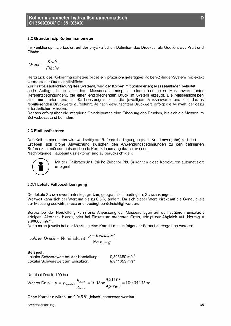
2.2 Grundprinzip Kolbenmanometer Ihr Funktionsprinzip basiert auf der physikalischen Definition des Druckes, als Quotient aus Kraft und Fläche.
FlächeKraftDruck =
Herzstück des Kolbenmanometers bildet ein präzisionsgefertigtes Kolben-Zylinder-System mit exakt vermessener Querschnittsfläche. Zur Kraft-Beaufschlagung des Systems, wird der Kolben mit (kalibrierten) Masseauflagen belastet. Jede Auflagescheibe aus dem Massensatz entspricht einem nominalen Massenwert (unter Referenzbedingungen), die einen entsprechenden Druck im System erzeugt. Die Massenscheiben sind nummeriert und im Kalibrierzeugnis sind die jeweiligen Massenwerte und die daraus resultierenden Druckwerte aufgeführt. Je nach gewünschtem Druckwert, erfolgt die Auswahl der dazu erforderlichen Massen. Danach erfolgt über die integrierte Spindelpumpe eine Erhöhung des Druckes, bis sich die Massen im Schwebezustand befinden. 2.3 Einflussfaktoren Das Kolbenmanometer wird werkseitig auf Referenzbedingungen (nach Kundenvorgabe) kalibriert. Ergeben sich große Abweichung zwischen den Anwendungsbedingungen zu den definierten Referenzen, müssen entsprechende Korrektionen angebracht werden. Nachfolgende Haupteinflussfaktoren sind zu berücksichtigen.
Mit der CalibratorUnit (siehe Zubehör Pkt. 8) können diese Korrekturen automatisiert erfolgen!
2.3.1 Lokale Fallbeschleunigung Der lokale Schwerewert unterliegt großen, geographisch bedingten, Schwankungen. Weltweit kann sich der Wert um bis zu 0,5 % ändern. Da sich dieser Wert, direkt auf die Genauigkeit der Messung auswirkt, muss er unbedingt berücksichtigt werden. Bereits bei der Herstellung kann eine Anpassung der Masseauflagen auf den späteren Einsatzort erfolgen. Alternativ hierzu, oder bei Einsatz an mehreren Orten, erfolgt der Abgleich auf „Norm-g = 9,80665 m/s2“. Dann muss jeweils bei der Messung eine Korrektur nach folgender Formel durchgeführt werden:
gNormEinsatzortgDruckwahrer
−−
⋅= tNominalwer
Beispiel: Lokaler Schwerewert bei der Herstellung: 9,806650 m/s2
Lokaler Schwerewert am Einsatzort: 9,811053 m/s2
Nominal-Druck: 100 bar
Wahrer Druck: barbarggpp
Norm
lokal 0449,10080665,981105,9100Nominal ===
Ohne Korrektur würde um 0,045 % „falsch“ gemessen werden.
Kolbenmanometer hydraulisch/pneumatisch D C1350X3XX/ C1351X3XX
Betriebsanleitung 36
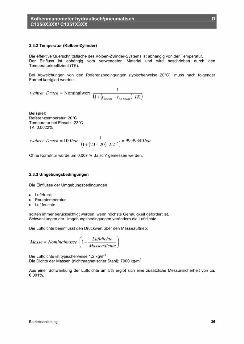
2.3.2 Temperatur (Kolben-Zylinder) Die effektive Querschnittsfläche des Kolben-Zylinder-Systems ist abhängig von der Temperatur. Der Einfluss ist abhängig vom verwendeten Material und wird beschrieben durch den Temperaturkoeffizient (TK). Bei Abweichungen von den Referenzbedingungen (typischerweise 20°C), muss nach folgender Formel korrigiert werden:
( )( )TKttDruckwahrer
ferenzEinsatz ⋅−+⋅=
Re11tNominalwer
Beispiel: Referenztemperatur: 20°C Temperatur bei Einsatz: 23°C TK: 0,0022%
( )( ) barbarDruckwahrer 99340,992,220231
1100 5 =⋅−+
⋅= −
Ohne Korrektur würde um 0,007 % „falsch“ gemessen werden.
2.3.3 Umgebungsbedingungen Die Einflüsse der Umgebungsbedingungen • Luftdruck • Raumtemperatur • Luftfeuchte sollten immer berücksichtigt werden, wenn höchste Genauigkeit gefordert ist. Schwankungen der Umgebungsbedingungen verändern die Luftdichte. Die Luftdichte beeinflusst den Druckwert über den Masseauftrieb:
−⋅=
teMassendichLuftdichteseNominalmasMasse 1
Die Luftdichte ist typischerweise 1,2 kg/m3
Die Dichte der Massen (nichtmagnetischer Stahl): 7900 kg/m3 Aus einer Schwankung der Luftdichte um 5% ergibt sich eine zusätzliche Messunsicherheit von ca. 0,001%.
Kolbenmanometer hydraulisch/pneumatisch D C1350X3XX/ C1351X3XX
Betriebsanleitung 37
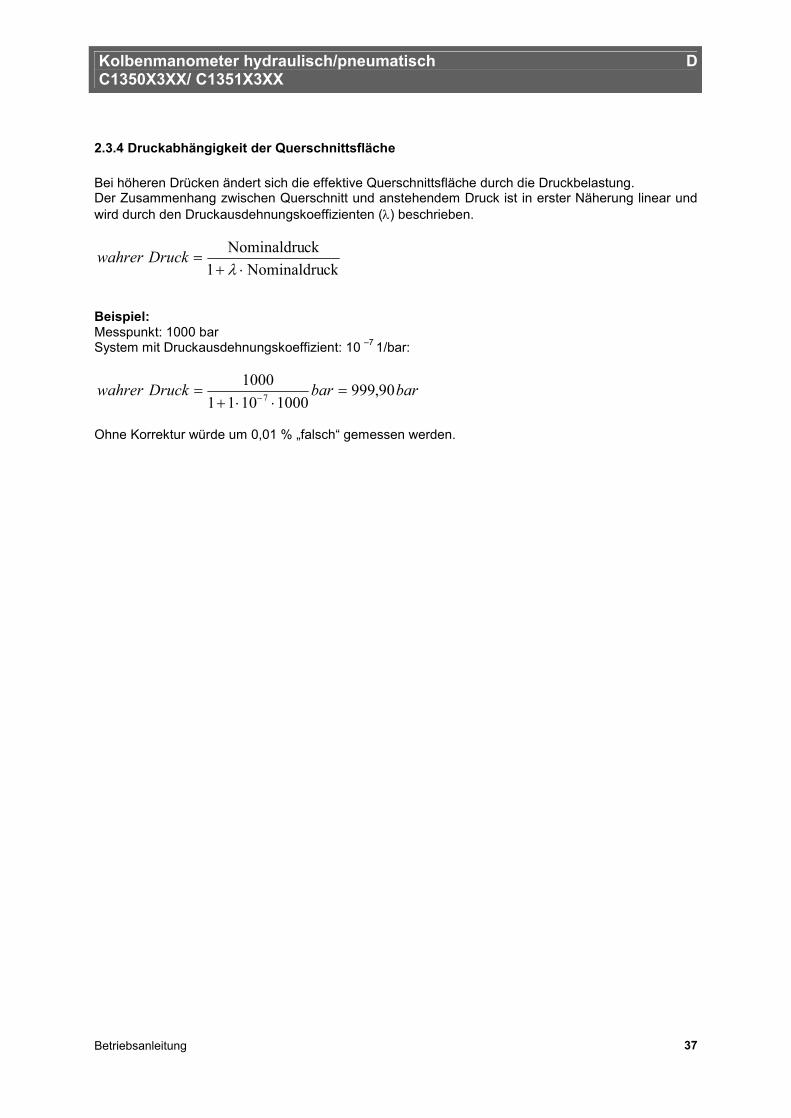
2.3.4 Druckabhängigkeit der Querschnittsfläche Bei höheren Drücken ändert sich die effektive Querschnittsfläche durch die Druckbelastung. Der Zusammenhang zwischen Querschnitt und anstehendem Druck ist in erster Näherung linear und wird durch den Druckausdehnungskoeffizienten (λ) beschrieben.
ckNominaldru1ckNominaldru
⋅+=
λDruckwahrer
Beispiel: Messpunkt: 1000 bar System mit Druckausdehnungskoeffizient: 10 –7 1/bar:
barbarDruckwahrer 90,99910001011
10007 =
⋅⋅+= −
Ohne Korrektur würde um 0,01 % „falsch“ gemessen werden.
Kolbenmanometer hydraulisch/pneumatisch D C1350X3XX/ C1351X3XX
Betriebsanleitung 38
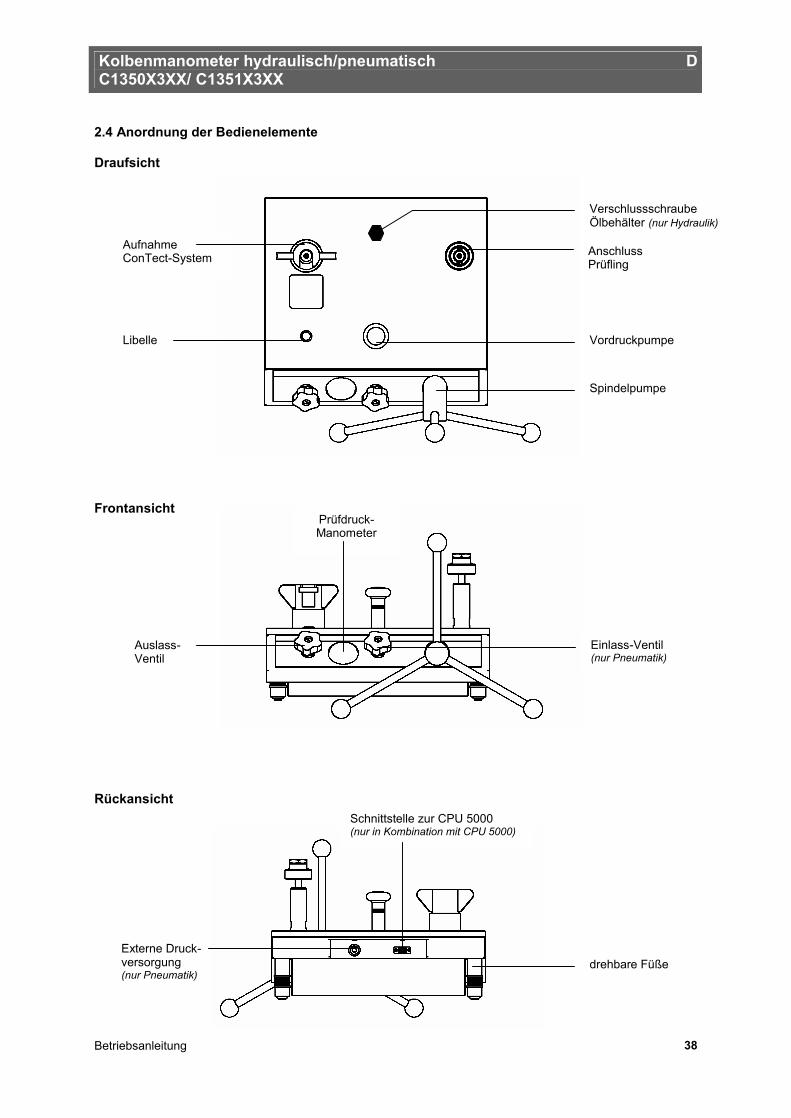
2.4 Anordnung der Bedienelemente Draufsicht Frontansicht Rückansicht
Externe Druck-versorgung (nur Pneumatik)
Anschluss Prüfling
Vordruckpumpe
Aufnahme ConTect-System
Libelle
Spindelpumpe
Einlass-Ventil (nur Pneumatik)
Auslass- Ventil
Prüfdruck- Manometer
drehbare Füße
Schnittstelle zur CPU 5000 (nur in Kombination mit CPU 5000)
Verschlussschraube Ölbehälter (nur Hydraulik)
Kolbenmanometer hydraulisch/pneumatisch D C1350X3XX/ C1351X3XX
Betriebsanleitung 39
3. Inbetriebnahme und Betrieb
3.1 Vorbereitung
3.1.1 Aufstellung des Gerätes
• Das Kolbenmanometer auf einer festen Unterlage aufstellen. Ein unsicherer Stand oder Vibrationen beeinflussen die Messung und sollten vermieden werden.
• Ist kein klimatisierter Raum vorhanden, sollte das Gerät zumindest nicht in der Nähe von Heizung
oder Fenster stehen, um Zugerscheinungen oder Wärmeströmungen zu minimieren. • Die Libelle zeigt die Ausrichtung des Gerätes an. Eine grobe Ausrichtung kann bereits jetzt ohne
ConTect-System erfolgen. Über die drehbaren Füße wird das Gerät in die Waagrechte gestellt.
• In der Pneumatik-Ausführung kann eine externe Druckluftversorgung angeschlossen werden.
Achtung: Der Versorgungsdruck darf max. 110% des Messbereichsendwertes des zu prüfenden Gerätes oder des eingesetzten ConTect-Systems betragen.
• Es dürfen nur trockene, gereinigte und partikelfreie Gase (z.B. Stickstoff 4.0 oder synthetische Luft) verwendet werden.
• In der Hydraulik-Ausführung muss ggf. der Ölbehälter auf- bzw. nachgefüllt werden (Inhalt
250 ml). Hierzu ist die Verschlussschraube mit dem Öleinfüllsymbol auf der Basementoberseite zu öffnen. Zum Nachfüllen ist Spezialöl zu verwenden (1 Liter im Lieferumfang enthalten bzw. als Zubehör erhältlich). Bei Erstbefüllung oder nach einem kompletten Austausch des Öls ist das System zu entlüften. Hierzu ist nach Pkt. 5.3.3 vorzugehen.
• Das Drehkreuz mit Griffen auf die Spindelpumpe aufstecken. Hierbei ist darauf zu achten, dass
das Federdruckstück in die Drehkreuzhülse einrastet. • Es empfiehlt sich, die Spindelpumpe zu Beginn der Messwertaufnahme komplett herauszudrehen
(im Gegen-Uhrzeigersinn) um genügend Volumen für die Messungen bereit zu stellen. Während dieses Vorgangs ist das Auslass-Ventil zu öffnen.
Kolbenmanometer hydraulisch/pneumatisch D C1350X3XX/ C1351X3XX
Betriebsanleitung 40
3.1.2 Einbau des ConTect-Systems
• Je nach zu prüfendem Gerät, ist das entsprechende ConTect-System einzusetzen. Hier wird die vergleichbare oder jeweils nächsthöhere Abstufung gewählt.
Beispiel: Kalibrierung eines 600 bar Federmanometers è 600 bar Contect-System Kalibrierung eines 160 bar Federmanometers è 250 bar Contect-System
Vor Lösen des Verschlussstopfens im Basement, den drucklosen Zustand des Systems (Auslass-Ventil öffnen) sicherstellen.
• Das ConTect-System wird vertikal in den Schnellverschluss eingesetzt
Hinweis: Luft- und Öl-Systeme nicht vertauschen
Die O-Ring-Dichtung in der Aufnahme für das ConTect-System auf richtigen Sitz und Verschleiß überprüfen. Gegebenenfalls austauschen.
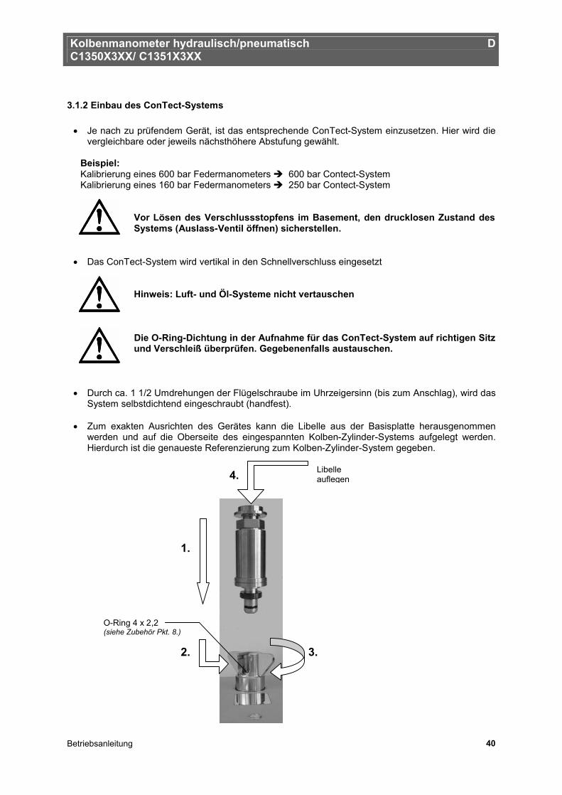
• Durch ca. 1 1/2 Umdrehungen der Flügelschraube im Uhrzeigersinn (bis zum Anschlag), wird das System selbstdichtend eingeschraubt (handfest).
• Zum exakten Ausrichten des Gerätes kann die Libelle aus der Basisplatte herausgenommen
werden und auf die Oberseite des eingespannten Kolben-Zylinder-Systems aufgelegt werden. Hierdurch ist die genaueste Referenzierung zum Kolben-Zylinder-System gegeben.
O-Ring 4 x 2,2 (siehe Zubehör Pkt. 8.)
3. 2.
1.
4.
Libelle auflegen
Kolbenmanometer hydraulisch/pneumatisch D C1350X3XX/ C1351X3XX
Betriebsanleitung 41
3.1.3 Anschluss des Prüflings
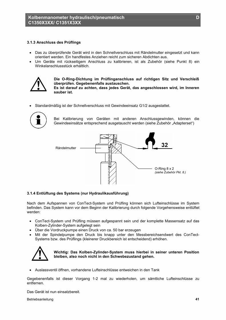
• Das zu überprüfende Gerät wird in den Schnellverschluss mit Rändelmutter eingesetzt und kann orientiert werden. Ein handfestes Anziehen reicht zum sicheren Abdichten aus.
• Um Geräte mit rückseitigem Anschluss zu kalibrieren, ist als Zubehör (siehe Punkt 8) ein Winkelanschlussstück erhältlich.
Die O-Ring-Dichtung im Prüflinganschluss auf richtigen Sitz und Verschleiß überprüfen. Gegebenenfalls austauschen. Es ist darauf zu achten, dass jedes Gerät, das angeschlossen wird, im Inneren sauber ist.
• Standardmäßig ist der Schnellverschluss mit Gewindeeinsatz G1/2 ausgestattet.
Bei Kalibrierung von Geräten mit anderen Anschlussgewinden, können die Gewindeeinsätze entsprechend ausgetauscht werden (siehe Zubehör „Adapterset“)
3.1.4 Entlüftung des Systems (nur Hydraulikausführung) Nach dem Aufspannen von ConTect-System und Prüfling können sich Lufteinschlüsse im System befinden. Das System kann vor dem Beginn der Kalibrierung durch folgende Vorgehensweise entlüftet werden:
• ConTect-System und Prüfling müssen aufgespannt sein und der komplette Massensatz auf das Kolben-Zylinder-System aufgelegt sein
• Über die Vordruckpumpe einen Druck von ca. 50 bar erzeugen • Mit der Spindelpumpe den Druck bis knapp unter den Messbereichsendwert des ConTect-
Systems bzw. des Prüflings (kleinerer Druckbereich ist entscheidend) erhöhen.
Wichtig: Das Kolben-Zylinder-System muss hierbei in seiner unteren Position bleiben, also noch nicht in den Schwebezustand gehen.
• Auslassventil öffnen, vorhandene Lufteinschlüsse entweichen in den Tank Gegebenenfalls ist dieser Vorgang 1-2 mal zu wiederholen, um sämtliche Lufteinschlüsse zu entfernen. Das Gerät ist nun einsatzbereit.
O-Ring 8 x 2 (siehe Zubehör Pkt. 8.)
Rändelmutter
Kolbenmanometer hydraulisch/pneumatisch D C1350X3XX/ C1351X3XX
Betriebsanleitung 42
3.2 Betrieb
3.2.1 Masseauflagen
• Je nach angestrebtem Druckwert, die entsprechenden Masseauflagen auf die Glocke stapeln. • Typischerweise beginnend mit dem größten Gewicht, um einen möglichst tiefen Schwerpunkt zu
erhalten. • Jede Komponente ist mit einer fortlaufenden Nummer gekennzeichnet. Im Kalibrierschein ist zu
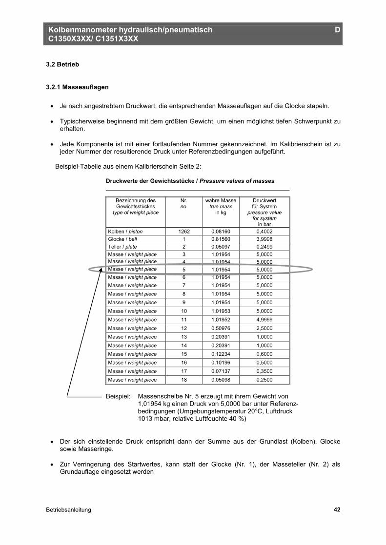
jeder Nummer der resultierende Druck unter Referenzbedingungen aufgeführt.
Beispiel-Tabelle aus einem Kalibrierschein Seite 2: Druckwerte der Gewichtsstücke / Pressure values of masses
Bezeichnung des Gewichtsstückes
type of weight piece
Nr. no.
wahre Masse true mass
in kg
Druckwert für System
pressure value for system
in bar Kolben / piston 1262 0,08160 0,4002 Glocke / bell 1 0,81560 3,9998 Teller / plate 2 0,05097 0,2499 Masse / weight piece 3 1,01954 5,0000 Masse / weight piece 4 1,01954 5,0000 Masse / weight piece 5 1,01954 5,0000 Masse / weight piece 6 1,01954 5,0000 Masse / weight piece 7 1,01954 5,0000 Masse / weight piece 8 1,01954 5,0000 Masse / weight piece 9 1,01954 5,0000 Masse / weight piece 10 1,01953 5,0000 Masse / weight piece 11 1,01952 4,9999 Masse / weight piece 12 0,50976 2,5000 Masse / weight piece 13 0,20391 1,0000 Masse / weight piece 14 0,20391 1,0000 Masse / weight piece 15 0,12234 0,6000 Masse / weight piece 16 0,10196 0,5000 Masse / weight piece 17 0,07137 0,3500 Masse / weight piece 18 0,05098 0,2500
Beispiel: Massenscheibe Nr. 5 erzeugt mit ihrem Gewicht von
1,01954 kg einen Druck von 5,0000 bar unter Referenz- bedingungen (Umgebungstemperatur 20°C, Luftdruck 1013 mbar, relative Luftfeuchte 40 %)
• Der sich einstellende Druck entspricht dann der Summe aus der Grundlast (Kolben), Glocke sowie Masseringe.
• Zur Verringerung des Startwertes, kann statt der Glocke (Nr. 1), der Masseteller (Nr. 2) als
Grundauflage eingesetzt werden
Kolbenmanometer hydraulisch/pneumatisch D C1350X3XX/ C1351X3XX
Betriebsanleitung 43
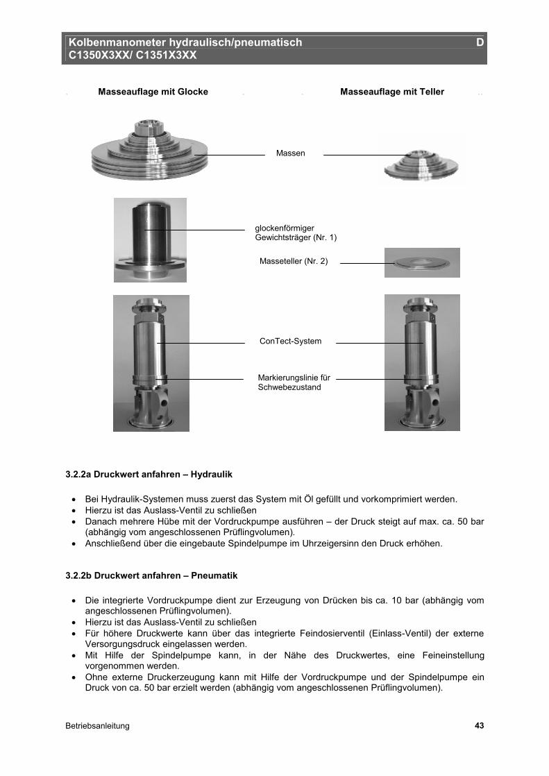
. Masseauflage mit Glocke . . Masseauflage mit Teller ..
3.2.2a Druckwert anfahren – Hydraulik
• Bei Hydraulik-Systemen muss zuerst das System mit Öl gefüllt und vorkomprimiert werden. • Hierzu ist das Auslass-Ventil zu schließen • Danach mehrere Hübe mit der Vordruckpumpe ausführen – der Druck steigt auf max. ca. 50 bar
(abhängig vom angeschlossenen Prüflingvolumen). • Anschließend über die eingebaute Spindelpumpe im Uhrzeigersinn den Druck erhöhen.
3.2.2b Druckwert anfahren – Pneumatik
• Die integrierte Vordruckpumpe dient zur Erzeugung von Drücken bis ca. 10 bar (abhängig vom angeschlossenen Prüflingvolumen).
• Hierzu ist das Auslass-Ventil zu schließen • Für höhere Druckwerte kann über das integrierte Feindosierventil (Einlass-Ventil) der externe
Versorgungsdruck eingelassen werden. • Mit Hilfe der Spindelpumpe kann, in der Nähe des Druckwertes, eine Feineinstellung
vorgenommen werden. • Ohne externe Druckerzeugung kann mit Hilfe der Vordruckpumpe und der Spindelpumpe ein
Druck von ca. 50 bar erzielt werden (abhängig vom angeschlossenen Prüflingvolumen).
ConTect-System
glockenförmiger Gewichtsträger (Nr. 1)
Masseteller (Nr. 2)
Massen
Markierungslinie für Schwebezustand
Kolbenmanometer hydraulisch/pneumatisch D C1350X3XX/ C1351X3XX
Betriebsanleitung 44
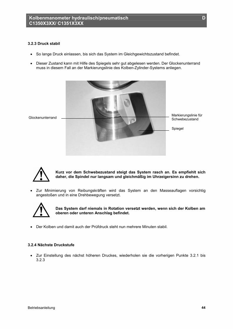
3.2.3 Druck stabil
• So lange Druck einlassen, bis sich das System im Gleichgewichtszustand befindet. • Dieser Zustand kann mit Hilfe des Spiegels sehr gut abgelesen werden. Der Glockenunterrand
muss in diesem Fall an der Markierungslinie des Kolben-Zylinder-Systems anliegen.
Kurz vor dem Schwebezustand steigt das System rasch an. Es empfiehlt sich daher, die Spindel nur langsam und gleichmäßig im Uhrzeigersinn zu drehen.
• Zur Minimierung von Reibungskräften wird das System an den Masseauflagen vorsichtig angestoßen und in eine Drehbewegung versetzt.
Das System darf niemals in Rotation versetzt werden, wenn sich der Kolben am oberen oder unteren Anschlag befindet.
• Der Kolben und damit auch der Prüfdruck steht nun mehrere Minuten stabil.
3.2.4 Nächste Druckstufe
• Zur Einstellung des nächst höheren Druckes, wiederholen sie die vorherigen Punkte 3.2.1 bis 3.2.3
Markierungslinie für Schwebezustand
Spiegel
Glockenunterrand
Kolbenmanometer hydraulisch/pneumatisch D C1350X3XX/ C1351X3XX
Betriebsanleitung 45
3.2.5 Druck entlasten – Hydraulik und Pneumatik
• Die Spindelpumpe im Gegen-Uhrzeigersinn drehen, um das System zu entlasten. • Befindet sich der Druck in der Nähe der nächsten Prüfstufe, kann die Feineinstellung über das
Spindelrad vorgenommen werden. • Für schnellere Druckentlastung oder zur kompletten Entlüftung kann auch das Feindosierventil
vorsichtig geöffnet werden.
Achtung: Der Kolben darf hierbei nicht in der Schwebe sein!
Vorsicht: Der Kolben sinkt kurz vor dem Gleichgewichtszustand recht schnell ab.
3.3 Abbau
• Nach Aufnahme aller Druckpunkte, das Einlassventil schließen und das Auslassventil öffnen. • Jetzt kann der Prüfling vom Schnellspanner abgenommen werden. • Ist ein weiterer Prüfling mit gleichem Messbereich vorhanden, kann das ConTect-System
aufgespannt bleiben. • Ansonsten wird empfohlen das System durch Drehung der Flügelschraube im Gegen-
Uhrzeigersinn zu lösen und im Schutzbehälter zu verstauen.
Demontieren sie den Prüfling oder das ConTect-System erst, wenn der Druck im Kolbenmanometer vollständig abgebaut ist.
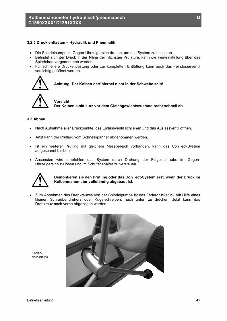
• Zum Abnehmen des Drehkreuzes von der Spindelpumpe ist das Federdruckstück mit Hilfe eines kleinen Schraubendrehers oder Kugelschreibers nach unten zu drücken. Jetzt kann das Drehkreuz nach vorne abgezogen werden.
Feder-druckstück
Kolbenmanometer hydraulisch/pneumatisch D C1350X3XX/ C1351X3XX
Betriebsanleitung 46
4. Maßnahmen bei Störungen
Können Störungen mit der Hilfe der Betriebsanleitung nicht beseitigt werden, ist das Gerät unverzüglich außer Betrieb zu setzen und der Hersteller ist zu kontaktieren. Reparaturen dürfen nur vom Hersteller durchgeführt werden. Eingriffe und Änderungen am Gerät durch den Betreiber sind unzulässig.
Bei Störungen, die auf Defekte an der pneumatischen/hydraulischen Ausrüstung zurückzuführen sind, muss das Bedienpersonal unverzüglich die Vorgesetzten informieren und qualifiziertes sowie autorisiertes Fachpersonal für Instandhaltung hinzuziehen. Tabelle: Fehlerbeschreibung und Maßnahmen
Fehlerart Maßnahmen I. Kein Druckaufbau möglich / Leckage im System
• Auslass-Ventil richtig verschließen • Achtung: Die Feindosierventile dürfen nur
fingerfest angezogen werden, sonst kann der Ventilsitz beschädigt werden.
• Überprüfen Sie, ob die Dichtungen im Schnellspanner für das ConTect-System sowie für den Prüfling eingelegt und in Ordnung sind.
II. Kein Druckaufbau möglich bzw. Mess- bereichsendwert nicht erreichbar (nur bei Hydraulikausführung)
• Nach dem Aufspannen von ConTect-
System und Prüfling können sich Lufteinschlüsse im System befinden.
• Achtung: Das System sollte vor dem Beginn der Kalibrierung entlüftet werden. Hierbei ist wie unter Pkt. 3.1.4 beschrieben vorzugehen.
• Danach Druck neu aufbauen
III. Langsames Absinken des Kolbens im Schwebezustand
• Leckage im System, siehe Punkt I. • Nach dem Aufspannen von ConTect-
System und Prüfling können sich Lufteinschlüsse im System befinden (nur bei Hydraulikausführung), siehe Punkt II.
• Danach Druck neu aufbauen
IV. Kolben dreht nicht oder reagiert unempfindlich
• Achtung: Dreht sich der Kolben nicht
leichtgängig oder „quietscht“, keinesfalls unter Gewalteinwirkung drehen. Ansonsten entstehen bleibende Schäden, die die Messeigenschaften stark beeinflussen.
• Kolben muss gereinigt werden (siehe Abschnitt 5.1.1)
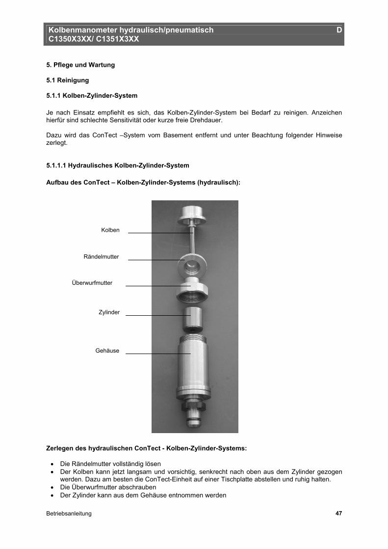
Kolbenmanometer hydraulisch/pneumatisch D C1350X3XX/ C1351X3XX
Betriebsanleitung 47
5. Pflege und Wartung
5.1 Reinigung
5.1.1 Kolben-Zylinder-System Je nach Einsatz empfiehlt es sich, das Kolben-Zylinder-System bei Bedarf zu reinigen. Anzeichen hierfür sind schlechte Sensitivität oder kurze freie Drehdauer. Dazu wird das ConTect –System vom Basement entfernt und unter Beachtung folgender Hinweise zerlegt.
5.1.1.1 Hydraulisches Kolben-Zylinder-System Aufbau des ConTect – Kolben-Zylinder-Systems (hydraulisch): Zerlegen des hydraulischen ConTect - Kolben-Zylinder-Systems:
• Die Rändelmutter vollständig lösen • Der Kolben kann jetzt langsam und vorsichtig, senkrecht nach oben aus dem Zylinder gezogen
werden. Dazu am besten die ConTect-Einheit auf einer Tischplatte abstellen und ruhig halten. • Die Überwurfmutter abschrauben • Der Zylinder kann aus dem Gehäuse entnommen werden
Kolben
Rändelmutter
Überwurfmutter
Zylinder
Gehäuse
Kolbenmanometer hydraulisch/pneumatisch D C1350X3XX/ C1351X3XX
Betriebsanleitung 48
Reinigen des hydraulischen ConTect - Kolben-Zylinder-Systems: Zur Reinigung der Einzelteile gibt es verschiedene Möglichkeiten. Die Empfehlung ist, die Teile mit einem mit Alkohol (z.B. Spiritus) getränkten, staubfreien, fusselfreien und weichen Tuch abzuwischen bzw. durch den Zylinder durchzuziehen. Danach mit einem trockenen, staubfreien, fusselfreien und weichen Tuch gut abtrocknen. Der gereinigte Kolben darf niemals mit bloßen Händen berührt werden. Das natürliche Hautfett kann zum Verkleben des Kolben-Zylinder-Systems führen. Zusammenbau des hydraulischen ConTect - Kolben-Zylinder-Systems: Die Teile in umgekehrter Reihenfolge wieder zusammensetzen.
• Den Zylinder in das Gehäuse stecken (schräge Kante nach unten) • Die Überwurfmutter aufschrauben • Das System senkrecht auf die Tischplatte stellen und den Kolben vorsichtig von oben einführen.
Er sollte aufgrund seines Eigengewichtes in den Zylinder „fallen“ • Die Rändelmutter wieder anziehen
Der Kolben darf niemals gewaltsam in den Zylinder gedrückt werden, da er sonst beschädigt wird. Das System ist wieder einsatzbereit.
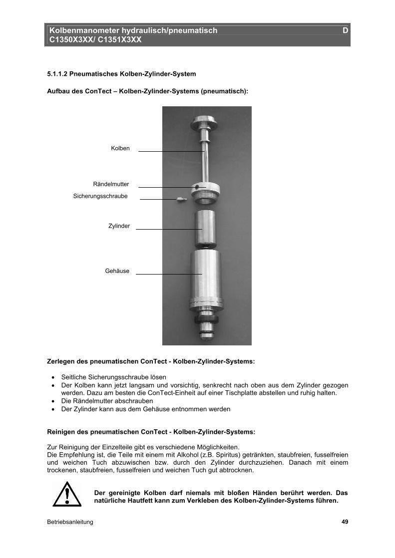
Kolbenmanometer hydraulisch/pneumatisch D C1350X3XX/ C1351X3XX
Betriebsanleitung 49
5.1.1.2 Pneumatisches Kolben-Zylinder-System Aufbau des ConTect – Kolben-Zylinder-Systems (pneumatisch): Zerlegen des pneumatischen ConTect - Kolben-Zylinder-Systems:
• Seitliche Sicherungsschraube lösen • Der Kolben kann jetzt langsam und vorsichtig, senkrecht nach oben aus dem Zylinder gezogen
werden. Dazu am besten die ConTect-Einheit auf einer Tischplatte abstellen und ruhig halten. • Die Rändelmutter abschrauben • Der Zylinder kann aus dem Gehäuse entnommen werden
Reinigen des pneumatischen ConTect - Kolben-Zylinder-Systems: Zur Reinigung der Einzelteile gibt es verschiedene Möglichkeiten. Die Empfehlung ist, die Teile mit einem mit Alkohol (z.B. Spiritus) getränkten, staubfreien, fusselfreien und weichen Tuch abzuwischen bzw. durch den Zylinder durchzuziehen. Danach mit einem trockenen, staubfreien, fusselfreien und weichen Tuch gut abtrocknen.
Der gereinigte Kolben darf niemals mit bloßen Händen berührt werden. Das natürliche Hautfett kann zum Verkleben des Kolben-Zylinder-Systems führen.
Kolben
Rändelmutter
Sicherungsschraube
Zylinder
Gehäuse
Kolbenmanometer hydraulisch/pneumatisch D C1350X3XX/ C1351X3XX
Betriebsanleitung 50
Zusammenbau des pneumatischen ConTect - Kolben-Zylinder-Systems: Die Teile in umgekehrter Reihenfolge wieder zusammensetzen.
• Den Zylinder in das Gehäuse stecken (schräge Kante nach unten) • Die Rändelmutter aufschrauben • Das System senkrecht auf die Tischplatte stellen und den Kolben vorsichtig von oben einführen.
Er sollte aufgrund seines Eigengewichtes in den Zylinder „fallen“ • Seitliche Sicherungsschraube wieder einschrauben
Der Kolben darf niemals gewaltsam in den Zylinder gedrückt werden, da er sonst beschädigt wird. Das System ist wieder einsatzbereit.
5.1.2 Massensatz
• Die Massen sollten nur mit Handschuhen angefasst werden. • Sind trotzdem Fingerabdrücke oder andere Verschmutzungen an den Masseauflagen, können
diese mit reinem Alkohol (Spiritus) entfernt werden. 5.2 Verschleißteile O-Ringe in Aufnahme ConTect-System und Prüflingaufnahme unterliegen einem Verschleiß. Beide O-Ringe sind vor jeder Kalibrierung auf korrekten Sitz und Verschleiß zu prüfen. Die O-Ringe sind ggf. in regelmäßigen Zeitabständen oder bei Bedarf auszutauschen (siehe Zubehör Pkt. 8).
Wichtig: Es dürfen nur Original-Dichtungen verwendet werden. Dichtungen abweichender Maße oder Werkstoffe bzw. Materialhärten können zu Beschädigungen am Gerät und am Prüfling führen und stellen eine Gefahr für den Bediener dar.
5.3 Austausch des Hydrauliköls (nur bei Hydraulikausführung) Das Hydrauliköl sollte bei sichtbarer Verunreinigung ausgetauscht werden.
5.3.1 Hydrauliköl entfernen
• Verschlussschraube mit Öleinfüllsymbol auf Basement-Oberseite öffnen • Öl aus Tank z.B. mit einer geeigneten Spritze absaugen • Kleine Restölmengen können bei geöffneter Aufnahme für ConTect-System und
Prüflinganschluss und geschlossenem Auslassventil durch langsames Eindrehen der Spindelpumpe zusätzlich an den Anschlüssen abgesaugt werden
• Geringe Restölmengen können im Rohrleitungssystem zurückbleiben
Bei starker Verschmutzung des Hydrauliköls ist ggf. eine Komplettreinigung der Verrohrung und aller medienberührten Einzelkomponenten des Basements im demontierten Zustand zu empfehlen. Dieser Eingriff darf nur vom Hersteller durchgeführt werden.
Die Altölentsorgung muss gemäß den gesetzlichen Bestimmungen erfolgen.
Kolbenmanometer hydraulisch/pneumatisch D C1350X3XX/ C1351X3XX
Betriebsanleitung 51
5.3.2 Hydrauliköl einfüllen
• Spindelpumpe im Uhrzeigersinn bis zum vorderen Anschlag eindrehen • Auslassventil schließen • Verschlussschraube mit Öleinfüllsymbol auf Basementoberseite öffnen • Spezialöl (1 Liter im Lieferumfang enthalten bzw. als Zubehör erhältlich) über die Tanköffnung
einfüllen bis der Füllstand das Gewinde der Tanköffnung erreicht (ca. 250 ml). Die Füllhöhe ist hierbei stets zu beobachten.
• Spindelpumpe gegen den Uhrzeigersinn bis zum hinteren Anschlag herausdrehen. Das Füllmedium wird vom Tank in das System gesaugt.
• Tanköffnung mit Verschlussschraube schließen
5.3.3 Entlüftung des Systems (nur nach Komplettbefüllung) Nach der Erstbefüllung oder nach einem kompletten Austausch des Öls können sich Lufteinschlüsse im System befinden. Das System sollte durch folgende Vorgehensweise entlüftet werden:
• Anschluss ConTect-System und Prüflinganschluss müssen offen sein • Auslassventil schließen • Spindelpumpe gegen den Uhrzeigersinn bis zum hinteren Anschlag herausdrehen • Mit Vordruckpumpe vorsichtig pumpen und dabei das Füllmedium in den offenen Anschlüssen
ConTect-System und Prüfling beobachten. Hier tritt die eingeschlossene Luft durch Blasenbildung nach außen. Die Vordruckpumpe ist so lange zu betätigen bis keine Luftblasen mehr auftauchen.
• Austretendes Öl in den offenen Anschlüssen ConTect-System und Prüfling mit z.B. einer Spritze absaugen.
Kolbenmanometer hydraulisch/pneumatisch D C1350X3XX/ C1351X3XX
Betriebsanleitung 52
5.4 Rekalibrierung Die empfohlene Rekalibrierungsdauer beträgt: 5 Jahre Hierbei handelt es sich um eine Empfehlung des Deutschen Kalibrierdienstes (DKD). Voraussetzung für dieses Intervall ist ein sorgsamer Umgang mit System und Massen. Sollten diese, bedingt durch rauhen Einsatz, Verschmutzungen oder Beschädigungen aufweisen, empfiehlt sich eine Verkürzung des Intervalls auf ca. drei Jahre. Das Kolbenmanometer sollte sofort überholt und neu kalibriert werden, wenn:
• Die Laufeigenschaften des Kolbens sich verschlechtern (Drehdauer, Sinkrate, Sensitivität) • Die Gewichte beschädigt sind oder korrodieren
Zur Rekalibrierung oder bei Fragen hinsichtlich des optimalen Rekalibrierungszyklus steht das DKD-Labor gerne zur Verfügung: tecsis GmbH Carl-Legien-Str. 40 63073 Offenbach / Germany Tel.: +49 69 5806-0 Fax national: +49 69 5806-170 Fax international: +49 69 5806-177 e-Mail: [email protected] www.tecsis.de
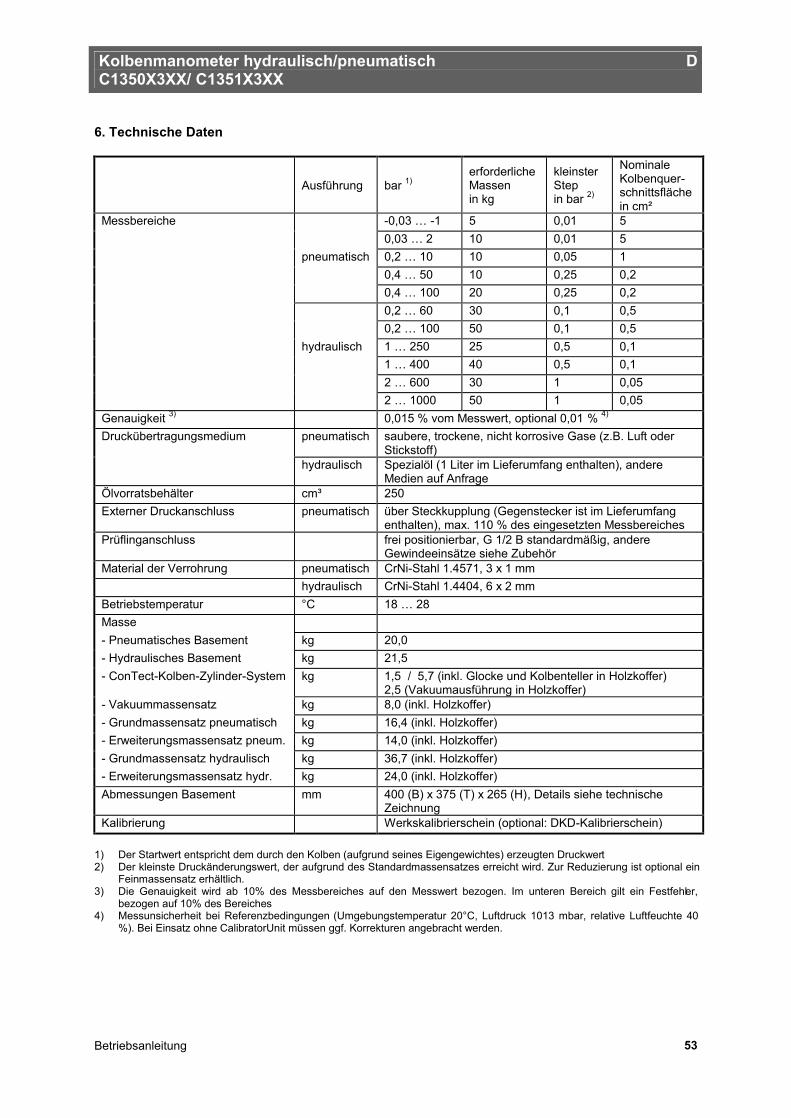
Kolbenmanometer hydraulisch/pneumatisch D C1350X3XX/ C1351X3XX
Betriebsanleitung 53
6. Technische Daten
Ausführung bar 1) erforderliche Massen in kg
kleinster Step in bar 2)
Nominale Kolbenquer-schnittsfläche in cm²
Messbereiche -0,03 … -1 5 0,01 5 0,03 … 2 10 0,01 5 pneumatisch 0,2 … 10 10 0,05 1 0,4 … 50 10 0,25 0,2 0,4 … 100 20 0,25 0,2 0,2 … 60 30 0,1 0,5 0,2 … 100 50 0,1 0,5 hydraulisch 1 … 250 25 0,5 0,1 1 … 400 40 0,5 0,1 2 … 600 30 1 0,05 2 … 1000 50 1 0,05 Genauigkeit 3) 0,015 % vom Messwert, optional 0,01 % 4) Druckübertragungsmedium pneumatisch saubere, trockene, nicht korrosive Gase (z.B. Luft oder
Stickstoff) hydraulisch Spezialöl (1 Liter im Lieferumfang enthalten), andere
Medien auf Anfrage Ölvorratsbehälter cm³ 250 Externer Druckanschluss pneumatisch über Steckkupplung (Gegenstecker ist im Lieferumfang
enthalten), max. 110 % des eingesetzten Messbereiches Prüflinganschluss frei positionierbar, G 1/2 B standardmäßig, andere
Gewindeeinsätze siehe Zubehör Material der Verrohrung pneumatisch CrNi-Stahl 1.4571, 3 x 1 mm hydraulisch CrNi-Stahl 1.4404, 6 x 2 mm Betriebstemperatur °C 18 … 28 Masse - Pneumatisches Basement kg 20,0 - Hydraulisches Basement kg 21,5 - ConTect-Kolben-Zylinder-System kg 1,5 / 5,7 (inkl. Glocke und Kolbenteller in Holzkoffer)
2,5 (Vakuumausführung in Holzkoffer) - Vakuummassensatz kg 8,0 (inkl. Holzkoffer) - Grundmassensatz pneumatisch kg 16,4 (inkl. Holzkoffer) - Erweiterungsmassensatz pneum. kg 14,0 (inkl. Holzkoffer) - Grundmassensatz hydraulisch kg 36,7 (inkl. Holzkoffer) - Erweiterungsmassensatz hydr. kg 24,0 (inkl. Holzkoffer) Abmessungen Basement mm 400 (B) x 375 (T) x 265 (H), Details siehe technische
Zeichnung Kalibrierung Werkskalibrierschein (optional: DKD-Kalibrierschein)
1) Der Startwert entspricht dem durch den Kolben (aufgrund seines Eigengewichtes) erzeugten Druckwert 2) Der kleinste Druckänderungswert, der aufgrund des Standardmassensatzes erreicht wird. Zur Reduzierung ist optional ein
Feinmassensatz erhältlich. 3) Die Genauigkeit wird ab 10% des Messbereiches auf den Messwert bezogen. Im unteren Bereich gilt ein Festfehler,
bezogen auf 10% des Bereiches 4) Messunsicherheit bei Referenzbedingungen (Umgebungstemperatur 20°C, Luftdruck 1013 mbar, relative Luftfeuchte 40
%). Bei Einsatz ohne CalibratorUnit müssen ggf. Korrekturen angebracht werden.
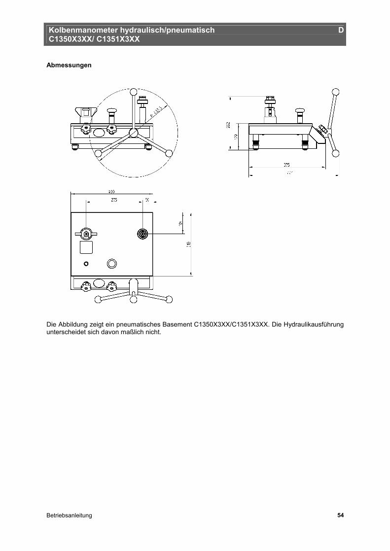
Kolbenmanometer hydraulisch/pneumatisch D C1350X3XX/ C1351X3XX
Betriebsanleitung 54
Abmessungen Die Abbildung zeigt ein pneumatisches Basement C1350X3XX/C1351X3XX. Die Hydraulikausführung unterscheidet sich davon maßlich nicht.
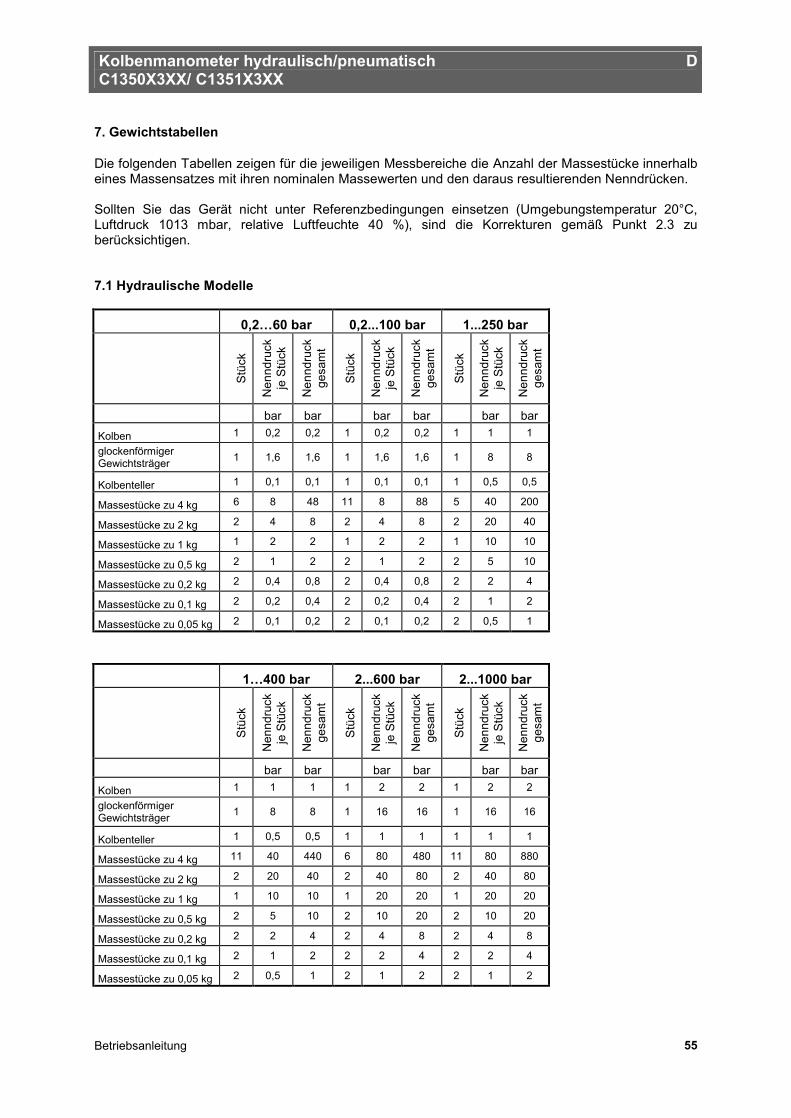
Kolbenmanometer hydraulisch/pneumatisch D C1350X3XX/ C1351X3XX
Betriebsanleitung 55
7. Gewichtstabellen
Die folgenden Tabellen zeigen für die jeweiligen Messbereiche die Anzahl der Massestücke innerhalb eines Massensatzes mit ihren nominalen Massewerten und den daraus resultierenden Nenndrücken. Sollten Sie das Gerät nicht unter Referenzbedingungen einsetzen (Umgebungstemperatur 20°C, Luftdruck 1013 mbar, relative Luftfeuchte 40 %), sind die Korrekturen gemäß Punkt 2.3 zu berücksichtigen. 7.1 Hydraulische Modelle
0,2…60 bar 0,2...100 bar 1...250 bar
Stü
ck
Nen
ndru
ck
je S
tück
Nen
ndru
ck
gesa
mt
Stü
ck
Nen
ndru
ck
je S
tück
Nen
ndru
ck
gesa
mt
Stü
ck
Nen
ndru
ck
je S
tück
Nen
ndru
ck
gesa
mt
bar bar bar bar bar bar
Kolben 1 0,2 0,2 1 0,2 0,2 1 1 1
glockenförmiger Gewichtsträger 1 1,6 1,6 1 1,6 1,6 1 8 8
Kolbenteller 1 0,1 0,1 1 0,1 0,1 1 0,5 0,5
Massestücke zu 4 kg 6 8 48 11 8 88 5 40 200
Massestücke zu 2 kg 2 4 8 2 4 8 2 20 40
Massestücke zu 1 kg 1 2 2 1 2 2 1 10 10
Massestücke zu 0,5 kg 2 1 2 2 1 2 2 5 10
Massestücke zu 0,2 kg 2 0,4 0,8 2 0,4 0,8 2 2 4
Massestücke zu 0,1 kg 2 0,2 0,4 2 0,2 0,4 2 1 2
Massestücke zu 0,05 kg 2 0,1 0,2 2 0,1 0,2 2 0,5 1
1…400 bar 2...600 bar 2...1000 bar
Stü
ck
Nen
ndru
ck
je S
tück
Nen
ndru
ck
gesa
mt
Stü
ck
Nen
ndru
ck
je S
tück
Nen
ndru
ck
gesa
mt
Stü
ck
Nen
ndru
ck
je S
tück
Nen
ndru
ck
gesa
mt
bar bar bar bar bar bar
Kolben 1 1 1 1 2 2 1 2 2
glockenförmiger Gewichtsträger 1 8 8 1 16 16 1 16 16
Kolbenteller 1 0,5 0,5 1 1 1 1 1 1
Massestücke zu 4 kg 11 40 440 6 80 480 11 80 880
Massestücke zu 2 kg 2 20 40 2 40 80 2 40 80
Massestücke zu 1 kg 1 10 10 1 20 20 1 20 20
Massestücke zu 0,5 kg 2 5 10 2 10 20 2 10 20
Massestücke zu 0,2 kg 2 2 4 2 4 8 2 4 8
Massestücke zu 0,1 kg 2 1 2 2 2 4 2 2 4
Massestücke zu 0,05 kg 2 0,5 1 2 1 2 2 1 2
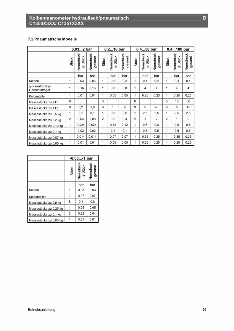
Kolbenmanometer hydraulisch/pneumatisch D C1350X3XX/ C1351X3XX
Betriebsanleitung 56
7.2 Pneumatische Modelle 0,03...2 bar 0,2...10 bar 0,4...50 bar 0,4...100 bar
S
tück
Nen
ndru
ck
je S
tück
Nen
ndru
ck
gesa
mt
Stü
ck
Nen
ndru
ck
je S
tück
Nen
ndru
ck
gesa
mt
Stü
ck
Nen
ndru
ck
je S
tück
Nen
ndru
ck
gesa
mt
Stü
ck
Nen
ndru
ck
je S
tück
Nen
ndru
ck
gesa
mt
bar bar bar bar bar bar bar bar Kolben 1 0,03 0,03 1 0,2 0,2 1 0,4 0,4 1 0,4 0,4
glockenförmiger Gewichtsträger 1 0,16 0,16 1 0,8 0,8 1 4 4 1 4 4
Kolbenteller 1 0,01 0,01 1 0,05 0,05 1 0,25 0,25 1 0,25 0,25
Massestücke zu 2 kg 0 0 0 5 10 50
Massestücke zu 1 kg 9 0,2 1,8 9 1 9 9 5 45 9 5 45
Massestücke zu 0,5 kg 1 0,1 0,1 1 0,5 0,5 1 2,5 2,5 1 2,5 2,5
Massestücke zu 0,2 kg 2 0,04 0,08 2 0,2 0,4 2 1 2 2 1 2
Massestücke zu 0,12 kg 1 0,024 0,024 1 0,12 0,12 1 0,6 0,6 1 0,6 0,6
Massestücke zu 0,1 kg 1 0,02 0,02 1 0,1 0,1 1 0,5 0,5 1 0,5 0,5
Massestücke zu 0,07 kg 1 0,014 0,014 1 0,07 0,07 1 0,35 0,35 1 0,35 0,35
Massestücke zu 0,05 kg 1 0,01 0,01 1 0,05 0,05 1 0,25 0,25 1 0,25 0,25
-0,03...-1 bar
Stü
ck
Nen
ndru
ck
je S
tück
Nen
ndru
ck
gesa
mt
bar bar Kolben 1 0,03 0,03
Kolbenteller 1 0,07 0,07
Massestücke zu 0,5 kg 8 0,1 0,8
Massestücke zu 0,25 kg 1 0,05 0,05
Massestücke zu 0,1 kg 2 0,02 0,04
Massestücke zu 0,05 kg 1 0,01 0,01
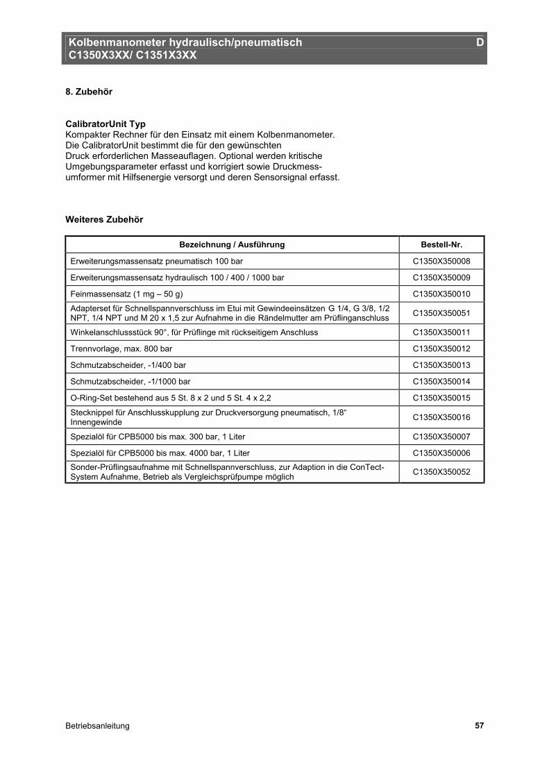
Kolbenmanometer hydraulisch/pneumatisch D C1350X3XX/ C1351X3XX
Betriebsanleitung 57
8. Zubehör
CalibratorUnit Typ Kompakter Rechner für den Einsatz mit einem Kolbenmanometer. Die CalibratorUnit bestimmt die für den gewünschten Druck erforderlichen Masseauflagen. Optional werden kritische Umgebungsparameter erfasst und korrigiert sowie Druckmess- umformer mit Hilfsenergie versorgt und deren Sensorsignal erfasst. Weiteres Zubehör
Bezeichnung / Ausführung Bestell-Nr.
Erweiterungsmassensatz pneumatisch 100 bar C1350X350008
Erweiterungsmassensatz hydraulisch 100 / 400 / 1000 bar C1350X350009
Feinmassensatz (1 mg – 50 g) C1350X350010
Adapterset für Schnellspannverschluss im Etui mit Gewindeeinsätzen G 1/4, G 3/8, 1/2 NPT, 1/4 NPT und M 20 x 1,5 zur Aufnahme in die Rändelmutter am Prüflinganschluss C1350X350051
Winkelanschlussstück 90°, für Prüflinge mit rückseitigem Anschluss C1350X350011
Trennvorlage, max. 800 bar C1350X350012
Schmutzabscheider, -1/400 bar C1350X350013
Schmutzabscheider, -1/1000 bar C1350X350014
O-Ring-Set bestehend aus 5 St. 8 x 2 und 5 St. 4 x 2,2 C1350X350015
Stecknippel für Anschlusskupplung zur Druckversorgung pneumatisch, 1/8“ Innengewinde C1350X350016
Spezialöl für CPB5000 bis max. 300 bar, 1 Liter C1350X350007
Spezialöl für CPB5000 bis max. 4000 bar, 1 Liter C1350X350006
Sonder-Prüflingsaufnahme mit Schnellspannverschluss, zur Adaption in die ConTect-System Aufnahme, Betrieb als Vergleichsprüfpumpe möglich C1350X350052

Kolbenmanometer hydraulisch/pneumatisch D C1350X3XX/ C1351X3XX
Betriebsanleitung 58

Kolbenmanometer hydraulisch/pneumatisch D C1350X3XX/ C1351X3XX
Betriebsanleitung 59

Kolbenmanometer hydraulisch/pneumatisch D C1350X3XX/ C1351X3XX
Betriebsanleitung 60
tecsis GmbH Carl-Legien-Str. 40 63073 Offenbach / Germany Tel.: +49 69 5806-0 Fax national: +49 69 5806-170 Fax international: +49 69 5806-177 e-Mail: [email protected] www.tecsis.de