Embed Size (px)
Citation preview
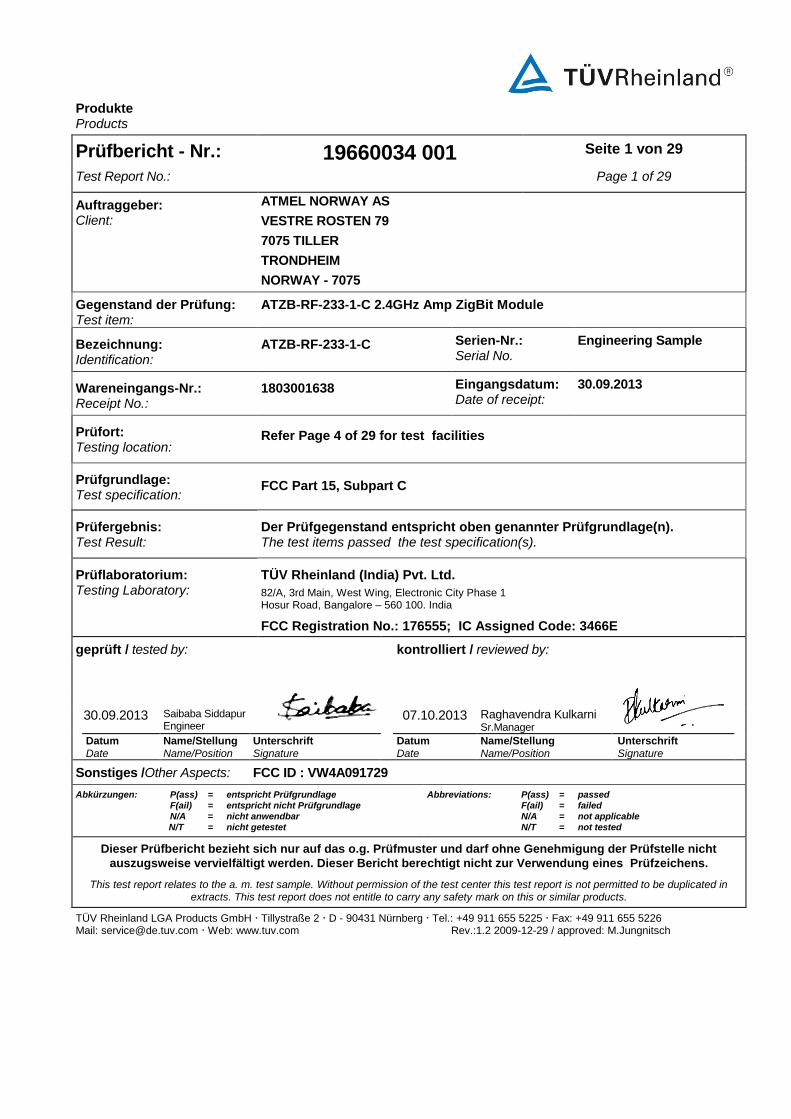
Produkte Products
TÜV Rheinland LGA Products GmbH Tillystraße 2 D - 90431 Nürnberg Tel.: +49 911 655 5225 Fax: +49 911 655 5226 Mail: [email protected] Web: www.tuv.com Rev.:1.2 2009-12-29 / approved: M.Jungnitsch
Prüfbericht - Nr.: 19660034 001 Seite 1 von 29
Test Report No.: Page 1 of 29
Auftraggeber: Client:
ATMEL NORWAY AS
VESTRE ROSTEN 79
7075 TILLER TRONDHEIM
NORWAY - 7075
Gegenstand der Prüfung: Test item:
ATZB-RF-233-1-C 2.4GHz Amp ZigBit Module
Bezeichnung: Identification:
ATZB-RF-233-1-C Serien-Nr.: Serial No.
Engineering Sample
Wareneingangs-Nr.: Receipt No.:
1803001638 Eingangsdatum: Date of receipt:
30.09.2013
Prüfort: Testing location:
Refer Page 4 of 29 for test facilities
Prüfgrundlage: Test specification:
FCC Part 15, Subpart C
Prüfergebnis: Test Result:
Der Prüfgegenstand entspricht oben genannter Prüfgrundlage(n). The test items passed the test specification(s).
Prüflaboratorium: Testing Laboratory:
TÜV Rheinland (India) Pvt. Ltd.
82/A, 3rd Main, West Wing, Electronic City Phase 1 Hosur Road, Bangalore – 560 100. India
FCC Registration No.: 176555; IC Assigned Code: 3466E
geprüft / tested by: kontrolliert / reviewed by:
30.09.2013 Saibaba Siddapur Engineer
07.10.2013 Raghavendra Kulkarni Sr.Manager
Datum
Date
Name/Stellung
Name/Position
Unterschrift
Signature
Datum
Date
Name/Stellung
Name/Position
Unterschrift
Signature
Sonstiges /Other Aspects: FCC ID : VW4A091729
Abkürzungen: P(ass) = entspricht Prüfgrundlage F(ail) = entspricht nicht Prüfgrundlage N/A = nicht anwendbar
N/T = nicht getestet
Abbreviations: P(ass) = passed F(ail) = failed N/A = not applicable
N/T = not tested
Dieser Prüfbericht bezieht sich nur auf das o.g. Prüfmuster und darf ohne Genehmigung der Prüfstelle nicht
auszugsweise vervielfältigt werden. Dieser Bericht berechtigt nicht zur Verwendung eines Prüfzeichens.
This test report relates to the a. m. test sample. Without permission of the test center this test report is not permitted to be duplicated in extracts. This test report does not entitle to carry any safety mark on this or similar products.
www.tuv.com
Test Report No.: 19660034 001 Date: 30.09.2013 Page 2 of 29
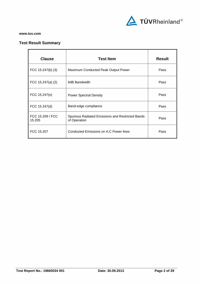
Test Result Summary
Clause Test Item Result
FCC 15.247(b) (3) Maximum Conducted Peak Output Power Pass
FCC 15.247(a) (2) 6dB Bandwidth Pass
FCC 15.247(e) Power Spectral Density Pass
FCC 15.247(d) Band-edge compliance Pass
FCC 15.209 / FCC 15.205
Spurious Radiated Emissions and Restricted Bands of Operation
Pass
FCC 15.207 Conducted Emissions on A.C Power lines Pass
www.tuv.com
Test Report No.: 19660034 001 Date: 30.09.2013 Page 3 of 29
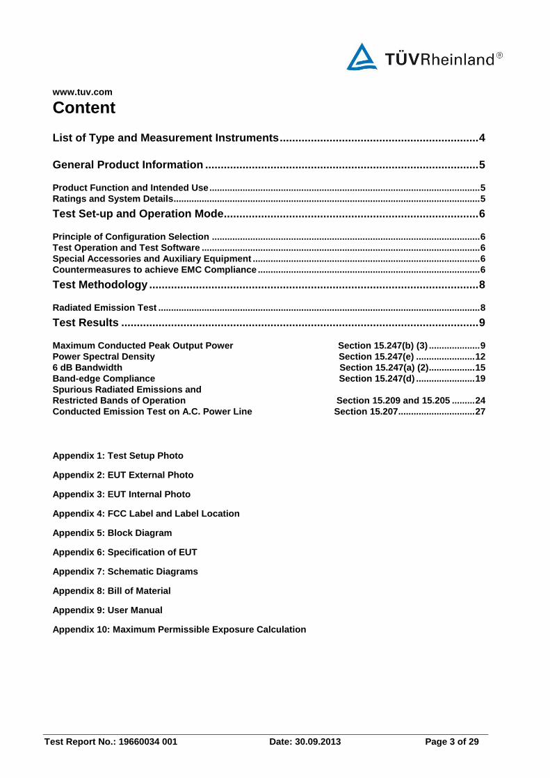
Content
List of Type and Measurement Instruments ................................................................ 4
General Product Information ........................................................................................ 5
Product Function and Intended Use .......................................................................................................... 5 Ratings and System Details ........................................................................................................................ 5
Test Set-up and Operation Mode .................................................................................. 6
Principle of Configuration Selection ......................................................................................................... 6 Test Operation and Test Software ............................................................................................................. 6 Special Accessories and Auxiliary Equipment ......................................................................................... 6 Countermeasures to achieve EMC Compliance ....................................................................................... 6
Test Methodology .......................................................................................................... 8
Radiated Emission Test .............................................................................................................................. 8
Test Results ................................................................................................................... 9
Maximum Conducted Peak Output Power Section 15.247(b) (3) .................... 9 Power Spectral Density Section 15.247(e) ....................... 12 6 dB Bandwidth Section 15.247(a) (2) .................. 15 Band-edge Compliance Section 15.247(d) ....................... 19 Spurious Radiated Emissions and Restricted Bands of Operation Section 15.209 and 15.205 ......... 24 Conducted Emission Test on A.C. Power Line Section 15.207 .............................. 27
Appendix 1: Test Setup Photo
Appendix 2: EUT External Photo
Appendix 3: EUT Internal Photo
Appendix 4: FCC Label and Label Location
Appendix 5: Block Diagram
Appendix 6: Specification of EUT
Appendix 7: Schematic Diagrams
Appendix 8: Bill of Material
Appendix 9: User Manual
Appendix 10: Maximum Permissible Exposure Calculation
www.tuv.com
Test Report No.: 19660034 001 Date: 30.09.2013 Page 4 of 29
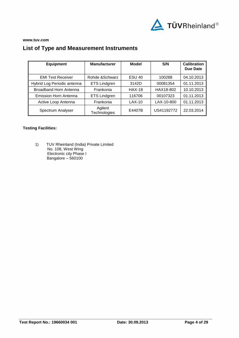
List of Type and Measurement Instruments
Equipment Manufacturer Model S/N Calibration
Due Date
EMI Test Receiver Rohde &Schwarz ESU 40 100288 04.10.2013
Hybrid Log Periodic antenna ETS Lindgren 3142D 00081354 01.11.2013
Broadband Horn Antenna Frankonia HAX-18 HAX18-802 10.10.2013
Emission Horn Antenna ETS Lindgren 116706 00107323 01.11.2013
Active Loop Antenna Frankonia LAX-10 LAX-10-800 01.11.2013
Spectrum Analyser Agilent
Technologies E4407B US41192772 22.03.2014
Testing Facilities:
1) TUV Rheinland (India) Private Limited No. 108, West Wing Electronic city Phase I
Bangalore – 560100
www.tuv.com
Test Report No.: 19660034 001 Date: 30.09.2013 Page 5 of 29
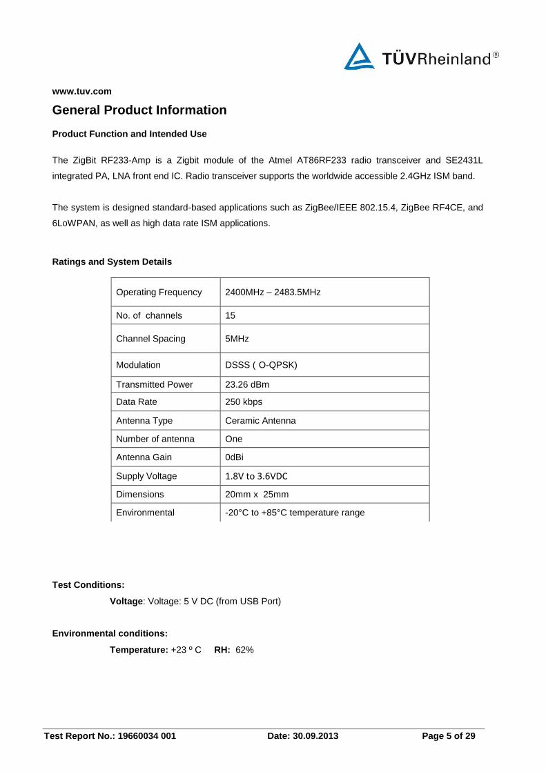
General Product Information
Product Function and Intended Use
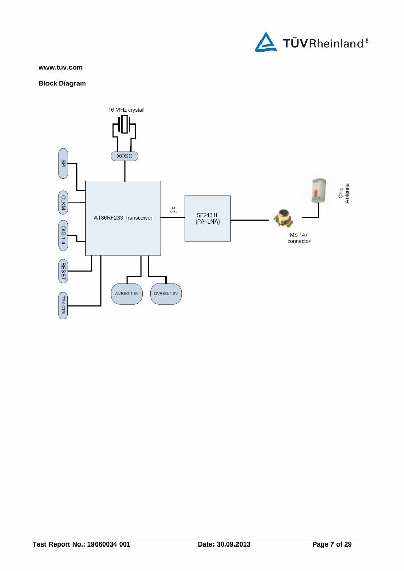
The ZigBit RF233-Amp is a Zigbit module of the Atmel AT86RF233 radio transceiver and SE2431L
integrated PA, LNA front end IC. Radio transceiver supports the worldwide accessible 2.4GHz ISM band.
The system is designed standard-based applications such as ZigBee/IEEE 802.15.4, ZigBee RF4CE, and
6LoWPAN, as well as high data rate ISM applications.
Ratings and System Details
Test Conditions:
Voltage: Voltage: 5 V DC (from USB Port)
Environmental conditions:
Temperature: +23 º C RH: 62%
Operating Frequency 2400MHz – 2483.5MHz
No. of channels 15
Channel Spacing 5MHz
Modulation DSSS ( O-QPSK)
Transmitted Power 23.26 dBm
Data Rate 250 kbps
Antenna Type Ceramic Antenna
Number of antenna One
Antenna Gain 0dBi
Supply Voltage 1.8V to 3.6VDC
Dimensions 20mm x 25mm
Environmental -20°C to +85°C temperature range
www.tuv.com
Test Report No.: 19660034 001 Date: 30.09.2013 Page 6 of 29
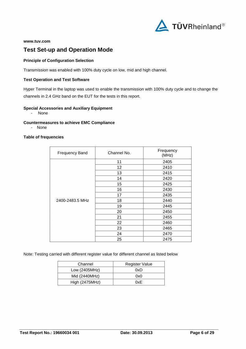
Test Set-up and Operation Mode
Principle of Configuration Selection Transmission was enabled with 100% duty cycle on low, mid and high channel.
Test Operation and Test Software Hyper Terminal in the laptop was used to enable the transmission with 100% duty cycle and to change the
channels in 2.4 GHz band on the EUT for the tests in this report.
Special Accessories and Auxiliary Equipment - None
Countermeasures to achieve EMC Compliance - None
Table of frequencies
Frequency Band Channel No. Frequency
(MHz)
2400-2483.5 MHz
11 2405
12 2410
13 2415
14 2420
15 2425
16 2430
17 2435
18 2440
19 2445
20 2450
21 2455
22 2460
23 2465
24 2470
25 2475
Note: Testing carried with different register value for different channel as listed below
Channel Register Value
Low (2405MHz) 0xD
Mid (2440MHz) 0x0
High (2475MHz) 0xE
www.tuv.com
Test Report No.: 19660034 001 Date: 30.09.2013 Page 7 of 29
Block Diagram
www.tuv.com
Test Report No.: 19660034 001 Date: 30.09.2013 Page 8 of 29
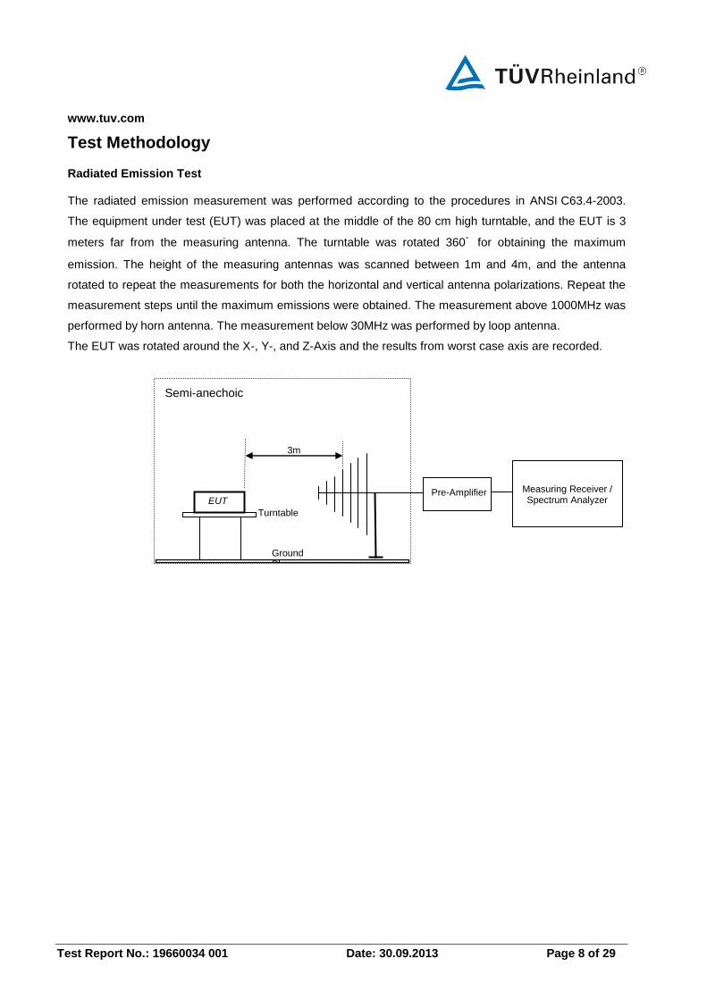
Test Methodology
Radiated Emission Test The radiated emission measurement was performed according to the procedures in ANSI C63.4-2003.
The equipment under test (EUT) was placed at the middle of the 80 cm high turntable, and the EUT is 3
meters far from the measuring antenna. The turntable was rotated 360゚ for obtaining the maximum
emission. The height of the measuring antennas was scanned between 1m and 4m, and the antenna
rotated to repeat the measurements for both the horizontal and vertical antenna polarizations. Repeat the
measurement steps until the maximum emissions were obtained. The measurement above 1000MHz was
performed by horn antenna. The measurement below 30MHz was performed by loop antenna.
The EUT was rotated around the X-, Y-, and Z-Axis and the results from worst case axis are recorded.
EUT
3m
Pre-Amplifier Measuring Receiver / Spectrum Analyzer
Turntable
Ground Plane
Semi-anechoic Chamber
www.tuv.com
Test Report No.: 19660034 001 Date: 30.09.2013 Page 9 of 29
Test Results
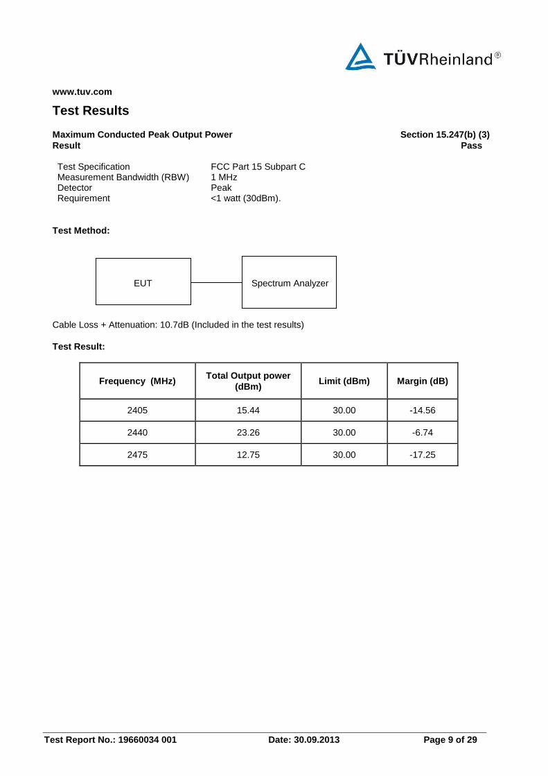
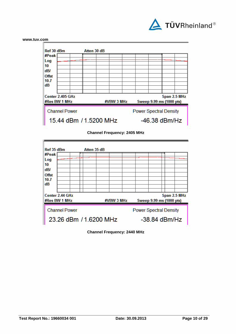
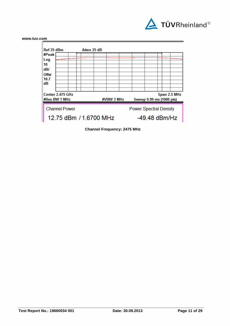
Maximum Conducted Peak Output Power Section 15.247(b) (3)
Result Pass Test Specification FCC Part 15 Subpart C Measurement Bandwidth (RBW) 1 MHz Detector Peak Requirement <1 watt (30dBm).
Test Method: EUT Spectrum Analyzer
Cable Loss + Attenuation: 10.7dB (Included in the test results)
Test Result:
Frequency (MHz) Total Output power
(dBm) Limit (dBm) Margin (dB)
2405 15.44 30.00 -14.56
2440 23.26 30.00 -6.74
2475 12.75 30.00 -17.25
www.tuv.com
Test Report No.: 19660034 001 Date: 30.09.2013 Page 10 of 29
Channel Frequency: 2405 MHz
Channel Frequency: 2440 MHz
www.tuv.com
Test Report No.: 19660034 001 Date: 30.09.2013 Page 11 of 29
Channel Frequency: 2475 MHz
www.tuv.com
Test Report No.: 19660034 001 Date: 30.09.2013 Page 12 of 29
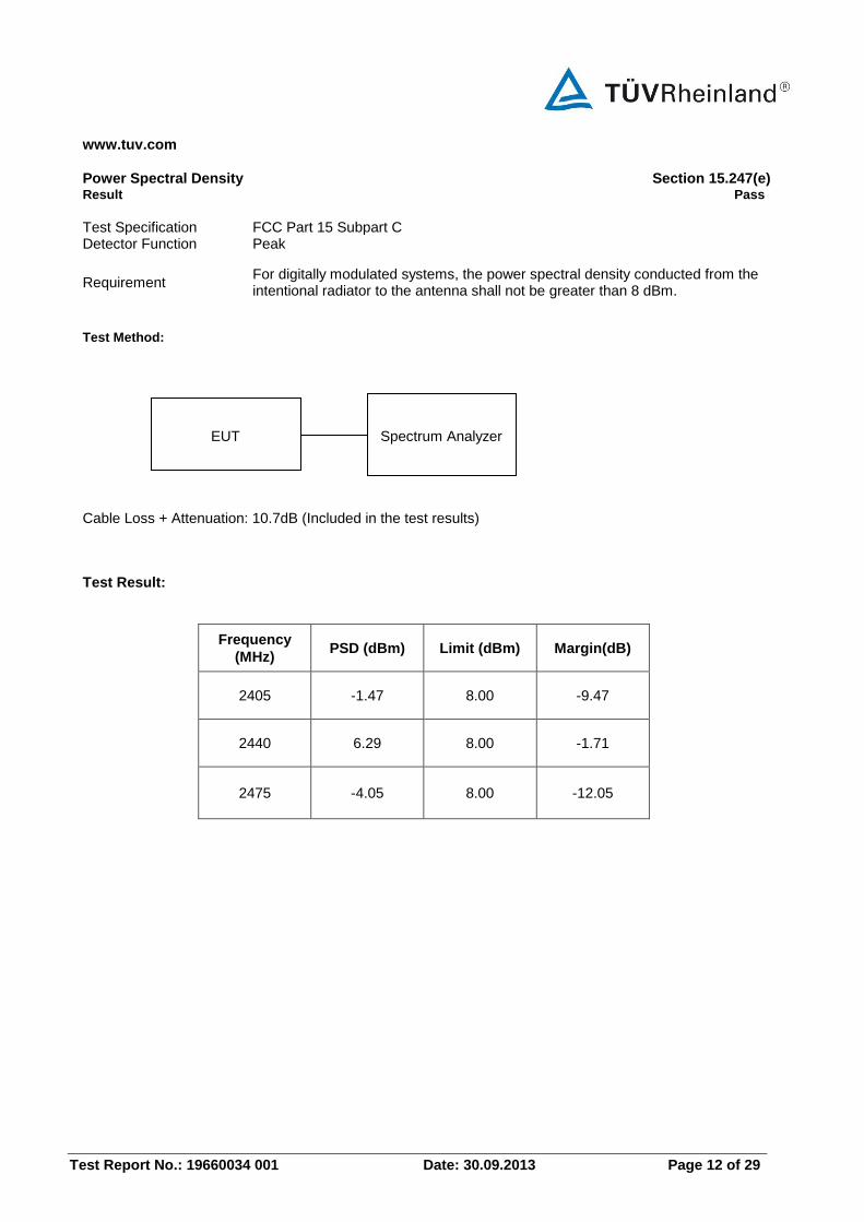
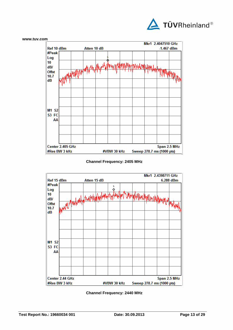
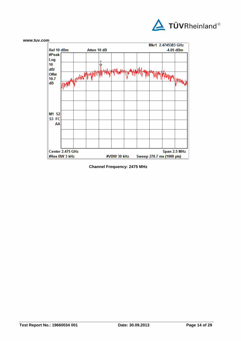
Power Spectral Density Section 15.247(e) Result Pass
Test Specification FCC Part 15 Subpart C Detector Function Peak
Requirement For digitally modulated systems, the power spectral density conducted from the intentional radiator to the antenna shall not be greater than 8 dBm.
Test Method:
EUT Spectrum Analyzer
Cable Loss + Attenuation: 10.7dB (Included in the test results)
Test Result:
Frequency
(MHz) PSD (dBm) Limit (dBm) Margin(dB)
2405 -1.47 8.00 -9.47
2440 6.29 8.00 -1.71
2475 -4.05 8.00 -12.05
www.tuv.com
Test Report No.: 19660034 001 Date: 30.09.2013 Page 13 of 29
Channel Frequency: 2405 MHz
Channel Frequency: 2440 MHz
www.tuv.com
Test Report No.: 19660034 001 Date: 30.09.2013 Page 14 of 29
Channel Frequency: 2475 MHz
www.tuv.com
Test Report No.: 19660034 001 Date: 30.09.2013 Page 15 of 29
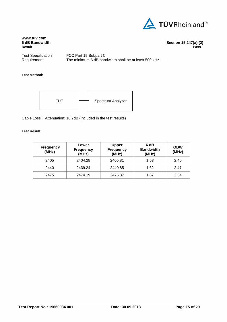
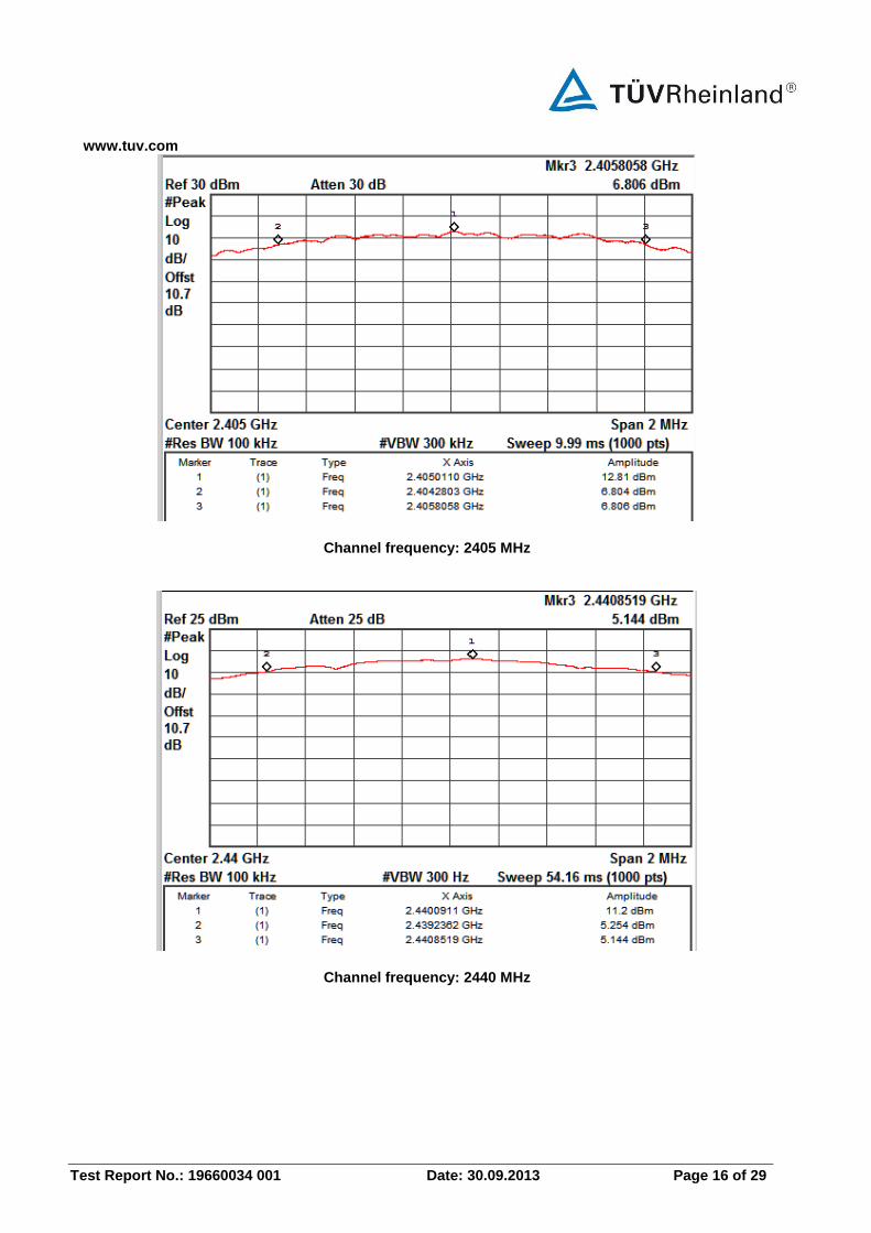
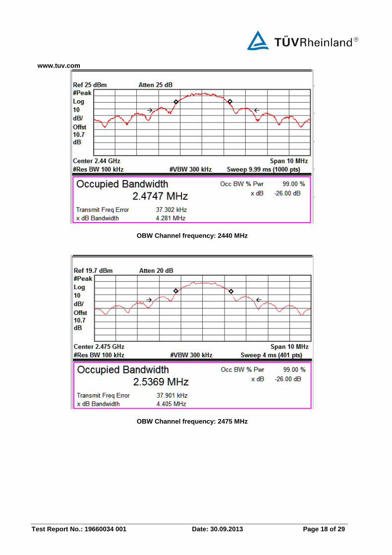
6 dB Bandwidth Section 15.247(a) (2) Result Pass
Test Specification FCC Part 15 Subpart C Requirement The minimum 6 dB bandwidth shall be at least 500 kHz.
Test Method:
EUT Spectrum Analyzer
Cable Loss + Attenuation: 10.7dB (Included in the test results) Test Result:
Frequency
(MHz)
Lower
Frequency
(MHz)
Upper
Frequency
(MHz)
6 dB
Bandwidth
(MHz)
OBW
(MHz)
2405 2404.28 2405.81 1.53 2.40
2440 2439.24 2440.85 1.62 2.47
2475 2474.19 2475.87 1.67 2.54
www.tuv.com
Test Report No.: 19660034 001 Date: 30.09.2013 Page 16 of 29
Channel frequency: 2405 MHz
Channel frequency: 2440 MHz
www.tuv.com
Test Report No.: 19660034 001 Date: 30.09.2013 Page 17 of 29
Channel frequency: 2475 MHz
OBW Channel frequency: 2405 MHz
www.tuv.com
Test Report No.: 19660034 001 Date: 30.09.2013 Page 18 of 29
OBW Channel frequency: 2440 MHz
OBW Channel frequency: 2475 MHz
www.tuv.com
Test Report No.: 19660034 001 Date: 30.09.2013 Page 19 of 29
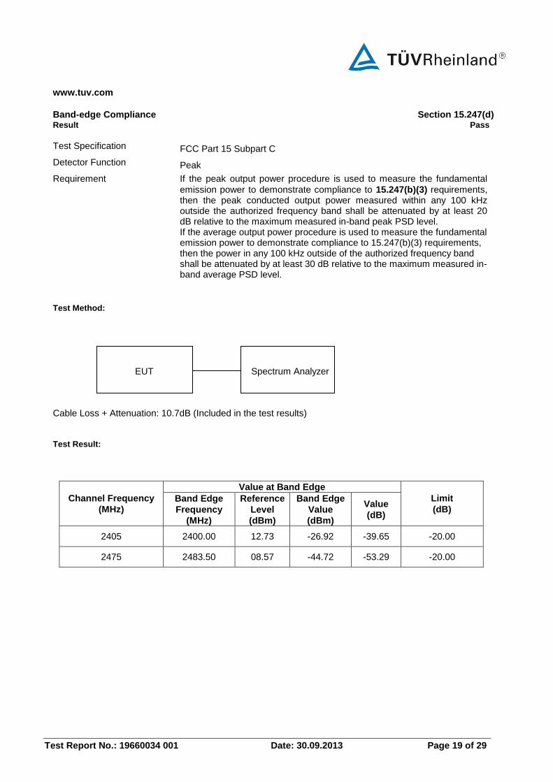
Band-edge Compliance Section 15.247(d) Result Pass
Test Specification FCC Part 15 Subpart C
Detector Function Peak
Requirement If the peak output power procedure is used to measure the fundamental
emission power to demonstrate compliance to 15.247(b)(3) requirements, then the peak conducted output power measured within any 100 kHz outside the authorized frequency band shall be attenuated by at least 20 dB relative to the maximum measured in-band peak PSD level. If the average output power procedure is used to measure the fundamental emission power to demonstrate compliance to 15.247(b)(3) requirements, then the power in any 100 kHz outside of the authorized frequency band shall be attenuated by at least 30 dB relative to the maximum measured in-band average PSD level.
Test Method:
EUT Spectrum Analyzer
Cable Loss + Attenuation: 10.7dB (Included in the test results)
Test Result:
Channel Frequency
(MHz)
Value at Band Edge
Limit
(dB) Band Edge
Frequency
(MHz)
Reference
Level
(dBm)
Band Edge
Value
(dBm)
Value
(dB)
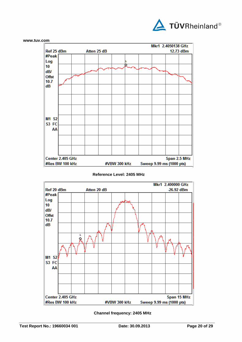
2405 2400.00 12.73 -26.92 -39.65 -20.00
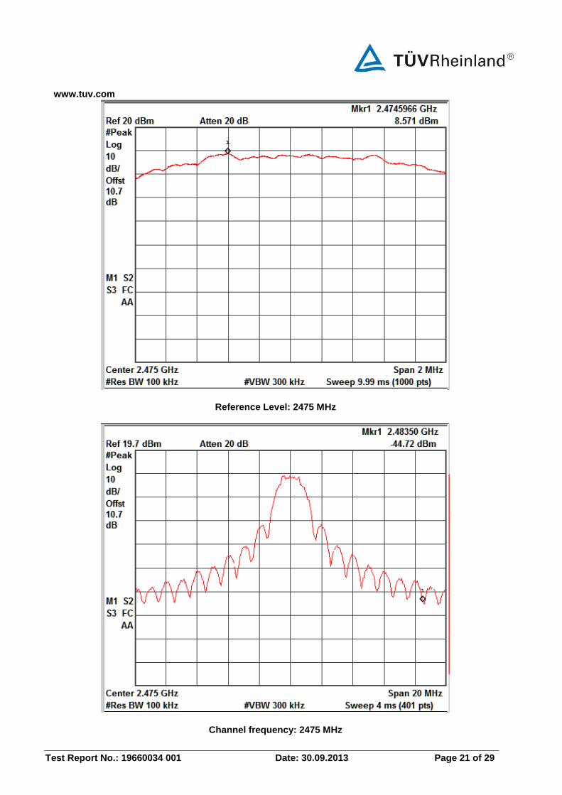
2475 2483.50 08.57 -44.72 -53.29 -20.00
www.tuv.com
Test Report No.: 19660034 001 Date: 30.09.2013 Page 20 of 29
Reference Level: 2405 MHz
Channel frequency: 2405 MHz
www.tuv.com
Test Report No.: 19660034 001 Date: 30.09.2013 Page 21 of 29
Reference Level: 2475 MHz
Channel frequency: 2475 MHz
www.tuv.com
Test Report No.: 19660034 001 Date: 30.09.2013 Page 22 of 29
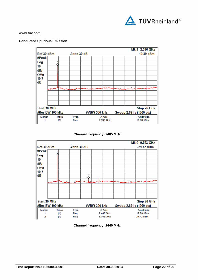
Conducted Spurious Emission
Channel frequency: 2405 MHz
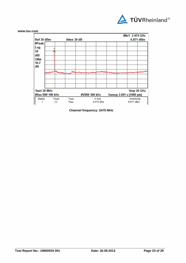
Channel frequency: 2440 MHz
www.tuv.com
Test Report No.: 19660034 001 Date: 30.09.2013 Page 23 of 29
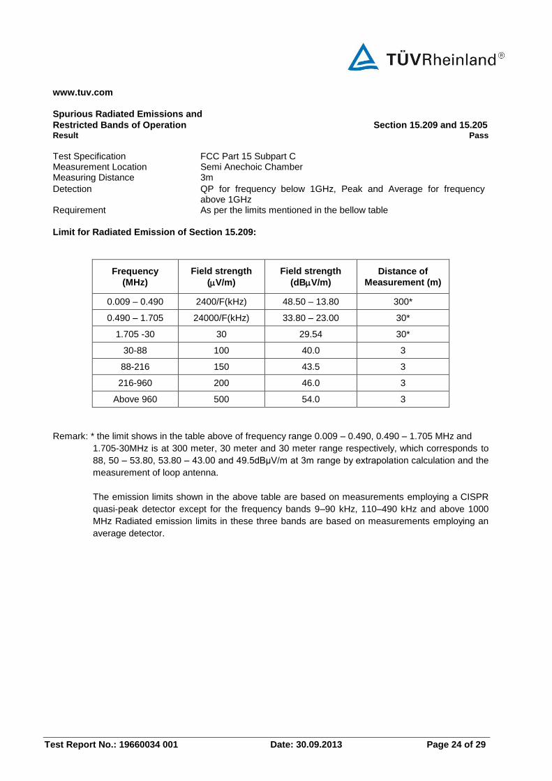
Channel frequency: 2475 MHz
www.tuv.com
Test Report No.: 19660034 001 Date: 30.09.2013 Page 24 of 29
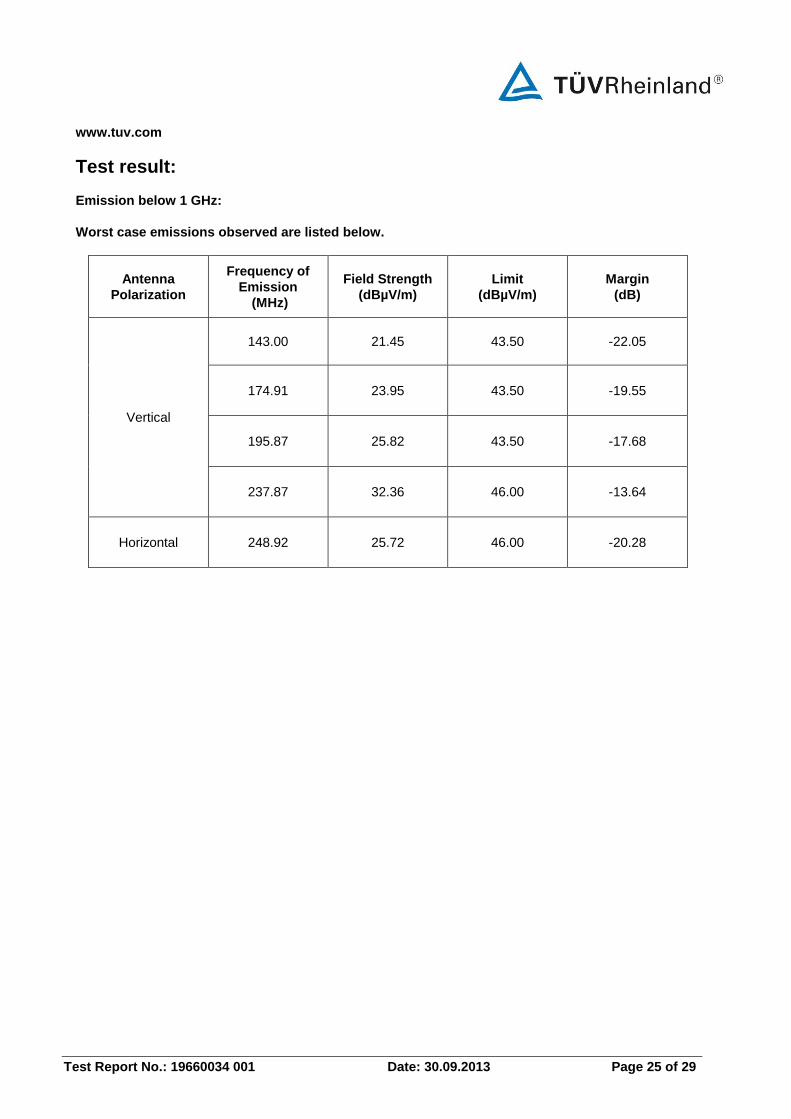
Spurious Radiated Emissions and
Restricted Bands of Operation Section 15.209 and 15.205 Result Pass
Test Specification FCC Part 15 Subpart C Measurement Location Semi Anechoic Chamber Measuring Distance 3m
Detection QP for frequency below 1GHz, Peak and Average for frequency above 1GHz
Requirement As per the limits mentioned in the bellow table
Limit for Radiated Emission of Section 15.209:
Frequency
(MHz)
Field strength
(V/m)
Field strength
(dBV/m)
Distance of
Measurement (m)
0.009 – 0.490 2400/F(kHz) 48.50 – 13.80 300*
0.490 – 1.705 24000/F(kHz) 33.80 – 23.00 30*
1.705 -30 30 29.54 30*
30-88 100 40.0 3
88-216 150 43.5 3
216-960 200 46.0 3
Above 960 500 54.0 3
Remark: * the limit shows in the table above of frequency range 0.009 – 0.490, 0.490 – 1.705 MHz and
1.705-30MHz is at 300 meter, 30 meter and 30 meter range respectively, which corresponds to
88, 50 – 53.80, 53.80 – 43.00 and 49.5dBμV/m at 3m range by extrapolation calculation and the
measurement of loop antenna.
The emission limits shown in the above table are based on measurements employing a CISPR
quasi-peak detector except for the frequency bands 9–90 kHz, 110–490 kHz and above 1000
MHz Radiated emission limits in these three bands are based on measurements employing an
average detector.
www.tuv.com
Test Report No.: 19660034 001 Date: 30.09.2013 Page 25 of 29
Test result:
Emission below 1 GHz:
Worst case emissions observed are listed below.
Antenna
Polarization
Frequency of
Emission
(MHz)
Field Strength
(dBµV/m)
Limit
(dBµV/m)
Margin
(dB)
Vertical
143.00 21.45 43.50 -22.05
174.91 23.95 43.50 -19.55
195.87 25.82 43.50 -17.68
237.87 32.36 46.00 -13.64
Horizontal 248.92 25.72 46.00 -20.28
www.tuv.com
Test Report No.: 19660034 001 Date: 30.09.2013 Page 26 of 29
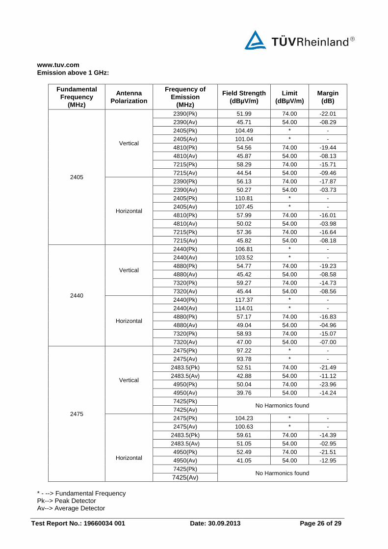
Emission above 1 GHz:
Fundamental
Frequency
(MHz)
Antenna
Polarization
Frequency of
Emission
(MHz)
Field Strength
(dBµV/m)
Limit
(dBµV/m)
Margin
(dB)
2405
Vertical
2390(Pk) 51.99 74.00 -22.01
2390(Av) 45.71 54.00 -08.29
2405(Pk) 104.49 * -
2405(Av) 101.04 * -
4810(Pk) 54.56 74.00 -19.44
4810(Av) 45.87 54.00 -08.13
7215(Pk) 58.29 74.00 -15.71
7215(Av) 44.54 54.00 -09.46
Horizontal
2390(Pk) 56.13 74.00 -17.87
2390(Av) 50.27 54.00 -03.73
2405(Pk) 110.81 * -
2405(Av) 107.45 * -
4810(Pk) 57.99 74.00 -16.01
4810(Av) 50.02 54.00 -03.98
7215(Pk) 57.36 74.00 -16.64
7215(Av) 45.82 54.00 -08.18
2440
Vertical
2440(Pk) 106.81 * -
2440(Av) 103.52 * -
4880(Pk) 54.77 74.00 -19.23
4880(Av) 45.42 54.00 -08.58
7320(Pk) 59.27 74.00 -14.73
7320(Av) 45.44 54.00 -08.56
Horizontal
2440(Pk) 117.37 * -
2440(Av) 114.01 * -
4880(Pk) 57.17 74.00 -16.83
4880(Av) 49.04 54.00 -04.96
7320(Pk) 58.93 74.00 -15.07
7320(Av) 47.00 54.00 -07.00
2475
Vertical
2475(Pk) 97.22 * -
2475(Av) 93.78 * -
2483.5(Pk) 52.51 74.00 -21.49
2483.5(Av) 42.88 54.00 -11.12
4950(Pk) 50.04 74.00 -23.96
4950(Av) 39.76 54.00 -14.24
7425(Pk) No Harmonics found
7425(Av)
Horizontal
2475(Pk) 104.23 * -
2475(Av) 100.63 * -
2483.5(Pk) 59.61 74.00 -14.39
2483.5(Av) 51.05 54.00 -02.95
4950(Pk) 52.49 74.00 -21.51
4950(Av) 41.05 54.00 -12.95
7425(Pk) No Harmonics found
7425(Av)
* - --> Fundamental Frequency Pk--> Peak Detector Av--> Average Detector
www.tuv.com
Test Report No.: 19660034 001 Date: 30.09.2013 Page 27 of 29
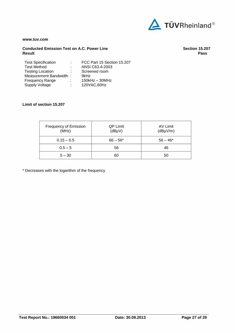
Conducted Emission Test on A.C. Power Line Section 15.207
Result Pass Test Specification : FCC Part 15 Section 15.207 Test Method : ANSI C63.4-2003 Testing Location : Screened room Measurement Bandwidth : 9kHz Frequency Range : 150kHz – 30MHz Supply Voltage : 120VAC,60Hz
Limit of section 15.207
Frequency of Emission (MHz)
QP Limit (dBµV)
AV Limit (dBµV/m)
0.15 – 0.5 66 – 56* 56 – 46*
0.5 – 5 56 46
5 – 30 60 50
* Decreases with the logarithm of the frequency
www.tuv.com
Test Report No.: 19660034 001 Date: 30.09.2013 Page 28 of 29
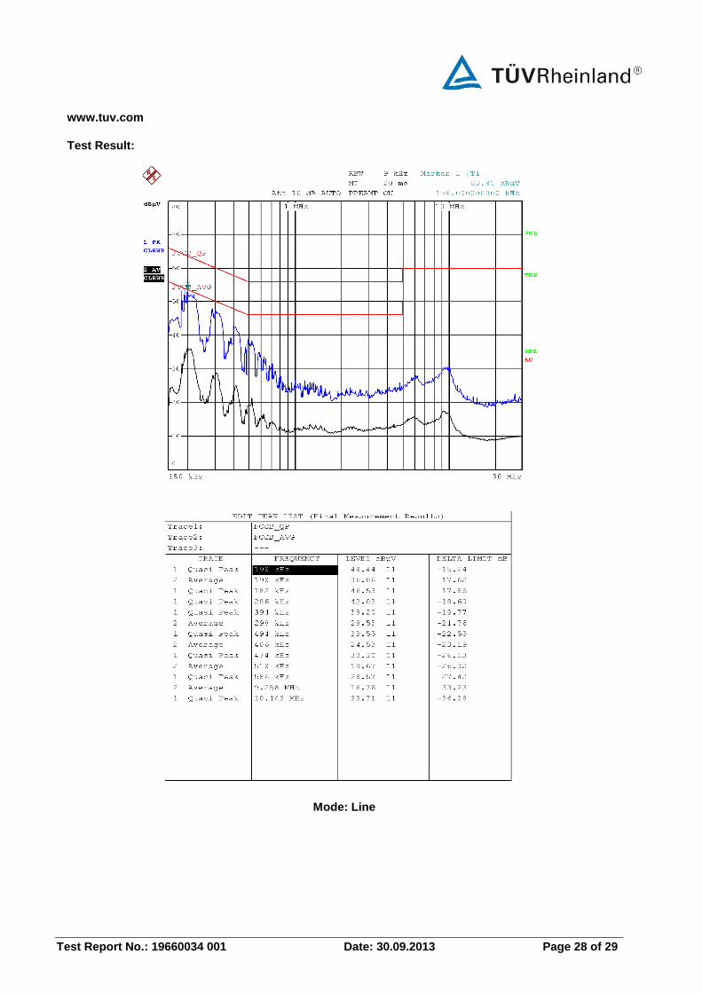
Test Result:
Mode: Line
www.tuv.com
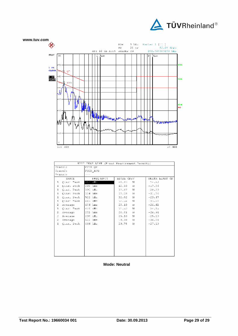
Test Report No.: 19660034 001 Date: 30.09.2013 Page 29 of 29
Mode: Neutral