Embed Size (px)
Citation preview
www.georg-jordan.de
Produktkatalog Kapazitive Spannungsprüfsysteme gemäß IEC 61243-5
Product catalogue Capacitive voltage detecting systems acc. IEC 61243-5
Release 2020-06
202
0/2
02
1
Kapazitive Spannungsprüfsysteme
Capacitive voltage detection system
Technische Änderung vorbehalten/ Subject to modification without prior notice Stand / Last revised: 2020/06
www.georg-jordan.de Kapitel / Section 2
VDS Seite / Page 2/13
Kapazitive Spannungsprüfsysteme (VDS)
Capacitive voltage detection systems (VDS)
Anwendung:
Kapazitive Spannungsprüfsysteme (Voltage Detection System / VDS) dienen der Prüfung des Zustandes „Spannung vorhanden“ oder „Spannung nicht vorhanden“ an elektrischen Mittelspannungsschaltanlagen. Die Prüfung erfolgt gemäß E DIN VDE 0682 Teil 415 bzw. IEC 61243-5.
Spannungsprüfsysteme werden unterteilt in:
Steckbare Systeme bestehend aus einer dreiphasigen Schnittstelle (HR od. LRM) mit einem ortsveränderlichen Anzeigegerät. Aufgrund der erforderli-chen Wiederholungsprüfung ist ein kapazitives Spannungs- und Schnittstel-lentester erforderlich.
Integrierte Systeme (KVDS/CAVIN) sind fest installierte Geräte der perma-nenten Spannungsüberwachung und -anzeige. Diese Systeme besitzen eine LRM-Schnittstelle und einen Messpunkt zum Phasenvergleich an der Front.
Integrierte dreiphasiges Spannungsprüfsystem besteht aus:
1. 3 x kapazitiven Abgriff (z.B. Teilerstützer (TSK), Koppelelektrode (KKE), …)
2. 3 x Anschlusskabel (AK) und koaxialen Verbindungsleitung
3. 1 x integriertes Anzeigegerät (KVDS/CAVIN mit Fernüberwachung)
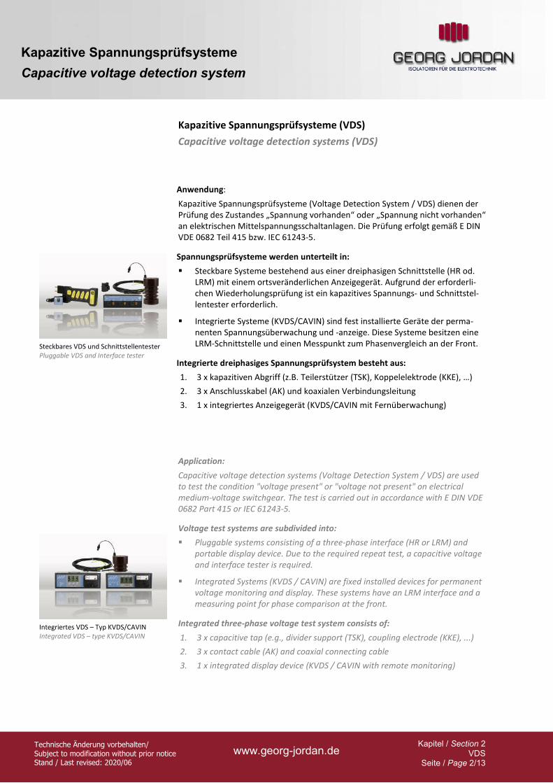
Steckbares VDS und Schnittstellentester Pluggable VDS and Interface tester
Application:
Capacitive voltage detection systems (Voltage Detection System / VDS) are used to test the condition "voltage present" or "voltage not present" on electrical medium-voltage switchgear. The test is carried out in accordance with E DIN VDE 0682 Part 415 or IEC 61243-5.
Voltage test systems are subdivided into:
Pluggable systems consisting of a three-phase interface (HR or LRM) and portable display device. Due to the required repeat test, a capacitive voltage and interface tester is required.
Integrated Systems (KVDS / CAVIN) are fixed installed devices for permanent voltage monitoring and display. These systems have an LRM interface and a measuring point for phase comparison at the front.
Integriertes VDS – Typ KVDS/CAVIN Integrated VDS – type KVDS/CAVIN
Integrated three-phase voltage test system consists of:
1. 3 x capacitive tap (e.g., divider support (TSK), coupling electrode (KKE), ...)
2. 3 x contact cable (AK) and coaxial connecting cable
3. 1 x integrated display device (KVDS / CAVIN with remote monitoring)
Kapazitive Spannungsprüfsysteme
Capacitive voltage detection system
Technische Änderung vorbehalten/ Subject to modification without prior notice Stand / Last revised: 2020/06
www.georg-jordan.de Kapitel / Section 2
VDS Seite / Page 3/13
Allgemeines Schaubild (VDS)
Schematic circuit diagram (VDS)
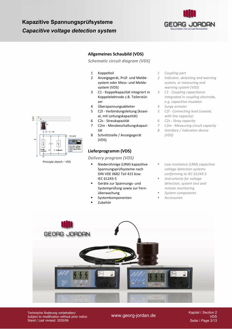
1 Koppelteil 2 Anzeigegerät, Prüf- und Melde-
system oder Mess- und Melde-system (VDS)
3 C1 - Koppelkapazität integriert in Koppelelektrode z.B. Teilerstüt-zer
4 Überspannungsableiter 5 C2l - Verbindungsleitung (koaxi-
al, mit Leitungskapazität) 6 C2s - Streukapazität 7 C2m - Messbeschaltungskapazi-
tät 8 Schnittstelle / Anzeigegerät
(VDS)
1 Coupling part 2 Indicator, detecting and warning
system, or measuring and warning system (VDS)
3 C1 - Coupling capacitance integrated in coupling electrode, e.g. capacitive insulator
4 Surge arrester 5 C2l - Connecting lead (coaxial,
with line capacity) 6 C2s - Stray capacity 7 C2m - Measuring circuit capacity 8 Interface / indication device
(VDS)
Lieferprogramm (VDS)
Delivery program (VDS)
Principle sketch – VDS
Niederohmige (LRM) kapazitive
Spannungsprüfsysteme nach DIN VDE 0682 Teil 415 bzw. IEC 61243-5
Geräte zur Spannungs- und Systemprüfung sowie zur Fern-überwachung
Systemkomponenten Zubehör
Low resistance (LRM) capacitive voltage detection systems conforming to IEC 61243-5
Instruments for voltage detection, system test and remote monitoring
System components Accessories
Kapazitive Spannungsprüfsysteme
Capacitive voltage detection system
Technische Änderung vorbehalten/ Subject to modification without prior notice Stand / Last revised: 2020/06
www.georg-jordan.de Kapitel / Section 2
VDS Seite / Page 4/13
Kapazitive Teilerstützer (TSK)
Capacitive insulators (TSK)
Anwendung:
Kapazitive Teilerstützer dienen innerhalb des kapazitiven Spannungsprüfsystems als oberspannungsseitige Kapazität zwischen Mittelspannung und Schnittstelle.
Baumerkmale:
Die Teilerstützer entsprechen in ihren Abmessungen sowie ihren Festigkeitsei-genschaften herkömmlichen DIN-Stützern ohne Koppelkapazität und können an deren Stelle eingesetzt werden.
Die Kapazität C1 im Teilerstützer bildet zusammen mit den nachgeschalteten Kapazitäten C2 einen kapazitiven Spannungsteiler. Die Stützer lassen sich zu-sammen mit den Verbindungsleitungen zu VDS komplettieren
Types - operating voltage:
TSKA; TSKB
12 - 24 - 36 - 45 kV
Applications:
Capacitive insulators are used as high voltage side capacity for voltage detecting systems between the medium voltage section and the interface.
Design features:
Capacitive insulators correspond in their measurements and physical properties to conventional DIN insulators without coupling capacitance and can therefore replace them.
In conjunction with the capacitances C2 of the downstream devices, the capacitance C1 of the capacitive insulator forms a capacitive voltage divider. The insulators can be combined with the connecting leads to form VDS.
Principle sketch – cap. divider
Kapazitive Koppelektroden (KKE)
Capacitive coupling electrodes (KKE)
Anwendung:
Zur Nachrüstung in bestehende Anlagen können kapazitive Koppelelektroden ohne Stützfunktion geliefert werden.
Baumerkmale:
Koppelelektroden sind im Gegensatz zu Teilerstützern nicht für mechanische Belastungen konstruiert. Auf diese Weise werden ein geringeres Gewicht und insgesamt kleinere Abmessungen erzielt.
Types - operating voltage:
KKE
12 - 24 kV
Applications:
For retrofits on existing switchgear non-supporting capacitive coupling electrodes can be used.
Design features:
Unlike capacitive insulators, they are not designed to withstand mechanical loading. They therefore weigh less and are generally smaller in size.
Kapazitive Spannungsprüfsysteme
Capacitive voltage detection system
Technische Änderung vorbehalten/ Subject to modification without prior notice Stand / Last revised: 2020/06
www.georg-jordan.de Kapitel / Section 2
VDS Seite / Page 5/13
Kapazitive Teilerstützer – TSK / KKE
Capacitive insulator – TSK / KKE
12 - 24
36 - 45 kV
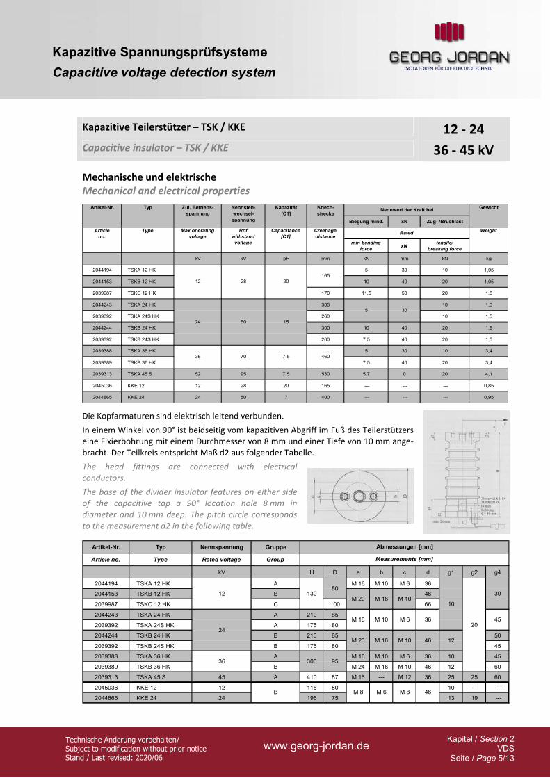
Mechanische und elektrische
Mechanical and electrical properties
Biegung mind. xN Zug- /Bruchlast
min bending
forcexN
tensile/
breaking force
kV kV pF mm kN mm kN kg
2044194 TSKA 12 HK 5 30 10 1,05
2044153 TSKB 12 HK 10 40 20 1,05
2039987 TSKC 12 HK 170 11,5 50 20 1,8
2044243 TSKA 24 HK 300 10 1,9
2039392 TSKA 24S HK 260 10 1,5
2044244 TSKB 24 HK 300 10 40 20 1,9
2039392 TSKB 24S HK 260 7,5 40 20 1,5
2039388 TSKA 36 HK 5 30 10 3,4
2039389 TSKB 36 HK 7,5 40 20 3,4
2039313 TSKA 45 S 52 95 7,5 530 5,7 0 20 4,1
2045036 KKE 12 12 28 20 165 --- --- --- 0,85
2044865 KKE 24 24 50 7 400 --- --- --- 0,95
Gewicht
Article
no.
Type Max operating
voltage
Rpf
withstand
voltage
Capacitance
[C1]
Creepage
distance
Weight
Artikel-Nr. Typ Zul. Betriebs-
spannung
7,5
20
15
36 70
12
24
28
50
Nennsteh-
wechsel-
spannung
Kapazität
[C1]
460
Nennwert der Kraft bei
Rated
Kriech-
strecke
5 30
165
Die Kopfarmaturen sind elektrisch leitend verbunden.
In einem Winkel von 90° ist beidseitig vom kapazitiven Abgriff im Fuß des Teilerstützers eine Fixierbohrung mit einem Durchmesser von 8 mm und einer Tiefe von 10 mm ange-bracht. Der Teilkreis entspricht Maß d2 aus folgender Tabelle.
The head fittings are connected with electrical conductors.
The base of the divider insulator features on either side of the capacitive tap a 90° location hole 8 mm in diameter and 10 mm deep. The pitch circle corresponds to the measurement d2 in the following table.
Artikel-Nr. Typ Nennspannung Gruppe
Article no. Type Rated voltage Group
kV H D a b c d g1 g2 g4
2044194 TSKA 12 HK A M 16 M 10 M 6 36
2044153 TSKB 12 HK B 46
2039987 TSKC 12 HK C 100 66
2044243 TSKA 24 HK A 210 85
2039392 TSKA 24S HK A 175 80
2044244 TSKB 24 HK B 210 85 50
2039392 TSKB 24S HK B 175 80 45
2039388 TSKA 36 HK A M 16 M 10 M 6 36 10 45
2039389 TSKB 36 HK B M 24 M 16 M 10 46 12 60
2039313 TSKA 45 S 45 A 410 87 M 16 --- M 12 36 25 25 60
2045036 KKE 12 12 115 80 10 --- ---
2044865 KKE 24 24 195 75 13 19 ---
4520
10
36
12
24
M 20130
80
M 20
Abmessungen [mm]
Measurements [mm]
M 16 M 1030
M 16 M 10 M 6 36
46
12
300 95
M 16 M 10 46
B M 8 M 6 M 8
Kapazitive Spannungsprüfsysteme
Capacitive voltage detection system
Technische Änderung vorbehalten/ Subject to modification without prior notice Stand / Last revised: 2020/06
www.georg-jordan.de Kapitel / Section 2
VDS Seite / Page 7/13
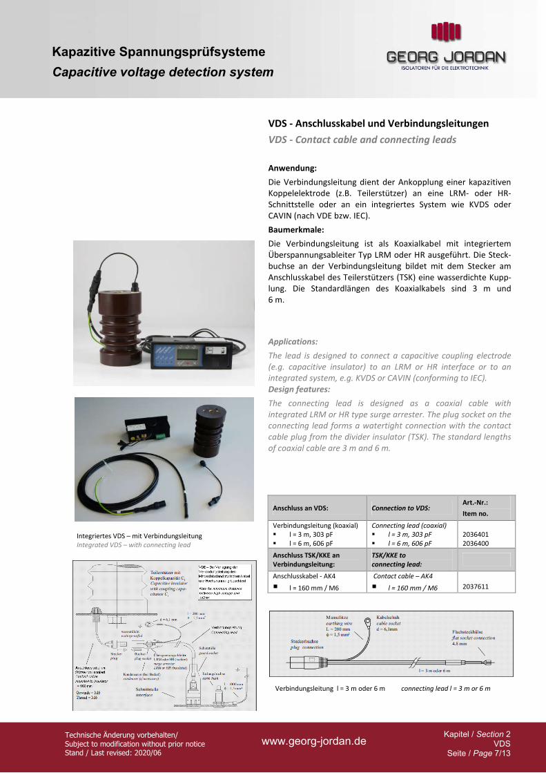
VDS - Anschlusskabel und Verbindungsleitungen
VDS - Contact cable and connecting leads
Anwendung:
Die Verbindungsleitung dient der Ankopplung einer kapazitiven Koppelelektrode (z.B. Teilerstützer) an eine LRM- oder HR-Schnittstelle oder an ein integriertes System wie KVDS oder CAVIN (nach VDE bzw. IEC).
Baumerkmale:
Die Verbindungsleitung ist als Koaxialkabel mit integriertem Überspannungsableiter Typ LRM oder HR ausgeführt. Die Steck-buchse an der Verbindungsleitung bildet mit dem Stecker am Anschlusskabel des Teilerstützers (TSK) eine wasserdichte Kupp-lung. Die Standardlängen des Koaxialkabels sind 3 m und 6 m.
Applications:
The lead is designed to connect a capacitive coupling electrode (e.g. capacitive insulator) to an LRM or HR interface or to an integrated system, e.g. KVDS or CAVIN (conforming to IEC). Design features:
The connecting lead is designed as a coaxial cable with integrated LRM or HR type surge arrester. The plug socket on the connecting lead forms a watertight connection with the contact cable plug from the divider insulator (TSK). The standard lengths of coaxial cable are 3 m and 6 m.
Integriertes VDS – mit Verbindungsleitung Integrated VDS – with connecting lead
Verbindungsleitung l = 3 m oder 6 m connecting lead l = 3 m or 6 m
Anschluss an VDS: Connection to VDS: Art.-Nr.:
Item no.
Verbindungsleitung (koaxial) l = 3 m, 303 pF l = 6 m, 606 pF
Connecting lead (coaxial) l = 3 m, 303 pF l = 6 m, 606 pF
2036401 2036400
Anschluss TSK/KKE an Verbindungsleitung:
TSK/KKE to connecting lead:
Anschlusskabel - AK4
l = 160 mm / M6
Contact cable – AK4
l = 160 mm / M6
2037611
Kapazitive Spannungsprüfsysteme
Capacitive voltage detection system
Technische Änderung vorbehalten/ Subject to modification without prior notice Stand / Last revised: 2020/06
www.georg-jordan.de Kapitel / Section 2
VDS Seite / Page 8/13
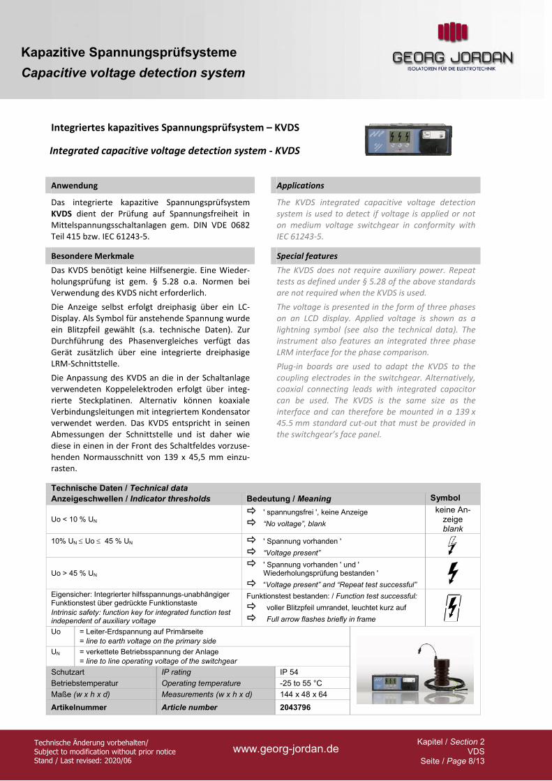
Integriertes kapazitives Spannungsprüfsystem – KVDS
Integrated capacitive voltage detection system - KVDS
Anwendung Applications
Das integrierte kapazitive Spannungsprüfsystem KVDS dient der Prüfung auf Spannungsfreiheit in Mittelspannungsschaltanlagen gem. DIN VDE 0682 Teil 415 bzw. IEC 61243-5.
The KVDS integrated capacitive voltage detection system is used to detect if voltage is applied or not on medium voltage switchgear in conformity with IEC 61243-5.
Besondere Merkmale Special features
Das KVDS benötigt keine Hilfsenergie. Eine Wieder-holungsprüfung ist gem. § 5.28 o.a. Normen bei Verwendung des KVDS nicht erforderlich.
Die Anzeige selbst erfolgt dreiphasig über ein LC-Display. Als Symbol für anstehende Spannung wurde ein Blitzpfeil gewählt (s.a. technische Daten). Zur Durchführung des Phasenvergleiches verfügt das Gerät zusätzlich über eine integrierte dreiphasige LRM-Schnittstelle.
Die Anpassung des KVDS an die in der Schaltanlage verwendeten Koppelelektroden erfolgt über integ-rierte Steckplatinen. Alternativ können koaxiale Verbindungsleitungen mit integriertem Kondensator verwendet werden. Das KVDS entspricht in seinen Abmessungen der Schnittstelle und ist daher wie diese in einen in der Front des Schaltfeldes vorzuse-henden Normausschnitt von 139 x 45,5 mm einzu-rasten.
The KVDS does not require auxiliary power. Repeat tests as defined under § 5.28 of the above standards are not required when the KVDS is used.
The voltage is presented in the form of three phases on an LCD display. Applied voltage is shown as a lightning symbol (see also the technical data). The instrument also features an integrated three phase LRM interface for the phase comparison.
Plug-in boards are used to adapt the KVDS to the coupling electrodes in the switchgear. Alternatively, coaxial connecting leads with integrated capacitor can be used. The KVDS is the same size as the interface and can therefore be mounted in a 139 x 45.5 mm standard cut-out that must be provided in the switchgear’s face panel.
Technische Daten / Technical data
Anzeigeschwellen / Indicator thresholds Bedeutung / Meaning Symbol
Uo < 10 % UN ' spannungsfrei ', keine Anzeige
“No voltage”, blank
keine An-zeige blank
10% UN Uo 45 % UN
' Spannung vorhanden '
“Voltage present”
Uo > 45 % UN ' Spannung vorhanden ' und '
Wiederholungsprüfung bestanden '
“Voltage present” and “Repeat test successful”
Eigensicher: Integrierter hilfsspannungs-unabhängiger Funktionstest über gedrückte Funktionstaste
Intrinsic safety: function key for integrated function test independent of auxiliary voltage
Funktionstest bestanden: / Function test successful:
voller Blitzpfeil umrandet, leuchtet kurz auf
Full arrow flashes briefly in frame Uo = Leiter-Erdspannung auf Primärseite
= line to earth voltage on the primary side
UN = verkettete Betriebsspannung der Anlage
= line to line operating voltage of the switchgear
Schutzart IP rating IP 54
Betriebstemperatur Operating temperature -25 to 55 °C
Maße (w x h x d) Measurements (w x h x d) 144 x 48 x 64
Artikelnummer Article number 2043796
Kapazitive Spannungsprüfsysteme
Capacitive voltage detection system
Technische Änderung vorbehalten/ Subject to modification without prior notice Stand / Last revised: 2020/06
www.georg-jordan.de Kapitel / Section 2
VDS Seite / Page 9/13
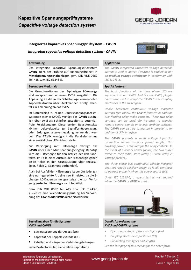
Integriertes kapazitives Spannungsprüfsystem – CAVIN
Integrated capacitive voltage detection system - CAVIN
Anwendung Application
Das integrierte kapazitive Spannungsprüfsystem CAVIN dient der Prüfung auf Spannungsfreiheit in Mittelspannungsschaltanlagen gem. DIN VDE 0682 Teil 415 bzw. IEC 61243-5.
The CAVIN integrated capacitive voltage detection system is used to detect if voltage is applied or not on medium voltage switchgear in conformity with IEC 61243-5.
Besondere Merkmale Special features
The basic functions of the three phase LCD are equivalent to our KVDS. And like the KVDS, plug-in boards are used to adapt the CAVIN to the coupling electrodes in the switchgear.
Unlike dedicated continuous voltage indicator systems (see KVDS), the CAVIN features in addition two floating relay make contacts. These two relay contacts can be used, for instance, to transfer remote control signals or to lock earthing switches. The CAVIN can also be connected in parallel to an additional LRM interface.
The CAVIN presents a multi voltage input for connection to an auxiliary power supply. This auxiliary power is required for the relay contacts. In the event of auxiliary power failure, the two relays revert to their initial state (relay 1: Error; relay 2: Voltage present).
The three phase LCD continuous voltage indicator does not require auxiliary power, so it still continues to operate properly when this power source fails.
Under IEC 61243-5, a repeat test is not required when the CAVIN or KVDS is used.
Die Grundfunktionen der 3-phasigen LC-Anzeige sind entsprechend unserem KVDS ausgeführt. Die Anpassung an die in der Schaltanlage verwendeten Koppelelektroden über Steckplatinen erfolgt eben-falls in Anlehnung an das KVDS.
Im Unterschied zu reinen Dauerspannungsanzeige-systemen (siehe: KVDS), verfügt das CAVIN zusätz-lich über zwei als Schließer ausgeführte potential-freie Relaiskontakte. Diese beiden Relaiskontakte können beispielsweise zur Signalfernübertragung oder Erdungsschalterverriegelung verwendet wer-den. Das CAVIN ermöglicht die Parallelschaltung einer zusätzlichen LRM-Schnittstelle.
Zur Versorgung mit Hilfsenergie verfügt das CAVIN über einen Multispannungseingang. Benötigt wird die Hilfsenergie für den Betrieb der Relaiskon-takte. Im Falle eines Ausfalls der Hilfsenergie gehen beide Relais in den Grundzustand über (Relais1: Error, Relais 2: Spannung vorhanden).
Auch bei Ausfall der Hilfsenergie ist vor Ort jederzeit eine normgerechte Anzeige gewährleistet, da die 3-phasige LC-Dauerspannungsanzeige die zur Verfü-gung gestellte Hilfsenergie nicht benötigt.
Gem. DIN VDE 0682 Teil 415 bzw. IEC 61243-5 § 5.28 ist eine Wiederholungsprüfung bei Verwen-dung des CAVIN oder KVDS nicht erforderlich.
Bestellangaben für die Systeme KVDS und CAVIN
Details for ordering the KVDS and CAVIN systems
Betriebsspannung der Anlage (Un)
Kapazität der Koppelelektrode (C1)
Kabeltyp und -länge der Verbindungsleitungen
Siehe Bestellformular, siehe letzte Kapitelseite
Operating voltage of the switchgear (Un)
Coupling electrode capacitance (C1)
Connecting lead types and lengths
See the last page of this section for the order form.
Kapazitive Spannungsprüfsysteme
Capacitive voltage detection system
Technische Änderung vorbehalten/ Subject to modification without prior notice Stand / Last revised: 2020/06
www.georg-jordan.de Kapitel / Section 2
VDS Seite / Page 10/13
Integriertes kapazitives Spannungsprüfsystem – CAVIN
Integrated capacitive voltage detection system - CAVIN
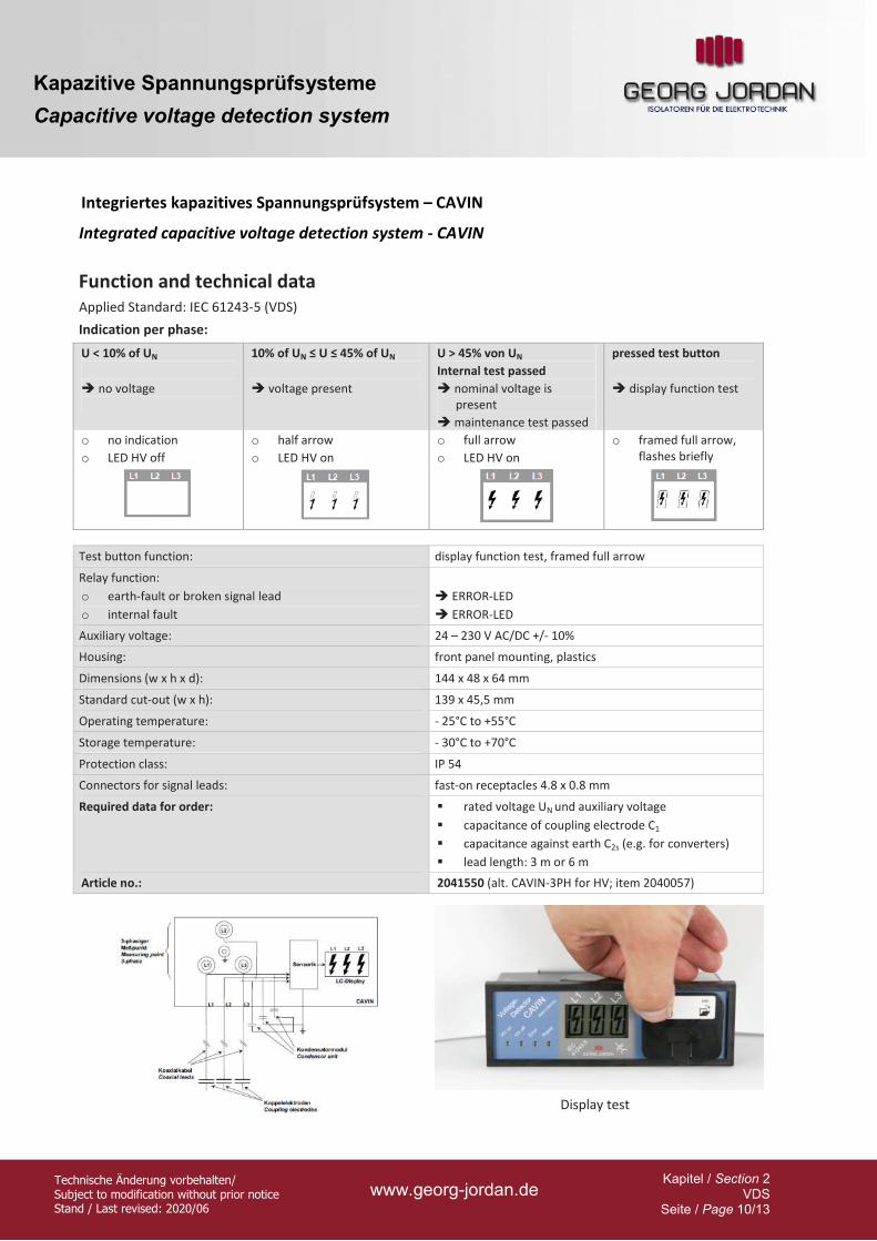
Function and technical data Applied Standard: IEC 61243-5 (VDS)
Indication per phase:
U < 10% of UN
no voltage
10% of UN ≤ U ≤ 45% of UN
voltage present
U > 45% von UN
Internal test passed
nominal voltage is present
maintenance test passed
pressed test button
display function test
o no indication
o LED HV off
o half arrow
o LED HV on
o full arrow
o LED HV on
o framed full arrow, flashes briefly
Test button function: display function test, framed full arrow
Relay function:
o earth-fault or broken signal lead
o internal fault
ERROR-LED
ERROR-LED
Auxiliary voltage: 24 – 230 V AC/DC +/- 10%
Housing: front panel mounting, plastics
Dimensions (w x h x d): 144 x 48 x 64 mm
Standard cut-out (w x h): 139 x 45,5 mm
Operating temperature: - 25°C to +55°C
Storage temperature: - 30°C to +70°C
Protection class: IP 54
Connectors for signal leads: fast-on receptacles 4.8 x 0.8 mm
Required data for order: rated voltage UN und auxiliary voltage
capacitance of coupling electrode C1
capacitance against earth C2s (e.g. for converters)
lead length: 3 m or 6 m
Article no.: 2041550 (alt. CAVIN-3PH for HV; item 2040057)
Display test
Kapazitive Spannungsprüfsysteme
Capacitive voltage detection system
Technische Änderung vorbehalten/ Subject to modification without prior notice Stand / Last revised: 2020/06
www.georg-jordan.de Kapitel / Section 2
VDS Seite / Page 11/13
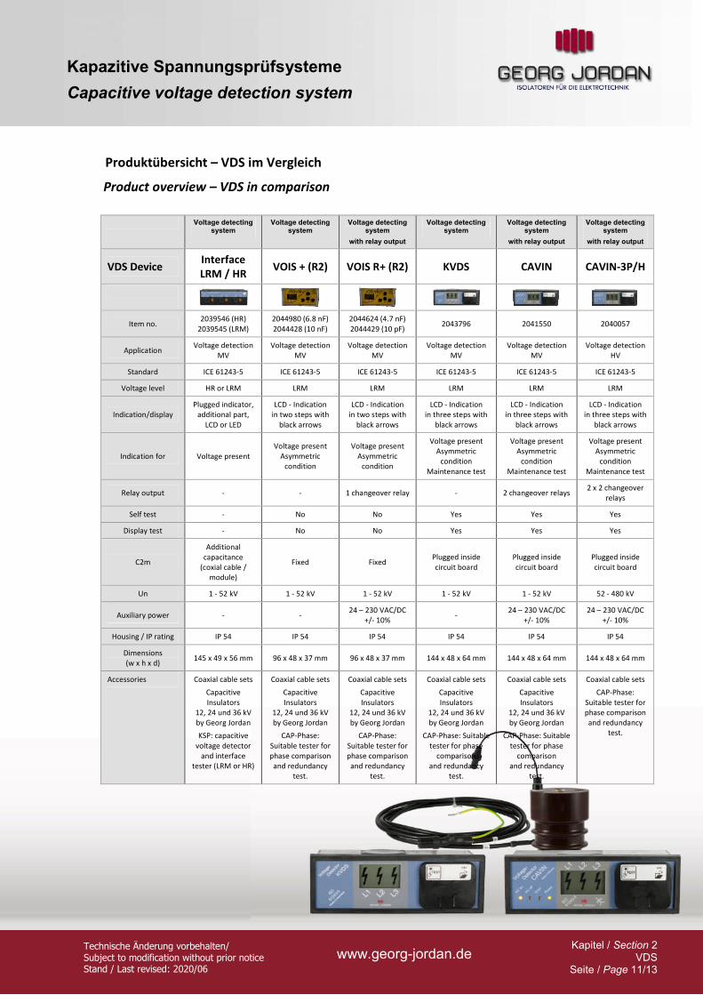
Produktübersicht – VDS im Vergleich
Product overview – VDS in comparison
Voltage detecting
system Voltage detecting
system Voltage detecting
system
with relay output
Voltage detecting system
Voltage detecting system
with relay output
Voltage detecting system
with relay output
VDS Device Interface LRM / HR
VOIS + (R2) VOIS R+ (R2) KVDS CAVIN CAVIN-3P/H
Item no. 2039546 (HR)
2039545 (LRM) 2044980 (6.8 nF) 2044428 (10 nF)
2044624 (4.7 nF) 2044429 (10 pF)
2043796 2041550 2040057
Application Voltage detection
MV Voltage detection
MV Voltage detection
MV Voltage detection
MV Voltage detection
MV Voltage detection
HV
Standard ICE 61243-5 ICE 61243-5 ICE 61243-5 ICE 61243-5 ICE 61243-5 ICE 61243-5
Voltage level HR or LRM LRM LRM LRM LRM LRM
Indication/display Plugged indicator,
additional part, LCD or LED
LCD - Indication in two steps with
black arrows
LCD - Indication in two steps with
black arrows
LCD - Indication in three steps with
black arrows
LCD - Indication in three steps with
black arrows
LCD - Indication in three steps with
black arrows
Indication for Voltage present Voltage present
Asymmetric condition
Voltage present Asymmetric
condition
Voltage present Asymmetric
condition Maintenance test
Voltage present Asymmetric
condition Maintenance test
Voltage present Asymmetric
condition Maintenance test
Relay output - - 1 changeover relay - 2 changeover relays 2 x 2 changeover
relays
Self test - No No Yes Yes Yes
Display test - No No Yes Yes Yes
C2m
Additional capacitance
(coxial cable / module)
Fixed Fixed Plugged inside circuit board
Plugged inside circuit board
Plugged inside circuit board
Un 1 - 52 kV 1 - 52 kV 1 - 52 kV 1 - 52 kV 1 - 52 kV 52 - 480 kV
Auxiliary power - - 24 – 230 VAC/DC
+/- 10% -
24 – 230 VAC/DC +/- 10%
24 – 230 VAC/DC +/- 10%
Housing / IP rating IP 54 IP 54 IP 54 IP 54 IP 54 IP 54
Dimensions (w x h x d)
145 x 49 x 56 mm 96 x 48 x 37 mm 96 x 48 x 37 mm 144 x 48 x 64 mm 144 x 48 x 64 mm 144 x 48 x 64 mm
Accessories Coaxial cable sets
Capacitive Insulators
12, 24 und 36 kV by Georg Jordan
KSP: capacitive voltage detector
and interface tester (LRM or HR)
Coaxial cable sets
Capacitive Insulators
12, 24 und 36 kV by Georg Jordan
CAP-Phase: Suitable tester for phase comparison and redundancy
test.
Coaxial cable sets
Capacitive Insulators
12, 24 und 36 kV by Georg Jordan
CAP-Phase: Suitable tester for phase comparison and redundancy
test.
Coaxial cable sets
Capacitive Insulators
12, 24 und 36 kV by Georg Jordan
CAP-Phase: Suitable tester for phase
comparison and redundancy
test.
Coaxial cable sets
Capacitive Insulators
12, 24 und 36 kV by Georg Jordan
CAP-Phase: Suitable tester for phase
comparison and redundancy
test.
Coaxial cable sets
CAP-Phase: Suitable tester for phase comparison and redundancy
test.
Kapazitive Spannungsprüfsysteme
Capacitive voltage detection system
Technische Änderung vorbehalten/ Subject to modification without prior notice Stand / Last revised: 2020/06
www.georg-jordan.de Kapitel / Section 2
VDS Seite / Page 12/13
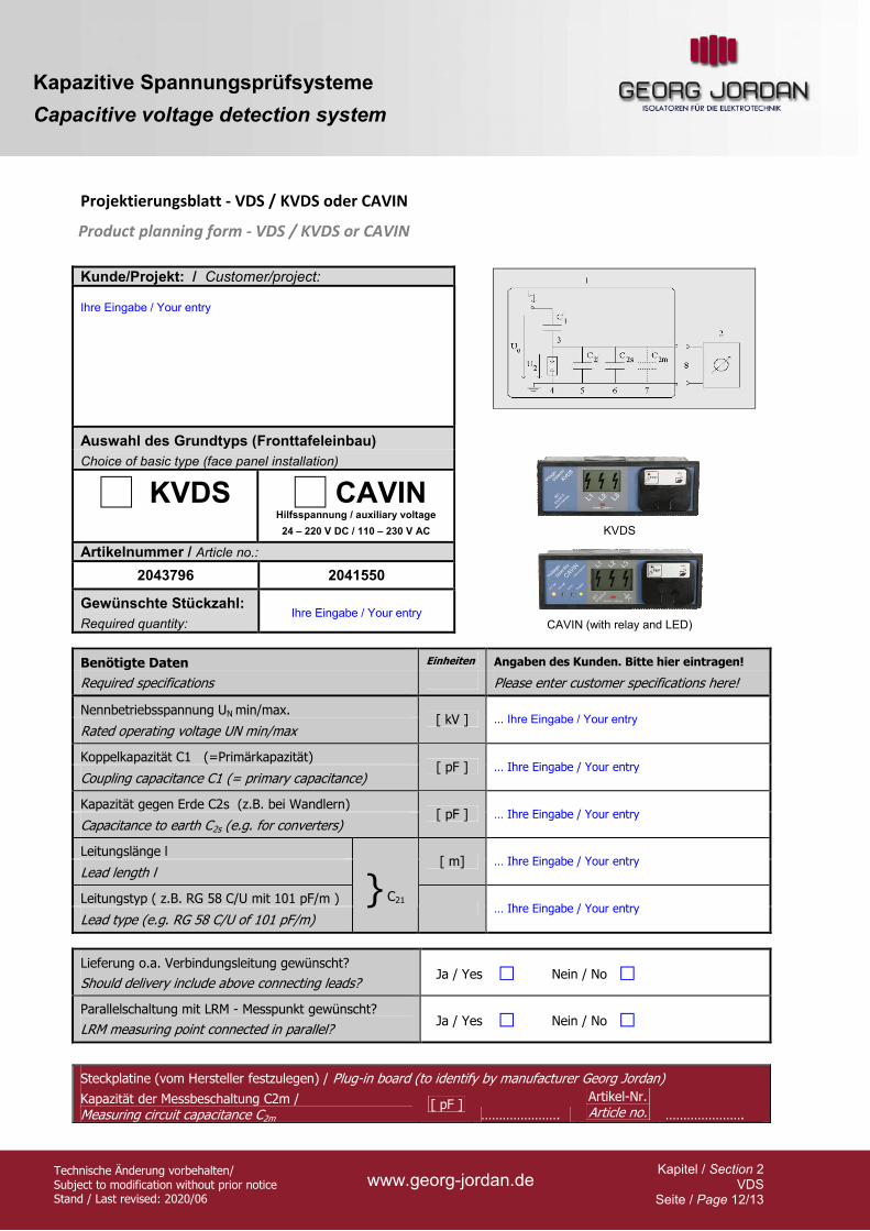
Projektierungsblatt - VDS / KVDS oder CAVIN
Product planning form - VDS / KVDS or CAVIN
Kunde/Projekt: / Customer/project: Ihre Eingabe / Your entry
Auswahl des Grundtyps (Fronttafeleinbau)
Choice of basic type (face panel installation)
KVDS CAVIN Hilfsspannung / auxiliary voltage
24 – 220 V DC / 110 – 230 V AC
Artikelnummer / Article no.:
2043796 2041550
Gewünschte Stückzahl:
Required quantity: Ihre Eingabe / Your entry
KVDS
CAVIN (with relay and LED)
Benötigte Daten Einheiten Angaben des Kunden. Bitte hier eintragen!
Required specifications Please enter customer specifications here!
Nennbetriebsspannung UN min/max.
Rated operating voltage UN min/max [ kV ] … Ihre Eingabe / Your entry
Koppelkapazität C1 (=Primärkapazität)
Coupling capacitance C1 (= primary capacitance) [ pF ] … Ihre Eingabe / Your entry
Kapazität gegen Erde C2s (z.B. bei Wandlern)
Capacitance to earth C2s (e.g. for converters) [ pF ] … Ihre Eingabe / Your entry
Leitungslänge l
Lead length l [ m] … Ihre Eingabe / Your entry
Leitungstyp ( z.B. RG 58 C/U mit 101 pF/m )
Lead type (e.g. RG 58 C/U of 101 pF/m)
} C21 … Ihre Eingabe / Your entry
Lieferung o.a. Verbindungsleitung gewünscht?
Should delivery include above connecting leads? Ja / Yes Nein / No
Parallelschaltung mit LRM - Messpunkt gewünscht?
LRM measuring point connected in parallel? Ja / Yes Nein / No
Steckplatine (vom Hersteller festzulegen) / Plug-in board (to identify by manufacturer Georg Jordan)
Kapazität der Messbeschaltung C2m / Measuring circuit capacitance C2m
[ pF ] ………………….
Artikel-Nr. Article no. ………………….
Kapazitive Spannungsprüfsysteme
Capacitive voltage detection system
Technische Änderung vorbehalten/ Subject to modification without prior notice Stand / Last revised: 2020/06
www.georg-jordan.de Kapitel / Section 2
VDS Seite / Page 13/13
GEORG JORDAN GmbH Industriestrasse 20 53721 Siegburg Germany Tel.: +49 2241 3098-0 Fax: +49 2241 55454 E-mail: [email protected] Georg Jordan Partner in Ihrer Nähe finden Sie im Internet unter: Homepage: www.georg-jordan.de
Speichern Sie unsere Kontaktinformation mit unserem QR Code auf Ihr Smartphone.

![6.4 Neuronale Netze zur Verarbeitung von Zeitreihen · Architekturen partiell rekurrenter Netze Jordan Netzwerk [Jordan 1986]: y(t) x(t) s(t) Schwenker NI1 116](https://img.pdfslide.org/doc/110x75/5ba0719a09d3f2fb538c9810/64-neuronale-netze-zur-verarbeitung-von-architekturen-partiell-rekurrenter.jpg)