Embed Size (px)
Citation preview
Lightning protection system / LPL installed
Optional
Customer data:
Project und Anschrift des zu planenden Objektes: (unbedingt angeben)
Type of building / use (e. g. offi ce, nursery school, industrial plant, ... )
Protection goals for this designoqnidbs
Project information sheetSelection of surge protective devices
International Technical Services & SupportDEHN-Formblatt-Nr. 2184/0816 E Page 1 of 5
No external lightning protection system
Class os LPS I / LPL I
Class of LPS II / LPL II
Class of LPS III / LPL III
Class of LPS IV / LPL IV
Site survey by DEHN + SÖHNE for collecting all relevant data (liable to costs)
Company: Name:
Address: Phone:
Address: E-mail:
Project name:
Address:
The complete building / installation should be protected (coordinated type 1 + type 2 + type 3 surge protective device)
Defi nition of protection goals during the site survey
Protection goal:
Protection goal:
Protection goal:
Lightning protection zone conceptThe lightning protection zone concept allows to plan, implement and monitor protection measures, thus ensuring that all relevant devices, installa-tions and systems are reliably protected at reasonable costs. In this context, a building is divided into zones according to the level of threat. Neces-sary protection measures, in particular the lightning and surge protection devices and components, can be defined based on these zones.
A lightning protection zone concept in conformance with EMC (electromagnetic compatibility) regulations includes external lightning protection (air-termination system, down conductor, earthing), equipotential bonding, spatial shielding and surge protection for the power supply and informa-tion technology system. The definition of lightning protection zones can be found in the table.
Project information sheetSelection of surge protective devices
International Technical Services & SupportDEHN-Formblatt-Nr. 2184/0816 E Page 2 of 5
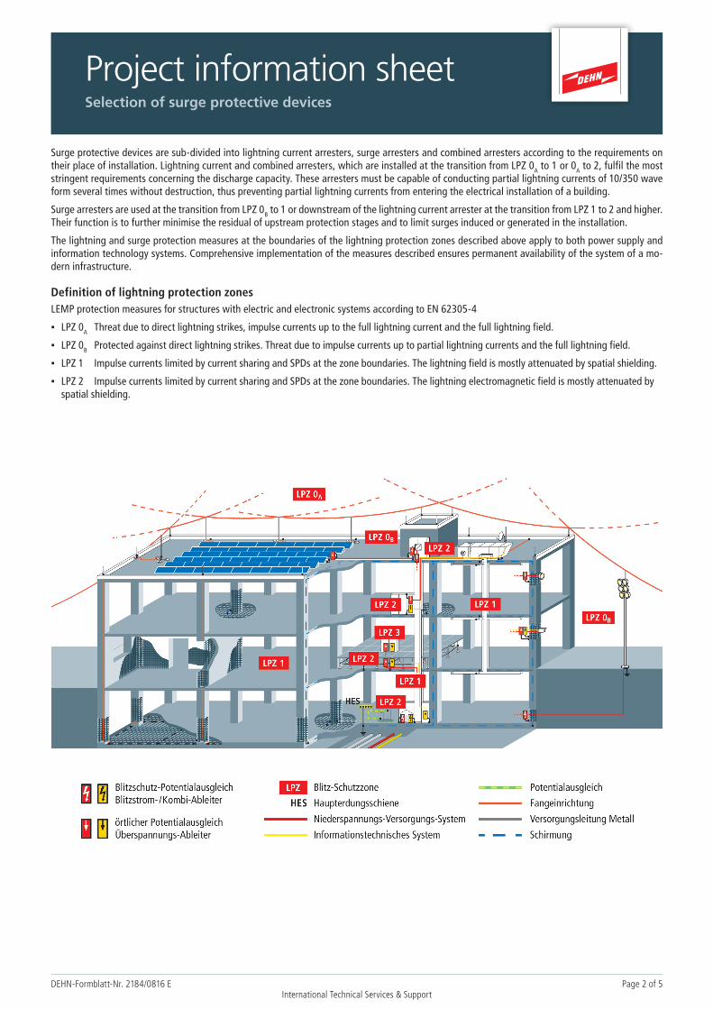
Surge protective devices are sub-divided into lightning current arresters, surge arresters and combined arresters according to the requirements on their place of installation. Lightning current and combined arresters, which are installed at the transition from LPZ 0A to 1 or 0A to 2, fulfil the most stringent requirements concerning the discharge capacity. These arresters must be capable of conducting partial lightning currents of 10/350 wave form several times without destruction, thus preventing partial lightning currents from entering the electrical installation of a building.
Surge arresters are used at the transition from LPZ 0B to 1 or downstream of the lightning current arrester at the transition from LPZ 1 to 2 and higher. Their function is to further minimise the residual of upstream protection stages and to limit surges induced or generated in the installation.
The lightning and surge protection measures at the boundaries of the lightning protection zones described above apply to both power supply and information technology systems. Comprehensive implementation of the measures described ensures permanent availability of the system of a mo-dern infrastructure.
Definition of lightning protection zonesLEMP protection measures for structures with electric and electronic systems according to EN 62305-4
▪ LPZ 0A Threat due to direct lightning strikes, impulse currents up to the full lightning current and the full lightning field.
▪ LPZ 0B Protected against direct lightning strikes. Threat due to impulse currents up to partial lightning currents and the full lightning field.
▪ LPZ 1 Impulse currents limited by current sharing and SPDs at the zone boundaries. The lightning field is mostly attenuated by spatial shielding.
▪ LPZ 2 Impulse currents limited by current sharing and SPDs at the zone boundaries. The lightning electromagnetic field is mostly attenuated by spatial shielding.
International Technical Services & SupportDEHN
-Formblatt-N
r. 2184/0816 Page 3 of 5
Project information sheet
Selection
of su
rge p
rotective d
evices
Term
inal
equ
ipm
ent /
supp
ly li
ne
Dist
ance
from
ups
trea
m
prot
ectio
n
Syst
em c
onfig
urat
ion
Num
ber o
f pha
ses
Type
of i
nsta
llatio
n/
desi
gn
Rem
ote
sign
allin
g co
ntac
t
Size
of u
pstr
eam
over
curr
ent p
rote
ctio
n
Arr
este
r typ
e
Syst
em c
onfig
urat
ion
Max
. con
tinou
sop
erat
ing
volta
ge
Rem
ote
sign
allin
g co
ntac
t
Size
of u
pstr
eam
over
curr
ent p
rote
ctio
n
Sepa
ratio
n di
stan
ce
mai
ntai
ned
Leng
th o
f d.c
. lin
e
Leng
th o
f a.c
. lin
e
Dow
n co
nduc
tors
of t
he
exte
rnal
LPS
Zone
OA
Zone
OB
1 or
hig
her
< 1
0 m
> 1
0 m
TT s
yste
m
TN s
yste
m
Unk
now
n
1 2 3 DIN
rail
40 m
m b
usba
r
Busb
ar e
xcee
ding
35
mm
2
Yes
No
Type
1
Type
2
TN-C
TN-S
IT 60 V
242
V
550
V
900
V
Yes
No
Yes
No
> 1
0 m
< 1
0 m
> 1
0 m
< 1
0 m
< 4
dow
n co
nduc
tors
> 4
dow
n co
nduc
tors
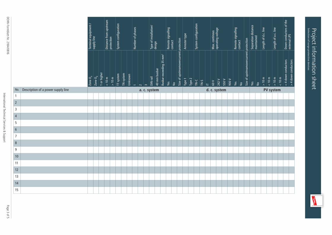
No. Description of a power supply line a. c. system d. c. system PV system1
2
3
4
5
6
7
8
9
10
11
12
13
14
15
Project information sheet
Selection
of su
rge p
rotective d
evices
International Technical Services & SupportDEHN
-Formblatt-N
r. 2184/0816 E Page 4 of 5
Inte
rfac
e(se
e ta
ble
1)In
stal
lati
on a
t th
e en
tran
ce
poin
t in
to t
he b
uild
ing
Inst
alla
tion
at
the
term
inal
eq
uipm
ent
Type
of i
nsta
llati
onD
IN r
ail
Type
of i
nsta
llati
onLS
A t
echn
olog
y Interface(see table 2)
Interface(see table 3)
Interface(see table 4)
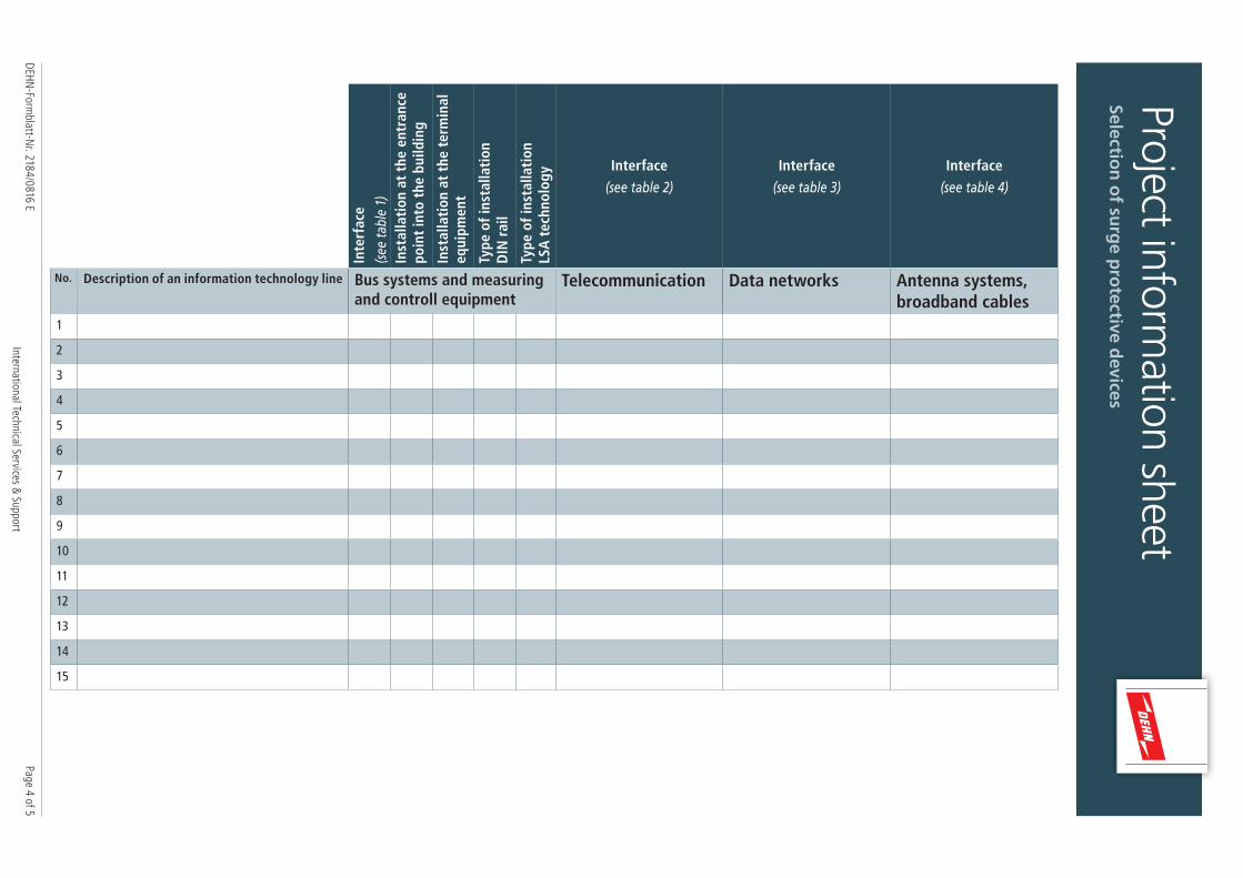
No. Description of an information technology line Bus systems and measuring and controll equipment
Telecommunication Data networks Antenna systems, broadband cables
1
2
3
4
5
6
7
8
9
10
11
12
13
14
15
Project information sheet
Selection
of su
rge p
rotective d
evices
International Technical Services & SupportDEHN
-Formblatt-N
r. 2184/0816 E Page 5 of 5
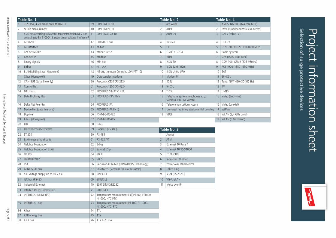
Table No. 1 Table No. 2 Table No. 41 0-20 mA, 4-20 mA (also with HART) 39 LON-TP/FTT 10 1 a/b wires 1 AMPS, NADAC (824-894 MHz)
2 ¾ line measurement 40 LON-TP/LPT 10 2 ADSL 2 BWA (Broadband Wireless Access)
3 4-20 mA according to NAMUR recommendation NE 21 or according to EN 610004-5, open-circuit voltage 1 kV core-P
41 LON-TP/XF 78 10 3 ADSL 2+ 3 CATV (cable TV)
4 ADVANT 42 LUXMATE bus 4 Datex-P 4 DCF 77
5 AS interface 43 M-bus 5 E1 5 DCS 1800 B162 (1710-1880 MHz)
6 BACnet MS/TP 44 Melsec Net 2 6 G.703 / G.704 6 Radio systems
7 BACnet/IP 45 Modbus 7 HDSL 7 GPS (1565-1585 MHz)
8 Binary signals 46 MPI bus 8 ISDN S0 8 GSM 900, GSMR (876-960 Hz)
9 Bitbus 47 N 1 LAN 9 ISDN S2M / U2m 9 PCS 1900 (1850-1990 MHz)
10 BLN (Building Level Netzwork) 48 N2 bus (Johnson Controls, LON FTT 10) 10 ISDN UK0 / UP0 10 SAT
11 C-bus (Honeywell) 49 Optocoupler interface 11 Modem M1 11 Sky DSL
12 CAN-BUS (data line only) 50 Procontic CS31 (RS 232) 12 SDSL 12 Tetra, NMT 450 (30-512 Hz)
13 Control Net 51 Procontic T200 (RS 422) 13 SHDSL 13 TV
14 DALI-bus 52 PROFIBUS SIMATIC NET 14 T-DSL 14 UMTS
15 Data Highway Plus 53 PROFIBUS-DP / FMS 15 Telephone system telephones e. g. Siemens, HICOM, Alcatel
15 Video (two-wire)
16 Delta Net Peer Bus 54 PROFIBUS-PA 16 Telecommunication systems 16 Video (coaxial)
17 Device Net (data line only) 55 PROFIBUS-PA Ex (i) 17 Universal lightning equipotential bonding 17 WiMax
18 Dupline 56 PSM-EG-RS422 18 VDSL 18 WLAN (2,4 GHz band)
19 E-bus (Honeywell) 57 PSM-EG-RS485 19 WLAN (5 GHz band)
20 EIB 58 R-bus
21 Electroaccoustic systems 59 Rackbus (RS 485) Table No. 322 ET 200 60 RS 485 1 Arcnet
23 Ex (i) measuring circuits 61 RS 422, V11 2 ATM
24 Fieldbus Foundation 62 S-bus 3 Ethernet 10 Base T
25 Fieldbus Foundation Ex (i) 63 SafetyBUS p 4 Ethernet 10/100/1000
26 FIP I/O 64 SDLC 5 FDDI, CDDI
27 FIPIO/FIPWAY 65 SDLS 6 Industrial Ethernet
28 FSK 66 Securilan-LON-bus (LONWORKS Technology) 7 Power over Ethernet PoE
29 GENIUS I/O bus 67 SIGMASYS (Siemens fire alarm system) 8 Token Ring
30 d.c. voltage supply up to 60 V d.c. 68 SINEC L1 9 V 24 (RS 232 C)
31 IEC bus (RS485) 69 SINEC L2 10 VG-AnyLAN
32 Industrial Ethernet 70 SS97 SIN/X (RS232) 11 Voice over IP
33 Interbus INLINE remote bus 71 SUCONET
34 INTERBUS-INLINE (I/O) 72 Temperature measurement Ex(i)PT100, PT1000, Ni1000, NTC,PTC
35 INTERBUS-Loop 73 Temperature measurement PT 100, PT 1000, Ni1000, NTC, PTC
36 K-bus 74 TTL
37 KBR energy bus 75 TTY
38 KNX bus 76 TTY 4-20 mA


![PDF] Einführung in dieEinführung in die Experimentalphysik I(D.C. Giancoli, „Physik“) Physik (grch. Φυσική= „die Natürliche“) ist grundlegende Naturwissenschaft in](https://img.pdfslide.org/doc/110x75/612d03391ecc51586941ecb7/einfhrung-in-dieeinfhrung-in-die-experimentalphysik-idc-giancoli-aphysikaoe.jpg)