Embed Size (px)
Citation preview
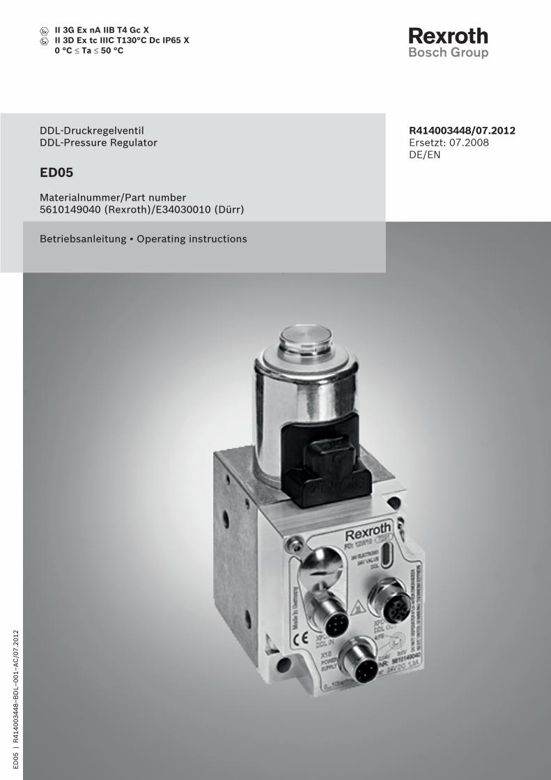
ED05
Materialnummer/Part number5610149040 (Rexroth)/E34030010 (Dürr)
DDL-DruckregelventilDDL-Pressure Regulator
Betriebsanleitung • Operating instructions
R414003448/07.2012Ersetzt: 07.2008DE/EN
ED
05
| R
41
40
03
44
8–
BD
L–0
01
–A
C/0
7.2
01
2
II 3G Ex nA IIB T4 Gc XII 3D Ex tc IIIC T130°C Dc IP65 X0 °C ≤ Ta ≤ 50 °C
24 V ELECTRONIC
24 V VALVE
DDL
15
16
17
4
2
1
3
5
67
14
13
8
9
10
12
11
012345
6789ABCDEF
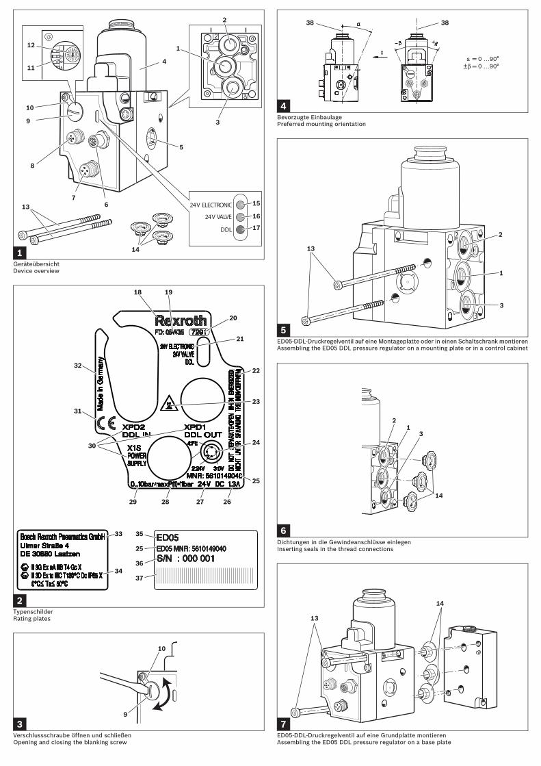
1GeräteübersichtDevice overview
ED05-DDL-Druckregelventil auf eine Montageplatte oder in einen Schaltschrank montierenAssembling the ED05 DDL pressure regulator on a mounting plate or in a control cabinet
Verschlussschraube öffnen und schließenOpening and closing the blanking screw
Bevorzugte EinbaulagePreferred mounting orientation
012345
6789ABCDEF
10
9
3
38 38
4
2
13
1
3
5
18 19
20
21
22
23
25
26272829
30
31
32
33
34
35
25
36
37
24
2TypenschilderRating plates
6
21
14
3
Dichtungen in die Gewindeanschlüsse einlegenInserting seals in the thread connections
7
14
13
ED05-DDL-Druckregelventil auf eine Grundplatte montierenAssembling the ED05 DDL pressure regulator on a base plate
X1S POWER SUPPLY 24 V VALVE
X1S POWER SUPPLY
24 V ELECTRONIC
24 V ELECTRONIC
24 V VALVE
X1S POWER SUPPLY
DDL
41
39
43
42
44
40
8
2
13
45
46
47
9
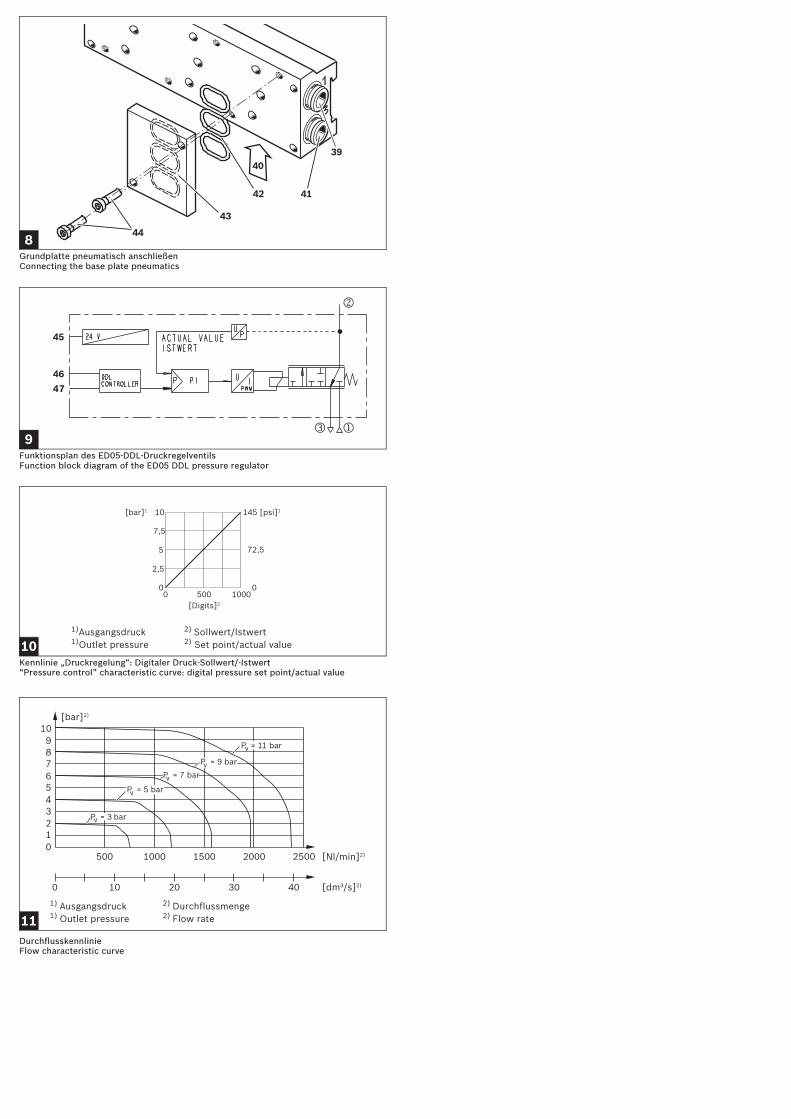
Grundplatte pneumatisch anschließenConnecting the base plate pneumatics
Funktionsplan des ED05-DDL-DruckregelventilsFunction block diagram of the ED05 DDL pressure regulator
0 00 1000500
10
5
7,5
2,5
145 [psi]1[bar]1
[Digits]2
72,5
101)Ausgangsdruck 2) Sollwert/Istwert1)Outlet pressure 2) Set point/actual value
Kennlinie „Druckregelung“: Digitaler Druck-Sollwert/-Istwert“Pressure control” characteristic curve: digital pressure set point/actual value
0123456789
10
0 10 20 30 40
500 1000 1500 2000 2500 [Nl/min]2)
[dm3/s]2)
[bar]1)
P = 9 barvP = 7 barv
P = 5 barv
P = 11 barv
P = 3 barv
111) Ausgangsdruck 2) Durchflussmenge1) Outlet pressure 2) Flow rate
DurchflusskennlinieFlow characteristic curve
X1S POWER SUPPLY 24 V VALVE
X1S POWER SUPPLY
24 V ELECTRONIC
24 V ELECTRONIC
24 V VALVE
X1S POWER SUPPLY
DDL
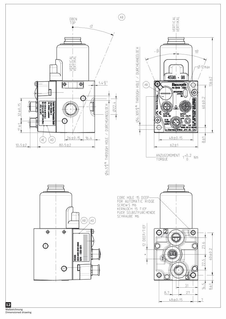
12MaßzeichnungDimensioned drawing
X1S POWER SUPPLY 24 V VALVE
X1S POWER SUPPLY
24 V ELECTRONIC
24 V ELECTRONIC
24 V VALVE
X1S POWER SUPPLY
DDL
13KonformitätserklärungDeclaration of conformity
1 Zu dieser DokumentationGültigkeit der DokumentationDiese Dokumentation gilt für das ED05-DDL-Druckregelventil mit folgender Materialnummer:
Diese Dokumentation richtet sich an Monteure, Bediener und Anlagenbetreiber. Sie enthält wichtige Informationen, um das ED05-DDL-Druckregelventil sicher und sachgerecht zu montieren, zu bedienen, zu warten und einfache Störungen selbst zu beseitigen.
Erforderliche DokumentationDas ED05-DDL-Druckregelventil ist eine Anlagenkomponente. Beachten Sie auch
• die Systembeschreibung DDL Drive & Diagnostic Link R499050030 (Deutsch), R499050031 (Englisch)
• die Anleitungen der übrigen Anlagenkomponenten,• die Anlagendokumentation des Anlagenherstellers.
Darstellung von Informationen
SicherheitshinweiseIn dieser Dokumentation stehen Sicherheitshinweise vor einer Handlungsabfolge, bei der die Gefahr von Personen- oder Sachschäden besteht. Die beschriebenen Maßnahmen zur Gefahrenabwehr müssen eingehalten werden.Sicherheitshinweise sind wie folgt aufgebaut:
Symbole
AbkürzungenIn dieser Dokumentation werden folgende Abkürzungen verwendet:
2 SicherheitshinweiseZu diesem KapitelDas ED05-DDL-Druckregelventil wurde gemäß den anerkannten Regeln der Technik hergestellt. Trotzdem besteht die Gefahr von Personen- und Sachschäden, wenn Sie dieses Kapitel und die Sicherheitshinweise in dieser Dokumentation nicht beachten.� Lesen Sie diese Dokumentation gründlich und vollständig, bevor Sie mit dem
ED05-DDL-Druckregelventil arbeiten.� Bewahren Sie die Anleitung so auf, dass sie jederzeit für alle Benutzer
zugänglich ist.� Geben Sie das ED05-DDL-Druckregelventil an Dritte stets zusammen mit der
Betriebsanleitung weiter.
Materialnummer Rexroth Materialnummer Dürr
5610149040 E34030010
SIGNALWORTArt und Quelle der Gefahr
Folgen bei Nichtbeachtung� Maßnahme zur Gefahrenabwehr� <Aufzählung>
Warnzeichen, Signalwort Bedeutung
GEFAHRkennzeichnet eine gefährliche Situation, in der Tod oder schwere Körperverletzung eintreten werden, wenn sie nicht vermieden wird
WARNUNGkennzeichnet eine gefährliche Situation, in der Tod oder schwere Körperverletzung eintreten können, wenn sie nicht vermieden wird
VORSICHTkennzeichnet eine gefährliche Situation, in der leichte bis mittelschwere Körperverletzungen eintreten können, wenn sie nicht vermieden wird
HINWEIS Sachschäden: Das Produkt oder die Umgebung können beschädigt werden.
Wenn diese Information nicht beachtet wird, kann das Produkt nicht optimal genutzt bzw. betrieben werden.
Abkürzung Bedeutung
ATEX EU-Richtlinie für Explosionsschutz (Atmosphère explosible)
ED05 E = Elektropneumatisches Druckregelventil,D = direkt angesteuert,05 = Nennweite 5
DC Direct Current (Gleichstrom)
DDL Drive & Diagnostic Link
FE Funktionserde
Nl Normliter Luft
n. c. not connected (nicht belegt)
Bestimmungsgemäße VerwendungDas ED05-DDL-Druckregelventil ist ein pneumatisches Gerät mit integrierter Elektronik, das ausschließlich zur Regelung von pneumatischen Drücken bestimmt ist. Es darf nur im eingebauten Zustand in einer Dürr-Anlage betrieben werden.Zulässige Medien sind trockene und kondensatfreie Luft. Der Betrieb mit reinem Sauerstoff ist nicht erlaubt.� Setzen Sie das ED05-DDL-Druckregelventil ausschließlich im industriellen
Bereich ein.Wenn Sie das ED05-DDL-Druckregelventil im Wohnbereich (Wohn-, Geschäfts- und Gewerbebereich) einsetzen wollen, müssen Sie eine Einzelgenehmigung bei einer Behörde oder Prüfstelle einholen. In Deutschland werden Einzelgenehmigungen von der Regulierungsbehörde für Telekommunikation erteilt.� Halten Sie die in den technischen Daten genannten Leistungsgrenzen ein.� Verwenden Sie das ED05-DDL-Druckregelventil ausschließlich in Innenräumen.
Das ED05-DDL-Druckregelventil ist kein Sicherheitsbauteil.� Setzen Sie sich mit der Bosch Rexroth AG in Verbindung, wenn Sie das Gerät in
sicherheitsgerichteten Steuerketten einsetzen wollen. Die Adresse finden Sie auf der Rückseite der Anleitung.
Nicht bestimmungsgemäße VerwendungJeder andere Gebrauch als in der bestimmungsgemäßen Verwendung beschrieben ist nicht bestimmungsgemäß und deshalb unzulässig.Für Schäden bei nicht bestimmungsgemäßer Verwendung übernimmt die Bosch Rexroth AG keine Haftung. Die Risiken bei nicht bestimmungsgemäßer Verwendung liegen allein beim Benutzer.Zur nicht bestimmungsgemäßen Verwendung des Produkts gehört, wenn Sie das ED05-DDL-Druckregelventil als Sicherheitsbauteil einsetzen.
Qualifikation des PersonalsDie Montage und Inbetriebnahme erfordert grundlegende elektrische und pneumatische Kenntnisse sowie Kenntnisse der zugehörigen Fachbegriffe. Die Montage und Inbetriebnahme darf daher nur von einer Elektro- oder Pneumatikfachkraft oder von einer unterwiesenen Person unter der Leitung und Aufsicht einer Fachkraft erfolgen. Eine Fachkraft ist, wer aufgrund seiner fachlichen Ausbildung, seiner Kenntnisse und Erfahrungen sowie seiner Kenntnisse der einschlägigen Bestimmungen, die ihm übertragenen Arbeiten beurteilen, mögliche Gefahren erkennen und geeignete Sicherheitsmaßnahmen treffen kann. Eine Fachkraft muss die einschlägigen fachspezifischen Regeln einhalten.
Allgemeine Sicherheitshinweise• Beachten Sie die gültigen Vorschriften zur Unfallverhütung und zum
Umweltschutz.• Beachten Sie die geltenden Bestimmungen des Anwenderlandes für
explosionsgefährdete Bereiche.• Beachten Sie die Sicherheitsvorschriften und -bestimmungen des Landes, in
dem das Produkt eingesetzt/angewendet wird.• Verwenden Sie Rexroth-Produkte nur in technisch einwandfreiem Zustand.• Verwenden Sie das Gerät ausschließlich im Leistungsbereich, der in den
technischen Daten angegeben ist. Wenn Sie die Grenzwerte nicht einhalten, besteht in explosionsgefährdeten Bereichen Zündgefahr.
• Beachten Sie alle Hinweise auf dem Produkt.• Personen, die Rexroth-Produkte montieren, bedienen, demontieren oder
warten, dürfen nicht unter dem Einfluss von Alkohol, sonstigen Drogen oder Medikamenten, die die Reaktionsfähigkeit beeinflussen, stehen.
• Verwenden Sie nur vom Hersteller zugelassene Zubehör- und Ersatzteile, um Personengefährdungen wegen nicht geeigneter Ersatzteile auszuschließen.
• Halten Sie die in der Produktdokumentation angegebenen technischen Daten und Umgebungsbedingungen ein.
• Wenn in sicherheitsrelevanten Anwendungen ungeeignete Produkte eingebaut oder verwendet werden, können unbeabsichtigte Betriebszustände in der Anwendung auftreten, die Personen- und/oder Sachschäden verursachen können. Setzen Sie daher ein Produkt nur dann in sicherheitsrelevante Anwendungen ein, wenn diese Verwendung ausdrücklich in der Dokumentation des Produkts spezifiziert und erlaubt ist.
• Sie dürfen das Produkt erst dann in Betrieb nehmen, wenn festgestellt wurde, dass das Endprodukt (beispielsweise eine Maschine oder Anlage), in das die Rexroth-Produkte eingebaut sind, den länderspezifischen Bestimmungen, Sicherheitsvorschriften und Normen der Anwendung entspricht.
• Sie dürfen das Produkt grundsätzlich nicht verändern oder umbauen.• Montieren Sie das ED05-DDL-Druckregelventil immer auf eine Montageplatte, in
einen Schaltschrank oder auf eine Grundplatte.
Produkt- und technologieabhängige Sicherheitshinweise
GEFAHRExplosionsgefahr durch Ziehen von Steckern in explosionsfähiger Atmosphäre!
Ziehen von Steckern unter Spannung führt zu großen Potentialunterschieden.� Ziehen Sie niemals Stecker in explosionsfähiger Atmosphäre.� Arbeiten Sie am Gerät nur bei explosionsfreier Atmosphäre.
Deutsch 1
Persönliche Schutzausrüstung� Tragen Sie bei Arbeiten am Gerät geeignete Schutzkleidung, insbesondere
Schutzbrille und Gehörschutz. Beachten Sie die geltenden Arbeitsschutzregelungen.
Pflichten des BetreibersAls Betreiber der Anlage, die mit diesem Produkt ausgestattet werden soll, sind Sie dafür verantwortlich,
• dass die bestimmungsgemäße Verwendung sichergestellt ist,• dass das Bedienpersonal regelmäßig unterwiesen wird,• dass die Einsatzbedingungen den Anforderungen an die sichere Verwendung
des Produkts entsprechen,• dass Reinigungsintervalle festgelegt und eingehalten werden,• dass Zündgefahren, die durch den Einbau von Betriebsmitteln in Ihre Anlage
entstehen, berücksichtigt werden,• dass bei einem aufgetretenen Defekt keine eigenmächtigen Reparaturversuche
unternommen werden, • dass Sie für ausreichenden Blitzschutz sorgen.• dass die Errichtungsbestimmungen für Ex-Bauteile und -Geräte unbedingt
eingehalten werden (z. B. EN 60079-14, EN 61241-14).
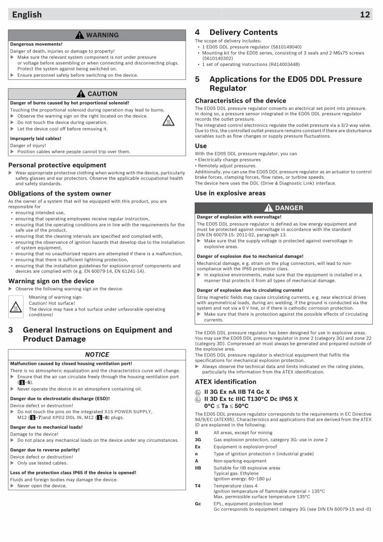
Warnschild am Gerät� Beachten Sie folgendes Warnschild am Gerät:
3 Allgemeine Hinweise zu Sachschäden und Produktschäden
WARNUNGGefahrbringende Bewegungen!
Lebensgefahr, Verletzungsgefahr oder Sachschaden!� Schalten Sie immer den relevanten Anlagenteil drucklos und spannungsfrei,
bevor Sie das Gerät montieren bzw. Stecker anschließen oder ziehen. Sichern Sie die Anlage gegen Wiedereinschalten.
� Stellen Sie vor dem Einschalten sicher, dass die Personensicherheit gewährleistet ist.
VORSICHTVerbrennungsgefahr durch heißen Proportionalmagneten!
Berühren des Proportionalmagneten im laufenden Betrieb kann zu Verbrennungen führen.� Beachten Sie nebenstehendes Warnschild auf dem Gerät.� Berühren Sie das Gerät nicht während des Betriebs.� Lassen Sie das Gerät abkühlen, bevor Sie es ausbauen.
Unsachgemäß verlegte Leitungen!
Verletzungsgefahr!� Verlegen Sie die Leitungen so, dass niemand darüber stolpern kann.
Bedeutung des Warnschildes:Vorsicht! Heiße Oberfläche!Das Gerät kann unter ungünstigen Betriebsbedingungen heiße Oberflächen besitzen!
HINWEISFehlfunktion durch verschlossene Gehäusebelüftungsöffnung!
Es findet kein Ausgleich zur Atmosphäre statt und die Kennlinie verschiebt sich.� Stellen Sie sicher, dass die Luft ungehindert durch die
Gehäusebelüftungsöffnung ( –5) zirkulieren kann. � Betreiben Sie das Gerät niemals in ölhaltiger Atmosphäre.
Gefahr durch elektrostatische Entladung (ESD)!
Gerätedefekt oder -zerstörung!� Berühren Sie nicht die Pins der Einbaustecker X1S POWER SUPPLY,
M12 ( –7) und XPD2 DDL IN, M12 ( –8).
Gefahr durch mechanische Belastung!
Beschädigung des Geräts!� Belasten Sie das Gerät unter keinen Umständen mechanisch.
Gefahr durch Verpolung!
Gerätedefekt oder -zerstörung!� Verwenden Sie ausschließlich geprüfte Leitungen.
Verlust der Schutzart IP65 durch Öffnen des Geräts!
Flüssigkeiten und Fremdkörper können das Gerät beschädigen.� Öffnen Sie niemals das Gerät.
1
1 1
4 LieferumfangIm Lieferumfang sind enthalten:
• 1 ED05-DDL-Druckregelventil (5610149040)• Montagesatz, Serie ED05, bestehend aus 3 Dichtungen und 2 Schrauben M6x75
(5610140302)• 1 Betriebsanleitung (R414003448)
5 Einsatzbereiche des ED05-DDL-Druckregelventils
Merkmale des GerätsDas ED05-DDL-Druckregelventil wandelt einen elektrischen Sollwert in einen Druck um. Dabei erfasst ein Drucksensor, der in das ED05-DDL-Druckregelventil integriert ist, den Ausgangsdruck.Die integrierte Regelelektronik regelt den Ausgangsdruck über ein 3/2-Wegeventil aus. Dadurch bleibt der geregelte Ausgangsdruck bei Störgrößen wie Volumenstrom-Änderungen oder Versorgungsdruck-Schwankungen konstant.
VerwendungMit dem ED05-DDL-Druckregelventil können Sie:• Drücke elektrisch verändern• Drücke fernverstellenAußerdem können Sie das ED05-DDL-Druckregelventil als Stellglied zur Regelung von Bremskräften, Spannkräften, Durchflussmengen oder der Drehzahl von Turbinen einsetzen. Das vorliegende Gerät benutzt die DDL-Schnittstelle (Drive & Diagnostic Link).
Einsatz in explosionsgefährdeten Bereichen
Das ED05-DDL-Druckregelventil ist für den Einsatz in explosionsgefährdeten Bereichen ausgelegt. Sie können das ED05-DDL-Druckregelventil innerhalb der Zone 2 (Kategorie 3G) und Zone 22 (Kategorie 3D) einsetzen. Die Druckluft muss immer außerhalb des explosionsgefährdeten Bereiches erzeugt und aufbereitet werden.Das ED05-DDL-Druckregelventil ist ein elektrisches Betriebsmittel und erfüllt die Anforderungen des mechanischen Explosionsschutzes.� Beachten Sie stets die technischen Daten und die auf den Typenschildern
angegebenen Grenzwerte, insbesondere die Angaben, die aus der ATEX-Kennzeichnung hervorgehen.
ATEX-Kennzeichnung
Das ED05-DDL-Druckregelventil entspricht den Anforderungen der EG-Richtlinie 94/9/EG (ATEX 95). Im Folgenden sind die Merkmale und Einsatzbereiche, die aus der ATEX-Kennzeichnung hervorgehen, erläutert:
GEFAHRExplosionsgefahr bei Überspannung!
Das ED05-DDL-Druckregelventil ist als Betriebsmittel mit niedriger Energie definiert und muss nach Norm DIN EN 60079-15: 2011-02, Absatz 13, gegen Überspannung geschützt werden.� Stellen Sie sicher, dass in explosionsgefährdeten Bereichen die
Versorgungsspannung gegen Überspannung geschützt ist.
Explosionsgefahr durch mechanische Beschädigungen!
Mechanische Beschädigungen, z. B. durch Belastung der Steckverbinder, führen zum Verlust der Schutzart IP65.� Stellen Sie sicher, dass das Betriebsmittel in explosionsgefährdeten
Bereichen gegen jegliche mechanische Beschädigung geschützt eingebaut wird.
Explosionsgefahr durch Zirkulationsströme!
Magnetische Streufelder können Zirkulationsströme verursachen, z. B. in der Nähe von elektrischen Antrieben bei unsymmetrischer Last, bei Elektroschweißen, wenn die Masse über die Anlage und nicht über eine 0-V-Leitung geleitet wird oder bei kathodischem Korrosionsschutz. � Stellen Sie sicher, dass ein Schutz gegen mögliche Effekte von
Zirkulationsströmen besteht.
II alle Bereiche, außer Bergbau
3G Gas-Ex, Kategorie 3G: Einsatz in Zone 2
Ex Gerät ist explosionsgeschützt
n Zündschutzart n (in guter Industriequalität)
A nichtfunkendes Betriebsmittel
IIB für Explosionsbereich IIB geeignetTypisches Gas: ÄthylenZündenergie: 60–180 �J
T4 Temperaturklasse 4Zündtemperatur brennbarer Stoffe > 135 °Cmax. zulässige Oberflächentemperatur 135 °C
II 3G Ex nA IIB T4 Gc XII 3D Ex tc IIIC T130°C Dc IP65 X0 °C ≤ Ta ≤ 50 °C
Deutsch 2
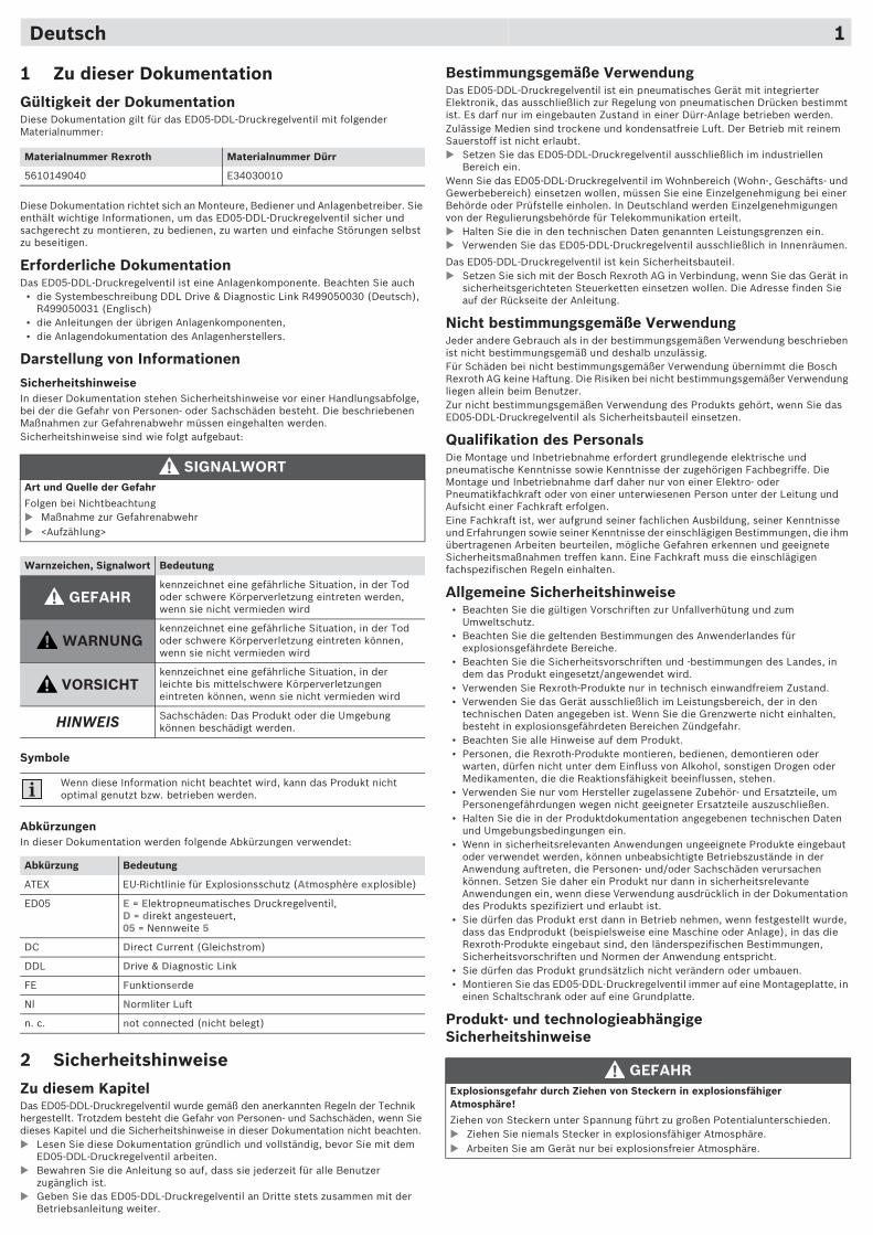
6 GerätebeschreibungDie Geräteübersicht ist in Abb. dargestellt.
Das ED05-DDL-Druckregelventil mit Einbaustecker M12 gibt es für den folgenden Ausgangsdruck:
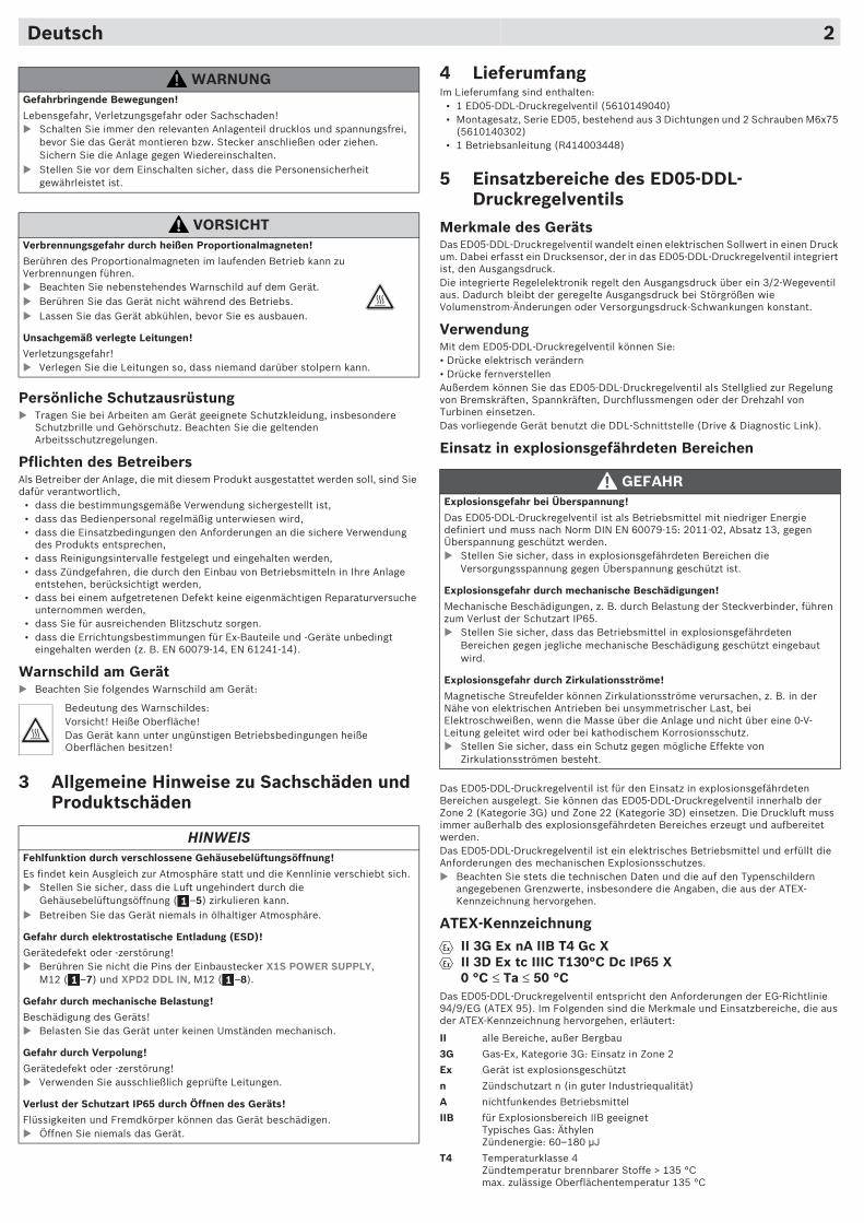
Kennzeichnung auf dem Typenschild
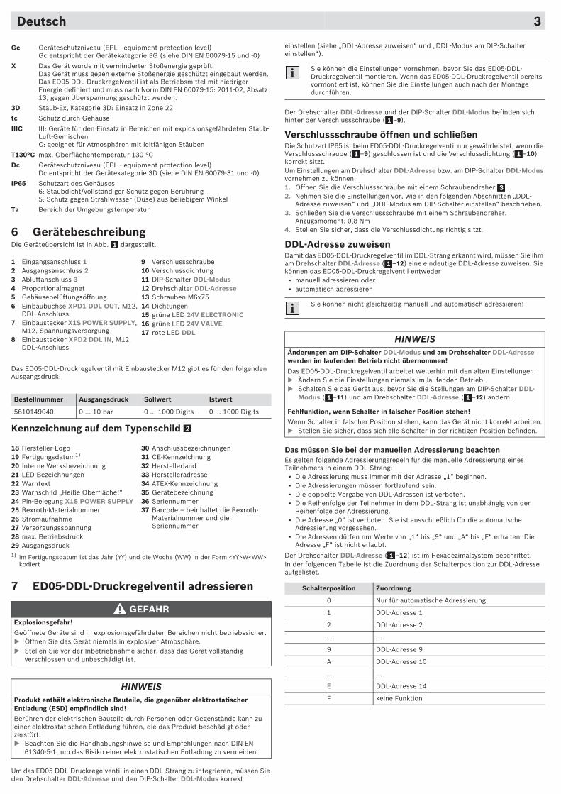
7 ED05-DDL-Druckregelventil adressieren
Um das ED05-DDL-Druckregelventil in einen DDL-Strang zu integrieren, müssen Sie den Drehschalter DDL-Adresse und den DIP-Schalter DDL-Modus korrekt
Gc Geräteschutzniveau (EPL - equipment protection level)Gc entspricht der Gerätekategorie 3G (siehe DIN EN 60079-15 und -0)
X Das Gerät wurde mit verminderter Stoßenergie geprüft. Das Gerät muss gegen externe Stoßenergie geschützt eingebaut werden.Das ED05-DDL-Druckregelventil ist als Betriebsmittel mit niedriger Energie definiert und muss nach Norm DIN EN 60079-15: 2011-02, Absatz 13, gegen Überspannung geschützt werden.
3D Staub-Ex, Kategorie 3D: Einsatz in Zone 22
tc Schutz durch Gehäuse
IIIC III: Geräte für den Einsatz in Bereichen mit explosionsgefährdeten Staub-Luft-GemischenC: geeignet für Atmosphären mit leitfähigen Stäuben
T130°C max. Oberflächentemperatur 130 °C
Dc Geräteschutzniveau (EPL - equipment protection level)Dc entspricht der Gerätekategorie 3D (siehe DIN EN 60079-31 und -0)
IP65 Schutzart des Gehäuses6: Staubdicht/vollständiger Schutz gegen Berührung5: Schutz gegen Strahlwasser (Düse) aus beliebigem Winkel
Ta Bereich der Umgebungstemperatur
1 Eingangsanschluss 12 Ausgangsanschluss 23 Abluftanschluss 34 Proportionalmagnet5 Gehäusebelüftungsöffnung6 Einbaubuchse XPD1 DDL OUT, M12,
DDL-Anschluss7 Einbaustecker X1S POWER SUPPLY,
M12, Spannungsversorgung8 Einbaustecker XPD2 DDL IN, M12,
DDL-Anschluss
9 Verschlussschraube10 Verschlussdichtung11 DIP-Schalter DDL-Modus12 Drehschalter DDL-Adresse13 Schrauben M6x7514 Dichtungen15 grüne LED 24V ELECTRONIC16 grüne LED 24V VALVE17 rote LED DDL
Bestellnummer Ausgangsdruck Sollwert Istwert
5610149040 0 ... 10 bar 0 ... 1000 Digits 0 ... 1000 Digits
18 Hersteller-Logo19 Fertigungsdatum1)
20 Interne Werksbezeichnung21 LED-Bezeichnungen22 Warntext23 Warnschild „Heiße Oberfläche!“24 Pin-Belegung X1S POWER SUPPLY25 Rexroth-Materialnummer26 Stromaufnahme27 Versorgungsspannung28 max. Betriebsdruck29 Ausgangsdruck1) im Fertigungsdatum ist das Jahr (YY) und die Woche (WW) in der Form <YY>W<WW>
kodiert
30 Anschlussbezeichnungen31 CE-Kennzeichnung32 Herstellerland33 Herstelleradresse34 ATEX-Kennzeichnung35 Gerätebezeichnung36 Seriennummer37 Barcode – beinhaltet die Rexroth-
Materialnummer und die Seriennummer
GEFAHRExplosionsgefahr!
Geöffnete Geräte sind in explosionsgefährdeten Bereichen nicht betriebssicher.� Öffnen Sie das Gerät niemals in explosiver Atmosphäre.� Stellen Sie vor der Inbetriebnahme sicher, dass das Gerät vollständig
verschlossen und unbeschädigt ist.
HINWEISProdukt enthält elektronische Bauteile, die gegenüber elektrostatischer Entladung (ESD) empfindlich sind!
Berühren der elektrischen Bauteile durch Personen oder Gegenstände kann zu einer elektrostatischen Entladung führen, die das Produkt beschädigt oder zerstört.� Beachten Sie die Handhabungshinweise und Empfehlungen nach DIN EN
61340-5-1, um das Risiko einer elektrostatischen Entladung zu vermeiden.
1
2
einstellen (siehe „DDL-Adresse zuweisen“ und „DDL-Modus am DIP-Schalter einstellen“).
Der Drehschalter DDL-Adresse und der DIP-Schalter DDL-Modus befinden sich hinter der Verschlussschraube ( –9).
Verschlussschraube öffnen und schließenDie Schutzart IP65 ist beim ED05-DDL-Druckregelventil nur gewährleistet, wenn die Verschlussschraube ( –9) geschlossen ist und die Verschlussdichtung ( –10) korrekt sitzt.Um Einstellungen am Drehschalter DDL-Adresse bzw. am DIP-Schalter DDL-Modus vornehmen zu können:1. Öffnen Sie die Verschlussschraube mit einem Schraubendreher .2. Nehmen Sie die Einstellungen vor, wie in den folgenden Abschnitten „DDL-
Adresse zuweisen“ und „DDL-Modus am DIP-Schalter einstellen“ beschrieben.3. Schließen Sie die Verschlussschraube mit einem Schraubendreher.
Anzugsmoment: 0,8 Nm4. Stellen Sie sicher, dass die Verschlussdichtung richtig sitzt.
DDL-Adresse zuweisenDamit das ED05-DDL-Druckregelventil im DDL-Strang erkannt wird, müssen Sie ihm am Drehschalter DDL-Adresse ( –12) eine eindeutige DDL-Adresse zuweisen. Sie können das ED05-DDL-Druckregelventil entweder
• manuell adressieren oder • automatisch adressieren
Das müssen Sie bei der manuellen Adressierung beachtenEs gelten folgende Adressierungsregeln für die manuelle Adressierung eines Teilnehmers in einem DDL-Strang:
• Die Adressierung muss immer mit der Adresse „1“ beginnen.• Die Adressierungen müssen fortlaufend sein.• Die doppelte Vergabe von DDL-Adressen ist verboten.• Die Reihenfolge der Teilnehmer in dem DDL-Strang ist unabhängig von der
Reihenfolge der Adressierung.• Die Adresse „0“ ist verboten. Sie ist ausschließlich für die automatische
Adressierung vorgesehen.• Die Adressen dürfen nur Werte von „1“ bis „9“ und „A“ bis „E“ erhalten. Die
Adresse „F“ ist nicht erlaubt.
Der Drehschalter DDL-Adresse ( –12) ist im Hexadezimalsystem beschriftet.In der folgenden Tabelle ist die Zuordnung der Schalterposition zur DDL-Adresse aufgelistet.
Sie können die Einstellungen vornehmen, bevor Sie das ED05-DDL-Druckregelventil montieren. Wenn das ED05-DDL-Druckregelventil bereits vormontiert ist, können Sie die Einstellungen auch nach der Montage durchführen.
Sie können nicht gleichzeitig manuell und automatisch adressieren!
HINWEISÄnderungen am DIP-Schalter DDL-Modus und am Drehschalter DDL-Adresse werden im laufenden Betrieb nicht übernommen!
Das ED05-DDL-Druckregelventil arbeitet weiterhin mit den alten Einstellungen.� Ändern Sie die Einstellungen niemals im laufenden Betrieb. � Schalten Sie das Gerät aus, bevor Sie die Stellungen am DIP-Schalter DDL-
Modus ( –11) und am Drehschalter DDL-Adresse ( –12) ändern.
Fehlfunktion, wenn Schalter in falscher Position stehen!
Wenn Schalter in falscher Position stehen, kann das Gerät nicht korrekt arbeiten.� Stellen Sie sicher, dass sich alle Schalter in der richtigen Position befinden.
Schalterposition Zuordnung
0 Nur für automatische Adressierung
1 DDL-Adresse 1
2 DDL-Adresse 2
... ...
9 DDL-Adresse 9
A DDL-Adresse 10
... ...
E DDL-Adresse 14
F keine Funktion
1
1 1
3
1
1 1
1
Deutsch 3
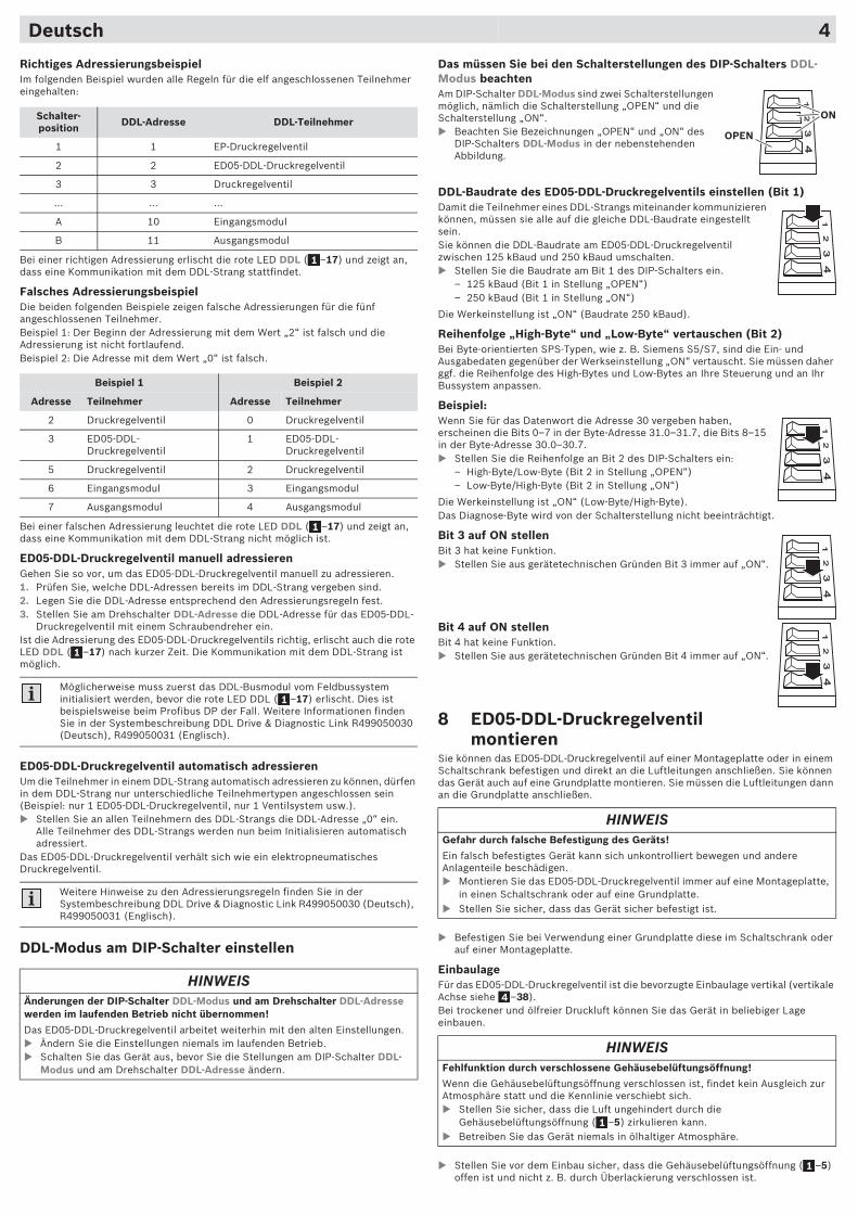
Richtiges AdressierungsbeispielIm folgenden Beispiel wurden alle Regeln für die elf angeschlossenen Teilnehmer eingehalten:
Bei einer richtigen Adressierung erlischt die rote LED DDL ( –17) und zeigt an, dass eine Kommunikation mit dem DDL-Strang stattfindet.
Falsches AdressierungsbeispielDie beiden folgenden Beispiele zeigen falsche Adressierungen für die fünf angeschlossenen Teilnehmer. Beispiel 1: Der Beginn der Adressierung mit dem Wert „2“ ist falsch und die Adressierung ist nicht fortlaufend.Beispiel 2: Die Adresse mit dem Wert „0“ ist falsch.
Bei einer falschen Adressierung leuchtet die rote LED DDL ( –17) und zeigt an, dass eine Kommunikation mit dem DDL-Strang nicht möglich ist.
ED05-DDL-Druckregelventil manuell adressierenGehen Sie so vor, um das ED05-DDL-Druckregelventil manuell zu adressieren.1. Prüfen Sie, welche DDL-Adressen bereits im DDL-Strang vergeben sind. 2. Legen Sie die DDL-Adresse entsprechend den Adressierungsregeln fest.3. Stellen Sie am Drehschalter DDL-Adresse die DDL-Adresse für das ED05-DDL-
Druckregelventil mit einem Schraubendreher ein.Ist die Adressierung des ED05-DDL-Druckregelventils richtig, erlischt auch die rote LED DDL ( –17) nach kurzer Zeit. Die Kommunikation mit dem DDL-Strang ist möglich.
ED05-DDL-Druckregelventil automatisch adressierenUm die Teilnehmer in einem DDL-Strang automatisch adressieren zu können, dürfen in dem DDL-Strang nur unterschiedliche Teilnehmertypen angeschlossen sein (Beispiel: nur 1 ED05-DDL-Druckregelventil, nur 1 Ventilsystem usw.).� Stellen Sie an allen Teilnehmern des DDL-Strangs die DDL-Adresse „0“ ein.
Alle Teilnehmer des DDL-Strangs werden nun beim Initialisieren automatisch adressiert.
Das ED05-DDL-Druckregelventil verhält sich wie ein elektropneumatisches Druckregelventil.
DDL-Modus am DIP-Schalter einstellen
Schalter-position DDL-Adresse DDL-Teilnehmer
1 1 EP-Druckregelventil
2 2 ED05-DDL-Druckregelventil
3 3 Druckregelventil
… … …
A 10 Eingangsmodul
B 11 Ausgangsmodul
Beispiel 1 Beispiel 2
Adresse Teilnehmer Adresse Teilnehmer
2 Druckregelventil 0 Druckregelventil
3 ED05-DDL-Druckregelventil
1 ED05-DDL-Druckregelventil
5 Druckregelventil 2 Druckregelventil
6 Eingangsmodul 3 Eingangsmodul
7 Ausgangsmodul 4 Ausgangsmodul
Möglicherweise muss zuerst das DDL-Busmodul vom Feldbussystem initialisiert werden, bevor die rote LED DDL ( –17) erlischt. Dies ist beispielsweise beim Profibus DP der Fall. Weitere Informationen finden Sie in der Systembeschreibung DDL Drive & Diagnostic Link R499050030 (Deutsch), R499050031 (Englisch).
Weitere Hinweise zu den Adressierungsregeln finden Sie in der Systembeschreibung DDL Drive & Diagnostic Link R499050030 (Deutsch), R499050031 (Englisch).
HINWEISÄnderungen der DIP-Schalter DDL-Modus und am Drehschalter DDL-Adresse werden im laufenden Betrieb nicht übernommen!
Das ED05-DDL-Druckregelventil arbeitet weiterhin mit den alten Einstellungen.� Ändern Sie die Einstellungen niemals im laufenden Betrieb. � Schalten Sie das Gerät aus, bevor Sie die Stellungen am DIP-Schalter DDL-
Modus und am Drehschalter DDL-Adresse ändern.
1
1
1
1
Das müssen Sie bei den Schalterstellungen des DIP-Schalters DDL-Modus beachtenAm DIP-Schalter DDL-Modus sind zwei Schalterstellungen möglich, nämlich die Schalterstellung „OPEN“ und die Schalterstellung „ON“.� Beachten Sie Bezeichnungen „OPEN“ und „ON“ des
DIP-Schalters DDL-Modus in der nebenstehenden Abbildung.
DDL-Baudrate des ED05-DDL-Druckregelventils einstellen (Bit 1)Damit die Teilnehmer eines DDL-Strangs miteinander kommunizieren können, müssen sie alle auf die gleiche DDL-Baudrate eingestellt sein.Sie können die DDL-Baudrate am ED05-DDL-Druckregelventil zwischen 125 kBaud und 250 kBaud umschalten.� Stellen Sie die Baudrate am Bit 1 des DIP-Schalters ein.
– 125 kBaud (Bit 1 in Stellung „OPEN“) – 250 kBaud (Bit 1 in Stellung „ON“)
Die Werkeinstellung ist „ON“ (Baudrate 250 kBaud).
Reihenfolge „High-Byte“ und „Low-Byte“ vertauschen (Bit 2)Bei Byte-orientierten SPS-Typen, wie z. B. Siemens S5/S7, sind die Ein- und Ausgabedaten gegenüber der Werkseinstellung „ON“ vertauscht. Sie müssen daher ggf. die Reihenfolge des High-Bytes und Low-Bytes an Ihre Steuerung und an Ihr Bussystem anpassen.
Beispiel:Wenn Sie für das Datenwort die Adresse 30 vergeben haben, erscheinen die Bits 0–7 in der Byte-Adresse 31.0–31.7, die Bits 8–15 in der Byte-Adresse 30.0–30.7.� Stellen Sie die Reihenfolge an Bit 2 des DIP-Schalters ein:
– High-Byte/Low-Byte (Bit 2 in Stellung „OPEN“)– Low-Byte/High-Byte (Bit 2 in Stellung „ON“)
Die Werkeinstellung ist „ON“ (Low-Byte/High-Byte).Das Diagnose-Byte wird von der Schalterstellung nicht beeinträchtigt.
Bit 3 auf ON stellenBit 3 hat keine Funktion.� Stellen Sie aus gerätetechnischen Gründen Bit 3 immer auf „ON“.
Bit 4 auf ON stellenBit 4 hat keine Funktion.� Stellen Sie aus gerätetechnischen Gründen Bit 4 immer auf „ON“.
8 ED05-DDL-Druckregelventil montieren
Sie können das ED05-DDL-Druckregelventil auf einer Montageplatte oder in einem Schaltschrank befestigen und direkt an die Luftleitungen anschließen. Sie können das Gerät auch auf eine Grundplatte montieren. Sie müssen die Luftleitungen dann an die Grundplatte anschließen.
� Befestigen Sie bei Verwendung einer Grundplatte diese im Schaltschrank oder auf einer Montageplatte.
EinbaulageFür das ED05-DDL-Druckregelventil ist die bevorzugte Einbaulage vertikal (vertikale Achse siehe –38).Bei trockener und ölfreier Druckluft können Sie das Gerät in beliebiger Lage einbauen.
� Stellen Sie vor dem Einbau sicher, dass die Gehäusebelüftungsöffnung ( –5) offen ist und nicht z. B. durch Überlackierung verschlossen ist.
HINWEISGefahr durch falsche Befestigung des Geräts!
Ein falsch befestigtes Gerät kann sich unkontrolliert bewegen und andere Anlagenteile beschädigen.� Montieren Sie das ED05-DDL-Druckregelventil immer auf eine Montageplatte,
in einen Schaltschrank oder auf eine Grundplatte.� Stellen Sie sicher, dass das Gerät sicher befestigt ist.
HINWEISFehlfunktion durch verschlossene Gehäusebelüftungsöffnung!
Wenn die Gehäusebelüftungsöffnung verschlossen ist, findet kein Ausgleich zur Atmosphäre statt und die Kennlinie verschiebt sich.� Stellen Sie sicher, dass die Luft ungehindert durch die
Gehäusebelüftungsöffnung ( –5) zirkulieren kann. � Betreiben Sie das Gerät niemals in ölhaltiger Atmosphäre.
ON
OPEN
4
1
1
Deutsch 4
Deutsch 5
Bevor Sie mit der Montage beginnen� Lassen Sie das ED05-DDL-Druckregelventil vor dem Einbau einige Stunden
akklimatisieren, da sich ansonsten im Gehäuse Kondenswasser niederschlagen kann.
� Schalten Sie den relevanten Anlagenteil spannungsfrei und drucklos.� Nehmen Sie die Einstellungen am Drehschalter DDL-Adresse und am DIP-
Schalter DDL-Modus vor, bevor Sie das ED05-DDL-Druckregelventil montieren (siehe „DDL-Adresse zuweisen“ und „DDL-Modus am DIP-Schalter einstellen“ in Kapitel 7).
Auf eine Montageplatte oder in einen Schaltschrank montieren1. Setzen Sie die beiden Schrauben M6x75 wie in Abb. gezeigt in die beiden
Durchgangsbohrungen im Gehäuse ein.2. Setzen Sie das Gerät auf die Montageplatte auf und ziehen Sie die Schrauben
an.Anzugsmoment: 6 Nm
ED05-DDL-Druckregelventil pneumatisch anschließen� Beachten Sie die Montagemomente der Verschraubungen.
Gewindeanschluss: G1/4“max. Anzugsmoment: 10 Nm
1. Schließen Sie die Versorgungsleitung am Eingangsanschluss 1 ( –1) an.2. Schließen Sie die Ausgangsleitung am Ausgangsanschluss 2 ( –2) an.3. Schließen Sie am Abluftanschluss 3 ( –3) immer einen Schalldämpfer oder
eine Leitung für gefasste Abluft an.
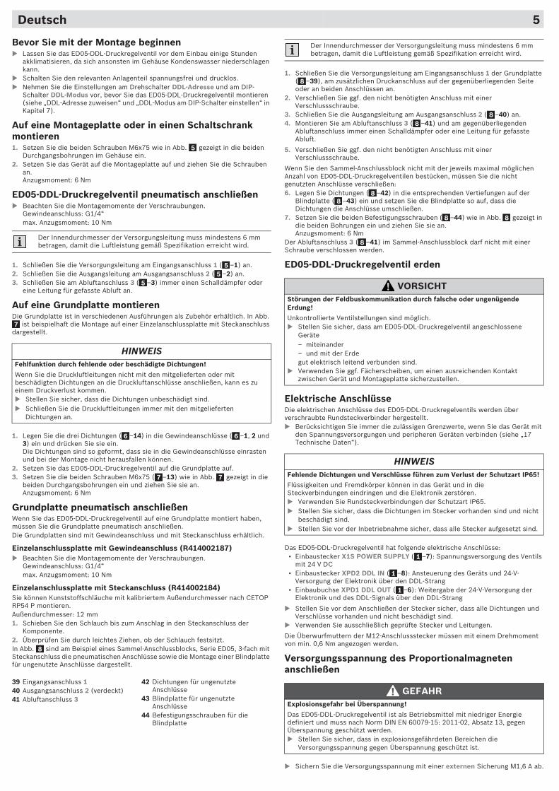
Auf eine Grundplatte montierenDie Grundplatte ist in verschiedenen Ausführungen als Zubehör erhältlich. In Abb.
ist beispielhaft die Montage auf einer Einzelanschlussplatte mit Steckanschluss dargestellt.
1. Legen Sie die drei Dichtungen ( –14) in die Gewindeanschlüsse ( –1, 2 und 3) ein und drücken Sie sie ein.Die Dichtungen sind so geformt, dass sie in die Gewindeanschlüsse einrasten und bei der Montage nicht herausfallen können.
2. Setzen Sie das ED05-DDL-Druckregelventil auf die Grundplatte auf.3. Setzen Sie die beiden Schrauben M6x75 ( –13) wie in Abb. gezeigt in die
beiden Durchgangsbohrungen ein und ziehen Sie sie an.Anzugsmoment: 6 Nm
Grundplatte pneumatisch anschließenWenn Sie das ED05-DDL-Druckregelventil auf eine Grundplatte montiert haben, müssen Sie die Grundplatte pneumatisch anschließen.Die Grundplatten sind mit Gewindeanschluss und mit Steckanschluss erhältlich.
Einzelanschlussplatte mit Gewindeanschluss (R414002187)� Beachten Sie die Montagemomente der Verschraubungen.
Gewindeanschluss: G1/4“max. Anzugsmoment: 10 Nm
Einzelanschlussplatte mit Steckanschluss (R414002184)Sie können Kunststoffschläuche mit kalibriertem Außendurchmesser nach CETOP RP54 P montieren.Außendurchmesser: 12 mm1. Schieben Sie den Schlauch bis zum Anschlag in den Steckanschluss der
Komponente.2. Überprüfen Sie durch leichtes Ziehen, ob der Schlauch festsitzt.In Abb. sind am Beispiel eines Sammel-Anschlussblocks, Serie ED05, 3-fach mit Steckanschluss die pneumatischen Anschlüsse sowie die Montage einer Blindplatte für ungenutzte Anschlüsse dargestellt.
Der Innendurchmesser der Versorgungsleitung muss mindestens 6 mm betragen, damit die Luftleistung gemäß Spezifikation erreicht wird.
HINWEISFehlfunktion durch fehlende oder beschädigte Dichtungen!
Wenn Sie die Druckluftleitungen nicht mit den mitgelieferten oder mit beschädigten Dichtungen an die Druckluftanschlüsse anschließen, kann es zu einem Druckverlust kommen. � Stellen Sie sicher, dass die Dichtungen unbeschädigt sind.� Schließen Sie die Druckluftleitungen immer mit den mitgelieferten
Dichtungen an.
39 Eingangsanschluss 140 Ausgangsanschluss 2 (verdeckt)41 Abluftanschluss 3
42 Dichtungen für ungenutzte Anschlüsse
43 Blindplatte für ungenutzte Anschlüsse
44 Befestigungsschrauben für die Blindplatte
5
55
5
7
6 6
7 7
8
1. Schließen Sie die Versorgungsleitung am Eingangsanschluss 1 der Grundplatte ( –39), am zusätzlichen Druckanschluss auf der gegenüberliegenden Seite oder an beiden Anschlüssen an.
2. Verschließen Sie ggf. den nicht benötigten Anschluss mit einer Verschlussschraube.
3. Schließen Sie die Ausgangsleitung am Ausgangsanschluss 2 ( –40) an.4. Montieren Sie am Abluftanschluss 3 ( –41) und am gegenüberliegenden
Abluftanschluss immer einen Schalldämpfer oder eine Leitung für gefasste Abluft.
5. Verschließen Sie ggf. den nicht benötigten Anschluss mit einer Verschlussschraube.
Wenn Sie den Sammel-Anschlussblock nicht mit der jeweils maximal möglichen Anzahl von ED05-DDL-Druckregelventilen bestücken, müssen Sie die nicht genutzten Anschlüsse verschließen:6. Legen Sie Dichtungen ( –42) in die entsprechenden Vertiefungen auf der
Blindplatte ( –43) ein und setzen Sie die Blindplatte so auf, dass die Dichtungen die Anschlüsse umschließen.
7. Setzen Sie die beiden Befestigungsschrauben ( –44) wie in Abb. gezeigt in die beiden Bohrungen ein und ziehen Sie sie an. Anzugsmoment: 6 Nm
Der Abluftanschluss 3 ( –41) im Sammel-Anschlussblock darf nicht mit einer Schraube verschlossen werden.
ED05-DDL-Druckregelventil erden
Elektrische AnschlüsseDie elektrischen Anschlüsse des ED05-DDL-Druckregelventils werden über verschraubte Rundsteckverbinder hergestellt.� Berücksichtigen Sie immer die zulässigen Grenzwerte, wenn Sie das Gerät mit
den Spannungsversorgungen und peripheren Geräten verbinden (siehe „17 Technische Daten“).
Das ED05-DDL-Druckregelventil hat folgende elektrische Anschlüsse:• Einbaustecker X1S POWER SUPPLY ( –7): Spannungsversorgung des Ventils
mit 24 V DC• Einbaustecker XPD2 DDL IN ( –8): Ansteuerung des Geräts und 24-V-
Versorgung der Elektronik über den DDL-Strang• Einbaubuchse XPD1 DDL OUT ( –6): Weitergabe der 24-V-Versorgung der
Elektronik und des DDL-Signals über den DDL-Strang
� Stellen Sie vor dem Anschließen der Stecker sicher, dass alle Dichtungen und Verschlüsse vorhanden und nicht beschädigt sind.
� Verwenden Sie ausschließlich geprüfte Stecker und Leitungen.
Die Überwurfmuttern der M12-Anschlussstecker müssen mit einem Drehmoment von min. 0,6 Nm angezogen werden.
Versorgungsspannung des Proportionalmagneten anschließen
� Sichern Sie die Versorgungsspannung mit einer externen Sicherung M1,6 A ab.
Der Innendurchmesser der Versorgungsleitung muss mindestens 6 mm betragen, damit die Luftleistung gemäß Spezifikation erreicht wird.
VORSICHTStörungen der Feldbuskommunikation durch falsche oder ungenügende Erdung!
Unkontrollierte Ventilstellungen sind möglich.� Stellen Sie sicher, dass am ED05-DDL-Druckregelventil angeschlossene
Geräte– miteinander– und mit der Erdegut elektrisch leitend verbunden sind.
� Verwenden Sie ggf. Fächerscheiben, um einen ausreichenden Kontakt zwischen Gerät und Montageplatte sicherzustellen.
HINWEISFehlende Dichtungen und Verschlüsse führen zum Verlust der Schutzart IP65!
Flüssigkeiten und Fremdkörper können in das Gerät und in die Steckverbindungen eindringen und die Elektronik zerstören.� Verwenden Sie Rundsteckverbindungen der Schutzart IP65.� Stellen Sie sicher, dass die Dichtungen im Stecker vorhanden sind und nicht
beschädigt sind.� Stellen Sie vor der Inbetriebnahme sicher, dass alle Stecker aufgesetzt sind.
GEFAHRExplosionsgefahr bei Überspannung!
Das ED05-DDL-Druckregelventil ist als Betriebsmittel mit niedriger Energie definiert und muss nach Norm DIN EN 60079-15: 2011-02, Absatz 13, gegen Überspannung geschützt werden.� Stellen Sie sicher, dass in explosionsgefährdeten Bereichen die
Versorgungsspannung gegen Überspannung geschützt ist.
8
88
88
8 8
8
1
1
1
Deutsch 6
Der Anschlussquerschnitt soll größtmöglich gewählt werden, aber mindestens 0,5 mm2 betragen.
� Schließen Sie die Versorgungsspannung am Einbaustecker X1S POWER SUPPLY ( –7) an.
In den NOT-AUS-Kreis einbindenSie können die Spannungsversorgung des Ventils, falls erforderlich, in den NOT-AUS-Kreis einbinden.Wenn im NOT-AUS-Fall die Spannungsversorgung unterbrochen wird, arbeitet die DDL-Schnittstelle des Geräts weiter, d. h. im NOT-AUS-Fall
• melden die Diagnosedaten an die Steuerung, dass die Versorgungsspannung fehlt,
• überträgt das Gerät Diagnosedaten, aber keine Eingangsdaten.
Sobald die Spannungsversorgung wieder am Gerät anliegt, regelt das Gerät den Druck aus.
DDL-Kabel anschließenÜber den Anschluss XPD2 DDL IN wird
• die Elektronik des ED05-DDL-Druckregelventils vom Busmodul des DDL-Strangs mit einer 24-V-DC-Spannung versorgt
• und das DDL-Signal empfangen.Über den Anschluss XPD1 DDL OUT wird
• die Elektronik der nachfolgenden Geräte des DDL-Strangs mit einer 24-V-DC-Spannung versorgt
• und das DDL-Signal weitergeleitet.
An die Anschlüsse XPD2 DDL IN und XPD1 DDL OUT dürfen nur DDL-Systeme angeschlossen werden.1. Schließen Sie das DDL-Kabel, das von dem vorhergehenden DDL-Teilnehmer
kommt, an den Einbaustecker XPD2 DDL IN ( –8) an.
Wenn das ED05-DDL-Druckregelventil nachfolgende Teilnehmer hat:2. Schließen Sie an die Einbaubuchse XPD1 DDL OUT ( –6) den nachfolgenden
DDL-Teilnehmer an.
HINWEISBeschädigung des Geräts durch Ausgleichsströme über die 0-V-Leitungen!
Die 0-V-Leitungen der Spannungsversorgung und des DDL-Anschlusses sind miteinander verbunden.� Schließen Sie die 0-V-Leitung der Spannungsversorgung immer niederohmig
an.� Schließen Sie das Gerät immer an das Netzteil an, das auch das Busmodul
versorgt.
Kontakt Pinbelegung am Einbaustecker X1S POWER SUPPLY
Pin 1 n. c. (nicht belegt)
Pin 2 24-V-Spannungsversorgung des Ventils
Pin 3 0-V-Spannungsversorgung des Ventils
Pin 4 Funktionserde (FE)
Kontakt Pinbelegung am Einbaustecker XPD2 DDL IN, M12 und an der Einbaubuchse XPD1 DDL OUT, M12
Pin 1 24-V-Spannungsversorgung der Elektronik
Pin 2 24-V-Spannungsversorgung der Ventile1)
1) wird nicht verwendet, da die Spannungsversorgung über Einbaustecker X1S POWER SUPPLY erfolgt
Pin 3 0-V-Leitung
Pin 4 Signalleitung DDL-H
Pin 5 Signalleitung DDL-L
Rändelmutter/Gewinde
Schirm (Gewinde ist mit dem Gehäuse verbunden)
HINWEISBeschädigung der DDL-Teilnehmer durch falsch konfektionierte oder beschädigte Kabel!� Verwenden Sie ausschließlich geschirmte und geprüfte Kabel.
Beschädigung des Geräts und der Anschlussstecker durch Summenstrom von mehr als 4 A auf der 0-Volt-Leitung!
Die Ströme aus der DDL-Sensor- und der DDL-Ventil-Spannungsversorgung (jeweils max. 3 A) addieren sich. Ist der Summenstrom auf der 0-Volt-Leitung größer als 4 A, werden die Stecker und Leiterbahnen des Geräts überlastet.� Dimensionieren Sie das DDL-System so, dass der Summenstrom auf der 0-
Volt-Leitung weniger als 4 A beträgt.
1
1 2
34
5
1 2
34
5
2 1
43
1
1
Wenn das ED05-DDL-Druckregelventil der letzte Teilnehmer im DDL-Strang ist:2. Schließen Sie an die Einbaubuchse XPD1 DDL OUT ( –6) einen
Datenendstecker (male), Serie CN2 an (siehe „18 Zubehör“).Der Datenendstecker stellt einen definierten Leitungsabschluss her und die Schutzklasse IP65 ist erfüllt.
9 ED05-DDL-Druckregelventil in Betrieb nehmen
Pneumatische und elektrische Versorgung einschaltenUm das ED05-DDL-Druckregelventil in Betrieb zu nehmen, gehen Sie so vor:1. Schalten Sie zuerst die pneumatische Versorgung ein.2. Schalten Sie dann die 24-V-DC-Versorgungsspannung ein.
Gerätefunktion mit Testbit überprüfenSie können die Funktion bzw. die korrekte Übertragung des ED05-DDL-Druckregelventils ohne Vordruck prüfen:� Steuern Sie dazu das Testbit (Bit 15) an (siehe „11 DDL-Datenprotokoll“).
Bei korrekter Funktion wird das Testbit im Istwert zurückgesendet.
Sollwert einstellen� Geben Sie den gewünschten Sollwert durch die Steuerung vor. Beachten Sie
dazu das Kapitel „10 ED05-DDL-Druckregelventil ansteuern”.
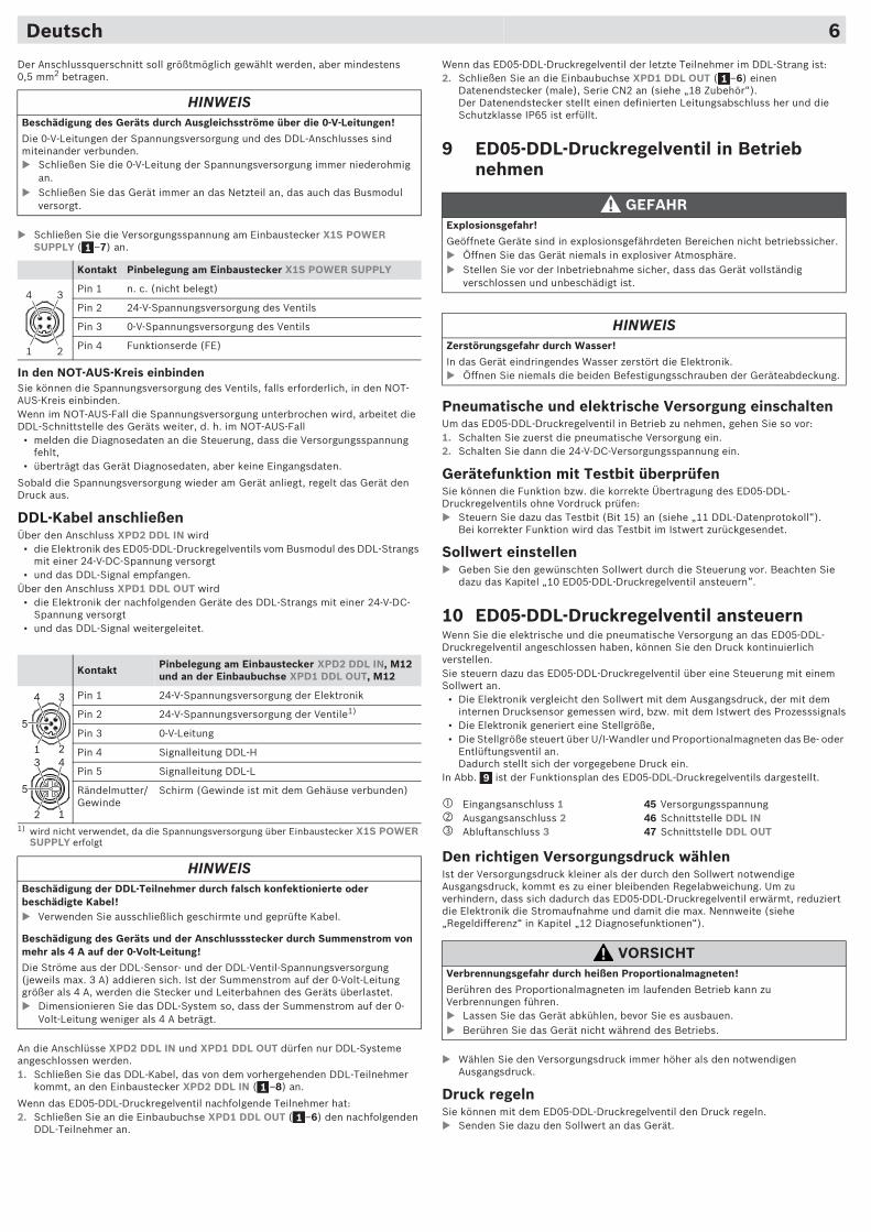
10 ED05-DDL-Druckregelventil ansteuernWenn Sie die elektrische und die pneumatische Versorgung an das ED05-DDL-Druckregelventil angeschlossen haben, können Sie den Druck kontinuierlich verstellen. Sie steuern dazu das ED05-DDL-Druckregelventil über eine Steuerung mit einem Sollwert an.
• Die Elektronik vergleicht den Sollwert mit dem Ausgangsdruck, der mit dem internen Drucksensor gemessen wird, bzw. mit dem Istwert des Prozesssignals
• Die Elektronik generiert eine Stellgröße, • Die Stellgröße steuert über U/I-Wandler und Proportionalmagneten das Be- oder
Entlüftungsventil an. Dadurch stellt sich der vorgegebene Druck ein.
In Abb. ist der Funktionsplan des ED05-DDL-Druckregelventils dargestellt.
Den richtigen Versorgungsdruck wählenIst der Versorgungsdruck kleiner als der durch den Sollwert notwendige Ausgangsdruck, kommt es zu einer bleibenden Regelabweichung. Um zu verhindern, dass sich dadurch das ED05-DDL-Druckregelventil erwärmt, reduziert die Elektronik die Stromaufnahme und damit die max. Nennweite (siehe „Regeldifferenz“ in Kapitel „12 Diagnosefunktionen“).
� Wählen Sie den Versorgungsdruck immer höher als den notwendigen Ausgangsdruck.
Druck regelnSie können mit dem ED05-DDL-Druckregelventil den Druck regeln.� Senden Sie dazu den Sollwert an das Gerät.
GEFAHRExplosionsgefahr!
Geöffnete Geräte sind in explosionsgefährdeten Bereichen nicht betriebssicher.� Öffnen Sie das Gerät niemals in explosiver Atmosphäre.� Stellen Sie vor der Inbetriebnahme sicher, dass das Gerät vollständig
verschlossen und unbeschädigt ist.
HINWEISZerstörungsgefahr durch Wasser!
In das Gerät eindringendes Wasser zerstört die Elektronik.� Öffnen Sie niemals die beiden Befestigungsschrauben der Geräteabdeckung.
� Eingangsanschluss 1 � Ausgangsanschluss 2� Abluftanschluss 3
45 Versorgungsspannung46 Schnittstelle DDL IN47 Schnittstelle DDL OUT
VORSICHTVerbrennungsgefahr durch heißen Proportionalmagneten!
Berühren des Proportionalmagneten im laufenden Betrieb kann zu Verbrennungen führen.� Lassen Sie das Gerät abkühlen, bevor Sie es ausbauen.� Berühren Sie das Gerät nicht während des Betriebs.
1
9
Deutsch 7
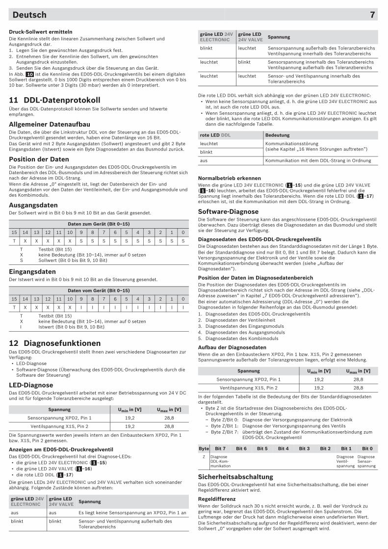
Druck-Sollwert ermittelnDie Kennlinie stellt den linearen Zusammenhang zwischen Sollwert und Ausgangsdruck dar.1. Legen Sie den gewünschten Ausgangsdruck fest.2. Entnehmen Sie der Kennlinie den Sollwert, um den gewünschten
Ausgangsdruck einzustellen.3. Senden Sie den Ausgangsdruck über die Steuerung an das Gerät.In Abb. ist die Kennlinie des ED05-DDL-Druckregelventils bei einem digitalen Sollwert dargestellt. 0 bis 1000 Digits entsprechen einem Druckbereich von 0 bis 10 bar. Sollwerte unter 3 Digits (30 mbar) werden als 0 interpretiert.
11 DDL-DatenprotokollÜber das DDL-Datenprotokoll können Sie Sollwerte senden und Istwerte empfangen.
Allgemeiner DatenaufbauDie Daten, die über die Linkstruktur DDL von der Steuerung an das ED05-DDL-Druckregelventil gesendet werden, haben eine Datenlänge von 16 Bit.Das Gerät wird mit 2 Byte Ausgangsdaten (Sollwert) angesteuert und gibt 2 Byte Eingangsdaten (Istwert) sowie ein Byte Diagnosedaten an das Busmodul zurück.
Position der DatenDie Position der Ein- und Ausgangsdaten des ED05-DDL-Druckregelventils im Datenbereich des DDL-Busmoduls und im Adressbereich der Steuerung richtet sich nach der Adresse im DDL-Strang.Wenn die Adresse „0“ eingestellt ist, liegt der Datenbereich der Ein- und Ausgangsdaten vor den Daten der Ventileinheit, der Ein- und Ausgangsmodule und des Kombimoduls.
AusgangsdatenDer Sollwert wird in Bit 0 bis 9 mit 10 Bit an das Gerät gesendet.
Eingangsdaten Der Istwert wird in Bit 0 bis 9 mit 10 Bit an die Steuerung gesendet.
12 DiagnosefunktionenDas ED05-DDL-Druckregelventil stellt Ihnen zwei verschiedene Diagnosearten zur Verfügung:
• LED-Diagnose• Software-Diagnose (Überwachung des ED05-DDL-Druckregelventils durch die
Software der Steuerung)
LED-DiagnoseDas ED05-DDL-Druckregelventil arbeitet mit einer Betriebsspannung von 24 V DC und ist für folgende Toleranzbereiche ausgelegt:
Die Spannungswerte werden jeweils intern an den Einbausteckern XPD2, Pin 1 bzw. X1S, Pin 2 gemessen.
Anzeigen am ED05-DDL-DruckregelventilDas ED05-DDL-Druckregelventil hat drei Diagnose-LEDs:
• die grüne LED 24V ELECTRONIC ( –15)• die grüne LED 24V VALVE ( –16)• die rote LED DDL ( –17)
Die grünen LEDs 24V ELECTRONIC und 24V VALVE verhalten sich voneinander abhängig. Folgende Zustände können auftreten:
Daten zum Gerät (Bit 0–15)
15 14 13 12 11 10 9 8 7 6 5 4 3 2 1 0
T X X X X X S S S S S S S S S S
T Testbit (Bit 15)X keine Bedeutung (Bit 10–14), immer auf 0 setzenS Sollwert (Bit 0 bis Bit 9, 10 Bit)
Daten vom Gerät (Bit 0–15)
15 14 13 12 11 10 9 8 7 6 5 4 3 2 1 0
T X X X X X I I I I I I I I I I
T Testbit (Bit 15)X keine Bedeutung (Bit 10–14), immer auf 0 setzenI Istwert (Bit 0 bis Bit 9, 10 Bit)
Spannung Umin in [V] Umax in [V]
Sensorspannung XPD2, Pin 1 19,2 28,8
Ventilspannung X1S, Pin 2 19,2 28,8
grüne LED 24V ELECTRONIC
grüne LED 24V VALVE Spannung
aus aus Es liegt keine Sensorspannung an XPD2, Pin 1 an
blinkt blinkt Sensor- und Ventilspannung außerhalb des Toleranzbereichs
10
11
1
Die rote LED DDL verhält sich abhängig von der grünen LED 24V ELECTRONIC:• Wenn keine Sensorspannung anliegt, d. h. die grüne LED 24V ELECTRONIC aus
ist, ist auch die rote LED DDL aus.• Wenn Sensorspannung anliegt, d. h. die grüne LED 24V ELECTRONIC leuchtet
oder blinkt, kann die rote LED DDL Kommunikationsstörungen anzeigen. Es gilt dann die nachfolgende Tabelle.
Normalbetrieb erkennenWenn die grüne LED 24V ELECTRONIC ( –15) und die grüne LED 24V VALVE ( –16) leuchten, arbeitet das ED05-DDL-Druckregelventil fehlerfrei und die Spannung liegt innerhalb des Toleranzbereichs. Wenn die rote LED DDL ( –17) erloschen ist, ist die Kommunikation mit dem DDL-Strang in Ordnung.
Software-DiagnoseDie Software der Steuerung kann das angeschlossene ED05-DDL-Druckregelventil überwachen. Dazu überträgt dieses die Diagnosedaten an das Busmodul und stellt sie der Steuerung zur Verfügung.
Diagnosedaten des ED05-DDL-DruckregelventilsDie Diagnosedaten bestehen aus den Standarddiagnosedaten mit der Länge 1 Byte.Bei der Standarddiagnose sind nur Bit 0, Bit 1 und Bit 7 belegt. Dadurch kann die Versorgungsspannung der Elektronik und der Ventile sowie die Kommunikationsverbindung überwacht werden (siehe „Aufbau der Diagnosedaten”).
Position der Daten im DiagnosedatenbereichDie Position der Diagnosedaten des ED05-DDL-Druckregelventils im Diagnosedatenbereich richtet sich nach der Adresse im DDL-Strang (siehe „DDL-Adresse zuweisen” in Kapitel „7 ED05-DDL-Druckregelventil adressieren“). Bei einer automatischen Adressierung (DDL-Adresse „0“) werden die Diagnosedaten in folgender Reihenfolge an das DDL-Busmodul gesendet:1. Diagnosedaten des ED05-DDL-Druckregelventils2. Diagnosedaten der Ventileinheit3. Diagnosedaten des Eingangsmoduls4. Diagnosedaten des Ausgangsmoduls5. Diagnosedaten des Kombimoduls
Aufbau der DiagnosedatenWenn die an den Einbausteckern XPD2, Pin 1 bzw. X1S, Pin 2 gemessenen Spannungswerte außerhalb der Toleranzgrenzen liegen, erfolgt eine Meldung.
In der folgenden Tabelle ist die Bedeutung der Bits der Standarddiagnosedaten dargestellt.
• Byte Z ist die Startadresse des Diagnosebereichs des ED05-DDL-Druckregelventils in der Steuerung.– Byte Z/Bit 0: Diagnose der Versorgungsspannung der Elektronik– Byte Z/Bit 1: Diagnose der Versorgungsspannung des Ventils– Byte Z/Bit 7: überträgt den Zustand der Kommunikationsverbindung zum
ED05-DDL-Druckregelventil
SicherheitsabschaltungDas ED05-DDL-Druckregelventil hat eine Sicherheitsabschaltung, die bei einer Regeldifferenz aktiviert wird.
RegeldifferenzWenn der Solldruck nach 30 s nicht erreicht wurde, z. B. weil der Vordruck zu gering war, begrenzt das ED05-DDL-Druckregelventil den Spulenstrom. Die Luftmenge oder der Druck hat dann möglicherweise einen undefinierten Wert.Die Sicherheitsabschaltung aufgrund der Regeldifferenz wird deaktiviert, wenn der Sollwert „0“ vorgegeben oder der Sollwert ausgeregelt wird.
blinkt leuchtet Sensorspannung außerhalb des ToleranzbereichsVentilspannung innerhalb des Toleranzbereichs
leuchtet blinkt Sensorspannung innerhalb des ToleranzbereichsVentilspannung außerhalb des Toleranzbereichs
leuchtet leuchtet Sensor- und Ventilspannung innerhalb des Toleranzbereichs
rote LED DDL Bedeutung
leuchtet Kommunikationsstörung(siehe Kapitel „16 Wenn Störungen auftreten”)
blinkt
aus Kommunikation mit dem DDL-Strang in Ordnung
Spannung Umin in [V] Umax in [V]
Sensorspannung XPD2, Pin 1 19,2 28,8
Ventilspannung X1S, Pin 2 19,2 28,8
Byte Bit 7 Bit 6 Bit 5 Bit 4 Bit 3 Bit 2 Bit 1 Bit 0
Z DiagnoseDDL-Kom-munikation
Diagnose Ventil-spannung
Diagnose Sensor-spannung
grüne LED 24V ELECTRONIC
grüne LED 24V VALVE Spannung
11
1
X1S POWER SUPPLY 24 V VALVE
X1S POWER SUPPLY
24 V ELECTRONIC
24 V ELECTRONIC
24 V VALVE
X1S POWER SUPPLY
DDL
Deutsch 8
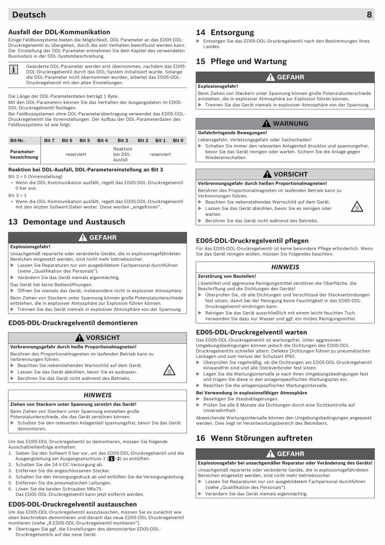
Ausfall der DDL-KommunikationEinige Feldbussysteme bieten die Möglichkeit, DDL-Parameter an das ED05-DDL-Druckregelventil zu übergeben, durch die sein Verhalten beeinflusst werden kann. Die Einstellung der DDL-Parameter entnehmen Sie dem Kapitel des verwendeten Busmoduls in der DDL-Systembeschreibung.
Die Länge der DDL-Parameterdaten beträgt 1 Byte.Mit den DDL-Parametern können Sie das Verhalten der Ausgangsdaten im ED05-DDL-Druckregelventil festlegen.Bei Feldbussystemen ohne DDL-Parameterübertragung verwendet das ED05-DDL-Druckregelventil die Voreinstellungen. Der Aufbau der DDL-Parameterdaten des Feldbussystems ist wie folgt:
Reaktion bei DDL-Ausfall, DDL-Parametereinstellung an Bit 3Bit 3 = 0 (Voreinstellung)
• Wenn die DDL-Kommunikation ausfällt, regelt das ED05-DDL-Druckregelventil 0 bar aus.
Bit 3 = 1• Wenn die DDL-Kommunikation ausfällt, regelt das ED05-DDL-Druckregelventil
mit den letzten Sollwert-Daten weiter. Diese werden „eingefroren“.
13 Demontage und Austausch
ED05-DDL-Druckregelventil demontieren
Um das ED05-DDL-Druckregelventil zu demontieren, müssen Sie folgende Ausschaltreihenfolge einhalten:1. Geben Sie den Sollwert 0 bar vor, um das ED05-DDL-Druckregelventil und die
Ausgangsleitung am Ausgangsanschluss 2 ( –2) zu entlüften.2. Schalten Sie die 24-V-DC-Versorgung ab.3. Entfernen Sie die angeschlossenen Stecker.4. Schalten Sie den Versorgungsdruck ab und entlüften Sie die Versorgungsleitung.5. Entfernen Sie die pneumatischen Leitungen.6. Lösen Sie die beiden Schrauben M6x75.
Das ED05-DDL-Druckregelventil kann jetzt entfernt werden.
ED05-DDL-Druckregelventil austauschenUm das ED05-DDL-Druckregelventil auszutauschen, müssen Sie es zunächst wie oben beschrieben demontieren und danach das neue ED05-DDL-Druckregelventil montieren (siehe „8 ED05-DDL-Druckregelventil montieren”).� Übertragen Sie ggf. die Einstellungen des demontierten ED05-DDL-
Druckregelventils auf das neue Gerät.
Geänderte DDL-Parameter werden erst übernommen, nachdem das ED05-DDL-Druckregelventil durch das DDL-System initialisiert wurde. Solange die DDL-Parameter nicht übernommen wurden, arbeitet das ED05-DDL-Druckregelventil mit den alten Einstellungen.
Bit-Nr. Bit 7 Bit 6 Bit 5 Bit 4 Bit 3 Bit 2 Bit 1 Bit 0
Parameter-bezeichnung reserviert
Reaktion bei DDL-Ausfall
reserviert
GEFAHRExplosionsgefahr!
Unsachgemäß reparierte oder veränderte Geräte, die in explosionsgefährdeten Bereichen eingesetzt werden, sind nicht mehr betriebssicher.� Lassen Sie Reparaturen nur von ausgebildetem Fachpersonal durchführen
(siehe „Qualifikation des Personals“).� Verändern Sie das Gerät niemals eigenmächtig.
Das Gerät hat keine Bedienöffnungen. � Öffnen Sie niemals das Gerät, insbesondere nicht in explosiver Atmosphäre.
Beim Ziehen von Steckern unter Spannung können große Potenzialunterschiede entstehen, die in explosiver Atmosphäre zur Explosion führen können.� Trennen Sie das Gerät niemals in explosiver Atmosphäre von der Spannung.
VORSICHTVerbrennungsgefahr durch heiße Proportionalmagneten!
Berühren des Proportionalmagneten im laufenden Betrieb kann zu Verbrennungen führen.� Beachten Sie nebenstehendes Warnschild auf dem Gerät.� Lassen Sie das Gerät abkühlen, bevor Sie es ausbauen.� Berühren Sie das Gerät nicht während des Betriebs.
HINWEISZiehen von Steckern unter Spannung zerstört das Gerät!
Beim Ziehen von Steckern unter Spannung entstehen große Potenzialunterschiede, die das Gerät zerstören können.� Schalten Sie den relevanten Anlagenteil spannungsfrei, bevor Sie das Gerät
demontieren.
1
14 Entsorgung� Entsorgen Sie das ED05-DDL-Druckregelventil nach den Bestimmungen Ihres
Landes.
15 Pflege und Wartung
ED05-DDL-Druckregelventil pflegenFür das ED05-DDL-Druckregelventil ist keine besondere Pflege erforderlich. Wenn Sie das Gerät reinigen wollen, müssen Sie Folgendes beachten:
ED05-DDL-Druckregelventil wartenDas ED05-DDL-Druckregelventil ist wartungsfrei. Unter aggressiven Umgebungsbedingungen können jedoch die Dichtungen des ED05-DDL-Druckregelventils schneller altern. Defekte Dichtungen führen zu pneumatischen Leckagen und zum Verlust der Schutzart IP65.� Überprüfen Sie regelmäßig, ob die Dichtungen am ED05-DDL-Druckregelventil
einwandfrei sind und alle Steckverbinder fest sitzen.� Legen Sie die Wartungsintervalle je nach Ihren Umgebungsbedingungen fest
und tragen Sie diese in den anlagenspezifischen Wartungsplan ein.� Beachten Sie die anlagenspezifischen Wartungsintervalle.
Bei Verwendung in explosionsfähiger Atmosphäre� Beseitigen Sie Staubablagerungen.� Prüfen Sie alle 6 Monate die Dichtungen durch eine Sichtkontrolle auf
Unversehrtheit.
Abweichende Wartungsintervalle können den Umgebungsbedingungen angepasst werden. Dies liegt im Verantwortungsbereich des Betreibers.
16 Wenn Störungen auftreten
GEFAHRExplosionsgefahr!
Beim Ziehen von Steckern unter Spannung können große Potenzialunterschiede entstehen, die in explosiver Atmosphäre zur Explosion führen können.� Trennen Sie das Gerät niemals in explosiver Atmosphäre von der Spannung.
WARNUNGGefahrbringende Bewegungen!
Lebensgefahr, Verletzungsgefahr oder Sachschaden!� Schalten Sie immer den relevanten Anlagenteil drucklos und spannungsfrei,
bevor Sie das Gerät reinigen oder warten. Sichern Sie die Anlage gegen Wiedereinschalten.
VORSICHTVerbrennungsgefahr durch heißen Proportionalmagneten!
Berühren des Proportionalmagneten im laufenden Betrieb kann zu Verbrennungen führen.� Beachten Sie nebenstehendes Warnschild auf dem Gerät.� Lassen Sie das Gerät abkühlen, bevor Sie es reinigen oder
warten.� Berühren Sie das Gerät nicht während des Betriebs.
HINWEISZerstörung von Bauteilen!
Lösemittel und aggressive Reinigungsmittel zerstören die Oberfläche, die Beschriftung und die Dichtungen des Geräts!� Überprüfen Sie, ob alle Dichtungen und Verschlüsse der Steckverbindungen
fest sitzen, damit bei der Reinigung keine Feuchtigkeit in das ED05-DDL-Druckregelventil eindringen kann.
� Reinigen Sie das Gerät ausschließlich mit einem leicht feuchten Tuch. Verwenden Sie dazu nur Wasser und ggf. ein mildes Reinigungsmittel.
GEFAHRExplosionsgefahr bei unsachgemäßer Reparatur oder Veränderung des Geräts!
Unsachgemäß reparierte oder veränderte Geräte, die in explosionsgefährdeten Bereichen eingesetzt werden, sind nicht mehr betriebssicher.� Lassen Sie Reparaturen nur von ausgebildetem Fachpersonal durchführen
(siehe „Qualifikation des Personals“).� Verändern Sie das Gerät niemals eigenmächtig.
X1S POWER SUPPLY 24 V VALVE
X1S POWER SUPPLY
24 V ELECTRONIC
24 V ELECTRONIC
24 V VALVE
X1S POWER SUPPLY
DDL
Deutsch 9
Störung mögliche Ursache Abhilfe
kein Ausgangsdruck vorhanden
keine Spannungsversorgung (LEDs aus) siehe auch Verhalten der einzelnen LEDs am Ende der Tabelle
Spannungsversorgung anschließen (auch am Busmodul)
Polung der Spannungsversorgung prüfen (auch am Busmodul)
Anlagenteil einschalten
kein Sollwert vorgegeben Sollwert vorgeben
Sollwert-Bereich falsch mit Testbit überprüfen und Sollwertbereich korrigieren
kein Versorgungsdruck vorhanden
Versorgungsdruck anschließen
Ausgangsdruck zu niedrig
Versorgungsdruck zu niedrig Versorgungsdruck erhöhen
Sollwert anpassen
keine ausreichende Spannungsversorgung des Geräts
Gerät mit der richtigen (ausreichenden) Spannung versorgen
Ausgangsdruck kleiner als der Sollwert
Verbraucher mit großer Luftentnahme (> 1000 Nl/min) erzeugt einen großen Druckabfall im Gerät
Luftentnahme reduzieren
Ausgangsdruck entspricht nicht der Sollwertvorgabe
Gehäusebelüftungsöffnung ist verschlossen
sicherstellen, dass Gehäusebelüftungsöffnung offen ist
Sollwert-Bereich falsch mit Testbit überprüfen und Sollwertbereich korrigieren
ED05-DDL-Druckregelventil entlüftet nicht
Abluftanschluss ist verschlossen
Abluftanschluss öffnen und Schalldämpfer montieren oder als gefasste Abluft verschlauchen
Proportionalmagnet wird nicht angesteuert
keine Spannung am Einbaustecker XX1S POWER SUPPLY (grüne LED 24 V VALVE blinkt)
Spannungsversorgung am Einbaustecker X1S POWER SUPPLY überprüfen
Luft entweicht hörbar
Dichtung an Eingangsanschluss, Ausgangsanschluss oder Abluftanschluss fehlt oder ist beschädigt
Dichtung überprüfen und ggf. austauschen
Undichtigkeit zwischen ED05-DDL-Druckregelventil und angeschlossener Druckleitung bzw. Grundplatte
Bei Direktmontage:Anschlüsse der Druckleitungen prüfen und ggf. nachziehen.Bei Grundplattenmontage:Schrauben mit Anzugsmoment 6 Nm anziehen
ED05-DDL-Druckregelventil ist undicht
ED05-DDL-Druckregelventil austauschen
pneumatische Anschlüsse vertauscht
Druckleitungen oder Grundplatte pneumatisch richtig anschließen (siehe „Auf eine Montageplatte oder in einen Schaltschrank montieren“ oder „Grundplatte pneumatisch anschließen“)
grüne LED 24 V ELECTRONIC leuchtet nicht
keine Elektronikspannung vorhanden
Elektronikversorgung am DDL-Busmodul prüfen
ED05-DDL-Druckregelventil defekt
ED05-DDL-Druckregelventil austauschen
falsch konfektioniertes oder defektes Kabel
geprüfte DDL-Kabel verwenden
grüne LED 24 V ELECTRONIC blinkt
Über- oder Unterspannung Spannungsversorgung des DDL-Strangs prüfen
grüne LED 24 V VALVE blinkt
Über- oder Unterspannung Spannungsversorgung des Proportionalmagneten am EinbausteckerX1S POWER SUPPLY prüfen
rote LED DDL leuchtet oder blinkt
Baudrate der DDL-Teilnehmer ist unterschiedlich
Baudrate überprüfen (siehe „DDL-Baudrate des ED05-DDL-Druckregelventils einstellen (Bit 1)“)
Adressierung ist falsch Adressierung überprüfen (siehe „DDL-Adresse zuweisen“)
Kabel defekt Kabel austauschen
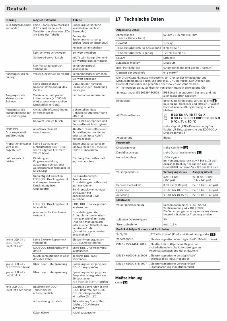
17 Technische Daten
Maßzeichnungsiehe
Allgemeine Daten
Abmessungen (Breite x Höhe x Tiefe)
62 mm x 136 mm x 91 mm
Gewicht 1,05 kg
Temperaturbereich für Anwendung 0 °C bis 50 °C
Temperaturbereich Lagerung –20 °C bis 70 °C
Bauart Sitzventil
zulässiges Medium Druckluft
max. Partikelgröße 50 �m (ungeölte und geölte Druckluft)
Ölgehalt der Druckluft 0–1 mg/m3
Der Drucktaupunkt muss mindestens 15 °C unter der Umgebungs- und Mediumstemperatur liegen und darf max. 3 °C betragen. Der Ölgehalt der Druckluft muss über die gesamte Lebensdauer konstant bleiben.� Verwenden Sie ausschließlich von Bosch Rexroth zugelassene Öle.
Schutzart nach EN 60529/IEC529 IP65 (nur in montiertem Zustand und mit allen montierten Steckern)
Einbaulage bevorzugte Einbaulage: vertikal (siehe )beliebig bei trockener und ölfreier DruckluftDie Gehäusebelüftungsöffnung muss frei bleiben
ATEX-Klassifikation
siehe Kapitel „ATEX-Kennzeichnung“ in Kapitel „5 Einsatzbereiche des ED05-DDL-Druckregelventils“
Ansteuerung digital
Pneumatik
Druckregelung siehe Kennlinie
Durchflussmenge siehe Durchflusskennlinie
Nenndurchfluss 1000 Nl/minbei Versorgungsdruck pv = 7 bar (102 psi), Ausgangsdruck pa = 6 bar (87 psi) und Druckabfall im Gerät �p = 0,2 bar (2,9 psi)
Versorgungsdruck Versorgungsdruck Ausgangsdruck
max. 11 bar(160 psi)
bei 0 bis 10 bar (0 bis 145 psi)
Reproduzierbarkeit 0,06 bar (0,87 psi) bei 10 bar (145 psi)
Hysterese < 0,06 bar (0,87 psi) bei 10 bar (145 psi)
Auflösung < 0,01 bar (0,15 psi) bei 10 bar (145 psi)
Elektronik
Versorgungsspannung Sensorspannung 24 V DC (±20%)Ventilspannung 24 V DC (±20%)Die Versorgungsspannung muss aus einem Netzteil mit sicherer Trennung erfolgen
zulässige Oberwelligkeit 5%
Stromaufnahme max. 1,3 A
Berücksichtigte Normen und Richtlinien
94/9/EG „ATEX-Richtlinie“ (Konformitätserklärung siehe )
2004/108/EG „Elektromagnetische Verträglichkeit“(EMV-Richtlinie)
DIN EN ISO 4414: 2011 „Fluidtechnik – Allgemeine Regeln und sicherheitstechnische Anforderungen an Pneumatikanlagen und deren Bauteile“
DIN EN 61000-6-2: 2006 „Elektromagnetische Verträglichkeit“(Störfestigkeit Industriebereich)
DIN EN 61000-6-4: 2007 „Elektromagnetische Verträglichkeit“(Störaussendung Industriebereich)
4
II 3G Ex nA IIB T4 Gc XII 3D Ex tc IIIC T130°C Dc IP65 X0 °C ≤ Ta ≤ 50 °C
10
11
13
12
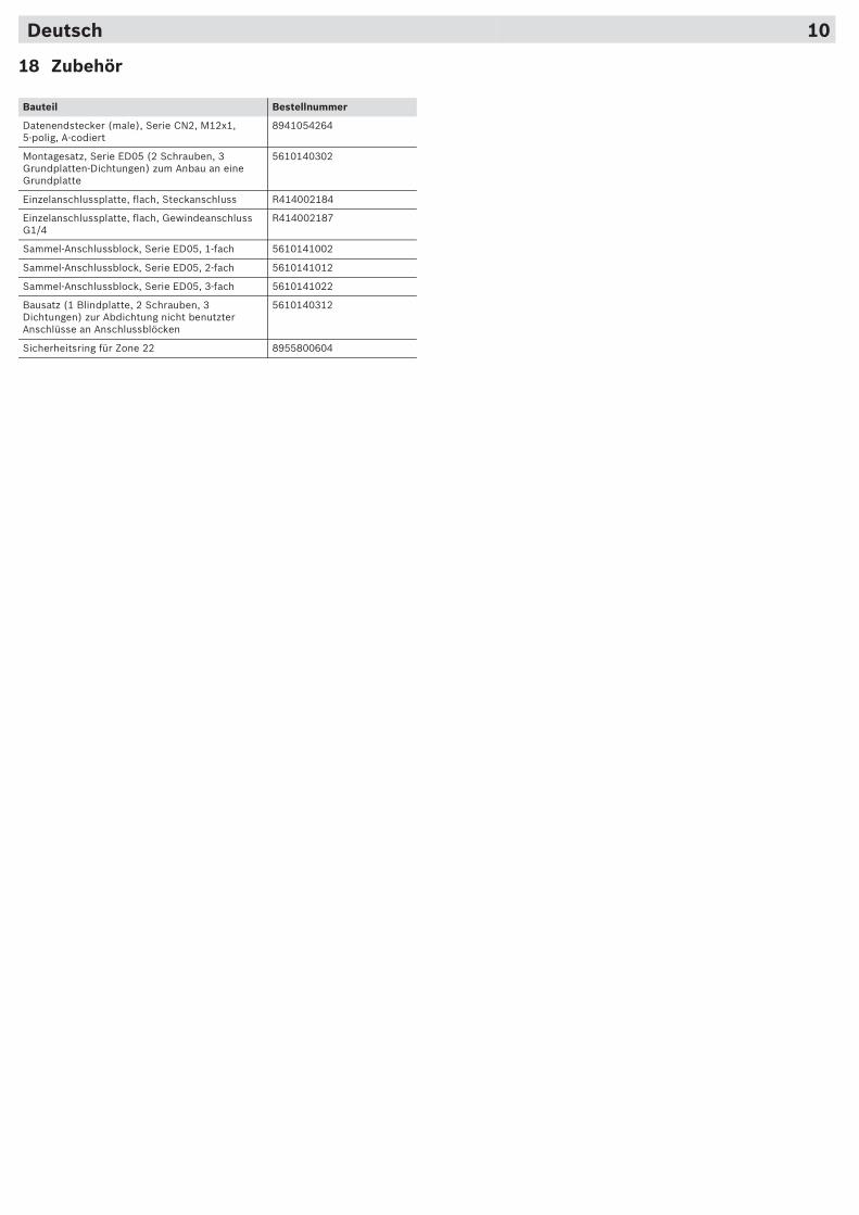
18 Zubehör
Bauteil Bestellnummer
Datenendstecker (male), Serie CN2, M12x1, 5-polig, A-codiert
8941054264
Montagesatz, Serie ED05 (2 Schrauben, 3 Grundplatten-Dichtungen) zum Anbau an eine Grundplatte
5610140302
Einzelanschlussplatte, flach, Steckanschluss R414002184
Einzelanschlussplatte, flach, Gewindeanschluss G1/4
R414002187
Sammel-Anschlussblock, Serie ED05, 1-fach 5610141002
Sammel-Anschlussblock, Serie ED05, 2-fach 5610141012
Sammel-Anschlussblock, Serie ED05, 3-fach 5610141022
Bausatz (1 Blindplatte, 2 Schrauben, 3 Dichtungen) zur Abdichtung nicht benutzter Anschlüsse an Anschlussblöcken
5610140312
Sicherheitsring für Zone 22 8955800604
X1S POWER SUPPLY 24 V VALVE
X1S POWER SUPPLY
24 V ELECTRONIC
24 V ELECTRONIC
24 V VALVE
X1S POWER SUPPLY
DDL
Deutsch 10
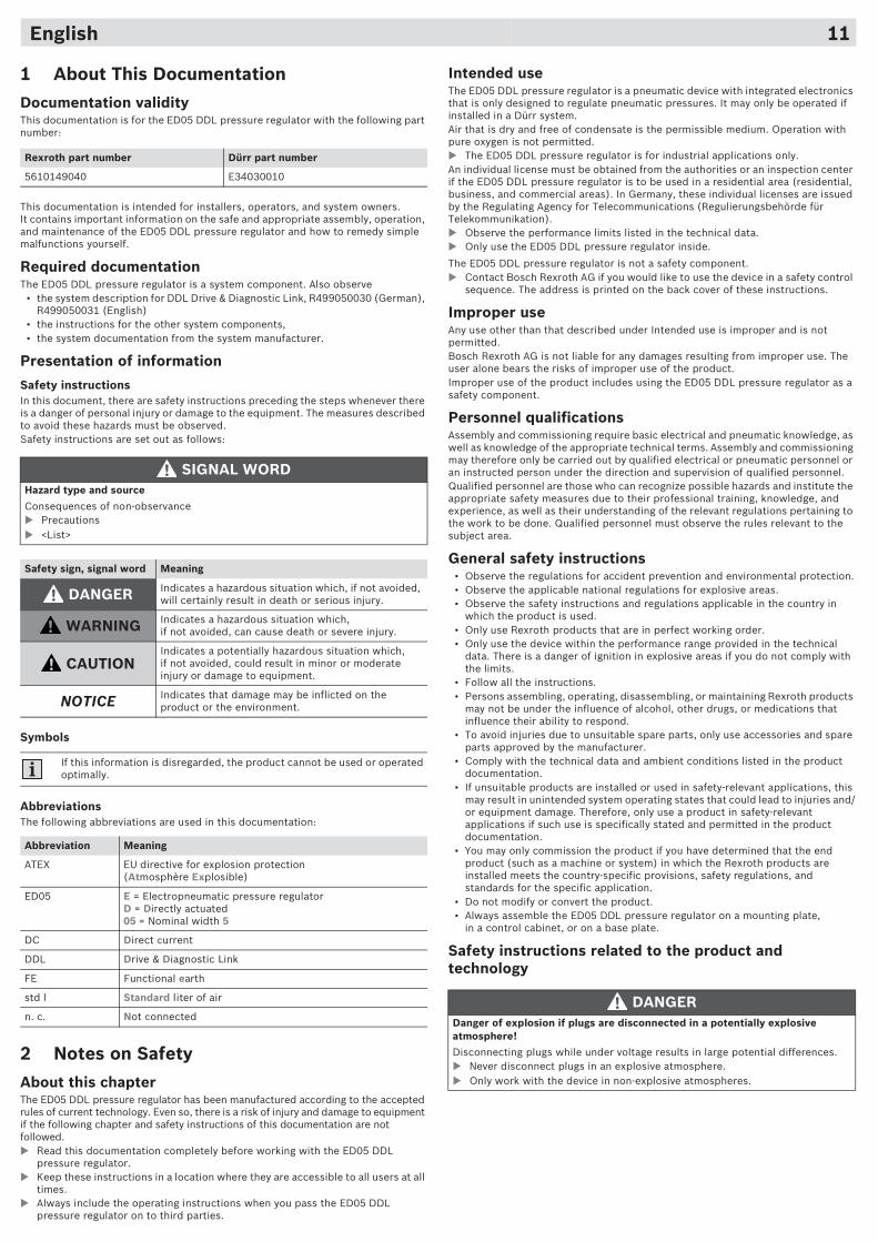
1 About This DocumentationDocumentation validityThis documentation is for the ED05 DDL pressure regulator with the following part number:
This documentation is intended for installers, operators, and system owners. It contains important information on the safe and appropriate assembly, operation, and maintenance of the ED05 DDL pressure regulator and how to remedy simple malfunctions yourself.
Required documentationThe ED05 DDL pressure regulator is a system component. Also observe
• the system description for DDL Drive & Diagnostic Link, R499050030 (German), R499050031 (English)
• the instructions for the other system components,• the system documentation from the system manufacturer.
Presentation of information
Safety instructionsIn this document, there are safety instructions preceding the steps whenever there is a danger of personal injury or damage to the equipment. The measures described to avoid these hazards must be observed.Safety instructions are set out as follows:
Symbols
AbbreviationsThe following abbreviations are used in this documentation:
2 Notes on SafetyAbout this chapterThe ED05 DDL pressure regulator has been manufactured according to the accepted rules of current technology. Even so, there is a risk of injury and damage to equipment if the following chapter and safety instructions of this documentation are not followed.� Read this documentation completely before working with the ED05 DDL
pressure regulator.� Keep these instructions in a location where they are accessible to all users at all
times.� Always include the operating instructions when you pass the ED05 DDL
pressure regulator on to third parties.
Rexroth part number Dürr part number
5610149040 E34030010
SIGNAL WORDHazard type and source
Consequences of non-observance� Precautions� <List>
Safety sign, signal word Meaning
DANGER Indicates a hazardous situation which, if not avoided, will certainly result in death or serious injury.
WARNING Indicates a hazardous situation which, if not avoided, can cause death or severe injury.
CAUTIONIndicates a potentially hazardous situation which, if not avoided, could result in minor or moderate injury or damage to equipment.
NOTICE Indicates that damage may be inflicted on the product or the environment.
If this information is disregarded, the product cannot be used or operated optimally.
Abbreviation Meaning
ATEX EU directive for explosion protection (Atmosphère Explosible)
ED05 E = Electropneumatic pressure regulatorD = Directly actuated05 = Nominal width 5
DC Direct current
DDL Drive & Diagnostic Link
FE Functional earth
std l Standard liter of air
n. c. Not connected
Intended useThe ED05 DDL pressure regulator is a pneumatic device with integrated electronics that is only designed to regulate pneumatic pressures. It may only be operated if installed in a Dürr system.Air that is dry and free of condensate is the permissible medium. Operation with pure oxygen is not permitted.� The ED05 DDL pressure regulator is for industrial applications only.An individual license must be obtained from the authorities or an inspection center if the ED05 DDL pressure regulator is to be used in a residential area (residential, business, and commercial areas). In Germany, these individual licenses are issued by the Regulating Agency for Telecommunications (Regulierungsbehörde für Telekommunikation).� Observe the performance limits listed in the technical data.� Only use the ED05 DDL pressure regulator inside.
The ED05 DDL pressure regulator is not a safety component.� Contact Bosch Rexroth AG if you would like to use the device in a safety control
sequence. The address is printed on the back cover of these instructions.
Improper useAny use other than that described under Intended use is improper and is not permitted.Bosch Rexroth AG is not liable for any damages resulting from improper use. The user alone bears the risks of improper use of the product.Improper use of the product includes using the ED05 DDL pressure regulator as a safety component.
Personnel qualificationsAssembly and commissioning require basic electrical and pneumatic knowledge, as well as knowledge of the appropriate technical terms. Assembly and commissioning may therefore only be carried out by qualified electrical or pneumatic personnel or an instructed person under the direction and supervision of qualified personnel. Qualified personnel are those who can recognize possible hazards and institute the appropriate safety measures due to their professional training, knowledge, and experience, as well as their understanding of the relevant regulations pertaining to the work to be done. Qualified personnel must observe the rules relevant to the subject area.
General safety instructions• Observe the regulations for accident prevention and environmental protection.• Observe the applicable national regulations for explosive areas.• Observe the safety instructions and regulations applicable in the country in
which the product is used.• Only use Rexroth products that are in perfect working order.• Only use the device within the performance range provided in the technical
data. There is a danger of ignition in explosive areas if you do not comply with the limits.
• Follow all the instructions.• Persons assembling, operating, disassembling, or maintaining Rexroth products
may not be under the influence of alcohol, other drugs, or medications that influence their ability to respond.
• To avoid injuries due to unsuitable spare parts, only use accessories and spare parts approved by the manufacturer.
• Comply with the technical data and ambient conditions listed in the product documentation.
• If unsuitable products are installed or used in safety-relevant applications, this may result in unintended system operating states that could lead to injuries and/or equipment damage. Therefore, only use a product in safety-relevant applications if such use is specifically stated and permitted in the product documentation.
• You may only commission the product if you have determined that the end product (such as a machine or system) in which the Rexroth products are installed meets the country-specific provisions, safety regulations, and standards for the specific application.
• Do not modify or convert the product.• Always assemble the ED05 DDL pressure regulator on a mounting plate,
in a control cabinet, or on a base plate.
Safety instructions related to the product and technology
DANGERDanger of explosion if plugs are disconnected in a potentially explosive atmosphere!
Disconnecting plugs while under voltage results in large potential differences.� Never disconnect plugs in an explosive atmosphere.� Only work with the device in non-explosive atmospheres.
English 11
Personal protective equipment� Wear appropriate protective clothing when working with the device, particularly
safety glasses and ear protectors. Observe the applicable occupational health and safety standards.
Obligations of the system ownerAs the owner of a system that will be equipped with this product, you are responsible for
• ensuring intended use,• ensuring that operating employees receive regular instruction,• ensuring that the operating conditions are in line with the requirements for the
safe use of the product,• ensuring that the cleaning intervals are specified and complied with,• ensuring the observance of ignition hazards that develop due to the installation
of system equipment,• ensuring that no unauthorized repairs are attempted if there is a malfunction,• ensuring that there is sufficient lightning protection,• ensuring that the installation guidelines for explosion-proof components and
devices are complied with (e.g. EN 60079-14, EN 61241-14).
Warning sign on the device� Observe the following warning sign on the device:
3 General Instructions on Equipment and Product Damage
WARNINGDangerous movements!
Danger of death, injuries or damage to property!� Make sure the relevant system component is not under pressure
or voltage before assembling or when connecting and disconnecting plugs. Protect the system against being switched on.
� Ensure personnel safety before switching on the device.
CAUTIONDanger of burns caused by hot proportional solenoid!
Touching the proportional solenoid during operation may lead to burns.� Observe the warning sign on the right located on the device.� Do not touch the device during operation.� Let the device cool off before removing it.
Improperly laid cables!
Danger of injury!� Position cables where people cannot trip over them.
Meaning of warning sign:Caution! Hot surface!The device may have a hot surface under unfavorable operating conditions!
NOTICEMalfunction caused by closed housing ventilation port!
There is no atmospheric equalization and the characteristics curve will change.� Ensure that the air can circulate freely through the housing ventilation port
( –5). � Never operate the device in an atmosphere containing oil.
Danger due to electrostatic discharge (ESD)!
Device defect or destruction!� Do not touch the pins on the integrated X1S POWER SUPPLY,
M12 ( –7)and XPD2 DDL IN, M12 ( –8) plugs.
Danger due to mechanical loads!
Damage to the device!� Do not place any mechanical loads on the device under any circumstances.
Danger due to reverse polarity!
Device defect or destruction!� Only use tested cables.
Loss of the protection class IP65 if the device is opened!
Fluids and foreign bodies may damage the device.� Never open the device.
1
1 1
4 Delivery ContentsThe scope of delivery includes:
• 1 ED05 DDL pressure regulator (5610149040)• Mounting kit for the ED05 series, consisting of 3 seals and 2 M6x75 screws
(5610140302)• 1 set of operating instructions (R414003448)
5 Applications for the ED05 DDL Pressure Regulator
Characteristics of the deviceThe ED05 DDL pressure regulator converts an electrical set point into pressure. In doing so, a pressure sensor integrated in the ED05 DDL pressure regulator records the outlet pressure.The integrated control electronics regulate the outlet pressure via a 3/2-way valve. Due to this, the controlled outlet pressure remains constant if there are disturbance variables such as flow changes or supply pressure fluctuations.
UseWith the ED05 DDL pressure regulator, you can• Electrically change pressures• Remotely adjust pressures.Additionally, you can use the ED05 DDL pressure regulator as an actuator to control brake forces, clamping forces, flow rates, or turbine speeds. The device here uses the DDL (Drive & Diagnostic Link) interface.
Use in explosive areas
The ED05 DDL pressure regulator has been designed for use in explosive areas. You may use the ED05 DDL pressure regulator in zone 2 (category 3G) and zone 22 (category 3D). Compressed air must always be generated and prepared outside of the explosive area.The ED05 DDL pressure regulator is electrical equipment that fulfils the specifications for mechanical explosion protection.� Always observe the technical data and limits indicated on the rating plates,
particularly the information from the ATEX identification.
ATEX identification
The ED05 DDL pressure regulator corresponds to the requirements in EC Directive 94/9/EC (ATEX95). Characteristics and applications that are derived from the ATEX ID are explained in the following:
DANGERDanger of explosion with overvoltage!
The ED05 DDL pressure regulator is defined as low energy equipment and must be protected against overvoltage in accordance with the standard DIN EN 60079-15: 2011-02, paragraph 13.� Make sure that the supply voltage is protected against overvoltage in
explosive areas.
Danger of explosion due to mechanical damage!
Mechanical damage, e g. strain on the plug connectors, will lead to non-compliance with the IP65 protection class.� In explosive environments, make sure that the equipment is installed in a
manner that protects it from all types of mechanical damage.
Danger of explosion due to circulating currents!
Stray magnetic fields may cause circulating currents, e g. near electrical drives with asymmetrical loads, during arc welding, if the ground is conducted via the system and not via a 0 V line, or if there is cathodic corrosion protection.� Make sure that there is protection against the possible effects of circulating
currents.
II All areas, except for mining
3G Gas explosion protection, category 3G: use in zone 2
Ex Equipment is explosion-proof
n Type of ignition protection n (industrial grade)
A Non-sparking equipment
IIB Suitable for IIB explosive areasTypical gas: EthyleneIgnition energy: 60–180 �J
T4 Temperature class 4Ignition temperature of flammable material > 135°CMax. permissible surface temperature 135°C
Gc EPL, equipment protection levelGc corresponds to equipment category 3G (see DIN EN 60079-15 and -0)
II 3G Ex nA IIB T4 Gc XII 3D Ex tc IIIC T130°C Dc IP65 X0°C ≤ Ta ≤ 50°C
English 12
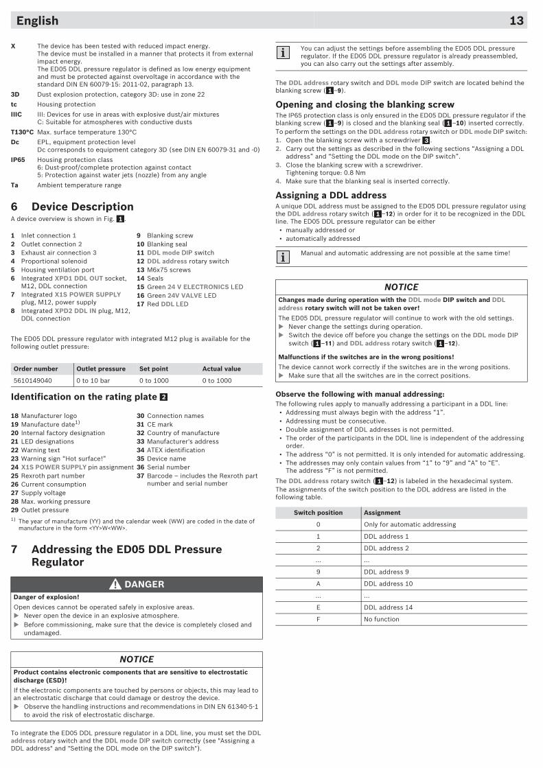
6 Device DescriptionA device overview is shown in Fig. .
The ED05 DDL pressure regulator with integrated M12 plug is available for the following outlet pressure:
Identification on the rating plate
7 Addressing the ED05 DDL Pressure Regulator
To integrate the ED05 DDL pressure regulator in a DDL line, you must set the DDL address rotary switch and the DDL mode DIP switch correctly (see "Assigning a DDL address" and "Setting the DDL mode on the DIP switch").
X The device has been tested with reduced impact energy. The device must be installed in a manner that protects it from external impact energy.The ED05 DDL pressure regulator is defined as low energy equipment and must be protected against overvoltage in accordance with the standard DIN EN 60079-15: 2011-02, paragraph 13.
3D Dust explosion protection, category 3D: use in zone 22
tc Housing protection
IIIC III: Devices for use in areas with explosive dust/air mixturesC: Suitable for atmospheres with conductive dusts
T130°C Max. surface temperature 130°C
Dc EPL, equipment protection levelDc corresponds to equipment category 3D (see DIN EN 60079-31 and -0)
IP65 Housing protection class6: Dust-proof/complete protection against contact5: Protection against water jets (nozzle) from any angle
Ta Ambient temperature range
1 Inlet connection 12 Outlet connection 23 Exhaust air connection 34 Proportional solenoid5 Housing ventilation port6 Integrated XPD1 DDL OUT socket,
M12, DDL connection7 Integrated X1S POWER SUPPLY
plug, M12, power supply8 Integrated XPD2 DDL IN plug, M12,
DDL connection
9 Blanking screw10 Blanking seal11 DDL mode DIP switch12 DDL address rotary switch13 M6x75 screws14 Seals15 Green 24 V ELECTRONICS LED16 Green 24V VALVE LED17 Red DDL LED
Order number Outlet pressure Set point Actual value
5610149040 0 to 10 bar 0 to 1000 0 to 1000
18 Manufacturer logo19 Manufacture date1)
20 Internal factory designation21 LED designations22 Warning text23 Warning sign “Hot surface!”24 X1S POWER SUPPLY pin assignment25 Rexroth part number26 Current consumption27 Supply voltage28 Max. working pressure29 Outlet pressure1) The year of manufacture (YY) and the calendar week (WW) are coded in the date of
manufacture in the form <YY>W<WW>.
30 Connection names31 CE mark32 Country of manufacture33 Manufacturer's address34 ATEX identification35 Device name36 Serial number37 Barcode – includes the Rexroth part
number and serial number
DANGERDanger of explosion!
Open devices cannot be operated safely in explosive areas.� Never open the device in an explosive atmosphere.� Before commissioning, make sure that the device is completely closed and
undamaged.
NOTICEProduct contains electronic components that are sensitive to electrostatic discharge (ESD)!
If the electronic components are touched by persons or objects, this may lead to an electrostatic discharge that could damage or destroy the device.� Observe the handling instructions and recommendations in DIN EN 61340-5-1
to avoid the risk of electrostatic discharge.
1
2
The DDL address rotary switch and DDL mode DIP switch are located behind the blanking screw ( –9).
Opening and closing the blanking screwThe IP65 protection class is only ensured in the ED05 DDL pressure regulator if the blanking screw ( –9) is closed and the blanking seal ( –10) inserted correctly.To perform the settings on the DDL address rotary switch or DDL mode DIP switch:1. Open the blanking screw with a screwdriver .2. Carry out the settings as described in the following sections “Assigning a DDL
address” and “Setting the DDL mode on the DIP switch”.3. Close the blanking screw with a screwdriver.
Tightening torque: 0.8 Nm4. Make sure that the blanking seal is inserted correctly.
Assigning a DDL addressA unique DDL address must be assigned to the ED05 DDL pressure regulator using the DDL address rotary switch ( –12) in order for it to be recognized in the DDL line. The ED05 DDL pressure regulator can be either
• manually addressed or • automatically addressed
Observe the following with manual addressing:The following rules apply to manually addressing a participant in a DDL line:
• Addressing must always begin with the address “1”.• Addressing must be consecutive.• Double assignment of DDL addresses is not permitted.• The order of the participants in the DDL line is independent of the addressing
order.• The address “0” is not permitted. It is only intended for automatic addressing.• The addresses may only contain values from “1” to “9” and “A” to “E”.
The address “F” is not permitted.
The DDL address rotary switch ( –12) is labeled in the hexadecimal system.The assignments of the switch position to the DDL address are listed in the following table.
You can adjust the settings before assembling the ED05 DDL pressure regulator. If the ED05 DDL pressure regulator is already preassembled, you can also carry out the settings after assembly.
Manual and automatic addressing are not possible at the same time!
NOTICEChanges made during operation with the DDL mode DIP switch and DDL address rotary switch will not be taken over!
The ED05 DDL pressure regulator will continue to work with the old settings.� Never change the settings during operation. � Switch the device off before you change the settings on the DDL mode DIP
switch ( –11) and DDL address rotary switch ( –12).
Malfunctions if the switches are in the wrong positions!
The device cannot work correctly if the switches are in the wrong positions.� Make sure that all the switches are in the correct positions.
Switch position Assignment
0 Only for automatic addressing
1 DDL address 1
2 DDL address 2
... ...
9 DDL address 9
A DDL address 10
... ...
E DDL address 14
F No function
1
1 1
3
1
1 1
1
English 13
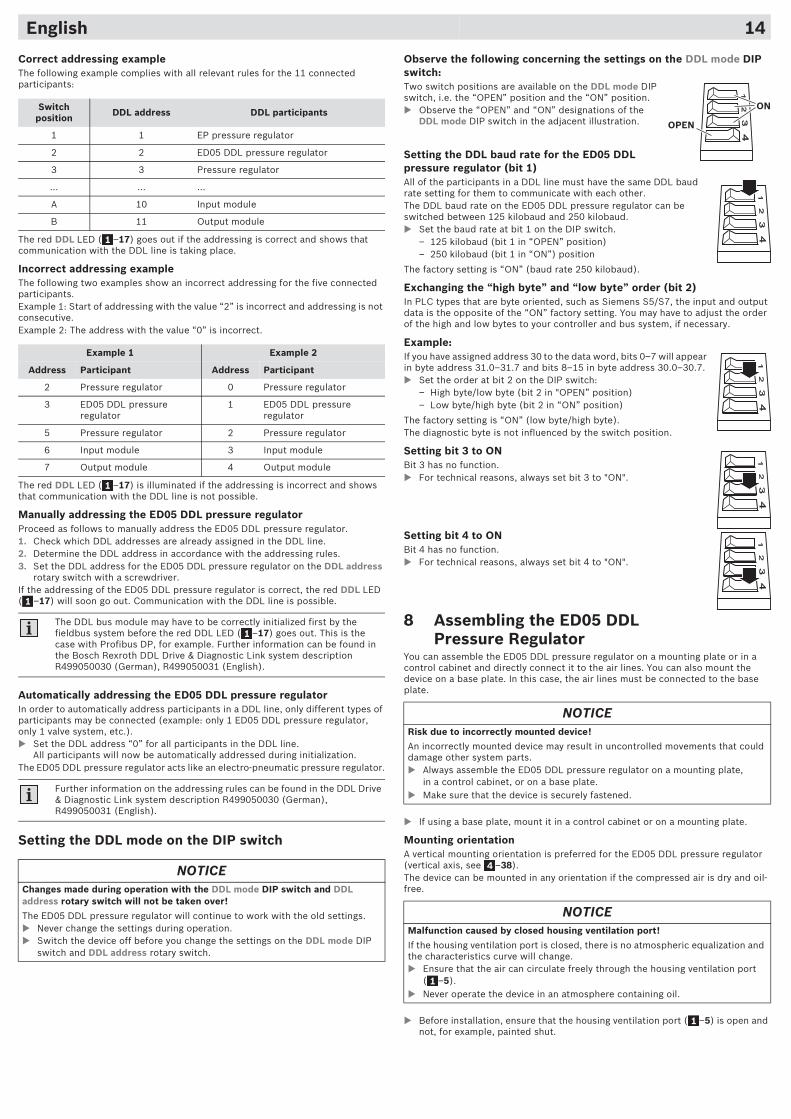
Correct addressing exampleThe following example complies with all relevant rules for the 11 connected participants:
The red DDL LED ( –17) goes out if the addressing is correct and shows that communication with the DDL line is taking place.
Incorrect addressing exampleThe following two examples show an incorrect addressing for the five connected participants. Example 1: Start of addressing with the value “2” is incorrect and addressing is not consecutive.Example 2: The address with the value “0” is incorrect.
The red DDL LED ( –17) is illuminated if the addressing is incorrect and shows that communication with the DDL line is not possible.
Manually addressing the ED05 DDL pressure regulatorProceed as follows to manually address the ED05 DDL pressure regulator.1. Check which DDL addresses are already assigned in the DDL line. 2. Determine the DDL address in accordance with the addressing rules.3. Set the DDL address for the ED05 DDL pressure regulator on the DDL address
rotary switch with a screwdriver.If the addressing of the ED05 DDL pressure regulator is correct, the red DDL LED ( –17) will soon go out. Communication with the DDL line is possible.
Automatically addressing the ED05 DDL pressure regulatorIn order to automatically address participants in a DDL line, only different types of participants may be connected (example: only 1 ED05 DDL pressure regulator, only 1 valve system, etc.).� Set the DDL address “0” for all participants in the DDL line.
All participants will now be automatically addressed during initialization.The ED05 DDL pressure regulator acts like an electro-pneumatic pressure regulator.
Setting the DDL mode on the DIP switch
Switch position DDL address DDL participants
1 1 EP pressure regulator
2 2 ED05 DDL pressure regulator
3 3 Pressure regulator
… … …
A 10 Input module
B 11 Output module
Example 1 Example 2
Address Participant Address Participant
2 Pressure regulator 0 Pressure regulator
3 ED05 DDL pressure regulator
1 ED05 DDL pressure regulator
5 Pressure regulator 2 Pressure regulator
6 Input module 3 Input module
7 Output module 4 Output module
The DDL bus module may have to be correctly initialized first by the fieldbus system before the red DDL LED ( –17) goes out. This is the case with Profibus DP, for example. Further information can be found in the Bosch Rexroth DDL Drive & Diagnostic Link system description R499050030 (German), R499050031 (English).
Further information on the addressing rules can be found in the DDL Drive & Diagnostic Link system description R499050030 (German), R499050031 (English).
NOTICEChanges made during operation with the DDL mode DIP switch and DDL address rotary switch will not be taken over!
The ED05 DDL pressure regulator will continue to work with the old settings.� Never change the settings during operation. � Switch the device off before you change the settings on the DDL mode DIP
switch and DDL address rotary switch.
1
1
1
1
Observe the following concerning the settings on the DDL mode DIP switch:Two switch positions are available on the DDL mode DIP switch, i.e. the “OPEN” position and the “ON” position.� Observe the “OPEN” and “ON” designations of the
DDL mode DIP switch in the adjacent illustration.
Setting the DDL baud rate for the ED05 DDL pressure regulator (bit 1)All of the participants in a DDL line must have the same DDL baud rate setting for them to communicate with each other.The DDL baud rate on the ED05 DDL pressure regulator can be switched between 125 kilobaud and 250 kilobaud.� Set the baud rate at bit 1 on the DIP switch.
– 125 kilobaud (bit 1 in “OPEN” position) – 250 kilobaud (bit 1 in “ON”) position
The factory setting is “ON” (baud rate 250 kilobaud).
Exchanging the “high byte” and “low byte” order (bit 2)In PLC types that are byte oriented, such as Siemens S5/S7, the input and output data is the opposite of the “ON” factory setting. You may have to adjust the order of the high and low bytes to your controller and bus system, if necessary.
Example:If you have assigned address 30 to the data word, bits 0–7 will appear in byte address 31.0–31.7 and bits 8–15 in byte address 30.0–30.7.� Set the order at bit 2 on the DIP switch:
– High byte/low byte (bit 2 in "OPEN” position)– Low byte/high byte (bit 2 in “ON” position)
The factory setting is “ON” (low byte/high byte).The diagnostic byte is not influenced by the switch position.
Setting bit 3 to ONBit 3 has no function.� For technical reasons, always set bit 3 to "ON".
Setting bit 4 to ONBit 4 has no function.� For technical reasons, always set bit 4 to "ON".
8 Assembling the ED05 DDL Pressure Regulator
You can assemble the ED05 DDL pressure regulator on a mounting plate or in a control cabinet and directly connect it to the air lines. You can also mount the device on a base plate. In this case, the air lines must be connected to the base plate.
� If using a base plate, mount it in a control cabinet or on a mounting plate.
Mounting orientationA vertical mounting orientation is preferred for the ED05 DDL pressure regulator (vertical axis, see –38).The device can be mounted in any orientation if the compressed air is dry and oil-free.
� Before installation, ensure that the housing ventilation port ( –5) is open and not, for example, painted shut.
NOTICERisk due to incorrectly mounted device!
An incorrectly mounted device may result in uncontrolled movements that could damage other system parts.� Always assemble the ED05 DDL pressure regulator on a mounting plate,
in a control cabinet, or on a base plate.� Make sure that the device is securely fastened.
NOTICEMalfunction caused by closed housing ventilation port!
If the housing ventilation port is closed, there is no atmospheric equalization and the characteristics curve will change.� Ensure that the air can circulate freely through the housing ventilation port
( –5). � Never operate the device in an atmosphere containing oil.
ON
OPEN
4
1
1
English 14
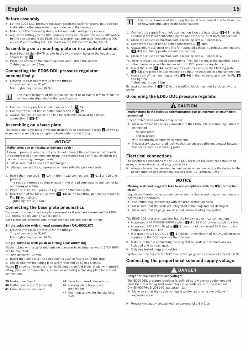
English 15
Before assembly� Let the ED05 DDL pressure regulator acclimate itself for several hours before
installation, otherwise water may condense in the housing.� Make sure the relevant system part is not under voltage or pressure.� Adjust the settings on the DDL address rotary switch and DDL mode DIP switch
before you assemble the ED05 DDL pressure regulator (see "Assigning a DDL address" and "Setting the DDL mode on the DIP switch" in chapter 7).
Assembling on a mounting plate or in a control cabinet1. Insert both of the M6x75 screws in the two through holes in the housing as
shown in Fig. .2. Place the device on the mounting plate and tighten the screws.
Tightening torque: 6 Nm
Connecting the ED05 DDL pressure regulator pneumatically� Observe the assembly torque for the fittings.
Thread connection: G1/4"Max. tightening torque: 10 Nm
1. Connect the supply line at inlet connection 1 ( –1).2. Connect the outlet line at outlet connection 2 ( –2).3. Always connect a silencer or a line for restricted exhaust to exhaust
connection 3 ( –3).
Assembling on a base plateThe base plate is available in various designs as an accessory. Figure shows an example of assembly on a single subbase with push-in fitting.
1. Insert the three seals ( –14) in the thread connections ( –1, 2 and 3) and press in.The seals are formed so they engage in the thread connections and cannot fall out during assembly.
2. Place the ED05 DDL pressure regulator on the base plate.3. Insert both of the M6x75 screws ( –13) in the two through holes as shown in
Fig. and tighten.Tightening torque: 6 Nm
Connecting the base plate pneumaticsYou have to connect the base plate pneumatics if you have assembled the ED05 DDL pressure regulator on a base plate.Base plates are available with thread connections and push-in fittings.
Single subbase with thread connection (R414002187)� Observe the assembly torque for the fittings.
Thread connection: G1/4"Max. tightening torque: 10 Nm
Single subbase with push-in fitting (R414002184)Plastic tubing with a calibrated outside diameter in accordance with CETOP RP54 can be mounted.Outside diameter: 12 mm1. Insert the tubing into the component's push-in fitting up to the stop.2. Check whether the tubing is securely fastened by pulling slightly.Figure shows an example of an ED05 series manifold block, triple, with push-in fitting, pneumatic connections, as well as mounting a blanking plate for unused connections.
The inside diameter of the supply line must be at least 6 mm to attain the air flow rate stipulated in the specifications.
NOTICEMalfunction due to missing or damaged seals!
A drop in pressure may occur if you do not connect the compressed air lines to the compressed air connections using the provided seals or if you establish the connections using damaged seals. � Make sure that all seals are undamaged.� Always connect the compressed air lines with the provided seals.
39 Inlet connection 140 Outlet connection 2 (covered)41 Exhaust air connection 3
42 Seals for unused connections43 Blanking plate for unused
connections44 Mounting screws for the blanking
plate
5
55
5
7
6 6
77
8
1. Connect the supply line at inlet connection 1 on the base plate ( –39), at the additional pressure connection on the opposite side, or at both connections.
2. Close the unused connection with a blanking screw, if necessary.3. Connect the outlet line at outlet connection 2 ( –40).4. Always mount a silencer or a line for restricted exhaust to exhaust connection 3
( –41) and the opposite exhaust connection.
5. Close the unused connection with a blanking screw, if necessary.
You have to close the unused connections if you do not equip the manifold block with the maximum possible number of ED05 DDL pressure regulators:6. Insert the seals ( –42) in the appropriate recesses on the blanking plate
( –43) and place the blanking plate so that the seals enclose the connections.7. Insert both of the mounting screws ( –44) in the two holes as shown in Fig.
and tighten.Tightening torque: 6 Nm
Exhaust connection 3 ( –41) in the manifold block must not be closed with a screw.
Grounding the ED05 DDL pressure regulator
Electrical connectionsThe electrical connections of the ED05 DDL pressure regulator are established using screwed-down round plug connectors.� Always observe the permissible limit values when connecting the device to the
power supplies and peripheral devices (see “17 Technical Data”).
The ED05 DDL pressure regulator has the following electrical connections:• Integrated X1S POWER SUPPLY plug ( –7): 24 V DC power supply to valve• Integrated XPD2 DDL IN plug ( –8): control of device and 24 V electronics
supply via the DDL line• Integrated XPD1 DDL OUT ( –6) socket: transmission of the 24V electronics
supply and the DDL signal via the DDL line
� Make sure before connecting the plug that all seals and connections are included and not damaged.
� Only use tested plugs and cables.
Tighten the tube nuts on the M12 connection plugs with a torque of at least 0.6 Nm.
Connecting the proportional solenoid supply voltage
� Protect the supply voltage with an external M 1.6 A fuse.
The inside diameter of the supply line must be at least 6 mm to attain the air flow rate stipulated in the specifications.
CAUTIONMalfunctions in the fieldbus communication due to incorrect or insufficient grounding!
Uncontrolled valve positions may occur.� Make sure that all devices connected to the ED05 DDL pressure regulator are
connected– to each other– and to groundwith electrically conductive connections.
� If necessary, use serrated lock washers to ensure sufficient contact between the device and the mounting plate.
NOTICEMissing seals and plugs will lead to non-compliance with the IP65 protection class!
Liquids and foreign objects could penetrate the device and plug connections and destroy the electronics.� Use round plug connectors with the IP65 protection class.� Make sure that the seals are integrated in the plug and not damaged.� Make sure that all plugs are attached before starting the system.
DANGERDanger of explosion with overvoltage!
The ED05 DDL pressure regulator is defined as low energy equipment and must be protected against overvoltage in accordance with the standard DIN EN 60079-15: 2011-02, paragraph 13.� Make sure that the supply voltage is protected against overvoltage in
explosive areas.
8
8
8
88
8 8
8
11
1
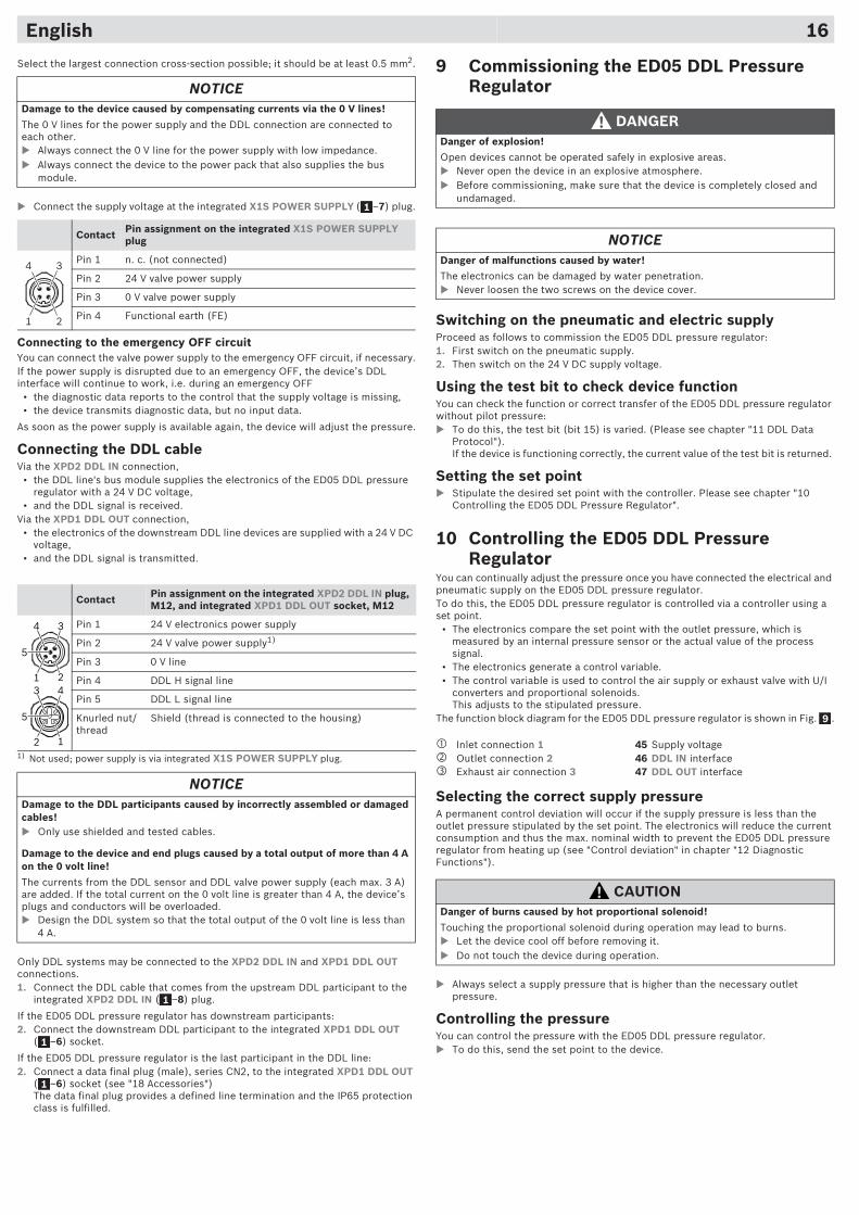
English 16
Select the largest connection cross-section possible; it should be at least 0.5 mm2.
� Connect the supply voltage at the integrated X1S POWER SUPPLY ( –7) plug.
Connecting to the emergency OFF circuitYou can connect the valve power supply to the emergency OFF circuit, if necessary.If the power supply is disrupted due to an emergency OFF, the device’s DDL interface will continue to work, i.e. during an emergency OFF
• the diagnostic data reports to the control that the supply voltage is missing,• the device transmits diagnostic data, but no input data.
As soon as the power supply is available again, the device will adjust the pressure.
Connecting the DDL cableVia the XPD2 DDL IN connection,
• the DDL line's bus module supplies the electronics of the ED05 DDL pressure regulator with a 24 V DC voltage,
• and the DDL signal is received.Via the XPD1 DDL OUT connection,
• the electronics of the downstream DDL line devices are supplied with a 24 V DC voltage,
• and the DDL signal is transmitted.
Only DDL systems may be connected to the XPD2 DDL IN and XPD1 DDL OUT connections.1. Connect the DDL cable that comes from the upstream DDL participant to the
integrated XPD2 DDL IN ( –8) plug.
If the ED05 DDL pressure regulator has downstream participants:2. Connect the downstream DDL participant to the integrated XPD1 DDL OUT
( –6) socket.
If the ED05 DDL pressure regulator is the last participant in the DDL line:2. Connect a data final plug (male), series CN2, to the integrated XPD1 DDL OUT
( –6) socket (see "18 Accessories")The data final plug provides a defined line termination and the IP65 protection class is fulfilled.
NOTICEDamage to the device caused by compensating currents via the 0 V lines!
The 0 V lines for the power supply and the DDL connection are connected to each other.� Always connect the 0 V line for the power supply with low impedance.� Always connect the device to the power pack that also supplies the bus
module.
Contact Pin assignment on the integrated X1S POWER SUPPLY plug
Pin 1 n. c. (not connected)
Pin 2 24 V valve power supply
Pin 3 0 V valve power supply
Pin 4 Functional earth (FE)
Contact Pin assignment on the integrated XPD2 DDL IN plug, M12, and integrated XPD1 DDL OUT socket, M12
Pin 1 24 V electronics power supply
Pin 2 24 V valve power supply1)
1) Not used; power supply is via integrated X1S POWER SUPPLY plug.
Pin 3 0 V line
Pin 4 DDL H signal line
Pin 5 DDL L signal line
Knurled nut/thread
Shield (thread is connected to the housing)
NOTICEDamage to the DDL participants caused by incorrectly assembled or damaged cables!� Only use shielded and tested cables.
Damage to the device and end plugs caused by a total output of more than 4 A on the 0 volt line!
The currents from the DDL sensor and DDL valve power supply (each max. 3 A) are added. If the total current on the 0 volt line is greater than 4 A, the device’s plugs and conductors will be overloaded.� Design the DDL system so that the total output of the 0 volt line is less than
4 A.
1
1 2
34
5
1 2
34
5
2 1
43
1
1
1
9 Commissioning the ED05 DDL Pressure Regulator
Switching on the pneumatic and electric supplyProceed as follows to commission the ED05 DDL pressure regulator:1. First switch on the pneumatic supply.2. Then switch on the 24 V DC supply voltage.
Using the test bit to check device functionYou can check the function or correct transfer of the ED05 DDL pressure regulator without pilot pressure:� To do this, the test bit (bit 15) is varied. (Please see chapter "11 DDL Data
Protocol").If the device is functioning correctly, the current value of the test bit is returned.
Setting the set point� Stipulate the desired set point with the controller. Please see chapter "10
Controlling the ED05 DDL Pressure Regulator".
10 Controlling the ED05 DDL Pressure Regulator
You can continually adjust the pressure once you have connected the electrical and pneumatic supply on the ED05 DDL pressure regulator. To do this, the ED05 DDL pressure regulator is controlled via a controller using a set point.
• The electronics compare the set point with the outlet pressure, which is measured by an internal pressure sensor or the actual value of the process signal.
• The electronics generate a control variable.• The control variable is used to control the air supply or exhaust valve with U/I
converters and proportional solenoids. This adjusts to the stipulated pressure.
The function block diagram for the ED05 DDL pressure regulator is shown in Fig. .
Selecting the correct supply pressureA permanent control deviation will occur if the supply pressure is less than the outlet pressure stipulated by the set point. The electronics will reduce the current consumption and thus the max. nominal width to prevent the ED05 DDL pressure regulator from heating up (see "Control deviation" in chapter "12 Diagnostic Functions").
� Always select a supply pressure that is higher than the necessary outlet pressure.
Controlling the pressureYou can control the pressure with the ED05 DDL pressure regulator.� To do this, send the set point to the device.
DANGERDanger of explosion!
Open devices cannot be operated safely in explosive areas.� Never open the device in an explosive atmosphere.� Before commissioning, make sure that the device is completely closed and
undamaged.
NOTICEDanger of malfunctions caused by water!
The electronics can be damaged by water penetration.� Never loosen the two screws on the device cover.
� Inlet connection 1 � Outlet connection 2� Exhaust air connection 3
45 Supply voltage46 DDL IN interface47 DDL OUT interface
CAUTIONDanger of burns caused by hot proportional solenoid!
Touching the proportional solenoid during operation may lead to burns.� Let the device cool off before removing it.� Do not touch the device during operation.
9
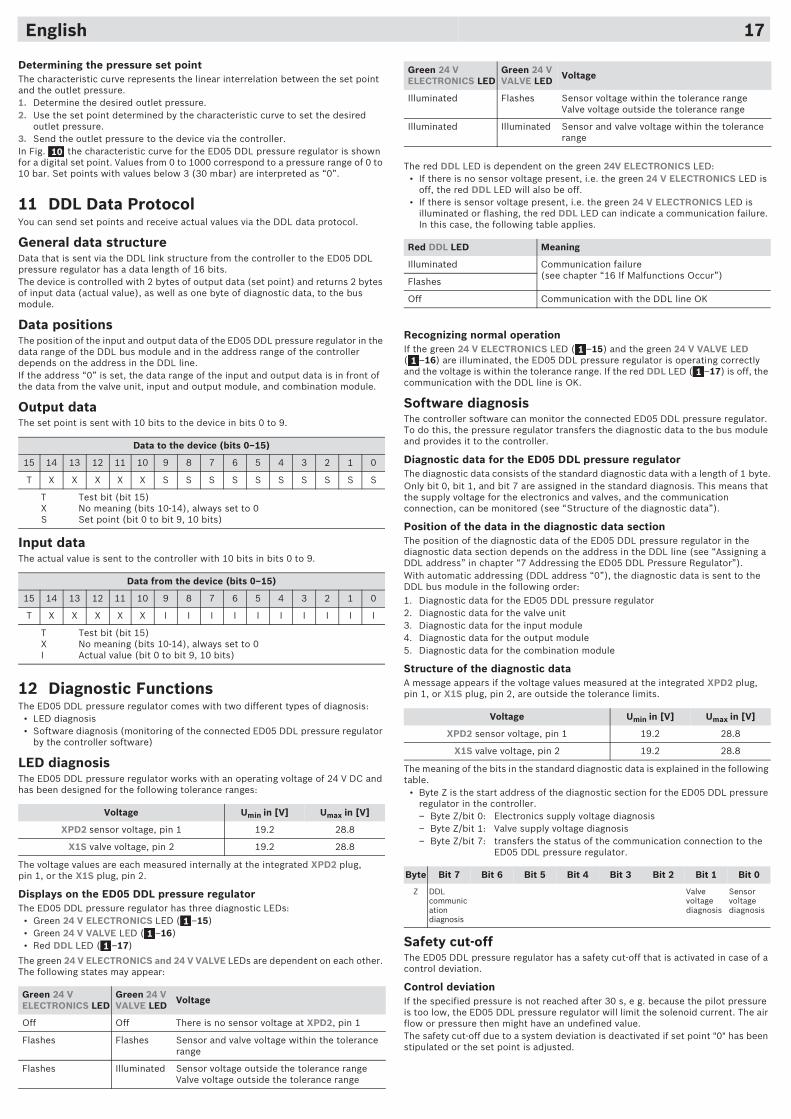
English 17
Determining the pressure set pointThe characteristic curve represents the linear interrelation between the set point and the outlet pressure.1. Determine the desired outlet pressure.2. Use the set point determined by the characteristic curve to set the desired
outlet pressure.3. Send the outlet pressure to the device via the controller.In Fig. the characteristic curve for the ED05 DDL pressure regulator is shown for a digital set point. Values from 0 to 1000 correspond to a pressure range of 0 to 10 bar. Set points with values below 3 (30 mbar) are interpreted as “0”.
11 DDL Data ProtocolYou can send set points and receive actual values via the DDL data protocol.
General data structureData that is sent via the DDL link structure from the controller to the ED05 DDL pressure regulator has a data length of 16 bits.The device is controlled with 2 bytes of output data (set point) and returns 2 bytes of input data (actual value), as well as one byte of diagnostic data, to the bus module.
Data positionsThe position of the input and output data of the ED05 DDL pressure regulator in the data range of the DDL bus module and in the address range of the controller depends on the address in the DDL line.If the address “0” is set, the data range of the input and output data is in front of the data from the valve unit, input and output module, and combination module.
Output dataThe set point is sent with 10 bits to the device in bits 0 to 9.
Input data The actual value is sent to the controller with 10 bits in bits 0 to 9.
12 Diagnostic FunctionsThe ED05 DDL pressure regulator comes with two different types of diagnosis:
• LED diagnosis• Software diagnosis (monitoring of the connected ED05 DDL pressure regulator
by the controller software)
LED diagnosisThe ED05 DDL pressure regulator works with an operating voltage of 24 V DC and has been designed for the following tolerance ranges:
The voltage values are each measured internally at the integrated XPD2 plug, pin 1, or the X1S plug, pin 2.
Displays on the ED05 DDL pressure regulatorThe ED05 DDL pressure regulator has three diagnostic LEDs:
• Green 24 V ELECTRONICS LED ( –15)• Green 24 V VALVE LED ( –16)• Red DDL LED ( –17)
The green 24 V ELECTRONICS and 24 V VALVE LEDs are dependent on each other. The following states may appear:
Data to the device (bits 0–15)
15 14 13 12 11 10 9 8 7 6 5 4 3 2 1 0
T X X X X X S S S S S S S S S S
T Test bit (bit 15)X No meaning (bits 10-14), always set to 0S Set point (bit 0 to bit 9, 10 bits)
Data from the device (bits 0–15)
15 14 13 12 11 10 9 8 7 6 5 4 3 2 1 0
T X X X X X I I I I I I I I I I
T Test bit (bit 15)X No meaning (bits 10-14), always set to 0I Actual value (bit 0 to bit 9, 10 bits)
Voltage Umin in [V] Umax in [V]
XPD2 sensor voltage, pin 1 19.2 28.8
X1S valve voltage, pin 2 19.2 28.8
Green 24 V ELECTRONICS LED
Green 24 V VALVE LED Voltage
Off Off There is no sensor voltage at XPD2, pin 1
Flashes Flashes Sensor and valve voltage within the tolerance range
Flashes Illuminated Sensor voltage outside the tolerance rangeValve voltage outside the tolerance range
10
11
1
The red DDL LED is dependent on the green 24V ELECTRONICS LED:• If there is no sensor voltage present, i.e. the green 24 V ELECTRONICS LED is
off, the red DDL LED will also be off.• If there is sensor voltage present, i.e. the green 24 V ELECTRONICS LED is
illuminated or flashing, the red DDL LED can indicate a communication failure. In this case, the following table applies.
Recognizing normal operationIf the green 24 V ELECTRONICS LED ( –15) and the green 24 V VALVE LED ( –16) are illuminated, the ED05 DDL pressure regulator is operating correctly and the voltage is within the tolerance range. If the red DDL LED ( –17) is off, the communication with the DDL line is OK.
Software diagnosisThe controller software can monitor the connected ED05 DDL pressure regulator. To do this, the pressure regulator transfers the diagnostic data to the bus module and provides it to the controller.
Diagnostic data for the ED05 DDL pressure regulatorThe diagnostic data consists of the standard diagnostic data with a length of 1 byte.Only bit 0, bit 1, and bit 7 are assigned in the standard diagnosis. This means that the supply voltage for the electronics and valves, and the communication connection, can be monitored (see “Structure of the diagnostic data”).
Position of the data in the diagnostic data sectionThe position of the diagnostic data of the ED05 DDL pressure regulator in the diagnostic data section depends on the address in the DDL line (see “Assigning a DDL address” in chapter “7 Addressing the ED05 DDL Pressure Regulator”).With automatic addressing (DDL address “0”), the diagnostic data is sent to the DDL bus module in the following order:1. Diagnostic data for the ED05 DDL pressure regulator2. Diagnostic data for the valve unit3. Diagnostic data for the input module4. Diagnostic data for the output module5. Diagnostic data for the combination module
Structure of the diagnostic dataA message appears if the voltage values measured at the integrated XPD2 plug, pin 1, or X1S plug, pin 2, are outside the tolerance limits.
The meaning of the bits in the standard diagnostic data is explained in the following table.
• Byte Z is the start address of the diagnostic section for the ED05 DDL pressure regulator in the controller.– Byte Z/bit 0: Electronics supply voltage diagnosis– Byte Z/bit 1: Valve supply voltage diagnosis– Byte Z/bit 7: transfers the status of the communication connection to the
ED05 DDL pressure regulator.
Safety cut-offThe ED05 DDL pressure regulator has a safety cut-off that is activated in case of a control deviation.
Control deviationIf the specified pressure is not reached after 30 s, e g. because the pilot pressure is too low, the ED05 DDL pressure regulator will limit the solenoid current. The air flow or pressure then might have an undefined value.The safety cut-off due to a system deviation is deactivated if set point "0" has been stipulated or the set point is adjusted.
Illuminated Flashes Sensor voltage within the tolerance rangeValve voltage outside the tolerance range
Illuminated Illuminated Sensor and valve voltage within the tolerance range
Red DDL LED Meaning
Illuminated Communication failure(see chapter “16 If Malfunctions Occur”)
Flashes
Off Communication with the DDL line OK
Voltage Umin in [V] Umax in [V]
XPD2 sensor voltage, pin 1 19.2 28.8
X1S valve voltage, pin 2 19.2 28.8
Byte Bit 7 Bit 6 Bit 5 Bit 4 Bit 3 Bit 2 Bit 1 Bit 0
Z DDL communication diagnosis
Valve voltage diagnosis
Sensor voltage diagnosis
Green 24 V ELECTRONICS LED
Green 24 V VALVE LED Voltage
11
1
24 V VALVEX1S POWER
24 V ELECTRONICS
24 V ELECTRONICS
24 V VALVE
X1S SUPPLY VOLTAGE
DDL
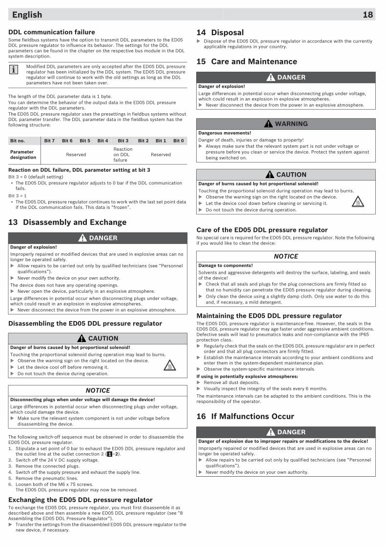
English 18
DDL communication failureSome fieldbus systems have the option to transmit DDL parameters to the ED05 DDL pressure regulator to influence its behavior. The settings for the DDL parameters can be found in the chapter on the respective bus module in the DDL system description.
The length of the DDL parameter data is 1 byte.You can determine the behavior of the output data in the ED05 DDL pressure regulator with the DDL parameters.The ED05 DDL pressure regulator uses the presettings in fieldbus systems without DDL parameter transfer. The DDL parameter data in the fieldbus system has the following structure:
Reaction on DDL failure, DDL parameter setting at bit 3Bit 3 = 0 (default setting)
• The ED05 DDL pressure regulator adjusts to 0 bar if the DDL communication fails.
Bit 3 = 1• The ED05 DDL pressure regulator continues to work with the last set point data
if the DDL communication fails. This data is “frozen”.
13 Disassembly and Exchange
Disassembling the ED05 DDL pressure regulator
The following switch-off sequence must be observed in order to disassemble the ED05 DDL pressure regulator.1. Stipulate a set point of 0 bar to exhaust the ED05 DDL pressure regulator and
the outlet line at the outlet connection 2 ( –2).2. Switch off the 24 V DC supply voltage.3. Remove the connected plugs.4. Switch off the supply pressure and exhaust the supply line.5. Remove the pneumatic lines.6. Loosen both of the M6 x 75 screws.
The ED05 DDL pressure regulator may now be removed.
Exchanging the ED05 DDL pressure regulatorTo exchange the ED05 DDL pressure regulator, you must first disassemble it as described above and then assemble a new ED05 DDL pressure regulator (see “8 Assembling the ED05 DDL Pressure Regulator”).� Transfer the settings from the disassembled ED05 DDL pressure regulator to the
new device, if necessary.
Modified DDL parameters are only accepted after the ED05 DDL pressure regulator has been initialized by the DDL system. The ED05 DDL pressure regulator will continue to work with the old settings as long as the DDL parameters have not been taken over.
Bit no. Bit 7 Bit 6 Bit 5 Bit 4 Bit 3 Bit 2 Bit 1 Bit 0
Parameter designation Reserved
Reaction on DDL failure
Reserved
DANGERDanger of explosion!
Improperly repaired or modified devices that are used in explosive areas can no longer be operated safely.� Allow repairs to be carried out only by qualified technicians (see “Personnel
qualifications”).� Never modify the device on your own authority.
The device does not have any operating openings. � Never open the device, particularly in an explosive atmosphere.
Large differences in potential occur when disconnecting plugs under voltage, which could result in an explosion in explosive atmospheres.� Never disconnect the device from the power in an explosive atmosphere.
CAUTIONDanger of burns caused by hot proportional solenoid!
Touching the proportional solenoid during operation may lead to burns.� Observe the warning sign on the right located on the device.� Let the device cool off before removing it.� Do not touch the device during operation.
NOTICEDisconnecting plugs when under voltage will damage the device!
Large differences in potential occur when disconnecting plugs under voltage, which could damage the device.� Make sure the relevant system component is not under voltage before
disassembling the device.
1
14 Disposal� Dispose of the ED05 DDL pressure regulator in accordance with the currently
applicable regulations in your country.
15 Care and Maintenance
Care of the ED05 DDL pressure regulatorNo special care is required for the ED05 DDL pressure regulator. Note the following if you would like to clean the device:
Maintaining the ED05 DDL pressure regulatorThe ED05 DDL pressure regulator is maintenance-free. However, the seals in the ED05 DDL pressure regulator may age faster under aggressive ambient conditions. Defective seals will lead to pneumatics leaks and non-compliance with the IP65 protection class.� Regularly check that the seals on the ED05 DDL pressure regulator are in perfect
order and that all plug connectors are firmly fitted.� Establish the maintenance intervals according to your ambient conditions and
enter them in the system-dependent maintenance plan.� Observe the system-specific maintenance intervals.
If using in potentially explosive atmospheres:� Remove all dust deposits.� Visually inspect the integrity of the seals every 6 months.
The maintenance intervals can be adapted to the ambient conditions. This is the responsibility of the operator.
16 If Malfunctions Occur
DANGERDanger of explosion!
Large differences in potential occur when disconnecting plugs under voltage, which could result in an explosion in explosive atmospheres.� Never disconnect the device from the power in an explosive atmosphere.
WARNINGDangerous movements!
Danger of death, injuries or damage to property!� Always make sure that the relevant system part is not under voltage or
pressure before you clean or service the device. Protect the system against being switched on.
CAUTIONDanger of burns caused by hot proportional solenoid!
Touching the proportional solenoid during operation may lead to burns.� Observe the warning sign on the right located on the device.� Let the device cool down before cleaning or servicing it.� Do not touch the device during operation.
NOTICEDamage to components!
Solvents and aggressive detergents will destroy the surface, labeling, and seals of the device!� Check that all seals and plugs for the plug connections are firmly fitted so
that no humidity can penetrate the ED05 pressure regulator during cleaning.� Only clean the device using a slightly damp cloth. Only use water to do this
and, if necessary, a mild detergent.
DANGERDanger of explosion due to improper repairs or modifications to the device!
Improperly repaired or modified devices that are used in explosive areas can no longer be operated safely.� Allow repairs to be carried out only by qualified technicians (see “Personnel
qualifications”).� Never modify the device on your own authority.
24 V VALVEX1S POWER
24 V ELECTRONICS
24 V ELECTRONICS
24 V VALVE
X1S SUPPLY VOLTAGE
DDL
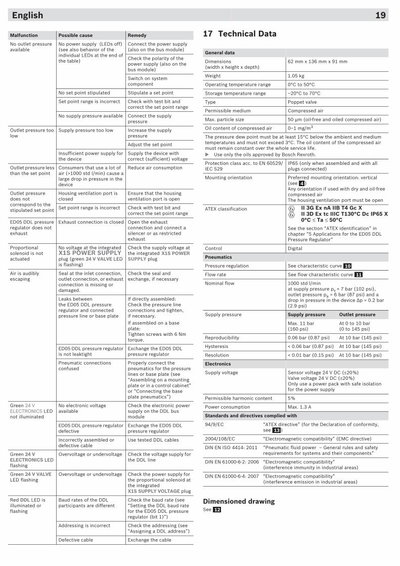
English 19
Malfunction Possible cause Remedy
No outlet pressure available
No power supply (LEDs off) (see also behavior of the individual LEDs at the end of the table)
Connect the power supply (also on the bus module)
Check the polarity of the power supply (also on the bus module)
Switch on system component
No set point stipulated Stipulate a set point
Set point range is incorrect Check with test bit and correct the set point range
No supply pressure available Connect the supply pressure
Outlet pressure too low
Supply pressure too low Increase the supply pressure
Adjust the set point
Insufficient power supply for the device
Supply the device with correct (sufficient) voltage
Outlet pressure less than the set point
Consumers that use a lot of air (>1000 std l/min) cause a large drop in pressure in the device
Reduce air consumption
Outlet pressure does not correspond to the stipulated set point
Housing ventilation port is closed
Ensure that the housing ventilation port is open
Set point range is incorrect Check with test bit and correct the set point range
ED05 DDL pressure regulator does not exhaust
Exhaust connection is closed Open the exhaust connection and connect a silencer or as restricted exhaust
Proportional solenoid is not actuated
No voltage at the integrated X1S POWER SUPPLY plug (green 224 V VALVE LED is flashing)
Check the supply voltage at the integrated X1S POWER SUPPLY plug
Air is audibly escaping
Seal at the inlet connection, outlet connection, or exhaust connection is missing or damaged.
Check the seal and exchange, if necessary
Leaks betweenthe ED05 DDL pressure regulator and connected pressure line or base plate
If directly assembled:Check the pressure line connections and tighten, if necessary.If assembled on a base plate:Tighten screws with 6 Nm torque.
ED05 DDL pressure regulator is not leaktight
Exchange the ED05 DDL pressure regulator
Pneumatic connections confused
Properly connect the pneumatics for the pressure lines or base plate (see “Assembling on a mounting plate or in a control cabinet” or “Connecting the base plate pneumatics”)
Green 24 V ELECTRONICS LED not illuminated
No electronic voltage available
Check the electronic power supply on the DDL bus module
ED05 DDL pressure regulator defective
Exchange the ED05 DDL pressure regulator
Incorrectly assembled or defective cable
Use tested DDL cables
Green 24 V ELECTRONICS LED flashing
Overvoltage or undervoltage Check the voltage supply for the DDL line
Green 24 V VALVE LED flashing
Overvoltage or undervoltage Check the power supply for the proportional solenoid at the integratedX1S SUPPLY VOLTAGE plug
Red DDL LED is illuminated or flashing
Baud rates of the DDL participants are different
Check the baud rate (see “Setting the DDL baud rate for the ED05 DDL pressure regulator (bit 1)”)
Addressing is incorrect Check the addressing (see “Assigning a DDL address”)
Defective cable Exchange the cable
17 Technical Data
Dimensioned drawingSee
General data
Dimensions (width x height x depth)
62 mm x 136 mm x 91 mm
Weight 1.05 kg
Operating temperature range 0°C to 50°C
Storage temperature range –20°C to 70°C
Type Poppet valve
Permissible medium Compressed air
Max. particle size 50 �m (oil-free and oiled compressed air)
Oil content of compressed air 0–1 mg/m3
The pressure dew point must be at least 15°C below the ambient and medium temperatures and must not exceed 3°C. The oil content of the compressed air must remain constant over the whole service life.� Use only the oils approved by Bosch Rexroth.
Protection class acc. to EN 60529/IEC 529
IP65 (only when assembled and with all plugs connected)
Mounting orientation Preferred mounting orientation: vertical (see )Any orientation if used with dry and oil-free compressed airThe housing ventilation port must be open
ATEX classification
See the section “ATEX identification” in chapter “5 Applications for the ED05 DDL Pressure Regulator”
Control Digital
Pneumatics
Pressure regulation See characteristic curve
Flow rate See flow characteristic curve
Nominal flow 1000 std l/minat supply pressure pv = 7 bar (102 psi), outlet pressure pa = 6 bar (87 psi) and a drop in pressure in the device �p = 0.2 bar (2.9 psi)
Supply pressure Supply pressure Outlet pressure
Max. 11 bar(160 psi)
At 0 to 10 bar (0 to 145 psi)
Reproducibility 0.06 bar (0.87 psi) At 10 bar (145 psi)
Hysteresis < 0.06 bar (0.87 psi) At 10 bar (145 psi)
Resolution < 0.01 bar (0.15 psi) At 10 bar (145 psi)
Electronics
Supply voltage Sensor voltage 24 V DC (±20%)Valve voltage 24 V DC (±20%)Only use a power pack with safe isolation for the power supply
Permissible harmonic content 5%
Power consumption Max. 1.3 A
Standards and directives complied with
94/9/EC “ATEX directive” (for the Declaration of conformity, see )
2004/108/EC “Electromagnetic compatibility” (EMC directive)
DIN EN ISO 4414: 2011 “Pneumatic fluid power – General rules and safety requirements for systems and their components”
DIN EN 61000-6-2: 2006 “Electromagnetic compatibility”(interference immunity in industrial areas)
DIN EN 61000-6-4: 2007 “Electromagnetic compatibility”(interference emission in industrial areas)
4
II 3G Ex nA IIB T4 Gc XII 3D Ex tc IIIC T130°C Dc IP65 X0°C ≤ Ta ≤ 50°C
10
11
13
12

18 Accessories
Component Order number
Data final plug (male), CN2 series, M12x1, 5-pin, A-coded
8941054264
ED05 series mounting kit (2 screws, 3 base plate seals) for mounting on a base plate
5610140302
Single subbase, flat, push-in fitting R414002184
Single subbase, flat, thread connection G1/4 R414002187
Manifold block, ED05 series, single 5610141002
Manifold block, ED05 series, double 5610141012
Manifold block, ED05 series, triple 5610141022
Kit (1 blanking plate, 2 screws, 3 seals) for sealing unused connections on connecting blocks
5610140312
Lock ring for zone 22 8955800604
24 V VALVEX1S POWER
24 V ELECTRONICS
24 V ELECTRONICS
24 V VALVE
X1S SUPPLY VOLTAGE
DDL
English 20
Bosch Rexroth AGPneumaticsUlmer Straße 4D30880 LaatzenPhone +49 (0) 5 11-21 36-0Fax: +49 (0) 511-21 36-2 [email protected]/pneumatics
The data specified above only serve to describe the product. The information provided in the instructions on how to use the supplied product should only be considered application examples and suggestions. Catalog statements should not be regarded as guaranteed information. The given information does not release the user from the obligation of own judgement and verification. Our products are subject to a natural process of wear and aging.
© All rights reserved by Bosch Rexroth AG, even and especially in cases of proprietary rights applications. It may not be reproduced or given to third parties without its consent.
An example configuration is depicted on the title page. The delivered product may thus vary from that in the illustration.
Translation of the original operating instructions. The original operating instructions were created in the German language.
1