Embed Size (px)
Citation preview
CT16IGBD2 B1
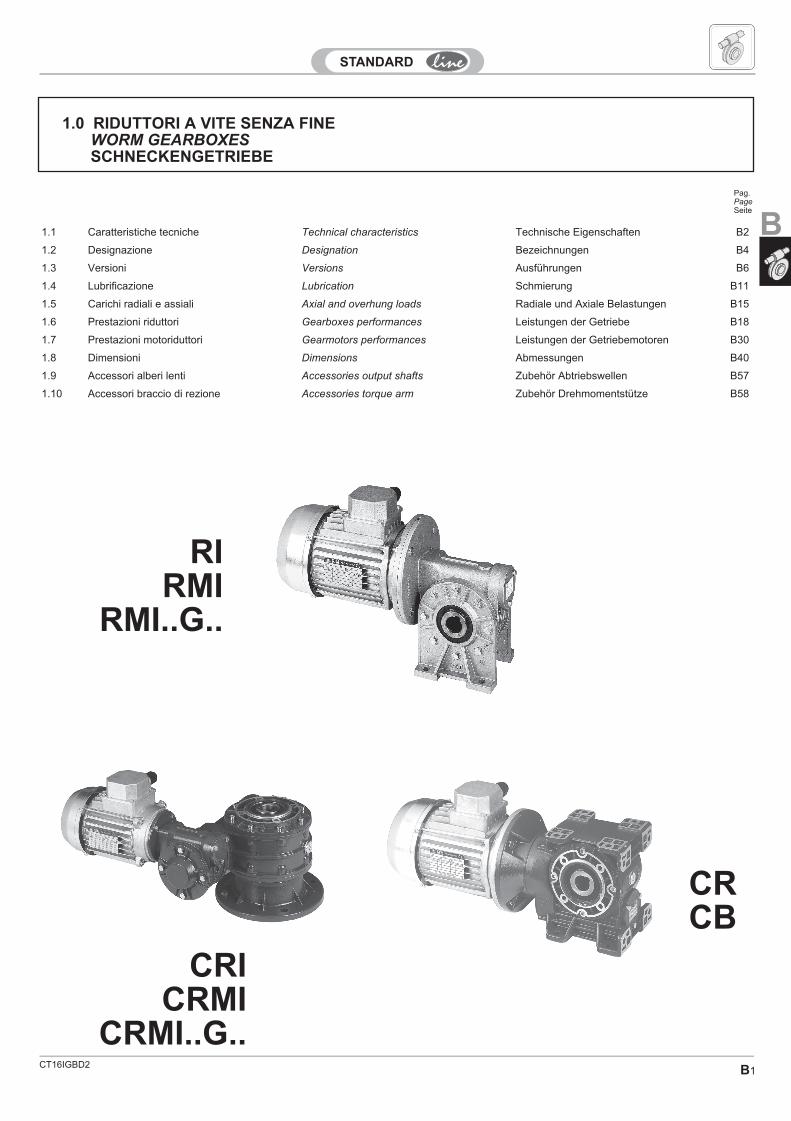
1.0 RIDUTTORI A VITE SENZA FINEWORM GEARBOXESSCHNECKENGETRIEBE
RIRMI
RMI..G..
1.1 Caratteristiche tecniche Technical characteristics Technische Eigenschaften B2
1.2 Designazione Designation Bezeichnungen B4
1.3 Versioni Versions Ausführungen B6
1.4 Lubrificazione Lubrication Schmierung B11
1.5 Carichi radiali e assiali Axial and overhung loads Radiale und Axiale Belastungen B15
1.6 Prestazioni riduttori Gearboxes performances Leistungen der Getriebe B18
1.7 Prestazioni motoriduttori Gearmotors performances Leistungen der Getriebemotoren B30
1.8 Dimensioni Dimensions Abmessungen B40
1.9 Accessori alberi lenti Accessories output shafts Zubehör Abtriebswellen B57
1.10 Accessori braccio di rezione Accessories torque arm Zubehör Drehmomentstütze B58
Pag.PageSeite
CRICRMI
CRMI..G..
CRCB
B
B2
I nostri riduttori a vite senza fine vengonorealizzati seguendo il criterio della massimaaffidabilità nel tempo, risultato ottenutoutilizzando ottimi materiali e moderni criteridi progettazione.Le viti senza fine sono realizzate in acciaio evengono cementate, temprate e rettifi-cate. La rettifica sul filetto, nei rapporti diriduzione per i quali il valore del modulo loconsente, viene eseguita con profilo ZImigliorando così i contatti tra le superficidentate e, conseguentemente, il rendi-mento e la silenziosità di funzionamento.
Giunto:
1 - ACCIAIO:- RMI - UMI 50 Ø19- RMI - UMI 63 Ø24- RMI - UMI 75 Ø19, Ø24, Ø28- RMI - UMI 90 Ø19, Ø24, Ø28- RMI - UMI 110 Ø24, Ø28, Ø38
2 - Tecnopolimero:- RMI - UMI 40 Ø9, Ø11, Ø14- RMI - UMI 50 Ø11, Ø14- RMI - UMI 63 Ø14, Ø19
Sono utilizzati cuscinetti a rulli conici oradiali a sfere di qualità per garantire unalunga durata.Il programma di fabbricazione prevedeanche, l’applicazione di un limitatore dicoppia con allarme di arresto e l’assem-blaggio con variatore.
Our gearboxes are manufactured with highquality material and modern design in orderto guarantee the maximum reliability andduration.Wormshafts are made of steel and arecasehardened, hardened and ground.The thread grinding in the gear ratios thatthe module value permits is carried out withZI-Profile. This improves the contactbetween the toothed surfaces andtherefore performance and reducesoperating noise.
Coupling:
1 - STEEL:- RMI - UMI 50 Ø19- RMI - UMI 63 Ø24- RMI - UMI 75 Ø19, Ø24, Ø28- RMI - UMI 90 Ø19, Ø24, Ø28- RMI - UMI 110 Ø24, Ø28, Ø38
2 - Technopolymer:- RMI - UMI 40 Ø9, Ø11, Ø14- RMI - UMI 50 Ø11, Ø14- RMI - UMI 63 Ø14, Ø19
To guarantee a long life, taper roller bearingor radial ball bearings are used.Our range also provides possibleapplication of torque limiters equipped withstop devices and assembly on to variators.
Unsere Untersetzungsgetriebe werden unterVerwendung von besten Materialien undmit modernsten Herstellungsmethoden her-gestellt, um eine maximale Zuverlässigkeitsowie eine lange Lebensdauer zu garantie-ren.Die Schnecken sind aus einsatzgehärte-tem, gehärtetem und geschliffenem Stahl.Das Gewindeschleifen erfolgt in den vomModulwert zulässigen Übersetzunsverhält-nissen mit ZI-Profil, wodurch die Kontaktezwischen den verzahnten Oberflächen undfolglich die Leistung und der geräu-scharme Betrieb verbessert werden.
Kupplung:
1 - STAHL:- RMI - UMI 50 Ø19- RMI - UMI 63 Ø24- RMI - UMI 75 Ø19, Ø24, Ø28- RMI - UMI 90 Ø19, Ø24, Ø28- RMI - UMI 110 Ø24, Ø28, Ø38
2 - Technischer Kunststoff:- RMI - UMI 40 Ø9, Ø11, Ø14- RMI - UMI 50 Ø11, Ø14- RMI - UMI 63 Ø14, Ø19
Um eine lange Lebensdauer zu gewährlei-sten, werden Kegelrollenlager oder Radial-kugellager von hoher Qualität verwendet.Die Getriebe können mit einer Rutsch-kupplung, einem einstellbaren Drehmo-mentbegrenzer und mit einem Drehzahlreglerausgerüstet werden.
1.1 Technical characteristics 1.1 Technische Eigenschaften1.1 Caratteristiche tecniche
CT16IGBD2.1
B3CT16IGBD2
1.1 Technical characteristics 1.1 Technische Eigenschaften1.1 Caratteristiche tecniche
MATERIALE:Tecnopolimero;Acciaio.
MANUTENZIONE:-Facilità di Montaggio motore;-Facilità di SmontaggioMODULARITA':-Possibilità di utilizzare il giunto sulleserie "U" - "RMI...G..." - "CRMI...G"-"S".TEMPI DI CONSEGNA:-Maggiore modularità del prodotto;-Stock a magazzino del prodottoassemblato.
CARATTERISTICHE PECULIARI:- Ingombri Ridotti;- Semplicità di connessione;- NO Fretting;- NO Vibrazioni;- Progettato per garantire efficienza eaffidabilità con servizi gravosi inpresenza di urti e con numerosiavviamenti.
SPECIAL FEATURES:
-Reduced Sizes-Simplified connections-No fretting-No vibrations-Designed in order to warrant efficiencyand reliability with heavy duty in case ofbumps and frequent start-upsSimplified
connections
SONDERMERKMALE:-Verringerter Platzbedarf;-Einfacher Anschluss;-Keine Abnutzung;-Keine Vibrationen;-Gewährleistet Effizienz undZuverlässigkeit bei hoher Belastung,Stossbeeinträchtigung und zahlreichenMaschinen-Starts.
MATERIAL:
Technopolymer;Steel.
MAINTEINANCE:-Easy motor assembly;-Easy disassembly.MODULARITY:
Possibility of coupling’s using speciallythose of “U”, RMI…G”, - “CRMI…G” - “S”
series.DELIVERY DATES
-Higher product’s modularity
-Stock warehouse finished product.
MATERIAL:Technischer Kunststoff;Stahl.
WARTUNG:-Einfacher Motoreinbau;-Einfacher Ausbau.MODULARITÄTDie Kupplung kann in den Serien „U“ –„RMI...G...“ – „CRMI...G“ und „S“verwendet werden.LIEFERZEITEN:-Größere Modularität des Produktes;-Montiertes Produkt imLaberbestand
B
CT16IGBD2B4
GrandezzaSize
Größe
VersioneVersion
Ausführung
Vers.montaggioMounting
vers.Montageaus
irGiunto
CouplingKupplung
IEC [*1] [*2]FlangiaFlangeFlasch
[*3] [*4] [*5] [*6]
[*7]Limitatore Coppia/Torque LimiterRutschKupplung
28/2828/4028/5028/6340/7040/85
50/11063/13085/15085/180
......
SID
A
12
....
140200280400600980
1372196028004000560070008000
10000
-
G
Grandezze
Sizes
Größe
40/...50/...63/...
-B
-C
— (FL)
F1F2F3F4P
PP
-� 25
CRMI
CRI - -
B7B9
GrandezzaSize
Größe
VersioneVersion
Ausführungir
(*)
IEC[*1] [*2]
[*3] [*4] [*5] [*6]
[*7] [*8]Limitatore Coppia/Torque LimiterRutschKupplung
—F/FP
PPF1F2F3F4
40507085
110
veditabelle
see tablessiehe
Tabellen
-B
-C
-� 25
—(standard)
SIN
CB
CR -
B10
B7B9
CRMI 40/85 S11/980 63(B5)
CRI 40/85 S11/980
CRMI 40/85 S11/980 T63A4B5
D1
B28
56(B5)...
315(B5)
T63...
D1
B29
56(B5)...
315(B5)
T63...
CB 40 1/82.763(B5)
CR 40 1/82.7
CB 40 1/82.7T63A4B5
GrandezzaSize
Größe
VersioneVersion
Ausführung
irGiunto
CouplingKupplung
(*)IEC
[*1] [*2]
[*3] [*4] [*5] [*6]
[*7] [*8]Limitatore Coppia/Torque LimiterRutschkupplung
284050637085
110130150180
SID
PPPFL
(F1)(F2)(F3)(F4)
7101520284049567080
100
-
G
GrandezzeSizes
Größe
40 50 63 -B
-C
-� 25
—(standard)
SIN
RMI
RI -B6
D1
B28
56(B5)...
315(B5)
T63....
RMI 40 1/20 S 63(B5)
RMI 40 1/20 S T63A4B5
RMI 40 1/20 S B 63(B5)
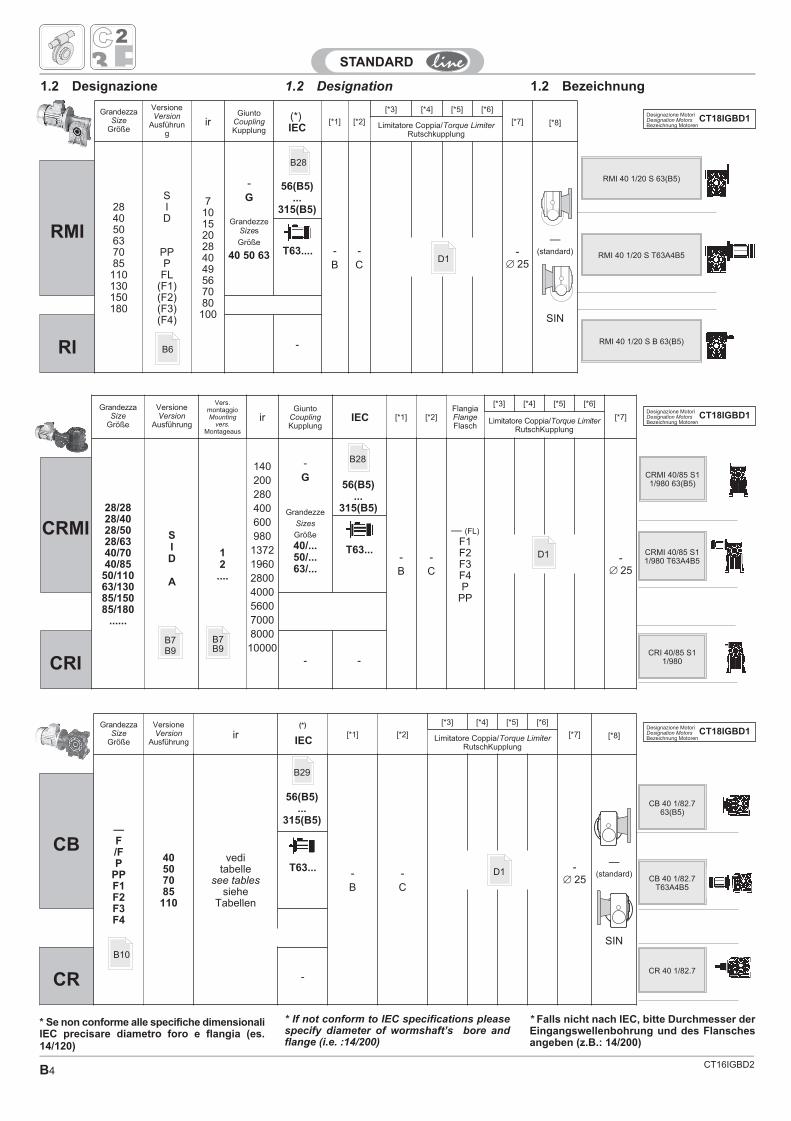
1.2 Designation1.2 Designazione 1.2 Bezeichnung
* If not conform to IEC specifications pleasespecify diameter of wormshaft’s bore andflange (i.e. :14/200)
* Falls nicht nach IEC, bitte Durchmesser derEingangswellenbohrung und des Flanschesangeben (z.B.: 14/200)
* Se non conforme alle specifiche dimensionaliIEC precisare diametro foro e flangia (es.14/120)
Designazione MotoriDesignation MotorsBezeichnung Motoren
CT18IGBD1
Designazione MotoriDesignation MotorsBezeichnung Motoren
CT18IGBD1
Designazione MotoriDesignation MotorsBezeichnung Motoren
CT18IGBD1
CT16IGBD2 B5
FURTHER SPECIFICATION:
• terminal board box position if different fromstandard (1)
• lubrication (except for size 28,40,50,63,70,85 lubricated for life)
• left helix (special version)
• mounting position. Indications must be givenregarding level and breather plugs. If notspecified positions 01 are consideredstandard
ACCESSORIES
• output shafts
• Torque arm
WEITERE SPEZIFIKATIONEN:
• Stellung des Klemmenkastens des Motors,falls diese von der Standard- Ausführungabweicht (1)
• Schmiermittelfüllung (außer bei denwartungsfreien Typen 28,40,50,63,70,85)
• Linksgängige Schraubenlinie der Schnek- ke(Spezialausführung)
• Montagestellung mit Angabe der Ölpegelund Entlüfterstöpsel. Falls nicht andersangegeben, gelten die Pos. 01 als Standard.
ZUBEHOR
• Abtriebswellen
• Drehmomentstütze
ALTRE SPECIFICHE:
• posizione della morsettiera del motore sediversa da quella standard (1)
• lubrificante (non per i tipi 28,40,50,63, 70,85già lubrificati a vita)
• elica della vite sinistra (esecuzione speciale)
• posizione di montaggio con indicazione tappidi livello e sfiato;se non specificato siconsiderano standard le posizioni M1
ACCESSORI
• alberi lenti
• braccio di reazione
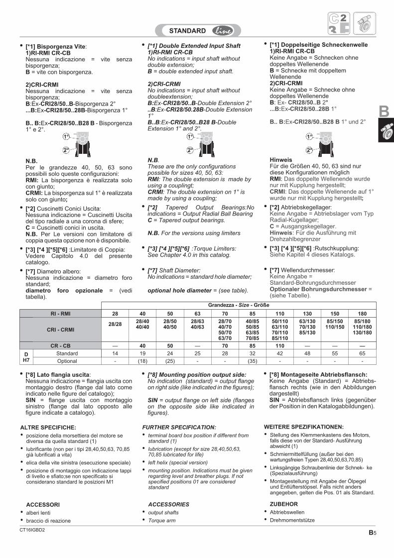
• [*1] Bisporgenza Vite:1)RI-RMI CR-CBNessuna indicazione = vite senzabisporgenza;B = vite con bisporgenza.
2)CRI-CRMINessuna indicazione = vite senzabisporgenza;B:Ex-CRI28/50..B-Bisporgenza 2°...B:Ex-CRI28/50..28B-Bisporgenza 1°
B.. B:Ex-CRI28/50..B28 B - Bisporgenza1° e 2°.
N.B.Per le grandezze 40, 50, 63 sonopossibili solo queste configurazioni:RMI: La bisporgenza è realizzata solocon giunto;CRMI: La bisporgenza sul 1° è realizzatasolo con giunto;
• [*2] Cuscinetti Conici Uscita:Nessuna indicazione = Cuscinetti Uscitadel tipo radiale a una corona di sfere;C = Cuscinetti conici in uscita.N.B. Per Le versioni con limitatore dicoppia questa opzione non è disponibile.
• [*3] [*4 ][*5][*6] :Limitatore di Coppia:Vedere Capitolo 4.0 del presentecatalogo.
• [*7] Diametro albero:Nessuna indicazione = diametro forostandard;diametro foro opzionale = (veditabella).
• [*8] Mounting position output side:No indication (standard) = output flangeon right side (like indicated in the figures);
SIN = output flange on left side (flangeson the opposite side like indicated infigures).
• [*8] Lato flangia uscita:Nessuna indicazione = flangia uscita conmontaggio destro (flange dal lato comeindicato nelle figure del catalogo);SIN = flange uscita con montaggiosinistro (flange dal lato opposto allefigure indicate a catalogo).
• [*8] Montageseite Abtriebsflansch:Keine Angabe (Standard) = Abtriebs-flansch rechts (wie in den Abbildungendargestellt)SIN = Abtriebsflansch links (gegenüberder Position in den Katalogabbildungen).
• [*1] Doppelseitige Schneckenwelle1)RI-RMI CR-CBKeine Angabe = Schnecken ohnedoppeltes WellenendeB = Schnecke mit doppeltemWellenende2)CRI-CRMIKeine Angabe = Schnecke ohnedoppeltes WellenendeB: Ex- CRI28/50..B 2°...B:Ex-CRI28/50..28B 1°
B.. B:Ex-CRI28/50..B28 B 1° und 2°
HinweisFür die Größen 40, 50, 63 sind nurdiese Konfigurationen möglichRMI: Das doppelte Wellenende wurdenur mit Kupplung hergestellt;CRMI: Das doppelte Wellenende auf 1°wurde nur mit Kupplung hergestellt;
• [*2] Abtriebskegellager:Keine Angabe = Abtriebslager vom TypRadial-Kugellager;C = Ausgangskegellager.Hinweis: Für die Ausführung mitDrehzahlbegrenzer
• [*3] [*4 ][*5][*6] :Rutschkupplung:Siehe Kapitel 4 dieses Katalogs.
• [*7] Wellendurchmesser:Keine Angabe =Standard-BohrungsdurchmesserOptionaler Bohrungsdurchmesser =(siehe Tabelle).
• [*1] Double Extended Input Shaft1)RI-RMI CR-CBNo indications = input shaft withoutdouble extension;B = double extended input shaft.
2)CRI-CRMINo indications = input shaft withoutdoubleextension;B:Ex-CRI28/50..B-Double Extension 2°..B:Ex-CRI28/50.28B-Double Extension1°B..B:Ex-CRI28/50..B28 B-DoubleExtension 1° and 2°.
N.B.These are the only configurationspossible for sizes 40, 50, 63:RMI: The double extension is made byusing a couplingt;CRMI: The double extension on 1° ismade by using a coupling;
• [*2] Tapered Output Bearings:Noindications = Output Radial Ball BearingC = Tapered output bearings.
N.B. For the versions using limiters
• [*3] [*4 ][*5][*6] :Torque Limiters:See Chapter 4.0 in this catalog.
• [*7] Shaft Diameter:No indications = standard hole diameter;
optional hole diameter = (see table).
Grandezza - Size - Größe
RI - RMI 28 40 50 63 70 85 110 130 150 180
CRI - CRMI28/28 28/40
40/4028/5040/50
28/6340/63
28/7040/7050/7063/70
40/8550/8563/8570/85
50/11063/11070/11085/110
63/13070/13085/130
85/150110/150
85/180110/180130/180
CR - CB — 40 50 — 70 85 110 — — —
DH7
Standard 14 19 24 25 28 32 42 48 55 65
Optional - (18) (25) - - (35) - - - -
B
CT16IGBD2B6
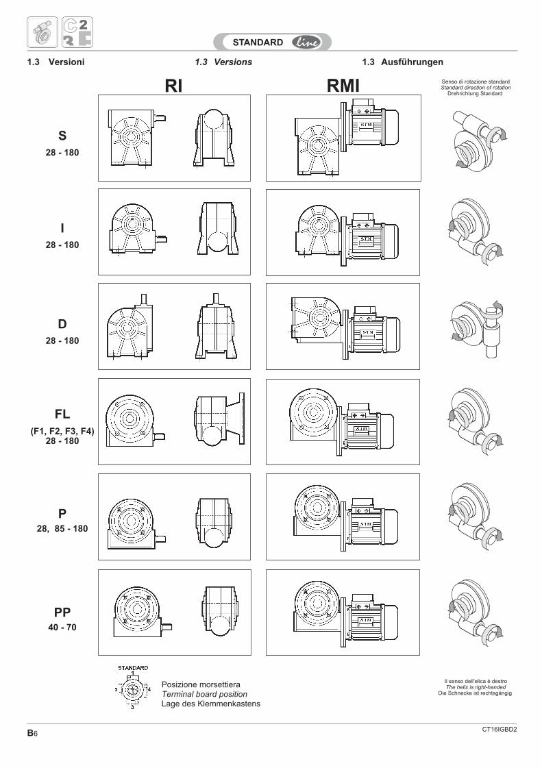
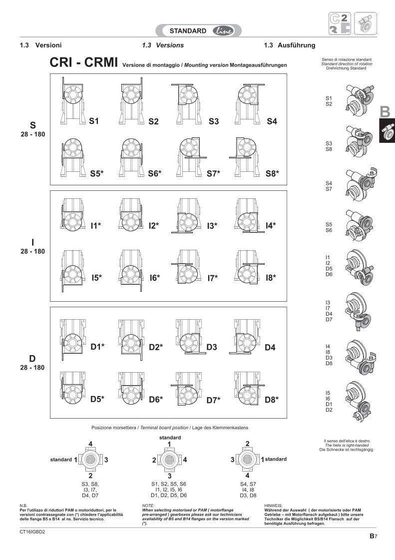
1.3 Versions 1.3 Ausführungen1.3 Versioni
RMIRI
I
D
FL
P
PP
28 - 180
(F1, F2, F3, F4)28 - 180
28, 85 - 180
40 - 70
28 - 180
Posizione morsettieraTerminal board positionLage des Klemmenkastens
S28 - 180
Senso di rotazione standardStandard direction of rotation
Drehrichtung Standard
Il senso dell'elica è destroThe helix is right-handed
Die Schnecke ist rechtsgängig
CT16IGBD2B7
1.3 Versions 1.3 Ausführung1.3 Versioni
1
2
3
4
1
2
3
4 1
2
3
4
S1
I1*
D5*
S8*
I3*
D4
S6*
I6*
D2*
S4
I8*
D8*
S2
I2*
D6*
S7*
I4*
D3
S5*
I5*
D1*
S3
I7*
D7*
standard
standard standard
Posizione morsettiera / / Lage des KlemmenkastensTerminal board position
S28 - 180
I28 - 180
D28 - 180
S1S2
S3S8
S4S7
S5S6
I1I2D5D6
I3I7D4D7
I4I8D3D8
I5I6D1D2
N.B.Per l'utilizzo di riduttori PAM o motoriduttori, per leversioni contrassegnate con (*) chiedere l'applicabilitàdelle flange B5 e B14 al ns. Servizio tecnico.
Versione di montaggio / Mounting version MontageausführungenCRI - CRMI
S3, S8,I3, I7,
D4, D7
S1, S2, S5, S6I1, I2, I5, I6
D1, D2, D5, D6
S4, S7I4, I8
D3, D8
Senso di rotazione standardStandard direction of rotation
Drehrichtung Standard
Il senso dell'elica è destroThe helix is right-handed
Die Schnecke ist rechtsgängig
NOTE:When selecting motorised or PAM ( motorflangepre-arranged ) gearboxes please ask our techniciansavailability of B5 and B14 flanges on the version marked(*).
HINWEIS:Während der Auswahl ( der motorisierte oder PAMGetriebe – mit Motorflansch aufgebaut ) bitte unsereTechniker die Möglichkeit B5/B14 Flansch auf derbenötigte Ausführung befragen.
B
CT16IGBD2B8
1
2
3
4
1
2
3
4 1
2
3
4
A15*
A4
A13*
A8*
A11*
A10*
A1
A6
A3
A16*
A7*
A14*
A9*
A12*
A5
A2
standard
standard standard
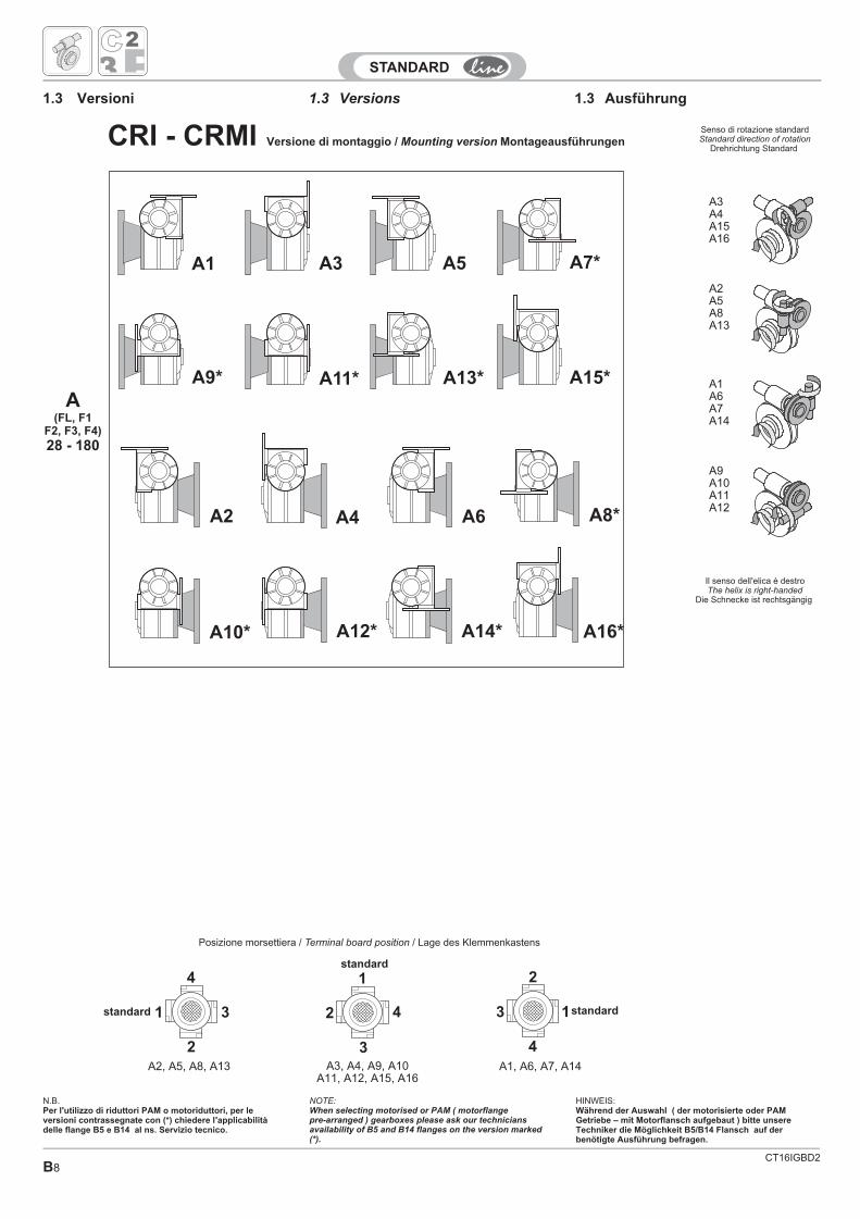
Posizione morsettiera / / Lage des KlemmenkastensTerminal board position
CRI - CRMI
A(FL, F1
F2, F3, F4)
28 - 180
Versione di montaggio / / MontageausführungenMounting version
1.3 Versions 1.3 Ausführung1.3 Versioni
A3A4A15A16
A2A5A8A13
A1A6A7A14
A9A10A11A12
Versione di montaggio / Mounting version MontageausführungenCRI - CRMI
N.B.Per l'utilizzo di riduttori PAM o motoriduttori, per leversioni contrassegnate con (*) chiedere l'applicabilitàdelle flange B5 e B14 al ns. Servizio tecnico.
A2, A5, A8, A13 A3, A4, A9, A10A11, A12, A15, A16
A1, A6, A7, A14
Senso di rotazione standardStandard direction of rotation
Drehrichtung Standard
Il senso dell'elica è destroThe helix is right-handed
Die Schnecke ist rechtsgängig
NOTE:When selecting motorised or PAM ( motorflangepre-arranged ) gearboxes please ask our techniciansavailability of B5 and B14 flanges on the version marked(*).
HINWEIS:Während der Auswahl ( der motorisierte oder PAMGetriebe – mit Motorflansch aufgebaut ) bitte unsereTechniker die Möglichkeit B5/B14 Flansch auf derbenötigte Ausführung befragen.
CT16IGBD2B9
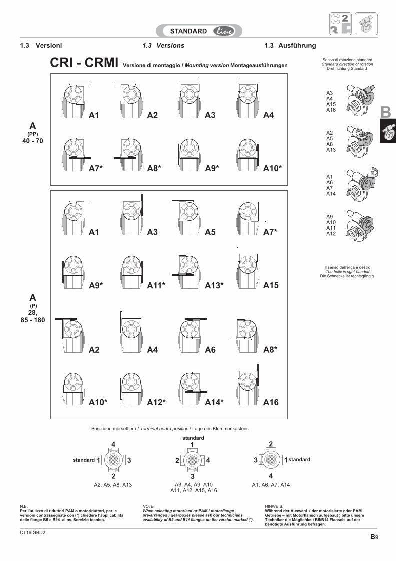
1.3 Versions 1.3 Ausführung1.3 Versioni
N.B.Per l'utilizzo di riduttori PAM o motoriduttori, per leversioni contrassegnate con (*) chiedere l'applicabilitàdelle flange B5 e B14 al ns. Servizio tecnico.
Versione di montaggio / Mounting version MontageausführungenCRI - CRMI
A3A4A15A16
A2A5A8A13
A1A6A7A14
A9A10A11A12
A2, A5, A8, A13 A3, A4, A9, A10A11, A12, A15, A16
A1, A6, A7, A14
Senso di rotazione standardStandard direction of rotation
Drehrichtung Standard
Il senso dell'elica è destroThe helix is right-handed
Die Schnecke ist rechtsgängig
NOTE:When selecting motorised or PAM ( motorflangepre-arranged ) gearboxes please ask our techniciansavailability of B5 and B14 flanges on the version marked (*).
HINWEIS:Während der Auswahl ( der motorisierte oder PAMGetriebe – mit Motorflansch aufgebaut ) bitte unsereTechniker die Möglichkeit B5/B14 Flansch auf derbenötigte Ausführung befragen.
B
CT16IGBD2B10
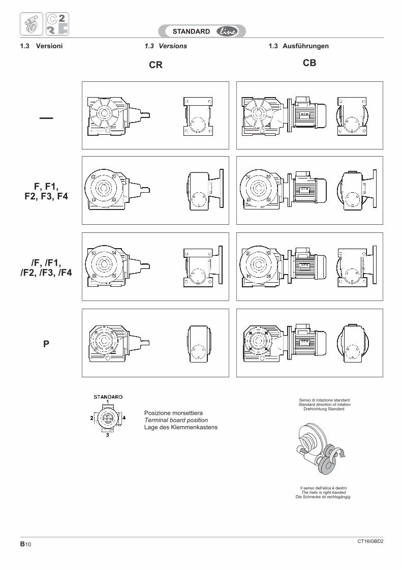
1.3 Versions 1.3 Ausführungen1.3 Versioni
CBCR
F, F1,F2, F3, F4
/F, /F1,/F2, /F3, /F4
P
—
Posizione morsettieraTerminal board positionLage des Klemmenkastens
Senso di rotazione standardStandard direction of rotation
Drehrichtung Standard
Il senso dell'elica è destroThe helix is right-handed
Die Schnecke ist rechtsgängig
CT16IGBD2 B11
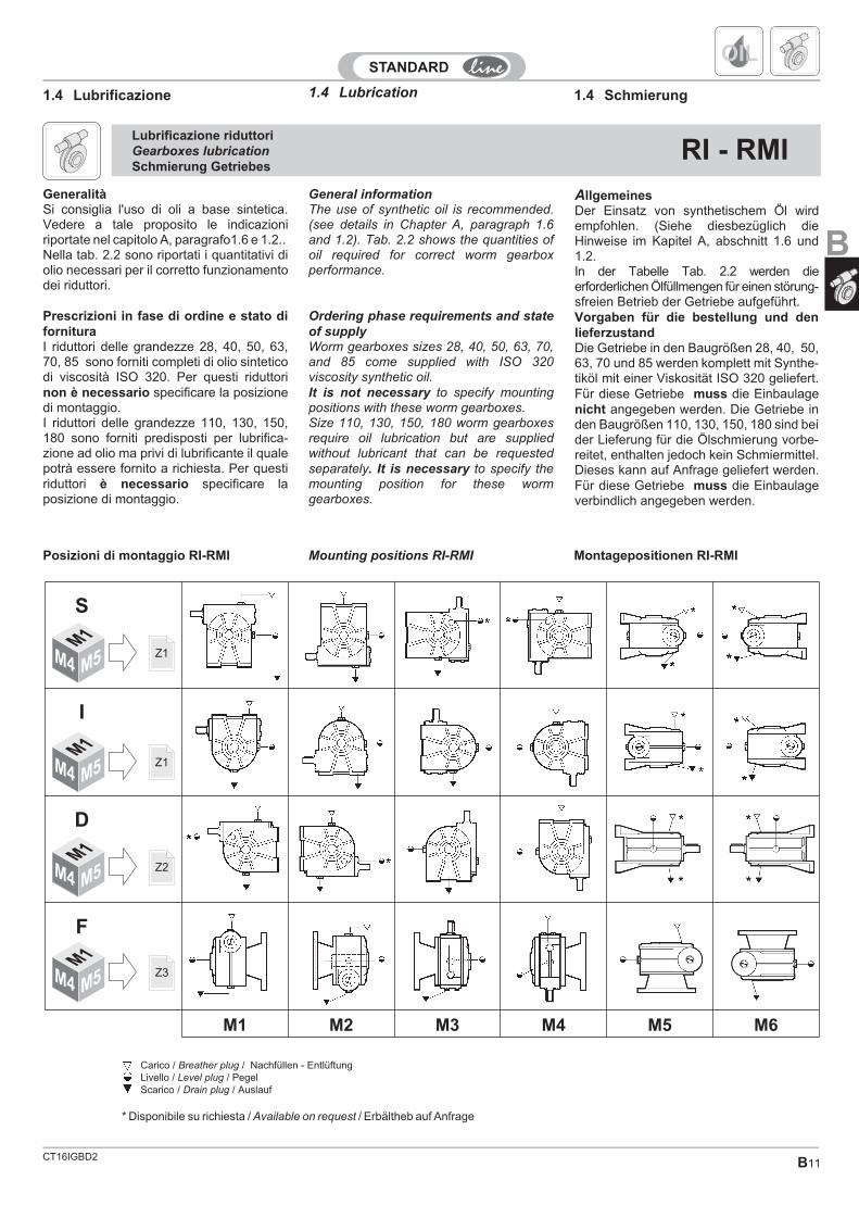
General informationThe use of synthetic oil is recommended.(see details in Chapter A, paragraph 1.6and 1.2). Tab. 2.2 shows the quantities ofoil required for correct worm gearboxperformance.
Ordering phase requirements and state
of supplyWorm gearboxes sizes 28, 40, 50, 63, 70,and 85 come supplied with ISO 320viscosity synthetic oil.It is not necessary to specify mountingpositions with these worm gearboxes.Size 110, 130, 150, 180 worm gearboxesrequire oil lubrication but are suppliedwithout lubricant that can be requestedseparately. It is necessary to specify themounting position for these wormgearboxes.
AllgemeinesDer Einsatz von synthetischem Öl wirdempfohlen. (Siehe diesbezüglich dieHinweise im Kapitel A, abschnitt 1.6 und1.2.In der Tabelle Tab. 2.2 werden dieerforderlichen Ölfüllmengen für einen störung-sfreien Betrieb der Getriebe aufgeführt.Vorgaben für die bestellung und denlieferzustandDie Getriebe in den Baugrößen 28, 40, 50,63, 70 und 85 werden komplett mit Synthe-tiköl mit einer Viskosität ISO 320 geliefert.Für diese Getriebe muss die Einbaulagenicht angegeben werden. Die Getriebe inden Baugrößen 110, 130, 150, 180 sind beider Lieferung für die Ölschmierung vorbe-reitet, enthalten jedoch kein Schmiermittel.Dieses kann auf Anfrage geliefert werden.Für diese Getriebe muss die Einbaulageverbindlich angegeben werden.
1.4 Lubrication1.4 Lubrificazione 1.4 Schmierung
GeneralitàSi consiglia l'uso di oli a base sintetica.Vedere a tale proposito le indicazioniriportate nel capitolo A, paragrafo1.6 e 1.2..Nella tab. 2.2 sono riportati i quantitativi diolio necessari per il corretto funzionamentodei riduttori.
Prescrizioni in fase di ordine e stato difornituraI riduttori delle grandezze 28, 40, 50, 63,70, 85 sono forniti completi di olio sinteticodi viscosità ISO 320. Per questi riduttorinon è necessario specificare la posizionedi montaggio.I riduttori delle grandezze 110, 130, 150,180 sono forniti predisposti per lubrifica-zione ad olio ma privi di lubrificante il qualepotrà essere fornito a richiesta. Per questiriduttori è necessario specificare laposizione di montaggio.
OIL
Lubrificazione riduttoriGearboxes lubrication
Schmierung GetriebesRI - RMI
Mounting positions RI-RMIPosizioni di montaggio RI-RMI Montagepositionen RI-RMI
* Disponibile su richiesta / Available on request / Erbältheb auf Anfrage
Carico / Breather plug / Nachfüllen - EntlüftungLivello / Level plug / PegelScarico / Drain plug / Auslauf
Z3M1
M4 M5
Z2M1
M4 M5
Z1M1
M4 M5
Z1M1
M4 M5
S
I
D
F
M1 M2 M3 M4 M5 M6
B
CT16IGBD2B12
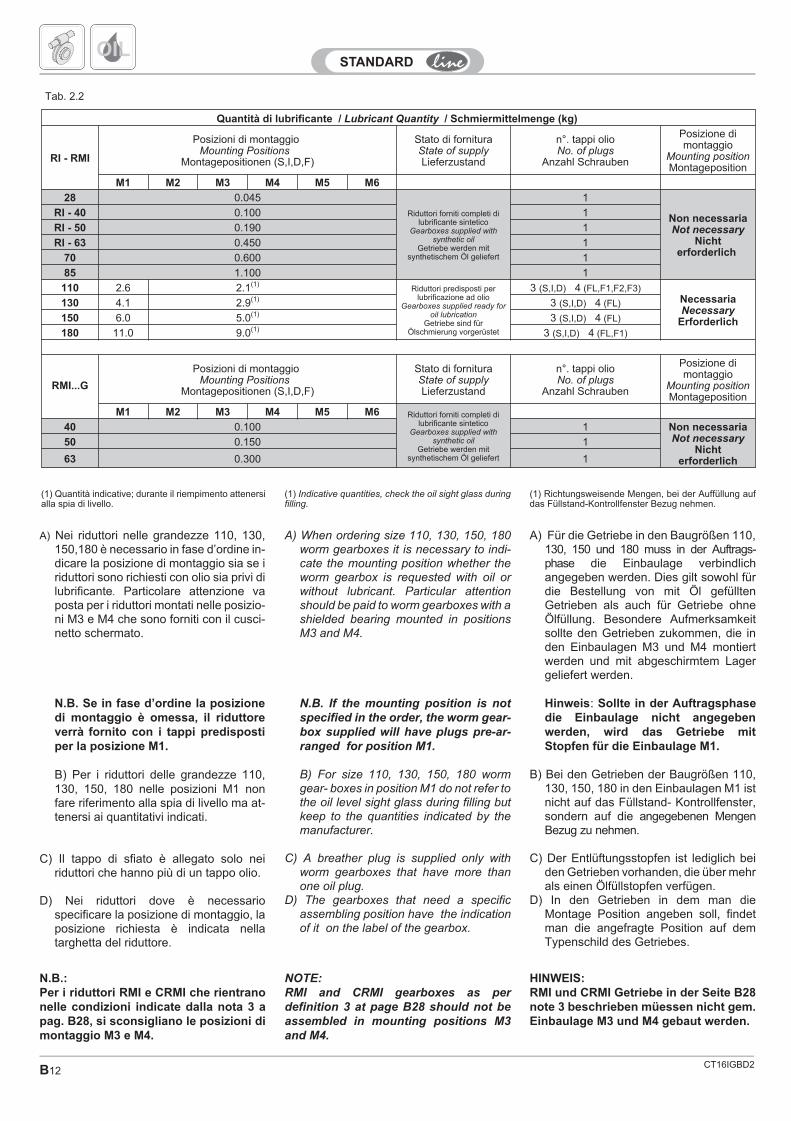
Tab. 2.2
A) Nei riduttori nelle grandezze 110, 130,150,180 è necessario in fase d’ordine in-dicare la posizione di montaggio sia se iriduttori sono richiesti con olio sia privi dilubrificante. Particolare attenzione vaposta per i riduttori montati nelle posizio-ni M3 e M4 che sono forniti con il cusci-netto schermato.
N.B. Se in fase d’ordine la posizionedi montaggio è omessa, il riduttoreverrà fornito con i tappi predispostiper la posizione M1.
B) Per i riduttori delle grandezze 110,130, 150, 180 nelle posizioni M1 nonfare riferimento alla spia di livello ma at-tenersi ai quantitativi indicati.
C) Il tappo di sfiato è allegato solo neiriduttori che hanno più di un tappo olio.
D) Nei riduttori dove è necessariospecificare la posizione di montaggio, laposizione richiesta è indicata nellatarghetta del riduttore.
OIL
(1) Indicative quantities, check the oil sight glass duringfilling.
N.B.:Per i riduttori RMI e CRMI che rientranonelle condizioni indicate dalla nota 3 apag. B28, si sconsigliano le posizioni dimontaggio M3 e M4.
NOTE:
RMI and CRMI gearboxes as per
definition 3 at page B28 should not be
assembled in mounting positions M3
and M4.
HINWEIS:RMI und CRMI Getriebe in der Seite B28note 3 beschrieben müessen nicht gem.Einbaulage M3 und M4 gebaut werden.
Quantità di lubrificante / Lubricant Quantity / Schmiermittelmenge (kg)
RI - RMI
Posizioni di montaggioMounting Positions
Montagepositionen (S,I,D,F)
Stato di fornituraState of supplyLieferzustand
n°. tappi olioNo. of plugs
Anzahl Schrauben
Posizione dimontaggio
Mounting positionMontageposition
M1 M2 M3 M4 M5 M6
28 0.045
Riduttori forniti completi dilubrificante sintetico
Gearboxes supplied withsynthetic oil
Getriebe werden mitsynthetischem Öl geliefert
1
Non necessariaNot necessary
Nichterforderlich
RI - 40 0.100 1
RI - 50 0.190 1
RI - 63 0.450 1
70 0.600 1
85 1.100 1
110 2.6 2.1(1)Riduttori predisposti per
lubrificazione ad olioGearboxes supplied ready for
oil lubricationGetriebe sind für
Ölschmierung vorgerüstet
3 (S,I,D) 4 (FL,F1,F2,F3)NecessariaNecessary
Erforderlich
130 4.1 2.9(1) 3 (S,I,D) 4 (FL)
150 6.0 5.0(1) 3 (S,I,D) 4 (FL)
180 11.0 9.0(1) 3 (S,I,D) 4 (FL,F1)
RMI...G
Posizioni di montaggioMounting Positions
Montagepositionen (S,I,D,F)
Stato di fornituraState of supplyLieferzustand
n°. tappi olioNo. of plugs
Anzahl Schrauben
Posizione dimontaggio
Mounting positionMontageposition
M1 M2 M3 M4 M5 M6 Riduttori forniti completi dilubrificante sintetico
Gearboxes supplied withsynthetic oil
Getriebe werden mitsynthetischem Öl geliefert
40 0.100 1 Non necessariaNot necessary
Nichterforderlich
50 0.150 1
63 0.300 1
(1) Richtungsweisende Mengen, bei der Auffüllung aufdas Füllstand-Kontrollfenster Bezug nehmen.
(1) Quantità indicative; durante il riempimento attenersialla spia di livello.
A) Für die Getriebe in den Baugrößen 110,130, 150 und 180 muss in der Auftrags-phase die Einbaulage verbindlichangegeben werden. Dies gilt sowohl fürdie Bestellung von mit Öl gefülltenGetrieben als auch für Getriebe ohneÖlfüllung. Besondere Aufmerksamkeitsollte den Getrieben zukommen, die inden Einbaulagen M3 und M4 montiertwerden und mit abgeschirmtem Lagergeliefert werden.
Hinweis: Sollte in der Auftragsphasedie Einbaulage nicht angegebenwerden, wird das Getriebe mitStopfen für die Einbaulage M1.
B) Bei den Getrieben der Baugrößen 110,130, 150, 180 in den Einbaulagen M1 istnicht auf das Füllstand- Kontrollfenster,sondern auf die angegebenen MengenBezug zu nehmen.
C) Der Entlüftungsstopfen ist lediglich beiden Getrieben vorhanden, die über mehrals einen Ölfüllstopfen verfügen.
D) In den Getrieben in dem man dieMontage Position angeben soll, findetman die angefragte Position auf demTypenschild des Getriebes.
A) When ordering size 110, 130, 150, 180worm gearboxes it is necessary to indi-cate the mounting position whether theworm gearbox is requested with oil orwithout lubricant. Particular attentionshould be paid to worm gearboxes with ashielded bearing mounted in positionsM3 and M4.
N.B. If the mounting position is not
specified in the order, the worm gear-
box supplied will have plugs pre-ar-
ranged for position M1.
B) For size 110, 130, 150, 180 wormgear- boxes in position M1 do not refer tothe oil level sight glass during filling butkeep to the quantities indicated by themanufacturer.
C) A breather plug is supplied only withworm gearboxes that have more thanone oil plug.
D) The gearboxes that need a specificassembling position have the indicationof it on the label of the gearbox.
B13
CRI - CRMIStato di fornituraState Of SupplyLieferzustand
Posizione di montaggioMounting positionMontageposition
Quantità di lubrificanteLubricant Quantity
Schmiermittelmenge(kg)
28/28, 28/40, 40/40, 28/50,40/50, 28/63, 40/63, 28/70,40/70, 50/70, 63/70, 40/85,50/85, 63/85, 70/85
Riduttori forniti completi di lubrificante sinteticoGearboxes supplied with synthetic oil
Getriebe werden mit synthetischem Öl geliefert
Non necessariaNot necessary
Nicht erforderlich
1° Riduttore e 2° Riduttore Tabella Tab. 2.2 a pag. B12.1° Gearbox and 2° Gearbox Tab 2.2 to page B12
1° Getriebe und 2° Getriebe Siehe Tab. 2.2 seite B12
50/110, 63/110, 70/110,63/130, 70/130
Non necessariaNot necessary
Nicht erforderlich
1° Riduttore: Tabella Tab. 2.2 a pag. B122° Riduttore: quantitativo M1Tabella Tab. 2.2 a pag. B12
1° Gearbox: Tab. 2.2 to page B12
2° Gearbox: Look at lubrificant quantity M1 Tab. 2.2 . to page B12
1° Getriebe: Siehe Tab. 2.2 seite B122° Getriebe: Siehe Menge M1 Tab. 2.2 seite B12
85/110, 85/130, 85/150, 85/180
Riduttori predisposti per lubrificazione ad olioGearboxes supplied ready for oil lubricationGetriebe sind für Ölschmierung vorgesehen
Non necessariaNot necessary
Nicht erforderlich
110/150, 110/180, 130/180NecessariaNecessaryErforderlich
1° Riduttore: vedere posizione di montaggio indicata in targhetta eriempire con quantitativo secondo Tab.2.2 a pag. B12
2° Riduttore: quantitativo M1 tabella Tab. 2.2 a pag. B12
1° Gearbox: Look at Mounting Position on the label of the gearbox
and filling keep with lubrificant quantity Tab. 2.2 to page B12
2° Gearbox: Look at lubrificant quantity M1 Tab. 2.2 to page B12
1° Getriebe: Siehe Aufbau auf dem typenschild gezeichnet undabfüllen gem menge Tab. 2.2 seite B12
2° Getriebe: Siehe Menge M1 Tab. 2.2 seite B12
Tab. 2.3
OIL
Lubrificazione riduttoriGearboxes lubrication
Schmierung GetriebesCRI - CRMI
General informationThe use of synthetic oil is recommended (seedetails in Chapter A, paragraph 1.6 and 1.2).
Ordering phase requirements and state ofsupplyCombined gearboxes sizes 28/28, 28/40, 40/40,28/50, 40/50, 28/63, 40/63, 28/70, 40/70, 63/70,40/85, 50/85, 63/85, 70/85, 50/110, 63/110,70/110, 63/130, 70/130 come supplied with ISOIt is not necessary to specify mounting positionswith these worm gearboxes.Combined gearboxes sizes 85/110, 85/130,85/150, 110/150, 85/180, 110/180, 130/180 arepre-arranged for oil lubrication but suppliedwithout lubricant.For 85/110, 85/130, 85/150, 85/180 it is notnecessary to specify mounting positions.For 110/150, 110/180, 130/180, gearboxes it isnecessary to specify the mounting position ofthe gearboxes 110 and 130 referring to the RMIgearbox diagram (page B11).
Lubrificazione riduttoriGearboxes lubrication
Schmierung GetriebesCR - CB
Generalita’Questi riduttori sono composti da uncinematismo misto costituito da una precoppiaad ingranaggi anteposta ad una coppia vitesenza fine - corona.Si consiglia l’uso di oli a base sintetica. (Vedere atale proposito le indicazioni riportate nel capitoloA, paragrafo 1.6 e 1.2).Nella tabella Tab. 2.4 sono riportati i quantitatividi olio necessari per il corretto funzionamento deiriduttori.
AllgemeinesDer Einsatz von synthetischem Öl wirdempfohlen. (Siehe diesbezüglich die Hinweiseim Kapitel A, Abschnitt 1.6 und 1.2.)
Vorgaben für die bestellung und denlieferzustandDie Getriebe in den Baugrößen 28/28, 28/40,40/40, 28/50, 40/50, 28/63, 40/63, 28/70, 40/70,63/70, 40/85, 50/85, 63/85, 70/85, 50/110,63/110, 70/110, 63/130, 70/130 werden komplettmit Synthetiköl mit einer Viskosität ISO 320geliefert.Für diese Getriebe muss die Einbaulage nichtangegeben werden.Die Getriebe in den Baugrößen 85/110, 85/130,85/150, 110/150, 85/180, 110/180, 130/180 sindbei der Lieferung für die Ölschmierungvorbereitet, enthalten jedoch kein SchmiermittelFür die Getriebe 110/150, 110/180, 130/180,muss die Einbaulage des Getriebes 110 und130 verbindlich angegeben werden.Dabei ist auf den Anschlussplan der GetriebeRMI Bezug zu nehmen (Seite B11).
GeneralitàSi consiglia l’uso di oli a base sintetica. (Vedere atale proposito le indicazioni riportate nel capitoloA, paragrafo 1.6 e 1.2.)
Prescrizioni in fase d’ordine e stato difornituraI riduttori delle grandezze 28/28, 28/40, 40/40,28/50, 40/50, 28/63, 40/63, 28/70, 40/70, 63/70,40/85, 50/85, 63/85, 70/85, 50/110, 63/110,70/110, 63/130, 70/130 sono forniti completi diolio sintetico di viscosità ISO 320.Per questi riduttori non è necessario indicare laposizione di montaggioI riduttori nelle grandezze 85/110, 85/130,85/150, 110/150, 85/180, 110/180, 130/180 sonoforniti predisposti per lubrificazione ad olio maprivi di lubrificante.Per i riduttori 85/110, 85/130, 85/150, 85/180non è necessario specificare la posizione dimontaggio.Per i riduttori 110/150, 110/180, 130/180, ènecessario specificare la posizione di montaggiodei riduttori 110 e 130 facendo riferimento alloschema dei riduttori RMI (pag. B11).
General informationThese gear units are composed of a mixedkinematic motion made up of a gearedpre-torque unit placed before a dual-crown wormscrew.The use of synthetic oil is recommended (seedetails in Chapter A, paragraph 1.6 and 1.2).Tab. 2.4 shows the quantities of oil required forcorrect gear unit performance.
AllgemeinesDiese Getriebe bestehen aus einemHybridgetriebe, mit einem Vorstadium mitZahnrädern vor einem Schnecken-Kranz-Stadium. Der Einsatz von synthetischem Öl wirdempfohlen. (Siehe diesbezüglich die Hinweiseim Kapitel A, Abschnitt 1.6 und 1.2).In der Tabelle Tab 2.4 werden die erforderlichenÖlfüllmengen für einen störungsfreien Betriebder Getriebe aufgeführt.
CT16IGBD0
B
CT16IGBD2B14
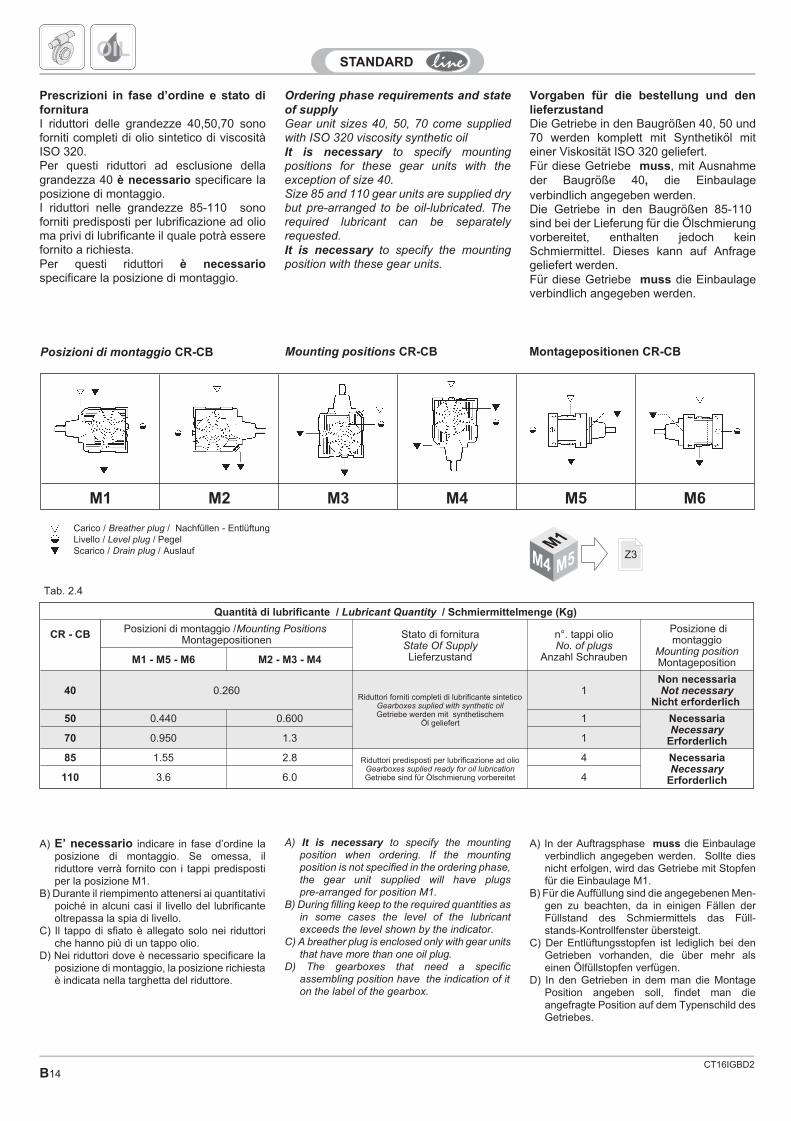
Mounting positions CR-CB Montagepositionen CR-CB
Tab. 2.4
Carico / Breather plug / Nachfüllen - EntlüftungLivello / Level plug / PegelScarico / Drain plug / Auslauf
Quantità di lubrificante / Lubricant Quantity / Schmiermittelmenge (Kg)
CR - CB Posizioni di montaggio /Mounting PositionsMontagepositionen Stato di fornitura
State Of SupplyLieferzustand
n°. tappi olioNo. of plugs
Anzahl Schrauben
Posizione dimontaggio
Mounting positionMontagepositionM1 - M5 - M6 M2 - M3 - M4
40 0.260Riduttori forniti completi di lubrificante sintetico
Gearboxes suplied with synthetic oilGetriebe werden mit synthetischem
Öl geliefert
1Non necessariaNot necessary
Nicht erforderlich
50 0.440 0.600 1 NecessariaNecessary
Erforderlich70 0.950 1.3 1
85 1.55 2.8 Riduttori predisposti per lubrificazione ad olioGearboxes suplied ready for oil lubricationGetriebe sind für Ölschmierung vorbereitet
4 NecessariaNecessary
Erforderlich110 3.6 6.0 4
OIL
Prescrizioni in fase d’ordine e stato difornituraI riduttori delle grandezze 40,50,70 sonoforniti completi di olio sintetico di viscositàISO 320.Per questi riduttori ad esclusione dellagrandezza 40 è necessario specificare laposizione di montaggio.I riduttori nelle grandezze 85-110 sonoforniti predisposti per lubrificazione ad olioma privi di lubrificante il quale potrà esserefornito a richiesta.Per questi riduttori è necessariospecificare la posizione di montaggio.
M1 M2 M3 M4 M5 M6
A) It is necessary to specify the mountingposition when ordering. If the mountingposition is not specified in the ordering phase,the gear unit supplied will have plugspre-arranged for position M1.
B) During filling keep to the required quantities asin some cases the level of the lubricantexceeds the level shown by the indicator.
C) A breather plug is enclosed only with gear unitsthat have more than one oil plug.
D) The gearboxes that need a specificassembling position have the indication of iton the label of the gearbox.
Ordering phase requirements and state
of supplyGear unit sizes 40, 50, 70 come suppliedwith ISO 320 viscosity synthetic oilIt is necessary to specify mountingpositions for these gear units with theexception of size 40.Size 85 and 110 gear units are supplied drybut pre-arranged to be oil-lubricated. Therequired lubricant can be separatelyrequested.It is necessary to specify the mountingposition with these gear units.
Vorgaben für die bestellung und denlieferzustandDie Getriebe in den Baugrößen 40, 50 und70 werden komplett mit Synthetiköl miteiner Viskosität ISO 320 geliefert.Für diese Getriebe muss, mit Ausnahmeder Baugröße 40, die Einbaulageverbindlich angegeben werden.Die Getriebe in den Baugrößen 85-110sind bei der Lieferung für die Ölschmierungvorbereitet, enthalten jedoch keinSchmiermittel. Dieses kann auf Anfragegeliefert werden.Für diese Getriebe muss die Einbaulageverbindlich angegeben werden.
A) In der Auftragsphase muss die Einbaulageverbindlich angegeben werden. Sollte diesnicht erfolgen, wird das Getriebe mit Stopfenfür die Einbaulage M1.
B) Für die Auffüllung sind die angegebenen Men-gen zu beachten, da in einigen Fällen derFüllstand des Schmiermittels das Füll-stands-Kontrollfenster übersteigt.
C) Der Entlüftungsstopfen ist lediglich bei denGetrieben vorhanden, die über mehr alseinen Ölfüllstopfen verfügen.
D) In den Getrieben in dem man die MontagePosition angeben soll, findet man dieangefragte Position auf dem Typenschild desGetriebes.
A) E’ necessario indicare in fase d’ordine laposizione di montaggio. Se omessa, ilriduttore verrà fornito con i tappi predispostiper la posizione M1.
B) Durante il riempimento attenersi ai quantitativipoiché in alcuni casi il livello del lubrificanteoltrepassa la spia di livello.
C) Il tappo di sfiato è allegato solo nei riduttoriche hanno più di un tappo olio.
D) Nei riduttori dove è necessario specificare laposizione di montaggio, la posizione richiestaè indicata nella targhetta del riduttore.
Posizioni di montaggio CR-CB
Z3M1
M4 M5
CT16IGBD2 B15
n1
min-1
Fr1 (N)
RI - CRI28 40 50 63 70 85 110 130 150 180
2800 51 187 272 357 425 595 850 1360 1870 2125
1400 60 220 320 420 500 700 1000 1600 2200 2500
900 60 250 350 460 530 800 1200 1800 2350 2700
700 70 280 400 500 570 900 1300 2000 2500 3000
500 70 310 450 530 600 1000 1450 2200 2700 3200
Tab. 2.5
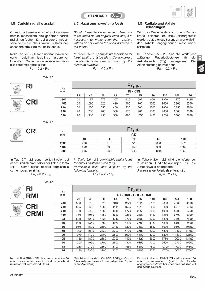
In Table 2.6 - 2.8 permissible radial loadsfor output shaft are listed (Fr2).Permissible axial load is given by thefollowing formula:
Fa2 = 0.2 x Fr2
In Tabelle 2.6 - 2.8 sind die Werte derzulässigen Radialbelastungen für dieAbtriebswelle angegeben.Als zulässige Axialbelas- tung gilt:
Fa2 = 0.2 x Fr2
In Tab. 2.7 - 2.8 sono riportati i valori deicarichi radiali ammissibili per l’albero lento(Fr2) . Come carico assiale ammissibilecontemporaneo si ha:
Fa2 = 0.2 x Fr2
Should transmission movement determineradial loads on the angular shaft end, it isnecessary to make sure that resultingvalues do not exceed the ones indicated inthe tables.
In Table 2.5 - 2.6 permissible radial load forinput shaft are listed (Fr1). Contemporarypermissible axial load is given by thefollowing formula:
Fa1 = 0.2 x Fr1
Wird das Wellenende auch durch Radial-kräfte belastet, so muß sichergestelltwerden, daß die resultierenden Werte die inder Tabelle angegebenen nicht über-schreiten.
In Tabelle 2.5 - 2.6 sind die Werte derzulässigen Radialbelastungen für dieAntriebswelle (Fr1) angegeben. DieAxialbelastung beträgt dann:
Fa1 = 0.2 x Fr1
Quando la trasmissione del moto avvienetramite meccanismi che generano carichiradiali sull’estremità dell’albero,è neces-sario verificare che i valori risultanti noneccedono quelli indicati nelle tabelle.
Nella Tab. 2.5 - 2.6 sono riportati i valori deicarichi radiali ammissibili per l’albero ve-loce (Fr1). Come carico assiale ammissi-bile contemporaneo si ha:
Fa1 = 0.2 x Fr1
1.5 Axial and overhung loads1.5 Carichi radiali e assiali 1.5 Radiale und AxialeBelastungen
n1
min-1
Fr1 (N)
CR40 50 70 85 110
2800 468 510 723 808 1275
1400 550 600 850 950 1500
900 605 660 935 1045 1650
n2
min-1
Fr2 (N)
RI - RMI - CRI - CRMI28 40 50 63 70 85 110 130 150 180
400 506 686 925 946 1279 1626 2168 2890 4263 4516
280 595 808 1088 1114 1505 1913 2550 3400 5015 5313
200 700 950 1280 1310 1770 2250 3000 4000 5900 6250
140 750 1050 1450 1680 2350 2400 3150 4250 6700 6900
93 800 1200 1620 1740 2700 2500 3600 4800 7500 7500
70 900 1350 1850 1930 3100 2650 4150 5300 8400 8500
50 950 1500 2100 2150 3300 3560 4850 6600 9400 10300
35 1000 1600 2230 2300 3700 3850 5700 7500 10100 11500
29 1070 1700 2400 2500 3900 4400 6200 8200 11100 12500
25 1130 1800 2580 2700 4100 4620 6600 8750 12000 13400
20 1200 1950 2700 2900 4300 5150 7200 9600 12700 15200
18 1280 2100 2850 3100 4450 5500 7800 10300 14000 16300
14 1430 2300 3200 3300 4700 5800 8250 10700 15000 17000
Nei riduttori CRI-CRMI utilizzare i carichi a 14min-1 (ovviamente i valori indicati in tabella siriferiscono al secondo riduttore).
RI
CR
CRI
RIRMI
CRICRMI
Tab. 2.7
Tab. 2.6
Use 14 min-1 loads in the CRI-CRMI gearboxes(obviously the values in the table refer to thesecond gearbox).
Bei den Getrieben CRI-CRMI sind Lasten mit 14min-1 zu verwenden (die in der Tabelleangegebenen Werte beziehen sich natürlich aufdas zweite Getriebe).
B
B16
n2
min-1
Fr2 (N)
CR - CB40 50 70 85 110
30 1800 2160 3030 3390 4020
27 1880 2290 3140 3590 4170
23 1970 2400 3340 3690 4560
20 1970 2890 3580 3890 4800
16 2010 2930 3960 4490 6000
13 2010 2930 3960 4620 6230
10 2010 2930 3960 4620 6230
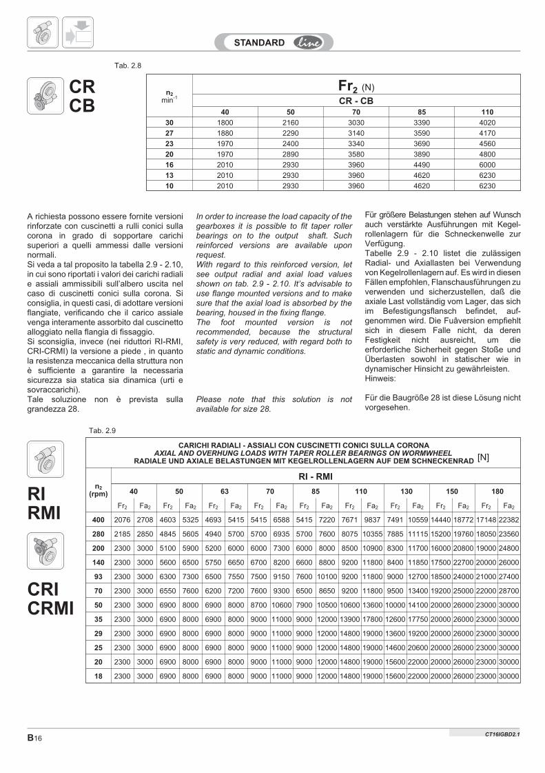
In order to increase the load capacity of thegearboxes it is possible to fit taper rollerbearings on to the output shaft. Suchreinforced versions are available uponrequest.With regard to this reinforced version, letsee output radial and axial load valuesshown on tab. 2.9 - 2.10. It’s advisable touse flange mounted versions and to makesure that the axial load is absorbed by thebearing, housed in the fixing flange.The foot mounted version is notrecommended, because the structuralsafety is very reduced, with regard both tostatic and dynamic conditions.
Please note that this solution is notavailable for size 28.
Für größere Belastungen stehen auf Wunschauch verstärkte Ausführungen mit Kegel-rollenlagern für die Schneckenwelle zurVerfügung.Tabelle 2.9 - 2.10 listet die zulässigenRadial- und Axiallasten bei Verwendungvon Kegelrollenlagern auf. Es wird in diesenFällen empfohlen, Flanschausführungen zuverwenden und sicherzustellen, daß dieaxiale Last vollständig vom Lager, das sichim Befestigungsflansch befindet, auf-genommen wird. Die Fuâversion empfiehltsich in diesem Falle nicht, da derenFestigkeit nicht ausreicht, um dieerforderliche Sicherheit gegen Stoße undÜberlasten sowohl in statischer wie indynamischer Hinsicht zu gewährleisten.Hinweis:
Für die Baugröße 28 ist diese Lösung nichtvorgesehen.
A richiesta possono essere fornite versionirinforzate con cuscinetti a rulli conici sullacorona in grado di sopportare carichisuperiori a quelli ammessi dalle versioninormali.Si veda a tal proposito la tabella 2.9 - 2.10,in cui sono riportati i valori dei carichi radialie assiali ammissibili sull’albero uscita nelcaso di cuscinetti conici sulla corona. Siconsiglia, in questi casi, di adottare versioniflangiate, verificando che il carico assialevenga interamente assorbito dal cuscinettoalloggiato nella flangia di fissaggio.Si sconsiglia, invece (nei riduttori RI-RMI,CRI-CRMI) la versione a piede , in quantola resistenza meccanica della struttura nonè sufficiente a garantire la necessariasicurezza sia statica sia dinamica (urti esovraccarichi).Tale soluzione non è prevista sullagrandezza 28.
CARICHI RADIALI - ASSIALI CON CUSCINETTI CONICI SULLA CORONAAXIAL AND OVERHUNG LOADS WITH TAPER ROLLER BEARINGS ON WORMWHEEL
RADIALE UND AXIALE BELASTUNGEN MIT KEGELROLLENLAGERN AUF DEM SCHNECKENRAD
n2
(rpm)
RI - RMI
40 50 63 70 85 110 130 150 180
Fr2 Fa2 Fr2 Fa2 Fr2 Fa2 Fr2 Fa2 Fr2 Fa2 Fr2 Fa2 Fr2 Fa2 Fr2 Fa2 Fr2 Fa2
400 2076 2708 4603 5325 4693 5415 5415 6588 5415 7220 7671 9837 7491 10559 14440 18772 17148 22382
280 2185 2850 4845 5605 4940 5700 5700 6935 5700 7600 8075 10355 7885 11115 15200 19760 18050 23560
200 2300 3000 5100 5900 5200 6000 6000 7300 6000 8000 8500 10900 8300 11700 16000 20800 19000 24800
140 2300 3000 5600 6500 5750 6650 6700 8200 6600 8800 9200 11800 8400 11850 17500 22700 20000 26000
93 2300 3000 6300 7300 6500 7550 7500 9150 7600 10100 9200 11800 9000 12700 18500 24000 21000 27400
70 2300 3000 6550 7600 6200 7200 7600 9300 6500 8650 9200 11800 9500 13400 19200 25000 22000 28700
50 2300 3000 6900 8000 6900 8000 8700 10600 7900 10500 10600 13600 10000 14100 20000 26000 23000 30000
35 2300 3000 6900 8000 6900 8000 9000 11000 9000 12000 13900 17800 12600 17750 20000 26000 23000 30000
29 2300 3000 6900 8000 6900 8000 9000 11000 9000 12000 14800 19000 13600 19200 20000 26000 23000 30000
25 2300 3000 6900 8000 6900 8000 9000 11000 9000 12000 14800 19000 14600 20600 20000 26000 23000 30000
20 2300 3000 6900 8000 6900 8000 9000 11000 9000 12000 14800 19000 15600 22000 20000 26000 23000 30000
18 2300 3000 6900 8000 6900 8000 9000 11000 9000 12000 14800 19000 15600 22000 20000 26000 23000 30000
Tab. 2.9
[N]
CRCB
RIRMI
CRICRMI
Tab. 2.8
CT16IGBD2.1
CT16IGBD2 B17
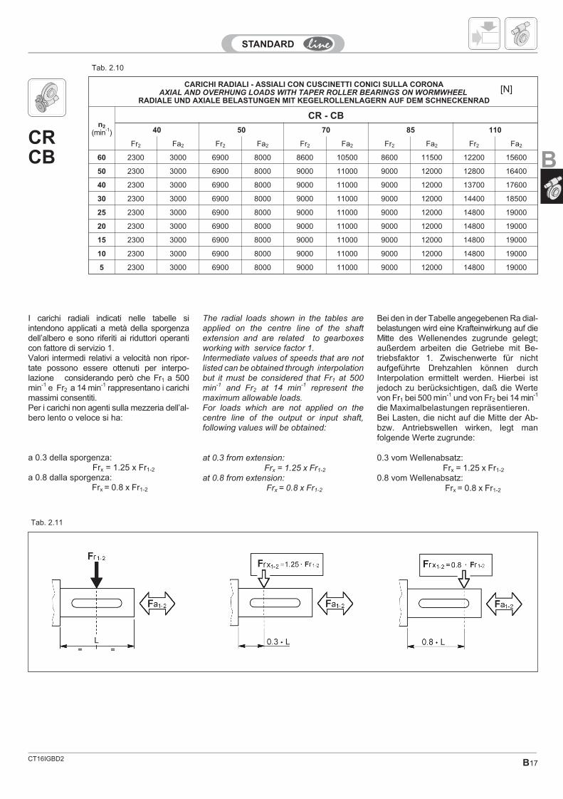
I carichi radiali indicati nelle tabelle siintendono applicati a metà della sporgenzadell’albero e sono riferiti ai riduttori operanticon fattore di servizio 1.Valori intermedi relativi a velocità non ripor-tate possono essere ottenuti per interpo-lazione considerando però che Fr1 a 500min-1 e Fr2 a 14 min-1 rappresentano i carichimassimi consentiti.Per i carichi non agenti sulla mezzeria dell’al-bero lento o veloce si ha:
a 0.3 della sporgenza:Frx = 1.25 x Fr1-2
a 0.8 dalla sporgenza:Frx = 0.8 x Fr1-2
The radial loads shown in the tables areapplied on the centre line of the shaftextension and are related to gearboxesworking with service factor 1.Intermediate values of speeds that are notlisted can be obtained through interpolationbut it must be considered that Fr1 at 500min-1 and Fr2 at 14 min-1 represent themaximum allowable loads.For loads which are not applied on thecentre line of the output or input shaft,following values will be obtained:
at 0.3 from extension:Frx = 1.25 x Fr1-2
at 0.8 from extension:Frx = 0.8 x Fr1-2
Bei den in der Tabelle angegebenen Ra dial-belastungen wird eine Krafteinwirkung auf dieMitte des Wellenendes zugrunde gelegt;außerdem arbeiten die Getriebe mit Be-triebsfaktor 1. Zwischenwerte für nichtaufgeführte Drehzahlen können durchInterpolation ermittelt werden. Hierbei istjedoch zu berücksichtigen, daß die Wertevon Fr1 bei 500 min-1 und von Fr2 bei 14 min-1
die Maximalbelastungen repräsentieren.Bei Lasten, die nicht auf die Mitte der Ab-bzw. Antriebswellen wirken, legt manfolgende Werte zugrunde:
0.3 vom Wellenabsatz:Frx = 1.25 x Fr1-2
0.8 vom Wellenabsatz:Frx = 0.8 x Fr1-2
Tab. 2.11
CARICHI RADIALI - ASSIALI CON CUSCINETTI CONICI SULLA CORONAAXIAL AND OVERHUNG LOADS WITH TAPER ROLLER BEARINGS ON WORMWHEEL
RADIALE UND AXIALE BELASTUNGEN MIT KEGELROLLENLAGERN AUF DEM SCHNECKENRAD
n2
(min-1)
CR - CB
40 50 70 85 110
Fr2 Fa2 Fr2 Fa2 Fr2 Fa2 Fr2 Fa2 Fr2 Fa2
60 2300 3000 6900 8000 8600 10500 8600 11500 12200 15600
50 2300 3000 6900 8000 9000 11000 9000 12000 12800 16400
40 2300 3000 6900 8000 9000 11000 9000 12000 13700 17600
30 2300 3000 6900 8000 9000 11000 9000 12000 14400 18500
25 2300 3000 6900 8000 9000 11000 9000 12000 14800 19000
20 2300 3000 6900 8000 9000 11000 9000 12000 14800 19000
15 2300 3000 6900 8000 9000 11000 9000 12000 14800 19000
10 2300 3000 6900 8000 9000 11000 9000 12000 14800 19000
5 2300 3000 6900 8000 9000 11000 9000 12000 14800 19000
Tab. 2.10
[N]
CRCB B
B18CT16IGBD2
RI 28 1.4
RI 40 2.1
RI 50 3.8
RI 63 6.0
irn1 = 2800 min-1 n1 = 1400 min-1 n1 = 900 min-1 n1 = 500 min-1 RMI RMI...G
n2 T2M P RD n2 T2M P RD n2 T2M P RD n2 T2M P RD IECmin-1 Nm kW % min-1 Nm kW % min-1 Nm kW % min-1 Nm kW %
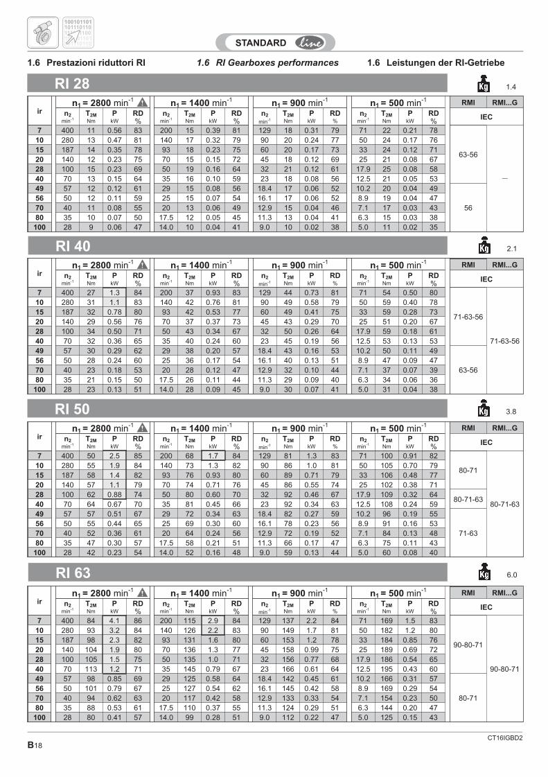
7 400 11 0.56 83 200 15 0.39 81 129 18 0.31 79 71 22 0.21 78
63-56
—
10 280 13 0.47 81 140 17 0.32 79 90 20 0.24 77 50 24 0.17 7615 187 14 0.35 78 93 18 0.23 75 60 20 0.17 73 33 24 0.12 7120 140 12 0.23 75 70 15 0.15 72 45 18 0.12 69 25 21 0.08 6728 100 15 0.23 69 50 19 0.16 64 32 21 0.12 61 17.9 25 0.08 5840 70 13 0.15 64 35 16 0.10 59 23 18 0.08 56 12.5 21 0.05 5349 57 12 0.12 61 29 15 0.08 56 18.4 17 0.06 52 10.2 20 0.04 49
5656 50 12 0.11 59 25 15 0.07 54 16.1 17 0.06 52 8.9 19 0.04 4770 40 11 0.08 55 20 13 0.06 49 12.9 15 0.04 46 7.1 17 0.03 4380 35 10 0.07 50 17.5 12 0.05 45 11.3 13 0.04 41 6.3 15 0.03 38
100 28 9 0.06 47 14.0 10 0.04 41 9.0 10 0.02 38 5.0 11 0.02 35
irn1 = 2800 min-1 n1 = 1400 min-1 n1 = 900 min-1 n1 = 500 min-1 RMI RMI...G
n2 T2M P RD n2 T2M P RD n2 T2M P RD n2 T2M P RD IECmin-1 Nm kW % min-1 Nm kW % min-1 Nm kW % min-1 Nm kW %
7 400 27 1.3 84 200 37 0.93 83 129 44 0.73 81 71 54 0.50 80
71-63-56
71-63-56
10 280 31 1.1 83 140 42 0.76 81 90 49 0.58 79 50 59 0.40 7815 187 32 0.78 80 93 42 0.53 77 60 49 0.41 75 33 59 0.28 7320 140 29 0.56 76 70 37 0.37 73 45 43 0.29 70 25 51 0.20 6728 100 34 0.50 71 50 43 0.34 67 32 50 0.26 64 17.9 59 0.18 6140 70 32 0.36 65 35 40 0.24 60 23 45 0.19 56 12.5 53 0.13 5349 57 30 0.29 62 29 38 0.20 57 18.4 43 0.16 53 10.2 50 0.11 49
63-5656 50 28 0.24 60 25 36 0.17 54 16.1 40 0.13 51 8.9 47 0.09 4770 40 23 0.18 53 20 28 0.12 47 12.9 32 0.10 44 7.1 37 0.07 3980 35 21 0.15 50 17.5 26 0.11 44 11.3 29 0.09 40 6.3 34 0.06 36
100 28 23 0.13 51 14.0 28 0.09 45 9.0 30 0.07 41 5.0 31 0.04 38
irn1 = 2800 min-1 n1 = 1400 min-1 n1 = 900 min-1 n1 = 500 min-1 RMI RMI...G
n2 T2M P RD n2 T2M P RD n2 T2M P RD n2 T2M P RD IECmin-1 Nm kW % min-1 Nm kW % min-1 Nm kW % min-1 Nm kW %
7 400 50 2.5 85 200 68 1.7 84 129 81 1.3 83 71 100 0.91 82
80-71
80-71-63
10 280 55 1.9 84 140 73 1.3 82 90 86 1.0 81 50 105 0.70 7915 187 58 1.4 82 93 76 0.93 80 60 89 0.71 79 33 106 0.48 7720 140 57 1.1 79 70 74 0.71 76 45 86 0.55 74 25 102 0.38 7128 100 62 0.88 74 50 80 0.60 70 32 92 0.46 67 17.9 109 0.32 64
80-71-6340 70 64 0.67 70 35 81 0.45 66 23 92 0.34 63 12.5 108 0.24 5949 57 57 0.51 67 29 72 0.34 63 18.4 82 0.27 59 10.2 96 0.19 55
71-6356 50 55 0.44 65 25 69 0.30 60 16.1 78 0.23 56 8.9 91 0.16 5370 40 52 0.36 61 20 64 0.24 56 12.9 72 0.19 52 7.1 84 0.13 4880 35 47 0.30 57 17.5 58 0.21 51 11.3 66 0.17 47 6.3 75 0.11 43
100 28 42 0.23 54 14.0 52 0.16 48 9.0 59 0.13 44 5.0 60 0.08 40
irn1 = 2800 min-1 n1 = 1400 min-1 n1 = 900 min-1 n1 = 500 min-1 RMI RMI...G
n2 T2M P RD n2 T2M P RD n2 T2M P RD n2 T2M P RD IECmin-1 Nm kW % min-1 Nm kW % min-1 Nm kW % min-1 Nm kW %
7 400 84 4.1 86 200 115 2.9 84 129 137 2.2 84 71 169 1.5 83
90-80-71
90-80-71
10 280 93 3.2 84 140 126 2.2 83 90 149 1.7 81 50 182 1.2 8015 187 98 2.3 82 93 131 1.6 80 60 153 1.2 78 33 184 0.85 7620 140 104 1.9 80 70 136 1.3 77 45 158 0.99 75 25 189 0.69 7228 100 105 1.5 75 50 135 1.0 71 32 156 0.77 68 17.9 186 0.54 6540 70 113 1.2 71 35 145 0.79 67 23 166 0.61 64 12.5 195 0.43 6049 57 98 0.85 69 29 125 0.58 64 18.4 142 0.45 61 10.2 166 0.31 57
80-7156 50 101 0.79 67 25 127 0.54 62 16.1 145 0.42 58 8.9 169 0.29 5470 40 94 0.62 63 20 117 0.42 58 12.9 133 0.33 54 7.1 154 0.23 5080 35 88 0.53 61 17.5 110 0.37 55 11.3 124 0.29 51 6.3 144 0.20 47
100 28 80 0.41 57 14.0 99 0.28 51 9.0 112 0.22 47 5.0 125 0.15 43
100101101
100101101
101110110
101110110
111101100
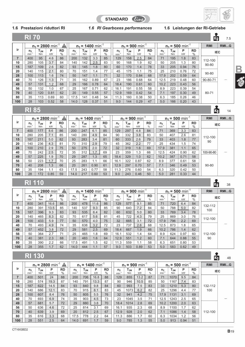
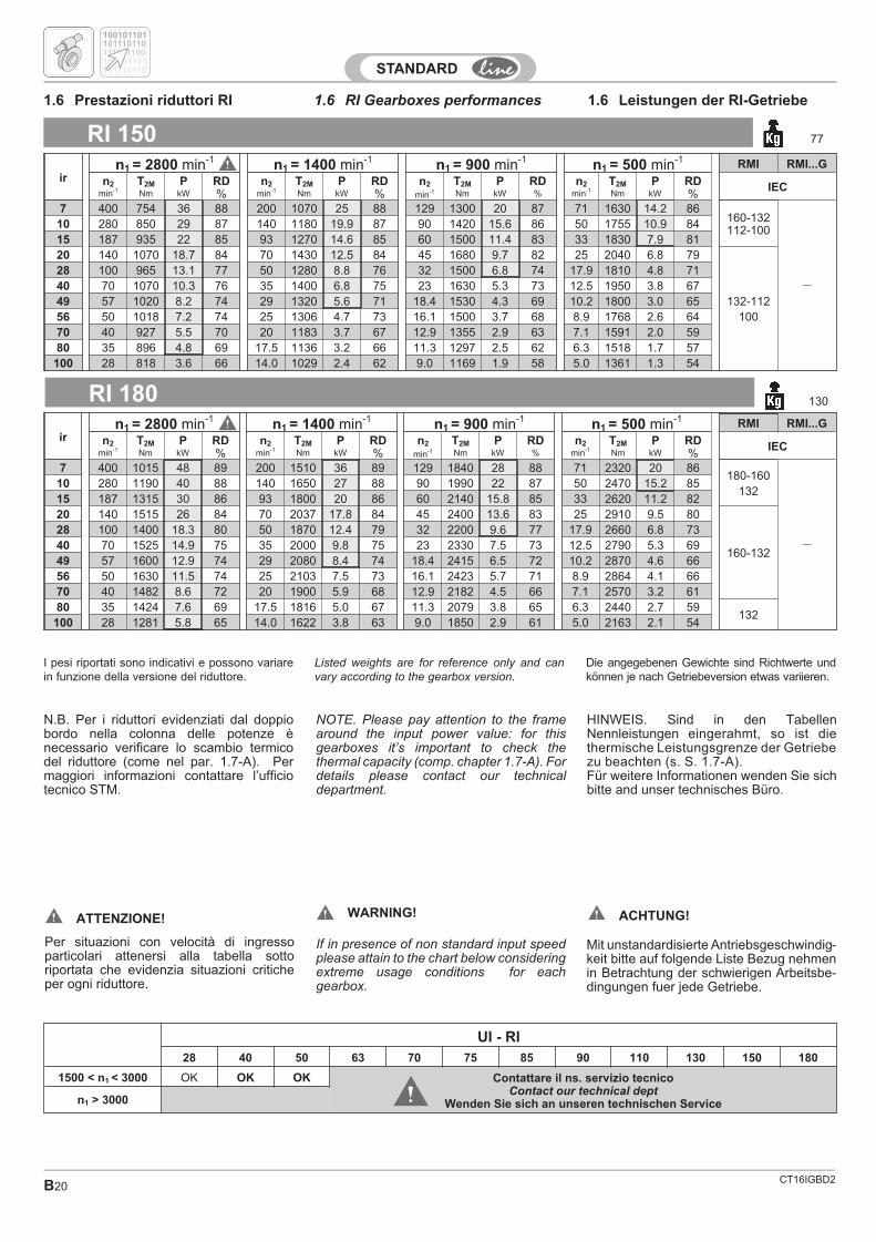
1.6 RI Gearboxes performances 1.6 Leistungen der RI-Getriebe1.6 Prestazioni riduttori RI
CT16IGBD2 B19
RI 70 7.5
RI 85 14
RI 110 38
RI 130 48
irn1 = 2800 min-1 n1 = 1400 min-1 n1 = 900 min-1 n1 = 500 min-1 RMI RMI...G
n2 T2M P RD n2 T2M P RD n2 T2M P RD n2 T2M P RD IECmin-1 Nm kW % min-1 Nm kW % min-1 Nm kW % min-1 Nm kW %
7 400 95 4.6 86 200 132 3.3 85 129 158 2.5 84 71 195 1.8 83112-100
90-80
—
10 280 105 3.7 84 140 142 2.5 83 90 168 1.9 82 50 205 1.3 8015 187 109 2.6 82 93 145 1.8 80 60 170 1.4 78 33 205 0.94 7620 140 115 2.1 80 70 151 1.4 77 45 175 1.1 75 25 210 0.76 72
90-8028 100 113 1.6 74 50 147 1.1 71 32 170 0.84 68 17.9 202 0.59 6440 70 126 1.3 71 35 162 0.89 67 23 186 0.68 64 12.5 219 0.48 60 90-80-7149 57 131 1.2 68 29 166 0.78 64 18.4 190 0.61 60 10.2 223 0.43 56
80-7156 50 132 1.0 67 25 167 0.71 62 16.1 191 0.55 58 8.9 223 0.39 5470 40 120 0.81 62 20 149 0.55 57 12.9 169 0.42 54 7.1 197 0.30 4980 35 113 0.69 60 17.5 141 0.48 54 11.3 160 0.38 50 6.3 185 0.26 46
100 28 103 0.52 58 14.0 128 0.37 51 9.0 144 0.29 47 5.0 166 0.20 43
irn1 = 2800 min-1 n1 = 1400 min-1 n1 = 900 min-1 n1 = 500 min-1 RMI RMI...G
n2 T2M P RD n2 T2M P RD n2 T2M P RD n2 T2M P RD IECmin-1 Nm kW % min-1 Nm kW % min-1 Nm kW % min-1 Nm kW %
7 400 177 8.6 86 200 247 6.1 85 129 297 4.8 84 71 369 3.3 83
112-10090
—
10 280 205 7.1 85 140 280 4.9 84 90 332 3.8 83 50 407 2.6 8115 187 211 5.0 82 93 283 3.4 81 60 333 2.6 79 33 403 1.8 7720 140 236 4.3 81 70 310 2.9 79 45 362 2.2 77 25 434 1.5 7428 100 210 2.9 75 50 275 2.0 72 32 319 1.6 69 17.9 381 1.1 6540 70 242 2.5 72 35 312 1.7 69 23 359 1.3 66 12.5 424 0.90 62 100-90-8049 57 225 1.9 70 29 287 1.3 65 18.4 329 1.0 62 10.2 387 0.71 58
90-8056 50 223 1.7 70 25 283 1.1 66 16.1 322 0.87 62 8.9 377 0.61 5870 40 208 1.3 66 20 261 0.90 61 12.9 297 0.70 57 7.1 346 0.49 5380 35 194 1.1 63 17.5 243 0.77 58 11.3 276 0.60 54 6.3 320 0.42 50
100 28 172 0.85 59 14.0 217 0.60 53 9.0 243 0.46 50 5.0 281 0.33 44
irn1 = 2800 min-1 n1 = 1400 min-1 n1 = 900 min-1 n1 = 500 min-1 RMI RMI...G
n2 T2M P RD n2 T2M P RD n2 T2M P RD n2 T2M P RD IECmin-1 Nm kW % min-1 Nm kW % min-1 Nm kW % min-1 Nm kW %
7 400 341 16.6 86 200 478 11.6 86 129 577 9.1 85 71 720 6.4 84132-112
100
—
10 280 391 13.5 85 140 537 9.3 85 90 640 7.2 84 50 788 5.0 8215 187 396 9.3 83 93 535 6.4 82 60 632 5.0 80 33 769 3.4 7820 140 465 8.3 82 70 617 5.6 81 45 722 4.3 79 25 869 3.0 76
112-10028 100 433 5.9 77 50 570 4.0 75 32 665 3.1 72 17.9 796 2.2 6940 70 493 4.9 74 35 638 3.2 72 23 737 2.6 68 12.5 873 1.8 65
112-10090
49 57 452 3.8 72 29 581 2.5 69 18.4 667 1.9 66 10.2 786 1.4 6256 50 364 2.7 71 25 465 1.8 69 16.1 532 1.4 64 8.9 624 0.97 6070 40 381 2.3 68 20 483 1.6 64 12.9 551 1.2 60 7.1 644 0.88 5580 35 390 2.2 66 17.5 491 1.5 62 11.3 559 1.1 58 6.3 651 0.80 53
100 28 355 1.7 62 14.0 444 1.1 57 9.0 503 0.89 53 5.0 583 0.62 49
irn1 = 2800 min-1 n1 = 1400 min-1 n1 = 900 min-1 n1 = 500 min-1 RMI RMI...G
n2 T2M P RD n2 T2M P RD n2 T2M P RD n2 T2M P RD IECmin-1 Nm kW % min-1 Nm kW % min-1 Nm kW % min-1 Nm kW %
7 400 501 24 88 200 706 16.8 88 129 855 13.2 87 71 1070 9.5 84
132-112100
—
10 280 574 19.3 87 140 791 13.3 87 90 946 10.5 85 50 1167 7.4 8315 187 622 14.5 84 93 840 9.8 84 60 993 7.5 83 33 1210 5.3 8020 140 686 12.1 83 70 915 8.1 83 45 1073 6.2 82 25 1296 4.4 7728 100 607 8.4 76 50 805 5.5 76 32 941 4.2 75 17.9 1131 3.1 6940 70 693 6.9 74 35 903 4.5 73 23 1045 3.5 71 12.5 1243 2.5 6549 57 681 5.7 72 29 880 3.8 70 18.4 1014 2.8 69 10.2 1200 2.0 63
112-10056 50 636 4.6 72 25 814 3.1 69 16.1 935 2.3 68 8.9 1100 1.7 6270 40 639 3.9 69 20 812 2.5 67 12.9 928 2.0 62 7.1 1086 1.4 5880 35 616 3.3 68 17.5 778 2.2 64 11.3 886 1.7 60 6.3 1034 1.2 56
100 28 551 2.5 64 14.0 691 1.7 59 9.0 785 1.3 55 5.0 913 0.94 51
100101101
100101101
101110110
101110110
111101100
1.6 RI Gearboxes performances 1.6 Leistungen der RI-Getriebe1.6 Prestazioni riduttori RI
B
CT16IGBD2B20
1.6 RI Gearboxes performances 1.6 Leistungen der RI-Getriebe1.6 Prestazioni riduttori RI
RI 150 77
RI 180 130
Listed weights are for reference only and canvary according to the gearbox version.
Die angegebenen Gewichte sind Richtwerte undkönnen je nach Getriebeversion etwas variieren.
I pesi riportati sono indicativi e possono variarein funzione della versione del riduttore.
irn1 = 2800 min-1 n1 = 1400 min-1 n1 = 900 min-1 n1 = 500 min-1 RMI RMI...G
n2 T2M P RD n2 T2M P RD n2 T2M P RD n2 T2M P RD IECmin-1 Nm kW % min-1 Nm kW % min-1 Nm kW % min-1 Nm kW %
7 400 754 36 88 200 1070 25 88 129 1300 20 87 71 1630 14.2 86160-132112-100
—
10 280 850 29 87 140 1180 19.9 87 90 1420 15.6 86 50 1755 10.9 8415 187 935 22 85 93 1270 14.6 85 60 1500 11.4 83 33 1830 7.9 8120 140 1070 18.7 84 70 1430 12.5 84 45 1680 9.7 82 25 2040 6.8 79
132-112100
28 100 965 13.1 77 50 1280 8.8 76 32 1500 6.8 74 17.9 1810 4.8 7140 70 1070 10.3 76 35 1400 6.8 75 23 1630 5.3 73 12.5 1950 3.8 6749 57 1020 8.2 74 29 1320 5.6 71 18.4 1530 4.3 69 10.2 1800 3.0 6556 50 1018 7.2 74 25 1306 4.7 73 16.1 1500 3.7 68 8.9 1768 2.6 6470 40 927 5.5 70 20 1183 3.7 67 12.9 1355 2.9 63 7.1 1591 2.0 5980 35 896 4.8 69 17.5 1136 3.2 66 11.3 1297 2.5 62 6.3 1518 1.7 57
100 28 818 3.6 66 14.0 1029 2.4 62 9.0 1169 1.9 58 5.0 1361 1.3 54
irn1 = 2800 min-1 n1 = 1400 min-1 n1 = 900 min-1 n1 = 500 min-1 RMI RMI...G
n2 T2M P RD n2 T2M P RD n2 T2M P RD n2 T2M P RD IECmin-1 Nm kW % min-1 Nm kW % min-1 Nm kW % min-1 Nm kW %
7 400 1015 48 89 200 1510 36 89 129 1840 28 88 71 2320 20 86180-160
132
—
10 280 1190 40 88 140 1650 27 88 90 1990 22 87 50 2470 15.2 8515 187 1315 30 86 93 1800 20 86 60 2140 15.8 85 33 2620 11.2 8220 140 1515 26 84 70 2037 17.8 84 45 2400 13.6 83 25 2910 9.5 80
160-132
28 100 1400 18.3 80 50 1870 12.4 79 32 2200 9.6 77 17.9 2660 6.8 7340 70 1525 14.9 75 35 2000 9.8 75 23 2330 7.5 73 12.5 2790 5.3 6949 57 1600 12.9 74 29 2080 8.4 74 18.4 2415 6.5 72 10.2 2870 4.6 6656 50 1630 11.5 74 25 2103 7.5 73 16.1 2423 5.7 71 8.9 2864 4.1 6670 40 1482 8.6 72 20 1900 5.9 68 12.9 2182 4.5 66 7.1 2570 3.2 6180 35 1424 7.6 69 17.5 1816 5.0 67 11.3 2079 3.8 65 6.3 2440 2.7 59
132100 28 1281 5.8 65 14.0 1622 3.8 63 9.0 1850 2.9 61 5.0 2163 2.1 54
NOTE. Please pay attention to the framearound the input power value: for thisgearboxes it’s important to check thethermal capacity (comp. chapter 1.7-A). Fordetails please contact our technicaldepartment.
HINWEIS. Sind in den TabellenNennleistungen eingerahmt, so ist diethermische Leistungsgrenze der Getriebezu beachten (s. S. 1.7-A).Für weitere Informationen wenden Sie sichbitte and unser technisches Büro.
N.B. Per i riduttori evidenziati dal doppiobordo nella colonna delle potenze ènecessario verificare lo scambio termicodel riduttore (come nel par. 1.7-A). Permaggiori informazioni contattare l’ufficiotecnico STM.
100101101
100101101
101110110
101110110
111101100
ATTENZIONE! WARNING! ACHTUNG!
Per situazioni con velocità di ingressoparticolari attenersi alla tabella sottoriportata che evidenzia situazioni criticheper ogni riduttore.
If in presence of non standard input speedplease attain to the chart below consideringextreme usage conditions for eachgearbox.
Mit unstandardisierte Antriebsgeschwindig-keit bitte auf folgende Liste Bezug nehmenin Betrachtung der schwierigen Arbeitsbe-dingungen fuer jede Getriebe.
UI - RI28 40 50 63 70 75 85 90 110 130 150 180
1500 < n1 < 3000 OK OK OK Contattare il ns. servizio tecnicoContact our technical dept
Wenden Sie sich an unseren technischen Servicen1 > 3000
CT16IGBD2 B21
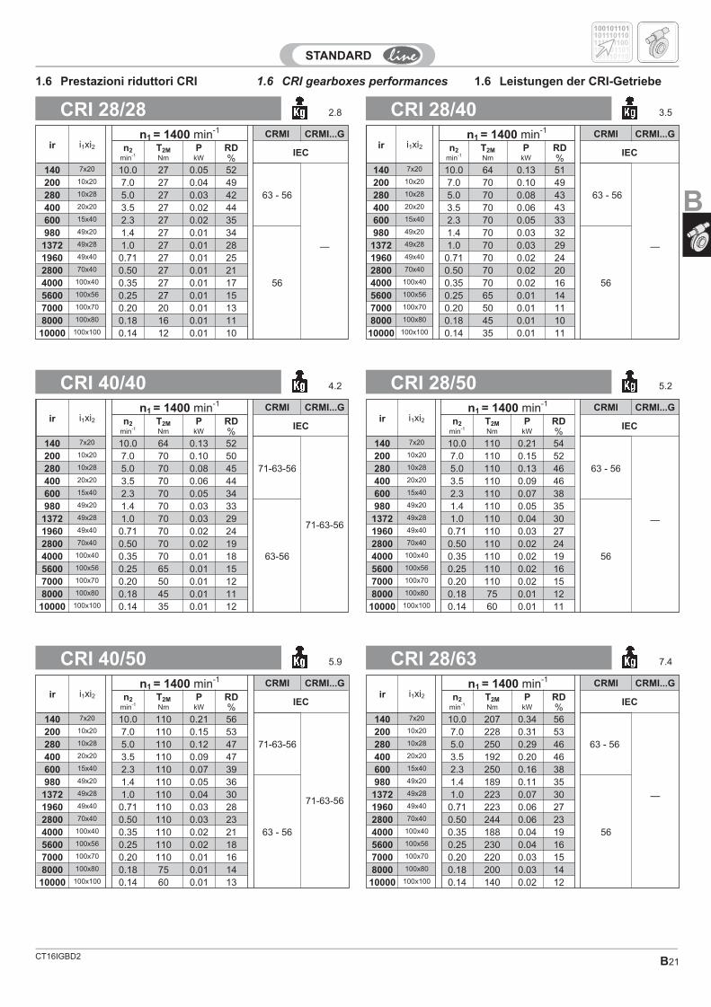
1.6 CRI gearboxes performances 1.6 Leistungen der CRI-Getriebe1.6 Prestazioni riduttori CRI
CRI 28/50 5.2CRI 40/40 4.2
CRI 28/63 7.4CRI 40/50 5.9
CRI 28/40 3.5CRI 28/28 2.8
ir i1xi2n1 = 1400 min-1 CRMI CRMI...G
n2 T2M P RD IECmin-1 Nm kW %
140 7x20 10.0 27 0.05 52
63 - 56
—
200 10x20 7.0 27 0.04 49280 10x28 5.0 27 0.03 42400 20x20 3.5 27 0.02 44600 15x40 2.3 27 0.02 35980 49x20 1.4 27 0.01 34
56
1372 49x28 1.0 27 0.01 281960 49x40 0.71 27 0.01 252800 70x40 0.50 27 0.01 214000 100x40 0.35 27 0.01 175600 100x56 0.25 27 0.01 157000 100x70 0.20 20 0.01 138000 100x80 0.18 16 0.01 11
10000 100x100 0.14 12 0.01 10
ir i1xi2n1 = 1400 min-1 CRMI CRMI...G
n2 T2M P RD IECmin-1 Nm kW %
140 7x20 10.0 64 0.13 51
63 - 56
—
200 10x20 7.0 70 0.10 49280 10x28 5.0 70 0.08 43400 20x20 3.5 70 0.06 43600 15x40 2.3 70 0.05 33980 49x20 1.4 70 0.03 32
56
1372 49x28 1.0 70 0.03 291960 49x40 0.71 70 0.02 242800 70x40 0.50 70 0.02 204000 100x40 0.35 70 0.02 165600 100x56 0.25 65 0.01 147000 100x70 0.20 50 0.01 118000 100x80 0.18 45 0.01 10
10000 100x100 0.14 35 0.01 11
ir i1xi2n1 = 1400 min-1 CRMI CRMI...G
n2 T2M P RD IECmin-1 Nm kW %
140 7x20 10.0 110 0.21 54
63 - 56
—
200 10x20 7.0 110 0.15 52280 10x28 5.0 110 0.13 46400 20x20 3.5 110 0.09 46600 15x40 2.3 110 0.07 38980 49x20 1.4 110 0.05 35
56
1372 49x28 1.0 110 0.04 301960 49x40 0.71 110 0.03 272800 70x40 0.50 110 0.02 244000 100x40 0.35 110 0.02 195600 100x56 0.25 110 0.02 167000 100x70 0.20 110 0.02 158000 100x80 0.18 75 0.01 12
10000 100x100 0.14 60 0.01 11
ir i1xi2n1 = 1400 min-1 CRMI CRMI...G
n2 T2M P RD IECmin-1 Nm kW %
140 7x20 10.0 64 0.13 52
71-63-56
71-63-56
200 10x20 7.0 70 0.10 50280 10x28 5.0 70 0.08 45400 20x20 3.5 70 0.06 44600 15x40 2.3 70 0.05 34980 49x20 1.4 70 0.03 33
63-56
1372 49x28 1.0 70 0.03 291960 49x40 0.71 70 0.02 242800 70x40 0.50 70 0.02 194000 100x40 0.35 70 0.01 185600 100x56 0.25 65 0.01 157000 100x70 0.20 50 0.01 128000 100x80 0.18 45 0.01 11
10000 100x100 0.14 35 0.01 12
ir i1xi2n1 = 1400 min-1 CRMI CRMI...G
n2 T2M P RD IECmin-1 Nm kW %
140 7x20 10.0 207 0.34 56
63 - 56
—
200 10x20 7.0 228 0.31 53280 10x28 5.0 250 0.29 46400 20x20 3.5 192 0.20 46600 15x40 2.3 250 0.16 38980 49x20 1.4 189 0.11 35
56
1372 49x28 1.0 223 0.07 301960 49x40 0.71 223 0.06 272800 70x40 0.50 244 0.06 234000 100x40 0.35 188 0.04 195600 100x56 0.25 230 0.04 167000 100x70 0.20 220 0.03 158000 100x80 0.18 200 0.03 14
10000 100x100 0.14 140 0.02 12
ir i1xi2n1 = 1400 min-1 CRMI CRMI...G
n2 T2M P RD IECmin-1 Nm kW %
140 7x20 10.0 110 0.21 56
71-63-56
71-63-56
200 10x20 7.0 110 0.15 53280 10x28 5.0 110 0.12 47400 20x20 3.5 110 0.09 47600 15x40 2.3 110 0.07 39980 49x20 1.4 110 0.05 36
63 - 56
1372 49x28 1.0 110 0.04 301960 49x40 0.71 110 0.03 282800 70x40 0.50 110 0.03 234000 100x40 0.35 110 0.02 215600 100x56 0.25 110 0.02 187000 100x70 0.20 110 0.01 168000 100x80 0.18 75 0.01 14
10000 100x100 0.14 60 0.01 13
100101101
100101101
101110110
101110110
111101100
B
CT16IGBD2B22
CRI 50/70 16.8CRI 40/70 16.1
CRI 40/85 20CRI 63/70 19.0
CRI 28/70 14.4CRI 40/63 8.1
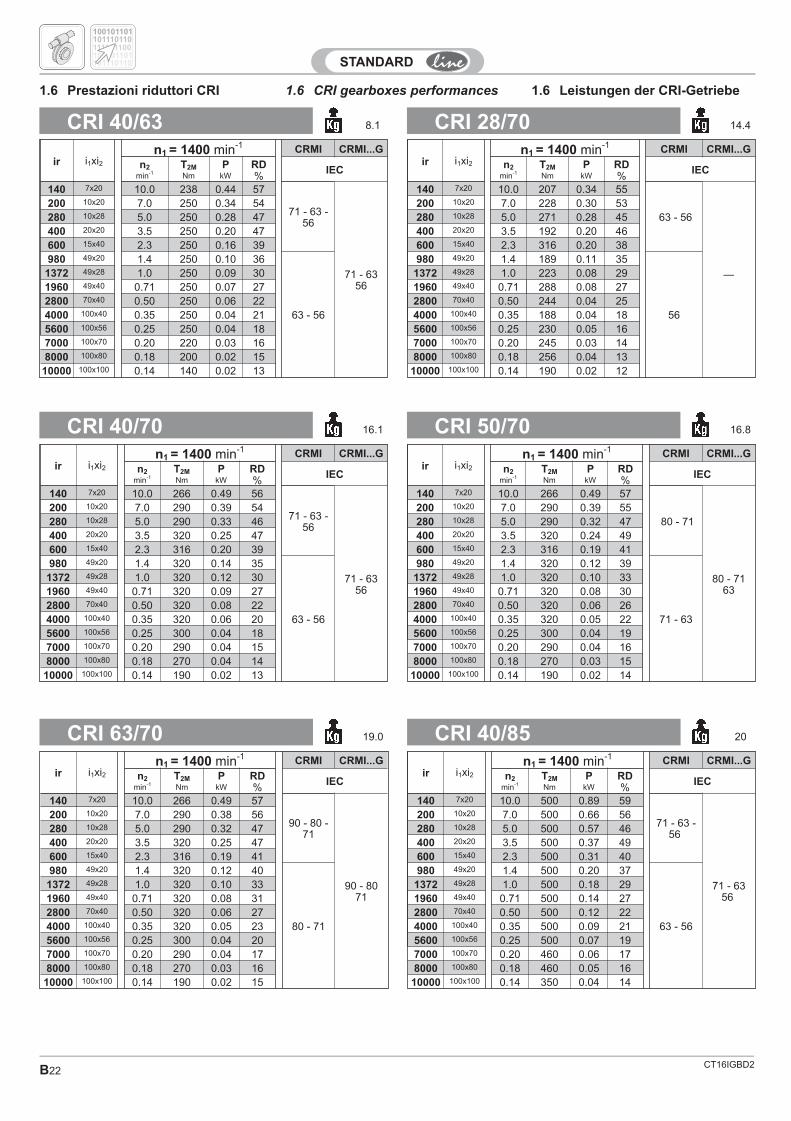
1.6 CRI gearboxes performances 1.6 Leistungen der CRI-Getriebe1.6 Prestazioni riduttori CRI
ir i1xi2n1 = 1400 min-1 CRMI CRMI...G
n2 T2M P RD IECmin-1 Nm kW %
140 7x20 10.0 207 0.34 55
63 - 56
—
200 10x20 7.0 228 0.30 53280 10x28 5.0 271 0.28 45400 20x20 3.5 192 0.20 46600 15x40 2.3 316 0.20 38980 49x20 1.4 189 0.11 35
56
1372 49x28 1.0 223 0.08 291960 49x40 0.71 288 0.08 272800 70x40 0.50 244 0.04 254000 100x40 0.35 188 0.04 185600 100x56 0.25 230 0.05 167000 100x70 0.20 245 0.03 148000 100x80 0.18 256 0.04 13
10000 100x100 0.14 190 0.02 12
ir i1xi2n1 = 1400 min-1 CRMI CRMI...G
n2 T2M P RD IECmin-1 Nm kW %
140 7x20 10.0 238 0.44 57
71 - 63 -56
71 - 6356
200 10x20 7.0 250 0.34 54280 10x28 5.0 250 0.28 47400 20x20 3.5 250 0.20 47600 15x40 2.3 250 0.16 39980 49x20 1.4 250 0.10 36
63 - 56
1372 49x28 1.0 250 0.09 301960 49x40 0.71 250 0.07 272800 70x40 0.50 250 0.06 224000 100x40 0.35 250 0.04 215600 100x56 0.25 250 0.04 187000 100x70 0.20 220 0.03 168000 100x80 0.18 200 0.02 15
10000 100x100 0.14 140 0.02 13
ir i1xi2n1 = 1400 min-1 CRMI CRMI...G
n2 T2M P RD IECmin-1 Nm kW %
140 7x20 10.0 266 0.49 57
80 - 71
80 - 7163
200 10x20 7.0 290 0.39 55280 10x28 5.0 290 0.32 47400 20x20 3.5 320 0.24 49600 15x40 2.3 316 0.19 41980 49x20 1.4 320 0.12 39
71 - 63
1372 49x28 1.0 320 0.10 331960 49x40 0.71 320 0.08 302800 70x40 0.50 320 0.06 264000 100x40 0.35 320 0.05 225600 100x56 0.25 300 0.04 197000 100x70 0.20 290 0.04 168000 100x80 0.18 270 0.03 15
10000 100x100 0.14 190 0.02 14
ir i1xi2n1 = 1400 min-1 CRMI CRMI...G
n2 T2M P RD IECmin-1 Nm kW %
140 7x20 10.0 266 0.49 56
71 - 63 -56
71 - 6356
200 10x20 7.0 290 0.39 54280 10x28 5.0 290 0.33 46400 20x20 3.5 320 0.25 47600 15x40 2.3 316 0.20 39980 49x20 1.4 320 0.14 35
63 - 56
1372 49x28 1.0 320 0.12 301960 49x40 0.71 320 0.09 272800 70x40 0.50 320 0.08 224000 100x40 0.35 320 0.06 205600 100x56 0.25 300 0.04 187000 100x70 0.20 290 0.04 158000 100x80 0.18 270 0.04 14
10000 100x100 0.14 190 0.02 13
ir i1xi2n1 = 1400 min-1 CRMI CRMI...G
n2 T2M P RD IECmin-1 Nm kW %
140 7x20 10.0 500 0.89 59
71 - 63 -56
71 - 6356
200 10x20 7.0 500 0.66 56280 10x28 5.0 500 0.57 46400 20x20 3.5 500 0.37 49600 15x40 2.3 500 0.31 40980 49x20 1.4 500 0.20 37
63 - 56
1372 49x28 1.0 500 0.18 291960 49x40 0.71 500 0.14 272800 70x40 0.50 500 0.12 224000 100x40 0.35 500 0.09 215600 100x56 0.25 500 0.07 197000 100x70 0.20 460 0.06 178000 100x80 0.18 460 0.05 16
10000 100x100 0.14 350 0.04 14
ir i1xi2n1 = 1400 min-1 CRMI CRMI...G
n2 T2M P RD IECmin-1 Nm kW %
140 7x20 10.0 266 0.49 57
90 - 80 -71
90 - 8071
200 10x20 7.0 290 0.38 56280 10x28 5.0 290 0.32 47400 20x20 3.5 320 0.25 47600 15x40 2.3 316 0.19 41980 49x20 1.4 320 0.12 40
80 - 71
1372 49x28 1.0 320 0.10 331960 49x40 0.71 320 0.08 312800 70x40 0.50 320 0.06 274000 100x40 0.35 320 0.05 235600 100x56 0.25 300 0.04 207000 100x70 0.20 290 0.04 178000 100x80 0.18 270 0.03 16
10000 100x100 0.14 190 0.02 15
100101101
100101101
101110110
101110110
111101100
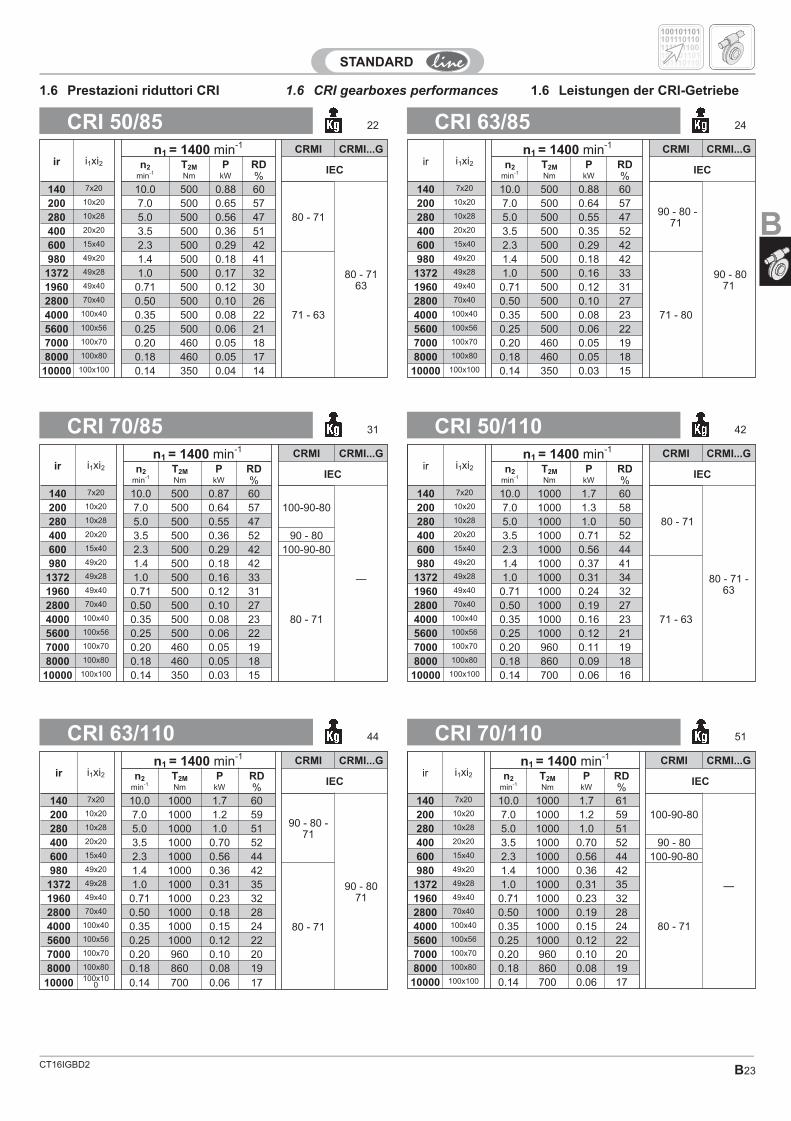
CT16IGBD2 B23
CRI 50/110 42CRI 70/85 31
CRI 70/110 51CRI 63/110 44
CRI 63/85 24CRI 50/85 22
1.6 CRI gearboxes performances 1.6 Leistungen der CRI-Getriebe1.6 Prestazioni riduttori CRI
ir i1xi2n1 = 1400 min-1 CRMI CRMI...G
n2 T2M P RD IECmin-1 Nm kW %
140 7x20 10.0 500 0.88 60
90 - 80 -71
90 - 8071
200 10x20 7.0 500 0.64 57280 10x28 5.0 500 0.55 47400 20x20 3.5 500 0.35 52600 15x40 2.3 500 0.29 42980 49x20 1.4 500 0.18 42
71 - 80
1372 49x28 1.0 500 0.16 331960 49x40 0.71 500 0.12 312800 70x40 0.50 500 0.10 274000 100x40 0.35 500 0.08 235600 100x56 0.25 500 0.06 227000 100x70 0.20 460 0.05 198000 100x80 0.18 460 0.05 18
10000 100x100 0.14 350 0.03 15
ir i1xi2n1 = 1400 min-1 CRMI CRMI...G
n2 T2M P RD IECmin-1 Nm kW %
140 7x20 10.0 500 0.88 60
80 - 71
80 - 7163
200 10x20 7.0 500 0.65 57280 10x28 5.0 500 0.56 47400 20x20 3.5 500 0.36 51600 15x40 2.3 500 0.29 42980 49x20 1.4 500 0.18 41
71 - 63
1372 49x28 1.0 500 0.17 321960 49x40 0.71 500 0.12 302800 70x40 0.50 500 0.10 264000 100x40 0.35 500 0.08 225600 100x56 0.25 500 0.06 217000 100x70 0.20 460 0.05 188000 100x80 0.18 460 0.05 17
10000 100x100 0.14 350 0.04 14
ir i1xi2n1 = 1400 min-1 CRMI CRMI...G
n2 T2M P RD IECmin-1 Nm kW %
140 7x20 10.0 500 0.87 60100-90-80
—
200 10x20 7.0 500 0.64 57280 10x28 5.0 500 0.55 47400 20x20 3.5 500 0.36 52 90 - 80600 15x40 2.3 500 0.29 42 100-90-80980 49x20 1.4 500 0.18 42
80 - 71
1372 49x28 1.0 500 0.16 331960 49x40 0.71 500 0.12 312800 70x40 0.50 500 0.10 274000 100x40 0.35 500 0.08 235600 100x56 0.25 500 0.06 227000 100x70 0.20 460 0.05 198000 100x80 0.18 460 0.05 18
10000 100x100 0.14 350 0.03 15
ir i1xi2n1 = 1400 min-1 CRMI CRMI...G
n2 T2M P RD IECmin-1 Nm kW %
140 7x20 10.0 1000 1.7 60
80 - 71
80 - 71 -63
200 10x20 7.0 1000 1.3 58280 10x28 5.0 1000 1.0 50400 20x20 3.5 1000 0.71 52600 15x40 2.3 1000 0.56 44980 49x20 1.4 1000 0.37 41
71 - 63
1372 49x28 1.0 1000 0.31 341960 49x40 0.71 1000 0.24 322800 70x40 0.50 1000 0.19 274000 100x40 0.35 1000 0.16 235600 100x56 0.25 1000 0.12 217000 100x70 0.20 960 0.11 198000 100x80 0.18 860 0.09 18
10000 100x100 0.14 700 0.06 16
ir i1xi2n1 = 1400 min-1 CRMI CRMI...G
n2 T2M P RD IECmin-1 Nm kW %
140 7x20 10.0 1000 1.7 61100-90-80
—
200 10x20 7.0 1000 1.2 59280 10x28 5.0 1000 1.0 51400 20x20 3.5 1000 0.70 52 90 - 80600 15x40 2.3 1000 0.56 44 100-90-80980 49x20 1.4 1000 0.36 42
80 - 71
1372 49x28 1.0 1000 0.31 351960 49x40 0.71 1000 0.23 322800 70x40 0.50 1000 0.19 284000 100x40 0.35 1000 0.15 245600 100x56 0.25 1000 0.12 227000 100x70 0.20 960 0.10 208000 100x80 0.18 860 0.08 19
10000 100x100 0.14 700 0.06 17
ir i1xi2n1 = 1400 min-1 CRMI CRMI...G
n2 T2M P RD IECmin-1 Nm kW %
140 7x20 10.0 1000 1.7 60
90 - 80 -71
90 - 8071
200 10x20 7.0 1000 1.2 59280 10x28 5.0 1000 1.0 51400 20x20 3.5 1000 0.70 52600 15x40 2.3 1000 0.56 44980 49x20 1.4 1000 0.36 42
80 - 71
1372 49x28 1.0 1000 0.31 351960 49x40 0.71 1000 0.23 322800 70x40 0.50 1000 0.18 284000 100x40 0.35 1000 0.15 245600 100x56 0.25 1000 0.12 227000 100x70 0.20 960 0.10 208000 100x80 0.18 860 0.08 19
10000 100x100 0.14 700 0.06 17
100101101
100101101
101110110
101110110
111101100
B
CT16IGBD2B24
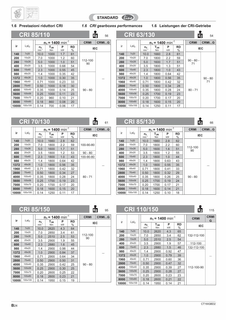
CRI 85/130 66CRI 70/130 61
CRI 110/150 115CRI 85/150 95
CRI 63/130 54CRI 85/110 56
1.6 CRI gearboxes performances 1.6 Leistungen der CRI-Getriebe1.6 Prestazioni riduttori CRI
ir i1xi2n1 = 1400 min-1 CRMI CRMI...G
n2 T2M P RD IECmin-1 Nm kW %
140 7x20 10.0 1660 2.8 61
90 - 80 -71
90 - 8071
200 10x20 7.0 1800 2.2 59280 10x28 5.0 1600 1.7 51400 20x20 3.5 1800 1.3 51600 15x40 2.3 1800 1.0 43980 49x20 1.4 1800 0.64 42
80 - 71
1372 49x28 1.0 1800 0.56 351960 49x40 0.71 1800 0.42 322800 70x40 0.50 1800 0.34 284000 100x40 0.35 1800 0.28 245600 100x56 0.25 1700 0.19 237000 100x70 0.20 1700 0.17 208000 100x80 0.18 1600 0.15 20
10000 100x100 0.14 1250 0.11 17
ir i1xi2n1 = 1400 min-1 CRMI CRMI...G
n2 T2M P RD IECmin-1 Nm kW %
140 7x20 10.0 1000 1.7 61
112-10090
—
200 10x20 7.0 1000 1.2 60280 10x28 5.0 1000 1.0 51400 20x20 3.5 1000 0.68 54600 15x40 2.3 1000 0.55 45980 49x20 1.4 1000 0.35 42
90 - 80
1372 49x28 1.0 1000 0.30 351960 49x40 0.71 1000 0.23 332800 70x40 0.50 1000 0.18 304000 100x40 0.35 1000 0.14 255600 100x56 0.25 1000 0.11 237000 100x70 0.20 960 0.10 218000 100x80 0.18 860 0.08 20
10000 100x100 0.14 700 0.06 17
ir i1xi2n1 = 1400 min-1 CRMI CRMI...G
n2 T2M P RD IECmin-1 Nm kW %
140 7x20 10.0 1660 2.8 62
112-10090
—
200 10x20 7.0 1800 2.2 60280 10x28 5.0 1600 1.6 51400 20x20 3.5 1800 1.2 55600 15x40 2.3 1800 1.0 44980 49x20 1.4 1800 0.63 43
90 - 80
1372 49x28 1.0 1800 0.55 351960 49x40 0.71 1800 0.41 332800 70x40 0.50 1800 0.32 294000 100x40 0.35 1800 0.26 255600 100x56 0.25 1700 0.19 247000 100x70 0.20 1700 0.17 218000 100x80 0.18 1600 0.14 21
10000 100x100 0.14 1250 0.10 18
ir i1xi2n1 = 1400 min-1 CRMI CRMI...G
n2 T2M P RD IECmin-1 Nm kW %
140 7x20 10.0 1660 2.8 62100-90-80
—
200 10x20 7.0 1800 2.2 59280 10x28 5.0 1600 1.7 51400 20x20 3.5 1800 1.2 53 90 - 80600 15x40 2.3 1800 1.0 43 100-90-80980 49x20 1.4 1800 0.64 42
80 - 71
1372 49x28 1.0 1800 0.56 351960 49x40 0.71 1800 0.42 322800 70x40 0.50 1800 0.34 274000 100x40 0.35 1800 0.28 245600 100x56 0.25 1700 0.19 237000 100x70 0.20 1700 0.17 208000 100x80 0.18 1600 0.15 20
10000 100x100 0.14 1250 0.11 17
ir i1xi2n1 = 1400 min-1
CRMICRMI
Gn2 T2M P RD IEC
min-1 Nm kW %140 7x20 10.0 2620 4.3 65
132-112-100
—
200 10x20 7.0 2850 3.4 62280 10x28 5.0 2510 2.5 54400 20x20 3.5 2900 1.9 57 112-100600 15x40 2.3 2880 1.5 46 132-112-100980 49x20 1.4 2900 0.92 47
112-100-90
1372 49x28 1.0 2900 0.79 391960 49x40 0.71 2900 0.60 362800 70x40 0.50 2900 0.47 324000 100x40 0.35 2900 0.39 275600 100x56 0.25 2900 0.28 277000 100x70 0.20 2600 0.23 238000 100x80 0.18 2600 0.21 22
10000 100x100 0.14 1950 0.14 21
ir i1xi2n1 = 1400 min-1 CRMI CRMI...G
n2 T2M P RD IECmin-1 Nm kW %
140 7x20 10.0 2620 4.3 64
112-10090
—
200 10x20 7.0 2850 3.4 61280 10x28 5.0 2510 2.5 53400 20x20 3.5 2900 1.9 55600 15x40 2.3 2880 1.6 45980 49x20 1.4 2900 0.98 44
90 - 80
1372 49x28 1.0 2900 0.84 371960 49x40 0.71 2900 0.64 342800 70x40 0.50 2900 0.50 314000 100x40 0.35 2900 0.42 255600 100x56 0.25 2900 0.30 257000 100x70 0.20 2600 0.25 228000 100x80 0.18 2600 0.23 21
10000 100x100 0.14 1950 0.15 19
100101101
100101101
101110110
101110110
111101100
CT16IGBD2 B25
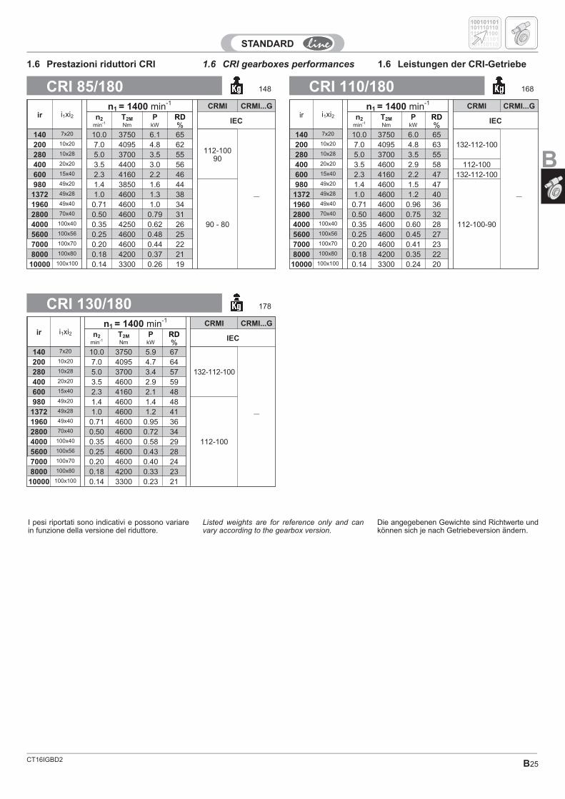
CRI 130/180 178
CRI 110/180 168CRI 85/180 148
I pesi riportati sono indicativi e possono variarein funzione della versione del riduttore.
Listed weights are for reference only and canvary according to the gearbox version.
Die angegebenen Gewichte sind Richtwerte undkönnen sich je nach Getriebeversion ändern.
1.6 CRI gearboxes performances 1.6 Leistungen der CRI-Getriebe1.6 Prestazioni riduttori CRI
ir i1xi2n1 = 1400 min-1 CRMI CRMI...G
n2 T2M P RD IECmin-1 Nm kW %
140 7x20 10.0 3750 6.0 65132-112-100
—
200 10x20 7.0 4095 4.8 63280 10x28 5.0 3700 3.5 55400 20x20 3.5 4600 2.9 58 112-100600 15x40 2.3 4160 2.2 47 132-112-100980 49x20 1.4 4600 1.5 47
112-100-90
1372 49x28 1.0 4600 1.2 401960 49x40 0.71 4600 0.96 362800 70x40 0.50 4600 0.75 324000 100x40 0.35 4600 0.60 285600 100x56 0.25 4600 0.45 277000 100x70 0.20 4600 0.41 238000 100x80 0.18 4200 0.35 22
10000 100x100 0.14 3300 0.24 20
ir i1xi2n1 = 1400 min-1 CRMI CRMI...G
n2 T2M P RD IECmin-1 Nm kW %
140 7x20 10.0 3750 6.1 65
112-10090
—
200 10x20 7.0 4095 4.8 62280 10x28 5.0 3700 3.5 55400 20x20 3.5 4400 3.0 56600 15x40 2.3 4160 2.2 46980 49x20 1.4 3850 1.6 44
90 - 80
1372 49x28 1.0 4600 1.3 381960 49x40 0.71 4600 1.0 342800 70x40 0.50 4600 0.79 314000 100x40 0.35 4250 0.62 265600 100x56 0.25 4600 0.48 257000 100x70 0.20 4600 0.44 228000 100x80 0.18 4200 0.37 21
10000 100x100 0.14 3300 0.26 19
ir i1xi2n1 = 1400 min-1 CRMI CRMI...G
n2 T2M P RD IECmin-1 Nm kW %
140 7x20 10.0 3750 5.9 67
132-112-100
—
200 10x20 7.0 4095 4.7 64280 10x28 5.0 3700 3.4 57400 20x20 3.5 4600 2.9 59600 15x40 2.3 4160 2.1 48980 49x20 1.4 4600 1.4 48
112-100
1372 49x28 1.0 4600 1.2 411960 49x40 0.71 4600 0.95 362800 70x40 0.50 4600 0.72 344000 100x40 0.35 4600 0.58 295600 100x56 0.25 4600 0.43 287000 100x70 0.20 4600 0.40 248000 100x80 0.18 4200 0.33 23
10000 100x100 0.14 3300 0.23 21
100101101
100101101
101110110
101110110
111101100
B
CT16IGBD2B26
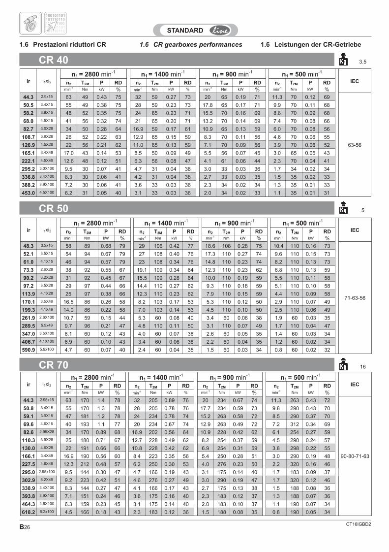
CR 40 3.5
CR 50 5
CR 70 16
1.6 CR gearboxes performances 1.6 Leistungen der CR-Getriebe1.6 Prestazioni riduttori CR
ir i1xi2n1 = 2800 min-1 n1 = 1400 min-1 n1 = 900 min-1 n1 = 500 min-1
IECn2 T2M P RD n2 T2M P RD n2 T2M P RD n2 T2M P RDmin-1 Nm kW % min-1 Nm kW % min-1 Nm kW % min-1 Nm kW %
44.3 2.9x15 63 49 0.43 75 32 59 0.27 73 20 65 0.19 71 11.3 70 0.12 69
63-56
50.5 3.4X15 55 49 0.38 75 28 59 0.23 73 17.8 65 0.17 71 9.9 70 0.11 68
58.2 3.9X15 48 52 0.35 75 24 65 0.23 71 15.5 70 0.16 69 8.6 70 0.09 68
68.0 4.5X15 41 56 0.32 74 21 65 0.20 71 13.2 70 0.14 69 7.4 70 0.08 66
82.7 3.0X28 34 50 0.28 64 16.9 59 0.17 61 10.9 65 0.13 59 6.0 70 0.08 56
108.7 3.9X28 26 52 0.22 63 12.9 65 0.15 59 8.3 70 0.11 56 4.6 70 0.06 55
126.9 4.5X28 22 56 0.21 62 11.0 65 0.13 59 7.1 70 0.09 56 3.9 70 0.06 52
165.1 3.4X49 17.0 43 0.14 53 8.5 50 0.09 49 5.5 56 0.07 45 3.0 65 0.05 43
222.1 4.5X49 12.6 48 0.12 51 6.3 56 0.08 47 4.1 61 0.06 44 2.3 70 0.04 41
295.2 3.0X100 9.5 30 0.07 41 4.7 31 0.04 38 3.0 33 0.03 36 1.7 34 0.02 34
336.8 3.4X100 8.3 30 0.06 41 4.2 31 0.04 38 2.7 33 0.03 35 1.5 35 0.02 33
388.2 3.9X100 7.2 30 0.06 41 3.6 33 0.03 36 2.3 34 0.02 34 1.3 35 0.01 33
453.0 4.5X100 6.2 31 0.05 40 3.1 33 0.03 36 2.0 34 0.02 33 1.1 35 0.01 31
ir i1xi2n1 = 2800 min-1 n1 = 1400 min-1 n1 = 900 min-1 n1 = 500 min-1
IECn2 T2M P RD n2 T2M P RD n2 T2M P RD n2 T2M P RDmin-1 Nm kW % min-1 Nm kW % min-1 Nm kW % min-1 Nm kW %
48.3 3.2x15 58 89 0.68 79 29 106 0.42 77 18.6 108 0.28 75 10.4 110 0.16 73
71-63-56
52.1 3.5X15 54 94 0.67 79 27 108 0.40 76 17.3 110 0.27 74 9.6 110 0.15 73
61.0 4.1X15 46 94 0.57 79 23 108 0.34 76 14.8 110 0.23 74 8.2 110 0.13 73
73.3 2.6X28 38 92 0.55 67 19.1 109 0.34 64 12.3 110 0.23 62 6.8 110 0.13 59
90.2 3.2X28 31 92 0.45 67 15.5 109 0.28 64 10.0 110 0.19 59 5.5 110 0.11 58
97.2 3.5X28 29 97 0.44 66 14.4 110 0.27 62 9.3 110 0.18 59 5.1 110 0.10 58
113.9 4.1X28 25 97 0.38 66 12.3 110 0.23 62 7.9 110 0.15 59 4.4 110 0.09 58
170.1 3.5X49 16.5 86 0.26 58 8.2 103 0.17 53 5.3 110 0.12 50 2.9 110 0.07 49
199.3 4.1X49 14.0 86 0.22 58 7.0 103 0.14 53 4.5 110 0.10 50 2.5 110 0.06 49
261.9 2.6X100 10.7 59 0.15 44 5.3 60 0.08 40 3.4 60 0.06 38 1.9 60 0.03 35
289.5 5.9x49 9.7 96 0.21 47 4.8 110 0.11 50 3.1 110 0.07 49 1.7 110 0.04 47
347.0 3.5X100 8.1 60 0.12 43 4.0 60 0.07 38 2.6 60 0.05 35 1.4 60 0.03 34
406.7 4.1X100 6.9 60 0.10 43 3.4 60 0.06 38 2.2 60 0.04 35 1.2 60 0.02 34
590.9 5.9x100 4.7 60 0.07 40 2.4 60 0.04 35 1.5 60 0.03 34 0.8 60 0.02 32
ir i1xi2n1 = 2800 min-1 n1 = 1400 min-1 n1 = 900 min-1 n1 = 500 min-1
IECn2 T2M P RD n2 T2M P RD n2 T2M P RD n2 T2M P RDmin-1 Nm kW % min-1 Nm kW % min-1 Nm kW % min-1 Nm kW %
44.3 2.95x15 63 170 1.4 78 32 205 0.89 76 20 234 0.67 74 11.3 263 0.43 72
90-80-71-63
50.8 3.4X15 55 170 1.3 78 28 205 0.78 76 17.7 234 0.59 73 9.8 290 0.43 70
59.1 3.9X15 47 181 1.2 78 24 234 0.78 74 15.2 263 0.58 72 8.5 290 0.37 70
69.6 4.6X15 40 193 1.1 77 20 234 0.67 74 12.9 263 0.49 72 7.2 312 0.34 69
82.6 2.95X28 34 170 0.89 68 16.9 202 0.56 64 10.9 228 0.42 62 6.1 254 0.27 59
110.3 3.9X28 25 180 0.71 67 12.7 228 0.49 62 8.2 254 0.37 59 4.5 290 0.24 57
130.0 4.6X28 22 191 0.66 66 10.8 228 0.42 62 6.9 254 0.31 59 3.8 298 0.22 55
166.1 3.4X49 16.9 190 0.56 60 8.4 223 0.35 56 5.4 250 0.28 51 3.0 290 0.19 48
227.5 4.6X49 12.3 212 0.48 57 6.2 250 0.30 53 4.0 276 0.23 50 2.2 320 0.16 46
295.0 2.95x100 9.5 144 0.30 47 4.7 166 0.19 43 3.1 175 0.14 40 1.7 183 0.09 37
302.9 6.2X49 9.2 223 0.42 51 4.6 276 0.27 49 3.0 290 0.19 47 1.7 320 0.12 46
338.9 3.4X100 8.3 144 0.27 47 4.1 166 0.17 43 2.7 175 0.13 38 1.5 188 0.08 36
393.8 3.9X100 7.1 151 0.24 46 3.6 175 0.16 40 2.3 183 0.12 37 1.3 188 0.07 36
464.3 4.6X100 6.3 159 0.23 45 3.1 175 0.14 40 2.0 183 0.10 37 1.1 190 0.07 34
618.2 6.2x100 4.5 166 0.18 43 2.3 183 0.12 36 1.5 188 0.08 35 0.8 190 0.05 34
100101101
100101101
101110110
101110110
111101100
CT16IGBD2 B27
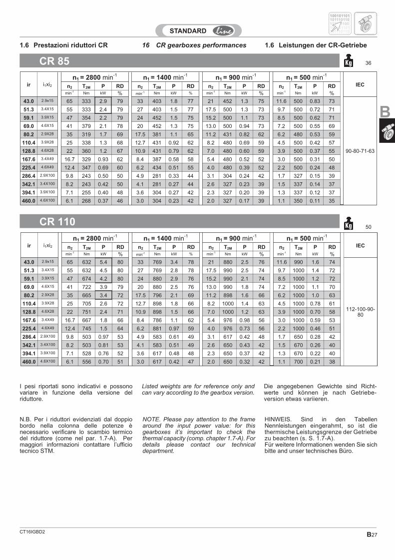
16 CR gearboxes performances 1.6 Leistungen der CR-Getriebe1.6 Prestazioni riduttori CR
Listed weights are for reference only andcan vary according to the gearbox version.
Die angegebenen Gewichte sind Richt-werte und können je nach Getriebe-version etwas variieren.
I pesi riportati sono indicativi e possonovariare in funzione della versione delriduttore.
CR 85 36
CR 11050
NOTE. Please pay attention to the framearound the input power value: for thisgearboxes it’s important to check thethermal capacity (comp. chapter 1.7-A). Fordetails please contact our technicaldepartment.
HINWEIS. Sind in den TabellenNennleistungen eingerahmt, so ist diethermische Leistungsgrenze der Getriebezu beachten (s. S. 1.7-A).Für weitere Informationen wenden Sie sichbitte and unser technisches Büro.
N.B. Per i riduttori evidenziati dal doppiobordo nella colonna delle potenze ènecessario verificare lo scambio termicodel riduttore (come nel par. 1.7-A). Permaggiori informazioni contattare l’ufficiotecnico STM.
ir i1xi2
n1 = 2800 min-1 n1 = 1400 min-1 n1 = 900 min-1 n1 = 500 min-1
IECn2 T2M P RD n2 T2M P RD n2 T2M P RD n2 T2M P RDmin-1 Nm kW % min-1 Nm kW % min-1 Nm kW % min-1 Nm kW %
43.0 2.9x15 65 333 2.9 79 33 403 1.8 77 21 452 1.3 75 11.6 500 0.83 73
90-80-71-63
51.3 3.4X15 55 333 2.4 79 27 403 1.5 77 17.5 500 1.3 73 9.7 500 0.72 71
59.1 3.9X15 47 354 2.2 79 24 452 1.5 75 15.2 500 1.1 73 8.5 500 0.62 71
69.0 4.6X15 41 379 2.1 78 20 452 1.3 75 13.0 500 0.94 73 7.2 500 0.55 69
80.2 2.9X28 35 319 1.7 69 17.5 381 1.1 65 11.2 431 0.82 62 6.2 480 0.53 59
110.4 3.9X28 25 338 1.3 68 12.7 431 0.92 62 8.2 480 0.69 59 4.5 500 0.42 57
128.8 4.6X28 22 360 1.2 67 10.9 431 0.79 62 7.0 480 0.60 59 3.9 500 0.37 55
167.6 3.4X49 16.7 329 0.93 62 8.4 387 0.58 58 5.4 480 0.52 52 3.0 500 0.31 50
225.4 4.6X49 12.4 347 0.69 60 6.2 434 0.51 55 4.0 480 0.39 52 2.2 500 0.24 48
286.4 2.9X100 9.8 243 0.50 50 4.9 281 0.33 44 3.1 304 0.24 42 1.7 327 0.15 39
342.1 3.4X100 8.2 243 0.42 50 4.1 281 0.27 44 2.6 327 0.23 39 1.5 337 0.14 37
394.1 3.9X100 7.1 255 0.40 48 3.6 304 0.27 42 2.3 327 0.20 39 1.3 337 0.12 37
460.0 4.6X100 6.1 268 0.37 46 3.0 304 0.23 42 2.0 327 0.17 39 1.1 350 0.11 35
ir i1xi2
n1 = 2800 min-1 n1 = 1400 min-1 n1 = 900 min-1 n1 = 500 min-1
IECn2 T2M P RD n2 T2M P RD n2 T2M P RD n2 T2M P RDmin-1 Nm kW % min-1 Nm kW % min-1 Nm kW % min-1 Nm kW %
43.0 2.9x15 65 632 5.4 80 33 769 3.4 78 21 880 2.5 76 11.6 990 1.6 74
112-100-90-80
51.3 3.4X15 55 632 4.5 80 27 769 2.8 78 17.5 990 2.5 74 9.7 1000 1.4 72
59.1 3.9X15 47 674 4.2 80 24 880 2.9 76 15.2 990 2.1 74 8.5 1000 1.2 72
69.0 4.6X15 41 722 3.9 79 20 880 2.5 76 13.0 990 1.8 74 7.2 1000 1.1 70
80.2 2.9X28 35 665 3.4 72 17.5 796 2.1 69 11.2 898 1.6 66 6.2 1000 1.0 63
110.4 3.9X28 25 705 2.6 72 12.7 898 1.8 66 8.2 1000 1.4 63 4.5 1000 0.78 61
128.8 4.6X28 22 751 2.4 71 10.9 898 1.5 66 7.0 1000 1.2 63 3.9 1000 0.70 58
167.6 3.4X49 16.7 667 1.8 66 8.4 786 1.1 62 5.4 976 0.98 56 3.0 1000 0.59 53
225.4 4.6X49 12.4 745 1.5 64 6.2 881 0.97 59 4.0 976 0.73 56 2.2 1000 0.46 51
286.4 2.9X100 9.8 503 0.97 53 4.9 583 0.61 49 3.1 617 0.42 48 1.7 650 0.28 42
342.1 3.4X100 8.2 503 0.81 53 4.1 583 0.51 49 2.6 650 0.43 42 1.5 670 0.26 40
394.1 3.9X100 7.1 528 0.76 52 3.6 617 0.48 48 2.3 650 0.37 42 1.3 670 0.22 40
460.0 4.6X100 6.1 556 0.70 51 3.0 617 0.42 47 2.0 650 0.32 42 1.1 700 0.21 38
100101101
100101101
101110110
101110110
111101100
B
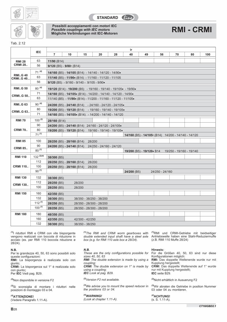
B28
IECir
7 10 15 20 28 40 49 56 70 80 100
RMI 28CRMI 28..
63 11/90 (B14)
56 9/120 (B5) - 9/80• (B14)
RMI..G 40CRMI..G 40...
71 (4)14/160 (B5) - 14/105 (B14) - 14/140 - 14/120 - 14/90�
63 11/140 (B5) - 11/90� (B14) - 11/160 - 11/120 - 11/105
56 9/120 (B5) - 9/160 - 9/140 - 9/105 - 9/90�
RMI..G 50 80 (4)19/120 (B14) - 19/200 (B5) - 19/160 - 19/140 - 19/105� - 19/90�
CRMI..G 50..71 14/160 (B5) - 14/105� (B14) - 14/200 - 14/140 - 14/120 - 14/90�
63 11/140 (B5) - 11/90� (B14) - 11/200 - 11/160 - 11/120 - 11/105�
RMI..G 63 90 (4)24/200 (B5) - 24/140 (B14) - 24/160 - 24/120 - 24/105�
CRMI..G 63..80 19/200 (B5) - 19/120 (B14) - 19/160 - 19/140 - 19/105�
71 14/160 (B5) - 14/105� (B14) - 14/200 - 14/140 - 14/120
RMI 70 100 (3)28/160 (B14)
CRMI 70..
90 24/200 (B5) - 24/140 (B14) 24/160 - 24/120 - 24/105�
80 19/200 (B5) - 19/120 (B14) 19/160 - 19/140 - 19/105�
71 (1)14/160 (B5) - 14/105• (B14) 14/200 - 14/140 - 14/120
RMI 85 100 28/250 (B5) - 28/160 (B14) 28/200
CRMI 85..90 24/200 (B5) - 24/140 (B14) 24/250 - 24/160 - 24/120
80 (1)19/200 (B5) - 19/120� B14 19/250 - 19/160 - 19/140
RMI 110 132 (2)(4)38/300 (B5)
CRMI 110..
112 28/250 (B5) - 28/160 (B14) 28/200
100 28/250 (B5) - 28/160 (B14) 28/200
90 (1)24/200 (B5) 24/250 - 24/160
RMI 130 132 38/300 (B5)
CRMI 130..112 28/250 (B5) 28/200
100 28/250 (B5) 28/200
RMI 150 160 42/350 (B5)
132 38/300 (B5) 38/350 - 38/250 - 38/200
112 (1)28/250 (B5) 28/350 - 28/300 - 28/200
100 (1)28/250 (B5) 28/350 - 28/300 - 28/200
RMI 180 180 48/350 (B5)
160 42/350 (B5) 42/300 - 42/250
132 38/300 (B5) 38/350 - 38/250
Tab. 2.12
(1)RMI und CRMI-Getriebe mit beidseitigerAntriebswelle haben eine Stahl-Reduziermuffe(z.B. RMI 110 Muffe 28/24)
Hinweis:Für die Größen 40, 50, 63 sind nur dieseKonfigurationen möglich:RMI: Das doppelte Wellenende wurde nur mitKupplung hergestellt;CRMI: Das doppelte Wellenende auf 1° wurdenur mit Kupplung hergestellt;IEC seite B29.
(2)Nicht erhältlich in Ausuerung F2
(3)Wir abraten die Getriebe in position Nummer03 oder 04 zu montieren.
(4)ACHTUNG!(s. S. 1.11-A).
(1)I riduttori RMI e CRMI con vite bisporgentevengono realizzati con boccola di riduzione inacciaio (es. per RMI 110 boccola riduzione ø28/24).
N.B.Per le grandezze 40, 50, 63 sono possibili soloqueste configurazioni:RMI: La bisporgenza è realizzata solo congiunto;CRMI: La bisporgenza sul 1° è realizzata solocon giunto;Per IEC Vedi pag. B29.
(2)Non disponibile in versione F2
(3)Si sconsiglia di montare i riduttori nelleposizioni di montaggio 03 e 04.
(4)ATTENZIONE!(Vedere Paragrafo 1.11-A).
(1)The RMI and CRMI worm gearboxes withdouble extended input shaft have a steel axlebox (e.g. for RMI 110 axle box ø 28/24).
N.B.These are the only configurations possible forsizes 40, 50, 63RMI: The double extension is made by using acoupling;CRMI: The double extension on 1° is made byusing a coupling;IEC Look at pag. B29.
(2)Version F2 not available.
(3)We advise you to mount the speed reducer inthe positions 03 or 04.
(4)WARNING!
(Look at chapter 1.11-A).
100101101
100101101
101110110
101110110
111101100
Possibili accoppiamenti con motori IECPossible couplings with IEC motorsMögliche Verbindungen mit IEC-Motoren
RMI - CRMI
CT16IGBD2.1
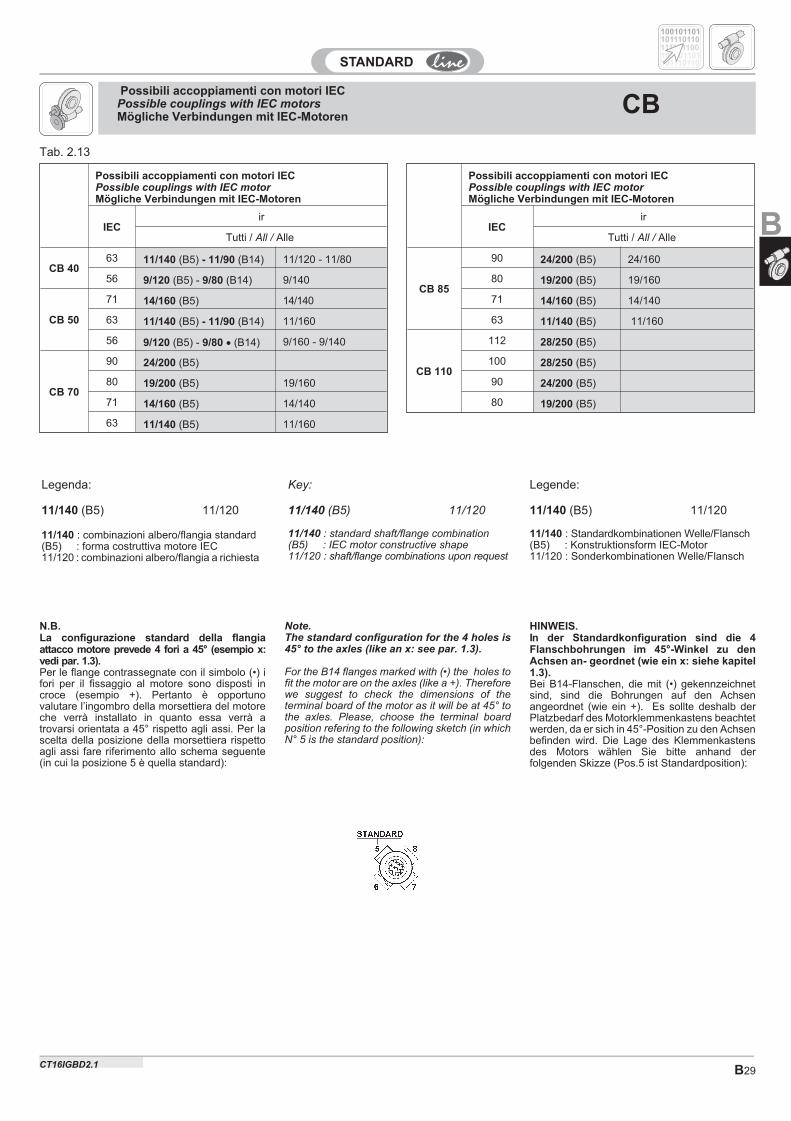
B29
Key:
11/140 (B5) 11/120
11/140 : standard shaft/flange combination(B5) : IEC motor constructive shape11/120 : shaft/flange combinations upon request
Tab. 2.13
Legende:
11/140 (B5) 11/120
11/140 : Standardkombinationen Welle/Flansch(B5) : Konstruktionsform IEC-Motor11/120 : Sonderkombinationen Welle/Flansch
Legenda:
11/140 (B5) 11/120
11/140 : combinazioni albero/flangia standard(B5) : forma costruttiva motore IEC11/120 : combinazioni albero/flangia a richiesta
Possibili accoppiamenti con motori IECPossible couplings with IEC motorMögliche Verbindungen mit IEC-Motoren
IECir
Tutti / All / Alle
CB 85
90 24/200 (B5) 24/160
80 19/200 (B5) 19/160
71 14/160 (B5) 14/140
63 11/140 (B5) 11/160
CB 110
112 28/250 (B5)
100 28/250 (B5)
90 24/200 (B5)
80 19/200 (B5)
Possibili accoppiamenti con motori IECPossible couplings with IEC motorMögliche Verbindungen mit IEC-Motoren
IECir
Tutti / All / Alle
CB 4063 11/140 (B5) - 11/90 (B14) 11/120 - 11/80
56 9/120 (B5) - 9/80 (B14) 9/140
CB 50
71 14/160 (B5) 14/140
63 11/140 (B5) - 11/90 (B14) 11/160
56 9/120 (B5) - 9/80 � (B14) 9/160 - 9/140
CB 70
90 24/200 (B5)
80 19/200 (B5) 19/160
71 14/160 (B5) 14/140
63 11/140 (B5) 11/160
100101101
100101101
101110110
101110110
111101100
Note.The standard configuration for the 4 holes is45° to the axles (like an x: see par. 1.3).
For the B14 flanges marked with (•) the holes tofit the motor are on the axles (like a +). Thereforewe suggest to check the dimensions of theterminal board of the motor as it will be at 45° tothe axles. Please, choose the terminal boardposition refering to the following sketch (in whichN° 5 is the standard position):
N.B.La configurazione standard della flangiaattacco motore prevede 4 fori a 45° (esempio x:vedi par. 1.3).Per le flange contrassegnate con il simbolo (•) ifori per il fissaggio al motore sono disposti incroce (esempio +). Pertanto è opportunovalutare l’ingombro della morsettiera del motoreche verrà installato in quanto essa verrà atrovarsi orientata a 45° rispetto agli assi. Per lascelta della posizione della morsettiera rispettoagli assi fare riferimento allo schema seguente(in cui la posizione 5 è quella standard):
HINWEIS.In der Standardkonfiguration sind die 4Flanschbohrungen im 45°-Winkel zu denAchsen an- geordnet (wie ein x: siehe kapitel1.3).Bei B14-Flanschen, die mit (•) gekennzeichnetsind, sind die Bohrungen auf den Achsenangeordnet (wie ein +). Es sollte deshalb derPlatzbedarf des Motorklemmenkastens beachtetwerden, da er sich in 45°-Position zu den Achsenbefinden wird. Die Lage des Klemmenkastensdes Motors wählen Sie bitte anhand derfolgenden Skizze (Pos.5 ist Standardposition):
Possibili accoppiamenti con motori IECPossible couplings with IEC motorsMögliche Verbindungen mit IEC-Motoren
CB
B
CT16IGBD2.1
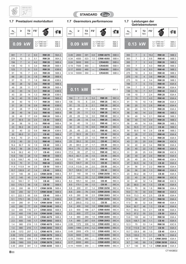
CT16IGBD2B30
1.7 Gearmotors performances 1.7 Leistungen derGetriebemotoren
1.7 Prestazioni motoriduttori
n2
min-1
ir T2Nm
FS’
391 7 2 6.0 RMI 28 56A 2
274 10 3 5.1 RMI 28 56A 2
194 7 4 4.2 RMI 28 56B 4
136 10 5 3.4 RMI 28 56B 4
123 7 6 3.3 RMI 28 63B 6
91 15 7 2.5 RMI 28 56B 4
68 20 9 1.6 RMI 28 56B 4
57 15 11 1.8 RMI 28 63B 6
49 28 12 3.6 RMI 40 56B 4
49 28 11 1.7 RMI 28 56B 4
43 20 14 3.1 RMI 40 63B 6
43 20 14 1.3 RMI 28 63B 6
34 40 15 2.6 RMI 40 56B 4
34 40 15 1.1 RMI 28 56B 4
31 28 18 2.8 RMI 40 63B 6
31 28 17 1.2 RMI 28 63B 6
28 49 18 2.2 RMI 40 56B 4
28 49 17 0.9 RMI 28 56B 4
27 50.5 23 2.5 CB 40 56B 4
24 56 19 1.9 RMI 40 56B 4
23 58.2 26 2.5 CB 40 56B 4
22 40 22 0.8 RMI 28 63B 6
20 68.0 31 2.1 CB 40 56B 4
19.4 70 21 1.3 RMI 40 56B 4
17.0 80 22 1.2 RMI 40 56B 4
16.4 82.7 32 1.9 CB 40 56B 4
15.4 56 29 1.4 RMI 40 63B 6
14.8 58.2 40 1.7 CB 40 63B 6
13.6 100 28 1.0 RMI 40 56B 4
12.5 108.7 40 1.6 CB 40 56B 4
12.3 70 31 1.0 RMI 40 63B 6
11.9 113.9 44 2.5 CB 50 56B 4
10.7 126.9 47 1.4 CB 40 56B 4
9.7 140 48 2.3 CRMI 28/50 56B 4
9.7 140 45 1.4 CRMI 28/40 56B 4
8.2 165.1 51 1.0 CB 40 56B 4
8.0 170.1 56 1.8 CB 50 56B 4
6.8 200 66 1.7 CRMI 28/50 56B 4
6.8 200 62 1.1 CRMI 28/40 56B 4
6.1 222.1 65 0.9 CB 40 56B 4
5.1 170.1 85 1.3 CB 50 63B 6
4.9 280 81 1.4 CRMI 28/50 56B 4
4.9 280 77 0.9 CRMI 28/40 56B 4
3.4 400 116 2.1 CRMI 28/63 56B 4
3.4 400 116 0.9 CRMI 28/50 56B 4
2.3 600 149 2.1 CRMI 40/70 56B 4
2.3 600 145 1.7 CRMI 28/63 56B 4
1.4 980 219 1.5 CRMI 40/70 56B 4
1.4 980 219 1.1 CRMI 28/63 56B 4
0.99 1372 257 1.2 CRMI 40/70 56B 4
0.99 1372 252 0.9 CRMI 28/70 56B 4
0.69 1960 339 1.5 CRMI 40/85 56B 4
0.69 1960 333 0.9 CRMI 28/70 56B 4
0.49 2800 391 1.3 CRMI 40/85 56B 4
n2
min-1
ir T2Nm
FS’ n2
min-1
ir T2Nm
FS’
0.49 2800 391 0.8 CRMI 40/70 56B 4
0.34 4000 523 1.0 CRMI 40/85 56B 4
0.24 5600 500 — CRI40/85 56B 4
0.19 7000 460 — CRI40/85 56B 4
0.17 8000 460 — CRI40/85 56B 4
0.14 10000 350 — CRI40/85 56B 4
0.09 kWn1= 2740 min-1
n1= 1360 min-1
n1= 860 min-1
56A 256B 463B 6
0.09 kWn1= 2740 min-1
n1= 1360 min-1
n1= 860 min-1
56A 256B 463B 6
0.13 kWn1= 2750 min-1
n1= 1360 min-1
n1= 860 min-1
56B 263A 463C 6
0.11 kW n1= 1360 min-156C 4
100101101
100101101
101110110
101110110
111101100
194 7 4 3.4 RMI 28 56C 4
136 10 6 2.8 RMI 28 56C 4
91 15 9 2.1 RMI 28 56C 4
68 20 11 3.3 RMI 40 56C 4
68 20 11 1.3 RMI 28 56C 4
49 28 14 3.0 RMI 40 56C 4
49 28 14 1.4 RMI 28 56C 4
34 40 19 2.2 RMI 40 56C 4
34 40 18 0.9 RMI 28 56C 4
28 49 22 1.8 RMI 40 56C 4
27 50.5 28 2.1 CB 40 56C 4
24 56 23 1.5 RMI 40 56C 4
23 58.2 32 2.0 CB 40 56C 4
20 68.0 37 1.7 CB 40 56C 4
19.4 70 25 1.1 RMI 40 56C 4
17.0 80 27 1.0 RMI 40 56C 4
16.4 82.7 39 1.5 CB 40 56C 4
13.6 100 35 0.8 RMI 40 56C 4
12.5 108.7 49 1.3 CB 40 56C 4
11.9 113.9 54 2.0 CB 50 56C 4
10.7 126.9 57 1.1 CB 40 56C 4
9.7 140 59 1.9 CRMI 28/50 56C 4
9.7 140 55 1.2 CRMI 28/40 56C 4
8.2 165.1 62 0.8 CB 40 56C 4
8.0 170.1 69 1.5 CB 50 56C 4
6.8 200 81 1.4 CRMI 28/50 56C 4
6.8 200 76 0.9 CRMI 28/40 56C 4
4.9 280 99 2.5 CRMI 28/63 56C 4
4.9 280 99 1.1 CRMI 28/50 56C 4
4.7 289.5 112 1.0 CB 50 56C 4
3.4 400 142 1.8 CRMI 28/63 56C 4
2.3 600 186 2.7 CRMI 40/85 56C 4
2.3 600 177 1.4 CRMI 28/63 56C 4
1.4 980 280 1.8 CRMI 40/85 56C 4
1.4 980 267 0.9 CRMI 28/63 56C 4
0.99 1372 308 1.6 CRMI 40/85 56C 4
0.69 1960 414 1.2 CRMI 40/85 56C 4
0.49 2800 478 1.0 CRMI 40/85 56C 4
0.24 5600 500 — CRMI 40/85 56C 4
0.19 7000 460 — CRMI 40/85 56C 4
0.17 8000 460 — CRMI 40/85 56C 4
0.14 10000 350 — CRMI 40/85 56C 4
393 7 3 10.2 RMI 40 56B 2
393 7 3 9.8 RMI 40 56B 2
393 7 3 4.2 RMI 28 56B 2
393 7 3 4.0 RMI 28 56B 2
275 10 4 8.3 RMI 40 56B 2
275 10 4 8.0 RMI 40 56B 2
275 10 4 3.6 RMI 28 56B 2
275 10 4 3.4 RMI 28 56B 2
194 7 5 7.0 RMI 40 63A 4
194 7 5 2.9 RMI 28 63A 4
136 10 7 5.7 RMI 40 63A 4
136 10 7 2.4 RMI 28 63A 4
91 15 11 4.0 RMI 40 63A 4
91 15 10 1.8 RMI 28 63A 4
68 20 13 2.8 RMI 40 63A 4
68 20 13 1.1 RMI 28 63A 4
56 49 14 2.2 RMI 40 56B 2
56 49 14 2.1 RMI 40 56B 2
56 49 13 0.9 RMI 28 56B 2
56 49 14 0.9 RMI 28 56B 2
54 50.5 17 2.9 CB 40 56B 2
54 50.5 18 2.8 CB 40 56B 2
49 28 17 2.5 RMI 40 63A 4
49 28 16 1.2 RMI 28 63A 4
43 20 20 0.9 RMI 28 63C 6
34 40 24 3.4 RMI 50 63A 4
34 40 22 1.8 RMI 40 63A 4
31 28 25 0.9 RMI 28 63C 6
28 49 28 2.6 RMI 50 63A 4
28 49 25 1.5 RMI 40 63A 4
27 50.5 34 1.8 CB 40 63A 4
24 56 31 2.2 RMI 50 63A 4
24 56 28 1.3 RMI 40 63A 4
23 58.2 38 1.7 CB 40 63A 4
22 40 36 2.5 RMI 50 63C 6
22 40 32 1.4 RMI 40 63C 6
20 68.0 44 1.5 CB 40 63A 4
19.4 70 36 1.8 RMI 50 63A 4
19.4 70 30 0.9 RMI 40 63A 4
18.6 73.3 43 2.5 CB 50 63A 4
17.0 80 37 1.6 RMI 50 63A 4
17.0 80 32 0.8 RMI 40 63A 4
16.4 82.7 46 1.3 CB 40 63A 4
15.1 90.2 53 2.1 CB 50 63A 4
14.0 97.2 55 2.0 CB 50 63A 4
13.6 100 44 1.2 RMI 50 63A 4
12.5 108.7 58 1.1 CB 40 63A 4
12.3 70 53 1.4 RMI 50 63C 6
11.9 113.9 64 1.7 CB 50 63A 4
10.7 126.9 68 1.0 CB 40 63A 4
10.5 130.0 73 3.1 CB 70 63A 4
9.7 140 71 2.6 CRMI 28/63 63A 4
9.7 140 69 1.6 CRMI 28/50 63A 4
9.7 140 65 1.0 CRMI 28/40 63A 4
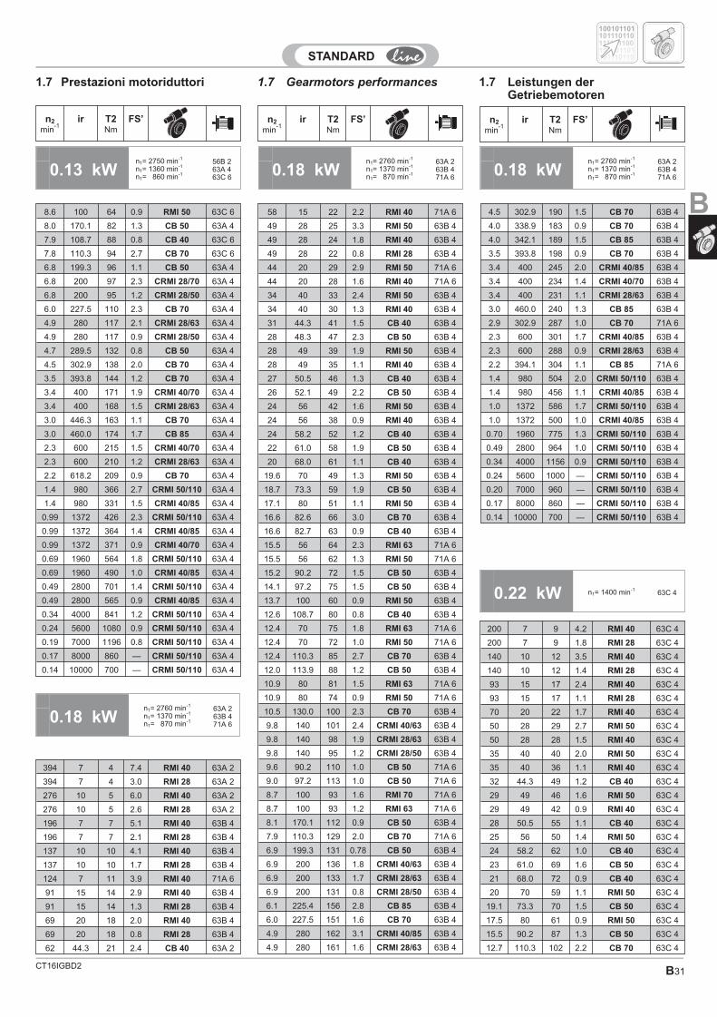
CT16IGBD2 B31
1.7 Gearmotors performances 1.7 Leistungen derGetriebemotoren
1.7 Prestazioni motoriduttori
n2
min-1
ir T2Nm
FS’ n2
min-1
ir T2Nm
FS’ n2
min-1
ir T2Nm
FS’
0.13 kWn1= 2750 min-1
n1= 1360 min-1
n1= 860 min-1
56B 263A 463C 6
0.18 kWn1= 2760 min-1
n1= 1370 min-1
n1= 870 min-1
63A 263B 471A 6
8.6 100 64 0.9 RMI 50 63C 6
8.0 170.1 82 1.3 CB 50 63A 4
7.9 108.7 88 0.8 CB 40 63C 6
7.8 110.3 94 2.7 CB 70 63C 6
6.8 199.3 96 1.1 CB 50 63A 4
6.8 200 97 2.3 CRMI 28/70 63A 4
6.8 200 95 1.2 CRMI 28/50 63A 4
6.0 227.5 110 2.3 CB 70 63A 4
4.9 280 117 2.1 CRMI 28/63 63A 4
4.9 280 117 0.9 CRMI 28/50 63A 4
4.7 289.5 132 0.8 CB 50 63A 4
4.5 302.9 138 2.0 CB 70 63A 4
3.5 393.8 144 1.2 CB 70 63A 4
3.4 400 171 1.9 CRMI 40/70 63A 4
3.4 400 168 1.5 CRMI 28/63 63A 4
3.0 446.3 163 1.1 CB 70 63A 4
3.0 460.0 174 1.7 CB 85 63A 4
2.3 600 215 1.5 CRMI 40/70 63A 4
2.3 600 210 1.2 CRMI 28/63 63A 4
2.2 618.2 209 0.9 CB 70 63A 4
1.4 980 366 2.7 CRMI 50/110 63A 4
1.4 980 331 1.5 CRMI 40/85 63A 4
0.99 1372 426 2.3 CRMI 50/110 63A 4
0.99 1372 364 1.4 CRMI 40/85 63A 4
0.99 1372 371 0.9 CRMI 40/70 63A 4
0.69 1960 564 1.8 CRMI 50/110 63A 4
0.69 1960 490 1.0 CRMI 40/85 63A 4
0.49 2800 701 1.4 CRMI 50/110 63A 4
0.49 2800 565 0.9 CRMI 40/85 63A 4
0.34 4000 841 1.2 CRMI 50/110 63A 4
0.24 5600 1080 0.9 CRMI 50/110 63A 4
0.19 7000 1196 0.8 CRMI 50/110 63A 4
0.17 8000 860 — CRMI 50/110 63A 4
0.14 10000 700 — CRMI 50/110 63A 4
0.18 kWn1= 2760 min-1
n1= 1370 min-1
n1= 870 min-1
63A 263B 471A 6
0.22 kW n1= 1400 min-163C 4
200 7 9 4.2 RMI 40 63C 4
200 7 9 1.8 RMI 28 63C 4
140 10 12 3.5 RMI 40 63C 4
140 10 12 1.4 RMI 28 63C 4
93 15 17 2.4 RMI 40 63C 4
93 15 17 1.1 RMI 28 63C 4
70 20 22 1.7 RMI 40 63C 4
50 28 29 2.7 RMI 50 63C 4
50 28 28 1.5 RMI 40 63C 4
35 40 40 2.0 RMI 50 63C 4
35 40 36 1.1 RMI 40 63C 4
32 44.3 49 1.2 CB 40 63C 4
29 49 46 1.6 RMI 50 63C 4
29 49 42 0.9 RMI 40 63C 4
28 50.5 55 1.1 CB 40 63C 4
25 56 50 1.4 RMI 50 63C 4
24 58.2 62 1.0 CB 40 63C 4
23 61.0 69 1.6 CB 50 63C 4
21 68.0 72 0.9 CB 40 63C 4
20 70 59 1.1 RMI 50 63C 4
19.1 73.3 70 1.5 CB 50 63C 4
17.5 80 61 0.9 RMI 50 63C 4
15.5 90.2 87 1.3 CB 50 63C 4
12.7 110.3 102 2.2 CB 70 63C 4
100101101
100101101
101110110
101110110
111101100
0.18 kWn1= 2760 min-1
n1= 1370 min-1
n1= 870 min-1
63A 263B 471A 6
394 7 4 7.4 RMI 40 63A 2
394 7 4 3.0 RMI 28 63A 2
276 10 5 6.0 RMI 40 63A 2
276 10 5 2.6 RMI 28 63A 2
196 7 7 5.1 RMI 40 63B 4
196 7 7 2.1 RMI 28 63B 4
137 10 10 4.1 RMI 40 63B 4
137 10 10 1.7 RMI 28 63B 4
124 7 11 3.9 RMI 40 71A 6
91 15 14 2.9 RMI 40 63B 4
91 15 14 1.3 RMI 28 63B 4
69 20 18 2.0 RMI 40 63B 4
69 20 18 0.8 RMI 28 63B 4
62 44.3 21 2.4 CB 40 63A 2
58 15 22 2.2 RMI 40 71A 6
49 28 25 3.3 RMI 50 63B 4
49 28 24 1.8 RMI 40 63B 4
49 28 22 0.8 RMI 28 63B 4
44 20 29 2.9 RMI 50 71A 6
44 20 28 1.6 RMI 40 71A 6
34 40 33 2.4 RMI 50 63B 4
34 40 30 1.3 RMI 40 63B 4
31 44.3 41 1.5 CB 40 63B 4
28 48.3 47 2.3 CB 50 63B 4
28 49 39 1.9 RMI 50 63B 4
28 49 35 1.1 RMI 40 63B 4
27 50.5 46 1.3 CB 40 63B 4
26 52.1 49 2.2 CB 50 63B 4
24 56 42 1.6 RMI 50 63B 4
24 56 38 0.9 RMI 40 63B 4
24 58.2 52 1.2 CB 40 63B 4
22 61.0 58 1.9 CB 50 63B 4
20 68.0 61 1.1 CB 40 63B 4
19.6 70 49 1.3 RMI 50 63B 4
18.7 73.3 59 1.9 CB 50 63B 4
17.1 80 51 1.1 RMI 50 63B 4
16.6 82.6 66 3.0 CB 70 63B 4
16.6 82.7 63 0.9 CB 40 63B 4
15.5 56 64 2.3 RMI 63 71A 6
15.5 56 62 1.3 RMI 50 71A 6
15.2 90.2 72 1.5 CB 50 63B 4
14.1 97.2 75 1.5 CB 50 63B 4
13.7 100 60 0.9 RMI 50 63B 4
12.6 108.7 80 0.8 CB 40 63B 4
12.4 70 75 1.8 RMI 63 71A 6
12.4 70 72 1.0 RMI 50 71A 6
12.4 110.3 85 2.7 CB 70 63B 4
12.0 113.9 88 1.2 CB 50 63B 4
10.9 80 81 1.5 RMI 63 71A 6
10.9 80 74 0.9 RMI 50 71A 6
10.5 130.0 100 2.3 CB 70 63B 4
9.8 140 101 2.4 CRMI 40/63 63B 4
9.8 140 98 1.9 CRMI 28/63 63B 4
9.8 140 95 1.2 CRMI 28/50 63B 4
9.6 90.2 110 1.0 CB 50 71A 6
9.0 97.2 113 1.0 CB 50 71A 6
8.7 100 93 1.6 RMI 70 71A 6
8.7 100 93 1.2 RMI 63 71A 6
8.1 170.1 112 0.9 CB 50 63B 4
7.9 110.3 129 2.0 CB 70 71A 6
6.9 199.3 131 0.78 CB 50 63B 4
6.9 200 136 1.8 CRMI 40/63 63B 4
6.9 200 133 1.7 CRMI 28/63 63B 4
6.9 200 131 0.8 CRMI 28/50 63B 4
6.1 225.4 156 2.8 CB 85 63B 4
6.0 227.5 151 1.6 CB 70 63B 4
4.9 280 162 3.1 CRMI 40/85 63B 4
4.9 280 161 1.6 CRMI 28/63 63B 4
B4.5 302.9 190 1.5 CB 70 63B 4
4.0 338.9 183 0.9 CB 70 63B 4
4.0 342.1 189 1.5 CB 85 63B 4
3.5 393.8 198 0.9 CB 70 63B 4
3.4 400 245 2.0 CRMI 40/85 63B 4
3.4 400 234 1.4 CRMI 40/70 63B 4
3.4 400 231 1.1 CRMI 28/63 63B 4
3.0 460.0 240 1.3 CB 85 63B 4
2.9 302.9 287 1.0 CB 70 71A 6
2.3 600 301 1.7 CRMI 40/85 63B 4
2.3 600 288 0.9 CRMI 28/63 63B 4
2.2 394.1 304 1.1 CB 85 71A 6
1.4 980 504 2.0 CRMI 50/110 63B 4
1.4 980 456 1.1 CRMI 40/85 63B 4
1.0 1372 586 1.7 CRMI 50/110 63B 4
1.0 1372 500 1.0 CRMI 40/85 63B 4
0.70 1960 775 1.3 CRMI 50/110 63B 4
0.49 2800 964 1.0 CRMI 50/110 63B 4
0.34 4000 1156 0.9 CRMI 50/110 63B 4
0.24 5600 1000 — CRMI 50/110 63B 4
0.20 7000 960 — CRMI 50/110 63B 4
0.17 8000 860 — CRMI 50/110 63B 4
0.14 10000 700 — CRMI 50/110 63B 4
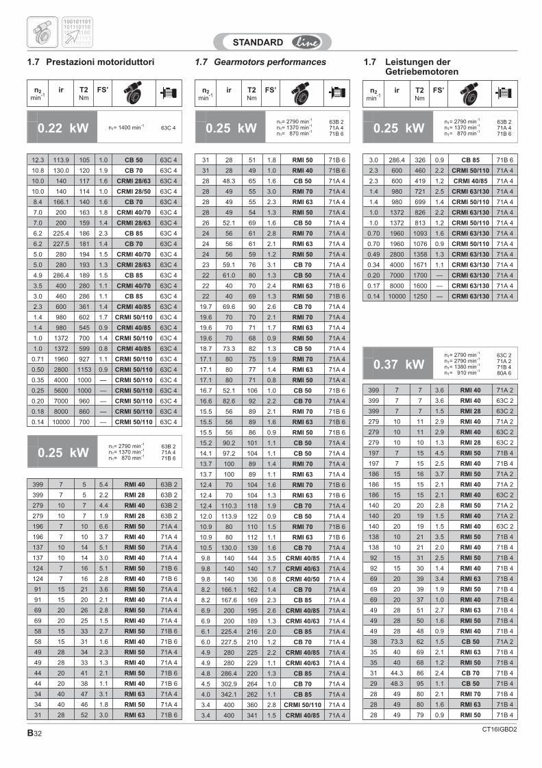
CT16IGBD2B32
1.7 Gearmotors performances 1.7 Leistungen derGetriebemotoren
1.7 Prestazioni motoriduttori
0.25 kWn1= 2790 min-1
n1= 1370 min-1
n1= 870 min-1
63B 271A 471B 6
0.22 kW n1= 1400 min-163C 4 0.25 kW
n1= 2790 min-1
n1= 1370 min-1
n1= 870 min-1
63B 271A 471B 6
n2
min-1
ir T2Nm
FS’ n2
min-1
ir T2Nm
FS’ n2
min-1
ir T2Nm
FS’
12.3 113.9 105 1.0 CB 50 63C 4
10.8 130.0 120 1.9 CB 70 63C 4
10.0 140 117 1.6 CRMI 28/63 63C 4
10.0 140 114 1.0 CRMI 28/50 63C 4
8.4 166.1 140 1.6 CB 70 63C 4
7.0 200 163 1.8 CRMI 40/70 63C 4
7.0 200 159 1.4 CRMI 28/63 63C 4
6.2 225.4 186 2.3 CB 85 63C 4
6.2 227.5 181 1.4 CB 70 63C 4
5.0 280 194 1.5 CRMI 40/70 63C 4
5.0 280 193 1.3 CRMI 28/63 63C 4
4.9 286.4 189 1.5 CB 85 63C 4
3.5 400 280 1.1 CRMI 40/70 63C 4
3.0 460 286 1.1 CB 85 63C 4
2.3 600 361 1.4 CRMI 40/85 63C 4
1.4 980 602 1.7 CRMI 50/110 63C 4
1.4 980 545 0.9 CRMI 40/85 63C 4
1.0 1372 700 1.4 CRMI 50/110 63C 4
1.0 1372 599 0.8 CRMI 40/85 63C 4
0.71 1960 927 1.1 CRMI 50/110 63C 4
0.50 2800 1153 0.9 CRMI 50/110 63C 4
0.35 4000 1000 — CRMI 50/110 63C 4
0.25 5600 1000 — CRMI 50/110 63C 4
0.20 7000 960 — CRMI 50/110 63C 4
0.18 8000 860 — CRMI 50/110 63C 4
0.14 10000 700 — CRMI 50/110 63C 4
0.25 kWn1= 2790 min-1
n1= 1370 min-1
n1= 870 min-1
63B 271A 471B 6
399 7 5 5.4 RMI 40 63B 2
399 7 5 2.2 RMI 28 63B 2
279 10 7 4.4 RMI 40 63B 2
279 10 7 1.9 RMI 28 63B 2
196 7 10 6.6 RMI 50 71A 4
196 7 10 3.7 RMI 40 71A 4
137 10 14 5.1 RMI 50 71A 4
137 10 14 3.0 RMI 40 71A 4
124 7 16 5.1 RMI 50 71B 6
124 7 16 2.8 RMI 40 71B 6
91 15 21 3.6 RMI 50 71A 4
91 15 20 2.1 RMI 40 71A 4
69 20 26 2.8 RMI 50 71A 4
69 20 25 1.5 RMI 40 71A 4
58 15 33 2.7 RMI 50 71B 6
58 15 31 1.6 RMI 40 71B 6
49 28 34 2.3 RMI 50 71A 4
49 28 33 1.3 RMI 40 71A 4
44 20 41 2.1 RMI 50 71B 6
44 20 38 1.1 RMI 40 71B 6
34 40 47 3.1 RMI 63 71A 4
34 40 46 1.8 RMI 50 71A 4
31 28 52 3.0 RMI 63 71B 6
0.37 kWn1= 2790 min-1
n1= 2790 min-1
n1= 1380 min-1
n1= 910 min-1
63C 271A 271B 480A 6
399 7 7 3.6 RMI 40 71A 2
399 7 7 3.6 RMI 40 63C 2
399 7 7 1.5 RMI 28 63C 2
279 10 11 2.9 RMI 40 71A 2
279 10 11 2.9 RMI 40 63C 2
279 10 10 1.3 RMI 28 63C 2
197 7 15 4.5 RMI 50 71B 4
197 7 15 2.5 RMI 40 71B 4
186 15 16 3.7 RMI 50 71A 2
186 15 15 2.1 RMI 40 71A 2
186 15 15 2.1 RMI 40 63C 2
140 20 20 2.8 RMI 50 71A 2
140 20 19 1.5 RMI 40 71A 2
140 20 19 1.5 RMI 40 63C 2
138 10 21 3.5 RMI 50 71B 4
138 10 21 2.0 RMI 40 71B 4
92 15 31 2.5 RMI 50 71B 4
92 15 30 1.4 RMI 40 71B 4
69 20 39 3.4 RMI 63 71B 4
69 20 39 1.9 RMI 50 71B 4
69 20 37 1.0 RMI 40 71B 4
49 28 51 2.7 RMI 63 71B 4
49 28 50 1.6 RMI 50 71B 4
49 28 48 0.9 RMI 40 71B 4
38 73.3 62 1.5 CB 50 71A 2
35 40 69 2.1 RMI 63 71B 4
35 40 68 1.2 RMI 50 71B 4
31 44.3 86 2.4 CB 70 71B 4
29 48.3 95 1.1 CB 50 71B 4
28 49 80 2.1 RMI 70 71B 4
28 49 80 1.6 RMI 63 71B 4
28 49 79 0.9 RMI 50 71B 4
100101101
100101101
101110110
101110110
111101100
31 28 51 1.8 RMI 50 71B 6
31 28 49 1.0 RMI 40 71B 6
28 48.3 65 1.6 CB 50 71A 4
28 49 55 3.0 RMI 70 71A 4
28 49 55 2.3 RMI 63 71A 4
28 49 54 1.3 RMI 50 71A 4
26 52.1 69 1.6 CB 50 71A 4
24 56 61 2.8 RMI 70 71A 4
24 56 61 2.1 RMI 63 71A 4
24 56 59 1.2 RMI 50 71A 4
23 59.1 76 3.1 CB 70 71A 4
22 61.0 80 1.3 CB 50 71A 4
22 40 70 2.4 RMI 63 71B 6
22 40 69 1.3 RMI 50 71B 6
19.7 69.6 90 2.6 CB 70 71A 4
19.6 70 70 2.1 RMI 70 71A 4
19.6 70 71 1.7 RMI 63 71A 4
19.6 70 68 0.9 RMI 50 71A 4
18.7 73.3 82 1.3 CB 50 71A 4
17.1 80 75 1.9 RMI 70 71A 4
17.1 80 77 1.4 RMI 63 71A 4
17.1 80 71 0.8 RMI 50 71A 4
16.7 52.1 106 1.0 CB 50 71B 6
16.6 82.6 92 2.2 CB 70 71A 4
15.5 56 89 2.1 RMI 70 71B 6
15.5 56 89 1.6 RMI 63 71B 6
15.5 56 86 0.9 RMI 50 71B 6
15.2 90.2 101 1.1 CB 50 71A 4
14.1 97.2 104 1.1 CB 50 71A 4
13.7 100 89 1.4 RMI 70 71A 4
13.7 100 89 1.1 RMI 63 71A 4
12.4 70 104 1.6 RMI 70 71B 6
12.4 70 104 1.3 RMI 63 71B 6
12.4 110.3 118 1.9 CB 70 71A 4
12.0 113.9 122 0.9 CB 50 71A 4
10.9 80 110 1.5 RMI 70 71B 6
10.9 80 112 1.1 RMI 63 71B 6
10.5 130.0 139 1.6 CB 70 71A 4
9.8 140 144 3.5 CRMI 40/85 71A 4
9.8 140 140 1.7 CRMI 40/63 71A 4
9.8 140 136 0.8 CRMI 40/50 71A 4
8.2 166.1 162 1.4 CB 70 71A 4
8.2 167.6 169 2.3 CB 85 71A 4
6.9 200 195 2.6 CRMI 40/85 71A 4
6.9 200 189 1.3 CRMI 40/63 71A 4
6.1 225.4 216 2.0 CB 85 71A 4
6.0 227.5 210 1.2 CB 70 71A 4
4.9 280 225 2.2 CRMI 40/85 71A 4
4.9 280 229 1.1 CRMI 40/63 71A 4
4.8 286.4 220 1.3 CB 85 71A 4
4.5 302.9 264 1.0 CB 70 71A 4
4.0 342.1 262 1.1 CB 85 71A 4
3.4 400 360 2.8 CRMI 50/110 71A 4
3.4 400 341 1.5 CRMI 40/85 71A 4
3.0 286.4 326 0.9 CB 85 71B 6
2.3 600 460 2.2 CRMI 50/110 71A 4
2.3 600 419 1.2 CRMI 40/85 71A 4
1.4 980 721 2.5 CRMI 63/130 71A 4
1.4 980 699 1.4 CRMI 50/110 71A 4
1.0 1372 826 2.2 CRMI 63/130 71A 4
1.0 1372 813 1.2 CRMI 50/110 71A 4
0.70 1960 1093 1.6 CRMI 63/130 71A 4
0.70 1960 1076 0.9 CRMI 50/110 71A 4
0.49 2800 1358 1.3 CRMI 63/130 71A 4
0.34 4000 1671 1.1 CRMI 63/130 71A 4
0.20 7000 1700 — CRMI 63/130 71A 4
0.17 8000 1600 — CRMI 63/130 71A 4
0.14 10000 1250 — CRMI 63/130 71A 4
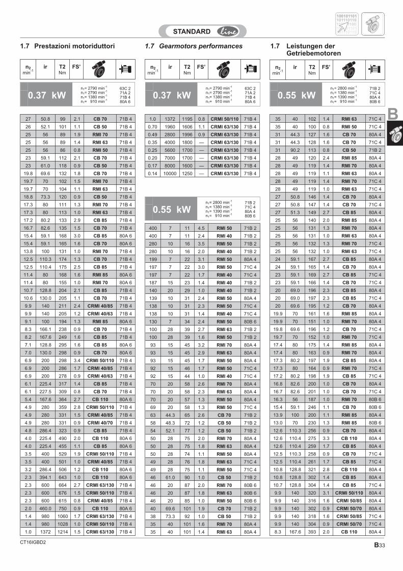
CT16IGBD2 B33
1.7 Gearmotors performances 1.7 Leistungen derGetriebemotoren
1.7 Prestazioni motoriduttori
0.37 kWn1= 2790 min-1
n1= 2790 min-1
n1= 1380 min-1
n1= 910 min-1
63C 271A 271B 480A 6
0.55 kWn1= 2800 min-1
n1= 1380 min-1
n1= 1390 min-1
n1= 910 min-1
71B 271C 480A 480B 6
27 50.8 99 2.1 CB 70 71B 4
26 52.1 101 1.1 CB 50 71B 4
25 56 89 1.9 RMI 70 71B 4
25 56 89 1.4 RMI 63 71B 4
25 56 86 0.8 RMI 50 71B 4
23 59.1 112 2.1 CB 70 71B 4
23 61.0 118 0.9 CB 50 71B 4
19.8 69.6 132 1.8 CB 70 71B 4
19.7 70 102 1.5 RMI 70 71B 4
19.7 70 104 1.1 RMI 63 71B 4
18.8 73.3 120 0.9 CB 50 71B 4
17.3 80 111 1.3 RMI 70 71B 4
17.3 80 113 1.0 RMI 63 71B 4
17.2 80.2 133 2.9 CB 85 71B 4
16.7 82.6 135 1.5 CB 70 71B 4
15.4 59.1 168 3.0 CB 85 80A 6
15.4 59.1 165 1.6 CB 70 80A 6
13.8 100 131 1.0 RMI 70 71B 4
12.5 110.3 174 1.3 CB 70 71B 4
12.5 110.4 175 2.5 CB 85 71B 4
11.4 80 168 1.6 RMI 85 80A 6
11.4 80 155 1.0 RMI 70 80A 6
10.7 128.8 204 2.1 CB 85 71B 4
10.6 130.0 205 1.1 CB 70 71B 4
9.9 140 211 2.4 CRMI 40/85 71B 4
9.9 140 205 1.2 CRMI 40/63 71B 4
9.1 100 194 1.3 RMI 85 80A 6
8.3 166.1 238 0.9 CB 70 71B 4
8.2 167.6 249 1.6 CB 85 71B 4
7.1 128.8 295 1.6 CB 85 80A 6
7.0 130.0 298 0.9 CB 70 80A 6
6.9 200 298 3.4 CRMI 50/110 71B 4
6.9 200 286 1.7 CRMI 40/85 71B 4
6.9 200 278 0.9 CRMI 40/63 71B 4
6.1 225.4 317 1.4 CB 85 71B 4
6.1 227.5 309 0.8 CB 70 71B 4
5.4 167.6 364 2.7 CB 110 80A 6
4.9 280 359 2.8 CRMI 50/110 71B 4
4.9 280 331 1.5 CRMI 40/85 71B 4
4.9 280 331 0.9 CRMI 40/70 71B 4
4.8 286.4 323 0.9 CB 85 71B 4
4.0 225.4 490 2.0 CB 110 80A 6
4.0 225.4 455 1.1 CB 85 80A 6
3.5 400 529 1.9 CRMI 50/110 71B 4
3.5 400 501 1.0 CRMI 40/85 71B 4
3.2 286.4 506 1.2 CB 110 80A 6
2.3 394.1 643 1.0 CB 110 80A 6
2.3 600 664 2.7 CRMI 63/130 71B 4
2.3 600 676 1.5 CRMI 50/110 71B 4
2.3 600 615 0.8 CRMI 40/85 71B 4
2.0 460.0 750 0.9 CB 110 80A 6
1.4 980 1060 1.7 CRMI 63/130 71B 4
1.4 980 1028 1.0 CRMI 50/110 71B 4
1.0 1372 1214 1.5 CRMI 63/130 71B 4
1.0 1372 1195 0.8 CRMI 50/110 71B 4
0.70 1960 1606 1.1 CRMI 63/130 71B 4
0.49 2800 1996 0.9 CRMI 63/130 71B 4
0.35 4000 1800 — CRMI 63/130 71B 4
0.25 5600 1700 — CRMI 63/130 71B 4
0.20 7000 1700 — CRMI 63/130 71B 4
0.17 8000 1600 — CRMI 63/130 71B 4
0.14 10000 1250 — CRMI 63/130 71B 4
n2
min-1
ir T2Nm
FS’ n2
min-1
ir T2Nm
FS’ n2
min-1
ir T2Nm
FS’
0.37 kWn1= 2790 min-1
n1= 2790 min-1
n1= 1380 min-1
n1= 910 min-1
63C 271A 271B 480A 6
0.55 kWn1= 2800 min-1
n1= 1380 min-1
n1= 1390 min-1
n1= 910 min-1
71B 271C 480A 480B 6
400 7 11 4.5 RMI 50 71B 2
400 7 11 2.4 RMI 40 71B 2
280 10 16 3.5 RMI 50 71B 2
280 10 16 2.0 RMI 40 71B 2
199 7 22 3.1 RMI 50 80A 4
197 7 22 3.0 RMI 50 71C 4
197 7 22 1.7 RMI 40 71C 4
187 15 23 1.4 RMI 40 71B 2
140 20 29 1.0 RMI 40 71B 2
139 10 31 2.4 RMI 50 80A 4
138 10 31 2.3 RMI 50 71C 4
138 10 31 1.4 RMI 40 71C 4
130 7 34 2.4 RMI 50 80B 6
100 28 39 2.7 RMI 63 71B 2
100 28 39 1.6 RMI 50 71B 2
93 15 45 3.2 RMI 70 80A 4
93 15 45 2.9 RMI 63 80A 4
93 15 45 1.7 RMI 50 80A 4
92 15 46 1.7 RMI 50 71C 4
92 15 44 1.0 RMI 40 71C 4
70 20 58 2.6 RMI 70 80A 4
70 20 58 2.3 RMI 63 80A 4
70 20 57 1.3 RMI 50 80A 4
69 20 58 1.3 RMI 50 71C 4
63 44.3 65 2.6 CB 70 71B 2
58 48.3 72 1.2 CB 50 71B 2
54 52.1 77 1.2 CB 50 71B 2
50 28 75 2.0 RMI 70 80A 4
50 28 75 1.8 RMI 63 80A 4
50 28 74 1.1 RMI 50 80A 4
49 28 76 1.8 RMI 63 71C 4
49 28 75 1.1 RMI 50 71C 4
46 61.0 90 1.0 CB 50 71B 2
46 20 87 2.0 RMI 70 80B 6
46 20 87 1.8 RMI 63 80B 6
46 20 85 1.0 RMI 50 80B 6
40 69.6 101 1.9 CB 70 71B 2
38 73.3 92 1.0 CB 50 71B 2
35 40 101 1.6 RMI 70 80A 4
35 40 101 1.4 RMI 63 80A 4
35 40 102 1.4 RMI 63 71C 4
35 40 100 0.8 RMI 50 71C 4
31 44.3 127 1.6 CB 70 80A 4
31 44.3 128 1.6 CB 70 71C 4
31 90.2 113 0.8 CB 50 71B 2
28 49 120 2.4 RMI 85 80A 4
28 49 119 1.4 RMI 70 80A 4
28 49 119 1.1 RMI 63 80A 4
28 49 119 1.4 RMI 70 71C 4
28 49 119 1.0 RMI 63 71C 4
27 50.8 146 1.4 CB 70 80A 4
27 50.8 147 1.4 CB 70 71C 4
27 51.3 149 2.7 CB 85 80A 4
25 56 140 2.0 RMI 85 80A 4
25 56 131 1.3 RMI 70 80A 4
25 56 131 1.0 RMI 63 80A 4
25 56 132 1.3 RMI 70 71C 4
25 56 132 1.0 RMI 63 71C 4
24 59.1 167 2.7 CB 85 80A 4
24 59.1 165 1.4 CB 70 80A 4
23 59.1 169 2.7 CB 85 71C 4
23 59.1 166 1.4 CB 70 71C 4
20 69.0 196 2.3 CB 85 80A 4
20 69.0 197 2.3 CB 85 71C 4
20 69.6 195 1.2 CB 70 80A 4
19.9 70 161 1.6 RMI 85 80A 4
19.9 70 151 1.0 RMI 70 80A 4
19.8 69.6 196 1.2 CB 70 71C 4
19.7 70 152 1.0 RMI 70 71C 4
17.4 80 175 1.4 RMI 85 80A 4
17.4 80 163 0.9 RMI 70 80A 4
17.3 80.2 197 1.9 CB 85 80A 4
17.3 80 164 0.9 RMI 70 71C 4
17.2 80.2 198 1.9 CB 85 71C 4
16.8 82.6 200 1.0 CB 70 80A 4
16.7 82.6 201 1.0 CB 70 71C 4
16.3 56 187 1.0 RMI 70 80B 6
15.4 59.1 246 1.1 CB 70 80B 6
13.9 100 200 1.1 RMI 85 80A 4
13.0 70 230 1.3 RMI 85 80B 6
12.6 110.3 256 0.9 CB 70 80A 4
12.6 110.4 275 3.3 CB 110 80A 4
12.6 110.4 259 1.7 CB 85 80A 4
12.5 110.3 258 0.9 CB 70 71C 4
12.5 110.4 261 1.7 CB 85 71C 4
10.8 128.8 321 2.8 CB 110 80A 4
10.8 128.8 302 1.4 CB 85 80A 4
10.7 128.8 304 1.4 CB 85 71C 4
9.9 140 320 3.1 CRMI 50/110 80A 4
9.9 140 316 1.6 CRMI 50/85 80A 4
9.9 140 302 0.9 CRMI 50/70 80A 4
9.9 140 318 1.6 CRMI 50/85 71C 4
9.9 140 304 0.9 CRMI 50/70 71C 4
8.3 167.6 393 2.0 CB 110 80A 4
100101101
100101101
101110110
101110110
111101100
B
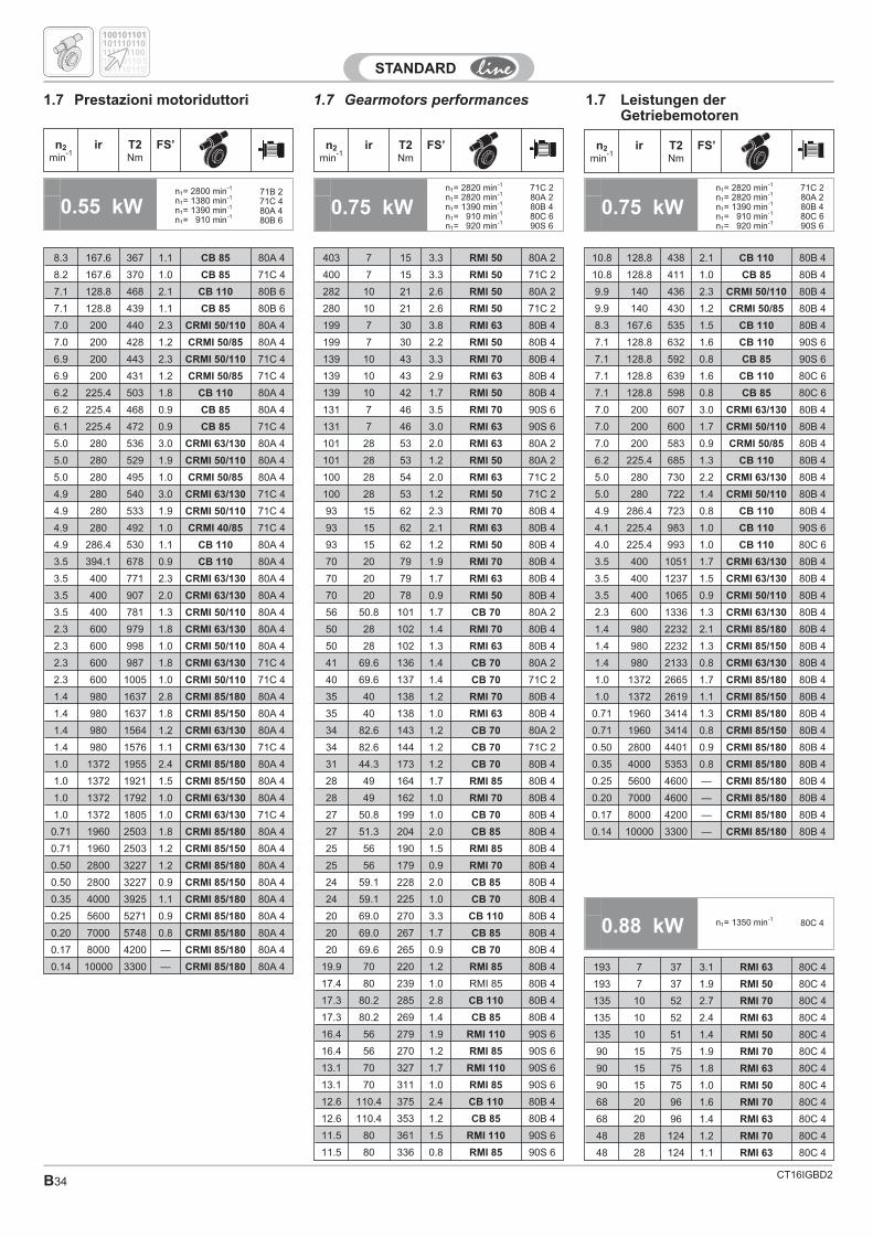
CT16IGBD2B34
1.7 Gearmotors performances 1.7 Leistungen derGetriebemotoren
1.7 Prestazioni motoriduttori
0.55 kWn1= 2800 min-1
n1= 1380 min-1
n1= 1390 min-1
n1= 910 min-1
71B 271C 480A 480B 6
403 7 15 3.3 RMI 50 80A 2
400 7 15 3.3 RMI 50 71C 2
282 10 21 2.6 RMI 50 80A 2
280 10 21 2.6 RMI 50 71C 2
199 7 30 3.8 RMI 63 80B 4
199 7 30 2.2 RMI 50 80B 4
139 10 43 3.3 RMI 70 80B 4
139 10 43 2.9 RMI 63 80B 4
139 10 42 1.7 RMI 50 80B 4
131 7 46 3.5 RMI 70 90S 6
131 7 46 3.0 RMI 63 90S 6
101 28 53 2.0 RMI 63 80A 2
101 28 53 1.2 RMI 50 80A 2
100 28 54 2.0 RMI 63 71C 2
100 28 53 1.2 RMI 50 71C 2
93 15 62 2.3 RMI 70 80B 4
93 15 62 2.1 RMI 63 80B 4
93 15 62 1.2 RMI 50 80B 4
70 20 79 1.9 RMI 70 80B 4
70 20 79 1.7 RMI 63 80B 4
70 20 78 0.9 RMI 50 80B 4
56 50.8 101 1.7 CB 70 80A 2
50 28 102 1.4 RMI 70 80B 4
50 28 102 1.3 RMI 63 80B 4
41 69.6 136 1.4 CB 70 80A 2
40 69.6 137 1.4 CB 70 71C 2
35 40 138 1.2 RMI 70 80B 4
35 40 138 1.0 RMI 63 80B 4
34 82.6 143 1.2 CB 70 80A 2
34 82.6 144 1.2 CB 70 71C 2
31 44.3 173 1.2 CB 70 80B 4
28 49 164 1.7 RMI 85 80B 4
28 49 162 1.0 RMI 70 80B 4
27 50.8 199 1.0 CB 70 80B 4
27 51.3 204 2.0 CB 85 80B 4
25 56 190 1.5 RMI 85 80B 4
25 56 179 0.9 RMI 70 80B 4
24 59.1 228 2.0 CB 85 80B 4
24 59.1 225 1.0 CB 70 80B 4
20 69.0 270 3.3 CB 110 80B 4
20 69.0 267 1.7 CB 85 80B 4
20 69.6 265 0.9 CB 70 80B 4
19.9 70 220 1.2 RMI 85 80B 4
17.4 80 239 1.0 RMI 85 80B 4
17.3 80.2 285 2.8 CB 110 80B 4
17.3 80.2 269 1.4 CB 85 80B 4
16.4 56 279 1.9 RMI 110 90S 6
16.4 56 270 1.2 RMI 85 90S 6
13.1 70 327 1.7 RMI 110 90S 6
13.1 70 311 1.0 RMI 85 90S 6
12.6 110.4 375 2.4 CB 110 80B 4
12.6 110.4 353 1.2 CB 85 80B 4
11.5 80 361 1.5 RMI 110 90S 6
11.5 80 336 0.8 RMI 85 90S 6
8.3 167.6 367 1.1 CB 85 80A 4
8.2 167.6 370 1.0 CB 85 71C 4
7.1 128.8 468 2.1 CB 110 80B 6
7.1 128.8 439 1.1 CB 85 80B 6
7.0 200 440 2.3 CRMI 50/110 80A 4
7.0 200 428 1.2 CRMI 50/85 80A 4
6.9 200 443 2.3 CRMI 50/110 71C 4
6.9 200 431 1.2 CRMI 50/85 71C 4
6.2 225.4 503 1.8 CB 110 80A 4
6.2 225.4 468 0.9 CB 85 80A 4
6.1 225.4 472 0.9 CB 85 71C 4
5.0 280 536 3.0 CRMI 63/130 80A 4
5.0 280 529 1.9 CRMI 50/110 80A 4
5.0 280 495 1.0 CRMI 50/85 80A 4
4.9 280 540 3.0 CRMI 63/130 71C 4
4.9 280 533 1.9 CRMI 50/110 71C 4
4.9 280 492 1.0 CRMI 40/85 71C 4
4.9 286.4 530 1.1 CB 110 80A 4
3.5 394.1 678 0.9 CB 110 80A 4
3.5 400 771 2.3 CRMI 63/130 80A 4
3.5 400 907 2.0 CRMI 63/130 80A 4
3.5 400 781 1.3 CRMI 50/110 80A 4
2.3 600 979 1.8 CRMI 63/130 80A 4
2.3 600 998 1.0 CRMI 50/110 80A 4
2.3 600 987 1.8 CRMI 63/130 71C 4
2.3 600 1005 1.0 CRMI 50/110 71C 4
1.4 980 1637 2.8 CRMI 85/180 80A 4
1.4 980 1637 1.8 CRMI 85/150 80A 4
1.4 980 1564 1.2 CRMI 63/130 80A 4
1.4 980 1576 1.1 CRMI 63/130 71C 4
1.0 1372 1955 2.4 CRMI 85/180 80A 4
1.0 1372 1921 1.5 CRMI 85/150 80A 4
1.0 1372 1792 1.0 CRMI 63/130 80A 4
1.0 1372 1805 1.0 CRMI 63/130 71C 4
0.71 1960 2503 1.8 CRMI 85/180 80A 4
0.71 1960 2503 1.2 CRMI 85/150 80A 4
0.50 2800 3227 1.2 CRMI 85/180 80A 4
0.50 2800 3227 0.9 CRMI 85/150 80A 4
0.35 4000 3925 1.1 CRMI 85/180 80A 4
0.25 5600 5271 0.9 CRMI 85/180 80A 4
0.20 7000 5748 0.8 CRMI 85/180 80A 4
0.17 8000 4200 — CRMI 85/180 80A 4
0.14 10000 3300 — CRMI 85/180 80A 4
0.75 kWn1= 2820 min-1
n1= 2820 min-1
n1= 1390 min-1
n1= 910 min-1
n1= 920 min-1
71C 280A 280B 480C 690S 6
n2
min-1
ir T2Nm
FS’ n2
min-1
ir T2Nm
FS’ n2
min-1
ir T2Nm
FS’
10.8 128.8 438 2.1 CB 110 80B 4
10.8 128.8 411 1.0 CB 85 80B 4
9.9 140 436 2.3 CRMI 50/110 80B 4
9.9 140 430 1.2 CRMI 50/85 80B 4
8.3 167.6 535 1.5 CB 110 80B 4
7.1 128.8 632 1.6 CB 110 90S 6
7.1 128.8 592 0.8 CB 85 90S 6
7.1 128.8 639 1.6 CB 110 80C 6
7.1 128.8 598 0.8 CB 85 80C 6
7.0 200 607 3.0 CRMI 63/130 80B 4
7.0 200 600 1.7 CRMI 50/110 80B 4
7.0 200 583 0.9 CRMI 50/85 80B 4
6.2 225.4 685 1.3 CB 110 80B 4
5.0 280 730 2.2 CRMI 63/130 80B 4
5.0 280 722 1.4 CRMI 50/110 80B 4
4.9 286.4 723 0.8 CB 110 80B 4
4.1 225.4 983 1.0 CB 110 90S 6
4.0 225.4 993 1.0 CB 110 80C 6
3.5 400 1051 1.7 CRMI 63/130 80B 4
3.5 400 1237 1.5 CRMI 63/130 80B 4
3.5 400 1065 0.9 CRMI 50/110 80B 4
2.3 600 1336 1.3 CRMI 63/130 80B 4
1.4 980 2232 2.1 CRMI 85/180 80B 4
1.4 980 2232 1.3 CRMI 85/150 80B 4
1.4 980 2133 0.8 CRMI 63/130 80B 4
1.0 1372 2665 1.7 CRMI 85/180 80B 4
1.0 1372 2619 1.1 CRMI 85/150 80B 4
0.71 1960 3414 1.3 CRMI 85/180 80B 4
0.71 1960 3414 0.8 CRMI 85/150 80B 4
0.50 2800 4401 0.9 CRMI 85/180 80B 4
0.35 4000 5353 0.8 CRMI 85/180 80B 4
0.25 5600 4600 — CRMI 85/180 80B 4
0.20 7000 4600 — CRMI 85/180 80B 4
0.17 8000 4200 — CRMI 85/180 80B 4
0.14 10000 3300 — CRMI 85/180 80B 4
0.75 kWn1= 2820 min-1
n1= 2820 min-1
n1= 1390 min-1
n1= 910 min-1
n1= 920 min-1
71C 280A 280B 480C 690S 6
100101101
100101101
101110110
101110110
111101100
0.88 kW n1= 1350 min-180C 4
193 7 37 3.1 RMI 63 80C 4
193 7 37 1.9 RMI 50 80C 4
135 10 52 2.7 RMI 70 80C 4
135 10 52 2.4 RMI 63 80C 4
135 10 51 1.4 RMI 50 80C 4
90 15 75 1.9 RMI 70 80C 4
90 15 75 1.8 RMI 63 80C 4
90 15 75 1.0 RMI 50 80C 4
68 20 96 1.6 RMI 70 80C 4
68 20 96 1.4 RMI 63 80C 4
48 28 124 1.2 RMI 70 80C 4
48 28 124 1.1 RMI 63 80C 4
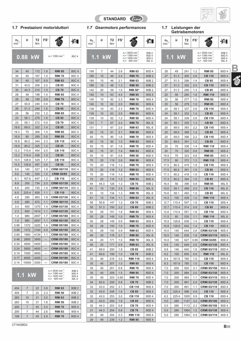
CT16IGBD2 B35
1.7 Gearmotors performances 1.7 Leistungen derGetriebemotoren
1.7 Prestazioni motoriduttori
0.88 kW n1= 1350 min-180C 4 1.1 kW
n1= 2830 min-1
n1= 1390 min-1
n1= 1400 min-1
n1= 920 min-1
80B 280D 490S 490L 6
n2
min-1
ir T2Nm
FS’ n2
min-1
ir T2Nm
FS’ n2
min-1
ir T2Nm
FS’
34 40 172 1.8 RMI 85 80C 4
34 40 167 1.0 RMI 70 80C 4
34 40 167 0.9 RMI 63 80C 4
31 43.0 206 2.0 CB 85 80C 4
30 44.3 210 1.0 CB 70 80C 4
28 49 198 1.4 RMI 85 80C 4
28 49 195 0.9 RMI 70 80C 4
27 50.8 240 0.9 CB 70 80C 4
26 51.3 246 1.6 CB 85 80C 4
24 56 230 1.2 RMI 85 80C 4
23 59.1 276 1.6 CB 85 80C 4
23 59.1 272 0.9 CB 70 80C 4
19.6 69.0 322 1.4 CB 85 80C 4
19.3 70 266 1.0 RMI 85 80C 4
16.9 80 289 0.8 RMI 85 80C 4
16.8 80.2 344 2.3 CB 110 80C 4
16.8 80.2 325 1.2 CB 85 80C 4
12.2 110.4 454 2.0 CB 110 80C 4
12.2 110.4 426 1.0 CB 85 80C 4
10.5 128.8 529 1.7 CB 110 80C 4
10.5 128.8 497 0.9 CB 85 80C 4
9.6 140 527 1.9 CRMI 50/110 80C 4
9.6 140 520 1.0 CRMI 50/85 80C 4
8.1 167.6 647 1.2 CB 110 80C 4
6.8 200 734 2.5 CRMI 63/130 80C 4
6.8 200 725 1.4 CRMI 50/110 80C 4
6.0 225.4 828 1.1 CB 110 80C 4
4.8 280 883 1.8 CRMI 63/130 80C 4
4.8 280 872 1.1 CRMI 50/110 80C 4
3.4 400 1270 1.4 CRMI 63/130 80C 4
2.3 600 1614 1.1 CRMI 63/130 80C 4
1.4 980 2697 1.7 CRMI 85/180 80C 4
1.4 980 2697 1.1 CRMI 85/150 80C 4
0.98 1372 3220 1.4 CRMI 85/180 80C 4
0.98 1372 3164 0.9 CRMI 85/150 80C 4
0.69 1960 4124 1.1 CRMI 85/180 80C 4
0.48 2800 3900 — CRMI 85/180 80C 4
0.34 4000 4400 — CRMI 85/180 80C 4
0.24 5600 4600 — CRMI 85/180 80C 4
0.19 7000 4600 — CRMI 85/180 80C 4
0.17 8000 4200 — CRMI 85/180 80C 4
0.14 10000 3300 — CRMI 85/180 80C 4
1.1 kWn1= 2830 min-1
n1= 1390 min-1
n1= 1400 min-1
n1= 920 min-1
80B 280D 490S 490L 6
100101101
100101101
101110110
101110110
111101100
1.1 kWn1= 2830 min-1
n1= 1390 min-1
n1= 1400 min-1
n1= 920 min-1
80B 280D 490S 490L 6
404 7 22 3.8 RMI 63 80B 2
404 7 22 2.3 RMI 50 80B 2
283 10 31 3.0 RMI 63 80B 2
283 10 31 1.8 RMI 50 80B 2
200 7 45 3.0 RMI 70 90S 4
200 7 44 2.6 RMI 63 90S 4
199 7 45 2.9 RMI 70 80D 4
B199 7 44 2.6 RMI 63 80D 4
189 15 46 2.4 RMI 70 80B 2
189 15 46 2.1 RMI 63 80B 2
189 15 46 1.3 RMI 50 80B 2
142 20 59 1.0 RMI 50* 80B 2
140 10 63 4.4 RMI 85 90S 4
140 10 62 2.3 RMI 70 90S 4
140 10 62 2.0 RMI 63 90S 4
139 10 63 2.3 RMI 70 80D 4
139 10 63 2.0 RMI 63 80D 4
139 10 62 1.2 RMI 50 80D 4
131 7 67 2.4 RMI 70 90L 6
131 7 67 2.0 RMI 63 90L 6
93 15 91 3.1 RMI 85 90S 4
93 15 90 1.6 RMI 70 90S 4
93 15 90 1.5 RMI 63 90S 4
93 15 91 1.6 RMI 70 80D 4
93 15 91 1.4 RMI 63 80D 4
93 15 91 0.8 RMI 50 80D 4
70 20 119 2.6 RMI 85 90S 4
70 20 116 1.3 RMI 70 90S 4
70 20 116 1.2 RMI 63 90S 4
70 20 116 1.3 RMI 70 80D 4
70 20 116 1.2 RMI 63 80D 4
64 44.3 128 1.3 CB 70 80B 2
61 15 135 2.5 RMI 85 90L 6
61 15 134 1.3 RMI 70 90L 6
61 15 134 1.1 RMI 63 90L 6
56 50.8 147 1.2 CB 70 80B 2
55 51.3 150 2.2 CB 85 80B 2
50 28 151 1.8 RMI 85 90S 4
50 28 149 1.0 RMI 70 90S 4
50 28 149 0.9 RMI 63 90S 4
50 28 150 1.0 RMI 70 80D 4
50 28 150 0.9 RMI 63 80D 4
46 20 176 2.1 RMI 85 90L 6
46 20 171 1.0 RMI 70 90L 6
46 20 171 0.9 RMI 63 90L 6
41 69.0 200 1.9 CB 85 80B 2
41 69.6 199 1.0 CB 70 80B 2
35 40 216 3.0 RMI 110 90S 4
35 40 207 1.5 RMI 85 90S 4
35 40 201 0.8 RMI 70 90S 4
35 40 209 1.5 RMI 85 80D 4
35 40 203 0.80 RMI 70 80D 4
34 82.6 208 0.8 CB 70 80B 2
33 43.0 252 3.1 CB 110 90S 4
33 43.0 248 1.6 CB 85 90S 4
32 43.0 253 3.0 CB 110 80D 4
32 43.0 250 1.6 CB 85 80D 4
32 44.3 253 0.8 CB 70 90S 4
31 44.3 254 0.8 CB 70 80D 4
29 49 254 2.3 RMI 110 90S 4
29 49 239 1.2 RMI 85 90S 4
28 49 241 1.2 RMI 85 80D 4
27 51.3 300 2.6 CB 110 90S 4
27 51.3 296 1.4 CB 85 90S 4
27 51.3 302 2.5 CB 110 80D 4
27 51.3 299 1.3 CB 85 80D 4
25 56 290 1.6 RMI 110 90S 4
25 56 277 1.0 RMI 85 90S 4
25 56 279 1.0 RMI 85 80D 4
24 59.1 337 2.6 CB 110 90S 4
24 59.1 333 1.4 CB 85 90S 4
24 59.1 339 2.6 CB 110 80D 4
24 59.1 335 1.3 CB 85 80D 4
20 69.0 393 2.2 CB 110 90S 4
20 69.0 388 1.2 CB 85 90S 4
20 69.0 396 2.2 CB 110 80D 4
20 69.0 391 1.2 CB 85 80D 4
20 70 336 1.4 RMI 110 90S 4
20 70 320 0.8 RMI 85 90S 4
19.9 70 323 0.8 RMI 85 80D 4
17.5 80 372 1.3 RMI 110 90S 4
17.5 80.2 415 1.9 CB 110 90S 4
17.5 80.2 391 1.0 CB 85 90S 4
17.3 80.2 418 1.9 CB 110 80D 4
17.3 80.2 394 1.0 CB 85 80D 4
16.4 56 396 0.8 RMI 85 90L 6
15.6 59.1 499 2.0 CB 110 90L 6
15.6 59.1 493 1.0 CB 85 90L 6
14.0 100 428 1.0 RMI 110 90S 4
12.7 110.4 547 1.6 CB 110 90S 4
12.7 110.4 514 0.8 CB 85 90S 4
12.6 110.4 551 1.6 CB 110 80D 4
11.5 80 530 1.1 RMI 110 90L 6
10.9 128.8 638 1.4 CB 110 90S 4
10.8 128.8 642 1.4 CB 110 80D 4
10.0 140 644 2.6 CRMI 63/130 90S 4
10.0 140 635 1.6 CRMI 63/110 90S 4
10.0 140 627 0.80 CRMI 63/85 90S 4
9.9 140 649 2.6 CRMI 63/130 80D 4
9.9 140 640 1.6 CRMI 63/110 80D 4
9.2 100 605 0.8 RMI 110 90L 6
8.4 167.6 780 1.0 CB 110 90S 4
8.3 167.6 785 1.0 CB 110 80D 4
7.0 200 920 3.1 CRMI 85/150 90S 4
7.0 200 884 2.0 CRMI 63/130 90S 4
7.0 200 884 1.1 CRMI 63/110 90S 4
7.0 200 891 2.0 CRMI 63/130 80D 4
7.0 200 891 1.1 CRMI 63/110 80D 4
6.2 225.4 998 0.9 CB 110 90S 4
6.2 225.4 1005 0.9 CB 110 80D 4
5.0 280 1147 3.2 CRMI 85/180 90S 4
5.0 280 1112 2.3 CRMI 85/150 90S 4
5.0 280 1064 1.5 CRMI 63/130 90S 4
5.0 280 1064 0.9 CRMI 63/110 90S 4
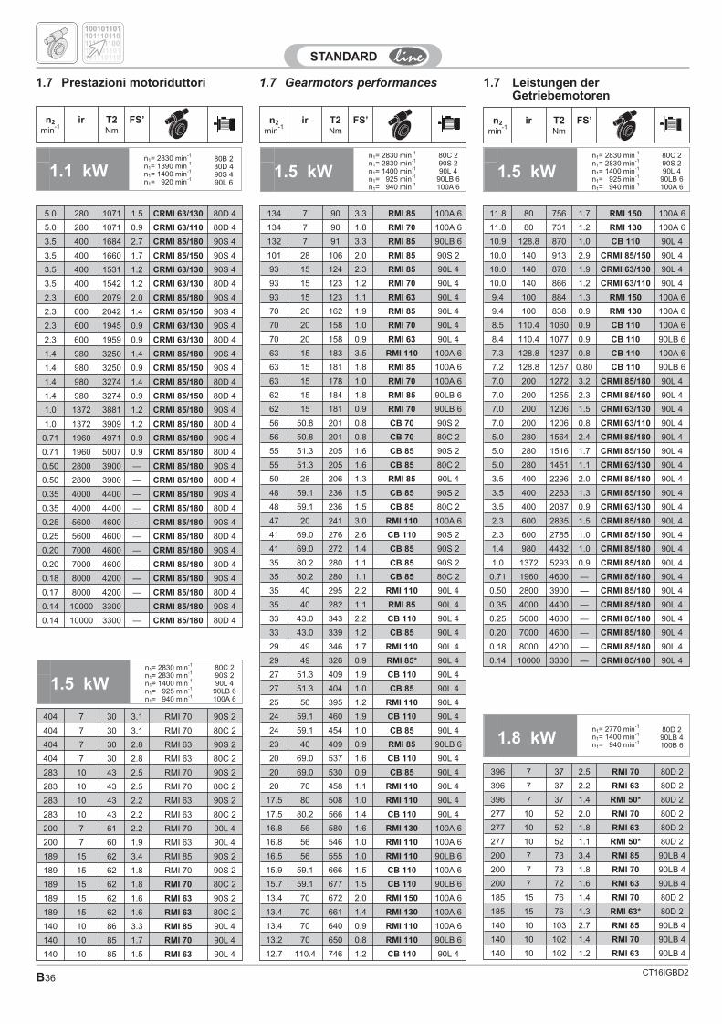
CT16IGBD2B36
1.7 Gearmotors performances 1.7 Leistungen derGetriebemotoren
1.7 Prestazioni motoriduttori
1.5 kWn1= 2830 min-1
n1= 2830 min-1
n1= 1400 min-1
n1= 925 min-1
n1= 940 min-1
80C 290S 290L 4
90LB 6100A 6
1.5 kWn1= 2830 min-1
n1= 2830 min-1
n1= 1400 min-1
n1= 925 min-1
n1= 940 min-1
80C 290S 290L 4
90LB 6100A 6
n2
min-1
ir T2Nm
FS’ n2
min-1
ir T2Nm
FS’ n2
min-1
ir T2Nm
FS’
1.1 kWn1= 2830 min-1
n1= 1390 min-1
n1= 1400 min-1
n1= 920 min-1
80B 280D 490S 490L 6
5.0 280 1071 1.5 CRMI 63/130 80D 4
5.0 280 1071 0.9 CRMI 63/110 80D 4
3.5 400 1684 2.7 CRMI 85/180 90S 4
3.5 400 1660 1.7 CRMI 85/150 90S 4
3.5 400 1531 1.2 CRMI 63/130 90S 4
3.5 400 1542 1.2 CRMI 63/130 80D 4
2.3 600 2079 2.0 CRMI 85/180 90S 4
2.3 600 2042 1.4 CRMI 85/150 90S 4
2.3 600 1945 0.9 CRMI 63/130 90S 4
2.3 600 1959 0.9 CRMI 63/130 80D 4
1.4 980 3250 1.4 CRMI 85/180 90S 4
1.4 980 3250 0.9 CRMI 85/150 90S 4
1.4 980 3274 1.4 CRMI 85/180 80D 4
1.4 980 3274 0.9 CRMI 85/150 80D 4
1.0 1372 3881 1.2 CRMI 85/180 90S 4
1.0 1372 3909 1.2 CRMI 85/180 80D 4
0.71 1960 4971 0.9 CRMI 85/180 90S 4
0.71 1960 5007 0.9 CRMI 85/180 80D 4
0.50 2800 3900 — CRMI 85/180 90S 4
0.50 2800 3900 — CRMI 85/180 80D 4
0.35 4000 4400 — CRMI 85/180 90S 4
0.35 4000 4400 — CRMI 85/180 80D 4
0.25 5600 4600 — CRMI 85/180 90S 4
0.25 5600 4600 — CRMI 85/180 80D 4
0.20 7000 4600 — CRMI 85/180 90S 4
0.20 7000 4600 — CRMI 85/180 80D 4
0.18 8000 4200 — CRMI 85/180 90S 4
0.17 8000 4200 — CRMI 85/180 80D 4
0.14 10000 3300 — CRMI 85/180 90S 4
0.14 10000 3300 — CRMI 85/180 80D 4
1.5 kWn1= 2830 min-1
n1= 2830 min-1
n1= 1400 min-1
n1= 925 min-1
n1= 940 min-1
80C 290S 290L 4
90LB 6100A 6
404 7 30 3.1 RMI 70 90S 2
404 7 30 3.1 RMI 70 80C 2
404 7 30 2.8 RMI 63 90S 2
404 7 30 2.8 RMI 63 80C 2
283 10 43 2.5 RMI 70 90S 2
283 10 43 2.5 RMI 70 80C 2
283 10 43 2.2 RMI 63 90S 2
283 10 43 2.2 RMI 63 80C 2
200 7 61 2.2 RMI 70 90L 4
200 7 60 1.9 RMI 63 90L 4
189 15 62 3.4 RMI 85 90S 2
189 15 62 1.8 RMI 70 90S 2
189 15 62 1.8 RMI 70 80C 2
189 15 62 1.6 RMI 63 90S 2
189 15 62 1.6 RMI 63 80C 2
140 10 86 3.3 RMI 85 90L 4
140 10 85 1.7 RMI 70 90L 4
140 10 85 1.5 RMI 63 90L 4
134 7 90 3.3 RMI 85 100A 6
134 7 90 1.8 RMI 70 100A 6
132 7 91 3.3 RMI 85 90LB 6
101 28 106 2.0 RMI 85 90S 2
93 15 124 2.3 RMI 85 90L 4
93 15 123 1.2 RMI 70 90L 4
93 15 123 1.1 RMI 63 90L 4
70 20 162 1.9 RMI 85 90L 4
70 20 158 1.0 RMI 70 90L 4
70 20 158 0.9 RMI 63 90L 4
63 15 183 3.5 RMI 110 100A 6
63 15 181 1.8 RMI 85 100A 6
63 15 178 1.0 RMI 70 100A 6
62 15 184 1.8 RMI 85 90LB 6
62 15 181 0.9 RMI 70 90LB 6
56 50.8 201 0.8 CB 70 90S 2
56 50.8 201 0.8 CB 70 80C 2
55 51.3 205 1.6 CB 85 90S 2
55 51.3 205 1.6 CB 85 80C 2
50 28 206 1.3 RMI 85 90L 4
48 59.1 236 1.5 CB 85 90S 2
48 59.1 236 1.5 CB 85 80C 2
47 20 241 3.0 RMI 110 100A 6
41 69.0 276 2.6 CB 110 90S 2
41 69.0 272 1.4 CB 85 90S 2
35 80.2 280 1.1 CB 85 90S 2
35 80.2 280 1.1 CB 85 80C 2
35 40 295 2.2 RMI 110 90L 4
35 40 282 1.1 RMI 85 90L 4
33 43.0 343 2.2 CB 110 90L 4
33 43.0 339 1.2 CB 85 90L 4
29 49 346 1.7 RMI 110 90L 4
29 49 326 0.9 RMI 85* 90L 4
27 51.3 409 1.9 CB 110 90L 4
27 51.3 404 1.0 CB 85 90L 4
25 56 395 1.2 RMI 110 90L 4
24 59.1 460 1.9 CB 110 90L 4
24 59.1 454 1.0 CB 85 90L 4
23 40 409 0.9 RMI 85 90LB 6
20 69.0 537 1.6 CB 110 90L 4
20 69.0 530 0.9 CB 85 90L 4
20 70 458 1.1 RMI 110 90L 4
17.5 80 508 1.0 RMI 110 90L 4
17.5 80.2 566 1.4 CB 110 90L 4
16.8 56 580 1.6 RMI 130 100A 6
16.8 56 546 1.0 RMI 110 100A 6
16.5 56 555 1.0 RMI 110 90LB 6
15.9 59.1 666 1.5 CB 110 100A 6
15.7 59.1 677 1.5 CB 110 90LB 6
13.4 70 672 2.0 RMI 150 100A 6
13.4 70 661 1.4 RMI 130 100A 6
13.4 70 640 0.9 RMI 110 100A 6
13.2 70 650 0.8 RMI 110 90LB 6
12.7 110.4 746 1.2 CB 110 90L 4
11.8 80 756 1.7 RMI 150 100A 6
11.8 80 731 1.2 RMI 130 100A 6
10.9 128.8 870 1.0 CB 110 90L 4
10.0 140 913 2.9 CRMI 85/150 90L 4
10.0 140 878 1.9 CRMI 63/130 90L 4
10.0 140 866 1.2 CRMI 63/110 90L 4
9.4 100 884 1.3 RMI 150 100A 6
9.4 100 838 0.9 RMI 130 100A 6
8.5 110.4 1060 0.9 CB 110 100A 6
8.4 110.4 1077 0.9 CB 110 90LB 6
7.3 128.8 1237 0.8 CB 110 100A 6
7.2 128.8 1257 0.80 CB 110 90LB 6
7.0 200 1272 3.2 CRMI 85/180 90L 4
7.0 200 1255 2.3 CRMI 85/150 90L 4
7.0 200 1206 1.5 CRMI 63/130 90L 4
7.0 200 1206 0.8 CRMI 63/110 90L 4
5.0 280 1564 2.4 CRMI 85/180 90L 4
5.0 280 1516 1.7 CRMI 85/150 90L 4
5.0 280 1451 1.1 CRMI 63/130 90L 4
3.5 400 2296 2.0 CRMI 85/180 90L 4
3.5 400 2263 1.3 CRMI 85/150 90L 4
3.5 400 2087 0.9 CRMI 63/130 90L 4
2.3 600 2835 1.5 CRMI 85/180 90L 4
2.3 600 2785 1.0 CRMI 85/150 90L 4
1.4 980 4432 1.0 CRMI 85/180 90L 4
1.0 1372 5293 0.9 CRMI 85/180 90L 4
0.71 1960 4600 — CRMI 85/180 90L 4
0.50 2800 3900 — CRMI 85/180 90L 4
0.35 4000 4400 — CRMI 85/180 90L 4
0.25 5600 4600 — CRMI 85/180 90L 4
0.20 7000 4600 — CRMI 85/180 90L 4
0.18 8000 4200 — CRMI 85/180 90L 4
0.14 10000 3300 — CRMI 85/180 90L 4
1.8 kWn1= 2770 min-1
n1= 1400 min-1
n1= 940 min-1
80D 290LB 4100B 6
396 7 37 2.5 RMI 70 80D 2
396 7 37 2.2 RMI 63 80D 2
396 7 37 1.4 RMI 50* 80D 2
277 10 52 2.0 RMI 70 80D 2
277 10 52 1.8 RMI 63 80D 2
277 10 52 1.1 RMI 50* 80D 2
200 7 73 3.4 RMI 85 90LB 4
200 7 73 1.8 RMI 70 90LB 4
200 7 72 1.6 RMI 63 90LB 4
185 15 76 1.4 RMI 70 80D 2
185 15 76 1.3 RMI 63* 80D 2
140 10 103 2.7 RMI 85 90LB 4
140 10 102 1.4 RMI 70 90LB 4
140 10 102 1.2 RMI 63 90LB 4
100101101
100101101
101110110
101110110
111101100
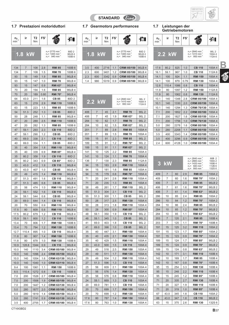
CT16IGBD2 B37
1.7 Gearmotors performances 1.7 Leistungen derGetriebemotoren
1.7 Prestazioni motoriduttori
1.8 kWn1= 2770 min-1
n1= 1400 min-1
n1= 940 min-1
80D 290LB 4100B 6
n2
min-1
ir T2Nm
FS’ n2
min-1
ir T2Nm
FS’ n2
min-1
ir T2Nm
FS’
100101101
100101101
101110110
101110110
111101100
134 7 108 2.8 RMI 85 100B 6
134 7 108 1.5 RMI 70 100B 6
93 15 149 1.9 RMI 85 90LB 4
93 15 147 1.0 RMI 70 90LB 4
93 15 147 0.9 RMI 63* 90LB 4
70 20 194 1.6 RMI 85 90LB 4
70 20 189 0.80 RMI 70* 90LB 4
64 43.0 211 1.6 CB 85 80D 2
63 15 219 2.9 RMI 110 100B 6
63 15 223 1.5 RMI 85 100B 6
54 51.3 252 1.3 CB 85 80D 2
50 28 248 1.1 RMI 85 90LB 4
47 20 289 2.5 RMI 110 100B 6
47 20 282 1.3 RMI 85 100B 6
47 59.1 293 2.3 CB 110 80D 2
47 59.1 290 1.2 CB 85 80D 2
40 69.0 338 2.1 CB 110 80D 2
40 69.0 334 1.1 CB 85 80D 2
35 40 354 1.8 RMI 110 90LB 4
35 40 339 0.9 RMI 85* 90LB 4
35 80.2 358 1.9 CB 110 80D 2
35 80.2 343 0.9 CB 85* 80D 2
33 43.0 412 1.9 CB 110 90LB 4
33 43.0 407 1.0 CB 85 90LB 4
29 49 415 1.4 RMI 110 90LB 4
27 51.3 491 1.6 CB 110 90LB 4
27 51.3 485 0.8 CB 85 90LB 4
25 56 474 1.0 RMI 110 90LB 4
24 59.1 552 1.6 CB 110 90LB 4
24 59.1 544 0.8 CB 85 90LB 4
20 69.0 644 1.4 CB 110 90LB 4
20 70 550 0.9 RMI 110 90LB 4
17.5 80 609 0.8 RMI 110 90LB 4
17.5 80.2 679 1.2 CB 110 90LB 4
15.9 59.1 800 1.2 CB 110 100B 6
13.4 70 806 1.7 RMI 150 100B 6
13.4 70 794 1.2 RMI 130 100B 6
12.7 110.4 895 1.0 CB 110 90LB 4
11.8 80 907 1.4 RMI 150 100B 6
11.8 80 878 1.0 RMI 130 100B 6
10.9 128.8 1044 0.9 CB 110 90LB 4
10.0 140 1110 3.4 CRMI 85/180 90LB 4
10.0 140 1096 2.4 CRMI 85/150 90LB 4
10.0 140 1054 1.6 CRMI 63/130 90LB 4
10.0 140 1040 1.0 CRMI 63/110 90LB 4
9.4 100 1061 1.1 RMI 150 100B 6
8.5 110.4 1272 0.8 CB 110 100B 6
7.0 200 1526 2.7 CRMI 85/180 90LB 4
7.0 200 1506 1.9 CRMI 85/150 90LB 4
7.0 200 1447 1.2 CRMI 63/130 90LB 4
5.0 280 1877 2.0 CRMI 85/180 90LB 4
5.0 280 1819 1.4 CRMI 85/150 90LB 4
5.0 280 1741 0.9 CRMI 63/130 90LB 4
3.5 400 2755 1.7 CRMI 85/180 90LB 4
3.5 400 2716 1.1 CRMI 85/150 90LB 4
2.3 600 3401 1.2 CRMI 85/180 90LB 4
2.3 600 3342 0.9 CRMI 85/150 90LB 4
1.4 980 5319 0.9 CRMI 85/180 90LB 4
2.2 kWn1= 2840 min-1
n1= 1410 min-1
n1= 950 min-1
90L 2100A 4112A 6
2.2 kWn1= 2840 min-1
n1= 1410 min-1
n1= 950 min-1
90L 2100A 4112A 6
1.8 kWn1= 2770 min-1
n1= 1400 min-1
n1= 940 min-1
80D 290LB 4100B 6
406 7 45 2.1 RMI 70 90L 2
406 7 45 1.9 RMI 63* 90L 2
284 10 62 1.7 RMI 70 90L 2
284 10 62 1.5 RMI 63* 90L 2
201 7 89 2.8 RMI 85 100A 4
201 7 89 1.5 RMI 70 100A 4
189 15 91 2.3 RMI 85 90L 2
189 15 91 1.2 RMI 70* 90L 2
189 15 91 1.1 RMI 63* 90L 2
141 10 125 2.2 RMI 85 100A 4
141 10 124 1.1 RMI 70 100A 4
136 7 130 2.3 RMI 85 112A 6
94 15 183 2.9 RMI 110 100A 4
94 15 181 1.6 RMI 85 100A 4
94 15 179 0.8 RMI 70* 100A 4
71 20 241 2.6 RMI 110 100A 4
71 20 235 1.3 RMI 85 100A 4
58 49 261 1.7 RMI 110 90L 2
55 51.3 304 2.1 CB 110 90L 2
55 51.3 300 1.1 CB 85 90L 2
50 28 317 2.5 RMI 130 100A 4
50 28 313 1.8 RMI 110 100A 4
50 28 300 0.9 RMI 85* 100A 4
48 59.1 350 1.9 CB 110 90L 2
48 59.1 345 1.0 CB 85 90L 2
41 69.0 403 1.8 CB 110 90L 2
41 69.0 398 1.0 CB 85 90L 2
35 40 447 3.1 RMI 150 100A 4
35 40 435 2.1 RMI 130 100A 4
35 40 429 1.5 RMI 110 100A 4
33 43.0 500 1.5 CB 110 100A 4
29 49 518 2.5 RMI 150 100A 4
29 49 511 1.7 RMI 130 100A 4
29 49 504 1.2 RMI 110 100A 4
27 51.3 596 1.3 CB 110 100A 4
25 56 609 2.1 RMI 150 100A 4
25 56 576 1.4 RMI 130 100A 4
25 56 576 0.8 RMI 110 100A 4
24 59.1 669 1.3 CB 110 100A 4
20 69.0 781 1.1 CB 110 100A 4
20 70 699 1.7 RMI 150 100A 4
20 70 699 1.2 RMI 130 100A 4
17.6 80 787 1.4 RMI 150 100A 4
17.6 80 763 1.0 RMI 130 100A 4
17.6 80.2 825 1.0 CB 110 100A 4
16.1 59.1 967 1.0 CB 110 112A 6
14.1 100 924 1.1 RMI 150 100A 4
14.1 100 879 0.79 RMI 130 100A 4
12.8 110.4 1086 0.8 CB 110 100A 4
11.9 80 1097 1.2 RMI 150 112A 6
11.9 80 1062 0.8 RMI 130 112A 6
10.1 140 1348 2.8 CRMI 85/180 100A 4
10.1 140 1330 2.0 CRMI 85/150 100A 4
10.1 140 1294 1.3 CRMI 70/130 100A 4
7.1 200 1852 2.2 CRMI 85/180 100A 4
7.1 200 1827 1.6 CRMI 85/150 100A 4
7.1 200 1756 1.0 CRMI 70/130 100A 4
5.0 280 2278 1.6 CRMI 85/180 100A 4
5.0 280 2208 1.1 CRMI 85/150 100A 4
3.5 400 3343 1.4 CRMI 85/180 100A 4
3.5 400 3296 0.9 CRMI 85/150 100A 4
2.4 600 4128 1.0 CRMI 85/180 100A 4
3 kWn1= 2840 min-1
n1= 2860 min-1
n1= 1420 min-1
n1= 940 min-1
n1= 950 min-1
90B 2100A 2100B 4112B 6132S 6
409 7 60 2.9 RMI 85 100A 2
409 7 60 1.6 RMI 70* 100A 2
406 7 61 2.9 RMI 85 90LB 2
406 7 61 1.6 RMI 70* 90LB 2
406 7 61 1.4 RMI 63* 90LB 2
286 10 85 2.4 RMI 85 100A 2
286 10 84 1.2 RMI 70* 100A 2
284 10 86 2.4 RMI 85 90LB 2
284 10 85 1.2 RMI 70* 90LB 2
284 10 85 1.1 RMI 63* 90LB 2
203 7 120 2.1 RMI 85 100B 4
203 7 120 1.1 RMI 70* 100B 4
191 15 125 3.2 RMI 110 100A 2
191 15 123 1.7 RMI 85* 100A 2
191 15 123 0.9 RMI 70* 100A 2
189 15 124 1.7 RMI 85* 90LB 2
189 15 124 0.9 RMI 70* 90LB 2
189 15 124 0.8 RMI 63* 90LB 2
142 10 171 3.1 RMI 110 100B 4
142 10 169 1.7 RMI 85 100B 4
142 10 167 0.8 RMI 70* 100B 4
95 15 254 3.3 RMI 130 100B 4
95 15 248 2.2 RMI 110 100B 4
95 15 245 1.2 RMI 85* 100B 4
71 20 335 2.7 RMI 130 100B 4
71 20 327 1.9 RMI 110 100B 4
71 20 319 1.0 RMI 85* 100B 4
67 43.0 345 1.8 CB 110 100A 2
66 43.0 347 1.8 CB 110 90LB 2
63 15 375 2.6 RMI 130 132S 6
B
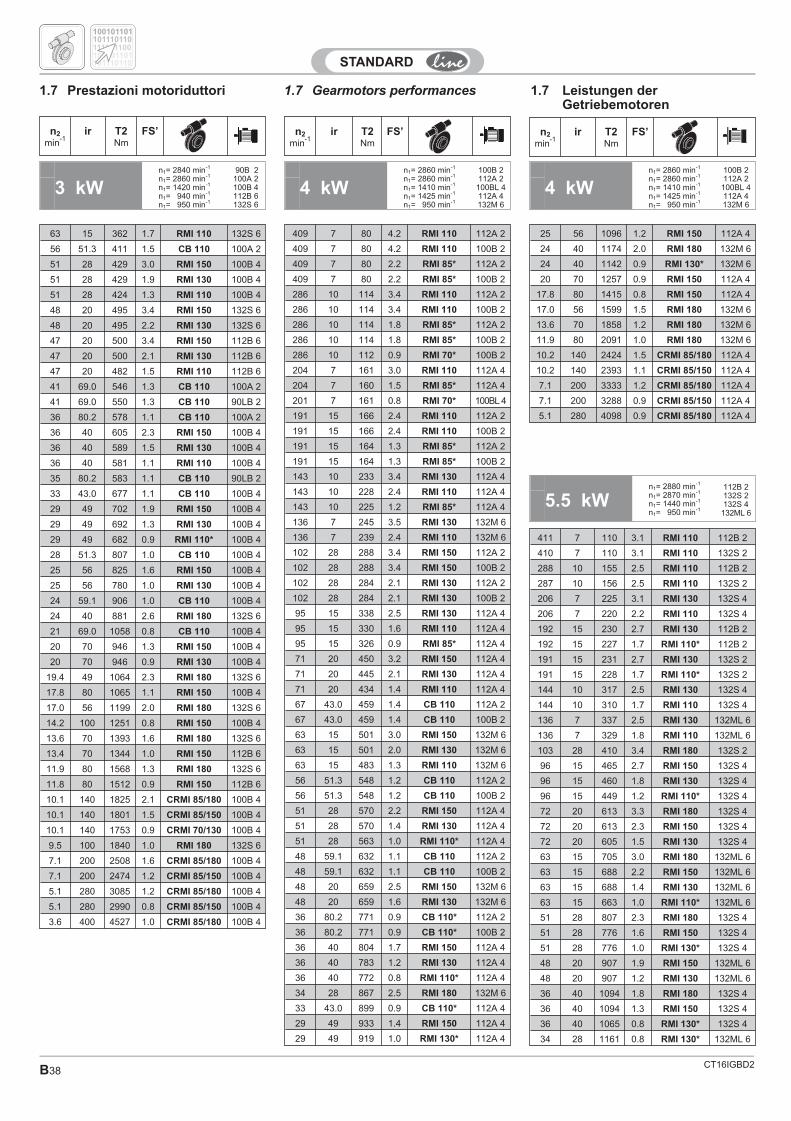
CT16IGBD2B38
1.7 Gearmotors performances 1.7 Leistungen derGetriebemotoren
1.7 Prestazioni motoriduttori
4 kWn1= 2860 min-1
n1= 2860 min-1
n1= 1410 min-1
n1= 1425 min-1
n1= 950 min-1
100B 2112A 2
100BL 4112A 4132M 6
n2
min-1
ir T2Nm
FS’ n2
min-1
ir T2Nm
FS’ n2
min-1
ir T2Nm
FS’
100101101
100101101
101110110
101110110
111101100
3 kWn1= 2840 min-1
n1= 2860 min-1
n1= 1420 min-1
n1= 940 min-1
n1= 950 min-1
90B 2100A 2100B 4112B 6132S 6
63 15 362 1.7 RMI 110 132S 6
56 51.3 411 1.5 CB 110 100A 2
51 28 429 3.0 RMI 150 100B 4
51 28 429 1.9 RMI 130 100B 4
51 28 424 1.3 RMI 110 100B 4
48 20 495 3.4 RMI 150 132S 6
48 20 495 2.2 RMI 130 132S 6
47 20 500 3.4 RMI 150 112B 6
47 20 500 2.1 RMI 130 112B 6
47 20 482 1.5 RMI 110 112B 6
41 69.0 546 1.3 CB 110 100A 2
41 69.0 550 1.3 CB 110 90LB 2
36 80.2 578 1.1 CB 110 100A 2
36 40 605 2.3 RMI 150 100B 4
36 40 589 1.5 RMI 130 100B 4
36 40 581 1.1 RMI 110 100B 4
35 80.2 583 1.1 CB 110 90LB 2
33 43.0 677 1.1 CB 110 100B 4
29 49 702 1.9 RMI 150 100B 4
29 49 692 1.3 RMI 130 100B 4
29 49 682 0.9 RMI 110* 100B 4
28 51.3 807 1.0 CB 110 100B 4
25 56 825 1.6 RMI 150 100B 4
25 56 780 1.0 RMI 130 100B 4
24 59.1 906 1.0 CB 110 100B 4
24 40 881 2.6 RMI 180 132S 6
21 69.0 1058 0.8 CB 110 100B 4
20 70 946 1.3 RMI 150 100B 4
20 70 946 0.9 RMI 130 100B 4
19.4 49 1064 2.3 RMI 180 132S 6
17.8 80 1065 1.1 RMI 150 100B 4
17.0 56 1199 2.0 RMI 180 132S 6
14.2 100 1251 0.8 RMI 150 100B 4
13.6 70 1393 1.6 RMI 180 132S 6
13.4 70 1344 1.0 RMI 150 112B 6
11.9 80 1568 1.3 RMI 180 132S 6
11.8 80 1512 0.9 RMI 150 112B 6
10.1 140 1825 2.1 CRMI 85/180 100B 4
10.1 140 1801 1.5 CRMI 85/150 100B 4
10.1 140 1753 0.9 CRMI 70/130 100B 4
9.5 100 1840 1.0 RMI 180 132S 6
7.1 200 2508 1.6 CRMI 85/180 100B 4
7.1 200 2474 1.2 CRMI 85/150 100B 4
5.1 280 3085 1.2 CRMI 85/180 100B 4
5.1 280 2990 0.8 CRMI 85/150 100B 4
3.6 400 4527 1.0 CRMI 85/180 100B 4
409 7 80 4.2 RMI 110 112A 2
409 7 80 4.2 RMI 110 100B 2
409 7 80 2.2 RMI 85* 112A 2
409 7 80 2.2 RMI 85* 100B 2
286 10 114 3.4 RMI 110 112A 2
286 10 114 3.4 RMI 110 100B 2
286 10 114 1.8 RMI 85* 112A 2
286 10 114 1.8 RMI 85* 100B 2
286 10 112 0.9 RMI 70* 100B 2
204 7 161 3.0 RMI 110 112A 4
204 7 160 1.5 RMI 85* 112A 4
201 7 161 0.8 RMI 70* 100BL 4
191 15 166 2.4 RMI 110 112A 2
191 15 166 2.4 RMI 110 100B 2
191 15 164 1.3 RMI 85* 112A 2
191 15 164 1.3 RMI 85* 100B 2
143 10 233 3.4 RMI 130 112A 4
143 10 228 2.4 RMI 110 112A 4
143 10 225 1.2 RMI 85* 112A 4
136 7 245 3.5 RMI 130 132M 6
136 7 239 2.4 RMI 110 132M 6
102 28 288 3.4 RMI 150 112A 2
102 28 288 3.4 RMI 150 100B 2
102 28 284 2.1 RMI 130 112A 2
102 28 284 2.1 RMI 130 100B 2
95 15 338 2.5 RMI 130 112A 4
95 15 330 1.6 RMI 110 112A 4
95 15 326 0.9 RMI 85* 112A 4
71 20 450 3.2 RMI 150 112A 4
71 20 445 2.1 RMI 130 112A 4
71 20 434 1.4 RMI 110 112A 4
67 43.0 459 1.4 CB 110 112A 2
67 43.0 459 1.4 CB 110 100B 2
63 15 501 3.0 RMI 150 132M 6
63 15 501 2.0 RMI 130 132M 6
63 15 483 1.3 RMI 110 132M 6
56 51.3 548 1.2 CB 110 112A 2
56 51.3 548 1.2 CB 110 100B 2
51 28 570 2.2 RMI 150 112A 4
51 28 570 1.4 RMI 130 112A 4
51 28 563 1.0 RMI 110* 112A 4
48 59.1 632 1.1 CB 110 112A 2
48 59.1 632 1.1 CB 110 100B 2
48 20 659 2.5 RMI 150 132M 6
48 20 659 1.6 RMI 130 132M 6
36 80.2 771 0.9 CB 110* 112A 2
36 80.2 771 0.9 CB 110* 100B 2
36 40 804 1.7 RMI 150 112A 4
36 40 783 1.2 RMI 130 112A 4
36 40 772 0.8 RMI 110* 112A 4
34 28 867 2.5 RMI 180 132M 6
33 43.0 899 0.9 CB 110* 112A 4
29 49 933 1.4 RMI 150 112A 4
29 49 919 1.0 RMI 130* 112A 4
25 56 1096 1.2 RMI 150 112A 4
24 40 1174 2.0 RMI 180 132M 6
24 40 1142 0.9 RMI 130* 132M 6
20 70 1257 0.9 RMI 150 112A 4
17.8 80 1415 0.8 RMI 150 112A 4
17.0 56 1599 1.5 RMI 180 132M 6
13.6 70 1858 1.2 RMI 180 132M 6
11.9 80 2091 1.0 RMI 180 132M 6
10.2 140 2424 1.5 CRMI 85/180 112A 4
10.2 140 2393 1.1 CRMI 85/150 112A 4
7.1 200 3333 1.2 CRMI 85/180 112A 4
7.1 200 3288 0.9 CRMI 85/150 112A 4
5.1 280 4098 0.9 CRMI 85/180 112A 4
4 kWn1= 2860 min-1
n1= 2860 min-1
n1= 1410 min-1
n1= 1425 min-1
n1= 950 min-1
100B 2112A 2
100BL 4112A 4132M 6
5.5 kWn1= 2880 min-1
n1= 2870 min-1
n1= 1440 min-1
n1= 950 min-1
112B 2132S 2132S 4
132ML 6
411 7 110 3.1 RMI 110 112B 2
410 7 110 3.1 RMI 110 132S 2
288 10 155 2.5 RMI 110 112B 2
287 10 156 2.5 RMI 110 132S 2
206 7 225 3.1 RMI 130 132S 4
206 7 220 2.2 RMI 110 132S 4
192 15 230 2.7 RMI 130 112B 2
192 15 227 1.7 RMI 110* 112B 2
191 15 231 2.7 RMI 130 132S 2
191 15 228 1.7 RMI 110* 132S 2
144 10 317 2.5 RMI 130 132S 4
144 10 310 1.7 RMI 110 132S 4
136 7 337 2.5 RMI 130 132ML 6
136 7 329 1.8 RMI 110 132ML 6
103 28 410 3.4 RMI 180 132S 2
96 15 465 2.7 RMI 150 132S 4
96 15 460 1.8 RMI 130 132S 4
96 15 449 1.2 RMI 110* 132S 4
72 20 613 3.3 RMI 180 132S 4
72 20 613 2.3 RMI 150 132S 4
72 20 605 1.5 RMI 130 132S 4
63 15 705 3.0 RMI 180 132ML 6
63 15 688 2.2 RMI 150 132ML 6
63 15 688 1.4 RMI 130 132ML 6
63 15 663 1.0 RMI 110* 132ML 6
51 28 807 2.3 RMI 180 132S 4
51 28 776 1.6 RMI 150 132S 4
51 28 776 1.0 RMI 130* 132S 4
48 20 907 1.9 RMI 150 132ML 6
48 20 907 1.2 RMI 130 132ML 6
36 40 1094 1.8 RMI 180 132S 4
36 40 1094 1.3 RMI 150 132S 4
36 40 1065 0.8 RMI 130* 132S 4
34 28 1161 0.8 RMI 130* 132ML 6
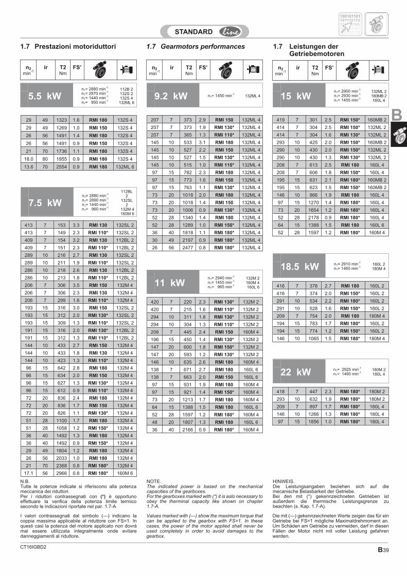
CT16IGBD2 B39
1.7 Gearmotors performances 1.7 Leistungen derGetriebemotoren
1.7 Prestazioni motoriduttori
29 49 1323 1.6 RMI 180 132S 4
29 49 1269 1.0 RMI 150 132S 4
26 56 1491 1.4 RMI 180 132S 4
26 56 1491 0.9 RMI 150 132S 4
21 70 1736 1.1 RMI 180 132S 4
18.0 80 1955 0.9 RMI 180 132S 4
13.6 70 2554 0.9 RMI 180 132ML 6
413 7 153 3.3 RMI 130 132SL 2
413 7 149 2.3 RMI 110* 132SL 2
409 7 154 3.2 RMI 130 112BL 2
409 7 151 2.3 RMI 110* 112BL 2
289 10 216 2.7 RMI 130 132SL 2
289 10 211 1.9 RMI 110* 132SL 2
286 10 218 2.6 RMI 130 112BL 2
286 10 213 1.8 RMI 110* 112BL 2
206 7 306 3.5 RMI 150 132M 4
206 7 306 2.3 RMI 130 132M 4
206 7 299 1.6 RMI 110* 132M 4
193 15 316 3.0 RMI 150 132SL 2
193 15 312 2.0 RMI 130* 132SL 2
193 15 309 1.3 RMI 110* 132SL 2
191 15 316 2.0 RMI 130* 112BL 2
191 15 312 1.3 RMI 110* 112BL 2
144 10 433 2.7 RMI 150 132M 4
144 10 433 1.8 RMI 130 132M 4
144 10 423 1.3 RMI 110* 132M 4
96 15 642 2.8 RMI 180 132M 4
96 15 634 2.0 RMI 150 132M 4
96 15 627 1.3 RMI 130* 132M 4
96 15 612 0.9 RMI 110* 132M 4
72 20 836 2.4 RMI 180 132M 4
72 20 836 1.7 RMI 150 132M 4
72 20 826 1.1 RMI 130* 132M 4
51 28 1100 1.7 RMI 180 132M 4
51 28 1058 1.2 RMI 150* 132M 4
36 40 1492 1.3 RMI 180 132M 4
36 40 1492 0.9 RMI 150* 132M 4
29 49 1804 1.2 RMI 180 132M 4
26 56 2033 1.0 RMI 180 132M 4
21 70 2368 0.8 RMI 180* 132M 4
17.1 56 2966 0.8 RMI 180* 160M 6
n2
min-1
ir T2Nm
FS’ n2
min-1
ir T2Nm
FS’ n2
min-1
ir T2Nm
FS’
100101101
100101101
101110110
101110110
111101100
5.5 kWn1= 2880 min-1
n1= 2870 min-1
n1= 1440 min-1
n1= 950 min-1
112B 2132S 2132S 4
132ML 69.2 kW n1= 1450 min-1
132ML 4
7.5 kWn1= 2880 min-1
n1= 2890 min-1
n1= 1440 min-1
n1= 960 min-1
112BL2
132SL2
132M 4160M 6
207 7 373 2.9 RMI 150 132ML 4
207 7 373 1.9 RMI 130* 132ML 4
207 7 365 1.3 RMI 110* 132ML 4
145 10 533 3.1 RMI 180 132ML 4
145 10 527 2.2 RMI 150 132ML 4
145 10 527 1.5 RMI 130* 132ML 4
145 10 515 1.0 RMI 110* 132ML 4
97 15 782 2.3 RMI 180 132ML 4
97 15 773 1.6 RMI 150 132ML 4
97 15 763 1.1 RMI 130* 132ML 4
73 20 1018 2.0 RMI 180 132ML 4
73 20 1018 1.4 RMI 150 132ML 4
73 20 1006 0.9 RMI 130* 132ML 4
52 28 1340 1.4 RMI 180 132ML 4
52 28 1289 1.0 RMI 150* 132ML 4
36 40 1818 1.1 RMI 180* 132ML 4
30 49 2197 0.9 RMI 180* 132ML 4
26 56 2477 0.8 RMI 180* 132ML 4
419 7 301 2.5 RMI 150* 160MB 2
414 7 304 2.5 RMI 150* 132ML 2
414 7 304 1.6 RMI 130* 132ML 2
293 10 425 2.0 RMI 150* 160MB 2
290 10 430 2.0 RMI 150* 132ML 2
290 10 430 1.3 RMI 130* 132ML 2
208 7 613 2.5 RMI 180 160L 4
208 7 606 1.8 RMI 150* 160L 4
195 15 631 2.1 RMI 180* 160MB 2
195 15 623 1.5 RMI 150* 160MB 2
146 10 866 1.9 RMI 180 160L 4
97 15 1270 1.4 RMI 180* 160L 4
73 20 1654 1.2 RMI 180* 160L 4
52 28 2178 0.9 RMI 180* 160L 4
64 15 1388 1.5 RMI 180 160L 6
52 28 1597 1.2 RMI 180* 160M 4
15 kWn1= 2900 min-1
n1= 2930 min-1
n1= 1455 min-1
132ML 2160MB 2160L 4
18.5 kW n1= 2910 min-1
n1= 1460 min-1160L 2180M 4
416 7 378 2.7 RMI 180 160L 2
416 7 374 2.0 RMI 150* 160L 2
291 10 534 2.2 RMI 180* 160L 2
291 10 528 1.6 RMI 150* 160L 2
209 7 754 2.0 RMI 180 180M 4
194 15 783 1.7 RMI 180* 160L 2
194 15 774 1.2 RMI 150* 160L 2
146 10 1065 1.5 RMI 180* 180M 4
22 kW n1= 2925 min-1
n1= 1460 min-1180M 2180L 4
418 7 447 2.3 RMI 180* 180M 2
293 10 632 1.9 RMI 180* 180M 2
209 7 897 1.7 RMI 180* 180L 4
146 10 1266 1.3 RMI 180* 180L 4
97 15 1856 1.0 RMI 180* 180L 4
11 kWn1= 2940 min-1
n1= 1455 min-1
n1= 965 min-1
132M 2160M 4160L 6
420 7 220 2.3 RMI 130* 132M 2
420 7 215 1.6 RMI 110* 132M 2
294 10 311 1.8 RMI 130* 132M 2
294 10 304 1.3 RMI 110* 132M 2
208 7 445 2.4 RMI 150 160M 4
196 15 450 1.4 RMI 130* 132M 2
147 20 600 1.8 RMI 150* 132M 2
147 20 593 1.2 RMI 130* 132M 2
146 10 635 2.6 RMI 180 160M 4
138 7 671 2.7 RMI 180 160L 6
138 7 663 2.0 RMI 150 160L 6
97 15 931 1.9 RMI 180 160M 4
97 15 921 1.4 RMI 150* 160M 4
73 20 1213 1.7 RMI 180 160M 4
64 15 1388 1.5 RMI 180 160L 6
52 28 1597 1.2 RMI 180* 160M 4
48 20 1807 1.3 RMI 180 160L 6
36 40 2166 0.9 RMI 180* 160M 4
N.B.Tutte le potenze indicate si riferiscono alla potenzameccanica dei riduttori.Per i riduttori contrassegnati con (*) è opportunoeffettuare la verifica della potenza limite termicosecondo le indicazioni riportate nel par. 1.7-A
I valori contrassegnati dal simbolo (—) indicano lacoppia massima applicabile al riduttore con FS=1. Inquesti casi la potenza del motore applicato non dovràmai essere utilizzata integralmente onde evitaredanneggiamenti al riduttore.
Values marked with (—) show the maximum torque thatcan be applied to the gearbox with FS=1. In thesecases, the power of the motor applied shall never beused completely in order to avoid damages to thegearbox.
Die mit (—) gekennzeichneten Werte zeigen das für einGetriebe bei FS=1 mögliche Maximaldrehmoment an.Um Schäden am Getriebe zu vermeiden, darf in diesenFällen der Motor nicht mit voller Leistung gefahrenwerden.
NOTE.The indicated power is based on the mechanicalcapacities of the gearboxes.For the gearboxes marked with (*) it is aslo necessary toobey the therminal capacity like shown on chapter1.7-A.
HINWEIS.Die Leistungsangaben beziehen sich auf diemecanische Belasbarkeit der Getriebe.Bei den mit (*) gekennzeichneten Getrieben istaußerdem die thermische Leistungsgrenze zubeachten (s. Kap. 1.7-A).
B
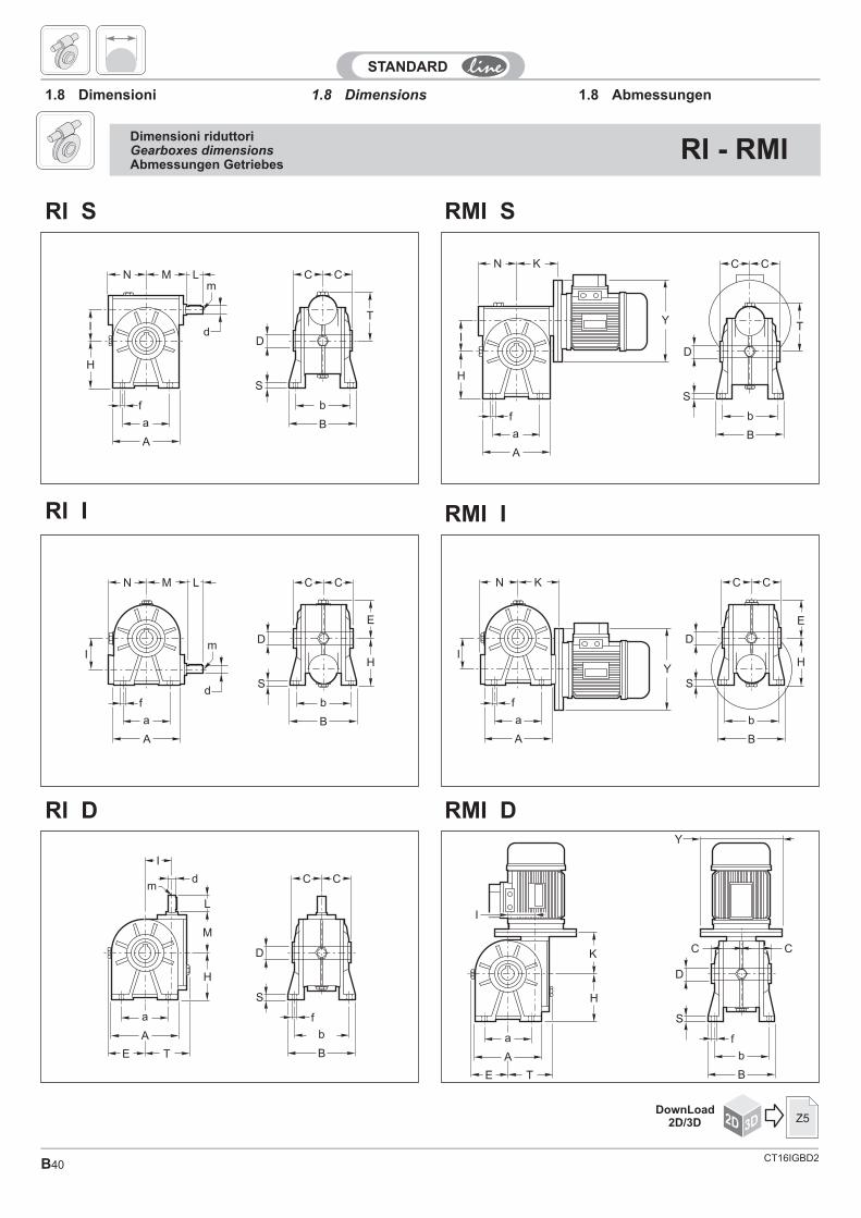
CT16IGBD2B40
1.8 Dimensions1.8 Dimensioni 1.8 Abmessungen
N K
I
H
f
a
A
C C
D
S
T
b
B
Y
dm
I
C C
fa
A
E
D
S
b
B
L
M
H
T
N M L
I
H
d
m
f
a
A
C C
D
S
T
b
B
RI I
N K
I
C C
f
a
A
D
S
b
B
E
HY
a
A
E
K
H
T
f
D
S
b
B
C
Y
C
I
N M L
I
d
m
C C
f
a
A
D
S
b
B
E
H
RMI D
RMI S
RMI I
RI D
RI S
Dimensioni riduttoriGearboxes dimensionsAbmessungen Getriebes
RI - RMI
2D 3DDownLoad
2D/3D Z5
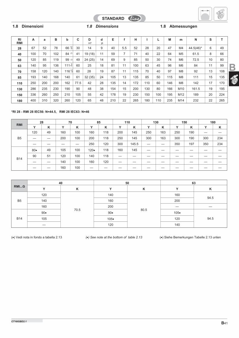
B41
+2- 8
�3
RIRMI
A a B b C DH7
dj6
E f H I L M m N S T
28 67 52 78 66 30 14 9 40 5.5 52 28 20 47 M4 44.5(46)* 6 49
40 100 70 102 84 41 19 (18) 11 59 7 71 40 22 64 M5 61.5 8 66
50 120 85 119 99 49 24 (25) 14 69 9 85 50 30 74 M6 72.5 10 80
63 140 95 136 111 60 25 18 81 11 100 63 45 96 M6 84 11 99
70 158 120 140 116 60 28 19 87 11 115 70 40 97 M8 92 13 108
85 193 140 168 140 61 32 (35) 24 105 13 135 85 50 115 M8 111 15 135
110 250 200 200 162 77.5 42 28 135 14 172 110 60 146 M8 142 17 170
130 286 235 230 190 90 48 38 154 15 200 130 80 166 M10 161.5 19 195
150 336 260 250 210 105 55 42 178 19 230 150 100 195 M12 189 20 224
180 400 310 320 260 120 65 48 210 22 265 180 110 235 M14 232 22 265
�3
1.8 Dimensions 1.8 Abmessungen1.8 Dimensioni
RMI28 70 85 110 130 150 180
Y K Y K Y K Y K Y K Y K Y K
B5
120 49 160 100 160 118 200 145 250 163 250 190 — —
— — 200 100 200 118 250 145 300 163 300 190 300 234
— — — — 250 120 300 145.5 — — 350 197 350 234
B14
80� 49 105 100 120� 118 160 145 — — — — — —
90 51 120 100 140 118 — — — — — — — —
— — 140 100 160 120 — — — — — — — —
— — 160 100 — — — — — — — — — —
*RI 28 - RMI 28 IEC56: N=44.5, RMI 28 IEC63: N=46
+2- 6
(�) See note at the bottom of table 2.13 (�) Siehe Bemerkungen Tabelle 2.13 unten(�) Vedi nota in fondo a tabella 2.13
0+5
RMI...G40 50 63
Y K Y K Y K
B5
120
70.5
140
80.5
16094.5
140 160 200
160 200 — —
B14
90� 90� 105�
94.5105 105� 120
— 120 140
B
CT16IGBD2.1
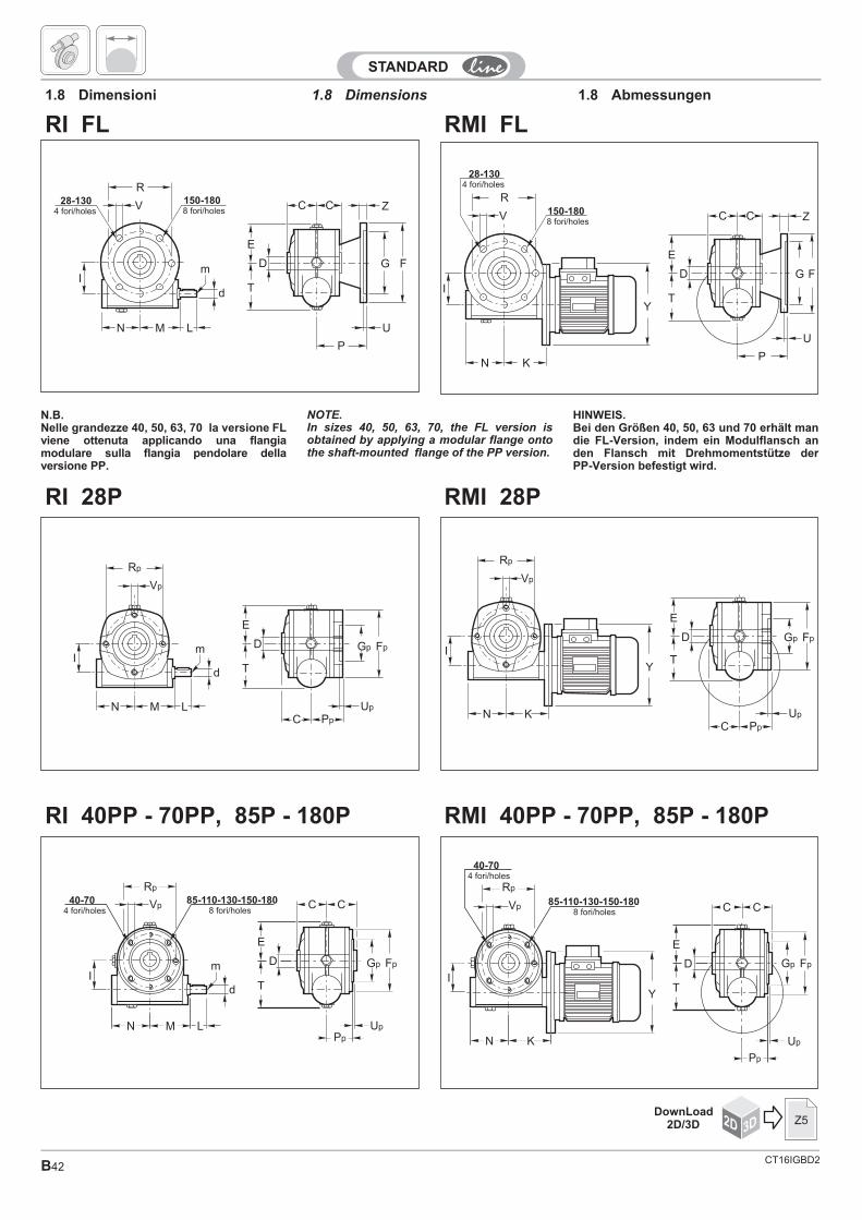
CT16IGBD2B42
R
V
I
KN
Y
C C Z
E
T
D G F
U
P
150-1808 fori/holes
28-1304 fori/holesR
V
Im
d
MN L
C C Z
E
T
D G F
U
P
150-1808 fori/holes
28-1304 fori/holes
RI 28P
I
Y
Up
PpC
Rp
Vp
KN
E
T
D Gp Fp
E
T
D
Up
Pp
Rp
Vp
I
MN
m
d
LC
Gp Fp
RMI 40PP - 70PP, 85P - 180P
RMI FL
RMI 28P
RI 40PP - 70PP, 85P - 180P
RI FL
1.8 Dimensions1.8 Dimensioni 1.8 Abmessungen
NOTE.In sizes 40, 50, 63, 70, the FL version isobtained by applying a modular flange ontothe shaft-mounted flange of the PP version.
HINWEIS.Bei den Größen 40, 50, 63 und 70 erhält mandie FL-Version, indem ein Modulflansch anden Flansch mit Drehmomentstütze derPP-Version befestigt wird.
N.B.Nelle grandezze 40, 50, 63, 70 la versione FLviene ottenuta applicando una flangiamodulare sulla flangia pendolare dellaversione PP.
85-110-130-150-1808 fori/holes
40-704 fori/holes
C C
E
T
D
UpPp
Rp
Vp
I
MN
m
d
L
Gp Fp
I
85-110-130-150-1808 fori/holes
40-704 fori/holes
Y
Up
Pp
Rp
Vp
KN
E
T
D Gp Fp
C C
2D 3DDownLoad
2D/3D Z5
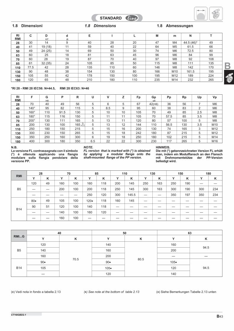
B43
RIRMI
C DH7
dj6
E I L M m N T
28 30 14 9 40 28 20 47 M4 44.5 (46)* 49
40 41 19 (18) 11 59 40 22 64 M5 61.5 66
50 49 24 (25) 14 69 50 30 74 M6 72.5 80
63 60 25 18 81 63 45 96 M6 84 99
70 60 28 19 87 70 40 97 M8 92 108
85 61 32 (35) 24 105 85 50 115 M8 111 135
110 77.5 42 28 135 110 60 146 M8 142 170
130 90 48 38 154 130 80 166 M10 161.5 195
150 105 55 42 178 150 100 195 M12 189 224
180 120 65 48 210 180 110 235 M14 232 265
1.8 Dimensions1.8 Dimensioni 1.8 Abmessungen
*RI 28 - RMI 28 IEC56: N=44.5, RMI 28 IEC63: N=46
RIRMI
F GH8
P R U V Z Fp Gpe8
Pp Rp Up Vp
28 70 40 49 56 5 6 5 67 42(H8) 36 56 7 M6
40 140° 95 82 115 5 8.5 9 95 60 38 83 2 M6
50 160° 110 91.5 130 5 10 10 105 70 49 85 2.5 M8
63 180° 115 116 150 5 11 11 105 70 57.5 85 3.5 M8
70 200° 130 111 165 5 13 11 120 80 57 100 5 M8
85 200 130 100 165 5 13 12 144 110 56.5 130 3.5 M10
110 250 180 150 215 5 15 16 200 130 74 165 3 M12
130 300 230 150 265 5 15 18 242 180 87 215 5 M12
150 350 250 160 300 6 19 18 250 180 102 215 5 M14
180 400 300 180 350 6.5 22 22 300 230 117 265 5 M16
0+11
NOTE.FL version that is marked with (°) is obtainedby applying a modular flange onto theshaft-mounted flange of the PP version.
HINWEIS.Die mit (°) gekennzeichneten Version FL erhältman, indem ein Modulflansch an den Flanschmit Drehmomentstütze der PP-Versionbefestigt wird.
N.B.La versione FL contrassegnata con il simbolo(°) è ottenuta applicando una flangiamodulare sulla flangia pendolare dellaversione PP.
RMI28 70 85 110 130 150 180
Y K Y K Y K Y K Y K Y K Y K
B5
120 49 160 100 160 118 200 145 250 163 250 190 — —
— — 200 100 200 118 250 145 300 163 300 190 300 234
— — — — 250 120 300 145.5 — — 350 197 350 234
B14
80� 49 105 100 120� 118 160 145 — — — — — —
90 51 120 100 140 118 — — — — — — — —
— — 140 100 160 120 — — — — — — — —
— — 160 100 — — — — — — — — — —
(�) See note at the bottom of table 2.13 (�) Siehe Bemerkungen Tabelle 2.13 unten(�) Vedi nota in fondo a tabella 2.13
RMI...G40 50 63
Y K Y K Y K
B5
120
70.5
140
80.5
16094.5
140 160 200
160 200 — —
B14
90� 90� 105�
94.5105 105� 120
— 120 140
B
CT16IGBD2.1
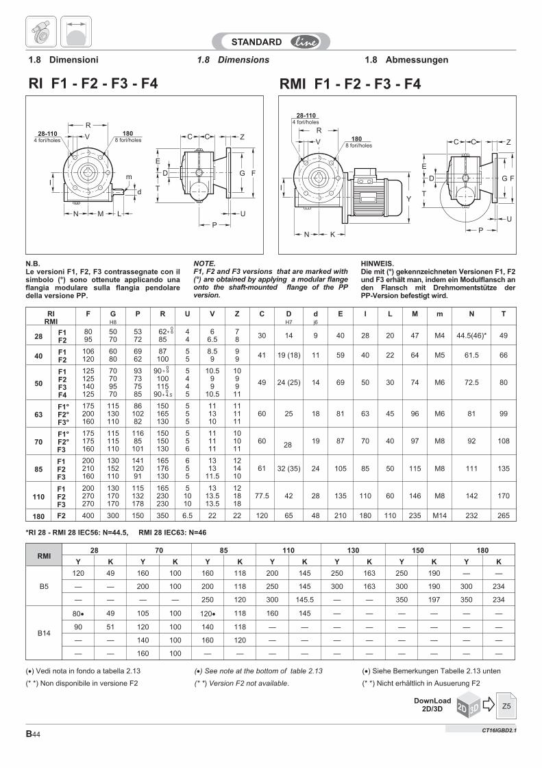
CT16IGBD2B44
RIRMI
F GH8
P R U V Z C DH7
dj6
E I L M m N T
28 F1F2
8095
5070
5372
6285
44
66.5
78 30 14 9 40 28 20 47 M4 44.5(46)* 49
40 F1F2
106120
6080
6962
87100
55
8.59
99 41 19 (18) 11 59 40 22 64 M5 61.5 66
50
F1F2F3F4
125125140125
70709570
93737585
90100115
90
5445
10.599
10.5
109911
49 24 (25) 14 69 50 30 74 M6 72.5 80
63F1°F2°F3°
175200160
115130110
8610282
150165130
555
111310
111111
60 25 18 81 63 45 96 M6 81 99
70F1°F2°F3
175175160
115115110
11685101
150150130
556
111111
101011
60 28 19 87 70 40 97 M8 92 108
85F1F2F3
200210160
130152110
14112091
165176130
655
1313
11.5
121410
61 32 (35) 24 105 85 50 115 M8 111 135
110F1F2F3
200270270
130170170
115132178
165230230
51010
1313.513.5
121818
77.5 42 28 135 110 60 146 M8 142 170
180 F2 400 300 150 350 6.5 22 22 120 65 48 210 180 110 235 M14 232 265
0+ 9
R
V
I
KN
Y
C C Z
E
T
D G F
U
P
1808 fori/holes
28-1104 fori/holes
RMI F1 - F2 - F3 - F4
R
V
Im
d
MN L
C C Z
E
T
D G F
U
P
1808 fori/holes
28-1104 fori/holes
RI F1 - F2 - F3 - F4
1.8 Dimensions1.8 Dimensioni 1.8 Abmessungen
NOTE.F1, F2 and F3 versions that are marked with(°) are obtained by applying a modular flangeonto the shaft-mounted flange of the PPversion.
*RI 28 - RMI 28 IEC56: N=44.5, RMI 28 IEC63: N=46
HINWEIS.Die mit (°) gekennzeichneten Versionen F1, F2und F3 erhält man, indem ein Modulflansch anden Flansch mit Drehmomentstütze derPP-Version befestigt wird.
N.B.Le versioni F1, F2, F3 contrassegnate con ilsimbolo (°) sono ottenute applicando unaflangia modulare sulla flangia pendolaredella versione PP.
0+ 6
(�) See note at the bottom of table 2.13 (�) Siehe Bemerkungen Tabelle 2.13 unten(�) Vedi nota in fondo a tabella 2.13
(* *) Non disponibile in versione F2 (* *) Version F2 not available. (* *) Nicht erhältlich in Ausuerung F2
0+ 4.5
RMI28 70 85 110 130 150 180
Y K Y K Y K Y K Y K Y K Y K
B5
120 49 160 100 160 118 200 145 250 163 250 190 — —
— — 200 100 200 118 250 145 300 163 300 190 300 234
— — — — 250 120 300 145.5 — — 350 197 350 234
B14
80� 49 105 100 120� 118 160 145 — — — — — —
90 51 120 100 140 118 — — — — — — — —
— — 140 100 160 120 — — — — — — — —
— — 160 100 — — — — — — — — — —
2D 3DDownLoad
2D/3D Z5
CT16IGBD2.1
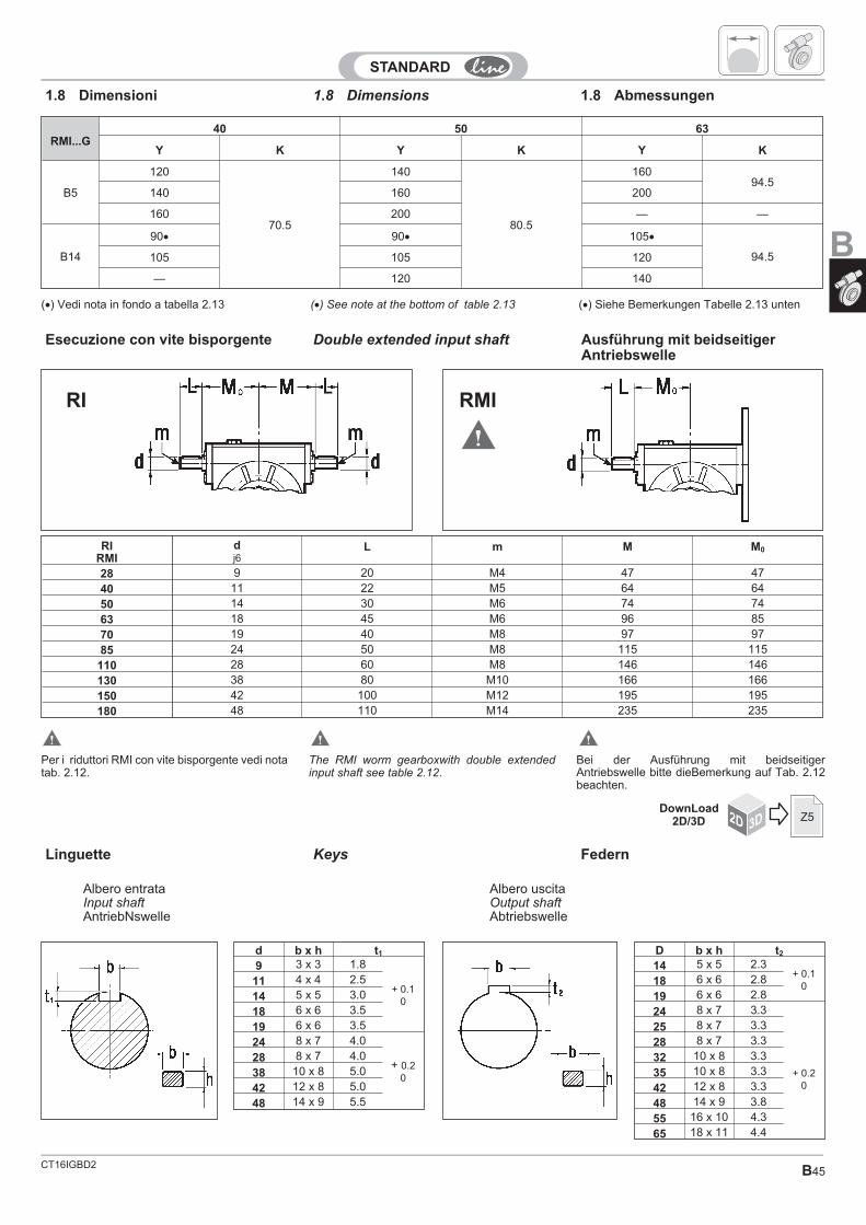
CT16IGBD2 B45
Double extended input shaft
RIRMI
dj6
L m M M0
28 9 20 M4 47 47
40 11 22 M5 64 64
50 14 30 M6 74 74
63 18 45 M6 96 85
70 19 40 M8 97 97
85 24 50 M8 115 115
110 28 60 M8 146 146
130 38 80 M10 166 166
150 42 100 M12 195 195
180 48 110 M14 235 235
RMIRI
Ausführung mit beidseitigerAntriebswelle
Esecuzione con vite bisporgente
1.8 Dimensions1.8 Dimensioni 1.8 Abmessungen
Bei der Ausführung mit beidseitigerAntriebswelle bitte dieBemerkung auf Tab. 2.12beachten.
Per i riduttori RMI con vite bisporgente vedi notatab. 2.12.
The RMI worm gearboxwith double extendedinput shaft see table 2.12.
(�) See note at the bottom of table 2.13 (�) Siehe Bemerkungen Tabelle 2.13 unten(�) Vedi nota in fondo a tabella 2.13
RMI...G40 50 63
Y K Y K Y K
B5
120
70.5
140
80.5
16094.5
140 160 200
160 200 — —
B14
90� 90� 105�
94.5105 105 120
— 120 140
Keys FedernLinguette
D b x h t2
14 5 x 5 2.3+ 0.1
018 6 x 6 2.8
19 6 x 6 2.8
24 8 x 7 3.3
25 8 x 7 3.3
+ 0.20
28 8 x 7 3.3
32 10 x 8 3.3
35 10 x 8 3.3
42 12 x 8 3.3
48 14 x 9 3.8
55 16 x 10 4.3
65 18 x 11 4.4
d b x h t1
9 3 x 3 1.8
+ 0.10
11 4 x 4 2.5
14 5 x 5 3.0
18 6 x 6 3.5
19 6 x 6 3.5
24 8 x 7 4.0
+ 0.20
28 8 x 7 4.0
38 10 x 8 5.0
42 12 x 8 5.0
48 14 x 9 5.5
Albero uscitaOutput shaftAbtriebswelle
Albero entrataInput shaftAntriebNswelle
2D 3DDownLoad
2D/3D Z5
B
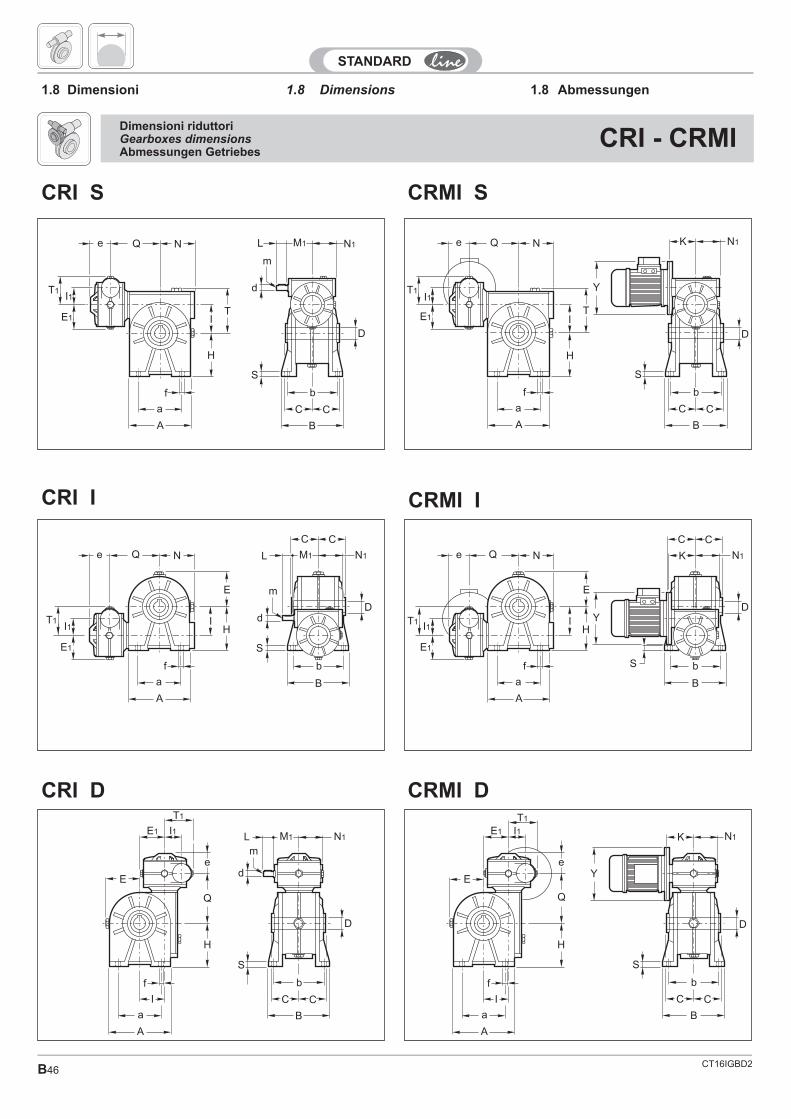
CT16IGBD2B46
1.8 Dimensions1.8 Dimensioni 1.8 Abmessungen
T1
e Q N
I1
H
TI
f
a
A
E1
K N1
S
b
B
D
Y
C C
T1
f
a
I
A
M1 N1L
d
S
b
B
C C
D
m
H
Q
e
E
E1 I1
CRI I
T1
C C
S b
B
DY
Ke Q N
I1 H
E
I
f
a
A
E1
N1
T1
f
a
I
A
K N1
S
b
B
D
Y
H
Q
e
E
E1 I1
C C
T1 d
S
b
B
m
e Q N
I1
E1
H
E
I
f
a
A
C C
D
M1 N1L
CRMI D
CRMI S
CRMI I
CRI D
CRI S
e Q N
I1
E1
T1
IT
H
f
a
A
M1 N1L
d
S
b
B
C C
D
m
Dimensioni riduttoriGearboxes dimensionsAbmessungen Getriebes
CRI - CRMI
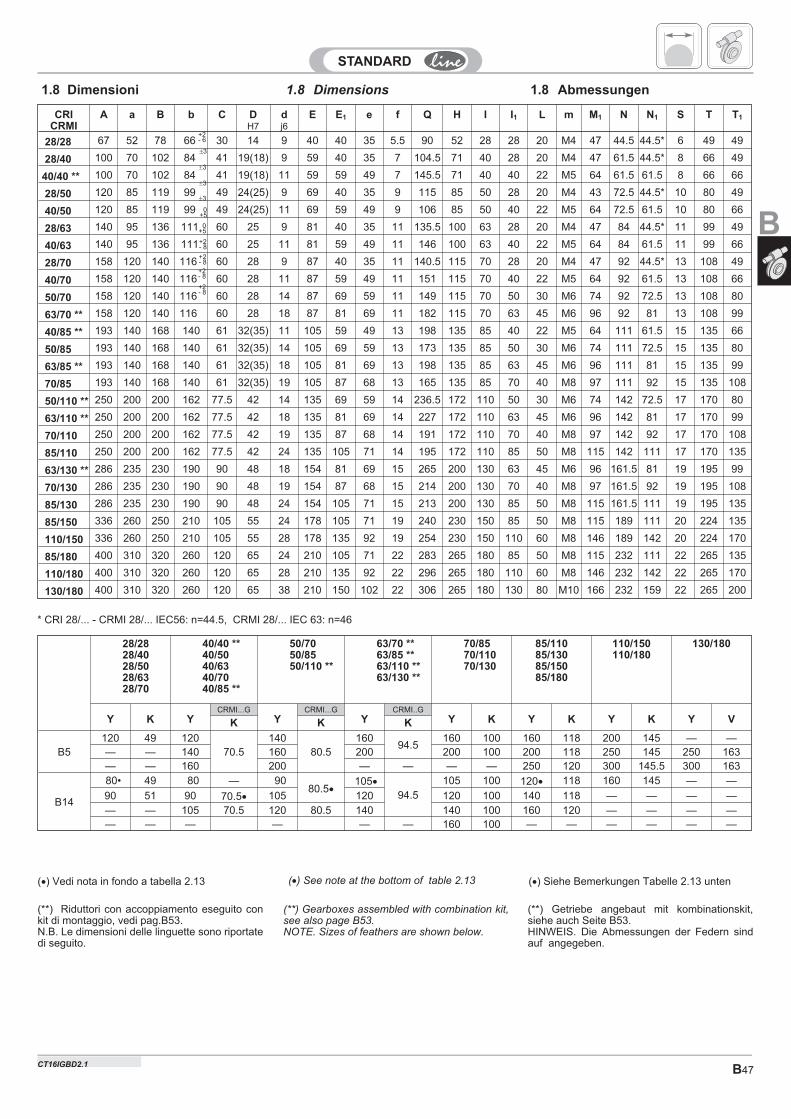
B47
1.8 Dimensions 1.8 Abmessungen1.8 Dimensioni
CRICRMI
A a B b C DH7
dj6
E E1 e f Q H I I1 L m M1 N N1 S T T1
28/28 67 52 78 66 30 14 9 40 40 35 5.5 90 52 28 28 20 M4 47 44.5 44.5* 6 49 49
28/40 100 70 102 84 41 19(18) 9 59 40 35 7 104.5 71 40 28 20 M4 47 61.5 44.5* 8 66 49
40/40 ** 100 70 102 84 41 19(18) 11 59 59 49 7 145.5 71 40 40 22 M5 64 61.5 61.5 8 66 66
28/50 120 85 119 99 49 24(25) 9 69 40 35 9 115 85 50 28 20 M4 43 72.5 44.5* 10 80 49
40/50 120 85 119 99 49 24(25) 11 69 59 49 9 106 85 50 40 22 M5 64 72.5 61.5 10 80 66
28/63 140 95 136 111 60 25 9 81 40 35 11 135.5 100 63 28 20 M4 47 84 44.5* 11 99 49
40/63 140 95 136 111 60 25 11 81 59 49 11 146 100 63 40 22 M5 64 84 61.5 11 99 66
28/70 158 120 140 116 60 28 9 87 40 35 11 140.5 115 70 28 20 M4 47 92 44.5* 13 108 49
40/70 158 120 140 116 60 28 11 87 59 49 11 151 115 70 40 22 M5 64 92 61.5 13 108 66
50/70 158 120 140 116 60 28 14 87 69 59 11 149 115 70 50 30 M6 74 92 72.5 13 108 80
63/70 ** 158 120 140 116 60 28 18 87 81 69 11 182 115 70 63 45 M6 96 92 81 13 108 99
40/85 ** 193 140 168 140 61 32(35) 11 105 59 49 13 198 135 85 40 22 M5 64 111 61.5 15 135 66
50/85 193 140 168 140 61 32(35) 14 105 69 59 13 173 135 85 50 30 M6 74 111 72.5 15 135 80
63/85 ** 193 140 168 140 61 32(35) 18 105 81 69 13 198 135 85 63 45 M6 96 111 81 15 135 99
70/85 193 140 168 140 61 32(35) 19 105 87 68 13 165 135 85 70 40 M8 97 111 92 15 135 108
50/110 ** 250 200 200 162 77.5 42 14 135 69 59 14 236.5 172 110 50 30 M6 74 142 72.5 17 170 80
63/110 ** 250 200 200 162 77.5 42 18 135 81 69 14 227 172 110 63 45 M6 96 142 81 17 170 99
70/110 250 200 200 162 77.5 42 19 135 87 68 14 191 172 110 70 40 M8 97 142 92 17 170 108
85/110 250 200 200 162 77.5 42 24 135 105 71 14 195 172 110 85 50 M8 115 142 111 17 170 135
63/130 ** 286 235 230 190 90 48 18 154 81 69 15 265 200 130 63 45 M6 96 161.5 81 19 195 99
70/130 286 235 230 190 90 48 19 154 87 68 15 214 200 130 70 40 M8 97 161.5 92 19 195 108
85/130 286 235 230 190 90 48 24 154 105 71 15 213 200 130 85 50 M8 115 161.5 111 19 195 135
85/150 336 260 250 210 105 55 24 178 105 71 19 240 230 150 85 50 M8 115 189 111 20 224 135
110/150 336 260 250 210 105 55 28 178 135 92 19 254 230 150 110 60 M8 146 189 142 20 224 170
85/180 400 310 320 260 120 65 24 210 105 71 22 283 265 180 85 50 M8 115 232 111 22 265 135
110/180 400 310 320 260 120 65 28 210 135 92 22 296 265 180 110 60 M8 146 232 142 22 265 170
130/180 400 310 320 260 120 65 38 210 150 102 22 306 265 180 130 80 M10 166 232 159 22 265 200
+2- 8
+2- 6
* CRI 28/... - CRMI 28/... IEC56: n=44.5, CRMI 28/... IEC 63: n=46
(**) Gearboxes assembled with combination kit,see also page B53.NOTE. Sizes of feathers are shown below.
(**) Getriebe angebaut mit kombinationskit,siehe auch Seite B53.HINWEIS. Die Abmessungen der Federn sindauf angegeben.
(**) Riduttori con accoppiamento eseguito conkit di montaggio, vedi pag.B53.N.B. Le dimensioni delle linguette sono riportatedi seguito.
�3
�3
�3
�3
0+5
+2- 8+2- 8
(�) See note at the bottom of table 2.13 (�) Siehe Bemerkungen Tabelle 2.13 unten(�) Vedi nota in fondo a tabella 2.13
+2- 8
0+5
28/2828/4028/5028/6328/70
40/40 **40/5040/6340/7040/85 **
50/7050/8550/110 **
63/70 **63/85 **63/110 **63/130 **
70/8570/11070/130
85/11085/13085/15085/180
110/150110/180
130/180
Y K YCRMI...G
YCRMI...G
YCRMI..G
Y K Y K Y K Y VK K K
B5120 49 120
70.5140
80.5160
94.5160 100 160 118 200 145 — —
— — 140 160 200 200 100 200 118 250 145 250 163— — 160 200 — — — — 250 120 300 145.5 300 163
B14
80• 49 80 — 9080.5�
105�
94.5
105 100 120� 118 160 145 — —
90 51 90 70.5� 105 120 120 100 140 118 — — — —
— — 105 70.5 120 80.5 140 140 100 160 120 — — — —— — — — — — 160 100 — — — — — —
B
CT16IGBD2.1
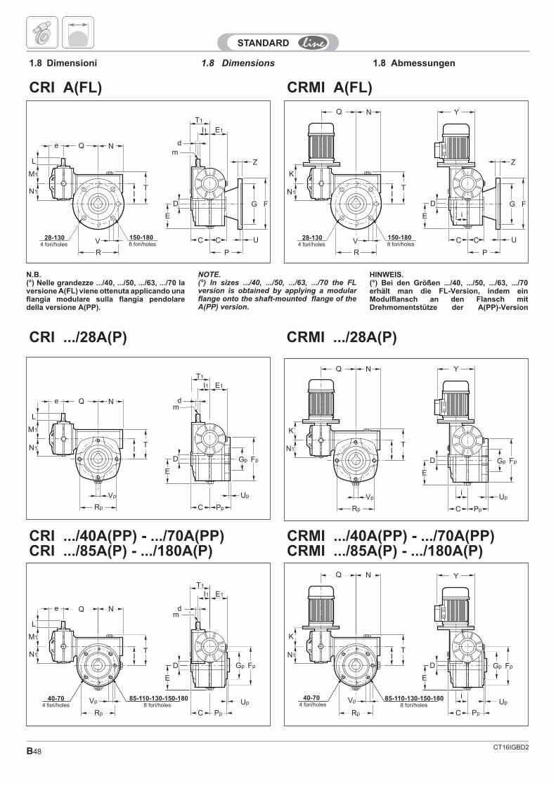
CT16IGBD2B48
150-1808 fori/holes
28-1304 fori/holes
N
K
N1 IT
V
R
Q
Z
G F
U
P
C C
E
D
Y
i
e Q N
L
M1
N1 IT
V
R
Z
G F
U
P
E
D
md
I1 E1
T1
C C150-1808 fori/holes
28-1304 fori/holes
CRI .../28A(P)
Gp Fp
Up
C Pp
E
D
YN
K
N1 IT
Vp
Rp
Q
i
Gp Fp
Up
C Pp
E
D
N1 IT
Vp
Rp
e Q N
L
M1
md
I1 E1
T1
CRMI A(FL)
CRMI .../28A(P)
CRMI .../40A(PP) - .../70A(PP)CRMI .../85A(P) - .../180A(P)
CRI A(FL)
1.8 Dimensions1.8 Dimensioni 1.8 Abmessungen
CRI .../40A(PP) - .../70A(PP)CRI .../85A(P) - .../180A(P)
N.B.(°) Nelle grandezze .../40, .../50, .../63, .../70 laversione A(FL) viene ottenuta applicando unaflangia modulare sulla flangia pendolaredella versione A(PP).
NOTE.(°) In sizes .../40, .../50, .../63, .../70 the FLversion is obtained by applying a modularflange onto the shaft-mounted flange of theA(PP) version.
HINWEIS.(°) Bei den Größen .../40, .../50, .../63, .../70erhält man die FL-Version, indem einModulflansch an den Flansch mitDrehmomentstütze der A(PP)-Version
85-110-130-150-1808 fori/holes
40-704 fori/holes
I1 E1
T1
N1 IT
Vp
Rp
e Q N
L
M1
Gp Fp
Up
C Pp
E
D
md
85-110-130-150-1808 fori/holes
40-704 fori/holes
N
K
N1
Vp
Rp
Q
IT
Gp Fp
Up
C Pp
E
D
Y
i
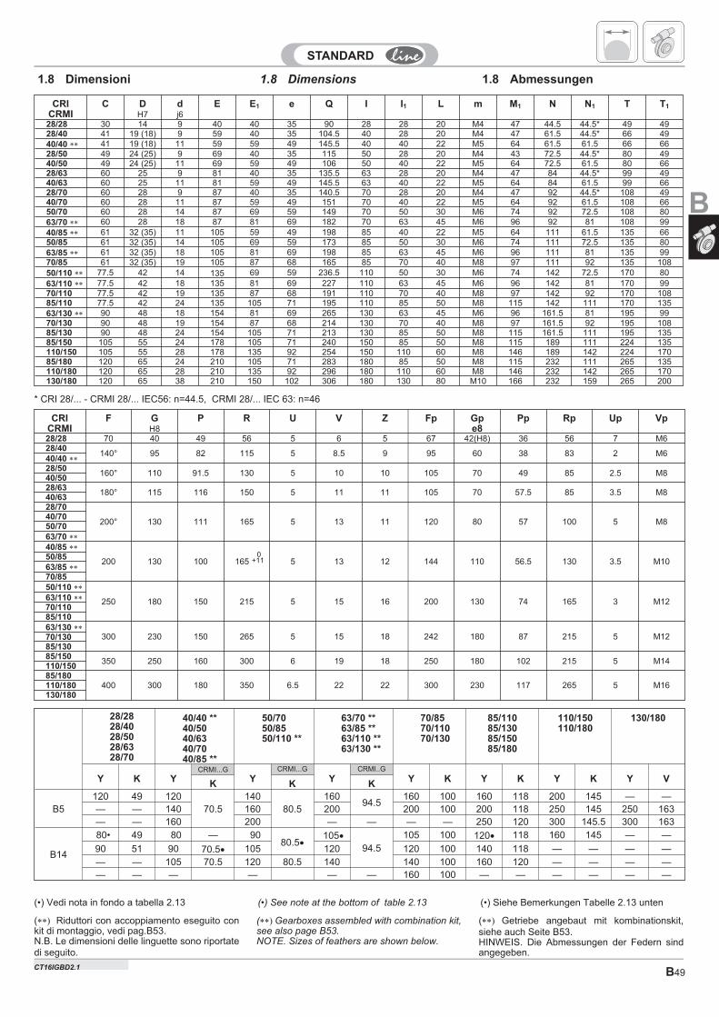
B49
CRICRMI
F GH8
P R U V Z Fp Gpe8
Pp Rp Up Vp
28/28 70 40 49 56 5 6 5 67 42(H8) 36 56 7 M628/40
140° 95 82 115 5 8.5 9 95 60 38 83 2 M640/40 ��
28/50160° 110 91.5 130 5 10 10 105 70 49 85 2.5 M8
40/5028/63
180° 115 116 150 5 11 11 105 70 57.5 85 3.5 M840/6328/70
200° 130 111 165 5 13 11 120 80 57 100 5 M840/7050/7063/70 ��
40/85 ��
200 130 100 165 5 13 12 144 110 56.5 130 3.5 M1050/8563/85 ��
70/8550/110 ��
250 180 150 215 5 15 16 200 130 74 165 3 M1263/110 ��
70/11085/11063/130 ��
300 230 150 265 5 15 18 242 180 87 215 5 M1270/13085/13085/150
350 250 160 300 6 19 18 250 180 102 215 5 M14110/15085/180
400 300 180 350 6.5 22 22 300 230 117 265 5 M16110/180130/180
0+11
1.8 Dimensions 1.8 Abmessungen1.8 Dimensioni
CRICRMI
C DH7
dj6
E E1 e Q I I1 L m M1 N N1 T T1
28/28 30 14 9 40 40 35 90 28 28 20 M4 47 44.5 44.5* 49 4928/40 41 19 (18) 9 59 40 35 104.5 40 28 20 M4 47 61.5 44.5* 66 4940/40 �� 41 19 (18) 11 59 59 49 145.5 40 40 22 M5 64 61.5 61.5 66 6628/50 49 24 (25) 9 69 40 35 115 50 28 20 M4 43 72.5 44.5* 80 4940/50 49 24 (25) 11 69 59 49 106 50 40 22 M5 64 72.5 61.5 80 6628/63 60 25 9 81 40 35 135.5 63 28 20 M4 47 84 44.5* 99 4940/63 60 25 11 81 59 49 145.5 63 40 22 M5 64 84 61.5 99 6628/70 60 28 9 87 40 35 140.5 70 28 20 M4 47 92 44.5* 108 4940/70 60 28 11 87 59 49 151 70 40 22 M5 64 92 61.5 108 6650/70 60 28 14 87 69 59 149 70 50 30 M6 74 92 72.5 108 8063/70 �� 60 28 18 87 81 69 182 70 63 45 M6 96 92 81 108 9940/85 �� 61 32 (35) 11 105 59 49 198 85 40 22 M5 64 111 61.5 135 6650/85 61 32 (35) 14 105 69 59 173 85 50 30 M6 74 111 72.5 135 8063/85 �� 61 32 (35) 18 105 81 69 198 85 63 45 M6 96 111 81 135 9970/85 61 32 (35) 19 105 87 68 165 85 70 40 M8 97 111 92 135 10850/110 �� 77.5 42 14 135 69 59 236.5 110 50 30 M6 74 142 72.5 170 8063/110 �� 77.5 42 18 135 81 69 227 110 63 45 M6 96 142 81 170 9970/110 77.5 42 19 135 87 68 191 110 70 40 M8 97 142 92 170 10885/110 77.5 42 24 135 105 71 195 110 85 50 M8 115 142 111 170 13563/130 �� 90 48 18 154 81 69 265 130 63 45 M6 96 161.5 81 195 9970/130 90 48 19 154 87 68 214 130 70 40 M8 97 161.5 92 195 10885/130 90 48 24 154 105 71 213 130 85 50 M8 115 161.5 111 195 13585/150 105 55 24 178 105 71 240 150 85 50 M8 115 189 111 224 135110/150 105 55 28 178 135 92 254 150 110 60 M8 146 189 142 224 17085/180 120 65 24 210 105 71 283 180 85 50 M8 115 232 111 265 135110/180 120 65 28 210 135 92 296 180 110 60 M8 146 232 142 265 170130/180 120 65 38 210 150 102 306 180 130 80 M10 166 232 159 265 200
* CRI 28/... - CRMI 28/... IEC56: n=44.5, CRMI 28/... IEC 63: n=46
(��� Gearboxes assembled with combination kit,see also page B53.NOTE. Sizes of feathers are shown below.
(��� Getriebe angebaut mit kombinationskit,siehe auch Seite B53.HINWEIS. Die Abmessungen der Federn sindangegeben.
(��� Riduttori con accoppiamento eseguito conkit di montaggio, vedi pag.B53.N.B. Le dimensioni delle linguette sono riportatedi seguito.
(•) See note at the bottom of table 2.13(•) Vedi nota in fondo a tabella 2.13
28/2828/4028/5028/6328/70
40/40 **40/5040/6340/7040/85 **
50/7050/8550/110 **
63/70 **63/85 **63/110 **63/130 **
70/8570/11070/130
85/11085/13085/15085/180
110/150110/180
130/180
Y K YCRMI...G
YCRMI...G
YCRMI..G
Y K Y K Y K Y VK K K
B5120 49 120
70.5140
80.5160
94.5160 100 160 118 200 145 — —
— — 140 160 200 200 100 200 118 250 145 250 163— — 160 200 — — — — 250 120 300 145.5 300 163
B14
80• 49 80 — 9080.5�
105�
94.5
105 100 120� 118 160 145 — —
90 51 90 70.5� 105 120 120 100 140 118 — — — —
— — 105 70.5 120 80.5 140 140 100 160 120 — — — —— — — — — — 160 100 — — — — — —
B
(•) Siehe Bemerkungen Tabelle 2.13 unten
CT16IGBD2.1
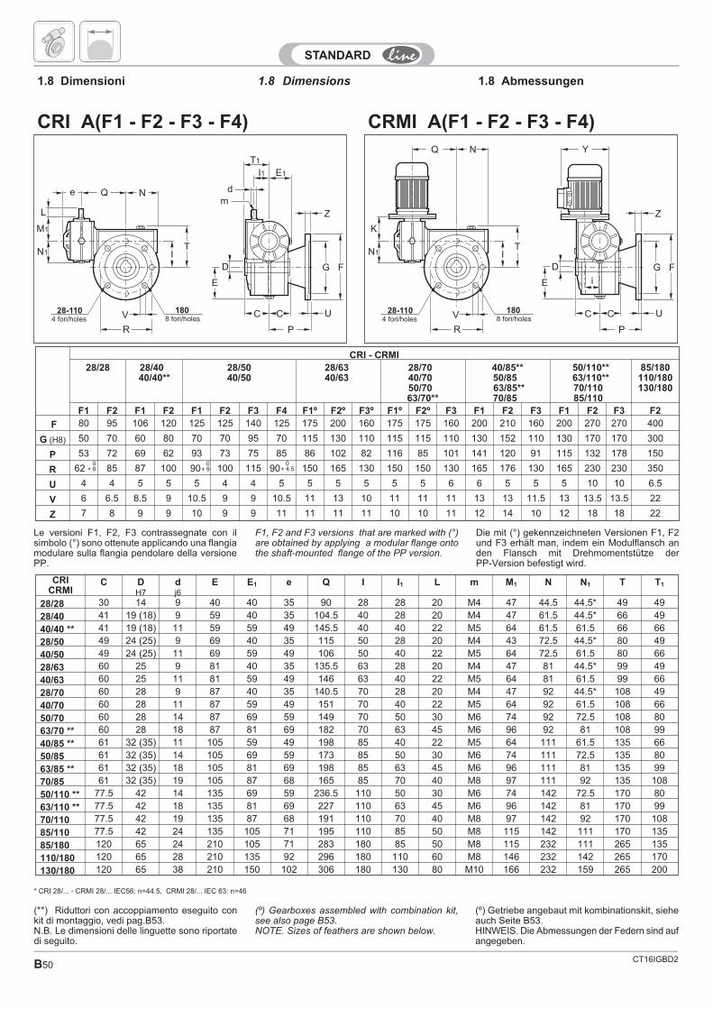
CT16IGBD2B50
1808 fori/holes
28-1104 fori/holes
N
K
N1 IT
V
R
Q
Z
G F
U
P
C C
E
D
Y
i
CRMI A(F1 - F2 - F3 - F4)
e Q N
L
M1
N1 IT
V
R
Z
G F
U
P
E
D
md
I1 E1
T1
C C1808 fori/holes
28-1104 fori/holes
CRI A(F1 - F2 - F3 - F4)
1.8 Dimensions1.8 Dimensioni 1.8 Abmessungen
CRICRMI
C DH7
dj6
E E1 e Q I I1 L m M1 N N1 T T1
28/28 30 14 9 40 40 35 90 28 28 20 M4 47 44.5 44.5* 49 49
28/40 41 19 (18) 9 59 40 35 104.5 40 28 20 M4 47 61.5 44.5* 66 49
40/40 ** 41 19 (18) 11 59 59 49 145.5 40 40 22 M5 64 61.5 61.5 66 66
28/50 49 24 (25) 9 69 40 35 115 50 28 20 M4 43 72.5 44.5* 80 49
40/50 49 24 (25) 11 69 59 49 106 50 40 22 M5 64 72.5 61.5 80 66
28/63 60 25 9 81 40 35 135.5 63 28 20 M4 47 81 44.5* 99 49
40/63 60 25 11 81 59 49 146 63 40 22 M5 64 81 61.5 99 66
28/70 60 28 9 87 40 35 140.5 70 28 20 M4 47 92 44.5* 108 49
40/70 60 28 11 87 59 49 151 70 40 22 M5 64 92 61.5 108 66
50/70 60 28 14 87 69 59 149 70 50 30 M6 74 92 72.5 108 80
63/70 ** 60 28 18 87 81 69 182 70 63 45 M6 96 92 81 108 99
40/85 ** 61 32 (35) 11 105 59 49 198 85 40 22 M5 64 111 61.5 135 66
50/85 61 32 (35) 14 105 69 59 173 85 50 30 M6 74 111 72.5 135 80
63/85 ** 61 32 (35) 18 105 81 69 198 85 63 45 M6 96 111 81 135 99
70/85 61 32 (35) 19 105 87 68 165 85 70 40 M8 97 111 92 135 108
50/110 ** 77.5 42 14 135 69 59 236.5 110 50 30 M6 74 142 72.5 170 80
63/110 ** 77.5 42 18 135 81 69 227 110 63 45 M6 96 142 81 170 99
70/110 77.5 42 19 135 87 68 191 110 70 40 M8 97 142 92 170 108
85/110 77.5 42 24 135 105 71 195 110 85 50 M8 115 142 111 170 135
85/180 120 65 24 210 105 71 283 180 85 50 M8 115 232 111 265 135
110/180 120 65 28 210 135 92 296 180 110 60 M8 146 232 142 265 170
130/180 120 65 38 210 150 102 306 180 130 80 M10 166 232 159 265 200
CRI - CRMI28/28 28/40
40/40**28/5040/50
28/6340/63
28/7040/7050/7063/70**
40/85**50/8563/85**70/85
50/110**63/110**70/11085/110
85/180110/180130/180
F1 F2 F1 F2 F1 F2 F3 F4 F1º F2º F3º F1º F2º F3 F1 F2 F3 F1 F2 F3 F2
F 80 95 106 120 125 125 140 125 175 200 160 175 175 160 200 210 160 200 270 270 400
G (H8) 50 70 60 80 70 70 95 70 115 130 110 115 115 110 130 152 110 130 170 170 300
P 53 72 69 62 93 73 75 85 86 102 82 116 85 101 141 120 91 115 132 178 150
R 62 85 87 100 90 100 115 90 150 165 130 150 150 130 165 176 130 165 230 230 350
U 4 4 5 5 5 4 4 5 5 5 5 5 5 6 6 5 5 5 10 10 6.5
V 6 6.5 8.5 9 10.5 9 9 10.5 11 13 10 11 11 11 13 13 11.5 13 13.5 13.5 22
Z 7 8 9 9 10 9 9 11 11 11 11 10 10 11 12 14 10 12 18 18 22
0+ 9
* CRI 28/... - CRMI 28/... IEC56: n=44.5, CRMI 28/... IEC 63: n=46
Le versioni F1, F2, F3 contrassegnate con ilsimbolo (°) sono ottenute applicando una flangiamodulare sulla flangia pendolare della versionePP.
F1, F2 and F3 versions that are marked with (°)are obtained by applying a modular flange ontothe shaft-mounted flange of the PP version.
Die mit (°) gekennzeichneten Versionen F1, F2und F3 erhält man, indem ein Modulflansch anden Flansch mit Drehmomentstütze derPP-Version befestigt wird.
(º) Gearboxes assembled with combination kit,see also page B53.NOTE. Sizes of feathers are shown below.
(º) Getriebe angebaut mit kombinationskit, sieheauch Seite B53.HINWEIS. Die Abmessungen der Federn sind aufangegeben.
(**) Riduttori con accoppiamento eseguito conkit di montaggio, vedi pag.B53.N.B. Le dimensioni delle linguette sono riportatedi seguito.
0+ 6
0+ 4.5
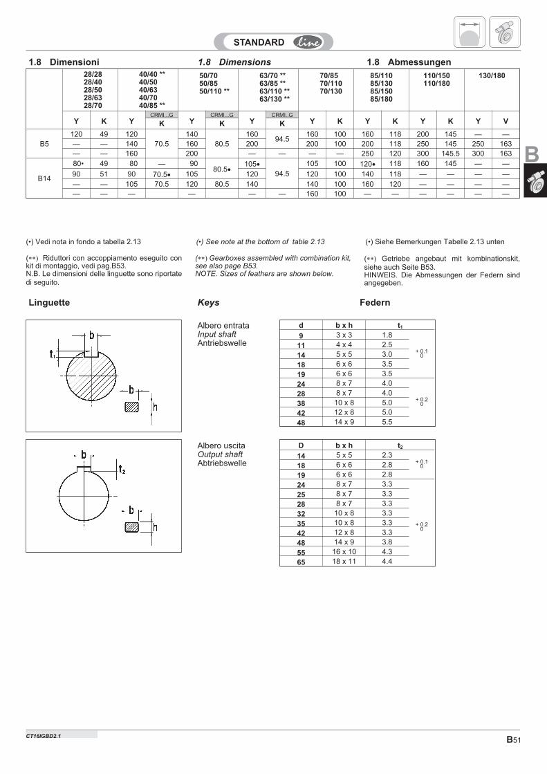
B51
1.8 Dimensions1.8 Dimensioni 1.8 Abmessungen
Keys FedernLinguette
D b x h t2
14 5 x 5 2.3+ 0.1
018 6 x 6 2.8
19 6 x 6 2.8
24 8 x 7 3.3
25 8 x 7 3.3
+ 0.20
28 8 x 7 3.3
32 10 x 8 3.3
35 10 x 8 3.3
42 12 x 8 3.3
48 14 x 9 3.8
55 16 x 10 4.3
65 18 x 11 4.4
d b x h t1
9 3 x 3 1.8
+ 0.10
11 4 x 4 2.5
14 5 x 5 3.0
18 6 x 6 3.5
19 6 x 6 3.5
24 8 x 7 4.0
+ 0.20
28 8 x 7 4.0
38 10 x 8 5.0
42 12 x 8 5.0
48 14 x 9 5.5
Albero uscitaOutput shaftAbtriebswelle
Albero entrataInput shaftAntriebswelle
28/2828/4028/5028/6328/70
40/40 **40/5040/6340/7040/85 **
50/7050/8550/110 **
63/70 **63/85 **63/110 **63/130 **
70/8570/11070/130
85/11085/13085/15085/180
110/150110/180
130/180
Y K YCRMI...G
YCRMI...G
YCRMI..G
Y K Y K Y K Y VK K K
B5120 49 120
70.5140
80.5160
94.5160 100 160 118 200 145 — —
— — 140 160 200 200 100 200 118 250 145 250 163— — 160 200 — — — — 250 120 300 145.5 300 163
B14
80• 49 80 — 9080.5�
105�
94.5
105 100 120� 118 160 145 — —
90 51 90 70.5� 105 120 120 100 140 118 — — — —
— — 105 70.5 120 80.5 140 140 100 160 120 — — — —— — — — — — 160 100 — — — — — —
(��� Gearboxes assembled with combination kit,see also page B53.NOTE. Sizes of feathers are shown below.
(��� Getriebe angebaut mit kombinationskit,siehe auch Seite B53.HINWEIS. Die Abmessungen der Federn sindangegeben.
(��� Riduttori con accoppiamento eseguito conkit di montaggio, vedi pag.B53.N.B. Le dimensioni delle linguette sono riportatedi seguito.
(•) See note at the bottom of table 2.13 (•) Siehe Bemerkungen Tabelle 2.13 unten(•) Vedi nota in fondo a tabella 2.13
B
CT16IGBD2.1
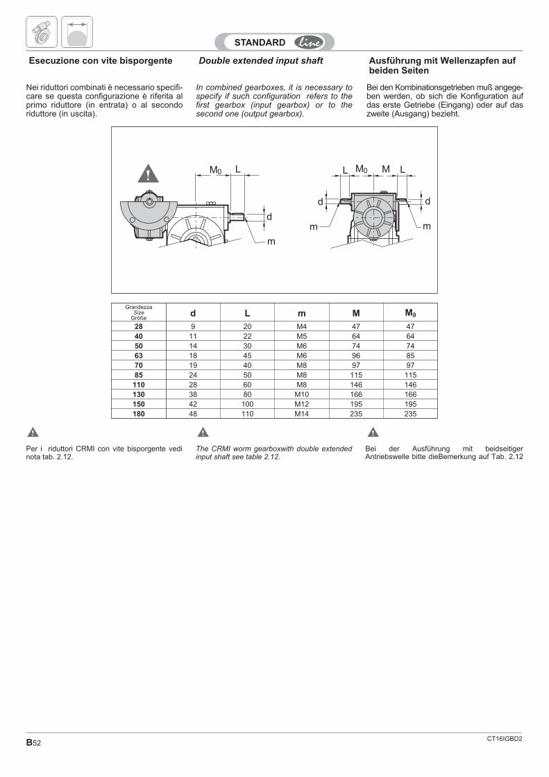
CT16IGBD2B52
Double extended input shaft
dd
d
LL ML
mm
m
M0 M0
Ausführung mit Wellenzapfen aufbeiden Seiten
Esecuzione con vite bisporgente
In combined gearboxes, it is necessary tospecify if such configuration refers to thefirst gearbox (input gearbox) or to thesecond one (output gearbox).
GrandezzaSize
Größed L m M M0
28 9 20 M4 47 4740 11 22 M5 64 6450 14 30 M6 74 7463 18 45 M6 96 8570 19 40 M8 97 9785 24 50 M8 115 115110 28 60 M8 146 146130 38 80 M10 166 166150 42 100 M12 195 195180 48 110 M14 235 235
Bei den Kombinationsgetrieben muß angege-ben werden, ob sich die Konfiguration aufdas erste Getriebe (Eingang) oder auf daszweite (Ausgang) bezieht.
Nei riduttori combinati è necessario specifi-care se questa configurazione è riferita alprimo riduttore (in entrata) o al secondoriduttore (in uscita).
Bei der Ausführung mit beidseitigerAntriebswelle bitte dieBemerkung auf Tab. 2.12
Per i riduttori CRMI con vite bisporgente vedinota tab. 2.12.
The CRMI worm gearboxwith double extendedinput shaft see table 2.12.
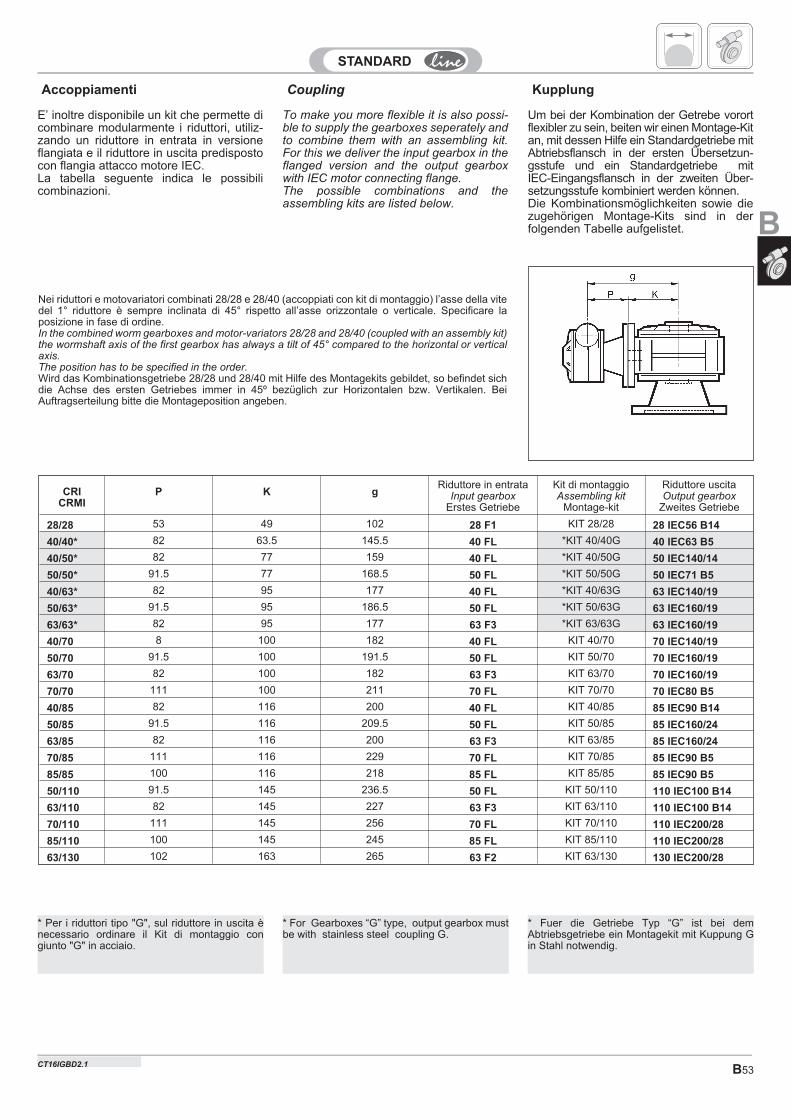
B53
CouplingAccoppiamenti Kupplung
CRICRMI
P K gRiduttore in entrata
Input gearboxErstes Getriebe
Kit di montaggioAssembling kit
Montage-kit
Riduttore uscitaOutput gearbox
Zweites Getriebe
28/28 53 49 102 28 F1 KIT 28/28 28 IEC56 B14
40/40* 82 63.5 145.5 40 FL *KIT 40/40G 40 IEC63 B5
40/50* 82 77 159 40 FL *KIT 40/50G 50 IEC140/14
50/50* 91.5 77 168.5 50 FL *KIT 50/50G 50 IEC71 B5
40/63* 82 95 177 40 FL *KIT 40/63G 63 IEC140/19
50/63* 91.5 95 186.5 50 FL *KIT 50/63G 63 IEC160/19
63/63* 82 95 177 63 F3 *KIT 63/63G 63 IEC160/19
40/70 8 100 182 40 FL KIT 40/70 70 IEC140/19
50/70 91.5 100 191.5 50 FL KIT 50/70 70 IEC160/19
63/70 82 100 182 63 F3 KIT 63/70 70 IEC160/19
70/70 111 100 211 70 FL KIT 70/70 70 IEC80 B5
40/85 82 116 200 40 FL KIT 40/85 85 IEC90 B14
50/85 91.5 116 209.5 50 FL KIT 50/85 85 IEC160/24
63/85 82 116 200 63 F3 KIT 63/85 85 IEC160/24
70/85 111 116 229 70 FL KIT 70/85 85 IEC90 B5
85/85 100 116 218 85 FL KIT 85/85 85 IEC90 B5
50/110 91.5 145 236.5 50 FL KIT 50/110 110 IEC100 B14
63/110 82 145 227 63 F3 KIT 63/110 110 IEC100 B14
70/110 111 145 256 70 FL KIT 70/110 110 IEC200/28
85/110 100 145 245 85 FL KIT 85/110 110 IEC200/28
63/130 102 163 265 63 F2 KIT 63/130 130 IEC200/28
To make you more flexible it is also possi-ble to supply the gearboxes seperately andto combine them with an assembling kit.For this we deliver the input gearbox in theflanged version and the output gearboxwith IEC motor connecting flange.The possible combinations and theassembling kits are listed below.
Um bei der Kombination der Getrebe vorortflexibler zu sein, beiten wir einen Montage-Kitan, mit dessen Hilfe ein Standardgetriebe mitAbtriebsflansch in der ersten Übersetzun-gsstufe und ein Standardgetriebe mitIEC-Eingangsflansch in der zweiten Über-setzungsstufe kombiniert werden können.Die Kombinationsmöglichkeiten sowie diezugehörigen Montage-Kits sind in derfolgenden Tabelle aufgelistet.
E’ inoltre disponibile un kit che permette dicombinare modularmente i riduttori, utiliz-zando un riduttore in entrata in versioneflangiata e il riduttore in uscita predispostocon flangia attacco motore IEC.La tabella seguente indica le possibilicombinazioni.
Nei riduttori e motovariatori combinati 28/28 e 28/40 (accoppiati con kit di montaggio) l’asse della vitedel 1° riduttore è sempre inclinata di 45° rispetto all’asse orizzontale o verticale. Specificare laposizione in fase di ordine.In the combined worm gearboxes and motor-variators 28/28 and 28/40 (coupled with an assembly kit)the wormshaft axis of the first gearbox has always a tilt of 45° compared to the horizontal or verticalaxis.The position has to be specified in the order.Wird das Kombinationsgetriebe 28/28 und 28/40 mit Hilfe des Montagekits gebildet, so befindet sichdie Achse des ersten Getriebes immer in 45º bezüglich zur Horizontalen bzw. Vertikalen. BeiAuftragserteilung bitte die Montageposition angeben.
B
* Per i riduttori tipo "G", sul riduttore in uscita ènecessario ordinare il Kit di montaggio congiunto "G" in acciaio.
CT16IGBD2.1
* For Gearboxes “G” type, output gearbox mustbe with stainless steel coupling G.
* Fuer die Getriebe Typ “G” ist bei demAbtriebsgetriebe ein Montagekit mit Kuppung Gin Stahl notwendig.
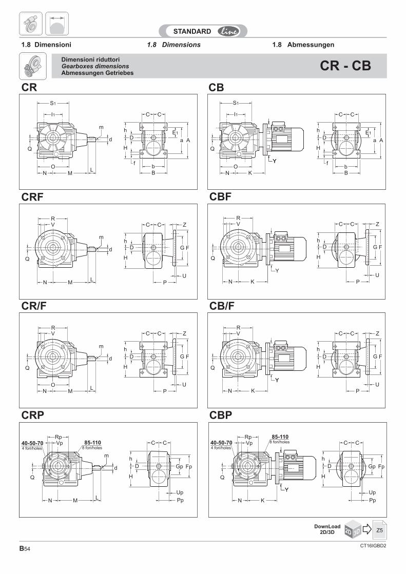
CT16IGBD2B54
1.8 Dimensions1.8 Dimensioni 1.8 Abmessungen
Dimensioni riduttoriGearboxes dimensionsAbmessungen Getriebes
CR - CB
CC
Dh
H
Z
G F
UP
m
M
d
L
RV
Q
N
CR/F
C
D
h
H
Fp
Up
Pp
Gp
m
M
d
L
RpVp
Q
N
C
CRP
C
Y
C
D
h
H
Fp
Up
Pp
Gp
K
RpVp
Q
N
Y
CBP
C
D
h
H
Z
G F
UP
ON M
RV
Q
C
m
d
L
CRF
Y
K
RV
Q
N
CC
Dh
H
Z
G F
UP
CBF
CB/F
CC
D
h
H
Z
G F
UPN K
RV
Q
YY
C
B
E1
C
D
h
H
a A
bf
ON M
m
d
L
S1
I1
Q
CR
Y
C
B
E1
C
D
h
H
a A
bf
ON K
S1
I1
Q
Y
CB
2D 3DDownLoad
2D/3D Z5
C
Y
C C
D D
h h
H H
Fp Fp
Up Up
Pp Pp
Gp Gp
m
M K
d
L
Rp RpVp Vp
Q Q
N N
C
Y
40-50-70 40-50-7085-11085-110
4 fori/holes 4 fori/holes8 fori/holes
8 fori/holes
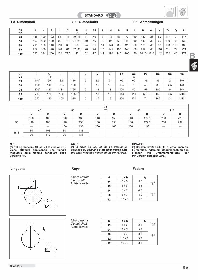
B55
1.8 Dimensions1.8 Dimensioni 1.8 Abmessungen
CRCB
F GH8
P R U V Z Fp Gpe8
Pp Rp Up Vp
40 140° 95 82 115 5 8.5 9 95 60 38 83 2 M6
50 160° 110 91.5 130 5 10 10 105 70 49 85 2.5 M8
70 200° 130 111 165 5 13 11 120 80 57 100 5 M8
85 200 130 100 165 5 13 12 144 110 56.5 130 3.5 M10
110 250 180 150 215 5 15 16 200 130 74 165 3 M12
0+11
Keys FedernLinguette
D b x h t2
19 6 x 6 2.8 + 0.10
24 8 x 7 3.3
+0.20
28 8 x 7 3.3
32 10 x 8 3.3
42 12 x 8 3.3
d b x h t1
14 5 x 5 3.0 + 0.10
19 6 x 6 3.5
24 8 x 7 4.0+ 0.2
028 8 x 7 4.0
32 10 x 8 5.0
Albero uscitaOutput shaftAbtriebswelle
Albero entrataInput shaftAntriebswelle
CRCB
A a B b C DH7
dJ6
E1 f H h I1 L M m N O Q S1
40 135 100 102 84 41 19 (18) 14 40 7 78 57 70 30 137 M6 59 117 7 117
50 166 120 120 99 49 24 (25) 19 46 9 97 69 85 40 143 M8 69 130 9 130
70 215 160 140 116 60 28 24 61 11 124 88 120 50 188 M8 93 193 17.5 186
85 252 188 170 140 61 32 (35) 28 74 13 145 107 140 60 212 M8 116 231 29 221
110 330 244 200 162 77.5 42 32 97 14 190 140 200 70 264.5 M10 142 282 43 277
CB
40 50 70 85 110
Y K Y K Y K Y K Y K
B5
120 108 120 133 140 153 140 172.5 200 229
140 108 140 133 160 153 160 172.5 250 239
— — 160 133 200 165 200 193 — —
B1480 108 80 133
— — — — — —90 112 90 133
NOTE.(°) In sizes 40, 50, 70 the FL version isobtained by applying a modular flange ontothe shaft mounted flange on the PP version.
HINWEIS.(°) Bei den Größen 40, 50, 70 erhält man dieFL-Version, indem ein Modulflansch an denFlansch mit Drehmomentstütze derPP-Version befestigt wird.
N.B.(°) Nelle grandezze 40, 50, 70 la versione FLviene ottenuta applicando una flangiamodulare sulla flangia pendolare dellaversione PP.
B
CT16IGBD2.1
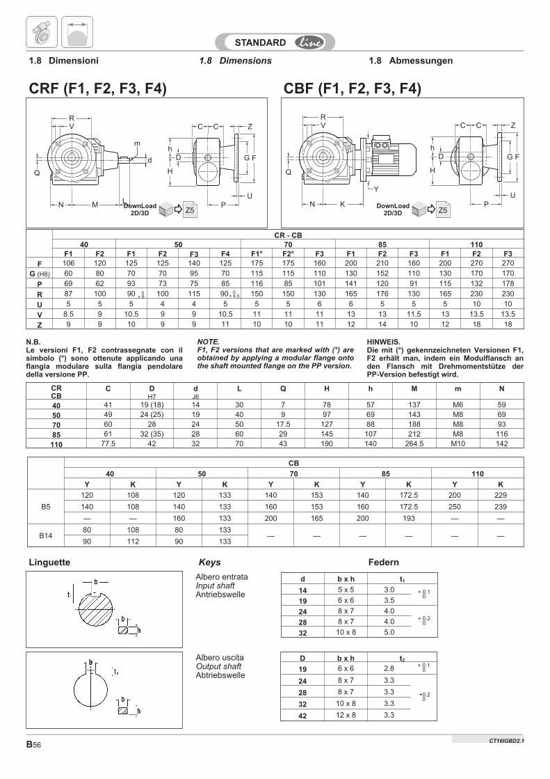
CT16IGBD2B56
CR - CB40 50 70 85 110
F1 F2 F1 F2 F3 F4 F1° F2° F3 F1 F2 F3 F1 F2 F3
F 106 120 125 125 140 125 175 175 160 200 210 160 200 270 270
G (H8) 60 80 70 70 95 70 115 115 110 130 152 110 130 170 170
P 69 62 93 73 75 85 116 85 101 141 120 91 115 132 178
R 87 100 90 100 115 90 150 150 130 165 176 130 165 230 230
U 5 5 5 4 4 5 5 5 6 6 5 5 5 10 10
V 8.5 9 10.5 9 9 10.5 11 11 11 13 13 11.5 13 13.5 13.5
Z 9 9 10 9 9 11 10 10 11 12 14 10 12 18 18
CC
Dh
H
Z
G F
UP
m
M
d
L
RV
Q
N
CRF (F1, F2, F3, F4)
Y
K
RV
Q
N
CC
Dh
H
Z
G F
UP
CBF (F1, F2, F3, F4)
1.8 Dimensions1.8 Dimensioni 1.8 Abmessungen
CRCB
C DH7
dJ6
L Q H h M m N
40 41 19 (18) 14 30 7 78 57 137 M6 59
50 49 24 (25) 19 40 9 97 69 143 M8 69
70 60 28 24 50 17.5 127 88 188 M8 93
85 61 32 (35) 28 60 29 145 107 212 M8 116
110 77.5 42 32 70 43 190 140 264.5 M10 142
Keys FedernLinguette
D b x h t2
19 6 x 6 2.8 + 0.10
24 8 x 7 3.3
+0.20
28 8 x 7 3.3
32 10 x 8 3.3
42 12 x 8 3.3
d b x h t1
14 5 x 5 3.0 + 0.10
19 6 x 6 3.5
24 8 x 7 4.0+ 0.2
028 8 x 7 4.0
32 10 x 8 5.0
Albero uscitaOutput shaftAbtriebswelle
Albero entrataInput shaftAntriebswelle
NOTE.F1, F2 versions that are marked with (°) areobtained by applying a modular flange ontothe shaft mounted flange on the PP version.
HINWEIS.Die mit (°) gekennzeichneten Versionen F1,F2 erhält man, indem ein Modulflansch anden Flansch mit Drehmomentstütze derPP-Version befestigt wird.
N.B.Le versioni F1, F2 contrassegnate con ilsimbolo (°) sono ottenute applicando unaflangia modulare sulla flangia pendolaredella versione PP.
0+ 9
0+ 4.5
2D 3DDownLoad
2D/3D Z5 2D 3DDownLoad
2D/3D Z5
CT16IGBD2.1
CB
40 50 70 85 110
Y K Y K Y K Y K Y K
B5
120 108 120 133 140 153 140 172.5 200 229
140 108 140 133 160 153 160 172.5 250 239
— — 160 133 200 165 200 193 — —
B1480 108 80 133
— — — — — —90 112 90 133
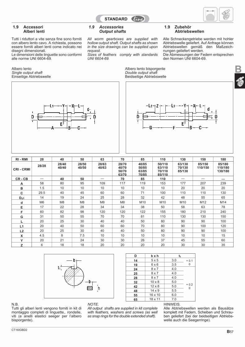
CT16IGBD2 B57
1.9 AccessoriesOutput shafts
1.9 AccessoriAlberi lenti
1.9 ZubehörAbtriebswellen
All worm gearboxes are supplied withhollow output shaft. Output shafts as shownin the size drawings can be supplied uponrequest.Sizes of feathers comply with standardsUNI 6604-69.
RI - RMI 28 40 50 63 70 85 110 130 150 180
CRI - CRMI28/28 28/40
40/4028/5040/50
28/6340/63
28/7040/7050/7063/70
40/8550/8563/8570/85
50/11063/11070/11085/110
63/13070/13085/130
85/150110/150
85/180110/180130/180
CR - CB — 40 50 — 70 85 110 — — —
A 58 80 95 109 117 119 153 177 207 239
B 1.5 10 10 10 10 10 10 20 20 20
C 29.5 40 45 60 60 71 100 110 110 130
Dg6 14 19 24 25 28 32 42 48 55 65
d M6 M8 M8 M8 M8 M10 M10 M10 M12 M14
E 17 22 28 34 34 38 50 58 63 78
F 60 82 98 120 120 122 155 180 210 240
G 31 50 55 70 70 81 110 130 130 150
L 20 25 30 40 40 50 80 90 90 100
L1 20 40 50 60 60 70 80 90 100 120
L2 20 25 30 40 40 50 80 90 90 100
X 4.5 8 7.5 10 10 10 10 10 10 15
Y 20 21 24 30 30 26 37 45 55 60
Z 6 18 18 20 20 20 20 30 30 35
Albero lento bisporgenteDouble output shaftBeidseitige Abtriebswelle
Albero lentoSingle output shaftEinseitige Abtriebswelle
NOTE.All output shafts are supplied in kit completewith feathers, washers and screws (as wellas snap rings for the double extended shaft).
D b x h t1
14 5 x 5 3.0 + 0.1019 6 x 6 3.5
24 8 x 7 4.0
25 8 x 7 4.0
+ 0.20
28 8 x 7 4.0
32 10 x 8 5.0
42 12 x 8 5.0
48 14 x 9 5.5
55 16 x 10 6.0
65 18 x 11 7.0
Alle Schneckengetriebe werden mit hohlerAbtriebswelle geliefert. Auf Anfrage könnenAbtriebswellen gemäß den Maßzeich-nungen geliefert werden.Die Abmessungen der Federn entsprechenden Normen UNI 6604-69.
Tutti i riduttori a vite senza fine sono forniticon albero lento cavo. A richiesta, possonoessere forniti alberi lenti come indicato neidisegni dimensionali.Le dimensioni delle linguette sono conformialle norme UNI 6604-69.
HINWEIS.Alle Abtriebswellen werden als Bausätzekomplett mit Federn, Scheiben und Schrau-ben geliefert (bei der beidseitigen Abtriebs-welle auch die Seegerringe).
N.B.Tutti gli alberi lenti vengono forniti in kit dimontaggio completi di linguette,. rondelle,viti (e anelli elastici seeger per l’alberobisporgente).
B
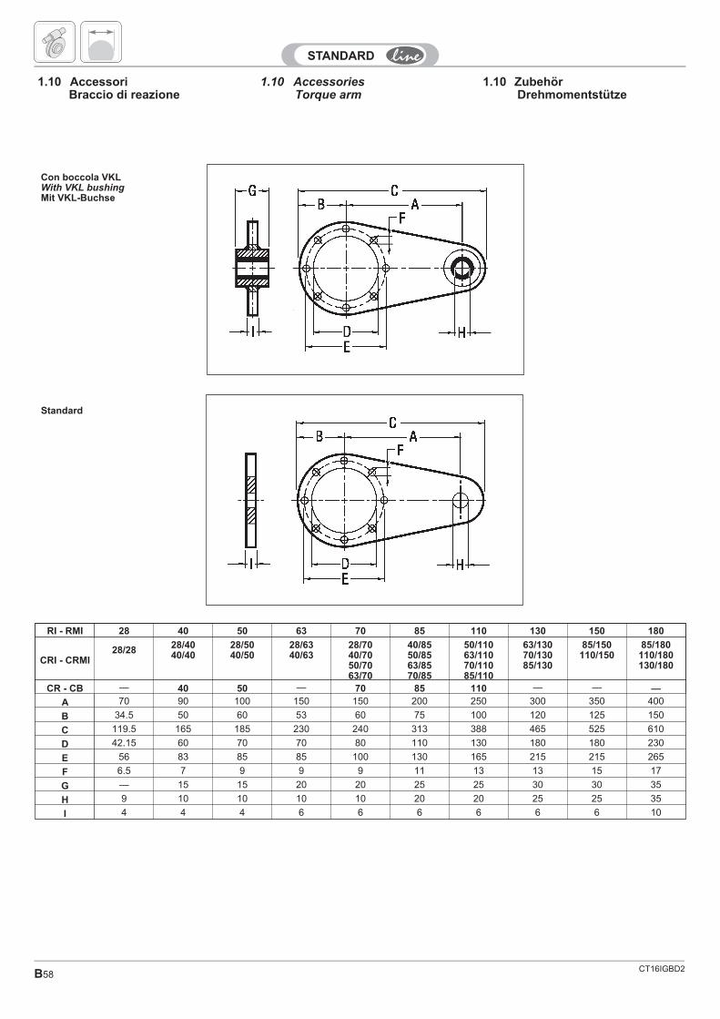
CT16IGBD2B58
1.10 AccessoriesTorque arm
1.10 AccessoriBraccio di reazione
1.10 ZubehörDrehmomentstütze
Standard
Con boccola VKLWith VKL bushingMit VKL-Buchse
RI - RMI 28 40 50 63 70 85 110 130 150 180
CRI - CRMI28/28 28/40
40/4028/5040/50
28/6340/63
28/7040/7050/7063/70
40/8550/8563/8570/85
50/11063/11070/11085/110
63/13070/13085/130
85/150110/150
85/180110/180130/180
CR - CB — 40 50 — 70 85 110 — — —
A 70 90 100 150 150 200 250 300 350 400
B 34.5 50 60 53 60 75 100 120 125 150
C 119.5 165 185 230 240 313 388 465 525 610
D 42.15 60 70 70 80 110 130 180 180 230
E 56 83 85 85 100 130 165 215 215 265
F 6.5 7 9 9 9 11 13 13 15 17
G — 15 15 20 20 25 25 30 30 35
H 9 10 10 10 10 20 20 25 25 35
I 4 4 4 6 6 6 6 6 6 10