Embed Size (px)
Citation preview
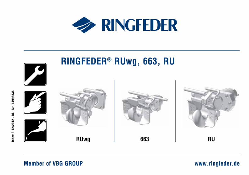
RINGFEDER® RUwg, 663, RU
Member of VBG GROUP www.ringfeder.de
Inde
x B
12/2
012
· Id
.- N
r. 1
4996
835
RUwg 663 RU
2
DE
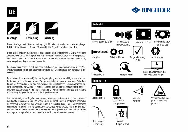
Diese Montage und Betriebsanleitung gilt für die automatischen Hakenkupplungen RINGFDER der Baureihen RUwg, 663 sowie RU K5DV (siehe Tabellen, Seiten 4-5).
Diese axial drehbaren automatischen Hakenkupplungen entsprechend STANAG 4101 sind ausschließlich zur Verbindung von Fahrzeugen mit axial nicht drehbaren 76 mm Ringzugösen der Klasse L gemäß Richtlinie ECE 55-01 und 76 mm Ringzugösen nach VG 74059 (Nato) oder baugleichen Ringzugösen zu verwenden.
Bei den automatischen Hakenkupplungen mit allgemeiner Bauartgenehmigung ist der Ver-wendungsbereich durch die Bauartgenehmigung auf Kraftfahrzeuge der Bundeswehr be-schränkt.
Beim Anbau (bzw. Austausch) der Anhängekupplung sind die einschlägigen gesetzlichen Bestimmungen und die Angaben der Fahrzeughersteller zwingend zu beachten! Beim Aus-tausch der Anhängekupplung sind alle im Lieferumfang enthaltenen Teile der Anhängekupp-lung zu wechseln. Der Anbau der Anhängekupplung ist sinngemäß entsprechend den For-derungen des Anhanges VII der Richtline ECE 55-01 vorzunehemen. Montage und Wartung müssen sorgfältig und fachmännisch durchgeführt werden.
Von den nachfolgenden Angaben sind eventuell abweichende Schrauben- und Mutternormen der Befestigungsschrauben und selbstsichernden Ganzmetallmuttern der Fahrzeughersteller zu beachten! Alternativ zu der Verschraubung mit Scheiben können auch entsprechende Flanschkopfschrauben und Flanschmuttern verwendet werden, wobei dann die Scheiben entfallen. Die Schraubenlänge ist der Traversenstärke anzupassen. Die axiale Drehbarkeit der Anhängekupplung darf nicht durch überstehende Schrauben behindert werden.
WartungMontage Bedienung
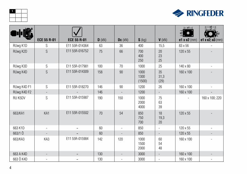
Seite 4-5
Tabellen (siehe Seite 29) automatische Hakenkupplung
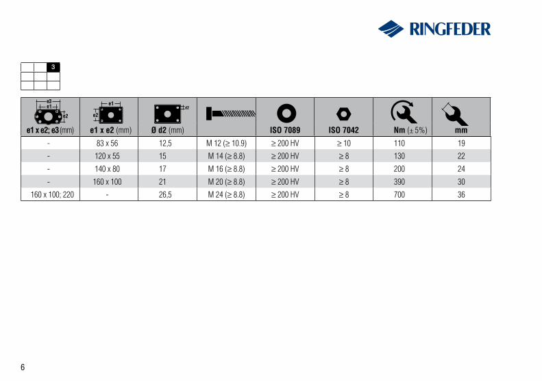
Lochbild (e1 x e2)
Schraube Scheibe Mutter Typgenehmigung,ABG
Kronenmutter
Schlüsselweite Anzugsmoment
Seite 6 - 16
Kupplung offen Kupplung geschlossenund gesichert
Visuelle Kontrolle
Achtung! Verletzungs-gefahr – Hand wird gequetscht
Abschmieren (Fettpresse)
Intervall1 x pro Quartal
Zulässige Anhängelast des Starrdeichselanhängers
Lochbild RU K5DV(e1 x e2; e3)
3
EN
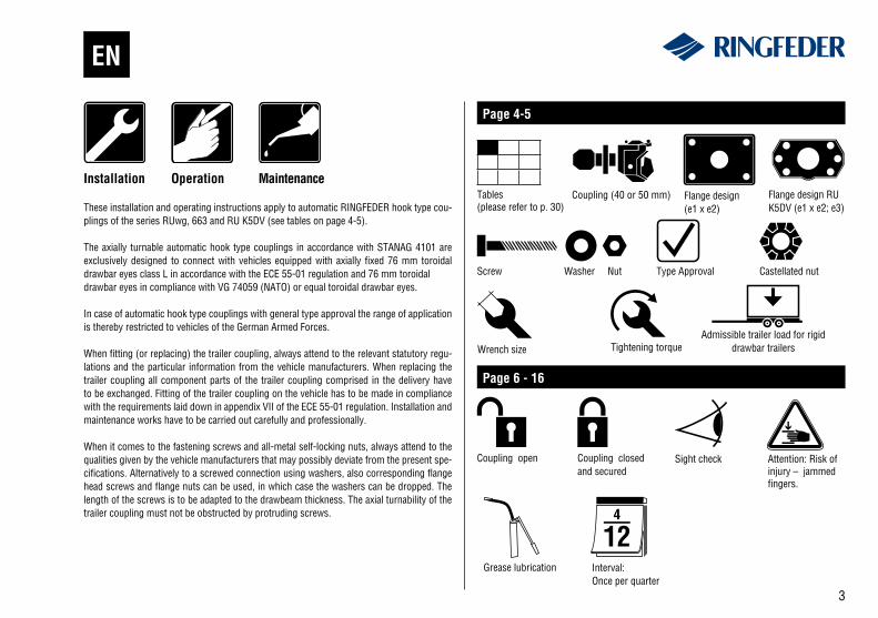
These installation and operating instructions apply to automatic RINGFEDER hook type cou-plings of the series RUwg, 663 and RU K5DV (see tables on page 4-5).
The axially turnable automatic hook type couplings in accordance with STANAG 4101 are exclusively designed to connect with vehicles equipped with axially fixed 76 mm toroidal drawbar eyes class L in accordance with the ECE 55-01 regulation and 76 mm toroidaldrawbar eyes in compliance with VG 74059 (NATO) or equal toroidal drawbar eyes.
In case of automatic hook type couplings with general type approval the range of application is thereby restricted to vehicles of the German Armed Forces.
When fitting (or replacing) the trailer coupling, always attend to the relevant statutory regu-lations and the particular information from the vehicle manufacturers. When replacing the trailer coupling all component parts of the trailer coupling comprised in the delivery have to be exchanged. Fitting of the trailer coupling on the vehicle has to be made in compliance with the requirements laid down in appendix VII of the ECE 55-01 regulation. Installation and maintenance works have to be carried out carefully and professionally.
When it comes to the fastening screws and all-metal self-locking nuts, always attend to the qualities given by the vehicle manufacturers that may possibly deviate from the present spe-cifications. Alternatively to a screwed connection using washers, also corresponding flange head screws and flange nuts can be used, in which case the washers can be dropped. The length of the screws is to be adapted to the drawbeam thickness. The axial turnability of the trailer coupling must not be obstructed by protruding screws.
MaintenanceInstallation Operation
Page 4-5
Tables (please refer to p. 30)
Coupling (40 or 50 mm) Flange design (e1 x e2)
Screw Washer Nut Type Approval Castellated nut
Wrench size Tightening torque
Page 6 - 16
Coupling open Coupling closed and secured
Sight check Attention: Risk of injury – jammed fingers.
Flange design RU K5DV (e1 x e2; e3)
Admissible trailer load for rigid drawbar trailers
Grease lubrication Interval:Once per quarter
4
RUwg K1D S E11 55R-014364 63 36 400 15,5 83 x 56 -RUwg K2D S E11 55R-016752 75 66 700
400250
202325
120 x 55 -
RUwg K3D S E11 55R-017981 100 70 1000 25 140 x 80 -
RUwg K4D S E11 55R-014309 158 90 10001300(1500)
3531,3(29)
160 x 100 -
RUwg K4D F1 S E11 55R-018270 146 90 1200 26 160 x 100 -RUwg K4D F2 - - 146 - 1200 - 160 x 100 -
RU K5DV S E11 55R-015987 190 150 100020004000
756339
- 160 x 100; 220
663/KA1 KA1 E11 55R-015502 70 54 850750700
1819,320
120 x 55 -
663 K1D - - 60 - 850 - 120 x 55 -663/1 Ö - - 60 - 850 - 120 x 55 -
663/KA3 KA3 E11 55R-015984 142 120 100015002000
605448
160 x 100 -
663 A K4D - - 130 - 3000 - 160 x 100 -663 Ö K4D - - 130 - 3000 - 160 x 100 -
ECE 55 R-01 ECE 55 R-01 D (kN) Dc (kN) S (kg) V (kN) e1 x e2 (mm) e1 x e2; e3 (mm)
1
5
RUwg K1D F 3143 42 400 5000 83 x 56 -
RUwg K2D F 3236 75 700 6500 120 x 55 -
RUwg K3D F 3233 95 950 9000 140 x 80 -
RUwg K4D F 3142 130 1000 12000 160 x 100 -
RU K5DV F 672 390 4000 16000 - 160 x 100; 220
ABG D (kN) S (kg) kg e1 x e2 (mm) e1 x e2; e3 (mm)
2
6
3
- 83 x 56 12,5 M 12 (≥ 10.9) ≥ 200 HV ≥ 10 110 19
- 120 x 55 15 M 14 (≥ 8.8) ≥ 200 HV ≥ 8 130 22
- 140 x 80 17 M 16 (≥ 8.8) ≥ 200 HV ≥ 8 200 24
- 160 x 100 21 M 20 (≥ 8.8) ≥ 200 HV ≥ 8 390 30
160 x 100; 220 - 26,5 M 24 (≥ 8.8) ≥ 200 HV ≥ 8 700 36
e1 x e2; e3 (mm) e1 x e2 (mm) Ø d2 (mm) ISO 7089 ISO 7042 Nm (± 5%) mm
7
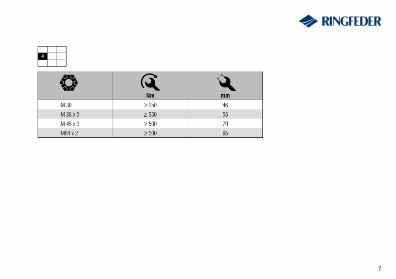
4
M 30 ≥ 250 46
M 36 x 3 ≥ 350 55
M 45 x 3 ≥ 500 70
M64 x 2 ≥ 500 95
Nm mm
8
A13
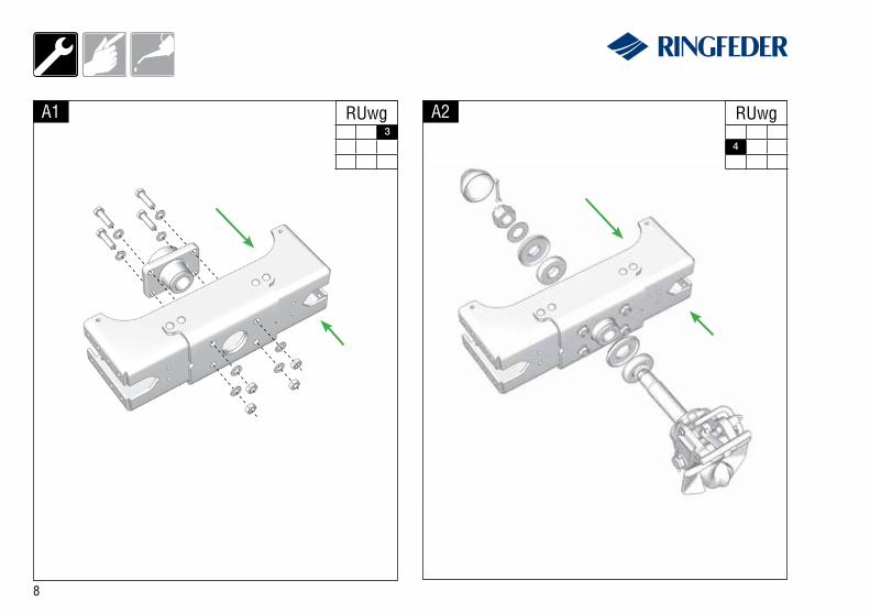
A2
4
RUwg RUwg
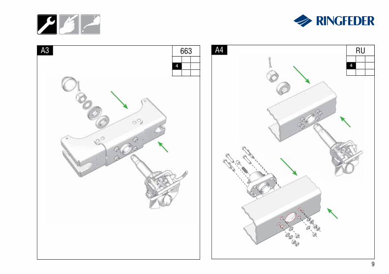
9
A4A3
4
663
4
RU
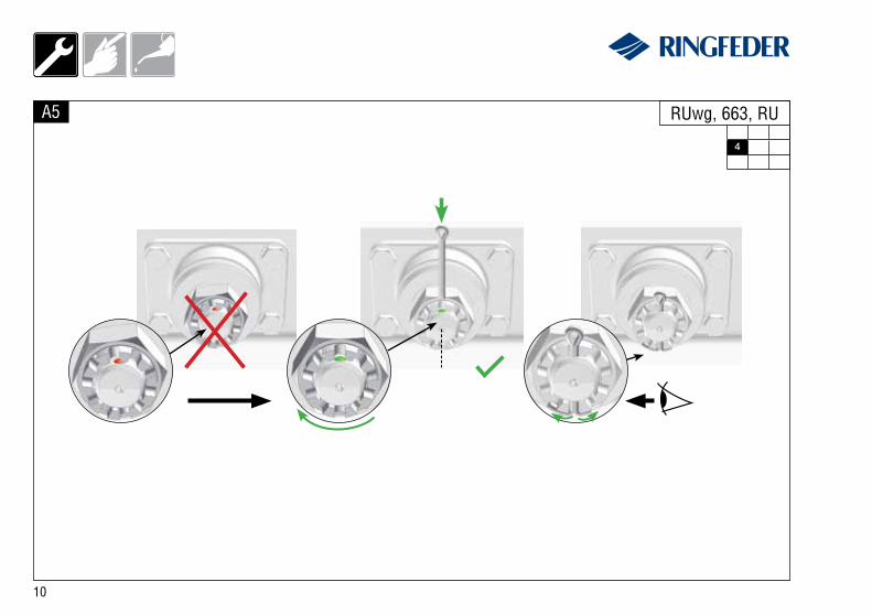
10
A5
4
RUwg, 663, RU
11
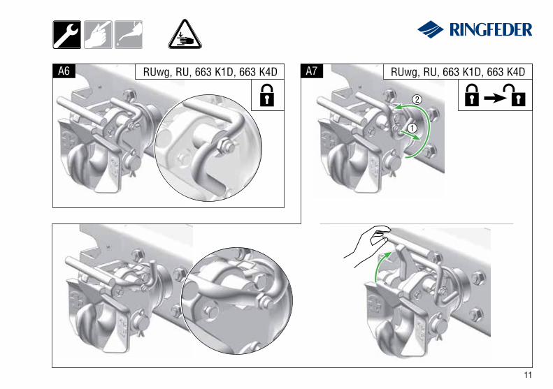
A6 A7 RUwg, RU, 663 K1D, 663 K4DRUwg, RU, 663 K1D, 663 K4D
1
2
12
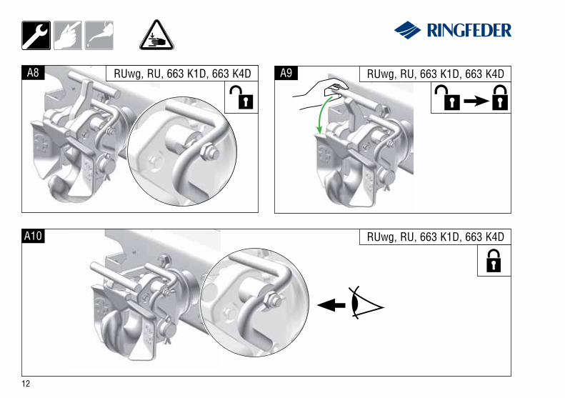
A8 RUwg, RU, 663 K1D, 663 K4D A9 RUwg, RU, 663 K1D, 663 K4D
A10 RUwg, RU, 663 K1D, 663 K4D
13
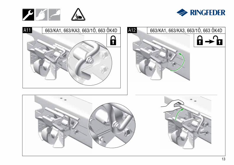
A11 A12663/KA1, 663/KA3, 663/1Ö, 663 ÖK4D 663/KA1, 663/KA3, 663/1Ö, 663 ÖK4D
14
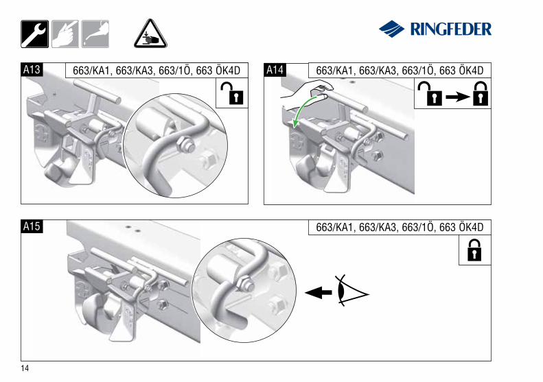
A13 A14
A15
663/KA1, 663/KA3, 663/1Ö, 663 ÖK4D 663/KA1, 663/KA3, 663/1Ö, 663 ÖK4D
663/KA1, 663/KA3, 663/1Ö, 663 ÖK4D
15
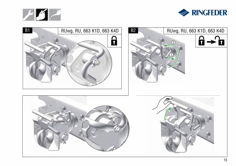
B1 B2
1
2
RUwg, RU, 663 K1D, 663 K4D RUwg, RU, 663 K1D, 663 K4D
16
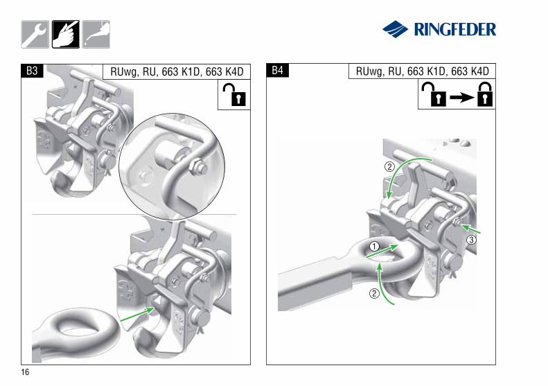
B3 RUwg, RU, 663 K1D, 663 K4D B4 RUwg, RU, 663 K1D, 663 K4D
2
2
31
17
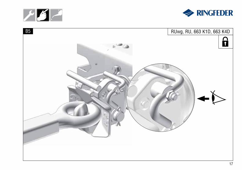
B5 RUwg, RU, 663 K1D, 663 K4D
18
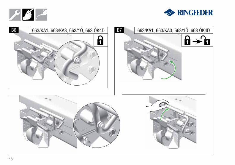
B6 B7663/KA1, 663/KA3, 663/1Ö, 663 ÖK4D 663/KA1, 663/KA3, 663/1Ö, 663 ÖK4D
19
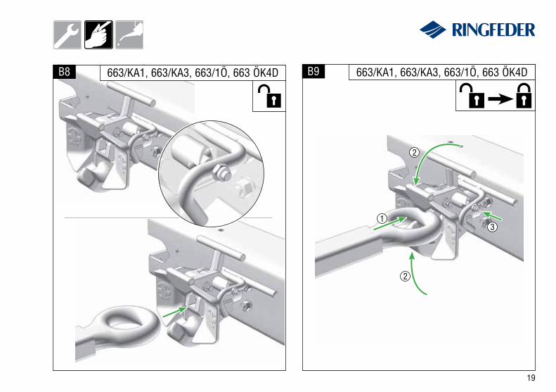
B8 B9663/KA1, 663/KA3, 663/1Ö, 663 ÖK4D 663/KA1, 663/KA3, 663/1Ö, 663 ÖK4D
2
2
31
20
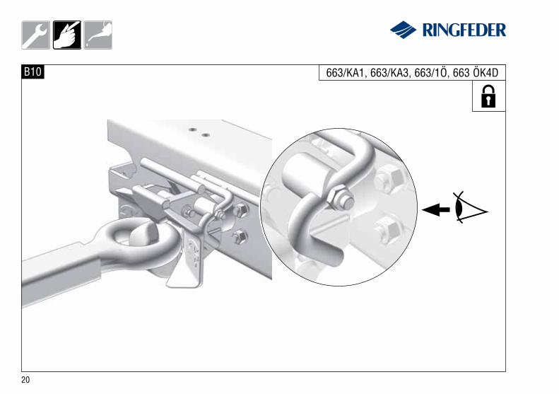
B10 663/KA1, 663/KA3, 663/1Ö, 663 ÖK4D
21
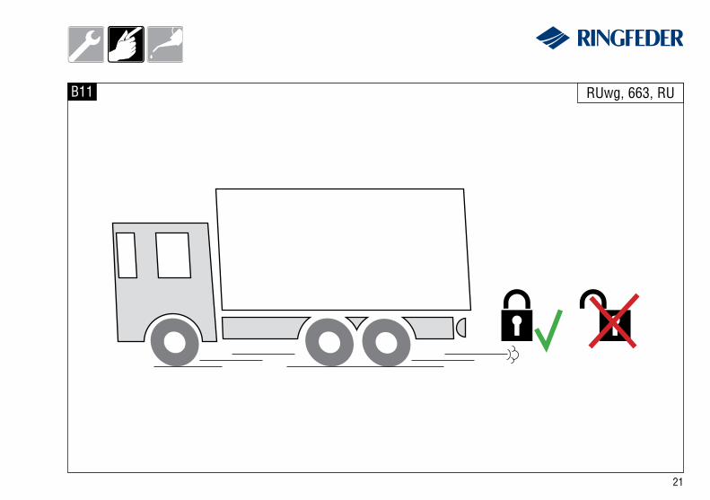
B11 RUwg, 663, RU
22
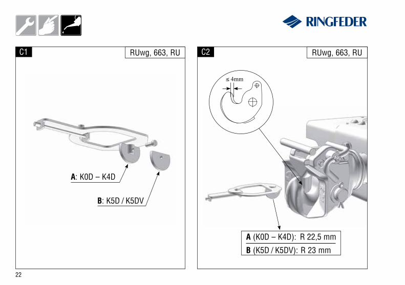
wC1 RUwg, 663, RU
A: K0D – K4D
B: K5D / K5DV
C2 RUwg, 663, RU
A (K0D – K4D): R 22,5 mm
B (K5D / K5DV): R 23 mm
≤ 4mm
23
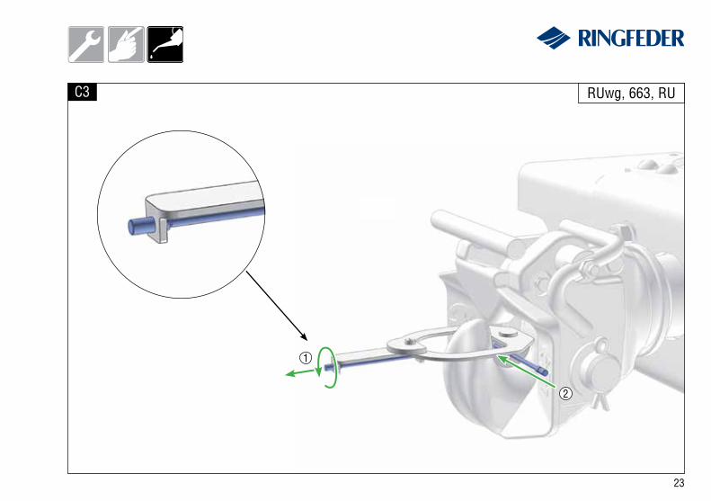
C3 RUwg, 663, RU
1
2
24
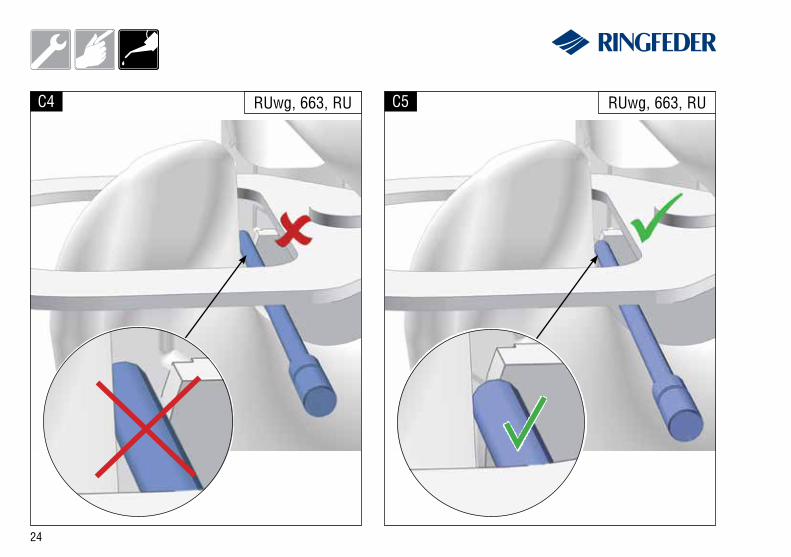
C4 RUwg, 663, RU C5 RUwg, 663, RU
25
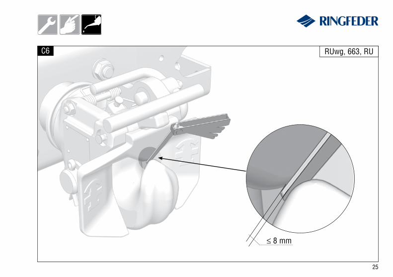
C6
≤ 8 mm
RUwg, 663, RU
26
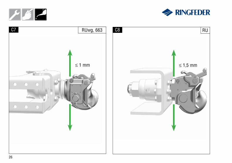
C7 RUwg, 663
≤ 1 mm
C8 RU
≤ 1,5 mm
27
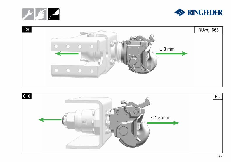
C10 RU
C9 RUwg, 663
± 0 mm
≤ 1,5 mm
28
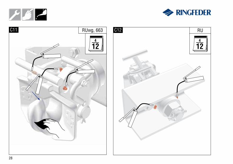
C11 RUwg, 663 C12 RU

29

30
31
VBG GROUP TRUCK EQUIPMENT GMBH · Girmesgath 5 · D-47803 Krefeldwww.ringfeder.de · e-mail: [email protected]
Produced in a certified company DIN EN ISO 9001:2008, ISO TS 16949:2009, DIN EN ISO 14001:2004


![Weitere Standard-Kugeldrehverbindungen · 2020. 2. 24. · DIN 71412 radiales Spiel axiales Kippspiel G [kg] n a [-] n i [-] C o rad [kN] C o ax [kN] C rad [kN] C ax [kN] T [-] X](https://img.pdfslide.org/doc/110x75/61256d940e198236cc39393f/weitere-standard-kugeldrehverbindungen-2020-2-24-din-71412-radiales-spiel-axiales.jpg)