Embed Size (px)
Citation preview
�
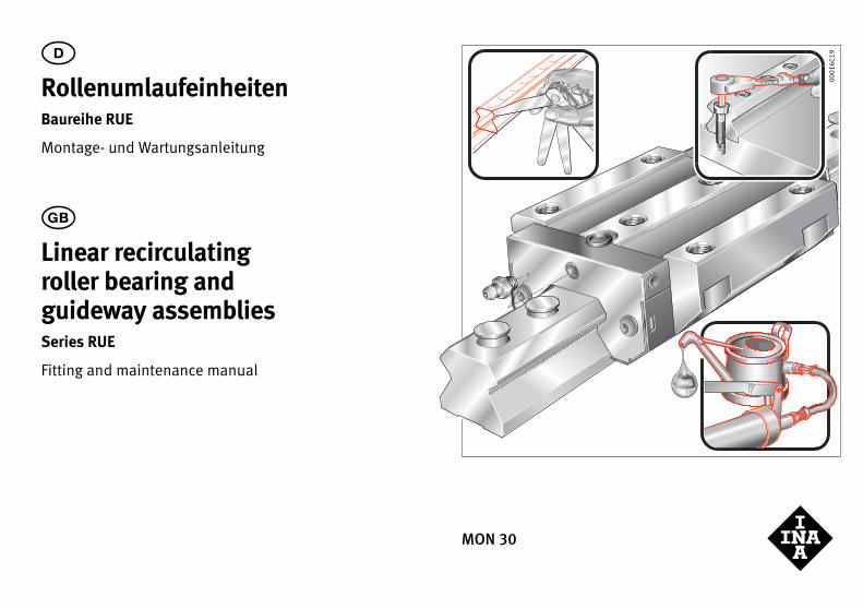
Linear recirculating roller bearing and guideway assembliesSeries RUE
Fitting and maintenance manual
MON 30
0001
6C19D
RollenumlaufeinheitenBaureihe RUE
Montage- und Wartungsanleitung
2
D Inhaltsverzeichnis Seite
Benötigte Werkzeuge und Hilfsmittel ............................................. 2Montageplatz/Montagewerkzeuge................................................... 3Anschlusskonstruktion kontrollieren .............................................. 4Lieferausführung kontrollieren............................................................ 7Befestigungsschrauben/Anziehdrehmomente......................... 10Führungswagen demontieren/montieren .................................... 11Vormontierte Rollenumlaufeinheiten einbauen....................... 12Schmierung ...................................................................................................... 21Mindestölmenge bei Inbetriebnahme Qmind/Ölimpulsmenge Qimp ................................................................................. 26Erstbefettungsmenge................................................................................. 26Nachschmiermengen bei Ölimpulsschmierung ....................... 27
� Contents Page
Tools and equipment required ............................................................ 2Fitting area/fitting tools ........................................................................... 3Checking the adjacent construction ................................................ 4Checking the delivered condition...................................................... 7Fasteners and tightening torques...................................................... 10Dismantling and fitting of carriages................................................. 11Fitting of preassembled linear roller bearing and guideway assembly .................................................................................... 12Lubrication........................................................................................................ 21Minimum oil quantity Qmind/oil pulse quantity Qimp ........... 26Initial grease quantity ............................................................................... 26Relubrication quantities for oil pulse lubrication ................... 27
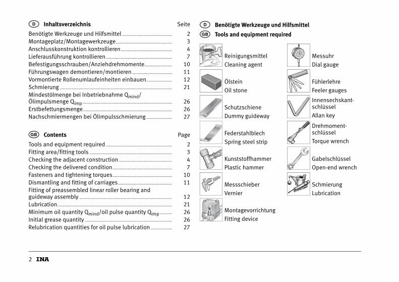
D Benötigte Werkzeuge und Hilfsmittel
� Tools and equipment required
Reinigungsmittel
Cleaning agent
Messuhr
Dial gauge
Ölstein
Oil stone
Fühlerlehre
Feeler gauges
Schutzschiene
Dummy guideway
Innensechskant-schlüssel
Allan key
Federstahlblech
Spring steel strip
Drehmoment-schlüssel
Torque wrench
Kunststoffhammer
Plastic hammer
Gabelschlüssel
Open-end wrench
Messschieber
Vernier
Schmierung
Lubrication
Montagevorrichtung
Fitting device
3
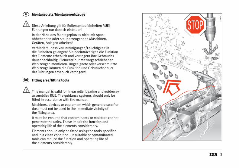
Diese Anleitung gilt für Rollenumlaufeinheiten RUE!Führungen nur danach einbauen!
In der Nähe des Montageplatzes nicht mit span-abhebenden oder stauberzeugenden Maschinen, Geräten, Anlagen arbeiten!
Verhindern, dass Verunreinigungen/Feuchtigkeit in die Einheiten gelangen! Sie beeinträchtigen die Funktion der Elemente erheblich und verringern ihre Gebrauchs-dauer nachhaltig! Elemente nur mit vorgeschriebenen Werkzeugen montieren. Ungeeignete oder verschmutzte Werkzeuge können die Funktion und Gebrauchsdauer der Führungen erheblich verringern!
D Montageplatz/Montagewerkzeuge
This manual is valid for linear roller bearing and guideway assemblies RUE. The guidance systems should only befitted in accordance with the manual.
Machines, devices or equipment which generate swarf or dust must not be used in the immediate vicinity of the fitting area.
It must be ensured that contaminants or moisture cannot penetrate the units. These impair the function and operating life of the elements considerably.
Elements should only be fitted using the tools specified and in a clean condition. Unsuitable or contaminated tools can reduce the function and operating life of the elements considerably.
� Fitting area/fitting tools
156
703
4
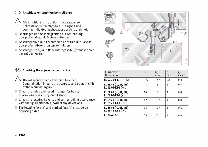
Die Anschlusskonstruktion muss sauber sein!Schmutz beeinträchtigt die Genauigkeit und verringert die Gebrauchsdauer der Umlaufeinheit!
■ Bohrungen und Anschlagkanten auf Gratbildung überprüfen; Grat mit Ölstein entfernen.
■ Anschlaghöhen und Eckenradien nach Bild und Tabelle überprüfen; Abweichungen korrigieren.
■ Anschlagseite � und Beschriftungsseite � müssen sich gegenüber liegen.
D Anschlusskonstruktion kontrollieren
The adjacent construction must be clean.Contamination impairs the accuracy and operating life of the recirculating unit.
■ Check the holes and locating edges for burrs; remove any burrs using an oil stone.
■ Check the locating heights and corner radii in accordance with the figure and table; correct any deviations.
■ The locating face � and marked face � must be onopposing sides.
� Checking the adjacent constructionKurzzeichenDesignation
h1 h2max.
r1max.
r2max.
RUE25-D (-L, -H, -HL) 7,5 4,5 0,8 0,3
RUE35-E (-L, -H, -HL)RUE35-E-KT-L (-HL)
8 6 1 0,8
RUE45-E (-L, -H, -HL)RUE45-E-KT-L (-HL)
10 8 1 0,8
RUE55-E (-L, -H, -HL)RUE55-E-KT-L (-HL)
12 9,5 1 0,8
RUE65-E (-L, -H, -HL)RUE65-E-KT-L (-HL)
15 10,5 1 0,8
RUE100-E-L 25 13 1 0,8
r
h
1
1
h2r2
�
�
�
�
156
704
5
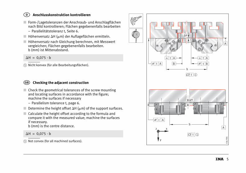
■ Form-/Lagetoleranzen der Anschraub- und Anschlagflächen nach Bild kontrollieren; Flächen gegebenenfalls bearbeiten– Parallelitätstoleranz t, Seite 6.
■ Höhenversatz �H (�m) der Auflageflächen ermitteln.
■ Höhenversatz nach Gleichung berechnen, mit Messwert vergleichen; Flächen gegebenenfalls bearbeiten.b (mm) ist Mittenabstand.
� Nicht konvex (für alle Bearbeitungsflächen).
D Anschlusskonstruktion kontrollieren
�H 0,075 · b=
■ Check the geometrical tolerances of the screw mounting and locating surfaces in accordance with the figure; machine the surfaces if necessary– Parallelism tolerance t, page 6.
■ Determine the height offset �H (�m) of the support surfaces.
■ Calculate the height offset according to the formula and compare it with the measured value; machine the surfaces if necessary.b (mm) is the centre distance.
� Not convex (for all machined surfaces).
� Checking the adjacent construction
�H 0,075 · b=
A
AA
B BA
b
A
Ab
z x
y
t
t
t
t
t
t
t
�H
�H
1
1
156
705
6
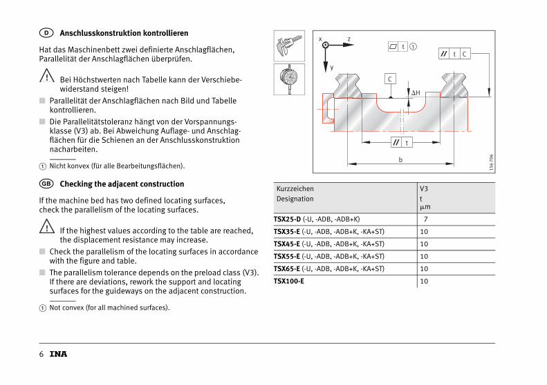
Hat das Maschinenbett zwei definierte Anschlagflächen, Parallelität der Anschlagflächen überprüfen.
Bei Höchstwerten nach Tabelle kann der Verschiebe-widerstand steigen!
■ Parallelität der Anschlagflächen nach Bild und Tabelle kontrollieren.
■ Die Parallelitätstoleranz hängt von der Vorspannungs-klasse (V3) ab. Bei Abweichung Auflage- und Anschlag-flächen für die Schienen an der Anschlusskonstruktion nacharbeiten.
� Nicht konvex (für alle Bearbeitungsflächen).
D Anschlusskonstruktion kontrollieren
If the machine bed has two defined locating surfaces, check the parallelism of the locating surfaces.
If the highest values according to the table are reached, the displacement resistance may increase.
■ Check the parallelism of the locating surfaces in accordance with the figure and table.
■ The parallelism tolerance depends on the preload class (V3). If there are deviations, rework the support and locating surfaces for the guideways on the adjacent construction.
� Not convex (for all machined surfaces).
� Checking the adjacent constructionKurzzeichenDesignation
V3t�m
TSX25-D (-U, -ADB, -ADB+K) 7
TSX35-E (-U, -ADB, -ADB+K, -KA+ST) 10
TSX45-E (-U, -ADB, -ADB+K, -KA+ST) 10
TSX55-E (-U, -ADB, -ADB+K, -KA+ST) 10
TSX65-E (-U, -ADB, -ADB+K, -KA+ST) 10
TSX100-E 10
x z
y
t
�H
C
b
t C
t
1
156
706
7
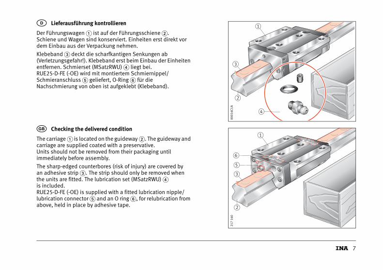
Der Führungswagen � ist auf der Führungsschiene �. Schiene und Wagen sind konserviert. Einheiten erst direkt vor dem Einbau aus der Verpackung nehmen.
Klebeband � deckt die scharfkantigen Senkungen ab (Verletzungsgefahr!). Klebeband erst beim Einbau der Einheiten entfernen. Schmierset (MSatzRWU) � liegt bei.RUE25-D-FE (-OE) wird mit montiertem Schmiernippel/Schmieranschluss � geliefert, O-Ring � für dieNachschmierung von oben ist aufgeklebt (Klebeband).
D Lieferausführung kontrollieren
The carriage � is located on the guideway �. The guideway and carriage are supplied coated with a preservative. Units should not be removed from their packaging until immediately before assembly.
The sharp-edged counterbores (risk of injury) are covered by an adhesive strip �. The strip should only be removed when the units are fitted. The lubrication set (MSatzRWU) �is included.RUE25-D-FE (-OE) is supplied with a fitted lubrication nipple/lubrication connector � and an O ring �, for relubrication from above, held in place by adhesive tape.
� Checking the delivered condition
3
4
2
1
0001
6C1A
Fet tFet t
3
1
2
5
6
217
160
8
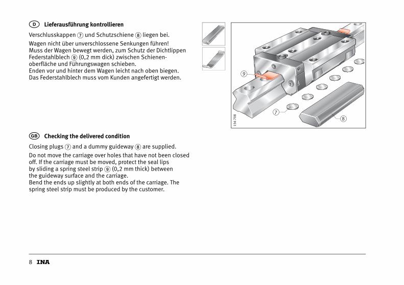
Verschlusskappen � und Schutzschiene liegen bei.
Wagen nicht über unverschlossene Senkungen führen! Muss der Wagen bewegt werden, zum Schutz der Dichtlippen Federstahlblech (0,2 mm dick) zwischen Schienen-oberfläche und Führungswagen schieben. Enden vor und hinter dem Wagen leicht nach oben biegen. Das Federstahlblech muss vom Kunden angefertigt werden.
D Lieferausführung kontrollieren
Closing plugs � and a dummy guideway are supplied.
Do not move the carriage over holes that have not been closed off. If the carriage must be moved, protect the seal lips by sliding a spring steel strip (0,2 mm thick) between the guideway surface and the carriage.Bend the ends up slightly at both ends of the carriage. The spring steel strip must be produced by the customer.
� Checking the delivered condition
9
78
156
708
9
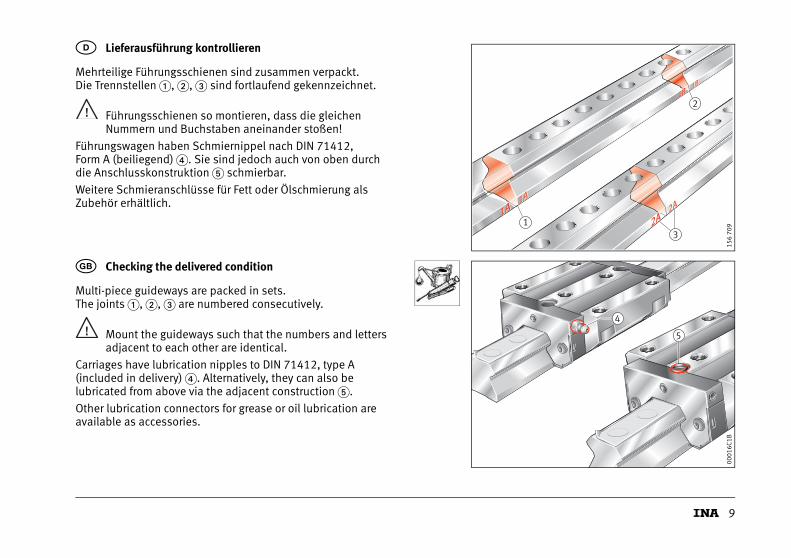
Mehrteilige Führungsschienen sind zusammen verpackt. Die Trennstellen �, �, � sind fortlaufend gekennzeichnet.
Führungsschienen so montieren, dass die gleichen Nummern und Buchstaben aneinander stoßen!
Führungswagen haben Schmiernippel nach DIN 71412,Form A (beiliegend) �. Sie sind jedoch auch von oben durchdie Anschlusskonstruktion � schmierbar.
Weitere Schmieranschlüsse für Fett oder Ölschmierung als Zubehör erhältlich.
D Lieferausführung kontrollieren
Multi-piece guideways are packed in sets. The joints �, �, � are numbered consecutively.
Mount the guideways such that the numbers and letters adjacent to each other are identical.
Carriages have lubrication nipples to DIN 71412, type A (included in delivery) �. Alternatively, they can also be lubricated from above via the adjacent construction �.
Other lubrication connectors for grease or oil lubrication are available as accessories.
� Checking the delivered condition
1
2
3
1A1A1A1A
1B1B1B1B
2A2A2A2A
156
709
4
5
0001
6C1B
10
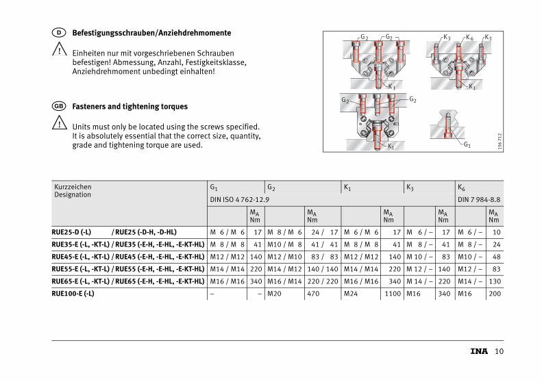
Einheiten nur mit vorgeschriebenen Schrauben befestigen! Abmessung, Anzahl, Festigkeitsklasse, Anziehdrehmoment unbedingt einhalten!
D Befestigungsschrauben/Anziehdrehmomente
Units must only be located using the screws specified. It is absolutely essential that the correct size, quantity, grade and tightening torque are used.
� Fasteners and tightening torques
G1
K3 K 6 K3G2 G2
K1 K1
G2 G2
K1 156
712
KurzzeichenDesignation
G1 G2 K1 K3 K6
DIN ISO 4 762-12.9 DIN 7 984-8.8
MANm
MANm
MANm
MANm
MANm
RUE25-D (-L) /RUE25 (-D-H, -D-HL) M 6 / M 6 17 M 8 / M 6 24 / 17 M 6 / M 6 17 M 6 / – 17 M 6 / – 10
RUE35-E (-L, -KT-L) / RUE35 (-E-H, -E-HL, -E-KT-HL) M 8 / M 8 41 M10 / M 8 41 / 41 M 8 / M 8 41 M 8 / – 41 M 8 / – 24
RUE45-E (-L, -KT-L) / RUE45 (-E-H, -E-HL, -E-KT-HL) M12 / M12 140 M12 / M10 83 / 83 M12 / M12 140 M 10 / – 83 M10 / – 48
RUE55-E (-L, -KT-L) / RUE55 (-E-H, -E-HL, -E-KT-HL) M14 / M14 220 M14 / M12 140 / 140 M14 / M14 220 M 12 / – 140 M12 / – 83
RUE65-E (-L, -KT-L) / RUE65 (-E-H, -E-HL, -E-KT-HL) M16 / M16 340 M16 / M14 220 / 220 M16 / M16 340 M 14 / – 220 M14 / – 130
RUE100-E (-L) – – M20 470 M24 1100 M16 340 M16 200
11
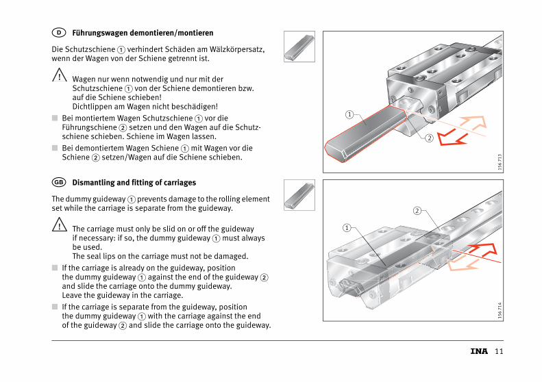
Die Schutzschiene � verhindert Schäden am Wälzkörpersatz, wenn der Wagen von der Schiene getrennt ist.
Wagen nur wenn notwendig und nur mit der Schutzschiene � von der Schiene demontieren bzw. auf die Schiene schieben! Dichtlippen am Wagen nicht beschädigen!
■ Bei montiertem Wagen Schutzschiene � vor die Führungschiene � setzen und den Wagen auf die Schutz-schiene schieben. Schiene im Wagen lassen.
■ Bei demontiertem Wagen Schiene � mit Wagen vor die Schiene � setzen/Wagen auf die Schiene schieben.
D Führungswagen demontieren/montieren
The dummy guideway � prevents damage to the rolling element set while the carriage is separate from the guideway.
The carriage must only be slid on or off the guideway if necessary: if so, the dummy guideway � must always be used.The seal lips on the carriage must not be damaged.
■ If the carriage is already on the guideway, position the dummy guideway � against the end of the guideway � and slide the carriage onto the dummy guideway. Leave the guideway in the carriage.
■ If the carriage is separate from the guideway, position the dummy guideway � with the carriage against the end of the guideway � and slide the carriage onto the guideway.
� Dismantling and fitting of carriages
2
1
156
713
2
1
156
714
12
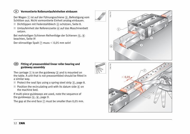
Der Wagen � ist auf der Führungsschiene �, Befestigung vom Schlitten aus. Nicht vormontierte Einheit analog einbauen.■ Dichtlippen mit Federstahlblech � schützen, Seite 8.
■ Umlaufeinheit der Referenzseite � auf das Maschinenbett setzen.
Bei mehrteiligen Schienen Reihenfolge der Schienen �, � beachten, Seite 9!
Der stirnseitige Spalt � muss � 0,05 mm sein!
D Vormontierte Rollenumlaufeinheiten einbauen
The carriage � is on the guideway � and is mounted on the table. A unit that is not preassembled should be fitted in a similar way.■ Protect the seal lips using a spring steel strip �, page 8.
■ Position the recirculating unit with its datum side � on the machine bed.
If multi-piece guideways are used, note the sequence of the guideways �, �, page 9.
The gap at the end face � must be smaller than 0,05 mm.
� Fitting of preassembled linear roller bearing and guideway assembly
1
2
3
4
156
715
5
6
� 0,05
2A2A2A2A
7
156
716
13
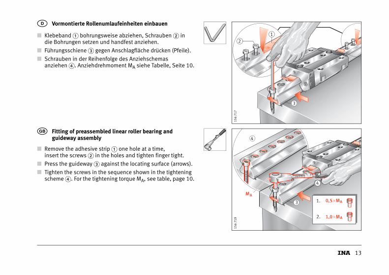
■ Klebeband � bohrungsweise abziehen, Schrauben � in die Bohrungen setzen und handfest anziehen.
■ Führungsschiene � gegen Anschlagfläche drücken (Pfeile).
■ Schrauben in der Reihenfolge des Anziehschemas anziehen �. Anziehdrehmoment MA siehe Tabelle, Seite 10.
D Vormontierte Rollenumlaufeinheiten einbauen
■ Remove the adhesive strip � one hole at a time, insert the screws � in the holes and tighten finger tight.
■ Press the guideway � against the locating surface (arrows).
■ Tighten the screws in the sequence shown in the tightening scheme �. For the tightening torque MA, see table, page 10.
� Fitting of preassembled linear roller bearing and guideway assembly
21
3
156
717
3
4
MA
4
0,5�M
1,0�M
1.
2.
A
A
156
719
14
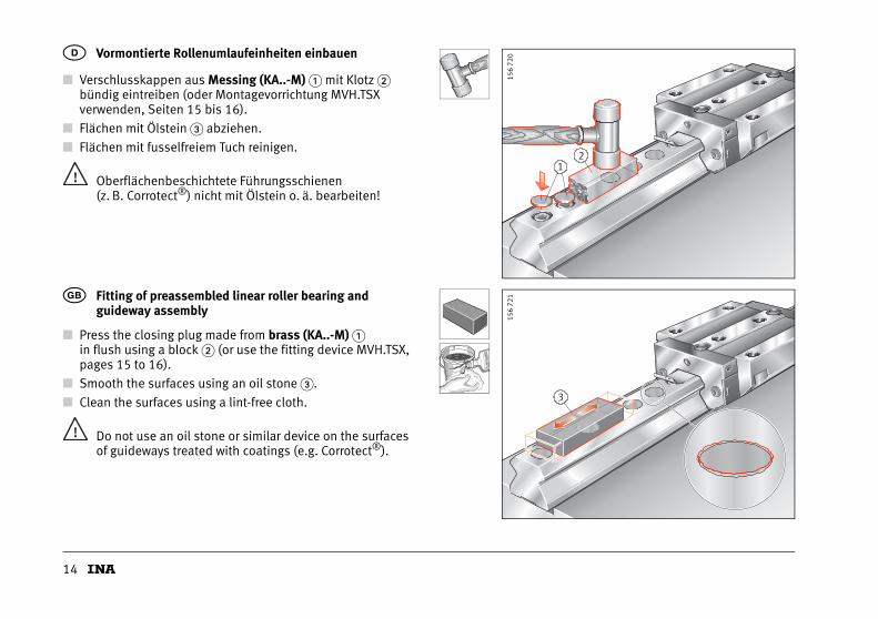
■ Verschlusskappen aus Messing (KA..-M) � mit Klotz �bündig eintreiben (oder Montagevorrichtung MVH.TSXverwenden, Seiten 15 bis 16).
■ Flächen mit Ölstein � abziehen.
■ Flächen mit fusselfreiem Tuch reinigen.
Oberflächenbeschichtete Führungsschienen(z. B. Corrotect®) nicht mit Ölstein o. ä. bearbeiten!
D Vormontierte Rollenumlaufeinheiten einbauen
■ Press the closing plug made from brass (KA..-M) �in flush using a block � (or use the fitting device MVH.TSX,pages 15 to 16).
■ Smooth the surfaces using an oil stone �.
■ Clean the surfaces using a lint-free cloth.
Do not use an oil stone or similar device on the surfaces of guideways treated with coatings (e.g. Corrotect®).
� Fitting of preassembled linear roller bearing and guideway assembly
21
156
720
3
156
721
15
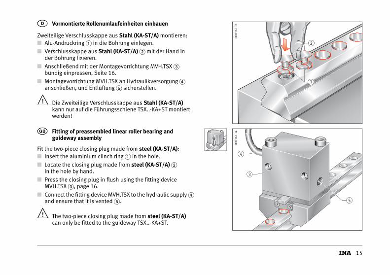
Zweiteilige Verschlusskappe aus Stahl (KA-ST/A) montieren:■ Alu-Andruckring � in die Bohrung einlegen.
■ Verschlusskappe aus Stahl (KA-ST/A) � mit der Hand inder Bohrung fixieren.
■ Anschließend mit der Montagevorrichtung MVH.TSX � bündig einpressen, Seite 16.
■ Montagevorrichtung MVH.TSX an Hydraulikversorgung � anschließen, und Entlüftung � sicherstellen.
Die Zweiteilige Verschlusskappe aus Stahl (KA-ST/A)kann nur auf die Führungsschiene TSX..-KA+ST montiert werden!
D Vormontierte Rollenumlaufeinheiten einbauen
Fit the two-piece closing plug made from steel (KA-ST/A):■ Insert the aluminium clinch ring � in the hole.
■ Locate the closing plug made from steel (KA-ST/A) �in the hole by hand.
■ Press the closing plug in flush using the fitting device MVH.TSX �, page 16.
■ Connect the fitting device MVH.TSX to the hydraulic supply � and ensure that it is vented �.
The two-piece closing plug made from steel (KA-ST/A)can only be fitted to the guideway TSX..-KA+ST.
� Fitting of preassembled linear roller bearing and guideway assembly
1
2
0001
6C33
3
4
5
0001
6C34
16
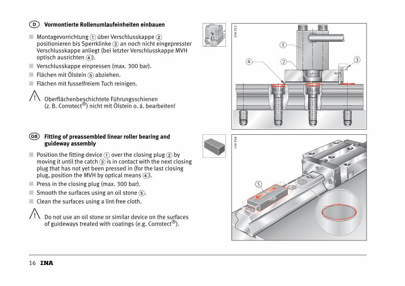
■ Montagevorrichtung � über Verschlusskappe � positionieren bis Sperrklinke � an noch nicht eingepresster Verschlusskappe anliegt (bei letzter Verschlusskappe MVH optisch ausrichten �).
■ Verschlusskappe einpressen (max. 300 bar).
■ Flächen mit Ölstein � abziehen.
■ Flächen mit fusselfreiem Tuch reinigen.
Oberflächenbeschichtete Führungsschienen (z. B. Corrotect®) nicht mit Ölstein o. ä. bearbeiten!
D Vormontierte Rollenumlaufeinheiten einbauen
■ Position the fitting device � over the closing plug � by moving it until the catch � is in contact with the next closing plug that has not yet been pressed in (for the last closing plug, position the MVH by optical means �).
■ Press in the closing plug (max. 300 bar).
■ Smooth the surfaces using an oil stone �.
■ Clean the surfaces using a lint-free cloth.
Do not use an oil stone or similar device on the surfaces of guideways treated with coatings (e.g. Corrotect®).
� Fitting of preassembled linear roller bearing and guideway assembly
4 3
1
2
156
913
5
156
916
17
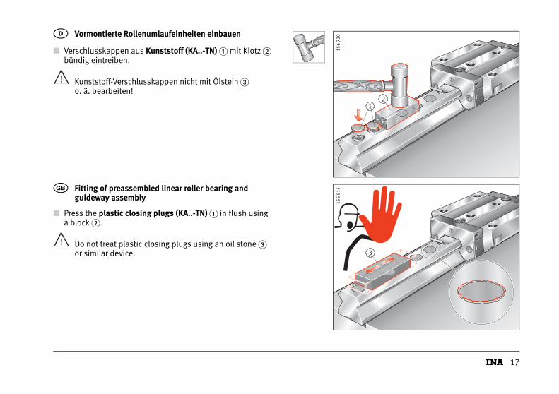
■ Verschlusskappen aus Kunststoff (KA..-TN) � mit Klotz � bündig eintreiben.
Kunststoff-Verschlusskappen nicht mit Ölstein �o. ä. bearbeiten!
D Vormontierte Rollenumlaufeinheiten einbauen
■ Press the plastic closing plugs (KA..-TN) � in flush using a block �.
Do not treat plastic closing plugs using an oil stone �or similar device.
� Fitting of preassembled linear roller bearing and guideway assembly
21
156
720
3
156
915
18
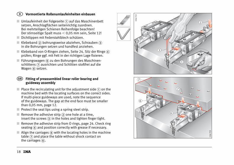
■ Umlaufeinheit der Folgeseite � auf das Maschinenbett setzen, Anschlagflächen seitenrichtig zuordnen.Bei mehrteiligen Schienen Reihenfolge beachten! Der stirnseitige Spalt muss � 0,05 mm sein, Seite 12!
■ Dichtlippen mit Federstahlblech schützen.
■ Klebeband � bohrungsweise abziehen, Schrauben � in die Bohrungen setzen und handfest anziehen.
■ Klebeband von O-Ringen ziehen, Seite 24. Sitz der Ringe � prüfen; Ringe ggf. mit Fett in der richtigen Lage fixieren.
■ Führungswagen � zu den Bohrungen des Maschinen-schlittens � ausrichten und Schlitten stoßfrei auf die Wagen � setzen.
D Vormontierte Rollenumlaufeinheiten einbauen
■ Place the recirculating unit for the adjustment side � on the machine bed with the locating surfaces on the correct sides.If multi-piece guideways are used, note the sequence of the guideways. The gap at the end face must be smaller than 0,05 mm, page 12.
■ Protect the seal lips using a spring steel strip.
■ Remove the adhesive strip � one hole at a time, insert the screws � in the holes and tighten finger tight.
■ Remove the adhesive strip from O rings, page 24. Check ring seating � and position correctly with grease if necessary.
■ Align the carriages � with the locating holes in the machine table � and place the table without shock contact onthe carriages �.
� Fitting of preassembled linear roller bearing and guideway assembly
2
41
3
156
722
6
7
7
6
156
723
19
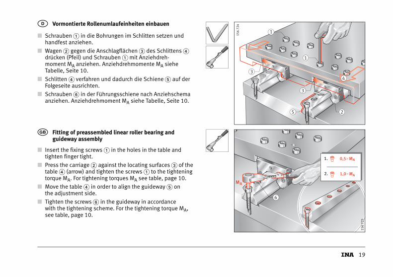
■ Schrauben � in die Bohrungen im Schlitten setzen und handfest anziehen.
■ Wagen � gegen die Anschlagflächen � des Schlittens � drücken (Pfeil) und Schrauben � mit Anziehdreh-moment MA anziehen. Anziehdrehmomente MA siehe Tabelle, Seite 10.
■ Schlitten � verfahren und dadurch die Schiene � auf der Folgeseite ausrichten.
■ Schrauben � in der Führungsschiene nach Anziehschema anziehen. Anziehdrehmoment MA siehe Tabelle, Seite 10.
D Vormontierte Rollenumlaufeinheiten einbauen
■ Insert the fixing screws � in the holes in the table and tighten finger tight.
■ Press the carriage � against the locating surfaces � of the table � (arrow) and tighten the screws � to the tightening torque MA. For tightening torques MA see table, page 10.
■ Move the table � in order to align the guideway � on the adjustment side.
■ Tighten the screws � in the guideway in accordance with the tightening scheme. For the tightening torque MA, see table, page 10.
� Fitting of preassembled linear roller bearing and guideway assembly
1
1
3
2
4
5
3
156
724
6
MA
1. 0,5 MA�
2. 1,0 MA�
156
725
20
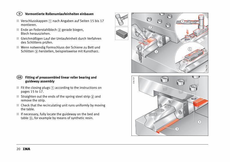
■ Verschlusskappen � nach Angaben auf Seiten 15 bis 17 montieren.
■ Ende an Federstahlblech � gerade biegen, Blech herausziehen.
■ Gleichmäßigen Lauf der Umlaufeinheit durch Verfahren des Schlittens prüfen.
■ Wenn notwendig Formschluss der Schiene zu Bett und Schlitten � herstellen, beispielsweise mit Kunstharz.
D Vormontierte Rollenumlaufeinheiten einbauen
■ Fit the closing plugs � according to the instructions on pages 15 to 17.
■ Straighten out the ends of the spring steel strip � and remove the strip.
■ Check that the recirculating unit runs uniformly by moving the table.
■ If necessary, fully locate the guideway on the bed and table �, for example by means of synthetic resin.
� Fitting of preassembled linear roller bearing and guideway assembly
1
1
1
2
156
726
3
3
156
727
21
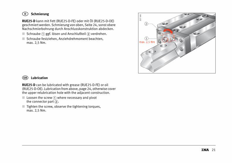
RUE25-D kann mit Fett (RUE25-D-FE) oder mit Öl (RUE25-D-OE) geschmiert werden. Schmierung von oben, Seite 24, sonst obere Nachschmierbohrung durch Anschlusskonstruktion abdecken.
■ Schraube � ggf. lösen und Anschlußteil � verdrehen.
■ Schraube festziehen, Anziehdrehmoment beachten,max. 2,5 Nm.
D Schmierung
RUE25-D can be lubricated with grease (RUE25-D-FE) or oil (RUE25-D-OE). Lubrication from above, page 24, otherwise cover the upper relubrication hole with the adjacent construction.
■ Loosen the screw � where necessary and pivotthe connector part �.
■ Tighten the screw, observe the tightening torques,max. 2,5 Nm.
� Lubrication
Fet tFet t1
2
max. 2,5 Nm
217
161
22
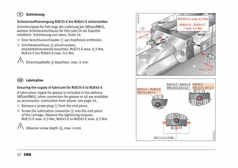
Schmierstoffversorgung RUE35-E bis RUE65-E sicherstellenSchmiernippel für Fett liegt der Lieferung bei (MSatzRWU), weitere Schmieranschlüsse für Fett oder Öl als Zubehör erhältlich. Schmierung von oben, Seite 24.
■ Eine Verschlussschraube � aus Kopfstück entfernen.
■ Schmieranschluss � einschrauben,Anziehdrehmomente beachten, RUE35-E max. 0,3 Nm,RUE45-E bis RUE65-E max. 0,5 Nm.
Einschraubtiefe � beachten, max. 6 mm.
D Schmierung
Ensuring the supply of lubricant for RUE35-E to RUE65-EA lubrication nipple for grease is included in the delivery (MSatzRWU), other connectors for grease or oil are availableas accessories. Lubrication from above, see page 24.
■ Remove a screw plug � from the end piece.
■ Screw the lubrication connector � into the end pieceof the carriage. Observe the tightening torques,RUE35-E max. 0,3 Nm, RUE45-E to RUE65-E max. 0,5 Nm.
Observe screw depth �, max. 6 mm
� Lubrication
12
max. 6 mm
max. 6 mm
2
3
3
RUE35-E = max. 0,3 Nm
RUE45-E ...RUE65-E = max. 0,5 Nm
0001
6C1D
RUE35-E – RUE65-EDIN 914-M4�4
RUE65-EDIN 3771 18�1,5
RUE35-E – RUE55-EDIN 3771 10�1,5
DIN 71412-A M6
0001
6C1C
23
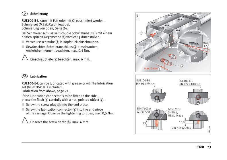
RUE100-E-L kann mit Fett oder mit Öl geschmiert werden. Schmierset (MSatzRWU) liegt bei.Schmierung von oben, Seite 24.
Bei Schmieranschluss seitlich, die Schwimmhaut � mit einem heißen spitzen Gegenstand � vorsichtig durchstoßen.
■ Verschlussschraube � in Kopfstück einschrauben.
■ Gewünschten Schmieranschluss � einschrauben,Anziehdrehmoment beachten, max. 0,5 Nm.
Einschraubtiefe � beachten, max. 6 mm.
D Schmierung
RUE100-E-L can be lubricated with grease or oil. The lubrication set (MSatzRWU) is included.Lubrication from above, page 24.
If the lubrication connector is to be fitted to the side,pierce the flash � carefully with a hot, pointed object �.
■ Screw the screw plug � into the end piece.
■ Screw the lubrication connector � into the end piece of the carriage. Observe the tightening torques, max. 0,5 Nm.
Observe the screw depth �, max. 6 mm.
� Lubrication
2
1
max.1,5
3
max. 6 mm4
5
217
165
10,8
DIN 914-M4�4RUE100-E-L
23
ANST 9313SHRG 4,UEMU M831
DIN 7603 A6,539,5 VF
DIN 71412-AM6
DIN 3771 18�1,5RUE100-E-L
217
166
24
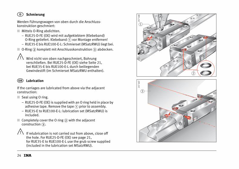
Werden Führungswagen von oben durch die Anschluss-konstruktion geschmiert:
■ Mittels O-Ring abdichten.– RUE25-D-FE (OE) wird mit aufgeklebtem (Klebeband)
O-Ring geliefert. Klebeband � vor Montage entfernen!– RUE35-E bis RUE100-E-L: Schmierset (MSatzRWU) liegt bei.
■ O-Ring � komplett mit Anschlusskonstruktion � abdecken.
Wird nicht von oben nachgeschmiert, Bohrungverschließen. Bei RUE25-D-FE (OE) siehe Seite 21,bei RUE35-E bis RUE100-E-L durch beiliegenden Gewindestift (im Schmierset MSatzRWU enthalten).
D Schmierung
If the carriages are lubricated from above via the adjacent construction:
■ Seal using O ring.
– RUE25-D-FE (OE) is supplied with an O ring held in place by adhesive tape. Remove the tape � prior to assembly.
– RUE35-E to RUE100-E-L: lubrication set (MSatzRWU) is included.
■ Completely cover the O ring � with the adjacentconstruction �.
If relubrication is not carried out from above, close offthe hole. For RUE25-D-FE (OE) see page 21,for RUE35-E to RUE100-E-L use the grub screw supplied (included in the lubrication set MSatzRWU).
� Lubrication
Fet tFet t
2
1
eO leO l
217
168
3
217
167
25
Wagen beim Schmieren immer verfahren! Mindesthub ist viermal Tragkörperlänge!
Vor Inbetriebnahme■ Führungsschienen leicht ölen oder fetten
– abhängig ob Öl- oder Fettschmierung.
■ Wagen bei Ölschmierung mit Mindestölmenge schmieren– Ölmengen Tabelle, Seite 26.
■ Bei Fettschmierung Wagen fetten bis frisches Schmierfett austritt– Fettmengen Tabelle, Seite 26.
Schmierintervalle■ Schmierfrist beachten
– max. 12 Monate bei Fettschmierung.
■ Wird über eine Zentralschmieranlage geschmiert, Ölimpulsmenge Qimp beachten (Tabelle, Seite 26).
D Schmierung
Always move the carriages during lubrication. The minimum stroke is four times the length of the saddle plate.
Before initial operation■ lightly oil or grease the guideways
– depending on whether oil or grease lubrication is used.
■ if oil lubrication is used, lubricate the carriages with the minimum oil quantity– for oil quantities, see table, page 26.
■ if grease lubrication is used, continue greasing the carriage until fresh grease appears– for grease quantities, see table, page 26.
Lubrication intervals■ Note the lubrication interval
– max. 12 months if grease lubrication is used.
■ If lubrication is carried out by means of a central lubrication system, note the oil pulse quantity Qimp (table, page 26).
� Lubrication
26
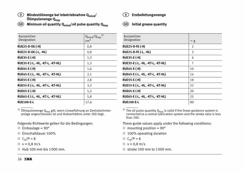
1) Ölimpulsmenge Qimp gilt, wenn Linearführung an Zentralschmier-anlage angeschlossen ist und Hubverhältnis unter 200 liegt.
D Mindestölmenge bei Inbetriebnahme Qmind/ Ölimpulsmenge Qimp
� Minimum oil quantity Qmind/oil pulse quantity Qimp
KurzzeichenDesignation
Qmind/Qimp1)
cm3
RUE25-D-OE (-H) 0,8
RUE25-D-OE (-L, -HL) 0,8
RUE35-E (-H) 1,3
RUE35-E (-L, -HL, -KT-L, -KT-HL) 1,3
RUE45-E (-H) 1,6
RUE45-E (-L, -HL, -KT-L, -KT-HL) 2,1
RUE55-E (-H) 2,8
RUE55-E (-L, -HL, -KT-L, -KT-HL) 3,2
RUE65-E (-H) 5,2
RUE65-E (-L, -HL, -KT-L, -KT-HL) 5,8
RUE100-E-L 17,6
1) The oil pulse quantity Qimp is valid if the linear guidance system is connected to a central lubrication system and the stroke ratio is less than 200.
D Erstbefettungsmenge
� Initial grease quantity
KurzzeichenDesignation � g
RUE25-D-FE (-H) 2
RUE25-D-FE (-L, -HL) 3
RUE35-E (-H) 6
RUE35-E (-L, -HL, -KT-L, -KT-HL) 7
RUE45-E (-H) 10
RUE45-E (-L, -HL, -KT-L, -KT-HL) 14
RUE55-E (-H) 18
RUE55-E (-L, -HL, -KT-L, -KT-HL) 22
RUE65-E (-H) 20
RUE65-E (-L, -HL, -KT-L, -KT-HL) 25
RUE100-E-L 80
Folgende Richtwerte gelten für die Bedingungen:■ Einbaulage = 90°
■ Einschaltdauer 100%
■ C0/P = 8
■ v = 0,8 m/s
■ Hub 500 mm bis 1000 mm.
These guide values apply under the following conditions:■ mounting position = 90°
■ 100% operating duration
■ C0/P = 8
■ v = 0,8 m/s
■ stroke 500 mm to 1000 mm.
27
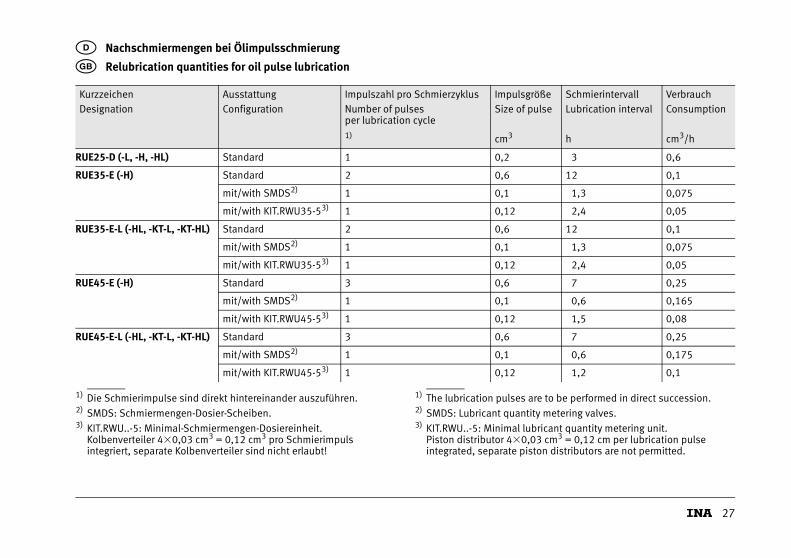
D Nachschmiermengen bei Ölimpulsschmierung
� Relubrication quantities for oil pulse lubrication
KurzzeichenDesignation
AusstattungConfiguration
Impulszahl pro SchmierzyklusNumber of pulsesper lubrication cycle
ImpulsgrößeSize of pulse
SchmierintervallLubrication interval
VerbrauchConsumption
1) cm3 h cm3/h
RUE25-D (-L, -H, -HL) Standard 1 0,2 3 0,6
RUE35-E (-H) Standard 2 0,6 12 0,1
mit/with SMDS2) 1 0,1 1,3 0,075
mit/with KIT.RWU35-53) 1 0,12 2,4 0,05
RUE35-E-L (-HL, -KT-L, -KT-HL) Standard 2 0,6 12 0,1
mit/with SMDS2) 1 0,1 1,3 0,075
mit/with KIT.RWU35-53) 1 0,12 2,4 0,05
RUE45-E (-H) Standard 3 0,6 7 0,25
mit/with SMDS2) 1 0,1 0,6 0,165
mit/with KIT.RWU45-53) 1 0,12 1,5 0,08
RUE45-E-L (-HL, -KT-L, -KT-HL) Standard 3 0,6 7 0,25
mit/with SMDS2) 1 0,1 0,6 0,175
mit/with KIT.RWU45-53) 1 0,12 1,2 0,1
1) Die Schmierimpulse sind direkt hintereinander auszuführen.2) SMDS: Schmiermengen-Dosier-Scheiben.3) KIT.RWU..-5: Minimal-Schmiermengen-Dosiereinheit.
Kolbenverteiler 4�0,03 cm3 = 0,12 cm3 pro Schmierimpuls integriert, separate Kolbenverteiler sind nicht erlaubt!
1) The lubrication pulses are to be performed in direct succession.2) SMDS: Lubricant quantity metering valves.3) KIT.RWU..-5: Minimal lubricant quantity metering unit.
Piston distributor 4�0,03 cm3 = 0,12 cm per lubrication pulse integrated, separate piston distributors are not permitted.
28
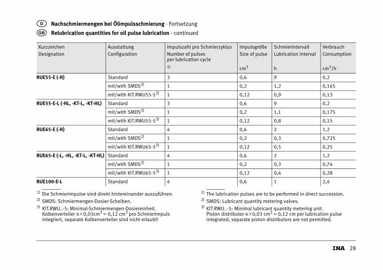
D Nachschmiermengen bei Ölimpulsschmierung · Fortsetzung
� Relubrication quantities for oil pulse lubrication · continued
KurzzeichenDesignation
AusstattungConfiguration
Impulszahl pro SchmierzyklusNumber of pulsesper lubrication cycle
ImpulsgrößeSize of pulse
SchmierintervallLubrication interval
VerbrauchConsumption
1) cm3 h cm3/h
RUE55-E (-H) Standard 3 0,6 9 0,2
mit/with SMDS2) 1 0,2 1,2 0,165
mit/with KIT.RWU55-53) 1 0,12 0,9 0,13
RUE55-E-L (-HL, -KT-L, -KT-HL) Standard 3 0,6 9 0,2
mit/with SMDS2) 1 0,2 1,1 0,175
mit/with KIT.RWU55-53) 1 0,12 0,8 0,15
RUE65-E (-H) Standard 4 0,6 2 1,2
mit/with SMDS2) 1 0,2 0,3 0,725
mit/with KIT.RWU65-53) 1 0,12 0,5 0,25
RUE65-E (-L, -HL, -KT-L, -KT-HL) Standard 4 0,6 2 1,2
mit/with SMDS2) 1 0,2 0,3 0,74
mit/with KIT.RWU65-53) 1 0,12 0,4 0,28
RUE100-E-L Standard 4 0,6 1 2,4
1) Die Schmierimpulse sind direkt hintereinander auszuführen.2) SMDS: Schmiermengen-Dosier-Scheiben.3) KIT.RWU..-5: Minimal-Schmiermengen-Dosiereinheit.
Kolbenverteiler 4�0,03cm3 = 0,12 cm3 pro Schmierimpuls integriert, separate Kolbenverteiler sind nicht erlaubt!
1) The lubrication pulses are to be performed in direct succession.2) SMDS: Lubricant quantity metering valves.3) KIT.RWU..-5: Minimal lubricant quantity metering unit.
Piston distributor 4�0,03 cm3 = 0,12 cm per lubrication pulse integrated, separate piston distributors are not permitted.
29
Folgende Richtwerte gelten für die Bedingungen:
■ Einbaulage = 90°
■ Einschaltdauer 100%
■ C0/P = 8
■ v = 0,8 m/s
■ Hub 500 mm bis 1000 mm
■ Temperatur +20 °C bis +40 °C
■ Schmierstoffanschluss einseitig.
D Nachschmiermengen bei Ölimpulsschmierung
These guide values apply under the following conditions:
■ mounting position = 90°
■ 100% operating duration
■ C0/P = 8
■ v = 0,8 m/s
■ stroke 500 mm to 1000 mm
■ temperature +20 °C to +40 °C
■ lubrication connector on one side.
� Relubrication quantities for oil pulse lubrication

30

31
MA
TNR
0181
0145
3-00
00 /
MO
N 3
0 /
D/G
B-D
/GB
/ 2
0100
5 /
pdf o
nly
Schaeffler TechnologiesGmbH & Co. KG
Geschäftsbereich Lineartechnik
Berliner Straße 134
66424 Homburg (Saar)
Internet www.ina.de
E-Mail [email protected]
In Deutschland:
Telefon 0180 5003872
Telefax 0180 5003873
Aus anderen Ländern:
Telefon +49 6841 701-0
Telefax +49 6841 701-2625
Schaeffler (UK) Ltd
Forge Lane
Minworth
Sutton Coldfield
West Midlands
B76 1AP
Phone 0121 351 5870
Fax 0121 351 0080
E-Mail [email protected]
Internet www.schaeffler.co.uk
Nachdruck, auch auszugsweise, nur mit
unserer Genehmigung.
This publication or parts thereof may not
be reproduced without our permission.
© Schaeffler Technologies GmbH & Co. KG
Ausgabe, Issued: 2010, Mai
MON 30 D/GB-D/GB