Embed Size (px)
Citation preview
SAFETINEXSAFETY LIGHT CURTAINSHAND PROTECTION, TYPE 2YBB, YBBS SERIES
INSTRUCTION MANUAL
32 Contrinex Industrial Electronics Contrinex Industrial Electronics
ORIGINAL INSTRUCTIONS
EN - This manual is available to download from our website in many language versions, inclu-ding English:
DE - Diese Bedienungsanleitung steht auf unserer Internetseite in vielen Sprachversionen, darunter Deutsch, zum Download bereit:
FR - Ce manuel est téléchargeable depuis notre site internet en plusieurs versions linguistiques, dont le français:
IT - Questo manuale è téléchargeable dal nostro sito internet in parecchie versioni linguistiche di cui l’italiano:
ESP - Este manual está disponible para su descargar desde nuestro sitio web en varios idiomas, incluyendo el español:
PT - Este manual está disponível para descarregar a partir do nosso sítio Web em muitas línguas, incluindo o português:
http://www.contrinex.com/download/#anchor_manuals
32 Contrinex Industrial Electronics Contrinex Industrial Electronics
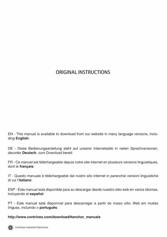
TABLE OF CONTENTS 1. INTRODUCTION ...........................................................51.1. Contrinex ..................................................................................................51.2. Safetinex safety systems .........................................................................51.3. Active optoelectronic protective devices (AOPD) ...................................51.3.1. Safeguarding function ........................................................................61.3.2. Hazardous area ..................................................................................61.3.3. AOPD detection capability .................................................................61.4. Advantages of AOPDs .............................................................................71.5. Operating principle ..................................................................................71.6. Certification of Safetinex products ...........................................................8
2. EUROPEAN SAFETY STANDARDS .............................82.1. Types of safety standards applicable in the EU ......................................82.2. Examples of safety standards..................................................................92.3. An approach to European standards ...........................................................102.4. The user side .........................................................................................102.5. Machine manufacturer side ...................................................................112.6. Notified bodies .......................................................................................11
3. NORTH AMERICAN SAFETY STANDARDS .............123.1. A different approach ..............................................................................123.2. OSHA Regulations and U.S. Consensus Standards .............................123.3. North American Standards for safety issues: UL, ANSI and CSA .........133.3.1. American standard agencies ...........................................................133.3.2. Canadian standard agencies ...........................................................143.4. International standard agencies ............................................................14
4. RISK ASSESSMENT .....................................................154.1. Definition of hazards and risk reduction strategy ..................................154.2. Risk assessment process ......................................................................154.3. Methods for determination of risk level ..................................................184.3.1. Determination of risk level in north america .....................................184.3.2. Determination of required performance level (PLr) ..........................184.3.3. Specific standards for safety distance calculation ...........................20
5. INSTALLATION ............................................................205.1. Installation rules .....................................................................................205.1.1. Positioning the AOPD .......................................................................205.1.2. Minimum Safety Distance required ...................................................215.1.3. Minimum Safety Distance Calculation (US & Canada).....................24
6. OTHER COUNTRIES ....................................................25
7. ACRONYMS..................................................................26
8. TECHNICAL DOCUMENTATION ...............................278.1. Safetinex YBB for hand protection .........................................................278.2. Safetinex YBBS for hand protection ......................................................278.3. Advantages of the Safetinex range .......................................................278.4. Scope of this technical documentation .................................................28
54 Contrinex Industrial Electronics Contrinex Industrial Electronics
8.5. Self protected outputs............................................................................288.6. Resolution (R) of an AOPD ....................................................................298.7. LED status indicators .............................................................................308.7.1. Test mode selection ..........................................................................308.8. Installation ..............................................................................................318.8.1. Minimum safety distance ..................................................................318.8.2. Positioning the sender and receiver units ........................................328.8.3. Distance from reflective surfaces .....................................................338.8.4. Installation of multiple systems .........................................................348.8.5. Mechanical installation .....................................................................358.9. YBB series..............................................................................................368.9.1. Mounting with bracket No1 (standard bracket).................................368.9.2. Mounting with bracket No3 (optional bracket) ..................................368.9.3. Available models YBB ......................................................................378.9.4. Technical data YBB ..........................................................................388.10. YBBS series ...........................................................................................398.10.1. Mounting with bracket No5 (standard bracket).................................398.10.2. Mounting with bracket No6 (optional bracket) ..................................408.10.3. Mounting with bracket No7 (optional bracket) ..................................418.10.4. L-shaped installation ........................................................................428.10.5. Twin installation and resolution at the end of the light curtain ..........428.10.6. No blind zone capability ...................................................................438.10.7. Available models YBBS ....................................................................448.10.8. Technical data YBBS ........................................................................458.11. Connecting the protective device ..........................................................468.11.1. Power supply ....................................................................................468.11.2. Electromagnetic compatibility (EMC) ...............................................468.11.3. Light radiation ...................................................................................468.11.4. Pin assignment for YBB series .........................................................478.11.5. Pin assignment for YBBS series .......................................................478.12. Safetinex safety relay YRB-4EML-31S ...................................................488.12.1. Response time from protective field intrusion to switching of safety relay ...............................................................488.12.2. Connection examples for YRB-4EML-31S safety relay ....................498.13. Connection cables .................................................................................508.14. Alignment of sender and receiver units .................................................518.15. Test before the first commissioning .......................................................53
9. TESTING AND MAINTENANCE ................................549.1. Daily functional test ................................................................................549.2. Troubleshooting .....................................................................................559.3. Preventive periodic inspections .............................................................569.4. Cleaning .................................................................................................569.5. Daily testing log file ................................................................................56
10. DISCLAIMER ...............................................................58
11. EC DECLARATION OF CONFORMITY .......................60
54 Contrinex Industrial Electronics Contrinex Industrial Electronics
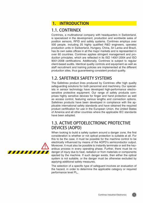
1. INTRODUCTION 1.1. CONTRINEXContrinex, a multinational company with headquarters in Switzerland, is specialized in the development, production and worldwide sales of position sensors, RFID and safety systems. Contrinex employs over 500 people, including 25 highly qualified R&D engineers, operates production units in Switzerland, Hungary, China, Sri Lanka and Brazil, has its own sales offices in all the major markets and is represented in over 60 countries. Contrinex applies stringent management and pro-duction principles, which are reflected in its ISO 14001:2004 and ISO 9001:2008 certifications. Additionally, Contrinex is subject to regular client-based audits. Identical quality controls and equipment as well as staff recruitment and training policies are implemented at the different production sites, thus guaranteeing consistent product quality.
1.2. SAFETINEX SAFETY SYSTEMSThe Safetinex product lines produced by Contrinex offer high quality safeguarding solutions for both personnel and machinery. Our special-ists in sensor technology have developed high-performance electro-sensitive protective equipment. Our range of safety products com-prises highly sensitive devices for finger and hand protection as well as access control, featuring various lengths and connection options. Safetinex products have been developed in compliance with the ap-plicable international safety standards and have obtained the required product certification for use in the European Union, the United States of America and all other countries where the applicable IEC standards have been adopted.
1.3. ACTIVE OPTOELECTRONIC PROTECTIVE DEVICES (AOPD)When looking to build a safety system around a danger zone, the first consideration is whether or not optical protection is suitable at all. For this to be the case, it must be possible for the machine control to be electrically influenced by means of the AOPD’s semiconductor output. Moreover, it must also be possible to instantly terminate or exit the haz-ardous process in every operating phase. Further, there must be no danger of injury due to heat, radiation or from materials or components ejected by the machine. If such danger exists, then either the optical system is not suitable, or the danger must be otherwise excluded by applying additional safety measures.
The selection of a specific type of safeguard involves an evaluation of the hazard, in order to determine the applicable category or required performance level PLr.
76 Contrinex Industrial Electronics Contrinex Industrial Electronics
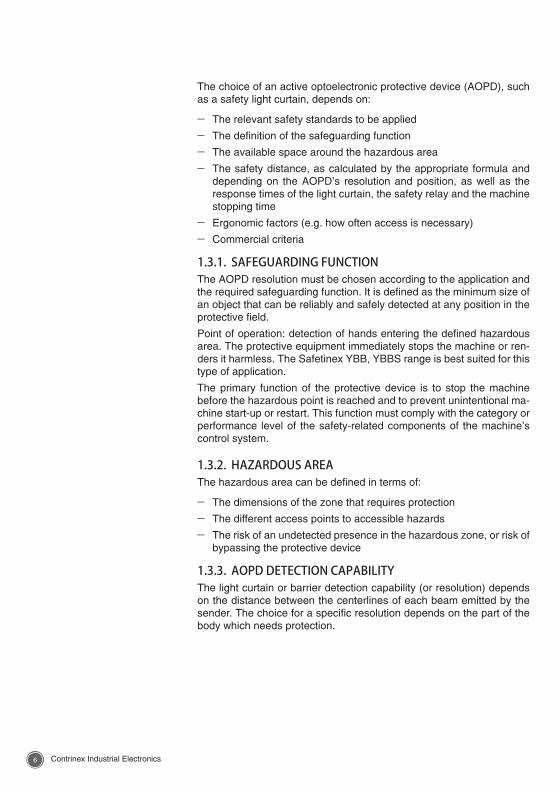
The choice of an active optoelectronic protective device (AOPD), such as a safety light curtain, depends on:
– The relevant safety standards to be applied
– The definition of the safeguarding function
– The available space around the hazardous area
– The safety distance, as calculated by the appropriate formula and depending on the AOPD’s resolution and position, as well as the response times of the light curtain, the safety relay and the machine stopping time
– Ergonomic factors (e.g. how often access is necessary)
– Commercial criteria
1.3.1. SAFEGUARDING FUNCTIONThe AOPD resolution must be chosen according to the application and the required safeguarding function. It is defined as the minimum size of an object that can be reliably and safely detected at any position in the protective field.
Point of operation: detection of hands entering the defined hazardous area. The protective equipment immediately stops the machine or ren-ders it harmless. The Safetinex YBB, YBBS range is best suited for this type of application.
The primary function of the protective device is to stop the machine before the hazardous point is reached and to prevent unintentional ma-chine start-up or restart. This function must comply with the category or performance level of the safety-related components of the machine’s control system.
1.3.2. HAZARDOUS AREAThe hazardous area can be defined in terms of:
– The dimensions of the zone that requires protection
– The different access points to accessible hazards
– The risk of an undetected presence in the hazardous zone, or risk of bypassing the protective device
1.3.3. AOPD DETECTION CAPABILITYThe light curtain or barrier detection capability (or resolution) depends on the distance between the centerlines of each beam emitted by the sender. The choice for a specific resolution depends on the part of the body which needs protection.
76 Contrinex Industrial Electronics Contrinex Industrial Electronics
1.4. ADVANTAGES OF AOPDSSafeguarding devices are used where risks cannot be eliminated by machine design. Rather than preventing access to a hazardous area, safety light curtains detect the entry of a person or part of a body and eliminate the hazard by triggering an immediate stop of the hazardous machine motion. They present several advantages over mechanical safeguarding devices:
– Access time to the machine is reduced, thereby increasing produc-tivity
– Workplace ergonomics are greatly improved and less space is re-quired
– The invisible infrared beams allow better visibility of the machine and operating process
– Protection applies to any approaching person
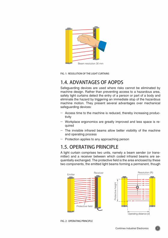
1.5. OPERATING PRINCIPLEA light curtain comprises two units, namely a beam sender (or trans-mitter) and a receiver between which coded infrared beams are se-quentially exchanged. The protective field is the area enclosed by these two components, the emitted light beams forming a permanent, though
FIG. 1: RESOLUTION OF THE LIGHT CURTAINS
Beam resolution 30 mm
FIG. 2: OPERATING PRINCIPLE
EmitterReceiver
Protective field
Resolution (R)
Pro
tect
ive
heig
ht
Operating distance (d)
98 Contrinex Industrial Electronics Contrinex Industrial Electronics
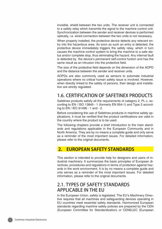
invisible, shield between the two units. The receiver unit is connected to a safety relay which transmits the signal to the machine control unit. Synchronization between the sender and receiver devices is performed optically, i.e. wired connection between the two units is not necessary.
When properly installed, the protective device detects any relevant en-try into the hazardous area. As soon as such an entry is detected, the protective device immediately triggers the safety relay, which in turn causes the machine control system to bring the machine to a safe sta-tus and/or complete stop, thus eliminating the hazard. Any internal fault is detected by the device’s permanent self-control fuction and has the same result as an intrusion into the protective field.
The size of the protective field depends on the dimension of the AOPD and the distance between the sender and receiver units.
AOPDs are also commonly used as sensors to automate industrial operations where no critical human safety issue is involved. However, when directly linked to the safety of persons, their design and installa-tion are strictly regulated.
1.6. CERTIFICATION OF SAFETINEX PRODUCTSSafetinex products satisfy all the requirements of category 2, PL c, ac-cording to EN / ISO 13849 - 1 (formerly EN 954-1) and Type 2 accord-ing to EN / IEC 61496 - 1 and - 2.
Before considering the use of Safetinex products in machine safety ap-plications, it must be verified that the product certifications are valid in the country where the product is to be used.
The following chapters provide a brief introduction to the main stand-ards and regulations applicable in the European Community and in North America. They are by no means a complete guide and only serve as a reminder of the most important issues. For detailed information, please refer to the original documents.
2. EUROPEAN SAFETY STANDARDS This section is intended to provide help for designers and users of in-dustrial machinery. It summarizes the basic principles of European di-rectives, procedures and regulations in terms of protection against haz-ards in the work environment. It is by no means a complete guide and only serves as a reminder of the most important issues. For detailed information, please refer to the original documents.
2.1. TYPES OF SAFETY STANDARDS APPLICABLE IN THE EUIn the European Union, safety is legislated. The EU’s Machinery Direc-tive requires that all machines and safeguarding devices operating in EU countries meet essential safety standards. Harmonized European standards regarding machine safety policies are prepared by the CEN (European Committee for Standardization) or CENELEC (European
98 Contrinex Industrial Electronics Contrinex Industrial Electronics
Committee for Electrotechnical Standardization) and finalized by the EU Commission. Once ratified, these standards become European Standards (EN) that take precedence over national laws. Thus, EU countries must remove or modify any national standard that conflicts with the European Standard. CENELEC and CEN cooperate closely with ISO and IEC, the main bodies for international standards.
Applicable standards usually have the prefix EN (“European Norm”), but most also have international – ISO/IEC – equivalents. There are different types of standards:
– A-type standards are basic safety standards applicable to all ma-chinery, e.g. EN/ISO 14121
– B1-type standards set out special safety aspects and procedures, e.g. EN/ISO 13849-1
– B2-type standards set rules on safety equipment design, e.g. EN/IEC 61496-1, EN/TS/IEC 61496-2/-3
– C-type standards set safety requirements for a specific machine or type of machine
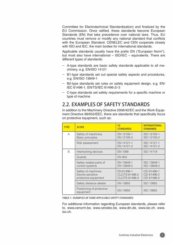
2.2. EXAMPLES OF SAFETY STANDARDSIn addition to the Machinery Directive 2006/42/EC and the Work Equip-ment Directive 89/655/EEC, there are standards that specifically focus on protective equipment, such as:
TYPE SCOPE CE STANDARDS
INTERNATIONAL STANDARDS
A Safety of machineryBasic principles
EN 12100-1EN 12100-2
ISO 12100-1ISO 12100-2
Risk assessment EN 14121-1EN 14121-2
ISO 14121-1ISO 14121-2
B Interlocking devices EN 1088 ISO 14119
Guards EN 953
Safety related parts ofcontrol systems
EN 13849-1EN 13849-2
ISO 13849-1ISO 13849-2
Safety of machines:Electro-sensitiveprotective equipment
EN 61496-1CLC/TS 61496-2CLC/TS 61496-3
CEI 61496-1CEI 61496-2CEI 61496-3
Safety distance details EN 13855 ISO 13855
Positioning of protectiveequipment EN 13855 ISO 13855
TABLE 1: EXAMPLES OF SOME APPLICABLE SAFETY STANDARDS
For additional information regarding European standards, please refer to, www.cenorm.be, www.cenelec.be, www.din.de, www.iec.ch, www.iso.ch.
1110 Contrinex Industrial Electronics Contrinex Industrial Electronics
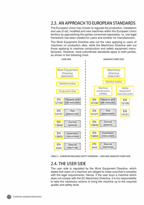
2.3. AN APPROACH TO EUROPEAN STANDARDSThe European Union has chosen to regulate the production, installation and use of old, modified and new machines within the European Union territory by approaching the parties concerned separately, i.e. one legal framework has been created for users and another for manufacturers.
The Work Equipment Directive sets out the rules applying to users of machines on production sites, while the Machinery Directive sets out those applying to machine constructors and safety equipment manu-facturers. However, most subordinate standards apply to both parties, as shown in the following chart.
2.4. THE USER SIDEThe user side is regulated by the Work Equipment Directive, which states that users of a machine are obliged to make sure that it complies with the legal requirements. Hence, if the user buys a machine which does not comply with the EU Machinery Directive, it is his responsibility to take the necessary actions to bring the machine up to the required quality and safety level.
TABLE 2 : EUROPEAN MACHINE SAFETY OVERVIEW – USER AND MANUFACTURER SIDE.
USER SIDE MANUFACTURER SIDE
1110 Contrinex Industrial Electronics Contrinex Industrial Electronics
Additionally, the Work Equipment Directive specifies what minimum regulations must be observed for safety purposes when work equip-ment is being used. The original text can be found on the relevant Eu-ropean Union website.
2.5. MACHINE MANUFACTURER SIDEThe manufacturer side is addressed by the Machinery Directive. This umbrella document refers to the specific requirements described in EN standards, and stipulates that each danger zone of a machine must be made safe. The method used to make different zones safe depends on the type of hazard.
The Machinery Directive requires that, before placing machinery on the market and/or putting it into service, the manufacturer ensures that a technical file is made available. This technical file shall comprise a construction file including, among others, “the documentation on risk assessment demonstrating the procedure followed, including:
(i) a list of the essential health and safety requirements which apply to the machinery,
(ii) the description of the protective measures implemented to eliminate identified hazards or to reduce risks and, when appropriate, the indi-cation of the residual risks associated with the machinery.” (Machin-ery Directive 2006/42/EC, Annex VII, A, 1, a)
Machines that are highly hazardous (as listed in Annex IV of the Ma-chinery Directive) must conform to special procedures. The manufac-turer is responsible for obtaining conformity through various procedures that may require examination of the machine by an EU notified body.
2.6. NOTIFIED BODIESIn order to have control over the execution of these directives, veri-fication of certain steps by certifying bodies may be imposed by the directives. For example, all safety device concepts must be analyzed, checked and tested by such a third party organization. In many cases, this third party organization also audits the production process of a safety device manufacturer.
A notified (or certified) body is a certification, inspection or testing body designated by the notifying authority of an EU member state to issue attestations of conformity for products. Each EU member state has a list of notified bodies authorized to issue EU-type examination certifi-cates. The lists include the identification number of each notified body, as well as the specific areas of activity and the tasks for which it has been designated.
European notified bodies responsible for carrying out conformity as-sessment procedures can be found through the NANDO (New Ap-proach Notified and Designated Organizations) website, where accred-ited bodies can be searched for by country, product or directive. An official list of notified bodies responsible for assessing products in com-pliance with the Machinery Directive can also be found on the relevant European Union website.
1312 Contrinex Industrial Electronics Contrinex Industrial Electronics
3. NORTH AMERICAN SAFETY STANDARDS This section is intended to provide help for designers and users of in-dustrial machinery. It summarizes the basic principles of North Ameri-can regulations and standards in terms of protection against hazards in the working environment. It is by no means a complete guide and only serves as a reminder of the important issues. For detailed information, please refer to appropriate agencies and documents.
3.1. A DIFFERENT APPROACHWhereas European standards are mainly machine manufacturer ori-ented, North American standards are primarily directed towards users. Unlike in the EU, third party certification is not mandatory in the US or Canada. In terms of liability, it is the employer’s responsibility to prove that he has done his utmost to ensure his employees’ safety. However, certification has become a strong commercial asset in terms of market requirement. On users’ request, national compliance agencies assess and grant the required certification.
Although the US and the EU have different methods for developing and applying standards, their purpose is the same, namely to ensure an ap-propriate level of safety in the workplace. Harmonized standards have the advantage of promoting world trade and reducing duplication of ef-fort. Harmonized international standards allow manufacturers to access many markets with one product. Users profit from competitive products that meet uniform quality and functional requirements – wherever they were manufactured.
In the United States, standards are developed and enforced both by governmental agencies and industry groups. US employers, install-ers or OEMs are legally responsible for compliance with all applicable regulations, both national and international. In the US, the Occupational Safety and Health Administration (OSHA) is a federal agency that can enforce its regulations through penalties and fines.
3.2. OSHA REGULATIONS AND U.S. CONSENSUS STANDARDSThe Occupational Safety and Health Act passed on Dec. 29, 1970 es-tablished guidelines for safe and healthy working conditions.
Occupational and Health Standards in the U.S. are defined in Title 29 of the Code of Federal Regulations Part 1910. Subpart O of this document deals specifically with machinery and machine guarding, and defines the general requirements for all machines (1910.212) and for some specific types of machinery.
Encouraged and assisted by OSHA, more than half of the US states have developed their own safety and health programs and regulations which are then enforced by OSHA as “National Consensus Standards”. Information on both state plans and OSHA regulations may be obtained from their respective websites.
OSHA uses national consensus standards to further define machine
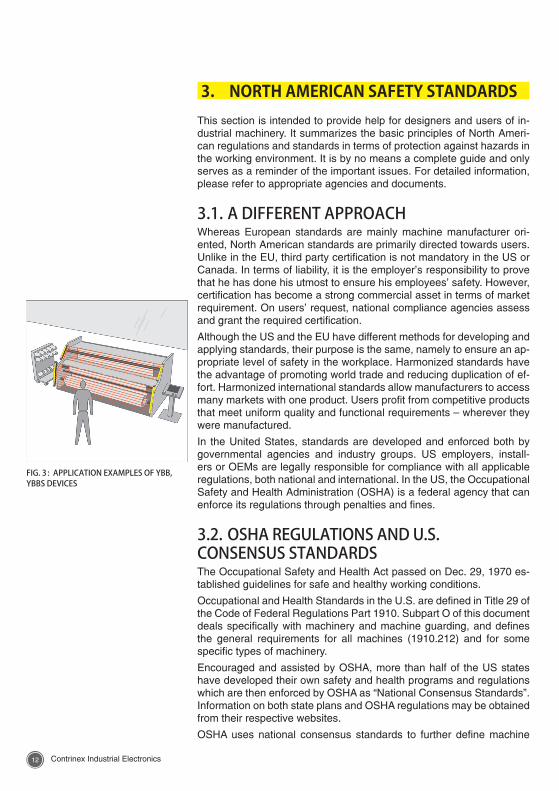
FIG. 3 : APPLICATION EXAMPLES OF YBB, YBBS DEVICES
1312 Contrinex Industrial Electronics Contrinex Industrial Electronics
protection requirements in addition to subpart O. In 1910.212, it states that “The point of operation of machines whose operation exposes an employee to injury, shall be guarded. The guarding device shall be in conformity with any appropriate standards therefore, or, in the absence of applicable specific standards, shall be so designed and constructed as to prevent the operator from having any part of his body in the dan-ger zone during the operating cycle.”
“Any appropriate standards” refers to national consensus standards generally recognized in the industry. Bodies frequently referenced by OSHA include the American National Standards Institute (ANSI), the National Fire Protection Agency (NFPA), Underwriters Laboratories (UL) and the American Society of Mechanical Engineers (ASME).
As an example, ANSI B11.1 sets safety requirements for mechani-cal power presses, ANSI B11.15 specifies standards for pipe bending machines, ANSI B11 TR.1 gives ergonomic guidelines for the design, installation and use of machine tools, and ANSI/RIA R15.06 stipulates the safety requirements for industrial robots. Please consult national consensus standards bodies for complete listings.
3.3. NORTH AMERICAN STANDARDS FOR SAFETY ISSUES: UL, ANSI AND CSA3.3.1. AMERICAN STANDARD AGENCIESUL STANDARDSUnderwriters Laboratories Inc. is a testing organization established in 1894 and is authorized to conduct certification testing of any electrical device. Although UL certification is not mandatory, many companies strive to obtain its certification for products aimed at the U.S. market.
UL certification has two levels, namely listing certification, generally for final products, and recognition certification, for parts or components built into a product. Once a product has obtained UL certification, additional on-site inspections are carried out on a quarterly basis to ensure that the produc-tion plant continues to manufacture products conforming to UL standards.
Since the purpose of UL standards is to eliminate the danger of fire or electric shock caused by electrical appliances, in principle only those appliances presenting such risks are subject to this certification.
For more details on the UL Standards, please consult the UL website.
ANSI STANDARDSThe American National Standards Institute was founded in 1918 to manage the standardization system in the US. It is not ANSI’s task to create standards of its own, but rather to approve the standards set up by specialized organizations. Many UL standards have been converted into ANSI/UL standards.
For instance, ANSI standards include ANSI B 11.19: Standard for per-formance of safeguarding devices and ANSI/RIA R15.06: Standard for robot safety.
For more details on the ANSI Standards, please visit the ANSI website.
1514 Contrinex Industrial Electronics Contrinex Industrial Electronics
3.3.2. CANADIAN STANDARD AGENCIESCSA STANDARDSThe Canadian Standards Association is an organization that admin-isters and coordinates the standardization system in Canada. Cross-certification between the U.S. and Canada has been granted, based on the Mutual Recognition Agreement (MRA).
Electrical appliances connected to a public power source in Canada must conform to CSA Standards. Manufacturers of these products need to obtain C-UL or CSA certification, or the seller needs to apply for cer-tification directly to the provincial authorities.
For more details on the CSA Standards, please visit the CSA website.
3.4. INTERNATIONAL STANDARD AGENCIESInternational standards also play a significant role in North American machine safety. The two main international entities are the Internation-al Electrotechnical Committee (IEC) and the International Standards Organization (ISO). IEC is a recognized provider of standards in the electrotechnical field and is composed of national electrotechnical com-mittees. ISO is an international federation of national standardization bodies. ISO and IEC influence international standards through formal relationships. In the US, ANSI coordinates with ISO and IEC through technical advisory groups (TAG).
1514 Contrinex Industrial Electronics Contrinex Industrial Electronics
4. RISK ASSESSMENT4.1. DEFINITION OF HAZARDS AND RISK REDUCTION STRATEGYEN/ISO 12100 serves as a basis for all subsequent standards. It de-scribes every type of hazard that needs to be considered in terms of machine safety. Exposure to hazards includes numerous potential situ-ations that must first be identified.
Mechanical hazards may result in crushing, shearing, cutting/severing, entanglement, drawing-in/trapping, impact, stabbing/puncture, friction/abrasion, injuries due to high pressure fluid ejection, etc. Machine haz-ards are also influenced by sharp edges, vibrations and unstable or moving objects. The list quotes electrical and thermal hazards, radia-tion, dust and hazardous substances (gas, vapors). In terms of ergo-nomics and the working environment, there are risks of falling, tripping or slipping. A combination of hazards may result in a specific new haz-ard.
EN/ISO 12100 subsequently gives general guidelines for eliminating or reducing hazards through prevention and protection. It is recommended to use technology that avoids most of the problems linked with the haz-ards listed above. Any decision that contributes to prevention against hazards is part of the security process and risk reduction strategy.
In this respect, taking ergonomic principles into consideration is im-portant. A high level of automation will not only help operators, it will also increase productivity and reliability. Reducing unnecessary human movements and efforts can contribute to a safer working environment. Proper lighting of the work place will help to minimize hazards.
Operators must be able to stop machines at any time in case of an emergency. Starting and/or restarting the machine after an interruption must be carefully planned. When programmable electronic safety sys-tems are used, the behaviour of such systems in case of defect and the protection of the software requires particular attention.
4.2. RISK ASSESSMENT PROCESSIn essence, conducting a risk assessment involves identifying hazards, evaluating the potential severity of harm and identifying measures and solutions for eliminating or reducing such risks.
This requirement is stated in U.S. standards (Title 29 US Code of Fed-eral Regulations, Part 1910, Subpart O).
For more details, please refer to the following documents:
– OSHA 3071, Job Hazard Analysis
– ANSI/RIA R15.06-1999, Safety Requirements for Industrial Robots and Robot Systems
– ANSI B11.TR3, Risk Assessment and Risk Reduction
EN/ISO 12100
1716 Contrinex Industrial Electronics Contrinex Industrial Electronics
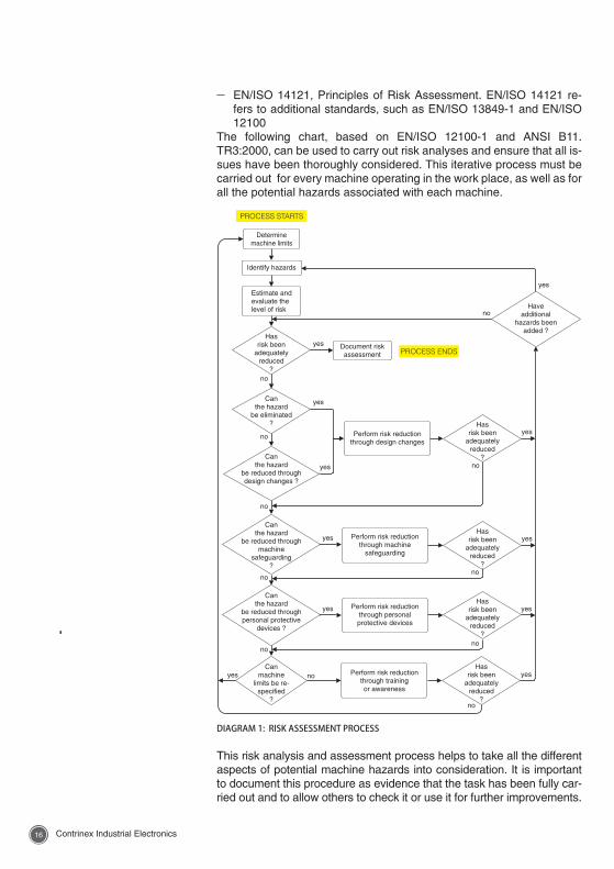
– EN/ISO 14121, Principles of Risk Assessment. EN/ISO 14121 re-fers to additional standards, such as EN/ISO 13849-1 and EN/ISO 12100
The following chart, based on EN/ISO 12100-1 and ANSI B11.TR3:2000, can be used to carry out risk analyses and ensure that all is-sues have been thoroughly considered. This iterative process must be carried out for every machine operating in the work place, as well as for all the potential hazards associated with each machine.
This risk analysis and assessment process helps to take all the different aspects of potential machine hazards into consideration. It is important to document this procedure as evidence that the task has been fully car-ried out and to allow others to check it or use it for further improvements.
DIAGRAM 1: RISK ASSESSMENT PROCESS
1716 Contrinex Industrial Electronics Contrinex Industrial Electronics
EN/ISO 14121 also describes procedures for identifying hazards and assessing risks, and provides guidance on the information required to achieve this goal. The process involves analyzing the risks in a sys-tematic and documented way, in order to eliminate or reduce hazards. Qualitative and quantitative methods can be used.
All aspects of potential hazards must be taken into consideration:
– The phases of a machine’s life
– The full range of foreseeable uses and misuses of a machine
– All persons possibly exposed to hazards when the machine is being used
Risk is defined as a function of the severity of possible harm and the probability that such harm occurs (frequency and duration of exposure, possibility of avoiding harm, etc.). One important piece of information is the history of accidents, if available.
Among the aspects to be considered when establishing elements of risk, the analysis should account for
– Different types of exposure depending on the type of work (setting, teaching, operating, cleaning, etc.)
– Human factors, such as applicability and ergonomic issues
– The reliability of safety functions, including their maintenance
– The possibility to defeat or circumvent safety measures
EN/ISO 14121-1:2007 gives a full list of hazards referenced by EN/ISO 12100.
In addition, the safety of any machine will diminish with time due to the deterioration of components, wear, loosening of parts, etc. It is there-fore important to conduct regular inspections in order to detect defects that may lead to reduced safety, and to effect the necessary repairs before the level of risk exceeds the original assessment.
EN/ISO 14121
1918 Contrinex Industrial Electronics Contrinex Industrial Electronics
4.3. METHODS FOR DETERMINATION OF RISK LEVELThe methods used for assessing the risks associated with a specific machine are addressed by several standards. Standards either impose or recommend corrective measures that will establish an adequate level of safety.
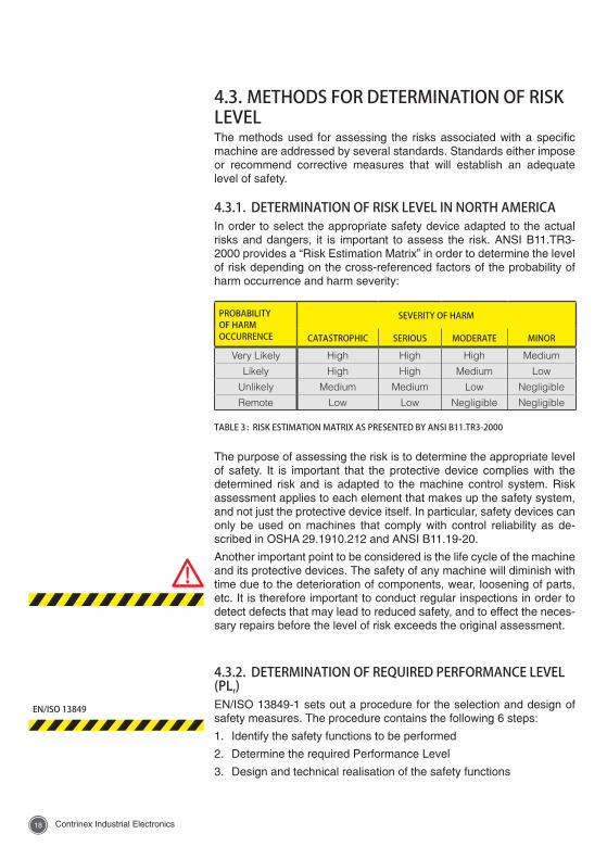
4.3.1. DETERMINATION OF RISK LEVEL IN NORTH AMERICAIn order to select the appropriate safety device adapted to the actual risks and dangers, it is important to assess the risk. ANSI B11.TR3-2000 provides a “Risk Estimation Matrix” in order to determine the level of risk depending on the cross-referenced factors of the probability of harm occurrence and harm severity:
PROBABILITY OF HARM OCCURRENCE
SEVERITY OF HARM
CATASTROPHIC SERIOUS MODERATE MINOR
Very Likely High High High Medium
Likely High High Medium Low
Unlikely Medium Medium Low Negligible
Remote Low Low Negligible Negligible
TABLE 3 : RISK ESTIMATION MATRIX AS PRESENTED BY ANSI B11.TR3-2000
The purpose of assessing the risk is to determine the appropriate level of safety. It is important that the protective device complies with the determined risk and is adapted to the machine control system. Risk assessment applies to each element that makes up the safety system, and not just the protective device itself. In particular, safety devices can only be used on machines that comply with control reliability as de-scribed in OSHA 29.1910.212 and ANSI B11.19-20.
Another important point to be considered is the life cycle of the machine and its protective devices. The safety of any machine will diminish with time due to the deterioration of components, wear, loosening of parts, etc. It is therefore important to conduct regular inspections in order to detect defects that may lead to reduced safety, and to effect the neces-sary repairs before the level of risk exceeds the original assessment.
4.3.2. DETERMINATION OF REQUIRED PERFORMANCE LEVEL (PLr)EN/ISO 13849-1 sets out a procedure for the selection and design of safety measures. The procedure contains the following 6 steps:
1. Identify the safety functions to be performed
2. Determine the required Performance Level
3. Design and technical realisation of the safety functions
EN/ISO 13849
1918 Contrinex Industrial Electronics Contrinex Industrial Electronics
4. Evaluate the achieved Performance Level
5. Verify the achieved Performance Level
6. Validate that all requirements are met
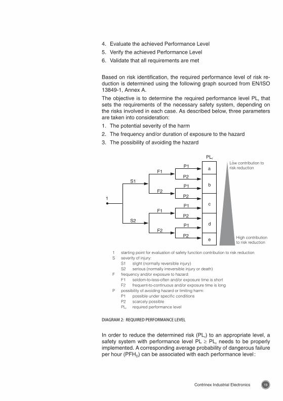
Based on risk identification, the required performance level of risk re-duction is determined using the following graph sourced from EN/ISO 13849-1, Annex A.
The objective is to determine the required performance level PLr that sets the requirements of the necessary safety system, depending on the risks involved in each case. As described below, three parameters are taken into consideration:
1. The potential severity of the harm
2. The frequency and/or duration of exposure to the hazard
3. The possibility of avoiding the hazard
DIAGRAM 2: REQUIRED PERFORMANCE LEVEL
PLr
L
H
P2
F2
S2
P1
P2
F1
P1
P2
F2
S1
1
P1
F1
P2
P1a
b
c
d
e
1 starting point for evaluation of safety function contribution to risk reductionS severity of injury: S1 slight (normally reversible injury) S2 serious (normally irreversible injury or death)F frequency and/or exposure to hazard: F1 seldom-to-less-often and/or exposure time is short F2 frequent-to-continuous and/or exposure time is longP possibility of avoiding hazard or limiting harm: P1 possible under specific conditions P2 scarcely possible PLr required performance level
Low contribution to risk reduction
High contribution to risk reduction
In order to reduce the determined risk (PLr) to an appropriate level, a safety system with performance level PL ≥ PLr needs to be properly implemented. A corresponding average probability of dangerous failure per hour (PFHD) can be associated with each performance level :
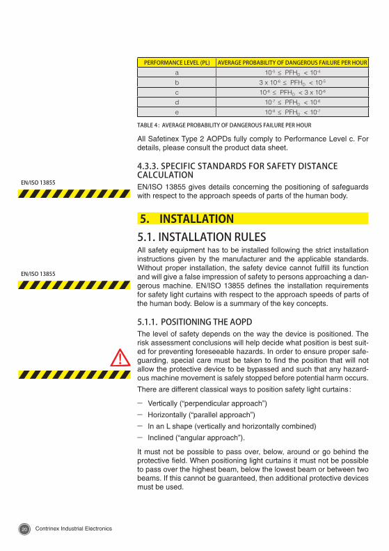
2120 Contrinex Industrial Electronics Contrinex Industrial Electronics
PERFORMANCE LEVEL (PL) AVERAGE PROBABILITY OF DANGEROUS FAILURE PER HOUR
a 10-5 ≤ PFHD < 10-4
b 3 x 10⁻⁶ ≤ PFHD < 10-5
c 10-6 ≤ PFHD < 3 x 10⁻⁶
d 10-7 ≤ PFHD < 10-6
e 10-8 ≤ PFHD < 10-7
TABLE 4 : AVERAGE PROBABILITY OF DANGEROUS FAILURE PER HOUR
All Safetinex Type 2 AOPDs fully comply to Performance Level c. For details, please consult the product data sheet.
4.3.3. SPECIFIC STANDARDS FOR SAFETY DISTANCE CALCULATIONEN/ISO 13855 gives details concerning the positioning of safeguards with respect to the approach speeds of parts of the human body.
5. INSTALLATION5.1. INSTALLATION RULESAll safety equipment has to be installed following the strict installation instructions given by the manufacturer and the applicable standards. Without proper installation, the safety device cannot fulfill its function and will give a false impression of safety to persons approaching a dan-gerous machine. EN/ISO 13855 defines the installation requirements for safety light curtains with respect to the approach speeds of parts of the human body. Below is a summary of the key concepts.
5.1.1. POSITIONING THE AOPDThe level of safety depends on the way the device is positioned. The risk assessment conclusions will help decide what position is best suit-ed for preventing foreseeable hazards. In order to ensure proper safe-guarding, special care must be taken to find the position that will not allow the protective device to be bypassed and such that any hazard-ous machine movement is safely stopped before potential harm occurs.
There are different classical ways to position safety light curtains :
– Vertically (“perpendicular approach”)
– Horizontally (“parallel approach”)
– In an L shape (vertically and horizontally combined)
– Inclined (“angular approach”).
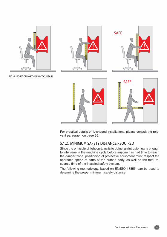
It must not be possible to pass over, below, around or go behind the protective field. When positioning light curtains it must not be possible to pass over the highest beam, below the lowest beam or between two beams. If this cannot be guaranteed, then additional protective devices must be used.
EN/ISO 13855
EN/ISO 13855
2120 Contrinex Industrial Electronics Contrinex Industrial Electronics
SAFEFIG. 4: POSITIONING THE LIGHT CURTAIN
SAFE
For practical details on L-shaped installations, please consult the rele-vant paragraph on page 35.
5.1.2. MINIMUM SAFETY DISTANCE REQUIREDSince the principle of light curtains is to detect an intrusion early enough to intervene in the machine cycle before anyone has had time to reach the danger zone, positioning of protective equipment must respect the approach speed of parts of the human body, as well as the total re-sponse time of the installed safety system.
The following methodology, based on EN/ISO 13855, can be used to determine the proper minimum safety distance:
2322 Contrinex Industrial Electronics Contrinex Industrial Electronics
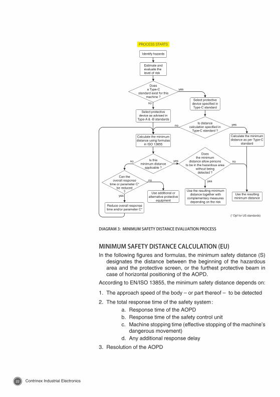
MINIMUM SAFETY DISTANCE CALCULATION (EU)In the following figures and formulas, the minimum safety distance (S)
designates the distance between the beginning of the hazardous area and the protective screen, or the furthest protective beam in case of horizontal positioning of the AOPD.
According to EN/ISO 13855, the minimum safety distance depends on:
1. The approach speed of the body – or part thereof – to be detected
2. The total response time of the safety system :a. Response time of the AOPDb. Response time of the safety control unitc. Machine stopping time (effective stopping of the machine’s
dangerous movement)d. Any additional response delay
3. Resolution of the AOPD
Does
a Type-C
standard exist for this
machine ?
Is this
minimum distance
applicable ?
Identify hazards
Estimate and
evaluate the
level of risk
yes
yes
yes
no
no
no
Reduce overall response
time and/or parameter C*
Does
the minimum
distance allow persons
to be in the hazardous area
without being
detected ?
Select protective
device specified in
Type-C standard
Is distance
calculation specified in
Type-C standard ?
Calculate the minimum
distance using formulas
in ISO 13855
Calculate the minimum
distance as per Type-C
standard
Can the
overall response
time or parameter C*
be reduced
?
Select protective
device as advised in
Type-A & -B standards
yes
yes no
Use the resulting
minimum distance
Use the resulting minimum
distance together with
complementary measures
depending on the risk
no
Use additional or
alternative protective
equipment
PROCESS STARTS
(* Dpf for US standards)
DIAGRAM 3: MINIMUM SAFETY DISTANCE EVALUATION PROCESS
2322 Contrinex Industrial Electronics Contrinex Industrial Electronics
EN/ISO 13855 defines a basic formula for calculating the minimum safety clearance between the protective device and the hazardous lo-cation:
S = (K x T) + C
Parameters:
S: Minimum safety distance between the AOPD sensing field and the hazardous area (mm). Cannot be less than 100 mm.
K: Average approach speed at which a body or part of a body en-ters the detection zone (mm/s).
T: Total response time (seconds), including
Tc : Response time of the protective device (in seconds, value provided on manufacturer’s data sheet)
Tr : Response time of the safety relay (in seconds, value provided on manufacturer’s data sheet)
Tm: Machine stopping time (in seconds, value provided by manufacturer or measured on request by specialists)
C: Additional safety distance in mm, which depends on the resolu-tion of the protective device. It cannot be less than zero.
R = Resolution of the protective device (mm)
C = 8 x (R -14 mm) where R ≤ 40 mm (= 0 when the light curtain has a resolution of 14 mm)
C = 850 mm where 40 mm < R ≤ 70 mm
For a detection resolution ≤ 40 mm, the formula thus becomes:
S = K x (Tc + Tr + Tm) + 8 x (R -14 mm)
for a detection resolution 40 mm < R ≤ 70 mm :
S = K x (Tc + Tr + Tm) + 850 mm
where
K = 2000 mm/s ** if the calculated value of S is > 500 mm, then recalculate S using
K = 1600 mm/s
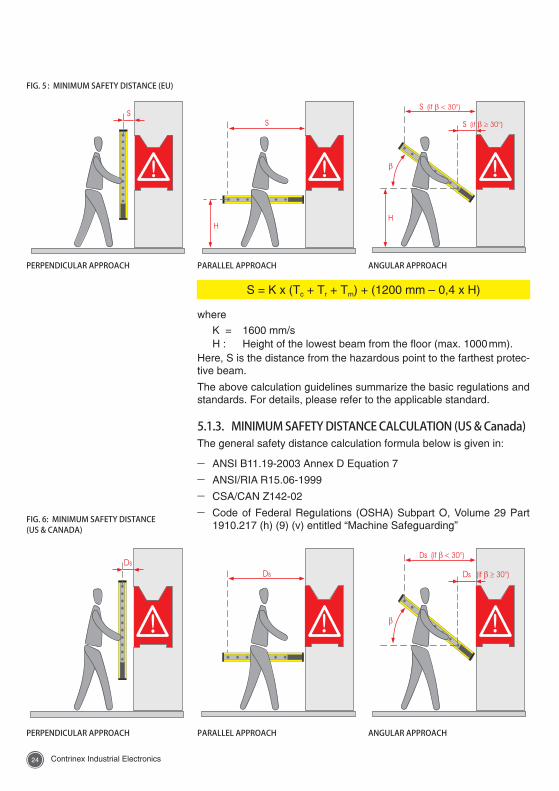
The above calculation formula applies when the protective device is positioned vertically (perpendicular approach) or in case of an angular approach if the angle (b) between the protective field and the direction of entry exceeds 30°. S is then the distance from the hazardous point to the closest protective beam.
In the case of horizontal positioning of the protective device (parallel approach) or if the angle between the protective field and the direction of entry is less than 30°, the applicable formula is:
2524 Contrinex Industrial Electronics Contrinex Industrial Electronics
S = K x (Tc + Tr + Tm) + (1200 mm – 0,4 x H)
where
K = 1600 mm/sH : Height of the lowest beam from the floor (max. 1000 mm).
Here, S is the distance from the hazardous point to the farthest protec-tive beam.
The above calculation guidelines summarize the basic regulations and standards. For details, please refer to the applicable standard.
5.1.3. MINIMUM SAFETY DISTANCE CALCULATION (US & Canada)The general safety distance calculation formula below is given in:
– ANSI B11.19-2003 Annex D Equation 7
– ANSI/RIA R15.06-1999
– CSA/CAN Z142-02
– Code of Federal Regulations (OSHA) Subpart O, Volume 29 Part 1910.217 (h) (9) (v) entitled “Machine Safeguarding”
PERPENDICULAR APPROACH ANGULAR APPROACHPARALLEL APPROACH
FIG. 5 : MINIMUM SAFETY DISTANCE (EU)
PERPENDICULAR APPROACH PARALLEL APPROACH ANGULAR APPROACH
FIG. 6: MINIMUM SAFETY DISTANCE (US & CANADA)
2524 Contrinex Industrial Electronics Contrinex Industrial Electronics
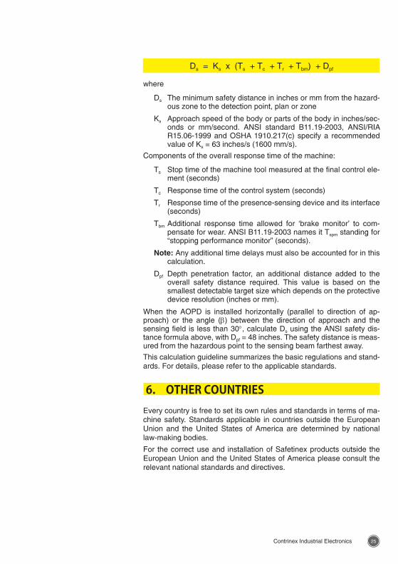
where
Ds The minimum safety distance in inches or mm from the hazard-ous zone to the detection point, plan or zone
Ks Approach speed of the body or parts of the body in inches/sec-onds or mm/second. ANSI standard B11.19-2003, ANSI/RIA R15.06-1999 and OSHA 1910.217(c) specify a recommended value of Ks = 63 inches/s (1600 mm/s).
Components of the overall response time of the machine:
Ts Stop time of the machine tool measured at the final control ele-ment (seconds)
Tc Response time of the control system (seconds)
Tr Response time of the presence-sensing device and its interface (seconds)
Tbm Additional response time allowed for ‘brake monitor’ to com-pensate for wear. ANSI B11.19-2003 names it Tspm standing for “stopping performance monitor” (seconds).
Note: Any additional time delays must also be accounted for in this calculation.
Dpf Depth penetration factor, an additional distance added to the overall safety distance required. This value is based on the smallest detectable target size which depends on the protective device resolution (inches or mm).
When the AOPD is installed horizontally (parallel to direction of ap-proach) or the angle (b) between the direction of approach and the sensing field is less than 30°, calculate Ds using the ANSI safety dis-tance formula above, with Dpf = 48 inches. The safety distance is meas-ured from the hazardous point to the sensing beam farthest away.
This calculation guideline summarizes the basic regulations and stand-ards. For details, please refer to the applicable standards.
6. OTHER COUNTRIESEvery country is free to set its own rules and standards in terms of ma-chine safety. Standards applicable in countries outside the European Union and the United States of America are determined by national law-making bodies.
For the correct use and installation of Safetinex products outside the European Union and the United States of America please consult the relevant national standards and directives.
Ds = Ks x (Ts + Tc + Tr + Tbm) + Dpf
2726 Contrinex Industrial Electronics Contrinex Industrial Electronics
7. ACRONYMSANSI American National Standards InstituteAOPD Active Optoelectronic Protective DeviceBSI British Standards InstitutionCEN European Committee for StandardisationCENELEC European Committee for Electrotechnical StandardisationCLC CENELEC (in document references)CSA Canadian Standards AssociationDCavg Average Diagnostic CoverageDIN Deutsches Institut für Normung (German Institute for
Standardization)EC European CommunityEEC European Economic CommunityEN European NormESPE Electro-Sensitive Protective EquipmentFMEA Failure Mode and Effects AnalysisIEC International Electrotechnical CommissionIEEE Institute of Electrical & Electronics EngineersISO International Organization for StandardizationMTTFd Mean Time To Dangerous FailureNFPA National Fire Protection AssociationOEM Original Equipment ManufacturerOSHA Occupational Safety and Health AdministrationOSSD Output Signal Switching DevicePES Programmable Electronic SystemsPLC Programmable Logic ControllerTS Technical SpecificationTÜV Technischer ÜberwachungsvereinUL Underwriters Laboratories Inc.
2726 Contrinex Industrial Electronics Contrinex Industrial Electronics
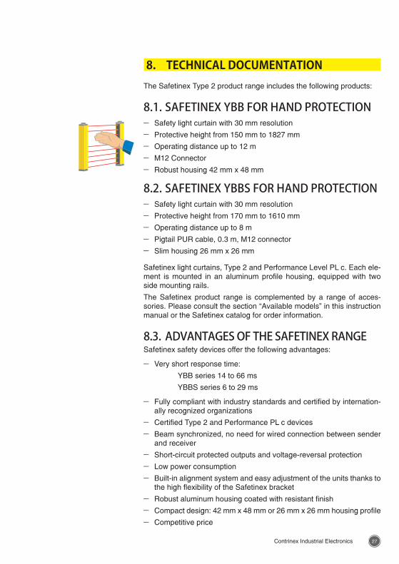
8. TECHNICAL DOCUMENTATIONThe Safetinex Type 2 product range includes the following products:
8.1. SAFETINEX YBB FOR HAND PROTECTION – Safety light curtain with 30 mm resolution
– Protective height from 150 mm to 1827 mm
– Operating distance up to 12 m
– M12 Connector
– Robust housing 42 mm x 48 mm
8.2. SAFETINEX YBBS FOR HAND PROTECTION – Safety light curtain with 30 mm resolution
– Protective height from 170 mm to 1610 mm
– Operating distance up to 8 m
– Pigtail PUR cable, 0.3 m, M12 connector
– Slim housing 26 mm x 26 mm
Safetinex light curtains, Type 2 and Performance Level PL c. Each ele-ment is mounted in an aluminum profile housing, equipped with two side mounting rails.
The Safetinex product range is complemented by a range of acces-sories. Please consult the section “Available models” in this instruction manual or the Safetinex catalog for order information.
8.3. ADVANTAGES OF THE SAFETINEX RANGESafetinex safety devices offer the following advantages:
– Very short response time:
YBB series 14 to 66 ms
YBBS series 6 to 29 ms
– Fully compliant with industry standards and certified by internation-ally recognized organizations
– Certified Type 2 and Performance PL c devices
– Beam synchronized, no need for wired connection between sender and receiver
– Short-circuit protected outputs and voltage-reversal protection
– Low power consumption
– Built-in alignment system and easy adjustment of the units thanks to the high flexibility of the Safetinex bracket
– Robust aluminum housing coated with resistant finish
– Compact design: 42 mm x 48 mm or 26 mm x 26 mm housing profile
– Competitive price
2928 Contrinex Industrial Electronics Contrinex Industrial Electronics
– No blind zone (YBBS series only)
– Resolution is maintained even in L-shaped installation or when 2 units are set next to each other to increase the total light curtain length, twin installation (YBBS series only)
– Flexible connector (YBBS series only)
Furthermore, Safetinex light curtains have been designed to provide users with a comfortable work environment. Their use involves no addi-tional unproductive movements and no waste of time. Users can freely access and move around the machine in complete safety.
8.4. SCOPE OF THIS TECHNICAL DOCUMENTATIONThis section contains useful information for the selection, installation, operation and maintenance of Safetinex light curtains. It is intended for skilled personnel with a knowledge of safety issues and electronic equipment. For safety compliance of your installation, please refer to the relevant standards and directives.
8.5. SELF PROTECTED OUTPUTSBoth OSSD1 and OSSD2 are self-protected and actively monitored PNP outputs. Both outputs are controlled by independent current-monitored high-side switches. Thanks to continuous monitoring, any short-circuit between an output and the power supply or ground is detected, leading to the deactivation of the other output. Similarly, a cross-circuit between the two outputs is also detected and both OSSDs are deactivated within the specified response time. The OSSD outputs are switched off and remain in that state as long as the fault remains.
2928 Contrinex Industrial Electronics Contrinex Industrial Electronics
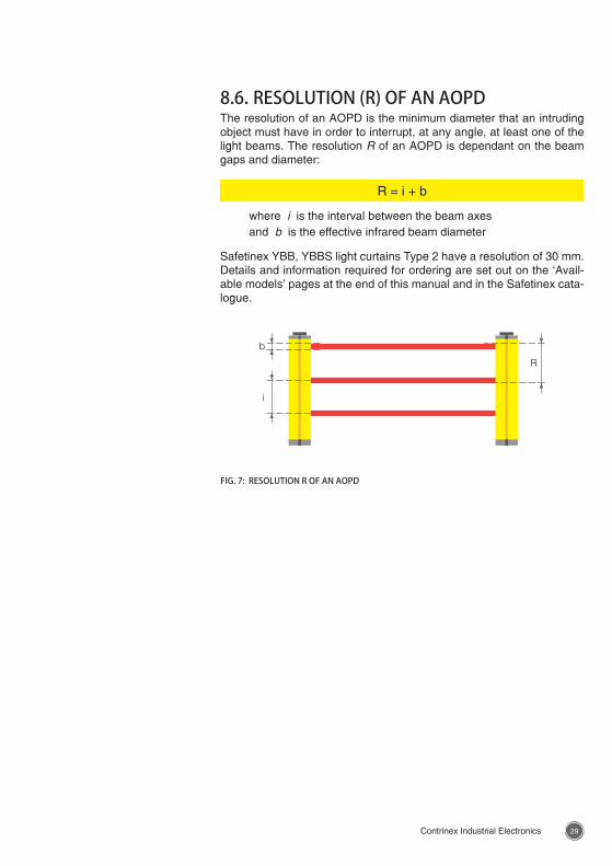
8.6. RESOLUTION (R) OF AN AOPDThe resolution of an AOPD is the minimum diameter that an intruding object must have in order to interrupt, at any angle, at least one of the light beams. The resolution R of an AOPD is dependant on the beam gaps and diameter:
R = i + b
where i is the interval between the beam axesand b is the effective infrared beam diameter
Safetinex YBB, YBBS light curtains Type 2 have a resolution of 30 mm. Details and information required for ordering are set out on the ‘Avail-able models’ pages at the end of this manual and in the Safetinex cata-logue.
FIG. 7: RESOLUTION R OF AN AOPD
3130 Contrinex Industrial Electronics Contrinex Industrial Electronics
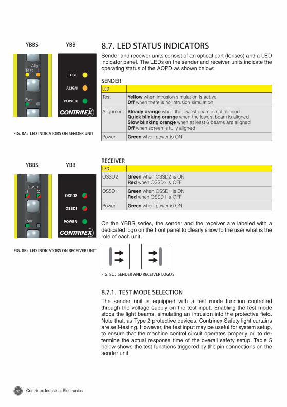
8.7. LED STATUS INDICATORSSender and receiver units consist of an optical part (lenses) and a LED indicator panel. The LEDs on the sender and receiver units indicate the operating status of the AOPD as shown below:
SENDERLED
Test Yellow when intrusion simulation is activeOff when there is no intrusion simulation
Alignment Steady orange when the lowest beam is not alignedQuick blinking orange when the lowest beam is alignedSlow blinking orange when at least 6 beams are alignedOff when screen is fully aligned
Power Green when power is ON
RECEIVERLED
OSSD2 Green when OSSD2 is ONRed when OSSD2 is OFF
OSSD1 Green when OSSD1 is ONRed when OSSD1 is OFF
Power Green when power is ON
On the YBBS series, the sender and the receiver are labeled with a dedicated logo on the front panel to clearly show to the user what is the role of each unit.
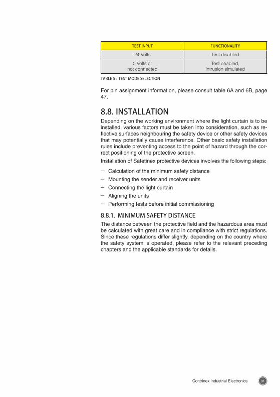
8.7.1. TEST MODE SELECTIONThe sender unit is equipped with a test mode function controlled through the voltage supply on the test input. Enabling the test mode stops the light beams, simulating an intrusion into the protective field. Note that, as Type 2 protective devices, Contrinex Safety light curtains are self-testing. However, the test input may be useful for system setup, to ensure that the machine control circuit operates properly or, to de-termine the actual response time of the overall safety setup. Table 5 below shows the test functions triggered by the pin connections on the sender unit.
FIG. 8A : LED INDICATORS ON SENDER UNIT
YBBS YBB
FIG. 8B : LED INDICATORS ON RECEIVER UNIT
YBBS YBB
TEST
ALIGN
POWER
OSSD2
OSSD1
POWER
FIG. 8C : SENDER AND RECEIVER LOGOS
3130 Contrinex Industrial Electronics Contrinex Industrial Electronics
TEST INPUT FUNCTIONALITY
24 Volts Test disabled
0 Volts or not connected
Test enabled, intrusion simulated
TABLE 5 : TEST MODE SELECTION
For pin assignment information, please consult table 6A and 6B, page 47.
8.8. INSTALLATIONDepending on the working environment where the light curtain is to be installed, various factors must be taken into consideration, such as re-flective surfaces neighbouring the safety device or other safety devices that may potentially cause interference. Other basic safety installation rules include preventing access to the point of hazard through the cor-rect positioning of the protective screen.
Installation of Safetinex protective devices involves the following steps:
– Calculation of the minimum safety distance
– Mounting the sender and receiver units
– Connecting the light curtain
– Aligning the units
– Performing tests before initial commissioning
8.8.1. MINIMUM SAFETY DISTANCEThe distance between the protective field and the hazardous area must be calculated with great care and in compliance with strict regulations. Since these regulations differ slightly, depending on the country where the safety system is operated, please refer to the relevant preceding chapters and the applicable standards for details.
3332 Contrinex Industrial Electronics Contrinex Industrial Electronics
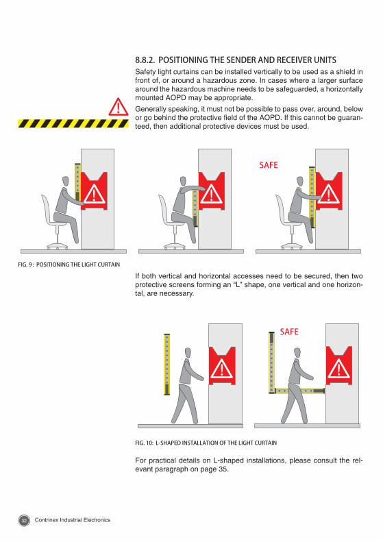
8.8.2. POSITIONING THE SENDER AND RECEIVER UNITSSafety light curtains can be installed vertically to be used as a shield in front of, or around a hazardous zone. In cases where a larger surface around the hazardous machine needs to be safeguarded, a horizontally mounted AOPD may be appropriate.
Generally speaking, it must not be possible to pass over, around, below or go behind the protective field of the AOPD. If this cannot be guaran-teed, then additional protective devices must be used.
If both vertical and horizontal accesses need to be secured, then two protective screens forming an “L” shape, one vertical and one horizon-tal, are necessary.
For practical details on L-shaped installations, please consult the rel-evant paragraph on page 35.
FIG. 9 : POSITIONING THE LIGHT CURTAIN
SAFE
SAFE
FIG. 10: L-SHAPED INSTALLATION OF THE LIGHT CURTAIN
3332 Contrinex Industrial Electronics Contrinex Industrial Electronics
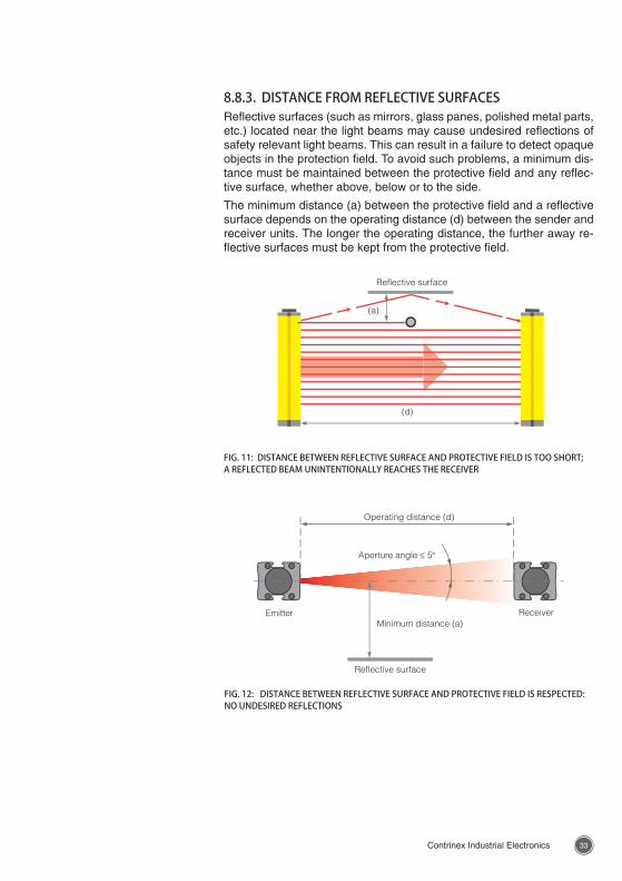
8.8.3. DISTANCE FROM REFLECTIVE SURFACESReflective surfaces (such as mirrors, glass panes, polished metal parts, etc.) located near the light beams may cause undesired reflections of safety relevant light beams. This can result in a failure to detect opaque objects in the protection field. To avoid such problems, a minimum dis-tance must be maintained between the protective field and any reflec-tive surface, whether above, below or to the side.
The minimum distance (a) between the protective field and a reflective surface depends on the operating distance (d) between the sender and receiver units. The longer the operating distance, the further away re-flective surfaces must be kept from the protective field.
FIG. 11: DISTANCE BETWEEN REFLECTIVE SURFACE AND PROTECTIVE FIELD IS TOO SHORT; A REFLECTED BEAM UNINTENTIONALLY REACHES THE RECEIVER
Reflective surface
(a)
(d)
FIG. 12: DISTANCE BETWEEN REFLECTIVE SURFACE AND PROTECTIVE FIELD IS RESPECTED: NO UNDESIRED REFLECTIONS
Operating distance (d)
Aperture angle ≤ 5°
Minimum distance (a)
Reflective surface
Emitter Receiver
3534 Contrinex Industrial Electronics Contrinex Industrial Electronics
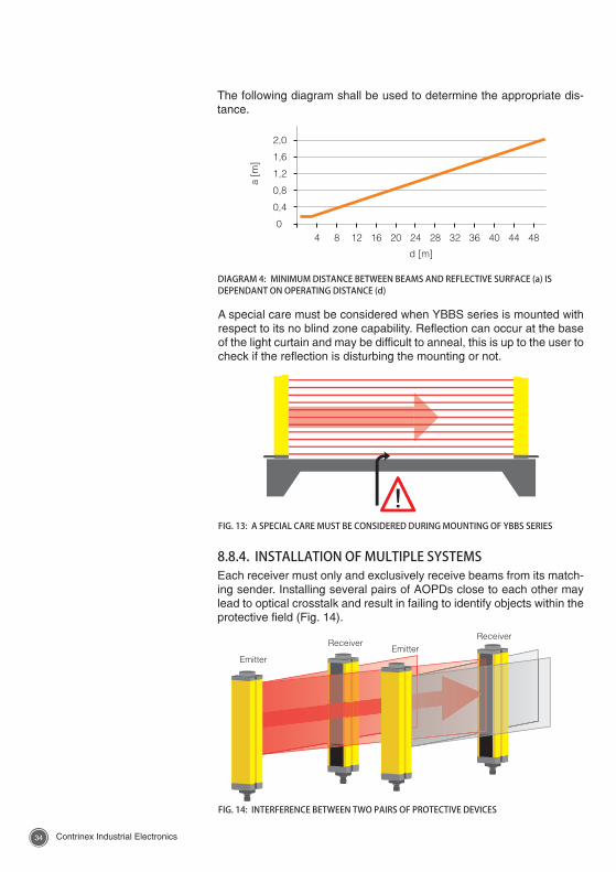
The following diagram shall be used to determine the appropriate dis-tance.
8.8.4. INSTALLATION OF MULTIPLE SYSTEMSEach receiver must only and exclusively receive beams from its match-ing sender. Installing several pairs of AOPDs close to each other may lead to optical crosstalk and result in failing to identify objects within the protective field (Fig. 14).
DIAGRAM 4: MINIMUM DISTANCE BETWEEN BEAMS AND REFLECTIVE SURFACE (a) IS DEPENDANT ON OPERATING DISTANCE (d)
FIG. 14: INTERFERENCE BETWEEN TWO PAIRS OF PROTECTIVE DEVICES
EmitterEmitter
ReceiverReceiver
A special care must be considered when YBBS series is mounted with respect to its no blind zone capability. Reflection can occur at the base of the light curtain and may be difficult to anneal, this is up to the user to check if the reflection is disturbing the mounting or not.
FIG. 13: A SPECIAL CARE MUST BE CONSIDERED DURING MOUNTING OF YBBS SERIES
3534 Contrinex Industrial Electronics Contrinex Industrial Electronics
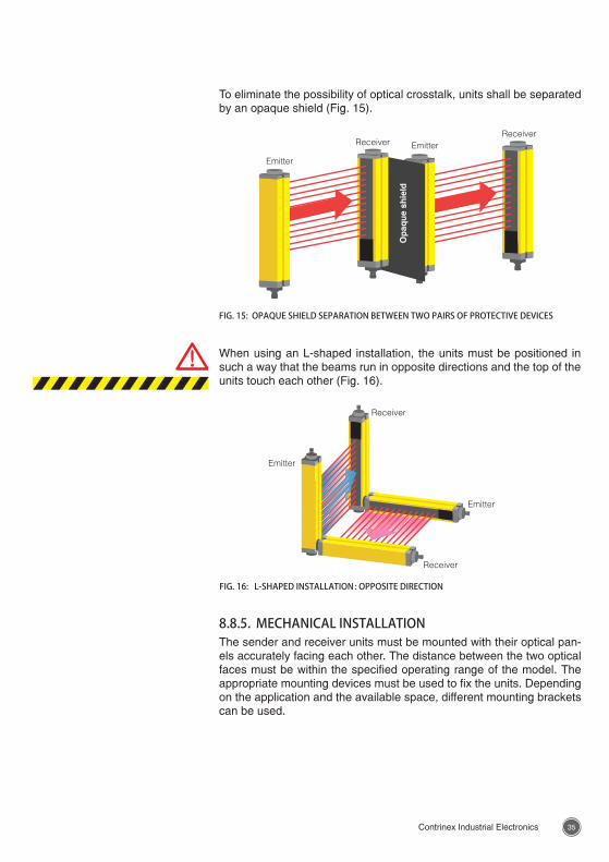
To eliminate the possibility of optical crosstalk, units shall be separated by an opaque shield (Fig. 15).
FIG. 15: OPAQUE SHIELD SEPARATION BETWEEN TWO PAIRS OF PROTECTIVE DEVICES
Emitter
Receiver
Op
aqu
e sh
ield
EmitterReceiver
Emitter
Emitter
Receiver
Receiver
FIG. 16: L-SHAPED INSTALLATION : OPPOSITE DIRECTION
When using an L-shaped installation, the units must be positioned in such a way that the beams run in opposite directions and the top of the units touch each other (Fig. 16).
8.8.5. MECHANICAL INSTALLATIONThe sender and receiver units must be mounted with their optical pan-els accurately facing each other. The distance between the two optical faces must be within the specified operating range of the model. The appropriate mounting devices must be used to fix the units. Depending on the application and the available space, different mounting brackets can be used.
3736 Contrinex Industrial Electronics Contrinex Industrial Electronics
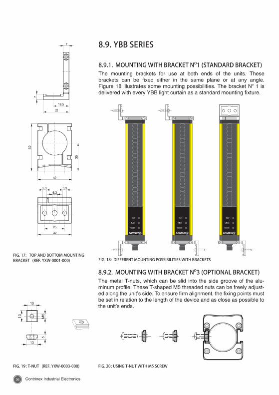
FIG. 18: DIFFERENT MOUNTING POSSIBILITIES WITH BRACKETSFIG. 17: TOP AND BOTTOM MOUNTING BRACKET (REF. YXW-0001-000)
FIG. 20 : USING T-NUT WITH M5 SCREWFIG. 19 : T-NUT (REF. YXW-0003-000)
8.9. YBB SERIES
8.9.1. MOUNTING WITH BRACKET NO1 (STANDARD BRACKET)The mounting brackets for use at both ends of the units. These brackets can be fixed either in the same plane or at any angle. Figure 18 illustrates some mounting possibilities. The bracket No 1 is delivered with every YBB light curtain as a standard mounting fixture.
8.9.2. MOUNTING WITH BRACKET NO3 (OPTIONAL BRACKET)The metal T-nuts, which can be slid into the side groove of the alu-minum profile. These T-shaped M5 threaded nuts can be freely adjust-ed along the unit’s side. To ensure firm alignment, the fixing points must be set in relation to the length of the device and as close as possible to the unit’s ends.
3736 Contrinex Industrial Electronics Contrinex Industrial Electronics
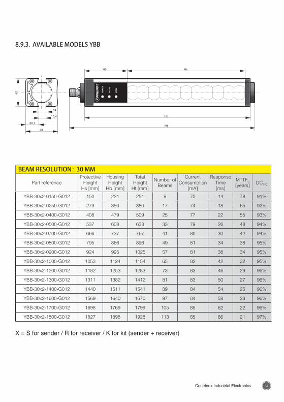
8.9.3. AVAILABLE MODELS YBB
BEAM RESOLUTION : 30 MM
Part referenceProtective
Height Hs [mm]
Housing Height
Hb [mm]
Total Height
Ht [mm]
Number of Beams
Current Consumption
[mA]
Response Time [ms]
MTTFd [years]
DCavg
YBB-30x2-0150-G012 150 221 251 9 70 14 78 91%
YBB-30x2-0250-G012 279 350 380 17 74 18 65 92%
YBB-30x2-0400-G012 408 479 509 25 77 22 55 93%
YBB-30x2-0500-G012 537 608 638 33 79 26 48 94%
YBB-30x2-0700-G012 666 737 767 41 80 30 42 94%
YBB-30x2-0800-G012 795 866 896 49 81 34 38 95%
YBB-30x2-0900-G012 924 995 1025 57 81 38 34 95%
YBB-30x2-1000-G012 1053 1124 1154 65 82 42 32 95%
YBB-30x2-1200-G012 1182 1253 1283 73 83 46 29 96%
YBB-30x2-1300-G012 1311 1382 1412 81 83 50 27 96%
YBB-30x2-1400-G012 1440 1511 1541 89 84 54 25 96%
YBB-30x2-1600-G012 1569 1640 1670 97 84 58 23 96%
YBB-30x2-1700-G012 1698 1769 1799 105 85 62 22 96%
YBB-30x2-1800-G012 1827 1898 1928 113 85 66 21 97%
X = S for sender / R for receiver / K for kit (sender + receiver)
3938 Contrinex Industrial Electronics Contrinex Industrial Electronics
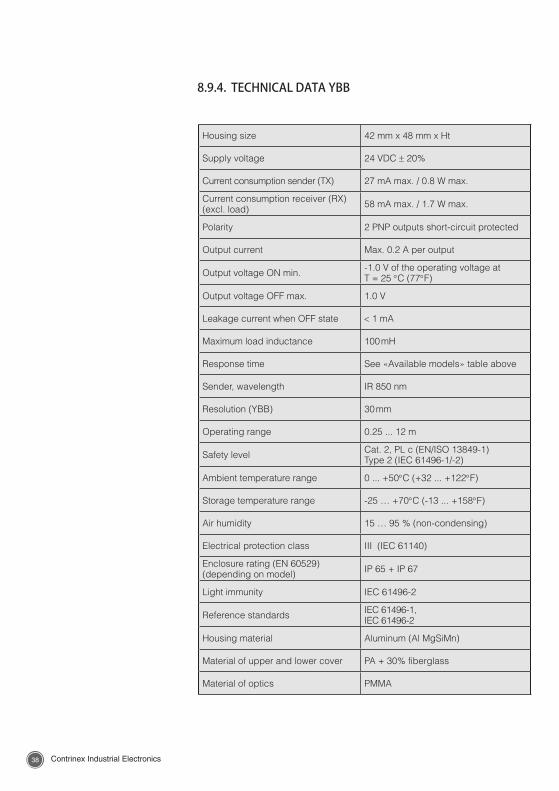
Housing size 42 mm x 48 mm x Ht
Supply voltage 24 VDC ± 20%
Current consumption sender (TX) 27 mA max. / 0.8 W max.
Current consumption receiver (RX) (excl. load) 58 mA max. / 1.7 W max.
Polarity 2 PNP outputs short-circuit protected
Output current Max. 0.2 A per output
Output voltage ON min. -1.0 V of the operating voltage atT = 25 °C (77°F)
Output voltage OFF max. 1.0 V
Leakage current when OFF state < 1 mA
Maximum load inductance 100 mH
Response time See «Available models» table above
Sender, wavelength IR 850 nm
Resolution (YBB) 30 mm
Operating range 0.25 ... 12 m
Safety level Cat. 2, PL c (EN/ISO 13849-1)Type 2 (IEC 61496-1/-2)
Ambient temperature range 0 ... +50°C (+32 ... +122°F)
Storage temperature range -25 … +70°C (-13 ... +158°F)
Air humidity 15 … 95 % (non-condensing)
Electrical protection class III (IEC 61140)
Enclosure rating (EN 60529) (depending on model) IP 65 + IP 67
Light immunity IEC 61496-2
Reference standards IEC 61496-1, IEC 61496-2
Housing material Aluminum (Al MgSiMn)
Material of upper and lower cover PA + 30% fiberglass
Material of optics PMMA
8.9.4. TECHNICAL DATA YBB
3938 Contrinex Industrial Electronics Contrinex Industrial Electronics
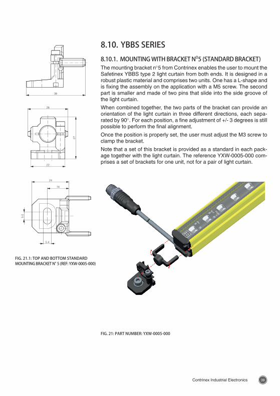
FIG. 21: PART NUMBER: YXW-0005-000
8.10. YBBS SERIES8.10.1. MOUNTING WITH BRACKET NO5 (STANDARD BRACKET)The mounting bracket n°5 from Contrinex enables the user to mount the Safetinex YBBS type 2 light curtain from both ends. It is designed in a robust plastic material and comprises two units. One has a L-shape and is fixing the assembly on the application with a M5 screw. The second part is smaller and made of two pins that slide into the side groove of the light curtain.
When combined together, the two parts of the bracket can provide an orientation of the light curtain in three different directions, each sepa-rated by 90°. For each position, a fine adjustment of +/- 3 degrees is still possible to perform the final alignment.
Once the position is properly set, the user must adjust the M3 screw to clamp the bracket.
Note that a set of this bracket is provided as a standard in each pack-age together with the light curtain. The reference YXW-0005-000 com-prises a set of brackets for one unit, not for a pair of light curtain.
FIG. 21.1: TOP AND BOTTOM STANDARD MOUNTING BRACKET N° 5 (REF: YXW-0005-000)
4140 Contrinex Industrial Electronics Contrinex Industrial Electronics
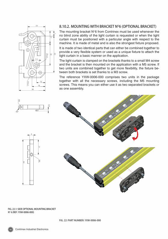
FIG. 22: PART NUMBER: YXW-0006-000
8.10.2. MOUNTING WITH BRACKET NO6 (OPTIONAL BRACKET)The mounting bracket N°6 from Contrinex must be used whenever the no blind zone ability of the light curtain is requested or when the light curtain must be positioned with a particular angle with respect to the machine. It is made of metal and is also the strongest fixture proposed.
It is made of two identical parts that can either be combined together to provide a very flexible system or used as a unique fixture to attach the light curtain in a basic manner on the application.
The light curtain is clamped on the brackets thanks to a small M4 screw and the bracket is then mounted on the application with a M5 screw. If two units are combined together to get more flexibility, the fixture be-tween both brackets is set thanks to a M3 screw.
The reference YXW-0006-000 comprises two units in the package together with all the necessary screws, including the M5 mounting screws. This means you can either use it as two separated brackets or as one assembly.
FIG. 22.1: SIDE OPTIONAL MOUNTING BRACKET N° 6 (REF: YXW-0006-000)
4140 Contrinex Industrial Electronics Contrinex Industrial Electronics
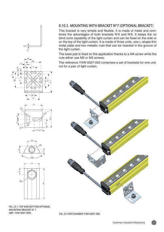
FIG. 23: PART NUMBER: YXW-0007-000
8.10.3. MOUNTING WITH BRACKET NO7 (OPTIONAL BRACKET)This bracket is very simple and flexible. It is made of metal and com-bines the advantages of both brackets No5 and No6. It keeps the no blind zone capability of the light curtain and can be fixed on the side or on the top of the light curtain. It is made of three units, one L-shape thin metal plate and two metallic nuts that can be inserted in the groove of the light curtain.
The base plat is fixed on the application thanks to a M4 screw while the nuts either use M2 or M3 screws.
The reference YXW-0007-000 comprises a set of brackets for one unit, not for a pair of light curtain.
FIG. 23.1: TOP AND BOTTOM OPTIONAL MOUNTING BRACKET N° 7 (REF: YXW-0007-000)
4342 Contrinex Industrial Electronics Contrinex Industrial Electronics
Pwr
Align
Test
I
Pwr
OSSD1 2
Pwr
Align
TestI
Pwr
OSSD1 2
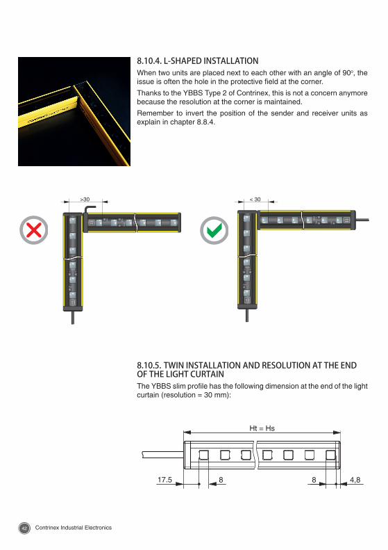
8.10.4. L-SHAPED INSTALLATIONWhen two units are placed next to each other with an angle of 90o, the issue is often the hole in the protective field at the corner.
Thanks to the YBBS Type 2 of Contrinex, this is not a concern anymore because the resolution at the corner is maintained.
Remember to invert the position of the sender and receiver units as explain in chapter 8.8.4.
8.10.5. TWIN INSTALLATION AND RESOLUTION AT THE END OF THE LIGHT CURTAINThe YBBS slim profile has the following dimension at the end of the light curtain (resolution = 30 mm):
4342 Contrinex Industrial Electronics Contrinex Industrial Electronics
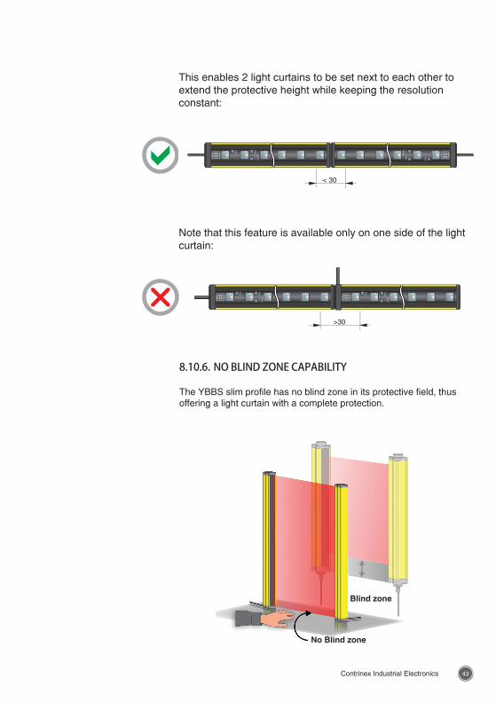
This enables 2 light curtains to be set next to each other to extend the protective height while keeping the resolution constant:
Note that this feature is available only on one side of the light curtain:
8.10.6. NO BLIND ZONE CAPABILITY
The YBBS slim profile has no blind zone in its protective field, thus offering a light curtain with a complete protection.
Blind zone
No Blind zone
4544 Contrinex Industrial Electronics Contrinex Industrial Electronics
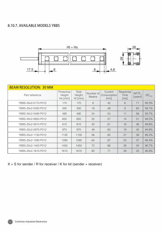
X = S for sender / R for receiver / K for kit (sender + receiver)
8.10.7. AVAILABLE MODELS YBBS
BEAM RESOLUTION: 30 MM
Part referenceProtective
Height Hs [mm]
Total Height
Ht [mm]
Number of Beams
Current Consumption
[mA]
Response Time [ms]
MTTFd [years]
DCavg
YBBS-30x2-0170-P012 170 170 8 42 6 71 92.3%
YBBS-30x2-0330-P012 330 330 16 49 9 62 93.1%
YBBS-30x2-0490-P012 490 490 24 54 11 56 93.7%
YBBS-30x2-0650-P012 650 650 32 57 14 51 94.2%
YBBS-30x2-0810-P012 810 810 40 61 16 46 94.6%
YBBS-30x2-0970-P012 970 970 48 63 19 42 94.9%
YBBS-30x2-1130-P012 1130 1130 56 65 21 39 95.2%
YBBS-30x2-1290-P012 1290 1290 64 67 24 37 95.4%
YBBS-30x2-1450-P012 1450 1450 72 68 26 34 95.7%
YBBS-30x2-1610-P012 1610 1610 80 71 29 32 95.9%
4544 Contrinex Industrial Electronics Contrinex Industrial Electronics
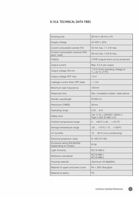
Housing size 26 mm x 26 mm x Ht
Supply voltage 24 VDC ± 20%
Current consumption sender (TX) 42 mA max. / 1.4 W max.
Current consumption receiver (RX) (excl. load) 29 mA max. / 0.8 W max.
Polarity 2 PNP outputs short-circuit protected
Output current Max. 0.4 A per output
Output voltage ON min. -1.8 V of the operating voltage atT = 25 °C (77°F)
Output voltage OFF max. 1.0 V
Leakage current when OFF state < 1 mA
Maximum load inductance 100 mH
Response time See «Available models» table above
Sender, wavelength IR 850 nm
Resolution (YBBS) 30 mm
Operating range 0.25 ... 8 m
Safety level Cat. 2, PL c (EN/ISO 13849-1)Type 2 (IEC 61496-1/-2)
Ambient temperature range 0 ... +55°C (+32 ... +131°F)
Storage temperature range -25 … +70°C (-13 ... +158°F)
Air humidity 15 … 95 % (non-condensing)
Electrical protection class III (IEC 61140)
Enclosure rating (EN 60529) (depending on model) IP 65
Light immunity IEC 61496-2
Reference standards IEC 61496-1, IEC 61496-2
Housing material Aluminum (Al MgSiMn)
Material of upper and lower cover PA + 30% fiberglass
Material of optics PC
8.10.8. TECHNICAL DATA YBBS
4746 Contrinex Industrial Electronics Contrinex Industrial Electronics
8.11. CONNECTING THE PROTECTIVE DEVICEPlease note that all electrical connections must be performed by expe-rienced and qualified personnel.
8.11.1. POWER SUPPLYThe power supply to both the sender and receiver units must be 24 V DC ± 20%. The power consumption depends on the model. Please refer to the data sheets for details.
The external supply voltage must be capable of buffering brief main voltage failures of 10 ms as specified in IEC 61496-1.
Use a dedicated 24 VDC, Class 2 Safety Extra-low Voltage (SELV) or Protective Extra-low Voltage (PELV) power supply to supply each unit. These power supplies provide the necessary protection to ensure that under normal and single-fault conditions, the voltage between the dif-ferent conductors, and between conductors and functional earth, does not exceed a safe value.
8.11.2. ELECTROMAGNETIC COMPATIBILITY (EMC)In terms of immunity to electromagnetic fields, Safetinex protective de-vices fully comply with EN 55011/A2 and EN 61000-6-4 (electrostatic discharge, electrical and radio-frequency disturbances). Proximity to potential electromagnetic interference is acceptable within the limits of these standards.
In case of presence of strong electromagnetic fields, the use of shielded 5-pin cables is strongly recommended.
8.11.3. LIGHT RADIATIONAdditional measures may be necessary to ensure that the AOPD does not fail to danger when other forms of light radiation are present in a particular application (for example, use of cableless control devices on cranes, radiation from weld spatter or effects from stroboscopic light).
4746 Contrinex Industrial Electronics Contrinex Industrial Electronics
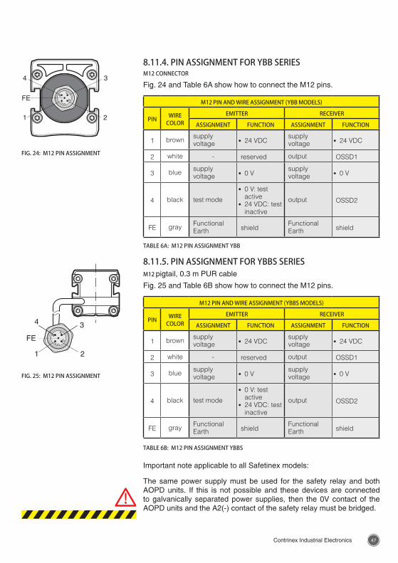
FIG. 24: M12 PIN ASSIGNMENT
FIG. 25: M12 PIN ASSIGNMENT
8.11.4. PIN ASSIGNMENT FOR YBB SERIESM12 CONNECTOR
Fig. 24 and Table 6A show how to connect the M12 pins.
M12 PIN AND WIRE ASSIGNMENT (YBB MODELS)
PIN WIRE COLOR
EMITTER RECEIVER
ASSIGNMENT FUNCTION ASSIGNMENT FUNCTION
1 brown supply voltage · 24 VDC
supply voltage · 24 VDC
2 white - reserved output OSSD1
3 blue supply voltage · 0 V
supply voltage · 0 V
4 black test mode
· 0 V: test active
· 24 VDC: test inactive
output OSSD2
FE gray Functional Earth shield
Functional Earth shield
TABLE 6A: M12 PIN ASSIGNMENT YBB
8.11.5. PIN ASSIGNMENT FOR YBBS SERIESM12 pigtail, 0.3 m PUR cable
Fig. 25 and Table 6B show how to connect the M12 pins.
M12 PIN AND WIRE ASSIGNMENT (YBBS MODELS)
PIN WIRE COLOR
EMITTER RECEIVER
ASSIGNMENT FUNCTION ASSIGNMENT FUNCTION
1 brown supply voltage · 24 VDC
supply voltage · 24 VDC
2 white - reserved output OSSD1
3 blue supply voltage · 0 V
supply voltage · 0 V
4 black test mode
· 0 V: test active
· 24 VDC: test inactive
output OSSD2
FE gray Functional Earth shield
Functional Earth shield
TABLE 6B: M12 PIN ASSIGNMENT YBBS
Important note applicable to all Safetinex models:
The same power supply must be used for the safety relay and both AOPD units. If this is not possible and these devices are connected to galvanically separated power supplies, then the 0V contact of the AOPD units and the A2(-) contact of the safety relay must be bridged.
4948 Contrinex Industrial Electronics Contrinex Industrial Electronics
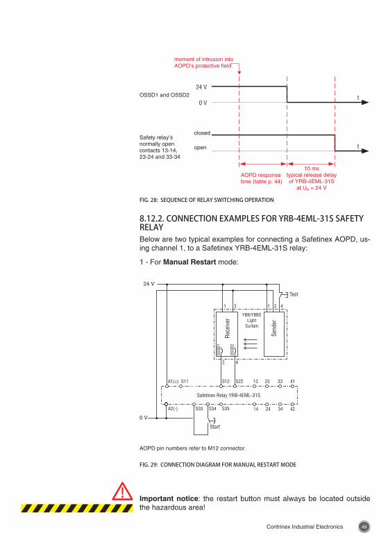
FIG. 27: BLOCK DIAGRAM
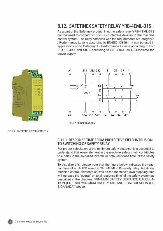
FIG. 26 : SAFETY RELAY YRB-4EML-31S
8.12. SAFETINEX SAFETY RELAY YRB-4EML-31SAs a part of the Safetinex product line, the safety relay YRB-4EML-31S can be used to connect YBB/YBBS protective devices to the machine control system. The relay complies with the requirements of Category 4 / Performance Level e according to EN/ISO 13849-1. It can be used in applications up to Category 4 / Performance Level e according to EN/ISO 13849-1 and SIL 3 according to EN 62061. Its LED indicate the power supply.
8.12.1. RESPONSE TIME FROM PROTECTIVE FIELD INTRUSION TO SWITCHING OF SAFETY RELAYFor proper calculation of the minimum safety distance, it is essential to understand that every element in the machine safety chain contributes to a delay in the so-called ‘overall’ or ‘total response time’ of the safety system.
To visualize this, please note that the figure below indicates the reac-tion time of an AOPD wired to YRB-4EML-31S safety relay. Additional machine control elements as well as the machine’s own stopping time will increase the “overall” or ‘total response time’ of the safety system as described in the chapters “MINIMUM SAFETY DISTANCE CALCULA-TION (EU)” and “MINIMUM SAFETY DISTANCE CALCULATION (US & CANADA)” above.
4948 Contrinex Industrial Electronics Contrinex Industrial Electronics
FIG. 28: SEQUENCE OF RELAY SWITCHING OPERATION
AOPD response time (table p. 44)
10 mstypical release delay of YRB-4EML-31S
at UN = 24 V
OSSD1 and OSSD2
Safety relay’s normally open contacts 13-14, 23-24 and 33-34
moment of intrusion into AOPD’s protective field
closed
open
Important notice: the restart button must always be located outside the hazardous area!
AOPD pin numbers refer to M12 connector.
FIG. 29: CONNECTION DIAGRAM FOR MANUAL RESTART MODE
8.12.2. CONNECTION EXAMPLES FOR YRB-4EML-31S SAFETY RELAYBelow are two typical examples for connecting a Safetinex AOPD, us-ing channel 1, to a Safetinex YRB-4EML-31S relay:
1 - For Manual Restart mode:
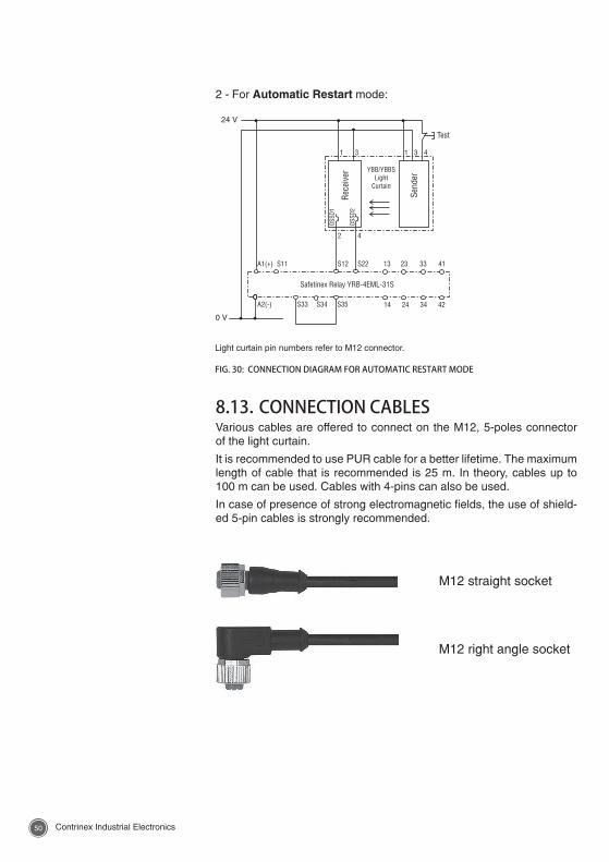
5150 Contrinex Industrial Electronics Contrinex Industrial Electronics
2 - For Automatic Restart mode:
M12 straight socket
M12 right angle socket
Light curtain pin numbers refer to M12 connector.
FIG. 30: CONNECTION DIAGRAM FOR AUTOMATIC RESTART MODE
8.13. CONNECTION CABLESVarious cables are offered to connect on the M12, 5-poles connector of the light curtain.
It is recommended to use PUR cable for a better lifetime. The maximum length of cable that is recommended is 25 m. In theory, cables up to 100 m can be used. Cables with 4-pins can also be used.
In case of presence of strong electromagnetic fields, the use of shield-ed 5-pin cables is strongly recommended.
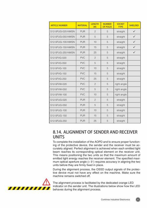
5150 Contrinex Industrial Electronics Contrinex Industrial Electronics
ARTICLE NUMBER MATERIAL LENGTH (M)
NUMBER OF POLES
SOCKET TYPE SHIELDED
S12-5FUG-020-NWSN PUR 2 5 straight ü
S12-5FUG-050-NWSN PUR 5 5 straight ü
S12-5FUG-100-NWSN PUR 10 5 straight ü
S12-5FUG-150-NWSN PUR 15 5 straight ü
S12-5FUG-250-NWSN PUR 25 5 straight ü
S12-5FVG-020 PVC 2 5 straight
S12-5FVG-050 PVC 5 5 straight
S12-5FVG-100 PVC 10 5 straight
S12-5FVG-150 PVC 15 5 straight
S12-5FVG-250 PVC 25 5 straight
S12-5FVW-020 PVC 2 5 right angle
S12-5FVW-050 PVC 5 5 right angle
S12-5FVW-100 PVC 10 5 right angle
S12-5FUG-020 PUR 2 5 straight
S12-5FUG-050 PUR 5 5 straight
S12-5FUG-100 PUR 10 5 straight
S12-5FUG-150 PUR 15 5 straight
S12-5FUG-250 PUR 25 5 straight
8.14. ALIGNMENT OF SENDER AND RECEIVER UNITSTo complete the installation of the AOPD and to ensure proper function-ing of the protective device, the sender and the receiver must be ac-curately aligned. Perfect alignment is achieved when each emitted light beam reaches its corresponding optical element on the receiver unit. This means positioning the two units so that the maximum amount of emitted light energy reaches the receiver element. The specified maxi-mum optical aperture angle (± 5°) requires accuracy in aligning the two units before they are firmly fixed in place.
During the alignment process, the OSSD output signals of the protec-tive device must not have any effect on the machine. Make sure the machine remains switched off.
The alignment process is facilitated by the dedicated orange LED indicator on the sender unit. The illustrations below show how the LED behaves during the alignment process.
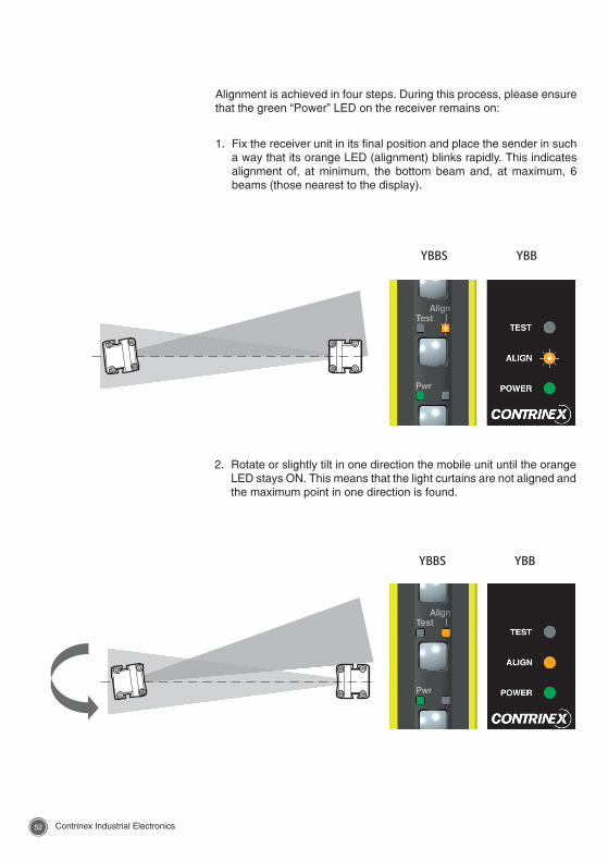
5352 Contrinex Industrial Electronics Contrinex Industrial Electronics
Alignment is achieved in four steps. During this process, please ensure that the green “Power” LED on the receiver remains on:
1. Fix the receiver unit in its final position and place the sender in such a way that its orange LED (alignment) blinks rapidly. This indicates alignment of, at minimum, the bottom beam and, at maximum, 6 beams (those nearest to the display).
YBBS YBB
YBBS YBB
2. Rotate or slightly tilt in one direction the mobile unit until the orange LED stays ON. This means that the light curtains are not aligned and the maximum point in one direction is found.
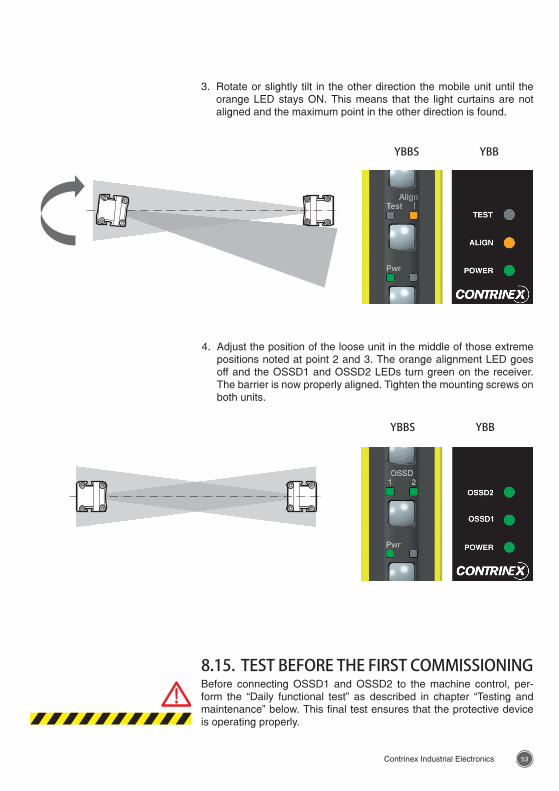
5352 Contrinex Industrial Electronics Contrinex Industrial Electronics
YBBS YBB
YBBS YBB
3. Rotate or slightly tilt in the other direction the mobile unit until the orange LED stays ON. This means that the light curtains are not aligned and the maximum point in the other direction is found.
4. Adjust the position of the loose unit in the middle of those extreme positions noted at point 2 and 3. The orange alignment LED goes off and the OSSD1 and OSSD2 LEDs turn green on the receiver. The barrier is now properly aligned. Tighten the mounting screws on both units.
8.15. TEST BEFORE THE FIRST COMMISSIONINGBefore connecting OSSD1 and OSSD2 to the machine control, per-form the “Daily functional test” as described in chapter “Testing and maintenance” below. This final test ensures that the protective device is operating properly.
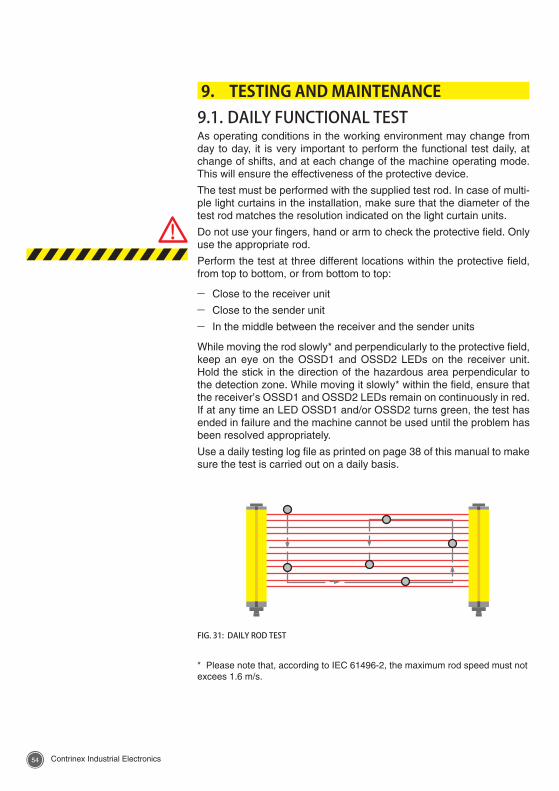
5554 Contrinex Industrial Electronics Contrinex Industrial Electronics
9. TESTING AND MAINTENANCE 9.1. DAILY FUNCTIONAL TESTAs operating conditions in the working environment may change from day to day, it is very important to perform the functional test daily, at change of shifts, and at each change of the machine operating mode. This will ensure the effectiveness of the protective device.
The test must be performed with the supplied test rod. In case of multi-ple light curtains in the installation, make sure that the diameter of the test rod matches the resolution indicated on the light curtain units.
Do not use your fingers, hand or arm to check the protective field. Only use the appropriate rod.
Perform the test at three different locations within the protective field, from top to bottom, or from bottom to top:
– Close to the receiver unit
– Close to the sender unit
– In the middle between the receiver and the sender units
While moving the rod slowly* and perpendicularly to the protective field, keep an eye on the OSSD1 and OSSD2 LEDs on the receiver unit. Hold the stick in the direction of the hazardous area perpendicular to the detection zone. While moving it slowly* within the field, ensure that the receiver’s OSSD1 and OSSD2 LEDs remain on continuously in red. If at any time an LED OSSD1 and/or OSSD2 turns green, the test has ended in failure and the machine cannot be used until the problem has been resolved appropriately.
Use a daily testing log file as printed on page 38 of this manual to make sure the test is carried out on a daily basis.
FIG. 31: DAILY ROD TEST
* Please note that, according to IEC 61496-2, the maximum rod speed must not excees 1.6 m/s.
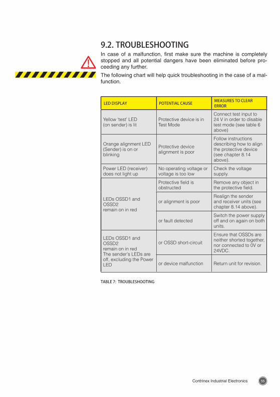
5554 Contrinex Industrial Electronics Contrinex Industrial Electronics
9.2. TROUBLESHOOTINGIn case of a malfunction, first make sure the machine is completely stopped and all potential dangers have been eliminated before pro-ceeding any further.
The following chart will help quick troubleshooting in the case of a mal-function.
LED DISPLAY POTENTIAL CAUSE MEASURES TO CLEAR ERROR
Yellow ‘test’ LED (on sender) is lit
Protective device is in Test Mode
Connect test input to 24 V in order to disable test mode (see table 6 above)
Orange alignment LED(Sender) is on or blinking
Protective device alignment is poor
Follow instructions describing how to align the protective device (see chapter 8.14 above).
Power LED (receiver) does not light up
No operating voltage or voltage is too low
Check the voltage supply.
LEDs OSSD1 and OSSD2remain on in red
Protective field is obstructed
Remove any object in the protective field.
or alignment is poorRealign the sender and receiver units (see chapter 8.14 above).
or fault detectedSwitch the power supply off and on again on both units.
LEDs OSSD1 and OSSD2 remain on in redThe sender’s LEDs are off, excluding the Power LED
or OSSD short-circuit
Ensure that OSSDs are neither shorted together, nor connected to 0V or 24VDC.
or device malfunction Return unit for revision.
TABLE 7: TROUBLESHOOTING
5756 Contrinex Industrial Electronics Contrinex Industrial Electronics
9.3. PREVENTIVE PERIODIC INSPECTIONSThe EU directive on the use of machinery equipment stipulates the regular inspection of safety devices. Light curtains and access control barriers must be periodically tested by qualified and trained person-nel. This allows early detection of new hazards and helps maintain the necessary level of safety. At the same time, it should be checked that the protective devices operate in accordance with the current use of the machine. Periodic inspections give the opportunity to ensure that the type of protective device corresponds to the hazards actually en-countered, that the user cannot bypass it and that nothing hinders its functionality.
Please use a form such as the one on table 8 of this manual. It will help keep track of periodic testing.
9.4. CLEANINGIn order to keep the protective device in full operating condition and prevent potentially biased results, the active screens on the sender and receiver units must be regularly cleaned. The cleaning frequency de-pends on the ambient air pollution and the presence of dust and dirt on the screen. Use a mild and non-abrasive detergent to remove dirt from these surfaces, then dry the screen with a soft cloth. After cleaning, the daily functional test, as described above, must be performed in order to detect potential position changes of the protective devices.
9.5. DAILY TESTING LOG FILEThe following tests must be carried out every day the protective device is in operation.
The tests must be conducted by authorized and trained personnel, and entered in a log file as printed on table 8 of this manual.
– Check for signs of external damage, particularly to the front screen, the mounting or the electrical connections.
– Check that it is not possible to access the machine’s danger zone from any unprotected area.
– Test the protective field: Perform the daily functional test as de-scribed above.
If any of the above tests have failed, block the machine immediately to prevent its use and notify the supervisor.
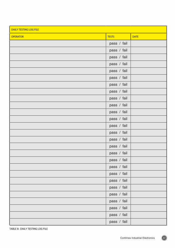
5756 Contrinex Industrial Electronics Contrinex Industrial Electronics
DAILY TESTING LOG FILE
OPERATOR TESTS DATE
pass / fail
pass / fail
pass / fail
pass / fail
pass / fail
pass / fail
pass / fail
pass / fail
pass / fail
pass / fail
pass / fail
pass / fail
pass / fail
pass / fail
pass / fail
pass / fail
pass / fail
pass / fail
pass / fail
pass / fail
pass / fail
pass / fail
pass / fail
pass / fail
pass / fail
pass / fail
pass / fail
TABLE 8: DAILY TESTING LOG FILE
5958 Contrinex Industrial Electronics Contrinex Industrial Electronics
10. DISCLAIMER
A safety light curtain is a safety device, designed to protect operators and other personnel working around a potentially dangerous machine. Before installing or using a safety light curtain the following requirements must be met:
– This instruction manual is part of the Safetinex light curtain. It must re-main accessible during its whole life cycle for anybody in charge of in-stallation, operation, maintenance, cleaning and safety control.
– Safetinex products are only safe protective devices if all the procedures in this instruction manual and in the related documents are carefully fol-lowed and fully complied with. If these instructions are not entirely fol-lowed, or the safety device is subject to manipulation, it may lead to serious injury or death. Contrinex AG declines any responsibility in case of faulty installation and/or manipulation of Safetinex devices.
– In any installation where the light curtain is used as a safety device, the employer is responsible for ensuring that all applicable governmental re-quirements are satisfied. The installer is also responsible for complying with all local laws and standards.
– The installation and inspection of the protective device must be per-formed by trained and qualified specialists, i.e. personnel technically experienced in operating the machinery and the specific protective de-vice involved, and well aware of the applicable safety regulations and standards.
– The employer must ensure that all machine operators, maintenance personnel, supervisors, etc. are familiar with and understand all instruc-tions regarding the proper use of the light curtain, the machinery on which it is installed and the appropriate safety regulations. Operators must be instructed and trained by qualified specialists.
– Optoelectronic protective devices cannot be used as stand-alone solu-tions if the operator is exposed to any risk of injury from flying or splash-ing (e.g. molten) materials. Light curtains do not offer protection against flying objects.
– The machine for which the safety light curtain is installed must be able to stop its motion at any point in its cycle.
– Light curtains cannot be used on any machinery that has an irregular stopping time or inadequate control devices or mechanisms.
– Light curtains cannot be used where the environment may weaken the efficiency of the protective device.
– If the light curtain cannot protect all accesses to the hazardous area, additional safeguards, such as mechanical guards, may be required.
– All brakes and other stopping mechanisms and controls must be in-spected regularly to ensure they are in proper working order. If the stop mechanisms are not performing properly, the machine may not stop safely even though the light curtain is functioning properly.
5958 Contrinex Industrial Electronics Contrinex Industrial Electronics
– The test procedure described in this instruction manual must be per-formed during installation and after any maintenance, cleaning, adjust-ment, repair or modification to the light curtain, or the machine. In ad-dition, the test procedure must be carried out every time the system is started, in general, once a day.
– The log file presented in this manual must be used to document the regular testing of Safetinex products. Contrinex AG declines any re-sponsibility if the test procedure has not been carried out as prescribed in this instruction manual and fully documented in the log file. Testing ensures that the light curtain and the machine control system properly stop the machine.
– The device contains no parts that require maintenance. In case of failure, do not open the device, but send it to manufacturer for repair. Opening the device or implementing unauthorized changes voids any warranty.
– Contrinex AG declines any responsibility if the protective device is not used for its specific purpose, or if it has been modified, whether before, during or after installation.
The enforcement of these requirements is outside Contrinex’s control. The employer is responsible for following the above provisions and any other procedures, conditions and requirements specific to the machinery.
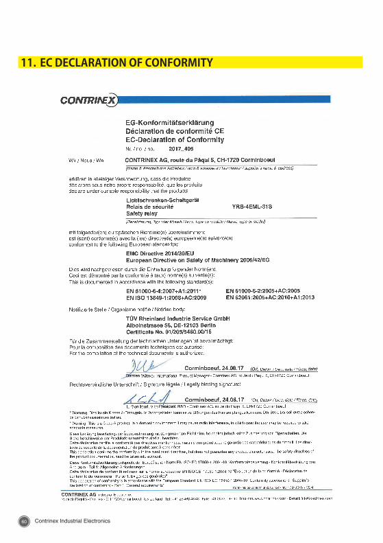
6160 Contrinex Industrial Electronics Contrinex Industrial Electronics
11. EC DECLARATION OF CONFORMITY
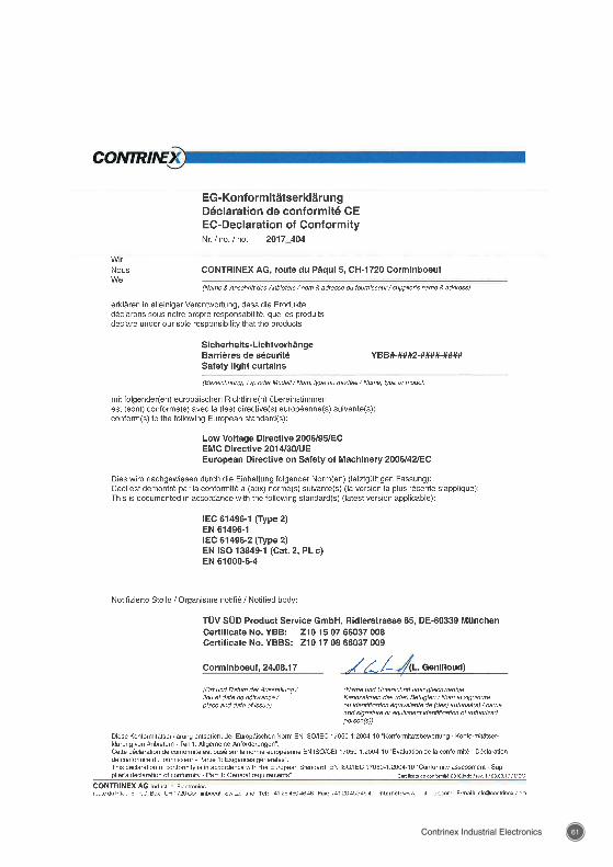
6160 Contrinex Industrial Electronics Contrinex Industrial Electronics

Terms of delivery and right to change design reserved.
Please check our website for updates.
CONTRINEX HEADQUARTERS Industrial Electronics route du Pâqui 5 - PO Box - CH 1720 Corminboeuf - Switzerland Tel: +41 26 460 46 46 - Fax: +41 26 460 46 40 Internet: www.contrinex.com - E-mail: [email protected]
© CONTRINEX SA 2017
EUROPEAustria Belgium* Croatia Czech Republic Denmark Estonia Finland France* Germany* Great Britain* Greece Hungary Ireland Italy* Luxembourg Netherlands Norway Poland Portugal* Romania Russian Federation Slovakia
Slovenia Spain Sweden Switzerland* Turkey Ukraine
AFRICAMoroccoSouth Africa
THE AMERICASArgentina Brazil* Canada Chile Mexico* Peru United States* Venezuela
ASIAChina* India*
Indonesia Japan* Korea Malaysia Pakistan Philippines Singapore* Taiwan Thailand Vietnam
MIDDLE EASTUnited Arab EmiratesIsrael
AUSTRALASIAAustralia New Zealand
ALL OVER THE WORLD
900 200 091 - 08.17
* Contrinex subsidiary
www.contrinex.comINS_107/V2