Embed Size (px)
Citation preview
Schüco Zusatzprofile
Schüco Supplementary profiles
Bestell- und Fertigungskatalog Kunststo3-Systeme
Order and fabrication Manual PVC-U Systems
Iconübersicht
Icon overview
Hinweise zur Nutzung des Katalogs Instructions for using the manual
Diese Broschüre ist eine Übersicht über sämtliche
zusätzliche Profile (gegebenenfalls mit Verarbeitung) und
deren Zubehör zu den Schüco Kunststoff-Systemen.
PVC-, Stahl- und Aluminiumprofile werden in Längen von
6 m geliefert. Alle Ausnahmen sind auf den jeweiligen
Seiten des Kataloges gekennzeichnet.
Alle Artikelnummern sind 8-stellig.
Bei PVC-Profilen geben die letzten 3 Ziffern die
Farbausführung an, z.B. 1 8596 160.
Üblicherweise werden in unseren Katalogen nur die
ersten 5 Stellen der Artikelnummer eines Profils
angegeben.
Den entsprechenden Farbcode und die Verfügbarkeit
können der Foliierungsübersicht entnommen werden.
Es ist zu beachten, dass alle angegebenen Farben
Schüco-Farben entsprechen.
weiß : ähnlich RAL 9016
schwarz : ähnlich RAL 9005
cremeweiß : ähnlich RAL 9001
braun : ähnlich RAL 8014
karamell : ähnlich RAL 8001
grau : ähnlich RAL 7035
Aluminiumprofile liefern wir in roher, eloxierter oder
farbbeschichteter Ausführung.
Bei der Bestellung ist die gewünschte
Oberflächenveredelung gemäß RAL-Farbfächer
anzugeben.
This brochure provides an overview of all additional pro-
files (with fabrication, where applicable) and their acces-
sories for the Schüco PVC-U systems.
PVC, steel and aluminium profiles are supplied in 6 m
lengths. Any exceptions to this are indicated on the rele-
vant pages of the manual.
All article numbers have 8 digits.
For PVC profiles, the last 3 digits indicate the colour de-
sign, e.g. 1 8596 160.
As a rule, only the first 5 digits of a profile article number
are indicated in our manuals.
The corresponding colour code and the availability can
be found in the foiling overview.
It must be ensured that all specified colours match
Schüco colours.
White: similar to RAL 9016
Black: similar to RAL 9005
Cream white: similar to RAL 9001
Brown: similar to RAL 8014
Caramel: similar to RAL 8001
Grey: similar to RAL 7035
Aluminium profiles are supplied either in mill finish, ano-
dised or colour-coated.
When ordering, the required surface finish must be indi-
cated as per the RAL colour charts.
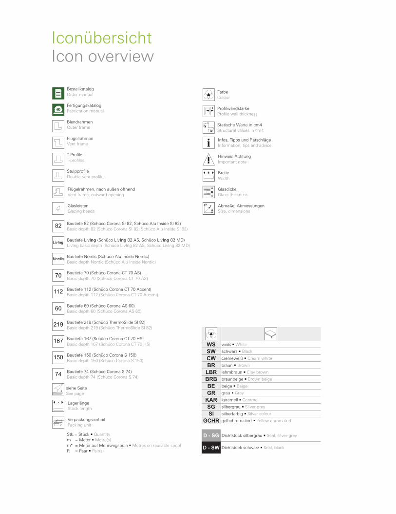
WS weiß • White
SW schwarz • Black
CW cremeweiß • Cream white
BR braun • Brown
LBR lehmbraun • Clay brown
BRB braunbeige • Brown beige
BE beige • Beige
GR grau • Grey
KAR karamell • Caramel
SG silbergrau • Silver grey
SI silberfarbig • Silver colour
GCHR gelbchromatiert • Yellow chromated
D - SG Dichtstück silbergrau • Seal, silver-grey
D - SW Dichtstück schwarz • Seal, black
Bestellkatalog
Order manual
Fertigungskatalog
Fabrication manual
Blendrahmen
Outer frame
Flügelrahmen
Vent frame
T-Profile
T-profiles
Stulpprofile
Double-vent profiles
Flügelrahmen, nach außen öLnend
Vent frame, outward-opening
Glasleisten
Glazing beads
82 Bautiefe 82 (Schüco Corona SI 82, Schüco Alu Inside SI 82)
Basic depth 82 (Schüco Corona SI 82, Schüco Alu Inside SI 82)
LivIngBautiefe LivIng (Schüco LivIng 82 AS, Schüco LivIng 82 MD)
LivIng basic depth (Schüco LivIng 82 AS, Schüco LivIng 82 MD)
NordicBautiefe Nordic (Schüco Alu Inside Nordic)
Basic depth Nordic (Schüco Alu Inside Nordic)
70Bautiefe 70 (Schüco Corona CT 70 AS)
Basic depth 70 (Schüco Corona CT 70 AS)
112 Bautiefe 112 (Schüco Corona CT 70 Accent)
Basic depth 112 (Schüco Corona CT 70 Accent)
60Bautiefe 60 (Schüco Corona AS 60)
Basic depth 60 (Schüco Corona AS 60)
219 Bautiefe 219 (Schüco ThermoSlide SI 82)
Basic depth 219 (Schüco ThermoSlide SI 82)
167 Bautiefe 167 (Schüco Corona CT 70 HS)
Basic depth 167 (Schüco Corona CT 70 HS)
150 Bautiefe 150 (Schüco Corona S 150)
Basic depth 150 (Schüco Corona S 150)
74Bautiefe 74 (Schüco Corona S 74)
Basic depth 74 (Schüco Corona S 74)
siehe Seite
See page
x Lagerlänge
Stock length
Verpackungseinheit
Packing unit
Stk.= Stück • Quantity
m = Meter • Metre(s)
m* = Meter auf Mehrwegspule • Metres on reusable spool
P. = Paar • Pair(s)
Farbe
Colour
Profilwandstärke
Profile wall thickness
x
y
Ix
Iy Statische Werte in cm4
Structural values in cm4
Infos, Tipps und Ratschläge
Information, tips and advice
Hinweis Achtung
Important note
Breite
Width
Glasdicke
Glass thickness
Abmaße, Abmessungen
Size, dimensions
IconübersichtIcon overview
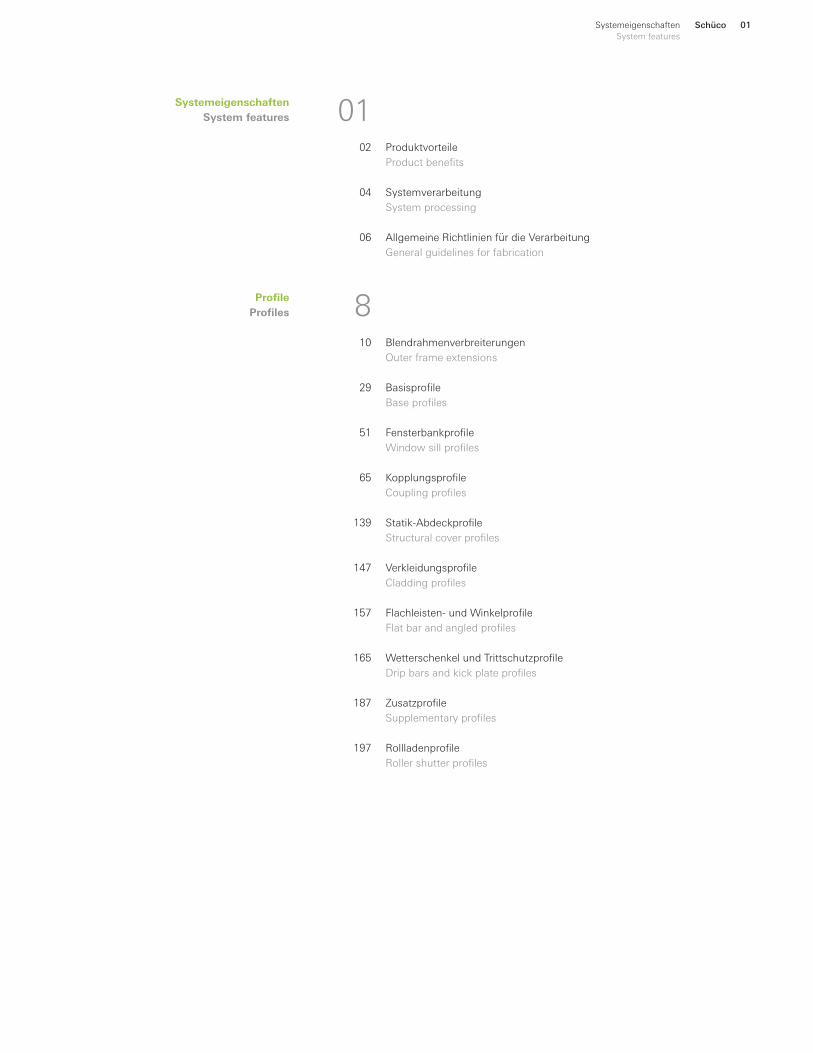
Systemeigenschaften
System features
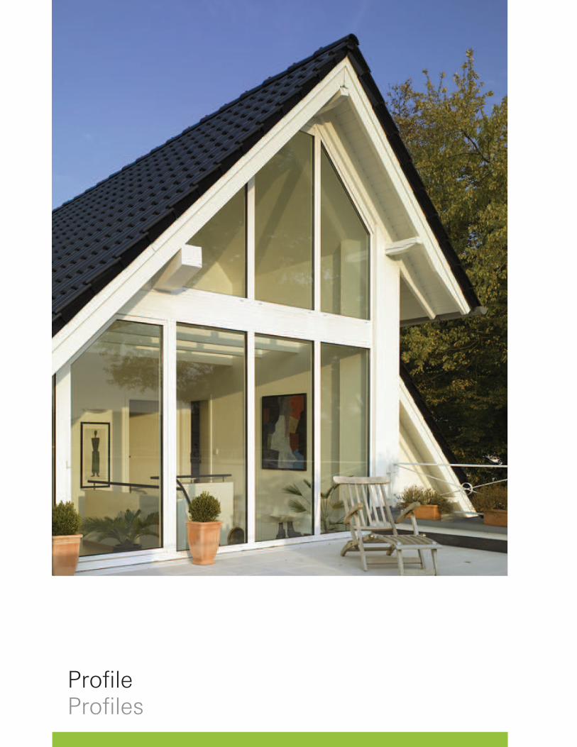
Profile
Profiles
0102
04
06
810
29
51
65
139
147
157
165
187
197
Produktvorteile
Product benefits
Systemverarbeitung
System processing
Allgemeine Richtlinien für die Verarbeitung
General guidelines for fabrication
Blendrahmenverbreiterungen
Outer frame extensions
Basisprofile
Base profiles
Fensterbankprofile
Window sill profiles
Kopplungsprofile
Coupling profiles
Statik-Abdeckprofile
Structural cover profiles
Verkleidungsprofile
Cladding profiles
Flachleisten- und Winkelprofile
Flat bar and angled profiles
Wetterschenkel und Trittschutzprofile
Drip bars and kick plate profiles
Zusatzprofile
Supplementary profiles
Rollladenprofile
Roller shutter profiles
Schüco 01Systemeigenschaften
System features
Schüco02 Systemeigenschaften
System features
Zusatzprofile Supplementary profiles 08.2016 / 75838
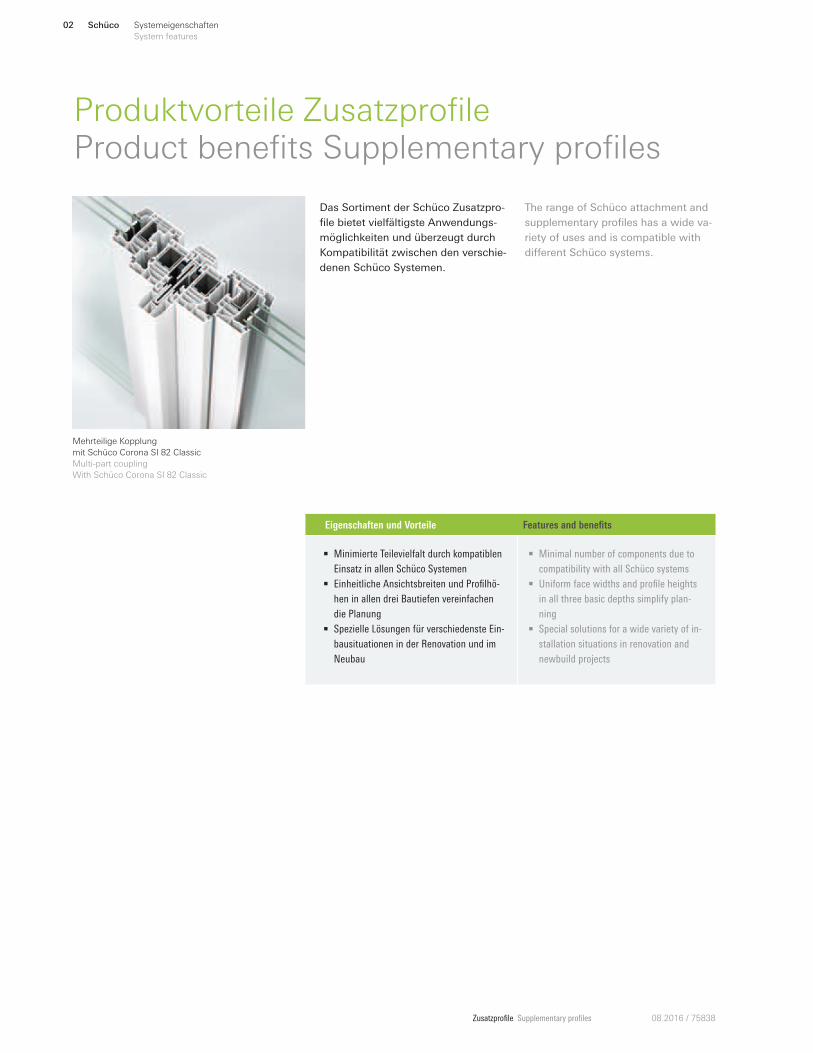
Produktvorteile ZusatzprofileProduct benefits Supplementary profiles
Das Sortiment der Schüco Zusatzpro-
file bietet vielfältigste Anwendungs-
möglichkeiten und überzeugt durch
Kompatibilität zwischen den verschie-
denen Schüco Systemen.
The range of Schüco attachment and
supplementary profiles has a wide va-
riety of uses and is compatible with
diEerent Schüco systems.
Eigenschaften und Vorteile Features and benefits
• Minimierte Teilevielfalt durch kompatiblen
Einsatz in allen Schüco Systemen
• Einheitliche Ansichtsbreiten und Profilhö-
hen in allen drei Bautiefen vereinfachen
die Planung
• Spezielle Lösungen für verschiedenste Ein-
bausituationen in der Renovation und im
Neubau
• Minimal number of components due to
compatibility with all Schüco systems
• Uniform face widths and profile heights
in all three basic depths simplify plan-
ning
• Special solutions for a wide variety of in-
stallation situations in renovation and
newbuild projects
Mehrteilige Kopplung
mit Schüco Corona SI 82 Classic
Multi-part coupling
With Schüco Corona SI 82 Classic
Schüco 03Systemeigenschaften
System features
Zusatzprofile Supplementary profiles08.2016 / 75838
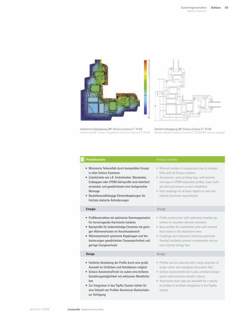
Isotherme Eckkopplung 90° Schüco Corona CT 70 AS
Isothermal 90° corner coupling for Schüco Corona CT 70 AS
20
15
120
14.5
Schnitt Eckkopplung 90° Schüco Corona CT 70 AS
Section detail of Schüco Corona CT 70 AS 90° corner coupling
Produktvorteile Product benefits
• Minimierte Teilevielfalt durch kompatiblen Einsatz
in allen Schüco Systemen
• Zubehörteile wie z.B. Eindrehanker, Wandanker,
Endkappen oder EPDM-Dehnprofile sind mehrfach
einsetzbar und gewährleisten eine fachgerechte
Montage
• Bautiefenunabhängige Elementkopplungen für
höchste statische Anforderungen
• Minimal number of components due to compati-
bility with all Schüco systems
• Accessories, such as fixing lugs, wall anchors,
end caps or EPDM expansion profiles, have multi-
ple uses and ensure correct installation
• Unit couplings for all basic depths to meet the
highest structural requirements
Energie Energy
• Profilkonstruktion mit optimierter Kammergeometrie
für hervorragende thermische Isolation
• Basisprofile für bodenständige Elemente mit gerin-
gen Wärmeverlusten im Anschlussbereich
• Wärmetechnisch optimierte Kopplungen und Ver-
breiterungen gewährleisten Tauwasserfreiheit und
geringe Energieverluste
• Profile construction with optimised chamber ge-
ometry for excellent thermal insulation
• Base profiles for established units with minimal
heat losses in the attachment area
• Couplings and extensions featuring optimised
thermal insulation prevent condensation and en-
sure minimal energy loss
Design Design
• Farbliche Gestaltung der Profile durch eine große
Auswahl an Unifarben und Holzdekoren möglich
• Schüco AutomotiveFinish ist zudem eine brillante
Gestaltungsmöglichkeit mit exklusiven Metallicfar-
ben
• Zur Integration in das TopAlu System stehen für
eine Vielzahl von Profilen Aluminium-Deckschalen
zur Verfügung
• Profiles can be coloured with a large selection of
single colour and woodgrain decorative foils
• Schüco AutomotiveFinish is also a brilliant design
option with exclusive metallic colours
• Aluminium cover caps are available for a variety
of profiles to facilitate integration in the TopAlu
system
Schüco04 Systemeigenschaften
System features
Zusatzprofile Supplementary profiles 08.2016 / 75838
SystemverarbeitungSystem processing
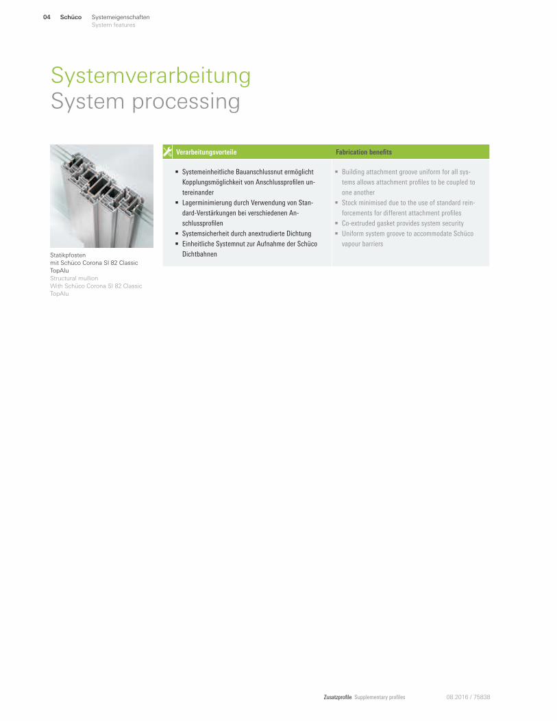
Statikpfosten
mit Schüco Corona SI 82 Classic
TopAlu
Structural mullion
With Schüco Corona SI 82 Classic
TopAlu
Verarbeitungsvorteile Fabrication benefits
• Systemeinheitliche Bauanschlussnut ermöglicht
Kopplungsmöglichkeit von Anschlussprofilen un-
tereinander
• Lagerminimierung durch Verwendung von Stan-
dard-Verstärkungen bei verschiedenen An-
schlussprofilen
• Systemsicherheit durch anextrudierte Dichtung
• Einheitliche Systemnut zur Aufnahme der Schüco
Dichtbahnen
• Building attachment groove uniform for all sys-
tems allows attachment profiles to be coupled to
one another
• Stock minimised due to the use of standard rein-
forcements for diZerent attachment profiles
• Co-extruded gasket provides system security
• Uniform system groove to accommodate Schüco
vapour barriers
Schüco 05Systemeigenschaften
System features
Zusatzprofile Supplementary profiles08.2016 / 75838
Verarbeitungsvorteile Fabrication benefits
4 mm Systemnut
• Die 4 mm Systemnut ermöglicht je nach Anforderung
den Einsatz von weiteren Zusatzprofilen
• Als Alternative zur herkömmlichen Silikonabdich-
tung können aus dem Sortiment Systemzubehör
Bauanschlussdichtungen zur optimalen Abdich-
tung eingesetzt werden
• Im Hinblick auf RAL-Montage oder bei entspre-
chenden optischen Anforderungen kann die Nut
mit dem Nutabdeckprofil verschlossen werden
32 mm Systemnut
• Die 32 mm Systemnut ermöglicht je nach Anforde-
rung den Einsatz von Anschluss- oder Transport-
schutzprofilen
6,3 mm Systemnut
• Die 6,3 mm Systemnut ermöglicht den Einsatz von
Schüco EPDM-Dichtbahnen zur RAL-gerechten
Ausführung von Baukörperanschlüssen
12 mm Systemnut
• Die 12 mm Systemnut ermöglicht den Einsatz von
Eindrehankern zur zusätzlichen Elementbefesti-
gung
9 mm Systemnut
• Die 9 mm Systemnut ermöglicht die problemlose
Profilbefestigung mittels Klemmkopfschrauben
oder dem Schüco Adapterprofil
4 mm system groove
• The 4 mm system groove allows further attach-
ment and supplementary profiles to be inserted as
required
• Building attachment gaskets from the range of ac-
cessories can be used for optimum sealing as an
alternative to conventional silicone sealing
• For RAL installation, or for similar aesthetic re-
quirements, the groove can be sealed using the
groove cover profile
32 mm system groove
• The 32 mm system groove allows attachment or
transport protection profiles to be inserted as re-
quired
6.3 mm system groove
• The 6.3 mm system groove allows Schüco EPDM
vapour barriers to be used to design attachments
to building structures compatible with RAL
12 mm system groove
• The 12 mm system groove allows fixing lugs to be
used for an additional unit fixing
9 mm system groove
• The 9 mm system groove allows the profiles to be
easily fixed using fixing studs or the Schüco
adapter profile
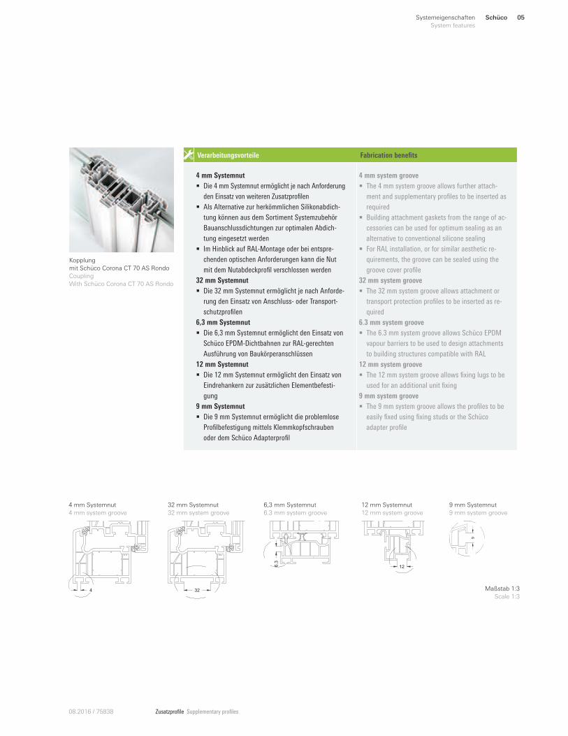
Kopplung
mit Schüco Corona CT 70 AS Rondo
Coupling
With Schüco Corona CT 70 AS Rondo
4 mm Systemnut
4 mm system groove
32 mm Systemnut
32 mm system groove
6,3 mm Systemnut
6.3 mm system groove
12 mm Systemnut
12 mm system groove
9 mm Systemnut
9 mm system groove
9
6.3
12
4 32 Maßstab 1:3
Scale 1:3
Schüco06 Systemeigenschaften
System features
Zusatzprofile Supplementary profiles 08.2016 / 75838
Allgemeine Richtlinien für die Verarbeitung General guidelines for fabrication
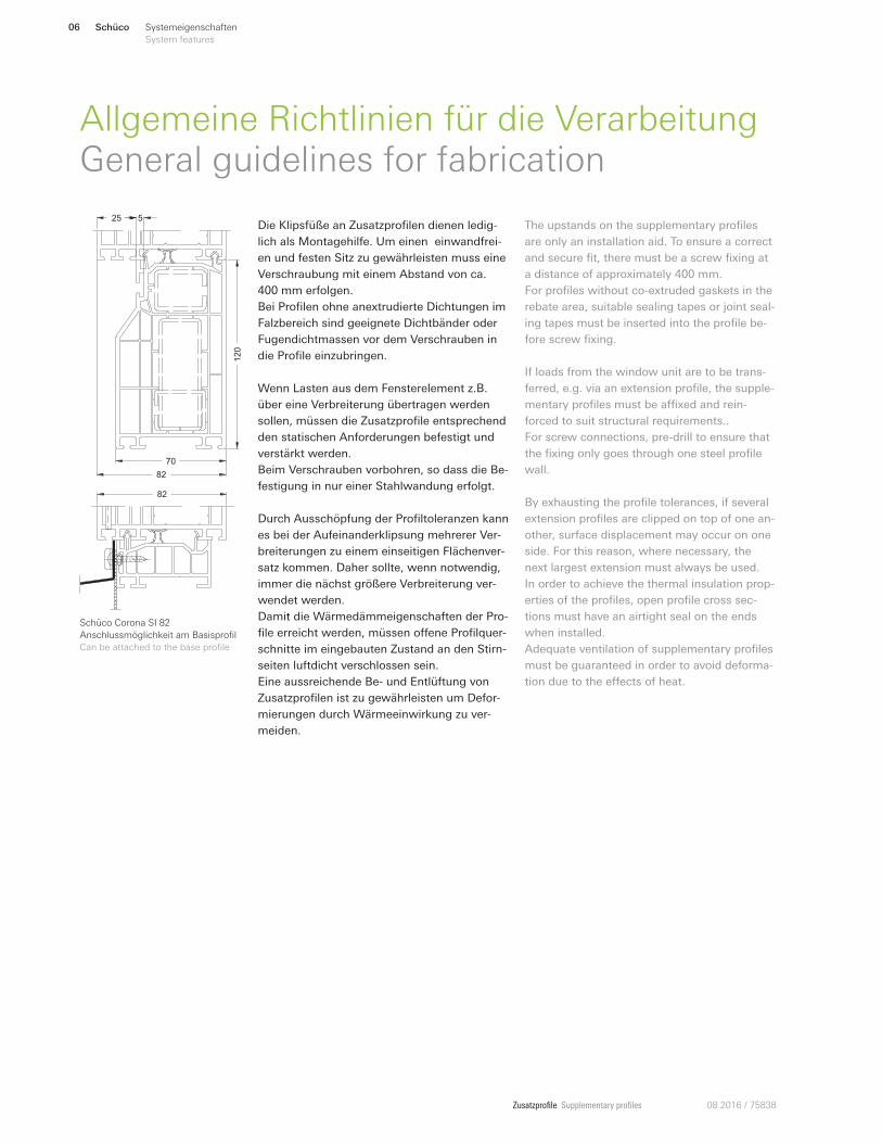
Schüco Corona SI 82
Anschlussmöglichkeit am Basisprofil
Can be attached to the base profile
70
82
120
25 5
82
Die Klipsfüße an Zusatzprofilen dienen ledig-
lich als Montagehilfe. Um einen einwandfrei-
en und festen Sitz zu gewährleisten muss eine
Verschraubung mit einem Abstand von ca.
400 mm erfolgen.
Bei Profilen ohne anextrudierte Dichtungen im
Falzbereich sind geeignete Dichtbänder oder
Fugendichtmassen vor dem Verschrauben in
die Profile einzubringen.
Wenn Lasten aus dem Fensterelement z.B.
über eine Verbreiterung übertragen werden
sollen, müssen die Zusatzprofile entsprechend
den statischen Anforderungen befestigt und
verstärkt werden.
Beim Verschrauben vorbohren, so dass die Be-
festigung in nur einer Stahlwandung erfolgt.
Durch Ausschöpfung der Profiltoleranzen kann
es bei der Aufeinanderklipsung mehrerer Ver-
breiterungen zu einem einseitigen Flächenver-
satz kommen. Daher sollte, wenn notwendig,
immer die nächst größere Verbreiterung ver-
wendet werden.
Damit die Wärmedämmeigenschaften der Pro-
file erreicht werden, müssen oEene Profilquer-
schnitte im eingebauten Zustand an den Stirn-
seiten luftdicht verschlossen sein.
Eine aussreichende Be- und Entlüftung von
Zusatzprofilen ist zu gewährleisten um Defor-
mierungen durch Wärmeeinwirkung zu ver-
meiden.
The upstands on the supplementary profiles
are only an installation aid. To ensure a correct
and secure fit, there must be a screw fixing at
a distance of approximately 400 mm.
For profiles without co-extruded gaskets in the
rebate area, suitable sealing tapes or joint seal-
ing tapes must be inserted into the profile be-
fore screw fixing.
If loads from the window unit are to be trans-
ferred, e.g. via an extension profile, the supple-
mentary profiles must be aWxed and rein-
forced to suit structural requirements..
For screw connections, pre-drill to ensure that
the fixing only goes through one steel profile
wall.
By exhausting the profile tolerances, if several
extension profiles are clipped on top of one an-
other, surface displacement may occur on one
side. For this reason, where necessary, the
next largest extension must always be used.
In order to achieve the thermal insulation prop-
erties of the profiles, open profile cross sec-
tions must have an airtight seal on the ends
when installed.
Adequate ventilation of supplementary profiles
must be guaranteed in order to avoid deforma-
tion due to the eEects of heat.
Schüco 07Systemeigenschaften
System features
Zusatzprofile Supplementary profiles08.2016 / 75838
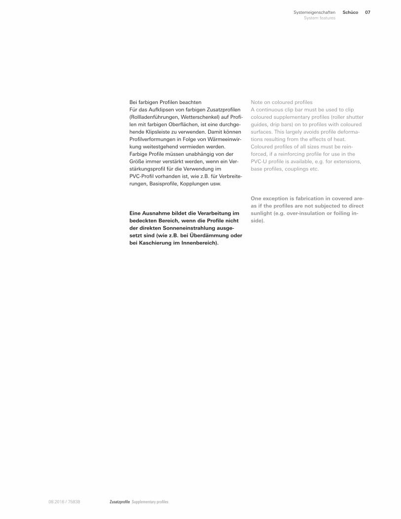
Eine Ausnahme bildet die Verarbeitung im
bedeckten Bereich, wenn die Profile nicht
der direkten Sonneneinstrahlung ausge-
setzt sind (wie z.B. bei Überdämmung oder
bei Kaschierung im Innenbereich).
One exception is fabrication in covered are-
as if the profiles are not subjected to direct
sunlight (e.g. over-insulation or foiling in-
side).
Bei farbigen Profilen beachten
Für das Aufklipsen von farbigen Zusatzprofilen
(Rollladenführungen, Wetterschenkel) auf Profi-
len mit farbigen Oberflächen, ist eine durchge-
hende Klipsleiste zu verwenden. Damit können
Profilverformungen in Folge von Wärmeeinwir-
kung weitestgehend vermieden werden.
Farbige Profile müssen unabhängig von der
Größe immer verstärkt werden, wenn ein Ver-
stärkungsprofil für die Verwendung im
PVC-Profil vorhanden ist, wie z.B. für Verbreite-
rungen, Basisprofile, Kopplungen usw.
Note on coloured profiles
A continuous clip bar must be used to clip
coloured supplementary profiles (roller shutter
guides, drip bars) on to profiles with coloured
surfaces. This largely avoids profile deforma-
tions resulting from the eEects of heat.
Coloured profiles of all sizes must be rein-
forced, if a reinforcing profile for use in the
PVC-U profile is available, e.g. for extensions,
base profiles, couplings etc.
Profile
Profiles
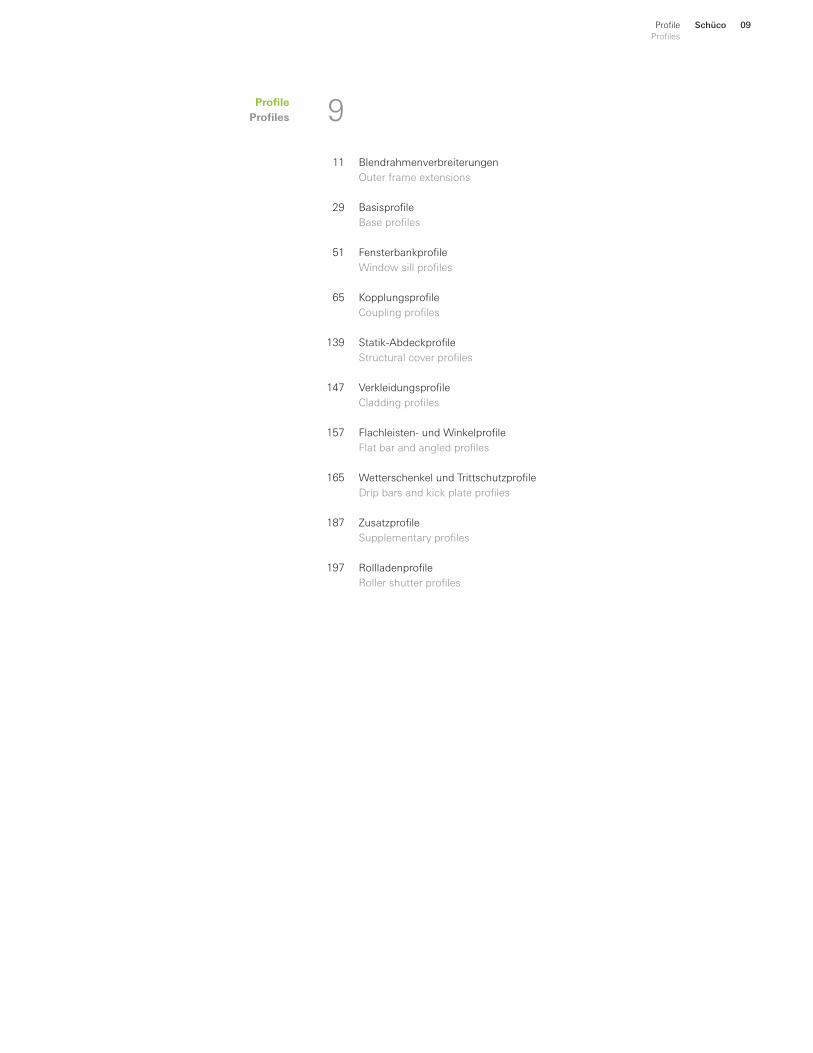
Profile
Profiles 9
11
29
51
65
139
147
157
165
187
197
Blendrahmenverbreiterungen
Outer frame extensions
Basisprofile
Base profiles
Fensterbankprofile
Window sill profiles
Kopplungsprofile
Coupling profiles
Statik-Abdeckprofile
Structural cover profiles
Verkleidungsprofile
Cladding profiles
Flachleisten- und Winkelprofile
Flat bar and angled profiles
Wetterschenkel und Trittschutzprofile
Drip bars and kick plate profiles
Zusatzprofile
Supplementary profiles
Rollladenprofile
Roller shutter profiles
Schüco 09Profile
Profiles
Schüco10 Blendrahmenverbreiterungen
Outer frame extensions
Zusatzprofile Supplementary profiles 08.2016 / 75838
Blendrahm
enverbreiterungen
Outer fram
e extensions
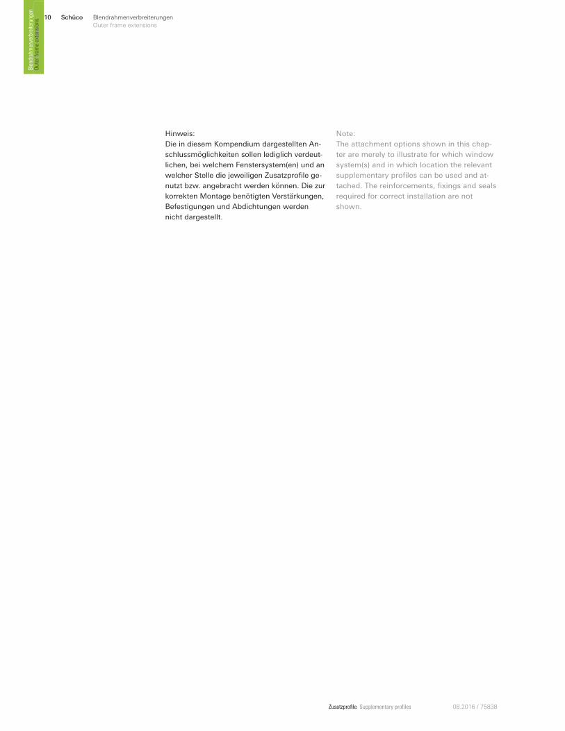
Hinweis:
Die in diesem Kompendium dargestellten An-
schlussmöglichkeiten sollen lediglich verdeut-
lichen, bei welchem Fenstersystem(en) und an
welcher Stelle die jeweiligen Zusatzprofile ge-
nutzt bzw. angebracht werden können. Die zur
korrekten Montage benötigten Verstärkungen,
Befestigungen und Abdichtungen werden
nicht dargestellt.
Note:
The attachment options shown in this chap-
ter are merely to illustrate for which window
system(s) and in which location the relevant
supplementary profiles can be used and at-
tached. The reinforcements, fixings and seals
required for correct installation are not
shown.
Schüco 11Blendrahmenverbreiterungen
Outer frame extensions
Zusatzprofile Supplementary profiles08.2016 / 75838
Outer fram
e extensions
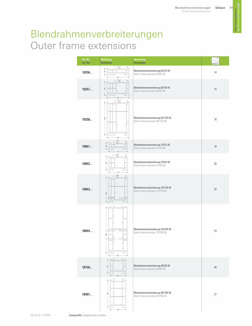
Blendrahmenverbreiterungen
BlendrahmenverbreiterungenOuter frame extensions
Art.-Nr. Art. No.
Abbildung Illustration
Benennung Description
19256 ... 25
82
Blendrahmenverbreiterung 82/25 5K Outer frame extension 82/25 5K
14
19257 ... 50
82
Blendrahmenverbreiterung 82/50 5K Outer frame extension 82/50 5K
15
19258 ... 120
82
Blendrahmenverbreiterung 82/120 5K Outer frame extension 82/120 5K
16
19841 ... 25
70
Blendrahmenverbreiterung 70/25 4K Outer frame extension 70/25 4K
18
19842 ... 50
70
Blendrahmenverbreiterung 70/50 4K Outer frame extension 70/50 4K
20
19843 ...
120
70
Blendrahmenverbreiterung 70/120 4K Outer frame extension 70/120 4K
22
18844 ...
240
70
Blendrahmenverbreiterung 70/240 3K Outer frame extension 70/240 3K
24
18756 ...
60
50 Blendrahmenverbreiterung 60/50 3K
Outer frame extension 60/50 3K 26
18401 ...
60
100 Blendrahmenverbreiterung 60/100 3K
Outer frame extension 60/100 3K 27
Schüco12 Blendrahmenverbreiterungen
Outer frame extensions
Zusatzprofile Supplementary profiles 08.2016 / 75838
Blendrahm
enverbreiterungen
Outer fram
e extensions
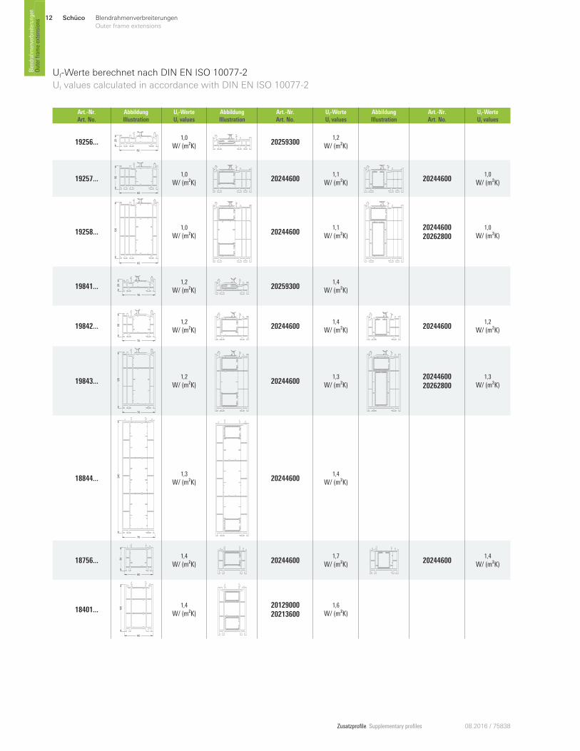
Uf-Werte berechnet nach DIN EN ISO 10077-2
Uf values calculated in accordance with DIN EN ISO 10077-2
Art.-Nr. Art. No.
Abbildung Illustration
Uf-Werte Uf values
Abbildung Illustration
Art.-Nr. Art. No.
Uf-Werte Uf values
Abbildung Illustration
Art.-Nr. Art. No.
Uf-Werte Uf values
19256 ... 25
82
1,0
W/ (m²K) 20259300 1,2
W/ (m²K)
19257 ... 50
82
1,0
W/ (m²K) 20244600 1,1
W/ (m²K) 20244600 1,0
W/ (m²K)
19258 ... 120
82
1,0
W/ (m²K) 20244600 1,1
W/ (m²K)2024460020262800
1,0
W/ (m²K)
19841 ... 25
70
1,2
W/ (m²K) 20259300 1,4
W/ (m²K)
19842 ... 50
70
1,2
W/ (m²K) 20244600 1,4
W/ (m²K) 20244600 1,2
W/ (m²K)
19843 ...
70
120 1,2
W/ (m²K) 20244600 1,3
W/ (m²K)2024460020262800
1,3
W/ (m²K)
18844 ... 240
70
1,3
W/ (m²K) 20244600 1,4
W/ (m²K)
18756 ...
60
50 1,4
W/ (m²K) 20244600 1,7
W/ (m²K) 20244600 1,4
W/ (m²K)
18401 ...
60
100 1,4
W/ (m²K)2012900020213600
1,6
W/ (m²K)
Schüco 13Blendrahmenverbreiterungen
Outer frame extensions
Zusatzprofile Supplementary profiles08.2016 / 75838
Outer fram
e extensions
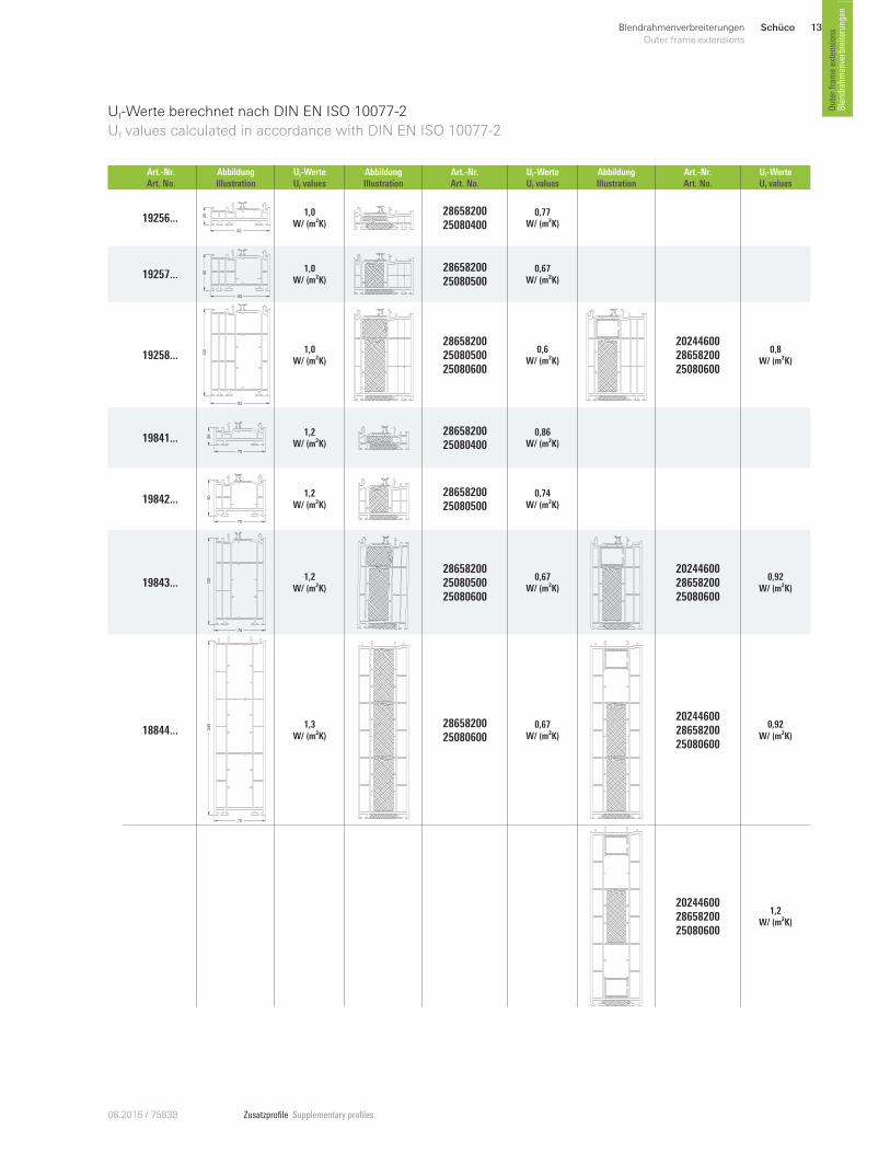
Blendrahmenverbreiterungen
Uf-Werte berechnet nach DIN EN ISO 10077-2
Uf values calculated in accordance with DIN EN ISO 10077-2
Art.-Nr. Art. No.
Abbildung Illustration
Uf-Werte Uf values
Abbildung Illustration
Art.-Nr. Art. No.
Uf-Werte Uf values
Abbildung Illustration
Art.-Nr. Art. No.
Uf-Werte Uf values
19256 ... 25
82
1,0W/ (m²K)
28658200 25080400
0,77W/ (m²K)
19257 ... 50
82
1,0W/ (m²K)
2865820025080500
0,67W/ (m²K)
19258 ... 120
82
1,0W/ (m²K)
2865820025080500 25080600
0,6W/ (m²K)
202446002865820025080600
0,8W/ (m²K)
19841 ... 25
70
1,2W/ (m²K)
2865820025080400
0,86W/ (m²K)
19842 ... 50
70
1,2W/ (m²K)
2865820025080500
0,74W/ (m²K)
19843 ...
70
120 1,2
W/ (m²K)
286582002508050025080600
0,67W/ (m²K)
202446002865820025080600
0,92W/ (m²K)
18844 ... 240
70
1,3W/ (m²K)
2865820025080600
0,67W/ (m²K)
202446002865820025080600
0,92W/ (m²K)
202446002865820025080600
1,2W/ (m²K)
Schüco14 Blendrahmenverbreiterungen
Outer frame extensions
Zusatzprofile Supplementary profiles 08.2016 / 75838
Blendrahm
enverbreiterungen
Outer fram
e extensions
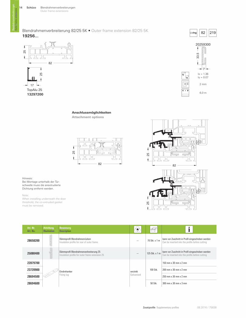
25
82
17
25
TopAlu 25
13297200
Art.-Nr. Art. No.
Abbildung Illustration
Benennung Description
28658200 Dämmprofil Blendrahmenrücken Insulation profile for rear of outer frame
— 70 Stk. x 1 m kann vor Zuschnitt in Profil eingeschoben werden Can be inserted into the profile before cutting
25080400 Dämmprofil Blendrahmenverbreiterung 25 Insulation profile for outer frame extension 25
— 125 Stk. x 1 m kann vor Zuschnitt in Profil eingeschoben werden Can be inserted into the profile before cutting
22879700
Eindrehanker Fixing lug
verzinkt Galvanised
100 Stk.
150 mm x 30 mm x 2 mm
23720900 200 mm x 30 mm x 2 mm
28694500 250 mm x 30 mm x 2 mm
28694600 50 Stk. 300 mm x 30 mm x 3 mm
Blendrahmenverbreiterung 82/25 5K • Outer frame extension 82/25 5K
19256...
20259300
7
33.5
x
y
Ix
Iy Ix = 1.36
Iy = 0.07
2 mm
x
6,0 m
Anschlussmöglichkeiten
Attachment options
25
8282
25
21982LivIng
Hinweis:
Bei Montage unterhalb der Tür-
schwelle muss die anextrudierte
Dichtung entfernt werden.
Note:
When installing underneath the door
threshold, the co-extruded gasket
must be removed.
82
25
Schüco 15Blendrahmenverbreiterungen
Outer frame extensions
Zusatzprofile Supplementary profiles08.2016 / 75838
Outer fram
e extensions
Blendrahmenverbreiterungen
50
82
17
50
TopAlu 50
13298500
Art.-Nr. Art. No.
Abbildung Illustration
Benennung Description
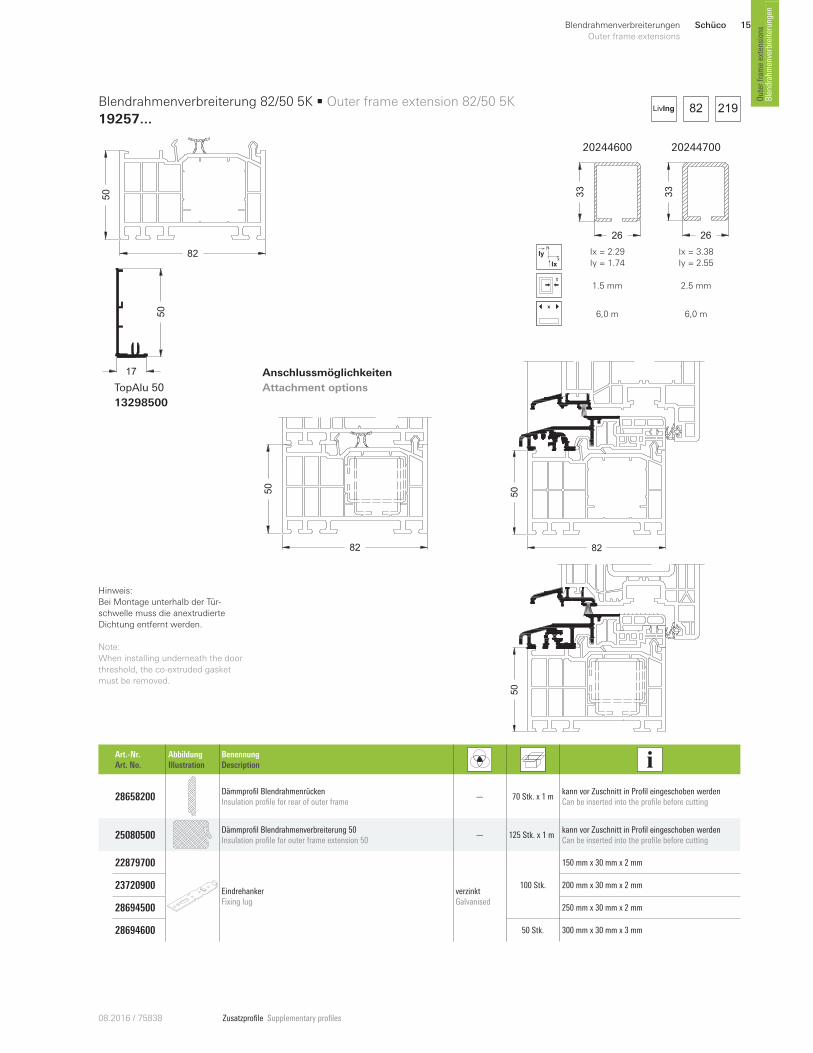
28658200 Dämmprofil Blendrahmenrücken Insulation profile for rear of outer frame
— 70 Stk. x 1 m kann vor Zuschnitt in Profil eingeschoben werden Can be inserted into the profile before cutting
25080500 Dämmprofil Blendrahmenverbreiterung 50 Insulation profile for outer frame extension 50
— 125 Stk. x 1 m kann vor Zuschnitt in Profil eingeschoben werden Can be inserted into the profile before cutting
22879700
Eindrehanker Fixing lug
verzinkt Galvanised
100 Stk.
150 mm x 30 mm x 2 mm
23720900 200 mm x 30 mm x 2 mm
28694500 250 mm x 30 mm x 2 mm
28694600 50 Stk. 300 mm x 30 mm x 3 mm
Blendrahmenverbreiterung 82/50 5K • Outer frame extension 82/50 5K
19257 ...
Anschlussmöglichkeiten
Attachment options
21982LivIng
20244600 20244700
26
33
26
33
x
y
Ix
Iy Ix = 2.29
Iy = 1.74
Ix = 3.38
Iy = 2.55
1.5 mm 2.5 mm
x
6,0 m 6,0 m
50
82
50
82
50
Hinweis:
Bei Montage unterhalb der Tür-
schwelle muss die anextrudierte
Dichtung entfernt werden.
Note:
When installing underneath the door
threshold, the co-extruded gasket
must be removed.
Schüco16 Blendrahmenverbreiterungen
Outer frame extensions
Zusatzprofile Supplementary profiles 08.2016 / 75838
Blendrahm
enverbreiterungen
Outer fram
e extensions
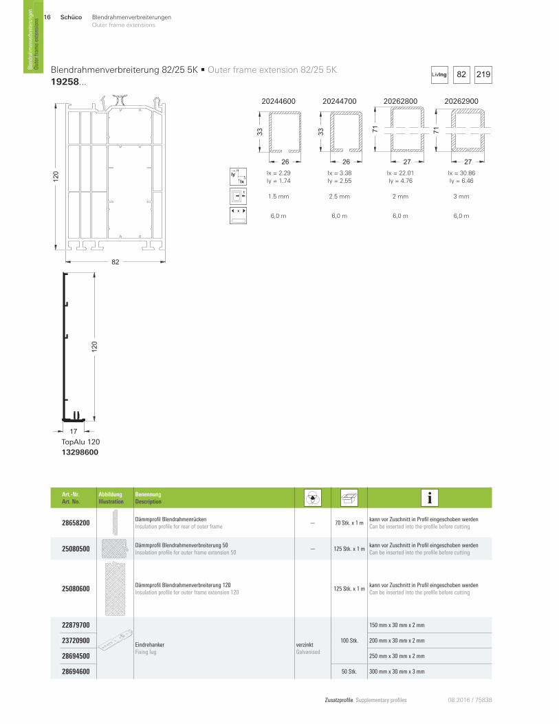
120
82
17
120
TopAlu 120
13298600
Art.-Nr. Art. No.
Abbildung Illustration
Benennung Description
28658200 Dämmprofil Blendrahmenrücken Insulation profile for rear of outer frame
— 70 Stk. x 1 m kann vor Zuschnitt in Profil eingeschoben werden Can be inserted into the profile before cutting
25080500 Dämmprofil Blendrahmenverbreiterung 50 Insulation profile for outer frame extension 50
— 125 Stk. x 1 m kann vor Zuschnitt in Profil eingeschoben werden Can be inserted into the profile before cutting
25080600 Dämmprofil Blendrahmenverbreiterung 120 Insulation profile for outer frame extension 120
125 Stk. x 1 m kann vor Zuschnitt in Profil eingeschoben werden Can be inserted into the profile before cutting
22879700
Eindrehanker Fixing lug
verzinkt Galvanised
100 Stk.
150 mm x 30 mm x 2 mm
23720900 200 mm x 30 mm x 2 mm
28694500 250 mm x 30 mm x 2 mm
28694600 50 Stk. 300 mm x 30 mm x 3 mm
Blendrahmenverbreiterung 82/25 5K • Outer frame extension 82/25 5K
19258...21982LivIng
20244600 20244700 20262800 20262900
26
33
26
33
27
71
27
71
x
y
Ix
Iy Ix = 2.29
Iy = 1.74
Ix = 3.38
Iy = 2.55
Ix = 22.01
Iy = 4.76
Ix = 30.86
Iy = 6.46
1.5 mm 2.5 mm 2 mm 3 mm
x
6,0 m 6,0 m 6,0 m 6,0 m
Schüco 17Blendrahmenverbreiterungen
Outer frame extensions
Zusatzprofile Supplementary profiles08.2016 / 75838
Outer fram
e extensions
Blendrahmenverbreiterungen
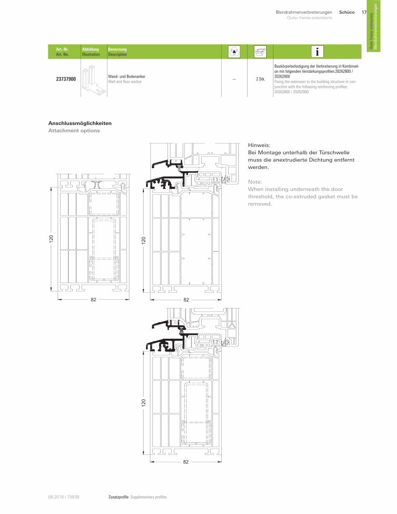
Anschlussmöglichkeiten
Attachment options
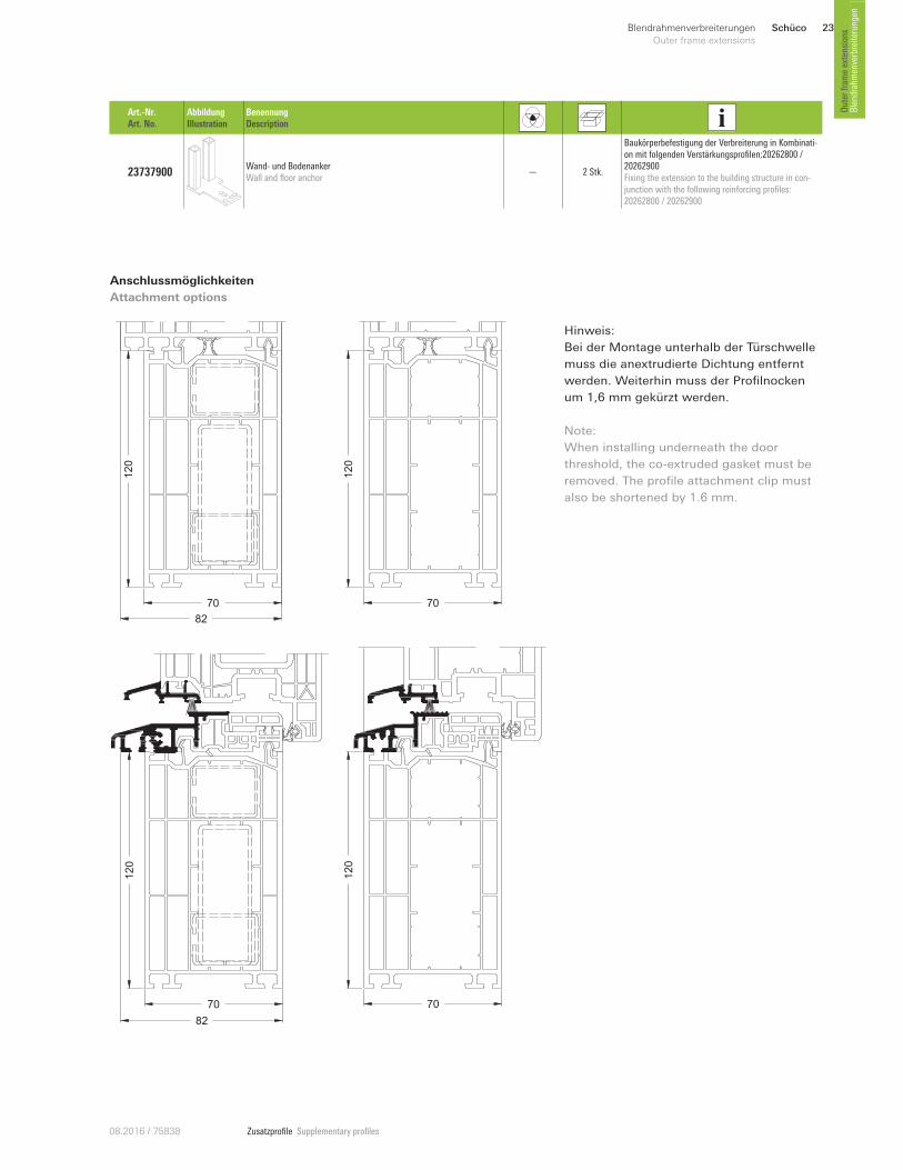
Hinweis:
Bei Montage unterhalb der Türschwelle
muss die anextrudierte Dichtung entfernt
werden.
Note:
When installing underneath the door
threshold, the co-extruded gasket must be
removed.
120
82
12
0
82
Art.-Nr. Art. No.
Abbildung Illustration
Benennung Description
23737900 Wand- und Bodenanker Wall and floor anchor
— 2 Stk.
Baukörperbefestigung der Verbreiterung in Kombinati-on mit folgenden Verstärkungsprofilen:20262800 / 20262900Fixing the extension to the building structure in con-junction with the following reinforcing profiles: 20262800 / 20262900
82
12
0
Schüco18 Blendrahmenverbreiterungen
Outer frame extensions
Zusatzprofile Supplementary profiles 08.2016 / 75838
Blendrahm
enverbreiterungen
Outer fram
e extensions
82
167 150
70 112
219
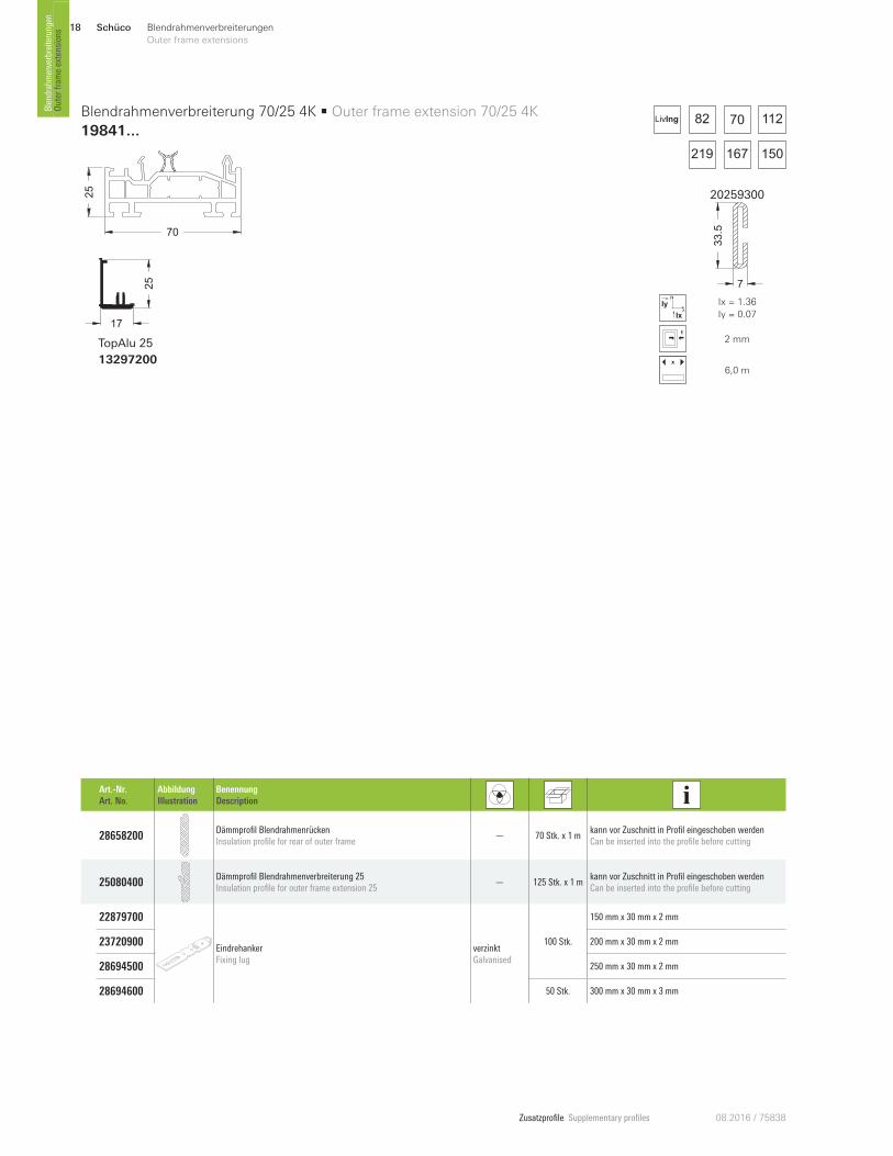
LivIng
25
70
17
25
TopAlu 25
13297200
Art.-Nr. Art. No.
Abbildung Illustration
Benennung Description
28658200 Dämmprofil Blendrahmenrücken Insulation profile for rear of outer frame
— 70 Stk. x 1 m kann vor Zuschnitt in Profil eingeschoben werden Can be inserted into the profile before cutting
25080400 Dämmprofil Blendrahmenverbreiterung 25 Insulation profile for outer frame extension 25
— 125 Stk. x 1 m kann vor Zuschnitt in Profil eingeschoben werden Can be inserted into the profile before cutting
22879700
Eindrehanker Fixing lug
verzinkt Galvanised
100 Stk.
150 mm x 30 mm x 2 mm
23720900 200 mm x 30 mm x 2 mm
28694500 250 mm x 30 mm x 2 mm
28694600 50 Stk. 300 mm x 30 mm x 3 mm
Blendrahmenverbreiterung 70/25 4K • Outer frame extension 70/25 4K
19841 ...
20259300
7
33.5
x
y
Ix
Iy Ix = 1.36
Iy = 0.07
2 mm
x
6,0 m
Schüco 19Blendrahmenverbreiterungen
Outer frame extensions
Zusatzprofile Supplementary profiles08.2016 / 75838
Outer fram
e extensions
Blendrahmenverbreiterungen
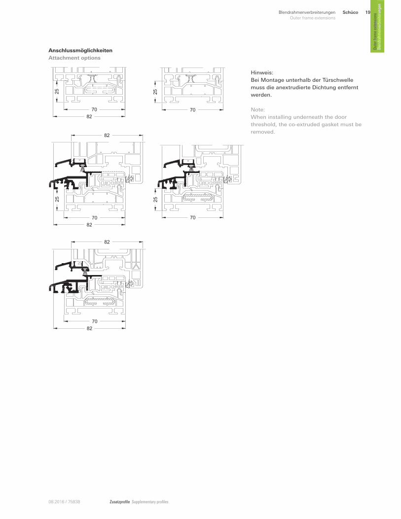
Anschlussmöglichkeiten
Attachment options
25
70
70
25
82
25
70
82
70
82
82
25
70
82
Hinweis:
Bei Montage unterhalb der Türschwelle
muss die anextrudierte Dichtung entfernt
werden.
Note:
When installing underneath the door
threshold, the co-extruded gasket must be
removed.
Schüco20 Blendrahmenverbreiterungen
Outer frame extensions
Zusatzprofile Supplementary profiles 08.2016 / 75838
Blendrahm
enverbreiterungen
Outer fram
e extensions
82
167 150
70 112
219
LivIng
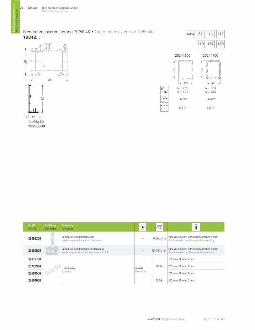
50
70
17
50
TopAlu 50
13298500
Blendrahmenverbreiterung 70/50 4K • Outer frame extension 70/50 4K
19842 ...
Art.-Nr. Art. No.
Abbildung Illustration
Benennung Description
28658200 Dämmprofil Blendrahmenrücken Insulation profile for rear of outer frame
— 70 Stk. x 1 m kann vor Zuschnitt in Profil eingeschoben werden Can be inserted into the profile before cutting
25080500 Dämmprofil Blendrahmenverbreiterung 50 Insulation profile for outer frame extension 50
— 125 Stk. x 1 m kann vor Zuschnitt in Profil eingeschoben werden Can be inserted into the profile before cutting
22879700
Eindrehanker Fixing lug
verzinkt Galvanised
100 Stk.
150 mm x 30 mm x 2 mm
23720900 200 mm x 30 mm x 2 mm
28694500 250 mm x 30 mm x 2 mm
28694600 50 Stk. 300 mm x 30 mm x 3 mm
20244600 20244700
26
33
26
33
x
y
Ix
Iy Ix = 2.29
Iy = 1.74
Ix = 3.38
Iy = 2.55
1.5 mm 2.5 mm
x
6,0 m 6,0 m
Schüco 21Blendrahmenverbreiterungen
Outer frame extensions
Zusatzprofile Supplementary profiles08.2016 / 75838
Outer fram
e extensions
Blendrahmenverbreiterungen
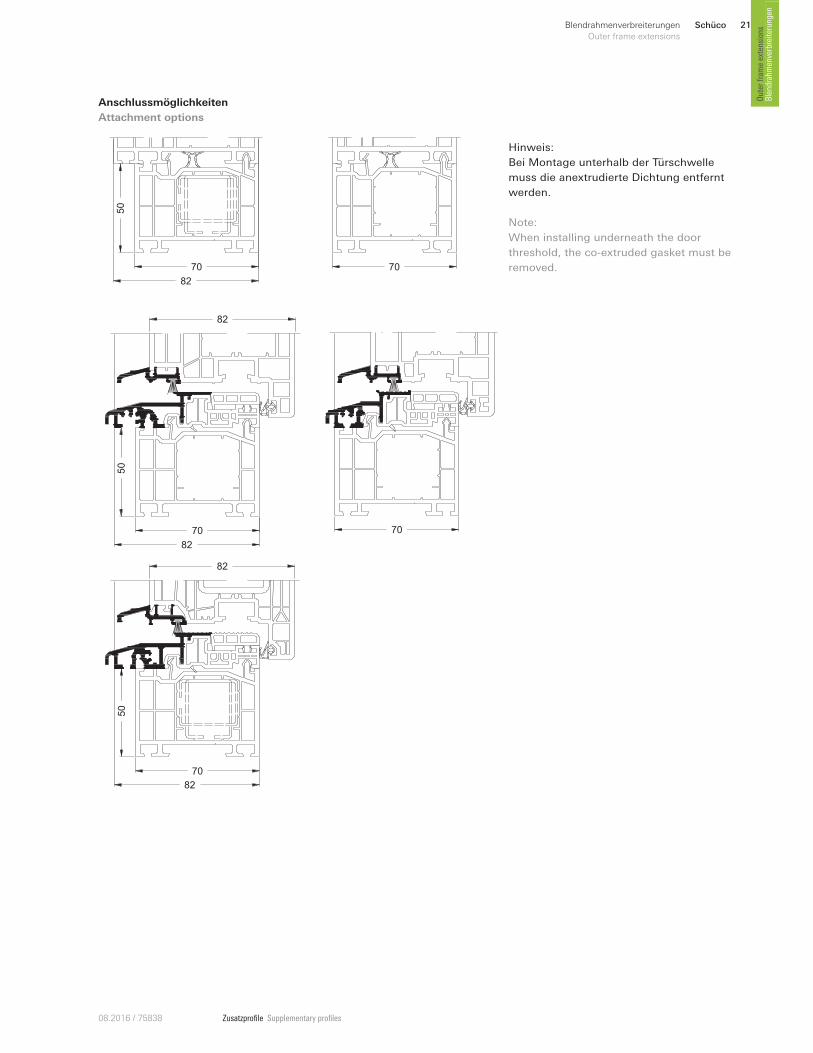
Anschlussmöglichkeiten
Attachment options
Hinweis:
Bei Montage unterhalb der Türschwelle
muss die anextrudierte Dichtung entfernt
werden.
Note:
When installing underneath the door
threshold, the co-extruded gasket must be
removed. 70
50
82
70
82
50
70
82
82
70
50
82
70
Schüco22 Blendrahmenverbreiterungen
Outer frame extensions
Zusatzprofile Supplementary profiles 08.2016 / 75838
Blendrahm
enverbreiterungen
Outer fram
e extensions
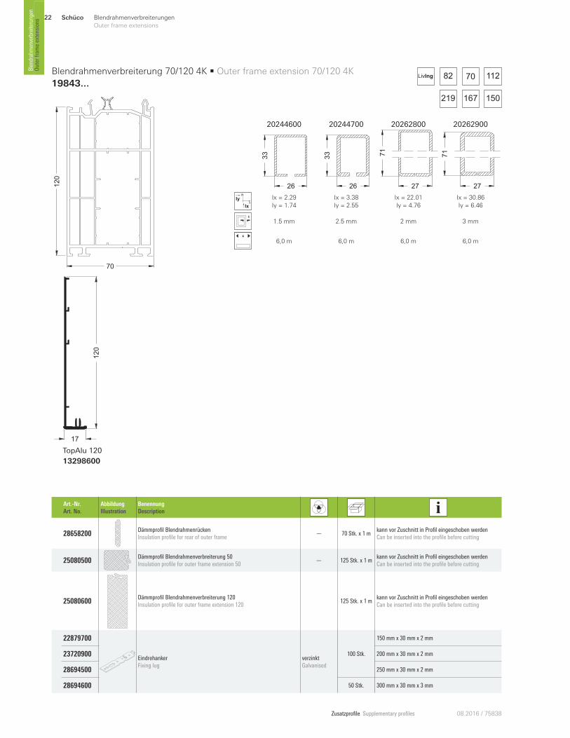
70
120
17
120
TopAlu 120
13298600
Art.-Nr. Art. No.
Abbildung Illustration
Benennung Description
28658200 Dämmprofil Blendrahmenrücken Insulation profile for rear of outer frame
— 70 Stk. x 1 m kann vor Zuschnitt in Profil eingeschoben werden Can be inserted into the profile before cutting
25080500 Dämmprofil Blendrahmenverbreiterung 50 Insulation profile for outer frame extension 50
— 125 Stk. x 1 m kann vor Zuschnitt in Profil eingeschoben werden Can be inserted into the profile before cutting
25080600 Dämmprofil Blendrahmenverbreiterung 120 Insulation profile for outer frame extension 120
125 Stk. x 1 m kann vor Zuschnitt in Profil eingeschoben werden Can be inserted into the profile before cutting
22879700
Eindrehanker Fixing lug
verzinkt Galvanised
100 Stk.
150 mm x 30 mm x 2 mm
23720900 200 mm x 30 mm x 2 mm
28694500 250 mm x 30 mm x 2 mm
28694600 50 Stk. 300 mm x 30 mm x 3 mm
Blendrahmenverbreiterung 70/120 4K • Outer frame extension 70/120 4K
19843 ...
20244600 20244700 20262800 20262900
26
33
26
33
27
71
27
71
x
y
Ix
Iy Ix = 2.29
Iy = 1.74
Ix = 3.38
Iy = 2.55
Ix = 22.01
Iy = 4.76
Ix = 30.86
Iy = 6.46
1.5 mm 2.5 mm 2 mm 3 mm
x
6,0 m 6,0 m 6,0 m 6,0 m
82
167 150
70 112
219
LivIng
Schüco 23Blendrahmenverbreiterungen
Outer frame extensions
Zusatzprofile Supplementary profiles08.2016 / 75838
Outer fram
e extensions
Blendrahmenverbreiterungen
Anschlussmöglichkeiten
Attachment options
Hinweis:
Bei der Montage unterhalb der Türschwelle
muss die anextrudierte Dichtung entfernt
werden. Weiterhin muss der Profilnocken
um 1,6 mm gekürzt werden.
Note:
When installing underneath the door
threshold, the co-extruded gasket must be
removed. The profile attachment clip must
also be shortened by 1.6 mm.
Art.-Nr. Art. No.
Abbildung Illustration
Benennung Description
23737900 Wand- und Bodenanker Wall and floor anchor
— 2 Stk.
Baukörperbefestigung der Verbreiterung in Kombinati-on mit folgenden Verstärkungsprofilen:20262800 / 20262900Fixing the extension to the building structure in con-junction with the following reinforcing profiles: 20262800 / 20262900
120
70
82
120
70
70
12
0
82
12
0
70
Schüco24 Blendrahmenverbreiterungen
Outer frame extensions
Zusatzprofile Supplementary profiles 08.2016 / 75838
Blendrahm
enverbreiterungen
Outer fram
e extensions
240
70
Art.-Nr. Art. No.
Abbildung Illustration
Benennung Description
28658200 Dämmprofil Blendrahmenrücken Insulation profile for rear of outer frame
— 70 Stk. x 1 m kann vor Zuschnitt in Profil eingeschoben werden Can be inserted into the profile before cutting
25080600 Dämmprofil Blendrahmenverbreiterung 120 Insulation profile for outer frame extension 120
125 Stk. x 1 m kann vor Zuschnitt in Profil eingeschoben werden Can be inserted into the profile before cutting
22879700
Eindrehanker Fixing lug
verzinkt Galvanised
100 Stk.
150 mm x 30 mm x 2 mm
23720900 200 mm x 30 mm x 2 mm
28694500 250 mm x 30 mm x 2 mm
28694600 50 Stk. 300 mm x 30 mm x 3 mm
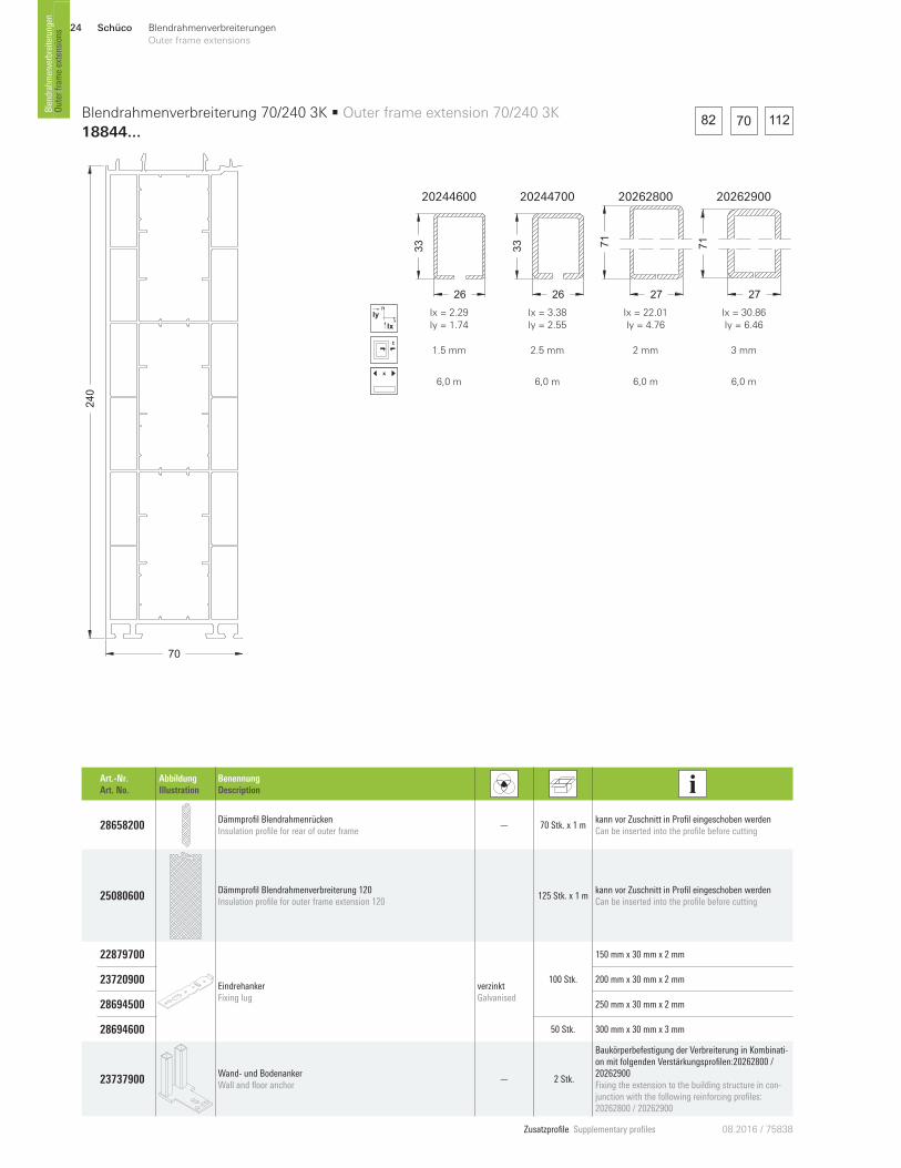
23737900 Wand- und Bodenanker Wall and floor anchor
— 2 Stk.
Baukörperbefestigung der Verbreiterung in Kombinati-on mit folgenden Verstärkungsprofilen:20262800 / 20262900Fixing the extension to the building structure in con-junction with the following reinforcing profiles: 20262800 / 20262900
Blendrahmenverbreiterung 70/240 3K • Outer frame extension 70/240 3K
18844 ...
20244600 20244700 20262800 20262900
26
33
26
33
27
71
27
71
x
y
Ix
Iy Ix = 2.29
Iy = 1.74
Ix = 3.38
Iy = 2.55
Ix = 22.01
Iy = 4.76
Ix = 30.86
Iy = 6.46
1.5 mm 2.5 mm 2 mm 3 mm
x
6,0 m 6,0 m 6,0 m 6,0 m
82 70 112
Schüco 25Blendrahmenverbreiterungen
Outer frame extensions
Zusatzprofile Supplementary profiles08.2016 / 75838
Outer fram
e extensions
Blendrahmenverbreiterungen
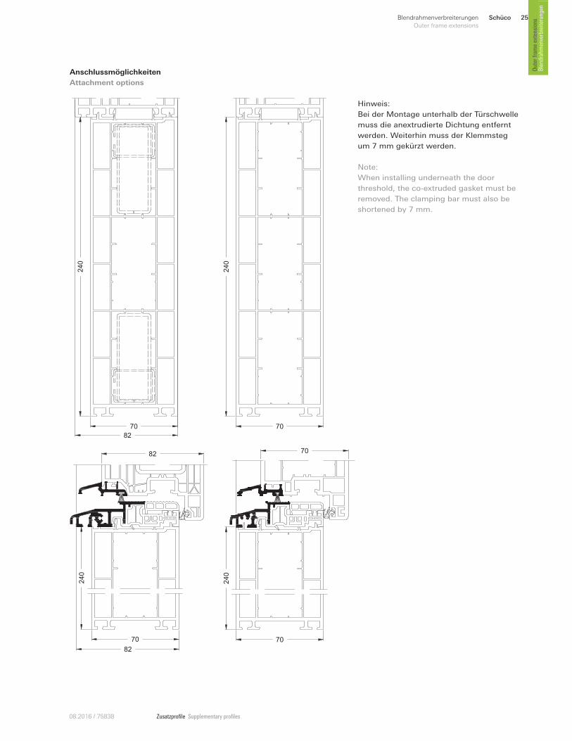
Anschlussmöglichkeiten
Attachment options
240
70
240
70
82
Hinweis:
Bei der Montage unterhalb der Türschwelle
muss die anextrudierte Dichtung entfernt
werden. Weiterhin muss der Klemmsteg
um 7 mm gekürzt werden.
Note:
When installing underneath the door
threshold, the co-extruded gasket must be
removed. The clamping bar must also be
shortened by 7 mm.
24
0
70
82
82
24
0
70
70
Schüco26 Blendrahmenverbreiterungen
Outer frame extensions
Zusatzprofile Supplementary profiles 08.2016 / 75838
Blendrahm
enverbreiterungen
Outer fram
e extensions
60
50
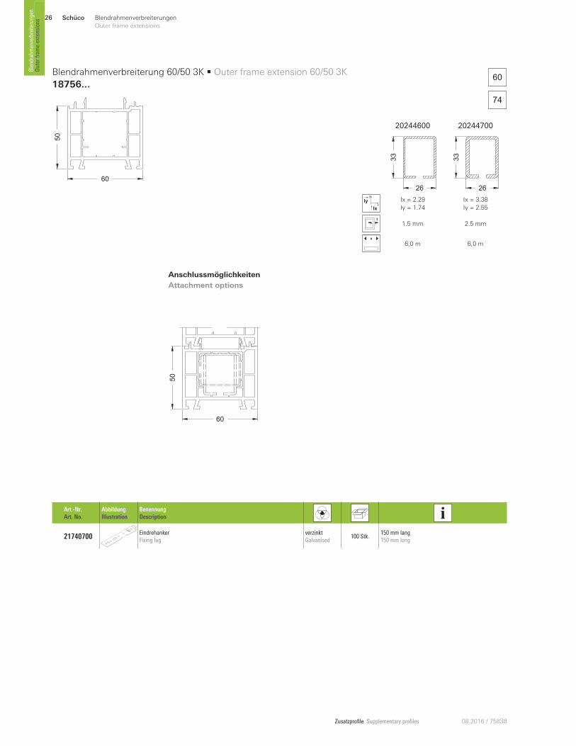
Blendrahmenverbreiterung 60/50 3K • Outer frame extension 60/50 3K
18756 ...
Art.-Nr. Art. No.
Abbildung Illustration
Benennung Description
21740700 Eindrehanker Fixing lug
verzinkt Galvanised
100 Stk. 150 mm lang 150 mm long
20244600 20244700
26
33
26
33
x
y
Ix
Iy Ix = 2.29
Iy = 1.74
Ix = 3.38
Iy = 2.55
1.5 mm 2.5 mm
x
6,0 m 6,0 m
60
74
50
60
Anschlussmöglichkeiten
Attachment options
Schüco 27Blendrahmenverbreiterungen
Outer frame extensions
Zusatzprofile Supplementary profiles08.2016 / 75838
Outer fram
e extensions
Blendrahmenverbreiterungen
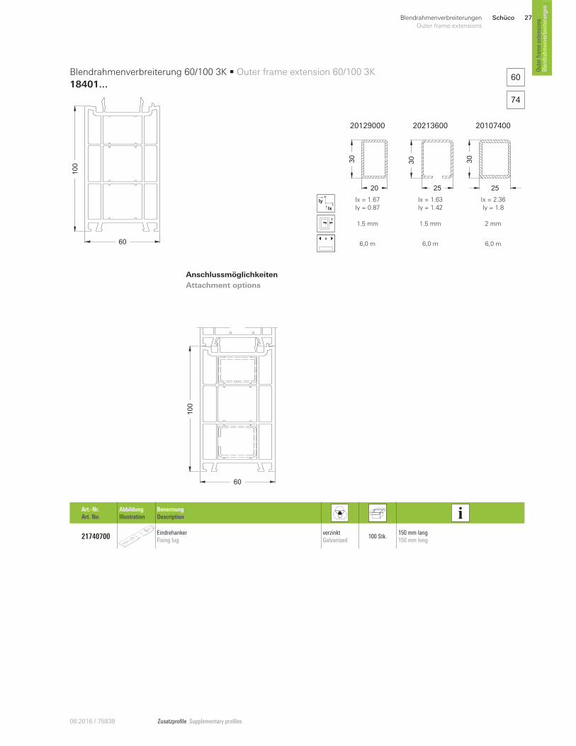
60
100
Blendrahmenverbreiterung 60/100 3K • Outer frame extension 60/100 3K
18401 ...
Art.-Nr. Art. No.
Abbildung Illustration
Benennung Description
21740700 Eindrehanker Fixing lug
verzinkt Galvanised
100 Stk. 150 mm lang 150 mm long
60
74
Anschlussmöglichkeiten
Attachment options
20129000 20213600 20107400
20
30
25
30 30
25
x
y
Ix
Iy Ix = 1.67
Iy = 0.87
Ix = 1.63
Iy = 1.42
Ix = 2.36
Iy = 1.8
1.5 mm 1.5 mm 2 mm
x
6,0 m 6,0 m 6,0 m
100
60
Schüco28 Blendrahmenverbreiterungen
Outer frame extensions
Zusatzprofile Supplementary profiles 08.2016 / 75838
Blendrahm
enverbreiterungen
Outer fram
e extensions
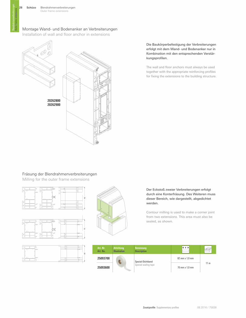
Montage Wand- und Bodenanker an Verbreiterungen
Installation of wall and floor anchor in extensions
Die Baukörperbefestigung der Verbreiterungen
erfolgt mit dem Wand- und Bodenanker nur in
Kombination mit den entsprechenden Verstär-
kungsprofilen.
20262800 20262900
The wall and floor anchors must always be used
together with the appropriate reinforcing profiles
for fixing the extensions to the building structure.
Fräsung der Blendrahmenverbreiterungen
Milling for the outer frame extensions
82
70
60
Der Eckstoß zweier Verbreiterungen erfolgt
durch eine Konterfräsung. Des Weiteren muss
dieser Bereich, wie dargestellt, abgedichtet
werden.
Contour milling is used to make a corner joint
from two extensions. This area must also be
sealed, as shown.
Art.-Nr. Art. No.
Abbildung Illustration
Benennung Description
25093700 Spezial-Dichtband Special sealing tape
82 mm x 1,0 mm
11 m
25093600 70 mm x 1,0 mm
Zusatzprofile Supplementary profiles08.2016 / 75838
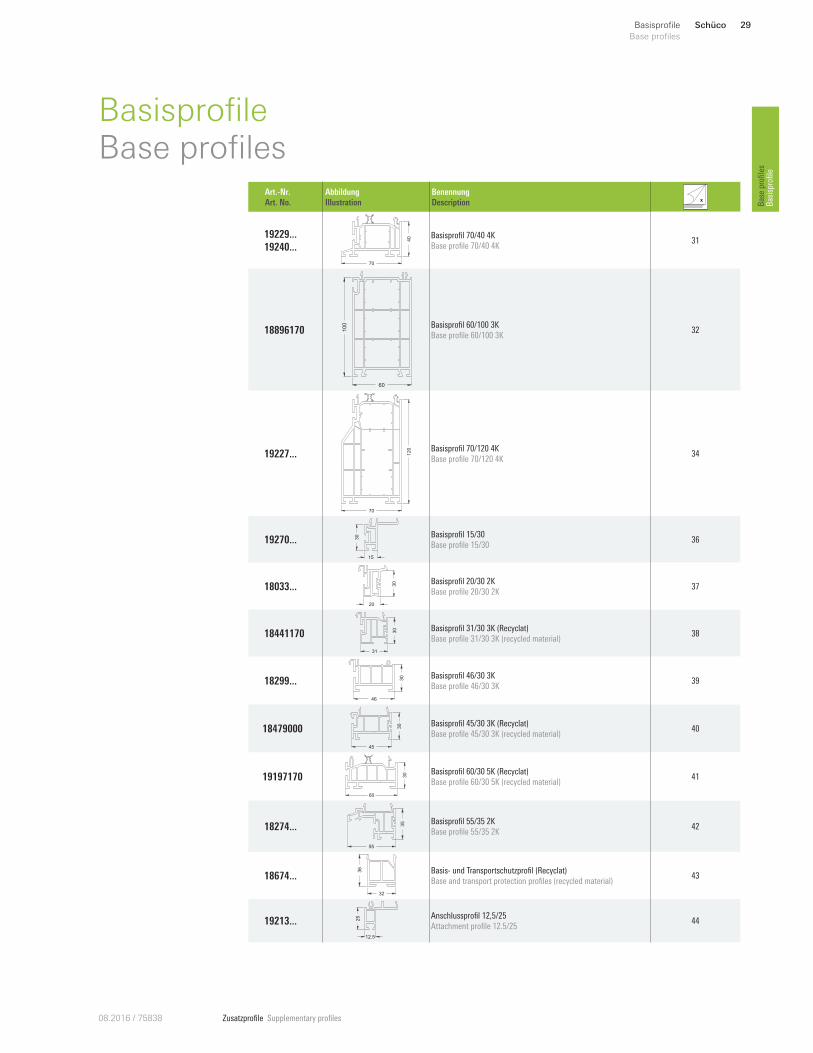
Schüco 29Basisprofile
Base profiles
Base profiles
Basisprofile
BasisprofileBase profiles
Art.-Nr. Art. No.
Abbildung Illustration
Benennung Description
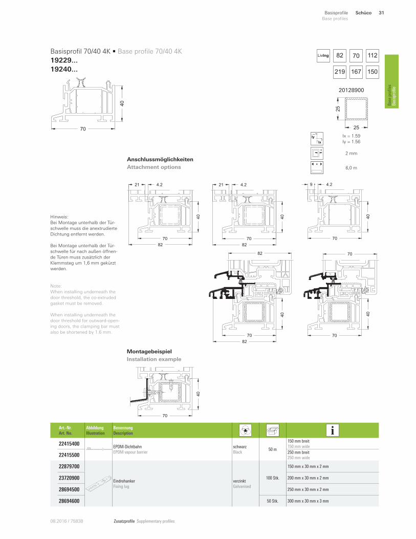
19229 ...19240...
70
40 Basisprofil 70/40 4K
Base profile 70/40 4K 31
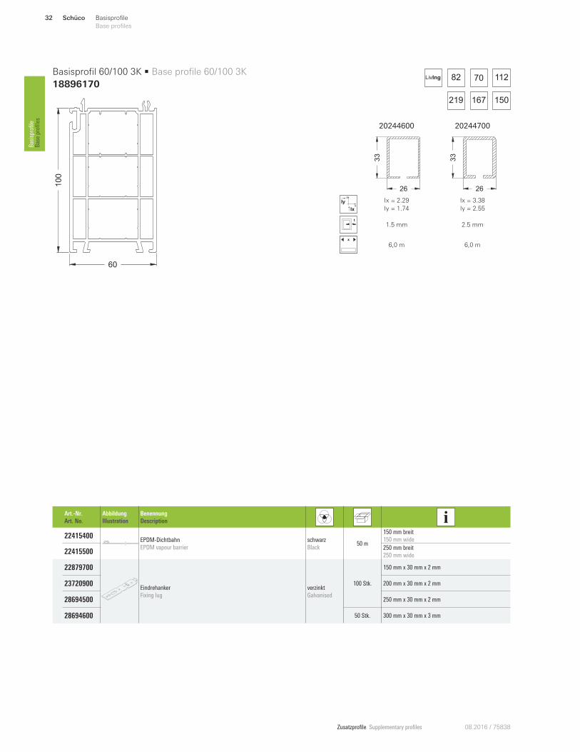
18896170
60
100 Basisprofil 60/100 3K
Base profile 60/100 3K 32
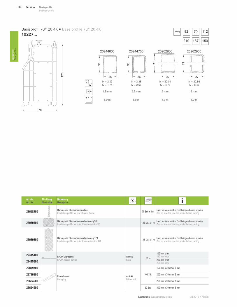
19227 ...
70
120 Basisprofil 70/120 4K
Base profile 70/120 4K 34
19270 ...
15
30 Basisprofil 15/30
Base profile 15/30 36
18033 ...
20
30 Basisprofil 20/30 2K
Base profile 20/30 2K 37
18441170
31
30 Basisprofil 31/30 3K (Recyclat)
Base profile 31/30 3K (recycled material) 38
18299 ...
46
30 Basisprofil 46/30 3K
Base profile 46/30 3K 39
18479000
45
30 Basisprofil 45/30 3K (Recyclat)
Base profile 45/30 3K (recycled material) 40
19197170
60
30 Basisprofil 60/30 5K (Recyclat)
Base profile 60/30 5K (recycled material) 41
18274 ...
55
35 Basisprofil 55/35 2K
Base profile 55/35 2K 42
18674 ...
32
36 Basis- und Transportschutzprofil (Recyclat)
Base and transport protection profiles (recycled material) 43
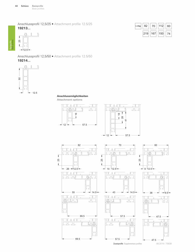
19213 ...
12.5
25 Anschlussprofil 12,5/25
Attachment profile 12.5/25 44
Zusatzprofile Supplementary profiles 08.2016 / 75838
Schüco30 Basisprofile
Base profiles Basisprofile
Base profiles
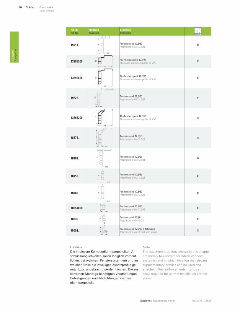
Art.-Nr.
Art. No.
Abbildung
Illustration
Benennung
Description
19214 ...
12.5
50 Anschlussprofil 12,5/50
Attachment profile 12.5/50 44
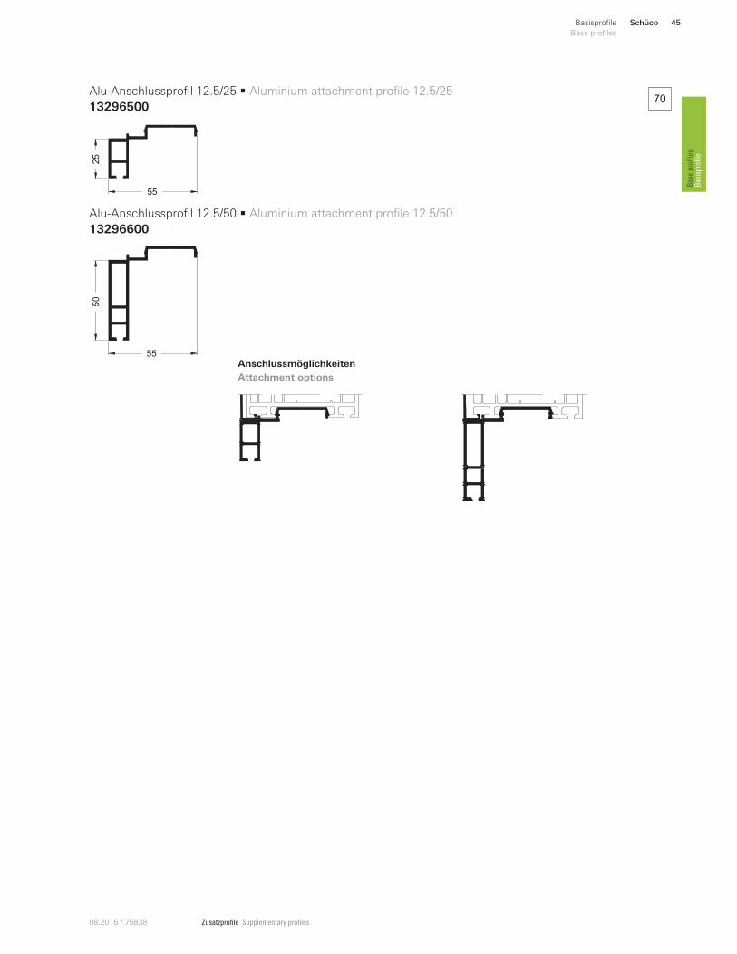
13296500
55
25 Alu-Anschlussprofil 12.5/25
Aluminium attachment profile 12.5/25 45
13296600
55
50 Alu-Anschlussprofil 12.5/50
Aluminium attachment profile 12.5/50 45
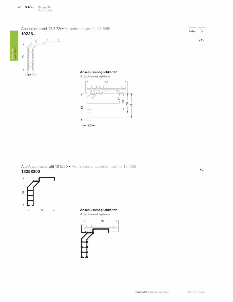
19228 ... 55
12.5
Anschlussprofil 12,5/55
Attachment profile 12.5/55 46
13298200
55
57 Alu-Anschlussprofil 12.5/50
Aluminium attachment profile 12.5/50 46
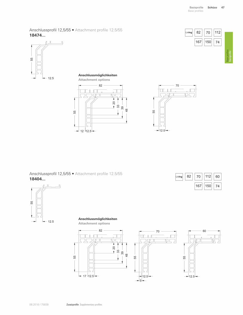
18474 ...
12.5
55 Anschlussprofil 12,5/55
Attachment profile 12.5/55 47
18404 ...
12.5
55 Anschlussprofil 12,5/55
Attachment profile 12.5/55 47
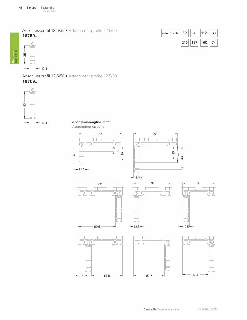
18759 ...
12.5
35 Anschlussprofil 12,5/35
Attachment profile 12.5/35 48
18769 ...
12.5
50 Anschlussprofil 12,5/50
Attachment profile 12.5/50 48
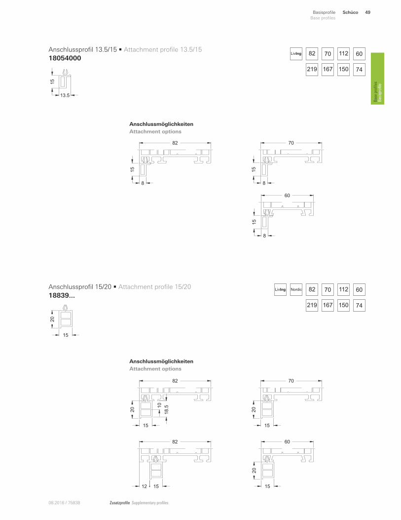
18054000 13.5
15 Anschlussprofil 13.5/15
Attachment profile 13.5/15 49
18839 ...15
20 Anschlussprofil 15/20
Attachment profile 15/20 49
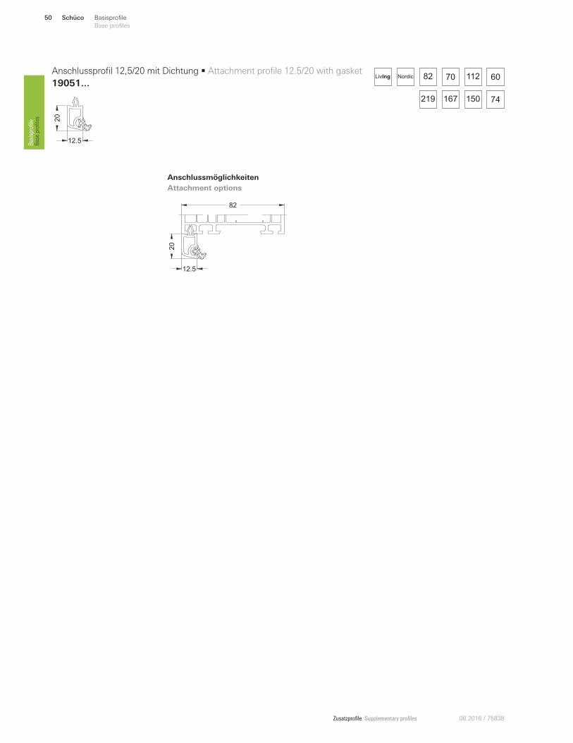
19051 ...12.5
20 Anschlussprofil 12,5/20 mit Dichtung
Attachment profile 12.5/20 with gasket 50
Hinweis:
Die in diesem Kompendium dargestellten An-
schlussmöglichkeiten sollen lediglich verdeut-
lichen, bei welchem Fenstersystem(en) und an
welcher Stelle die jeweiligen Zusatzprofile ge-
nutzt bzw. angebracht werden können. Die zur
korrekten Montage benötigten Verstärkungen,
Befestigungen und Abdichtungen werden
nicht dargestellt.
Note:
The attachment options shown in this chapter
are merely to illustrate for which window
system(s) and in which location the relevant
supplementary profiles can be used and
attached. The reinforcements, fixings and
seals required for correct installation are not
shown.
Zusatzprofile Supplementary profiles08.2016 / 75838
20128900
25
25
x
y
Ix
Iy Ix = 1.59
Iy = 1.56
2 mm
x
6,0 m
70
40
Montagebeispiel
Installation example
70
9
40
4.221
70
40
82
4.2
70
40
70
82
167 150
70 112LivIng
70
40
Art.-Nr.
Art. No.
Abbildung
Illustration
Benennung
Description
22415400 EPDM-Dichtbahn
EPDM vapour barrier
schwarz
Black 50 m
150 mm breit
150 mm wide
22415500 250 mm breit
250 mm wide
22879700
Eindrehanker
Fixing lug
verzinkt
Galvanised
100 Stk.
150 mm x 30 mm x 2 mm
23720900 200 mm x 30 mm x 2 mm
28694500 250 mm x 30 mm x 2 mm
28694600 50 Stk. 300 mm x 30 mm x 3 mm
Basisprofil 70/40 4K • Base profile 70/40 4K
19229 ...
19240...
Anschlussmöglichkeiten
Attachment options
21
70
40
82
4.2
70
40
82
82
Hinweis:
Bei Montage unterhalb der Tür-
schwelle muss die anextrudierte
Dichtung entfernt werden.
Bei Montage unterhalb der Tür-
schwelle für nach außen öRnen-
de Türen muss zusätzlich der
Klemmsteg um 1,6 mm gekürzt
werden.
Note:
When installing underneath the
door threshold, the co-extruded
gasket must be removed.
When installing underneath the
door threshold for outward-open-
ing doors, the clamping bar must
also be shortened by 1.6 mm.
219
Schüco 31Basisprofile
Base profiles
Base profiles
Basisprofile
Zusatzprofile Supplementary profiles 08.2016 / 75838
20244600 20244700
26
33
26
33
x
y
Ix
Iy Ix = 2.29
Iy = 1.74
Ix = 3.38
Iy = 2.55
1.5 mm 2.5 mm
x
6,0 m 6,0 m
82
167 150
70 112LivIng
60
100
Art.-Nr.
Art. No.
Abbildung
Illustration
Benennung
Description
22415400 EPDM-Dichtbahn
EPDM vapour barrier
schwarz
Black 50 m
150 mm breit
150 mm wide
22415500 250 mm breit
250 mm wide
22879700
Eindrehanker
Fixing lug
verzinkt
Galvanised
100 Stk.
150 mm x 30 mm x 2 mm
23720900 200 mm x 30 mm x 2 mm
28694500 250 mm x 30 mm x 2 mm
28694600 50 Stk. 300 mm x 30 mm x 3 mm
Basisprofil 60/100 3K • Base profile 60/100 3K
18896170
219
Schüco32 Basisprofile
Base profiles Basisprofile
Base profiles
Zusatzprofile Supplementary profiles08.2016 / 75838
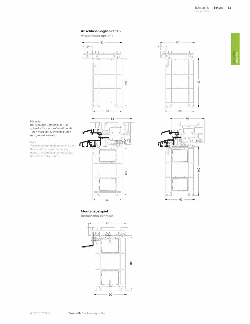
Anschlussmöglichkeiten
Attachment options
60
100
22
82
10
0
82
60
60
100
10
70
10
0
70
60
60
100
70
Montagebeispiel
Installation example
Hinweis:
Bei Montage unterhalb der Tür-
schwelle für nach außen öRnende
Türen muss der Klemmsteg um 7
mm gekürzt werden.
Note:
When installing underneath the door
threshold for outward-opening
doors, the clamping bar must also
be shortened by 7 mm.
Schüco 33Basisprofile
Base profiles
Base profiles
Basisprofile
Zusatzprofile Supplementary profiles 08.2016 / 75838
20244600 20244700 20262800 20262900
26
33
26
33
27
71
27
71
x
y
Ix
Iy Ix = 2.29
Iy = 1.74
Ix = 3.38
Iy = 2.55
Ix = 22.01
Iy = 4.76
Ix = 30.86
Iy = 6.46
1.5 mm 2.5 mm 2 mm 3 mm
x
6,0 m 6,0 m 6,0 m 6,0 m
82
167 150
70 112
219
LivIng
70
120
Basisprofil 70/120 4K • Base profile 70/120 4K
19227...
Art.-Nr.
Art. No.
Abbildung
Illustration
Benennung
Description
28658200 Dämmprofil Blendrahmenrücken
Insulation profile for rear of outer frame 70 Stk. x 1 m
kann vor Zuschnitt in Profil eingeschoben werden
Can be inserted into the profile before cutting
25080500 Dämmprofil Blendrahmenverbreiterung 50
Insulation profile for outer frame extension 50 125 Stk. x 1 m
kann vor Zuschnitt in Profil eingeschoben werden
Can be inserted into the profile before cutting
25080600 Dämmprofil Blendrahmenverbreiterung 120
Insulation profile for outer frame extension 120 125 Stk. x 1 m
kann vor Zuschnitt in Profil eingeschoben werden
Can be inserted into the profile before cutting
22415400 EPDM-Dichtbahn
EPDM vapour barrier
schwarz
Black 50 m
150 mm breit
150 mm wide
22415500 250 mm breit
250 mm wide
22879700
Eindrehanker
Fixing lug
verzinkt
Galvanised
100 Stk.
150 mm x 30 mm x 2 mm
23720900 200 mm x 30 mm x 2 mm
28694500 250 mm x 30 mm x 2 mm
28694600 50 Stk. 300 mm x 30 mm x 3 mm
Schüco34 Basisprofile
Base profiles Basisprofile
Base profiles
Zusatzprofile Supplementary profiles08.2016 / 75838
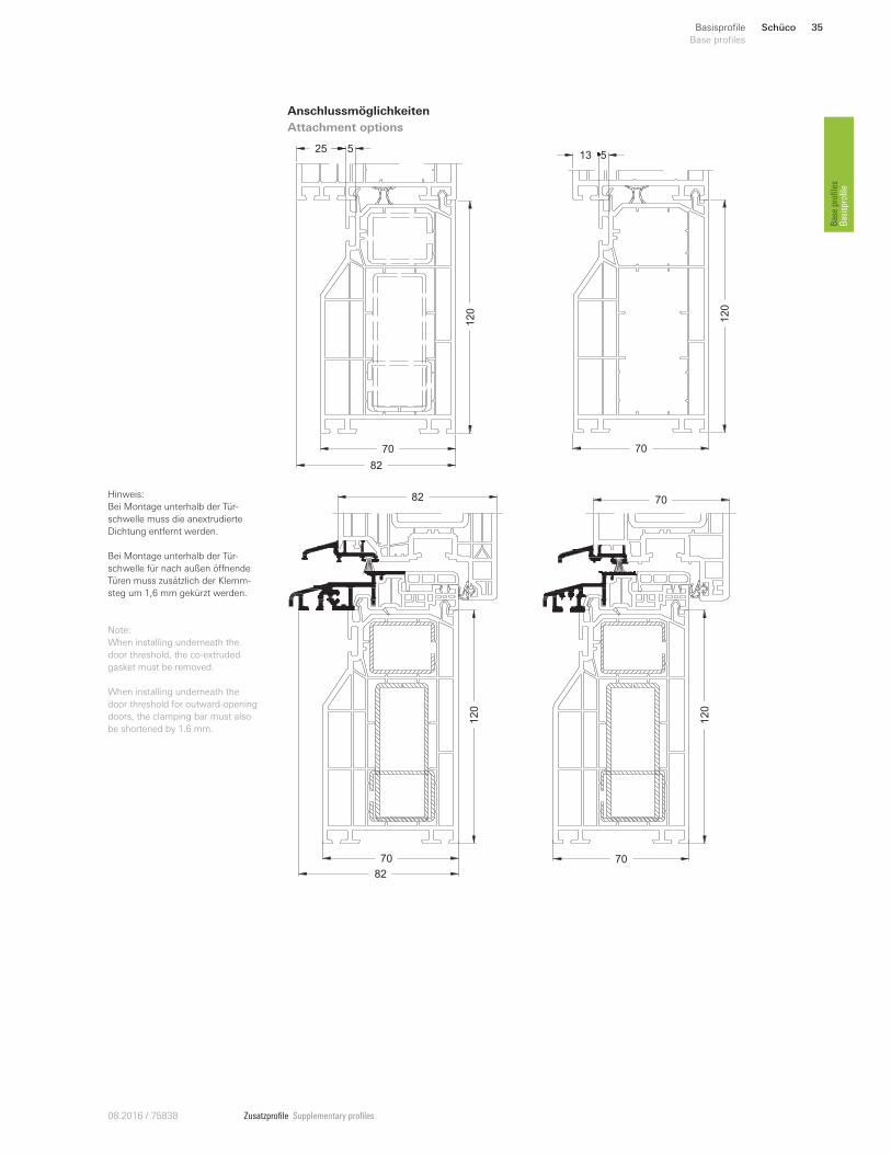
Anschlussmöglichkeiten
Attachment options
70
82120
25 5
120
70
13 5
82
12
0
70
82
Hinweis:
Bei Montage unterhalb der Tür-
schwelle muss die anextrudierte
Dichtung entfernt werden.
Bei Montage unterhalb der Tür-
schwelle für nach außen öRnende
Türen muss zusätzlich der Klemm-
steg um 1,6 mm gekürzt werden.
Note:
When installing underneath the
door threshold, the co-extruded
gasket must be removed.
When installing underneath the
door threshold for outward-opening
doors, the clamping bar must also
be shortened by 1.6 mm.
12
0
70
70
Schüco 35Basisprofile
Base profiles
Base profiles
Basisprofile

Zusatzprofile Supplementary profiles 08.2016 / 75838
Anschlussmöglichkeiten
Attachment options
15
30
12
70
15
30
24
82
30
15
7
60
82 6070 112LivIng
15
30
Basisprofil 15/30 • Base profile 15/30
19270...
Art.-Nr.
Art. No.
Abbildung
Illustration
Benennung
Description
22415400 EPDM-Dichtbahn
EPDM vapour barrier
schwarz
Black 50 m
150 mm breit
150 mm wide
22415500 250 mm breit
250 mm wide
219
Schüco36 Basisprofile
Base profiles Basisprofile
Base profiles
Zusatzprofile Supplementary profiles08.2016 / 75838
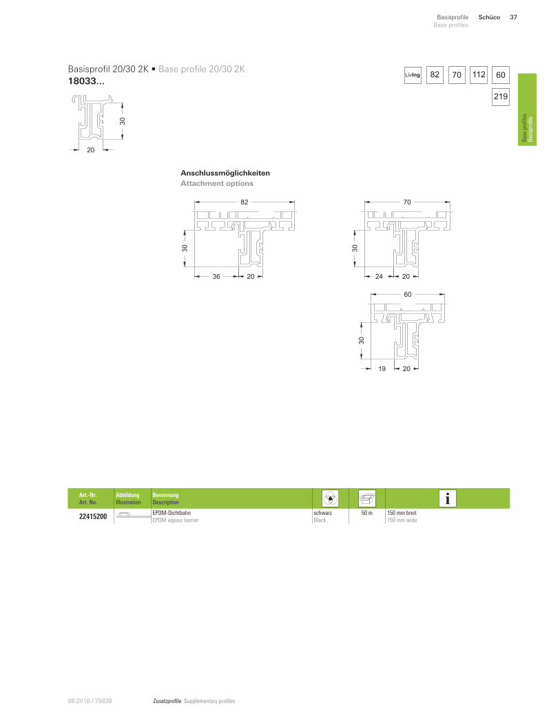
Anschlussmöglichkeiten
Attachment options
20
30
Basisprofil 20/30 2K • Base profile 20/30 2K
18033...
Art.-Nr.
Art. No.
Abbildung
Illustration
Benennung
Description
22415200 EPDM-Dichtbahn
EPDM vapour barrier
schwarz
Black
50 m 150 mm breit
150 mm wide
20
30
24
70
20
30
36
82
2030
19
60
82 6070 112LivIng
219
Schüco 37Basisprofile
Base profiles
Base profiles
Basisprofile
Zusatzprofile Supplementary profiles 08.2016 / 75838
31
30
24
70
31
30
36
82
31
30
19
60
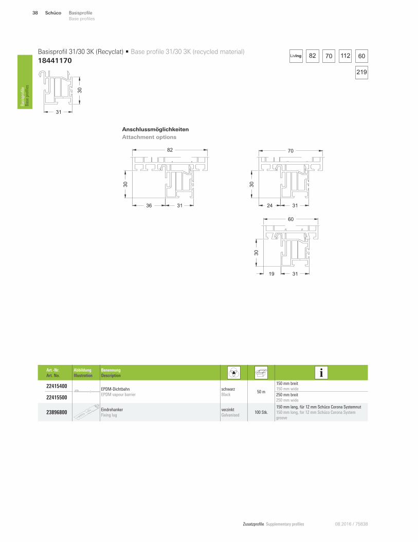
Anschlussmöglichkeiten
Attachment options
82 6070 112LivIng
31
30
Basisprofil 31/30 3K (Recyclat) • Base profile 31/30 3K (recycled material)
18441170
Art.-Nr.
Art. No.
Abbildung
Illustration
Benennung
Description
22415400 EPDM-Dichtbahn
EPDM vapour barrier
schwarz
Black 50 m
150 mm breit
150 mm wide
22415500 250 mm breit
250 mm wide
23896800 Eindrehanker
Fixing lug
verzinkt
Galvanised 100 Stk.
150 mm lang, für 12 mm Schüco Corona Systemnut
150 mm long, for 12 mm Schüco Corona System
groove
219
Schüco38 Basisprofile
Base profiles Basisprofile
Base profiles
Zusatzprofile Supplementary profiles08.2016 / 75838
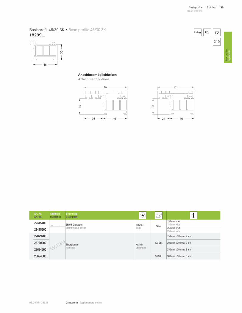
Anschlussmöglichkeiten
Attachment options
4630
Basisprofil 46/30 3K • Base profile 46/30 3K
18299...
46
30
24
70
46
30
36
82
82 70LivIng
Art.-Nr.
Art. No.
Abbildung
Illustration
Benennung
Description
22415400 EPDM-Dichtbahn
EPDM vapour barrier
schwarz
Black 50 m
150 mm breit
150 mm wide
22415500 250 mm breit
250 mm wide
22879700
Eindrehanker
Fixing lug
verzinkt
Galvanised
100 Stk.
150 mm x 30 mm x 2 mm
23720900 200 mm x 30 mm x 2 mm
28694500 250 mm x 30 mm x 2 mm
28694600 50 Stk. 300 mm x 30 mm x 3 mm
219
Schüco 39Basisprofile
Base profiles
Base profiles
Basisprofile
Zusatzprofile Supplementary profiles 08.2016 / 75838
Anschlussmöglichkeiten
Attachment options
45
30
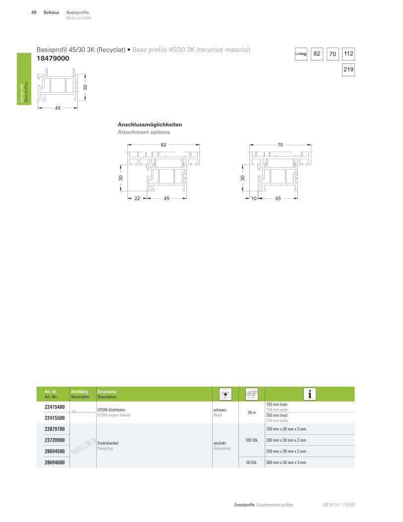
Basisprofil 45/30 3K (Recyclat) • Base profile 45/30 3K (recycled material)
18479000
30
4510
70
22 45
30
82
82 70 112LivIng
Art.-Nr.
Art. No.
Abbildung
Illustration
Benennung
Description
22415400 EPDM-Dichtbahn
EPDM vapour barrier
schwarz
Black 50 m
150 mm breit
150 mm wide
22415500 250 mm breit
250 mm wide
22879700
Eindrehanker
Fixing lug
verzinkt
Galvanised
100 Stk.
150 mm x 30 mm x 2 mm
23720900 200 mm x 30 mm x 2 mm
28694500 250 mm x 30 mm x 2 mm
28694600 50 Stk. 300 mm x 30 mm x 3 mm
219
Schüco40 Basisprofile
Base profiles Basisprofile
Base profiles
Zusatzprofile Supplementary profiles08.2016 / 75838
Anschlussmöglichkeiten
Attachment options
6030
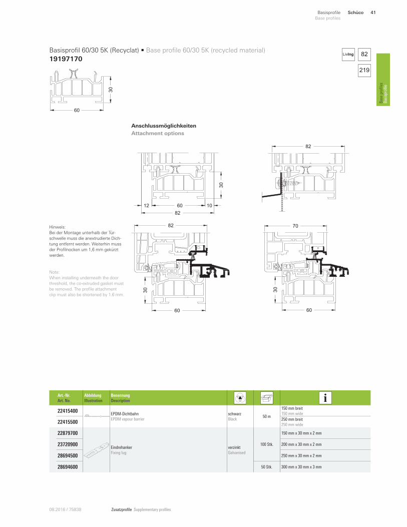
Basisprofil 60/30 5K (Recyclat) • Base profile 60/30 5K (recycled material)
19197170
Art.-Nr.
Art. No.
Abbildung
Illustration
Benennung
Description
22415400 EPDM-Dichtbahn
EPDM vapour barrier
schwarz
Black 50 m
150 mm breit
150 mm wide
22415500 250 mm breit
250 mm wide
22879700
Eindrehanker
Fixing lug
verzinkt
Galvanised
100 Stk.
150 mm x 30 mm x 2 mm
23720900 200 mm x 30 mm x 2 mm
28694500 250 mm x 30 mm x 2 mm
28694600 50 Stk. 300 mm x 30 mm x 3 mm
82
12 60 10
30
82
30
70
60
30
60
82
82LivIng
Hinweis:
Bei der Montage unterhalb der Tür-
schwelle muss die anextrudierte Dich-
tung entfernt werden. Weiterhin muss
der Profilnocken um 1,6 mm gekürzt
werden.
Note:
When installing underneath the door
threshold, the co-extruded gasket must
be removed. The profile attachment
clip must also be shortened by 1.6 mm.
219
Schüco 41Basisprofile
Base profiles
Base profiles
Basisprofile
Zusatzprofile Supplementary profiles 08.2016 / 75838
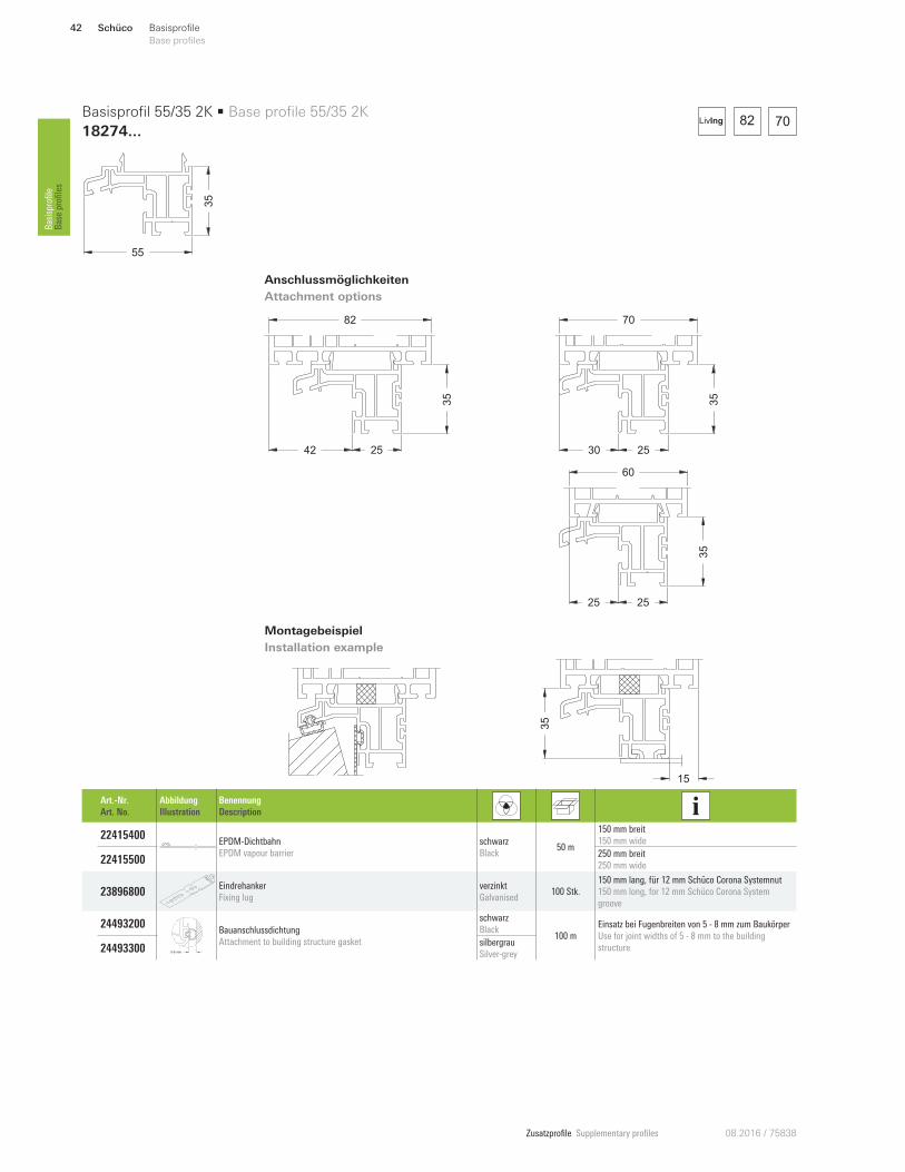
Montagebeispiel
Installation example
42 2535
82
30 25
35
70
25 25
35
60
15
35
82 70LivIng
Anschlussmöglichkeiten
Attachment options
55
35
Basisprofil 55/35 2K • Base profile 55/35 2K
18274...
Art.-Nr.
Art. No.
Abbildung
Illustration
Benennung
Description
22415400 EPDM-Dichtbahn
EPDM vapour barrier
schwarz
Black 50 m
150 mm breit
150 mm wide
22415500 250 mm breit
250 mm wide
23896800 Eindrehanker
Fixing lug
verzinkt
Galvanised 100 Stk.
150 mm lang, für 12 mm Schüco Corona Systemnut
150 mm long, for 12 mm Schüco Corona System
groove
24493200
5-8 mm
Bauanschlussdichtung
Attachment to building structure gasket
schwarz
Black 100 m
Einsatz bei Fugenbreiten von 5 - 8 mm zum Baukörper
Use for joint widths of 5 - 8 mm to the building
structure 24493300 silbergrau
Silver-grey
Schüco42 Basisprofile
Base profiles Basisprofile
Base profiles
Zusatzprofile Supplementary profiles08.2016 / 75838
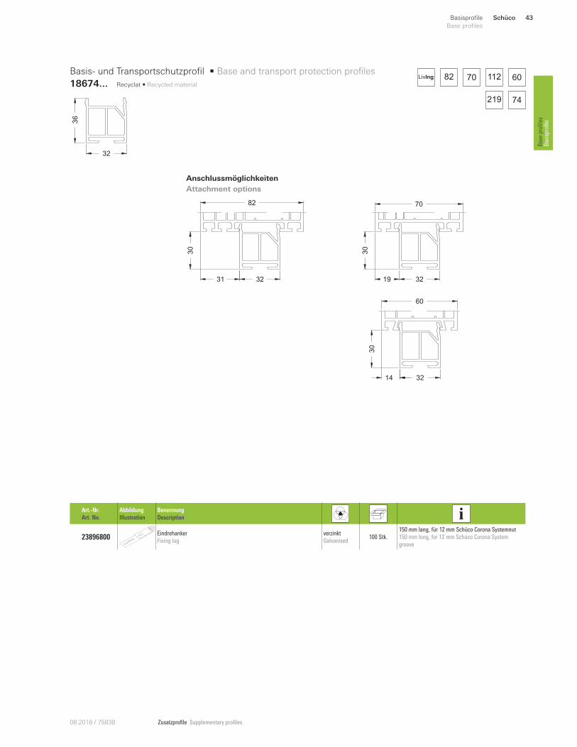
Anschlussmöglichkeiten
Attachment options
32
36
Basis- und Transportschutzprofil • Base and transport protection profiles
18674... Recyclat • Recycled material
Art.-Nr.
Art. No.
Abbildung
Illustration
Benennung
Description
23896800 Eindrehanker
Fixing lug
verzinkt
Galvanised 100 Stk.
150 mm lang, für 12 mm Schüco Corona Systemnut
150 mm long, for 12 mm Schüco Corona System
groove
19 32
30
70
31 32
30
82
14 3230
60
82 60
74
70 112LivIng
219
Schüco 43Basisprofile
Base profiles
Base profiles
Basisprofile
Zusatzprofile Supplementary profiles 08.2016 / 75838
57.5
57.5
14
25
12.5
70
43 14.5
12 57.5
16
38 9.555 14.5
9 12.5
25
60
26
25
12.5
82
69.5 47.5
69.5 47.5
12 57.5
18
28
41
82 60
74167 150
70 112
219
LivIng
Anschlussmöglichkeiten
Attachment options
12.5
25
12.5
50
Anschlussprofil 12,5/25 • Attachment profile 12.5/25
19213...
Anschlussprofil 12,5/50 • Attachment profile 12.5/50
19214...
Schüco44 Basisprofile
Base profiles Basisprofile
Base profiles
Zusatzprofile Supplementary profiles08.2016 / 75838
Anschlussmöglichkeiten
Attachment options
55
25
55
50
Alu-Anschlussprofil 12.5/25 • Aluminium attachment profile 12.5/25
13296500
Alu-Anschlussprofil 12.5/50 • Aluminium attachment profile 12.5/50
13296600
70
Schüco 45Basisprofile
Base profiles
Base profiles
Basisprofile
Zusatzprofile Supplementary profiles 08.2016 / 75838
8255
12.5
20
33
39
48
70
70
219
82LivIng
Anschlussmöglichkeiten
Attachment options
Anschlussmöglichkeiten
Attachment options
55
12.5
55
57
Anschlussprofil 12,5/55 • Attachment profile 12.5/55
19228...
Alu-Anschlussprofil 12.5/50 • Aluminium attachment profile 12.5/50
13298200
Schüco46 Basisprofile
Base profiles Basisprofile
Base profiles
Zusatzprofile Supplementary profiles08.2016 / 75838
Anschlussmöglichkeiten
Attachment options
Anschlussmöglichkeiten
Attachment options
12.5
55
12.5
55
Anschlussprofil 12,5/55 • Attachment profile 12.5/55
18474...
Anschlussprofil 12,5/55 • Attachment profile 12.5/55
18404...
12 12.5
55
82
483
933
20
12.5
55
70
12.5
5
55
70
12.517
55
82
483
933
20
12.5
55
60
82
167 150
70 112 60
74
LivIng
167 150
82 70 112
74
LivIng
Schüco 47Basisprofile
Base profiles
Base profiles
Basisprofile
Zusatzprofile Supplementary profiles 08.2016 / 75838
12.5
70
57.5
69.5
47.5
12.5
82
43
3025
82
12.5
60
12 57.5
12.5
35
82
282
010
219
82 70 112 60
167 74150
NordicLivIng
Anschlussmöglichkeiten
Attachment options
12.5
35
12.5
50
Anschlussprofil 12,5/35 • Attachment profile 12.5/35
18759...
Anschlussprofil 12,5/50 • Attachment profile 12.5/50
18769...
Schüco48 Basisprofile
Base profiles Basisprofile
Base profiles
Zusatzprofile Supplementary profiles08.2016 / 75838
15
8
82
15
8
70
15
8
60
15
20
70
15
20
82
18.51
0
15
20
60
15
82
12
219
82 70 112 60
167 74150
LivIng
219
82 70 112 60
167 74150
NordicLivIng
Anschlussmöglichkeiten
Attachment options
Anschlussmöglichkeiten
Attachment options
13.5
15
15
20
Anschlussprofil 13.5/15 • Attachment profile 13.5/15
18054000
Anschlussprofil 15/20 • Attachment profile 15/20
18839...
Schüco 49Basisprofile
Base profiles
Base profiles
Basisprofile
Zusatzprofile Supplementary profiles 08.2016 / 75838
219
82 70 112 60
167 74150
NordicLivIng
Anschlussmöglichkeiten
Attachment options
12.5
20
Anschlussprofil 12,5/20 mit Dichtung • Attachment profile 12.5/20 with gasket
19051...
12.5
20
82
Schüco50 Basisprofile
Base profiles Basisprofile
Base profiles
Zusatzprofile Supplementary profiles08.2016 / 75838
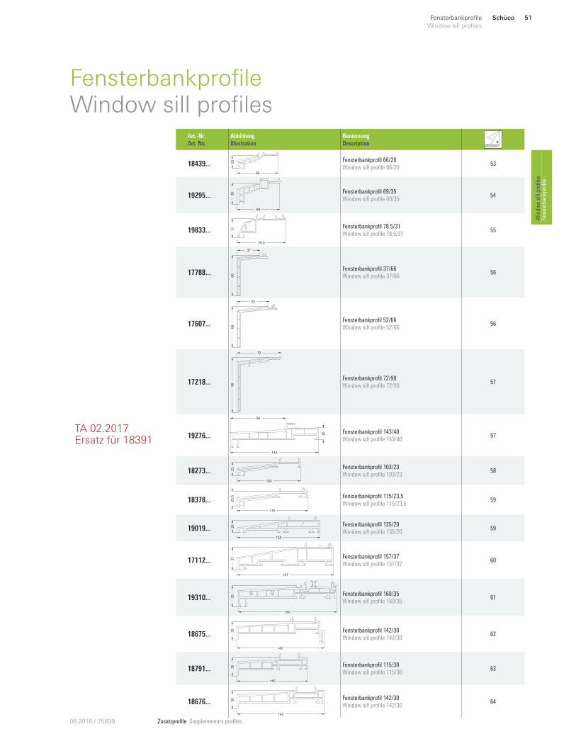
TA 02.2017Ersatz für 18391
Schüco 51Fensterbankprofile
Window sill profiles
Window sill profiles
Fensterbankprofile
FensterbankprofileWindow sill profiles
Art.-Nr.
Art. No.
Abbildung
Illustration
Benennung
Description
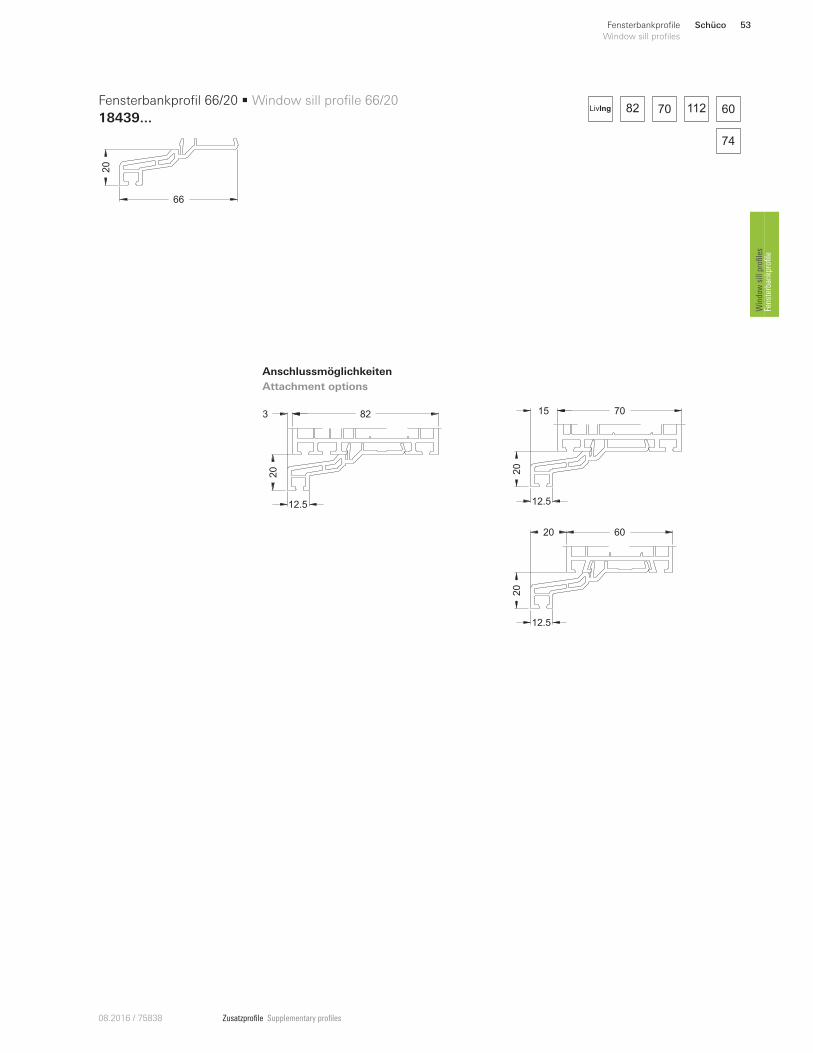
18439 ...66
20 Fensterbankprofil 66/20
Window sill profile 66/20 53
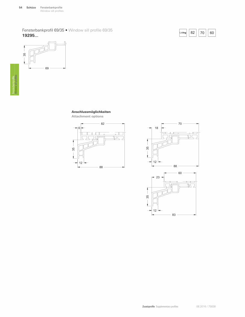
19295 ... 35
69
Fensterbankprofil 69/35
Window sill profile 69/35 54
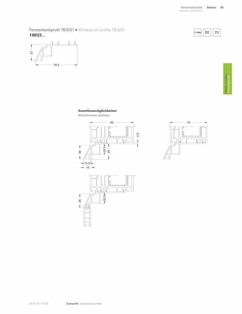
19833 ...
78.5
31 Fensterbankprofil 78.5/31
Window sill profile 78.5/31 55
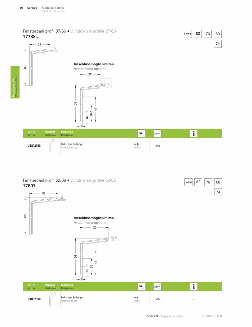
17788 ...
66
37
Fensterbankprofil 37/66
Window sill profile 37/66 56
17607 ...
66
52
Fensterbankprofil 52/66
Window sill profile 52/66 56
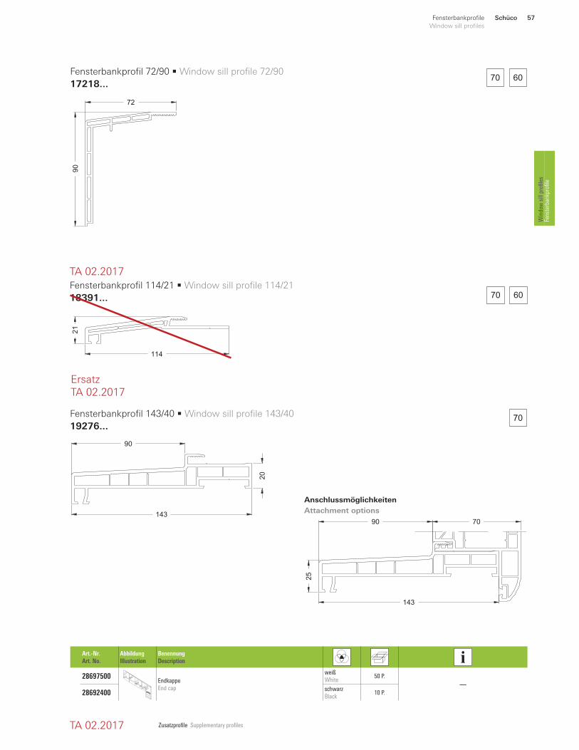
17218 ...
90
72
Fensterbankprofil 72/90
Window sill profile 72/90 57
19276...
143
20
90
Fensterbankprofil 143/40
Window sill profile 143/4057
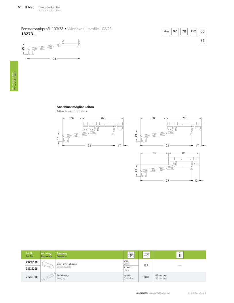
18273 ...
103
23 Fensterbankprofil 103/23
Window sill profile 103/23 58
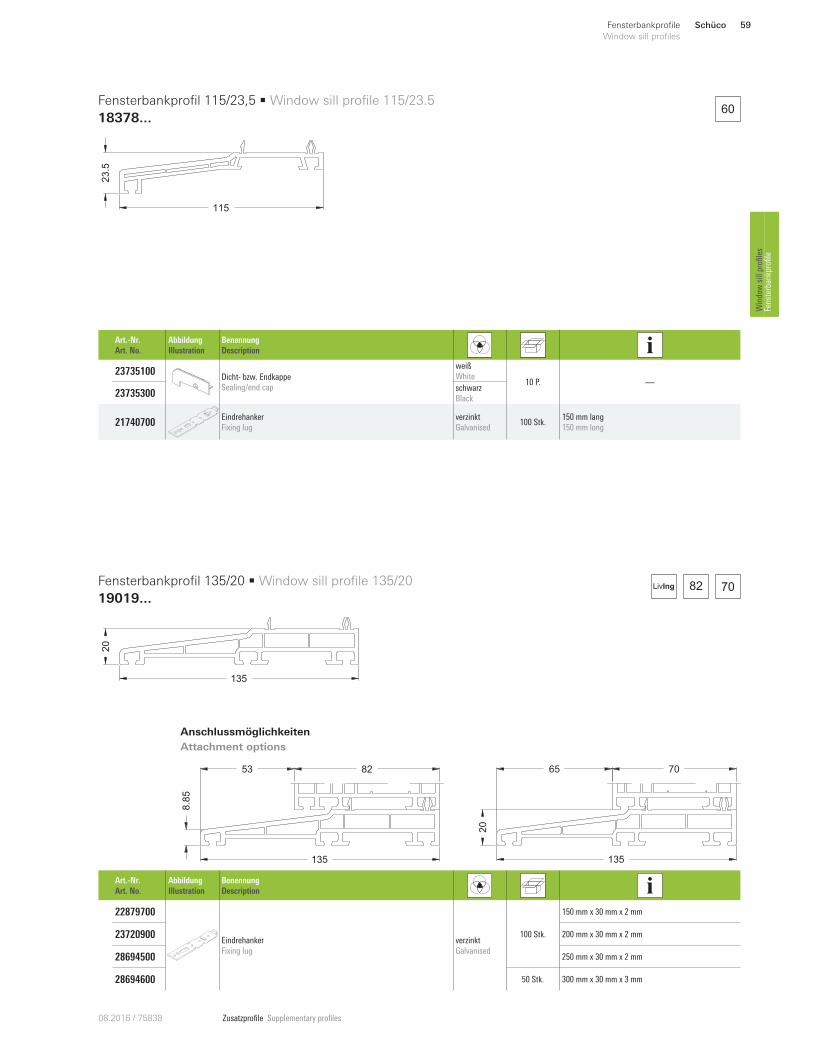
18378 ... 23.5
115
Fensterbankprofil 115/23,5
Window sill profile 115/23.5 59
19019 ...135
20 Fensterbankprofil 135/20
Window sill profile 135/20 59
17112 ...
157
37 Fensterbankprofil 157/37
Window sill profile 157/37 60
19310 ... 35
160
Fensterbankprofil 160/35
Window sill profile 160/35 61
18675 ...
142
30 Fensterbankprofil 142/30
Window sill profile 142/30 62
18791 ... 30
115
Fensterbankprofil 115/30
Window sill profile 115/30 63
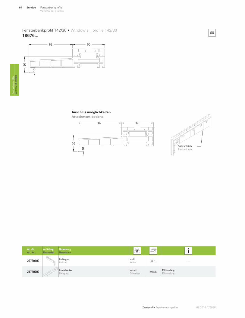
18676 ...
142
30 Fensterbankprofil 142/30
Window sill profile 142/30 64
Zusatzprofile Supplementary profiles 08.2016 / 75838
Schüco52 Fensterbankprofile
Window sill profiles Fensterbankprofile
Window sill profiles
Hinweis:
Die in diesem Kompendium dargestellten An-
schlussmöglichkeiten sollen lediglich verdeut-
lichen, bei welchem Fenstersystem(en) und an
welcher Stelle die jeweiligen Zusatzprofile ge-
nutzt bzw. angebracht werden können. Die zur
korrekten Montage benötigten Verstärkungen,
Befestigungen und Abdichtungen werden
nicht dargestellt.
Note:
The attachment options shown in this chapter
are merely to illustrate for which window
system(s) and in which location the relevant
supplementary profiles can be used and at-
tached. The reinforcements, fixings and seals
required for correct installation are not shown.
Zusatzprofile Supplementary profiles08.2016 / 75838
15
20
12.5
703
20
12.5
82
20
20
12.5
60
82 70 112 60
74
LivIng
Schüco 53Fensterbankprofile
Window sill profiles
Window sill profiles
Fensterbankprofile
66
20
Fensterbankprofil 66/20 • Window sill profile 66/20
18439 ...
Anschlussmöglichkeiten
Attachment options
Zusatzprofile Supplementary profiles 08.2016 / 75838
6
82
35
88
12
70
35
18
88
12
60
35
23
83
12
82 70 60LivIng
Schüco54 Fensterbankprofile
Window sill profiles Fensterbankprofile
Window sill profiles
35
69
Fensterbankprofil 69/35 • Window sill profile 69/35
19295 ...
Anschlussmöglichkeiten
Attachment options
Zusatzprofile Supplementary profiles08.2016 / 75838
7082
26
2.5
12.5
15
20.5
29
26 20.5
82 70LivIng
Schüco 55Fensterbankprofile
Window sill profiles
Window sill profiles
Fensterbankprofile
78.5
31
Fensterbankprofil 78.5/31 • Window sill profile 78.5/31
19833 ...
Anschlussmöglichkeiten
Attachment options
Zusatzprofile Supplementary profiles 08.2016 / 75838
3766
5
15 3
0.5
46
52
5
66
15
30
45
82 70 60
74
LivIng
82 70 60
74
LivIng
Anschlussmöglichkeiten
Attachment options
Anschlussmöglichkeiten
Attachment options
66
37
66
52
Fensterbankprofil 37/66 • Window sill profile 37/66
17788...
Fensterbankprofil 52/66 • Window sill profile 52/66
17607...
Art.-Nr.
Art. No.
Abbildung
Illustration
Benennung
Description
21893900 Dicht- bzw. Endkappe
Sealing/end cap
weiß
White 5 Pa —
Art.-Nr.
Art. No.
Abbildung
Illustration
Benennung
Description
21852300 Dicht- bzw. Endkappe
Sealing/end cap
weiß
White 5 Pa —
Schüco56 Fensterbankprofile
Window sill profiles Fensterbankprofile
Window sill profiles
Zusatzprofile Supplementary profiles08.2016 / 75838
Anschlussmöglichkeiten
Attachment options
90
72
114
21
143
20
90
Fensterbankprofil 72/90 • Window sill profile 72/90
17218...
Fensterbankprofil 114/21 • Window sill profile 114/21
18391...
Fensterbankprofil 143/40 • Window sill profile 143/40
19276...
Art.-Nr.
Art. No.
Abbildung
Illustration
Benennung
Description
28697500 Endkappe
End cap
weiß
White 50 P.
—
28692400 schwarz
Black 10 P.
70 60
70 60
70
TA 02.2017
TA 02.2017
Ersatz
TA 02.2017
7090
25
143
Schüco 57Fensterbankprofile
Window sill profiles
Window sill profiles
Fensterbankprofile
Zusatzprofile Supplementary profiles 08.2016 / 75838
50
103
23
70
17
38
103
82
17
13
55
103
23
60
12
82 70 112 60
74
LivIng
103
23
Fensterbankprofil 103/23 • Window sill profile 103/23
18273 ...
Anschlussmöglichkeiten
Attachment options
Art.-Nr.
Art. No.
Abbildung
Illustration
Benennung
Description
23735100 Dicht- bzw. Endkappe
Sealing/end cap
weiß
White 10 P. —
23735300 schwarz
Black
21740700 Eindrehanker
Fixing lug
verzinkt
Galvanised 100 Stk.
150 mm lang
150 mm long
Schüco58 Fensterbankprofile
Window sill profiles Fensterbankprofile
Window sill profiles
Zusatzprofile Supplementary profiles08.2016 / 75838
Art.-Nr.
Art. No.
Abbildung
Illustration
Benennung
Description
23735100 Dicht- bzw. Endkappe
Sealing/end cap
weiß
White 10 P. —
23735300 schwarz
Black
21740700 Eindrehanker
Fixing lug
verzinkt
Galvanised 100 Stk.
150 mm lang
150 mm long
65
135
20
7053
8.8
5
135
82
60
82 70LivIng
Anschlussmöglichkeiten
Attachment options
23.5
115
135
20
Fensterbankprofil 115/23,5 • Window sill profile 115/23.5
18378...
Fensterbankprofil 135/20 • Window sill profile 135/20
19019...
Art.-Nr.
Art. No.
Abbildung
Illustration
Benennung
Description
22879700
Eindrehanker
Fixing lug
verzinkt
Galvanised
100 Stk.
150 mm x 30 mm x 2 mm
23720900 200 mm x 30 mm x 2 mm
28694500 250 mm x 30 mm x 2 mm
28694600 50 Stk. 300 mm x 30 mm x 3 mm
Schüco 59Fensterbankprofile
Window sill profiles
Window sill profiles
Fensterbankprofile
Zusatzprofile Supplementary profiles 08.2016 / 75838
157
37
7087
157
21.4
8275
7
157
37
6097
82 70 60LivIng
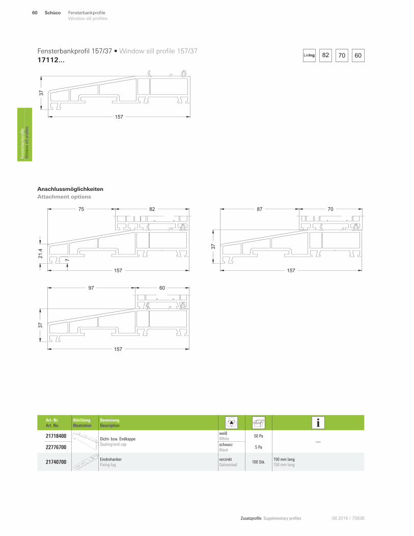
157
37
Fensterbankprofil 157/37 • Window sill profile 157/37
17112 ...
Anschlussmöglichkeiten
Attachment options
Art.-Nr.
Art. No.
Abbildung
Illustration
Benennung
Description
21718400 Dicht- bzw. Endkappe
Sealing/end cap
weiß
White 50 Pa
—
22776700 schwarz
Black 5 Pa
21740700 Eindrehanker
Fixing lug
verzinkt
Galvanised 100 Stk.
150 mm lang
150 mm long
Schüco60 Fensterbankprofile
Window sill profiles Fensterbankprofile
Window sill profiles
Zusatzprofile Supplementary profiles08.2016 / 75838
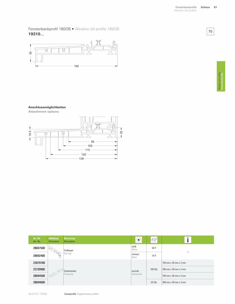
35
160
Fensterbankprofil 160/35 • Window sill profile 160/35
19310 ...
Anschlussmöglichkeiten
Attachment options
70
105
139
95
115
130
20
16.5
Art.-Nr.
Art. No.
Abbildung
Illustration
Benennung
Description
28697500 Endkappe
End cap
weiß
White 50 P.
—
28692400 schwarz
Black 10 P.
22879700
Eindrehanker
Fixing lug
verzinkt
Galvanised
100 Stk.
150 mm x 30 mm x 2 mm
23720900 200 mm x 30 mm x 2 mm
28694500 250 mm x 30 mm x 2 mm
28694600 50 Stk. 300 mm x 30 mm x 3 mm
Schüco 61Fensterbankprofile
Window sill profiles
Window sill profiles
Fensterbankprofile
Zusatzprofile Supplementary profiles 08.2016 / 75838
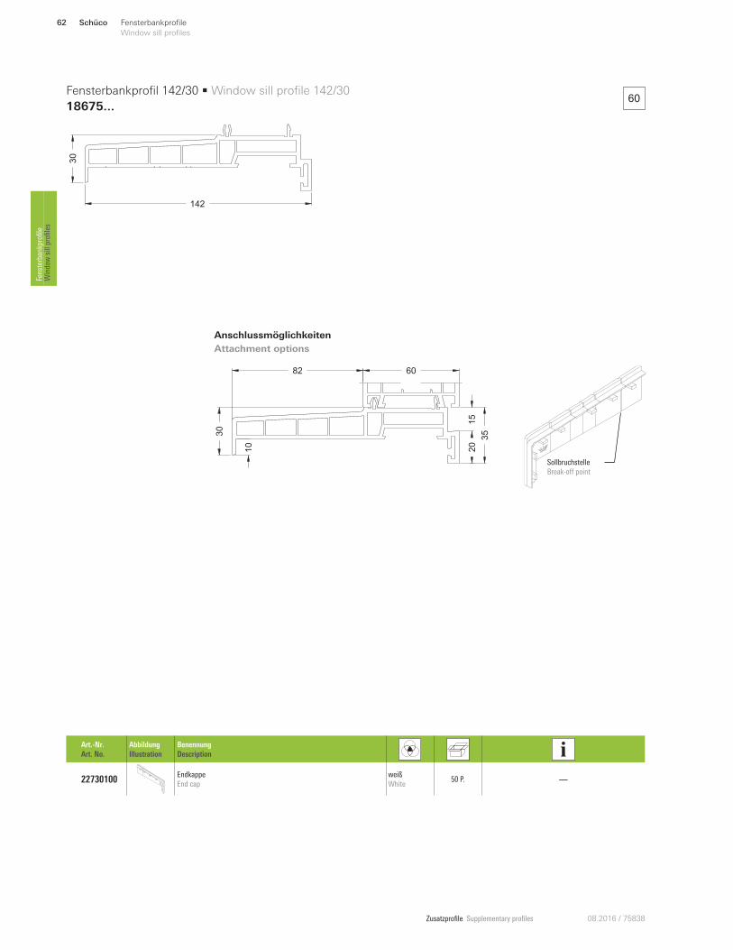
60
142
30
Fensterbankprofil 142/30 • Window sill profile 142/30
18675 ...
Anschlussmöglichkeiten
Attachment options
Art.-Nr.
Art. No.
Abbildung
Illustration
Benennung
Description
22730100 Endkappe
End cap
weiß
White 50 P. —
82 60
3530
10
20
15
Sollbruchstelle
Break-oQ point
Schüco62 Fensterbankprofile
Window sill profiles Fensterbankprofile
Window sill profiles
Zusatzprofile Supplementary profiles08.2016 / 75838
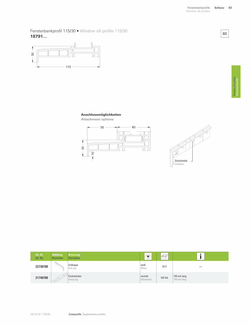
6030
115
Fensterbankprofil 115/30 • Window sill profile 115/30
18791...
Anschlussmöglichkeiten
Attachment options
55
30
60
10
Art.-Nr.
Art. No.
Abbildung
Illustration
Benennung
Description
22730100 Endkappe
End cap
weiß
White 50 P. —
21740700 Eindrehanker
Fixing lug
verzinkt
Galvanised 100 Stk.
150 mm lang
150 mm long
Schnittstelle
Interface
Schüco 63Fensterbankprofile
Window sill profiles
Window sill profiles
Fensterbankprofile
Zusatzprofile Supplementary profiles 08.2016 / 75838
60
30
82 60
10
Fensterbankprofil 142/30 • Window sill profile 142/30
18676...
Sollbruchstelle
Break-oQ point
30
82 60
10
Anschlussmöglichkeiten
Attachment options
Art.-Nr.
Art. No.
Abbildung
Illustration
Benennung
Description
22730100 Endkappe
End cap
weiß
White 50 P. —
21740700 Eindrehanker
Fixing lug
verzinkt
Galvanised 100 Stk.
150 mm lang
150 mm long
Schüco64 Fensterbankprofile
Window sill profiles Fensterbankprofile
Window sill profiles
Zusatzprofile Supplementary profiles08.2016 / 75838
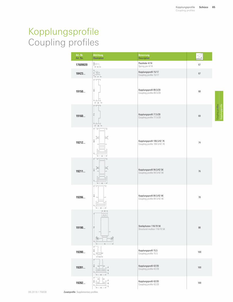
Schüco 65Kopplungsprofile
Coupling profiles
Coupling profiles
Kopplungsprofile
KopplungsprofileCoupling profiles
Art.-Nr.
Art. No.
Abbildung
Illustration
Benennung
Description
17609020 14
4 Passfeder 4/14
Spring pin 4/14 67
18423 ...17
15 Kopplungsprofil 15/17
Coupling profile 15/17 67
19150 ... 89.5
20
Kopplungsprofil 89,5/20
Coupling profile 89.5/20 68
19160 ... 77.5
20
Kopplungsprofil 77,5/20
Coupling profile 77.5/20 69
19212 ... 106.5
42
Kopplungsprofil 106,5/42 7K
Coupling profile 106.5/42 7K 74
19211 ... 94.5
42
Kopplungsprofil 94,5/42 5K
Coupling profile 94.5/42 5K 76
19206 ... 84.5
42
Kopplungsprofil 84,5/42 4K
Coupling profile 84.5/42 4K 78
19190 ...
70
116
24
Statikpfosten 116/70 5K
Structural mullion 116/70 5K 88
19280 ...
15.5
35.5 Kopplungsprofil 15,5
Coupling profile 15.5 100
19281 ... 55.5
42
20
Kopplungsprofil 42/20
Coupling profile 42/20 100
19282 ... 35.5
42
20
Kopplungsprofil 42/20
Coupling profile 42/20 100
Zusatzprofile Supplementary profiles 08.2016 / 75838
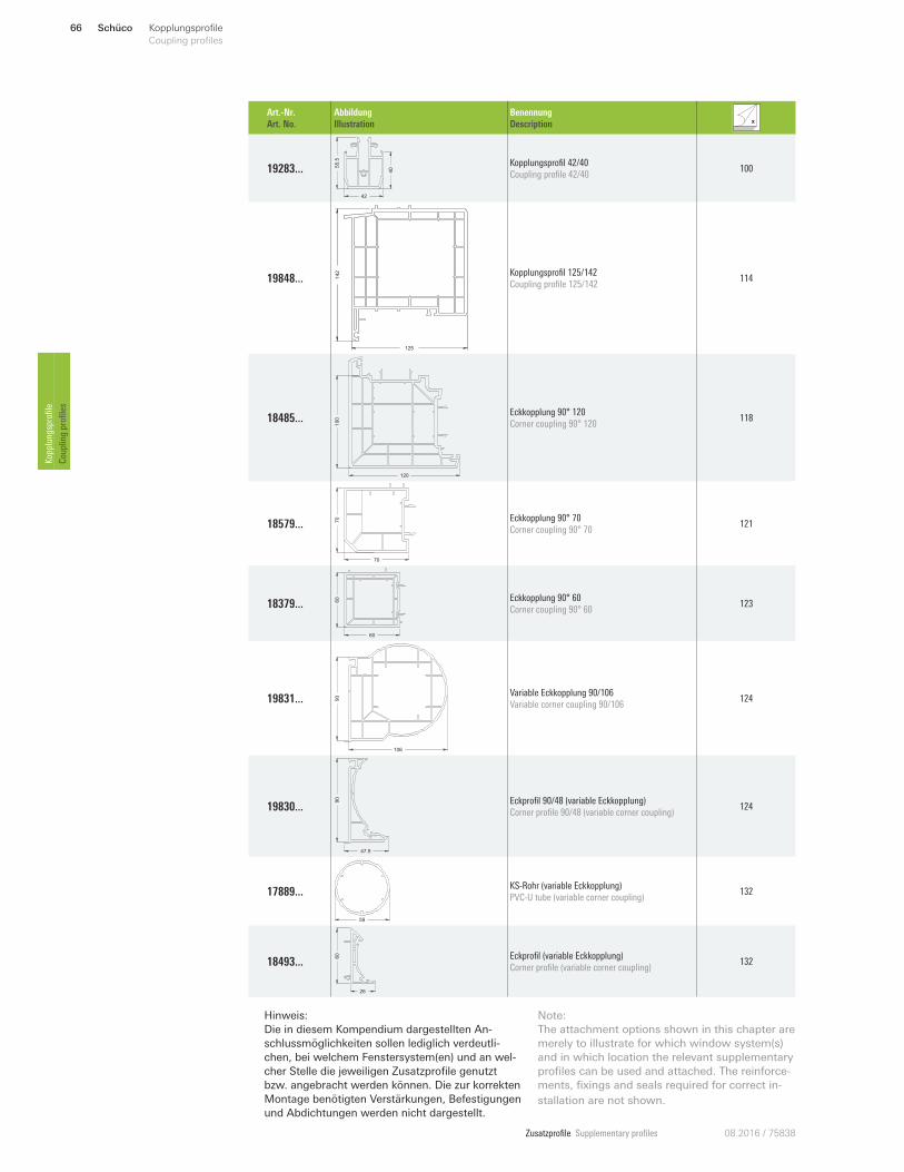
Schüco66 Kopplungsprofile
Coupling profiles Kopplungsprofile
Coupling profiles
Hinweis: Die in diesem Kompendium dargestellten An-schlussmöglichkeiten sollen lediglich verdeutli-chen, bei welchem Fenstersystem(en) und an wel-cher Stelle die jeweiligen Zusatzprofile genutzt bzw. angebracht werden können. Die zur korrekten Montage benötigten Verstärkungen, Befestigungen und Abdichtungen werden nicht dargestellt.
Note:The attachment options shown in this chapter are merely to illustrate for which window system(s) and in which location the relevant supplementary profiles can be used and attached. The reinforce-ments, fixings and seals required for correct in-
stallation are not shown.
Art.-Nr.
Art. No.
Abbildung
Illustration
Benennung
Description
19283 ...
42
405
5.5 Kopplungsprofil 42/40
Coupling profile 42/40 100
19848 ...
125
142 Kopplungsprofil 125/142
Coupling profile 125/142 114
18485 ...
120
100
Eckkopplung 90° 120
Corner coupling 90° 120 118
18579 ...
70
70 Eckkopplung 90° 70
Corner coupling 90° 70 121
18379 ...
60
60 Eckkopplung 90° 60
Corner coupling 90° 60 123
19831 ...
106
90
Variable Eckkopplung 90/106
Variable corner coupling 90/106 124
19830 ...
90
47.9
Eckprofil 90/48 (variable Eckkopplung)
Corner profile 90/48 (variable corner coupling) 124
17889 ...
59
KS-Rohr (variable Eckkopplung)
PVC-U tube (variable corner coupling) 132
18493 ...
26
60 Eckprofil (variable Eckkopplung)
Corner profile (variable corner coupling) 132
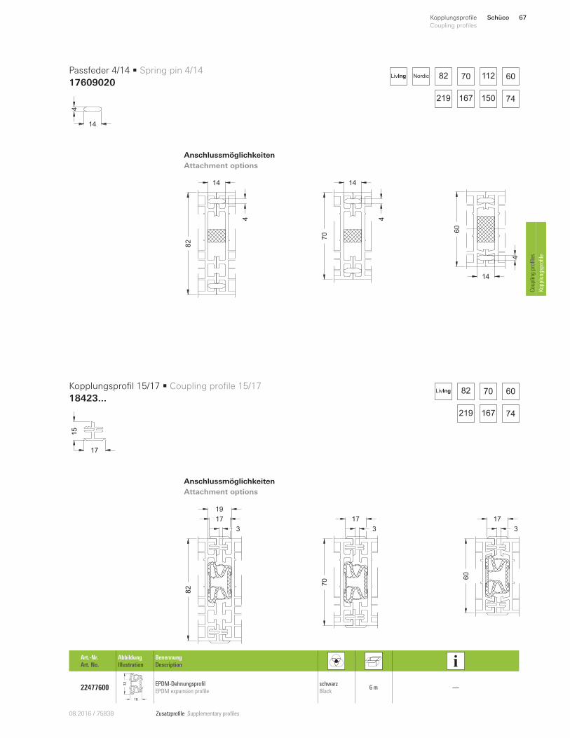
Zusatzprofile Supplementary profiles08.2016 / 75838
82
14
4
70
14
4
60
14
4
70
3
17
82
3
17
19
60
3
17
82 70 112 60
167 74150219
NordicLivIng
82 70 60
167 74219
LivIng
Schüco 67Kopplungsprofile
Coupling profiles
Coupling profiles
Kopplungsprofile
14
4
17
15
Passfeder 4/14 • Spring pin 4/14
17609020
Kopplungsprofil 15/17 • Coupling profile 15/17
18423...
Anschlussmöglichkeiten
Attachment options
Anschlussmöglichkeiten
Attachment options
Art.-Nr.
Art. No.
Abbildung
Illustration
Benennung
Description
22477600
18
32 EPDM-Dehnungsprofil
EPDM expansion profile
schwarz
Black 6 m —
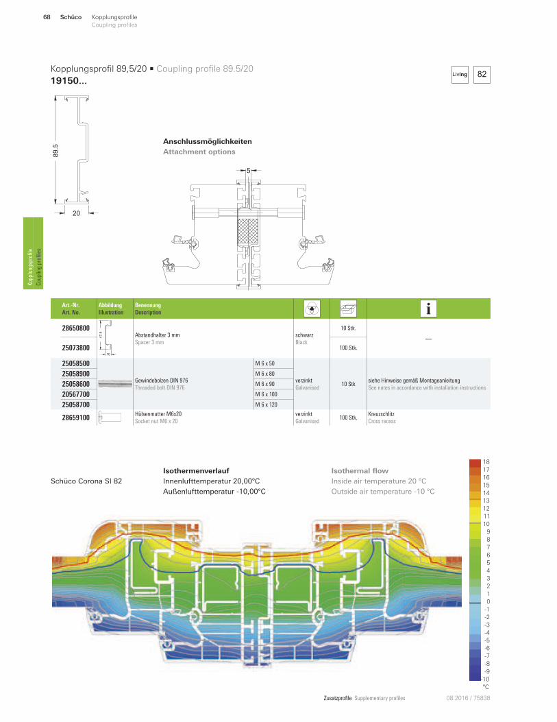
Zusatzprofile Supplementary profiles 08.2016 / 75838
Anschlussmöglichkeiten
Attachment options
5
Isothermenverlauf
Innenlufttemperatur 20,00°C
Außenlufttemperatur -10,00°C
Inside air temperature 20 °C
Outside air temperature -10 °C
Schüco Corona SI 82
18
16
12
11
10
9
8
6
1
5
4
3
0
-6
-9
-10
°C
2
-5
7
13
15
14
-2
-3
-4
-1
-7
-8
17
82LivIng
Art.-Nr.
Art. No.
Abbildung
Illustration
Benennung
Description
28650800
47
.5
10
Abstandhalter 3 mm
Spacer 3 mm
schwarz
Black
10 Stk.
—
25073800 100 Stk.
250585 00
Gewindebolzen DIN 976
Threaded bolt DIN 976
M 6 x 50
verzinkt
Galvanised 10 Stk
siehe Hinweise gemäß Montageanleitung
See notes in accordance with installation instructions
250589 00 M 6 x 80
250586 00 M 6 x 90
205677 00 M 6 x 100
250587 00 M 6 x 120
28659100 Hülsenmutter M6x20
Socket nut M6 x 20
verzinkt
Galvanised 100 Stk.
Kreuzschlitz
Cross recess
89.5
20
Kopplungsprofil 89,5/20 • Coupling profile 89.5/20
19150...
Isothermal flow
Schüco68 Kopplungsprofile
Coupling profiles Kopplungsprofile
Coupling profiles
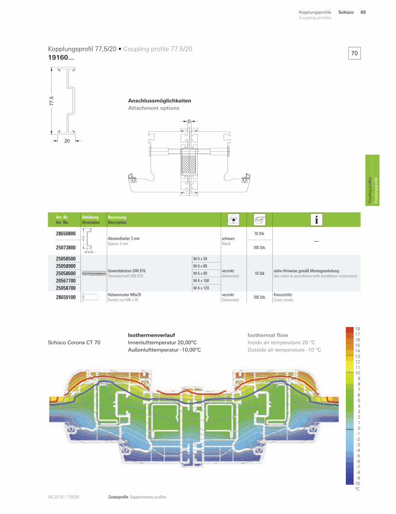
Zusatzprofile Supplementary profiles08.2016 / 75838
Anschlussmöglichkeiten
Attachment options
Isothermenverlauf
Innenlufttemperatur 20,00°C
Außenlufttemperatur -10,00°C
Inside air temperature 20 °C
Outside air temperature -10 °C
Schüco Corona CT 70
18
16
12
11
10
9
8
6
1
5
4
3
0
-6
-9
-10
°C
2
-5
7
13
15
14
-2
-3
-4
-1
-7
-8
17
Art.-Nr.
Art. No.
Abbildung
Illustration
Benennung
Description
28650800
47
.5
10
Abstandhalter 3 mm
Spacer 3 mm
schwarz
Black
10 Stk.
—
25073800 100 Stk.
250585 00
Gewindebolzen DIN 976
Threaded bolt DIN 976
M 6 x 50
verzinkt
Galvanised 10 Stk
siehe Hinweise gemäß Montageanleitung
See notes in accordance with installation instructions
250589 00 M 6 x 80
250586 00 M 6 x 90
205677 00 M 6 x 100
250587 00 M 6 x 120
28659100 Hülsenmutter M6x20
Socket nut M6 x 20
verzinkt
Galvanised 100 Stk.
Kreuzschlitz
Cross recess
77.5
20
Kopplungsprofil 77,5/20 • Coupling profile 77.5/20
19160...
5
70
Isothermal flow
Schüco 69Kopplungsprofile
Coupling profiles
Coupling profiles
Kopplungsprofile
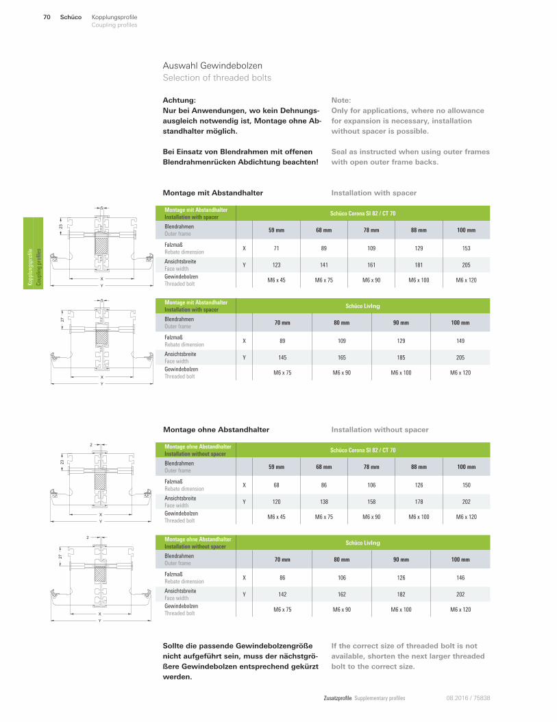
Zusatzprofile Supplementary profiles 08.2016 / 75838
Auswahl Gewindebolzen
Selection of threaded bolts
23
X
Y
5
27
X
Y
5
Montage mit Abstandhalter
Montage ohne Abstandhalter
23
2
X
Y
27
X
Y
2
Sollte die passende Gewindebolzengröße
nicht aufgeführt sein, muss der nächstgrö-
ßere Gewindebolzen entsprechend gekürzt
werden.
If the correct size of threaded bolt is not
available, shorten the next larger threaded
bolt to the correct size.
Achtung:
Nur bei Anwendungen, wo kein Dehnungs-
ausgleich notwendig ist, Montage ohne Ab-
standhalter möglich.
Bei Einsatz von Blendrahmen mit oUenen
Blendrahmenrücken Abdichtung beachten!
Note:
Only for applications, where no allowance
for expansion is necessary, installation
without spacer is possible.
Seal as instructed when using outer frames
with open outer frame backs.
Montage mit Abstandhalter
Installation with spacer Schüco Corona SI 82 / CT 70
Blendrahmen
Outer frame 59 mm 68 mm 78 mm 88 mm 100 mm
Falzmaß
Rebate dimension X 71 89 109 129 153
Ansichtsbreite
Face width Y 123 141 161 181 205
Gewindebolzen
Threaded bolt M6 x 45 M6 x 75 M6 x 90 M6 x 100 M6 x 120
Montage mit Abstandhalter
Installation with spacer Schüco LivIng
Blendrahmen
Outer frame 70 mm 80 mm 90 mm 100 mm
Falzmaß
Rebate dimension X 89 109 129 149
Ansichtsbreite
Face width Y 145 165 185 205
Gewindebolzen
Threaded bolt M6 x 75 M6 x 90 M6 x 100 M6 x 120
Montage ohne Abstandhalter
Installation without spacer Schüco Corona SI 82 / CT 70
Blendrahmen
Outer frame 59 mm 68 mm 78 mm 88 mm 100 mm
Falzmaß
Rebate dimension X 68 86 106 126 150
Ansichtsbreite
Face width Y 120 138 158 178 202
Gewindebolzen
Threaded bolt M6 x 45 M6 x 75 M6 x 90 M6 x 100 M6 x 120
Montage ohne Abstandhalter
Installation without spacer Schüco LivIng
Blendrahmen
Outer frame 70 mm 80 mm 90 mm 100 mm
Falzmaß
Rebate dimension X 86 106 126 146
Ansichtsbreite
Face width Y 142 162 182 202
Gewindebolzen
Threaded bolt M6 x 75 M6 x 90 M6 x 100 M6 x 120
Installation with spacer
Installation without spacer
Schüco70 Kopplungsprofile
Coupling profiles Kopplungsprofile
Coupling profiles
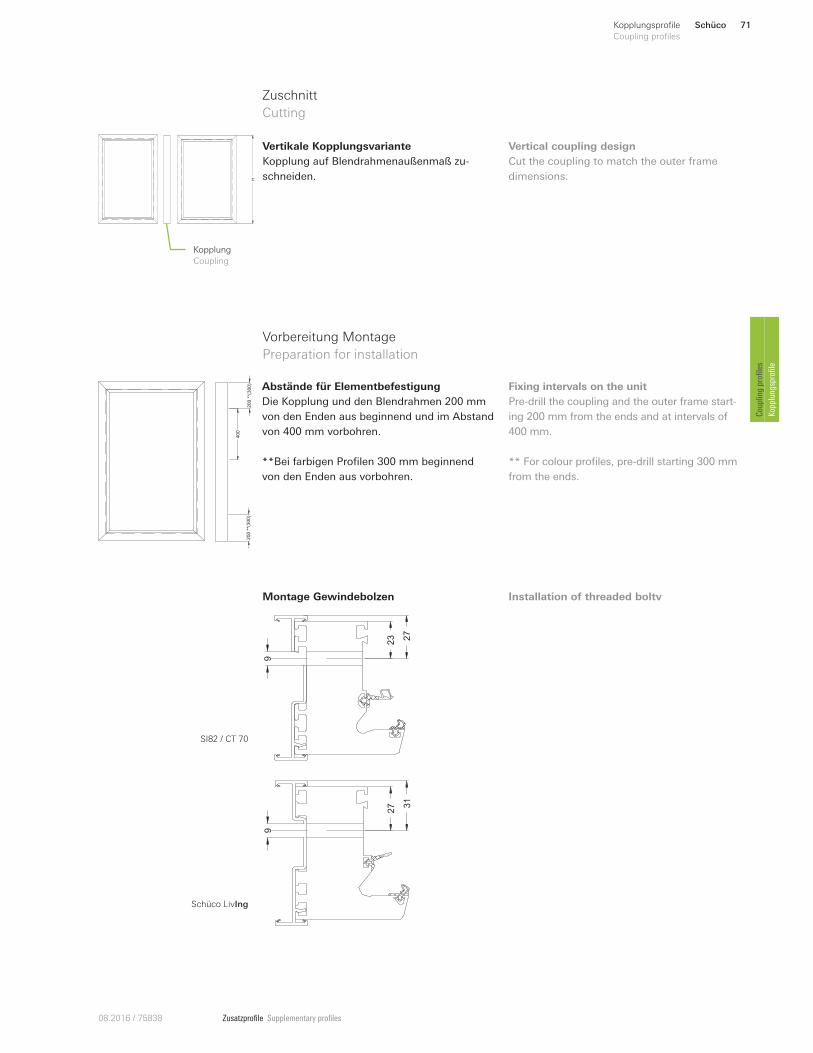
Zusatzprofile Supplementary profiles08.2016 / 75838
Zuschnitt
Cutting
HKopplung
Coupling
Vertikale Kopplungsvariante
Kopplung auf Blendrahmenaußenmaß zu-
schneiden.
Vertical coupling design
Cut the coupling to match the outer frame
dimensions.
200
**(3
00)
200
**(3
00)
400
9
27
23
9
31
27
Abstände für Elementbefestigung
Die Kopplung und den Blendrahmen 200 mm
von den Enden aus beginnend und im Abstand
von 400 mm vorbohren.
**Bei farbigen Profilen 300 mm beginnend
von den Enden aus vorbohren.
Fixing intervals on the unit
Pre-drill the coupling and the outer frame start-
ing 200 mm from the ends and at intervals of
400 mm.
** For colour profiles, pre-drill starting 300 mm
from the ends.
Vorbereitung Montage
Preparation for installation
Montage Gewindebolzen Installation of threaded boltv
SI82 / CT 70
Schüco LivIng
Schüco 71Kopplungsprofile
Coupling profiles
Coupling profiles
Kopplungsprofile
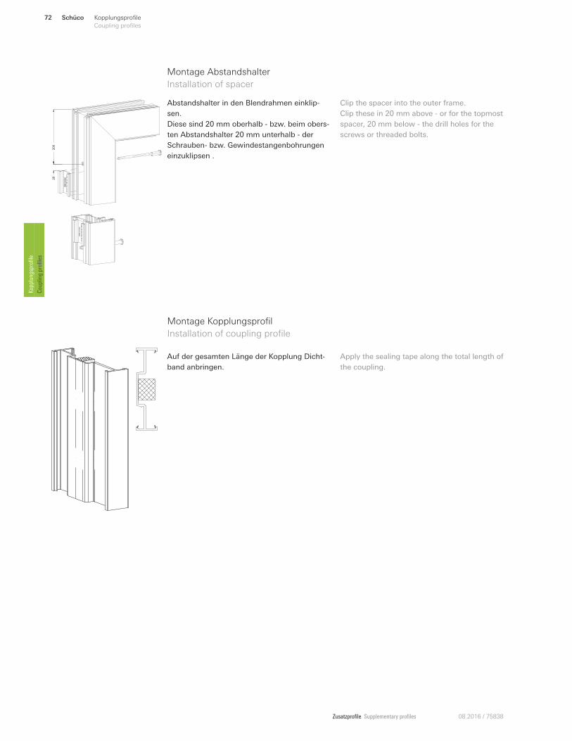
Zusatzprofile Supplementary profiles 08.2016 / 75838
Montage Abstandshalter
Installation of spacer
Abstandshalter in den Blendrahmen einklip-
sen.
Diese sind 20 mm oberhalb - bzw. beim obers-
ten Abstandshalter 20 mm unterhalb - der
Schrauben- bzw. Gewindestangenbohrungen
einzuklipsen .
20
200
Clip the spacer into the outer frame.
Clip these in 20 mm above - or for the topmost
spacer, 20 mm below - the drill holes for the
screws or threaded bolts.
Montage Kopplungsprofil
Installation of coupling profile
Auf der gesamten Länge der Kopplung Dicht-
band anbringen.
Apply the sealing tape along the total length of
the coupling.
Schüco72 Kopplungsprofile
Coupling profiles Kopplungsprofile
Coupling profiles
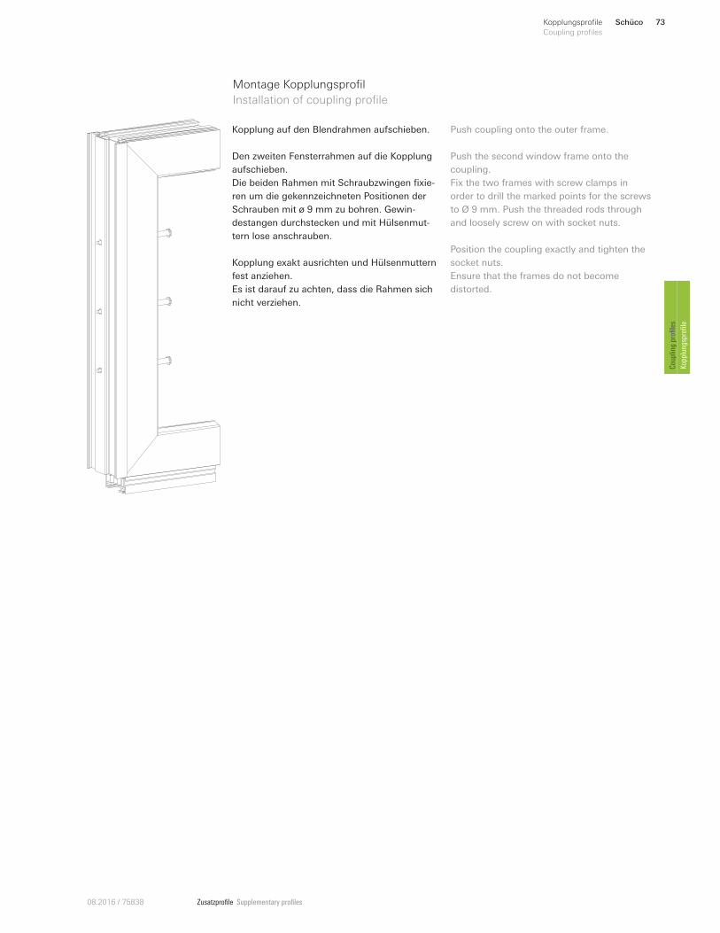
Zusatzprofile Supplementary profiles08.2016 / 75838
Montage Kopplungsprofil
Installation of coupling profile
Kopplung auf den Blendrahmen aufschieben.
Den zweiten Fensterrahmen auf die Kopplung
aufschieben.
Die beiden Rahmen mit Schraubzwingen fixie-
ren um die gekennzeichneten Positionen der
Schrauben mit ø 9 mm zu bohren. Gewin-
destangen durchstecken und mit Hülsenmut-
tern lose anschrauben.
Kopplung exakt ausrichten und Hülsenmuttern
fest anziehen.
Es ist darauf zu achten, dass die Rahmen sich
nicht verziehen.
Push coupling onto the outer frame.
Push the second window frame onto the
coupling.
Fix the two frames with screw clamps in
order to drill the marked points for the screws
to Ø 9 mm. Push the threaded rods through
and loosely screw on with socket nuts.
Position the coupling exactly and tighten the
socket nuts.
Ensure that the frames do not become
distorted.
Schüco 73Kopplungsprofile
Coupling profiles
Coupling profiles
Kopplungsprofile
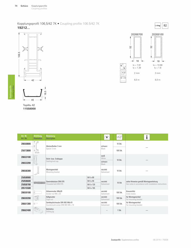
Zusatzprofile Supplementary profiles 08.2016 / 75838
20268700 20269100
52
18
52
18
x
y
Ix
Iy Ix = 7.81
Iy = 1.39
Ix = 10.68
Iy = 1.8
2 mm 3 mm
x
6,0 m 6,0 m
82LivIng
106.5
42
45
18.5
TopAlu 42
11558000
Kopplungsprofil 106,5/42 7K • Coupling profile 106.5/42 7K
19212 ...
Art.-Nr.
Art. No.
Abbildung
Illustration
Benennung
Description
28650800
47
.5
10
Abstandhalter 3 mm
Spacer 3 mm
schwarz
Black
10 Stk.
—
25073800 100 Stk.
28653100 Dicht- bzw. Endkappe
Sealing/end cap
weiß
White 10 Stk. —
28653200 schwarz
Black
28658300 Montagewinkel
Mounting bracket
verzinkt
Galvanised 10 Stk. —
250589 00
Gewindebolzen DIN 976
Threaded bolt DIN 976
M 6 x 80
verzinkt
Galvanised 10 Stk
siehe Hinweise gemäß Montageanleitung
See notes in accordance with installation instructions
250586 00 M 6 x 90
250587 00 M 6 x 120
205155 00 M 6 x 165
28659100 Hülsenmutter M6x20
Socket nut M6 x 20
verzinkt
Galvanised 100 Stk.
Kreuzschlitz
Cross recess
28659200 Käfigmutter
Cage nut
verzinkt
Galvanised 100 Stk.
für Montagewinkel
For mounting bracket
28661300 Senkkopfschraube DIN 965 M6x10
Countersunk screw DIN 965 M6 x 10
verzinkt
Galvanised 100 Stk.
für Montagewinkel
For mounting bracket
28662400 Bohrlehre
Drilling jig — 1 Stk. —
Schüco74 Kopplungsprofile
Coupling profiles Kopplungsprofile
Coupling profiles
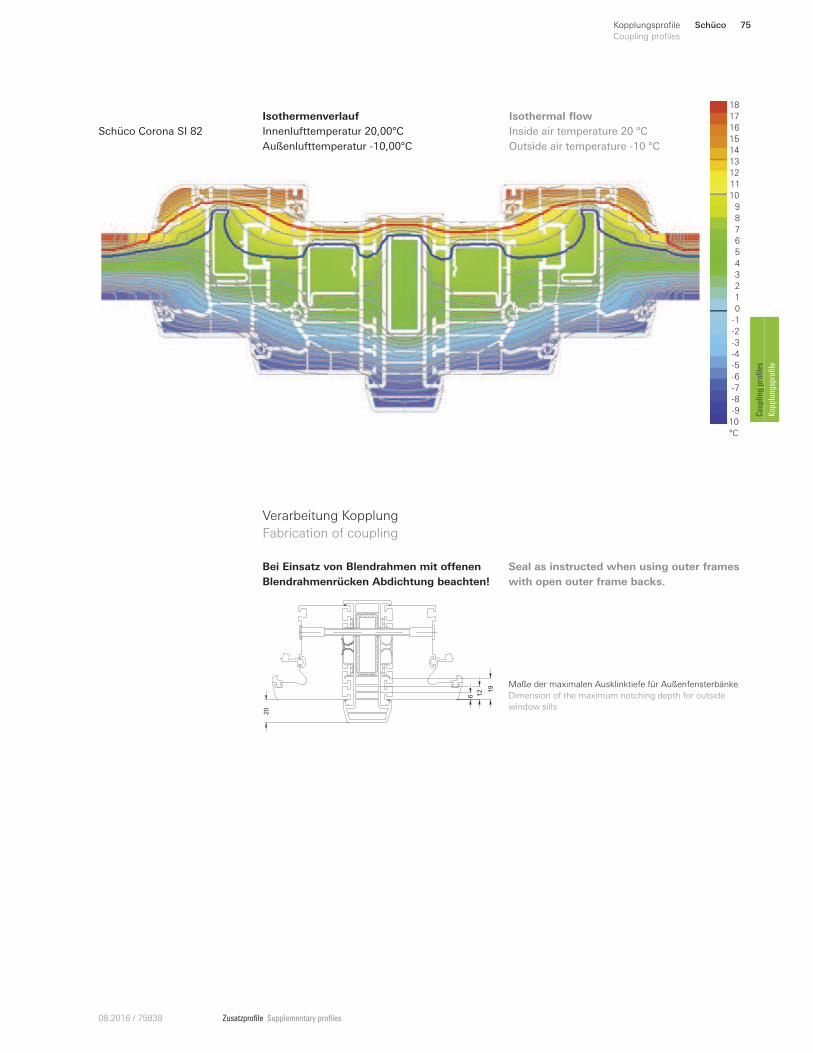
Zusatzprofile Supplementary profiles08.2016 / 75838
18
16
12
11
10
9
8
6
1
5
4
3
0
-6
-9
-10
°C
2
-5
7
13
15
14
-2
-3
-4
-1
-7
-8
17Isothermenverlauf
Innenlufttemperatur 20,00°C
Außenlufttemperatur -10,00°C
Inside air temperature 20 °C
Outside air temperature -10 °C
Schüco Corona SI 82
Isothermal flow
Verarbeitung Kopplung
Fabrication of coupling
6 12 1
9
20
Maße der maximalen Ausklinktiefe für Außenfensterbänke
Dimension of the maximum notching depth for outside
window sills
Bei Einsatz von Blendrahmen mit oUenen
Blendrahmenrücken Abdichtung beachten!
Seal as instructed when using outer frames
with open outer frame backs.
Schüco 75Kopplungsprofile
Coupling profiles
Coupling profiles
Kopplungsprofile

Zusatzprofile Supplementary profiles 08.2016 / 75838
70
20268700 20269100
52
18
52
18
x
y
Ix
Iy Ix = 7.81
Iy = 1.39
Ix = 10.68
Iy = 1.8
2 mm 3 mm
x
6,0 m 6,0 m
94.5
42
45
18.5
TopAlu 42
11558000
Kopplungsprofil 94,5/42 5K • Coupling profile 94.5/42 5K
19211 ...
Art.-Nr.
Art. No.
Abbildung
Illustration
Benennung
Description
28650800
47
.5
10
Abstandhalter 3 mm
Spacer 3 mm
schwarz
Black
10 Stk.
—
25073800 100 Stk.
28654700 Dicht- bzw. Endkappe
Sealing/end cap
weiß
White 10 Stk. —
28654800 schwarz
Black
28658300 Montagewinkel
Mounting bracket
verzinkt
Galvanised 10 Stk. —
250589 00
Gewindebolzen DIN 976
Threaded bolt DIN 976
M 6 x 80
verzinkt
Galvanised 10 Stk
siehe Hinweise gemäß Montageanleitung
See notes in accordance with installation instructions
250586 00 M 6 x 90
250587 00 M 6 x 120
205155 00 M 6 x 165
28659100 Hülsenmutter M6x20
Socket nut M6 x 20
verzinkt
Galvanised 100 Stk.
Kreuzschlitz
Cross recess
28659200 Käfigmutter
Cage nut
verzinkt
Galvanised 100 Stk.
für Montagewinkel
For mounting bracket
28661300 Senkkopfschraube DIN 965 M6x10
Countersunk screw DIN 965 M6 x 10
verzinkt
Galvanised 100 Stk.
für Montagewinkel
For mounting bracket
28662400 Bohrlehre
Drilling jig — 1 Stk. —
Schüco76 Kopplungsprofile
Coupling profiles Kopplungsprofile
Coupling profiles
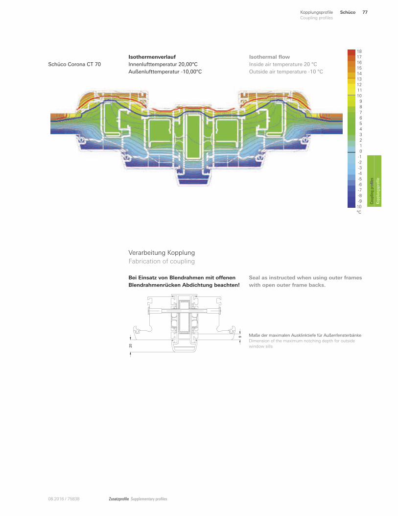
Zusatzprofile Supplementary profiles08.2016 / 75838
18
16
12
11
10
9
8
6
1
5
4
3
0
-6
-9
-10
°C
2
-5
7
13
15
14
-2
-3
-4
-1
-7
-8
17Isothermenverlauf
Innenlufttemperatur 20,00°C
Außenlufttemperatur -10,00°C
Inside air temperature 20 °C
Outside air temperature -10 °C
Schüco Corona CT 70
Isothermal flow
Verarbeitung Kopplung
Fabrication of coupling
Maße der maximalen Ausklinktiefe für Außenfensterbänke
Dimension of the maximum notching depth for outside
window sills
Bei Einsatz von Blendrahmen mit oUenen
Blendrahmenrücken Abdichtung beachten!
Seal as instructed when using outer frames
with open outer frame backs.
9
20
Schüco 77Kopplungsprofile
Coupling profiles
Coupling profiles
Kopplungsprofile
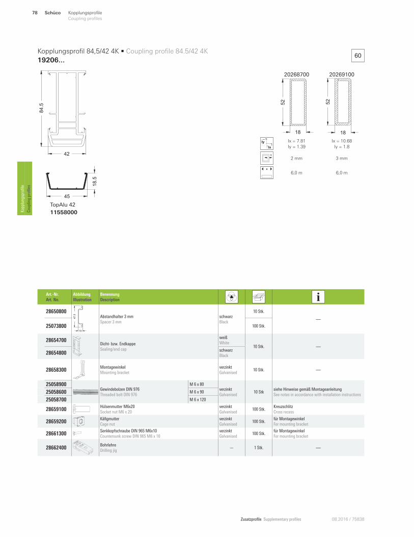
Zusatzprofile Supplementary profiles 08.2016 / 75838
60
20268700 20269100
52
18
52
18
x
y
Ix
Iy Ix = 7.81
Iy = 1.39
Ix = 10.68
Iy = 1.8
2 mm 3 mm
x
6,0 m 6,0 m
84.5
42
45
18.5
TopAlu 42
11558000
Kopplungsprofil 84,5/42 4K • Coupling profile 84.5/42 4K
19206 ...
Art.-Nr.
Art. No.
Abbildung
Illustration
Benennung
Description
28650800
47
.5
10
Abstandhalter 3 mm
Spacer 3 mm
schwarz
Black
10 Stk.
—
25073800 100 Stk.
28654700 Dicht- bzw. Endkappe
Sealing/end cap
weiß
White 10 Stk. —
28654800 schwarz
Black
28658300 Montagewinkel
Mounting bracket
verzinkt
Galvanised 10 Stk. —
250589 00Gewindebolzen DIN 976
Threaded bolt DIN 976
M 6 x 80 verzinkt
Galvanised 10 Stk
siehe Hinweise gemäß Montageanleitung
See notes in accordance with installation instructions 250586 00 M 6 x 90
250587 00 M 6 x 120
28659100 Hülsenmutter M6x20
Socket nut M6 x 20
verzinkt
Galvanised 100 Stk.
Kreuzschlitz
Cross recess
28659200 Käfigmutter
Cage nut
verzinkt
Galvanised 100 Stk.
für Montagewinkel
For mounting bracket
28661300 Senkkopfschraube DIN 965 M6x10
Countersunk screw DIN 965 M6 x 10
verzinkt
Galvanised 100 Stk.
für Montagewinkel
For mounting bracket
28662400 Bohrlehre
Drilling jig — 1 Stk. —
Schüco78 Kopplungsprofile
Coupling profiles Kopplungsprofile
Coupling profiles
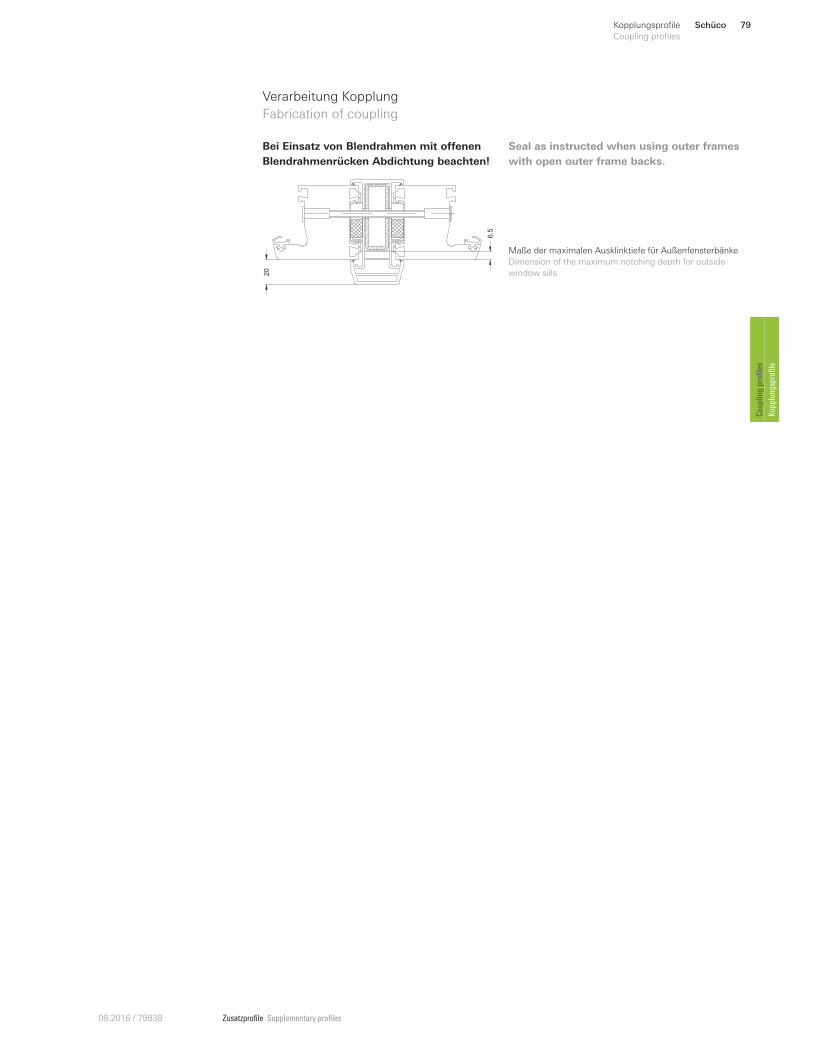
Zusatzprofile Supplementary profiles08.2016 / 75838
Verarbeitung Kopplung
Fabrication of coupling
Maße der maximalen Ausklinktiefe für Außenfensterbänke
Dimension of the maximum notching depth for outside
window sills
Bei Einsatz von Blendrahmen mit oUenen
Blendrahmenrücken Abdichtung beachten!
Seal as instructed when using outer frames
with open outer frame backs.
20
6.5
Schüco 79Kopplungsprofile
Coupling profiles
Coupling profiles
Kopplungsprofile
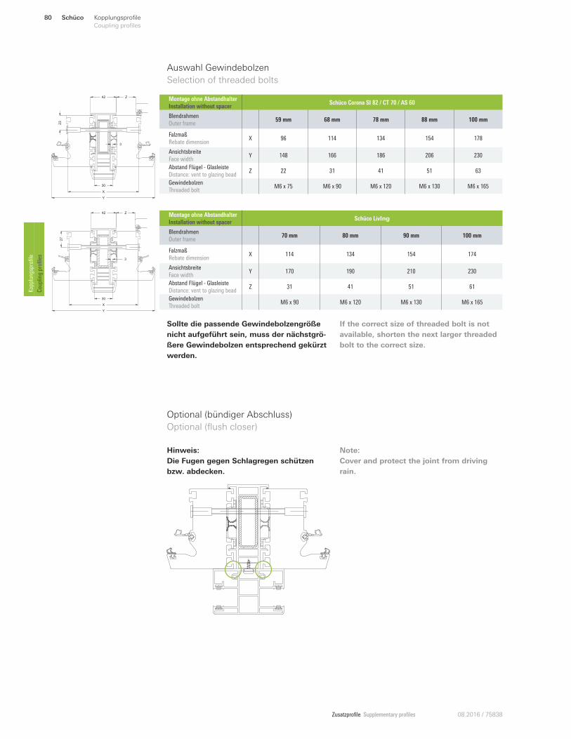
Zusatzprofile Supplementary profiles 08.2016 / 75838
Optional (bündiger Abschluss)
Optional (flush closer)
Hinweis:
Die Fugen gegen Schlagregen schützen
bzw. abdecken.
Note:
Cover and protect the joint from driving
rain.
Auswahl Gewindebolzen
Selection of threaded bolts
23
X
Y
30
3
Z42
27
X
Y
30
Z42
3
Sollte die passende Gewindebolzengröße
nicht aufgeführt sein, muss der nächstgrö-
ßere Gewindebolzen entsprechend gekürzt
werden.
If the correct size of threaded bolt is not
available, shorten the next larger threaded
bolt to the correct size.
Montage ohne Abstandhalter
Installation without spacer Schüco LivIng
Blendrahmen
Outer frame 70 mm 80 mm 90 mm 100 mm
Falzmaß
Rebate dimension X 114 134 154 174
Ansichtsbreite
Face width Y 170 190 210 230
Abstand Flügel - Glasleiste
Distance: vent to glazing bead Z 31 41 51 61
Gewindebolzen
Threaded bolt M6 x 90 M6 x 120 M6 x 130 M6 x 165
Montage ohne Abstandhalter
Installation without spacer Schüco Corona SI 82 / CT 70 / AS 60
Blendrahmen
Outer frame 59 mm 68 mm 78 mm 88 mm 100 mm
Falzmaß
Rebate dimension X 96 114 134 154 178
Ansichtsbreite
Face width Y 148 166 186 206 230
Abstand Flügel - Glasleiste
Distance: vent to glazing bead Z 22 31 41 51 63
Gewindebolzen
Threaded bolt M6 x 75 M6 x 90 M6 x 120 M6 x 130 M6 x 165
Schüco80 Kopplungsprofile
Coupling profiles Kopplungsprofile
Coupling profiles
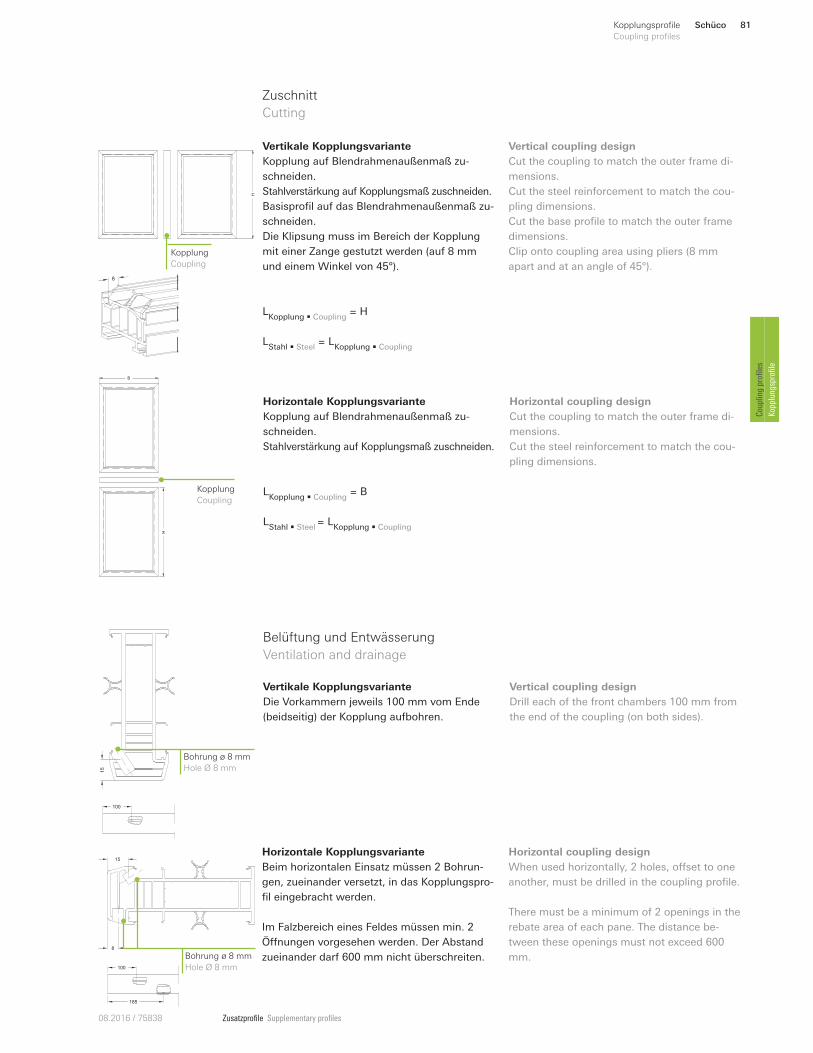
Zusatzprofile Supplementary profiles08.2016 / 75838
Horizontale Kopplungsvariante
Kopplung auf Blendrahmenaußenmaß zu-
schneiden.
Stahlverstärkung auf Kopplungsmaß zuschneiden.
Horizontal coupling design
Cut the coupling to match the outer frame di-
mensions.
Cut the steel reinforcement to match the cou-
pling dimensions.
H
B
Kopplung
Coupling L
Kopplung • Coupling = B
LStahl • Steel
= LKopplung • Coupling
Zuschnitt
Cutting
HKopplung
Coupling
Vertikale Kopplungsvariante
Kopplung auf Blendrahmenaußenmaß zu-
schneiden.
Stahlverstärkung auf Kopplungsmaß zuschneiden.
Basisprofil auf das Blendrahmenaußenmaß zu-
schneiden.
Die Klipsung muss im Bereich der Kopplung
mit einer Zange gestutzt werden (auf 8 mm
und einem Winkel von 45°).
Vertical coupling design
Cut the coupling to match the outer frame di-
mensions.
Cut the steel reinforcement to match the cou-
pling dimensions.
Cut the base profile to match the outer frame
dimensions.
Clip onto coupling area using pliers (8 mm
apart and at an angle of 45°). 8
LKopplung • Coupling
= H
LStahl • Steel
= LKopplung • Coupling
15
100
Bohrung ø 8 mm
Hole Ø 8 mm
Vertikale Kopplungsvariante
Die Vorkammern jeweils 100 mm vom Ende
(beidseitig) der Kopplung aufbohren.
Belüftung und Entwässerung
Ventilation and drainage
Vertical coupling design
Drill each of the front chambers 100 mm from
the end of the coupling (on both sides).
8
15
100
185
Bohrung ø 8 mm
Hole Ø 8 mm
Horizontale Kopplungsvariante
Beim horizontalen Einsatz müssen 2 Bohrun-
gen, zueinander versetzt, in das Kopplungspro-
fil eingebracht werden.
Im Falzbereich eines Feldes müssen min. 2
Önnungen vorgesehen werden. Der Abstand
zueinander darf 600 mm nicht überschreiten.
Horizontal coupling design
When used horizontally, 2 holes, onset to one
another, must be drilled in the coupling profile.
There must be a minimum of 2 openings in the
rebate area of each pane. The distance be-
tween these openings must not exceed 600
mm.
Schüco 81Kopplungsprofile
Coupling profiles
Coupling profiles
Kopplungsprofile
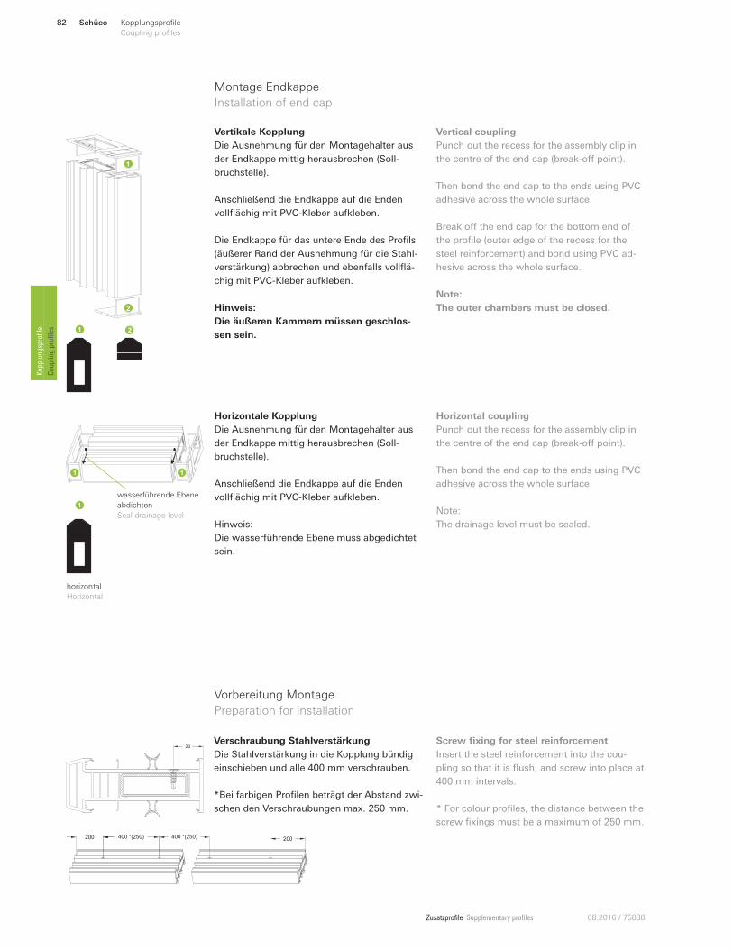
Zusatzprofile Supplementary profiles 08.2016 / 75838
Montage Endkappe
Installation of end cap
Vertikale Kopplung
Die Ausnehmung für den Montagehalter aus
der Endkappe mittig herausbrechen (Soll-
bruchstelle).
Anschließend die Endkappe auf die Enden
vollflächig mit PVC-Kleber aufkleben.
Die Endkappe für das untere Ende des Profils
(äußerer Rand der Ausnehmung für die Stahl-
verstärkung) abbrechen und ebenfalls vollflä-
chig mit PVC-Kleber aufkleben.
Hinweis:
Die äußeren Kammern müssen geschlos-
sen sein.
Vertical coupling
Punch out the recess for the assembly clip in
the centre of the end cap (break-on point).
Then bond the end cap to the ends using PVC
adhesive across the whole surface.
Break on the end cap for the bottom end of
the profile (outer edge of the recess for the
steel reinforcement) and bond using PVC ad-
hesive across the whole surface.
Note:
The outer chambers must be closed.
horizontal
Horizontal
Horizontale Kopplung
Die Ausnehmung für den Montagehalter aus
der Endkappe mittig herausbrechen (Soll-
bruchstelle).
Anschließend die Endkappe auf die Enden
vollflächig mit PVC-Kleber aufkleben.
Hinweis:
Die wasserführende Ebene muss abgedichtet
sein.
Horizontal coupling
Punch out the recess for the assembly clip in
the centre of the end cap (break-on point).
Then bond the end cap to the ends using PVC
adhesive across the whole surface.
Note:
The drainage level must be sealed.
wasserführende Ebene
abdichten
Seal drainage level
Vorbereitung Montage
Preparation for installation
23Verschraubung Stahlverstärkung
Die Stahlverstärkung in die Kopplung bündig
einschieben und alle 400 mm verschrauben.
*Bei farbigen Profilen beträgt der Abstand zwi-
schen den Verschraubungen max. 250 mm.
Screw fixing for steel reinforcement
Insert the steel reinforcement into the cou-
pling so that it is flush, and screw into place at
400 mm intervals.
* For colour profiles, the distance between the
screw fixings must be a maximum of 250 mm.
200 400 *(250) 400 *(250) 200
Schüco82 Kopplungsprofile
Coupling profiles Kopplungsprofile
Coupling profiles
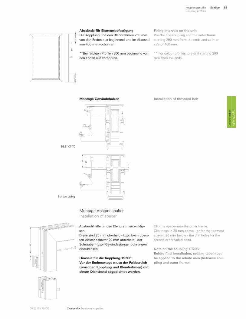
Zusatzprofile Supplementary profiles08.2016 / 75838
200
**(3
00)
200
**(3
00)
400
232
7
9
273
1
9
Abstände für Elementbefestigung
Die Kopplung und den Blendrahmen 200 mm
von den Enden aus beginnend und im Abstand
von 400 mm vorbohren.
**Bei farbigen Profilen 300 mm beginnend von
den Enden aus vorbohren.
Fixing intervals on the unit
Pre-drill the coupling and the outer frame
starting 200 mm from the ends and at inter-
vals of 400 mm.
** For colour profiles, pre-drill starting 300
mm from the ends.
Montage Gewindebolzen Installation of threaded bolt
Montage Abstandshalter
Installation of spacer
20
200
Abstandshalter in den Blendrahmen einklip-
sen.
Diese sind 20 mm oberhalb - bzw. beim obers-
ten Abstandshalter 20 mm unterhalb - der
Schrauben- bzw. Gewindestangenbohrungen
einzuklipsen .
Clip the spacer into the outer frame.
Clip these in 20 mm above - or for the topmost
spacer, 20 mm below - the drill holes for the
screws or threaded bolts.
Hinweis für die Kopplung 19206:
Vor der Endmontage muss der Falzbereich
(zwischen Kopplung und Blendrahmen) mit
einem Dichtband abgedichtet werden.
Note on the coupling 19206:
Before final installation, sealing tape must
be applied to the rebate area (between cou-
pling and outer frame).
SI82 / CT 70
Schüco LivIng
Schüco 83Kopplungsprofile
Coupling profiles
Coupling profiles
Kopplungsprofile
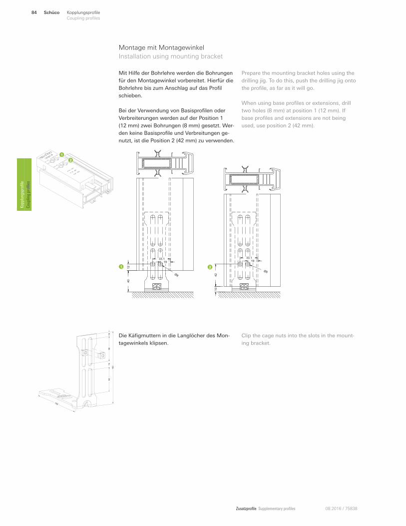
Zusatzprofile Supplementary profiles 08.2016 / 75838
Montage mit Montagewinkel
Installation using mounting bracket
Mit Hilfe der Bohrlehre werden die Bohrungen
für den Montagewinkel vorbereitet. Hierfür die
Bohrlehre bis zum Anschlag auf das Profil
schieben.
Bei der Verwendung von Basisprofilen oder
Verbreiterungen werden auf der Position 1
(12 mm) zwei Bohrungen (8 mm) gesetzt. Wer-
den keine Basisprofile und Verbreitungen ge-
nutzt, ist die Position 2 (42 mm) zu verwenden.
Prepare the mounting bracket holes using the
drilling jig. To do this, push the drilling jig onto
the profile, as far as it will go.
When using base profiles or extensions, drill
two holes (8 mm) at position 1 (12 mm). If
base profiles and extensions are not being
used, use position 2 (42 mm).
150
15
0
50
50
13
10
Die Käfigmuttern in die Langlöcher des Mon-
tagewinkels klipsen.
Clip the cage nuts into the slots in the mount-
ing bracket.
40
Ø8
12
33.119
Ø8
10
42
33.119
Schüco84 Kopplungsprofile
Coupling profiles Kopplungsprofile
Coupling profiles
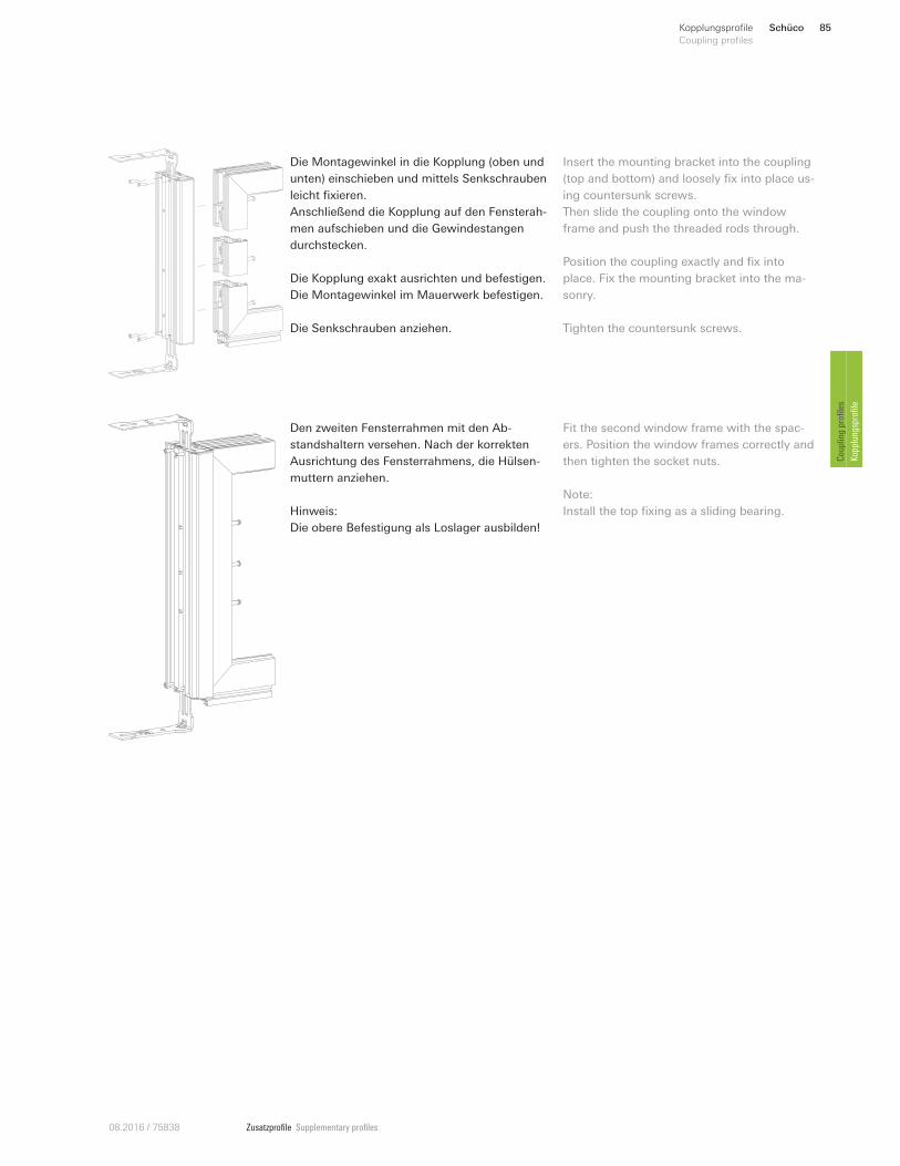
Zusatzprofile Supplementary profiles08.2016 / 75838
Die Montagewinkel in die Kopplung (oben und
unten) einschieben und mittels Senkschrauben
leicht fixieren.
Anschließend die Kopplung auf den Fensterah-
men aufschieben und die Gewindestangen
durchstecken.
Die Kopplung exakt ausrichten und befestigen.
Die Montagewinkel im Mauerwerk befestigen.
Die Senkschrauben anziehen.
Insert the mounting bracket into the coupling
(top and bottom) and loosely fix into place us-
ing countersunk screws.
Then slide the coupling onto the window
frame and push the threaded rods through.
Position the coupling exactly and fix into
place. Fix the mounting bracket into the ma-
sonry.
Tighten the countersunk screws.
Den zweiten Fensterrahmen mit den Ab-
standshaltern versehen. Nach der korrekten
Ausrichtung des Fensterrahmens, die Hülsen-
muttern anziehen.
Hinweis:
Die obere Befestigung als Loslager ausbilden!
Fit the second window frame with the spac-
ers. Position the window frames correctly and
then tighten the socket nuts.
Note:
Install the top fixing as a sliding bearing.
Schüco 85Kopplungsprofile
Coupling profiles
Coupling profiles
Kopplungsprofile
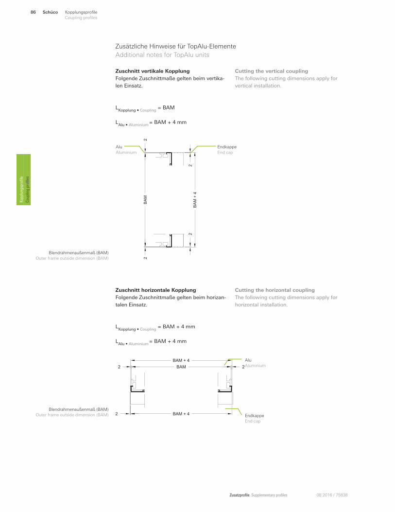
Zusatzprofile Supplementary profiles 08.2016 / 75838
Zusätzliche Hinweise für TopAlu-Elemente
Additional notes for TopAlu units
LKopplung • Coupling
= BAM
LAlu • Aluminium
= BAM + 4 mm
Zuschnitt vertikale Kopplung
Folgende Zuschnittmaße gelten beim vertika-
len Einsatz.
Cutting the vertical coupling
The following cutting dimensions apply for
vertical installation.
LKopplung • Coupling
= BAM + 4 mm
LAlu • Aluminium
= BAM + 4 mm
Zuschnitt horizontale Kopplung
Folgende Zuschnittmaße gelten beim horizan-
talen Einsatz.
Cutting the horizontal coupling
The following cutting dimensions apply for
horizontal installation.
BAM + 4
BAM + 4
BAM 22
2 Endkappe
End cap
Alu
Aluminium
Blendrahmenaußenmaß (BAM)
Outer frame outside dimension (BAM)
BA
M
BA
M+
4
22
22
Endkappe
End cap
Alu
Aluminium
Blendrahmenaußenmaß (BAM)
Outer frame outside dimension (BAM)
Schüco86 Kopplungsprofile
Coupling profiles Kopplungsprofile
Coupling profiles
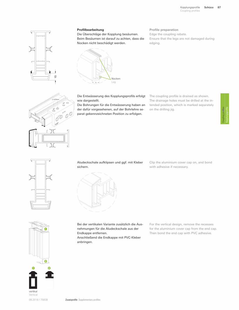
Zusatzprofile Supplementary profiles08.2016 / 75838
15
15
Nocken
Leg
Profilbearbeitung
Die Überschläge der Kopplung besäumen.
Beim Besäumen ist darauf zu achten, dass die
Nocken nicht beschädigt werden.
Profile preparation
Edge the coupling rebate.
Ensure that the legs are not damaged during
edging.
Die Entwässerung des Kopplungsprofils erfolgt
wie dargestellt.
Die Bohrungen für die Entwässerung haben an
der dafür vorgesehenen, auf der Bohrlehre se-
parat gekennzeichneten Position zu erfolgen.
The coupling profile is drained as shown.
The drainage holes must be drilled at the in-
tended position, which is marked separately
on the drilling jig.
2 x Ø 8mm
Aludeckschale aufklipsen und ggf. mit Kleber
sichern.
Clip the aluminium cover cap on, and bond
with adhesive if necessary.
Bei der vertikalen Variante zusätzlich die Aus-
nehmungen für die Aludeckschale aus der
Endkappe entfernen.
Anschließend die Endkappe mit PVC-Kleber
anbringen.
For the vertical design, remove the recesses
for the aluminium cover cap from the end cap.
Then bond the end cap with PVC adhesive.
vertikal
Vertical
Schüco 87Kopplungsprofile
Coupling profiles
Coupling profiles
Kopplungsprofile
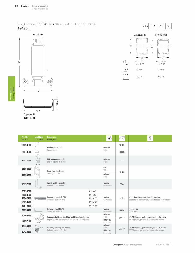
Zusatzprofile Supplementary profiles 08.2016 / 75838
82 70 60LivIng
20262800 20262900
27
71
27
71
x
y
Ix
Iy Ix = 22.01
Iy = 4.76
Ix = 30.86
Iy = 6.46
2 m m 3 mm
x
6,0 m 6,0 m
70
116
24
72.5
18.5
TopAlu 70
13165500
Statikpfosten 116/70 5K • Structural mullion 116/70 5K
19190...
Art.-Nr.
Art. No.
Abbildung
Illustration
Benennung
Description
28650800
47
.5
10
Abstandhalter 3 mm
Spacer 3 mm
schwarz
Black
10 Stk.
—
25073800 100 Stk.
22477600
18
32 EPDM-Dehnungsprofil
EPDM expansion profile
schwarz
Black 6 m
28653300 Dicht- bzw. Endkappe
Sealing/end cap
weiß
White 10 Stk.
28653400 schwarz
Black
23737900 Wand- und Bodenanker
Wall and floor anchor
verzinkt
Galvanised 2 Stk.
25058900
Gewindebolzen DIN 976
Threaded bolt DIN 976
M 6 x 80
verzinkt
Galvanised 10 Stk
siehe Hinweise gemäß Montageanleitung
See notes in accordance with installation instructions
25058600 M 6 x 90
20567700 M 6 x 100
25058700 M 6 x 120
20515500 M 6 x 165
28659100 Hülsenmutter M6x20
Socket nut M6 x 20
verzinkt
Galvanised 100 Stk.
Kreuzschlitz
Cross recess
22492700 Reparaturdichtung: Anschlag- und Glasanlagedichtung
Repair gasket: rebate gasket and glazing rebate gasket
schwarz
Black 100 m*
EPDM-Dichtung, polymerisiert, nicht schweißbar
EPDM gasket, polymerised, cannot be welded 22492800
silbergrau
Silver grey
22490200 Anschlagdichtung für TopAlu
Rebate gasket for TopAlu
schwarz
Black 200 m*
EPDM-Dichtung, polymerisiert, nicht schweißbar
EPDM gasket, polymerised, cannot be welded 22424200
silbergrau
Silver grey
Schüco88 Kopplungsprofile
Coupling profiles Kopplungsprofile
Coupling profiles
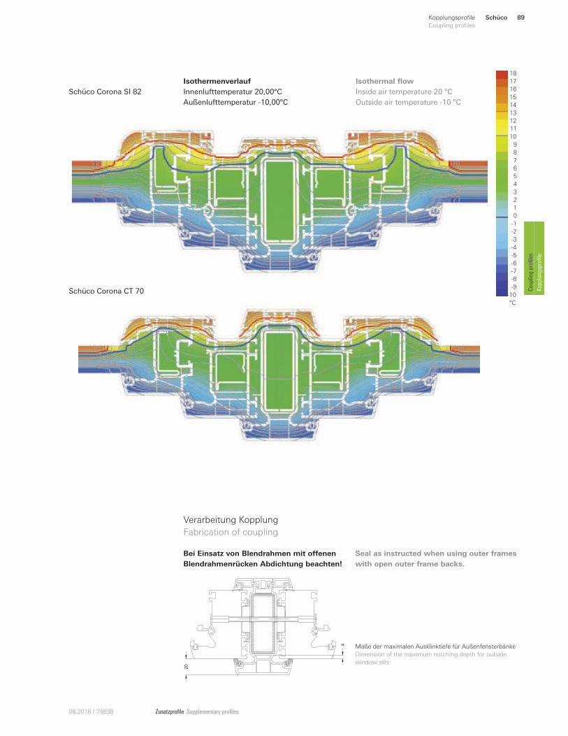
Zusatzprofile Supplementary profiles08.2016 / 75838
Isothermenverlauf
Innenlufttemperatur 20,00°C
Außenlufttemperatur -10,00°C
Inside air temperature 20 °C
Outside air temperature -10 °C
Schüco Corona SI 82
Isothermal flow 18
16
12
11
10
9
8
6
1
5
4
3
0
-6
-9
-10
°C
2
-5
7
13
15
14
-2
-3
-4
-1
-7
-8
17
Schüco Corona CT 70
20
4
Verarbeitung Kopplung
Fabrication of coupling
Maße der maximalen Ausklinktiefe für Außenfensterbänke
Dimension of the maximum notching depth for outside
window sills
Bei Einsatz von Blendrahmen mit oUenen
Blendrahmenrücken Abdichtung beachten!
Seal as instructed when using outer frames
with open outer frame backs.
Schüco 89Kopplungsprofile
Coupling profiles
Coupling profiles
Kopplungsprofile
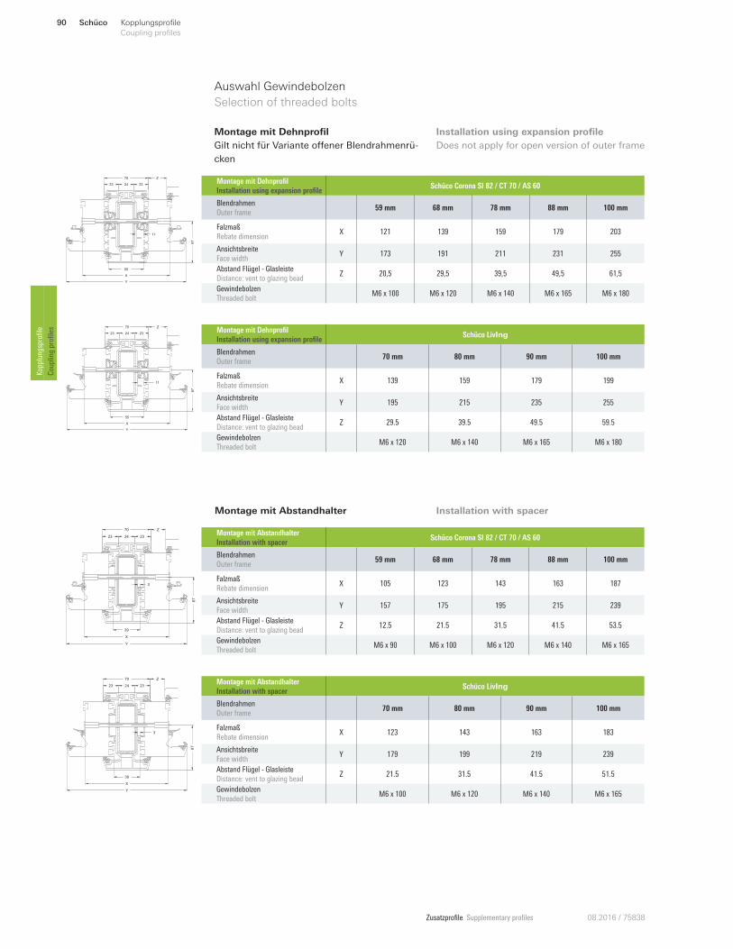
Zusatzprofile Supplementary profiles 08.2016 / 75838
X
Y
67
11
70
23
55
24 23
Z
Y
67
X
70
11
23 24 23
Z
55
X
Y
39
67
3
70
23 24 23
Z
X
Y
39
67
3
70
23 24 23
Z
Auswahl Gewindebolzen
Selection of threaded bolts
Montage mit Dehnprofil
Gilt nicht für Variante onener Blendrahmenrü-
cken
Montage mit Abstandhalter
Installation using expansion profile
Does not apply for open version of outer frame
Installation with spacer
Montage mit Abstandhalter
Installation with spacer Schüco Corona SI 82 / CT 70 / AS 60
Blendrahmen
Outer frame 59 mm 68 mm 78 mm 88 mm 100 mm
Falzmaß
Rebate dimension X 105 123 143 163 187
Ansichtsbreite
Face width Y 157 175 195 215 239
Abstand Flügel - Glasleiste
Distance: vent to glazing bead Z 12.5 21.5 31.5 41.5 53.5
Gewindebolzen
Threaded bolt M6 x 90 M6 x 100 M6 x 120 M6 x 140 M6 x 165
Montage mit Abstandhalter
Installation with spacer Schüco LivIng
Blendrahmen
Outer frame 70 mm 80 mm 90 mm 100 mm
Falzmaß
Rebate dimension X 123 143 163 183
Ansichtsbreite
Face width Y 179 199 219 239
Abstand Flügel - Glasleiste
Distance: vent to glazing bead Z 21.5 31.5 41.5 51.5
Gewindebolzen
Threaded bolt M6 x 100 M6 x 120 M6 x 140 M6 x 165
Montage mit Dehnprofil
Installation using expansion profile Schüco Corona SI 82 / CT 70 / AS 60
Blendrahmen
Outer frame 59 mm 68 mm 78 mm 88 mm 100 mm
Falzmaß
Rebate dimension X 121 139 159 179 203
Ansichtsbreite
Face width Y 173 191 211 231 255
Abstand Flügel - Glasleiste
Distance: vent to glazing bead Z 20,5 29,5 39,5 49,5 61,5
Gewindebolzen
Threaded bolt M6 x 100 M6 x 120 M6 x 140 M6 x 165 M6 x 180
Montage mit Dehnprofil
Installation using expansion profile Schüco LivIng
Blendrahmen
Outer frame 70 mm 80 mm 90 mm 100 mm
Falzmaß
Rebate dimension X 139 159 179 199
Ansichtsbreite
Face width Y 195 215 235 255
Abstand Flügel - Glasleiste
Distance: vent to glazing bead Z 29.5 39.5 49.5 59.5
Gewindebolzen
Threaded bolt M6 x 120 M6 x 140 M6 x 165 M6 x 180
Schüco90 Kopplungsprofile
Coupling profiles Kopplungsprofile
Coupling profiles
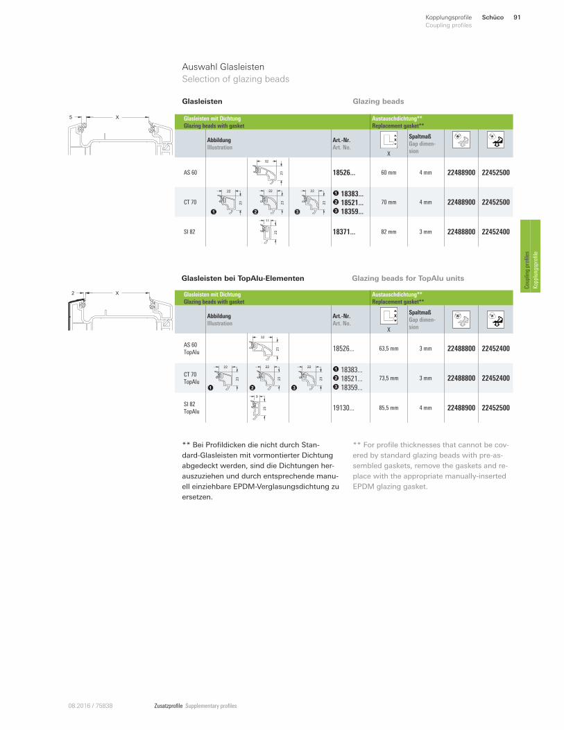
Zusatzprofile Supplementary profiles08.2016 / 75838
Glasleisten bei TopAlu-Elementen Glazing beads for TopAlu units
X5
Auswahl Glasleisten
Selection of glazing beads
Glasleisten mit Dichtung
Glazing beads with gasket
Austauschdichtung**
Replacement gasket**
Abbildung
Illustration
Art.-Nr.
Art. No. X
Spaltmaß
Gap dimen-
sion
AS 60
32
23 18526 ... 60 mm 4 mm 22488900 22452500
CT 70
22
23
22
23
22
23
18383 ...
18521 ...
18359...
70 mm 4 mm 22488900 22452500
SI 82
11
23 18371... 82 mm 3 mm 22488800 22452400
Glasleisten
Glasleisten mit Dichtung
Glazing beads with gasket
Austauschdichtung**
Replacement gasket**
Abbildung
Illustration
Art.-Nr.
Art. No. X
Spaltmaß
Gap dimen-
sion
AS 60
TopAlu
32
23 18526 ... 63,5 mm 3 mm 22488800 22452400
CT 70
TopAlu
22
23
22
23
22
23
18383 ...
18521 ...
18359...
73,5 mm 3 mm 22488800 22452400
SI 82
TopAlu
9
23 19130 ... 85,5 mm 4 mm 22488900 22452500
** Bei Profildicken die nicht durch Stan-
dard-Glasleisten mit vormontierter Dichtung
abgedeckt werden, sind die Dichtungen her-
auszuziehen und durch entsprechende manu-
ell einziehbare EPDM-Verglasungsdichtung zu
ersetzen.
** For profile thicknesses that cannot be cov-
ered by standard glazing beads with pre-as-
sembled gaskets, remove the gaskets and re-
place with the appropriate manually-inserted
EPDM glazing gasket.
X2
Glazing beads
Schüco 91Kopplungsprofile
Coupling profiles
Coupling profiles
Kopplungsprofile
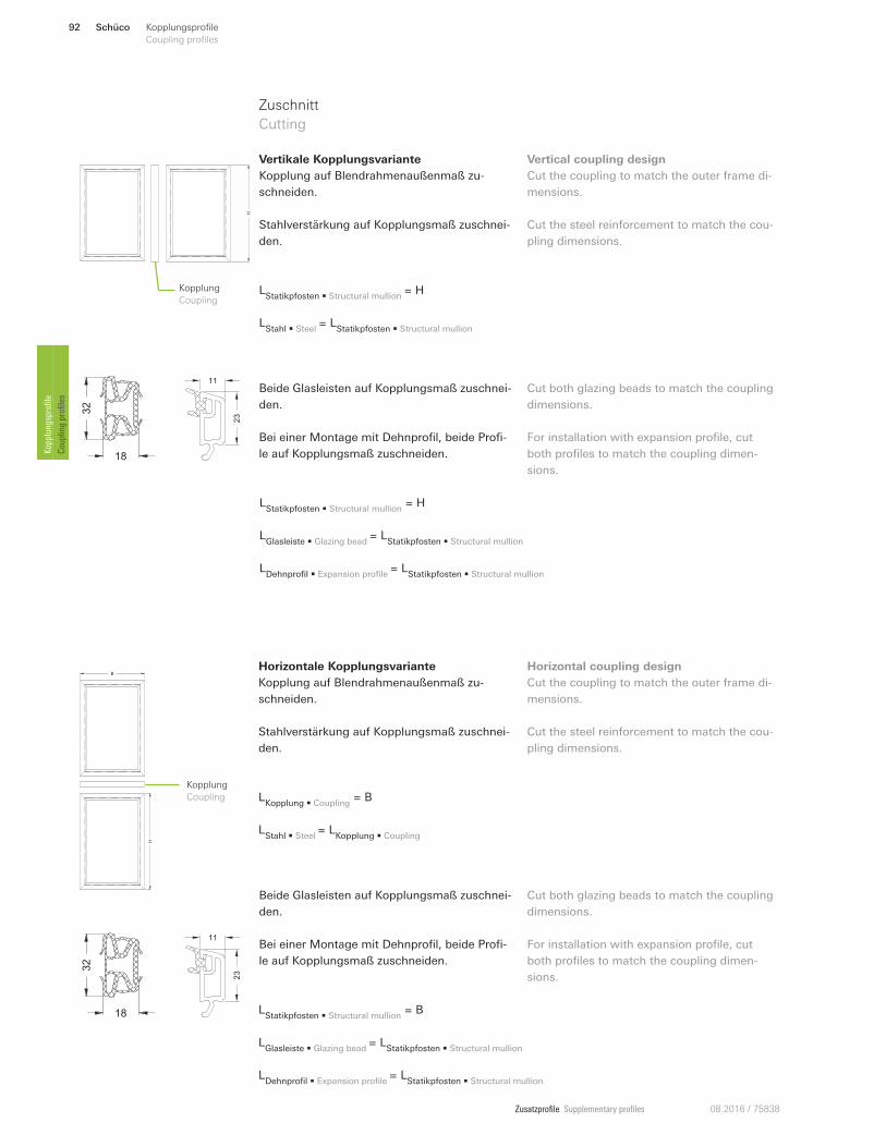
Zusatzprofile Supplementary profiles 08.2016 / 75838
LStatikpfosten • Structural mullion
= H
LStahl • Steel
= LStatikpfosten • Structural mullion
18
32
18
32
11
23
11
23
Beide Glasleisten auf Kopplungsmaß zuschnei-
den.
Bei einer Montage mit Dehnprofil, beide Profi-
le auf Kopplungsmaß zuschneiden.
Beide Glasleisten auf Kopplungsmaß zuschnei-
den.
Bei einer Montage mit Dehnprofil, beide Profi-
le auf Kopplungsmaß zuschneiden.
Cut both glazing beads to match the coupling
dimensions.
For installation with expansion profile, cut
both profiles to match the coupling dimen-
sions.
Cut both glazing beads to match the coupling
dimensions.
For installation with expansion profile, cut
both profiles to match the coupling dimen-
sions.
LStatikpfosten • Structural mullion
= H
LGlasleiste • Glazing bead
= LStatikpfosten • Structural mullion
LDehnprofil • Expansion profile
= LStatikpfosten • Structural mullion
Zuschnitt
Cutting
H
Kopplung
Coupling
Vertikale Kopplungsvariante
Kopplung auf Blendrahmenaußenmaß zu-
schneiden.
Stahlverstärkung auf Kopplungsmaß zuschnei-
den.
Vertical coupling design
Cut the coupling to match the outer frame di-
mensions.
Cut the steel reinforcement to match the cou-
pling dimensions.
LStatikpfosten • Structural mullion
= B
LGlasleiste • Glazing bead
= LStatikpfosten • Structural mullion
LDehnprofil • Expansion profile
= LStatikpfosten • Structural mullion
Horizontale Kopplungsvariante
Kopplung auf Blendrahmenaußenmaß zu-
schneiden.
Stahlverstärkung auf Kopplungsmaß zuschnei-
den.
Horizontal coupling design
Cut the coupling to match the outer frame di-
mensions.
Cut the steel reinforcement to match the cou-
pling dimensions.
H
B
Kopplung
Coupling LKopplung • Coupling
= B
LStahl • Steel
= LKopplung • Coupling
Schüco92 Kopplungsprofile
Coupling profiles Kopplungsprofile
Coupling profiles
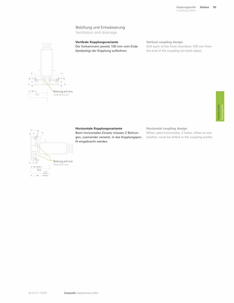
Zusatzprofile Supplementary profiles08.2016 / 75838
Belüftung und Entwässerung
Ventilation and drainage 17
30°
17
30°
100 Bohrung ø 5 mm
Hole Ø 5 mm
Vertikale Kopplungsvariante
Die Vorkammern jeweils 100 mm vom Ende
(beidseitig) der Kopplung aufbohren.
Vertical coupling design
Drill each of the front chambers 100 mm from
the end of the coupling (on both sides).
Horizontale Kopplungsvariante
Beim horizontalen Einsatz müssen 2 Bohrun-
gen, zueinander versetzt, in das Kopplungspro-
fil eingebracht werden.
17
30°
5.5
100 30
185 30
Bohrung ø 5 mm
Hole Ø 5 mm
Horizontal coupling design
When used horizontally, 2 holes, onset to one
another, must be drilled in the coupling profile.
Schüco 93Kopplungsprofile
Coupling profiles
Coupling profiles
Kopplungsprofile
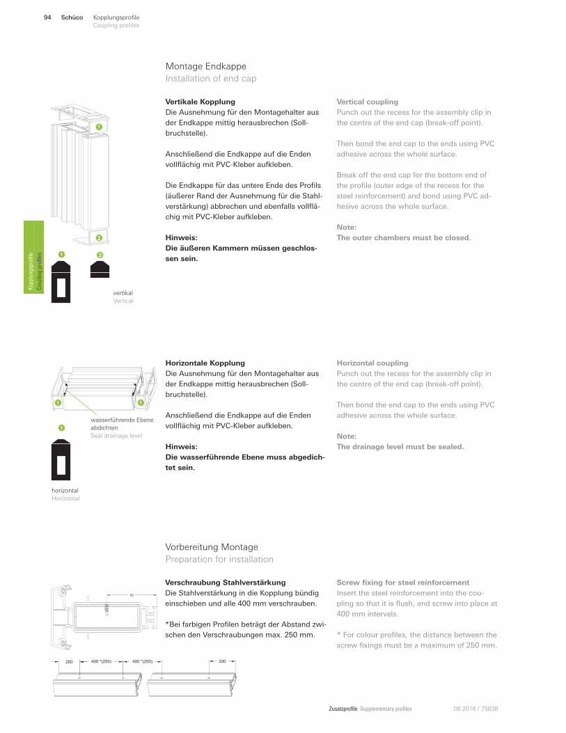
Zusatzprofile Supplementary profiles 08.2016 / 75838
Horizontale Kopplung
Die Ausnehmung für den Montagehalter aus
der Endkappe mittig herausbrechen (Soll-
bruchstelle).
Anschließend die Endkappe auf die Enden
vollflächig mit PVC-Kleber aufkleben.
Hinweis:
Die wasserführende Ebene muss abgedich-
tet sein.
Horizontal coupling
Punch out the recess for the assembly clip in
the centre of the end cap (break-on point).
Then bond the end cap to the ends using PVC
adhesive across the whole surface.
Note:
The drainage level must be sealed.
horizontal
Horizontal
wasserführende Ebene
abdichten
Seal drainage level
Vorbereitung Montage
Preparation for installation
55
200 400 *(250) 400 *(250) 200
Verschraubung Stahlverstärkung
Die Stahlverstärkung in die Kopplung bündig
einschieben und alle 400 mm verschrauben.
*Bei farbigen Profilen beträgt der Abstand zwi-
schen den Verschraubungen max. 250 mm.
Screw fixing for steel reinforcement
Insert the steel reinforcement into the cou-
pling so that it is flush, and screw into place at
400 mm intervals.
* For colour profiles, the distance between the
screw fixings must be a maximum of 250 mm.
Montage Endkappe
Installation of end cap
Vertikale Kopplung
Die Ausnehmung für den Montagehalter aus
der Endkappe mittig herausbrechen (Soll-
bruchstelle).
Anschließend die Endkappe auf die Enden
vollflächig mit PVC-Kleber aufkleben.
Die Endkappe für das untere Ende des Profils
(äußerer Rand der Ausnehmung für die Stahl-
verstärkung) abbrechen und ebenfalls vollflä-
chig mit PVC-Kleber aufkleben.
Hinweis:
Die äußeren Kammern müssen geschlos-
sen sein.
Vertical coupling
Punch out the recess for the assembly clip in
the centre of the end cap (break-on point).
Then bond the end cap to the ends using PVC
adhesive across the whole surface.
Break on the end cap for the bottom end of
the profile (outer edge of the recess for the
steel reinforcement) and bond using PVC ad-
hesive across the whole surface.
Note:
The outer chambers must be closed.
vertikal
Vertical
Schüco94 Kopplungsprofile
Coupling profiles Kopplungsprofile
Coupling profiles
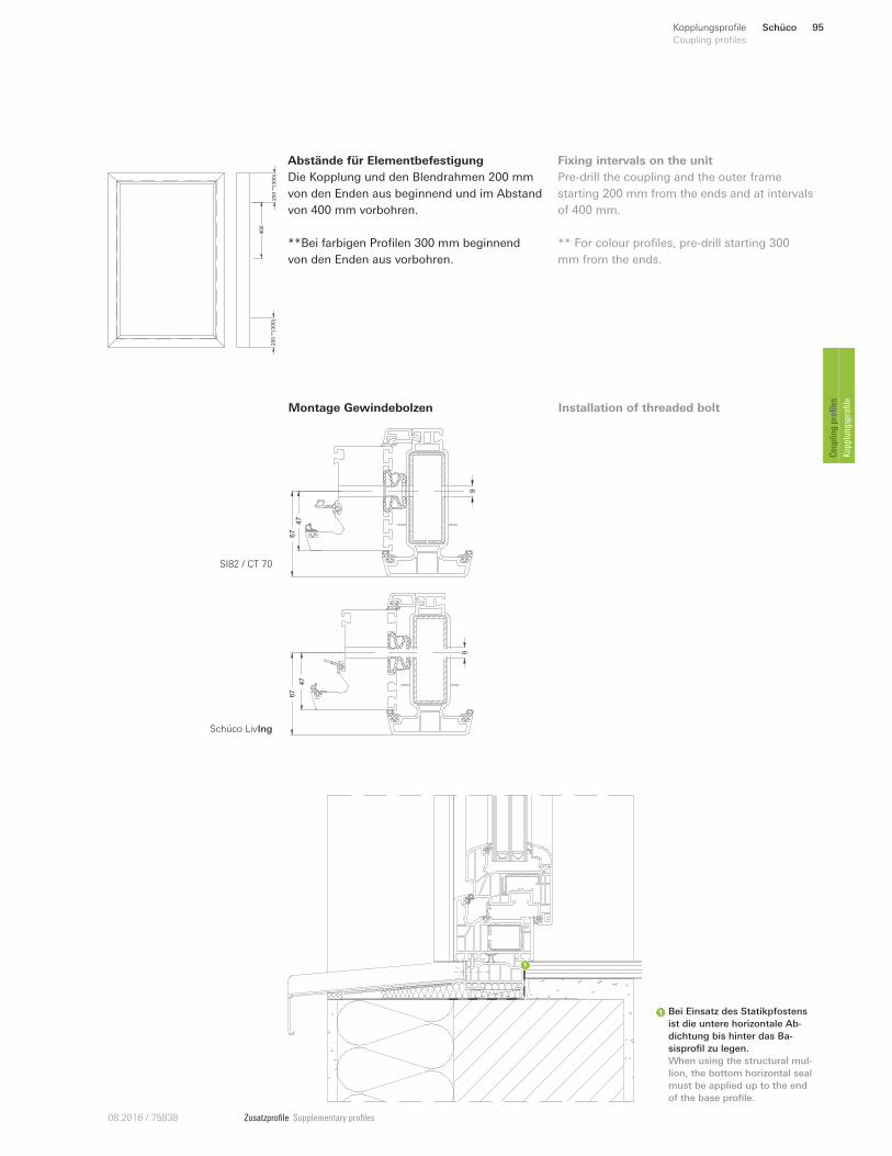
Zusatzprofile Supplementary profiles08.2016 / 75838
200
**(3
00)
200
**(3
00)
400
Abstände für Elementbefestigung
Die Kopplung und den Blendrahmen 200 mm
von den Enden aus beginnend und im Abstand
von 400 mm vorbohren.
**Bei farbigen Profilen 300 mm beginnend
von den Enden aus vorbohren.
Fixing intervals on the unit
Pre-drill the coupling and the outer frame
starting 200 mm from the ends and at intervals
of 400 mm.
** For colour profiles, pre-drill starting 300
mm from the ends.
67
47
9
67
9
47
Bei Einsatz des Statikpfostens
ist die untere horizontale Ab-
dichtung bis hinter das Ba-
sisprofil zu legen.
When using the structural mul-
lion, the bottom horizontal seal
must be applied up to the end
of the base profile.
Montage Gewindebolzen Installation of threaded bolt
SI82 / CT 70
Schüco LivIng
Schüco 95Kopplungsprofile
Coupling profiles
Coupling profiles
Kopplungsprofile
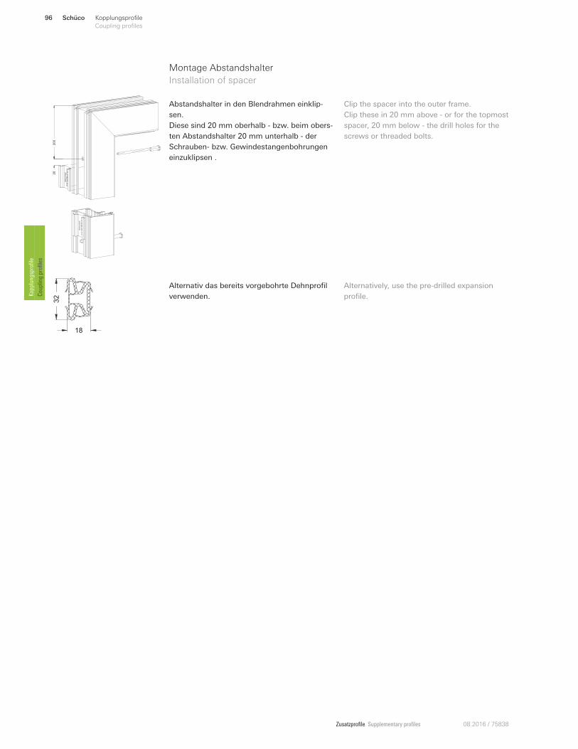
Zusatzprofile Supplementary profiles 08.2016 / 75838
Montage Abstandshalter
Installation of spacer
20
200
18
32
Abstandshalter in den Blendrahmen einklip-
sen.
Diese sind 20 mm oberhalb - bzw. beim obers-
ten Abstandshalter 20 mm unterhalb - der
Schrauben- bzw. Gewindestangenbohrungen
einzuklipsen .
Clip the spacer into the outer frame.
Clip these in 20 mm above - or for the topmost
spacer, 20 mm below - the drill holes for the
screws or threaded bolts.
Alternativ das bereits vorgebohrte Dehnprofil
verwenden.
Alternatively, use the pre-drilled expansion
profile.
Schüco96 Kopplungsprofile
Coupling profiles Kopplungsprofile
Coupling profiles
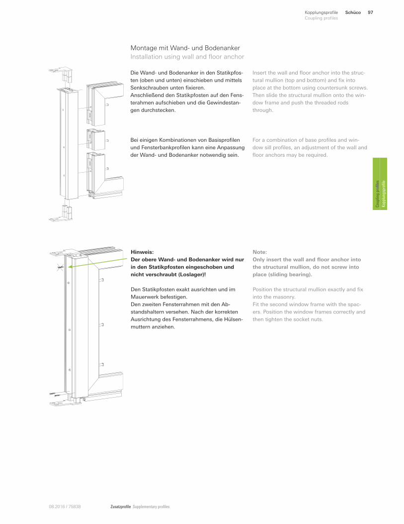
Zusatzprofile Supplementary profiles08.2016 / 75838
Die Wand- und Bodenanker in den Statikpfos-
ten (oben und unten) einschieben und mittels
Senkschrauben unten fixieren.
Anschließend den Statikpfosten auf den Fens-
terahmen aufschieben und die Gewindestan-
gen durchstecken.
Montage mit Wand- und Bodenanker
Installation using wall and floor anchor
Insert the wall and floor anchor into the struc-
tural mullion (top and bottom) and fix into
place at the bottom using countersunk screws.
Then slide the structural mullion onto the win-
dow frame and push the threaded rods
through.
Hinweis:
Der obere Wand- und Bodenanker wird nur
in den Statikpfosten eingeschoben und
nicht verschraubt (Loslager)!
Den Statikpfosten exakt ausrichten und im
Mauerwerk befestigen.
Den zweiten Fensterrahmen mit den Ab-
standshaltern versehen. Nach der korrekten
Ausrichtung des Fensterrahmens, die Hülsen-
muttern anziehen.
Note:
Only insert the wall and floor anchor into
the structural mullion, do not screw into
place (sliding bearing).
Position the structural mullion exactly and fix
into the masonry.
Fit the second window frame with the spac-
ers. Position the window frames correctly and
then tighten the socket nuts.
Bei einigen Kombinationen von Basisprofilen
und Fensterbankprofilen kann eine Anpassung
der Wand- und Bodenanker notwendig sein.
For a combination of base profiles and win-
dow sill profiles, an adjustment of the wall and
floor anchors may be required.
Schüco 97Kopplungsprofile
Coupling profiles
Coupling profiles
Kopplungsprofile
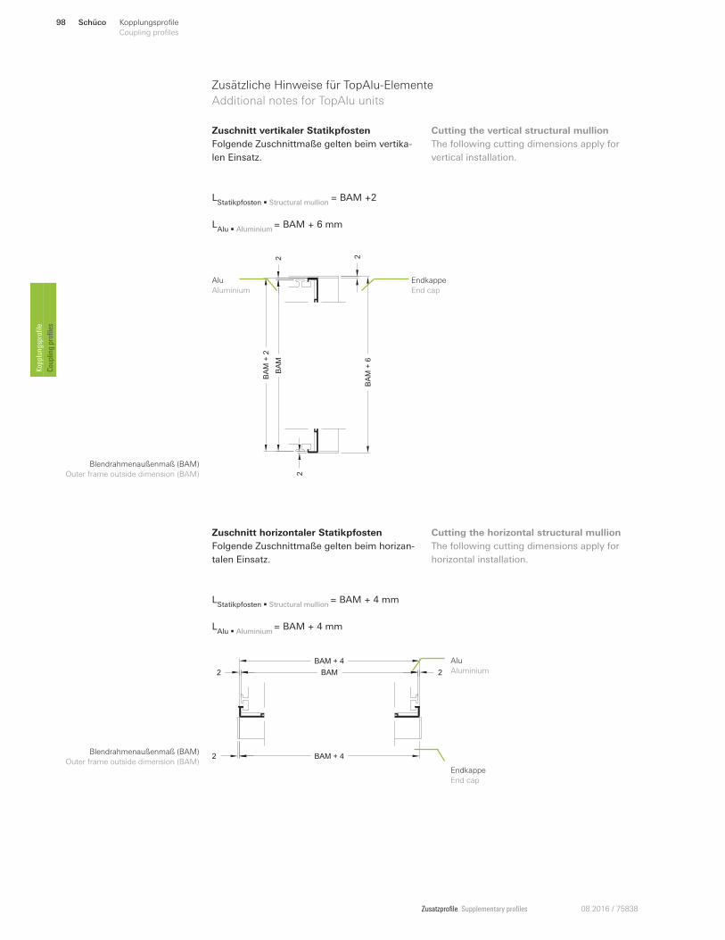
Zusatzprofile Supplementary profiles 08.2016 / 75838
Zusätzliche Hinweise für TopAlu-Elemente
Additional notes for TopAlu units
Zuschnitt vertikaler Statikpfosten
Folgende Zuschnittmaße gelten beim vertika-
len Einsatz.
Cutting the vertical structural mullion
The following cutting dimensions apply for
vertical installation.
Zuschnitt horizontaler Statikpfosten
Folgende Zuschnittmaße gelten beim horizan-
talen Einsatz.
Cutting the horizontal structural mullion
The following cutting dimensions apply for
horizontal installation.
Blendrahmenaußenmaß (BAM)
Outer frame outside dimension (BAM)
Blendrahmenaußenmaß (BAM)
Outer frame outside dimension (BAM)
BAM + 4
BAM + 4
BAM 22
2
Endkappe
End cap
Alu
Aluminium
LStatikpfosten • Structural mullion
= BAM + 4 mm
LAlu • Aluminium
= BAM + 4 mm
LStatikpfosten • Structural mullion
= BAM +2
LAlu • Aluminium
= BAM + 6 mm
BA
M
2
2 2
BA
M+
6
BA
M+
2
Endkappe
End cap
Alu
Aluminium
Schüco98 Kopplungsprofile
Coupling profiles Kopplungsprofile
Coupling profiles

Zusatzprofile Supplementary profiles08.2016 / 75838
Zusätzliche Hinweise für TopAlu-Elemente
Additional notes for TopAlu units
Die Dichtungen entfernen.
Aludeckschale aufklipsen und ggf. mit Kleber
sichern.
Die Dichtungen für die Aludeckschale einzie-
hen.
Remove the gaskets.
Clip the aluminium cover cap on, and bond
with adhesive if necessary.
Insert the gaskets for the aluminium cover
cap.
Die Ausnehmung für den Montagehalter aus
der Endkappe mittig herausbrechen (Soll-
bruchstelle).
Anschließend die Endkappe auf die Enden
vollflächig mit PVC-Kleber aufkleben.
Die Endkappe für das untere Ende des Profils
(äußerer Rand der Ausnehmung für die Stahl-
verstärkung) abbrechen und ebenfalls vollflä-
chig mit PVC-Kleber aufkleben.
Hinweis:
Die äußeren Kammern müssen geschlos-
sen sein.
Punch out the recess for the assembly clip in
the centre of the end cap (break-on point).
Then bond the end cap to the ends using PVC
adhesive across the whole surface.
Break on the end cap for the bottom end of
the profile (outer edge of the recess for the
steel reinforcement) and bond using PVC ad-
hesive across the whole surface.
Note:
The outer chambers must be closed.
vertikal
Vertical
Schüco 99Kopplungsprofile
Coupling profiles
Coupling profiles
Kopplungsprofile
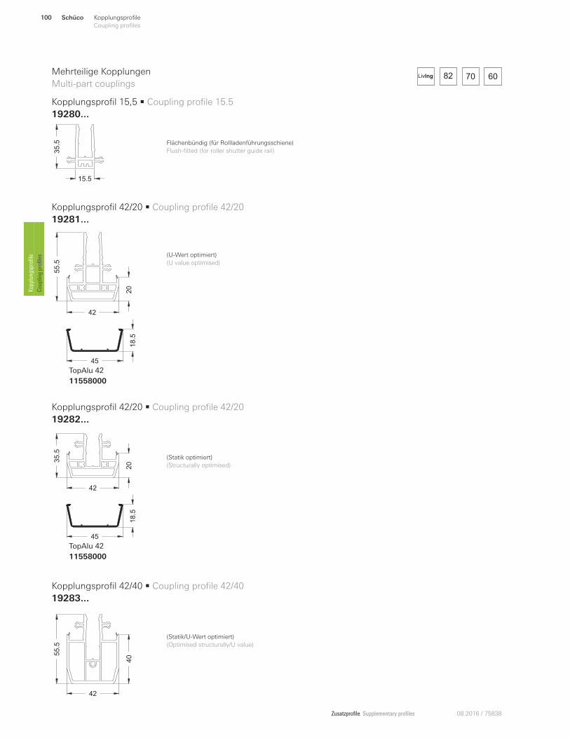
Zusatzprofile Supplementary profiles 08.2016 / 75838
82 70 60LivIng
15.5
35.5
42
405
5.5
Kopplungsprofil 15,5 • Coupling profile 15.5
19280...
Kopplungsprofil 42/40 • Coupling profile 42/40
19283...
Kopplungsprofil 42/20 • Coupling profile 42/20
19281...
Kopplungsprofil 42/20 • Coupling profile 42/20
19282...
Mehrteilige Kopplungen
Multi-part couplings
(Statik/U-Wert optimiert)
(Optimised structurally/U value)
55.5
42
20
45
18.5
TopAlu 42
11558000
35.5
42
20
45
18.5
TopAlu 42
11558000
(Statik optimiert)
(Structurally optimised)
Flächenbündig (für Rollladenführungsschiene)
Flush-fitted (for roller shutter guide rail)
(U-Wert optimiert)
(U value optimised)
Schüco100 Kopplungsprofile
Coupling profiles Kopplungsprofile
Coupling profiles
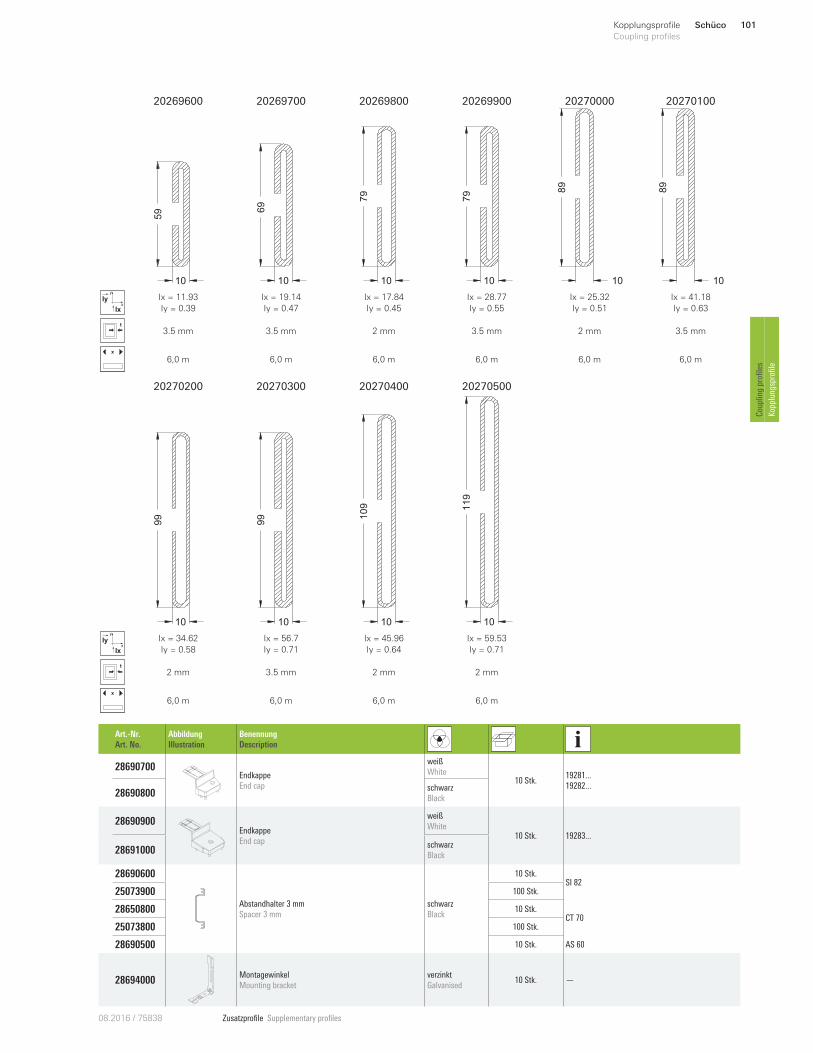
Zusatzprofile Supplementary profiles08.2016 / 75838
20269600 20269700 20269800 20269900 20270000 20270100
59
10
69
10 10
79
10
79
10
89
10
89
x
y
Ix
Iy Ix = 11.93
Iy = 0.39
Ix = 19.14
Iy = 0.47
Ix = 17.84
Iy = 0.45
Ix = 28.77
Iy = 0.55
Ix = 25.32
Iy = 0.51
Ix = 41.18
Iy = 0.63
3.5 mm 3.5 mm 2 mm 3.5 mm 2 mm 3.5 mm
x
6,0 m 6,0 m 6,0 m 6,0 m 6,0 m 6,0 m
20270200 20270300 20270400 20270500
10
99
10
99
10
109
10
119
x
y
Ix
Iy Ix = 34.62
Iy = 0.58
Ix = 56.7
Iy = 0.71
Ix = 45.96
Iy = 0.64
Ix = 59.53
Iy = 0.71
2 mm 3.5 mm 2 mm 2 mm
x
6,0 m 6,0 m 6,0 m 6,0 m
Art.-Nr.
Art. No.
Abbildung
Illustration
Benennung
Description
28690700 Endkappe
End cap
weiß
White 10 Stk.
19281...
19282...28690800
schwarz
Black
28690900 Endkappe
End cap
weiß
White 10 Stk. 19283...
28691000 schwarz
Black
28690600
10
Abstandhalter 3 mm
Spacer 3 mm
schwarz
Black
10 Stk. SI 82
25073900 100 Stk.
28650800 10 Stk. CT 70
25073800 100 Stk.
28690500 10 Stk. AS 60
28694000 Montagewinkel
Mounting bracket
verzinkt
Galvanised 10 Stk. —
Schüco 101Kopplungsprofile
Coupling profiles
Coupling profiles
Kopplungsprofile
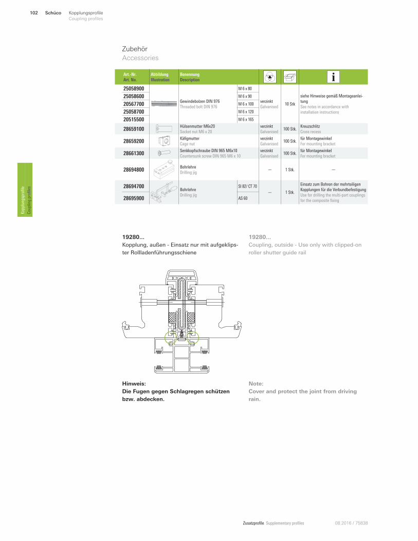
Zusatzprofile Supplementary profiles 08.2016 / 75838
Zubehör
Accessories
19280...
Kopplung, außen - Einsatz nur mit aufgeklips-
ter Rollladenführungsschiene
Art.-Nr.
Art. No.
Abbildung
Illustration
Benennung
Description
25058900
Gewindebolzen DIN 976
Threaded bolt DIN 976
M 6 x 80
verzinkt
Galvanised 10 Stk
siehe Hinweise gemäß Montageanlei-
tung
See notes in accordance with
installation instructions
25058600 M 6 x 90
20567700 M 6 x 100
25058700 M 6 x 120
20515500 M 6 x 165
28659100 Hülsenmutter M6x20
Socket nut M6 x 20
verzinkt
Galvanised 100 Stk.
Kreuzschlitz
Cross recess
28659200 Käfigmutter
Cage nut
verzinkt
Galvanised 100 Stk.
für Montagewinkel
For mounting bracket
28661300 Senkkopfschraube DIN 965 M6x10
Countersunk screw DIN 965 M6 x 10
verzinkt
Galvanised 100 Stk.
für Montagewinkel
For mounting bracket
28694800 Bohrlehre
Drilling jig — 1 Stk. —
28694700 Bohrlehre
Drilling jig
SI 82/ CT 70
— 1 Stk.
Einsatz zum Bohren der mehrteiligen
Kopplungen für die Verbundbefestigung
Use for drilling the multi-part couplings
for the composite fixing 28695900 AS 60
19280...
Coupling, outside - Use only with clipped-on
roller shutter guide rail
Hinweis:
Die Fugen gegen Schlagregen schützen
bzw. abdecken.
Note:
Cover and protect the joint from driving
rain.
Schüco102 Kopplungsprofile
Coupling profiles Kopplungsprofile
Coupling profiles
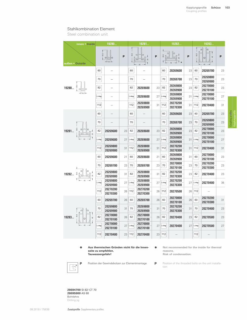
Zusatzprofile Supplementary profiles08.2016 / 75838
Stahlkombination Element
Steel combination unit
innen • Inside
außen • Outside
19280... 19281... 19282... 19283...
15.5
35
.5
P
55
.5
42
20
P 35
.5
42
20
*
P
42
405
5.5
P
19280...
15.5
35
.5
60 — 60 — 60 20269600 23 60 20269700 23
70 — 70 — 70 20269700 23 7020269800
2320269900
82 — 82 20269600 23 8220269800
23 8220270000
2320269900 20270100
LivIng — LivIng 20269600 27 LivIng20269800
31 LivIng20270000
2720269900 20270100
112 — 11220269800
31 11220270200
31 112 20270400 3120269900 20270300
19281... 55
.5
42
20
60 — 60 — 60 20269600 23 60 20269700 23
70 — 70 — 70 20269700 23 7020269800
2320269900
82 20269600 23 82 20269600 23 8220269800
23 8220270000
2320269900 20270100
LivIng 20269600 27 LivIng 20269600 27 LivIng20269800
31 LivIng20270000
2720269900 20270100
11220269800
31 11220269800
31 11220270200
31 112 20270400 3120269900 20269900 20270300
19282... 35
.5
42
20
60 20269600 21 60 20269600 21 6020269800
31 6020270000
2320269900 20270100
70 20269700 23 70 20269700 23 7020270000
23 7020270200
2320270100 20270300
8220269800
31 8220269800
31 8220270200
23 82 20270400 2320269900 20269900 20270300
LivIng20269800
27 LivIng20269800
27 LivIng20270200
27 LivIng 20270400 3520269900 20269900 20270300
11220270200
26 11220270200
26 112 20270500 26 112 —20270300 20270300
19283...
42
405
5.5
60 20269700 26 60 20269700 26 6020270000
26 6020270200
3120270100 20270300
7020269800
31 7020269800
31 7020270200
31 70 20270400 2320269900 20269900 20270300
8220270000
26 8220270000
26 82 20270400 23 82 20270500 2320270100 20270100
LivIng20270000
27 LivIng20270000
27 LivIng 20270400 27 LivIng 20270500 2720270100 20270100
112 20270400 23 112 20270400 23 112 — 112 —
PP Position der Gewindebolzen zur Elementmontage P Position of the threaded bolts on the unit installa-
tion
Aus thermischen Gründen nicht für die Innen-
seite zu empfehlen.
Tauwassergefahr!
* Not recommended for the inside for thermal
reasons.
Risk of condensation.
*
28694700 SI 82/ CT 7028695900 AS 60Bohrlehre
Drilling jig
Schüco 103Kopplungsprofile
Coupling profiles
Coupling profiles
Kopplungsprofile
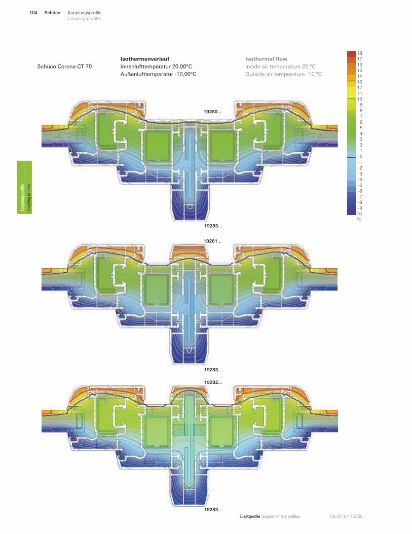
Zusatzprofile Supplementary profiles 08.2016 / 75838
19280...
19283...
19283...
19281...
Zusatzprofile Supplementary profiles 08.201
19283...
19282...
Isothermenverlauf
Innenlufttemperatur 20,00°C
Außenlufttemperatur -10,00°C
Inside air temperature 20 °C
Outside air temperature -10 °C
Isothermal flow 18
16
12
11
10
9
8
6
1
5
4
3
0
-6
-9
-10
°C
2
-5
7
13
15
14
-2
-3
-4
-1
-7
-8
17
Schüco Corona CT 70
Schüco104 Kopplungsprofile
Coupling profiles Kopplungsprofile
Coupling profiles
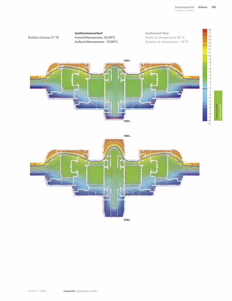
Zusatzprofile Supplementary profiles08.2016 / 75838
Isothermenverlauf
Innenlufttemperatur 20,00°C
Außenlufttemperatur -10,00°C
Inside air temperature 20 °C
Outside air temperature -10 °C
Isothermal flow 18
16
12
11
10
9
8
6
1
5
4
3
0
-6
-9
-10
°C
2
-5
7
13
15
14
-2
-3
-4
-1
-7
-8
17
Schüco Corona CT 70
19282...
19282...
19283...
19283...
Schüco 105Kopplungsprofile
Coupling profiles
Coupling profiles
Kopplungsprofile
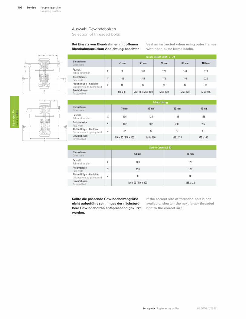
Zusatzprofile Supplementary profiles 08.2016 / 75838
P
42 Z
X
Y
Bei Einsatz von Blendrahmen mit oUenen
Blendrahmenrücken Abdichtung beachten!
Seal as instructed when using outer frames
with open outer frame backs.
Auswahl Gewindebolzen
Selection of threaded bolts
Sollte die passende Gewindebolzengröße
nicht aufgeführt sein, muss der nächstgrö-
ßere Gewindebolzen entsprechend gekürzt
werden.
If the correct size of threaded bolt is not
available, shorten the next larger threaded
bolt to the correct size.
Schüco Corona SI 82 / CT 70
Blendrahmen
Outer frame 59 mm 68 mm 78 mm 88 mm 100 mm
Falzmaß
Rebate dimension X 88 106 126 146 170
Ansichtsbreite
Face width Y 140 158 178 198 222
Abstand Flügel - Glasleiste
Distance: vent to glazing bead Z 18 27 37 47 59
Gewindebolzen
Threaded bolt M6 x 80 M6 x 90 / M6 x 100 M6 x 120 M6 x 130 M6 x 165
Schüco LivIng
Blendrahmen
Outer frame 70 mm 80 mm 90 mm 100 mm
Falzmaß
Rebate dimension X 106 126 146 166
Ansichtsbreite
Face width Y 162 182 202 222
Abstand Flügel - Glasleiste
Distance: vent to glazing bead Z 27 37 47 57
Gewindebolzen
Threaded bolt M6 x 90 / M6 x 100 M6 x 120 M6 x 130 M6 x 165
Schüco Corona AS 60
Blendrahmen
Outer frame 68 mm 78 mm
Falzmaß
Rebate dimension X 108 128
Ansichtsbreite
Face width Y 158 178
Abstand Flügel - Glasleiste
Distance: vent to glazing bead Z 30 40
Gewindebolzen
Threaded bolt M6 x 90 / M6 x 100 M6 x 120
P
42 Z
X
Y
Schüco106 Kopplungsprofile
Coupling profiles Kopplungsprofile
Coupling profiles
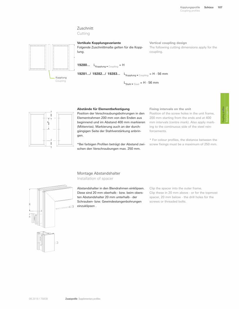
Zusatzprofile Supplementary profiles08.2016 / 75838
Zuschnitt
Cutting
H
Kopplung
Coupling
Vertikale Kopplungsvariante
Folgende Zuschnittmaße gelten für die Kopp-
lung.
Vertical coupling design
The following cutting dimensions apply for the
coupling.
LStahl • Steel
= H - 56 mm
LKopplung • Coupling
= H19280...
19281.../ 19282.../ 19283... LKopplung • Coupling
= H - 56 mm
Abstände für Elementbefestigung
Position der Verschraubungsbohrungen in den
Elementrahmen 200 mm von den Enden aus
beginnend und im Abstand 400 mm markieren
(Mittenriss). Markierung auch an der durch-
gängigen Seite der Stahlverstärkung anbrin-
gen.
*Bei farbigen Profilen beträgt der Abstand zwi-
schen den Verschraubungen max. 250 mm.
Fixing intervals on the unit
Position of the screw holes in the unit frame,
200 mm starting from the ends and at 400
mm intervals (centre mark). Also apply mark-
ing to the continuous side of the steel rein-
forcements.
* For colour profiles, the distance between the
screw fixings must be a maximum of 250 mm.
200
400
200
*
Montage Abstandshalter
Installation of spacer
Abstandshalter in den Blendrahmen einklipsen.
Diese sind 20 mm oberhalb - bzw. beim obers-
ten Abstandshalter 20 mm unterhalb - der
Schrauben- bzw. Gewindestangenbohrungen
einzuklipsen .
20
200
Clip the spacer into the outer frame.
Clip these in 20 mm above - or for the topmost
spacer, 20 mm below - the drill holes for the
screws or threaded bolts.
Schüco 107Kopplungsprofile
Coupling profiles
Coupling profiles
Kopplungsprofile
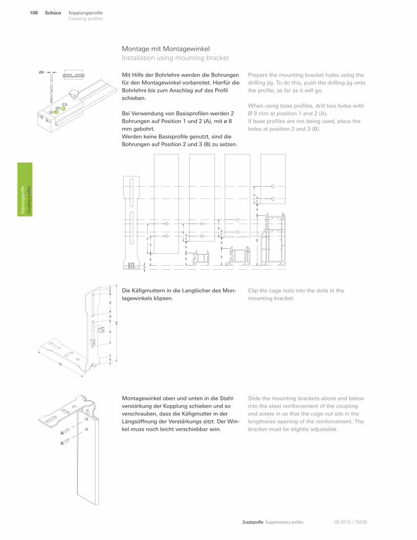
Zusatzprofile Supplementary profiles 08.2016 / 75838
Montage mit Montagewinkel
Installation using mounting bracket
Mit Hilfe der Bohrlehre werden die Bohrungen
für den Montagewinkel vorbereitet. Hierfür die
Bohrlehre bis zum Anschlag auf das Profil
schieben.
Bei Verwendung von Basisprofilen werden 2
Bohrungen auf Position 1 und 2 (A), mit ø 8
mm gebohrt.
Werden keine Basisprofile genutzt, sind die
Bohrungen auf Position 2 und 3 (B) zu setzen.
Prepare the mounting bracket holes using the
drilling jig. To do this, push the drilling jig onto
the profile, as far as it will go.
When using base profiles, drill two holes with
Ø 8 mm at position 1 and 2 (A).
If base profiles are not being used, place the
holes at position 2 and 3 (B).
150
245
60
70
20
10
20
Die Käfigmuttern in die Langlöcher des Mon-
tagewinkels klipsen.
Clip the cage nuts into the slots in the
mounting bracket.
10
28
28
28
28
30 4
0
12
0
42
72
12
42
12
42
12
42
Ø8
Montagewinkel oben und unten in die Stahl-
verstärkung der Kopplung schieben und so
verschrauben, dass die Käfigmutter in der
Längsönnung der Verstärkungs sitzt. Der Win-
kel muss noch leicht verschiebbar sein.
Slide the mounting brackets above and below
into the steel reinforcement of the coupling
and screw in so that the cage nut sits in the
lengthwise opening of the reinforcement. The
bracket must be slightly adjustable.
Schüco108 Kopplungsprofile
Coupling profiles Kopplungsprofile
Coupling profiles
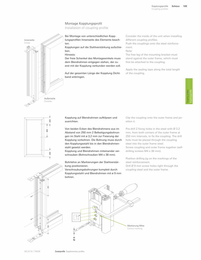
Zusatzprofile Supplementary profiles08.2016 / 75838
Montage Kopplungsprofil
Installation of coupling profile
Bei Montage von unterschiedlichen Kopp-
lungsprofilen Innenseite des Elements beach-
ten.
Kopplungen auf die Stahlverstärkung aufschie-
ben.
Hinweis:
Der freie Schenkel des Montagewinkels muss
dem Blendrahmen entgegen stehen, der zu-
erst mit der Kopplung verbunden werden soll.
Auf der gesamten Länge der Kopplung Dicht-
band anbringen.
Consider the inside of the unit when installing
dinerent coupling profiles.
Push the couplings onto the steel reinforce-
ment.
Note:
The free leg of the mounting bracket must
stand against the outer frame, which must
first be attached to the coupling.
Apply the sealing tape along the total length
of the coupling.
Außenseite
Outside
Innenseite
Inside
250
250
Kopplung auf Blendrahmen aufklipsen und
ausrichten.
Von beiden Ecken des Blendrahmens aus im
Abstand von 250 mm 2 Befestigungsbohrun-
gen im Stahl mit ø 3,2 mm zur Fixierung der
Kopplung vorbohren. Die Bohrung muss durch
den Kopplungsstahl bis in den Blendrahmen-
stahl gesetzt werden.
Kopplung und Blendrahmen miteinander ver-
schrauben (Bohrschrauben M4 x 38 mm).
Bohrlehre an Markierungen der Stahlverstär-
kung positionieren.
Verschraubungsbohrungen komplett durch
Kopplungsstahl und Blendrahmen mit ø 9 mm
bohren.
Clip the coupling onto the outer frame and po-
sition it.
Pre-drill 2 fixing holes in the steel with Ø 3.2
mm, from both corners of the outer frame at
250 mm intervals, to fix the coupling. The drill
hole must be placed through the coupling
steel into the outer frame steel.
Screw coupling and outer frame together (self-
drilling screws M4 x 38 mm).
Position drilling jig on the markings of the
steel reinforcement.
Drill Ø 9 mm screw holes right through the
coupling steel and the outer frame.
200
400
200
Ø9
Markierung Mitte
Centre marking
P
Schüco 109Kopplungsprofile
Coupling profiles
Coupling profiles
Kopplungsprofile
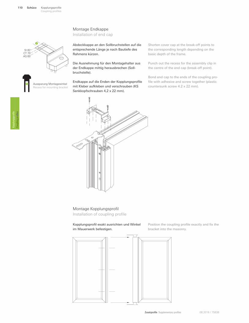
Zusatzprofile Supplementary profiles 08.2016 / 75838
Aussparung Montagewinkel
Recess for mounting bracket
SI 82CT 70AS 60
Abdeckkappe an den Sollbruchstellen auf die
entsprechende Länge je nach Bautiefe des
Rahmens kürzen.
Die Ausnehmung für den Montagehalter aus
der Endkappe mittig herausbrechen (Soll-
bruchstelle).
Endkappe auf die Enden der Kopplungsprofile
mit Kleber aufkleben und verschrauben (KS
Senkkopfschrauben 4,2 x 22 mm).
Shorten cover cap at the break-on points to
the corresponding length depending on the
basic depth of the frame.
Punch out the recess for the assembly clip in
the centre of the end cap (break-on point).
Bond end cap to the ends of the coupling pro-
file with adhesive and screw together (plastic
countersunk screw 4.2 x 22 mm).
Montage Endkappe
Installation of end cap
Montage Kopplungsprofil
Installation of coupling profile
Kopplungsprofil exakt ausrichten und Winkel
im Mauerwerk befestigen.
Position the coupling profile exactly and fix the
bracket into the masonry.
Schüco110 Kopplungsprofile
Coupling profiles Kopplungsprofile
Coupling profiles
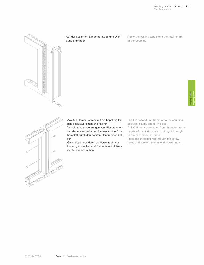
Zusatzprofile Supplementary profiles08.2016 / 75838
Auf der gesamten Länge der Kopplung Dicht-
band anbringen.
Apply the sealing tape along the total length
of the coupling.
Zweiten Elementrahmen auf die Kopplung klip-
sen, exakt ausrichten und fixieren.
Verschraubungsbohrungen vom Blendrahmen-
falz des ersten verbauten Elements mit ø 9 mm
komplett durch den zweiten Blendrahmen boh-
ren.
Gewindestangen durch die Verschraubungs-
bohrungen stecken und Elemente mit Hülsen-
muttern verschrauben.
Clip the second unit frame onto the coupling,
position exactly and fix in place.
Drill Ø 9 mm screw holes from the outer frame
rebate of the first installed unit right through
to the second outer frame.
Place the threaded rod through the screw
holes and screw the units with socket nuts.
Schüco 111Kopplungsprofile
Coupling profiles
Coupling profiles
Kopplungsprofile
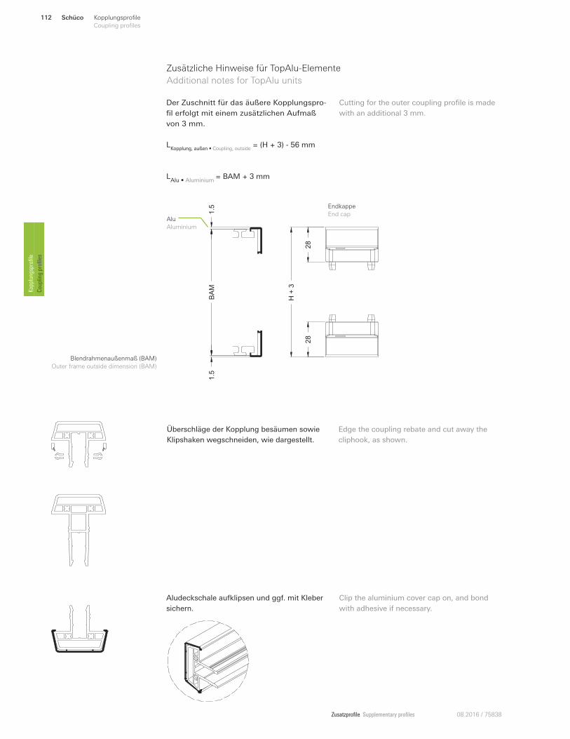
Zusatzprofile Supplementary profiles 08.2016 / 75838
Zusätzliche Hinweise für TopAlu-Elemente
Additional notes for TopAlu units
Blendrahmenaußenmaß (BAM)
Outer frame outside dimension (BAM)
BA
M1.5
1.5
H+
3
28
28
Alu
Aluminium
Endkappe
End cap
LKopplung, außen • Coupling, outside
= (H + 3) - 56 mm
LAlu • Aluminium
= BAM + 3 mm
Der Zuschnitt für das äußere Kopplungspro-
fil erfolgt mit einem zusätzlichen Aufmaß
von 3 mm.
Cutting for the outer coupling profile is made
with an additional 3 mm.
Überschläge der Kopplung besäumen sowie
Klipshaken wegschneiden, wie dargestellt.
Edge the coupling rebate and cut away the
cliphook, as shown.
Aludeckschale aufklipsen und ggf. mit Kleber
sichern.
Clip the aluminium cover cap on, and bond
with adhesive if necessary.
Schüco112 Kopplungsprofile
Coupling profiles Kopplungsprofile
Coupling profiles
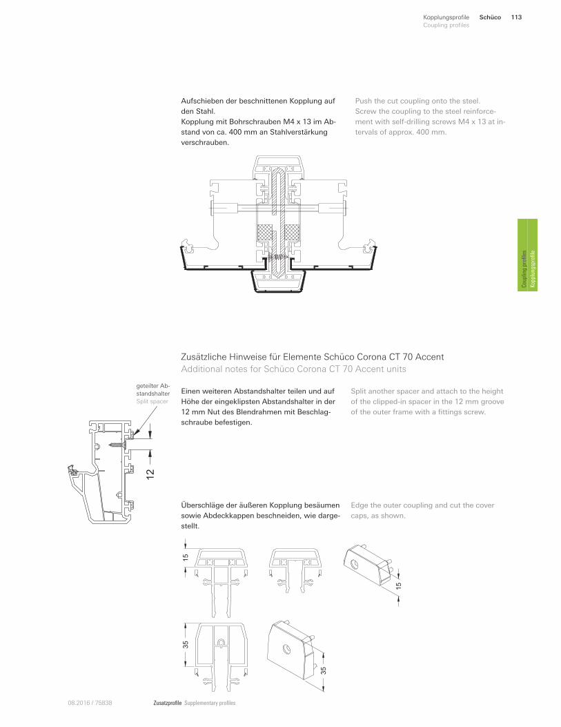
Zusatzprofile Supplementary profiles08.2016 / 75838
Aufschieben der beschnittenen Kopplung auf
den Stahl.
Kopplung mit Bohrschrauben M4 x 13 im Ab-
stand von ca. 400 mm an Stahlverstärkung
verschrauben.
Push the cut coupling onto the steel.
Screw the coupling to the steel reinforce-
ment with self-drilling screws M4 x 13 at in-
tervals of approx. 400 mm.
Zusätzliche Hinweise für Elemente Schüco Corona CT 70 Accent
Additional notes for Schüco Corona CT 70 Accent units
Einen weiteren Abstandshalter teilen und auf
Höhe der eingeklipsten Abstandshalter in der
12 mm Nut des Blendrahmen mit Beschlag-
schraube befestigen.
Split another spacer and attach to the height
of the clipped-in spacer in the 12 mm groove
of the outer frame with a fittings screw.
12
geteilter Ab-
standshalter
Split spacer
15
15
35
35
Überschläge der äußeren Kopplung besäumen
sowie Abdeckkappen beschneiden, wie darge-
stellt.
Edge the outer coupling and cut the cover
caps, as shown.
Schüco 113Kopplungsprofile
Coupling profiles
Coupling profiles
Kopplungsprofile
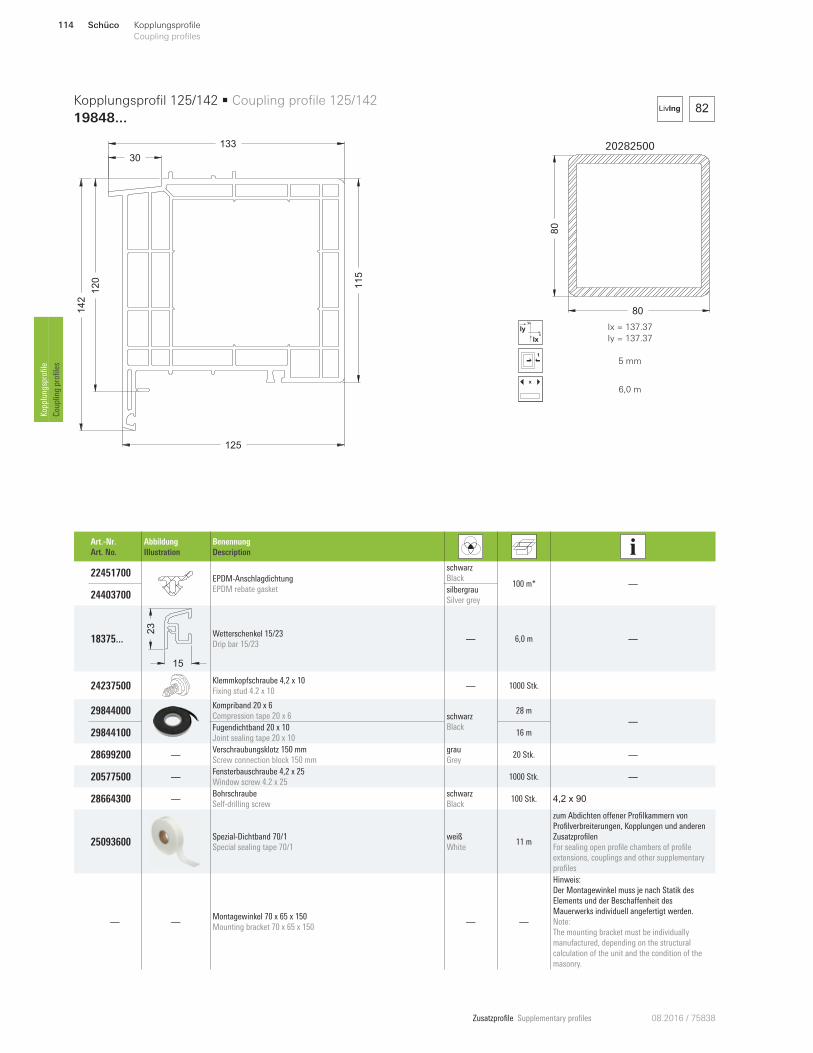
Zusatzprofile Supplementary profiles 08.2016 / 75838
20282500
80
80
x
y
Ix
Iy Ix = 137.37
Iy = 137.37
5 mm
x
6,0 m
82LivIng
12
0
125
14
2
133
30
11
5
Kopplungsprofil 125/142 • Coupling profile 125/142
19848...
Art.-Nr.
Art. No.
Abbildung
Illustration
Benennung
Description
22451700 EPDM-Anschlagdichtung
EPDM rebate gasket
schwarz
Black 100 m* —
24403700 silbergrau
Silver grey
18375 ...
15
23
Wetterschenkel 15/23
Drip bar 15/23 — 6,0 m —
24237500 Klemmkopfschraube 4,2 x 10
Fixing stud 4.2 x 10 — 1000 Stk.
29844000 Kompriband 20 x 6
Compression tape 20 x 6 schwarz
Black
28 m
—
29844100 Fugendichtband 20 x 10
Joint sealing tape 20 x 1016 m
28699200 —Verschraubungsklotz 150 mm
Screw connection block 150 mm
grau
Grey 20 Stk. —
20577500 —Fensterbauschraube 4,2 x 25
Window screw 4.2 x 25 1000 Stk. —
28664300 —Bohrschraube
Self-drilling screw
schwarz
Black 100 Stk. 4,2 x 90
25093600 Spezial-Dichtband 70/1
Special sealing tape 70/1
weiß
White 11 m
zum Abdichten omener Profilkammern von
Profilverbreiterungen, Kopplungen und anderen
Zusatzprofilen
For sealing open profile chambers of profile
extensions, couplings and other supplementary
profiles
— —Montagewinkel 70 x 65 x 150
Mounting bracket 70 x 65 x 150 — —
Hinweis:
Der Montagewinkel muss je nach Statik des
Elements und der Beschamenheit des
Mauerwerks individuell angefertigt werden.
Note:
The mounting bracket must be individually
manufactured, depending on the structural
calculation of the unit and the condition of the
masonry.
Schüco114 Kopplungsprofile
Coupling profiles Kopplungsprofile
Coupling profiles
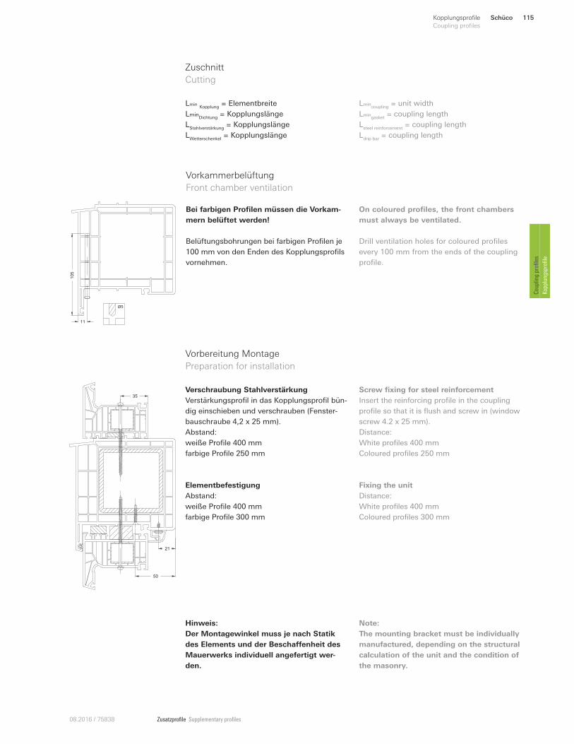
Zusatzprofile Supplementary profiles08.2016 / 75838
50
21
35
Ø5
10
5
11
Lmin Kopplung
= Elementbreite
LminDichtung
= Kopplungslänge
LStahlverstärkung
= Kopplungslänge
LWetterschenkel
= Kopplungslänge
Lmincoupling
= unit width
Lmingasket
= coupling length
Lsteel reinforcement
= coupling length
Ldrip bar
= coupling length
Zuschnitt
Cutting
Verschraubung Stahlverstärkung
Verstärkungsprofil in das Kopplungsprofil bün-
dig einschieben und verschrauben (Fenster-
bauschraube 4,2 x 25 mm).
Abstand:
weiße Profile 400 mm
farbige Profile 250 mm
Screw fixing for steel reinforcement
Insert the reinforcing profile in the coupling
profile so that it is flush and screw in (window
screw 4.2 x 25 mm).
Distance:
White profiles 400 mm
Coloured profiles 250 mm
Vorbereitung Montage
Preparation for installation
Elementbefestigung
Abstand:
weiße Profile 400 mm
farbige Profile 300 mm
Fixing the unit
Distance:
White profiles 400 mm
Coloured profiles 300 mm
Vorkammerbelüftung
Front chamber ventilation
Bei farbigen Profilen müssen die Vorkam-
mern belüftet werden!
Belüftungsbohrungen bei farbigen Profilen je
100 mm von den Enden des Kopplungsprofils
vornehmen.
On coloured profiles, the front chambers
must always be ventilated.
Drill ventilation holes for coloured profiles
every 100 mm from the ends of the coupling
profile.
Hinweis:
Der Montagewinkel muss je nach Statik
des Elements und der BeschaUenheit des
Mauerwerks individuell angefertigt wer-
den.
Note:
The mounting bracket must be individually
manufactured, depending on the structural
calculation of the unit and the condition of
the masonry.
Schüco 115Kopplungsprofile
Coupling profiles
Coupling profiles
Kopplungsprofile
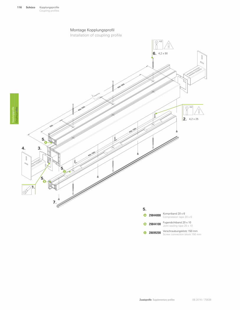
Zusatzprofile Supplementary profiles 08.2016 / 75838
4.2
4.2
L Kopplung
L coupling
Montage Kopplungsprofil
Installation of coupling profile
7.
3.4.
5.
5.
2. 4,2 x 25
4,2 x 906.
1.
A
B
5.
AKompriband 20 x 6
Compression tape 20 x 6
Fugendichtband 20 x 10
Joint sealing tape 20 x 10
Verschraubungsklotz 150 mm
Screw connection block 150 mm
29844000
29844100
28699200
B
C
5.C
Schüco116 Kopplungsprofile
Coupling profiles Kopplungsprofile
Coupling profiles
Zusatzprofile Supplementary profiles08.2016 / 75838
Montage Kopplungsprofil
Installation of coupling profile
1. Dichtung einziehen
2. Verstärkungsprofil in der Kopplung ver-
schrauben.
3. Dichtband auf die Enden des Kopplungspro-
fils kleben, wie dargestellt Stahlkammer aus-
lassen.
4. Montagewinkel einschieben, Kopplung aus-
richten. Montagewinkel am Mauerwerk befes-
tigen und Kopplungsprofil fixieren.
5. Fugendichtband und Verschraubungsklötze
entsprechend der Darstellung auf Element
ausrichten und fixieren.
6. Element und Kopplung miteinander ver-
schrauben, dabei Profildeformation vermeiden.
7. Klemmkopfschrauben an Kopplung anbrin-
gen und Wetterschenkel befestigen.
1. Insert the gasket
2. Fix the reinforcing profile in the coupling
using screws.
3. Bond the sealing tape at the ends of the
coupling profile, leave out steel chamber as
shown.
4. Insert mounting bracket, align coupling.
Attach the mounting bracket to the masonry
and fix the coupling profile.
5. Align and fix the joint sealing tape and
screw connection blocks on the unit in ac-
cordance with the illustration.
6. Screw together the unit and coupling,
thereby avoiding profile deformations.
7. Attach fixing studs to the coupling and fix
the drip bar.
Schüco 117Kopplungsprofile
Coupling profiles
Coupling profiles
Kopplungsprofile
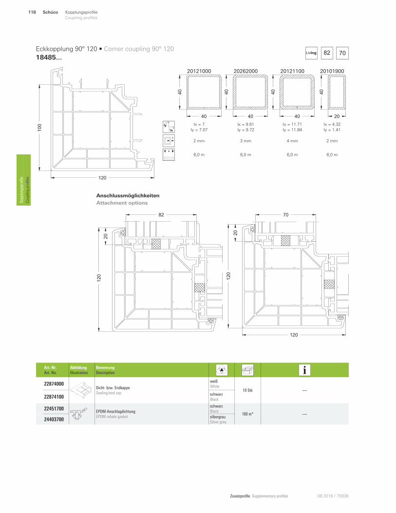
Zusatzprofile Supplementary profiles 08.2016 / 75838
20121000 20262000 20121100 20101900
40
40
40
40
40
40
20
40
x
y
Ix
Iy Ix = 7
Iy = 7.07
Ix = 9.61
Iy = 9.72
Ix = 11.71
Iy = 11.84
Ix = 4.32
Iy = 1.41
2 mm 3 mm 4 mm 2 mm
x
6,0 m 6,0 m 6,0 m 6,0 m
Anschlussmöglichkeiten
Attachment options
20
120
82
20
120
120
70
82 70LivIng
120
100
Eckkopplung 90° 120 • Corner coupling 90° 120
18485...
Art.-Nr.
Art. No.
Abbildung
Illustration
Benennung
Description
22874000 Dicht- bzw. Endkappe
Sealing/end cap
weiß
White 10 Stk —
22874100 schwarz
Black
22451700 EPDM-Anschlagdichtung
EPDM rebate gasket
schwarz
Black 100 m* —
24403700 silbergrau
Silver grey
Schüco118 Kopplungsprofile
Coupling profiles Kopplungsprofile
Coupling profiles
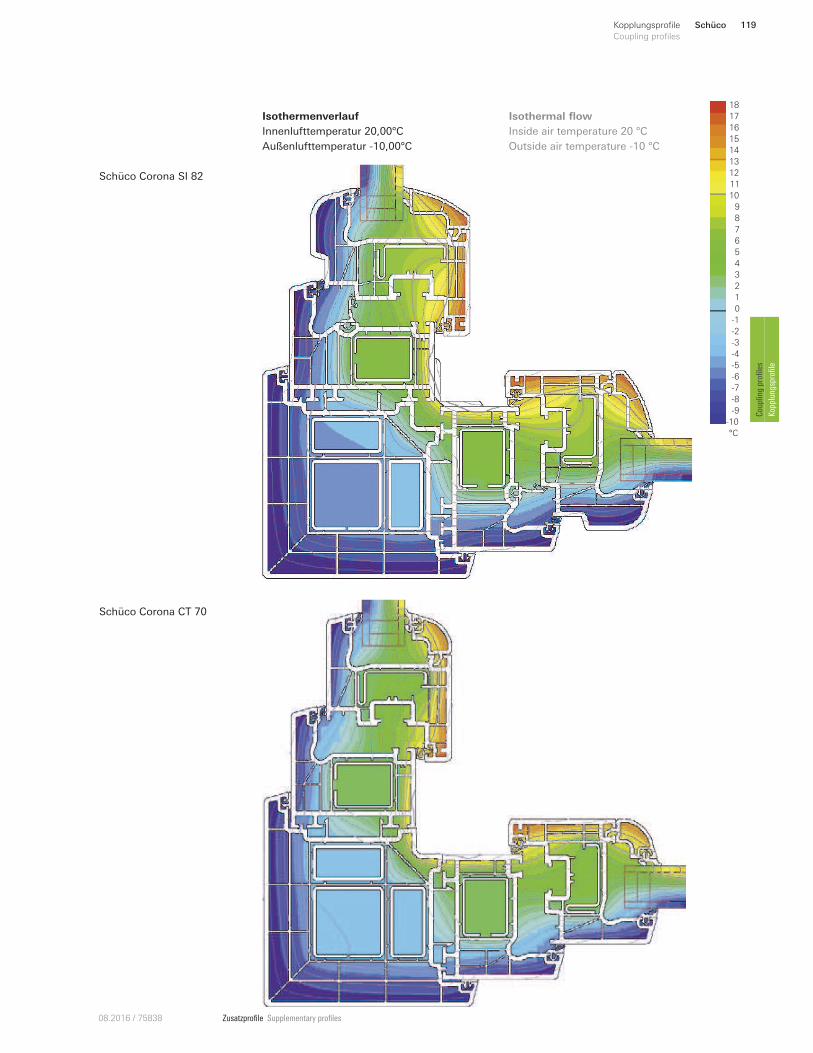
Zusatzprofile Supplementary profiles08.2016 / 75838
Isothermenverlauf
Innenlufttemperatur 20,00°C
Außenlufttemperatur -10,00°C
Inside air temperature 20 °C
Outside air temperature -10 °C
Isothermal flow 18
16
12
11
10
9
8
6
1
5
4
3
0
-6
-9
-10
°C
2
-5
7
13
15
14
-2
-3
-4
-1
-7
-8
17
Schüco Corona SI 82
Schüco Corona CT 70
Schüco 119Kopplungsprofile
Coupling profiles
Coupling profiles
Kopplungsprofile
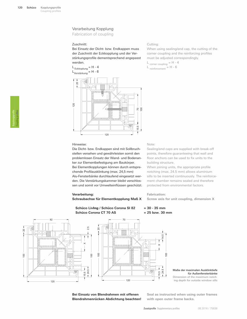
Zusatzprofile Supplementary profiles 08.2016 / 75838
Verarbeitung Kopplung
Fabrication of coupling
Hinweise:
Die Dicht- bzw. Endkappen sind mit Sollbruch-
stellen versehen und gewährleisten somit den
problemlosen Einsatz der Wand- und Bodenan-
ker zur Elementbefestigung am Baukörper.
Bei Elementkopplungen können durch entspre-
chende Profilausklinkung (max. 24,5 mm)
Alu-Fensterbänke durchlaufend eingesetzt wer-
den. Die Verstärkungskammer bleibt verschlos-
sen und somit vor Umwelteinflüssen geschützt.
Note:
Sealing/end caps are supplied with break-on
points, therefore guaranteeing that wall and
floor anchors can be used to fix units to the
building structure.
When joining units, the appropriate profile
notching (max. 24.5 mm) allows aluminium
sills to be inserted continuously. The reinforce-
ment chamber remains sealed and therefore
protected from environmental factors.
Cutting:
When using sealing/end cap, the cutting of the
corner coupling and the reinforcing profiles
must be adjusted correspondingly.
L corner coupling
= H - 4
L reinforcement
= H - 6
Zuschnitt:
Bei Einsatz der Dicht- bzw. Endkappen muss
der Zuschnitt der Eckkopplung und der Ver-
stärkungsprofile dementsprechend angepasst
werden.
L Eckkoplung
= H - 4
LVerstärkung
= H - 6
20
120
12015.5
70
100
Schüco LivIng / Schüco Corona SI 82 = 30 - 35 mm
Schüco Corona CT 70 AS = 25 bzw. 30 mm
Verarbeitung:
Schraubachse für Elementkopplung Maß X
Fabrication:
Screw axis for unit coupling, dimension X
X
20
100
120
15.5 24.5
100
2.5
82
X
20
100
120
15.5 24.5
100
14.5
70
Bei Einsatz von Blendrahmen mit oUenen
Blendrahmenrücken Abdichtung beachten!
Maße der maximalen Ausklinktiefe
für Außenfensterbänke
Dimension of the maximum notch-
ing depth for outside window sills
Seal as instructed when using outer frames
with open outer frame backs.
Schüco120 Kopplungsprofile
Coupling profiles Kopplungsprofile
Coupling profiles
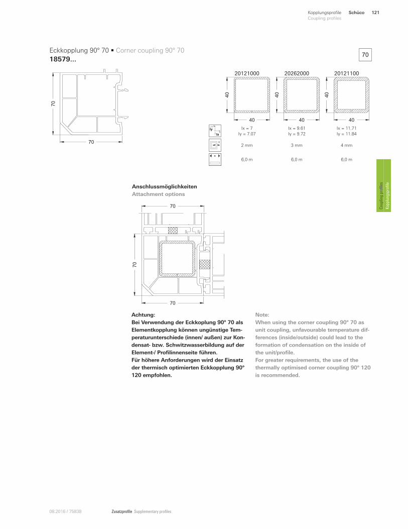
Zusatzprofile Supplementary profiles08.2016 / 75838
Anschlussmöglichkeiten
Attachment options
70
70
Eckkopplung 90° 70 • Corner coupling 90° 70
18579...
20121000 20262000 20121100
40
40
40
40
40
40
x
y
Ix
Iy Ix = 7
Iy = 7.07
Ix = 9.61
Iy = 9.72
Ix = 11.71
Iy = 11.84
2 mm 3 mm 4 mm
x
6,0 m 6,0 m 6,0 m
70
70
70
Achtung:
Bei Verwendung der Eckkoplung 90° 70 als
Elementkopplung können ungünstige Tem-
peraturunterschiede (innen/ außen) zur Kon-
densat- bzw. Schwitzwasserbildung auf der
Element-/ Profilinnenseite führen.
Für höhere Anforderungen wird der Einsatz
der thermisch optimierten Eckkopplung 90°
120 empfohlen.
70
Note:
When using the corner coupling 90° 70 as
unit coupling, unfavourable temperature dif-
ferences (inside/outside) could lead to the
formation of condensation on the inside of
the unit/profile.
For greater requirements, the use of the
thermally optimised corner coupling 90° 120
is recommended.
Schüco 121Kopplungsprofile
Coupling profiles
Coupling profiles
Kopplungsprofile
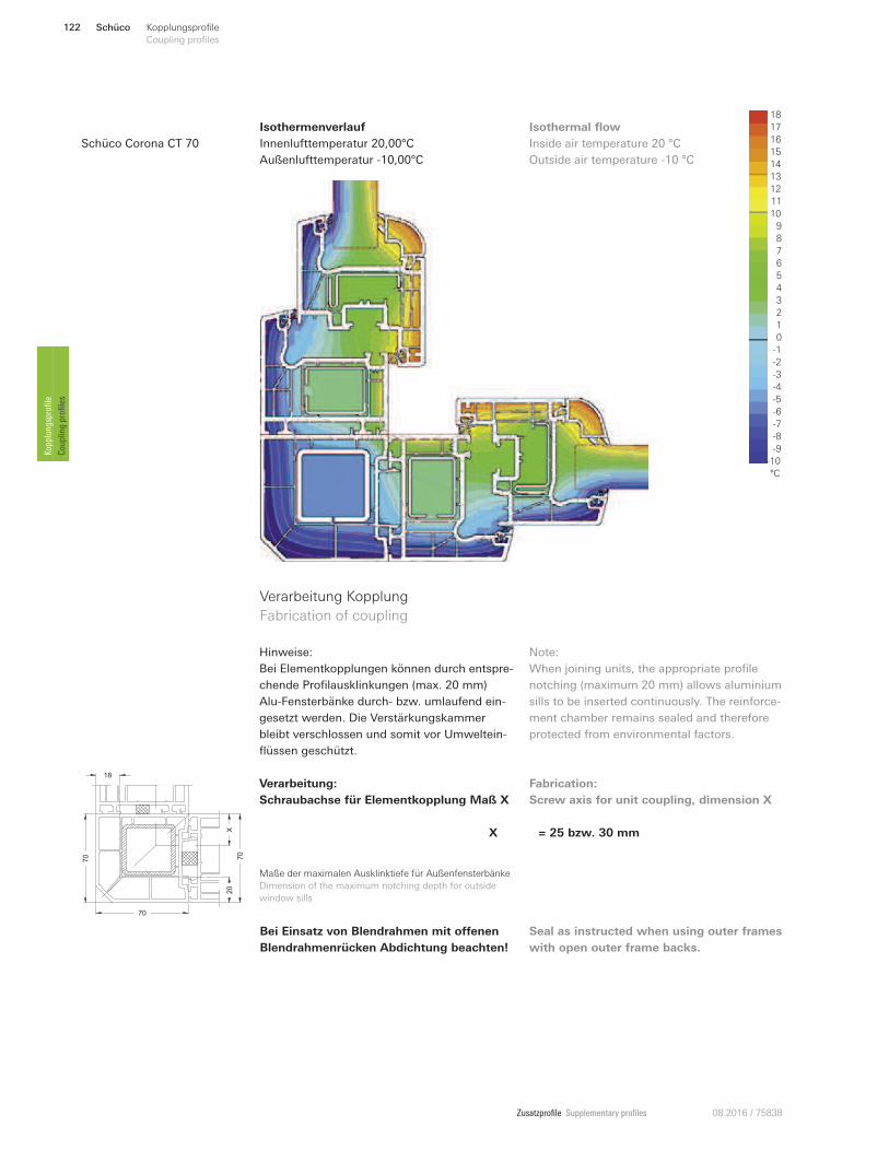
Zusatzprofile Supplementary profiles 08.2016 / 75838
Isothermenverlauf
Innenlufttemperatur 20,00°C
Außenlufttemperatur -10,00°C
Inside air temperature 20 °C
Outside air temperature -10 °C
Isothermal flow 18
16
12
11
10
9
8
6
1
5
4
3
0
-6
-9
-10
°C
2
-5
7
13
15
14
-2
-3
-4
-1
-7
-8
17
Schüco Corona CT 70
Verarbeitung Kopplung
Fabrication of coupling
Hinweise:
Bei Elementkopplungen können durch entspre-
chende Profilausklinkungen (max. 20 mm)
Alu-Fensterbänke durch- bzw. umlaufend ein-
gesetzt werden. Die Verstärkungskammer
bleibt verschlossen und somit vor Umweltein-
flüssen geschützt.
Note:
When joining units, the appropriate profile
notching (maximum 20 mm) allows aluminium
sills to be inserted continuously. The reinforce-
ment chamber remains sealed and therefore
protected from environmental factors.
Verarbeitung:
Schraubachse für Elementkopplung Maß X
X = 25 bzw. 30 mm
Fabrication:
Screw axis for unit coupling, dimension X
70
70
20
18
X
70
Bei Einsatz von Blendrahmen mit oUenen
Blendrahmenrücken Abdichtung beachten!
Seal as instructed when using outer frames
with open outer frame backs.
Maße der maximalen Ausklinktiefe für Außenfensterbänke
Dimension of the maximum notching depth for outside
window sills
Schüco122 Kopplungsprofile
Coupling profiles Kopplungsprofile
Coupling profiles
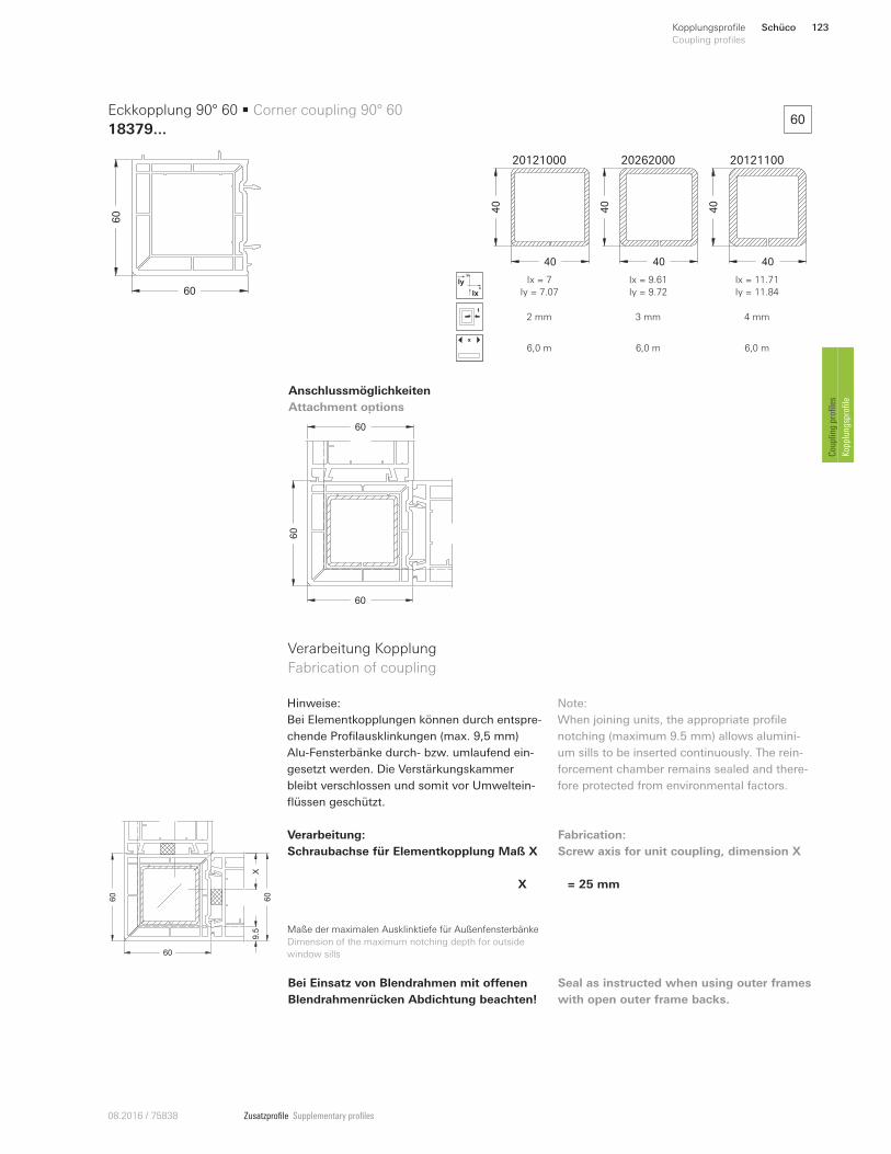
Zusatzprofile Supplementary profiles08.2016 / 75838
Verarbeitung Kopplung
Fabrication of coupling
Verarbeitung:
Schraubachse für Elementkopplung Maß X
Fabrication:
Screw axis for unit coupling, dimension X
Bei Einsatz von Blendrahmen mit oUenen
Blendrahmenrücken Abdichtung beachten!
Seal as instructed when using outer frames
with open outer frame backs.
Maße der maximalen Ausklinktiefe für Außenfensterbänke
Dimension of the maximum notching depth for outside
window sills
Anschlussmöglichkeiten
Attachment options
60
60
Eckkopplung 90° 60 • Corner coupling 90° 60
18379...
20121000 20262000 20121100
40
40
40
40
40
40
x
y
Ix
Iy Ix = 7
Iy = 7.07
Ix = 9.61
Iy = 9.72
Ix = 11.71
Iy = 11.84
2 mm 3 mm 4 mm
x
6,0 m 6,0 m 6,0 m
60
60
60
Hinweise:
Bei Elementkopplungen können durch entspre-
chende Profilausklinkungen (max. 9,5 mm)
Alu-Fensterbänke durch- bzw. umlaufend ein-
gesetzt werden. Die Verstärkungskammer
bleibt verschlossen und somit vor Umweltein-
flüssen geschützt.
X = 25 mm
Note:
When joining units, the appropriate profile
notching (maximum 9.5 mm) allows alumini-
um sills to be inserted continuously. The rein-
forcement chamber remains sealed and there-
fore protected from environmental factors.
60
60
9.5
60
X
60
Schüco 123Kopplungsprofile
Coupling profiles
Coupling profiles
Kopplungsprofile
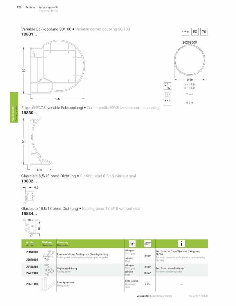
Zusatzprofile Supplementary profiles 08.2016 / 75838
82 70LivIng
106
90
Variable Eckkopplung 90/106 • Variable corner coupling 90/106
19831...
Eckprofil 90/48 (variable Eckkopplung) • Corner profile 90/48 (variable corner coupling)
19830...
Art.-Nr.
Art. No.
Abbildung
Illustration
Benennung
Description
25040700 Reparaturdichtung: Anschlag- und Glasanlagedichtung
Repair gasket: rebate gasket and glazing rebate gasket
silbergrau
Silver grey 100 m*
Zum Einsatz im Eckprofil (variable Eckkopplung
90/106)
For use in the corner profile (variable corner coupling
90/106)) 25040300 schwarz
Black
22488800 Verglasungsdichtung
Glazing gasket
silbergrau
Silver grey 100 m*
Zum Einsatz in den Glasleisten
For use in the glazing beads 22452400
schwarz
Black 200 m*
28691100 Befestigungsanker
Fixing anchor
Stahl verzinkt
Galvanised
steel
2 Stk. —
20269500
Ø 60
x
y
Ix
Iy Ix = 15.34
Iy = 15.34
2 mm
x
6,0 m
90
47.9
Glasleiste 6,5/18 ohne Dichtung • Glazing bead 6.5/18 without seal
19832 ...
6.5
18
Glasleiste 18,5/18 ohne Dichtung • Glazing bead 18.5/18 without seal
19834 ...
18
18.5
Schüco124 Kopplungsprofile
Coupling profiles Kopplungsprofile
Coupling profiles
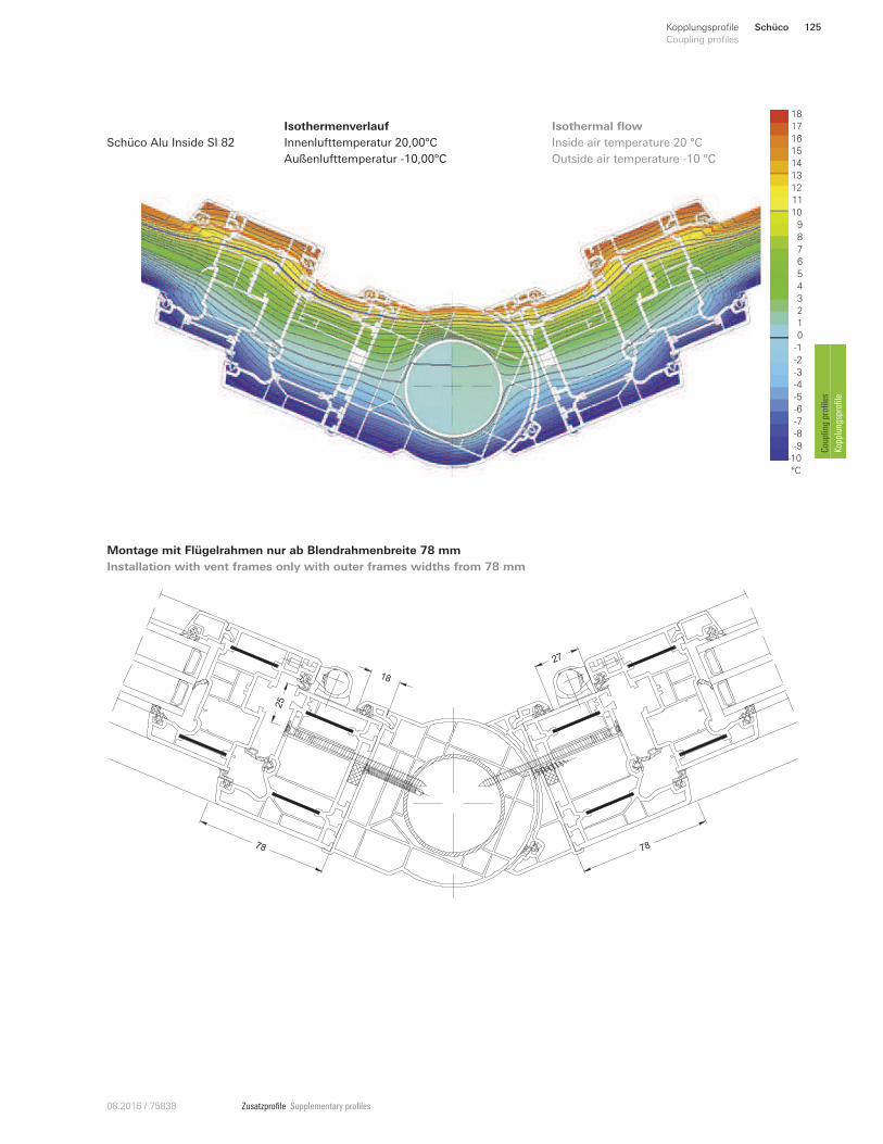
Zusatzprofile Supplementary profiles08.2016 / 75838
Isothermenverlauf
Innenlufttemperatur 20,00°C
Außenlufttemperatur -10,00°C
Inside air temperature 20 °C
Outside air temperature -10 °C
Isothermal flow 18
16
12
11
10
9
8
6
1
5
4
3
0
-6
-9
-10
°C
2
-5
7
13
15
14
-2
-3
-4
-1
-7
-8
17
Schüco Alu Inside SI 82
18
78 78
25
27
Montage mit Flügelrahmen nur ab Blendrahmenbreite 78 mm
Installation with vent frames only with outer frames widths from 78 mm
Schüco 125Kopplungsprofile
Coupling profiles
Coupling profiles
Kopplungsprofile
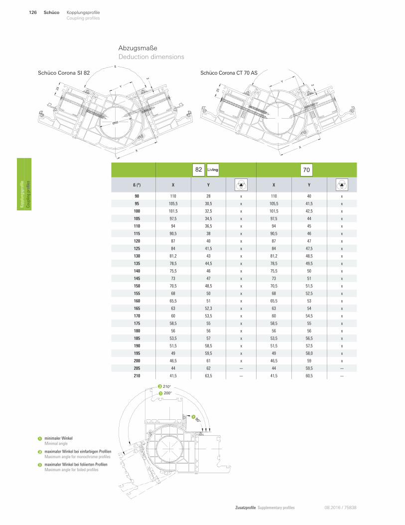
Zusatzprofile Supplementary profiles 08.2016 / 75838
82
LivIng 70
ß (°) X Y X Y
90 110 28 x 110 40 x
95 105,5 30,5 x 105,5 41,5 x
100 101,5 32,5 x 101,5 42,5 x
105 97,5 34,5 x 97,5 44 x
110 94 36,5 x 94 45 x
115 90,5 38 x 90,5 46 x
120 87 40 x 87 47 x
125 84 41,5 x 84 47,5 x
130 81,2 43 x 81,2 48,5 x
135 78,5 44,5 x 78,5 49,5 x
140 75,5 46 x 75,5 50 x
145 73 47 x 73 51 x
150 70,5 48,5 x 70,5 51,5 x
155 68 50 x 68 52,5 x
160 65,5 51 x 65,5 53 x
165 63 52,3 x 63 54 x
170 60 53,5 x 60 54,5 x
175 58,5 55 x 58,5 55 x
180 56 56 x 56 56 x
185 53,5 57 x 53,5 56,5 x
190 51,5 58,5 x 51,5 57,5 x
195 49 59,5 x 49 58,0 x
200 46,5 61 x 46,5 59 x
205 44 62 — 44 59,5 —
210 41,5 63,5 — 41,5 60,5 —
Abzugsmaße
Deduction dimensions
ß
Y
X
Ø60
2
25
Schüco Corona SI 82
Y
X
25
2
Schüco Corona CT 70 AS
maximaler Winkel bei einfarbigen Profilen
Maximum angle for monochrome profiles
minimaler Winkel
Minimal angle
maximaler Winkel bei foliierten Profilen
Maximum angle for foiled profiles 3
90°
210°
200°3
Schüco126 Kopplungsprofile
Coupling profiles Kopplungsprofile
Coupling profiles
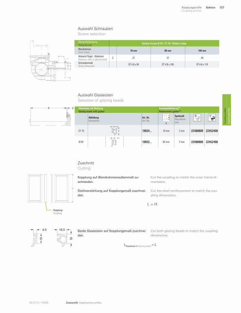
Zusatzprofile Supplementary profiles08.2016 / 75838
X 2
Auswahl Glasleisten
Selection of glazing beads
Auswahl Schrauben
Screw selection
Z
2925
Elementbefestigung
Fixing the unit Schüco Corona SI 82 / CT 70 / Schüco LivIng
Blendrahmen
Outer frame 78 mm 88 mm 100 mm
Abstand Flügel - Glasleiste
Distance: vent to glazing bead Z 27 37 49
Schraubenmaß
Screw dimension ST 4.8 x 90 ST 4.8 x 100 ST 4.8 x 110
Glasleisten mit Dichtung
Glazing beads with gasket
Austauschdichtung**
Replacement gasket**
Abbildung
Illustration
Art.-Nr.
Art. No. X
Spaltmaß
Gap dimen-
sion
CT 70 18
18.5
19834 ... 70 mm 2 mm 22488800 22452400
SI 82
6.5
18 19832... 82 mm 2 mm 22488800 22452400
L = H
Zuschnitt
Cutting
H
Kopplung
Coupling
Kopplung auf Blendrahmenaußenmaß zu-
schneiden.
Stahlverstärkung auf Kopplungsmaß zuschnei-
den.
Cut the coupling to match the outer frame di-
mensions.
Cut the steel reinforcement to match the cou-
pling dimensions.
Beide Glasleisten auf Kopplungsmaß zuschnei-
den.
Cut both glazing beads to match the coupling
dimensions.
LGlasleiste • Glazing bead
= L
6.5
18
18
18.5
Schüco 127Kopplungsprofile
Coupling profiles
Coupling profiles
Kopplungsprofile
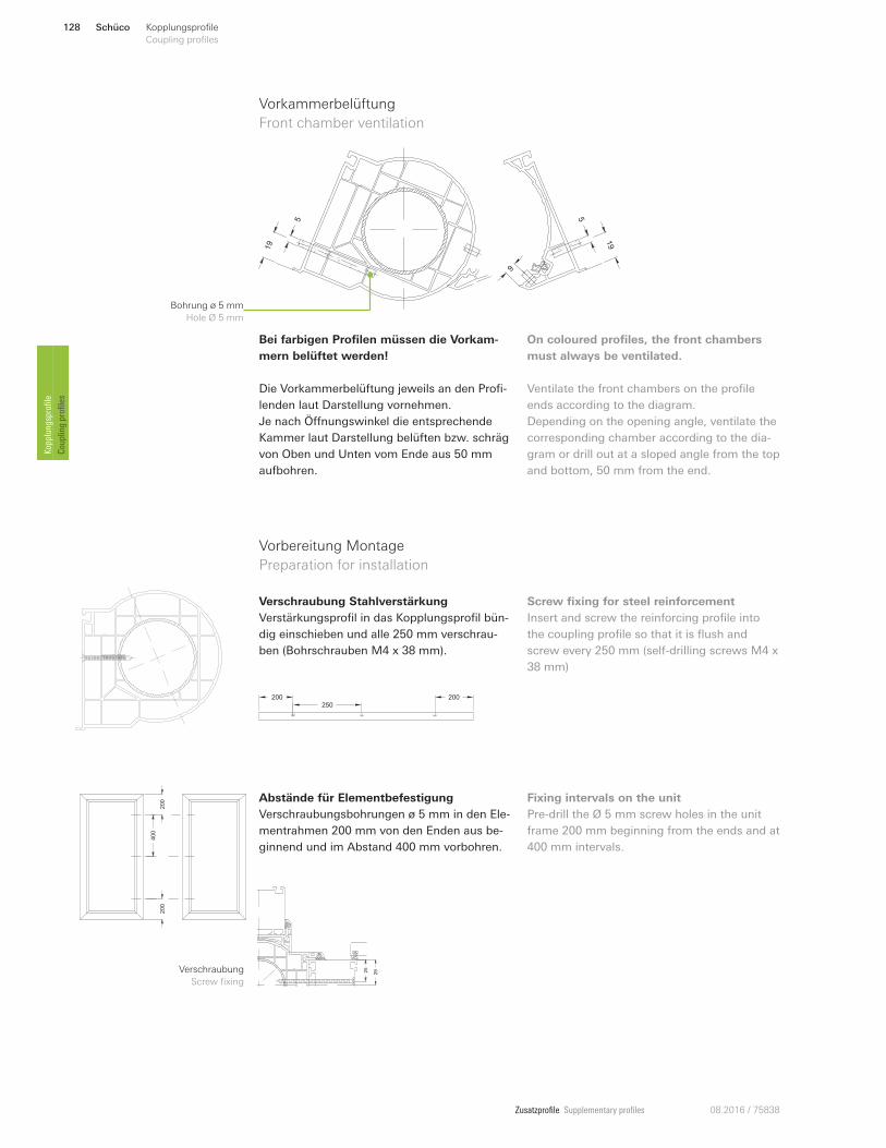
Zusatzprofile Supplementary profiles 08.2016 / 75838
Vorkammerbelüftung
Front chamber ventilation
Bohrung ø 5 mm
Hole Ø 5 mm
19
5
19
5
9
Bei farbigen Profilen müssen die Vorkam-
mern belüftet werden!
Die Vorkammerbelüftung jeweils an den Profi-
lenden laut Darstellung vornehmen.
Je nach Önnungswinkel die entsprechende
Kammer laut Darstellung belüften bzw. schräg
von Oben und Unten vom Ende aus 50 mm
aufbohren.
On coloured profiles, the front chambers
must always be ventilated.
Ventilate the front chambers on the profile
ends according to the diagram.
Depending on the opening angle, ventilate the
corresponding chamber according to the dia-
gram or drill out at a sloped angle from the top
and bottom, 50 mm from the end.
Verschraubung Stahlverstärkung
Verstärkungsprofil in das Kopplungsprofil bün-
dig einschieben und alle 250 mm verschrau-
ben (Bohrschrauben M4 x 38 mm).
Screw fixing for steel reinforcement
Insert and screw the reinforcing profile into
the coupling profile so that it is flush and
screw every 250 mm (self-drilling screws M4 x
38 mm)
200250
200
Vorbereitung Montage
Preparation for installation
Z
2925
Abstände für Elementbefestigung
Verschraubungsbohrungen ø 5 mm in den Ele-
mentrahmen 200 mm von den Enden aus be-
ginnend und im Abstand 400 mm vorbohren.
Fixing intervals on the unit
Pre-drill the Ø 5 mm screw holes in the unit
frame 200 mm beginning from the ends and at
400 mm intervals.
200
400
200
Verschraubung
Screw fixing
Schüco128 Kopplungsprofile
Coupling profiles Kopplungsprofile
Coupling profiles
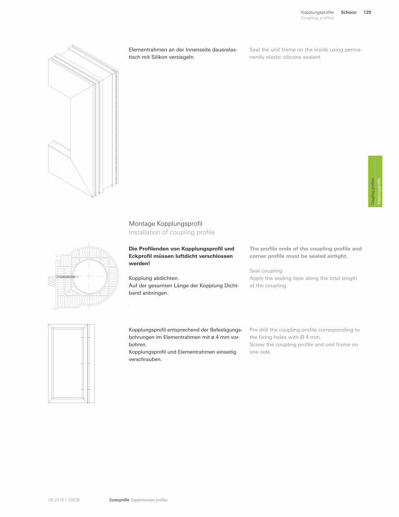
Zusatzprofile Supplementary profiles08.2016 / 75838
Elementrahmen an der Innenseite dauerelas-
tisch mit Silikon versiegeln.
Seal the unit frame on the inside using perma-
nently elastic silicone sealant.
Montage Kopplungsprofil
Installation of coupling profile
Die Profilenden von Kopplungsprofil und
Eckprofil müssen luftdicht verschlossen
werden!
Kopplung abdichten.
Auf der gesamten Länge der Kopplung Dicht-
band anbringen.
The profile ends of the coupling profile and
corner profile must be sealed airtight.
Seal coupling.
Apply the sealing tape along the total length
of the coupling.
Kopplungsprofil entsprechend der Befestigungs-
bohrungen im Elementrahmen mit ø 4 mm vor-
bohren.
Kopplungsprofil und Elementrahmen einseitig
verschrauben.
Pre-drill the coupling profile corresponding to
the fixing holes with Ø 4 mm.
Screw the coupling profile and unit frame on
one side.
Schüco 129Kopplungsprofile
Coupling profiles
Coupling profiles
Kopplungsprofile
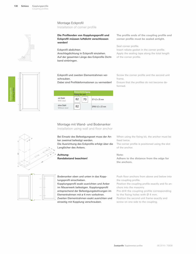
Zusatzprofile Supplementary profiles 08.2016 / 75838
Die Profilenden von Kopplungsprofil und
Eckprofil müssen luftdicht verschlossen
werden!
Eckprofil abdichten.
Anschlagdichtung in Eckprofil einziehen.
Auf der gesamten Länge des Eckprofils Dicht-
band einbringen.
The profile ends of the coupling profile and
corner profile must be sealed airtight.
Seal corner profile.
Insert rebate gasket in the corner profile.
Apply the sealing tape along the total length
of the corner profile.
Montage Eckprofil
Installation of corner profile
Eckprofil und zweiten Elementrahmen ver-
schrauben.
Dabei sind Profildeformationen zu vermeiden!
Screw the corner profile and the second unit
frame.
Ensure that the profiles do not become de-
formed.
Elementbefestigung
Fixing the unit
mit Stahl
With steel 82 70 ST 4,2 x 25 mm
ohne Stahl
Without steel 82 SPAX 4,2 x 22 mm
225
30
8.5
200
40
Bei Einsatz des Befestigungsset muss der An-
ker zweimal befestigt werden.
Die Ausrichtung des Eckprofils erfolgt über die
Langlöcher des Ankers.
Achtung:
Randabstand beachten!
When using the fixing kit, the anchor must be
fixed twice.
The corner profile is positioned using the slot
of the anchor.
Note:
Adhere to the distance from the edge for
the anchors.
Montage mit Wand- und Bodenanker
Installation using wall and floor anchor
Bodenanker oben und unten in das Kopp-
lungsprofil einschieben.
Kopplungsprofil exakt ausrichten und Anker
im Mauerwerk befestigen. Kopplungsprofil
entsprechend der Befestigungsbohrungen im
Elementrahmen mit ø 4 mm vorbohren.
Zweiten Elementrahmen exakt ausrichten und
einseitig mit Kopplung verschrauben.
Push floor anchors from above and below into
the coupling profile.
Position the coupling profile exactly and fix an-
chors into the masonry.
Pre-drill the coupling profile corresponding
to the fixing holes with Ø 4 mm.
Position the second unit frame exactly and
screw on one side to the coupling.
Schüco130 Kopplungsprofile
Coupling profiles Kopplungsprofile
Coupling profiles
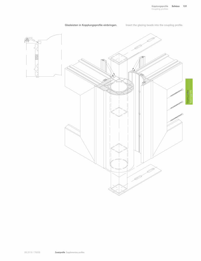
Zusatzprofile Supplementary profiles08.2016 / 75838
Glasleisten in Kopplungsprofile einbringen. Insert the glazing beads into the coupling profile.
Schüco 131Kopplungsprofile
Coupling profiles
Coupling profiles
Kopplungsprofile
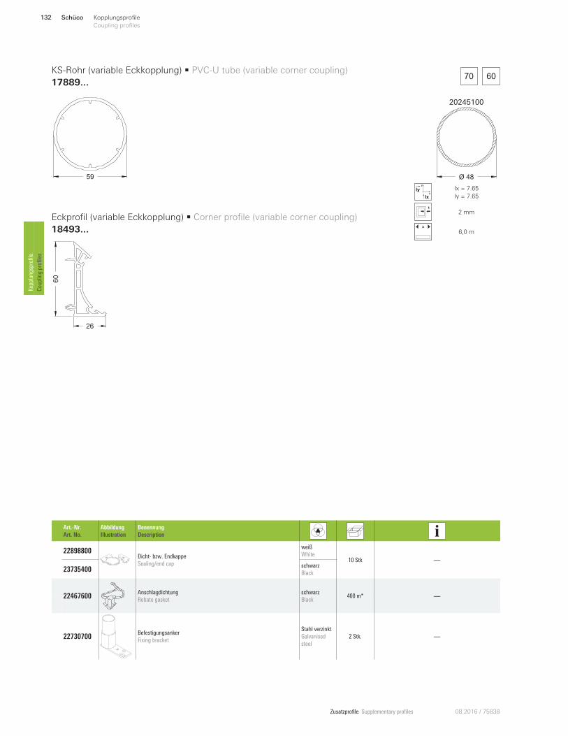
Zusatzprofile Supplementary profiles 08.2016 / 75838
20245100
Ø 48
x
y
Ix
Iy Ix = 7.65
Iy = 7.65
2 mm
x
6,0 m
26
60
70 60
59
KS-Rohr (variable Eckkopplung) • PVC-U tube (variable corner coupling)
17889...
Eckprofil (variable Eckkopplung) • Corner profile (variable corner coupling)
18493...
Art.-Nr.
Art. No.
Abbildung
Illustration
Benennung
Description
22898800 Dicht- bzw. Endkappe
Sealing/end cap
weiß
White 10 Stk —
23735400 schwarz
Black
22467600 Anschlagdichtung
Rebate gasket
schwarz
Black 400 m* —
22730700 Befestigungsanker
Fixing bracket
Stahl verzinkt
Galvanised
steel
2 Stk. —
Schüco132 Kopplungsprofile
Coupling profiles Kopplungsprofile
Coupling profiles
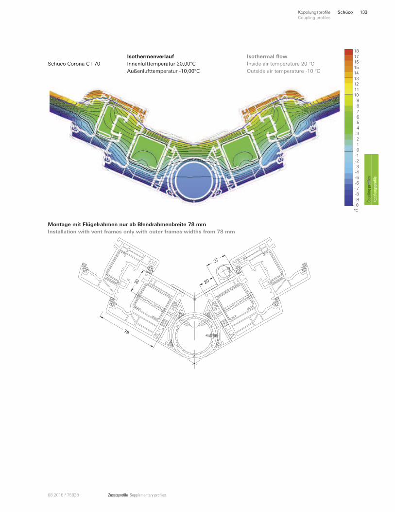
Zusatzprofile Supplementary profiles08.2016 / 75838
Isothermenverlauf
Innenlufttemperatur 20,00°C
Außenlufttemperatur -10,00°C
Inside air temperature 20 °C
Outside air temperature -10 °C
Isothermal flow 18
16
12
11
10
9
8
6
1
5
4
3
0
-6
-9
-10
°C
2
-5
7
13
15
14
-2
-3
-4
-1
-7
-8
17
Schüco Corona CT 70
2030
27
78
Montage mit Flügelrahmen nur ab Blendrahmenbreite 78 mm
Installation with vent frames only with outer frames widths from 78 mm
Schüco 133Kopplungsprofile
Coupling profiles
Coupling profiles
Kopplungsprofile
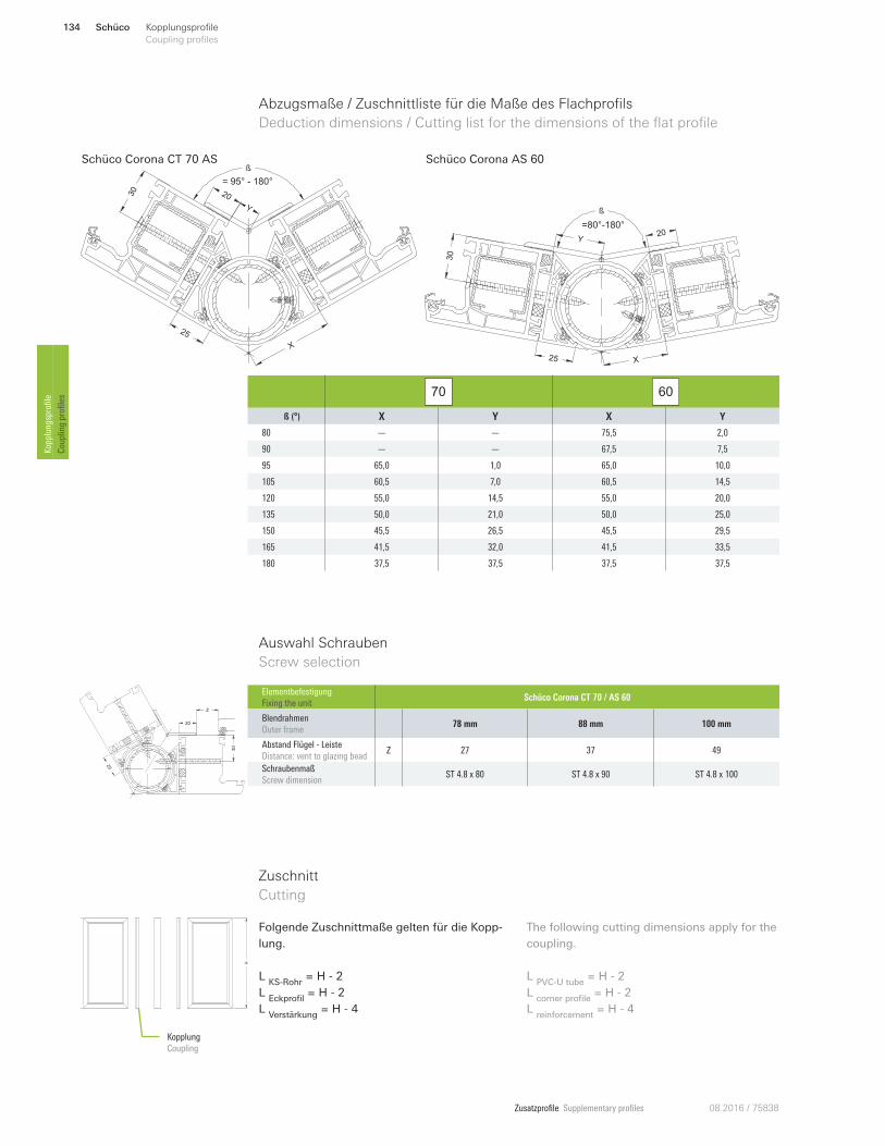
Zusatzprofile Supplementary profiles 08.2016 / 75838
X
2030
Y
25
ß
= 95° - 180°
Schüco Corona CT 70 AS
ß
20Y
=80°-180°
25 X
30
Schüco Corona AS 60
70 60
ß (°) X Y X Y
80 — — 75,5 2,0
90 — — 67,5 7,5
95 65,0 1,0 65,0 10,0
105 60,5 7,0 60,5 14,5
120 55,0 14,5 55,0 20,0
135 50,0 21,0 50,0 25,0
150 45,5 26,5 45,5 29,5
165 41,5 32,0 41,5 33,5
180 37,5 37,5 37,5 37,5
Abzugsmaße / Zuschnittliste für die Maße des Flachprofils
Deduction dimensions / Cutting list for the dimensions of the flat profile
Auswahl Schrauben
Screw selection
20
25
30
Z
Elementbefestigung
Fixing the unit Schüco Corona CT 70 / AS 60
Blendrahmen
Outer frame 78 mm 88 mm 100 mm
Abstand Flügel - Leiste
Distance: vent to glazing bead Z 27 37 49
Schraubenmaß
Screw dimension ST 4.8 x 80 ST 4.8 x 90 ST 4.8 x 100
Folgende Zuschnittmaße gelten für die Kopp-
lung.
L KS-Rohr
= H - 2
L Eckprofil
= H - 2
L Verstärkung
= H - 4
The following cutting dimensions apply for the
coupling.
L PVC-U tube
= H - 2
L corner profile
= H - 2
L reinforcement
= H - 4
Zuschnitt
Cutting
Kopplung
Coupling
H
Schüco134 Kopplungsprofile
Coupling profiles Kopplungsprofile
Coupling profiles
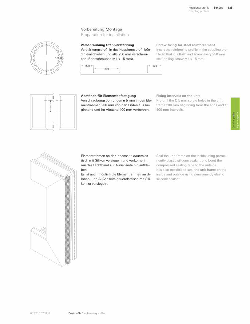
Zusatzprofile Supplementary profiles08.2016 / 75838
Verschraubung Stahlverstärkung
Verstärkungsprofil in das Kopplungsprofil bün-
dig einschieben und alle 250 mm verschrau-
ben (Bohrschrauben M4 x 15 mm).
Screw fixing for steel reinforcement
Insert the reinforcing profile in the coupling pro-
file so that it is flush and screw every 250 mm
(self-drilling screw M4 x 15 mm)
200250
200
Vorbereitung Montage
Preparation for installation
Abstände für Elementbefestigung
Verschraubungsbohrungen ø 5 mm in den Ele-
mentrahmen 200 mm von den Enden aus be-
ginnend und im Abstand 400 mm vorbohren.
Fixing intervals on the unit
Pre-drill the Ø 5 mm screw holes in the unit
frame 200 mm beginning from the ends and at
400 mm intervals.
200
400
200
Elementrahmen an der Innenseite dauerelas-
tisch mit Silikon versiegeln und vorkompri-
miertes Dichtband zur Außenseite hin aufkle-
ben.
Es ist auch möglich die Elementrahmen an der
Innen- und Außenseite dauerelastisch mit Sili-
kon zu versiegeln.
Seal the unit frame on the inside using perma-
nently elastic silicone sealant and bond the
compressed sealing tape to the outside.
It is also possible to seal the unit frame on the
inside and outside using permanently elastic
silicone sealant.
Schüco 135Kopplungsprofile
Coupling profiles
Coupling profiles
Kopplungsprofile
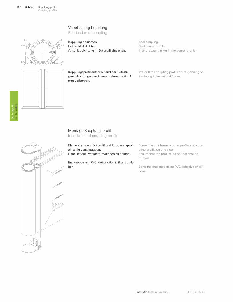
Zusatzprofile Supplementary profiles 08.2016 / 75838
Elementrahmen, Eckprofil und Kopplungsprofil
einseitig verschrauben.
Dabei ist auf Profildeformationen zu achten!
Endkappen mit PVC-Kleber oder Silikon aufkle-
ben.
Screw the unit frame, corner profile and cou-
pling profile on one side.
Ensure that the profiles do not become de-
formed.
Bond the end caps using PVC adhesive or sili-
cone.
Montage Kopplungsprofil
Installation of coupling profile
Verarbeitung Kopplung
Fabrication of coupling
Kopplung abdichten.
Eckprofil abdichten.
Anschlagdichtung in Eckprofil einziehen.
Seal coupling.
Seal corner profile.
Insert rebate gasket in the corner profile.
Kopplungsprofil entsprechend der Befesti-
gungsbohrungen im Elementrahmen mit ø 4
mm vorbohren.
Pre-drill the coupling profile corresponding to
the fixing holes with Ø 4 mm.
Schüco136 Kopplungsprofile
Coupling profiles Kopplungsprofile
Coupling profiles
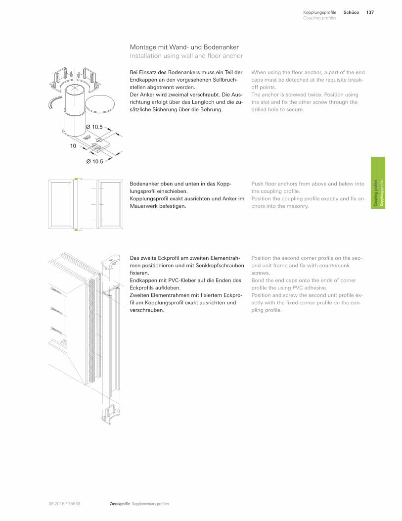
Zusatzprofile Supplementary profiles08.2016 / 75838
Bodenanker oben und unten in das Kopp-
lungsprofil einschieben.
Kopplungsprofil exakt ausrichten und Anker im
Mauerwerk befestigen.
Push floor anchors from above and below into
the coupling profile.
Position the coupling profile exactly and fix an-
chors into the masonry.
Ø 10.5
10
Ø 10.5
Bei Einsatz des Bodenankers muss ein Teil der
Endkappen an den vorgesehenen Sollbruch-
stellen abgetrennt werden.
Der Anker wird zweimal verschraubt. Die Aus-
richtung erfolgt über das Langloch und die zu-
sätzliche Sicherung über die Bohrung.
When using the floor anchor, a part of the end
caps must be detached at the requisite break-
on points.
The anchor is screwed twice. Position using
the slot and fix the other screw through the
drilled hole to secure.
Montage mit Wand- und Bodenanker
Installation using wall and floor anchor
Das zweite Eckprofil am zweiten Elementrah-
men positionieren und mit Senkkopfschrauben
fixieren.
Endkappen mit PVC-Kleber auf die Enden des
Eckprofils aufkleben.
Zweiten Elementrahmen mit fixiertem Eckpro-
fil am Kopplungsprofil exakt ausrichten und
verschrauben.
Position the second corner profile on the sec-
ond unit frame and fix with countersunk
screws.
Bond the end caps onto the ends of corner
profile the using PVC adhesive.
Position and screw the second unit profile ex-
actly with the fixed corner profile on the cou-
pling profile.
Schüco 137Kopplungsprofile
Coupling profiles
Coupling profiles
Kopplungsprofile
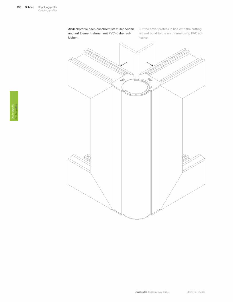
Zusatzprofile Supplementary profiles 08.2016 / 75838
Abdeckprofile nach Zuschnittliste zuschneiden
und auf Elementrahmen mit PVC-Kleber auf-
kleben.
Cut the cover profiles in line with the cutting
list and bond to the unit frame using PVC ad-
hesive.
Schüco138 Kopplungsprofile
Coupling profiles Kopplungsprofile
Coupling profiles
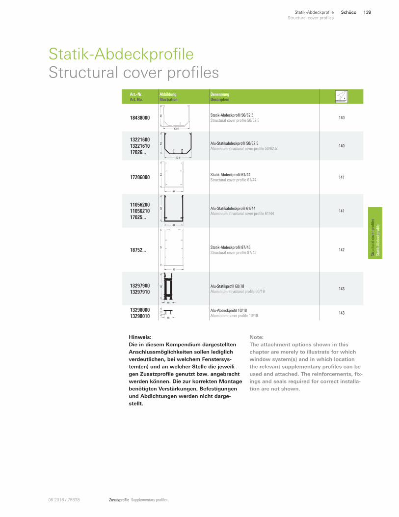
Zusatzprofile Supplementary profiles08.2016 / 75838
Hinweis:
Die in diesem Kompendium dargestellten
Anschlussmöglichkeiten sollen lediglich
verdeutlichen, bei welchem Fenstersys-
tem(en) und an welcher Stelle die jeweili-
gen Zusatzprofile genutzt bzw. angebracht
werden können. Die zur korrekten Montage
benötigten Verstärkungen, Befestigungen
und Abdichtungen werden nicht darge-
stellt.
Note:
The attachment options shown in this
chapter are merely to illustrate for which
window system(s) and in which location
the relevant supplementary profiles can be
used and attached. The reinforcements, fix-
ings and seals required for correct installa-
tion are not shown.
Schüco 139Statik-Abdeckprofile
Structural cover profiles
Structural cover profiles
Statik-Abdeckprofile
Statik-AbdeckprofileStructural cover profiles
Art.-Nr.
Art. No.
Abbildung
Illustration
Benennung
Description
18438000
62.5
50 Statik-Abdeckprofil 50/62,5
Structural cover profile 50/62.5 140
13221600
13221610
17026 ...62.5
50 Alu-Statikabdeckprofil 50/62.5
Aluminium structural cover profile 50/62.5 140
17206000
44
61 Statik-Abdeckprofil 61/44
Structural cover profile 61/44 141
11056200
11056210
17025 ...
44
61 Alu-Statikabdeckprofil 61/44
Aluminium structural cover profile 61/44 141
18752 ...
45
87 Statik-Abdeckprofil 87/45
Structural cover profile 87/45 142
13297900
13297910
18
60 Alu-Statikprofil 60/18
Aluminium structural profile 60/18 143
13298000
13298010 18
10 Alu-Abdeckprofil 10/18
Aluminium cover profile 10/18 143
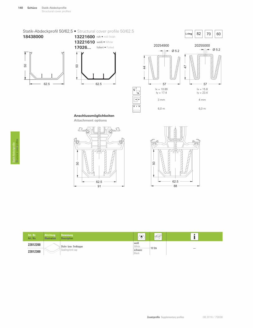
Zusatzprofile Supplementary profiles 08.2016 / 75838
20254900 20255000
57
44
Ø 5.2
57
47
Ø 5.2
x
y
Ix
Iy Ix = 10.89
Iy = 17.4
Ix = 15.8
Iy = 23.4
3 mm 4 mm
x
6,0 m 6,0 m
50
62.5
91
50
62.5
88
13221610 weiß • White
13221600 roh • mill finish
17026... foliert • Foiled
82 70 60LivIng
62.5
50
62.5
50
Statik-Abdeckprofil 50/62,5 • Structural cover profile 50/62.5
18438000
Anschlussmöglichkeiten
Attachment options
Art.-Nr.
Art. No.
Abbildung
Illustration
Benennung
Description
22812200 Dicht- bzw. Endkappe
Sealing/end cap
weiß
White 10 Stk —
22812300 schwarz
Black
Schüco140 Statik-Abdeckprofile
Structural cover profiles Statik-Abdeckprofile
Structural cover profiles
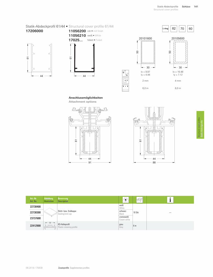
Zusatzprofile Supplementary profiles08.2016 / 75838
82 70 60LivIng
44
61
44
61
Statik-Abdeckprofil 61/44 • Structural cover profile 61/44
17206000
Anschlussmöglichkeiten
Attachment options
Art.-Nr.
Art. No.
Abbildung
Illustration
Benennung
Description
22730400
Dicht- bzw. Endkappe
Sealing/end cap
weiß
White
10 Stk —22730300 schwarz
Black
23737600 cremeweiß
Cream white
22412900
32KS-Halteprofil
Plastic retaining profile
grau
Grey 6 m
20101600 20105600
30
50
30
50
x
y
Ix
Iy Ix = 9.97
Iy = 4.44
Ix = 16.48
Iy = 7.12
2 mm 4 mm
x
6,0 m 6,0 m
61
44
91
61
44
88
11056210 weiß • White
11056200 roh • mill finish
17025 ... foliert • Foiled
Schüco 141Statik-Abdeckprofile
Structural cover profiles
Structural cover profiles
Statik-Abdeckprofile
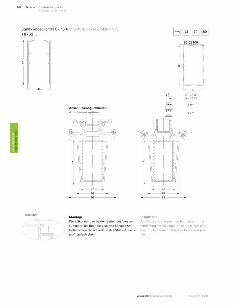
Zusatzprofile Supplementary profiles 08.2016 / 75838
45
87
Statik-Abdeckprofil 87/45 • Structural cover profile 87/45
18752...
Anschlussmöglichkeiten
Attachment options
20128100
80
40
x
y
Ix
Iy Ix = 37.89
Iy = 12.78
2 mm
x
6,0 m
82 70 60LivIng
87
61
45
91
87
61
45
88
Montage
Die Silikonnaht an beiden Seiten des Verstär-
kungsprofiles über die gesamte Länge bzw.
Höhe ziehen. Anschließend das Statik-Abdeck-
profil aufschieben.
Installation
Apply the silicone seam on both sides of the
reinforcing profile along the entire length and
height. Then slide on the structural cover pro-
file.
Schüco142 Statik-Abdeckprofile
Structural cover profiles Statik-Abdeckprofile
Structural cover profiles
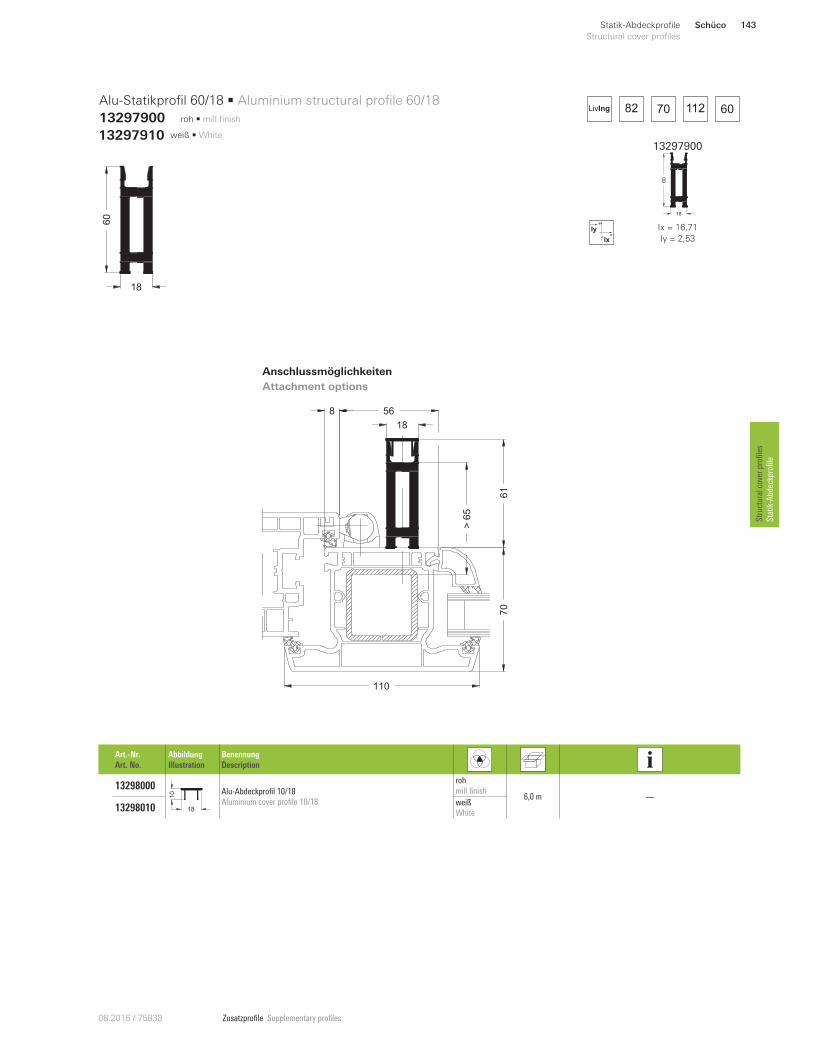
Zusatzprofile Supplementary profiles08.2016 / 75838
18
61
>65
70
110
568
13297900
18
60
x
y
Ix
Iy Ix = 16,71
Iy = 2,53
13297910 weiß • White
roh • mill finish 82 70 112 60LivIng
18
60
Alu-Statikprofil 60/18 • Aluminium structural profile 60/18
13297900
Anschlussmöglichkeiten
Attachment options
Art.-Nr.
Art. No.
Abbildung
Illustration
Benennung
Description
13298000
18
10 Alu-Abdeckprofil 10/18
Aluminium cover profile 10/18
roh
mill finish 6,0 m —
13298010 weiß
White
Schüco 143Statik-Abdeckprofile
Structural cover profiles
Structural cover profiles
Statik-Abdeckprofile
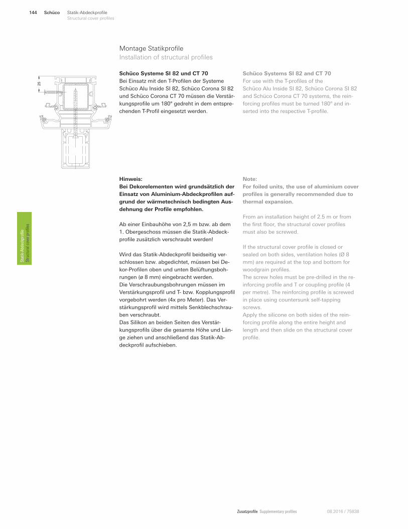
Zusatzprofile Supplementary profiles 08.2016 / 75838
Montage Statikprofile
Installation of structural profiles
Schüco Systeme SI 82 und CT 70
Bei Einsatz mit den T-Profilen der Systeme
Schüco Alu Inside SI 82, Schüco Corona SI 82
und Schüco Corona CT 70 müssen die Verstär-
kungsprofile um 180° gedreht in dem entspre-
chenden T-Profil eingesetzt werden.
Hinweis:
Bei Dekorelementen wird grundsätzlich der
Einsatz von Aluminium-Abdeckprofilen auf-
grund der wärmetechnisch bedingten Aus-
dehnung der Profile empfohlen.
Ab einer Einbauhöhe von 2,5 m bzw. ab dem
1. Obergeschoss müssen die Statik-Abdeck-
profile zusätzlich verschraubt werden!
Wird das Statik-Abdeckprofil beidseitig ver-
schlossen bzw. abgedichtet, müssen bei De-
kor-Profilen oben und unten Belüftungsboh-
rungen (ø 8 mm) eingebracht werden.
Die Verschraubungsbohrungen müssen im
Verstärkungsprofil und T- bzw. Kopplungsprofil
vorgebohrt werden (4x pro Meter). Das Ver-
stärkungsprofil wird mittels Senkblechschrau-
ben verschraubt.
Das Silikon an beiden Seiten des Verstär-
kungsprofils über die gesamte Höhe und Län-
ge ziehen und anschließend das Statik-Ab-
deckprofil aufschieben.
Schüco Systems SI 82 and CT 70
For use with the T-profiles of the
Schüco Alu Inside SI 82, Schüco Corona SI 82
and Schüco Corona CT 70 systems, the rein-
forcing profiles must be turned 180° and in-
serted into the respective T-profile.
Note:
For foiled units, the use of aluminium cover
profiles is generally recommended due to
thermal expansion.
From an installation height of 2.5 m or from
the first floor, the structural cover profiles
must also be screwed.
If the structural cover profile is closed or
sealed on both sides, ventilation holes (Ø 8
mm) are required at the top and bottom for
woodgrain profiles.
The screw holes must be pre-drilled in the re-
inforcing profile and T or coupling profile (4
per metre). The reinforcing profile is screwed
in place using countersunk self-tapping
screws.
Apply the silicone on both sides of the rein-
forcing profile along the entire height and
length and then slide on the structural cover
profile.
25
Schüco144 Statik-Abdeckprofile
Structural cover profiles Statik-Abdeckprofile
Structural cover profiles
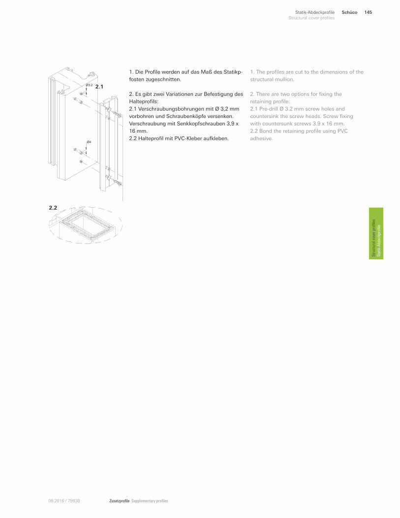
Zusatzprofile Supplementary profiles08.2016 / 75838
1. Die Profile werden auf das Maß des Statikp-
fosten zugeschnitten.
2. Es gibt zwei Variationen zur Befestigung des
Halteprofils:
2.1 Verschraubungsbohrungen mit Ø 3,2 mm
vorbohren und Schraubenköpfe versenken.
Verschraubung mit Senkkopfschrauben 3,9 x
16 mm.
2.2 Halteprofil mit PVC-Kleber aufkleben.
1. The profiles are cut to the dimensions of the
structural mullion.
2. There are two options for fixing the
retaining profile:
2.1 Pre-drill Ø 3.2 mm screw holes and
countersink the screw heads. Screw fixing
with countersunk screws 3.9 x 16 mm.
2.2 Bond the retaining profile using PVC
adhesive. Ø4
Ø3.2
2.2
2.1
Schüco 145Statik-Abdeckprofile
Structural cover profiles
Structural cover profiles
Statik-Abdeckprofile
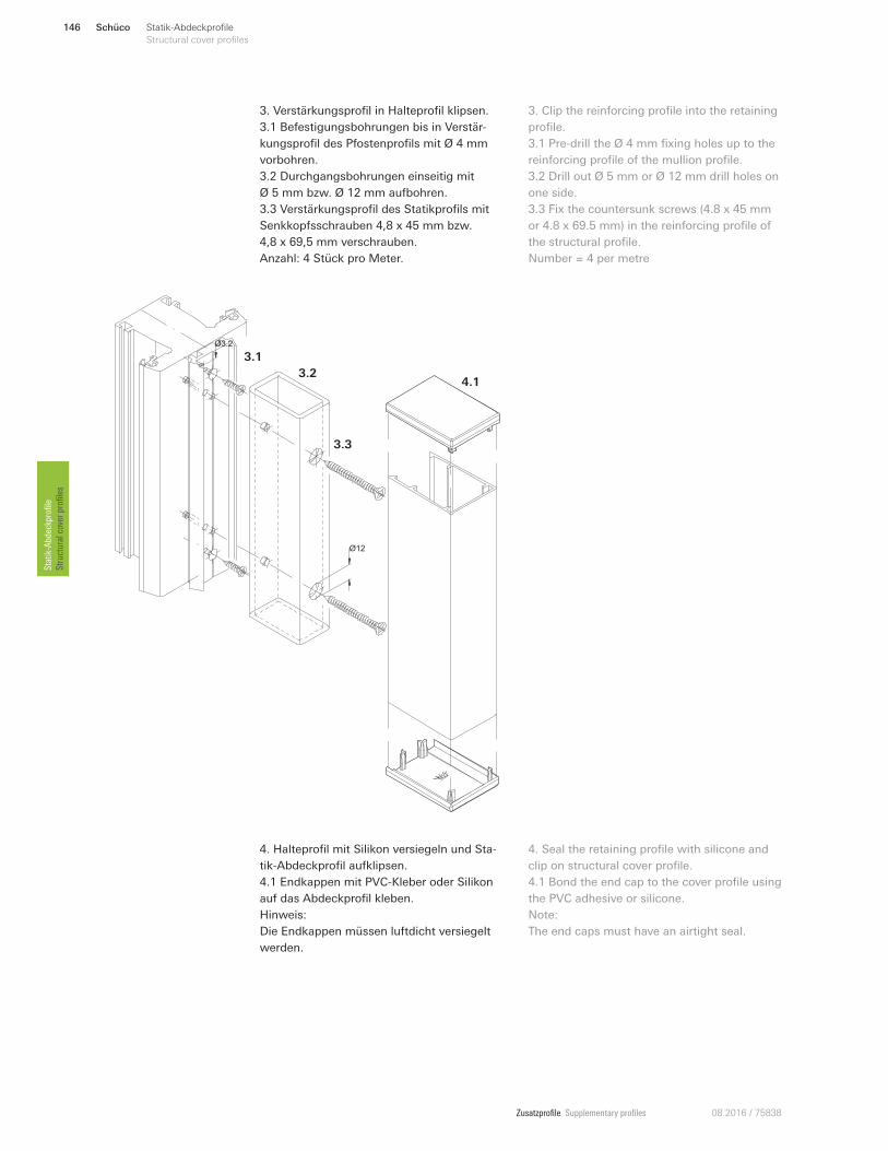
Zusatzprofile Supplementary profiles 08.2016 / 75838
3. Verstärkungsprofil in Halteprofil klipsen.
3.1 Befestigungsbohrungen bis in Verstär-
kungsprofil des Pfostenprofils mit Ø 4 mm
vorbohren.
3.2 Durchgangsbohrungen einseitig mit
Ø 5 mm bzw. Ø 12 mm aufbohren.
3.3 Verstärkungsprofil des Statikprofils mit
Senkkopfsschrauben 4,8 x 45 mm bzw.
4,8 x 69,5 mm verschrauben.
Anzahl: 4 Stück pro Meter.
3. Clip the reinforcing profile into the retaining
profile.
3.1 Pre-drill the Ø 4 mm fixing holes up to the
reinforcing profile of the mullion profile.
3.2 Drill out Ø 5 mm or Ø 12 mm drill holes on
one side.
3.3 Fix the countersunk screws (4.8 x 45 mm
or 4.8 x 69.5 mm) in the reinforcing profile of
the structural profile.
Number = 4 per metre
Ø4
Ø3.2
Ø4
Ø12
Ø3.2
3.1
3.3
3.24.1
4. Halteprofil mit Silikon versiegeln und Sta-
tik-Abdeckprofil aufklipsen.
4.1 Endkappen mit PVC-Kleber oder Silikon
auf das Abdeckprofil kleben.
Hinweis:
Die Endkappen müssen luftdicht versiegelt
werden.
4. Seal the retaining profile with silicone and
clip on structural cover profile.
4.1 Bond the end cap to the cover profile using
the PVC adhesive or silicone.
Note:
The end caps must have an airtight seal.
Schüco146 Statik-Abdeckprofile
Structural cover profiles Statik-Abdeckprofile
Structural cover profiles
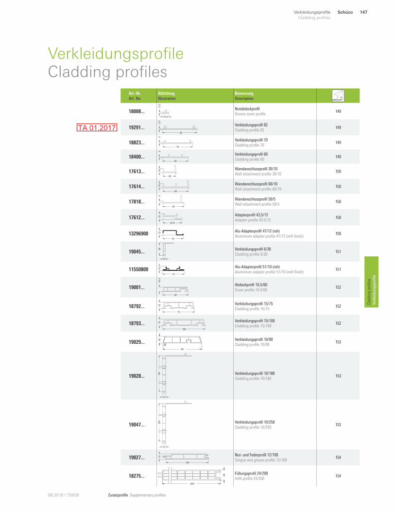
Zusatzprofile Supplementary profiles08.2016 / 75838
Schüco 147Verkleidungsprofile
Cladding profiles
Cladding profiles
Verkleidungsprofile
VerkleidungsprofileCladding profiles
Art.-Nr.
Art. No.
Abbildung
Illustration
Benennung
Description
18008 ...13.5
2.5
Nutabdeckprofil
Groove cover profile 149
19291 ...82
2.5
Verkleidungsprofil 82
Cladding profile 82 149
18823 ...70
3
Verkleidungsprofil 70
Cladding profile 70 149
18400 ...60
2
Verkleidungsprofil 60
Cladding profile 60 149
17613 ...30
10 Wandanschlussprofil 30/10
Wall attachment profile 30/10 150
17614 ...60
10 Wandanschlussprofil 60/10
Wall attachment profile 60/10 150
17818 ...50
5
Wandanschlussprofil 50/5
Wall attachment profile 50/5 150
17612 ... 12
43.5
Adapterprofil 43,5/12
Adapter profile 43.5/12 150
13296900 47
12 Alu-Adapterprofil 47/12 (roh)
Aluminium adapter profile 47/12 (mill finish) 150
19045 ...
30
6
Verkleidungsprofil 6/30
Cladding profile 6/30 151
11550800 10
51
Alu-Adapterprofil 51/10 (roh)
Aluminium adapter profile 51/10 (mill finish) 151
19001 ...
60
10.5
Abdeckprofil 10,5/60
Cover profile 10.5/60 152
18792...75
15 Verkleidungsprofil 15/75
Cladding profile 15/75 152
18793 ...100
15 Verkleidungsprofil 15/100
Cladding profile 15/100 152
19029 ...
90
16 Verkleidungsprofil 10/90
Cladding profile 10/90 153
19028 ... 180
10
Verkleidungsprofil 10/180
Cladding profile 10/180 153
19047 ...
250
10
Verkleidungsprofil 10/250
Cladding profile 10/250 153
19027 ... 12
100
Nut- und Federprofil 12/100
Tongue and groove profile 12/100 154
18275 ... 24
200
Füllungsprofil 24/200
Infill profile 24/200 154
TA 01.2017
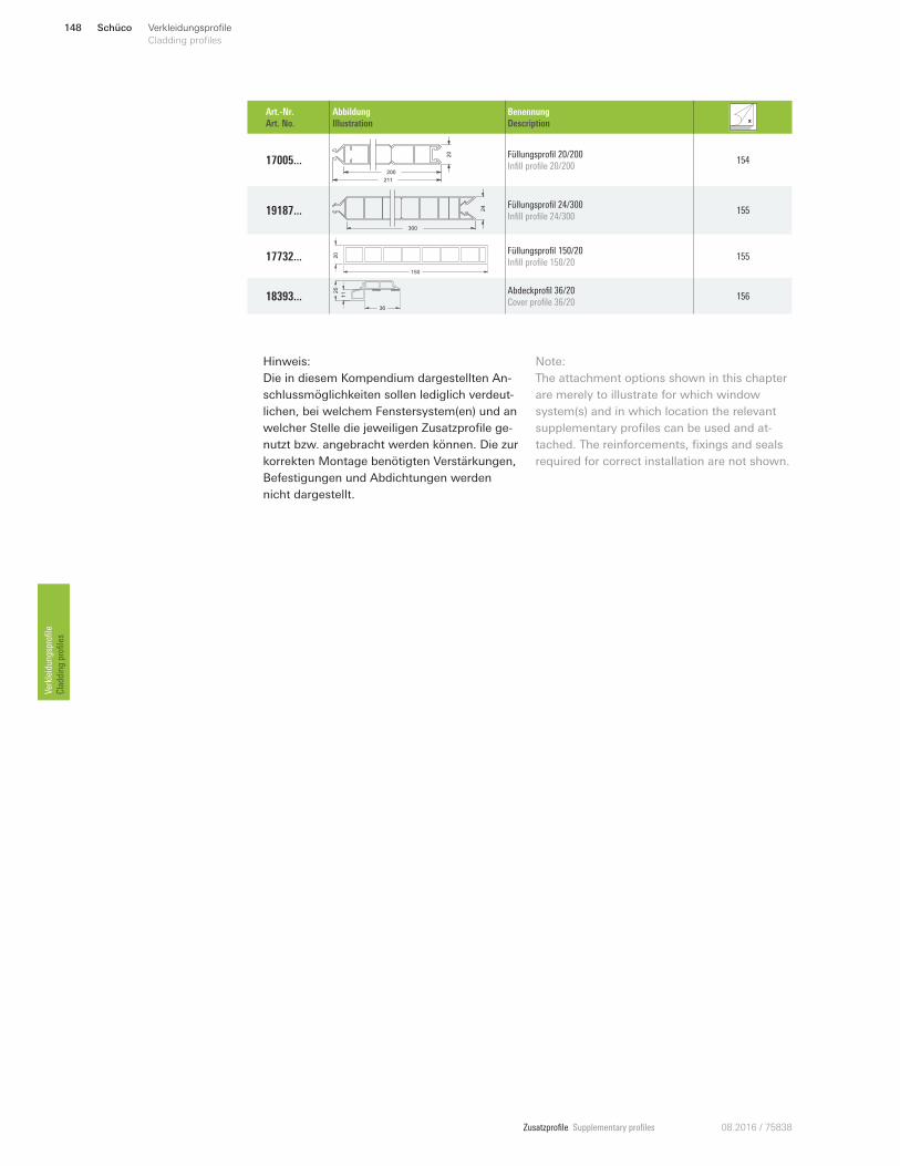
Zusatzprofile Supplementary profiles 08.2016 / 75838
Schüco148 Verkleidungsprofile
Cladding profilesVerkleidungsprofile
Cladding profiles
Art.-Nr.
Art. No.
Abbildung
Illustration
Benennung
Description
17005 ...
20
200
211
Füllungsprofil 20/200
Infill profile 20/200 154
19187 ...
300
24 Füllungsprofil 24/300
Infill profile 24/300 155
17732 ...150
20 Füllungsprofil 150/20
Infill profile 150/20 155
18393 ...
20
36
11 Abdeckprofil 36/20
Cover profile 36/20 156
Hinweis:
Die in diesem Kompendium dargestellten An-
schlussmöglichkeiten sollen lediglich verdeut-
lichen, bei welchem Fenstersystem(en) und an
welcher Stelle die jeweiligen Zusatzprofile ge-
nutzt bzw. angebracht werden können. Die zur
korrekten Montage benötigten Verstärkungen,
Befestigungen und Abdichtungen werden
nicht dargestellt.
Note:
The attachment options shown in this chapter
are merely to illustrate for which window
system(s) and in which location the relevant
supplementary profiles can be used and at-
tached. The reinforcements, fixings and seals
required for correct installation are not shown.
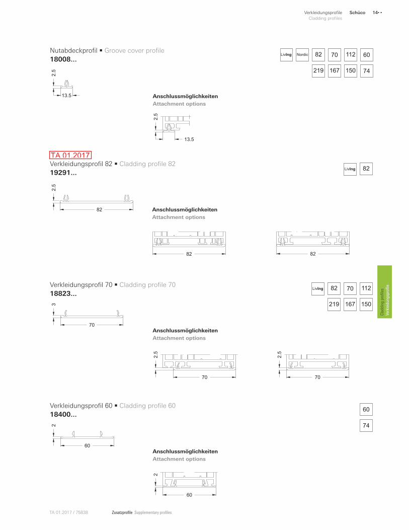
Zusatzprofile Supplementary profilesTA 01.2017 / 75838
60
2
70
2.5
70
2.5
82
167 150
70 112
219
LivIng
82LivIng
60
74
82 82
Schüco 14• •Verkleidungsprofile
Cladding profiles
Cladding profiles
Verkleidungsprofile
70
3
82
2.5
60
2
Verkleidungsprofil 70 • Cladding profile 70
18823...
Verkleidungsprofil 82 • Cladding profile 82
19291...
Verkleidungsprofil 60 • Cladding profile 60
18400...
Anschlussmöglichkeiten
Attachment options
Anschlussmöglichkeiten
Attachment options
Anschlussmöglichkeiten
Attachment options
82 70 112 60
167 74150219
NordicLivIng
13.5
2.5
13.5
2.5
Nutabdeckprofil • Groove cover profile
18008...
Anschlussmöglichkeiten
Attachment options
TA 01.2017
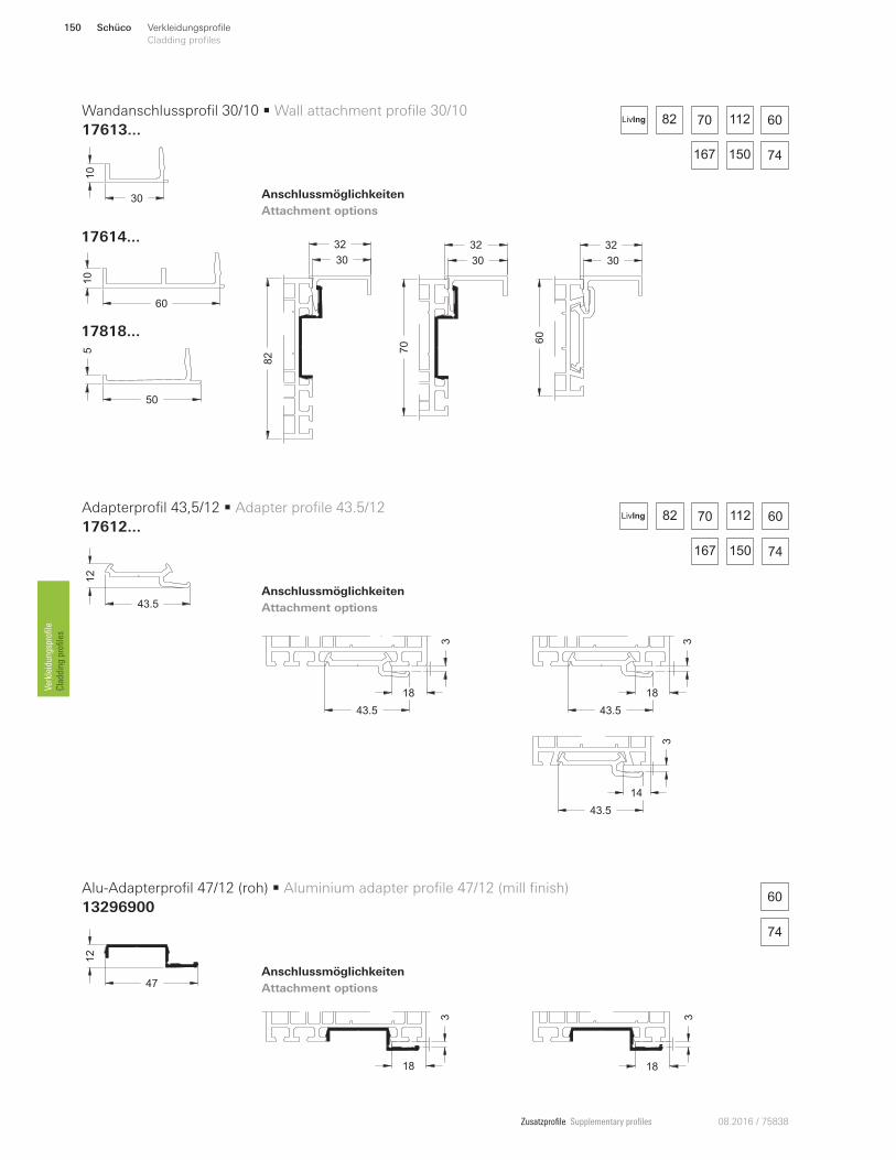
Zusatzprofile Supplementary profiles 08.2016 / 75838
14
43.5
3
18
43.5
318
43.5
3
60
10
17614 ...
50
5
17818...
82
32
30
70
32
30
60
30
32
3
18
3
18
82 60
74167 150
70 112LivIng
82 60
74167 150
70 112LivIng
Schüco150 Verkleidungsprofile
Cladding profilesVerkleidungsprofile
Cladding profiles
60
74
30
10
12
43.5
47
12
Wandanschlussprofil 30/10 • Wall attachment profile 30/10
17613...
Adapterprofil 43,5/12 • Adapter profile 43.5/12
17612...
Alu-Adapterprofil 47/12 (roh) • Aluminium adapter profile 47/12 (mill finish)
13296900
Anschlussmöglichkeiten
Attachment options
Anschlussmöglichkeiten
Attachment options
Anschlussmöglichkeiten
Attachment options
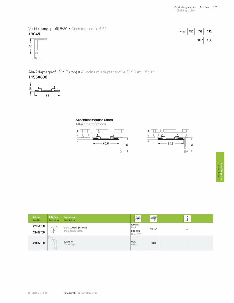
Zusatzprofile Supplementary profiles08.2016 / 75838
50.5
4
3050.5
4
30
82 70 112
167 150
LivIng
Art.-Nr.
Art. No.
Abbildung
Illustration
Benennung
Description
22451700 EPDM-Anschlagdichtung
EPDM rebate gasket
schwarz
Black 100 m* —
24403700 silbergrau
Silver grey
23837100 Eckwinkel
Corner angle
weiß
White 20 Stk —
Schüco 151Verkleidungsprofile
Cladding profiles
Cladding profiles
Verkleidungsprofile
30
6
10
51
Verkleidungsprofil 6/30 • Cladding profile 6/30
19045...
Alu-Adapterprofil 51/10 (roh) • Aluminium adapter profile 51/10 (mill finish)
11550800
Anschlussmöglichkeiten
Attachment options
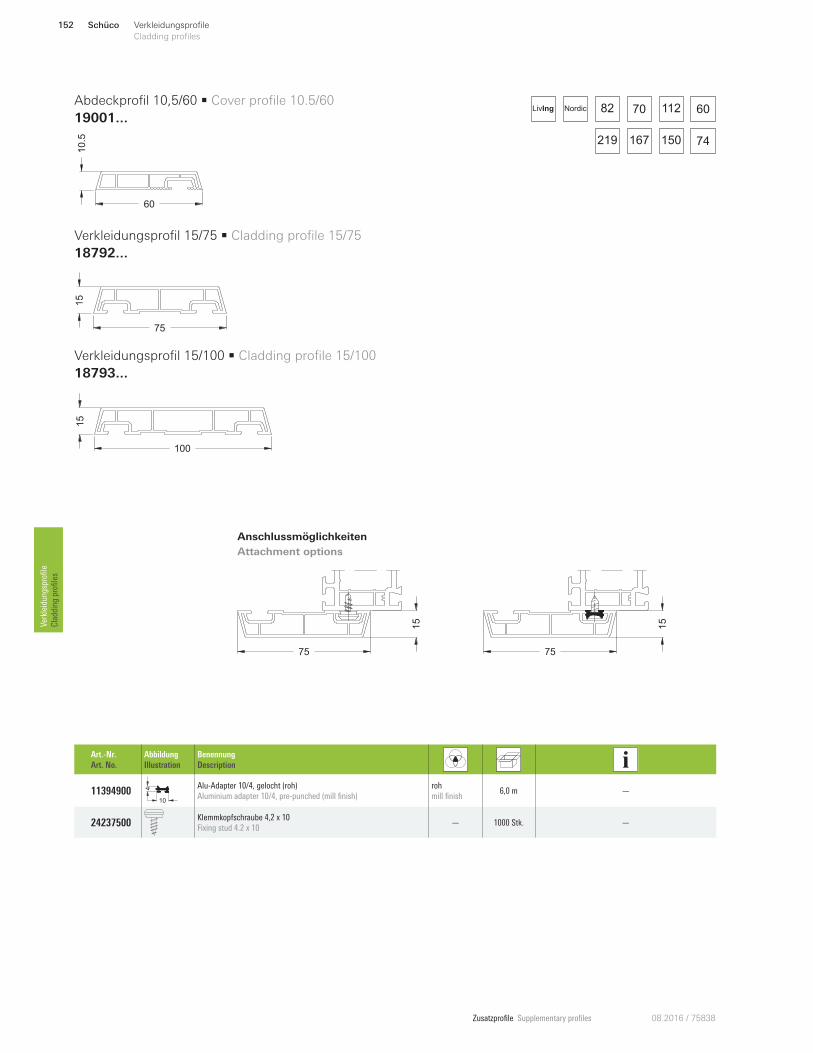
Zusatzprofile Supplementary profiles 08.2016 / 75838
75
15
100
15
75
15
7515
82 70 112 60
150219 167 74
NordicLivIng
Schüco152 Verkleidungsprofile
Cladding profilesVerkleidungsprofile
Cladding profiles
Art.-Nr.
Art. No.
Abbildung
Illustration
Benennung
Description
11394900 10
4 Alu-Adapter 10/4, gelocht (roh)
Aluminium adapter 10/4, pre-punched (mill finish)
roh
mill finish 6,0 m —
24237500 Klemmkopfschraube 4,2 x 10
Fixing stud 4.2 x 10 — 1000 Stk. —
60
10.5
Abdeckprofil 10,5/60 • Cover profile 10.5/60
19001...
Verkleidungsprofil 15/100 • Cladding profile 15/100
18793...
Verkleidungsprofil 15/75 • Cladding profile 15/75
18792...
Anschlussmöglichkeiten
Attachment options
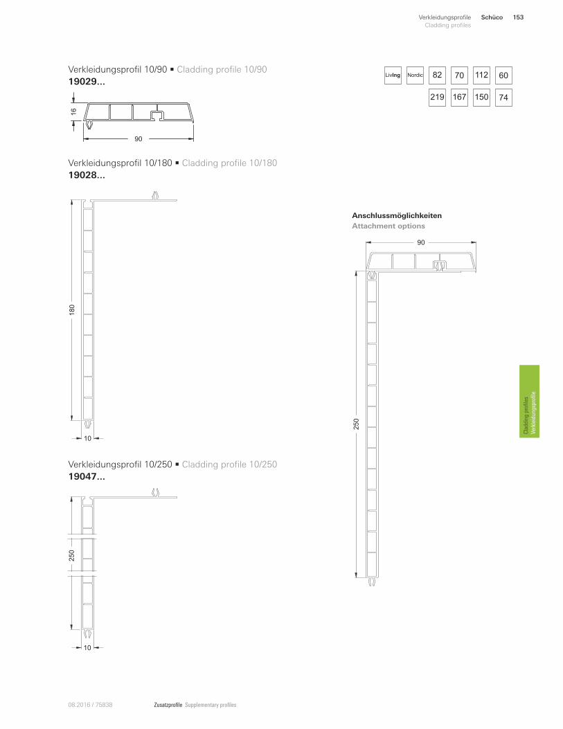
Zusatzprofile Supplementary profiles08.2016 / 75838
82 70 112 60
150219 167 74
NordicLivIng
90
250
250
10
180
10
Schüco 153Verkleidungsprofile
Cladding profiles
Cladding profiles
Verkleidungsprofile
90
16
Verkleidungsprofil 10/90 • Cladding profile 10/90
19029...
Verkleidungsprofil 10/250 • Cladding profile 10/250
19047...
Verkleidungsprofil 10/180 • Cladding profile 10/180
19028...
Anschlussmöglichkeiten
Attachment options
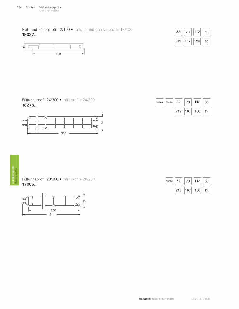
Zusatzprofile Supplementary profiles 08.2016 / 75838
82 60
74167 150
70 112
219
82 70 112 60
150219 167 74
Nordic
Schüco154 Verkleidungsprofile
Cladding profilesVerkleidungsprofile
Cladding profiles
82 70 112 60
150219 167 74
NordicLivIng
12
100
24
200
20
200
211
Nut- und Federprofil 12/100 • Tongue and groove profile 12/100
19027...
Füllungsprofil 24/200 • Infill profile 24/200
18275...
Füllungsprofil 20/200 • Infill profile 20/200
17005...
82 60
74167 150
70 112
219
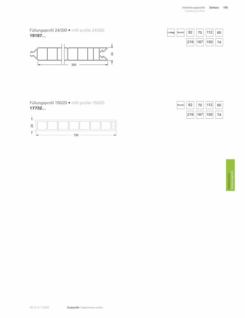
Zusatzprofile Supplementary profiles08.2016 / 75838
82 70 112 60
150219 167 74
NordicLivIng
82 70 112 60
150219 167 74
Nordic
Schüco 155Verkleidungsprofile
Cladding profiles
Cladding profiles
Verkleidungsprofile
300
24
150
20
Füllungsprofil 24/300 • Infill profile 24/300
19187...
Füllungsprofil 150/20 • Infill profile 150/20
17732...
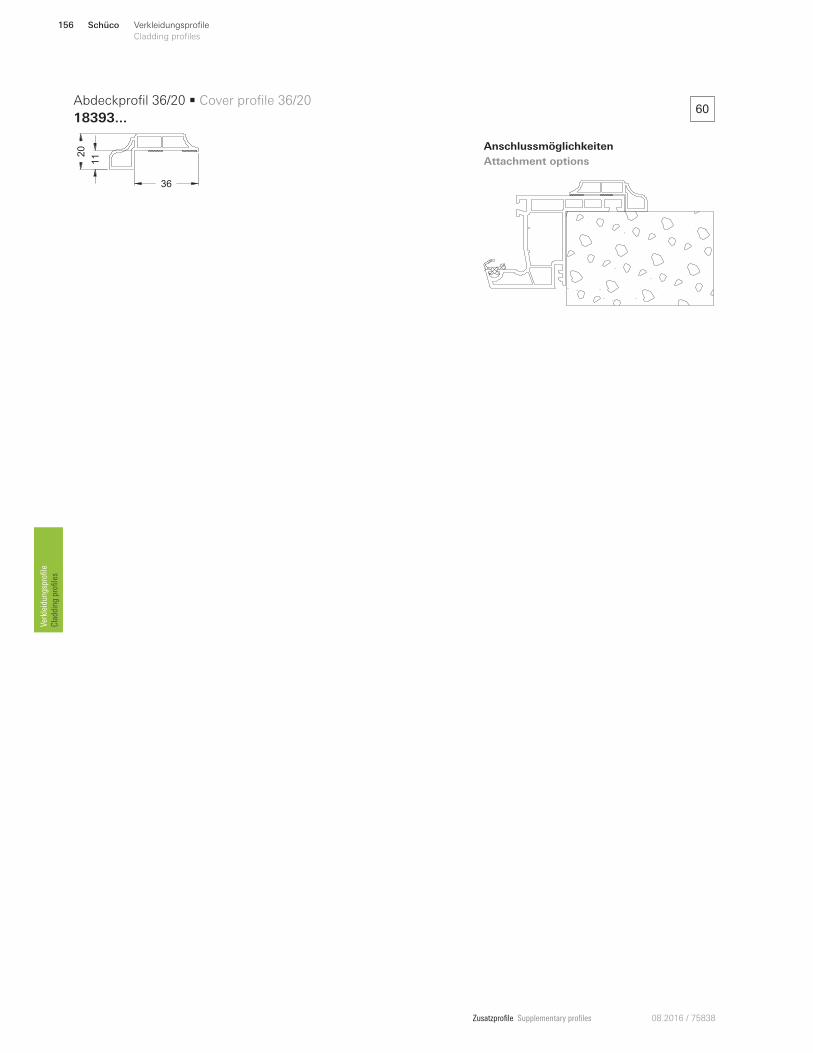
Zusatzprofile Supplementary profiles 08.2016 / 75838
Anschlussmöglichkeiten
Attachment options
60
20
36
11
Abdeckprofil 36/20 • Cover profile 36/20
18393...
Schüco156 Verkleidungsprofile
Cladding profilesVerkleidungsprofile
Cladding profiles
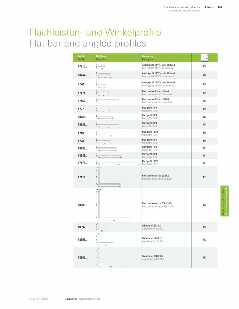
Zusatzprofile Supplementary profiles08.2016 / 75838
Schüco 157Flachleisten- und Winkelprofile
Flat bar and angled profiles
Flat bar and angled profiles
Flachleisten- und Winkelprofile
Flachleisten- und WinkelprofileFlat bar and angled profiles
Art.-Nr.
Art. No.
Abbildung
Illustration
Benennung
Description
17710 ... 7.5
30
Abdeckprofil 30/7.5, selbstklebend
Cover profile 30/7.5, self-adhesive 159
18737 ... 7.5
50
Abdeckprofil 50/7.5, selbstklebend
Cover profile 50/7.5, self-adhesive 159
17708 ...
2.5
25
Abdeckprofil 25/2.5, selbstklebend
Cover profile 25/2.5, self-adhesive 159
17171...40
6 Hohlkammer-Flachprofil 40/6
Hollow chamber flat profile 40/6 159
17164 ...80
6 Hohlkammer-Flachprofil 80/6
Hollow chamber flat profile 80/6 159
17775 ...40
3
Flachprofil 40/3
Flat profile 40/3 160
18785 ...60
3
Flachprofil 60/3
Flat profile 60/3 160
18787 ...80
3
Flachprofil 80/3
Flat profile 80/3 160
17165 ...100
3
Flachprofil 100/3
Flat profile 100/3 160
17283 ...50
3 Flachprofil 50/3
Flat profile 50/3 160
18786 ...70
3 Flachprofil 70/3
Flat profile 70/3 161
18788 ...90
3 Flachprofil 90/3
Flat profile 90/3 161
17172 ...160
3 Flachprofil 160/3
Flat profile 160/3 161
17114 ...
90
60
5
Hohlkammer-Winkel 90/60/5
Hollow chamber angle 90/60/5 161
18402 ...
130
110
5
Hohlkammer-Winkel 130/110/5
Hollow chamber angle 130/110/5 162
18397 ...30
15
3
Winkelprofil 30/15/3
Angled profile 30/15/3 162
18398 ...
60
30
3
Winkelprofil 60/30/3
Angled profile 60/30/3 162
18399 ...
100
60
3
Winkelprofil 100/60/3
Angled profile 100/60/3 162
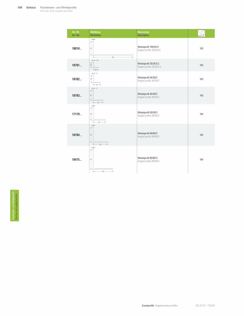
Zusatzprofile Supplementary profiles 08.2016 / 75838
Schüco158 Flachleisten- und Winkelprofile
Flat bar and angled profilesFlachleisten- und Winkelprofile
Flat bar and angled profiles
Art.-Nr.
Art. No.
Abbildung
Illustration
Benennung
Description
18010 ...
160
55
3
Winkelprofil 160/55/3
Angled profile 160/55/3 163
18781 ...
20
20
2.5
Winkelprofil 20/20/2,5
Angled profile 20/20/2.5 163
18782 ...
30
30
2
Winkelprofil 30/30/2
Angled profile 30/30/2 163
18783 ...
40
40
2
Winkelprofil 40/40/2
Angled profile 40/40/2 163
17170 ...
50
50
3
Winkelprofil 50/50/3
Angled profile 50/50/3 164
18784 ...
60
60
3
Winkelprofil 60/60/3
Angled profile 60/60/3 164
18475 ...
80
80
3
Winkelprofil 80/80/3
Angled profile 80/80/3 164
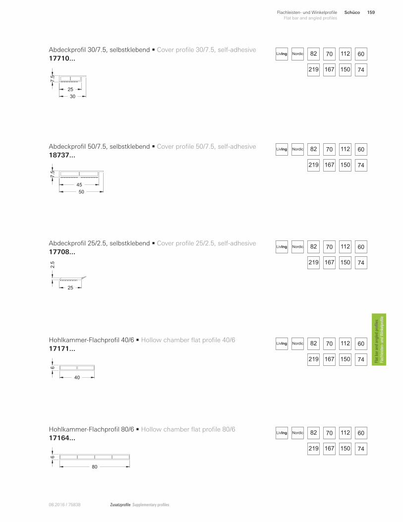
Zusatzprofile Supplementary profiles08.2016 / 75838
7.5
30
25
7.5
50
45
2.5
25
40
6
80
6Abdeckprofil 30/7.5, selbstklebend • Cover profile 30/7.5, self-adhesive
17710 ...
Abdeckprofil 50/7.5, selbstklebend • Cover profile 50/7.5, self-adhesive
18737 ...
Abdeckprofil 25/2.5, selbstklebend • Cover profile 25/2.5, self-adhesive
17708 ...
Hohlkammer-Flachprofil 40/6 • Hollow chamber flat profile 40/6
17171 ...
Hohlkammer-Flachprofil 80/6 • Hollow chamber flat profile 80/6
17164 ...
82 70 112 60
150219 167 74
NordicLivIng
82 70 112 60
150219 167 74
NordicLivIng
82 70 112 60
150219 167 74
NordicLivIng
82 70 112 60
150219 167 74
NordicLivIng
82 70 112 60
150219 167 74
NordicLivIng
Schüco 159Flachleisten- und Winkelprofile
Flat bar and angled profiles
Flat bar and angled profiles
Flachleisten- und Winkelprofile
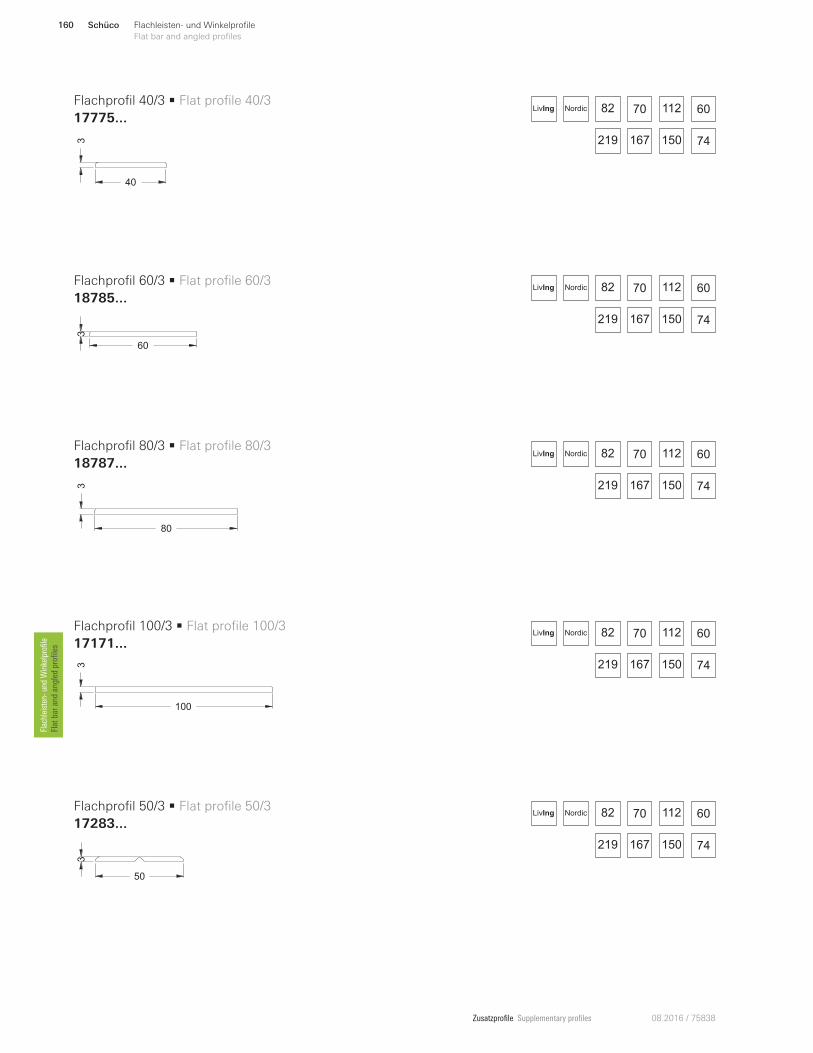
Zusatzprofile Supplementary profiles 08.2016 / 75838
40
3
60
3
80
3
100
3
50
3
Flachprofil 40/3 • Flat profile 40/3
17775 ...
Flachprofil 60/3 • Flat profile 60/3
18785 ...
Flachprofil 80/3 • Flat profile 80/3
18787 ...
Flachprofil 100/3 • Flat profile 100/3
17171 ...
Flachprofil 50/3 • Flat profile 50/3
17283 ...
82 70 112 60
150219 167 74
NordicLivIng
82 70 112 60
150219 167 74
NordicLivIng
82 70 112 60
150219 167 74
NordicLivIng
82 70 112 60
150219 167 74
NordicLivIng
82 70 112 60
150219 167 74
NordicLivIng
Schüco160 Flachleisten- und Winkelprofile
Flat bar and angled profilesFlachleisten- und Winkelprofile
Flat bar and angled profiles
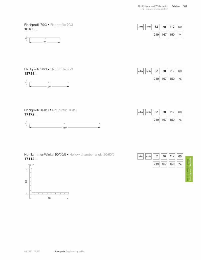
Zusatzprofile Supplementary profiles08.2016 / 75838
70
3
90
3
160
3
90
60
5
Flachprofil 70/3 • Flat profile 70/3
18786 ...
Flachprofil 90/3 • Flat profile 90/3
18788 ...
Flachprofil 160/3 • Flat profile 160/3
17172 ...
Hohlkammer-Winkel 90/60/5 • Hollow chamber angle 90/60/5
17114 ...
82 70 112 60
150219 167 74
NordicLivIng
82 70 112 60
150219 167 74
NordicLivIng
82 70 112 60
150219 167 74
NordicLivIng
82 70 112 60
150219 167 74
NordicLivIng
Schüco 161Flachleisten- und Winkelprofile
Flat bar and angled profiles
Flat bar and an
gled
profiles
Flachleisten
- un
d Winkelprofile
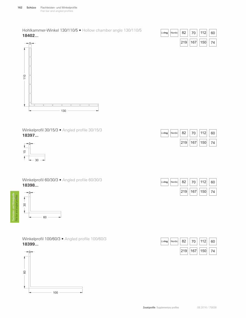
Zusatzprofile Supplementary profiles 08.2016 / 75838
130
110
5
30
15
3
60
30
3
100
60
3
Hohlkammer-Winkel 130/110/5 • Hollow chamber angle 130/110/5
18402 ...
Winkelprofil 30/15/3 • Angled profile 30/15/3
18397 ...
Winkelprofil 60/30/3 • Angled profile 60/30/3
18398 ...
Winkelprofil 100/60/3 • Angled profile 100/60/3
18399 ...
82 70 112 60
150219 167 74
NordicLivIng
82 70 112 60
150219 167 74
NordicLivIng
82 70 112 60
150219 167 74
NordicLivIng
82 70 112 60
150219 167 74
NordicLivIng
Schüco162 Flachleisten- und Winkelprofile
Flat bar and angled profilesFlachleisten
- un
d Winkelprofile
Flat bar and an
gled
profiles
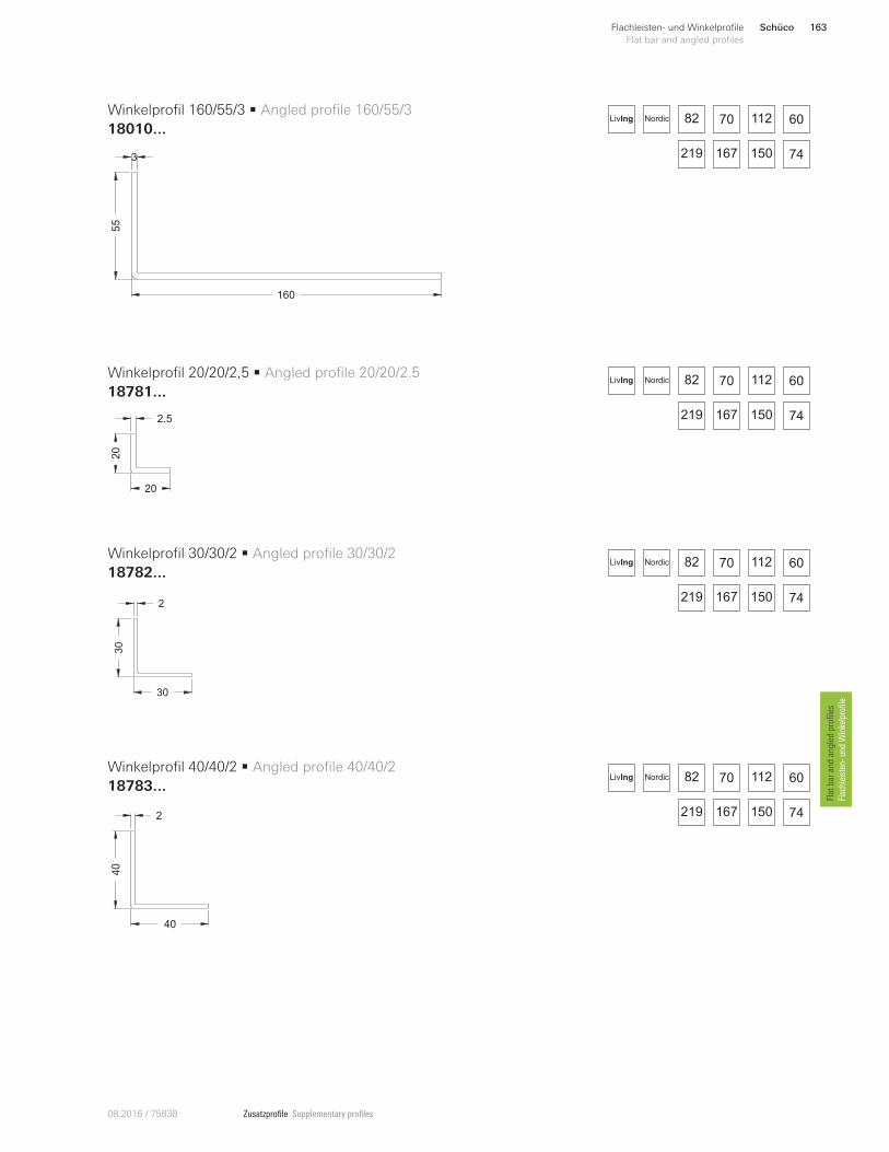
Zusatzprofile Supplementary profiles08.2016 / 75838
160
55
3
20
20
2.5
30
30
2
40
40
2
Winkelprofil 160/55/3 • Angled profile 160/55/3
18010 ...
Winkelprofil 20/20/2,5 • Angled profile 20/20/2.5
18781 ...
Winkelprofil 30/30/2 • Angled profile 30/30/2
18782 ...
Winkelprofil 40/40/2 • Angled profile 40/40/2
18783 ...
82 70 112 60
150219 167 74
NordicLivIng
82 70 112 60
150219 167 74
NordicLivIng
82 70 112 60
150219 167 74
NordicLivIng
82 70 112 60
150219 167 74
NordicLivIng
Schüco 163Flachleisten- und Winkelprofile
Flat bar and angled profiles
Flat bar and an
gled
profiles
Flachleisten
- un
d Winkelprofile
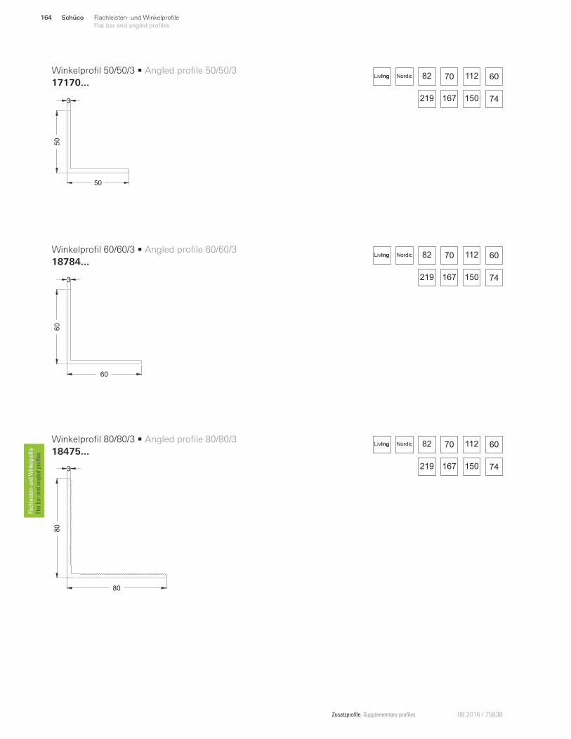
Zusatzprofile Supplementary profiles 08.2016 / 75838
50
50
3
60
60
3
80
80
3
Winkelprofil 50/50/3 • Angled profile 50/50/3
17170 ...
Winkelprofil 60/60/3 • Angled profile 60/60/3
18784 ...
Winkelprofil 80/80/3 • Angled profile 80/80/3
18475 ...
82 70 112 60
150219 167 74
NordicLivIng
82 70 112 60
150219 167 74
NordicLivIng
82 70 112 60
150219 167 74
NordicLivIng
Schüco164 Flachleisten- und Winkelprofile
Flat bar and angled profilesFlachleisten
- un
d Winkelprofile
Flat bar and an
gled
profiles
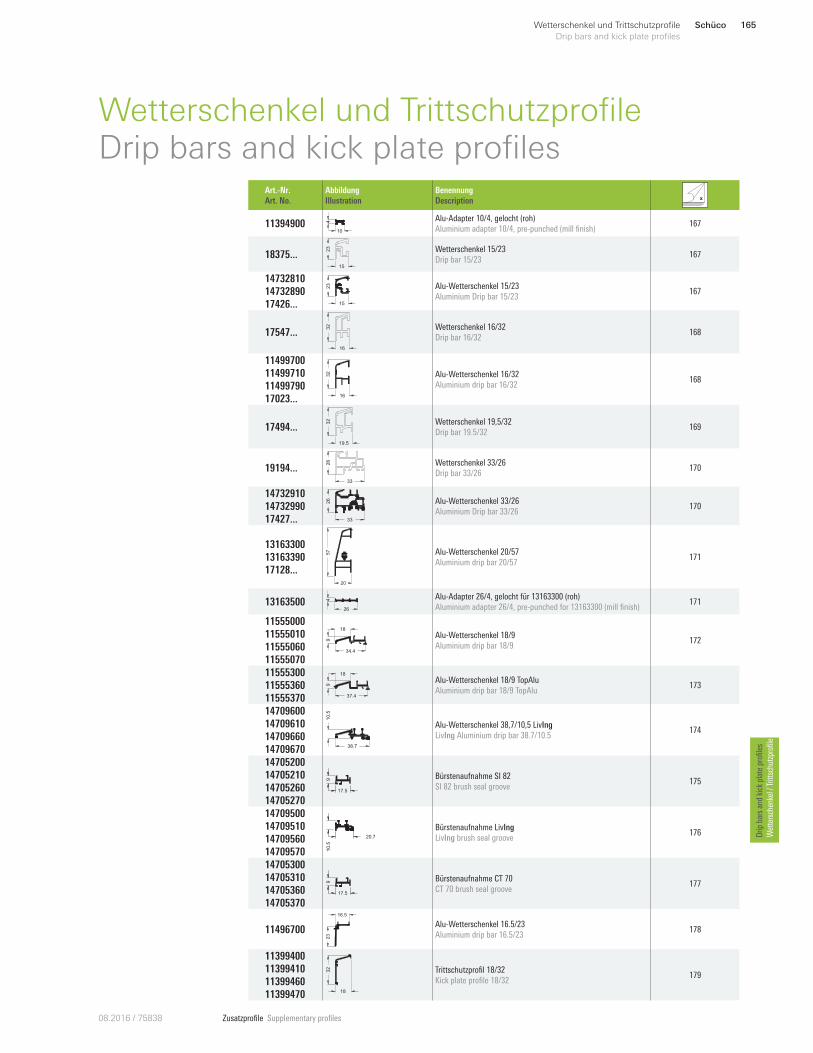
Zusatzprofile Supplementary profiles08.20 16 / 75838
Schüco 165Wetterschenkel und Trittschutzprofile
Drip bars and kick plate profiles
Drip
bars an
d kick plate profiles
Wettersch
enkel / Trittsch
utzprofile
Wetterschenkel und TrittschutzprofileDrip bars and kick plate profiles
Art.-Nr.
Art. No.
Abbildung
Illustration
Benennung
Description
11394900 10
4 Alu-Adapter 10/4, gelocht (roh)
Aluminium adapter 10/4, pre-punched (mill finish) 167
18375 ...15
23 Wetterschenkel 15/23
Drip bar 15/23 167
14732810
14732890
17426...
23
15
Alu-Wetterschenkel 15/23
Aluminium Drip bar 15/23 167
17547 ...
16
32 Wetterschenkel 16/32
Drip bar 16/32 168
11499700
11499710
11499790
17023 ... 16
32 Alu-Wetterschenkel 16/32
Aluminium drip bar 16/32 168
17494 ...
19.5
32 Wetterschenkel 19,5/32
Drip bar 19.5/32 169
19194 ...33
26 Wetterschenkel 33/26
Drip bar 33/26 170
14732910
14732990
17427... 33
26 Alu-Wetterschenkel 33/26
Aluminium Drip bar 33/26 170
13163300
13163390
17128 ...20
57 Alu-Wetterschenkel 20/57
Aluminium drip bar 20/57 171
13163500 26
4 Alu-Adapter 26/4, gelocht für 13163300 (roh)
Aluminium adapter 26/4, pre-punched for 13163300 (mill finish) 171
11555000
11555010
11555060
11555070 34.4
9
18
Alu-Wetterschenkel 18/9
Aluminium drip bar 18/9 172
11555300
11555360
11555370 37.4
18
9
Alu-Wetterschenkel 18/9 TopAlu
Aluminium drip bar 18/9 TopAlu 173
14709600
14709610
14709660
14709670 38.7
10
.5
Alu-Wetterschenkel 38,7/10,5 LivIng
LivIng Aluminium drip bar 38.7/10.5 174
14705200
14705210
14705260
14705270
9
17.5
Bürstenaufnahme SI 82
SI 82 brush seal groove 175
14709500
14709510
14709560
14709570
20.7
10.5
Bürstenaufnahme LivIng
LivIng brush seal groove 176
14705300
14705310
14705360
14705370
9
17.5
Bürstenaufnahme CT 70
CT 70 brush seal groove 177
11496700
23
16.5
Alu-Wetterschenkel 16.5/23
Aluminium drip bar 16.5/23 178
11399400
11399410
11399460
11399470 18
32 Trittschutzprofil 18/32
Kick plate profile 18/32 179
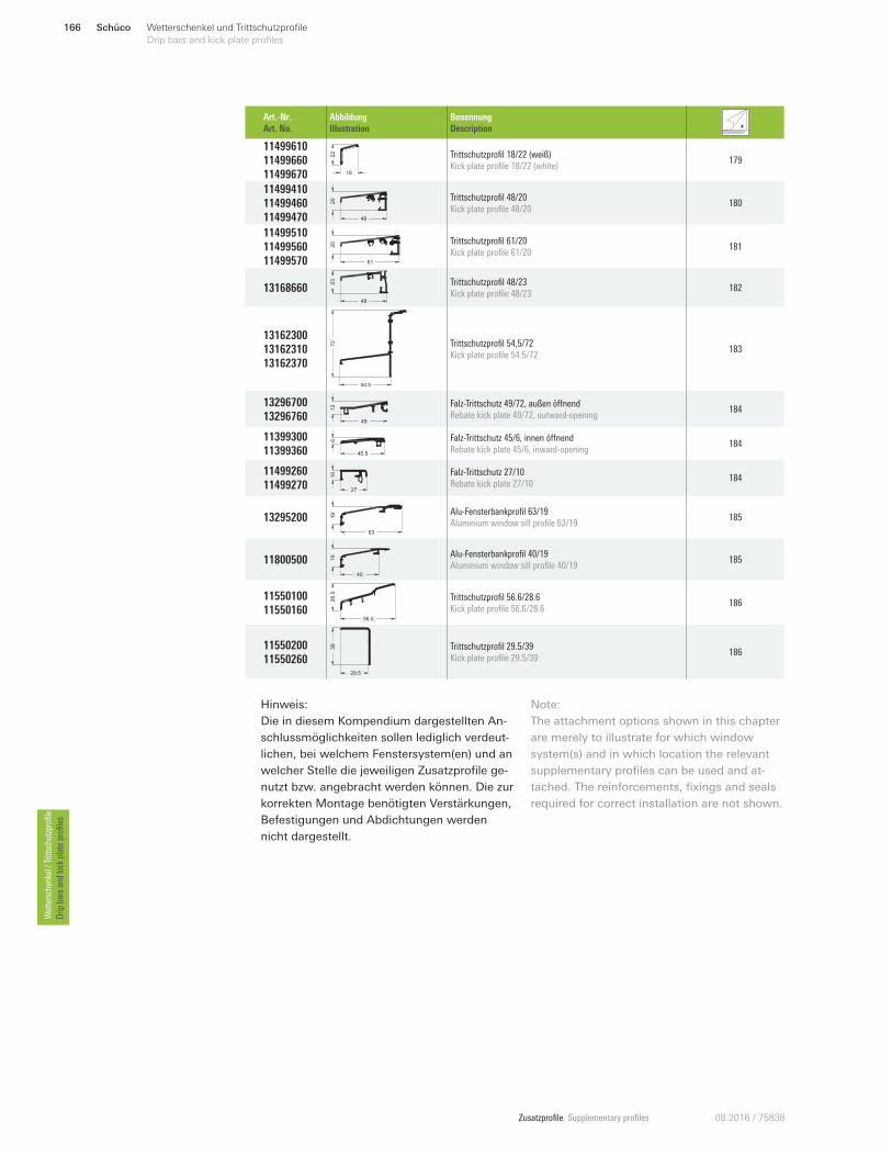
Zusatzprofile Supplementary profiles 08.2016 / 75838
Hinweis:
Die in diesem Kompendium dargestellten An-
schlussmöglichkeiten sollen lediglich verdeut-
lichen, bei welchem Fenstersystem(en) und an
welcher Stelle die jeweiligen Zusatzprofile ge-
nutzt bzw. angebracht werden können. Die zur
korrekten Montage benötigten Verstärkungen,
Befestigungen und Abdichtungen werden
nicht dargestellt.
Note:
The attachment options shown in this chapter
are merely to illustrate for which window
system(s) and in which location the relevant
supplementary profiles can be used and at-
tached. The reinforcements, fixings and seals
required for correct installation are not shown.
Schüco166 Wetterschenkel und Trittschutzprofile
Drip bars and kick plate profiles Wettersch
enkel / Trittsch
utzprofile
Drip
bars an
d kick plate profiles
Art.-Nr.
Art. No.
Abbildung
Illustration
Benennung
Description
11499610
11499660
11499670 18
22 Trittschutzprofil 18/22 (weiß)
Kick plate profile 18/22 (white) 179
11499410
11499460
11499470 48
20 Trittschutzprofil 48/20
Kick plate profile 48/20 180
11499510
11499560
11499570 61
20 Trittschutzprofil 61/20
Kick plate profile 61/20 181
13168660 48
23 Trittschutzprofil 48/23
Kick plate profile 48/23 182
13162300
13162310
13162370
54.5
72 Trittschutzprofil 54,5/72
Kick plate profile 54.5/72 183
13296700
13296760 49
12 Falz-Trittschutz 49/72, außen öWnend
Rebate kick plate 49/72, outward-opening 184
11399300
11399360 45.5
6 Falz-Trittschutz 45/6, innen öWnend
Rebate kick plate 45/6, inward-opening 184
11499260
11499270
10
27
Falz-Trittschutz 27/10
Rebate kick plate 27/10 184
13295200 63
19 Alu-Fensterbankprofil 63/19
Aluminium window sill profile 63/19 185
11800500 19
40
Alu-Fensterbankprofil 40/19
Aluminium window sill profile 40/19 185
11550100
11550160 56.5
28.5 Trittschutzprofil 56.6/28.6
Kick plate profile 56.6/28.6 186
11550200
11550260 29.5
39 Trittschutzprofil 29.5/39
Kick plate profile 29.5/39 186
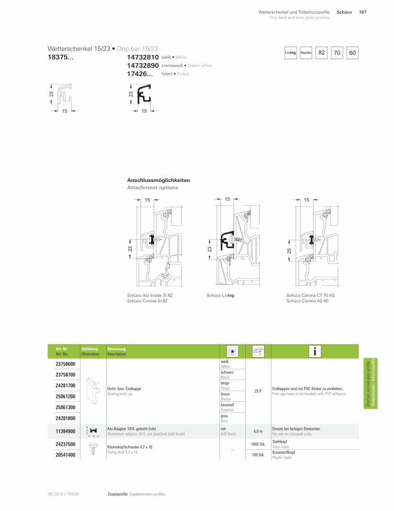
Zusatzprofile Supplementary profiles08.20 16 / 75838
15
23
23
15
Art.-Nr.
Art. No.
Abbildung
Illustration
Benennung
Description
23758600
Dicht- bzw. Endkappe
Sealing/end cap
weiß
White
25 P. Endkappen sind mit PVC-Kleber zu verkleben.
End caps have to be bonded with PVC adhesive.
23758700 schwarz
Black
24281700 beige
Beige
25061200 braun
Brown
25061300 karamell
Caramel
24281800 grau
Grey
11394900 10
4 Alu-Adapter 10/4, gelocht (roh)
Aluminium adapter 10/4, pre-punched (mill finish)
roh
mill finish 6,0 m
Einsatz bei farbigen Elementen
For use on coloured units
24237500 Klemmkopfschraube 4,2 x 10
Fixing stud 4.2 x 10 —
1000 Stk. Stahlkopf
Steel head
205414 00 100 Stk.KunststoWkopf
Plastic head
Wetterschenkel 15/23 • Drip bar 15/23
18375 ...
Anschlussmöglichkeiten
Attachment options
22
15
Schüco Alu Inside SI 82
Schüco Corona SI 82
25
15
Schüco Corona CT 70 AS
Schüco Corona AS 60
82 70 60NordicLivIng
14732890 cremeweiß • Cream white
14732810 weiß • White
17426 ... foliert • Foiled
Schüco LivIng
15
23
Schüco 167Wetterschenkel und Trittschutzprofile
Drip bars and kick plate profiles
Drip
bars an
d kick plate profiles
Wettersch
enkel / Trittsch
utzprofile
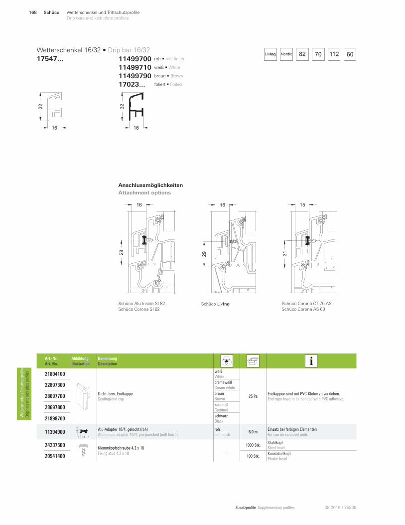
Zusatzprofile Supplementary profiles 08.2016 / 75838
28
16
82 70 112 60NordicLivIng
16
32
1632
Art.-Nr.
Art. No.
Abbildung
Illustration
Benennung
Description
21804100
Dicht- bzw. Endkappe
Sealing/end cap
weiß
White
25 Pa Endkappen sind mit PVC-Kleber zu verkleben.
End caps have to be bonded with PVC adhesive.
22897300 cremeweiß
Cream white
28697700 braun
Brown
28697800 karamell
Caramel
21898700 schwarz
Black
11394900 10
4 Alu-Adapter 10/4, gelocht (roh)
Aluminium adapter 10/4, pre-punched (mill finish)
roh
mill finish 6,0 m
Einsatz bei farbigen Elementen
For use on coloured units
24237500 Klemmkopfschraube 4,2 x 10
Fixing stud 4.2 x 10 —
1000 Stk. Stahlkopf
Steel head
205414 00 100 Stk.KunststoWkopf
Plastic head
Wetterschenkel 16/32 • Drip bar 16/32
17547 ...
Anschlussmöglichkeiten
Attachment options
Schüco Alu Inside SI 82
Schüco Corona SI 82
31
15
Schüco Corona CT 70 AS
Schüco Corona AS 60
11499710 weiß • White
11499700 roh • mill finish
11499790 braun • Brown
17023 ... foliert • Foiled
Schüco LivIng
162
9
Schüco168 Wetterschenkel und Trittschutzprofile
Drip bars and kick plate profiles Wettersch
enkel / Trittsch
utzprofile
Drip
bars an
d kick plate profiles
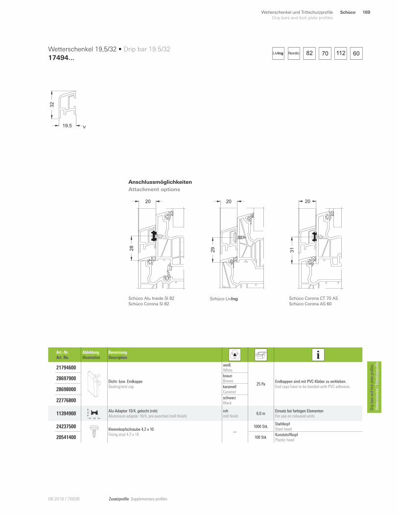
Zusatzprofile Supplementary profiles08.20 16 / 75838
28
20
19.5
32
v
Art.-Nr.
Art. No.
Abbildung
Illustration
Benennung
Description
21794600
Dicht- bzw. Endkappe
Sealing/end cap
weiß
White
25 Pa Endkappen sind mit PVC-Kleber zu verkleben.
End caps have to be bonded with PVC adhesive.
28697900 braun
Brown
28698000 karamell
Caramel
22776800 schwarz
Black
11394900 10
4 Alu-Adapter 10/4, gelocht (roh)
Aluminium adapter 10/4, pre-punched (mill finish)
roh
mill finish 6,0 m
Einsatz bei farbigen Elementen
For use on coloured units
24237500 Klemmkopfschraube 4,2 x 10
Fixing stud 4.2 x 10 —
1000 Stk. Stahlkopf
Steel head
205414 00 100 Stk.KunststoWkopf
Plastic head
Wetterschenkel 19,5/32 • Drip bar 19.5/32
17494 ...
Anschlussmöglichkeiten
Attachment options
Schüco Alu Inside SI 82
Schüco Corona SI 82
31
20
82 70 112 60NordicLivIng
Schüco LivIng
20
29
Schüco Corona CT 70 AS
Schüco Corona AS 60
Schüco 169Wetterschenkel und Trittschutzprofile
Drip bars and kick plate profiles
Drip
bars an
d kick plate profiles
Wettersch
enkel / Trittsch
utzprofile
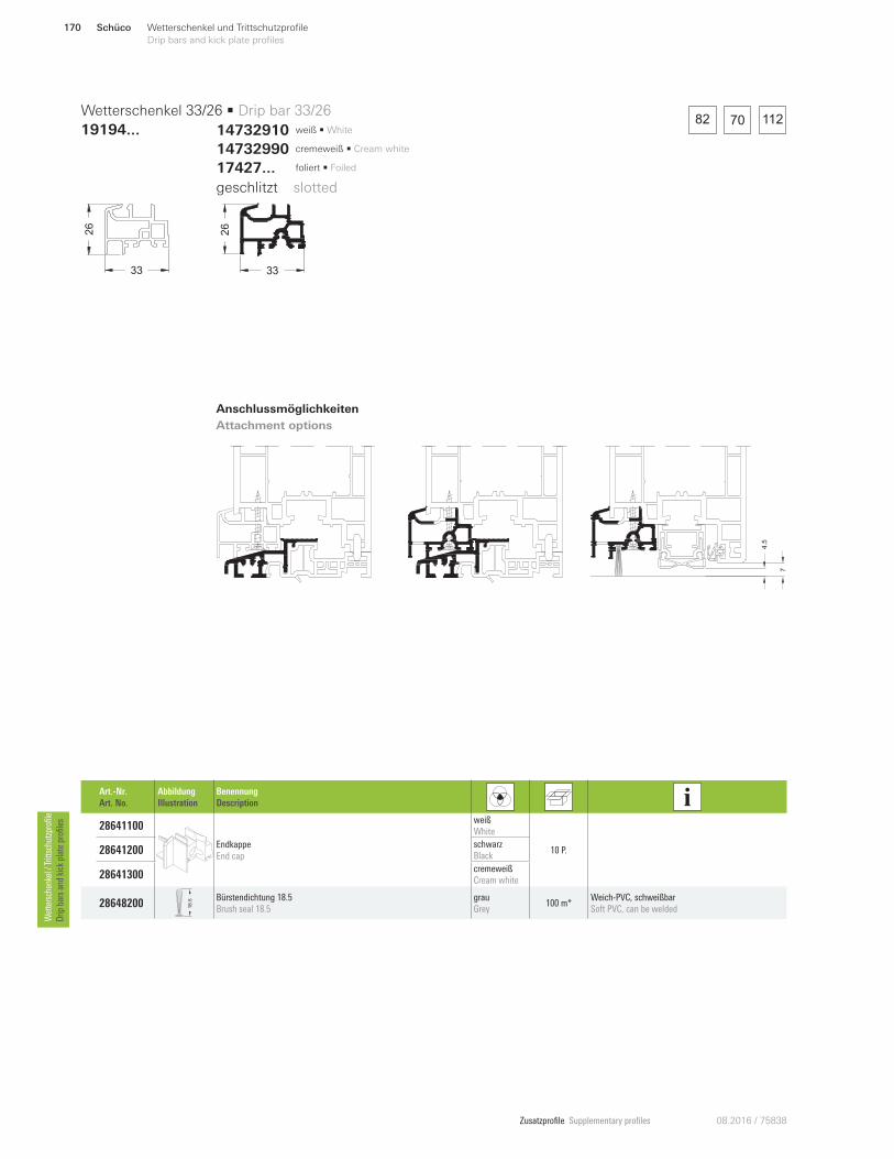
Zusatzprofile Supplementary profiles 08.2016 / 75838
82 70 112
7
4.5
33
26
33
26
Art.-Nr.
Art. No.
Abbildung
Illustration
Benennung
Description
28641100
Endkappe
End cap
weiß
White
10 P. 28641200 schwarz
Black
28641300 cremeweiß
Cream white
28648200 18.5 Bürstendichtung 18.5
Brush seal 18.5
grau
Grey 100 m*
Weich-PVC, schweißbar
Soft PVC, can be welded
Wetterschenkel 33/26 • Drip bar 33/26
19194 ...
Anschlussmöglichkeiten
Attachment options
geschlitzt • slotted
14732990 cremeweiß • Cream white
14732910 weiß • White
17427... foliert • Foiled
Schüco170 Wetterschenkel und Trittschutzprofile
Drip bars and kick plate profiles Wettersch
enkel / Trittsch
utzprofile
Drip
bars an
d kick plate profiles
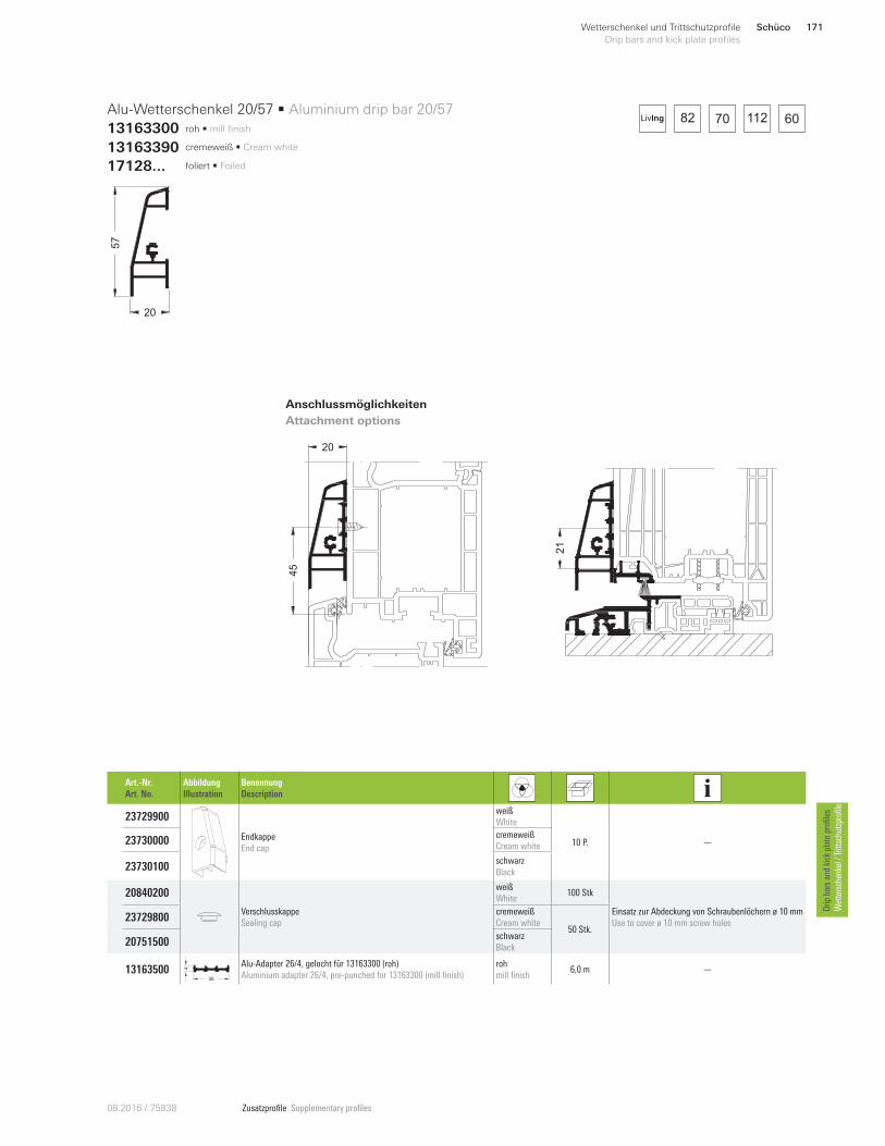
Zusatzprofile Supplementary profiles08.20 16 / 75838
82 70 112 60
20
45
21
20
57
Art.-Nr.
Art. No.
Abbildung
Illustration
Benennung
Description
23729900
Endkappe
End cap
weiß
White
10 P. —23730000 cremeweiß
Cream white
23730100 schwarz
Black
20840200
Verschlusskappe
Sealing cap
weiß
White 100 Stk
Einsatz zur Abdeckung von Schraubenlöchern ø 10 mm
Use to cover ø 10 mm screw holes 23729800
cremeweiß
Cream white 50 Stk.
20751500 schwarz
Black
13163500 26
4
Alu-Adapter 26/4, gelocht für 13163300 (roh)
Aluminium adapter 26/4, pre-punched for 13163300 (mill finish)
roh
mill finish 6,0 m —
Alu-Wetterschenkel 20/57 • Aluminium drip bar 20/57
13163300
Anschlussmöglichkeiten
Attachment options
13163390 cremeweiß • Cream white
17128... foliert • Foiled
roh • mill finish LivIng
Schüco 171Wetterschenkel und Trittschutzprofile
Drip bars and kick plate profiles
Drip
bars an
d kick plate profiles
Wettersch
enkel / Trittsch
utzprofile
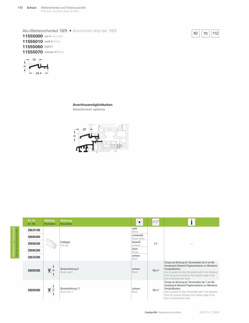
Zusatzprofile Supplementary profiles 08.2016 / 75838
34.4
9
18
Art.-Nr.
Art. No.
Abbildung
Illustration
Benennung
Description
28634100
Endkappe
End cap
weiß
White
5 P. —
28696400 cremeweiß
Cream white
28696200 karamell
Caramel
28696300 braun
Brown
28634200 schwarz
Black
28699300 9
Bürstendichtung 9
Brush seal 9
schwarz
Black 100 m*
Einsatz als Dichtung für Türschwellen bei 5 mm Bo-
denabstand (Abstand Flügelunterkante zur Oberkante
Fertigfußboden)
Use as gasket for door thresholds with 5 mm distance
from the ground (distance from bottom edge of the
leaf to finished floor level)
28699400 11 Bürstendichtung 11
Brush seal 11
schwarz
Black 100 m*
Einsatz als Dichtung für Türschwellen bei 7 mm Bo-
denabstand (Abstand Flügelunterkante zur Oberkante
Fertigfußboden)
Use as gasket for door thresholds with 7 mm distance
from the ground (distance from bottom edge of the
leaf to finished floor level)
Alu-Wetterschenkel 18/9 • Aluminium drip bar 18/9
11555000
Anschlussmöglichkeiten
Attachment options
11555060 E6/EV1
11555070 schwarz • Black
roh • mill finish
20
9
82 70 112
11555010 weiß • White
Schüco172 Wetterschenkel und Trittschutzprofile
Drip bars and kick plate profiles Wettersch
enkel / Trittsch
utzprofile
Drip
bars an
d kick plate profiles
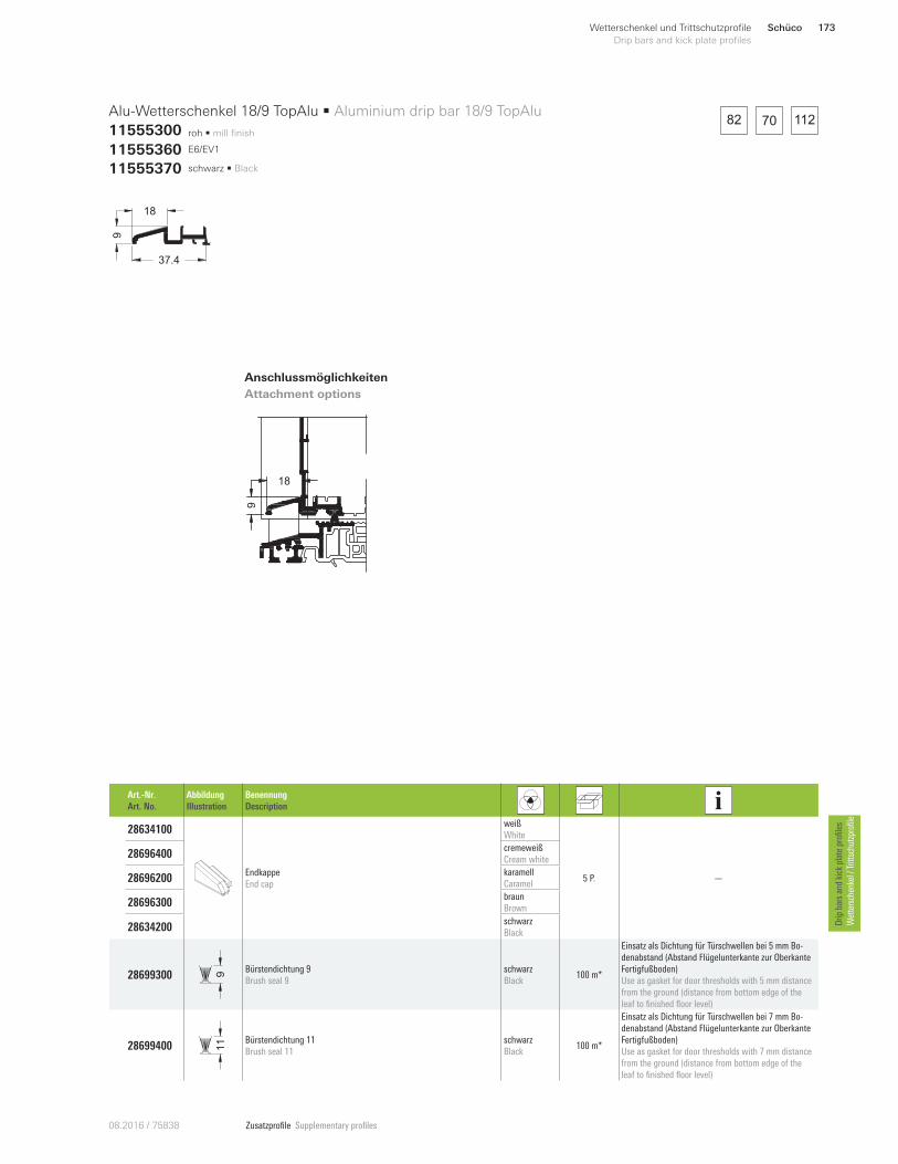
Zusatzprofile Supplementary profiles08.20 16 / 75838
Alu-Wetterschenkel 18/9 TopAlu • Aluminium drip bar 18/9 TopAlu
11555300 roh • mill finish
37.4
18
9
Anschlussmöglichkeiten
Attachment options
11555360 E6/EV1
11555370 schwarz • Black
Art.-Nr.
Art. No.
Abbildung
Illustration
Benennung
Description
28634100
Endkappe
End cap
weiß
White
5 P. —
28696400 cremeweiß
Cream white
28696200 karamell
Caramel
28696300 braun
Brown
28634200 schwarz
Black
28699300 9
Bürstendichtung 9
Brush seal 9
schwarz
Black 100 m*
Einsatz als Dichtung für Türschwellen bei 5 mm Bo-
denabstand (Abstand Flügelunterkante zur Oberkante
Fertigfußboden)
Use as gasket for door thresholds with 5 mm distance
from the ground (distance from bottom edge of the
leaf to finished floor level)
28699400 11 Bürstendichtung 11
Brush seal 11
schwarz
Black 100 m*
Einsatz als Dichtung für Türschwellen bei 7 mm Bo-
denabstand (Abstand Flügelunterkante zur Oberkante
Fertigfußboden)
Use as gasket for door thresholds with 7 mm distance
from the ground (distance from bottom edge of the
leaf to finished floor level)
18
9
82 70 112
Schüco 173Wetterschenkel und Trittschutzprofile
Drip bars and kick plate profiles
Drip
bars an
d kick plate profiles
Wettersch
enkel / Trittsch
utzprofile
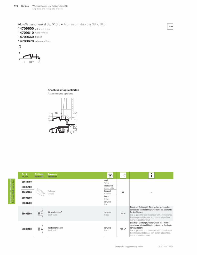
Zusatzprofile Supplementary profiles 08.2016 / 75838
roh • mill finish
18
9
LivIng
38.7
10
.5
Alu-Wetterschenkel 38,7/10,5 • Aluminium drip bar 38.7/10.5
14709600
Anschlussmöglichkeiten
Attachment options
14709610 weiß • White
14709670 schwarz • Black
14709660 E6/EV1
Art.-Nr.
Art. No.
Abbildung
Illustration
Benennung
Description
28634100
Endkappe
End cap
weiß
White
5 P. —
28696400 cremeweiß
Cream white
28696200 karamell
Caramel
28696300 braun
Brown
28634200 schwarz
Black
28699300 9
Bürstendichtung 9
Brush seal 9
schwarz
Black 100 m*
Einsatz als Dichtung für Türschwellen bei 5 mm Bo-
denabstand (Abstand Flügelunterkante zur Oberkante
Fertigfußboden)
Use as gasket for door thresholds with 5 mm distance
from the ground (distance from bottom edge of the
leaf to finished floor level)
28699400 11 Bürstendichtung 11
Brush seal 11
schwarz
Black 100 m*
Einsatz als Dichtung für Türschwellen bei 7 mm Bo-
denabstand (Abstand Flügelunterkante zur Oberkante
Fertigfußboden)
Use as gasket for door thresholds with 7 mm distance
from the ground (distance from bottom edge of the
leaf to finished floor level)
Schüco174 Wetterschenkel und Trittschutzprofile
Drip bars and kick plate profiles Wettersch
enkel / Trittsch
utzprofile
Drip
bars an
d kick plate profiles
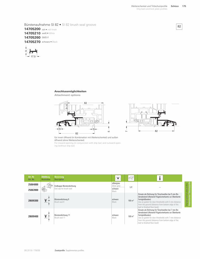
Zusatzprofile Supplementary profiles08.20 16 / 75838
roh • mill finish
9
17.5
Bürstenaufnahme SI 82 • SI 82 brush seal groove
14705200
Anschlussmöglichkeiten
Attachment options
14705210 weiß • White
14705270 schwarz • Black
14705260 E6/EV1
Art.-Nr.
Art. No.
Abbildung
Illustration
Benennung
Description
25064000 Endkappe Bürstendichtung
End cap for brush seal
silbergrau
Silver grey 5 P. —
25063900 schwarz
Black
28699300 9
Bürstendichtung 9
Brush seal 9
schwarz
Black 100 m*
Einsatz als Dichtung für Türschwellen bei 5 mm Bo-
denabstand (Abstand Flügelunterkante zur Oberkante
Fertigfußboden)
Use as gasket for door thresholds with 5 mm distance
from the ground (distance from bottom edge of the
leaf to finished floor level)
28699400 11 Bürstendichtung 11
Brush seal 11
schwarz
Black 100 m*
Einsatz als Dichtung für Türschwellen bei 7 mm Bo-
denabstand (Abstand Flügelunterkante zur Oberkante
Fertigfußboden)
Use as gasket for door thresholds with 7 mm distance
from the ground (distance from bottom edge of the
leaf to finished floor level)
5
55
82
82
7 82
für innen öVnend (in Kombination mit Wetterschenkel) und außen
öVnend (ohne Wetterschenkel)
For inward-opening (in conjunction with drip bar) and outward-open-
ing (without drip bar)
82
Schüco 175Wetterschenkel und Trittschutzprofile
Drip bars and kick plate profiles
Drip
bars an
d kick plate profiles
Wettersch
enkel / Trittsch
utzprofile
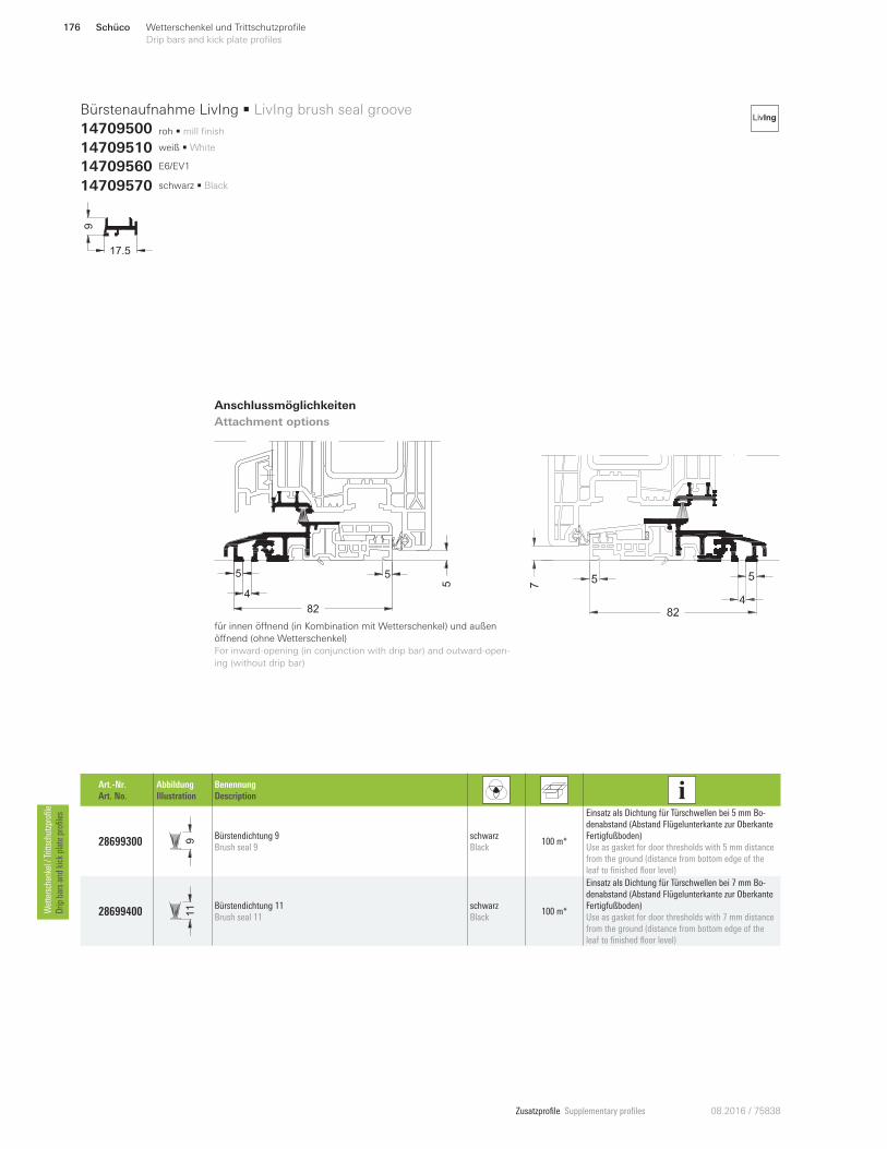
Zusatzprofile Supplementary profiles 08.2016 / 75838
Anschlussmöglichkeiten
Attachment options
für innen öVnend (in Kombination mit Wetterschenkel) und außen
öVnend (ohne Wetterschenkel)
For inward-opening (in conjunction with drip bar) and outward-open-
ing (without drip bar)
Art.-Nr.
Art. No.
Abbildung
Illustration
Benennung
Description
28699300 9
Bürstendichtung 9
Brush seal 9
schwarz
Black 100 m*
Einsatz als Dichtung für Türschwellen bei 5 mm Bo-
denabstand (Abstand Flügelunterkante zur Oberkante
Fertigfußboden)
Use as gasket for door thresholds with 5 mm distance
from the ground (distance from bottom edge of the
leaf to finished floor level)
28699400 11 Bürstendichtung 11
Brush seal 11
schwarz
Black 100 m*
Einsatz als Dichtung für Türschwellen bei 7 mm Bo-
denabstand (Abstand Flügelunterkante zur Oberkante
Fertigfußboden)
Use as gasket for door thresholds with 7 mm distance
from the ground (distance from bottom edge of the
leaf to finished floor level)
roh • mill finish
9
17.5
Bürstenaufnahme LivIng • LivIng brush seal groove
14709500
14709510 weiß • White
14709570 schwarz • Black
14709560 E6/EV1
LivIng
5
55
4
82
Schüco176 Wetterschenkel und Trittschutzprofile
Drip bars and kick plate profiles Wettersch
enkel / Trittsch
utzprofile
Drip
bars an
d kick plate profiles
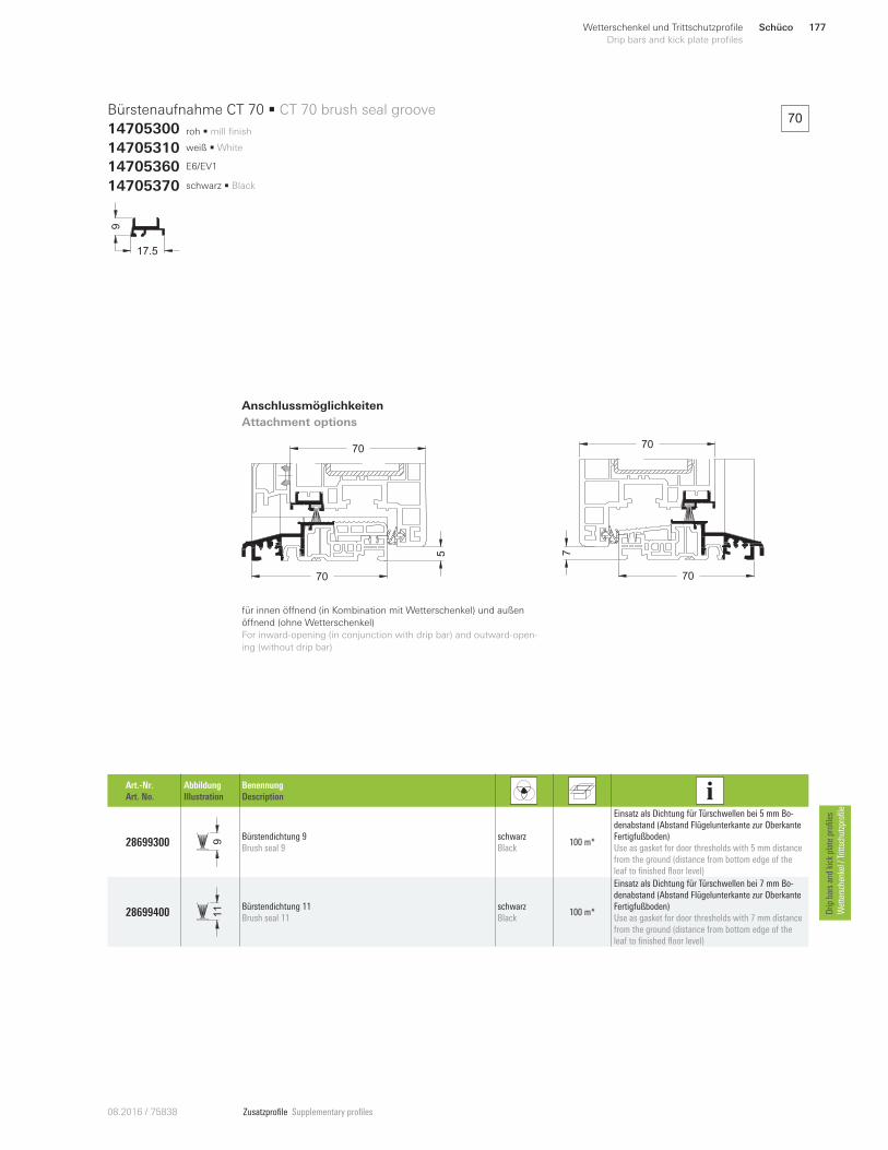
Zusatzprofile Supplementary profiles08.20 16 / 75838
roh • mill finish
17.5
9Bürstenaufnahme CT 70 • CT 70 brush seal groove
14705300
Anschlussmöglichkeiten
Attachment options
14705310 weiß • White
14705370 schwarz • Black
14705360 E6/EV1
Art.-Nr.
Art. No.
Abbildung
Illustration
Benennung
Description
28699300 9
Bürstendichtung 9
Brush seal 9
schwarz
Black 100 m*
Einsatz als Dichtung für Türschwellen bei 5 mm Bo-
denabstand (Abstand Flügelunterkante zur Oberkante
Fertigfußboden)
Use as gasket for door thresholds with 5 mm distance
from the ground (distance from bottom edge of the
leaf to finished floor level)
28699400 11 Bürstendichtung 11
Brush seal 11
schwarz
Black 100 m*
Einsatz als Dichtung für Türschwellen bei 7 mm Bo-
denabstand (Abstand Flügelunterkante zur Oberkante
Fertigfußboden)
Use as gasket for door thresholds with 7 mm distance
from the ground (distance from bottom edge of the
leaf to finished floor level)
für innen öVnend (in Kombination mit Wetterschenkel) und außen
öVnend (ohne Wetterschenkel)
For inward-opening (in conjunction with drip bar) and outward-open-
ing (without drip bar)
570
707
70
70
70
Schüco 177Wetterschenkel und Trittschutzprofile
Drip bars and kick plate profiles
Drip
bars an
d kick plate profiles
Wettersch
enkel / Trittsch
utzprofile
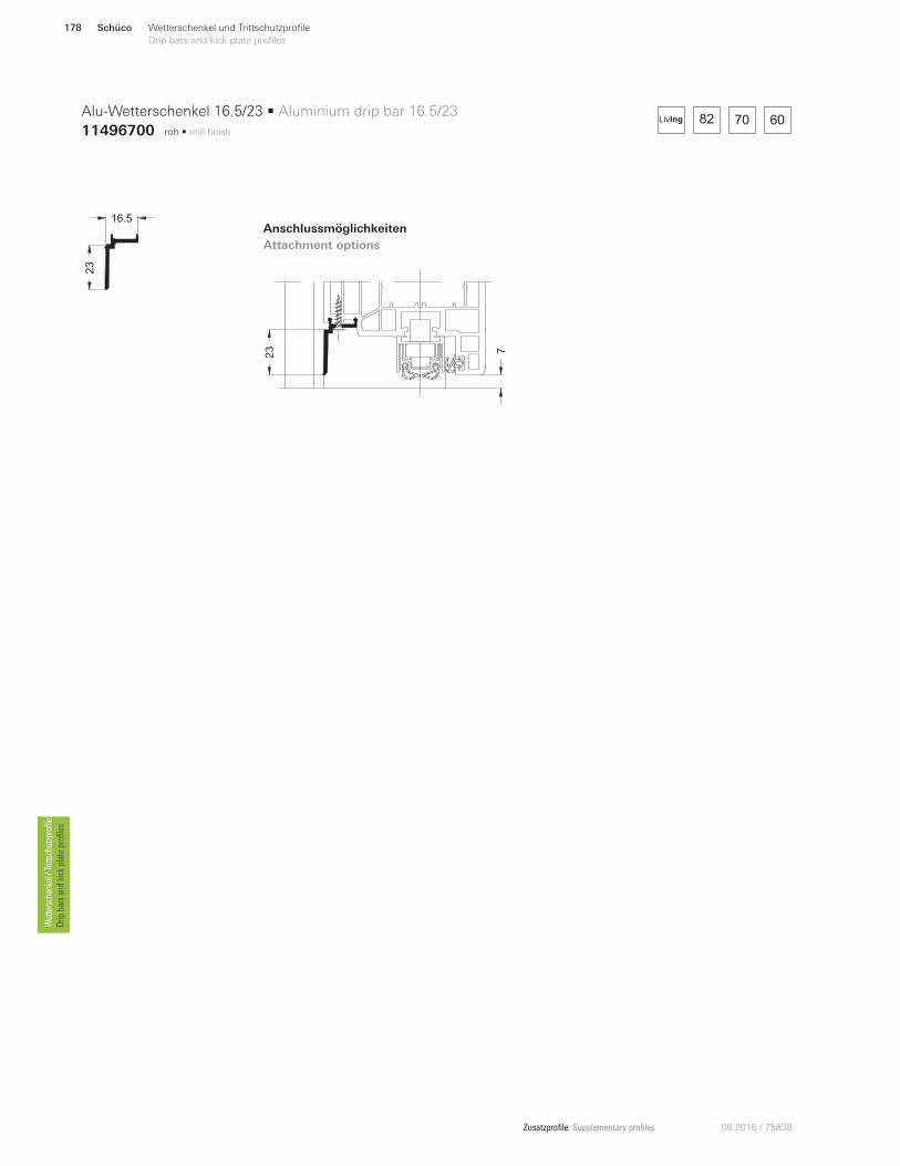
Zusatzprofile Supplementary profiles 08.2016 / 75838
723
roh • mill finish
82 70 60LivIng
23
16.5
Alu-Wetterschenkel 16.5/23 • Aluminium drip bar 16.5/23
11496700
Anschlussmöglichkeiten
Attachment options
Schüco178 Wetterschenkel und Trittschutzprofile
Drip bars and kick plate profiles Wettersch
enkel / Trittsch
utzprofile
Drip
bars an
d kick plate profiles
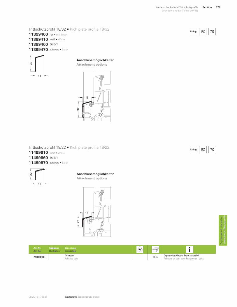
Zusatzprofile Supplementary profiles08.20 16 / 75838
roh • mill finish
weiß • White
18
32
18
22
Trittschutzprofil 18/32 • Kick plate profile 18/32
11399400
Trittschutzprofil 18/22 • Kick plate profile 18/22
11499610
Anschlussmöglichkeiten
Attachment options
Anschlussmöglichkeiten
Attachment options
Art.-Nr.
Art. No.
Abbildung
Illustration
Benennung
Description
29840600 Klebeband
Adhesive tape 66 m
Doppelseitig klebend Reparaturartikel
Adhesive on both sides Replacement parts
18
32
18
22
82 70LivIng
82 70LivIng
11399410 weiß • White
11499660 E6/EV1
11399470 schwarz • Black
11399460 E6/EV1
11499670 schwarz • Black
Schüco 179Wetterschenkel und Trittschutzprofile
Drip bars and kick plate profiles
Drip
bars an
d kick plate profiles
Wettersch
enkel / Trittsch
utzprofile
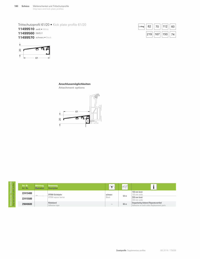
Zusatzprofile Supplementary profiles 08.2016 / 75838
82 60
74167 150
70 112
219
LivIng
weiß • White
61
20
Trittschutzprofil 61/20 • Kick plate profile 61/20
11499510
Anschlussmöglichkeiten
Attachment options
Art.-Nr.
Art. No.
Abbildung
Illustration
Benennung
Description
22415400 EPDM-Dichtbahn
EPDM vapour barrier
schwarz
Black 50 m
150 mm breit
150 mm wide
22415500 250 mm breit
250 mm wide
29840600 Klebeband
Adhesive tape — 66 m
Doppelseitig klebend Reparaturartikel
Adhesive on both sides Replacement parts
11499560 E6/EV1
11499570 schwarz • Black
61
20
Schüco180 Wetterschenkel und Trittschutzprofile
Drip bars and kick plate profiles Wettersch
enkel / Trittsch
utzprofile
Drip
bars an
d kick plate profiles
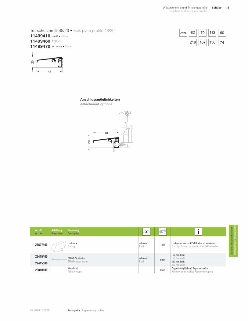
Zusatzprofile Supplementary profiles08.20 16 / 75838
48
20
82 60
74167 150
70 112
219
LivIng
weiß • White
48
20
Trittschutzprofil 48/20 • Kick plate profile 48/20
11499410
Anschlussmöglichkeiten
Attachment options
11499460 E6/EV1
11499470 schwarz • Black
Art.-Nr.
Art. No.
Abbildung
Illustration
Benennung
Description
26607400 Endkappe
End cap
schwarz
Black 10 P.
Endkappen sind mit PVC-Kleber zu verkleben.
End caps have to be bonded with PVC adhesive.
22415400 EPDM-Dichtbahn
EPDM vapour barrier
schwarz
Black 50 m
150 mm breit
150 mm wide
22415500 250 mm breit
250 mm wide
29840600 Klebeband
Adhesive tape 66 m
Doppelseitig klebend Reparaturartikel
Adhesive on both sides Replacement parts
Schüco 181Wetterschenkel und Trittschutzprofile
Drip bars and kick plate profiles
Drip
bars an
d kick plate profiles
Wettersch
enkel / Trittsch
utzprofile
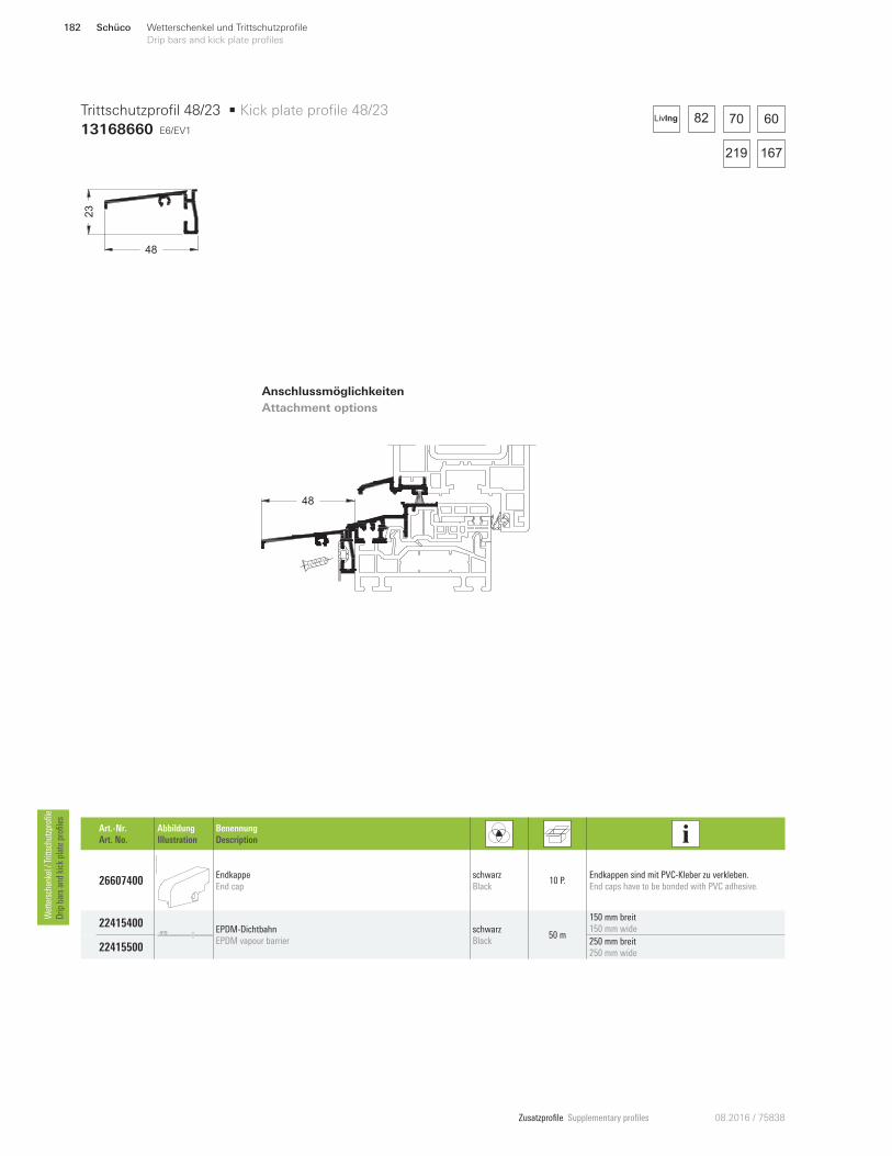
Zusatzprofile Supplementary profiles 08.2016 / 75838
E6/EV1
48
23
Trittschutzprofil 48/23 • Kick plate profile 48/23
13168660
Anschlussmöglichkeiten
Attachment options
Art.-Nr.
Art. No.
Abbildung
Illustration
Benennung
Description
26607400 Endkappe
End cap
schwarz
Black 10 P.
Endkappen sind mit PVC-Kleber zu verkleben.
End caps have to be bonded with PVC adhesive.
22415400 EPDM-Dichtbahn
EPDM vapour barrier
schwarz
Black 50 m
150 mm breit
150 mm wide
22415500 250 mm breit
250 mm wide
82 6070
167219
LivIng
48
Schüco182 Wetterschenkel und Trittschutzprofile
Drip bars and kick plate profiles Wettersch
enkel / Trittsch
utzprofile
Drip
bars an
d kick plate profiles
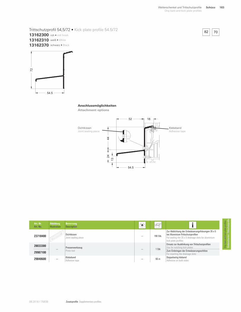
Zusatzprofile Supplementary profiles08.20 16 / 75838
1852
44
13
24
54.5
Dichtkissen
Joint sealing piece
82 70roh • mill finish
54.5
72
Trittschutzprofil 54,5/72 • Kick plate profile 54.5/72
13162300
Anschlussmöglichkeiten
Attachment options
13162310 weiß • White
13162370 schwarz • Black
Art.-Nr.
Art. No.
Abbildung
Illustration
Benennung
Description
23718400 Dichtkissen
Joint sealing piece — 190 Stk.
Zur Abdichtung der Entwässerungsfräsungen 35 x 5
bei Aluminium-Trittschutzprofilen
For sealing the 35 x 5 drainage slots for aluminium
kick plate profiles
28033300 —
Pressenwerkzeug
Press tool — 1 Stk
Einsatz zur Ausklinkung von Trittschutzprofilen
Use for notching kick plates
29987100 Zum Einbringen der Entwässerungsschlitze
For inserting the drainage slots
29840600 —Klebeband
Adhesive tape — 66 m
Doppelseitig klebend
Adhesive on both sides
Klebeband
Adhesive tape
Schüco 183Wetterschenkel und Trittschutzprofile
Drip bars and kick plate profiles
Drip
bars an
d kick plate profiles
Wettersch
enkel / Trittsch
utzprofile
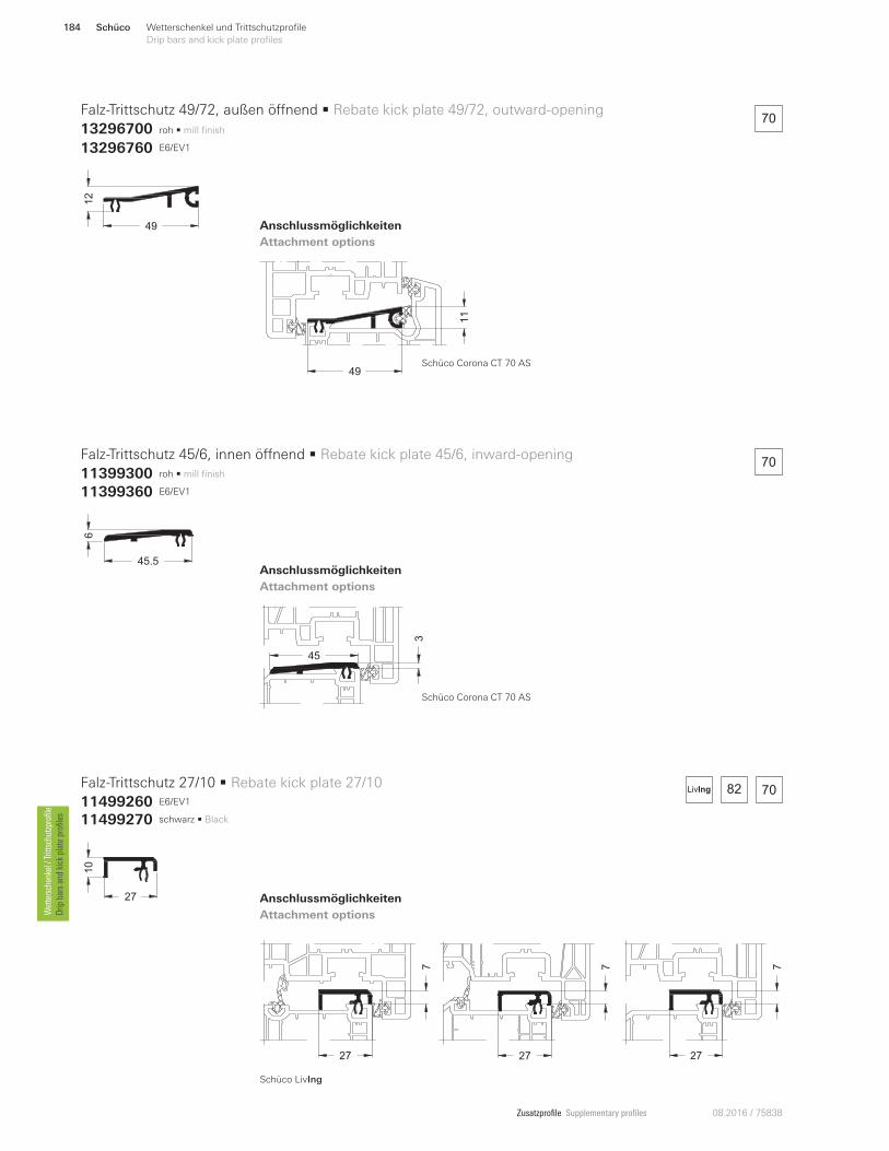
Zusatzprofile Supplementary profiles 08.2016 / 75838
roh • mill finish
roh • mill finish
E6/EV1
49
12
45.5
610
27
Falz-Trittschutz 49/72, außen öVnend • Rebate kick plate 49/72, outward-opening
13296700
Falz-Trittschutz 45/6, innen öVnend • Rebate kick plate 45/6, inward-opening
11399300
Falz-Trittschutz 27/10 • Rebate kick plate 27/10
11499260
Anschlussmöglichkeiten
Attachment options
Anschlussmöglichkeiten
Attachment options
Anschlussmöglichkeiten
Attachment options
13296760 E6/EV1
11399360 E6/EV1
11499270 schwarz • Black
49
11
45
3
70
70
27
7
27
7
27
7
82 70
Schüco Corona CT 70 AS
Schüco Corona CT 70 AS
LivIng
Schüco LivIng
Schüco184 Wetterschenkel und Trittschutzprofile
Drip bars and kick plate profiles Wettersch
enkel / Trittsch
utzprofile
Drip
bars an
d kick plate profiles
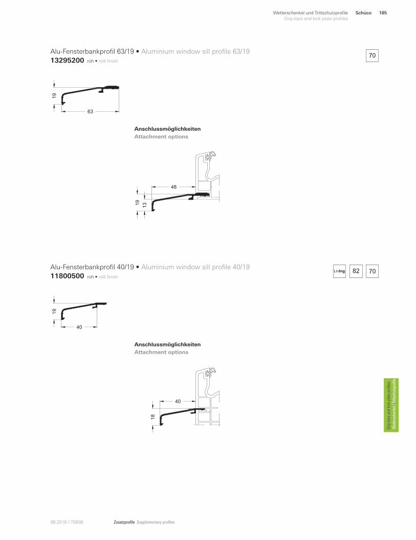
Zusatzprofile Supplementary profiles08.20 16 / 75838
48
1319
40
18
82 70
70roh • mill finish
roh • mill finish
63
19
19
40
Alu-Fensterbankprofil 63/19 • Aluminium window sill profile 63/19
13295200
Alu-Fensterbankprofil 40/19 • Aluminium window sill profile 40/19
11800500
Anschlussmöglichkeiten
Attachment options
Anschlussmöglichkeiten
Attachment options
LivIng
Schüco 185Wetterschenkel und Trittschutzprofile
Drip bars and kick plate profiles
Drip
bars an
d kick plate profiles
Wettersch
enkel / Trittsch
utzprofile
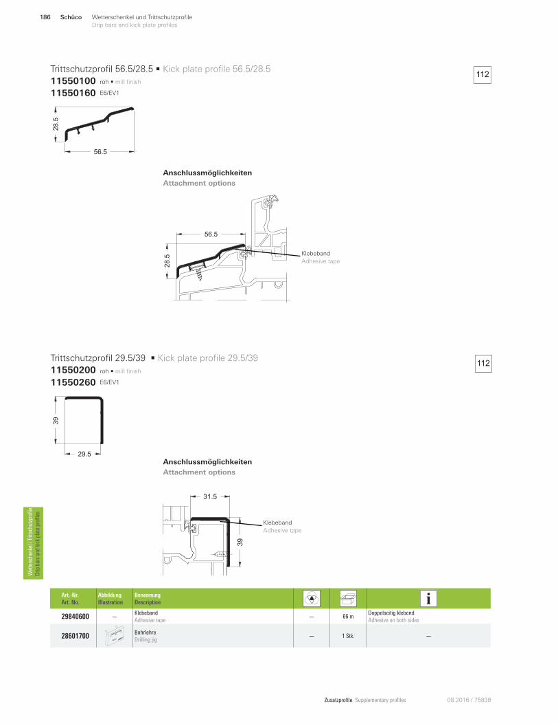
Zusatzprofile Supplementary profiles 08.2016 / 75838
31.5
39
56.5
28.5
112
112
roh • mill finish
roh • mill finish
56.5
28.5
29.5
39
Trittschutzprofil 56.5/28.5 • Kick plate profile 56.5/28.5
11550100
Trittschutzprofil 29.5/39 • Kick plate profile 29.5/39
11550200
Anschlussmöglichkeiten
Attachment options
Anschlussmöglichkeiten
Attachment options
11550160 E6/EV1
11550260 E6/EV1
Art.-Nr.
Art. No.
Abbildung
Illustration
Benennung
Description
29840600 —Klebeband
Adhesive tape — 66 m
Doppelseitig klebend
Adhesive on both sides
28601700 Bohrlehre
Drilling jig — 1 Stk. —
Klebeband
Adhesive tape
Klebeband
Adhesive tape
Schüco186 Wetterschenkel und Trittschutzprofile
Drip bars and kick plate profiles Wettersch
enkel / Trittsch
utzprofile
Drip
bars an
d kick plate profiles
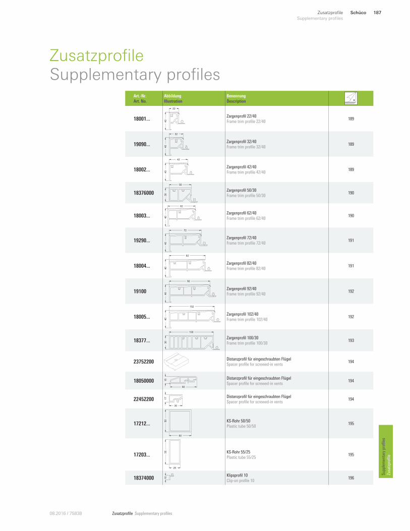
Zusatzprofile Supplementary profiles08.2016 / 75838
Supp
lemen
tary profiles
Zusatzprofi
le
Schüco 187Zusatzprofile
Supplementary profiles
ZusatzprofileSupplementary profiles
Art.-Nr.
Art. No.
Abbildung
Illustration
Benennung
Description
18001 ...
40
22
Zargenprofil 22/40
Frame trim profile 22/40 189
19090 ...
40
32
Zargenprofil 32/40
Frame trim profile 32/40 189
18002 ...40
42
Zargenprofil 42/40
Frame trim profile 42/40 189
18376000
30
50
Zargenprofil 50/30
Frame trim profile 50/30 190
18003 ... 40
62
Zargenprofil 62/40
Frame trim profile 62/40 190
19290 ...
40
72
Zargenprofil 72/40
Frame trim profile 72/40 191
18004 ...
40
82
Zargenprofil 82/40
Frame trim profile 82/40 191
19100
40
92
Zargenprofil 92/40
Frame trim profile 92/40 192
18005 ...
40
102
Zargenprofil 102/40
Frame trim profile 102/40 192
18377 ...
30
100
Zargenprofil 100/30
Frame trim profile 100/30 193
23752200 Distanzprofil für eingeschraubten Flügel
Spacer profile for screwed-in vents 194
18050000 15
60
Distanzprofil für eingeschraubten Flügel
Spacer profile for screwed-in vents 194
22452200 30
17 Distanzprofil für eingeschraubten Flügel
Spacer profile for screwed-in vents 194
17212 ...
50
50 KS-Rohr 50/50
Plastic tube 50/50 195
17203 ...
25
55 KS-Rohr 55/25
Plastic tube 55/25 195
18374000 10 Klipsprofil 10
Clip-on profile 10 196
Zusatzprofile Supplementary profiles 08.2016 / 75838
Zusatzprofi
le
Supp
lemen
tary profiles
Hinweis:
Die in diesem Kompendium dargestellten An-
schlussmöglichkeiten sollen lediglich verdeut-
lichen, bei welchem Fenstersystem(en) und an
welcher Stelle die jeweiligen Zusatzprofile ge-
nutzt bzw. angebracht werden können. Die zur
korrekten Montage benötigten Verstärkungen,
Befestigungen und Abdichtungen werden
nicht dargestellt.
Note:
The attachment options shown in this chapter
are merely to illustrate for which window
system(s) and in which location the relevant
supplementary profiles can be used and at-
tached. The reinforcements, fixings and seals
required for correct installation are not shown.
Schüco188 Zusatzprofile
Supplementary profiles
Art.-Nr.
Art. No.
Abbildung
Illustration
Benennung
Description
18927000 7
Klipsprofil 7
Clip-on profile 7 196
18669000 5.7
13.8 Adapterprofil 5,7/13,8
Adapter profile 5.7/13.8 196
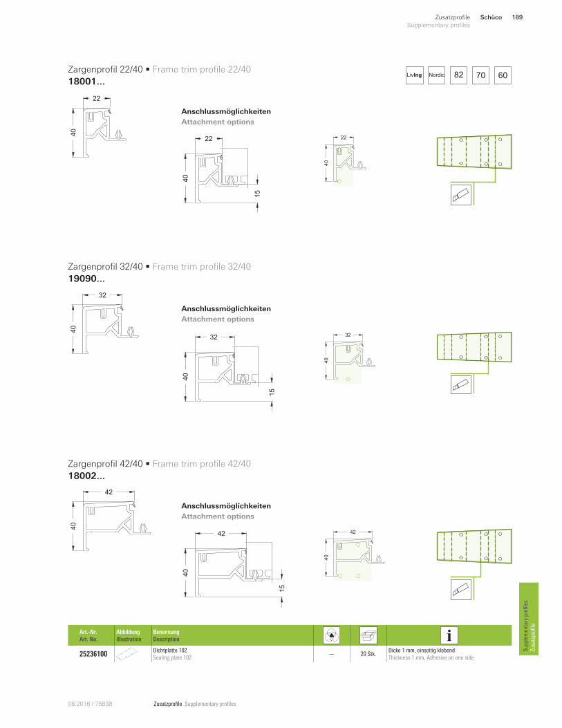
Zusatzprofile Supplementary profiles08.2016 / 75838
Supp
lemen
tary profiles
Zusatzprofi
le
40
22
40
32
40
42
Art.-Nr.
Art. No.
Abbildung
Illustration
Benennung
Description
25236100 Dichtplatte 102
Sealing plate 102 — 20 Stk.
Dicke 1 mm, einseitig klebend
Thickness 1 mm, Adhesive on one side
Zargenprofil 22/40 • Frame trim profile 22/40
18001...
Zargenprofil 32/40 • Frame trim profile 32/40
19090...
Zargenprofil 42/40 • Frame trim profile 42/40
18002...
Anschlussmöglichkeiten
Attachment options
Anschlussmöglichkeiten
Attachment options
Anschlussmöglichkeiten
Attachment options
82 70 60NordicLivIng
40
22
15
40
32
15
40
42
15
40
22
40
32
40
42
Schüco 189Zusatzprofile
Supplementary profiles
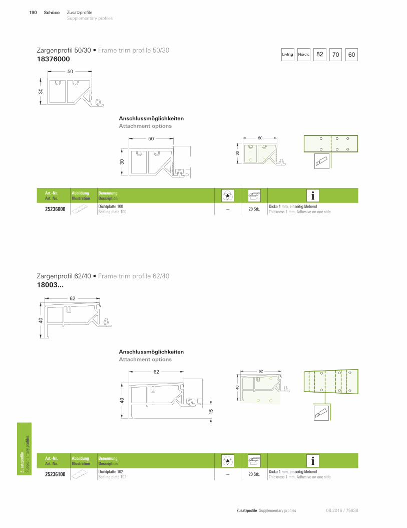
Zusatzprofile Supplementary profiles 08.2016 / 75838
Zusatzprofi
le
Supp
lemen
tary profiles
30
50
30
50
40
62
Zargenprofil 50/30 • Frame trim profile 50/30
18376000
Zargenprofil 62/40 • Frame trim profile 62/40
18003...
Anschlussmöglichkeiten
Attachment options
Anschlussmöglichkeiten
Attachment options
82 70 60NordicLivIng
40
62
15
Art.-Nr.
Art. No.
Abbildung
Illustration
Benennung
Description
25236100 Dichtplatte 102
Sealing plate 102 — 20 Stk.
Dicke 1 mm, einseitig klebend
Thickness 1 mm, Adhesive on one side
Art.-Nr.
Art. No.
Abbildung
Illustration
Benennung
Description
25236000 Dichtplatte 100
Sealing plate 100 — 20 Stk.
Dicke 1 mm, einseitig klebend
Thickness 1 mm, Adhesive on one side
30
50
40
62
Schüco190 Zusatzprofile
Supplementary profiles
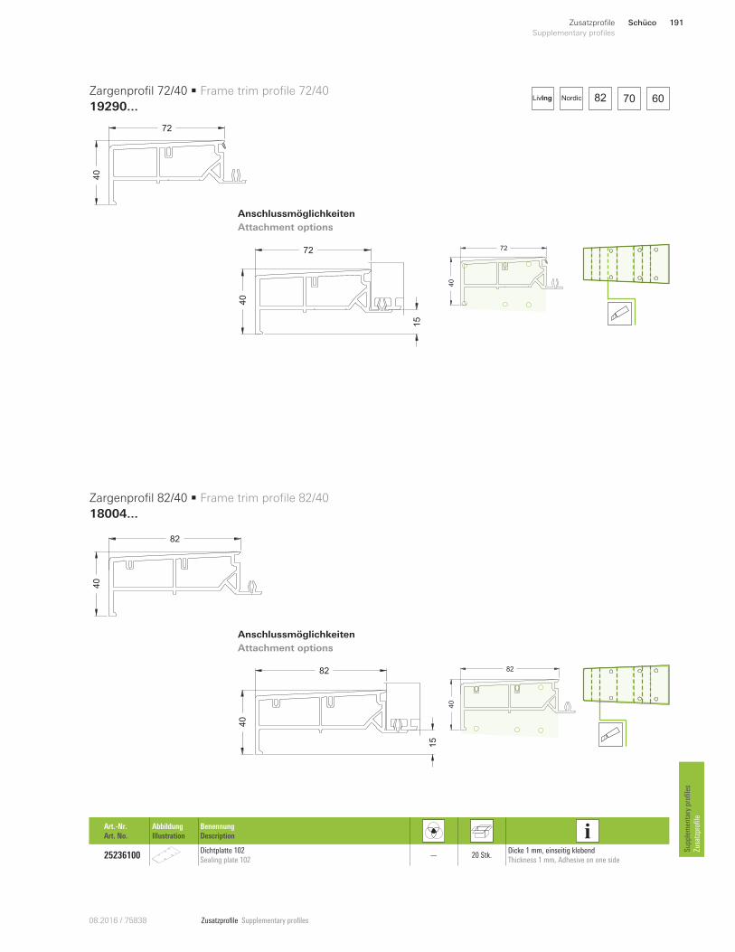
Zusatzprofile Supplementary profiles08.2016 / 75838
Supp
lemen
tary profiles
Zusatzprofi
le
40
72
40
82
Anschlussmöglichkeiten
Attachment options
Anschlussmöglichkeiten
Attachment options
82 70 60NordicLivIng
40
82
15
Zargenprofil 72/40 • Frame trim profile 72/40
19290...
Zargenprofil 82/40 • Frame trim profile 82/40
18004...
40
72
15
Art.-Nr.
Art. No.
Abbildung
Illustration
Benennung
Description
25236100 Dichtplatte 102
Sealing plate 102 — 20 Stk.
Dicke 1 mm, einseitig klebend
Thickness 1 mm, Adhesive on one side
40
72
40
82
Schüco 191Zusatzprofile
Supplementary profiles
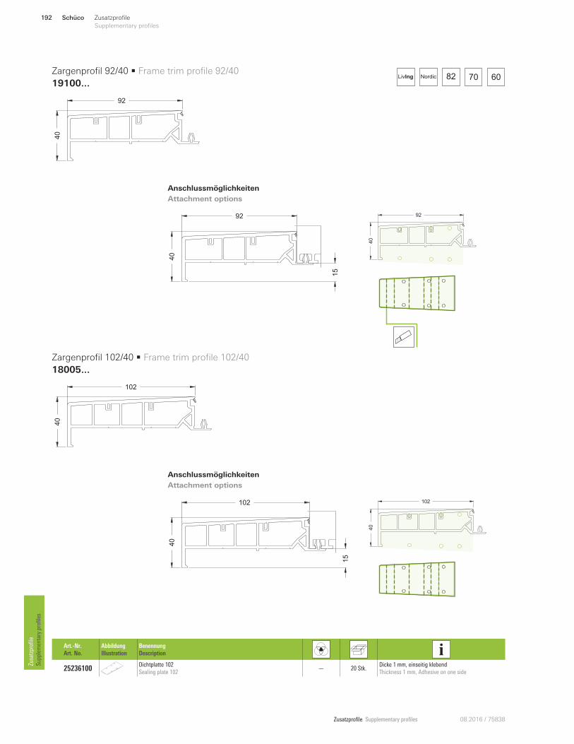
Zusatzprofile Supplementary profiles 08.2016 / 75838
Zusatzprofi
le
Supp
lemen
tary profiles
40
92
15
40
92
40
102
Zargenprofil 92/40 • Frame trim profile 92/40
19100...
Zargenprofil 102/40 • Frame trim profile 102/40
18005...
Anschlussmöglichkeiten
Attachment options
Anschlussmöglichkeiten
Attachment options
82 70 60NordicLivIng
40
102
15
Art.-Nr.
Art. No.
Abbildung
Illustration
Benennung
Description
25236100 Dichtplatte 102
Sealing plate 102 — 20 Stk.
Dicke 1 mm, einseitig klebend
Thickness 1 mm, Adhesive on one side
40
92
40
102
Schüco192 Zusatzprofile
Supplementary profiles

Zusatzprofile Supplementary profiles08.2016 / 75838
Supplementary profiles
Zusatzprofile
30
100
Zargenprofil 100/30 • Frame trim profile 100/30
18377...
Anschlussmöglichkeiten
Attachment options
82 70 60NordicLivIng
30
30
50
60
72.5
80
90
18.5
38.5
68.5
30
100
Art.-Nr.
Art. No.
Abbildung
Illustration
Benennung
Description
25236000 Dichtplatte 100
Sealing plate 100 — 20 Stk.
Dicke 1 mm, einseitig klebend
Thickness 1 mm, Adhesive on one side
Schüco 193Zusatzprofile
Supplementary profiles
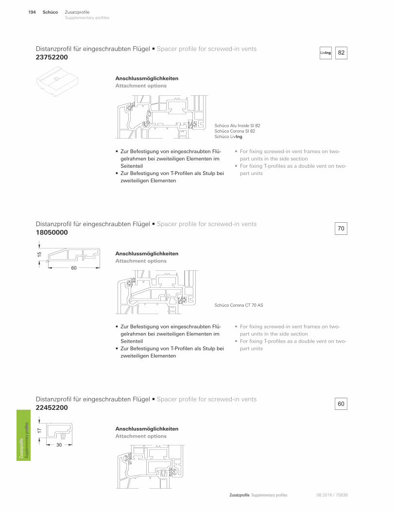
Zusatzprofile Supplementary profiles 08.2016 / 75838
Zusatzprofile
Supplementary profiles
• Zur Befestigung von eingeschraubten Flü-
gelrahmen bei zweiteiligen Elementen im
Seitenteil
• Zur Befestigung von T-Profilen als Stulp bei
zweiteiligen Elementen
• For fixing screwed-in vent frames on two-
part units in the side section
• For fixing T-profiles as a double vent on two-
part units
Schüco Alu Inside SI 82
Schüco Corona SI 82
Schüco LivIng
82LivIng
60
70
• Zur Befestigung von eingeschraubten Flü-
gelrahmen bei zweiteiligen Elementen im
Seitenteil
• Zur Befestigung von T-Profilen als Stulp bei
zweiteiligen Elementen
• For fixing screwed-in vent frames on two-
part units in the side section
• For fixing T-profiles as a double vent on two-
part units
Schüco Corona CT 70 AS
15
60
30
17
Distanzprofil für eingeschraubten Flügel • Spacer profile for screwed-in vents
23752200
Distanzprofil für eingeschraubten Flügel • Spacer profile for screwed-in vents
18050000
Distanzprofil für eingeschraubten Flügel • Spacer profile for screwed-in vents
22452200
Anschlussmöglichkeiten
Attachment options
Anschlussmöglichkeiten
Attachment options
Anschlussmöglichkeiten
Attachment options
Schüco194 Zusatzprofile
Supplementary profiles
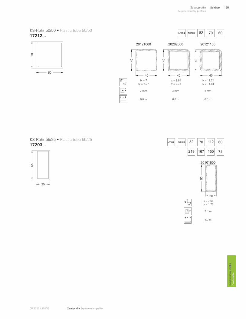
Zusatzprofile Supplementary profiles08.2016 / 75838
Supplementary profiles
Zusatzprofile
50
50
25
55
KS-Rohr 50/50 • Plastic tube 50/50
17212...
KS-Rohr 55/25 • Plastic tube 55/25
17203...
82 70 60NordicLivIng
LivIng
219
82 70 112 60
167 74150
Nordic
20121000 20262000 20121100
40
40
40
40
40
40
x
y
Ix
Iy Ix = 7
Iy = 7.07
Ix = 9.61
Iy = 9.72
Ix = 11.71
Iy = 11.84
2 mm 3 mm 4 mm
x
6,0 m 6,0 m 6,0 m
20101500
20
50
x
y
Ix
Iy Ix = 7.66
Iy = 1.73
2 mm
x
6,0 m
Schüco 195Zusatzprofile
Supplementary profiles
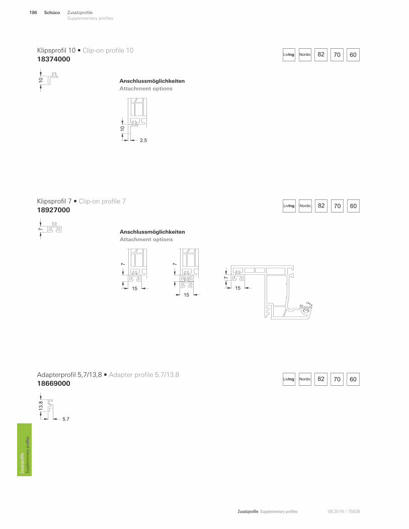
Zusatzprofile Supplementary profiles 08.2016 / 75838
Zusatzprofile
Supplementary profiles
10
2.5
82 70 60NordicLivIng
82 70 60NordicLivIng
82 70 60NordicLivIng
7
15
7
15
7
15
15
7
15
10
5.7
13.8
7
Klipsprofil 10 • Clip-on profile 10
18374000
Adapterprofil 5,7/13,8 • Adapter profile 5.7/13.8
18669000
Klipsprofil 7 • Clip-on profile 7
18927000
Anschlussmöglichkeiten
Attachment options
Anschlussmöglichkeiten
Attachment options
Schüco196 Zusatzprofile
Supplementary profiles
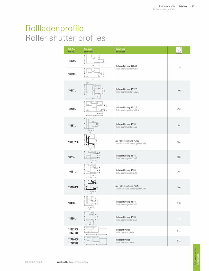
Zusatzprofile Supplementary profiles08.2016 / 75838
Schüco 197Rollladenprofile
Roller shutter profiles
Roller shutter profiles
Rollladenprofile
RollladenprofileRoller shutter profiles
Art.-Nr.
Art. No.
Abbildung
Illustration
Benennung
Description
18930 ... 40.5
61
8 12
Rollladenführung 40,5/61
Roller shutter guide 40.5/61 199
18940 ... 40.5
61
8 12
19217 ...
47
62.5
17.5
25
15.5
Rollladenführung 47/62,5
Roller shutter guide 47/62.5 200
18289 ...
72.5
47
17.5
25
15.5 Rollladenführung 47/72,5
Roller shutter guide 47/72.5 202
18287 ...
36
47
17.5
25
15.5 Rollladenführung 47/36
Roller shutter guide 47/36 204
13167200
36
47
25
17.5 Alu-Rollladenführung 47/36
Aluminium roller shutter guide 47/36 204
18294 ...
43
33
17
25
15
Rollladenführung 33/43
Roller shutter guide 33/43 206
19151 ...
43
42
25
15
17 Rollladenführung 42/43
Roller shutter guide 42/43 208
13296800
25
43
42
17
Alu-Rollladenführung 42/43
Aluminium roller shutter guide 42/43 208
18488 ...
33
42
12
25
8.5
Rollladenführung 43/33
Roller shutter guide 43/33 210
18486 ...
33
42
19
25
15.5 Rollladenführung 42/33
Roller shutter guide 42/33 212
18277000
18277150 91
26 Rollladentraverse
Roller shutter traverse 214
17780000
17780150 90
27 Rollladentraverse
Roller shutter traverse 214
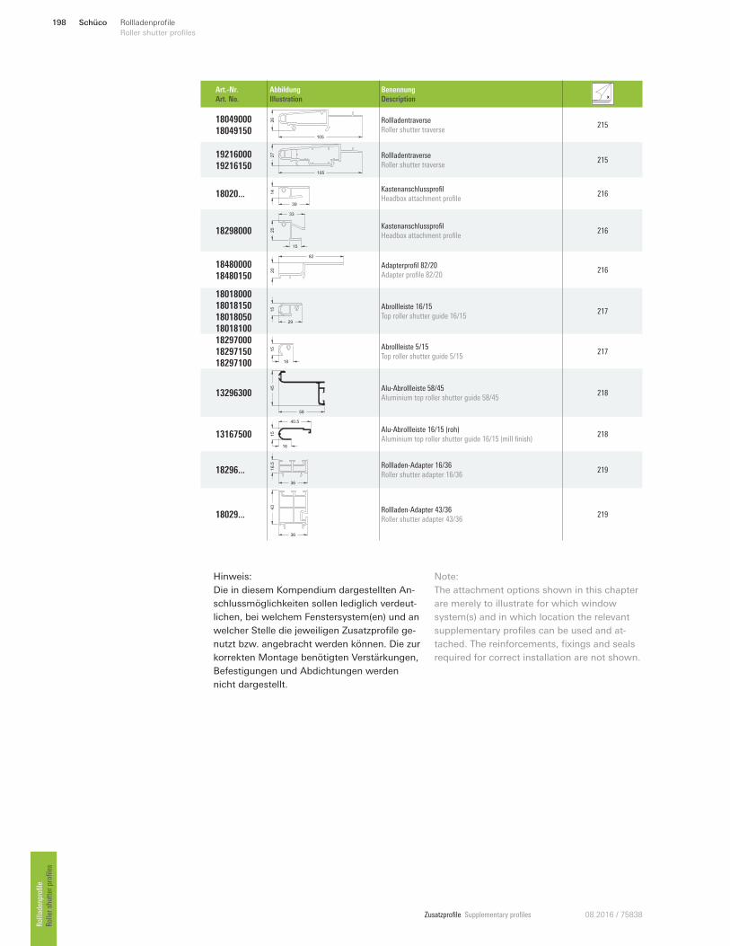
Zusatzprofile Supplementary profiles 08.2016 / 75838
Hinweis:
Die in diesem Kompendium dargestellten An-
schlussmöglichkeiten sollen lediglich verdeut-
lichen, bei welchem Fenstersystem(en) und an
welcher Stelle die jeweiligen Zusatzprofile ge-
nutzt bzw. angebracht werden können. Die zur
korrekten Montage benötigten Verstärkungen,
Befestigungen und Abdichtungen werden
nicht dargestellt.
Note:
The attachment options shown in this chapter
are merely to illustrate for which window
system(s) and in which location the relevant
supplementary profiles can be used and at-
tached. The reinforcements, fixings and seals
required for correct installation are not shown.
Schüco198 Rollladenprofile
Roller shutter profiles Rollladenprofile
Roller shutter profiles
Art.-Nr.
Art. No.
Abbildung
Illustration
Benennung
Description
18049000
18049150 105
26 Rollladentraverse
Roller shutter traverse 215
19216000
19216150
27
105
Rollladentraverse
Roller shutter traverse 215
18020 ...39
14 Kastenanschlussprofil
Headbox attachment profile 216
18298000 25
33
15
Kastenanschlussprofil
Headbox attachment profile 216
18480000
18480150 20
82
Adapterprofil 82/20
Adapter profile 82/20 216
18018000
18018150
18018050
18018100
15
29
Abrollleiste 16/15
Top roller shutter guide 16/15 217
18297000
18297150
18297100
15
18
Abrollleiste 5/15
Top roller shutter guide 5/15 217
13296300
58
45 Alu-Abrollleiste 58/45
Aluminium top roller shutter guide 58/45 218
13167500 16
15
40.5
Alu-Abrollleiste 16/15 (roh)
Aluminium top roller shutter guide 16/15 (mill finish) 218
18296 ... 16.5
36
Rollladen-Adapter 16/36
Roller shutter adapter 16/36 219
18029 ...
36
43
Rollladen-Adapter 43/36
Roller shutter adapter 43/36 219
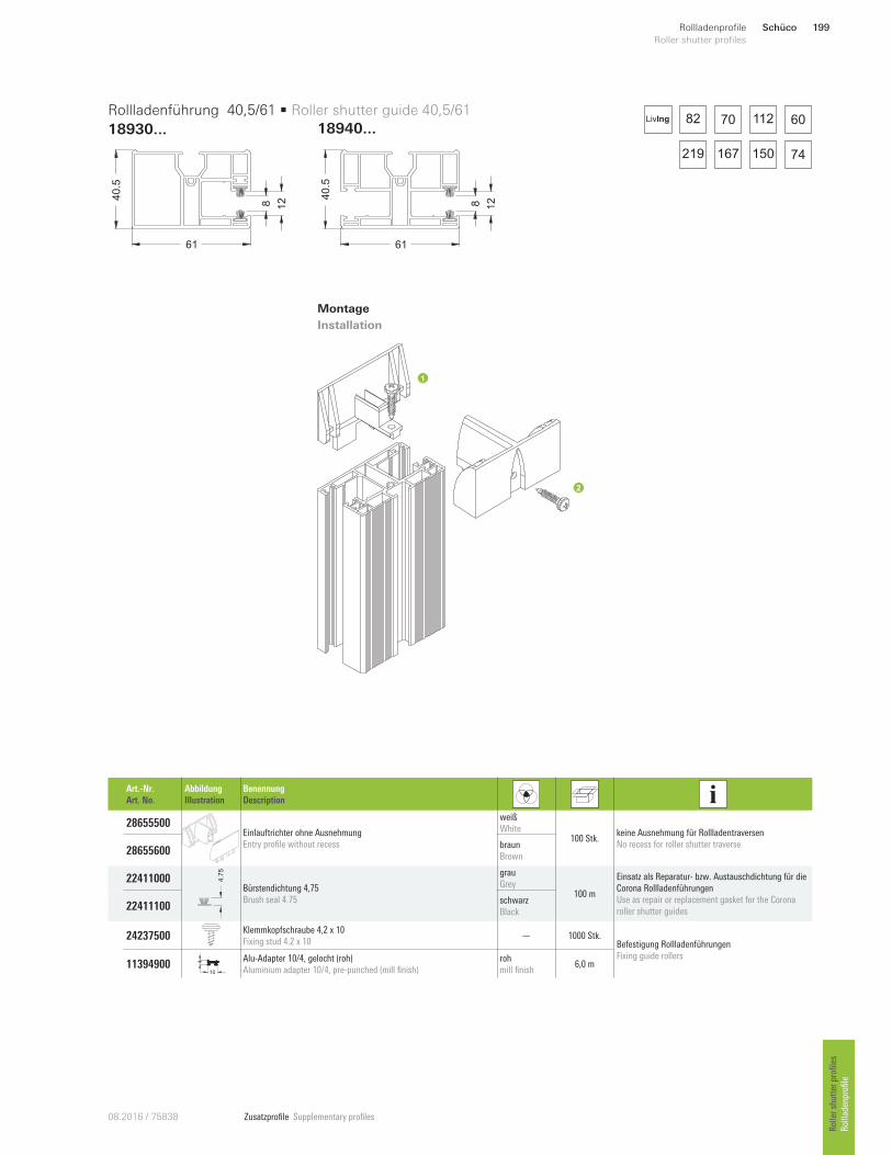
Zusatzprofile Supplementary profiles08.2016 / 75838
40.5
61
8 12 4
0.5
61
8 12
Art.-Nr.
Art. No.
Abbildung
Illustration
Benennung
Description
28655500 Einlauftrichter ohne Ausnehmung
Entry profile without recess
weiß
White 100 Stk.
keine Ausnehmung für Rollladentraversen
No recess for roller shutter traverse 28655600
braun
Brown
22411000 4.7
5
Bürstendichtung 4,75
Brush seal 4.75
grau
Grey 100 m
Einsatz als Reparatur- bzw. Austauschdichtung für die
Corona Rollladenführungen
Use as repair or replacement gasket for the Corona
roller shutter guides 22411100 schwarz
Black
24237500 Klemmkopfschraube 4,2 x 10
Fixing stud 4.2 x 10 — 1000 Stk.
Befestigung Rollladenführungen
Fixing guide rollers 11394900
10
4 Alu-Adapter 10/4, gelocht (roh)
Aluminium adapter 10/4, pre-punched (mill finish)
roh
mill finish 6,0 m
Rollladenführung 40,5/61 • Roller shutter guide 40,5/61
18930...
Montage
Installation
18940 ...82 70 112 60
150219 167 74
LivIng
Schüco 199Rollladenprofile
Roller shutter profiles
Roller shutter profiles
Rollladenprofile
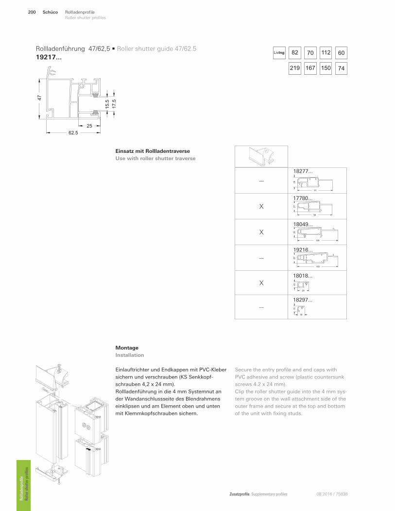
Zusatzprofile Supplementary profiles 08.2016 / 75838
Montage
Installation
Einlauftrichter und Endkappen mit PVC-Kleber
sichern und verschrauben (KS Senkkopf-
schrauben 4,2 x 24 mm).
Rollladenführung in die 4 mm Systemnut an
der Wandanschlussseite des Blendrahmens
einklipsen und am Element oben und unten
mit Klemmkopfschrauben sichern.
Secure the entry profile and end caps with
PVC adhesive and screw (plastic countersunk
screws 4.2 x 24 mm).
Clip the roller shutter guide into the 4 mm sys-
tem groove on the wall attachment side of the
outer frame and secure at the top and bottom
of the unit with fixing studs.
47
62.5
17.5
25
15.5
Rollladenführung 47/62,5 • Roller shutter guide 47/62.5
19217...82 70 112 60
150219 167 74
LivIng
—
91
26
18277 ...
X90
27
17780 ...
X105
26
18049...
— 27
105
19216 ...
X 15
29
18018...
— 15
18
18297...
Einsatz mit Rollladentraverse
Use with roller shutter traverse
Schüco200 Rollladenprofile
Roller shutter profiles Rollladenprofile
Roller shutter profiles
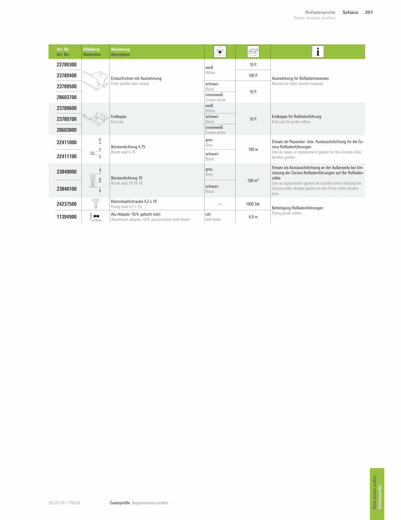
Zusatzprofile Supplementary profiles08.2016 / 75838
Art.-Nr.
Art. No.
Abbildung
Illustration
Benennung
Description
23789300
Einlauftrichter mit Ausnehmung
Entry profile with recess
weiß
White
10 P.
Ausnehmung für Rollladentraversen
Recess for roller shutter traverse
23789400 100 P.
23789500 schwarz
Black 10 P.
28603700 cremeweiß
Cream white
23789600
Endkappe
End cap
weiß
White
10 P. Endkappe für Rollladenführung
End cap for guide rollers 23789700
schwarz
Black
28603800 cremeweiß
Cream white
22411000 4.7
5
Bürstendichtung 4,75
Brush seal 4.75
grau
Grey 100 m
Einsatz als Reparatur- bzw. Austauschdichtung für die Co-
rona Rollladenführungen
Use as repair or replacement gasket for the Corona roller
shutter guides 22411100 schwarz
Black
23840000
10 Bürstendichtung 10
Brush seal 10 10 10
grau
Grey
100 m*
Einsatz als Austauschdichtung an der Außenseite bei Um-
rüstung der Corona Rollladenführungen auf 9er Rollladen-
stäbe
Use as replacement gasket on outside when refitting the
Corona roller shutter guides on the 9 mm roller shutter
bars 23840100
schwarz
Black
24237500 Klemmkopfschraube 4,2 x 10
Fixing stud 4.2 x 10 — 1000 Stk.
Befestigung Rollladenführungen
Fixing guide rollers 11394900
10
4 Alu-Adapter 10/4, gelocht (roh)
Aluminium adapter 10/4, pre-punched (mill finish)
roh
mill finish 6,0 m
Schüco 201Rollladenprofile
Roller shutter profiles
Roller shutter profiles
Rollladenprofile

Zusatzprofile Supplementary profiles 08.2016 / 75838
Einsatz mit Rollladentraverse
Use with roller shutter traverse
Montage
Installation
Einlauftrichter und Endkappen mit PVC-Kleber
sichern und verschrauben (KS Senkkopf-
schrauben 4,2 x 24 mm).
Rollladenführung mit Klemmkopfschrauben,
3 x pro Meter, oder alternativ mit Alu-Adapter
10/4 am Element befestigen.
Secure the entry profile and end caps with
PVC adhesive and screw (plastic countersunk
screws 4.2 x 24 mm).
Roller shutter guide with fixing studs, 3 per
metre, or alternatively fix to the unit with alu-
minium adapter 10/4.
72.5
47
17.5
2515.5
Rollladenführung 47/72,5 • Roller shutter guide 47/72.5
18289...82 70 112 60
150219 167 74
LivIng
— X
91
26
18277 ...
X X90
27
17780 ...
X X105
26
18049...
— X 27
105
19216 ...
X X 15
29
18018...
— X 15
18
18297...
Schüco202 Rollladenprofile
Roller shutter profiles Rollladenprofile
Roller shutter profiles
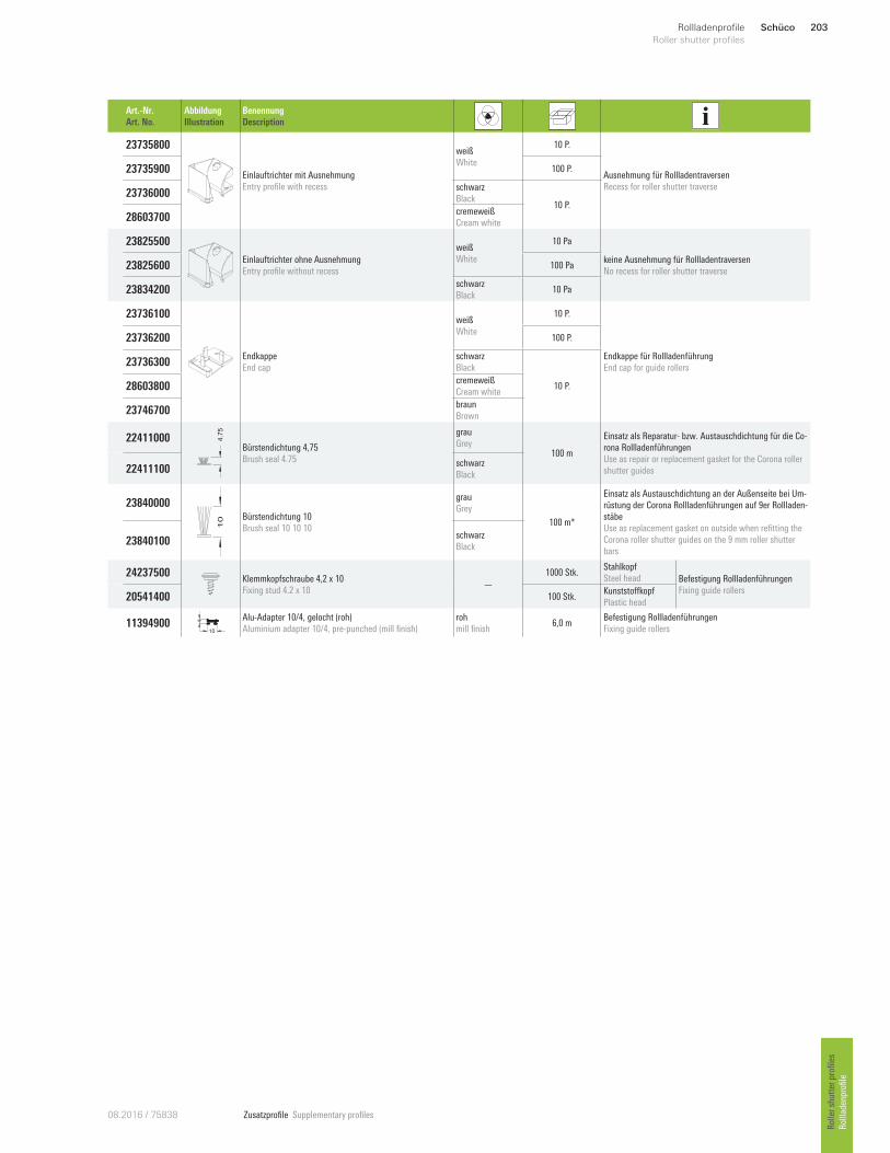
Zusatzprofile Supplementary profiles08.2016 / 75838
Art.-Nr.
Art. No.
Abbildung
Illustration
Benennung
Description
23735800
Einlauftrichter mit Ausnehmung
Entry profile with recess
weiß
White
10 P.
Ausnehmung für Rollladentraversen
Recess for roller shutter traverse
23735900 100 P.
23736000 schwarz
Black 10 P.
28603700 cremeweiß
Cream white
23825500
Einlauftrichter ohne Ausnehmung
Entry profile without recess
weiß
White
10 Pa
keine Ausnehmung für Rollladentraversen
No recess for roller shutter traverse 23825600 100 Pa
23834200 schwarz
Black 10 Pa
23736100
Endkappe
End cap
weiß
White
10 P.
Endkappe für Rollladenführung
End cap for guide rollers
23736200 100 P.
23736300 schwarz
Black
10 P. 28603800 cremeweiß
Cream white
23746700 braun
Brown
22411000 4.7
5
Bürstendichtung 4,75
Brush seal 4.75
grau
Grey 100 m
Einsatz als Reparatur- bzw. Austauschdichtung für die Co-
rona Rollladenführungen
Use as repair or replacement gasket for the Corona roller
shutter guides 22411100 schwarz
Black
23840000
10 Bürstendichtung 10
Brush seal 10 10 10
grau
Grey
100 m*
Einsatz als Austauschdichtung an der Außenseite bei Um-
rüstung der Corona Rollladenführungen auf 9er Rollladen-
stäbe
Use as replacement gasket on outside when refitting the
Corona roller shutter guides on the 9 mm roller shutter
bars 23840100
schwarz
Black
24237500 Klemmkopfschraube 4,2 x 10
Fixing stud 4.2 x 10 —
1000 Stk. Stahlkopf
Steel head Befestigung Rollladenführungen
Fixing guide rollers 205414 00 100 Stk.
Kunststo`kopf
Plastic head
11394900 10
4 Alu-Adapter 10/4, gelocht (roh)
Aluminium adapter 10/4, pre-punched (mill finish)
roh
mill finish 6,0 m
Befestigung Rollladenführungen
Fixing guide rollers
Schüco 203Rollladenprofile
Roller shutter profiles
Roller shutter profiles
Rollladenprofile
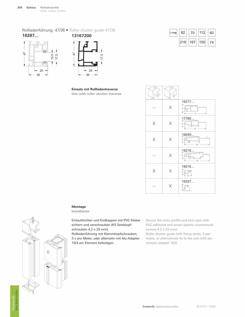
Zusatzprofile Supplementary profiles 08.2016 / 75838
13167200
Einsatz mit Rollladentraverse
Use with roller shutter traverse
Montage
Installation
Einlauftrichter und Endkappen mit PVC-Kleber
sichern und verschrauben (KS Senkkopf-
schrauben 4,2 x 24 mm).
Rollladenführung mit Klemmkopfschrauben,
3 x pro Meter, oder alternativ mit Alu-Adapter
10/4 am Element befestigen.
Secure the entry profile and end caps with
PVC adhesive and screw (plastic countersunk
screws 4.2 x 24 mm).
Roller shutter guide with fixing studs, 3 per
metre, or alternatively fix to the unit with alu-
minium adapter 10/4.
36
47
17.5
25
15.5
3647
25
17.5
Rollladenführung 47/36 • Roller shutter guide 47/36
18287...82 70 112 60
150219 167 74
LivIng
— X
91
26
18277 ...
X X90
27
17780 ...
X X105
26
18049...
— X 27
105
19216 ...
X X 15
29
18018...
— X 15
18
18297...
Schüco204 Rollladenprofile
Roller shutter profiles Rollladenprofile
Roller shutter profiles
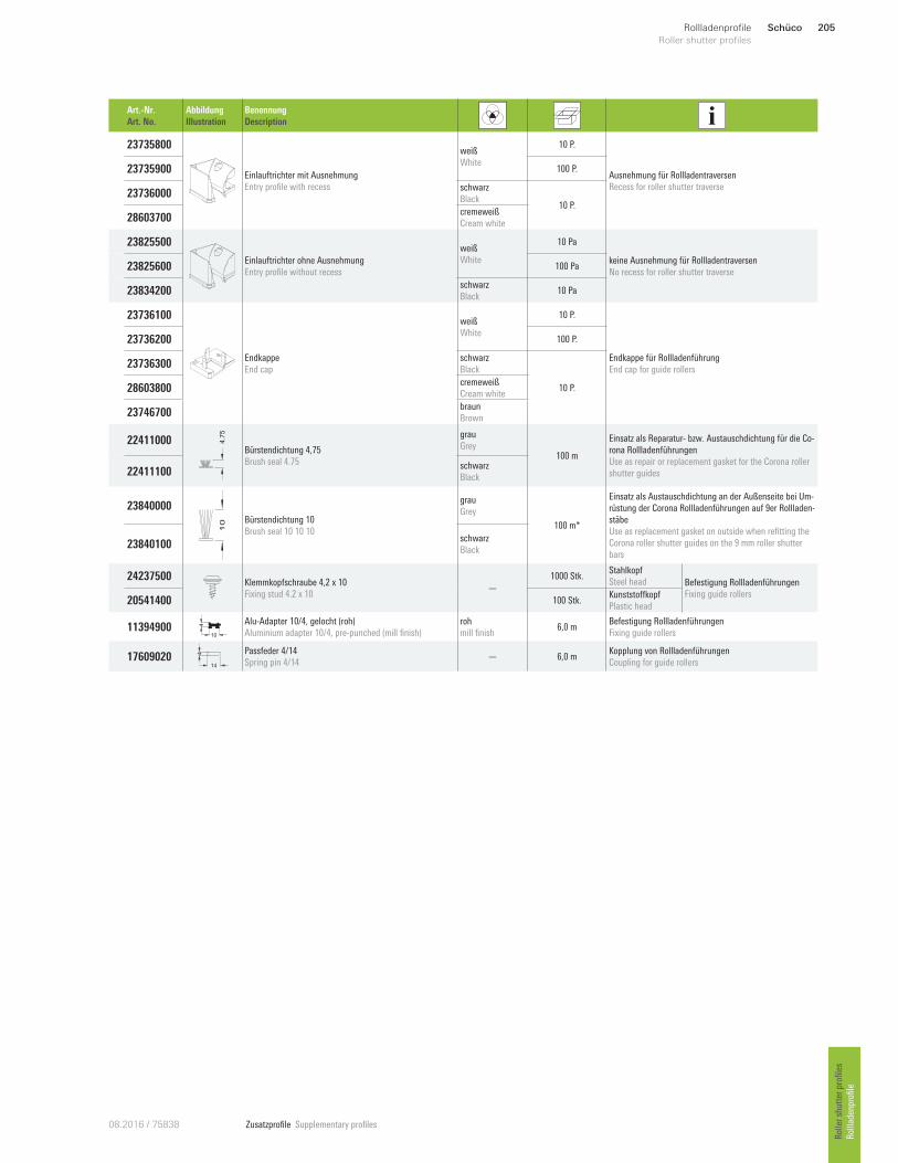
Zusatzprofile Supplementary profiles08.2016 / 75838
Art.-Nr.
Art. No.
Abbildung
Illustration
Benennung
Description
23735800
Einlauftrichter mit Ausnehmung
Entry profile with recess
weiß
White
10 P.
Ausnehmung für Rollladentraversen
Recess for roller shutter traverse
23735900 100 P.
23736000 schwarz
Black 10 P.
28603700 cremeweiß
Cream white
23825500
Einlauftrichter ohne Ausnehmung
Entry profile without recess
weiß
White
10 Pa
keine Ausnehmung für Rollladentraversen
No recess for roller shutter traverse 23825600 100 Pa
23834200 schwarz
Black 10 Pa
23736100
Endkappe
End cap
weiß
White
10 P.
Endkappe für Rollladenführung
End cap for guide rollers
23736200 100 P.
23736300 schwarz
Black
10 P. 28603800 cremeweiß
Cream white
23746700 braun
Brown
22411000 4.7
5
Bürstendichtung 4,75
Brush seal 4.75
grau
Grey 100 m
Einsatz als Reparatur- bzw. Austauschdichtung für die Co-
rona Rollladenführungen
Use as repair or replacement gasket for the Corona roller
shutter guides 22411100 schwarz
Black
23840000
10 Bürstendichtung 10
Brush seal 10 10 10
grau
Grey
100 m*
Einsatz als Austauschdichtung an der Außenseite bei Um-
rüstung der Corona Rollladenführungen auf 9er Rollladen-
stäbe
Use as replacement gasket on outside when refitting the
Corona roller shutter guides on the 9 mm roller shutter
bars 23840100
schwarz
Black
24237500 Klemmkopfschraube 4,2 x 10
Fixing stud 4.2 x 10 —
1000 Stk. Stahlkopf
Steel head Befestigung Rollladenführungen
Fixing guide rollers 205414 00 100 Stk.
Kunststo`kopf
Plastic head
11394900 10
4 Alu-Adapter 10/4, gelocht (roh)
Aluminium adapter 10/4, pre-punched (mill finish)
roh
mill finish 6,0 m
Befestigung Rollladenführungen
Fixing guide rollers
17609020 14
4 Passfeder 4/14
Spring pin 4/14 — 6,0 m
Kopplung von Rollladenführungen
Coupling for guide rollers
Schüco 205Rollladenprofile
Roller shutter profiles
Roller shutter profiles
Rollladenprofile
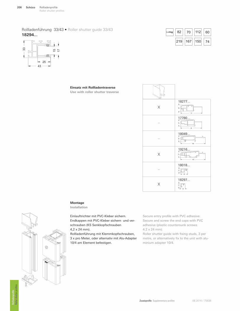
Zusatzprofile Supplementary profiles 08.2016 / 75838
Einsatz mit Rollladentraverse
Use with roller shutter traverse
Montage
Installation
Einlauftrichter mit PVC-Kleber sichern.
Endkappen mit PVC-Kleber sichern und ver-
schrauben (KS Senkkopfschrauben
4,2 x 24 mm).
Rollladenführung mit Klemmkopfschrauben,
3 x pro Meter, oder alternativ mit Alu-Adapter
10/4 am Element befestigen.
Secure entry profile with PVC adhesive.
Secure and screw the end caps with PVC
adhesive (plastic countersunk screws
4.2 x 24 mm).
Roller shutter guide with fixing studs, 3 per
metre, or alternatively fix to the unit with alu-
minium adapter 10/4.
43
33
17
25
15
Rollladenführung 33/43 • Roller shutter guide 33/43
18294...82 70 112 60
150219 167 74
LivIng
X
91
26
18277 ...
—
90
27
17780 ...
—
105
26
18049...
X 27
105
19216 ...
—
15
29
18018...
X 15
18
18297...
Schüco206 Rollladenprofile
Roller shutter profiles Rollladenprofile
Roller shutter profiles
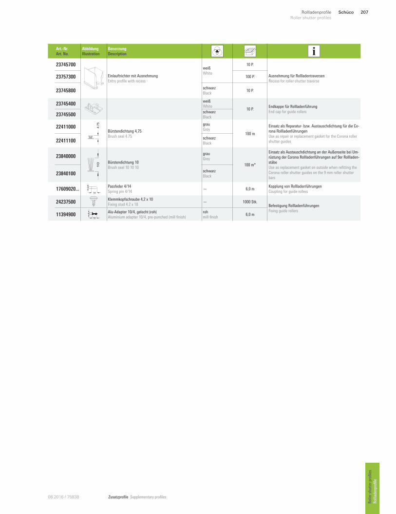
Zusatzprofile Supplementary profiles08.2016 / 75838
Art.-Nr.
Art. No.
Abbildung
Illustration
Benennung
Description
23745700
Einlauftrichter mit Ausnehmung
Entry profile with recess
weiß
White
10 P.
Ausnehmung für Rollladentraversen
Recess for roller shutter traverse 23757300 100 P.
23745800 schwarz
Black 10 P.
23745400 weiß
White 10 P.
Endkappe für Rollladenführung
End cap for guide rollers 23745500
schwarz
Black
22411000 4.7
5
Bürstendichtung 4,75
Brush seal 4.75
grau
Grey 100 m
Einsatz als Reparatur- bzw. Austauschdichtung für die Co-
rona Rollladenführungen
Use as repair or replacement gasket for the Corona roller
shutter guides 22411100 schwarz
Black
23840000
10 Bürstendichtung 10
Brush seal 10 10 10
grau
Grey
100 m*
Einsatz als Austauschdichtung an der Außenseite bei Um-
rüstung der Corona Rollladenführungen auf 9er Rollladen-
stäbe
Use as replacement gasket on outside when refitting the
Corona roller shutter guides on the 9 mm roller shutter
bars 23840100
schwarz
Black
17609020 ...14
4 Passfeder 4/14
Spring pin 4/14 — 6,0 m
Kopplung von Rollladenführungen
Coupling for guide rollers
24237500 Klemmkopfschraube 4,2 x 10
Fixing stud 4.2 x 10 — 1000 Stk.
Befestigung Rollladenführungen
Fixing guide rollers 11394900
10
4 Alu-Adapter 10/4, gelocht (roh)
Aluminium adapter 10/4, pre-punched (mill finish)
roh
mill finish 6,0 m
Schüco 207Rollladenprofile
Roller shutter profiles
Roller shutter profiles
Rollladenprofile
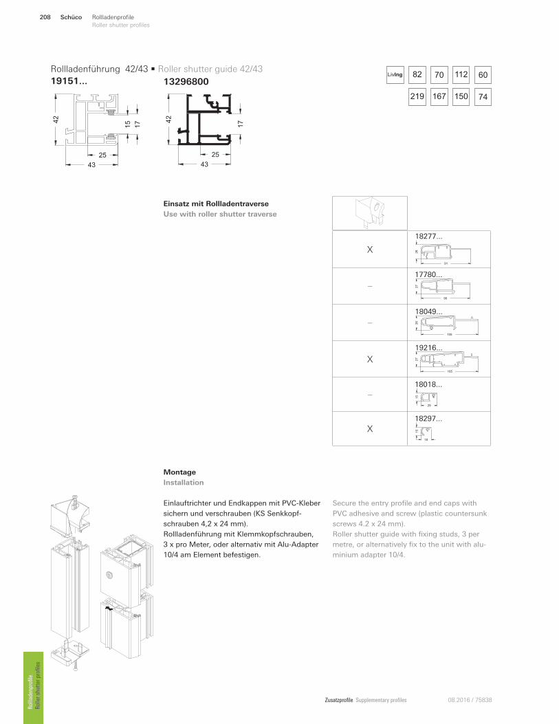
Zusatzprofile Supplementary profiles 08.2016 / 75838
13296800
Einsatz mit Rollladentraverse
Use with roller shutter traverse
Montage
Installation
Einlauftrichter und Endkappen mit PVC-Kleber
sichern und verschrauben (KS Senkkopf-
schrauben 4,2 x 24 mm).
Rollladenführung mit Klemmkopfschrauben,
3 x pro Meter, oder alternativ mit Alu-Adapter
10/4 am Element befestigen.
Secure the entry profile and end caps with
PVC adhesive and screw (plastic countersunk
screws 4.2 x 24 mm).
Roller shutter guide with fixing studs, 3 per
metre, or alternatively fix to the unit with alu-
minium adapter 10/4.
43
42
25
15
17
25
4342
17
Rollladenführung 42/43 • Roller shutter guide 42/43
19151...82 70 112 60
150219 167 74
LivIng
X
91
26
18277 ...
—
90
27
17780 ...
—
105
26
18049...
X 27
105
19216 ...
—
15
29
18018...
X 15
18
18297...
Schüco208 Rollladenprofile
Roller shutter profiles Rollladenprofile
Roller shutter profiles
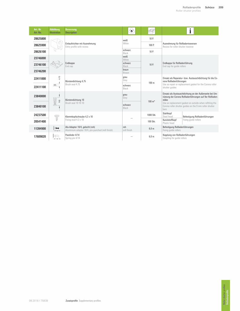
Zusatzprofile Supplementary profiles08.2016 / 75838
Art.-Nr.
Art. No.
Abbildung
Illustration
Benennung
Description
28625800
Einlauftrichter mit Ausnehmung
Entry profile with recess
weiß
White
10 P.
Ausnehmung für Rollladentraversen
Recess for roller shutter traverse 28625900 100 P.
28626100 schwarz
Black 10 P.
23746000
Endkappe
End cap
weiß
White
10 P. Endkappe für Rollladenführung
End cap for guide rollers 23746100
schwarz
Black
23746200 braun
Brown
22411000 4.7
5
Bürstendichtung 4,75
Brush seal 4.75
grau
Grey 100 m
Einsatz als Reparatur- bzw. Austauschdichtung für die Co-
rona Rollladenführungen
Use as repair or replacement gasket for the Corona roller
shutter guides 22411100 schwarz
Black
23840000
10 Bürstendichtung 10
Brush seal 10 10 10
grau
Grey
100 m*
Einsatz als Austauschdichtung an der Außenseite bei Um-
rüstung der Corona Rollladenführungen auf 9er Rollladen-
stäbe
Use as replacement gasket on outside when refitting the
Corona roller shutter guides on the 9 mm roller shutter
bars 23840100
schwarz
Black
24237500 Klemmkopfschraube 4,2 x 10
Fixing stud 4.2 x 10 —
1000 Stk. Stahlkopf
Steel head Befestigung Rollladenführungen
Fixing guide rollers 205414 00 100 Stk.
Kunststo`kopf
Plastic head
11394900 10
4 Alu-Adapter 10/4, gelocht (roh)
Aluminium adapter 10/4, pre-punched (mill finish)
roh
mill finish 6,0 m
Befestigung Rollladenführungen
Fixing guide rollers
17609020 14
4 Passfeder 4/14
Spring pin 4/14 — 6,0 m
Kopplung von Rollladenführungen
Coupling for guide rollers
Schüco 209Rollladenprofile
Roller shutter profiles
Roller shutter profiles
Rollladenprofile

Zusatzprofile Supplementary profiles 08.2016 / 75838
Einsatz mit Rollladentraverse
Use with roller shutter traverse
Montage
Installation
Einlauftrichter mit PVC-Kleber sichern.
Endkappen mit PVC-Kleber sichern und
verschrauben (KS Senkkopfschrauben
4,2 x 24 mm).
Rollladenführung mit Klemmkopfschrauben,
3 x pro Meter, oder alternativ mit Alu-Adapter
10/4 am Element befestigen.
Secure entry profile with PVC adhesive.
Secure and screw the end caps with PVC
adhesive (plastic countersunk screws
4.2 x 24 mm).
Roller shutter guide with fixing studs, 3 per
metre, or alternatively fix to the unit with alu-
minium adapter 10/4.
33
42
12
25
8.5
Rollladenführung 43/33 • Roller shutter guide 43/33
18488...82 70 112 60
150219 167 74
LivIng
—
91
26
18277 ...
X90
27
17780 ...
X105
26
18049...
X 27
105
19216 ...
X 15
29
18018...
—
15
18
18297...
Schüco210 Rollladenprofile
Roller shutter profiles Rollladenprofile
Roller shutter profiles
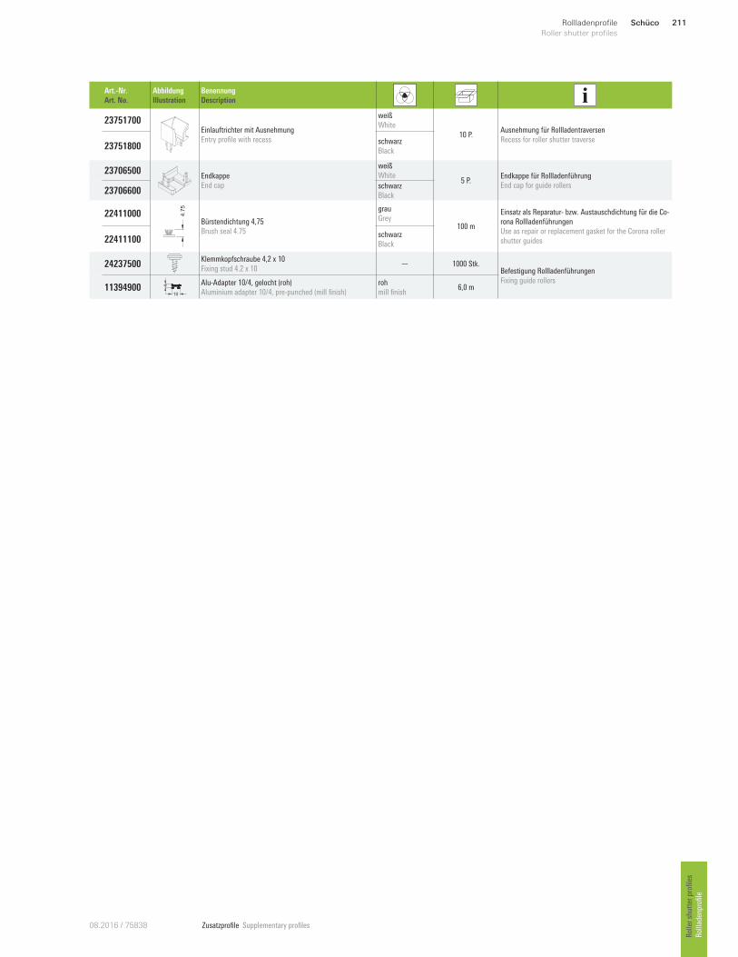
Zusatzprofile Supplementary profiles08.2016 / 75838
Art.-Nr.
Art. No.
Abbildung
Illustration
Benennung
Description
23751700 Einlauftrichter mit Ausnehmung
Entry profile with recess
weiß
White
10 P. Ausnehmung für Rollladentraversen
Recess for roller shutter traverse 23751800
schwarz
Black
23706500 Endkappe
End cap
weiß
White 5 P.
Endkappe für Rollladenführung
End cap for guide rollers 23706600
schwarz
Black
22411000 4.7
5
Bürstendichtung 4,75
Brush seal 4.75
grau
Grey 100 m
Einsatz als Reparatur- bzw. Austauschdichtung für die Co-
rona Rollladenführungen
Use as repair or replacement gasket for the Corona roller
shutter guides 22411100 schwarz
Black
24237500 Klemmkopfschraube 4,2 x 10
Fixing stud 4.2 x 10 — 1000 Stk.
Befestigung Rollladenführungen
Fixing guide rollers 11394900
10
4 Alu-Adapter 10/4, gelocht (roh)
Aluminium adapter 10/4, pre-punched (mill finish)
roh
mill finish 6,0 m
Schüco 211Rollladenprofile
Roller shutter profiles
Roller shutter profiles
Rollladenprofile

Zusatzprofile Supplementary profiles 08.2016 / 75838
Einsatz mit Rollladentraverse
Use with roller shutter traverse
Montage
Installation
Einlauftrichter mit PVC-Kleber sichern.
Endkappen mit PVC-Kleber sichern und
verschrauben (KS Senkkopfschrauben
4,2 x 24 mm).
Rollladenführung mit Klemmkopfschrauben,
3 x pro Meter, oder alternativ mit Alu-Adapter
10/4 am Element befestigen.
Secure entry profile with PVC adhesive.
Secure and screw the end caps with PVC
adhesive (plastic countersunk screws
4.2 x 24 mm).
Roller shutter guide with fixing studs, 3 per
metre, or alternatively fix to the unit with alu-
minium adapter 10/4.
33
42
19
25
15.5
Rollladenführung 42/33 • Roller shutter guide 42/33
18486...82 70 112 60
150219 167 74
LivIng
—
91
26
18277 ...
X90
27
17780 ...
X105
26
18049...
— 27
105
19216 ...
X 15
29
18018...
—
15
18
18297...
Schüco212 Rollladenprofile
Roller shutter profiles Rollladenprofile
Roller shutter profiles
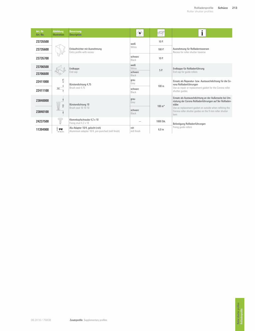
Zusatzprofile Supplementary profiles08.2016 / 75838
Art.-Nr.
Art. No.
Abbildung
Illustration
Benennung
Description
23735500
Einlauftrichter mit Ausnehmung
Entry profile with recess
weiß
White
10 P.
Ausnehmung für Rollladentraversen
Recess for roller shutter traverse 23735600 100 P.
23735700 schwarz
Black 10 P.
23706500 Endkappe
End cap
weiß
White 5 P.
Endkappe für Rollladenführung
End cap for guide rollers 23706600
schwarz
Black
22411000 4.7
5
Bürstendichtung 4,75
Brush seal 4.75
grau
Grey 100 m
Einsatz als Reparatur- bzw. Austauschdichtung für die Co-
rona Rollladenführungen
Use as repair or replacement gasket for the Corona roller
shutter guides 22411100 schwarz
Black
23840000
10 Bürstendichtung 10
Brush seal 10 10 10
grau
Grey
100 m*
Einsatz als Austauschdichtung an der Außenseite bei Um-
rüstung der Corona Rollladenführungen auf 9er Rollladen-
stäbe
Use as replacement gasket on outside when refitting the
Corona roller shutter guides on the 9 mm roller shutter
bars 23840100
schwarz
Black
24237500 Klemmkopfschraube 4,2 x 10
Fixing stud 4.2 x 10 — 1000 Stk.
Befestigung Rollladenführungen
Fixing guide rollers 11394900
10
4 Alu-Adapter 10/4, gelocht (roh)
Aluminium adapter 10/4, pre-punched (mill finish)
roh
mill finish 6,0 m
Schüco 213Rollladenprofile
Roller shutter profiles
Roller shutter profiles
Rollladenprofile
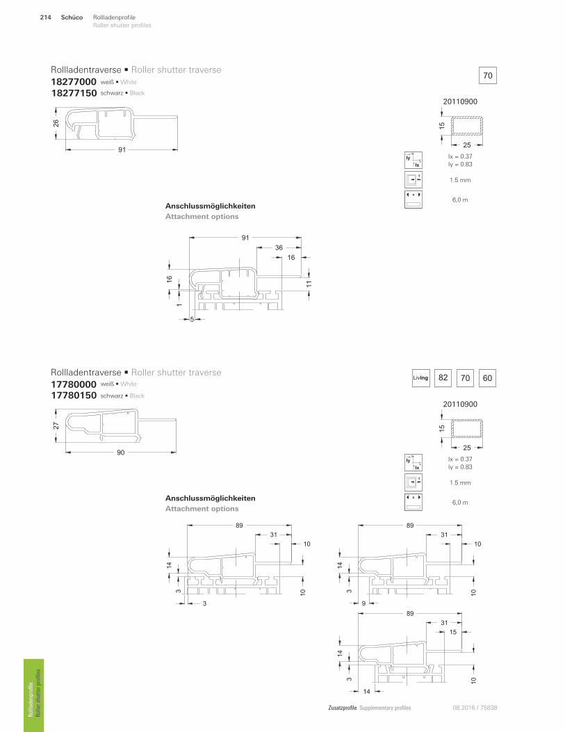
Zusatzprofile Supplementary profiles 08.2016 / 75838
20110900
25
15
x
y
Ix
Iy Ix = 0.37
Iy = 0.83
1.5 mm
x
6,0 m
20110900
2515
x
y
Ix
Iy Ix = 0.37
Iy = 0.83
1.5 mm
x
6,0 m
1
16
5
91
36
16
11
3
14
3
89
31
10
10 3
14
9
89
31
10
10
3
14
14
89
31
15
10
18277150 schwarz • Black
schwarz • Black 17780150
82 70 60LivIng
70weiß • White
weiß • White
91
26
90
27
Rollladentraverse • Roller shutter traverse
18277000
Rollladentraverse • Roller shutter traverse
17780000
Anschlussmöglichkeiten
Attachment options
Anschlussmöglichkeiten
Attachment options
Schüco214 Rollladenprofile
Roller shutter profiles Rollladenprofile
Roller shutter profiles
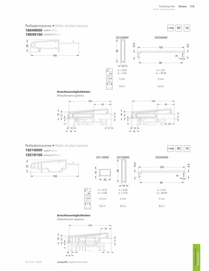
Zusatzprofile Supplementary profiles08.2016 / 75838
20103600 20259400
10
50
10210.5
8.5
96
8°
x
y
Ix
Iy Ix = 5.02
Iy = 0.32
Ix = 0.31
Iy = 38.46
2 mm 3 mm
x
6,0 m 6,0 m
20110900 20103600 20259400
25
15
10
50
10210.5
8.5
96
8°
x
y
Ix
Iy Ix = 0.37
Iy = 0.83
Ix = 5.02
Iy = 0.32
Ix = 0.31
Iy = 38.46
1.5 mm 2 mm 3 mm
x
6,0 m 6,0 m 6,0 m
18049150 schwarz • Black
schwarz • Black 19216150
weiß • White
weiß • White
105
26
27
105
Rollladentraverse • Roller shutter traverse
18049000
Rollladentraverse • Roller shutter traverse
19216000
Anschlussmöglichkeiten
Attachment options
Anschlussmöglichkeiten
Attachment options
16
13
2
15
12
43
23
11
105
16
13
2
15
43
11
11
105
12
16
13
2
9
27
17
11
105
6
82 70LivIng
82 70LivIng
Schüco 215Rollladenprofile
Roller shutter profiles
Roller shutter profiles
Rollladenprofile
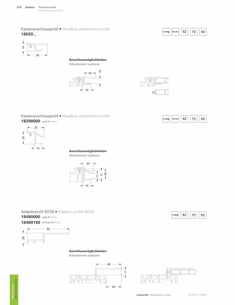
Zusatzprofile Supplementary profiles 08.2016 / 75838
49
11
30
15
20
17
11 2
0
Anschlussmöglichkeiten
Attachment options
Anschlussmöglichkeiten
Attachment options
Anschlussmöglichkeiten
Attachment options
22 10
16
weiß • White
weiß • White
82 70 60NordicLivIng
82 70 60LivIng
82 70 60NordicLivIng
Kastenanschlussprofil • Headbox attachment profile
18020...
Kastenanschlussprofil • Headbox attachment profile
18298000
Adapterprofil 82/20 • Adapter profile 82/20
18480000
39
14
25
33
15
20
82
18480150 schwarz • Black
Schüco216 Rollladenprofile
Roller shutter profiles Rollladenprofile
Roller shutter profiles
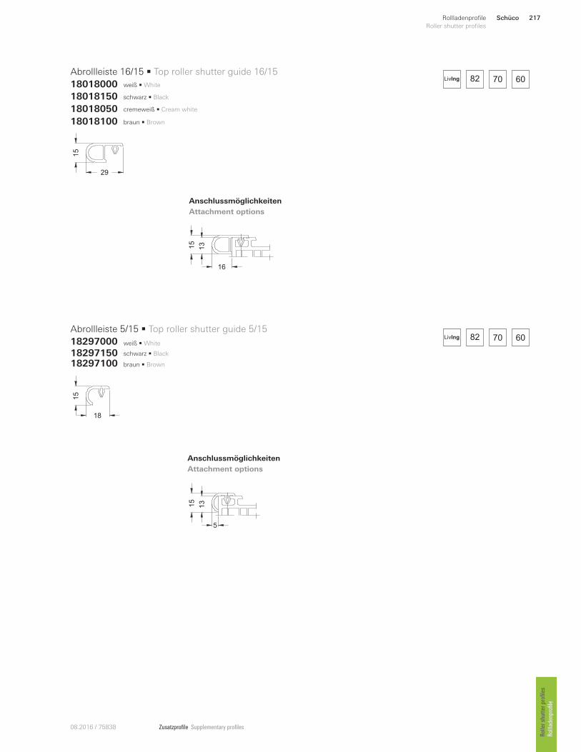
Zusatzprofile Supplementary profiles08.2016 / 75838
Anschlussmöglichkeiten
Attachment options
Anschlussmöglichkeiten
Attachment options
Abrollleiste 16/15 • Top roller shutter guide 16/15
18018000
Abrollleiste 5/15 • Top roller shutter guide 5/15
18297000
15
29
15
18
15
13
16
15
13
5
weiß • White
schwarz • Black
cremeweiß • Cream white
braun • Brown
18018150
18297150
18018050
18018100
18297100
weiß • White
schwarz • Black
braun • Brown
82 70 60LivIng
82 70 60LivIng
Schüco 217Rollladenprofile
Roller shutter profiles
Roller shutter profiles
Rollladenprofile
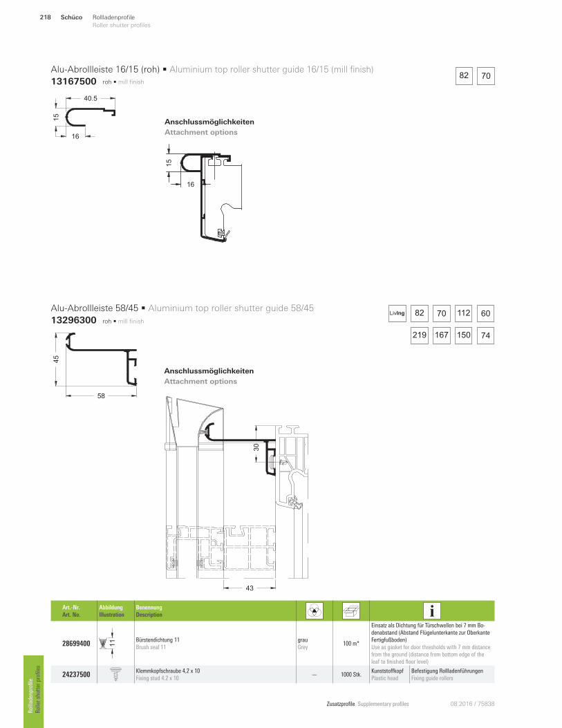
Zusatzprofile Supplementary profiles 08.2016 / 75838
roh • mill finish
roh • mill finish
Anschlussmöglichkeiten
Attachment options
43
30
58
45
Art.-Nr.
Art. No.
Abbildung
Illustration
Benennung
Description
28699400 11 Bürstendichtung 11
Brush seal 11
grau
Grey 100 m*
Einsatz als Dichtung für Türschwellen bei 7 mm Bo-
denabstand (Abstand Flügelunterkante zur Oberkante
Fertigfußboden)
Use as gasket for door thresholds with 7 mm distance
from the ground (distance from bottom edge of the
leaf to finished floor level)
24237500 Klemmkopfschraube 4,2 x 10
Fixing stud 4.2 x 10 — 1000 Stk.
Kunststo`kopf
Plastic head
Befestigung Rollladenführungen
Fixing guide rollers
Alu-Abrollleiste 58/45 • Aluminium top roller shutter guide 58/45
13296300 82 70 112 60
150219 167 74
LivIng
Anschlussmöglichkeiten
Attachment options
Alu-Abrollleiste 16/15 (roh) • Aluminium top roller shutter guide 16/15 (mill finish)
13167500
16
15
40.5
15
16
82 70
Schüco218 Rollladenprofile
Roller shutter profiles Rollladenprofile
Roller shutter profiles
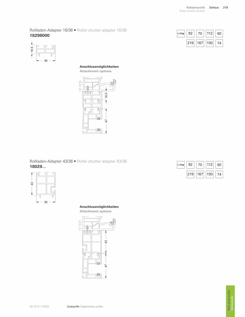
Zusatzprofile Supplementary profiles08.2016 / 75838
Anschlussmöglichkeiten
Attachment options
Anschlussmöglichkeiten
Attachment options
Rollladen-Adapter 16/36 • Roller shutter adapter 16/36
18298000
Rollladen-Adapter 43/36 • Roller shutter adapter 43/36
18029...
16.5
36
36
43
47
16.5
47
43
LivIng 82 70 112 60
150219 167 74
LivIng 82 70 112 60
150219 167 74
Schüco 219Rollladenprofile
Roller shutter profiles
Roller shutter profiles
Rollladenprofile
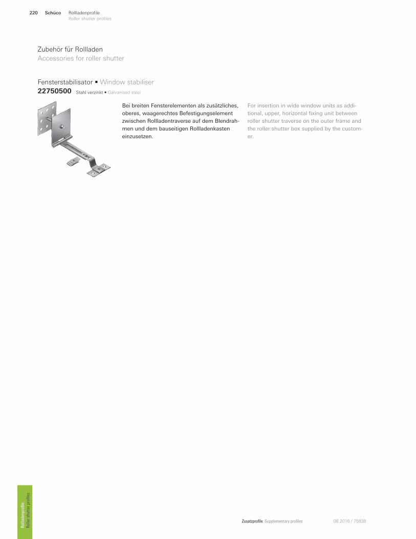
Zusatzprofile Supplementary profiles 08.2016 / 75838
Zubehör für Rollladen
Accessories for roller shutter
For insertion in wide window units as addi-
tional, upper, horizontal fixing unit between
roller shutter traverse on the outer frame and
the roller shutter box supplied by the custom-
er.
Bei breiten Fensterelementen als zusätzliches,
oberes, waagerechtes Befestigungselement
zwischen Rollladentraverse auf dem Blendrah-
men und dem bauseitigen Rollladenkasten
einzusetzen.
Fensterstabilisator • Window stabiliser
22750500 Stahl verzinkt • Galvanised steel
Schüco220 Rollladenprofile
Roller shutter profiles Rollladenprofile
Roller shutter profiles