Embed Size (px)
Citation preview
2003-01.Slovenski inštitut za standardizacijo. Razmnoževanje celote ali delov tega standarda ni dovoljeno.
Neogrevane (nekurjene) tlačne posode - 3. del: Konstruiranje - Dopolnilo A6
Unbefeuerte Druckbehälter - Teil 3: Konstruktion
Récipients sous pression non soumis à la flamme - Partie 3 : Conception
Unfired pressure vessels - Part 3 : Design
23.020.32 Tlačne posode Pressure vessels
ICS:
Ta slovenski standard je istoveten z: EN 13445-3:2014/A6:2019
SIST EN 13445-3:2014/A6:2019 en,fr,de
01-maj-2019
SIST EN 13445-3:2014/A6:2019SLOVENSKI STANDARD
iTeh STANDARD PREVIEW(standards.iteh.ai)
SIST EN 13445-3:2014/A6:2019https://standards.iteh.ai/catalog/standards/sist/77750bca-46e5-4d46-98dc-
143ceaf121dc/sist-en-13445-3-2014-a6-2019

SIST EN 13445-3:2014/A6:2019
iTeh STANDARD PREVIEW(standards.iteh.ai)
SIST EN 13445-3:2014/A6:2019https://standards.iteh.ai/catalog/standards/sist/77750bca-46e5-4d46-98dc-
143ceaf121dc/sist-en-13445-3-2014-a6-2019

EUROPEAN STANDARD NORME EUROPÉENNE EUROPÄISCHE NORM
EN 13445-3:2014/A6 March 2019
ICS 23.020.30 English Version Unfired pressure vessels - Part 3: Design Récipients sous pression non soumis à la flamme - Partie 3 : Conception Unbefeuerte Druckbehälter - Teil 3: Konstruktion
This amendment A6 modifies the European Standard EN 13445-3:2014; it was approved by CEN on 27 August 2018. CEN members are bound to comply with the CEN/CENELEC Internal Regulations which stipulate the conditions for inclusion of this amendment into the relevant national standard without any alteration. Up-to-date lists and bibliographical references concerning such national standards may be obtained on application to the CEN-CENELEC Management Centre or to any CEN member. This amendment exists in three official versions (English, French, German). A version in any other language made by translation under the responsibility of a CEN member into its own language and notified to the CEN-CENELEC Management Centre has the same status as the official versions. CEN members are the national standards bodies of Austria, Belgium, Bulgaria, Croatia, Cyprus, Czech Republic, Denmark, Estonia, Finland, Former Yugoslav Republic of Macedonia, France, Germany, Greece, Hungary, Iceland, Ireland, Italy, Latvia, Lithuania, Luxembourg, Malta, Netherlands, Norway, Poland, Portugal, Romania, Serbia, Slovakia, Slovenia, Spain, Sweden, Switzerland, Turkey and United Kingdom.
EUROPEAN COMMITTEE FOR STANDARDIZATION C O M I T É E U R O P É E N D E N O R M A L I S A T I O N E U R O P Ä I S C H E S K O M I T E E F Ü R N O R M U N G CEN-CENELEC Management Centre: Rue de la Science 23, B-1040 Brussels
© 2019 CEN All rights of exploitation in any form and by any means reserved worldwide for CEN national Members. Ref. No. EN 13445-3:2014/A6:2019 E
SIST EN 13445-3:2014/A6:2019
iTeh STANDARD PREVIEW(standards.iteh.ai)
SIST EN 13445-3:2014/A6:2019https://standards.iteh.ai/catalog/standards/sist/77750bca-46e5-4d46-98dc-
143ceaf121dc/sist-en-13445-3-2014-a6-2019
EN 13445-3:2014/A6:2019 (E)
2
Contents Page
European foreword ....................................................................................................................................................... 3
1 Modification to Clause 2, Normative references .................................................................................. 4
2 Modification to G.1, Purpose ....................................................................................................................... 4
3 Deletion of Annex GA (informative), Alternative design rules for flanges and gasketed flange connections .......................................................................................................................................... 4
4 Modification to Annex J (normative), Alternative method for the design of heat exchanger tubesheets .................................................................................................................................... 4
SIST EN 13445-3:2014/A6:2019
iTeh STANDARD PREVIEW(standards.iteh.ai)
SIST EN 13445-3:2014/A6:2019https://standards.iteh.ai/catalog/standards/sist/77750bca-46e5-4d46-98dc-
143ceaf121dc/sist-en-13445-3-2014-a6-2019

EN 13445-3:2014/A6:2019 (E)
3
European foreword
This document (EN 13445-3:2014/A6:2019) has been prepared by Technical Committee CEN/TC 54 “Unfired pressure vessels”, the secretariat of which is held by BSI.
This European Standard shall be given the status of a national standard, either by publication of an identical text or by endorsement, at the latest by September 2019, and conflicting national standards shall be withdrawn at the latest by September 2019.
Attention is drawn to the possibility that some of the elements of this document may be the subject of patent rights. CEN shall not be held responsible for identifying any or all such patent rights.
This document has been prepared under a mandate given to CEN by the European Commission and the European Free Trade Association, and supports essential requirements of EU Directive(s).
For relationship with EU Directive(s), see informative Annex ZA, which is an integral part of EN 13445-3:2014.
According to the CEN-CENELEC Internal Regulations, the national standards organizations of the following countries are bound to implement this European Standard: Austria, Belgium, Bulgaria, Croatia, Cyprus, Czech Republic, Denmark, Estonia, Finland, Former Yugoslav Republic of Macedonia, France, Germany, Greece, Hungary, Iceland, Ireland, Italy, Latvia, Lithuania, Luxembourg, Malta, Netherlands, Norway, Poland, Portugal, Romania, Serbia, Slovakia, Slovenia, Spain, Sweden, Switzerland, Turkey and the United Kingdom.
SIST EN 13445-3:2014/A6:2019
iTeh STANDARD PREVIEW(standards.iteh.ai)
SIST EN 13445-3:2014/A6:2019https://standards.iteh.ai/catalog/standards/sist/77750bca-46e5-4d46-98dc-
143ceaf121dc/sist-en-13445-3-2014-a6-2019
EN 13445-3:2014/A6:2019 (E)
4
1 Modification to Clause 2, Normative references
Add the following new reference at the appropriate place:
“EN 13555:2014, Flanges and their joints — Gasket parameters and test procedures relevant to the design rules for gasketed circular flange connections”.
2 Modification to G.1, Purpose
Replace the content of this clause with the following text:
“This annex provides a calculation method for bolted, gasketed circular flange joints. It is applicable to flanges and bolted domed ends, and is an alternative to the methods in Clauses 11 and 12. Its purpose is to ensure structural integrity and leak tightness for an assembly comprising two flanges, bolts and a gasket. Flange loadings are shown in Figure G.3-1. Different types of bolts and gaskets are shown in Figures G.3-2 to G.3-3.
Use of this alternative method is particularly recommended in case a more accurate calculation is imposed by one of the following circumstances:
a) need of assuring leak tightness in presence of dangerous fluids;
b) multiple design or testing conditions;
c) presence of additional external loads;
d) presence of temperature differences among the different components of the bolted joint;
e) need to avoid overstress of the bolts and/or the gasket.
Using this alternative calculation method a controlled bolting-up method (see Table G.8-2) is recommended and should be documented by the Manufacturer in the User’s manual.
This annex is based on EN 1591-1:2001, Flanges and their joints — Design rules for gasketed circular flange connections — Part 1: Calculation method. The new edition of this standard, EN 1591-1:2013, provides a calculation of a bolted joint considering specified leak rates through the gasket: such calculation is however only possible if the gasket manufacturer is able to supply sufficient gasket parameters, or if such parameters are the result of specific testing, carried out in accordance with EN 13555:2014. Therefore, when specified leak rates are a design requirement and when sufficient gasket data are available, EN 1591-1:2013 shall be used as an alternative either to this Annex or to Clauses 11 and 12. The use of EN 1591-1:2013 is not applicable in the case of a bolted joint between a flange and the flanged extension of a heat exchanger tubesheet (see Figures J.12 and J.13) and in the case where a tubesheet is clamped between two flanges (see Figure J.11).”.
3 Deletion of Annex GA (informative), Alternative design rules for flanges and gasketed flange connections
Delete the whole informative Annex GA.
4 Modification to Annex J (normative), Alternative method for the design of heat exchanger tubesheets
Replace the whole annex with the following one:
“
SIST EN 13445-3:2014/A6:2019
iTeh STANDARD PREVIEW(standards.iteh.ai)
SIST EN 13445-3:2014/A6:2019https://standards.iteh.ai/catalog/standards/sist/77750bca-46e5-4d46-98dc-
143ceaf121dc/sist-en-13445-3-2014-a6-2019
EN 13445-3:2014/A6:2019 (E)
5
Annex J (normative)
Alternative method for the design of heat exchanger tubesheets
J.1 Purpose
This annex specifies alternative rules to those in Clause 13 for the design of shell and tube heat exchanger tubesheets. They apply to heat exchangers of the following types:
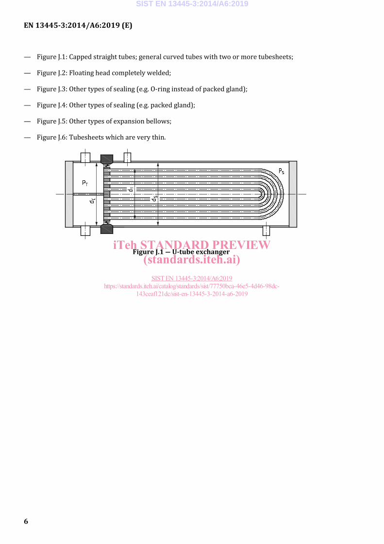
— U-tube type, see Figure J.1; also to exchangers with capped tubes and one tubesheet only and exchangers with curved tubes and a number of separate tubesheets;
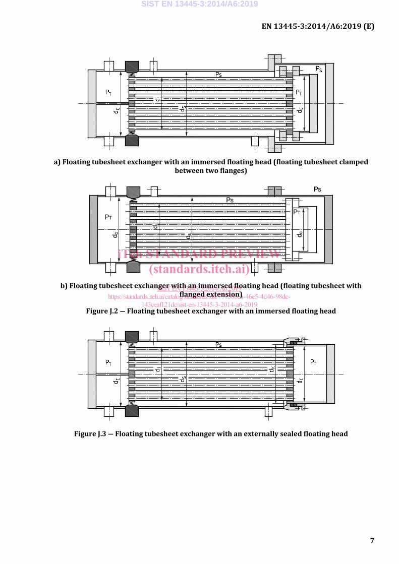
— immersed floating head; see Figures J.2 a) and J.2 b);
— externally sealed floating head; see Figure J.3;
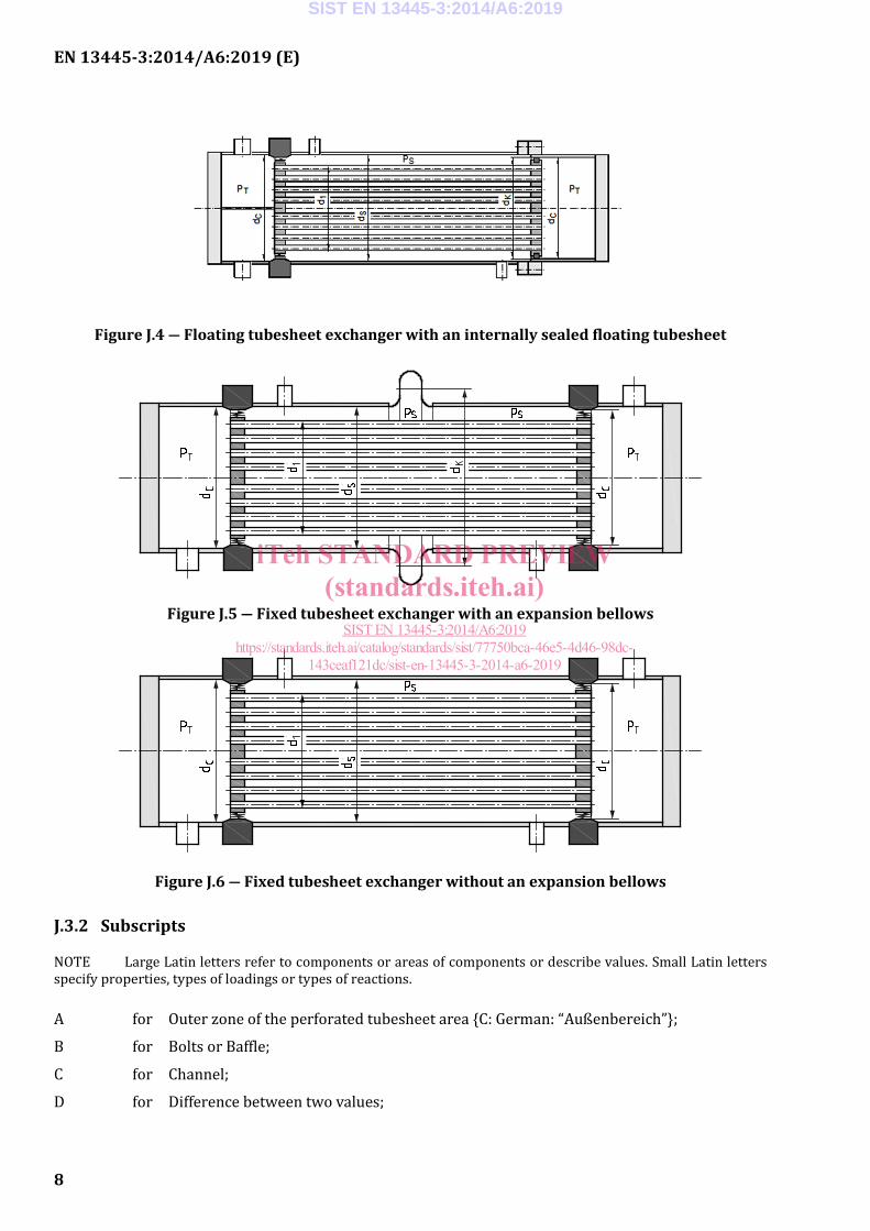
— internally sealed floating head; see Figure J.4;
— fixed tubesheet with expansion bellows; see Figure J.5;
— fixed tubesheet without expansion bellows; see Figure J.6.
J.2 Specific definitions
The following terms and definitions are in addition to those in Clause 3.
J.2.1 outer tube limit circle which encloses all the tubes
J.2.2 load ratio calculated load or moment applied to a component divided by the allowable load or moment
J.3 Specific symbols and abbreviations
J.3.1 General
The following symbols and abbreviations are in addition to those in Clause 4.
Figures J.1 to J.6 illustrate the six main types of shell and tube heat exchanger. Figures J.7 to J.13 cover specific details. All Figures illustrate general characteristics. They are not intended to cover all of the possible combinations for which the method is valid.
In Figures J.1 to J.6 the outer part of the stationary tubesheet may be either bolted or welded to the adjoining shell(s). The details of this outer tubesheet portion with the relevant flanges (if any) have been sketched with a dark colour, since they are not needed for the determination of the main axial forces (calculation parameter PR). For simplification all the ends have been shown as flat (although they are generally dished).
Baffles and support plates have not been included in the figures.
Other types not shown in Figures J.1 to J.6 include:
SIST EN 13445-3:2014/A6:2019
iTeh STANDARD PREVIEW(standards.iteh.ai)
SIST EN 13445-3:2014/A6:2019https://standards.iteh.ai/catalog/standards/sist/77750bca-46e5-4d46-98dc-
143ceaf121dc/sist-en-13445-3-2014-a6-2019
EN 13445-3:2014/A6:2019 (E)
6
— Figure J.1: Capped straight tubes; general curved tubes with two or more tubesheets;
— Figure J.2: Floating head completely welded;
— Figure J.3: Other types of sealing (e.g. O-ring instead of packed gland);
— Figure J.4: Other types of sealing (e.g. packed gland);
— Figure J.5: Other types of expansion bellows;
— Figure J.6: Tubesheets which are very thin.
Figure J.1 ― U-tube exchanger
SIST EN 13445-3:2014/A6:2019
iTeh STANDARD PREVIEW(standards.iteh.ai)
SIST EN 13445-3:2014/A6:2019https://standards.iteh.ai/catalog/standards/sist/77750bca-46e5-4d46-98dc-
143ceaf121dc/sist-en-13445-3-2014-a6-2019
EN 13445-3:2014/A6:2019 (E)
7
a) Floating tubesheet exchanger with an immersed floating head (floating tubesheet clamped
between two flanges)
b) Floating tubesheet exchanger with an immersed floating head (floating tubesheet with
flanged extension)
Figure J.2 ― Floating tubesheet exchanger with an immersed floating head
Figure J.3 ― Floating tubesheet exchanger with an externally sealed floating head
SIST EN 13445-3:2014/A6:2019
iTeh STANDARD PREVIEW(standards.iteh.ai)
SIST EN 13445-3:2014/A6:2019https://standards.iteh.ai/catalog/standards/sist/77750bca-46e5-4d46-98dc-
143ceaf121dc/sist-en-13445-3-2014-a6-2019
EN 13445-3:2014/A6:2019 (E)
8
Figure J.4 ― Floating tubesheet exchanger with an internally sealed floating tubesheet
Figure J.5 ― Fixed tubesheet exchanger with an expansion bellows
Figure J.6 ― Fixed tubesheet exchanger without an expansion bellows
J.3.2 Subscripts
NOTE Large Latin letters refer to components or areas of components or describe values. Small Latin letters specify properties, types of loadings or types of reactions.
A for Outer zone of the perforated tubesheet area {C: German: “Außenbereich”};
B for Bolts or Baffle;
C for Channel;
D for Difference between two values;
SIST EN 13445-3:2014/A6:2019
iTeh STANDARD PREVIEW(standards.iteh.ai)
SIST EN 13445-3:2014/A6:2019https://standards.iteh.ai/catalog/standards/sist/77750bca-46e5-4d46-98dc-
143ceaf121dc/sist-en-13445-3-2014-a6-2019
EN 13445-3:2014/A6:2019 (E)
9
E for Effective values;
F for Flange;
G for Gasket;
I for Inner zone of the perforated tubesheet area {C: German: “Innenbereich”};
J for Expansion bellows {C: Clause 13};
K for Compensation {C: German: “Kompensation”};
M for Moment related values;
P for Plate (tubesheet); or Pressure related values;
Q for Load related values {C: Similar to “P” and “R”};
R for Resultant load; or Tube bundle {C: German: “Rohrbündel”}, perforated tubesheet area ; or any value between “Q” and “S”;
S for Shell;
T for Tubes or tube side (channel side);
U for Unperforated tubesheet area;
W for Weight; or Weld;
X for Tube-to-tubesheet connection;
av for average value;
b for bending;
c for compressive (stress or force);
e for external (pressure); or effective;
i for internal (pressure);
l for longitudinal;
min for minimum value;
max for maximum value;
opt for optimum value;
red for reduced value;
t for tensile (stress or force); or total
J.3.3 Symbols
NOTE Units are given in square brackets; [1] indicates a “dimensionless” quantity.
AR is the cross-sectional area of the perforated tubesheet area, [mm2];
AR(min) is the minimum area of the perforated tubesheet area, [mm2], see J.5.1.1.3.2;
SIST EN 13445-3:2014/A6:2019
iTeh STANDARD PREVIEW(standards.iteh.ai)
SIST EN 13445-3:2014/A6:2019https://standards.iteh.ai/catalog/standards/sist/77750bca-46e5-4d46-98dc-
143ceaf121dc/sist-en-13445-3-2014-a6-2019
EN 13445-3:2014/A6:2019 (E)
10
AX is the cross-sectional area of the connection between tube and tubesheet, [mm2];
aT is the effective throat thickness of the tube end weld [mm], specified as follows: aT,P at the plate (tubesheet); aT,T at the tube; aT,R between plate and tube;
B0 is the resulting factor for the tube bundle, shell and channel [1];
BR1, BR2, BR3 are factors for the tube bundle [1];
BS1, BS2, BS3 are factors for shell and channel [1];
bF is the actual width of the tubesheet flanged extension [mm], see Figures J.10 to J.13;
bR is the average width of the untubed rim subject to pressure on both sides [mm], see J.5.1;
bS is the actual width of the untubed rim [mm] subject to pressure on one side only, may be positive or negative; see J.5.1;
bU is the maximum width of the untubed rim [mm], obtained from the tubesheet layout; see Figures J.7, and J.9.3;
C0, CA, CC, CAA, CAC, CCC are coefficients [1] to determine the buckling length, see J.7.1.3;
C1, C2 are factors used in the fatigue analysis [1], see Figure J.15;
DJ is the inside diameter of the expansion bellows [mm]; see 13.5;
dC, dS are the inside diameters of the channel cylinder (C), of the shell cylinder (S), [mm];
d0, d0,e is the tubehole diameter [mm], d0 is the actual value, d0,e is the effective value;
dF is the diameter where the tubesheet thickness changes from eP to eF;
d1 is the diameter of the perforated tubesheet area to be used in the calculation [mm], see J.5.1;
d1(av) is the average of ( )1 mind and ( )1 max
d , [mm], see J.5.1.1.4;
d1(max) is the maximum value of 1d , [mm], see J.5.1.1.2;
d1(min) is the minimum value of 1d , [mm], see J.5.1.1.3;
d2 is the actual diameter [mm] over which PS and PT act;
d3, d3,e is the bolt pitch circle diameter [mm]; d3 for the actual value, d3,e for the effective value;
dGC, dGS are the effective gasket diameters [mm] for channel side (C), shell side (S);
dK is the diameter over which the axial forces act [mm]; for floating heads this is the diameter of the sliding face at a packed gland or an O-ring seal; for expansion bellows this is the mean inside diameter of the bellows: dK = DJ + hJ;
dT is the tube outside diameter [mm];
EP, ET are the elastic moduli of the tubesheet (P = plate), of the tubes (T), [MPa];
EC, ES are the elastic moduli of the channel (C), of the shell (S), [MPa];
SIST EN 13445-3:2014/A6:2019
iTeh STANDARD PREVIEW(standards.iteh.ai)
SIST EN 13445-3:2014/A6:2019https://standards.iteh.ai/catalog/standards/sist/77750bca-46e5-4d46-98dc-
143ceaf121dc/sist-en-13445-3-2014-a6-2019
EN 13445-3:2014/A6:2019 (E)
11
E* is the effective elastic modulus of the tubesheet [MPa], see Figures 13.7.8–1 and/or 13.7.8–2;
eC is the analysis thickness of the channel cylinder adjacent to the tubesheet [mm];
eF is the average thickness of the tubesheet flanged extension [mm], see Figures J.10 to J.13;
eP is the analysis thickness of the tubesheet (plate) [mm] in the perforated tubesheet area and the untubed rim;
eP,red is a possibly reduced thickness of the tubesheet (plate) at its outer periphery [mm]; eP,red ≤ eP ;
eS is the analysis thickness of the shell cylinder adjacent to the tubesheet [mm];
eS,av is the average thickness of the shell cylinder, taken over the overall length LT [mm];
eT is the tube thickness [mm];
eU is the analysis thickness of the tubesheet in the unperforated tubesheet area [mm]; normally eU = eP ;
FB is the total force applied by the bolts (total force for one flange connection) [N], see Annex G; Pending the elaboration of a specific method to calculate the bolt load in the connection between a flange and a tubesheet bolted to it (see Figures J.12 and J.13), the value of FB may be calculated considering the tubesheet as a flat closure with the same thickness. For tubesheets clamped between two flanges (see Figure J.11) the flange calculation may be done with a modified effective gasket taking into account the tubesheet. See J.4.3.1 for further details;
FG,C, FG,S are the total gasket reaction forces [N], channel side (C), shell side (S);
[Ft], [Fc] are the allowable total axial forces in the shell [N], [Ft] for tension, [Fc] for compression, see J.7.5;
FR is the total axial force acting on tube bundle and shell [N], see J.7.5;
FW is the total weight acting as a force on a tubesheet [N], see J.9.4;
fC is the nominal design stress for the channel cylinder adjacent to the tubesheet [MPa];
fF is the nominal design stress for the tubesheet (plate) flanged extension [MPa]; normally fF = fP ;
fP is the nominal design stress for the tubesheet (plate) [MPa];
fS is the nominal design stress for the shell cylinder adjacent to the tubesheet [MPa];
fT is the nominal design stress for the tubes [MPa];
fT,t is the allowable longitudinal stress for the tubes in tension [MPa]; see J.7.3;
fT,c is the allowable longitudinal stress for tubes in compression [MPa]; see J.7.3;
fX is the calculated design stress for the tube-to-tubesheet connection [MPa]; see J.7.3; fX,E and fX,W are special values of fX ;
SIST EN 13445-3:2014/A6:2019
iTeh STANDARD PREVIEW(standards.iteh.ai)
SIST EN 13445-3:2014/A6:2019https://standards.iteh.ai/catalog/standards/sist/77750bca-46e5-4d46-98dc-
143ceaf121dc/sist-en-13445-3-2014-a6-2019
EN 13445-3:2014/A6:2019 (E)
12
H1, H2, H3 are factors used in the fatigue analysis [1], see Figure J.15;
hJ is the inside height of the expansion bellows [mm]; see 13.5;
j is an integer to identify any trapezoidal area (tubed or untubed);
k is an integer to identify an untubed (pass partition) zone;
Ke1, Ke2, Ke3 are effective stress-strain concentration factors [1] used in the fatigue analysis, see J.10;
L1, L2, L3 are loading parameters [1], used in the calculation of a load ratio, see J.9.1;
LT is the actual total length of the tubes [mm]; in Figure J.9 shown between outer faces of tubesheets;
lA is the unsupported length of the tubes [mm] between the first tubesheet and the first supporting baffle, see Figure J.9;
lB is the maximum value of the unsupported lengths of tubes [mm] between two adjacent supporting baffles, see Figure J.9.
lC is the unsupported length of tubes [mm] between the last supporting baffle and the second tubesheet, see Figure J.9;
lR is a characteristic length of the tube bundle [mm], used for the fatigue analysis, see J.10.3;
lT,K is the buckling length of tubes [mm], see J.7.1;
lX is the contact length between tube and tubesheet [mm], see J.5.2.1;
M1 is the resultant bending moment [Nmm/mm] at the diameter d1;
M2 is the resultant bending moment [Nmm/mm] at the diameter d2;
MA is the active bolt load bending moment [Nmm/mm] at the diameter d2, see J.8.2;
MB is the active fluid pressure bending moment [Nmm/mm] at the diameter d2, see J.8.3;
MC is the reactive bending moment [Nmm/mm] from connected components, see J.8.4;
MD is the reactive bending moment [Nmm/mm] limitation at the diameter d2, see J 8.5;
NB is the number of baffles [1]; NB,t is the actual number, NB,e is the effective number;
NC is the number of load cycles [1];
NI is the number of possible tubes, [1]; see J.5.1;
NI(min) is the total minimum number of potential extra tubes for the whole perforated tubesheet area, [1], see J.5.1.1.3.2;
NI(k) is the number of potential extra tubes in a given untubed trapezoidal area, [1], see J.5.1.1.3.2;
NI(r) is the number of potential extra tubes in a given row, [1], see J.5.1.1.3.2;
NT is the number of tubeholes [1];
nB is the number of bolts [1] in a flanged connection;
SIST EN 13445-3:2014/A6:2019
iTeh STANDARD PREVIEW(standards.iteh.ai)
SIST EN 13445-3:2014/A6:2019https://standards.iteh.ai/catalog/standards/sist/77750bca-46e5-4d46-98dc-
143ceaf121dc/sist-en-13445-3-2014-a6-2019
EN 13445-3:2014/A6:2019 (E)
13
PA, PI are the resultants of active and reactive axial forces per unit area in the tube bundle in the perforated tubesheet area [N/mm2 = MPa]; PA in the outer zone, PI in the inner zone; see J.7.6;
PD is the direct difference between tube side and shell side fluid pressure [MPa], see J.6.2, J.7.2;
PE is the effective differential pressure in the perforated tubesheet area [MPa], see J.7.2;
PM is an equivalent pressure [MPa], representing the resultant bending moment M1 (resultant of active and reactive moments, may be zero) at the diameter of the perforated tubesheet area, see J.8.6;
PQ is an equivalent pressure [MPa], representing the resultant effective axial force (resultant of active and reactive forces, may be zero) at the diameter of the perforated tubesheet area [MPa], see J.6.3, J.7.6;
PR is an equivalent pressure [MPa], representing the resultant active axial shear force at the diameter of the perforated tubesheet area [MPa], see J.6.2, J.7.5;
p is the tube pitch in the perforated tubesheet area [mm], see Figure J.7;
pb is the tube pitch in relation to the height of the trapezoidal area, [mm];
pc is the tube pitch in relation to the width of the trapezoidal area, [mm];
QA, QI are reactive axial forces per unit area of the tube bundle in the perforated tubesheet area [MPa]; QA in the outer zone, QI in the inner zone; see J.7.4;
[Qt], [Qc] are the allowable axial forces per unit area of the tube bundle in the perforated tubesheet area [MPa]; [Qt] for tension, [Qc] for compression; see J.7.3;
q is a factor for the tube support [1], see J.9.3;
r is an integer to identify a tube row;
ro is the radius of the outermost tube hole centre [mm]; see Figure J.7 a) and last paragraph in Subclause J.5.1.1.2 (also Figure 13.7.3–1);
TS, TT are temperature ranges [K] between maximum and minimum temperature for shell (S), tubes (T). For the purpose of determining these values, the ambient temperature shall be assumed to be +20°C;
u, v, w are factors [1], used in J.7.6;
xS, xT are relative areas of the tubesheet [1] subject to PS and PT respectively; see J.7.1;
Y is a factor [1], used in J.7.1;
αS, αT are the thermal expansion coefficients of the shell, of the tubes [K−1];
β is a factor given by Formula (J.10.2–3);
γR is the rigidity factor for the untubed rim, see J.10.3;
Δd(act) is the difference between ( )1 maxd and ( )1 min
d , [mm];
Δd(all) is the allowable difference between ( )1 maxd and ( )1 min
d , [mm];
SIST EN 13445-3:2014/A6:2019
iTeh STANDARD PREVIEW(standards.iteh.ai)
SIST EN 13445-3:2014/A6:2019https://standards.iteh.ai/catalog/standards/sist/77750bca-46e5-4d46-98dc-
143ceaf121dc/sist-en-13445-3-2014-a6-2019