Embed Size (px)
Citation preview
2003-01.Slovenski inštitut za standardizacijo. Razmnoževanje celote ali delov tega standarda ni dovoljeno.
Neogrevane (nekurjene) tlačne posode - 3. del: Konstruiranje - Dopolnilo A8
Unbefeuerte Druckbehälter - Teil 3: Konstruktion
Récipients sous pression non soumis à la flamme - Partie 3 : Conception
Unfired pressure vessels - Part 3: Design
23.020.32 Tlačne posode Pressure vessels
ICS:
Ta slovenski standard je istoveten z: EN 13445-3:2014/A8:2019
SIST EN 13445-3:2014/A8:2019 en,fr,de
01-maj-2019
SIST EN 13445-3:2014/A8:2019SLOVENSKI STANDARD
iTeh STANDARD PREVIEW(standards.iteh.ai)
SIST EN 13445-3:2014/A8:2019https://standards.iteh.ai/catalog/standards/sist/922bf16a-b695-40d0-9824-
5d4a1800df30/sist-en-13445-3-2014-a8-2019

SIST EN 13445-3:2014/A8:2019
iTeh STANDARD PREVIEW(standards.iteh.ai)
SIST EN 13445-3:2014/A8:2019https://standards.iteh.ai/catalog/standards/sist/922bf16a-b695-40d0-9824-
5d4a1800df30/sist-en-13445-3-2014-a8-2019
EUROPEAN STANDARD NORME EUROPÉENNE EUROPÄISCHE NORM
EN 13445-3:2014/A8 April 2019
ICS 23.020.30 English Version Unfired pressure vessels - Part 3: Design Récipients sous pression non soumis à la flamme - Partie 3 : Conception Unbefeuerte Druckbehälter - Teil 3: Konstruktion
This amendment A8 modifies the European Standard EN 13445-3:2014; it was approved by CEN on 19 November 2018. CEN members are bound to comply with the CEN/CENELEC Internal Regulations which stipulate the conditions for inclusion of this amendment into the relevant national standard without any alteration. Up-to-date lists and bibliographical references concerning such national standards may be obtained on application to the CEN-CENELEC Management Centre or to any CEN member. This amendment exists in three official versions (English, French, German). A version in any other language made by translation under the responsibility of a CEN member into its own language and notified to the CEN-CENELEC Management Centre has the same status as the official versions. CEN members are the national standards bodies of Austria, Belgium, Bulgaria, Croatia, Cyprus, Czech Republic, Denmark, Estonia, Finland, Former Yugoslav Republic of Macedonia, France, Germany, Greece, Hungary, Iceland, Ireland, Italy, Latvia, Lithuania, Luxembourg, Malta, Netherlands, Norway, Poland, Portugal, Romania, Serbia, Slovakia, Slovenia, Spain, Sweden, Switzerland, Turkey and United Kingdom.
EUROPEAN COMMITTEE FOR STANDARDIZATION C O M I T É E U R O P É E N D E N O R M A L I S A T I O N E U R O P Ä I S C H E S K O M I T E E F Ü R N O R M U N G CEN-CENELEC Management Centre: Rue de la Science 23, B-1040 Brussels
© 2019 CEN All rights of exploitation in any form and by any means reserved worldwide for CEN national Members. Ref. No. EN 13445-3:2014/A8:2019 E
SIST EN 13445-3:2014/A8:2019
iTeh STANDARD PREVIEW(standards.iteh.ai)
SIST EN 13445-3:2014/A8:2019https://standards.iteh.ai/catalog/standards/sist/922bf16a-b695-40d0-9824-
5d4a1800df30/sist-en-13445-3-2014-a8-2019
EN 13445-3:2014/A8:2019 (E)
2
Contents Page
European foreword ....................................................................................................................................................... 3
1 Modifications to Clause 2, Normative references ................................................................................ 4
2 Modification to 5.3.1, Actions ...................................................................................................................... 4
3 Addition of a new Subclause 5.3.2.4, Load combinations ................................................................. 4
4 Addition of a new Subclause 6.7, Nominal design stress of anchor bolting ............................... 8
5 Modifications to 8.4, General ....................................................................................................................... 8
6 Modification to Subclause 16.4, Local loads on nozzles in spherical shells ............................... 8
7 Modification to 16.5, Local loads on nozzles in cylindrical shells .............................................. 18
8 Modification to 16.6.6, Bending Limit Stress ...................................................................................... 27
9 Modification to 16.7.2, Specific symbols and abbreviations ......................................................... 28
10 Modification to 16.7.4, Applied force .................................................................................................... 29
11 Modification to 16.7.5, Load limits for shell ....................................................................................... 29
12 Modification to 16.8.6.2, Vessel under external pressure ............................................................. 29
13 Modification to 16.8.7, Load limit at the saddle (without a reinforcing plate) ...................... 29
14 Modification to 16.12.4.1, Specific symbols and abbreviations ................................................... 29
15 Modification to 16.12.4.3, Check of the skirt in regions with openings .................................... 29
16 Modification to 16.12.5.1, Specific symbols and abbreviations ................................................... 30
17 Modifications to 16.12.5.2, Anchor bolt and concrete forces ....................................................... 30
18 Modification to 16.14, Global loads ........................................................................................................ 30
19 Modification to 16.14.2, Specific symbols and abbreviations ...................................................... 30
20 Modification to 16.14.8, Compressive stress limits ......................................................................... 32
21 Modification to 16.14.8.1, Calculation .................................................................................................. 32
22 Modification to 16.14.8.2, Tolerances ................................................................................................... 34
23 Modifications to 16.14.9, Wind and earthquake loads ................................................................... 38
24 Modification to Clause 22, Static analysis of tall vertical vessels on skirts ............................. 39
25 Modification to O.4.1, General.................................................................................................................. 49
26 Modification to O.4.2, Polynomial coefficients .................................................................................. 49
27 Modification to O.4.3, Figures for physical properties of steels .................................................. 50
28 Addition of a new Annex V (informative), Consider a buffer for unknown nozzle loads — Opening design for unknown nozzle loads ........................................................................ 50
SIST EN 13445-3:2014/A8:2019
iTeh STANDARD PREVIEW(standards.iteh.ai)
SIST EN 13445-3:2014/A8:2019https://standards.iteh.ai/catalog/standards/sist/922bf16a-b695-40d0-9824-
5d4a1800df30/sist-en-13445-3-2014-a8-2019

EN 13445-3:2014/A8:2019 (E)
3
European foreword
This document (EN 13445-3:2014/A8:2019) has been prepared by Technical Committee CEN/TC 54 “Unfired pressure vessels”, the secretariat of which is held by BSI.
This European Standard shall be given the status of a national standard, either by publication of an identical text or by endorsement, at the latest by October 2019, and conflicting national standards shall be withdrawn at the latest by October 2019.
Attention is drawn to the possibility that some of the elements of this document may be the subject of patent rights. CEN shall not be held responsible for identifying any or all such patent rights.
This document has been prepared under a mandate given to CEN by the European Commission and the European Free Trade Association, and supports essential requirements of EU Directive(s).
For relationship with EU Directive(s), see informative Annex ZA, which is an integral part of EN 13445-3:2014.
According to the CEN-CENELEC Internal Regulations, the national standards organizations of the following countries are bound to implement this European Standard: Austria, Belgium, Bulgaria, Croatia, Cyprus, Czech Republic, Denmark, Estonia, Finland, Former Yugoslav Republic of Macedonia, France, Germany, Greece, Hungary, Iceland, Ireland, Italy, Latvia, Lithuania, Luxembourg, Malta, Netherlands, Norway, Poland, Portugal, Romania, Serbia, Slovakia, Slovenia, Spain, Sweden, Switzerland, Turkey and the United Kingdom.
SIST EN 13445-3:2014/A8:2019
iTeh STANDARD PREVIEW(standards.iteh.ai)
SIST EN 13445-3:2014/A8:2019https://standards.iteh.ai/catalog/standards/sist/922bf16a-b695-40d0-9824-
5d4a1800df30/sist-en-13445-3-2014-a8-2019
EN 13445-3:2014/A8:2019 (E)
4
1 Modifications to Clause 2, Normative references
Add a footnote number “1” after the reference “EN 1991-1-4:2005” and the corresponding footnote at the bottom of the page:
“1 EN 1991-1-4:2005 is impacted by the stand-alone amendment EN 1991-1-4:2005/A1:2010 and the corrigendum EN 1991-1-4:2005/AC:2010.”.
In the reference to EN 1991-1-6, replace "EN 1991-1-6" with “EN 1991-1-6:2005”.
Add the following new reference at the appropriate place:
“EN 12195-1:2010, Load restraining on road vehicles — Safety — Part 1: Calculation of securing forces”.
2 Modification to 5.3.1, Actions
Add the following note at the end of the subclause:
“ NOTE The combination of actions is given in 5.3.2.4.”.
3 Addition of a new Subclause 5.3.2.4, Load combinations
Insert the following new subclause:
“
5.3.2.4 Load combinations
5.3.2.4.1 General
Load combinations of non-pressure loads in Table 5.3.2.4-1 are used in connection with calculations according to Clause 16 and Annex C (linear elastic behaviour). The basic calculation of pressure envelope by design pressures and temperatures shall be made before Clause 16 (or Annex C) calculations. The load combinations in Table 5.3.2.4-1 are minimum to be taken into account, if they are relevant. There may also be other loads.
5.3.2.4.2 Specific definitions
5.3.2.4.2.1 Dead loads
Maximum dead load (Gmax) is the weight of the whole un-corroded vessel with all internals (trays, packing, etc.), attachments, insulation, fire protection, piping, platforms and ladders.
Corroded dead load (Gcorr) is defined as Gmax but with the weight of the corroded vessel.
Minimum dead load (Gmin) is the weight of the un-corroded vessel during the installation phase, excluding the weight of items not already mounted on the vessel before erection (e.g. removable internals, platforms, ladders, attached piping, insulation and fire protection). NOTE A scaffold is normally self-supported. In this case, the weight of the scaffold is not included in the vessel weight.
Transport dead load (Gtrans) is the case, when vessel has the removable internals and insulation already mounted on the vessel in the workshop.
5.3.2.4.2.2 Live loads
Live loads (L) used in this clause are weight loads of the contents (fluids or solids in the bottom of the vessel, on trays and in packing) and traffic loads on platforms and ladders by personnel and machinery.
SIST EN 13445-3:2014/A8:2019
iTeh STANDARD PREVIEW(standards.iteh.ai)
SIST EN 13445-3:2014/A8:2019https://standards.iteh.ai/catalog/standards/sist/922bf16a-b695-40d0-9824-
5d4a1800df30/sist-en-13445-3-2014-a8-2019
EN 13445-3:2014/A8:2019 (E)
5
5.3.2.4.2.3 Wind loads
Wind loads (W) are horizontal global pressure loads caused by wind and acting on the projected area of the vessel and its attachments, as influenced by the force coefficients (see 22.4.4).
5.3.2.4.2.4 Earthquake loads
Earthquake loads (E) are quasi-static horizontal forces on the vessel sections caused by seismic accelerations at the base of vessel calculated by the “lateral force method of analysis” (see 22.4.5).
5.3.2.4.2.5 Forces from attached external piping
Reaction forces from attached external piping are forces resulting from weight (G), wind (W), earthquake (E) and other additional forces (F) as far as they influence the global equilibrium of the vessel (see 22.4.6 for columns). NOTE Forces and moments on nozzles and supports on the vessel caused by attached external piping can act as internal and/or external loads. Internal loads are those that cause local loads only and have no influence on the global equilibrium because they are self-compensating. Furthermore, attached pipes can either load the vessel or restrain it depending on their layout. Consideration of these aspects is given in the recommendations in 22.4.6.
5.3.2.4.3 Specific symbols and abbreviations
The following specific symbols and abbreviations are used in Table 5.3.2.4-1 in addition to those in Clause 4:
E earthquake load (see 5.3.2.4.2.4)
F additional loads from piping (thermal expansion loads) (see 5.3.2.4.2.5)
fB,op nominal design stress for operation conditions for anchor bolts, see Formula (6.7–1)
Gmin minimum dead loads (see 5.3.2.4.2.1)
Gmax maximum dead loads (see 5.3.2.4.2.1)
Gcorr corroded dead loads (see 5.3.2.4.2.1)
Gtrans transport dead loads (see 5.3.2.4.2.1)
L live loads of each loading case (contents, etc.) (see 5.3.2.4.2.2)
Pi internal calculation pressure as defined in 5.3.10 for P > 0 (including hydrostatic pressure)
Pe external calculation pressure as defined in 5.3.10 for P < 0 (e.g. vacuum)
W wind load (Clause 22 and EN 1991-1-4)
σc,all maximum allowable compressive stress for operation conditions in accordance with 16.14.8, with σe as defined in 8.4 and with a safety factor of 1,5 in Formula (16.14–29)
σc,all,test maximum allowable compressive stress for test conditions in accordance with 16.14.8, with σe as defined in 8.4 and with safety factor 1,05 in Formula (16.14–29)
& operator which means: superposition of the different load types for the axial and lateral forces, the bending moments and the resulting shear and longitudinal stresses using the beam theory for non-pressure loads and the membrane theory for pressure loads
SIST EN 13445-3:2014/A8:2019
iTeh STANDARD PREVIEW(standards.iteh.ai)
SIST EN 13445-3:2014/A8:2019https://standards.iteh.ai/catalog/standards/sist/922bf16a-b695-40d0-9824-
5d4a1800df30/sist-en-13445-3-2014-a8-2019
EN 13445-3:2014/A8:2019 (E)
6
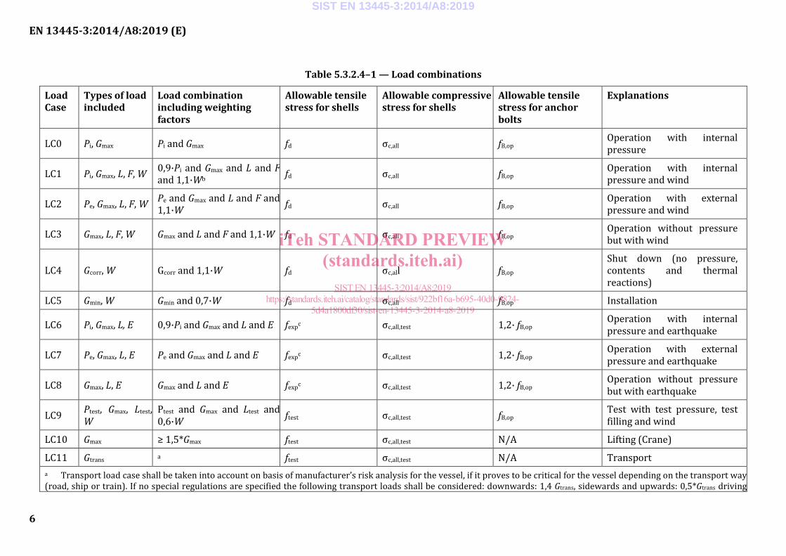
Table 5.3.2.4–1 — Load combinations
Load Case
Types of load included
Load combination including weighting factors
Allowable tensile stress for shells
Allowable compressive stress for shells
Allowable tensile stress for anchor bolts
Explanations
LC0 Pi, Gmax Pi and Gmax fd σc,all fB,op Operation with internal pressure
LC1 Pi, Gmax, L, F, W 0,9·Pi and Gmax and L and F and 1,1·Wb fd σc,all fB,op Operation with internal
pressure and wind
LC2 Pe, Gmax, L, F, W Pe and Gmax and L and F and 1,1·W fd σc,all fB,op Operation with external
pressure and wind
LC3 Gmax, L, F, W Gmax and L and F and 1,1·W fd σc,all fB,op Operation without pressure but with wind
LC4 Gcorr, W Gcorr and 1,1·W fd σc,all fB,op Shut down (no pressure, contents and thermal reactions)
LC5 Gmin, W Gmin and 0,7·W fd σc,all fB,op Installation
LC6 Pi, Gmax, L, E 0,9·Pi and Gmax and L and E fexpc σc,all,test 1,2· fB,op Operation with internal pressure and earthquake
LC7 Pe, Gmax, L, E Pe and Gmax and L and E fexpc σc,all,test 1,2· fB,op Operation with external pressure and earthquake
LC8 Gmax, L, E Gmax and L and E fexpc σc,all,test 1,2· fB,op Operation without pressure but with earthquake
LC9 Ptest, Gmax, Ltest, W
Ptest and Gmax and Ltest and 0,6·W ftest σc,all,test fB,op Test with test pressure, test
filling and wind
LC10 Gmax ≥ 1,5*Gmax ftest σc,all,test N/A Lifting (Crane)
LC11 Gtrans a ftest σc,all,test N/A Transport a Transport load case shall be taken into account on basis of manufacturer’s risk analysis for the vessel, if it proves to be critical for the vessel depending on the transport way (road, ship or train). If no special regulations are specified the following transport loads shall be considered: downwards: 1,4 Gtrans, sidewards and upwards: 0,5*Gtrans driving
SIST EN 13445-3:2014/A8:2019
iTeh STANDARD PREVIEW(standards.iteh.ai)
SIST EN 13445-3:2014/A8:2019https://standards.iteh.ai/catalog/standards/sist/922bf16a-b695-40d0-9824-
5d4a1800df30/sist-en-13445-3-2014-a8-2019
EN 13445-3:2014/A8:2019 (E)
7
direction: 0,8*Gtrans. The transport loads shall be agreed with transport company so that the transport will not damage the vessel (see EN 12195-1). b Real operating pressure may be used instead of 0,9*Pi, if it is limited either naturally (e.g. steam temperature) or by safety related control and instrumentation system. c After exceptional load case the vessel shall have re-inspection.
Remarks
For LC1 and LC2: If more than one combination of coincident design pressure and design temperature exists then all combinations shall be investigated. Alternatively a single combination of the maximum pressure and maximum temperature of all the cases may be used. It is not certain that the governing condition of coincident pressure and temperature is also governing for the load combinations.
For LC1 and LC6: The factor 0,9 is applied to the internal calculation pressure Pi because the internal operating pressure is normally 10 % below PS due to the pressure limiting device.
For LC3 and LC8: These load cases are not required when both loading cases LC1 and LC2, or LC6 and LC7 are applicable, i.e. internal and external pressure are applied.
For LC5: The wind load in this case depends on configuration at this time (with or without scaffold, platforms, insulation). The reduced factor for the wind load is in accordance with EN 1991-1-6:2005 for duration times < 12 months.
For LC9: The reduced factor for the wind load is in accordance with EN 1991-1-6:2005 for duration times < 3 d.
In calculation of allowable bending stress σb,all for transport and lifting cases according to 16.6.6, the nominal design stress ftest can be used instead of f and K2 shall be set equal 1,05.
The global effect of additional piping loads on shell stresses or anchoring shall be taken into account by designer, if considered relevant.”.
SIST EN 13445-3:2014/A8:2019
iTeh STANDARD PREVIEW(standards.iteh.ai)
SIST EN 13445-3:2014/A8:2019https://standards.iteh.ai/catalog/standards/sist/922bf16a-b695-40d0-9824-
5d4a1800df30/sist-en-13445-3-2014-a8-2019
EN 13445-3:2014/A8:2019 (E)
8
4 Addition of a new Subclause 6.7, Nominal design stress of anchor bolting
Insert the following new subclause:
“
6.7 Nominal design stress of anchor bolting
The nominal design stress for the anchor bolts for the operation condition shall be calculated as follows:
=
p0,2/TB m/20
1 65 2 062 5, min ;, ,B op
R Rf (6.7-1)
where
TB is design temperature for anchor bolts NOTE In most cases the design temperature TB of the anchor bolts will be 20 °C and will generally be much lower than the design temperature of the vessel.”.
5 Modifications to 8.4, General
Replace the first sentence of 8.4.2 with the following one:
“
8.4.2 For shells made in non-austenitic steels, excluding ferritic, martensitic and precipitation hardened stainless steels in material group 7 and austenitic ferritic stainless steels in material group 10, the nominal elastic limit shall be given by:”.
Replace the first sentence of 8.4.3 with the following one:
“
8.4.3 For shells made in austenitic steels, ferritic, martensitic and precipitation hardened stainless steels and austenitic ferritic stainless steels, the nominal elastic limit shall be given by:”.
6 Modification to Subclause 16.4, Local loads on nozzles in spherical shells
Replace Subclause 16.4 with the following one:
“
16.4 Local loads on nozzles in spherical shells
16.4.1 Purpose
This clause provides a method for the design of a spherical shell with a nozzle subjected to local loads and internal pressure.
In cases where the loads are unknown see Annex V.
16.4.2 Additional specific symbols and abbreviations
The following symbols and abbreviations are in addition to those in Clause 4 and 16.3:
d is mean nozzle diameter;
di is inside nozzle diameter;
SIST EN 13445-3:2014/A8:2019
iTeh STANDARD PREVIEW(standards.iteh.ai)
SIST EN 13445-3:2014/A8:2019https://standards.iteh.ai/catalog/standards/sist/922bf16a-b695-40d0-9824-
5d4a1800df30/sist-en-13445-3-2014-a8-2019
EN 13445-3:2014/A8:2019 (E)
9
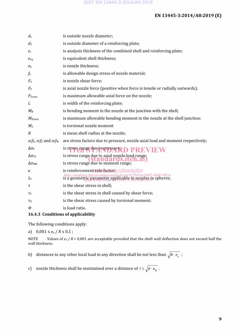
de is outside nozzle diameter;
d2 is outside diameter of a reinforcing plate;
ec is analysis thickness of the combined shell and reinforcing plate;
eeq is equivalent shell thickness;
eb is nozzle thickness;
fb is allowable design stress of nozzle material;
FS is nozzle shear force;
FZ is axial nozzle force (positive when force is tensile or radially outwards);
FZ,max is maximum allowable axial force on the nozzle;
L is width of the reinforcing plate;
MB is bending moment in the nozzle at the junction with the shell;
MB,max is maximum allowable bending moment in the nozzle at the shell junction;
MZ is torsional nozzle moment
R is mean shell radius at the nozzle;
scfP, scfZ and scfM are stress factors due to pressure, nozzle axial load and moment respectively;
ΔσP is stress range due to pressure;
ΔσFZ is stress range due to axial nozzle load range;
ΔσMB is stress range due to moment range;
κ is reinforcement rate factor;
λS is a geometric parameter applicable to nozzles in spheres;
τ is the shear stress in shell;
τF is the shear stress in shell caused by shear force;
τZ is the shear stress caused by torsional moment;
Φ is load ratio. 16.4.3 Conditions of applicability
The following conditions apply:
a) 0,001 ≤ ea / R ≤ 0,1 ; NOTE Values of ea / R < 0,001 are acceptable provided that the shell wall deflection does not exceed half the wall thickness.
b) distances to any other local load in any direction shall be not less than ⋅ cR e ;
c) nozzle thickness shall be maintained over a distance of ≥ ⋅ bl d e .
SIST EN 13445-3:2014/A8:2019
iTeh STANDARD PREVIEW(standards.iteh.ai)
SIST EN 13445-3:2014/A8:2019https://standards.iteh.ai/catalog/standards/sist/922bf16a-b695-40d0-9824-
5d4a1800df30/sist-en-13445-3-2014-a8-2019
EN 13445-3:2014/A8:2019 (E)
10
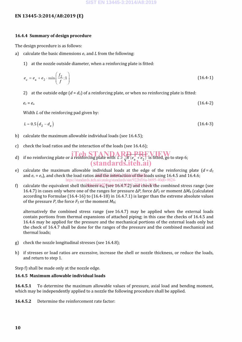
16.4.4 Summary of design procedure
The design procedure is as follows:
a) calculate the basic dimensions ec and L from the following:
1) at the nozzle outside diameter, when a reinforcing plate is fitted:
c a 2 = + ⋅
2 1min ;f
e e ef
(16.4-1)
2) at the outside edge (d = d2) of a reinforcing plate, or when no reinforcing plate is fitted:
ec = ea (16.4-2)
Width L of the reinforcing pad given by:
( )= −2 e0 5,L d d (16.4-3)
b) calculate the maximum allowable individual loads (see 16.4.5);
c) check the load ratios and the interaction of the loads (see 16.4.6);
d) if no reinforcing plate or a reinforcing plate with ≥ +a 2( )L R e e is fitted, go to step 6;
e) calculate the maximum allowable individual loads at the edge of the reinforcing plate (d = d2 and ec = ea), and check the load ratios and the interaction of the loads using 16.4.5 and 16.4.6;
f) calculate the equivalent shell thickness eeq (see 16.4.7.2) and check the combined stress range (see 16.4.7) in cases only where one of the ranges for pressure ∆P, force ∆FZ or moment ∆MB (calculated according to Formulae (16.4-16) to (16.4-18) in 16.4.7.1) is larger than the extreme absolute values of the pressure P, the force FZ or the moment MB;
alternatively the combined stress range (see 16.4.7) may be applied when the external loads contain portions from thermal expansions of attached piping; in this case the checks of 16.4.5 and 16.4.6 may be applied for the pressure and the mechanical portions of the external loads only but the check of 16.4.7 shall be done for the ranges of the pressure and the combined mechanical and thermal loads;
g) check the nozzle longitudinal stresses (see 16.4.8);
h) if stresses or load ratios are excessive, increase the shell or nozzle thickness, or reduce the loads, and return to step 1.
Step f) shall be made only at the nozzle edge.
16.4.5 Maximum allowable individual loads
16.4.5.1 To determine the maximum allowable values of pressure, axial load and bending moment, which may be independently applied to a nozzle the following procedure shall be applied.
16.4.5.2 Determine the reinforcement rate factor:
SIST EN 13445-3:2014/A8:2019
iTeh STANDARD PREVIEW(standards.iteh.ai)
SIST EN 13445-3:2014/A8:2019https://standards.iteh.ai/catalog/standards/sist/922bf16a-b695-40d0-9824-
5d4a1800df30/sist-en-13445-3-2014-a8-2019
EN 13445-3:2014/A8:2019 (E)
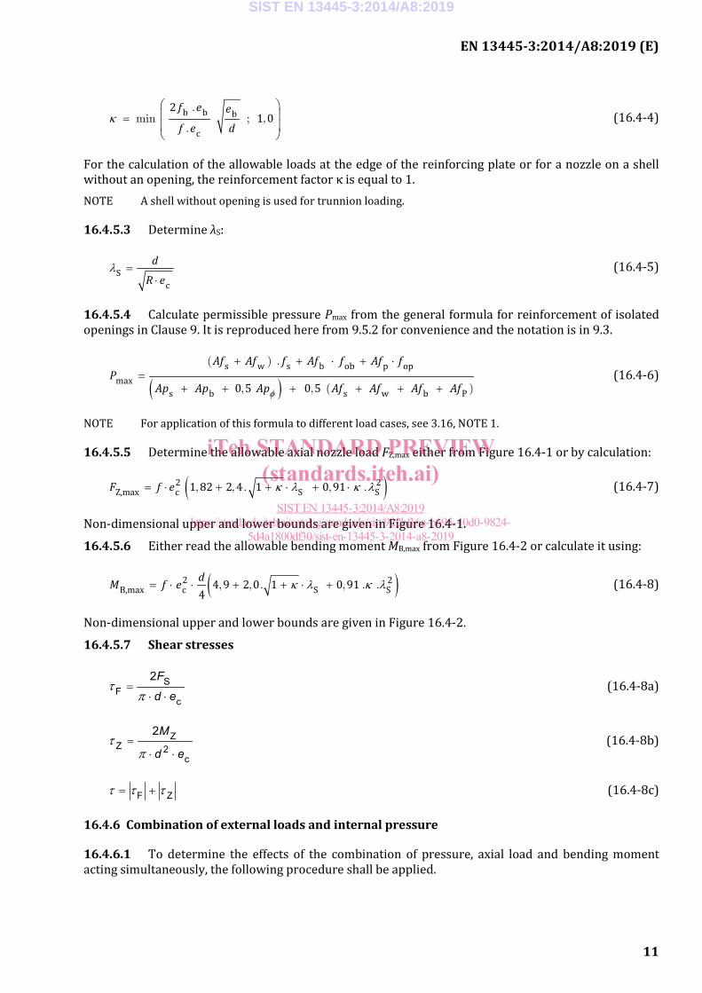
11
κ =
b b b
c
21 0
.min ; ,
.
f e e
f e d (16.4-4)
For the calculation of the allowable loads at the edge of the reinforcing plate or for a nozzle on a shell without an opening, the reinforcement factor κ is equal to 1. NOTE A shell without opening is used for trunnion loading.
16.4.5.3 Determine λS:
λ =⋅
Sc
d
R e (16.4-5)
16.4.5.4 Calculate permissible pressure Pmax from the general formula for reinforcement of isolated openings in Clause 9. It is reproduced here from 9.5.2 for convenience and the notation is in 9.3.
( )φ
+ + ⋅ + ⋅=
+ + + + + +
s w s b ob p opmax
s b s w b P0 5 0 5
( ) .
, , ( )
Af Af f Af f Af fP
Ap Ap Ap Af Af Af Af (16.4-6)
NOTE For application of this formula to different load cases, see 3.16, NOTE 1.
16.4.5.5 Determine the allowable axial nozzle load FZ,max either from Figure 16.4-1 or by calculation:
( )κ λ κ λ= ⋅ + + ⋅ + ⋅2 2Z,max c S S1 82 2 4 1 0 91, , . , .F f e (16.4-7)
Non-dimensional upper and lower bounds are given in Figure 16.4-1.
16.4.5.6 Either read the allowable bending moment MB,max from Figure 16.4-2 or calculate it using:
( )κ λ κ λ= ⋅ ⋅ + + ⋅ +2 2B,max c S S4 9 2 0 1 0 91
4, , . , . .
dM f e (16.4-8)
Non-dimensional upper and lower bounds are given in Figure 16.4-2.
16.4.5.7 Shear stresses
SF
c
2τ
π=
⋅ ⋅
F
d e (16.4-8a)
ZZ 2
c
2τ
π=
⋅ ⋅
M
d e (16.4-8b)
F Zτ τ τ= + (16.4-8c)
16.4.6 Combination of external loads and internal pressure
16.4.6.1 To determine the effects of the combination of pressure, axial load and bending moment acting simultaneously, the following procedure shall be applied.
SIST EN 13445-3:2014/A8:2019
iTeh STANDARD PREVIEW(standards.iteh.ai)
SIST EN 13445-3:2014/A8:2019https://standards.iteh.ai/catalog/standards/sist/922bf16a-b695-40d0-9824-
5d4a1800df30/sist-en-13445-3-2014-a8-2019
EN 13445-3:2014/A8:2019 (E)
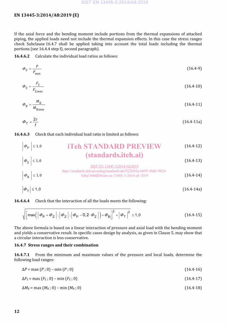
12
If the axial force and the bending moment include portions from the thermal expansions of attached piping, the applied loads need not include the thermal expansion effects. In this case the stress ranges check Subclause 16.4.7 shall be applied taking into account the total loads including the thermal portions (see 16.4.4 step f), second paragraph).
16.4.6.2 Calculate the individual load ratios as follows:
Φ =Pmax
PP
(16.4-9)
Φ = ZZ
Z,max
F
F (16.4-10)
Φ = BB
B,max
M
M (16.4-11)
T2τΦ =f
(16.4-11a)
16.4.6.3 Check that each individual load ratio is limited as follows:
Φ ≤P 1 0, (16.4-12)
Φ ≤Z 1 0, (16.4-13)
Φ ≤B 1 0, (16.4-14)
T 1,0Φ ≤ (16.4-14a)
16.4.6.4 Check that the interaction of all the loads meets the following:
( ) 2 2P Z Z P Z B Tmax 1,00,2Φ Φ Φ Φ Φ Φ Φ + − ⋅ + + ≤
; ; (16.4-15)
The above formula is based on a linear interaction of pressure and axial load with the bending moment and yields a conservative result. In specific cases design by analysis, as given in Clause 5, may show that a circular interaction is less conservative.
16.4.7 Stress ranges and their combination
16.4.7.1 From the minimum and maximum values of the pressure and local loads, determine the following load ranges:
ΔP = max (P ; 0) – min (P ; 0) (16.4-16)
ΔFZ = max (FZ ; 0) – min (FZ ; 0) (16.4-17)
ΔMB = max (MB ; 0) – min (MB ; 0) (16.4-18)
SIST EN 13445-3:2014/A8:2019
iTeh STANDARD PREVIEW(standards.iteh.ai)
SIST EN 13445-3:2014/A8:2019https://standards.iteh.ai/catalog/standards/sist/922bf16a-b695-40d0-9824-
5d4a1800df30/sist-en-13445-3-2014-a8-2019
EN 13445-3:2014/A8:2019 (E)
13
ΔFS = max (FS ; 0) – min (FS; 0) (16.6-18a)
ΔMZ = max (MZ ; 0) – min (MZ ; 0) (16.4-18b)
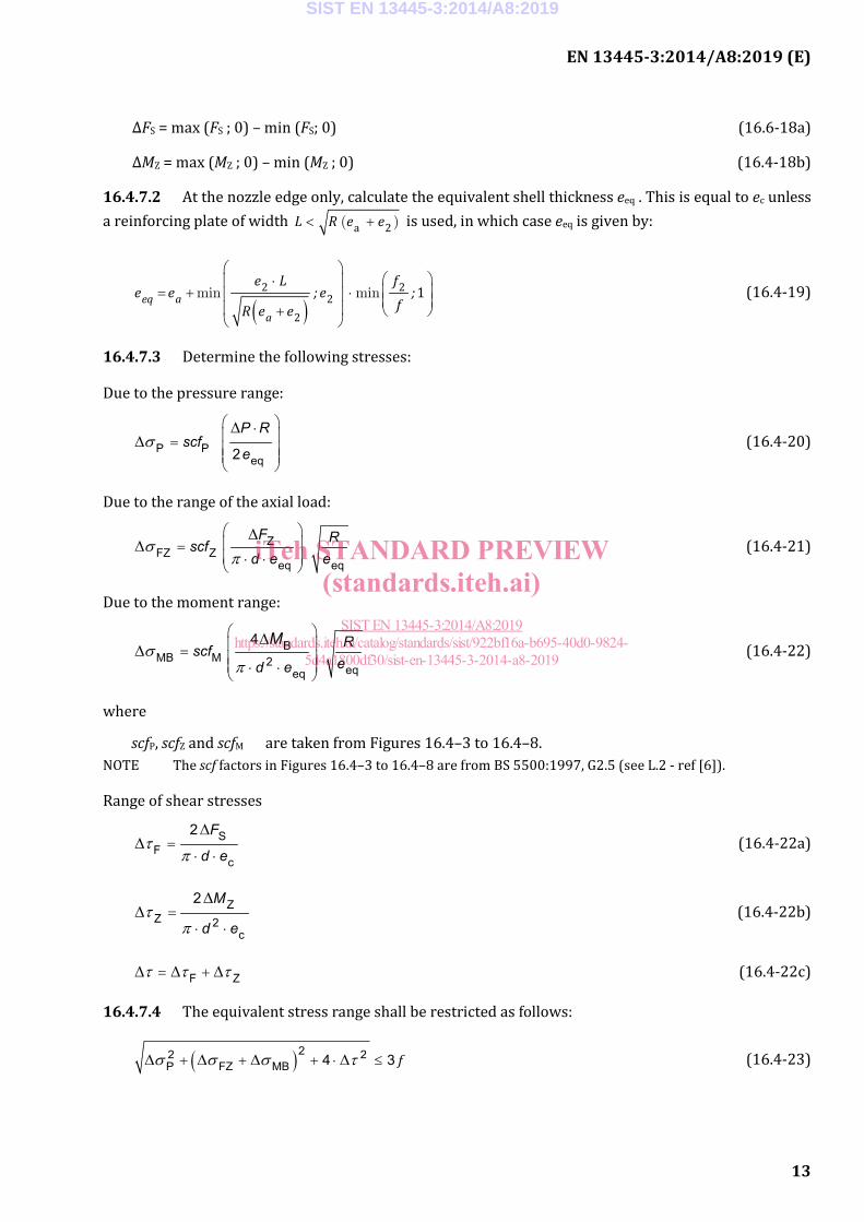
16.4.7.2 At the nozzle edge only, calculate the equivalent shell thickness eeq . This is equal to ec unless a reinforcing plate of width < +a 2( )L R e e is used, in which case eeq is given by:
( )
⋅ = + ⋅ +
2 22
2
1min mineq aa
e L fe e ; e ;
fR e e (16.4-19)
16.4.7.3 Determine the following stresses:
Due to the pressure range:
P Peq2
σ ⋅ =
∆∆
P Rscf
e (16.4-20)
Due to the range of the axial load:
ZFZ Z
eq eqσ
π
= ⋅ ⋅
∆∆
F Rscfd e e
(16.4-21)
Due to the moment range:
BMB M 2
eqeq
4σ
π
= ⋅ ⋅
∆∆ Rscf
ed e
M (16.4-22)
where
scfP, scfZ and scfM are taken from Figures 16.4–3 to 16.4–8. NOTE The scf factors in Figures 16.4–3 to 16.4–8 are from BS 5500:1997, G2.5 (see L.2 - ref [6]).
Range of shear stresses
SF
c
2τ
π=
⋅ ⋅
∆∆
F
d e (16.4-22a)
ZZ 2
c
2τ
π=
⋅ ⋅
∆∆
M
d e (16.4-22b)
F Zτ τ τ= +∆ ∆ ∆ (16.4-22c)
16.4.7.4 The equivalent stress range shall be restricted as follows:
( )22 2P FZ MB 4 3σ σ σ τ+ + + ⋅ ≤∆ ∆ ∆ ∆ f (16.4-23)
SIST EN 13445-3:2014/A8:2019
iTeh STANDARD PREVIEW(standards.iteh.ai)
SIST EN 13445-3:2014/A8:2019https://standards.iteh.ai/catalog/standards/sist/922bf16a-b695-40d0-9824-
5d4a1800df30/sist-en-13445-3-2014-a8-2019