Embed Size (px)
Citation preview
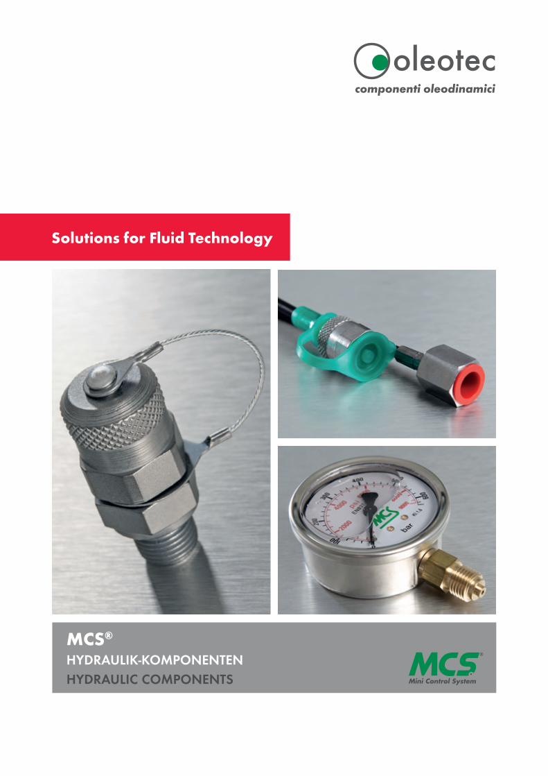
MCS®
HYDRAULIK-KOMPONENTENHYDRAULIC COMPONENTS
Solutions for Fluid Technology
2
Oleotec S.r.l. ist seit 1976 in der Fluidtechnik tätig und steht seit über 40 Jahren für sichere Druckmessung in hydraulischen Anlagen. Unter dem Markennamen MCS® stellen wir modernste Produkte zur Überprüfung von Parametern in Hydraulikkreisläufen her, darunter ein umfassendes Sortiment an Messkupplungen, Hyd-raulikschläuchen und Manometern. Unsere Hydraulik-komponenten sind zuverlässig und wirtschaftlich und können in vielen verschiedenen Industriebereichen ein-gesetzt werden.
MCS® - Abkürzung für „Mini Control System“ – definiert ein komplettes Sortiment von Messkupplungen, Miniaturanschlüssen und Schläuchen, welches gemäß der Norm UNI EN 9001: 2000 hergestellt wird und womit der Druck an jedem beliebigen Punkt in hydraulischen Systemen bei vollem Druck einfach und kostengünstig geprüft werden kann.
Unsere innovative Messkupplung MCS® 621 stellt eine leckagefreie Lösung dar, auch beim Einsatz von Flüssigkeiten mit sehr niedriger Viskosität. Die neu kon-zipierte Serie reduziert Druckverluste und sorgt für ein schnelleres Ansprechen und präzisere Messungen. Die hochwertige Zink-Nickel-Beschichtung ist korrosi-onsbeständig. Die neuen 621 Messkupplungen wer-den von hochmodernen, vollautomatischen Transfer-maschinen montiert und zu 100% geprüft.
In unseren Produktionsstätten werden Oleotec-Produk-te schnell und in hoher Qualität hergestellt. Wir sind auch schnell und flexibel, wenn es darum geht, kun-denspezifische Aufträge zu erstellen. Mit unserer stra-tegischen Position in der Provinz Varese in der Nähe von Mailand und unserem weltweiten Vertriebsnetz, ist Oleotec auf der ganzen Welt tätig und konzentriert sich stets auf die Bedürfnisse seiner Kunden sowie auf einen zuverlässigen und effizienten Service.
UNTERNEHMEN COMPANY
Oleotec S.r.l. has been operating in the fluid power industry since 1976 and has been synonymous of safe pressure measurement in hydraulic systems for more than 40 years. We produce cutting-edge products for checking parameters in hydraulic circuits, including a comprehensive range of test points, hydraulic hoses and pressure gauges under the brand name MCS®. Our hydraulic components are reliable and cost- effective and can be used in many different sectors.
MCS® – abbreviation for “Mini Control System“– defines a complete range of test points, miniaturised fittings and hoses manufactured according to UNI EN 9001:2000 standards. The products offer simple and inexpensive means to check pressure at any point in hydraulic systems, while at full pressure.
Our innovative test point MCS® 621 represents a leakage-free solution, even when dealing with very low viscosity fluids. The newly designed series reduces pressure losses and ensures a quicker response and more precise measurements. Its high-quality zinc-nickel plating is resistant to corrosion. The new 621 test points are assembled and 100% checked by state-of- the-art, fully automated transfer machines.
In our production facilities, Oleotec products are manu- factured quickly and in high quality. We are also fast and flexible when it comes to producing customised orders. With our strategic position in the province of Varese, near Milan and our worldwide distribution network, Oleotec operates all over the world, with a constant focus on its customers’ needs and with a reliable and efficient customer service.
ISO 9001:2015 Cert. n° 445
Mit der Herausgabe dieses Kataloges erlöschen sämtliche Anga-
ben aus früheren Publikationen. Änderungen und Abweichungen
bleiben Oleotec vorbehalten. Für mögliche Druckfehler übernimmt
Oleotec keine Haftung. Vervielfältigung, auch Auszüge, sind nur
nach schriftlicher Genehmigung durch Oleotec gestattet. Oleotec
behält sich das Recht vor, jederzeit technische Änderungen durch-
zuführen. Stand: 02/2020
The current publication of this catalogue supersedes all information
from previous publications. Oleotec reserves the right to make
changes and substitutions. Oleotec is not liable for any printing
errors. Reproduction, including excerpts, is permitted only after
written approval by Oleotec. Oleotec reserves the right to modify
technical data at any time. Last revised: 02/2020
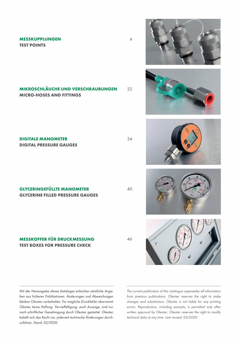
DIGITALE MANOMETERDIGITAL PRESSURE GAUGES
GLYCERINGEFÜLLTE MANOMETER GLYCERINE FILLED PRESSURE GAUGES
MESSKOFFER FÜR DRUCKMESSUNG TEST BOXES FOR PRESSURE CHECK
MESSKUPPLUNGENTEST POINTS
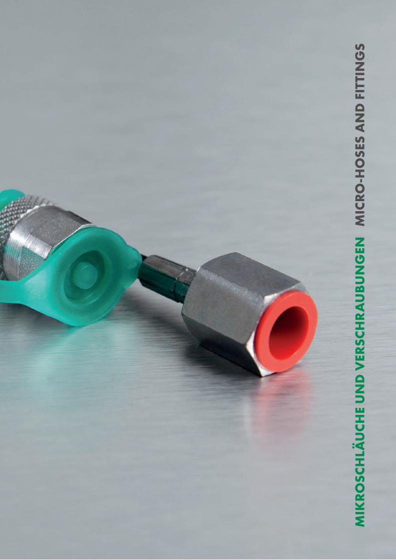
MIKROSCHLÄUCHE UND VERSCHRAUBUNGENMICRO-HOSES AND FITTINGS
34
40
46
4
22
4
5
MES
SKU
PP
LUN
GEN
TE
ST P
OIN
TS
6 MESSKUPPLUNGEN TEST POINTS
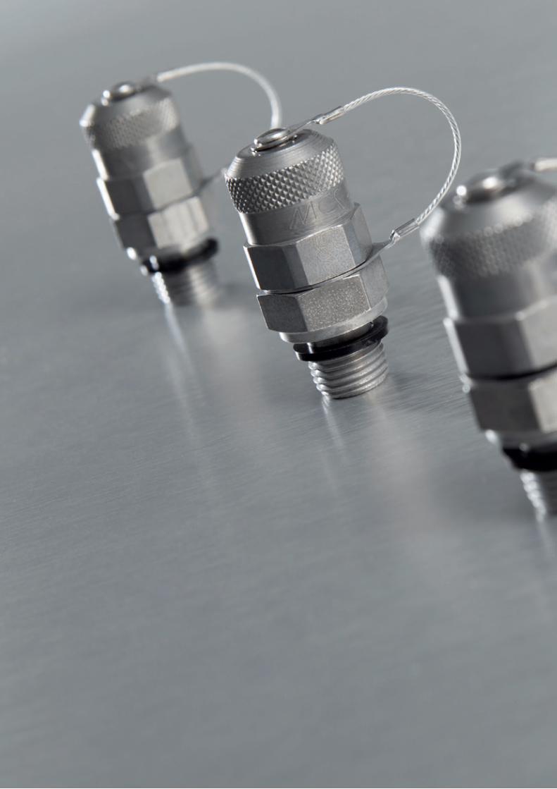
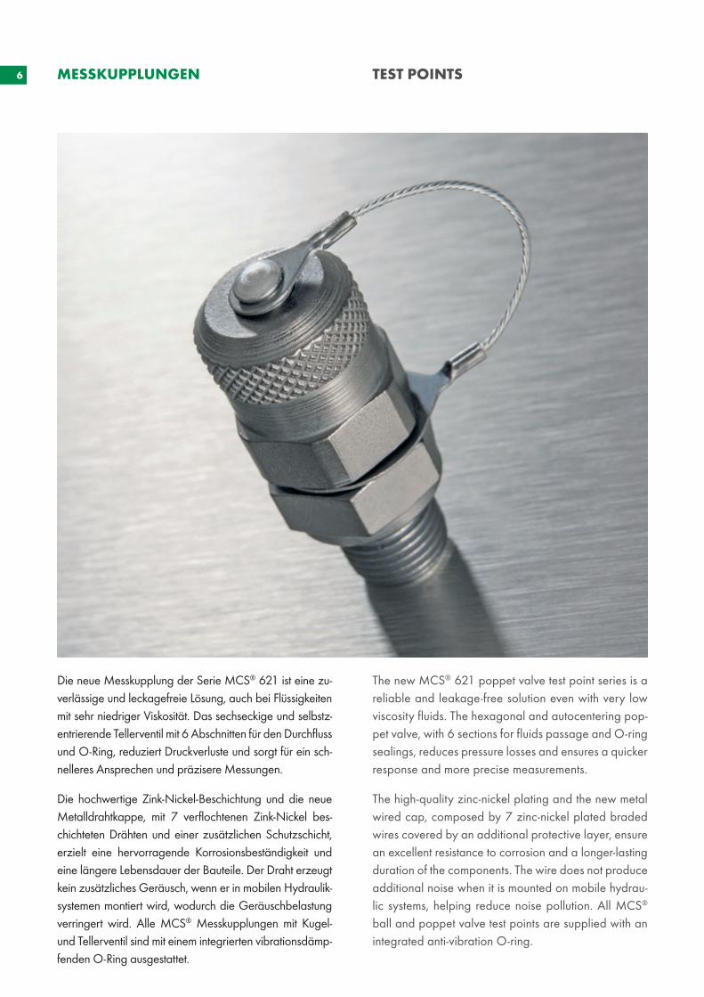
Die neue Messkupplung der Serie MCS® 621 ist eine zu-verlässige und leckagefreie Lösung, auch bei Flüssigkeiten mit sehr niedriger Viskosität. Das sechseckige und selbstz-entrierende Tellerventil mit 6 Abschnitten für den Durchfluss und O-Ring, reduziert Druckverluste und sorgt für ein sch-nelleres Ansprechen und präzisere Messungen.
Die hochwertige Zink-Nickel-Beschichtung und die neue Metalldrahtkappe, mit 7 verflochtenen Zink-Nickel bes-chichteten Drähten und einer zusätzlichen Schutzschicht, erzielt eine hervorragende Korrosionsbeständigkeit und eine längere Lebensdauer der Bauteile. Der Draht erzeugt kein zusätzliches Geräusch, wenn er in mobilen Hydraulik-systemen montiert wird, wodurch die Geräuschbelastung verringert wird. Alle MCS® Messkupplungen mit Kugel- und Tellerventil sind mit einem integrierten vibrationsdämp-fenden O-Ring ausgestattet.
The new MCS® 621 poppet valve test point series is a reliable and leakage-free solution even with very low viscosity fluids. The hexagonal and autocentering pop-pet valve, with 6 sections for fluids passage and O-ring sealings, reduces pressure losses and ensures a quicker response and more precise measurements.
The high-quality zinc-nickel plating and the new metal wired cap, composed by 7 zinc-nickel plated braded wires covered by an additional protective layer, ensure an excellent resistance to corrosion and a longer-lasting duration of the components. The wire does not produce additional noise when it is mounted on mobile hydrau-lic systems, helping reduce noise pollution. All MCS® ball and poppet valve test points are supplied with an integrated anti-vibration O-ring.
7
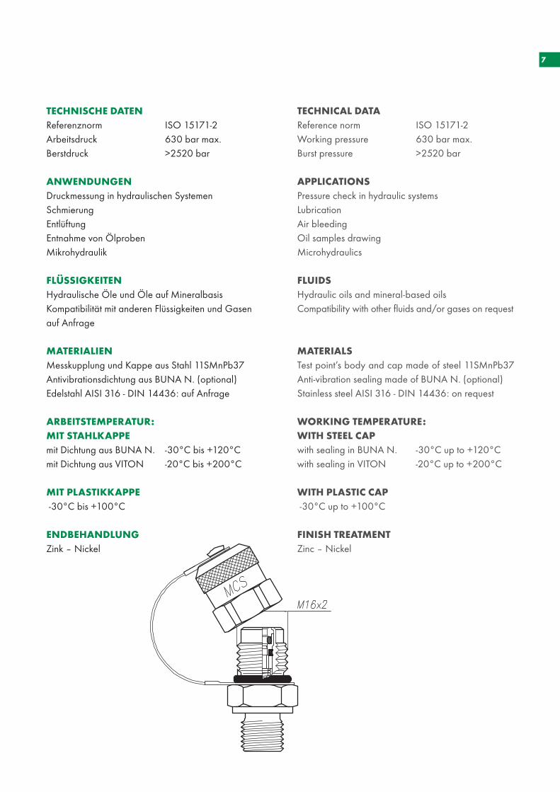
TECHNICAL DATAReference norm ISO 15171-2 Working pressure 630 bar max.Burst pressure >2520 bar
APPLICATIONSPressure check in hydraulic systemsLubricationAir bleedingOil samples drawingMicrohydraulics
FLUIDSHydraulic oils and mineral-based oilsCompatibility with other fluids and/or gases on request
MATERIALSTest point’s body and cap made of steel 11SMnPb37 Anti-vibration sealing made of BUNA N. (optional)Stainless steel AISI 316 - DIN 14436: on request
WORKING TEMPERATURE:WITH STEEL CAPwith sealing in BUNA N. -30°C up to +120°Cwith sealing in VITON -20°C up to +200°C
WITH PLASTIC CAP -30°C up to +100°C
FINISH TREATMENTZinc – Nickel
TECHNISCHE DATENReferenznorm ISO 15171-2 Arbeitsdruck 630 bar max.Berstdruck >2520 bar
ANWENDUNGENDruckmessung in hydraulischen SystemenSchmierungEntlüftungEntnahme von ÖlprobenMikrohydraulik
FLÜSSIGKEITENHydraulische Öle und Öle auf MineralbasisKompatibilität mit anderen Flüssigkeiten und Gasen auf Anfrage
MATERIALIENMesskupplung und Kappe aus Stahl 11SMnPb37Antivibrationsdichtung aus BUNA N. (optional)Edelstahl AISI 316 - DIN 14436: auf Anfrage
ARBEITSTEMPERATUR:MIT STAHLKAPPEmit Dichtung aus BUNA N. -30°C bis +120°Cmit Dichtung aus VITON -20°C bis +200°C
MIT PLASTIKKAPPE -30°C bis +100°C
ENDBEHANDLUNGZink – Nickel
8
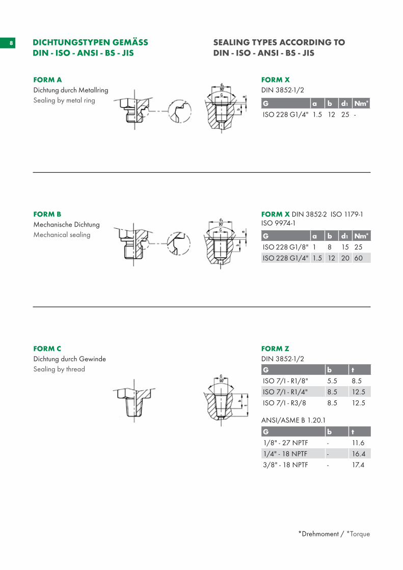
FORM BMechanische DichtungMechanical sealing
FORM CDichtung durch GewindeSealing by thread
FORM ADichtung durch MetallringSealing by metal ring
DICHTUNGSTYPEN GEMÄSS DIN - ISO - ANSI - BS - JIS
SEALING TYPES ACCORDING TO DIN - ISO - ANSI - BS - JIS
FORM ZDIN 3852-1/2
ANSI/ASME B 1.20.1
FORM XDIN 3852-1/2
FORM X DIN 3852-2 ISO 1179-1ISO 9974-1
G b t
ISO 7/I - R1/8" 5.5 8.5
ISO 7/I - R1/4" 8.5 12.5
ISO 7/I - R3/8 8.5 12.5
G b t
1/8" - 27 NPTF - 11.6
1/4" - 18 NPTF - 16.4
3/8" - 18 NPTF - 17.4
*Drehmoment / *Torque
G a b d1 Nm*
ISO 228 G1/4" 1.5 12 25 -
G a b d1 Nm*
ISO 228 G1/8" 1 8 15 25
ISO 228 G1/4" 1.5 12 20 60
9
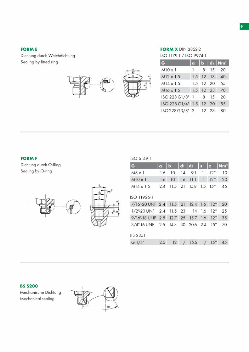
FORM EDichtung durch WeichdichtungSealing by fitted ring
FORM FDichtung durch O-RingSealing by O-ring
BS 5200Mechanische DichtungMechanical sealing
FORM X DIN 3852-2 ISO 1179-1 / ISO 9974-1
ISO 6149-1
G a b d1 d2 s z Nm*
M8 x 1 1.6 10 14 9.1 1 12° 10
M10 x 1 1.6 10 16 11.1 1 12° 20
M14 x 1.5 2.4 11.5 21 15.8 1.5 15° 45
7/16"-20 UNF 2.4 11.5 21 12.4 1.6 12° 20
1/2"-20 UNF 2.4 11.5 23 14 1.6 12° 25
9/16"-18 UNF 2.5 12.7 25 15.7 1.6 12° 35
3/4"-16 UNF 2.5 14.3 30 20.6 2.4 15° 70
G 1/4" 2.5 12 / 15.6 / 15° 45
G a b d1 Nm*
M10 x 1 1 8 15 20
M12 x 1.5 1.5 12 18 40
M14 x 1.5 1.5 12 20 55
M16 x 1.5 1.5 12 23 70
ISO 228 G1/8" 1 8 15 20
ISO 228 G1/4" 1.5 12 20 55
ISO 228 G3/8" 2 12 23 80
JIS 2351
ISO 11926-1
10
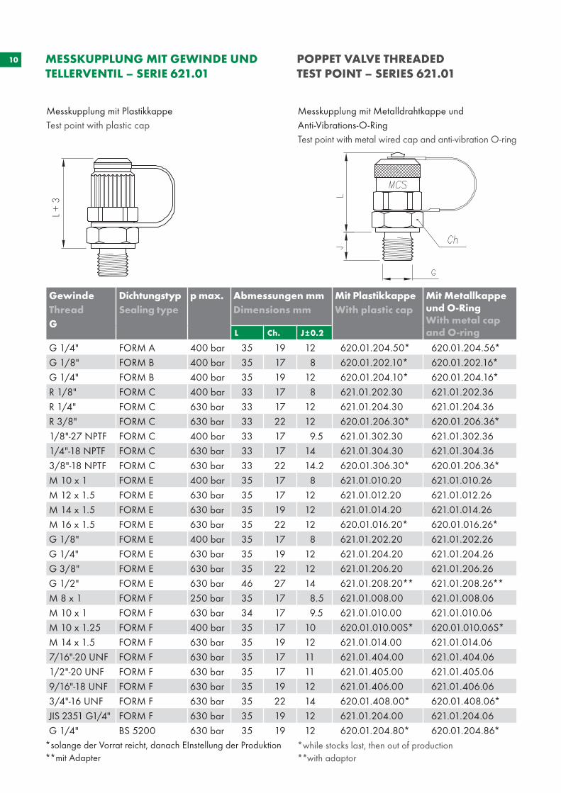
Messkupplung mit PlastikkappeTest point with plastic cap
Messkupplung mit Metalldrahtkappe und Anti-Vibrations-O-RingTest point with metal wired cap and anti-vibration O-ring
MESSKUPPLUNG MIT GEWINDE UND TELLERVENTIL – SERIE 621.01
POPPET VALVE THREADED TEST POINT – SERIES 621.01
L +
3
*solange der Vorrat reicht, danach EInstellung der Produktion **mit Adapter
GewindeThread G
DichtungstypSealing type
p max. Abmessungen mmDimensions mm
Mit PlastikkappeWith plastic cap
Mit Metallkappe und O-RingWith metal cap and O-ringL Ch. J±0.2
G 1/4" FORM A 400 bar 35 19 12 620.01.204.50* 620.01.204.56* G 1/8" FORM B 400 bar 35 17 8 620.01.202.10* 620.01.202.16*G 1/4" FORM B 400 bar 35 19 12 620.01.204.10* 620.01.204.16*R 1/8" FORM C 400 bar 33 17 8 621.01.202.30 621.01.202.36 R 1/4" FORM C 630 bar 33 17 12 621.01.204.30 621.01.204.36 R 3/8" FORM C 630 bar 33 22 12 620.01.206.30* 620.01.206.36* 1/8"-27 NPTF FORM C 400 bar 33 17 9.5 621.01.302.30 621.01.302.36 1/4"-18 NPTF FORM C 630 bar 33 17 14 621.01.304.30 621.01.304.36 3/8"-18 NPTF FORM C 630 bar 33 22 14.2 620.01.306.30* 620.01.206.36* M 10 x 1 FORM E 400 bar 35 17 8 621.01.010.20 621.01.010.26M 12 x 1.5 FORM E 630 bar 35 17 12 621.01.012.20 621.01.012.26 M 14 x 1.5 FORM E 630 bar 35 19 12 621.01.014.20 621.01.014.26 M 16 x 1.5 FORM E 630 bar 35 22 12 620.01.016.20* 620.01.016.26*G 1/8" FORM E 400 bar 35 17 8 621.01.202.20 621.01.202.26 G 1/4" FORM E 630 bar 35 19 12 621.01.204.20 621.01.204.26 G 3/8" FORM E 630 bar 35 22 12 621.01.206.20 621.01.206.26 G 1/2" FORM E 630 bar 46 27 14 621.01.208.20** 621.01.208.26**M 8 x 1 FORM F 250 bar 35 17 8.5 621.01.008.00 621.01.008.06 M 10 x 1 FORM F 630 bar 34 17 9.5 621.01.010.00 621.01.010.06 M 10 x 1.25 FORM F 400 bar 35 17 10 620.01.010.00S* 620.01.010.06S*M 14 x 1.5 FORM F 630 bar 35 19 12 621.01.014.00 621.01.014.06 7/16"-20 UNF FORM F 630 bar 35 17 11 621.01.404.00 621.01.404.06 1/2"-20 UNF FORM F 630 bar 35 17 11 621.01.405.00 621.01.405.06 9/16"-18 UNF FORM F 630 bar 35 19 12 621.01.406.00 621.01.406.06 3/4"-16 UNF FORM F 630 bar 35 22 14 620.01.408.00* 620.01.408.06*JIS 2351 G1/4" FORM F 630 bar 35 19 12 621.01.204.00 621.01.204.06G 1/4" BS 5200 630 bar 35 19 12 620.01.204.80* 620.01.204.86*
*while stocks last, then out of production **with adaptor
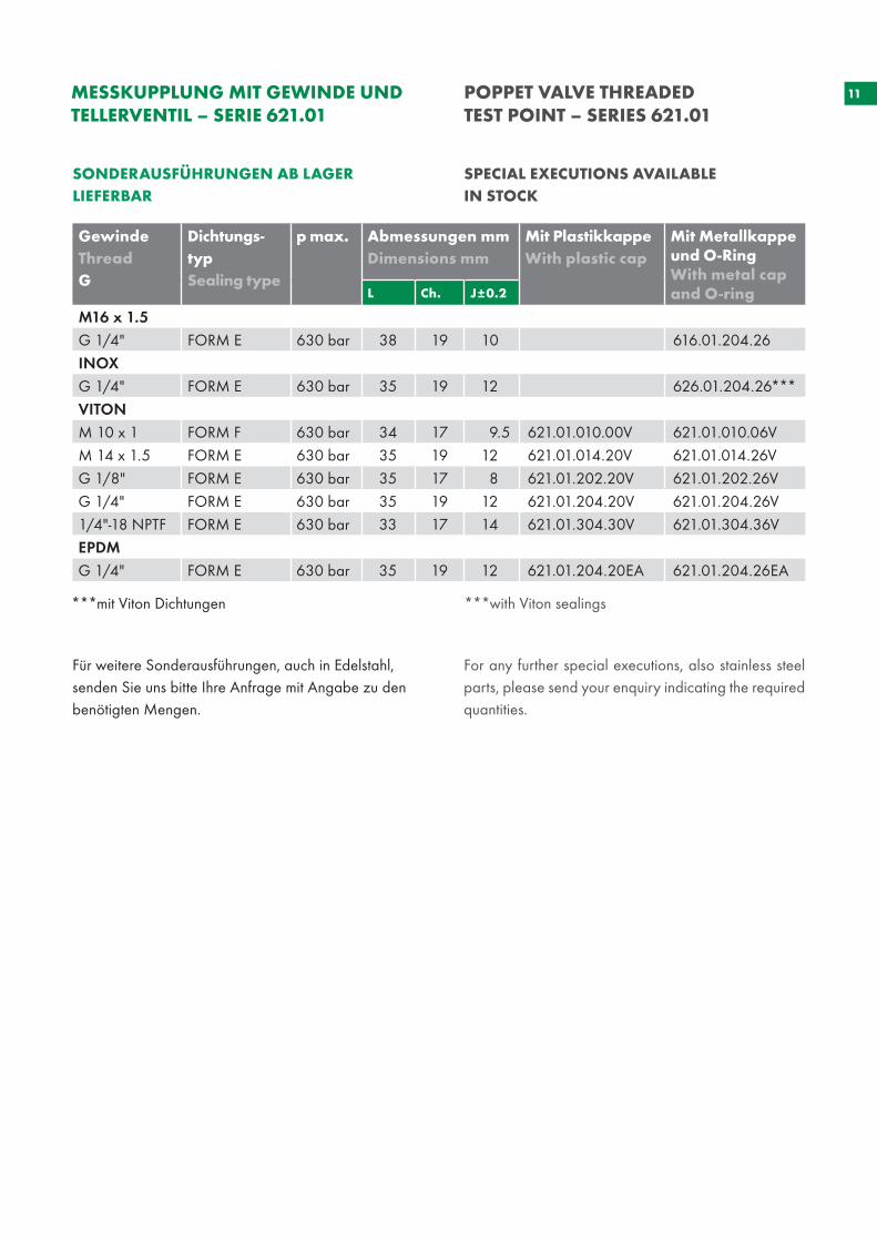
11MESSKUPPLUNG MIT GEWINDE UND TELLERVENTIL – SERIE 621.01
POPPET VALVE THREADED TEST POINT – SERIES 621.01
***mit Viton Dichtungen ***with Viton sealings
SONDERAUSFÜHRUNGEN AB LAGER LIEFERBAR
SPECIAL EXECUTIONS AVAILABLE IN STOCK
GewindeThread G
Dichtungs-typSealing type
p max. Abmessungen mmDimensions mm
Mit PlastikkappeWith plastic cap
Mit Metallkappe und O-RingWith metal cap and O-ringL Ch. J±0.2
M16 x 1.5 G 1/4" FORM E 630 bar 38 19 10 616.01.204.26 INOX G 1/4" FORM E 630 bar 35 19 12 626.01.204.26*** VITONM 10 x 1 FORM F 630 bar 34 17 9.5 621.01.010.00V 621.01.010.06V M 14 x 1.5 FORM E 630 bar 35 19 12 621.01.014.20V 621.01.014.26V G 1/8" FORM E 630 bar 35 17 8 621.01.202.20V 621.01.202.26V G 1/4" FORM E 630 bar 35 19 12 621.01.204.20V 621.01.204.26V 1/4"-18 NPTF FORM E 630 bar 33 17 14 621.01.304.30V 621.01.304.36VEPDM G 1/4" FORM E 630 bar 35 19 12 621.01.204.20EA 621.01.204.26EA
Für weitere Sonderausführungen, auch in Edelstahl, senden Sie uns bitte Ihre Anfrage mit Angabe zu den benötigten Mengen.
For any further special executions, also stainless steel parts, please send your enquiry indicating the required quantities.
12
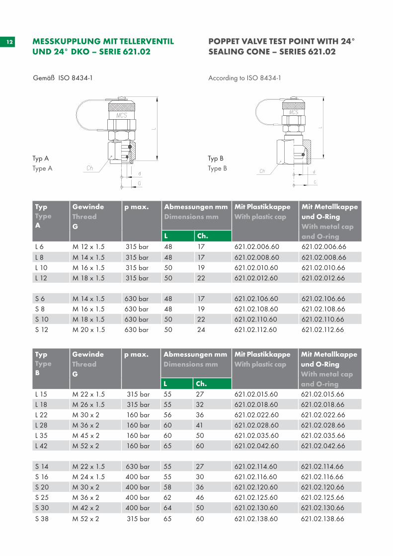
Gemäß ISO 8434-1 According to ISO 8434-1
MESSKUPPLUNG MIT TELLERVENTIL UND 24° DKO – SERIE 621.02
POPPET VALVE TEST POINT WITH 24° SEALING CONE – SERIES 621.02
Typ AType A
Typ BType B
TypTypeA
Gewinde Thread G
p max. Abmessungen mm Dimensions mm
Mit PlastikkappeWith plastic cap
Mit Metallkappe und O-RingWith metal cap and O-ringL Ch.
L 6 M 12 x 1.5 315 bar 48 17 621.02.006.60 621.02.006.66
L 8 M 14 x 1.5 315 bar 48 17 621.02.008.60 621.02.008.66L 10 M 16 x 1.5 315 bar 50 19 621.02.010.60 621.02.010.66L 12 M 18 x 1.5 315 bar 50 22 621.02.012.60 621.02.012.66 S 6 M 14 x 1.5 630 bar 48 17 621.02.106.60 621.02.106.66S 8 M 16 x 1.5 630 bar 48 19 621.02.108.60 621.02.108.66S 10 M 18 x 1.5 630 bar 50 22 621.02.110.60 621.02.110.66S 12 M 20 x 1.5 630 bar 50 24 621.02.112.60 621.02.112.66
TypTypeB
Gewinde Thread G
p max. Abmessungen mm Dimensions mm
Mit PlastikkappeWith plastic cap
Mit Metallkappe und O-RingWith metal cap and O-ringL Ch.
L 15 M 22 x 1.5 315 bar 55 27 621.02.015.60 621.02.015.66L 18 M 26 x 1.5 315 bar 55 32 621.02.018.60 621.02.018.66L 22 M 30 x 2 160 bar 56 36 621.02.022.60 621.02.022.66L 28 M 36 x 2 160 bar 60 41 621.02.028.60 621.02.028.66L 35 M 45 x 2 160 bar 60 50 621.02.035.60 621.02.035.66L 42 M 52 x 2 160 bar 65 60 621.02.042.60 621.02.042.66 S 14 M 22 x 1.5 630 bar 55 27 621.02.114.60 621.02.114.66S 16 M 24 x 1.5 400 bar 55 30 621.02.116.60 621.02.116.66S 20 M 30 x 2 400 bar 58 36 621.02.120.60 621.02.120.66S 25 M 36 x 2 400 bar 62 46 621.02.125.60 621.02.125.66S 30 M 42 x 2 400 bar 64 50 621.02.130.60 621.02.130.66
S 38 M 52 x 2 315 bar 65 60 621.02.138.60 621.02.138.66
13
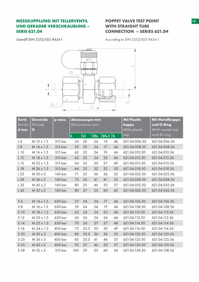
Gemäß DIN 2353/ISO 8434-1 According to DIN 2353/ISO 8434-1
MESSKUPPLUNG MIT TELLERVENTIL UND GERADER VERSCHRAUBUNG – SERIE 621.04
POPPET VALVE TEST POINT WITH STRAIGHT TUBE CONNECTION – SERIES 621.04
SerieSeriesd mm
Gewinde Thread G
p max. Abmessungen mmDimensions mm
Mit Plastik-kappeWith plastic cap
Mit Metallkappe und O-RingWith metal cap and O-ringL L1 Ch. Ch.1 h
L 6 M 12 x 1.5 315 bar 54 20 24 14 46 621.04.006.50 621.04.006.56
L 8 M 14 x 1.5 315 bar 59 20 24 17 46 621.04.008.50 621.04.008.56
L 10 M 16 x 1.5 315 bar 62 22 24 19 46 621.04.010.50 621.04.010.56
L 12 M 18 x 1.5 315 bar 62 22 24 22 46 621.04.012.50 621.04.012.56
L 15 M 22 x 1.5 315 bar 64 25 30 27 49 621.04.015.50 621.04.015.56
L 18 M 26 x 1.5 315 bar 64 25 32 32 50 621.04.018.50 621.04.018.56
L 22 M 30 x 2 160 bar 71 25 36 36 52 621.04.022.50 621.04.022.56
L 28 M 36 x 2 160 bar 73 26 41 41 55 621.04.028.50 621.04.028.56
L 35 M 45 x 2 160 bar 80 25 46 50 57 621.04.035.50 621.04.035.56
L 42 M 52 x 2 160 bar 80 27 55 60 62 621.04.042.50 621.04.042.56
S 6 M 14 x 1.5 630 bar 57 24 24 17 46 621.04.106.50 621.04.106.56
S 8 M 16 x 1.5 630 bar 59 24 24 19 46 621.04.108.50 621.04.108.56
S 10 M 18 x 1.5 630 bar 63 24 24 22 46 621.04.110.50 621.04.110.56
S 12 M 20 x 1.5 630 bar 63 24 24 24 46 621.04.112.50 621.04.112.56
S 14 M 22 x 1.5 630 bar 70 24 27 27 48 621.04.114.50 621.04.114.56
S 16 M 24 x 1.5 400 bar 72 25.5 30 30 49 621.04.116.50 621.04.116.56
S 20 M 30 x 2 400 bar 80 25.5 36 36 53 621.04.120.50 621.04.120.56
S 25 M 36 x 2 400 bar 85 25.5 41 46 55 621.04.125.50 621.04.125.56
S 30 M 42 x 2 400 bar 92 27 46 50 57 621.04.130.50 621.04.130.56
S 38 M 52 x 2 315 bar 100 29 55 60 62 621.04.138.50 621.04.138.56
14
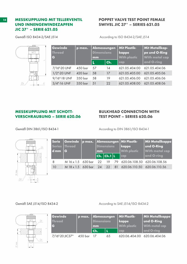
Gemäß DIN 3861/ISO 8434-1 According to DIN 3861/ISO 8434-1
Gemäß SAE J514/ISO 8434-2 According to SAE J514/ISO 8434-2
MESSKUPPLUNG MIT SCHOTT-VERSCHRAUBUNG – SERIE 620.06
BULKHEAD CONNECTION WITH TEST POINT – SERIES 620.06
Gemäß ISO 8434-2/SAE J514 According to ISO 8434-2/SAE J514
MESSKUPPLUNG MIT TELLERVENTIL UND INNENGEWINDEZAPFEN JIC 37° – SERIE 621.05
POPPET VALVE TEST POINT FEMALE SWIVEL JIC 37° – SERIES 621.05
Gewinde Thread G
p max. Abmessungen Dimensions mm
Mit Plastik-kappeWith plastic cap
Mit Metallkap-pe und O-RingWith metal cap and O-ringL Ch.
7/16"-20 UNF 450 bar 57 14 621.05.404.00 621.05.404.06
1/2"-20 UNF 420 bar 58 17 621.05.405.00 621.05.405.06
9/16"-18 UNF 350 bar 58 19 621.05.406.00 621.05.406.06
3/4"-16 UNF 350 bar 51 22 621.05.408.00 621.05.408.06
SerieSeriesd mm
Gewinde Thread G
p max. Abmessungen Dimensions mm
Mit Plastik-kappeWith plastic cap
Mit Metallkappe und O-RingWith metal cap and O-ringCh. Ch.1 L
8 M 16 x 1.5 630 bar 22 19 79 620.06.108.50 620.06.108.56
10 M 18 x 1.5 630 bar 24 22 81 620.06.110.50 620.06.110.56
Gewinde Thread G
p max. AbmessungenDimensions mm
Mit Plastik-kappeWith plastic cap
Mit Metallkappe und O-RingWith metal capand O-ringCh. L
7/16"-20 JIC37° 450 bar 17 65 620.06.404.00 620.06.404.06
15
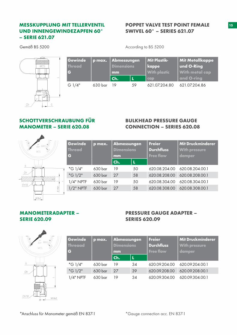
*Anschluss für Manometer gemäß EN 837-1 *Gauge connection acc. EN 837-1
SCHOTTVERSCHRAUBUNG FÜR MANOMETER – SERIE 620.08
BULKHEAD PRESSURE GAUGE CONNECTION – SERIES 620.08
MANOMETERADAPTER – SERIE 620.09
PRESSURE GAUGE ADAPTER – SERIES 620.09
Gemäß BS 5200 According to BS 5200
MESSKUPPLUNG MIT TELLERVENTIL UND INNENGEWINDEZAPFEN 60°– SERIE 621.07
POPPET VALVE TEST POINT FEMALE SWIVEL 60° – SERIES 621.07
Gewinde Thread G
p max. Abmessungen Dimensions mm
Mit Plastik-kappeWith plastic cap
Mit Metallkappe und O-RingWith metal cap and O-ringCh. L
G 1/4" 630 bar 19 59 621.07.204.80 621.07.204.86
Gewinde Thread G
p max. AbmessungenDimensionsmm
Freier DurchflussFree flow
Mit DruckmindererWith pressuredamper
Ch. L
*G 1/4" 630 bar 19 50 620.08.204.00 620.08.204.00.1
*G 1/2" 630 bar 27 58 620.08.208.00 620.08.208.00.1
1/4" NPTF 630 bar 19 50 620.08.304.00 620.08.304.00.1
1/2" NPTF 630 bar 27 58 620.08.308.00 620.08.308.00.1
Gewinde Threaad G
p max. AbmessungenDimensionsmm
Freier DurchflussFree flow
Mit DruckmindererWith pressuredamper
Ch. L
*G 1/4" 630 bar 19 34 620.09.204.00 620.09.204.00.1
*G 1/2" 630 bar 27 39 620.09.208.00 620.09.208.00.1
1/4" NPTF 630 bar 19 34 620.09.304.00 620.09.304.00.1
16
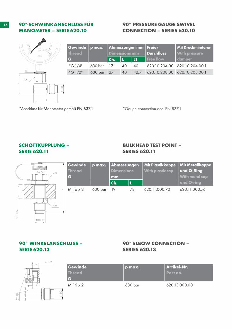
SCHOTTKUPPLUNG – SERIE 620.11
BULKHEAD TEST POINT – SERIES 620.11
90° WINKELANSCHLUSS – SERIE 620.13
90° ELBOW CONNECTION – SERIES 620.13
*Anschluss für Manometer gemäß EN 837-1 *Gauge connection acc. EN 837-1
90°-SCHWENKANSCHLUSS FÜRMANOMETER – SERIE 620.10
90° PRESSURE GAUGE SWIVEL CONNECTION – SERIES 620.10
GewindeThread G
p max. Abmessungen mmDimensions mm
Freier DurchflussFree flow
Mit Druckminderer With pressuredamperCh. L L1
*G 1/4" 630 bar 17 40 40 620.10.204.00 620.10.204.00.1
*G 1/2" 630 bar 27 40 42.7 620.10.208.00 620.10.208.00.1
Gewinde Thread G
p max. AbmessungenDimensionsmm
Mit PlastikkappeWith plastic cap
Mit Metallkappe und O-RingWith metal cap and O-ringCh. L
M 16 x 2 630 bar 19 78 620.11.000.70 620.11.000.76
GewindeThread G
p max. Artikel-Nr.Part no.
M 16 x 2 630 bar 620.13.000.00
17
Gemäß BS 5200 According to BS 5200
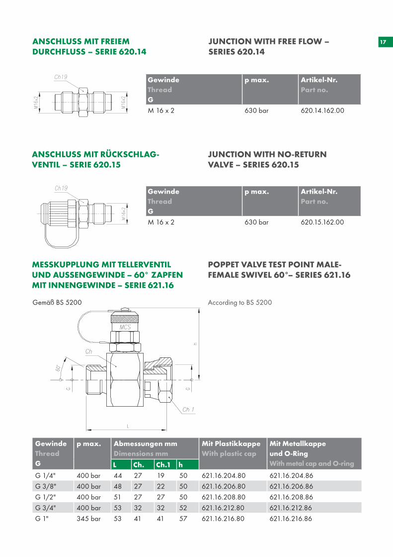
ANSCHLUSS MIT FREIEM DURCHFLUSS – SERIE 620.14
JUNCTION WITH FREE FLOW – SERIES 620.14
MESSKUPPLUNG MIT TELLERVENTIL UND AUSSENGEWINDE – 60° ZAPFEN MIT INNENGEWINDE – SERIE 621.16
POPPET VALVE TEST POINT MALE- FEMALE SWIVEL 60°– SERIES 621.16
ANSCHLUSS MIT RÜCKSCHLAG - VENTIL – SERIE 620.15
JUNCTION WITH NO-RETURN VALVE – SERIES 620.15
GewindeThread G
p max. Artikel-Nr.Part no.
M 16 x 2 630 bar 620.14.162.00
Gewinde Thread G
p max. Artikel-Nr.Part no.
M 16 x 2 630 bar 620.15.162.00
Gewinde Thread G
p max. Abmessungen mmDimensions mm
Mit PlastikkappeWith plastic cap
Mit Metallkappe und O-RingWith metal cap and O-ringL Ch. Ch.1 h
G 1/4" 400 bar 44 27 19 50 621.16.204.80 621.16.204.86
G 3/8" 400 bar 48 27 22 50 621.16.206.80 621.16.206.86
G 1/2" 400 bar 51 27 27 50 621.16.208.80 621.16.208.86
G 3/4" 400 bar 53 32 32 52 621.16.212.80 621.16.212.86
G 1" 345 bar 53 41 41 57 621.16.216.80 621.16.216.86
18
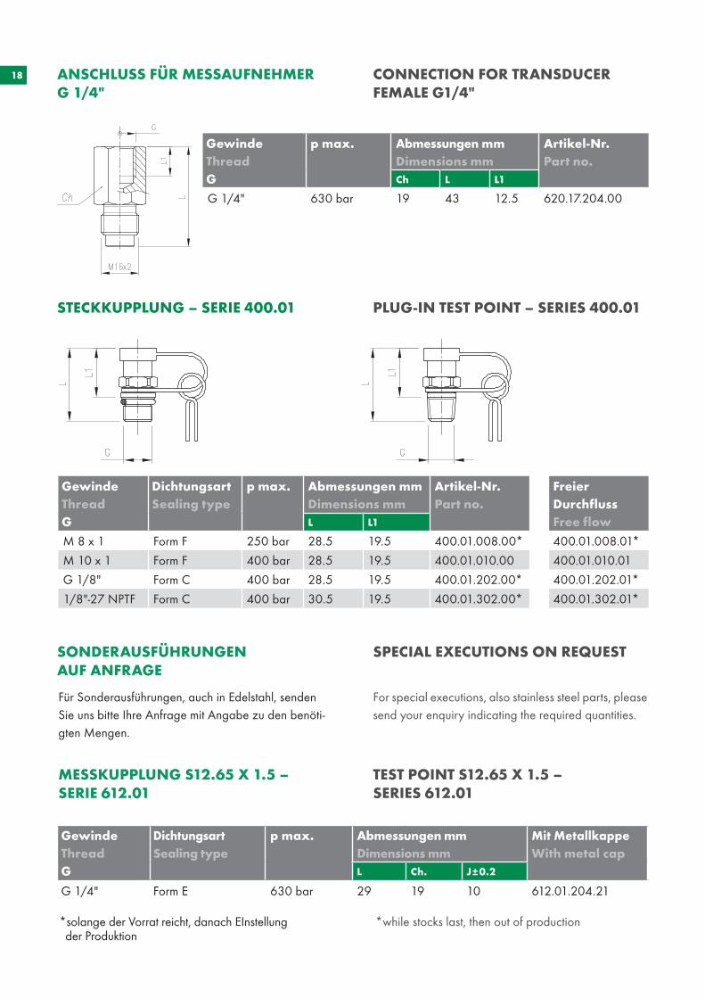
STECKKUPPLUNG – SERIE 400.01 PLUG-IN TEST POINT – SERIES 400.01
GewindeThread G
p max. Abmessungen mmDimensions mm
Artikel-Nr.Part no.
Ch L L1
G 1/4" 630 bar 19 43 12.5 620.17.204.00
ANSCHLUSS FÜR MESSAUFNEHMER G 1/4"
CONNECTION FOR TRANSDUCER FEMALE G1/4"
Gewinde Thread G
Dichtungsart Sealing type
p max. Abmessungen mmDimensions mm
Artikel-Nr.Part no.
Freier DurchflussFree flowL L1
M 8 x 1 Form F 250 bar 28.5 19.5 400.01.008.00* 400.01.008.01*
M 10 x 1 Form F 400 bar 28.5 19.5 400.01.010.00 400.01.010.01
G 1/8" Form C 400 bar 28.5 19.5 400.01.202.00* 400.01.202.01*
1/8"-27 NPTF Form C 400 bar 30.5 19.5 400.01.302.00* 400.01.302.01*
MESSKUPPLUNG S12.65 X 1.5 – SERIE 612.01
TEST POINT S12.65 X 1.5 – SERIES 612.01
GewindeThread G
DichtungsartSealing type
p max. Abmessungen mmDimensions mm
Mit MetallkappeWith metal cap
L Ch. J±0.2
G 1/4" Form E 630 bar 29 19 10 612.01.204.21
SONDERAUSFÜHRUNGEN AUF ANFRAGE
SPECIAL EXECUTIONS ON REQUEST
Für Sonderausführungen, auch in Edelstahl, senden Sie uns bitte Ihre Anfrage mit Angabe zu den benöti-gten Mengen.
For special executions, also stainless steel parts, please send your enquiry indicating the required quantities.
*solange der Vorrat reicht, danach EInstellung der Produktion
*while stocks last, then out of production
19OPTIONEN OPTIONS
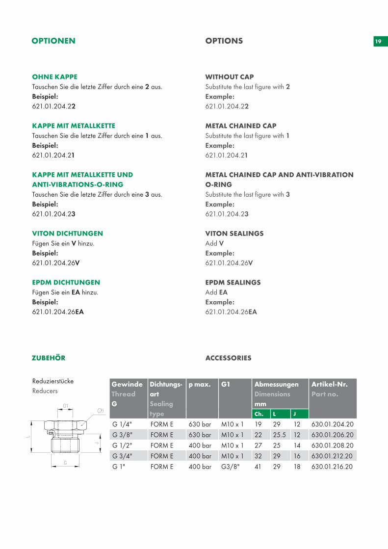
ReduzierstückeReducers
ZUBEHÖR ACCESSORIES
OHNE KAPPETauschen Sie die letzte Ziffer durch eine 2 aus. Beispiel: 621.01.204.22
KAPPE MIT METALLKETTETauschen Sie die letzte Ziffer durch eine 1 aus. Beispiel: 621.01.204.21
KAPPE MIT METALLKETTE UND ANTI-VIBRATIONS-O-RING Tauschen Sie die letzte Ziffer durch eine 3 aus. Beispiel: 621.01.204.23
VITON DICHTUNGEN Fügen Sie ein V hinzu. Beispiel: 621.01.204.26V
EPDM DICHTUNGEN Fügen Sie ein EA hinzu. Beispiel: 621.01.204.26EA
WITHOUT CAPSubstitute the last figure with 2Example: 621.01.204.22
METAL CHAINED CAP Substitute the last figure with 1 Example: 621.01.204.21
METAL CHAINED CAP AND ANTI-VIBRATION O-RING Substitute the last figure with 3Example: 621.01.204.23
VITON SEALINGS Add VExample: 621.01.204.26V
EPDM SEALINGS Add EA Example: 621.01.204.26EA
Gewinde Thread G
Dichtungs-art Sealing type
p max. G1 AbmessungenDimensionsmm
Artikel-Nr.Part no.
Ch. L J
G 1/4" FORM E 630 bar M10 x 1 19 29 12 630.01.204.20
G 3/8" FORM E 630 bar M10 x 1 22 25.5 12 630.01.206.20
G 1/2" FORM E 400 bar M10 x 1 27 25 14 630.01.208.20
G 3/4" FORM E 400 bar M10 x 1 32 29 16 630.01.212.20
G 1" FORM E 400 bar G3/8" 41 29 18 630.01.216.20
20
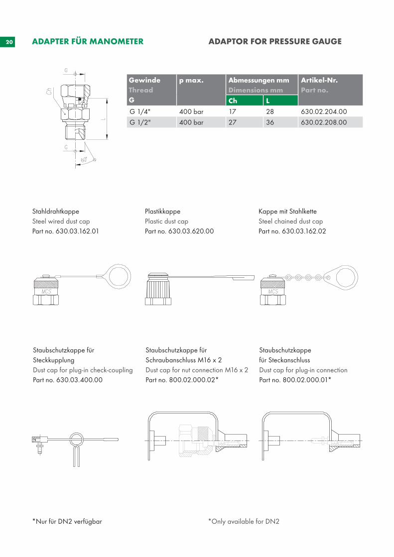
*Nur für DN2 verfügbar *Only available for DN2
GewindeThread G
p max. Abmessungen mmDimensions mm
Artikel-Nr.Part no.
Ch L
G 1/4" 400 bar 17 28 630.02.204.00
G 1/2" 400 bar 27 36 630.02.208.00
ADAPTER FÜR MANOMETER ADAPTOR FOR PRESSURE GAUGE
PlastikkappePlastic dust capPart no. 630.03.620.00
Kappe mit StahlketteSteel chained dust capPart no. 630.03.162.02
Staubschutzkappe für Schraubanschluss M16 x 2Dust cap for nut connection M16 x 2Part no. 800.02.000.02*
StahldrahtkappeSteel wired dust capPart no. 630.03.162.01
Staubschutzkappe für SteckanschlussDust cap for plug-in connectionPart no. 800.02.000.01*
Staubschutzkappe für SteckkupplungDust cap for plug-in check-couplingPart no. 630.03.400.00

21
Anti-Vibrations-O-RingAnti-vibration O-ring
InnendurchmesserInternal Diameter (i. d.)
QuerschnittSection(s)
MaterialMaterial
HärteHardness
Artikel-Nr.Part no.
12.6 mm 2.4 mm NBR 70 SH 000.03.1224.0
22
23
MIK
RO
SCH
LÄU
CH
E U
ND
VER
SCH
RA
UB
UN
GEN
M
ICR
O-H
OSE
S A
ND
FIT
TIN
GS
24 MIKROSCHLÄUCHE UND VERSCHRAUBUNGEN
MICRO-HOSES AND FITTINGS
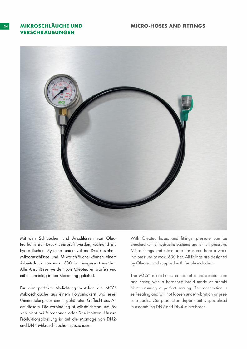
Mit den Schläuchen und Anschlüssen von Oleo-tec kann der Druck überprüft werden, während die hydraulischen Systeme unter vollem Druck stehen. Mikroanschlüsse und Mikroschläuche können einem Arbeitsdruck von max. 630 bar eingesetzt werden. Alle Anschlüsse werden von Oleotec entworfen und mit einem integrierten Klemmring geliefert.
Für eine perfekte Abdichtung bestehen die MCS® Mikroschläuche aus einem Polyamidkern und einer Ummantelung aus einem gehärteten Geflecht aus Ar-amidfasern. Die Verbindung ist selbstdichtend und löst sich nicht bei Vibrationen oder Druckspitzen. Unsere Produktionsabteilung ist auf die Montage von DN2- und DN4-Mikroschläuchen spezialisiert.
With Oleotec hoses and fittings, pressure can be checked while hydraulic systems are at full pressure. Micro-fittings and micro-bore hoses can bear a work-ing pressure of max. 630 bar. All fittings are designed by Oleotec and supplied with ferrule included.
The MCS® micro-hoses consist of a polyamide core and cover, with a hardened braid made of aramid fibre, ensuring a perfect sealing. The connection is self-sealing and will not loosen under vibration or pres-sure peaks. Our production department is specialised in assembling DN2 and DN4 micro-hoses.
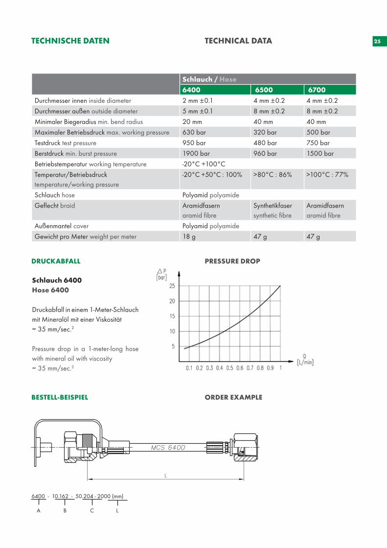
25TECHNISCHE DATEN TECHNICAL DATA
Schlauch 6400Hose 6400
Druckabfall in einem 1-Meter-Schlauch mit Mineralöl mit einer Viskosität = 35 mm/sec.2
Pressure drop in a 1-meter-long hose with mineral oil with viscosity = 35 mm/sec.2
DRUCKABFALL PRESSURE DROP
BESTELL-BEISPIEL ORDER EXAMPLE
6400 - 10.162 - 50.204 - 2000 (mm)
A B C L
Schlauch / Hose
6400 6500 6700
Durchmesser innen inside diameter 2 mm ±0.1 4 mm ±0.2 4 mm ±0.2
Durchmesser außen outside diameter 5 mm ±0.1 8 mm ±0.2 8 mm ±0.2
Minimaler Biegeradius min. bend radius 20 mm 40 mm 40 mm
Maximaler Betriebsdruck max. working pressure 630 bar 320 bar 500 bar
Testdruck test pressure 950 bar 480 bar 750 bar
Berstdruck min. burst pressure 1900 bar 960 bar 1500 bar
Betriebstemperatur working temperature -20°C +100°C
Temperatur/Betriebsdruck temperature/working pressure
-20°C +50°C : 100% >80°C : 86% >100°C : 77%
Schlauch hose Polyamid polyamide
Geflecht braid Aramidfasernaramid fibre
Synthetikfasersynthetic fibre
Aramidfasernaramid fibre
Außenmantel cover Polyamid polyamide
Gewicht pro Meter weight per meter 18 g 47 g 47 g
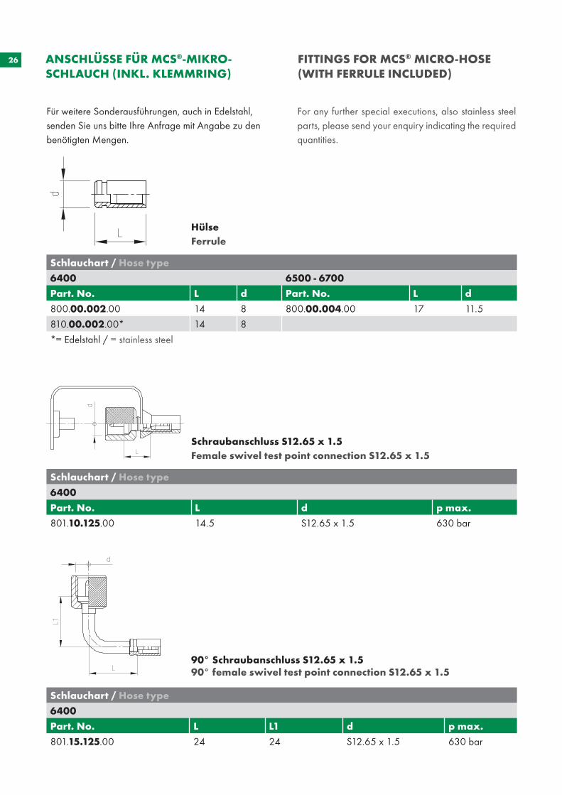
26 FITTINGS FOR MCS® MICRO-HOSE (WITH FERRULE INCLUDED)
ANSCHLÜSSE FÜR MCS®-MIKRO- SCHLAUCH (INKL. KLEMMRING)
Hülse Ferrule
Schlauchart / Hose type
6400 6500 - 6700
Part. No. L d Part. No. L d
800.00.002.00 14 8 800.00.004.00 17 11.5
810.00.002.00* 14 8
*= Edelstahl / = stainless steel
Schraubanschluss S12.65 x 1.5 Female swivel test point connection S12.65 x 1.5
Schlauchart / Hose type
6400
Part. No. L d p max.
801.10.125.00 14.5 S12.65 x 1.5 630 bar
90° Schraubanschluss S12.65 x 1.590° female swivel test point connection S12.65 x 1.5
Schlauchart / Hose type
6400
Part. No. L L1 d p max.
801.15.125.00 24 24 S12.65 x 1.5 630 bar
Für weitere Sonderausführungen, auch in Edelstahl, senden Sie uns bitte Ihre Anfrage mit Angabe zu den benötigten Mengen.
For any further special executions, also stainless steel parts, please send your enquiry indicating the required quantities.
27
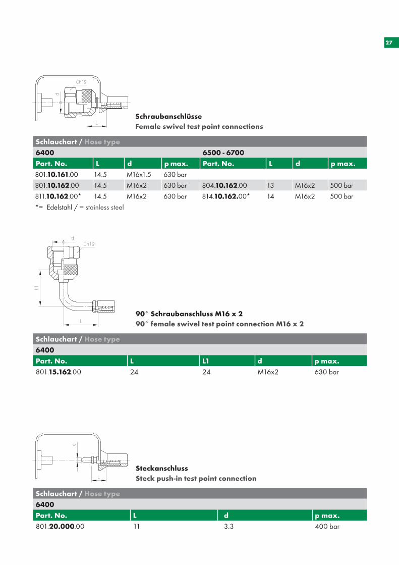
SchraubanschlüsseFemale swivel test point connections
Schlauchart / Hose type
6400 6500 - 6700
Part. No. L d p max. Part. No. L d p max.
801.10.161.00 14.5 M16x1.5 630 bar
801.10.162.00 14.5 M16x2 630 bar 804.10.162.00 13 M16x2 500 bar
811.10.162.00* 14.5 M16x2 630 bar 814.10.162.00* 14 M16x2 500 bar
*= Edelstahl / = stainless steel
SteckanschlussSteck push-in test point connection
Schlauchart / Hose type
6400
Part. No. L d p max.
801.20.000.00 11 3.3 400 bar
90° Schraubanschluss M16 x 290° female swivel test point connection M16 x 2
Schlauchart / Hose type
6400
Part. No. L L1 d p max.
801.15.162.00 24 24 M16x2 630 bar
28
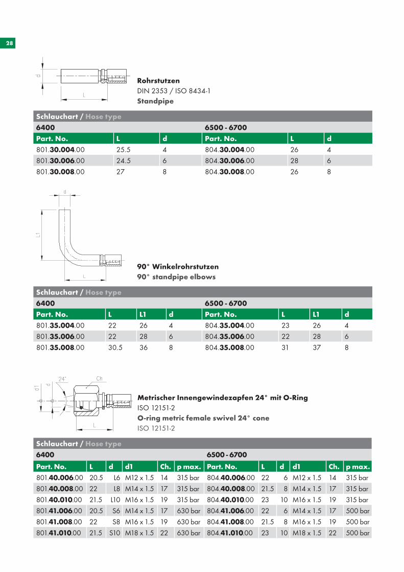
Metrischer Innengewindezapfen 24° mit O-RingISO 12151-2O-ring metric female swivel 24° cone ISO 12151-2
Schlauchart / Hose type
6400 6500 - 6700
Part. No. L d d1 Ch. p max. Part. No. L d d1 Ch. p max.
801.40.006.00 20.5 L6 M12 x 1.5 14 315 bar 804.40.006.00 22 6 M12 x 1.5 14 315 bar
801.40.008.00 22 L8 M14 x 1.5 17 315 bar 804.40.008.00 21.5 8 M14 x 1.5 17 315 bar
801.40.010.00 21.5 L10 M16 x 1.5 19 315 bar 804.40.010.00 23 10 M16 x 1.5 19 315 bar
801.41.006.00 20.5 S6 M14 x 1.5 17 630 bar 804.41.006.00 22 6 M14 x 1.5 17 500 bar
801.41.008.00 22 S8 M16 x 1.5 19 630 bar 804.41.008.00 21.5 8 M16 x 1.5 19 500 bar
801.41.010.00 21.5 S10 M18 x 1.5 22 630 bar 804.41.010.00 23 10 M18 x 1.5 22 500 bar
Schlauchart / Hose type
6400 6500 - 6700
Part. No. L d Part. No. L d
801.30.004.00 25.5 4 804.30.004.00 26 4
801.30.006.00 24.5 6 804.30.006.00 28 6
801.30.008.00 27 8 804.30.008.00 26 8
Rohrstutzen DIN 2353 / ISO 8434-1Standpipe
90° Winkelrohrstutzen90° standpipe elbows
Schlauchart / Hose type
6400 6500 - 6700
Part. No. L L1 d Part. No. L L1 d
801.35.004.00 22 26 4 804.35.004.00 23 26 4
801.35.006.00 22 28 6 804.35.006.00 22 28 6
801.35.008.00 30.5 36 8 804.35.008.00 31 37 8
29
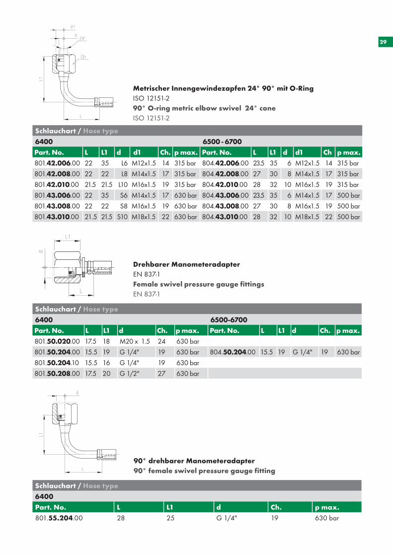
Metrischer Innengewindezapfen 24° 90° mit O-RingISO 12151-290° O-ring metric elbow swivel 24° cone ISO 12151-2
Schlauchart / Hose type
6400 6500 - 6700
Part. No. L L1 d d1 Ch. p max. Part. No. L L1 d d1 Ch p max.
801.42.006.00 22 35 L6 M12x1.5 14 315 bar 804.42.006.00 23.5 35 6 M12x1.5 14 315 bar
801.42.008.00 22 22 L8 M14x1.5 17 315 bar 804.42.008.00 27 30 8 M14x1.5 17 315 bar
801.42.010.00 21.5 21.5 L10 M16x1.5 19 315 bar 804.42.010.00 28 32 10 M16x1.5 19 315 bar
801.43.006.00 22 35 S6 M14x1.5 17 630 bar 804.43.006.00 23.5 35 6 M14x1.5 17 500 bar
801.43.008.00 22 22 S8 M16x1.5 19 630 bar 804.43.008.00 27 30 8 M16x1.5 19 500 bar
801.43.010.00 21.5 21.5 S10 M18x1.5 22 630 bar 804.43.010.00 28 32 10 M18x1.5 22 500 bar
Drehbarer ManometeradapterEN 837-1Female swivel pressure gauge fittingsEN 837-1
Schlauchart / Hose type
6400 6500-6700
Part. No. L L1 d Ch. p max. Part. No. L L1 d Ch. p max.
801.50.020.00 17.5 18 M20 x 1.5 24 630 bar
801.50.204.00 15.5 19 G 1/4" 19 630 bar 804.50.204.00 15.5 19 G 1/4" 19 630 bar
801.50.204.10 15.5 16 G 1/4" 19 630 bar
801.50.208.00 17.5 20 G 1/2" 27 630 bar
Schlauchart / Hose type
6400
Part. No. L L1 d Ch. p max.
801.55.204.00 28 25 G 1/4" 19 630 bar
90° drehbarer Manometeradapter90° female swivel pressure gauge fitting
30
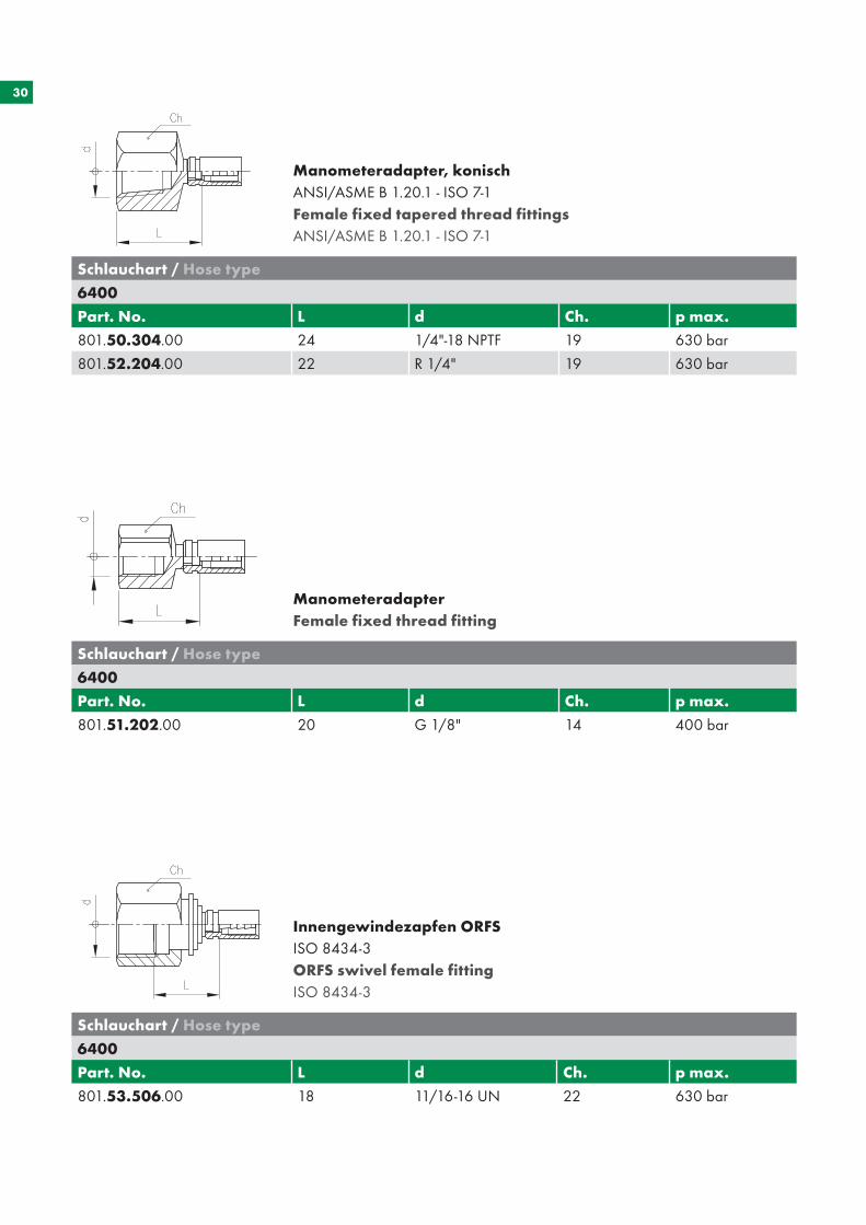
Manometeradapter, konischANSI/ASME B 1.20.1 - ISO 7-1Female fixed tapered thread fittingsANSI/ASME B 1.20.1 - ISO 7-1
ManometeradapterFemale fixed thread fitting
Schlauchart / Hose type
6400
Part. No. L d Ch. p max.
801.50.304.00 24 1/4"-18 NPTF 19 630 bar
801.52.204.00 22 R 1/4" 19 630 bar
Schlauchart / Hose type
6400
Part. No. L d Ch. p max.
801.51.202.00 20 G 1/8" 14 400 bar
Innengewindezapfen ORFSISO 8434-3 ORFS swivel female fittingISO 8434-3
Schlauchart / Hose type
6400
Part. No. L d Ch. p max.
801.53.506.00 18 11/16-16 UN 22 630 bar
31
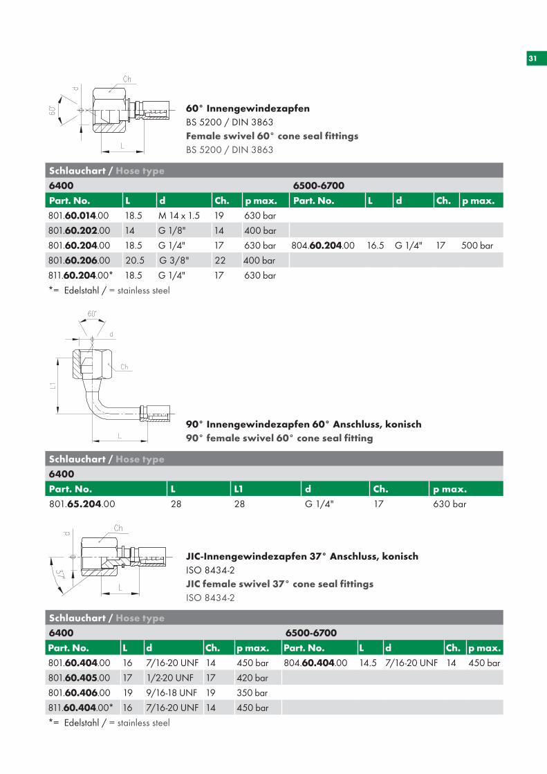
60° InnengewindezapfenBS 5200 / DIN 3863Female swivel 60° cone seal fittingsBS 5200 / DIN 3863
90° Innengewindezapfen 60° Anschluss, konisch 90° female swivel 60° cone seal fitting
Schlauchart / Hose type
6400 6500-6700
Part. No. L d Ch. p max. Part. No. L d Ch. p max.
801.60.014.00 18.5 M 14 x 1.5 19 630 bar
801.60.202.00 14 G 1/8" 14 400 bar
801.60.204.00 18.5 G 1/4" 17 630 bar 804.60.204.00 16.5 G 1/4" 17 500 bar
801.60.206.00 20.5 G 3/8" 22 400 bar
811.60.204.00* 18.5 G 1/4" 17 630 bar
*= Edelstahl / = stainless steel
JIC-Innengewindezapfen 37° Anschluss, konischISO 8434-2 JIC female swivel 37° cone seal fittings ISO 8434-2
Schlauchart / Hose type
6400 6500-6700
Part. No. L d Ch. p max. Part. No. L d Ch. p max.
801.60.404.00 16 7/16-20 UNF 14 450 bar 804.60.404.00 14.5 7/16-20 UNF 14 450 bar
801.60.405.00 17 1/2-20 UNF 17 420 bar
801.60.406.00 19 9/16-18 UNF 19 350 bar
811.60.404.00* 16 7/16-20 UNF 14 450 bar
*= Edelstahl / = stainless steel
Schlauchart / Hose type
6400
Part. No. L L1 d Ch. p max.
801.65.204.00 28 28 G 1/4" 17 630 bar
32
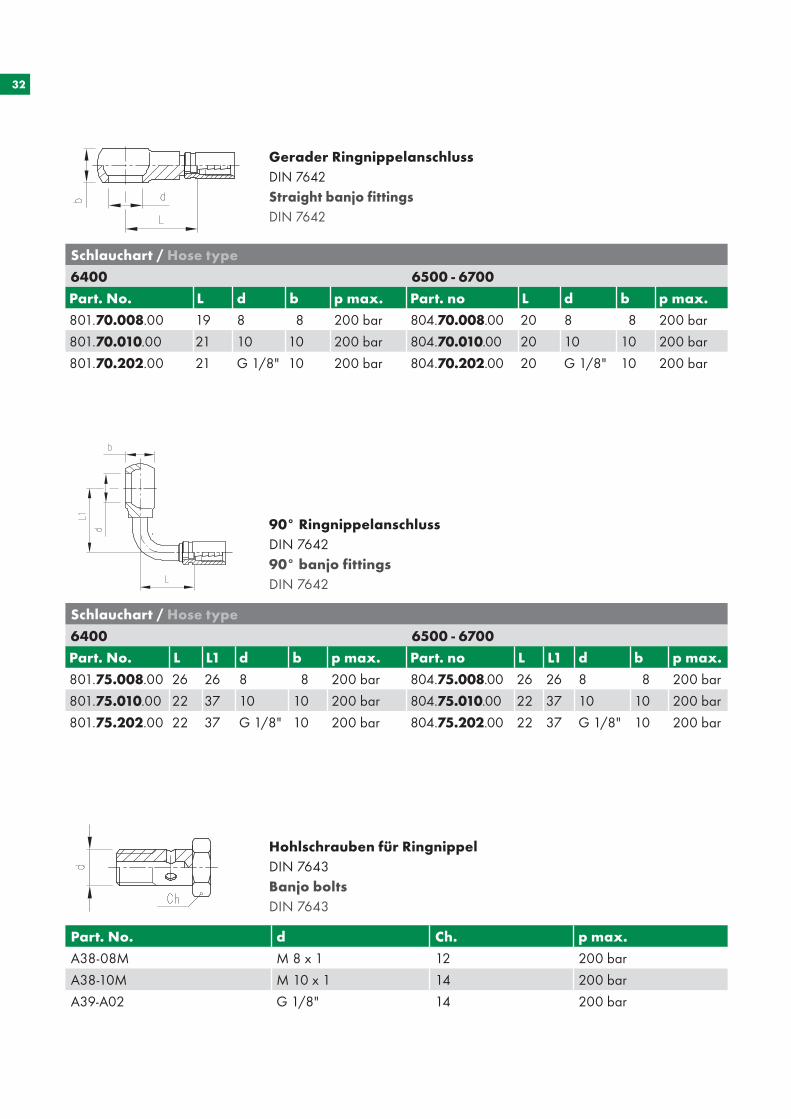
90° RingnippelanschlussDIN 764290° banjo fittingsDIN 7642
Schlauchart / Hose type
6400 6500 - 6700
Part. No. L d b p max. Part. no L d b p max.
801.70.008.00 19 8 8 200 bar 804.70.008.00 20 8 8 200 bar
801.70.010.00 21 10 10 200 bar 804.70.010.00 20 10 10 200 bar
801.70.202.00 21 G 1/8" 10 200 bar 804.70.202.00 20 G 1/8" 10 200 bar
Schlauchart / Hose type
6400 6500 - 6700
Part. No. L L1 d b p max. Part. no L L1 d b p max.
801.75.008.00 26 26 8 8 200 bar 804.75.008.00 26 26 8 8 200 bar
801.75.010.00 22 37 10 10 200 bar 804.75.010.00 22 37 10 10 200 bar
801.75.202.00 22 37 G 1/8" 10 200 bar 804.75.202.00 22 37 G 1/8" 10 200 bar
Gerader RingnippelanschlussDIN 7642Straight banjo fittingsDIN 7642
Hohlschrauben für RingnippelDIN 7643Banjo boltsDIN 7643
Part. No. d Ch. p max.
A38-08M M 8 x 1 12 200 bar
A38-10M M 10 x 1 14 200 bar
A39-A02 G 1/8" 14 200 bar
33
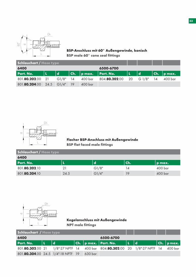
BSP-Anschluss mit 60° Außengewinde, konischBSP male 60° cone seal fittings
Flacher BSP-Anschluss mit AußengewindeBSP flat faced male fittings
Schlauchart / Hose type
6400 6500-6700
Part. No. L d Ch. p max. Part. No. L d Ch. p max.
801.80.202.00 21 G1/8" 14 400 bar 804.80.202.00 20 G 1/8" 14 400 bar
801.80.204.00 24.5 G1/4" 19 400 bar
Schlauchart / Hose type
6400
Part. No. L d Ch. p max.
801.80.202.10 21 G1/8" 14 400 bar
801.80.204.10 24.5 G1/4" 19 400 bar
Kegelanschluss mit AußengewindeNPT male fittings
Schlauchart / Hose type
6400 6500-6700
Part. No. L d Ch. p max. Part. No. L d Ch. p max.
801.80.302.00 21 1/8"-27 NPTF 14 400 bar 804.80.302.00 20 1/8"-27 NPTF 14 400 bar
801.80.304.00 24.5 1/4"-18 NPTF 19 630 bar
34
35
DIG
ITA
LE M
AN
OM
ETER
D
IGIT
AL
PR
ESSU
RE
GA
UG
ES
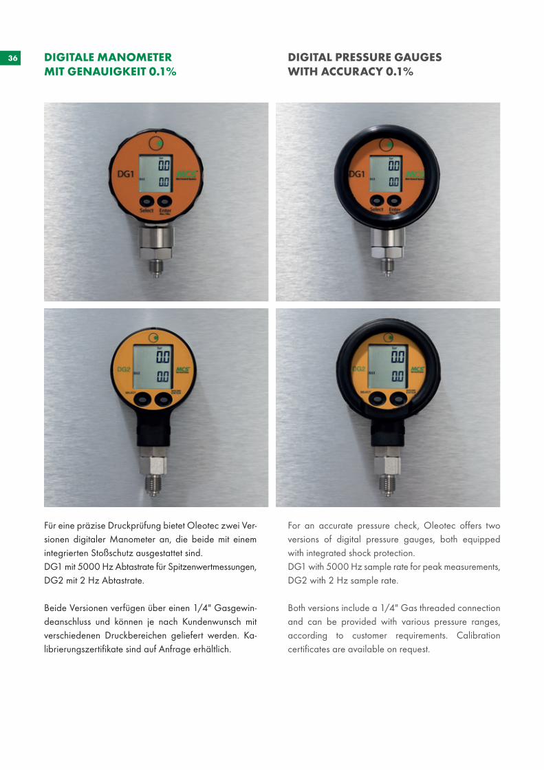
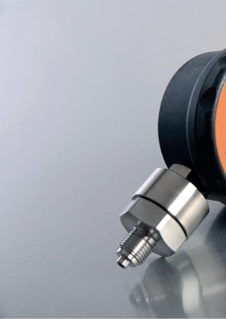
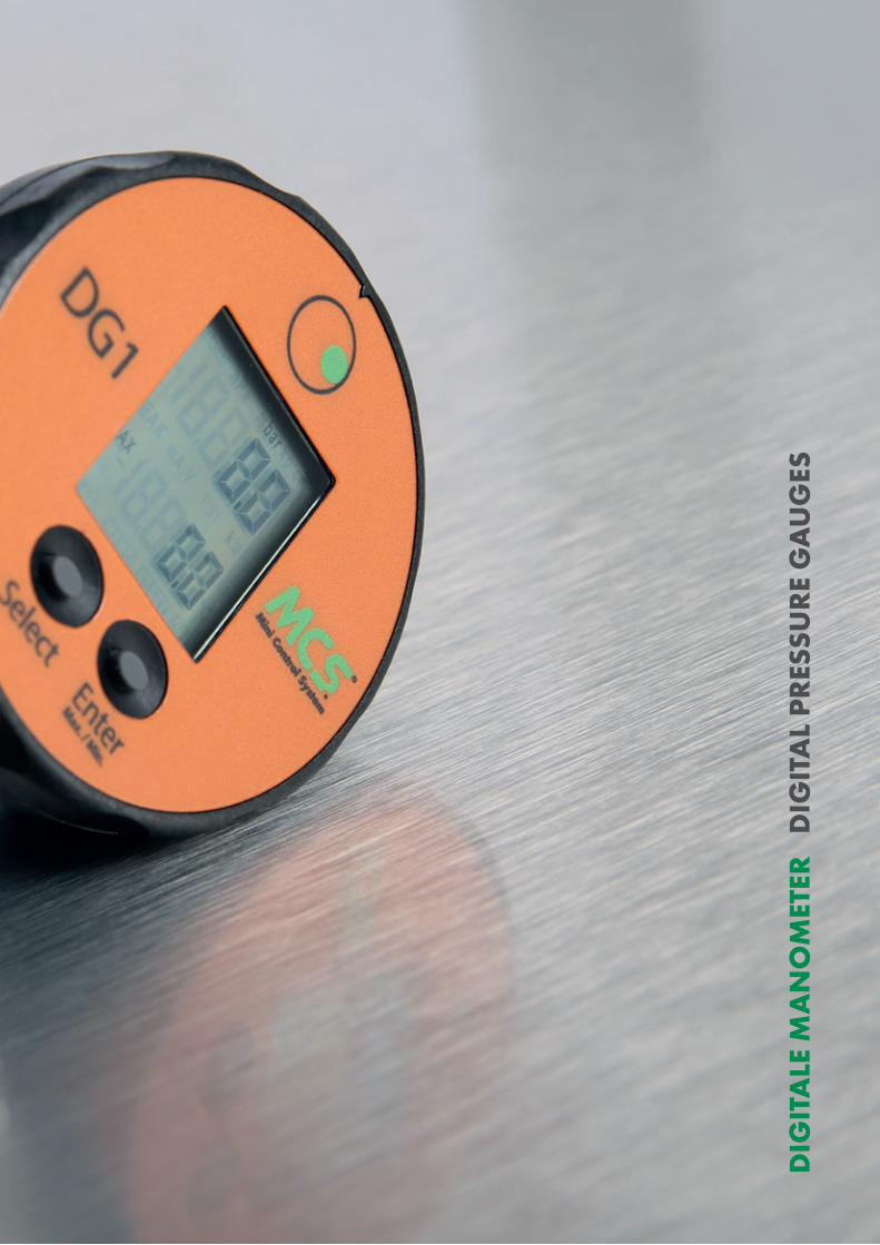
36 DIGITALE MANOMETER MIT GENAUIGKEIT 0.1%
DIGITAL PRESSURE GAUGES WITH ACCURACY 0.1%
Für eine präzise Druckprüfung bietet Oleotec zwei Ver-sionen digitaler Manometer an, die beide mit einem integrierten Stoßschutz ausgestattet sind.DG1 mit 5000 Hz Abtastrate für Spitzenwertmessungen,DG2 mit 2 Hz Abtastrate.
Beide Versionen verfügen über einen 1/4" Gasgewin-deanschluss und können je nach Kundenwunsch mit verschiedenen Druckbereichen geliefert werden. Ka-librierungszertifikate sind auf Anfrage erhältlich.
For an accurate pressure check, Oleotec offers two versions of digital pressure gauges, both equipped with integrated shock protection. DG1 with 5000 Hz sample rate for peak measurements, DG2 with 2 Hz sample rate.
Both versions include a 1/4" Gas threaded connection and can be provided with various pressure ranges, according to customer requirements. Calibration certificates are available on request.
37
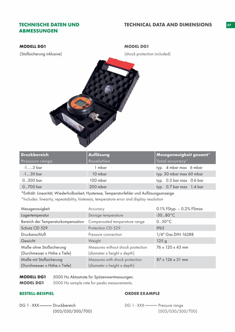
MODELL DG1 5000 Hz Abtastrate für Spitzenwertmessungen.MODEL DG1 5000 Hz sample rate for peaks measurements.
BESTELL-BEISPIEL
DG 1 - XXX Druckbereich (003/030/300/700)
ORDER EXAMPLE DG 1 - XXX Pressure range (003/030/300/700)
TECHNISCHE DATEN UND ABMESSUNGEN
TECHNICAL DATA AND DIMENSIONS
MODELL DG1 MODEL DG1
(Stoßsicherung inklusive) (shock protection included)
Druckbereich Auflösung Messgenauigkeit gesamt*
Pressure range Resolution Total accuracy*
-1......3 bar 1 mbar typ. 4 mbar max 6 mbar
-1....30 bar 10 mbar typ. 30 mbar max 60 mbar
0...300 bar 100 mbar typ. 0.3 bar max 0.6 bar
0...700 bar 200 mbar typ. 0.7 bar max 1.4 bar
*Enthält: Linearität, Wiederholbarkeit, Hysterese, Temperaturfehler und Auflösungsanzeige*Includes: linearity, repeatability, histeresis, temperature error and display resolution
Messgenauigkeit Accuracy 0.1% FStyp. – 0.2% FSmax
Lagertemperatur Storage temperature -30...80°C
Bereich der Temperaturkompensation Compensated temperature range 0...50°C
Schutz CEI 529 Protection CEI 529 IP65
Druckanschluß Pressure connection 1/4" Gas DIN 16288
Gewicht Weight 125 g
Maße ohne Stoßsicherung(Durchmesser x Höhe x Tiefe)
Measures without shock protection(diameter x height x depth)
76 x 120 x 43 mm
Maße mit Stoßsicherung(Durchmesser x Höhe x Tiefe)
Measures with shock protection (diameter x height x depth)
87 x 126 x 51 mm
38
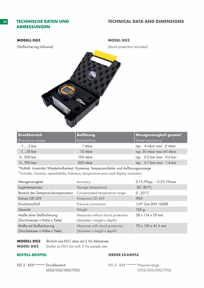
MODELL DG2 MODEL DG2
MODELL DG2 Ähnlich wie DG1 aber mit 2 Hz Abtastrate.MODEL DG2 Similar as DG1 but with 2 Hz sample rate.
BESTELL-BEISPIEL
DG 2 - XXX Druckbereich (003/030/300/700)
ORDER EXAMPLE
DG 2 - XXX Pressure range (003/030/300/700)
TECHNISCHE DATEN UND ABMESSUNGEN
TECHNICAL DATA AND DIMENSIONS
(Stoßsicherung inklusive) (shock protection included)
Druckbereich Auflösung Messgenauigkeit gesamt*
Pressure range Resolution Total accuracy*
-1......3 bar 1 mbar typ. 4 mbar max 6 mbar
-1....30 bar 10 mbar typ. 30 mbar max 60 mbar
0...300 bar 100 mbar typ. 0.3 bar max 0.6 bar
0...700 bar 200 mbar typ. 0.7 bar max 1.4 bar
*Enthält: Linearität, Wiederholbarkeit, Hysterese, Temperaturfehler und Auflösungsanzeige*Includes: linearity, repeatability, histeresis, temperature error and display resolution
Messgenauigkeit Accuracy 0.1% FStyp. – 0.2% FSmax
Lagertemperatur Storage temperature -30...80°C
Bereich der Temperaturkompensation Compensated temperature range 0...50°C
Schutz CEI 529 Protection CEI 529 IP65
Druckanschluß Pressure connection 1/4" Gas DIN 16288
Gewicht Weight 125 g
Maße ohne Stoßsicherung(Durchmesser x Höhe x Tiefe)
Measures without shock protection(diameter x height x depth)
58 x 114 x 29 mm
Maße mit Stoßsicherung (Durchmesser x Höhe x Tiefe)
Measures with shock protection (diameter x height x depth)
70 x 120 x 41,5 mm

39
40
41
GLY
CER
ING
EFÜ
LLTE
MA
NO
MET
ER
GLY
CER
INE
FILL
ED P
RES
SUR
E G
AU
GES
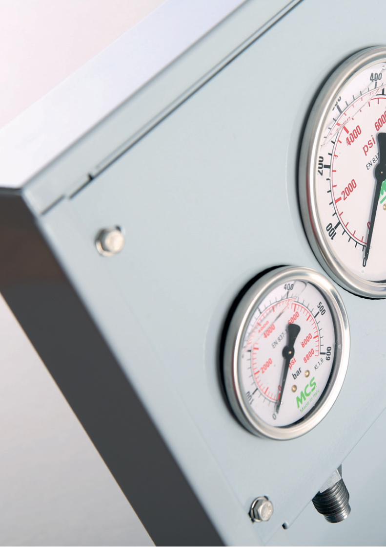
42 GLYCERINGEFÜLLTE MANOMETER GLYCERINE FILLED PRESSURE GAUGES
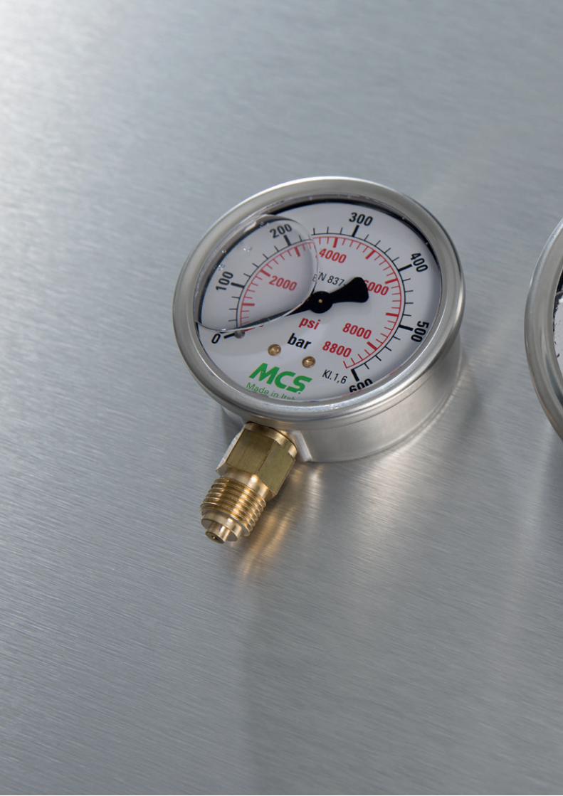
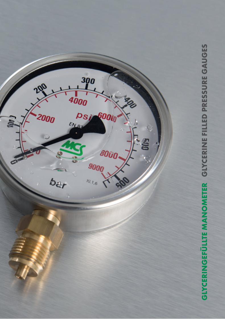
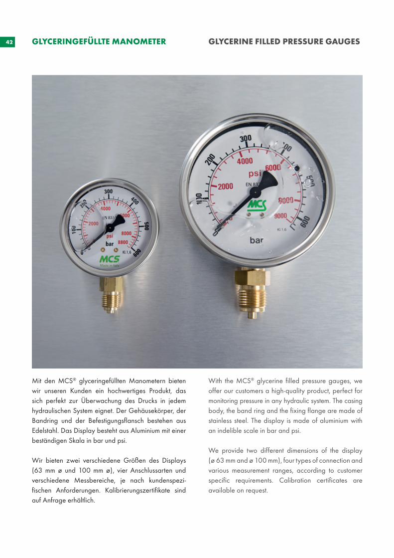
Mit den MCS® glyceringefüllten Manometern bieten wir unseren Kunden ein hochwertiges Produkt, das sich perfekt zur Überwachung des Drucks in jedem hydraulischen System eignet. Der Gehäusekörper, der Bandring und der Befestigungsflansch bestehen aus Edelstahl. Das Display besteht aus Aluminium mit einer beständigen Skala in bar und psi.
Wir bieten zwei verschiedene Größen des Displays (63 mm ø und 100 mm ø), vier Anschlussarten und verschiedene Messbereiche, je nach kundenspezi-fischen Anforderungen. Kalibrierungszertifikate sind auf Anfrage erhältlich.
With the MCS® glycerine filled pressure gauges, we offer our customers a high-quality product, perfect for monitoring pressure in any hydraulic system. The casing body, the band ring and the fixing flange are made of stainless steel. The display is made of aluminium with an indelible scale in bar and psi.
We provide two different dimensions of the display (ø 63 mm and ø 100 mm), four types of connection and various measurement ranges, according to customer specific requirements. Calibration certificates are available on request.
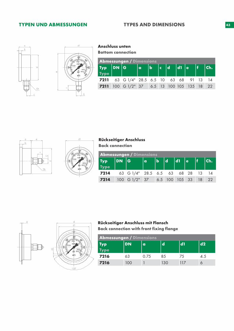
43TYPEN UND ABMESSUNGEN TYPES AND DIMENSIONS
Anschluss untenBottom connection
Abmessungen / Dimensions
TypType
DN G a b c d d1 e f Ch.
7211 63 G 1/4" 28.5 6.5 10 63 68 91 13 14
7211 100 G 1/2" 37 6.5 13 100 105 135 18 22
Abmessungen / Dimensions
Typ Type
DN G a b d d1 e f Ch.
7214 63 G 1/4" 28.5 6.5 63 68 28 13 14
7214 100 G 1/2" 37 6.5 100 105 33 18 22
Rückseitiger AnschlussBack connection
Rückseitiger Anschluss mit FlanschBack connection with front fixing flange
Abmessungen / Dimensions
Typ Type
DN a d d1 d2
7216 63 0.75 85 75 4.5
7216 100 1 130 117 6
44
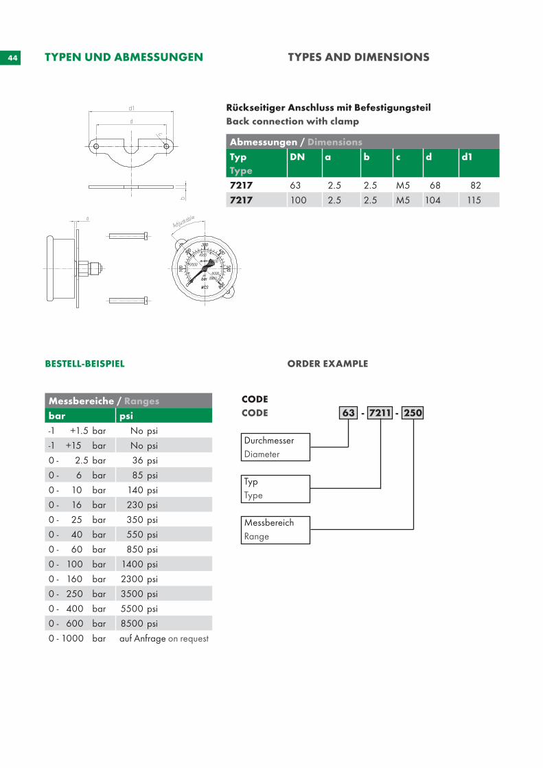
BESTELL-BEISPIEL ORDER EXAMPLE
CODECODE 63 - 7211 - 250
Durchmesser Diameter
Typ Type
Messbereich Range
TYPEN UND ABMESSUNGEN TYPES AND DIMENSIONS
Rückseitiger Anschluss mit BefestigungsteilBack connection with clamp
Messbereiche / Ranges
bar psi
-1 +1.5 bar No psi
-1 +15 bar No psi
0 - 2.5 bar 36 psi
0 - 6 bar 85 psi
0 - 10 bar 140 psi
0 - 16 bar 230 psi
0 - 25 bar 350 psi
0 - 40 bar 550 psi
0 - 60 bar 850 psi
0 - 100 bar 1400 psi
0 - 160 bar 2300 psi
0 - 250 bar 3500 psi
0 - 400 bar 5500 psi
0 - 600 bar 8500 psi
0 - 1000 bar auf Anfrage on request
Abmessungen / Dimensions
Typ Type
DN a b c d d1
7217 63 2.5 2.5 M5 68 82
7217 100 2.5 2.5 M5 104 115
45
Betriebsdruck Dauerhaft: 75% des vollen Skalenwerts
Bereich der Betriebstemperatur Umgebung: -25 °C bis 65 °C / 40 °F bis 150 °F
Überdruck 25% <= 100 bar ; 15% > 100 bar
Konstruktion mit Glycerin gefülltes Gehäuse aus Edelstahl mit Sicherheitsventil
Gehäusering Edelstahl AISI 304
Befestigungsflansch Edelstahl AISI 304 mit 3 Löchern
Skala weiß lackiertes Aluminium mit unlöschbarer schwarzer und roter Skaleneinteilung grünes MCS®-Markenzeichen
Nadel schwarz lackiertes Aluminium
Transparente Abdeckung Polycarbonat
Anschluss Messing für Drücke bis 600 bar
Rohrfeder Phosphor Bronze für Drücke bis 600 bar Cr-Ni Stahl für Drücke bis 1000 bar
Abmessungen und Konstruktion gemäß EN 837
Messgenauigkeit bei 20°C +/- 1.6% bezogen auf den vollen Skalenwert ø 63 UNI 8293 und DIN 16005+/- 1% bezogen auf den vollen Skalenwert ø 100 UNI 8293 und DIN 16005
Schutzklasse IP 65 gemäß EN 837
Messbereich und Skaleneinteilung gemäß EN 837
Working pressure Steady: 75% of full scale value
Working temperature range Ambient: -25°C to 65°C / -40°F to 150°F
Overpressure 25% <= 100 bar ; 15% > 100 bar
Casing body glycerine filled in stainless steel case with safety vent
Band ring stainless steel AISI 304
Fixing flange stainless steel AISI 304 with 3 holes
Dial white painted aluminium with indelible black and red graduation and MCS® green mark
Needle black painted aluminium
Transparent cover polycarbonate
Connection brass for pressure up to 600 bar
Tubolar spring in phosphor bronze for pressure up to 600 bar Cr-Ni steel for pressure up to 1000 bar
Dimensions and assembly according to EN 837
Accuracy with temperature 20°C +/- 1.6% referred to full scale value ø 63 UNI 8293 and DIN 16005 +/- 1% referred to full scale value ø 100 UNI 8293 and DIN 16005
Protection class IP 65 according to EN 837
Range and graduation according to EN 837
TECHNISCHE DATEN TECHNICAL DATA
46
47
MES
SKO
FFER
FÜ
R D
RU
CK
MES
SUN
G
TEST
BO
XES
FO
R P
RES
SUR
E C
HEC
K
48 MESSKOFFER FÜR DRUCKMESSUNG
TEST BOXES FOR PRESSURE CHECK
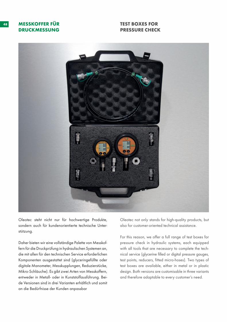
Oleotec steht nicht nur für hochwertige Produkte, sondern auch für kundenorientierte technische Unter-stützung.
Daher bieten wir eine vollständige Palette von Messkof-fern für die Druckprüfung in hydraulischen Systemen an, die mit allen für den technischen Service erforderlichen Komponenten ausgestattet sind (glyceringefüllte oder digitale Manometer, Messkupplungen, Reduzierstücke, Mikro-Schläuche). Es gibt zwei Arten von Messkoffern, entweder in Metall- oder in Kunststoffausführung. Bei-de Versionen sind in drei Varianten erhältlich und somit an die Bedürfnisse der Kunden anpassbar
Oleotec not only stands for high-quality products, but also for customer-oriented technical assistance.
For this reason, we offer a full range of test boxes for pressure check in hydraulic systems, each equipped with all tools that are necessary to complete the tech-nical service (glycerine filled or digital pressure gauges, test points, reducers, fitted micro-hoses). Two types of test boxes are available, either in metal or in plastic design. Both versions are customisable in three variants and therefore adaptable to every customer’s need.
49
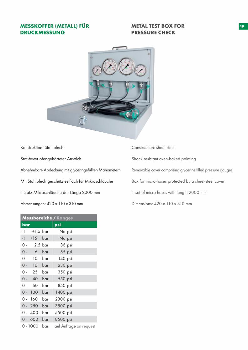
Konstruktion: Stahlblech
Stoßfester ofengehärteter Anstrich
Abnehmbare Abdeckung mit glyceringefüllten Manometern
Mit Stahlblech geschütztes Fach für Mikroschläuche
1 Satz Mikroschläuche der Länge 2000 mm
Abmessungen: 420 x 110 x 310 mm
Construction: sheet-steel
Shock resistant oven-baked painting
Removable cover comprising glycerine filled pressure gauges
Box for micro-hoses protected by a sheet-steel cover
1 set of micro-hoses with length 2000 mm
Dimensions: 420 x 110 x 310 mm
Messbereiche / Ranges
bar psi
-1 +1.5 bar No psi
-1 +15 bar No psi
0 - 2.5 bar 36 psi
0 - 6 bar 85 psi
0 - 10 bar 140 psi
0 - 16 bar 230 psi
0 - 25 bar 350 psi
0 - 40 bar 550 psi
0 - 60 bar 850 psi
0 - 100 bar 1400 psi
0 - 160 bar 2300 psi
0 - 250 bar 3500 psi
0 - 400 bar 5500 psi
0 - 600 bar 8500 psi
0 - 1000 bar auf Anfrage on request
MESSKOFFER (METALL) FÜR DRUCKMESSUNG
METAL TEST BOX FOR PRESSURE CHECK
50
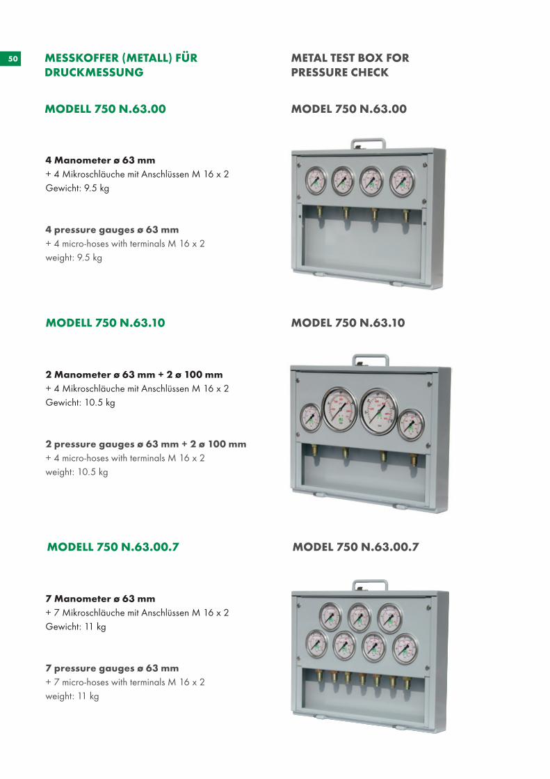
4 Manometer ø 63 mm+ 4 Mikroschläuche mit Anschlüssen M 16 x 2Gewicht: 9.5 kg
4 pressure gauges ø 63 mm+ 4 micro-hoses with terminals M 16 x 2weight: 9.5 kg
2 Manometer ø 63 mm + 2 ø 100 mm+ 4 Mikroschläuche mit Anschlüssen M 16 x 2Gewicht: 10.5 kg
2 pressure gauges ø 63 mm + 2 ø 100 mm+ 4 micro-hoses with terminals M 16 x 2weight: 10.5 kg
7 Manometer ø 63 mm+ 7 Mikroschläuche mit Anschlüssen M 16 x 2Gewicht: 11 kg
7 pressure gauges ø 63 mm+ 7 micro-hoses with terminals M 16 x 2weight: 11 kg
MODELL 750 N.63.00 MODEL 750 N.63.00
MODELL 750 N.63.10 MODEL 750 N.63.10
MODELL 750 N.63.00.7 MODEL 750 N.63.00.7
MESSKOFFER (METALL) FÜR DRUCKMESSUNG
METAL TEST BOX FOR PRESSURE CHECK
51
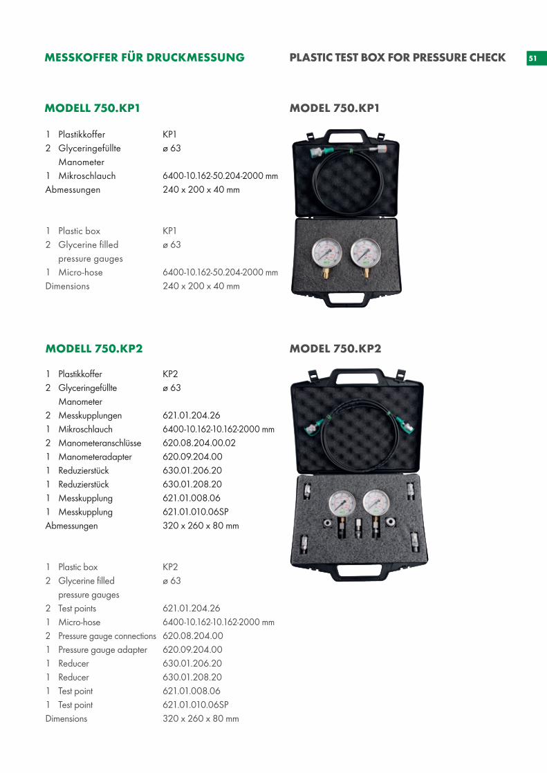
MODELL 750.KP1 MODEL 750.KP1
MODELL 750.KP2 MODEL 750.KP2
MESSKOFFER FÜR DRUCKMESSUNG PLASTIC TEST BOX FOR PRESSURE CHECK
1 Plastikkoffer 2 Glyceringefüllte Manometer2 Messkupplungen 1 Mikroschlauch 2 Manometeranschlüsse 1 Manometeradapter1 Reduzierstück 1 Reduzierstück 1 Messkupplung 1 Messkupplung Abmessungen
1 Plastic box 2 Glycerine filled pressure gauges 2 Test points 1 Micro-hose 2 Pressure gauge connections 1 Pressure gauge adapter 1 Reducer 1 Reducer 1 Test point 1 Test point Dimensions
1 Plastikkoffer 2 Glyceringefüllte Manometer 1 Mikroschlauch Abmessungen
1 Plastic box 2 Glycerine filled pressure gauges 1 Micro-hose Dimensions
KP1ø 63
6400-10.162-50.204-2000 mm240 x 200 x 40 mm
KP1ø 63
6400-10.162-50.204-2000 mm 240 x 200 x 40 mm
KP2ø 63
621.01.204.266400-10.162-10.162-2000 mm620.08.204.00.02620.09.204.00630.01.206.20 630.01.208.20 621.01.008.06 621.01.010.06SP320 x 260 x 80 mm
KP2ø 63
621.01.204.266400-10.162-10.162-2000 mm620.08.204.00 620.09.204.00 630.01.206.20630.01.208.20 621.01.008.06 621.01.010.06SP320 x 260 x 80 mm
52
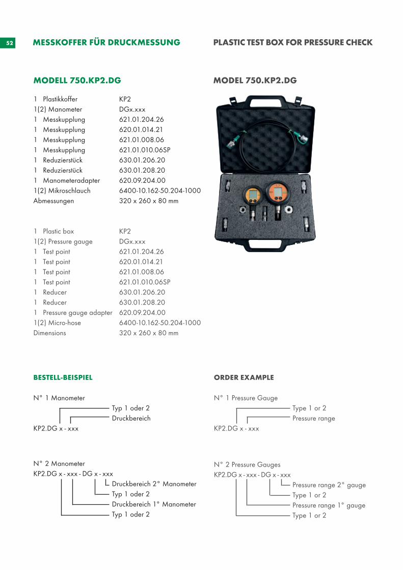
MODELL 750.KP2.DG MODEL 750.KP2.DG
BESTELL-BEISPIEL
N° 1 Manometer Typ 1 oder 2 Druckbereich KP2.DG x - xxx
N° 2 ManometerKP2.DG x - xxx - DG x - xxx Druckbereich 2° Manometer Typ 1 oder 2 Druckbereich 1° Manometer Typ 1 oder 2
ORDER EXAMPLE
N° 1 Pressure Gauge Type 1 or 2 Pressure range KP2.DG x - xxx
N° 2 Pressure GaugesKP2.DG x - xxx - DG x - xxx Pressure range 2° gauge Type 1 or 2 Pressure range 1° gauge Type 1 or 2
1 Plastikkoffer 1(2) Manometer1 Messkupplung1 Messkupplung 1 Messkupplung 1 Messkupplung 1 Reduzierstück 1 Reduzierstück 1 Manometeradapter 1(2) Mikroschlauch Abmessungen
1 Plastic box 1(2) Pressure gauge 1 Test point 1 Test point1 Test point1 Test point1 Reducer 1 Reducer 1 Pressure gauge adapter 1(2) Micro-hose Dimensions
KP2DGx.xxx621.01.204.26 620.01.014.21621.01.008.06 621.01.010.06SP 630.01.206.20 630.01.208.20 620.09.204.00 6400-10.162-50.204-1000320 x 260 x 80 mm
KP2DGx.xxx621.01.204.26 620.01.014.21621.01.008.06 621.01.010.06SP 630.01.206.20 630.01.208.20 620.09.204.00 6400-10.162-50.204-1000320 x 260 x 80 mm
MESSKOFFER FÜR DRUCKMESSUNG PLASTIC TEST BOX FOR PRESSURE CHECK


www.e-holding.de
Oleotec S.r.l. Via Varese 1921050 Cantello (VA)/Italy
Phone +39 03 32 / 41 97-11Fax +39 03 32 / 41 [email protected] www.oleotec.it ID
_VN
D_0
1-3
REV.
02
/20
ww
w.p
laka
rt.de