Embed Size (px)
Citation preview

1
SOMMARIO
Descrizione Description Beschreibung
1 INFORMAZIONI GENERALI GENERAL INFORMATION ALLGEMEINE INFORMATIONEN 2
1.1 SIMBOLOGIA E UNITÀ DI MISURA SYMBOLS AND UNITS
OF MEASUREMENT
SYMBOLE UND MASSEINHEITEN 2
1.2 CARATTERISTICHE COSTRUTTIVE PRODUCT FEATURES BAULICHE EIGENSCHAFTEN 3
1.3 LUBRIFICAZIONE LUBRICATION SCHMIERUNG 4
2 SELEZIONE DEL RIDUTTORE SELECTING THE GEAR UNIT WAHL DES GETRIEBES 5
2.1 DIMENSIONAMENTO ENGINEERING SELECTION BEMESSUNG 5
2.2 VERIFICHE VERIFICATIONS KONTROLLEN 6
2.3 CASO APPLICATIVO SAMPLE APPLICATION ANWENDUNGSFALL 9
3 CONFIGURAZIONI PRODOTTO PRODUCT CONFIGURATIONS PRODUKTKONFIGURATIONEN 10
3.1 VARIANTI BASE BASE VARIANTS BASISVARIANTEN 10
3.2 VARIANTI OPZIONALI OPTIONAL VARIANTS OPTIONALE VARIANTEN 11
3.3 POSIZIONI DI MONTAGGIO MOUNTING POSITION EINBAULAGEN 12
3.4 CONFIGURAZIONE LATO INGRESSOE USCITA
INPUT AND OUTPUT
CONFIGURATION
KONFIGURATION ANTRIEBSUND ABTRIEBSSEITE
12
3.5 PREDISPOSIZIONI MOTORE MOTOR AVAILABILITY MOTORAUSLEGUNGEN 14
3.6 VARIANTI OPZIONALI OPTIONAL VARIANTS OPTIONALE VARIANTEN 15
4 COPPIA MASSIMATRASMISSIBILE
MAXIMUM TRANSMISSIBLE
TORQUE
ÜBERSETZBARES MAXIMALESDREHMOMENT
21
4.1 POTENZA TERMICAE DATI TECNICI
THERMAL CAPACITY
AND RATING CHARTS
WARMELEISTUNGUND AUSWAHLTABELLEN
21
4.2 RAPPORTI ESATTI EXACT RATIOS EXAKTE ÜBERSETZUNG 40
5 DIMENSIONI DIMENSIONS ABMESSUNGEN 41
5.1 PREDISPOSIZIONE ATTACCOMOTORE DIRETTO
MOTOR MOUNTING FOR DIRECT
COUPLING
VORRÜSTUNG FÜR DEN DIREKTENANSCHLUSS DES MOTORS
50
5.2 PREDISPOSIZIONE ATTACCOMOTORE CON CAMPANA E GIUNTOELASTICO
MOTOR MOUNTING WITH BELL
HOUSING AND FLEXIBLE COUPLING
AUSLEGUNG FÜR MOTORANSCHLUSSMIT GLOCKE UND ELASTISCHERKUPPLUNG
51
ParagrafoChapterAbschnitt
RevisionsRefer to page 54 for the catalogue revision in-dex. Visit www.bonfiglioli.com to search for cata-logues with up-to-date revisions.
ÄnderungenDas Revisionsverzeichnis des Katalogs wird aufSeite 54 wiedergegeben. Auf unserer Websitewww.bonfiglioli.com werden die Kataloge in ihrerletzten, überarbeiteten Version angeboten.
RevisioniL’indice di revisione del catalogo è riportato apag. 54. Al sito www.bonfiglioli.com sono dispo-nibili i cataloghi con le revisioni aggiornate.
SUMMARY ZUSAMMENFASSUNG
2
Descrizione Description Beschreibung
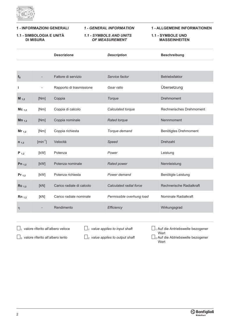
fS - Fattore di servizio Service factor Betriebsfaktor
i - Rapporto di trasmissione Gear ratio Übersetzung
M 1,2 [Nm] Coppia Torque Drehmoment
Mc 1,2 [Nm] Coppia di calcolo Calculated torque Rechnerisches Drehmoment
Mn 1,2 [Nm] Coppia nominale Rated torque Nennmoment
Mr 1,2 [Nm] Coppia richiesta Torque demand Benötigtes Drehmoment
n 1,2 [min-1] Velocità Speed Drehzahl
P 1,2 [kW] Potenza Power Leistung
Pn 1,2 [kW] Potenza nominale Rated power Nennleistung
Pr 1,2 [kW] Potenza richiesta Power demand Benötigte Leistung
Rc 1,2 [kN] Carico radiale di calcolo Calculated radial force Rechnerische Radialkraft
Rn 1,2 [kN] Carico radiale nominale Permissible overhung load Nominale Radialkraft
� - Rendimento Efficiency Wirkungsgrad
1 - INFORMAZIONI GENERALI
1.1 - SIMBOLOGIA E UNITÀ
DI MISURA
1 - GENERAL INFORMATION
1.1 - SYMBOLS AND UNITS
OF MEASUREMENT
1 - ALLGEMEINE INFORMATIONEN
1.1 - SYMBOLE UND
MASSEINHEITEN
�1 valore riferito all’albero veloce
�2 valore riferito all’albero lento
�1 value applies to input shaft
�2 value applies to output shaft
�1 Auf die Antriebswelle bezogenerWert
�2 Auf die Abtriebswelle bezogenerWert
3
1.2 - CARATTERISTICHE
COSTRUTTIVE
1.2 - PRODUCT FEATURES 1.2 - BAULICHE EIGENSCHAFTEN
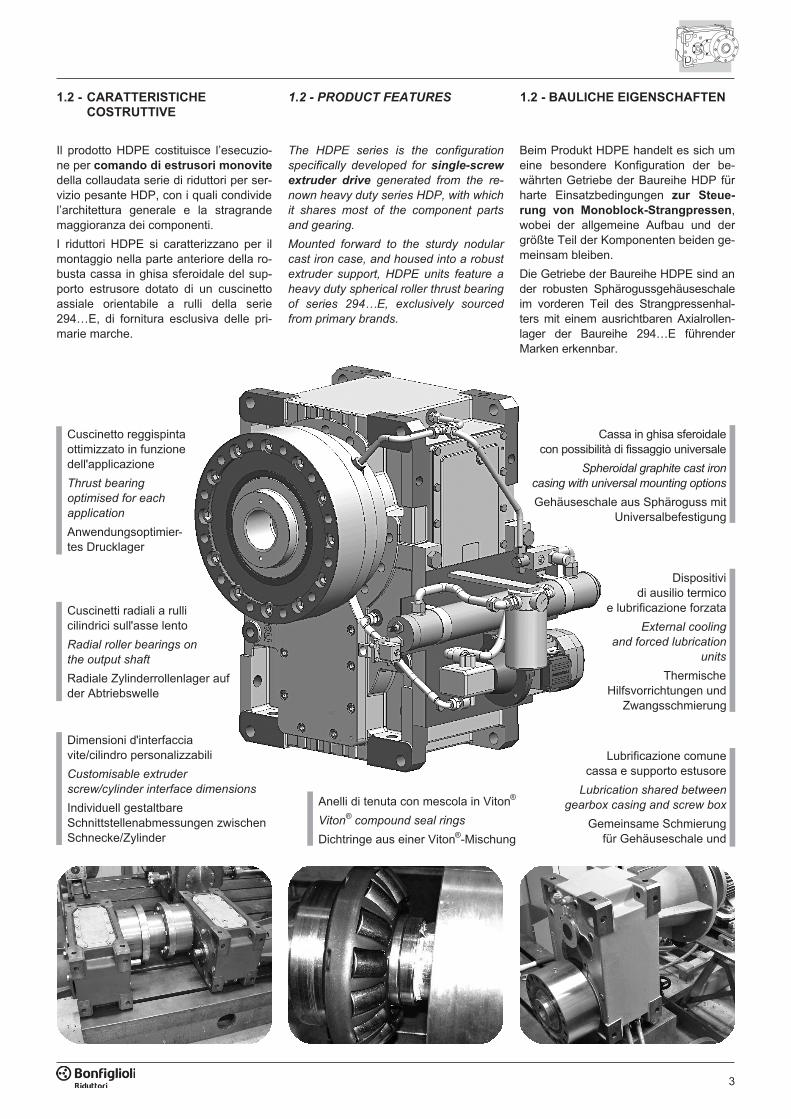
Cuscinetto reggispintaottimizzato in funzionedell'applicazione
Thrust bearing
optimised for each
application
Anwendungsoptimier-tes Drucklager
Cassa in ghisa sferoidalecon possibilità di fissaggio universale
Spheroidal graphite cast iron
casing with universal mounting options
Gehäuseschale aus Sphäroguss mitUniversalbefestigung
Il prodotto HDPE costituisce l’esecuzio-ne per comando di estrusori monovite
della collaudata serie di riduttori per ser-vizio pesante HDP, con i quali condividel’architettura generale e la stragrandemaggioranza dei componenti.
I riduttori HDPE si caratterizzano per ilmontaggio nella parte anteriore della ro-busta cassa in ghisa sferoidale del sup-porto estrusore dotato di un cuscinettoassiale orientabile a rulli della serie294…E, di fornitura esclusiva delle pri-marie marche.
Beim Produkt HDPE handelt es sich umeine besondere Konfiguration der be-währten Getriebe der Baureihe HDP fürharte Einsatzbedingungen zur Steue-
rung von Monoblock-Strangpressen,wobei der allgemeine Aufbau und dergrößte Teil der Komponenten beiden ge-meinsam bleiben.
Die Getriebe der Baureihe HDPE sind ander robusten Sphärogussgehäuseschaleim vorderen Teil des Strangpressenhal-ters mit einem ausrichtbaren Axialrollen-lager der Baureihe 294…E führenderMarken erkennbar.
The HDPE series is the configuration
specifically developed for single-screw
extruder drive generated from the re-
nown heavy duty series HDP, with which
it shares most of the component parts
and gearing.
Mounted forward to the sturdy nodular
cast iron case, and housed into a robust
extruder support, HDPE units feature a
heavy duty spherical roller thrust bearing
of series 294…E, exclusively sourced
from primary brands.
Dimensioni d'interfacciavite/cilindro personalizzabili
Customisable extruder
screw/cylinder interface dimensions
Individuell gestaltbareSchnittstellenabmessungen zwischenSchnecke/Zylinder
Cuscinetti radiali a rullicilindrici sull'asse lento
Radial roller bearings on
the output shaft
Radiale Zylinderrollenlager aufder Abtriebswelle
Anelli di tenuta con mescola in Viton®
Viton®
compound seal rings
Dichtringe aus einer Viton®-Mischung
Dispositividi ausilio termico
e lubrificazione forzata
External cooling
and forced lubrication
units
ThermischeHilfsvorrichtungen und
Zwangsschmierung
Lubrificazione comunecassa e supporto estusore
Lubrication shared between
gearbox casing and screw box
Gemeinsame Schmierungfür Gehäuseschale und
4
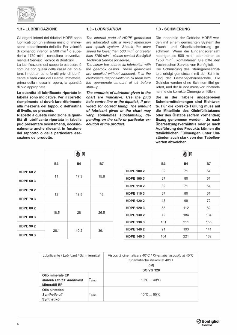
1.3 - LUBRIFICAZIONE
Gli organi interni dei riduttori HDPE sonolubrificati con un sistema misto di immer-sione e sbattimento dell’olio. Per velocitàdi comando inferiori a 500 min-1 o supe-riori a 1750 min-1, consultare preventiva-mente il Servizio Tecnico di Bonfiglioli.La lubrificazione del supporto estrusore ècomune con quella della cassa del ridut-tore. I riduttori sono forniti privi di lubrifi-cante e sarà cura del Cliente immettere,prima della messa in opera, la quantitàdi olio appropriata.
Le quantità di lubrificante riportate in
tabella sono indicative. Per il corretto
riempimento si dovrà fare riferimento
alla mezzeria del tappo, o dell’astina
di livello, se presente.
Rispetto a questa condizione la quan-
tità di lubrificante riportata in tabella
può presentare scostamenti, occasio-
nalmente anche rilevanti, in funzione
del rapporto o della particolare ese-
cuzione del prodotto.
1.3 - LUBRICATION
The internal parts of HDPE gearboxes
are lubricated with a mixed immersion
and splash system. Should the drive
speed be lower than 500 min-1
or greater
than 1750 min-1
, please contact Bonfiglioli
Technical Service for advise.
The screw box shares its lubrication with
the gearbox casing. These gearboxes
are supplied without lubricant. It is the
customer’s responsibility to fill them with
the appropriate amount of oil before
start-up.
The amounts of lubricant given in the
chart are indicative. Use the plug
hole centre line or the dipstick, if pro-
vided, for correct filling. The amount
of lubricant given in the chart may
vary, sometimes substantially, de-
pending on the ratio or particular ex-
ecution of the product.
1.3 - SCHMIERUNG
Die Innenteile der Getriebe HDPE wer-den mit einem gemischten System derTauch- und Ölspritzschmierung ge-schmiert. Wenn die Eingangsdrehzahlniedriger als 500 min-1 oder höher als1750 min-1, kontaktieren Sie bitte denTechnischen Service von Bonfiglioli.Die Schmierung des Strangpressenhal-ters erfolgt gemeinsam mit der Schmie-rung der Getriebegehäuseschale. DieGetriebe werden ohne Schmiermittel ge-liefert, und der Kunde muss vor Inbetrieb-nahme die korrekte Ölmenge einfüllen.
Die in der Tabelle angegebenen
Schmiermittelmengen sind Richtwer-
te. Für die korrekte Füllung muss auf
die Mittellinie des Öleinfüllstutzens
oder des Ölstabs (sofern vorhanden)
Bezug genommen werden. Je nach
Übersetzungsverhältnis oder je nach
Ausführung des Produkts können die
tatsächlichen Füllmengen unter Um-
ständen auch stark von den Tabellen-
werten abweichen.
oil [l]
B3 B6 B7
HDPE 60 2
11 17.3 15.6HDPE 60 3
HDPE 70 2
12 18.5 16HDPE 70 3
HDPE 80 2
18.5 28 26.5HDPE 80 3
HDPE 90 2
26.1 40.2 36.1HDPE 90 3
oil [l]
B3 B6 B7
HDPE 100 2 32 71 54
HDPE 100 3 37 80 61
HDPE 110 2 32 71 54
HDPE 110 3 37 80 61
HDPE 120 2 43 99 72
HDPE 120 3 53 112 82
HDPE 130 2 72 184 134
HDPE 130 3 101 211 155
HDPE 140 2 91 193 141
HDPE 140 3 104 221 162
Lubrificante / Lubricant / Schmiermittel Viscosità cinematica a 40°C / Kinematic viscosity at 40°C
Kinematische Viskosität 40°C
[cst]
ISO VG 320
Olio minerale EP
Mineral Oil (EP additives)
Mineralöl EP
Tamb 10°C ... 40°C
Olio sintetico
Synthetic oil
Synthetiköl
Tamb 10°C ... 50°C
5
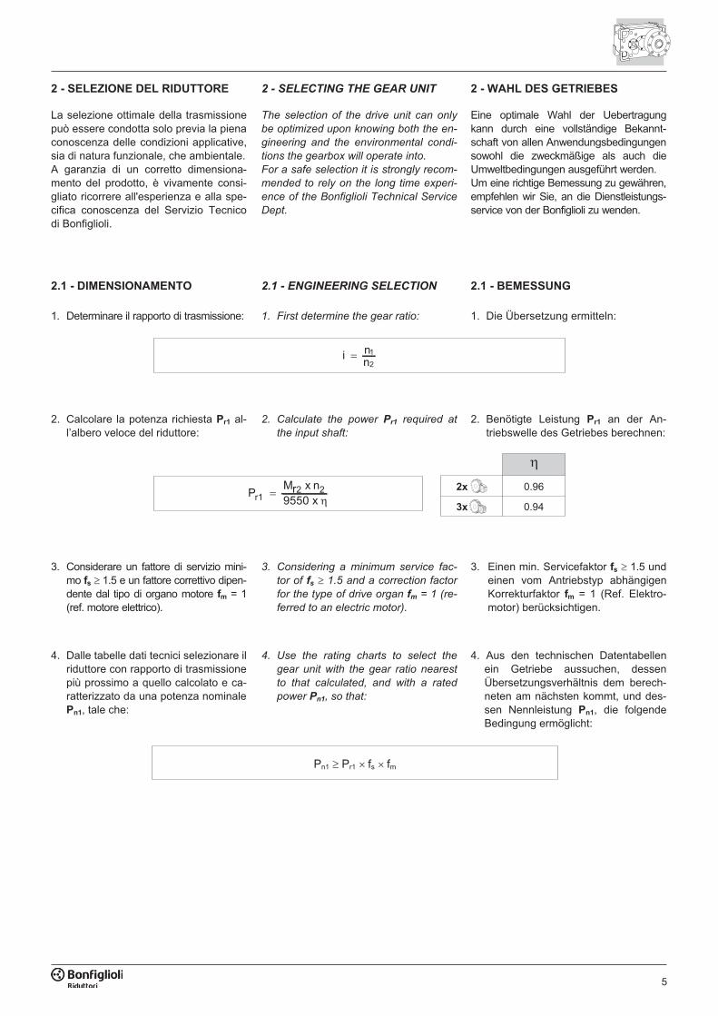
Pn1 � Pr1 � fs � fm
i nn
� 1
2
PMr x n9550 xr1
2 2��
�
2x 0.96
3x 0.94
2 - SELEZIONE DEL RIDUTTORE
La selezione ottimale della trasmissionepuò essere condotta solo previa la pienaconoscenza delle condizioni applicative,sia di natura funzionale, che ambientale.A garanzia di un corretto dimensiona-mento del prodotto, è vivamente consi-gliato ricorrere all'esperienza e alla spe-cifica conoscenza del Servizio Tecnicodi Bonfiglioli.
2.1 - DIMENSIONAMENTO
1. Determinare il rapporto di trasmissione:
2. Calcolare la potenza richiesta Pr1 al-l’albero veloce del riduttore:
3. Considerare un fattore di servizio mini-mo fs � 1.5 e un fattore correttivo dipen-dente dal tipo di organo motore fm = 1(ref. motore elettrico).
4. Dalle tabelle dati tecnici selezionare ilriduttore con rapporto di trasmissionepiù prossimo a quello calcolato e ca-ratterizzato da una potenza nominalePn1, tale che:
2 - SELECTING THE GEAR UNIT
The selection of the drive unit can only
be optimized upon knowing both the en-
gineering and the environmental condi-
tions the gearbox will operate into.
For a safe selection it is strongly recom-
mended to rely on the long time experi-
ence of the Bonfiglioli Technical Service
Dept.
2.1 - ENGINEERING SELECTION
1. First determine the gear ratio:
2. Calculate the power Pr1 required at
the input shaft:
3. Considering a minimum service fac-
tor of fs � 1.5 and a correction factor
for the type of drive organ fm = 1 (re-
ferred to an electric motor).
4. Use the rating charts to select the
gear unit with the gear ratio nearest
to that calculated, and with a rated
power Pn1, so that:
2 - WAHL DES GETRIEBES
Eine optimale Wahl der Uebertragungkann durch eine vollständige Bekannt-schaft von allen Anwendungsbedingungensowohl die zweckmäßige als auch dieUmweltbedingungen ausgeführt werden.Um eine richtige Bemessung zu gewähren,empfehlen wir Sie, an die Dienstleistungs-service von der Bonfiglioli zu wenden.
2.1 - BEMESSUNG
1. Die Übersetzung ermitteln:
2. Benötigte Leistung Pr1 an der An-triebswelle des Getriebes berechnen:
3. Einen min. Servicefaktor fs � 1.5 undeinen vom Antriebstyp abhängigenKorrekturfaktor fm = 1 (Ref. Elektro-motor) berücksichtigen.
4. Aus den technischen Datentabellenein Getriebe aussuchen, dessenÜbersetzungsverhältnis dem berech-neten am nächsten kommt, und des-sen Nennleistung Pn1, die folgendeBedingung ermöglicht:
6
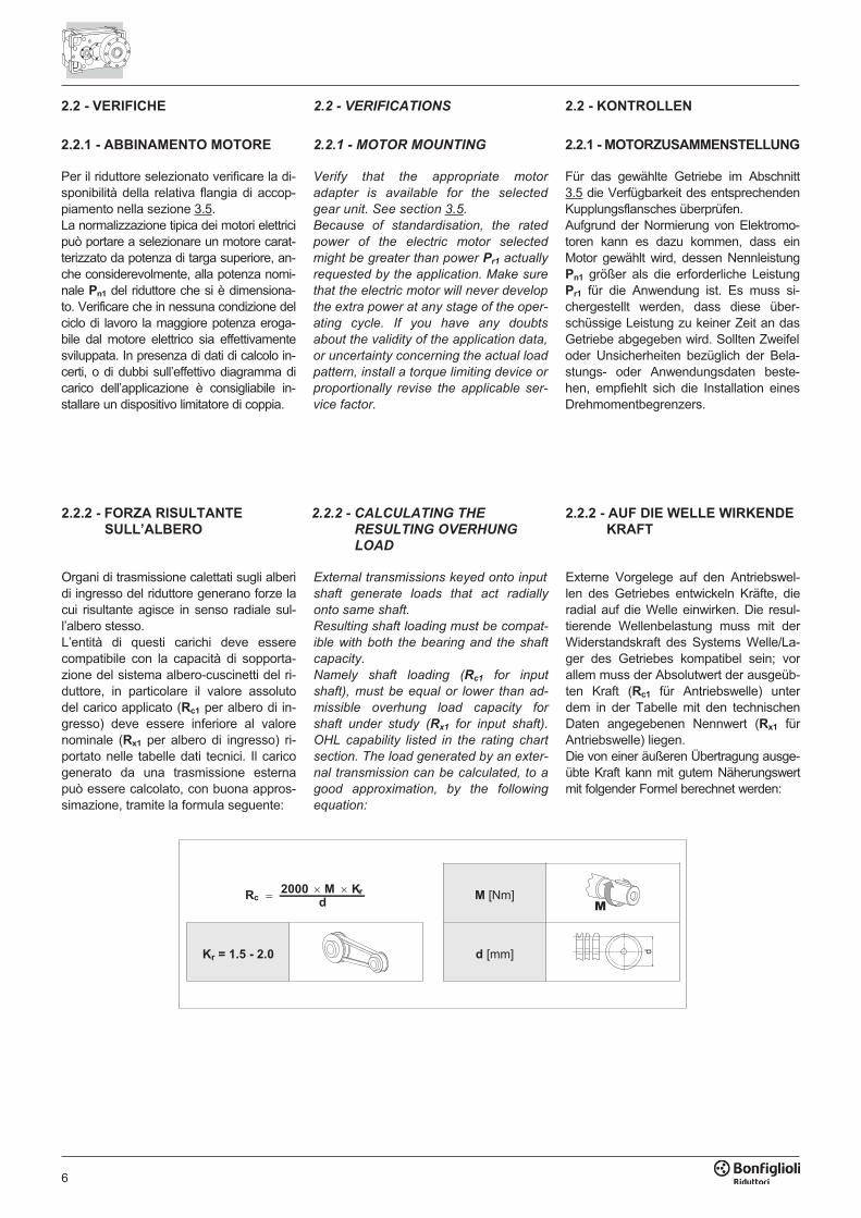
2.2.2 - FORZA RISULTANTE
SULL’ALBERO
Organi di trasmissione calettati sugli alberidi ingresso del riduttore generano forze lacui risultante agisce in senso radiale sul-l’albero stesso.L’entità di questi carichi deve esserecompatibile con la capacità di sopporta-zione del sistema albero-cuscinetti del ri-duttore, in particolare il valore assolutodel carico applicato (Rc1 per albero di in-gresso) deve essere inferiore al valorenominale (Rx1 per albero di ingresso) ri-portato nelle tabelle dati tecnici. Il caricogenerato da una trasmissione esternapuò essere calcolato, con buona appros-simazione, tramite la formula seguente:
2.2.2 - CALCULATING THE
RESULTING OVERHUNG
LOAD
External transmissions keyed onto input
shaft generate loads that act radially
onto same shaft.
Resulting shaft loading must be compat-
ible with both the bearing and the shaft
capacity.
Namely shaft loading (Rc1 for input
shaft), must be equal or lower than ad-
missible overhung load capacity for
shaft under study (Rx1 for input shaft).
OHL capability listed in the rating chart
section. The load generated by an exter-
nal transmission can be calculated, to a
good approximation, by the following
equation:
2.2.2 - AUF DIE WELLE WIRKENDE
KRAFT
Externe Vorgelege auf den Antriebswel-len des Getriebes entwickeln Kräfte, dieradial auf die Welle einwirken. Die resul-tierende Wellenbelastung muss mit derWiderstandskraft des Systems Welle/La-ger des Getriebes kompatibel sein; vorallem muss der Absolutwert der ausgeüb-ten Kraft (Rc1 für Antriebswelle) unterdem in der Tabelle mit den technischenDaten angegebenen Nennwert (Rx1 fürAntriebswelle) liegen.Die von einer äußeren Übertragung ausge-übte Kraft kann mit gutem Näherungswertmit folgender Formel berechnet werden:
R2000 M K
dc
r�� �
M [Nm]
Kr = 1.5 - 2.0 d [mm]
�
�
2.2.1 - MOTOR MOUNTING
Verify that the appropriate motor
adapter is available for the selected
gear unit. See section 3.5.
Because of standardisation, the rated
power of the electric motor selected
might be greater than power Pr1 actually
requested by the application. Make sure
that the electric motor will never develop
the extra power at any stage of the oper-
ating cycle. If you have any doubts
about the validity of the application data,
or uncertainty concerning the actual load
pattern, install a torque limiting device or
proportionally revise the applicable ser-
vice factor.
2.2.1 - MOTORZUSAMMENSTELLUNG
Für das gewählte Getriebe im Abschnitt3.5 die Verfügbarkeit des entsprechendenKupplungsflansches überprüfen.Aufgrund der Normierung von Elektromo-toren kann es dazu kommen, dass einMotor gewählt wird, dessen NennleistungPn1 größer als die erforderliche LeistungPr1 für die Anwendung ist. Es muss si-chergestellt werden, dass diese über-schüssige Leistung zu keiner Zeit an dasGetriebe abgegeben wird. Sollten Zweifeloder Unsicherheiten bezüglich der Bela-stungs- oder Anwendungsdaten beste-hen, empfiehlt sich die Installation einesDrehmomentbegrenzers.
2.2 - VERIFICHE 2.2 - VERIFICATIONS 2.2 - KONTROLLEN
2.2.1 - ABBINAMENTO MOTORE
Per il riduttore selezionato verificare la di-sponibilità della relativa flangia di accop-piamento nella sezione 3.5.La normalizzazione tipica dei motori elettricipuò portare a selezionare un motore carat-terizzato da potenza di targa superiore, an-che considerevolmente, alla potenza nomi-nale Pn1 del riduttore che si è dimensiona-to. Verificare che in nessuna condizione delciclo di lavoro la maggiore potenza eroga-bile dal motore elettrico sia effettivamentesviluppata. In presenza di dati di calcolo in-certi, o di dubbi sull’effettivo diagramma dicarico dell’applicazione è consigliabile in-stallare un dispositivo limitatore di coppia.
7
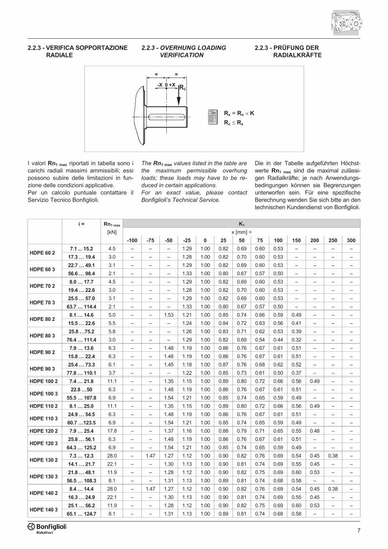
2.2.3 - OVERHUNG LOADING
VERIFICATION
2.2.3 - VERIFICA SOPPORTAZIONE
RADIALE
2.2.3 - PRÜFUNG DER
RADIALKRÄFTE
Rx = Rn � K
Rc � Rx
�
�� �� ��
�
�
i = Rn1 max K1
[kN] x [mm] =
-100 -75 -50 -25 0 25 50 75 100 150 200 250 300
HDPE 60 27.1 ... 15.2 4.5 – – – 1.29 1.00 0.82 0.69 0.60 0.53 – – – –
17.3 … 19.4 3.0 – – – 1.28 1.00 0.82 0.70 0.60 0.53 – – – –
HDPE 60 322.7 … 49.1 3.1 – – – 1.29 1.00 0.82 0.69 0.60 0.53 – – – –
56.6 … 98.4 2.1 – – – 1.33 1.00 0.80 0.67 0.57 0.50 – – – –
HDPE 70 28.0 … 17.7 4.5 – – – 1.29 1.00 0.82 0.69 0.60 0.53 – – – –
19.4 … 22.6 3.0 – – – 1.28 1.00 0.82 0.70 0.60 0.53 – – – –
HDPE 70 325.5 … 57.0 3.1 – – – 1.29 1.00 0.82 0.69 0.60 0.53 – – – –
63.7 … 114.4 2.1 – – – 1.33 1.00 0.80 0.67 0.57 0.50 – – – –
HDPE 80 28.1 … 14.6 5.0 – – 1.53 1.21 1.00 0.85 0.74 0.66 0.59 0.49 – – –
15.5 … 22.6 5.5 – – – 1.24 1.00 0.84 0.72 0.63 0.56 0.41 – – –
HDPE 80 325.8 …75.2 5.8 – – – 1.26 1.00 0.83 0.71 0.62 0.53 0.39 – – –
76.4 … 111.4 3.0 – – – 1.29 1.00 0.82 0.69 0.54 0.44 0.32 – – –
HDPE 90 27.9 … 13.6 6.3 – – 1.48 1.19 1.00 0.86 0.76 0.67 0.61 0.51 – – –
15.8 … 22.4 6.3 – – 1.48 1.19 1.00 0.86 0.76 0.67 0.61 0.51 – – –
HDPE 90 325.4 … 73.3 6.1 – – 1.45 1.18 1.00 0.87 0.76 0.68 0.62 0.52 – – –
77.8 … 110.1 3.7 – – – 1.22 1.00 0.85 0.73 0.61 0.50 0.37 – – –
HDPE 100 2 7.4 … 21.8 11.1 – – 1.35 1.15 1.00 0.89 0.80 0.72 0.66 0.56 0.49 – –
HDPE 100 322.8 …50 6.3 – – 1.48 1.19 1.00 0.86 0.76 0.67 0.61 0.51 – – –
55.5 … 107.8 6.9 – – 1.54 1.21 1.00 0.85 0.74 0.65 0.59 0.49 – – –
HDPE 110 2 8.1 … 25.0 11.1 – – 1.35 1.15 1.00 0.89 0.80 0.72 0.66 0.56 0.49 – –
HDPE 110 324.9 … 54.5 6.3 – – 1.48 1.19 1.00 0.86 0.76 0.67 0.61 0.51 – – –
60.7 …123.5 6.9 – – 1.54 1.21 1.00 0.85 0.74 0.65 0.59 0.49 – – –
HDPE 120 2 7.9 … 25.4 17.8 – – 1.37 1.16 1.00 0.88 0.79 0.71 0.65 0.55 0.48 – –
HDPE 120 325.8 … 56.1 6.3 – – 1.48 1.19 1.00 0.86 0.76 0.67 0.61 0.51 – – –
64.3 … 125.2 6.9 – – 1.54 1.21 1.00 0.85 0.74 0.65 0.59 0.49 – – –
HDPE 130 27.3 … 12.3 28.0 – 1.47 1.27 1.12 1.00 0.90 0.82 0.76 0.69 0.54 0.45 0.38 –
14.1 … 21.7 22.1 – – 1.30 1.13 1.00 0.90 0.81 0.74 0.69 0.55 0.45 – –
HDPE 130 321.8 … 48.1 11.9 – – 1.28 1.12 1.00 0.90 0.82 0.75 0.69 0.60 0.53 – –
56.5 … 108.3 8.1 – – 1.31 1.13 1.00 0.89 0.81 0.74 0.68 0.58 – – –
HDPE 140 28.4 … 14.4 28.0 – 1.47 1.27 1.12 1.00 0.90 0.82 0.76 0.69 0.54 0.45 0.38 –
16.3 … 24.9 22.1 – – 1.30 1.13 1.00 0.90 0.81 0.74 0.69 0.55 0.45 – –
HDPE 140 325.1 … 56.2 11.9 – – 1.28 1.12 1.00 0.90 0.82 0.75 0.69 0.60 0.53 – –
65.1 … 124.7 8.1 – – 1.31 1.13 1.00 0.89 0.81 0.74 0.68 0.58 – – –
I valori Rn1 max riportati in tabella sono icarichi radiali massimi ammissibili; essipossono subire delle limitazioni in fun-zione delle condizioni applicative.Per un calcolo puntuale contattare ilServizio Tecnico Bonfiglioli.
The Rn1 max values listed in the table are
the maximum permissible overhung
loads; these loads may have to be re-
duced in certain applications.
For an exact value, please contact
Bonfiglioli’s Technical Service.
Die in der Tabelle aufgeführten Höchst-werte Rn1 max sind die maximal zulässi-gen Radialkräfte; je nach Anwendungs-bedingungen können sie Begrenzungenunterworfen sein. Für eine spezifischeBerechnung wenden Sie sich bitte an dentechnischen Kundendienst von Bonfiglioli.
8
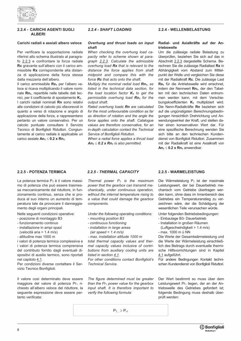
2.2.4 - CARICHI AGENTI SUGLI
ALBERI
Carichi radiali e assiali albero veloce
Per verificare la sopportazione radialeriferirsi allo schema illustrato al paragra-fo 2.2.3 e confrontare la forza radialeRc gravante sull’albero con il carico am-missibile Rx corrispondente alla distan-za di applicazione della forza stessadalla mezzeria dell’albero.Il carico ammissibile Rx1 per l’albero ve-loce si ricava moltiplicando il valore nomi-nale Rn1, reperibile nelle tabelle dati tec-nici, per il coefficiente di spostamento K1.I carichi radiali nominali Rn sono relativialle condizioni di calcolo più sfavorevoli inquanto a verso di rotazione e angolo diapplicazione della forza, e rappresentanopertanto un valore conservativo. Per uncalcolo puntuale consultare il ServizioTecnico di Bonfiglioli Riduttori. Congiun-tamente al carico radiale è applicabile uncarico assiale An1 � 0.2 x Rn1.
2.2.4 - SHAFT LOADING
Overhung and thrust loads on input
shaft
When checking the overhung load ca-
pacity refer to scheme shown at para-
graph 2.2.3. Calculate the admissible
overhung load Rx that is relevant to the
distance the force applies from shaft
midpoint and compare this with the
force Rc that acts onto the shaft.
Multiply the nominal radial load Rn1, as
listed in the technical data section, for
the load location factor K1 to get the
permissible overhung load Rx1 for the
output shaft.
Rated overhung loads Rn are calculated
for the most unfavourable condition as far
as direction of rotation and the angle the
force applies onto the shaft. Catalogue
values are therefore conservative, for an
in-depth calculation contact the Technical
Service of Bonfiglioli Riduttori.
When a radial force applies a thrust load
An1 � 0.2 x Rn1 is also permitted.
2.2.4 - WELLENBELASTUNG
Radial- und Axialkräfte auf der An-
triebswelle
Um die zulässige radiale Belastung zuüberprüfen, beziehen Sie sich auf das inAbschnitt 2.2.3 dargestellte Schema. Be-rechnen Sie die zulässige Radiallast Rx inAbhängigkeit vom Abstand zum Mittel-punkt der Welle und vergleichen Sie diesemit der Radialkraft Rc. Die zulässige LastRx1 für die Antriebswelle wird errechnet,indem der Nennwert Rn1, der den Tabel-len mit den technischen Daten entnom-men werden kann, mit dem Verschie-bungskoeffizienten K1 multipliziert wird.Die Nenn-Radialkräfte Rn beziehen sichauf die ungünstigsten Berechnungsbedin-gungen hinsichtlich Drehrichtung und An-wendungswinkel der Kraft, und stellen da-her einen konservativen Wert dar. Füreine spezifische Berechnung wenden Siesich bitte an den technischen Kunden-dienst von Bonfiglioli Riduttori. Zusammenmit der Radialkraft ist eine Axialkraft vonAn1 � 0.2 x Rn1 anwendbar.
2.2.5 - POTENZA TERMICA
La potenza termica PT è il valore massi-mo di potenza che può essere trasmes-sa meccanicamente dal riduttore, in fun-zionamento continuo, senza che si pro-duca al suo interno un aumento di tem-peratura tale da provocare il danneggia-mento degli organi principali.
Nelle seguenti condizioni operative:- posizione di montaggio B3- funzionamento continuo- installazione in ampi spazi
(velocità aria > 1.4 m/s)- altitudine max 1000 mi valori di potenza termica complessiva ei valori di potenza termica comprensivadel contributo fornito dagli eventuali di-spositivi di ausilio termico, sono riportatinel capitolo 4.1.Per condizioni diverse contattare il Ser-vizio Tecnico Bonfiglioli.
Il valore così determinato deve esseremaggiore del valore di potenza Pr1 ri-chiesto all’albero veloce del riduttore, laseguente espressione deve essere per-tanto verificata:
2.2.5 - THERMAL CAPACITY
Thermal power PT is the maximum
power that the gearbox can transmit me-
chanically, under continuous operation,
without the internal temperature rising to
a value that could damage the gearbox
components.
Under the following operating conditions:
- mounting position B3
- continuous functioning
- installation in large areas
(air speed > 1.4 m/s)
- max. installation altitude 1000 m
total thermal capacity values and ther-
mal capacity values inclusive of contri-
butions from auxiliary cooling units are
listed in section 4.1.
For other conditions contact Bonfiglioli’s
Technical Service.
The figure determined must be greater
than the Pr1 power value for the gearbox
input shaft. It is therefore important to
verify the following formula:
2.2.5 - WARMELEISTUNG
Die Wärmeleistung PT ist der maximaleLeistungswert, der bei Dauerbetrieb me-chanisch vom Getriebe übertragen wer-den kann, ohne dass im Innenbereich desGetriebes ein Temperaturanstieg zu ver-zeichnen wäre, der die Schädigung derwesentlichen Teile verursachen würde.
Unter folgenden Betriebsbedingungen:- Einbaulage B3- Dauerbetrieb- Installation in großen Räumen
(Luftgeschwindigkeit > 1.4 m/s)- max. 1000 m ü NNDie Werte der Gesamtwärmeleistung unddie Werte der Wärmeleistung einschließ-lich des Beitrags durch eventuelle thermi-sche Hilfsvorrichtungen sind in Kapitel4.1 aufgeführt.Für andere Bedingungen Kontakt techni-schen Kundendienst von Bonfiglioli Riduttori.
Der Wert bestimmt so muss über demLeistungswert Pr1 liegen, der an der An-triebswelle des Getriebes gefordert ist;folgende Bedingung muss deshalb über-prüft werden:
PT... � Pr1
9
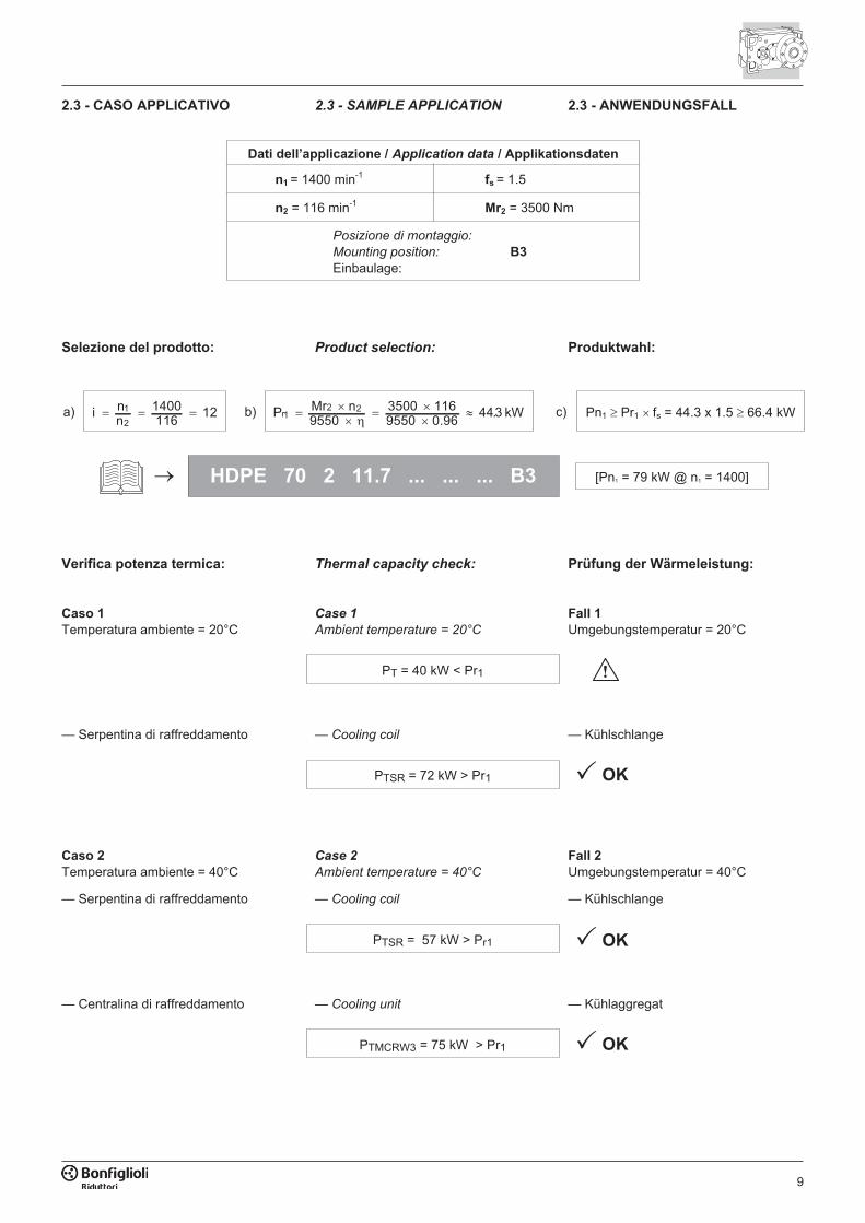
2.3 - CASO APPLICATIVO 2.3 - ANWENDUNGSFALL2.3 - SAMPLE APPLICATION
Dati dell’applicazione / Application data / Applikationsdaten
n1 = 1400 min-1fs = 1.5
n2 = 116 min-1Mr2 = 3500 Nm
Posizione di montaggio:
Mounting position: B3
Einbaulage:
Verifica potenza termica: Prüfung der Wärmeleistung:Thermal capacity check:
Selezione del prodotto: Produktwahl:Product selection:
HDPE 70 2 11.7 ... ... ... B3 [Pn1 = 79 kW @ n1 = 1400]�
Caso 2
Temperatura ambiente = 40°CFall 2
Umgebungstemperatur = 40°CCase 2
Ambient temperature = 40°C
PTSR = 57 kW > Pr1
i nn
1400116
121
2� � � Pn1 � Pr1 � fs = 44.3 x 1.5 � 66.4 kWP Mr n
95503500 19550 0.96
4 kWr12 2�
��
���
��
16 43.a) b) c)
— Serpentina di raffreddamento — Kühlschlange— Cooling coil
Caso 1
Temperatura ambiente = 20°CFall 1
Umgebungstemperatur = 20°CCase 1
Ambient temperature = 20°C
PT = 40 kW < Pr1
� OKPTSR = 72 kW > Pr1
— Serpentina di raffreddamento — Kühlschlange— Cooling coil
� OKPTMCRW3 = 75 kW > Pr1
— Centralina di raffreddamento — Kühlaggregat— Cooling unit
� OK
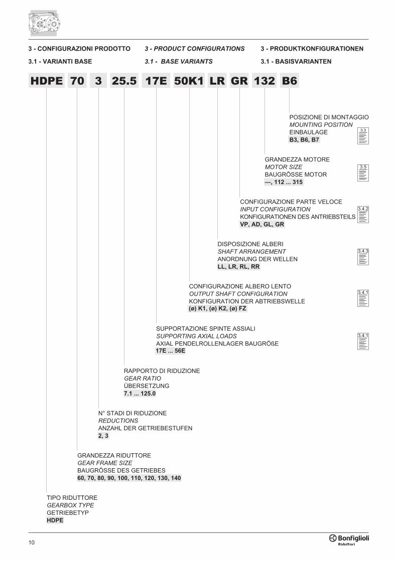
GRANDEZZA RIDUTTOREGEAR FRAME SIZE
BAUGRÖSSE DES GETRIEBES60, 70, 80, 90, 100, 110, 120, 130, 140
TIPO RIDUTTOREGEARBOX TYPE
GETRIEBETYPHDPE
N° STADI DI RIDUZIONEREDUCTIONS
ANZAHL DER GETRIEBESTUFEN2, 3
DISPOSIZIONE ALBERISHAFT ARRANGEMENT
ANORDNUNG DER WELLENLL, LR, RL, RR
CONFIGURAZIONE PARTE VELOCEINPUT CONFIGURATION
KONFIGURATIONEN DES ANTRIEBSTEILSVP, AD, GL, GR
POSIZIONE DI MONTAGGIOMOUNTING POSITION
EINBAULAGEB3, B6, B7
10
GRANDEZZA MOTOREMOTOR SIZE
BAUGRÖSSE MOTOR—, 112 ... 315
RAPPORTO DI RIDUZIONEGEAR RATIO
ÜBERSETZUNG7.1 ... 125.0
3.3
3.5
3.4.2
3.4.3
HDPE 70 3 25.5 LR GR 132 B6
3 - CONFIGURAZIONI PRODOTTO
3.1 - VARIANTI BASE
3 - PRODUCT CONFIGURATIONS
3.1 - BASE VARIANTS
3 - PRODUKTKONFIGURATIONEN
3.1 - BASISVARIANTEN
3.4.1
CONFIGURAZIONE ALBERO LENTOOUTPUT SHAFT CONFIGURATION
KONFIGURATION DER ABTRIEBSWELLE(ø) K1, (ø) K2, (ø) FZ
17E
SUPPORTAZIONE SPINTE ASSIALISUPPORTING AXIAL LOADS
AXIAL PENDELROLLENLAGER BAUGRÖßE17E ... 56E
3.4.1
50K1
11
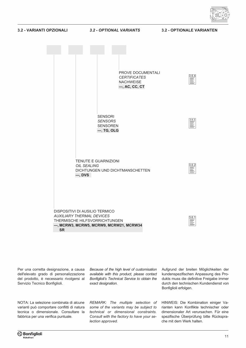
DISPOSITIVI DI AUSILIO TERMICOAUXILIARY THERMAL DEVICES
THERMISCHE HILFSVORRICHTUNGEN—, MCRW3, MCRW5, MCRW9, MCRW21, MCRW34
SR
TENUTE E GUARNIZIONIOIL SEALING
DICHTUNGEN UND DICHTMANSCHETTEN—, DVS
SENSORISENSORS
SENSOREN—, TG, OLG
PROVE DOCUMENTALICERTIFICATES
NACHWEISE—, AC, CC, CT
3.2 - VARIANTI OPZIONALI 3.2 - OPTIONAL VARIANTS 3.2 - OPTIONALE VARIANTEN
NOTA: La selezione combinata di alcunevarianti può comportare conflitti di naturatecnica o dimensionale. Consultare lafabbrica per una verifica puntuale.
REMARK: The multiple selection of
some of the variants may be subject to
technical or dimensional constraints.
Consult with the factory to have your se-
lection approved.
HINWEIS: Die Kombination einiger Va-rianten kann Konflikte technischer oderdimensionaler Art verursachen. Für einespezifische Überprüfung bitte Rückspra-che mit dem Werk halten.
3.6.4
3.6.2
3.6.1
3.6.3
Per una corretta designazione, a causadell'elevato grado di personalizzazionedel prodotto, è necessario rivolgersi alServizio Tecnico Bonfiglioli.
Because of the high level of customisation
available with this product, please contact
Bonfiglioli’s Technical Service to obtain the
exact designation.
Aufgrund der breiten Möglichkeiten derkundenspezifischen Anpassung des Pro-dukts muss die definitive Freigabe immerdurch den technischen Kundendienst vonBonfiglioli erfolgen.
12
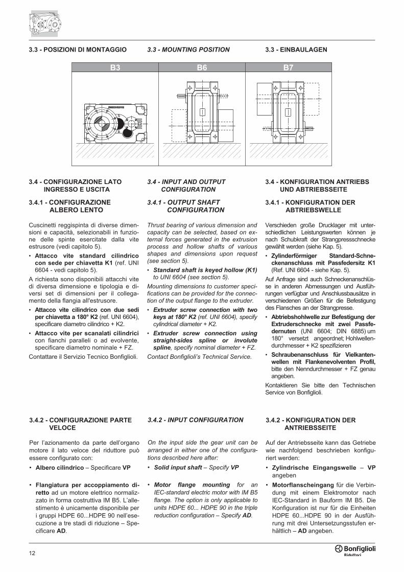
3.3 - POSIZIONI DI MONTAGGIO 3.3 - MOUNTING POSITION 3.3 - EINBAULAGEN
�� �� ��
3.4 - CONFIGURAZIONE LATOINGRESSO E USCITA
3.4.1 - CONFIGURAZIONEALBERO LENTO
3.4 - INPUT AND OUTPUT
CONFIGURATION
3.4.1 - OUTPUT SHAFT
CONFIGURATION
3.4 - KONFIGURATION ANTRIEBSUND ABTRIEBSSEITE
3.4.1 - KONFIGURATION DERABTRIEBSWELLE
3.4.2 - CONFIGURAZIONE PARTEVELOCE
Per l’azionamento da parte dell’organomotore il lato veloce del riduttore puòessere configurato con:
• Albero cilindrico – Specificare VP
• Flangiatura per accoppiamento di-retto ad un motore elettrico normaliz-zato in forma costruttiva IM B5. L’alle-stimento è unicamente disponibile peri gruppi HDPE 60...HDPE 90 nell’ese-cuzione a tre stadi di riduzione – Spe-cificare AD.
3.4.2 - INPUT CONFIGURATION
On the input side the gear unit can be
arranged in either one of the configura-
tions described here after:
• Solid input shaft – Specify VP
• Motor flange mounting for an
IEC-standard electric motor with IM B5
flange. The option is only applicable to
units HDPE 60... HDPE 90 in the triple
reduction configuration – Specify AD.
3.4.2 - KONFIGURATION DERANTRIEBSSEITE
Auf der Antriebsseite kann das Getriebewie nachfolgend beschrieben konfigu-riert werden:
• Zylindrische Eingangswelle – VPangeben
• Motorflanscheingang für die Verbin-dung mit einem Elektromotor nachIEC-Standard in Bauform IM B5. DieKonfiguration ist nur für die EinheitenHDPE 60...HDPE 90 in der Ausfüh-rung mit drei Untersetzungsstufen er-hältlich – AD angeben.
Cuscinetti reggispinta di diverse dimen-sioni e capacità, selezionabili in funzio-ne delle spinte esercitate dalla viteestrusore (vedi capitolo 5).
• Attacco vite standard cilindricocon sede per chiavetta K1 (ref. UNI6604 - vedi capitolo 5).
A richiesta sono disponibili attacchi vitedi diversa dimensione e tipologia e di-versi set di dimensioni per il collega-mento della flangia all'estrusore.
• Attacco vite cilindrico con due sediper chiavetta a 180° K2 (ref. UNI 6604),specificare diametro cilindrico + K2.
• Attacco vite per scanalati cilindricicon fianchi paralleli o ad evolvente,specificare diametro nominale + FZ.
Contattare il Servizio Tecnico Bonfiglioli.
Thrust bearing of various dimension andcapacity can be selected, based on ex-ternal forces generated in the extrusionprocess and hollow shafts of variousshapes and dimensions upon request(see section 5).
• Standard shaft is keyed hollow (K1)
to UNI 6604 (see section 5).
Mounting dimensions to customer speci-fications can be provided for the connec-tion of the output flange to the extruder.
• Extruder screw connection with two
keys at 180° K2 (ref. UNI 6604), specifycylindrical diameter + K2.
• Extruder screw connection using
straight-sides spline or involute
spline, specify nominal diameter + FZ.
Contact Bonfiglioli’s Technical Service.
Verschieden große Drucklager mit unter-schiedlichen Leistungswerten können jenach Schubkraft der Strangpressschneckegewählt werden (siehe Kap. 5).
• Zylinderförmiger Standard-Schne-ckenanschluss mit Passfedersitz K1(Ref. UNI 6604 - siehe Kap. 5).
Auf Anfrage sind auch Schneckenanschlüs-se in anderen Abmessungen und Ausfüh-rungen verfügbar und Anschlussbausätze inverschiedenen Größen für die Befestigungdes Flansches an der Strangpresse.
• Abtriebshohlwelle zur Befestigung derExtruderschnecke mit zwei Passfe-dernuten (UNI 6604; DIN 6885) um180° versetzt angeordnet; Hohlwellen-durchmesser + K2 spezifizieren
• Schraubenanschluss für Vielkanten-wellen mit Flankenevolventen Profil,bitte den Nenndurchmesser + FZ genauangeben.
Kontaktieren Sie bitte den TechnischenService von Bonfiglioli.
13
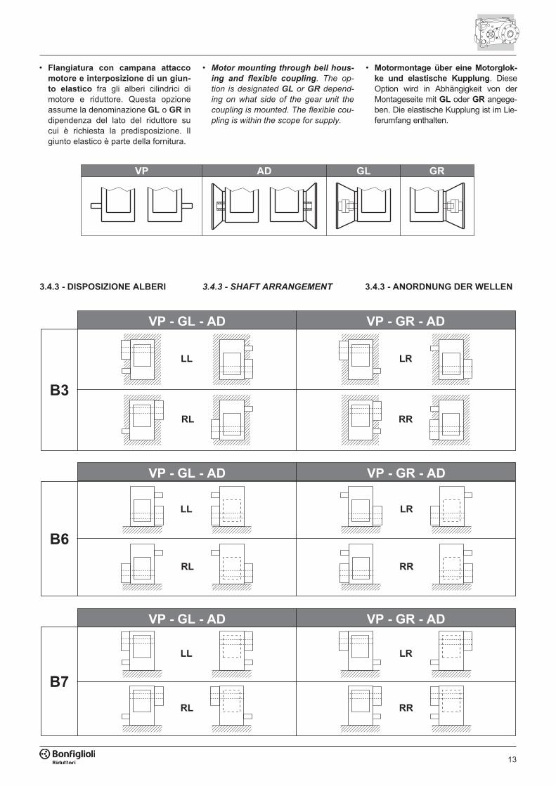
3.4.3 - DISPOSIZIONE ALBERI 3.4.3 - SHAFT ARRANGEMENT 3.4.3 - ANORDNUNG DER WELLEN
��
���������� ����� �����
��
���������� ����� �����
����������
��
����� �����
�� ��
• Flangiatura con campana attaccomotore e interposizione di un giun-to elastico fra gli alberi cilindrici dimotore e riduttore. Questa opzioneassume la denominazione GL o GR indipendenza del lato del riduttore sucui è richiesta la predisposizione. Ilgiunto elastico è parte della fornitura.
• Motor mounting through bell hous-
ing and flexible coupling. The op-
tion is designated GL or GR depend-
ing on what side of the gear unit the
coupling is mounted. The flexible cou-
pling is within the scope for supply.
• Motormontage über eine Motorglok-ke und elastische Kupplung. DieseOption wird in Abhängigkeit von derMontageseite mit GL oder GR angege-ben. Die elastische Kupplung ist im Lie-ferumfang enthalten.
14
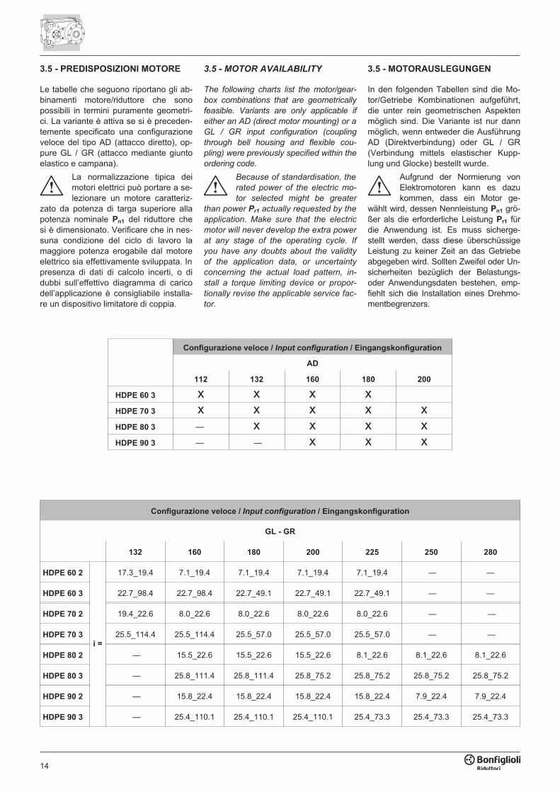
3.5 - PREDISPOSIZIONI MOTORE
Le tabelle che seguono riportano gli ab-binamenti motore/riduttore che sonopossibili in termini puramente geometri-ci. La variante è attiva se si è preceden-temente specificato una configurazioneveloce del tipo AD (attacco diretto), op-pure GL / GR (attacco mediante giuntoelastico e campana).
La normalizzazione tipica deimotori elettrici può portare a se-lezionare un motore caratteriz-
zato da potenza di targa superiore allapotenza nominale Pn1 del riduttore chesi è dimensionato. Verificare che in nes-suna condizione del ciclo di lavoro lamaggiore potenza erogabile dal motoreelettrico sia effettivamente sviluppata. Inpresenza di dati di calcolo incerti, o didubbi sull’effettivo diagramma di caricodell’applicazione è consigliabile installa-re un dispositivo limitatore di coppia.
3.5 - MOTOR AVAILABILITY
The following charts list the motor/gear-
box combinations that are geometrically
feasible. Variants are only applicable if
either an AD (direct motor mounting) or a
GL / GR input configuration (coupling
through bell housing and flexible cou-
pling) were previously specified within the
ordering code.
Because of standardisation, the
rated power of the electric mo-
tor selected might be greater
than power Pr1 actually requested by the
application. Make sure that the electric
motor will never develop the extra power
at any stage of the operating cycle. If
you have any doubts about the validity
of the application data, or uncertainty
concerning the actual load pattern, in-
stall a torque limiting device or propor-
tionally revise the applicable service fac-
tor.
3.5 - MOTORAUSLEGUNGEN
In den folgenden Tabellen sind die Mo-tor/Getriebe Kombinationen aufgeführt,die unter rein geometrischen Aspektenmöglich sind. Die Variante ist nur dannmöglich, wenn entweder die AusführungAD (Direktverbindung) oder GL / GR(Verbindung mittels elastischer Kupp-lung und Glocke) bestellt wurde.
Aufgrund der Normierung vonElektromotoren kann es dazukommen, dass ein Motor ge-
wählt wird, dessen Nennleistung Pn1 grö-ßer als die erforderliche Leistung Pr1 fürdie Anwendung ist. Es muss sicherge-stellt werden, dass diese überschüssigeLeistung zu keiner Zeit an das Getriebeabgegeben wird. Sollten Zweifel oder Un-sicherheiten bezüglich der Belastungs-oder Anwendungsdaten bestehen, emp-fiehlt sich die Installation eines Drehmo-mentbegrenzers.
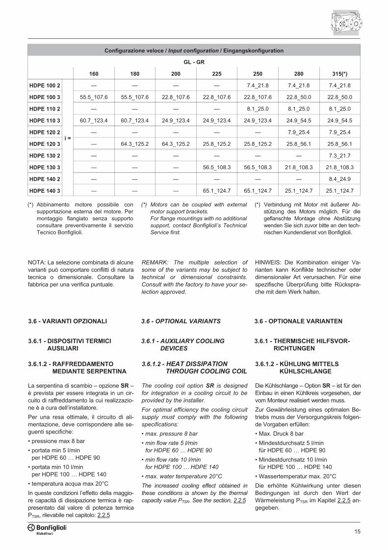
Configurazione veloce / Input configuration / Eingangskonfiguration
AD
112 132 160 180 200
HDPE 60 3 x x x xHDPE 70 3 x x x x xHDPE 80 3 — x x x xHDPE 90 3 — — x x x
Configurazione veloce / Input configuration / Eingangskonfiguration
GL - GR
132 160 180 200 225 250 280
HDPE 60 2
i =
17.3_19.4 7.1_19.4 7.1_19.4 7.1_19.4 7.1_19.4 — —
HDPE 60 3 22.7_98.4 22.7_98.4 22.7_49.1 22.7_49.1 22.7_49.1 — —
HDPE 70 2 19.4_22.6 8.0_22.6 8.0_22.6 8.0_22.6 8.0_22.6 — —
HDPE 70 3 25.5_114.4 25.5_114.4 25.5_57.0 25.5_57.0 25.5_57.0 — —
HDPE 80 2 — 15.5_22.6 15.5_22.6 15.5_22.6 8.1_22.6 8.1_22.6 8.1_22.6
HDPE 80 3 — 25.8_111.4 25.8_111.4 25.8_75.2 25.8_75.2 25.8_75.2 25.8_75.2
HDPE 90 2 — 15.8_22.4 15.8_22.4 15.8_22.4 15.8_22.4 7.9_22.4 7.9_22.4
HDPE 90 3 — 25.4_110.1 25.4_110.1 25.4_110.1 25.4_73.3 25.4_73.3 25.4_73.3
15
Configurazione veloce / Input configuration / Eingangskonfiguration
GL - GR
160 180 200 225 250 280 315(*)
HDPE 100 2
i =
— — — — 7.4_21.8 7.4_21.8 7.4_21.8
HDPE 100 3 55.5_107.6 55.5_107.6 22.8_107.6 22.8_107.6 22.8_107.6 22.8_50.0 22.8_50.0
HDPE 110 2 — — — — 8.1_25.0 8.1_25.0 8.1_25.0
HDPE 110 3 60.7_123.4 60.7_123.4 24.9_123.4 24.9_123.4 24.9_123.4 24.9_54.5 24.9_54.5
HDPE 120 2 — — — — — 7.9_25.4 7.9_25.4
HDPE 120 3 — 64.3_125.2 64.3_125.2 25.8_125.2 25.8_125.2 25.8_56.1 25.8_56.1
HDPE 130 2 — — — — — — 7.3_21.7
HDPE 130 3 — — — 56.5_108.3 56.5_108.3 21.8_108.3 21.8_108.3
HDPE 140 2 — — — — — — 8.4_24.9
HDPE 140 3 — — — 65.1_124.7 65.1_124.7 25.1_124.7 25.1_124.7
(*) Abbinamento motore possibile consupportazione esterna del motore. Permontaggio flangiato senza supportoconsultare preventivamente il servizioTecnico Bonfiglioli.
(*) Motors can be coupled with external
motor support brackets.
For flange mountings with no additional
support, contact Bonfiglioli’s Technical
Service first.
(*) Verbindung mit Motor mit äußerer Ab-stützung des Motors möglich. Für diegeflanschte Montage ohne Abstützungwenden Sie sich zuvor bitte an den tech-nischen Kundendienst von Bonfiglioli.
3.6 - VARIANTI OPZIONALI
3.6.1 - DISPOSITIVI TERMICIAUSILIARI
3.6 - OPTIONAL VARIANTS
3.6.1 - AUXILIARY COOLING
DEVICES
3.6 - OPTIONALE VARIANTEN
3.6.1 - THERMISCHE HILFSVOR-RICHTUNGEN
3.6.1.2 - RAFFREDDAMENTOMEDIANTE SERPENTINA
La serpentina di scambio – opzione SR –è prevista per essere integrata in un cir-cuito di raffreddamento la cui realizzazio-ne è a cura dell’installatore.
Per una resa ottimale, il circuito di ali-mentazione, deve corrispondere alle se-guenti specifiche:
• pressione max 8 bar
• portata min 5 l/minper HDPE 60 … HDPE 90
• portata min 10 l/minper HDPE 100 … HDPE 140
• temperatura acqua max 20°C
In queste condizioni l’effetto della maggio-re capacità di dissipazione termica è rap-presentato dal valore di potenza termicaPTSR, rilevabile nel capitolo: 2.2.5
3.6.1.2 - HEAT DISSIPATION
THROUGH COOLING COIL
The cooling coil option SR is designed
for integration in a cooling circuit to be
provided by the installer.
For optimal efficiency the cooling circuit
supply must comply with the following
specifications:
• max. pressure 8 bar
• min flow rate 5 l/min
for HDPE 60 … HDPE 90
• min flow rate 10 l/min
for HDPE 100 … HDPE 140
• max. water temperature 20°C
The increased cooling effect obtained in
these conditions is shown by the thermal
capacity value PTSR. See the section, 2.2.5
3.6.1.2 - KÜHLUNG MITTELSKÜHLSCHLANGE
Die Kühlschlange – Option SR – ist für denEinbau in einen Kühlkreis vorgesehen, dervom Monteur realisiert werden muss.
Zur Gewährleistung eines optimalen Be-triebs muss der Versorgungskreis folgen-de Vorgaben erfüllen:
• Max. Druck 8 bar
• Mindestdurchsatz 5 l/minfür HDPE 60 … HDPE 90
• Mindestdurchsatz 10 l/minfür HDPE 100 … HDPE 140
• Wassertemperatur max. 20°C
Die erhöhte Kühlwirkung unter diesenBedingungen ist durch den Wert derWärmeleistung PTSR im Kapitel 2.2.5 an-gegeben.
NOTA: La selezione combinata di alcunevarianti può comportare conflitti di naturatecnica o dimensionale. Consultare lafabbrica per una verifica puntuale.
REMARK: The multiple selection of
some of the variants may be subject to
technical or dimensional constraints.
Consult with the factory to have your se-
lection approved.
HINWEIS: Die Kombination einiger Va-rianten kann Konflikte technischer oderdimensionaler Art verursachen. Für einespezifische Überprüfung bitte Rückspra-che mit dem Werk halten.
16
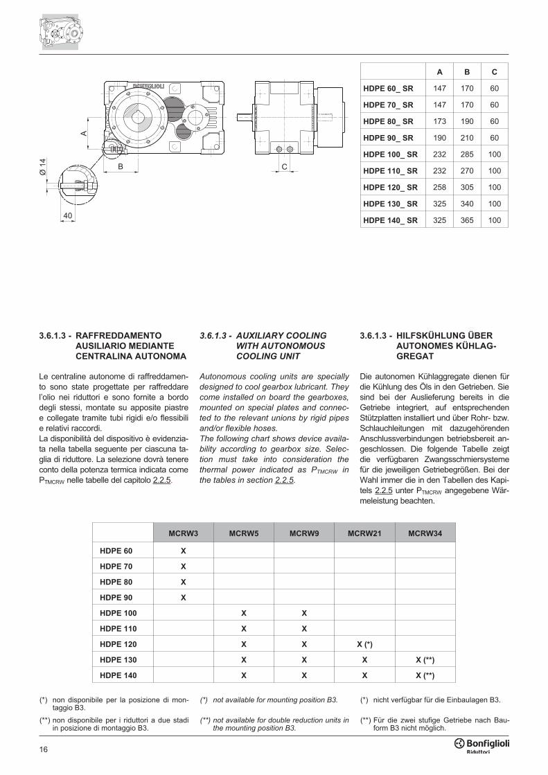
�
A B C
HDPE 60_ SR 147 170 60
HDPE 70_ SR 147 170 60
HDPE 80_ SR 173 190 60
HDPE 90_ SR 190 210 60
HDPE 100_ SR 232 285 100
HDPE 110_ SR 232 270 100
HDPE 120_ SR 258 305 100
HDPE 130_ SR 325 340 100
HDPE 140_ SR 325 365 100
3.6.1.3 - RAFFREDDAMENTOAUSILIARIO MEDIANTECENTRALINA AUTONOMA
Le centraline autonome di raffreddamen-to sono state progettate per raffreddarel’olio nei riduttori e sono fornite a bordodegli stessi, montate su apposite piastree collegate tramite tubi rigidi e/o flessibilie relativi raccordi.La disponibilità del dispositivo è evidenzia-ta nella tabella seguente per ciascuna ta-glia di riduttore. La selezione dovrà tenereconto della potenza termica indicata comePTMCRW nelle tabelle del capitolo 2.2.5.
3.6.1.3 - AUXILIARY COOLING
WITH AUTONOMOUS
COOLING UNIT
Autonomous cooling units are specially
designed to cool gearbox lubricant. They
come installed on board the gearboxes,
mounted on special plates and connec-
ted to the relevant unions by rigid pipes
and/or flexible hoses.
The following chart shows device availa-
bility according to gearbox size. Selec-
tion must take into consideration the
thermal power indicated as PTMCRW in
the tables in section 2.2.5.
3.6.1.3 - HILFSKÜHLUNG ÜBERAUTONOMES KÜHLAG-GREGAT
Die autonomen Kühlaggregate dienen fürdie Kühlung des Öls in den Getrieben. Siesind bei der Auslieferung bereits in dieGetriebe integriert, auf entsprechendenStützplatten installiert und über Rohr- bzw.Schlauchleitungen mit dazugehörendenAnschlussverbindungen betriebsbereit an-geschlossen. Die folgende Tabelle zeigtdie verfügbaren Zwangsschmiersystemefür die jeweiligen Getriebegrößen. Bei derWahl immer die in den Tabellen des Kapi-tels 2.2.5 unter PTMCRW angegebene Wär-meleistung beachten.
MCRW3 MCRW5 MCRW9 MCRW21 MCRW34
HDPE 60 X
HDPE 70 X
HDPE 80 X
HDPE 90 X
HDPE 100 X X
HDPE 110 X X
HDPE 120 X X X (*)
HDPE 130 X X X X (**)
HDPE 140 X X X X (**)
(*) non disponibile per la posizione di mon-taggio B3.
(*) not available for mounting position B3. (*) nicht verfügbar für die Einbaulagen B3.
(**) non disponibile per i riduttori a due stadiin posizione di montaggio B3.
(**) not available for double reduction units inthe mounting position B3.
(**) Für die zwei stufige Getriebe nach Bau-form B3 nicht möglich.
17
�� ����
�
� � �
��
�
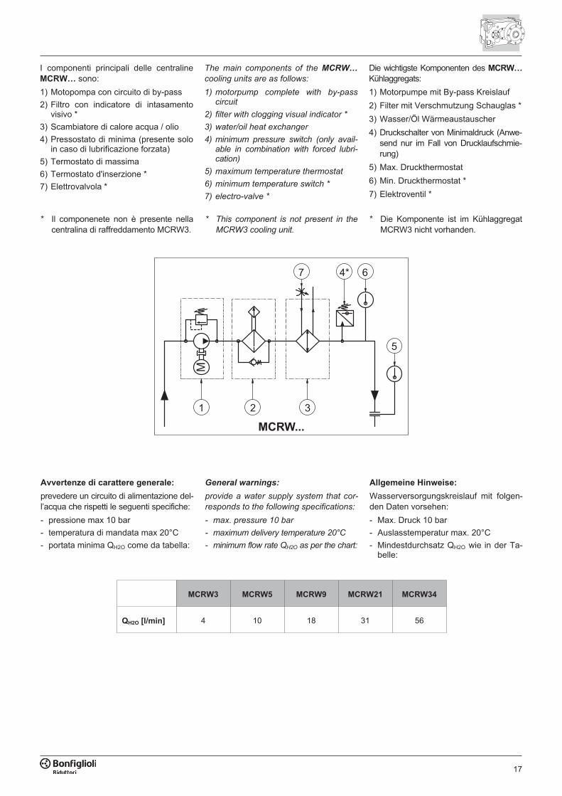
The main components of the MCRW…
cooling units are as follows:
1) motorpump complete with by-passcircuit
2) filter with clogging visual indicator *
3) water/oil heat exchanger
4) minimum pressure switch (only avail-able in combination with forced lubri-cation)
5) maximum temperature thermostat
6) minimum temperature switch *
7) electro-valve *
Die wichtigste Komponenten des MCRW…Kühlaggregats:
1) Motorpumpe mit By-pass Kreislauf
2) Filter mit Verschmutzung Schauglas *
3) Wasser/Öl Wärmeaustauscher
4) Druckschalter von Minimaldruck (Anwe-send nur im Fall von Drucklaufschmie-rung)
5) Max. Druckthermostat
6) Min. Druckthermostat *
7) Elektroventil *
I componenti principali delle centralineMCRW… sono:
1) Motopompa con circuito di by-pass
2) Filtro con indicatore di intasamentovisivo *
3) Scambiatore di calore acqua / olio
4) Pressostato di minima (presente soloin caso di lubrificazione forzata)
5) Termostato di massima
6) Termostato d'inserzione *
7) Elettrovalvola *
Avvertenze di carattere generale:
prevedere un circuito di alimentazione del-l’acqua che rispetti le seguenti specifiche:
- pressione max 10 bar
- temperatura di mandata max 20°C
- portata minima QH2O come da tabella:
General warnings:
provide a water supply system that cor-
responds to the following specifications:
- max. pressure 10 bar
- maximum delivery temperature 20°C
- minimum flow rate QH2O as per the chart:
Allgemeine Hinweise:
Wasserversorgungskreislauf mit folgen-den Daten vorsehen:
- Max. Druck 10 bar
- Auslasstemperatur max. 20°C
- Mindestdurchsatz QH2O wie in der Ta-belle:
MCRW3 MCRW5 MCRW9 MCRW21 MCRW34
QH2O [l/min] 4 10 18 31 56
* Il componenete non è presente nellacentralina di raffreddamento MCRW3.
* This component is not present in the
MCRW3 cooling unit.
* Die Komponente ist im KühlaggregatMCRW3 nicht vorhanden.
18
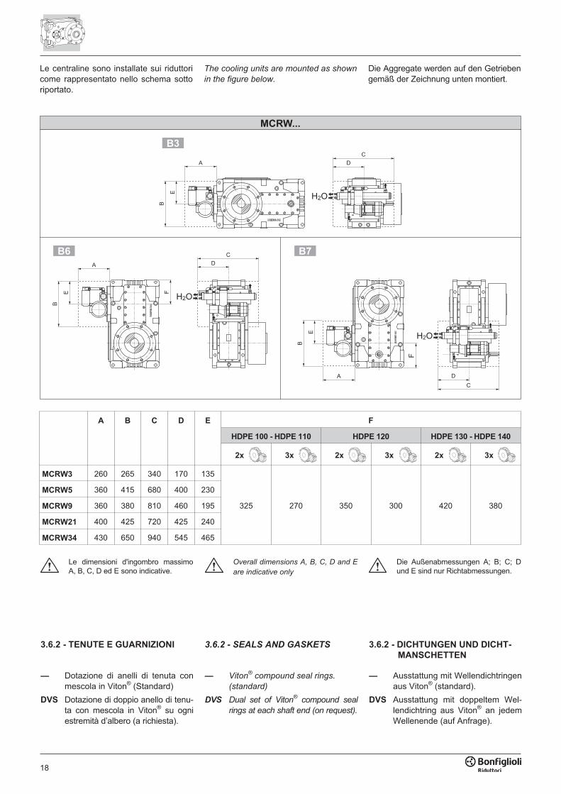
Le centraline sono installate sui riduttoricome rappresentato nello schema sottoriportato.
The cooling units are mounted as shown
in the figure below.
Die Aggregate werden auf den Getriebengemäß der Zeichnung unten montiert.
�� ����
�
�
�
���
��
��
�
���
�
�
�
�
��
�
�
���
��
��
A B C D E F
HDPE 100 - HDPE 110 HDPE 120 HDPE 130 - HDPE 140
2x 3x 2x 3x 2x 3x
MCRW3 260 265 340 170 135
325 270 350 300 420 380
MCRW5 360 415 680 400 230
MCRW9 360 380 810 460 195
MCRW21 400 425 720 425 240
MCRW34 430 650 940 545 465
Le dimensioni d'ingombro massimoA, B, C, D ed E sono indicative.
Overall dimensions A, B, C, D and E
are indicative only
Die Außenabmessungen A; B; C; Dund E sind nur Richtabmessungen.
3.6.2 - SEALS AND GASKETS
— Viton®
compound seal rings.
(standard)
DVS Dual set of Viton®
compound seal
rings at each shaft end (on request).
3.6.2 - DICHTUNGEN UND DICHT-MANSCHETTEN
— Ausstattung mit Wellendichtringenaus Viton® (standard).
DVS Ausstattung mit doppeltem Wel-lendichtring aus Viton® an jedemWellenende (auf Anfrage).
3.6.2 - TENUTE E GUARNIZIONI
— Dotazione di anelli di tenuta conmescola in Viton® (Standard)
DVS Dotazione di doppio anello di tenu-ta con mescola in Viton® su ogniestremità d’albero (a richiesta).
19
3.6.3 - SENSORI
Termostato bimetallico – Su specificadell’opzione TG è fornita una sonda bi-metallica termostatica per rilevarequando la temperatura dell’olio supera ilvalore di 90°C ± 5°C. Il dispositivo è for-nito a corredo e l’installazione e il relati-vo cablaggio elettrico sono a cura del-l’installatore.
Controllo livello olio – Su specificadell’opzione OLG in fase di ordinativo èinstallata una sonda per il controllo re-moto del livello del lubrificante. Il dispo-sitivo è funzionante in condizioni di inat-tività del riduttore. Durante il funziona-mento dello stesso, il dispositivo deveessere bypassato. Il cablaggio è a curadell’installatore. Il dispositivo può nonessere compatibile con altri accessorie/o alcune configurazioni, contattare ilServizio Tecnico Bonfiglioli.
3.6.3 - SENSORS
Bimetal thermostat – If the TG option
is specified, a bimetallic thermostat de-
tects when the oil temperature exceeds
90°C ± 5°C.
The device is supplied with the gear
unit, but installation and wiring are the
responsibility of the installer.
Oil level indicator – If the OLG option
is specified in the order, the gearbox is
supplied with a device to permit remote
control of the oil level. The device best
operates when the gearbox is idle and
should be bypassed when the gearbox
is operating. Wiring is the responsibility
of the installer. The device may not be
available in combination with other ac-
cessories and/or particular product con-
figurations. Please contact Bonfiglioli
Technical Service for advise.
3.6.3 - SENSOREN
Bimetallthermostat – Bei Bestellung derOption TG ist ein Bimetalltemperaturfühlerverfügbar, der dazu dient, die Überschreitungdes Werts 90°C ± 5°C der Öltemperatur zuerfassen. Die Vorrichtung wird im Zubehörmitgeliefert; die Installation und die entspre-chende elektrische Verkabelung müssenvom Monteur durchgeführt werden.
Ölstandkontrolle – Wird bei Auftragser-teilung die Option OLG bestellt, erfolgt dieInstallation eines Fühlers für die Fernkon-trolle des Ölstands. Die Vorrichtung funk-tioniert bei Stillstand des Getriebes. Wäh-rend des Betriebs des Getriebes muss dieVorrichtung überbrückt werden.Diese Ausführung könnte nicht mit weite-ren Zubehören und/oder Ausführungenmöglich sein. Kontaktieren Sie bitte denTechnischen Service von Bonfiglioli.
3.6.4 - PROVE DOCUMENTALI
AC - Attestato di conformitàDocumento il cui rilascio attesta la con-formità del prodotto all’ordinativo e la co-struzione dello stesso in conformità alleprocedure standard di processo e dicontrollo previste dal sistema di QualitàBonfiglioli Riduttori.
CC - Certificato di collaudoLa specifica comporta la conduzione diverifiche di conformità all’ordine, controllivisivi generali e verifiche strumentali del-le dimensioni di accoppiamento. Sonoinoltre condotti controlli generali di fun-zionamento a vuoto e verifiche della fun-zionalità delle guarnizioni di tenuta inmodalità statica e in funzionamento. Ilcollaudo si applica ad un campione stati-stico del lotto di spedizione.
CT - Certificato di tipoOltre alle attività competenti al Certifica-to di collaudo si aggiungono controllifunzionali specifici relativi a:
• controllo rumorosità
• temperatura superficiale a regime
• verifica della coppia di serraggio vite-ria esterna
• funzionalità eventuali organi accessori
Tutte le attività sono condotte con fun-zionamento a vuoto del riduttore. Il colla-udo si applica ad un campione statisticodel lotto di spedizione.
3.6.4 - CERTIFICATES
AC - Certificate of compliance
The document certifies the compliance
of the product with the purchase order
and the construction in conformity with
the applicable procedures of the
Bonfiglioli Quality System.
CC - Inspection certificate
The document entails checking on order
compliance, the visual inspection of ex-
ternal conditions and of mating dimen-
sions. Checking on main functional pa-
rameters in unloaded conditions is also
performed along with oil seal proofing,
both in static and in running conditions.
Units inspected are sampled within the
shipping batch and marked individually.
CT - Type certificate
Further to the activities relevant to the
Inspection certificate the following
checks are also conducted:
• noise
• surface temperature
• tightness of external hardware
• functionality of ancillary devices, if fit-
ted
All checks are conducted with the gear
unit running unloaded. Units inspected
are sampled within the shipping batch
and marked individually.
3.6.4 - NACHWEISE
AC - Konformitätsbescheinigung Do-kumentmit dessen Ausstellung die Konformität desProdukts mit dem Auftrag, und dessen Kon-struktion in Konformität mit den vom Quali-tätsmanagementsystem von Bonfiglioli Ri-duttori vorgesehenen Standardfertigungs-und -kontrollverfahren bescheinigt wird.
CC – PrüfzeugnisDie Bestellung führt zur Durchführungvon Kontrollen der Konformität mit demAuftrag, allgemeinen Sichtkontrollen undinstrumentalen Prüfungen der Passma-ße. Des Weiteren werden allgemeine Be-triebskontrollen bei Leerlauf sowie Prü-fungen der Funktionalität der Dichtungenbei Stillstand und während des Betriebsdurchgeführt. Die Prüfung wird anhandeiner Stichprobe des Versandlosesdurchgeführt.
CT – BaumusterzeugnisZu den Tätigkeiten, die unter das Prüf-zeugnis fallen, kommen spezifischeFunktionskontrollen in Bezug auf:
• Geräuschentwicklung
• Oberflächentemperatur bei Betriebs-drehzahl
• Prüfung des Anzugsmoments der äu-ßeren Schrauben
• Funktionalität eventueller zusätzlicherOrgane
Alle Vorgänge werden bei Leerlauf desGetriebes durchgeführt. Die Prüfungwird anhand einer Stichprobe des Ver-sandloses durchgeführt.

20
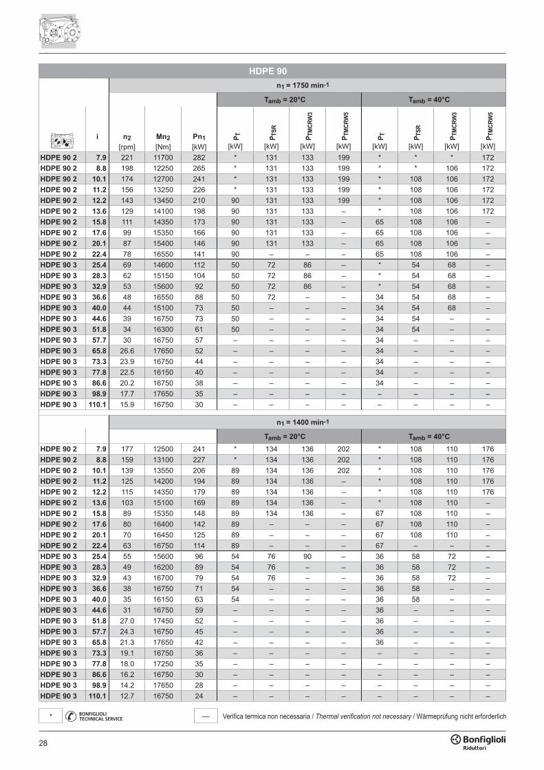
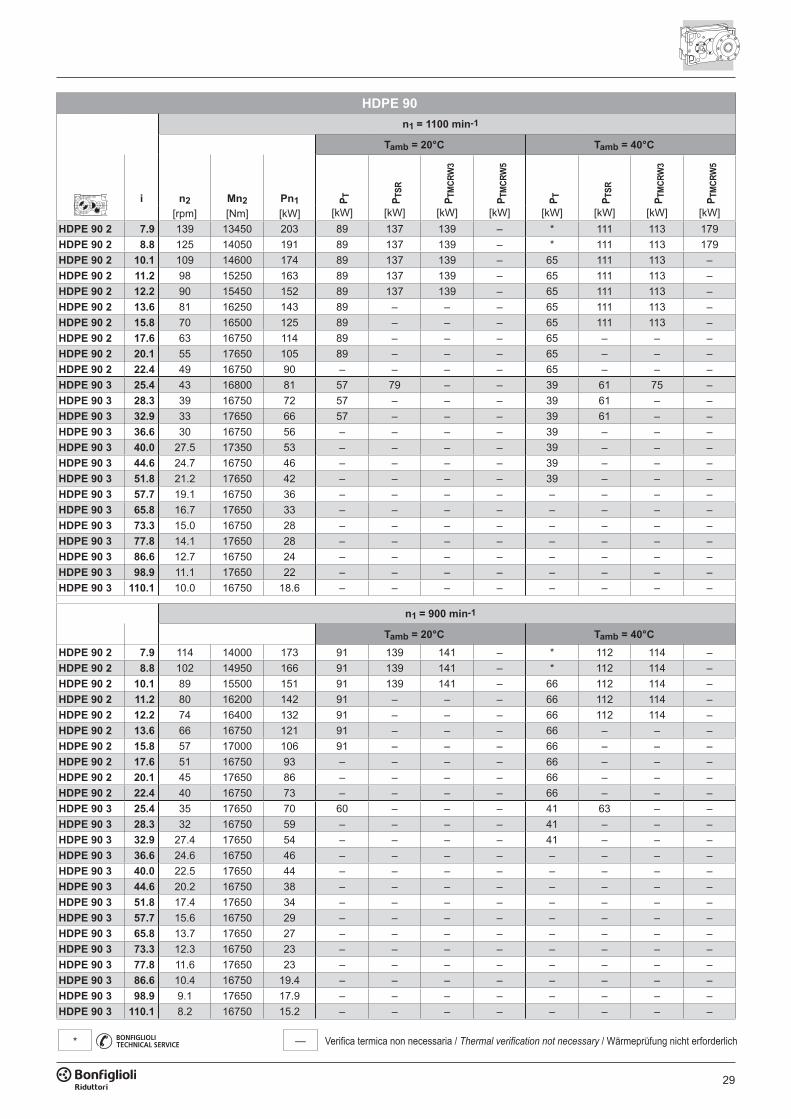
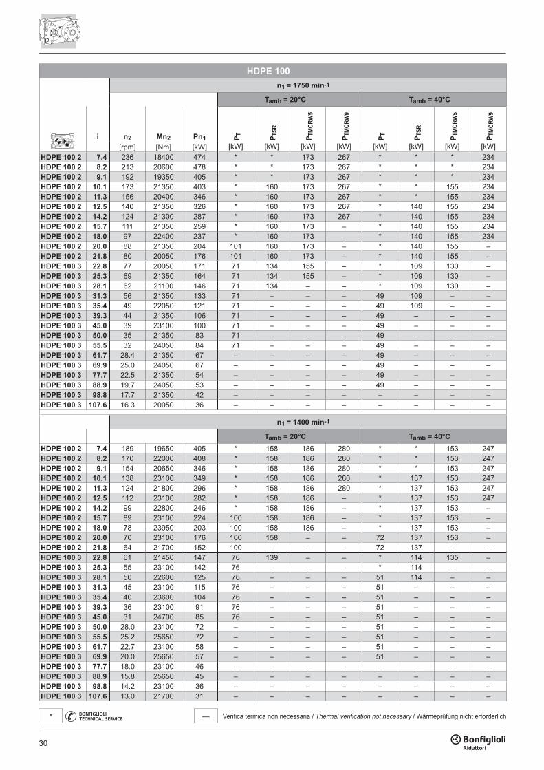
21
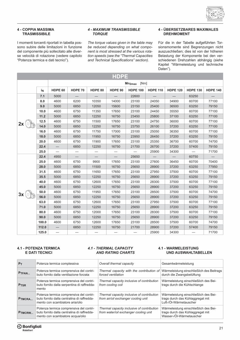
4.1 - POTENZA TERMICA E DATI TECNICI
4.1 - THERMAL CAPACITY AND RATING CHARTS
4.1 - WARMELEISTUNG UND AUSWAHLTABELLEN
PT Potenza termica complessiva Overall thermal capacity Gesamtwärmeleistung
PTFAN...Potenza termica comprensiva del contri-buto fornito dalla ventilazione forzata
Thermal capacity with the contribution of forced ventilation
Wärmeleistung einschließlich des Beitrags durch die Zwangsbelüftung
PTSRPotenza termica comprensiva del contri-buto fornito dalla serpentina di raffredda-mento
Thermal capacity inclusive of contribution from cooling coil
Wärmeleistung einschließlich des Bei-trags durch die Kühlschlange
PTMCRA...Potenza termica comprensiva del contri-buto fornito dalla centralina di raffredda-mento con scambiatore aria/olio
Thermal capacity inclusive of contribution from air/oil exchanger cooling unit
Wärmeleistung einschließlich des Bei-trags durch das Kühlaggregat mitLuft-/Öl-Wärmetauscher
PTMCRW...Potenza termica comprensiva del contri-buto fornito dalla centralina di raffredda-mento con scambiatore acqua/olio
Thermal capacity inclusive of contribution from water/oil exchanger cooling unit
Wärmeleistung einschließlich des Bei-trags durch das Kühlaggregat mitWasser-/Öl-Wärmetauscher
4 - COPPIA MASSIMA TRASMISSIBILE
I momenti torcenti riportati in tabella pos-sono subire delle limitazioni in funzione del componente più sollecitato alle diver-se velocità di rotazione (vedere capitolo “Potenza termica e dati tecnici”).
4 - MAXIMUM TRANSMISSIBLE TORQUE
The torque values given in the table may be reduced depending on what compo-nent is most stressed at the various rota-tion speeds (see the “Thermal Capacities and Technical Specifications” section).
4 - ÜBERSETZBARES MAXIMALES DREHMOMENT
Für die in der Tabelle aufgeführten Tor-sionsmomente sind Begrenzungen nicht auszuschließen; dies ist von der höheren Belastung der Komponente bei den ver-schiedenen Drehzahlen abhängig (siehe Kapitel “Wärmeleistung und technische Daten”).
HDPEMn2max [Nm]
iN HDPE 60 HDPE 70 HDPE 80 HDPE 90 HDPE 100 HDPE 110 HDPE 120 HDPE 130 HDPE 140
2x
7.1 5000 — — — 22600 — — 63250 —8.0 4600 6200 10350 14000 23100 24050 34900 60700 771009.0 5000 6850 12050 15600 23150 25400 36500 63250 79150
10.0 4600 6750 11350 17650 23100 24450 35550 60700 7710011.2 5000 6850 12250 16750 23450 25800 37100 63250 7710012.5 4600 6750 11500 17650 23100 24750 36000 60700 7710014.0 5000 6850 12250 16750 23750 26100 37200 63250 7710016.0 4600 6750 11750 17000 23100 25050 36350 60700 7710018.0 5000 6850 11950 16750 23950 26450 37200 63250 7915020.0 4600 6750 11900 17650 23100 25350 36700 60700 7470022.4 — 6850 12250 16750 21700 26700 37200 57400 7915025.0 — — — — — 25900 34300 — 71700
3x
22.4 4950 — — — 25650 — — 60750 —25.0 4600 6750 9900 17650 23100 27600 36450 60700 7040028.0 5000 6850 11500 16750 25650 28900 37200 63250 7795031.5 4600 6750 11650 17650 23100 27950 37500 60700 7710035.5 5000 6850 12250 16750 25650 28900 37200 63250 7915040.0 4600 6750 12600 17650 23100 28300 37500 60700 7710045.0 5000 6850 12250 16750 25650 28900 37200 63250 7915050.0 4600 6750 11950 17650 23100 28500 37500 60700 7470056.0 5000 6850 12250 16750 25650 28900 37200 63250 7915063.0 4600 6750 12600 17650 23100 27950 37500 60700 7710071.0 5000 6850 12250 16750 25650 28900 37200 63250 7915080.0 4600 6750 12000 17650 23100 28300 37500 60700 7710090.0 5000 6850 12250 16750 25650 28900 37200 63250 79150
100.0 4600 6750 12600 17650 23100 28500 37500 60700 74700112.0 — 6850 12250 16750 21700 28900 37200 57400 79150125.0 — — — — — 25900 34300 — 71700
22
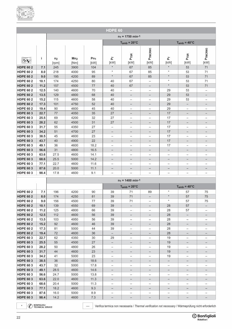
— Verifica termica non necessaria / Thermal verification not necessary / Wärmeprüfung nicht erforderlich*
HDPE 60n1 = 1750 min-1
Tamb = 20°C Tamb = 40°C
i n2 Mn2 Pn1 P T P TSR
P TM
CRW
3
P T P TSR
P TM
CRW
3
[rpm] [Nm] [kW] [kW] [kW] [kW] [kW] [kW] [kW]HDPE 60 2 7.1 245 3900 104 * 67 85 * 53 71HDPE 60 2 8.0 218 4000 95 * 67 85 * 53 71HDPE 60 2 9.0 195 4200 89 * 67 85 * 53 71HDPE 60 2 10.1 174 4250 80 40 67 – * 53 71HDPE 60 2 11.2 157 4500 77 40 67 – * 53 71HDPE 60 2 12.5 140 4600 70 40 – – 29 53 –HDPE 60 2 13.5 129 4800 68 40 – – 29 53 –HDPE 60 2 15.2 115 4600 58 40 – – 29 53 –HDPE 60 2 17.3 101 4750 52 40 – – 29 – –HDPE 60 2 19.4 90 4600 45 40 – – 29 – –HDPE 60 3 22.7 77 4050 35 27 – – 17 – –HDPE 60 3 25.5 69 4200 32 27 – – 17 – –HDPE 60 3 28.2 62 4500 31 27 – – 17 – –HDPE 60 3 31.7 55 4350 27 – – – 17 – –HDPE 60 3 34.2 51 4700 27 – – – 17 – –HDPE 60 3 38.5 45 4600 23 – – – 17 – –HDPE 60 3 43.7 40 4900 22 – – – 17 – –HDPE 60 3 49.1 36 4600 18.2 – – – 17 – –HDPE 60 3 56.6 31 4800 16.5 – – – – – –HDPE 60 3 63.6 27.5 4600 14.1 – – – – – –HDPE 60 3 68.6 25.5 5000 14.2 – – – – – –HDPE 60 3 77.1 22.7 4600 11.6 – – – – – –HDPE 60 3 87.6 20.0 5000 11.1 – – – – – –HDPE 60 3 98.4 17.8 4600 9.1 – – – – – –
n1 = 1400 min-1
Tamb = 20°C Tamb = 40°CHDPE 60 2 7.1 196 4200 90 39 71 89 * 57 75HDPE 60 2 8.0 174 4250 81 39 71 – * 57 75HDPE 60 2 9.0 156 4500 77 39 71 – * 57 75HDPE 60 2 10.1 139 4550 69 39 – – 28 57 –HDPE 60 2 11.2 125 4800 66 39 – – 28 57 –HDPE 60 2 12.5 112 4600 56 39 – – 28 – –HDPE 60 2 13.5 103 4950 56 39 – – 28 – –HDPE 60 2 15.2 92 4600 46 39 – – 28 – –HDPE 60 2 17.3 81 5000 44 39 – – 28 – –HDPE 60 2 19.4 72 4600 36 – – – 28 – –HDPE 60 3 22.7 62 4350 30 29 – – 19 – –HDPE 60 3 25.5 55 4500 27 – – – 19 – –HDPE 60 3 28.2 50 4800 26 – – – 19 – –HDPE 60 3 31.7 44 4600 23 – – – 19 – –HDPE 60 3 34.2 41 5000 23 – – – 19 – –HDPE 60 3 38.5 36 4600 18.6 – – – – – –HDPE 60 3 43.7 32 5000 17.8 – – – – – –HDPE 60 3 49.1 28.5 4600 14.6 – – – – – –HDPE 60 3 56.6 24.7 5000 13.8 – – – – – –HDPE 60 3 63.6 22.0 4600 11.3 – – – – – –HDPE 60 3 68.6 20.4 5000 11.3 – – – – – –HDPE 60 3 77.1 18.2 4600 9.3 – – – – – –HDPE 60 3 87.6 16.0 5000 8.9 – – – – – –HDPE 60 3 98.4 14.2 4600 7.3 – – – – – –
23
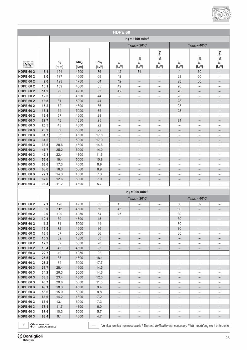
— Verifica termica non necessaria / Thermal verification not necessary / Wärmeprüfung nicht erforderlich*
HDPE 60n1 = 1100 min-1
Tamb = 20°C Tamb = 40°C
i n2 Mn2 Pn1 P T P TSR
P TM
CRW
3
P T P TSR
P TM
CRW
3
[rpm] [Nm] [kW] [kW] [kW] [kW] [kW] [kW] [kW]HDPE 60 2 7.1 154 4500 76 42 74 – * 60 –HDPE 60 2 8.0 137 4600 69 42 – – 28 60 –HDPE 60 2 9.0 123 4750 64 42 – – 28 60 –HDPE 60 2 10.1 109 4600 55 42 – – 28 – –HDPE 60 2 11.2 99 4950 53 42 – – 28 – –HDPE 60 2 12.5 88 4600 44 – – – 28 – –HDPE 60 2 13.5 81 5000 44 – – – 28 – –HDPE 60 2 15.2 72 4600 36 – – – 28 – –HDPE 60 2 17.3 64 5000 35 – – – 28 – –HDPE 60 2 19.4 57 4600 28 – – – – – –HDPE 60 3 22.7 48 4650 25 – – – 21 – –HDPE 60 3 25.5 43 4600 22 – – – – – –HDPE 60 3 28.2 39 5000 22 – – – – – –HDPE 60 3 31.7 35 4600 17.8 – – – – – –HDPE 60 3 34.2 32 5000 17.9 – – – – – –HDPE 60 3 38.5 28.6 4600 14.6 – – – – – –HDPE 60 3 43.7 25.2 5000 14.0 – – – – – –HDPE 60 3 49.1 22.4 4600 11.5 – – – – – –HDPE 60 3 56.6 19.4 5000 10.8 – – – – – –HDPE 60 3 63.6 17.3 4600 8.9 – – – – – –HDPE 60 3 68.6 16.0 5000 8.9 – – – – – –HDPE 60 3 77.1 14.3 4600 7.3 – – – – – –HDPE 60 3 87.6 12.6 5000 7.0 – – – – – –HDPE 60 3 98.4 11.2 4600 5.7 – – – – – –
n1 = 900 min-1
Tamb = 20°C Tamb = 40°CHDPE 60 2 7.1 126 4750 65 45 – – 30 62 –HDPE 60 2 8.0 112 4600 56 45 – – 30 – –HDPE 60 2 9.0 100 4950 54 45 – – 30 – –HDPE 60 2 10.1 89 4600 45 – – – 30 – –HDPE 60 2 11.2 81 5000 44 – – – 30 – –HDPE 60 2 12.5 72 4600 36 – – – 30 – –HDPE 60 2 13.5 67 5000 36 – – – 30 – –HDPE 60 2 15.2 59 4600 30 – – – – – –HDPE 60 2 17.3 52 5000 28 – – – – – –HDPE 60 2 19.4 46 4600 23 – – – – – –HDPE 60 3 22.7 40 4950 22 – – – – – –HDPE 60 3 25.5 35 4600 18.1 – – – – – –HDPE 60 3 28.2 32 5000 17.7 – – – – – –HDPE 60 3 31.7 28.4 4600 14.5 – – – – – –HDPE 60 3 34.2 26.3 5000 14.6 – – – – – –HDPE 60 3 38.5 23.4 4600 12.0 – – – – – –HDPE 60 3 43.7 20.6 5000 11.5 – – – – – –HDPE 60 3 49.1 18.3 4600 9.4 – – – – – –HDPE 60 3 56.6 15.9 5000 8.8 – – – – – –HDPE 60 3 63.6 14.2 4600 7.2 – – – – – –HDPE 60 3 68.6 13.1 5000 7.3 – – – – – –HDPE 60 3 77.1 11.7 4600 6.0 – – – – – –HDPE 60 3 87.6 10.3 5000 5.7 – – – – – –HDPE 60 3 98.4 9.1 4600 4.7 – – – – – –
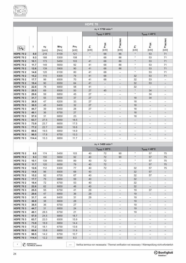
24
— Verifica termica non necessaria / Thermal verification not necessary / Wärmeprüfung nicht erforderlich*
HDPE 70n1 = 1750 min-1
Tamb = 20°C Tamb = 40°C
i n2 Mn2 Pn1 P T P TSR
P TM
CRW
3
P T P TSR
P TM
CRW
3
[rpm] [Nm] [kW] [kW] [kW] [kW] [kW] [kW] [kW]HDPE 70 2 8.0 218 5100 121 * 68 86 * 53 71HDPE 70 2 9.3 188 5300 108 * 68 86 * 53 71HDPE 70 2 10.1 173 5450 103 41 68 86 * 53 71HDPE 70 2 11.7 149 5650 92 41 68 86 * 53 71HDPE 70 2 12.6 139 5900 90 41 68 86 * 53 71HDPE 70 2 14.6 120 6100 80 41 68 – * 53 71HDPE 70 2 15.2 115 6300 79 41 68 – 32 53 71HDPE 70 2 17.7 99 6500 70 41 68 – 32 53 –HDPE 70 2 19.4 90 6550 64 41 – – 32 53 –HDPE 70 2 22.6 78 6850 58 41 – – 32 – –HDPE 70 3 25.5 69 6500 50 27 45 – * 34 –HDPE 70 3 29.6 59 6850 45 27 – – * 34 –HDPE 70 3 31.7 55 6000 37 27 – – 18 34 –HDPE 70 3 36.9 47 6200 33 27 – – 18 – –HDPE 70 3 38.5 45 6400 32 27 – – 18 – –HDPE 70 3 44.7 39 6450 28 27 – – 18 – –HDPE 70 3 49.1 36 6750 27 – – – 18 – –HDPE 70 3 57.0 31 6850 23 – – – 18 – –HDPE 70 3 63.7 27.5 6050 18.5 – – – – – –HDPE 70 3 73.9 23.7 6650 17.5 – – – – – –HDPE 70 3 77.2 22.7 6600 16.6 – – – – – –HDPE 70 3 89.6 19.5 6850 14.9 – – – – – –HDPE 70 3 98.5 17.8 6750 13.3 – – – – – –HDPE 70 3 114.4 15.3 6850 11.7 – – – – – –
n1 = 1400 min-1
Tamb = 20°C Tamb = 40°CHDPE 70 2 8.0 174 5450 103 40 72 90 * 57 75HDPE 70 2 9.3 150 5650 92 40 72 90 * 57 75HDPE 70 2 10.1 139 5850 89 40 72 – * 57 75HDPE 70 2 11.7 120 6050 79 40 72 – * 57 75HDPE 70 2 12.6 112 6300 77 40 72 – 32 57 75HDPE 70 2 14.6 96 6500 68 40 – – 32 57 –HDPE 70 2 15.2 92 6700 67 40 – – 32 57 –HDPE 70 2 17.7 79 6850 59 40 – – 32 – –HDPE 70 2 19.4 72 6750 53 40 – – 32 – –HDPE 70 2 22.6 62 6850 46 40 – – 32 – –HDPE 70 3 25.5 55 6750 41 29 – – 19 37 –HDPE 70 3 29.6 47 6850 36 29 – – 19 – –HDPE 70 3 31.7 44 6400 31 29 – – 19 – –HDPE 70 3 36.9 38 6600 28 – – – 19 – –HDPE 70 3 38.5 36 6750 27 – – – 19 – –HDPE 70 3 44.7 31 6850 24 – – – 19 – –HDPE 70 3 49.1 28.5 6750 21 – – – 19 – –HDPE 70 3 57.0 24.5 6850 18.7 – – – – – –HDPE 70 3 63.7 22.0 6500 15.9 – – – – – –HDPE 70 3 73.9 18.9 6850 14.4 – – – – – –HDPE 70 3 77.2 18.1 6750 13.6 – – – – – –HDPE 70 3 89.6 15.6 6850 11.9 – – – – – –HDPE 70 3 98.5 14.2 6750 10.7 – – – – – –HDPE 70 3 114.4 12.2 6850 9.3 – – – – – –
25
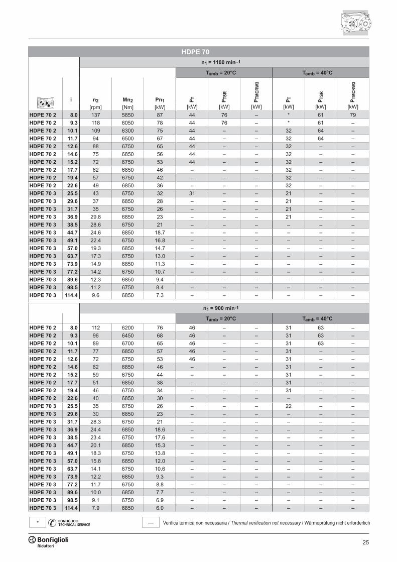
— Verifica termica non necessaria / Thermal verification not necessary / Wärmeprüfung nicht erforderlich*
HDPE 70n1 = 1100 min–1
Tamb = 20°C Tamb = 40°C
i n2 Mn2 Pn1 P T P TSR
P TM
CRW
3
P T P TSR
P TM
CRW
3
[rpm] [Nm] [kW] [kW] [kW] [kW] [kW] [kW] [kW]HDPE 70 2 8.0 137 5850 87 44 76 – * 61 79HDPE 70 2 9.3 118 6050 78 44 76 – * 61 –HDPE 70 2 10.1 109 6300 75 44 – – 32 64 –HDPE 70 2 11.7 94 6500 67 44 – – 32 64 –HDPE 70 2 12.6 88 6750 65 44 – – 32 – –HDPE 70 2 14.6 75 6850 56 44 – – 32 – –HDPE 70 2 15.2 72 6750 53 44 – – 32 – –HDPE 70 2 17.7 62 6850 46 – – – 32 – –HDPE 70 2 19.4 57 6750 42 – – – 32 – –HDPE 70 2 22.6 49 6850 36 – – – 32 – –HDPE 70 3 25.5 43 6750 32 31 – – 21 – –HDPE 70 3 29.6 37 6850 28 – – – 21 – –HDPE 70 3 31.7 35 6750 26 – – – 21 – –HDPE 70 3 36.9 29.8 6850 23 – – – 21 – –HDPE 70 3 38.5 28.6 6750 21 – – – – – –HDPE 70 3 44.7 24.6 6850 18.7 – – – – – –HDPE 70 3 49.1 22.4 6750 16.8 – – – – – –HDPE 70 3 57.0 19.3 6850 14.7 – – – – – –HDPE 70 3 63.7 17.3 6750 13.0 – – – – – –HDPE 70 3 73.9 14.9 6850 11.3 – – – – – –HDPE 70 3 77.2 14.2 6750 10.7 – – – – – –HDPE 70 3 89.6 12.3 6850 9.4 – – – – – –HDPE 70 3 98.5 11.2 6750 8.4 – – – – – –HDPE 70 3 114.4 9.6 6850 7.3 – – – – – –
n1 = 900 min-1
Tamb = 20°C Tamb = 40°CHDPE 70 2 8.0 112 6200 76 46 – – 31 63 –HDPE 70 2 9.3 96 6450 68 46 – – 31 63 –HDPE 70 2 10.1 89 6700 65 46 – – 31 63 –HDPE 70 2 11.7 77 6850 57 46 – – 31 – –HDPE 70 2 12.6 72 6750 53 46 – – 31 – –HDPE 70 2 14.6 62 6850 46 – – – 31 – –HDPE 70 2 15.2 59 6750 44 – – – 31 – –HDPE 70 2 17.7 51 6850 38 – – – 31 – –HDPE 70 2 19.4 46 6750 34 – – – 31 – –HDPE 70 2 22.6 40 6850 30 – – – – – –HDPE 70 3 25.5 35 6750 26 – – – 22 – –HDPE 70 3 29.6 30 6850 23 – – – – – –HDPE 70 3 31.7 28.3 6750 21 – – – – – –HDPE 70 3 36.9 24.4 6850 18.6 – – – – – –HDPE 70 3 38.5 23.4 6750 17.6 – – – – – –HDPE 70 3 44.7 20.1 6850 15.3 – – – – – –HDPE 70 3 49.1 18.3 6750 13.8 – – – – – –HDPE 70 3 57.0 15.8 6850 12.0 – – – – – –HDPE 70 3 63.7 14.1 6750 10.6 – – – – – –HDPE 70 3 73.9 12.2 6850 9.3 – – – – – –HDPE 70 3 77.2 11.7 6750 8.8 – – – – – –HDPE 70 3 89.6 10.0 6850 7.7 – – – – – –HDPE 70 3 98.5 9.1 6750 6.9 – – – – – –HDPE 70 3 114.4 7.9 6850 6.0 – – – – – –
26
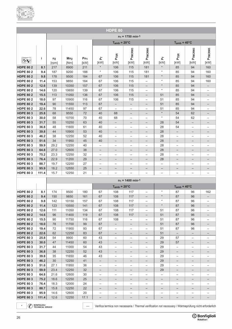
— Verifica termica non necessaria / Thermal verification not necessary / Wärmeprüfung nicht erforderlich*
HDPE 80n1 = 1750 min-1
Tamb = 20°C Tamb = 40°C
i n2 Mn2 Pn1 P T P TSR
P TM
CRW
3
P TM
CRW
5
P T P TSR
P TM
CRW
3
P TM
CRW
5
[rpm] [Nm] [kW] [kW] [kW] [kW] [kW] [kW] [kW] [kW] [kW]HDPE 80 2 8.1 217 8900 211 * 106 115 181 * 85 94 160HDPE 80 2 9.4 187 9200 188 * 106 115 181 * 85 94 160HDPE 80 2 9.8 178 9500 184 67 106 115 181 * 85 94 160HDPE 80 2 11.4 153 9850 164 67 106 115 – * 85 94 160HDPE 80 2 12.6 139 10350 157 67 106 115 – * 85 94 –HDPE 80 2 14.6 120 10650 139 67 106 115 – * 85 94 –HDPE 80 2 15.5 113 11050 136 67 106 115 – 51 85 94 –HDPE 80 2 18.0 97 10900 116 67 106 115 – 51 85 94 –HDPE 80 2 19.4 90 11550 113 67 – – – 51 85 94 –HDPE 80 2 22.6 78 11450 97 67 – – – 51 85 94 –HDPE 80 3 25.8 68 9550 72 40 68 – – * 54 62 –HDPE 80 3 30.0 58 10700 70 40 68 – – * 54 62 –HDPE 80 3 31.7 55 10250 63 40 – – – 28 54 – –HDPE 80 3 36.8 48 11600 61 40 – – – 28 54 – –HDPE 80 3 39.8 44 10900 53 40 – – – 28 – – –HDPE 80 3 46.2 38 12250 52 40 – – – 28 – – –HDPE 80 3 51.6 34 11950 45 40 – – – 28 – – –HDPE 80 3 59.9 29.2 12250 40 – – – – 28 – – –HDPE 80 3 64.8 27.0 12600 38 – – – – 28 – – –HDPE 80 3 75.2 23.3 12250 32 – – – – 28 – – –HDPE 80 3 76.4 22.9 11200 29 – – – – 28 – – –HDPE 80 3 88.7 19.7 12250 27 – – – – – – – –HDPE 80 3 95.9 18.2 12550 25 – – – – – – – –HDPE 80 3 111.4 15.7 12250 21 – – – – – – – –
n1 = 1400 min-1
Tamb = 20°C Tamb = 40°CHDPE 80 2 8.1 174 9500 180 67 108 117 – * 87 96 162HDPE 80 2 9.4 150 9850 161 67 108 117 – * 87 96 –HDPE 80 2 9.8 142 10150 157 67 108 117 – * 87 96 –HDPE 80 2 11.4 123 10550 141 67 108 117 – * 87 96 –HDPE 80 2 12.6 111 11050 134 67 108 117 – 51 87 96 –HDPE 80 2 14.6 96 11400 119 67 108 117 – 51 87 96 –HDPE 80 2 15.5 90 11750 116 67 108 – – 51 87 96 –HDPE 80 2 18.0 78 11700 99 67 – – – 51 87 96 –HDPE 80 2 19.4 72 11900 93 67 – – – 51 87 96 –HDPE 80 2 22.6 62 12250 83 67 – – – 51 – – –HDPE 80 3 25.8 54 9900 60 43 – – – 29 57 – –HDPE 80 3 30.0 47 11450 60 43 – – – 29 57 – –HDPE 80 3 31.7 44 11000 54 43 – – – 29 – – –HDPE 80 3 36.8 38 12250 52 43 – – – 29 – – –HDPE 80 3 39.8 35 11650 46 43 – – – 29 – – –HDPE 80 3 46.2 30 12250 41 – – – – 29 – – –HDPE 80 3 51.6 27.1 11950 36 – – – – 29 – – –HDPE 80 3 59.9 23.4 12250 32 – – – – 29 – – –HDPE 80 3 64.8 21.6 12600 30 – – – – – – – –HDPE 80 3 75.2 18.6 12250 25 – – – – – – – –HDPE 80 3 76.4 18.3 12000 24 – – – – – – – –HDPE 80 3 88.7 15.8 12250 22 – – – – – – – –HDPE 80 3 95.9 14.6 12600 20 – – – – – – – –HDPE 80 3 111.4 12.6 12250 17.1 – – – – – – – –
27
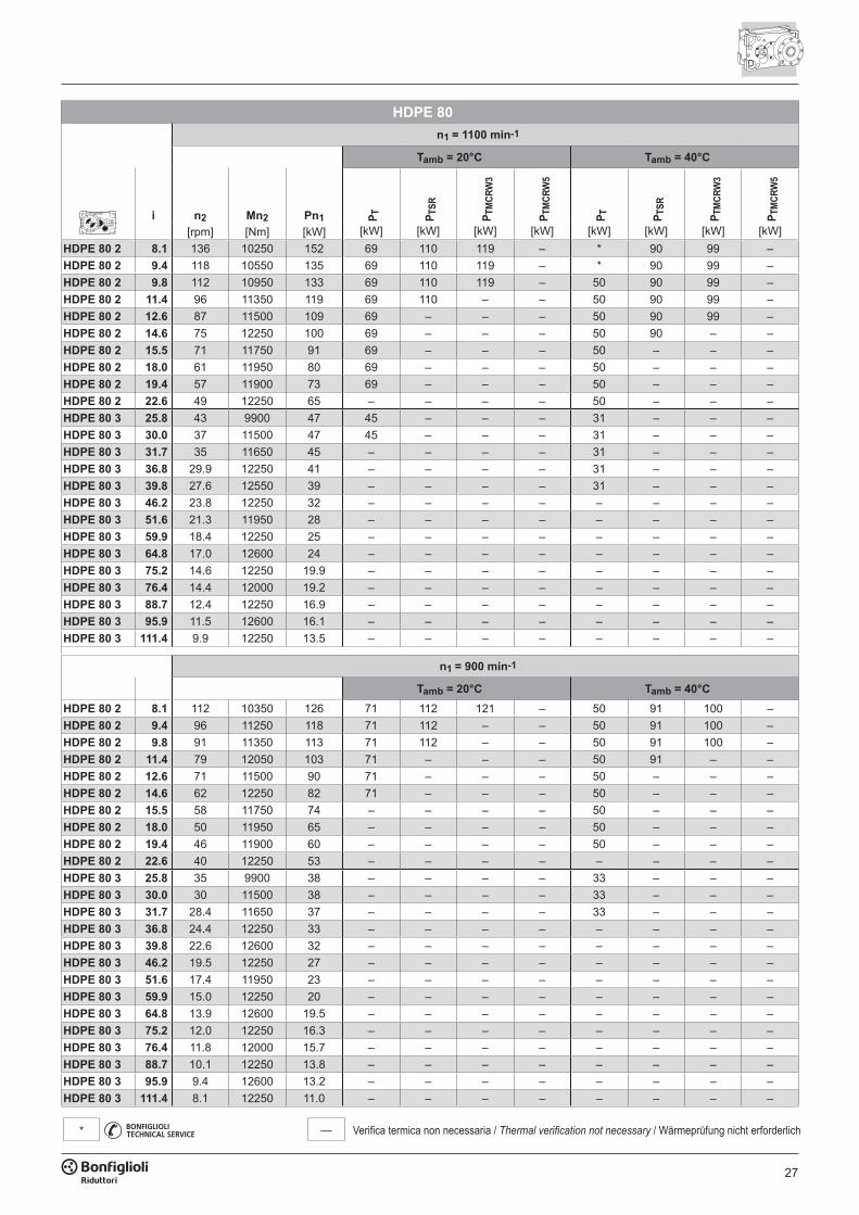
— Verifica termica non necessaria / Thermal verification not necessary / Wärmeprüfung nicht erforderlich*
HDPE 80n1 = 1100 min-1
Tamb = 20°C Tamb = 40°C
i n2 Mn2 Pn1 P T P TSR
P TM
CRW
3
P TM
CRW
5
P T P TSR
P TM
CRW
3
P TM
CRW
5
[rpm] [Nm] [kW] [kW] [kW] [kW] [kW] [kW] [kW] [kW] [kW]HDPE 80 2 8.1 136 10250 152 69 110 119 – * 90 99 –HDPE 80 2 9.4 118 10550 135 69 110 119 – * 90 99 –HDPE 80 2 9.8 112 10950 133 69 110 119 – 50 90 99 –HDPE 80 2 11.4 96 11350 119 69 110 – – 50 90 99 –HDPE 80 2 12.6 87 11500 109 69 – – – 50 90 99 –HDPE 80 2 14.6 75 12250 100 69 – – – 50 90 – –HDPE 80 2 15.5 71 11750 91 69 – – – 50 – – –HDPE 80 2 18.0 61 11950 80 69 – – – 50 – – –HDPE 80 2 19.4 57 11900 73 69 – – – 50 – – –HDPE 80 2 22.6 49 12250 65 – – – – 50 – – –HDPE 80 3 25.8 43 9900 47 45 – – – 31 – – –HDPE 80 3 30.0 37 11500 47 45 – – – 31 – – –HDPE 80 3 31.7 35 11650 45 – – – – 31 – – –HDPE 80 3 36.8 29.9 12250 41 – – – – 31 – – –HDPE 80 3 39.8 27.6 12550 39 – – – – 31 – – –HDPE 80 3 46.2 23.8 12250 32 – – – – – – – –HDPE 80 3 51.6 21.3 11950 28 – – – – – – – –HDPE 80 3 59.9 18.4 12250 25 – – – – – – – –HDPE 80 3 64.8 17.0 12600 24 – – – – – – – –HDPE 80 3 75.2 14.6 12250 19.9 – – – – – – – –HDPE 80 3 76.4 14.4 12000 19.2 – – – – – – – –HDPE 80 3 88.7 12.4 12250 16.9 – – – – – – – –HDPE 80 3 95.9 11.5 12600 16.1 – – – – – – – –HDPE 80 3 111.4 9.9 12250 13.5 – – – – – – – –
n1 = 900 min-1
Tamb = 20°C Tamb = 40°CHDPE 80 2 8.1 112 10350 126 71 112 121 – 50 91 100 –HDPE 80 2 9.4 96 11250 118 71 112 – – 50 91 100 –HDPE 80 2 9.8 91 11350 113 71 112 – – 50 91 100 –HDPE 80 2 11.4 79 12050 103 71 – – – 50 91 – –HDPE 80 2 12.6 71 11500 90 71 – – – 50 – – –HDPE 80 2 14.6 62 12250 82 71 – – – 50 – – –HDPE 80 2 15.5 58 11750 74 – – – – 50 – – –HDPE 80 2 18.0 50 11950 65 – – – – 50 – – –HDPE 80 2 19.4 46 11900 60 – – – – 50 – – –HDPE 80 2 22.6 40 12250 53 – – – – – – – –HDPE 80 3 25.8 35 9900 38 – – – – 33 – – –HDPE 80 3 30.0 30 11500 38 – – – – 33 – – –HDPE 80 3 31.7 28.4 11650 37 – – – – 33 – – –HDPE 80 3 36.8 24.4 12250 33 – – – – – – – –HDPE 80 3 39.8 22.6 12600 32 – – – – – – – –HDPE 80 3 46.2 19.5 12250 27 – – – – – – – –HDPE 80 3 51.6 17.4 11950 23 – – – – – – – –HDPE 80 3 59.9 15.0 12250 20 – – – – – – – –HDPE 80 3 64.8 13.9 12600 19.5 – – – – – – – –HDPE 80 3 75.2 12.0 12250 16.3 – – – – – – – –HDPE 80 3 76.4 11.8 12000 15.7 – – – – – – – –HDPE 80 3 88.7 10.1 12250 13.8 – – – – – – – –HDPE 80 3 95.9 9.4 12600 13.2 – – – – – – – –HDPE 80 3 111.4 8.1 12250 11.0 – – – – – – – –
28
— Verifica termica non necessaria / Thermal verification not necessary / Wärmeprüfung nicht erforderlich*
HDPE 90n1 = 1750 min-1
Tamb = 20°C Tamb = 40°C
i n2 Mn2 Pn1 P T P TSR
P TM
CRW
3
P TM
CRW
5
P T P TSR
P TM
CRW
3
P TM
CRW
5
[rpm] [Nm] [kW] [kW] [kW] [kW] [kW] [kW] [kW] [kW] [kW]HDPE 90 2 7.9 221 11700 282 * 131 133 199 * * * 172HDPE 90 2 8.8 198 12250 265 * 131 133 199 * * 106 172HDPE 90 2 10.1 174 12700 241 * 131 133 199 * 108 106 172HDPE 90 2 11.2 156 13250 226 * 131 133 199 * 108 106 172HDPE 90 2 12.2 143 13450 210 90 131 133 199 * 108 106 172HDPE 90 2 13.6 129 14100 198 90 131 133 – * 108 106 172HDPE 90 2 15.8 111 14350 173 90 131 133 – 65 108 106 –HDPE 90 2 17.6 99 15350 166 90 131 133 – 65 108 106 –HDPE 90 2 20.1 87 15400 146 90 131 133 – 65 108 106 –HDPE 90 2 22.4 78 16550 141 90 – – – 65 108 106 –HDPE 90 3 25.4 69 14600 112 50 72 86 – * 54 68 –HDPE 90 3 28.3 62 15150 104 50 72 86 – * 54 68 –HDPE 90 3 32.9 53 15600 92 50 72 86 – * 54 68 –HDPE 90 3 36.6 48 16550 88 50 72 – – 34 54 68 –HDPE 90 3 40.0 44 15100 73 50 – – – 34 54 68 –HDPE 90 3 44.6 39 16750 73 50 – – – 34 54 – –HDPE 90 3 51.8 34 16300 61 50 – – – 34 54 – –HDPE 90 3 57.7 30 16750 57 – – – – 34 – – –HDPE 90 3 65.8 26.6 17650 52 – – – – 34 – – –HDPE 90 3 73.3 23.9 16750 44 – – – – 34 – – –HDPE 90 3 77.8 22.5 16150 40 – – – – 34 – – –HDPE 90 3 86.6 20.2 16750 38 – – – – 34 – – –HDPE 90 3 98.9 17.7 17650 35 – – – – – – – –HDPE 90 3 110.1 15.9 16750 30 – – – – – – – –
n1 = 1400 min-1
Tamb = 20°C Tamb = 40°CHDPE 90 2 7.9 177 12500 241 * 134 136 202 * 108 110 176HDPE 90 2 8.8 159 13100 227 * 134 136 202 * 108 110 176HDPE 90 2 10.1 139 13550 206 89 134 136 202 * 108 110 176HDPE 90 2 11.2 125 14200 194 89 134 136 – * 108 110 176HDPE 90 2 12.2 115 14350 179 89 134 136 – * 108 110 176HDPE 90 2 13.6 103 15100 169 89 134 136 – * 108 110 –HDPE 90 2 15.8 89 15350 148 89 134 136 – 67 108 110 –HDPE 90 2 17.6 80 16400 142 89 – – – 67 108 110 –HDPE 90 2 20.1 70 16450 125 89 – – – 67 108 110 –HDPE 90 2 22.4 63 16750 114 89 – – – 67 – – –HDPE 90 3 25.4 55 15600 96 54 76 90 – 36 58 72 –HDPE 90 3 28.3 49 16200 89 54 76 – – 36 58 72 –HDPE 90 3 32.9 43 16700 79 54 76 – – 36 58 72 –HDPE 90 3 36.6 38 16750 71 54 – – – 36 58 – –HDPE 90 3 40.0 35 16150 63 54 – – – 36 58 – –HDPE 90 3 44.6 31 16750 59 – – – – 36 – – –HDPE 90 3 51.8 27.0 17450 52 – – – – 36 – – –HDPE 90 3 57.7 24.3 16750 45 – – – – 36 – – –HDPE 90 3 65.8 21.3 17650 42 – – – – 36 – – –HDPE 90 3 73.3 19.1 16750 36 – – – – – – – –HDPE 90 3 77.8 18.0 17250 35 – – – – – – – –HDPE 90 3 86.6 16.2 16750 30 – – – – – – – –HDPE 90 3 98.9 14.2 17650 28 – – – – – – – –HDPE 90 3 110.1 12.7 16750 24 – – – – – – – –
29
— Verifica termica non necessaria / Thermal verification not necessary / Wärmeprüfung nicht erforderlich*
HDPE 90n1 = 1100 min-1
Tamb = 20°C Tamb = 40°C
i n2 Mn2 Pn1 P T P TSR
P TM
CRW
3
P TM
CRW
5
P T P TSR
P TM
CRW
3
P TM
CRW
5
[rpm] [Nm] [kW] [kW] [kW] [kW] [kW] [kW] [kW] [kW] [kW]HDPE 90 2 7.9 139 13450 203 89 137 139 – * 111 113 179HDPE 90 2 8.8 125 14050 191 89 137 139 – * 111 113 179HDPE 90 2 10.1 109 14600 174 89 137 139 – 65 111 113 –HDPE 90 2 11.2 98 15250 163 89 137 139 – 65 111 113 –HDPE 90 2 12.2 90 15450 152 89 137 139 – 65 111 113 –HDPE 90 2 13.6 81 16250 143 89 – – – 65 111 113 –HDPE 90 2 15.8 70 16500 125 89 – – – 65 111 113 –HDPE 90 2 17.6 63 16750 114 89 – – – 65 – – –HDPE 90 2 20.1 55 17650 105 89 – – – 65 – – –HDPE 90 2 22.4 49 16750 90 – – – – 65 – – –HDPE 90 3 25.4 43 16800 81 57 79 – – 39 61 75 –HDPE 90 3 28.3 39 16750 72 57 – – – 39 61 – –HDPE 90 3 32.9 33 17650 66 57 – – – 39 61 – –HDPE 90 3 36.6 30 16750 56 – – – – 39 – – –HDPE 90 3 40.0 27.5 17350 53 – – – – 39 – – –HDPE 90 3 44.6 24.7 16750 46 – – – – 39 – – –HDPE 90 3 51.8 21.2 17650 42 – – – – 39 – – –HDPE 90 3 57.7 19.1 16750 36 – – – – – – – –HDPE 90 3 65.8 16.7 17650 33 – – – – – – – –HDPE 90 3 73.3 15.0 16750 28 – – – – – – – –HDPE 90 3 77.8 14.1 17650 28 – – – – – – – –HDPE 90 3 86.6 12.7 16750 24 – – – – – – – –HDPE 90 3 98.9 11.1 17650 22 – – – – – – – –HDPE 90 3 110.1 10.0 16750 18.6 – – – – – – – –
n1 = 900 min-1
Tamb = 20°C Tamb = 40°CHDPE 90 2 7.9 114 14000 173 91 139 141 – * 112 114 –HDPE 90 2 8.8 102 14950 166 91 139 141 – * 112 114 –HDPE 90 2 10.1 89 15500 151 91 139 141 – 66 112 114 –HDPE 90 2 11.2 80 16200 142 91 – – – 66 112 114 –HDPE 90 2 12.2 74 16400 132 91 – – – 66 112 114 –HDPE 90 2 13.6 66 16750 121 91 – – – 66 – – –HDPE 90 2 15.8 57 17000 106 91 – – – 66 – – –HDPE 90 2 17.6 51 16750 93 – – – – 66 – – –HDPE 90 2 20.1 45 17650 86 – – – – 66 – – –HDPE 90 2 22.4 40 16750 73 – – – – 66 – – –HDPE 90 3 25.4 35 17650 70 60 – – – 41 63 – –HDPE 90 3 28.3 32 16750 59 – – – – 41 – – –HDPE 90 3 32.9 27.4 17650 54 – – – – 41 – – –HDPE 90 3 36.6 24.6 16750 46 – – – – – – – –HDPE 90 3 40.0 22.5 17650 44 – – – – – – – –HDPE 90 3 44.6 20.2 16750 38 – – – – – – – –HDPE 90 3 51.8 17.4 17650 34 – – – – – – – –HDPE 90 3 57.7 15.6 16750 29 – – – – – – – –HDPE 90 3 65.8 13.7 17650 27 – – – – – – – –HDPE 90 3 73.3 12.3 16750 23 – – – – – – – –HDPE 90 3 77.8 11.6 17650 23 – – – – – – – –HDPE 90 3 86.6 10.4 16750 19.4 – – – – – – – –HDPE 90 3 98.9 9.1 17650 17.9 – – – – – – – –HDPE 90 3 110.1 8.2 16750 15.2 – – – – – – – –
30
— Verifica termica non necessaria / Thermal verification not necessary / Wärmeprüfung nicht erforderlich*
HDPE 100n1 = 1750 min-1
Tamb = 20°C Tamb = 40°C
i n2 Mn2 Pn1 P T P TSR
P TM
CRW
5
P TM
CRW
9
P T P TSR
P TM
CRW
5
P TM
CRW
9
[rpm] [Nm] [kW] [kW] [kW] [kW] [kW] [kW] [kW] [kW] [kW]HDPE 100 2 7.4 236 18400 474 * * 173 267 * * * 234HDPE 100 2 8.2 213 20600 478 * * 173 267 * * * 234HDPE 100 2 9.1 192 19350 405 * * 173 267 * * * 234HDPE 100 2 10.1 173 21350 403 * 160 173 267 * * 155 234HDPE 100 2 11.3 156 20400 346 * 160 173 267 * * 155 234HDPE 100 2 12.5 140 21350 326 * 160 173 267 * 140 155 234HDPE 100 2 14.2 124 21300 287 * 160 173 267 * 140 155 234HDPE 100 2 15.7 111 21350 259 * 160 173 – * 140 155 234HDPE 100 2 18.0 97 22400 237 * 160 173 – * 140 155 234HDPE 100 2 20.0 88 21350 204 101 160 173 – * 140 155 –HDPE 100 2 21.8 80 20050 176 101 160 173 – * 140 155 –HDPE 100 3 22.8 77 20050 171 71 134 155 – * 109 130 –HDPE 100 3 25.3 69 21350 164 71 134 155 – * 109 130 –HDPE 100 3 28.1 62 21100 146 71 134 – – * 109 130 –HDPE 100 3 31.3 56 21350 133 71 – – – 49 109 – –HDPE 100 3 35.4 49 22050 121 71 – – – 49 109 – –HDPE 100 3 39.3 44 21350 106 71 – – – 49 – – –HDPE 100 3 45.0 39 23100 100 71 – – – 49 – – –HDPE 100 3 50.0 35 21350 83 71 – – – 49 – – –HDPE 100 3 55.5 32 24050 84 71 – – – 49 – – –HDPE 100 3 61.7 28.4 21350 67 – – – – 49 – – –HDPE 100 3 69.9 25.0 24050 67 – – – – 49 – – –HDPE 100 3 77.7 22.5 21350 54 – – – – 49 – – –HDPE 100 3 88.9 19.7 24050 53 – – – – 49 – – –HDPE 100 3 98.8 17.7 21350 42 – – – – – – – –HDPE 100 3 107.6 16.3 20050 36 – – – – – – – –
n1 = 1400 min-1
Tamb = 20°C Tamb = 40°CHDPE 100 2 7.4 189 19650 405 * 158 186 280 * * 153 247HDPE 100 2 8.2 170 22000 408 * 158 186 280 * * 153 247HDPE 100 2 9.1 154 20650 346 * 158 186 280 * * 153 247HDPE 100 2 10.1 138 23100 349 * 158 186 280 * 137 153 247HDPE 100 2 11.3 124 21800 296 * 158 186 280 * 137 153 247HDPE 100 2 12.5 112 23100 282 * 158 186 – * 137 153 247HDPE 100 2 14.2 99 22800 246 * 158 186 – * 137 153 –HDPE 100 2 15.7 89 23100 224 100 158 186 – * 137 153 –HDPE 100 2 18.0 78 23950 203 100 158 186 – * 137 153 –HDPE 100 2 20.0 70 23100 176 100 158 – – 72 137 153 –HDPE 100 2 21.8 64 21700 152 100 – – – 72 137 – –HDPE 100 3 22.8 61 21450 147 76 139 – – * 114 135 –HDPE 100 3 25.3 55 23100 142 76 – – – * 114 – –HDPE 100 3 28.1 50 22600 125 76 – – – 51 114 – –HDPE 100 3 31.3 45 23100 115 76 – – – 51 – – –HDPE 100 3 35.4 40 23600 104 76 – – – 51 – – –HDPE 100 3 39.3 36 23100 91 76 – – – 51 – – –HDPE 100 3 45.0 31 24700 85 76 – – – 51 – – –HDPE 100 3 50.0 28.0 23100 72 – – – – 51 – – –HDPE 100 3 55.5 25.2 25650 72 – – – – 51 – – –HDPE 100 3 61.7 22.7 23100 58 – – – – 51 – – –HDPE 100 3 69.9 20.0 25650 57 – – – – 51 – – –HDPE 100 3 77.7 18.0 23100 46 – – – – – – – –HDPE 100 3 88.9 15.8 25650 45 – – – – – – – –HDPE 100 3 98.8 14.2 23100 36 – – – – – – – –HDPE 100 3 107.6 13.0 21700 31 – – – – – – – –
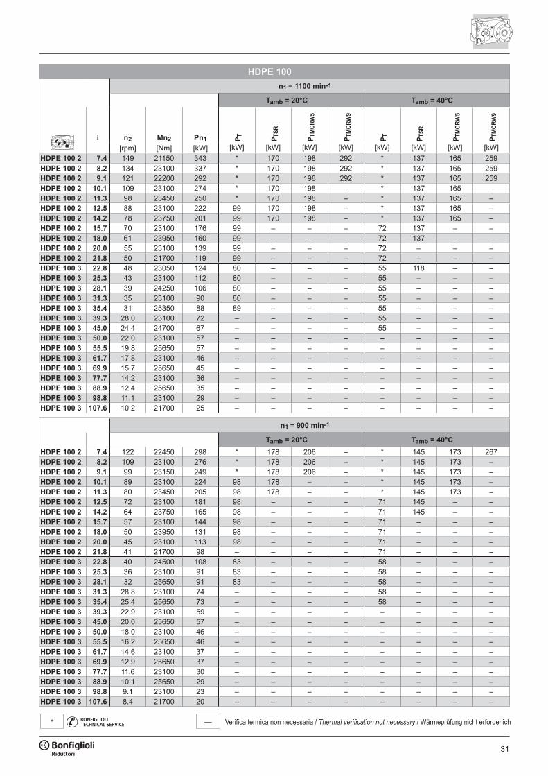
31
— Verifica termica non necessaria / Thermal verification not necessary / Wärmeprüfung nicht erforderlich*
HDPE 100n1 = 1100 min-1
Tamb = 20°C Tamb = 40°C
i n2 Mn2 Pn1 P T P TSR
P TM
CRW
5
P TM
CRW
9
P T P TSR
P TM
CRW
5
P TM
CRW
9
[rpm] [Nm] [kW] [kW] [kW] [kW] [kW] [kW] [kW] [kW] [kW]HDPE 100 2 7.4 149 21150 343 * 170 198 292 * 137 165 259HDPE 100 2 8.2 134 23100 337 * 170 198 292 * 137 165 259HDPE 100 2 9.1 121 22200 292 * 170 198 292 * 137 165 259HDPE 100 2 10.1 109 23100 274 * 170 198 – * 137 165 –HDPE 100 2 11.3 98 23450 250 * 170 198 – * 137 165 –HDPE 100 2 12.5 88 23100 222 99 170 198 – * 137 165 –HDPE 100 2 14.2 78 23750 201 99 170 198 – * 137 165 –HDPE 100 2 15.7 70 23100 176 99 – – – 72 137 – –HDPE 100 2 18.0 61 23950 160 99 – – – 72 137 – –HDPE 100 2 20.0 55 23100 139 99 – – – 72 – – –HDPE 100 2 21.8 50 21700 119 99 – – – 72 – – –HDPE 100 3 22.8 48 23050 124 80 – – – 55 118 – –HDPE 100 3 25.3 43 23100 112 80 – – – 55 – – –HDPE 100 3 28.1 39 24250 106 80 – – – 55 – – –HDPE 100 3 31.3 35 23100 90 80 – – – 55 – – –HDPE 100 3 35.4 31 25350 88 89 – – – 55 – – –HDPE 100 3 39.3 28.0 23100 72 – – – – 55 – – –HDPE 100 3 45.0 24.4 24700 67 – – – – 55 – – –HDPE 100 3 50.0 22.0 23100 57 – – – – – – – –HDPE 100 3 55.5 19.8 25650 57 – – – – – – – –HDPE 100 3 61.7 17.8 23100 46 – – – – – – – –HDPE 100 3 69.9 15.7 25650 45 – – – – – – – –HDPE 100 3 77.7 14.2 23100 36 – – – – – – – –HDPE 100 3 88.9 12.4 25650 35 – – – – – – – –HDPE 100 3 98.8 11.1 23100 29 – – – – – – – –HDPE 100 3 107.6 10.2 21700 25 – – – – – – – –
n1 = 900 min-1
Tamb = 20°C Tamb = 40°CHDPE 100 2 7.4 122 22450 298 * 178 206 – * 145 173 267HDPE 100 2 8.2 109 23100 276 * 178 206 – * 145 173 –HDPE 100 2 9.1 99 23150 249 * 178 206 – * 145 173 –HDPE 100 2 10.1 89 23100 224 98 178 – – * 145 173 –HDPE 100 2 11.3 80 23450 205 98 178 – – * 145 173 –HDPE 100 2 12.5 72 23100 181 98 – – – 71 145 – –HDPE 100 2 14.2 64 23750 165 98 – – – 71 145 – –HDPE 100 2 15.7 57 23100 144 98 – – – 71 – – –HDPE 100 2 18.0 50 23950 131 98 – – – 71 – – –HDPE 100 2 20.0 45 23100 113 98 – – – 71 – – –HDPE 100 2 21.8 41 21700 98 – – – – 71 – – –HDPE 100 3 22.8 40 24500 108 83 – – – 58 – – –HDPE 100 3 25.3 36 23100 91 83 – – – 58 – – –HDPE 100 3 28.1 32 25650 91 83 – – – 58 – – –HDPE 100 3 31.3 28.8 23100 74 – – – – 58 – – –HDPE 100 3 35.4 25.4 25650 73 – – – – 58 – – –HDPE 100 3 39.3 22.9 23100 59 – – – – – – – –HDPE 100 3 45.0 20.0 25650 57 – – – – – – – –HDPE 100 3 50.0 18.0 23100 46 – – – – – – – –HDPE 100 3 55.5 16.2 25650 46 – – – – – – – –HDPE 100 3 61.7 14.6 23100 37 – – – – – – – –HDPE 100 3 69.9 12.9 25650 37 – – – – – – – –HDPE 100 3 77.7 11.6 23100 30 – – – – – – – –HDPE 100 3 88.9 10.1 25650 29 – – – – – – – –HDPE 100 3 98.8 9.1 23100 23 – – – – – – – –HDPE 100 3 107.6 8.4 21700 20 – – – – – – – –
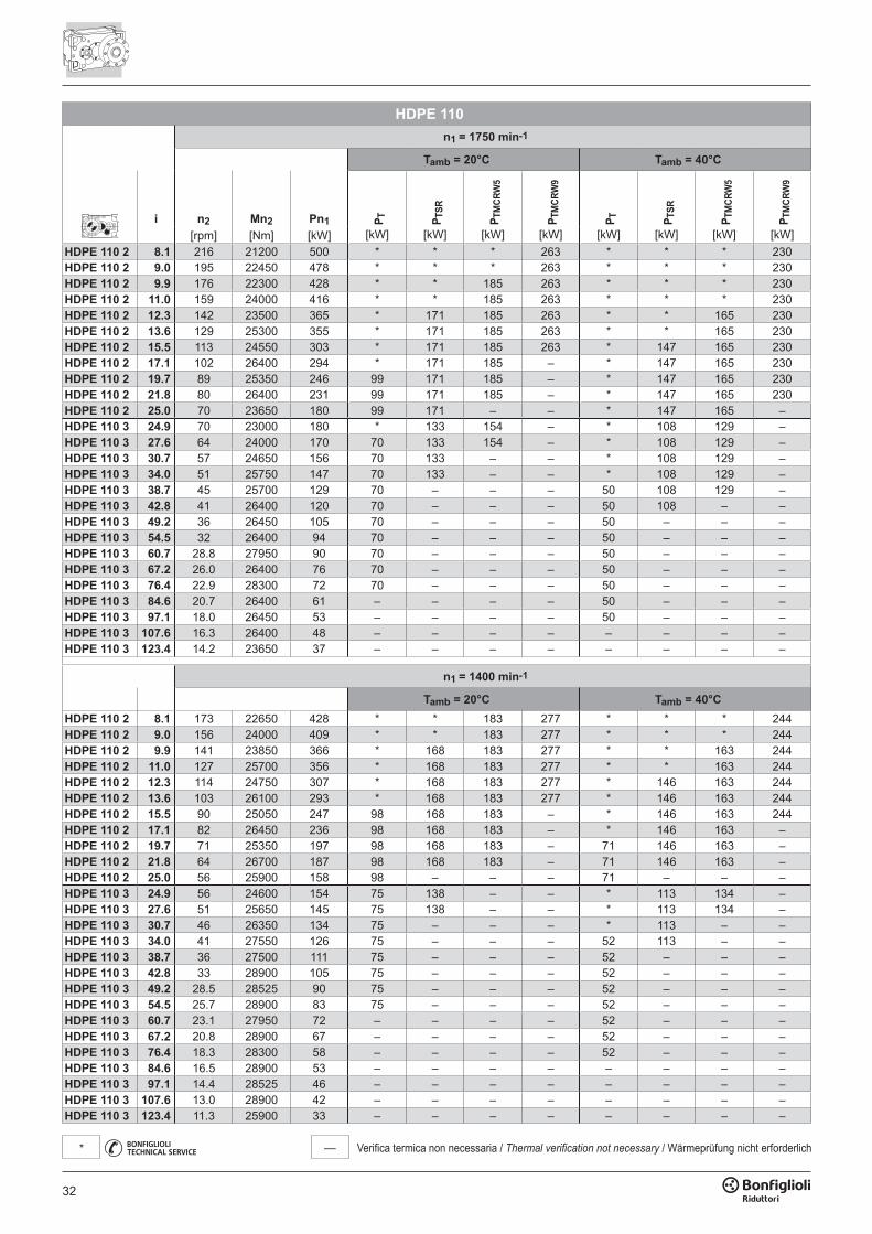
32
— Verifica termica non necessaria / Thermal verification not necessary / Wärmeprüfung nicht erforderlich*
HDPE 110n1 = 1750 min-1
Tamb = 20°C Tamb = 40°C
i n2 Mn2 Pn1 P T P TSR
P TM
CRW
5
P TM
CRW
9
P T P TSR
P TM
CRW
5
P TM
CRW
9
[rpm] [Nm] [kW] [kW] [kW] [kW] [kW] [kW] [kW] [kW] [kW]HDPE 110 2 8.1 216 21200 500 * * * 263 * * * 230HDPE 110 2 9.0 195 22450 478 * * * 263 * * * 230HDPE 110 2 9.9 176 22300 428 * * 185 263 * * * 230HDPE 110 2 11.0 159 24000 416 * * 185 263 * * * 230HDPE 110 2 12.3 142 23500 365 * 171 185 263 * * 165 230HDPE 110 2 13.6 129 25300 355 * 171 185 263 * * 165 230HDPE 110 2 15.5 113 24550 303 * 171 185 263 * 147 165 230HDPE 110 2 17.1 102 26400 294 * 171 185 – * 147 165 230HDPE 110 2 19.7 89 25350 246 99 171 185 – * 147 165 230HDPE 110 2 21.8 80 26400 231 99 171 185 – * 147 165 230HDPE 110 2 25.0 70 23650 180 99 171 – – * 147 165 –HDPE 110 3 24.9 70 23000 180 * 133 154 – * 108 129 –HDPE 110 3 27.6 64 24000 170 70 133 154 – * 108 129 –HDPE 110 3 30.7 57 24650 156 70 133 – – * 108 129 –HDPE 110 3 34.0 51 25750 147 70 133 – – * 108 129 –HDPE 110 3 38.7 45 25700 129 70 – – – 50 108 129 –HDPE 110 3 42.8 41 26400 120 70 – – – 50 108 – –HDPE 110 3 49.2 36 26450 105 70 – – – 50 – – –HDPE 110 3 54.5 32 26400 94 70 – – – 50 – – –HDPE 110 3 60.7 28.8 27950 90 70 – – – 50 – – –HDPE 110 3 67.2 26.0 26400 76 70 – – – 50 – – –HDPE 110 3 76.4 22.9 28300 72 70 – – – 50 – – –HDPE 110 3 84.6 20.7 26400 61 – – – – 50 – – –HDPE 110 3 97.1 18.0 26450 53 – – – – 50 – – –HDPE 110 3 107.6 16.3 26400 48 – – – – – – – –HDPE 110 3 123.4 14.2 23650 37 – – – – – – – –
n1 = 1400 min-1
Tamb = 20°C Tamb = 40°CHDPE 110 2 8.1 173 22650 428 * * 183 277 * * * 244HDPE 110 2 9.0 156 24000 409 * * 183 277 * * * 244HDPE 110 2 9.9 141 23850 366 * 168 183 277 * * 163 244HDPE 110 2 11.0 127 25700 356 * 168 183 277 * * 163 244HDPE 110 2 12.3 114 24750 307 * 168 183 277 * 146 163 244HDPE 110 2 13.6 103 26100 293 * 168 183 277 * 146 163 244HDPE 110 2 15.5 90 25050 247 98 168 183 – * 146 163 244HDPE 110 2 17.1 82 26450 236 98 168 183 – * 146 163 –HDPE 110 2 19.7 71 25350 197 98 168 183 – 71 146 163 –HDPE 110 2 21.8 64 26700 187 98 168 183 – 71 146 163 –HDPE 110 2 25.0 56 25900 158 98 – – – 71 – – –HDPE 110 3 24.9 56 24600 154 75 138 – – * 113 134 –HDPE 110 3 27.6 51 25650 145 75 138 – – * 113 134 –HDPE 110 3 30.7 46 26350 134 75 – – – * 113 – –HDPE 110 3 34.0 41 27550 126 75 – – – 52 113 – –HDPE 110 3 38.7 36 27500 111 75 – – – 52 – – –HDPE 110 3 42.8 33 28900 105 75 – – – 52 – – –HDPE 110 3 49.2 28.5 28525 90 75 – – – 52 – – –HDPE 110 3 54.5 25.7 28900 83 75 – – – 52 – – –HDPE 110 3 60.7 23.1 27950 72 – – – – 52 – – –HDPE 110 3 67.2 20.8 28900 67 – – – – 52 – – –HDPE 110 3 76.4 18.3 28300 58 – – – – 52 – – –HDPE 110 3 84.6 16.5 28900 53 – – – – – – – –HDPE 110 3 97.1 14.4 28525 46 – – – – – – – –HDPE 110 3 107.6 13.0 28900 42 – – – – – – – –HDPE 110 3 123.4 11.3 25900 33 – – – – – – – –
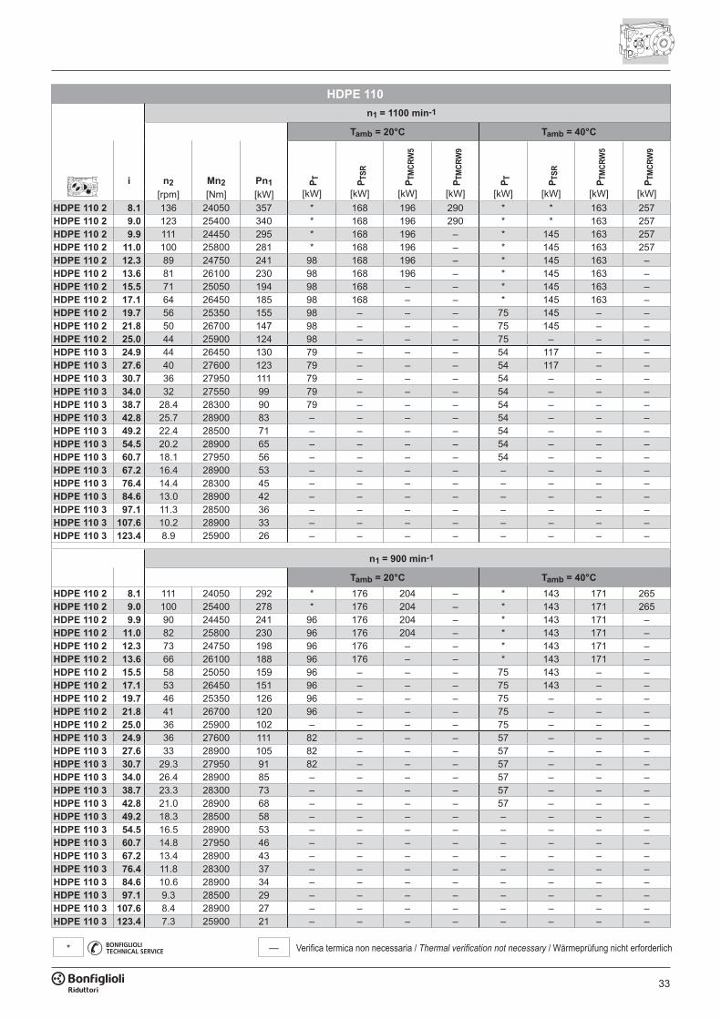
33
— Verifica termica non necessaria / Thermal verification not necessary / Wärmeprüfung nicht erforderlich*
HDPE 110n1 = 1100 min-1
Tamb = 20°C Tamb = 40°C
i n2 Mn2 Pn1 P T P TSR
P TM
CRW
5
P TM
CRW
9
P T P TSR
P TM
CRW
5
P TM
CRW
9
[rpm] [Nm] [kW] [kW] [kW] [kW] [kW] [kW] [kW] [kW] [kW]HDPE 110 2 8.1 136 24050 357 * 168 196 290 * * 163 257HDPE 110 2 9.0 123 25400 340 * 168 196 290 * * 163 257HDPE 110 2 9.9 111 24450 295 * 168 196 – * 145 163 257HDPE 110 2 11.0 100 25800 281 * 168 196 – * 145 163 257HDPE 110 2 12.3 89 24750 241 98 168 196 – * 145 163 –HDPE 110 2 13.6 81 26100 230 98 168 196 – * 145 163 –HDPE 110 2 15.5 71 25050 194 98 168 – – * 145 163 –HDPE 110 2 17.1 64 26450 185 98 168 – – * 145 163 –HDPE 110 2 19.7 56 25350 155 98 – – – 75 145 – –HDPE 110 2 21.8 50 26700 147 98 – – – 75 145 – –HDPE 110 2 25.0 44 25900 124 98 – – – 75 – – –HDPE 110 3 24.9 44 26450 130 79 – – – 54 117 – –HDPE 110 3 27.6 40 27600 123 79 – – – 54 117 – –HDPE 110 3 30.7 36 27950 111 79 – – – 54 – – –HDPE 110 3 34.0 32 27550 99 79 – – – 54 – – –HDPE 110 3 38.7 28.4 28300 90 79 – – – 54 – – –HDPE 110 3 42.8 25.7 28900 83 – – – – 54 – – –HDPE 110 3 49.2 22.4 28500 71 – – – – 54 – – –HDPE 110 3 54.5 20.2 28900 65 – – – – 54 – – –HDPE 110 3 60.7 18.1 27950 56 – – – – 54 – – –HDPE 110 3 67.2 16.4 28900 53 – – – – – – – –HDPE 110 3 76.4 14.4 28300 45 – – – – – – – –HDPE 110 3 84.6 13.0 28900 42 – – – – – – – –HDPE 110 3 97.1 11.3 28500 36 – – – – – – – –HDPE 110 3 107.6 10.2 28900 33 – – – – – – – –HDPE 110 3 123.4 8.9 25900 26 – – – – – – – –
n1 = 900 min-1
Tamb = 20°C Tamb = 40°CHDPE 110 2 8.1 111 24050 292 * 176 204 – * 143 171 265HDPE 110 2 9.0 100 25400 278 * 176 204 – * 143 171 265HDPE 110 2 9.9 90 24450 241 96 176 204 – * 143 171 –HDPE 110 2 11.0 82 25800 230 96 176 204 – * 143 171 –HDPE 110 2 12.3 73 24750 198 96 176 – – * 143 171 –HDPE 110 2 13.6 66 26100 188 96 176 – – * 143 171 –HDPE 110 2 15.5 58 25050 159 96 – – – 75 143 – –HDPE 110 2 17.1 53 26450 151 96 – – – 75 143 – –HDPE 110 2 19.7 46 25350 126 96 – – – 75 – – –HDPE 110 2 21.8 41 26700 120 96 – – – 75 – – –HDPE 110 2 25.0 36 25900 102 – – – – 75 – – –HDPE 110 3 24.9 36 27600 111 82 – – – 57 – – –HDPE 110 3 27.6 33 28900 105 82 – – – 57 – – –HDPE 110 3 30.7 29.3 27950 91 82 – – – 57 – – –HDPE 110 3 34.0 26.4 28900 85 – – – – 57 – – –HDPE 110 3 38.7 23.3 28300 73 – – – – 57 – – –HDPE 110 3 42.8 21.0 28900 68 – – – – 57 – – –HDPE 110 3 49.2 18.3 28500 58 – – – – – – – –HDPE 110 3 54.5 16.5 28900 53 – – – – – – – –HDPE 110 3 60.7 14.8 27950 46 – – – – – – – –HDPE 110 3 67.2 13.4 28900 43 – – – – – – – –HDPE 110 3 76.4 11.8 28300 37 – – – – – – – –HDPE 110 3 84.6 10.6 28900 34 – – – – – – – –HDPE 110 3 97.1 9.3 28500 29 – – – – – – – –HDPE 110 3 107.6 8.4 28900 27 – – – – – – – –HDPE 110 3 123.4 7.3 25900 21 – – – – – – – –
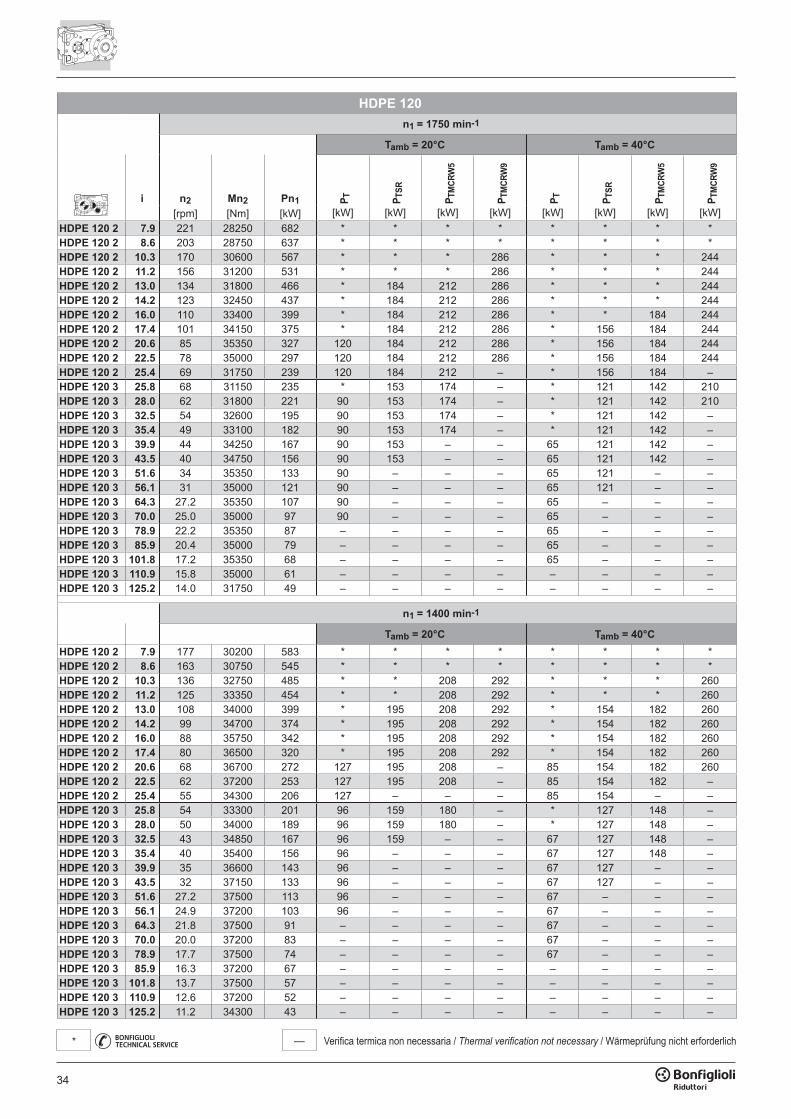
34
— Verifica termica non necessaria / Thermal verification not necessary / Wärmeprüfung nicht erforderlich*
HDPE 120n1 = 1750 min-1
Tamb = 20°C Tamb = 40°C
i n2 Mn2 Pn1 P T P TSR
P TM
CRW
5
P TM
CRW
9
P T P TSR
P TM
CRW
5
P TM
CRW
9
[rpm] [Nm] [kW] [kW] [kW] [kW] [kW] [kW] [kW] [kW] [kW]HDPE 120 2 7.9 221 28250 682 * * * * * * * *HDPE 120 2 8.6 203 28750 637 * * * * * * * *HDPE 120 2 10.3 170 30600 567 * * * 286 * * * 244HDPE 120 2 11.2 156 31200 531 * * * 286 * * * 244HDPE 120 2 13.0 134 31800 466 * 184 212 286 * * * 244HDPE 120 2 14.2 123 32450 437 * 184 212 286 * * * 244HDPE 120 2 16.0 110 33400 399 * 184 212 286 * * 184 244HDPE 120 2 17.4 101 34150 375 * 184 212 286 * 156 184 244HDPE 120 2 20.6 85 35350 327 120 184 212 286 * 156 184 244HDPE 120 2 22.5 78 35000 297 120 184 212 286 * 156 184 244HDPE 120 2 25.4 69 31750 239 120 184 212 – * 156 184 –HDPE 120 3 25.8 68 31150 235 * 153 174 – * 121 142 210HDPE 120 3 28.0 62 31800 221 90 153 174 – * 121 142 210HDPE 120 3 32.5 54 32600 195 90 153 174 – * 121 142 –HDPE 120 3 35.4 49 33100 182 90 153 174 – * 121 142 –HDPE 120 3 39.9 44 34250 167 90 153 – – 65 121 142 –HDPE 120 3 43.5 40 34750 156 90 153 – – 65 121 142 –HDPE 120 3 51.6 34 35350 133 90 – – – 65 121 – –HDPE 120 3 56.1 31 35000 121 90 – – – 65 121 – –HDPE 120 3 64.3 27.2 35350 107 90 – – – 65 – – –HDPE 120 3 70.0 25.0 35000 97 90 – – – 65 – – –HDPE 120 3 78.9 22.2 35350 87 – – – – 65 – – –HDPE 120 3 85.9 20.4 35000 79 – – – – 65 – – –HDPE 120 3 101.8 17.2 35350 68 – – – – 65 – – –HDPE 120 3 110.9 15.8 35000 61 – – – – – – – –HDPE 120 3 125.2 14.0 31750 49 – – – – – – – –
n1 = 1400 min-1
Tamb = 20°C Tamb = 40°CHDPE 120 2 7.9 177 30200 583 * * * * * * * *HDPE 120 2 8.6 163 30750 545 * * * * * * * *HDPE 120 2 10.3 136 32750 485 * * 208 292 * * * 260HDPE 120 2 11.2 125 33350 454 * * 208 292 * * * 260HDPE 120 2 13.0 108 34000 399 * 195 208 292 * 154 182 260HDPE 120 2 14.2 99 34700 374 * 195 208 292 * 154 182 260HDPE 120 2 16.0 88 35750 342 * 195 208 292 * 154 182 260HDPE 120 2 17.4 80 36500 320 * 195 208 292 * 154 182 260HDPE 120 2 20.6 68 36700 272 127 195 208 – 85 154 182 260HDPE 120 2 22.5 62 37200 253 127 195 208 – 85 154 182 –HDPE 120 2 25.4 55 34300 206 127 – – – 85 154 – –HDPE 120 3 25.8 54 33300 201 96 159 180 – * 127 148 –HDPE 120 3 28.0 50 34000 189 96 159 180 – * 127 148 –HDPE 120 3 32.5 43 34850 167 96 159 – – 67 127 148 –HDPE 120 3 35.4 40 35400 156 96 – – – 67 127 148 –HDPE 120 3 39.9 35 36600 143 96 – – – 67 127 – –HDPE 120 3 43.5 32 37150 133 96 – – – 67 127 – –HDPE 120 3 51.6 27.2 37500 113 96 – – – 67 – – –HDPE 120 3 56.1 24.9 37200 103 96 – – – 67 – – –HDPE 120 3 64.3 21.8 37500 91 – – – – 67 – – –HDPE 120 3 70.0 20.0 37200 83 – – – – 67 – – –HDPE 120 3 78.9 17.7 37500 74 – – – – 67 – – –HDPE 120 3 85.9 16.3 37200 67 – – – – – – – –HDPE 120 3 101.8 13.7 37500 57 – – – – – – – –HDPE 120 3 110.9 12.6 37200 52 – – – – – – – –HDPE 120 3 125.2 11.2 34300 43 – – – – – – – –
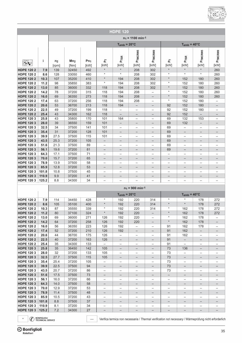
35
— Verifica termica non necessaria / Thermal verification not necessary / Wärmeprüfung nicht erforderlich*
HDPE 120n1 = 1100 min-1
Tamb = 20°C Tamb = 40°C
i n2 Mn2 Pn1 P T P TSR
P TM
CRW
5
P TM
CRW
9
P T P TSR
P TM
CRW
5
P TM
CRW
9
[rpm] [Nm] [kW] [kW] [kW] [kW] [kW] [kW] [kW] [kW] [kW]HDPE 120 2 7.9 139 32450 492 * * 208 302 * * * 260HDPE 120 2 8.6 128 33050 460 * * 208 302 * * * 260HDPE 120 2 10.3 107 35200 410 * 194 208 302 * 152 180 260HDPE 120 2 11.2 98 35850 383 * 194 208 302 * 152 180 260HDPE 120 2 13.0 85 36000 332 118 194 208 302 * 152 180 260HDPE 120 2 14.2 78 37200 315 118 194 208 – * 152 180 260HDPE 120 2 16.0 69 36350 273 118 194 208 – * 152 180 260HDPE 120 2 17.4 63 37200 256 118 194 208 – * 152 180 –HDPE 120 2 20.6 53 36700 213 118 194 – – 92 152 180 –HDPE 120 2 22.5 49 37200 199 118 – – – 92 152 180 –HDPE 120 2 25.4 43 34300 162 118 – – – 92 152 – –HDPE 120 3 25.8 43 35800 170 101 164 – – 69 132 153 –HDPE 120 3 28.0 39 36550 159 101 – – – 69 132 – –HDPE 120 3 32.5 34 37500 141 101 – – – 69 – – –HDPE 120 3 35.4 31 37200 128 101 – – – 69 – – –HDPE 120 3 39.9 27.5 37500 115 101 – – – 69 – – –HDPE 120 3 43.5 25.3 37200 105 – – – – 69 – – –HDPE 120 3 51.6 21.3 37500 89 – – – – 69 – – –HDPE 120 3 56.1 19.6 37200 81 – – – – 69 – – –HDPE 120 3 64.3 17.1 37500 71 – – – – – – – –HDPE 120 3 70.0 15.7 37200 65 – – – – – – – –HDPE 120 3 78.9 13.9 37500 58 – – – – – – – –HDPE 120 3 85.9 12.8 37200 53 – – – – – – – –HDPE 120 3 101.8 10.8 37500 45 – – – – – – – –HDPE 120 3 110.9 9.9 37200 41 – – – – – – – –HDPE 120 3 125.2 8.8 34300 34 – – – – – – – –
n1 = 900 min-1
Tamb = 20°C Tamb = 40°CHDPE 120 2 7.9 114 34450 428 * 192 220 314 * * 178 272HDPE 120 2 8.6 105 35100 400 * 192 220 314 * * 178 272HDPE 120 2 10.3 87 35550 339 * 192 220 314 * 162 178 272HDPE 120 2 11.2 80 37100 324 * 192 220 – * 162 178 272HDPE 120 2 13.0 69 36000 271 126 192 220 – * 162 178 –HDPE 120 2 14.2 64 37200 258 126 192 220 – * 162 178 –HDPE 120 2 16.0 56 36350 223 126 192 – – 91 162 178 –HDPE 120 2 17.4 52 37200 210 126 192 – – 91 162 – –HDPE 120 2 20.6 44 36700 175 126 – – – 91 162 – –HDPE 120 2 22.5 40 37200 163 126 – – – 91 – – –HDPE 120 2 25.4 35 34300 133 – – – – 91 – – –HDPE 120 3 25.8 35 36450 142 105 – – – 73 136 – –HDPE 120 3 28.0 32 37200 133 105 – – – 73 – – –HDPE 120 3 32.5 27.7 37500 115 105 – – – 73 – – –HDPE 120 3 35.4 25.4 37200 105 – – – – 73 – – –HDPE 120 3 39.9 22.5 37500 94 – – – – 73 – – –HDPE 120 3 43.5 20.7 37200 86 – – – – 73 – – –HDPE 120 3 51.6 17.5 37500 73 – – – – – – – –HDPE 120 3 56.1 16.0 37200 66 – – – – – – – –HDPE 120 3 64.3 14.0 37500 58 – – – – – – – –HDPE 120 3 70.0 12.9 37200 53 – – – – – – – –HDPE 120 3 78.9 11.4 37500 48 – – – – – – – –HDPE 120 3 85.9 10.5 37200 43 – – – – – – – –HDPE 120 3 101.8 8.8 37500 37 – – – – – – – –HDPE 120 3 110.9 8.1 37200 34 – – – – – – – –HDPE 120 3 125.2 7.2 34300 27 – – – – – – – –
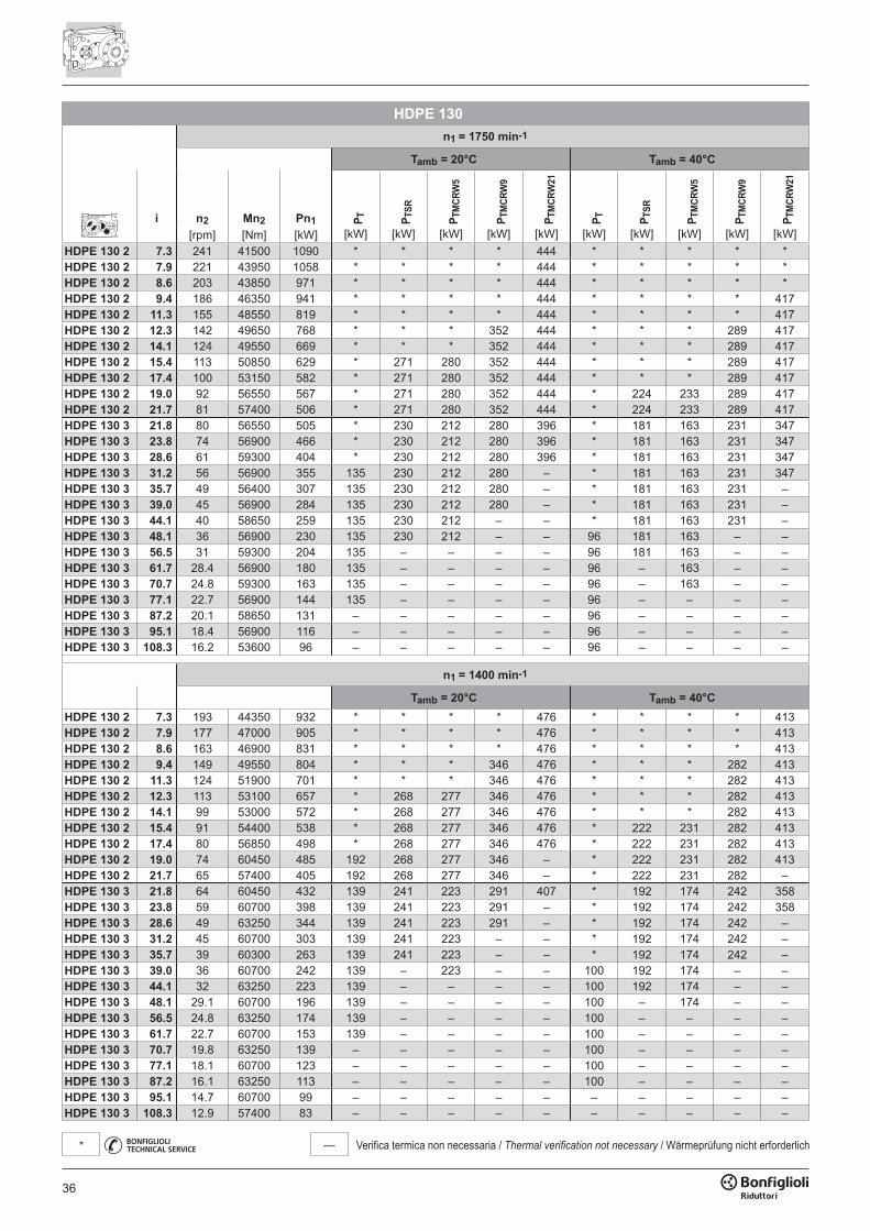
36
— Verifica termica non necessaria / Thermal verification not necessary / Wärmeprüfung nicht erforderlich*
HDPE 130n1 = 1750 min-1
Tamb = 20°C Tamb = 40°C
i n2 Mn2 Pn1 P T P TSR
P TM
CRW
5
P TM
CRW
9
P TM
CRW
21
P T P TSR
P TM
CRW
5
P TM
CRW
9
P TM
CRW
21
[rpm] [Nm] [kW] [kW] [kW] [kW] [kW] [kW] [kW] [kW] [kW] [kW] [kW]HDPE 130 2 7.3 241 41500 1090 * * * * 444 * * * * *HDPE 130 2 7.9 221 43950 1058 * * * * 444 * * * * *HDPE 130 2 8.6 203 43850 971 * * * * 444 * * * * *HDPE 130 2 9.4 186 46350 941 * * * * 444 * * * * 417HDPE 130 2 11.3 155 48550 819 * * * * 444 * * * * 417HDPE 130 2 12.3 142 49650 768 * * * 352 444 * * * 289 417HDPE 130 2 14.1 124 49550 669 * * * 352 444 * * * 289 417HDPE 130 2 15.4 113 50850 629 * 271 280 352 444 * * * 289 417HDPE 130 2 17.4 100 53150 582 * 271 280 352 444 * * * 289 417HDPE 130 2 19.0 92 56550 567 * 271 280 352 444 * 224 233 289 417HDPE 130 2 21.7 81 57400 506 * 271 280 352 444 * 224 233 289 417HDPE 130 3 21.8 80 56550 505 * 230 212 280 396 * 181 163 231 347HDPE 130 3 23.8 74 56900 466 * 230 212 280 396 * 181 163 231 347HDPE 130 3 28.6 61 59300 404 * 230 212 280 396 * 181 163 231 347HDPE 130 3 31.2 56 56900 355 135 230 212 280 – * 181 163 231 347HDPE 130 3 35.7 49 56400 307 135 230 212 280 – * 181 163 231 –HDPE 130 3 39.0 45 56900 284 135 230 212 280 – * 181 163 231 –HDPE 130 3 44.1 40 58650 259 135 230 212 – – * 181 163 231 –HDPE 130 3 48.1 36 56900 230 135 230 212 – – 96 181 163 – –HDPE 130 3 56.5 31 59300 204 135 – – – – 96 181 163 – –HDPE 130 3 61.7 28.4 56900 180 135 – – – – 96 – 163 – –HDPE 130 3 70.7 24.8 59300 163 135 – – – – 96 – 163 – –HDPE 130 3 77.1 22.7 56900 144 135 – – – – 96 – – – –HDPE 130 3 87.2 20.1 58650 131 – – – – – 96 – – – –HDPE 130 3 95.1 18.4 56900 116 – – – – – 96 – – – –HDPE 130 3 108.3 16.2 53600 96 – – – – – 96 – – – –
n1 = 1400 min-1
Tamb = 20°C Tamb = 40°CHDPE 130 2 7.3 193 44350 932 * * * * 476 * * * * 413HDPE 130 2 7.9 177 47000 905 * * * * 476 * * * * 413HDPE 130 2 8.6 163 46900 831 * * * * 476 * * * * 413HDPE 130 2 9.4 149 49550 804 * * * 346 476 * * * 282 413HDPE 130 2 11.3 124 51900 701 * * * 346 476 * * * 282 413HDPE 130 2 12.3 113 53100 657 * 268 277 346 476 * * * 282 413HDPE 130 2 14.1 99 53000 572 * 268 277 346 476 * * * 282 413HDPE 130 2 15.4 91 54400 538 * 268 277 346 476 * 222 231 282 413HDPE 130 2 17.4 80 56850 498 * 268 277 346 476 * 222 231 282 413HDPE 130 2 19.0 74 60450 485 192 268 277 346 – * 222 231 282 413HDPE 130 2 21.7 65 57400 405 192 268 277 346 – * 222 231 282 –HDPE 130 3 21.8 64 60450 432 139 241 223 291 407 * 192 174 242 358HDPE 130 3 23.8 59 60700 398 139 241 223 291 – * 192 174 242 358HDPE 130 3 28.6 49 63250 344 139 241 223 291 – * 192 174 242 –HDPE 130 3 31.2 45 60700 303 139 241 223 – – * 192 174 242 –HDPE 130 3 35.7 39 60300 263 139 241 223 – – * 192 174 242 –HDPE 130 3 39.0 36 60700 242 139 – 223 – – 100 192 174 – –HDPE 130 3 44.1 32 63250 223 139 – – – – 100 192 174 – –HDPE 130 3 48.1 29.1 60700 196 139 – – – – 100 – 174 – –HDPE 130 3 56.5 24.8 63250 174 139 – – – – 100 – – – –HDPE 130 3 61.7 22.7 60700 153 139 – – – – 100 – – – –HDPE 130 3 70.7 19.8 63250 139 – – – – – 100 – – – –HDPE 130 3 77.1 18.1 60700 123 – – – – – 100 – – – –HDPE 130 3 87.2 16.1 63250 113 – – – – – 100 – – – –HDPE 130 3 95.1 14.7 60700 99 – – – – – – – – – –HDPE 130 3 108.3 12.9 57400 83 – – – – – – – – – –
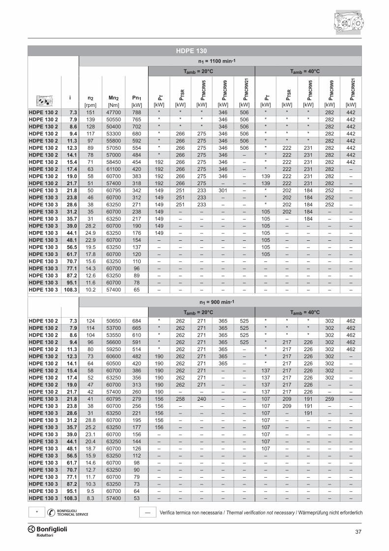
37
— Verifica termica non necessaria / Thermal verification not necessary / Wärmeprüfung nicht erforderlich*
HDPE 130n1 = 1100 min-1
Tamb = 20°C Tamb = 40°C
i n2 Mn2 Pn1 P T P TSR
P TM
CRW
5
P TM
CRW
9
P TM
CRW
21
P T P TSR
P TM
CRW
5
P TM
CRW
9
P TM
CRW
21
[rpm] [Nm] [kW] [kW] [kW] [kW] [kW] [kW] [kW] [kW] [kW] [kW] [kW]HDPE 130 2 7.3 151 47700 788 * * * 346 506 * * * 282 442HDPE 130 2 7.9 139 50550 765 * * * 346 506 * * * 282 442HDPE 130 2 8.6 128 50400 702 * * * 346 506 * * * 282 442HDPE 130 2 9.4 117 53300 680 * 266 275 346 506 * * * 282 442HDPE 130 2 11.3 97 55800 592 * 266 275 346 506 * * * 282 442HDPE 130 2 12.3 89 57050 554 * 266 275 346 506 * 222 231 282 442HDPE 130 2 14.1 78 57000 484 * 266 275 346 – * 222 231 282 442HDPE 130 2 15.4 71 58450 454 192 266 275 346 – * 222 231 282 442HDPE 130 2 17.4 63 61100 420 192 266 275 346 – * 222 231 282 –HDPE 130 2 19.0 58 60700 383 192 266 275 346 – 139 222 231 282 –HDPE 130 2 21.7 51 57400 318 192 266 275 – – 139 222 231 282 –HDPE 130 3 21.8 50 60795 342 149 251 233 301 – * 202 184 252 –HDPE 130 3 23.8 46 60700 312 149 251 233 – – * 202 184 252 –HDPE 130 3 28.6 38 63250 271 149 251 233 – – * 202 184 252 –HDPE 130 3 31.2 35 60700 238 149 – – – – 105 202 184 – –HDPE 130 3 35.7 31 63250 217 149 – – – – 105 – 184 – –HDPE 130 3 39.0 28.2 60700 190 149 – – – – 105 – – – –HDPE 130 3 44.1 24.9 63250 176 149 – – – – 105 – – – –HDPE 130 3 48.1 22.9 60700 154 – – – – – 105 – – – –HDPE 130 3 56.5 19.5 63250 137 – – – – – 105 – – – –HDPE 130 3 61.7 17.8 60700 120 – – – – – 105 – – – –HDPE 130 3 70.7 15.6 63250 110 – – – – – – – – – –HDPE 130 3 77.1 14.3 60700 96 – – – – – – – – – –HDPE 130 3 87.2 12.6 63250 89 – – – – – – – – – –HDPE 130 3 95.1 11.6 60700 78 – – – – – – – – – –HDPE 130 3 108.3 10.2 57400 65 – – – – – – – – – –
n1 = 900 min-1
Tamb = 20°C Tamb = 40°CHDPE 130 2 7.3 124 50650 684 * 262 271 365 525 * * * 302 462HDPE 130 2 7.9 114 53700 665 * 262 271 365 525 * * * 302 462HDPE 130 2 8.6 104 53550 610 * 262 271 365 525 * * * 302 462HDPE 130 2 9.4 96 56600 591 * 262 271 365 525 * 217 226 302 462HDPE 130 2 11.3 80 59250 514 * 262 271 365 – * 217 226 302 462HDPE 130 2 12.3 73 60600 482 190 262 271 365 – * 217 226 302 –HDPE 130 2 14.1 64 60500 420 190 262 271 365 – * 217 226 302 –HDPE 130 2 15.4 58 60700 386 190 262 271 – – 137 217 226 302 –HDPE 130 2 17.4 52 63250 356 190 262 271 – – 137 217 226 302 –HDPE 130 2 19.0 47 60700 313 190 262 271 – – 137 217 226 – –HDPE 130 2 21.7 42 57400 260 190 – – – – 137 217 226 – –HDPE 130 3 21.8 41 60795 279 156 258 240 – – 107 209 191 259 –HDPE 130 3 23.8 38 60700 256 156 – – – – 107 209 191 – –HDPE 130 3 28.6 31 63250 221 156 – – – – 107 – 191 – –HDPE 130 3 31.2 28.8 60700 195 156 – – – – 107 – – – –HDPE 130 3 35.7 25.2 63250 177 156 – – – – 107 – – – –HDPE 130 3 39.0 23.1 60700 156 – – – – – 107 – – – –HDPE 130 3 44.1 20.4 63250 144 – – – – – 107 – – – –HDPE 130 3 48.1 18.7 60700 126 – – – – – 107 – – – –HDPE 130 3 56.5 15.9 63250 112 – – – – – – – – – –HDPE 130 3 61.7 14.6 60700 98 – – – – – – – – – –HDPE 130 3 70.7 12.7 63250 90 – – – – – – – – – –HDPE 130 3 77.1 11.7 60700 79 – – – – – – – – – –HDPE 130 3 87.2 10.3 63250 73 – – – – – – – – – –HDPE 130 3 95.1 9.5 60700 64 – – – – – – – – – –HDPE 130 3 108.3 8.3 57400 53 – – – – – – – – – –
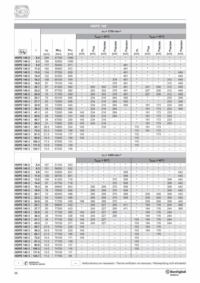
38
— Verifica termica non necessaria / Thermal verification not necessary / Wärmeprüfung nicht erforderlich*
HDPE 140n1 = 1750 min-1
Tamb = 20°C Tamb = 40°C
i n2 Mn2 Pn1 P T P TSR
P TM
CRW
5
P TM
CRW
9
P TM
CRW
21
P T P TSR
P TM
CRW
5
P TM
CRW
9
P TM
CRW
21
[rpm] [Nm] [kW] [kW] [kW] [kW] [kW] [kW] [kW] [kW] [kW] [kW] [kW]HDPE 140 2 8.4 209 47750 1090 * * * * * * * * * *HDPE 140 2 9.3 189 52850 1090 * * * * * * * * * *HDPE 140 2 9.9 177 50450 971 * * * * 481 * * * * *HDPE 140 2 11.0 160 55850 972 * * * * 481 * * * * *HDPE 140 2 13.0 134 57250 839 * * * * 481 * * * * 449HDPE 140 2 14.4 122 63350 839 * * * * 481 * * * * 449HDPE 140 2 16.3 108 65100 764 * * * 378 481 * * * 312 449HDPE 140 2 18.0 97 70150 744 * * * 378 481 * * * 312 449HDPE 140 2 20.1 87 61200 582 * 293 302 378 481 * 227 236 312 449HDPE 140 2 22.2 79 67700 582 * 293 302 378 481 * 227 236 312 449HDPE 140 2 24.9 70 71700 549 * 293 302 378 481 * 227 236 312 449HDPE 140 3 25.1 70 65100 506 * 234 216 284 400 * * * 233 349HDPE 140 3 27.7 63 72050 506 * 234 216 284 400 * * * 233 349HDPE 140 3 32.9 53 73350 434 * 234 216 284 400 * 191 173 233 349HDPE 140 3 36.4 48 73500 393 * 234 216 284 – * 191 173 233 349HDPE 140 3 41.1 43 73050 346 145 234 216 284 – * 191 173 233 –HDPE 140 3 45.5 38 73500 314 145 234 216 284 – * 191 173 233 –HDPE 140 3 50.7 34 67550 259 145 234 216 – – * 191 173 233 –HDPE 140 3 56.2 31 73500 255 145 234 216 – – * 191 173 233 –HDPE 140 3 65.1 26.9 74850 224 145 – 216 – – 115 191 173 – –HDPE 140 3 72.0 24.3 73500 199 145 – – – – 115 191 173 – –HDPE 140 3 81.3 21.5 74100 177 145 – – – – 115 – 173 – –HDPE 140 3 90.0 19.4 73500 159 145 – – – – 115 – – – –HDPE 140 3 100.3 17.4 67550 131 – – – – – 115 – – – –HDPE 140 3 111.0 15.8 73500 129 – – – – – 115 – – – –HDPE 140 3 124.7 14.0 67200 105 – – – – – – – – – –
n1 = 1400 min-1
Tamb = 20°C Tamb = 40°CHDPE 140 2 8.4 167 51100 933 * * * * * * * * * *HDPE 140 2 9.3 151 56500 932 * * * * * * * * * *HDPE 140 2 9.9 141 53950 831 * * * * 508 * * * * 442HDPE 140 2 11.0 128 59700 831 * * * * 508 * * * * 442HDPE 140 2 13.0 108 61200 718 * * * 375 508 * * * 309 442HDPE 140 2 14.4 97 67750 718 * * * 375 508 * * * 309 442HDPE 140 2 16.3 86 69600 653 * 290 299 375 508 * * * 309 442HDPE 140 2 18.0 78 75000 636 * 290 299 375 508 * * * 309 442HDPE 140 2 20.1 70 65400 498 * 290 299 375 508 * 239 248 309 442HDPE 140 2 22.2 63 72400 498 * 290 299 375 508 * 239 248 309 442HDPE 140 2 24.9 56 71700 439 198 290 299 375 – * 239 248 309 442HDPE 140 3 25.1 56 69600 432 * 245 227 295 411 * 194 176 244 360HDPE 140 3 27.7 50 77050 433 * 245 227 295 411 * 194 176 244 360HDPE 140 3 32.9 43 77100 365 149 245 227 295 – * 194 176 244 –HDPE 140 3 36.4 38 79150 338 149 245 227 295 – * 194 176 244 –HDPE 140 3 41.1 34 77100 292 149 245 227 – – 103 194 176 244 –HDPE 140 3 45.5 31 79150 271 149 245 227 – – 103 194 176 244 –HDPE 140 3 50.7 27.6 74700 229 149 – – – – 103 194 176 – –HDPE 140 3 56.2 24.9 79150 220 149 – – – – 103 194 176 – –HDPE 140 3 65.1 21.5 77100 185 149 – – – – 103 – 176 – –HDPE 140 3 72.0 19.4 79150 171 149 – – – – 103 – – – –HDPE 140 3 81.3 17.2 77100 148 – – – – – 103 – – – –HDPE 140 3 90.0 15.6 79150 137 – – – – – 103 – – – –HDPE 140 3 100.3 14.0 74700 116 – – – – – 103 – – – –HDPE 140 3 111.0 12.6 79150 111 – – – – – – – – – –HDPE 140 3 124.7 11.2 71700 90 – – – – – – – – – –
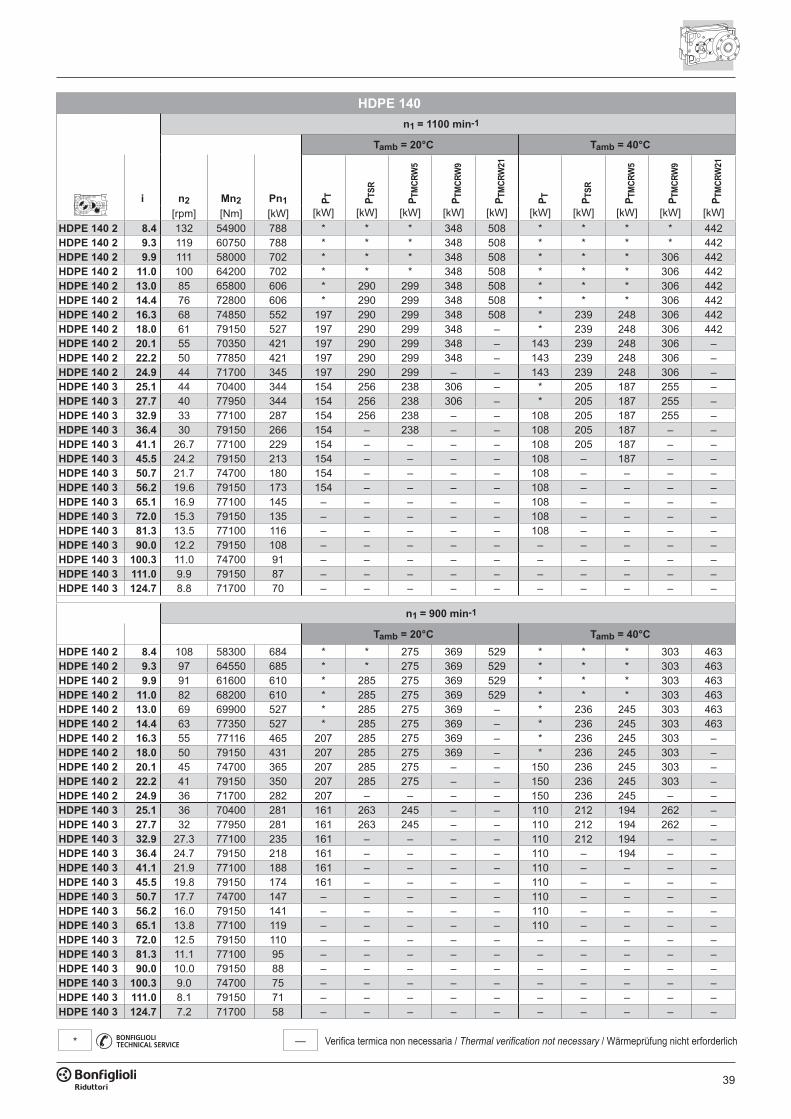
39
— Verifica termica non necessaria / Thermal verification not necessary / Wärmeprüfung nicht erforderlich*
HDPE 140n1 = 1100 min-1
Tamb = 20°C Tamb = 40°C
i n2 Mn2 Pn1 P T P TSR
P TM
CRW
5
P TM
CRW
9
P TM
CRW
21
P T P TSR
P TM
CRW
5
P TM
CRW
9
P TM
CRW
21
[rpm] [Nm] [kW] [kW] [kW] [kW] [kW] [kW] [kW] [kW] [kW] [kW] [kW]HDPE 140 2 8.4 132 54900 788 * * * 348 508 * * * * 442HDPE 140 2 9.3 119 60750 788 * * * 348 508 * * * * 442HDPE 140 2 9.9 111 58000 702 * * * 348 508 * * * 306 442HDPE 140 2 11.0 100 64200 702 * * * 348 508 * * * 306 442HDPE 140 2 13.0 85 65800 606 * 290 299 348 508 * * * 306 442HDPE 140 2 14.4 76 72800 606 * 290 299 348 508 * * * 306 442HDPE 140 2 16.3 68 74850 552 197 290 299 348 508 * 239 248 306 442HDPE 140 2 18.0 61 79150 527 197 290 299 348 – * 239 248 306 442HDPE 140 2 20.1 55 70350 421 197 290 299 348 – 143 239 248 306 –HDPE 140 2 22.2 50 77850 421 197 290 299 348 – 143 239 248 306 –HDPE 140 2 24.9 44 71700 345 197 290 299 – – 143 239 248 306 –HDPE 140 3 25.1 44 70400 344 154 256 238 306 – * 205 187 255 –HDPE 140 3 27.7 40 77950 344 154 256 238 306 – * 205 187 255 –HDPE 140 3 32.9 33 77100 287 154 256 238 – – 108 205 187 255 –HDPE 140 3 36.4 30 79150 266 154 – 238 – – 108 205 187 – –HDPE 140 3 41.1 26.7 77100 229 154 – – – – 108 205 187 – –HDPE 140 3 45.5 24.2 79150 213 154 – – – – 108 – 187 – –HDPE 140 3 50.7 21.7 74700 180 154 – – – – 108 – – – –HDPE 140 3 56.2 19.6 79150 173 154 – – – – 108 – – – –HDPE 140 3 65.1 16.9 77100 145 – – – – – 108 – – – –HDPE 140 3 72.0 15.3 79150 135 – – – – – 108 – – – –HDPE 140 3 81.3 13.5 77100 116 – – – – – 108 – – – –HDPE 140 3 90.0 12.2 79150 108 – – – – – – – – – –HDPE 140 3 100.3 11.0 74700 91 – – – – – – – – – –HDPE 140 3 111.0 9.9 79150 87 – – – – – – – – – –HDPE 140 3 124.7 8.8 71700 70 – – – – – – – – – –
n1 = 900 min-1
Tamb = 20°C Tamb = 40°CHDPE 140 2 8.4 108 58300 684 * * 275 369 529 * * * 303 463HDPE 140 2 9.3 97 64550 685 * * 275 369 529 * * * 303 463HDPE 140 2 9.9 91 61600 610 * 285 275 369 529 * * * 303 463HDPE 140 2 11.0 82 68200 610 * 285 275 369 529 * * * 303 463HDPE 140 2 13.0 69 69900 527 * 285 275 369 – * 236 245 303 463HDPE 140 2 14.4 63 77350 527 * 285 275 369 – * 236 245 303 463HDPE 140 2 16.3 55 77116 465 207 285 275 369 – * 236 245 303 –HDPE 140 2 18.0 50 79150 431 207 285 275 369 – * 236 245 303 –HDPE 140 2 20.1 45 74700 365 207 285 275 – – 150 236 245 303 –HDPE 140 2 22.2 41 79150 350 207 285 275 – – 150 236 245 303 –HDPE 140 2 24.9 36 71700 282 207 – – – – 150 236 245 – –HDPE 140 3 25.1 36 70400 281 161 263 245 – – 110 212 194 262 –HDPE 140 3 27.7 32 77950 281 161 263 245 – – 110 212 194 262 –HDPE 140 3 32.9 27.3 77100 235 161 – – – – 110 212 194 – –HDPE 140 3 36.4 24.7 79150 218 161 – – – – 110 – 194 – –HDPE 140 3 41.1 21.9 77100 188 161 – – – – 110 – – – –HDPE 140 3 45.5 19.8 79150 174 161 – – – – 110 – – – –HDPE 140 3 50.7 17.7 74700 147 – – – – – 110 – – – –HDPE 140 3 56.2 16.0 79150 141 – – – – – 110 – – – –HDPE 140 3 65.1 13.8 77100 119 – – – – – 110 – – – –HDPE 140 3 72.0 12.5 79150 110 – – – – – – – – – –HDPE 140 3 81.3 11.1 77100 95 – – – – – – – – – –HDPE 140 3 90.0 10.0 79150 88 – – – – – – – – – –HDPE 140 3 100.3 9.0 74700 75 – – – – – – – – – –HDPE 140 3 111.0 8.1 79150 71 – – – – – – – – – –HDPE 140 3 124.7 7.2 71700 58 – – – – – – – – – –
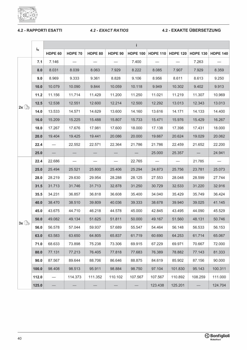
40
iN
i
HDPE 60 HDPE 70 HDPE 80 HDPE 90 HDPE 100 HDPE 110 HDPE 120 HDPE 130 HDPE 140
2x
7.1 7.146 — — — 7.400 — — 7.263 —
8.0 8.031 8.039 8.063 7.929 8.222 8.085 7.907 7.929 8.359
9.0 8.969 9.333 9.361 8.828 9.106 8.956 8.611 8.613 9.250
10.0 10.079 10.090 9.844 10.059 10.118 9.949 10.302 9.402 9.913
11.2 11.156 11.714 11.429 11.200 11.250 11.021 11.219 11.307 10.969
12.5 12.538 12.551 12.600 12.214 12.500 12.292 13.013 12.343 13.013
14.0 13.533 14.571 14.629 13.600 14.160 13.616 14.171 14.133 14.400
16.0 15.209 15.225 15.488 15.807 15.733 15.471 15.976 15.429 16.267
18.0 17.267 17.676 17.981 17.600 18.000 17.138 17.398 17.431 18.000
20.0 19.404 19.425 19.441 20.086 20.000 19.667 20.624 19.029 20.062
22.4 — 22.552 22.571 22.364 21.786 21.786 22.459 21.652 22.200
25.0 — — — — — 25.000 25.357 — 24.941
3x
22.4 22.686 — — — 22.765 — — 21.785 —
25.0 25.494 25.521 25.800 25.406 25.294 24.873 25.756 23.781 25.073
28.0 28.219 29.630 29.954 28.288 28.125 27.553 28.048 28.599 27.744
31.5 31.713 31.746 31.713 32.878 31.250 30.729 32.533 31.220 32.916
35.5 34.231 36.857 36.818 36.608 35.400 34.040 35.429 35.749 36.424
40.0 38.470 38.510 39.809 40.036 39.333 38.678 39.940 39.025 41.145
45.0 43.675 44.710 46.218 44.578 45.000 42.845 43.495 44.090 45.529
50.0 49.082 49.134 51.625 51.811 50.000 49.167 51.560 48.131 50.746
56.0 56.578 57.044 59.937 57.689 55.547 54.464 56.148 56.533 56.153
63.0 63.583 63.650 64.805 65.837 61.719 60.690 64.253 61.714 65.067
71.0 68.633 73.898 75.238 73.306 69.915 67.229 69.971 70.667 72.000
80.0 77.131 77.213 76.405 77.818 77.683 76.389 78.882 77.143 81.333
90.0 87.567 89.644 88.706 86.646 88.875 84.619 85.902 87.156 90.000
100.0 98.408 98.513 95.911 98.884 98.750 97.104 101.830 95.143 100.311
112.0 — 114.373 111.352 110.102 107.567 107.567 110.892 108.259 111.000
125.0 — — — — — 123.438 125.201 — 124.704
4.2 - RAPPORTI ESATTI 4.2 - EXACT RATIOS 4.2 - EXAKTE ÜBERSETZUNG
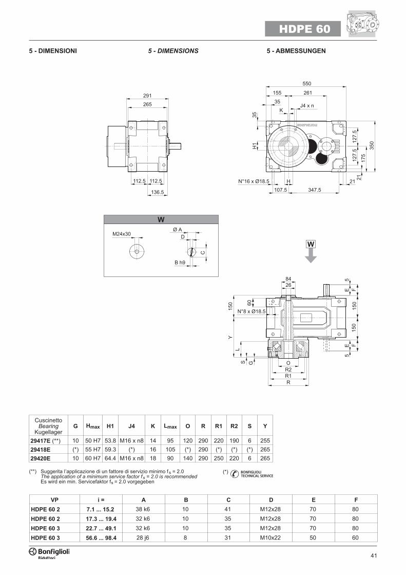
41
VP i = A B C D E F
HDPE 60 2 7.1 ... 15.2 38 k6 10 41 M12x28 70 80
HDPE 60 2 17.3 ... 19.4 32 k6 10 35 M12x28 70 80
HDPE 60 3 22.7 ... 49.1 32 k6 10 35 M12x28 70 80
HDPE 60 3 56.6 ... 98.4 28 j6 8 31 M10x22 50 60
��� ���
���
����� ����
��
�����
�����
��
���
���� ������
��
��
���
��
�� ���
�
��� ������
��
����
���
�
���
��
��
���
���
���
��
��
�
���
���
����� �����
�����
�� ��
����
�� !
"
�
HDPE 60
(*)
5 - DIMENSIONI 5 - DIMENSIONS 5 - ABMESSUNGEN
CuscinettoBearing
KugellagerG Hmax H1 J4 K Lmax O R R1 R2 S Y
29417E (**) 10 50 H7 53.8 M16 x n8 14 95 120 290 220 190 6 255
29418E (*) 55 H7 59.3 (*) 16 105 (*) 290 (*) (*) (*) 265
29420E 10 60 H7 64.4 M16 x n8 18 90 140 290 250 220 6 265
(**) Suggerita l’applicazione di un fattore di servizio minimo fs = 2.0The application of a minimum service factor f s = 2.0 is recommendedEs wird ein min. Servicefaktor fs = 2.0 vorgegeben
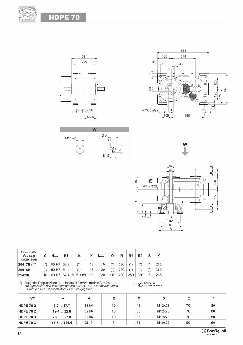
42
HDPE 70
VP i = A B C D E F
HDPE 70 2 8.0 ... 17.7 38 k6 10 41 M12x28 70 80
HDPE 70 2 19.4 ... 22.6 32 k6 10 35 M12x28 70 80
HDPE 70 3 25.5 ... 57.0 32 k6 10 35 M12x28 70 80
HDPE 70 3 63.7 ... 114.4 28 j6 8 31 M10x22 50 60
���
���
���
������
��
��
���� ����
��� ���
�� ��
���
���
���
���
��� ����
��
����
���
���
��
����� �����
�����
�
��� �
����
�� !
"
�
��
�� ���
�
���
��
��
���
���
���
(*)
CuscinettoBearing
KugellagerG Hmax H1 J4 K Lmax O R R1 R2 S Y
29417E (**) (*) 55 H7 59.3 (*) 16 110 (*) 290 (*) (*) (*) 255
29418E (*) 60 H7 64.4 (*) 18 120 (*) 290 (*) (*) (*) 265
29420E 10 60 H7 64.4 M16 x n8 18 120 140 290 250 220 6 265
(**) Suggerita l’applicazione di un fattore di servizio minimo fs = 2.0The application of a minimum service factor f s = 2.0 is recommendedEs wird ein min. Servicefaktor fs = 2.0 vorgegeben
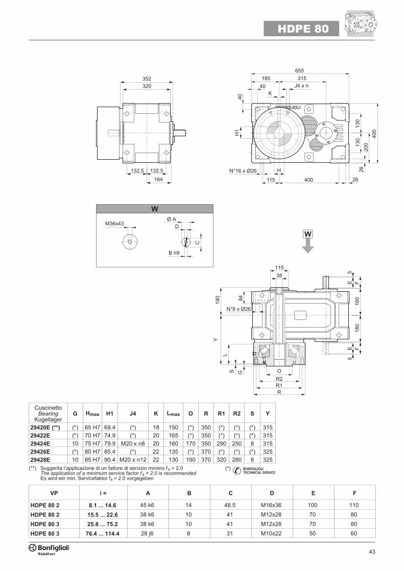
43
HDPE 80
VP i = A B C D E F
HDPE 80 2 8.1 ... 14.6 45 k6 14 48.5 M16x36 100 110
HDPE 80 2 15.5 ... 22.6 38 k6 10 41 M12x28 70 80
HDPE 80 3 25.8 ... 75.2 38 k6 10 41 M12x28 70 80
HDPE 80 3 76.4 ... 114.4 28 j6 8 31 M10x22 50 60
���
���
��� ��
��� ������
����������
��
���
��
��
���
��
���� ����
�
�
���
���
����
�
�
��� ����
��
��
�
��� �
����
�� !
"
�
��
�� ���
�
���
�
�
��
�����
���
���
(**) Suggerita l’applicazione di un fattore di servizio minimo fs = 2.0The application of a minimum service factor f s = 2.0 is recommendedEs wird ein min. Servicefaktor fs = 2.0 vorgegeben
(*)
CuscinettoBearing
KugellagerG Hmax H1 J4 K Lmax O R R1 R2 S Y
29420E (**) (*) 65 H7 69.4 (*) 18 150 (*) 350 (*) (*) (*) 315
29422E (*) 70 H7 74.9 (*) 20 165 (*) 350 (*) (*) (*) 315
29424E 10 75 H7 79.9 M20 x n8 20 160 170 350 290 250 8 315
29426E (*) 80 H7 85.4 (*) 22 135 (*) 370 (*) (*) (*) 325
29428E 10 85 H7 90.4 M20 x n12 22 130 190 370 320 280 8 325
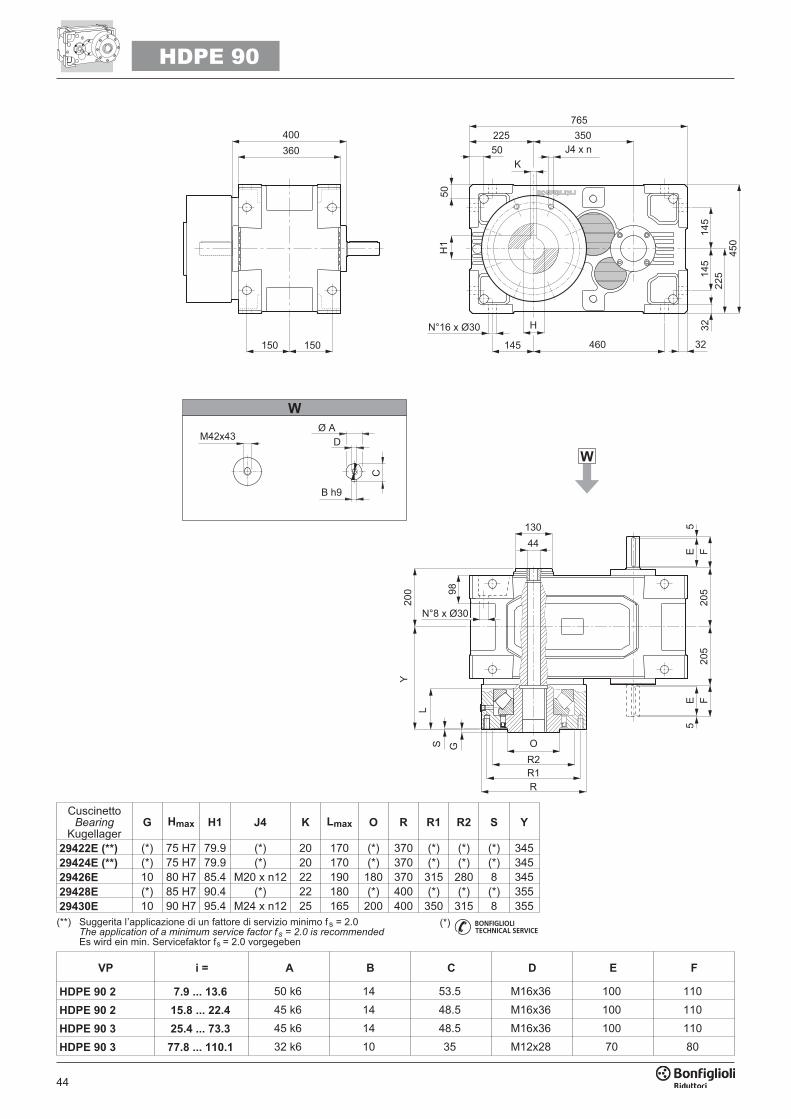
44
HDPE 90
VP i = A B C D E F
HDPE 90 2 7.9 ... 13.6 50 k6 14 53.5 M16x36 100 110
HDPE 90 2 15.8 ... 22.4 45 k6 14 48.5 M16x36 100 110
HDPE 90 3 25.4 ... 73.3 45 k6 14 48.5 M16x36 100 110
HDPE 90 3 77.8 ... 110.1 32 k6 10 35 M12x28 70 80
��� ����
��
����
���
�
��
���
��� ���
���� ����
�� �� ��
���
��� �����
��
��
��
��
�����
��
��
�
�� �
����
�� !
"
�
��
�� ���
�
���
�
�
��
���
���
��
�
(**) Suggerita l’applicazione di un fattore di servizio minimo fs = 2.0The application of a minimum service factor f s = 2.0 is recommendedEs wird ein min. Servicefaktor fs = 2.0 vorgegeben
(*)
CuscinettoBearing
KugellagerG Hmax H1 J4 K Lmax O R R1 R2 S Y
29422E (**) (*) 75 H7 79.9 (*) 20 170 (*) 370 (*) (*) (*) 34529424E (**) (*) 75 H7 79.9 (*) 20 170 (*) 370 (*) (*) (*) 34529426E 10 80 H7 85.4 M20 x n12 22 190 180 370 315 280 8 34529428E (*) 85 H7 90.4 (*) 22 180 (*) 400 (*) (*) (*) 35529430E 10 90 H7 95.4 M24 x n12 25 165 200 400 350 315 8 355
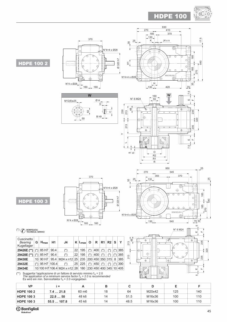
45
VP i = A B C D E F
HDPE 100 2 7.4 … 21.8 60 m6 18 64 M20x42 125 140
HDPE 100 3 22.8 … 50 48 k6 14 51.5 M16x36 100 110
HDPE 100 3 55.5 … 107.8 45 k6 14 48.5 M16x36 100 110
��� �
���
����
���
�
������
���
���
��
��
�����
���
���
����
����
���
�� ������� ���
�#� ����
��������
��
��� �����
����
��
���
���
��
�������
��
���
��
�� ���
�
�#� ����
���������
�
����
�� !
"
���$�% ��
��
��
�
���
�� ������� ���
��������
�#� ����
��
��
������ ��
��
����
���
���
���������
���
���������
�#� ����
������
���
��
��
�
���
���
�
���
���
�
HDPE 100
(*)
HDPE 100 2
HDPE 100 3
(**) Suggerita l’applicazione di un fattore di servizio minimo fs = 2.0The application of a minimum service factor f s = 2.0 is recommendedEs wird ein min. Servicefaktor fs = 2.0 vorgegeben
CuscinettoBearing
KugellagerG Hmax H1 J4 K Lmax O R R1 R2 S Y
29426E (**) (*) 85 H7 90.4 (*) 22 195 (*) 400 (*) (*) (*) 385
29428E (**) (*) 85 H7 90.4 (*) 22 195 (*) 400 (*) (*) (*) 385
29430E 10 90 H7 95.4 M24 x n12 25 235 200 450 350 315 8 385
29432E (*) 95 H7 100.4 (*) 25 225 (*) 450 (*) (*) (*) 390
29434E 10 100 H7 106.4 M24 x n12 28 180 230 450 400 345 10 405
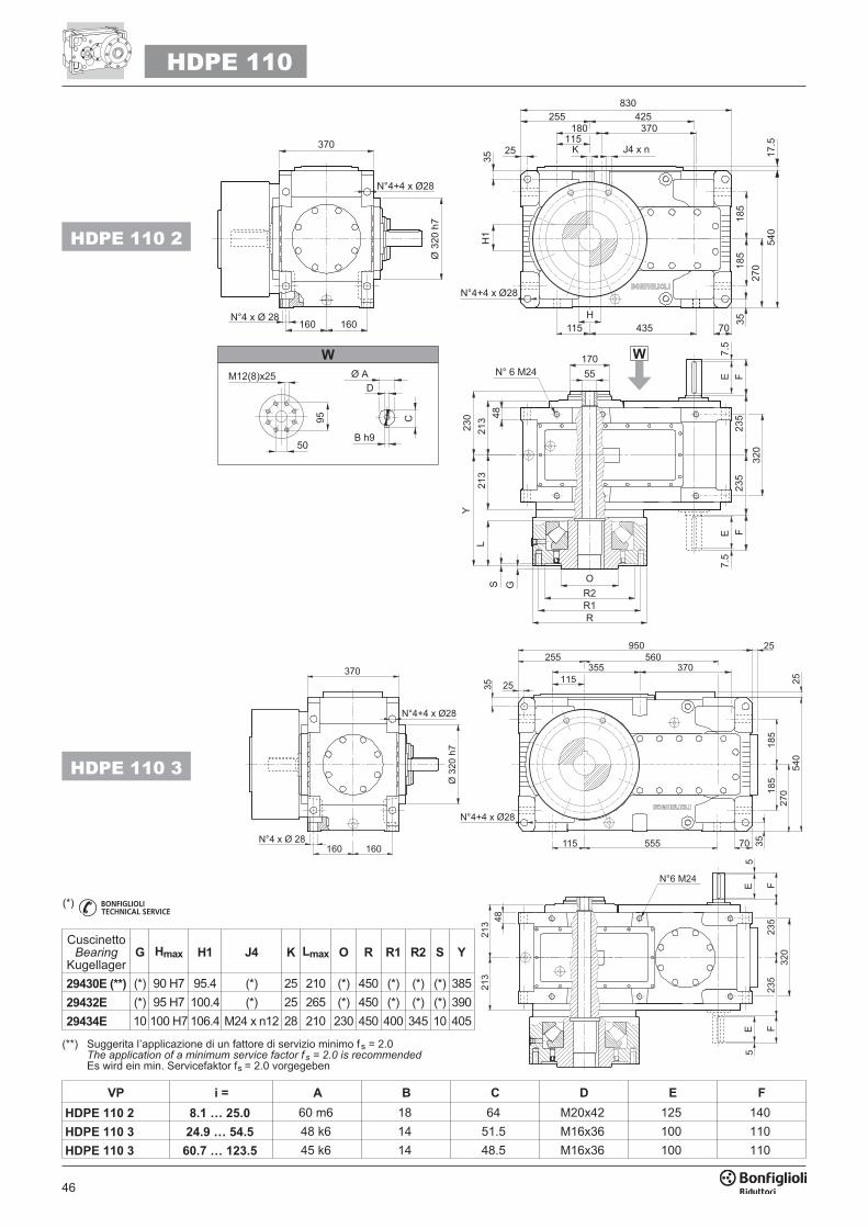
46
VP i = A B C D E F
HDPE 110 2 8.1 … 25.0 60 m6 18 64 M20x42 125 140
HDPE 110 3 24.9 … 54.5 48 k6 14 51.5 M16x36 100 110
HDPE 110 3 60.7 … 123.5 45 k6 14 48.5 M16x36 100 110
HDPE 110
HDPE 110 2
��� �
���
����
���
�
������
���
���
��
��
�����
���
���
����
����
���
�� �������� ���
��������
�#� ����
��
��� �����
����
��
���
���
��
�������
��
���
��
�� ���
�
���������
�#� ����
�
����
�� !
"
���$�% ��
��
��
�
��������
�#� ����
���
�� �������� ���
�� ��
������ ���
��
����
���
���
����������
���
���������
�#� ����
�����
���
���
���
�
���
���
���
��
�
HDPE 110 3
(**) Suggerita l’applicazione di un fattore di servizio minimo fs = 2.0The application of a minimum service factor f s = 2.0 is recommendedEs wird ein min. Servicefaktor fs = 2.0 vorgegeben
(*)
CuscinettoBearing
KugellagerG Hmax H1 J4 K Lmax O R R1 R2 S Y
29430E (**) (*) 90 H7 95.4 (*) 25 210 (*) 450 (*) (*) (*) 385
29432E (*) 95 H7 100.4 (*) 25 265 (*) 450 (*) (*) (*) 390
29434E 10 100 H7 106.4 M24 x n12 28 210 230 450 400 345 10 405
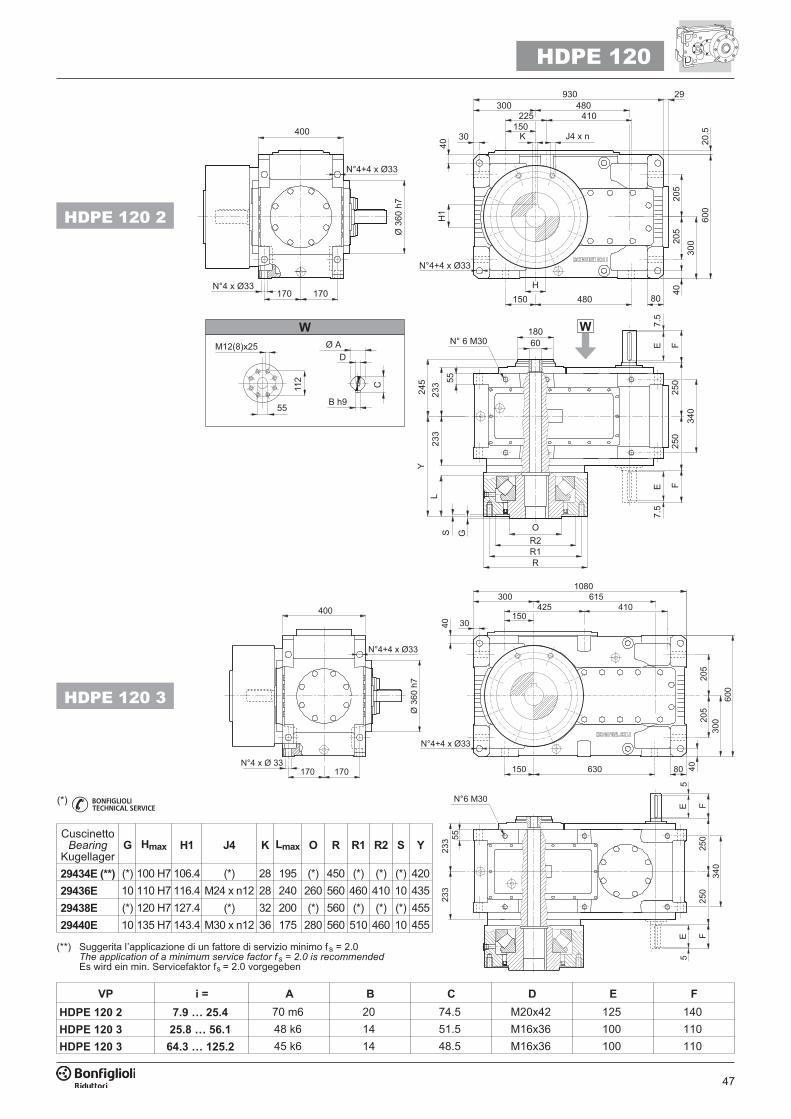
47
VP i = A B C D E F
HDPE 120 2 7.9 … 25.4 70 m6 20 74.5 M20x42 125 140
HDPE 120 3 25.8 … 56.1 48 k6 14 51.5 M16x36 100 110
HDPE 120 3 64.3 … 125.2 45 k6 14 48.5 M16x36 100 110
HDPE 120
HDPE 120 2
��� ��
���
����
���
�
�������
��
��
��
��
�����
���
���
����
����
��
��� �����
����
���
���
���
�
�������
�
��
���
��������
��
�� ���
�
�#� ����
��
�� ������� ���
��������
�#� ����
�
����
�� !
"
���$�% ��
��
���
�
������
��
���
���
��
���
���
���
��
�
� ��
������� ���
���
���
���
���������
���
�������
�#� ����
��
�� �������� ���
��������
�#� ����
HDPE 120 3
(**) Suggerita l’applicazione di un fattore di servizio minimo fs = 2.0The application of a minimum service factor f s = 2.0 is recommendedEs wird ein min. Servicefaktor fs = 2.0 vorgegeben
(*)
CuscinettoBearing
KugellagerG Hmax H1 J4 K Lmax O R R1 R2 S Y
29434E (**) (*) 100 H7 106.4 (*) 28 195 (*) 450 (*) (*) (*) 420
29436E 10 110 H7 116.4 M24 x n12 28 240 260 560 460 410 10 435
29438E (*) 120 H7 127.4 (*) 32 200 (*) 560 (*) (*) (*) 455
29440E 10 135 H7 143.4 M30 x n12 36 175 280 560 510 460 10 455
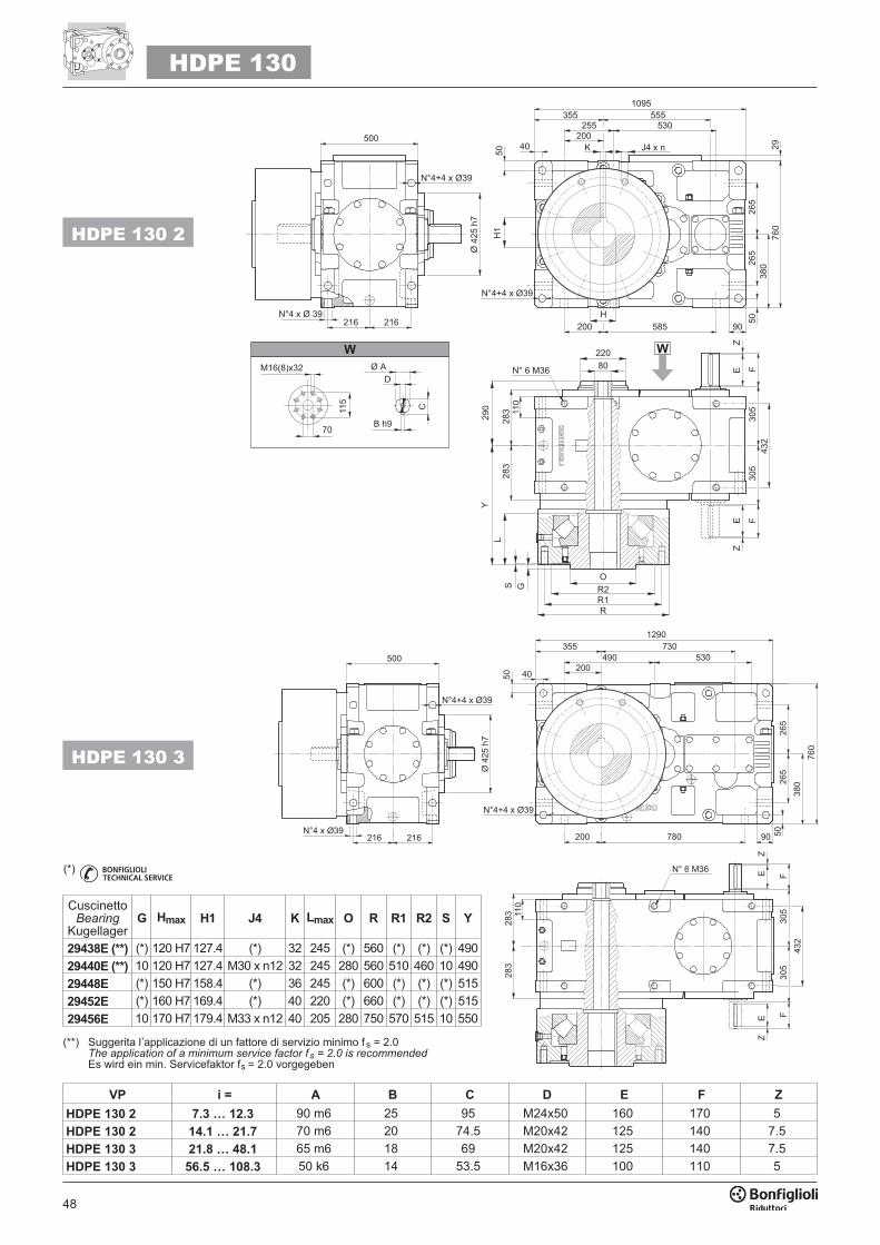
48
VP i = A B C D E F Z
HDPE 130 2 7.3 … 12.3 90 m6 25 95 M24x50 160 170 5
HDPE 130 2 14.1 … 21.7 70 m6 20 74.5 M20x42 125 140 7.5
HDPE 130 3 21.8 … 48.1 65 m6 18 69 M20x42 125 140 7.5
HDPE 130 3 56.5 … 108.3 50 k6 14 53.5 M16x36 100 110 5
HDPE 130
HDPE 130 2
���������
�#� ����
������� ���
��
���
���
���
��
��������
�
��
���
��
�� ���
�
�������
��
���
���
���
���
���
���
&�
&
���
��
��
�����
���
���
�� �������� ���
���
�������
�#� ����
�
����
�� !
"
���$�% ��
��
���
�
���
��
������� ���
���
���
���
����������
�
��������
�#� ����
���
���
���
���
���
��
�������
��
�&
�&
�� ������� ���
���
�������
�#� ����
HDPE 130 3
(**) Suggerita l’applicazione di un fattore di servizio minimo fs = 2.0The application of a minimum service factor f s = 2.0 is recommendedEs wird ein min. Servicefaktor fs = 2.0 vorgegeben
(*)
CuscinettoBearing
KugellagerG Hmax H1 J4 K Lmax O R R1 R2 S Y
29438E (**) (*) 120 H7 127.4 (*) 32 245 (*) 560 (*) (*) (*) 490
29440E (**) 10 120 H7 127.4 M30 x n12 32 245 280 560 510 460 10 490
29448E (*) 150 H7 158.4 (*) 36 245 (*) 600 (*) (*) (*) 515
29452E (*) 160 H7 169.4 (*) 40 220 (*) 660 (*) (*) (*) 515
29456E 10 170 H7 179.4 M33 x n12 40 205 280 750 570 515 10 550
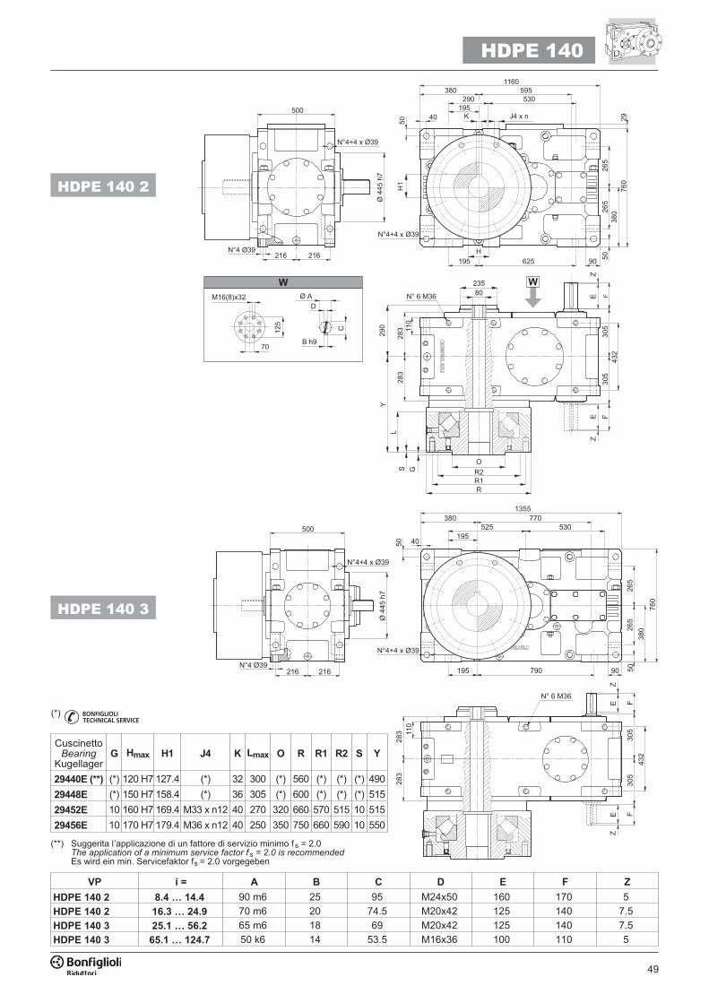
49
VP i = A B C D E F Z
HDPE 140 2 8.4 … 14.4 90 m6 25 95 M24x50 160 170 5
HDPE 140 2 16.3 … 24.9 70 m6 20 74.5 M20x42 125 140 7.5
HDPE 140 3 25.1 … 56.2 65 m6 18 69 M20x42 125 140 7.5
HDPE 140 3 65.1 … 124.7 50 k6 14 53.5 M16x36 100 110 5
HDPE 140
HDPE 140 2
���
������� ���
�
��
��� ��� �� �����
���
���
��
���������
�#� ����
��
�� ���
�
���
���
���
����
���
�
�������
��
�&
�&
���
��
��
�����
���
���
���
�����������
������
�#� ����
�
����
�� !
"
���$�% ��
��
���
�
���
����������
���
��� ��� ����
���
���
���
���������
�#� ����
���
��� ���
���
���
��
�������
��
�&
�&
�������� ���
���
������
�#� ����
HDPE 140 3
(**) Suggerita l’applicazione di un fattore di servizio minimo fs = 2.0The application of a minimum service factor f s = 2.0 is recommendedEs wird ein min. Servicefaktor fs = 2.0 vorgegeben
(*)
CuscinettoBearing
KugellagerG Hmax H1 J4 K Lmax O R R1 R2 S Y
29440E (**) (*) 120 H7 127.4 (*) 32 300 (*) 560 (*) (*) (*) 490
29448E (*) 150 H7 158.4 (*) 36 305 (*) 600 (*) (*) (*) 515
29452E 10 160 H7 169.4 M33 x n12 40 270 320 660 570 515 10 515
29456E 10 170 H7 179.4 M36 x n12 40 250 350 750 660 590 10 550
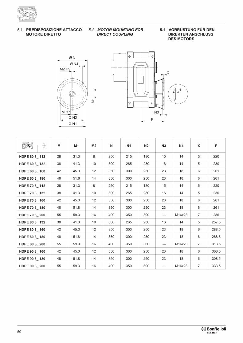
50
���
���������
����
���
���
�
��
�
M M1 M2 N N1 N2 N3 N4 X P
HDPE 60 3_ 112 28 31.3 8 250 215 180 15 14 5 220
HDPE 60 3_ 132 38 41.3 10 300 265 230 16 14 5 230
HDPE 60 3_ 160 42 45.3 12 350 300 250 23 18 6 261
HDPE 60 3_ 180 48 51.8 14 350 300 250 23 18 6 261
HDPE 70 3_ 112 28 31.3 8 250 215 180 15 14 5 220
HDPE 70 3_ 132 38 41.3 10 300 265 230 16 14 5 230
HDPE 70 3_ 160 42 45.3 12 350 300 250 23 18 6 261
HDPE 70 3_ 180 48 51.8 14 350 300 250 23 18 6 261
HDPE 70 3_ 200 55 59.3 16 400 350 300 — M16x23 7 286
HDPE 80 3_ 132 38 41.3 10 300 265 230 16 14 5 257.5
HDPE 80 3_ 160 42 45.3 12 350 300 250 23 18 6 288.5
HDPE 80 3_ 180 48 51.8 14 350 300 250 23 18 6 288.5
HDPE 80 3_ 200 55 59.3 16 400 350 300 — M16x23 7 313.5
HDPE 90 3_ 160 42 45.3 12 350 300 250 23 18 6 308.5
HDPE 90 3_ 180 48 51.8 14 350 300 250 23 18 6 308.5
HDPE 90 3_ 200 55 59.3 16 400 350 300 — M16x23 7 333.5
5.1 - PREDISPOSIZIONE ATTACCO
MOTORE DIRETTO
5.1 - MOTOR MOUNTING FOR
DIRECT COUPLING
5.1 - VORRÜSTUNG FÜR DEN
DIREKTEN ANSCHLUSS
DES MOTORS
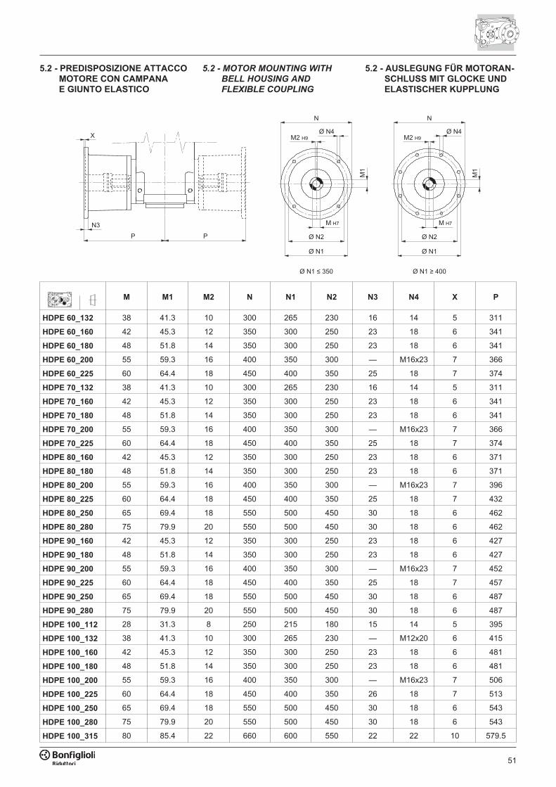
51
5.2 - PREDISPOSIZIONE ATTACCO
MOTORE CON CAMPANA
E GIUNTO ELASTICO
M M1 M2 N N1 N2 N3 N4 X P
HDPE 60_132 38 41.3 10 300 265 230 16 14 5 311
HDPE 60_160 42 45.3 12 350 300 250 23 18 6 341
HDPE 60_180 48 51.8 14 350 300 250 23 18 6 341
HDPE 60_200 55 59.3 16 400 350 300 — M16x23 7 366
HDPE 60_225 60 64.4 18 450 400 350 25 18 7 374
HDPE 70_132 38 41.3 10 300 265 230 16 14 5 311
HDPE 70_160 42 45.3 12 350 300 250 23 18 6 341
HDPE 70_180 48 51.8 14 350 300 250 23 18 6 341
HDPE 70_200 55 59.3 16 400 350 300 — M16x23 7 366
HDPE 70_225 60 64.4 18 450 400 350 25 18 7 374
HDPE 80_160 42 45.3 12 350 300 250 23 18 6 371
HDPE 80_180 48 51.8 14 350 300 250 23 18 6 371
HDPE 80_200 55 59.3 16 400 350 300 — M16x23 7 396
HDPE 80_225 60 64.4 18 450 400 350 25 18 7 432
HDPE 80_250 65 69.4 18 550 500 450 30 18 6 462
HDPE 80_280 75 79.9 20 550 500 450 30 18 6 462
HDPE 90_160 42 45.3 12 350 300 250 23 18 6 427
HDPE 90_180 48 51.8 14 350 300 250 23 18 6 427
HDPE 90_200 55 59.3 16 400 350 300 — M16x23 7 452
HDPE 90_225 60 64.4 18 450 400 350 25 18 7 457
HDPE 90_250 65 69.4 18 550 500 450 30 18 6 487
HDPE 90_280 75 79.9 20 550 500 450 30 18 6 487
HDPE 100_112 28 31.3 8 250 215 180 15 14 5 395
HDPE 100_132 38 41.3 10 300 265 230 — M12x20 6 415
HDPE 100_160 42 45.3 12 350 300 250 23 18 6 481
HDPE 100_180 48 51.8 14 350 300 250 23 18 6 481
HDPE 100_200 55 59.3 16 400 350 300 — M16x23 7 506
HDPE 100_225 60 64.4 18 450 400 350 26 18 7 513
HDPE 100_250 65 69.4 18 550 500 450 30 18 6 543
HDPE 100_280 75 79.9 20 550 500 450 30 18 6 543
HDPE 100_315 80 85.4 22 660 600 550 22 22 10 579.5
5.2 - MOTOR MOUNTING WITH
BELL HOUSING AND
FLEXIBLE COUPLING
5.2 - AUSLEGUNG FÜR MOTORAN-
SCHLUSS MIT GLOCKE UND
ELASTISCHER KUPPLUNG
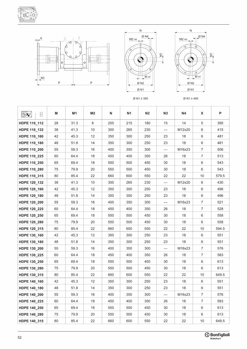
52
M M1 M2 N N1 N2 N3 N4 X P
HDPE 110_112 28 31.3 8 250 215 180 15 14 5 395
HDPE 110_132 38 41.3 10 300 265 230 — M12x20 6 415
HDPE 110_160 42 45.3 12 350 300 250 23 18 6 481
HDPE 110_180 48 51.8 14 350 300 250 23 18 6 481
HDPE 110_200 55 59.3 16 400 350 300 — M16x23 7 506
HDPE 110_225 60 64.4 18 450 400 350 26 18 7 513
HDPE 110_250 65 69.4 18 550 500 450 30 18 6 543
HDPE 110_280 75 79.9 20 550 500 450 30 18 6 543
HDPE 110_315 80 85.4 22 660 600 550 22 22 10 579.5
HDPE 120_132 38 41.3 10 300 265 230 — M12x20 6 430
HDPE 120_160 42 45.3 12 350 300 250 23 18 6 496
HDPE 120_180 48 51.8 14 350 300 250 23 18 6 496
HDPE 120_200 55 59.3 16 400 350 300 — M16x23 7 521
HDPE 120_225 60 64.4 18 450 400 350 26 18 7 528
HDPE 120_250 65 69.4 18 550 500 450 30 18 6 558
HDPE 120_280 75 79.9 20 550 500 450 30 18 6 558
HDPE 120_315 80 85.4 22 660 600 550 22 22 10 594.5
HDPE 130_160 42 45.3 12 350 300 250 23 18 6 551
HDPE 130_180 48 51.8 14 350 300 250 23 18 6 551
HDPE 130_200 55 59.3 16 400 350 300 — M16x23 7 576
HDPE 130_225 60 64.4 18 450 400 350 26 18 7 583
HDPE 130_250 65 69.4 18 550 500 450 30 18 6 613
HDPE 130_280 75 79.9 20 550 500 450 30 18 6 613
HDPE 130_315 80 85.4 22 660 600 550 22 22 10 649.5
HDPE 140_160 42 45.3 12 350 300 250 23 18 6 551
HDPE 140_180 48 51.8 14 350 300 250 23 18 6 551
HDPE 140_200 55 59.3 16 400 350 300 — M16x23 7 576
HDPE 140_225 60 64.4 18 450 400 350 26 18 7 583
HDPE 140_250 65 69.4 18 550 500 450 30 18 6 613
HDPE 140_280 75 79.9 20 550 500 450 30 18 6 613
HDPE 140_315 80 85.4 22 660 600 550 22 22 10 649.5

53
54
INDICE DI REVISIONE (R) INDEX OF REVISIONS (R) LISTE DER ÄNDERUNGEN (R)
Questa pubblicazione annulla e sostituisceogni precedente edizione o revisione. Ci ri-serviamo il diritto di apportare modifiche sen-za preavviso. È vietata la produzione ancheparziale senza autorizzazione.
This publication supersedes and replaces any
previous edition and revision. We reserve the
right to implement modifications without no-
tice. This catalogue cannot be reproduced,
even partially, without prior consent.
Diese Veröffentlichung annuliert und ersetztjeder hergehende Edition oder Revision.BONFIGLIOLI behält sich das Recht vor,Änderungen ohne vorherige Informationendurchzuführen.
14
01
22
R01_0
Descrizione Description Beschereibung
10, 12Aggiunto informazioni relative a"Configurazione albero lento".
Added information concerning
“Output shaft configuration”.
Added information concerning“Output shaft configuration”.
41...49 Aggiornato capitolo "Dimensioni". “Dimensions” chapter updated. Kapitel “Abmessungen” aktualisiert.
BR_CAT_HDPE_STD_I-UK-DE_R01_0


![Agile - Wolfgang Graf · Bonfiglioli Default-Motordaten Frequenzumrichter Flansch / Kompakt-Asynchronmotor Nennleistung [kW] AGL402-02 1 F A BN63C4 / M05B4 0.25 AGL402-03 1 F A BN71B4](https://img.pdfslide.org/doc/110x75/6074e1a2d54a5806726ac7c5/agile-wolfgang-graf-bonfiglioli-default-motordaten-frequenzumrichter-flansch-.jpg)