Embed Size (px)
Citation preview
KA-FLA-DEU/ENG-HA-2.000-07/2009 - 9910000025
Walter Stauffenberg GmbH & Co. KG
P.O.Box 1745 • D-58777 WerdohlIm Ehrenfeld 4 • D-58791 WerdohlTel. +49 2392 916-0 Fax +49 2392 2505E-Mail: [email protected] Internet: www.stauff.com S
TA
UF
FSTAUFF SCHELLENBefestigungssysteme für Rohre, Schläuche, Kabel und Bauteile; individuell gefertigte Sonderschellen
STAUFF CLAMPSClamping systems for pipes, hoses, cables and components; custom-made special clamps
STAUFF TESTMesssysteme zur Drucküberwachung, Entlüftung und Probeentnahmegasförmiger und fluider Medien
STAUFF TESTMeasuring systems for pressure monitoring of fluid and gaseous media;venting and sampling of fluid and gaseous pressure systems
STAUFF FILTRATION TECHNOLOGYFiltersysteme für die Erstausrüstung in der Mobil- und Stationär-hydraulik; Austauschelemente zu allen marktgängigen Fabrikaten
STAUFF FILTRATION TECHNOLOGYFilter systems for the basic equipment of mobile and industrial hydraulicapplications; wide range of replacement filter elements
STAUFF DIAGTRONICSKomponenten zur Überwachung und Analyse von Hydraulikflüssigkeitenin der Mobil- und Stationärhydraulik
STAUFF DIAGTRONICSComponents and services for the monitoring and analysis of hydraulicfluids for the mobile and industrial hydraulic sectors
STAUFF HYDRAULIKZUBEHÖRKomponenten für den Aggregate-, Tank- und Behälterbau in der Mobil- und Stationärhydraulik
STAUFF HYDRAULIC ACCESSORIESComponents for the construction of hydraulic reservoirs and power unitsfor the mobile and industrial hydraulic sectors
STAUFF FLANSCHESAE-Flansche nach ISO 6162-1/2 und SAE J518; Pumpenflansche
STAUFF FLANGESSAE Flanges acc. to ISO 6162-1/2 and SAE J518; pump flanges
STAUFF SYSTEMTECHNIKDreh- und Systemteile aus Edelstahl, Stahl, NE-Metallen undThermoplasten für sämtliche Industriebereiche
STAUFF MACHINED PARTSPrecision parts machined from stainless steel, carbon steel, non-ferrous-metals and thermoplastics for all fields of industry
Local solutions forindividual customers
worldwideSTA
UF
F
SAE-Flansche SAE Flanges
WWW.STAUFF.COM
Coverseiten Flansche Korrekturstand 07-2009:Layout 1 13.07.2009 09:40 Seite 1
02
Unternehmensprofil und NiederlassungsverzeichnisCompany Profile and Register of Establishments
Große AuswahlSofortige LieferbereitschaftHoher Qualitätsstandard
Als mittelständisches Unternehmen mit Hauptsitz in Werdohl sind wir alsEntwickler, Hersteller und Lieferant von Rohrleitungskomponenten undHydraulikzubehör unter der Markenbezeichnung STAUFF national undinternational erfolgreich.
Jahrzehntelange Erfahrung, motivierte und qualifizierte Mitarbeiter,modernste Fertigungstechniken und die vorausschauende Unterneh-mensführung machen uns zu einem kompetenten Partner.
Sämtliche Produkte werden einschlägigen Prüfungen in Anlehnung an internationale Normen unterzogen und unterliegen unserem betrieblichen Qualitätsmanagement nach EN ISO 9001:2000.
Unser umfangreicher Lagerbestand und unsere flexible Fertigung sind einGarant für schnelle Reaktion und kurze Lieferzeiten.
Unterstützt werden wir von einem flächendeckenden Händlernetzwerksowie eigenen Produktions-, Vertriebs- und Logistik-Niederlassungen inderzeit 14 Ländern.
Walter Stauffenberg GmbH & Co. KG
P. O. Box 1745 � 58777 WerdohlIm Ehrenfeld 4 � 58791 WerdohlDeutschland / Germany
Tel.: +49 2392 916-0Fax: +49 2392 2505E-Mail: [email protected]: www.stauff.com
2
Comprehensive choiceImmediate deliveryHigh quality standard
Originating and located in Werdohl in the German Sauerland region, wehave become an internationally leading developer, manufacturer andsupplier of pipework components and hydraulic accessories.
More than 5 decades of experience, highly-motivated and qualified staff,state-of-the-art manufacturing technologies and a foresighted management give us the reputation of being a competitive partner.
Our in-house laboratories carry out constant tests in line with international standards on all products. Certified in accordance with ENISO 9001:2000, our quality assurance system continually strives for perfection.
Our well-stocked warehouses and flexible production lines ensureprompt reactions and short delivery times.
Represented by a tight network of distributors and wholly-owned manufacturing facilities, distribution bases and warehouses in 14 countries worldwide, we are also close to you.
AUSTRALIEN / AUSTRALIASTAUFF Corporation Pty. Ltd.P. O. Box 227Wollongong, NSW, 2526 24-26 Doyle AvenueUnanderra, Wollongong, NSW, 2526Tel.: +61 2 4271 18 77Fax: +61 2 4271 84 [email protected]
BRASILIEN / BRAZILSTAUFF Brasil Ltda.Avenida Gupê 10767Galpão 2 - Bloco ABarueri - São PauloCEP 06422-120Tel.: +55 11 47 72 72 00Fax: +55 11 47 72 72 [email protected]
CHINASTAUFF International Trading (Shanghai) Co., Ltd.No. 41-42,Lane 369, Chuang Ye RoadJushuo Industrial Zone, Kang Qiao201319 ShanghaiTel.: +86 21 68 18 70 00Fax: +86 21 68 18 71 [email protected]
FRANKREICH / FRANCESTAUFF S.A.S230, Avenue du Grain d'OrZ.I. de Vineuil - Blois Sud41354 Vineuil-cedexTel.: +33 2 54 50 55 50Fax: +33 2 54 42 29 [email protected]
INDIEN / INDIASTAUFF India Pvt. Ltd.Gat. No. 2340Pune Nagar Road, WagholiPune, 412207Tel.: +91 20 6620 2473Fax: +91 20 2705 [email protected]
ITALIEN / ITALY STAUFF Italia s.r.l.Viale Nuova Valassina 78angolo Via Baragiola sn20033 Desio (MI)Tel.: +39 0362 63 80 70 Fax: +39 0362 63 80 [email protected]
IRLAND / IRELANDSTAUFF Ireland Ltd.Unit B3Weatherwell Business ParkClondalkinDublin 22Tel.: +353 1457 4936Fax: +353 1467 [email protected]
KANADA / CANADASTAUFF Canada Ltd.866 Milner AvenueScarboroughOntario M1B 5N7Tel.: +1 416 282 46 08Fax: +1 416 282 30 [email protected]
KOREASTAUFF Korea Ltd.1500-12, Dadae-DongSaha-KuPusan, 604-826Tel.: +82 51 266 6666Fax.: +82 51 266 [email protected]
NEUSEELAND / NEW ZEALANDSTAUFF Corporation (NZ) Ltd.P. O. Box 58517Greenmount, AucklandUnit D, 103 Harris Road East Tamaki, AucklandTel.: +64 9 271 48 12Fax: +64 9 271 48 [email protected]
POLEN / POLANDSTAUFF Polska Sp. z o.o.Miszewko 43 A80-297 Banino Tel.: +48 58 660 11 60Fax: +48 58 629 79 [email protected]
RUSSISCHE FÖDERATION /RUSSIAN FEDERATIONSTAUFF LLCOffice 205, Building 7Scharikopodschipnikovskaya 11Moscow, 115088Tel.: +7 495 223 89 61
+7 495 987 36 29Fax: +7 495 679 90 [email protected]
VEREINIGTES KÖNIGREICH /UNITED KINGDOMSTAUFF UK500, Carlisle Street EastOff Downgate DriveSheffield, S4 8BSTel.: +44 114 251 85 18Fax: +44 114 251 85 [email protected]
VEREINIGTE STAATEN /UNITED STATESSTAUFF Corporation7 Wm. Demarest PlaceWaldwick, 07463-1542New JerseyTel.: +1 201 444 78 00Fax: +1 201 444 78 [email protected]
Globale Präsenz mit eigenenNiederlassungen und Händlern inallen Industrieländern weltweit.
Globally available through wholly-owned branches and distributors in all industrial countries.
67
Technischer Anhang - Größenübersicht SAE-Flansche Hochdruck-BaureiheTechnical Appendix - SAE Flange Sizing Guide High Pressure Series
6.000-PSI-Baureihe6.000 PSI SeriesAnleitung:Um den Typ und die Größe desFlansches zu bestimmen, platzieren Sieden Flansch über der ausgewähltenKontur und gleichen die Schraubloch-bohrungen mit der Skizze ab.
InstructionsTo determine flange type and size, placeflange over drawing provided and line upholes.
Bei Schmiedeteilen können die Maße der unbearbeiteten Flächen von den aufgeführten Werten abweichen und sind daher nur als Richtwerte zubetrachten.Unmachined surfaces of forged parts may differ from shown values and should be considered as reference values only.
GrößeSize H I
Ø-Schraubloch-bohrung
Ø Screw Holes
Ø-Gewinde-bohrung
Ø Threads
1/2" 18,2 40,5 8,7 M8
3/4" 23,8 50,8 10,5 M10
1" 27,8 57,2 13 M12
1"1/4 31,8 66,6 13,5/15 M12/M14
1"1/2 36,5 79,3 17 M16
2" 44,5 96,8 21 M20
Coverseiten Flansche Korrekturstand 07-2009:Layout 1 13.07.2009 09:40 Seite 2
InhaltsverzeichnisTable of Contents
Unternehmensprofil und Niederlassungsverzeichnis . . . . . . . . . . . . . . . . . . . . . . . . . . . . . . . . . . . . . . . . . . . . . . . . . . . . . . . . . . . . . . . . . . . . . . . 02Company Profile and Register of Establishments
Inhaltsverzeichnis . . . . . . . . . . . . . . . . . . . . . . . . . . . . . . . . . . . . . . . . . . . . . . . . . . . . . . . . . . . . . . . . . . . . . . . . . . . . . . . . . . . . . . . . . . . . . . 03 / 4 / 5Table of Contents
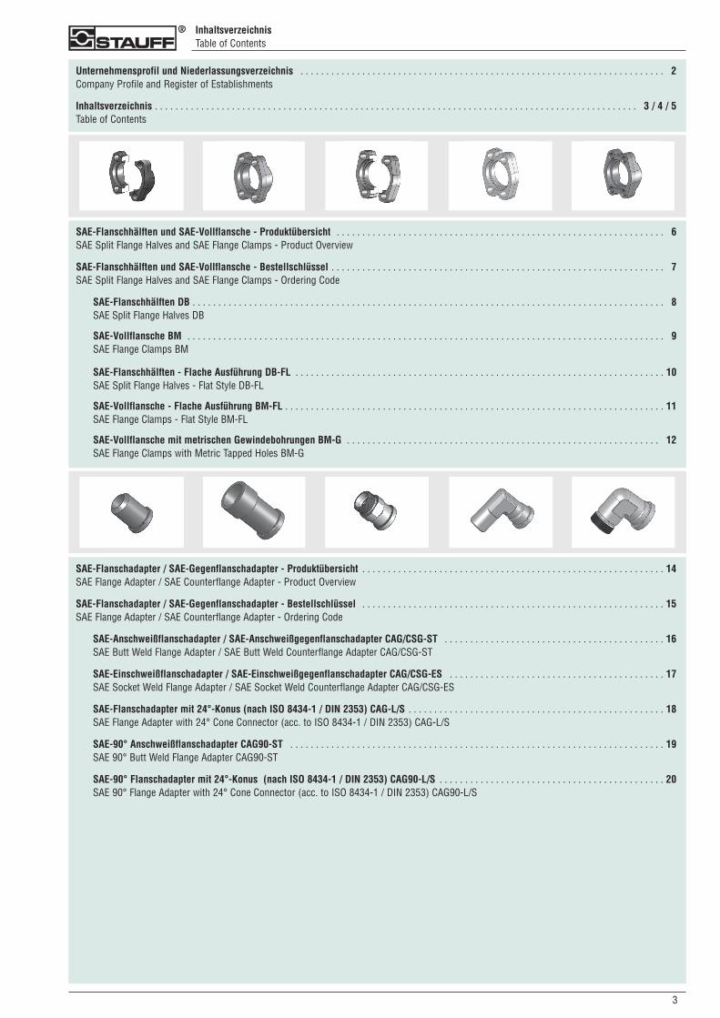
SAE-Flanschhälften und SAE-Vollflansche - Produktübersicht . . . . . . . . . . . . . . . . . . . . . . . . . . . . . . . . . . . . . . . . . . . . . . . . . . . . . . . . . . . . . . . . 06SAE Split Flange Halves and SAE Flange Clamps - Product Overview
SAE-Flanschhälften und SAE-Vollflansche - Bestellschlüssel . . . . . . . . . . . . . . . . . . . . . . . . . . . . . . . . . . . . . . . . . . . . . . . . . . . . . . . . . . . . . . . . . 07SAE Split Flange Halves and SAE Flange Clamps - Ordering Code
SAE-Flanschhälften DB . . . . . . . . . . . . . . . . . . . . . . . . . . . . . . . . . . . . . . . . . . . . . . . . . . . . . . . . . . . . . . . . . . . . . . . . . . . . . . . . . . . . . . . . . . . . 08SAE Split Flange Halves DB
SAE-Vollflansche BM . . . . . . . . . . . . . . . . . . . . . . . . . . . . . . . . . . . . . . . . . . . . . . . . . . . . . . . . . . . . . . . . . . . . . . . . . . . . . . . . . . . . . . . . . . . . . 09SAE Flange Clamps BM
SAE-Flanschhälften - Flache Ausführung DB-FL . . . . . . . . . . . . . . . . . . . . . . . . . . . . . . . . . . . . . . . . . . . . . . . . . . . . . . . . . . . . . . . . . . . . . . . . 10SAE Split Flange Halves - Flat Style DB-FL
SAE-Vollflansche - Flache Ausführung BM-FL . . . . . . . . . . . . . . . . . . . . . . . . . . . . . . . . . . . . . . . . . . . . . . . . . . . . . . . . . . . . . . . . . . . . . . . . . . 11SAE Flange Clamps - Flat Style BM-FL
SAE-Vollflansche mit metrischen Gewindebohrungen BM-G . . . . . . . . . . . . . . . . . . . . . . . . . . . . . . . . . . . . . . . . . . . . . . . . . . . . . . . . . . . . . 012SAE Flange Clamps with Metric Tapped Holes BM-G
SAE-Flanschadapter / SAE-Gegenflanschadapter - Produktübersicht . . . . . . . . . . . . . . . . . . . . . . . . . . . . . . . . . . . . . . . . . . . . . . . . . . . . . . . . . . . 14SAE Flange Adapter / SAE Counterflange Adapter - Product Overview
SAE-Flanschadapter / SAE-Gegenflanschadapter - Bestellschlüssel . . . . . . . . . . . . . . . . . . . . . . . . . . . . . . . . . . . . . . . . . . . . . . . . . . . . . . . . . . . 15SAE Flange Adapter / SAE Counterflange Adapter - Ordering Code
SAE-Anschweißflanschadapter / SAE-Anschweißgegenflanschadapter CAG/CSG-ST . . . . . . . . . . . . . . . . . . . . . . . . . . . . . . . . . . . . . . . . . . . 16SAE Butt Weld Flange Adapter / SAE Butt Weld Counterflange Adapter CAG/CSG-ST
SAE-Einschweißflanschadapter / SAE-Einschweißgegenflanschadapter CAG/CSG-ES . . . . . . . . . . . . . . . . . . . . . . . . . . . . . . . . . . . . . . . . . . 17SAE Socket Weld Flange Adapter / SAE Socket Weld Counterflange Adapter CAG/CSG-ES
SAE-Flanschadapter mit 24°-Konus (nach ISO 8434-1 / DIN 2353) CAG-L/S . . . . . . . . . . . . . . . . . . . . . . . . . . . . . . . . . . . . . . . . . . . . . . . . . . 18SAE Flange Adapter with 24° Cone Connector (acc. to ISO 8434-1 / DIN 2353) CAG-L/S
SAE-90° Anschweißflanschadapter CAG90-ST . . . . . . . . . . . . . . . . . . . . . . . . . . . . . . . . . . . . . . . . . . . . . . . . . . . . . . . . . . . . . . . . . . . . . . . . . 19SAE 90° Butt Weld Flange Adapter CAG90-ST
SAE-90° Flanschadapter mit 24°-Konus (nach ISO 8434-1 / DIN 2353) CAG90-L/S . . . . . . . . . . . . . . . . . . . . . . . . . . . . . . . . . . . . . . . . . . . . 20SAE 90° Flange Adapter with 24° Cone Connector (acc. to ISO 8434-1 / DIN 2353) CAG90-L/S
30
04
Inhaltsverzeichnis - FortsetzungTable of Contents - Continuation
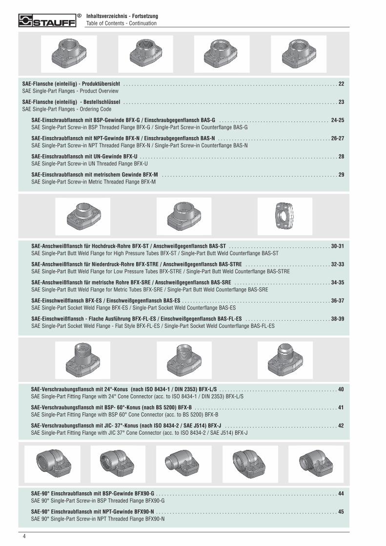
SAE-Flansche (einteilig) - Produktübersicht . . . . . . . . . . . . . . . . . . . . . . . . . . . . . . . . . . . . . . . . . . . . . . . . . . . . . . . . . . . . . . . . . . . . . . . . . . . . . . 22SAE Single-Part Flanges - Product Overview
SAE-Flansche (einteilig) - Bestellschlüssel . . . . . . . . . . . . . . . . . . . . . . . . . . . . . . . . . . . . . . . . . . . . . . . . . . . . . . . . . . . . . . . . . . . . . . . . . . . . . . 23SAE Single-Part Flanges - Ordering Code
SAE-Einschraubflansch mit BSP-Gewinde BFX-G / Einschraubgegenflansch BAS-G . . . . . . . . . . . . . . . . . . . . . . . . . . . . . . . . . . . . . . . . 24-25SAE Single-Part Screw-in BSP Threaded Flange BFX-G / Single-Part Screw-in Counterflange BAS-G
SAE-Einschraubflansch mit NPT-Gewinde BFX-N / Einschraubgegenflansch BAS-N . . . . . . . . . . . . . . . . . . . . . . . . . . . . . . . . . . . . . . . . . 26-27SAE Single-Part Screw-in NPT Threaded Flange BFX-N / Single-Part Screw-in Counterflange BAS-N
SAE-Einschraubflansch mit UN-Gewinde BFX-U . . . . . . . . . . . . . . . . . . . . . . . . . . . . . . . . . . . . . . . . . . . . . . . . . . . . . . . . . . . . . . . . . . . . . . . . 28SAE Single-Part Screw-in UN Threaded Flange BFX-U
SAE-Einschraubflansch mit metrischem Gewinde BFX-M . . . . . . . . . . . . . . . . . . . . . . . . . . . . . . . . . . . . . . . . . . . . . . . . . . . . . . . . . . . . . . . . 29SAE Single-Part Screw-in Metric Threaded Flange BFX-M
SAE-Anschweißflansch für Hochdruck-Rohre BFX-ST / Anschweißgegenflansch BAS-ST . . . . . . . . . . . . . . . . . . . . . . . . . . . . . . . . . . . . . 30-31SAE Single-Part Butt Weld Flange for High Pressure Tubes BFX-ST / Single-Part Butt Weld Counterflange BAS-ST
SAE-Anschweißflansch für Niederdruck-Rohre BFX-STRE / Anschweißgegenflansch BAS-STRE . . . . . . . . . . . . . . . . . . . . . . . . . . . . . . . 32-33SAE Single-Part Butt Weld Flange for Low Pressure Tubes BFX-STRE / Single-Part Butt Weld Counterflange BAS-STRE
SAE-Anschweißflansch für metrische Rohre BFX-SRE / Anschweißgegenflansch BAS-SRE . . . . . . . . . . . . . . . . . . . . . . . . . . . . . . . . . . . 34-35SAE Single-Part Butt Weld Flange for Metric Tubes BFX-SRE / Single-Part Butt Weld Counterflange BAS-SRE
SAE-Einschweißflansch BFX-ES / Einschweißgegenflansch BAS-ES . . . . . . . . . . . . . . . . . . . . . . . . . . . . . . . . . . . . . . . . . . . . . . . . . . . . . . 36-37SAE Single-Part Socket Weld Flange BFX-ES / Single-Part Socket Weld Counterflange BAS-ES
SAE-Einschweißflansch - Flache Ausführung BFX-FL-ES / Einschweißgegenflansch BAS-FL-ES . . . . . . . . . . . . . . . . . . . . . . . . . . . . . . . 38-39SAE Single-Part Socket Weld Flange - Flat Style BFX-FL-ES / Single-Part Socket Weld Counterflange BAS-FL-ES
SAE-Verschraubungsflansch mit 24°-Konus (nach ISO 8434-1 / DIN 2353) BFX-L/S . . . . . . . . . . . . . . . . . . . . . . . . . . . . . . . . . . . . . . . . . . . 40SAE Single-Part Fitting Flange with 24° Cone Connector (acc. to ISO 8434-1 / DIN 2353) BFX-L/S
SAE-Verschraubungsflansch mit BSP- 60°-Konus (nach BS 5200) BFX-B . . . . . . . . . . . . . . . . . . . . . . . . . . . . . . . . . . . . . . . . . . . . . . . . . . . . 41SAE Single-Part Fitting Flange with BSP 60° Cone Connector (acc. to BS 5200) BFX-B
SAE-Verschraubungsflansch mit JIC- 37°-Konus (nach ISO 8434-2 / SAE J514) BFX-J . . . . . . . . . . . . . . . . . . . . . . . . . . . . . . . . . . . . . . . . . 42SAE Single-Part Fitting Flange with JIC 37° Cone Connector (acc. to ISO 8434-2 / SAE J514) BFX-J
SAE-90° Einschraubflansch mit BSP-Gewinde BFX90-G . . . . . . . . . . . . . . . . . . . . . . . . . . . . . . . . . . . . . . . . . . . . . . . . . . . . . . . . . . . . . . . . . . 44SAE 90° Single-Part Screw-in BSP Threaded Flange BFX90-G
SAE-90° Einschraubflansch mit NPT-Gewinde BFX90-N . . . . . . . . . . . . . . . . . . . . . . . . . . . . . . . . . . . . . . . . . . . . . . . . . . . . . . . . . . . . . . . . . . 45SAE 90° Single-Part Screw-in NPT Threaded Flange BFX90-N
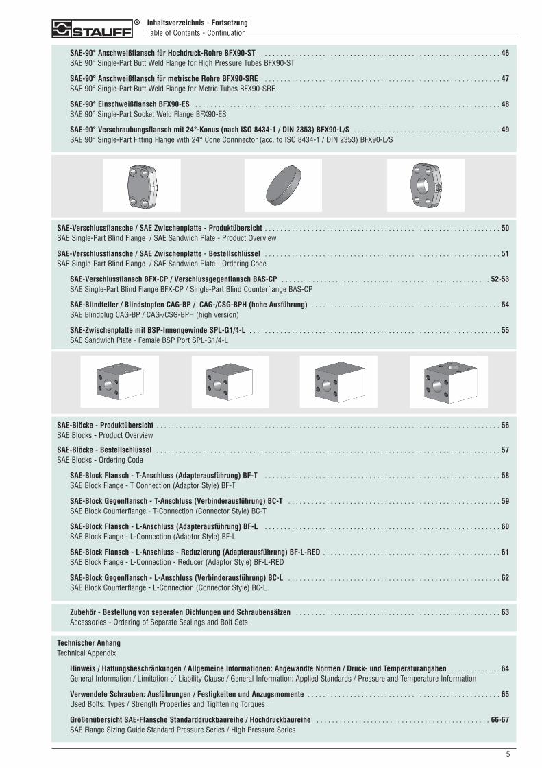
SAE-Verschlussflansche / SAE Zwischenplatte - Produktübersicht . . . . . . . . . . . . . . . . . . . . . . . . . . . . . . . . . . . . . . . . . . . . . . . . . . . . . . . . . . . . . 50SAE Single-Part Blind Flange / SAE Sandwich Plate - Product Overview
SAE-Verschlussflansche / SAE Zwischenplatte - Bestellschlüssel . . . . . . . . . . . . . . . . . . . . . . . . . . . . . . . . . . . . . . . . . . . . . . . . . . . . . . . . . . . . . 51SAE Single-Part Blind Flange / SAE Sandwich Plate - Ordering Code
SAE-Verschlussflansch BFX-CP / Verschlussgegenflansch BAS-CP . . . . . . . . . . . . . . . . . . . . . . . . . . . . . . . . . . . . . . . . . . . . . . . . . . . . . . 52-53SAE Single-Part Blind Flange BFX-CP / Single-Part Blind Counterflange BAS-CP
SAE-Blindteller / Blindstopfen CAG-BP / CAG-/CSG-BPH (hohe Ausführung) . . . . . . . . . . . . . . . . . . . . . . . . . . . . . . . . . . . . . . . . . . . . . . . . . 54SAE Blindplug CAG-BP / CAG-/CSG-BPH (high version)
SAE-Zwischenplatte mit BSP-Innengewinde SPL-G1/4-L . . . . . . . . . . . . . . . . . . . . . . . . . . . . . . . . . . . . . . . . . . . . . . . . . . . . . . . . . . . . . . . . . 55SAE Sandwich Plate - Female BSP Port SPL-G1/4-L
50
Inhaltsverzeichnis - FortsetzungTable of Contents - Continuation
SAE-90° Anschweißflansch für Hochdruck-Rohre BFX90-ST . . . . . . . . . . . . . . . . . . . . . . . . . . . . . . . . . . . . . . . . . . . . . . . . . . . . . . . . . . . . . . 46SAE 90° Single-Part Butt Weld Flange for High Pressure Tubes BFX90-ST
SAE-90° Anschweißflansch für metrische Rohre BFX90-SRE . . . . . . . . . . . . . . . . . . . . . . . . . . . . . . . . . . . . . . . . . . . . . . . . . . . . . . . . . . . . . . 47SAE 90° Single-Part Butt Weld Flange for Metric Tubes BFX90-SRE
SAE-90° Einschweißflansch BFX90-ES . . . . . . . . . . . . . . . . . . . . . . . . . . . . . . . . . . . . . . . . . . . . . . . . . . . . . . . . . . . . . . . . . . . . . . . . . . . . . . . 48SAE 90° Single-Part Socket Weld Flange BFX90-ES
SAE-90° Verschraubungsflansch mit 24°-Konus (nach ISO 8434-1 / DIN 2353) BFX90-L/S . . . . . . . . . . . . . . . . . . . . . . . . . . . . . . . . . . . . . . 49SAE 90° Single-Part Fitting Flange with 24° Cone Connnector (acc. to ISO 8434-1 / DIN 2353) BFX90-L/S
Zubehör - Bestellung von seperaten Dichtungen und Schraubensätzen . . . . . . . . . . . . . . . . . . . . . . . . . . . . . . . . . . . . . . . . . . . . . . . . . . . . . 63Accessories - Ordering of Separate Sealings and Bolt Sets
SAE-Blöcke - Produktübersicht . . . . . . . . . . . . . . . . . . . . . . . . . . . . . . . . . . . . . . . . . . . . . . . . . . . . . . . . . . . . . . . . . . . . . . . . . . . . . . . . . . . . . . . . . 56SAE Blocks - Product Overview
SAE-Blöcke - Bestellschlüssel . . . . . . . . . . . . . . . . . . . . . . . . . . . . . . . . . . . . . . . . . . . . . . . . . . . . . . . . . . . . . . . . . . . . . . . . . . . . . . . . . . . . . . . . . 57SAE Blocks - Ordering Code
SAE-Block Flansch - T-Anschluss (Adapterausführung) BF-T . . . . . . . . . . . . . . . . . . . . . . . . . . . . . . . . . . . . . . . . . . . . . . . . . . . . . . . . . . . . . 58SAE Block Flange - T Connection (Adaptor Style) BF-T
SAE-Block Gegenflansch - T-Anschluss (Verbinderausführung) BC-T . . . . . . . . . . . . . . . . . . . . . . . . . . . . . . . . . . . . . . . . . . . . . . . . . . . . . . . 59SAE Block Counterflange - T-Connection (Connector Style) BC-T
SAE-Block Flansch - L-Anschluss (Adapterausführung) BF-L . . . . . . . . . . . . . . . . . . . . . . . . . . . . . . . . . . . . . . . . . . . . . . . . . . . . . . . . . . . . . 60SAE Block Flange - L-Connection (Adaptor Style) BF-L
SAE-Block Flansch - L-Anschluss - Reduzierung (Adapterausführung) BF-L-RED . . . . . . . . . . . . . . . . . . . . . . . . . . . . . . . . . . . . . . . . . . . . . . 61SAE Block Flange - L-Connection - Reducer (Adaptor Style) BF-L-RED
SAE-Block Gegenflansch - L-Anschluss (Verbinderausführung) BC-L . . . . . . . . . . . . . . . . . . . . . . . . . . . . . . . . . . . . . . . . . . . . . . . . . . . . . . . 62SAE Block Counterflange - L-Connection (Connector Style) BC-L
Technischer AnhangTechnical Appendix
Hinweis / Haftungsbeschränkungen / Allgemeine Informationen: Angewandte Normen / Druck- und Temperaturangaben . . . . . . . . . . . . . 64General Information / Limitation of Liability Clause / General Information: Applied Standards / Pressure and Temperature Information
Verwendete Schrauben: Ausführungen / Festigkeiten und Anzugsmomente . . . . . . . . . . . . . . . . . . . . . . . . . . . . . . . . . . . . . . . . . . . . . . . . . . 65Used Bolts: Types / Strength Properties and Tightening Torques
Größenübersicht SAE-Flansche Standarddruckbaureihe / Hochdruckbaureihe . . . . . . . . . . . . . . . . . . . . . . . . . . . . . . . . . . . . . . . . . . . . . 66-67SAE Flange Sizing Guide Standard Pressure Series / High Pressure Series
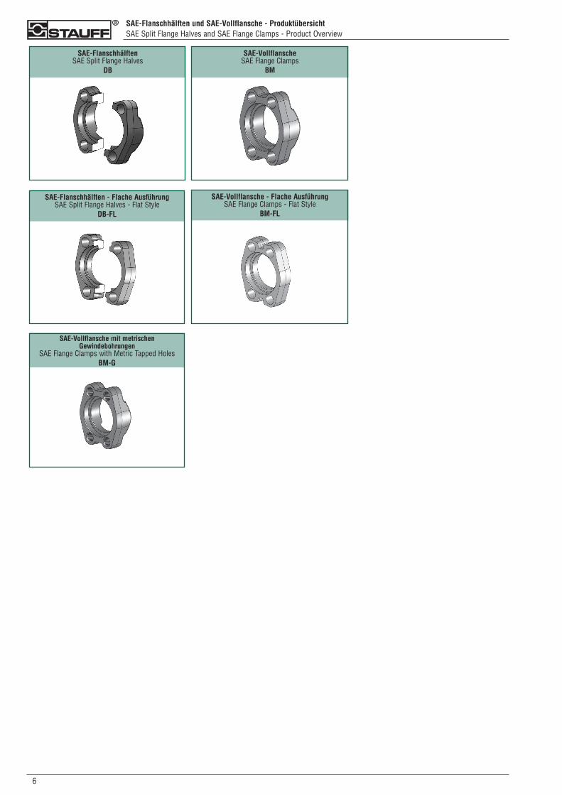
SAE-Flanschhälften und SAE-Vollflansche - ProduktübersichtSAE Split Flange Halves and SAE Flange Clamps - Product Overview
06
SAE-Flanschhälften SAE Split Flange Halves
DB
SAE-VollflanscheSAE Flange Clamps
BM
SAE-Flanschhälften - Flache AusführungSAE Split Flange Halves - Flat Style
DB-FL
SAE-Vollflansche - Flache AusführungSAE Flange Clamps - Flat Style
BM-FL
SAE-Vollflansche mit metrischen Gewindebohrungen
SAE Flange Clamps with Metric Tapped HolesBM-G
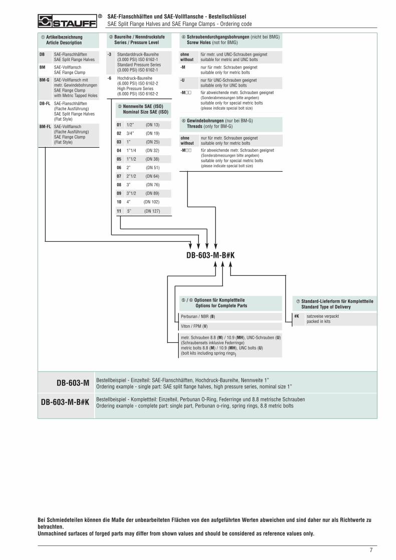
➀ ArtikelbezeichnungArticle Description
➁ Baureihe / NenndruckstufeSeries / Pressure Level
➂ Nennweite SAE (ISO)Nominal Size SAE (ISO)
➃ Schraubendurchgangsbohrungen (nicht bei BMG)Screw Holes (not for BMG)
Bei Schmiedeteilen können die Maße der unbearbeiteten Flächen von den aufgeführten Werten abweichen und sind daher nur als Richtwerte zubetrachten.Unmachined surfaces of forged parts may differ from shown values and should be considered as reference values only.
DB SAE-FlanschhälftenSAE Split Flange Halves
BM SAE-VollflanschSAE Flange Clamp
BM-G SAE-Vollflansch mit metr. GewindebohrungenSAE Flange Clamp with Metric Tapped Holes
DB-FL SAE-Flanschhälften(Flache Ausführung)SAE Split Flange Halves(Flat Style)
BM-FL SAE-Vollflansch(Flache Ausführung)SAE Flange Clamp(Flat Style)
-3 Standarddruck-Baureihe(3.000 PSI) ISO 6162-1Standard Pressure Series(3.000 PSI) ISO 6162-1
-6 Hochdruck-Baureihe(6.000 PSI) ISO 6162-2High Pressure Series(6.000 PSI) ISO 6162-2
01 1/2” (DN 13)
02 3/4” (DN 19)
03 1” (DN 25)
04 1”1/4 (DN 32)
05 1”1/2 (DN 38)
06 2” (DN 51)
07 2”1/2 (DN 64)
08 3” (DN 76)
09 3”1/2 (DN 89)
10 4” (DN 102)
11 5” (DN 127)
ohnewithout
für metr. und UNC-Schrauben geeignetsuitable for metric and UNC bolts
-M nur für metr. Schrauben geeignetsuitable only for metric bolts
-U nur für UNC-Schrauben geeignetsuitable only for UNC bolts
-M�� für abweichende metr. Schrauben geeignet(Sonderabmessungen bitte angeben)suitable only for special metric bolts(please indicate special bolt size)
DB-603-M-B#K
#K satzweise verpacktpacked in kits
metr. Schrauben 8.8 (M) / 10.9 (MH), UNC-Schrauben (U)(Schraubensets inklusive Federringe)metric bolts 8.8 (M) / 10.9 (MH), UNC bolts (U)(bolt kits including spring rings)
Viton / FPM (V)
Perbunan / NBR (B)
➃ Gewindebohrungen (nur bei BM-G)Threads (only for BM-G)
ohnewithout
nur für metr. Schrauben geeignetsuitable only for metric bolts
-M�� für abweichende metr. Schrauben geeignet(Sonderabmessungen bitte angeben)suitable only for special metric bolts(please indicate special bolt size)
➄ / ➅ Optionen für KomplettteileOptions for Complete Parts
➆ Standard-Lieferform für KomplettteileStandard Type of Delivery
SAE-Flanschhälften und SAE-Vollflansche - BestellschlüsselSAE Split Flange Halves and SAE Flange Clamps - Ordering code
Bestellbeispiel - Einzelteil: SAE-Flanschhälften, Hochdruck-Baureihe, Nennweite 1”Ordering example - single part: SAE split flange halves, high pressure series, nominal size 1”
Bestellbeispiel - Komplettteil: Einzelteil, Perbunan O-Ring, Federringe und 8.8 metrische SchraubenOrdering example - complete part: single part, Perbunan o-ring, spring rings, 8.8 metric bolts
DB-603-M
DB-603-M-B#K
70
08
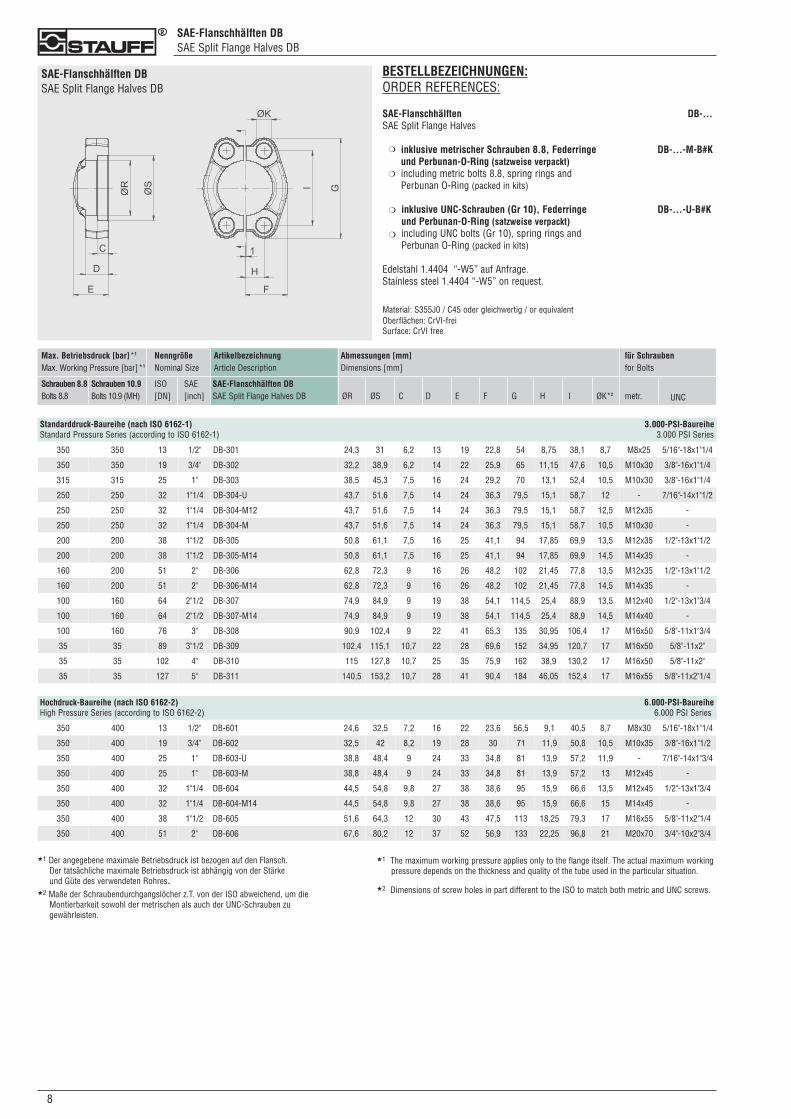
SAE-Flanschhälften DBSAE Split Flange Halves DB
SAE-Flanschhälften DBSAE Split Flange Halves DB
ArtikelbezeichnungArticle Description
SAE-Flanschhälften DBSAE Split Flange Halves DB
Max. Betriebsdruck [bar]*1
Max. Working Pressure [bar]*1
Schrauben 8.8Bolts 8.8
Schrauben 10.9Bolts 10.9 (MH)
NenngrößeNominal Size
ISO[DN]
SAE[inch]
Abmessungen [mm]Dimensions [mm]
ØR ØS C D E F G H I ØK*2
für Schraubenfor Bolts
metr. UNC
Standarddruck-Baureihe (nach ISO 6162-1) 3.000-PSI-BaureiheStandard Pressure Series (according to ISO 6162-1) 3.000 PSI Series
Hochdruck-Baureihe (nach ISO 6162-2) 6.000-PSI-BaureiheHigh Pressure Series (according to ISO 6162-2) 6.000 PSI Series
★1 Der angegebene maximale Betriebsdruck ist bezogen auf den Flansch. Der tatsächliche maximale Betriebsdruck ist abhängig von der Stärke und Güte des verwendeten Rohres.
★2 Maße der Schraubendurchgangslöcher z.T. von der ISO abweichend, um die Montierbarkeit sowohl der metrischen als auch der UNC-Schrauben zu gewährleisten.
★1 The maximum working pressure applies only to the flange itself. The actual maximum workingpressure depends on the thickness and quality of the tube used in the particular situation.
350 350 13 1/2" DB-301 24,3 31 6,2 13 19 22,8 54 8,75 38,1 8,7 M8x25 5/16"-18x1"1/4
350 350 19 3/4" DB-302 32,2 38,9 6,2 14 22 25,9 65 11,15 47,6 10,5 M10x30 3/8"-16x1"1/4
315 315 25 1" DB-303 38,5 45,3 7,5 16 24 29,2 70 13,1 52,4 10,5 M10x30 3/8"-16x1"1/4
250 250 32 1"1/4 DB-304-U 43,7 51,6 7,5 14 24 36,3 79,5 15,1 58,7 12 - 7/16"-14x1"1/2
250 250 32 1"1/4 DB-304-M12 43,7 51,6 7,5 14 24 36,3 79,5 15,1 58,7 12,5 M12x35 -
250 250 32 1"1/4 DB-304-M 43,7 51,6 7,5 14 24 36,3 79,5 15,1 58,7 10,5 M10x30 -
200 200 38 1"1/2 DB-305 50,8 61,1 7,5 16 25 41,1 94 17,85 69,9 13,5 M12x35 1/2"-13x1"1/2
200 200 38 1"1/2 DB-305-M14 50,8 61,1 7,5 16 25 41,1 94 17,85 69,9 14,5 M14x35 -
160 200 51 2" DB-306 62,8 72,3 9 16 26 48,2 102 21,45 77,8 13,5 M12x35 1/2"-13x1"1/2
160 200 51 2" DB-306-M14 62,8 72,3 9 16 26 48,2 102 21,45 77,8 14,5 M14x35 -
100 160 64 2"1/2 DB-307 74,9 84,9 9 19 38 54,1 114,5 25,4 88,9 13,5 M12x40 1/2"-13x1"3/4
100 160 64 2"1/2 DB-307-M14 74,9 84,9 9 19 38 54,1 114,5 25,4 88,9 14,5 M14x40 -
100 160 76 3" DB-308 90,9 102,4 9 22 41 65,3 135 30,95 106,4 17 M16x50 5/8"-11x1"3/4
35 35 89 3"1/2 DB-309 102,4 115,1 10,7 22 28 69,6 152 34,95 120,7 17 M16x50 5/8"-11x2"
35 35 102 4" DB-310 115 127,8 10,7 25 35 75,9 162 38,9 130,2 17 M16x50 5/8"-11x2"
35 35 127 5" DB-311 140,5 153,2 10,7 28 41 90,4 184 46,05 152,4 17 M16x55 5/8"-11x2"1/4
350 400 13 1/2" DB-601 24,6 32,5 7,2 16 22 23,6 56,5 9,1 40,5 8,7 M8x30 5/16"-18x1"1/4
350 400 19 3/4" DB-602 32,5 42 8,2 19 28 30 71 11,9 50,8 10,5 M10x35 3/8"-16x1"1/2
350 400 25 1" DB-603-U 38,8 48,4 9 24 33 34,8 81 13,9 57,2 11,9 - 7/16"-14x1"3/4
350 400 25 1" DB-603-M 38,8 48,4 9 24 33 34,8 81 13,9 57,2 13 M12x45 -
350 400 32 1"1/4 DB-604 44,5 54,8 9,8 27 38 38,6 95 15,9 66,6 13,5 M12x45 1/2"-13x1"3/4
350 400 32 1"1/4 DB-604-M14 44,5 54,8 9,8 27 38 38,6 95 15,9 66,6 15 M14x45 -
350 400 38 1"1/2 DB-605 51,6 64,3 12 30 43 47,5 113 18,25 79,3 17 M16x55 5/8"-11x2"1/4
350 400 51 2" DB-606 67,6 80,2 12 37 52 56,9 133 22,25 96,8 21 M20x70 3/4"-10x2"3/4
BESTELLBEZEICHNUNGEN:ORDER REFERENCES:
SAE-Flanschhälften DB-...SAE Split Flange Halves
inklusive metrischer Schrauben 8.8, Federringe DB-...-M-B#Kund Perbunan-O-Ring (satzweise verpackt)including metric bolts 8.8, spring rings andPerbunan O-Ring (packed in kits)
inklusive UNC-Schrauben (Gr 10), Federringe DB-...-U-B#Kund Perbunan-O-Ring (satzweise verpackt)including UNC bolts (Gr 10), spring rings andPerbunan O-Ring (packed in kits)
Edelstahl 1.4404 “-W5” auf Anfrage.Stainless steel 1.4404 “-W5” on request.
Material: S355J0 / C45 oder gleichwertig / or equivalentOberflächen: CrVI-freiSurface: CrVI free
❍
❍
❍
❍
★2 Dimensions of screw holes in part different to the ISO to match both metric and UNC screws.
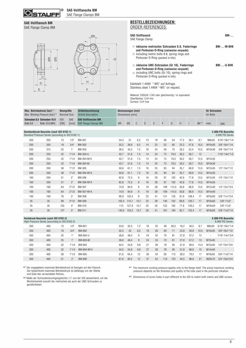
SAE-Vollflansche BMSAE Flange Clamps BM
90
SAE-Vollflansch BMSAE Flange Clamp BM
ArtikelbezeichnungArticle Description
SAE-Vollflansche BMSAE Flange Clamps BM
Max. Betriebsdruck [bar]*1
Max. Working Pressure [bar]*1
Schrauben 8.8Bolts 8.8
Schrauben 10.9Bolts 10.9 (MH)
NenngrößeNominal Size
ISO[DN]
SAE[inch]
Abmessungen [mm]Dimensions [mm]
ØR ØS C D E F G H I ØK*2
für Schraubenfor Bolts
metr. UNC
350 350 13 1/2" BM-301 24,3 31 6,2 13 19 46 54 17,5 38,1 8,7 M8x25 5/16"-18x1"1/4
350 350 19 3/4" BM-302 32,2 38,9 6,2 14 22 52 65 22,3 47,6 10,5 M10x30 3/8"-16x1"1/4
250 315 25 1" BM-303 38,5 45,3 7,5 16 24 59 70 26,2 52,4 10,5 M10x30 3/8"-16x1"1/4
200 250 32 1"1/4 BM-304-U 43,7 51,6 7,5 14 24 73 79,5 30,2 58,7 12 - 7/16"-14x1"1/2
200 250 32 1"1/4 BM-304-M12 43,7 51,6 7,5 14 24 73 79,5 30,2 58,7 12,5 M12x35 -
200 250 32 1"1/4 BM-304-M 43,7 51,6 7,5 14 24 73 79,5 30,2 58,7 10,5 M10x30 -
200 200 38 1"1/2 BM-305 50,8 61,1 7,5 16 25 83 94 35,7 69,9 13,5 M12x35 1/2"-13x1"1/2
200 200 38 1"1/2 BM-305-M14 50,8 61,1 7,5 16 25 83 94 35,7 69,9 14,5 M14x35 -
160 200 51 2" BM-306 62,8 72,3 9 16 26 97 102 42,9 77,8 13,5 M12x35 1/2"-13x1"1/2
160 200 51 2" BM-306-M14 62,8 72,3 9 16 26 97 102 42,9 77,8 14,5 M14x35 -
100 160 64 2"1/2 BM-307 74,9 84,9 9 19 38 109 114,5 50,8 88,9 13,5 M12x40 1/2"-13x1"3/4
100 160 64 2"1/2 BM-307-M14 74,9 84,9 9 19 38 109 114,5 50,8 88,9 14,5 M14x40 -
100 160 76 3" BM-308 90,9 102,4 9 22 41 131 135 61,9 106,4 17 M16x50 5/8"-11x1"3/4
35 35 89 3"1/2 BM-309 102,4 115,1 10,7 22 28 140 152 69,9 120,7 17 M16x50 5/8"-11x2"
35 35 102 4" BM-310 115 127,8 10,7 25 35 152 162 77,8 130,2 17 M16x50 5/8"-11x2"
35 35 127 5" BM-311 140,5 153,2 10,7 28 41 181 184 92,1 152,4 17 M16x55 5/8"-11x2"1/4
Standarddruck-Baureihe (nach ISO 6162-1) 3.000-PSI-BaureiheStandard Pressure Series (according to ISO 6162-1) 3.000 PSI Series
Hochdruck-Baureihe (nach ISO 6162-2) 6.000-PSI-BaureiheHigh Pressure Series (according to ISO 6162-2) 6.000 PSI Series
350 400 13 1/2" BM-601 24,6 32,5 7,2 16 22 48 56,5 18,2 40,5 8,7 M8x30 5/16"-18x1"1/4
350 400 19 3/4" BM-602 32,5 42 8,2 19 28 60 71 23,8 50,8 10,5 M10x35 3/8"-16x1"1/2
350 400 25 1" BM-603-U 38,8 48,4 9 24 33 70 81 27,8 57,2 12 - 7/16"-14x1"3/4
350 400 25 1" BM-603-M 38,8 48,4 9 24 33 70 81 27,8 57,2 13 M12x45 -
350 400 32 1"1/4 BM-604 44,5 54,8 9,8 27 38 78 95 31,8 66,6 13,5 M12x45 1/2"-13x1"3/4
350 400 32 1"1/4 BM-604-M14 44,5 54,8 9,8 27 38 78 95 31,8 66,6 15 M14x45 -
350 400 38 1"1/2 BM-605 51,6 64,3 12 30 43 95 113 36,5 79,3 17 M16x55 5/8"-11x2"1/4
350 400 51 2" BM-606 67,6 80,2 12 37 52 114 133 44,5 96,8 21 M20x70 3/4"-10x2"3/4
★1 Der angegebene maximale Betriebsdruck ist bezogen auf den Flansch. Der tatsächliche maximale Betriebsdruck ist abhängig von der Stärke und Güte des verwendeten Rohres.
★2 Maße der Schraubendurchgangslöcher z.T. von der ISO abweichend, um die Montierbarkeit sowohl der metrischen als auch der UNC-Schrauben zu gewährleisten.
BESTELLBEZEICHNUNGEN:ORDER REFERENCES:
SAE-Vollflansch BM-...SAE Flange Clamp
inklusive metrischer Schrauben 8.8, Federringe BM-...-M-B#Kund Perbunan-O-Ring (satzweise verpackt)including metric bolts 8.8, spring rings andPerbunan O-Ring (packed in kits)
inklusive UNC-Schrauben (Gr 10), Federringe BM-...-U-B#Kund Perbunan-O-Ring (satzweise verpackt)including UNC bolts (Gr 10), spring rings andPerbunan O-Ring (packed in kits)
Edelstahl 1.4404 “-W5” auf Anfrage.Stainless steel 1.4404 “-W5” on request.
Material: S355J0 / C45 oder gleichwertig / or equivalentOberflächen: CrVI-freiSurface: CrVI free
❍
❍
❍
❍
★1 The maximum working pressure applies only to the flange itself. The actual maximum workingpressure depends on the thickness and quality of the tube used in the particular situation.
★2 Dimensions of screw holes in part different to the ISO to match both metric and UNC screws.
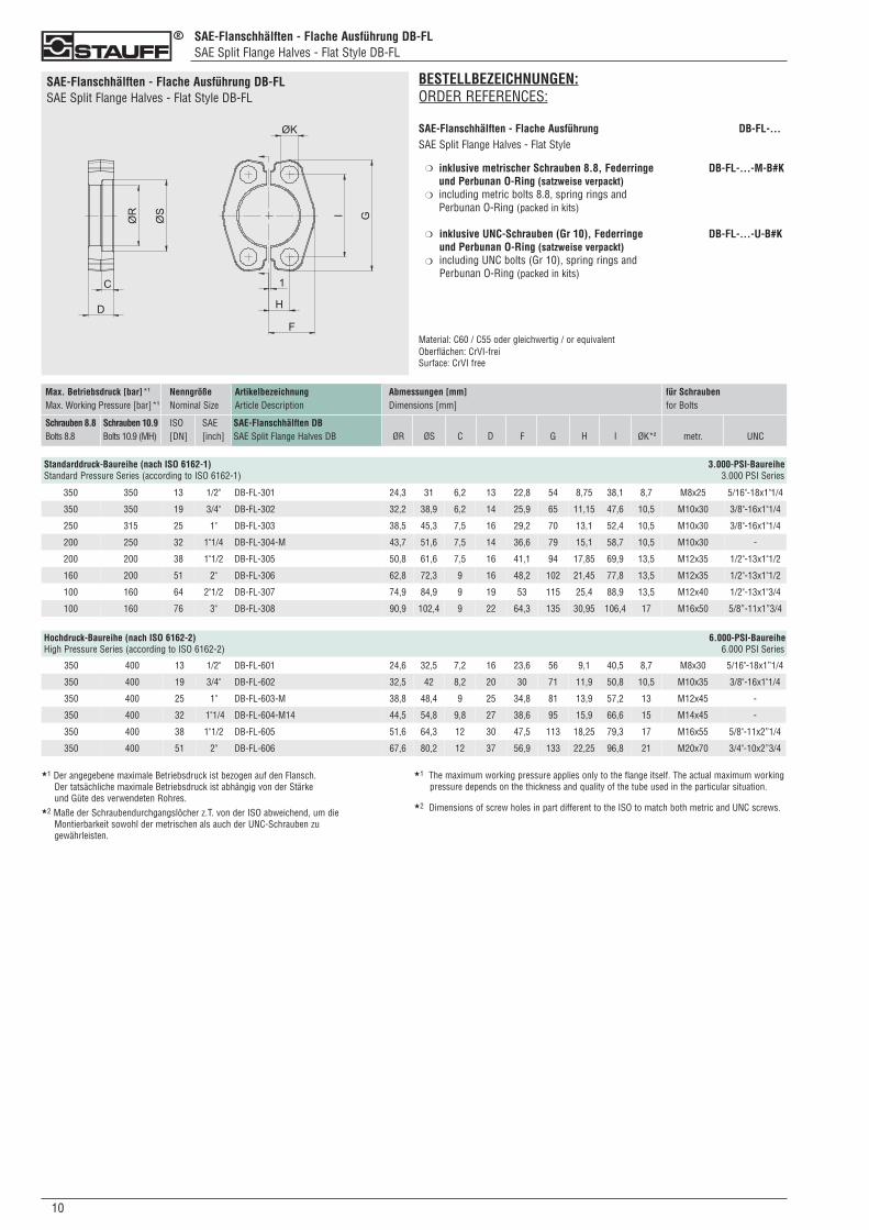
SAE-Flanschhälften - Flache Ausführung DB-FLSAE Split Flange Halves - Flat Style DB-FL
SAE-Flanschhälften - Flache Ausführung DB-FLSAE Split Flange Halves - Flat Style DB-FL
BESTELLBEZEICHNUNGEN:ORDER REFERENCES:
SAE-Flanschhälften - Flache Ausführung DB-FL-...SAE Split Flange Halves - Flat Style
inklusive metrischer Schrauben 8.8, Federringe DB-FL-...-M-B#K und Perbunan O-Ring (satzweise verpackt)including metric bolts 8.8, spring rings andPerbunan O-Ring (packed in kits)
inklusive UNC-Schrauben (Gr 10), Federringe DB-FL-...-U-B#Kund Perbunan O-Ring (satzweise verpackt)including UNC bolts (Gr 10), spring rings and Perbunan O-Ring (packed in kits)
Material: C60 / C55 oder gleichwertig / or equivalentOberflächen: CrVI-freiSurface: CrVI free
ArtikelbezeichnungArticle Description
SAE-Flanschhälften DBSAE Split Flange Halves DB
Max. Betriebsdruck [bar]*1
Max. Working Pressure [bar]*1
Schrauben 8.8Bolts 8.8
Schrauben 10.9Bolts 10.9 (MH)
NenngrößeNominal Size
ISO[DN]
SAE[inch]
Abmessungen [mm]Dimensions [mm]
ØR ØS C D F G H I ØK*2
für Schraubenfor Bolts
metr. UNC
Standarddruck-Baureihe (nach ISO 6162-1) 3.000-PSI-BaureiheStandard Pressure Series (according to ISO 6162-1) 3.000 PSI Series
❍
❍
❍
❍
350 400 13 1/2" DB-FL-601 24,6 32,5 7,2 16 23,6 56 9,1 40,5 8,7 M8x30 5/16"-18x1”1/4
350 400 19 3/4" DB-FL-602 32,5 42 8,2 20 30 71 11,9 50,8 10,5 M10x35 3/8"-16x1"1/4
350 400 25 1" DB-FL-603-M 38,8 48,4 9 25 34,8 81 13,9 57,2 13 M12x45 -
350 400 32 1"1/4 DB-FL-604-M14 44,5 54,8 9,8 27 38,6 95 15,9 66,6 15 M14x45 -
350 400 38 1"1/2 DB-FL-605 51,6 64,3 12 30 47,5 113 18,25 79,3 17 M16x55 5/8"-11x2”1/4
350 400 51 2" DB-FL-606 67,6 80,2 12 37 56,9 133 22,25 96,8 21 M20x70 3/4"-10x2”3/4
350 350 13 1/2" DB-FL-301 24,3 31 6,2 13 22,8 54 8,75 38,1 8,7 M8x25 5/16"-18x1"1/4
350 350 19 3/4" DB-FL-302 32,2 38,9 6,2 14 25,9 65 11,15 47,6 10,5 M10x30 3/8"-16x1"1/4
250 315 25 1" DB-FL-303 38,5 45,3 7,5 16 29,2 70 13,1 52,4 10,5 M10x30 3/8"-16x1"1/4
200 250 32 1"1/4 DB-FL-304-M 43,7 51,6 7,5 14 36,6 79 15,1 58,7 10,5 M10x30 -
200 200 38 1"1/2 DB-FL-305 50,8 61,6 7,5 16 41,1 94 17,85 69,9 13,5 M12x35 1/2"-13x1"1/2
160 200 51 2" DB-FL-306 62,8 72,3 9 16 48,2 102 21,45 77,8 13,5 M12x35 1/2"-13x1"1/2
100 160 64 2"1/2 DB-FL-307 74,9 84,9 9 19 53 115 25,4 88,9 13,5 M12x40 1/2"-13x1"3/4
100 160 76 3" DB-FL-308 90,9 102,4 9 22 64,3 135 30,95 106,4 17 M16x50 5/8”-11x1”3/4
Hochdruck-Baureihe (nach ISO 6162-2) 6.000-PSI-BaureiheHigh Pressure Series (according to ISO 6162-2) 6.000 PSI Series
★1 Der angegebene maximale Betriebsdruck ist bezogen auf den Flansch. Der tatsächliche maximale Betriebsdruck ist abhängig von der Stärke und Güte des verwendeten Rohres.
★2 Maße der Schraubendurchgangslöcher z.T. von der ISO abweichend, um die Montierbarkeit sowohl der metrischen als auch der UNC-Schrauben zu gewährleisten.
010
★1 The maximum working pressure applies only to the flange itself. The actual maximum workingpressure depends on the thickness and quality of the tube used in the particular situation.
★2 Dimensions of screw holes in part different to the ISO to match both metric and UNC screws.
110
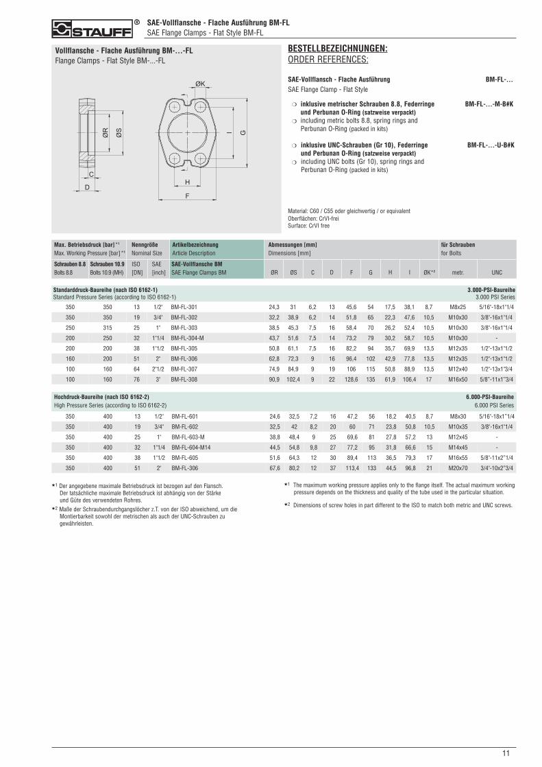
SAE-Vollflansche - Flache Ausführung BM-FLSAE Flange Clamps - Flat Style BM-FL
Vollflansche - Flache Ausführung BM-...-FLFlange Clamps - Flat Style BM-...-FL
BESTELLBEZEICHNUNGEN:ORDER REFERENCES:
SAE-Vollflansch - Flache Ausführung BM-FL-...SAE Flange Clamp - Flat Style
inklusive metrischer Schrauben 8.8, Federringe BM-FL-...-M-B#K und Perbunan O-Ring (satzweise verpackt)including metric bolts 8.8, spring rings andPerbunan O-Ring (packed in kits)
inklusive UNC-Schrauben (Gr 10), Federringe BM-FL-...-U-B#Kund Perbunan O-Ring (satzweise verpackt)including UNC bolts (Gr 10), spring rings and Perbunan O-Ring (packed in kits)
Material: C60 / C55 oder gleichwertig / or equivalentOberflächen: CrVI-freiSurface: CrVI free
❍
❍
❍
❍
ArtikelbezeichnungArticle Description
SAE-Vollflansche BMSAE Flange Clamps BM
Max. Betriebsdruck [bar]*1
Max. Working Pressure [bar]*1
Schrauben 8.8Bolts 8.8
Schrauben 10.9Bolts 10.9 (MH)
NenngrößeNominal Size
ISO[DN]
SAE[inch]
Abmessungen [mm]Dimensions [mm]
ØR ØS C D F G H I ØK*2
für Schraubenfor Bolts
metr. UNC
Standarddruck-Baureihe (nach ISO 6162-1) 3.000-PSI-BaureiheStandard Pressure Series (according to ISO 6162-1) 3.000 PSI Series
350 350 13 1/2" BM-FL-301 24,3 31 6,2 13 45,6 54 17,5 38,1 8,7 M8x25 5/16"-18x1"1/4
350 350 19 3/4" BM-FL-302 32,2 38,9 6,2 14 51,8 65 22,3 47,6 10,5 M10x30 3/8"-16x1"1/4
250 315 25 1" BM-FL-303 38,5 45,3 7,5 16 58,4 70 26,2 52,4 10,5 M10x30 3/8"-16x1"1/4
200 250 32 1"1/4 BM-FL-304-M 43,7 51,6 7,5 14 73,2 79 30,2 58,7 10,5 M10x30 -
200 200 38 1"1/2 BM-FL-305 50,8 61,1 7,5 16 82,2 94 35,7 69,9 13,5 M12x35 1/2"-13x1"1/2
160 200 51 2" BM-FL-306 62,8 72,3 9 16 96,4 102 42,9 77,8 13,5 M12x35 1/2"-13x1"1/2
100 160 64 2"1/2 BM-FL-307 74,9 84,9 9 19 106 115 50,8 88,9 13,5 M12x40 1/2"-13x1"3/4
100 160 76 3" BM-FL-308 90,9 102,4 9 22 128,6 135 61,9 106,4 17 M16x50 5/8”-11x1”3/4
350 400 13 1/2" BM-FL-601 24,6 32,5 7,2 16 47,2 56 18,2 40,5 8,7 M8x30 5/16"-18x1”1/4
350 400 19 3/4" BM-FL-602 32,5 42 8,2 20 60 71 23,8 50,8 10,5 M10x35 3/8"-16x1"1/4
350 400 25 1" BM-FL-603-M 38,8 48,4 9 25 69,6 81 27,8 57,2 13 M12x45 -
350 400 32 1"1/4 BM-FL-604-M14 44,5 54,8 9,8 27 77,2 95 31,8 66,6 15 M14x45 -
350 400 38 1"1/2 BM-FL-605 51,6 64,3 12 30 89,4 113 36,5 79,3 17 M16x55 5/8"-11x2”1/4
350 400 51 2" BM-FL-306 67,6 80,2 12 37 113,4 133 44,5 96,8 21 M20x70 3/4"-10x2”3/4
Hochdruck-Baureihe (nach ISO 6162-2) 6.000-PSI-BaureiheHigh Pressure Series (according to ISO 6162-2) 6.000 PSI Series
★1 Der angegebene maximale Betriebsdruck ist bezogen auf den Flansch. Der tatsächliche maximale Betriebsdruck ist abhängig von der Stärke und Güte des verwendeten Rohres.
★2 Maße der Schraubendurchgangslöcher z.T. von der ISO abweichend, um die Montierbarkeit sowohl der metrischen als auch der UNC-Schrauben zu gewährleisten.
★1 The maximum working pressure applies only to the flange itself. The actual maximum workingpressure depends on the thickness and quality of the tube used in the particular situation.
★2 Dimensions of screw holes in part different to the ISO to match both metric and UNC screws.
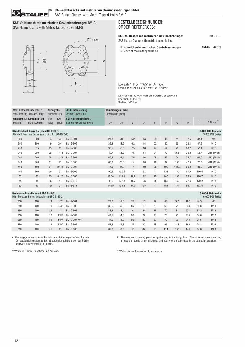
SAE-Vollflansche mit metrischen Gewindebohrungen BM-GSAE Flange Clamps with Metric Tapped Holes BM-G
SAE-Vollflansch mit metrischen Gewindebohrungen BM-GSAE Flange Clamp with Metric Tapped Holes BM-G
BESTELLBEZEICHNUNGEN:ORDER REFERENCES:
SAE-Vollflansch mit metrischen Gewindebohrungen BM-G-...SAE Flange Clamp with metric tapped holes
abweichende metrischen Gewindebohrungen BM-G-...-M��deviant metric tapped holes
Edelstahl 1.4404 “-W5” auf Anfrage.Stainless steel 1.4404 “-W5” on request.
Material: S355J0 / C45 oder gleichwertig / or equivalentOberflächen: CrVI-freiSurface: CrVI free
ArtikelbezeichnungArticle Description
SAE-Vollflansche BM-GSAE Flange Clamps BM-G
Max. Betriebsdruck [bar]*1
Max. Working Pressure [bar]*1
Schrauben 8.8Bolts 8.8
Schrauben 10.9Bolts 10.9 (MH)
NenngrößeNominal Size
ISO[DN]
SAE[inch]
Abmessungen [mm]Dimensions [mm]
ØR ØS C D E F G H I Ø Thread
Standarddruck-Baureihe (nach ISO 6162-1) 3.000-PSI-BaureiheStandard Pressure Series (according to ISO 6162-1) 3.000 PSI Series
350 350 13 1/2" BM-G-301 24,3 31 6,2 13 19 46 54 17,5 38,1 M8
350 350 19 3/4" BM-G-302 32,2 38,9 6,2 14 22 52 65 22,3 47,6 M10
250 315 25 1" BM-G-303 38,5 45,3 7,5 16 24 59 70 26,2 52,4 M10
200 250 32 1"1/4 BM-G-304 43,7 51,6 7,5 14 24 73 79,5 30,2 58,7 M10 (M12)
200 200 38 1"1/2 BM-G-305 50,8 61,1 7,5 16 25 83 94 35,7 69,9 M12 (M14)
160 200 51 2" BM-G-306 62,8 72,3 9 16 26 97 102 42,9 77,8 M12 (M14)
100 160 64 2"1/2 BM-G-307 74,9 84,9 9 19 38 109 114,5 50,8 88,9 M12 (M14)
100 160 76 3" BM-G-308 90,9 102,4 9 22 41 131 135 61,9 106,4 M16
35 35 89 3"1/2 BM-G-309 102,4 115,1 10,7 22 28 140 152 69,9 120,7 M16
35 35 102 4" BM-G-310 115 127,8 10,7 25 35 152 162 77,8 130,2 M16
35 35 127 5" BM-G-311 140,5 153,2 10,7 28 41 181 184 92,1 152,4 M16
350 400 13 1/2" BM-G-601 24,6 32,5 7,2 16 22 48 56,5 18,2 40,5 M8
350 400 19 3/4" BM-G-602 32,5 42 8,2 19 28 60 71 23,8 50,8 M10
350 400 25 1" BM-G-603 38,8 48,4 9 24 33 70 81 27,8 57,2 M12
350 400 32 1"1/4 BM-G-604 44,5 54,8 9,8 27 38 78 95 31,8 66,6 M12
350 400 32 1"1/4 BM-G-604-M14 44,5 54,8 9,8 27 38 78 95 31,8 66,6 M14
350 400 38 1"1/2 BM-G-605 51,6 64,3 12 30 43 95 113 36,5 79,3 M16
350 400 51 2" BM-G-606 67,6 80,2 12 37 52 114 133 44,5 96,8 M20
Hochdruck-Baureihe (nach ISO 6162-2) 6.000-PSI-BaureiheHigh Pressure Series (according to ISO 6162-2) 6.000 PSI Series
★1 Der angegebene maximale Betriebsdruck ist bezogen auf den Flansch. Der tatsächliche maximale Betriebsdruck ist abhängig von der Stärke und Güte des verwendeten Rohres.
❍
❍
012
★1 The maximum working pressure applies only to the flange itself. The actual maximum workingpressure depends on the thickness and quality of the tube used in the particular situation.
★2 Werte in Klammern optional auf Anfrage.
*2
★2 Values in brackets optionally on inquiry.
NotizenNotes
130
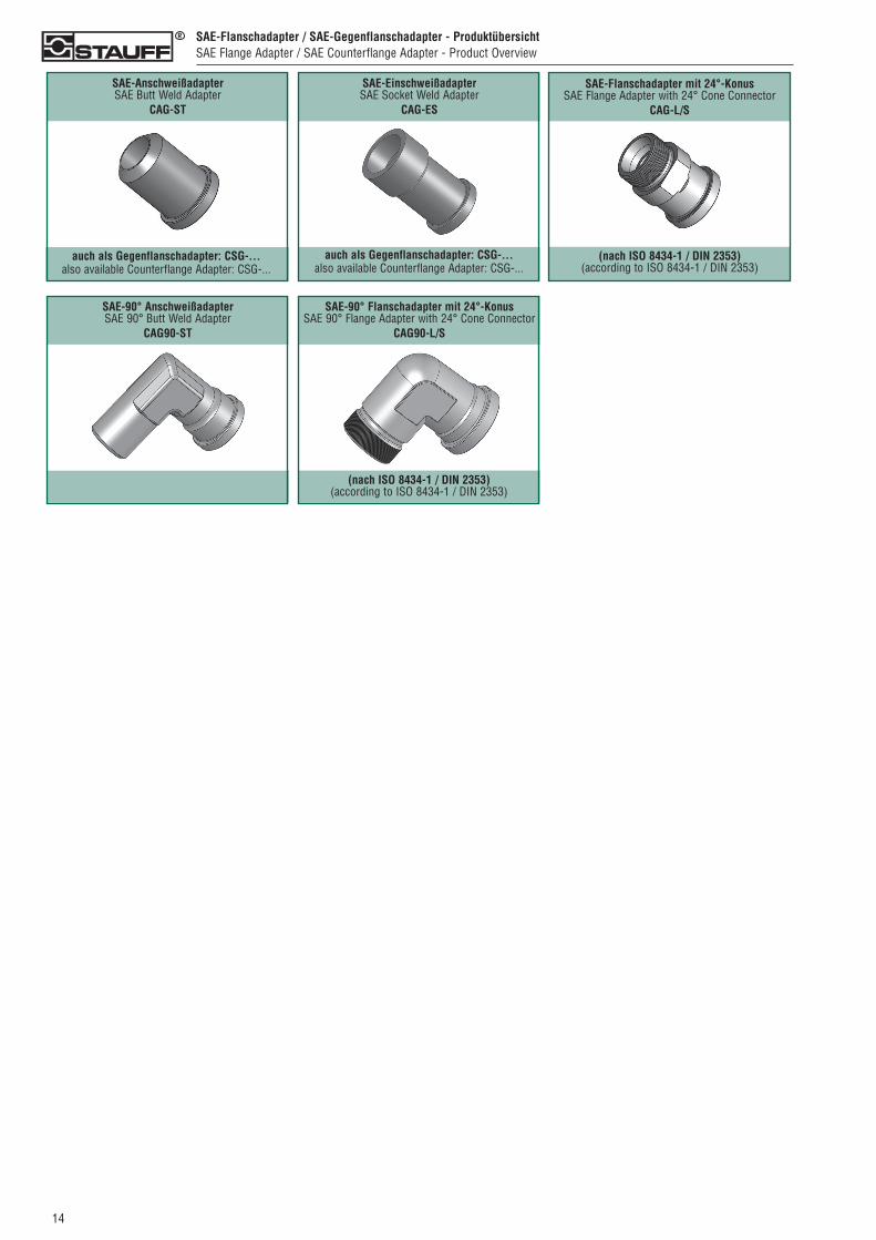
SAE-Flanschadapter / SAE-Gegenflanschadapter - ProduktübersichtSAE Flange Adapter / SAE Counterflange Adapter - Product Overview
SAE-AnschweißadapterSAE Butt Weld Adapter
CAG-ST
SAE-EinschweißadapterSAE Socket Weld Adapter
CAG-ES
auch als Gegenflanschadapter: CSG-...also available Counterflange Adapter: CSG-...
auch als Gegenflanschadapter: CSG-...also available Counterflange Adapter: CSG-...
SAE-Flanschadapter mit 24°-Konus SAE Flange Adapter with 24° Cone Connector
CAG-L/S
(nach ISO 8434-1 / DIN 2353)(according to ISO 8434-1 / DIN 2353)
SAE-90° AnschweißadapterSAE 90° Butt Weld Adapter
CAG90-ST
SAE-90° Flanschadapter mit 24°-KonusSAE 90° Flange Adapter with 24° Cone Connector
CAG90-L/S
(nach ISO 8434-1 / DIN 2353)(according to ISO 8434-1 / DIN 2353)
014
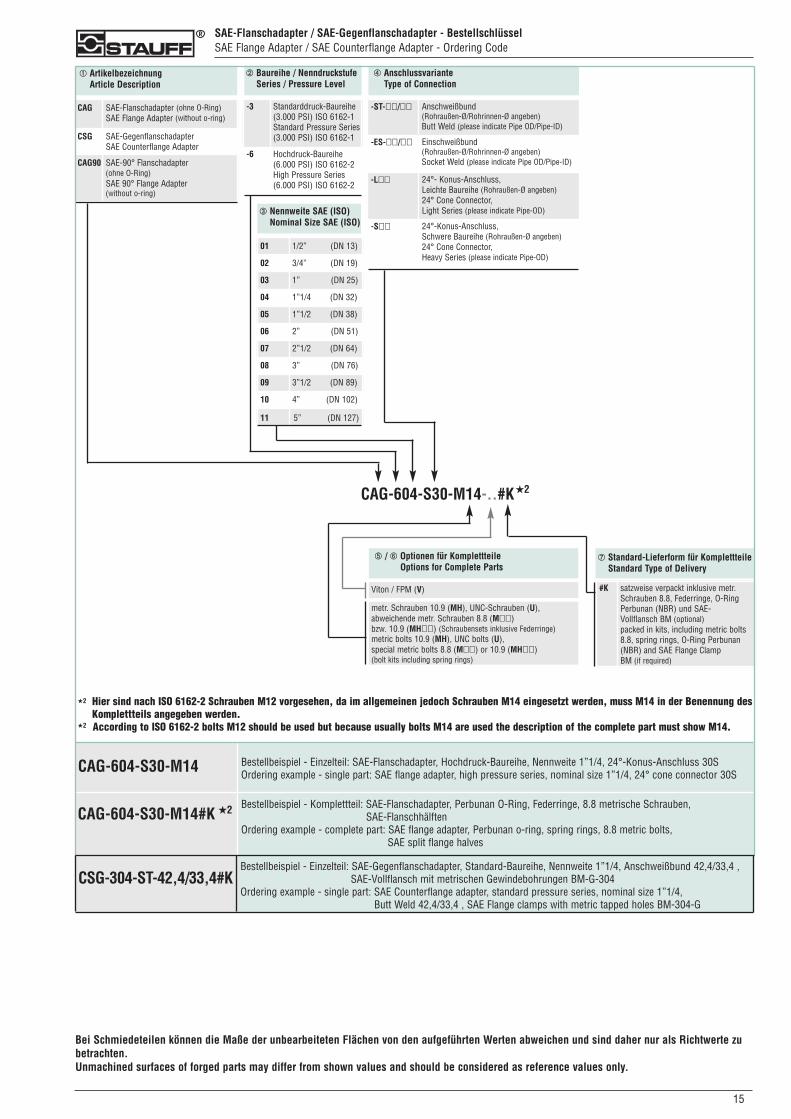
SAE-Flanschadapter / SAE-Gegenflanschadapter - BestellschlüsselSAE Flange Adapter / SAE Counterflange Adapter - Ordering Code
➀ ArtikelbezeichnungArticle Description
➁ Baureihe / NenndruckstufeSeries / Pressure Level
➂ Nennweite SAE (ISO)Nominal Size SAE (ISO)
➃ AnschlussvarianteType of Connection
CAG SAE-Flanschadapter (ohne O-Ring)SAE Flange Adapter (without o-ring)
CSG SAE-GegenflanschadapterSAE Counterflange Adapter
CAG90 SAE-90° Flanschadapter (ohne O-Ring)SAE 90° Flange Adapter(without o-ring)
-3 Standarddruck-Baureihe(3.000 PSI) ISO 6162-1Standard Pressure Series(3.000 PSI) ISO 6162-1
-6 Hochdruck-Baureihe(6.000 PSI) ISO 6162-2High Pressure Series(6.000 PSI) ISO 6162-2
01 1/2” (DN 13)
02 3/4” (DN 19)
03 1” (DN 25)
04 1”1/4 (DN 32)
05 1”1/2 (DN 38)
06 2” (DN 51)
07 2”1/2 (DN 64)
08 3” (DN 76)
09 3”1/2 (DN 89)
10 4” (DN 102)
11 5” (DN 127)
-ST-��/�� Anschweißbund(Rohraußen-Ø/Rohrinnen-Ø angeben)Butt Weld (please indicate Pipe OD/Pipe-ID)
-ES-��/�� Einschweißbund(Rohraußen-Ø/Rohrinnen-Ø angeben)Socket Weld (please indicate Pipe OD/Pipe-ID)
-L�� 24°- Konus-Anschluss, Leichte Baureihe (Rohraußen-Ø angeben)24° Cone Connector, Light Series (please indicate Pipe-OD)
-S�� 24°-Konus-Anschluss,Schwere Baureihe (Rohraußen-Ø angeben)24° Cone Connector,Heavy Series (please indicate Pipe-OD)
CAG-604-S30-M14-..#K
➆ Standard-Lieferform für KomplettteileStandard Type of Delivery
#K satzweise verpackt inklusive metr.Schrauben 8.8, Federringe, O-Ring Perbunan (NBR) und SAE-Vollflansch BM (optional)packed in kits, including metric bolts 8.8, spring rings, O-Ring Perbunan (NBR) and SAE Flange Clamp BM (if required)
➄ / ➅ Optionen für KomplettteileOptions for Complete Parts
metr. Schrauben 10.9 (MH), UNC-Schrauben (U), abweichende metr. Schrauben 8.8 (M��) bzw. 10.9 (MH��) (Schraubensets inklusive Federringe)metric bolts 10.9 (MH), UNC bolts (U),special metric bolts 8.8 (M��) or 10.9 (MH��)(bolt kits including spring rings)
Viton / FPM (V)
Bestellbeispiel - Einzelteil: SAE-Flanschadapter, Hochdruck-Baureihe, Nennweite 1”1/4, 24°-Konus-Anschluss 30SOrdering example - single part: SAE flange adapter, high pressure series, nominal size 1”1/4, 24° cone connector 30S
CAG-604-S30-M14
CAG-604-S30-M14#K
★2
Hier sind nach ISO 6162-2 Schrauben M12 vorgesehen, da im allgemeinen jedoch Schrauben M14 eingesetzt werden, muss M14 in der Benennung desKomplettteils angegeben werden.According to ISO 6162-2 bolts M12 should be used but because usually bolts M14 are used the description of the complete part must show M14.
★2
★2
★2 Bestellbeispiel - Komplettteil: SAE-Flanschadapter, Perbunan O-Ring, Federringe, 8.8 metrische Schrauben, SAE-Flanschhälften
Ordering example - complete part: SAE flange adapter, Perbunan o-ring, spring rings, 8.8 metric bolts, SAE split flange halves
0150
Bei Schmiedeteilen können die Maße der unbearbeiteten Flächen von den aufgeführten Werten abweichen und sind daher nur als Richtwerte zubetrachten.Unmachined surfaces of forged parts may differ from shown values and should be considered as reference values only.
Bestellbeispiel - Einzelteil: SAE-Gegenflanschadapter, Standard-Baureihe, Nennweite 1”1/4, Anschweißbund 42,4/33,4 ,SAE-Vollflansch mit metrischen Gewindebohrungen BM-G-304
Ordering example - single part: SAE Counterflange adapter, standard pressure series, nominal size 1”1/4, Butt Weld 42,4/33,4 , SAE Flange clamps with metric tapped holes BM-304-G
CSG-304-ST-42,4/33,4#K
016
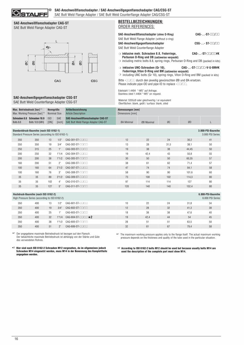
SAE-Anschweißflanschadapter / SAE-Anschweißgegenflanschadapter CAG/CSG-STSAE Butt Weld Flange Adapter / SAE Butt Weld Counterflange Adapter CAG/CSG-ST
Standarddruck-Baureihe (nach ISO 6162-1) 3.000-PSI-BaureiheStandard Pressure Series (according to ISO 6162-1) 3.000 PSI Series
350 350 13 1/2" CAG-301-ST-��/�� 12 22 24 30,2 41
350 350 19 3/4" CAG-302-ST-��/�� 13 28 31,5 38,1 50
250 315 25 1" CAG-303-ST-��/�� 19 38 38 44,45 50
200 250 32 1"1/4 CAG-304-ST-��/�� 19 42,4 43 50,8 55
200 200 38 1"1/2 CAG-305-ST-��/�� 30 50 50 60,35 57
160 200 51 2" CAG-306-ST-��/�� 38 61 62 71,4 57
100 160 64 2"1/2 CAG-307-ST-��/�� 47 74 74 84,1 58
100 160 76 3" CAG-308-ST-��/�� 58 90 90 101,6 60
35 35 89 3"1/2 CAG-309-ST-��/�� 73 100 102 114,3 80
35 35 102 4" CAG-310-ST-��/�� 97 114 114 127 80
35 35 127 5" CAG-311-ST-��/�� 120 140 140 152,4 80
ArtikelbezeichnungArticle Description
SAE-Anschweißflanschadapter CAG-ST SAE Butt Weld Flange Adapter CAG-ST
Max. Betriebsdruck [bar]*1
Max. Working Pressure [bar]*1
Schrauben 8.8Bolts 8.8
Schrauben 10.9Bolts 10.9 (MH)
NenngrößeNominal Size
ISO[DN]
SAE[inch]
Abmessungen [mm]Dimensions [mm]
ØA Minimal ØB Maximal ØC ØD L
Hochdruck-Baureihe (nach ISO 6162-2) 6.000-PSI-BaureiheHigh Pressure Series (according to ISO 6162-2) 6.000 PSI Series
350 400 13 1/2" CAG-601-ST-��/�� 10 22 24 31,8 34
350 400 19 3/4" CAG-602-ST-��/�� 12 28 32 41,3 38
350 400 25 1" CAG-603-ST-��/�� 18 38 38 47,6 40
350 400 32 1"1/4 CAG-604-ST-��/�� 19 42,4 44 54 45
350 400 38 1"1/2 CAG-605-ST-��/�� 28 51 51 63,5 50
350 400 51 2" CAG-606-ST-��/�� 32 61 67 79,4 58
BESTELLBEZEICHNUNGEN:ORDER REFERENCES:
SAE-Anschweißflanschadapter (ohne O-Ring) CAG-...-ST-��/��SAE Butt Weld Flange Adapter (without o-ring)
SAE-Anschweißgegenflanschadapter CSG-...- ST-��/��SAE Butt Weld Counterflange Adapter
inklusive metr. Schrauben 8.8, Federringe, CAG-...-ST-��/��#K Perbunan O-Ring und DB (satzweise verpackt)including metric bolts 8.8, spring rings, Perbunan O-Ring and DB (packed in kits)
inklusive UNC-Schrauben (Gr 10), CAG-...-ST-��/��-V-U-BM#KFederringe,Viton O-Ring und BM (satzweise verpackt)including UNC bolts (Gr 10), spring rings, Viton O-Ring and BM (packed in kits)
Bitte -��/�� durch den jeweilig gewünschten ØB und ØA ersetzen.Please indicate pipe-OD and pipe-ID to replace -��/��.
Edelstahl 1.4404 “-W5” auf Anfrage.Stainless steel 1.4404 “-W5” on request.
Material: S355J0 oder gleichwertig / or equivalentOberflächen: blank, geölt / surface: blank, oiled
❍
❍
❍
❍
Der angegebene maximale Betriebsdruck ist bezogen auf den Flansch. Der tatsächliche maximale Betriebsdruck ist abhängig von der Stärke und Güte des verwendeten Rohres.
SAE-Anschweißflanschadapter CAG-STSAE Butt Weld Flange Adapter CAG-ST
SAE-Anschweißgegenflanschadapter CSG-STSAE Butt Weld Counterflange Adapter CSG-ST
★2
★1
Hier sind nach ISO 6162-2 Schrauben M12 vorgesehen, da im allgemeinen jedochSchrauben M14 eingesetzt werden, muss M14 in der Benennung des Komplettteilsangegeben werden.
★2 According to ISO 6162-2 bolts M12 should be used but because usually bolts M14 areused the description of the complete part must show M14.
★2
★1 The maximum working pressure applies only to the flange itself. The actual maximum workingpressure depends on the thickness and quality of the tube used in the particular situation.
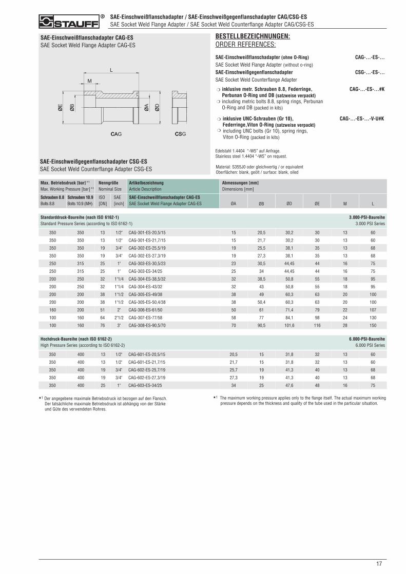
SAE-Einschweißflanschadapter / SAE-Einschweißgegenflanschadapter CAG/CSG-ESSAE Socket Weld Flange Adapter / SAE Socket Weld Counterflange Adapter CAG/CSG-ES
170
SAE-Einschweißflanschadapter CAG-ESSAE Socket Weld Flange Adapter CAG-ES
Hochdruck-Baureihe (nach ISO 6162-2) 6.000-PSI-BaureiheHigh Pressure Series (according to ISO 6162-2) 6.000 PSI Series
Standarddruck-Baureihe (nach ISO 6162-1) 3.000-PSI-BaureiheStandard Pressure Series (according to ISO 6162-1) 3.000 PSI Series
SAE-Einschweißgegenflanschadapter CSG-ESSAE Socket Weld Counterflange Adapter CSG-ES
350 350 13 1/2" CAG-301-ES-20,5/15 15 20,5 30,2 30 13 60
350 350 13 1/2" CAG-301-ES-21,7/15 15 21,7 30,2 30 13 60
350 350 19 3/4" CAG-302-ES-25,5/19 19 25,5 38,1 35 13 68
350 350 19 3/4" CAG-302-ES-27,3/19 19 27,3 38,1 35 13 68
250 315 25 1" CAG-303-ES-30,5/23 23 30,5 44,45 44 16 75
250 315 25 1" CAG-303-ES-34/25 25 34 44,45 44 16 75
200 250 32 1"1/4 CAG-304-ES-38,5/32 32 38,5 50,8 55 18 95
200 250 32 1"1/4 CAG-304-ES-43/32 32 43 50,8 55 18 95
200 200 38 1"1/2 CAG-305-ES-49/38 38 49 60,3 63 20 100
200 200 38 1"1/2 CAG-305-ES-50,4/38 38 50,4 60,3 63 20 100
160 200 51 2" CAG-306-ES-61/50 50 61 71,4 79 22 107
100 160 64 2"1/2 CAG-307-ES-77/58 58 77 84,1 98 24 130
100 160 76 3" CAG-308-ES-90,5/70 70 90,5 101,6 116 28 150
ArtikelbezeichnungArticle Description
SAE-Einschweißflanschadapter CAG-ES SAE Socket Weld Flange Adapter CAG-ES
Max. Betriebsdruck [bar]*1
Max. Working Pressure [bar]*1
Schrauben 8.8Bolts 8.8
Schrauben 10.9Bolts 10.9 (MH)
NenngrößeNominal Size
ISO[DN]
SAE[inch]
Abmessungen [mm]Dimensions [mm]
ØA ØB ØD ØE L
BESTELLBEZEICHNUNGEN:ORDER REFERENCES:
SAE-Einschweißflanschadapter (ohne O-Ring) CAG-...-ES-...SAE Socket Weld Flange Adapter (without o-ring)
SAE-Einschweißgegenflanschadapter CSG-...-ES-...SAE Socket Weld Counterflange Adapter
inklusive metr. Schrauben 8.8, Federringe, CAG-...-ES-...#K Perbunan O-Ring und DB (satzweise verpackt)including metric bolts 8.8, spring rings, Perbunan O-Ring and DB (packed in kits)
inklusive UNC-Schrauben (Gr 10), CAG-...-ES-...-V-U#KFederringe,Viton O-Ring (satzweise verpackt)including UNC bolts (Gr 10), spring rings, Viton O-Ring (packed in kits)
Edelstahl 1.4404 “-W5” auf Anfrage.Stainless steel 1.4404 “-W5” on request.
Material: S355J0 oder gleichwertig / or equivalentOberflächen: blank, geölt / surface: blank, oiled
❍
❍
❍
❍
M
350 400 13 1/2" CAG-601-ES-20,5/15 20,5 15 31,8 32 13 60
350 400 13 1/2" CAG-601-ES-21,7/15 21,7 15 31,8 32 13 60
350 400 19 3/4" CAG-602-ES-25,7/19 25,7 19 41,3 40 13 68
350 400 19 3/4" CAG-602-ES-27,3/19 27,3 19 41,3 40 13 68
350 400 25 1" CAG-603-ES-34/25 34 25 47,6 48 16 75
★1 Der angegebene maximale Betriebsdruck ist bezogen auf den Flansch. Der tatsächliche maximale Betriebsdruck ist abhängig von der Stärke und Güte des verwendeten Rohres.
★1 The maximum working pressure applies only to the flange itself. The actual maximum workingpressure depends on the thickness and quality of the tube used in the particular situation.
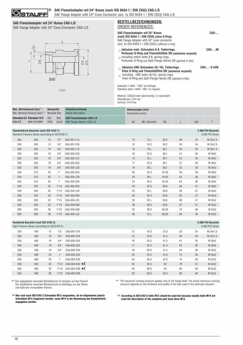
SAE-Flanschadapter mit 24°-Konus (nach ISO 8434-1 / DIN 2353) CAG-L/SSAE Flange Adapter with 24° Cone Connector (acc. to ISO 8434-1 / DIN 2353) CAG-L/S
018
SAE-Flanschadapter mit 24°-Konus CAG-L/SSAE Flange Adapter with 24° Cone Connector CAG-L/S
BESTELLBEZEICHNUNGEN:ORDER REFERENCES:SAE-Flanschadapter mit 24°-Konus CAG-...(nach ISO 8434-1 / DIN 2353) (ohne O-Ring)SAE Flange Adapter with 24° cone connector(acc. to ISO 8434-1 / DIN 2353) (without o-ring)
inklusive metr. Schrauben 8.8, Federringe, CAG-...#K Perbunan O-Ring und Flanschhälften DB (satzweise verpackt)including metric bolts 8.8, spring rings,Perbunan O-Ring and Split Flange Halves DB (packed in kits)
inklusive UNC-Schrauben (Gr 10), Federringe, CAG-...-V-U#K Viton O-Ring und Flanschhälften DB (satzweise verpackt)including , UNC bolts (Gr10), spring rings, Viton O-Ring and Split Flange Halves DB (packed in kits)
Edelstahl 1.4404 “-W5” auf Anfrage.Stainless steel 1.4404 “-W5” on request.
Material: S355J0 oder gleichwertig / or equivalentOberflächen: CrVI-freiSurface: CrVI free
❍
❍
❍
❍
ArtikelbezeichnungArticle Description
SAE-Flanschadapter CAG-L/SSAE Flange Adapter CAG-L/S
Max. Betriebsdruck [bar]*1
Max. Working Pressure [bar]*1
Schrauben 8.8Bolts 8.8
Schrauben 10.9Bolts 10.9 (MH)
NenngrößeNominal Size
ISO[DN]
SAE[inch]
Abmessungen [mm]Dimensions [mm]
ØA ØB x Baureihe ØD L SW T
Standarddruck-Baureihe (nach ISO 6162-1) 3.000-PSI-BaureiheStandard Pressure Series (according to ISO 6162-1) 3.000 PSI Series
350 350 13 1/2" CAG-301-L15 12 15 L 30,2 48 24 M 22x1,5
350 350 13 1/2" CAG-301-S16 12 16 S 30,2 50 24 M 24x1,5
350 350 19 3/4" CAG-302-L18 15 18 L 38,1 53 30 M 26x1,5
350 350 19 3/4" CAG-302-S20 16 20 S 38,1 57 30 M 30x2
350 350 19 3/4" CAG-302-L22 19 22 L 38,1 53 30 M 30x2
350 350 19 3/4" CAG-302-S25 17 25 S 38,1 57 30 M 36x2
350 350 19 3/4" CAG-302-L28 19 28 L 38,1 53 30 M 36x2
250 315 25 1" CAG-303-S25 20 25 S 44,45 58 36 M 36x2
250 315 25 1" CAG-303-L28 24 28 L 44,45 54 36 M 36x2
250 315 25 1" CAG-303-S30 24 30 S 44,45 63 36 M 42x2
200 250 32 1"1/4 CAG-304-S25 20 25 S 50,8 60 41 M 36x2
200 250 32 1"1/4 CAG-304-L28 22 28 L 50,8 59 41 M 36x2
200 250 32 1"1/4 CAG-304-S30 25 30 S 50,8 62 41 M 42x2
200 250 32 1"1/4 CAG-304-L35 30 35 L 50,8 58 41 M 45x2
200 250 32 1"1/4 CAG-304-S38 28 38 S 50,8 67 41 M 52x2
200 200 38 1"1/2 CAG-305-S38 32 38 S 60,35 70 46 M 52x2
200 200 38 1"1/2 CAG-305-L42 36 42 L 60,35 64 46 M 52x2
Hochdruck-Baureihe (nach ISO 6162-2) 6.000-PSI-BaureiheHigh Pressure Series (according to ISO 6162-2) 6.000 PSI Series
350 400 13 1/2" CAG-601-S16 12 16 S 31,8 53 24 M 24x1,5
350 400 19 3/4" CAG-602-S16 12 16 S 41,3 59 30 M 24x1,5
350 400 19 3/4" CAG-602-S20 16 20 S 41,3 61 30 M 30x2
350 400 19 3/4" CAG-602-S25 17 25 S 41,3 63 30 M 36x2
350 400 19 3/4" CAG-602-S30 18 30 S 41,3 64 36 M 42x2
350 400 25 1" CAG-603-S25 20 25 S 47,6 72 36 M 36x2
350 400 25 1" CAG-603-S30 24 30 S 47,6 74 36 M 42x2
350 400 32 1"1/4 CAG-604-S30 25 30 S 54 79 41 M 42x2
350 400 32 1"1/4 CAG-604-S38 30 38 S 54 83 46 M 52x2
350 400 38 1"1/2 CAG-605-S38 30 38 S 63,5 89 46 M 52x2
★1 Der angegebene maximale Betriebsdruck ist bezogen auf den Flansch. Der tatsächliche maximale Betriebsdruck ist abhängig von der Stärke und Güte des verwendeten Rohres.
★2
Hier sind nach ISO 6162-2 Schrauben M12 vorgesehen, da im allgemeinen jedochSchrauben M14 eingesetzt werden, muss M14 in der Benennung des Komplettteilsangegeben werden.
★2
★2
According to ISO 6162-2 bolts M12 should be used but because usually bolts M14 areused the description of the complete part must show M14.
★2
★1 The maximum working pressure applies only to the flange itself. The actual maximum workingpressure depends on the thickness and quality of the tube used in the particular situation.
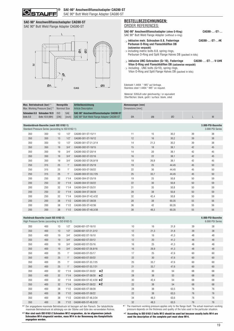
SAE-90° Anschweißflanschadapter CAG90-STSAE 90° Butt Weld Flange Adapter CAG90-ST
190
SAE-90° Anschweißflanschadapter CAG90-STSAE 90° Butt Weld Flange Adapter CAG90-ST
350 350 13 1/2" CAG90-301-ST-15/11 11 15 30,2 39 38
350 350 13 1/2" CAG90-301-ST-16/12 12 16 30,2 39 38
350 350 13 1/2" CAG90-301-ST-21,3/14 14 21,3 30,2 39 38
350 350 19 3/4" CAG90-302-ST-18/15 15 18 38,1 42 45
350 350 19 3/4" CAG90-302-ST-20/14 14 20 38,1 42 45
350 350 19 3/4" CAG90-302-ST-22/16 16 22 38,1 42 45
350 350 19 3/4" CAG90-302-ST-26,9/19 19 26,9 38,1 42 45
250 315 25 1" CAG90-303-ST-25/19 19 25 44,45 45 50
250 315 25 1" CAG90-303-ST-30/22 22 30 44,45 45 50
250 315 25 1" CAG90-303-ST-33,7/25 25 33,7 44,45 45 50
200 250 32 1"1/4 CAG90-304-ST-25/19 19 25 50,8 50 59
200 250 32 1"1/4 CAG90-304-ST-30/22 22 30 50,8 50 59
200 250 32 1"1/4 CAG90-304-ST-35/31 31 35 50,8 50 59
200 250 32 1"1/4 CAG90-304-ST-38/28 28 38 50,8 50 59
200 250 32 1"1/4 CAG90-304-ST-42,4/32 32 42,4 50,8 50 59
200 200 38 1"1/2 CAG90-305-ST-38/28 28 38 60,35 55 56
200 200 38 1"1/2 CAG90-305-ST-42/36 36 42 60,35 55 56
200 200 38 1"1/2 CAG90-305-ST-48,3/38 38 48,3 60,35 55 56
ArtikelbezeichnungArticle Description
SAE-90° Anschweißflanschadapter CAG90-ST SAE 90° Butt Weld Flange Adapter CAG90-ST
Max. Betriebsdruck [bar]*1
Max. Working Pressure [bar]*1
Schrauben 8.8Bolts 8.8
Schrauben 10.9Bolts 10.9 (MH)
NenngrößeNominal Size
ISO[DN]
SAE[inch]
Abmessungen [mm]Dimensions [mm]
ØA ØB ØD L M
Standarddruck-Baureihe (nach ISO 6162-1) 3.000-PSI-BaureiheStandard Pressure Series (according to ISO 6162-1) 3.000 PSI Series
BESTELLBEZEICHNUNGEN:ORDER REFERENCES:SAE-90° Anschweißflanschadapter (ohne O-Ring) CAG90-...-ST-...SAE 90° Butt Weld Flange Adapter (without o-ring)
inklusive metr. Schrauben 8.8, Federringe CAG90-...-ST-...#K Perbunan O-Ring und Flanschhälften DB(satzweise verpackt)including metric bolts 8.8, spring rings,Perbunan O-Ring and Split Flange Halves DB (packed in kits)
inklusive UNC-Schrauben (Gr 10), Federringe CAG90-...-ST-...-V-U#K Viton O-Ring und Flanschhälften DB (satzweise verpackt)including , UNC bolts (Gr10), spring rings,Viton O-Ring and Split Flange Halves DB (packed in kits)
Edelstahl 1.4404 “-W5” auf Anfrage.Stainless steel 1.4404 “-W5” on request.
Material: S355J0 oder gleichwertig / or equivalentOberflächen: blank, geölt / surface: blank, oiled
❍
❍
❍
❍
Hochdruck-Baureihe (nach ISO 6162-2) 6.000-PSI-BaureiheHigh Pressure Series (according to ISO 6162-2) 6.000 PSI Series
350 400 13 1/2" CAG90-601-ST-16/10 10 16 31,8 39 38
350 400 13 1/2" CAG90-601-ST-21,3/12 12 21,3 31,8 39 38
350 400 19 3/4" CAG90-602-ST-16/10 10 16 41,3 48 48
350 400 19 3/4" CAG90-602-ST-20/12 12 20 41,2 48 48
350 400 19 3/4" CAG90-602-ST-25/16 16 25 41,3 48 48
350 400 19 3/4" CAG90-602-ST-26,9/16 16 26,9 41,3 48 48
350 400 25 1" CAG90-603-ST-25/17 17 25 47,6 60 60
350 400 25 1" CAG90-603-ST-30/22 22 30 47,6 60 60
350 400 25 1" CAG90-603-ST-33,7/25 25 33,7 47,6 60 60
350 400 25 1" CAG90-603-ST-33,7/21 21 33,7 47,6 60 60
350 400 32 1"1/4 CAG90-604-ST-30/22 22 30 54 68 68
350 400 32 1"1/4 CAG90-604-ST-38/28 28 38 53 68 68
350 400 32 1"1/4 CAG90-604-ST-42,4/30 30 42,4 54 68 68
350 400 32 1"1/4 CAG90-604-ST-38/22 22 38 54 68 68
350 400 38 1"1/2 CAG90-605-ST-38/28 28 38 63,5 76 76
350 400 38 1"1/2 CAG90-605-ST-38/22 22 38 63,5 76 76
350 400 38 1"1/2 CAG90-605-ST-48,3/34 34 48,3 63,6 76 76
350 400 38 1"1/2 CAG90-605-ST-48,3/32 32 48,3 63,5 76 76★1 Der angegebene maximale Betriebsdruck ist bezogen auf den Flansch. Der tatsächliche
maximale Betriebsdruck ist abhängig von der Stärke und Güte des verwendeten Rohres.Hier sind nach ISO 6162-2 Schrauben M12 vorgesehen, da im allgemeinen jedochSchrauben M14 eingesetzt werden, muss M14 in der Benennung des Komplettteilsangegeben werden.
★2 According to ISO 6162-2 bolts M12 should be used but because usually bolts M14 areused the description of the complete part must show M14.
★2
★2★2★2★2
★1 The maximum working pressure applies only to the flange itself. The actual maximum workingpressure depends on the thickness and quality of the tube used in the particular situation.
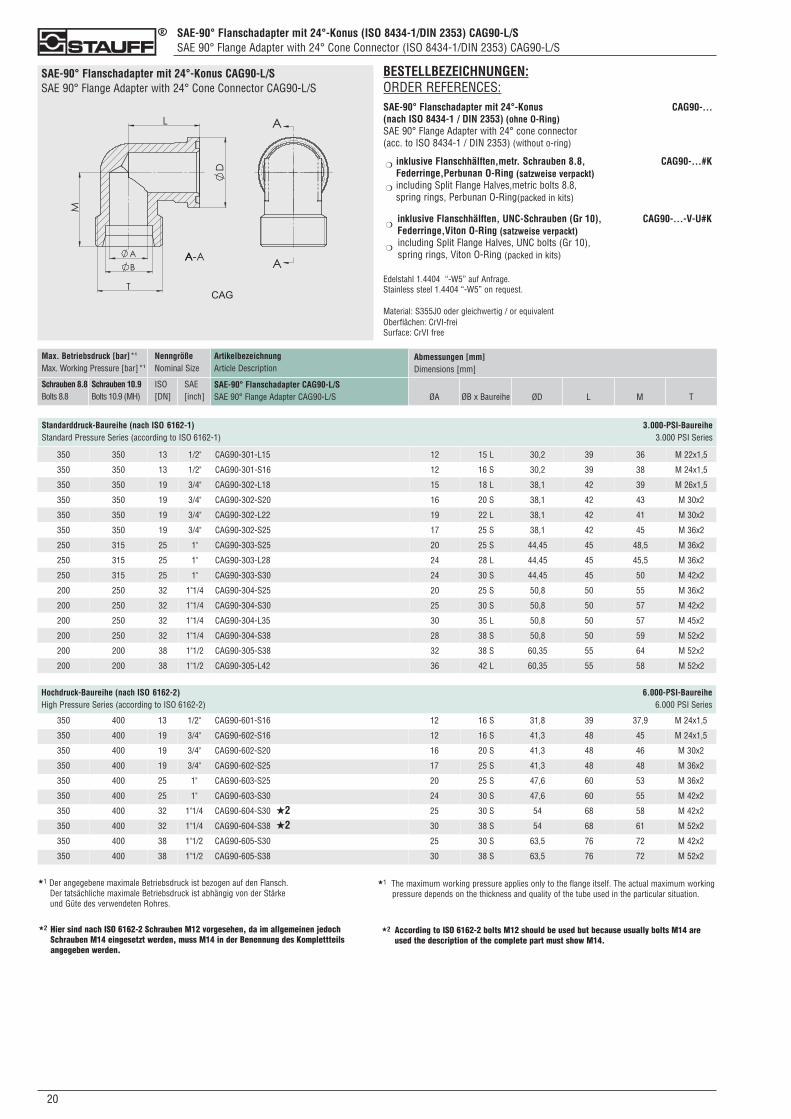
SAE-90° Flanschadapter mit 24°-Konus (ISO 8434-1/DIN 2353) CAG90-L/SSAE 90° Flange Adapter with 24° Cone Connector (ISO 8434-1/DIN 2353) CAG90-L/S
020
SAE-90° Flanschadapter mit 24°-Konus CAG90-L/SSAE 90° Flange Adapter with 24° Cone Connector CAG90-L/S
BESTELLBEZEICHNUNGEN:ORDER REFERENCES:SAE-90° Flanschadapter mit 24°-Konus CAG90-...(nach ISO 8434-1 / DIN 2353) (ohne O-Ring)SAE 90° Flange Adapter with 24° cone connector(acc. to ISO 8434-1 / DIN 2353) (without o-ring)
inklusive Flanschhälften,metr. Schrauben 8.8, CAG90-...#K Federringe,Perbunan O-Ring (satzweise verpackt)including Split Flange Halves,metric bolts 8.8, spring rings, Perbunan O-Ring(packed in kits)
inklusive Flanschhälften, UNC-Schrauben (Gr 10), CAG90-...-V-U#K Federringe,Viton O-Ring (satzweise verpackt)including Split Flange Halves, UNC bolts (Gr 10), spring rings, Viton O-Ring (packed in kits)
Edelstahl 1.4404 “-W5” auf Anfrage.Stainless steel 1.4404 “-W5” on request.
Material: S355J0 oder gleichwertig / or equivalentOberflächen: CrVI-freiSurface: CrVI free
❍
❍
❍
❍
ArtikelbezeichnungArticle Description
SAE-90° Flanschadapter CAG90-L/SSAE 90° Flange Adapter CAG90-L/S
Max. Betriebsdruck [bar]*1
Max. Working Pressure [bar]*1
Schrauben 8.8Bolts 8.8
Schrauben 10.9Bolts 10.9 (MH)
NenngrößeNominal Size
ISO[DN]
SAE[inch]
Abmessungen [mm]Dimensions [mm]
ØA ØB x Baureihe ØD L M T
Standarddruck-Baureihe (nach ISO 6162-1) 3.000-PSI-BaureiheStandard Pressure Series (according to ISO 6162-1) 3.000 PSI Series
350 350 13 1/2" CAG90-301-L15 12 15 L 30,2 39 36 M 22x1,5
350 350 13 1/2" CAG90-301-S16 12 16 S 30,2 39 38 M 24x1,5
350 350 19 3/4" CAG90-302-L18 15 18 L 38,1 42 39 M 26x1,5
350 350 19 3/4" CAG90-302-S20 16 20 S 38,1 42 43 M 30x2
350 350 19 3/4" CAG90-302-L22 19 22 L 38,1 42 41 M 30x2
350 350 19 3/4" CAG90-302-S25 17 25 S 38,1 42 45 M 36x2
250 315 25 1" CAG90-303-S25 20 25 S 44,45 45 48,5 M 36x2
250 315 25 1" CAG90-303-L28 24 28 L 44,45 45 45,5 M 36x2
250 315 25 1" CAG90-303-S30 24 30 S 44,45 45 50 M 42x2
200 250 32 1"1/4 CAG90-304-S25 20 25 S 50,8 50 55 M 36x2
200 250 32 1"1/4 CAG90-304-S30 25 30 S 50,8 50 57 M 42x2
200 250 32 1"1/4 CAG90-304-L35 30 35 L 50,8 50 57 M 45x2
200 250 32 1"1/4 CAG90-304-S38 28 38 S 50,8 50 59 M 52x2
200 200 38 1"1/2 CAG90-305-S38 32 38 S 60,35 55 64 M 52x2
200 200 38 1"1/2 CAG90-305-L42 36 42 L 60,35 55 58 M 52x2
Hochdruck-Baureihe (nach ISO 6162-2) 6.000-PSI-BaureiheHigh Pressure Series (according to ISO 6162-2) 6.000 PSI Series
350 400 13 1/2" CAG90-601-S16 12 16 S 31,8 39 37,9 M 24x1,5
350 400 19 3/4" CAG90-602-S16 12 16 S 41,3 48 45 M 24x1,5
350 400 19 3/4" CAG90-602-S20 16 20 S 41,3 48 46 M 30x2
350 400 19 3/4" CAG90-602-S25 17 25 S 41,3 48 48 M 36x2
350 400 25 1" CAG90-603-S25 20 25 S 47,6 60 53 M 36x2
350 400 25 1" CAG90-603-S30 24 30 S 47,6 60 55 M 42x2
350 400 32 1"1/4 CAG90-604-S30 25 30 S 54 68 58 M 42x2
350 400 32 1"1/4 CAG90-604-S38 30 38 S 54 68 61 M 52x2
350 400 38 1"1/2 CAG90-605-S30 25 30 S 63,5 76 72 M 42x2
350 400 38 1"1/2 CAG90-605-S38 30 38 S 63,5 76 72 M 52x2
★1 Der angegebene maximale Betriebsdruck ist bezogen auf den Flansch. Der tatsächliche maximale Betriebsdruck ist abhängig von der Stärke und Güte des verwendeten Rohres.
Hier sind nach ISO 6162-2 Schrauben M12 vorgesehen, da im allgemeinen jedochSchrauben M14 eingesetzt werden, muss M14 in der Benennung des Komplettteilsangegeben werden.
★2 According to ISO 6162-2 bolts M12 should be used but because usually bolts M14 areused the description of the complete part must show M14.
★2
★2★2
★1 The maximum working pressure applies only to the flange itself. The actual maximum workingpressure depends on the thickness and quality of the tube used in the particular situation.

210
NotizenNotes
022
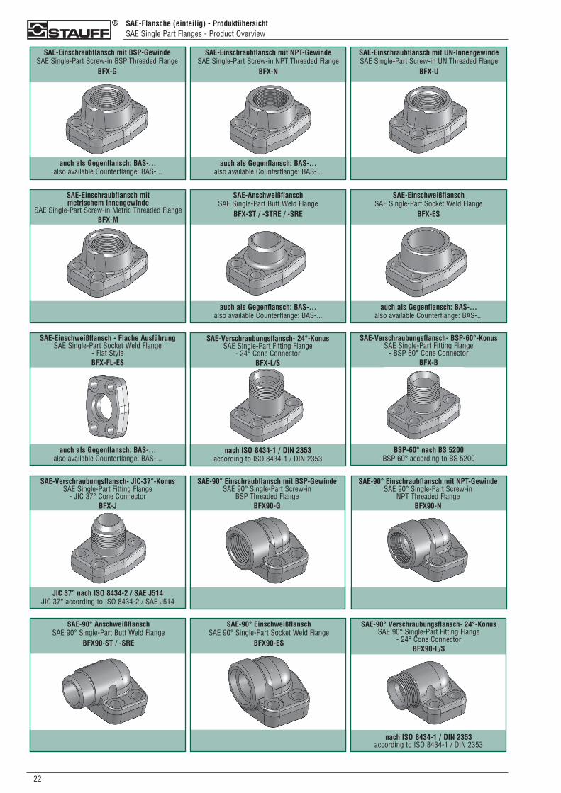
SAE-Flansche (einteilig) - ProduktübersichtSAE Single Part Flanges - Product Overview
SAE-Einschraubflansch mit NPT-Gewinde SAE Single-Part Screw-in NPT Threaded Flange
BFX-N
auch als Gegenflansch: BAS-... also available Counterflange: BAS-...
auch als Gegenflansch: BAS-... also available Counterflange: BAS-...
SAE-Einschraubflansch mit BSP-Gewinde SAE Single-Part Screw-in BSP Threaded Flange
BFX-G
SAE-Einschraubflansch mit UN-InnengewindeSAE Single-Part Screw-in UN Threaded Flange
BFX-U
SAE-Einschraubflansch mit metrischem Innengewinde
SAE Single-Part Screw-in Metric Threaded FlangeBFX-M
auch als Gegenflansch: BAS-... also available Counterflange: BAS-...
SAE-AnschweißflanschSAE Single-Part Butt Weld Flange
BFX-ST / -STRE / -SRE
auch als Gegenflansch: BAS-... also available Counterflange: BAS-...
SAE-EinschweißflanschSAE Single-Part Socket Weld Flange
BFX-ES
auch als Gegenflansch: BAS-... also available Counterflange: BAS-...
SAE-Einschweißflansch - Flache Ausführung SAE Single-Part Socket Weld Flange
- Flat Style BFX-FL-ES
nach ISO 8434-1 / DIN 2353according to ISO 8434-1 / DIN 2353
SAE-Verschraubungsflansch- 24°-Konus SAE Single-Part Fitting Flange
- 24° Cone ConnectorBFX-L/S
BSP-60° nach BS 5200BSP 60° according to BS 5200
SAE-Verschraubungsflansch- BSP-60°-Konus SAE Single-Part Fitting Flange
- BSP 60° Cone ConnectorBFX-B
JIC 37° nach ISO 8434-2 / SAE J514JIC 37° according to ISO 8434-2 / SAE J514
SAE-Verschraubungsflansch- JIC-37°-Konus SAE Single-Part Fitting Flange
- JIC 37° Cone ConnectorBFX-J
SAE-90° Einschraubflansch mit BSP-Gewinde SAE 90° Single-Part Screw-in
BSP Threaded FlangeBFX90-G
SAE-90° Einschraubflansch mit NPT-Gewinde SAE 90° Single-Part Screw-in
NPT Threaded FlangeBFX90-N
SAE-90° Anschweißflansch SAE 90° Single-Part Butt Weld Flange
BFX90-ST / -SRE
SAE-90° Einschweißflansch SAE 90° Single-Part Socket Weld Flange
BFX90-ES
nach ISO 8434-1 / DIN 2353according to ISO 8434-1 / DIN 2353
SAE-90° Verschraubungsflansch- 24°-Konus SAE 90° Single-Part Fitting Flange
- 24° Cone Connector BFX90-L/S
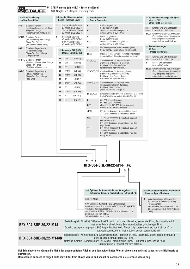
SAE-Flansche (einteilig) - BestellschlüsselSAE Single-Part Flanges - Odering code
➀ ArtikelbezeichnungArticle Description
➁ Baureihe / NenndruckstufeSeries / Pressure Level
➃ AnschlussvarianteType of Connection
BFX Einteiliger Flansch(gerade Ausführung, ohne O-Ring)Single-Part Flange(Straight Version, without o-ring)
BFX90 Einteiliger Flansch(90° Ausführung, ohne O-Ring)Single-Part Flange(90° Version, without o-ring)
BAS Einteiliger Gegenflansch(gerade Ausführung)Single-Part Counterflange(Straight Version)
BFX-FL Einteiliger Flansch- Flache Ausführung (ohne O-Ring)Single-Part Flange- Flat Style (without o-ring)
BAS-FL Einteiliger Gegenflansch- Flache AusführungSingle-Part Counterflange- Flat Style
-3 Standarddruck-Baureihe(3.000 PSI) ISO 6162-1Standard Pressure Series(3.000 PSI) ISO 6162-1
-6 Hochdruck-Baureihe(6.000 PSI) ISO 6162-2High Pressure Series(6.000 PSI) ISO 6162-2
-G
-G��
BSP-InnengewindeScrew-In BSP Threadabweichendes BSP-Innengewindedeviant Screw-In BSP Thread
-N
-N��
NPT-InnengewindeScrew-In NPT Threadabweichendes NPT-Innengewindedeviant Screw-In NPT Thread
-U�� UNC-Innengewinde (Gewinde bitte angeben)Screw-In UNC Thread (please indicate thread)
-M�� metrisches Innengewinde (Gewinde bitte angeben)Screw-In Metric Thread (please indicate thread)
-ST-��/�� Anschweißbund für Hochdruck-Rohre(Rohraußen-Ø/Rohrinnen-Ø angeben)Butt Weld - High Pressure Tubes(please indicate Pipe OD/Pipe-ID)
-STRE-��/�� Anschweißbund für Niederdruck-Rohre(Rohraußen-Ø/Rohrinnen-Ø angeben)Butt Weld - Low Pressure Tubes(please indicate Pipe OD/Pipe-ID)
-SRE-��/�� Anschweißbund für metrische Rohre(Rohraußen-Ø/Rohrinnen-Ø angeben)Butt Weld - Metric Tubes
(please indicate Pipe OD/Pipe-ID)
-ES-��/�� Einschweißbund (Rohraußen-Ø/Rohrinnen-Ø angeben)Socket Weld (please indicate Pipe OD/Pipe-ID)
-B
-B��
60° BSP Konus-Anschluss60° BSP Cone Connectorabweichender 60° BSP Konus-Anschlussdeviant 60° BSP Cone Connector
-J�� 37° Konus-Anschluss (Gewinde bitte angeben)37° Cone Connector (please indicate thread)
-L��
-S��
24° Konus-Anschluss (Rohraußen-Ø angeben)Leichte Baureihe24° Cone Connector (please indicate Pipe OD)Light Series24° Konus-Anschluss (Rohraußen-Ø angeben)Schwere Baureihe24° Cone Connector (please indicate Pipe OD)Heavy Series
➂ Nennweite SAE (ISO)Nominal Size SAE (ISO)
01 1/2” (DN 13)
02 3/4” (DN 19)
03 1” (DN 25)
04 1”1/4 (DN 32)
05 1”1/2 (DN 38)
06 2” (DN 51)
07 2”1/2 (DN 64)
08 3” (DN 76)
09 3”1/2 (DN 89)
10 4” (DN 102)
11 5” (DN 127)
➄ Schraubendurchgangsbohrungen(nicht bei BAS)Screw Holes (not for BAS)
ohnewithout
für metr. und UNC-Schraubenfor metric and UNC bolts
-M�� für abweichende metr. Schrauben (Sonderabmessungen bitte angeben)only for special metric bolts(please indicate special bolt size)
BFX-604-SRE-30/22-M14-..#K
Bei Schmiedeteilen können die Maße der unbearbeiteten Flächen von den aufgeführten Werten abweichen und sind daher nur als Richtwerte zubetrachten.Unmachined surfaces of forged parts may differ from shown values and should be considered as reference values only.
➄/➅ Optionen für Komplettteile (vor #K angeben)Options for Complete Parts (indicate in front of #K)
Viton / FPM (V)
metr. Schrauben 10.9 (MH), UNC-Schrauben (U), abweichende metr. Schrauben 8.8 (M��) bzw. 10.9 (MH��)(Schraubensets inklusive Federringe)metric bolts 10.9 (MH), UNC-bolts (U),special metric bolts 8.8 (M��) bzw. 10.9 (MH��)(bolt kits including spring rings)
➆ Standard-Lieferform für KomplettteileStandard Type of Delivery
#K satzweise verpackt inklusive metr.Schrauben 8.8, Federringe, O-RingPerbunan (NBR)packed in kits, including metric bolts8.8, spring washers, O-Ring Perbunan(NBR)
➄ Gewindebohrungen(für BAS)Threads (only for BAS)
ohnewithout
für metr. und UNC-Schraubenfor metric and UNC bolts
-U nur für UNC Schraubenonly for UNC bolts
-M�� für abweichende metr. Schrauben (Sonderabmessungen bitte angeben)only for special metric bolts(please indicate special bolt size)
230
Bestellbeispiel - Einzelteil: SAE-Anschweißflansch, Hochdruck-Baureihe, Nennweite 1”1/4, Anschweißbund für metrische Rohre, abweichende Schraubendurchgangsbohrungen M14
Ordering example - single part: SAE Single-Part Butt Weld Flange, high pressure series, nominal size 1”1/4, butt weld connection for metric tubes, deviant screw holes M14
BFX-604-SRE-30/22-M14#K
BFX-604-SRE-30/22-M14
Bestellbeispiel - Komplettteil: SAE-Anschweißflansch, Perbunan O-Ring, Federringe, 8.8 metrische Schrauben,abweichende Schraubengröße M14x45
Ordering example - complete part: SAE Single-Part Butt Weld Flange, Perbunan o-ring, spring rings, 8.8 metric bolts, deviant bolt size M14x45
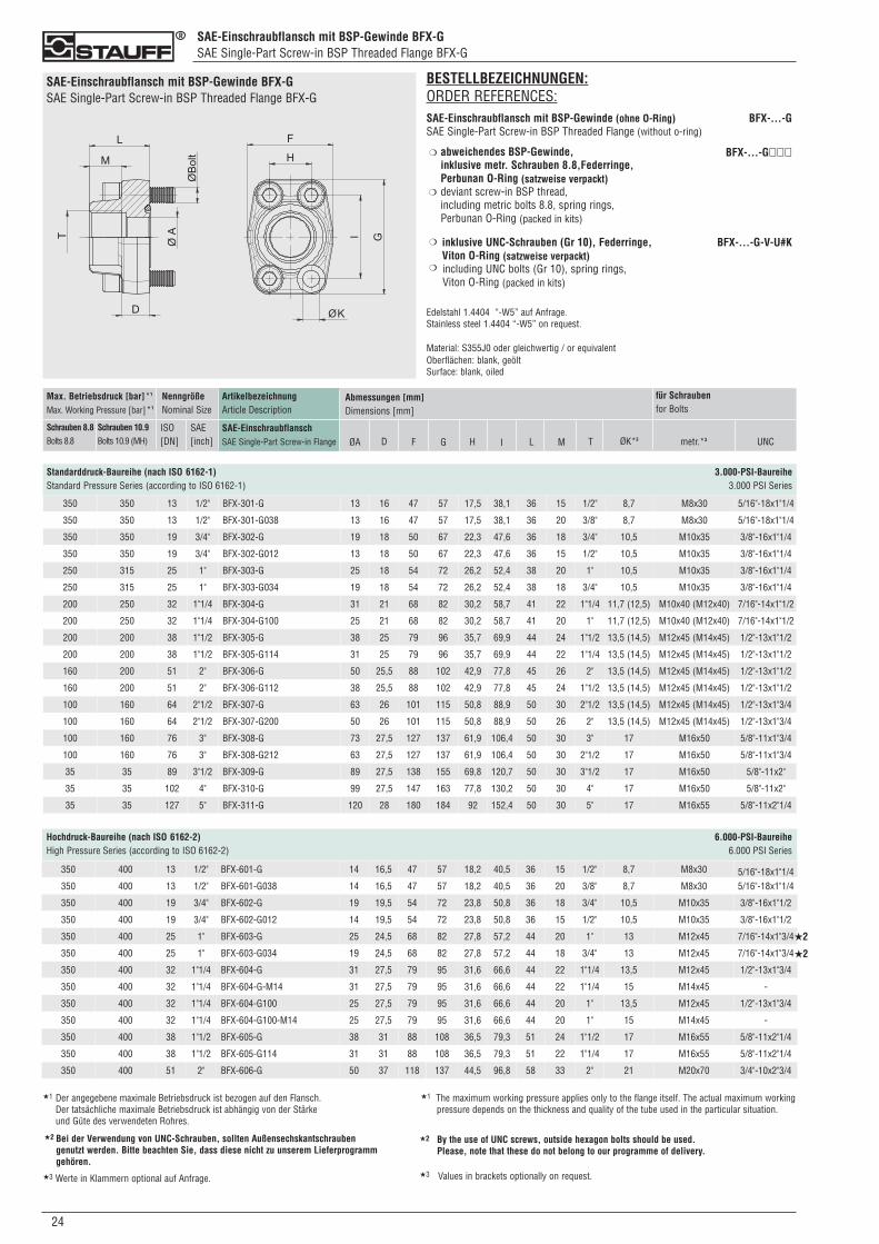
SAE-Einschraubflansch mit BSP-Gewinde BFX-GSAE Single-Part Screw-in BSP Threaded Flange BFX-G
024
SAE-Einschraubflansch mit BSP-Gewinde BFX-GSAE Single-Part Screw-in BSP Threaded Flange BFX-G
BESTELLBEZEICHNUNGEN:ORDER REFERENCES:SAE-Einschraubflansch mit BSP-Gewinde (ohne O-Ring)SAE Single-Part Screw-in BSP Threaded Flange (without o-ring)
abweichendes BSP-Gewinde,inklusive metr. Schrauben 8.8,Federringe,Perbunan O-Ring (satzweise verpackt)deviant screw-in BSP thread,including metric bolts 8.8, spring rings, Perbunan O-Ring (packed in kits)
inklusive UNC-Schrauben (Gr 10), Federringe,Viton O-Ring (satzweise verpackt)including UNC bolts (Gr 10), spring rings, Viton O-Ring (packed in kits)
Edelstahl 1.4404 “-W5” auf Anfrage.Stainless steel 1.4404 “-W5” on request.
Material: S355J0 oder gleichwertig / or equivalentOberflächen: blank, geöltSurface: blank, oiled
❍
❍
❍
❍
BFX-...-G
BFX-...-G���
BFX-...-G-V-U#K
ArtikelbezeichnungArticle Description
SAE-EinschraubflanschSAE Single-Part Screw-in Flange
Max. Betriebsdruck [bar]*1
Max. Working Pressure [bar]*1
Schrauben 8.8Bolts 8.8
Schrauben 10.9Bolts 10.9 (MH)
NenngrößeNominal Size
ISO[DN]
SAE[inch]
Abmessungen [mm]Dimensions [mm]
ØA D F G T ØK*3
Standarddruck-Baureihe (nach ISO 6162-1) 3.000-PSI-BaureiheStandard Pressure Series (according to ISO 6162-1) 3.000 PSI Series
H I L M metr.*3 UNC
für Schraubenfor Bolts
350 350 13 1/2" BFX-301-G 13 16 47 57 17,5 38,1 36 15 1/2" 8,7 M8x30 5/16"-18x1"1/4
350 350 13 1/2" BFX-301-G038 13 16 47 57 17,5 38,1 36 20 3/8" 8,7 M8x30 5/16"-18x1"1/4
350 350 19 3/4" BFX-302-G 19 18 50 67 22,3 47,6 36 18 3/4" 10,5 M10x35 3/8"-16x1"1/4
350 350 19 3/4" BFX-302-G012 13 18 50 67 22,3 47,6 36 15 1/2" 10,5 M10x35 3/8"-16x1"1/4
250 315 25 1" BFX-303-G 25 18 54 72 26,2 52,4 38 20 1" 10,5 M10x35 3/8"-16x1"1/4
250 315 25 1" BFX-303-G034 19 18 54 72 26,2 52,4 38 18 3/4" 10,5 M10x35 3/8"-16x1"1/4
200 250 32 1"1/4 BFX-304-G 31 21 68 82 30,2 58,7 41 22 1"1/4 11,7 (12,5) M10x40 (M12x40) 7/16"-14x1"1/2
200 250 32 1"1/4 BFX-304-G100 25 21 68 82 30,2 58,7 41 20 1" 11,7 (12,5) M10x40 (M12x40) 7/16"-14x1"1/2
200 200 38 1"1/2 BFX-305-G 38 25 79 96 35,7 69,9 44 24 1"1/2 13,5 (14,5) M12x45 (M14x45) 1/2"-13x1"1/2
200 200 38 1"1/2 BFX-305-G114 31 25 79 96 35,7 69,9 44 22 1"1/4 13,5 (14,5) M12x45 (M14x45) 1/2"-13x1"1/2
160 200 51 2" BFX-306-G 50 25,5 88 102 42,9 77,8 45 26 2" 13,5 (14,5) M12x45 (M14x45) 1/2"-13x1"1/2
160 200 51 2" BFX-306-G112 38 25,5 88 102 42,9 77,8 45 24 1"1/2 13,5 (14,5) M12x45 (M14x45) 1/2"-13x1"1/2
100 160 64 2"1/2 BFX-307-G 63 26 101 115 50,8 88,9 50 30 2"1/2 13,5 (14,5) M12x45 (M14x45) 1/2"-13x1"3/4
100 160 64 2"1/2 BFX-307-G200 50 26 101 115 50,8 88,9 50 26 2" 13,5 (14,5) M12x45 (M14x45) 1/2"-13x1"3/4
100 160 76 3" BFX-308-G 73 27,5 127 137 61,9 106,4 50 30 3" 17 M16x50 5/8"-11x1"3/4
100 160 76 3" BFX-308-G212 63 27,5 127 137 61,9 106,4 50 30 2"1/2 17 M16x50 5/8"-11x1"3/4
35 35 89 3"1/2 BFX-309-G 89 27,5 138 155 69,8 120,7 50 30 3"1/2 17 M16x50 5/8"-11x2"
35 35 102 4" BFX-310-G 99 27,5 147 163 77,8 130,2 50 30 4" 17 M16x50 5/8"-11x2"
35 35 127 5" BFX-311-G 120 28 180 184 92 152,4 50 30 5" 17 M16x55 5/8"-11x2"1/4
350 400 13 1/2" BFX-601-G 14 16,5 47 57 18,2 40,5 36 15 1/2" 8,7 M8x30 5/16"-18x1"1/4350 400 13 1/2" BFX-601-G038 14 16,5 47 57 18,2 40,5 36 20 3/8" 8,7 M8x30 5/16"-18x1"1/4
350 400 19 3/4" BFX-602-G 19 19,5 54 72 23,8 50,8 36 18 3/4" 10,5 M10x35 3/8"-16x1"1/2
350 400 19 3/4" BFX-602-G012 14 19,5 54 72 23,8 50,8 36 15 1/2" 10,5 M10x35 3/8"-16x1"1/2
350 400 25 1" BFX-603-G 25 24,5 68 82 27,8 57,2 44 20 1" 13 M12x45 7/16"-14x1"3/4
350 400 25 1" BFX-603-G034 19 24,5 68 82 27,8 57,2 44 18 3/4" 13 M12x45 7/16"-14x1"3/4
350 400 32 1"1/4 BFX-604-G 31 27,5 79 95 31,6 66,6 44 22 1"1/4 13,5 M12x45 1/2"-13x1"3/4
350 400 32 1"1/4 BFX-604-G-M14 31 27,5 79 95 31,6 66,6 44 22 1"1/4 15 M14x45 -
350 400 32 1"1/4 BFX-604-G100 25 27,5 79 95 31,6 66,6 44 20 1" 13,5 M12x45 1/2"-13x1"3/4
350 400 32 1"1/4 BFX-604-G100-M14 25 27,5 79 95 31,6 66,6 44 20 1" 15 M14x45 -
350 400 38 1"1/2 BFX-605-G 38 31 88 108 36,5 79,3 51 24 1"1/2 17 M16x55 5/8"-11x2"1/4
350 400 38 1"1/2 BFX-605-G114 31 31 88 108 36,5 79,3 51 22 1"1/4 17 M16x55 5/8"-11x2"1/4
350 400 51 2" BFX-606-G 50 37 118 137 44,5 96,8 58 33 2" 21 M20x70 3/4"-10x2"3/4
Hochdruck-Baureihe (nach ISO 6162-2) 6.000-PSI-BaureiheHigh Pressure Series (according to ISO 6162-2) 6.000 PSI Series
★1 Der angegebene maximale Betriebsdruck ist bezogen auf den Flansch. Der tatsächliche maximale Betriebsdruck ist abhängig von der Stärke und Güte des verwendeten Rohres.
★1 The maximum working pressure applies only to the flange itself. The actual maximum workingpressure depends on the thickness and quality of the tube used in the particular situation.
★2
★2
Bei der Verwendung von UNC-Schrauben, sollten Außensechskantschrauben genutzt werden. Bitte beachten Sie, dass diese nicht zu unserem Lieferprogramm gehören.
★2 By the use of UNC screws, outside hexagon bolts should be used. Please, note that these do not belong to our programme of delivery.
★2
★3 Werte in Klammern optional auf Anfrage. ★3 Values in brackets optionally on request.
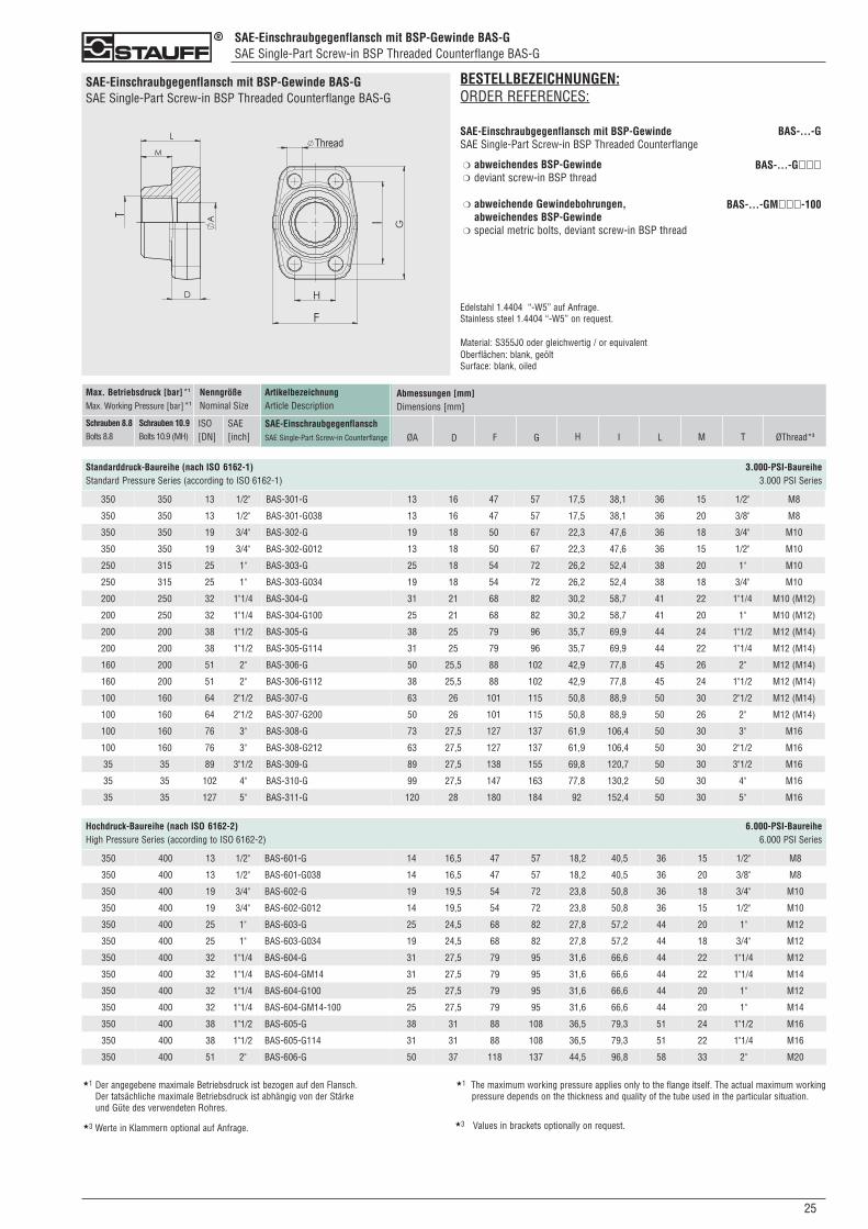
SAE-Einschraubgegenflansch mit BSP-Gewinde BAS-GSAE Single-Part Screw-in BSP Threaded Counterflange BAS-G
250
SAE-Einschraubgegenflansch mit BSP-Gewinde BAS-GSAE Single-Part Screw-in BSP Threaded Counterflange BAS-G
BESTELLBEZEICHNUNGEN:ORDER REFERENCES:
SAE-Einschraubgegenflansch mit BSP-GewindeSAE Single-Part Screw-in BSP Threaded Counterflange
abweichendes BSP-Gewindedeviant screw-in BSP thread
abweichende Gewindebohrungen, abweichendes BSP-Gewindespecial metric bolts, deviant screw-in BSP thread
Edelstahl 1.4404 “-W5” auf Anfrage.Stainless steel 1.4404 “-W5” on request.
Material: S355J0 oder gleichwertig / or equivalentOberflächen: blank, geöltSurface: blank, oiled
❍
❍
BAS-...-G
BAS-...-G���
BAS-...-GM���-100❍
❍
350 350 13 1/2" BAS-301-G 13 16 47 57 17,5 38,1 36 15 1/2" M8
350 350 13 1/2" BAS-301-G038 13 16 47 57 17,5 38,1 36 20 3/8" M8
350 350 19 3/4" BAS-302-G 19 18 50 67 22,3 47,6 36 18 3/4" M10
350 350 19 3/4" BAS-302-G012 13 18 50 67 22,3 47,6 36 15 1/2" M10
250 315 25 1" BAS-303-G 25 18 54 72 26,2 52,4 38 20 1" M10
250 315 25 1" BAS-303-G034 19 18 54 72 26,2 52,4 38 18 3/4" M10
200 250 32 1"1/4 BAS-304-G 31 21 68 82 30,2 58,7 41 22 1"1/4 M10 (M12)
200 250 32 1"1/4 BAS-304-G100 25 21 68 82 30,2 58,7 41 20 1" M10 (M12)
200 200 38 1"1/2 BAS-305-G 38 25 79 96 35,7 69,9 44 24 1"1/2 M12 (M14)
200 200 38 1"1/2 BAS-305-G114 31 25 79 96 35,7 69,9 44 22 1"1/4 M12 (M14)
160 200 51 2" BAS-306-G 50 25,5 88 102 42,9 77,8 45 26 2" M12 (M14)
160 200 51 2" BAS-306-G112 38 25,5 88 102 42,9 77,8 45 24 1"1/2 M12 (M14)
100 160 64 2"1/2 BAS-307-G 63 26 101 115 50,8 88,9 50 30 2"1/2 M12 (M14)
100 160 64 2"1/2 BAS-307-G200 50 26 101 115 50,8 88,9 50 26 2" M12 (M14)
100 160 76 3" BAS-308-G 73 27,5 127 137 61,9 106,4 50 30 3" M16
100 160 76 3" BAS-308-G212 63 27,5 127 137 61,9 106,4 50 30 2"1/2 M16
35 35 89 3"1/2 BAS-309-G 89 27,5 138 155 69,8 120,7 50 30 3"1/2 M16
35 35 102 4" BAS-310-G 99 27,5 147 163 77,8 130,2 50 30 4" M16
35 35 127 5" BAS-311-G 120 28 180 184 92 152,4 50 30 5" M16
ArtikelbezeichnungArticle Description
SAE-EinschraubgegenflanschSAE Single-Part Screw-in Counterflange
Max. Betriebsdruck [bar]*1
Max. Working Pressure [bar]*1
Schrauben 8.8Bolts 8.8
Schrauben 10.9Bolts 10.9 (MH)
NenngrößeNominal Size
ISO[DN]
SAE[inch]
Abmessungen [mm]Dimensions [mm]
ØA D F G T
Standarddruck-Baureihe (nach ISO 6162-1) 3.000-PSI-BaureiheStandard Pressure Series (according to ISO 6162-1) 3.000 PSI Series
H I L M ØThread*3
350 400 13 1/2" BAS-601-G 14 16,5 47 57 18,2 40,5 36 15 1/2" M8
350 400 13 1/2" BAS-601-G038 14 16,5 47 57 18,2 40,5 36 20 3/8" M8
350 400 19 3/4" BAS-602-G 19 19,5 54 72 23,8 50,8 36 18 3/4" M10
350 400 19 3/4" BAS-602-G012 14 19,5 54 72 23,8 50,8 36 15 1/2" M10
350 400 25 1" BAS-603-G 25 24,5 68 82 27,8 57,2 44 20 1" M12
350 400 25 1" BAS-603-G034 19 24,5 68 82 27,8 57,2 44 18 3/4" M12
350 400 32 1"1/4 BAS-604-G 31 27,5 79 95 31,6 66,6 44 22 1"1/4 M12
350 400 32 1"1/4 BAS-604-GM14 31 27,5 79 95 31,6 66,6 44 22 1"1/4 M14
350 400 32 1"1/4 BAS-604-G100 25 27,5 79 95 31,6 66,6 44 20 1" M12
350 400 32 1"1/4 BAS-604-GM14-100 25 27,5 79 95 31,6 66,6 44 20 1" M14
350 400 38 1"1/2 BAS-605-G 38 31 88 108 36,5 79,3 51 24 1"1/2 M16
350 400 38 1"1/2 BAS-605-G114 31 31 88 108 36,5 79,3 51 22 1"1/4 M16
350 400 51 2" BAS-606-G 50 37 118 137 44,5 96,8 58 33 2" M20
Hochdruck-Baureihe (nach ISO 6162-2) 6.000-PSI-BaureiheHigh Pressure Series (according to ISO 6162-2) 6.000 PSI Series
★1 Der angegebene maximale Betriebsdruck ist bezogen auf den Flansch. Der tatsächliche maximale Betriebsdruck ist abhängig von der Stärke und Güte des verwendeten Rohres.
★1 The maximum working pressure applies only to the flange itself. The actual maximum workingpressure depends on the thickness and quality of the tube used in the particular situation.
★3 Werte in Klammern optional auf Anfrage. ★3 Values in brackets optionally on request.
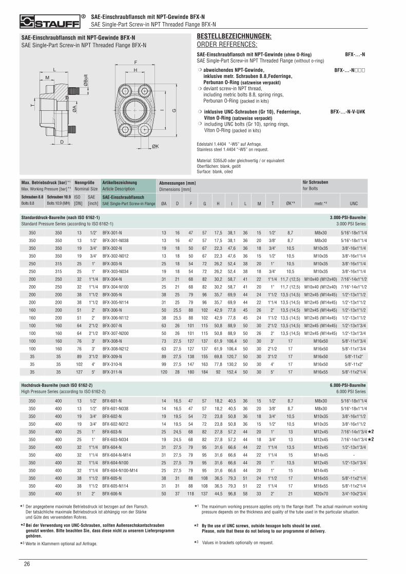
SAE-Einschraubflansch mit NPT-Gewinde BFX-NSAE Single-Part Screw-in NPT Threaded Flange BFX-N
026
SAE-Einschraubflansch mit NPT-Gewinde BFX-NSAE Single-Part Screw-in NPT Threaded Flange BFX-N
BESTELLBEZEICHNUNGEN:ORDER REFERENCES:SAE-Einschraubflansch mit NPT-Gewinde (ohne O-Ring)SAE Single-Part Screw-in NPT Threaded Flange (without o-ring)
abweichendes NPT-Gewinde,inklusive metr. Schrauben 8.8,Federringe,Perbunan O-Ring (satzweise verpackt)deviant screw-in NPT thread,including metric bolts 8.8, spring rings, Perbunan O-Ring (packed in kits)
inklusive UNC-Schrauben (Gr 10), Federringe,Viton O-Ring (satzweise verpackt)including UNC bolts (Gr 10), spring rings, Viton O-Ring (packed in kits)
Edelstahl 1.4404 “-W5” auf Anfrage.Stainless steel 1.4404 “-W5” on request.
Material: S355J0 oder gleichwertig / or equivalentOberflächen: blank, geöltSurface: blank, oiled
❍
❍
❍
❍
BFX-...-N
BFX-...-N���
BFX-...-N-V-U#K
ArtikelbezeichnungArticle Description
SAE-EinschraubflanschSAE Single-Part Screw-in Flange
Max. Betriebsdruck [bar]*1
Max. Working Pressure [bar]*1
Schrauben 8.8Bolts 8.8
Schrauben 10.9Bolts 10.9 (MH)
NenngrößeNominal Size
ISO[DN]
SAE[inch]
Abmessungen [mm]Dimensions [mm]
ØA D F G T ØK*3
Standarddruck-Baureihe (nach ISO 6162-1) 3.000-PSI-BaureiheStandard Pressure Series (according to ISO 6162-1) 3.000 PSI Series
H I L M metr.*3 UNC
für Schraubenfor Bolts
350 350 13 1/2" BFX-301-N 13 16 47 57 17,5 38,1 36 15 1/2" 8,7 M8x30 5/16"-18x1"1/4
350 350 13 1/2" BFX-301-N038 13 16 47 57 17,5 38,1 36 20 3/8" 8,7 M8x30 5/16"-18x1"1/4
350 350 19 3/4" BFX-302-N 19 18 50 67 22,3 47,6 36 18 3/4" 10,5 M10x35 3/8"-16x1"1/4
350 350 19 3/4" BFX-302-N012 13 18 50 67 22,3 47,6 36 15 1/2" 10,5 M10x35 3/8"-16x1"1/4
250 315 25 1" BFX-303-N 25 18 54 72 26,2 52,4 38 20 1" 10,5 M10x35 3/8"-16x1"1/4
250 315 25 1" BFX-303-N034 19 18 54 72 26,2 52,4 38 18 3/4" 10,5 M10x35 3/8"-16x1"1/4
200 250 32 1"1/4 BFX-304-N 31 21 68 82 30,2 58,7 41 22 1"1/4 11,7 (12,5) M10x40 (M12x40) 7/16"-14x1"1/2
200 250 32 1"1/4 BFX-304-N100 25 21 68 82 30,2 58,7 41 20 1" 11,7 (12,5) M10x40 (M12x40) 7/16"-14x1"1/2
200 200 38 1"1/2 BFX-305-N 38 25 79 96 35,7 69,9 44 24 1"1/2 13,5 (14,5) M12x45 (M14x45) 1/2"-13x1"1/2
200 200 38 1"1/2 BFX-305-N114 31 25 79 96 35,7 69,9 44 22 1"1/4 13,5 (14,5) M12x45 (M14x45) 1/2"-13x1"1/2
160 200 51 2" BFX-306-N 50 25,5 88 102 42,9 77,8 45 26 2" 13,5 (14,5) M12x45 (M14x45) 1/2"-13x1"1/2
160 200 51 2" BFX-306-N112 38 25,5 88 102 42,9 77,8 45 24 1"1/2 13,5 (14,5) M12x45 (M14x45) 1/2"-13x1"1/2
100 160 64 2"1/2 BFX-307-N 63 26 101 115 50,8 88,9 50 30 2"1/2 13,5 (14,5) M12x45 (M14x45) 1/2"-13x1"3/4
100 160 64 2"1/2 BFX-307-N200 50 26 101 115 50,8 88,9 50 26 2" 13,5 (14,5) M12x45 (M14x45) 1/2"-13x1"3/4
100 160 76 3" BFX-308-N 73 27,5 127 137 61,9 106,4 50 30 3" 17 M16x50 5/8"-11x1"3/4
100 160 76 3" BFX-308-N212 63 27,5 127 137 61,9 106,4 50 30 2"1/2 17 M16x50 5/8"-11x1"3/4
35 35 89 3"1/2 BFX-309-N 89 27,5 138 155 69,8 120,7 50 30 3"1/2 17 M16x50 5/8"-11x2"
35 35 102 4" BFX-310-N 99 27,5 147 163 77,8 130,2 50 30 4" 17 M16x50 5/8"-11x2"
35 35 127 5" BFX-311-N 120 28 180 184 92 152,4 50 30 5" 17 M16x55 5/8"-11x2"1/4
350 400 13 1/2" BFX-601-N 14 16,5 47 57 18,2 40,5 36 15 1/2" 8,7 M8x30 5/16"-18x1"1/4
350 400 13 1/2" BFX-601-N038 14 16,5 47 57 18,2 40,5 36 20 3/8" 8,7 M8x30 5/16"-18x1"1/4
350 400 19 3/4" BFX-602-N 19 19,5 54 72 23,8 50,8 36 18 3/4" 10,5 M10x35 3/8"-16x1"1/2
350 400 19 3/4" BFX-602-N012 14 19,5 54 72 23,8 50,8 36 15 1/2" 10,5 M10x35 3/8"-16x1"1/2
350 400 25 1" BFX-603-N 25 24,5 68 82 27,8 57,2 44 20 1" 13 M12x45 7/16"-14x1"3/4
350 400 25 1" BFX-603-N034 19 24,5 68 82 27,8 57,2 44 18 3/4" 13 M12x45 7/16"-14x1"3/4
350 400 32 1"1/4 BFX-604-N 31 27,5 79 95 31,6 66,6 44 22 1"1/4 13,5 M12x45 1/2"-13x1"3/4
350 400 32 1"1/4 BFX-604-N-M14 31 27,5 79 95 31,6 66,6 44 22 1"1/4 15 M14x45 -
350 400 32 1"1/4 BFX-604-N100 25 27,5 79 95 31,6 66,6 44 20 1" 13,5 M12x45 1/2"-13x1"3/4
350 400 32 1"1/4 BFX-604-N100-M14 25 27,5 79 95 31,6 66,6 44 20 1" 15 M14x45 -
350 400 38 1"1/2 BFX-605-N 38 31 88 108 36,5 79,3 51 24 1"1/2 17 M16x55 5/8"-11x2"1/4
350 400 38 1"1/2 BFX-605-N114 31 31 88 108 36,5 79,3 51 22 1"1/4 17 M16x55 5/8"-11x2"1/4
350 400 51 2" BFX-606-N 50 37 118 137 44,5 96,8 58 33 2" 21 M20x70 3/4"-10x2"3/4
Hochdruck-Baureihe (nach ISO 6162-2) 6.000-PSI-BaureiheHigh Pressure Series (according to ISO 6162-2) 6.000 PSI Series
★2
★2
★1 Der angegebene maximale Betriebsdruck ist bezogen auf den Flansch. Der tatsächliche maximale Betriebsdruck ist abhängig von der Stärke und Güte des verwendeten Rohres.
★1 The maximum working pressure applies only to the flange itself. The actual maximum workingpressure depends on the thickness and quality of the tube used in the particular situation.
Bei der Verwendung von UNC-Schrauben, sollten Außensechskantschrauben genutzt werden. Bitte beachten Sie, dass diese nicht zu unserem Lieferprogramm gehören.
★2 By the use of UNC screws, outside hexagon bolts should be used. Please, note that these do not belong to our programme of delivery.
★2
★3 Werte in Klammern optional auf Anfrage. ★3 Values in brackets optionally on request.

SAE-Einschraubgegenflansch mit NPT-Gewinde BAS-NSAE Single-Part Screw-in NPT Threaded Counterflange BAS-N
270
SAE-Einschraubgegenflansch mit NPT-Gewinde BAS-NSAE Single-Part Screw-in NPT Threaded Counterflange BAS-N
BESTELLBEZEICHNUNGEN:ORDER REFERENCES:
SAE-Einschraubgegenflansch mit NPT-GewindeSAE Single-Part Screw-in NPT Threaded Counterflange
abweichendes BSP-Gewindedeviant screw-in NPT thread
abweichende Gewindebohrungen, abweichendes NPT-Gewindespecial metric bolts, deviant screw-in NPT thread
Edelstahl 1.4404 “-W5” auf Anfrage.Stainless steel 1.4404 “-W5” on request.
Material: S355J0 oder gleichwertig / or equivalentOberflächen: blank, geöltSurface: blank, oiled
❍
❍
BAS-...-N
BAS-...-N���
BAS-...-NM���-100❍
❍
350 350 13 1/2" BAS-301-N 13 16 47 57 17,5 38,1 36 15 1/2" M8
350 350 13 1/2" BAS-301-N038 13 16 47 57 17,5 38,1 36 20 3/8" M8
350 350 19 3/4" BAS-302-N 19 18 50 67 22,3 47,6 36 18 3/4" M10
350 350 19 3/4" BAS-302-N012 13 18 50 67 22,3 47,6 36 15 1/2" M10
250 315 25 1" BAS-303-N 25 18 54 72 26,2 52,4 38 20 1" M10
250 315 25 1" BAS-303-N034 19 18 54 72 26,2 52,4 38 18 3/4" M10
200 250 32 1"1/4 BAS-304-N 31 21 68 82 30,2 58,7 41 22 1"1/4 M10 (M12)
200 250 32 1"1/4 BAS-304-N100 25 21 68 82 30,2 58,7 41 20 1" M10 (M12)
200 200 38 1"1/2 BAS-305-N 38 25 79 96 35,7 69,9 44 24 1"1/2 M12 (M14)
200 200 38 1"1/2 BAS-305-N114 31 25 79 96 35,7 69,9 44 22 1"1/4 M12 (M14)
160 200 51 2" BAS-306-N 50 25,5 88 102 42,9 77,8 45 26 2" M12 (M14)
160 200 51 2" BAS-306-N112 38 25,5 88 102 42,9 77,8 45 24 1"1/2 M12 (M14)
100 160 64 2"1/2 BAS-307-N 63 26 101 115 50,8 88,9 50 30 2"1/2 M12 (M14)
100 160 64 2"1/2 BAS-307-N200 50 26 101 115 50,8 88,9 50 26 2" M12 (M14)
100 160 76 3" BAS-308-N 73 27,5 127 137 61,9 106,4 50 30 3" M16
100 160 76 3" BAS-308-N212 63 27,5 127 137 61,9 106,4 50 30 2"1/2 M16
35 35 89 3"1/2 BAS-309-N 89 27,5 138 155 69,8 120,7 50 30 3"1/2 M16
35 35 102 4" BAS-310-N 99 27,5 147 163 77,8 130,2 50 30 4" M16
35 35 127 5" BAS-311-N 120 28 180 184 92 152,4 50 30 5" M16
ArtikelbezeichnungArticle Description
SAE-EinschraubgegenflanschSAE Single-Part Screw-in Counterflange
Max. Betriebsdruck [bar]*1
Max. Working Pressure [bar]*1
Schrauben 8.8Bolts 8.8
Schrauben 10.9Bolts 10.9 (MH)
NenngrößeNominal Size
ISO[DN]
SAE[inch]
Abmessungen [mm]Dimensions [mm]
ØA D F G T
Standarddruck-Baureihe (nach ISO 6162-1) 3.000-PSI-BaureiheStandard Pressure Series (according to ISO 6162-1) 3.000 PSI Series
H I L M ØThread*3
350 400 13 1/2" BAS-601-N 14 16,5 47 57 18,2 40,5 36 15 1/2" M8
350 400 13 1/2" BAS-601-N038 14 16,5 47 57 18,2 40,5 36 20 3/8" M8
350 400 19 3/4" BAS-602-N 19 19,5 54 72 23,8 50,8 36 18 3/4" M10
350 400 19 3/4" BAS-602-N012 14 19,5 54 72 23,8 50,8 36 15 1/2" M10
350 400 25 1" BAS-603-N 25 24,5 68 82 27,8 57,2 44 20 1" M12
350 400 25 1" BAS-603-N034 19 24,5 68 82 27,8 57,2 44 18 3/4" M12
350 400 32 1"1/4 BAS-604-N 31 27,5 79 95 31,6 66,6 44 22 1"1/4 M12
350 400 32 1"1/4 BAS-604-NM14 31 27,5 79 95 31,6 66,6 44 22 1"1/4 M14
350 400 32 1"1/4 BAS-604-N100 25 27,5 79 95 31,6 66,6 44 20 1" M12
350 400 32 1"1/4 BAS-604-NM14-100 25 27,5 79 95 31,6 66,6 44 20 1" M14
350 400 38 1"1/2 BAS-605-N 38 31 88 108 36,5 79,3 51 24 1"1/2 M16
350 400 38 1"1/2 BAS-605-N114 31 31 88 108 36,5 79,3 51 22 1"1/4 M16
350 400 51 2" BAS-606-N 50 37 118 137 44,5 96,8 58 33 2" M20
Hochdruck-Baureihe (nach ISO 6162-2) 6.000-PSI-BaureiheHigh Pressure Series (according to ISO 6162-2) 6.000 PSI Series
★1 Der angegebene maximale Betriebsdruck ist bezogen auf den Flansch. Der tatsächliche maximale Betriebsdruck ist abhängig von der Stärke und Güte des verwendeten Rohres.
★1 The maximum working pressure applies only to the flange itself. The actual maximum workingpressure depends on the thickness and quality of the tube used in the particular situation.
★3 Werte in Klammern optional auf Anfrage. ★3 Values in brackets optionally on request.
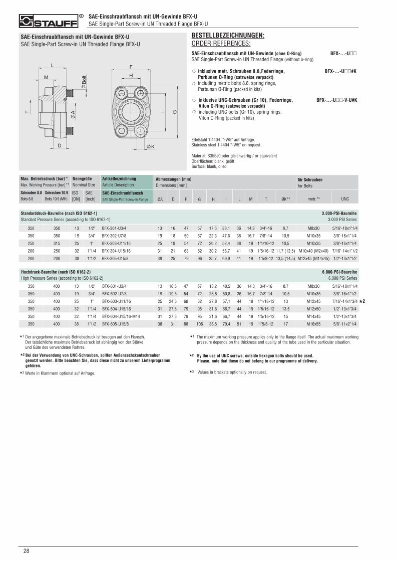
SAE-Einschraubflansch mit UN-Gewinde BFX-USAE Single-Part Screw-in UN Threaded Flange BFX-U
028
SAE-Einschraubflansch mit UN-Gewinde BFX-USAE Single-Part Screw-in UN Threaded Flange BFX-U
BESTELLBEZEICHNUNGEN:ORDER REFERENCES:SAE-Einschraubflansch mit UN-Gewinde (ohne O-Ring) BFX-...-U��SAE Single-Part Screw-in UN Threaded Flange (without o-ring)
inklusive metr. Schrauben 8.8,Federringe, BFX-...-U��#KPerbunan O-Ring (satzweise verpackt)including metric bolts 8.8, spring rings, Perbunan O-Ring (packed in kits)
inklusive UNC-Schrauben (Gr 10), Federringe, BFX-...-U��-V-U#KViton O-Ring (satzweise verpackt) including UNC bolts (Gr 10), spring rings, Viton O-Ring (packed in kits)
Edelstahl 1.4404 “-W5” auf Anfrage.Stainless steel 1.4404 “-W5” on request.
Material: S355J0 oder gleichwertig / or equivalentOberflächen: blank, geöltSurface: blank, oiled
❍
❍
❍
❍
350 350 13 1/2" BFX-301-U3/4 13 16 47 57 17,5 38,1 36 14,3 3/4"-16 8,7 M8x30 5/16"-18x1"1/4
350 350 19 3/4" BFX-302-U7/8 19 18 50 67 22,3 47,6 36 16,7 7/8"-14 10,5 M10x35 3/8"-16x1"1/4
250 315 25 1" BFX-303-U11/16 25 18 54 72 26,2 52,4 38 19 1"1/16-12 10,5 M10x35 3/8"-16x1"1/4
200 250 32 1"1/4 BFX-304-U15/16 31 21 68 82 30,2 58,7 41 19 1"5/16-12 11,7 (12,5) M10x40 (M2x40) 7/16"-14x1"1/2
200 200 38 1"1/2 BFX-305-U15/8 38 25 79 96 35,7 69,9 41 19 1"5/8-12 13,5 (14,5) M12x45 (M14x45) 1/2"-13x1"1/2
ArtikelbezeichnungArticle Description
SAE-EinschraubflanschSAE Single-Part Screw-in Flange
Max. Betriebsdruck [bar]*1
Max. Working Pressure [bar]*1
Schrauben 8.8Bolts 8.8
Schrauben 10.9Bolts 10.9 (MH)
NenngrößeNominal Size
ISO[DN]
SAE[inch]
Abmessungen [mm]Dimensions [mm]
ØA D F G TH I L M ØK*3 metr.*3
für Schraubenfor Bolts
UNC
Standarddruck-Baureihe (nach ISO 6162-1) 3.000-PSI-BaureiheStandard Pressure Series (according to ISO 6162-1) 3.000 PSI Series
Hochdruck-Baureihe (nach ISO 6162-2) 6.000-PSI-BaureiheHigh Pressure Series (according to ISO 6162-2) 6.000 PSI Series
350 400 13 1/2" BFX-601-U3/4 13 16,5 47 57 18,2 40,5 36 14,3 3/4"-16 8,7 M8x30 5/16"-18x1"1/4
350 400 19 3/4" BFX-602-U7/8 19 19,5 54 72 23,8 50,8 36 16,7 7/8"-14 10,5 M10x35 3/8"-16x1"1/2
350 400 25 1" BFX-603-U11/16 25 24,5 68 82 27,8 57,1 44 19 1"1/16-12 13 M12x45 7/16"-14x1"3/4
350 400 32 1"1/4 BFX-604-U15/16 31 27,5 79 95 31,6 66,7 44 19 1"5/16-12 13,5 M12x50 1/2"-13x1"3/4
350 400 32 1"1/4 BFX-604-U15/16-M14 31 27,5 79 95 31,6 66,7 44 19 1"5/16-12 15 M14x45 1/2"-13x1"3/4
350 400 38 1"1/2 BFX-605-U15/8 38 31 88 108 36,5 79,4 51 19 1"5/8-12 17 M16x55 5/8"-11x2"1/4
★2
★1 Der angegebene maximale Betriebsdruck ist bezogen auf den Flansch. Der tatsächliche maximale Betriebsdruck ist abhängig von der Stärke und Güte des verwendeten Rohres.
★1 The maximum working pressure applies only to the flange itself. The actual maximum workingpressure depends on the thickness and quality of the tube used in the particular situation.
Bei der Verwendung von UNC-Schrauben, sollten Außensechskantschrauben genutzt werden. Bitte beachten Sie, dass diese nicht zu unserem Lieferprogramm gehören.
★2 By the use of UNC screws, outside hexagon bolts should be used. Please, note that these do not belong to our programme of delivery.
★2
★3 Werte in Klammern optional auf Anfrage. ★3 Values in brackets optionally on request.
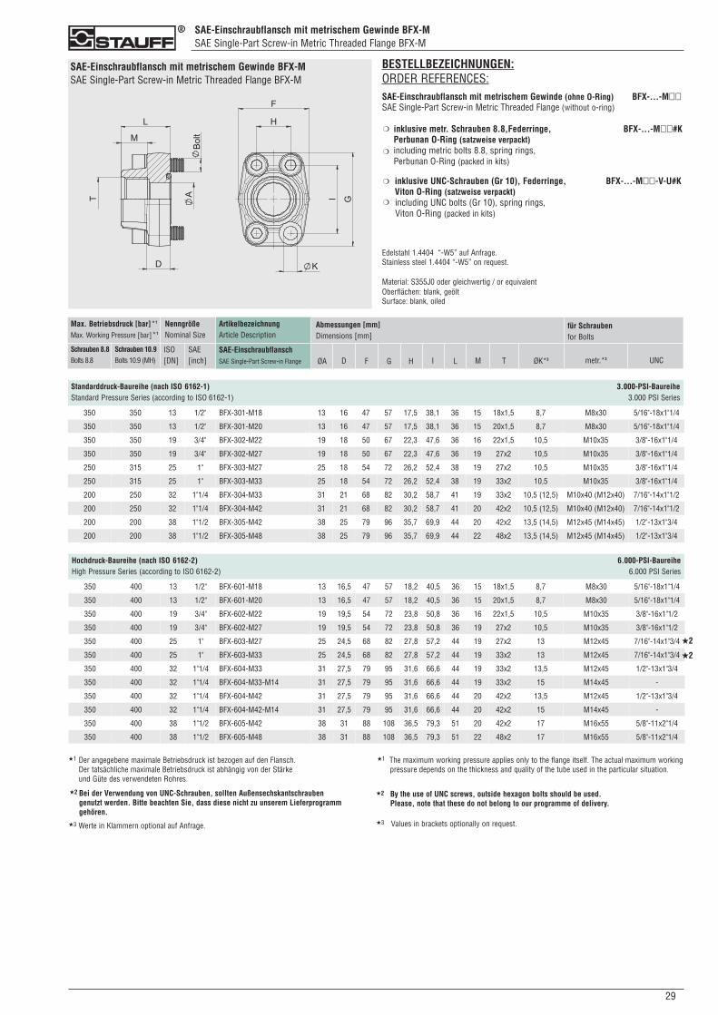
SAE-Einschraubflansch mit metrischem Gewinde BFX-MSAE Single-Part Screw-in Metric Threaded Flange BFX-M
290
SAE-Einschraubflansch mit metrischem Gewinde BFX-MSAE Single-Part Screw-in Metric Threaded Flange BFX-M
BESTELLBEZEICHNUNGEN:ORDER REFERENCES:SAE-Einschraubflansch mit metrischem Gewinde (ohne O-Ring) BFX-...-M��SAE Single-Part Screw-in Metric Threaded Flange (without o-ring)
inklusive metr. Schrauben 8.8,Federringe, BFX-...-M��#KPerbunan O-Ring (satzweise verpackt)including metric bolts 8.8, spring rings, Perbunan O-Ring (packed in kits)
inklusive UNC-Schrauben (Gr 10), Federringe, BFX-...-M��-V-U#KViton O-Ring (satzweise verpackt) including UNC bolts (Gr 10), spring rings, Viton O-Ring (packed in kits)
Edelstahl 1.4404 “-W5” auf Anfrage.Stainless steel 1.4404 “-W5” on request.
Material: S355J0 oder gleichwertig / or equivalentOberflächen: blank, geöltSurface: blank, oiled
❍
❍
❍
❍
ArtikelbezeichnungArticle Description
SAE-EinschraubflanschSAE Single-Part Screw-in Flange
Max. Betriebsdruck [bar]*1
Max. Working Pressure [bar]*1
Schrauben 8.8Bolts 8.8
Schrauben 10.9Bolts 10.9 (MH)
NenngrößeNominal Size
ISO[DN]
SAE[inch]
Abmessungen [mm]Dimensions [mm]
ØA D F G TH I L M ØK*3 metr.*3
für Schraubenfor Bolts
UNC
Standarddruck-Baureihe (nach ISO 6162-1) 3.000-PSI-BaureiheStandard Pressure Series (according to ISO 6162-1) 3.000 PSI Series
350 350 13 1/2" BFX-301-M18 13 16 47 57 17,5 38,1 36 15 18x1,5 8,7 M8x30 5/16"-18x1"1/4
350 350 13 1/2" BFX-301-M20 13 16 47 57 17,5 38,1 36 15 20x1,5 8,7 M8x30 5/16"-18x1"1/4
350 350 19 3/4" BFX-302-M22 19 18 50 67 22,3 47,6 36 16 22x1,5 10,5 M10x35 3/8"-16x1"1/4
350 350 19 3/4" BFX-302-M27 19 18 50 67 22,3 47,6 36 19 27x2 10,5 M10x35 3/8"-16x1"1/4
250 315 25 1" BFX-303-M27 25 18 54 72 26,2 52,4 38 19 27x2 10,5 M10x35 3/8"-16x1"1/4
250 315 25 1" BFX-303-M33 25 18 54 72 26,2 52,4 38 19 33x2 10,5 M10x35 3/8"-16x1"1/4
200 250 32 1"1/4 BFX-304-M33 31 21 68 82 30,2 58,7 41 19 33x2 10,5 (12,5) M10x40 (M12x40) 7/16"-14x1"1/2
200 250 32 1"1/4 BFX-304-M42 31 21 68 82 30,2 58,7 41 20 42x2 10,5 (12,5) M10x40 (M12x40) 7/16"-14x1"1/2
200 200 38 1"1/2 BFX-305-M42 38 25 79 96 35,7 69,9 44 20 42x2 13,5 (14,5) M12x45 (M14x45) 1/2"-13x1"3/4
200 200 38 1"1/2 BFX-305-M48 38 25 79 96 35,7 69,9 44 22 48x2 13,5 (14,5) M12x45 (M14x45) 1/2"-13x1"3/4
Hochdruck-Baureihe (nach ISO 6162-2) 6.000-PSI-BaureiheHigh Pressure Series (according to ISO 6162-2) 6.000 PSI Series
350 400 13 1/2" BFX-601-M18 13 16,5 47 57 18,2 40,5 36 15 18x1,5 8,7 M8x30 5/16"-18x1"1/4
350 400 13 1/2" BFX-601-M20 13 16,5 47 57 18,2 40,5 36 15 20x1,5 8,7 M8x30 5/16"-18x1"1/4
350 400 19 3/4" BFX-602-M22 19 19,5 54 72 23,8 50,8 36 16 22x1,5 10,5 M10x35 3/8"-16x1"1/2
350 400 19 3/4" BFX-602-M27 19 19,5 54 72 23,8 50,8 36 19 27x2 10,5 M10x35 3/8"-16x1"1/2
350 400 25 1" BFX-603-M27 25 24,5 68 82 27,8 57,2 44 19 27x2 13 M12x45 7/16"-14x1"3/4
350 400 25 1" BFX-603-M33 25 24,5 68 82 27,8 57,2 44 19 33x2 13 M12x45 7/16"-14x1"3/4
350 400 32 1"1/4 BFX-604-M33 31 27,5 79 95 31,6 66,6 44 19 33x2 13,5 M12x45 1/2"-13x1"3/4
350 400 32 1"1/4 BFX-604-M33-M14 31 27,5 79 95 31,6 66,6 44 19 33x2 15 M14x45 -
350 400 32 1"1/4 BFX-604-M42 31 27,5 79 95 31,6 66,6 44 20 42x2 13,5 M12x45 1/2"-13x1"3/4
350 400 32 1"1/4 BFX-604-M42-M14 31 27,5 79 95 31,6 66,6 44 20 42x2 15 M14x45 -
350 400 38 1"1/2 BFX-605-M42 38 31 88 108 36,5 79,3 51 20 42x2 17 M16x55 5/8"-11x2"1/4
350 400 38 1"1/2 BFX-605-M48 38 31 88 108 36,5 79,3 51 22 48x2 17 M16x55 5/8"-11x2"1/4
★2
★2
★1 Der angegebene maximale Betriebsdruck ist bezogen auf den Flansch. Der tatsächliche maximale Betriebsdruck ist abhängig von der Stärke und Güte des verwendeten Rohres.
★1 The maximum working pressure applies only to the flange itself. The actual maximum workingpressure depends on the thickness and quality of the tube used in the particular situation.
Bei der Verwendung von UNC-Schrauben, sollten Außensechskantschrauben genutzt werden. Bitte beachten Sie, dass diese nicht zu unserem Lieferprogramm gehören.
★2 By the use of UNC screws, outside hexagon bolts should be used. Please, note that these do not belong to our programme of delivery.
★2
★3 Werte in Klammern optional auf Anfrage. ★3 Values in brackets optionally on request.
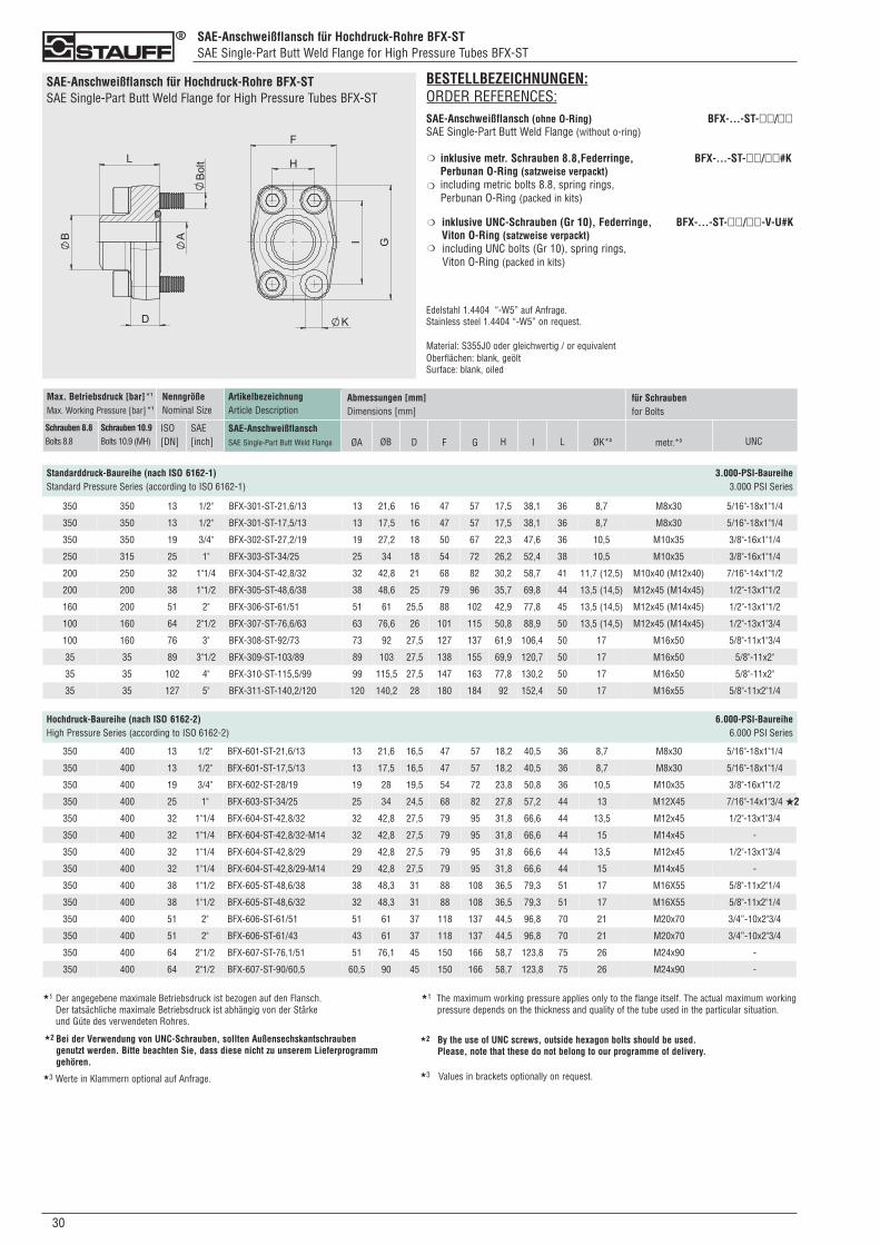
SAE-Anschweißflansch für Hochdruck-Rohre BFX-STSAE Single-Part Butt Weld Flange for High Pressure Tubes BFX-ST
030
SAE-Anschweißflansch für Hochdruck-Rohre BFX-STSAE Single-Part Butt Weld Flange for High Pressure Tubes BFX-ST
Standarddruck-Baureihe (nach ISO 6162-1) 3.000-PSI-BaureiheStandard Pressure Series (according to ISO 6162-1) 3.000 PSI Series
ArtikelbezeichnungArticle Description
SAE-AnschweißflanschSAE Single-Part Butt Weld Flange
Max. Betriebsdruck [bar]*1
Max. Working Pressure [bar]*1
Schrauben 8.8Bolts 8.8
Schrauben 10.9Bolts 10.9 (MH)
NenngrößeNominal Size
ISO[DN]
SAE[inch]
Abmessungen [mm]Dimensions [mm]
ØA ØB D F G H I L ØK*3 metr.*3
für Schraubenfor Bolts
UNC
BESTELLBEZEICHNUNGEN:ORDER REFERENCES:SAE-Anschweißflansch (ohne O-Ring) BFX-...-ST-��/��SAE Single-Part Butt Weld Flange (without o-ring)
inklusive metr. Schrauben 8.8,Federringe, BFX-...-ST-��/��#KPerbunan O-Ring (satzweise verpackt)including metric bolts 8.8, spring rings, Perbunan O-Ring (packed in kits)
inklusive UNC-Schrauben (Gr 10), Federringe, BFX-...-ST-��/��-V-U#KViton O-Ring (satzweise verpackt) including UNC bolts (Gr 10), spring rings, Viton O-Ring (packed in kits)
Edelstahl 1.4404 “-W5” auf Anfrage.Stainless steel 1.4404 “-W5” on request.
Material: S355J0 oder gleichwertig / or equivalentOberflächen: blank, geöltSurface: blank, oiled
❍
❍
❍
❍
350 350 13 1/2" BFX-301-ST-21,6/13 13 21,6 16 47 57 17,5 38,1 36 8,7 M8x30 5/16"-18x1"1/4
350 350 13 1/2" BFX-301-ST-17,5/13 13 17,5 16 47 57 17,5 38,1 36 8,7 M8x30 5/16"-18x1"1/4
350 350 19 3/4" BFX-302-ST-27,2/19 19 27,2 18 50 67 22,3 47,6 36 10,5 M10x35 3/8"-16x1"1/4
250 315 25 1" BFX-303-ST-34/25 25 34 18 54 72 26,2 52,4 38 10,5 M10x35 3/8"-16x1"1/4
200 250 32 1"1/4 BFX-304-ST-42,8/32 32 42,8 21 68 82 30,2 58,7 41 11,7 (12,5) M10x40 (M12x40) 7/16"-14x1"1/2
200 200 38 1"1/2 BFX-305-ST-48,6/38 38 48,6 25 79 96 35,7 69,8 44 13,5 (14,5) M12x45 (M14x45) 1/2"-13x1"1/2
160 200 51 2" BFX-306-ST-61/51 51 61 25,5 88 102 42,9 77,8 45 13,5 (14,5) M12x45 (M14x45) 1/2"-13x1"1/2
100 160 64 2"1/2 BFX-307-ST-76,6/63 63 76,6 26 101 115 50,8 88,9 50 13,5 (14,5) M12x45 (M14x45) 1/2"-13x1"3/4
100 160 76 3" BFX-308-ST-92/73 73 92 27,5 127 137 61,9 106,4 50 17 M16x50 5/8"-11x1"3/4
35 35 89 3"1/2 BFX-309-ST-103/89 89 103 27,5 138 155 69,9 120,7 50 17 M16x50 5/8"-11x2"
35 35 102 4" BFX-310-ST-115,5/99 99 115,5 27,5 147 163 77,8 130,2 50 17 M16x50 5/8"-11x2"
35 35 127 5" BFX-311-ST-140,2/120 120 140,2 28 180 184 92 152,4 50 17 M16x55 5/8"-11x2"1/4
350 400 13 1/2" BFX-601-ST-21,6/13 13 21,6 16,5 47 57 18,2 40,5 36 8,7 M8x30 5/16"-18x1"1/4
350 400 13 1/2" BFX-601-ST-17,5/13 13 17,5 16,5 47 57 18,2 40,5 36 8,7 M8x30 5/16"-18x1"1/4
350 400 19 3/4" BFX-602-ST-28/19 19 28 19,5 54 72 23,8 50,8 36 10,5 M10x35 3/8"-16x1"1/2
350 400 25 1" BFX-603-ST-34/25 25 34 24,5 68 82 27,8 57,2 44 13 M12X45 7/16"-14x1"3/4
350 400 32 1"1/4 BFX-604-ST-42,8/32 32 42,8 27,5 79 95 31,8 66,6 44 13,5 M12x45 1/2"-13x1"3/4
350 400 32 1"1/4 BFX-604-ST-42,8/32-M14 32 42,8 27,5 79 95 31,8 66,6 44 15 M14x45 -
350 400 32 1"1/4 BFX-604-ST-42,8/29 29 42,8 27,5 79 95 31,8 66,6 44 13,5 M12x45 1/2"-13x1"3/4
350 400 32 1"1/4 BFX-604-ST-42,8/29-M14 29 42,8 27,5 79 95 31,8 66,6 44 15 M14x45 -
350 400 38 1"1/2 BFX-605-ST-48,6/38 38 48,3 31 88 108 36,5 79,3 51 17 M16X55 5/8"-11x2"1/4
350 400 38 1"1/2 BFX-605-ST-48,6/32 32 48,3 31 88 108 36,5 79,3 51 17 M16X55 5/8"-11x2"1/4
350 400 51 2" BFX-606-ST-61/51 51 61 37 118 137 44,5 96,8 70 21 M20x70 3/4”-10x2"3/4
350 400 51 2" BFX-606-ST-61/43 43 61 37 118 137 44,5 96,8 70 21 M20x70 3/4”-10x2"3/4
350 400 64 2"1/2 BFX-607-ST-76,1/51 51 76,1 45 150 166 58,7 123,8 75 26 M24x90 -
350 400 64 2"1/2 BFX-607-ST-90/60,5 60,5 90 45 150 166 58,7 123,8 75 26 M24x90 -
Hochdruck-Baureihe (nach ISO 6162-2) 6.000-PSI-BaureiheHigh Pressure Series (according to ISO 6162-2) 6.000 PSI Series
★2
★1 Der angegebene maximale Betriebsdruck ist bezogen auf den Flansch. Der tatsächliche maximale Betriebsdruck ist abhängig von der Stärke und Güte des verwendeten Rohres.
★1 The maximum working pressure applies only to the flange itself. The actual maximum workingpressure depends on the thickness and quality of the tube used in the particular situation.
Bei der Verwendung von UNC-Schrauben, sollten Außensechskantschrauben genutzt werden. Bitte beachten Sie, dass diese nicht zu unserem Lieferprogramm gehören.
★2 By the use of UNC screws, outside hexagon bolts should be used. Please, note that these do not belong to our programme of delivery.
★2
★3 Werte in Klammern optional auf Anfrage. ★3 Values in brackets optionally on request.
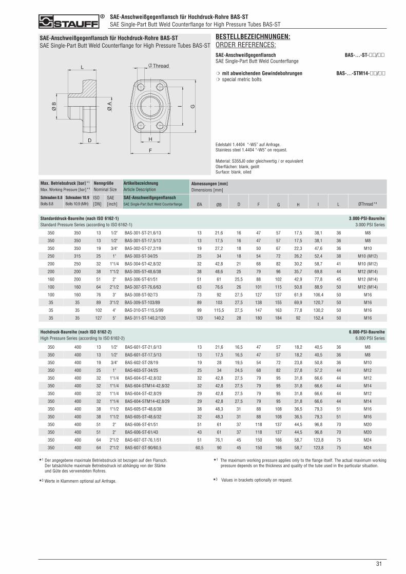
SAE-Anschweißgegenflansch für Hochdruck-Rohre BAS-STSAE Single-Part Butt Weld Counterflange for High Pressure Tubes BAS-ST
310
SAE-Anschweißgegenflansch für Hochdruck-Rohre BAS-STSAE Single-Part Butt Weld Counterflange for High Pressure Tubes BAS-ST
Standarddruck-Baureihe (nach ISO 6162-1) 3.000-PSI-BaureiheStandard Pressure Series (according to ISO 6162-1) 3.000 PSI Series
ArtikelbezeichnungArticle Description
SAE-AnschweißgegenflanschSAE Single-Part Butt Weld Counterflange
Max. Betriebsdruck [bar]*1
Max. Working Pressure [bar]*1
Schrauben 8.8Bolts 8.8
Schrauben 10.9Bolts 10.9 (MH)
NenngrößeNominal Size
ISO[DN]
SAE[inch]
Abmessungen [mm]Dimensions [mm]
ØA ØB D F G H I L ØThread*3
BESTELLBEZEICHNUNGEN:ORDER REFERENCES:SAE-Anschweißgegenflansch BAS-...-ST-��/��SAE Single-Part Butt Weld Counterflange
mit abweichenden Gewindebohrungen BAS-...-STM14-��/��special metric bolts
Edelstahl 1.4404 “-W5” auf Anfrage.Stainless steel 1.4404 “-W5” on request.
Material: S355J0 oder gleichwertig / or equivalentOberflächen: blank, geöltSurface: blank, oiled
❍
❍
Hochdruck-Baureihe (nach ISO 6162-2) 6.000-PSI-BaureiheHigh Pressure Series (according to ISO 6162-2) 6.000 PSI Series
350 350 13 1/2" BAS-301-ST-21,6/13 13 21,6 16 47 57 17,5 38,1 36 M8
350 350 13 1/2" BAS-301-ST-17,5/13 13 17,5 16 47 57 17,5 38,1 36 M8
350 350 19 3/4" BAS-302-ST-27,2/19 19 27,2 18 50 67 22,3 47,6 36 M10
250 315 25 1" BAS-303-ST-34/25 25 34 18 54 72 26,2 52,4 38 M10 (M12)
200 250 32 1"1/4 BAS-304-ST-42,8/32 32 42,8 21 68 82 30,2 58,7 41 M10 (M12)
200 200 38 1"1/2 BAS-305-ST-48,6/38 38 48,6 25 79 96 35,7 69,8 44 M12 (M14)
160 200 51 2" BAS-306-ST-61/51 51 61 25,5 88 102 42,9 77,8 45 M12 (M14)
100 160 64 2"1/2 BAS-307-ST-76,6/63 63 76,6 26 101 115 50,8 88,9 50 M12 (M14)
100 160 76 3" BAS-308-ST-92/73 73 92 27,5 127 137 61,9 106,4 50 M16
35 35 89 3"1/2 BAS-309-ST-103/89 89 103 27,5 138 155 69,9 120,7 50 M16
35 35 102 4" BAS-310-ST-115,5/99 99 115,5 27,5 147 163 77,8 130,2 50 M16
35 35 127 5" BAS-311-ST-140,2/120 120 140,2 28 180 184 92 152,4 50 M16
350 400 13 1/2" BAS-601-ST-21,6/13 13 21,6 16,5 47 57 18,2 40,5 36 M8
350 400 13 1/2" BAS-601-ST-17,5/13 13 17,5 16,5 47 57 18,2 40,5 36 M8
350 400 19 3/4" BAS-602-ST-28/19 19 28 19,5 54 72 23,8 50,8 36 M10
350 400 25 1" BAS-603-ST-34/25 25 34 24,5 68 82 27,8 57,2 44 M12
350 400 32 1"1/4 BAS-604-ST-42,8/32 32 42,8 27,5 79 95 31,8 66,6 44 M12
350 400 32 1"1/4 BAS-604-STM14-42,8/32 32 42,8 27,5 79 95 31,8 66,6 44 M14
350 400 32 1"1/4 BAS-604-ST-42,8/29 29 42,8 27,5 79 95 31,8 66,6 44 M12
350 400 32 1"1/4 BAS-604-STM14-42,8/29 29 42,8 27,5 79 95 31,8 66,6 44 M14
350 400 38 1"1/2 BAS-605-ST-48,6/38 38 48,3 31 88 108 36,5 79,3 51 M16
350 400 38 1"1/2 BAS-605-ST-48,6/32 32 48,3 31 88 108 36,5 79,3 51 M16
350 400 51 2" BAS-606-ST-61/51 51 61 37 118 137 44,5 96,8 70 M20
350 400 51 2" BAS-606-ST-61/43 43 61 37 118 137 44,5 96,8 70 M20
350 400 64 2"1/2 BAS-607-ST-76,1/51 51 76,1 45 150 166 58,7 123,8 75 M24
350 400 64 2"1/2 BAS-607-ST-90/60,5 60,5 90 45 150 166 58,7 123,8 75 M24
★1 Der angegebene maximale Betriebsdruck ist bezogen auf den Flansch. Der tatsächliche maximale Betriebsdruck ist abhängig von der Stärke und Güte des verwendeten Rohres.
★1 The maximum working pressure applies only to the flange itself. The actual maximum workingpressure depends on the thickness and quality of the tube used in the particular situation.
★3 Werte in Klammern optional auf Anfrage. ★3 Values in brackets optionally on request.
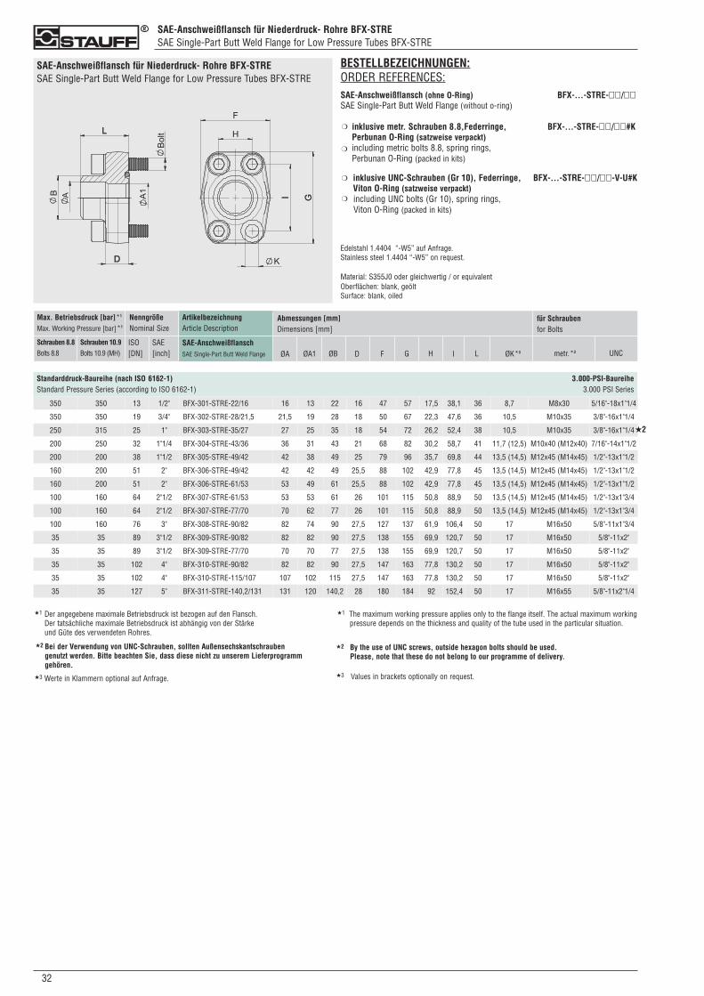
SAE-Anschweißflansch für Niederdruck- Rohre BFX-STRESAE Single-Part Butt Weld Flange for Low Pressure Tubes BFX-STRE
SAE-Anschweißflansch für Niederdruck- Rohre BFX-STRESAE Single-Part Butt Weld Flange for Low Pressure Tubes BFX-STRE
Standarddruck-Baureihe (nach ISO 6162-1) 3.000-PSI-BaureiheStandard Pressure Series (according to ISO 6162-1) 3.000 PSI Series
ArtikelbezeichnungArticle Description
SAE-AnschweißflanschSAE Single-Part Butt Weld Flange
Max. Betriebsdruck [bar]*1
Max. Working Pressure [bar]*1
Schrauben 8.8Bolts 8.8
Schrauben 10.9Bolts 10.9 (MH)
NenngrößeNominal Size
ISO[DN]
SAE[inch]
Abmessungen [mm]Dimensions [mm]
ØA ØB D F G H I L ØK*3 metr.*3
für Schraubenfor Bolts
UNC
BESTELLBEZEICHNUNGEN:ORDER REFERENCES:SAE-Anschweißflansch (ohne O-Ring) BFX-...-STRE-��/��SAE Single-Part Butt Weld Flange (without o-ring)
inklusive metr. Schrauben 8.8,Federringe, BFX-...-STRE-��/��#KPerbunan O-Ring (satzweise verpackt)including metric bolts 8.8, spring rings, Perbunan O-Ring (packed in kits)
inklusive UNC-Schrauben (Gr 10), Federringe, BFX-...-STRE-��/��-V-U#KViton O-Ring (satzweise verpackt) including UNC bolts (Gr 10), spring rings, Viton O-Ring (packed in kits)
Edelstahl 1.4404 “-W5” auf Anfrage.Stainless steel 1.4404 “-W5” on request.
Material: S355J0 oder gleichwertig / or equivalentOberflächen: blank, geöltSurface: blank, oiled
❍
❍
❍
❍
ØA1
350 350 13 1/2" BFX-301-STRE-22/16 16 13 22 16 47 57 17,5 38,1 36 8,7 M8x30 5/16"-18x1"1/4
350 350 19 3/4" BFX-302-STRE-28/21,5 21,5 19 28 18 50 67 22,3 47,6 36 10,5 M10x35 3/8"-16x1"1/4
250 315 25 1" BFX-303-STRE-35/27 27 25 35 18 54 72 26,2 52,4 38 10,5 M10x35 3/8"-16x1"1/4
200 250 32 1"1/4 BFX-304-STRE-43/36 36 31 43 21 68 82 30,2 58,7 41 11,7 (12,5) M10x40 (M12x40) 7/16"-14x1"1/2
200 200 38 1"1/2 BFX-305-STRE-49/42 42 38 49 25 79 96 35,7 69,8 44 13,5 (14,5) M12x45 (M14x45) 1/2"-13x1"1/2
160 200 51 2" BFX-306-STRE-49/42 42 42 49 25,5 88 102 42,9 77,8 45 13,5 (14,5) M12x45 (M14x45) 1/2"-13x1"1/2
160 200 51 2" BFX-306-STRE-61/53 53 49 61 25,5 88 102 42,9 77,8 45 13,5 (14,5) M12x45 (M14x45) 1/2"-13x1"1/2
100 160 64 2"1/2 BFX-307-STRE-61/53 53 53 61 26 101 115 50,8 88,9 50 13,5 (14,5) M12x45 (M14x45) 1/2"-13x1"3/4
100 160 64 2"1/2 BFX-307-STRE-77/70 70 62 77 26 101 115 50,8 88,9 50 13,5 (14,5) M12x45 (M14x45) 1/2"-13x1"3/4
100 160 76 3" BFX-308-STRE-90/82 82 74 90 27,5 127 137 61,9 106,4 50 17 M16x50 5/8"-11x1"3/4
35 35 89 3"1/2 BFX-309-STRE-90/82 82 82 90 27,5 138 155 69,9 120,7 50 17 M16x50 5/8"-11x2"
35 35 89 3"1/2 BFX-309-STRE-77/70 70 70 77 27,5 138 155 69,9 120,7 50 17 M16x50 5/8"-11x2"
35 35 102 4" BFX-310-STRE-90/82 82 82 90 27,5 147 163 77,8 130,2 50 17 M16x50 5/8"-11x2"
35 35 102 4" BFX-310-STRE-115/107 107 102 115 27,5 147 163 77,8 130,2 50 17 M16x50 5/8"-11x2"
35 35 127 5" BFX-311-STRE-140,2/131 131 120 140,2 28 180 184 92 152,4 50 17 M16x55 5/8"-11x2"1/4
032
★2
★1 Der angegebene maximale Betriebsdruck ist bezogen auf den Flansch. Der tatsächliche maximale Betriebsdruck ist abhängig von der Stärke und Güte des verwendeten Rohres.
★1 The maximum working pressure applies only to the flange itself. The actual maximum workingpressure depends on the thickness and quality of the tube used in the particular situation.
Bei der Verwendung von UNC-Schrauben, sollten Außensechskantschrauben genutzt werden. Bitte beachten Sie, dass diese nicht zu unserem Lieferprogramm gehören.
★2 By the use of UNC screws, outside hexagon bolts should be used. Please, note that these do not belong to our programme of delivery.
★2
★3 Werte in Klammern optional auf Anfrage. ★3 Values in brackets optionally on request.
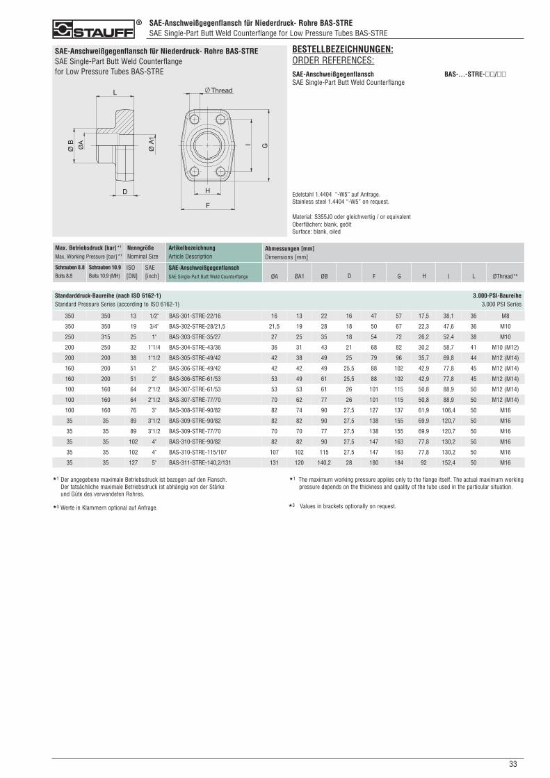
330
SAE-Anschweißgegenflansch für Niederdruck- Rohre BAS-STRESAE Single-Part Butt Weld Counterflange for Low Pressure Tubes BAS-STRE
SAE-Anschweißgegenflansch für Niederdruck- Rohre BAS-STRESAE Single-Part Butt Weld Counterflange for Low Pressure Tubes BAS-STRE
Standarddruck-Baureihe (nach ISO 6162-1) 3.000-PSI-BaureiheStandard Pressure Series (according to ISO 6162-1) 3.000 PSI Series
ArtikelbezeichnungArticle Description
SAE-AnschweißgegenflanschSAE Single-Part Butt Weld Counterflange
Max. Betriebsdruck [bar]*1
Max. Working Pressure [bar]*1
Schrauben 8.8Bolts 8.8
Schrauben 10.9Bolts 10.9 (MH)
NenngrößeNominal Size
ISO[DN]
SAE[inch]
Abmessungen [mm]Dimensions [mm]
ØA ØB D F G H I L ØThread*3
BESTELLBEZEICHNUNGEN:ORDER REFERENCES:SAE-Anschweißgegenflansch BAS-...-STRE-��/��SAE Single-Part Butt Weld Counterflange
Edelstahl 1.4404 “-W5” auf Anfrage.Stainless steel 1.4404 “-W5” on request.
Material: S355J0 oder gleichwertig / or equivalentOberflächen: blank, geöltSurface: blank, oiled
ØA1
350 350 13 1/2" BAS-301-STRE-22/16 16 13 22 16 47 57 17,5 38,1 36 M8
350 350 19 3/4" BAS-302-STRE-28/21,5 21,5 19 28 18 50 67 22,3 47,6 36 M10
250 315 25 1" BAS-303-STRE-35/27 27 25 35 18 54 72 26,2 52,4 38 M10
200 250 32 1"1/4 BAS-304-STRE-43/36 36 31 43 21 68 82 30,2 58,7 41 M10 (M12)
200 200 38 1"1/2 BAS-305-STRE-49/42 42 38 49 25 79 96 35,7 69,8 44 M12 (M14)
160 200 51 2" BAS-306-STRE-49/42 42 42 49 25,5 88 102 42,9 77,8 45 M12 (M14)
160 200 51 2" BAS-306-STRE-61/53 53 49 61 25,5 88 102 42,9 77,8 45 M12 (M14)
100 160 64 2"1/2 BAS-307-STRE-61/53 53 53 61 26 101 115 50,8 88,9 50 M12 (M14)
100 160 64 2"1/2 BAS-307-STRE-77/70 70 62 77 26 101 115 50,8 88,9 50 M12 (M14)
100 160 76 3" BAS-308-STRE-90/82 82 74 90 27,5 127 137 61,9 106,4 50 M16
35 35 89 3"1/2 BAS-309-STRE-90/82 82 82 90 27,5 138 155 69,9 120,7 50 M16
35 35 89 3"1/2 BAS-309-STRE-77/70 70 70 77 27,5 138 155 69,9 120,7 50 M16
35 35 102 4" BAS-310-STRE-90/82 82 82 90 27,5 147 163 77,8 130,2 50 M16
35 35 102 4" BAS-310-STRE-115/107 107 102 115 27,5 147 163 77,8 130,2 50 M16
35 35 127 5" BAS-311-STRE-140,2/131 131 120 140,2 28 180 184 92 152,4 50 M16
★1 Der angegebene maximale Betriebsdruck ist bezogen auf den Flansch. Der tatsächliche maximale Betriebsdruck ist abhängig von der Stärke und Güte des verwendeten Rohres.
★1 The maximum working pressure applies only to the flange itself. The actual maximum workingpressure depends on the thickness and quality of the tube used in the particular situation.
★3 Werte in Klammern optional auf Anfrage. ★3 Values in brackets optionally on request.
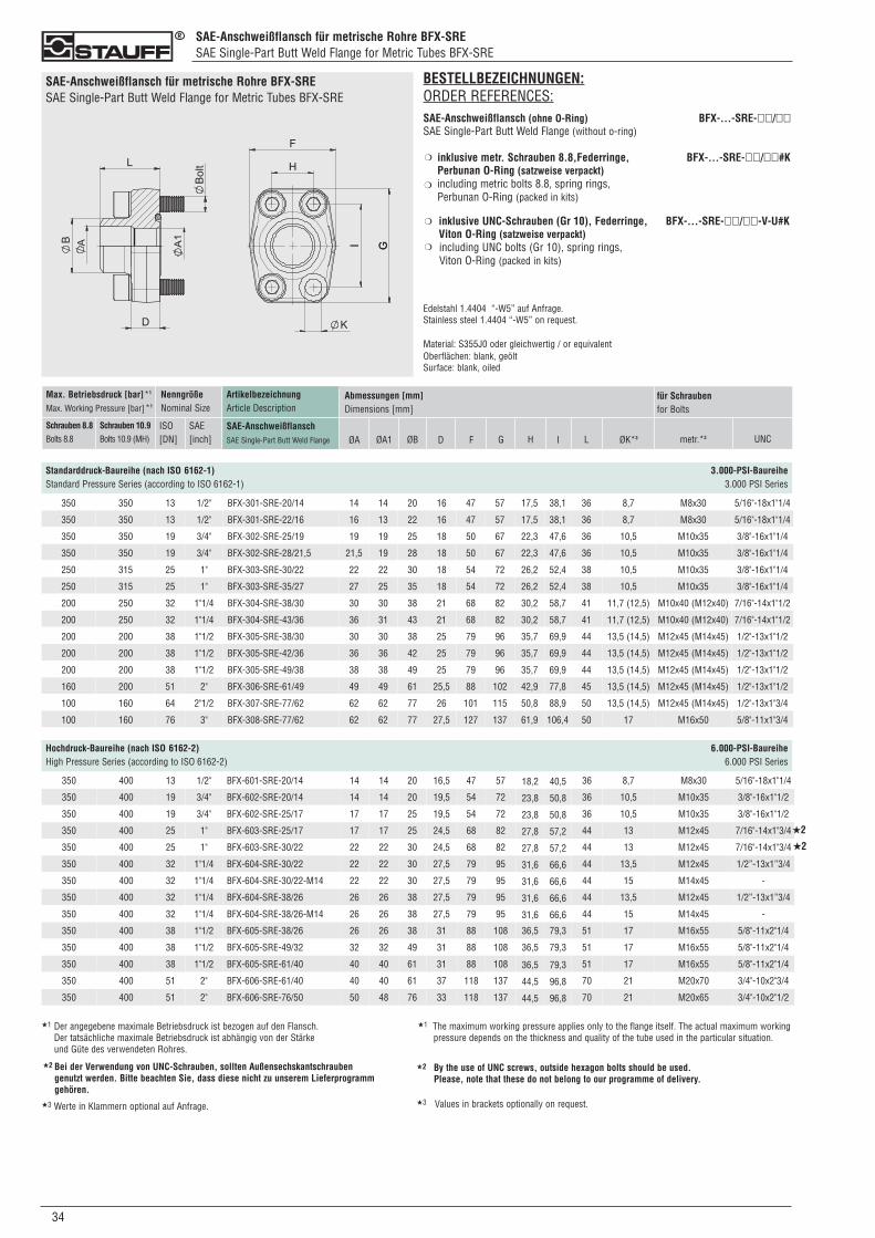
034
SAE-Anschweißflansch für metrische Rohre BFX-SRESAE Single-Part Butt Weld Flange for Metric Tubes BFX-SRE
SAE-Anschweißflansch für metrische Rohre BFX-SRESAE Single-Part Butt Weld Flange for Metric Tubes BFX-SRE
Standarddruck-Baureihe (nach ISO 6162-1) 3.000-PSI-BaureiheStandard Pressure Series (according to ISO 6162-1) 3.000 PSI Series
ArtikelbezeichnungArticle Description
SAE-AnschweißflanschSAE Single-Part Butt Weld Flange
Max. Betriebsdruck [bar]*1
Max. Working Pressure [bar]*1
Schrauben 8.8Bolts 8.8
Schrauben 10.9Bolts 10.9 (MH)
NenngrößeNominal Size
ISO[DN]
SAE[inch]
Abmessungen [mm]Dimensions [mm]
ØA ØB D F G H I L ØK*3 metr.*3
für Schraubenfor Bolts
UNC
BESTELLBEZEICHNUNGEN:ORDER REFERENCES:SAE-Anschweißflansch (ohne O-Ring) BFX-...-SRE-��/��SAE Single-Part Butt Weld Flange (without o-ring)
inklusive metr. Schrauben 8.8,Federringe, BFX-...-SRE-��/��#KPerbunan O-Ring (satzweise verpackt)including metric bolts 8.8, spring rings, Perbunan O-Ring (packed in kits)
inklusive UNC-Schrauben (Gr 10), Federringe, BFX-...-SRE-��/��-V-U#KViton O-Ring (satzweise verpackt) including UNC bolts (Gr 10), spring rings, Viton O-Ring (packed in kits)
Edelstahl 1.4404 “-W5” auf Anfrage.Stainless steel 1.4404 “-W5” on request.
Material: S355J0 oder gleichwertig / or equivalentOberflächen: blank, geöltSurface: blank, oiled
❍
❍
❍
❍
ØA1
350 350 13 1/2" BFX-301-SRE-20/14 14 14 20 16 47 57 17,5 38,1 36 8,7 M8x30 5/16"-18x1"1/4
350 350 13 1/2" BFX-301-SRE-22/16 16 13 22 16 47 57 17,5 38,1 36 8,7 M8x30 5/16"-18x1"1/4
350 350 19 3/4" BFX-302-SRE-25/19 19 19 25 18 50 67 22,3 47,6 36 10,5 M10x35 3/8"-16x1"1/4
350 350 19 3/4" BFX-302-SRE-28/21,5 21,5 19 28 18 50 67 22,3 47,6 36 10,5 M10x35 3/8"-16x1"1/4
250 315 25 1" BFX-303-SRE-30/22 22 22 30 18 54 72 26,2 52,4 38 10,5 M10x35 3/8"-16x1"1/4
250 315 25 1" BFX-303-SRE-35/27 27 25 35 18 54 72 26,2 52,4 38 10,5 M10x35 3/8"-16x1"1/4
200 250 32 1"1/4 BFX-304-SRE-38/30 30 30 38 21 68 82 30,2 58,7 41 11,7 (12,5) M10x40 (M12x40) 7/16"-14x1"1/2
200 250 32 1"1/4 BFX-304-SRE-43/36 36 31 43 21 68 82 30,2 58,7 41 11,7 (12,5) M10x40 (M12x40) 7/16"-14x1"1/2
200 200 38 1"1/2 BFX-305-SRE-38/30 30 30 38 25 79 96 35,7 69,9 44 13,5 (14,5) M12x45 (M14x45) 1/2"-13x1"1/2
200 200 38 1"1/2 BFX-305-SRE-42/36 36 36 42 25 79 96 35,7 69,9 44 13,5 (14,5) M12x45 (M14x45) 1/2"-13x1"1/2
200 200 38 1"1/2 BFX-305-SRE-49/38 38 38 49 25 79 96 35,7 69,9 44 13,5 (14,5) M12x45 (M14x45) 1/2"-13x1"1/2
160 200 51 2" BFX-306-SRE-61/49 49 49 61 25,5 88 102 42,9 77,8 45 13,5 (14,5) M12x45 (M14x45) 1/2"-13x1"1/2
100 160 64 2"1/2 BFX-307-SRE-77/62 62 62 77 26 101 115 50,8 88,9 50 13,5 (14,5) M12x45 (M14x45) 1/2"-13x1"3/4
100 160 76 3" BFX-308-SRE-77/62 62 62 77 27,5 127 137 61,9 106,4 50 17 M16x50 5/8"-11x1"3/4
Hochdruck-Baureihe (nach ISO 6162-2) 6.000-PSI-BaureiheHigh Pressure Series (according to ISO 6162-2) 6.000 PSI Series
350 400 13 1/2" BFX-601-SRE-20/14 14 14 20 16,5 47 57 18,2 40,5 36 8,7 M8x30 5/16"-18x1"1/4
350 400 19 3/4" BFX-602-SRE-20/14 14 14 20 19,5 54 72 23,8 50,8 36 10,5 M10x35 3/8"-16x1"1/2
350 400 19 3/4" BFX-602-SRE-25/17 17 17 25 19,5 54 72 23,8 50,8 36 10,5 M10x35 3/8"-16x1"1/2
350 400 25 1" BFX-603-SRE-25/17 17 17 25 24,5 68 82 27,8 57,2 44 13 M12x45 7/16"-14x1"3/4
350 400 25 1" BFX-603-SRE-30/22 22 22 30 24,5 68 82 27,8 57,2 44 13 M12x45 7/16"-14x1"3/4
350 400 32 1"1/4 BFX-604-SRE-30/22 22 22 30 27,5 79 95 31,6 66,6 44 13,5 M12x45 1/2”-13x1”3/4
350 400 32 1"1/4 BFX-604-SRE-30/22-M14 22 22 30 27,5 79 95 31,6 66,6 44 15 M14x45 -
350 400 32 1"1/4 BFX-604-SRE-38/26 26 26 38 27,5 79 95 31,6 66,6 44 13,5 M12x45 1/2”-13x1”3/4
350 400 32 1"1/4 BFX-604-SRE-38/26-M14 26 26 38 27,5 79 95 31,6 66,6 44 15 M14x45 -
350 400 38 1"1/2 BFX-605-SRE-38/26 26 26 38 31 88 108 36,5 79,3 51 17 M16x55 5/8"-11x2"1/4
350 400 38 1"1/2 BFX-605-SRE-49/32 32 32 49 31 88 108 36,5 79,3 51 17 M16x55 5/8"-11x2"1/4
350 400 38 1"1/2 BFX-605-SRE-61/40 40 40 61 31 88 108 36,5 79,3 51 17 M16x55 5/8"-11x2"1/4
350 400 51 2" BFX-606-SRE-61/40 40 40 61 37 118 137 44,5 96,8 70 21 M20x70 3/4"-10x2"3/4
350 400 51 2" BFX-606-SRE-76/50 50 48 76 33 118 137 44,5 96,8 70 21 M20x65 3/4"-10x2"1/2
★2
★2
★1 Der angegebene maximale Betriebsdruck ist bezogen auf den Flansch. Der tatsächliche maximale Betriebsdruck ist abhängig von der Stärke und Güte des verwendeten Rohres.
★1 The maximum working pressure applies only to the flange itself. The actual maximum workingpressure depends on the thickness and quality of the tube used in the particular situation.
Bei der Verwendung von UNC-Schrauben, sollten Außensechskantschrauben genutzt werden. Bitte beachten Sie, dass diese nicht zu unserem Lieferprogramm gehören.
★2 By the use of UNC screws, outside hexagon bolts should be used. Please, note that these do not belong to our programme of delivery.
★2
★3 Werte in Klammern optional auf Anfrage. ★3 Values in brackets optionally on request.
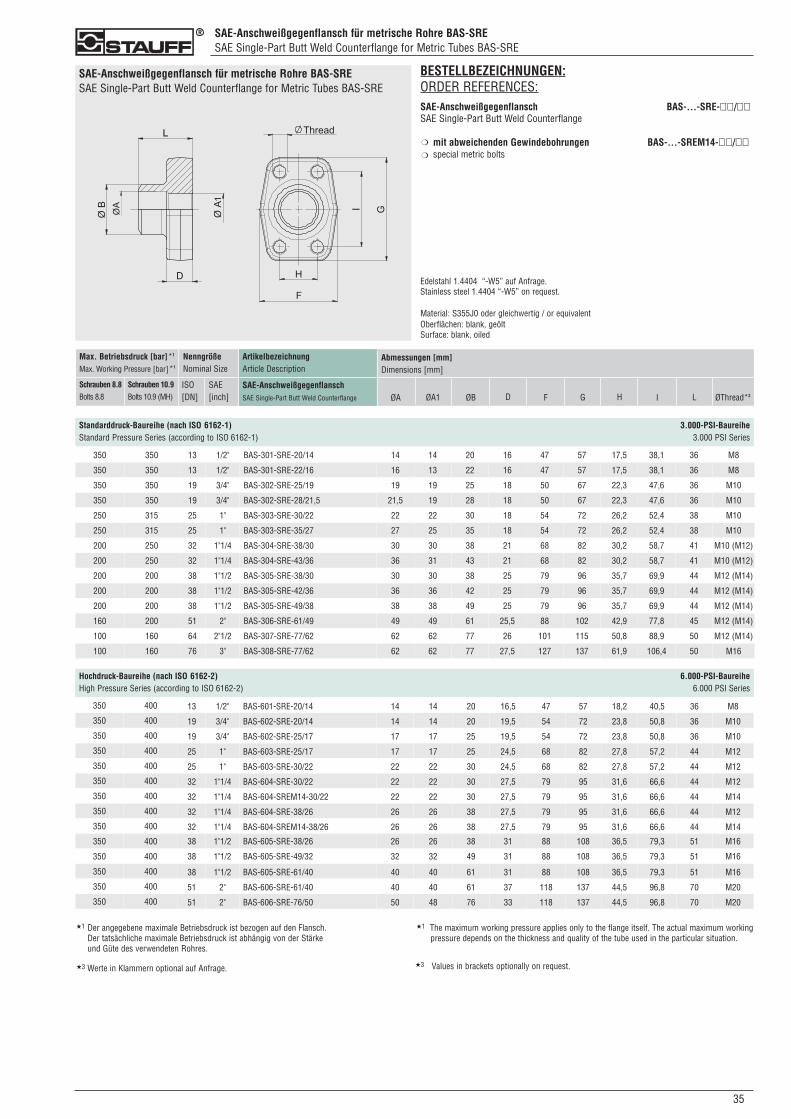
350
SAE-Anschweißgegenflansch für metrische Rohre BAS-SRESAE Single-Part Butt Weld Counterflange for Metric Tubes BAS-SRE
SAE-Anschweißgegenflansch für metrische Rohre BAS-SRESAE Single-Part Butt Weld Counterflange for Metric Tubes BAS-SRE
Standarddruck-Baureihe (nach ISO 6162-1) 3.000-PSI-BaureiheStandard Pressure Series (according to ISO 6162-1) 3.000 PSI Series
ArtikelbezeichnungArticle Description
SAE-AnschweißgegenflanschSAE Single-Part Butt Weld Counterflange
Max. Betriebsdruck [bar]*1
Max. Working Pressure [bar]*1
Schrauben 8.8Bolts 8.8
Schrauben 10.9Bolts 10.9 (MH)
NenngrößeNominal Size
ISO[DN]
SAE[inch]
Abmessungen [mm]Dimensions [mm]
ØA ØB D F G H I L ØThread*3
BESTELLBEZEICHNUNGEN:ORDER REFERENCES:SAE-Anschweißgegenflansch BAS-...-SRE-��/��SAE Single-Part Butt Weld Counterflange
mit abweichenden Gewindebohrungen BAS-...-SREM14-��/��special metric bolts
Edelstahl 1.4404 “-W5” auf Anfrage.Stainless steel 1.4404 “-W5” on request.
Material: S355J0 oder gleichwertig / or equivalentOberflächen: blank, geöltSurface: blank, oiled
❍
❍
ØA1
350 350 13 1/2" BAS-301-SRE-20/14 14 14 20 16 47 57 17,5 38,1 36 M8
350 350 13 1/2" BAS-301-SRE-22/16 16 13 22 16 47 57 17,5 38,1 36 M8
350 350 19 3/4" BAS-302-SRE-25/19 19 19 25 18 50 67 22,3 47,6 36 M10
350 350 19 3/4" BAS-302-SRE-28/21,5 21,5 19 28 18 50 67 22,3 47,6 36 M10
250 315 25 1" BAS-303-SRE-30/22 22 22 30 18 54 72 26,2 52,4 38 M10
250 315 25 1" BAS-303-SRE-35/27 27 25 35 18 54 72 26,2 52,4 38 M10
200 250 32 1"1/4 BAS-304-SRE-38/30 30 30 38 21 68 82 30,2 58,7 41 M10 (M12)
200 250 32 1"1/4 BAS-304-SRE-43/36 36 31 43 21 68 82 30,2 58,7 41 M10 (M12)
200 200 38 1"1/2 BAS-305-SRE-38/30 30 30 38 25 79 96 35,7 69,9 44 M12 (M14)
200 200 38 1"1/2 BAS-305-SRE-42/36 36 36 42 25 79 96 35,7 69,9 44 M12 (M14)
200 200 38 1"1/2 BAS-305-SRE-49/38 38 38 49 25 79 96 35,7 69,9 44 M12 (M14)
160 200 51 2" BAS-306-SRE-61/49 49 49 61 25,5 88 102 42,9 77,8 45 M12 (M14)
100 160 64 2"1/2 BAS-307-SRE-77/62 62 62 77 26 101 115 50,8 88,9 50 M12 (M14)
100 160 76 3" BAS-308-SRE-77/62 62 62 77 27,5 127 137 61,9 106,4 50 M16
Hochdruck-Baureihe (nach ISO 6162-2) 6.000-PSI-BaureiheHigh Pressure Series (according to ISO 6162-2) 6.000 PSI Series
350 400 13 1/2" BAS-601-SRE-20/14 14 14 20 16,5 47 57 18,2 40,5 36 M8
350 400 19 3/4" BAS-602-SRE-20/14 14 14 20 19,5 54 72 23,8 50,8 36 M10
350 400 19 3/4" BAS-602-SRE-25/17 17 17 25 19,5 54 72 23,8 50,8 36 M10
350 400 25 1" BAS-603-SRE-25/17 17 17 25 24,5 68 82 27,8 57,2 44 M12
350 400 25 1" BAS-603-SRE-30/22 22 22 30 24,5 68 82 27,8 57,2 44 M12
350 400 32 1"1/4 BAS-604-SRE-30/22 22 22 30 27,5 79 95 31,6 66,6 44 M12
350 400 32 1"1/4 BAS-604-SREM14-30/22 22 22 30 27,5 79 95 31,6 66,6 44 M14
350 400 32 1"1/4 BAS-604-SRE-38/26 26 26 38 27,5 79 95 31,6 66,6 44 M12
350 400 32 1"1/4 BAS-604-SREM14-38/26 26 26 38 27,5 79 95 31,6 66,6 44 M14
350 400 38 1"1/2 BAS-605-SRE-38/26 26 26 38 31 88 108 36,5 79,3 51 M16
350 400 38 1"1/2 BAS-605-SRE-49/32 32 32 49 31 88 108 36,5 79,3 51 M16
350 400 38 1"1/2 BAS-605-SRE-61/40 40 40 61 31 88 108 36,5 79,3 51 M16
350 400 51 2" BAS-606-SRE-61/40 40 40 61 37 118 137 44,5 96,8 70 M20
350 400 51 2" BAS-606-SRE-76/50 50 48 76 33 118 137 44,5 96,8 70 M20
★1 Der angegebene maximale Betriebsdruck ist bezogen auf den Flansch. Der tatsächliche maximale Betriebsdruck ist abhängig von der Stärke und Güte des verwendeten Rohres.
★1 The maximum working pressure applies only to the flange itself. The actual maximum workingpressure depends on the thickness and quality of the tube used in the particular situation.
★3 Werte in Klammern optional auf Anfrage. ★3 Values in brackets optionally on request.
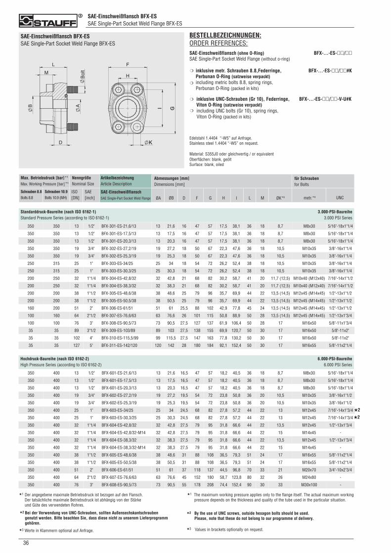
SAE-Einschweißflansch BFX-ESSAE Single-Part Socket Weld Flange BFX-ES
036
SAE-Einschweißflansch BFX-ESSAE Single-Part Socket Weld Flange BFX-ES
BESTELLBEZEICHNUNGEN:ORDER REFERENCES:SAE-Einschweißflansch (ohne O-Ring) BFX-...-ES-��/��SAE Single-Part Socket Weld Flange (without o-ring)
inklusive metr. Schrauben 8.8,Federringe, BFX-...-ES-��/��#KPerbunan O-Ring (satzweise verpackt)including metric bolts 8.8, spring rings, Perbunan O-Ring (packed in kits)
inklusive UNC-Schrauben (Gr 10), Federringe, BFX-...-ES-��/��-V-U#KViton O-Ring (satzweise verpackt) including UNC bolts (Gr 10), spring rings, Viton O-Ring (packed in kits)
Edelstahl 1.4404 “-W5” auf Anfrage.Stainless steel 1.4404 “-W5” on request.
Material: S355J0 oder gleichwertig / or equivalentOberflächen: blank, geöltSurface: blank, oiled
❍
❍
❍
❍
Standarddruck-Baureihe (nach ISO 6162-1) 3.000-PSI-BaureiheStandard Pressure Series (according to ISO 6162-1) 3.000 PSI Series
ArtikelbezeichnungArticle Description
SAE-EinschweißflanschSAE Single-Part Socket Weld Flange
Max. Betriebsdruck [bar]*1
Max. Working Pressure [bar]*1
Schrauben 8.8Bolts 8.8
Schrauben 10.9Bolts 10.9 (MH)
NenngrößeNominal Size
ISO[DN]
SAE[inch]
Abmessungen [mm]Dimensions [mm]
ØA ØB D F G H I L ØK*3 metr.*3
für Schraubenfor Bolts
UNCM
350 350 13 1/2" BFX-301-ES-21,6/13 13 21,6 16 47 57 17,5 38,1 36 18 8,7 M8x30 5/16"-18x1"1/4
350 350 13 1/2" BFX-301-ES-17,5/13 13 17,5 16 47 57 17,5 38,1 36 18 8,7 M8x30 5/16"-18x1"1/4
350 350 13 1/2" BFX-301-ES-20,3/13 13 20,3 16 47 57 17,5 38,1 36 18 8,7 M8x30 5/16"-18x1"1/4
350 350 19 3/4" BFX-302-ES-27,2/19 19 27,2 18 50 67 22,3 47,6 36 18 10,5 M10x35 3/8"-16x1"1/4
350 350 19 3/4" BFX-302-ES-25,3/19 19 25,3 18 50 67 22,3 47,6 36 18 10,5 M10x35 3/8"-16x1"1/4
250 315 25 1" BFX-303-ES-34/25 25 34 18 54 72 26,2 52,4 38 18 10,5 M10x35 3/8"-16x1"1/4
250 315 25 1" BFX-303-ES-30,3/25 25 30,3 18 54 72 26,2 52,4 38 18 10,5 M10x35 3/8"-16x1"1/4
200 250 32 1"1/4 BFX-304-ES-42,8/32 32 42,8 21 68 82 30,2 58,7 41 20 11,7 (12,5) M10x40 (M12x40) 7/16"-14x1"1/2
200 250 32 1"1/4 BFX-304-ES-38,3/32 32 38,3 21 68 82 30,2 58,7 41 20 11,7 (12,5) M10x40 (M12x40) 7/16"-14x1"1/2
200 200 38 1"1/2 BFX-305-ES-48,6/38 38 48,6 25 79 96 35,7 69,9 44 22 13,5 (14,5) M12x45 (M14x45) 1/2"-13x1"1/2
200 200 38 1"1/2 BFX-305-ES-50,5/38 38 50,5 25 79 96 35,7 69,9 44 22 13,5 (14,5) M12x45 (M14x45) 1/2"-13x1"1/2
160 200 51 2" BFX-306-ES-61/51 51 61 25,5 88 102 42,9 77,8 45 24 13,5 (14,5) M12x45 (M14x45) 1/2"-13x1"1/2
100 160 64 2"1/2 BFX-307-ES-76,6/63 63 76,6 26 101 115 50,8 88,9 50 28 13,5 (14,5) M12x45 (M14x45) 1/2"-13x1"3/4
100 100 76 3" BFX-308-ES-90,5/73 73 90,5 27,5 127 137 61,9 106,4 50 28 17 M16x50 5/8"-11x1"3/4
35 35 89 3"1/2 BFX-309-ES-103/89 89 103 27,5 138 155 69,9 120,7 50 30 17 M16x50 5/8"-11x2"
35 35 102 4" BFX-310-ES-115,5/99 99 115,5 27,5 147 163 77,8 130,2 50 30 17 M16x50 5/8"-11x2"
35 35 127 5" BFX-311-ES-142/120 120 142 28 180 184 92,1 152,4 50 30 17 M16x55 5/8"-11x2"1/4
Hochdruck-Baureihe (nach ISO 6162-2) 6.000-PSI-BaureiheHigh Pressure Series (according to ISO 6162-2) 6.000 PSI Series
350 400 13 1/2" BFX-601-ES-21,6/13 13 21,6 16,5 47 57 18,2 40,5 36 18 8,7 M8x30 5/16"-18x1"1/4
350 400 13 1/2" BFX-601-ES-17,5/13 13 17,5 16,5 47 57 18,2 40,5 36 18 8,7 M8x30 5/16"-18x1"1/4
350 400 13 1/2" BFX-601-ES-20,3/13 13 20,3 16,5 47 57 18,2 40,5 36 18 8,7 M8x30 5/16"-18x1"1/4
350 400 19 3/4" BFX-602-ES-27,2/19 19 27,2 19,5 54 72 23,8 50,8 36 20 10,5 M10x35 3/8"-16x1"1/2
350 400 19 3/4" BFX-602-ES-25,3/19 19 25,3 19,5 54 72 23,8 50,8 36 20 10,5 M10x35 3/8"-16x1"1/2
350 400 25 1" BFX-603-ES-34/25 25 34 24,5 68 82 27,8 57,2 44 22 13 M12x45 7/16"-14x1"3/4
350 400 25 1" BFX-603-ES-30,3/25 25 30,3 24,5 68 82 27,8 57,2 44 22 13 M12x45 7/16"-14x1"3/4
350 400 32 1"1/4 BFX-604-ES-42,8/32 32 42,8 27,5 79 95 31,8 66,6 44 22 13,5 M12x45 1/2"-13x1"3/4
350 400 32 1"1/4 BFX-604-ES-42,8/32-M14 32 42,8 27,5 79 95 31,8 66,6 44 22 15 M14x45 -
350 400 32 1"1/4 BFX-604-ES-38,3/32 32 38,3 27,5 79 95 31,8 66,6 44 22 13,5 M12x45 1/2"-13x1"3/4
350 400 32 1"1/4 BFX-604-ES-38,3/32-M14 32 38,3 27,5 79 95 31,8 66,6 44 22 15 M14x45 -
350 400 38 1"1/2 BFX-605-ES-48,6/38 38 48,6 31 88 108 36,5 79,3 51 24 17 M16x55 5/8"-11x2"1/4
350 400 38 1"1/2 BFX-605-ES-50,5/38 38 50,5 31 88 108 36,5 79,3 51 24 17 M16x55 5/8"-11x2"1/4
350 400 51 2" BFX-606-ES-61/51 51 61 37 118 137 44,5 96,8 70 33 21 M20x70 3/4"-10x2"3/4
350 400 64 2"1/2 BFX-607-ES-76,6/63 63 76,6 45 152 180 58,7 123,8 80 32 26 M24x80 -
350 400 76 3" BFX-608-ES-90,5/73 73 90,5 55 178 208 74,4 152,4 90 30 33 M30x100 -
★2
★2
★1 Der angegebene maximale Betriebsdruck ist bezogen auf den Flansch. Der tatsächliche maximale Betriebsdruck ist abhängig von der Stärke und Güte des verwendeten Rohres.
★1 The maximum working pressure applies only to the flange itself. The actual maximum workingpressure depends on the thickness and quality of the tube used in the particular situation.
Bei der Verwendung von UNC-Schrauben, sollten Außensechskantschrauben genutzt werden. Bitte beachten Sie, dass diese nicht zu unserem Lieferprogramm gehören.
★2 By the use of UNC screws, outside hexagon bolts should be used. Please, note that these do not belong to our programme of delivery.
★2
★3 Werte in Klammern optional auf Anfrage. ★3 Values in brackets optionally on request.
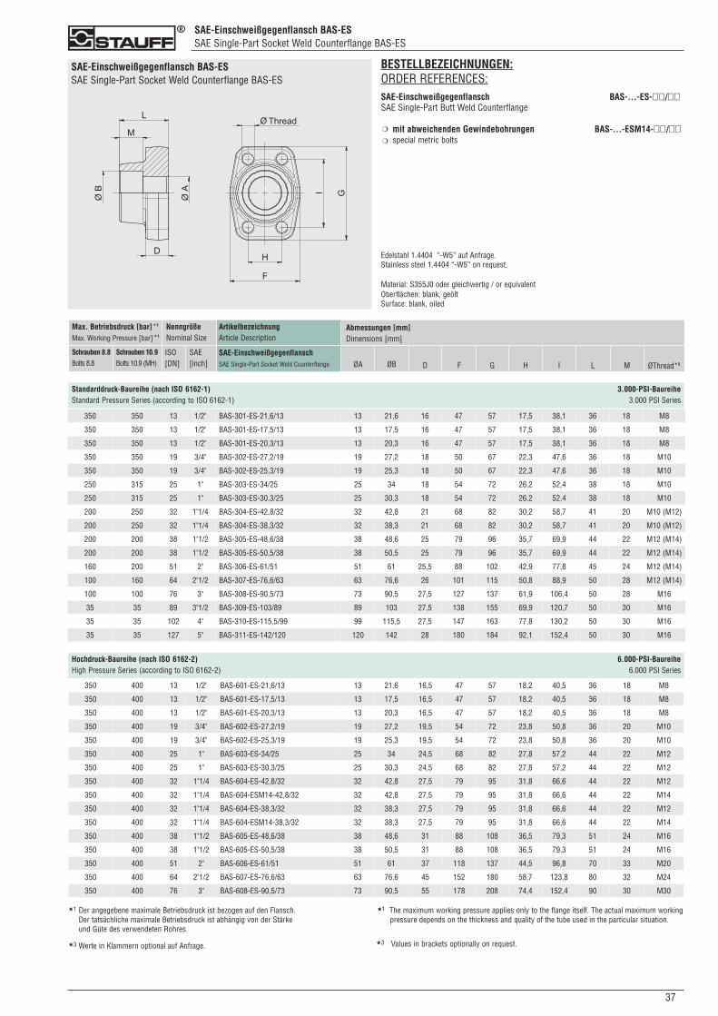
SAE-Einschweißgegenflansch BAS-ESSAE Single-Part Socket Weld Counterflange BAS-ES
370
SAE-Einschweißgegenflansch BAS-ESSAE Single-Part Socket Weld Counterflange BAS-ES
Standarddruck-Baureihe (nach ISO 6162-1) 3.000-PSI-BaureiheStandard Pressure Series (according to ISO 6162-1) 3.000 PSI Series
ArtikelbezeichnungArticle Description
SAE-EinschweißgegenflanschSAE Single-Part Socket Weld Counterflange
Max. Betriebsdruck [bar]*1
Max. Working Pressure [bar]*1
Schrauben 8.8Bolts 8.8
Schrauben 10.9Bolts 10.9 (MH)
NenngrößeNominal Size
ISO[DN]
SAE[inch]
Abmessungen [mm]Dimensions [mm]
ØA ØB D F G H I L ØThread*3M
350 350 13 1/2" BAS-301-ES-21,6/13 13 21,6 16 47 57 17,5 38,1 36 18 M8
350 350 13 1/2" BAS-301-ES-17,5/13 13 17,5 16 47 57 17,5 38,1 36 18 M8
350 350 13 1/2" BAS-301-ES-20,3/13 13 20,3 16 47 57 17,5 38,1 36 18 M8
350 350 19 3/4" BAS-302-ES-27,2/19 19 27,2 18 50 67 22,3 47,6 36 18 M10
350 350 19 3/4" BAS-302-ES-25,3/19 19 25,3 18 50 67 22,3 47,6 36 18 M10
250 315 25 1" BAS-303-ES-34/25 25 34 18 54 72 26,2 52,4 38 18 M10
250 315 25 1" BAS-303-ES-30,3/25 25 30,3 18 54 72 26,2 52,4 38 18 M10
200 250 32 1"1/4 BAS-304-ES-42,8/32 32 42,8 21 68 82 30,2 58,7 41 20 M10 (M12)
200 250 32 1"1/4 BAS-304-ES-38,3/32 32 38,3 21 68 82 30,2 58,7 41 20 M10 (M12)
200 200 38 1"1/2 BAS-305-ES-48,6/38 38 48,6 25 79 96 35,7 69,9 44 22 M12 (M14)
200 200 38 1"1/2 BAS-305-ES-50,5/38 38 50,5 25 79 96 35,7 69,9 44 22 M12 (M14)
160 200 51 2" BAS-306-ES-61/51 51 61 25,5 88 102 42,9 77,8 45 24 M12 (M14)
100 160 64 2"1/2 BAS-307-ES-76,6/63 63 76,6 26 101 115 50,8 88,9 50 28 M12 (M14)
100 100 76 3" BAS-308-ES-90,5/73 73 90,5 27,5 127 137 61,9 106,4 50 28 M16
35 35 89 3"1/2 BAS-309-ES-103/89 89 103 27,5 138 155 69,9 120,7 50 30 M16
35 35 102 4" BAS-310-ES-115,5/99 99 115,5 27,5 147 163 77,8 130,2 50 30 M16
35 35 127 5" BAS-311-ES-142/120 120 142 28 180 184 92,1 152,4 50 30 M16
Hochdruck-Baureihe (nach ISO 6162-2) 6.000-PSI-BaureiheHigh Pressure Series (according to ISO 6162-2) 6.000 PSI Series
350 400 13 1/2" BAS-601-ES-21,6/13 13 21,6 16,5 47 57 18,2 40,5 36 18 M8
350 400 13 1/2" BAS-601-ES-17,5/13 13 17,5 16,5 47 57 18,2 40,5 36 18 M8
350 400 13 1/2" BAS-601-ES-20,3/13 13 20,3 16,5 47 57 18,2 40,5 36 18 M8
350 400 19 3/4" BAS-602-ES-27,2/19 19 27,2 19,5 54 72 23,8 50,8 36 20 M10
350 400 19 3/4" BAS-602-ES-25,3/19 19 25,3 19,5 54 72 23,8 50,8 36 20 M10
350 400 25 1" BAS-603-ES-34/25 25 34 24,5 68 82 27,8 57,2 44 22 M12
350 400 25 1" BAS-603-ES-30,3/25 25 30,3 24,5 68 82 27,8 57,2 44 22 M12
350 400 32 1"1/4 BAS-604-ES-42,8/32 32 42,8 27,5 79 95 31,8 66,6 44 22 M12
350 400 32 1"1/4 BAS-604-ESM14-42,8/32 32 42,8 27,5 79 95 31,8 66,6 44 22 M14
350 400 32 1"1/4 BAS-604-ES-38,3/32 32 38,3 27,5 79 95 31,8 66,6 44 22 M12
350 400 32 1"1/4 BAS-604-ESM14-38,3/32 32 38,3 27,5 79 95 31,8 66,6 44 22 M14
350 400 38 1"1/2 BAS-605-ES-48,6/38 38 48,6 31 88 108 36,5 79,3 51 24 M16
350 400 38 1"1/2 BAS-605-ES-50,5/38 38 50,5 31 88 108 36,5 79,3 51 24 M16
350 400 51 2" BAS-606-ES-61/51 51 61 37 118 137 44,5 96,8 70 33 M20
350 400 64 2"1/2 BAS-607-ES-76,6/63 63 76,6 45 152 180 58,7 123,8 80 32 M24
350 400 76 3" BAS-608-ES-90,5/73 73 90,5 55 178 208 74,4 152,4 90 30 M30
BESTELLBEZEICHNUNGEN:ORDER REFERENCES:SAE-Einschweißgegenflansch BAS-...-ES-��/��SAE Single-Part Butt Weld Counterflange
mit abweichenden Gewindebohrungen BAS-...-ESM14-��/��special metric bolts
Edelstahl 1.4404 “-W5” auf Anfrage.Stainless steel 1.4404 “-W5” on request.
Material: S355J0 oder gleichwertig / or equivalentOberflächen: blank, geöltSurface: blank, oiled
❍
❍
★1 Der angegebene maximale Betriebsdruck ist bezogen auf den Flansch. Der tatsächliche maximale Betriebsdruck ist abhängig von der Stärke und Güte des verwendeten Rohres.
★1 The maximum working pressure applies only to the flange itself. The actual maximum workingpressure depends on the thickness and quality of the tube used in the particular situation.
★3 Werte in Klammern optional auf Anfrage. ★3 Values in brackets optionally on request.
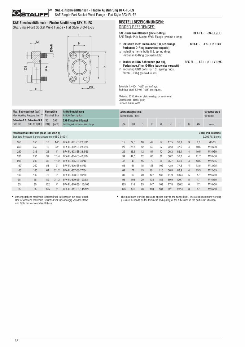
SAE-Einschweißflansch - Flache Ausführung BFX-FL-ESSAE Single-Part Socket Weld Flange - Flat Style BFX-FL-ES
038
SAE-Einschweißflansch - Flache Ausführung BFX-FL-ESSAE Single-Part Socket Weld Flange - Flat Style BFX-FL-ES
Standarddruck-Baureihe (nach ISO 6162-1) 3.000-PSI-BaureiheStandard Pressure Series (according to ISO 6162-1) 3.000 PSI Series
ArtikelbezeichnungArticle Description
SAE-EinschweißflanschSAE Single-Part Socket Weld Flange
Max. Betriebsdruck [bar]*1
Max. Working Pressure [bar]*1
Schrauben 8.8Bolts 8.8
Schrauben 10.9Bolts 10.9 (MH)
NenngrößeNominal Size
ISO[DN]
SAE[inch]
Abmessungen [mm]Dimensions [mm]
ØA ØB D F G H I ØK metr.
für Schraubenfor Bolts
M
350 350 13 1/2" BFX-FL-301-ES-22,5/15 15 22,5 10 47 57 17,5 38,1 3 8,7 M8x25
350 350 19 3/4" BFX-FL-302-ES-28,5/20 20 28,5 12 50 67 22,3 47,6 4 10,5 M10x30
250 315 25 1" BFX-FL-303-ES-35,5/29 29 35,5 12 54 72 26,2 52,4 4 10,5 M10x30
200 250 32 1"1/4 BFX-FL-304-ES-42,5/34 34 42,5 12 68 82 30,2 58,7 4 11,7 M10x30
200 200 38 1"1/2 BFX-FL-305-ES-49/42 42 49 15 79 96 35,7 69,9 4 13,5 M12x35
160 200 51 2" BFX-FL-306-ES-61/53 53 61 15 88 102 42,9 77,8 4 13,5 M12x35
100 160 64 2"1/2 BFX-FL-307-ES-77/64 64 77 15 101 115 50,8 88,9 4 13,5 M12x35
100 100 76 3" BFX-FL-308-ES-90/80 80 90 20 127 137 61,9 106,4 5 17 M16x50
35 35 89 3"1/2 BFX-FL-309-ES-103/93 93 103 20 138 155 69,9 120,7 5 17 M16x50
35 35 102 4" BFX-FL-310-ES-116/105 105 116 25 147 163 77,8 130,2 6 17 M16x50
35 35 125 5" BFX-FL-311-ES-141/126 126 141 28 180 184 92,1 152,4 8 17 M16x50
★1 Der angegebene maximale Betriebsdruck ist bezogen auf den Flansch. Der tatsächliche maximale Betriebsdruck ist abhängig von der Stärke und Güte des verwendeten Rohres.
★1 The maximum working pressure applies only to the flange itself. The actual maximum workingpressure depends on the thickness and quality of the tube used in the particular situation.
BESTELLBEZEICHNUNGEN:ORDER REFERENCES:SAE-Einschweißflansch (ohne O-Ring) BFX-FL-...-ES-��/��SAE Single-Part Socket Weld Flange (without o-ring)
inklusive metr. Schrauben 8.8,Federringe, BFX-FL-...-ES-��/��#KPerbunan O-Ring (satzweise verpackt)including metric bolts 8.8, spring rings, Perbunan O-Ring (packed in kits)
inklusive UNC-Schrauben (Gr 10), BFX-FL-...-ES-��/��-V-U#KFederringe,Viton O-Ring (satzweise verpackt) including UNC bolts (Gr 10), spring rings, Viton O-Ring (packed in kits)
Edelstahl 1.4404 “-W5” auf Anfrage.Stainless steel 1.4404 “-W5” on request.
Material: S355J0 oder gleichwertig / or equivalentOberflächen: blank, geöltSurface: blank, oiled
❍
❍
❍
❍
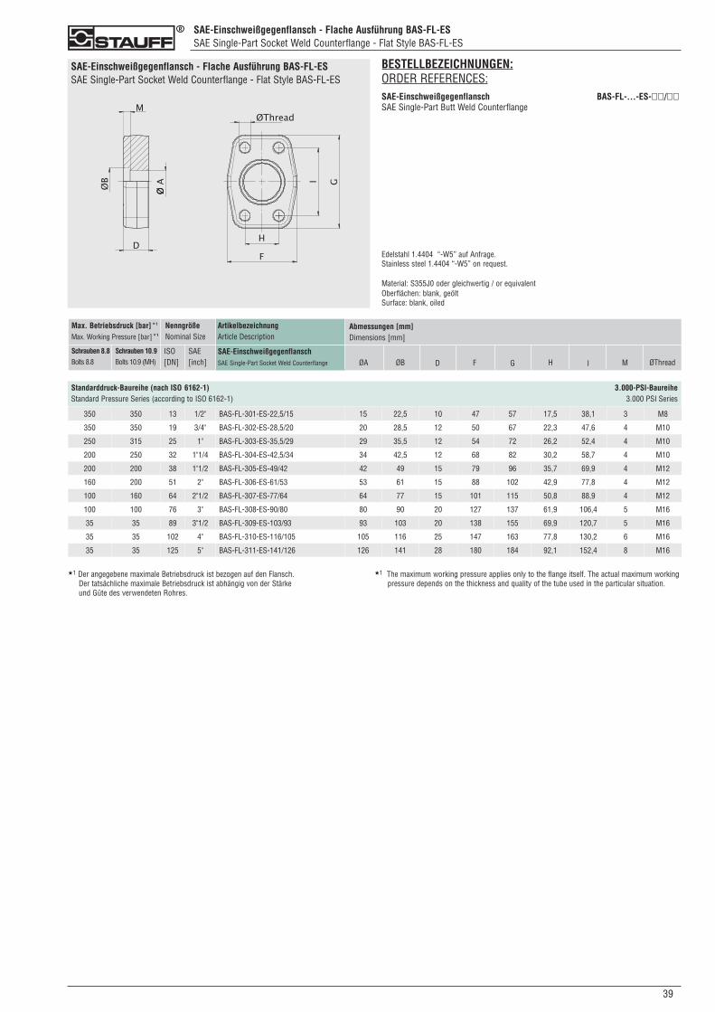
SAE-Einschweißgegenflansch - Flache Ausführung BAS-FL-ESSAE Single-Part Socket Weld Counterflange - Flat Style BAS-FL-ES
390
SAE-Einschweißgegenflansch - Flache Ausführung BAS-FL-ESSAE Single-Part Socket Weld Counterflange - Flat Style BAS-FL-ES
Standarddruck-Baureihe (nach ISO 6162-1) 3.000-PSI-BaureiheStandard Pressure Series (according to ISO 6162-1) 3.000 PSI Series
ArtikelbezeichnungArticle Description
SAE-EinschweißgegenflanschSAE Single-Part Socket Weld Counterflange
Max. Betriebsdruck [bar]*1
Max. Working Pressure [bar]*1
Schrauben 8.8Bolts 8.8
Schrauben 10.9Bolts 10.9 (MH)
NenngrößeNominal Size
ISO[DN]
SAE[inch]
Abmessungen [mm]Dimensions [mm]
ØA ØB D F G H I ØThreadM
350 350 13 1/2" BAS-FL-301-ES-22,5/15 15 22,5 10 47 57 17,5 38,1 3 M8
350 350 19 3/4" BAS-FL-302-ES-28,5/20 20 28,5 12 50 67 22,3 47,6 4 M10
250 315 25 1" BAS-FL-303-ES-35,5/29 29 35,5 12 54 72 26,2 52,4 4 M10
200 250 32 1"1/4 BAS-FL-304-ES-42,5/34 34 42,5 12 68 82 30,2 58,7 4 M10
200 200 38 1"1/2 BAS-FL-305-ES-49/42 42 49 15 79 96 35,7 69,9 4 M12
160 200 51 2" BAS-FL-306-ES-61/53 53 61 15 88 102 42,9 77,8 4 M12
100 160 64 2"1/2 BAS-FL-307-ES-77/64 64 77 15 101 115 50,8 88,9 4 M12
100 100 76 3" BAS-FL-308-ES-90/80 80 90 20 127 137 61,9 106,4 5 M16
35 35 89 3"1/2 BAS-FL-309-ES-103/93 93 103 20 138 155 69,9 120,7 5 M16
35 35 102 4" BAS-FL-310-ES-116/105 105 116 25 147 163 77,8 130,2 6 M16
35 35 125 5" BAS-FL-311-ES-141/126 126 141 28 180 184 92,1 152,4 8 M16
★1 Der angegebene maximale Betriebsdruck ist bezogen auf den Flansch. Der tatsächliche maximale Betriebsdruck ist abhängig von der Stärke und Güte des verwendeten Rohres.
★1 The maximum working pressure applies only to the flange itself. The actual maximum workingpressure depends on the thickness and quality of the tube used in the particular situation.
BESTELLBEZEICHNUNGEN:ORDER REFERENCES:SAE-Einschweißgegenflansch BAS-FL-...-ES-��/��SAE Single-Part Butt Weld Counterflange
Edelstahl 1.4404 “-W5” auf Anfrage.Stainless steel 1.4404 “-W5” on request.
Material: S355J0 oder gleichwertig / or equivalentOberflächen: blank, geöltSurface: blank, oiled
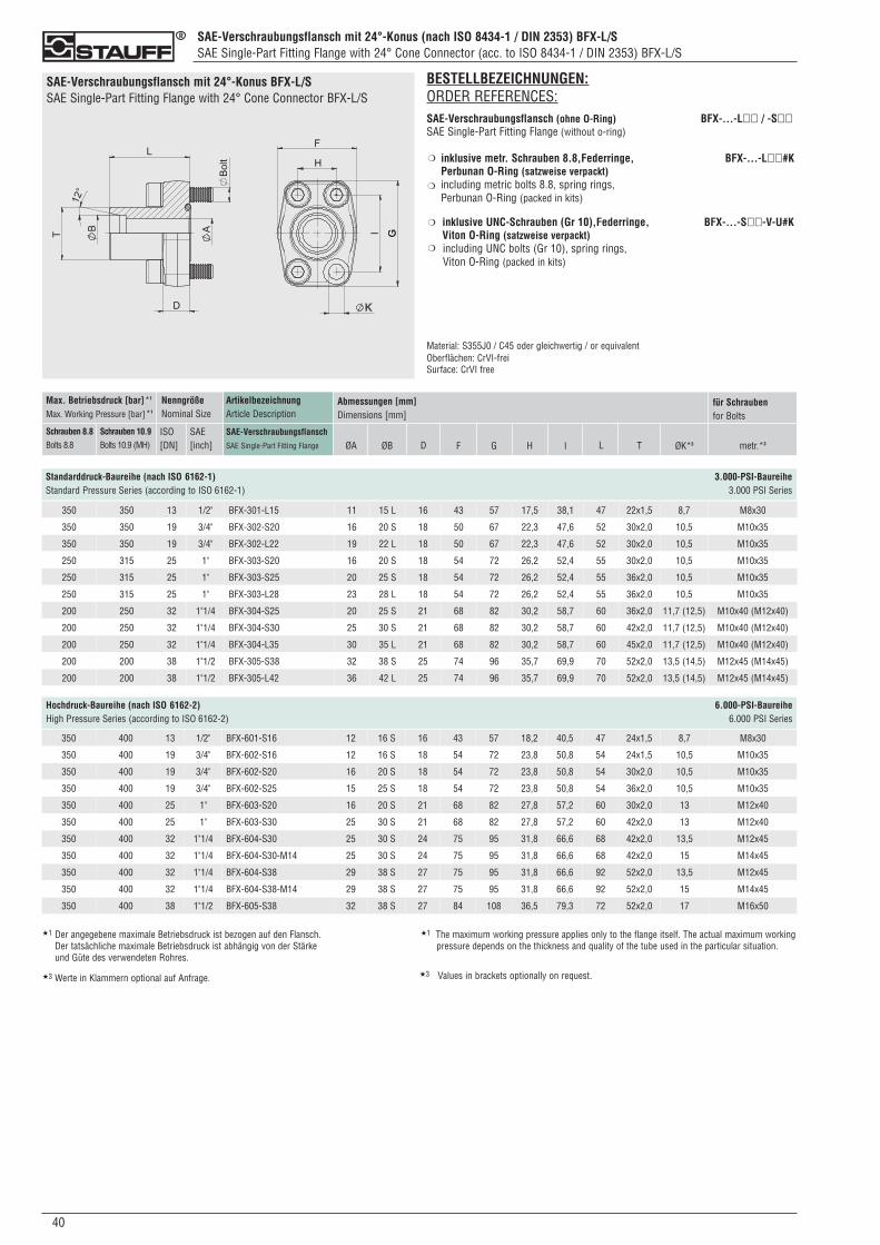
SAE-Verschraubungsflansch mit 24°-Konus (nach ISO 8434-1 / DIN 2353) BFX-L/SSAE Single-Part Fitting Flange with 24° Cone Connector (acc. to ISO 8434-1 / DIN 2353) BFX-L/S
040
SAE-Verschraubungsflansch mit 24°-Konus BFX-L/SSAE Single-Part Fitting Flange with 24° Cone Connector BFX-L/S
Standarddruck-Baureihe (nach ISO 6162-1) 3.000-PSI-BaureiheStandard Pressure Series (according to ISO 6162-1) 3.000 PSI Series
ArtikelbezeichnungArticle Description
SAE-VerschraubungsflanschSAE Single-Part Fitting Flange
Max. Betriebsdruck [bar]*1
Max. Working Pressure [bar]*1
Schrauben 8.8Bolts 8.8
Schrauben 10.9Bolts 10.9 (MH)
NenngrößeNominal Size
ISO[DN]
SAE[inch]
Abmessungen [mm]Dimensions [mm]
ØA ØB D F G H I ØK*3 metr.*3
für Schraubenfor Bolts
L T
Hochdruck-Baureihe (nach ISO 6162-2) 6.000-PSI-BaureiheHigh Pressure Series (according to ISO 6162-2) 6.000 PSI Series
350 400 13 1/2" BFX-601-S16 12 16 S 16 43 57 18,2 40,5 47 24x1,5 8,7 M8x30
350 400 19 3/4" BFX-602-S16 12 16 S 18 54 72 23,8 50,8 54 24x1,5 10,5 M10x35
350 400 19 3/4" BFX-602-S20 16 20 S 18 54 72 23,8 50,8 54 30x2,0 10,5 M10x35
350 400 19 3/4" BFX-602-S25 15 25 S 18 54 72 23,8 50,8 54 36x2,0 10,5 M10x35
350 400 25 1" BFX-603-S20 16 20 S 21 68 82 27,8 57,2 60 30x2,0 13 M12x40
350 400 25 1" BFX-603-S30 25 30 S 21 68 82 27,8 57,2 60 42x2,0 13 M12x40
350 400 32 1"1/4 BFX-604-S30 25 30 S 24 75 95 31,8 66,6 68 42x2,0 13,5 M12x45
350 400 32 1"1/4 BFX-604-S30-M14 25 30 S 24 75 95 31,8 66,6 68 42x2,0 15 M14x45
350 400 32 1"1/4 BFX-604-S38 29 38 S 27 75 95 31,8 66,6 92 52x2,0 13,5 M12x45
350 400 32 1"1/4 BFX-604-S38-M14 29 38 S 27 75 95 31,8 66,6 92 52x2,0 15 M14x45
350 400 38 1"1/2 BFX-605-S38 32 38 S 27 84 108 36,5 79,3 72 52x2,0 17 M16x50
BESTELLBEZEICHNUNGEN:ORDER REFERENCES:SAE-Verschraubungsflansch (ohne O-Ring) BFX-...-L�� / -S��SAE Single-Part Fitting Flange (without o-ring)
inklusive metr. Schrauben 8.8,Federringe, BFX-...-L��#KPerbunan O-Ring (satzweise verpackt)including metric bolts 8.8, spring rings, Perbunan O-Ring (packed in kits)
inklusive UNC-Schrauben (Gr 10),Federringe, BFX-...-S��-V-U#KViton O-Ring (satzweise verpackt) including UNC bolts (Gr 10), spring rings, Viton O-Ring (packed in kits)
Material: S355J0 / C45 oder gleichwertig / or equivalentOberflächen: CrVI-freiSurface: CrVI free
❍
❍
❍
❍
350 350 13 1/2" BFX-301-L15 11 15 L 16 43 57 17,5 38,1 47 22x1,5 8,7 M8x30
350 350 19 3/4" BFX-302-S20 16 20 S 18 50 67 22,3 47,6 52 30x2,0 10,5 M10x35
350 350 19 3/4" BFX-302-L22 19 22 L 18 50 67 22,3 47,6 52 30x2,0 10,5 M10x35
250 315 25 1" BFX-303-S20 16 20 S 18 54 72 26,2 52,4 55 30x2,0 10,5 M10x35
250 315 25 1" BFX-303-S25 20 25 S 18 54 72 26,2 52,4 55 36x2,0 10,5 M10x35
250 315 25 1" BFX-303-L28 23 28 L 18 54 72 26,2 52,4 55 36x2,0 10,5 M10x35
200 250 32 1"1/4 BFX-304-S25 20 25 S 21 68 82 30,2 58,7 60 36x2,0 11,7 (12,5) M10x40 (M12x40)
200 250 32 1"1/4 BFX-304-S30 25 30 S 21 68 82 30,2 58,7 60 42x2,0 11,7 (12,5) M10x40 (M12x40)
200 250 32 1"1/4 BFX-304-L35 30 35 L 21 68 82 30,2 58,7 60 45x2,0 11,7 (12,5) M10x40 (M12x40)
200 200 38 1"1/2 BFX-305-S38 32 38 S 25 74 96 35,7 69,9 70 52x2,0 13,5 (14,5) M12x45 (M14x45)
200 200 38 1"1/2 BFX-305-L42 36 42 L 25 74 96 35,7 69,9 70 52x2,0 13,5 (14,5) M12x45 (M14x45)
★1 Der angegebene maximale Betriebsdruck ist bezogen auf den Flansch. Der tatsächliche maximale Betriebsdruck ist abhängig von der Stärke und Güte des verwendeten Rohres.
★1 The maximum working pressure applies only to the flange itself. The actual maximum workingpressure depends on the thickness and quality of the tube used in the particular situation.
★3 Werte in Klammern optional auf Anfrage. ★3 Values in brackets optionally on request.
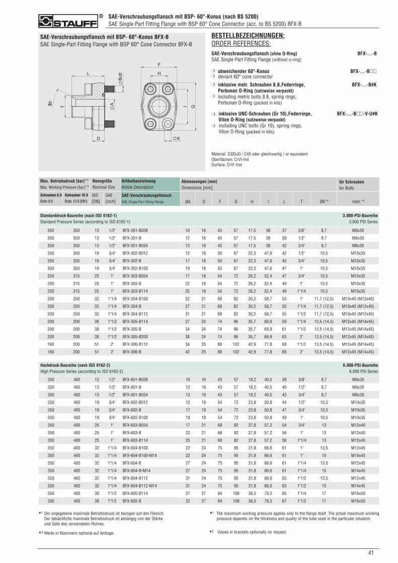
SAE-Verschraubungsflansch mit BSP- 60°-Konus (nach BS 5200)SAE Single-Part Fitting Flange with BSP 60° Cone Connector (acc. to BS 5200) BFX-B
410
SAE-Verschraubungsflansch mit BSP- 60°-Konus BFX-BSAE Single-Part Fitting Flange with BSP 60° Cone Connector BFX-B
Standarddruck-Baureihe (nach ISO 6162-1) 3.000-PSI-BaureiheStandard Pressure Series (according to ISO 6162-1) 3.000 PSI Series
ArtikelbezeichnungArticle Description
SAE-VerschraubungsflanschSAE Single-Part Fitting Flange
Max. Betriebsdruck [bar]*1
Max. Working Pressure [bar]*1
Schrauben 8.8Bolts 8.8
Schrauben 10.9Bolts 10.9 (MH)
NenngrößeNominal Size
ISO[DN]
SAE[inch]
Abmessungen [mm]Dimensions [mm]
ØA D F G H I ØK*3 metr.*3
für Schraubenfor Bolts
L T
350 350 13 1/2" BFX-301-B038 10 16 43 57 17,5 38 37 3/8" 8,7 M8x30
350 350 13 1/2" BFX-301-B 12 16 43 57 17,5 38 39 1/2" 8,7 M8x30
350 350 13 1/2" BFX-301-B034 13 16 43 57 17,5 38 42 3/4" 8,7 M8x30
350 350 19 3/4" BFX-302-B012 12 18 50 67 22,3 47,6 42 1/2" 10,5 M10x35
350 350 19 3/4" BFX-302-B 17 18 50 67 22,3 47,6 45 3/4" 10,5 M10x35
350 350 19 3/4" BFX-302-B100 19 18 50 67 22,3 47,6 47 1" 10,5 M10x35
250 315 25 1" BFX-303-B034 17 18 54 72 26,2 52,4 47 3/4" 10,5 M10x35
250 315 25 1" BFX-303-B 22 18 54 72 26,2 52,4 49 1" 10,5 M10x35
250 315 25 1" BFX-303-B114 25 18 54 72 26,2 52,4 49 1"1/4 10,5 M10x35
200 250 32 1"1/4 BFX-304-B100 22 21 68 82 30,2 58,7 53 1" 11,7 (12,5) M10x40 (M12x40)
200 250 32 1"1/4 BFX-304-B 27 21 68 82 30,2 58,7 55 1"1/4 11,7 (12,5) M10x40 (M12x40)
200 250 32 1"1/4 BFX-304-B112 31 21 68 82 30,2 58,7 55 1"1/2 11,7 (12,5) M10x40 (M12x40)
200 200 38 1"1/2 BFX-305-B114 27 24 74 96 35,7 69,9 59 1"1/4 13,5 (14,5) M12x45 (M14x45)
200 200 38 1"1/2 BFX-305-B 34 24 74 96 35,7 69,9 61 1"1/2 13,5 (14,5) M12x45 (M14x45)
200 200 38 1"1/2 BFX-305-B200 38 24 74 96 35,7 69,9 63 2" 13,5 (14,5) M12x45 (M14x45)
160 200 51 2" BFX-306-B112 34 25 88 102 42,9 77,8 69 1"1/2 13,5 (14,5) M12x45 (M14x45)
160 200 51 2" BFX-306-B 42 25 88 102 42,9 77,8 69 2" 13,5 (14,5) M12x45 (M14x45)
Hochdruck-Baureihe (nach ISO 6162-2) 6.000-PSI-BaureiheHigh Pressure Series (according to ISO 6162-2) 6.000 PSI Series
350 400 13 1/2" BFX-601-B038 10 16 43 57 18,2 40,5 38 3/8" 8,7 M8x30
350 400 13 1/2" BFX-601-B 12 16 43 57 18,2 40,5 40 1/2" 8,7 M8x30
350 400 13 1/2" BFX-601-B034 13 16 43 57 18,2 40,5 43 3/4" 8,7 M8x30
350 400 19 3/4" BFX-602-B012 12 18 54 72 23,8 50,8 44 1/2" 10,5 M10x35
350 400 19 3/4" BFX-602-B 17 18 54 72 23,8 50,8 47 3/4" 10,5 M10x35
350 400 19 3/4" BFX-602-B100 19 18 54 72 23,8 50,8 49 1" 10,5 M10x35
350 400 25 1" BFX-603-B034 17 21 68 82 27,8 57,2 54 3/4" 13 M12x40
350 400 25 1" BFX-603-B 22 21 68 82 27,8 57,2 56 1" 13 M12x40
350 400 25 1" BFX-603-B114 25 21 68 82 27,8 57,2 56 1"1/4 13 M12x40
350 400 32 1"1/4 BFX-604-B100 22 24 75 95 31,8 66,6 61 1" 13,5 M12x45
350 400 32 1"1/4 BFX-604-B100-M14 22 24 75 95 31,8 66,6 61 1" 15 M14x45
350 400 32 1"1/4 BFX-604-B 27 24 75 95 31,8 66,6 61 1"1/4 13,5 M12x45
350 400 32 1"1/4 BFX-604-B-M14 27 24 75 95 31,8 66,6 61 1"1/4 15 M14x45
350 400 32 1"1/4 BFX-604-B112 31 24 75 95 31,8 66,6 63 1"1/2 13,5 M12x45
350 400 32 1"1/4 BFX-604-B112-M14 31 24 75 95 31,8 66,6 63 1"1/2 15 M14x45
350 400 38 1"1/2 BFX-605-B114 27 27 84 108 36,5 79,3 65 1"1/4 17 M16x50
350 400 38 1"1/2 BFX-605-B 32 27 84 108 36,5 79,3 67 1"1/2 17 M16x50
BESTELLBEZEICHNUNGEN:ORDER REFERENCES:SAE-Verschraubungsflansch (ohne O-Ring) BFX-...-BSAE Single-Part Fitting Flange (without o-ring)
abweichender 60°-Konus BFX-...-B��deviant 60° cone connector
inklusive metr. Schrauben 8.8,Federringe, BFX-...-B#KPerbunan O-Ring (satzweise verpackt)including metric bolts 8.8, spring rings, Perbunan O-Ring (packed in kits)
inklusive UNC-Schrauben (Gr 10),Federringe, BFX-...-B��-V-U#KViton O-Ring (satzweise verpackt) including UNC bolts (Gr 10), spring rings, Viton O-Ring (packed in kits)
Material: S355J0 / C45 oder gleichwertig / or equivalentOberflächen: CrVI-freiSurface: CrVI free
❍
❍
❍
❍
❍
❍
★1 Der angegebene maximale Betriebsdruck ist bezogen auf den Flansch. Der tatsächliche maximale Betriebsdruck ist abhängig von der Stärke und Güte des verwendeten Rohres.
★1 The maximum working pressure applies only to the flange itself. The actual maximum workingpressure depends on the thickness and quality of the tube used in the particular situation.
★3 Werte in Klammern optional auf Anfrage. ★3 Values in brackets optionally on request.
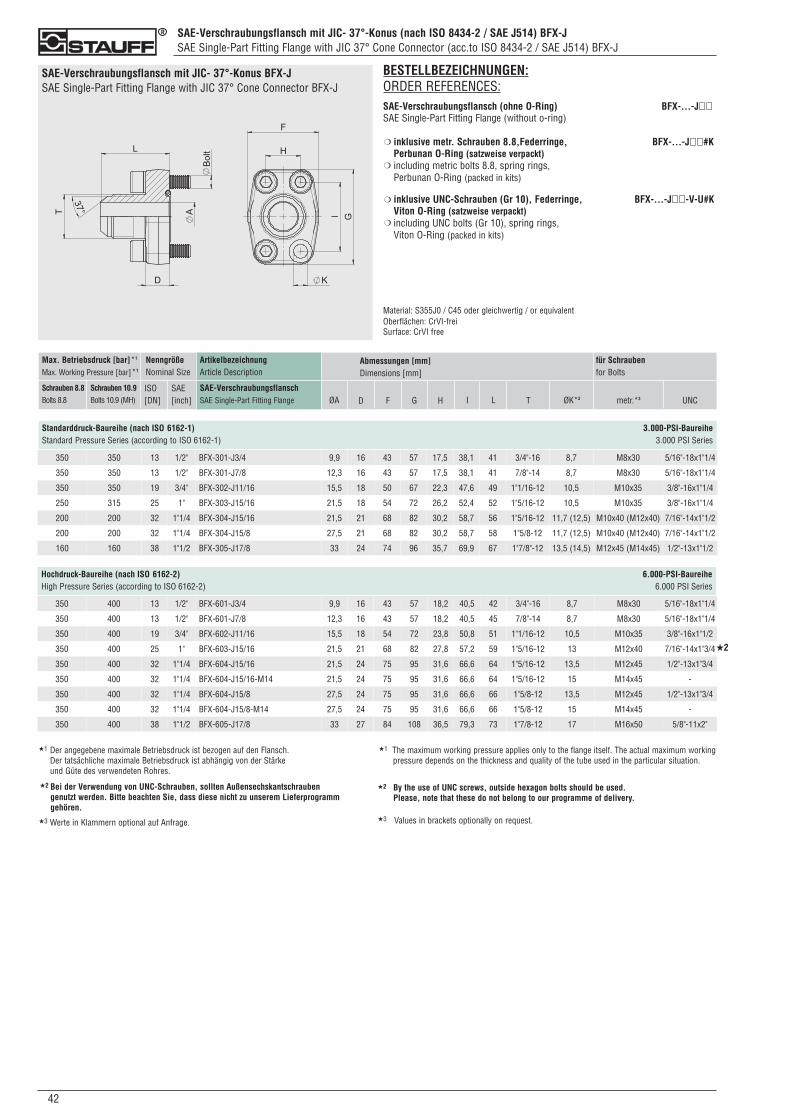
SAE-Verschraubungsflansch mit JIC- 37°-Konus (nach ISO 8434-2 / SAE J514) BFX-JSAE Single-Part Fitting Flange with JIC 37° Cone Connector (acc.to ISO 8434-2 / SAE J514) BFX-J
042
SAE-Verschraubungsflansch mit JIC- 37°-Konus BFX-JSAE Single-Part Fitting Flange with JIC 37° Cone Connector BFX-J
BESTELLBEZEICHNUNGEN:ORDER REFERENCES:SAE-Verschraubungsflansch (ohne O-Ring) BFX-...-J��SAE Single-Part Fitting Flange (without o-ring)
inklusive metr. Schrauben 8.8,Federringe, BFX-...-J��#KPerbunan O-Ring (satzweise verpackt)including metric bolts 8.8, spring rings, Perbunan O-Ring (packed in kits)
inklusive UNC-Schrauben (Gr 10), Federringe, BFX-...-J��-V-U#KViton O-Ring (satzweise verpackt)including UNC bolts (Gr 10), spring rings, Viton O-Ring (packed in kits)
Material: S355J0 / C45 oder gleichwertig / or equivalentOberflächen: CrVI-freiSurface: CrVI free
❍
❍
❍
❍
ArtikelbezeichnungArticle Description
SAE-VerschraubungsflanschSAE Single-Part Fitting Flange
Max. Betriebsdruck [bar]*1
Max. Working Pressure [bar]*1
Schrauben 8.8Bolts 8.8
Schrauben 10.9Bolts 10.9 (MH)
NenngrößeNominal Size
ISO[DN]
SAE[inch]
Abmessungen [mm]Dimensions [mm]
ØA D F T ØK*3
Standarddruck-Baureihe (nach ISO 6162-1) 3.000-PSI-BaureiheStandard Pressure Series (according to ISO 6162-1) 3.000 PSI Series
G H I metr.*3
für Schraubenfor Bolts
L
Hochdruck-Baureihe (nach ISO 6162-2) 6.000-PSI-BaureiheHigh Pressure Series (according to ISO 6162-2) 6.000 PSI Series
UNC
350 350 13 1/2" BFX-301-J3/4 9,9 16 43 57 17,5 38,1 41 3/4"-16 8,7 M8x30 5/16"-18x1"1/4
350 350 13 1/2" BFX-301-J7/8 12,3 16 43 57 17,5 38,1 41 7/8"-14 8,7 M8x30 5/16"-18x1"1/4
350 350 19 3/4" BFX-302-J11/16 15,5 18 50 67 22,3 47,6 49 1"1/16-12 10,5 M10x35 3/8"-16x1"1/4
250 315 25 1" BFX-303-J15/16 21,5 18 54 72 26,2 52,4 52 1"5/16-12 10,5 M10x35 3/8"-16x1"1/4
200 200 32 1"1/4 BFX-304-J15/16 21,5 21 68 82 30,2 58,7 56 1"5/16-12 11,7 (12,5) M10x40 (M12x40) 7/16"-14x1"1/2
200 200 32 1"1/4 BFX-304-J15/8 27,5 21 68 82 30,2 58,7 58 1"5/8-12 11,7 (12,5) M10x40 (M12x40) 7/16"-14x1"1/2
160 160 38 1"1/2 BFX-305-J17/8 33 24 74 96 35,7 69,9 67 1"7/8"-12 13,5 (14,5) M12x45 (M14x45) 1/2"-13x1"1/2
350 400 13 1/2" BFX-601-J3/4 9,9 16 43 57 18,2 40,5 42 3/4"-16 8,7 M8x30 5/16"-18x1"1/4
350 400 13 1/2" BFX-601-J7/8 12,3 16 43 57 18,2 40,5 45 7/8"-14 8,7 M8x30 5/16"-18x1"1/4
350 400 19 3/4" BFX-602-J11/16 15,5 18 54 72 23,8 50,8 51 1"1/16-12 10,5 M10x35 3/8"-16x1"1/2
350 400 25 1" BFX-603-J15/16 21,5 21 68 82 27,8 57,2 59 1"5/16-12 13 M12x40 7/16"-14x1"3/4
350 400 32 1"1/4 BFX-604-J15/16 21,5 24 75 95 31,6 66,6 64 1"5/16-12 13,5 M12x45 1/2"-13x1"3/4
350 400 32 1"1/4 BFX-604-J15/16-M14 21,5 24 75 95 31,6 66,6 64 1"5/16-12 15 M14x45 -
350 400 32 1"1/4 BFX-604-J15/8 27,5 24 75 95 31,6 66,6 66 1"5/8-12 13,5 M12x45 1/2"-13x1"3/4
350 400 32 1"1/4 BFX-604-J15/8-M14 27,5 24 75 95 31,6 66,6 66 1"5/8-12 15 M14x45 -
350 400 38 1"1/2 BFX-605-J17/8 33 27 84 108 36,5 79,3 73 1"7/8-12 17 M16x50 5/8"-11x2"
★2
★1 Der angegebene maximale Betriebsdruck ist bezogen auf den Flansch. Der tatsächliche maximale Betriebsdruck ist abhängig von der Stärke und Güte des verwendeten Rohres.
★1 The maximum working pressure applies only to the flange itself. The actual maximum workingpressure depends on the thickness and quality of the tube used in the particular situation.
Bei der Verwendung von UNC-Schrauben, sollten Außensechskantschrauben genutzt werden. Bitte beachten Sie, dass diese nicht zu unserem Lieferprogramm gehören.
★2 By the use of UNC screws, outside hexagon bolts should be used. Please, note that these do not belong to our programme of delivery.
★2
★3 Werte in Klammern optional auf Anfrage. ★3 Values in brackets optionally on request.

NotizenNotes
430
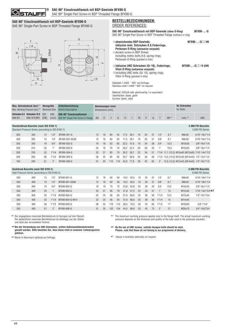
SAE-90° Einschraubflansch mit BSP-Gewinde BFX90-GSAE 90° Single-Part Screw-in BSP Threaded Flange BFX90-G
044
SAE-90° Einschraubflansch mit BSP-Gewinde BFX90-GSAE 90° Single-Part Screw-in BSP Threaded Flange BFX90-G
BESTELLBEZEICHNUNGEN:ORDER REFERENCES:SAE-90° Einschraubflansch mit BSP-Gewinde (ohne O-Ring) BFX90-...-GSAE 90° Single-Part Screw-in BSP Threaded Flange (without o-ring)
abweichendes BSP-Gewinde, BFX90-...-G��#Kinklusive metr. Schrauben 8.8,Federringe,Perbunan O-Ring (satzweise verpackt)deviant screw-in BSP thread,including metric bolts 8.8, spring rings, Perbunan O-Ring (packed in kits)
inklusive UNC-Schrauben (Gr 10), Federringe, BFX90-...-G��-V-U#KViton O-Ring (satzweise verpackt)including UNC bolts (Gr 10), spring rings, Viton O-Ring (packed in kits)
Edelstahl 1.4404 “-W5” auf Anfrage.Stainless steel 1.4404 “-W5” on request.
Material: S355J0 oder gleichwertig / or equivalentOberflächen: blank, geöltSurface: blank, oiled
❍
❍
❍
❍
ArtikelbezeichnungArticle Description
SAE-90° EinschraubflanschSAE 90° Single-Part Screw-in Flange
Max. Betriebsdruck [bar]*1
Max. Working Pressure [bar]*1
Schrauben 8.8Bolts 8.8
Schrauben 10.9Bolts 10.9 (MH)
NenngrößeNominal Size
ISO[DN]
SAE[inch]
Abmessungen [mm]Dimensions [mm]
ØA ØK*3D F Q T
Standarddruck-Baureihe (nach ISO 6162-1) 3.000-PSI-BaureiheStandard Pressure Series (according to ISO 6162-1) 3.000 PSI Series
G H I P metr.*3 UNC
für Schraubenfor Bolts
M
350 350 13 1/2" BFX90-301-G 13 16 60 54 17,5 38,1 19 20 37 1/2" 8,7 M8x30 5/16"-18x1"1/4
350 350 13 1/2" BFX90-301-G038 13 16 60 54 17,5 38,1 19 20 37 3/8" 8,7 M8x30 5/16"-18x1"1/4
350 350 19 3/4" BFX90-302-G 19 18 63 65 22,3 47,6 19 24 38 3/4" 10,5 M10x35 3/8"-16x1"1/4
250 315 25 1" BFX90-303-G 25 19 70 70 26,2 52,4 20 28 43 1" 10,5 M10x35 3/8"-16x1"1/4
200 250 32 1"1/4 BFX90-304-G 32 21 85 79 30,2 58,7 22 34 51 1"1/4 11,7 (12,5) M10x40 (M12x40) 7/16"-14x1"1/2
200 200 38 1"1/2 BFX90-305-G 38 25 95 93 35,7 69,9 25 38 56 1"1/2 13,5 (14,5) M12x45 (M14x45) 1/2"-13x1"1/2
160 200 51 2" BFX90-306-G 51 25 110 110 42,9 77,8 28 42 65 2" 13,5 (14,5) M12x45 (M14x45) 1/2"-13x1"1/2
Hochdruck-Baureihe (nach ISO 6162-2) 6.000-PSI-BaureiheHigh Pressure Series (according to ISO 6162-2) 6.000 PSI Series
350 400 13 1/2" BFX90-601-G 13 16 60 56 18,2 40,5 19 20 37 1/2" 8,7 M8x30 5/16"-18x1"1/4
350 400 13 1/2" BFX90-601-G038 13 16 60 56 18,2 40,5 19 20 37 3/8" 8,7 M8x30 5/16"-18x1"1/4
350 400 19 3/4" BFX90-602-G 19 19 70 70 23,8 50,8 20 28 43 3/4" 10,5 M10x35 3/8"-16x1"1/2
350 400 25 1" BFX90-603-G 25 21 85 79 27,8 57,2 22 34 51 1" 13 M12x45 7/16"-14x1"3/4
350 400 32 1"1/4 BFX90-604-G 32 25 95 93 31,6 66,6 25 38 56 1"1/4 13,5 M12x45 1/2"-13x1"3/4
350 400 32 1"1/4 BFX90-604-G-M14 32 25 95 93 31,6 66,6 25 38 56 1"1/4 15 M14x45 -
350 400 38 1"1/2 BFX90-605-G 38 25 110 110 36,5 79,3 28 42 65 1"1/2 17 M16x50 5/8"-11x2"
350 400 51 2" BFX90-606-G 51 35 132 134 44,5 96,8 33 45 75 2" 21 M20x70 3/4"-10x2"3/4
★2
★1 Der angegebene maximale Betriebsdruck ist bezogen auf den Flansch. Der tatsächliche maximale Betriebsdruck ist abhängig von der Stärke und Güte des verwendeten Rohres.
★1 The maximum working pressure applies only to the flange itself. The actual maximum workingpressure depends on the thickness and quality of the tube used in the particular situation.
Bei der Verwendung von UNC-Schrauben, sollten Außensechskantschrauben genutzt werden. Bitte beachten Sie, dass diese nicht zu unserem Lieferprogramm gehören.
★2 By the use of UNC screws, outside hexagon bolts should be used. Please, note that these do not belong to our programme of delivery.
★2
★3 Werte in Klammern optional auf Anfrage. ★3 Values in brackets optionally on request.
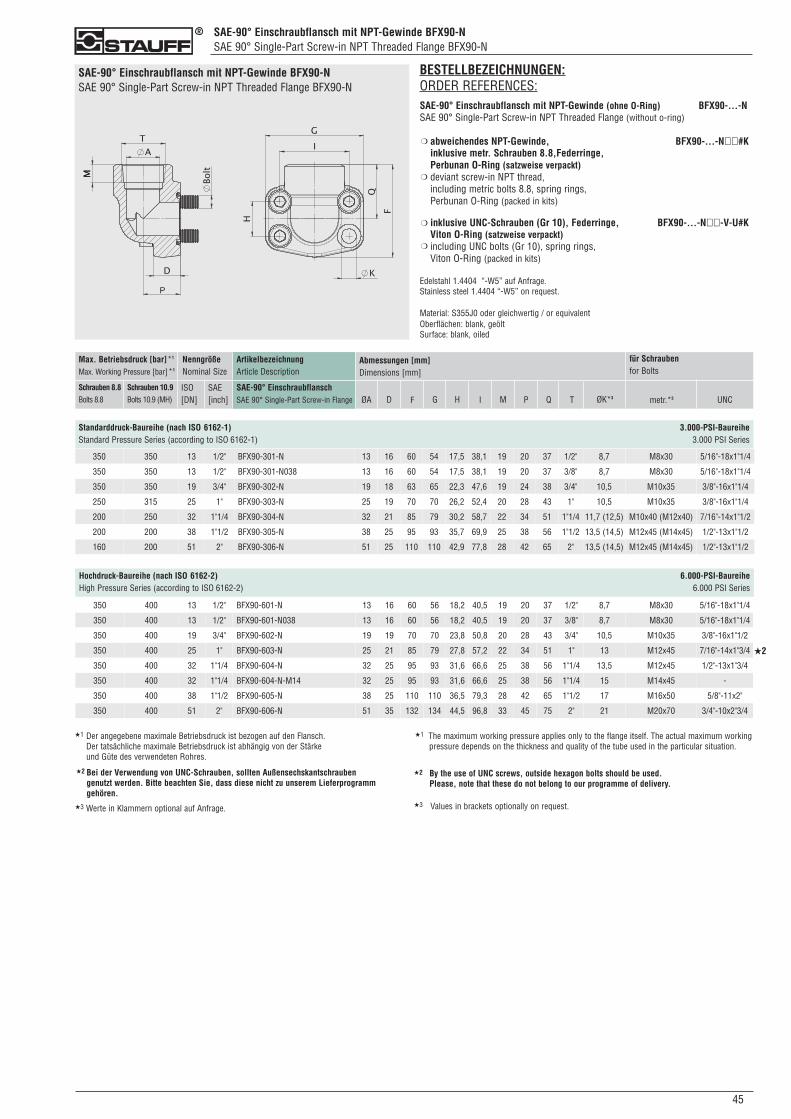
450
SAE-90° Einschraubflansch mit NPT-Gewinde BFX90-NSAE 90° Single-Part Screw-in NPT Threaded Flange BFX90-N
SAE-90° Einschraubflansch mit NPT-Gewinde BFX90-NSAE 90° Single-Part Screw-in NPT Threaded Flange BFX90-N
BESTELLBEZEICHNUNGEN:ORDER REFERENCES:SAE-90° Einschraubflansch mit NPT-Gewinde (ohne O-Ring) BFX90-...-NSAE 90° Single-Part Screw-in NPT Threaded Flange (without o-ring)
abweichendes NPT-Gewinde, BFX90-...-N��#Kinklusive metr. Schrauben 8.8,Federringe,Perbunan O-Ring (satzweise verpackt)deviant screw-in NPT thread,including metric bolts 8.8, spring rings, Perbunan O-Ring (packed in kits)
inklusive UNC-Schrauben (Gr 10), Federringe, BFX90-...-N��-V-U#KViton O-Ring (satzweise verpackt)including UNC bolts (Gr 10), spring rings, Viton O-Ring (packed in kits)
Edelstahl 1.4404 “-W5” auf Anfrage.Stainless steel 1.4404 “-W5” on request.
Material: S355J0 oder gleichwertig / or equivalentOberflächen: blank, geöltSurface: blank, oiled
❍
❍
❍
❍
ArtikelbezeichnungArticle Description
SAE-90° EinschraubflanschSAE 90° Single-Part Screw-in Flange
Max. Betriebsdruck [bar]*1
Max. Working Pressure [bar]*1
Schrauben 8.8Bolts 8.8
Schrauben 10.9Bolts 10.9 (MH)
NenngrößeNominal Size
ISO[DN]
SAE[inch]
Abmessungen [mm]Dimensions [mm]
ØA ØK*3D F Q T
Standarddruck-Baureihe (nach ISO 6162-1) 3.000-PSI-BaureiheStandard Pressure Series (according to ISO 6162-1) 3.000 PSI Series
G H I P metr.*3 UNC
für Schraubenfor Bolts
M
Hochdruck-Baureihe (nach ISO 6162-2) 6.000-PSI-BaureiheHigh Pressure Series (according to ISO 6162-2) 6.000 PSI Series
350 350 13 1/2" BFX90-301-N 13 16 60 54 17,5 38,1 19 20 37 1/2" 8,7 M8x30 5/16"-18x1"1/4
350 350 13 1/2" BFX90-301-N038 13 16 60 54 17,5 38,1 19 20 37 3/8" 8,7 M8x30 5/16"-18x1"1/4
350 350 19 3/4" BFX90-302-N 19 18 63 65 22,3 47,6 19 24 38 3/4" 10,5 M10x35 3/8"-16x1"1/4
250 315 25 1" BFX90-303-N 25 19 70 70 26,2 52,4 20 28 43 1" 10,5 M10x35 3/8"-16x1"1/4
200 250 32 1"1/4 BFX90-304-N 32 21 85 79 30,2 58,7 22 34 51 1"1/4 11,7 (12,5) M10x40 (M12x40) 7/16"-14x1"1/2
200 200 38 1"1/2 BFX90-305-N 38 25 95 93 35,7 69,9 25 38 56 1"1/2 13,5 (14,5) M12x45 (M14x45) 1/2"-13x1"1/2
160 200 51 2" BFX90-306-N 51 25 110 110 42,9 77,8 28 42 65 2" 13,5 (14,5) M12x45 (M14x45) 1/2"-13x1"1/2
350 400 13 1/2" BFX90-601-N 13 16 60 56 18,2 40,5 19 20 37 1/2" 8,7 M8x30 5/16"-18x1"1/4
350 400 13 1/2" BFX90-601-N038 13 16 60 56 18,2 40,5 19 20 37 3/8" 8,7 M8x30 5/16"-18x1"1/4
350 400 19 3/4" BFX90-602-N 19 19 70 70 23,8 50,8 20 28 43 3/4" 10,5 M10x35 3/8"-16x1"1/2
350 400 25 1" BFX90-603-N 25 21 85 79 27,8 57,2 22 34 51 1" 13 M12x45 7/16"-14x1"3/4
350 400 32 1"1/4 BFX90-604-N 32 25 95 93 31,6 66,6 25 38 56 1"1/4 13,5 M12x45 1/2"-13x1"3/4
350 400 32 1"1/4 BFX90-604-N-M14 32 25 95 93 31,6 66,6 25 38 56 1"1/4 15 M14x45 -
350 400 38 1"1/2 BFX90-605-N 38 25 110 110 36,5 79,3 28 42 65 1"1/2 17 M16x50 5/8"-11x2"
350 400 51 2" BFX90-606-N 51 35 132 134 44,5 96,8 33 45 75 2" 21 M20x70 3/4"-10x2"3/4
★2
★1 Der angegebene maximale Betriebsdruck ist bezogen auf den Flansch. Der tatsächliche maximale Betriebsdruck ist abhängig von der Stärke und Güte des verwendeten Rohres.
★1 The maximum working pressure applies only to the flange itself. The actual maximum workingpressure depends on the thickness and quality of the tube used in the particular situation.
Bei der Verwendung von UNC-Schrauben, sollten Außensechskantschrauben genutzt werden. Bitte beachten Sie, dass diese nicht zu unserem Lieferprogramm gehören.
★2 By the use of UNC screws, outside hexagon bolts should be used. Please, note that these do not belong to our programme of delivery.
★2
★3 Werte in Klammern optional auf Anfrage. ★3 Values in brackets optionally on request.
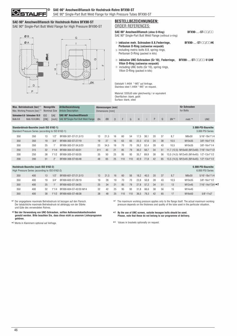
SAE-90° Anschweißflansch für Hochdruck-Rohre BFX90-STSAE 90° Single-Part Butt Weld Flange for High Pressure Tubes BFX90-ST
046
SAE-90° Anschweißflansch für Hochdruck-Rohre BFX90-STSAE 90° Single-Part Butt Weld Flange for High Pressure BFX90-ST
BESTELLBEZEICHNUNGEN:ORDER REFERENCES:SAE-90° Anschweißflansch (ohne O-Ring) BFX90-...-ST-��/��SAE 90° Single-Part Butt Weld Flange (without o-ring)
inklusive metr. Schrauben 8.8,Federringe, BFX90-...-ST-��/��#KPerbunan O-Ring (satzweise verpackt)including metric bolts 8.8, spring rings, Perbunan O-Ring (packed in kits)
inklusive UNC-Schrauben (Gr 10), Federringe, BFX90-...-ST-��/��-V-U#KViton O-Ring (satzweise verpackt) including UNC bolts (Gr 10), spring rings, Viton O-Ring (packed in kits)
Edelstahl 1.4404 “-W5” auf Anfrage.Stainless steel 1.4404 “-W5” on request.
Material: S355J0 oder gleichwertig / or equivalentOberflächen: blank, geöltSurface: blank, oiled
❍
❍
❍
❍
ArtikelbezeichnungArticle Description
SAE-90° AnschweißflanschSAE 90°Single-Part Butt Weld Flange
Max. Betriebsdruck [bar]*1
Max. Working Pressure [bar]*1
Schrauben 8.8Bolts 8.8
Schrauben 10.9Bolts 10.9 (MH)
NenngrößeNominal Size
ISO[DN]
SAE[inch]
Abmessungen [mm]Dimensions [mm]
ØA ØB D F Q ØK*3
Standarddruck-Baureihe (nach ISO 6162-1) 3.000-PSI-BaureiheStandard Pressure Series (according to ISO 6162-1) 3.000 PSI Series
G H I P metr.*3 UNC
für Schraubenfor Bolts
350 350 13 1/2" BFX90-301-ST-21,5/13 13 21,5 16 60 54 17,5 38,1 20 37 8,7 M8x30 5/16"-18x1"1/4
350 350 19 3/4" BFX90-302-ST-27/19 19 27 16 63 65 22,3 47,6 24 38 10,5 M10x35 3/8"-16x1"1/4
350 350 25 1" BFX90-303-ST-34,5/23 23 34,5 19 70 70 26,2 52,4 28 43 10,5 M10x35 3/8"-16x1"1/4
250 315 32 1"1/4 BFX90-304-ST-43/31 311 43 21 85 79 30,2 58,7 34 51 11,7 (12,5) M10x40 (M12x40) 7/16"-14x1"1/2
200 250 38 1"1/2 BFX90-305-ST-50/35 35 50 25 95 93 35,7 69,9 38 56 13,5 (14,5) M12x45 (M14x45) 1/2"-13x1"1/2
200 200 51 2" BFX90-306-ST-65/48 48 65 25 110 110 42,9 77,8 42 65 13,5 (14,5) M12x45 (M14x45) 1/2"-13x1"1/2
Hochdruck-Baureihe (nach ISO 6162-2) 6.000-PSI-BaureiheHigh Pressure Series (according to ISO 6162-2) 6.000 PSI Series
350 400 13 1/2" BFX90-601-ST-21,5/13 13 21,5 16 60 56 18,2 40,5 20 37 8,7 M8x30 5/16"-18x1"1/4
350 400 19 3/4" BFX90-602-ST-28/19 19 28 19 70 70 23,8 50,8 28 43 10,5 M10x35 3/8"-16x1"1/2
350 400 25 1" BFX90-603-ST-34/25 25 34 21 85 79 27,8 57,2 34 51 13 M12x45 7/16"-14x1"3/4
350 400 32 1"1/4 BFX90-604-ST-42/32-M14 32 42 25 95 93 31,8 66,6 38 56 15 M14x45 -
350 400 38 1"1/2 BFX90-605-ST-48/38 38 48 25 110 110 36,5 79,3 42 65 17 M16x50 5/8"-11x2"
★2
★1 Der angegebene maximale Betriebsdruck ist bezogen auf den Flansch. Der tatsächliche maximale Betriebsdruck ist abhängig von der Stärke und Güte des verwendeten Rohres.
★1 The maximum working pressure applies only to the flange itself. The actual maximum workingpressure depends on the thickness and quality of the tube used in the particular situation.
Bei der Verwendung von UNC-Schrauben, sollten Außensechskantschrauben genutzt werden. Bitte beachten Sie, dass diese nicht zu unserem Lieferprogramm gehören.
★2 By the use of UNC screws, outside hexagon bolts should be used. Please, note that these do not belong to our programme of delivery.
★2
★3 Werte in Klammern optional auf Anfrage. ★3 Values in brackets optionally on request.
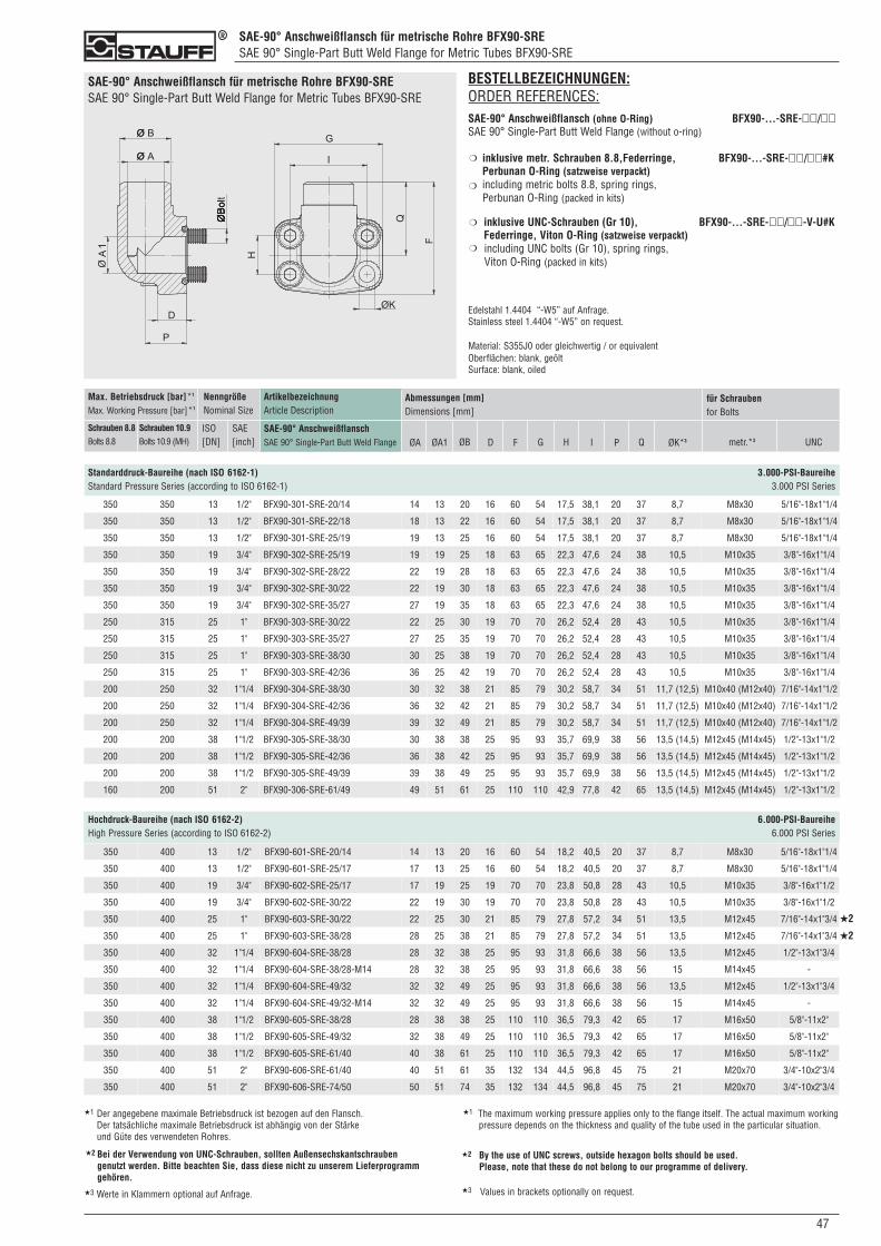
SAE-90° Anschweißflansch für metrische Rohre BFX90-SRESAE 90° Single-Part Butt Weld Flange for Metric Tubes BFX90-SRE
470
SAE-90° Anschweißflansch für metrische Rohre BFX90-SRESAE 90° Single-Part Butt Weld Flange for Metric Tubes BFX90-SRE
BESTELLBEZEICHNUNGEN:ORDER REFERENCES:SAE-90° Anschweißflansch (ohne O-Ring) BFX90-...-SRE-��/��SAE 90° Single-Part Butt Weld Flange (without o-ring)
inklusive metr. Schrauben 8.8,Federringe, BFX90-...-SRE-��/��#KPerbunan O-Ring (satzweise verpackt)including metric bolts 8.8, spring rings, Perbunan O-Ring (packed in kits)
inklusive UNC-Schrauben (Gr 10), BFX90-...-SRE-��/��-V-U#KFederringe, Viton O-Ring (satzweise verpackt) including UNC bolts (Gr 10), spring rings, Viton O-Ring (packed in kits)
Edelstahl 1.4404 “-W5” auf Anfrage.Stainless steel 1.4404 “-W5” on request.
Material: S355J0 oder gleichwertig / or equivalentOberflächen: blank, geöltSurface: blank, oiled
❍
❍
❍
❍
ArtikelbezeichnungArticle Description
SAE-90° AnschweißflanschSAE 90° Single-Part Butt Weld Flange
Max. Betriebsdruck [bar]*1
Max. Working Pressure [bar]*1
Schrauben 8.8Bolts 8.8
Schrauben 10.9Bolts 10.9 (MH)
NenngrößeNominal Size
ISO[DN]
SAE[inch]
Abmessungen [mm]Dimensions [mm]
ØA ØB D F Q ØK*3
Standarddruck-Baureihe (nach ISO 6162-1) 3.000-PSI-BaureiheStandard Pressure Series (according to ISO 6162-1) 3.000 PSI Series
G H I P metr.*3 UNC
für Schraubenfor Bolts
Hochdruck-Baureihe (nach ISO 6162-2) 6.000-PSI-BaureiheHigh Pressure Series (according to ISO 6162-2) 6.000 PSI Series
ØA1
350 350 13 1/2" BFX90-301-SRE-20/14 14 13 20 16 60 54 17,5 38,1 20 37 8,7 M8x30 5/16"-18x1"1/4
350 350 13 1/2" BFX90-301-SRE-22/18 18 13 22 16 60 54 17,5 38,1 20 37 8,7 M8x30 5/16"-18x1"1/4
350 350 13 1/2" BFX90-301-SRE-25/19 19 13 25 16 60 54 17,5 38,1 20 37 8,7 M8x30 5/16"-18x1"1/4
350 350 19 3/4" BFX90-302-SRE-25/19 19 19 25 18 63 65 22,3 47,6 24 38 10,5 M10x35 3/8"-16x1"1/4
350 350 19 3/4" BFX90-302-SRE-28/22 22 19 28 18 63 65 22,3 47,6 24 38 10,5 M10x35 3/8"-16x1"1/4
350 350 19 3/4" BFX90-302-SRE-30/22 22 19 30 18 63 65 22,3 47,6 24 38 10,5 M10x35 3/8"-16x1"1/4
350 350 19 3/4" BFX90-302-SRE-35/27 27 19 35 18 63 65 22,3 47,6 24 38 10,5 M10x35 3/8"-16x1"1/4
250 315 25 1" BFX90-303-SRE-30/22 22 25 30 19 70 70 26,2 52,4 28 43 10,5 M10x35 3/8"-16x1"1/4
250 315 25 1" BFX90-303-SRE-35/27 27 25 35 19 70 70 26,2 52,4 28 43 10,5 M10x35 3/8"-16x1"1/4
250 315 25 1" BFX90-303-SRE-38/30 30 25 38 19 70 70 26,2 52,4 28 43 10,5 M10x35 3/8"-16x1"1/4
250 315 25 1" BFX90-303-SRE-42/36 36 25 42 19 70 70 26,2 52,4 28 43 10,5 M10x35 3/8"-16x1"1/4
200 250 32 1"1/4 BFX90-304-SRE-38/30 30 32 38 21 85 79 30,2 58,7 34 51 11,7 (12,5) M10x40 (M12x40) 7/16"-14x1"1/2
200 250 32 1"1/4 BFX90-304-SRE-42/36 36 32 42 21 85 79 30,2 58,7 34 51 11,7 (12,5) M10x40 (M12x40) 7/16"-14x1"1/2
200 250 32 1"1/4 BFX90-304-SRE-49/39 39 32 49 21 85 79 30,2 58,7 34 51 11,7 (12,5) M10x40 (M12x40) 7/16"-14x1"1/2
200 200 38 1"1/2 BFX90-305-SRE-38/30 30 38 38 25 95 93 35,7 69,9 38 56 13,5 (14,5) M12x45 (M14x45) 1/2"-13x1"1/2
200 200 38 1"1/2 BFX90-305-SRE-42/36 36 38 42 25 95 93 35,7 69,9 38 56 13,5 (14,5) M12x45 (M14x45) 1/2"-13x1"1/2
200 200 38 1"1/2 BFX90-305-SRE-49/39 39 38 49 25 95 93 35,7 69,9 38 56 13,5 (14,5) M12x45 (M14x45) 1/2"-13x1"1/2
160 200 51 2" BFX90-306-SRE-61/49 49 51 61 25 110 110 42,9 77,8 42 65 13,5 (14,5) M12x45 (M14x45) 1/2"-13x1"1/2
350 400 13 1/2" BFX90-601-SRE-20/14 14 13 20 16 60 54 18,2 40,5 20 37 8,7 M8x30 5/16"-18x1"1/4
350 400 13 1/2" BFX90-601-SRE-25/17 17 13 25 16 60 54 18,2 40,5 20 37 8,7 M8x30 5/16"-18x1"1/4
350 400 19 3/4" BFX90-602-SRE-25/17 17 19 25 19 70 70 23,8 50,8 28 43 10,5 M10x35 3/8"-16x1"1/2
350 400 19 3/4" BFX90-602-SRE-30/22 22 19 30 19 70 70 23,8 50,8 28 43 10,5 M10x35 3/8"-16x1"1/2
350 400 25 1" BFX90-603-SRE-30/22 22 25 30 21 85 79 27,8 57,2 34 51 13,5 M12x45 7/16"-14x1"3/4
350 400 25 1" BFX90-603-SRE-38/28 28 25 38 21 85 79 27,8 57,2 34 51 13,5 M12x45 7/16"-14x1"3/4
350 400 32 1"1/4 BFX90-604-SRE-38/28 28 32 38 25 95 93 31,8 66,6 38 56 13,5 M12x45 1/2"-13x1"3/4
350 400 32 1"1/4 BFX90-604-SRE-38/28-M14 28 32 38 25 95 93 31,8 66,6 38 56 15 M14x45 -
350 400 32 1"1/4 BFX90-604-SRE-49/32 32 32 49 25 95 93 31,8 66,6 38 56 13,5 M12x45 1/2"-13x1"3/4
350 400 32 1"1/4 BFX90-604-SRE-49/32-M14 32 32 49 25 95 93 31,8 66,6 38 56 15 M14x45 -
350 400 38 1"1/2 BFX90-605-SRE-38/28 28 38 38 25 110 110 36,5 79,3 42 65 17 M16x50 5/8"-11x2"
350 400 38 1"1/2 BFX90-605-SRE-49/32 32 38 49 25 110 110 36,5 79,3 42 65 17 M16x50 5/8"-11x2"
350 400 38 1"1/2 BFX90-605-SRE-61/40 40 38 61 25 110 110 36,5 79,3 42 65 17 M16x50 5/8"-11x2"
350 400 51 2" BFX90-606-SRE-61/40 40 51 61 35 132 134 44,5 96,8 45 75 21 M20x70 3/4"-10x2"3/4
350 400 51 2" BFX90-606-SRE-74/50 50 51 74 35 132 134 44,5 96,8 45 75 21 M20x70 3/4"-10x2"3/4
★2
★2
★1 Der angegebene maximale Betriebsdruck ist bezogen auf den Flansch. Der tatsächliche maximale Betriebsdruck ist abhängig von der Stärke und Güte des verwendeten Rohres.
★1 The maximum working pressure applies only to the flange itself. The actual maximum workingpressure depends on the thickness and quality of the tube used in the particular situation.
Bei der Verwendung von UNC-Schrauben, sollten Außensechskantschrauben genutzt werden. Bitte beachten Sie, dass diese nicht zu unserem Lieferprogramm gehören.
★2 By the use of UNC screws, outside hexagon bolts should be used. Please, note that these do not belong to our programme of delivery.
★2
★3 Werte in Klammern optional auf Anfrage. ★3 Values in brackets optionally on request.
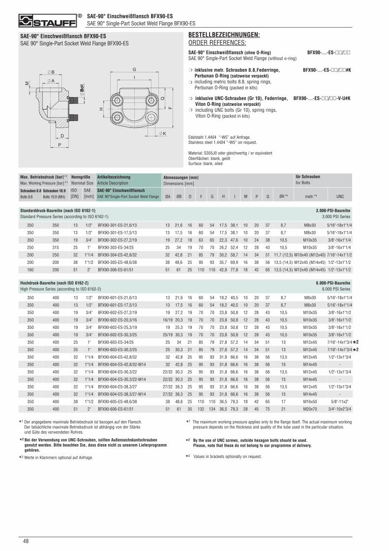
SAE-90° Einschweißflansch BFX90-ESSAE 90° Single-Part Socket Weld Flange BFX90-ES
048
SAE-90° Einschweißflansch BFX90-ESSAE 90° Single-Part Socket Weld Flange BFX90-ES
ArtikelbezeichnungArticle Description
SAE-90° EinschweißflanschSAE 90°Single-Part Socket Weld Flange
Max. Betriebsdruck [bar]*1
Max. Working Pressure [bar]*1
Schrauben 8.8Bolts 8.8
Schrauben 10.9Bolts 10.9 (MH)
NenngrößeNominal Size
ISO[DN]
SAE[inch]
Abmessungen [mm]Dimensions [mm]
ØA ØB D F Q ØK*3
Standarddruck-Baureihe (nach ISO 6162-1) 3.000-PSI-BaureiheStandard Pressure Series (according to ISO 6162-1) 3.000 PSI Series
G H I P metr.*3 UNC
für Schraubenfor Bolts
BESTELLBEZEICHNUNGEN:ORDER REFERENCES:SAE-90° Einschweißflansch (ohne O-Ring) BFX90-...-ES-��/��SAE 90° Single-Part Socket Weld Flange (without o-ring)
inklusive metr. Schrauben 8.8,Federringe, BFX90-...-ES-��/��#KPerbunan O-Ring (satzweise verpackt)including metric bolts 8.8, spring rings, Perbunan O-Ring (packed in kits)
inklusive UNC-Schrauben (Gr 10), Federringe, BFX90-...-ES-��/��-V-U#KViton O-Ring (satzweise verpackt) including UNC bolts (Gr 10), spring rings, Viton O-Ring (packed in kits)
Edelstahl 1.4404 “-W5” auf Anfrage.Stainless steel 1.4404 “-W5” on request.
Material: S355J0 oder gleichwertig / or equivalentOberflächen: blank, geöltSurface: blank, oiled
❍
❍
❍
❍
350 350 13 1/2" BFX90-301-ES-21,6/13 13 21,6 16 60 54 17,5 38,1 10 20 37 8,7 M8x30 5/16"-18x1"1/4
350 350 13 1/2" BFX90-301-ES-17,5/13 13 17,5 16 60 54 17,5 38,1 10 20 37 8,7 M8x30 5/16"-18x1"1/4
350 350 19 3/4" BFX90-302-ES-27,2/19 19 27,2 18 63 65 22,3 47,6 10 24 38 10,5 M10x35 3/8"-16x1"1/4
250 315 25 1" BFX90-303-ES-34/25 25 34 19 70 70 26,2 52,4 12 28 43 10,5 M10x35 3/8"-16x1"1/4
200 250 32 1"1/4 BFX90-304-ES-42,8/32 32 42,8 21 85 79 30,2 58,7 14 34 51 11,7 (12,5) M10x40 (M12x40) 7/16"-14x1"1/2
200 200 38 1"1/2 BFX90-305-ES-48,6/38 38 48,6 25 95 93 35,7 69,9 16 38 56 13,5 (14,5) M12x45 (M14x45) 1/2"-13x1"1/2
160 200 51 2" BFX90-306-ES-61/51 51 61 25 110 110 42,9 77,8 18 42 65 13,5 (14,5) M12x45 (M14x45) 1/2"-13x1"1/2
M
350 400 13 1/2" BFX90-601-ES-21,6/13 13 21,6 16 60 54 18,2 40,5 10 20 37 8,7 M8x30 5/16"-18x1"1/4
350 400 13 1/2" BFX90-601-ES-17,5/13 13 17,5 16 60 54 18,2 40,5 10 20 37 8,7 M8x30 5/16"-18x1"1/4
350 400 19 3/4" BFX90-602-ES-27,2/19 19 27,2 19 70 70 23,8 50,8 12 28 43 10,5 M10x35 3/8"-16x1"1/2
350 400 19 3/4" BFX90-602-ES-20,3/16 16/19 20,3 19 70 70 23,8 50,8 12 28 43 10,5 M10x35 3/8"-16x1"1/2
350 400 19 3/4" BFX90-602-ES-25,3/19 19 25,3 19 70 70 23,8 50,8 12 28 43 10,5 M10x35 3/8"-16x1"1/2
350 400 19 3/4" BFX90-602-ES-30,3/25 25/19 30,3 19 70 70 23,8 50,8 12 28 43 10,5 M10x35 3/8"-16x1"1/2
350 400 25 1" BFX90-603-ES-34/25 25 34 21 85 79 27,8 57,2 14 34 51 13 M12x45 7/16"-14x1"3/4
350 400 25 1" BFX90-603-ES-30,3/25 25 30,3 21 85 79 27,8 57,2 14 34 51 13 M12x45 7/16"-14x1"3/4
350 400 32 1"1/4 BFX90-604-ES-42,8/32 32 42,8 25 95 93 31,8 66,6 16 38 56 13,5 M12x45 1/2"-13x1"3/4
350 400 32 1"1/4 BFX90-604-ES-42,8/32-M14 32 42,8 25 95 93 31,8 66,6 16 38 56 15 M14x45 -
350 400 32 1"1/4 BFX90-604-ES-30,3/22 22/32 30,3 25 95 93 31,8 66,6 16 38 56 13,5 M12x45 1/2"-13x1"3/4
350 400 32 1"1/4 BFX90-604-ES-30,3/22-M14 22/32 30,3 25 95 93 31,8 66,6 16 38 56 15 M14x45 -
350 400 32 1"1/4 BFX90-604-ES-38,3/27 27/32 38,3 25 95 93 31,8 66,6 16 38 56 13,5 M12x45 1/2"-13x1"3/4
350 400 32 1"1/4 BFX90-604-ES-38,3/27-M14 27/32 38,3 25 95 93 31,8 66,6 16 38 56 15 M14x45 -
350 400 38 1"1/2 BFX90-605-ES-48,6/38 38 48,6 25 110 110 36,5 79,3 18 42 65 17 M16x50 5/8"-11x2"
350 400 51 2" BFX90-606-ES-61/51 51 61 35 132 134 36,5 79,3 28 45 75 21 M20x70 3/4"-10x2"3/4
Hochdruck-Baureihe (nach ISO 6162-2) 6.000-PSI-BaureiheHigh Pressure Series (according to ISO 6162-2) 6.000 PSI Series
★2
★2
★1 Der angegebene maximale Betriebsdruck ist bezogen auf den Flansch. Der tatsächliche maximale Betriebsdruck ist abhängig von der Stärke und Güte des verwendeten Rohres.
★1 The maximum working pressure applies only to the flange itself. The actual maximum workingpressure depends on the thickness and quality of the tube used in the particular situation.
Bei der Verwendung von UNC-Schrauben, sollten Außensechskantschrauben genutzt werden. Bitte beachten Sie, dass diese nicht zu unserem Lieferprogramm gehören.
★2 By the use of UNC screws, outside hexagon bolts should be used. Please, note that these do not belong to our programme of delivery.
★2
★3 Werte in Klammern optional auf Anfrage. ★3 Values in brackets optionally on request.
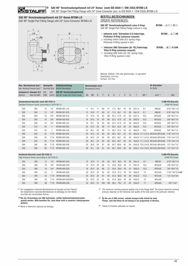
SAE-90° Verschraubungsflansch mit 24°-Konus (nach ISO 8434-1 / DIN 2353) BFX90-L/SSAE 90° Single-Part Fitting Flange with 24° Cone Connector (acc. to ISO 8434-1 / DIN 2353) BFX90-L/S
490
SAE-90° Verschraubungsflansch mit 24°-Konus BFX90-L/SSAE 90° Single-Part Fitting Flange with 24° Cone Connector BFX90-L/S
350 350 13 1/2" BFX90-301-L15 11 15 L 17 60 57 17,5 38,1 19 36 22x1,5 8,7 M8x30 5/16"-18x1"1/4
350 350 13 1/2" BFX90-301-S16 12 16 S 17 60 57 17,5 38,1 19 36 24x1,5 8,7 M8x30 5/16"-18x1"1/4
350 350 19 3/4" BFX90-302-S16 12 16 S 19 63 68 22,3 47,6 22 38 24x1,5 10,5 M10x35 3/8"-16x1"1/4
350 350 19 3/4" BFX90-302-S20 16 20 S 19 63 68 22,3 47,6 22 38 30x2,0 10,5 M10x35 3/8"-16x1"1/4
350 350 19 3/4" BFX90-302-L22 18 22 L 19 63 68 22,3 47,6 22 38 30x2,0 10,5 M10x35 3/8"-16x1"1/4
250 315 25 1" BFX90-303-S25 20 25 S 20 69 74 26,2 52,4 28 42 36x2,0 10,5 M10x35 3/8"-16x1"1/4
250 315 25 1" BFX90-303-L28 23 28 L 20 69 74 26,2 52,4 28 42 36x2,0 10,5 M10x35 3/8"-16x1"1/4
200 250 32 1"1/4 BFX90-304-S25 20 25 S 24 85 82 30,2 58,7 30 50 36x2,0 11,7 (12,5) M10x40 (M12x40) 7/16"-14x1"1/2
200 250 32 1"1/4 BFX90-304-S30 25 30 S 24 85 82 30,2 58,7 30 50 42x2,0 11,7 (12,5) M10x40 (M12x40) 7/16"-14x1"1/2
200 250 32 1"1/4 BFX90-304-L35 30 35 L 24 85 82 30,2 58,7 30 50 45x2,0 11,7 (12,5) M10x40 (M12x40) 7/16"-14x1"1/2
200 200 38 1"1/2 BFX90-305-S38 32 38 S 26 97 94 35,7 69,9 36 58 52x2,0 13,5 (14,5) M12x45 (M14x45) 1/2"-13x1"1/2
200 200 38 1"1/2 BFX90-305-L42 36 42 L 26 97 94 35,7 69,9 36 58 52x2,0 13,5 (14,5) M12x45 (M14x45) 1/2"-13x1"1/2
ArtikelbezeichnungArticle Description
SAE-90° VerschraubungsflanschSAE 90° Single-Part Fitting Flange
Max. Betriebsdruck [bar]*1
Max. Working Pressure [bar]*1
Schrauben 8.8Bolts 8.8
Schrauben 10.9Bolts 10.9 (MH)
NenngrößeNominal Size
ISO[DN]
SAE[inch]
Abmessungen [mm]Dimensions [mm]
ØA ØB D F Q ØK*3
Standarddruck-Baureihe (nach ISO 6162-1) 3.000-PSI-BaureiheStandard Pressure Series (according to ISO 6162-1) 3.000 PSI Series
G H I P metr.*3 UNC
für Schraubenfor Bolts
T
BESTELLBEZEICHNUNGEN:ORDER REFERENCES:SAE-90° Verschraubungsflansch (ohne O-Ring) BFX90-...-L�� / -S��SAE 90° Single-Part Fitting Flange (without o-ring)
inklusive metr. Schrauben 8.8,Federringe, BFX90-...-L��#KPerbunan O-Ring (satzweise verpackt)including metric bolts 8.8, spring rings, Perbunan O-Ring (packed in kits)
inklusive UNC-Schrauben (Gr 10),Federringe, BFX90-...-S��-V-U#KViton O-Ring (satzweise verpackt) including UNC bolts (Gr 10), spring rings, Viton O-Ring (packed in kits)
Material: S355J0 / C45 oder gleichwertig / or equivalentOberflächen: CrVI-freiSurface: CrVI free
❍
❍
❍
❍
Hochdruck-Baureihe (nach ISO 6162-2) 6.000-PSI-BaureiheHigh Pressure Series (according to ISO 6162-2) 6.000 PSI Series
350 400 13 1/2" BFX90-601-S16 12 16 S 17 59 58 18,2 40,5 19 36 24x1,5 8,7 M8x30 5/16"-18x1"1/4
350 400 19 3/4" BFX90-602-S16 12 16 S 20 68 72 23,8 50,8 26 41 24x1,5 10,5 M10x35 3/8"-16x1"1/2
350 400 19 3/4" BFX90-602-S20 16 20 S 20 68 72 23,8 50,8 26 41 30x2,0 10,5 M10x35 3/8"-16x1"1/2
350 400 25 1" BFX90-603-S25 20 25 S 24 84 82 27,8 57,2 30 50 36x2,0 13 M12x45 7/16"-14x1"3/4
350 400 32 1"1/4 BFX90-604-S30 25 30 S 25 97 94 31,8 66,6 36 58 42x2,0 13,5 M12x45 1/2"-13x1"3/4
350 400 32 1"1/4 BFX90-604-S30-M14 25 30 S 25 97 94 31,8 66,6 36 58 42x2,0 15 M14x45 -
350 400 38 1"1/2 BFX90-605-S38 32 38 S 27 109 105 36,5 79,3 41 65 52x2,0 17 M16x50 5/8"-11x2"
★2
★1 Der angegebene maximale Betriebsdruck ist bezogen auf den Flansch. Der tatsächliche maximale Betriebsdruck ist abhängig von der Stärke und Güte des verwendeten Rohres.
★1 The maximum working pressure applies only to the flange itself. The actual maximum workingpressure depends on the thickness and quality of the tube used in the particular situation.
Bei der Verwendung von UNC-Schrauben, sollten Außensechskantschrauben genutzt werden. Bitte beachten Sie, dass diese nicht zu unserem Lieferprogramm gehören.
★2 By the use of UNC screws, outside hexagon bolts should be used. Please, note that these do not belong to our programme of delivery.
★2
★3 Werte in Klammern optional auf Anfrage. ★3 Values in brackets optionally on request.
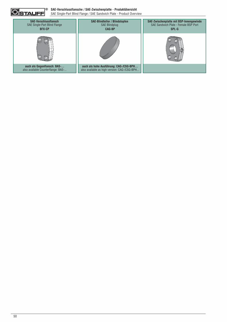
SAE-Verschlussflansche / SAE-Zwischenplatte - ProduktübersichtSAE Single-Part Blind Flange / SAE Sandwich Plate - Product Overview
050
SAE-Blindteller / Blindstopfen SAE Blindplug
CAG-BP
auch als Gegenflansch: BAS-... also available Counterflange: BAS-...
SAE-Verschlussflansch SAE Single-Part Blind Flange
BFX-CP
SAE-Zwischenplatte mit BSP-InnengewindeSAE Sandwich Plate - Female BSP Port
SPL-G
auch als hohe Ausführung: CAG-/CSG-BPH...also available as high version: CAG-/CSG-BPH...
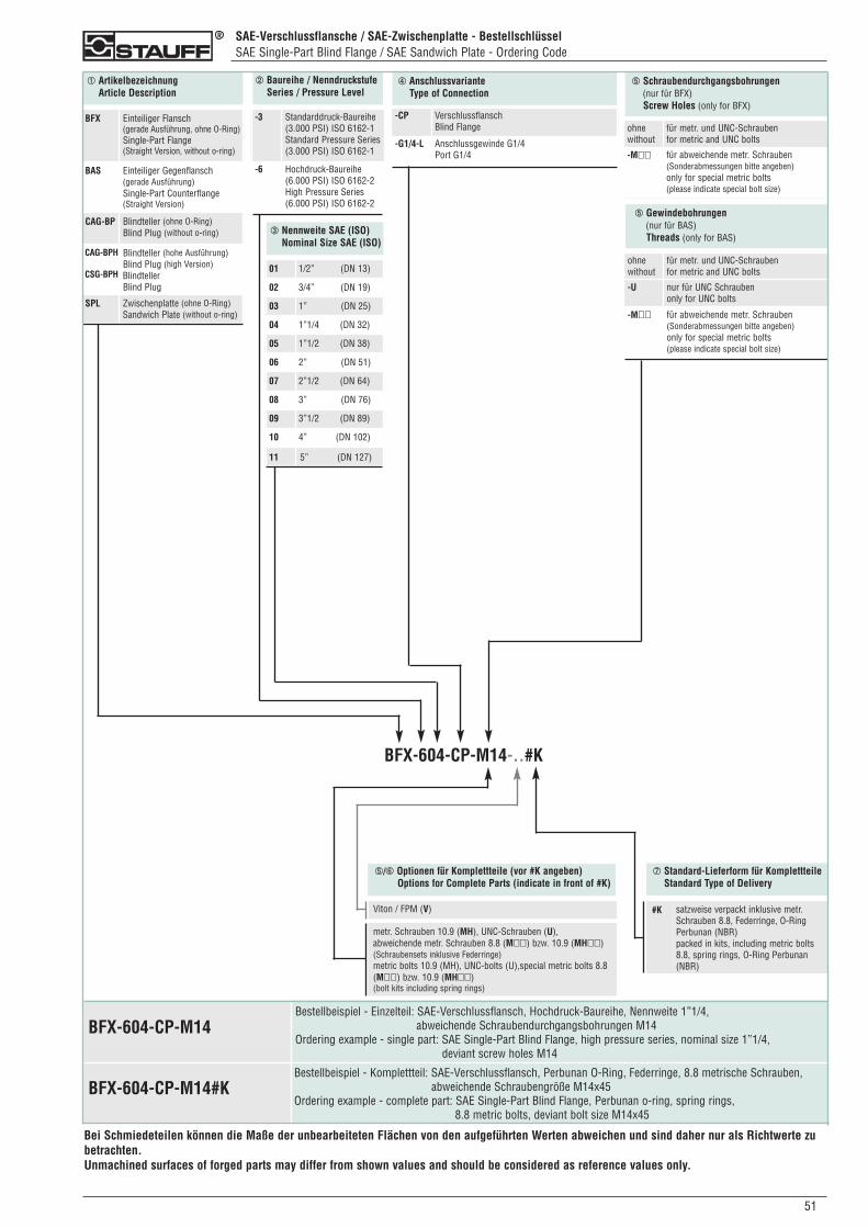
SAE-Verschlussflansche / SAE-Zwischenplatte - BestellschlüsselSAE Single-Part Blind Flange / SAE Sandwich Plate - Ordering Code
510
➀ ArtikelbezeichnungArticle Description
➁ Baureihe / NenndruckstufeSeries / Pressure Level
➃ AnschlussvarianteType of Connection
BFX Einteiliger Flansch(gerade Ausführung, ohne O-Ring)Single-Part Flange(Straight Version, without o-ring)
BAS Einteiliger Gegenflansch(gerade Ausführung)Single-Part Counterflange(Straight Version)
CAG-BP Blindteller (ohne O-Ring)Blind Plug (without o-ring)
CAG-BPH
CSG-BPH
Blindteller (hohe Ausführung)Blind Plug (high Version)BlindtellerBlind Plug
SPL Zwischenplatte (ohne O-Ring)Sandwich Plate (without o-ring)
-3 Standarddruck-Baureihe(3.000 PSI) ISO 6162-1Standard Pressure Series(3.000 PSI) ISO 6162-1
-6 Hochdruck-Baureihe(6.000 PSI) ISO 6162-2High Pressure Series(6.000 PSI) ISO 6162-2
-CP VerschlussflanschBlind Flange
-G1/4-L Anschlussgewinde G1/4Port G1/4
➂ Nennweite SAE (ISO)Nominal Size SAE (ISO)
01 1/2” (DN 13)
02 3/4” (DN 19)
03 1” (DN 25)
04 1”1/4 (DN 32)
05 1”1/2 (DN 38)
06 2” (DN 51)
07 2”1/2 (DN 64)
08 3” (DN 76)
09 3”1/2 (DN 89)
10 4” (DN 102)
11 5” (DN 127)
➄ Schraubendurchgangsbohrungen(nur für BFX)Screw Holes (only for BFX)
ohnewithout
für metr. und UNC-Schraubenfor metric and UNC bolts
-M�� für abweichende metr. Schrauben (Sonderabmessungen bitte angeben)only for special metric bolts(please indicate special bolt size)
BFX-604-CP-M14-..#K
➄/➅ Optionen für Komplettteile (vor #K angeben)Options for Complete Parts (indicate in front of #K)
Viton / FPM (V)
metr. Schrauben 10.9 (MH), UNC-Schrauben (U), abweichende metr. Schrauben 8.8 (M��) bzw. 10.9 (MH��)(Schraubensets inklusive Federringe)metric bolts 10.9 (MH), UNC-bolts (U),special metric bolts 8.8(M��) bzw. 10.9 (MH��)(bolt kits including spring rings)
➆ Standard-Lieferform für KomplettteileStandard Type of Delivery
#K satzweise verpackt inklusive metr.Schrauben 8.8, Federringe, O-RingPerbunan (NBR)packed in kits, including metric bolts8.8, spring rings, O-Ring Perbunan(NBR)
➄ Gewindebohrungen(nur für BAS)Threads (only for BAS)
ohnewithout
für metr. und UNC-Schraubenfor metric and UNC bolts
-U nur für UNC Schraubenonly for UNC bolts
-M�� für abweichende metr. Schrauben (Sonderabmessungen bitte angeben)only for special metric bolts(please indicate special bolt size)
Bestellbeispiel - Einzelteil: SAE-Verschlussflansch, Hochdruck-Baureihe, Nennweite 1”1/4, abweichende Schraubendurchgangsbohrungen M14
Ordering example - single part: SAE Single-Part Blind Flange, high pressure series, nominal size 1”1/4, deviant screw holes M14
BFX-604-CP-M14#K
BFX-604-CP-M14
Bestellbeispiel - Komplettteil: SAE-Verschlussflansch, Perbunan O-Ring, Federringe, 8.8 metrische Schrauben,abweichende Schraubengröße M14x45
Ordering example - complete part: SAE Single-Part Blind Flange, Perbunan o-ring, spring rings, 8.8 metric bolts, deviant bolt size M14x45
Bei Schmiedeteilen können die Maße der unbearbeiteten Flächen von den aufgeführten Werten abweichen und sind daher nur als Richtwerte zubetrachten.Unmachined surfaces of forged parts may differ from shown values and should be considered as reference values only.
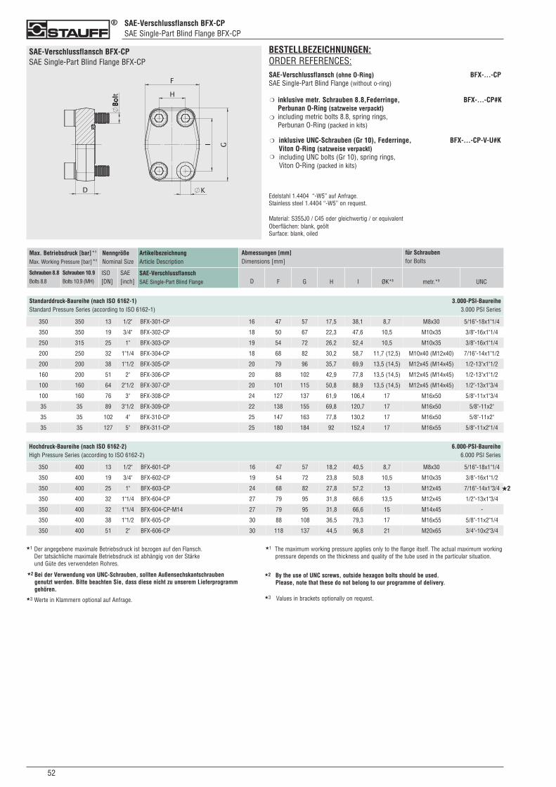
SAE-Verschlussflansch BFX-CPSAE Single-Part Blind Flange BFX-CP
052
SAE-Verschlussflansch BFX-CPSAE Single-Part Blind Flange BFX-CP
BESTELLBEZEICHNUNGEN:ORDER REFERENCES:SAE-Verschlussflansch (ohne O-Ring) BFX-...-CPSAE Single-Part Blind Flange (without o-ring)
inklusive metr. Schrauben 8.8,Federringe, BFX-...-CP#KPerbunan O-Ring (satzweise verpackt)including metric bolts 8.8, spring rings, Perbunan O-Ring (packed in kits)
inklusive UNC-Schrauben (Gr 10), Federringe, BFX-...-CP-V-U#KViton O-Ring (satzweise verpackt) including UNC bolts (Gr 10), spring rings, Viton O-Ring (packed in kits)
Edelstahl 1.4404 “-W5” auf Anfrage.Stainless steel 1.4404 “-W5” on request.
Material: S355J0 / C45 oder gleichwertig / or equivalentOberflächen: blank, geöltSurface: blank, oiled
❍
❍
❍
❍
ArtikelbezeichnungArticle Description
SAE-VerschlussflanschSAE Single-Part Blind Flange
Max. Betriebsdruck [bar]*1
Max. Working Pressure [bar]*1
Schrauben 8.8Bolts 8.8
Schrauben 10.9Bolts 10.9 (MH)
NenngrößeNominal Size
ISO[DN]
SAE[inch]
Abmessungen [mm]Dimensions [mm]
D F ØK*3
Standarddruck-Baureihe (nach ISO 6162-1) 3.000-PSI-BaureiheStandard Pressure Series (according to ISO 6162-1) 3.000 PSI Series
G H I metr.*3 UNC
für Schraubenfor Bolts
350 350 13 1/2" BFX-301-CP 16 47 57 17,5 38,1 8,7 M8x30 5/16"-18x1"1/4
350 350 19 3/4" BFX-302-CP 18 50 67 22,3 47,6 10,5 M10x35 3/8"-16x1"1/4
250 315 25 1" BFX-303-CP 19 54 72 26,2 52,4 10,5 M10x35 3/8"-16x1"1/4
200 250 32 1"1/4 BFX-304-CP 18 68 82 30,2 58,7 11,7 (12,5) M10x40 (M12x40) 7/16"-14x1"1/2
200 200 38 1"1/2 BFX-305-CP 20 79 96 35,7 69,9 13,5 (14,5) M12x45 (M14x45) 1/2-13"x1"1/2
160 200 51 2" BFX-306-CP 20 88 102 42,9 77,8 13,5 (14,5) M12x45 (M14x45) 1/2-13"x1"1/2
100 160 64 2"1/2 BFX-307-CP 20 101 115 50,8 88,9 13,5 (14,5) M12x45 (M14x45) 1/2"-13x1"3/4
100 160 76 3" BFX-308-CP 24 127 137 61,9 106,4 17 M16x50 5/8"-11x1"3/4
35 35 89 3"1/2 BFX-309-CP 22 138 155 69,8 120,7 17 M16x50 5/8"-11x2"
35 35 102 4" BFX-310-CP 25 147 163 77,8 130,2 17 M16x50 5/8"-11x2"
35 35 127 5" BFX-311-CP 25 180 184 92 152,4 17 M16x55 5/8"-11x2"1/4
Hochdruck-Baureihe (nach ISO 6162-2) 6.000-PSI-BaureiheHigh Pressure Series (according to ISO 6162-2) 6.000 PSI Series
350 400 13 1/2" BFX-601-CP 16 47 57 18,2 40,5 8,7 M8x30 5/16"-18x1"1/4
350 400 19 3/4" BFX-602-CP 19 54 72 23,8 50,8 10,5 M10x35 3/8"-16x1"1/2
350 400 25 1" BFX-603-CP 24 68 82 27,8 57,2 13 M12x45 7/16"-14x1"3/4
350 400 32 1"1/4 BFX-604-CP 27 79 95 31,8 66,6 13,5 M12x45 1/2"-13x1"3/4
350 400 32 1"1/4 BFX-604-CP-M14 27 79 95 31,8 66,6 15 M14x45 -
350 400 38 1"1/2 BFX-605-CP 30 88 108 36,5 79,3 17 M16x55 5/8"-11x2"1/4
350 400 51 2" BFX-606-CP 30 118 137 44,5 96,8 21 M20x65 3/4"-10x2"3/4
★2
★1 Der angegebene maximale Betriebsdruck ist bezogen auf den Flansch. Der tatsächliche maximale Betriebsdruck ist abhängig von der Stärke und Güte des verwendeten Rohres.
★1 The maximum working pressure applies only to the flange itself. The actual maximum workingpressure depends on the thickness and quality of the tube used in the particular situation.
Bei der Verwendung von UNC-Schrauben, sollten Außensechskantschrauben genutzt werden. Bitte beachten Sie, dass diese nicht zu unserem Lieferprogramm gehören.
★2 By the use of UNC screws, outside hexagon bolts should be used. Please, note that these do not belong to our programme of delivery.
★2
★3 Werte in Klammern optional auf Anfrage. ★3 Values in brackets optionally on request.
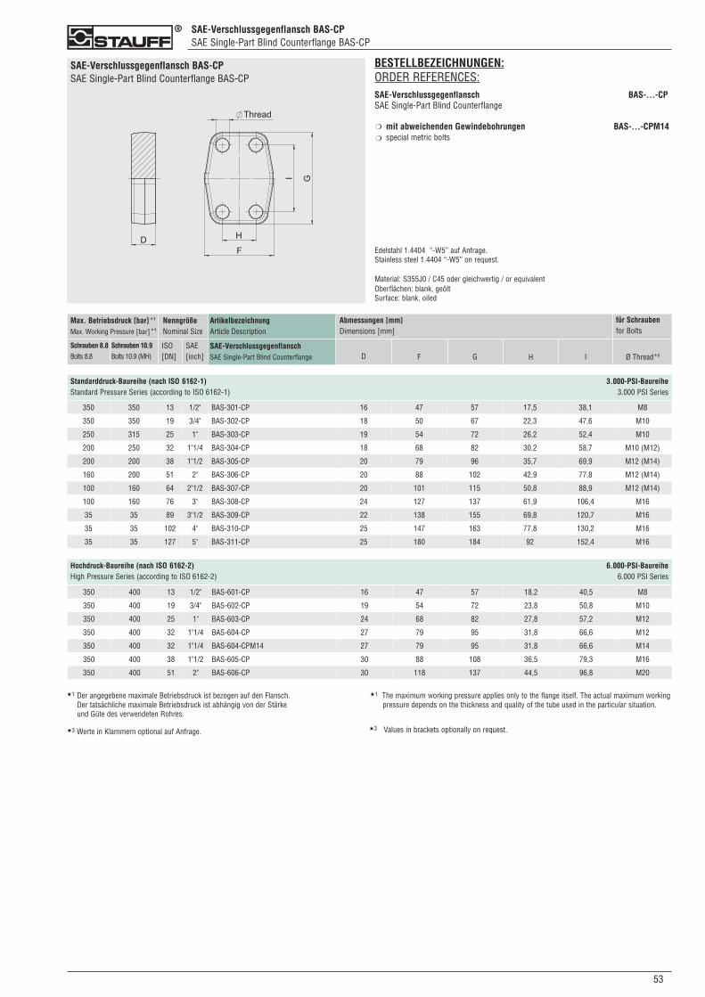
SAE-Verschlussgegenflansch BAS-CPSAE Single-Part Blind Counterflange BAS-CP
530
SAE-Verschlussgegenflansch BAS-CPSAE Single-Part Blind Counterflange BAS-CP
ArtikelbezeichnungArticle Description
SAE-VerschlussgegenflanschSAE Single-Part Blind Counterflange
Max. Betriebsdruck [bar]*1
Max. Working Pressure [bar]*1
Schrauben 8.8Bolts 8.8
Schrauben 10.9Bolts 10.9 (MH)
NenngrößeNominal Size
ISO[DN]
SAE[inch]
Abmessungen [mm]Dimensions [mm]
D F
Standarddruck-Baureihe (nach ISO 6162-1) 3.000-PSI-BaureiheStandard Pressure Series (according to ISO 6162-1) 3.000 PSI Series
G H I Ø Thread*3
für Schraubenfor Bolts
350 350 13 1/2" BAS-301-CP 16 47 57 17,5 38,1 M8
350 350 19 3/4" BAS-302-CP 18 50 67 22,3 47,6 M10
250 315 25 1" BAS-303-CP 19 54 72 26,2 52,4 M10
200 250 32 1"1/4 BAS-304-CP 18 68 82 30,2 58,7 M10 (M12)
200 200 38 1"1/2 BAS-305-CP 20 79 96 35,7 69,9 M12 (M14)
160 200 51 2" BAS-306-CP 20 88 102 42,9 77,8 M12 (M14)
100 160 64 2"1/2 BAS-307-CP 20 101 115 50,8 88,9 M12 (M14)
100 160 76 3" BAS-308-CP 24 127 137 61,9 106,4 M16
35 35 89 3"1/2 BAS-309-CP 22 138 155 69,8 120,7 M16
35 35 102 4" BAS-310-CP 25 147 163 77,8 130,2 M16
35 35 127 5" BAS-311-CP 25 180 184 92 152,4 M16
BESTELLBEZEICHNUNGEN:ORDER REFERENCES:SAE-Verschlussgegenflansch BAS-...-CPSAE Single-Part Blind Counterflange
mit abweichenden Gewindebohrungen BAS-...-CPM14special metric bolts
Edelstahl 1.4404 “-W5” auf Anfrage.Stainless steel 1.4404 “-W5” on request.
Material: S355J0 / C45 oder gleichwertig / or equivalentOberflächen: blank, geöltSurface: blank, oiled
❍
❍
350 400 13 1/2" BAS-601-CP 16 47 57 18,2 40,5 M8
350 400 19 3/4" BAS-602-CP 19 54 72 23,8 50,8 M10
350 400 25 1" BAS-603-CP 24 68 82 27,8 57,2 M12
350 400 32 1"1/4 BAS-604-CP 27 79 95 31,8 66,6 M12
350 400 32 1"1/4 BAS-604-CPM14 27 79 95 31,8 66,6 M14
350 400 38 1"1/2 BAS-605-CP 30 88 108 36,5 79,3 M16
350 400 51 2" BAS-606-CP 30 118 137 44,5 96,8 M20
Hochdruck-Baureihe (nach ISO 6162-2) 6.000-PSI-BaureiheHigh Pressure Series (according to ISO 6162-2) 6.000 PSI Series
★1 Der angegebene maximale Betriebsdruck ist bezogen auf den Flansch. Der tatsächliche maximale Betriebsdruck ist abhängig von der Stärke und Güte des verwendeten Rohres.
★1 The maximum working pressure applies only to the flange itself. The actual maximum workingpressure depends on the thickness and quality of the tube used in the particular situation.
★3 Werte in Klammern optional auf Anfrage. ★3 Values in brackets optionally on request.
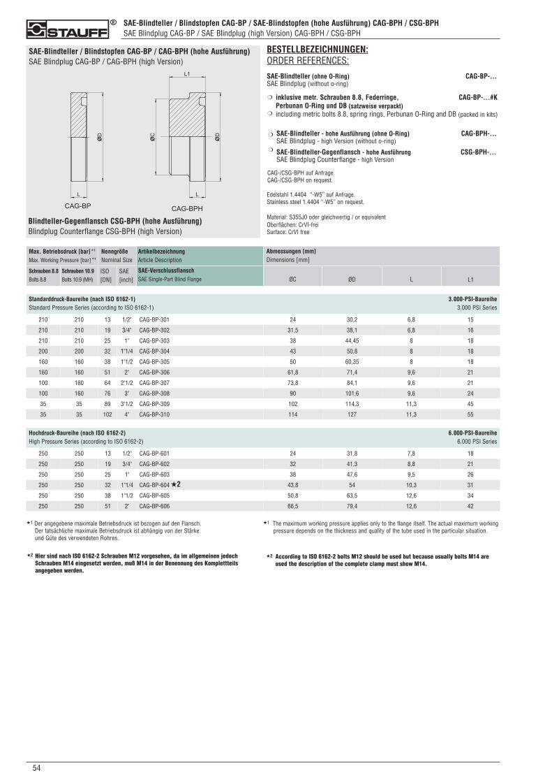
054
SAE-Blindteller / Blindstopfen CAG-BP / SAE-Blindstopfen (hohe Ausführung) CAG-BPH / CSG-BPH SAE Blindplug CAG-BP / SAE Blindplug (high Version) CAG-BPH / CSG-BPH
SAE-Blindteller / Blindstopfen CAG-BP / CAG-BPH (hohe Ausführung)SAE Blindplug CAG-BP / CAG-BPH (high Version)
BESTELLBEZEICHNUNGEN:ORDER REFERENCES:
SAE-Blindteller (ohne O-Ring) CAG-BP-...SAE Blindplug (without o-ring)
inklusive metr. Schrauben 8.8, Federringe, CAG-BP-...#K Perbunan O-Ring und DB (satzweise verpackt)including metric bolts 8.8, spring rings, Perbunan O-Ring and DB (packed in kits)
SAE-Blindteller - hohe Ausführung (ohne O-Ring) CAG-BPH-...SAE Blindplug - high Version (without o-ring)
SAE-Blindteller-Gegenflansch - hohe Ausführung CSG-BPH-...SAE Blindplug Counterflange - high Version
CAG-/CSG-BPH auf Anfrage.CAG-/CSG-BPH on request.
Edelstahl 1.4404 “-W5” auf Anfrage.Stainless steel 1.4404 “-W5” on request.
Material: S355J0 oder gleichwertig / or equivalentOberflächen: CrVI-freiSurface: CrVI free
❍
❍
❍
❍
Blindteller-Gegenflansch CSG-BPH (hohe Ausführung)Blindplug Counterflange CSG-BPH (high Version)
ArtikelbezeichnungArticle Description
SAE-VerschlussflanschSAE Single-Part Blind Flange
Max. Betriebsdruck [bar]*1
Max. Working Pressure [bar]*1
Schrauben 8.8Bolts 8.8
Schrauben 10.9Bolts 10.9 (MH)
NenngrößeNominal Size
ISO[DN]
SAE[inch]
Abmessungen [mm]Dimensions [mm]
ØC ØD
Standarddruck-Baureihe (nach ISO 6162-1) 3.000-PSI-BaureiheStandard Pressure Series (according to ISO 6162-1) 3.000 PSI Series
L
210 210 13 1/2" CAG-BP-301 24 30,2 6,8 15
210 210 19 3/4" CAG-BP-302 31,5 38,1 6,8 16
210 210 25 1" CAG-BP-303 38 44,45 8 18
200 200 32 1"1/4 CAG-BP-304 43 50,8 8 18
160 160 38 1"1/2 CAG-BP-305 50 60,35 8 18
160 160 51 2" CAG-BP-306 61,8 71,4 9,6 21
100 160 64 2"1/2 CAG-BP-307 73,8 84,1 9,6 21
100 160 76 3" CAG-BP-308 90 101,6 9,6 24
35 35 89 3"1/2 CAG-BP-309 102 114,3 11,3 45
35 35 102 4" CAG-BP-310 114 127 11,3 55
★1 Der angegebene maximale Betriebsdruck ist bezogen auf den Flansch. Der tatsächliche maximale Betriebsdruck ist abhängig von der Stärke und Güte des verwendeten Rohres.
★1 The maximum working pressure applies only to the flange itself. The actual maximum workingpressure depends on the thickness and quality of the tube used in the particular situation.
Hier sind nach ISO 6162-2 Schrauben M12 vorgesehen, da im allgemeinen jedochSchrauben M14 eingesetzt werden, muß M14 in der Benennung des Komplettteilsangegeben werden.
★2 According to ISO 6162-2 bolts M12 should be used but because usually bolts M14 areused the description of the complete clamp must show M14.
★2
Hochdruck-Baureihe (nach ISO 6162-2) 6.000-PSI-BaureiheHigh Pressure Series (according to ISO 6162-2) 6.000 PSI Series
250 250 13 1/2" CAG-BP-601 24 31,8 7,8 18
250 250 19 3/4" CAG-BP-602 32 41,3 8,8 21
250 250 25 1" CAG-BP-603 38 47,6 9,5 26
250 250 32 1"1/4 CAG-BP-604 43,8 54 10,3 31
250 250 38 1"1/2 CAG-BP-605 50,8 63,5 12,6 34
250 250 51 2" CAG-BP-606 66,5 79,4 12,6 42
★2
L1
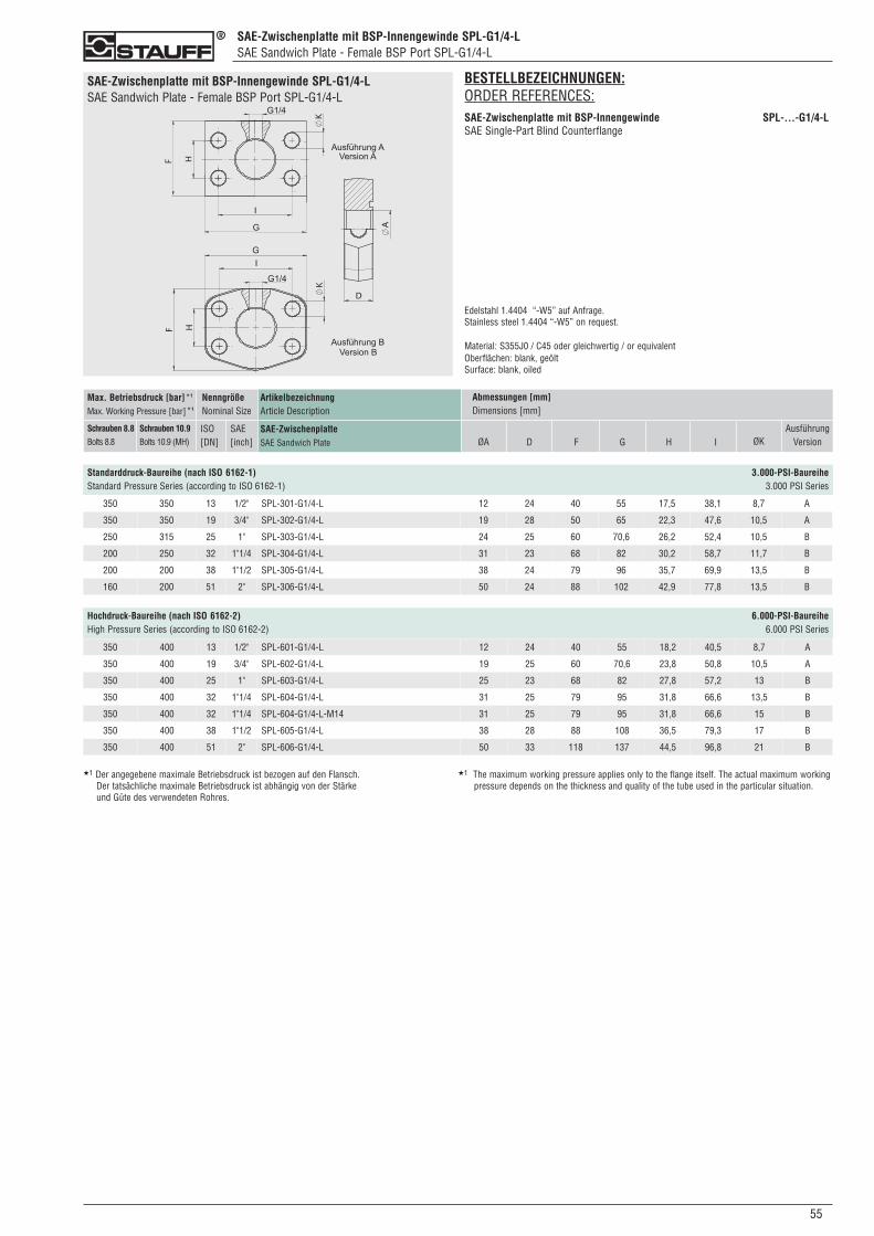
Hochdruck-Baureihe (nach ISO 6162-2) 6.000-PSI-BaureiheHigh Pressure Series (according to ISO 6162-2) 6.000 PSI Series
SAE-Zwischenplatte mit BSP-Innengewinde SPL-G1/4-LSAE Sandwich Plate - Female BSP Port SPL-G1/4-L
Standarddruck-Baureihe (nach ISO 6162-1) 3.000-PSI-BaureiheStandard Pressure Series (according to ISO 6162-1) 3.000 PSI Series
SAE-Zwischenplatte mit BSP-Innengewinde SPL-G1/4-LSAE Sandwich Plate - Female BSP Port SPL-G1/4-L
550
ArtikelbezeichnungArticle Description
SAE-ZwischenplatteSAE Sandwich Plate
Max. Betriebsdruck [bar]*1
Max. Working Pressure [bar]*1
Schrauben 8.8Bolts 8.8
Schrauben 10.9Bolts 10.9 (MH)
NenngrößeNominal Size
ISO[DN]
SAE[inch]
Abmessungen [mm]Dimensions [mm]
ØA DAusführung
Version
350 350 13 1/2" SPL-301-G1/4-L 12 24 40 55 17,5 38,1 8,7 A
350 350 19 3/4" SPL-302-G1/4-L 19 28 50 65 22,3 47,6 10,5 A
250 315 25 1" SPL-303-G1/4-L 24 25 60 70,6 26,2 52,4 10,5 B
200 250 32 1"1/4 SPL-304-G1/4-L 31 23 68 82 30,2 58,7 11,7 B
200 200 38 1"1/2 SPL-305-G1/4-L 38 24 79 96 35,7 69,9 13,5 B
160 200 51 2" SPL-306-G1/4-L 50 24 88 102 42,9 77,8 13,5 B
350 400 13 1/2" SPL-601-G1/4-L 12 24 40 55 18,2 40,5 8,7 A
350 400 19 3/4" SPL-602-G1/4-L 19 25 60 70,6 23,8 50,8 10,5 A
350 400 25 1" SPL-603-G1/4-L 25 23 68 82 27,8 57,2 13 B
350 400 32 1"1/4 SPL-604-G1/4-L 31 25 79 95 31,8 66,6 13,5 B
350 400 32 1"1/4 SPL-604-G1/4-L-M14 31 25 79 95 31,8 66,6 15 B
350 400 38 1"1/2 SPL-605-G1/4-L 38 28 88 108 36,5 79,3 17 B
350 400 51 2" SPL-606-G1/4-L 50 33 118 137 44,5 96,8 21 B
★1 Der angegebene maximale Betriebsdruck ist bezogen auf den Flansch. Der tatsächliche maximale Betriebsdruck ist abhängig von der Stärke und Güte des verwendeten Rohres.
★1 The maximum working pressure applies only to the flange itself. The actual maximum workingpressure depends on the thickness and quality of the tube used in the particular situation.
BESTELLBEZEICHNUNGEN:ORDER REFERENCES:SAE-Zwischenplatte mit BSP-Innengewinde SPL-...-G1/4-LSAE Single-Part Blind Counterflange
Edelstahl 1.4404 “-W5” auf Anfrage.Stainless steel 1.4404 “-W5” on request.
Material: S355J0 / C45 oder gleichwertig / or equivalentOberflächen: blank, geöltSurface: blank, oiled
F G H I ØK
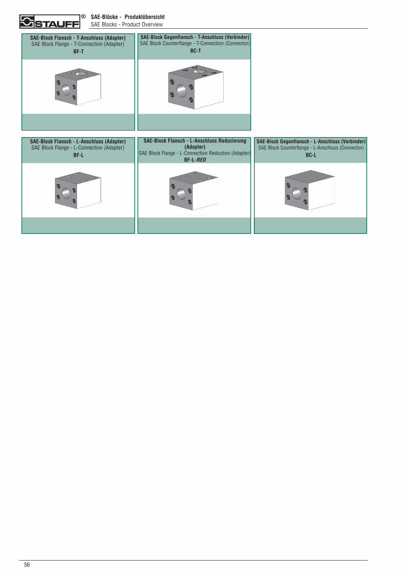
056
SAE-Blöcke - ProduktübersichtSAE Blocks - Product Overview
SAE-Block Flansch - L-Anschluss (Adapter) SAE Block Flange - L-Connection (Adapter)
BF-L
SAE-Block Gegenflansch - L-Anschluss (Verbinder)SAE Block Counterflange - L-Anschluss (Connector)
BC-L
SAE-Block Flansch - L-Anschluss Reduzierung(Adapter)
SAE Block Flange - L-Connection Reduction (Adapter)BF-L-RED
SAE-Block Flansch - T-Anschluss (Adapter) SAE Block Flange - T-Connection (Adapter)
BF-T
SAE-Block Gegenflansch - T-Anschluss (Verbinder)SAE Block Counterflange - T-Connection (Connector)
BC-T
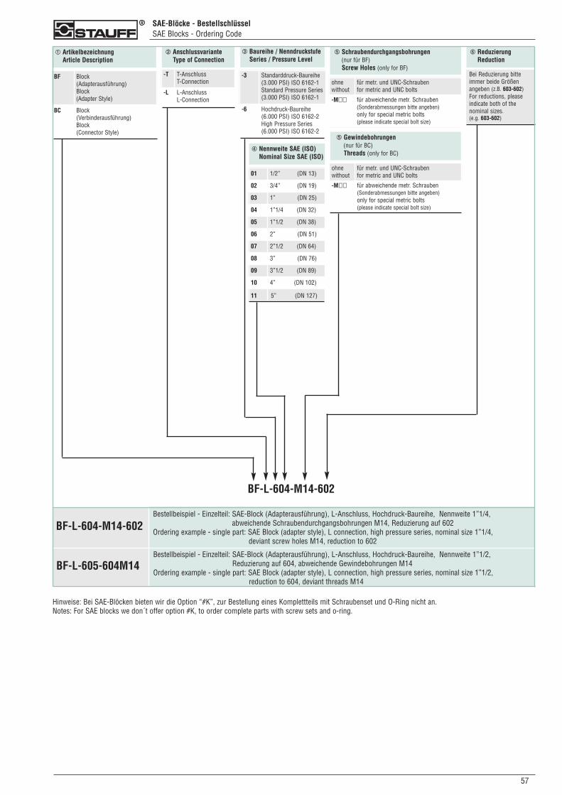
SAE-Blöcke - BestellschlüsselSAE Blocks - Ordering Code
570
➀ ArtikelbezeichnungArticle Description
➂ Baureihe / NenndruckstufeSeries / Pressure Level
➁ AnschlussvarianteType of Connection
BF Block (Adapterausführung)Block(Adapter Style)
BC Block (Verbinderausführung)Block(Connector Style)
-3 Standarddruck-Baureihe(3.000 PSI) ISO 6162-1Standard Pressure Series(3.000 PSI) ISO 6162-1
-6 Hochdruck-Baureihe(6.000 PSI) ISO 6162-2High Pressure Series(6.000 PSI) ISO 6162-2
-T T-AnschlussT-Connection
-L L-AnschlussL-Connection
➃ Nennweite SAE (ISO)Nominal Size SAE (ISO)
01 1/2” (DN 13)
02 3/4” (DN 19)
03 1” (DN 25)
04 1”1/4 (DN 32)
05 1”1/2 (DN 38)
06 2” (DN 51)
07 2”1/2 (DN 64)
08 3” (DN 76)
09 3”1/2 (DN 89)
10 4” (DN 102)
11 5” (DN 127)
➄ Schraubendurchgangsbohrungen(nur für BF)Screw Holes (only for BF)
ohnewithout
für metr. und UNC-Schraubenfor metric and UNC bolts
-M�� für abweichende metr. Schrauben (Sonderabmessungen bitte angeben)only for special metric bolts(please indicate special bolt size)
BF-L-604-M14-602
➄ Gewindebohrungen(nur für BC)Threads (only for BC)
ohnewithout
für metr. und UNC-Schraubenfor metric and UNC bolts
-M�� für abweichende metr. Schrauben (Sonderabmessungen bitte angeben)only for special metric bolts(please indicate special bolt size)
Bestellbeispiel - Einzelteil: SAE-Block (Adapterausführung), L-Anschluss, Hochdruck-Baureihe, Nennweite 1”1/4, abweichende Schraubendurchgangsbohrungen M14, Reduzierung auf 602
Ordering example - single part: SAE Block (adapter style), L connection, high pressure series, nominal size 1”1/4, deviant screw holes M14, reduction to 602
BF-L-604-M14-602
➅ Reduzierung Reduction
Bei Reduzierung bitteimmer beide Größen angeben (z.B. 603-602)For reductions, pleaseindicate both of the nominal sizes. (e.g. 603-602)
BF-L-605-604M14Bestellbeispiel - Einzelteil: SAE-Block (Adapterausführung), L-Anschluss, Hochdruck-Baureihe, Nennweite 1”1/2,
Reduzierung auf 604, abweichende Gewindebohrungen M14Ordering example - single part: SAE Block (adapter style), L connection, high pressure series, nominal size 1”1/2,
reduction to 604, deviant threads M14
Hinweise: Bei SAE-Blöcken bieten wir die Option “#K”, zur Bestellung eines Komplettteils mit Schraubenset und O-Ring nicht an.Notes: For SAE blocks we don´t offer option #K, to order complete parts with screw sets and o-ring.
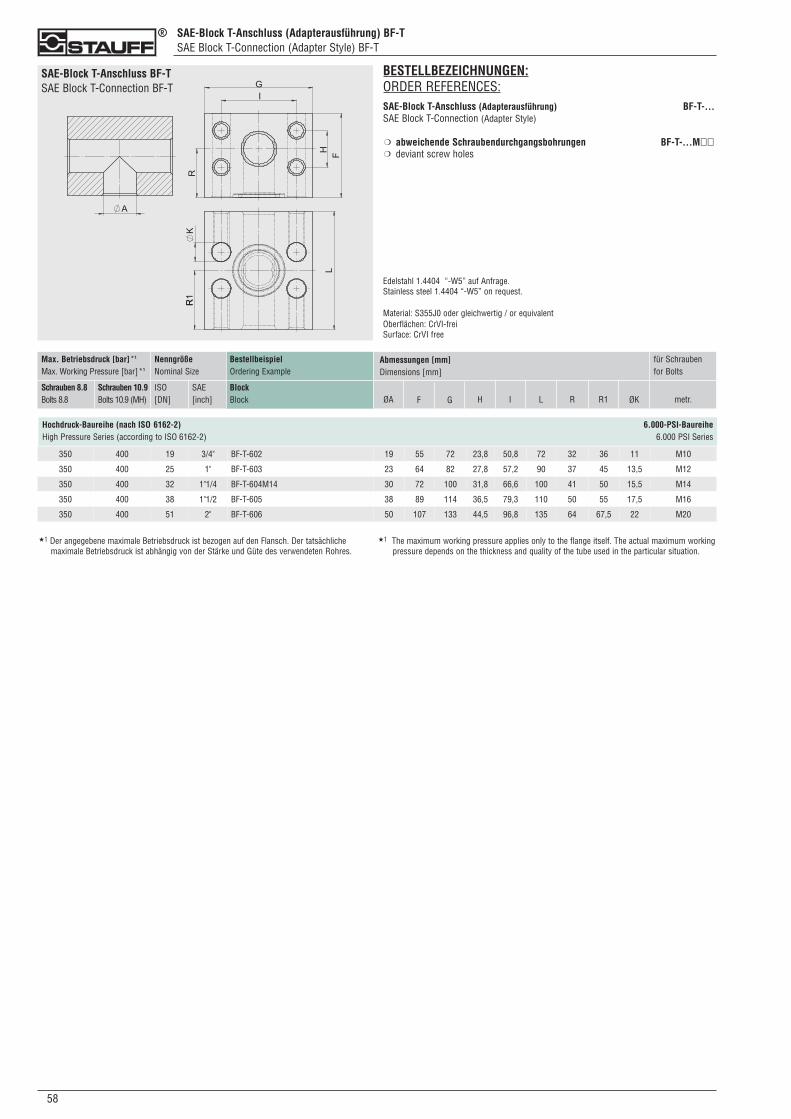
SAE-Block T-Anschluss (Adapterausführung) BF-TSAE Block T-Connection (Adapter Style) BF-T
058
SAE-Block T-Anschluss BF-TSAE Block T-Connection BF-T
BESTELLBEZEICHNUNGEN:ORDER REFERENCES:SAE-Block T-Anschluss (Adapterausführung) BF-T-...SAE Block T-Connection (Adapter Style)
abweichende Schraubendurchgangsbohrungen BF-T-...M��deviant screw holes
Edelstahl 1.4404 “-W5” auf Anfrage.Stainless steel 1.4404 “-W5” on request.
Material: S355J0 oder gleichwertig / or equivalentOberflächen: CrVI-freiSurface: CrVI free
❍
❍
Hochdruck-Baureihe (nach ISO 6162-2) 6.000-PSI-BaureiheHigh Pressure Series (according to ISO 6162-2) 6.000 PSI Series
★1 Der angegebene maximale Betriebsdruck ist bezogen auf den Flansch. Der tatsächliche maximale Betriebsdruck ist abhängig von der Stärke und Güte des verwendeten Rohres.
★1 The maximum working pressure applies only to the flange itself. The actual maximum workingpressure depends on the thickness and quality of the tube used in the particular situation.
BestellbeispielOrdering Example
BlockBlock
Max. Betriebsdruck [bar]*1
Max. Working Pressure [bar]*1
Schrauben 8.8Bolts 8.8
Schrauben 10.9Bolts 10.9 (MH)
NenngrößeNominal Size
ISO[DN]
SAE[inch]
Abmessungen [mm]Dimensions [mm]
ØA LF G H I metr.
für Schraubenfor Bolts
R1R ØK
350 400 19 3/4" BF-T-602 19 55 72 23,8 50,8 72 32 36 11 M10
350 400 25 1" BF-T-603 23 64 82 27,8 57,2 90 37 45 13,5 M12
350 400 32 1"1/4 BF-T-604M14 30 72 100 31,8 66,6 100 41 50 15,5 M14
350 400 38 1"1/2 BF-T-605 38 89 114 36,5 79,3 110 50 55 17,5 M16
350 400 51 2" BF-T-606 50 107 133 44,5 96,8 135 64 67,5 22 M20
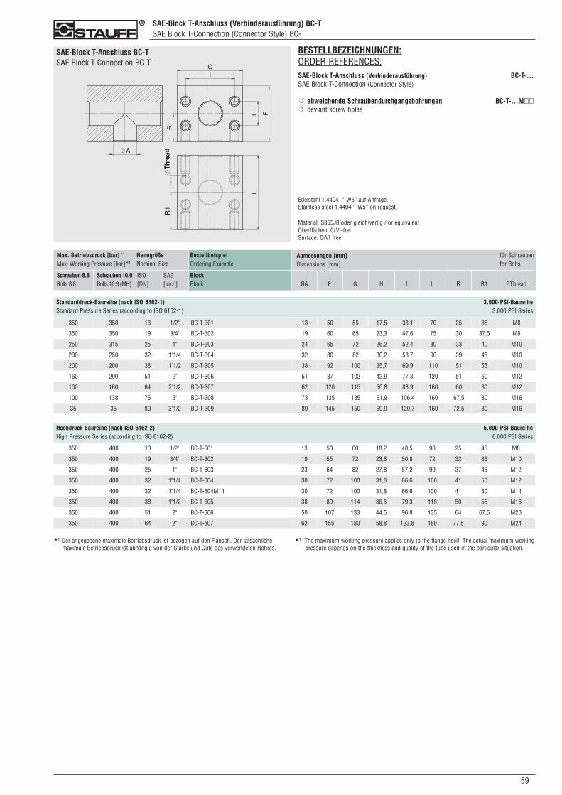
SAE-Block T-Anschluss (Verbinderausführung) BC-TSAE Block T-Connection (Connector Style) BC-T
590
SAE-Block T-Anschluss BC-TSAE Block T-Connection BC-T
BESTELLBEZEICHNUNGEN:ORDER REFERENCES:SAE-Block T-Anschluss (Verbinderausführung) BC-T-...SAE Block T-Connection (Connector Style)
abweichende Schraubendurchgangsbohrungen BC-T-...M��deviant screw holes
Edelstahl 1.4404 “-W5” auf Anfrage.Stainless steel 1.4404 “-W5” on request.
Material: S355J0 oder gleichwertig / or equivalentOberflächen: CrVI-freiSurface: CrVI free
❍
❍
BestellbeispielOrdering Example
BlockBlock
NenngrößeNominal Size
SAE[inch]
Abmessungen [mm]Dimensions [mm]
ØA LF G H I
für Schraubenfor Bolts
R1R ØThread
Max. Betriebsdruck [bar]*1
Max. Working Pressure [bar]*1
Schrauben 8.8Bolts 8.8
Schrauben 10.9Bolts 10.9 (MH)
ISO[DN]
350 350 13 1/2" BC-T-301 13 50 55 17,5 38,1 70 25 35 M8
350 350 19 3/4" BC-T-302 19 60 65 23,3 47,6 75 30 37,5 M8
250 315 25 1" BC-T-303 24 65 72 26,2 52,4 80 33 40 M10
200 250 32 1"1/4 BC-T-304 32 80 82 30,2 58,7 90 39 45 M10
200 200 38 1"1/2 BC-T-305 38 92 100 35,7 69,9 110 51 55 M10
160 200 51 2" BC-T-306 51 87 102 42,9 77,8 120 51 60 M12
100 160 64 2"1/2 BC-T-307 62 120 115 50,8 88,9 160 60 80 M12
100 138 76 3" BC-T-308 73 135 135 61,9 106,4 160 67,5 80 M16
35 35 89 3"1/2 BC-T-309 89 145 150 69,9 120,7 160 72,5 80 M16
Standarddruck-Baureihe (nach ISO 6162-1) 3.000-PSI-BaureiheStandard Pressure Series (according to ISO 6162-1) 3.000 PSI Series
Hochdruck-Baureihe (nach ISO 6162-2) 6.000-PSI-BaureiheHigh Pressure Series (according to ISO 6162-2) 6.000 PSI Series
350 400 13 1/2" BC-T-601 13 50 60 18,2 40,5 90 25 45 M8
350 400 19 3/4" BC-T-602 19 55 72 23,8 50,8 72 32 36 M10
350 400 25 1" BC-T-603 23 64 82 27,8 57,2 90 37 45 M12
350 400 32 1"1/4 BC-T-604 30 72 100 31,8 66,6 100 41 50 M12
350 400 32 1"1/4 BC-T-604M14 30 72 100 31,8 66,6 100 41 50 M14
350 400 38 1"1/2 BC-T-605 38 89 114 36,5 79,3 110 50 55 M16
350 400 51 2" BC-T-606 50 107 133 44,5 96,8 135 64 67,5 M20
350 400 64 2" BC-T-607 62 155 180 58,8 123,8 180 77,5 90 M24
★1 Der angegebene maximale Betriebsdruck ist bezogen auf den Flansch. Der tatsächliche maximale Betriebsdruck ist abhängig von der Stärke und Güte des verwendeten Rohres.
★1 The maximum working pressure applies only to the flange itself. The actual maximum workingpressure depends on the thickness and quality of the tube used in the particular situation.
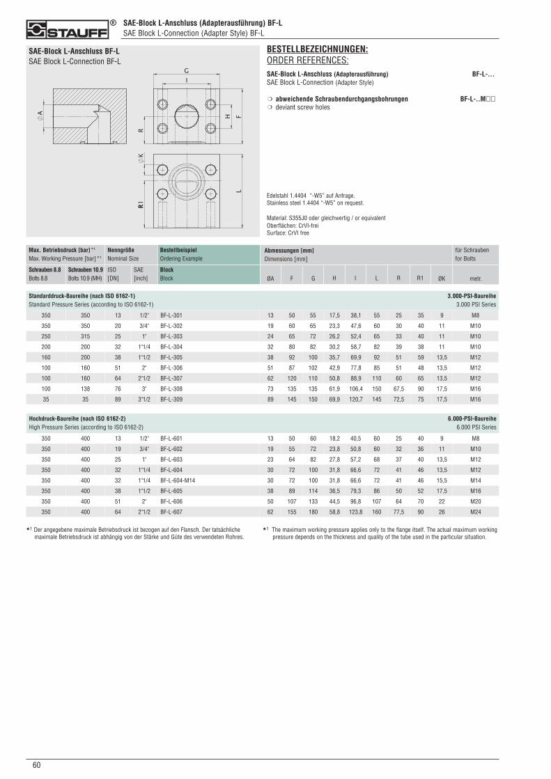
060
SAE-Block L-Anschluss (Adapterausführung) BF-LSAE Block L-Connection (Adapter Style) BF-L
SAE-Block L-Anschluss BF-LSAE Block L-Connection BF-L
Standarddruck-Baureihe (nach ISO 6162-1) 3.000-PSI-BaureiheStandard Pressure Series (according to ISO 6162-1) 3.000 PSI Series
BestellbeispielOrdering Example
BlockBlock
Max. Betriebsdruck [bar]*1
Max. Working Pressure [bar]*1
Schrauben 8.8Bolts 8.8
Schrauben 10.9Bolts 10.9 (MH)
NenngrößeNominal Size
ISO[DN]
SAE[inch]
Abmessungen [mm]Dimensions [mm]
ØA LF G H I metr.
für Schraubenfor Bolts
350 350 13 1/2" BF-L-301 13 50 55 17,5 38,1 55 25 35 9 M8
350 350 20 3/4" BF-L-302 19 60 65 23,3 47,6 60 30 40 11 M10
250 315 25 1" BF-L-303 24 65 72 26,2 52,4 65 33 40 11 M10
200 200 32 1"1/4 BF-L-304 32 80 82 30,2 58,7 82 39 38 11 M10
160 200 38 1"1/2 BF-L-305 38 92 100 35,7 69,9 92 51 59 13,5 M12
100 160 51 2" BF-L-306 51 87 102 42,9 77,8 85 51 48 13,5 M12
100 160 64 2"1/2 BF-L-307 62 120 110 50,8 88,9 110 60 65 13,5 M12
100 138 76 3" BF-L-308 73 135 135 61,9 106,4 150 67,5 90 17,5 M16
35 35 89 3"1/2 BF-L-309 89 145 150 69,9 120,7 145 72,5 75 17,5 M16
R1R ØK
BESTELLBEZEICHNUNGEN:ORDER REFERENCES:SAE-Block L-Anschluss (Adapterausführung) BF-L-...SAE Block L-Connection (Adapter Style)
abweichende Schraubendurchgangsbohrungen BF-L-..M��deviant screw holes
Edelstahl 1.4404 “-W5” auf Anfrage.Stainless steel 1.4404 “-W5” on request.
Material: S355J0 oder gleichwertig / or equivalentOberflächen: CrVI-freiSurface: CrVI free
❍
❍
Hochdruck-Baureihe (nach ISO 6162-2) 6.000-PSI-BaureiheHigh Pressure Series (according to ISO 6162-2) 6.000 PSI Series
350 400 13 1/2" BF-L-601 13 50 60 18,2 40,5 60 25 40 9 M8
350 400 19 3/4" BF-L-602 19 55 72 23,8 50,8 60 32 36 11 M10
350 400 25 1" BF-L-603 23 64 82 27,8 57,2 68 37 40 13,5 M12
350 400 32 1"1/4 BF-L-604 30 72 100 31,8 66,6 72 41 46 13,5 M12
350 400 32 1"1/4 BF-L-604-M14 30 72 100 31,8 66,6 72 41 46 15,5 M14
350 400 38 1"1/2 BF-L-605 38 89 114 36,5 79,3 86 50 52 17,5 M16
350 400 51 2" BF-L-606 50 107 133 44,5 96,8 107 64 70 22 M20
350 400 64 2"1/2 BF-L-607 62 155 180 58,8 123,8 160 77,5 90 26 M24
★1 Der angegebene maximale Betriebsdruck ist bezogen auf den Flansch. Der tatsächliche maximale Betriebsdruck ist abhängig von der Stärke und Güte des verwendeten Rohres.
★1 The maximum working pressure applies only to the flange itself. The actual maximum workingpressure depends on the thickness and quality of the tube used in the particular situation.
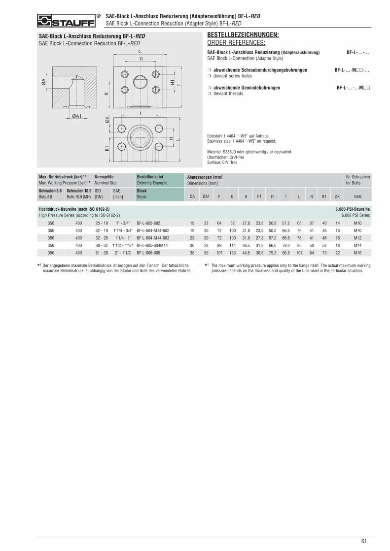
SAE-Block L-Anschluss Reduzierung (Adapterausführung) BF-L-REDSAE Block L-Connection Reduction (Adapter Style) BF-L-RED
SAE-Block L-Anschluss Reduzierung BF-L-REDSAE Block L-Connection Reduction BF-L-RED
610
BestellbeispielOrdering Example
BlockBlock
Max. Betriebsdruck [bar]*1
Max. Working Pressure [bar]*1
Schrauben 8.8Bolts 8.8
Schrauben 10.9Bolts 10.9 (MH)
NenngrößeNominal Size
ISO[DN]
SAE[inch]
Abmessungen [mm]Dimensions [mm]
ØA1 LF G H I1 metr.
für Schraubenfor Bolts
R1R ØKØA H1 I
Hochddruck-Baureihe (nach ISO 6162-2) 6.000-PSI-BaureiheHigh Pressure Series (according to ISO 6162-2) 6.000 PSI Series
350 400 25 - 19 1" - 3/4" BF-L-603-602 19 23 64 82 27,8 23,8 50,8 57,2 68 37 40 14 M10
350 400 32 - 19 1"1/4 - 3/4" BF-L-604-M14-602 19 30 72 100 31,8 23,8 50,8 66,6 76 41 46 16 M10
350 400 32 - 25 1"1/4 - 1" BF-L-604-M14-603 23 30 72 100 31,8 27,8 57,2 66,6 76 41 46 16 M12
350 400 38 - 32 1"1/2 - 1"1/4 BF-L-605-604M14 30 38 89 114 36,5 31,8 66,6 79,3 86 50 52 18 M14
350 400 51 - 38 2" - 1"1/2 BF-L-606-605 38 50 107 133 44,5 36,5 79,3 96,8 107 64 70 22 M16
★1 Der angegebene maximale Betriebsdruck ist bezogen auf den Flansch. Der tatsächliche maximale Betriebsdruck ist abhängig von der Stärke und Güte des verwendeten Rohres.
★1 The maximum working pressure applies only to the flange itself. The actual maximum workingpressure depends on the thickness and quality of the tube used in the particular situation.
BESTELLBEZEICHNUNGEN:ORDER REFERENCES:SAE-Block L-Anschluss Reduzierung (Adapterausführung) BF-L-...-...SAE Block L-Connection (Adapter Style)
abweichende Schraubendurchgangsbohrungen BF-L-...-M��-...deviant screw holes
abweichende Gewindebohrungen BF-L-...-...M��deviant threads
Edelstahl 1.4404 “-W5” auf Anfrage.Stainless steel 1.4404 “-W5” on request.
Material: S355J0 oder gleichwertig / or equivalentOberflächen: CrVI-freiSurface: CrVI free
❍
❍
❍
❍
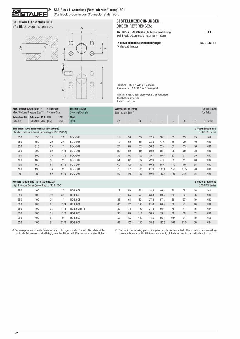
062
SAE-Block L-Anschluss (Verbinderausführung) BC-LSAE Block L-Connection (Connector Style) BC-L
SAE-Block L-Anschluss BC-LSAE Block L-Connection BC-L
Standarddruck-Baureihe (nach ISO 6162-1) 3.000-PSI-BaureiheStandard Pressure Series (according to ISO 6162-1) 3.000 PSI Series
BESTELLBEZEICHNUNGEN:ORDER REFERENCES:SAE-Block L-Anschluss (Verbinderausführung) BC-L-...SAE Block L-Connection (Connector Style)
abweichende Gewindebohrungen BC-L-..M��deviant threads
Edelstahl 1.4404 “-W5” auf Anfrage.Stainless steel 1.4404 “-W5” on request.
Material: S355J0 oder gleichwertig / or equivalentOberflächen: CrVI-freiSurface: CrVI free
❍
❍
Hochdruck-Baureihe (nach ISO 6162-2) 6.000-PSI-BaureiheHigh Pressure Series (according to ISO 6162-2) 6.000 PSI Series
★1 Der angegebene maximale Betriebsdruck ist bezogen auf den Flansch. Der tatsächliche maximale Betriebsdruck ist abhängig von der Stärke und Güte des verwendeten Rohres.
★1 The maximum working pressure applies only to the flange itself. The actual maximum workingpressure depends on the thickness and quality of the tube used in the particular situation.
BestellbeispielOrdering Example
BlockBlock
NenngrößeNominal Size
SAE[inch]
Abmessungen [mm]Dimensions [mm]
ØA LF G H I
für Schraubenfor Bolts
R1R ØThread
Max. Betriebsdruck [bar]*1
Max. Working Pressure [bar]*1
Schrauben 8.8Bolts 8.8
Schrauben 10.9Bolts 10.9 (MH)
ISO[DN]
350 350 13 1/2" BC-L-301 13 50 55 17,5 38,1 55 25 35 M8
350 350 20 3/4" BC-L-302 19 60 65 23,3 47,6 60 30 40 M10
250 315 25 1" BC-L-303 24 65 72 26,2 52,4 65 33 40 M10
200 200 32 1"1/4 BC-L-304 32 80 82 30,2 58,7 82 39 38 M10
160 200 38 1"1/2 BC-L-305 38 92 100 35,7 69,9 92 51 59 M12
100 160 51 2" BC-L-306 51 87 102 42,9 77,8 85 51 48 M12
100 160 64 2"1/2 BC-L-307 62 120 110 50,8 88,9 110 60 65 M12
100 138 76 3" BC-L-308 73 135 135 61,9 106,4 150 67,5 90 M16
35 35 89 3"1/2 BC-L-309 89 145 150 69,9 120,7 145 72,5 75 M16
350 400 13 1/2" BC-L-601 13 50 60 18,2 40,5 60 25 40 M8
350 400 19 3/4" BC-L-602 19 55 72 23,8 50,8 60 32 36 M10
350 400 25 1" BC-L-603 23 64 82 27,8 57,2 68 37 40 M12
350 400 32 1"1/4 BC-L-604 30 72 100 31,8 66,6 76 41 46 M12
350 400 32 1"1/4 BC-L-604M14 30 72 100 31,8 66,6 76 41 46 M14
350 400 38 1"1/2 BC-L-605 38 89 114 36,5 79,3 86 50 52 M16
350 400 51 2" BC-L-606 50 107 133 44,5 96,8 107 64 70 M20
350 400 64 2"1/2 BC-L-607 62 155 180 58,8 123,8 160 77,5 60 M24
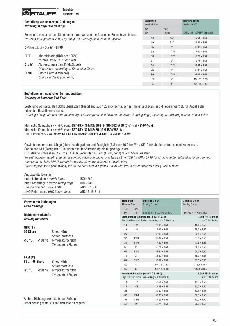
630
ZubehörAccessories
Bestellung von separaten Schraubensätzen Ordering of Separate Bolt Sets
Bestellung von separaten Schraubensätzen (bestehend aus 4 Zylinderschrauben mit Innensechskant und 4 Federringen) durch Angabe der folgenden Bestellbezeichnung:Ordering of separate bolt sets (consisting of 4 hexagon socket head cap bolts and 4 spring rings) by using the ordering code as stated below:
Metrische Schrauben / metric bolts: SET-BFX-IS-M12x50-8.8-ISO4762-W66 (CrVI-frei / CrVI-free)Metrische Schrauben / metric bolts: SET-BFX-IS-M12x50-10.9-ISO4762-W1UNC-Schrauben/ UNC bolts: SET-BFX-IS-U5/16”-18x1”1/4-GR10-ANSI-B18.3-W1
Gewindedurchmesser, Länge (siehe Katalogseiten) und Festigkeit (8.8 oder 10.9 für MH / GR10 für U) sind entsprechend zu ersetzen. Schrauben MH (Festigkeit 10.9) werden in der Ausführung blank, geölt geliefert.Für Edelstahlschrauben (1.4571) ist W66 (verzinkt) bzw. W1 (blank, geölt) durch W5 zu ersetzen.Thread diameter, length (see corresponding catalogue pages) and type (8.8 or 10.9 for MH / GR10 for U) have to be replaced according to yourrequirements. Bolts MH (Strength Properties 10.9) are delivered in blank, oiled.Please replace W66 (zinc plated) for metric bolts and W1 (blank, oiled) with W5 to order stainless steel (1.4571) bolts.
Angewandte Normen:metr. Schrauben / metric bolts: ISO 4762metr. Federringe / metric spring rings: DIN 7980UNC-Schrauben / UNC bolts: ANSI B 18.3UNC-Federringe / UNC Spring rings: ANSI B 18.21.1
Bestellung von separaten Dichtungen Ordering of Separate Sealings
Bestellung von separaten Dichtungen durch Angabe der folgenden Bestellbezeichnung:Ordering of separate sealings by using the ordering code as stated below:
O-Ring ��� - D x W - SH90
��� Materialcode (NBR oder FKM)Material Code (NBR or FKM)
D x W Abmessungen gemäß MaßtabelleDimensions according to Dimension Table
SH90 Shore-Härte (Standard)Shore Hardness (Standard)
NenngrößeNominal Size
ISO[DN]
SAE[inch]
Dichtung D x WSealing D x W
SAE J515 - STAUFF Standard
13 1/2” 18,64 x 3,53
19 3/4” 24,99 x 3,53
25 1” 32,92 x 3,53
32 1”1/4 37,69 x 3,53
38 1”1/2 47,22 x 3,53
51 2” 56,74 x 3,53
64 2”1/2 69,44 x 3,53
76 3” 85,32 x 3,53
89 3”1/2 98,02 x 3,53
102 4” 110,72 x 3,53
127 5” 136,12 x 3,53
Standarddruck-Baureihe (nach ISO 6162-1) 3.000-PSI-BaureiheStandard Pressure Series (according to ISO 6162-1) 3.000 PSI Series
NenngrößeNominal Size
ISO[DN]
SAE[inch]
Dichtung D x WSealing D x W
Dichtung D x WSealing D x W
ISO 3601-1 - Alternative
Hochdruck-Baureihe (nach ISO 6162-2) 6.000-PSI-BaureiheHigh Pressure Series (according to ISO 6162-2) 6.000 PSI Series
SAE J515 - STAUFF Standard
Verwendete Dichtungen Used Sealings
Dichtungswerkstoffe Sealing Materials
NBR (B)90 Shore Shore-Härte
Shore Hardness-30 °C ... +100 °C Temperaturbereich
Temperature Range
FKM (V)85 ... 90 Shore Shore-Härte
Shore Hardness-20 °C ... +200 °C Temperaturbereich
Temperature Range
Andere Dichtungswerkstoffe auf Anfrage.Other sealing materials are available on request.
13 1/2" 18,64 x 3,53 19,0 x 3,55
19 3/4" 24,99 x 3,53 25,0 x 3,55
25 1" 32,92 x 3,53 32,5 x 3,55
32 1"1/4 37,69 x 3,53 37,5 x 3,55
38 1"1/2 47,22 x 3,53 47,5 x 3,55
51 2" 56,74 x 3,53 56,0 x 3,55
64 2"1/2 69,44 x 3,53 69,0 x 3,55
76 3" 85,32 x 3,53 85,0 x 3,55
89 3"1/2 98,02 x 3,53 97,5 x 3,55
102 4" 110,72 x 3,53 112,0 x 3,55
127 5" 136,12 x 3,53 136,0 x 3,55
13 1/2" 18,64 x 3,53 19,0 x 3,55
19 3/4" 24,99 x 3,53 25,0 x 3,55
25 1" 32,92 x 3,53 32,5 x 3,55
32 1"1/4 37,69 x 3,53 37,5 x 3,55
38 1"1/2 47,22 x 3,53 47,5 x 3,55
51 2" 56,74 x 3,53 56,0 x 3,55
064
Technischer AnhangTechnical Appendix
Allgemeine Informationen: Angewandte NormenGeneral Information: Applied Standards
Bei der Entwicklung und Produktion von STAUFF SAE-Flanschen werden folgende Normen angewendet:The following standards have been applied for the development and manufacturing of STAUFF SAE Flanges:
� SAE J 518 C� ISO 6162-1/2
Die Verwendung hochwertiger Werkstoffe in Verbindung mit hoher Fertigungsqualität garantieren die lange Lebensdauer und zuverlässige Funktionvon STAUFF SAE-Flanschen.The use of top-quality materials in conjunction with highest manufacturing quality garantee longest life cycles and the reliable operation of STAUFFSAE Flanges.
Allgemeine Informationen: DruckangabenGeneral Information: Pressure Information
Die im Katalog genannten Druckangaben (maximale Betriebsdrücke) beziehen sich ausschliesslich auf das jeweilige Einzelteil, nicht jedoch auf dieeingesetzten Rohre, Verschraubungen oder die erforderlichen Schweiß- oder Schraubverbindungen. Bitte berücksichtigen Sie die Druckangaben undVorgaben der Hersteller der anderen eingesetzen Komponenten sowie die gesetzlichen Richtlinien.The pressure information (maximum working pressures) stated in this catalogue only apply to the single components mentioned in the particularsituation. It does not apply to the used bolts, fittings, welded or screwed connections. Please take notice of the information and specification of themanufaturers for all further components used in the situation, and also the legal regulations.
Bitte beachten Sie ebenfalls, dass bei einer Kombination (bestehend aus Flansch und Stutzen) die Druckangaben der einzelnen Komponenten voneinander abweichen können. Es ist der jeweils niedrigere Druck als maximaler Betriebsdruck zu berücksichtigen.Please note: The pressure information of the components of flange combinations (consisiting of the flange itself and a tube end) may vary fromeach other. Please consider the lower pressure as the maximum working pressure of this combination.
Allgemeine Informationen: TemperaturangabenGeneral Information: Temperature Information
Sämtliche Angaben beziehen sich auf einen Temperaturbereich vonAll information apply to a temperature range of
-20 °C ... +90 °C.
Ausserhalb dieses Bereiches reduzieren sich die materialspezifischen Eigenschaften. Dies gilt insbesondere für die Auswahl des Dichtungswerkstoffes.Outside of this temperature range, the material-specific properties could be reduced. This applies to the selection of the sealing materials in particular.
Hinweis / HaftungsbeschränkungGeneral Information / Limitation of Liability Clause
Bitte beachten Sie: Alle genannten Daten sind Durchschnittswerte und gelten nur als unverbindliche Hinweise, auch in Bezug auf etwaige Schutzrechte Dritter. Sie können nur bedingt zu Konstruktionszwecken verwendet werden und befreien nicht von der eigenen Prüfung der von unsgelieferten Produkte auf ihre Eignung.Please note: All outlined particulars are approximate values and are only valid as references, which are not binding, also with regard to possible protection of third parties. Therefore, these values can only be used in a limited sense for construction purposes, and do not exempt you from yourown examination of suitability of the products delivered by us.
Die Anwendung der Produkte erfolgt außerhalb unserer Kontrollmöglichkeiten und liegt daher ausschließlich in Ihrem Verantwortungsbereich.The application of the products is carried out outside our control possibilities and, therefore, is exclusively subject to your own area of responsibility.
Sollte dennoch eine Haftung in Frage kommen, so ist dies für alle Schäden auf den Wert der von uns gelieferten und von Ihnen eingesetzten Warebegrenzt.If, however, liability should be possible, it would be limited for all damages to the value of the goods supplied by us and in use by you.
Selbstverständlich gewährleisten wir die einwandfreie Qualität unserer Produkte nach Maßgabe unserer Allgemeinen Verkaufs- undLieferbedingungen.It goes without saying, that we guarantee the perfect quality of our products according to our general sales terms and delivery conditions.
Änderungen, die der technischen Weiterentwicklung dienen, behalten wir uns vor. Alle vorangegangenen Kataloge verlieren ihre Gültigkeit.Due to technical advances, dimensions subject to change without notification. This catalogue supercedes all previous catalogues.
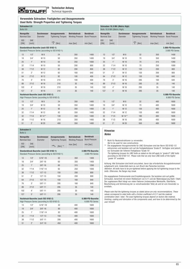
Technischer AnhangTechnical Appendix
Verwendete Schrauben: Festigkeiten und AnzugsmomenteUsed Bolts: Strength Properties and Tightening Torques
NenngrößeNominal Size
ISO[DN]
SAE[inch]
DurchmesserDiameter
AnzugsmomenteTightening Torques
0 [Nm]
BetriebsdruckWorking Pressure
max [bar]
BerstdruckBurst Pressure
min [bar]
NenngrößeNominal Size
ISO[DN]
SAE[inch]
DurchmesserDiameter
AnzugsmomenteTightening Torques
0 [Nm]
BetriebsdruckWorking Pressure
max [bar]
BerstdruckBurst Pressure
min [bar]
Schrauben 8.8Bolts 8.8
Schrauben 10.9 MH (Metric High)Bolts 10.9 MH (Metric High)
HinweiseNotes
*1 Nicht für Neukonstruktionen zu verwenden.Not to be used for new constructions.
*2 Die angegebenen Anzugsmomente für UNC-Schrauben sind der Norm ISO 6162-1/2 entnommen und beziehen sich auf die Festigkeitsklasse "Grade 8". Verfügbar sind jedoch nur Schrauben der höheren Festigklasse "Grade 10". The tightening torques for UNC bolts as stated on the left apply to “grade 8” UNC bolts according to ISO 6162-1/2. Please note that we only have UNC bolts of the higher “grade 10” available.
Achtung: Alle Schrauben sind leicht anzuziehen, bevor das erforderliche Anzugsdrehmoment aufgebracht wird. Andernfalls kann es zum Bruch des Flansches kommen.Attention: All bolts have to be pre-tightened before applying the full tightening torque to the bolts. Otherwise, the flange may break.
Die angegebenen Drehmomente sind Empfehlungswerte. Sie beziehen sich auf geölte Schrauben, berechnet mit einem Reibbeiwert von 0,17 und der Materialpaarung Stahl / Stahl. Der zugelassene Wert hängt von vielen Faktoren (insbesondere Werkstoffe, Oberfläche, Beschichtung und Schmierung der zu verschraubenden Teile) ab und ist vom Anwender zu ermitteln.
Please note that the tightening torques as stated above are only recommendations. These values correspond to oiled bolts with a friction coefficient of 0,17 and the material combination steel / steel. The exact tightening torques depend on factors like material, finishing, coating and lubrication of the components used, and have to be determined by the user himself.
+10% +10%
Standarddruck-Baureihe (nach ISO 6162-1) 3.000-PSI-BaureiheStandard Pressure Series (according to ISO 6162-1) 3.000 PSI Series
13 1/2" M 8 24 350 1400 13 1/2" M 8 32 350 1400
19 3/4" M 10 50 350 1400 19 3/4" M 10 70 350 1400
25 1" M 10 50 250 1000 25 1" M 10 70 315 1260
32 1"1/4 M 10 50 200 800 32 1"1/4 M 10 70 250 1000
38 1"1/2 M 12 92 200 800 38 1"1/2 M 12 130 200 800
51 2" M 12 92 160 640 51 2" M 12 130 200 800
64 2"1/2 M 12 92 100 400 64 2"1/2 M 12 130 160 640
76 3" M 16 210 100 400 76 3" M 16 295 160 640
89 3"1/2 M 16 210 35 140 89 3"1/2 M 16 295 35 140
102 4" M 16 210 35 140 102 4" M 16 295 35 140
127 5" M 16 210 35 140 127 5" M 16 295 35 140
Hochdruck-Baureihe (nach ISO 6162-2) 6.000-PSI-BaureiheHigh Pressure Series (according to ISO 6162-2) 6.000 PSI Series
13 1/2" M 8 24 350 1400 13 1/2" M 8 32 400 1600
19 3/4" M 10 50 350 1400 19 3/4" M 10 70 400 1600
25 1" M 12 92 350 1400 25 1" M 12 130 400 1600
32 1"1/4 M 12 92 350 1400 32 1"1/4 M 12 130 400 1600
32 1"1/4 M 14*1 130 350 1400 32 1"1/4 M 14*1 180 400 1600
38 1"1/2 M 16 210 350 1400 38 1"1/2 M 16 295 400 1600
51 2" M 20 400 350 1400 51 2" M 20 550 400 1600
0 [Nm] *2
Standarddruck-Baureihe (nach ISO 6162-1) 3.000-PSI-BaureiheStandard Pressure Series (according to ISO 6162-1) 3.000 PSI Series
NenngrößeNominal Size
ISO[DN]
SAE[inch]
DurchmesserDiameter
AnzugsmomenteTightening Torques
BetriebsdruckWorking Pressure
max [bar]
BerstdruckBurst Pressure
min [bar]
Schrauben UBolts U
+10%
13 1/2" 5/16”-18 32 350 1400
19 3/4" 3/8”-16 60 350 1400
25 1" 3/8”-16 60 315 1260
32 1"1/4 7/16”-14 92 250 1000
38 1"1/2 1/2”-13 150 200 800
51 2" 1/2”-13 150 200 800
64 2"1/2 1/2”-13 150 160 640
76 3" 5/8”-11 295 160 640
89 3"1/2 5/8”-11 295 35 140
102 4" 5/8”-11 295 35 140
127 5" 5/8”-11 295 35 140
Hochdruck-Baureihe (nach ISO 6162-2) 6.000-PSI-BaureiheHigh Pressure Series (according to ISO 6162-2) 6.000 PSI Series
13 1/2" 5/16”-18 32 400 1600
19 3/4" 3/8”-16 60 400 1600
25 1" 7/16”-14 92 400 1600
32 1"1/4 1/2”-13 150 400 1600
38 1"1/2 5/8”-11 295 400 1600
51 2" 3/4”-10 450 400 1600
650
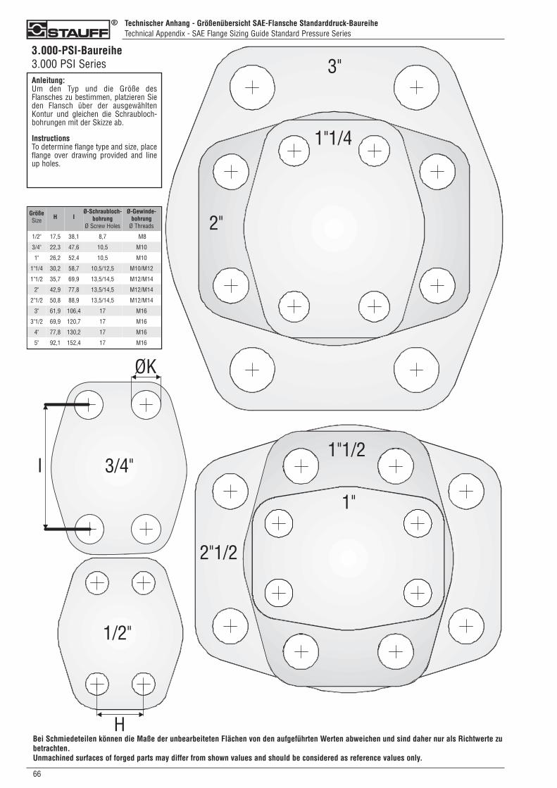
066
Technischer Anhang - Größenübersicht SAE-Flansche Standarddruck-BaureiheTechnical Appendix - SAE Flange Sizing Guide Standard Pressure Series
3.000-PSI-Baureihe3.000 PSI SeriesAnleitung:Um den Typ und die Größe desFlansches zu bestimmen, platzieren Sieden Flansch über der ausgewähltenKontur und gleichen die Schraubloch-bohrungen mit der Skizze ab.
InstructionsTo determine flange type and size, placeflange over drawing provided and lineup holes.
Bei Schmiedeteilen können die Maße der unbearbeiteten Flächen von den aufgeführten Werten abweichen und sind daher nur als Richtwerte zubetrachten.Unmachined surfaces of forged parts may differ from shown values and should be considered as reference values only.
GrößeSize H I
Ø-Schraubloch-bohrung
Ø Screw Holes
Ø-Gewinde-bohrung
Ø Threads
1/2" 17,5 38,1 8,7 M8
3/4" 22,3 47,6 10,5 M10
1" 26,2 52,4 10,5 M10
1"1/4 30,2 58,7 10,5/12,5 M10/M12
1"1/2 35,7 69,9 13,5/14,5 M12/M14
2" 42,9 77,8 13,5/14,5 M12/M14
2"1/2 50,8 88,9 13,5/14,5 M12/M14
3" 61,9 106,4 17 M16
3"1/2 69,9 120,7 17 M16
4" 77,8 130,2 17 M16
5" 92,1 152,4 17 M16
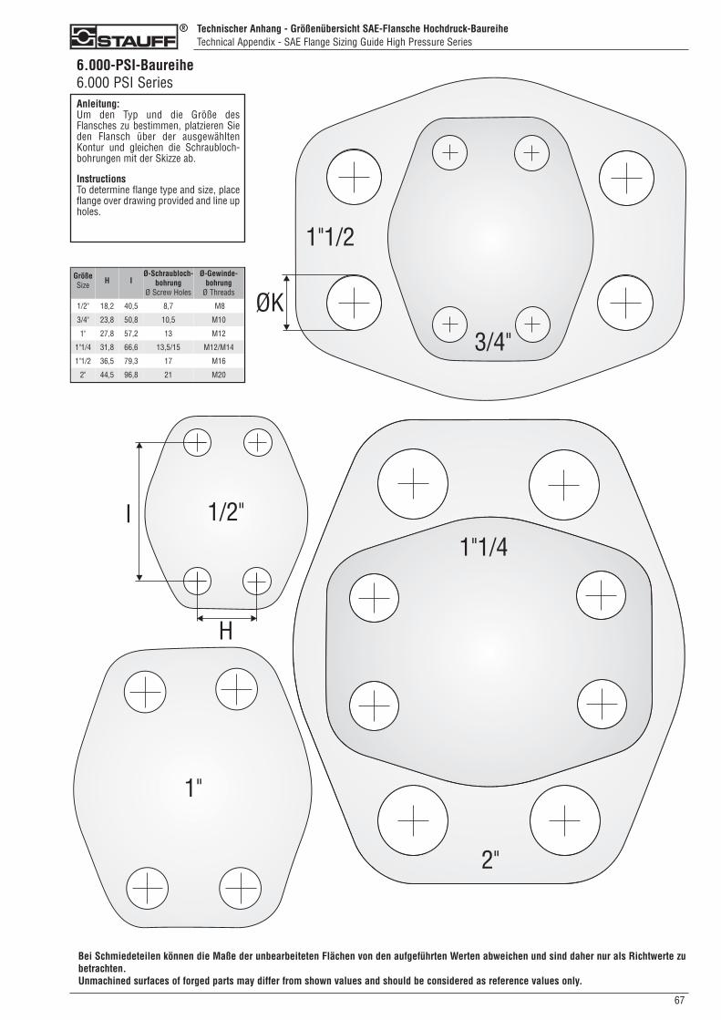
02
Unternehmensprofil und NiederlassungsverzeichnisCompany Profile and Register of Establishments
Große AuswahlSofortige LieferbereitschaftHoher Qualitätsstandard
Als mittelständisches Unternehmen mit Hauptsitz in Werdohl sind wir alsEntwickler, Hersteller und Lieferant von Rohrleitungskomponenten undHydraulikzubehör unter der Markenbezeichnung STAUFF national undinternational erfolgreich.
Jahrzehntelange Erfahrung, motivierte und qualifizierte Mitarbeiter,modernste Fertigungstechniken und die vorausschauende Unterneh-mensführung machen uns zu einem kompetenten Partner.
Sämtliche Produkte werden einschlägigen Prüfungen in Anlehnung an internationale Normen unterzogen und unterliegen unserem betrieblichen Qualitätsmanagement nach EN ISO 9001:2000.
Unser umfangreicher Lagerbestand und unsere flexible Fertigung sind einGarant für schnelle Reaktion und kurze Lieferzeiten.
Unterstützt werden wir von einem flächendeckenden Händlernetzwerksowie eigenen Produktions-, Vertriebs- und Logistik-Niederlassungen inderzeit 14 Ländern.
Walter Stauffenberg GmbH & Co. KG
P. O. Box 1745 � 58777 WerdohlIm Ehrenfeld 4 � 58791 WerdohlDeutschland / Germany
Tel.: +49 2392 916-0Fax: +49 2392 2505E-Mail: [email protected]: www.stauff.com
2
Comprehensive choiceImmediate deliveryHigh quality standard
Originating and located in Werdohl in the German Sauerland region, wehave become an internationally leading developer, manufacturer andsupplier of pipework components and hydraulic accessories.
More than 5 decades of experience, highly-motivated and qualified staff,state-of-the-art manufacturing technologies and a foresighted management give us the reputation of being a competitive partner.
Our in-house laboratories carry out constant tests in line with international standards on all products. Certified in accordance with ENISO 9001:2000, our quality assurance system continually strives for perfection.
Our well-stocked warehouses and flexible production lines ensureprompt reactions and short delivery times.
Represented by a tight network of distributors and wholly-owned manufacturing facilities, distribution bases and warehouses in 14 countries worldwide, we are also close to you.
AUSTRALIEN / AUSTRALIASTAUFF Corporation Pty. Ltd.P. O. Box 227Wollongong, NSW, 2526 24-26 Doyle AvenueUnanderra, Wollongong, NSW, 2526Tel.: +61 2 4271 18 77Fax: +61 2 4271 84 [email protected]
BRASILIEN / BRAZILSTAUFF Brasil Ltda.Avenida Gupê 10767Galpão 2 - Bloco ABarueri - São PauloCEP 06422-120Tel.: +55 11 47 72 72 00Fax: +55 11 47 72 72 [email protected]
CHINASTAUFF International Trading (Shanghai) Co., Ltd.No. 41-42,Lane 369, Chuang Ye RoadJushuo Industrial Zone, Kang Qiao201319 ShanghaiTel.: +86 21 68 18 70 00Fax: +86 21 68 18 71 [email protected]
FRANKREICH / FRANCESTAUFF S.A.S230, Avenue du Grain d'OrZ.I. de Vineuil - Blois Sud41354 Vineuil-cedexTel.: +33 2 54 50 55 50Fax: +33 2 54 42 29 [email protected]
INDIEN / INDIASTAUFF India Pvt. Ltd.Gat. No. 2340Pune Nagar Road, WagholiPune, 412207Tel.: +91 20 6620 2473Fax: +91 20 2705 [email protected]
ITALIEN / ITALY STAUFF Italia s.r.l.Viale Nuova Valassina 78angolo Via Baragiola sn20033 Desio (MI)Tel.: +39 0362 63 80 70 Fax: +39 0362 63 80 [email protected]
IRLAND / IRELANDSTAUFF Ireland Ltd.Unit B3Weatherwell Business ParkClondalkinDublin 22Tel.: +353 1457 4936Fax: +353 1467 [email protected]
KANADA / CANADASTAUFF Canada Ltd.866 Milner AvenueScarboroughOntario M1B 5N7Tel.: +1 416 282 46 08Fax: +1 416 282 30 [email protected]
KOREASTAUFF Korea Ltd.1500-12, Dadae-DongSaha-KuPusan, 604-826Tel.: +82 51 266 6666Fax.: +82 51 266 [email protected]
NEUSEELAND / NEW ZEALANDSTAUFF Corporation (NZ) Ltd.P. O. Box 58517Greenmount, AucklandUnit D, 103 Harris Road East Tamaki, AucklandTel.: +64 9 271 48 12Fax: +64 9 271 48 [email protected]
POLEN / POLANDSTAUFF Polska Sp. z o.o.Miszewko 43 A80-297 Banino Tel.: +48 58 660 11 60Fax: +48 58 629 79 [email protected]
RUSSISCHE FÖDERATION /RUSSIAN FEDERATIONSTAUFF LLCOffice 205, Building 7Scharikopodschipnikovskaya 11Moscow, 115088Tel.: +7 495 223 89 61
+7 495 987 36 29Fax: +7 495 679 90 [email protected]
VEREINIGTES KÖNIGREICH /UNITED KINGDOMSTAUFF UK500, Carlisle Street EastOff Downgate DriveSheffield, S4 8BSTel.: +44 114 251 85 18Fax: +44 114 251 85 [email protected]
VEREINIGTE STAATEN /UNITED STATESSTAUFF Corporation7 Wm. Demarest PlaceWaldwick, 07463-1542New JerseyTel.: +1 201 444 78 00Fax: +1 201 444 78 [email protected]
Globale Präsenz mit eigenenNiederlassungen und Händlern inallen Industrieländern weltweit.
Globally available through wholly-owned branches and distributors in all industrial countries.
67
Technischer Anhang - Größenübersicht SAE-Flansche Hochdruck-BaureiheTechnical Appendix - SAE Flange Sizing Guide High Pressure Series
6.000-PSI-Baureihe6.000 PSI SeriesAnleitung:Um den Typ und die Größe desFlansches zu bestimmen, platzieren Sieden Flansch über der ausgewähltenKontur und gleichen die Schraubloch-bohrungen mit der Skizze ab.
InstructionsTo determine flange type and size, placeflange over drawing provided and line upholes.
Bei Schmiedeteilen können die Maße der unbearbeiteten Flächen von den aufgeführten Werten abweichen und sind daher nur als Richtwerte zubetrachten.Unmachined surfaces of forged parts may differ from shown values and should be considered as reference values only.
GrößeSize H I
Ø-Schraubloch-bohrung
Ø Screw Holes
Ø-Gewinde-bohrung
Ø Threads
1/2" 18,2 40,5 8,7 M8
3/4" 23,8 50,8 10,5 M10
1" 27,8 57,2 13 M12
1"1/4 31,8 66,6 13,5/15 M12/M14
1"1/2 36,5 79,3 17 M16
2" 44,5 96,8 21 M20
Coverseiten Flansche Korrekturstand 07-2009:Layout 1 13.07.2009 09:40 Seite 2
KA-FLA-DEU/ENG-HA-2.000-07/2009 - 9910000025
Walter Stauffenberg GmbH & Co. KG
P.O.Box 1745 • D-58777 WerdohlIm Ehrenfeld 4 • D-58791 WerdohlTel. +49 2392 916-0 Fax +49 2392 2505E-Mail: [email protected] Internet: www.stauff.com STA
UF
F
STAUFF SCHELLENBefestigungssysteme für Rohre, Schläuche, Kabel und Bauteile; individuell gefertigte Sonderschellen
STAUFF CLAMPSClamping systems for pipes, hoses, cables and components; custom-made special clamps
STAUFF TESTMesssysteme zur Drucküberwachung, Entlüftung und Probeentnahmegasförmiger und fluider Medien
STAUFF TESTMeasuring systems for pressure monitoring of fluid and gaseous media;venting and sampling of fluid and gaseous pressure systems
STAUFF FILTRATION TECHNOLOGYFiltersysteme für die Erstausrüstung in der Mobil- und Stationär-hydraulik; Austauschelemente zu allen marktgängigen Fabrikaten
STAUFF FILTRATION TECHNOLOGYFilter systems for the basic equipment of mobile and industrial hydraulicapplications; wide range of replacement filter elements
STAUFF DIAGTRONICSKomponenten zur Überwachung und Analyse von Hydraulikflüssigkeitenin der Mobil- und Stationärhydraulik
STAUFF DIAGTRONICSComponents and services for the monitoring and analysis of hydraulicfluids for the mobile and industrial hydraulic sectors
STAUFF HYDRAULIKZUBEHÖRKomponenten für den Aggregate-, Tank- und Behälterbau in der Mobil- und Stationärhydraulik
STAUFF HYDRAULIC ACCESSORIESComponents for the construction of hydraulic reservoirs and power unitsfor the mobile and industrial hydraulic sectors
STAUFF FLANSCHESAE-Flansche nach ISO 6162-1/2 und SAE J518; Pumpenflansche
STAUFF FLANGESSAE Flanges acc. to ISO 6162-1/2 and SAE J518; pump flanges
STAUFF SYSTEMTECHNIKDreh- und Systemteile aus Edelstahl, Stahl, NE-Metallen undThermoplasten für sämtliche Industriebereiche
STAUFF MACHINED PARTSPrecision parts machined from stainless steel, carbon steel, non-ferrous-metals and thermoplastics for all fields of industry
Local solutions forindividual customers
worldwideSTA
UF
F
SAE-Flansche SAE Flanges
WWW.STAUFF.COM
Coverseiten Flansche Korrekturstand 07-2009:Layout 1 13.07.2009 09:40 Seite 1