Embed Size (px)
Citation preview
Stromortskurve Asynchronmaschine
Stromortskurve Asynchronmaschine
Stromortskurve der Drehstrom-Asynchronmaschine mitkurzgeschlossenem Rotor beim Betrieb am Drehstromnetz mit
fester Frequenz und SpannungProf. Dr.-Ing. Carsten Frager
Prof. Dr.-Ing. Carsten Frager
3. Dezember 2013
Stromortskurve der Asynchronmaschine – Prof. Dr.-Ing. Carsten Frager Folie 1 von 61
Stromortskurve Asynchronmaschine
Inhaltsverzeichnis
1 Ubersicht
2 Ersatzschaltbild und Spannungsgleichung
3 Ortskurve mit konstanten Ersatzschaltbildelementen
4 Stromortskurve Beispiel MCA26 - 55 kW
5 Stromortskurve Beispiel IEC 080 - 0,75 kW
6 Stromortskurve Beispiel IEC 180 - 22 kW
7 Stromverdrangung im Rotor
8 Stromortskurve mit Stromverdrangung
Stromortskurve der Asynchronmaschine – Prof. Dr.-Ing. Carsten Frager Folie 2 von 61
Stromortskurve Asynchronmaschine
Ubersicht
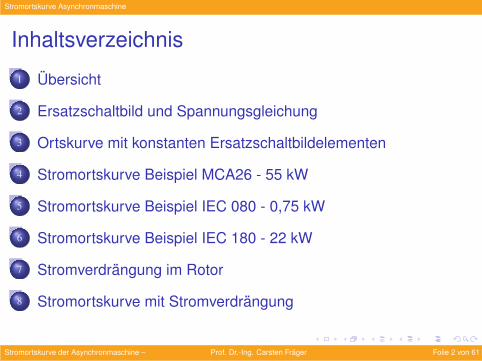
Die Stromortskurve beschreibt das Verhalten derAsynchronmaschine in Abhangigkeit vom Schlupf s und damitvon der Drehzahl n.
n = (1− s) ·n0 = (1− s) ·fSp
(1)
s =fRfS
, fR = s · fS (2)
Sie enthalt den Statorstrom IS, den transformierten RotorstromI′R, das Drehmoment M, die mechanische Leistung Pmech, dieRotorverlustleistung PVR, die Statorverlustleistung PVS und dieStatorleistung PS.
Stromortskurve der Asynchronmaschine – Ubersicht Prof. Dr.-Ing. Carsten Frager Folie 3 von 61
Stromortskurve Asynchronmaschine
Ubersicht
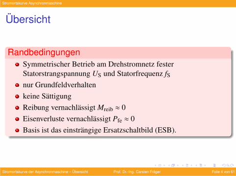
RandbedingungenSymmetrischer Betrieb am Drehstromnetz festerStatorstrangspannung US und Statorfrequenz fSnur Grundfeldverhaltenkeine SattigungReibung vernachlassigt Mreib ≈ 0Eisenverluste vernachlassigt Pfe ≈ 0Basis ist das einstrangige Ersatzschaltbild (ESB).
Stromortskurve der Asynchronmaschine – Ubersicht Prof. Dr.-Ing. Carsten Frager Folie 4 von 61
Stromortskurve Asynchronmaschine
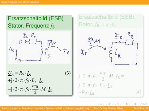
Ersatzschaltbild (ESB)Stator, Frequenz fS
US = RS · IS (3)+j ·2 ·π · fS ·LS · IS
−j ·2 ·π · fS ·mR
2·M · IR
Ersatzschaltbild (ESB)Rotor, fR = s · fS
j ·2 ·π · fR ·mS
2·M · IS =
j ·2 ·π · fR ·LR · IR
+RR · IR (4)
Stromortskurve der Asynchronmaschine – Ersatzschaltbild und Spannungsgleichung Prof. Dr.-Ing. Carsten Frager Folie 5 von 61
Stromortskurve Asynchronmaschine
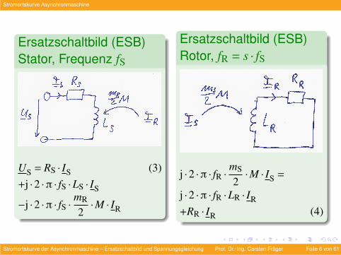
Ersatzschaltbild (ESB)Stator, Frequenz fS
US = RS · IS (3)+j ·2 ·π · fS ·LS · IS
−j ·2 ·π · fS ·mR
2·M · IR
Ersatzschaltbild (ESB)Rotor, fR = s · fS
j ·2 ·π · fR ·mS
2·M · IS =
j ·2 ·π · fR ·LR · IR
+RR · IR (4)
Stromortskurve der Asynchronmaschine – Ersatzschaltbild und Spannungsgleichung Prof. Dr.-Ing. Carsten Frager Folie 6 von 61
Stromortskurve Asynchronmaschine
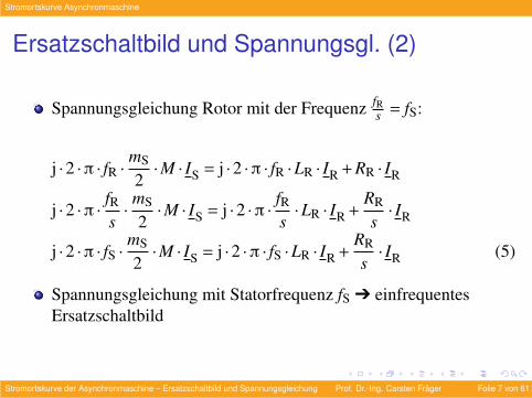
Ersatzschaltbild und Spannungsgl. (2)
Spannungsgleichung Rotor mit der Frequenz fRs = fS:
j ·2 ·π · fR ·mS
2·M · IS = j ·2 ·π · fR ·LR · IR + RR · IR
j ·2 ·π ·fRs·mS
2·M · IS = j ·2 ·π ·
fRs·LR · IR +
RR
s· IR
j ·2 ·π · fS ·mS
2·M · IS = j ·2 ·π · fS ·LR · IR +
RR
s· IR (5)
Spannungsgleichung mit Statorfrequenz fS Ô einfrequentesErsatzschaltbild
Stromortskurve der Asynchronmaschine – Ersatzschaltbild und Spannungsgleichung Prof. Dr.-Ing. Carsten Frager Folie 7 von 61
Stromortskurve Asynchronmaschine
Ersatzschaltbild und Spannungsgl. (3)
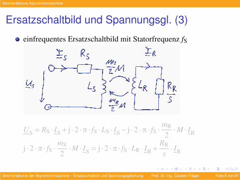
einfrequentes Ersatzschaltbild mit Statorfrequenz fS
US = RS · IS + j ·2 ·π · fS ·LS · IS− j ·2 ·π · fS ·mR
2·M · IR
j ·2 ·π · fS ·mS
2·M · IS = j ·2 ·π · fS ·LR · IR +
RR
s· IR
Stromortskurve der Asynchronmaschine – Ersatzschaltbild und Spannungsgleichung Prof. Dr.-Ing. Carsten Frager Folie 8 von 61
Stromortskurve Asynchronmaschine
Ersatzschaltbild und Spannungsgl. (3)
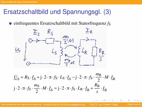
einfrequentes Ersatzschaltbild mit Statorfrequenz fS
US = RS · IS + j ·2 ·π · fS ·LS · IS− j ·2 ·π · fS ·mR
2·M · IR
j ·2 ·π · fS ·mS
2·M · IS = j ·2 ·π · fS ·LR · IR +
RR
s· IR
Stromortskurve der Asynchronmaschine – Ersatzschaltbild und Spannungsgleichung Prof. Dr.-Ing. Carsten Frager Folie 9 von 61
Stromortskurve Asynchronmaschine
Ersatzschaltbild und Spannungsgl. (4)
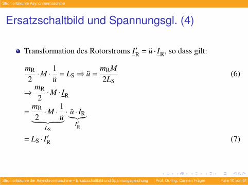
Transformation des Rotorstroms I′R = u · IR, so dass gilt:
mR
2·M ·
1u
= LS⇒ u =mRM2LS
(6)
⇒mR
2·M · IR
=mR
2·M ·
1u︸ ︷︷ ︸
LS
· u · IR︸︷︷︸I′R
= LS · I′R (7)
Stromortskurve der Asynchronmaschine – Ersatzschaltbild und Spannungsgleichung Prof. Dr.-Ing. Carsten Frager Folie 10 von 61
Stromortskurve Asynchronmaschine
Ersatzschaltbild und Spannungsgl. (5)
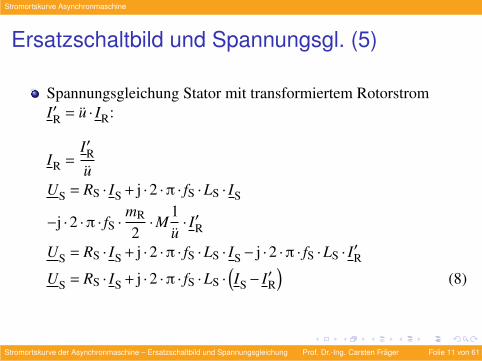
Spannungsgleichung Stator mit transformiertem RotorstromI′R = u · IR:
IR =I′Ru
US = RS · IS + j ·2 ·π · fS ·LS · IS
−j ·2 ·π · fS ·mR
2·M
1u· I′R
US = RS · IS + j ·2 ·π · fS ·LS · IS− j ·2 ·π · fS ·LS · I′RUS = RS · IS + j ·2 ·π · fS ·LS ·
(IS− I′R
)(8)
Stromortskurve der Asynchronmaschine – Ersatzschaltbild und Spannungsgleichung Prof. Dr.-Ing. Carsten Frager Folie 11 von 61
Stromortskurve Asynchronmaschine
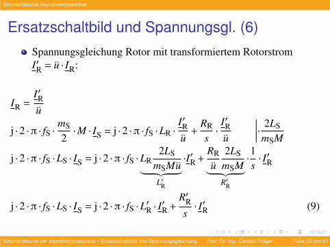
Ersatzschaltbild und Spannungsgl. (6)
Spannungsgleichung Rotor mit transformiertem RotorstromI′R = u · IR:
IR =I′Ru
j ·2 ·π · fS ·mS
2·M · IS = j ·2 ·π · fS ·LR ·
I′Ru
+RR
s·I′Ru
∣∣∣∣∣· 2LS
mSM
j ·2 ·π · fS ·LS · IS = j ·2 ·π · fS ·LR2LS
mSMu︸ ︷︷ ︸L′R
·I′R +RR
u2LS
mSM︸ ︷︷ ︸R′R
·1s· I′R
j ·2 ·π · fS ·LS · IS = j ·2 ·π · fS ·L′R · I′R +
R′Rs· I′R (9)
Stromortskurve der Asynchronmaschine – Ersatzschaltbild und Spannungsgleichung Prof. Dr.-Ing. Carsten Frager Folie 12 von 61
Stromortskurve Asynchronmaschine
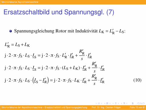
Ersatzschaltbild und Spannungsgl. (7)
Spannungsgleichung Rotor mit Induktivitat LK = L′R−LS:
L′R = LS + LK
j ·2 ·π · fS ·LS · IS = j ·2 ·π · fS ·L′R · I′R +
R′Rs· I′R
j ·2 ·π · fS ·LS · IS = j ·2 ·π · fS · (LS + LK) · I′R +R′Rs· I′R
j ·2 ·π · fS ·LS ·(IS− I′R
)= j ·2 ·π · fS ·LK · I′R +
R′Rs· I′R (10)
Stromortskurve der Asynchronmaschine – Ersatzschaltbild und Spannungsgleichung Prof. Dr.-Ing. Carsten Frager Folie 13 von 61
Stromortskurve Asynchronmaschine
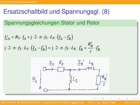
Ersatzschaltbild und Spannungsgl. (8)
Spannungsgleichungen Stator und Rotor
US = RS · IS + j ·2 ·π · fS ·LS ·(IS− I′R
)j ·2 ·π · fS ·LS ·
(IS− I′R
)= j ·2 ·π · fS ·LK · I′R +
R′Rs· I′R
Stromortskurve der Asynchronmaschine – Ersatzschaltbild und Spannungsgleichung Prof. Dr.-Ing. Carsten Frager Folie 14 von 61
Stromortskurve Asynchronmaschine
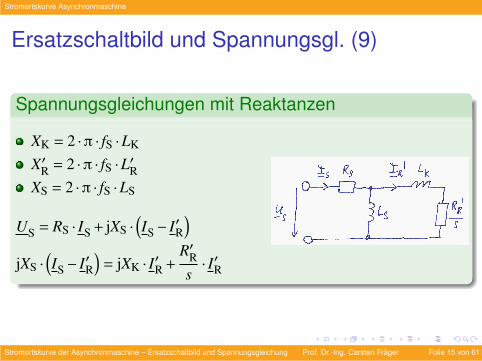
Ersatzschaltbild und Spannungsgl. (9)
Spannungsgleichungen mit Reaktanzen
XK = 2 ·π · fS ·LK
X′R = 2 ·π · fS ·L′RXS = 2 ·π · fS ·LS
US = RS · IS + jXS ·(IS− I′R
)jXS ·
(IS− I′R
)= jXK · I′R +
R′Rs· I′R
Stromortskurve der Asynchronmaschine – Ersatzschaltbild und Spannungsgleichung Prof. Dr.-Ing. Carsten Frager Folie 15 von 61
Stromortskurve Asynchronmaschine
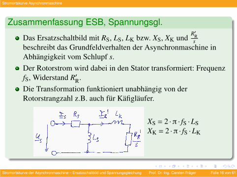
Zusammenfassung ESB, Spannungsgl.
Das Ersatzschaltbild mit RS, LS, LK bzw. XS, XK undR′Rs
beschreibt das Grundfeldverhalten der Asynchronmaschine inAbhangigkeit vom Schlupf s.Der Rotorstrom wird dabei in den Stator transformiert: FrequenzfS, Widerstand R′R.Die Transformation funktioniert unabhangig von derRotorstrangzahl z.B. auch fur Kafiglaufer.
XS = 2 ·π · fS ·LSXK = 2 ·π · fS ·LK
Stromortskurve der Asynchronmaschine – Ersatzschaltbild und Spannungsgleichung Prof. Dr.-Ing. Carsten Frager Folie 16 von 61
Stromortskurve Asynchronmaschine
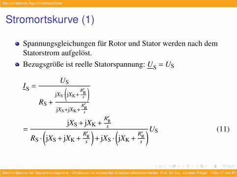
Stromortskurve (1)
Spannungsgleichungen fur Rotor und Stator werden nach demStatorstrom aufgelost.Bezugsgroße ist reelle Statorspannung: US = US
IS =US
RS +jXS·
(jXK+
R′Rs
)jXS+jXK+
R′Rs
=jXS + jXK +
R′Rs
RS ·
(jXS + jXK +
R′Rs
)+ jXS ·
(jXK +
R′Rs
)US (11)
Stromortskurve der Asynchronmaschine – Ortskurve mit konstanten Ersatzschaltbildelementen Prof. Dr.-Ing. Carsten Frager Folie 17 von 61
Stromortskurve Asynchronmaschine
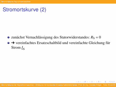
Stromortskurve (2)
zunachst Vernachlassigung des Statorwiderstandes: RS = 0Ô vereinfachtes Ersatzschaltbild und vereinfachte Gleichung furStrom IS
Stromortskurve der Asynchronmaschine – Ortskurve mit konstanten Ersatzschaltbildelementen Prof. Dr.-Ing. Carsten Frager Folie 18 von 61
Stromortskurve Asynchronmaschine
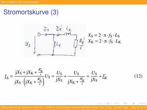
Stromortskurve (3)
XS = 2 ·π · fS ·LSXK = 2 ·π · fS ·LK
IS =jXS + jXK +
R′Rs
jXS ·
(jXK +
R′Rs
)US =US
jXS+
US
jXK +R′Rs
=US
jXS+ I′R (12)
Stromortskurve der Asynchronmaschine – Ortskurve mit konstanten Ersatzschaltbildelementen Prof. Dr.-Ing. Carsten Frager Folie 19 von 61
Stromortskurve Asynchronmaschine
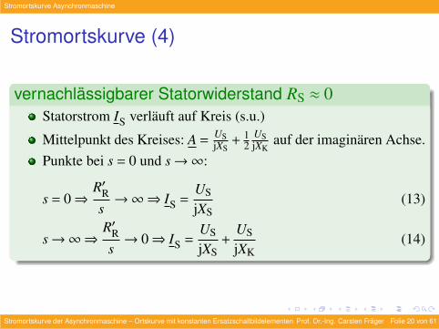
Stromortskurve (4)
vernachlassigbarer Statorwiderstand RS ≈ 0Statorstrom IS verlauft auf Kreis (s.u.)
Mittelpunkt des Kreises: A =USjXS
+ 12
USjXK
auf der imaginaren Achse.Punkte bei s = 0 und s→∞:
s = 0⇒R′Rs→∞⇒ IS =
US
jXS(13)
s→∞⇒R′Rs→ 0⇒ IS =
US
jXS+
US
jXK(14)
Stromortskurve der Asynchronmaschine – Ortskurve mit konstanten Ersatzschaltbildelementen Prof. Dr.-Ing. Carsten Frager Folie 20 von 61
Stromortskurve Asynchronmaschine
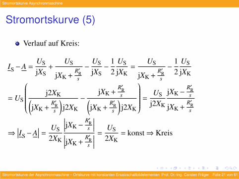
Stromortskurve (5)
Verlauf auf Kreis:
IS−A =US
jXS+
US
jXK +R′Rs
−US
jXS−
12
US
jXK=
US
jXK +R′Rs
−12
US
jXK
= US
j2XK(jXK +
R′Rs
)j2XK
−jXK +
R′Rs(
jXK +R′Rs
)j2XK
=US
j2XK
jXK−R′Rs
jXK +R′Rs
⇒∣∣∣IS−A
∣∣∣ =US
2XK
∣∣∣∣jXK−R′Rs
∣∣∣∣∣∣∣∣jXK +R′Rs
∣∣∣∣ =US
2XK= konst⇒ Kreis
Stromortskurve der Asynchronmaschine – Ortskurve mit konstanten Ersatzschaltbildelementen Prof. Dr.-Ing. Carsten Frager Folie 21 von 61
Stromortskurve Asynchronmaschine
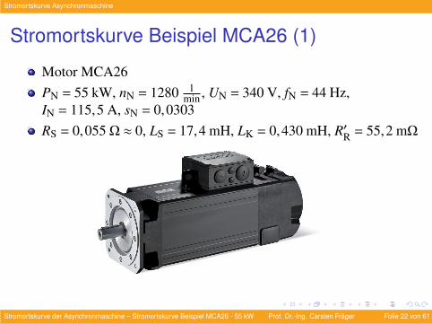
Stromortskurve Beispiel MCA26 (1)
Motor MCA26PN = 55 kW, nN = 1280 1
min , UN = 340 V, fN = 44 Hz,IN = 115,5 A, sN = 0,0303RS = 0,055 Ω ≈ 0, LS = 17,4 mH, LK = 0,430 mH, R′R = 55,2 mΩ
Stromortskurve der Asynchronmaschine – Stromortskurve Beispiel MCA26 - 55 kW Prof. Dr.-Ing. Carsten Frager Folie 22 von 61
Stromortskurve Asynchronmaschine
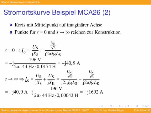
Stromortskurve Beispiel MCA26 (2)
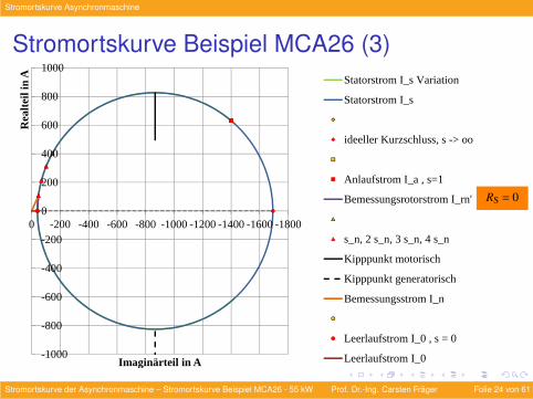
Kreis mit Mittelpunkt auf imaginarer AchsePunkte fur s = 0 und s→∞ reichen zur Konstruktion
s = 0⇒ IS =US
jXS=
UN√3
j2πfNLS
= −j196 V
2π ·44 Hz ·0,0174 H= −j40,9 A
s→∞⇒ IS =US
jXS+
US
jXK=
UN√3
j2πfNLS+
UN√3
j2πfNLK
= −j40,9 A− j196 V
2π ·44 Hz ·0,00043 H= −j1692 A
Stromortskurve der Asynchronmaschine – Stromortskurve Beispiel MCA26 - 55 kW Prof. Dr.-Ing. Carsten Frager Folie 23 von 61
Stromortskurve Asynchronmaschine
Stromortskurve Beispiel MCA26 (3)
-1000
-800
-600
-400
-200
0
200
400
600
800
1000
-1800-1600-1400-1200-1000-800-600-400-2000
Rea
lteil
in A
Imaginärteil in A
Statorstrom I_s Variation
Statorstrom I_s
ideeller Kurzschluss, s -> oo
Anlaufstrom I_a , s=1
Bemessungsrotorstrom I_rn'
s_n, 2 s_n, 3 s_n, 4 s_n
Kipppunkt motorisch
Kipppunkt generatorisch
Bemessungsstrom I_n
Leerlaufstrom I_0 , s = 0
Leerlaufstrom I_0
RS = 0
Stromortskurve der Asynchronmaschine – Stromortskurve Beispiel MCA26 - 55 kW Prof. Dr.-Ing. Carsten Frager Folie 24 von 61
Stromortskurve Asynchronmaschine
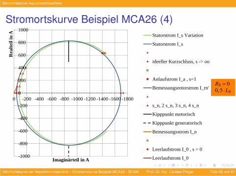
Stromortskurve Beispiel MCA26 (4)
-1000
-800
-600
-400
-200
0
200
400
600
800
1000
-1800-1600-1400-1200-1000-800-600-400-2000
Rea
lteil
in A
Imaginärteil in A
Statorstrom I_s Variation
Statorstrom I_s
ideeller Kurzschluss, s -> oo
Anlaufstrom I_a , s=1
Bemessungsrotorstrom I_rn'
s_n, 2 s_n, 3 s_n, 4 s_n
Kipppunkt motorisch
Kipppunkt generatorisch
Bemessungsstrom I_n
Leerlaufstrom I_0 , s = 0
Leerlaufstrom I_0
RS = 00,5 ·LS
Stromortskurve der Asynchronmaschine – Stromortskurve Beispiel MCA26 - 55 kW Prof. Dr.-Ing. Carsten Frager Folie 25 von 61

Stromortskurve Asynchronmaschine
Stromortskurve Beispiel MCA26 (5)
-1000
-800
-600
-400
-200
0
200
400
600
800
1000
-1800-1600-1400-1200-1000-800-600-400-2000
Rea
lteil
in A
Imaginärteil in A
Statorstrom I_s Variation
Statorstrom I_s
ideeller Kurzschluss, s -> oo
Anlaufstrom I_a , s=1
Bemessungsrotorstrom I_rn'
s_n, 2 s_n, 3 s_n, 4 s_n
Kipppunkt motorisch
Kipppunkt generatorisch
Bemessungsstrom I_n
Leerlaufstrom I_0 , s = 0
Leerlaufstrom I_0
RS = 01,5 ·LK
Stromortskurve der Asynchronmaschine – Stromortskurve Beispiel MCA26 - 55 kW Prof. Dr.-Ing. Carsten Frager Folie 26 von 61
Stromortskurve Asynchronmaschine
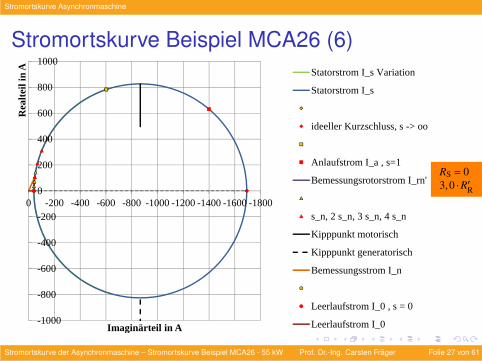
Stromortskurve Beispiel MCA26 (6)
-1000
-800
-600
-400
-200
0
200
400
600
800
1000
-1800-1600-1400-1200-1000-800-600-400-2000
Rea
lteil
in A
Imaginärteil in A
Statorstrom I_s Variation
Statorstrom I_s
ideeller Kurzschluss, s -> oo
Anlaufstrom I_a , s=1
Bemessungsrotorstrom I_rn'
s_n, 2 s_n, 3 s_n, 4 s_n
Kipppunkt motorisch
Kipppunkt generatorisch
Bemessungsstrom I_n
Leerlaufstrom I_0 , s = 0
Leerlaufstrom I_0
RS = 03,0 ·R′R
Stromortskurve der Asynchronmaschine – Stromortskurve Beispiel MCA26 - 55 kW Prof. Dr.-Ing. Carsten Frager Folie 27 von 61
Stromortskurve Asynchronmaschine
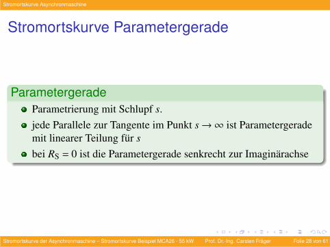
Stromortskurve Parametergerade
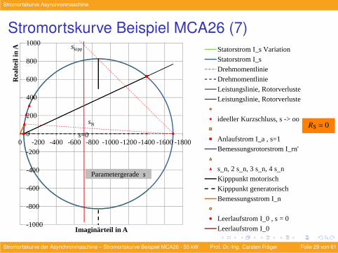
ParametergeradeParametrierung mit Schlupf s.jede Parallele zur Tangente im Punkt s→∞ ist Parametergerademit linearer Teilung fur sbei RS = 0 ist die Parametergerade senkrecht zur Imaginarachse
Stromortskurve der Asynchronmaschine – Stromortskurve Beispiel MCA26 - 55 kW Prof. Dr.-Ing. Carsten Frager Folie 28 von 61
Stromortskurve Asynchronmaschine
Stromortskurve Beispiel MCA26 (7)
-1000
-800
-600
-400
-200
0
200
400
600
800
1000
-1800-1600-1400-1200-1000-800-600-400-2000
Rea
lteil
in A
Imaginärteil in A
Statorstrom I_s VariationStatorstrom I_sDrehmomentlinieDrehmomentlinie
Leistungslinie, RotorverlusteLeistungslinie, Rotorverluste
ideeller Kurzschluss, s -> oo
Anlaufstrom I_a , s=1Bemessungsrotorstrom I_rn'
s_n, 2 s_n, 3 s_n, 4 s_nKipppunkt motorischKipppunkt generatorisch
Bemessungsstrom I_n
Leerlaufstrom I_0 , s = 0
Leerlaufstrom I_0
Parametergerade s
s=0
sN
skipp
RS = 0
Stromortskurve der Asynchronmaschine – Stromortskurve Beispiel MCA26 - 55 kW Prof. Dr.-Ing. Carsten Frager Folie 29 von 61
Stromortskurve Asynchronmaschine
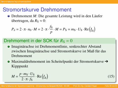
Stromortskurve DrehmomentDrehmoment M: Die gesamte Leistung wird in den Lauferubertragen, da RS ≈ 0:
Pδ = 2 ·π ·n0 ·M = 2 ·π ·fSp·M = PS = mS ·US ·Re
(IS
)Drehmoment in der SOK fur RS = 0
Imaginarachse ist Drehmomentlinie, senkrechter Abstandzwischen Imaginarachse und Stromortskurve ist Maß fur dasDrehmomentMaximaldrehmoment im Scheitelpunkt der Stromortskurve Ô
Kipppunkt
M =p ·mS ·US
2 ·π · fS·Re
(IS
)(15)
Stromortskurve der Asynchronmaschine – Stromortskurve Beispiel MCA26 - 55 kW Prof. Dr.-Ing. Carsten Frager Folie 30 von 61
Stromortskurve Asynchronmaschine
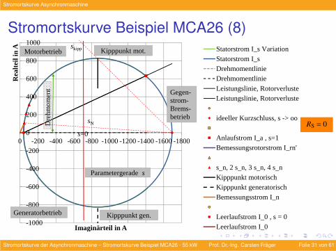
Stromortskurve Beispiel MCA26 (8)
-1000
-800
-600
-400
-200
0
200
400
600
800
1000
-1800-1600-1400-1200-1000-800-600-400-2000
Rea
lteil
in A
Imaginärteil in A
Statorstrom I_s VariationStatorstrom I_sDrehmomentlinieDrehmomentlinie
Leistungslinie, RotorverlusteLeistungslinie, Rotorverluste
ideeller Kurzschluss, s -> oo
Anlaufstrom I_a , s=1Bemessungsrotorstrom I_rn'
s_n, 2 s_n, 3 s_n, 4 s_nKipppunkt motorischKipppunkt generatorisch
Bemessungsstrom I_n
Leerlaufstrom I_0 , s = 0
Leerlaufstrom I_0
Gegen-strom-Brems-betrieb
Motorbetrieb
Generatorbetrieb
Dre
hm
om
ent
Parametergerade s
Kipppunkt mot.
Kipppunkt gen.
s=0
sN
skipp
RS = 0
Stromortskurve der Asynchronmaschine – Stromortskurve Beispiel MCA26 - 55 kW Prof. Dr.-Ing. Carsten Frager Folie 31 von 61
Stromortskurve Asynchronmaschine
Stromortskurve Rotorverluste (1)
Rotorverluste PVR und mechanische Leistung Pmech ergebenzusammen die Luftspaltleistung:
Pmech = Pδ−PVR (16)
Rotorverluste:
PVR = mS ·R′R · I′R
2 (17)
Stromortskurve der Asynchronmaschine – Stromortskurve Beispiel MCA26 - 55 kW Prof. Dr.-Ing. Carsten Frager Folie 32 von 61
Stromortskurve Asynchronmaschine
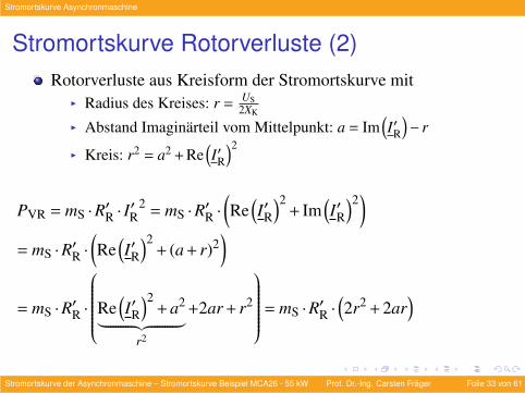
Stromortskurve Rotorverluste (2)Rotorverluste aus Kreisform der Stromortskurve mit
I Radius des Kreises: r =US
2XK
I Abstand Imaginarteil vom Mittelpunkt: a = Im(I′R
)− r
I Kreis: r2 = a2 + Re(I′R
)2
PVR = mS ·R′R · I′R
2= mS ·R′R ·
(Re
(I′R
)2+ Im
(I′R
)2)
= mS ·R′R ·(Re
(I′R
)2+ (a + r)2
)= mS ·R′R ·
Re(I′R
)2+ a2︸ ︷︷ ︸
r2
+2ar + r2
= mS ·R′R ·(2r2 + 2ar
)
Stromortskurve der Asynchronmaschine – Stromortskurve Beispiel MCA26 - 55 kW Prof. Dr.-Ing. Carsten Frager Folie 33 von 61
Stromortskurve Asynchronmaschine
Stromortskurve Rotorverluste (3)
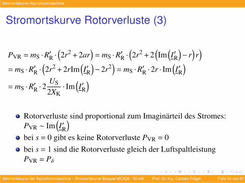
PVR = mS ·R′R ·(2r2 + 2ar
)= mS ·R′R ·
(2r2 + 2
(Im
(I′R
)− r
)r)
= mS ·R′R ·(2r2 + 2rIm
(I′R
)−2r2
)= mS ·R′R ·2r · Im
(I′R
)= mS ·R′R ·2
US
2XK· Im
(I′R
)Rotorverluste sind proportional zum Imaginarteil des Stromes:PVR ∼ Im
(I′R
)bei s = 0 gibt es keine Rotorverluste PVR = 0bei s = 1 sind die Rotorverluste gleich der LuftspaltleistungPVR = Pδ
Stromortskurve der Asynchronmaschine – Stromortskurve Beispiel MCA26 - 55 kW Prof. Dr.-Ing. Carsten Frager Folie 34 von 61
Stromortskurve Asynchronmaschine
Stromortskurve Rotorverluste (4)
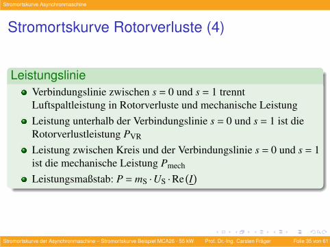
LeistungslinieVerbindungslinie zwischen s = 0 und s = 1 trenntLuftspaltleistung in Rotorverluste und mechanische LeistungLeistung unterhalb der Verbindungslinie s = 0 und s = 1 ist dieRotorverlustleistung PVR
Leistung zwischen Kreis und der Verbindungslinie s = 0 und s = 1ist die mechanische Leistung Pmech
Leistungsmaßstab: P = mS ·US ·Re(I)
Stromortskurve der Asynchronmaschine – Stromortskurve Beispiel MCA26 - 55 kW Prof. Dr.-Ing. Carsten Frager Folie 35 von 61
Stromortskurve Asynchronmaschine
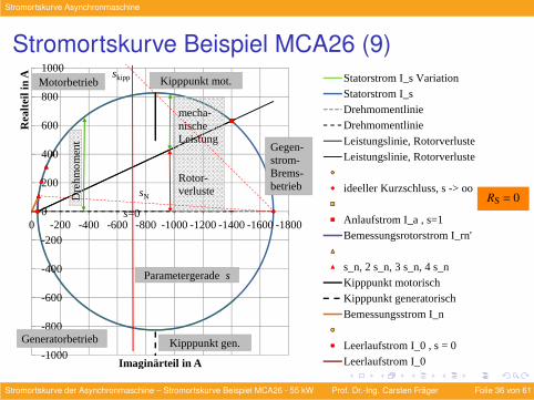
Stromortskurve Beispiel MCA26 (9)
-1000
-800
-600
-400
-200
0
200
400
600
800
1000
-1800-1600-1400-1200-1000-800-600-400-2000
Rea
lteil
in A
Imaginärteil in A
Statorstrom I_s VariationStatorstrom I_sDrehmomentlinieDrehmomentlinie
Leistungslinie, RotorverlusteLeistungslinie, Rotorverluste
ideeller Kurzschluss, s -> oo
Anlaufstrom I_a , s=1Bemessungsrotorstrom I_rn'
s_n, 2 s_n, 3 s_n, 4 s_nKipppunkt motorischKipppunkt generatorisch
Bemessungsstrom I_n
Leerlaufstrom I_0 , s = 0
Leerlaufstrom I_0
Gegen-strom-Brems-betrieb
Motorbetrieb
Generatorbetrieb
mecha-nische Leistung
Rotor-verlusteD
reh
mo
men
t
Parametergerade s
Kipppunkt mot.
Kipppunkt gen.
s=0
sN
skipp
RS = 0
Stromortskurve der Asynchronmaschine – Stromortskurve Beispiel MCA26 - 55 kW Prof. Dr.-Ing. Carsten Frager Folie 36 von 61
Stromortskurve Asynchronmaschine
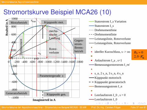
Stromortskurve Beispiel MCA26 (10)
-1000
-800
-600
-400
-200
0
200
400
600
800
1000
-1800-1600-1400-1200-1000-800-600-400-2000
Rea
lteil
in A
Imaginärteil in A
Statorstrom I_s VariationStatorstrom I_sDrehmomentlinieDrehmomentlinie
Leistungslinie, RotorverlusteLeistungslinie, Rotorverluste
ideeller Kurzschluss, s -> oo
Anlaufstrom I_a , s=1Bemessungsrotorstrom I_rn'
s_n, 2 s_n, 3 s_n, 4 s_nKipppunkt motorischKipppunkt generatorisch
Bemessungsstrom I_n
Leerlaufstrom I_0 , s = 0
Leerlaufstrom I_0
Gegen-strom-Brems-betrieb
Motorbetrieb
Generatorbetrieb
mecha-nische Leistung
Rotor-verlusteD
reh
mo
men
t
Parametergerade s
Kipppunkt mot.
Kipppunkt gen.
s=0
sN
skipp
RS = 02,0 ·R′R
Stromortskurve der Asynchronmaschine – Stromortskurve Beispiel MCA26 - 55 kW Prof. Dr.-Ing. Carsten Frager Folie 37 von 61
Stromortskurve Asynchronmaschine
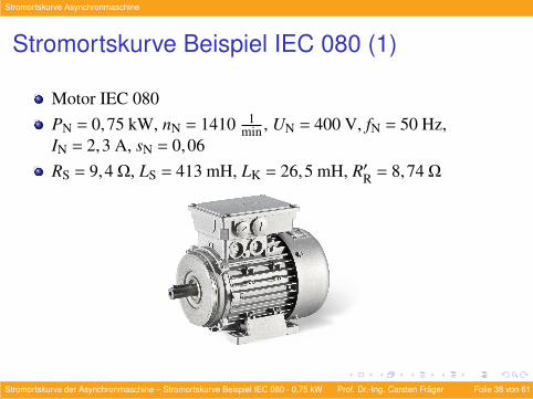
Stromortskurve Beispiel IEC 080 (1)
Motor IEC 080PN = 0,75 kW, nN = 1410 1
min , UN = 400 V, fN = 50 Hz,IN = 2,3 A, sN = 0,06RS = 9,4 Ω, LS = 413 mH, LK = 26,5 mH, R′R = 8,74 Ω
Stromortskurve der Asynchronmaschine – Stromortskurve Beispiel IEC 080 - 0,75 kW Prof. Dr.-Ing. Carsten Frager Folie 38 von 61
Stromortskurve Asynchronmaschine
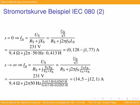
Stromortskurve Beispiel IEC 080 (2)
s = 0⇒ IS =US
RS + jXS=
UN√3
RS + j2πfNLS
=231 V
9,4 Ω+ j2π ·50 Hz ·0,413 H= (0,128− j1,77) A
s→∞⇒ IS =US
RS + j XSXKXS+XK
=
UN√3
RS + j2πfNLSLK
LS+LK
=231 V
9,4 Ω+ j2π50 Hz 0,413 H·0,0265 H0,413 H+0,0265 H
= (14,5− j12,1) A
Stromortskurve der Asynchronmaschine – Stromortskurve Beispiel IEC 080 - 0,75 kW Prof. Dr.-Ing. Carsten Frager Folie 39 von 61
Stromortskurve Asynchronmaschine
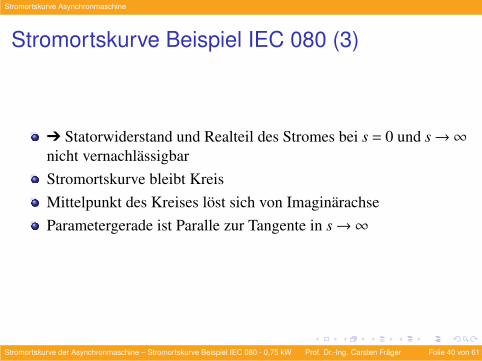
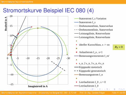
Stromortskurve Beispiel IEC 080 (3)
Ô Statorwiderstand und Realteil des Stromes bei s = 0 und s→∞nicht vernachlassigbarStromortskurve bleibt KreisMittelpunkt des Kreises lost sich von ImaginarachseParametergerade ist Paralle zur Tangente in s→∞
Stromortskurve der Asynchronmaschine – Stromortskurve Beispiel IEC 080 - 0,75 kW Prof. Dr.-Ing. Carsten Frager Folie 40 von 61
Stromortskurve Asynchronmaschine
Stromortskurve Beispiel IEC 080 (4)
-15
-10
-5
0
5
10
15
20
-30-25-20-15-10-50
Rea
lteil
in A
Imaginärteil in A
Statorstrom I_s VariationStatorstrom I_sDrehmomentlinie, StatorverlusteDrehmomentlinie, Statorverluste
Leistungslinie, RotorverlusteLeistungslinie, Rotorverluste
ideeller Kurzschluss, s -> oo
Anlaufstrom I_a , s=1Bemessungsrotorstrom I_rn'
s_n, 2 s_n, 3 s_n, 4 s_nKipppunkt motorischKipppunkt generatorisch
Bemessungsstrom I_n
Leerlaufstrom I_0 , s = 0
Leerlaufstrom I_0
RS = 0
Stromortskurve der Asynchronmaschine – Stromortskurve Beispiel IEC 080 - 0,75 kW Prof. Dr.-Ing. Carsten Frager Folie 41 von 61
Stromortskurve Asynchronmaschine
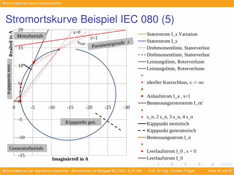
Stromortskurve Beispiel IEC 080 (5)
-15
-10
-5
0
5
10
15
20
-30-25-20-15-10-50
Rea
lteil
in A
Imaginärteil in A
Statorstrom I_s VariationStatorstrom I_sDrehmomentlinie, StatorverlusteDrehmomentlinie, Statorverluste
Leistungslinie, RotorverlusteLeistungslinie, Rotorverluste
ideeller Kurzschluss, s -> oo
Anlaufstrom I_a , s=1Bemessungsrotorstrom I_rn'
s_n, 2 s_n, 3 s_n, 4 s_nKipppunkt motorischKipppunkt generatorisch
Bemessungsstrom I_n
Leerlaufstrom I_0 , s = 0
Leerlaufstrom I_0
Motorbetrieb
Generatorbetrieb
Kip
pp
un
kt m
ot.
Kipppunkt gen.
s=0
skipp
s=1
Stromortskurve der Asynchronmaschine – Stromortskurve Beispiel IEC 080 - 0,75 kW Prof. Dr.-Ing. Carsten Frager Folie 42 von 61
Stromortskurve Asynchronmaschine
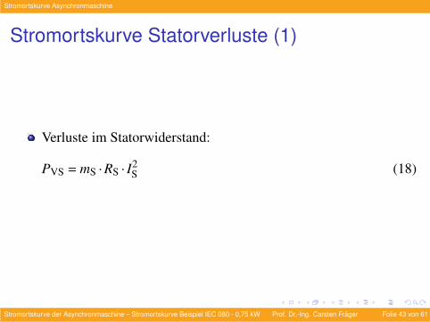
Stromortskurve Statorverluste (1)
Verluste im Statorwiderstand:
PVS = mS ·RS · I2S (18)
Stromortskurve der Asynchronmaschine – Stromortskurve Beispiel IEC 080 - 0,75 kW Prof. Dr.-Ing. Carsten Frager Folie 43 von 61
Stromortskurve Asynchronmaschine
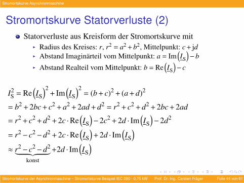
Stromortskurve Statorverluste (2)Statorverluste aus Kreisform der Stromortskurve mit
I Radius des Kreises: r, r2 = a2 + b2, Mittelpunkt: c + jdI Abstand Imaginarteil vom Mittelpunkt: a = Im
(IS
)−b
I Abstand Realteil vom Mittelpunkt: b = Re(IS
)− c
I2S = Re
(IS
)2+ Im
(IS
)2= (b + c)2 + (a + d)2
= b2 + 2bc + c2 + a2 + 2ad + d2 = r2 + c2 + d2 + 2bc + 2ad
= r2 + c2 + d2 + 2c ·Re(IS
)−2c2 + 2d · Im
(IS
)−2d2
= r2− c2−d2 + 2c ·Re(IS
)+ 2d · Im
(IS
)≈ r2− c2−d2︸ ︷︷ ︸
konst
+2d · Im(IS
)Stromortskurve der Asynchronmaschine – Stromortskurve Beispiel IEC 080 - 0,75 kW Prof. Dr.-Ing. Carsten Frager Folie 44 von 61
Stromortskurve Asynchronmaschine
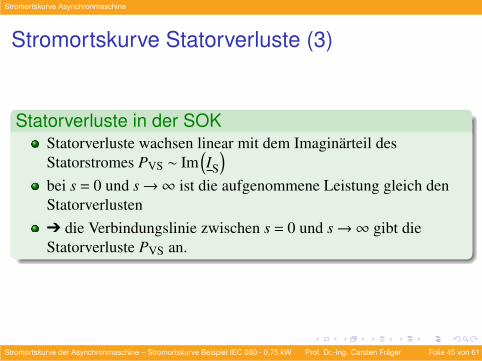
Stromortskurve Statorverluste (3)
Statorverluste in der SOKStatorverluste wachsen linear mit dem Imaginarteil desStatorstromes PVS ∼ Im
(IS
)bei s = 0 und s→∞ ist die aufgenommene Leistung gleich denStatorverlustenÔ die Verbindungslinie zwischen s = 0 und s→∞ gibt dieStatorverluste PVS an.
Stromortskurve der Asynchronmaschine – Stromortskurve Beispiel IEC 080 - 0,75 kW Prof. Dr.-Ing. Carsten Frager Folie 45 von 61
Stromortskurve Asynchronmaschine
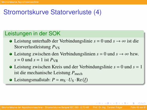
Stromortskurve Statorverluste (4)
Leistungen in der SOKLeistung unterhalb der Verbindungslinie s = 0 und s→∞ ist dieStorverlustleistung PVS
Leistung zwischen den Verbindungslinien s = 0 und s→∞ bzw.s = 0 und s = 1 ist PVR
Leistung zwischen Kreis und der Verbindungslinie s = 0 und s = 1ist die mechanische Leistung Pmech
Leistungsmaßstab: P = mS ·US ·Re(I)
Stromortskurve der Asynchronmaschine – Stromortskurve Beispiel IEC 080 - 0,75 kW Prof. Dr.-Ing. Carsten Frager Folie 46 von 61
Stromortskurve Asynchronmaschine
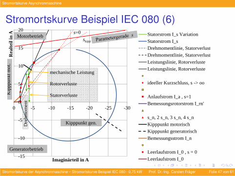
Stromortskurve Beispiel IEC 080 (6)
-15
-10
-5
0
5
10
15
20
-30-25-20-15-10-50
Rea
lteil
in A
Imaginärteil in A
Statorstrom I_s VariationStatorstrom I_sDrehmomentlinie, StatorverlusteDrehmomentlinie, Statorverluste
Leistungslinie, RotorverlusteLeistungslinie, Rotorverluste
ideeller Kurzschluss, s -> oo
Anlaufstrom I_a , s=1Bemessungsrotorstrom I_rn'
s_n, 2 s_n, 3 s_n, 4 s_nKipppunkt motorischKipppunkt generatorisch
Bemessungsstrom I_n
Leerlaufstrom I_0 , s = 0
Leerlaufstrom I_0
Motorbetrieb
Generatorbetrieb
mechanische Leistung
Rotorverluste
Statorverluste
Dre
hm
om
ent
Kip
pp
un
kt m
ot.
Kipppunkt gen.
s=0
skipp
Stromortskurve der Asynchronmaschine – Stromortskurve Beispiel IEC 080 - 0,75 kW Prof. Dr.-Ing. Carsten Frager Folie 47 von 61
Stromortskurve Asynchronmaschine
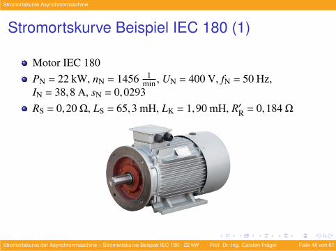
Stromortskurve Beispiel IEC 180 (1)
Motor IEC 180PN = 22 kW, nN = 1456 1
min , UN = 400 V, fN = 50 Hz,IN = 38,8 A, sN = 0,0293RS = 0,20 Ω, LS = 65,3 mH, LK = 1,90 mH, R′R = 0,184 Ω
Stromortskurve der Asynchronmaschine – Stromortskurve Beispiel IEC 180 - 22 kW Prof. Dr.-Ing. Carsten Frager Folie 48 von 61
Stromortskurve Asynchronmaschine
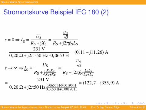
Stromortskurve Beispiel IEC 180 (2)
s = 0⇒ IS =US
RS + jXS=
UN√3
RS + j2πfNLS
=231 V
0,20 Ω+ j2π ·50 Hz ·0,0653 H= (0,11− j11,26) A
s→∞⇒ IS =US
RS + j XSXKXS+XK
=
UN√3
RS + j2πfNLSLK
LS+LK
=231 V
0,20 Ω+ j2π50 Hz 0,0653 H·0,00190 H0,0653 H+0,00190 H
= (122,7− j355,9) A
Stromortskurve der Asynchronmaschine – Stromortskurve Beispiel IEC 180 - 22 kW Prof. Dr.-Ing. Carsten Frager Folie 49 von 61
Stromortskurve Asynchronmaschine
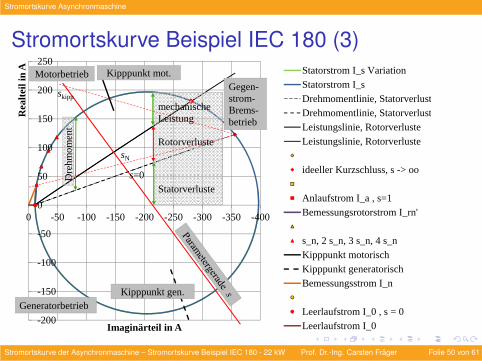
Stromortskurve Beispiel IEC 180 (3)
-200
-150
-100
-50
0
50
100
150
200
250
-400-350-300-250-200-150-100-500
Rea
lteil
in A
Imaginärteil in A
Statorstrom I_s VariationStatorstrom I_sDrehmomentlinie, StatorverlusteDrehmomentlinie, StatorverlusteLeistungslinie, Rotorverluste
Leistungslinie, Rotorverluste
ideeller Kurzschluss, s -> oo
Anlaufstrom I_a , s=1Bemessungsrotorstrom I_rn'
s_n, 2 s_n, 3 s_n, 4 s_nKipppunkt motorischKipppunkt generatorischBemessungsstrom I_n
Leerlaufstrom I_0 , s = 0Leerlaufstrom I_0
Gegen-strom-Brems-betrieb
Motorbetrieb
Generatorbetrieb
mechanische Leistung
Rotorverluste
Statorverluste
Dre
hm
om
ent
Kipppunkt mot.
Kipppunkt gen.
s=0
sN
skipp
Stromortskurve der Asynchronmaschine – Stromortskurve Beispiel IEC 180 - 22 kW Prof. Dr.-Ing. Carsten Frager Folie 50 von 61
Stromortskurve Asynchronmaschine
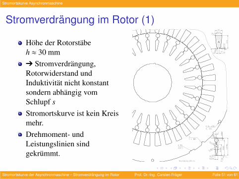
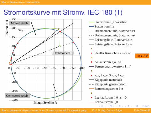
Stromverdrangung im Rotor (1)
Hohe der Rotorstabeh ≈ 30 mmÔ Stromverdrangung,Rotorwiderstand undInduktivitat nicht konstantsondern abhangig vomSchlupf sStromortskurve ist kein Kreismehr.Drehmoment- undLeistungslinien sindgekrummt.
Kienle + Spiess GmbHBahnhofstraße 23D-74343 Sachsenheim / GermanyTel: +49 (7147) 29 0Fax: +49 (7147) 29 1488E-mail: [email protected] These sketch drawings are meant for information only. Detailed product drawings are available on requestWeb: www.kienle-spiess.com Dies ist eine unverbindliche Schnittzeichnung. Detailierte Produktzeichnungen erhalten Sie auf Anfrage © 2003-2012 Kienle + Spiess GmbH
Stromortskurve der Asynchronmaschine – Stromverdrangung im Rotor Prof. Dr.-Ing. Carsten Frager Folie 51 von 61
Stromortskurve Asynchronmaschine
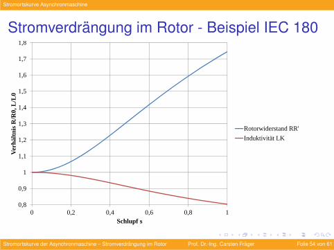
Stromverdrangung im Rotor (2)
Mit steigender Rotorfrequenz fR nimmt der Rotorwiderstand RRbzw. R′R zu und geht die Rotorinduktivitat LK zuruck.Nur ein Teil des gesamten Widerstands und der Induktivitat istvon der Stromverdrangung betroffen.Hier naherungsweise Berechnung fur Hochstableiter ausAluminium.
Stromortskurve der Asynchronmaschine – Stromverdrangung im Rotor Prof. Dr.-Ing. Carsten Frager Folie 52 von 61
Stromortskurve Asynchronmaschine
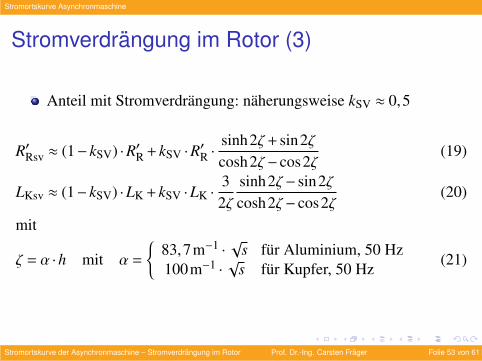
Stromverdrangung im Rotor (3)
Anteil mit Stromverdrangung: naherungsweise kSV ≈ 0,5
R′Rsv ≈ (1− kSV) ·R′R + kSV ·R′R ·sinh2ζ + sin2ζcosh2ζ − cos2ζ
(19)
LKsv ≈ (1− kSV) ·LK + kSV ·LK ·32ζ
sinh2ζ − sin2ζcosh2ζ − cos2ζ
(20)
mit
ζ = α ·h mit α =
83,7m−1 ·
√s fur Aluminium, 50 Hz
100m−1 ·√
s fur Kupfer, 50 Hz(21)
Stromortskurve der Asynchronmaschine – Stromverdrangung im Rotor Prof. Dr.-Ing. Carsten Frager Folie 53 von 61
Stromortskurve Asynchronmaschine
Stromverdrangung im Rotor - Beispiel IEC 180
0,8
0,9
1
1,1
1,2
1,3
1,4
1,5
1,6
1,7
1,8
0 0,2 0,4 0,6 0,8 1
Ver
hältn
is R
/R0,
L/L
0
Schlupf s
Rotorwiderstand RR'
Induktivität LK
Stromortskurve der Asynchronmaschine – Stromverdrangung im Rotor Prof. Dr.-Ing. Carsten Frager Folie 54 von 61
Stromortskurve Asynchronmaschine
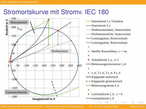
Stromortskurve mit Stromv. IEC 180 (1)
-200
-150
-100
-50
0
50
100
150
200
250
-400-350-300-250-200-150-100-500
Rea
lteil
in A
Imaginärteil in A
Statorstrom I_s VariationStatorstrom I_sDrehmomentlinie, StatorverlusteDrehmomentlinie, StatorverlusteLeistungslinie, Rotorverluste
Leistungslinie, Rotorverluste
ideeller Kurzschluss, s -> oo
Anlaufstrom I_a , s=1Bemessungsrotorstrom I_rn'
s_n, 2 s_n, 3 s_n, 4 s_nKipppunkt motorischKipppunkt generatorischBemessungsstrom I_n
Leerlaufstrom I_0 , s = 0Leerlaufstrom I_0
Motorbetrieb
Generatorbetrieb
Drehmoment
skipp
10% SV
Stromortskurve der Asynchronmaschine – Stromortskurve mit Stromverdrangung Prof. Dr.-Ing. Carsten Frager Folie 55 von 61
Stromortskurve Asynchronmaschine
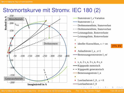
Stromortskurve mit Stromv. IEC 180 (2)
-200
-150
-100
-50
0
50
100
150
200
250
-400-350-300-250-200-150-100-500
Rea
lteil
in A
Imaginärteil in A
Statorstrom I_s VariationStatorstrom I_sDrehmomentlinie, StatorverlusteDrehmomentlinie, StatorverlusteLeistungslinie, Rotorverluste
Leistungslinie, Rotorverluste
ideeller Kurzschluss, s -> oo
Anlaufstrom I_a , s=1Bemessungsrotorstrom I_rn'
s_n, 2 s_n, 3 s_n, 4 s_nKipppunkt motorischKipppunkt generatorischBemessungsstrom I_n
Leerlaufstrom I_0 , s = 0Leerlaufstrom I_0
Motorbetrieb
Generatorbetrieb
Drehmoment
skipp
25% SV
Stromortskurve der Asynchronmaschine – Stromortskurve mit Stromverdrangung Prof. Dr.-Ing. Carsten Frager Folie 56 von 61
Stromortskurve Asynchronmaschine
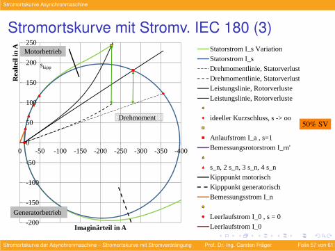
Stromortskurve mit Stromv. IEC 180 (3)
-200
-150
-100
-50
0
50
100
150
200
250
-400-350-300-250-200-150-100-500
Rea
lteil
in A
Imaginärteil in A
Statorstrom I_s VariationStatorstrom I_sDrehmomentlinie, StatorverlusteDrehmomentlinie, StatorverlusteLeistungslinie, Rotorverluste
Leistungslinie, Rotorverluste
ideeller Kurzschluss, s -> oo
Anlaufstrom I_a , s=1Bemessungsrotorstrom I_rn'
s_n, 2 s_n, 3 s_n, 4 s_nKipppunkt motorischKipppunkt generatorischBemessungsstrom I_n
Leerlaufstrom I_0 , s = 0Leerlaufstrom I_0
Motorbetrieb
Generatorbetrieb
Drehmoment
skipp
50% SV
Stromortskurve der Asynchronmaschine – Stromortskurve mit Stromverdrangung Prof. Dr.-Ing. Carsten Frager Folie 57 von 61
Stromortskurve Asynchronmaschine
Eisenverluste
Berucksichtigung EisenverlusteBerucksichtigung der Eisenverluste naherungsweise durchEisenverlustwiderstand parallel zur Induktivitat LS.Spannung an LS etwa so groß wie Strangspannung US
Ô zusatzlicher reeller Strom Ife =USRfe
, verschiebt die gesamteStromortskuve nach oben
Stromortskurve der Asynchronmaschine – Stromortskurve mit Stromverdrangung Prof. Dr.-Ing. Carsten Frager Folie 58 von 61
Stromortskurve Asynchronmaschine
Reibung
Berucksichtigung ReibmomentReibmoment Mreib in etwa konstantBerucksichtigung als Parallele oberhalb der Drehmomentliniezwischen s = 0 und s→∞ im Abstand des Reibmoments Ô
ReibmomentlinieWellendrehmoment ergibt sich dann aus dem Abstand zwischenStromortskurve und Reibmomentlinie
Stromortskurve der Asynchronmaschine – Stromortskurve mit Stromverdrangung Prof. Dr.-Ing. Carsten Frager Folie 59 von 61
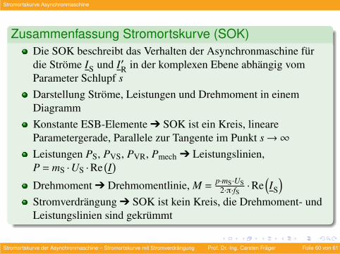
Stromortskurve Asynchronmaschine
Zusammenfassung Stromortskurve (SOK)Die SOK beschreibt das Verhalten der Asynchronmaschine furdie Strome IS und I′R in der komplexen Ebene abhangig vomParameter Schlupf sDarstellung Strome, Leistungen und Drehmoment in einemDiagrammKonstante ESB-Elemente Ô SOK ist ein Kreis, lineareParametergerade, Parallele zur Tangente im Punkt s→∞Leistungen PS, PVS, PVR, Pmech Ô Leistungslinien,P = mS ·US ·Re
(I)
Drehmoment Ô Drehmomentlinie, M =p·mS·US
2·π·fS·Re
(IS
)Stromverdrangung Ô SOK ist kein Kreis, die Drehmoment- undLeistungslinien sind gekrummt
Stromortskurve der Asynchronmaschine – Stromortskurve mit Stromverdrangung Prof. Dr.-Ing. Carsten Frager Folie 60 von 61
Stromortskurve Asynchronmaschine
Stromortskurve mit Stromv. IEC 180
-200
-150
-100
-50
0
50
100
150
200
250
-400-350-300-250-200-150-100-500
Rea
lteil
in A
Imaginärteil in A
Statorstrom I_s VariationStatorstrom I_sDrehmomentlinie, StatorverlusteDrehmomentlinie, StatorverlusteLeistungslinie, Rotorverluste
Leistungslinie, Rotorverluste
ideeller Kurzschluss, s -> oo
Anlaufstrom I_a , s=1Bemessungsrotorstrom I_rn'
s_n, 2 s_n, 3 s_n, 4 s_nKipppunkt motorischKipppunkt generatorischBemessungsstrom I_n
Leerlaufstrom I_0 , s = 0Leerlaufstrom I_0
Motorbetrieb
Generatorbetrieb
Drehmoment
skipp
Stromortskurve der Asynchronmaschine – Stromortskurve mit Stromverdrangung Prof. Dr.-Ing. Carsten Frager Folie 61 von 61


![PM-Synchronmaschine – hohe Energieeffizienz auch in Ex ... · bei der Asynchronmaschine auch, die Temperaturen in Stator und Rotor [1] und [2] im Normalbetrieb und im Störungsfall](https://img.pdfslide.org/doc/110x75/5e083e137784cc30f07337cd/pm-synchronmaschine-a-hohe-energieeffizienz-auch-in-ex-bei-der-asynchronmaschine.jpg)


![Zum Quellungsdruck von polymeren Hydrogelen · anionischen Hydrogels. 40 Bild 3.6 Ersatzschaltbild eines Voigt-Festkörpers und Verhalten im Kriechversuch [Pahl91]. 46. Bildverzeichnis](https://img.pdfslide.org/doc/110x75/5e133382f5c45f110525b518/zum-quellungsdruck-von-polymeren-hydrogelen-anionischen-hydrogels-40-bild-36-ersatzschaltbild.jpg)