Embed Size (px)
Citation preview
The theoretical maximum spans of reinforcedconcrete arch bridges
Autor(en): Baravalle, F.
Objekttyp: Article
Zeitschrift: IABSE congress report = Rapport du congrès AIPC = IVBHKongressbericht
Band (Jahr): 2 (1936)
Persistenter Link: http://doi.org/10.5169/seals-3313
PDF erstellt am: 07.04.2022
NutzungsbedingungenDie ETH-Bibliothek ist Anbieterin der digitalisierten Zeitschriften. Sie besitzt keine Urheberrechte anden Inhalten der Zeitschriften. Die Rechte liegen in der Regel bei den Herausgebern.Die auf der Plattform e-periodica veröffentlichten Dokumente stehen für nicht-kommerzielle Zwecke inLehre und Forschung sowie für die private Nutzung frei zur Verfügung. Einzelne Dateien oderAusdrucke aus diesem Angebot können zusammen mit diesen Nutzungsbedingungen und denkorrekten Herkunftsbezeichnungen weitergegeben werden.Das Veröffentlichen von Bildern in Print- und Online-Publikationen ist nur mit vorheriger Genehmigungder Rechteinhaber erlaubt. Die systematische Speicherung von Teilen des elektronischen Angebotsauf anderen Servern bedarf ebenfalls des schriftlichen Einverständnisses der Rechteinhaber.
HaftungsausschlussAlle Angaben erfolgen ohne Gewähr für Vollständigkeit oder Richtigkeit. Es wird keine Haftungübernommen für Schäden durch die Verwendung von Informationen aus diesem Online-Angebot oderdurch das Fehlen von Informationen. Dies gilt auch für Inhalte Dritter, die über dieses Angebotzugänglich sind.
Ein Dienst der ETH-BibliothekETH Zürich, Rämistrasse 101, 8092 Zürich, Schweiz, www.library.ethz.ch
http://www.e-periodica.ch
IVb 13
The Theoretical Maximum Spans of Reinforced ConcreteArch Bridges.
Die theoretisch größtmöglichen Spannweiten vonEisenbetonbogenbrücken.
Les portees theoriquement maxima des ponts en are de
beton arme.
Dr. techn. F. Baravalle,Ingenieur im Stadtbauamt Wien.
M. Boussiron, in his exhaustive and interesting paper as printed in thePreliminary Report, has included a calculation and diagram of the average concretesection of reinforced concrete arch bridges of different spans in relation to theconcrete compressive stress where the ratio of rise to span remains constant atf 1
-y- -jr- (Preliminary Report, page 739, Fig. 11). The basis for his calculations
/ e • Rn \is the theoretical principle which he explains (1 .1 and the assumption
that the arch has to carry a live load of 2 tonnes per linear m (corresponding2
to ^ — 0.5 tonnes per m2) in addition to its own weight and a dead load of
4,6 tonnes per m, representing the roadway, Suspension bars, etc. The Variationin temperature is assumed at + 25° C.
f 1From the curves given it will be seen that for j — and öbperm 100 kg/cm2
the maximum possible span is approximately 600 m, or with öbpeim 150 kg/cm2approximately 900 m.
In amplification of this work and of the contribution to the discussion made
by Professor K. Gaede. the present writer proposes to give an account of his
own investigations which lead to a generalised determination of the maximumpossible spans of reinforced concrete arch bridges.
Basic assumptions and principles.According to this study, the form of arch which allows the longest span is of
the hingeless type, built in at either end and supporting the roadway above.
The Theoretical Maximum Spans of Reinforced Concrete Arch Bridges 523
Using the method of calculation given by Dr. A. Straßner,1 the thicknessesat the crown and springing corresponding to different amounts of rise withöbpem. 100 and 150 kg/cm2 will be determined on the assumptions stated below:
I. Nature of arch.
Fixed hingeless arch of füll cross section with the roadway above.
II. Calculation.
(The basic idea is that subjeet to a particular law of change of loading the axisof the arch may be represented as a geometrical function of the line of thrustfor dead load, and that the statically unknown values may then be obtained fromthe equations of elasticity. In the same way, the Variation in thickness of the arch
may be calculated from a law of change. The notation adopted by Dr. A. Straßneris retained here throughout.)
Further: —1) The planes of action of the forces coincide with the prineipal longitudinal
planes of symmetry.2) The system of axes in a vertical direction is determined through the choiee
of values ma and mb such thatTa + ea ma 0
Yb — eb mb 0
In other words, the angle of the abutment at the springing under a loadingH 1 and the angle of the built-in cross section are in agreement for equalor opposite loading.
3) The system of axes in a horizontal direction is determined by a suitablechoiee of values za and zb such that
Za (aa 4- ß H- 8a) Zb (db + ß + ^b)-
4) Equilibrium exists between internal and external forces.
5) The modulus of elasticity E remains the same for the whole of the arch.
6 The distribution of stress follows Navier's straight line law.
7) The proportion between stress and strain is constant (Hooke's law)ö e • E
dF8) Z =J zt • ——- • dF ä; J, or accurately: J J z2
In the case of a rectangular cross seefion this gives
->K(ÄR(£)'which in turn gives Z 1.0015 J when r 10 d.
1 Dr. A. Sttaßner: Neuere Methoden zur Statik der Rahmentragvverke. Berlin 1927.
524 IVb 13 F. Baravalle
9) No account is taken of the following:
a) The value— in relation to N in the expression 8 =^—= • (N-| j;
hence ehi • r
x m, £ M Adw M eb) lhe value— in relation to irr m the expression tor —=—*¦ =—-| ;
r EJ r ds EJ rAde? M
hence —r-L =rr.ds EJ
10) The arch is symmetrical and is firmly fixed on each side, so that1
Za Zb —z JVdwmo= J^v~; * (X
11) A geometrical law of loading holds good: gz gs (l+^-(m—1)1.
12) The axis of the arch eoineides with the line of thrust under its ownweight:
y' —*_(Cos£k — 1).J m — 1 v ^ l
13) The moment of inertia of any given cross section of concrete varies inaecordance with a geometrical law:
ri!_ i_(i_n).^.Jz COS (p
14) The calculation of thickness of the arch is governed solely by thecompressive stress in the concrete, all tensile stresses being taken up by the steelreinforcement.
III. Loading.
1) From own weight:The change in cross section from the crown to the springing follows in aecordance
with the above-mentioned law from the equation
t 1 — (1 — n) Y1, wherein nJz cos cp Jk cos cpk
2) Due to the weight of the floor construction and superstruetures of the bridge.A load of 2 tonnes per m2 will be assumed to include the average weight of lhe
roadway paving, the slab and the longitudinal and cross girders. In addition thefollowing load in tonnes per m2 will be allowed for the necessary superstructure:
1.9 tonnes per m2 for spans up to 1 250 m4.0 tonnes per m2 for spans 1 500 m8.0 tonnes per m2 for spans 1 750 m
This simplification involves errors, which do not, however, appreciably affectthe final result.
The Theoretical Maximum Spans of Reinforced Concrete Arch Bridges 5£5
3) Due to live load.
Here a uniform moving load equal to p 1.0 tonnes per m2 is assumed,
corresponding approximately with the loading for an (Austrian) first-classhighway (Oenorm B 6201, Case 1). Since we are dealing mainly with spans ofover 100 m the value p is made amply high enough to cover the possibility ofa future increase in loading. With very large spans the live load has so small aneffect that a reduction in p would not alter the final result, consequently the valueof p 1.0 tonnes per m2 is here retained. For the subsequent calculation of Mpand Np the ordinates of the influence lines calculated by Dr. A. Straßner are utilised.
4) The Variation in temperature is taken at 4- 15° C and allowance for shrinkage
is made by assuming a drop in temperature of — 15° C. These assumptions
appear to be entirely justified on the basis of experiments carried out on the
Langwieser viaduct and on the Hundwilertobel bridge in Switzerland. By the
adoption of special methods of construction the shrinkage effects can be
considerably reduced, but in the present investigation this possibility has been
neglected.
5) No account is taken of stresses due to wind loading, braking loads andmovement of the supports.
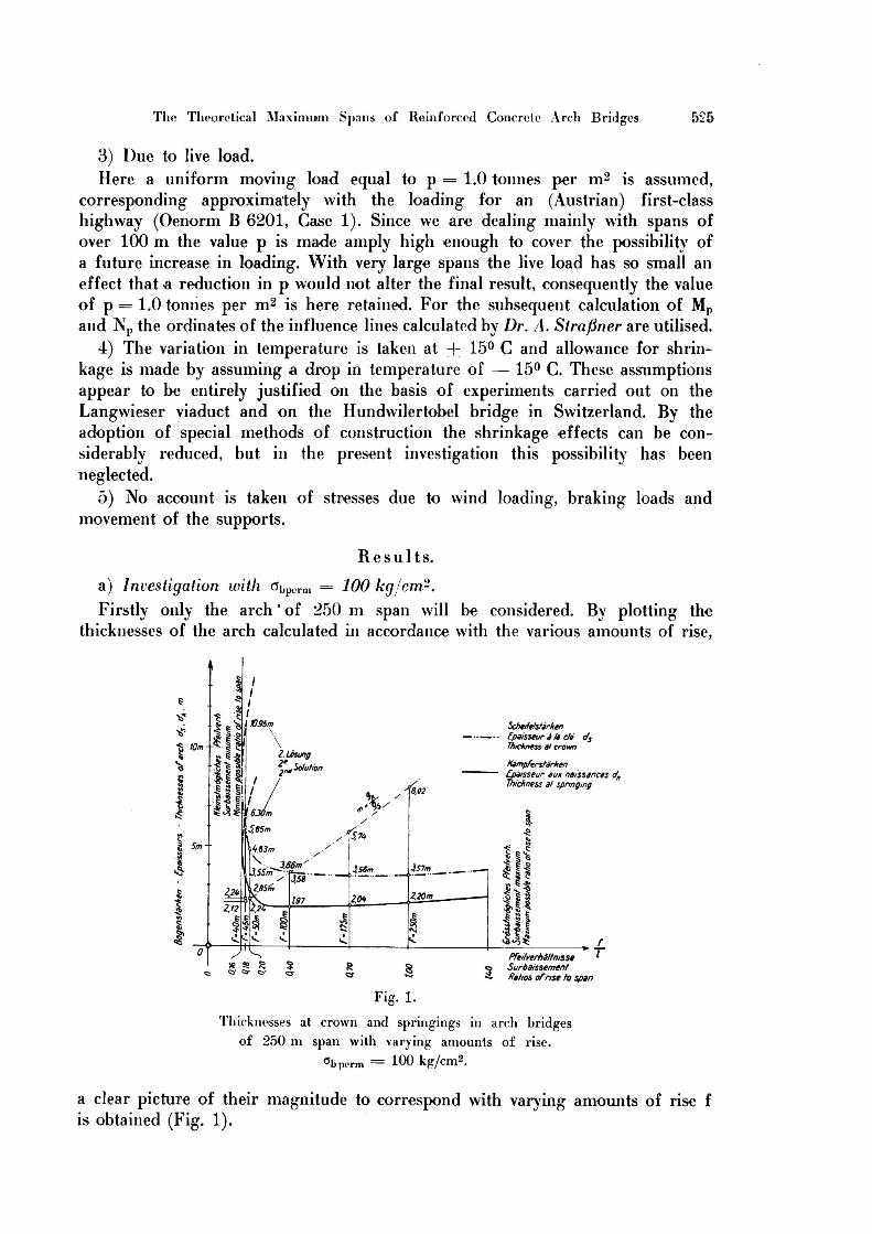
Results.a) Investigation with öbpilI„ 100 kg/cm2.
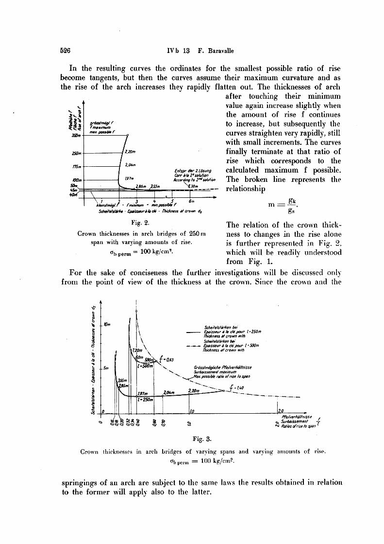
Firstly only the arch' of 250 m span will be considered. By plotting thethicknesses of the arch calculated in aecordance with the various amounts of rise,
ScheifefstarkenEpaisseur ale de dsThickness al crown
KampferstarkenEpaisseur eux naissances dhThickness at spnnging
1095m\\\%%\
2 Losung1%* «* Solution
2™
-%M585.
574,
*63m
366m' l%£3.S7mAS6m\355. fcS5358 14I«285t,2.2U 220m20*212
<i<Pfeitverhältnisse
ö SurbaissementIfahos ofnse to span
Fig. 1.
TliLcknesses at crown and springings in arch bridgesof 250 m span with \arjing amounts of rise.
öbperm 100 kg/cm*.
a clear picture of their magnitude to correspond with varying amounts of rise fis obtained (Fig. 1).
526 IVb 13 F. Baravalle
In the resulting curves the ordinates for the smallest possible ratio of risebecome tangents, but then the curves assume their maximum curvature and asthe rise of the arch increases they rapidly flatten out. The thicknesses of arch
after touching their minimumvalue again increase slightly whenthe amount of rise f continuesto increase, but subsequently lhecurves straighten very rapidly, stillwith small increments. The curvesfinally terminate at that ratio ofrise which corresponds to thecalculated maximum f possible.The broken line represents the
¦£?- relationshipi * gk
grösstmögl rm fmaximummax possible f350m
220m250m
2,04m175m
197mtOQm
50m s. 2.85m 155m*S»VM
Entspr der 2 LösungCorr ala 2*Solution
According to 2*Solution
3 * ^fmuumum - mm possible f 6mk/einstmogl' F
Scheitetstarke - Epaisseura lade - Ftuckness afcrovm ds
Fig. 2.
Crown thicknesses in arch bridges of 250 m
span with varying amounts of rise.
The relation of the crown thickness
to changes in the rise aloneis further represented in Fig. 2.
100 kg/cm8. which will be readily understoodfrom Fig. 1.
For the sake of conciseness the further investigations will be discussed onlyfrom the point of view of the thickness at the crown. Since the crown and the
öb perm
Scheite/starken bei
^—— Epaisseur a h de pour l • 250mthickness at crown withScheitelstarken bei
— ._._ Epaisseur ä fa de pour t • 500mThickness at crown with
T* ..Vm
7.20m
W/nl'SOOm Nv
0.63
Grösstmögliche PfeilverhaltnisseSurbaissement maximumMax possible ratio ofnse to span
KSmUfiSm 1.W_T2.20m
2,0UmWml*250m
Pfeitverhältnisse ^«^ Surbaissement -r*•^ Ratios ofnse to span
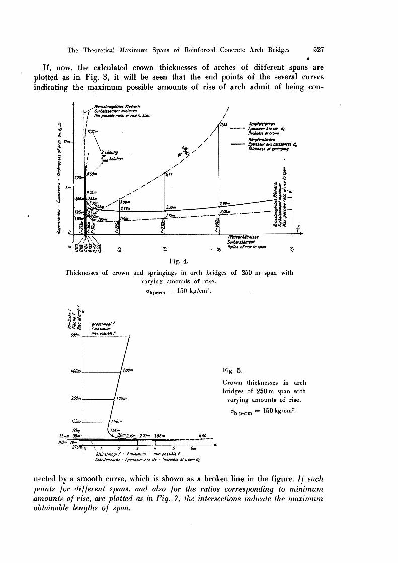
Fig. 3.
Crown thicknesses in arch bridges of >ar>ing spans and van ing amounts of rise.
Öb perm 100 kg/cm*.
springings of an arch are subjeet to the same laws the results obtained in relationto the former will apply also to the latter.
The Theoretical Maximum Spans of Reinforced Concrete Arch Bridges 527
If, now, the calculated crown thicknesses of arches of different spans are
plotted as in Fig. 3, it will be seen that the end points of the several curves
indicating the maximum possible amounts of rise of arch admit of being con-
einshnogliches PfeaverhSurbaissement mmimumlfm.possible ratio ofriseto Span
/' ocnems/anrenEpaisseur ät» de dsThickness at crown
11.93
11 Wm
KämpferstärkenEpaisseur aux naissances dA
Ttvckness at springing
Wm
A2.Losung
Solution2na
S'6,776.50m
1.35m II-3824«336m 299m
-259m2.58m2.08m3541
I75m_l#m8m*
88fe!ö<y«s-wcs<s
PfethrerhältnisseSurbaissementRatios ofrise to span
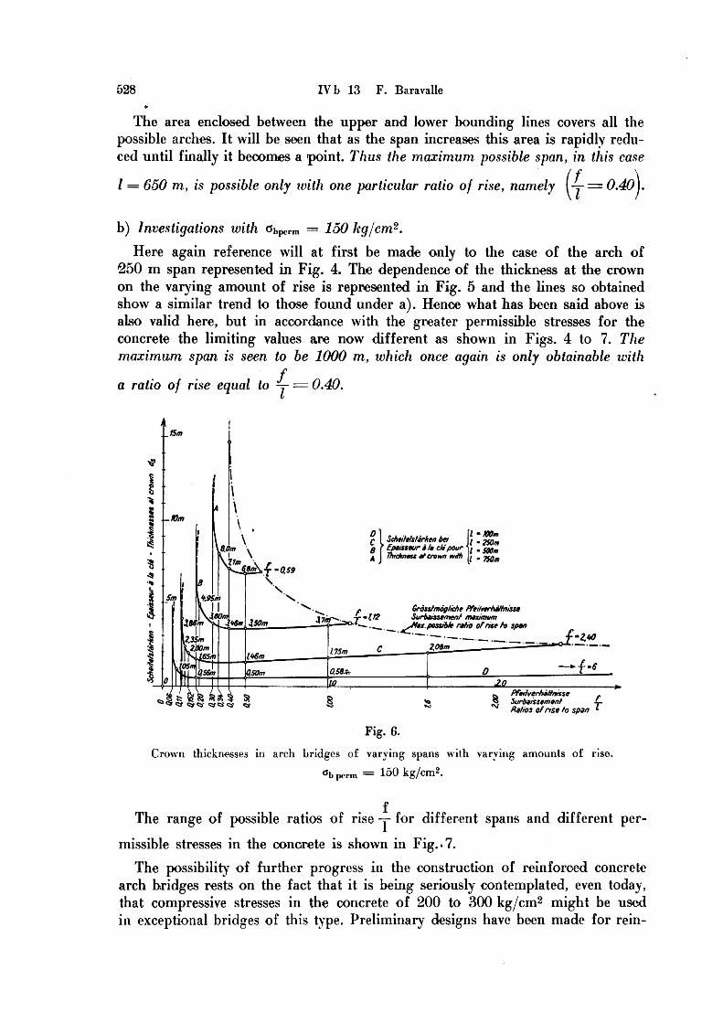
Fig. 4.
Thicknesses of crown and springings in arch bridges of 250 m span withvarying amounts of rise.
Öbperm 150 kg/dl!2.
$is<9 3 grösstmögl f^<S fmaximum
max possible f600m
2.06m400m
250m f.75m
125m 146m
50m 165m
2j0f>2,35m_2.70m 3.86m 650334 38m
310m 29m275m Yhte*
Fig. 5.
Crown thicknesses in arch
bridges of 250 m span withvarying amounts of rise.
°bperm= 150 kg/cm2.
2 3 * 5)tteinstmogl f • fminimum - mm possible f
Scheitelstarke - Epaisseur äla de • Thickness el crown ds
nected by a smooth curve, which is shown as a broken line in the figure. // such
points for different spans, and also for the ratios corresponding to minimumamounts of rise, are plotted as in Fig. 7, the intersections indicate the maximumoblainable lengths of span.
528 IVb 13 F. Baravalle
The area enclosed between the upper and lower bounding lines covers all thepossible arches. It will be seen that as the span increases this area is rapidly reduced
until finally it becomes a point. Thus the maximum possible span, in this case
l 650 m, is possible only tuith one particular ratio of rise, namely t-H-b) Investigations with öbperm 150 kg/cm2.
Here again reference will at first be made only to the case of the arch of•250 m span represented in Fig. 4. The dependence of the thickness at the crownon the varying amount of rise is represented in Fig. 5 and the hnes so obtainedshow a similar trend to those found under a). Henoe what has been said above isalso valid here, but in aecordance with the greater permissible stresses for theconcrete the limiting values are now different as shown in Figs. 4 to 7. Themaximum span is seen to be 1000 m, which once again is only obtainable with
fa ratio of rise equal to y 0.40.
15m
-10m
l'KOml '250ml '500ml - 750m
c I Scheitelstärken bei
ß r Epaisseur ä la de'pour'A
I Thickness at crown withVm
0.59
%95m
Grösstmögliche PfeitverhältnisseSurbaissement maximum3.80m\ 1.123.7m XI3.50m486 246m ^Max possible ratio ofnse to span
C 208m "^ 1*0235i7.2j0Q 75m
1.46m65m
—{¦'»05m
0.58*,0,50mQ56m
Wffl ZQ.
ö Pfeitverhältnisse__$ Surbaissementc»^ fc « ^ $& § ^
Hahos ofnse to span
Fig. 6.
Crown thicknesses in arch bridges of varying spans with varying amounts of riso.
öbperm 150 kg/cm2.
The ränge of possible ratios of rise -y- for different spans and different
permissible stresses in the concrete is shown in Fig..7.The possibility of further progress in the construction of reinforced concrete
arch bridges rests on the fact that it is being seriously contemplated, even today,that compressive stresses in the concrete of 200 to 300 kg/cm2 might be used
in exceptional bridges of this type. Preliminary designs have been made for rein-
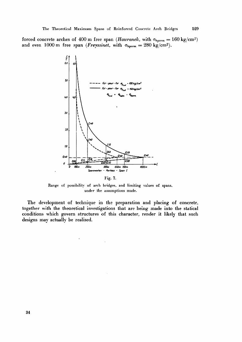
The Theoretical Maximum Spans of Reinforced Concrete Arch Bridges 529
forced concrete arches of 400 m free span (Hawranek, with öbperm 160 kg/cm2)and even 1000 m free span (Freyssinet, with öbperm 280 kg/cm2).
— ——— für-pour-for er^ •tOOkg/cm'
für-pour-for o^, fSOMg/cm'
\m ' *>*lm ' %
i0.. %}
40
2.40
20.
\W
063 Q59Q40-¦—Q*o
WSfl« 0.30
100m 250m 500m 650m 750m 1000m
Spannweiten - Portees - Span lFig. 7.
Range of possibility of arch bridges, and limiting \alues of spans,under the assumptions made.
The development of technique in the preparation and placing of concrete,together with the theoretical investigations that are being made into the staticalconditions which govern structures of this character, render it likely that such
designs may actually be realised.
34


![Towards a Theoretical Foundation for Explicitation and ......2017/12/21 · Hinde De Metsenaere & Sonia Vandepitte trans-kom 10 [3] (2017): 385-419 Towards a Theoretical Foundation](https://img.pdfslide.org/doc/110x75/608cf66ba6689f6b7f23dbc8/towards-a-theoretical-foundation-for-explicitation-and-20171221-hinde.jpg)