Embed Size (px)
Citation preview

8/10/2019 ThermoTop V Service Manual
http://slidepdf.com/reader/full/thermotop-v-service-manual 1/46
Luft-Heizgeräte
Water heaters
03/2003
Workshop Manual
Thermo Top V
Type Thermo Top V (Petrol)Type Thermo Top V (Diesel)
8/10/2019 ThermoTop V Service Manual
http://slidepdf.com/reader/full/thermotop-v-service-manual 2/46
Thermo Top V
Improper installation or repair of Webasto heating and cooling systems can causefire or the leakage of deadly carbon monoxide leading to serious injury or death.
To install and repair Webasto heating and cooling systems you need to havecompleted a Webasto training course and have the appropriate technical
documentation, special tools and special equipment.
NEVER try to install or repair Webasto heating or cooling systems if you have notcompleted a Webasto training course, you do not have the necessary technical skillsand you do not have the technical documentation, tools and equipment availableto ensure that you can complete the installation and repair work properly.
ALWAYS carefully follow Webasto installation and repair instructions and heed allWARNINGS.
Webasto rejects any liability for problems and damage caused by the system beinginstalled by untrained personnel.

8/10/2019 ThermoTop V Service Manual
http://slidepdf.com/reader/full/thermotop-v-service-manual 3/46
Thermo Top V Table of Contents
I
Table of Contents
1 Introduction . . . . . . . . . . . . . . . . . . . . . . . . . . . . . . . . . . . . . . . . . . . . . . . . . . . . . . . . . . . . . . . . . . . . . . . . . . 101
1.1 Contents and purpose. . . . . . . . . . . . . . . . . . . . . . . . . . . . . . . . . . . . . . . . . . . . . . . . . . . . . . . . . . . . . . . 1011.1.1 Using water heaters . . . . . . . . . . . . . . . . . . . . . . . . . . . . . . . . . . . . . . . . . . . . . . . . . . . . . . . . . . 101
1.2 Meaning of signal words. . . . . . . . . . . . . . . . . . . . . . . . . . . . . . . . . . . . . . . . . . . . . . . . . . . . . . . . . . . . . 1011.3 Additional documentation to be used . . . . . . . . . . . . . . . . . . . . . . . . . . . . . . . . . . . . . . . . . . . . . . . . . . . 1011.4 Statutory regulations and safety instructions . . . . . . . . . . . . . . . . . . . . . . . . . . . . . . . . . . . . . . . . . . . . . . 101
1.4.1 General safety instructions . . . . . . . . . . . . . . . . . . . . . . . . . . . . . . . . . . . . . . . . . . . . . . . . . . . . . 1011.4.2 Statutory regulations governing installation. . . . . . . . . . . . . . . . . . . . . . . . . . . . . . . . . . . . . . . . . 1021.4.3 General information . . . . . . . . . . . . . . . . . . . . . . . . . . . . . . . . . . . . . . . . . . . . . . . . . . . . . . . . . . 102
2 General description . . . . . . . . . . . . . . . . . . . . . . . . . . . . . . . . . . . . . . . . . . . . . . . . . . . . . . . . . . . . . . . . . . . . 201
2.1 Combustion-air fan unit/control unit . . . . . . . . . . . . . . . . . . . . . . . . . . . . . . . . . . . . . . . . . . . . . . . . . . . . 201
2.2 Diesel/petrol burner. . . . . . . . . . . . . . . . . . . . . . . . . . . . . . . . . . . . . . . . . . . . . . . . . . . . . . . . . . . . . . . . . 2022.2.1 Fuel preheating(diesel burner with FPH only). . . . . . . . . . . . . . . . . . . . . . . . . . . . . . . . . . . . . . . . . . . . . . . . . . . . 203
2.2.2 Solenoid valve(diesel burner with SV only). . . . . . . . . . . . . . . . . . . . . . . . . . . . . . . . . . . . . . . . . . . . . . . . . . . . . 203
2.3 Temperature sensor and overheating sensor . . . . . . . . . . . . . . . . . . . . . . . . . . . . . . . . . . . . . . . . . . . . . . 2042.4 Heat exchanger. . . . . . . . . . . . . . . . . . . . . . . . . . . . . . . . . . . . . . . . . . . . . . . . . . . . . . . . . . . . . . . . . . . . 2042.5 Circulating pump . . . . . . . . . . . . . . . . . . . . . . . . . . . . . . . . . . . . . . . . . . . . . . . . . . . . . . . . . . . . . . . . . . 2042.6 Metering pump. . . . . . . . . . . . . . . . . . . . . . . . . . . . . . . . . . . . . . . . . . . . . . . . . . . . . . . . . . . . . . . . . . . . 205
3 Description of operation . . . . . . . . . . . . . . . . . . . . . . . . . . . . . . . . . . . . . . . . . . . . . . . . . . . . . . . . . . . . . . . . 301
3.1 Switching on/starting process . . . . . . . . . . . . . . . . . . . . . . . . . . . . . . . . . . . . . . . . . . . . . . . . . . . . . . . . . 3013.2 Heating mode. . . . . . . . . . . . . . . . . . . . . . . . . . . . . . . . . . . . . . . . . . . . . . . . . . . . . . . . . . . . . . . . . . . . . 3013.3 Restarting after fault lock-out . . . . . . . . . . . . . . . . . . . . . . . . . . . . . . . . . . . . . . . . . . . . . . . . . . . . . . . . . 3013.4 Starting after long period of non-use . . . . . . . . . . . . . . . . . . . . . . . . . . . . . . . . . . . . . . . . . . . . . . . . . . . 3023.5 Switching off/Switch-off function . . . . . . . . . . . . . . . . . . . . . . . . . . . . . . . . . . . . . . . . . . . . . . . . . . . . . . 302
4 Technical data. . . . . . . . . . . . . . . . . . . . . . . . . . . . . . . . . . . . . . . . . . . . . . . . . . . . . . . . . . . . . . . . . . . . . . . . . 401
5 Troubleshooting . . . . . . . . . . . . . . . . . . . . . . . . . . . . . . . . . . . . . . . . . . . . . . . . . . . . . . . . . . . . . . . . . . . . . . . 501
5.1 General error symptoms . . . . . . . . . . . . . . . . . . . . . . . . . . . . . . . . . . . . . . . . . . . . . . . . . . . . . . . . . . . . . 5015.1.1 Fault analysis on heater and components . . . . . . . . . . . . . . . . . . . . . . . . . . . . . . . . . . . . . . . . . . 501
5.2 Faults . . . . . . . . . . . . . . . . . . . . . . . . . . . . . . . . . . . . . . . . . . . . . . . . . . . . . . . . . . . . . . . . . . . . . . . . . . . 5035.2.1 Fault lock-out due to fault on heater. . . . . . . . . . . . . . . . . . . . . . . . . . . . . . . . . . . . . . . . . . . . . . 5035.2.2 Fault lock-out due to undervoltage or overvoltage . . . . . . . . . . . . . . . . . . . . . . . . . . . . . . . . . . . 503

8/10/2019 ThermoTop V Service Manual
http://slidepdf.com/reader/full/thermotop-v-service-manual 4/46
Table of Contents Thermo Top V
II
6 Operating tests . . . . . . . . . . . . . . . . . . . . . . . . . . . . . . . . . . . . . . . . . . . . . . . . . . . . . . . . . . . . . . . . . . . . . . . 601
6.1 General . . . . . . . . . . . . . . . . . . . . . . . . . . . . . . . . . . . . . . . . . . . . . . . . . . . . . . . . . . . . . . . . . . . . . . . . . 6016.2 Operating checks in vehicle . . . . . . . . . . . . . . . . . . . . . . . . . . . . . . . . . . . . . . . . . . . . . . . . . . . . . . . . . . 601
6.2.1 Testing heating mode . . . . . . . . . . . . . . . . . . . . . . . . . . . . . . . . . . . . . . . . . . . . . . . . . . . . . . . . 6016.2.2 Setting CO2 content . . . . . . . . . . . . . . . . . . . . . . . . . . . . . . . . . . . . . . . . . . . . . . . . . . . . . . . . . 601
6.3 Operating test in workshop . . . . . . . . . . . . . . . . . . . . . . . . . . . . . . . . . . . . . . . . . . . . . . . . . . . . . . . . . . 6026.3.1 Testing individual components . . . . . . . . . . . . . . . . . . . . . . . . . . . . . . . . . . . . . . . . . . . . . . . . . . 6026.3.1.1 Testing fan unit . . . . . . . . . . . . . . . . . . . . . . . . . . . . . . . . . . . . . . . . . . . . . . . . . 6026.3.1.2 Testing fuel preheating. . . . . . . . . . . . . . . . . . . . . . . . . . . . . . . . . . . . . . . . . . . . 6026.3.1.3 Testing solenoid valve. . . . . . . . . . . . . . . . . . . . . . . . . . . . . . . . . . . . . . . . . . . . . 6026.3.1.4 Electrical test of glow plug . . . . . . . . . . . . . . . . . . . . . . . . . . . . . . . . . . . . . . . . . 6036.3.1.5 Testing temperature sensor and overheating sensor . . . . . . . . . . . . . . . . . . . . . . 603
7 Circuit diagrams. . . . . . . . . . . . . . . . . . . . . . . . . . . . . . . . . . . . . . . . . . . . . . . . . . . . . . . . . . . . . . . . . . . . . . . 701
7.1 General . . . . . . . . . . . . . . . . . . . . . . . . . . . . . . . . . . . . . . . . . . . . . . . . . . . . . . . . . . . . . . . . . . . . . . . . . 7017.2 Legend for wiring diagram . . . . . . . . . . . . . . . . . . . . . . . . . . . . . . . . . . . . . . . . . . . . . . . . . . . . . . . . . . 703
8 Servicing work. . . . . . . . . . . . . . . . . . . . . . . . . . . . . . . . . . . . . . . . . . . . . . . . . . . . . . . . . . . . . . . . . . . . . . . . 801
8.1 General . . . . . . . . . . . . . . . . . . . . . . . . . . . . . . . . . . . . . . . . . . . . . . . . . . . . . . . . . . . . . . . . . . . . . . . . . 8018.2 Work on the heater . . . . . . . . . . . . . . . . . . . . . . . . . . . . . . . . . . . . . . . . . . . . . . . . . . . . . . . . . . . . . . . . 8018.3 Work on the vehicle . . . . . . . . . . . . . . . . . . . . . . . . . . . . . . . . . . . . . . . . . . . . . . . . . . . . . . . . . . . . . . . . 8018.4 Heater trial. . . . . . . . . . . . . . . . . . . . . . . . . . . . . . . . . . . . . . . . . . . . . . . . . . . . . . . . . . . . . . . . . . . . . . . 8018.5 Servicing work . . . . . . . . . . . . . . . . . . . . . . . . . . . . . . . . . . . . . . . . . . . . . . . . . . . . . . . . . . . . . . . . . . . . 8018.6 Visual inspections and installation instructions . . . . . . . . . . . . . . . . . . . . . . . . . . . . . . . . . . . . . . . . . . . . 801
8.6.1 Connection to vehicle cooling system. . . . . . . . . . . . . . . . . . . . . . . . . . . . . . . . . . . . . . . . . . . . . 8018.6.2 Connection to vehicle fuel system . . . . . . . . . . . . . . . . . . . . . . . . . . . . . . . . . . . . . . . . . . . . . . . 802
8.6.2.1 Fuel lines . . . . . . . . . . . . . . . . . . . . . . . . . . . . . . . . . . . . . . . . . . . . . . . . . . . . . . 8028.6.2.2 Metering pump . . . . . . . . . . . . . . . . . . . . . . . . . . . . . . . . . . . . . . . . . . . . . . . . . 802
8.7 Heater, removal and installation . . . . . . . . . . . . . . . . . . . . . . . . . . . . . . . . . . . . . . . . . . . . . . . . . . . . . . . 8048.7.1 Removal. . . . . . . . . . . . . . . . . . . . . . . . . . . . . . . . . . . . . . . . . . . . . . . . . . . . . . . . . . . . . . . . . . . 8048.7.2 Installation. . . . . . . . . . . . . . . . . . . . . . . . . . . . . . . . . . . . . . . . . . . . . . . . . . . . . . . . . . . . . . . . . 804
8.8 Initial start-up. . . . . . . . . . . . . . . . . . . . . . . . . . . . . . . . . . . . . . . . . . . . . . . . . . . . . . . . . . . . . . . . . . . . . 804
9 Repair . . . . . . . . . . . . . . . . . . . . . . . . . . . . . . . . . . . . . . . . . . . . . . . . . . . . . . . . . . . . . . . . . . . . . . . . . . . . . . . 901
9.1 General . . . . . . . . . . . . . . . . . . . . . . . . . . . . . . . . . . . . . . . . . . . . . . . . . . . . . . . . . . . . . . . . . . . . . . . . . 9019.2 Dismantling and assembling. . . . . . . . . . . . . . . . . . . . . . . . . . . . . . . . . . . . . . . . . . . . . . . . . . . . . . . . . . 901
9.2.1 Dismantling heater. . . . . . . . . . . . . . . . . . . . . . . . . . . . . . . . . . . . . . . . . . . . . . . . . . . . . . . . . . . 9019.2.2 Assembling heater . . . . . . . . . . . . . . . . . . . . . . . . . . . . . . . . . . . . . . . . . . . . . . . . . . . . . . . . . . . 9029.2.3 Installing water connection piece variants . . . . . . . . . . . . . . . . . . . . . . . . . . . . . . . . . . . . . . . . . 902
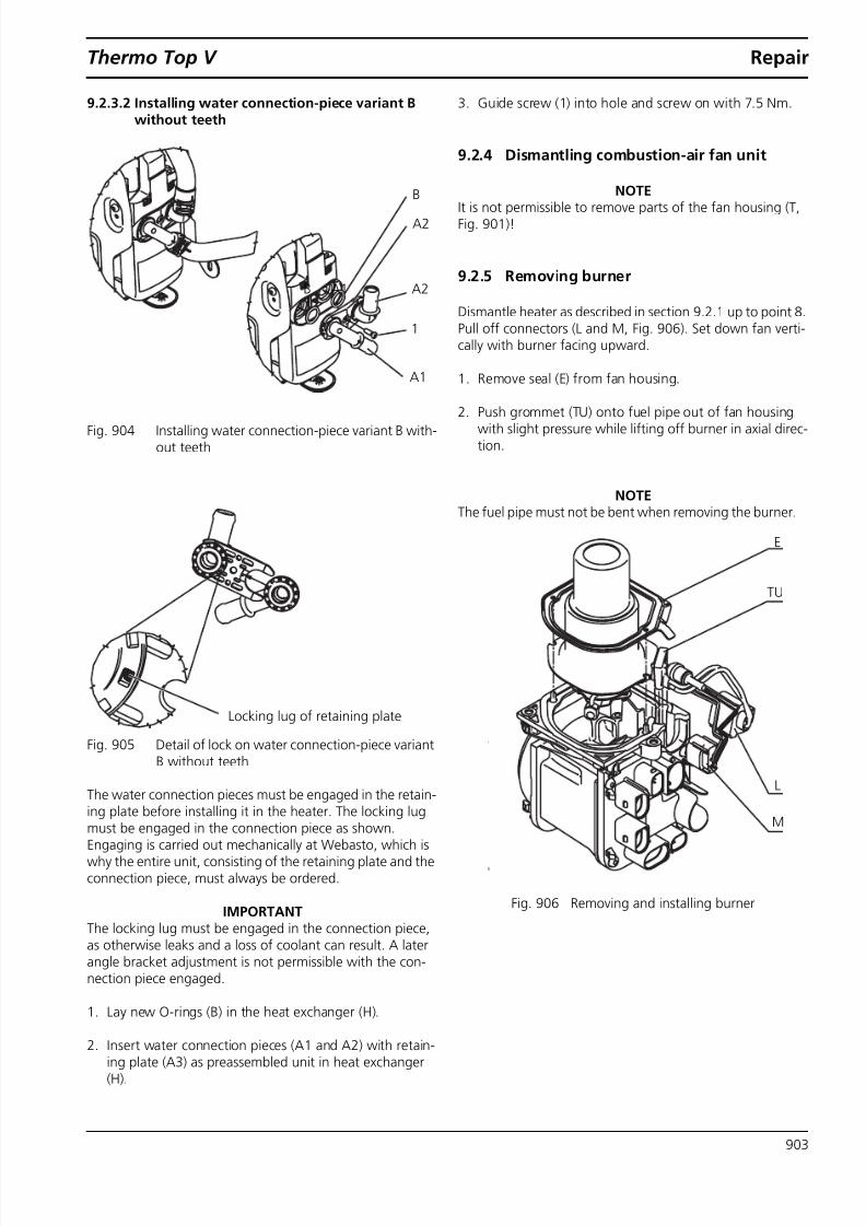
9.2.3.1 Installing water connection-piece variant A with teeth . . . . . . . . . . . . . . . . . . . 9029.2.3.2 Installing water connection-piece variant B without teeth . . . . . . . . . . . . . . . . 903
9.2.4 Dismantling combustion-air fan unit . . . . . . . . . . . . . . . . . . . . . . . . . . . . . . . . . . . . . . . . . . . . . 9039.2.5 Removing burner . . . . . . . . . . . . . . . . . . . . . . . . . . . . . . . . . . . . . . . . . . . . . . . . . . . . . . . . . . . . 9039.2.6 Cable routing for glow plug on burner. . . . . . . . . . . . . . . . . . . . . . . . . . . . . . . . . . . . . . . . . . . . 9049.2.7 Installing burner. . . . . . . . . . . . . . . . . . . . . . . . . . . . . . . . . . . . . . . . . . . . . . . . . . . . . . . . . . . . . 9049.2.8 Removing temperature sensor and overheating sensor. . . . . . . . . . . . . . . . . . . . . . . . . . . . . . . . 9049.2.9 Installing temperature sensor and overheating sensor. . . . . . . . . . . . . . . . . . . . . . . . . . . . . . . . . 9059.2.10 Heat exchanger . . . . . . . . . . . . . . . . . . . . . . . . . . . . . . . . . . . . . . . . . . . . . . . . . . . . . . . . . . . . . 905

8/10/2019 ThermoTop V Service Manual
http://slidepdf.com/reader/full/thermotop-v-service-manual 5/46
Thermo Top V Table of Contents
III
10 Packing, Storage and Shipping . . . . . . . . . . . . . . . . . . . . . . . . . . . . . . . . . . . . . . . . . . . . . . . . . . . . . . . . . . 1001
10.1 General. . . . . . . . . . . . . . . . . . . . . . . . . . . . . . . . . . . . . . . . . . . . . . . . . . . . . . . . . . . . . . . . . . . . . . . . . 100110.2 Storage. . . . . . . . . . . . . . . . . . . . . . . . . . . . . . . . . . . . . . . . . . . . . . . . . . . . . . . . . . . . . . . . . . . . . . . . . 100110.3 Transport . . . . . . . . . . . . . . . . . . . . . . . . . . . . . . . . . . . . . . . . . . . . . . . . . . . . . . . . . . . . . . . . . . . . . . . 1001
8/10/2019 ThermoTop V Service Manual
http://slidepdf.com/reader/full/thermotop-v-service-manual 6/46
List of illustrations Thermo Top V
IV
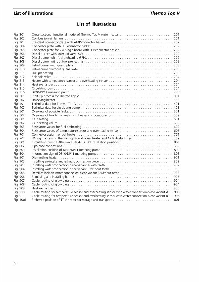
List of illustrations
Fig. 201 Cross-sectional functional model of Thermo Top V water heater . . . . . . . . . . . . . . . . . . . . . . . . . . . . . . 201Fig. 202 Combustion-air fan unit . . . . . . . . . . . . . . . . . . . . . . . . . . . . . . . . . . . . . . . . . . . . . . . . . . . . . . . . . . . . . 201Fig. 203 Standard connector plate with AMP connector basket . . . . . . . . . . . . . . . . . . . . . . . . . . . . . . . . . . . . . . 202
Fig. 204 Connector plate with FEP connector basket . . . . . . . . . . . . . . . . . . . . . . . . . . . . . . . . . . . . . . . . . . . . . . 202Fig. 205 Connector plate for VW single board with FEP connector basket . . . . . . . . . . . . . . . . . . . . . . . . . . . . . . 202Fig. 206 Diesel burner with solenoid valve (SV). . . . . . . . . . . . . . . . . . . . . . . . . . . . . . . . . . . . . . . . . . . . . . . . . . . 202Fig. 207 Diesel burner with fuel preheating (FPH). . . . . . . . . . . . . . . . . . . . . . . . . . . . . . . . . . . . . . . . . . . . . . . . . 202Fig. 208 Diesel burner without fuel preheating . . . . . . . . . . . . . . . . . . . . . . . . . . . . . . . . . . . . . . . . . . . . . . . . . . 203Fig. 209 Petrol burner with guard plate . . . . . . . . . . . . . . . . . . . . . . . . . . . . . . . . . . . . . . . . . . . . . . . . . . . . . . . . 203Fig. 210 Petrol burner without guard plate . . . . . . . . . . . . . . . . . . . . . . . . . . . . . . . . . . . . . . . . . . . . . . . . . . . . . 203Fig. 211 Fuel preheating . . . . . . . . . . . . . . . . . . . . . . . . . . . . . . . . . . . . . . . . . . . . . . . . . . . . . . . . . . . . . . . . . . . 203Fig. 212 Solenoid valve . . . . . . . . . . . . . . . . . . . . . . . . . . . . . . . . . . . . . . . . . . . . . . . . . . . . . . . . . . . . . . . . . . . . 204Fig. 213 Heater with temperature sensor and overheating sensor . . . . . . . . . . . . . . . . . . . . . . . . . . . . . . . . . . . . 204Fig. 214 Heat exchanger . . . . . . . . . . . . . . . . . . . . . . . . . . . . . . . . . . . . . . . . . . . . . . . . . . . . . . . . . . . . . . . . . . . 204Fig. 215 Circulating pump . . . . . . . . . . . . . . . . . . . . . . . . . . . . . . . . . . . . . . . . . . . . . . . . . . . . . . . . . . . . . . . . . . 204Fig. 216 DP40/DP41 metering pump . . . . . . . . . . . . . . . . . . . . . . . . . . . . . . . . . . . . . . . . . . . . . . . . . . . . . . . . . . 205Fig. 301 Start-up process for Thermo Top V . . . . . . . . . . . . . . . . . . . . . . . . . . . . . . . . . . . . . . . . . . . . . . . . . . . . . 301Fig. 302 Unlocking heater . . . . . . . . . . . . . . . . . . . . . . . . . . . . . . . . . . . . . . . . . . . . . . . . . . . . . . . . . . . . . . . . . . 302Fig. 401 Technical data for Thermo Top V . . . . . . . . . . . . . . . . . . . . . . . . . . . . . . . . . . . . . . . . . . . . . . . . . . . . . . 401Fig. 402 Technical data for circulating pump . . . . . . . . . . . . . . . . . . . . . . . . . . . . . . . . . . . . . . . . . . . . . . . . . . . . 401Fig. 501 Overview of possible faults. . . . . . . . . . . . . . . . . . . . . . . . . . . . . . . . . . . . . . . . . . . . . . . . . . . . . . . . . . . 501Fig. 502 Overview of functional analysis of heater and components. . . . . . . . . . . . . . . . . . . . . . . . . . . . . . . . . . . 502Fig. 601 CO2 setting . . . . . . . . . . . . . . . . . . . . . . . . . . . . . . . . . . . . . . . . . . . . . . . . . . . . . . . . . . . . . . . . . . . . . . 601Fig. 602 CO2 setting values . . . . . . . . . . . . . . . . . . . . . . . . . . . . . . . . . . . . . . . . . . . . . . . . . . . . . . . . . . . . . . . . . 602Fig. 603 Resistance values for fuel preheating . . . . . . . . . . . . . . . . . . . . . . . . . . . . . . . . . . . . . . . . . . . . . . . . . . . 602Fig. 604 Resistance values of temperature sensor and overheating sensor . . . . . . . . . . . . . . . . . . . . . . . . . . . . . . 603Fig. 701 Connector assignment of heater . . . . . . . . . . . . . . . . . . . . . . . . . . . . . . . . . . . . . . . . . . . . . . . . . . . . . . 701Fig. 702 Wiring diagram of Thermo Top V additional heater and 12 V digital timer.. . . . . . . . . . . . . . . . . . . . . . . 702
Fig. 801 Circulating pump U4849 and U4847 ECON installation positions . . . . . . . . . . . . . . . . . . . . . . . . . . . . . . 801Fig. 802 Pipe/hose connections . . . . . . . . . . . . . . . . . . . . . . . . . . . . . . . . . . . . . . . . . . . . . . . . . . . . . . . . . . . . . . 802Fig. 803 Installation position of DP40/DP41 metering pump. . . . . . . . . . . . . . . . . . . . . . . . . . . . . . . . . . . . . . . . . 802Fig. 804 Information sign of DP40/DP41 metering pump . . . . . . . . . . . . . . . . . . . . . . . . . . . . . . . . . . . . . . . . . . . 803Fig. 901 Dismantling heater. . . . . . . . . . . . . . . . . . . . . . . . . . . . . . . . . . . . . . . . . . . . . . . . . . . . . . . . . . . . . . . . . 901Fig. 902 Installing air-intake and exhaust connection piece . . . . . . . . . . . . . . . . . . . . . . . . . . . . . . . . . . . . . . . . . 902Fig. 903 Installing water connection-piece variant A with teeth . . . . . . . . . . . . . . . . . . . . . . . . . . . . . . . . . . . . . . 902Fig. 904 Installing water connection-piece variant B without teeth. . . . . . . . . . . . . . . . . . . . . . . . . . . . . . . . . . . . 903Fig. 905 Detail of lock on water connection-piece variant B without teeth . . . . . . . . . . . . . . . . . . . . . . . . . . . . . . 903Fig. 906 Removing and installing burner . . . . . . . . . . . . . . . . . . . . . . . . . . . . . . . . . . . . . . . . . . . . . . . . . . . . . . . 903Fig. 907 Cable routing of glow plug . . . . . . . . . . . . . . . . . . . . . . . . . . . . . . . . . . . . . . . . . . . . . . . . . . . . . . . . . . 904Fig. 908 Cable routing of glow plug . . . . . . . . . . . . . . . . . . . . . . . . . . . . . . . . . . . . . . . . . . . . . . . . . . . . . . . . . . 904Fig. 909 Heat exchanger . . . . . . . . . . . . . . . . . . . . . . . . . . . . . . . . . . . . . . . . . . . . . . . . . . . . . . . . . . . . . . . . . . . 905Fig. 910 Cable routing for temperature sensor and overheating sensor with water connection-piece variant A . . 906Fig. 911 Cable routing for temperature sensor and overheating sensor with water connection-piece variant B. . . 906Fig. 1001 Preferred position of TT-V heater for storage and transport . . . . . . . . . . . . . . . . . . . . . . . . . . . . . . . . . 1001

8/10/2019 ThermoTop V Service Manual
http://slidepdf.com/reader/full/thermotop-v-service-manual 7/46
Thermo Top V 1 Introduction
101
1 Introduction
1.1 Contents and purpose
This workshop manual supports personnel trained by
Webasto, who are responsible for repairing theThermo Top V auxiliary and additional water heaters in thepetrol and diesel versions.This manual applies exclusively for the repair of heaters,which are only installed with a vehicle-specific vehicle kit ordirectly at the vehicle manufacturer's plant as original equip-ment.
1.1.1 Using water heaters
The Thermo Top V water heater was designed for installa-
tion in Class M1 motor vehicles. Installation in Class O, N2,N3 motor vehicles and hazard substances transports inaccordance with the EC Directive 70/156/EEC and/or EC/ 2007/46 (for new vehicle models from 29/04/2009) is notpermissible. The applicable regulations must be taken intoaccount when installing in special vehicles. No other usesare permissible.
The Thermo Top V auxiliary water heater is used to compen-sate the heat deficit on consumption-optimised vehicleengines and can be upgraded to an additional/auxiliaryheater with an upgrade kit.
The Thermo Top V additional water heater is used:– to heat the vehicle interior,– to defrost the vehicle windows,– to preheat water-cooled vehicle engines.
The heaters are marked on the type label with the text "Pet-rol" or "Diesel". The heaters may only be operated with thefuel specified on the type label (for information on dieseland petrol fuel, see Chapter 4) and only with the respec-tively specified type of electrical connection.
1.2 Meaning of signal words
Throughout this manual, the signal words WARNING,IMPORTANT and NOTE have the following meanings:
WARNINGThis heading is used to highlight operating instructions orprocedures which, if not or not correctly followed, mayresult in personal injury or fatal accidents.
IMPORTANTThis heading is used to highlight operating instructions orprocedures which, if not or not correctly followed, mayresult in damage to the equipment or its components.
NOTEThis heading is used to direct your attention to a special fea-ture deemed essential to highlight.
1.3 Additional documentation to be used
This workshop manual contains all necessary informationand instructions for the repair of Thermo Top V water heat-ers.Normally, there is no need to use additional documentation.If necessary, the operating instructions and/or the installa-tion suggestion for the specific vehicle may also beused.When working on OEM heaters and performing diag-nostic work on them, the instructions of the respective vehi-
cle manufacturer must be followed.
1.4 Statutory regulations and safetyinstructions
1.4.1 General safety instructions
In principle, the general accident prevention regulations andcurrent works safety instructions are applicable.
Any special safety regulations relevant to this instructionmanual will be highlighted in the relevant sections or textpassages of the procedures.
The repair and commissioning of the unit may only be car-ried out by personnel trained by Webasto. The unit may onlybe installed professionally in accordance with the installa-tion instructions.
The heater must not be operated:• In filling stations and tank farms.• At locations at which highly flammable gases or dusts
can form, and at locations at which highly flammableliquids or solid materials are stored (e.g. near fuel, coal
and wood dust, grain warehouses, dry grass and leaves,cardboard , paper, etc.).• In closed rooms (e.g. garages), not even via the timer or
Telestart.
The heater:• may not be subjected to temperatures of more than
120 °C (storage temperature).• must be operated with at least a 20 % mix of a brand-
name antifreeze in the water of the heating circuit.• may only be operated with the fuel and the nominal
voltage specified on the type label.• must be shut down by immediately switching off the
heater and removing the fuse in case of heavy smoke,unusual combustion noises or fuel odours. Restartingmay only be carried out by personnel trained by Webas-to after the unit has been checked.

8/10/2019 ThermoTop V Service Manual
http://slidepdf.com/reader/full/thermotop-v-service-manual 8/46
1 Introduction Thermo Top V
102
• Must be put into operation at least once a year for 10minutes with the engine cold and the lowest fan speedselected.
• Must be checked by a professional every 2 years, at thecommencement of the heating period.
Warranty and liability claims:• A failure to observe the vehicle-specific installation in-structions/operating instructions and the informationcontained in them will result in the warranty being void-ed by Webasto. The same applies if repairs are carriedout incorrectly or with the use of parts other than gen-uine spare parts. This will result in the invalidation of thetype approval for the heater and therefore of its ho-mologation / EC type licence. In addition, we shall alsoexclude our liability for slightly negligent violations ofduties, provided damages from injury to life, body orhealth or guarantees are not affected or claims in ac-cordance with the applicable product liability laws arenot concerned. Also unaffected by this is the liability forthe violation of duties which, when fulfilled, enable theproper execution of the contract in the first place and inthe regular fulfilment of which the customer may placeits trust. The same applies to violations of duties by ourvicarious agents.
1.4.2 Statutory regulations governing installa-tion
For the Thermo Top V heater there are homologationapprovals in accordance with the EC Directives 72/245/EEC(EMC) and 2001/56/EC (heating) with the EC approval num-bers:
e1*72/245*2006/96*1232*__e1*2001/56*2006/119*0018*__
Installation is governed above all by the provisions in AnnexVII of Directive 2001/56/EC and the regulations in accord-ance with the installation instructions.
NOTE:The specifications of this Directive are binding in the scopeof the Basic Directive EEC/70/156 and/or EC/2007/46 (for
new vehicle models from 29/04/2009) and should also beobserved in countries in which no special regulations exist.
1.4.3 General information
Some vehicle manufacturers have provided components likethe auxiliary/additional heater with component protection.On these vehicles the new unit must be activated afterreplacing the unit at a specialist workshop of the respective
manufacturer.Please note that this is generally linked to low additionalcosts for the customer.

8/10/2019 ThermoTop V Service Manual
http://slidepdf.com/reader/full/thermotop-v-service-manual 9/46
Thermo Top V General description
201
2 General description
The heaters operate in accordance with the venturi principleand use the physical effects of film evaporation and dropletevaporation for the processing of the fuel-air mixture.
After reaching a coolant temperature of approx. 80 °C, theheater switches from full load to partial load. In this operat-ing mode the heater runs especially quietly and more effi-ciently with regards to electrical and fuel consumption.
The heater consists of the combustion-air fan unit with thecontrol unit, the heat exchanger with the water connectionpiece and the venturi burner.
Fig. 201 Cross-sectional functional model of Thermo Top V water heater
2.1 Combustion-air fan unit/control unit
The combustion air fan supplies the air required for thecombustion process from the combustion air inlet to thecombustion chamber.The combustion-air fan unit contains:• the heater type label
• the opening for the combustion-air connection pieceand the combustion air pipe• the control unit with the plug-in contacts for the electri-
cal contact• the engine and the impeller
For information on checking the fan unit, see section6.3.1.1 .
Fig. 202 Combustion-air fan unit
Sensors
Coolant inlet
Burner
Heat exchanger
Glow plug
Exhaust outletFuel inlet
Combustion air inlet
Electrical connection
Control unit
Combustion air fan
Venturi burner
Coolant outlet
8/10/2019 ThermoTop V Service Manual
http://slidepdf.com/reader/full/thermotop-v-service-manual 10/46
General description Thermo Top V
202
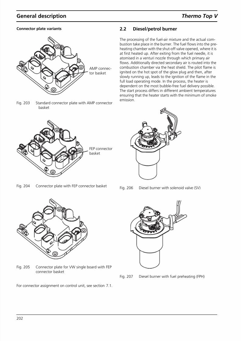
Connector plate variants
Fig. 203 Standard connector plate with AMP connectorbasket
Fig. 204 Connector plate with FEP connector basket
Fig. 205 Connector plate for VW single board with FEPconnector basket
For connector assignment on control unit, see section 7.1 .
2.2 Diesel/petrol burner
The processing of the fuel-air mixture and the actual com-bustion take place in the burner. The fuel flows into the pre-heating chamber with the shut-off valve opened, where it isat first heated up. After exiting from the fuel needle, it isatomised in a venturi nozzle through which primary airflows. Additionally directed secondary air is routed into thecombustion chamber via the heat shield. The pilot flame isignited on the hot spot of the glow plug and then, afterslowly running up, leads to the ignition of the flame in thefull load operating mode. In the process, the heater isdependent on the most bubble-free fuel delivery possible.The start process differs in different ambient temperaturesensuring that the heater starts with the minimum of smokeemission.
Fig. 206 Diesel burner with solenoid valve (SV)
Fig. 207 Diesel burner with fuel preheating (FPH)
AMP connec-tor basket
FEP connectorbasket

8/10/2019 ThermoTop V Service Manual
http://slidepdf.com/reader/full/thermotop-v-service-manual 11/46
Thermo Top V General description
203
Fig. 208 Diesel burner without fuel preheating
Fig. 209 Petrol burner with guard plate
Fig. 210 Petrol burner without guard plate
For information on removing and installing the burner, seesection 9.2.5 and 9.2.7 .
IMPORTANTEnsure that the correct burner is always used, as otherwisemalfunctions and/or damage will occur on the heater and its
service life will be reduced!
2.2.1 Fuel preheating(diesel burner with FPH only)
The fuel flows in a spiral in the preheater between athreaded sleeve and a smooth outer sleeve and is heated byan electrically operated heating cartridge during starting.Preheating is briefly activated in the burn-out with a lowoutput to be able to burn the remaining fuel after the unitis switched off.
For information on checking fuel preheating, see section6.3.1.2 .
Fig. 211 Fuel preheating
2.2.2 Solenoid valve(diesel burner with SV only)
The solenoid valve is only used with a certain diesel heatervariant. It ensures that fuel is routed into the combustionchamber at the correct time in the start-up phase. When theheater is switched off, the solenoid valve is intended to pre-vent any fuel from flowing into the combustion chamber.
For information on checking the solenoid valve, see section6.3.1.3 .
NOTEThe solenoid valve cannot be removed
Guard plate
Fuel preheating
Fuel preheating 1(fuel pipe without SV)
Fuel preheating 2(fuel pipe with SV)

8/10/2019 ThermoTop V Service Manual
http://slidepdf.com/reader/full/thermotop-v-service-manual 12/46
General description Thermo Top V
204
Fig. 212 Solenoid valve
2.3 Temperature sensor and overheatingsensor
The temperature sensor detects the coolant temperature inthe heat exchanger of the heater as an electrical resistance.This signal is fed to the control unit, where it is processed.The temperature sensor G1 (NTC) and the overheating sen-sor G2 (PTC) form a unit together with the cable and theconnector.The overheating sensor protects the heater against imper-missibly high operating temperatures. This reacts at a hous-ing temperature above 125 °C and switches off the heater.
For information on checking the sensors, see section6.3.1.5 .For information on dismantling and assembly, see section9.2.8 and 9.2.9 .
Fig. 213 Heater with temperature sensor and overheat-ing sensor
2.4 Heat exchanger
The heat generated in the heat exchanger by combustion istransferred to the coolant circuit.The heat exchanger consists of an inner and an outer sec-tion, which are sealed off with an O-ring. The inner sectionand the outer section are interconnected with a press fit.
For information on removing and installing the heatexchanger, see section 9.2.1 and 9.2.2 .For information on maintenance, see section 9.2.10 .
Fig. 214 Heat exchanger
2.5 Circulating pump
The circulating pump U4849 ensures a feed rate of the cool-
ant in the vehicle or heater circuit.The pump is switched onwith the control unit and runs during the entire operation ofthe heater.
For information on checking and installing the circulatingpump, see section 8.6.1 .
Fig. 215 Circulating pump
Solenoid valve
(SV)
G1
G2
Coolant connection
Holes forsensors
Exhaust connection piece

8/10/2019 ThermoTop V Service Manual
http://slidepdf.com/reader/full/thermotop-v-service-manual 13/46
Thermo Top V General description
205
2.6 Metering pump
The metering pump is a combined transport, metering andshut-off system for supplying fuel from the vehicle’s tank tothe heater.
For information on checking and installing the meteringpump, see section 8.6.2.2 .
Fig. 216 DP40/DP41 metering pump

8/10/2019 ThermoTop V Service Manual
http://slidepdf.com/reader/full/thermotop-v-service-manual 14/46
General description Thermo Top V
206
Page for notes
8/10/2019 ThermoTop V Service Manual
http://slidepdf.com/reader/full/thermotop-v-service-manual 15/46
Thermo Top V Description of operation
301
3 Description of operation
3.1 Switching on/starting process
The heater start-up can be carried out for the additional
heater via a remote control element, the immediate heatbutton or timer programming of the clock.For the auxiliary heater, the start-up is triggered by the pres-ence of previously specified switch-on conditions (generallyfrom an outside temperature below 5 °C) via the vehicledata bus.
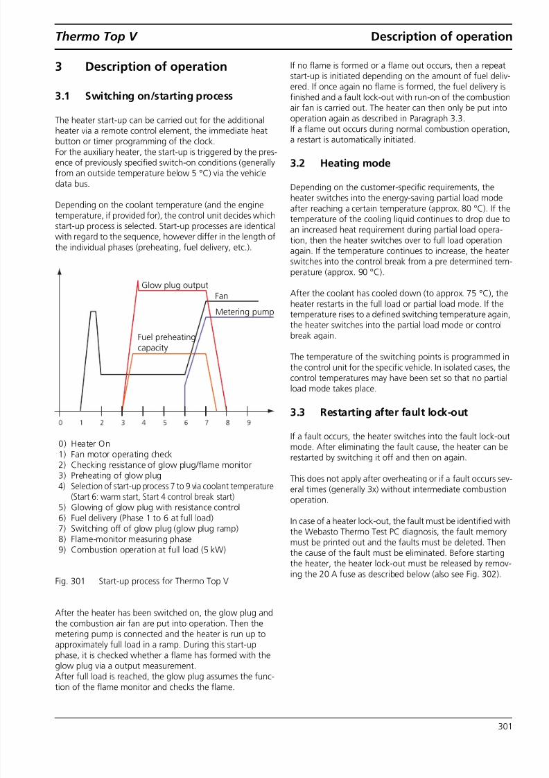
Depending on the coolant temperature (and the enginetemperature, if provided for), the control unit decides whichstart-up process is selected. Start-up processes are identicalwith regard to the sequence, however differ in the length ofthe individual phases (preheating, fuel delivery, etc.).
Fig. 301 Start-up process for Thermo Top V
After the heater has been switched on, the glow plug andthe combustion air fan are put into operation. Then themetering pump is connected and the heater is run up toapproximately full load in a ramp. During this start-up
phase, it is checked whether a flame has formed with theglow plug via a output measurement.After full load is reached, the glow plug assumes the func-tion of the flame monitor and checks the flame.
If no flame is formed or a flame out occurs, then a repeatstart-up is initiated depending on the amount of fuel deliv-ered. If once again no flame is formed, the fuel delivery isfinished and a fault lock-out with run-on of the combustionair fan is carried out. The heater can then only be put intooperation again as described in Paragraph 3.3 .
If a flame out occurs during normal combustion operation,a restart is automatically initiated.
3.2 Heating mode
Depending on the customer-specific requirements, theheater switches into the energy-saving partial load modeafter reaching a certain temperature (approx. 80 °C). If thetemperature of the cooling liquid continues to drop due toan increased heat requirement during partial load opera-tion, then the heater switches over to full load operationagain. If the temperature continues to increase, the heater
switches into the control break from a pre determined tem-perature (approx. 90 °C).
After the coolant has cooled down (to approx. 75 °C), theheater restarts in the full load or partial load mode. If thetemperature rises to a defined switching temperature again,the heater switches into the partial load mode or controlbreak again.
The temperature of the switching points is programmed inthe control unit for the specific vehicle. In isolated cases, thecontrol temperatures may have been set so that no partialload mode takes place.
3.3 Restarting after fault lock-out
If a fault occurs, the heater switches into the fault lock-outmode. After eliminating the fault cause, the heater can berestarted by switching it off and then on again.
This does not apply after overheating or if a fault occurs sev-eral times (generally 3x) without intermediate combustionoperation.
In case of a heater lock-out, the fault must be identified withthe Webasto Thermo Test PC diagnosis, the fault memorymust be printed out and the faults must be deleted. Thenthe cause of the fault must be eliminated. Before startingthe heater, the heater lock-out must be released by remov-ing the 20 A fuse as described below (also see Fig. 302 ).
Glow plug outputFan
Metering pump
Fuel preheatingcapacity
0) Heater On1) Fan motor operating check2) Checking resistance of glow plug/flame monitor3) Preheating of glow plug4) Selection of start-up process 7 to 9 via coolant temperature
(Start 6: warm start, Start 4 control break start)5) Glowing of glow plug with resistance control6) Fuel delivery (Phase 1 to 6 at full load)7) Switching off of glow plug (glow plug ramp)8) Flame-monitor measuring phase9) Combustion operation at full load (5 kW)

8/10/2019 ThermoTop V Service Manual
http://slidepdf.com/reader/full/thermotop-v-service-manual 16/46
Description of operation Thermo Top V
302
Fig. 302 Unlocking heater
1. Voltage interruptions by removing the 20 A fuse (yellow)in the heater-unit wiring harness (ongoing processes in
the control unit are ended)
2. Refit the fuse
3. Briefly press the button on the transmitter or the flamebutton on the digital timer (heater switches into theheater lock-out state)
4. Interrupt the voltage by removing the 20 A fuse (yellow)in the heater-unit wiring harness (heater lock-out isreleased)
5. Refit the fuse (heater in the OFF state)To start the heater, it must be switched on again!
NOTEIf no Webasto Thermo Test PC diagnosis is available, thelock-out can also be released without deleting the fault. Asthe fault will not be identified without PC diagnosis, it can-not be specifically eliminated and the heater goes into thelock-out mode again during the next start-up.
NOTEAs the Thermo Top V auxiliary heater is not switched onwith a heater control, but instead receives the On signalwhen the vehicle engine is started, it must be started via thePC diagnosis following the repairs. To start the heater, thecoolant temperature should not be above 40 °C.
3.4 Starting after long period of non-use
Longer periods of non-use generally have no effect on thestarting function of the heater. However, limitations mustbe made here with regard to filling of the fuel lines. Espe-cially with petrol heaters, the fuel evaporates from the fuelline in the summer months. As a result, it must be expectedthat several complete starting attempts will be required forinitial starting. There is no possibility of lasting damage tothe heater occurring due to longer periods of non-use. If thelimitations specified above are taken into account, a shortcombustion operation at regular intervals is not necessary.
IMPORTANT
The vehicle fuel tank should be at least ¼ full during eachstarting attempt. A tank fill level below ¼ of the maximumfilling capacity can result in the formation of bubbles andthen false starts and smoking.
3.5 Switching off/Switch-off function
The auxiliary heater is switched off together with theengine. The additional heater switches itself off via the pro-grammed heating time or is switched off with the respectiveheater control. The combustion is ended and the run-onbegins. In the process, the combustion air fan continues torun to cool down the heater, the metering pump is switchedoff and the solenoid valve is closed so that the flame extin-guishes. Restarting is not possible until the run-on has beencompleted.
NOTEThe run-on time and the combustion-air fan speed aredependent on the heater model and operating mode fromwhich the heater is switched off.
waitapprox.
3 sec.ON
ONwait
approx.3 sec.
waitapprox.3 sec.

8/10/2019 ThermoTop V Service Manual
http://slidepdf.com/reader/full/thermotop-v-service-manual 17/46
Thermo Top V Description of operation
303
Switch-off or new switch-on signals are processed accord-ing to the following rules:
1. A switch-off signal on a heater control always as priorityirrespective of the heater operating state.
2. If the original switch-on signal is no longer active, or ifthe included heating duration has expired, then this isinterpreted as a switch-off signal.
3. New switch-on signals are ignored until the originalswitch-on signal is no longer active.
4. It is therefore not possible to change the heating timeduring operation. The heater must be switched off andthen on again with the changed heating duration.
5. If the heater has been started as an auxiliary heater, thenswitching off the vehicle engine must be interpreted asa switch-off signal (legal requirement).
6. A restart of the heater is not possible until after the burn-out has completed and the first cooling phase (forcedrun-on) has been ended. New switch-on signals are tem-porarily stored and are not followed until then.

8/10/2019 ThermoTop V Service Manual
http://slidepdf.com/reader/full/thermotop-v-service-manual 18/46
Description of operation Thermo Top V
304
Page for notes

8/10/2019 ThermoTop V Service Manual
http://slidepdf.com/reader/full/thermotop-v-service-manual 19/46
Thermo Top V Technical data
401
4 Technical data
Except where limit values are specified, the technical data listed in the tables refer to the usual heater tolerances of ± 10%at an ambient temperature of + 20 °C and at the rated voltage and in rated conditions. All electrical components aredesigned for a nominal voltage of 12 volts.
Heater Operation Thermo Top V Petrol Thermo Top V Diesel
Type test permit EMCheater
e1*72/245*2006/96*1232*__e1*2001/56*2006/119*0018*__
Model Water heater with atomization burner
Heat output Full loadPartial load
5.0 kW3 kW
Fuel PetrolEN 228
DIN 51625
DieselEN 590
Fuel consumption Full loadPartial load
0.67 l/h0.39 l/h
0.60 l/h0.35 l/h
Rated voltage 12 V
Operating voltage range 10.5 to 16 V
Nominal power consumption withoutcirculating pump (without vehicle fan)
Full loadPartial load
34 W24 W
Max. ambient temperature:Heater: - Operation
- Storage-40 to + 50 °C
-40 to + 120 °C-40 to + 80 °C
-40 to + 120 °C
Perm. operating pressure (heat carrier) 0.4 to 2.5 bar
Capacity of the heat exchanger 0.075 lMinimum capacity of the circuit 4.00 l
Minimum flow rate for the heater 150 l/h
CO2 in exhaust gas(permitted function range)
8 to 13.0 % by vol.
Heater dimensions Length 222 mmWidth 91 mm
Height 144/180 mm
Weight 2.1 kg
Fig. 401 Technical data for Thermo Top V
Circulating pump 4849 4847 EconVolume flow against 0.14 bar 500 l/h 450 l/h
Rated voltage 12 V
Operating voltage range 9 to 16 V
Rated power consumption 12 W 13.9 W
Dimensions, circulating pump Length 107 mmDiameter 48.5 mm
Length 112 mmDiameter 48.5 mm
Weight 0.35 kg 0.285 kg
Fig. 402 Technical data for circulating pump

8/10/2019 ThermoTop V Service Manual
http://slidepdf.com/reader/full/thermotop-v-service-manual 20/46
Technical data Thermo Top V
402
Page for notes

8/10/2019 ThermoTop V Service Manual
http://slidepdf.com/reader/full/thermotop-v-service-manual 21/46
Thermo Top V Troubleshooting
501
5 Troubleshooting
5.1 General error symptoms
NOTE
Before troubleshooting is conducted on the heater, an oper-ating test should be carried out as described in section 6.2 .
IMPORTANTTroubleshooting work demands precise knowledge of thestructure and theory of operation of the various compo-nents and must be carried out by trained personnel only. Ifin doubt, refer to section 2 or 3 for a description of how thefunctions interact.
IMPORTANTThe error remedy is generally limited to the localisation of
the faulty components and provides information on defec-tive line connections. The following potential sources ofmalfunctions are not directly detected by the heater andshould always be checked so that they can then be excludedas the cause of the particular fault:
• Corrosion on connectors• Contact fault on plug connections• Crimping error on connectors• Corroded cables and fuses• Corroded battery terminals
Conduct a function test in the vehicle after rectifying eachfault (see section 6.2 )
Use only genuine spare parts!
If there is doubt as to whether the parts are reusable, thennew parts should generally be installed.
5.1.1 Fault analysis on heater and components
Possible faults
The overview only shows some of the possible faults. TheWebasto Service Hotline must be contacted in individualcases.
Fault Description Possible Faulty Com-ponent(see table in Fig. 502 )
Heater does not react 1, 2, 3, 4, 16, 17
Heater does not heat 5, 6, 7, 8, 9, 10, 12, 15
Heater switches off prema-turely
1, 5, 11, 12
Heater has intermittend com-
bustion
5, 10, 12
Heater smokes in start-upphase
5, 8, 10, 12
Telestart cannot be tuned 1, 3, 4, 16
Vehicle passenger compart-ment is cold
4, 11, 13, 15
Heater smokes in heatingphase/white smoke
5, 10, 12, 14
Heater smokes in run-onphase
5, 14
Fuel odour 8, 12
Fig. 501 Overview of possible faults

8/10/2019 ThermoTop V Service Manual
http://slidepdf.com/reader/full/thermotop-v-service-manual 22/46
Troubleshooting Thermo Top V
502
Functional analysis of heater and its components
No. System Component Test/Measure/Parameter
1. Power supply Measure supply voltage under load at heater connector X2 ≥ 11.5 V,see section 5.2.2 (Undervoltage switch-off)
2. Clock Press Flame button; display lighting must light upTest W bus signal on Pin 2 on heater connector X1 with an LED lamp against “+”(LED flickers when button is pressed)
3. Receiver (Telestart T80 andT91)
On 6-pin connector on receiver, test W bus signal on Pin 2 with an LED lampagainst Pin 1 “+” (LED flickers when On button is pressed)
4. Transmitter (Telestart) Assign/teach transmitter as described in instructions for receiverTest operating mode on Telestart hand-held transmitter (heat/ventilate)Battery of hand-held transmitter should have sufficient capacity (new)
5. Metering pump Test continuity from connector X1, Pin 5 to connector X7 (blue)
Test continuity from connector X7 (brown) against earthTest resistance of the metering pump at +20 °C = 5.2 ohms ± 5 % as describedin section 8.6.2.2 Measure delivery rate with Webasto Thermo Test PC Diagnosis as described insection 8.6.2.2 - Petrol: 34 to 42 ml in 180 sec. at 7 Hz.- Diesel: 36 to 44 ml in 180 sec. at 7 Hz.Test connection of fuel line on connection piece as described in section 8.6.2.1
6. Glow plug Measure glow plug resistance value on glow plug connector X3 (white wire) asdescribed in section 6.3.1.4 .At 24 ± 6 °C: 0.200 to 0.300 ohms.
7. Fuel preheating Test resistance of fuel preheating on connector X6, 4-pin (black wire) as describedin section 6.3.1.2 for Variant 1 or 2
8. Solenoid valve (if present) Testing of solenoid valve as described in section 6.3.1.3 .At 20 ± 5 °C: 145 ± 9 ohms.
9. Temperature sensor Test sensors as described in section 6.3.1.5Coolant temperature sensor G1, blue wire, at 20 ± 6 °C:min. 1,988, max. 4,050 ohms.Overheating sensor G2: Red wire, at 20 ± 6 °C: max. 250 ohms.
10. Combustion air fan Test operation of fan motor with Webasto Thermo Test PC Diagnosis componenttest
Checking of CO 2 setting as described in section 6.2.2
11. Circulating pump Test resistance and installation as described in section 8.6.1 : 10 ± 1 kohmsTest operation with Webasto Thermo Test PC Diagnosis component test
12. Fuel connection Fuel visible in line? Air Bubbles in fuel line?If there is, then change connection or routing of line!Check connection in vehicle fuel system (also see section 8.6.2.1 ).Ensure sufficient fuel in vehicle tank ( no reserve ), fuel extraction installation cor-rect, inspect fuel lines for leaks, kinks or clogging.Remove the heater and carry out troubleshooting in the workshop.
Fig. 502 Overview of functional analysis of heater and components

8/10/2019 ThermoTop V Service Manual
http://slidepdf.com/reader/full/thermotop-v-service-manual 23/46
Thermo Top V Troubleshooting
503
5.2 Faults
5.2.1 Fault lock-out due to fault on heater
If no flame forms, fuel will be delivered for a maximum of240 seconds. Then the heater goes into the fault mode andswitches off. The reason for the fault may be faultsdescribed in section 5.1.1 .
The fuel supply is shut off immediately if the system over-heats (temperature limiter is tripped) and the heater goesinto a heater lock-out.
In all cases (except for a defect in the combustion air fan),the fan is controlled after the fault lock-out to cool downthe heater. Restarting is not possible until the run-on hasbeen completed.
NOTEFaults are not indicated by the heater control.
5.2.2 Fault lock-out due to undervoltage orovervoltage
At a battery voltage of less than approx. 11.5 V, a fault lock-out with a run-on is carried out. The minimum permissiblevoltage is customer-specific (software-dependent) and ismeasured at the wiring harness inlet.
In case of an overvoltage of 15 to 17 V (measured at theheater) for a certain period of time, a fault lock-out withrun-on is also carried out.
Fault releaseAfter the fault cause is eliminated, the fault release is carriedout by switching the heater off and then on again.
Heater lock-outIn case of overheating, a heater lock-out will be initiated bythe heater.
The heater release is carried out as described in section 3.3 .
13. Coolant circuit Test connection in vehicle coolant circuit as described in installation instructions/ installation suggestion,bleeding of coolant circuit ensured,test circulation in coolant circuit,eliminate kinks and chaffing.
14. Exhaust system and air intakesystem
Intake pipe and exhaust pipe routed as described in installation instructions/instal-lation suggestionMake sure lines are not restricted with insulation/cloggedEliminate existing leaks on intake pipe and exhaust pipe (now CO 2 in intake air)
15. Vehicle fan Test switching signal on relay K3 (Pin 86) as described in installation instructions/ installation suggestionWatch coolant temperature (K3 switches at 50 °C)Test flap position of vehicle heater (air conditioning set to HI)
16. Control unit/heater locked Unlock as described in section 5.2.2 and installation instructions/installation sug-gestion
17. Control unit (fault memory) Read out fault memory with Webasto Thermo Test PC Diagnosis, then print outand clear fault memory.Include fault log when sending heater to Webasto.
No. System Component Test/Measure/Parameter
Fig. 502 Overview of functional analysis of heater and components

8/10/2019 ThermoTop V Service Manual
http://slidepdf.com/reader/full/thermotop-v-service-manual 24/46
Troubleshooting Thermo Top V
504
Page for notes

8/10/2019 ThermoTop V Service Manual
http://slidepdf.com/reader/full/thermotop-v-service-manual 25/46
Thermo Top V Operating tests
601
6 Operating tests
6.1 General
This section describes the tests of the heater and its compo-
nents in the installed and the removed state.
WARNINGThe heater must not be operated in enclosed areas such asgarages and workshops without an emissions extraction sys-tem.
6.2 Operating checks in vehicle
6.2.1 Testing heating mode
1 Make sure that the vehicle fan speed is set to the slowestor to the speed recommended in the operating instruc-tions.
2 Make sure that the air ducting to the heater is clear offoreign bodies (snow, leaves, etc.) and any pollen anddust filter are clear.
3 Make sure that the coolant circuit and the fuel systemare carefully bled in accordance with the vehicle manu-facturer's specifications.
4 Make sure that the fuel fill level is not at Reserve (1/4 fuel
tank capacity) and the operating voltage is greater than11.5 V.
5 Switch on the heater with the heater control or theWebasto Thermo Test PC Diagnosis.
6 When the heater is switched on, the circulating pumpand the combustion air fan run (perceptible by listening).The vehicle fan runs when the coolant temperature hasreached approx. 40 °C to 50 °C.
7 The heater then starts after approx. 130 sec. This can bedetected from exhaust exiting at the exhaust silencer orconnection piece.
8 Allow the heater to run. Check the heating effect at theair outlet of the vehicle fan.
NOTEThe heating effect is dependent on several factors:To evaluate it, the outside temperature, the vehiclemodel, the engine temperature and the type of integra-tion in the vehicle cooling system, the quantity of coolantto be heated up and the time since the start must beused for the evaluation.
9 Switch off the heater again with the heater control orthe Webasto Thermo Test PC Diagnosis.
• The run-on is activated with the heater is switchedoff. This is apparent from the fact that exhaust stopsexiting and the circulating pump continues to run(perceptible by listening).
• Then the heater is switched off completely (with theauxiliary heater, with the ignition switched off).
6.2.2 Setting CO 2 content
The heater is optimally set to a CO 2 value for operation at
altitudes between 0 and 1,000 m above sea level at the fac-tory. Continuous operation above 1,000 m above sea levelcan result in heavy smoking and soot formation and in fail-ure of the unit.
IMPORTANTAfter replacing the fan unit or the control unit, the CO 2 value must be reset in full-load combustion operation!
NOTEThe CO2 value of the exhaust gas must be measured onlyafter the heater has operated in full-load combustion forapprox. 8 min. Measure the CO 2 approx. 20 mm from theend of the exhaust outlet using a CO 2 meter (e.g. from MSI).
The CO 2 setting is carried out with Webasto Thermo Test PCDiagnosis.
Fig. 601 CO 2 setting
NOTEThe hose -2- of the exhaust probe may not hinder theexhaust from exiting the exhaust pipe -1- during the test.
8/10/2019 ThermoTop V Service Manual
http://slidepdf.com/reader/full/thermotop-v-service-manual 26/46
Operating tests Thermo Top V
602
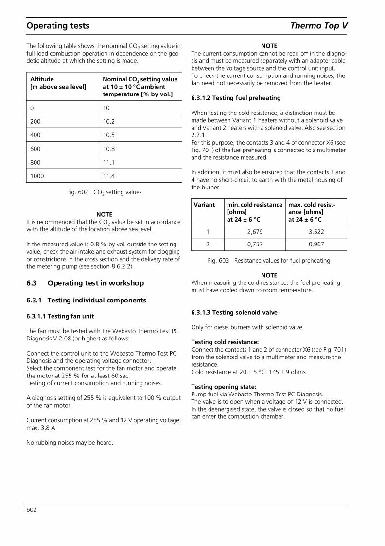
The following table shows the nominal CO 2 setting value infull-load combustion operation in dependence on the geo-detic altitude at which the setting is made.
NOTEIt is recommended that the CO 2 value be set in accordancewith the altitude of the location above sea level.
If the measured value is 0.8 % by vol. outside the settingvalue, check the air intake and exhaust system for cloggingor constrictions in the cross section and the delivery rate ofthe metering pump (see section 8.6.2.2 ).
6.3 Operating test in workshop
6.3.1 Testing individual components
6.3.1.1 Testing fan unit
The fan must be tested with the Webasto Thermo Test PCDiagnosis V 2.08 (or higher) as follows:
Connect the control unit to the Webasto Thermo Test PCDiagnosis and the operating voltage connector.
Select the component test for the fan motor and operatethe motor at 255 % for at least 60 sec.Testing of current consumption and running noises.
A diagnosis setting of 255 % is equivalent to 100 % outputof the fan motor.
Current consumption at 255 % and 12 V operating voltage:max. 3.8 A
No rubbing noises may be heard.
NOTEThe current consumption cannot be read off in the diagno-sis and must be measured separately with an adapter cablebetween the voltage source and the control unit input.To check the current consumption and running noises, thefan need not necessarily be removed from the heater.
6.3.1.2 Testing fuel preheating
When testing the cold resistance, a distinction must bemade between Variant 1 heaters without a solenoid valveand Variant 2 heaters with a solenoid valve. Also see section2.2.1 .For this purpose, the contacts 3 and 4 of connector X6 (seeFig. 701 ) of the fuel preheating is connected to a multimeterand the resistance measured.
In addition, it must also be ensured that the contacts 3 and4 have no short-circuit to earth with the metal housing ofthe burner.
NOTEWhen measuring the cold resistance, the fuel preheatingmust have cooled down to room temperature.
6.3.1.3 Testing solenoid valve
Only for diesel burners with solenoid valve.
Testing cold resistance: Connect the contacts 1 and 2 of connector X6 (see Fig. 701 )from the solenoid valve to a multimeter and measure theresistance.Cold resistance at 20 ± 5 °C: 145 ± 9 ohms.
Testing opening state: Pump fuel via Webasto Thermo Test PC Diagnosis.The valve is to open when a voltage of 12 V is connected.In the deenergised state, the valve is closed so that no fuelcan enter the combustion chamber.
Altitude[m above sea level]
Nominal CO 2 setting valueat 10 ± 10 °C ambienttemperature [% by vol.]
0 10
200 10.2
400 10.5
600 10.8
800 11.1
1000 11.4
Fig. 602 CO 2 setting values
Variant min. cold resistance[ohms]at 24 ± 6 °C
max. cold resist-ance [ohms]at 24 ± 6 °C
1 2,679 3,522
2 0,757 0,967
Fig. 603 Resistance values for fuel preheating

8/10/2019 ThermoTop V Service Manual
http://slidepdf.com/reader/full/thermotop-v-service-manual 27/46
Thermo Top V Operating tests
603
6.3.1.4 Electrical test of glow plug
The cold resistance must be checked using a multimeterwith the 4-conductor measuring principle.Multimeters without the 4-conductor measuring principlemay not be used for this purpose.
Cold resistance between Contact 1 and 2 (connector X3,see Fig. 701 ) at 24 ± 6 °C: 0.200 to 0.300 ohms.
Short-circuit test between Contact 1 or 2 (connector X3, seeFig. 701 ) and fan housing = ohms
6.3.1.5 Testing temperature sensor and overheatingsensor
When testing the cold resistance, a distinction must bemade between the variants coolant temperature sensor G1(NTC) and overheating sensor G2 (PTC). For this purpose,the contacts of the connector X5 (see Fig. 701 ) of the sen-sors are connected to a multimeter and the resistance meas-ured.
In addition, the short-circuit to earth to the metal housing,wire crimpings and deformations of the plastic cap of thesensors must also be checked.
Variant Contacts onconnector X5
min. coldresistance[ohms]at 20 ± 6 °C
max. coldresistance[ohms]at 20 ± 6 °C
G1(NTC)
Connect Con-tact 2 to 6
1998 4050
G2 (PTC) Connect Con-tact 3 to 7
0 250
Fig. 604 Resistance values of temperature sensor andoverheating sensor
8

8/10/2019 ThermoTop V Service Manual
http://slidepdf.com/reader/full/thermotop-v-service-manual 28/46
Operating tests Thermo Top V
604

8/10/2019 ThermoTop V Service Manual
http://slidepdf.com/reader/full/thermotop-v-service-manual 29/46
Thermo Top V Circuit diagrams
701
7 Circuit diagrams
7.1 General
Fig. 701 shows the plug assignment on the control unit.
Fig. 702 shows the circuit of the Thermo Top V heater, additional heater and 12 V digital timer.
See section 7.2 for legend of wiring diagram.
Fig. 701 Connector assignment of heater
X1 = Connection of vehicle wiring harness (radio remote control, control of metering pump)
X2 = Connection of 2x power supply to vehicle- Contact 1: Power supply of Terminal 30 (fuse)- Contact 2: Earth connection
X3 = Connection to glow plug
X4 = Connection to circulating pump
X5 = Connection to heater temperature sensors
X6 = Connection to fuel preheating/solenoid valve

8/10/2019 ThermoTop V Service Manual
http://slidepdf.com/reader/full/thermotop-v-service-manual 30/46
Circuit diagrams Thermo Top V
702
Fig. 702 Wiring diagram of Thermo Top V additional heater and 12 V digital timer.
M
M
M

8/10/2019 ThermoTop V Service Manual
http://slidepdf.com/reader/full/thermotop-v-service-manual 31/46
Thermo Top V Circuit diagrams
703
7.2 Legend for wiring diagram
Cable cross-sections
< 7.5 m 7.5 - 15 m
0.5 mm 2 0.75 mm 2
0.75 mm 2 1.0 mm 2
1.0 mm 2 1.5 mm 2
1.5 mm 2 2.5 mm 2
2.5 mm 2 4.0 mm 2
4.0 mm 2 6.0 mm 2
Cable colours
bl
brgegngrorrtswviws
blue
brownyellowgreengreyorangeredblackvioletwhite
Item Description Comment1 Webasto data bus interface W bus
2 Webasto outside temperature
3 Vehicle fan fuse present in vehicle
4 Option
5 Main switch
6 Summer/winter operation via W bus
A1 Heater Thermo Top VA2 Control moduleA2 Fuse holder
A4 Digital timer with W busB1 Temperature sensorB2 Overheating sensorE Glow plugF1 Fuse 20 A Flat fuse SAE J 1284F2 Fuse 1 A Flat fuse SAE J 1284F4 Fuse 25 A Flat fuse SAE J 1284K3 Relay Vehicle fanM1 Motor Combustion air fanM2 Motor Circulating pumpM3 Motor Vehicle fanS1 Switch for vehicle fan S1 or S2 depending on vehicleS2 Switch for vehicle fan S1 or S2 depending on vehicleS3 Switch Summer/winter switchS4 Switch CoolantS5 Sensor (optional) Outside temperatureX1 Plug connector, 8-pinX2 Plug connector, 2-pinX3 Plug connector, 2-pinX4 Plug connector, 3-pinX5 Plug connector, 8-pinX6 Plug connector, 4-pinX7 Plug connector, 2-pin
X8 Plug connector, 4-pinY1 Metering pumpY2 Solenoid valve

8/10/2019 ThermoTop V Service Manual
http://slidepdf.com/reader/full/thermotop-v-service-manual 32/46
Circuit diagrams Thermo Top V
704
Page for notes
8/10/2019 ThermoTop V Service Manual
http://slidepdf.com/reader/full/thermotop-v-service-manual 33/46
Thermo Top V Servicing work
801
8 Servicing work
8.1 General
This section describes the servicing work that can be carried
out on the heater when it is installed.
WARNINGThere is a danger of burns, as the heater and the attachedparts may be extremely hot.
8.2 Work on the heater
Disconnect the 20 A fuse for voltage interruption of theheater or the main power cable from the vehicle’s batterybefore carrying out any work on the heater. The main bat-tery power must not be disconnected whilst the heater isoperating or slowing down as a result of the risk of theheater overheating and the overheating protection thusbeing tripped. If extensive repair work is carried out on theheater, it must be completely removed. After work is per-formed on the heating circuit, a coolant mixture of waterand antifreeze must be added in accordance with the vehi-cle manufacturer's specifications and the heating circuitmust be carefully bled.
8.3 Work on the vehicle
WARNINGA temperature of 120 °C must not be exceeded in the vicin-ity of the heater under any circumstances (for example, dur-ing painting work on the vehicle).
8.4 Heater trial
The heater must not be operated in enclosed areas such asgarages and workshops without an emissions extraction sys-tem, even if you use the timer.
8.5 Servicing work
The following servicing work is to be carried out once a yearto maintain the functional reliability of the heater:
• Visual inspection of the heater for external damage, fas-tening and, if possible, external cleaning (avoid penetra-tion of water)
• Inspect electrical connections for contact corrosion andfirm seating and examine wiring routing (for cracks,kinks or rub spots)
• Check the exhaust and combustion air lines for signs ofdamage and to ensure that they are clear
• Check fuel lines for leaks (cracks, kinks or rub spots)
• Check coolant hoses and circulating pump (if present)for leaks (cracks, kinks or rub spots)
• Check fastening of circulating pump and meteringpump for damage
• Conduct operating test of heater as described in section6.2 .
8.6 Visual inspections and installationinstructions
8.6.1 Connection to vehicle cooling system
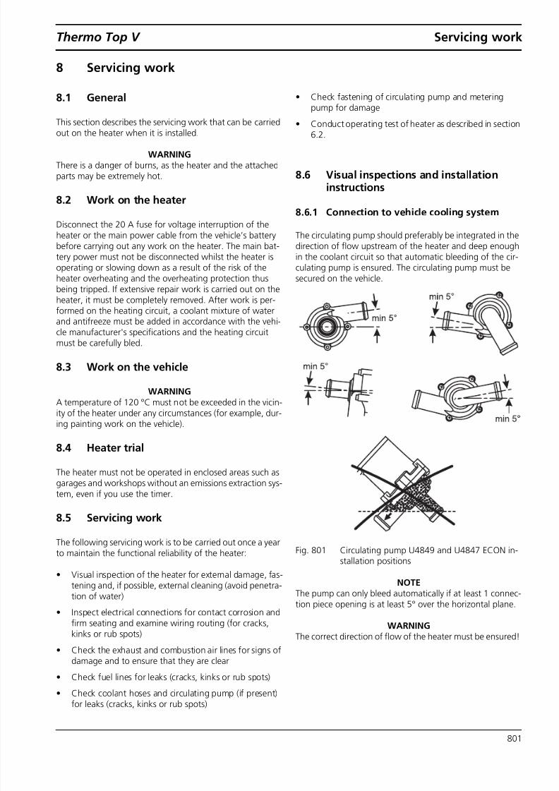
The circulating pump should preferably be integrated in thedirection of flow upstream of the heater and deep enoughin the coolant circuit so that automatic bleeding of the cir-culating pump is ensured. The circulating pump must besecured on the vehicle.
Fig. 801 Circulating pump U4849 and U4847 ECON in-stallation positions
NOTEThe pump can only bleed automatically if at least 1 connec-tion piece opening is at least 5° over the horizontal plane.
WARNINGThe correct direction of flow of the heater must be ensured!

8/10/2019 ThermoTop V Service Manual
http://slidepdf.com/reader/full/thermotop-v-service-manual 34/46
Servicing work Thermo Top V
802
NOTEA defective circulating pump must be replaced with theU4847 ECON in accordance with the spare parts list.
Electrical checking of circulating pump
Internal resistance of the circulating pump: 10 ± 1 kohms
In addition, the operation of the pump must be tested as fol-lows:When starting the heater, a slight vibration must be felt onthe pump. When controlling with the Webasto Thermo TestPC Diagnosis with maximum power, a soft pump noise mustbe audible.
8.6.2 Connection to vehicle fuel system
The values for the maximum pressure at the fuel extractionpoint are listed in following table.
NOTEAn empty fuel line or larger bubbles in the fuel line or meter-ing pump can result in a repeat start of the heater withincreased smoke.
8.6.2.1 Fuel lines
IMPORTANTThe hose connections on the connection pieces from theheater, the metering pump, fuel standpipe and various hoseconnection pieces must be executed as shown in Fig. 802 .
Mecanyl lines must mounted flush up to the connectionpieces to prevent collections of bubbles.
Fig. 802 Pipe/hose connections
8.6.2.2 Metering pump
It is advisable to install the metering pump in a cool place toavoid the formation of bubbles during operation. The max-imum ambient temperature must not exceed +20 °C at anytime during operation.
Fig. 803 Installation position of DP40/DP41 metering pump
For the diesel heater with a solenoid valve, the DP41 (ID No.9009529_) is used without a zero termination, as a pressurecompensation must be carried out between the closed sole-
noid valve in the heater and the tank (= fuel removal point).
Permissible fuelinflow height H[m]
At max. perm. pressure [bar]in the fuel line
Petrol Diesel
0.00 DP40: 0.30DP41: 0.10
DP40: 2.00DP41: 0.10
1.00 DP40: 0.22
DP41: 0.02
DP40: 1.92
DP41: 0.02Permissible fuelintake height S[m]
At max. perm. negative pressure[bar]
in the fuel tank
Petrol Diesel
0.00 -0.1 -0.1
0.50 -0.06 -0.06
1.00 -0.02 -0.02
Petrol Diesel
Pressure linelength
0 to 6 m 2 to 4 m
Inside hosediameter
2 ± 0.2 mm 2 ± 0.2 mm
Correct
Wrong
Clip
Bubble Bubble
Y View Y

8/10/2019 ThermoTop V Service Manual
http://slidepdf.com/reader/full/thermotop-v-service-manual 35/46
Thermo Top V Servicing work
803
Overview of uses for metering pumps
IMPORTANTObserve DP41 information sign (do not use for petrol)!
Fig. 804 Information sign of DP40/DP41 metering pump
IMPORTANTThe DP40 (ID No. 9002853_) may not be used for theheater with solenoid fuel valve , as otherwise fuel mayescape!The DP41 (ID No. 9009529_) may not be used for heaterswithout solenoid fuel valve or for petrol heaters , asotherwise fuel may escape.
WARNINGThe use of the DP2 and DP30 is prohibited for the ThermoTop V heaters.
Delivery quantity of metering pumps DP40 and DP41
Tolerance of the delivery quantity: ± 10% depending on theambient conditions and the application.
Operating temperature
WARNINGThe metering pump and fuel lines must not be installedwithin range of the radiated heat from hot vehicle parts. If
necessary, a thermal radiation guard must be provided inorder not to exceed the maximum permissible operatingtemperature.
NOTEThe metering pump requires a correct body earthing pointfor operation. If faults occur in other wires in the vehicle, apotential offset of the earthing point can occur. If the vehi-cle earthing point is not 0 V, but is instead > +0.25 V, thenthe heater may be supplied with an insufficient quantity offuel.
Electrical checking of metering pumpResistance of metering pump at +20 °C: 5.2 ohms ± 5%
Metering pump Use
DP41 ID No. 9009529_ Diesel heater with solenoidvalve (see section 2.2.2 )
DP40 ID No. 9002853_ – Diesel heater without sole-noid valve
– Petrol heater
Modulationfrequency ofmeteringpump [Hz]
Diesel Petrol
1 115 ml/h 109 ml/h
5.24(full load fordiesel)
603 ml/h -
6.14(full load forpetrol)
- 669 ml/h
7(testing ofdelivery quantitywith PCdiagnosis)
40 ml in 180 sec. 38 ml in 180 sec.
Pumpingmedium
DP41ID No. 9009529_
DP40ID No. 9002853_
Arctic Diesel -40 to +30 °C -40 to -10 °CWinter diesel -20 to +30 °C -20 to +30 °C
Winter petrol not approved -40 to +10 °C
Summer petrol not approved 0 to +20 °C
8/10/2019 ThermoTop V Service Manual
http://slidepdf.com/reader/full/thermotop-v-service-manual 36/46
Servicing work Thermo Top V
804
8.7 Heater, removal and installation
8.7.1 Removal
1 Interrupt power supply of heater by removing 20 Ablade fuse from Webasto fuse holder.
2 Separate connectors on heater.
3 Open coolant cap, release pressure and close cap again.
4 Loosen hose clamps and pull coolant hoses off heater.
5 Disconnect exhaust pipe from heater or detach fastenersof exhaust system.
6 Remove heater from bracket or detach bracket withheater from vehicle.
7 Loosen hose clamps, pull off fuel line and seal off withsuitable sealing plugs etc.
NOTEAll open plugs and connectors must be protected againstmoisture and soiling.
NOTEThe coolant must be prevented from escaping with hoseclamping pliers or caught with appropriate containers.
8.7.2 Installation1 Move heater into position and fasten on bracket.
2 Connect fuel line and fasten with hose clamp.
3 Connect coolant hoses and fasten with spring clips.
4 Fasten exhaust pipe on heater.
5 Restore all electrical connections on plug connector.
6 Connect vehicle battery.
7 Bleed coolant circuit.
8 Bleed fuel system if necessary.
WARNINGOnly the original-equipment wiring harness approved byWebasto may be used.
IMPORTANTA polarity reversal of the power supply can result in damageto the control unit. The correct polarity of the connection
wires must be ensured. A direct connection to a power sup-ply without an intermediate fuse is not permissible.
8.8 Initial start-up
After the heater has been installed, the coolant circuit andthe fuel supply system must be carefully bled. Observe thevehicle manufacturer's specifications when doing so.
All coolant and fuel connections must be checked for leaksand secure attachment during a trial run of the heater. If theheater suffers a fault during operation, troubleshootingmust be carried out (see Chapter 5).
8/10/2019 ThermoTop V Service Manual
http://slidepdf.com/reader/full/thermotop-v-service-manual 37/46
Thermo Top V Repair
901
9 Repair
9.1 General
This section describes the permissible repair work on the
Thermo Top V heater while removed. If it is dismantled fur-ther, any and all warranty claims are voided. An operatingtest must be conducted after all repairs.
9.2 Dismantling and assembling
9.2.1 Dismantling heater
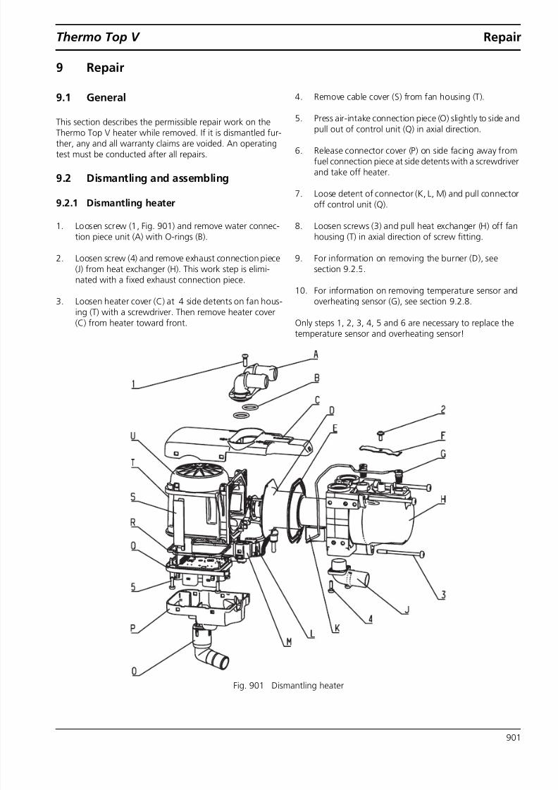
1. Loosen screw (1, Fig. 901 ) and remove water connec-tion piece unit (A) with O-rings (B).
2. Loosen screw (4) and remove exhaust connection piece(J) from heat exchanger (H). This work step is elimi-nated with a fixed exhaust connection piece.
3. Loosen heater cover (C) at 4 side detents on fan hous-ing (T) with a screwdriver. Then remove heater cover(C) from heater toward front.
4. Remove cable cover (S) from fan housing (T).
5. Press air-intake connection piece (O) slightly to side and
pull out of control unit (Q) in axial direction.6. Release connector cover (P) on side facing away from
fuel connection piece at side detents with a screwdriverand take off heater.
7. Loose detent of connector (K, L, M) and pull connectoroff control unit (Q).
8. Loosen screws (3) and pull heat exchanger (H) off fanhousing (T) in axial direction of screw fitting.
9. For information on removing the burner (D), seesection 9.2.5 .
10. For information on removing temperature sensor andoverheating sensor (G), see section 9.2.8 .
Only steps 1, 2, 3, 4, 5 and 6 are necessary to replace thetemperature sensor and overheating sensor!
Fig. 901 Dismantling heater
8/10/2019 ThermoTop V Service Manual
http://slidepdf.com/reader/full/thermotop-v-service-manual 38/46
Repair Thermo Top V
902
9.2.2 Assembling heater
1. For information on installing new temperature sensors(G, Fig. 901 ), see section 9.2.9 .
2. For information on installing burner (D), see section
9.2.7 .
3. Clean heat exchanger (H) inside and outside and placeon fan. Tighten screws (3) with 7 ± 0.7 Nm and do notcut new thread if possible when doing so (i.e. turnscrew into existing thread).
4. Insert connector (K, L, M) into control unit until it audi-bly engages. As the connectors are shape-coded, theycan be neither confused nor incorrectly poled.
5. Place connector cover (P) on control unit (Q) and
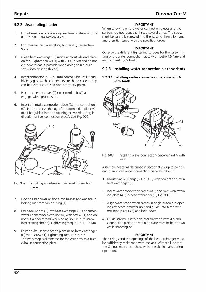
engage with light presure.6. Insert air-intake connection piece (O) into control unit
(Q). In the process, the lug of the connection piece (O)must be guided into the opening provided (facing indirection of fuel connection piece). See Fig. 902 .
Fig. 902 Installing air-intake and exhaust connectionpiece
7. Hook heater cover at front into heater and engage inlocking lug from fan housing (T).
8. Lay new O-rings (B) into heat exchanger (H) and fastenwater connection-piece unit (A) with screw (1) and donot cut a new thread when doing so (i.e. turn screwinto existing thread). Tightening torque 7.5 ± 0.7 Nm.
9. Fasten exhaust connection piece (J) on heat exchanger(H) with screw (4). Tightening torque: 4.5 NmThe work step is eliminated for the variant with a fixedexhaust connection piece.
IMPORTANTWhen screwing on the water connection pieces and thesensors, do not recut the thread several times. The screwmust be carefully screwed into the existing thread by handand then tightened with the specified torque.
IMPORTANTObserve the different tightening torques for the screw fit-ting of the water connection piece with teeth (4.5 Nm) andwithout teeth (7.5 Nm)!
9.2.3 Installing water connection piece variants
9.2.3.1 Installing water connection-piece variant Awith teeth
Fig. 903 Installing water connection-piece variant A withteeth
Assemble heater as described in section 9.2.2 up to point 7. and then install water connection piece as follows:
1. Moisten new O-rings (B, Fig. 903 ) with coolant and lay inheat exchanger (H).
2. Insert water connection pieces (A1) and (A2) with retain-ing plate (A3) in heat exchanger (H, Fig. 903 ).
3. Align water connection pieces in angle bracket in open-ings of heater transfer unit and guide into teeth withretaining plate (A3) and hold down.
4. Guide screw (1) into hole and screw on with 4.5 Nm.Connection piece and retaining plate must be held downwhile screwing on.
IMPORTANTThe O-rings and the openings of the heat exchanger mustbe sufficiently moistened with coolant. Without lubricant,the O-rings may be crushed, which results in leaks duringoperation.
Lug TeethA2
1
A2B A1H
8/10/2019 ThermoTop V Service Manual
http://slidepdf.com/reader/full/thermotop-v-service-manual 39/46
Thermo Top V Repair
903
9.2.3.2 Installing water connection-piece variant Bwithout teeth
Fig. 904 Installing water connection-piece variant B with-out teeth
Fig. 905 Detail of lock on water connection-piece variantB without teeth
The water connection pieces must be engaged in the retain-ing plate before installing it in the heater. The locking lugmust be engaged in the connection piece as shown.Engaging is carried out mechanically at Webasto, which iswhy the entire unit, consisting of the retaining plate and theconnection piece, must always be ordered.
IMPORTANTThe locking lug must be engaged in the connection piece,as otherwise leaks and a loss of coolant can result. A laterangle bracket adjustment is not permissible with the con-nection piece engaged.
1. Lay new O-rings (B) in the heat exchanger (H).
2. Insert water connection pieces (A1 and A2) with retain-ing plate (A3) as preassembled unit in heat exchanger(H).
3. Guide screw (1) into hole and screw on with 7.5 Nm.
9.2.4 Dismantling combustion-air fan unit
NOTEIt is not permissible to remove parts of the fan housing (T,Fig. 901 )!
9.2.5 Removing burner
Dismantle heater as described in section 9.2.1 up to point 8. Pull off connectors (L and M, Fig. 906 ). Set down fan verti-cally with burner facing upward.
1. Remove seal (E) from fan housing.
2. Push grommet (TU) onto fuel pipe out of fan housingwith slight pressure while lifting off burner in axial direc-tion.
NOTEThe fuel pipe must not be bent when removing the burner.
Fig. 906 Removing and installing burner
B
A2
A2B A1
1
A1
Locking lug of retaining plate
E
TU
L
M
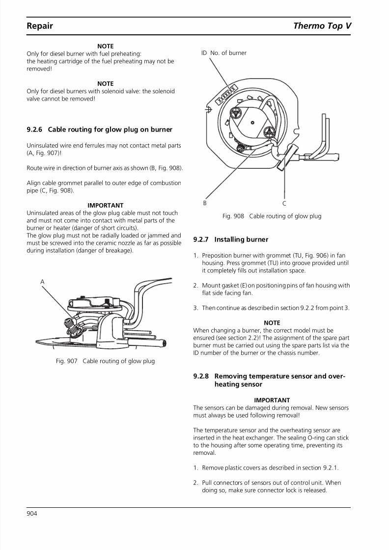
8/10/2019 ThermoTop V Service Manual
http://slidepdf.com/reader/full/thermotop-v-service-manual 40/46
Repair Thermo Top V
904
NOTEOnly for diesel burner with fuel preheating:the heating cartridge of the fuel preheating may not beremoved!
NOTE
Only for diesel burners with solenoid valve: the solenoidvalve cannot be removed!
9.2.6 Cable routing for glow plug on burner
Uninsulated wire end ferrules may not contact metal parts(A, Fig. 907 )!
Route wire in direction of burner axis as shown (B, Fig. 908 ).
Align cable grommet parallel to outer edge of combustionpipe (C, Fig. 908 ).
IMPORTANTUninsulated areas of the glow plug cable must not touchand must not come into contact with metal parts of theburner or heater (danger of short circuits).The glow plug must not be radially loaded or jammed andmust be screwed into the ceramic nozzle as far as possibleduring installation (danger of breakage).
Fig. 907 Cable routing of glow plug
Fig. 908 Cable routing of glow plug
9.2.7 Installing burner
1. Preposition burner with grommet (TU, Fig. 906 ) in fanhousing. Press grommet (TU) into groove provided untilit completely fills out installation space.
2. Mount gasket (E) on positioning pins of fan housing withflat side facing fan.
3. Then continue as described in section 9.2.2 from point 3.
NOTEWhen changing a burner, the correct model must beensured (see section 2.2 )! The assignment of the spare partburner must be carried out using the spare parts list via theID number of the burner or the chassis number.
9.2.8 Removing temperature sensor and over-heating sensor
IMPORTANTThe sensors can be damaged during removal. New sensorsmust always be used following removal!
The temperature sensor and the overheating sensor areinserted in the heat exchanger. The sealing O-ring can stickto the housing after some operating time, preventing itsremoval.
1. Remove plastic covers as described in section 9.2.1 .
2. Pull connectors of sensors out of control unit. Whendoing so, make sure connector lock is released.
A
B C
ID No. of burner

8/10/2019 ThermoTop V Service Manual
http://slidepdf.com/reader/full/thermotop-v-service-manual 41/46
Thermo Top V Repair
905
3. Loosen screw (2, Fig. 901 ).
4. Remove retaining spring (F) and pull sensors out of heatexchanger (sensors are not accessible from inside). Donot pull on plastic head or cable when doing so.
9.2.9 Installing temperature sensor and over-heating sensor
IMPORTANTThe sensors can be damaged during removal. New sensorsmust always be used following removal!
IMPORTANTIncorrect wiring routing can result in heater malfunctionsand/or coolant loss!
Cable routing with radially sealing water connection-piecevariant A with teeth (section 9.2.3.1 , with stainless-steelretaining plate):See Fig. 910 .
Cable routing with axially sealing water connection-piecevariant B (section 9.2.3.1 , with aluminium retaining plate):See Fig. 911 .
1. Moisten sensors with coolant and press as far as possibleinto hole of heat exchanger. In the process, ensure cor-rect position of sensors and cable (see Fig. 910 and Fig.911 ).
2. Lay on retaining spring and fasten with screw (2) with4 ± 0.4 Nm tightening torque. Before screwing on,make sure that wires are not crushed by retaining springas shown. Retaining spring (F) must face toward frontwith 2 side notches and be fixed in place by positioningpins of heat exchanger.
3. Route cable tautly as shown in Fig. 910 and Fig. 911 . Thecable may not lie outside the cable duct provided, as oth-erwise it may be damaged when installing the waterconnection piece.
4. The cable is then fixed in place in the control unit frameand the connector engaged in the connector basket.
5. Installing heater cover.
6. Installing connector cover and cable cover.
9.2.10 Heat exchanger
Existing soot deposits must be completely removed with asoft brass wire brush.
Fig. 909 Heat exchanger
IMPORTANTThe inside and outside section of the heat exchanger maynot be removed!
NOTEWhen changing the heat exchanger, only new sensors andnew gaskets may be mounted.
Coolant connection
Holes forsensors
Exhaust connection piece

8/10/2019 ThermoTop V Service Manual
http://slidepdf.com/reader/full/thermotop-v-service-manual 42/46
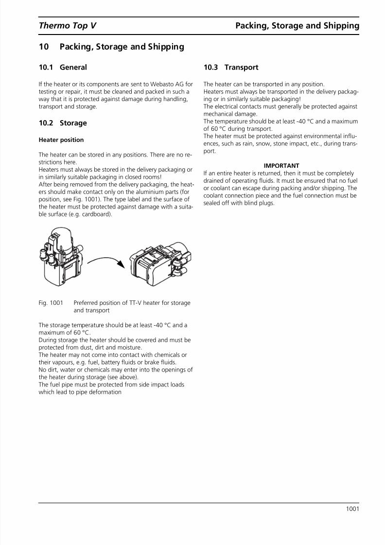
8/10/2019 ThermoTop V Service Manual
http://slidepdf.com/reader/full/thermotop-v-service-manual 43/46
Thermo Top V Packing, Storage and Shipping
1001
10 Packing, Storage and Shipping
10.1 General
If the heater or its components are sent to Webasto AG for
testing or repair, it must be cleaned and packed in such away that it is protected against damage during handling,transport and storage.
10.2 Storage
Heater position
The heater can be stored in any positions. There are no re-strictions here.Heaters must always be stored in the delivery packaging orin similarly suitable packaging in closed rooms!After being removed from the delivery packaging, the heat-ers should make contact only on the aluminium parts (forposition, see Fig. 1001 ). The type label and the surface ofthe heater must be protected against damage with a suita-ble surface (e.g. cardboard).
Fig. 1001 Preferred position of TT-V heater for storageand transport
The storage temperature should be at least -40 °C and amaximum of 60 °C.During storage the heater should be covered and must beprotected from dust, dirt and moisture.The heater may not come into contact with chemicals ortheir vapours, e.g. fuel, battery fluids or brake fluids.No dirt, water or chemicals may enter into the openings ofthe heater during storage (see above).The fuel pipe must be protected from side impact loadswhich lead to pipe deformation
10.3 Transport
The heater can be transported in any position.
Heaters must always be transported in the delivery packag-ing or in similarly suitable packaging!The electrical contacts must generally be protected againstmechanical damage.The temperature should be at least -40 °C and a maximumof 60 °C during transport.The heater must be protected against environmental influ-ences, such as rain, snow, stone impact, etc., during trans-port.
IMPORTANTIf an entire heater is returned, then it must be completely
drained of operating fluids. It must be ensured that no fuelor coolant can escape during packing and/or shipping. Thecoolant connection piece and the fuel connection must besealed off with blind plugs.

8/10/2019 ThermoTop V Service Manual
http://slidepdf.com/reader/full/thermotop-v-service-manual 44/46
Packing, Storage and Shipping Thermo Top V
1002
Page for notes

8/10/2019 ThermoTop V Service Manual
http://slidepdf.com/reader/full/thermotop-v-service-manual 45/46

8/10/2019 ThermoTop V Service Manual
http://slidepdf.com/reader/full/thermotop-v-service-manual 46/46
• 0 1 / 1 0 •
E r r o r s a n d o m
i s s i o n s e x c e p t e d •
P r i n t e d i n G e r m a n y • ©
W e b a s t o
A G
, G C S 2 0 1 0
Webasto AGPostfach 80D - 82131 StockdorfGermany
National: