Embed Size (px)
Citation preview
ubersetzungen vonDIN-Normen
M a n u s k r i p t i i b e r s e t z u n g e n
Die in Kopie beigefugte Rohubersetzung wurde vom DIN-Sprachendienstnicht auf ihre Richtigkeit gepruft. Deshalb schlief3t das Deutsche lnstitut furNormung e.V. (DIN) ausdrucklich jegliche Haftung fur deren Richtigkeitbzw. Vollstandigkeit aus.
Translations ofDIN-Standards
T y p e s c r i p t t r a n s l a t i o n s
The attached typescript translation has not been checked by DIN-Sprachendienst for its accuracy. Deutsches lnstitut fur Normung e.V. (DIN)cannot, therefore, assume responsibility for its correctness orcompleteness.
On no account shall the translation be considered authorized by DIN.
Beuth Vet- lag GmbH Berlin l Wien l Zurich
Technical Help to Exporters
T R A N S L A T I 0 N_
DIN 18 891
August 1984
SOLID FUEL STOVES
originallanguage version
Kaminofen fur feste Brennstoffe
issued by (DIN) DEUTSCHES INSTITUT FUR NORMUNG EVPostfach 1107D- 1000 Berlin 30WEST GERMANY
Technical Help to-Exporters has taken all reasonable measures to ensure the accuracy of this translationbut regrets that no responsibility can be accepted for any error, omission or inaccuracy. In cases of doubt
or dispute, the original language text only is valid.
,
0 Technical Help to ExportersBritish Standards Institution
Linford Wood, Milton Keynes, MK14 6LETel: Milton Keynes (0908) 320033 Telex: 825777
L
GERMAN STANDARD
UDC 683.93/.94 : 697.243.3 : 001.4: 614.8 : 620.1 : 62-777
D I N
18 891
August 1984
SOLID FUEL STOVES
Original language version:
Kaminijfen fiir feste Rrennstoffe
Paragraphs 4.2, S and 6 of this standard contain safety requirements in the
sense of the Gesetz fiber technische Arbeitsmittet (Gergtesicherheitsgesetz)'
(the Equipment Safety Law).
Commencement of validity
This standard enters into effect from 01 August 1984.
The temperatures expressed in K relate to the test room temperature.
ALL dimensions in millimetres
/
General tolerances: see DIN 7168 - g
1
DIN 18 891
List of contents page
1
22.12.22.32.42.52.62.72.82.92.102.112.122.132.142.152.162.172.182.192.202.212.22
Field of application _........_._............................ 3
Definitions and design characteristics....---..------... 5ConsumptionWaste gasDamper arrangementPre-heater bafflesSteady conditionThermal loadThermal outputRated thermal outputBasic embers.~.........._._.................-......-............ 6Fire boxFire box openingAsh compartmentPlane grateStanding grateFire box floorFire-dogRegulatorEfficiency 1Heating gas.~.....................~.........._..._........~._... 7Re-kindling abilityFuel selector of the stoveModels of stove
3 Designation
44.14.1.14.1.24.1.34.1.44.1.54.24.2.14.2.24.2.34.2.44.2.54.2.64.2.74.2.84.2.94.2.104.2.114.2.124.2.13
R e q u i r e m e n t sGeneral requirementsRated thermal outputGrate arrangement*Ash box.~.........__.....~......_..._....................-..-...8EfficiencyRe-kindling abilitySafety requirementsMaterials and wall thicknessesRegulators and controlsFuel seLectorPre-heater bafflesDamper..~......__._...._......................................- 9
Fire boxFire box openingHeating gas channelsWaste gas pipe stubOperating handlesTemperatures at adjacent surfaces and in the wood store-----.----IDWaste gas temperatureEscape of heating gas and faLling out of embers
55.15.25.2.15.2.2
TestingPoints of measurementTypes of testing and test documentsType testingComponent testing...:...._.....................................-- 11
2
DIN 18 891
5.2.35.2.45.2.55.35.3.15.3.25.3.35.3.45.3.55.3.65.45.55.65.75.7.15.7.25.7.3
5.7.45.7.5
5.7.65.7.75.85.8.15.8.25.8.35.8.45.9
6
7
Supplementary testing .::.....................................___ 11Design testing 1 :Type verification............................................._._~~Test equipment ’Measurement apparatusfor fuel consumption...... _._....._........I~
Measured sectionDelivery pressure mettWaste gas analysis plotterTemperature measurement devices :.................................14Test floor and test wallsTest fuelsPreliminary testingDesign testing....._.................................._......_.. 15Technical testing from the point of view of heatingInstallation of the stoveDry heatingCreation of steady condition and basic embersin a closed fire box
Testing of safetyTesting of rated thermat output with the fire box closed,........17determination of efficiency, and measurement of waste gastemperature and the temperature of the operating handles
Testing at reduced rated thermat output..........................18Testing of re-kindling ability with the fire box closedEvaluation of measurementsEfficiencyThermal output...................... . . . . . . . . . . . . . . . . . . . . . . . . . . . . . 19Mass flow rate of waste gas, in g/sMeaning of symbols...................._._.....__............._...20Test report..............................................__..~...Zl
Installation and operating instructions -. . . . . . . . . . . . . . ..Zl
Marking . . . . . . . . . . . . . . . . . . . . . . . ..*...........*......*........... 23
Standards and other documents referred to in the text
Explanatory Notes
1 Field of application
1.1 This standard is applicable to solid fuel stoves with a rated
thermal output of up to 11 kW.
Stoves are used for room heating with the solid fuels listed as low-smoke
fuels in the first decree relating to the implementation of the
Bundesimmissionsschutzgesetz (the Federal German Immision Control Act).
These stoves differ from the controlled-combustion stoves in accordance with
DIN 18890 in respect 0'; the flat grate, the associated reduced fuel charge
and limited continuous combustion capacity, and the possibility, if
required, of being used with an open fire box.
3
t
._
DIN 18 897
l-2 This standard is not applicable to stoves in which water is used as
a heat transfer medium, or to open fires produced on-site or assembled from
prefabricated components and attached to the building.
1.3 Designs which deviate in certain detailed respetts from the
provisions of this standard as a resul't of further technical developments
may be approved as satisfying the standard by a Special Committee on receipt
of a separate request. All such requests shall be addressed to the
NormenausschuO Heir, Koch- und WZrmgerZt CFNH) (the Heating and Cooking
Appliances Standards Committee), Am Hauptbahnhof 10, D-6000 Frankfurt a.M.
Federal Republic of Germany. The application shall be accompanied by the
test report of an independent testing station approved by the Norrnenausschtin
Heiz-, Koch- und Wsrmgerat CFNH). The testing station shall apply the
provisions of this standard as appropriate in the course of testing.
For the purposes of granting approval of compliance with the standard, the
Special Committee shall arrive at its decision after examining the applicant
before the following panel:
a1 Chairman of the FNH Section "Domestic fireplaces for solid fuels".
b> Chairman of the FNH Working Committee on DIN 18891 and his deputy.
c> Director of the testing station asked to carry out the testing.
d) A representative of the group of manufacturers concerned.
e) Chairman of the FNH.
The decision in respect of approval 'of compliance with the standard shall be
arrived at on the basis of whether the requirements relating to safety,
serviceability and testing to be imposed in accordance with this standard on
stoves have been satisfied in a manner other than that stipulated in the
standard.
Approval of compliance with the standard issued by the Special Committee
shall become effective only after having been confirmed by the Working
Committee responsible for DIN 18 891.
The request for approval of compliance with the standard shall be regarded
as a request for standardization. Approval of compliance with the standard
issued by the Special Committee shall be regarded as acceptance of the
request for standardization. Details shall be published in the Standards
Section of the DIN-Mitteilungen, together with
that it is proposed to issue a corresponding
a statement to the effect
subsequent edition of the
4
standard by the abridged procedure. Immediately on expiry of the four-week
period for comments required under the abridged procedure, and provided that
DIN 18 891
no objections have been received, confirmation of approval of Compliance
with the standard by the Working Committee shall have the effect of adopting
the subsequent edition.
Addresses of testing stations are available on request from:
Normenausschul3 Heiz-, Koch- und WBrmgerZt im DIN (FNH), Am Hauptbahnhof IO,
D-6000 Frankfurt a.M. Federal Republic of Germany.
2 Definitions and design characteristics
2.1 Consumption
The consumption is the rate at which the quantity of fuel is used up during
combustion (see DIN 18 890/09.71>.
2.2 Waste gas
Waste gas is the combustion gas which exits from the waste gas pipe stub of
the fireplace.
2-3 Damper arrangement
Damper arrangements are arrangements for the purpose of increasing the flow
resistance in the heating gas channel.
2.4 Pre-heater baffles
Pre-heater baffles (flaps or slides) are devices which, when opened, reduce
the length of the path for the heating gases.
2.5 Steady condition
The steady condition is
to a specific thermal
variation in the values
of identical length.
the operating state of the fireplace corresponding
load at which there is no longer a significant
which are to be measured over consecutive periods
2.6 Thermal load
The thermal load is the quantity of heat supplied to the fireplace every
hour, calculated on the basis of the calorific value of the fuel.
2.7 Thermal output
The thermal output is the useable quantity of heat emitted by the fireplace
every hour.
2.8 Rated thermal output
The rated thermal output is the thermal output value declared by the
manufacturer on the rating plate.
5
DIN 18 891
2.9 Basic embers
The basic embers consist of the mass of glowing, degassed fuel which must
remain, after removal of the ashes, in order to ensure the ignition of the
charge of fuel to be added.
z-10 Fire box
The fire box is the space formed by.the fire box floor, the fire box walls
and the fire box top, and the fire box opening, and, if appropriate, the
fire box door.
2.11 Fire box opening
The fire box opening is the unobstructed opening in the fire box through
Hhich radiant heat emerges into the room in which the stove is installed.
Depending on the design, some or all of the combustion air can flow in
through the fire box opening.
2.12 Ash compartment
The ash compartment serves the purpose of accommodating the ash pan and, if
appropriate, of guiding combustion air beneath the grate.
2.13 Plane grate
The plane grate is a device in the fire box floor through which the ash
falls into the ash pan and through which combustion air is introduced.
2.14 Standing grate
The standing grate is a device which prevents fuel from falling from the
fire box, and which may be a component part of the fire-dog.
2.15 Fire box floor
The fire box floor provides a surface on which to lay fuel for the purpose
of combustion and a support for the fire-dog or the fire basket. The fire
box floor is by the side walls, the back wall, the fire box opening ‘/ ;.A-, ,'-,- -1
and the standing grate.
2.16 Fire-dog
The fire-dog is an arrangement situated above or in the fire box floor
through which the ash faLls and combustion air is introduced.
2.17 Regulator
Regulators are used for the purpose of adjusting the primary or secondary
air cross-section.
2.18 Efficiency '
The efficiency is the relationship between the thermal output and the
associated thermat Load expressed as a percentage.
6
DIN 18 891
2.19 Heating gas
Heating gas is the combustion gas which flows inside the fireplace (see DIN
18890109.71).
2.20 Re-kindling ability _
The r-kindling ability is the property exhibited by fireplaces of being
able to ignite a charge of fuel which is added after a specific period of
burning.
2.21 Fuel selector of the stove
The fuel selector of the stove is an arrangement for the pre-setting of the
maximum primary or secondary air cross-section to suit the nature of the
particular fuel which has been selected.
2.22 Models of stove
a) Model 1
Stoves of Model ? have an enclosed fire box, the door of which is opened
only for servicing purposes. Compliance with this shall be ensured
through the requirements set out in Paragraph 4.2.6.
b) Model 2
Stoves of Model 2 have a loackable fire box opening and can be operated
with the fire box door closed or open.
3 Designation
Designation of the requirements relating to a Model 1 (1) stove:
Kaminofen DIN 18 891 - 1
(Stove DIN 18 891 - I>
4 Requirements
4.1 General requirements
4.1.1 Rated thermal output
The rated thermal output in kW shall be determined on the basis of the test
results and shall be rounded-off to the nearest whole kW.
4.1.2 Grate arrangement
If fitted, a grate arran%ement shall be easily servicedand permit therconvenient removal of ashes. It shall be suitable for the fuels
recommended by the manufacturer.
7
DIN 18 891
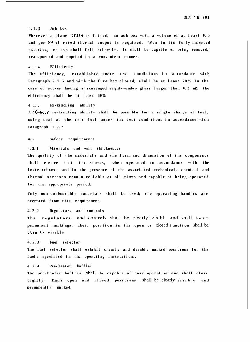
4.1.3 Ash box
Wherever a plane .grate is fitted, an ash box with a volume of at least 0.5
dm3 per kW of rated thermal output is required. When in its fully-inserted
position, no ash shall fall below it. It shall be capable of being removed,
transported and emptied in a convenient manner.
4.1.4 Efficiency
The efficiency, established under test conditions in accordance with
Paragraph 5.7.5 and with the fire box closed, shall be at least 70%. In the
case of stoves having a scavenged sight-window glass larger than 0.2 m2, the
efficiency shall be at least 60%.
4.1.5 Re-kindling ability
A 10-hour re-kindling ability shall be possible for a single charge of fuel,
using coal as the test fuel under the test conditions in accordance with
Paragraph 5.7.7.
4.2 Safety requirements
4.2.1 Materials and wall thicknesses
The quality of the materials and the form and dimension of the components
shall ensure that the stoves, when operated in accordance with the
instructions, and in the presence of the associated mechanical, chemical and
thermal stresses remain reliable at all times and capable of being operated
for the appropriate period.
Only non-combustible materials shall be used; the operating handles are
exempted from this requirement.
4.2.2 Regulators and controls
The regulators and controls shall be clearly visible and shall b e a r
permanent markings. Their position in the open or closed function shall be
clearky v i s i b l e .
4.2.3 Fuel selector
The fuel selector shall exhibit clearly and durably marked positions for the
fuels specified in the operating instructions.
4.2.4 Pre-heater baffles
The pre-heater baffles shall be capable of easy operation and shall close
tightly. Their open and closed positions shall be clearly visible and
permanently marked.
DIN 18 891
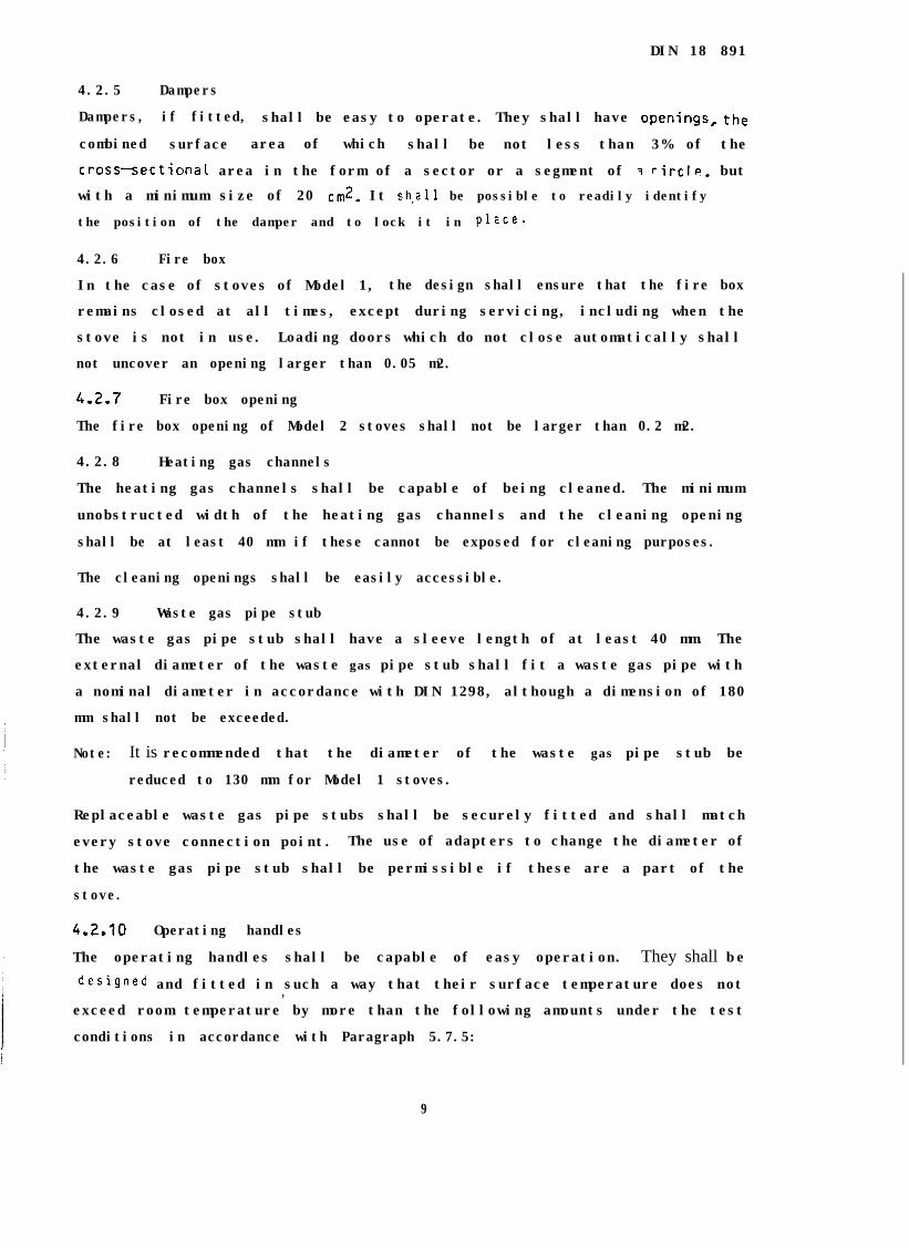
4.2.5 Dampers
Dampers, if fitted, shall be easy to operate. They shall have openings, the
combined surface area of which shall be not less than 3% of the
cross-sectiona~ area in the form of a sector or a segment of 3 rircle, but
with a minimum size of 20 cm2_ It sh.all be possible to readily identify
the position of the damper and to lock it in Place-
4.2.6 Fire box
In the case of stoves of Model 1, the design shall ensure that the fire box
remains closed at all times, except during servicing, including when the
stove is not in use. Loading doors which do not close automatically shall
not uncover an opening larger than 0.05 m2.
4.2.7 Fire box opening
The fire box opening of Model 2 stoves shall not be larger than 0.2 m2.
4.2.8 Heating gas channels
The heating gas channels shall be capable of being cleaned. The minimum
unobstructed width of the heating gas channels and the cleaning opening
shall be at least 40 mm if these cannot be exposed for cleaning purposes.
The cleaning openings shall be easily accessible.
4.2.9 Waste gas pipe stub
The waste gas pipe stub shall have a sleeve length of at least 40 mm. The
external diameter of the waste gas pipe stub shall fit a waste gas pipe with
a nominal diameter in accordance with DIN 1298, although a dimension of 180
mm shall not be exceeded.
Note: It is recommended that the diameter of the waste gas pipe stub be
reduced to 130 mm for Model 1 stoves.
Replaceable waste gas pipe stubs shall be securely fitted and shall match
every stove connection point. The use of adapters to change the diameter of
the waste gas pipe stub shall be permissible if these are a part of the
stove.
4.2.10 Operating handles
The operating handles shall be capable of easy operation. They shall be
designed and fitted in such a way that their surface temperature does not,exceed room temperature by more than the following amounts under the test
conditions in accordance with Paragraph 5.7.5:
9
DIN 18 891
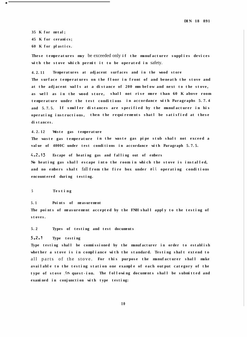
35 K for metal;
45 K for ceramics;
60 K for plastics.
These temperatures may be exceeded only if the manufacturer supplies devices
with the stove which permit it to be operated in safety.
4.2.11 Temperatures at adjacent surfaces and in the wood store
The surface temperatures on the floor in front of and beneath the stove and
at the adjacent walls at a distance of 200 mm below and next to the stove,
as well as in the wood store, shall not rise more than 60 K above room
temperature under the test conditions in accordance with Paragraphs 5.7.4
and 5.7.5. If smaller distances are specified by the manufacturer in his
operating instructions, then the requirements shatl be satisfied at these
distances.
4.2.12 Waste gas temperature
The waste gas temperature in the waste gas pipe stub shalt not exceed a
value of 4000C under test conditions in accordance with Paragraph 5.7.5.
4.2-13 Escape of heating gas and falling out of embers
No heating gas shall escape into the room in which the stove is installed,
and no embers shalt fall from the fire box under all operating conditions
encountered during testing.
5 Testing
5.1 Points of measurement
The points of measurement accepted by the FNH shall apply to the testing of
stoves.
5.2 Types of testing and test documents
5.2.1 Type testing
Type testing shall be commissioned by the manufacturer in order to establish
whether a stove is in compliance with the standard. Testing shalt extend to
a l l p a r t s o f t h e s t o v e . For this purpose the manufacturer shall make
available to the testing station one example of each output category of the
type of stove .in quest-ion. The following documents shall be submitted and
examined in conjunction with type testing:
10
D I N 1 8 8 9 7
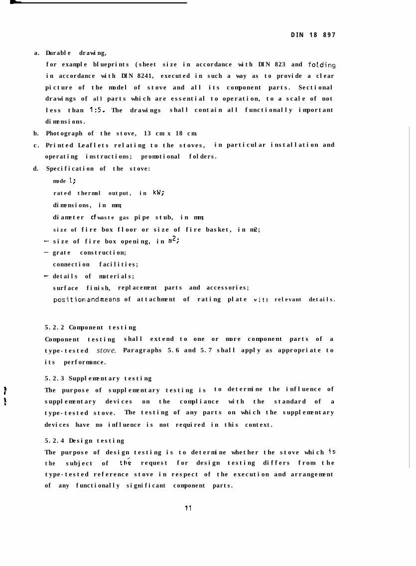
a. Durable drawing,
for example blueprints (sheet size in accordance with DIN 823 and folding
in accordance with DIN 8241, executed in such a way as to provide a clear
picture of the model of stove and all its component parts. Sectional
drawings of all parts which are essential to operation, to a scale of not
less than 1:s. The drawings shall contain all functionally important
dimensions.
b. Photograph of the stove, 13 cm x 18 cm.
c. Printed Leaflets relating to the stoves, in particular installation and
operating instructions; promotional folders.
d. Specification of the stove:
-
-
-
mode I;
rated thermal output, in kW;
dimensions, in mm;
diameter cf waste gas pipe stub, in mm;
size of fire box floor or size of fire basket, in m2;
size of fire box opening, in m2;
grate construction;
connection facilities;
details of materials;
surface finish, replacement parts and accessories;
position and means of attachment of rating plate with relevant details.
5.2.2 Component testing
Component testing shall extend to one or more component parts of a
type-tested stove. Paragraphs 5.6 and 5.7 shall apply as appropriate to
its performance.
5.2.3 Supplementary testing
The purpose of supplementary testing is to determine the influence of
supplementary devices on the compliance with the standard of a
type-tested stove. The testing of any parts on which the supplementary
devices have no influence is not required in this context.
5.2.4 Design testing
The purpose of design testing is to determine whether the stove which is
the subject of th; request for design testing differs from the
type-tested reference stove in respect of the execution and arrangement
of any functionally significant component parts.
DIN 18 891
5.2.5 Type verification
Type verification may be requested by anyone in the event of there being any
doubt as to the compliance with the standard of a stove bearing the DIN Test
and Control Mark.
It shall be performed by a recognized independent testing station, which
shall arrange for the test item to be selected from a sufficient number in a
factory or commercial store by an organization (e.g. the FNHI instructed to
do this on behalf of the testing station.
Type verification shall be performed fundamentally as type testing. If the
objection relates only to a limited part of the standard, type verification
may be performed as component testing, supplementary testing or design
testing, at the discretion cf the testing station.
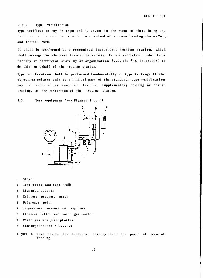
5.3 Test equipment (see Figures 1 to 31
1
2
3
4
5
6
7
8
9'
Stove
Test floor and test walls
Measured section
Delivery pressure meter
Reference point
Temperature measurement equipment
Cleaning filter and waste gas washer
Waste gas analysis plotter
Consumption scale balance
8i
B.i:-
‘5
Figure 1. Test device for technical testing from the point of view ofheating
12
DIN 18 891
5.3.1 Reasurement apparatus for fuel consumption
5.3.1.1 Fuel scale balance for the purpose of determining the quantity of
test fuel to be added and the weight of the removed ashes, with a maximum
error of 10 g and a scale graduation of 2 g-
5.3.1.2 Consumption scale balance for: the purpose of determining fuel
consumption with a maximum error cf 100 g and a scale graduation of 20 g.
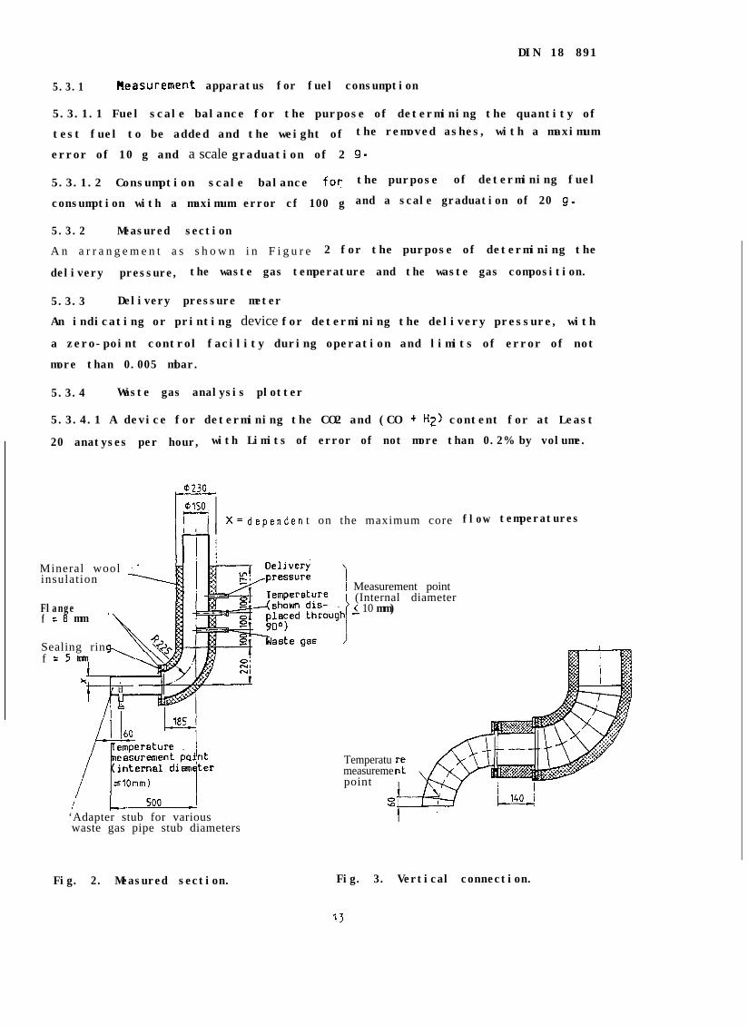
5.3.2 Measured section
A n a r r a n g e m e n t a s s h o w n i n F i g u r e 2 for the purpose of determining the
delivery pressure, the waste gas temperature and the waste gas composition.
5.3.3 Delivery pressure meter
An indicating or printing device for determining the delivery pressure, with
a zero-point control facility during operation and limits of error of not
more than 0.005 mbar.
5.3.4 Waste gas analysis plotter
5.3.4.1 A device for determining the CO2 and (CO + H2) content for at Least
20 anatyses per hour, with Limits of error of not more than 0.2% by volume.
Mineral wool iinsulation
Flangef = 8 mm
'\
Sealing rin\ %k\f
X= dependen t on the maximum core
‘Adapter stub for variouswaste gas pipe stub diameters
Fig. 2. Measured section.
flow temperatures
Measurement point(Internal diameteri 10 mm)
Temperatumeasuremepoint
Fig. 3. Vertical connection.
5.3.4.2 A continuous plotting device for determi
limits of error of not more than + 0.2% by volume.
5.3.5 Temperature measurement devices
5.3.5.1 A device for determining the waste gas tc
error of not more than 5OC.
DIN 18 891
ning the CO content with
lmperature with limits of
5.3.5.2 A device for determining the surface temperatures with limits of
error of not more than + 2oC.
5.3.5.3 A device for determining the ambient temperature with limits of
error of not more than 1oC.
5.3.6 Test floor and test walls
Equipment as shown in Figure 3 for determining the surface temperature of
the test floor and the test walls.
5.4 Test fuels
5.4.1 Test fuels for rated thermal output and, if appropriate,re-kindling ability
Test fuels are the fuels specified as being suitable by the manufacturer in
the operating instructions.I
If wood is used as a test fuet, Logs with a maximum water content of 20% by
mass, of (330 + 30) mm in length, and with a circumference of 300 to 355 mm
shall be used. Brown coal briquettes and various types and grades of mineral
coal may be specified only if the stove has a suitable grate (e.g. size 180
mm x 200 mm, with a slot width of 8 mm> and an ash box.
In order to ensure adequate coverage of the grate, logs of smaller and
greater length may be used.
5.4.2 Test fuels for safety testing
Safety testing shall be performed using a piece of wood with an edge length
of 50 mm x 50 mm or 40 mm x 60 mm, with a maximum water content of 15X,
and with a length to suit the fire box.
5.5 Preliminary testing
Before starting the test, the documents submitted in accordance with
Paragraph 5.2 shall be inspected for completeness and correctness.
Checks shall then be made to establish whether the marking Crating plate)
corresponds to the req;irements in accordance with Paragraph 7, and whether
the stove to be tested exhibits any obvious transport damage which could
influence its function.
5.6 Design testing
A check shall be made
DIN 18 891
to establish whether the requirements in accordance
with Paragraphs 4.2.1 to 4.2.9 have been met.
5.7 Technical testing from the point of view of heating -
The damper arrangement shall be kept open, and the fuel selector shall be
set to the appropriate test fuel during all the tests.
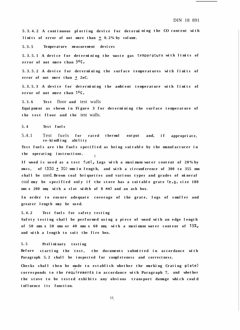
5.7.1 Installation of the stove
The stove shall be installed on the test floor of the test equipment in
accordance with Figure 4, using the appropriate floor protection specified
by the manufacturer.
5.7.2 Dry heating
The stove shall be dry heated or pre-heated.
I
ICallers Pipe stub centre
Wood$I%Asbestos’ cement(surface smoothed)
Aluminiuk foil ’
Fig. 4. Test floor and test walls fig. 5. Collar for pipe stub opening.with accessories.
5.7.3 Creation of steady condition and basic embers in a closed fire box
Depending err the loading required or expected in conjunction with each test,
the basic embers shall be produced by the use of a sufficient quantity of
test fuel to ensure that the necessary quantity of basic embers is still
available after each ol'f the test periods of identical duration. For this
purpose the regulators and the delivery pressure shall be adjusted in
accordance with the conditions of testing.
15
--.- .- __
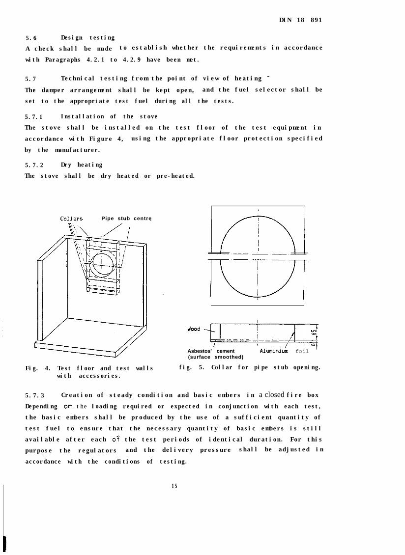
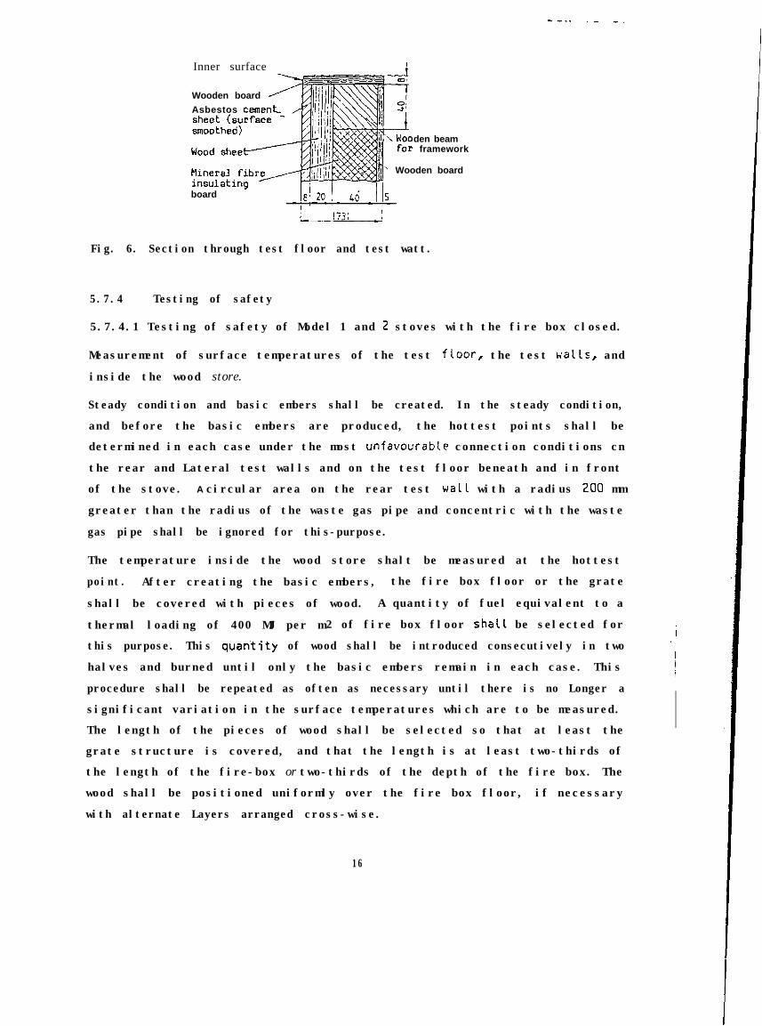
Inner surface
Wooden board
Asbestos ceme
den beamframework
Wooden board
board -
Fig. 6. Section through test floor and test watt.
5.7.4 Testing of safety
5.7.4.1 Testing of safety of Model 1 and 2 stoves with the fire box closed.
Measurement of surface temperatures of the test fLoor, the test Halls, and
inside the wood store.
Steady condition and basic embers shall be created. In the steady condition,
and before the basic embers are produced, the hottest points shall be
determined in each case under the most unfavourable connection conditions cn
the rear and Lateral test walls and on the test floor beneath and in front
of the stove. A circular area on the rear test watt with a radius 200 mm
greater than the radius of the waste gas pipe and concentric with the waste
gas pipe shall be ignored for this-purpose.
The temperature inside the wood store shalt be measured at the hottest
point. After creating the basic embers, the fire box floor or the grate
shall be covered with pieces of wood. A quantity of fuel equivalent to a
thermal loading of 400 MJ per m2 of fire box floor shaC1 be selected for
this purpose. This quan’tity of wood shall be introduced consecutively in two
halves and burned until only the basic embers remain in each case. This
procedure shall be repeated as often as necessary until there is no Longer a
significant variation in the surface temperatures which are to be measured.
The length of the pieces of wood shall be selected so that at least the
grate structure is covered, and that the length is at least two-thirds of
the length of the fire-box or two-thirds of the depth of the fire box. The
wood shall be positioned uniformly over the fire box floor, if necessary
with alternate Layers arranged cross-wise.
16
DIN 18 891
The fuel shall be burned with the operating control set to its maximum
position and with a mean delivery pressure of (0.17 2 0.03) mbar until the
basic embers present at the start of the test are produced.
During the test the surface temperatures of the test floor, t-he test ualls,
and inside the wood store shall be measured continuously at the hottest
points, as shall the delivery pressure and the ambient temperature.
Compliance OF otherwise with the
4.2.13 shall then be determined.
requirements of Paragraphs 4.2.11 and
5.7.4.2 Testing of safety of Model 2 stoves with the fire box open.
Unlike the test procedure outlined in Paragraph 5.7.4.1, a layer of logs
shalt be placed on the basic embers on the fire box floor or on the grate.
This quantity of test fuel shall be burned at a delivery pressure in
accordance with the manufacturer's specifications, although this shall not
exceed 0.1 mbar. CompLiance or otherwise with the requirements of Paragraph
4.2.13 shall then be determined. The mass fiow rate of waste gas, the waste
gas temperature and the necessary delivery pressure shall be determined in
conjunction with this.
5.7.5 Testing of rated thermal output with the fire box cLosed,determination of efficiency, and measurement of uaste gastemperature and temperature of operating handles
Unlike Paragraph 5.7.4, once the basic embers have been produced, the fire
box floor OF the grate shall be covered with logs OF with a Layer of brown
coal briquettes, a Layer of mineral coal briquettes or a layer of mineral
coal Grade 2 OF G r a d e
fuel shall be burned at
the operating controls
least three consecutive
3 nuts to a depth of 30 to 40 mm. This quantity of
a mean delivery pressure of CO.10 + 0.02) mbar, with
at their maximum setting OF at a reduced setting. At
burning periods shaL1 be carried out and evaluated.
During the test the surface temperatures of the operating handles, the
temperature and composition of the uaste gas, the delivery pressure and the
ambient temperature shalt be measured continuously. Compliance OF otherwise
with the requirements of Paragraphs 4.1.1, 4.1.4, 4.2.10, 4.2.11 and 4.2.12
shall then be determined. The requirements of Paragraph 4.2.12 shall be
considered to have been satisfied if the waste gas temperature in the
measured section does cot exceed ambient temperature by more than 350 K on
average at the rated thermal output.
17
DIN 18 891
In the event of these requirements not being met in one or more respects,
due to the actual thermal output having been greater than the rated thermal
output, testing shall be repeated with the regulator set to produce the
rated thermal output. The thermal output, calculated from the consumption
period, the results of measurement and the fuel, shall- be at least
equivalent to the rated thermal output. Compliance or otherwise with the
requirements of Paragraph 4.2.12 shall then be determined. The mass flow
rate of the waste gas, the waste gas temperature and the necessary delivery
pressure shall be determined as a minimum for this purpose.
5.7.6 Testing at reduced rated thermal output
Unlike Paragraph 5.7.5, testing shall be performed with the delivery
pressure reduced to such an extent that 0.8 times the rated thermal output
is achieved. In the event of 0.8 times the rated thermal output not being
achieved, the results shall be calculated by interpolation from the recorded
data for the testing in accordance with Paragraph 5.7.5.
5-7.7 Testing of re-kindling ability with the fire box closed
After having produced the basic embers, the same quantity of test fuel in
the form of coal as was used in conjunction with testing in accordance with
Paragraph 5.7.5 shall be introduced, and shall be burned Gith the regulator
set to its minimum setting and with a mean delivery pressure of (0.07 +
0.02) mbar.
Compliance or otherwise with the requirements of Paragraph 4.1.5 shall be
determined after 10 hours have elapsed.
5.8 Evaluation of measurements
The indicated formulae are numerical equations; the symbols and units are
set out in Paragraph 5.8.4.
5.8.1 Efficiency
The losses shall be determined from the mean values of the waste gas
temperature and ambient temperature, the waste gas composition, and the
combustible matter in the material which has fallen and has been raked
through the grate. The efficiency is determined on the basis of these
losses. -
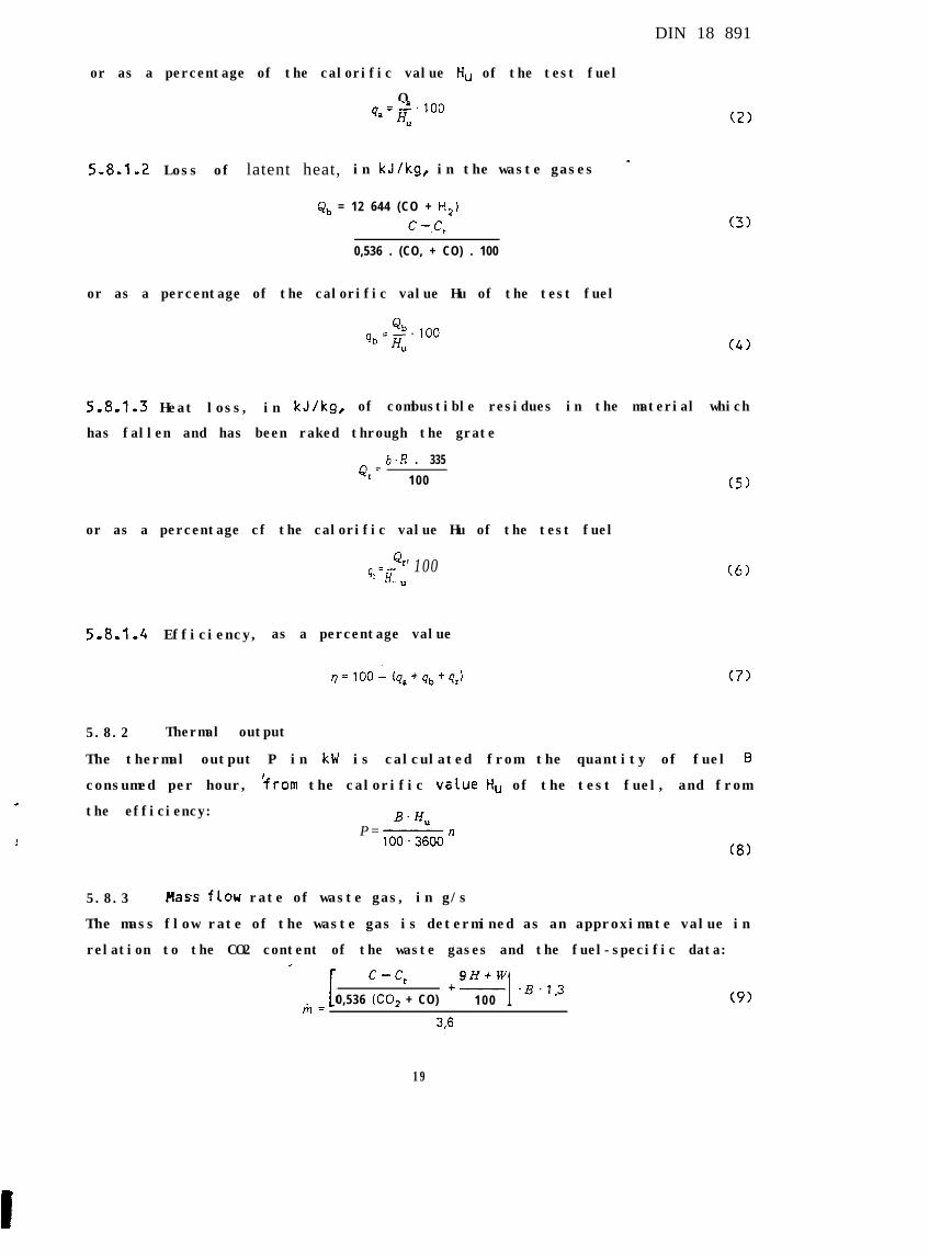
5.8-1.1 Loss of free heat, in kJ/kg, in the waste gases
/ c-c,Qa= 'pm.'0,536. (CO, + CO)
+,CJ*.9H+F-100 1 . u* - f*)
(1)
18
DIN 18 891
or as a percentage of the calorific value flu of the test fuel
Q4, = 2%. 100
H”
5.8.1.2 Loss of latent heat, in kJ/kg, in the waste gases _
Qb = 12 644 (CO + Hz)
c -.c,
0,536 . (CO, + CO) . 100
or as a percentage of the calorific value Hu of the test fuel
Q4.100qb =H,
(2)
(31
(41
5.8.1.3 Heat loss, in kJ/kg, of combustible residues in the material which
has fallen and has been raked through the grate
b. R . 335Q,=
100 (51
or as a percentage cf the calorific value Hu of the test fuel
Q,q+- '100u (61
5.8.1.4 Efficiency, as a percentage value
q= 100 - (qa+qb+qJ (71
5.8.2 Thermal output
The thermal output P in kW is calculated from the quantity of fuel B
consumed per hour, $rom the calorific vc?lue H, of the test fuel, and from
the efficiency:P=
B. H,
100.3600n(8)
5.8.3 Mass flou rate of waste gas, in g/s
The mass flow rate of the waste gas is determined as an approximate value in
relation to the CO2 content of the waste gases and the fuel-specific data:,
c - c, 9Lltw
0,536 (CO, + CO)f- .B.1,3
100 1 (91m=33
19
5.8.4
B
b
C
CO
CO2
Cr
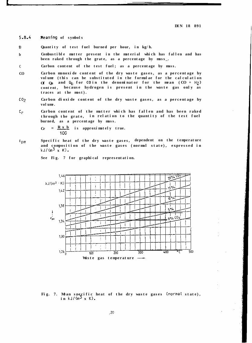
Cpm
DIN 18 891
Pleaning of symbols
Quantity of test fuel burned per hour, in kg/h.
Combustible matter present in the material which has fallen and hasbeen raked through the grate, as a percentage by mass_.
Carbon content of the test fuel; as a percentage by mass.
Carbon monoxide content of the dry waste gases, as a percentage byvolume (this can be substituted in the formulae for the calculationOf Qa and Qb for CO in the denominator for the mean (CO + Hz)content, because hydrogen is present in the waste gas only astraces at the most).
Carbon dioxide content of the dry waste gases, as a percentage byvolume.
Carbon content of the matter which has fallen and has been rakedthrough the grate, in relation to the quantity of the test fuelburned, as a percentage by mass.
R x bCr = - is approximately true.1CC
Specific heat of the dry waste gases, dependent on the temperatureand composition of the waste gases (normal state), expressed inkJ/(m3 x K1.
See Fig. 7 for graphical representation.
kJ/(m3
Waste gas temperature -
Fig. 7. Mean specific heat of the dry waste gases (normai state),in kJ/(m3 x K).
,.20
DIN 18 891
H
HU
lil
11
P
Qa
Qb
Qr
qa
qb
qr
R
ta
trw
5.9
Hydrogen content of the test fuel, as a percentage by mass.
Calorific value of the test fuel, in kJ/kg.
Mass flow rate of waste gas, in g/s.
Efficiency, as a percentage.
Thermal output, in kW.
LOSS through free heat present ,in the waste gases, in relation tothe unit of quantity of the test fuel, in kJ/kg.
Loss through latent heat present in the waste gases, in relation tothe unit of quantity of the test fuel, in kJ/kg.
Heat loss due to combustible components in the material which hasfallen and has been raked through the grate, in relation to theunit of quantity of the test fuel, in kJ/kg.
Proportion of the loss due to free heat in the exhaust gases Q,in relation to the calorific value H, of the test fuel, as apercentage.
Proportion cf the loss due to latent heat in the exhaust gases Qbin relation to the calorific value H, of the test fuel, as apercentage.
Proportion cf the energy loss due to combustible components bin thematerial which has fallen and has been raked through the grate Q,,in relation to the calorific value H, of the test fuel, as apercentage.
Material which has fallen and has been raked through the grate, inrelation to the burned test fuel, as a percentage by mass.
Waste gas temperature, in OC.
Ambient temperature, in OC.
Water content of the test fuel, as a percentage by mass.
Test reportNeither the full text nor any extracts from the test reports shall be
published.
6 Insta l lat ion and operat ing instruct ions
Every stove shall be accompanied by operating instructions in the German
language, which shall contain all necessary details in respect of
installation, suitable fuels, operation, servicing and maintenance, etc.
6.1 Instat lation instructionsThe installation instructions for a given fuel shall contain the following
details:
a> Operation with the fi.re box open:
- mass flow rate of waste gas, in g/s;- waste gas temperature after the waste gas pipe stub, in OC;- minimum delivery pressure at rated thermal output, in mbar.
21 .
DIN 18 891
b> Operation with the fire box closed:
- mass flow rate of waste gas, in g/s;
- waste gas temperature after the waste gas pipe stub, in OC;
- minimum delivery pressure at rated thermal output, in mbar;_- minimum delivery pressure at 0.8 x rated thermal output, in mbar;
- nature of chimney use by the stove.
In the case of stoves of Model 1, connection to multiple-use chimneys is
possible; the dimensions of the chimney are covered by DIN 4705, Part 3.
In the case of stoves of Model 2, connection shall be made to an individual
chimney; the dimensions of the chimney are covered by DIN 4705, Part 1 or
Part 2.
In addition, indications shall be given of the room ventilation necessary to
ensure an adequate supply of combustion air, and in order to take account of
the building regulations applicable in each case to the installation work
and to the connection to the chimney.
6.2 Operating instructions
The operating instructions shall contain the following details:
Directions relating to operation with:
- suitable types and grades of fuel, with which the stove satisfies the
requirements of this standard.
- operation cf the fuel selector, if appropriate.
- a direction in the case of Nodei 1 stoves to the effect that the fire box
shall be kept closed at all times, except during servicing, including
during periods when the stove is not in use.
- all necessary instructions relating to normal operation.
- all necessary instructions relating to operation during the transitional
period at external temperatures of more than 15OC (e.g. frequent raking,
further opening of the regulator).
- instructions relating to cleaning.
- instructions relating to operation with the fire box open. The stove shall
bear the instruction "Bedienungsanleitung beachten" (see operating
instructions) in a permanent and clearly visible manner. None of the other
printed material issued by the manufacturer shall contain details which
contradict the operating instructions.
22
DIN 18 891
7 Marking
The stove shall bear the following marking in a clearly visible position on
a permanently legible and permanently attached rating plate, or in
characters cast into the stove:
a> Manufacturer and/or registered trade mark;
b) Type designation;
c> Model;
d) DIN Test and Control Mark, with registered number;
e1 Rated thermal output.
These details shall agree with the information contained in the printed
material issued by the manufacturer.
Note: It is recommended that the rating plate be executed in accordance withDIN 825 Part 1, uith characters in accordance with DIN 1451 Part 1.
Approval to bear the DIN Test and Control Mark will be granted if the stove
corresponds to the requirements of this standard in all respects, and if the
manufacturer has demonstrated compliance with the standard in the form of a
test report from a recognized testing station and has received a
registration number from the FNH office in response to an application.
Applications shall be addressed to the headquarters cf the FNH.
Through this approval, the manufacturer confirms that the stove complies
with this standard.
Standards and other documents referred to in the text
DIN 823DIN 824DIN 825 Part 1DIN 1298
DIN 1451 Part 1DIN 4705 Part 1
DIN 4705 Part 2
DIN 4705 Part 3
DIN 7168 Part 1DIN 18 890
Technical drawings; Sheet sizes.Technical drawings; Folding to filing formats.Plate dimensions; Square and rectangular plates.Connecting pieces for heating installations; Pipes, bendsand elbows made of metal, for waste gases.Lettering; Sanserif Linear-Antiqua; General.Calculation of chimney dimensions; Terminology; Detailedcalculation procedure.Calculation of chimney dimensions; Approximation procedurefor single-use chimneys.Calculation of chimney dimensions; Approximation procedurefor multiple-use chimneys.General tolerances; Longitudinal and angular dimensions.Controlled-combustion stoves for solid fuels.
First/Decree relating to the Implementation of the FederalGerman Immision Control Act (Erste Verordnung turDurchfShrung des Bundesimmissionsschutzgesetzes).
DIN 18 891
Explanatory Notes
The "Stoves" ("Kamin6fen") Working Committee of the FNH (the Heating and
Cooking Appliances Standards Committee) has compiled this standard as part
of its standardization work in response to a reque_st from the
AREGEBAU-Arbeitskreises Haustechnische Anlagen organization.
The standard contains requirements in respect of design and operation,
safety requirements, and the relevant test requirements for factory-built,
ready-to-install fireplaces for solid fuels with a fire box opening into the
room in which the fireplace is installed or closed by means of a sight
glass, which correspond to the current state of the art.
International Patent Classification
F 24 B 1-18
24