Embed Size (px)
Citation preview

Fachtagung “Experimentelle Strömungsmechanik” 6. – 8. September 2016, Cottbus
Untersuchungen zur thermoelektrohydrodynamischen Konvektion im Zylinderspalt
Investigations on thermal electro-hydrodynamic convection in a cylindrical gap
Martin Meier, Marcel Jongmanns, Christoph Egbers
Department of Aerodynamics and Fluid Mechanics Brandenburg University of Technology (BTU) Cottbus - Senftenberg LG 3A, Siemens-Halske-Ring 14 D-03046 Cottbus, Germany Phone: +49-(0)355-69-4868 Fax: +49-(0)355-69-4891
Schlagworte: Annulus, Dielektrophoretische Kraft, Mikrogravitation
Key words: Annulus, Dielectrophoretic force, Microgravity
Abstract
The objective of our research is to describe a dielectrophoretic (DEP) force driven augmenta-
tion of heat transfer during natural convection in a vertical annulus. Therefore, we execute
experiments on thermal convective flows in a microgravity environment with radial buoyancy
induced by DEP forces, and additionally also the superposition of both buoyancy force fields.
Understanding the heat transport mechanisms in a dielectric liquid confined between two con-
centric cylinders may lead to the improvement of heat exchangers.
Introduction
Within the project “CIC - Convection in Cylinders” we investigate the thermal convection in an
annular cavity, with differentially heated inner and outer cylinders, under the influence of a
centripetal electric force field. Our experiments focus on a dielectrophoretic (DEP) force driven
augmentation of heat transfer during natural convection in a vertical annulus filled with a die-
lectric liquid. Figure 1 gives an overview on the expected flow behavior.
Fig. 1: Schematic representation of the annulus cavity with a radial temperature gradient and different
directions of gravities. The schematics show the expected flow behaviour with axial gravity (left) in
Earth’s gravity environment, DEP force induced radially acting electric gravity gE in a microgravity envi-
ronment (center), and the superposition of both gravities (right).
Copyright © 2016 and published by German Association for Laser Anemometry GALA e.V., Karlsruhe, Germany, ISBN 978-3-9816764-2-6
39-1

The superposition of both forces leads to different flow structures, e.g. columnar or helicoidal,
depending mainly on the temperature gradient and the electrical field force. Therefore, we
execute experiments on thermal convective flows in a microgravity environment with radial
buoyancy induced by DEP forces, and additionally also the superposition of both buoyancy
force fields in laboratory experiments.
A better understanding of the heat transport mechanisms inside a dielectric liquid confined
between two concentric cylinders can deliver solutions for the improvement of the heat
transport in technical applications. Examples are the optimization of heat exchangers or the
improvement of boiler systems to maintain and enhance boiling processes in microgravity con-
ditions (see Snyder and Chung 2000). The DEP force can be used to control the heat transport
in cylindrical systems. The generation of convective motions by the dielectrophoretic force has
been successfully tested in the GEOFLOW experiments that were performed in Fluid Science
Laboratory of the International Space Station (see Futterer et al. 2015) where thermal convec-
tion patterns have been observed in a differentially rotating spherical shell submitted to a die-
lectrophoretic force.
Theory
Theoretical and experimental studies on the convective instability in a dielectric fluid between
two coaxial cylinders were performed e. g. by Chandra and Smylie 1972, Takashima 1980,
Stiles and Kagan 1993, Sitte and Rath 2003, Bahloul et al. 2000, Yoshikawa et al. 2013, Travni-
kov et al. 2015, Egbers et al. 2015, Futterer et al. 2015 and 2016 and Meyer et al., 2016.
A number of parameters are considered to describe the annulus cavity system with dielectric
force field. Figure 2 shows the schematic layout for the cylindrical annulus experiments.
Figure 2: Experiment layout (schematically) and properties of experimental dielectric silicone oils
(Wacker AK5 and AK0.65). The high ac-voltage (up to 10kV) is connected to the inner cylinder whereas
the outer cylinder is connected to ground.
Geometrical parameters are the radius ratio 𝛈 = 𝐑𝟏/𝐑𝟐 and the aspect ratio 𝚪 = 𝐇/𝐝. Param-
eters to characterize the convection are the Prandtl number 𝐏𝐫 = 𝛎 𝛋⁄ and the Rayleigh num-
ber Ra. 𝛒(𝐓) is the temperature dependent fluid density, 𝐑𝟏 and 𝐑𝟐 are the radii of the inner
Copyright © 2016 and published by German Association for Laser Anemometry GALA e.V., Karlsruhe, Germany, ISBN 978-3-9816764-2-6
39-2
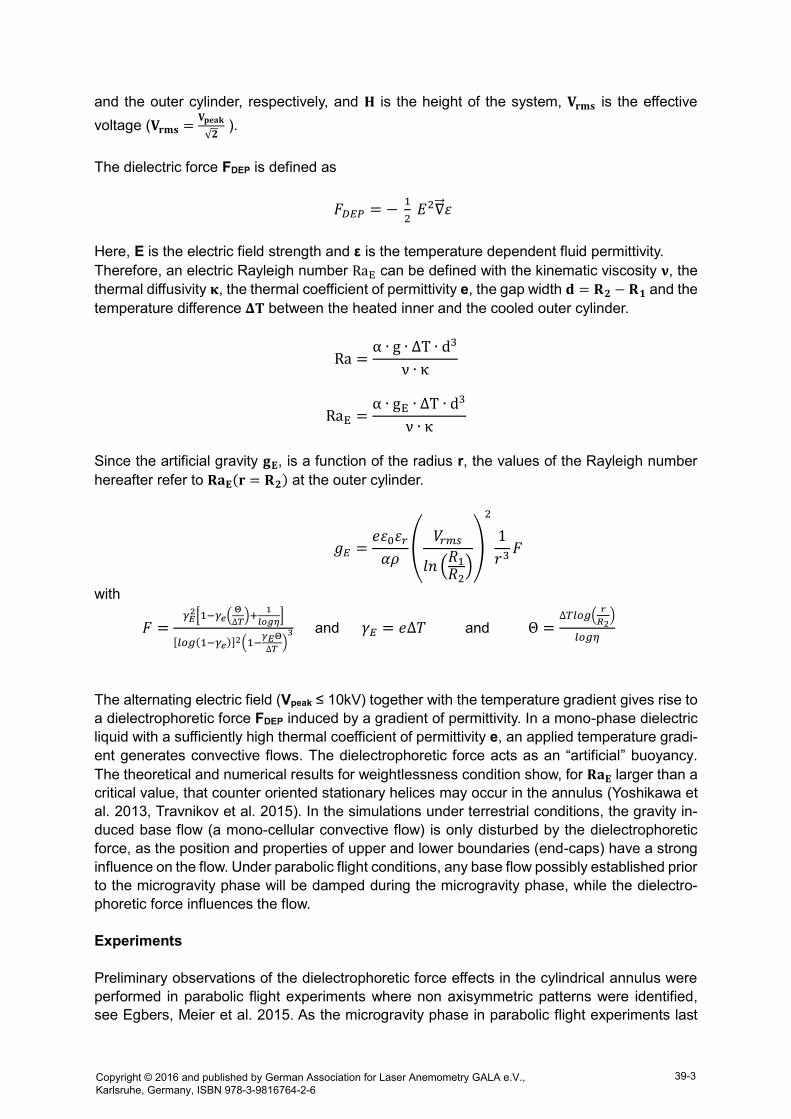
and the outer cylinder, respectively, and 𝐇 is the height of the system, 𝐕𝐫𝐦𝐬 is the effective
voltage (𝐕𝐫𝐦𝐬 =𝐕𝐩𝐞𝐚𝐤
√𝟐 ).
The dielectric force FDEP is defined as
𝐹𝐷𝐸𝑃 = − 1
2 𝐸2∇⃗⃗ 𝜀
Here, E is the electric field strength and ε is the temperature dependent fluid permittivity.
Therefore, an electric Rayleigh number RaE can be defined with the kinematic viscosity 𝛎, the
thermal diffusivity 𝛋, the thermal coefficient of permittivity e, the gap width 𝐝 = 𝐑𝟐 − 𝐑𝟏 and the
temperature difference 𝚫𝐓 between the heated inner and the cooled outer cylinder.
Ra =α ∙ g ∙ ∆T ∙ d3
ν ∙ κ
RaE =α ∙ gE ∙ ∆T ∙ d3
ν ∙ κ
Since the artificial gravity 𝐠𝐄, is a function of the radius r, the values of the Rayleigh number
hereafter refer to 𝐑𝐚𝐄(𝐫 = 𝐑𝟐) at the outer cylinder.
𝑔𝐸 =𝑒𝜀0𝜀𝑟
𝛼𝜌(
𝑉𝑟𝑚𝑠
𝑙𝑛 (𝑅1
𝑅2))
2
1
𝑟3𝐹
with
𝐹 =𝛾𝐸
2[1−𝛾𝑒(Θ
∆𝑇)+
1
𝑙𝑜𝑔𝜂]
[𝑙𝑜𝑔(1−𝛾𝑒)]2(1−𝛾𝐸Θ
∆𝑇)3 and 𝛾𝐸 = 𝑒∆𝑇 and Θ =
∆𝑇𝑙𝑜𝑔(𝑟
𝑅2)
𝑙𝑜𝑔𝜂
The alternating electric field (Vpeak ≤ 10kV) together with the temperature gradient gives rise to
a dielectrophoretic force FDEP induced by a gradient of permittivity. In a mono-phase dielectric
liquid with a sufficiently high thermal coefficient of permittivity e, an applied temperature gradi-
ent generates convective flows. The dielectrophoretic force acts as an “artificial” buoyancy.
The theoretical and numerical results for weightlessness condition show, for 𝐑𝐚𝐄 larger than a
critical value, that counter oriented stationary helices may occur in the annulus (Yoshikawa et
al. 2013, Travnikov et al. 2015). In the simulations under terrestrial conditions, the gravity in-
duced base flow (a mono-cellular convective flow) is only disturbed by the dielectrophoretic
force, as the position and properties of upper and lower boundaries (end-caps) have a strong
influence on the flow. Under parabolic flight conditions, any base flow possibly established prior
to the microgravity phase will be damped during the microgravity phase, while the dielectro-
phoretic force influences the flow.
Experiments
Preliminary observations of the dielectrophoretic force effects in the cylindrical annulus were
performed in parabolic flight experiments where non axisymmetric patterns were identified,
see Egbers, Meier et al. 2015. As the microgravity phase in parabolic flight experiments last
Copyright © 2016 and published by German Association for Laser Anemometry GALA e.V., Karlsruhe, Germany, ISBN 978-3-9816764-2-6
39-3

only 22 seconds, it is necessary to perform an exhaustive investigation of the different effects
of the control parameters of the flow systems in order to isolate the real contribution of the
dielectrophoretic effect compared to the Archimedean buoyancy.
The parameter field of our experiments with η=0.5, max. ΔT=15K and max. Vpeak=10kV is in a
range of the thermal Rayleigh-numbers of up to 6·104 (for Pr=64.6) and 4.8·105 (for Pr=7.65).
The corresponding electrical Rayleigh-numbers are in a range of up to 1.5·104 (for Pr=64.6)
and 1·105 (for Pr=7.65).
Under laboratory conditions, thermal convection experiments are limited to the unidirectional
gravity field of the earth. Other field geometries can be realized with the dielectrophoretic force.
In analogy to large-scale geophysical flows, the thermal convection in a spherical shell under
a central force field is investigated experimentally and numerically under microgravity in the
“GeoFlow” experiment (Futterer et al. 2013). Different optical measurement methods are used
to visualize and/or quantify the flow field inside the gap. Due to the electric high voltage field
in the gap, non-invasive measurement methods should be used. For investigations in a wider
parameter field, we designed a new modular experiment cell system (see figure 4) which will
be used in our next PFC in October 2016.
The inner cylinder is heated by a heating fluid loop using silicone oil as fluid and connected to
high voltage. The outer cylinder is connected to ground potential and is cooled by a cooling
fluid loop, which also uses silicone oil. Inner and outer cylinder are made of Aluminium
(AlMgSi0.5). The top and bottom caps are made of Polymethylmethacrylate (PMMA) to ensure
thermal and electrical insulation. Temperatures of heating and cooling fluid loop are measured
by thermocouples located in the in- and outlets outside the electric high voltage field. With this
heating and cooling system it is possible to generate a temperature difference between the
inner and outer cylinder of up to 10K. To visualize the flow pattern a Schlieren/ Shadowgraph
method is used.
Fig. 4: Design of the new modular experiment cell. For our PFC-experiment in Oct. 2016, the radius of
the inner cylinder is R1 = 5mm and that of the outer cylinder is R2 = 10mm, the gap width is d = 5 m
and its height is H = 30mm. Thus, the radius ratio is η = 0.5 and the aspect ratio is Γ = 6.
Copyright © 2016 and published by German Association for Laser Anemometry GALA e.V., Karlsruhe, Germany, ISBN 978-3-9816764-2-6
39-4
The cell is illuminated from the bottom by a LED with approximate telecentric lighting. The light
rays go through the liquid in the cell and are refracted because of density gradients inside the
fluid. When the temperature changes, the density and the refractive index of the fluid change
and the flow also changes. The image of the flow changes is captured with a camera, which is
focused on the top of the cell. To enhance the contrast a false colour representation is used.
Parabolic Flight Experiments
In parabolic flights we have the opportunity to investigate thermal convection and heat transfer
in three different gravity conditions. Additionally to the (normal) 1g-conditions, there are two
hyper-gravity phases with 1.8g for about 20s and the µg-phase with about 22s during one
parabola. One parabola has 5 succeeding phases of acceleration – 1g, 1.8g, µg, 1.8g and
again 1g. Each scientific PFC has 3 flight days with about 30 parabolas per flight.
Up to now, 5 Parabolic Flight Campaigns (PFC) have been executed successfully by our group
with varying aspect ratios, Prandtl and Rayleigh numbers of the CIC-experimental set-up, see
Egbers et al. 2015 and Futterer et al. 2016. For the next two years we are preparing 2 PFC
with our newly designed experimental set-up. For the CNES-PFC#125 in October 2016 our
new designed experimental set-up contains two experiment cells, which differ in the used fluid.
While Cell A contains Silicone oil Wacker AK5, Cell B contains Wacker AK0.65 (lower kinematic
viscosity). Figure 4 shows the experimental set-up of our next parabolic flight campaign. While
the microgravity time frame in parabolic flights is rather short (22s), we are also preparing a
sounding rocket experiment (TEXUS-program). Onboard a TEXUS-rocket, a µg-time of about
360s can be achieved. Parabolic flights give the opportunity to investigate thermal convection
and heat transfer in three different gravity g conditions.
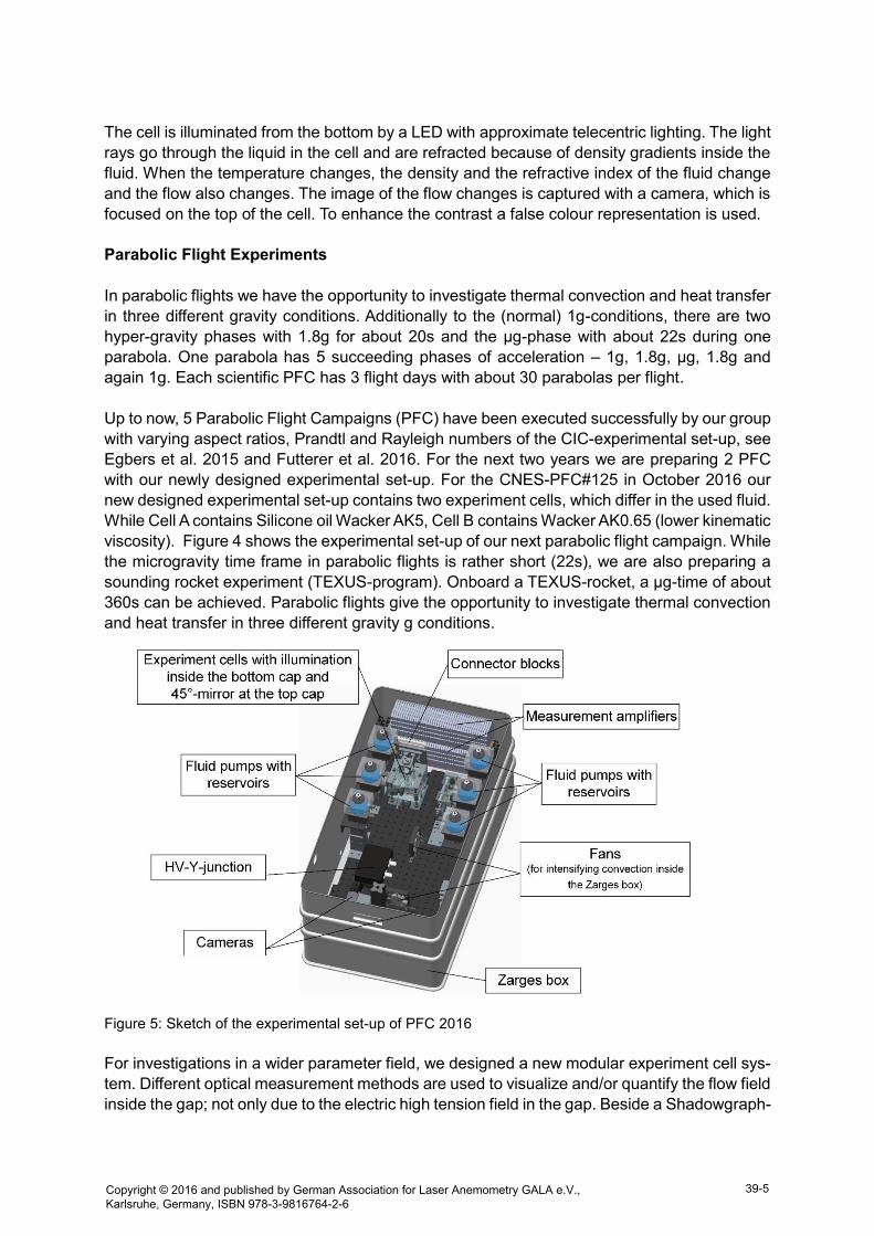
Figure 5: Sketch of the experimental set-up of PFC 2016
For investigations in a wider parameter field, we designed a new modular experiment cell sys-
tem. Different optical measurement methods are used to visualize and/or quantify the flow field
inside the gap; not only due to the electric high tension field in the gap. Beside a Shadowgraph-
Copyright © 2016 and published by German Association for Laser Anemometry GALA e.V., Karlsruhe, Germany, ISBN 978-3-9816764-2-6
39-5
technique to visualize simple flow patterns we are preparing the use of a Back-oriented Schlie-
ren-technique. By means of coating the outer cylinder with a transparent conductive (TCO)
layer we are also planning to perform PIV-measurements. By using PIV we will visualize and
quantify the 2D (later on 3D) flow field inside the gap.
In the following some results of our PFC-experiments in Oct. 2015 are presented. The
shadowgraph-images in figure 6 show the base flow at 1g, 1.8g and at the end of the
microgravity phase. Heating power was set at 80% corresponding to a ΔT of about 7K and no
voltage applied. In the 1g phase one can see an inner structure, corresponding to a higher
temperature due to the heated oil moving towards the top of the cell. This structure is enhanced
during the 1.8g phase. In the microgravity phase there are no structures visible. The
shadowgraph in the microgravity phase (right picture) shows that the buoyancy driven flow
was stopped due to microgravity conditions. This behavior is verified by temperature measure-
ments inside the gap as shown in figure 8.
Figure 6: Shadowgraph pictures taken in succeeding three phases of one parabola – 1g (left), 1.8g
(middle) and µg (right). Vertical annulus with a gap width of 5.1mm and a height of 100mm.
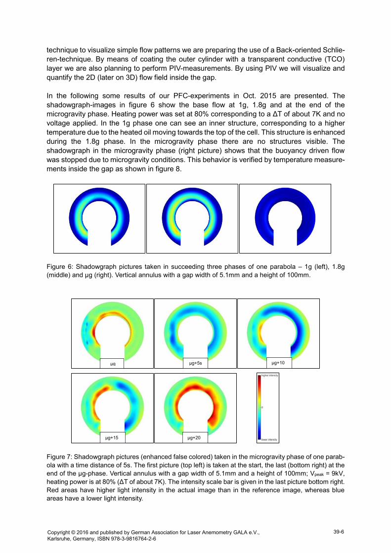
Figure 7: Shadowgraph pictures (enhanced false colored) taken in the microgravity phase of one parab-
ola with a time distance of 5s. The first picture (top left) is taken at the start, the last (bottom right) at the
end of the µg-phase. Vertical annulus with a gap width of 5.1mm and a height of 100mm; Vpeak = 9kV,
heating power is at 80% (ΔT of about 7K). The intensity scale bar is given in the last picture bottom right.
Red areas have higher light intensity in the actual image than in the reference image, whereas blue
areas have a lower light intensity.
µg µg+5s µg+10s
µg+15s
µg+20s
Copyright © 2016 and published by German Association for Laser Anemometry GALA e.V., Karlsruhe, Germany, ISBN 978-3-9816764-2-6
39-6

In figure 7 Shadowgraph pictures taken in the microgravity phase of one parabola with a time
distance of 5s can be seen. For comparison of intensities see the scale bar (picture bottom
right). The enhanced false coloured images show the succeeding development of the flow
during the microgravity phase. The first image is taken at the start of the µg-phase, the
following are taken 5s, 10s, 15s and 20s later in the µg-phase. It takes roughly 15s for the flow
to recover from the 1.8g phase with enhanced buoyancy and to enter another flow state
influenced by the electrical gravity, mainly. This result is verified by the temperature
measurement inside the cell given in figure 8 showing that the temperature distribution over
the height of the cell is nearly equalized at the end of the µg-phase.
Figure 8: Temperature field measured at 6 vertical positions at the outside of the annulus. Plotted accel-
eration shows the 5 succeeding phases – 1g, 1.8g, µg, 1.8g, 1g – of one parabola.
Conclusion
The presented work addresses the stability of a dielectric liquid under a combined action of the
Earth gravity and an electric gravity. Experiments performed in a parabolic flight campaign
2015 confirm the existence of non-axisymmetric modes predicted by theory. Further investiga-
tions are needed for a better description of this complex problem. Results of ongoing numerical
simulations and stability analyses done by two cooperative partners (LOMC-CNRS, University
Le Havre, France, and ICSC-EMCL, University of Heidelberg) will be validated by our experi-
mental results.
Acknowledgement
The work is and has been funded by the German Aerospace Center DLR (grant no. 50WM1644
and 50WM0822). The authors appreciate the support of the technical staff of LAS, Novespace
and CNES. M.M. thanks for fruitful discussions with A. Meyer, LOMC, University of Le Havre,
France.
References
Bahloul, A., Mutabazi, I., & Ambari, A., 2000: “Codimension 2 points in the flow inside a cylindrical
annulus with a radial temperature gradient”, Eur. Phys. J. AP, 9, p. 253-264
Copyright © 2016 and published by German Association for Laser Anemometry GALA e.V., Karlsruhe, Germany, ISBN 978-3-9816764-2-6
39-7

Chandra, B., Smylie, D., 1972: “A laboratory model of thermal convection under a central force field”,
Geophys. Fluid Dyn. 3, p. 211-224
Futterer, B., Krebs, A., Plesa, A.C., Zaussinger, F., Hollerbach, R., Breuer, D., Egbers, C., 2013,
“Sheet-like and plume-like thermal flow in a spherical convection experiment performed under micro-
gravity”, J. Fluid Mech. 735, pp. 647
Futterer, B., Yoshikawa, H., Mutabazi, I., Egbers, C., 2015: “Electric Fields. In: Generation and Appl
ications of Extra-Terrestrial Environments on Earth”, Chapt. 9, Editors: D. A. Beysens, J. J. W. A. van
Loon, ISBN: 9788793237537
Futterer, B., Dahley, N., Egbers, Ch., 2016: “Thermal electro-hydrodynamic heat transfer augmenta-
tion in vertical annuli by the use of dielectrophoretic forces through a.c. electric field”, International Jour-
nal of Heat and Mass Transfer, Elsevier, 93, p. 144–154
Egbers, C., Meier, M., Stoebel, R., Schneidereit, T., Borcia, I.D., Mutabazi, I., Meyer, A., Crumey-
rolle, O., 2015: “Dielectrophoretic flow control of thermal convection in cylindrical gap: A Parabolic Flight
Experiment”, ELGRA conference Corfu, Greece Sept. 29th - Oct. 1st 2015
Meyer, A., Jongmanns, M., Meier, M., C. Egbers, C., Mutabazi, I., 2016, “Thermal convection in a
cylindrical annulus under a combined effect of the radial and vertical gravity”, accepted by Comptes-
Rendus Mécanique (2016)
Sitte, B., Rath, H. J., 2003: “Influence of the dielectrophoretic force on thermal convection”, Experiments
in Fluids 34, p. 24–27
Snyder, T. J., Chung, J. N., 2000: “Terrestrial and microgravity boiling heat transfer in a dielectropho-
retic force field”, Intern. J. Heat Mass Transfer, 43, p. 1547-1562
Stiles, P., Kagan, M., 1993: “Stability of cylindrical Couette flow of a radially polarised dielectric liquid
in a radial temperature gradient”, Physica A, 197, p. 583-592
Takashima, M., 1980: “Electrohydrodynamic instability in a dielectric fluid between two coaxial cylin-
ders”, Q. J. Mech. Appl. Math. 33, p. 91-103
Travnikov, V., Crumeyrolle, O., Mutabazi, I., 2015, “Numerical investigation of the heat transfer in
cylindrical annulus with a dielectric fluid under microgravity”, Phys. Fluids 27, pp. 054103
Yoshikawa, H., Crumeyrolle, O., Mutabazi, I., 2013: “Dielectrophoretic force-driven thermal convec-
tion in annular geometry”, Phys. Fluids, 25, p. 024106-024130
Copyright © 2016 and published by German Association for Laser Anemometry GALA e.V., Karlsruhe, Germany, ISBN 978-3-9816764-2-6
39-8