Embed Size (px)
Citation preview
Vaasa 27.01.2020Supervisor: Professor Martti LarmiAdvisor: DI Kaj Portin

Aalto-yliopisto, PL 11000, 00076 AALTOwww.aalto.fi
Sammandrag av diplomarbetet
FörfattareTitelMagisters program KoodiÖvervakareHandledareDatum Sidantal Språk
Sammandrag
Nyckelord:

Aalto-yliopisto, PL 11000, 00076 AALTOwww.aalto.fi
2
AuthorTitle of thesisMaster Programme CodeThesis supervisorThesis advisor(s)Date Number of pages Language
Abstract
Keywords

Aalto-yliopisto, PL 11000, 00076 AALTOwww.aalto.fi
This thesis has been written on request by the research and development department atWärtsilä Finland Oy in Vaasa. Another thesis investigating the combustion of hydrogenin the Otto process by Alexander Ehrs has been written alongside this thesis. These con-cepts will later be evaluated by Wärtsilä for further development.
I would to thank Kaj Portin and Gilles Monnet at Wärtsilä for the opportunity to writethis thesis. The subject has been interesting and rewarding, as it is a highly discussedmatter. I would also like to thank Mikko Mäenpää for all the support regarding the injec-tor development. Professor Martti Larmi has also supported the thesis well with valuablefeedback in the writing process. As this thesis was written alongside thesis,we have been able to motivate each other in the writing process, as well as gain crossdisciplinary knowledge when researching our subjects.
Vaasa 27.01.2020
Philip Westberg
(i/4)
SammandragAbstractPrefaceTable of content ............................................................................................................. iSymbols ....................................................................................................................... iiiAbbreviation ................................................................................................................ iv1 Introduction........................................................................................................... 1
1.1 Motivation ...................................................................................................... 11.2 Research question ........................................................................................... 11.3 Goal of the work ............................................................................................. 11.4 Scope of the thesis .......................................................................................... 2
2 Theory of internal combustion engines .................................................................. 32.1 The four-stroke cycle [written in cooperation with Ehrs Alexander] ................ 32.2 Spark ignition engines [written in cooperation with Ehrs Alexander] .............. 42.3 Compression ignition engines ......................................................................... 4
2.3.1 Combustion ............................................................................................. 42.3.2 Emmisions ............................................................................................... 62.3.3 Injection .................................................................................................. 72.3.4 Gas injectors ............................................................................................ 9
2.4 Wärtsilä engine ............................................................................................. 102.4.1 Wärtsilä GD........................................................................................... 10
3 Hydrogen [written in cooperation with Ehrs Alexander] ...................................... 123.1 Hydrogen properties [written in cooperation with Ehrs Alexander] ............... 123.2 Hydrogen properties under operating conditions ........................................... 13
3.2.1 Compressibility...................................................................................... 133.2.2 Viscosity................................................................................................ 14
3.3 Hydrogen as fuel in IC engines. .................................................................... 153.4 Characteristics of IC hydrogen engines ......................................................... 18
3.4.1 Otto engines........................................................................................... 183.4.2 Diesel engines........................................................................................ 19
3.5 Alternatives to IC engines ............................................................................. 193.5.1 Gas turbines ........................................................................................... 193.5.2 Fuel cells ............................................................................................... 20
4 Material compatibility with hydrogen .................................................................. 214.1.1 Hydrogen embrittlement ........................................................................ 214.1.2 Wear characteristics ............................................................................... 254.1.3 Compatibility with oil ............................................................................ 254.1.4 Sealant compatibility ............................................................................. 26
5 Hydrogen Industry .............................................................................................. 275.1 Hydrogen production .................................................................................... 275.2 Hydrogen supply........................................................................................... 275.3 Hydrogen compressors .................................................................................. 285.4 Hydrogen safety ............................................................................................ 29
6 Hydrogen Diesel engine concepts ........................................................................ 316.1 Hydrogen only Diesel concepts ..................................................................... 316.2 Hydrogen GD concepts ................................................................................. 34
7 Hydrogen direct injector concepts ....................................................................... 37
ii
7.1 Hydraulically actuated injector...................................................................... 377.2 Piezoelectric actuated Injector ....................................................................... 397.3 Solenoid actuated injector ............................................................................. 417.4 Dual fuel high pressure injectors ................................................................... 41
7.4.1 Wärtsilä GD injector .............................................................................. 418 Injector design ..................................................................................................... 44
8.1 Operating principle ....................................................................................... 448.2 Nozzle designs .............................................................................................. 458.3 Mass flow ..................................................................................................... 468.4 Jet penetration ............................................................................................... 478.5 Injector simulation ........................................................................................ 508.6 Simulation results ......................................................................................... 558.7 Material considerations ................................................................................. 57
8.7.1 Material coating ..................................................................................... 578.7.2 Sealants ................................................................................................. 59
9 Converting an injector for operation on hydrogen ................................................ 619.1 Nozzle holes ................................................................................................. 619.2 Needle and needle seat .................................................................................. 619.3 Injector volyme ............................................................................................. 629.4 Material ........................................................................................................ 62
9.4.1 Injector body ......................................................................................... 629.4.2 Injector seals .......................................................................................... 63
9.5 Hydrogen supply........................................................................................... 649.6 Hydrogen Compressor .................................................................................. 64
10 Conclusions......................................................................................................... 6512 Discussion ........................................................................................................... 6613 References .......................................................................................................... 6714 Appendix .............................................................................................................. 1
iii
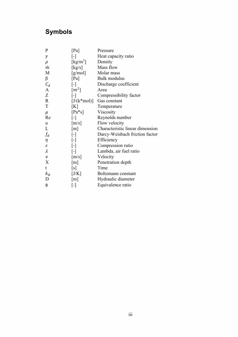
P [Pa] Pressure [-] Heat capacity ratio [kg/m3] Density [kg/s] Mass flow
M [g/mol] Molar mass [Pa] Bulk modulus
[-] Discharge coefficientA [ ] AreaZ [-] Compressibility factorR [J/(k*mol)] Gas constantT [K] Temperature
[Pa*s] ViscosityRe [-] Reynolds numberu [m/s] Flow velocityL [m] Characteristic linear dimension
[-] Darcy-Weisbach friction factor [-] Efficiency [-] Compression ratio [-] Lambda, air fuel ratio [m/s] Velocity
X [m] Penetration deptht [s] Time
[J/K] Boltzmann constantD [m] Hydraulic diameter
[- Equivalence ratio

iv
TDC Top dead centreBDC Bottom dead centreDF Dual fuelGD Gas DieselLNG Liquified natural gasSI Spark ignitionCI Compression ignitionIC Internal combustionEGR Exhaust gas recirculationMDO Marine Diesel oilLFO Light fuel oilHFO Heavy fuel oilERV Electronic rail valveSTP Standard temperature and pressureMHPS Mitsubishi Hitachi power systemsGE General electricNASA National Aeronautics and Space AdministrationPRF Permeability reduction factorIMEP Indicated mean effective pressureBMEP Break mean effective pressurePNNL Pacific Northwest National LabsCFD Computational fluid dynamicsCA Crank angleRPM Revolutions per minuteDLC Diamond like carbonPTFE PolytetrafluoroethyleneFFKM Perfluoro elastomerSCR Selective catalyst reductionPM Particulate matterCO2 Carbon dioxideNOx Nitrogen oxideH2O WaterH2 Hydrogen moleculeO2 Oxygen moleculeNH4 Ammonia moleculeCH4 Methane moleculeCH3OH Methanol moleculeGH2 Gaseous hydrogenLH2 Liquid Hydrogen
(1/74)
1
11.1 MotivationThe transport and energy production industries are facing major shifts in their operationas companies seek to reduce their carbon footprint. The awareness of emissions hasincreased over the last years and will most likely continue to do so, leading to politiciansfacing increased pressure from the general public to do something about the current stateof the environment. It is important that research is done on alternative fuels for the future,since the decisions that are made now will have long term consequences, as it governswhat types of engines are built for ship newbuilds. These engines will continuetheir operation for several decades if only supplied with fuels and spares. While modernengines are more environmentally friendly than older ones, ambitions such as becomingcarbon neutral or perhaps carbon free are a bit farfetched as long as fossil fuels are burnt.That is why research in this field is so important, so that companies and societies cancontinue their operations without sacrificing the environment.
Over the decades that the internal combustion engines have existed the combustible mat-ter has not changed much, until resent years when alternative fuels have been started toenter the market. An early example of these is liquified natural gas (LNG) which is cur-rently used for ship propulsion and electricity generation by internal combustion engines.LNG contains less carbon and more energy compared to traditional fuels, which reducesthe emissions. Nowadays there are several different fuels that are discussed, for ex-ample synthetic methane, ammonia and hydrogen. All of these have their pros and cons,but this thesis will be focusing on hydrogen.
combusted with oxygen the outcomeis water. The idea is to produce hydrogen from excess energy from renewable energysources, which would make hydrogen a green energy carrier for the transport and energysector.
The issue is however that hydrogen is quite challenging and behaves differently than reg-ular fuels such as Diesel. This thesis will therefore investigate possible limitations of run-ning a Diesel engine on hydrogen and how to tackle these problems.
1.2 Research questionHydrogen combustion in internal combustion engines have been researched earlier buthas not yet lead to any widespread commercial solution that runs on 100% hydrogen. Thiswork will investigate what needs to be changed on a current Wärtsilä Diesel engine to runon hydrogen, and specifically the fuel injector of a Gas Diesel engine also known as a GDengine. The GD engine burns gaseous fuels in a in a Diesel process, together with a smallamount of pilot fuel. GD engines are quite rare and untested. This is especially true whenit comes to running hydrogen as the main fuel. The focus of the thesis is the injector andhow to avoid things such as leakage, degradation of the material and how to achieve gooddurability, performance and low emissions.
1.3 Goal of the workThe goal is to learn about current compression ignition engines and their injector technol-ogy and to identify possible design issues with current injectors if they were to operate

2
on hydrogen. These issues should then be addressed and possible solutions to these shouldbe introduced. When this is done a new test setup should be planned for the new injector.
1.4 Scope of the thesisThe scope of this thesis is to learn from previous studies done in house and from otherresearch articles on how a compression ignition hydrogen engine would operate and howthe injection should be designed. This means there will be no actual tests of the injector,since the timeframe is relatively short, and the injector is to be designed and constructedfirst. Other aspects surrounding the engine will also be discussed, these are hydrogenproduction, transport, storage and supply. Less focus will be spent on these. The mainfocus area will be around the injection, combustion, performance and emissions of theengine. Different ways of feeding the engine with high pressure gas will also be discussed.Figure 1 shows the intended scope of the thesis, where the blue box illustrates the focusareas and the smaller boxes outside will be given less attention.
Figure 1. Illustration of the intended scope of the thesis.
3
2 T2.1 The four-stroke cycle [written in cooperation with Ehrs Alex-
ander]The four-stroke cycle used in both Otto and Diesel engines involves an induction, com-pression, power, and an exhaust stroke.1. Intake stroke. The cycle starts with the piston being at its topmost position in the
cylinder, called Top Dead Centre (TDC). While the piston moves down duringthe induction stroke, the volume in the combustion chamber increases, and freshair or fuel/air mixture is drawn into the cylinder past the open intake valve.
2. Compression stroke. At Bottom Dead Centre (BDC) the intake valve closes andthe compression stroke starts. The piston moves upwards again and compressesthe charge, rising the pressure and temperature
3. Expansion stroke. Slightly before the piston reaches TDC, a spark plug, in thecase of an Otto engine, initiates the ignition. The air-fuel mixture ignites, and arapid increase in temperature and pressure can be seen just after TDC. This ex-pansion forces the piston down again during the power stroke.
4. Exhaust stroke. The last stroke begins when the piston reaches BDC. The cylinderis now full of hot exhaust gases. The exhaust valve opens, and the piston travelsupwards, pushing the exhaust gases out of the cylinder. At TDC the exhaust valveclose and the cycle is repeated.
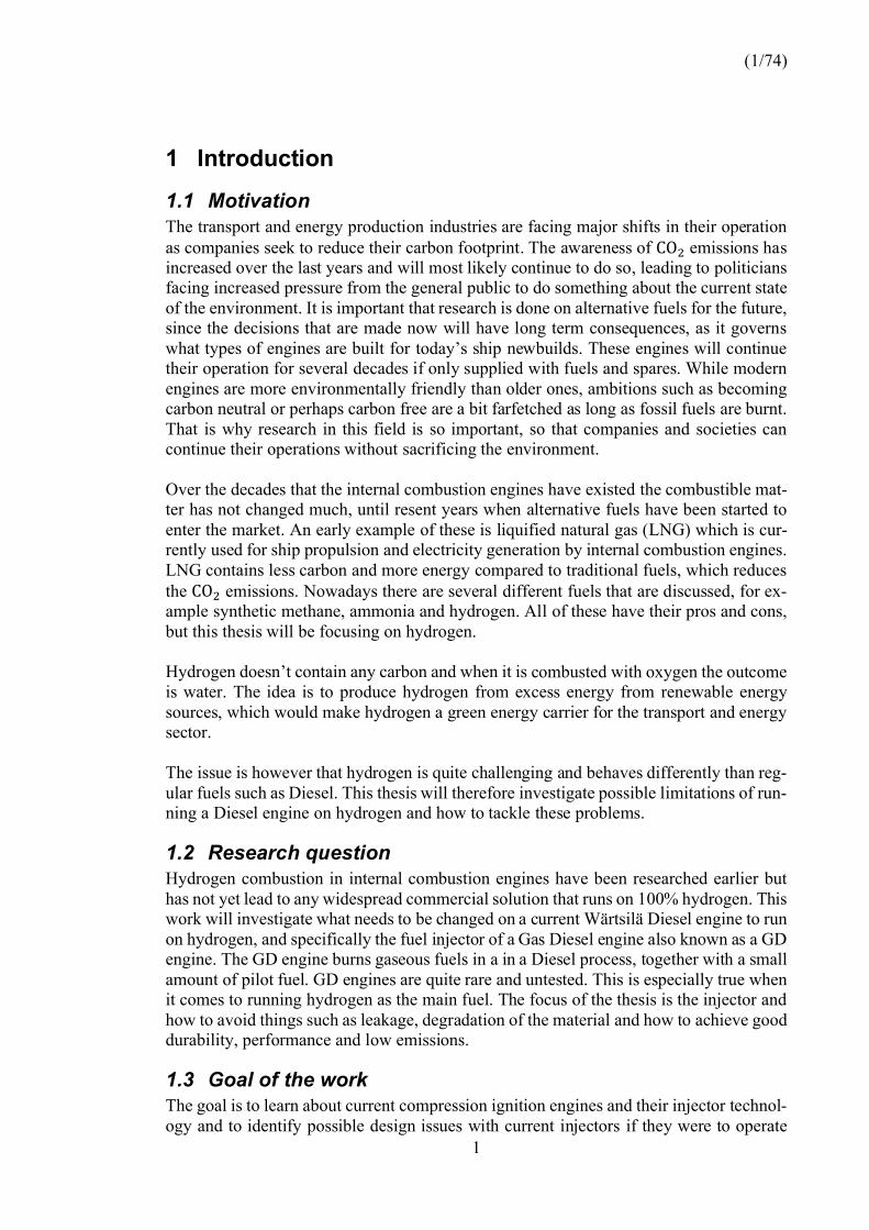
In an ideal Otto-cycle, compression and combustion are adiabatic and isentropic pro-cesses and are independent of time as the combustion occurs instantaneous. Meanwhilein an actual cycle, heat is transferred to the surroundings, and the process is non-reversi-ble. An illustration of these process in a pressure-volume diagram can be seen in figure2. (Heywood, 1988)
Figure 2. PV-diagrams of the four-stroke cycle. (Four-stroke cycle, n.d.)

4
2.2 Spark ignition engines [written in cooperation with Ehrs Al-exander]
A spark-ignition (SI) engine is a type of internal combustion engine which follows theOtto-cycle and converts chemical energy into rotational kinetic energy. Today, most SIengines are of four-stroke type and runs on gasoline or natural gas. Unlike a Diesel enginewhich ignites the fuel through the heat if compression, an SI engine burns a pre-mixedair/fuel mixture. The mixture is ignited by an external source such as a sparkplug or asmall Diesel pilot injection. The first person to construct this type of engine was NikolausOtto in 1878 (Heywood, 1988).
General characteristics compared to a Diesel engine are:1. Running on premixed charge which leads to lower amounts of exhaust gas emis-
sions, requiring less after-treatment equipment.2. Separate and controlled ignition system.3. Higher engine speed due to running on homogenous pre-mixed charge4. Lower compression ratio (CR) to prevent knocking, and thus also a lower thermal
efficiency of the engine.5. Lower engine weight as the engine can be built less sturdy.
2.3 Compression ignition engines
2.3.1 CombustionCompression ignition engines are based on the four-stroke principle, with the regular in-duction, compression, expansion and exhaust strokes seen in figure 2. As the name im-plies, compression ignition (CI) engines use the heat of the compression to ignite the fuel,compared to SI engines that use a spark to ignite the fuel. These engines were inventedby Rudolf Diesel and are commonly called Diesel engines. CI engines were designed torun on less refined fuels and CI engines usually offer better torque and fuel economycompared to SI engines. CI engines are commonly used in heavy industrial applicationsdue to its cheaper fuel and engine characteristics.
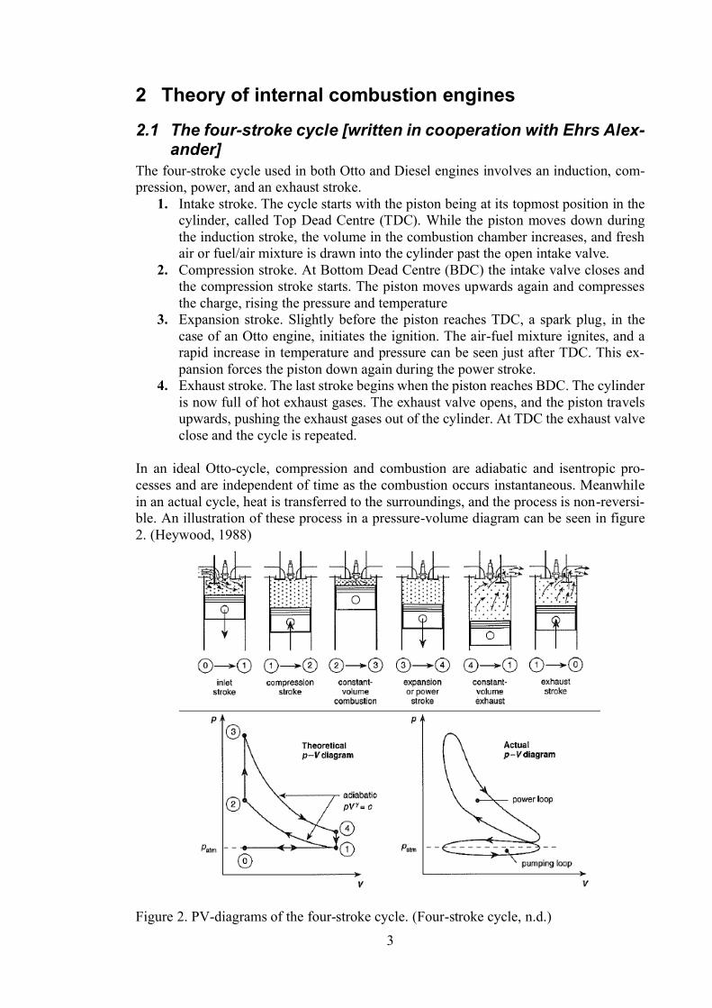
CI Diesel engines use late injection of the fuel at high pressure at around 1450 to 2000bar depending on the system (Van Basshuysen, R., 2004). The injected fuel evaporatesand mixes with the hot air and ignites. CI engines have a short timespan for the fuel tomix with the air, that is why good mixing and atomization of the injected fuel is important.The CI combustion phenomena can be described as a combination of a premixed anddiffusion combustion and can be divided in to three phases. The initial phase when thefuel is injected before the autoignition takes place is called the ignition delay time, whichallows for some mixing to take place and that is why the mixture is close to homogenousin this phase. When this mixture ignites it causes for a rapid increase in pressure and isalso the source of the characteristic noise that Diesel engines have. The second phase orthe main combustion is a mixture-controlled diffusion combustion, which is characterisedby fast chemistry and mixture-controlled combustion. The end of this phase is character-ized by the peak combustion chamber temperature. In the third phase the temperature andpressure of the flame front have dropped, and the chemistry is slow and is therefore adiffusion combustion. These phases are illustrated in figure 3.
5
Figure 3. Illustration of the combustion phases of Diesel in a compression ignition engine.(Van Basshuysen, R. 2004)
The ignition delay affects several aspects of the Diesel combustion process. For a shortignition delay less fuel is injected for the start of the combustion. This causes a lowerpressure and temperature increase at the start of the combustion, which puts less stress onthe mechanical components. The lower combustion temperature also results in lower NOxemissions. The downside is a higher specific fuel consumption and increased soot for-mation. This is due to the larger amount of fuel being injected into the hot flame afterignition and the slow mixing of fuel and air. The soot formation is due to a crack reactionwith local zones of insufficient air and high temperature. A longer ignition delay timewill have the opposite effect, lover soot and fuel consumption but higher temperature andpressure, which causes higher NOx formation. Shorter ignition delay can be achieved byphysical properties such as:
High gas temperature and pressureStrong atomization of fuelHigh relative speed of the fuel and air
(Van Basshuysen, R., 2004).
These properties cause the fuel to evaporate quickly, which promotes rapid distributionand mixing. Higher gas temperature and pressure can be achieved by:
High compression ratioLate injection timing, superchargingHigh coolant temperatureCombustion chamber design that changes the influence of the cylinder wall tem-peratureUse of ignition aids such as glow plugs and intake air heating
(Van Basshuysen, R., 2004).
The chemical properties of the fuel also have a major impact on the ignition delay for CIengines. High cetane number, which means a higher auto-ignition temperature, allows forhigher pressure and temperature in the combustion chamber (Van Basshuysen, R., 2004).

6
There are also other ways to manipulate the combustion in CI engines. Swirl is commonlyused to increase the turbulence in the engine. This increases the mixing of the air and thefuel. This can increase the heat release rate with the risk of increasing the NOx emissions.Increasing the injection pressure can improve the homogeneity of the charge by allowingfor more mixing of the fuel and air, this also increases the NOx emissions, but increasesthe heat release rate and reduces soot formation. Exhaust gas recirculation (EGR) is aneffective way of reducing the NOx emissions by lowering the oxygen content in thecharge air, which lowers the combustion temperature. While NOx is decreased the re-duced oxygen content will increase the particulate matter (PM) (Zheng, 2004).
An alternative to the conventional direct injection method is indirect fuel injection wherethe combustion is divided in a main combustion chamber and a secondary combustionchamber. The secondary combustion chamber is in the cylinder head and the main com-bustion chamber is formed by the cylinder and piston head. These combustion chambersare connected by a smaller recess in the cylinder head. The secondary combustion cham-ber can either be formed as a pre-chamber or a swirl-chamber. Both use moderate fuelinjection pressure into the secondary chamber. The fuel is quickly mixed with the air, thatis generated from the compression stroke, flowing through the recess. This creates a shortignition delay. The pressure then increases quickly in the secondary combustion chamberwhich causes the partially burning fuel-air mixture to move to the main combustion cham-ber where the mixture efficiently mixes with the air rich main combustion chamber. Thiscombustion process tends to produce more soot due to the lack of air in the secondarycombustion chamber. The positive side is a reduction in NOx and a smother operation ofthe engine. (Van Basshuysen, R., 2004)
2.3.2 EmmisionsDiesel engine operates under unthrottled lean conditions with an excess air ratio between1,2 at high load and 7 when idling, this gives the Diesel engine improved fuel consump-tion and less emissions. Compared to spark ignited engines Diesel engines have gen-erally around 20% lower emissions (Van Basshuysen, R., 2004).
The major consideration for Diesel engines is particulate matter and nitrogen oxide emis-sions. The particulate matter consists mainly of soot which is mainly deposited by hydro-carbon or sulphur compounds. Conditions in the combustion chamber have a direct rela-tion to the type and amount of pollutants produced.
Soot and nitrogen oxide pollutant formation are influenced by reaction kinetics, whichare not completely understood, but from experimental work with combustion in flameand shock wave tubes following conclusions can be made. Soot formation is limited bythe excess air factor and temperature but is independent on the predominant pressure. ForDiesel engines the maximum soot formation occurs at about 1600 K and with an excessair factor below 0,6. If the mixture temperature is held below 1450 K and excess air factorgreater than 0,8 the soot formation is negligible (Van Basshuysen, R., 2004).
The NOx formation can be divided into the formation of the two main components ofNOx, nitrogen monoxide (NO) and nitrogen dioxide ( ). The maximum formation ofNO occurs at 2200-2400 K. NO is quickly formed in the in the flame front from a sidereaction of OH radicals that form other compositions with the nitrogen molecules. The
formation is also mainly formed at the flame front, the ratio of NO and is mainly

7
governed by the oxygen concentration and dwell time. The maximum NOx formationoccurs in the slightly leaner region of (Van Basshuysen, R., 2004).
The contradicting conditions for low soot and NOx means that there must be some com-promises between the two. There are some methods that is beneficial to both NOx andparticulate emissions. Using a small pre-injection of fuel can reduce NOx and particleemissions. Secondary injection can also reduce particle emissions while NOx stays con-stant. Shorter closing time of for example piezo injector help reduce particle emissions.Exhaust gar recirculation can reduce NOx emissions at the cost of increasing particleemissions, but cooled EGR can have a beneficial effect for them both. With higher injec-tion pressure the contradiction between NOx and particle can be managed better withdifferent nozzle designs and different injection timing (Van Basshuysen, R., 2004).
These methods are applied and tested on Diesel combustion which might not translatedirectly into hydrogen combustion where soot is less of a problem and NOx is predictedto be a larger one due to increased combustion pressure and temperature. Soot emissionsshould be less of a problem since there is no carbon in the fuel, the only possible sourceof soot would be combustion of possible pilot fuel and lubricating oil. This means com-bustion strategies for reduced NOx should be preferred over the soot reducing methodsfor an engine running on hydrogen.
2.3.3 InjectionFuel injection has a major effect on the performance of the engine. With regards to asingle injection per power cycle the major variables are start of fuel injection and durationof the injection. The goal is to create the optimal mixture of fuel and air and the optimumdistribution of the fuel-air mixture. By doing so the optimum fuel consumption and emis-sions are reached. Limiting factor are usually the mechanical stresses from the combus-tion and balancing the fuel consumption with NOx and particle emissions (Van Bas-shuysen, R., 2004).
With regards to the injector itself it is important that the injector is capable of injectingthe appropriate amount of fuel within a certain timespan, with good dynamic responseand minimum leakage. Large engines usually use jerk pumps or unit-pump system forDiesel direct injection. This is an old and reliable way of injecting Diesel. Each cylinderis supplied with their own pump and injector. A more modern way is to use common railinjection consisting of a pressure rail that supplies each injector on the cylinder headswith high pressure fuel. It is important that the accumulator volume is capable of dampingthe pressure fluctuation caused by the fuel pulses from the fuel pump and injectors(Bosch, R., 2011).
One common type of injector used is the servo-valve injector. The injector can be dividedin to following functioning modules: nozzle, hydraulic servo and solenoid valve. Thebasic operation of the injector is the following: when the injection starts the injector is inits resting position, where the solenoid valve spring presses the valve ball into the seatrest. To start the injection, an electric current is sent to the solenoid which opens thesolenoid valve, which operates a hydraulic servo system. The magnetic force of the trig-gered electromagnetic armature is larger than the solenoid valve spring, which rises thevalve ball from the valve seat and opens the outlet restriction. When the solenoid is nolonger triggered the solenoid-valve spring close the fuel flow by pressing down the ballvalve back down on the valve seat. This method is used to control the hydraulic servo

8
system that can lift the nozzle needle, since the solenoid is not strong enough to lift it byitself (Bosch, R. 2011).
The injector nozzle is a highly important element of the injector with the task of atomizingliquid fuels, distributing the fuel in the combustion chamber and sealing the hydraulicsystem from the combustion chamber. The nozzle construction needs to be perfectlymatched to the engine conditions. Things to consider are:
Combustion processGeometry of combustion chamberNumber of injection jetsSpray shape and directionInjection time and rate
There are several different nozzle designs used where pintle nozzles and hole nozzles arethe major groups, some of them are illustrated in figure 4.
Figure 4. Illustration of different nozzle shapes. (Harianton, I., 2006)
Pintle nozzle commonly operate at lower pressures with good penetration of the fuel,since the flow from the single hole is greater than in the hole nozzle. Pintle nozzles doesnot offer the best atomization of the fuel. Hole nozzles on the other hand require higherfuel pressure but offer better distribution of the fuel without much turbulence in the com-bustion chamber. The number of holes used can wary from 3 to 18 and depends largelyon the amount of turbulence in the combustion chamber, the higher the turbulencethe fewer holes are needed (Van Basshuysen, R., 2004). Figure 5 summarises the injec-tion variables for a common rail system and gives a better overview of the whole injectionsystem.

9
Figure 5. Primary influencers of the injection jet.
2.3.4 Gas injectorsGas injectors have their own specific challenges compared to injectors dealing with liq-uids. Gases have a lower density which means a larger volume must be injected. Thiscalls for relatively high pressure on the injector side, which creates a high flow velocity.These flows can reach sonic speeds and becomes choked if the pressure difference aheadof the nozzle is around 2,1 times as high as the pressure in the combustion chamber(Bosch, R., 2011). The critical pressure difference is calculated according to equation 1.
(1)P1 and P2 represents the pressure before and after the nozzle and is the heat capacityratio of the gas. For air and hydrogen, the heat capacity ratios are around 1.4 (Lange, N.).When the flow becomes choked the volumetric flow rate is independent of the down-stream pressure. This means the mass flow rate can only be increased by increasing wordsincreasing the pressure upstream of the nozzle. The choked mass flow through the nozzlecan be calculated according to following equation (Perry, J.H., 1997):
(2)
(3)
Where is the density of the gas, the pressure of the gas ahead of the nozzle, isthe discharge coefficient and is the orifice area. The orifice area for a pintle nozzle isdefined as truncated cone with a maximum area of
(4)With limited supply pressure it is important to optimize the flow through the injector tominimise throttling points that could reduce the pressure before the nozzle.
The fuel injection process can be divided in to two phases: the flow of gas in the injectorand nozzle, the transition of fuel flowing from the injector tip to the combustion chamber.The second phase is basically injection of a gaseous fuel into another gaseous medium.Under assumption that the pressure difference between the nozzle inlet and outlet is suf-ficiently high, the outlet flow from the injector tip is choked with a velocity of Mach one.
10
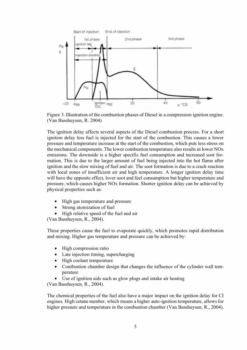
Mach one is defined as the local flow velocity divided by the speed of sound in the re-spective media. This pressure difference creates an underexpanded jet that rapidly ex-pands into the surrounding medium with a lover ambient pressure, illustration of an un-derexpanded jet is presented in figure 6. The expansion causes the jet to accelerate, whichcreates expansion waves (Verhelst, S., 2009). There are three basic flow directions in thejet, due to the strong shock wave. These directions are: outwards flow (yellow arrow)caused by the expansion waves in radial direction, inward flow (green arrow) due to thecompression waves, parallel flow (blue arrow) as a result of the expansion waves in inthe same axis as the jet (Yu, J., 2012).
Figure 6. Illustration of the near field of a highly underexpanded jet a jet (Yu, J., 2012)
The expansion waves are reflected as compression waves after meeting the outer bound-ary of the jet. The compression waves merge and form a barrel like structure. The barrelstructure ends with a disk like shock wave called a Mach disk. The Mach disk enclosesa region with supersonic flow. At sufficiently high pressures this structure can be repeatedseveral times. Downstream of the final Mach disk the flow is subsonic (Verhelst, S., 2009,p. 501). The Location of the Mach disc can be calculated as:
(5)D represents the diameter of the nozzle (Yu, J.., 2013). According to Hamzehloo et. alsimulation on near nozzle structures and mixing of gaseous jets the main air-fuel mixingoccurs after the Mach disk location and especially close to the jet boundary where intenseturbulence was observed (Hamzehloo A., 2014). This should limit the possibility of flash-backs, fuel burning back upstream of the flow, into the injector.
2.4 Wärtsilä engine
2.4.1 Wärtsilä GDWärtsilä gas Diesel is an engine that is designed to operate on two or multiple differentfuels in two different modes: Liquid fuel mode or Gas fuel mode. Liquid fuel mode usesmarine Diesel oil (MDO)/ Light fuel oil (LFO), heavy fuel oil (HFO) or crude oil as mainfuel while the engine is working as an ordinary Diesel engine. In gas fuel mode the engineuses natural gas as main fuel, which is ignited with a small amount of liquid fuel. In thismode and at high load the engine is using direct injection of natural gas into the combus-tion chamber, while at lower load and at start, Diesel fuel is used. An illustration of the

11
transfer between fuels at different loads is presented to the left in figure 7 and the basicoperation cycle is presented to the right in figure 7.
Advantages for Gas Diesel operation are output and thermal efficiency of an optimizedDiesel engine. A GD engine uses a higher compression ratio than traditional dual fuel(DF) engines and are therefore more efficient. There is also no need for deration of engineoutput depending on methane number (measure of methane content and effectively knockresistance for natural gases). This gives the Gas Diesel engine a wider fuel flexibility andtolerance of fuel quality. The amount of unburnt methane is very low for the GD engine,where the natural gas is burnt under the Diesel process compared to Otto or the so-called
engines. The combination of cleaner fuel and Diesel like com-bustion also gives the engine a high thermal efficiency with low emissions (Wärtsilä,2011). These are promising qualities for an engine if it would be adapted to run on hy-drogen.
The main modification between a regular Diesel engine and gas Diesel engine is the in-jector and fuel supply system. The gas is fed through a common rail system to the injec-tors. The injector is a combined Diesel and gas injector that has one centrally locatedDiesel needle with three surrounding gas needles. The gas needles are controlled withhydraulic oil from an electronic rail valve (ERV). The Diesel needle is controlled withfuel pressure from the jerk pump (Wärtsilä, 2011).
Figure 7. (left) The operating regions is presented in different modes and at differentloads. (right) Operating cycle of the engine in gas mode (Wärtsilä, 2011).
The option to switch the operation to Diesel is seen as an important factor for the hydro-gen engine to initially enter the market. Hydrogen is and will most likely not be availableat all ports in many years even if there is a boom for hydrogen.
12
3 Hydrogen
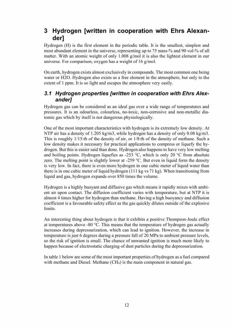
Hydrogen (H) is the first element in the periodic table. It is the smallest, simplest andmost abundant element in the universe, representing up to 75 mass-% and 90 vol-% of allmatter. With an atomic weight of only 1.008 g/mol it is also the lightest element in ouruniverse. For comparison, oxygen has a weight of 16 g/mol.
On earth, hydrogen exists almost exclusively in compounds. The most common one beingwater or H2O. Hydrogen also exists as a free element in the atmosphere, but only to theextent of 1 ppm. It is so light and escapes the atmosphere very easily.
3.1 Hydrogen properties [written in cooperation with Ehrs Alex-ander]
Hydrogen gas can be considered as an ideal gas over a wide range of temperatures andpressures. It is an odourless, colourless, no-toxic, non-corrosive and non-metallic dia-tomic gas which by itself is not dangerous physiologically.
One of the most important characteristics with hydrogen is its extremely low density. AtNTP air has a density of 1.205 kg/m3, while hydrogen has a density of only 0.08 kg/m3.This is roughly 1/15:th of the density of air, or 1/8:th of the density of methane. Such alow density makes it necessary for practical applications to compress or liquefy the hy-drogen. But this is easier said than done. Hydrogen also happens to have very low meltingand boiling points. Hydrogen liquefies as -253 °C, which is only 20 °C from absolutezero. The melting point is slightly lower at -259 °C. But even in liquid form the densityis very low. In fact, there is even more hydrogen in one cubic meter of liquid water thanthere is in one cubic meter of liquid hydrogen (111 kg vs 71 kg). When transitioning fromliquid and gas, hydrogen expands over 850 times the volume.
Hydrogen is a highly buoyant and diffusive gas which means it rapidly mixes with ambi-ent air upon contact. The diffusion coefficient varies with temperature, but at NTP it isalmost 4 times higher for hydrogen than methane. Having a high buoyancy and diffusioncoefficient is a favourable safety effect as the gas quickly dilutes outside of the explosivelimits.
An interesting thing about hydrogen is that it exhibits a positive Thompson-Joule effectat temperatures above -80 °C. This means that the temperature of hydrogen gas actuallyincreases during depressurization, which can lead to ignition. However, the increase intemperature is just 6 degrees during a pressure fall of 20 MPa to ambient pressure levels,so the risk of ignition is small. The chance of unwanted ignition is much more likely tohappen because of electrostatic charging of dust particles during the depressurization.
In table 1 below are some of the most important properties of hydrogen as a fuel comparedwith methane and Diesel. Methane (CH4) is the main component in natural gas.

13
Table 1. Comparison of fuel properties of hydrogen, methane and Diesel at NTP. [1]:Bechtold, R., 1997. [2]: Hysafe. [3]: Staffell, I., 2011. [4]: College of Desert, 2001b.
Property Hydrogen (H2) Methane Diesel UnitMolecular weight [1] 2.01594 16 ~200 g/molMelting point [2] -259 -182 -40 to -1 °CBoiling point [1] -253 -162 188 to 343 °CDensity of gas [3] 0.084 0.791 - kg/m3
Density of liquid [3] 70.78 428 810 890 kg/m3 at BPX
Diffusion coefficient in air [2] 0.756 0.21 - cm2/sFlammability limits in air [1] 4 75 4.4 16.4 1 6 vol - %Auto-ignition temperature [3] 793 1023 813 589 KLower heating value (mass) [3] 120.0 45.9 42.9 MJ/kgLower heat value (volume) [3] 10.1 (g) 35.2 (g) 35900 (l) MJ/m3
Stoichiometric air-fuel ratio(mass) [1]
34.3 17.2 14.7 -
Stoichiometric air-fuel ratio (vol-ume) [1]
2.38 9.52 - -
Methane number 0 100 - -Octane number [4] 130+ 125 30 -Cetane number 40 55 -
3.2 Hydrogen properties under operating conditions
3.2.1 CompressibilitySince hydrogen is such a low-density gas it must be compressed or stored at high pressure.This changes the density of the gas and thus the volumetric energy content of the gas. Athigher temperatures and pressures gases tend to act different than ideal gases. The com-pressibility factor is a correction factor to compensate for the deviation from the ideal gasbehaviour. Figure 8 shows a graph of the compressibility factor for hydrogen as functionof pressure. If the injector operates at around 350 700 bar the compressibility factor isin the range of 1,2 to 1,4; which results in a density of 30-40 (0.089 atNTP) at respective pressures lowing formula:
(6)Where p is the pressure in Pascal, the density, R the specific gas constant and T thetemperature in kelvin. This requires of course that the compressibility factor is known.It can be found from tables or calculate from following equation (Lemmon, E.W.,2008).
(7)
Values for the , , constants can be found in appendix 1.

14
Figure 8. Compressibility factor as a function of pressure for hydrogen (HydrogenTools,a).
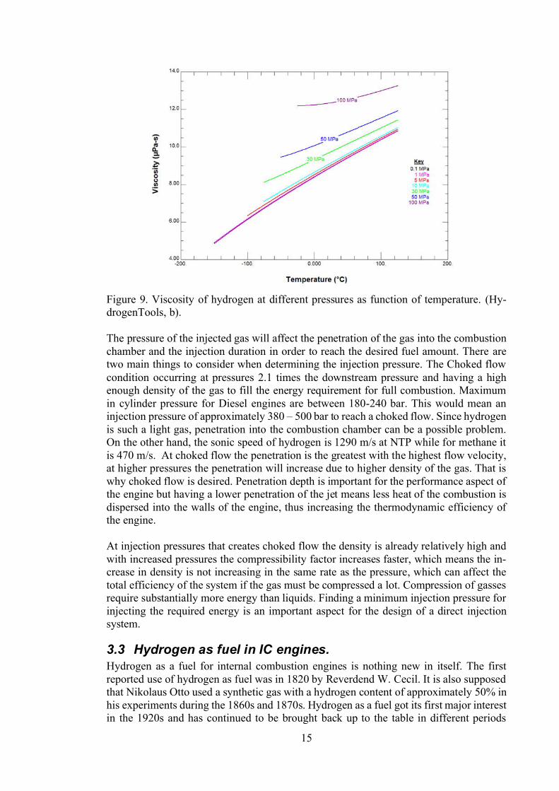
3.2.2 ViscosityGases have generally low viscosity, that is especially true with hydrogen. The viscosityof hydrogen at different pressures is presented in figure 9 as a function of temperature.The pressure is less of an influence on the viscosity than temperature. This can be ex-plained by equation 8 below.
(8)
Where is the Boltzmann constant, m the molecular mass, the mean free path and anumerical constant. Worth noting is that the viscosity increases with temperature forgases compared to liquids that get a lower viscosity at higher temperatures. According tothis, a slightly cooler gas will be beneficial for the injection since it will be denser andhave a lower viscosity. The benefit of having a lover viscosity will however be minorsince the flow velocities are high. This leads to a high Reynolds number for most pointsin the fuel supply. Reynolds number is calculated according to following equation:
(9)Where is the density, the flow velocity, L the characteristic linear dimension andthe dynamic viscosity. When Re is grater then 4000 the flow is considered turbulent. Thepressure loss in a cylindrical pipe can be calculated according to the Darcy-Weisbachequation below.
(10)Where D represents the hydraulic diameter and the Darcy-Weisbach friction factor,which in the case of laminar flow is proportional to . In turbulent flow thefriction factor stays more or less the same for a vide region of flow. The surface rough-ness of the pipe has a significantly bigger influence on the pressure drop than the vis-cosity of the gas.
15
Figure 9. Viscosity of hydrogen at different pressures as function of temperature. (Hy-drogenTools, b).
The pressure of the injected gas will affect the penetration of the gas into the combustionchamber and the injection duration in order to reach the desired fuel amount. There aretwo main things to consider when determining the injection pressure. The Choked flowcondition occurring at pressures 2.1 times the downstream pressure and having a highenough density of the gas to fill the energy requirement for full combustion. Maximumin cylinder pressure for Diesel engines are between 180-240 bar. This would mean aninjection pressure of approximately 380 500 bar to reach a choked flow. Since hydrogenis such a light gas, penetration into the combustion chamber can be a possible problem.On the other hand, the sonic speed of hydrogen is 1290 m/s at NTP while for methane itis 470 m/s. At choked flow the penetration is the greatest with the highest flow velocity,at higher pressures the penetration will increase due to higher density of the gas. That iswhy choked flow is desired. Penetration depth is important for the performance aspect ofthe engine but having a lower penetration of the jet means less heat of the combustion isdispersed into the walls of the engine, thus increasing the thermodynamic efficiency ofthe engine.
At injection pressures that creates choked flow the density is already relatively high andwith increased pressures the compressibility factor increases faster, which means the in-crease in density is not increasing in the same rate as the pressure, which can affect thetotal efficiency of the system if the gas must be compressed a lot. Compression of gassesrequire substantially more energy than liquids. Finding a minimum injection pressure forinjecting the required energy is an important aspect for the design of a direct injectionsystem.
3.3 Hydrogen as fuel in IC engines.Hydrogen as a fuel for internal combustion engines is nothing new in itself. The firstreported use of hydrogen as fuel was in 1820 by Reverdend W. Cecil. It is also supposedthat Nikolaus Otto used a synthetic gas with a hydrogen content of approximately 50% inhis experiments during the 1860s and 1870s. Hydrogen as a fuel got its first major interestin the 1920s and has continued to be brought back up to the table in different periods
16
without any major breakthrough (Norbeck, J.M., 1996). With current increased attentionto the environment the discussion around alternative ways of transportation substitutesfor Diesel and gasoline the discussion of alternative fuels and in this case, hydrogen hasbeen brought back up again.
One possible reason for no major breakthrough for hydrogen is that there are several tech-nical challenges related hydrogen combustion in IC engines. Based on the operation ofinternal combustion engines mentioned above the problems and opportunities of hydro-gen as a fuel for IC engines will be presented for the Otto and Diesel process.
To start with the positive sides, hydrogen has a wide flammability range, which meansthat hydrogen can be burnt at a higher air/fuel ratio than the stoichiometric and chemicalprocess would theoretically need for complete combustion. This typically means a morecomplete combustion with lower exhaust temperature and lower emissions. The downsideto running lean mixtures is a lowered power output. The combustible limit for gasoline is1% of fuel per volume while the stoichiometric value is 1.76%. For comparison the com-bustible limit for hydrogen is 4% of fuel per volume while the stoichiometric value is29.53% (Norbeck, J.M., 1996). The upper flammability limit for hydrogen is 75% of fuelin air, the range is then 4-75%. The flammability limit becomes wider with increasingtemperature, for example the lower limit drops to 2% of fuel per volume at a temperature
, the upper limit hasa more complex relation to pressure, but is less important for engines (Verhelst, S., 2009)
Hydrogen has a high auto-ignition temperature, which is the temperature the mixture hasto reach in order to ignite without any external source of energy. The fuels auto-ignitiontemperature is of major importance when determining the engines compression ratio. Thetemperature during compression is related to following equation
(11)where is the compression ratio, the ratio of specific heat and and are theinitial and the end temperatures. That is why the compression ratio is limited by whichcannot exceed the auto-ignition temperature for Otto engines (Norbeck, J.M., 1996). ForDiesel engines the tables are turned, and instead the engines must reach the auto-ignitiontemperature for the fuel to ignite. Because of the high auto-ignition temperature either thecompression ratio must be exceptionally high or T1 has to be higher. This creates someextreme loads on the engine components for the Diesel case. From the efficiency stand-point, a high compression ratio is desirable since it is related to the thermal efficiency ofthe system if following way
(12)where is the compression ratio and the efficiency. This means that the efficiency caneither be increased by higher compression ratio, which is possible due to the higher auto-ignition temperature, or by increasing the specific heat ratio, which is also possible withleaner mixtures resulting in lower exhaust gases. There is in other words a potential forhydrogen engines to operate with higher thermal efficiency (Norbeck, J.M., 1996).
Hydrogen has a very fast flame speed, which means that at stoichiometric mixtures hy-drogen engines can operate closer to the ideal engine cycle, meaning that the volumeduring combustion stays approximately constant. (Norbeck, J.M., 1996). Although theflame speed is high at stoichiometric and NTP conditions it is highly dependent on sur-rounding conditions. In figure 10 the laminar flame speed is presented as function of

17
lambda. In figure 10 the flame speed of methane and iso-octane is also presented. Thedependency between lambda and flame speed is much stronger for hydrogen. Atthe flame speed approaches the speed of methane and iso-octane. Turbulence will alsoaffect the flame speed in a positive way, but the effect might not be as strong as with otherfuels (Verhelst, S., 2009). Heywood and Vilchis reported an order of magnitude fasterflame speed for propane in turbulent conditions compared to laminar, for hydrogen theorder of magnitude stayed the same, but the turbulent case was still greater than the lam-inar (Heywood J.B. 1984).
Figure 10. Laminar flame speeds as function of lambda at 360 k and 1 bar (Verhelst, S.,2009)
The quenching distance, the distance between the cylinder wall and the point that theflame extinguishes due to heat losses, is less for hydrogen than for gasoline. This meansthat the flame will come closer to the walls and increases the chance of backfire in anOtto engine, since the flame is able to get past a nearly closed intake valve (Norbeck,J.M., 1996).
Diffusivity, the ability to disperse in air, is significantly higher for hydrogen compared togasoline. This promotes faster mixing of the fuel and air and leads to more uniform mix-tures for Otto engines. For Diesel engines the diffusivity will mainly affect the injectedgas jet, which supposedly will incorporate more air and therefore burn differently. Theincreased diffusivity of hydrogen also rises a potential safety hazard in the case of a leak-age in closed environments. With proper ventilation this can be avoided (Norbeck, J.M.,1996).
The extremely low density of hydrogen creates some problems. One is storage, hydrogenhas either to be liquified which occurs at -253 C or compressed to high pressure. Bothmethods require a high amount of energy. The second problem caused by low density ishydrogen will occupy more space in the combustion chamber, thus lowering the energydensity of the fuel-air mixture which leads to a lower power output for the engine. Thisis mainly an issue for pre-mixed Otto engine (Norbeck, J.M., 1996).
18
The lower heating value of hydrogen is 120 MJ/kg, which is significantly higher thanother fuels. However, on a volumetric scale, the lower heating value of hydrogen is only10.1 MJ/m3. This is over three times lower than the equivalent value for methane. Thehigh LHV by mass is one reason why hydrogen has been used in space shuttles (Verhelst,S., 2009).
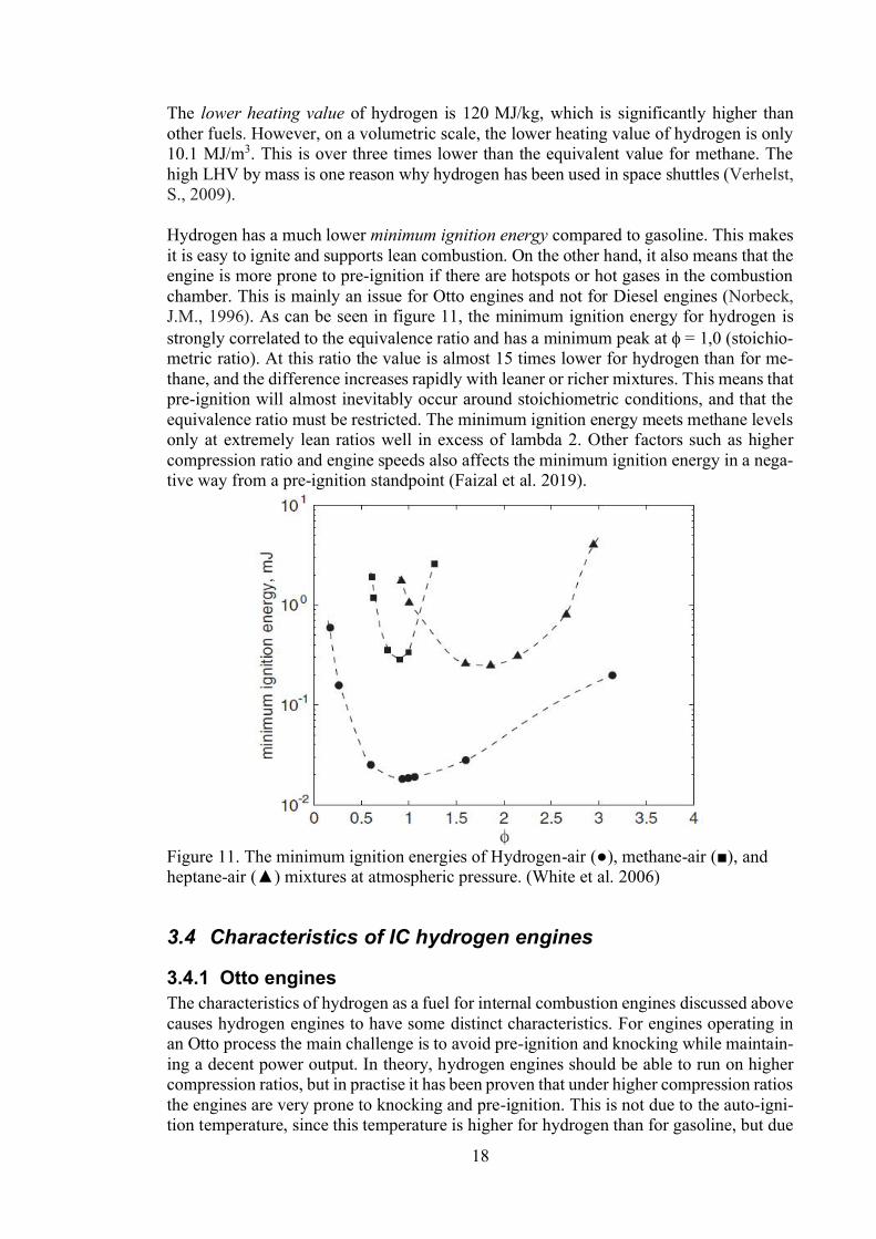
Hydrogen has a much lower minimum ignition energy compared to gasoline. This makesit is easy to ignite and supports lean combustion. On the other hand, it also means that theengine is more prone to pre-ignition if there are hotspots or hot gases in the combustionchamber. This is mainly an issue for Otto engines and not for Diesel engines (Norbeck,J.M., 1996). As can be seen in figure 11, the minimum ignition energy for hydrogen isstrongly correlated to the equivalence ratio and has a minimum peak at = 1,0 (stoichio-metric ratio). At this ratio the value is almost 15 times lower for hydrogen than for me-thane, and the difference increases rapidly with leaner or richer mixtures. This means thatpre-ignition will almost inevitably occur around stoichiometric conditions, and that theequivalence ratio must be restricted. The minimum ignition energy meets methane levelsonly at extremely lean ratios well in excess of lambda 2. Other factors such as highercompression ratio and engine speeds also affects the minimum ignition energy in a nega-tive way from a pre-ignition standpoint (Faizal et al. 2019).
Figure 11. The minimum ignition energies of Hydrogen- - andheptane-
3.4 Characteristics of IC hydrogen engines
3.4.1 Otto enginesThe characteristics of hydrogen as a fuel for internal combustion engines discussed abovecauses hydrogen engines to have some distinct characteristics. For engines operating inan Otto process the main challenge is to avoid pre-ignition and knocking while maintain-ing a decent power output. In theory, hydrogen engines should be able to run on highercompression ratios, but in practise it has been proven that under higher compression ratiosthe engines are very prone to knocking and pre-ignition. This is not due to the auto-igni-tion temperature, since this temperature is higher for hydrogen than for gasoline, but due
19
to hot spots in the engine from for example the sparkplug, exhaust valve or carbon depos-its. These hotspots are hot enough to cause the mixture to ignite due to the low ignitionenergy of hydrogen. Different methods to avoid this has been developed to manage theseproblems. These techniques include different fuel delivery systems, thermal dilution tech-niques and other engine design features that improve the engines operation.
3.4.2 Diesel enginesDiesel engines do not have the same problem as Otto engines when it comes to knockingand preignition. Instead the problem lies more on how to physically design an injectorthat is capable of injecting hydrogen in an efficient and safe way. The reason why hydro-gen direct injection is hard is because of the low density and viscosity, which means goodsealants and high pressures must be used to get the appropriate amount of fuel into thecombustion chamber. The high auto-ignition temperature of hydrogen makes it is hard toignite by compression alone. Early research done by Homan, et al. used a compressionratio of as high as 29:1 and were unable to obtain auto-ignition (Homan, H.S.,1978). Forthese reasons some assistance is required to start the combustion. There are a couple ofmethods that can help with ignition, these are annular glow plugs, heating of intake air,spark ignition and pilot fuel injection. These methods will be further discussed in Hydro-gen Diesel engine concepts.
3.5 Alternatives to IC engines
3.5.1 Gas turbinesGas turbine manufacturers are one of the main competitors to internal combustion enginemanufacturers such as Wärtsilä. Gas turbines also burn fossil fuels and replacing this fuelwith a cleaner green fuel is highly desired. As with internal combustion engines, gasturbines have quite similar challenges when it comes to burning hydrogen.
One challenge that both IC engines and gas turbines have is high NOx concentration inthe exhaust gases. There are some alternatives that can lower the NOx concentration forgas turbines. These are:
Hydrogen dilution with water, steam or nitrogen (reduced efficiency)Premixed combustion (challenging due to hydrogen properties)Removal from exhaust gases (expensive)
Diluting the hydrogen with water, steam or nitrogen in order to reduce the combustiontemperature of a diffusion flame will reduce the NOx concentration but have a negativeeffect on the efficiency of the turbine. Premixing the air and fuel is also an option, butdue to the properties of hydrogen, flashbacks are a major problem when increasing thehydrogen content of the fuel. Another problem with premixed combustion is combustionpressure fluctuation, which can destroy the combustor rapidly and creates a very loudsound (Mitsubishi Hitachi power systems, 2018). Removing NOx from the exhaust gasby either injecting ammonia in the exhaust gas or using a so called sconox process areconsidered expensive methods and are not economically feasible at the moment (Chiesa,P. 2005).
Manufacturers such as Mitsubishi Hitachi power systems (MHPS) claims that they canrun up to 30% hydrogen in premixed combustion (Mitsubishi Hitachi power systems,2018). MHPS also have an on-going project in the Netherlands of convert an operating

20
440MW natural gas power plant to run on 100% hydrogen by 2025. General electric (GE)claim to be able to operate on hydrogenous fuels with a hydrogen concentration of 5% to95% by volume (GE Power, 2019).
3.5.2 Fuel cellsAnother potential source of power are fuel cells. These are currently manly used in carsbut can as well be scaled in to powerplants for the electricity grid or ship propulsion incombination with an electric motor.
Fuel cells convert chemical energy in the form of fuel directly into electrical energy.There is no combustion involved in the energy conversion in fuel cells. Fuel cells differfrom other electro-chemical power sources such as batteries, which stores their reactantsin their cells. Fuel cells on the other hand are continuously fed from an external storageof reactants. The electrodes of a fuel cell are not either consumed as in batteries (Spiegel,C. 2007).
There are two main types of fuel cells, these are defined depending on the type of elec-trolyte they are using. These are alkaline or acid type electrolyte fuel cells. Independentof the fuel cell type the main reaction in the fuel cell is the following:
Fuel cells are also highly efficient with no moving parts. Fuel cells with an efficiencyranging from 40-60% have a higher efficiency than combustion engines (Wilberforce, T.,2016). The challenge with fuel cells is however durability and reliability of the fuel cellsystem. Fuel cells are also highly sensitive to the purity of the gas they are fed, both thehydrogen and oxygen. For fuel cells to become commercialized product for the energyand transport industry the cost must come down. The cost of a fuel cell system is currentlyaround 2500- Wilberforce, T., 2016). Fuel cell are a promising technology,but for it to get any major market traction it currently needs to be supported by govern-ment subsidies to compensate for the extra cost that is related to fuel cell installations.

21
4 Material compatibility with hydrogenIn this section material combability with hydrogen will be discussed. Besides hydrogenembrittlement there is also other aspects to consider when designing an engine for a newfuel. The fuel injection and delivery system will be in more or less constant contact withhydrogen at high pressure.
4.1.1 Hydrogen embrittlementSteel exposed to hydrogen can cause hydrogen embrittlement. This makes the steel moreprone to stress fractures. The process is caused when hydrogen is induced to the surfaceof the metal where the hydrogen atoms diffuse through the metal structure. This makesthe steel more susceptible to stress fractures and stress corrosion cracks that spared to thepoint of failure. Some points are more vulnerable than other, these are bends or otherstrain hardening methods, or parts that have been welded together. Hydrogen embrittle-ment is greatest near room temperature and is increased with higher strain rates, pressuresand purity of the gas (Bechtold, R.., 1997) ( ., 2010).
The degree of hydrogen embrittlement of steel depends on the strength and microstructureof the subject. Steels with a tensile strength less than 700 MPa are almost immune tohydrogen cracking. Steels with a tensile strength greater than 1000 MPa are more recep-tive, and steel over 1200 MPa are much more susceptive and thus might fail at muchlower stresses than their yield strength. Therefore, ductile steels have been used in appli-cations related to hydrogen previously. Steels with a lower level of impurities, such assulphur and phosphor, has a higher resistance against hydrogen embrittlement. (J., 2010). The permeability of different metals wary a lot. Some common metals are pre-sented in table 2. The difference between ferritic steels and austenitic steels are howevernot that big.
Table 2. - N ).Metal P (mol H2/m/s/Pa^0.5)Vanadium 2.9E-8 500Titanium 7.5E-9 500Nickel 1.2E-10 500Ferritic steels 3E-11 500Austenitic steels 0.9-1.2E-11 500Molybdenum 1.2E-11 500Tungsten 4.3E-15 500Beryllium 2E-15 400
NASA has a lot of experience of hydrogen and how to handle it. NASA has therefor madea Safety standard for hydrogen and hydrogen systems. From this standard following rec-ommendation are taken:
Metals with a face-centered cubic structure, such as, austenitic stainless steels, aluminumalloys, copper, and copper alloys, generally are satisfactory for hydrogen service. Nickel,a face-centered cubic material, is an exception and generally is not used because it issubject to severe hydrogen embrittlement (NASA, 1997)
The effect of hydrogen induced losses in mechanical properties, has been derived to becaused by:
The development of a critical, absorbed, localized hydrogen concentration

22
The existence of a critical stress intensity (crack length and applied or residualstress)The existence of a susceptible path for hydrogen d
(NASA, 1997).
The preventive actions suggested by NASA are the following: usage of coatings, elimi-nation of stress concentrations, oxidation treatments and careful alloy selection. Follow-ing bullet points are suggested by NASA:
Aluminium is one of the few metals known to show only minimal susceptibilityto hydrogen, so its use effectively eliminates hydrogen embrittlement.Most GH2 equipment is made of medium strength steel and most LH2 equip-
ment is made of stainless steel. Hydrogen embrittlement concerns are addressedthrough increased thickness, surface finish, welding techniques, and materials se-lection.Containers with thick walls of low-strength metals will generally contain hydro-
gen more safely than containers fabricated from similar alloys treated for highstrength, subject to appropriate welding techniques.A metal or alloy is almost certain to have a lower resistance to fatigue than if
hydrogen were not present if it is exposed to hydrogen and cyclic stresses. De-signers should, in the absence of data, assume a substantial (up to fivefold) de-crease in resistance to fatigue (NASA TM 104438 1992).Avoid the use of body-centred cubic metals and alloys whenever practical. Cast
iron shall not be used.Hydride-forming metals and alloys should not be used as structural materials for
hydrogen service. Their use requires careful consideration of operating tempera-tures and adverse effects of hydride formation.Exposure temperatures below room temperature generally retard hydrogen re-
action embrittlement; however, environmental and internal hydrogen embrittle-ment are increased in the temperature range of 200 to 300 K (-
(NASA, 1997).
These guidelines should be applied on the design of the injector and fuel system. Theselection of appropriate material is of great importance for a successful design and oper-ation of the equipment. In table 3 there is a summary of materials and their applicabilityto gaseous and liquid hydrogen service.
Table 3. Summary of material compatibility for hydrogen service (NASA, 1997)Material Service Remarks
Gas H2 Liquid H2Aluminium and its alloys Yes YesAustenitic stainless steels with >7%nickel (SAE 304, 304L, 308, 316, 321,347)
Yes Yes Some make martensitic conversion ifstressed above yield point at low tem-perature
Carbon steels Yes No To brittle for cryogenic serviceCopper and its alloys (brass, bronzeand copper-nickel)
Yes Yes
Gray, ductile or cast iron No No Not permitted for hydrogen serviceLow-alloy steels Yes No Too brittle for cryogenic serviceNickel and its alloys (Inconel, Monel) No Yes Susceptible to hydrogen embrittle-
ment

23
Nickel steels (2.25, 3.5, 5 and 9 % Ni) No No Ductility loss at liquid H2 tempera-tures
Titanium and its alloys Yes YesChloroprene rubber (Neoprene) Yes No Too brittle for cryogenic serviceDacron Yes No Too brittle for cryogenic serviceFluorocarbon rubber (Viton) Yes No Too brittle for cryogenic serviceMylar Yes No Too brittle for cryogenic serviceNitrile (Buna-N) Yes No Too brittle for cryogenic servicePolyamides (Nylon) Yes No Too brittle for cryogenic servicePolychlorotrifluoroethylene (Kel-F) Yes YesPolytetrafluorethylene (Teflon) Yes Yes
Worth noting from table 3 is that this data is from 1997 and there seems to have been aslight shift in how well the literature supports the use of aluminium alloys in hydrogenousenvironments and in technical reference for hydro-gen compatibility there is no direct indication of Aluminium alloys not being compatible,but there are research articles indicating that aluminium alloys in fact are affected. Forexample, 7075 aluminium the ductility loss was large in conditions of high fugacity andlong pre-charging periods at 318 K (Takano, N., 2008). For 2024 and 6013 Aluminiumthe corrosion-induced mechanical properties decreased gradually with exposure time andthe tensile ductility losses decreases exponentially to extremely low values (Petroyiannis,P.V., 2004). This causes for case to case investigation of specific aluminium grades todetermine if it is safe or not since no general conclusion can be made.
NASA has also made a list of recommended materials for specific applications such aspiping and flexible hoses. These are presented in table 4.
Table 4. Selection of recommended Materials for its applications (NASA, 1997)Application Typical materials
Liquid H2 Gas H2Valves Forged, machined, and cast valve bodies Appropriate industrial productsFittings Stainless steel bayonet type for vacuum
jacketsAppropriate industrial products
O-ring Stainless steel, Kel-F or Teflon Appropriate industrial productsGaskets Soft Aluminium, lead or annealed cop-
per, Kel-F, Teflon, glass-filled TeflonAppropriate industrial products
Flexible hoses Convoluted vacuum jacketed 316 321stainless steel
Stainless steel braided with Tef-lon
Rupture disk assembly 304, 304L, 316, 316L stainless steel 304, 304L, 316, 316L stainlesssteel
Piping 304, 304L, 316, 316L stainless steel 300 series stainless steel (316preferred)
Dewars 304, 304L, 316, 316L stainless steel Not applicableLubricants No lubricants used in some applications.
Lubricants listed for gas H2 are compat-ible but will become solid at low tem-peratures. Dry lubricants, such as PTFE,PTFE carbon, PTFE bronze, fiberglass-PTFE graphite. Graphite and molyb-denum disulphide permit only very lim-ited service life for bearings
Dupont Krytox 240AC, Fluo-ramics OXY-8, Dow CorningDC-33, Dow Corning FS-3452,Bray Oil Braycote 601, Generalelectric Verislube, HoughtonCasmolube 5100, Braycote 640AC, Dupont GPL 206, Halocar-bon Series 6.3 oil and Kel-F oil
Concerning high strength steels, low alloy steel generally offers better resistance againsthydrogen embrittlement and oxidisation (Lees, F., 2012). Alloys containing nickel showbetter resistance against hydrogen embrittlement, as long as the maximum content ofnickel is kept below 1%, above this percentage it will have a negative effect. Carbide
24
element such as titanium, molybdenum, niobium and vanadium also increase the re-sistance and the optimum content of these has been established by Zikeev, V.N. to be 1-1.5% Cr, 0.4-0.5% Mo, 0.05% Ti, 0.02-0.06% Nb, and 0.1% V. The content of theseelements can also be increased for improved resistance to hydrogen embrittlement, how-ever increasing these will make the steel more prone to brittle fracture drops. Same authoralso investigated the influence of carbon content in alloy steel and found that steels witha 0.2% content of carbon showed better resistance to embrittlement and according Zikeevthe ideal carbon content for hardenable steel is 0.2-0.3%, since it provides a good combi-nation of strength, ductility, toughness and resistance to hydrogen embrittlement (Zikeev,V.N., 1982).
Micro alloying is an option to improve the materials resistance to hydrogen embrittle-ment. This is due to the hydrogen trapping effect of Nb-microalloying precipitates. Thetrapping effect is increased with increased temperature during tempering of the steel,which causes an increase in micro-alloy precipitates. Tests on conventional low alloy42CrMo showed typical intergranular cracking at hydrogen content six times lower thanthe point where micro-alloyed 42CrMo exposed trans granular cracking (Bian, J., 2015).In the case of alloy steels there is a relationship between the tempering temperature afterquenching of the steel and resistance to hydrogen embrittlement. In a study made by Zafraet al. this was confirmed. Higher tempering temperatures generally results in better re-sistance against hydrogen embrittlement (Zafra, A., 2018).
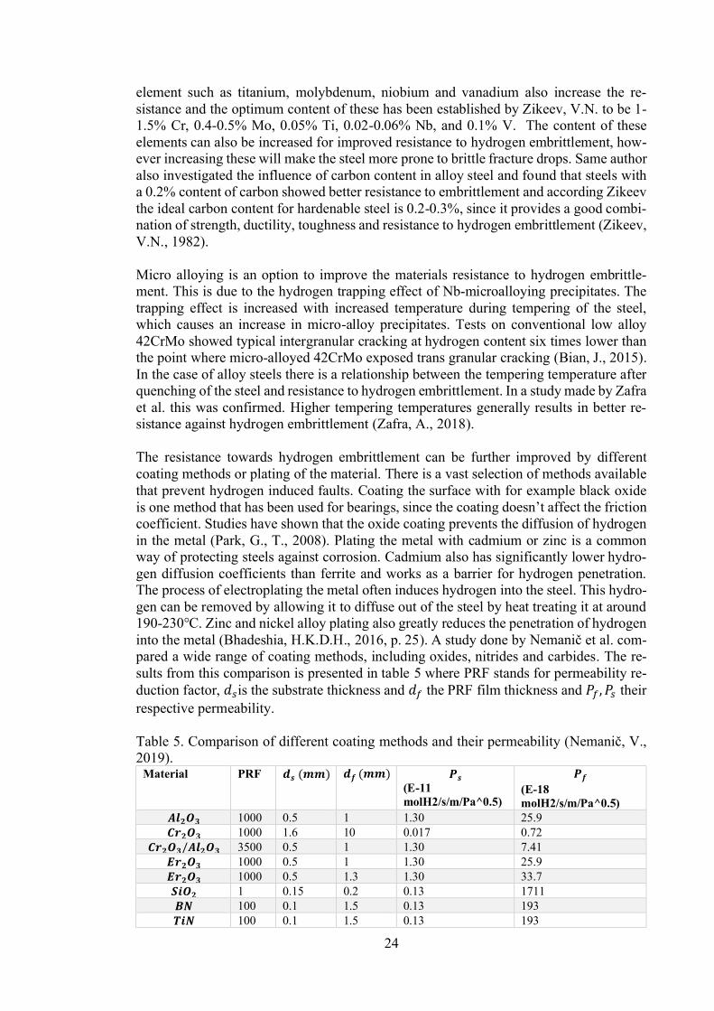
The resistance towards hydrogen embrittlement can be further improved by differentcoating methods or plating of the material. There is a vast selection of methods availablethat prevent hydrogen induced faults. Coating the surface with for example black oxideis one method that has been used for bearingscoefficient. Studies have shown that the oxide coating prevents the diffusion of hydrogenin the metal (Park, G., T., 2008). Plating the metal with cadmium or zinc is a commonway of protecting steels against corrosion. Cadmium also has significantly lower hydro-gen diffusion coefficients than ferrite and works as a barrier for hydrogen penetration.The process of electroplating the metal often induces hydrogen into the steel. This hydro-gen can be removed by allowing it to diffuse out of the steel by heat treating it at around190- . Zinc and nickel alloy plating also greatly reduces the penetration of hydrogeninto the metal (Bhadeshia, H.K.D.H., 2016, p. 25). A study done by et al. com-pared a wide range of coating methods, including oxides, nitrides and carbides. The re-sults from this comparison is presented in table 5 where PRF stands for permeability re-duction factor, is the substrate thickness and the PRF film thickness and theirrespective permeability.
Table 5. Comparison of different coating methods and their permeability (2019).
Material PRF(E-11molH2/s/m/Pa^0.5)
(E-18molH2/s/m/Pa^0.5)
1000 0.5 1 1.30 25.91000 1.6 10 0.017 0.723500 0.5 1 1.30 7.411000 0.5 1 1.30 25.91000 0.5 1.3 1.30 33.71 0.15 0.2 0.13 1711100 0.1 1.5 0.13 193100 0.1 1.5 0.13 193
25
1100 0.35 1.7 0.13 5.71000 0.1 1.7 0.13 21.86800 0.35 1.7 0.13 0.9220000 0.5 5 1.3 6.52000 0.5 0.5 1.3 6.538 0.5 2.3 1.3 1570100 0.5 4.4 1.3 1140117 0.5 2.6 1.3 576236 0.5 2.2 1.3 241350 0.5 4.5 1.3 3334600 0.5 1.4 1.3 7.910 0.1 1 0.27 2750100 0.5 1+0.25 1.3 324
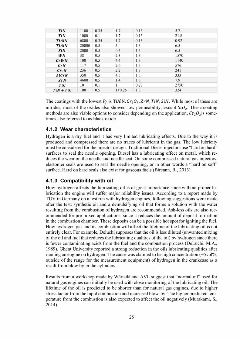
The coatings with the lowest is . While most of these arenitrides, most of the oxides also showed low permeability, except . These coatingmethods are also viable options to consider depending on the application, is some-times also referred to as black oxide.
4.1.2 Wear characteristicsHydrogen is a dry fuel and it has very limited lubricating effects. Due to the way it isproduced and compressed there are no traces of lubricant in the gas. The low lubricitymustsurfaces to seal the needle opening. Diesel has a lubricating effect on metal, which re-duces the wear on the needle and needle seat. On some compressed natural gas injectors,elastomer seals are used to seal the needle openingsurface. Hard on hard seals also exist for gaseous fuels (Bircann, R., 2013).
4.1.3 Compatibility with oilHow hydrogen affects the lubricating oil is of great importance since without proper lu-brication the engine will suffer major reliability issues. According to a report made byTUV in Germany on a test run with hydrogen engines, following suggestions were madeafter the test: synthetic oil and a demulsifying oil that forms a solution with the waterresulting from the combustion of hydrogen are recommended. Ash-less oils are also rec-ommended for pre-mixed applications, since it reduces the amount of deposit formationin the combustion chamber. These deposits can be a possible hot spot for igniting the fuel.How hydrogen gas and its combustion will affect the lifetime of the lubricating oil is notentirely clear. For example, Deluchi supposes that the oil is less diluted (unwanted mixingof the oil and fuel that reduces the lubricating qualities of the oil) by hydrogen since thereis fewer contaminating acids from the fuel and the combustion process (DeLuchi, M.A.,1989). Ghent University reported a strong reduction in the oils lubricating qualities afterrunning an engine on hydrogen. The cause was claimed to be high concentration (+5vol%,outside of the range for the measurement equipment) of hydrogen in the crankcase as aresult from blow by in the cylinders.
Results from a workshop made by Wärtsilä and AVL suggestnatural gas engines can initially be used with close monitoring of the lubricating oil. Thelifetime of the oil is predicted to be shorter than for natural gas engines, due to higherstress factor from the rapid combustion and increased blow-by. The higher predicted tem-perature from the combustion is also expected to affect the oil negatively (Murakami, S.,2014).

26
According to Antunes, J.G.that are cowered in oil. That is why they used a layer of Teflon to keep the oil fromwashing away on the actuating rod in the injector (Antunes, J.G., 2009)
4.1.4 Sealant compatibilityAccording to Bechtold, R et al. hydrogen is compatible with most of the elastomers avail-able, but hoses and containers of hydrogen must have minimum porosity to prevent per-meability of hydrogen through the walls (Bechtold, R., 1997). In high pressure applica-tions there are however some concerns. Hydrogen is typically soluble in polymer materi-als and exposure to high pressure hydrogen might therefore cause damage in the form ofblistering and swelling of the sealant (San Marchi, C., 2008). Different types of sealantswill be discussed more detail it the injector design chapter.
27
5 Hydrogen
5.1 Hydrogen productionHydrogen is currently produced for a variety of industrial applications. The most im-portant ones are in the production of methanol and ammonia, it is also used in the purifi-cation process of petroleum. As mentioned earlier hydrogen is the most abundant elementon earth, but it is only found in small quantities as a gas. To meet the demand there arecurrently several methods used to produce hydrogen.
The most economical and efficient method at the moment is steam reforming. Steam re-forming is a process that uses hydrocarbons and steam to produce hydrogen and carbonoxides. Natural gas is the primary gas used since it has a high content of methane whichhas the highest hydrogen to carbon ratio (Norbeck, J.M., 1997). This is obviously not arenewable process. For every 1kg of hydrogen the steam methane reformation processproduces approximately 7 kg of CO2 (Kolodziejczyk, B., 2019). There are currently othermethods that are considered green and would make the whole hydrogen energy cyclefrom generation to combustion green. The green hydrogen concept includes the usage ofexcess energy from renewable energy sources to split water molecules to make hydrogenand oxygen. This process can be divided in to three categories: electrolysis, thermolysisand photo electrolysis (Holladay, J.D., 2009).
Electrolysis is perhaps the simplest method that uses an electric current that passesthrough two electrodes soaked in an electrolyte that splits the water molecules. The effi-ciency of this process is around 56-73% (Holladay, J.D., 2009).
In thermolysis heat is used to decompose hydrogen and water, this happens at a tempera-tureposed methods to reduce the temperature needed by usage of chemical reagents. Thesehave significantly reduced the temperature, but require higher pressures instead (Hol-laday, J.D., 2009, p. 256).
Photoelectrolysis uses a similar technology that photovoltaics (solar panels) use to gen-erate electricity, but instead of creating an electric current between two semiconductors,hydrogen is created by splitting water into hydrogen and oxygen between a photocathodeand photoanode (Holladay, J.D., 2009).
5.2 Hydrogen supplyHydrogen can either be stored as a compressed gas or at liquid sate. There are hydrogenstorages at pressures up to 700 bar. Compressing gaseous hydrogen requires a substantialamount of energy. The compressors used to compress hydrogen to high pressures areusually dual or multistage compressors that cool the gas after each stage. This makes thecompression more isothermal and less adiabatic. In figure 12 the energy required to com-press hydrogen to a maximum of 800 bar is illustrated.
28
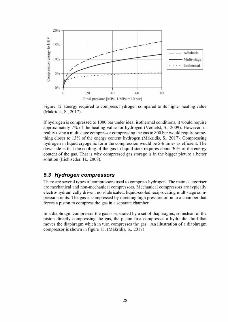
Figure 12. Energy required to compress hydrogen compared to its higher heating value(Makridis, S., 2017).
If hydrogen is compressed to 1000 bar under ideal isothermal conditions, it would requireapproximately 7% of the heating value for hydrogen (Verhelst, S., 2009). However, inreality using a multistage compressor compressing the gas to 800 bar would require some-thing closer to 13% of the energy content hydrogen (Makridis, S., 2017). Compressinghydrogen in liquid cryogenic form the compression would be 5-6 times as efficient. Thedownside is that the cooling of the gas to liquid state requires about 30% of the energycontent of the gas. That is why compressed gas storage is in the bigger picture a bettersolution (Eichlseder, H., 2008).
5.3 Hydrogen compressorsThere are several types of compressors used to compress hydrogen. The main categoriserare mechanical and non-mechanical compressors. Mechanical compressors are typicallyelectro-hydraulically driven, non-lubricated, liquid-cooled reciprocating multistage com-pression units. The gas is compressed by directing high pressure oil in to a chamber thatforces a piston to compress the gas in a separate chamber.
In a diaphragm compressor the gas is separated by a set of diaphragms, so instead of thepiston directly compressing the gas, the piston first compresses a hydraulic fluid thatmoves the diaphragm which in turn compresses the gas. An illustration of a diaphragmcompressor is shown in figure 13. (Makridis, S., 2017)

29
Figure 13. Illustration of diaphragm compressor unit (Makridis, S., 2017).
Besides mechanical compressors there are also non-mechanical compressors. These canbe divided in to electrochemical and metal hydride compressors. These non-mechanicalcompressors have the advantage of supplying hydrogen with higher purity with less con-taminants, which is highly important for fuel cells, less noise and parts subjected to wear.(Makridis, S., 2017). There are however less commercially available non-mechanicalcompressors, since these are still in the research stage of development.
Linde group has developed an ionic liquid compressor in 2002 called IC90, which is sortof a middle ground between mechanical and no-mechanical technologies. The ionic liquidcompressor uses, as the name implies, an ionic liquid, which is a liquid salt that is almostincompressible and has no vapour pressure. This makes it possible to separate it from thegas at the end of compression. The purpose of the liquid is to compress the gas by actingas a liquid piston. The ionic liquid also serves as a lubricant and coolant. This particularIC90 compressor uses a five-stage compressor and can be applied for either 350 bar or700 bar refuelling stations. The advantage of this technology is limited mechanical wear,low energy consumption, few moving parts and low maintenance. The Linde IC90 had amarket shear of >50% for 700bar refuelling stations in 2014 (Metz, S., 2014).
5.4 Hydrogen safetyHydrogen has a bad reputation for being unsafe and difficult to handle. As a matter offact, it is not that different to other gases such as natural gas or propane. There is annuallyover 50 million tons of hydrogen being produced and transported worldwide with fewmajor incidents (Grand view research, 2018). The scepticism for hydrogen might be acause of the major Hindenburg and Challenger accidents which both got major mediacoverage. Except for these hydrogen has an overall good safety record.
Hydrogen is still a hazardous gas and should be handled with care. The main hazards canbe defined as:

30
Physiological (suffocation and frostbites)Physical (embrittlement and component failure)Chemical (burning or explosion)
Hydrogen is a non-toxic odourless gas, but as with all gases except oxygen it can work asan asphyxiant. This is mainly a problem in closed environment if there is a large leak.This can easily be prevented by having appropriate ventilation, since hydrogen diffuseseasily in air. If skin is in direct contact with containers of liquid hydrogen skin mightbecome frozen or torn, such containers should be insulated to prevent accidents like that(Najjar, Y.S., 2013).
Physical failures related to hydrogen are typically due to hydrogen embrittlement whichcan lead to component failure and leaks. The rate of embrittlement depends on set ofvariables, these are: temperature, pressure, metal purity, exposure time and surface con-ditions (Najjar, Y.S., 2013).
The greatest threat is a fire or explosion of hydrogen. As discussed earlier the ignitionenergy is very small. This in combination with a wide flammability range makes fire andexplosion a major threat. In some practical applications, hydrogen is comparable to otherfuels. In the case of a leakage hydrogen is quickly dispersed in air and is thus no longer athreat, gasoline on the other hand will remain a hazard until it is removed. If the leakageis in an enclosed room the gas will quickly spread and crate a combustible mixture. Thatis why hydrogen should be handled in ventilated areas or outside (Norbeck, J.M., 1996).
In the case of a fire, hydrogen fires are typically hard to notice since the flame is un-noticeable in daylight and disperses little heat. Hydrogen fires do not either generate anytoxic smoke. Since hydrogen burn quickly the fires are typically short lived and diesquickly (Norbeck, J.M., 1996).

31
6 Hydrogen Diesel engine conceptsIn this section the main discoveries related to hydrogen Diesel engines will be presented.The section is divided in to two parts the: hydrogen only Diesel concepts and hydrogenGD concepts.
6.1 Hydrogen only Diesel conceptsAs mentioned earlier the early stages of hydrogen compression ignition engines were de-signed to operate like a traditional Diesel engine. It was quickly concluded that the re-quired compression ratio was too high and that the operating window was very narrow(Homan, H.S., 1983). The same Authors later investigated the use of glow plugs, whichresulted in better engine operation. There was still a lot of cycle to cycle variation and theNOx concentration was significantly higher compared to Diesel oil (Homan, H.S., 1989).The introduction of a swirl chamber on a single-cylinder water-cooled engine enabled anextended operating window by injecting a small amount of pilot hydrogen fuel in the swirlchamber.
In a comprehensive test by Eichlseder H. et al. which firstly investigated a port fuel in-jected (PFI) spark ignited Otto engine, but later concluded that it was limited in load andknocking. This led the author to test direct injection technologies together with spark ig-nition on an Otto engine. In order to improve the load capabilities, the author started toinvestigate the Diesel concept. This later led to the development of a compression ignitionengine based on a production BMW Diesel. The engine was a modified naturally aspi-rated single-cylinder engine. In the compression ignition layout intake air heating, sparkignition with single and multiple injections were tested, as well as glow plug ignition. Thetest concluded, that to achieve stable auto-ignition with Diesel-like ignition delay a com-pression temperature of 1100 K is needed. This was achieved at intake air temper-ature at a compression ratio of 22. With higher intake air temperature air mass flow isreduced, resulting in a lower potential power output. Having a compression ratio of 22 issomething that is not commonly used in practical applications.

32
Figure 14. Results from running with a glow plug (Eichlseder, H., 2010).
The compression ratio was later reduced to 18 and a glow plug was fitted. This resultedin a stable operation with a high pressure efficiency of 45.2% with peaks of 49% withdifferent injection timing. The raw NOx concentration from combustion was around thoseof a Euro-4 compliant engine. With an EGR rate of 9% the NOx concentration could bereduced by 58% with no penalty in efficiency. At an EGR rate of 30% the NOx concen-tration was reduced to 90% with only a reduction in efficiency by 1.3 percentage points.These are promising results showing that the NOx emissions can be managed efficiently.Results from this case is presented in figure 14. It is worth noticing the sharp heat releaserate occurring almost instantly as the needle opens. The author also reported that the glowplug ignition was very robust, assuming the surface temperature was high enough thesurface ignition started 0,4 ms after injector needle opens. The engine load tested wasfrom idle to 6 bar IMEP with natural aspiration, while supercharged pressure was raisedcontinuously to a maximum of 1 bar to reach full load conditions. The engine map withtarget BMEP and thermal efficiency as function of engine speed is presented in figure 15(Eichlseder, H., 2010).

33
Figure 15. Engine map when using glow plug (Eichlseder, H., 2010).
Similar tests were also done by Gomes Antunes et al., where compression ignition to-gether with intake air heating on an engine with a compression ratio of 17 was investi-gated. They reported an approximate reduction of 20% compared to normal Diesel NOxemissions, the peak power output also increased by 14%. This is quite astounding con-sidering that the engine was naturally aspirated and used intake air heating to achievestable combustion due to the higher compression temperature, which are aspects that tra-ditionally should contribute lower power output and higher NOx concentration (Antunes,J.G., 2009)
In a study by Tanno et al. from Toyota motor corporation the homogenous charge SIcombustion system was compared to a spark assisted diffusion combustion of hydrogen.The spark assisted diffusion combustion is achieved by first injecting a small amount offuel before TDC. This injection is later ignited by a spark, and the rest of the fuel amountis injected on top of this flame. The engine used for this test was a modified Diesel enginewith a compression ratio of 15-18. The results showed good thermal efficiency on thespark assisted diffusion combustion. The NOx emissions could be reduced with EGRwithout sacrificing the thermal efficiency significantly. Comparison on the efficiency andNOx emissions are presented in figure 16. The NOx levels could be reduced to the levelsof a Euro 6 compliant engine. The maximum injection pressure of the injector was 300bar. By lowering the injection pressure on low loads to 100 bar the thermal efficiency wasimproved to 52%, due to lower penetration and thus less energy dispersed into the cylin-der walls (Tanno, S., 2010). This research indicates that under medium and high load,both higher efficiency and lower NOx emissions can be achieved with the Diesel com-bustion compared to the Otto concept.

34
Figure 16. effect of NOx emissions as function of thermal efficiency. The thermal effi-ciency changes as the EGR increases (Tanno, S., 2010).
A hydrogen jetignition pre-chamber has also been considered by Boretti et al. The noveltyof this idea is to control the auto-ignition of hydrogen within the pre-chamber and leadthis mixture of hot gases and fuel into the main combustion chamber. In this way thecombustion in the main chamber, which has a separate main injector, starts as a pre-mixedcombustion and later develops into a diffusion combustion. The fuel share injected intothe pre-chamber was around 5%. The simulation showed better than Diesel power outputand efficiency at the same BMEP of 25 bar. Nothing is mentioned about the emissionsfrom this simulation. The simulation is done under various assumption, including that thehydrogen from the main chamber will not reach the glow plug in the pre-chamber, whichwould trigger the ignition of the fuel (Boretti, A., 2011a).
In a simulation on a hydrogen compression ignition engine made by Kavtaradze et al. thetotal NOx emissions from the combustion is comparable to the Diesel at same breakpower output. Kavtaradze et al. also investigated parameters that affected the NOx emis-sions. The results from this simulation were: (1) Higher amount of nozzle holes contrib-utes increased homogenization, which leads to lower NOx from the combustion. (2)Higher lambda will reduce the NOx concentration, but the effects are not as significantas in a homogenous charged combustion engine. (3) At constant lambda the NOx con-centration is reduced as the injected mass of hydrogen is increased i.e. the load is in-creased. This is due to the fact that if the lambda stays constant as the injected fuel massincreases the boost pressure has to increase. As the injection pressure stays the same theinjected gas will be closer to the nozzle with less air to support the combustion. This leadsto a slower heat release and lower NOx. (4) Increased swirl also had a positive effect onthe NOx reduction but reduced efficiency. This is a contradiction compared to a tradi-tional Diesel fuel engine where increased swirl can lead to a faster heat release with higherefficiency but also higher NOx (Kavtaradze, R. 2019).
6.2 Hydrogen GD conceptsUsing a fuel with lower ignition temperature to start the combustion in combination withhydrogen is another approach that has been researched extensively as a DF concept. Withearly injection of hydrogen in a DF engine, the challenges are the same as for an Ottoengine with knocking and pre-ignition still being a problem. These researches are there-fore not of major interest from the combustion perspective for this thesis.
There is limited knowledge of an actual working setup with a hydrogen high pressuredirect injection GD engine. The concept was however studied by Boretti et al. using a

35
WAVE code to simulate a 1.6L 4-cylinder TDI engine. The simulation was not capableof estimating the exhaust gases from combustion. The simulation is however capable ofcomputing break mean effective pressure and break thermal efficiency. The results fromthis simulation is presented in figure 17 and 18 (Boretti, A., 2011b).
Figure 17. Break efficiency comparison of hydrogen dual fuel compared to Diesel (Bo-retti, A., 2011b).
The results show increased efficiency over the whole operating range. The BMEP is alsosignificantly higher over the whole operating range. These are promising result for a hy-drogen Wärtsilä GD engine. Unfortunately, there are no emission estimates from thissimulation (Boretti, A., 2011b). By using a pilot injection of Diesel to start the combus-tion, it is possible to avoid the unreasonably high compression ratios needed to ignitehydrogen on compression alone. The usage of glow plugs to start the combustion mightalso have some reliability issues, therefore ignition by pilot fuel is a promising technol-ogy.
Figure 18. Break mean effective pressure comparison of hydrogen dual fuel compared toDiesel (Boretti, A., 2011b).
With regards to emission management a lot of the conclusions made in the hydrogen onlyconcepts in 4.1.1 could be implemented in this concept as well, considering that the Diesel

36
fuel mainly works as an ignition source with a relatively low total energy content ofaround 5-10% of the total fuel energy content.
No working example of a GD type engine could be found from the literature. This meansthere is novel research to be done yet in this subject. That is why this work is aimed to beapplied to a GD type inject even if all the real cases examples in following chapter mighthave been used in other types of engines.

37
7 Hydrogen direct injector conceptsFor successfully development of an injector for a Wärtsilä GD hydrogen engine it is im-portant to know what has been tried previously by other researchers. By studying otherswork early challenges and pitfalls can be avoided. There are no commercially availablehydrogen injectors, so the injectors presented below are made specific for their research.Usually they are based on either a Diesel or CNG injectors.
7.1 Hydraulically actuated injectorAntunes et al. developed an injector for their experiment. The injector body was madefrom construction steel while the nozzle and needle were made from tempered steel. Theinjector was hydraulically actuated and controlled via a three-way fast acting solenoid
hydrogen has on oil coated surfaces. Nitrile O-rings were used for sealing purposes, noconclusions were made on their durability. The only place where the effect of hydrogenembrittlement was observed was at the nozzle needle tip, even though it was made fromtempered steel. The maximum operating pressure was not stated by the author, but it wasmentioned to be slightly above the cylinder pressure of 80 bar and the hydrogen supplypressure was 200 bar. Design drawing of the injector is shown in figure 19 (Antunes, J.G.,2009).
Figure 19. Design drawing of the hydrogen injector developed by Gomes Antunes et al(Antunes, J.G., 2009).
Another hydraulically actuated injector was designed by Yamane et al. at Tokyo CityUniversity. Earlier iterations of the injector were used in the Musashi-3,4,5,6,7,8 and 9projects. The injector uses a hydrogen supply pressure of 100-200 bar and a working oilat 600-1200 bar depending on the fuel pressure. The maximum injection rate was 400ml/injection at an injection duration of 1,67 ms, which is equivalent of an injection dura-tion of 30 °CA at 3000 rpm. A picture of the injector and illustration of the operatingprinciple is presented in figure 20.

38
Figure 20. Picture of the injector (left), Illustration of the working principle while theinjector is in closed position (middle) and open position (right). (Yamane, K., 2011)
The team that developed this injector had previous experience of designing hydrogen in-jectors and were aware of the major problems related to hydrogen injectors, such as leak-age, deterioration of needle and seat. From this experience the following design recom-mendations were made:
successful in good finishing in such as flatness, perpendicularity and roundness
pt during the operation. In this study, aspecial diamond-like
high-pressure hydrogen gas is to be pre-
(Yamane, K., 2011)
Another potential weakness in the design was the usage of O-rings to seal the working oilfrom the hydrogen. In a previous test the O-rings were made from hydrogenated nitrile,co-polymer with a hardness of HS 70. These rings made from nitrile showed severe dam-age after only 50 hours of operation. This caused for change and a new test with O-ringsmade from polyurethane elastomer with a hardness of HS 94 (Yamane, K., 2011).
The injector was extensively tested to decide the injection rate and durability. The resultshowed that the after minor changes to the injector (increased orifice diameter from0.022mm to 0.028mm and needle seat taper from 30 to 45 degrees) the required injectionrate and dynamic response was achieved. The injector showed good durability during thetests with minimal leakage. The width of the sealing area shown in figure 21 was meas-ured with microscope. The result showed an increase in the seal width in the first 75 hoursof operation after that the width stayed the same for the rest of the 700 hours of the test.Regarding the performance of the O-rings no leakage was observed over the 700 hoursof test operation. The rings had some small sliding damage (Yamane, K., 2011).

39
Figure 21. Illustration of seal area on injector needle seat (Yamane, K., 2011).
Tanno et al. from Toyota Motor Corporation have developed a test engine with its ownhydrogen injector for spark assisted diffusion combustion. The injector is hydraulicallyactuated and based on a mass-produced Diesel injector, illustration of the injector is pre-sented in figure 22. The maximum injection pressure of hydrogen is 10-30MPa with theworking oil at 60 MPa. The nozzle configuration was a 6 x 0.43 mm. The injector wasalso designed so that no oil is leaking down to the gas, which excludes oil from beinginjected together with hydrogen in the combustion chamber to minimize carbon emis-sions. There are limited details on what techniques have been used to manufacture theinjector but following is mentioned: surface hardening and high-precision machining forseat and dry sliding parts, hydrogen rod seal at the sliding portion. Nothing is mentionedabout the durability of the injector (Tanno, S., 2010).
Figure 22. Tanno, S., 2010).
7.2 Piezoelectric actuated InjectorA piezoelectric actuated injector was developed by Welch, A. et al. at Westport innova-tions innovation centre and Pacific Northwest Na-tional Labs (PNNL). The base design for the injector was a J43 natural gas injector. Theoperating principle is slightly different for piezoelectric injector compared to hydrau-lically actuated injectors. An illustration of the injector is shown in figure 23 where themain components of the injector are marked. The needle and hydraulic compensator are
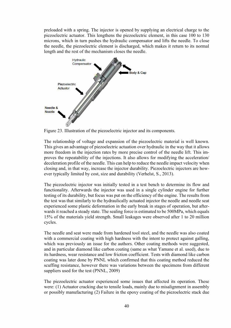
40
preloaded with a spring. The injector is opened by supplying an electrical charge to thepiezoelectric actuator. This lengthens the piezoelectric element, in this case 100 to 130microns, which in turn pushes the hydraulic compensator and lifts the needle. To closethe needle, the piezoelectric element is discharged, which makes it return to its normallength and the rest of the mechanism closes the needle.
Figure 23. Illustration of the piezoelectric injector and its components.
The relationship of voltage and expansion of the piezoelectric material is well known.This gives an advantage of piezoelectric actuation over hydraulic in the way that it allowsmore freedom in the injection rates by more precise control of the needle lift. This im-proves the repeatability of the injections. It also allows for modifying the acceleration/deceleration profile of the needle. This can help to reduce the needle impact velocity whenclosing and, in that way, increase the injector durability. Piezoelectric injectors are how-ever typically limited by cost, size and durability (Verhelst, S., 2013).
The piezoelectric injector was initially tested in a test bench to determine its flow andfunctionality. Afterwards the injector was used in a single cylinder engine for furthertesting of its durability, but focus was put on the efficiency of the engine. The results fromthe test was that similarly to the hydraulically actuated injector the needle and needle seatexperienced some plastic deformation in the early break in stages of operation, but after-wards it reached a steady state. The sealing force is estimated to be 500MPa, which equals15% of the materials yield strength. Small leakages were observed after 1 to 20 millioncycles.
The needle and seat were made from hardened tool steel, and the needle was also coatedwith a commercial coating with high hardness with the intent to protect against galling,which was previously an issue for the authors. Other coating methods were suggested,and in particular diamond like carbon coating (same as what Yamane et al. used), due toits hardness, wear resistance and low friction coefficient. Tests with diamond like carboncoating was later done by PNNL which confirmed that this coating method reduced thescuffing resistance, however there was variations between the specimens from differentsuppliers used for the test (PNNL, 2009)
The piezoelectric actuator experienced some issues that affected its operation. Thesewere: (1) Actuator cracking due to tensile loads, mainly due to misalignment in assemblyor possibly manufacturing (2) Failure in the epoxy coating of the piezoelectric stack due
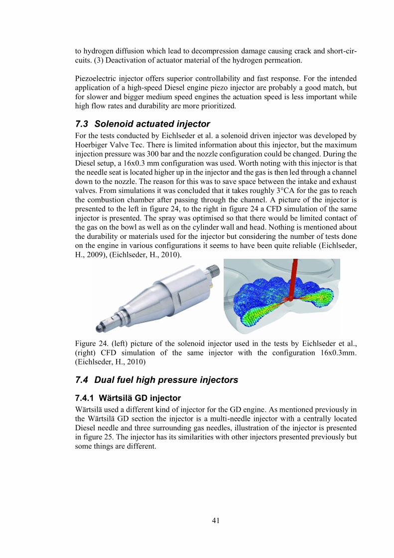
41
to hydrogen diffusion which lead to decompression damage causing crack and short-cir-cuits. (3) Deactivation of actuator material of the hydrogen permeation.
Piezoelectric injector offers superior controllability and fast response. For the intendedapplication of a high-speed Diesel engine piezo injector are probably a good match, butfor slower and bigger medium speed engines the actuation speed is less important whilehigh flow rates and durability are more prioritized.
7.3 Solenoid actuated injectorFor the tests conducted by Eichlseder et al. a solenoid driven injector was developed byHoerbiger Valve Tec. There is limited information about this injector, but the maximuminjection pressure was 300 bar and the nozzle configuration could be changed. During theDiesel setup, a 16x0.3 mm configuration was used. Worth noting with this injector is thatthe needle seat is located higher up in the injector and the gas is then led through a channeldown to the nozzle. The reason for this was to save space between the intake and exhaustvalves. From simulations it was concluded that it takes roughly 3°CA for the gas to reachthe combustion chamber after passing through the channel. A picture of the injector ispresented to the left in figure 24, to the right in figure 24 a CFD simulation of the sameinjector is presented. The spray was optimised so that there would be limited contact ofthe gas on the bowl as well as on the cylinder wall and head. Nothing is mentioned aboutthe durability or materials used for the injector but considering the number of tests doneon the engine in various configurations it seems to have been quite reliable (Eichlseder,H., 2009), (Eichlseder, H., 2010).
Figure 24. (left) picture of the solenoid injector used in the tests by Eichlseder et al.,(right) CFD simulation of the same injector with the configuration 16x0.3mm.(Eichlseder, H., 2010)
7.4 Dual fuel high pressure injectors
7.4.1 Wärtsilä GD injectorWärtsilä used a different kind of injector for the GD engine. As mentioned previously inthe Wärtsilä GD section the injector is a multi-needle injector with a centrally locatedDiesel needle and three surrounding gas needles, illustration of the injector is presentedin figure 25. The injector has its similarities with other injectors presented previously butsome things are different.

42
Figure 25. Illustration of the Wärtsilä GD injector (Wärtsilä, 2011).
The working principle of the injector is presented in figure 26. The gas needles are actu-ated by the hydraulic oil, which is controlled by a solenoid, similarly to the injector byYamane et al. The maximum gas pressure in the injector is 350 bar and the seal oil isslightly above this pressure at 370 bar. This, in combination with no real sealing surfaceof the working oil from the needle, makes the operating principle slightly different. Thisalso causes some of the seal oil to leak down the needle to the seat and into the combustionchamber where it is combusted. This leads to some small addition in carbon emissions.The leakage of the seal oil has the benefit of lubricating the needle seat slightly, whichwould be beneficial for a hydrogen application where there are no lubricants present inthe gas.
A similar injector was also later designed to run on methanol. The main modificationsneeded to run on methanol were slightly larger nozzle holes, injector volume and aslightly higher operating pressure, as well as a change in materials compatible with meth-anol.
With two separate injections there is an additional aspect to consider when injecting thetwo fuels. There is the consideration of when to inject the gas relative to the pilot fuel.This varies depending on load and speed, but a study done by Bärow et al. showed bestperformance when there is an 8°CA difference between pilot and gas injection. If thedifference increased, the Diesel pilot had more time to develop and caused more heat andtherefor increased NOx from the combustion. When the gas was injected closer to theDiesel, the gas had a cooling effect on the Diesel flame and due to the gas jet, there wasalso less oxygen present for the Diesel to combust. For minimizing the CO2 emissions, itwould be beneficial to go down as low as possible in pilot content but at lower than 3-5%the ignition of the natural gas was proven to be unstable (Bärow, E. 2019).
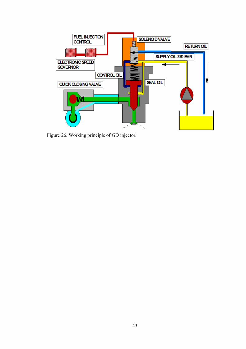
43
Figure 26. Working principle of GD injector.

44
8With an understanding of hydrogen gas and its potential benefits and challenges it is timeto start to evaluate the techniques presented above. The goal is to pick and identify thebest aspects of each injector type and how certain design aspects affect the performanceof the injector. Based on this information it should then afterwards be easy to modify anexisting system to work with hydrogen.
8.1 Operating principleSince there are several different injector types available, they need to be evaluated andcompared to each other based on their advantages and disadvantages. The main types ofinjectors that has been brought up in this thesis are open hydraulic actuation, sealed hy-draulic actuation, electromagnetic actuation and piezoelectric actuation. The solenoid in-jector by Hoerbiger Valve Tec was extensively tested in the research by Eichlseder et al.,but due to limited information on the performance of the injector it is not included in this
Re-newable Hydrogen Technologies: Production, Purification, Storage, Applications andSafety Gandia et al., in this comparison the solenoid injector did not perform verywell. In the comparison in the aforementioned book the piezoelectric injector was thesuggested operating principle with the motivation that it has the highest average massflux, superior needle control and lowest opening transient duration, but with the side notethat piezoelectric injector still needs development and that the epoxy coating of the pie-zoelectric stack was affected by hydrogen, which drastically reduced the reliability of theinjector. For that comparison the focus was on high speed engines, while this is for me-dium speed engines, which makes the transient response time less important due to thelonger window of injection at lower rotational speed of the engine. A summary of thepros and cons of respective injector type is presented in table 6.
Table 6. Comparison of the injector types presented in this thesis.Operational principle Pros Cons
Open hydraulic - High needle lift High massflow- Oil leakage into the gaseousfuel might help to lubricate theneedle seat
- Oil leakage to the combustionchamber +CO2- Need for additional system forsupplying the working oil
Sealed hydraulic - High needle lift high massflow- The working oil is not con-sumed
- Additional point of failure atthe working oil seal- Need for additional system forsupplying the working oil
Piezoelectric - Good controllability- Good transient response
- Piezo stack sensitive to Hydro-gen- Limited needle lift
There are multiple examples of hydraulically actuated injectors capable of working withhydrogen and with an inhouse injector already working under the same principle (Tanno,S., 2010), (Yamane, K., 2011) (Gomes Antunes, J.G., 2009). For these reasons, the hy-draulically actuated injector seems like a natural alternative for the continued develop-ment of a hydrogen injector for a Wärtsilä engine. Whether it should be a sealed systemas in Yamaneinjector to be made would be a Wärtsilä GD or methanol injector which is modified towork with hydrogen. This would need minimal work and resources to get a working test

45
example. Based on the performance of the injector the combustion concept can be con-firmed or discarded. If it shows promising results further development of the injector canbe investigated.
The drawback of an injector of the hydraulic actuation is the requirement of an additionalsystem to supply the working oil. This could possibly be avoided by using a sealed systemas in Yamane oil is substituted by Diesel oil at high pressure.In this way the injector would use a similar pressure as the common rail pressure used forthe pilot injection and in that way, there is no need for an additional system to supply theworking oil of a different medium.
8.2 Nozzle designsSeveral researches have investigated the effect different nozzle designs have on the hy-drogen jet formation and consequently the performance of the engine. For diffusion com-bustion a lower penetrating jet has the advantage of dispersing less heat into the cylinderwalls, thus being more efficient. An increase in the number of nozzles can increase thearea of the flame and increase the fuel air mixing. This causes a faster combustion andthus increasing the performance, but at the same time there is a potential for increasedNOx emissions. There is limited knowledge on ignited hydrogen jet and especially howto optimize the nozzle design. Most of the research is done on unignited hydrogen jetsthat later crate a homogenous charge. The thigs that have been observed is that if thenozzle holes are relatively close to each other the jets tend to unite and form a single jet.If a jet is close to an in-cylinder surface the jet is drawn towards the surface. These arephenomena of the Coanda effect (Verhelst, S., 2009). The consequence of the Coandaeffect is clearly visible in figure 27 for the nozzles with more than 7 holes.
Figure 27. Comparison of 7, 9- and 13-hole hydrogen injector (Petersen B.R., 2006).
The jet to jet interaction were seen in the 13-hole nozzle of Salazar et al. as well as in thethe 9 and 13-hole injector of injector of Petersen in figure 27 (Salazar, V.M., 2010) (Pe-tersen B.R., 2006). Depending on the spacing and angle of the holes the number of holescan wary but going beyond 9 holes might be unwise, since it might introduce more inter-action between the jets and in that way disrupt the spray pattern. However, according toa simulation study done by Kavtaradze, R. et al., who investigated the nozzle design of ahydrogen diffusion combustion, recommended more holes based on their result. The re-sults showed less NOx emissions on nozzles with increased number of holes, due to amore homogenous charge. The simulations also showed a clear difference in how thecombustion of a hydrogen jet differs to a Diesel jet. An illustration from the research isshown in figure 28, where the Diesel combustion is represented to the left and hydrogento the right. It is evident that the combustion of Diesel is mostly surrounded the liquidDiesel jet that first must evaporate before it is ignited. Hydrogen on the other hand is

46
already in gas state and diffuses more rapidly. The hydrogen jet itself also contains airand is therefore also combustible. This creates the shockwave like combustion in the cyl-inder.
Figure 28. Temperature fields of Diesel (left) and hydrogen (right) combustion (Kavta-radze, R. 2019).
8.3 Mass flowIn order to understand the influence of density, fellow velocity and energy content somebasic calculations must be conducted. For a reference case the geometries of a Wärtsilämethanol injector were used for these calculations. Mass flow for the gaseous fuel throughthe nozzle holes is calculated according to equation (2) in the gas injector chapter. Thepressure difference between upstream of the nozzle and downstream are assumed to besufficient to cause chocked flow. For comparison liquid methanol through the same noz-zle is calculated according to equations (13) and (14). These equations are derived from
(13)
(14)
It is possible that the cylinder pressure will be slightly higher from the rapid hydrogencombustion, but with proper control of the flow this should not be a major problem. Theconstants used for calculation is presented in table 7.
Table 7. Constants used for calculation.Nozzle 1.6 mm x 9Injection pressure 300 600 barCombustion chamber pressure 150 barDischarge coefficient (gas) 0.85Discharge coefficient (liquid) 0.63Density (H2) 20-34 kg/m^3Density (CH4) 191-320 kg/m^3Density (CH3OH) 789 kg/m^3
Based on the mass flow the energy flow rate can then be calculated. According to:
(15)
The basic result from the calculation is shown in figure 29. From this it is clear that theenergy flow of hydrogen is more restricted than methane. Surprisingly methanol is also
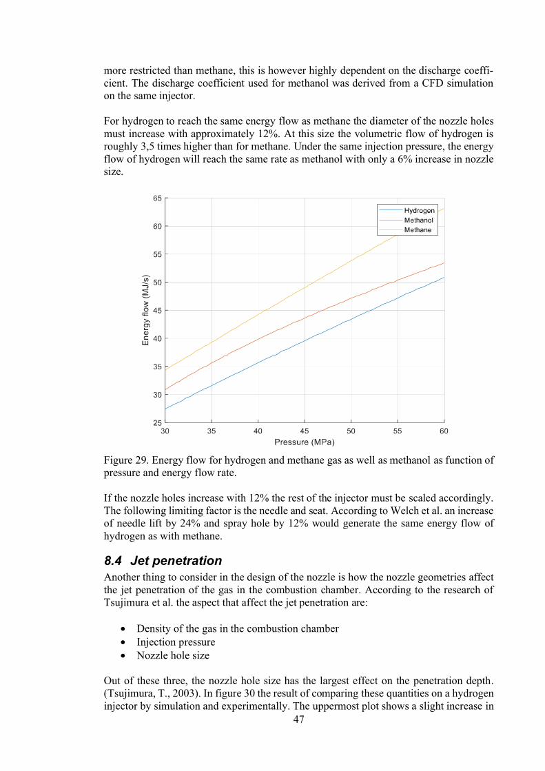
47
more restricted than methane, this is however highly dependent on the discharge coeffi-cient. The discharge coefficient used for methanol was derived from a CFD simulationon the same injector.
For hydrogen to reach the same energy flow as methane the diameter of the nozzle holesmust increase with approximately 12%. At this size the volumetric flow of hydrogen isroughly 3,5 times higher than for methane. Under the same injection pressure, the energyflow of hydrogen will reach the same rate as methanol with only a 6% increase in nozzlesize.
Figure 29. Energy flow for hydrogen and methane gas as well as methanol as function ofpressure and energy flow rate.
If the nozzle holes increase with 12% the rest of the injector must be scaled accordingly.The following limiting factor is the needle and seat. According to Welch et al. an increaseof needle lift by 24% and spray hole by 12% would generate the same energy flow ofhydrogen as with methane.
8.4 Jet penetrationAnother thing to consider in the design of the nozzle is how the nozzle geometries affectthe jet penetration of the gas in the combustion chamber. According to the research ofTsujimura et al. the aspect that affect the jet penetration are:
Density of the gas in the combustion chamberInjection pressureNozzle hole size
Out of these three, the nozzle hole size has the largest effect on the penetration depth.(Tsujimura, T., 2003). In figure 30 the result of comparing these quantities on a hydrogeninjector by simulation and experimentally. The uppermost plot shows a slight increase in
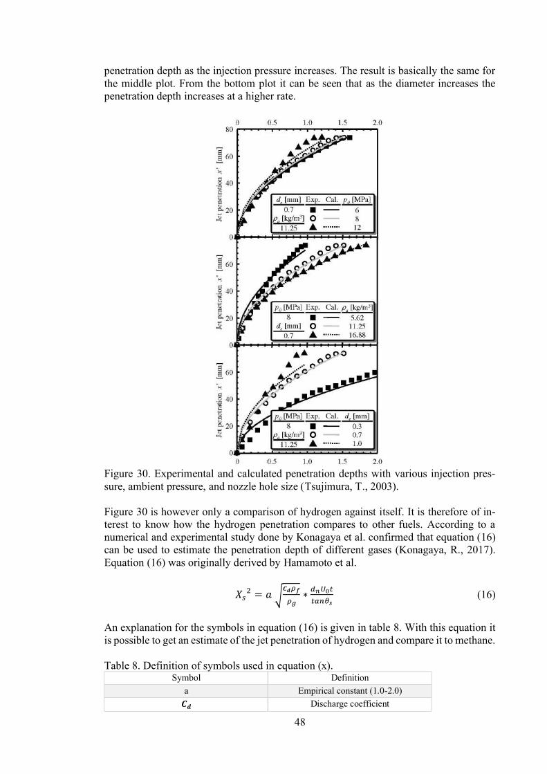
48
penetration depth as the injection pressure increases. The result is basically the same forthe middle plot. From the bottom plot it can be seen that as the diameter increases thepenetration depth increases at a higher rate.
Figure 30. Experimental and calculated penetration depths with various injection pres-sure, ambient pressure, and nozzle hole size (Tsujimura, T., 2003).
Figure 30 is however only a comparison of hydrogen against itself. It is therefore of in-terest to know how the hydrogen penetration compares to other fuels. According to anumerical and experimental study done by Konagaya et al. confirmed that equation (16)can be used to estimate the penetration depth of different gases (Konagaya, R., 2017).Equation (16) was originally derived by Hamamoto et al.
(16)
An explanation for the symbols in equation (16) is given in table 8. With this equation itis possible to get an estimate of the jet penetration of hydrogen and compare it to methane.
Table 8. Definition of symbols used in equation (x).Symbol Definition
a Empirical constant (1.0-2.0)Discharge coefficient
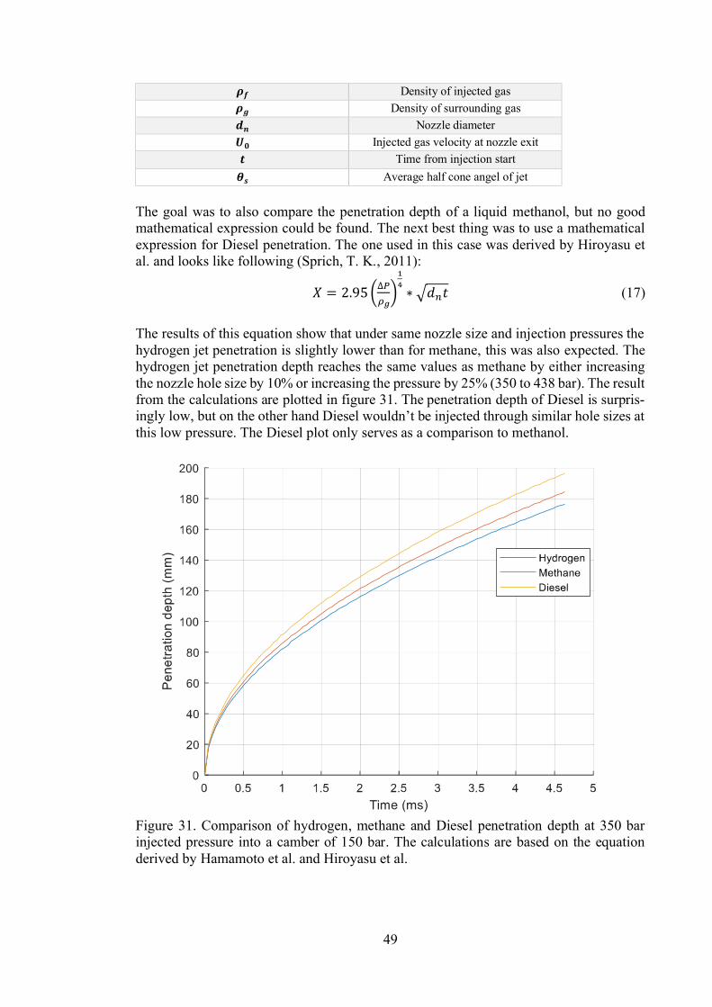
49
Density of injected gas Density of surrounding gas
Nozzle diameterInjected gas velocity at nozzle exit
Time from injection startAverage half cone angel of jet
The goal was to also compare the penetration depth of a liquid methanol, but no goodmathematical expression could be found. The next best thing was to use a mathematicalexpression for Diesel penetration. The one used in this case was derived by Hiroyasu etal. and looks like following (Sprich, T. K., 2011):
(17)
The results of this equation show that under same nozzle size and injection pressures thehydrogen jet penetration is slightly lower than for methane, this was also expected. Thehydrogen jet penetration depth reaches the same values as methane by either increasingthe nozzle hole size by 10% or increasing the pressure by 25% (350 to 438 bar). The resultfrom the calculations are plotted in figure 31. The penetration depth of Diesel is surpris-ingly low, but on the other hand Dthis low pressure. The Diesel plot only serves as a comparison to methanol.
Figure 31. Comparison of hydrogen, methane and Diesel penetration depth at 350 barinjected pressure into a camber of 150 bar. The calculations are based on the equationderived by Hamamoto et al. and Hiroyasu et al.
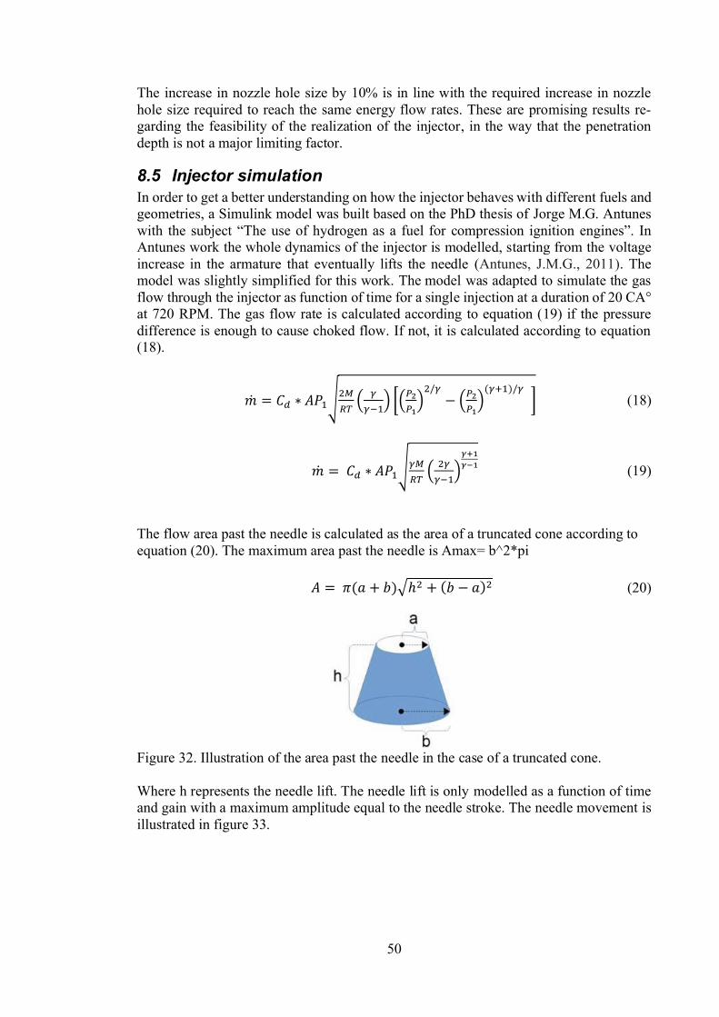
50
The increase in nozzle hole size by 10% is in line with the required increase in nozzlehole size required to reach the same energy flow rates. These are promising results re-garding the feasibility of the realization of the injector, in the way that the penetrationdepth is not a major limiting factor.
8.5 Injector simulationIn order to get a better understanding on how the injector behaves with different fuels andgeometries, a Simulink model was built based on the PhD thesis of Jorge M.G. Antunes
he use of hydrogen as a fuel for compression ignition engines InAntunes work the whole dynamics of the injector is modelled, starting from the voltageincrease in the armature that eventually lifts the needle (Antunes, J.M.G., 2011). Themodel was slightly simplified for this work. The model was adapted to simulate the gasflow through the injector as function of time for a single injection at a duration of 20 CA°at 720 RPM. The gas flow rate is calculated according to equation (19) if the pressuredifference is enough to cause choked flow. If not, it is calculated according to equation(18).
(18)
(19)
The flow area past the needle is calculated as the area of a truncated cone according toequation (20). The maximum area past the needle is Amax= b^2*pi
(20)
Figure 32. Illustration of the area past the needle in the case of a truncated cone.
Where h represents the needle lift. The needle lift is only modelled as a function of timeand gain with a maximum amplitude equal to the needle stroke. The needle movement isillustrated in figure 33.

51
Figure 33. Needle movement as function of time created in the signal builder block inSimulink.
contain any combustion, a generic pressure curve was modelled in the signal builder blockin Simulink. The combustion chamber pressure is illustrated in figure 34.
Figure 34. Illustration of combustion chamber pressure in the signal builder block in Sim-ulink.
As the original injector is a methanol injector the methanol mass flow was also modelledin order to get a reference performance of the injector. For this the equations (13) and(14) previously used suits this model as well.
As there is a rail valve between the injector and the rail, there will be a pressure drop inthe injector over the opening time of the injector. This is not included in the model byAntunes. The pressure drop is modelled according to equation (21)
(21)

52
Where represents the bulk modulus of the fuel (Sprich, T. K., 2011). The bulk modulusof gases in an isentropic process is depending on the pressure and the specific heat capac-ity of the gas according to equation (22).
(22)
In equation (21), represents the volumetric flow rate and the volume of the injector.The nozzle sack is also included in the model as a separate volume from the injector withits own pressure. The delta pressure in the nozzle sack is modelled according to equation(21) with one flow into the sac from the injector and another flow out of the sack troughthe nozzle to the combustion chamber (Sprich, T. K., 2011).
The initial conditions for the simulation are presented in table 9. The highest-level blockof the simulation is represented in figure 35. The gas mass flow is presented in figure 36.
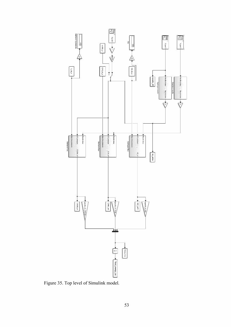
53
Figure 35. Top level of Simulink model.

54
Figure 36. Gas flow simulation blocks.

55
Table 9. Constants for simulationGas 0.85CH3OH 0.63
CH3OH 777 MPaH2 1.41CH4 1.32
Rail pressure H2 350 barRail pressure CH4 350 barRail pressure CH3OH 450 barCombustion chamber pressure 170 bar start of injection, 150 end of injectionM H2 0.002 kg/molM CH4 0.016 kg/molTemperature 300 KInjection time 20° CALower heating value H2 119.96 MJ/kgLower heating value CH4 50 MJ/kgLower heating value CH3OH 20 MJ/kg
23.18 kg/m^3210 kg/m^3789 kg/m^3
8.6 Simulation resultsWith the initial conditions from table 9, the simulation result is presented in figure 37.The total energy injected of hydrogen is less than both methanol and methane. The totalinjected hydrogen energy is roughly 2/3 of the total injected energy of methanol. Themethanol pressure-drop in the injector is around 150 bar while it is only 40 bar for hydro-gen and 10 bar for methane.

56
Figure 37. Result from initial conditions of the simulation. Top graph represents to totalenergy content injected. The middle graph represents the pressure in the injector. Thebottom graph represents the pressure inside the nozzle sack.
The total energy injected is in line with existing engines. The pressure in the nozzle isalso close to a previous simulation done by Wärtsilä. A model is only as good as its as-sumptions and in this case, there is a lot of them to simplify the model. However, themodel performs reasonably well in being relatively close to more complex simulationsdone previously by Wärtsilä.
After trying out several different geometries it was clear that the nozzle area is the majorlimiting factor for increasing the flow through the injector is the nozzle size. Increasingthe other parameters (injector volume and needle seat) will increase the flow but notnearly as much as just increasing the nozzle size.
If only the nozzle size would be modified, the required increase in nozzle size for hydro-gen approaches unrealistic changes to reach the same energy content injected by methanolat 450 bar. Increasing the injector volume is not necessary as the pressure drop for thegaseous fuels is significantly less than for methanol. However, by doing so the requiredincrease in nozzle size is less. An increased injector volume by 50%, nozzle and needleseat diameter increase by 21% is enough to reach the same flow as the methanol. Themotivation behind increasing the area of the needle seat and nozzle diameter by the samepercentage is to keep the ratio of area past the needle roughly 4 time bigger than the areaof the nozzle holes, this is general rule of thumb used by the injector designers. When

57
increasing the hydrogen rail pressure to 380 bar a nozzle and needle seat diameter increaseof 13%, as well as a 50% increase in volume would suffice. Increasing the injectionpressure alone to 430 bar as well as keeping the same 50% increase in injector volumewill reach the same injected energy content injected. These results are summarised intable 10.
Table 10. Simulation summaryH2 Rail pressure Volume increase Nozzle diameter in-
creaseNeedle seat diame-ter increase
350 Bar +25% +23% +23%380 Bar +25% +16% +16%430 Bar +25% +1% +1%350 Bar +50% +21% +21%380 Bar +50% +13% +13%430 Bar +50% +0% +0%350 Bar +75% +20% +20%380 Bar +75% +10% +10%430 Bar +75% -1% -1%450 Bar +0% +0% +0%
With no modifications to the injector and the hydrogen injection pressure raised to 450bar, the injected energy of hydrogen basically is the same as with methanol. This meansthat there is potential for some good tests if as similar injector would be used, since themethanol injection pressure is also 450 bar. The same sealing oil system could then alsobe used, since the sealing oil pressure is dependent on the injection gas pressure. Com-pressing the gas to a higher pressure will of course require more energy, but when lookingat the graph in figure 12 in the hydrogen supply chapter. The energy requirement forcompressing the gas, going from 350 bar to 450 is not such a big difference in energy
be a major issue, but for a commercial application thepressure should be kept at a minimum.
8.7 Material considerations
8.7.1 Material coatingSome form of coating has been used on almost all injectors previously mentioned that hasbeen operating with hydrogen. This is mainly due to the additional wear resistance certaincoatings have, but the coating also works as a hydrogen gas barrier with several orders ofmagnitude lover permeability than normal steels. It can thus be assumed that some sortof coating would be beneficial for improving the durability of the injector. In this sectiondifferent coating methods will be evaluated in order to find a suitable candidate for theapplication. The coating methods previously mentioned are black oxide coating, platingwith different metals, Teflon and diamond like carbon. In the literature revive only dia-mond like carbon (DLC) and Teflon had been applied to real applications. On the previ-ously mentioned methanol injector Balinit CNI and TC WC/C have been used, thereforethese will also be considered. DLC is the most tested coating method for hydrogenousapplications with tests made by both Yamane at al. and Welch et al. that recommended itfor further research.
Diamond like carbon has several advantageous aspects that make it an attractive candidatefor this application. The properties of DLC can vary a lot depending on its application.DLC is however defined as a family of amorphous carbon coating methods that consistof either trigonal sp2 bonding or a tetrahedral sp3 bonding and hydrogen. Depending on
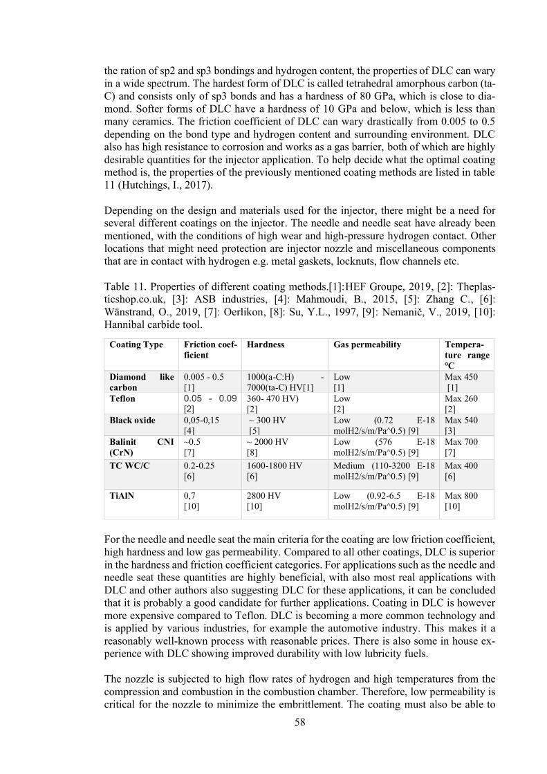
58
the ration of sp2 and sp3 bondings and hydrogen content, the properties of DLC can waryin a wide spectrum. The hardest form of DLC is called tetrahedral amorphous carbon (ta-C) and consists only of sp3 bonds and has a hardness of 80 GPa, which is close to dia-mond. Softer forms of DLC have a hardness of 10 GPa and below, which is less thanmany ceramics. The friction coefficient of DLC can wary drastically from 0.005 to 0.5depending on the bond type and hydrogen content and surrounding environment. DLCalso has high resistance to corrosion and works as a gas barrier, both of which are highlydesirable quantities for the injector application. To help decide what the optimal coatingmethod is, the properties of the previously mentioned coating methods are listed in table11 (Hutchings, I., 2017).
Depending on the design and materials used for the injector, there might be a need forseveral different coatings on the injector. The needle and needle seat have already beenmentioned, with the conditions of high wear and high-pressure hydrogen contact. Otherlocations that might need protection are injector nozzle and miscellaneous componentsthat are in contact with hydrogen e.g. metal gaskets, locknuts, flow channels etc.
Table 11. Properties of different coating methods.[1]:HEF Groupe, 2019, [2]: Theplas-ticshop.co.uk, [3]: ASB industries, [4]: Mahmoudi, B., 2015, [5]: Zhang C., [6]:Wänstrand, O., 2019, [7]: Oerlikon, [8]: Su, Y.L., 1997, [9]: , [10]:Hannibal carbide tool.
For the needle and needle seat the main criteria for the coating are low friction coefficient,high hardness and low gas permeability. Compared to all other coatings, DLC is superiorin the hardness and friction coefficient categories. For applications such as the needle andneedle seat these quantities are highly beneficial, with also most real applications withDLC and other authors also suggesting DLC for these applications, it can be concludedthat it is probably a good candidate for further applications. Coating in DLC is howevermore expensive compared to Teflon. DLC is becoming a more common technology andis applied by various industries, for example the automotive industry. This makes it areasonably well-known process with reasonable prices. There is also some in house ex-perience with DLC showing improved durability with low lubricity fuels.
The nozzle is subjected to high flow rates of hydrogen and high temperatures from thecompression and combustion in the combustion chamber. Therefore, low permeability iscritical for the nozzle to minimize the embrittlement. The coating must also be able to
Coating Type Friction coef-ficient
Hardness Gas permeability Tempera-ture range
Diamond likecarbon
0.005 - 0.5[1]
1000(a-C:H) -7000(ta-C) HV[1]
Low[1]
Max 450[1]
Teflon 0.05 - 0.09[2]
360- 470 HV)[2]
Low[2]
Max 260[2]
Black oxide 0,05-0,15[4]
~ 300 HV[5]
Low (0.72 E-18molH2/s/m/Pa^0.5) [9]
Max 540[3]
Balinit CNI(CrN)
~0.5[7]
~ 2000 HV[8]
Low (576 E-18molH2/s/m/Pa^0.5) [9]
Max 700[7]
TC WC/C 0.2-0.25[6]
1600-1800 HV[6]
Medium (110-3200 E-18molH2/s/m/Pa^0.5) [9]
Max 400[6]
TiAlN 0,7[10]
2800 HV[10]
Low (0.92-6.5 E-18molH2/s/m/Pa^0.5) [9]
Max 800[10]
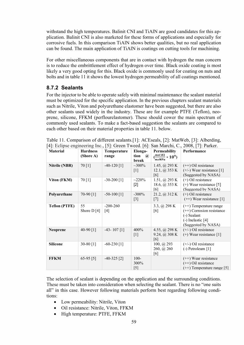
59
withstand the high temperatures. Balinit CNI and TiAlN are good candidates for this ap-plication. Balinit CNI is also marketed for these forms of applications and especially forcorrosive fuels. In this comparison TiAlN shows better qualities, but no real applicationcan be found. The main application of TiAlN is coatings on cutting tools for machining.
For other miscellaneous components that are in contact with hydrogen the man concernis to reduce the embrittlement effect of hydrogen over time. Black oxide coating is mostlikely a very good opting for this. Black oxide is commonly used for coating on nuts andbolts and in table 11 it shows the lowest hydrogen permeability of all coatings mentioned.
8.7.2 SealantsFor the injector to be able to operate safely with minimal maintenance the sealant materialmust be optimized for the specific application. In the previous chapters sealant materialssuch as Nitrile, Viton and polyurethane elastomer have been suggested, but there are alsoother sealants used widely in the industry. These are for example PTFE (Teflon), neo-prene, silicone, FFKM (perflourelastomer). These should cower the main spectrum ofcommonly used sealants. To make a fact-based suggestion the sealants are compared toeach other based on their material properties in table 11. below.
Table 11. Comparison of different sealants.[1]: ACEseals, [2]: MatWeb, [3]: Alberding,[4]: Eclipse engineering Inc., [5]: Green Tweed. [6]: San Marchi, C., 2008, [7]: Parker.
Material Hardness(Shore A)
Temperaturerange
Elonga-tion @break
Permeability( )
Performance
Nitrile (NBR) 70 [1] -40-120 [1] ~300%[1]
1.45, @ 293 K12.1, @ 353 K[6]
(++) Oil resistance(+/-) Wear resistance [1](Suggested by NASA)
Viton (FKM) 70 [1] -30-200 [1] ~220%[2]
1.51, @ 293 K18.6, @ 353 K[6]
(+) Oil resistance(+) Wear resistance [1](Suggested by NASA)
Polyurethane 70-90 [1] -50-100 [1] -300%[3]
21.2, @ 312 K[7]
(+) Oil resistance (++) Wear resistance [1]
Teflon (PTFE) 55Shore D [4]
-200-260[4]
3.3, @ 298 K[6]
(++) Temperature range(++) Corrosion resistance(-) Sealant(-) Inelastic [4](Suggested by NASA)
Neoprene 40-90 [1] -43- 107 [1] 400%[1]
4.55, @ 298 K9.24, @ 308 K[6]
(+/-) Oil resistance(+) Wear resistance [1]
Silicone 30-80 [1] -60-230 [1] 100, @ 293260, @ 260[6]
(+/-) Oil resistance(-) Petroleum [1]
FFKM 65-95 [5] -40-325 [2] 100-300%[5]
(++) Wear resistance(++) Oil resistance(++) Temperature range [5]
The selection of sealant is depending on the application and the surrounding conditions.These must be taken into consideration
following materials perform best regarding following condi-tions:
Low permeability: Nitrile, VitonOil resistance: Nitrile, Viton, FFKMHigh temperature: PTFE, FFKM

60
Varying temperature: PTFE, FFKMHigh wear: Polyurethane, FFKMHigh elasticity: Neoprene, Nitrile, Polyurethane
The previous suggestion of using Viton and polyurethane is also supported by table 11.Both showing good resistance to permeability, wear and oil with a relatively wide tem-perature range. Depending on the application sealants such as FFKM and PTFE might bean option. PTFE is however inelastic which means that it would probably have to bereplaced after being compressed once. The main applications of PTFE are seals usinghigh compression force and handling of cold cryogenics. FFKM is an elastic material, butit its elasticity can wary a lot depending on the composition of the material. This is alsotrue for most of the materials listed in table 11. It is therefore hard to give any exact valuesfor the materials but instead they are presented as ranges. Whatever the specific compo-sition of the material, their general performance is still accurate.

61
9After studying the literature and forming recommendations based the literature the goalis to apply these on to a real injector. The feasibility and the consequence of these changesare then evaluated. The injector to be modified is a methanol injector based on the GDinjector. The basic operation of the methanol injector is the same as for the GD injector.The on and most available injectordesign.
9.1 Nozzle holesConsidering that the nozzle holes size on the existing injector are already on the limit itis not realistic to go up +20% in diameter, which would be required if a rail pressure of350 bar would be applied. It is therefore necessary to increase the rail pressure. Increasing
-16% increasein nozzle size this is a much more realistic option. It is hard to know how much it isrealistically possible to increase the nozzle size. For this a more detailed finite elementmodel might be necessary to investigate the strain and loads on the injector body.
As mentioned in the simulation result section, increasing the rail pressure to the samepressure as used for the methanol case will cause sufficient energy flow. This is probablythe easiest way to develop a working concept of the engine. However, if it is concludedthat increasing the nozzle size is not an option, nor is increasing the rail pressure. Therewill probably be a need for a totally different design. On option would be to abandon theblind hole nozzle and make the gas nozzle a pintle nozzle instead. As mentioned earlierin this work, pintle nozzles offer good fuel penetration with worse atomization in the caseof liquid fuels. Since hydrogen will remain as a gas under all realistic pressures at roomtemperature the atomization is not an issue. Removing the holes in the nozzle will removethe most restricting flow area. This will introduce another problem; the spray cone angleis typically much lover for pintle nozzles. Therefore, some form of flow director must beconstructed to increase the spray cone angel and direct the spray from each pintle nozzleaway from each other.
Without further simulation or testing it is hard to know what the best solution would be.Blind hole nozzles are a known working concept, but as the design of the injector changesmore it must be analysed for its performance and durability. Before conversion to a pinitenozzle a CFD simulation would be good to find a good way of directing the spray.
9.2 Needle and needle seatIf the nozzle hole diameter increases the needle seat also must increase in order to keepthe same ratio of area past the needle and nozzle hole area. The suggested ratio is around3-4. There are of course other than the diameter geometries that mater. A steeper angleon the needle and seat improves the sealing of the injector and minimizes needle bounceand vibration. The downside is that the needle must move further and faster to achievethe same area past the needle under the same time. If the actuator is capable of increasingthe needle stroke the needle seat angle could be reduced, if not there is no need for achange at this point.
The geometrical tolerances and surface finish of the needle and seat are important, andaccording to Yamane et. al the flatness, perpendicular and roundness should be kept be-low one micron. The surface roughness is not an issue for the methanol injector as it isalready of sufficient quality.
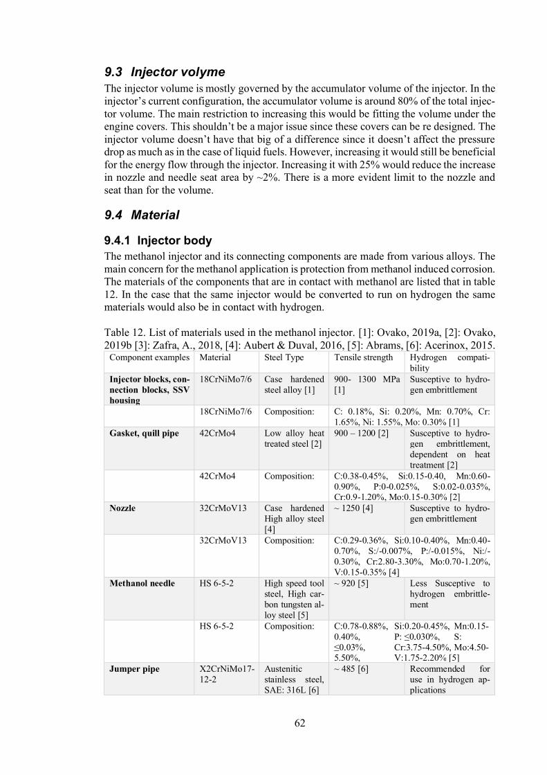
62
9.3 Injector volymeThe injector volume is mostly governed by the accumulator volume of the injector. In the
tor volume. The main restriction to increasing this would be fitting the volume under theengine cover be a major issue since these covers can be re designed. The
drop as much as in the case of liquid fuels. However, increasing it would still be beneficialfor the energy flow through the injector. Increasing it with 25% would reduce the increasein nozzle and needle seat area by ~2%. There is a more evident limit to the nozzle andseat than for the volume.
9.4 Material
9.4.1 Injector bodyThe methanol injector and its connecting components are made from various alloys. Themain concern for the methanol application is protection from methanol induced corrosion.The materials of the components that are in contact with methanol are listed that in table12. In the case that the same injector would be converted to run on hydrogen the samematerials would also be in contact with hydrogen.
Table 12. List of materials used in the methanol injector. [1]: Ovako, 2019a, [2]: Ovako,2019b [3]: Zafra, A., 2018, [4]: Aubert & Duval, 2016, [5]: Abrams, [6]: Acerinox, 2015.
Component examples Material Steel Type Tensile strength Hydrogen compati-bility
Injector blocks, con-nection blocks, SSVhousing
18CrNiMo7/6 Case hardenedsteel alloy [1]
900- 1300 MPa[1]
Susceptive to hydro-gen embrittlement
18CrNiMo7/6 Composition: C: 0.18%, Si: 0.20%, Mn: 0.70%, Cr:1.65%, Ni: 1.55%, Mo: 0.30% [1]
Gasket, quill pipe 42CrMo4 Low alloy heattreated steel [2]
900 1200 [2] Susceptive to hydro-gen embrittlement,dependent on heattreatment [2]
42CrMo4 Composition: C:0.38-0.45%, Si:0.15-0.40, Mn:0.60-0.90%, P:0-0.025%, S:0.02-0.035%,Cr:0.9-1.20%, Mo:0.15-0.30% [2]
Nozzle 32CrMoV13 Case hardenedHigh alloy steel[4]
~ 1250 [4] Susceptive to hydro-gen embrittlement
32CrMoV13 Composition: C:0.29-0.36%, Si:0.10-0.40%, Mn:0.40-0.70%, S:/-0.007%, P:/-0.015%, Ni:/-0.30%, Cr:2.80-3.30%, Mo:0.70-1.20%,V:0.15-0.35% [4]
Methanol needle HS 6-5-2 High speed toolsteel, High car-bon tungsten al-loy steel [5]
~ 920 [5] Less Susceptive tohydrogen embrittle-ment
HS 6-5-2 Composition: C:0.78-0.88%, Si:0.20-0.45%, Mn:0.15-0.40%, P: S:
Cr:3.75-4.50%, Mo:4.50-5.50%, V:1.75-2.20% [5]
Jumper pipe X2CrNiMo17-12-2
Austeniticstainless steel,SAE: 316L [6]
~ 485 [6] Recommended foruse in hydrogen ap-plications

63
Composition: C:0.03%, Si: 0.75, Mn: 2.0%, S: 0.03%, P:0.045%, Ni: 10-14%, Cr: 16-18%, Mo: 2-3%, N: 0.10%, Si: 0.75%. [6]
From table 12, it is clear that almost all steels used for the methanol injector are susceptiveto hydrogen embrittlement, which causes for some concern in the design aspect when itis to be converted to hydrogen. The best option from the perspective of reducing the hy-drogen embrittlement, would be to investigate if some steels with lower tensile strengthcould be used. This is unlikely since the pressures and stresses are quite high in theseapplications and making the injector bigger to reduce the stresses is not either an option,since the whole injector is already quite big and there is limited space between the intakeand exhaust valves. This makes the usage of softer steels less likely. However, when themethanol injector was designed the methanol corrosion had to be considered and conse-quently the steels used have good corrosion resistance. This is typical for alloy steels withhigh chromium and nickel content. Low alloy steels show better resistance against hydro-gen embrittlement and oxidisation (Lees, F., 2012.). According to the recommendationsby Zikeev the carbide forming elements are higher than the recommended content foralmost all metals except 42CrMo4, which only has a slightly higher carbon content thanrecommended. 18CrNiMo7/6 should be avoided, due to its high tensile strength and highnickel content, these factors indicate that it might me highly suspectable to hydrogen em-brittlement.
Tempering at high temperature reduces the influence of hydrogen and increases thetoughness of the steel, but it comes at a cost of reduced hardness (Zafra, A.,2018). Lowalloy steels with high tempering temperature are therefore recommended. In the hydrogenembrittlement section micro-alloying was presented as an option to reduce the embrittle-ment effect. This method could also further improve the resistance against hydrogen.
If the above presented methods are considered insufficient, coating components in thesuggested material described in the coating section should be applied. The suggestionswhere DLC for high wear applications, for less critical components black oxide coatingmight be preferred because of lower cost and permeability. Components that are subjectedto high temperature like the nozzle will need a coating that can resist higher temperatures,like Balinit CNI and TiAlN.
9.4.2 Injector sealsTo ensure safe operation the seals must be made from adequate material. The possiblecauses of failure are blistering or swelling of the sealant. In table 13 the sealant materialsare listed that are used to seal the fuel in the injector. There are no major concerns heresince both FKM and PTFE have relatively low hydrogen permeability. Both are also rec-ommended for gaseous hydrogen use by NASA presented in table 3.
There is however limited information about how FEPM will resist high pressure hydro-gen. FEPM has comparable properties as FKM and is also trade marked as Viton ® Ex-treme or in some cases Aflas®. These seals supposedly have reduced selling from sol-vents and better chemical resistance and especially against water vapor, ammonia andsour gases (Gehrckens, C.O., 2019)ensure safe operation the FEPM sealants should be tested in advance of usage to ensuresafe operation.
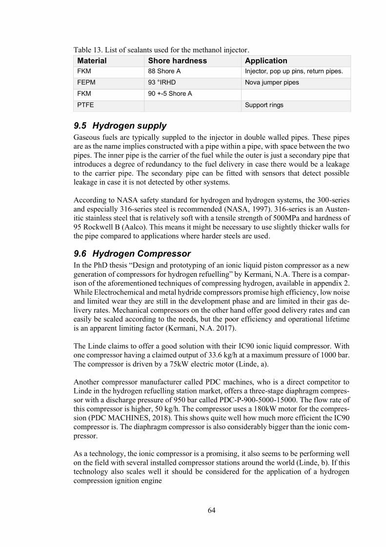
64
Table 13. List of sealants used for the methanol injector.
9.5 Hydrogen supplyGaseous fuels are typically suppled to the injector in double walled pipes. These pipesare as the name implies constructed with a pipe within a pipe, with space between the twopipes. The inner pipe is the carrier of the fuel while the outer is just a secondary pipe thatintroduces a degree of redundancy to the fuel delivery in case there would be a leakageto the carrier pipe. The secondary pipe can be fitted with sensors that detect possibleleakage in case it is not detected by other systems.
According to NASA safety standard for hydrogen and hydrogen systems, the 300-seriesand especially 316-series steel is recommended (NASA, 1997). 316-series is an Austen-itic stainless steel that is relatively soft with a tensile strength of 500MPa and hardness of95 Rockwell B (Aalco). This means it might be necessary to use slightly thicker walls forthe pipe compared to applications where harder steels are used.
9.6 Hydrogen Compressoriston compressor as a new
Kermani, N.A. There is a compar-ison of the aforementioned techniques of compressing hydrogen, available in appendix 2.While Electrochemical and metal hydride compressors promise high efficiency, low noiseand limited wear they are still in the development phase and are limited in their gas de-livery rates. Mechanical compressors on the other hand offer good delivery rates and caneasily be scaled according to the needs, but the poor efficiency and operational lifetimeis an apparent limiting factor (Kermani, N.A. 2017).
The Linde claims to offer a good solution with their IC90 ionic liquid compressor. Withone compressor having a claimed output of 33.6 kg/h at a maximum pressure of 1000 bar.The compressor is driven by a 75kW electric motor (Linde, a).
Another compressor manufacturer called PDC machines, who is a direct competitor toLinde in the hydrogen refuelling station market, offers a three-stage diaphragm compres-sor with a discharge pressure of 950 bar called PDC-P-900-5000-15000. The flow rate ofthis compressor is higher, 50 kg/h. The compressor uses a 180kW motor for the compres-sion (PDC MACHINES, 2018). This shows quite well how much more efficient the IC90compressor is. The diaphragm compressor is also considerably bigger than the ionic com-pressor.
As a technology, the ionic compressor is a promising, it also seems to be performing wellon the field with several installed compressor stations around the world (Linde, b). If thistechnology also scales well it should be considered for the application of a hydrogencompression ignition engine
Material Shore hardness ApplicationFKM 88 Shore A Injector, pop up pins, return pipes.
FEPM 93 °IRHD Nova jumper pipes
FKM 90 +-5 Shore A
PTFE Support rings

65
10
The goal of this study was to identify the necessary modifications needed to convert anexisting Diesel engine to run on hydrogen. The major focus was put on the injector design,since this was identified to be the major limiting factor to achieve a working concept. Theexisting methanol injector was studied and later chosen to be modified to run on hydro-gen, since it offers an ignition source with the pilot fuel and keeps the option to run onDiesel if necessary. A thorough literature review on hydrogen injectors and other injectorswas conducted and the most significant research was included in this paper.
From the literature review concepts of the modified GD injector started to take place.Mathematical expressions for penetration depth, mass flow and others were later used ina model built in Simulink to evaluate the injector performance with hydrogen. The resultswere also compared to other gaseous fuels, as well as liquid fuels. Based on this, recom-mendations could be made regarding the geometries of the injector. These results wheresummarised in table 10. The nozzle diameter was identified to be the clear bottle neck forincreasing the mass flow. Key points from the simulation were: while keeping the railpressure constant at 350 bar, the nozzle and seat diameter need to be increase by 23% andthe volume by 25%. If no modification on the injector is desired a rail pressure of 450 barwill suffice.
Material and coating recommendations were also made to account for the increased wearon certain components and how to minimize the effect of the notorious hydrogen embrit-tlement. The steel used on the existing methanol injector was susceptive to hydrogen em-brittlement on nearly all point. It was therefore recommended to consider softer steelswith a slightly different composition and higher degree of tempering. By coating the mostsensitive surfaces, such as the needle, seat and nozzle with DLC and TiAln or Balinit willimprove the durability of injector.
Different types of sealants were compared and evaluated by their hardnesses, operationaltemperatures, elongations at break and hydrogen permeabilities. It was however con-cluded that the existing seals are suitable of hydrogen operation and no major concernswas raised for these components.
Means of supplying the injector with high pressure hydrogen were also evaluated. In theliterature review a direct comparison of mechanical diaphragm compressors, non-me-chanical electrochemical compressors and an ionic liquid compressor. The non-mechan-ical compressors were limited by their delivery rate and was therefore not further inves-tigated. Compressors from two of the leading hydrogen refuelling station suppliers, Lindeand PDC machines, were evaluated. PDC offering a three-stage diaphragm compressorand Linde offering their ionic liquid compressor. The ionic liquid compressor was con-sidered as a better option for this application based on its varying compression ratio, su-perior efficiency and compactness.

66
12
In this study the limitations and possible points of failure of an existing injector has beenidentified. Methods of addressing the limitations and points of weaknesses have later beenaddressed. This work indicates promising result for the combustion concept, and allmeans of avoiding the limitations of the injector are based on peer reviewed articles withknown technology used by the industry.
The question is however how to proceed from this. New ways of generating energy andtransporting goods are needed. This work on its own will not help much, but the idea isthat based on this work a prototype injector could be designed for hydrogen GD operation.In order to make further progress in the matter, real tests on existing equipment could bedone. Both the W32GD and methanol engine could work as an initial test bench, sincethe operating principle is the same and the injection pressures are toughly the same. Basedon these tests the injector will probably show its true weaknesses and performance. Thisworks should then be able to support the designers and guide them in their work.
for vessels orpower plants in many years to come. That is why having Diesel as a secondary fuel issuch a good alternative. In the event of increased popularity for hydrogen it would notrequire any major modifications for the engine to run purely on hydrogen without thepilot fuel. By fitting an annular glow plug this could be achieved. As the pilot fuel onlyworks as an ignition source and the ignition energy for hydrogen is low. A glow plug hasbeen proven to be a reliable source of ignition (Eichlseder, H., 2010). Even if there is nomajor boom for hydrogen in a couple of years, running a GD engine on hydrogen givesthe operator the opportunity to switch to a clean fuel temporarily, if only for shorter peri-ods when e.g. entering and leaving emission sensitive areas, such as fjords or city har-bours. With no real indication that the NOx emissions should be considerably higher thanin a regular Diesel engine. It therefore should be possible to use a normal selective catalystreduction (SCR) to reduce the NOx emissions. With practically no CO2 or soot from thecombustion the engine would practically be emission free while still being capable ofhigh loads and efficiency. These should be compelling arguments for continued develop-ment of this concepts.
67
13
Aalco. Stainless Steel Grade 316 / 1.4401. Datasheet. Available at: http://www.far-nell.com/datasheets/26035.pdf[Accessed: 25.11.19].
Abrams. Steel grade. Datasheet. Available at: http://www.premium-steel.co.uk/im-ages/filedownloads/datasheets/BM2.pdf [Accessed: 21.10.2019].
Acerinox, 2019. Cr-Ni-Mo austenitic stainless steel acx 240. Datasheet. Available at:https://www.acerinox.com/opencms901/export/sites/acerinox/.content/galerias/galeria-descargas/galeria-documentos-producto/ACX240-low.pdf [Accessed: 21.10.2019].
ACEseals. O-ring materials. Available at: https://www.aceseal.com/o-ring-materi-als[Accessed: 21.10.2019].
Alberding. Technical Data Sheet. Available at:http://www.alberdingkusa.com/filead-min/pdf/t/us_u_801_t.pdf[Accessed: 21.10.2019].
Antunes, J.G., Mikalsen, R. and Roskilly, A.P., 2009. An experimental study of a directinjection compression ignition hydrogen engine. International journal of hydrogen en-ergy, 34(15), pp.6516-6522.
Antunes, J.M.G., 2011. The use of hydrogen as a fuel for compression ignition en-gines (Doctoral dissertation, Newcastle University).
ASB industries. Innovative surface technologies. Available at: https://www.asbindus-tries.com/chrome-oxide-coatings [Accessed: 21.1.2020].
Aubert & Duval (2016). GKH®(W - YW) 33CrMoV12-9 High-performance marten-sitic steel for critical mechanical components. Available at: https://www.au-bertduval.com/wp-media/uploads/2017/05/GKH_Brochure_Aubert_Duval_GB.pdf[Ac-cessed: 29.10.2019].
Bärow, E., Willman, M., Aßmus, K., Redtenbacher, C., Wimmer, A. 2019. OperatingExperience with a Combined High-Pressure Gas-Diesel Platform Injector. 17th Confer-
n Engine.
Bechtold, R., 1997. Alternative fuels guidebook, pp. 90, SAE.
Bhadeshia, H.K.D.H., 2016. Prevention of hydrogen embrittlement in steels. ISIJ inter-national, 56(1), pp.24-36.
Bian, J., Mohrbacher, H., Zhang, J.S., Zhao, Y.T., Lu, H.Z. and Dong, H., 2015. Appli-cation potential of high performance steels for weight reduction and efficiency increasein commercial vehicles. Advances in Manufacturing, 3(1), pp.27-36.
Bircann, R., Kazour, Y., Dauer, K., Fujita, M., Wells, A., Kabasin, D.F. and Husted, H.,2013. Cold Performance Challenges with CNG PFI Injectors (No. 2013-01-0863). SAETechnical Paper.

68
Blau, P.,Boyer B., Erdimer A., Welch, A., 2009. Hydrogen Material Compatibility forBoretti, A., 2011a. Advantages of the direct injection of both diesel and hydrogen indual fuel H2ICE. international journal of hydrogen energy, 36(15), pp.9312-9317.
Boretti, A., 2011b. Advances in hydrogen compression ignition internal combustion en-gines. International Journal of Hydrogen Energy, 36(19), pp.12601-12606.
Bosch, R., 2011. Bosch automotive handbook 8th edition. pp. 599, 616-617, 625.
C. Otto Gehrckens. 2019. FLUORKAUTSCHUK (FEPM) FEPM O-RING. Availableat: https://www.cog.de/produkte/datenblaetter/dichtungswerkstoffe-im-ueber-blick/fluorkautschuk-fepm[Accessed: 22.11.2019].
Chiesa, P., Lozza, G. and Mazzocchi, L., 2005. Using hydrogen as gas turbinefuel. Transactions of the ASME-A-Engineering for Gas Turbines and Power, 127(1),pp.73-80.
College of the Desert (2001b). Hydrogen properties. Hydrogen fuel cell engines and re-lated technologies [online] rev 0, 1 47. Available from URL: https://www1.eere.en-ergy.gov/hydrogenandfuelcells/tech_validation/pdfs/fcm01r0.pdf[Accessed: 10.2020]
Achievements in Materials and Manufacturing Engineering, 43(1), pp.214-221.
DeLuchi, M.A., 1989. Hydrogen vehicles: an evaluation of fuel storage, performance,safety, environmental impacts, and cost. International Journal of Hydrogen En-ergy, 14(2), pp.81-130.
Eclipse engineering Inc. The Advantages and Disadvantages of PTFE O-Rings. Availa-ble at: https://eclipseseal.com/blog/seals/advantages-disadvantages-ptfe-o-rings/[Ac-cessed: 21.10.2019]
Eichlseder, H., Klell, M., 2008, Wasserstoff in der Fahrzeugtechnik. ATZ-MTFachbuch, 1 edn, Vieweg+Teubner Verlag, GWV Fachverlage GmbH, Wiesbaden/DE.
Eichlseder, H., Spuller, C., Heindl, R., Gerbig, F. and Heller, K., 2009. New and innova-tive combustion systems for the H2 ICE: compression ignition and combined processes.In SAE P (Vol. 2009).
Eichlseder, H., Spuller, C., Heindl, R., Gerbig, F. and Heller, K., 2010. Concepts for die-sel-like hydrogen combustion. MTZ worldwide, 71(1), pp.46-51.
Faizal, M., Chuah, L.S., Lee, C., Hameed, A., Lee, J. and Shankar, M., 2019. ReviewOf Hydrogen Fuel For Internal Combustion Engines. Journal of Mechanical Engineer-ing Research & Developments (JMERD), 42(3), pp.35-46.
Four-stroke cycle, n.d. image, Available at: http://www.lear-neasy.info/MDME/iTester/tests/10907_Engine_Performance/images/otto.gif [Accessed:10.1.2020]

69
GE Power, 2019. Hydrogen fuelled gas turbines. Available at:https://www.ge.com/power/gas/fuel-capability/hydrogen-fueled-gas-turbines[Accessed30.7.2019]
Grand view research, 2018. Hydrogen Generation Market Size, Share & Trends Analy-sis Report By Application (Coal Gasification, Steam Methane Reforming), By Technol-ogy, By System (Merchant, Captive), And Segment Forecasts, 2018 2025. Availableat: https://www.grandviewresearch.com/industry-analysis/hydrogen-generation-mar-ket[Accessed 11.7.2019]
Green Tweed. FKM vs. FFKM. Available at: https://www.gtweed.com/materials/elas-tomeric-seals/fkm-vs-ffkm/ [Accessed: 21.10.2019]
Hamzehloo, A. and Aleiferis, P.G., 2014. Large eddy simulation of near-nozzle shockstructure and mixing characteristics of hydrogen jets for direct-injection spark-ignitionengines. HEFAT2014, pp. 300
Hannibal carbide tool. Titantium coatings tin - ticn - tialn altin for improved perfor-mance of wet or dry machining. Available at: https://www.hannibalcarbide.com/tech-nical-support/titanium-coatings.php [Accessed: 21.1.2020]
Harianton, I., Reksowardojo, I.K., Lilansa, N., Ruswandi, A., Bandanajaya, B. and Su-parlan, S., 2006. Development of Two Stroke DPE-SACI Engine in Lean Mixture.
HEF Groupe, 2019, Tetrahedral amorphous carbon (ta-c): an evolution of diamond likecarbon (dlc) for applications under extreme stress. Available at:https://www.hef.fr/en/dlc-type-ta-c-122198.html[Accessed: 31.1.2020]
Heywood J.B., Vilchis F.R., 1984. Comparison of flame development in a spark-igni-tion engine fueled with propane and hydrogen. Combust Sci Technol, pp. 313 324.
Heywood, J.B., 1988. Internal combustion engine fundamentals. McGraw-Hill. HySafe.Hydrogen Fundamentals [pdf]. Available at: http://www.hysafe.org/down-load/997/brhs_ch1_fundamentals-version%201_0_1.pdf [Accessed: 31.1.2020]
Holladay, J.D., Hu, J., King, D.L. and Wang, Y., 2009. An overview of hydrogen pro-duction technologies. Catalysis today, 139(4), pp.244-260.
Homan H.S., 1989. An experimental study of reciprocating internalcombustion enginesoperated on hydrogen. Cornell University.
Homan, H.S., Deboer, P.C.T. and McLean, W.J., 1978. The effect of fuel injection on NOxemissions and undesirable combustion for hydrogen-fueled piston engines (No. 780945).SAE Technical Paper, pp. 131.
Hutchings, I. and Shipway, P., 2017. Tribology: friction and wear of engineering mate-rials. Butterworth-Heinemann. P. 237-281
Hydrogen ICE (presentation). Available at: https://www.en-ergy.gov/sites/prod/files/2014/03/f13/pm_04_smith.pdf[Accessed: 14.8.2019]

70
HydrogenTools, a. Hydrogen Compressibility at different temperatures and pressures.Datasheet. Available at: https://h2tools.org/hyarc/hydrogen-data/hydrogen-compressi-bility-different-temperatures-and-pressures [Accessed: 23.1.2020]
HydrogenTools, b. Hydrogen Viscosity at different temperatures and pressures. Availa-ble at: https://h2tools.org/hyarc/hydrogen-data/hydrogen-viscosity-different-tempera-tures-and-pressures [Accessed: 23.1.2020]
Hysafe. Hydrogen fundamentals. Available at: http://www.hysafe.org/down-load/997/brhs_ch1_fundamentals-version%201_0_1.pdf[Accessed: 10.1.2020]
Kavtaradze, R., Natriashvili, T. and Gladyshev, S., 2019. Hydrogen-Diesel Engine:Problems and Prospects of Improving the Working Process (No. 2019-01-0541). SAETechnical Paper.
Kermani, N.A., Rokni, M. and Elmegaard, B., 2017. Design and prototyping of an ionicliquid piston compressor as a new generation of compressors for hydrogen refuelingstations. Technical University of Denmark (DTU).
Kolodziejczyk, B., 2019. Unsettled Issues Concerning the Use of Fuel Cells in ElectricGround Vehicles (No. EPR2019002). SAE Technical Paper.
Konagaya, R., Naitoh, K., Tsuru, K., Takagi, Y. and Mihara, Y., 2017. Unsteady three-dimensional computations of the penetration length and mixing process of various sin-gle high-speed gas jets for engines (No. 2017-01-0817). SAE Technical Paper.
Lange, Norbert A. Lange's Handbook of Chemistry (10th ed.). p. 1524
Lars Jahnel, 2018, Chemical Processes for the Surface Treatment of Components (1).Ringfeder Power Transmission. Available at: https://info.ringfeder.com/engineers-blog/surface-treatment-components-2-chemical-processes[Accessed: 31.9.2019]
Lees, F., 2012. Lees' Loss prevention in the process industries: Hazard identification,assessment and control. Butterworth-Heinemann.chapter 12.
Lemmon, E.W., Huber, M.L. and Leachman, J.W., 2008. Revised standardized equationfor hydrogen gas densities for fuel consumption applications. Journal of research of theNational Institute of Standards and Technology, 113(6), p.341.
Linde (a). Hydrogen technologies.The ionic compressor IC90 (90MPa), (Datasheet).Available at: https://www.boconline.co.uk/en/im-ages/Datasheet_Ionic%20Fueler%20IC90_tcm410-410855.pdf.[Accessed: 4.12.19]
Linde (b). References. Hydrogen projects and partnerships. Available:https://www.linde-engineering.com/en/images/Reference%20data%20sheets_interna-tional_tcm19-523710.pdf. [Accessed: 9.12.19]
Mahmoudi, B., Tury, B., Hager, C.H. and Doll, G.L., 2015. Effects of black oxide and aWC/aC: H coating on the micropitting of SAE 52100 bearing steel. Tribology Let-ters, 58(2), p.20.

71
Makridis, S., 2017. Hydrogen storage and compression. arXiv preprintarXiv:1702.06015.
MatWeb. Material property data. Available at: http://www.mat-web.com/search/DataSheet.aspx?MatGUID=6ae84ace1ebd4eeb8d150de078a06dc8[Ac-cessed: 21.10.2019].
Metz, S., 2014. Linde pioneers hydrogen compression techniques for fuel cell electricvehicles. Fuel Cells Bulletin, 2014(9), pp.12-15.
Mitsubishi Hitachi power systems, 2018. The hydrogen gas turbine, successfully firedwith a 30% fuel mix, is a major step towards a carbon-free society. Available at:https://www.mhps.com/special/hydrogen/article_1/index.html[Accessed 30.7.2019]
Murakami, S., Schlick, H., 2014. Hydrogen fuel workshop, Wärstilä.
Najjar, Y.S., 2013. Hydrogen safety: The road toward green technology. InternationalJournal of Hydrogen Energy, 38(25), pp.10716-10728.
National Aeronautics and Space Administration (NASA). 1997. Safety standard for hy-drogen and hydrogen systems. NSS 1740.16
tion, deposition methods, and quality evaluation. Nuclear Materials and Energy, 19,pp.451-457.
.Characterization of tungsten films and their hydrogenpermeability. Journal of Vacuum Science & Technology A: Vacuum, Surfaces, andFilms, 32.6: 061511.
Norbeck, J.M., Heffel, J.W., Durbin, T.D., Tabbara, B., Bowden, J.M. and Montano,M.C., 1996. Hydrogen fuel for surface transportation (Vol. 160), pp. 5-10, 160, 283.
Oerlikon. Balinit CNI. . Available at:https://www.oerlikon.com/balzers/com/en/portfo-lio/balzers-surface-solutions/pvd-and-pacvd-based-coatings/balinit/crn-based/balinit-cni/[Accessed: 25.10.2019]
Ovako, 2019a. Material data sheet steel grade 18CrNiMo7-6. Available at:https://steelnavigator.ovako.com/steel-grades/18crnimo7-6/[Accessed: 29.10.2019]
Ovako, 2019a. Material data sheet steel grade 42CrMo4. Available at: https://steelnavi-gator.ovako.com/steel-grades/42crmo4/?&variantIDs=53&variantIDs=50 [Accessed:29.10.2019]
Owston R, Magi V, Abraham J, 2008. Fuel air mixing characteristics of DI hydrogen-jets. SAE Paper No. 2008-01-1041, pp. 1041.
Park, G. T., S. U. Koh, H. G. Jung and K. Y. Kim, 2008.: Corros. Sci., 50, 1865.
Parker. Parker O-ring handbook. Available at: https://www.engineersedge.com/gen-eral_engineering/permeability-gas-rates.pdf[Accessed: 21.11.2019]
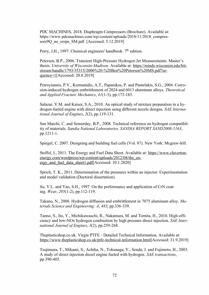
72
PDC MACHINES, 2018. Diaphragm Compressors (Brochure). Available at:https://www.pdcmachines.com/wp-content/uploads/2018/11/2018_compres-sors9Q_no_crops_SM.pdf. [Accessed: 5.12.2019]
Perry, J.H., 1997. Chemical engineers' handbook. 7th edition.
Petersen, B.P., 2006. Transient High-Pressure Hydrogen Jet Measurements. Mastethesis. University of Wisconsin-Madison. Available at: https://minds.wisconsin.edu/bit-stream/handle/1793/35315/2006%20-%20Ben%20Petersen%20MS.pdf?se-quence=1[Accessed: 20.8.2019]
Petroyiannis, P.V., Kermanidis, A.T., Papanikos, P. and Pantelakis, S.G., 2004. Corro-sion-induced hydrogen embrittlement of 2024 and 6013 aluminum alloys. Theoreticaland Applied Fracture Mechanics, 41(1-3), pp.173-183.
Salazar, V.M. and Kaiser, S.A., 2010. An optical study of mixture preparation in a hy-drogen-fueled engine with direct injection using different nozzle designs. SAE Interna-tional Journal of Engines, 2(2), pp.119-131.
San Marchi, C. and Somerday, B.P., 2008. Technical reference on hydrogen compatibil-ity of materials. Sandia National Laboratories, SANDIA REPORT SAND2008-1163,pp.1211-1.
Spiegel, C. 2007. Designing and building fuel cells (Vol. 87). New York: Mcgraw-hill.
Steffel, I., 2011. The Energy and Fuel Data Sheet. Available at: https://www.claverton-energy.com/wordpress/wp-content/uploads/2012/08/the_en-ergy_and_fuel_data_sheet1.pdf[Accessed: 10.1.2020]
Sprich, T. K., 2011. Determination of the pressures within an injector: Experimentationand model validation (Doctoral dissertation).
Su, Y.L. and Yao, S.H., 1997. On the performance and application of CrN coat-ing. Wear, 205(1-2), pp.112-119.
Takano, N., 2008. Hydrogen diffusion and embrittlement in 7075 aluminum alloy. Ma-terials Science and Engineering: A, 483, pp.336-339.
Tanno, S., Ito, Y., Michikawauchi, R., Nakamura, M. and Tomita, H., 2010. High-effi-ciency and low-NOx hydrogen combustion by high pressure direct injection. SAE Inter-national Journal of Engines, 3(2), pp.259-268.
Theplasticshop.co.uk. Virgin PTFE - Detailed Technical Information. Available at:https://www.theplasticshop.co.uk/ptfe-technical-information.html[Accessed: 31.9.2019]
Tsujimura, T., Mikami, S., Achiha, N., Tokunaga, Y., Senda, J. and Fujimoto, H., 2003.A study of direct injection diesel engine fueled with hydrogen. SAE transactions,pp.390-405.

73
Van Basshuysen, R. and Schäfer, F., 2004. Internal combustion engine handbook-basics,components, systems and perspectives (Vol. 345). pp. 410-411, 460-461, 463, 506, 576.
Verhelst, S. and Wallner, T., 2009. Hydrogen-fueled internal combustion engines. Pro-gress in energy and combustion science, 35(6), pp.490-527.
Verhelst, S., Demuynck, J., Sierens, R., Scarcelli, R., Matthias, N.S. and Wallner, T.,2013. Update on the progress of hydrogen-fueled internal combustion engines. Renewa-ble hydrogen technologies e production, purification, storage, applications and safety.Elsevier, pp.381-400.
White, C.M., Steeper, R.R. and Lutz, A.E., 2006. The hydrogen-fueled internal combus-tion engine: a technical review. International journal of hydrogen energy, 31(10),pp.1292-1305.
Wänstrand, O., Larsson, M. and Hedenqvist, P., 1999. Mechanical and tribological eval-uation of PVD WC/C coatings. Surface and Coatings Technology, 111(2-3), pp.247-254.
Wärtsilä, 2011, GD presentation.
Welch, A., Mumford, D., Munshi, S., Holbery, J., Boyer, B., Younkins, M. and Jung,H., 2008. Challenges in developing hydrogen direct injection technology for internalcombustion engines (No. 2008-01-2379). SAE Technical Paper.
Wilberforce, T., Alaswad, A., Palumbo, A., Dassisti, M. and Olabi, A.G., 2016. Ad-vances in stationary and portable fuel cell applications. International journal of hydro-gen energy, 41(37), pp.16509-16522.
Yamane, K., Nogami, M., Umemura, Y., Oikawa, M., Sato, Y. and Goto, Y., 2011. De-velopment of high pressure H2 gas injectors, capable of injection at large injection rateand high response using a common-rail type actuating system for a 4-cylinder, 4.7-litertotal displacement, spark ignition hydrogen engine (No. 2011-01-2005). SAE TechnicalPaper.
Yu, J., Vuorinen, V., Hillamo, H., Sarjovaara, T., Kaario, O. and Larmi, M., 2012. Anexperimental study on high pressure pulsed jets for DI gas engine using planar laser-induced fluorescence (No. 2012-01-1655). SAE Technical Paper.
Yu, J., Vuorinen, V., Kaario, O., Sarjovaara, T. and Larmi, M., 2013. Visualization andanalysis of the characteristics of transitional underexpanded jets. International Journalof Heat and Fluid Flow, 44, pp.140-154.
Zafra, A., Peral, L.B., Belzunce, J. and Rodríguez, C., 2018. Effect of hydrogen on thetensile properties of 42CrMo4 steel quenched and tempered at different tempera-tures. International Journal of Hydrogen Energy, 43(18), pp.9068-9082.
Zhang Chu, Oxide layer thickness modification of a dual phase steel by steam treat-ment, available at: http://www.diva-por-tal.org/smash/get/diva2:1023218/FULLTEXT02[Accessed: 31.9.2019]

74
Zheng, M., Reader, G.T. and Hawley, J.G., 2004. Diesel engine exhaust gas recircula-tion a review on advanced and novel concepts. Energy conversion and management,45(6), pp.883-900.
Zikeev, V.N., 1982. Alloying and the structure of constructional steels resistant to hy-drogen embrittlement. Metal Science and Heat Treatment, 24(5), pp.320-326.
(1/2)
1
14
Appendix (1/2). Constants for compressibility factor calculation from equation 8. (Lem-mon, E.W., 2008)

2
Appendix (2/2). Table of hydrogen compressor technology comparison (Kermani, N.A.2017).


![Coronavirus Checklist - Supervisor [German]€¦ · Supervisor Verifizierung COVID-19 (Coronavirus) Management von allgemeinen Nutzungsbereichen Konform 15. Sind Reinigungsmittel](https://img.pdfslide.org/doc/110x75/605acdaa413abf1af460c324/coronavirus-checklist-supervisor-german-supervisor-verifizierung-covid-19-coronavirus.jpg)