Embed Size (px)
Citation preview
04/2018 3332 04/2018
RAPID® Vollgewinde
1 2 3 1 2 3
8,0 x 120 110 S / Zj)
51 c) 50 1,41 3,71 99 60 84 124 164 46 51 7,41 14,32 21,07
8,0 x 140 130 S / Zj)
58 c) 60 1,70 4,44 114 67 84 124 164 53 58 8,89 17,18 25,27
8,0 x 160 150 S / Zj)
65 c) 70 1,98 5,18 128 74 84 124 164 60 65 10,37 20,05 29,49
8,0 x 180 170 S / Zj)
72 c) 80 2,26 5,93 142 81 84 124 164 67 72 11,85 22,91 33,71
8,0 x 200 190 S / Zj)
79 c) 90 2,55 6,67 156 88 84 124 164 74 80 13,34 25,78 37,93
8,0 x 220 210 S / Zj)
86 c) 100 2,83 7,41 170 95 84 124 164 81 87 14,82 28,65 42,15
8,0 x 240 230 S / Zj)
93 c) 110 3,11 8,15 184 102 84 124 164 88 94 16,30 31,50 46,35
8,0 x 260 250 S / Zj) 100 120 3,39 8,89 198 109 84 124 164 96 101 17,26 33,33 49,01
8,0 x 280 270 S / Zj) 108 130 3,68 9,63 213 117 84 124 164 103 108 18,00 34,72 51,00
8,0 x 300 290 S / Zj) 115 140 3,96 10,37 227 124 84 124 164 110 115 18,75 36,10 53,00
8,0 x 350 340 S / Zj) 132 165 4,67 12,23 262 141 84 124 164 127 133 20,60 39,56 57,98
8,0 x 400 390 S / Zj) 150 190 5,37 14,08 297 159 84 124 164 145 150 22,45 43,02 62,96
8,0 x 450 428 S / Z 172 209 5,91 15,91 333 177 84 124 164 167 172 23,86 45,64 66,74
8,0 x 500 478 S / Z 190 234 6,62 17,04 368 194 84 124 164 185 190 25,41 48,54 70,92
8,0 x 600 578 S / Z 225 284 7,85 17,04 439 230 84 124 164 220 225 25,41 48,54 70,92
8,0 x 120 110 S 51 c) 50 1,41 3,71 99 60 84 124 164 46 51 7,41 14,32 21,07
8,0 x 140 130 S 58 c) 60 1,70 4,44 114 67 84 124 164 53 58 8,89 17,18 25,27
8,0 x 160 150 S 65 c) 70 1,98 5,18 128 74 84 124 164 60 65 10,37 20,05 29,49
8,0 x 180 170 S 72 c) 80 2,26 5,93 142 81 84 124 164 67 72 11,85 22,91 33,71
8,0 x 200 190 S 79 c) 90 2,55 6,67 156 88 84 124 164 74 80 13,34 25,78 37,93
8,0 x 220 210 S 86 c) 100 2,83 7,41 170 95 84 124 164 81 87 14,15 27,31 40,13
8,0 x 240 230 S 93 c) 110 3,11 8,15 184 102 84 124 164 88 94 14,88 28,68 42,11
8,0 x 260 250 S 100 120 3,39 8,89 198 109 84 124 164 96 101 15,63 30,06 44,11
8,0 x 280 270 S 108 130 3,68 9,63 213 117 84 124 164 103 108 16,37 31,45 46,10
8,0 x 300 290 S 115 140 3,96 10,37 227 124 84 124 164 110 115 16,50 31,69 46,44
Fv,Rk
[kN]
Anzahl Paare Anzahl Paare
Ø 8,0
Fv,Rk
[kN]
hHTmin =
hNTmin
[mm]
bHTmin
[mm]
bNTmin d)
[mm] m
[mm]
mOFL
[mm]
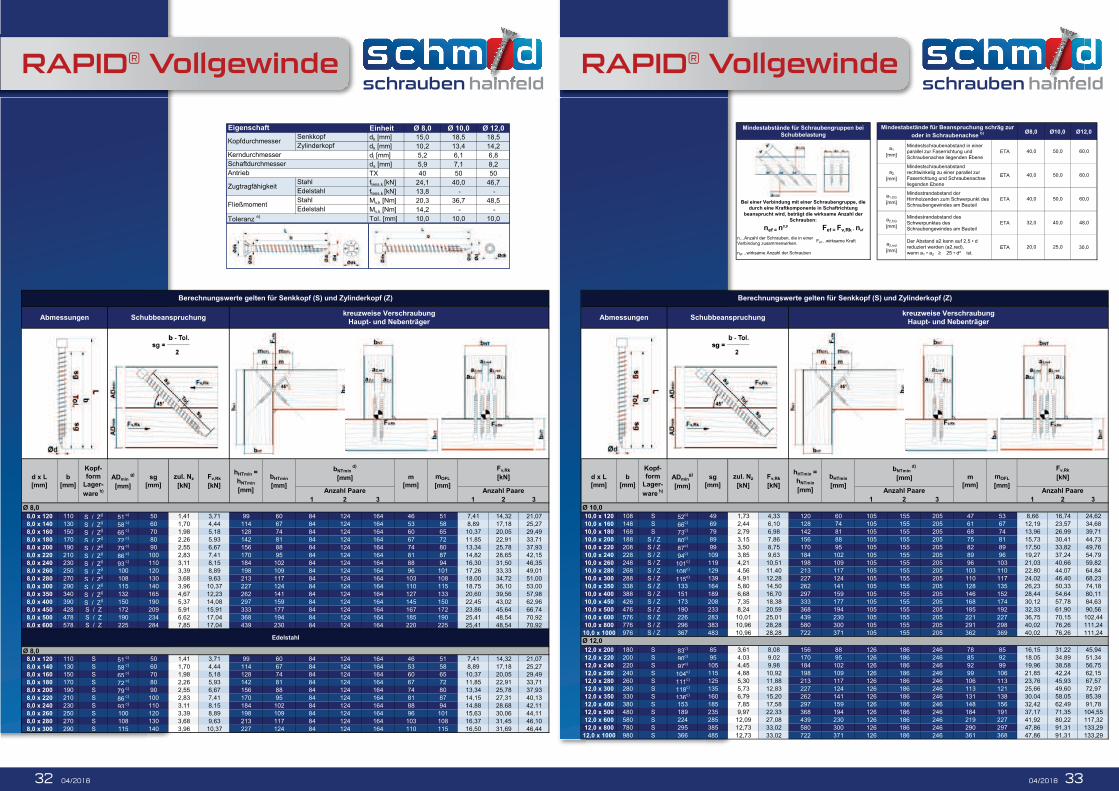
Berechnungswerte gelten für Senkkopf (S) und Zylinderkopf (Z)
Edelstahl
Ø 8,0
Abmessungen Schubbeanspruchungkreuzweise Verschraubung
Haupt- und Nebenträger
d x L
[mm]
b
[mm]
Kopf-
form
Lager-
ware h)
ADmin g)
[mm]
sg
[mm]
zul. Nz
[kN]
Einheit Ø 8,0 Ø 10,0 Ø 12,0dk [mm] 15,0 18,5 18,5
dk [mm] 10,2 13,4 14,2
di [mm] 5,2 6,1 6,8
ds [mm] 5,9 7,1 8,2
TX 40 50 50
ftens,k [kN] 24,1 40,0 46,7
ftens,k [kN] 13,8 - -
My,k [Nm] 20,3 36,7 48,5
My,k [Nm] 14,2 - -
Tol. [mm] 10,0 10,0 10,0
Schaftdurchmesser
Antrieb
Toleranz e)
Edelstahl
Zugtragfähigkeit
Fließmoment
Stahl
Edelstahl
Stahl
Kerndurchmesser
Eigenschaft
KopfdurchmesserSenkkopf
Zylinderkopf
1 2 3 1 2 3
Ø 10,0
10,0 x 120 108 S 52c) 49 1,73 4,33 120 60 105 155 205 47 53 8,66 16,74 24,62
10,0 x 160 148 S 66c) 69 2,44 6,10 128 74 105 155 205 61 67 12,19 23,57 34,68
10,0 x 180 168 S 73c) 79 2,79 6,98 142 81 105 155 205 68 74 13,96 26,99 39,71
10,0 x 200 188 S / Z 80c) 89 3,15 7,86 156 88 105 155 205 75 81 15,73 30,41 44,73
10,0 x 220 208 S / Z 87c) 99 3,50 8,75 170 95 105 155 205 82 89 17,50 33,82 49,76
10,0 x 240 228 S / Z 94c) 109 3,85 9,63 184 102 105 155 205 89 96 19,27 37,24 54,79
10,0 x 260 248 S / Z 101c) 119 4,21 10,51 198 109 105 155 205 96 103 21,03 40,66 59,82
10,0 x 280 268 S / Z 108c) 129 4,56 11,40 213 117 105 155 205 103 110 22,80 44,07 64,84
10,0 x 300 288 S / Z 115c) 139 4,91 12,28 227 124 105 155 205 110 117 24,02 46,40 68,23
10,0 x 350 338 S / Z 133 164 5,80 14,50 262 141 105 155 205 128 135 26,23 50,33 74,18
10,0 x 400 388 S / Z 151 189 6,68 16,70 297 159 105 155 205 146 152 28,44 54,64 80,11
10,0 x 450 426 S / Z 173 208 7,35 18,38 333 177 105 155 205 168 174 30,12 57,78 84,63
10,0 x 500 476 S / Z 190 233 8,24 20,59 368 194 105 155 205 185 192 32,33 61,90 90,56
10,0 x 600 576 S / Z 226 283 10,01 25,01 439 230 105 155 205 221 227 36,75 70,15 102,44
10,0 x 800 776 S / Z 296 383 10,96 28,28 580 300 105 155 205 291 298 40,02 76,26 111,24
10,0 x 1000 976 S / Z 367 483 10,96 28,28 722 371 105 155 205 362 369 40,02 76,26 111,24
12,0 x 200 180 S 83c) 85 3,61 8,08 156 88 126 186 246 78 85 16,15 31,22 45,94
12,0 x 220 200 S 90c) 95 4,03 9,02 170 95 126 186 246 85 92 18,05 34,89 51,34
12,0 x 240 220 S 97c) 105 4,45 9,98 184 102 126 186 246 92 99 19,96 38,58 56,75
12,0 x 260 240 S 104c) 115 4,88 10,92 198 109 126 186 246 99 106 21,85 42,24 62,15
12,0 x 280 260 S 111c) 125 5,30 11,88 213 117 126 186 246 106 113 23,76 45,93 67,57
12,0 x 300 280 S 118c) 135 5,73 12,83 227 124 126 186 246 113 121 25,66 49,60 72,97
12,0 x 350 330 S 136c) 160 6,79 15,20 262 141 126 186 246 131 138 30,04 58,05 85,39
12,0 x 400 380 S 153 185 7,85 17,58 297 159 126 186 246 148 156 32,42 62,49 91,78
12,0 x 500 480 S 189 235 9,97 22,33 368 194 126 186 246 184 191 37,17 71,35 104,55
12,0 x 600 580 S 224 285 12,09 27,08 439 230 126 186 246 219 227 41,92 80,22 117,32
12,0 x 800 780 S 295 385 12,73 33,02 580 300 126 186 246 290 297 47,86 91,31 133,29
12,0 x 1000 980 S 366 485 12,73 33,02 722 371 126 186 246 361 368 47,86 91,31 133,29
Mindestabstände für Schraubengruppen bei Mindestabstände für Beanspruchung schräg zur
Fv,Rk
[kN]
Berechnungswerte gelten für Senkkopf (S) und Zylinderkopf (Z)
Abmessungen Schubbeanspruchungkreuzweise Verschraubung
Haupt- und Nebenträger
Ø 12,0
hHTmin =
hNTmin
[mm]
bHTmin
[mm]
bNTmin d)
[mm] m
[mm]
mOFL
[mm]
Fv,Rk
[kN]
Anzahl Paare Anzahl Paare
d x L
[mm]
b
[mm]
Kopf-
form
Lager-
ware h)
ADming)
[mm]
sg
[mm]
zul. Nz
[kN]
RAPID® Vollgewinde
3
24,62
34,68
39,71
44,73
49,76
54,79
59,82
64,84
68,23
45,94
51,34
56,75
62,15
67,57
72,97
85,39
Ø8,0 Ø10,0 Ø12,0
60,0
40,0 60,050,0ETA
ETA
ETA
40,0 50,0
40,0 50,0 60,0
ETA 20,0 25,0 30,0
ETA 32,0 40,0 48,0
a1,CG
[mm]
a2,CG
[mm]
a2,red
[mm]reduziert werden (a2,red),
wenn a1 2
Mindestrandabstand des
Schwerpunktes des
Schraubengewindes am Bauteil
Mindestrandabstand der
Hirnholzenden zum Schwerpunkt des
Schraubengewindes am Bauteil
v,Rk n
Mindestschraubenabstand in einer
parallel zur Faserrichtung und
Schraubenachse liegenden Ebene
a1
[mm]
a2
[mm]
Mindestabstände für Beanspruchung schräg zur
oder in Schraubenachse b)
Mindestschraubenabstand
rechtwinkelig zu einer parallel zur
Faserrichtung und Schraubenachse
liegenden Ebene
120
128
142
156
170
184
198
213
227
156
170
184
198
213
227
262
Fef…wirksame Kraft
nef = n0,9 Fef = Fv,Rk nef
n…Anzahl der Schrauben, die in einer
Verbindung zusammenwirken.
nef…wirksame Anzahl der Schrauben
Mindestabstände für Schraubengruppen bei
Schubbelastung
Bei einer Verbindung mit einer Schraubengruppe, die
durch eine Kraftkomponente in Schaftrichtung
beansprucht wird, beträgt die wirksame Anzahl der
Schrauben:
04/2018 3534 04/2018
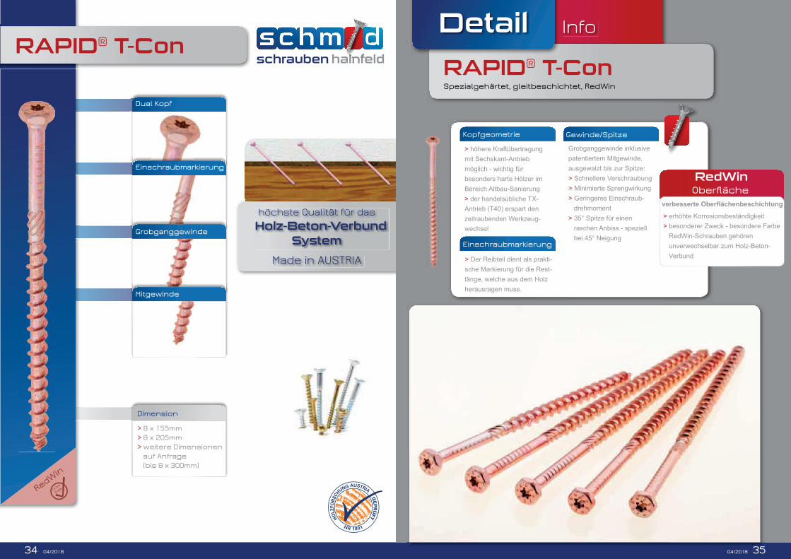
RAPID® T-Con
Dimension
> 8 x 155mm
> 8 x 205mm
> weitere Dimensionen
auf Anfrage
(bis 8 x 300mm)
Dual Kopf
Einschraubmarkierung
Grobganggewinde
Mitgewinde
höchste Qualität für das
Holz-Beton-Verbund
System
Detail
RAPID® T-Con
Info
Spezialgehärtet, gleitbeschichtet, RedWin
Gewinde/Spitze
Grobganggewinde inklusive
patentiertem Mitgewinde,
ausgewalzt bis zur Spitze:
> Schnellere Verschraubung
> Minimierte Sprengwirkung
> Geringeres Einschraub-
drehmoment
> 35° Spitze für einen
raschen Anbiss - speziell
bei 45° Neigung
Einschraubmarkierung
> Der Reibteil dient als prakti-
sche Markierung für die Rest-
länge, welche aus dem Holz
herausragen muss.
Kopfgeometrie
> höhere Kraftübertragung
mit Sechskant-Antrieb
möglich - wichtig für
besonders harte Hölzer im
Bereich Altbau-Sanierung
> der handelsübliche TX-
Antrieb (T40) erspart den
zeitraubenden Werkzeug-
wechsel
RedWin
> erhöhte Korrosionsbeständigkeit
> besonderer Zweck - besondere Farbe
RedWin-Schrauben gehören
unverwechselbar zum Holz-Beton-
Verbund
35
RedWin
Cr(VI)
free