Embed Size (px)
Citation preview
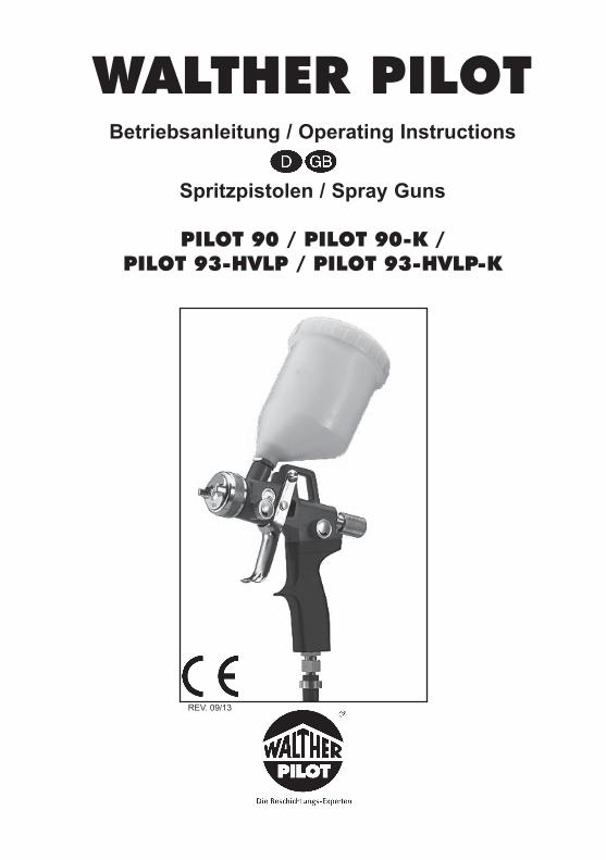
WALTHER PILOTBetriebsanleitung / Operating Instructions
Spritzpistolen / Spray Guns
PILOT 90 / PILOT 90-K / PILOT 93-HVLP / PILOT 93-HVLP-K
REV. 09/13
2 3
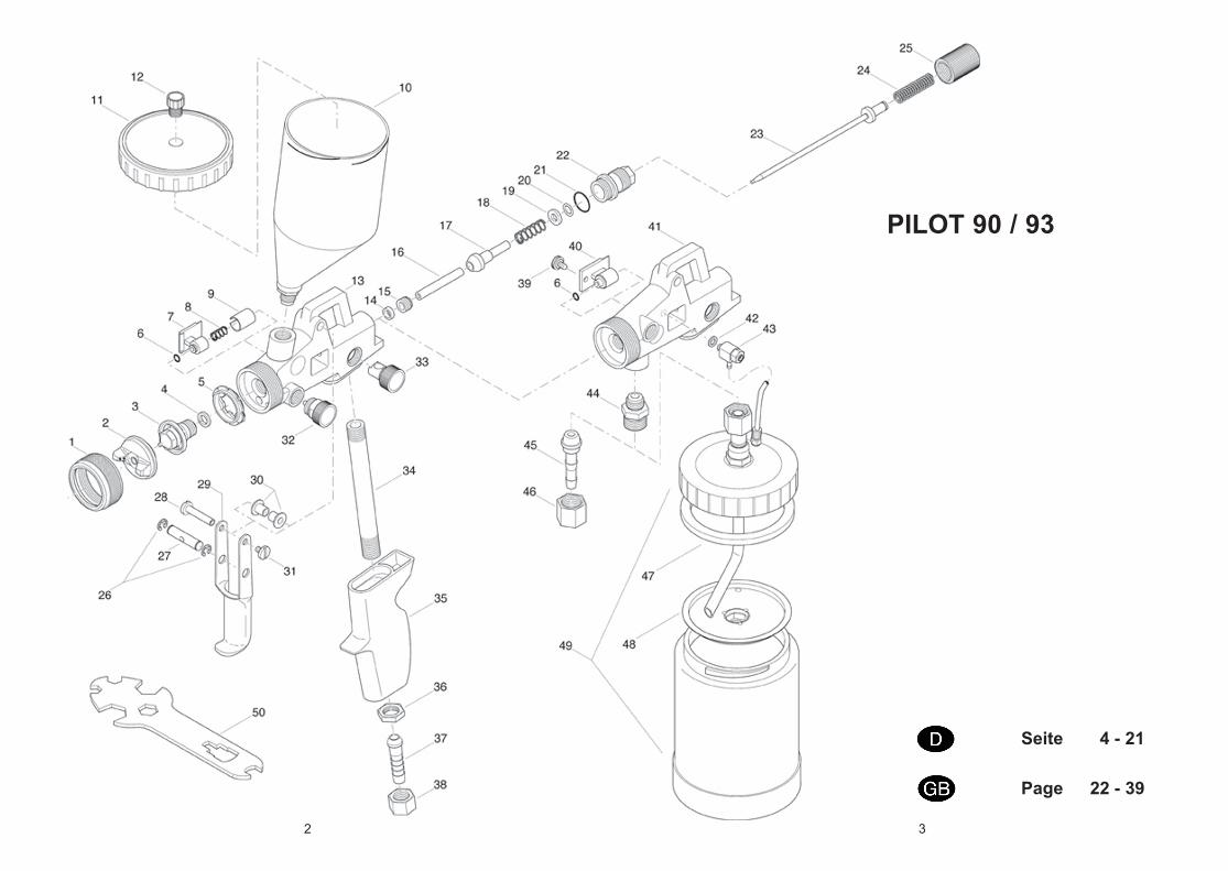
PILOT 90 / 93
Seite 4 - 21
Page 22 - 39
4 5
Inhaltsverzeichnis
Explosionszeichnung 2 Konformitätserklärung 5 Ersatzteilliste 6
1 Allgemeines 81.1 Kennzeichnung der Modelle 81.2 Bestimmungsgemäße Verwendung 81.3 Sachwidrige Verwendung 9
2 Technische Beschreibung 9
3 Sicherheitshinweise 103.1 Kennzeichnung der Sicherheitshinweise 103.2 Allgemeine Sicherheitshinweise 10
4 Versorgungsleitungen anschließen 11
5 Bedienung 125.1 Sicherheitshinweise 125.2 Inbetrieb- und Außerbetriebsetzen 125.3 Spritzbildprobe erzeugen 125.4 Spritzbild verändern 135.5 Spritzpistole umrüsten 145.6 Mängel eines Spritzbildes beheben 15
6 Reinigung und Wartung 156.1 Sicherheitshinweise 156.2 Grundreinigung 156.3 Routinereinigung 16
7 Instandsetzung 177.1 Undichte Nadelpackung austauschen 177.2 Materialdüse und -nadel austauschen 18
8 Fehlersuche und -beseitigung 19
9 Entsorgung 20
10 Technische Daten 2010.1 PILOT 90 / PILOT 90-K 2010.2 PILOT 93-HVLP / PILOT 93-HVLP-K 21
EG-KonformitätserklärungWir, der Gerätehersteller, erklären in alleiniger Verantwortung, dass das Produkt in der untenstehenden Beschreibung den einschlägigen grundlegenden Sicherheits- und Gesundheitsanforderungen entspricht. Bei einer nicht mit uns abgestimmten Änderung an dem Gerät oder bei einer unsachgemäßen Verwendung verliert diese Erklärung ihre Gültigkeit.
Hersteller WALTHER Spritz- und Lackiersysteme GmbHKärntner Str. 18 - 30 D - 42327 WuppertalTel.: +49(0)202 / 787 - 0Fax: +49(0)202 / 787 - 2217 www.walther-pilot.de • e-mail: [email protected]
Typenbezeichnung Handspritzpistolen PILOT 90, PILOT 93-HVLP, PILOT 90-K, 93-HVLP-K
PILOT 90 (Fließbecher) V 11 611PILOT 90 (Materialanschluss) V 11 612PILOT 90 (Saugbecher) V 11 603PILOT 93-HVLP (Fließbecher) V 11 631PILOT 93-HVLP (Materialanschluss) V 11 632PILOT 93-HVLP (Hängedruckbecher) V 11 638PILOT 90-K (Fließbecher) V 11 641PILOT 90-K (Materialanschluss) V 11 642PILOT 93-HVLP-K (Fließbecher) V 11 643PILOT 93-HVLP-K (Materialanschluss) V 11 644PILOT 93-HVLP-K (Hängedruckbecher) V 11 648
Verwendungszweck Verarbeitung spritzbarer Materialien
Angewandte Normen und RichtlinienEG-Maschinenrichtlinien 2006 / 42 / EG94 / 9 EG (ATEX Richtlinien)EN ISO 12100 Teil 1EN ISO 12100 Teil 2 DIN EN 1953DIN EN 1127-1 DIN EN 13463-1
Spezifikation im Sinne der Richtlinie 94 / 9 / EG
Kategorie 2 Gerätebezeichnung II 2 G c T 6Tech.File,Ref.:
2404
Bevollmächtigt mit der Zusammenstellung der technischen Unterlagen:Nico Kowalski, WALTHER Spritz- und Lackiersysteme GmbH, Kärntner Str. 18 - 30D- 42327 Wuppertal
Besondere Hinweise :Das Produkt ist zum Einbau in ein anderes Gerät bestimmt. Die Inbetriebnahme ist so lange untersagt, bis die Konformität des Endproduktes mit der Richtlinie 2006 / 42 / EG festgestellt ist.
Wuppertal, den 01. Januar 2010
Name: Torsten BrökerStellung im Betrieb: Leiter der Konstruktion und Entwicklung
Diese Erklärung ist keine Zusicherung von Eigenschaften im Sinne der Produkthaftung. Die Sicherheitshinweise der Produktdokumentation sind zu beachten.
i.V.
6 7
Ersatzteilliste PILOT 90
Pos. Artikelnummer BezeichnungNr. 1 V 11 360 04 300 Luftkopfmutter2 wahlweise V 11 360 35 . . .* Luftkopf3 wahlweise V 11 601 40 . . 3* Materialdüse4 V 09 002 16 000 Zwischenring5 V 11 601 04 000 Luftverteilerring6 V 09 103 20 001 O-Ring7 V 11 641 16 000 Nadelpackung8 V 11 601 19 000 Druckfeder 9 V 11 601 18 004 Hülse V 00 150 00 000 Fließbecher komplett bestehend aus:10 V 00 150 01 000 Fließbecher11 V 00 150 03 000 Fließbecherdeckel12 V 00 150 04 000 Tropfensperre13 V 11 601 01 000 Pistolenkörper für Fließbecher14 V 09 002 15 000 Ventildichtung15 V 11 601 06 004 Ventilstopfbuchse16 V 11 601 11 203 Ventilschaft17 V 11 601 11 100 Ventilkegel18 V 11 601 32 000 Ventilfeder19 V 11 601 13 000 Scheibe20 V 09 102 33 009 O-Ring21 V 09 103 19 001 O-Ring22 V 11 601 14 005 Federbuchse23 wahlweise V 11 601 30 . . 3* Materialnadel für Fließbecher wahlweise V 11 611 30 . . 3* Materialnadel für Saugbecher und Materialanschluss24 V 11 601 32 000 Nadelfeder25 V 11 601 15 005 Stellschraube26 V 11 601 23 000 Sicherungsscheibe27 V 11 601 09 005 Mitnehmerbolzen28 V 11 301 08 000 Hebelschaftschraube29 V 11 601 10 000 Abzugshebel30 V 11 601 08 000 Distanzstück31 V 10 301 09 000 Hebelschraube32 V 11 601 20 000 Breit- / Rundstrahlregelung33 V 11 621 02 000 Luftmengenregulierung34 V 11 601 05 000 Luftrohr35 V 11 601 03 100 Pistolengriff m. Platte36 V 00 112 03 005 Sechskantmutter37 V 00 101 02 000 Schlauchtülle38 V 00 101 03 000 Überwurfmutter G 1/4“ 39 V 11 641 19 003 Rändelschraube40 V 11 641 16 000 Nadelpackung kompl.
Pos. Artikelnummer BezeichnungNr. 41 wahlweise Pistolenkörper V 11 611 01 000 für Materialanschluss (o. Abb.) V 11 638 01 000 für Hängedruckbecher42 V 66 100 02 225 Dichtung 43 V 66 100 14 096 Drosselventil44 V 11 611 03 003 Doppelnippel45 V 00 101 81 093 Schlauchtülle46 V 00 101 12 005 Überwurfmutter47 V 09 002 06 000 Deckeldichtung48 V 11 352 57 000 Ablaufkappe49 V 11 352 61 000 Hängedruckbecher kompl. V 11 352 00 000 Saugbecher f. PILOT 90 (o. Abb.)50 V 11 360 23 000 Werkzeugschlüssel
Ersatzteilliste (abweichend von PILOT 90)PILOT 93-HVLP
2 wahlweise Niederdruck-Luftkopf V 11 631 11 061* Lack-Luftkopf f. Düsengr. 0,5 - 1,8 mm ø V 11 631 11 211* Lack-Luftkopf f. Düsengr. 2,0 - 2,5 mm ø5 V 11 631 04 000 Luftverteilerring wahlweise Pistolenkörper13 V 11 621 01 000 für Fließbecher41 V 11 621 10 000 für Materialanschluss41 V 11 638 01 000 für Hängedruckbecher34 V 11 631 05 100 Luftrohr35 V 11 601 03 000 Pistolengriff m. Platte
PILOT 90-K / PILOT 93-HVLP-K
2 wahlweise Luftkopf V 11 631 12 054* f. Düsengr 0,5 - 1,0 mm ø V 11 631 12 204* f. Düsengr 1,2 - 1,8 mm ø V 11 631 12 254* f. Düsengr 2,0 - 2,5 mm ø3 wahlweise Materialdüse V 11 641 40 . . 3* 4 Zwischenring entfällt13 wahlweise Pistolenkörper V 11 642 01 000 für Fließbecher PILOT 90-K V 11 643 01 000 für Fließbecher PILOT 93-ND-K41 wahlweise Pistolenkörper V 11 642 01 000 für Materialanschluss PILOT 90-K V 11 644 01 000 für Materialanschluss PILOT 93-ND-K23 wahlweise Materialnadel V 11 641 30 .. 3* für Fließbecher V 11 642 30 .. 3* für Materialanschluss
* Bei Ersatzteillieferung bitte entsprechende Größe angeben. Wir empfehlen, alle fettgedruck-ten Teile (Verschleißteile) auf Lager zu halten.
8 9
und Temperaturklasse.Beim Betreiben des Gerätes sind die Vorgaben dieser Betriebsanleitung unbedingt einzuhalten. Die vorgeschriebenen Inspektions- und Wartungsintervalle sind einzuhal-ten. Die Angaben auf den Geräteschildern bzw. die Angaben in dem Kapitel techni-sche Daten sind unbedingt einzuhalten und dürfen nicht überschritten werden. Eine Überlastung des Gerätes muss ausgeschlossen sein. Das Gerät darf in explosionsge-fährdeten Bereichen nur nach Maßgabe der zuständigen Aufsichtsbehörde eingesetzt werden. Der zuständigen Aufsichtsbehörde bzw. dem Betreiber obliegt die Festlegung der Explosionsgefährdung (Zoneneinteilung).Es ist betreiberseitig zu prüfen und sicherzustellen, dass alle technischen Daten und die Kennzeichnung gemäß ATEX mit den notwendigen Vorgaben übereinstimmen.Bei Anwendungen, bei denen der Ausfall des Gerätes zu einer Personengefährdung führen könnten, sind betreiberseitig entsprechende Sicherheitsmaßnahmen vorzuse-hen. Falls im Betrieb Auffälligkeiten erkannt werden, muss das Gerät sofort stillgesetzt werden und es ist mit WALTHER Spritz-und Lackiersysteme Rücksprache zu halten.Erdung / PotentialausgleichEs muss sichergestellt werden, dass die Spritzpistole über einen leitfähigen Luftschlauch ausreichend geerdet ist (maximaler Widerstand 106Ω).
1.3 Sachwidrige Verwendung
Die Spritzpistole darf nicht anders verwendet werden, als es im Abschnitt 1.2 Bestim- mungsgemäße Verwendung geschrieben steht. Jede andere Verwendung ist sachwid-rig. Zur sachwidrigen Verwendung gehören z.B.:• das Verspritzen von Materialien auf Personen und Tiere• das Verspritzen von flüssigem Stickstoff.
2 Technische Beschreibung
PILOT 90 bzw. PILOT 90-K: konventionelle Zerstäubung Ausführungen: Fließbecher, Saugbecher bzw. Hängedruckbecher, Materialanschluss.
PILOT 93-HVLP bzw. PILOT 93-HVLP-K: Niederdruck-Spritztechnik Bei einem Eingangsluftdruck von 4,5 bar beträgt der Spritzdruck 0,7 bar. Ausführungen: Fließbecher, Hängedruckbecher, Materialanschluss.
Bei Betätigung des Abzughebels (Pos. 29) wird zuerst das Luftventil (Pos. 17) geöffnet (Vorluft) und dann erst die Materialnadel (Pos. 23) zurückgezogen. Das Schließen erfolgt in umgekehrter Reihenfolge. Die Materialdurchflussmenge ist abhängig vom Durchmesser der Düse und der Einstellung des Materialdruckes am Druckgefäß oder Materialdruckregler. Zusätzlich lässt sich die Materialmenge durch Ein- bzw. Ausschrauben der Stellschraube (Pos. 25) regeln. Die Regelschraube (Pos. 32) dient zur Regulierung der Spritzstrahlbreite. Der Spritzstrahl wird durch Linksdrehen (Ausschrauben) zum Breitstrahl, durch Rechtsdrehen (Einschrauben) zum Rundstrahl. Die Regelschraube (Pos. 33) dient zur Regulierung der Zerstäuberluftmenge.
1 Allgemeines1.1 Kennzeichnung der Modelle
Modelle: Handspritzpistolen PILOT 90, PILOT 93-HVLP, PILOT 90-K, 93-HVLP-K
Typ: PILOT 90 (Fließbecher) V 11 611 PILOT 90 (Materialanschluss) V 11 612 PILOT 90 (Saugbecher) V 11 603 PILOT 93-HVLP (Fließbecher) V 11 631 PILOT 93-HVLP (Materialanschluss) V 11 632 PILOT 93-HVLP (Hängedruckbecher) V 11 638 PILOT 90-K (Fließbecher) V 11 641 PILOT 90-K (Materialanschluss) V 11 642
PILOT 93-HVLP-K (Fließbecher) V 11 643 PILOT 93-HVLP-K (Materialanschluss) V 11 644 PILOT 93-HVLP-K (Hängedruckbecher) V 11 648
Hersteller: WALTHER Spritz-und Lackiersysteme GmbH Kärntner Str. 18-30 D-42327 Wuppertal Tel.: 0202 / 787-0 Fax: 0202 / 787-2217 www.walther-pilot.de • Email: [email protected]
1.2 Bestimmungsgemäße Verwendung
Die Handspritzpistolen PILOT 90 und PILOT 93-HVLP dienen ausschließlich der Verarbeitung spritzbarer Medien. Da sämtliche materialführenden Teile aus Edelstahl-rostfrei gefertigt sind, können auch wasserhaltige bzw. aggressive Materialien ver-spritzt werden, wie z.B.:• Lacke und Farben• Fette, Öle und Korrosionsschutzmittel• Keramikglasuren• säurehaltige Materialien• BeizenSind die Materialien, die Sie verspritzen wollen, hier nicht aufgeführt, wenden Sie sich bitte an WALTHER Spritz- und Lackiersysteme GmbH, Wuppertal. Die spritzba-ren Materialien dürfen lediglich auf Werkstücke bzw. Gegenstände aufgetragen werden. Die Temperatur des Spritzmaterials darf 43°C grundsätzlich nicht über-schreiten. Die Spritzpistolenmodelle PILOT 90-K und PILOT 93-HVLP-K sind speziell zum Kleberauftrag vorgesehen. Da sämtliche materialführenden Teile aus Edelstahl-rostfrei gefertigt sind, kann auch Dispersionskleber verspritzt werden. Die bestimmungsgemäße Verwendung schließt auch ein, dass alle Hinweise und Angaben der vorliegenden Betriebsanleitung gelesen, verstanden und beachtet wer-den. Das Gerät erfüllt die Explosionsschutz-Forderungen der Richtlinie 94 / 9 EG (ATEX) für die auf dem Typenschild angegebene Explosionsgruppe, Gerätekategorie,
10 11
3 Sicherheitshinweise3.1 Kennzeichnung der Sicherheitshinweise
WarnungDas Piktogramm und die Dringlichkeitsstufe “Warnung“ kennzeichnen eine mögliche Gefahr für Personen. Mögliche Folgen: schwere oder leichte Verletzungen.
AchtungDas Piktogramm und die Dringlichkeitsstufe “Achtung“ kennzeichnen eine mögliche Gefahr für Sachwerte. Mögliche Folgen: Beschädigung von Sachen.
HinweisDas Piktogramm und die Dringlichkeitsstufe “Hinweis“ kennzeichnen zusätzliche Informationen für das sichere und effiziente Arbeiten mit der Spritzpistole.
3.2 Allgemeine Sicherheitshinweise
• Die einschlägigen Unfallverhütungsvorschriften sowie die sonstigen anerkann-ten sicherheitstechnischen und arbeitsmedizinischen Regeln sind einzuhalten.
• Benutzen Sie die Spritzpistole nur in gut belüfteten Räumen. Im Arbeitsbereich ist Feuer, offenes Licht und Rauchen verboten. Beim Verspritzen leichtentzünd-licher Materialien (z. B. Lacke, Kleber, Reinigungsmittel usw.) besteht erhöhte Gesundheits-, Explosions- und Brandgefahr.
• Es muss sichergestellt werden, dass die Spritzpistole über einen leitfähigen Luftschlauch ausreichend geerdet ist (maximaler Widerstand 106Ω).
• Schalten Sie vor jeder Wartung und Instandsetzung die Luft- und Materialzufuhr zur Spritzpistole drucklos - Verletzungsgefahr.
• Halten Sie beim Verspritzen von Materialien keine Hände oder andere Körperteile vor die unter Druck stehende Düse der Spritzpistole - Verletzungsgefahr.
• Richten Sie die Spritzpistole nicht auf Personen und Tiere - Verletzungsgefahr.• Beachten Sie die Verarbeitungs- und Sicherheitshinweise der Hersteller von
Spritz- material und Reinigungsmittel. Insbesondere aggressive und ätzende Materialien können gesundheitliche Schäden verursachen.
• Die partikelführende Abluft ist vom Arbeitsbereich und Betriebspersonal fernzu-halten. Tragen Sie dennoch vorschriftsgemäßen Atemschutz und vorschriftsge-mäße Arbeitskleidung, wenn Sie mit der Spritzpistole Materialien verarbeiten. Umherschwebende Partikel gefährden Ihre Gesundheit.
• Tragen Sie im Arbeitsbereich der Spritzpistole einen Gehörschutz. Der erzeugte Schallpegel der Spritzpistole beträgt ca. 85 dB (A)(PILOT 90) bzw. ca. 83 dB (A) (PILOT 93-HVLP).
• Achten Sie stets darauf, dass bei Inbetriebnahme, insbesondere nach Montage- und Wartungsarbeiten alle Muttern und Schrauben fest angezogen sind.
• Verwenden Sie nur Original-Ersatzteile, da WALTHER nur für diese eine sichere und einwandfreie Funktion garantieren kann.
• Bei Nachfragen zur gefahrlosen Benutzung der Spritzpistole sowie der darin verwendeten Materialien, wenden Sie sich bitte an WALTHER Spritz- und Lackiersysteme GmbH, D-42327 Wuppertal.
4 Versorgungsleitungen anschließen
HinweisZur Durchführung der im Folgenden aufgeführten Arbeitsschritte benutzen Sie bitte die Explosionszeichnung (Faltblatt) am Anfang dieser Betriebsanleitung.
WarnungDer an der Pistole anstehende Luftdruck darf 8 bar nicht überschreiten, da sonst kein funktionssicherer Betrieb der Spritzpistole gewährleistet ist.
WarnungMaterial- und Luftschläuche, die mit einer Schlauchtülle befestigt werden, müssen zusätzlich mit einer Schlauchschelle gesichert sein.
Ausführung: Fließbecher, Saugbecher und Hängedruckbecher1. Befestigen Sie den Druckluftschlauch an der Luftleitung (gereinigte Druckluft)
bzw. einem Luftreiniger und an dem Luftanschluss der Spritzpistole (Pos. 37).2. Befüllen Sie den Fließ-, Saug- oder Hängedruckbecher mit gesiebtem Material.
Verschließen Sie den Fließ- oder Hängedruckbecher.3. Schalten Sie die Druckluftversorgung ein. Die Pistole ist nun betriebsbereit.
Ausführung: Materialanschluss1. Befestigen Sie den Druckluftschlauch an der Luftleitung (gereinigte Druckluft)
bzw. einem Luftreiniger und an dem Luftanschluss der Spritzpistole (Pos. 37).2. Schalten Sie die Druckluft ein und stellen Sie am Reduzierventil den gewünsch-
ten Zerstäuberluftdruck ein.3. Befestigen Sie den Materialzuführungsschlauch am Materialdruckgefäß bzw.
Materialdruckregler einer Pumpenanlage und an dem Materialanschluss der Spritzpistole (Pos. 45).
4. Füllen Sie Material in das Materialdruckgefäß und verschließen Sie den Deckel.5. Stellen Sie am Druckluftreduzierventil den gewünschten Materialdruck ein; bei
Materialzufuhr über Pumpensysteme wird der Materialdruck mittels Einstellschlüssel am Materialdruckregler eingestellt.
6. Öffnen Sie den Materialhahn am Druckgefäß.7. Um die im Materialschlauch befindliche Luft entweichen zu lassen, betätigen
Sie den Abzugshebel (Pos. 29) solange, bis ein gleichmäßiger Materialstrahl aus der Düse tritt; nun kann die Pistole wieder geschlossen werden.
Die Pistole ist nun betriebsbereit.
12 13
5 Bedienung5.1 Sicherheitshinweise
Beachten Sie bei der Bedienung der Spritzpistole insbesondere die nachfolgenden Sicherheitshinweise!• Tragen Sie vorschriftsmäßigen Atemschutz und Arbeitskleidung, wenn Sie mit
der Spritzpistole Materialien verspritzen. Umherschwebende Partikel gefährden Ihre Gesundheit.
• Tragen Sie im Arbeitsbereich der Spritzpistole einen Gehörschutz. Der erzeugte Schallpegel der Spritzpistole beträgt ca. 85 dB (A) (PILOT 90) bzw. ca. 83 dB (A) (PILOT 93-HVLP).
• Im Arbeitsbereich ist Feuer, offenes Licht und Rauchen verboten. Beim Verspritzen leicht entzündlicher Materialien (z. B. Lacke, Kleber) besteht erhöh-te Explosions- und Brandgefahr.
5.2 Inbetrieb- und Außerbetriebsetzen
Bevor Sie die Spritzpistole in Betrieb setzen können, müssen folgende Voraussetzungen erfüllt sein:• Der Zerstäuberluftdruck muss an der Spritzpistole anstehen• Der Materialdruck muss an der Spritzpistole anstehen (entfällt bei Fließbecher,
Saugbecher, Hängedruckbecher).
AchtungDer Materialdruck darf nicht höher eingestellt sein als 8 bar. Der Luftdruck darf 8 bar nicht überschreiten, da sonst kein funktionssicherer Betrieb der Spritzpistole gewähr-leistet ist.
WarnungDie Spritzpistole muss nach Arbeitsende immer drucklos geschaltet werden. Die unter Druck stehenden Leitungen können platzen und nahestehende Personen durch das ausströmende Material verletzen.
5.3 Spritzbildprobe erzeugen
Eine Spritzbildprobe sollte immer dann erzeugt werden, wenn:• die Spritzpistole zum ersten Mal in Betrieb gesetzt wird• das Spritzmaterial ausgetauscht wird• die Pistole zur Wartung oder Instandsetzung zerlegt wurde.Das Spritzbild kann auf ein Probewerkstück, Blech, Pappe oder Papier abgegeben werden.
WarnungHalten Sie beim Verspritzen von Materialien keine Hände oder andere Körperteile vor die unter Druck stehende Düse der Spritzpistole - Verletzungsgefahr.
WarnungAchten Sie beim Inbetriebsetzen der Spritzpistole darauf, dass sich keine Person im Spritzbereich befindet - Verletzungsgefahr
1. Setzen Sie die Spritzpistole in Betrieb, um eine Spritzbildprobe zu erzeugen (siehe 5.2 Inbetrieb- und Außerbetriebsetzen).
2. Kontrollieren Sie die Spritzbildprobe und verändern Sie ggf. die Einstellungen an der Spritzpistole (siehe 5.4 Spritzbild verändern).
5.4 Spritzbild verändern
Sie können an der PILOT 90, PILOT 93-HVLP, PILOT 90-K und PILOT 93-HVLP-K durch die folgenden Einstellungen das Spritzbild verändern.
Breit- bzw. Rundstrahl einstellenDie Regelschraube (Pos. 32) dient zur Regulierung der Spritzstrahlbreite. Der Spritzstrahl wird durch Linksdrehen (Ausschrauben) zum Breitstrahl, durch Rechts- drehen (Einschrauben) zum Rundstrahl.
Materialdurchflussmenge einstellenDie Materialmenge lässt sich durch Ein- bzw. Ausschrauben der Stellschraube (Pos. 25) regeln. Die Materialmenge wird durch Linksdrehen (Ausschrauben) erhöht, durch Rechtsdrehen (Einschrauben) verringert.
Materialdruck regulierenPILOT 90 / 93-HVLP / 90-K / 93-HVLP-K (Hängedruckbecherausführung):Der Materialdruck lässt sich mittels eines Schraubendrehers an der Winkelver- schraubung (Pos. 43) einstellen.
PILOT 90 / 93-HVLP / 90-K / 93-HVLP-K (Ausführungen für Materialanschluss):Den Materialdruck können Sie nur an der Pumpe oder am Druckbehälter regulieren. Beachten Sie dabei die Anweisungen und Sicherheitshinweise des Herstellers.
Zerstäuberluft regulierenDie Zerstäuberluftmenge lässt sich durch Ein- bzw. Ausschrauben der Stellschraube (Pos. 33) regulieren. Der Zerstäuberluftdruck wird am Druckluft-Reduzierventil der Kompressoranlage eingestellt. Beachten Sie die Anweisungen und Sicherheitshin- weise des Herstellers.
Wenn Sie das Spritzbild über die bereits erwähnten Möglichkeiten hinaus verändern wollen, muss die Spritzpistole umgerüstet werden (siehe 5.5 Spritzpistole umrüsten).
WALTHER bietet dazu eine Vielzahl unterschiedlicher Luftkopf- / Materialdüse- / Nadel-Kombinationen an.
14 15
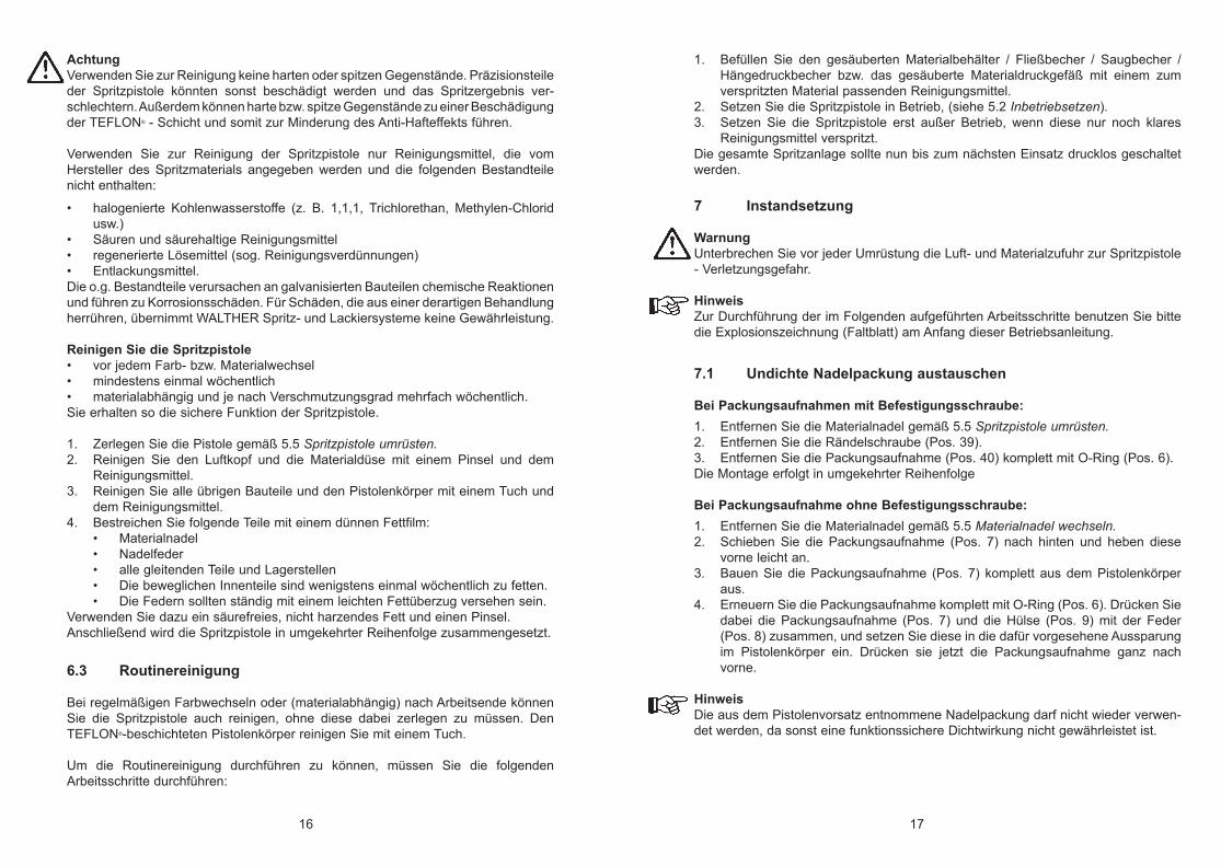
5.6 Mängel eines Spritzbildes beheben
Die folgende Tabelle zeigt Ihnen, mit welchen Einstellungen Sie das Spritzbild beein-flussen können.
Spritzbildprobe Abweichung erforderliche EinstellungSpritzbild ist in der Mitte zu dick
• breitere Spritzstrahlform einstellen
Spritzbild ist an den Enden zu dick
• rundere Spritzstrahlform einstellen
Spritzbild ist ziemlich grobtropfig
• Zerstäuberluftdruck erhöhen
Materialauftrag ist in der Spritzbildmitte sehr dünn
• Zerstäuberluftdruck verringern
Spritzbild ist in der Mitte gespalten
• Düsendurchmesser erhöhen• Zerstäuberluftdruck verringern• Materialdruck erhöhen
Spritzbild ist sehr ballig • Materialdruck verringern• Zerstäuberluftdruck erhöhen
6 Reinigung und Wartung6.1 Sicherheitshinweise
• Unterbrechen Sie vor jeder Wartung die Luft- und Materialzufuhr zur Spritzpistole - Verletzungsgefahr.
• Im Arbeitsbereich ist Feuer, offenes Licht und Rauchen verboten. Beim Verspritzen leichtentzündlicher Materialien (z. B. Reinigungsmittel) besteht erhöhte Explosions- und Brandgefahr.
• Beachten Sie die Sicherheitshinweise des Reinigungsmittel-Herstellers. Insbesondere aggressive und ätzende Reinigungsmittel können gesundheitli-che Schäden verursachen.
6.2 Grundreinigung
Damit die Lebensdauer und die Funktion der Spritzpistole lange erhalten bleibt, muss die Spritzpistole regelmäßig gereinigt und geschmiert werden.
AchtungLegen Sie die Spritzpistole nie in Lösemittel oder ein anderes Reinigungsmittel. Die einwandfreie Funktion der Spritzpistole kann sonst nicht garantiert werden.
5.5 Spritzpistole umrüsten
Die zum Spritzmaterial passende Luftkopf- / Materialdüse- / Nadel-Kombination bil-det eine aufeinander abgestimmte Einheit - die Düseneinlage. Tauschen Sie immer die komplette Düseneinlage aus, damit die gewünschte Spritzbildqualität erhalten bleibt.
WarnungUnterbrechen Sie vor jeder Umrüstung die Luft- und Materialzufuhr zur Spritzpistole - Verletzungsgefahr.
HinweisZur Durchführung der im Folgenden aufgeführten Arbeitsschritte benutzen Sie bitte die Explosionszeichnung (Faltblatt) am Anfang dieser Betriebsanleitung.
Materialdüse und Luftkopf wechseln1. Schrauben Sie die Überwurfmutter (Pos. 1) ab.2. Nehmen Sie den Luftkopf (Pos. 2) ab.3. Schrauben Sie die Materialdüse (Pos. 3) SW 13 aus dem Pistolenkörper aus. 4. Nehmen Sie die Dichtung (Pos. 4) von der Materialdüse ab.Die Montage der neuen Düseneinlage sowie der restlichen Bauteile erfolgt in umge-kehrter Reihenfolge.
Materialnadel wechseln1. Schrauben Sie die Stellschraube (Pos. 25) ab.2. Entnehmen Sie die Feder (Pos. 24).3. Ziehen Sie die Materialnadel (Pos. 23) aus dem Pistolenkörper.Die Montage erfolgt in umgekehrter Reihenfolge. Eine Vorlufteinstellung ist nicht erforderlich.
angestrebtes Spritzergebnis
16 17
AchtungVerwenden Sie zur Reinigung keine harten oder spitzen Gegenstände. Präzisionsteile der Spritzpistole könnten sonst beschädigt werden und das Spritzergebnis ver-schlechtern. Außerdem können harte bzw. spitze Gegenstände zu einer Beschädigung der TEFLON® - Schicht und somit zur Minderung des Anti-Hafteffekts führen.
Verwenden Sie zur Reinigung der Spritzpistole nur Reinigungsmittel, die vom Hersteller des Spritzmaterials angegeben werden und die folgenden Bestandteile nicht enthalten:
• halogenierte Kohlenwasserstoffe (z. B. 1,1,1, Trichlorethan, Methylen-Chlorid usw.)
• Säuren und säurehaltige Reinigungsmittel• regenerierte Lösemittel (sog. Reinigungsverdünnungen)• Entlackungsmittel.Die o.g. Bestandteile verursachen an galvanisierten Bauteilen chemische Reaktionen und führen zu Korrosionsschäden. Für Schäden, die aus einer derartigen Behandlung herrühren, übernimmt WALTHER Spritz- und Lackiersysteme keine Gewährleistung.
Reinigen Sie die Spritzpistole • vor jedem Farb- bzw. Materialwechsel• mindestens einmal wöchentlich• materialabhängig und je nach Verschmutzungsgrad mehrfach wöchentlich.Sie erhalten so die sichere Funktion der Spritzpistole.
1. Zerlegen Sie die Pistole gemäß 5.5 Spritzpistole umrüsten.2. Reinigen Sie den Luftkopf und die Materialdüse mit einem Pinsel und dem
Reinigungsmittel.3. Reinigen Sie alle übrigen Bauteile und den Pistolenkörper mit einem Tuch und
dem Reinigungsmittel.4. Bestreichen Sie folgende Teile mit einem dünnen Fettfilm:
• Materialnadel• Nadelfeder• alle gleitenden Teile und Lagerstellen• Die beweglichen Innenteile sind wenigstens einmal wöchentlich zu fetten.• Die Federn sollten ständig mit einem leichten Fettüberzug versehen sein.
Verwenden Sie dazu ein säurefreies, nicht harzendes Fett und einen Pinsel.Anschließend wird die Spritzpistole in umgekehrter Reihenfolge zusammengesetzt.
6.3 Routinereinigung
Bei regelmäßigen Farbwechseln oder (materialabhängig) nach Arbeitsende können Sie die Spritzpistole auch reinigen, ohne diese dabei zerlegen zu müssen. Den TEFLON®-beschichteten Pistolenkörper reinigen Sie mit einem Tuch.
Um die Routinereinigung durchführen zu können, müssen Sie die folgenden Arbeitsschritte durchführen:
1. Befüllen Sie den gesäuberten Materialbehälter / Fließbecher / Saugbecher / Hängedruckbecher bzw. das gesäuberte Materialdruckgefäß mit einem zum verspritzten Material passenden Reinigungsmittel.
2. Setzen Sie die Spritzpistole in Betrieb, (siehe 5.2 Inbetriebsetzen). 3. Setzen Sie die Spritzpistole erst außer Betrieb, wenn diese nur noch klares
Reinigungsmittel verspritzt.Die gesamte Spritzanlage sollte nun bis zum nächsten Einsatz drucklos geschaltet werden.
7 Instandsetzung
WarnungUnterbrechen Sie vor jeder Umrüstung die Luft- und Materialzufuhr zur Spritzpistole - Verletzungsgefahr.
HinweisZur Durchführung der im Folgenden aufgeführten Arbeitsschritte benutzen Sie bitte die Explosionszeichnung (Faltblatt) am Anfang dieser Betriebsanleitung.
7.1 Undichte Nadelpackung austauschen
Bei Packungsaufnahmen mit Befestigungsschraube:1. Entfernen Sie die Materialnadel gemäß 5.5 Spritzpistole umrüsten.2. Entfernen Sie die Rändelschraube (Pos. 39).3. Entfernen Sie die Packungsaufnahme (Pos. 40) komplett mit O-Ring (Pos. 6).Die Montage erfolgt in umgekehrter Reihenfolge
Bei Packungsaufnahme ohne Befestigungsschraube:1. Entfernen Sie die Materialnadel gemäß 5.5 Materialnadel wechseln.2. Schieben Sie die Packungsaufnahme (Pos. 7) nach hinten und heben diese
vorne leicht an.3. Bauen Sie die Packungsaufnahme (Pos. 7) komplett aus dem Pistolenkörper
aus.4. Erneuern Sie die Packungsaufnahme komplett mit O-Ring (Pos. 6). Drücken Sie
dabei die Packungsaufnahme (Pos. 7) und die Hülse (Pos. 9) mit der Feder (Pos. 8) zusammen, und setzen Sie diese in die dafür vorgesehene Aussparung im Pistolenkörper ein. Drücken sie jetzt die Packungsaufnahme ganz nach vorne.
HinweisDie aus dem Pistolenvorsatz entnommene Nadelpackung darf nicht wieder verwen-det werden, da sonst eine funktionssichere Dichtwirkung nicht gewährleistet ist.
18 19
7.2 Materialdüse und -nadel austauschen
Zerlegen Sie die Spritzpistole gemäß Abschnitt 5.5 Spritzpistole umrüsten
HinweisAlle beweglichen und gleitenden Bauteile müssen vor dem Einbau in den Pistolenkör- per mit einem säurefreien, nicht harzenden Fett eingefettet werden.
Reparatursets:
WALTHER Spritz-und Lackiersysteme hält für die Handspritzpistolen PILOT 90 und PILOT 93-HVLP Reparatursets bereit, die sämtliche Verschleißteile enthalten:
PILOT 90:I. Materialseitig + LuftseitigBestehend aus: Luftkopf (Pos. 2), Materialdüse (Pos. 3), Ventildichtung (Pos. 14), Ventilkegel (Pos. 17), Ventilfeder (Pos. 18), O-Ring (Pos. 20), O-Ring (Pos. 21), Materialnadel (Pos. 23), Nadelfeder (Pos. 24), Nadelpackung (Pos. 7 bzw. 40) und Zwischenring (Pos. 4).
Für Fließbecherpistole: Art. Nr.: V 16 090 03 . . 3Für Saugbecherpistoleund Materialanschlussausführung: Art. Nr.: V 16 090 06 . . 3
II. LuftseitigBestehend aus: Ventildichtung (Pos. 14), Ventilkegel (Pos. 17), Ventilfeder (Pos. 18), O-Ring (Pos. 20) und O-Ring (Pos. 21).
Für sämtliche Ausführungen: Art. Nr.: V 16 090 00 000
PILOT 93-HVLP:I. Materialseitig + LuftseitigBestehend aus: Luftkopf (Pos. 2), Materialdüse (Pos. 3), Ventildichtung (Pos. 14), Ventilkegel (Pos. 17), Ventilfeder (Pos. 18), O-Ring (Pos. 20), O-Ring (Pos. 21), Materialnadel (Pos. 23), Nadelfeder (Pos. 24), Nadelpackung (Pos. 7 bzw. 40) und Zwischenring (Pos. 4).
Für Fließbecherpistole: Art. Nr.: V 16 093 03 . . 3Für Materialanschlussausführung: Art. Nr.: V 16 094 03 . . 3
II. LuftseitigBestehend aus: Ventildichtung (Pos. 14), Ventilkegel (Pos. 17), Ventilfeder (Pos. 18), O-Ring (Pos. 20) und O-Ring (Pos. 21).
Für sämtliche Ausführungen: Art. Nr.: V 16 090 00 000
PILOT 90-K + PILOT 93-HVLP-K:I. Materialseitig + LuftseitigBestehend aus: Luftkopf (Pos. 2), Materialdüse (Pos. 3), Ventildichtung (Pos. 14), Ventilkegel (Pos. 17), Ventilfeder (Pos. 18), O-Ring (Pos. 20), O-Ring (Pos. 21), Materialnadel (Pos. 23), Nadelfeder (Pos. 24), Nadelpackung (Pos. 7 bzw. 40).
Für Fließbecherpistole: Art. Nr.: V 16 097 02 . . 3Für Materialanschlussausführung Art. Nr.: V 16 099 02 . . 3
8 Fehlersuche und -beseitigung
WarnungSchalten Sie vor jeder Instandsetzung die Steuer- und Zerstäuberluft sowie die Materialzufuhr zur Spritzpistole drucklos - Verletzungsgefahr.
Fehler Ursache Abhilfe
Pistole tropft
Materialnadel oder -düse ver-schmutzt
Materialnadel oder -düse beschädigt
Nadelfeder (Pos. 24) nicht in Ordnung, evtl. gebrochen
Materialnadel stimmt nicht mit Düsengröße überein
Stellschraube (Pos. 25) zu weit nach hinten gedreht
reinigen gemäß 5.5 Spritzpistole umrüsten
erneuern, gemäß 5.5 Spritzpistole umrüsten
Materialnadel ausbauen und Feder austauschen, gemäß 5.5 Spritzpistole umrüsten
auf gleiche Durchmesser achten
Stellschraube etwas Einschrauben (Rechtsdrehen)
Stoßweiser oder flatternder Spritz- strahl
zu wenig Material im Material-behälter
Saugbecher wird während des Spritzvorgangs zu stark geneigt
die Materialdüse ist lose oder beschädigt
das Material ist für Saugzufuhr zu schwer
Material auffüllen (s. Betriebs- anleitung des Anlagenherstel- lers)
gerader halten
festziehen, evtl. Luftverteilerring (Pos. 5) ersetzen
mit Druckgefäß oder Pumpenanlage fördern
Pistole bläst in Ruhestellung
Ventilfeder (Pos. 18) oder Ventilkegel (Pos. 17) beschä-digt
austauschen
20 21
9 Entsorgung
Die bei der Reinigung und Wartung anfallenden Materialien sind den Gesetzen und Vorschriften entsprechend sach- und fachgerecht zu entsorgen.
WarnungBeachten Sie insbesondere die Hinweise des Herstellers der Spritz- und Reinigungsmittel. Unachtsam entsorgtes Material gefährdet die Gesundheit von Mensch und Tier.
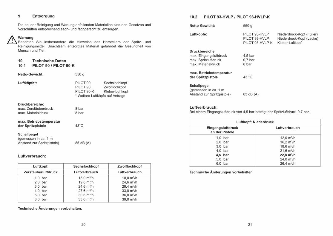
10 Technische Daten 10.1 PILOT 90 / PILOT 90-K
Netto-Gewicht: 550 g
Luftköpfe*: PILOT 90 Sechslochkopf PILOT 90 Zwöfllochkopf PILOT 90-K Kleber-Luftkopf * Weitere Luftköpfe auf Anfrage
Druckbereiche:max. Zerstäuberdruck 8 barmax. Materialdruck 8 bar
max. Betriebstemperaturder Spritzpistole 43°C
Schallpegel(gemessen in ca. 1 m Abstand zur Spritzpistole) 85 dB (A)
Luftverbrauch:
Luftkopf: Sechslochkopf ZwölflochkopfZerstäuberluftdruck Luftverbrauch Luftverbrauch
1,0 bar2,0 bar3,0 bar4,0 bar5,0 bar6,0 bar
15,0 m3/h19,8 m3/h24,6 m3/h27,6 m3/h30,6 m3/h33,6 m3/h
18,0 m3/h24,6 m3/h29,4 m3/h33,0 m3/h36,0 m3/h39,0 m3/h
Technische Änderungen vorbehalten.
10.2 PILOT 93-HVLP / PILOT 93-HVLP-K
Netto-Gewicht: 550 g Luftköpfe: PILOT 93-HVLP Niederdruck-Kopf (Füller) PILOT 93-HVLP Niederdruck-Kopf (Lacke) PILOT 93-HVLP-K Kleber-Luftkopf
Druckbereiche:max. Eingangsluftdruck 4,5 barmax. Spritzluftdruck 0,7 barmax. Materialdruck 8 bar
max. Betriebstemperaturder Spritzpistole 43 °C
Schallpegel(gemessen in ca. 1 m Abstand zur Spritzpistole) 83 dB (A)
Luftverbrauch: Bei einem Eingangsluftdruck von 4,5 bar beträgt der Spritzluftdruck 0,7 bar.
Luftkopf: NiederdruckEingangsluftdruck
an der PistoleLuftverbrauch
1,0 bar2,0 bar3,0 bar4,0 bar4,5 bar5,0 bar6,0 bar
12,0 m3/h16,2 m3/h18,6 m3/h21,6 m3/h22,8 m3/h24,0 m3/h26,4 m3/h
Technische Änderungen vorbehalten.
22 23
Contents
Exploded Drawing 2 Declaration of CE-Conformity 23 Replacement parts 24
1 General 261.1 Identification of Model Version 261.2 Normal Use 261.3 Improper Use 27
2 Technical Description 27
3 Safety Warnings 283.1 Safety Warning Symbols 283.2 General Safety Precautions 28
4 Connection of Input Lines 29
5 Operational Handling 305.1 Safety Warnings 305.2 Starting / Stopping Requirements 305.3 Spray Pattern Test 305.4 Spray Pattern Adjustments 315.5 Retooling of Spray Gun 32 5.6 Correction of Spray Pattern Imperfections 33
6 Servicing and Maintenance 336.1 Safety Warnings 336.2 Cleaning - Complete 336.3 Cleaning - Routine 34
7 Repairs / Replacements 357.1 Replacement of defective Needle Seal Packings 357.2 Replacement of Nozzle and Needle 36
8 Troubleshooting and Corrective Action 37
9 Disposal of Cleaning/Servicing Substances 38
10 Specification Data 3810.1 PILOT 90 / PILOT 90-K 3810.2 PILOT 93-HVLP / PILOT 93-HVLP-K 39
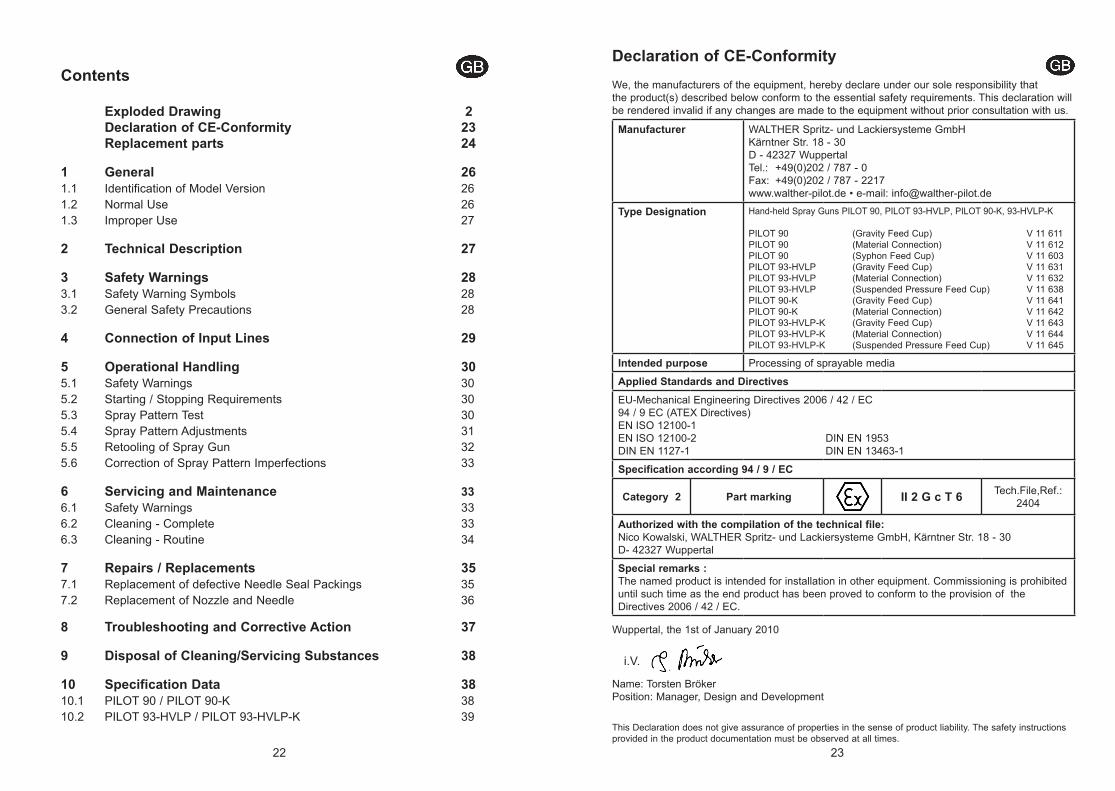
Declaration of CE-ConformityWe, the manufacturers of the equipment, hereby declare under our sole responsibility that the product(s) described below conform to the essential safety requirements. This declaration will be rendered invalid if any changes are made to the equipment without prior consultation with us.
Manufacturer WALTHER Spritz- und Lackiersysteme GmbHKärntner Str. 18 - 30 D - 42327 WuppertalTel.: +49(0)202 / 787 - 0Fax: +49(0)202 / 787 - 2217 www.walther-pilot.de • e-mail: [email protected]
Type Designation Hand-held Spray Guns PILOT 90, PILOT 93-HVLP, PILOT 90-K, 93-HVLP-K
PILOT 90 (Gravity Feed Cup) V 11 611PILOT 90 (Material Connection) V 11 612PILOT 90 (Syphon Feed Cup) V 11 603PILOT 93-HVLP (Gravity Feed Cup) V 11 631PILOT 93-HVLP (Material Connection) V 11 632PILOT 93-HVLP (Suspended Pressure Feed Cup) V 11 638PILOT 90-K (Gravity Feed Cup) V 11 641PILOT 90-K (Material Connection) V 11 642PILOT 93-HVLP-K (Gravity Feed Cup) V 11 643PILOT 93-HVLP-K (Material Connection) V 11 644PILOT 93-HVLP-K (Suspended Pressure Feed Cup) V 11 645
Intended purpose Processing of sprayable media
Applied Standards and DirectivesEU-Mechanical Engineering Directives 2006 / 42 / EC94 / 9 EC (ATEX Directives)EN ISO 12100-1EN ISO 12100-2 DIN EN 1953DIN EN 1127-1 DIN EN 13463-1
Specification according 94 / 9 / EC
Category 2 Part marking II 2 G c T 6 Tech.File,Ref.:2404
Authorized with the compilation of the technical file:Nico Kowalski, WALTHER Spritz- und Lackiersysteme GmbH, Kärntner Str. 18 - 30D- 42327 Wuppertal
Special remarks :The named product is intended for installation in other equipment. Commissioning is prohibited until such time as the end product has been proved to conform to the provision of the Directives 2006 / 42 / EC.
Wuppertal, the 1st of January 2010
Name: Torsten BrökerPosition: Manager, Design and Development
This Declaration does not give assurance of properties in the sense of product liability. The safety instructions provided in the product documentation must be observed at all times.
i.V.
24 25
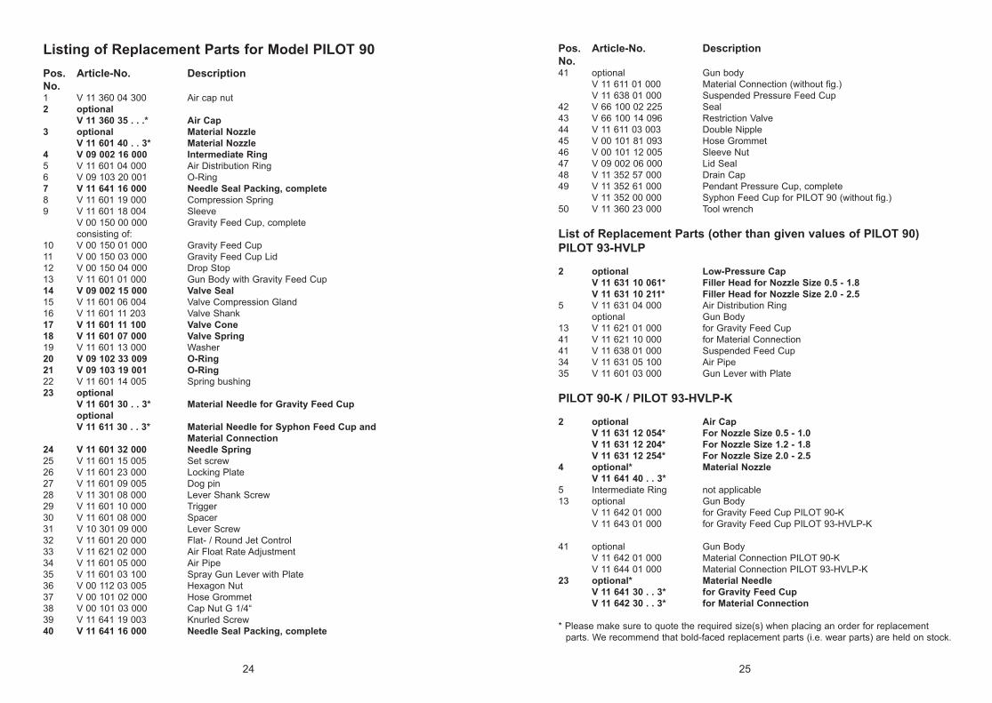
Listing of Replacement Parts for Model PILOT 90Pos. Article-No. DescriptionNo. 1 V 11 360 04 300 Air cap nut2 optional V 11 360 35 . . .* Air Cap3 optional Material Nozzle V 11 601 40 . . 3* Material Nozzle4 V 09 002 16 000 Intermediate Ring5 V 11 601 04 000 Air Distribution Ring6 V 09 103 20 001 O-Ring7 V 11 641 16 000 Needle Seal Packing, complete8 V 11 601 19 000 Compression Spring 9 V 11 601 18 004 Sleeve V 00 150 00 000 Gravity Feed Cup, complete consisting of:10 V 00 150 01 000 Gravity Feed Cup11 V 00 150 03 000 Gravity Feed Cup Lid12 V 00 150 04 000 Drop Stop13 V 11 601 01 000 Gun Body with Gravity Feed Cup14 V 09 002 15 000 Valve Seal15 V 11 601 06 004 Valve Compression Gland16 V 11 601 11 203 Valve Shank17 V 11 601 11 100 Valve Cone18 V 11 601 07 000 Valve Spring19 V 11 601 13 000 Washer20 V 09 102 33 009 O-Ring21 V 09 103 19 001 O-Ring22 V 11 601 14 005 Spring bushing23 optional V 11 601 30 . . 3* Material Needle for Gravity Feed Cup optional V 11 611 30 . . 3* Material Needle for Syphon Feed Cup and Material Connection24 V 11 601 32 000 Needle Spring25 V 11 601 15 005 Set screw26 V 11 601 23 000 Locking Plate27 V 11 601 09 005 Dog pin28 V 11 301 08 000 Lever Shank Screw29 V 11 601 10 000 Trigger30 V 11 601 08 000 Spacer31 V 10 301 09 000 Lever Screw32 V 11 601 20 000 Flat- / Round Jet Control33 V 11 621 02 000 Air Float Rate Adjustment34 V 11 601 05 000 Air Pipe35 V 11 601 03 100 Spray Gun Lever with Plate36 V 00 112 03 005 Hexagon Nut37 V 00 101 02 000 Hose Grommet38 V 00 101 03 000 Cap Nut G 1/4“ 39 V 11 641 19 003 Knurled Screw40 V 11 641 16 000 Needle Seal Packing, complete
Pos. Article-No. DescriptionNo.41 optional Gun body V 11 611 01 000 Material Connection (without fig.) V 11 638 01 000 Suspended Pressure Feed Cup 42 V 66 100 02 225 Seal 43 V 66 100 14 096 Restriction Valve44 V 11 611 03 003 Double Nipple45 V 00 101 81 093 Hose Grommet46 V 00 101 12 005 Sleeve Nut47 V 09 002 06 000 Lid Seal48 V 11 352 57 000 Drain Cap49 V 11 352 61 000 Pendant Pressure Cup, complete V 11 352 00 000 Syphon Feed Cup for PILOT 90 (without fig.)50 V 11 360 23 000 Tool wrench
List of Replacement Parts (other than given values of PILOT 90)PILOT 93-HVLP
2 optional Low-Pressure Cap V 11 631 10 061* Filler Head for Nozzle Size 0.5 - 1.8 V 11 631 10 211* Filler Head for Nozzle Size 2.0 - 2.55 V 11 631 04 000 Air Distribution Ring optional Gun Body 13 V 11 621 01 000 for Gravity Feed Cup41 V 11 621 10 000 for Material Connection41 V 11 638 01 000 Suspended Feed Cup34 V 11 631 05 100 Air Pipe35 V 11 601 03 000 Gun Lever with Plate
PILOT 90-K / PILOT 93-HVLP-K
2 optional Air Cap V 11 631 12 054* For Nozzle Size 0.5 - 1.0 V 11 631 12 204* For Nozzle Size 1.2 - 1.8 V 11 631 12 254* For Nozzle Size 2.0 - 2.54 optional* Material Nozzle V 11 641 40 . . 3* 5 Intermediate Ring not applicable13 optional Gun Body V 11 642 01 000 for Gravity Feed Cup PILOT 90-K V 11 643 01 000 for Gravity Feed Cup PILOT 93-HVLP-K
41 optional Gun Body V 11 642 01 000 Material Connection PILOT 90-K V 11 644 01 000 Material Connection PILOT 93-HVLP-K 23 optional* Material Needle V 11 641 30 . . 3* for Gravity Feed Cup V 11 642 30 . . 3* for Material Connection
* Please make sure to quote the required size(s) when placing an order for replacement parts. We recommend that bold-faced replacement parts (i.e. wear parts) are held on stock.
26 27
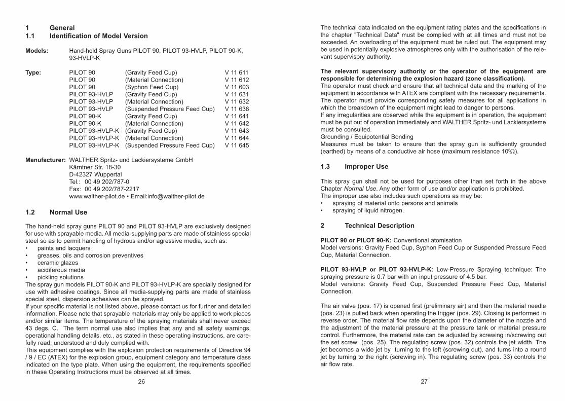
1 General1.1 Identification of Model Version
Models: Hand-held Spray Guns PILOT 90, PILOT 93-HVLP, PILOT 90-K, 93-HVLP-K
Type: PILOT 90 (Gravity Feed Cup) V 11 611 PILOT 90 (Material Connection) V 11 612 PILOT 90 (Syphon Feed Cup) V 11 603 PILOT 93-HVLP (Gravity Feed Cup) V 11 631 PILOT 93-HVLP (Material Connection) V 11 632 PILOT 93-HVLP (Suspended Pressure Feed Cup) V 11 638 PILOT 90-K (Gravity Feed Cup) V 11 641 PILOT 90-K (Material Connection) V 11 642 PILOT 93-HVLP-K (Gravity Feed Cup) V 11 643 PILOT 93-HVLP-K (Material Connection) V 11 644 PILOT 93-HVLP-K (Suspended Pressure Feed Cup) V 11 645 Manufacturer: WALTHER Spritz- und Lackiersysteme GmbH Kärntner Str. 18-30 D-42327 Wuppertal Tel.: 00 49 202/787-0 Fax: 00 49 202/787-2217 www.walther-pilot.de • Email:[email protected]
1.2 Normal Use
The hand-held spray guns PILOT 90 and PILOT 93-HVLP are exclusively designed for use with sprayable media. All media-supplying parts are made of stainless special steel so as to permit handling of hydrous and/or agressive media, such as:• paints and lacquers• greases, oils and corrosion preventives• ceramic glazes• acidiferous media • pickling solutionsThe spray gun models PILOT 90-K and PILOT 93-HVLP-K are specially designed for use with adhesive coatings. Since all media-supplying parts are made of stainless special steel, dispersion adhesives can be sprayed. If your specific material is not listed above, please contact us for further and detailed information. Please note that sprayable materials may only be applied to work pieces and/or similar items. The temperature of the spraying materials shall never exceed 43 degs. C. The term normal use also implies that any and all safety warnings, operational handling details, etc., as stated in these operating instructions, are care-fully read, understood and duly complied with.This equipment complies with the explosion protection requirements of Directive 94 / 9 / EC (ATEX) for the explosion group, equipment category and temperature class indicated on the type plate. When using the equipment, the requirements specified in these Operating Instructions must be observed at all times.
The technical data indicated on the equipment rating plates and the specifications in the chapter "Technical Data" must be complied with at all times and must not be exceeded. An overloading of the equipment must be ruled out. The equipment may be used in potentially explosive atmospheres only with the authorisation of the rele-vant supervisory authority.
The relevant supervisory authority or the operator of the equipment are responsible for determining the explosion hazard (zone classification). The operator must check and ensure that all technical data and the marking of the equipment in accordance with ATEX are compliant with the necessary requirements. The operator must provide corresponding safety measures for all applications in which the breakdown of the equipment might lead to danger to persons.If any irregularities are observed while the equipment is in operation, the equipment must be put out of operation immediately and WALTHER Spritz- und Lackiersysteme must be consulted.Grounding / Equipotential BondingMeasures must be taken to ensure that the spray gun is sufficiently grounded (earthed) by means of a conductive air hose (maximum resistance 106Ω).
1.3 Improper Use
This spray gun shall not be used for purposes other than set forth in the above Chapter Normal Use. Any other form of use and/or application is prohibited.The improper use also includes such operations as may be:• spraying of material onto persons and animals• spraying of liquid nitrogen.
2 Technical Description PILOT 90 or PILOT 90-K: Conventional atomisationModel versions: Gravity Feed Cup, Syphon Feed Cup or Suspended Pressure Feed Cup, Material Connection.
PILOT 93-HVLP or PILOT 93-HVLP-K: Low-Pressure Spraying technique: The spraying pressure is 0.7 bar with an input pressure of 4.5 bar. Model versions: Gravity Feed Cup, Suspended Pressure Feed Cup, Material Connection.
The air valve (pos. 17) is opened first (preliminary air) and then the material needle (pos. 23) is pulled back when operating the trigger (pos. 29). Closing is performed in reverse order. The material flow rate depends upon the diameter of the nozzle and the adjustment of the material pressure at the pressure tank or material pressure control. Furthermore, the material rate can be adjusted by screwing in/screwing out the set screw (pos. 25). The regulating screw (pos. 32) controls the jet width. The jet becomes a wide jet by turning to the left (screwing out), and turns into a round jet by turning to the right (screwing in). The regulating screw (pos. 33) controls the air flow rate.
28 29
3 Safety Warnings3.1 Safety Warning Symbols
WarningThis pictograph and the accompanying warning note “Warning“ indicate possible risks and dangers for yourself. Possible consequences: Injuries of any kind.
CautionThis pictograph and the accompanying warning note “Caution“ indicate possible damage to equipment. Possible consequences: Damage to equipment, workpieces, etc.
NoteThis pictograph and the accompanying note “Notice“ indicate additional and useful information to help you handling the spray gun with even greater confidence and efficiency.
3.2 General Safety Precautions
• All applicable accident prevention rules and regulations as well as other recog-nised industrial safety and health rules and regulations must be observed at all times.
• Use the spray gun only in well-ventilated rooms. Fire, naked flames and smo-king are strictly prohibited within the working area. WARNING – during the spraying of flammable materials (e.g. lacquers, adhesives, cleaning agents, etc.), there is an increased risk to health as well as an increased risk of explosi-on and fire.
• Measures must be taken to ensure that the spray gun is sufficiently grounded (earthed) by means of a conductive air hose (maximum resistance 106Ω).
• Before carrying out maintenance or servicing work, always ensure that the air and material feed to the spray gun have been de-pressurised. Risk of injury!
• When spraying materials, do not place your hands or other parts of the body in front of the pressurised nozzle or the spray gun. Risk of injury!
• Never point the spray gun at persons or animals. Risk of injury!• Always observe the spraying and safety instructions given by the manufacturers
of the spraying material and the cleaning agent. Aggressive and corrosive mate-rials in particular can be harmful to health.
• Exhaust air containing particles (overspray) must be kept away from the working area and personnel. In spite of these measures, always wear the regulation breathing masks and protective overalls when using the gun. Airborne particles represent a serious health hazard!
• Spray guns produce sound levels of approx. 85 dB (A) (PILOT 90) or approx. 83 dB (A) (PILOT 93-HVLP), which are likely to cause hearing defects. It is there-fore important to wear suitable hearing protectors.
• After carrying out assembly or maintenance work, always ensure that all nuts, bolts and screw connections have been fully tightened before the gun is used.
• Use only original replacement parts, since WALTHER can only guarantee safe
and fault-free operation for original parts. • For further information on the safe use of the spray gun and the spraying mate-
rials, please contact WALTHER Spritz- und Lackiersysteme GmbH, D-42327 Wuppertal, Germany.
4 Connection of Input Lines
NoteUse the exploded view at the beginning of these operating instructions to perform the operational steps described hereafter.
WarningThe air pressure at the gun shall not exceed 8 bar; otherwise a safe operation of the spray gun cannot be ensured.
WarningMaterial and air hoses which are installed with a hose grommet must be additonally secured with a hose clamp.
Design: Gravity Feed Cup, Syphon Feed Cup and Suspended Pressure Feed Cup1. Connect the air hose to the air pipe (cleaned compressed air) or on an air clea-
ner and on the air inlet of the spray gun (pos. 37).2. Fill the gravity feed cup, syphon cup or suspended pressure cup with screened
material. 3. Close the gravity feed cup or suspended pressure feed cup.
Switch on the pneumatic system. The spray gun can then be taken into opera-tion.
Design: Material Inlet1. Connect the air hose to the air reduction valve (cleaned compressed air) - or
an air cleaner - and to the air inlet of the spray gun (pos. 37).2. Switch on the pneumatic system and set the desired atomising air pressure at
the reduction valve.3. Fasten the material inlet hose to the material pressure tank or to the material
pressure control of a pump system and to the material connection of the spray gun (pos. 45).
4. Fill the material pressure tank with material and close the lid.5. Set the desired material pressure at the air pressure reduction valve; if the
material is supplied via pump systems, the material pressure is adjusted via the adjustment wrench at the material pressure control.
6. Open the material tap at the pressure tank.7. To let escape the air contained in the material hose, actuate the trigger
(pos. 29) until a uniform jet emerges from the nozzle; the spray gun can then be closed again. The spray gun can then be taken into operation.
30 31
5 Operational Handling5.1 Safety Warnings
Pay special attention to the following safety warnings when using the spray gun!• Make sure to wear proper respiratory protection masks and protective overalls,
whenever you are operating this spray gun. Airborne particles represent a health hazard.
• Make sure to wear suitable hearing protectors. Spray guns produce sound levels of approx. 85 dB (A) (PILOT 90) or approx. 83 dB (A) (PILOT 93-HVLP).
• Make sure your working area is absolutely free from open fires and naked lights - and anybody smoking. Spraying of readily flammable media (e.g. lac-quers, adhesives) is always accompanied by the risk of fire and explosion.
5.2 Starting / Stopping Requirements
The following requirements must be met before this spray gun can be taken into operation:• The atomizing air pressure must be available at the gun.• The material pressure must be availabe at the gun (is omitted when using the
gravity feed cup, syphon feed cup and suspended pressure feed cup).
CautionThe material pressure shall not exceed 8 bar. The air pressure shall not exceed 8 bar, as otherwise the functional reliability of the spray gun will suffer.
WarningIt is important to remember that the spray gun must be relieved of all pressures when work is terminated - lines left in pressurized condition could burst with their contents likely to injure anybody standing nearby.
5.3 Spray Pattern Test
Spray pattern tests should be performed whenever:• the spray gun is taken into operation for the first time• the spraying medium is changed• the spray gun was taken apart for servicing or repairs.The spray pattern is best tested using a workpiece sample, a sheet of metal, card-board or paper.
WarningKeep away from the front of the spray gun - imminent Risk of Injury.
WarningMake sure that nobody is present in the spraying zone when the gun is started - imminent Risk of Injury.
1. Start the gun to produce a spray pattern sample (see 5.2 Starting / Stopping Requirements).
2. Inspect the sample and readjust the settings of the gun as required (see 5.4 Spray Pattern Adjustments).
5.4 Spray Pattern Adjustments
The spray pattern of the PILOT 90, PILOT 93-HVLP, PILOT 90-K and PILOT 93-HVLP-K can be adjusted as follows:
Wide and / or Round Jet PatternThe regulating screw (pos. 32) controls the width of the jet. The jet turns to a wide jet pattern by turning it to the left (screwing out); it turns into a round jet pattern by turning it to the right (screwing in).
Adjusting the Material Flow RateThe material flow rate can be adjusted by screwing in/screwing out the set screw (pos. 25). The material rate is increased by turning it to the left (screwing out) and decreased by turning it to the right (screwing in).
Adjustment of the Material PressurePILOT 90 / 93-HVLP / 90-K / 93-HVLP-K (Pendant Pressure Cup Version):The material pressure can be adjusted with a screwdriver at the elbow (pos. 43).
PILOT 90 / 93-HVLP / 90-K / 93-HVLP-K (Versions for Material Inlet):The material pressure can only be adjusted at the controls of the pumping system or material pressure tank. Please comply with the operating instructions and safety warnings issued by the manufacturers concerned.
Adjustment of the Atomising Air PressureThe atomising air volume can be adjusted by screwing in/screwing out the set screw (pos. 33). The atomising air pressure is to be adjusted at the pressure reducing valve of the compressor system. Please comply with the operating instructions and safety warnings issued by the manufacturer.
If you wish to change the spraying pattern beyond the adjustments outlined so far, you must retool the spray gun (See 5.5 Retooling of spray gun).
WALTHER offers a great variety of air cap / material nozzle / needle combinations for this purpose.
32 33
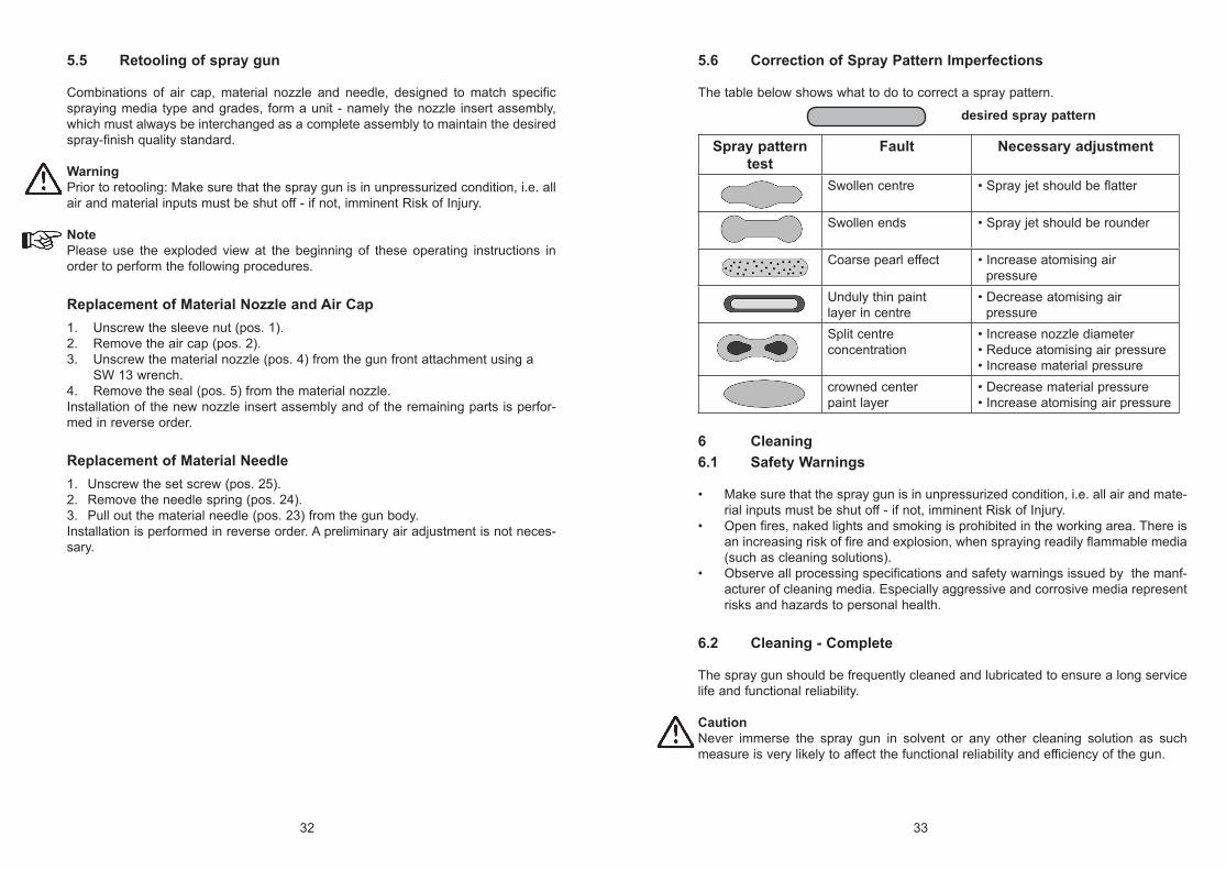
5.6 Correction of Spray Pattern Imperfections
The table below shows what to do to correct a spray pattern.
desired spray pattern
Spray pattern test
Fault Necessary adjustment
Swollen centre • Spray jet should be flatter
Swollen ends • Spray jet should be rounder
Coarse pearl effect • Increase atomising air pressure
Unduly thin paint layer in centre
• Decrease atomising air pressure
Split centreconcentration
• Increase nozzle diameter• Reduce atomising air pressure• Increase material pressure
crowned center paint layer
• Decrease material pressure• Increase atomising air pressure
6 Cleaning6.1 Safety Warnings
• Make sure that the spray gun is in unpressurized condition, i.e. all air and mate-rial inputs must be shut off - if not, imminent Risk of Injury.
• Open fires, naked lights and smoking is prohibited in the working area. There is an increasing risk of fire and explosion, when spraying readily flammable media (such as cleaning solutions).
• Observe all processing specifications and safety warnings issued by the manf-acturer of cleaning media. Especially aggressive and corrosive media represent risks and hazards to personal health.
6.2 Cleaning - Complete
The spray gun should be frequently cleaned and lubricated to ensure a long service life and functional reliability.
CautionNever immerse the spray gun in solvent or any other cleaning solution as such measure is very likely to affect the functional reliability and efficiency of the gun.
5.5 Retooling of spray gun
Combinations of air cap, material nozzle and needle, designed to match specific spraying media type and grades, form a unit - namely the nozzle insert assembly, which must always be interchanged as a complete assembly to maintain the desired spray-finish quality standard.
WarningPrior to retooling: Make sure that the spray gun is in unpressurized condition, i.e. all air and material inputs must be shut off - if not, imminent Risk of Injury.
NotePlease use the exploded view at the beginning of these operating instructions in order to perform the following procedures.
Replacement of Material Nozzle and Air Cap1. Unscrew the sleeve nut (pos. 1).2. Remove the air cap (pos. 2).3. Unscrew the material nozzle (pos. 4) from the gun front attachment using a
SW 13 wrench.4. Remove the seal (pos. 5) from the material nozzle.Installation of the new nozzle insert assembly and of the remaining parts is perfor-med in reverse order.
Replacement of Material Needle1. Unscrew the set screw (pos. 25).2. Remove the needle spring (pos. 24).3. Pull out the material needle (pos. 23) from the gun body.Installation is performed in reverse order. A preliminary air adjustment is not neces-sary.
34 35
CautionDo not use any hard, pointed or sharp-edged objects when cleaning the spray gun, as the precision-made parts can easily be damaged and are likely to affect your spraying results. The TEFLON® layer can be damaged as well, reducing the non-stick effect.
Clean the gun only with cleaning solutions recommended by the manufacturer of the spraying material which do not contain any of the following constituents:• halogenated hydrocarbons (e.g. 1,1,1-trichloroethane, methylene chloride, etc.)• acids and acidiferous cleaning solutions• regenerated solvents (so-called cleaning dilutions)• paint removers.The above constituents cause chemical reactions with electroplated components resulting in corrosion damage. WALTHER Spritz- und Lackiersysteme is not respon-sible for damages resulting from this kind of treatment.
Clean the spray gun • prior to each change of the spraying medium• at least once a week• as often as may be required by the spraying medium handled and the resultant
degree of fouling. Performing these steps will ensure safe gun operation.
1. Dismantle the spray gun accordaning to 5.5 Retooling of Spray Gun.2. Use a soft brush together with a compatible cleaning solution to clean the air cap
and nozzle.3. Use a suitable cloth with a compatible cleaning solution to clean the gun body
and all remaining parts.4. Apply a thin layer of grease to the following parts:
• material needle• needle spring• all sliding parts and bearing points• The moveable interior parts have to be greased at least once a week.• The springs have always to be coated with a thin layer of grease.
Make sure to use a non-acidic, non-resinogenic grease and apply this with a soft brush. Afterwards, assemble the spray gun in reverse order.
6.3 Cleaning - Routine
The spray gun does not have to be necessarily dismantled for cleaning if and when the paint is changed in regular intervals or upon termination of work (depending, of course, on the material used). Clean the gun body, which is coated with TEFLON®, with a soft cloth.
The following requirements must be met before the routine cleaning work can be performed:1. The cleaned material tank/gravity feed cup/syphon feed cup/suspended pressu-
re feed cup or the material pressure tank has to be filled with a cleaning solution compatible with the sprayed material.
2. Take the spray gun into operation (see 5.2 Starting/Stopping Requirements). 3. Do not stop the spray gun until clear cleaning solution emerges from the nozzle.All pressures should be removed from the complete spraying system until it is taken into operation again.
7 Repairs / Replacements
WarningPrior to any repairs/replacements: Make sure that the spray gun is in unpressurized condition, i.e. all air and material inputs must be shut off - if not, imminent Risk of Injury.
NotePlease use the exploded view at the beginning of these operating instructions in order to perform the following procedures.
7.1 Replacement of defective Needle Seal Packings
Packing seat with fastening screw:1. Remove the material needle (see 5.5 Retooling of Spray Gun).2. Remove the fastening screw (pos. 39).3. Remove the complete packing seat (pos. 40) including the O-ring (pos. 6).
Assembly is performed in reverse order.
Packing seat without fastening screw:1. Remove the material needle (see 5.5 Replacement of Material Needle).2. Push the packing seat (pos. 7) backwards and lift it up slightly at the front.3. Remove the packing seat (pos. 7) completely from the gun body.4. Replace the complete packing seat (pos. 7) and O-ring (pos. 6). Compress the
packing seat (pos. 7) and the sleeve (pos. 9) using the spring (pos. 8) and insert it in the according recess of the gun body. Then push the packing seat comple-tely to the front.
NoteNever reinstall a used needle seal packing, as otherwise the functional sealing relia-bility of the spray gun will suffer.
36 37
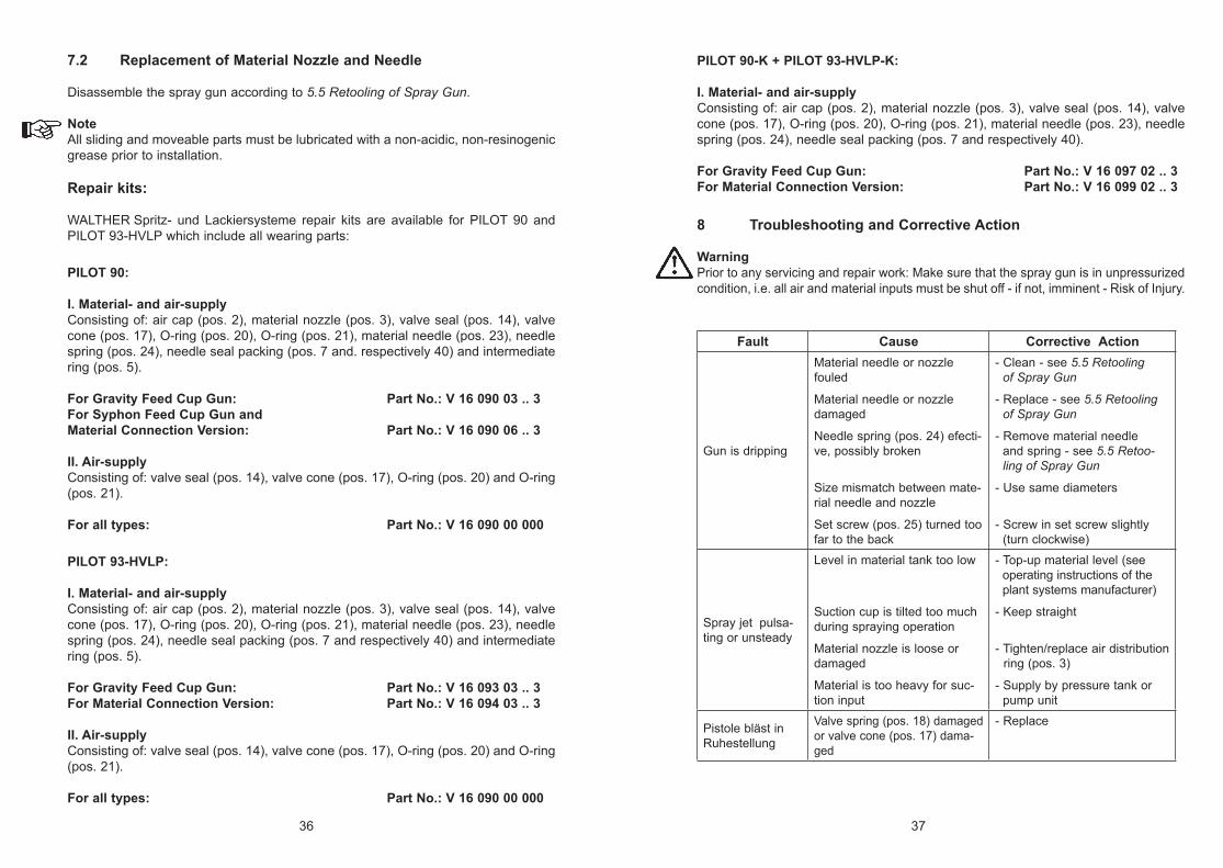
PILOT 90-K + PILOT 93-HVLP-K:
I. Material- and air-supplyConsisting of: air cap (pos. 2), material nozzle (pos. 3), valve seal (pos. 14), valve cone (pos. 17), O-ring (pos. 20), O-ring (pos. 21), material needle (pos. 23), needle spring (pos. 24), needle seal packing (pos. 7 and respectively 40).
For Gravity Feed Cup Gun: Part No.: V 16 097 02 .. 3For Material Connection Version: Part No.: V 16 099 02 .. 3
8 Troubleshooting and Corrective Action
WarningPrior to any servicing and repair work: Make sure that the spray gun is in unpressurized condition, i.e. all air and material inputs must be shut off - if not, imminent - Risk of Injury.
Fault Cause Corrective Action
Gun is dripping
Material needle or nozzle fouled
Material needle or nozzle damaged
Needle spring (pos. 24) efecti-ve, possibly broken
Size mismatch between mate-rial needle and nozzle
Set screw (pos. 25) turned too far to the back
- Clean - see 5.5 Retooling of Spray Gun
- Replace - see 5.5 Retooling of Spray Gun
- Remove material needle and spring - see 5.5 Retoo- ling of Spray Gun
- Use same diameters
- Screw in set screw slightly (turn clockwise)
Spray jet pulsa-ting or unsteady
Level in material tank too low
Suction cup is tilted too muchduring spraying operation
Material nozzle is loose or damaged
Material is too heavy for suc-tion input
- Top-up material level (see operating instructions of the plant systems manufacturer)
- Keep straight
- Tighten/replace air distribution ring (pos. 3)
- Supply by pressure tank or pump unit
Pistole bläst in Ruhestellung
Valve spring (pos. 18) damaged or valve cone (pos. 17) dama-ged
- Replace
7.2 Replacement of Material Nozzle and Needle
Disassemble the spray gun according to 5.5 Retooling of Spray Gun.
NoteAll sliding and moveable parts must be lubricated with a non-acidic, non-resinogenic grease prior to installation.
Repair kits:
WALTHER Spritz- und Lackiersysteme repair kits are available for PILOT 90 and PILOT 93-HVLP which include all wearing parts:
PILOT 90:
I. Material- and air-supplyConsisting of: air cap (pos. 2), material nozzle (pos. 3), valve seal (pos. 14), valve cone (pos. 17), O-ring (pos. 20), O-ring (pos. 21), material needle (pos. 23), needle spring (pos. 24), needle seal packing (pos. 7 and. respectively 40) and intermediate ring (pos. 5).
For Gravity Feed Cup Gun: Part No.: V 16 090 03 .. 3For Syphon Feed Cup Gun and Material Connection Version: Part No.: V 16 090 06 .. 3
II. Air-supplyConsisting of: valve seal (pos. 14), valve cone (pos. 17), O-ring (pos. 20) and O-ring (pos. 21).
For all types: Part No.: V 16 090 00 000
PILOT 93-HVLP:
I. Material- and air-supplyConsisting of: air cap (pos. 2), material nozzle (pos. 3), valve seal (pos. 14), valve cone (pos. 17), O-ring (pos. 20), O-ring (pos. 21), material needle (pos. 23), needle spring (pos. 24), needle seal packing (pos. 7 and respectively 40) and intermediate ring (pos. 5).
For Gravity Feed Cup Gun: Part No.: V 16 093 03 .. 3For Material Connection Version: Part No.: V 16 094 03 .. 3
II. Air-supplyConsisting of: valve seal (pos. 14), valve cone (pos. 17), O-ring (pos. 20) and O-ring (pos. 21).
For all types: Part No.: V 16 090 00 000
38 39
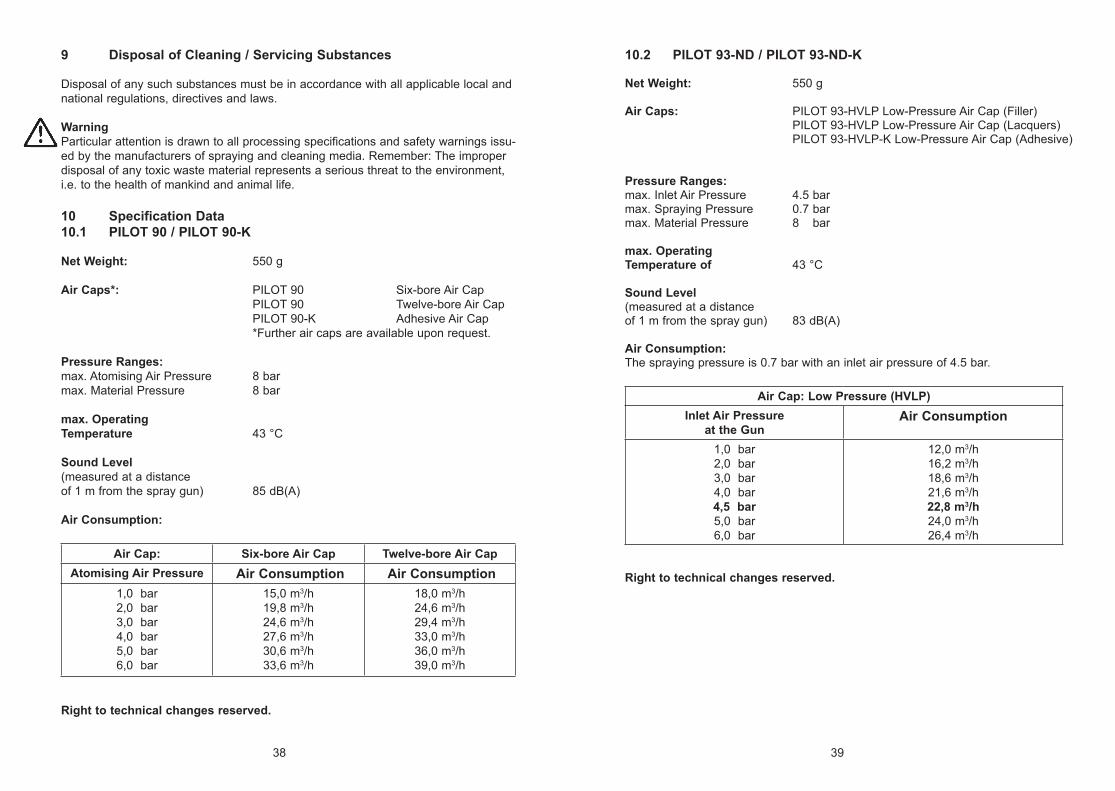
9 Disposal of Cleaning / Servicing Substances
Disposal of any such substances must be in accordance with all applicable local and national regulations, directives and laws.
WarningParticular attention is drawn to all processing specifications and safety warnings issu-ed by the manufacturers of spraying and cleaning media. Remember: The improper disposal of any toxic waste material represents a serious threat to the environment, i.e. to the health of mankind and animal life.
10 Specification Data10.1 PILOT 90 / PILOT 90-K
Net Weight: 550 g Air Caps*: PILOT 90 Six-bore Air Cap PILOT 90 Twelve-bore Air Cap PILOT 90-K Adhesive Air Cap *Further air caps are available upon request.
Pressure Ranges:max. Atomising Air Pressure 8 barmax. Material Pressure 8 bar max. Operating Temperature 43 °C Sound Level (measured at a distanceof 1 m from the spray gun) 85 dB(A)
Air Consumption:
Air Cap: Six-bore Air Cap Twelve-bore Air CapAtomising Air Pressure Air Consumption Air Consumption
1,0 bar2,0 bar3,0 bar4,0 bar5,0 bar6,0 bar
15,0 m3/h19,8 m3/h24,6 m3/h27,6 m3/h30,6 m3/h33,6 m3/h
18,0 m3/h24,6 m3/h29,4 m3/h33,0 m3/h36,0 m3/h39,0 m3/h
Right to technical changes reserved.
10.2 PILOT 93-ND / PILOT 93-ND-K
Net Weight: 550 g Air Caps: PILOT 93-HVLP Low-Pressure Air Cap (Filler) PILOT 93-HVLP Low-Pressure Air Cap (Lacquers) PILOT 93-HVLP-K Low-Pressure Air Cap (Adhesive) Pressure Ranges:max. Inlet Air Pressure 4.5 barmax. Spraying Pressure 0.7 barmax. Material Pressure 8 bar max. Operating Temperature of 43 °C
Sound Level (measured at a distanceof 1 m from the spray gun) 83 dB(A)
Air Consumption: The spraying pressure is 0.7 bar with an inlet air pressure of 4.5 bar.
Air Cap: Low Pressure (HVLP)Inlet Air Pressure
at the GunAir Consumption
1,0 bar2,0 bar3,0 bar4,0 bar4,5 bar5,0 bar6,0 bar
12,0 m3/h16,2 m3/h18,6 m3/h21,6 m3/h22,8 m3/h24,0 m3/h26,4 m3/h
Right to technical changes reserved.
WALTHER Spritz- und Lackiersysteme GmbHKärntner Str. 18-30 • D-42327 WuppertalTel.: 0202 / 787-0 • Fax: 0202 / 787-2217
www.walther-pilot.deE-mail: [email protected]
Das WALTHER PILOT-Programm
• Hand-Spritzpistolen• Automatik-Spritzpistolen• Niederdruck-Spritzpistolen
(System HVLP)• Zweikomponenten-Spritzpistolen
• Materialdruckbehälter• Drucklose Behälter• Rührwerk-Systeme
• Airless-Geräte und Flüssigkeitspumpen• Materialumlaufsysteme
• Kombinierte Spritz- und Trockenboxen
• Absaugsysteme mit Trockenabscheidung
• Absaugsysteme mit Naßabscheidung
• Trockner
• Zuluft-Systeme
• Atemschutzsysteme und Zubehör
The WALTHER PILOT Programme
• Hand-Held Spray Guns• Automatic Spray Guns• Low-Pressure Spray Guns
(System HVLP)• Two-Component Spray Guns
• Material Pressure Tanks• Non-Pressurized Tanks• Agitator Systems
• Airless Equipment and Transfer Pumps• Material Circulation Systems
• Combined Spray-Painting and Drying Booths
• Dry Back Extraction Systems
• Wet Back Extraction Systems
• Dryers
• Ventilation Systems
• Protective Respiratory Systems and Accessory Items and Equipment


![PILOT [TPM]](https://img.pdfslide.org/doc/110x75/56815a62550346895dc7a166/pilot-tpm.jpg)