Embed Size (px)
Citation preview
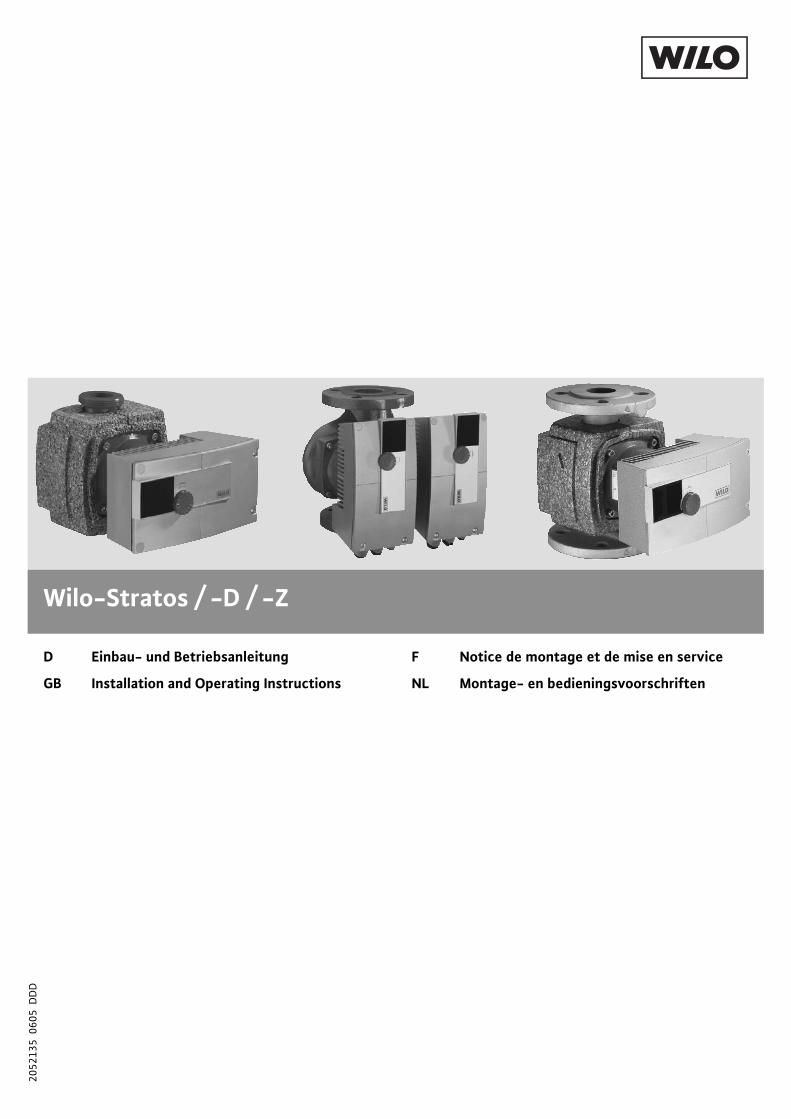
Wilo-Stratos / -D / -Z
D Einbau- und Betriebsanleitung
GB Installation and Operating Instructions
F Notice de montage et de mise en service
NL Montage- en bedieningsvoorschriften
2052
135
060
5 D
DD
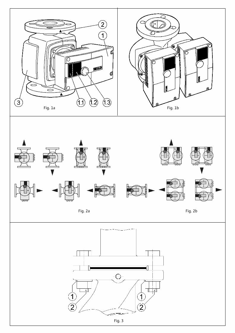
Fig. 1a Fig. 1b
Fig. 2a
Fig. 3
Fig. 2b
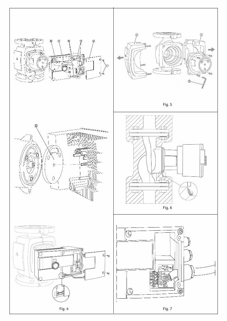
Fig. 5
Fig. 4
Fig. 6
Fig. 7
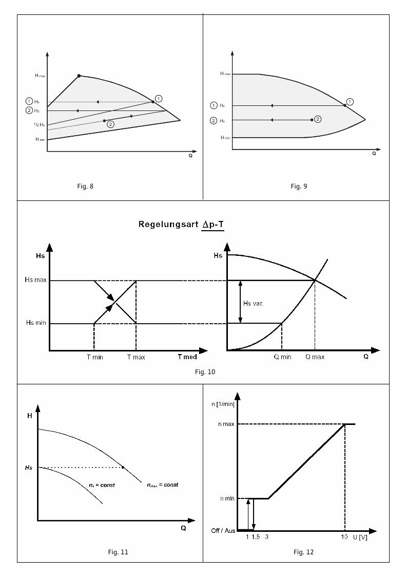
Fig. 8 Fig. 9
Fig. 11
Fig. 10
Fig. 12
L N
S
SM
Ach
tung
Achtung OptionIF-Modul
NetzspannungAttentionMainsVoltage
Atte
ntio
n1
- 230
V
!
IF-Modulpnnung
AttentionMainsVoltage
3
2
1
4a 4b 4c
4d
4e
~15 mm
~15 mm
Fig. 13
Fig. 14
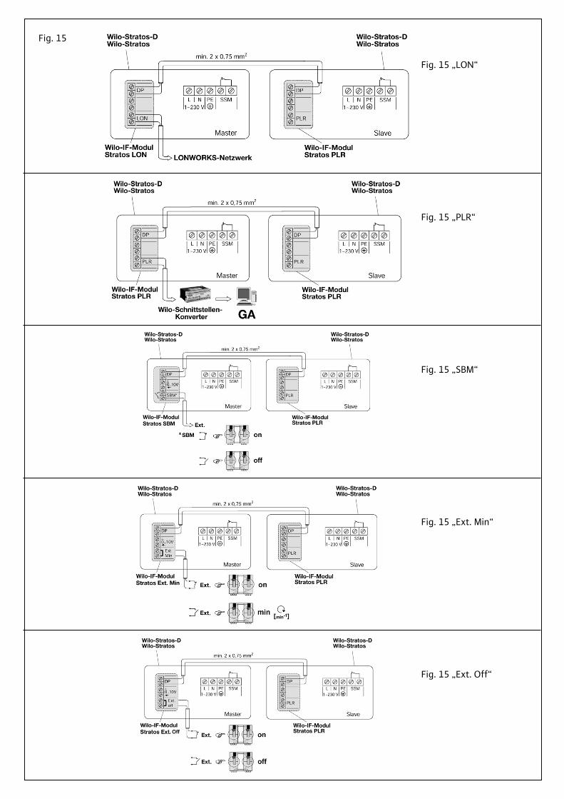
Fig. 15
Fig. 15 „LON“
Fig. 15 „PLR“
Fig. 15 „SBM“
Fig. 15 „Ext. Min“
Fig. 15 „Ext. Off“
Einbau- und Betriebsanleitung ……002Installation and Operating Instructions ……029Notice de montage et de mise en service ……056Montage- en bedieningsvoorschriften ……083
D
GB
F
NL
DEUTSCH
2
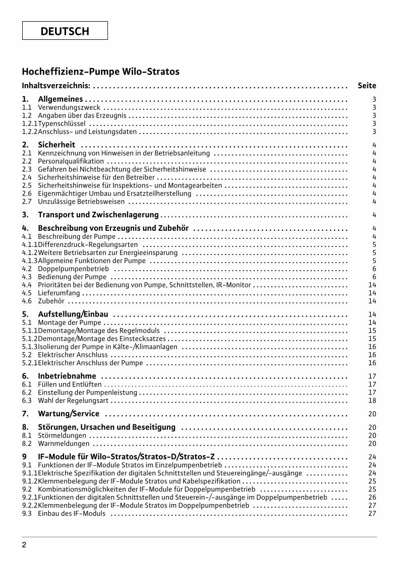
Hocheffizienz-Pumpe Wilo-StratosInhaltsverzeichnis: . . . . . . . . . . . . . . . . . . . . . . . . . . . . . . . . . . . . . . . . . . . . . . . . . . . . . . . . . . . . . . . . Seite
1. Allgemeines . . . . . . . . . . . . . . . . . . . . . . . . . . . . . . . . . . . . . . . . . . . . . . . . . . . . . . . . . . . . . . . . . . 31.1 Verwendungszweck . . . . . . . . . . . . . . . . . . . . . . . . . . . . . . . . . . . . . . . . . . . . . . . . . . . . . . . . . . . . . . . . . . . . . 31.2 Angaben über das Erzeugnis . . . . . . . . . . . . . . . . . . . . . . . . . . . . . . . . . . . . . . . . . . . . . . . . . . . . . . . . . . . . . . 31.2.1Typenschlüssel . . . . . . . . . . . . . . . . . . . . . . . . . . . . . . . . . . . . . . . . . . . . . . . . . . . . . . . . . . . . . . . . . . . . . . . . . 31.2.2Anschluss- und Leistungsdaten . . . . . . . . . . . . . . . . . . . . . . . . . . . . . . . . . . . . . . . . . . . . . . . . . . . . . . . . . . . 3
2. Sicherheit . . . . . . . . . . . . . . . . . . . . . . . . . . . . . . . . . . . . . . . . . . . . . . . . . . . . . . . . . . . . . . . . . . . 42.1 Kennzeichnung von Hinweisen in der Betriebsanleitung . . . . . . . . . . . . . . . . . . . . . . . . . . . . . . . . . . . . . . 42.2 Personalqualifikation . . . . . . . . . . . . . . . . . . . . . . . . . . . . . . . . . . . . . . . . . . . . . . . . . . . . . . . . . . . . . . . . . . . . 42.3 Gefahren bei Nichtbeachtung der Sicherheitshinweise . . . . . . . . . . . . . . . . . . . . . . . . . . . . . . . . . . . . . . . 42.4 Sicherheitshinweise für den Betreiber . . . . . . . . . . . . . . . . . . . . . . . . . . . . . . . . . . . . . . . . . . . . . . . . . . . . . . 42.5 Sicherheitshinweise für Inspektions- und Montagearbeiten . . . . . . . . . . . . . . . . . . . . . . . . . . . . . . . . . . . 42.6 Eigenmächtiger Umbau und Ersatzteilherstellung . . . . . . . . . . . . . . . . . . . . . . . . . . . . . . . . . . . . . . . . . . . 42.7 Unzulässige Betriebsweisen . . . . . . . . . . . . . . . . . . . . . . . . . . . . . . . . . . . . . . . . . . . . . . . . . . . . . . . . . . . . . . 4
3. Transport und Zwischenlagerung . . . . . . . . . . . . . . . . . . . . . . . . . . . . . . . . . . . . . . . . . . . . . . . . . . . . . 4
4. Beschreibung von Erzeugnis und Zubehör . . . . . . . . . . . . . . . . . . . . . . . . . . . . . . . . . . . . . . . 44.1 Beschreibung der Pumpe . . . . . . . . . . . . . . . . . . . . . . . . . . . . . . . . . . . . . . . . . . . . . . . . . . . . . . . . . . . . . . . . . 44.1.1Differenzdruck-Regelungsarten . . . . . . . . . . . . . . . . . . . . . . . . . . . . . . . . . . . . . . . . . . . . . . . . . . . . . . . . . . 54.1.2Weitere Betriebsarten zur Energieeinsparung . . . . . . . . . . . . . . . . . . . . . . . . . . . . . . . . . . . . . . . . . . . . . . . 54.1.3Allgemeine Funktionen der Pumpe . . . . . . . . . . . . . . . . . . . . . . . . . . . . . . . . . . . . . . . . . . . . . . . . . . . . . . . . 54.2 Doppelpumpenbetrieb . . . . . . . . . . . . . . . . . . . . . . . . . . . . . . . . . . . . . . . . . . . . . . . . . . . . . . . . . . . . . . . . . . 64.3 Bedienung der Pumpe . . . . . . . . . . . . . . . . . . . . . . . . . . . . . . . . . . . . . . . . . . . . . . . . . . . . . . . . . . . . . . . . . . . 64.4 Prioritäten bei der Bedienung von Pumpe, Schnittstellen, IR-Monitor . . . . . . . . . . . . . . . . . . . . . . . . . . . 144.5 Lieferumfang . . . . . . . . . . . . . . . . . . . . . . . . . . . . . . . . . . . . . . . . . . . . . . . . . . . . . . . . . . . . . . . . . . . . . . . . . . . 144.6 Zubehör . . . . . . . . . . . . . . . . . . . . . . . . . . . . . . . . . . . . . . . . . . . . . . . . . . . . . . . . . . . . . . . . . . . . . . . . . . . . . . . 14
5. Aufstellung/Einbau . . . . . . . . . . . . . . . . . . . . . . . . . . . . . . . . . . . . . . . . . . . . . . . . . . . . . . . . . . . 145.1 Montage der Pumpe . . . . . . . . . . . . . . . . . . . . . . . . . . . . . . . . . . . . . . . . . . . . . . . . . . . . . . . . . . . . . . . . . . . . . 145.1.1Demontage/Montage des Regelmoduls . . . . . . . . . . . . . . . . . . . . . . . . . . . . . . . . . . . . . . . . . . . . . . . . . . . . 155.1.2Demontage/Montage des Einstecksatzes . . . . . . . . . . . . . . . . . . . . . . . . . . . . . . . . . . . . . . . . . . . . . . . . . . . 155.1.3Isolierung der Pumpe in Kälte-/Klimaanlagen . . . . . . . . . . . . . . . . . . . . . . . . . . . . . . . . . . . . . . . . . . . . . . . 165.2 Elektrischer Anschluss . . . . . . . . . . . . . . . . . . . . . . . . . . . . . . . . . . . . . . . . . . . . . . . . . . . . . . . . . . . . . . . . . . . 165.2.1Elektrischer Anschluss der Pumpe . . . . . . . . . . . . . . . . . . . . . . . . . . . . . . . . . . . . . . . . . . . . . . . . . . . . . . . . . 16
6. Inbetriebnahme . . . . . . . . . . . . . . . . . . . . . . . . . . . . . . . . . . . . . . . . . . . . . . . . . . . . . . . . . . . . . . 176.1 Füllen und Entlüften . . . . . . . . . . . . . . . . . . . . . . . . . . . . . . . . . . . . . . . . . . . . . . . . . . . . . . . . . . . . . . . . . . . . . . . . 176.2 Einstellung der Pumpenleistung . . . . . . . . . . . . . . . . . . . . . . . . . . . . . . . . . . . . . . . . . . . . . . . . . . . . . . . . . . . 176.3 Wahl der Regelungsart . . . . . . . . . . . . . . . . . . . . . . . . . . . . . . . . . . . . . . . . . . . . . . . . . . . . . . . . . . . . . . . . . . . 18
7. Wartung/Service . . . . . . . . . . . . . . . . . . . . . . . . . . . . . . . . . . . . . . . . . . . . . . . . . . . . . . . . . . . . . 20
8. Störungen, Ursachen und Beseitigung . . . . . . . . . . . . . . . . . . . . . . . . . . . . . . . . . . . . . . . . . . 208.1 Störmeldungen . . . . . . . . . . . . . . . . . . . . . . . . . . . . . . . . . . . . . . . . . . . . . . . . . . . . . . . . . . . . . . . . . . . . . . . . . 208.2 Warnmeldungen . . . . . . . . . . . . . . . . . . . . . . . . . . . . . . . . . . . . . . . . . . . . . . . . . . . . . . . . . . . . . . . . . . . . . . . . 20
9 IF-Module für Wilo-Stratos/Stratos-D/Stratos-Z . . . . . . . . . . . . . . . . . . . . . . . . . . . . . . . . . 249.1 Funktionen der IF-Module Stratos im Einzelpumpenbetrieb . . . . . . . . . . . . . . . . . . . . . . . . . . . . . . . . . . . 249.1.1Elektrische Spezifikation der digitalen Schnittstellen und Steuereingänge/-ausgänge . . . . . . . . . . . . 249.1.2Klemmenbelegung der IF-Module Stratos und Kabelspezifikation . . . . . . . . . . . . . . . . . . . . . . . . . . . . . . 259.2 Kombinationsmöglichkeiten der IF-Module für Doppelpumpenbetrieb . . . . . . . . . . . . . . . . . . . . . . . . . 259.2.1Funktionen der digitalen Schnittstellen und Steuerein-/-ausgänge im Doppelpumpenbetrieb . . . . . 269.2.2Klemmenbelegung der IF-Module Stratos im Doppelpumpenbetrieb . . . . . . . . . . . . . . . . . . . . . . . . . . . 279.3 Einbau des IF-Moduls . . . . . . . . . . . . . . . . . . . . . . . . . . . . . . . . . . . . . . . . . . . . . . . . . . . . . . . . . . . . . . . . . . . 27
DEUTSCH
3
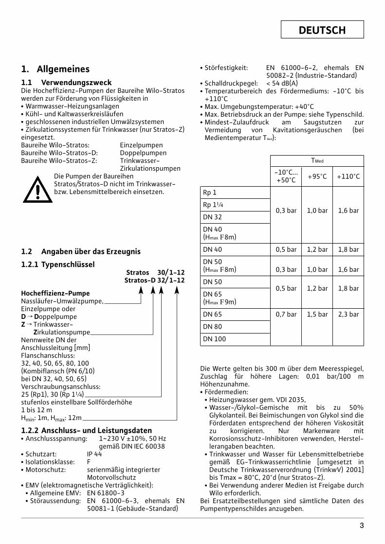
1. Allgemeines1.1 VerwendungszweckDie Hocheffizienz-Pumpen der Baureihe Wilo-Stratoswerden zur Förderung von Flüssigkeiten inx Warmwasser-Heizungsanlagenx Kühl- und Kaltwasserkreisläufenx geschlossenen industriellen Umwälzsystemenx Zirkulationssystemen für Trinkwasser (nur Stratos-Z)eingesetzt.Baureihe Wilo-Stratos: EinzelpumpenBaureihe Wilo-Stratos-D: DoppelpumpenBaureihe Wilo-Stratos-Z: Trinkwasser-
ZirkulationspumpenDie Pumpen der Baureihen Stratos/Stratos-D nicht im Trinkwasser-bzw. Lebensmittelbereich einsetzen.
1.2 Angaben über das Erzeugnis
1.2.1 TypenschlüsselStratos 30/ 1-12
Stratos-D 32/ 1-12
Hocheffizienz-PumpeNassläufer-Umwälzpumpe,Einzelpumpe oderD f DoppelpumpeZ f Trinkwasser-
ZirkulationspumpeNennweite DN der Anschlussleitung [mm]Flanschanschluss: 32, 40, 50, 65, 80, 100(Kombiflansch (PN 6/10) bei DN 32, 40, 50, 65)Verschraubungsanschluss: 25 (Rp1), 30 (Rp 1[)stufenlos einstellbare Sollförderhöhe 1 bis 12 mHmin: 1m, Hmax: 12m
1.2.2 Anschluss- und Leistungsdatenx Anschlussspannung: 1~230 V ±10%, 50 Hz
gemäß DIN IEC 60038x Schutzart: IP 44x Isolationsklasse: Fx Motorschutz: serienmäßig integrierter
Motorvollschutzx EMV (elektromagnetische Verträglichkeit):
x Allgemeine EMV: EN 61800-3x Störaussendung: EN 61000-6-3, ehemals EN
50081-1 (Gebäude-Standard)
x Störfestigkeit: EN 61000-6-2, ehemals EN50082-2 (Industrie-Standard)
x Schalldruckpegel: < 54 dB(A)x Temperaturbereich des Fördermediums: -10°C bis
+110°Cx Max. Umgebungstemperatur: +40°Cx Max. Betriebsdruck an der Pumpe: siehe Typenschild.x Mindest-Zulaufdruck am Saugstutzen zur
Vermeidung von Kavitationsgeräuschen (beiMedientemperatur TMed):
TMed
-10°C...+50°C +95°C +110°C
Rp 1
Rp 1[
DN 320,3 bar 1,0 bar 1,6 bar
DN 40 (Hmax F8m)
DN 40 0,5 bar 1,2 bar 1,8 bar
DN 50 (Hmax F8m) 0,3 bar 1,0 bar 1,6 bar
DN 500,5 bar 1,2 bar 1,8 bar
DN 65 (Hmax F9m)
DN 65 0,7 bar 1,5 bar 2,3 bar
DN 80
DN 100
Die Werte gelten bis 300 m über dem Meeresspiegel,Zuschlag für höhere Lagen: 0,01 bar/100 mHöhenzunahme.x Fördermedien:
x Heizungswasser gem. VDI 2035,x Wasser-/Glykol-Gemische mit bis zu 50%
Glykolanteil. Bei Beimischungen von Glykol sind dieFörderdaten entsprechend der höheren Viskositätzu korrigieren. Nur Markenware mitKorrosionsschutz-Inhibitoren verwenden, Herstel-lerangaben beachten.
x Trinkwasser und Wasser für Lebensmittelbetriebegemäß EG-Trinkwasserrichtlinie [umgesetzt inDeutsche Trinkwasserverordnung (TrinkwV) 2001]bis Tmax = 80°C, 20°d (nur Stratos-Z).
x Bei Verwendung anderer Medien ist Freigabe durchWilo erforderlich.
Bei Ersatzteilbestellungen sind sämtliche Daten desPumpentypenschildes anzugeben.
DEUTSCH
4
2. SicherheitDiese Betriebsanleitung enthält grundlegendeHinweise, die bei Aufstellung und Betrieb zu beachtensind. Daher ist diese Betriebsanleitung unbedingt vorMontage und Inbetriebnahme vom Monteur sowie demzuständigen Betreiber zu lesen.Es sind nicht nur die unter diesem HauptpunktSicherheit aufgeführten allgemeinen Sicherheits-hinweise zu beachten, sondern auch die unter den fol-genden Hauptpunkten eingefügten, speziellen Sicher-heitshinweise.
2.1 Kennzeichnung von Hinweisen in derBetriebsanleitung
Die in dieser Betriebsanleitung enthaltenenSicherheitshinweise, die bei NichtbeachtungGefährdungen für Personen hervorrufen können, sindmit dem allgemeinen Gefahrensymbol
bei Warnung vor elektrischer Spannung mit
besonders gekennzeichnet.Bei Sicherheitshinweisen, deren NichtbeachtungGefahren für die Pumpe/Anlage und deren Funktionhervorrufen können, ist das Wort
eingefügt.
2.2 PersonalqualifikationDas Personal für die Montage muß die entsprechendeQualifikation für diese Arbeiten aufweisen.
2.3 Gefahren bei Nichtbeachtung derSicherheitshinweise
Die Nichtbeachtung der Sicherheitshinweise kann eineGefährdung für Personen und Pumpe/Anlage zur Folgehaben. Die Nichtbeachtung der Sicherheitshinweisekann zum Verlust jeglicher Schadenersatzansprücheführen.Im einzelnen kann Nichtbeachtung beispielsweise fol-gende Gefährdungen nach sich ziehen:x Versagen wichtiger Funktionen der Pumpe/
Anlage,x Gefährdungen von Personen durch elektrische
und mechanische Einwirkungen.
2.4 Sicherheitshinweise für den BetreiberDie bestehenden Vorschriften zur Unfallverhütungsind zu beachten.
ACHTUNG!
Gefährdungen durch elektrische Energie sind auszu-schließen. Vorschriften des VDE und der örtlichenEnergieversorgungsunternehmen beachten.
2.5 Sicherheitshinweise für Inspektions-und Montagearbeiten
Der Betreiber hat dafür zu sorgen, dass alleInspektions- und Montagearbeiten von autorisiertemund qualifiziertem Fachpersonal ausgeführt werden,das sich durch eingehendes Studium derBetriebsanleitung ausreichend informiert hat.Grundsätzlich dürfen Arbeiten an der Pumpe/Anlagenur im Stillstand durchgeführt werden.
2.6 Eigenmächtiger Umbau undErsatzteilherstellung
Veränderungen der Pumpe/Anlage sind nur nachAbsprache mit dem Hersteller zulässig.Originalersatzteile und vom Hersteller autorisiertesZubehör dienen der Sicherheit. Die Verwendung ande-rer Teile hebt die Haftung für die daraus entstehendenFolgen auf.
2.7 Unzulässige BetriebsweisenDie Betriebssicherheit der gelieferten Pumpe/Anlageist nur bei bestimmungsgemäßer Verwendung ent-sprechend Abschnitt 1 der Betriebsanleitung gewähr-leistet. Die im Katalog/Datenblatt angegebenenGrenzwerte dürfen auf keinen Fall über- oder unter-schritten werden.
3 Transport und ZwischenlagerungDie Pumpe ist gegen Feuchtigkeit undmechanische Beschädigung zu schüt-zen. Bei Transport undZwischenlagerung darf die Pumpekeinen Temperaturen außerhalb desBereiches von -10°C bis +50°C ausge-setzt werden.
4 Beschreibung von Erzeugnis undZubehör
4.1 Beschreibung der Pumpe (Bilder 1a, 1b)Die Hocheffizienz-Pumpe Wilo-Stratos ist eineBaureihe von Nassläuferpumpen mit „E-lectronicCommutated Motor“ (ECM)-Technologie und inte-grierter Differenzdruckregelung. Die Pumpe kann alsEinzel- (Bild 1a) oder als Doppelpumpe (Bild 1b) ein-gebaut werden.Auf dem Motorgehäuse befindet sich in axialerBauform ein Regelmodul (Bild 1a, Pos.1), das denDifferenzdruck der Pumpe auf einen innerhalb desRegelbereiches einstellbaren Sollwert regelt. Je nachRegelungsart folgt der Differenzdruck unterschied-lichen Kriterien. Bei allen Regelungsarten passt sich je-doch die Pumpe einem wechselnden Leistungsbedarf
ACHTUNG!
DEUTSCH
5
der Anlage, wie er besonders beim Einsatz vonThermostatventilen, Zonenventilen oder Mischernentsteht, ständig an.Die wesentlichen Vorteile der elektronischen Regelungsind:x Energieeinsparung bei gleichzeitiger Reduzierung der
Betriebskosten,x Reduzierung von Fließgeräuschen,x Einsparung von Überströmventilen.Die Hocheffizienz-Pumpen der Baureihe Wilo-Stratos-Z sind durch Materialauswahl und Kon-struktion speziell auf die Betriebsverhältnisse inTrinkwasser-Zirkulationssystemen abgestimmt. Allemit dem Fördermedium in Berührung kommendenMaterialien sind KTW/WRC (WRAS) zugelassen.
4.1.1 Differenzdruck-RegelartenDie wählbaren Regelungsarten sind:x Vp-v: Die Elektronik verändert den von der Pumpe
einzuhaltenden Differenzdruck-Sollwert linear zwi-schen |Hs und Hs. Der Differenzdruck-Sollwert Hnimmt mit der Fördermenge ab bzw. zu (Bild 8).Werkseitige Grundeinstellung.
x Vp-c: Die Elektronik hält den von der Pumpe erzeug-ten Differenzdruck über den zulässigen Förder-strombereich konstant auf dem eingestelltenDifferenzdruck-Sollwert Hs bis zur Maximal-Kenn-linie (Bild 9).
x Vp-T: Die Elektronik verändert den von der Pumpeeinzuhaltenden Differenzdruck-Sollwert in Abhän-gigkeit der gemessenen Mediumtemperatur. DieseRegelungsart ist nur mit dem IR-Monitor oder überLON einstellbar. Dabei sind zwei Einstellungen mög-lich (Bild 10):x Regelung mit positiver Steigung: Mit steigender
Temperatur des Fördermediums wird der Dif-ferenzdruck-Sollwert linear zwischen Hsmin undHsmax erhöht. (Einstellung am IR-Monitor/ LON:Hsmax > Hsmin).Anwendung z.B. bei Standardkessel mit gleitenderVorlauftemperatur.
x Regelung mit negativer Steigung: Mit steigenderTemperatur des Fördermediums wird der Dif-ferenzdruck-Sollwert linear zwischen Hsmin undHsmax abgesenkt (Einstellung am IR-Monitor/ LON:Hsmax < Hsmin).Anwendung z.B. bei Brennwertkessel, bei dem einebestimmte minimale Rücklauftemperatur eingehal-ten werden soll, um einen möglichst hohenWärmenutzungsgrad des Heizmediums zu errei-chen. Hierzu ist der Einbau der Pumpe im Rücklaufder Anlage zwingend erforderlich.
4.1.2 Weitere Betriebsarten zurEnergieeinsparung
x Steller-Betrieb: Die Drehzahl der Pumpe wird auf ei-ner konstanten Drehzahl zwischen nmin und nmax ge-
halten (Bild 11). Die Betriebsart Steller deaktiviert dieDifferenzdruckregelung am Modul.
x Bei der Betriebsart „auto“ (werkseitige Einstellung)besitzt die Pumpe die Fähigkeit, einen minimalenHeizleistungsbedarf des Systems durch langanhal-tendes Absinken der Fördermedientemperatur zu er-kennen und dann auf Absenkbetrieb „Autopilot“umzuschalten. Bei steigendem Heizleistungsbedarfwird automatisch in den Regelbetrieb umgeschaltet.Diese Einstellung stellt sicher, dass derEnergieverbrauch der Pumpe auf ein Minimum redu-ziert wird und in den meisten Fällen die optimaleEinstellung ist.
Der Absenkbetrieb „Autopilot“ darfnur freigegeben werden, wenn der hy-draulische Abgleich der Anlage durch-geführt wurde. Bei Nichtbeachtungkönnen unterversorgte Anlagenteilebei Frost einfrieren.
4.1.3 Allgemeine Funktionen der Pumpex Die Pumpen sind mit einem elektronischen Überlast-
schutz ausgestattet, der im Überlastfall die Pumpeabschaltet.
x Zur Datenspeicherung ist das Regelmodul mit einemnichtflüchtigen Speicher ausgerüstet. Bei beliebiglanger Netzunterbrechung bleiben alle Einstellungenund Daten erhalten. Nach Rückkehr der Spannungläuft die Pumpe mit den Einstellwerten vor derNetzunterbrechung weiter.
x Das Modul-Typenschild ist im Modul-Klemmenraumeingeklebt. Es enthält alle Daten für die genaueZuordnung des Typs.
x Pumpenkick: Über ON/OFF, PLR, LON, IR-Monitor,Ext.Aus, 0…10V ausgeschaltete Pumpen laufen alle24 h kurzfristig an, um ein Blockieren bei langenStillstandszeiten zu vermeiden. Wenn eine Netzabschaltung über einen längerenZeitraum vorgesehen ist, sollte der Pumpenkick vonder Heizungs-/Kesselsteuerung übernommen wer-den. Dazu muss die Pumpe eingeschaltet sein(Display f Motor/Modulsymbol leuchtet).
Anbindungen zur Gebäudeautomation (GA)x SSM: An eine Leitstelle (Gebäudeautomation GA)
kann standardmäßig eine Sammelstörmeldung SSM(potenzialfreier Öffner) angeschlossen werden. Derinterne Kontakt ist geschlossen, wenn die Pumpestromlos ist, keine Störung oder ein Ausfall desRegelmoduls vorliegt. Die Störungen sind im Detail inKap.8.1 beschrieben.
x IF(InterFace)-Module (Zubehör):Zur Anbindung an externe Überwachungseinheiten(z.B. DDC/GA) stehen optionale analoge und digitaleSchnittstellen in Form von nachrüstbaren IF-Modulenzur Verfügung (siehe hierzu auch Kap.9).
ACHTUNG!
DEUTSCH
6
4.2 DoppelpumpenbetriebDoppelpumpen oder zwei korrespondierendeEinzelpumpen können mit einem integriertenDoppelpumpenmanagement nachgerüstet werden.x IF-Module Stratos: Zur Kommunikation zwischen
den Pumpen sind zwei IF-Module erforderlich, dieüber die DP-Schnittstelle miteinander verbundenwerden. Die IF-Module realisieren neben demDoppelpumpenmanagement weitere Schnittstellenfür die Doppelpumpe, siehe hierzu auch Kap.9.
Dieses Doppelpumpenmanagement weist folgendeFunktionen auf:x Master/Slave: Die Regelung beider Pumpen geht vom
Master aus. Am Master werden alle Einstellungen vor-genommen.
x Wirkungsgradoptimierter Spitzenlastbetrieb: ImTeillastbereich wird die hydraulische Leistung zu-nächst von einer der Pumpen erbracht. Die zweitePumpe wird dann wirkungsgradoptimiert zugeschal-tet, wenn die Summe der Leistungsaufnahmen P1 bei-der Pumpen geringer ist als die Leistungsaufnahme P1
einer Pumpe. Beide Pumpen werden dann synchron,falls erforderlich bis zur max. Drehzahl hochgeregelt.Durch diese Betriebsweise wird gegenüber dem kon-ventionellen Spitzenlastbetrieb (lastabhängige Zu-und Abschaltung) eine weitere Energieeinsparung er-reicht.
x Haupt-/Reservebetrieb: Jede der beiden Pumpenerbringt die Auslegungs-Förderleistung. Die anderePumpe steht für den Störfall bereit oder läuft nachPumpentausch. Es läuft immer nur eine Pumpe.
x Bei Ausfall/Störung einer Pumpe läuft die anderePumpe als Einzelpumpe im Regelbetrieb nachVorgabe durch den Master.
x Bei Kommunikationsunterbrechung: Der Sklaveläuft nach der letzten Sollwertvorgabe des Masters.
x Pumpentausch: Läuft nur eine Pumpe (Haupt-/Reserve-, Spitzenlast- oder Absenkbetrieb), so er-folgt nach jeweils 24 h effektiver Laufzeit einPumpentausch.
x SSM: An eine zentrale Leitstelle kann dieSammelstörmeldung (SSM) des Masters angeschlos-sen werden. Dabei wird nur der Kontakt am Masterbelegt. Die Anzeige gilt für das gesamte Aggregat.Wahlweise können mit dem IR-Monitor dieStörmeldekontakte von Master und Slave alsEinzelstörmeldungen (ESM) programmiert werden.Für die Einzelstörmeldungen muss der Kontakt an je-der Pumpe belegt werden.
4.3 Bedienung der PumpeAuf der Frontseite des Regelmoduls (Bild 1a, Pos.1) be-findet sich das IR-Fenster (Infrarot-Fenster, Pos.1.1)für die Kommunikation mit einem IR-Monitor sowiedas LC-Display (Pos.1.2) mit dem Stellknopf (Pos.1.3)für die lokale Bedienung der Pumpe. Die IR-Empfangs-und Sendefläche muß zur Herstellung der Verbindung
vom IR-Monitor angepeilt werden. Ist die Verbindungzum IR-Monitor hergestellt, so leuchtet im IR-Fensterdie grüne LED zur Bestätigung der IR-Kommunikation,und zwar von allen Pumpen, die gleichzeitig mit demIR-Monitor verbunden wurden. Die LED der Pumpe, mitder der IR-Monitor kommuniziert, blinkt. Sie erlischt 5Minuten, nachdem die Verbindung zum IR-Monitorunterbrochen wurde. Eine rote Stör-LED im IR-Fensterleuchtet beim Auftreten einer Störung. Über die Arbeitmit dem IR-Monitor gibt dessen Einbau- undBetriebsanleitung Auskunft.LC-Display: Auf dem LC-Display werden dieEinstellparameter der Pumpe durch Symbole undZahlenwerte sichtbar gemacht. Die Display-Anzeigelässt sich entsprechend der Modulposition, ob hori-zontal oder vertikal, auf eine ablesbare Blickrichtung(face to face) auswählen. Die Beleuchtung des Displays ist dauernd eingeschal-tet. Die Symbole haben folgende Bedeutung:
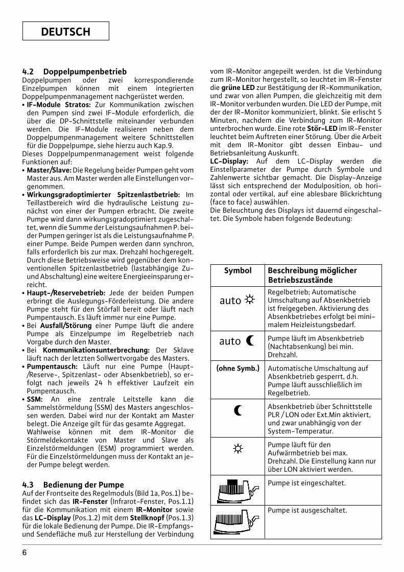
Symbol Beschreibung möglicherBetriebszustände
autoRegelbetrieb; AutomatischeUmschaltung auf Absenkbetriebist freigegeben. Aktivierung desAbsenkbetriebes erfolgt bei mini-malem Heizleistungsbedarf.
auto Pumpe läuft im Absenkbetrieb(Nachtabsenkung) bei min.Drehzahl.
(ohne Symb.) Automatische Umschaltung aufAbsenkbetrieb gesperrt, d.h.Pumpe läuft ausschließlich imRegelbetrieb.
Absenkbetrieb über SchnittstellePLR / LON oder Ext.Min aktiviert,und zwar unabhängig von derSystem-Temperatur.
Pumpe läuft für denAufwärmbetrieb bei max.Drehzahl. Die Einstellung kann nurüber LON aktiviert werden.
Pumpe ist eingeschaltet.
Pumpe ist ausgeschaltet.
DEUTSCH
7
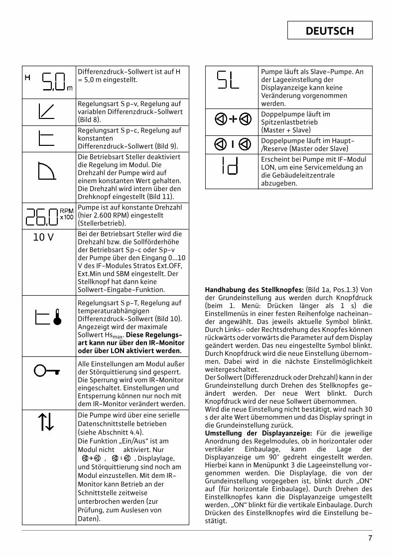
Differenzdruck-Sollwert ist auf H= 5,0 m eingestellt.
Regelungsart Sp-v, Regelung aufvariablen Differenzdruck-Sollwert(Bild 8).Regelungsart Sp-c, Regelung aufkonstanten Differenzdruck-Sollwert (Bild 9).Die Betriebsart Steller deaktiviertdie Regelung im Modul. DieDrehzahl der Pumpe wird auf einem konstanten Wert gehalten.Die Drehzahl wird intern über denDrehknopf eingestellt (Bild 11).Pumpe ist auf konstante Drehzahl(hier 2.600 RPM) eingestellt(Stellerbetrieb).Bei der Betriebsart Steller wird dieDrehzahl bzw. die Sollförderhöheder Betriebsart Sp-c oder Sp-vder Pumpe über den Eingang 0...10V des IF-Modules Stratos Ext.OFF,Ext.Min und SBM eingestellt. DerStellknopf hat dann keineSollwert-Eingabe-Funktion.
Regelungsart Sp-T, Regelung auftemperaturabhängigenDifferenzdruck-Sollwert (Bild 10).Angezeigt wird der maximaleSollwert Hsmax. Diese Regelungs-art kann nur über den IR-Monitoroder über LON aktiviert werden.
Alle Einstellungen am Modul außerder Störquittierung sind gesperrt.Die Sperrung wird vom IR-Monitoreingeschaltet. Einstellungen undEntsperrung können nur noch mitdem IR-Monitor verändert werden.
Die Pumpe wird über eine serielleDatenschnittstelle betrieben(siehe Abschnitt 4.4).Die Funktion „Ein/Aus“ ist amModul nicht aktiviert. Nur
, , Displaylage, und Störquittierung sind noch amModul einzustellen. Mit dem IR-Monitor kann Betrieb an derSchnittstelle zeitweiseunterbrochen werden (zurPrüfung, zum Auslesen vonDaten).
Pumpe läuft als Slave-Pumpe. Ander Lageeinstellung derDisplayanzeige kann keine Veränderung vorgenommenwerden.Doppelpumpe läuft imSpitzenlastbetrieb (Master + Slave)Doppelpumpe läuft im Haupt-/Reserve (Master oder Slave)Erscheint bei Pumpe mit IF-ModulLON, um eine Servicemeldung andie Gebäudeleitzentraleabzugeben.
Handhabung des Stellknopfes: (Bild 1a, Pos.1.3) Vonder Grundeinstellung aus werden durch Knopfdruck(beim 1. Menü: Drücken länger als 1 s) dieEinstellmenüs in einer festen Reihenfolge nacheinan-der angewählt. Das jeweils aktuelle Symbol blinkt.Durch Links- oder Rechtsdrehung des Knopfes könnenrückwärts oder vorwärts die Parameter auf dem Displaygeändert werden. Das neu eingestellte Symbol blinkt.Durch Knopfdruck wird die neue Einstellung übernom-men. Dabei wird in die nächste Einstellmöglichkeitweitergeschaltet.Der Sollwert (Differenzdruck oder Drehzahl) kann in derGrundeinstellung durch Drehen des Stellknopfes ge-ändert werden. Der neue Wert blinkt. DurchKnopfdruck wird der neue Sollwert übernommen.Wird die neue Einstellung nicht bestätigt, wird nach 30s der alte Wert übernommen und das Display springt indie Grundeinstellung zurück.Umstellung der Displayanzeige: Für die jeweiligeAnordnung des Regelmodules, ob in horizontaler odervertikaler Einbaulage, kann die Lage derDisplayanzeige um 90° gedreht eingestellt werden.Hierbei kann in Menüpunkt 3 die Lageeinstellung vor-genommen werden. Die Displaylage, die von derGrundeinstellung vorgegeben ist, blinkt durch „ON“auf (für horizontale Einbaulage). Durch Drehen desEinstellknopfes kann die Displayanzeige umgestelltwerden. „ON“ blinkt für die vertikale Einbaulage. DurchDrücken des Einstellknopfes wird die Einstellung be-stätigt.
10 V

DEUTSCH
8
Displaylage:
horizontal vertikalLageeinstellungin Menüpunkt 3
DEUTSCH
9
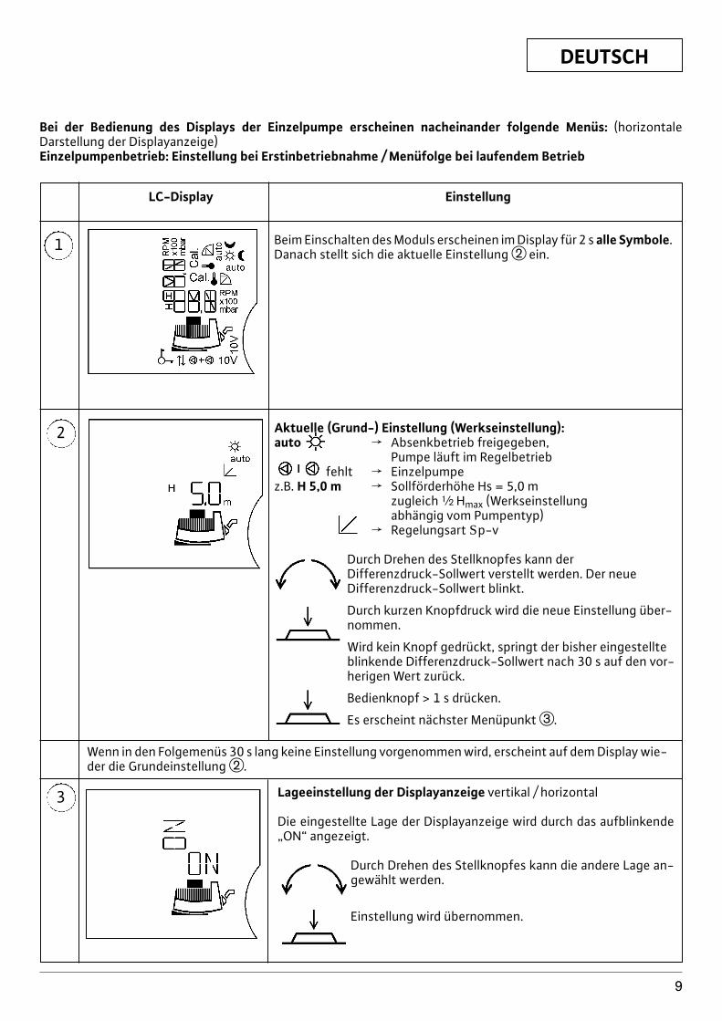
Bei der Bedienung des Displays der Einzelpumpe erscheinen nacheinander folgende Menüs: (horizontaleDarstellung der Displayanzeige)Einzelpumpenbetrieb: Einstellung bei Erstinbetriebnahme / Menüfolge bei laufendem Betrieb
1
LC-Display Einstellung
Beim Einschalten des Moduls erscheinen im Display für 2 s alle Symbole.Danach stellt sich die aktuelle Einstellung w ein.
2 Aktuelle (Grund-) Einstellung (Werkseinstellung):auto f Absenkbetrieb freigegeben,
Pumpe läuft im Regelbetriebfehlt f Einzelpumpe
z.B. H 5,0 m f Sollförderhöhe Hs = 5,0 mzugleich | Hmax (Werkseinstellungabhängig vom Pumpentyp)
f Regelungsart Sp-v
Durch Drehen des Stellknopfes kann derDifferenzdruck-Sollwert verstellt werden. Der neueDifferenzdruck-Sollwert blinkt.
Durch kurzen Knopfdruck wird die neue Einstellung über-nommen.
Wird kein Knopf gedrückt, springt der bisher eingestellteblinkende Differenzdruck-Sollwert nach 30 s auf den vor-herigen Wert zurück.
Bedienknopf > 1 s drücken.
Es erscheint nächster Menüpunkt e.
3 Lageeinstellung der Displayanzeige vertikal / horizontal
Die eingestellte Lage der Displayanzeige wird durch das aufblinkende„ON“ angezeigt.
Durch Drehen des Stellknopfes kann die andere Lage an-gewählt werden.
Einstellung wird übernommen.
Wenn in den Folgemenüs 30 s lang keine Einstellung vorgenommen wird, erscheint auf dem Display wie-der die Grundeinstellung w.
DEUTSCH
10
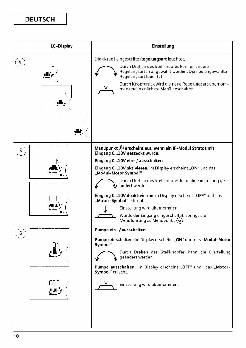
4
LC-Display Einstellung
5
6
Die aktuell eingestellte Regelungsart leuchtet.
Durch Drehen des Stellknopfes können andereRegelungsarten angewählt werden. Die neu angewählteRegelungsart leuchtet.
Durch Knopfdruck wird die neue Regelungsart übernom-men und ins nächste Menü geschaltet.
Menüpunkt t erscheint nur, wenn ein IF-Modul Stratos mitEingang 0...10V gesteckt wurde.
Eingang 0...10V ein- / ausschalten
Eingang 0...10V aktivieren: Im Display erscheint „ON“ und das„Modul-Motor Symbol“
Durch Drehen des Stellknopfes kann die Einstellung ge-ändert werden.
Eingang 0...10V deaktivieren: Im Display erscheint „OFF“ und das„Motor-Symbol“ erlischt.
Einstellung wird übernommen.
Wurde der Eingang eingeschaltet, springt dieMenüführung zu Menüpunkt 7a .
Pumpe ein- / ausschalten.
Pumpe einschalten: Im Display erscheint „ON“ und das „Modul-MotorSymbol“
Durch Drehen des Stellknopfes kann die Einstellung geändert werden.
Pumpe ausschalten: Im Display erscheint „OFF“ und das „Motor-Symbol“ erlischt.
Einstellung wird übernommen.
DEUTSCH
11
7
7a
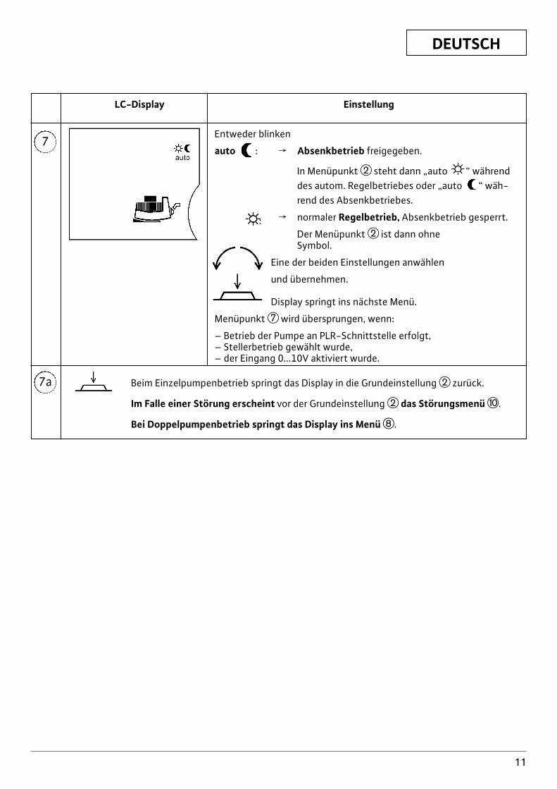
LC-Display Einstellung
Entweder blinken
auto : f Absenkbetrieb freigegeben.
In Menüpunkt w steht dann „auto “ währenddes autom. Regelbetriebes oder „auto “ wäh-rend des Absenkbetriebes.
: f normaler Regelbetrieb, Absenkbetrieb gesperrt.
Der Menüpunkt w ist dann ohneSymbol.
Eine der beiden Einstellungen anwählen
und übernehmen.
Display springt ins nächste Menü.
Menüpunkt u wird übersprungen, wenn:
– Betrieb der Pumpe an PLR-Schnittstelle erfolgt,– Stellerbetrieb gewählt wurde,– der Eingang 0...10V aktiviert wurde.
Beim Einzelpumpenbetrieb springt das Display in die Grundeinstellung w zurück.
Im Falle einer Störung erscheint vor der Grundeinstellung w das Störungsmenü p.
Bei Doppelpumpenbetrieb springt das Display ins Menü i.
DEUTSCH
12
1
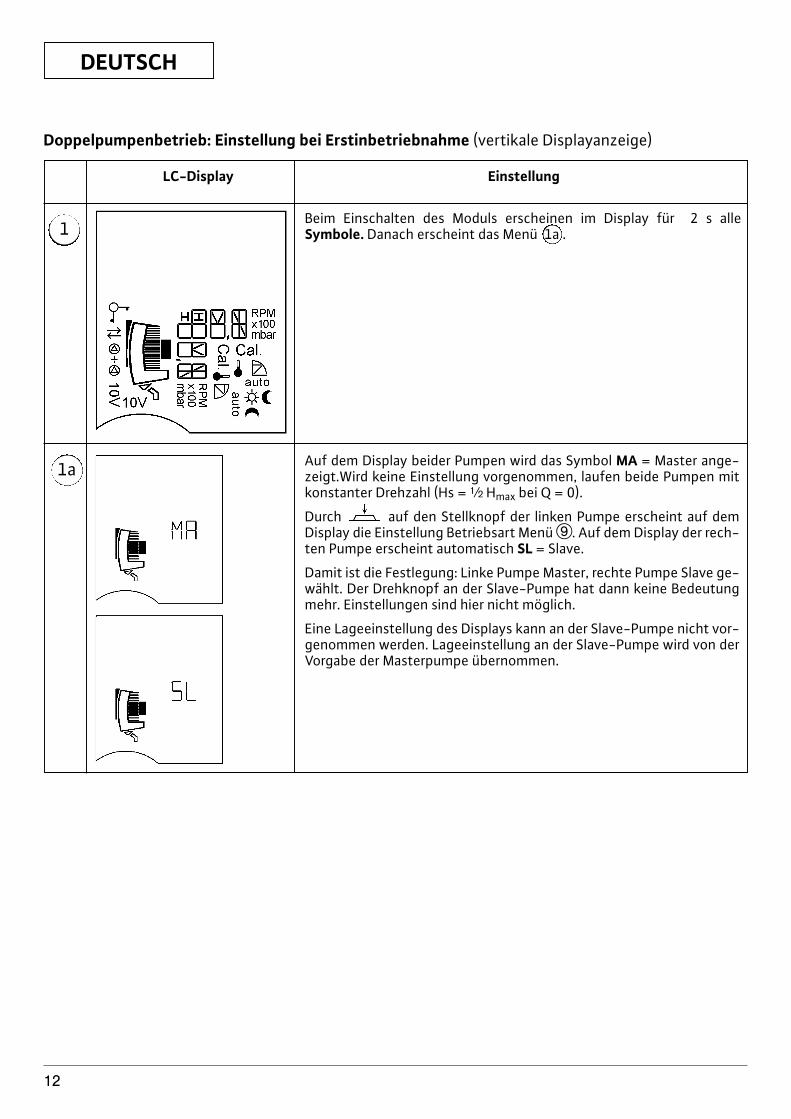
LC-Display Einstellung
1a
Beim Einschalten des Moduls erscheinen im Display für 2 s alleSymbole. Danach erscheint das Menü 1a .
Auf dem Display beider Pumpen wird das Symbol MA = Master ange-zeigt.Wird keine Einstellung vorgenommen, laufen beide Pumpen mitkonstanter Drehzahl (Hs = | Hmax bei Q = 0).
Durch auf den Stellknopf der linken Pumpe erscheint auf demDisplay die Einstellung Betriebsart Menü o. Auf dem Display der rech-ten Pumpe erscheint automatisch SL = Slave.
Damit ist die Festlegung: Linke Pumpe Master, rechte Pumpe Slave ge-wählt. Der Drehknopf an der Slave-Pumpe hat dann keine Bedeutungmehr. Einstellungen sind hier nicht möglich.
Eine Lageeinstellung des Displays kann an der Slave-Pumpe nicht vor-genommen werden. Lageeinstellung an der Slave-Pumpe wird von derVorgabe der Masterpumpe übernommen.
Doppelpumpenbetrieb: Einstellung bei Erstinbetriebnahme (vertikale Displayanzeige)
DEUTSCH
13
8
LC-Display Einstellung
9
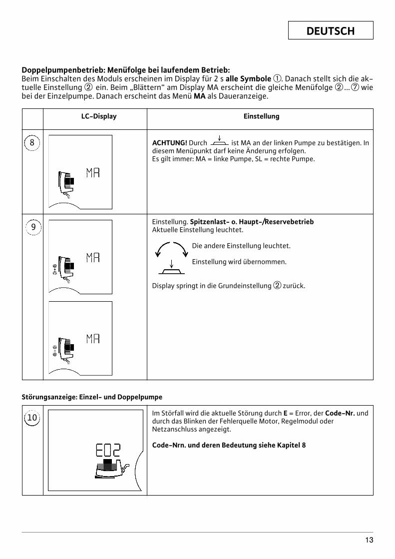
ACHTUNG! Durch ist MA an der linken Pumpe zu bestätigen. Indiesem Menüpunkt darf keine Änderung erfolgen.Es gilt immer: MA = linke Pumpe, SL = rechte Pumpe.
Einstellung. Spitzenlast- o. Haupt-/ReservebetriebAktuelle Einstellung leuchtet.
Die andere Einstellung leuchtet.
Einstellung wird übernommen.
Display springt in die Grundeinstellung w zurück.
10 Im Störfall wird die aktuelle Störung durch E = Error, der Code-Nr. unddurch das Blinken der Fehlerquelle Motor, Regelmodul oderNetzanschluss angezeigt.
Code-Nrn. und deren Bedeutung siehe Kapitel 8
Störungsanzeige: Einzel- und Doppelpumpe
Doppelpumpenbetrieb: Menüfolge bei laufendem Betrieb:Beim Einschalten des Moduls erscheinen im Display für 2 s alle Symbole q. Danach stellt sich die ak-tuelle Einstellung w ein. Beim „Blättern“ am Display MA erscheint die gleiche Menüfolge w ...u wiebei der Einzelpumpe. Danach erscheint das Menü MA als Daueranzeige.
DEUTSCH
14
4.4 Prioritäten bei der Bedienung vonPumpe, LON, PLR, IR-Monitor
Die Anzeige von Störungen (Menü 10) incl.Störquittierung hat die höchste Priorität. Das bedeu-tet, daß Störungen vorrangig auf dem Display derPumpe erscheinen und beseitigt bzw. quittiert werdenmüssen.Werden Einstellungen am Regelmodul oder vom IR-Monitor aus vorgenommen und nicht durchKnopfdruck bestätigt, so springt die Einstellung 30 snach der letzten Eingabe in den vorherigen Zustandzurück.x Pumpe m–n LON: Die Pumpe wird über das LON-
Netzwerk von der Gebäudeautomation (GA) kontrol-liert. Im Display erscheint . Eine Bedienung an derPumpe ist gesperrt. Ausnahme , ,Displaylageverstellung, Störquittierung.
x Pumpe m–n PLR: Bei Empfang eines Befehls von derGebäudeautomation (GA) schaltet die Pumpe auto-matisch auf PLR-Betrieb um. Im Display erscheint . Außerdem wird automatisch die Regelungsart Sp-c( ) eingestellt. Eine Bedienung an der Pumpe istgesperrt. Ausnahme , , Display-lageverstellung, Störquittierung.
x Pumpe m–n PLR/LON m–n IR: Bei dieserKonfiguration werden Einstellungen über die Schnitt-stelle vorrangig von der Pumpe übernommen. Mitdem IR-Monitor kann die Verbindung über dieSchnittstelle zur GA temporär unterbrochen werden.Danach können Einstellungen über den IR-Monitoroder lokal am Regelmodul vorgenommen werden. 5min. nach der letzten Einstellung durch den IR-Monitor wird die Verbindung über die Schnittstellewieder hergestellt. Für die Zeit der Unterbrechungverschwindet im Display.
x Pumpe m–n IR ohne Key-Funktion: Der letzte Befehl,ob vom IR-Monitor oder vom Regelmodul, wird vonder Pumpe übernommen.
x Pumpe m–n IR mit Key-Funktion: Bei Empfang desBefehls „Key-Funktion on“ bleiben die aktuellenEinstellungen des Regelmoduls bestehen. Im Displayerscheint „ .“ Eine Bedienung an der Pumpe ist,außer Störquittierung, gesperrt.
4.5 Lieferumfangx Pumpe komplett (mit 2 Dichtungen bei Gewinde-
anschluss)x zweiteilige Wärmeisolierschalen, (nur Einzelpumpe
Bild 1a, Pos.3)x Werkstoff: EPP, Polypropylen geschäumtx Wärmeleitfähigkeit: 0,04 W/m nach DIN 52612x Brennbarkeit: Klasse B2 nach DIN 4102,
FMVSS 302x Unterlegscheiben (für Flanschschrauben bei Kombi-
Flanschausführung DN32-DN65)x Einbau- und Betriebsanleitung
4.6 Zubehörx IF-Module Stratos PLR, LON, Ext.Off, Ext.Min, SBMx IR-Monitor
5 Montage/EinbauEinbau und Inbetriebnahme nurdurch Fachpersonal!
5.1 Montage der Pumpex Die Pumpe ist in einem trockenen, gut belüfteten und
frostsicheren Raum zu montieren.x Einbau erst nach Abschluss aller Schweiß- und
Lötarbeiten und der ggfs. erforderlichen Spülung desRohrsystems vornehmen. Schmutz kann die Pumpefunktionsunfähig machen.
x Der Einbau von Absperrarmaturen vor und hinter derPumpe ist zu empfehlen. Damit wird bei einem evtl.Austausch der Pumpe ein Ablassen undWiederauffüllen der Anlage erspart.
x Bei Einbau im Vorlauf offener Anlagen muß derSicherheitsvorlauf auf der Druckseite der Pumpe ab-zweigen.
x Spannungsfreie Montage durchführen. Die Rohre sindso zu befestigen, daß die Pumpe nicht das Gewichtder Rohre trägt.
x Vor dem Einbau der Einzelpumpe sind die beidenHalbschalen der Wärmeisolierung (Bild 5, Pos.1) ab-zunehmen.
x Die Fließrichtung des Mediums muß mit demRichtungsdreieck auf dem Pumpengehäuse (Bild 1a,Pos.2) übereinstimmen.
x Nur Einbaulagen nach Bild 2 sind zulässig. DiePumpenwelle muß waagerecht liegen.Bild 2a: Zulässige Einbaulagen für EinzelpumpenBild 2b: Zulässige Einbaulagen für DoppelpumpenBei beengten Einbauverhältnissen, beispielsweise inKompaktverteilern, kann durch Drehen des Motorsdas Regelmodul in eine senkrechte Position gebrachtwerden, siehe Kap. 5.1.2. Doppelpumpen werden mitsenkrecht montierten Regelmodulen ausgeliefert.
x Die Pumpe an gut zugänglicher Stelle montieren, sodass spätere Service-Arbeiten leicht möglich sind.Die Montage ist so durchzuführen, daß keinTropfwasser auf den Pumpenmotor bzw. Klem-menkasten tropfen kann.
x Bei der Montage von Pumpen mit KombiflanschPN6/10 (Flanschpumpen bis einschließlich DN 65)sind folgende Richtlinien zu beachten (Bild 3):
1. Die Montage von Kombi-Flansch mit Kombi-Flansch ist nicht zulässig.
2. Zwischen dem Schrauben-/Mutterkopf und demKombi-Flansch müssen beiliegende Unterleg-scheiben (Bild 3, Pos.1) unbedingt verwendetwerden.
Sicherungselemente (z.B Federringe)sind nicht zulässig. Bei fehlerhafter
ACHTUNG!
ACHTUNG!
DEUTSCH
15
Montage kann sich die Schrauben-mutter im Langloch verhaken.Dadurch kann, wegen unzureichenderVorspannung der Schrauben, dieFunktionsfähigkeit der Flanschver-bindung beeinträchtigt werden.
3. Es wird empfohlen Schrauben für Flansch-verbindungen mit einer Festigkeitsklasse von 4.6einzusetzen. Bei Verwendung von Schrauben auseinem anderen Werkstoff als 4.6 (z.B. Schraubenaus Werkstoff 5.6 oder noch höherfestemWerkstoff) ist für die Montage nur das zulässigeSchraubenanzugsmoment entsprechend Werk-stoff 4.6 zu verwenden.Zulässige Schraubenanzugsmomente:bei M 12 f 40 Nm,bei M 16 f 95 Nm
Werden die höherfesten Schrauben (G 4.6) abweichend den zulässigenAnzugsmomenten angezogen, kön-nen durch die höheren Schrauben-vorspannungen Absplitterungen imKantenbereich der Langlöcher auftre-ten. Dadurch verlieren die Schraubendie Vorspannung und die Flansch-verbindung kann undicht werden.
4. Es sind ausreichend lange Schrauben zu verwen-den:
ACHTUNG!
x Regelmodul vom Motor abziehen (Pos.5),x Montage in umgekehrter Reihenfolge.
Bei generatorischem Betrieb der Pumpe(Antrieb des Rotors durch Vordruckpumpe)entsteht an den Motorklemmen nachAbnehmen des Regelmoduls eine gefährli-che Spannung. Die Motorklemmen sind alsVDE-gerechte Buchsen ausgeführt, so dasseine Gefährdung durch bloßes Berühren mitdem Finger ausgeschlossen ist. Mit einemspitzen Gegenstand (Nagel, Schrauben-dreher, Draht), der in eine der Buchsen ge-steckt wird, lässt sich dennoch eineGefährdung erzeugen.
Zur einfachen Montage befinden sich an der Rückseitedes Regelmoduls 2 bzw. 3 (je nach Pumpentyp)Führungsstifte, die in entsprechende Bohrungen imMotorgehäuse eintauchen. Erst wenn diese Füh-rungsstifte das Regelmodul sicher am Motorgehäusefixieren, kontaktiert der zentrale Erdungsstift und an-schließend kontaktieren die Wicklungsstifte (Bild 4).
Zwischen Motorgehäuse und Regel-modul befindet sich eine Flach-dichtung (Bild 4, Pos.6), die die ther-mische Entkopplung der beidenKomponenten vornimmt. DieseDichtung ist unbedingt bei der Mon-tage des Regelmoduls zwischenModul und Motor zu platzieren.
5.1.2 Demontage/ Montage desEinstecksatzes
Zum Lösen des Motors müssen 4 Innen-sechskantschrauben M6 (SW5) gelöst werden. DieseSchrauben sind mit folgenden Werkzeugen zu errei-chen (Bild 5, Pos.2):x Abgewinkelter Innensechskant-Schraubendreherx Kugelkopf-Innensechskant-Schraubendreherx 1/4-Zoll-Umschaltknarre mit passendem BitSoll nur das Regelmodul in eine andere Position ge-bracht werden, so braucht der Motor nicht komplettaus dem Pumpengehäuse gezogen werden. Der Motorkann im Pumpengehäuse steckend in die gewünschtePosition gedreht werden, falls der entsprechende Platzvorhanden ist.
Dabei den O-Ring, der sich zwischenMotorkopf und Pumpengehäuse be-findet, nicht beschädigen. Der O-Ringmuß unverdreht in der zum Laufradweisenden Abkantung des Lager-schildes liegen.Die Welle ist mit dem Laufrad, demLagerschild und dem Rotor untrennbarverbunden. Diese Einheit ist gegenunbeabsichtigtes Herausziehen ausdem Motor gesichert. Wenn der Rotormit seinen starken Magneten nicht im
ACHTUNG!
ACHTUNG!
ACHTUNG!
Gewinde min. Schraubenlänge
DN 32 / DN 50 /DN 40 DN 65
Flanschanschluss PN6 M12 55 mm 60 mm
Flanschanschluss PN10 M16 60 mm 65 mm
Bei Montage von Flanschringen ist aufausreichende Schraubenlänge zu ach-ten. Das Gewinde der Schraube mussmin. einen Gewindegang aus derSchraubenmutter herausragen (Bild 3,Pos.2).
x Die beiden Halbschalen der Wärmeisolierung derEinzelpumpe anlegen und zusammendrücken, so daßdie Führungsstifte in ihren entsprechenden, gegen-überliegenden Bohrungen einrasten.
5.1.1 Demontage/ Montage des RegelmodulesDas Regelmodul kann durch Lösen von 2 Schraubenvom Motor getrennt werden (Bild 4):x Klemmenkastendeckel-Schrauben lösen (Pos.1),x Klemmenkastendeckel abnehmen (Pos.2),x Dichtstopfen mit geeignetem Werkzeug entfernen,
Beschädigung der Stopfen vermeiden (Pos.3),x 2 Innensechskantschrauben M5 (SW4) lösen (Pos.4),
ACHTUNG!
DEUTSCH
16
Motorgehäuse steckt, birgt er ein er-hebliches Gefährdungspotenzial z.B.durch plötzliches Anziehen vonGegenständen aus Eisen/Stahl, Beein-flussung von elektrischen Geräten(Personengefährdung bei Herzschritt-machern), Zerstörung von Magnet-karten etc..
Falls die Zugänglichkeit der Schrauben am Mo-torflansch nicht gewährleistet ist, kann das Regel-modul durch Lösen von 2 Schrauben vom Motor ge-trennt werden, siehe Kap.5.1.1.
5.1.3 Isolierung der Pumpe in Kälte-/Klimaanlagen
Die Baureihe Wilo-Stratos ist für den Einsatz in Kälte-und Klimaanlagen mit Fördermediumtemperaturen bis–10°C geeignet. In diesen Einsatzfällen ist auch inter-mittierender Betrieb der Pumpen zulässig.Die im Lieferumfang enthaltenen Wärmedämmschalen(Bild 5, Pos.1) sind jedoch nur in Heizungsanlagen mitFördermediumtemperaturen ab +20°C zulässig, dadiese Wärmedämmschalen das Pumpengehäuse nichtdiffusionsdicht umschließen.Bei dem Einsatz in Kälte- und Klimaanlagen ist bausei-tig eine diffusionsdichte Isolierung vorzusehen.
Dabei darf das Pumpengehäuse nurbis zur Trennfuge zum Motor isoliertwerden, damit die Kondensatab-laufbohrungen frei bleiben und imMotor entstehendes Kondensat un-gehindert abfließen kann (Bild 6).
Zum Schutz vor Korrosion ist das Pumpengehäuse ka-taphoresebeschichtet.
5.2 Elektrischer AnschlussDer elektrische Anschluss ist von einembeim örtlichen Energieversorgungsunter-nehmen (EVU) zugelassenen Elektroinstal-lateur und entsprechend den geltendenörtlichen (z.B. VDE-Vorschriften) auszu-führen.
x Der elektrische Anschluss muss nach VDE 0730/Teil 1über eine feste Netzanschlußleitung (3 x 1,5 mm2 mi-nimal einzuhaltender Querschnitt) erfolgen, die miteiner Steckvorrichtung oder einem allpoligen Schaltermit mindestens 3 mm Kontaktöffnungsweite verse-hen ist.
x Ein bauseitiger Motorschutzschalter ist nicht erfor-derlich. Ist ein solcher in der Installation bereits vor-handen, so ist er zu umgehen oder auf den maximalmöglichen Stromwert einzustellen.
x Um den Tropfwasserschutz und die Zugentlastungder Kabelverschraubungen sicherzustellen, sindKabel mit passendem Außendurchmesser zu verwen-den und ausreichend fest zu verschrauben.
ACHTUNG!
Außerdem sind die Kabel in der Nähe derVerschraubung zu einer Ablaufschleife, zur Ableitunganfallendem Tropfwassers, zu biegen. Nicht belegteKabelverschraubungen sind mit den vorhandenenDichtscheiben zu verschließen und ausreichend festzu verschrauben.
x Zur Anpassung der Anschlussleitungen an dieInnendurchmesser der Kabeleinführungen bestehendie Dichtungen aus konzentrisch angeordnetenGummiringen, von denen der/die innere(n) Ring(e) beiBedarf entfernt werden können.
Es sind Kabel mit entsprechendemAußendurchmesser zu verwenden, sodass die Kabelverschraubung nachdem Anziehen dicht ist. Nicht be-nutzte Kabelverschraubungen sindmit einer Kunststoffscheibe ver-schlossen. Diese Scheibe darf nichtentfernt werden. Auch nicht benutzteKabelverschraubungen sind anzuzie-hen.
x Bei Einsatz der Pumpe in Anlagen mit Wasser-temperaturen über 90°C muß eine entsprechendwärmebeständige Anschlußleitung verwendet wer-den.
x Alle Anschlussleitungen sind so zu verlegen, dass inkeinem Fall die Rohrleitung und / oder das Pumpen-und Motorgehäuse berührt werden.
x Diese Pumpe darf mit einem FI-Schutzschalter abge-sichert werden.Kennzeichnung: FI - oder
x Stromart und Spannung des Netzanschlusses müssenden Angaben auf dem Typenschild entsprechen,
x Netzseitige Absicherung: siehe Typenschild,x Pumpe/Anlage vorschriftsmäßig erden.
Bei Isolationsprüfungen mit einemHochspannungsgenerator ist diePumpe im Regelmodul allpolig vomNetz zu trennen. Die freien Kabel-enden sind entsprechend derSpannung des Hochspannungsgene-rators zu isolieren.
5.2.1 Elektrischer Anschluß der Pumpe (Bild 7)x L, N, : Netzanschlussspannung:
1 ~ 230 VAC, 50 Hz,DIN IEC 60038.
x SSM: Eine integrierte Sammelstörmeldung steht anden Klemmen SSM als potenzialfreier Öffner zurVerfügung.Kontaktbelastung: x minimal zulässig: 12 V DC,
10 mA,x maximal zulässig: 250 V AC, 1 A.
x Doppelpumpen: Beide Motoren der Doppelpumpesind mit einer separaten Netzzuleitung und einer se-paraten netzseitigen Absicherung zu versehen.
ACHTUNG!
ACHTUNG!
DEUTSCH
17
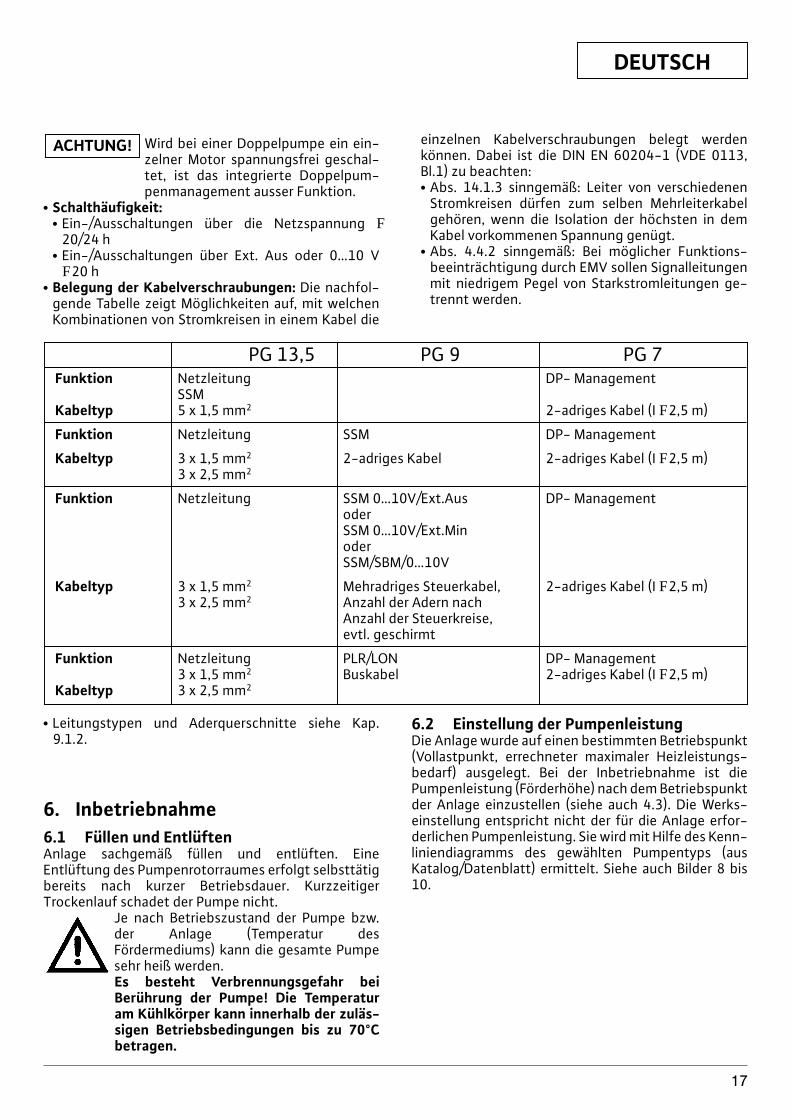
Wird bei einer Doppelpumpe ein ein-zelner Motor spannungsfrei geschal-tet, ist das integrierte Doppelpum-penmanagement ausser Funktion.
x Schalthäufigkeit:x Ein-/Ausschaltungen über die Netzspannung F
20/24 hx Ein-/Ausschaltungen über Ext. Aus oder 0…10 V F20 h
x Belegung der Kabelverschraubungen: Die nachfol-gende Tabelle zeigt Möglichkeiten auf, mit welchenKombinationen von Stromkreisen in einem Kabel die
ACHTUNG! einzelnen Kabelverschraubungen belegt werdenkönnen. Dabei ist die DIN EN 60204-1 (VDE 0113,Bl.1) zu beachten:x Abs. 14.1.3 sinngemäß: Leiter von verschiedenen
Stromkreisen dürfen zum selben Mehrleiterkabelgehören, wenn die Isolation der höchsten in demKabel vorkommenen Spannung genügt.
x Abs. 4.4.2 sinngemäß: Bei möglicher Funktions-beeinträchtigung durch EMV sollen Signalleitungenmit niedrigem Pegel von Starkstromleitungen ge-trennt werden.
PG 13,5 PG 9 PG 7Funktion Netzleitung DP- Management
SSMKabeltyp 5 x 1,5 mm2 2-adriges Kabel (I F2,5 m)
Funktion Netzleitung SSM DP- Management
Kabeltyp 3 x 1,5 mm2 2-adriges Kabel 2-adriges Kabel (I F2,5 m)3 x 2,5 mm2
Funktion Netzleitung SSM 0…10V/Ext.Aus DP- ManagementoderSSM 0…10V/Ext.MinoderSSM/SBM/0…10V
Kabeltyp 3 x 1,5 mm2 Mehradriges Steuerkabel, 2-adriges Kabel (I F2,5 m)3 x 2,5 mm2 Anzahl der Adern nach
Anzahl der Steuerkreise,evtl. geschirmt
Funktion Netzleitung PLR/LON DP- Management3 x 1,5 mm2 Buskabel 2-adriges Kabel (I F2,5 m)
Kabeltyp 3 x 2,5 mm2
x Leitungstypen und Aderquerschnitte siehe Kap.9.1.2.
6. Inbetriebnahme6.1 Füllen und EntlüftenAnlage sachgemäß füllen und entlüften. EineEntlüftung des Pumpenrotorraumes erfolgt selbsttätigbereits nach kurzer Betriebsdauer. KurzzeitigerTrockenlauf schadet der Pumpe nicht.
Je nach Betriebszustand der Pumpe bzw.der Anlage (Temperatur desFördermediums) kann die gesamte Pumpesehr heiß werden.Es besteht Verbrennungsgefahr beiBerührung der Pumpe! Die Temperaturam Kühlkörper kann innerhalb der zuläs-sigen Betriebsbedingungen bis zu 70°Cbetragen.
6.2 Einstellung der PumpenleistungDie Anlage wurde auf einen bestimmten Betriebspunkt(Vollastpunkt, errechneter maximaler Heizleistungs-bedarf) ausgelegt. Bei der Inbetriebnahme ist diePumpenleistung (Förderhöhe) nach dem Betriebspunktder Anlage einzustellen (siehe auch 4.3). Die Werks-einstellung entspricht nicht der für die Anlage erfor-derlichen Pumpenleistung. Sie wird mit Hilfe des Kenn-liniendiagramms des gewählten Pumpentyps (ausKatalog/Datenblatt) ermittelt. Siehe auch Bilder 8 bis10.
DEUTSCH
18
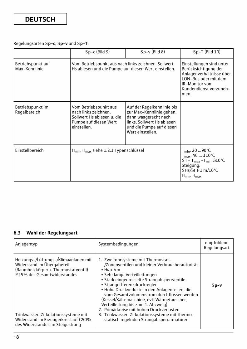
Regelungsarten Sp-c, Sp-v und Sp-T:
Betriebspunkt aufMax-Kennlinie
Vom Betriebspunkt aus nach links zeichnen. SollwertHs ablesen und die Pumpe auf diesen Wert einstellen.
Einstellungen sind unterBerücksichtigung derAnlagenverhältnisse überLON-Bus oder mit demIR-Monitor vomKundendienst vorzuneh-men.
Einstellbereich Hmin, Hmax siehe 1.2.1 Typenschlüssel Tmin: 20 ...90°CTmax: 40 ... 110°CST= Tmax -Tmin G10°CSteigung:SHs/ST F1 m/10°CHmin, Hmax
Betriebspunkt imRegelbereich
Vom Betriebspunkt ausnach links zeichnen.Sollwert Hs ablesen u. diePumpe auf diesen Werteinstellen.
Auf der Regelkennlinie biszur Max-Kennlinie gehen,dann waagerecht nachlinks, Sollwert Hs ablesenund die Pumpe auf diesenWert einstellen.
Sp-c (Bild 9) Sp-v (Bild 8) Sp-T (Bild 10)
6.3 Wahl der Regelungsart
Heizungs-/Lüftungs-/Klimaanlagen mitWiderstand im Übergabeteil(Raumheizkörper + Thermostatventil)F25% des Gesamtwiderstandes
Trinkwasser-Zirkulationssysteme mitWiderstand im Erzeugerkreislauf G50%des Widerstandes im Steigestrang
Anlagentyp Systembedingungen empfohleneRegelungsart
1. Zweirohrsysteme mit Thermostat-/Zonenventilen und kleiner Verbraucherautorität
x HN > 4mx Sehr lange Verteilleitungenx Stark eingedrosselte Strangabsperrventilex Strangdifferenzdruckreglerx Hohe Druckverluste in den Anlagenteilen, die
vom Gesamtvolumenstrom durchflossen werden(Kessel/Kältemaschine, evtl Wärmetauscher,Verteilleitung bis zum 1. Abzweig)
2. Primärkreise mit hohen Druckverlusten3. Trinkwasser-Zirkulationssysteme mit thermo-
statisch regelnden Strangabsperrarmaturen
Sp-v
DEUTSCH
19
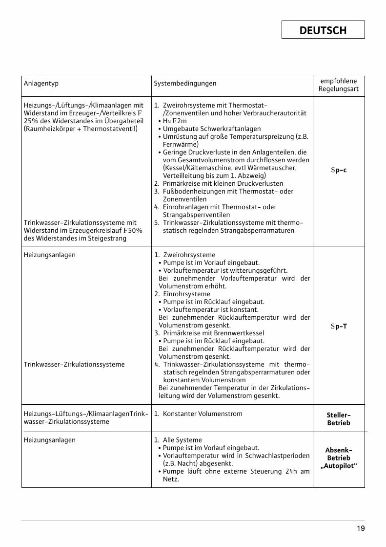
Anlagentyp Systembedingungen empfohleneRegelungsart
Heizungs-/Lüftungs-/Klimaanlagen mitWiderstand im Erzeuger-/Verteilkreis F25% des Widerstandes im Übergabeteil(Raumheizkörper + Thermostatventil)
Trinkwasser-Zirkulationssysteme mitWiderstand im Erzeugerkreislauf F50%des Widerstandes im Steigestrang
1. Zweirohrsysteme mit Thermostat-/Zonenventilen und hoher Verbraucherautorität
x HN F2mx Umgebaute Schwerkraftanlagenx Umrüstung auf große Temperaturspreizung (z.B.
Fernwärme)x Geringe Druckverluste in den Anlagenteilen, die
vom Gesamtvolumenstrom durchflossen werden(Kessel/Kältemaschine, evtl Wärmetauscher,Verteilleitung bis zum 1. Abzweig)
2. Primärkreise mit kleinen Druckverlusten3. Fußbodenheizungen mit Thermostat- oder
Zonenventilen4. Einrohranlagen mit Thermostat- oder
Strangabsperrventilen5. Trinkwasser-Zirkulationssysteme mit thermo-
statisch regelnden Strangabsperrarmaturen
Sp-c
Heizungsanlagen
Trinkwasser-Zirkulationssysteme
1. Zweirohrsystemex Pumpe ist im Vorlauf eingebaut.x Vorlauftemperatur ist witterungsgeführt.Bei zunehmender Vorlauftemperatur wird derVolumenstrom erhöht.
2. Einrohrsystemex Pumpe ist im Rücklauf eingebaut.x Vorlauftemperatur ist konstant.Bei zunehmender Rücklauftemperatur wird derVolumenstrom gesenkt.
3. Primärkreise mit Brennwertkesselx Pumpe ist im Rücklauf eingebaut.Bei zunehmender Rücklauftemperatur wird derVolumenstrom gesenkt.
4. Trinkwasser-Zirkulationssysteme mit thermo-statisch regelnden Strangabsperrarmaturen oderkonstantem Volumenstrom
Bei zunehmender Temperatur in der Zirkulations-leitung wird der Volumenstrom gesenkt.
Sp-T
Heizungs-Lüftungs-/KlimaanlagenTrink-wasser-Zirkulationssysteme
1. Konstanter Volumenstrom
Heizungsanlagen 1. Alle Systemex Pumpe ist im Vorlauf eingebaut.x Vorlauftemperatur wird in Schwachlastperioden
(z.B. Nacht) abgesenkt.x Pumpe läuft ohne externe Steuerung 24h am
Netz.
Steller-Betrieb
Absenk-Betrieb
„Autopilot“
DEUTSCH
20
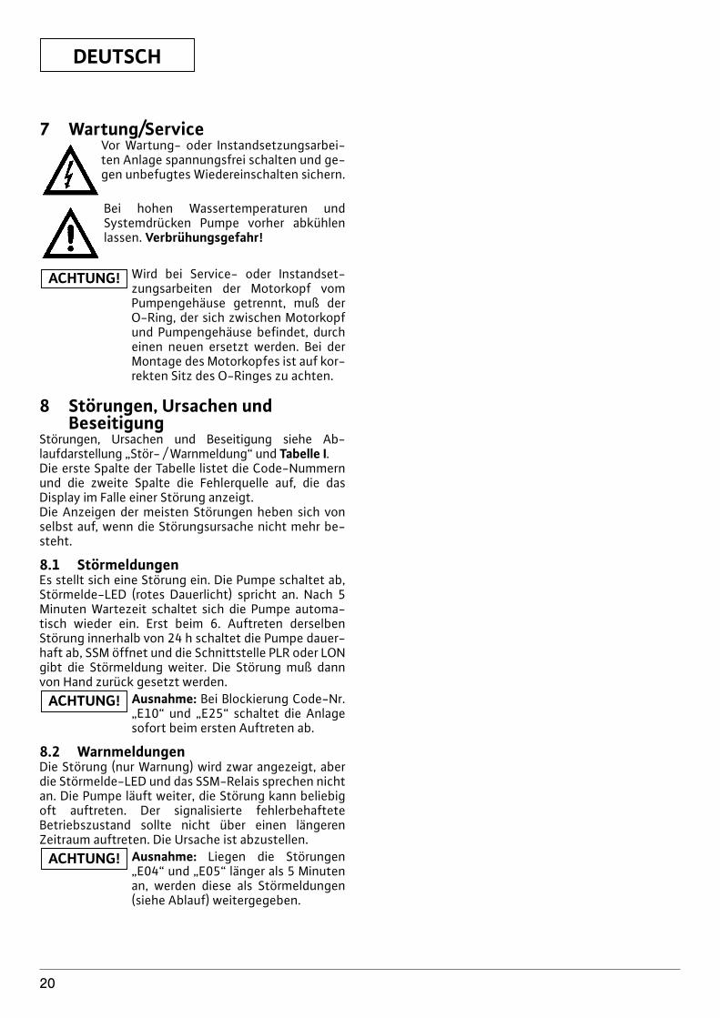
7 Wartung/ServiceVor Wartung- oder Instandsetzungsarbei-ten Anlage spannungsfrei schalten und ge-gen unbefugtes Wiedereinschalten sichern.
Bei hohen Wassertemperaturen undSystemdrücken Pumpe vorher abkühlenlassen. Verbrühungsgefahr!
Wird bei Service- oder Instandset-zungsarbeiten der Motorkopf vomPumpengehäuse getrennt, muß derO-Ring, der sich zwischen Motorkopfund Pumpengehäuse befindet, durcheinen neuen ersetzt werden. Bei derMontage des Motorkopfes ist auf kor-rekten Sitz des O-Ringes zu achten.
8 Störungen, Ursachen undBeseitigung
Störungen, Ursachen und Beseitigung siehe Ab-laufdarstellung „Stör- / Warnmeldung“ und Tabelle I.Die erste Spalte der Tabelle listet die Code-Nummernund die zweite Spalte die Fehlerquelle auf, die dasDisplay im Falle einer Störung anzeigt. Die Anzeigen der meisten Störungen heben sich vonselbst auf, wenn die Störungsursache nicht mehr be-steht.
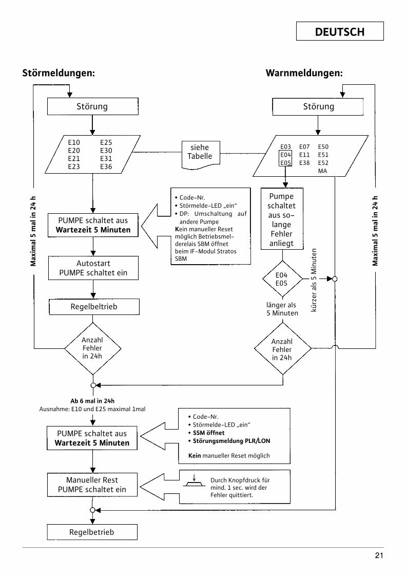
8.1 StörmeldungenEs stellt sich eine Störung ein. Die Pumpe schaltet ab,Störmelde-LED (rotes Dauerlicht) spricht an. Nach 5Minuten Wartezeit schaltet sich die Pumpe automa-tisch wieder ein. Erst beim 6. Auftreten derselbenStörung innerhalb von 24 h schaltet die Pumpe dauer-haft ab, SSM öffnet und die Schnittstelle PLR oder LONgibt die Störmeldung weiter. Die Störung muß dannvon Hand zurück gesetzt werden.
Ausnahme: Bei Blockierung Code-Nr.„E10“ und „E25“ schaltet die Anlagesofort beim ersten Auftreten ab.
8.2 WarnmeldungenDie Störung (nur Warnung) wird zwar angezeigt, aberdie Störmelde-LED und das SSM-Relais sprechen nichtan. Die Pumpe läuft weiter, die Störung kann beliebigoft auftreten. Der signalisierte fehlerbehafteteBetriebszustand sollte nicht über einen längerenZeitraum auftreten. Die Ursache ist abzustellen.
Ausnahme: Liegen die Störungen„E04“ und „E05“ länger als 5 Minutenan, werden diese als Störmeldungen(siehe Ablauf) weitergegeben.
ACHTUNG!
ACHTUNG!
ACHTUNG!
DEUTSCH
21
E10 E25E20 E30E21 E31E23 E36
Störung Störung
PUMPE schaltet ausWartezeit 5 Minuten
AutostartPUMPE schaltet ein
Regelbeltrieb
PUMPE schaltet ausWartezeit 5 Minuten
Ab 6 mal in 24hAusnahme: E10 und E25 maximal 1mal
Manueller RestPUMPE schaltet ein
sieheTabelle
E03 E07 E50E04 E11 E51E05 E38 E52
MA
Pumpeschaltetaus so-langeFehler anliegt
E04E05
länger als5 Minuten
AnzahlFehlerin 24h
AnzahlFehlerin 24h
kürz
er a
ls 5
Min
uten
Max
imal
5 m
al in
24
h
Max
imal
5 m
al in
24
h x Code-Nr.x Störmelde-LED „ein“x DP: Umschaltung auf
andere PumpeKein manueller Resetmöglich Betriebsmel-derelais SBM öffnetbeim IF-Modul StratosSBM
x Code-Nr.x Störmelde-LED „ein“x SSM öffnetx Störungsmeldung PLR/LON
Kein manueller Reset möglich
Durch Knopfdruck fürmind. 1 sec. wird derFehler quittiert.
Regelbetrieb
Störmeldungen: Warnmeldungen:
DEUTSCH
22
Tabelle IStörung Ursache Abhilfe
Pumpe läuft bei eingeschalteter Elektrische Sicherung defekt, Sicherungen überprüfen
Stromzufuhr nicht Pumpe hat keine Spannung, Spannungsunterbrechung beheben
Pumpe macht Geräusche Kavitation durch Systemvordruck innerhalb desunzureichenden Vorlaufdruck zulässigen Bereiches erhöhen
Förderhöheneinstellung überprüfen evtl. niedrigere Höheeinstellen
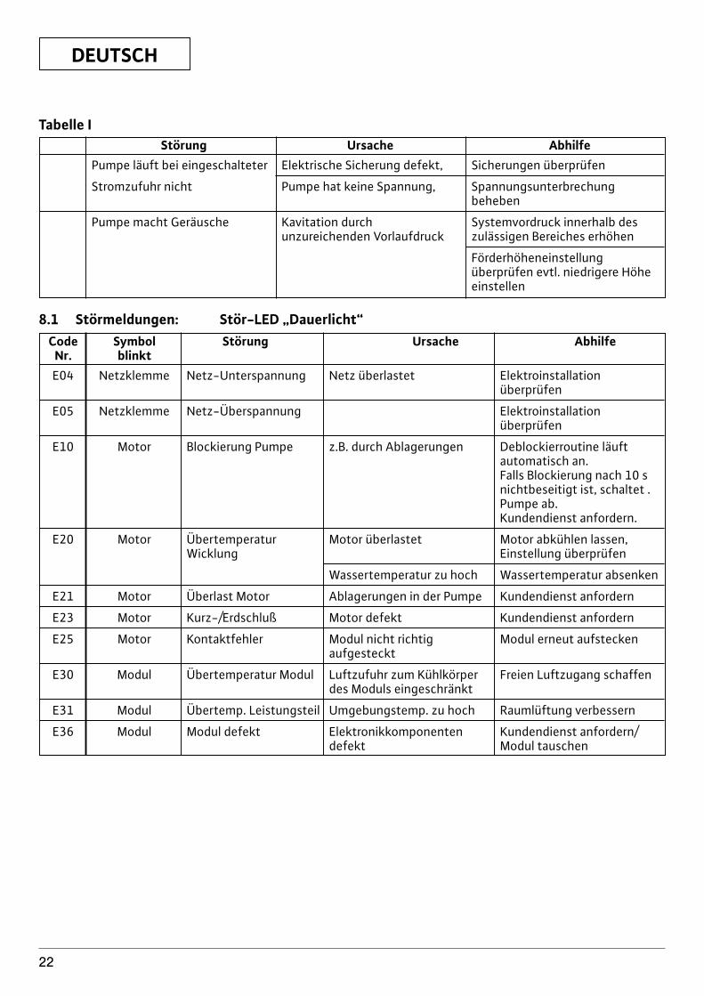
8.1 Störmeldungen: Stör-LED „Dauerlicht“Code Symbol Störung Ursache Abhilfe
Nr. blinktE04 Netzklemme Netz-Unterspannung Netz überlastet Elektroinstallation
überprüfen
E05 Netzklemme Netz-Überspannung Elektroinstallation überprüfen
E10 Motor Blockierung Pumpe z.B. durch Ablagerungen Deblockierroutine läuft automatisch an.Falls Blockierung nach 10 s nichtbeseitigt ist, schaltet .Pumpe ab.Kundendienst anfordern.
E20 Motor Übertemperatur Motor überlastet Motor abkühlen lassen, Wicklung Einstellung überprüfen
Wassertemperatur zu hoch Wassertemperatur absenken
E21 Motor Überlast Motor Ablagerungen in der Pumpe Kundendienst anfordern
E23 Motor Kurz-/Erdschluß Motor defekt Kundendienst anfordern
E25 Motor Kontaktfehler Modul nicht richtig Modul erneut aufsteckenaufgesteckt
E30 Modul Übertemperatur Modul Luftzufuhr zum Kühlkörper Freien Luftzugang schaffendes Moduls eingeschränkt
E31 Modul Übertemp. Leistungsteil Umgebungstemp. zu hoch Raumlüftung verbessern
E36 Modul Modul defekt Elektronikkomponenten Kundendienst anfordern/defekt Modul tauschen
DEUTSCH
23
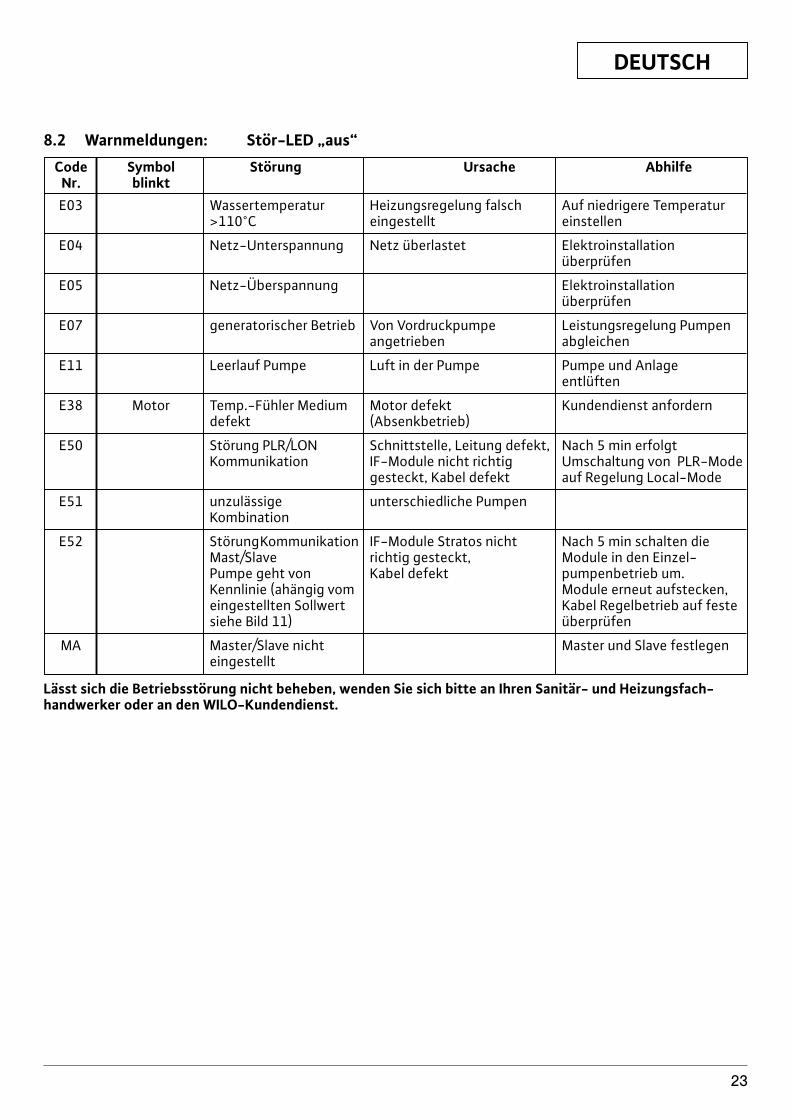
8.2 Warnmeldungen: Stör-LED „aus“
Code Symbol Störung Ursache AbhilfeNr. blinktE03 Wassertemperatur Heizungsregelung falsch Auf niedrigere Temperatur
>110°C eingestellt einstellen
E04 Netz-Unterspannung Netz überlastet Elektroinstallation überprüfen
E05 Netz-Überspannung Elektroinstallation überprüfen
E07 generatorischer Betrieb Von Vordruckpumpe Leistungsregelung Pumpenangetrieben abgleichen
E11 Leerlauf Pumpe Luft in der Pumpe Pumpe und Anlage entlüften
E38 Motor Temp.-Fühler Medium Motor defekt Kundendienst anforderndefekt (Absenkbetrieb)
E50 Störung PLR/LON Schnittstelle, Leitung defekt, Nach 5 min erfolgt Kommunikation IF-Module nicht richtig Umschaltung von PLR-Mode
gesteckt, Kabel defekt auf Regelung Local-Mode
E51 unzulässige unterschiedliche PumpenKombination
E52 StörungKommunikation IF-Module Stratos nicht Nach 5 min schalten die Mast/Slave richtig gesteckt, Module in den Einzel-Pumpe geht von Kabel defekt pumpenbetrieb um. Kennlinie (ahängig vom Module erneut aufstecken, eingestellten Sollwert Kabel Regelbetrieb auf feste siehe Bild 11) überprüfen
MA Master/Slave nicht Master und Slave festlegeneingestellt
Lässt sich die Betriebsstörung nicht beheben, wenden Sie sich bitte an Ihren Sanitär- und Heizungsfach-handwerker oder an den WILO-Kundendienst.
DEUTSCH
24
9 IF-Module für Wilo-Stratos/Stratos-D/Stratos-Z
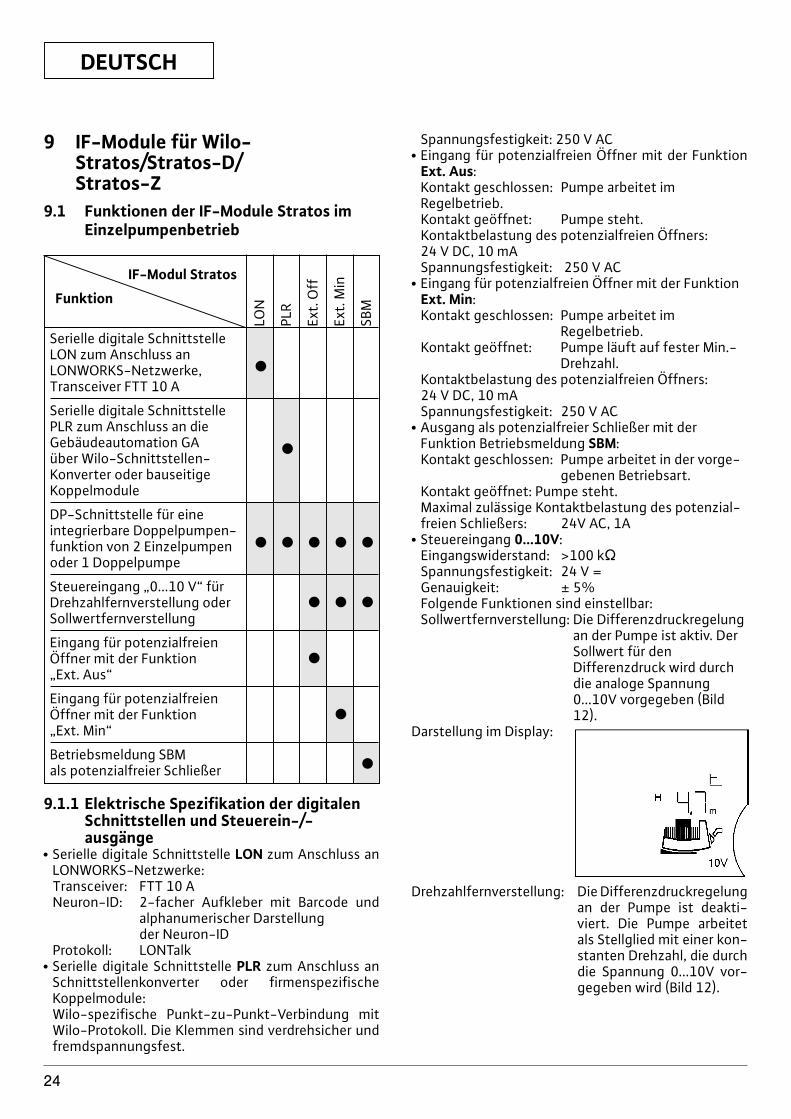
9.1 Funktionen der IF-Module Stratos imEinzelpumpenbetrieb
IF-Modul Stratos
Funktion
Serielle digitale Schnittstelle LON zum Anschluss an LONWORKS-Netzwerke, xTransceiver FTT 10 A
Serielle digitale Schnittstelle PLR zum Anschluss an die Gebäudeautomation GA xüber Wilo-Schnittstellen-Konverter oder bauseitige Koppelmodule
DP-Schnittstelle für eine integrierbare Doppelpumpen-funktion von 2 Einzelpumpen x x x x xoder 1 Doppelpumpe
Steuereingang „0...10 V“ für Drehzahlfernverstellung oder x x xSollwertfernverstellung
Eingang für potenzialfreien Öffner mit der Funktion x„Ext. Aus“
Eingang für potenzialfreien Öffner mit der Funktion x„Ext. Min“
Betriebsmeldung SBMxals potenzialfreier Schließer
LON
PLR
Ext.
Off
Ext.
Min
SBM
9.1.1 Elektrische Spezifikation der digitalenSchnittstellen und Steuerein-/-ausgänge
x Serielle digitale Schnittstelle LON zum Anschluss anLONWORKS-Netzwerke:Transceiver: FTT 10 ANeuron-ID: 2-facher Aufkleber mit Barcode und
alphanumerischer Darstellung der Neuron-ID
Protokoll: LONTalkx Serielle digitale Schnittstelle PLR zum Anschluss an
Schnittstellenkonverter oder firmenspezifischeKoppelmodule:Wilo-spezifische Punkt-zu-Punkt-Verbindung mitWilo-Protokoll. Die Klemmen sind verdrehsicher undfremdspannungsfest.
Spannungsfestigkeit: 250 V ACx Eingang für potenzialfreien Öffner mit der Funktion
Ext. Aus:Kontakt geschlossen: Pumpe arbeitet imRegelbetrieb.Kontakt geöffnet: Pumpe steht.Kontaktbelastung des potenzialfreien Öffners:24 V DC, 10 mASpannungsfestigkeit: 250 V AC
x Eingang für potenzialfreien Öffner mit der FunktionExt. Min:Kontakt geschlossen: Pumpe arbeitet im
Regelbetrieb.Kontakt geöffnet: Pumpe läuft auf fester Min.-
Drehzahl.Kontaktbelastung des potenzialfreien Öffners: 24 V DC, 10 mASpannungsfestigkeit: 250 V AC
x Ausgang als potenzialfreier Schließer mit derFunktion Betriebsmeldung SBM:Kontakt geschlossen: Pumpe arbeitet in der vorge-
gebenen Betriebsart.Kontakt geöffnet: Pumpe steht.Maximal zulässige Kontaktbelastung des potenzial-freien Schließers: 24V AC, 1A
x Steuereingang 0...10V:Eingangswiderstand: >100 kVSpannungsfestigkeit: 24 V =Genauigkeit: ± 5%Folgende Funktionen sind einstellbar:Sollwertfernverstellung: Die Differenzdruckregelung
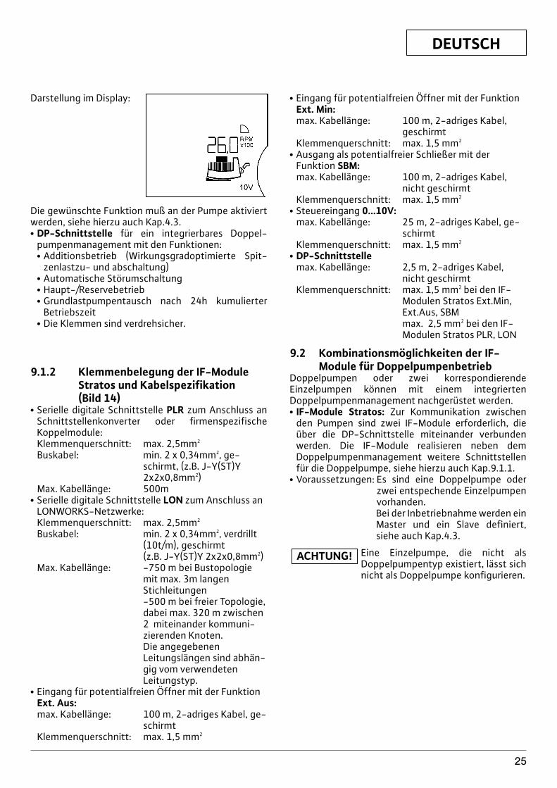
an der Pumpe ist aktiv. DerSollwert für denDifferenzdruck wird durchdie analoge Spannung0...10V vorgegeben (Bild12).
Darstellung im Display:
Drehzahlfernverstellung: Die Differenzdruckregelungan der Pumpe ist deakti-viert. Die Pumpe arbeitetals Stellglied mit einer kon-stanten Drehzahl, die durchdie Spannung 0...10V vor-gegeben wird (Bild 12).
DEUTSCH
25
Darstellung im Display:
Die gewünschte Funktion muß an der Pumpe aktiviertwerden, siehe hierzu auch Kap.4.3.x DP-Schnittstelle für ein integrierbares Doppel-
pumpenmanagement mit den Funktionen:x Additionsbetrieb (Wirkungsgradoptimierte Spit-
zenlastzu- und abschaltung)x Automatische Störumschaltungx Haupt-/Reservebetriebx Grundlastpumpentausch nach 24h kumulierter
Betriebszeitx Die Klemmen sind verdrehsicher.
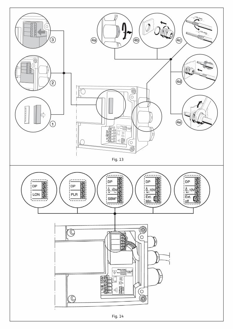
9.1.2 Klemmenbelegung der IF-ModuleStratos und Kabelspezifikation (Bild 14)
x Serielle digitale Schnittstelle PLR zum Anschluss anSchnittstellenkonverter oder firmenspezifischeKoppelmodule:Klemmenquerschnitt: max. 2,5mm2
Buskabel: min. 2 x 0,34mm2, ge-schirmt, (z.B. J-Y(ST)Y2x2x0,8mm2)
Max. Kabellänge: 500mx Serielle digitale Schnittstelle LON zum Anschluss an
LONWORKS-Netzwerke:Klemmenquerschnitt: max. 2,5mm2
Buskabel: min. 2 x 0,34mm2, verdrillt(10t/m), geschirmt(z.B. J-Y(ST)Y 2x2x0,8mm2)
Max. Kabellänge: -750 m bei Bustopologiemit max. 3m langenStichleitungen-500 m bei freier Topologie,dabei max. 320 m zwischen2 miteinander kommuni-zierenden Knoten.Die angegebenenLeitungslängen sind abhän-gig vom verwendetenLeitungstyp.
x Eingang für potentialfreien Öffner mit der FunktionExt. Aus:max. Kabellänge: 100 m, 2-adriges Kabel, ge-
schirmtKlemmenquerschnitt: max. 1,5 mm2
x Eingang für potentialfreien Öffner mit der FunktionExt. Min:max. Kabellänge: 100 m, 2-adriges Kabel,
geschirmtKlemmenquerschnitt: max. 1,5 mm2
x Ausgang als potentialfreier Schließer mit derFunktion SBM:max. Kabellänge: 100 m, 2-adriges Kabel,
nicht geschirmtKlemmenquerschnitt: max. 1,5 mm2
x Steuereingang 0...10V:max. Kabellänge: 25 m, 2-adriges Kabel, ge-
schirmtKlemmenquerschnitt: max. 1,5 mm2
x DP-Schnittstellemax. Kabellänge: 2,5 m, 2-adriges Kabel,
nicht geschirmtKlemmenquerschnitt: max. 1,5 mm2 bei den IF-
Modulen Stratos Ext.Min,Ext.Aus, SBMmax. 2,5 mm2 bei den IF-Modulen Stratos PLR, LON
9.2 Kombinationsmöglichkeiten der IF-Module für Doppelpumpenbetrieb
Doppelpumpen oder zwei korrespondierendeEinzelpumpen können mit einem integriertenDoppelpumpenmanagement nachgerüstet werden.x IF-Module Stratos: Zur Kommunikation zwischen
den Pumpen sind zwei IF-Module erforderlich, dieüber die DP-Schnittstelle miteinander verbundenwerden. Die IF-Module realisieren neben demDoppelpumpenmanagement weitere Schnittstellenfür die Doppelpumpe, siehe hierzu auch Kap.9.1.1.
x Voraussetzungen: Es sind eine Doppelpumpe oderzwei entspechende Einzelpumpenvorhanden.Bei der Inbetriebnahme werden einMaster und ein Slave definiert,siehe auch Kap.4.3.
Eine Einzelpumpe, die nicht alsDoppelpumpentyp existiert, lässt sichnicht als Doppelpumpe konfigurieren.
ACHTUNG!
DEUTSCH
26
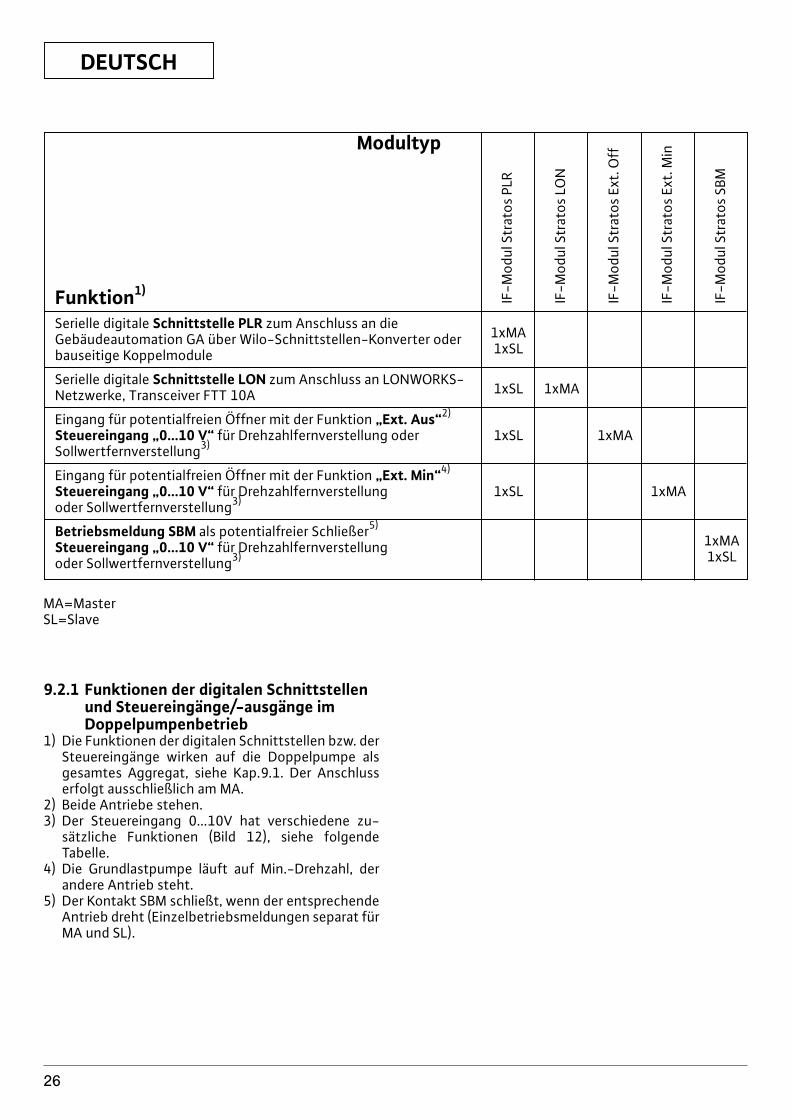
Modultyp
Funktion1)
Serielle digitale Schnittstelle PLR zum Anschluss an dieGebäudeautomation GA über Wilo-Schnittstellen-Konverter oder 1xMA
bauseitige Koppelmodule 1xSL
Serielle digitale Schnittstelle LON zum Anschluss an LONWORKS-Netzwerke, Transceiver FTT 10A 1xSL 1xMA
Eingang für potentialfreien Öffner mit der Funktion „Ext. Aus“2)
Steuereingang „0...10 V“ für Drehzahlfernverstellung oder 1xSL 1xMASollwertfernverstellung3)
Eingang für potentialfreien Öffner mit der Funktion „Ext. Min“4)
Steuereingang „0...10 V“ für Drehzahlfernverstellung 1xSL 1xMAoder Sollwertfernverstellung3)
Betriebsmeldung SBM als potentialfreier Schließer5)
Steuereingang „0...10 V“ für Drehzahlfernverstellung 1xMA
oder Sollwertfernverstellung3) 1xSL
IF-M
odul
Str
atos
PLR
IF-M
odul
Str
atos
LO
N
IF-M
odul
Str
atos
Ext
. Off
IF-M
odul
Str
atos
Ext
. Min
IF-M
odul
Str
atos
SBM
MA=MasterSL=Slave
9.2.1 Funktionen der digitalen Schnittstellenund Steuereingänge/-ausgänge imDoppelpumpenbetrieb
1) Die Funktionen der digitalen Schnittstellen bzw. derSteuereingänge wirken auf die Doppelpumpe alsgesamtes Aggregat, siehe Kap.9.1. Der Anschlusserfolgt ausschließlich am MA.
2) Beide Antriebe stehen.3) Der Steuereingang 0...10V hat verschiedene zu-
sätzliche Funktionen (Bild 12), siehe folgendeTabelle.
4) Die Grundlastpumpe läuft auf Min.-Drehzahl, derandere Antrieb steht.
5) Der Kontakt SBM schließt, wenn der entsprechendeAntrieb dreht (Einzelbetriebsmeldungen separat fürMA und SL).
DEUTSCH
27
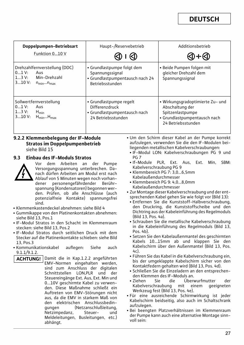
Doppelpumpen-Betriebsart
Funktion 0…10 V
Drehzahlfernverstellung (DDC)0...1 V: Aus1...3 V: Min-Drehzahl3...10 V: nmin...nmax
Haupt-/Reservebetrieb
x Grundlastpumpe folgt demSpannungssignal
x Grundlastpumpentausch nach 24Betriebsstunden
x Beide Pumpen folgen mit gleicher Drehzahl dem Spannungssignal
Sollwertfernverstellung0...1 V: Aus1...3 V: Hmin3...10 V: Hmin...Hmax
x Grundlastpumpe regelt Differenzdruck
x Grundlastpumpentausch nach 24 Betriebsstunden
x Wirkungsgradoptimierte Zu- undAbschaltung derSpitzenlastpumpe
x Grundlastpumpentausch nach 24 Betriebsstunden
Additionsbetrieb
9.2.2 Klemmenbelegung der IF-ModuleStratos im Doppelpumpenbetriebsiehe Bild 15
9.3 Einbau des IF-Moduls StratosVor dem Arbeiten an der PumpeVersorgungsspannung unterbrechen. Da-nach dürfen Arbeiten am Modul erst nachAblauf von 5 Minuten wegen noch vorhan-dener personengefährdender Berühr-spannung (Kondensatoren) begonnen wer-den. Prüfen, ob alle Anschlüsse (auchpotenzialfreie Kontakte) spannungsfreisind.
x Klemmenkastendeckel abnehmen: siehe Bild 4x Gummikappe von den Platinenkontakten abnehmen:
siehe Bild 13, Pos.1x IF-Modul Stratos in den Schacht im Klemmenraum
stecken: siehe Bild 13, Pos.2x IF-Modul Stratos durch seitlichen Druck mit dem
Stecker auf die Platinenkontakte schieben: siehe Bild13, Pos.3
x Kommunikationskabel auflegen: Siehe auch9.1.1/9.1.2.
Damit die in Kap.1.2.2 angeführtenEMV-Normen eingehalten werden,sind zum Anschluss der digitalenSchnittstellen LON,PLR und derSteuereingänge Ext. Aus, Ext. Min und0...10V geschirmte Kabel zu verwen-den. Diese Maßnahme schließt einAuftreten von EMV-Störungen nichtaus, da die EMV in starkem Maß vonden elektrischen Anschlussbedin-gungen (Netzanschlußleitung,Netzimpedanz, Steuer- undMeldeleitungen, Busleitungen, etc.)abhängt.
ACHTUNG!
x Um den Schirm dieser Kabel an der Pumpe korrektaufzulegen, verwenden Sie die den IF-Modulen bei-liegenden metallischen Kabelverschraubungen:x IF-Modul LON: Kabelverschraubungen PG 9 und
PG 7x If-Module PLR, Ext. Aus, Ext. Min, SBM:
Kabelverschraubung PG 9x Klemmbereich PG 7: 3,0...6,5mm
Kabelaußendurchmesserx Klemmbereich PG 9: 4,0...8,0mm
Kabelaußendurchmesserx Zur Montage dieser Kabelverschraubung und der ent-
sprechenden Kabel gehen Sie wie folgt vor (Bild 13):x Entfernen Sie die Kunststoff-Halbverschraubung,
den Druckring, die Kunststoffscheibe und denDichtring aus der Kabeleinführung des Regelmoduls(Bild 13, Pos. 4a).
x Schrauben Sie die metallische Kabelverschraubungin die Kabeleinführung des Regelmoduls (Bild 13,Pos. 4b).
x Setzen Sie den Kabelaußenmantel des geschirmtenKabels 10...15mm ab und klappen Sie denKabelschirm über den Außenmantel (Bild 13, Pos.4c).
x Führen Sie das Kabel in die Kabelverschraubung ein,bis der umgeklappte Kabelschirm sicher von denKontaktfedern gehalten wird (Bild 13, Pos. 4d).
x Schließen Sie die Einzeladern an den entsprechen-den Klemmen des IF-Moduls an.
x Ziehen Sie die Überwurfmutter derKabelverschraubung mit einem geeignetenWerkzeug fest (Bild 13, Pos. 4e).
x Für eine ausreichende Schirmwirkung ist jederKabelschirm beidseitig, also auch im Schaltschrankaufzulegen.
x Bei beengten Platzverhältnissen im Klemmenraumder Pumpe kann auch eine alternative Montage sinn-voll sein:
DEUTSCH
28
x Kommunikationskabel (abgesetzt) durch PG-Verschraubung führen,
x Drähte des Kommunikationskabels am IF-Modulauflegen (IF-Modul ist noch nicht gesteckt.),
x Drähte des Kommunikationskabels zu einerSchlaufe legen und IF-Modul montieren.
x Klemmenkastendeckel mit den Laschen in dieAussparungen einhaken und zuschrauben: siehe Bild 4
x IF-Modul Stratos LON: Ein Aufkleber mit der Neuron-ID verbleibt auf dem IF-Modul, der andere Aufkleberkann z.B. an die Stelle der zugehörigen Pumpe imAnlagenplan eingeklebt werden. Beim Binding kanndann die Neuron-ID aus dem Anlagenplan mit einemBarcode-Leser eingelesen oder manuell eingegebenwerden.
Technische Änderungen vorbehalten!
ENGLISH
29
Wilo Stratos High-Efficiency PumpTable of contents: Page1. General Information . . . . . . . . . . . . . . . . . . . . . . . . . . . . . . . . . . . . . . . . . . . . . . . . . . . . . . . . . . . . . . . . . . . . . . . 301.1 Uses . . . . . . . . . . . . . . . . . . . . . . . . . . . . . . . . . . . . . . . . . . . . . . . . . . . . . . . . . . . . . . . . . . . . . . . . . . . . . . . . . . . . . . 301.2 Product data . . . . . . . . . . . . . . . . . . . . . . . . . . . . . . . . . . . . . . . . . . . . . . . . . . . . . . . . . . . . . . . . . . . . . . . . . . . . . . . 301.2.1Rating plate . . . . . . . . . . . . . . . . . . . . . . . . . . . . . . . . . . . . . . . . . . . . . . . . . . . . . . . . . . . . . . . . . . . . . . . . . . . . . . . 301.2.2Connection and electrical data . . . . . . . . . . . . . . . . . . . . . . . . . . . . . . . . . . . . . . . . . . . . . . . . . . . . . . . . . . . . . . 30
2. Safety . . . . . . . . . . . . . . . . . . . . . . . . . . . . . . . . . . . . . . . . . . . . . . . . . . . . . . . . . . . . . . . . . . . . . . . . . . 312.1 Danger symbols used in these operating instructions . . . . . . . . . . . . . . . . . . . . . . . . . . . . . . . . . . . . . . . . . . 312.2 Staff training . . . . . . . . . . . . . . . . . . . . . . . . . . . . . . . . . . . . . . . . . . . . . . . . . . . . . . . . . . . . . . . . . . . . . . . . . . . . . . 312.3 Risks incurred by failure to comply with the safety precautions . . . . . . . . . . . . . . . . . . . . . . . . . . . . . . . . . 312.4 Safety precautions for the operator . . . . . . . . . . . . . . . . . . . . . . . . . . . . . . . . . . . . . . . . . . . . . . . . . . . . . . . . . . 312.5 Safety information for inspection and assembly . . . . . . . . . . . . . . . . . . . . . . . . . . . . . . . . . . . . . . . . . . . . . . . 312.6 Unauthorized modification and manufacture of spare parts . . . . . . . . . . . . . . . . . . . . . . . . . . . . . . . . . . . . 312.7 Unauthorized operating methods . . . . . . . . . . . . . . . . . . . . . . . . . . . . . . . . . . . . . . . . . . . . . . . . . . . . . . . . . . . . 31
3. Transport and interim storage . . . . . . . . . . . . . . . . . . . . . . . . . . . . . . . . . . . . . . . . . . . . . . . . . . . 31
4. Product and accessory description . . . . . . . . . . . . . . . . . . . . . . . . . . . . . . . . . . . . . . . . . . . . . . . 314.1 Pump description . . . . . . . . . . . . . . . . . . . . . . . . . . . . . . . . . . . . . . . . . . . . . . . . . . . . . . . . . . . . . . . . . . . . . . . . . . 314.1.1Differential pressure control systems . . . . . . . . . . . . . . . . . . . . . . . . . . . . . . . . . . . . . . . . . . . . . . . . . . . . . . . . . 324.1.2Other energy saving operating modes . . . . . . . . . . . . . . . . . . . . . . . . . . . . . . . . . . . . . . . . . . . . . . . . . . . . . . . . 324.1.3General pump functions . . . . . . . . . . . . . . . . . . . . . . . . . . . . . . . . . . . . . . . . . . . . . . . . . . . . . . . . . . . . . . . . . . . . 324.2 Double pump mode . . . . . . . . . . . . . . . . . . . . . . . . . . . . . . . . . . . . . . . . . . . . . . . . . . . . . . . . . . . . . . . . . . . . . . . . 324.3 Operating the pump . . . . . . . . . . . . . . . . . . . . . . . . . . . . . . . . . . . . . . . . . . . . . . . . . . . . . . . . . . . . . . . . . . . . . . . . 334.4 Important points on the operation of the pump, PLR and IR monitor . . . . . . . . . . . . . . . . . . . . . . . . . . . . . 414.5 Products delivered . . . . . . . . . . . . . . . . . . . . . . . . . . . . . . . . . . . . . . . . . . . . . . . . . . . . . . . . . . . . . . . . . . . . . . . . . 414.6 Accessories . . . . . . . . . . . . . . . . . . . . . . . . . . . . . . . . . . . . . . . . . . . . . . . . . . . . . . . . . . . . . . . . . . . . . . . . . . . . . . . . 41
5. Assembly / installation . . . . . . . . . . . . . . . . . . . . . . . . . . . . . . . . . . . . . . . . . . . . . . . . . . . . . . . . . . 415.1 Installing the pump . . . . . . . . . . . . . . . . . . . . . . . . . . . . . . . . . . . . . . . . . . . . . . . . . . . . . . . . . . . . . . . . . . . . . . . . . 415.1.1Removing/installing the control module . . . . . . . . . . . . . . . . . . . . . . . . . . . . . . . . . . . . . . . . . . . . . . . . . . . . . . 425.1.2Removing/installing the motor impeller unit . . . . . . . . . . . . . . . . . . . . . . . . . . . . . . . . . . . . . . . . . . . . . . . . . . 425.1.3Insulating the pump in refrigerating/air-conditioning systems . . . . . . . . . . . . . . . . . . . . . . . . . . . . . . . . . . 435.2 Electrical connection . . . . . . . . . . . . . . . . . . . . . . . . . . . . . . . . . . . . . . . . . . . . . . . . . . . . . . . . . . . . . . . . . . . . . . . 435.2.1Electrical pump connection . . . . . . . . . . . . . . . . . . . . . . . . . . . . . . . . . . . . . . . . . . . . . . . . . . . . . . . . . . . . . . . . . 43
6. Operation . . . . . . . . . . . . . . . . . . . . . . . . . . . . . . . . . . . . . . . . . . . . . . . . . . . . . . . . . . . . . . . . . . . . . . 446.1 Filling and ventilating the unit . . . . . . . . . . . . . . . . . . . . . . . . . . . . . . . . . . . . . . . . . . . . . . . . . . . . . . . . . . . . . . . 446.2 Setting the pump power . . . . . . . . . . . . . . . . . . . . . . . . . . . . . . . . . . . . . . . . . . . . . . . . . . . . . . . . . . . . . . . . . . . . 446.3 Selecting the control mode . . . . . . . . . . . . . . . . . . . . . . . . . . . . . . . . . . . . . . . . . . . . . . . . . . . . . . . . . . . . . . . . . . 45
7. Maintenance/service . . . . . . . . . . . . . . . . . . . . . . . . . . . . . . . . . . . . . . . . . . . . . . . . . . . . . . . . . . . . 47
8. Problems, causes and solutions . . . . . . . . . . . . . . . . . . . . . . . . . . . . . . . . . . . . . . . . . . . . . . . . . . 478.1 Error messages . . . . . . . . . . . . . . . . . . . . . . . . . . . . . . . . . . . . . . . . . . . . . . . . . . . . . . . . . . . . . . . . . . . . . . . . . . . . . 478.2 Warning messages . . . . . . . . . . . . . . . . . . . . . . . . . . . . . . . . . . . . . . . . . . . . . . . . . . . . . . . . . . . . . . . . . . . . . . . . . 47
9 IF modules for Wilo Stratos/Stratos-D/Stratos-Z . . . . . . . . . . . . . . . . . . . . . . . . . . . . . . . . . . 519.1 Functions of the Stratos IF modules in single pump mode . . . . . . . . . . . . . . . . . . . . . . . . . . . . . . . . . . . . . . 519.1.1Electrical specification of the digital interfaces and control inputs/outputs . . . . . . . . . . . . . . . . . . . . . . . 519.1.2Terminal assignment of the Stratos IF modules and cable specification . . . . . . . . . . . . . . . . . . . . . . . . . . 529.2 Combination possibilities of the IF modules for double pump mode . . . . . . . . . . . . . . . . . . . . . . . . . . . . . 529.2.1Functions of the digital interfaces and control inputs/outputs in double pump mode . . . . . . . . . . . . . . 539.2.2Terminal assignment of the Stratos IF modules in double pump mode . . . . . . . . . . . . . . . . . . . . . . . . . . . 549.3 Installing the IF module . . . . . . . . . . . . . . . . . . . . . . . . . . . . . . . . . . . . . . . . . . . . . . . . . . . . . . . . . . . . . . . . . . . . . 54
ENGLISH
30
1. General Information1.1 UsesThe high-efficiency pumps of the Wilo Stratos seriesare used to pump fluids inx Warm water heating systems,x Cooling and cold water circuits,x Closed industrial circulation systems,x Circulation systems for drinking water (Stratos-Z
only).Wilo-Stratos series: Single pumpsWilo-Stratos-D series: Double pumpsWilo-Stratos-Z series: Drinking water circulation
pumpsDo not use the pumps Stratos/Stratos-Dseries in the vicinity of drinking water orfoodstuffs.
1.2 Product data
1.2.1 Rating plateStratos 30/ 1-12
Stratos-D 32/ 1-12
High-efficiency pumpWet-rotor circulating pump,Single pump orD f Double pump Z f Drinking water circulation pumpNominal diameter DN of connecting lead [mm]Flanged end: 32, 40, 50, 65, 80, 100(Combination flange (PN 6/10) for DN 32, 40, 50, 65)Screw connection: 25 (Rp1), 30 (R 1[)Infinitely variable nominal pump lift 1 to 12 m Hmin: 1 m, Hmax: 12 m
1.2.2 Connection and electrical datax Supply voltage: 1~230 V ±10%, 50 Hz to DIN IEC
60038x System of protection: IP 44x Insulation class: Fx Motor protection: standard built-in full motor pro-
tectionx EMC (electromagnetic compatibility)x EMC general: EN 61800-3x Emitted interference: EN 61000-6-3, formerly EN
50081-1 (building standard)x Interference immunity: EN 61000-6-2, formerly EN
50082-2 (industry standard)x Sound pressure level < 54 dB(A)x Temperature range of the flow medium: -10 °C to
+110 °C
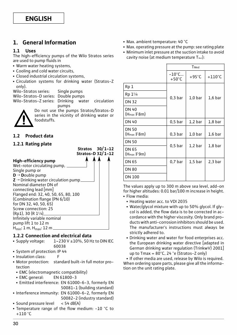
x Max. ambient temperature: 40 °Cx Max. operating pressure at the pump: see rating platex Minimum inlet pressure at the suction intake to avoid
cavity noise (at medium temperature TMed ):
TMed
-10°C...+50°C +95°C +110°C
Rp 1
Rp 1[
DN 320,3 bar 1,0 bar 1,6 bar
DN 40 (Hmax F8m)
DN 40 0,5 bar 1,2 bar 1,8 bar
DN 50 (Hmax F8m) 0,3 bar 1,0 bar 1,6 bar
DN 500,5 bar 1,2 bar 1,8 bar
DN 65 (Hmax F9m)
DN 65 0,7 bar 1,5 bar 2,3 bar
DN 80
DN 100
The values apply up to 300 m above sea level, add-onfor higher altitudes: 0.01 bar/100 m increase in height.x Flow media:
x Heating water acc. to VDI 2035x Water/glycol mixture with up to 50% glycol. If gly-
col is added, the flow data is to be corrected in ac-cordance with the higher viscosity. Only brand pro-ducts with anti-corrosion inhibitors should be used.The manufacturer's instructions must always bestrictly adhered to.
x Drinking water and water for food enterprises acc.the European drinking water directive [adapted inGerman drinking water regulation (TrinkwV) 2001]up to Tmax = 80°C, 24 °e (Stratos-Z only)
x If other media are used, release by Wilo is required.When ordering spare parts, please give all the informa-tion on the unit rating plate.
ENGLISH
31
2. SafetyThese instructions contain important informationwhich must be followed when installing and operatingthe pump. These operating instructions must thereforebe read before assembly and commissioning by the in-staller and the responsible operator.Both the general safety instructions in the “Safety pre-cautions” section and those in subsequent sections in-dicated by danger symbols should be carefully obser-ved.
2.1 Danger symbols used in these operatinginstructions
Safety precautions in these operating instructionswhich, if not followed, could cause personal injury areindicated by the symbol:
,
when warning of electrical voltage with
The following symbol is used to indicate that by igno-ring the relevant safety instructions, damage could becaused to the pump/machinery and its functions:
2.2 Staff trainingThe personnel installing the pump must have the ap-propriate qualifications for this work.
2.3 Risks incurred by failure to comply withthe safety precautions
Failure to comply with the safety precautions could re-sult in personal injury or damage to the pump or instal-lation. Failure to comply with the safety precautionscould also invalidate any claim for damages.In particular, lack of care may lead to problems such as:x Failure of important pump or machinery functions,x Injury resulting from electrical or mechanical factors.
2.4 Safety precautions for the operatorExisting regulations for the prevention of accidentsmust be followed.Dangers caused by electrical energy are to be excluded.Directives issued by the IEC, VDE etc. and the localelectricity supply companies are to be observed.
2.5 Safety information for inspection andassembly
The operator is responsible for ensuring that inspec-tion and assembly are carried out by authorized and
ATTENTION!
qualified personnel who have studied the operating in-structions closely.Work on the pump/machinery should only be carriedout when the machine has been brought to a standstill.
2.6 Unauthorized modification andmanufacture of spare parts
Alterations to the pump or installation may only be car-ried out with the manufacturer's consent. The use oforiginal spare parts and accessories authorized by themanufacturer will ensure safety. The use of any otherparts may invalidate claims invoking the liability of themanufacturer for any consequences.
2.7 Unauthorized operating methodsThe operating safety of the pump or installation supp-lied can only be guaranteed if it is used in accordancewith paragraph 1 of the operating instructions. The li-miting values given in the catalogue or data sheet mustneither be exceeded nor allowed to fall below thosespecified.
3 Transport and interim storageThe pump must be protected againstmoisture and physical damage. In thecase of transport and interim storagethe pump may not be exposed totemperatures outside the range -10°C to +50°C.
4 Product and accessory description4.1 Pump description (figs 1a, 1b)The Wilo Stratos high efficiency pump is a series ofglandless pumps with Electronic Commutated Motor(ECM) technology and built-in differential pressurecontrol. The pump can be installed as a single (fig. 1a)or double pump (fig. 1b).On the motor housing there is an axial control module(fig. 1a, pos. 1) which sets the pump's differential pres-sure to a set value that can be varied within the controlrange. Depending on the control system involved, thedifferential pressure is subject to different criteria.However, regardless of the control system the pumpconstantly adapts to changing system power require-ments, as it is especially the case when using thermo-static valves or mixers.The main benefits of electronic control are:x it saves energy whilst at the same time reducing ope-
rating costs,x it reduces noise caused by the flow.x it does not require overflow valves.The high efficiency pumps of the series Wilo-Stratos-Z are particularly suited with the operation conditionsin drinking water circulation systems by material selec-tion and design. All materials coming in contact withthe delivery medium are KTW/WRAS certified.
ATTENTION!
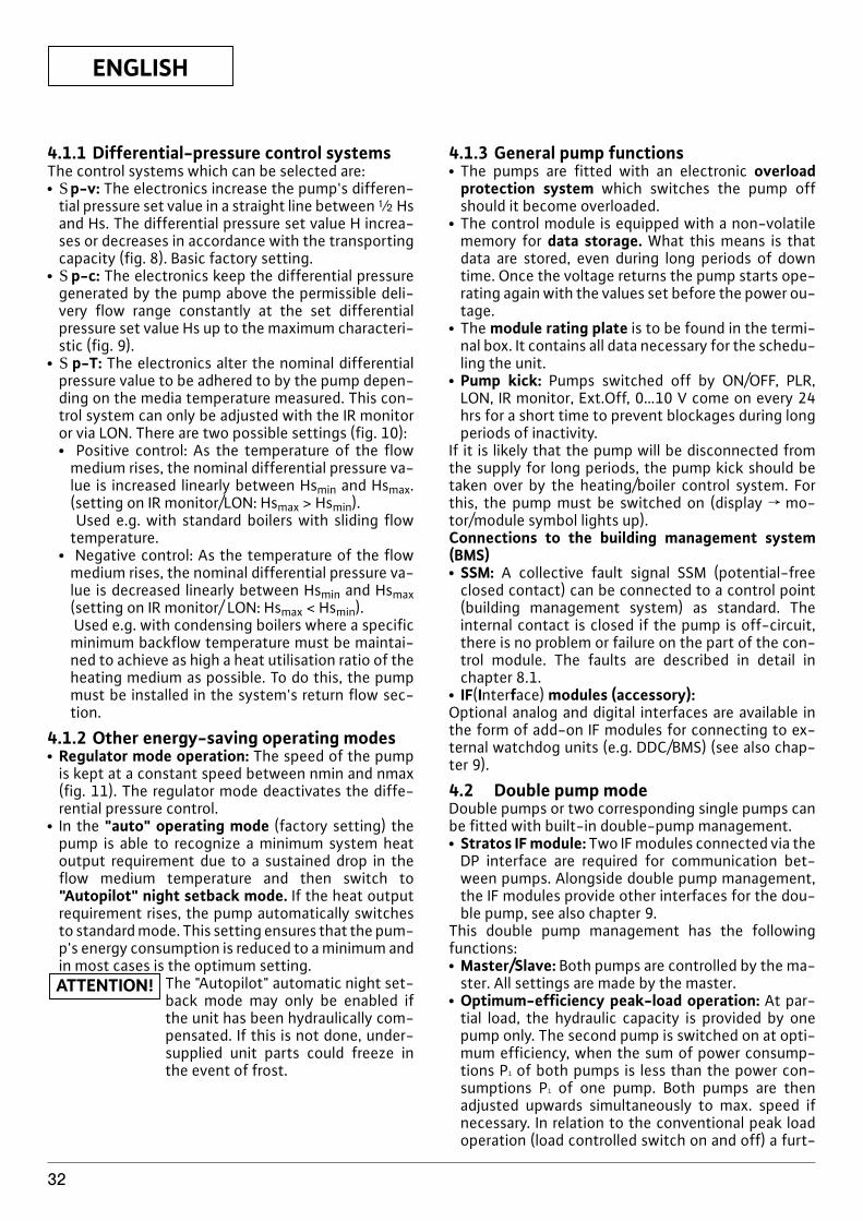
ENGLISH
32
4.1.1 Differential-pressure control systemsThe control systems which can be selected are:x Sp-v: The electronics increase the pump's differen-
tial pressure set value in a straight line between | Hsand Hs. The differential pressure set value H increa-ses or decreases in accordance with the transportingcapacity (fig. 8). Basic factory setting.
x Sp-c: The electronics keep the differential pressuregenerated by the pump above the permissible deli-very flow range constantly at the set differentialpressure set value Hs up to the maximum characteri-stic (fig. 9).
x S p-T: The electronics alter the nominal differentialpressure value to be adhered to by the pump depen-ding on the media temperature measured. This con-trol system can only be adjusted with the IR monitoror via LON. There are two possible settings (fig. 10):x Positive control: As the temperature of the flow
medium rises, the nominal differential pressure va-lue is increased linearly between Hsmin and Hsmax.(setting on IR monitor/LON: Hsmax > Hsmin).Used e.g. with standard boilers with sliding flow
temperature.x Negative control: As the temperature of the flow
medium rises, the nominal differential pressure va-lue is decreased linearly between Hsmin and Hsmax(setting on IR monitor/ LON: Hsmax < Hsmin).Used e.g. with condensing boilers where a specific
minimum backflow temperature must be maintai-ned to achieve as high a heat utilisation ratio of theheating medium as possible. To do this, the pumpmust be installed in the system's return flow sec-tion.
4.1.2 Other energy-saving operating modesx Regulator mode operation: The speed of the pump
is kept at a constant speed between nmin and nmax(fig. 11). The regulator mode deactivates the diffe-rential pressure control.
x In the "auto" operating mode (factory setting) thepump is able to recognize a minimum system heatoutput requirement due to a sustained drop in theflow medium temperature and then switch to"Autopilot" night setback mode. If the heat outputrequirement rises, the pump automatically switchesto standard mode. This setting ensures that the pum-p's energy consumption is reduced to a minimum andin most cases is the optimum setting.
The "Autopilot" automatic night set-back mode may only be enabled ifthe unit has been hydraulically com-pensated. If this is not done, under-supplied unit parts could freeze inthe event of frost.
ATTENTION!
4.1.3 General pump functionsx The pumps are fitted with an electronic overload
protection system which switches the pump offshould it become overloaded.
x The control module is equipped with a non-volatilememory for data storage. What this means is thatdata are stored, even during long periods of downtime. Once the voltage returns the pump starts ope-rating again with the values set before the power ou-tage.
x The module rating plate is to be found in the termi-nal box. It contains all data necessary for the schedu-ling the unit.
x Pump kick: Pumps switched off by ON/OFF, PLR,LON, IR monitor, Ext.Off, 0…10 V come on every 24hrs for a short time to prevent blockages during longperiods of inactivity.
If it is likely that the pump will be disconnected fromthe supply for long periods, the pump kick should betaken over by the heating/boiler control system. Forthis, the pump must be switched on (display f mo-tor/module symbol lights up).Connections to the building management system(BMS)x SSM: A collective fault signal SSM (potential-free
closed contact) can be connected to a control point(building management system) as standard. Theinternal contact is closed if the pump is off-circuit,there is no problem or failure on the part of the con-trol module. The faults are described in detail inchapter 8.1.
x IF(Interface) modules (accessory):Optional analog and digital interfaces are available inthe form of add-on IF modules for connecting to ex-ternal watchdog units (e.g. DDC/BMS) (see also chap-ter 9).
4.2 Double pump modeDouble pumps or two corresponding single pumps canbe fitted with built-in double-pump management.x Stratos IF module: Two IF modules connected via the
DP interface are required for communication bet-ween pumps. Alongside double pump management,the IF modules provide other interfaces for the dou-ble pump, see also chapter 9.
This double pump management has the followingfunctions:x Master/Slave: Both pumps are controlled by the ma-
ster. All settings are made by the master.x Optimum-efficiency peak-load operation: At par-
tial load, the hydraulic capacity is provided by onepump only. The second pump is switched on at opti-mum efficiency, when the sum of power consump-tions P1 of both pumps is less than the power con-sumptions P1 of one pump. Both pumps are thenadjusted upwards simultaneously to max. speed ifnecessary. In relation to the conventional peak loadoperation (load controlled switch on and off) a furt-
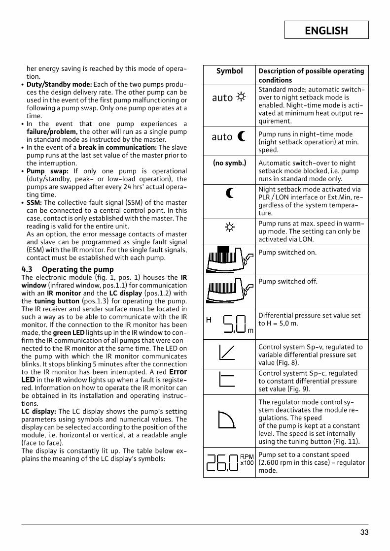
ENGLISH
33
her energy saving is reached by this mode of opera-tion.
x Duty/Standby mode: Each of the two pumps produ-ces the design delivery rate. The other pump can beused in the event of the first pump malfunctioning orfollowing a pump swap. Only one pump operates at atime.
x In the event that one pump experiences afailure/problem, the other will run as a single pumpin standard mode as instructed by the master.
x In the event of a break in communication: The slavepump runs at the last set value of the master prior tothe interruption.
x Pump swap: If only one pump is operational(duty/standby, peak- or low-load operation), thepumps are swapped after every 24 hrs’ actual opera-ting time.
x SSM: The collective fault signal (SSM) of the mastercan be connected to a central control point. In thiscase, contact is only established with the master. Thereading is valid for the entire unit.As an option, the error message contacts of masterand slave can be programmed as single fault signal(ESM) with the IR monitor. For the single fault signals,contact must be established with each pump.
4.3 Operating the pumpThe electronic module (fig. 1, pos. 1) houses the IRwindow (infrared window, pos.1.1) for communicationwith an IR monitor and the LC display (pos.1.2) withthe tuning button (pos.1.3) for operating the pump.The IR receiver and sender surface must be located insuch a way as to be able to communicate with the IRmonitor. If the connection to the IR monitor has beenmade, the green LED lights up in the IR window to con-firm the IR communication of all pumps that were con-nected to the IR monitor at the same time. The LED onthe pump with which the IR monitor communicatesblinks. It stops blinking 5 minutes after the connectionto the IR monitor has been interrupted. A red ErrorLED in the IR window lights up when a fault is registe-red. Information on how to operate the IR monitor canbe obtained in its installation and operating instruc-tions.LC display: The LC display shows the pump’s settingparameters using symbols and numerical values. Thedisplay can be selected according to the position of themodule, i.e. horizontal or vertical, at a readable angle(face to face).The display is constantly lit up. The table below ex-plains the meaning of the LC display's symbols:
Symbol Description of possible operatingconditions
autoStandard mode; automatic switch-over to night setback mode isenabled. Night-time mode is acti-vated at minimum heat output re-quirement.
auto Pump runs in night-time mode(night setback operation) at min.speed.
(no symb.) Automatic switch-over to nightsetback mode blocked, i.e. pumpruns in standard mode only.Night setback mode activated viaPLR / LON interface or Ext.Min, re-gardless of the system tempera-ture.Pump runs at max. speed in warm-up mode. The setting can only beactivated via LON.
Pump switched on.
Pump switched off.
Differential pressure set value setto H = 5,0 m.
Control system Sp-v, regulated tovariable differential pressure setvalue (Fig. 8).Control systemt Sp-c, regulatedto constant differential pressureset value (Fig. 9).
The regulator mode control sy-stem deactivates the module re-gulations. The speed of the pump is kept at a constantlevel. The speed is set internallyusing the tuning button (Fig. 11).
Pump set to a constant speed(2.600 rpm in this case) - regulatormode.
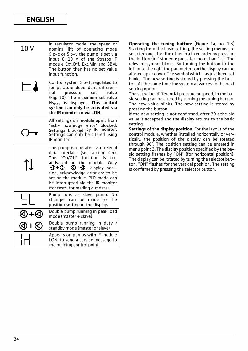
ENGLISH
34
In regulator mode, the speed ornominal lift of operating mode S p-c or S p-v the pump is set viainput 0...10 V of the Stratos IFmodule Ext.Off, Ext.Min and SBM.The button then has no set valueinput function.
Control system Sp-T, regulated totemperature dependent differen-tial pressure set value (Fig. 10). The maximum set valueHsmax is displayed. This controlsystem can only be activated viathe IR monitor or via LON.
All settings on module apart from"ack- nowledge error" blocked.Settings blocked by IR monitor.Settings can only be altered usingIR monitor.
The pump is operated via a serialdata interface (see section 4.4).The "On/Off" function is notactivated on the module. Only
, , display posi-tion, acknowledge error are to beset on the module. PLR mode canbe interrupted via the IR monitor(for tests, for reading out data).Pump runs as slave pump. Nochanges can be made to theposition setting of the display.Double pump running in peak loadmode (master + slave)Double pump running in duty /standby mode (master or slave)Appears on pumps with IF moduleLON, to send a service message tothe building control point.
Operating the tuning button: (Figure 1a, pos.1.3)Starting from the basic setting, the setting menus areselected one after the other in a fixed order by pressingthe button (in 1st menu: press for more than 1 s). Therelevant symbol blinks. By turning the button to theleft or to the right the parameters on the display can bealtered up or down. The symbol which has just been setblinks. The new setting is stored by pressing the but-ton. At the same time the system advances to the nextsetting option.The set value (differential pressure or speed) in the ba-sic setting can be altered by turning the tuning button.The new value blinks. The new setting is stored bypressing the button.If the new setting is not confirmed, after 30 s the oldvalue is accepted and the display returns to the basicsetting.Settings of the display position: For the layout of thecontrol module, whether installed horizontally or ver-tically, the position of the display can be rotatedthrough 90°. The position setting can be entered inmenu point 3. The display position specified by the ba-sic setting flashes by “ON“ (for horizontal position).The display can be rotated by turning the selector but-ton. “ON“ flashes for the vertical position. The settingis confirmed by pressing the selector button.
10 V
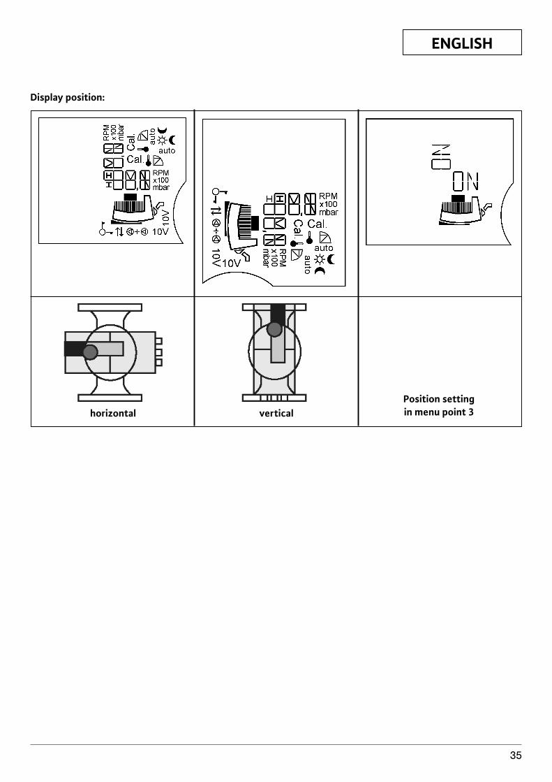
ENGLISH
35
Display position:
horizontal verticalPosition settingin menu point 3
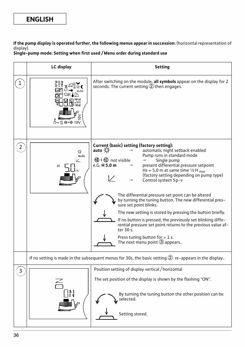
Current (basic) setting (factory setting):auto f automatic night setback enabled
Pump runs in standard modenot visible f Single pump
e.G. H 5,0 m f present differential pressure setpointHs = 5,0 m at same time | H max(factory setting depending on pump type)
f Control system Sp-v
The differential pressure set point can be alteredby turning the tuning button. The new differential pres-sure set point blinks.
The new setting is stored by pressing the button briefly.
If no button is pressed, the previously set blinking diffe-rential pressure set point returns to the previous value af-ter 30 s.
Press tuning button for > 1 s.The next menu point e appears..
ENGLISH
36
If the pump display is operated further, the following menus appear in succession: (horizontal representation ofdisplay)Single-pump mode: Setting when first used / Menu order during standard use
1
LC display Setting
After switching on the module, all symbols appear on the display for 2seconds. The current setting w then engages.
2
3 Position setting of display vertical / horizontal
The set position of the display is shown by the flashing "ON".
By turning the tuning button the other position can beselected.
Setting stored.
If no setting is made in the subsequent menus for 30s, the basic setting w re-appears in the display..
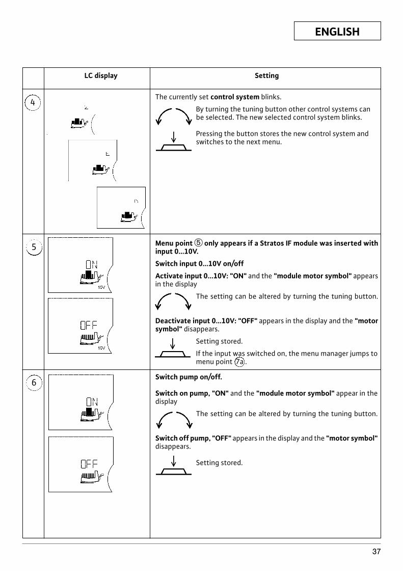
ENGLISH
37
4
LC display Setting
5
6
The currently set control system blinks.
By turning the tuning button other control systems canbe selected. The new selected control system blinks.
Pressing the button stores the new control system andswitches to the next menu.
Menu point t only appears if a Stratos IF module was inserted withinput 0...10V.
Switch input 0...10V on/off
Activate input 0...10V: "ON" and the "module motor symbol" appearsin the display
The setting can be altered by turning the tuning button.
Deactivate input 0...10V: "OFF" appears in the display and the "motorsymbol" disappears.
Setting stored.
If the input was switched on, the menu manager jumps tomenu point 7a .
Switch pump on/off.
Switch on pump, "ON" and the "module motor symbol" appear in thedisplay
The setting can be altered by turning the tuning button.
Switch off pump, "OFF" appears in the display and the "motor symbol"disappears.
Setting stored.
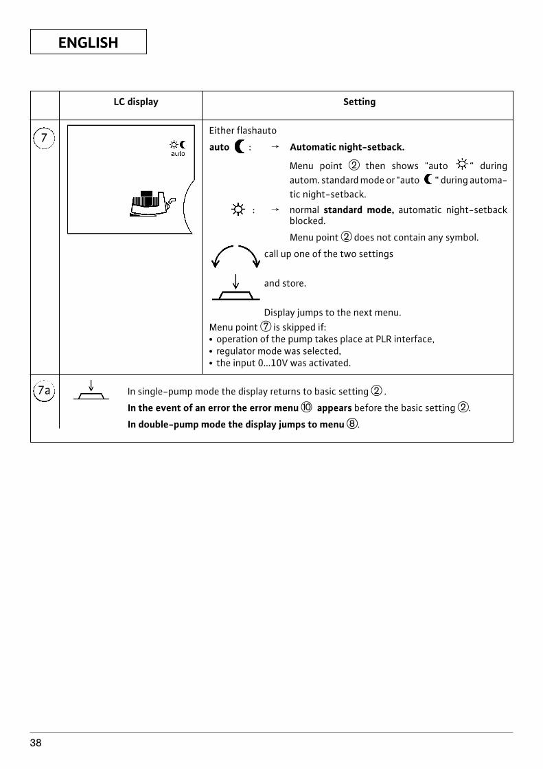
ENGLISH
38
7
7a
LC display Setting
Either flashauto
auto : f Automatic night-setback.
Menu point w then shows "auto “ duringautom. standard mode or "auto “ during automa-tic night-setback.
: f normal standard mode, automatic night-setbackblocked.
Menu point w does not contain any symbol.
call up one of the two settings
and store.
Display jumps to the next menu.Menu point u is skipped if:x operation of the pump takes place at PLR interface,x regulator mode was selected,x the input 0...10V was activated.
In single-pump mode the display returns to basic setting w .
In the event of an error the error menu p appears before the basic setting w.
In double-pump mode the display jumps to menu i.
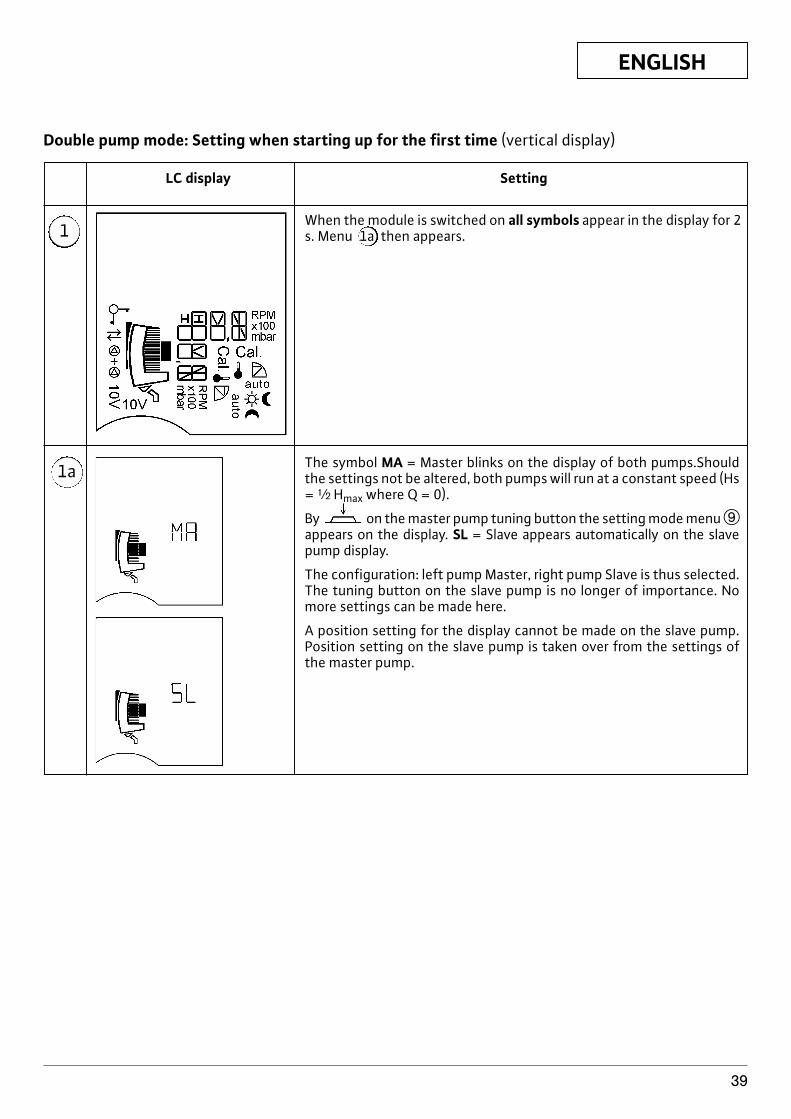
ENGLISH
39
1
LC display Setting
1a
When the module is switched on all symbols appear in the display for 2s. Menu 1a then appears.
The symbol MA = Master blinks on the display of both pumps.Shouldthe settings not be altered, both pumps will run at a constant speed (Hs= | Hmax where Q = 0).
By on the master pump tuning button the setting mode menu oappears on the display. SL = Slave appears automatically on the slavepump display.
The configuration: left pump Master, right pump Slave is thus selected.The tuning button on the slave pump is no longer of importance. Nomore settings can be made here.
A position setting for the display cannot be made on the slave pump.Position setting on the slave pump is taken over from the settings ofthe master pump.
Double pump mode: Setting when starting up for the first time (vertical display)
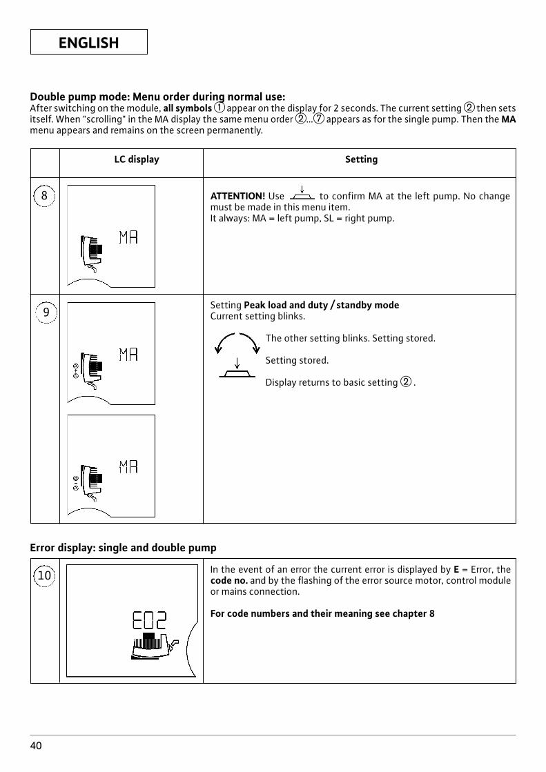
ENGLISH
40
8
LC display Setting
9
ATTENTION! Use to confirm MA at the left pump. No changemust be made in this menu item. It always: MA = left pump, SL = right pump.
Setting Peak load and duty / standby modeCurrent setting blinks.
The other setting blinks. Setting stored.
Setting stored.
Display returns to basic setting w .
10 In the event of an error the current error is displayed by E = Error, thecode no. and by the flashing of the error source motor, control moduleor mains connection.
For code numbers and their meaning see chapter 8
Error display: single and double pump
Double pump mode: Menu order during normal use:After switching on the module, all symbolsq appear on the display for 2 seconds. The current setting w then setsitself. When "scrolling" in the MA display the same menu order w…u appears as for the single pump. Then the MAmenu appears and remains on the screen permanently.
ENGLISH
41
4.4 Important points on the operation ofthe pump, PLR, LON, IR monitor
The display of errors (menu 10) incl. error acknowledg-ment has the highest priority. What this means is thaterrors take precedence on the pump's display and thatthey must be acknowledged and removed.If settings are made on the control module or from theIR monitor and not confirmed by pressing the button,the setting will return to the previous position 30 s af-ter the last entry.x Pump m–n LON: The pump is controlled via the LON
network of the building management system (BMS).The display shows . The pump is now blocked andcannot be operated. Exception , ,display position setting, error acknowledgement.
x Pump m–n PLR: When a command is received fromthe building management system (BMS) the pumpautomatically switches to PLR mode. The displayshows . The control system S p-c ( ) is alsoautomatically set, the control system Sp-vis unavai-lable. The pump is now blocked and cannot be ope-rated. Exception , , display positionsetting, error acknowledgement.
x Pump m–n PLR/LON m–n IR: With this configura-tion the pump gives the settings on the PLR priority.The connection via the interface to the BMS can betemporarily interrupted with the IR monitor. Settingscan then be made via the IR monitor or on the controlmodule. The connection to the interface is re-esta-blished 5 min after the last setting made via the IRmonitor. During the interruption disappears fromthe display.
x Pump m–n IR without Key function: The last com-mand, whether from the IR monitor or control mo-dule, is stored by the pump.
x Pump m–n IR with Key function: When the "Keyfunction on" command is received, the control mo-dule's current settings remain in place. The displayshows „ .“ The pump is now blocked and cannotbe operated.
4.5 Products deliveredx Pump complete (with 2 seals for threaded connec-
tion)x two-part thermal insulation shells, (single pump only
Figure 1a, pos.3)x material: EPP, foamed polypro-
pylenex Thermal conductivity: 0.04 W/m to DIN
52612x Inflammability: class B2 to DIN 4102,
FMVSS 302x Plain washer (for flange bolts with combi flange mo-
del DN32-DN65)
x Installation and Operating Instructions
4.6 Accessoriesx Stratos IF module PLR, LON, Ext.Off, Ext.Min, SBMx IR monitor
5 Assembly/installationInstallation and service by qualifiedpersonnel only!
5.1 Installing the pumpx The pump is to be installed in a dry, well-ventilated
and frost-free place.x Installation should only take place once all welding
and soldering work and the rinsing of the pipe net-work has been completed. Dirt can have an adverseeffect on the functioning of the pump.
x t is recommended that shut-off devices be installedbefore and after the pump. This will save you havingto drain and refill the unit if the pump has to be chan-ged.
x If installed in the flow pipe of open units, the expan-sion flow pipe must branch off on the pressure side ofthe pump.
x Install the pump stressfree. The pipes must be atta-ched in such a way that the pump does not bear theweight of the pipes.
x Before installing the single pump, the two shells ofthe thermal insulation (fig. 5, pos. 1) are to be remo-ved.
x The direction of flow of the media must match the di-rection triangle on the pump housing (fig. 1a, pos. 2).
x Only installation positions as shown in fig. 2 are per-mitted. The pump shaft must be horizontal.fig. 2a: Permissible installation positions for singlepumpsfig. 2b: Permissible installation positions for doublepumps
When installing in confined spaces, for example incompact distributors, the control module can be pla-ced in a vertical position by rotating the motor, seechapter 5.1.2. Double pumps are delivered with verti-cally fitted control modules.x Install the pump in an easily accessible place, so that
subsequent servicing work can easily be carried out.Installation is to be carried out such that dripping wa-ter cannot drip onto the pump motor or control mo-dule.x When installing pumps with combi flange PN6/10
(flange pumps up to and including DN 65), the fol-lowing guidelines are to be observed (fig. 3):1. Combi flanges may not be fitted to composite
flanges.
ATTENTION!
ENGLISH
42
2. The enclosed plain washers must be used bet-ween the screw/nut head and the combi flange(fig. 3, pos. 1).
Safety elements (e.g spring rings) arenot permitted.If the pump is not cor-rectly installed the nut can get incaught the slot. As a result, due to in-sufficient screw pretensioning, theperformance of the flanged connec-tion can be affected.
3. It is recommended that screws with a strengthclass of 4.6 are used for flanged connections.When using screws made from a material otherthan 4.6 (e.g. screws made from material 5.6 oran even higher-performance material), only thepermissible screw tightening torque correspon-ding to material 4.6 is to be used during installa-tion.Permissible screw tightening torques:
for M 12 f 40 Nm,for M 16 f 95 Nm
If higher-performance screws (G4.6)are tightened to tightening torquesother than those permitted, splinte-ring may occur around the edges ofthe slots due to the higher screwtensions. This will cause the screwsto lose their pretensioning and theflanged connection could leak.
4. Sufficiently long screws are to be used:
ATTENTION!
ATTENTION!
x Loosen 2 M5 hexagon socket screws (SW4) (pos. 4),x Remove control module from motor (pos. 5),x To install, reverse the above sequence.
If the pump is running off a generator (ro-tor driven by admission pressure pump), adangerous voltage is created at the motorterminals after the control module is re-moved. The motor terminals are designedas VDE-approved bushings, so that thereis no danger if simply touched with thefinger. However, there would be a dangerif a pointed object (nail, screwdriver, wire)were poked into one of the bushings.
For easy installation there are 2 or 3 (depending onpump type) pilot pins on the back of the control mo-dule which snap into corresponding holes in the motorhousing. Only when these pilot pins have secured thecontrol module to the motor housing does the centralearthing pin and then the winding pins make contact(fig. 4).
Between the motor housing and thecontrol module there is a flat seal (fig.4, pos. 6) which is responsible for thethermal decoupling of the two com-ponents. This seal must always beplaced between the module and themotor when installing the controlmodule.
5.1.2 Removing/installing the motor impellerunit
To remove the motor, 4 M6 hexagon socket screws(SW5) must be loosened. These screws can be reachedwith the following tools (fig. 5, pos. 2):x 90° offset socket-head screwdriverx spherical head socket-head screwdriverx [” reversing ratchet with suitable bitIf only the control module is to be moved into a diffe-rent position, the motor does not need to be comple-tely removed from the pump housing. The motor canbe turned to the desired position in the pump housing,provided there is sufficient room available.
Be careful not to damage the O-ringsituated between the motor headand the pump housing. The O-ringmust lie untwisted in the bevel of theend shield pointing to the impeller.The shaft is inextricably linked to theimpeller, the end shield and the rotor.This unit is secured against uninten-tional removal from the motor. If therotor with its strong magnets is not inthe motor housing, it has a consider-able potential for danger e.g. by sud-denly attracting objects made fromiron/steel, influencing electricalequipment (risk to people with pace-
ATTENTION!
ATTENTION!
ATTENTION!
Treading min. screw length
DN 32 / DN 50 /DN 40 DN 65
Flangedend PN6 M12 55 mm 60 mm
Flangedend PN10 M16 60 mm 65 mm
When fitting bolting flanges, makesure the screws are of sufficientlength. The screw thread must pro-trude from the nut by at least oneturn (fig. 3, pos. 2).
x Place the two shells of the lagging in position andpress together so that the pilot pins snap into theirappropriate opposite holes.
5.1.1 Removing/installing the control moduleThe control module can be separated from the motorby loosening 2 screws (fig. 4):x Loosen terminal box lid screws (pos. 1),x Remove terminal box lid (pos. 2),x Remove sealing stopper using a suitable tool, avoid
damaging the stopper (pos.3),
ATTENTION!
ENGLISH
43
makers), destroying magnetic cards,etc..
If the accessibility of the screws on the motor flange isnot guaranteed, the control module can be separatedfrom the motor by loosening 2 screws, see chapter5.1.1.
5.1.3 Insulating the pump in refrigerating/air-conditioning systems
The Wilo Stratos series is suitable for use in refrigera-ting and air-conditioning systems with flow mediumtemperatures up to -10 °C. In these cases, the pumpsmay also operate intermittently.The insulation blankets contained in the products de-livered (fig. 5, pos. 1) are, however, only permitted inheating systems with flow medium tepmperaturesfrom +20°C, since these insulation blankets are notdiffusion-proof when enclosing the pump housing.When using the pumps in refrigerating and air-condi-tioning systems, diffusion-proof insulation is to beprovided by the customer.
The pump housing may only be insu-lated up to the interstice with themotor, so that the condensationvents remain free and any condensa-tion produced in the motor can runoff without hindrance (fig. 6).
To protect it from corrosion, the pump housing is cata-phoretically coated.
5.2 Electrical connectionElectrical connection should be made by aqualified electrician. Current national re-gulations must be observed (e.g. VDE re-gulations in Germany).
x According to Part 1 of the VDE 0730, the pump mustbe connected to the electrical supply by a solid wire(3 x 1,5mm2 minimum cross-section) equipped with aplug or an all-pole switch. The width of the contactgap must be at least 3 mm.
x No motor protection is required. If this is already pre-sent in the installation, it is be bypassed or set to themaximum possible current value.
x To guarantee protection against dripping water andthe grip of the cable gland, cables with an adequateouter diameter are to be used and screwed suffi-ciently tightly. In addition, the cables in the vicinity ofthe cable gland are to be bent into a run-off loop todrain off any dripping water. Unoccupied cableglands are to be closed with the available sealing pla-stic washers and made sufficiently tight.
x To adapt the connecting leads to the inner diameterof the cable entries, the seals consist of concentricrubber rings, the inner one(s) of which can be remo-ved if required.
ATTENTION!
Cables of an appropriate outer dia-meter are to be used, so that the ca-ble gland is sealed after being tighte-ned. Unused cable glands are sealedwith a plastic washer. This washermust not be removed. Even unusedcable glands are to be tightened.
x When using the pump in systems where the watertemperature exceeds 90 °C, a connecting pipe withcorresponding heat resistance must be used.
x The connecting lead must be laid in such a way thatit never touches the pipework and/or the pump andmotor casing.
x This pump may be protected with an FI safety switch.Identification symbol: FI - or
x Check that the mains current and voltage complywith the data on the rating plate.
x Mains fuse: see rating platex Pump/installation must be earthed in compliance
with regulations.In insulation tests with a high-vol-tage generator the pump is to be di-sconnected on all poles from themains in the control module. The freecable ends are to be insulated in ac-cordance with the voltage of thehigh-voltage generator.
5.2.1 Electrical pump connection (Figure 7)x L, N, : Mains voltage: single-phase current 1 ~
230 VAC, 50 Hz, DIN IEC 38.x SSM: A built-in collective fault signal is available on
the SSM terminals as a potential-free closed contact.Permissible contact load: x minimum: 12 V DC,
10 mA,x maximum: 250 V AC, 1 A.
x Double pumps: Both motors in the double pump areto be provided with a separate mains cable and a se-parate mains fuse protection.
If a single motor in a double pump isswitched off-load, the built-in dou-ble-pump management is deactiva-ted.
x Switching frequency:x On-/Off switching by mains supply F20/24 hx On-/Off switching by Ext. Off or 0…10 V Signal F20 h
x Assignment of supply terminals: The following tableshows the possibilities for which combinations of cir-cuits the individual cable glands in a cable can be as-signed. DIN EN 60204-1 (VDE 0113, p.1) is to be ob-served:
ATTENTION!
ATTENTION!
ATTENTION!
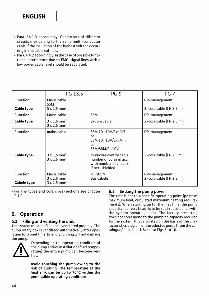
ENGLISH
44
x Para. 14.1.3 accordingly: Conductors of differentcircuits may belong to the same multi-conductorcable if the insulation of the highest voltage occur-ring in the cable suffices.
x Para. 4.4.2 accordingly: In the case of possible func-tional interference due to EMC, signal lines with alow power cable level should be separated.
PG 13,5 PG 9 PG 7Function Mains cable DP-management
SSMCable type 5 x 1,5 mm2 2-core cable (l F 2,5 m)
Function Mains cable SSM DP-management
Cable type 3 x 1,5 mm2 2-core cable 2-core cable (l F 2,5 m)3 x 2,5 mm2
Function mains cable SSM 10…10V/Ext.Off DP-managementorSSM 10…10V/Ext.MinorSSM/SBM/0…10V
Cable type 3 x 1,5 mm2 multicore control cable, 2-core cable (l F 2,5 m)3 x 2,5 mm2 number of cores in acc.
with number of circuits,if nec. shielded
Function Mains cable PLR/LON DP-management3 x 1,5 mm2 Bus cabele 2-core cable (l F 2,5 m)
Cabele type 3 x 2,5 mm2
x For line types and core cross-sections see chapter9.1.2.
6. Operation6.1 Filling and venting the unitThe system must be filled and ventilated properly. Thepump rotary box is ventilated automatically after ope-rating for a brief time. Brief dry running will not damagethe pump.
Depending on the operating condition ofthe pump and/or installation (fluid tempe-rature) the entire pump can become veryhot.
Avoid touching the pump owing to therisk of burning. The temperature at theheat sink can be up to 70°C within thepermissible operating conditions.
6.2 Setting the pump powerThe unit is set to a specific operating point (point ofmaximum load, calculated maximum heating require-ments). When starting up for the first time, the pumpcapacity (delivery head) is to be set in accordance withthe system operating point. The factory presettingdoes not correspond to the pumping capacity requiredfor the system. It is calculated on the basis of the cha-racteristics diagram of the selected pump (from the ca-talogue/data sheet). See also Figs 8 to 10.
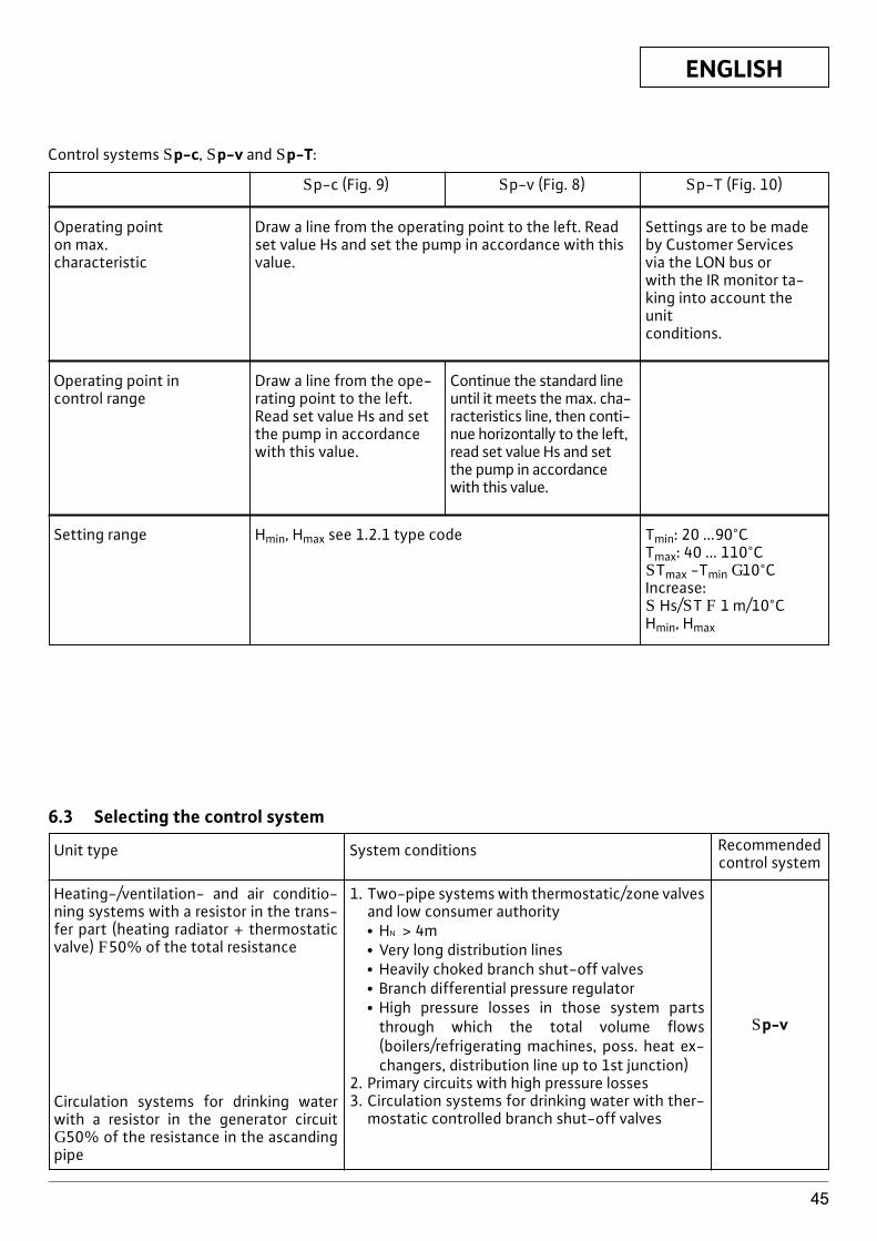
ENGLISH
45
Control systems Sp-c, Sp-v and Sp-T:
Operating pointon max. characteristic
Draw a line from the operating point to the left. Readset value Hs and set the pump in accordance with thisvalue.
Settings are to be made by Customer Services via the LON bus or with the IR monitor ta-king into account theunit conditions.
Setting range Hmin, Hmax see 1.2.1 type code Tmin: 20 ...90°CTmax: 40 ... 110°CSTmax -Tmin G10°CIncrease:S Hs/ST F 1 m/10°CHmin, Hmax
Operating point incontrol range
Draw a line from the ope-rating point to the left.Read set value Hs and setthe pump in accordancewith this value.
Continue the standard lineuntil it meets the max. cha-racteristics line, then conti-nue horizontally to the left,read set value Hs and setthe pump in accordancewith this value.
Sp-c (Fig. 9) Sp-v (Fig. 8) Sp-T (Fig. 10)
6.3 Selecting the control system
Heating-/ventilation- and air conditio-ning systems with a resistor in the trans-fer part (heating radiator + thermostaticvalve) F50% of the total resistance
Circulation systems for drinking waterwith a resistor in the generator circuit G 50% of the resistance in the ascandingpipe
Unit type System conditions Recommendedcontrol system
1. Two-pipe systems with thermostatic/zone valvesand low consumer authorityx HN > 4mx Very long distribution linesx Heavily choked branch shut-off valvesx Branch differential pressure regulatorx High pressure losses in those system parts
through which the total volume flows(boilers/refrigerating machines, poss. heat ex-changers, distribution line up to 1st junction)
2. Primary circuits with high pressure losses3. Circulation systems for drinking water with ther-
mostatic controlled branch shut-off valves
Sp-v
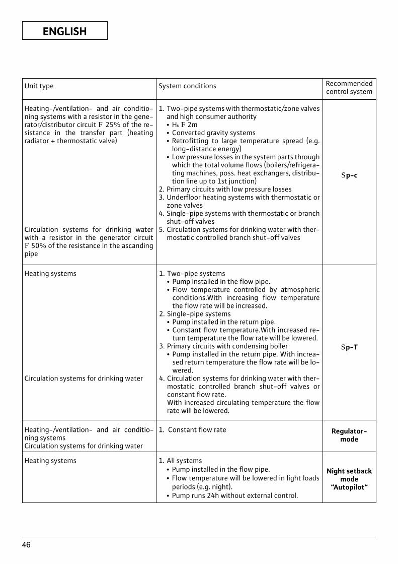
ENGLISH
46
Unit type System conditions Recommendedcontrol system
Heating-/ventilation- and air conditio-ning systems with a resistor in the gene-rator/distributor circuit F 25% of the re-sistance in the transfer part (heatingradiator + thermostatic valve)
Circulation systems for drinking waterwith a resistor in the generator circuitF 50% of the resistance in the ascandingpipe
1. Two-pipe systems with thermostatic/zone valvesand high consumer authorityx HN F 2mx Converted gravity systemsx Retrofitting to large temperature spread (e.g.
long-distance energy)x Low pressure losses in the system parts through
which the total volume flows (boilers/refrigera-ting machines, poss. heat exchangers, distribu-tion line up to 1st junction)
2. Primary circuits with low pressure losses3. Underfloor heating systems with thermostatic or
zone valves4. Single-pipe systems with thermostatic or branch
shut-off valves5. Circulation systems for drinking water with ther-
mostatic controlled branch shut-off valves
Sp-c
Heating systems
Circulation systems for drinking water
1. Two-pipe systemsx Pump installed in the flow pipe.x Flow temperature controlled by atmospheric
conditions.With increasing flow temperaturethe flow rate will be increased.
2. Single-pipe systems x Pump installed in the return pipe.x Constant flow temperature.With increased re-
turn temperature the flow rate will be lowered.3. Primary circuits with condensing boiler
x Pump installed in the return pipe. With increa-sed return temperature the flow rate will be lo-wered.
4. Circulation systems for drinking water with ther-mostatic controlled branch shut-off valves orconstant flow rate.With increased circulating temperature the flowrate will be lowered.
Sp-T
Heating-/ventilation- and air conditio-ning systemsCirculation systems for drinking water
1. Constant flow rate
Heating systems 1. All systemsx Pump installed in the flow pipe.x Flow temperature will be lowered in light loads
periods (e.g. night).x Pump runs 24h without external control.
Regulator-mode
Night setbackmode
“Autopilot“
ENGLISH
47
7 Maintenance/servicePrior to maintenance or repair work, turnoff the pump and ensure that it is not tur-ned on by unauthorised personnel.
In the event of high temperatures and highsystem pressure, the pumps should be al-lowed to cool down Danger of liquid boi-ling over! Risk of scalding!
If the motor head is separated fromthe pump housing for servicing or re-pair work, the O-ring situated bet-ween the motor head and pump hou-sing must be replace by a new one.When refitting the motor head, makesure the O-ring is positioned cor-rectly.
8 Problems, Causes and SolutionsFor problems, causes, and solutions see "Error /Warning Messages" flow chart and the tables below.The first column in the table lists the code numbersshown by the display in the event of an error. Most error displays disappear automatically once thecause of the error has been remedied.
8.1 Error messagesAn error has occurred. The pump shuts down, the errorLED (red permanent light) comes on. After 5 minutesthe pump switches on automatically. Only when thesame error occurs for the 6th time within 24 hours doesthe pump shut down permanently, the SSM relay opensand the PLR or LON interface forwards the error mes-sage. Manual reset is necessary.
Exception: With blocking code no."E10" and "E25" the unit immediatelyshuts down on the first occurrence.
8.2 Warning messagesThe problem (only Warning) is displayed, but the SSMrelay does not come into action. The pump continuesto run. The error can occur an infinite number of times.The indicated operating condition should not be igno-red for long periods of time. The cause of the error mustbe removed.
Exception: If errors "E04", and "E05"remain for more than 5 minutes,these are passed on as error readings(see diagram).
ATTENTION!
ATTENTION!
ATTENTION!
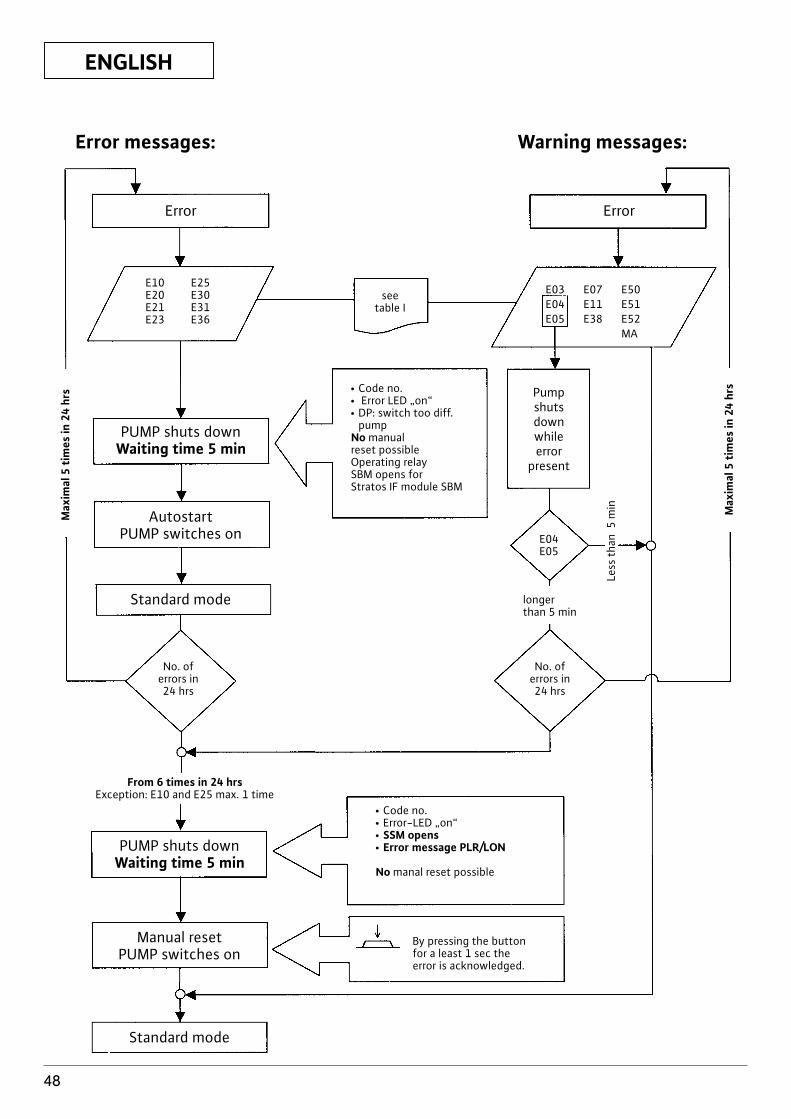
ENGLISH
48
E10 E25E20 E30E21 E31E23 E36
Error
PUMP shuts downWaiting time 5 min
AutostartPUMP switches on
Standard mode
PUMP shuts downWaiting time 5 min
From 6 times in 24 hrsException: E10 and E25 max. 1 time
Manual resetPUMP switches on
Standard mode
Error
seetable I
E03 E07 E50E04 E11 E51E05 E38 E52
MA
Pumpshutsdownwhileerror
present
E04E05
longerthan 5 min
No. oferrors in24 hrs
No. oferrors in24 hrs
Less
tha
n 5
min Max
imal
5 t
imes
in 2
4 hr
s
Max
imal
5 t
imes
in 2
4 hr
s x Code no.x Error LED „on“x DP: switch too diff.
pumpNo manual reset possibleOperating relaySBM opens forStratos IF module SBM
x Code no.x Error-LED „on“x SSM opensx Error message PLR/LON
No manal reset possible
By pressing the buttonfor a least 1 sec theerror is acknowledged.
Error messages: Warning messages:
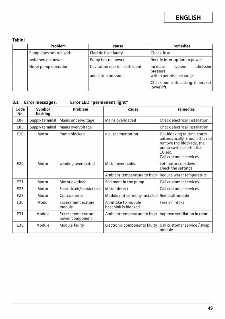
ENGLISH
49
Table IProblem cause remedies
Pump does not run with Electric fuse faulty, Check fuse
switched on power Pump has no power Rectify interruption to power
Noisy pump operation Cavitation due to insufficient Increase system admission pressure
admission pressure within permissible range
Check pump lift setting, if nec. setlower lift
8.1 Error messages: Error LED "permanent light"Code Symbol Problem cause remedies
Nr. flashingE04 Supply terminal Mains undervoltage Mains overloaded Check electrical installation
E05 Supply terminal Mains overvoltage Check electrical installation
E10 Motor Pump blocked e.g. sedimentation De-blocking routine startsautomatically. Should this notremove the blockage, the pump switches off after 10 sec.Call customer services
E20 Motor winding overheated Motor overloaded Let motor cool down,check the settings
Ambient temperature to high Reduce water temperature
E21 Motor Motor overload Sediment in the pump Call customer services
E23 Motor Short circuit/contact fault Motor defect Call customer services
E25 Motor Contact error Module not correctly installed Reinstall module
E30 Modul Excess temperature Air intake to module Free air intakemodule heat sink is blocked
E31 Module Excess temperature Ambient temperature to high Improve ventilation in roompower component
E36 Module Module faulty Electronic components faulty Call customer service / swapmodule
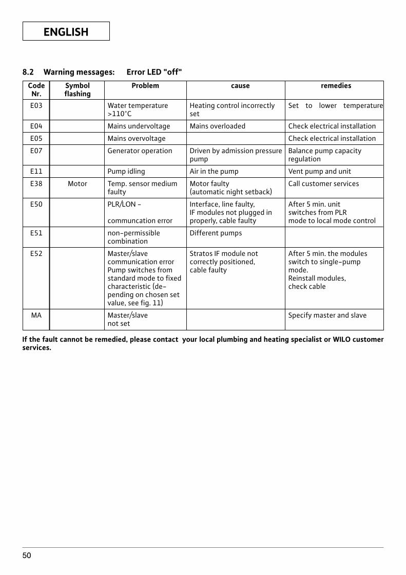
ENGLISH
50
8.2 Warning messages: Error LED "off"Code Symbol Problem cause remedies
Nr. flashingE03 Water temperature Heating control incorrectly Set to lower temperature
>110°C set
E04 Mains undervoltage Mains overloaded Check electrical installation
E05 Mains overvoltage Check electrical installation
E07 Generator operation Driven by admission pressure Balance pump capacity pump regulation
E11 Pump idling Air in the pump Vent pump and unit
E38 Motor Temp. sensor medium Motor faulty Call customer servicesfaulty (automatic night setback)
E50 PLR/LON - Interface, line faulty, After 5 min. unit IF modules not plugged in switches from PLR
communcation error properly, cable faulty mode to local mode control
E51 non-permissible Different pumpscombination
E52 Master/slave Stratos IF module not After 5 min. the modulescommunication error correctly positioned, switch to single-pump Pump switches from cable faulty mode.standard mode to fixed Reinstall modules, characteristic (de- check cablepending on chosen setvalue, see fig. 11)
MA Master/slave Specify master and slavenot set
If the fault cannot be remedied, please contact your local plumbing and heating specialist or WILO customerservices.
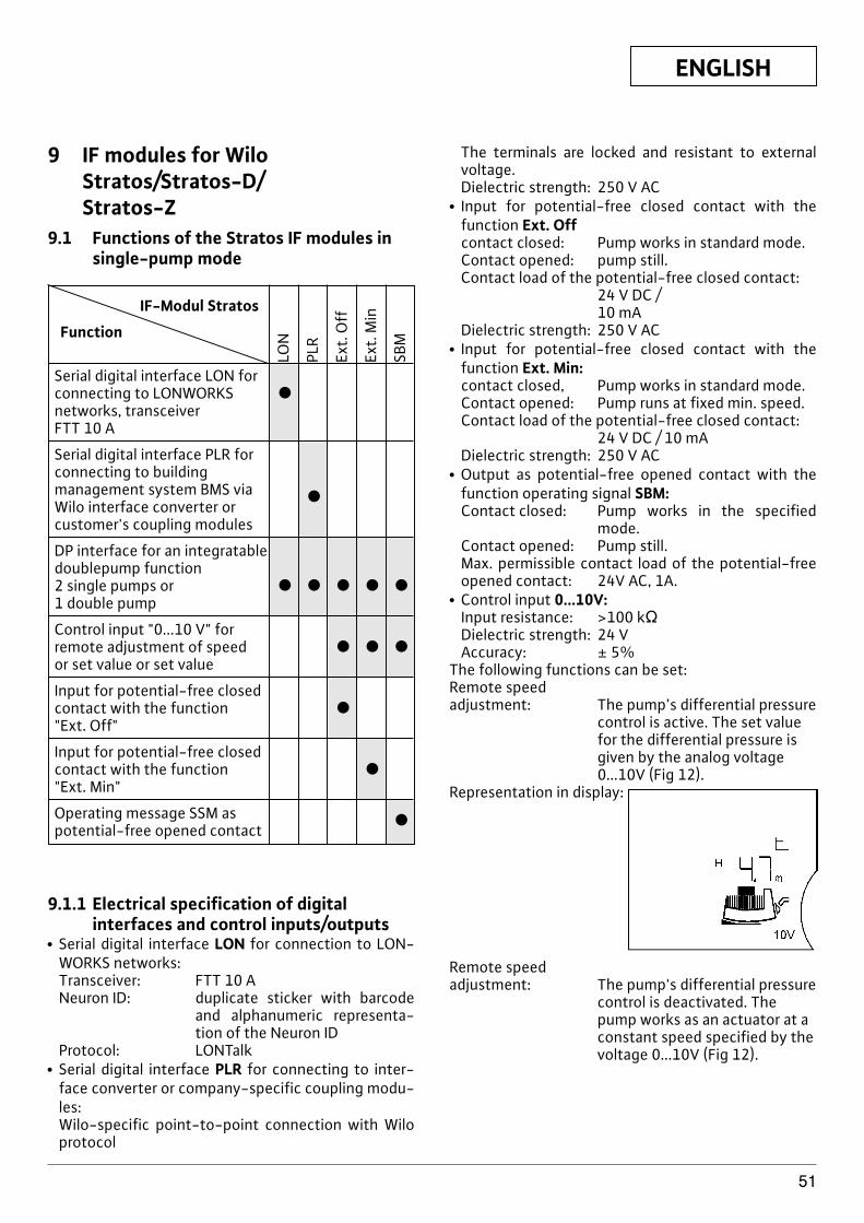
ENGLISH
51
9 IF modules for WiloStratos/Stratos-D/Stratos-Z
9.1 Functions of the Stratos IF modules insingle-pump mode
IF-Modul Stratos
Function
Serial digital interface LON forconnecting to LONWORKS xnetworks, transceiver FTT 10 A
Serial digital interface PLR forconnecting to building management system BMS via xWilo interface converter or customer's coupling modules
DP interface for an integratable doublepump function 2 single pumps or x x x x x1 double pump
Control input "0...10 V" for remote adjustment of speed x x xor set value or set value
Input for potential-free closed contact with the function x"Ext. Off"
Input for potential-free closed contact with the function x"Ext. Min"
Operating message SSM as xpotential-free opened contact
LON
PLR
Ext.
Off
Ext.
Min
SBM
9.1.1 Electrical specification of digitalinterfaces and control inputs/outputs
x Serial digital interface LON for connection to LON-WORKS networks:Transceiver: FTT 10 ANeuron ID: duplicate sticker with barcode
and alphanumeric representa-tion of the Neuron ID
Protocol: LONTalkx Serial digital interface PLR for connecting to inter-
face converter or company-specific coupling modu-les:Wilo-specific point-to-point connection with Wiloprotocol
The terminals are locked and resistant to externalvoltage.Dielectric strength: 250 V AC
x Input for potential-free closed contact with thefunction Ext. Offcontact closed: Pump works in standard mode.Contact opened: pump still.Contact load of the potential-free closed contact:
24 V DC / 10 mA
Dielectric strength: 250 V ACx Input for potential-free closed contact with the
function Ext. Min:contact closed, Pump works in standard mode.Contact opened: Pump runs at fixed min. speed.Contact load of the potential-free closed contact:
24 V DC / 10 mADielectric strength: 250 V AC
x Output as potential-free opened contact with thefunction operating signal SBM:Contact closed: Pump works in the specified
mode.Contact opened: Pump still.Max. permissible contact load of the potential-freeopened contact: 24V AC, 1A.
x Control input 0...10V:Input resistance: >100 kVDielectric strength: 24 VAccuracy: ± 5%
The following functions can be set:Remote speed adjustment: The pump’s differential pressure
control is active. The set valuefor the differential pressure isgiven by the analog voltage0...10V (Fig 12).
Representation in display:
Remote speed adjustment: The pump's differential pressure
control is deactivated. Thepump works as an actuator at aconstant speed specified by thevoltage 0...10V (Fig 12).
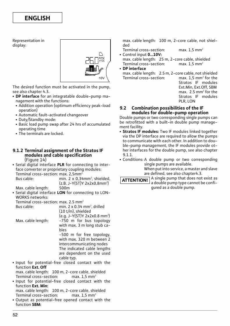
ENGLISH
52
Representation in display:
The desired function must be activated in the pump,see also chapter 4.3.x DP interface for an integratable double-pump ma-
nagement with the functions:x Addition operation (optimum efficiency peak-load
operation)x Automatic fault-activated changeoverx Duty/Standby mode:x Basic load pump swap after 24 hrs of accumulated
operating timex The terminals are locked.
9.1.2 Terminal assignment of the Stratos IFmodules and cable specification(Figure 14)
x Serial digital interface PLR for connecting to inter-face converter or proprietary coupling modules:Terminal cross-section: max. 2,5mm2
Bus cable: min. 2 x 0,34mm2, shielded,(z.B. J-Y(ST)Y 2x2x0,8mm2)
Max. cable length: 500mx Serial digital interface LON for connecting to LON-
WORKS networks:Terminal cross-section: max. 2.5 mm2
Bus cable: min. 2 x 0.34 mm2, drilled(10 t/m), shielded (e.g. J-Y(ST)Y 2x2x0.8 mm2)
Max. cable length: -750 m for bus topologywith max. 3 m long stub ca-bles-500 m for free topology,with max. 320 m between 2intercommunicating nodesThe indicated cable lengthsare dependent on the usedcable typ.
x Input for potential-free closed contact with thefunction Ext. Offmax. cable length: 100 m, 2-core cable, shieldedTerminal cross-section: max. 1,5 mm2
x Input for potential-free closed contact with thefunction Ext. Min:max. cable length: 100 m, 2-core cable, shieldedTerminal cross-section: max. 1,5 mm2
x Output as potential-free opened contact with thefunction SBM:
max. cable length: 100 m, 2-core cable, not shiel-dedTerminal cross-section: max. 1,5 mm2
x Control input 0...10V:max. cable length: 25 m, 2-core cable, shieldedTerminal cross-section: max. 1,5 mm2
x DP interfacemax. cable length: 2.5 m, 2-core cable, not shieldedTerminal cross-section: max. 1,5 mm2 for the
Stratos IF modulesExt.Min, Ext.Off, SBMmax. 2.5 mm2 for theStratos IF modulesPLR, LON
9.2 Combination possibilities of the IFmodules for double-pump operation
Double pumps or two corresponding single pumps canbe retrofitted with a built-in double pump manage-ment facility.x Stratos IF modules: Two IF modules linked together
via the DP interface are required to allow the pumpsto communicate with each other. In addition to dou-ble-pump management, the IF modules provide ot-her interfaces for the double pump, see also chapter9.1.1.
x Conditions: A double pump or two correspondingsingle pumps are available.When put into service, a master and slaveare defined, see also chapter4.3.
A single pump that does not exist asa double pump type cannot be confi-gured as a double pump.
ATTENTION!
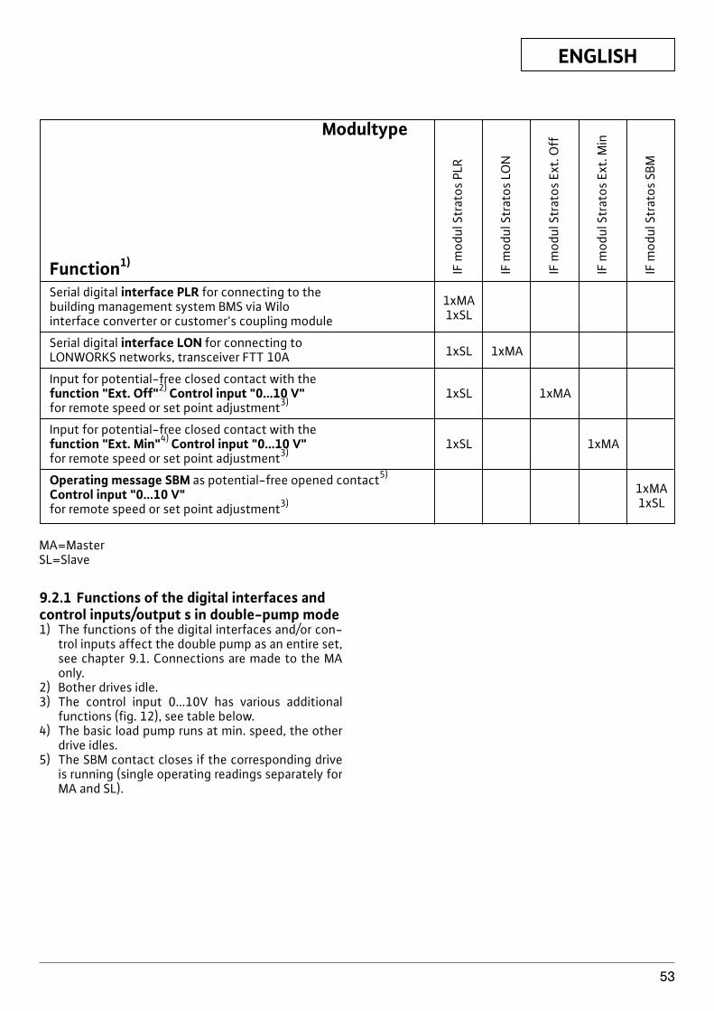
ENGLISH
53
Modultype
Function1)
Serial digital interface PLR for connecting to the building management system BMS via Wilo 1xMA
interface converter or customer's coupling module 1xSL
Serial digital interface LON for connecting to LONWORKS networks, transceiver FTT 10A 1xSL 1xMA
Input for potential-free closed contact with thefunction "Ext. Off"2) Control input "0...10 V" 1xSL 1xMAfor remote speed or set point adjustment3)
Input for potential-free closed contact with thefunction "Ext. Min"4) Control input "0...10 V" 1xSL 1xMAfor remote speed or set point adjustment3)
Operating message SBM as potential-free opened contact5)
Control input "0...10 V" 1xMA
for remote speed or set point adjustment3) 1xSL
IF m
odul
Str
atos
PLR
IF m
odul
Str
atos
LO
N
IF m
odul
Str
atos
Ext
. Off
IF m
odul
Str
atos
Ext
. Min
IF m
odul
Str
atos
SBM
MA=MasterSL=Slave
9.2.1 Functions of the digital interfaces andcontrol inputs/output s in double-pump mode1) The functions of the digital interfaces and/or con-
trol inputs affect the double pump as an entire set,see chapter 9.1. Connections are made to the MAonly.
2) Bother drives idle.3) The control input 0...10V has various additional
functions (fig. 12), see table below.4) The basic load pump runs at min. speed, the other
drive idles.5) The SBM contact closes if the corresponding drive
is running (single operating readings separately forMA and SL).
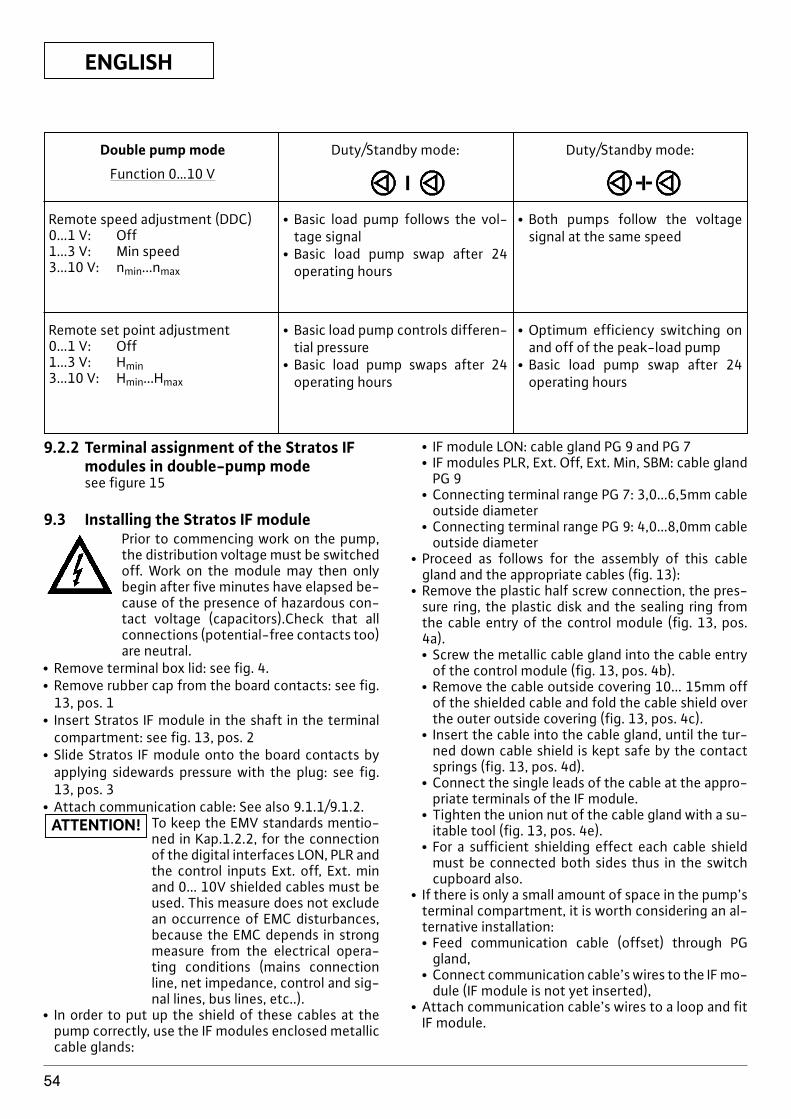
ENGLISH
54
Double pump mode
Function 0…10 V
Remote speed adjustment (DDC)0...1 V: Off1...3 V: Min speed3...10 V: nmin...nmax
Duty/Standby mode:
x Basic load pump follows the vol-tage signal
x Basic load pump swap after 24operating hours
x Both pumps follow the voltagesignal at the same speed
Remote set point adjustment0...1 V: Off1...3 V: Hmin3...10 V: Hmin...Hmax
x Basic load pump controls differen-tial pressure
x Basic load pump swaps after 24operating hours
x Optimum efficiency switching onand off of the peak-load pump
x Basic load pump swap after 24operating hours
Duty/Standby mode:
9.2.2 Terminal assignment of the Stratos IFmodules in double-pump modesee figure 15
9.3 Installing the Stratos IF modulePrior to commencing work on the pump,the distribution voltage must be switchedoff. Work on the module may then onlybegin after five minutes have elapsed be-cause of the presence of hazardous con-tact voltage (capacitors).Check that allconnections (potential-free contacts too)are neutral.
x Remove terminal box lid: see fig. 4.x Remove rubber cap from the board contacts: see fig.
13, pos. 1x Insert Stratos IF module in the shaft in the terminal
compartment: see fig. 13, pos. 2x Slide Stratos IF module onto the board contacts by
applying sidewards pressure with the plug: see fig.13, pos. 3
x Attach communication cable: See also 9.1.1/9.1.2.To keep the EMV standards mentio-ned in Kap.1.2.2, for the connectionof the digital interfaces LON, PLR andthe control inputs Ext. off, Ext. minand 0... 10V shielded cables must beused. This measure does not excludean occurrence of EMC disturbances,because the EMC depends in strongmeasure from the electrical opera-ting conditions (mains connectionline, net impedance, control and sig-nal lines, bus lines, etc..).
x In order to put up the shield of these cables at thepump correctly, use the IF modules enclosed metalliccable glands:
ATTENTION!
x IF module LON: cable gland PG 9 and PG 7x IF modules PLR, Ext. Off, Ext. Min, SBM: cable gland
PG 9x Connecting terminal range PG 7: 3,0...6,5mm cable
outside diameterx Connecting terminal range PG 9: 4,0...8,0mm cable
outside diameterx Proceed as follows for the assembly of this cable
gland and the appropriate cables (fig. 13):x Remove the plastic half screw connection, the pres-
sure ring, the plastic disk and the sealing ring fromthe cable entry of the control module (fig. 13, pos.4a).x Screw the metallic cable gland into the cable entry
of the control module (fig. 13, pos. 4b).x Remove the cable outside covering 10... 15mm off
of the shielded cable and fold the cable shield overthe outer outside covering (fig. 13, pos. 4c).
x Insert the cable into the cable gland, until the tur-ned down cable shield is kept safe by the contactsprings (fig. 13, pos. 4d).
x Connect the single leads of the cable at the appro-priate terminals of the IF module.
x Tighten the union nut of the cable gland with a su-itable tool (fig. 13, pos. 4e).
x For a sufficient shielding effect each cable shieldmust be connected both sides thus in the switchcupboard also.
x If there is only a small amount of space in the pump’sterminal compartment, it is worth considering an al-ternative installation:x Feed communication cable (offset) through PG
gland,x Connect communication cable’s wires to the IF mo-
dule (IF module is not yet inserted),x Attach communication cable’s wires to a loop and fit
IF module.
ENGLISH
55
Subject to technical alterations!
x Attach terminal box lid with the clips in the recessesand screw down: see fig. 4).
x Stratos LON IF module: One sticker with the NeuronID remains on the IF module, the other can e.g. be af-fixed to the side of the associated pump in the plantplan. When binding, the Neuron ID can then be readoff the plant plan with a barcode scanner or enteredmanually.
FRANÇAIS
56
Pompe à haut rendement Wilo-StratosTable des matières : Page
1. Généralités . . . . . . . . . . . . . . . . . . . . . . . . . . . . . . . . . . . . . . . . . . . . . . . . . . . . . . . . . . . . . . . . . . . . . . . . . . . . . . . 571.1 Applications . . . . . . . . . . . . . . . . . . . . . . . . . . . . . . . . . . . . . . . . . . . . . . . . . . . . . . . . . . . . . . . . . . . . . . . . . . . . . . . 571.2 Caractéristiques du produit . . . . . . . . . . . . . . . . . . . . . . . . . . . . . . . . . . . . . . . . . . . . . . . . . . . . . . . . . . . . . . . . . . 571.2.1Plaque signalétique . . . . . . . . . . . . . . . . . . . . . . . . . . . . . . . . . . . . . . . . . . . . . . . . . . . . . . . . . . . . . . . . . . . . . . . . . 571.2.2Raccordement et puissance . . . . . . . . . . . . . . . . . . . . . . . . . . . . . . . . . . . . . . . . . . . . . . . . . . . . . . . . . . . . . . . . . 57
2. Sécurité . . . . . . . . . . . . . . . . . . . . . . . . . . . . . . . . . . . . . . . . . . . . . . . . . . . . . . . . . . . . . . . . . . . . . . . . . . . . . . . . . . 582.1 Signalisation des consignes de la notice . . . . . . . . . . . . . . . . . . . . . . . . . . . . . . . . . . . . . . . . . . . . . . . . . . . . . . 582.2 Qualification du personnel . . . . . . . . . . . . . . . . . . . . . . . . . . . . . . . . . . . . . . . . . . . . . . . . . . . . . . . . . . . . . . . . . . 582.3 Dangers encourus en cas de non-observation des consignes . . . . . . . . . . . . . . . . . . . . . . . . . . . . . . . . . . . 582.4 Consignes de sécurité pour l'utilisateur . . . . . . . . . . . . . . . . . . . . . . . . . . . . . . . . . . . . . . . . . . . . . . . . . . . . . . . 582.5 Conseils de sécurité pour les travaux d'inspection et de montage . . . . . . . . . . . . . . . . . . . . . . . . . . . . . . . 582.6 Modification du matériel et utilisation de pièces détachées non agréées . . . . . . . . . . . . . . . . . . . . . . . . . 582.7 Modes d'utilisation non autorisés . . . . . . . . . . . . . . . . . . . . . . . . . . . . . . . . . . . . . . . . . . . . . . . . . . . . . . . . . . . . 58
3. Transport et stockage avant utilisation . . . . . . . . . . . . . . . . . . . . . . . . . . . . . . . . . . . . . . . . . . . . . . . . . . . . . 58
4. Description du produit et de ses accessoires . . . . . . . . . . . . . . . . . . . . . . . . . . . . . . . . . . . . . . . . . . . . . . . . 584.1 Description de la pompe . . . . . . . . . . . . . . . . . . . . . . . . . . . . . . . . . . . . . . . . . . . . . . . . . . . . . . . . . . . . . . . . . . . . 584.1.1Types de réglage de la pression différentielle . . . . . . . . . . . . . . . . . . . . . . . . . . . . . . . . . . . . . . . . . . . . . . . . . . 594.1.2Autres modes de fonctionnement pour l'économie d'énergie . . . . . . . . . . . . . . . . . . . . . . . . . . . . . . . . . . . 594.1.3Fonctions générales de la pompe . . . . . . . . . . . . . . . . . . . . . . . . . . . . . . . . . . . . . . . . . . . . . . . . . . . . . . . . . . . . 594.2 Fonctionnement sur pompe double . . . . . . . . . . . . . . . . . . . . . . . . . . . . . . . . . . . . . . . . . . . . . . . . . . . . . . . . . . 604.3 Manipulation de la pompe . . . . . . . . . . . . . . . . . . . . . . . . . . . . . . . . . . . . . . . . . . . . . . . . . . . . . . . . . . . . . . . . . . . 604.4 Priorités lors de la manipulation de la pompe, des interfaces et du moniteur IR . . . . . . . . . . . . . . . . . . . . 684.5 Étendue de la fourniture . . . . . . . . . . . . . . . . . . . . . . . . . . . . . . . . . . . . . . . . . . . . . . . . . . . . . . . . . . . . . . . . . . . . 684.6 Accessoires . . . . . . . . . . . . . . . . . . . . . . . . . . . . . . . . . . . . . . . . . . . . . . . . . . . . . . . . . . . . . . . . . . . . . . . . . . . . . . . . 68
5. Installation/montage . . . . . . . . . . . . . . . . . . . . . . . . . . . . . . . . . . . . . . . . . . . . . . . . . . . . . . . . . . . . . . . . . . . . . . 685.1 Montage de la pompe . . . . . . . . . . . . . . . . . . . . . . . . . . . . . . . . . . . . . . . . . . . . . . . . . . . . . . . . . . . . . . . . . . . . . . . 685.1.1Démontage/montage du module de régulation . . . . . . . . . . . . . . . . . . . . . . . . . . . . . . . . . . . . . . . . . . . . . . . . 695.1.2Démontage/montage du kit embrochable . . . . . . . . . . . . . . . . . . . . . . . . . . . . . . . . . . . . . . . . . . . . . . . . . . . . 695.1.3Isolation de la pompe dans les installations frigorifiques/de conditionnement d'air . . . . . . . . . . . . . . . . 705.2 Raccordement électrique . . . . . . . . . . . . . . . . . . . . . . . . . . . . . . . . . . . . . . . . . . . . . . . . . . . . . . . . . . . . . . . . . . . 705.2.1Raccordement électrique de la pompe . . . . . . . . . . . . . . . . . . . . . . . . . . . . . . . . . . . . . . . . . . . . . . . . . . . . . . . . 71
6. Mise en service . . . . . . . . . . . . . . . . . . . . . . . . . . . . . . . . . . . . . . . . . . . . . . . . . . . . . . . . . . . . . . . . . . . . . . . . . . . 716.1 Remplissage et dégazage . . . . . . . . . . . . . . . . . . . . . . . . . . . . . . . . . . . . . . . . . . . . . . . . . . . . . . . . . . . . . . . . . . . 716.2 Réglage de la puissance de la pompe . . . . . . . . . . . . . . . . . . . . . . . . . . . . . . . . . . . . . . . . . . . . . . . . . . . . . . . . . 726.3 Sélection du type de réglage . . . . . . . . . . . . . . . . . . . . . . . . . . . . . . . . . . . . . . . . . . . . . . . . . . . . . . . . . . . . . . . . 72
7. Entretien/service . . . . . . . . . . . . . . . . . . . . . . . . . . . . . . . . . . . . . . . . . . . . . . . . . . . . . . . . . . . . . . . . . . . . . . . . . 74
8. Pannes, causes et remèdes . . . . . . . . . . . . . . . . . . . . . . . . . . . . . . . . . . . . . . . . . . . . . . . . . . . . . . . . . . . . . . . . 748.1 Signaux de pannes . . . . . . . . . . . . . . . . . . . . . . . . . . . . . . . . . . . . . . . . . . . . . . . . . . . . . . . . . . . . . . . . . . . . . . . . . 748.2 Signaux d'avertissement . . . . . . . . . . . . . . . . . . . . . . . . . . . . . . . . . . . . . . . . . . . . . . . . . . . . . . . . . . . . . . . . . . . . 74
9 Modules IF pour Wilo-Stratos/Stratos-D/Stratos-Z . . . . . . . . . . . . . . . . . . . . . . . . . . . . . . . . . . . . . . . . . . 789.1 Fonctions des modules IF Stratos lors du fonctionnement sur pompe simple . . . . . . . . . . . . . . . . . . . . . 789.1.1Spécification électrique des interfaces numériques et entrées/sorties de commande . . . . . . . . . . . . . . 789.1.2Occupation des bornes des modules IF Stratos et spécification des câbles . . . . . . . . . . . . . . . . . . . . . . . 799.2 Possibilités de combinaison des modules IF pour le fonctionnement sur pompe double . . . . . . . . . . . . 799.2.1Fonctions des interfaces numériques et entrées/sorties de commandes
lors du fonctionnement sur pompe double . . . . . . . . . . . . . . . . . . . . . . . . . . . . . . . . . . . . . . . . . . . . . . . . . . . . 809.2.2Occupation des bornes des modules IF Stratos lors du fonctionnement sur pompe double . . . . . . . . . 819.3 Installation du module IF . . . . . . . . . . . . . . . . . . . . . . . . . . . . . . . . . . . . . . . . . . . . . . . . . . . . . . . . . . . . . . . . . . . . 81
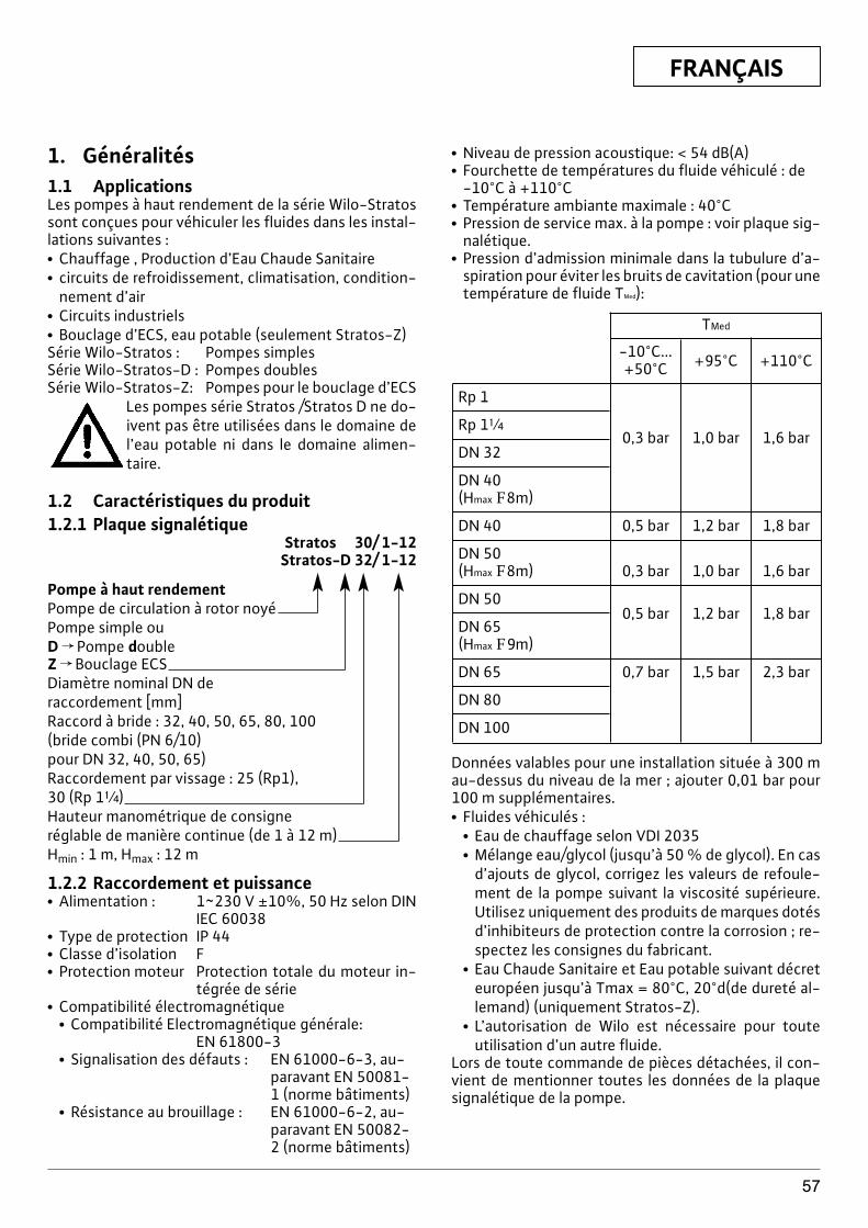
FRANÇAIS
57
1. Généralités1.1 ApplicationsLes pompes à haut rendement de la série Wilo-Stratossont conçues pour véhiculer les fluides dans les instal-lations suivantes :x Chauffage , Production d’Eau Chaude Sanitairex circuits de refroidissement, climatisation, condition-
nement d’airx Circuits industrielsx Bouclage d’ECS, eau potable (seulement Stratos-Z)Série Wilo-Stratos : Pompes simplesSérie Wilo-Stratos-D : Pompes doublesSérie Wilo-Stratos-Z: Pompes pour le bouclage d’ECS
Les pompes série Stratos /Stratos D ne do-ivent pas être utilisées dans le domaine del’eau potable ni dans le domaine alimen-taire.
1.2 Caractéristiques du produit1.2.1 Plaque signalétique
Stratos 30/ 1-12Stratos-D 32/ 1-12
Pompe à haut rendementPompe de circulation à rotor noyéPompe simple ouD f Pompe doubleZ f Bouclage ECSDiamètre nominal DN de raccordement [mm]Raccord à bride : 32, 40, 50, 65, 80, 100(bride combi (PN 6/10) pour DN 32, 40, 50, 65)Raccordement par vissage : 25 (Rp1), 30 (Rp 1[)Hauteur manométrique de consigneréglable de manière continue (de 1 à 12 m) Hmin : 1 m, Hmax : 12 m
1.2.2 Raccordement et puissancex Alimentation : 1~230 V ±10%, 50 Hz selon DIN
IEC 60038x Type de protection IP 44x Classe d’isolation Fx Protection moteur Protection totale du moteur in-
tégrée de sériex Compatibilité électromagnétique
x Compatibilité Electromagnétique générale:EN 61800-3
x Signalisation des défauts : EN 61000-6-3, au-paravant EN 50081-1 (norme bâtiments)
x Résistance au brouillage : EN 61000-6-2, au-paravant EN 50082-2 (norme bâtiments)
x Niveau de pression acoustique: < 54 dB(A)x Fourchette de températures du fluide véhiculé : de
-10°C à +110°Cx Température ambiante maximale : 40°Cx Pression de service max. à la pompe : voir plaque sig-
nalétique.x Pression d’admission minimale dans la tubulure d’a-
spiration pour éviter les bruits de cavitation (pour unetempérature de fluide TMed):
TMed
-10°C...+50°C +95°C +110°C
Rp 1
Rp 1[
DN 320,3 bar 1,0 bar 1,6 bar
DN 40 (Hmax F8m)
DN 40 0,5 bar 1,2 bar 1,8 bar
DN 50 (Hmax F8m) 0,3 bar 1,0 bar 1,6 bar
DN 500,5 bar 1,2 bar 1,8 bar
DN 65 (Hmax F9m)
DN 65 0,7 bar 1,5 bar 2,3 bar
DN 80
DN 100
Données valables pour une installation située à 300 mau-dessus du niveau de la mer ; ajouter 0,01 bar pour100 m supplémentaires.x Fluides véhiculés :
x Eau de chauffage selon VDI 2035x Mélange eau/glycol (jusqu’à 50 % de glycol). En cas
d’ajouts de glycol, corrigez les valeurs de refoule-ment de la pompe suivant la viscosité supérieure.Utilisez uniquement des produits de marques dotésd’inhibiteurs de protection contre la corrosion ; re-spectez les consignes du fabricant.
x Eau Chaude Sanitaire et Eau potable suivant décreteuropéen jusqu’à Tmax = 80°C, 20°d(de dureté al-lemand) (uniquement Stratos-Z).
x L’autorisation de Wilo est nécessaire pour touteutilisation d’un autre fluide.
Lors de toute commande de pièces détachées, il con-vient de mentionner toutes les données de la plaquesignalétique de la pompe.
FRANÇAIS
58
2. SécuritéLa présente notice contient des instructions primordi-ales, qui doivent être respectées lors du montage et dela mise en service. C'est pourquoi elle devra être lue at-tentivement par le monteur et l'utilisateur et ce, impé-rativement avant le montage et la mise en service.Il y a lieu d’observer non seulement les instructions gé-nérales de cette section, mais aussi les prescriptionsspécifiques abordées dans les points suivants.
2.1 Signalisation des consignes de la noticeLes consignes de sécurité reprises dans cette notice demise en service, qui en cas de non-observation peu-vent entraîner des dangers pour les personnes, sont re-présentées par le symbole de danger général
,
En cas de danger électrique, le symbole indiqué est lesuivant :
Les consignes de sécurité dont la non-observationpeut représenter un danger pour l’installation et sonfonctionnement sont indiquées par le signe :
2.2 Qualification du personnelIl convient de veiller à la qualification du personnelamené à réaliser le montage.
2.3 Dangers encourus en cas de non-observation des consignes
La non-observation des consignes de sécurité peutconstituer un danger pour les personnes, la pompe oul’installation. Elle peut également entraîner la suspen-sion de tout recours en garantie.Plus précisément, les dangers encourus peuvent êtreles suivants :x Défaillance de fonctions importantes de la pompe ou
de l'installation.x Danger pour les personnes en cas de dysfonctionne-
ment électrique et mécanique de la machine.
2.4 Consignes de sécurité pour l’utilisateurIl convient d’observer les consignes en vue d’excluretout risque d’accident.Il y a également lieu d’exclure tous dangers liés à l’é-nergie électrique. Respectez les consignes de la VDE(Union des électrotechniciens allemands) et de votredistributeur d’électricité local.
ATTENTION!
2.5 Conseils de sécurité pour les travauxd’inspection et de montage
L'utilisateur doit faire réaliser ces travaux par une per-sonne spécialisée et qualifiée ayant pris connaissancedu contenu de la notice.Les travaux réalisés sur la pompe ou l’installation nedoivent avoir lieu que si les appareillages correspon-dants sont à l’arrêt.
2.6 Modification du matériel et utilisationde pièces détachées non agréées
Toute modification de la pompe ou de l'installation nepeut être effectuée que moyennant l'autorisation pré-alable du fabricant. L'utilisation de pièces de rechanged'origine et d'accessoires autorisés par le fabricantgarantit la sécurité. L’utilisation d’autres pièces peutdégager notre société de toute responsabilité.
2.7 Modes d'utilisation non autorisésLa sécurité de fonctionnement de la pompe ou de l’in-stallation livrée n’est garantie que si les prescriptionsprécisées au chap. 1 de la notice d’utilisation sont re-spectées. Les valeurs indiquées dans le catalogue ou lafiche technique ne doivent en aucun cas être dépas-sées.
3 Transport et stockage avant utilisation
La pompe doit être protégée contrel’humidité et les dommages mécani-ques. Lors du transport et du stok-kage, la pompe ne doit pas être ex-posée à des températures inférieuresà -10°C et supérieures à +50°C.
4 Description du produit et de sesaccessoires
4.1 Description de la pompe (Figures 1a, 1b)Les pompes à haut rendement Wilo-Stratos sont despompes à rotor noyé dotées de la technologie ECM(Electronic Commutated Motor) et d’un système deréglage intégré de la pression différentielle. Elles peu-vent être utilisées comme des pompes simples (figure1a) ou doubles (figure 1b).Le module de régulation (figure 1a, pos. 1) qui setrouve sur la carcasse moteur dans une forme de con-struction axiale permet de régler la pression différen-tielle de la pompe quel que soit le débit véhiculé. Lapression différentielle présente des caractéristiquesdifférentes suivant le type de réglage. Toutefois, lapompe s'adapte en permanence aux évolutions desbesoins en énergie de l'installation suivant la façondont ils se manifestent, en particulier lorsqu'on y placedes robinets thermostatiques, des robinets de zone oudes mélangeurs.
ATTENTION!
FRANÇAIS
59
Les avantages importants de la régulation électroni-ques sont :x économie d’énergie et réduction simultanée des frais
de fonctionnement ;x atténuation des bruits d'écoulement ;x économies de soupapes de décharge.La conception et les matériaux des pompes à haut ren-dement de la série Wilo-Stratos-Z répondent parfaite-ment aux exigences de l’eau potable. Tous les matéri-aux entrant dans la construction de ces pompes sontagréés KTW/WRC (WRAS).
4.1.1 Types de réglage de la pressiondifférentielle
Les modes de pilotage sont :x Sp-v : L’électronique fait varier linéairement la pres-
sion différentielle entre |Hs et Hs. La pression diffé-rentielle H augmente ou diminue avec la quantité àrefouler (fig. 8). Réglage de base en usine.
x Sp-c : Le système électronique maintient constantela pression différentielle produite par la pompe enfonction du régime de débit autorisé à une valeur deconsigne de pression différentielle Hs jusqu’à lacourbe de caractéristique maximale (figure 9).
x Sp-T: L’électronique fait varier la consigne de pres-sion différentielle à maintenir par la pompe en fonc-tion de la température de fluide mesurée. Ce type deréglage n’est possible qu’avec le moniteur IR ou vial’interface LON. Deux réglages sont alors possibles(figure 10) :x Réglage avec progression positive : Lorsque la tem-
pérature du fluide véhiculé augmente, la consignede pression différentielle augmente linéairemententre Hsmin et Hsmax. (réglage via le moniteur IR /LON : Hsmax > Hsmin).Utilisation p. ex. pour les chaudières standard avectempérature aller variable.
x Réglage avec progression négative : Lorsque latempérature du fluide véhiculé augmente, la con-signe de pression différentielle diminue linéaire-ment entre Hsmin et Hsmin et Hsmax. (réglage via lemoniteur IR/ LON : Hsmax < Hsmin).Utilisation p. ex. pour les chaudières à condensationdans lesquelles une température retour doit êtrerespectée afin d’atteindre le taux d’utilisation de lachaleur le plus élevé possible du conducteur dechaleur. Pour cela, il est obligatoire d’installer lapompe dans le retour de l’installation.
4.1.2 Autres modes de fonctionnement pourl’économie d’énergie
x Réglage manuel : La vitesse de rotation de la pompeest maintenue à un niveau constant situé entre nmin etnmax (figure 11). Le mode de fonctionnement manueldésactive la régulation de pression différentielle dumodule.
x En mode de fonctionnement « auto » (réglage enusine), la pompe est en mesure de reconnaître un be-soin en puissance de chauffage minimal au niveau dusystème lorsque la température du fluide véhiculé necesse de diminuer. Elle passe alors à la fonction ral-enti de nuit « Pilotage automatique ». Lorsque lebesoin en puissance de chauffage augmente, le sy-stème passe automatiquement au fonctionnementnormal. Ce réglage garantit que la consommationénergétique de la pompe est réduite au minimum etconstitue dans la plupart des cas le réglage optimal.
La fonction ralenti de nuit « Pilotageautomatique » n’est possible que sil’ajustement hydraulique de l’instal-lation a eu lieu. En cas de non-obser-vation, les parties de l’installation in-suffisamment alimentées peuventgeler lorsque la température devientnégative.
4.1.3 Fonctions générales de la pompex Les pompes sont équipées d’une protection électro-
nique contre les surcharges qui coupe la pompe encas de surcharge.
x Le module de régulation est équipé d’une mémoirenon volatile pour l’enregistrement des données. Encas de coupure de courant d’une quelconque durée,l’ensemble des réglages et données est conservé.Après le retour de la tension, la pompe continue defonctionner avec les valeurs de réglage précédant lacoupure de courant.
x La plaque signalétique du module est collée dans laboîte à bornes. Elle contient toutes les informationspour l’affectation exacte du type.
x Impulsion d’amorçage de la pompe : Via la fonctionON/OFF, le moniteur IR, les interfaces PLR, LON,Ext.Off (arrêt externe) et 0…10 V, les pompes désac-tivées se mettent brièvement en marche toutes les24 heures afin d’éviter tout blocage éventuel dû à destemps d’arrêt prolongés. Lorsqu’une coupure de courant est prévue pour uneplus longue durée, l’impulsion d’amorçage de lapompe est prise en charge par la commande dechauffage/de la chaudière. Pour ce faire, la pompedoit être enclenchée (Affichage f le symbole mo-teur/module devient lumineux).
Raccordements à la GTC de l’installationx Signal défaut centralisé (SSM) : il est possible de
brancher un signal défaut centralisé SSM (contactouvert sans potentiel) à une GTC. Le contact interneest fermé lorsque la pompe n’est pas alimentée encourant et qu’aucune anomalie ni aucune défaillancedu module de régulation n’a été détectée. Les an-omalies sont décrites en détail au chapitre 8.1.
x Module (accessoire) IF (InterFace) :Des interfaces analogiques ou numériques, disponiblesen option sous la forme de modules IF évolutifs, sont
ATTENTION!
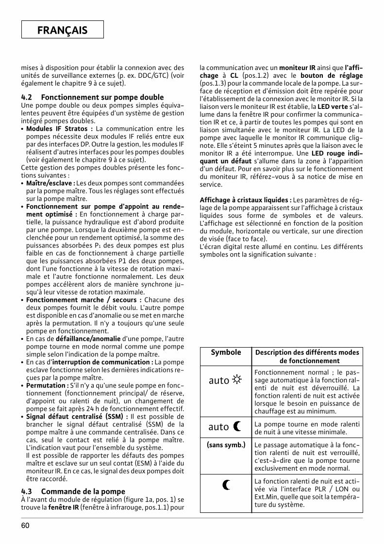
FRANÇAIS
60
mises à disposition pour établir la connexion avec desunités de surveillance externes (p. ex. DDC/GTC) (voirégalement le chapitre 9 à ce sujet).
4.2 Fonctionnement sur pompe doubleUne pompe double ou deux pompes simples équiva-lentes peuvent être équipées d’un système de gestionintégré pompes doubles.x Modules IF Stratos : La communication entre les
pompes nécessite deux modules IF reliés entre euxpar des interfaces DP. Outre la gestion, les modules IFréalisent d’autres interfaces pour les pompes doubles(voir également le chapitre 9 à ce sujet).
Cette gestion des pompes doubles présente les fonc-tions suivantes :x Maître/esclave : Les deux pompes sont commandées
par la pompe maître. Tous les réglages sont effectuéssur la pompe maître.
x Fonctionnement sur pompe d’appoint au rende-ment optimisé : En fonctionnement à charge par-tielle, la puissance hydraulique est d’abord produitepar une pompe. Lorsque la deuxième pompe est en-clenchée pour un rendement optimisé, la somme despuissances absorbées P1 des deux pompes est plusfaible en cas de fonctionnement à charge partielleque les puissances absorbées P1 des deux pompes,dont l’une fonctionne à la vitesse de rotation maxi-male et l’autre fonctionne normalement. Les deuxpompes accélèrent alors de manière synchrone ju-squ’à leur vitesse de rotation maximale.
x Fonctionnement marche / secours : Chacune desdeux pompes fournit le débit voulu. L’autre pompeest disponible en cas d’anomalie ou se met en marcheaprès la permutation. Il n'y a toujours qu'une seulepompe en fonctionnement.
x En cas de défaillance/anomalie d’une pompe, l’autrepompe tourne en mode normal comme une pompesimple selon l’indication de la pompe maître.
x En cas d’interruption de communication : La pompeesclave fonctionne selon les dernières indications re-çues par la pompe maître.
x Permutation : S’il n’y a qu’une seule pompe en fonc-tionnement (fonctionnement principal/ de réserve,d’appoint ou ralenti de nuit), un changement depompe se fait après 24 h de fonctionnement effectif.
x Signal défaut centralisé (SSM) : Il est possible debrancher le signal défaut centralisé (SSM) de lapompe maître à une commande centralisée. Dans cecas, seul le contact est relié à la pompe maître.L’indication vaut pour l’ensemble du système.Il est possible de rapporter les défauts des pompesmaître et esclave sur un seul contat (ESM) à l’aide dumoniteur IR. En ce cas, le signal des deux pompes doitêtre raccordé.
4.3 Commande de la pompeÀ l’avant du module de régulation (figure 1a, pos. 1) setrouve la fenêtre IR (fenêtre à infrarouge, pos.1.1) pour
la communication avec un moniteur IR ainsi que l’affi-chage à CL (pos.1.2) avec le bouton de réglage(pos.1.3) pour la commande locale de la pompe. La sur-face de réception et d’émission doit être repérée pourl’établissement de la connexion avec le monitor IR. Si laliaison vers le moniteur IR est établie, la LED verte s’al-lume dans la fenêtre IR pour confirmer la communica-tion IR et ce, à partir de toutes les pompes qui sont enliaison simultanée avec le moniteur IR. La LED de lapompe avec laquelle le monitor IR communique clig-note. Elle s’éteint 5 minutes après que la liaison avec lemonitor IR a été interrompue. Une LED rouge indi-quant un défaut s’allume dans la zone à l’apparitiond’un défaut. Pour en savoir plus sur le fonctionnementdu moniteur IR, référez-vous à sa notice de mise enservice.
Affichage à cristaux liquides : Les paramètres de rég-lage de la pompe apparaissent sur l’affichage à cristauxliquides sous forme de symboles et de valeurs.L’affichage est sélectionné en fonction de la positiondu module, horizontale ou verticale, sur une directionde visée (face to face). L’écran digital reste allumé en continu. Les différentssymboles ont la signification suivante :
Symbole Description des différents modesde fonctionnement
autoFonctionnement normal ; le pas-sage automatique à la fonction ral-enti de nuit est déverrouillé. Lafonction ralenti de nuit est activéelorsque le besoin en puissance dechauffage est au minimum.
auto La pompe tourne en mode ralentide nuit à une vitesse minimale.
(sans symb.) Le passage automatique à la fonc-tion ralenti de nuit est verrouillé,c'est-à-dire que la pompe tourneexclusivement en mode normal.
La fonction ralenti de nuit est acti-vée via l'interface PLR / LON ouExt.Min, quelle que soit la tempéra-ture du système.
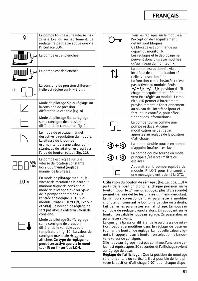
FRANÇAIS
61
Tous les réglages sur le module àl'exception de l'acquittement défaut sont bloqués. Ce blocage est commandé au départ du monitor IR. Les réglages et le déblocage nepeuvent donc plus être modifiésqu'au niveau du moniteur IR.La pompe est actionnée via uneinterface de communication sé-rielle (voir section 4.4).La fonction « marche/arrêt » n'estpas activée au module. Seuls
, , position d'affi-chage et acquittement défaut doi-vent être réglés au module. Le mo-niteur IR permet d'interrompreprovisoirement le fonctionnementau niveau de l'interface (pour ef-fectuer un contrôle, pour sélec-tionner des informations).La pompe tourne comme unepompe esclave. Aucunemodification ne peut êtreapportée au réglage de la positiond'affichage.La pompe double tourne en pompe d'appoint (maître + esclave)La pompe double tourne en modeprincipale / réserve (maître ouesclave)Apparaît sur la pompe équipée demodule IF LON pour transmettreune message d’entretien à la GTC.
Utilisation du bouton de réglage : (fig. 1a, pos. 1.3) Àpartir de la position d’origine, chaque pression sur lebouton (pour le 1er menu, appuyez plus d’1 seconde)permet de faire défiler les phases du menu déroulant.Le symbole correspondant au paramètre à modifierclignote. En tournant le bouton à gauche ou à droite,fait défiler les paramètres sur l’affichage. Le nouveausymbole de réglage clignote alors. En appuyant sur lebouton, on valide le nouveau réglage. On passe alors auparamètre suivant.La consigne (pression différentielle ou vitesse de rota-tion) peut être modifiée dans le réglage de base entournant le bouton de réglage. La nouvelle valeur clig-note. En appuyant sur le bouton, on sélectionne la nou-velle valeur de consigne.Si le nouveau réglage n’est pas confirmé, l’ancienne va-leur est reprise après 30 secondes et l’affichage revientau réglage de base.Réglage de l’affichage : Que la position de montagesoit horizontale ou verticale, il est possible de faire pi-voter la position d’affichage à 90° pour chaque dispo-
La pompe tourne à une vitesse ma-ximale lors du réchauffement. Leréglage ne peut être activé que vial'interface LON.
La pompe est enclenchée.
La pompe est déclenchée.
La consigne de pression différen-tielle est réglée sur H = 5,0 m.
Mode de pilotage Sp-v, réglage surla consigne de pression différentielle variable (fig. 8).
Mode de pilotage Sp-c, réglage sur la consigne de pression différentielle constante (fig. 9).
Le mode de pilotage manuel désactive la régulation du module. La vitesse de la pompe est maintenue à une valeur con-stante. La de rotation est réglée àl'aide du bouton rotatif (fig. 11).
La pompe est réglée sur unevitesse de rotation constante (ici 2 600 tr/min) (réglage manuel de la vitesse).
En mode de pilotage manuel, lavitesse de rotation et la hauteur 10 Vmanométrique de consigne dumode de pilotage Sp-c ou Sp-vde la pompe sont réglées vial'entrée analogique 0...10 V dumodule Stratos IF (Ext.Off, Ext.Minet SBM). Le bouton de réglage nesert pas alors à entrer la valeur deconsigne.Mode de pilotage Sp-T, réglagesur la consigne de pression différentielle variable avec la température (fig. 10). La valeur deconsigne maximale Hsmax est affichée. Ce type de réglage nepeut être activé que via le moni-teur IR ou l'interface LON.
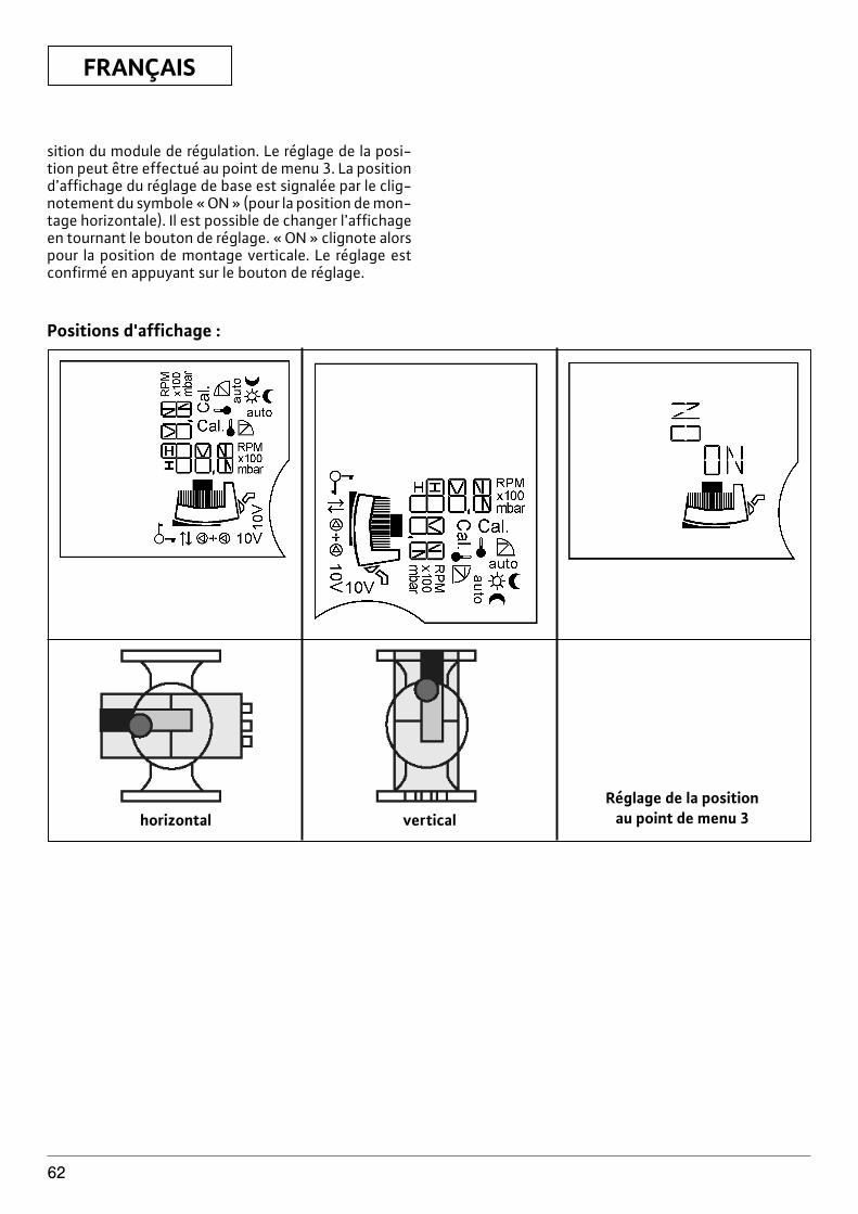
FRANÇAIS
62
Positions d'affichage :
horizontal verticalRéglage de la position
au point de menu 3
sition du module de régulation. Le réglage de la posi-tion peut être effectué au point de menu 3. La positiond’affichage du réglage de base est signalée par le clig-notement du symbole « ON » (pour la position de mon-tage horizontale). Il est possible de changer l’affichageen tournant le bouton de réglage. « ON » clignote alorspour la position de montage verticale. Le réglage estconfirmé en appuyant sur le bouton de réglage.
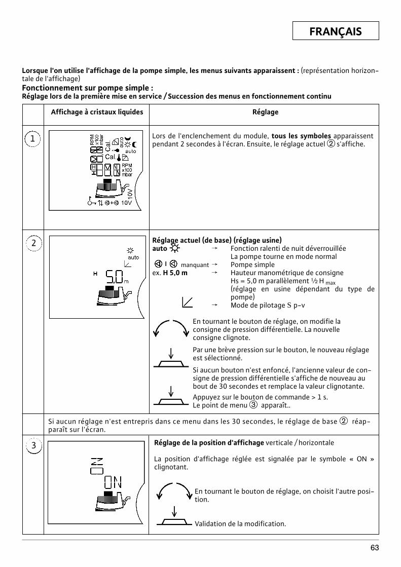
FRANÇAIS
63
Réglage actuel (de base) (réglage usine)auto f Fonction ralenti de nuit déverrouillée
La pompe tourne en mode normalmanquant f Pompe simple
ex. H 5,0 m f Hauteur manométrique de consigneHs = 5,0 m parallèlement | H max(réglage en usine dépendant du type depompe)
f Mode de pilotage S p-v
En tournant le bouton de réglage, on modifie laconsigne de pression différentielle. La nouvelleconsigne clignote.
Par une brève pression sur le bouton, le nouveau réglageest sélectionné.
Si aucun bouton n'est enfoncé, l'ancienne valeur de con-signe de pression différentielle s'affiche de nouveau aubout de 30 secondes et remplace la valeur clignotante.Appuyez sur le bouton de commande > 1 s.Le point de menu e apparaît..
Lorsque l'on utilise l'affichage de la pompe simple, les menus suivants apparaissent : (représentation horizon-tale de l'affichage)Fonctionnement sur pompe simple :Réglage lors de la première mise en service / Succession des menus en fonctionnement continu
1
Affichage à cristaux liquides Réglage
Lors de l'enclenchement du module, tous les symboles apparaissentpendant 2 secondes à l'écran. Ensuite, le réglage actuel w s'affiche.
2
3 Réglage de la position d'affichage verticale / horizontale
La position d'affichage réglée est signalée par le symbole « ON »clignotant.
En tournant le bouton de réglage, on choisit l'autre posi-tion.
Validation de la modification.
Si aucun réglage n'est entrepris dans ce menu dans les 30 secondes, le réglage de base w réap-paraît sur l'écran.
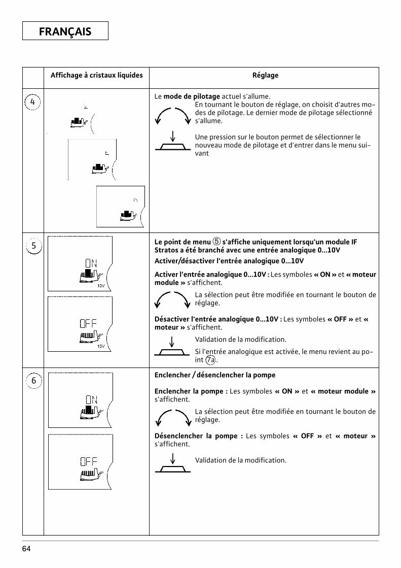
FRANÇAIS
64
4
Affichage à cristaux liquides Réglage
5
6
Le mode de pilotage actuel s'allume. En tournant le bouton de réglage, on choisit d'autres mo-des de pilotage. Le dernier mode de pilotage sélectionnés'allume.
Une pression sur le bouton permet de sélectionner lenouveau mode de pilotage et d'entrer dans le menu sui-vant
Le point de menu t s'affiche uniquement lorsqu'un module IFStratos a été branché avec une entrée analogique 0...10VActiver/désactiver l'entrée analogique 0...10V
Activer l'entrée analogique 0...10V : Les symboles « ON » et « moteurmodule » s'affichent.
La sélection peut être modifiée en tournant le bouton deréglage.
Désactiver l'entrée analogique 0...10V : Les symboles « OFF » et «moteur » s'affichent.
Validation de la modification.
Si l'entrée analogique est activée, le menu revient au po-int 7a .
Enclencher / désenclencher la pompe
Enclencher la pompe : Les symboles « ON » et « moteur module »s'affichent.
La sélection peut être modifiée en tournant le bouton deréglage.
Désenclencher la pompe : Les symboles « OFF » et « moteur »s'affichent.
Validation de la modification.
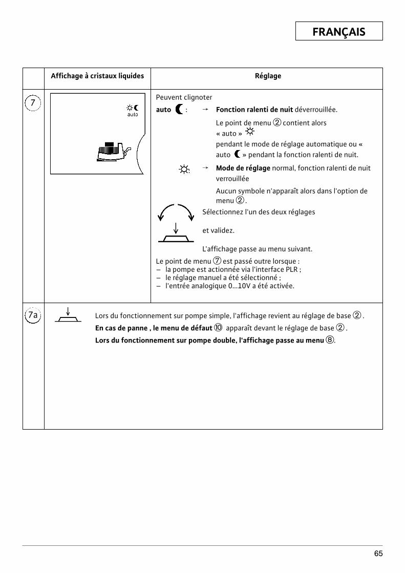
FRANÇAIS
65
7
7a
Affichage à cristaux liquides Réglage
Peuvent clignoter
auto : f Fonction ralenti de nuit déverrouillée.
Le point de menu w contient alors « auto » pendant le mode de réglage automatique ou «auto » pendant la fonction ralenti de nuit.
: f Mode de réglage normal, fonction ralenti de nuitverrouillée
Aucun symbole n'apparaît alors dans l'option demenu w .
Sélectionnez l'un des deux réglages
et validez.
L'affichage passe au menu suivant.
Le point de menu u est passé outre lorsque :– la pompe est actionnée via l'interface PLR ;– le réglage manuel a été sélectionné ;– l'entrée analogique 0...10V a été activée.
Lors du fonctionnement sur pompe simple, l'affichage revient au réglage de base w .
En cas de panne , le menu de défaut p apparaît devant le réglage de base w .
Lors du fonctionnement sur pompe double, l'affichage passe au menu i.
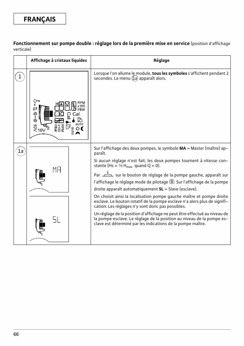
FRANÇAIS
66
1
Affichage à cristaux liquides Réglage
1a
Lorsque l'on allume le module, tous les symboles s'affichent pendant 2secondes. Le menu 1a apparaît alors.
Sur l'affichage des deux pompes, le symbole MA = Master (maître) ap-paraît.
Si aucun réglage n'est fait, les deux pompes tournent à vitesse con-stante (Hs = | Hmax quand Q = 0).
Par sur le bouton de réglage de la pompe gauche, apparaît sur
l'affichage le réglage mode de pilotage o. Sur l'affichage de la pompe
droite apparaît automatiquement SL = Slave (esclave).
On choisit ainsi la localisation pompe gauche maître et pompe droiteesclave. Le bouton rotatif de la pompe esclave n'a alors plus de signifi-cation. Les réglages n'y sont donc pas possibles.
Un réglage de la position d'affichage ne peut être effectué au niveau dela pompe esclave. Le réglage de la position au niveau de la pompe es-clave est déterminé par les indications de la pompe maître.
Fonctionnement sur pompe double : réglage lors de la première mise en service (position d'affichageverticale)
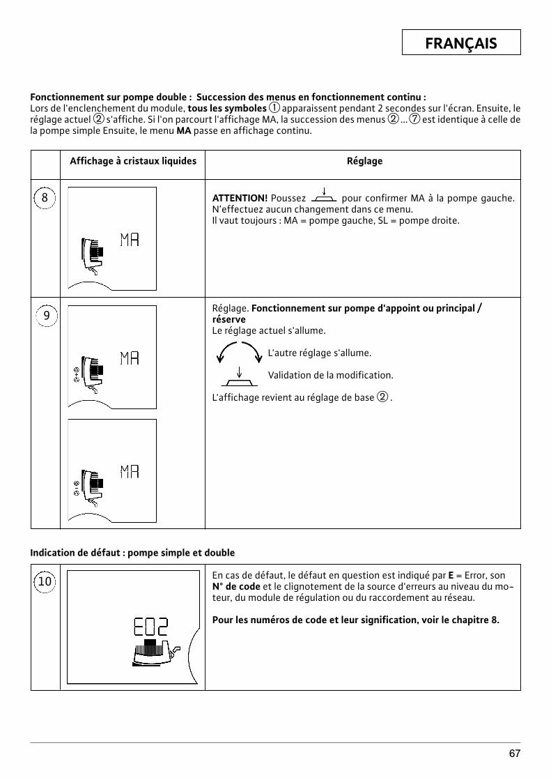
FRANÇAIS
67
8
Affichage à cristaux liquides Réglage
9
ATTENTION! Poussez pour confirmer MA à la pompe gauche.N’effectuez aucun changement dans ce menu. Il vaut toujours : MA = pompe gauche, SL = pompe droite.
Réglage. Fonctionnement sur pompe d'appoint ou principal / réserveLe réglage actuel s'allume.
L'autre réglage s'allume.
Validation de la modification.
L'affichage revient au réglage de base w .
10 En cas de défaut, le défaut en question est indiqué par E = Error, sonN° de code et le clignotement de la source d'erreurs au niveau du mo-teur, du module de régulation ou du raccordement au réseau.
Pour les numéros de code et leur signification, voir le chapitre 8.
Indication de défaut : pompe simple et double
Fonctionnement sur pompe double : Succession des menus en fonctionnement continu :Lors de l'enclenchement du module, tous les symboles q apparaissent pendant 2 secondes sur l'écran. Ensuite, leréglage actuel w s'affiche. Si l'on parcourt l'affichage MA, la succession des menus w ...u est identique à celle dela pompe simple Ensuite, le menu MA passe en affichage continu.
FRANÇAIS
68
4.4 Priorités lors de l’utilisation de pompe,LON, PLR, LON, moniteur IR
L’affichage des défauts (menu 10), y compris leur ac-quittement, a la première priorité. Cela signifie que lesdéfauts apparaissent prioritairement sur l’affichage dela pompe, et doivent être supprimés ou acquittés.Si les réglages sont effectués sur le module de régula-tion ou à partir du moniteur IR et ne sont pas confirméspar une pression sur le bouton, le réglage revient à l’é-tat précédent 30 secondes après la dernière entrée.x Pompe m–n LON : La pompe est contrôlée à partir de
la GTC via le réseau LON. L'affichage indique . Lescommandes sur la pompe sont bloquées. Exception
, , réglage de la position d'affichage,acquittement de défaut.
x Pompe m–n PLR : Lorsqu’elle reçoit un ordre de laGTC, la pompe bascule automatiquement en fonc-tionnement PLR. L’affichage indique . En outre, letype de réglage Sp-c ( ) est automatiquement uti-lisé, le mode S p-v n’est pas possible. Les comman-des sur la pompe sont bloquées. Exception ,
, réglage de la position d'affichage, acquit-tement de défaut.
x Pompe m–n PLR/LON m–n IR : Dans cette configu-ration, les réglages sont pris en charge en priorité parla pompe via l’interface. Le moniteur IR permet d’in-terrompre momentanément la liaison à la GTC via l’-interface. Les réglages peuvent alors être effectuésvia le moniteur IR ou localement sur le module de ré-gulation. 5 minutes après que le dernier réglage a étéréalisé au moyen du moniteur IR, la connexion via l’-interface est rétablie. Pendant la période d’interrup-tion, disparaît de l’affichage.
x Pompe m–n IR sans fonction-clé : Le dernier ordre,qu’il provienne du moniteur IR ou du module de régu-lation, est repris par la pompe.
x Pompe m–n IR avec fonction-clé : À la réception del’ordre « fonction-clé on », les réglages actuels dumodule de régulation subsistent. L’affichage indique« .» Les commandes sur la pompe sont blo-quées, à l’exception de l’acquittement de défauts.
4.5 Étendue de la fourniturex pompe complète (avec 2 joints pour raccordement fi-
leté)x système d’isolation thermique en deux parties (seu-
lement pour les pompes simples fig. 1a, pos.3)x matériau : EPP, polypropylène mousséx conductibilité thermique :
0,04 W/m selon DIN 52612x inflammabilité : classe B2 selon DIN 4102, FMVSS
302x rondelles (pour vis à bride dans le modèle avec bride
combi DN32-DN65)x Notice de montage et de mise en service
4.6 Accessoiresx Modules IF Stratos PLR, LON, Ext.Off, Ext.Min., SBMx Moniteur IR
5 Montage / installationL’installation et la mise en servicedevront être réalisées uniquementpar du personnel qualifié !
5.1 Montage de la pompex La pompe doit être montée dans un endroit sec, bien
aéré et protégé du gel.x Le montage devra être réalisé après avoir terminé
toutes les opérations de soudage et de brasage et, lecas échéant, le nettoyage de la tuyauterie. La saletépeut entraver le fonctionnement correct de lapompe.
x Il est recommandé d’installer des vannes d’isolementen amont et en aval de la pompe. Ceci permettra dene pas avoir à vider puis remplir de nouveau l'instal-lation lors du remplacement de la pompe.
x En cas de montage dans le conduit d’aspiration d’in-stallations ouvertes, le conduit d’aspiration de sécu-rité doit dériver avant la pompe.
x Effectuez le montage sans tension. La tuyauterie doitêtre fixée de telle sorte que la pompe ne supporte pasle poids des tuyaux.
x Avant le montage de la pompe simple, retirez les deuxdemi-coquilles d’isolation (figure 5, pos. 1).
x Le triangle sur le corps de pompe (figure 1a, pos. 2)indique le sens d’écoulement du fluide.
x Seules les positions de montage illustrées à la figure2 sont autorisées. L’arbre de la pompe doit être posi-tionné à l’horizontal.Figure 2a : positions de montage autorisées pour lespompes simplesFigure 2b : positions de montage autorisées pour lespompes doublesLorsque les côtes d’encombrement sont limitées,comme c’est le cas par exemple dans les distributeurscompacts, le module de régulation peut être posi-tionné à la verticale en faisant pivoter le moteur (voirchapitre 5.1.2).Les pompes doubles sont livrées avecdes modules de régulation montés à la verticale.
x Installez la pompe dans un endroit facile d’accès pourpermettre tout entretien ultérieur.On effectuera le montage de façon à éviter que lesgouttes d’eau ne tombent sur le moteur de la pompeou la boîte à bornes.x Pour le montage des pompes à bride combinée
PN6/10 (pompes à brides, y compris DN 65), il con-vient d’observer les recommandations suivantes(fig. 3) :1. Le montage bride combinée avec bride combinée
n’est pas autorisé.
ATTENTION!
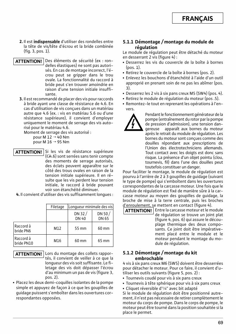
FRANÇAIS
69
2. Il est indispensable d’utiliser des rondelles entrela tête de vis/tête d’écrou et la bride combinée(fig. 3, pos. 1).
Des éléments de sécurité (ex : ron-delles élastiques) ne sont pas autori-sés. En cas de montage incorrect, l’é-crou peut se gripper dans le trouovale. La fonctionnalité du raccord àbride peut s’en trouver amoindrie enraison d’une tension initiale insuffi-sante.
3. Il est recommandé de placer des vis pour raccordsà bride ayant une classe de résistance de 4.6. Encas d’utilisation de vis conçues dans un matériauautre que 4.6 (ex. : vis en matériau 5.6 ou d’unerésistance supérieure), il convient d’employeruniquement le moment de serrage des vis auto-risé pour le matériau 4.6.Moment de serrage des vis autorisé :
pour M 12 f 40 Nmpour M 16 f 95 Nm
Si les vis de résistance supérieure (G4.6) sont serrées sans tenir comptedes moments de serrage autorisés,des éclats peuvent apparaître sur lecôté des trous ovales en raison de latension initiale supérieure. Il en ré-sulte que les vis perdent leur tensioninitiale, le raccord à bride pouvantvoir son étanchéité diminuer.
4. Il convient d’utiliser des vis suffisamment longues :
ATTENTION!
ATTENTION!
5.1.1 Démontage / montage du module derégulation
Le module de régulation peut être détaché du moteuren desserrant 2 vis (figure 4) :x Desserrez les vis du couvercle de la boîte à bornes
(pos. 1).x Retirez le couvercle de la boîte à bornes (pos. 2).x Enlevez les bouchons d’étanchéité à l’aide d’un outil
approprié en prenant soin de ne pas les abîmer (pos.3).
x Desserrez les 2 vis à six pans creux M5 (SW4) (pos. 4).x Retirez le module de régulation du moteur (pos .5).x Remontez-le tout en reprenant les opérations à l’en-
vers.Pendant le fonctionnement générateur de lapompe (entraînement du rotor par la pompede pression d’admission), une tension dan-gereuse apparaît aux bornes du moteuraprès le retrait du module de régulation. Lesbornes du moteur sont conçues comme desdouilles répondant aux prescriptions del’Union des électrotechniciens allemands.Tout contact avec les doigts est donc sansrisque. La présence d’un objet pointu (clou,tournevis, fil) dans l’une des douilles peuttoutefois constituer un danger.
Pour faciliter le montage, le module de régulation estpourvu à l’arrière de 2 à 3 goupilles de guidage (suivantle type de pompe) qui s’emboîtent dans les ouverturescorrespondantes de la carcasse moteur. Une fois que lemodule de régulation est fixé de manière sûre à la car-casse moteur au moyen des goupilles de guidage, labroche de mise à la terre centrale, puis les brochesd’enroulement, se mettent en contact (figure 4).
Entre la carcasse moteur et le modulede régulation se trouve un joint plat(figure 4, pos. 6) qui assure le décou-plage thermique des deux compo-sants. Ce joint doit être impérative-ment placé entre le module et lemoteur pendant le montage du mo-dule de régulation.
5.1.2 Démontage / montage du kitembrochable
4 vis à six pans creux M6 (SW5) doivent être desserréespour détacher le moteur. Pour ce faire, il convient d’u-tiliser les outils suivants (figure 5, pos. 2) :x Tournevis coudé pour vis à six pans creuxx Tournevis à tête sphérique pour vis à six pans creuxx Cliquet réversible d’[” avec bit adaptéSi le module de régulation doit être positionné autre-ment, il n’est pas nécessaire de retirer complètement lemoteur du corps de pompe. Dans le corps de pompe, lemoteur peut être tourné dans la position souhaitée si laplace le permet.
ATTENTION!Filetage Longueur minimale des vis
DN 32 / DN 50 /DN 40 DN 65
Raccord à bride PN6 M12 55 mm 60 mm
Raccord à bride PN10 M16 60 mm 65 mm
Lors du montage des collets rappor-tés, il convient de veiller à ce que lalongueur des vis soit suffisante. Le fi-letage des vis doit dépasser l’écroud’au minimum un pas de vis (figure 3,pos. 2).
x Placez les deux demi-coquilles isolantes de la pompesimple et appuyez de façon à ce que les goupilles deguidage puissent s’emboîter dans les ouvertures cor-respondantes opposées.
ATTENTION!
FRANÇAIS
70
Évitez d’endommager le joint toriquese trouvant entre la tête du moteur etle corps de la pompe. Le joint toriquedoit se trouver dans le chanfreinagedu flasque dirigé vers la roue mobileet ne doit pas être tordu ou vrillé.L’arbre est inséparable de la roue mo-bile, du flasque et du rotor. Cetteunité ne peut retirée inopinément dumoteur. Si le rotor et ses puissants ai-mants ne se trouvent pas dans la car-casse moteur, il existe un risque po-tentiel élevé ; exemple :actionnement soudain d’objets enfer/acier, influence des appareilsélectriques (danger pour les person-nes portant un stimulateur cardiaqueintracorporel), destruction des cartesmagnétiques, etc.
Si les vis situées sur le connecteur du moteur ne sontpas accessibles, le module de régulation peut être dé-taché du moteur en desserrant 2 vis (voir chapitre5.1.1).
5.1.3 Isolation de la pompe dans lesinstallations frigorifiques/deconditionnement d’air
La série Wilo-Stratos est conçue pour être utilisée dansdes installations frigorifiques/de conditionnement d’-air où les températures de fluides atteignent jusqu’à –10°C. Dans ces cas d’utilisation, le fonctionnementintermittent des pompes est également autorisé.Les coquilles d’isolation thermique comprises dans l’é-tendue de la livraison (figure 5, pos. 1) ne sont toute-fois autorisées que dans les installations de chauffageoù les températures de fluides sont supérieures à+20°C, car ces coquilles ne rendent pas la carcasse mo-teur étanche à la diffusion de liquides.En cas d’utilisation dans les installations frigorifi-ques/de conditionnement d’air, l’utilisateur doit pré-voir une isolation étanche à la diffusion de liquides.
Isolez le corps de pompe jusqu’à lafente de séparation du moteur uni-quement, de façon à ce que les orifi-ces d’écoulement de la condensationrestent libres et que les condensatsgénérés par le moteur puissent s’é-couler librement (figure 6).
Le corps de pompe doit être enduit de cataphorèse afind’être protégé contre la corrosion.
5.2 Raccordement électriqueLe raccordement électrique doit être ef-fectué par un électricien agréé, conformé-ment aux prescriptions locales en vigueur.
ATTENTION!
ATTENTION!
ATTENTION! x Conformément à la norme VDE 0730/partie 1, le rac-cordement électrique doit être effectué via une con-duite de raccordement fixe (section minimale de 3 x1,5 mm2) munie d’un connecteur ou d’un contacteurmultipolaire pourvu d’une plaque d’ouverture decontact minimale de 3 mm.
x Un discontacteur de protection moteur n’est pas né-cessaire. Si l’installation en est déjà pourvue, il con-vient de le contourner ou de sélectionner la valeur decourant maximale autorisée.
x Afin de garantir la protection contre l’eau d’égout-tage et le soulagement de traction des presse-étoupe, il faut utiliser des câbles avec un diamètreextérieur suffisant et les fixer de façon suffisammentsolide. En outre, il faut courber les câbles à proximitédu raccord-union en une boucle d’écoulement afinde détourner l’eau d’égouttage éventuelle. Lespresse-étoupe non couverts doivent être obturés aumoyen des plaques étanches disponibles et suffi-samment vissés.
x Pour adapter les conduites de raccordement aux dia-mètres intérieurs des entrées de câbles, les jointsd’étanchéité se composent d’anneaux en caout-chouc agencés de manière concentrique et dont lesanneaux intérieurs peuvent être retirés en cas de be-soin.
Utilisez des câbles avec un diamètreextérieur correspondant de façon àce que le presse-étoupe soit étancheaprès le retrait.Les presse-étoupenon utilisés sont fermés au moyend’une rondelle en plastique. Ces ron-delles ne peuvent être retirées.
x Si l'on place la pompe dans des installations refoulantdes liquides dont la température dépasse 90°C, ilconvient d'utiliser un câble de raccordement rési-stant à la chaleur.
x Tous les câbles de raccordement doivent être placésde façon à ne jamais entrer en contact avec la canali-sation principale et/ou le corps de pompe et la car-casse moteur.
x Cette pompe peut être protégée par un disjoncteurde protection FI.Signalisation : FI ou
x La nature du courant et la tension d’alimentation do-ivent correspondre aux indications figurant sur la pla-que signalétique.
x Protection par fusibles : voir plaque signalétiquex La pompe/l'installation doivent être mises à la terre
conformément aux prescriptions.Lors des essais d’isolation avec unegénératrice à haute tension, retirez lapompe du réseau sur tous les pôlesdans le module de régulation. Les ex-trémités des câbles doivent être iso-lées conformément à la tension de lagénératrice à haute tension.
ATTENTION!
ATTENTION!
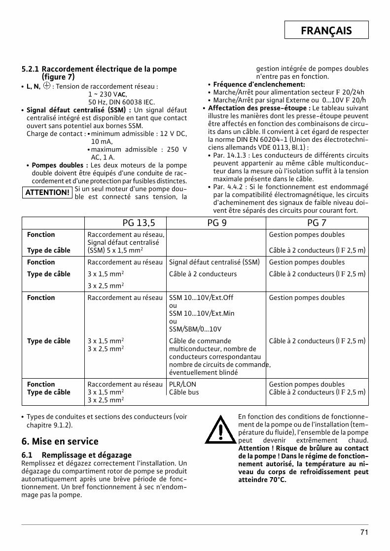
FRANÇAIS
71
5.2.1 Raccordement électrique de la pompe(figure 7)
x L, N, : Tension de raccordement réseau :1 ~ 230 VAC, 50 Hz, DIN 60038 IEC.
x Signal défaut centralisé (SSM) : Un signal défautcentralisé intégré est disponible en tant que contactouvert sans potentiel aux bornes SSM.Charge de contact : x minimum admissible : 12 V DC,
10 mA,x maximum admissible : 250 V
AC, 1 A.x Pompes doubles : Les deux moteurs de la pompe
double doivent être équipés d’une conduite de rac-cordement et d’une protection par fusibles distinctes.
Si un seul moteur d’une pompe dou-ble est connecté sans tension, laATTENTION!
gestion intégrée de pompes doublesn’entre pas en fonction.
x Fréquence d’enclenchement:x Marche/Arrêt pour alimentation secteur F 20/24hx Marche/Arrêt par signal Externe ou 0...10V F 20/h
x Affectation des presse-étoupe : Le tableau suivantillustre les manières dont les presse-étoupe peuventêtre affectés en fonction des combinaisons de circu-its dans un câble. Il convient à cet égard de respecterla norme DIN EN 60204-1 (Union des électrotechni-ciens allemands VDE 0113, Bl.1) :x Par. 14.1.3 : Les conducteurs de différents circuits
peuvent appartenir au même câble multiconduc-teur dans la mesure où l’isolation suffit à la tensionmaximale présente dans le câble.
x Par. 4.4.2 : Si le fonctionnement est endommagépar la compatibilité électromagnétique, les circuitsd’acheminement des signaux de faible niveau doi-vent être séparés des circuits pour courant fort.
PG 13,5 PG 9 PG 7Fonction Raccordement au réseau, Gestion pompes doubles
Signal défaut centralisé Type de câble (SSM) 5 x 1,5 mm2 Câble à 2 conducteurs (l F 2,5 m)
Fonction Raccordement au réseau Signal défaut centralisé (SSM) Gestion pompes doubles
Type de câble 3 x 1,5 mm2 Câble à 2 conducteurs Câble à 2 conducteurs (l F 2,5 m)
3 x 2,5 mm2
Fonction Raccordement au réseau SSM 10…10V/Ext.Off Gestion pompes doublesouSSM 10…10V/Ext.MinouSSM/SBM/0…10V
Type de câble 3 x 1,5 mm2 Câble de commande Câble à 2 conducteurs (l F 2,5 m)3 x 2,5 mm2 multiconducteur, nombre de
conducteurs correspondantau nombre de circuits de commande,éventuellement blindé
Fonction Raccordement au réseau PLR/LON Gestion pompes doublesType de câble 3 x 1,5 mm2 Câble bus Câble à 2 conducteurs (l F 2,5 m)
3 x 2,5 mm2
x Types de conduites et sections des conducteurs (voirchapitre 9.1.2).
6. Mise en service6.1 Remplissage et dégazageRemplissez et dégazez correctement l’installation. Undégazage du compartiment rotor de pompe se produitautomatiquement après une brève période de fonc-tionnement. Un bref fonctionnement à sec n’endom-mage pas la pompe.
En fonction des conditions de fonctionne-ment de la pompe ou de l’installation (tem-pérature du fluide), l’ensemble de la pompepeut devenir extrêmement chaud.Attention ! Risque de brûlure au contactde la pompe ! Dans le régime de fonction-nement autorisé, la température au ni-veau du corps de refroidissement peutatteindre 70°C.
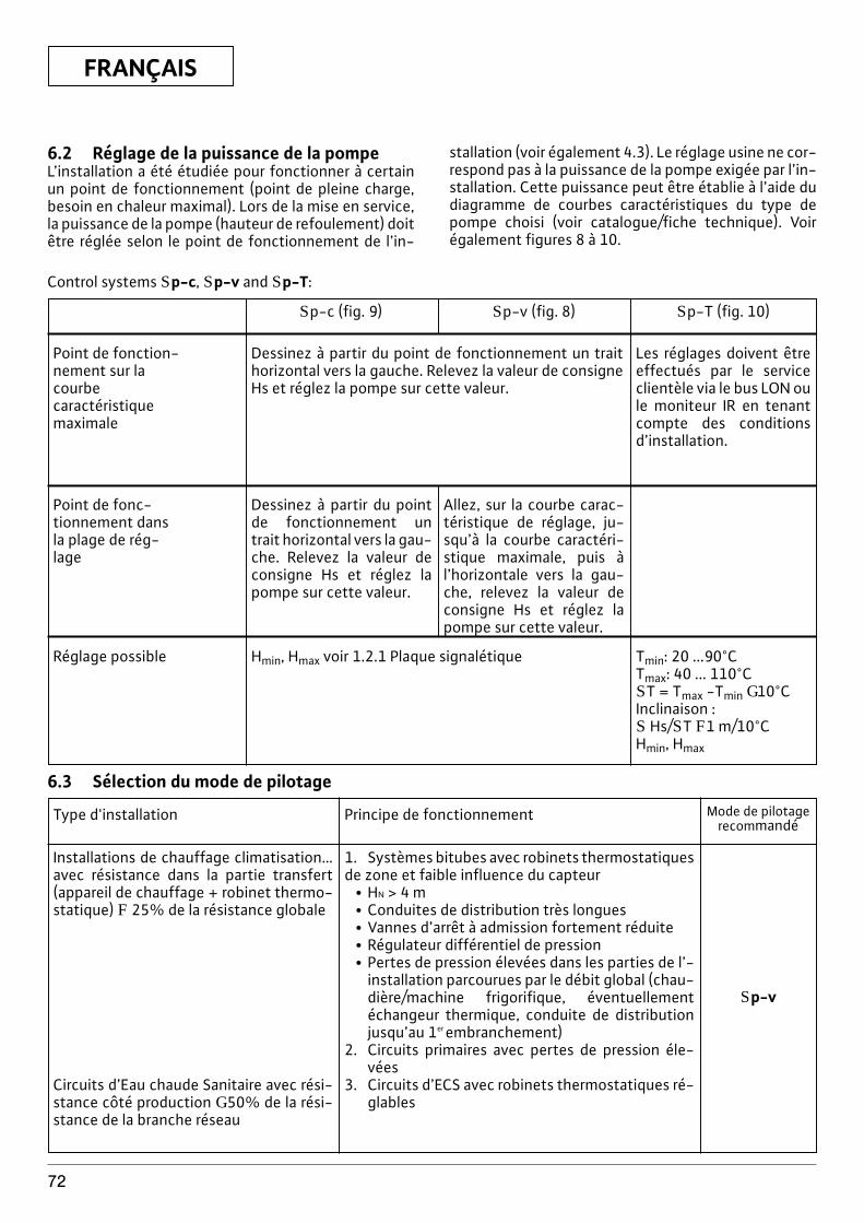
FRANÇAIS
72
Control systems Sp-c, Sp-v and Sp-T:
Point de fonction-nement sur lacourbe caractéristique maximale
Dessinez à partir du point de fonctionnement un traithorizontal vers la gauche. Relevez la valeur de consigneHs et réglez la pompe sur cette valeur.
Les réglages doivent êtreeffectués par le serviceclientèle via le bus LON oule moniteur IR en tenantcompte des conditionsd’installation.
Réglage possible Hmin, Hmax voir 1.2.1 Plaque signalétique Tmin: 20 ...90°CTmax: 40 ... 110°CST = Tmax -Tmin G10°CInclinaison :S Hs/ST F1 m/10°CHmin, Hmax
Point de fonc-tionnement dansla plage de rég-lage
Dessinez à partir du pointde fonctionnement untrait horizontal vers la gau-che. Relevez la valeur deconsigne Hs et réglez lapompe sur cette valeur.
Allez, sur la courbe carac-téristique de réglage, ju-squ’à la courbe caractéri-stique maximale, puis àl’horizontale vers la gau-che, relevez la valeur deconsigne Hs et réglez lapompe sur cette valeur.
Sp-c (fig. 9) Sp-v (fig. 8) Sp-T (fig. 10)
6.3 Sélection du mode de pilotage
Installations de chauffage climatisation…avec résistance dans la partie transfert(appareil de chauffage + robinet thermo-statique) F 25% de la résistance globale
Circuits d’Eau chaude Sanitaire avec rési-stance côté production G50% de la rési-stance de la branche réseau
Type d'installation Principe de fonctionnement Mode de pilotagerecommandé
1. Systèmes bitubes avec robinets thermostatiquesde zone et faible influence du capteur
x HN > 4 mx Conduites de distribution très longuesx Vannes d’arrêt à admission fortement réduitex Régulateur différentiel de pressionx Pertes de pression élevées dans les parties de l’-
installation parcourues par le débit global (chau-dière/machine frigorifique, éventuellementéchangeur thermique, conduite de distributionjusqu’au 1er embranchement)
2. Circuits primaires avec pertes de pression éle-vées
3. Circuits d’ECS avec robinets thermostatiques ré-glables
Sp-v
6.2 Réglage de la puissance de la pompeL’installation a été étudiée pour fonctionner à certainun point de fonctionnement (point de pleine charge,besoin en chaleur maximal). Lors de la mise en service,la puissance de la pompe (hauteur de refoulement) doitêtre réglée selon le point de fonctionnement de l’in-
stallation (voir également 4.3). Le réglage usine ne cor-respond pas à la puissance de la pompe exigée par l’in-stallation. Cette puissance peut être établie à l’aide dudiagramme de courbes caractéristiques du type depompe choisi (voir catalogue/fiche technique). Voirégalement figures 8 à 10.
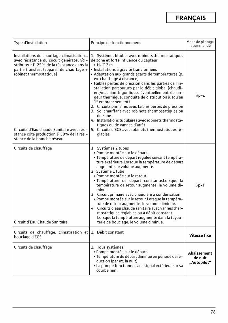
FRANÇAIS
73
Type d'installation Principe de fonctionnement Mode de pilotagerecommandé
Installations de chauffage climatisation...avec résistance du circuit générateur/di-stributeur F 25% de la résistance dans lapartie transfert (appareil de chauffage +robinet thermostatique)
Circuits d’Eau chaude Sanitaire avec rési-stance côté production F 50% de la rési-stance de la branche réseau
1. Systèmes bitubes avec robinets thermostatiquesde zone et forte influence du capteur
x HN F 2 mx Installations à gravité transforméesx Adaptation aux grands écarts de températures (p.
ex. chauffage à distance)x Faibles pertes de pression dans les parties de l’in-
stallation parcourues par le débit global (chaudi-ère/machine frigorifique, éventuellement échan-geur thermique, conduite de distribution jusqu’au1er embranchement)
2. Circuits primaires avec faibles pertes de pression3. Sol chauffant avec robinets thermostatiques ou
de zone4. Installations tubulaires avec robinets thermosta-
tiques ou de vannes d’arrêt5. Circuits d’ECS avec robinets thermostatiques ré-
glables
Sp-c
Circuits de chauffage
Circuit d’Eau Chaude Sanitaire
1. Systèmes 2 tubesx Pompe montée sur le départ.x Température de départ régulée suivant tempéra-
ture extérieure.Lorsque la température de départaugmente, le volume augmente.
2. Système 1 tubex Pompe montée sur le retour.x Température de départ constante.Lorsque la
température de retour augmente, le volume di-minue.
3. Circuit primaire avec chaudière à condensationx Pompe montée sur le retour.Lorsque la tempéra-
ture de retour augmente, le volume diminue.4. Circuits d’eau chaude sanitaire avec vannes ther-
mostatiques réglables ou à débit constantLorsque la température augmente dans la tuyau-terie de bouclage, le volume diminue.
Sp-T
Circuits de chauffage, climatisation etbouclage d’ECS
1. Débit constant
Circuits de chauffage 1. Tous systèmesx Pompe montée sur le départ.x Température de départ diminue en période de ré-
duction (par ex. la nuit)x La pompe fonctionne sans signal extérieur sur sa
courbe mini.
Vitesse fixe
Abaissementde nuit
„Autopilot“
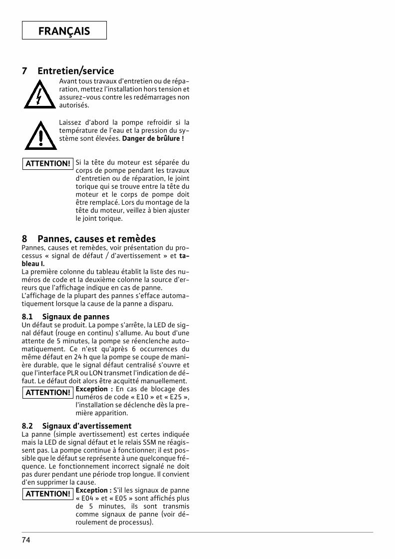
FRANÇAIS
74
7 Entretien/serviceAvant tous travaux d’entretien ou de répa-ration, mettez l’installation hors tension etassurez-vous contre les redémarrages nonautorisés.
Laissez d’abord la pompe refroidir si latempérature de l’eau et la pression du sy-stème sont élevées. Danger de brûlure !
Si la tête du moteur est séparée ducorps de pompe pendant les travauxd’entretien ou de réparation, le jointtorique qui se trouve entre la tête dumoteur et le corps de pompe doitêtre remplacé. Lors du montage de latête du moteur, veillez à bien ajusterle joint torique.
8 Pannes, causes et remèdesPannes, causes et remèdes, voir présentation du pro-cessus « signal de défaut / d’avertissement » et ta-bleau I.La première colonne du tableau établit la liste des nu-méros de code et la deuxième colonne la source d’er-reurs que l’affichage indique en cas de panne. L’affichage de la plupart des pannes s’efface automa-tiquement lorsque la cause de la panne a disparu.
8.1 Signaux de pannesUn défaut se produit. La pompe s’arrête, la LED de sig-nal défaut (rouge en continu) s’allume. Au bout d’uneattente de 5 minutes, la pompe se réenclenche auto-matiquement. Ce n’est qu’après 6 occurrences dumême défaut en 24 h que la pompe se coupe de mani-ère durable, que le signal défaut centralisé s’ouvre etque l’interface PLR ou LON transmet l’indication de dé-faut. Le défaut doit alors être acquitté manuellement.
Exception : En cas de blocage desnuméros de code « E10 » et « E25 »,l’installation se déclenche dès la pre-mière apparition.
8.2 Signaux d’avertissementLa panne (simple avertissement) est certes indiquéemais la LED de signal défaut et le relais SSM ne réagis-sent pas. La pompe continue à fonctionner; il est pos-sible que le défaut se représente à une quelconque fré-quence. Le fonctionnement incorrect signalé ne doitpas durer pendant une période trop longue. Il convientd’en supprimer la cause.
Exception : S’il les signaux de panne« E04 » et « E05 » sont affichés plusde 5 minutes, ils sont transmiscomme signaux de panne (voir dé-roulement de processus).
ATTENTION!
ATTENTION!
ATTENTION!
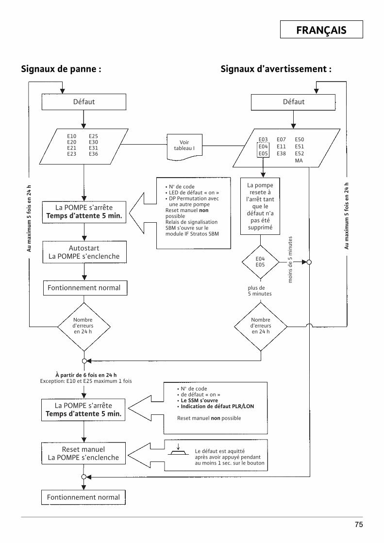
FRANÇAIS
75
E10 E25E20 E30E21 E31E23 E36
Défaut
La POMPE s’arrêteTemps d’attente 5 min.
AutostartLa POMPE s’enclenche
Fontionnement normal
La POMPE s’arrêteTemps d’attente 5 min.
À partir de 6 fois en 24 hException: E10 et E25 maximum 1 fois
Reset manuelLa POMPE s’enclenche
Fontionnement normal
Défaut
Voirtableau I
E03 E07 E50E04 E11 E51E05 E38 E52
MA
La pomperesete à
l’arrêt tantque le
défaut n’apas été
supprimé
E04E05
plus de5 minutes
Nombred’erreursen 24 h
Nombred’erreursen 24 h
moi
ns d
e 5
min
utes
Au
max
imum
5 f
ois
en 2
4 h
Au
max
imum
5 f
ois
en 2
4 h x No de code
x LED de défaut « on »x DP Permutation avec
une autre pompeReset manuel nonpossibleRelais de signalisationSBM s’ouvre sur lemodule IF Stratos SBM
x No de codex de défaut « on »x Le SSM s’ouvrex Indication de défaut PLR/LON
Reset manuel non possible
Le défaut est aquittéaprès avoir appuyé pendantau moins 1 sec. sur le bouton
Signaux de panne : Signaux d’avertissement :
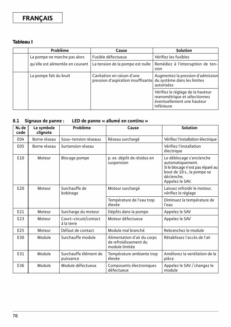
FRANÇAIS
76
Tableau I
Problème Cause SolutionLa pompe ne marche pas alors Fusible défectueux Vérifiez les fusibles
qu'elle est alimentée en courant La tension de la pompe est nulle Remédiez à l'interruption de ten-sion
La pompe fait du bruit Cavitation en raison d'une Augmentez la pression d'admission pression d'aspiration insuffisante du système dans les limites
autorisées
Vérifiez le réglage de la hauteurmanométrique et sélectionnezéventuellement une hauteurinférieure
8.1 Signaux de panne : LED de panne « allumé en continu »No de Le symbole Problème Cause Solutioncode clignote
E04 Borne réseau Sous-tension réseauu Réseau surchargé Vérifiez l'installation électrique
E05 Borne réseau Surtension réseau Vérifiez l'installation électrique
E10 Moteur Blocage pompe p. ex. dépôt de résidus en Le déblocage s'enclenche suspension automatiquement.
Si le blocage n'est pas réparé au bout de 10 s., la pompe sedéclenche.Appelez le SAV.
E20 Moteur Surchauffe de Moteur surchargé Laissez refroidir le moteur, bobinage vérifiez le réglage
Température de l'eau trop Diminuez la température deélevée l'eau
E21 Moteur Surcharge du moteur Dépôts dans la pompe Appelez le SAV
E23 Moteur Court-circuit/contact Moteur défectueux Appelez le SAVà la terre
E25 Moteur Défaut de contact Module mal branché Rebranchez le module
E30 Module Surchauffe module Alimentation d'air du corps Rétablissez l'accès de l'airde refroidissement du module limitée
E31 Module Surchauffe élément de Température ambiante trop Améliorez la ventilation de lapuissance élevée pièce
E36 Module Module défectueux Composants électroniques Appelez le SAV / changez le défectueux module
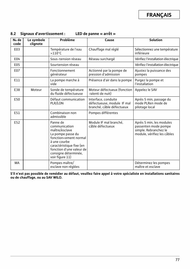
FRANÇAIS
77
8.2 Signaux d'avertissement : LED de panne « arrêt »No de Le symbole Problème Cause Solutioncode clignote
E03 Température de l'eau Chauffage mal réglé Sélectionnez une température >110°C inférieure
E04 Sous-tension réseau Réseau surchargé Vérifiez l'installation électrique
E05 Sourtension réseau Vérifiez l'installation électrique
E07 Fonctionnement Actionné par la pompe de Ajustez la puissance des générateur pression d'admission pompes
E11 La pompe marche à Présence d'air dans la pompe Purgez la pompe et vide l'installation
E38 Moteur Sonde de température Moteur défectueux (fonction Appelez le SAVdu fluide défectueuse ralenti de nuit)
E50 Défaut communication Interface, conduite Après 5 min, passage du PLR/LON défectueuse, module IF mal mode PLRen mode de
branché, câble défectueux pilotage local
E51 Combinaison non Pompes différentesadmissible
E52 Panne de Module IF mal branché, Après 5 min, les modules communication câble défectueux passenten mode pompe maître/esclave simple. Rebranchez le La pompe passe du module, vérifiez les câblesfonction<ement normalà une courbecaractéristique fixe (enfonction d'une valeur de consigne déterminée,voir figure 11)
MA Pompes maître/ Déterminez les pompes esclave non réglées maître et esclave
S’il n’est pas possible de remédier au défaut, veuillez faire appel à votre spécialiste en installations sanitairesou de chauffage, ou au SAV WILO.
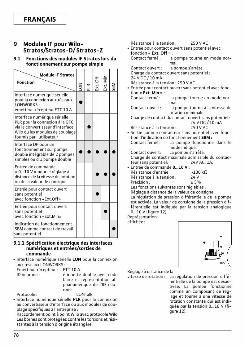
FRANÇAIS
78
9 Modules IF pour Wilo-Stratos/Stratos-D/ Stratos-Z
9.1 Fonctions des modules IF Stratos lors dufonctionnement sur pompe simple
Module IF Stratos
Fonction
Interface numérique sériellepour la connexion aux réseauxLONWORKS ; x
émetteur-récepteur FTT 10 A
Interface numérique sériellePLR pour la connexion à la GTCvia le convertisseur d'interface xWilo ou les modules de couplagefournis par l'utilisateur
Interface DP pour un fonctionnement sur pompe double intégrable de 2 pompes x x x x x
simples ou d'1 pompe double
Entrée de commande« 0...10 V » pour le réglage àdistance de la vitesse de rotation x x x
ou de la valeur de consigne
Entrée pour contact ouvert sans potentiel xavec fonction «Ext.Off»
Entrée pour contact ouvert sans potentiel xavec fonction «Ext.Min»
Indication de fonctionnementSBM comme contact de travail xsans potentiel
LON
PLR
Ext.
Off
Ext.
Min
SBM
9.1.1 Spécification électrique des interfacesnumériques et entrées/sorties decommande
x Interface numérique sérielle LON pour la connexionaux réseaux LONWORKS :Émetteur-récepteur : FTT 10 AID neurone : étiquette double avec code
barre et représentation al-phanumérique de l’ID neu-rone
Protocole : LONTalkx Interface numérique sérielle PLR pour la connexion
au convertisseur d’interface ou aux modules de cou-plage spécifiques à l’entreprise :Raccordement point à point Wilo avec protocole WiloLes bornes sont protégées contre les torsions et rési-stantes à la tension d’origine étrangère.
Résistance à la tension : 250 V ACx Entrée pour contact ouvert sans potentiel avec
fonction « Ext. Off » :Contact fermé : la pompe tourne en mode nor-
mal.Contact ouvert : la pompe s’arrête.Charge du contact ouvert sans potentiel :24 V DC / 10 mARésistance à la tension : 250 V AC
x Entrée pour contact ouvert sans potentiel avec fonc-tion « Ext. Min » :Contact fermé: La pompe tourne en mode nor-
mal.Contact ouvert: La pompe tourne à la vitesse de
rotation minimale.Charge de contact du contact ouvert sans potentiel :
24 V DC / 10 mARésistance à la tension : 250 V AC
x Sortie comme contacteur sans potentiel avec fonc-tion d’indication de fonctionnement SBM :Contact fermé: La pompe fonctionne dans le
mode indiqué.Contact ouvert: La pompe s’arrête.Charge de contact maximale admissible du contac-teur sans potentiel: 24V AC, 1A.
x Entrée de commande 0...10 V :Résistance d’entrée : >100 kÖRésistance à la tension : 24 V =Précision : ± 5%Les fonctions suivantes sont réglables :Réglage à distance de la valeur de consigne :La régulation de pression différentielle de la pompeest activée. La valeur de consigne de la pression dif-férentielle est indiquée par la tension analogique0...10 V (figure 12).
Représentationaffichée :
Réglage à distance de lavitesse de rotation : La régulation de pression diffé-
rentielle de la pompe est désac-tivée. La pompe fonctionnecomme un composant de rég-lage et tourne à une vitesse derotation constante qui est indi-quée par la tension 0...10 V (fi-gure 12).
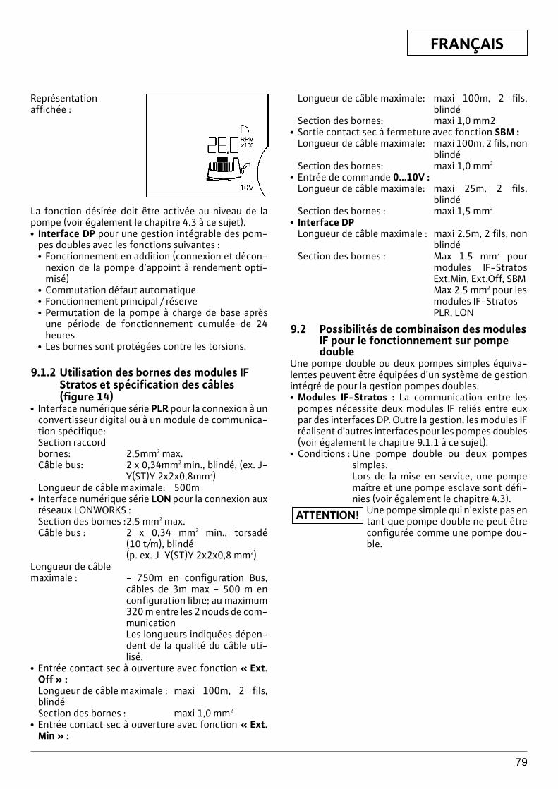
FRANÇAIS
79
Représentationaffichée :
La fonction désirée doit être activée au niveau de lapompe (voir également le chapitre 4.3 à ce sujet).x Interface DP pour une gestion intégrable des pom-
pes doubles avec les fonctions suivantes :x Fonctionnement en addition (connexion et décon-
nexion de la pompe d’appoint à rendement opti-misé)
x Commutation défaut automatiquex Fonctionnement principal / réservex Permutation de la pompe à charge de base après
une période de fonctionnement cumulée de 24heures
x Les bornes sont protégées contre les torsions.
9.1.2 Utilisation des bornes des modules IFStratos et spécification des câbles(figure 14)
x Interface numérique série PLR pour la connexion à unconvertisseur digital ou à un module de communica-tion spécifique:Section raccordbornes: 2,5mm2 max.Câble bus: 2 x 0,34mm2 min., blindé, (ex. J-
Y(ST)Y 2x2x0,8mm2)Longueur de câble maximale: 500m
x Interface numérique série LON pour la connexion auxréseaux LONWORKS :Section des bornes :2,5 mm2 max.Câble bus : 2 x 0,34 mm2 min., torsadé
(10 t/m), blindé(p. ex. J-Y(ST)Y 2x2x0,8 mm2)
Longueur de câblemaximale : - 750m en configuration Bus,
câbles de 3m max - 500 m enconfiguration libre; au maximum320 m entre les 2 nouds de com-municationLes longueurs indiquées dépen-dent de la qualité du câble uti-lisé.
x Entrée contact sec à ouverture avec fonction « Ext.Off » :Longueur de câble maximale : maxi 100m, 2 fils,blindéSection des bornes : maxi 1,0 mm2
x Entrée contact sec à ouverture avec fonction « Ext.Min » :
Longueur de câble maximale: maxi 100m, 2 fils,blindé
Section des bornes: maxi 1,0 mm2x Sortie contact sec à fermeture avec fonction SBM :
Longueur de câble maximale: maxi 100m, 2 fils, nonblindé
Section des bornes: maxi 1,0 mm2
x Entrée de commande 0...10V :Longueur de câble maximale: maxi 25m, 2 fils,
blindéSection des bornes : maxi 1,5 mm2
x Interface DPLongueur de câble maximale : maxi 2.5m, 2 fils, non
blindéSection des bornes : Max 1,5 mm2 pour
modules IF-StratosExt.Min, Ext.Off, SBMMax 2,5 mm2 pour lesmodules IF-StratosPLR, LON
9.2 Possibilités de combinaison des modulesIF pour le fonctionnement sur pompedouble
Une pompe double ou deux pompes simples équiva-lentes peuvent être équipées d’un système de gestionintégré de pour la gestion pompes doubles.x Modules IF-Stratos : La communication entre les
pompes nécessite deux modules IF reliés entre euxpar des interfaces DP. Outre la gestion, les modules IFréalisent d’autres interfaces pour les pompes doubles(voir également le chapitre 9.1.1 à ce sujet).
x Conditions : Une pompe double ou deux pompessimples.Lors de la mise en service, une pompemaître et une pompe esclave sont défi-nies (voir également le chapitre 4.3).
Une pompe simple qui n'existe pas entant que pompe double ne peut êtreconfigurée comme une pompe dou-ble.
ATTENTION!
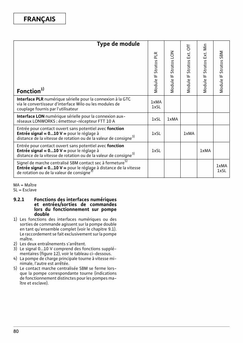
FRANÇAIS
80
Type de module
Fonction1)
Interface PLR numérique sérielle pour la connexion à la GTCvia le convertisseur d'interface Wilo ou les modules de 1xMA
couplage fournis par l'utilisateur 1xSL
Interface LON numérique sérielle pour la connexion aux-réseaux LONWORKS ; émetteur-récepteur FTT 10 A 1xSL 1xMA
Entrée pour contact ouvert sans potentiel avec fonctionEntrée signal « 0...10 V » pour le réglage à 1xSL 1xMAdistance de la vitesse de rotation ou de la valeur de consigne3)
Entrée pour contact ouvert sans potentiel avec fonctionEntrée signal « 0...10 V » pour le réglage à 1xSL 1xMAdistance de la vitesse de rotation ou de la valeur de consigne3)
Signel de marche centralisé SBM contact sec à fermeture5)
Entrée signal « 0...10 V » pour le réglage à distance de la vitesse 1xMA
de rotation ou de la valeur de consigne3) 1xSL
Mod
ule
IF S
trat
os P
LR
Mod
ule
IF S
trat
os L
ON
Mod
ule
IF S
trat
os E
xt. O
ff
Mod
ule
IF S
trat
os E
xt. M
in
Mod
ule
IF S
trat
os S
BM
MA = MaîtreSL = Esclave
9.2.1 Fonctions des interfaces numériqueset entrées/sorties de commandeslors du fonctionnement sur pompedouble
1) Les fonctions des interfaces numériques ou dessorties de commande agissent sur la pompe doubleen tant qu’ensemble complet (voir le chapitre 9.1).Le raccordement se fait exclusivement sur la pompemaître.
2) Les deux entraînements s’arrêtent.3) Le signal 0...10 V comprend des fonctions supplé-
mentaires (figure 12), voir le tableau ci-dessous.4) La pompe de charge principale tourne à vitesse mi-
nimale, l’autre est arrêtée.5) Le contact marche centralisée SBM se ferme lors-
que la pompe correspondante tourne (indicationsde fonctionnement distinctes pour les pompes ma-ître et esclave).
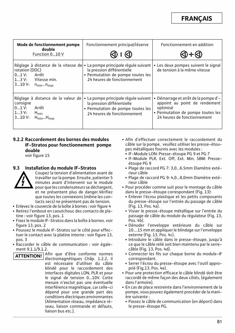
FRANÇAIS
81
Mode de fonctionnement pompedouble
Function 0…10 V
Réglage à distance de la vitesse derotation (DDC)0...1 V: Arrêt1...3 V: Vitesse min.3...10 V: nmin...nmax
Fonctionnement principal/réserve
x La pompe principale régule suivantla pression différentielle
x Permutation de pompe toutes les24 heures de fonctionnement
x Les deux pompes suivent le signalde tension à la même vitesse
Réglage à distance de la valeur deconsigne0...1 V: Arrêt1...3 V: Hmin3...10 V: Hmin...Hmax
x La pompe principale régule suivantla pression différentielle
x Permutation de pompe toutes les24 heures de fonctionnement
x Démarrage et arrêt de la pompe d’-appoint au point de rendementoptimisé
x Permutation de pompe toutes les24 heures de fonctionnement
Fonctionnement en addition
9.2.2 Raccordement des bornes des modulesIF-Stratos pour fonctionnement pompedoublevoir figure 15
9.3 Installation du module IF-StratosCoupez la tension d’alimentation avant detravailler sur la pompe. Ensuite, patienter 5minutes avant d’intervenir sur le modulepour que les condensateurs se déchargent,et ne présentent plus de danger.Vérifiezque toutes les connexions (même les con-tacts secs) ne présentent pas de tension.
x Enlevez le couvercle de la boîte à bornes : voir figure 4x Retirez l’embout en caoutchouc des contacts de pla-
tine : voir figure 13, pos. 1x Fixez le module IF-Stratos dans la boîte à bornes. voir
figure 13, pos. 2x Poussez le module IF-Stratos sur le côté pour effec-
tuer le contact avec la platine interne : voir figure 13,pos. 3
x Raccorder le câble de communication : voir égale-ment 9.1.1/9.1.2.
Afin que d’être conforme normesélectromagnétiques Châp. 1.2.2, ilest nécessaire d’utiliser du câbleblindé pour le raccordement desinterfaces digitales LON, PLR et pourle signal de tension 0...10V. Cettemesure n’exclut pas une éventuelleinterférence magnétique, car celle-cidépend pour une grande part desconditions électriques environnantes(Alimentation réseau, impédance ré-seau, liaison commande et défauts,liaison bus etc.).
ATTENTION!
x Afin d’effectuer correctement le raccordement ducâble sur la pompe, veuillez utiliser les presse-étou-pes métalliques fournis avec les modules :x IF-Module LON: Presse-étoupe PG 9 et PG 7x If-Module PLR, Ext. Off, Ext. Min, SBM: Presse-
étoupe PG 9x Plage de raccord PG 7: 3,0...6,5mm Diamètre exté-
rieur câblex Plage de raccord PG 9: 4,0...8,0mm Diamètre exté-
rieur câblex Pour procéder comme suit pour le montage du câble
dans le presse-étoupe correspondant (Fig. 13):x Enlever l’écrou plastique et les petits composants
du presse-étoupe sur l’entrée du passage de câble(Fig. 13, Pos. 4a).
x Visser le presse-étoupe métallique sur l’entrée dupassage de câble du module du régulateur (Fig. 13,Pos. 4b).
x Dénuder l’enveloppe extérieure du câble sur10....15 mm et appliquer le blindage sur l’enveloppeexterne (Fig. 13, Pos. 4c).
x Introduire le câble dans le presse-étoupe, jusqu’àce que le câble relié soit bien maintenu par le serre-câble (Fig. 13, Pos. 4d).
x Connecter les fils sur chaque borne du module-IFcorrespondant.
x Serrer l’écrou du presse-étoupe avec l’outil appro-prié (Fig.13, Pos. 4e).
x Pour une protection efficace le câble blindé doit êtreraccordé de même façon des deux côtés, (égalementdans l’armoire).
x En cas de place restreinte dans l’environnement de lapompe, vous pouvez également procéder de la mani-ère suivante :x Passez le câble de communication (en déport) dans
le presse-étoupe PG.
FRANÇAIS
82
x Attachez les fils du câble de communication au mo-dule IF (le module IF n’est pas encore branché).
x Disposez les fils du câble de communication enboucle et montez le module IF.
x Accrochez le couvercle de la boîte à bornes aux évi-dements à l’aide des attaches et vissez : voir figure 4
x Module IF-Stratos LON : Une étiquette avec l’ID neu-rone doit rester sur le module IF ; l’autre étiquettepeut par exemple être collée sur le schéma d’installa-tion à l’endroit de la pompe correspondante. Lors dela connexion, l’ID neurone peut être lu à partir du pland’installation à l’aide d’un lecteur de codes-barres ouêtre saisi manuellement.
Sous réserve de modifications techniques !
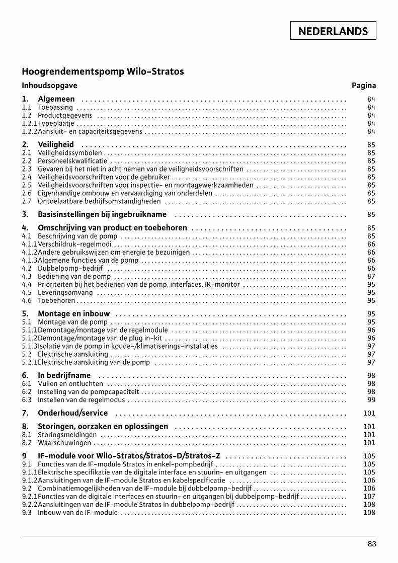
NEDERLANDS
83
Hoogrendementspomp Wilo-StratosInhoudsopgave Pagina
1. Algemeen . . . . . . . . . . . . . . . . . . . . . . . . . . . . . . . . . . . . . . . . . . . . . . . . . . . . . . . . . . . . . . . 841.1 Toepassing . . . . . . . . . . . . . . . . . . . . . . . . . . . . . . . . . . . . . . . . . . . . . . . . . . . . . . . . . . . . . . . . . . . . . . . . . . . . . . . . 841.2 Productgegevens . . . . . . . . . . . . . . . . . . . . . . . . . . . . . . . . . . . . . . . . . . . . . . . . . . . . . . . . . . . . . . . . . . . . . . . . . . 841.2.1Typeplaatje . . . . . . . . . . . . . . . . . . . . . . . . . . . . . . . . . . . . . . . . . . . . . . . . . . . . . . . . . . . . . . . . . . . . . . . . . . . . . . . . 841.2.2Aansluit- en capaciteitsgegevens . . . . . . . . . . . . . . . . . . . . . . . . . . . . . . . . . . . . . . . . . . . . . . . . . . . . . . . . . . . . 84
2. Veiligheid . . . . . . . . . . . . . . . . . . . . . . . . . . . . . . . . . . . . . . . . . . . . . . . . . . . . . . . . . . . . . . . 852.1 Veiligheidssymbolen . . . . . . . . . . . . . . . . . . . . . . . . . . . . . . . . . . . . . . . . . . . . . . . . . . . . . . . . . . . . . . . . . . . . . . . . 852.2 Personeelskwalificatie . . . . . . . . . . . . . . . . . . . . . . . . . . . . . . . . . . . . . . . . . . . . . . . . . . . . . . . . . . . . . . . . . . . . . . 852.3 Gevaren bij het niet in acht nemen van de veiligheidsvoorschriften . . . . . . . . . . . . . . . . . . . . . . . . . . . . . . 852.4 Veiligheidsvoorschriften voor de gebruiker . . . . . . . . . . . . . . . . . . . . . . . . . . . . . . . . . . . . . . . . . . . . . . . . . . . . 852.5 Veiligheidsvoorschriften voor inspectie- en montagewerkzaamheden . . . . . . . . . . . . . . . . . . . . . . . . . . . 852.6 Eigenhandige ombouw en vervaardiging van onderdelen . . . . . . . . . . . . . . . . . . . . . . . . . . . . . . . . . . . . . . . 852.7 Ontoelaatbare bedrijfsomstandigheden . . . . . . . . . . . . . . . . . . . . . . . . . . . . . . . . . . . . . . . . . . . . . . . . . . . . . . 85
3. Basisinstellingen bij ingebruikname . . . . . . . . . . . . . . . . . . . . . . . . . . . . . . . . . . . . . . . . . 85
4. Omschrijving van product en toebehoren . . . . . . . . . . . . . . . . . . . . . . . . . . . . . . . . . . . . . 854.1 Beschrijving van de pomp . . . . . . . . . . . . . . . . . . . . . . . . . . . . . . . . . . . . . . . . . . . . . . . . . . . . . . . . . . . . . . . . . . . 854.1.1Verschildruk-regelmodi . . . . . . . . . . . . . . . . . . . . . . . . . . . . . . . . . . . . . . . . . . . . . . . . . . . . . . . . . . . . . . . . . . . . . 864.1.2Andere gebruikswijzen om energie te bezuinigen . . . . . . . . . . . . . . . . . . . . . . . . . . . . . . . . . . . . . . . . . . . . . . 864.1.3Algemene functies van de pomp . . . . . . . . . . . . . . . . . . . . . . . . . . . . . . . . . . . . . . . . . . . . . . . . . . . . . . . . . . . . . 864.2 Dubbelpomp-bedrijf . . . . . . . . . . . . . . . . . . . . . . . . . . . . . . . . . . . . . . . . . . . . . . . . . . . . . . . . . . . . . . . . . . . . . . . 864.3 Bediening van de pomp . . . . . . . . . . . . . . . . . . . . . . . . . . . . . . . . . . . . . . . . . . . . . . . . . . . . . . . . . . . . . . . . . . . . . 874.4 Prioriteiten bij het bedienen van de pomp, interfaces, IR-monitor . . . . . . . . . . . . . . . . . . . . . . . . . . . . . . . 954.5 Leveringsomvang . . . . . . . . . . . . . . . . . . . . . . . . . . . . . . . . . . . . . . . . . . . . . . . . . . . . . . . . . . . . . . . . . . . . . . . . . . 954.6 Toebehoren . . . . . . . . . . . . . . . . . . . . . . . . . . . . . . . . . . . . . . . . . . . . . . . . . . . . . . . . . . . . . . . . . . . . . . . . . . . . . . . . 95
5. Montage en inbouw . . . . . . . . . . . . . . . . . . . . . . . . . . . . . . . . . . . . . . . . . . . . . . . . . . . . . . . 955.1 Montage van de pomp . . . . . . . . . . . . . . . . . . . . . . . . . . . . . . . . . . . . . . . . . . . . . . . . . . . . . . . . . . . . . . . . . . . . . . 955.1.1Demontage/montage van de regelmodule . . . . . . . . . . . . . . . . . . . . . . . . . . . . . . . . . . . . . . . . . . . . . . . . . . . . 965.1.2Demontage/montage van de plug in-kit . . . . . . . . . . . . . . . . . . . . . . . . . . . . . . . . . . . . . . . . . . . . . . . . . . . . . . 965.1.3Isolatie van de pomp in koude-/klimatiserings-installaties . . . . . . . . . . . . . . . . . . . . . . . . . . . . . . . . . . . . . 975.2 Elektrische aansluiting . . . . . . . . . . . . . . . . . . . . . . . . . . . . . . . . . . . . . . . . . . . . . . . . . . . . . . . . . . . . . . . . . . . . . . 97 5.2.1Elektrische aansluiting van de pomp . . . . . . . . . . . . . . . . . . . . . . . . . . . . . . . . . . . . . . . . . . . . . . . . . . . . . . . . . 97
6. In bedrijfname . . . . . . . . . . . . . . . . . . . . . . . . . . . . . . . . . . . . . . . . . . . . . . . . . . . . . . . . . . . 986.1 Vullen en ontluchten . . . . . . . . . . . . . . . . . . . . . . . . . . . . . . . . . . . . . . . . . . . . . . . . . . . . . . . . . . . . . . . . . . . . . . . 986.2 Instelling van de pompcapaciteit . . . . . . . . . . . . . . . . . . . . . . . . . . . . . . . . . . . . . . . . . . . . . . . . . . . . . . . . . . . . . 986.3 Instellen van de regelmodus . . . . . . . . . . . . . . . . . . . . . . . . . . . . . . . . . . . . . . . . . . . . . . . . . . . . . . . . . . . . . . . . . 99
7. Onderhoud/service . . . . . . . . . . . . . . . . . . . . . . . . . . . . . . . . . . . . . . . . . . . . . . . . . . . . . . . 101
8. Storingen, oorzaken en oplossingen . . . . . . . . . . . . . . . . . . . . . . . . . . . . . . . . . . . . . . . . . 1018.1 Storingsmeldingen . . . . . . . . . . . . . . . . . . . . . . . . . . . . . . . . . . . . . . . . . . . . . . . . . . . . . . . . . . . . . . . . . . . . . . . . . 1018.2 Waarschuwingen . . . . . . . . . . . . . . . . . . . . . . . . . . . . . . . . . . . . . . . . . . . . . . . . . . . . . . . . . . . . . . . . . . . . . . . . . . . 101
9 IF-module voor Wilo-Stratos/Stratos-D/Stratos-Z . . . . . . . . . . . . . . . . . . . . . . . . . . . . . 1059.1 Functies van de IF-module Stratos in enkel-pompbedrijf . . . . . . . . . . . . . . . . . . . . . . . . . . . . . . . . . . . . . . . 1059.1.1Elektrische specifikatie van de digitale interface en stuurin- en uitgangen . . . . . . . . . . . . . . . . . . . . . . . 1059.1.2Aansluitingen van de IF-module Stratos en kabelspecificatie . . . . . . . . . . . . . . . . . . . . . . . . . . . . . . . . . . . 1069.2 Combinatiemogelijkheden van de IF-module bij dubbelpomp-bedrijf . . . . . . . . . . . . . . . . . . . . . . . . . . . . 1069.2.1Functies van de digitale interfaces en stuurin- en uitgangen bij dubbelpomp-bedrijf . . . . . . . . . . . . . . 1079.2.2Aansluitingen van de IF-module Stratos in dubbelpomp-bedrijf . . . . . . . . . . . . . . . . . . . . . . . . . . . . . . . . . 1089.3 Inbouw van de IF-module . . . . . . . . . . . . . . . . . . . . . . . . . . . . . . . . . . . . . . . . . . . . . . . . . . . . . . . . . . . . . . . . . . . 108
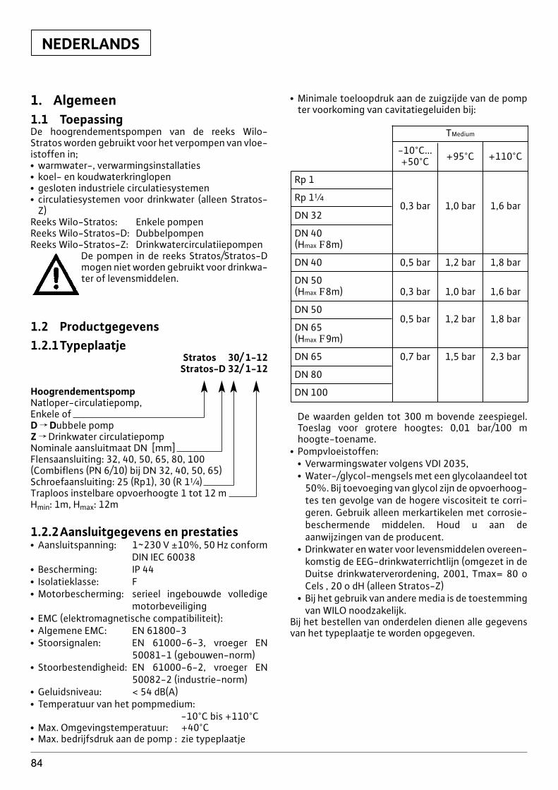
NEDERLANDS
84
1. Algemeen1.1 ToepassingDe hoogrendementspompen van de reeks Wilo-Stratos worden gebruikt voor het verpompen van vloe-istoffen in;x warmwater-, verwarmingsinstallaties x koel- en koudwaterkringlopen x gesloten industriele circulatiesystemenx circulatiesystemen voor drinkwater (alleen Stratos-
Z)Reeks Wilo-Stratos: Enkele pompenReeks Wilo-Stratos-D: DubbelpompenReeks Wilo-Stratos-Z: Drinkwatercirculatiiepompen
De pompen in de reeks Stratos/Stratos-Dmogen niet worden gebruikt voor drinkwa-ter of levensmiddelen.
1.2 Productgegevens1.2.1Typeplaatje
Stratos 30/ 1-12Stratos-D 32/ 1-12
HoogrendementspompNatloper-circulatiepomp,Enkele ofD f Dubbele pompZ f Drinkwater circulatiepompNominale aansluitmaat DN [mm]Flensaansluiting: 32, 40, 50, 65, 80, 100(Combiflens (PN 6/10) bij DN 32, 40, 50, 65)Schroefaansluiting: 25 (Rp1), 30 (R 1[)Traploos instelbare opvoerhoogte 1 tot 12 mHmin: 1m, Hmax: 12m
1.2.2Aansluitgegevens en prestatiesx Aansluitspanning: 1~230 V ±10%, 50 Hz conform
DIN IEC 60038x Bescherming: IP 44x Isolatieklasse: Fx Motorbescherming: serieel ingebouwde volledige
motorbeveiligingx EMC (elektromagnetische compatibiliteit):x Algemene EMC: EN 61800-3x Stoorsignalen: EN 61000-6-3, vroeger EN
50081-1 (gebouwen-norm)x Stoorbestendigheid: EN 61000-6-2, vroeger EN
50082-2 (industrie-norm)x Geluidsniveau: < 54 dB(A)x Temperatuur van het pompmedium:
-10°C bis +110°Cx Max. Omgevingstemperatuur: +40°Cx Max. bedrijfsdruk aan de pomp : zie typeplaatje
x Minimale toeloopdruk aan de zuigzijde van de pompter voorkoming van cavitatiegeluiden bij:
TMedium
-10°C...+50°C +95°C +110°C
Rp 1
Rp 1[
DN 320,3 bar 1,0 bar 1,6 bar
DN 40 (Hmax F8m)
DN 40 0,5 bar 1,2 bar 1,8 bar
DN 50 (Hmax F8m) 0,3 bar 1,0 bar 1,6 bar
DN 500,5 bar 1,2 bar 1,8 bar
DN 65 (Hmax F9m)
DN 65 0,7 bar 1,5 bar 2,3 bar
DN 80
DN 100
De waarden gelden tot 300 m bovende zeespiegel.Toeslag voor grotere hoogtes: 0,01 bar/100 mhoogte-toename.
x Pompvloeistoffen:x Verwarmingswater volgens VDI 2035,x Water-/glycol-mengsels met een glycolaandeel tot
50%. Bij toevoeging van glycol zijn de opvoerhoog-tes ten gevolge van de hogere viscositeit te corri-geren. Gebruik alleen merkartikelen met corrosie-beschermende middelen. Houd u aan deaanwijzingen van de producent.
x Drinkwater en water voor levensmiddelen overeen-komstig de EEG-drinkwaterrichtlijn (omgezet in deDuitse drinkwaterverordening, 2001, Tmax= 80 oCels , 20 o dH (alleen Stratos-Z)
x Bij het gebruik van andere media is de toestemmingvan WILO noodzakelijk.
Bij het bestellen van onderdelen dienen alle gegevensvan het typeplaatje te worden opgegeven.
NEDERLANDS
85
2. VeiligheidDeze handleiding bevat belangrijke aanwijzingen diebij de montage en de in bedrijfname moeten wordennageleefd. Daarom dienen de monteur en de bevoegdegebruiker deze handleiding beslist door te lezen vóórde montage en inbedrijfstelling.Men dient niet alleen te letten op de onder dit hoofd-stuk „Veiligheid” aangegeven algemene veiligheids-voorschriften, maar ook op de hierna aangegeven spe-ciale veiligheidssymbolen.
2.1 VeiligheidssymbolenDe in deze handleiding opgenomen veiligheidsaanwij-zingen, die bij veronachtzaming gevaar kunnen ople-veren voor personen, zijn aangegeven met het alge-mene gevaarssymbool
,
en bij gevaar voor elektrische spanning met
aangeduid.Bij veiligheidsvoorschriften, die bij het niet naleven er-van gevaar opleveren voor de pomp/installatie en haarwerking, worden aangeduid met:
2.2 PersoneelskwalificatieDe montage dient door gekwalificeerd personeel teworden uitgevoerd.
2.3 Gevaren bij het niet in acht nemen vande veiligheidsvoorschriften
De niet-naleving kan gevaar voor personen en de in-stallatie opleveren. De niet-naleving van de veilig-heidsvoorschriften kan ertoe leiden dat iedere aan-spraak op schadeloosstelling ongeldig wordt.Concreet kan niet-naleving de volgende gevaren in-houden:x Uitvallen van belangrijke functies van de pomp/in-
stallatie,x Verwonding van personen door elektrische en me-
chanische inwerking,
2.4 Veiligheidsvoorschriften voor degebruiker
De bestaande voorschriften ter voorkoming van onge-vallen dienen in acht te worden genomen.Gevaar door elektrische energie moet worden voorko-men. De algemene voorschriften en de voorschriften
OPGELET!
van de plaatselijke energiemaatschappijen moetenworden nageleefd.
2.5 Veiligheidsvoorschriften voor inspectie en montagewerkzaamheden
De gebruiker dient er voor zorgen dat alle inspectie- enmontagewerkzaamheden worden uitgevoerd door er-kend en gekwalificeerd vakpersoneel, dat zich door hetaandachtig lezen van de handleiding voldoende heeftgeïnformeerd.In principe mogen werkzaamheden aan de pomp/in-stallatie alleen bij stilstand worden uitgevoerd.
2.6 Eigenhandige ombouw en vervaardigingvan onderdelen
Veranderingen van de pomp/installatie zijn alleen inoverleg met de producent toegestaan. In het kader vande veiligheid mag enkel gebruik worden gemaakt vanoriginele onderdelen en door de producent toegelatentoebehoren. Het gebruik van andere delen ontslaat defabrikant voor de daar uit voortkomende gevolgen.
2.7 Ontoelaatbare bedrijfsomstandighedenDe bedrijfszekerheid van de geleverde pomp/installatieis alleen gewaarborgd bij een oordeelkundig gebruik,conform deel 1 van de handleiding. De in de catalo-gus/datablad aangegeven grenswaarden mogen ingeen geval onder- resp. overschreden worden.
3 Transport en tussenopslagDe pomp moet worden beschermd te-gen vocht en mechanische beschadi-ging.Tijdens transport en tussenops-lag mogen de pompen niet wordenblootgesteld aan temperaturen buitenhet gebied van -10°C tot +50°C.
4 Omschrijving van product en toebehoren
4.1 Beschrijving van de pomp (afb. 1a, 1b)
De hoogrendementspomp Wilo-Stratos is een reeksvan natloop-pompen met Electronic CommutatedMotor (ECM)-technologie en een geïntegreerde ver-schildruk-regeling. De pomp kan als enkele- (afb 1a)of als dubbelpomp (afb. 1b) worden ingebouwd.Op de behuizing van de motor zit een regelmodule inaxiale uitvoering (afb. 1a, pos.1), die de verschildrukvan de pomp op een binnen het regelbereik instelbaredoelwaarde regelt. Naargelang de regelmodus voldoetde verschildruk aan verschillende criteria. Daardoorpast de pomp zich voortdurend aan de wisselende ca-paciteitsbehoefte van de installatie aan. Vooral bij ge-bruik van thermostaatkranen is dit noodzakelijk.De wezenlijke voordelen van deze elektronische rege-ling zijn:
OPGELET!
NEDERLANDS
86
x Energie-besparing, en tegelijk een verlaging van degebruikskosten,
x Vermindering van stromingsgeluiden.x Overdrukventielen overbodig.De hoogrendementspompen van de serie Stratos-Zzijn door de materiaalkeuze en constructie speciaalvoor de bedrijfsomstandigheden in drinkwatercircula-tiesystemen geschikt. Alle materialen die in aanrakingkomen met het medium zijn toegelaten doorKTW/WRC (WRAS).
4.1.1Verschildruk-regelmodiDe beschikbare regelmodi zijn:
x S p-v: de elektronische sturing verandert de door depomp aan te houden doel-verschildruk lineair tussen|Hs en Hs. De doel-verschildruk H neemt af resp. toemet de opvoerhoeveelheid (afb. 8). Door de fabriekstandaard ingesteld.
x S p-c: de elektronische sturing houdt de door depomp opgewekte verschildruk over het toegelatenopvoerbereik constant op de ingestelde doel-ver-schildruk Hs tot op de maximum-lijn (afb. 9).
x S p-T: de stuur-elektronica verandert de door depomp aan te houden doel-verschildruk afhankelijkvan de gemeten temperatuur van het medium. Dezeregelmodus is nu alleen instelbaar met de IR-monitorof over LON. Hierbij zijn twee instellingen mogelijk(afb. 10):x regeling met positieve stijging: met toenemende
temperatuur van het opvoermedium wordt dedoel-verschildruk lineair tussen Hsmin en Hsmax ver-hoogd. (instelling aan de IR-monitor/ LON: Hsmax >Hsmin).Gebruik bijvoorbeeld bij standaardketels met eenglijdende aanlooptemperatuur.
x regeling met negatieve stijging: met toenemendetemperatuur van het opvoermedium wordt dedoel-verschildruk lineair tussen Hsmin en Hsmax ver-laagd (instelling aan de IR-monitor/ LON: Hsmax <Hsmin).Toepassing bijvoorbeeld bij verbrandingswaarde-ketels, waarbij een bepaalde minimum terugloop-temperatuur moet worden aangehouden, om eenzo groot mogelijk warmterendement van het me-dium te bereiken. Hiertoe is de inbouw van de pompin de terugloopkring van de installatie absoluut ver-eist.
4.1.2 Verdere gebruiksmodi ter energie-besparing
x Stelbedrijf: bij stelbedrijf is de electronische regelinguitgeschakeld. Het toerental van de pomp kan hand-matig met de knop op een gewenst constant toeren-tal worden ingesteld tussen nmin en nmax (afb. 11).
x Automatische verlaging: in de bedrijfsmodus „auto“(instelling van de fabriek uit) heeft de pomp de ei-genschap, een minimale warmtebehoefte van het sy-steem door een langdurig terugregelen van de medi-umtemperatuur te herkennen, om daarna om teschakelen naar een laag constant toerental. Bij toe-nemende warmtebehoefte wordt automatisch over-geschakeld naar regelbedrijf. Deze instelling verze-kert dat het energieverbruik van de pomp tot eenminimum wordt herleid. Het is meestal de optimaleinstelling.
De automatische verlaging „Auto“mag alleen worden vrijgegeven na dehydraulische afregeling van de instal-latie. Bij negeren van dit advies kun-nen niet verzorgde delen van de in-stallatie bij vorst bevriezen.
4.1.3Algemene functies van de pompx De pompen zijn met een elektronische overbela-
stingsbeveiliging uitgerust, die bij overbelasting depomp uitschakelt.
x Ten behoeve van de data-opslag is de regelmodulevoorzien van een niet vluchtig geheugen. Bij een wil-lekeurig lange onderbreking van de netstroom blijvenalle instellingen en data behouden. Na het terugko-men van de netspanning loopt de pomp verder metde instelwaarden van voor de stroomonderbreking.
x Het module-typeplaatje is in de aansluitdoos van demodule gekleefd. Het omvat alle gegevens voor eennauwkeurige herkenning van het type.
x Pomp-impuls: via ON/OFF, PLR, LON, IR-monitor,Ext. uit, 0…10V starten alle uitgeschakelde pompenom de 24h kortstondig, om blokkeren t.g.v. langdurigstilstaan te vermijden. Bij het uitschakelen van de pomp voor langere duurmoet de pomp-impuls worden overgenomen door deverwarmings-/ketelsturing. Hiertoe moet de pompzijn ingeschakeld (display ® motor/modulesymboolopgelicht).Aansluiten op de GBS-system
x SSM (verzamelstoringsmelding): op een GBS-sy-steem kan standaard een storingsmelding SSM (po-tentiaalvrij verbreekcontact) worden aangesloten.Het SSM-contact is onder de volgende omstandig-heden gesloten:- als de pomp stroomloos is, er geenstoring is of de regelmodule totaal defect is. De sto-ringen zijn in detail beschreven in hoofdstuk 8.1.
x IF(InterFace)-module (toebehoren):Voor het aansluiten op externe bewakingseenheden(vb. DDC/GBS) zijn er optionele analoge en digitaleinterfaces beschikbaar, uitgevoerd als achteraf instal-leerbare IF-modules (zie hiertoe ook hoofdstuk 9).
4.2 DubbelpompbedrijfDubbelpompen of twee afzonderlijke corresponde-rende pompen kunnen achteraf worden voorzien vaneen geïntegreerd dubbelpomp-management.
OPGELET!
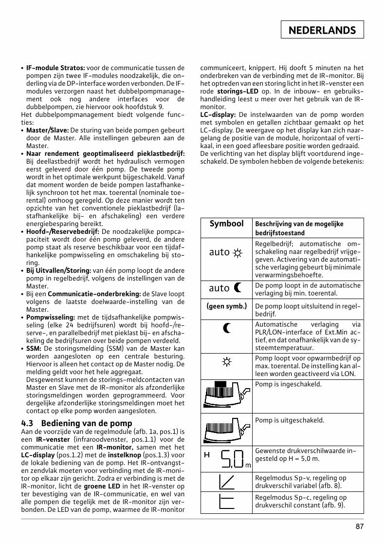
NEDERLANDS
87
x IF-module Stratos: voor de communicatie tussen depompen zijn twee IF-modules noodzakelijk, die on-derling via de DP-interface worden verbonden. De IF-modules verzorgen naast het dubbelpompmanage-ment ook nog andere interfaces voor dedubbelpompen, zie hiervoor ook hoofdstuk 9.
Het dubbelpompmanagement biedt volgende func-ties:x Master/Slave: De sturing van beide pompen gebeurt
door de Master. Alle instellingen gebeuren aan deMaster.
x Naar rendement geoptimaliseerd pieklastbedrijf:Bij deellastbedrijf wordt het hydraulisch vermogeneerst geleverd door één pomp. De tweede pompwordt in het optimale werkpunt bijgeschakeld. Vanafdat moment worden de beide pompen lastafhanke-lijk synchroon tot het max. toerental (nominale toe-rental) omhoog geregeld. Op deze manier wordt tenopzichte van het conventionele pieklastbedrijf (la-stafhankelijke bij- en afschakeling) een verdereenergiebesparing bereikt.
x Hoofd-/Reservebedrijf: De noodzakelijke pompca-paciteit wordt door één pomp geleverd, de anderepomp staat als reserve beschikbaar voor een tijdaf-hankelijke pompwisseling en omschakeling bij sto-ring.
x Bij Uitvallen/Storing: van één pomp loopt de anderepomp in regelbedrijf, volgens de instellingen van deMaster.
x Bij een Communicatie-onderbreking: de Slave looptvolgens de laatste doelwaarde-instelling van deMaster.
x Pompwisseling: met de tijdsafhankelijke pompwis-seling (elke 24 bedrijfsuren) wordt bij hoofd-/re-serve-, en parallelbedrijf met pieklast bij- en afscha-keling de bedrijfsuren over beide pompen verdeeld.
x SSM: De storingsmelding (SSM) van de Master kanworden aangesloten op een centrale besturing.Hiervoor is alleen het contact op de Master nodig. Demelding geldt voor het hele aggregaat.Desgewenst kunnen de storings-meldcontacten vanMaster en Slave met de IR-monitor als afzonderlijkestoringsmeldingen worden geprogrammeerd. Voordergelijke afzonderlijke storingsmeldingen moet hetcontact op elke pomp worden aangesloten.
4.3 Bediening van de pompAan de voorzijde van de regelmodule (afb. 1a, pos.1) iseen IR-venster (infraroodvenster, pos.1.1) voor decommunicatie met een IR-monitor, samen met hetLC-display (pos.1.2) met de instelknop (pos.1.3) voorde lokale bediening van de pomp. Het IR-ontvangst-en zendvlak moeten voor verbinding met de IR-moni-tor op elkaar zijn gericht. Zodra er verbinding is met deIR-monitor, licht de groene LED in het IR-venster opter bevestiging van de IR-communicatie, en wel vanalle pompen die tegelijk met de IR-monitor zijn ver-bonden. De LED van de pomp, waarmee de IR-monitor
communiceert, knippert. Hij dooft 5 minuten na hetonderbreken van de verbinding met de IR-monitor. Bijhet optreden van een storing licht in het IR-venster eenrode storings-LED op. In de inbouw- en gebruiks-handleiding leest u meer over het gebruik van de IR-monitor.LC-display: De instelwaarden van de pomp wordenmet symbolen en getallen zichtbaar gemaakt op hetLC-display. De weergave op het display kan zich naar-gelang de positie van de module, horizontaal of verti-kaal, in een goed afleesbare positie worden gedraaid.De verlichting van het display blijft voortdurend inge-schakeld. De symbolen hebben de volgende betekenis:
Symbool Beschrijving van de mogelijke bedrijfstoestand
autoRegelbedrijf; automatische om-schakeling naar regelbedrijf vrijge-geven. Activering van de automati-sche verlaging gebeurt bij minimaleverwarmingsbehoefte.
auto De pomp loopt in de automatischeverlaging bij min. toerental.
(geen symb.) De pomp loopt uitsluitend in regel-bedrijf.Automatische verlaging viaPLR/LON-interface of Ext.Min ac-tief, en dat onafhankelijk van de sy-steemtemperatuur.Pomp loopt voor opwarmbedrijf opmax. toerental. De instelling kan al-leen worden geactiveerd via LON.Pomp is ingeschakeld.
Pomp is uitgeschakeld.
Gewenste drukverschilwaarde in-gesteld op H = 5,0 m.
Regelmodus Sp-v, regeling opdrukverschil variabel (afb. 8).
Regelmodus Sp-c, regeling opdrukverschil constant (afb. 9).
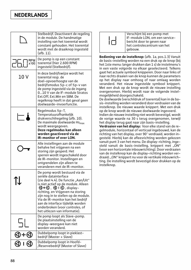
NEDERLANDS
88
Stelbedrijf. Deactiveert de regelingin de module. De handmatigeinstelling van het toerental wordt constant gehouden. Het toerental wordt met de draaiknop ingesteld (afb. 11).
De pomp is op een constanttoerental (hier 2.600 RPM) ingesteld (Stelbedrijf).
In deze bedrijfswijze wordt hettoerental resp. de 10 Vdoel-opvoerhoogte van debedrijfsmodus Sp-c of Sp-v vande pomp ingesteld via de ingang0...10 V van de IF-module StratosExt.Off, Ext.Min en SBM. Deregelknop heeft in dat geval geendoelwaarde-invoerfunctie.
Regelmodus Sp-T,Temperatuurafhankelijkdrukverschilregeling (afb. 10). De maximale doelwaarde Hsmaxwordt weergegeven. Deze regelmodus kan alleenworden geactiveerd via de IR-monitor of over LON.
Alle instellingen aan de modulebehalve het vrijgeven na eenstoring zijn gesperd. Het sperren wordt ingeschakeld doorde IR-monitor. Instellingen enontgrendelen zijn alleen teveranderen met de IR-monitor.
De pomp wordt bestuurd via deseriële datainterface (zie deel 4.4). De functie „Aan/Uit“is niet actief op de module. Alleen
, , display-richting, en Vrijgeven na storingzijn nog in te stellen op de module.Via de IR-monitor kan het bedrijfaan de interface tijdelijk wordenonderbroken (voor controles, ofhet uitlezen van informatie).De pomp loopt als Slave-pomp.De plaatsinstelling van de display-weergave kan niet worden veranderd.Dubbelpomp loopt in pieklast-bedrijf (Master + Slave)Dubbelpomp loopt in Hoofd-/Reservebedrijf (Master of Slave)
Bediening van de instelknop: (afb. 1a, pos.1.3) Vanuitde basis-instelling worden na een druk op de knop (bijhet 1ste menu: langer drukken dan 1 s) de instelmenu'sin een vaste volgorde na elkaar geselecteerd. Telkensgaat het actuele symbool knipperen. Door naar links ofnaar rechts draaien van de knop kunnen de parametersop het display naar omhoog of naar omlaag wordenveranderd. Het nieuw ingestelde symbool knippert.Met een druk op de knop wordt de nieuwe instellingovergenomen. Hierbij wordt naar de volgende instel-mogelijkheid doorgeschakeld.De doelwaarde (verschildruk of toerental) kan in de ba-sis-instelling worden veranderd door verdraaien van deinstelknop. De nieuwe waarde knippert. Met een drukop de knop wordt de nieuwe doelwaarde ingevoerd.Indien de nieuwe instelling niet wordt bevestigd, wordtde vorige waarde na 30 s terug overgenomen, terwijlhet display terug gaat naar zijn basis-instelling.Verdraaien van het display: Voor elke stand van de re-gelmodule, horizontaal of verticaal ingebouwd, kan derichting van het display, over 90° verdraaid, worden in-gesteld. Hierbij kan de afleesrichting worden gekozenvanuit punt 3 van het menu. De display-richting, inge-steld vanuit de basis-instelling, knippert met „ON“(voor een horizontale inbouwrichting). Door verdraaienvan de instelknop kan de display-richting worden ver-draaid; „ON“ knippert nu voor de vertikale inbouwrich-ting. De instelling wordt bevestigd door drukken op deinstelknop.
Verschijnt bij een pomp met IF-module LON, om een service-bericht door te geven naarhet controlecentrum van hetgebouw.
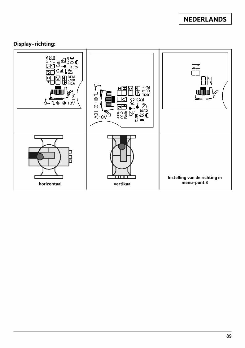
NEDERLANDS
89
Display-richting:
horizontaal vertikaalInstelling van de richting in
menu-punt 3
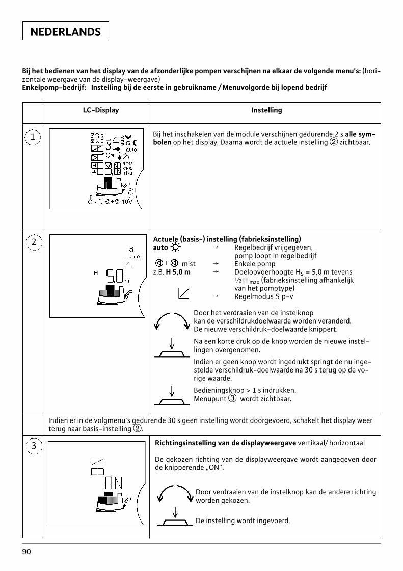
Actuele (basis-) instelling (fabrieksinstelling)auto f Regelbedrijf vrijgegeven,
pomp loopt in regelbedrijfmist f Enkele pomp
z.B. H 5,0 m f Doelopvoerhoogte Hs = 5,0 m tevens| H max (fabrieksinstelling afhankelijkvan het pomptype)
f Regelmodus S p-v
Door het verdraaien van de instelknopkan de verschildrukdoelwaarde worden veranderd.De nieuwe verschildruk-doelwaarde knippert.
Na een korte druk op de knop worden de nieuwe instel-lingen overgenomen.
Indien er geen knop wordt ingedrukt springt de nu inge-stelde verschildruk-doelwaarde na 30 s terug op de vo-rige waarde.
Bedieningsknop > 1 s indrukken.Menupunt e wordt zichtbaar.
NEDERLANDS
90
Bij het bedienen van het display van de afzonderlijke pompen verschijnen na elkaar de volgende menu's: (hori-zontale weergave van de display-weergave)Enkelpomp-bedrijf: Instelling bij de eerste in gebruikname / Menuvolgorde bij lopend bedrijf
1
LC-Display Instelling
Bij het inschakelen van de module verschijnen gedurende 2 s alle sym-bolen op het display. Daarna wordt de actuele instelling w zichtbaar.
2
3 Richtingsinstelling van de displayweergave vertikaal/ horizontaal
De gekozen richting van de displayweergave wordt aangegeven doorde knipperende „ON“.
Door verdraaien van de instelknop kan de andere richtingworden gekozen.
De instelling wordt ingevoerd.
Indien er in de volgmenu's gedurende 30 s geen instelling wordt doorgevoerd, schakelt het display weerterug naar basis-instelling w.
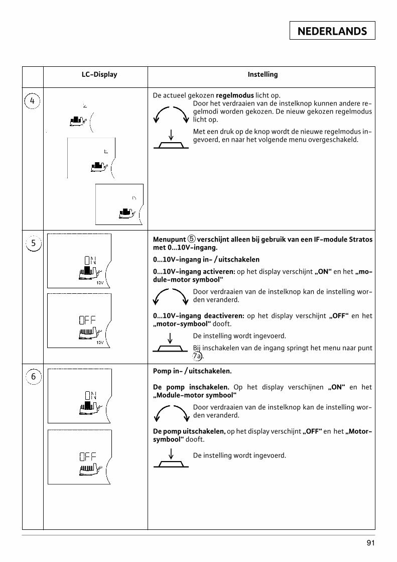
NEDERLANDS
91
4
LC-Display Instelling
5
6
De actueel gekozen regelmodus licht op.Door het verdraaien van de instelknop kunnen andere re-gelmodi worden gekozen. De nieuw gekozen regelmoduslicht op.
Met een druk op de knop wordt de nieuwe regelmodus in-gevoerd, en naar het volgende menu overgeschakeld.
Menupunt t verschijnt alleen bij gebruik van een IF-module Stratosmet 0...10V-ingang.
0...10V-ingang in- / uitschakelen
0...10V-ingang activeren: op het display verschijnt „ON“ en het „mo-dule-motor symbool“
Door verdraaien van de instelknop kan de instelling wor-den veranderd.
0...10V-ingang deactiveren: op het display verschijnt „OFF“ en het„motor-symbool“ dooft.
De instelling wordt ingevoerd.
Bij inschakelen van de ingang springt het menu naar punt7a .
Pomp in- / uitschakelen.
De pomp inschakelen. Op het display verschijnen „ON“ en het„Module-motor symbool“
Door verdraaien van de instelknop kan de instelling wor-den veranderd.
De pomp uitschakelen, op het display verschijnt „OFF“ en het „Motor-symbool“ dooft.
De instelling wordt ingevoerd.
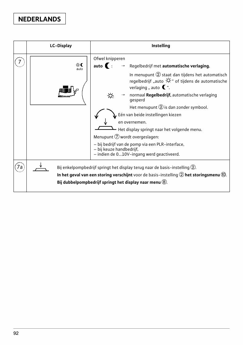
NEDERLANDS
92
7
7a
LC-Display Instelling
Ofwel knipperen
auto : f Regelbedrijf met automatische verlaging.
In menupunt w staat dan tijdens het automatischregelbedrijf „auto “ of tijdens de automatischeverlaging „ auto “.
: f normaal Regelbedrijf, automatische verlaginggesperd
Het menupunt w is dan zonder symbool.
Eén van beide instellingen kiezen
en overnemen.
Het display springt naar het volgende menu.
Menupunt u wordt overgeslagen:
– bij bedrijf van de pomp via een PLR-interface,– bij keuze handbedrijf,– indien de 0...10V-ingang werd geactiveerd.
Bij enkelpompbedrijf springt het display terug naar de basis-instelling w.
In het geval van een storing verschijnt voor de basis-instelling w het storingsmenu p.
Bij dubbelpompbedrijf springt het display naar menu i.
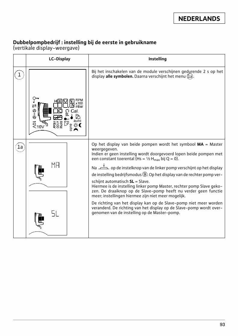
NEDERLANDS
93
1
LC-Display Instelling
1a
Bij het inschakelen van de module verschijnen gedurende 2 s op het display alle symbolen. Daarna verschijnt het menu 1a .
Op het display van beide pompen wordt het symbool MA = Masterweergegeven.Indien er geen instelling wordt doorgevoerd lopen beide pompen meteen constant toerental (Hs = | Hmax bij Q = 0).
Na op de instelknop van de linker pomp verschijnt op het display
de instelling bedrijfsmodus o. Op het display van de rechter pomp ver-
schijnt automatisch SL = Slave.Hiermee is de instelling linker pomp Master, rechter pomp Slave geko-zen. De draaiknop op de Slave-pomp heeft nu verder geen functiemeer; instellingen hiermee zijn niet meer mogelijk.
De richting van het display kan op de Slave-pomp niet meer wordenveranderd. De richting van het display op de Slave-pomp wordt over-genomen van de instelling op de Master-pomp.
Dubbelpompbedrijf : instelling bij de eerste in gebruikname (vertikale display-weergave)
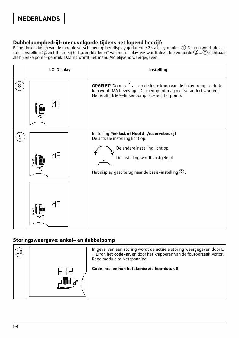
NEDERLANDS
94
8
LC-Display Instelling
9
OPGELET! Door op de instelknop van de linker pomp te druk-ken wordt MA bevestigd. Dit menupunt mag niet verandert worden. Het is altijd: MA=linker pomp, SL=rechter pomp.
Instelling Pieklast of Hoofd- /reservebedrijfDe actuele instelling licht op.
De andere instelling licht op.
De instelling wordt vastgelegd.
Het display gaat terug naar de basis-instelling w .
10 In geval van een storing wordt de actuele storing weergegeven door E= Error, het code-nr. en door het knipperen van de foutoorzaak Motor,Regelmodule of Netspanning.
Code-nrs. en hun betekenis: zie hoofdstuk 8
Storingsweergave: enkel- en dubbelpomp
Dubbelpompbedrijf: menuvolgorde tijdens het lopend bedrijf:Bij het inschakelen van de module verschijnen op het display gedurende 2 s alle symbolen q. Daarna wordt de ac-tuele instelling w zichtbaar. Bij het „doorbladeren“ van het display MA wordt dezelfde volgorde w ...u zichtbaarals bij enkelpomp-gebruik. Daarna wordt het menu MA blijvend weergegeven.
NEDERLANDS
95
4.4 Prioriteiten bij de bediening van depomp, LON, PLR, IR-monitor
De weergave van storingen (menu 10) incl. het vrijge-ven van storingen heeft de hoogste prioriteit. Dit bete-kent dat storingen met voorrang op het display van depomp verschijnen en verholpen resp. vrijgegeven moe-ten worden.Als de instellingen vanaf de regelmodule of vanaf de IR-monitor worden doorgevoerd, en ze niet worden beve-stigd met een druk op de knop, springt de instelling 30 sna de laatste invoer terug naar de vorige toestand.x Pomp m–n LON: De pomp wordt gestuurd via het
LON-netwerk van de gebouw-automatisering (GBS).Op het display verschijnt . Bediening aan de pompis niet mogelijk. Uitzondering , , in-stelling displaypositie en vrijgave na storing.
x Pomp m–n PLR: Bij het ontvangen van een stuursig-naal vanaf de gebouw-automatisering (GBS) schakeltde pomp automatisch over op PLR-bedrijf. Op het di-splay verschijnt . Bovendien wordt automatischgekozen voor de regelmodus Sp-c ( ). Bedieningaan de pomp is niet mogelijk. Uitzondering ,
, instelling displaypositie en vrijgave na sto-ring.
x Pomp m–n PLR/LON m–n IR: Bij deze configuratiegeeft de pomp voorrang aan de instellingen via deinterface. Met de IR-monitor kan de verbinding overde interface tijdelijk worden onderbroken. Hiernakunnen de instellingen via de IR-monitor of lokaalaan de regelmodule worden doorgevoerd. 5 min na delaatste instelling door de IR-monitor wordt de ver-binding terug over de interface geleid. Zolang de on-derbreking duurt verdwijnt de op het display.
x Pomp m–n IR zonder key-functie: de laatste instel-ling, of ze nu kwam van de IR-monitor of van de re-gelmodule, wordt door de pomp overgenomen.
x Pomp m–n IR met key-functie: Na ontvangst van hetsignaal „Key Function on“ blijven de actuele instellin-gen van de regelmodule behouden. Op het displayverschijnt „ .“ Bediening aan de pomp is nietmogelijk. Uitzondering: vrijgave na een storing.
4.5 Leveringomvangx pomp compleet (met 2 pakkingen bij schroefdraad-
aansluiting)x tweedelige warmte-isolatie, (alleen bij enkele pom-
pen afb. 1a, pos.3)x Materiaal: EPP, geschuimd polypropyleenx Warmtegeleiding: 0,04 W/m volgens DIN 52612x Brandbaarheid: Klasse B2 volgens DIN 4102,
FMVSS 302x Ringen (voor flensaansluitingen bij combi-flen-
saansluiting DN32-DN65)x Onderhouds- en bedieningsvoorschrift
4.6 Toebehorenx IF-module Stratos PLR, LON, Ext.Off, Ext.Min.,SBMx IR-monitor
5 Montage/InbouwInbouw en in gebruik nemen alleendoor vakpersoneel
5.1 Montage van de pompx De pomp moet worden opgesteld in een droog, goed
geventileerde en vorstvrije ruimte.x De pomp mag pas worden ingebouwd na het voltoo-
ien van alle las- en soldeerwerkzaamheden, en heteventueel noodzakelijke spoelen van het leidingstel-sel. Vuil kan de pomp onklaar maken.
x De inbouw van afsluitkranen voor en achter de pompis aanbevolen. Hiermee is het mogelijk de pompeventueel uit te wisselen zonder de hele installatie afte tappen en terug te vullen.
x Bij inbouw in open installaties dient de veiligheids-voorloop (open expansievat) in de toevoerleidingnaar de pomp op het leidingstel te worden aanges-loten.
x Zorg voor een spanningsvrije montage. De leidingenzodanig bevestigen dat het gewicht niet op de pomprust.
x Voor het inbouwen van de afzonderlijke pompen zijnde beide halve schalen van de warmte-isolatie (afb. 5,pos.1) weg te nemen.
x De stromingsrichting van het medium moet overeen-komen met de richtingsdriehoek op het pomphuis(afb. 1a, pos.2).
x Alleen inbouwposities volgens afb. 2 zijn toegelaten.De as van de pomp moet horizontaal liggen.Afb. 2a: toegelaten inbouwposities voor enkele pom-penAfb. 2b: toegelaten inbouwposities voor dubbelepompenBij krappe inbouw-omstandigheden, bijvoorbeeld incompacte verdelers, kan de regelmodule door ver-draaien van de motor in een vertikale positie wordengebracht, zie hoofdstuk 5.1.2. Dubbelpompen wor-den geleverd met vertikaal gemonteerde regelmodu-les.
x De pomp monteren op een goed toengankelijkeplaats, zodat onderhoudswerkzaamheden later mo-gelijk zijn.De montage zodanig uitvoeren dat er geen water opde pompmotor resp. de klemmenkast kan druppelen.x Bij montage van pompen met combiflens PN6/10
(flenspompen tot en met DN 65) moet worden ge-let op volgende richtlijnen (afb. 3):1. De montage van een combi-flens op een combi-
flens is niet toegestaan.2. Tussen de schroef-/moerkop en de combi-flens
moeten absoluut de meegeleverde ringen (afb.3, pos.1) worden gebruikt.
OPGELET!
NEDERLANDS
96
Borgringen (veerringen bvb) zijn niettoegestaan.Bij foutieve montage kande schroefmoer zich in het slobgat ha-ken. Hierdoor kan de functionaliteitvan de flensverbinding, door een on-voldoende voorspanning van deschroeven, worden beïnvloed.
3. We adviseren het gebruik van schroeven voorflensverbindingen met een kwaliteitsklasse van4.6. Bij gebruik van schroeven uit een ander ma-teriaal dan 4.6 (vb. Schroeven uit materiaal 5.6 ofnog harder) mag voor de montage alleen het toe-gelaten schroeven-aanspanmoment overeen-komstig materiaal 4.6 worden gebruikt.Toegelaten schroef-aanspanmomenten:
bij M 12 f 40 Nm,bij M 16 f 95 Nm
Indien hardere schroeven (G4.6) afwij-kend van de aanspanmomenten aan-gespannen, dan kunnen er door dehogere schroef-voorspanningensplinters optreden aan de rand van deslobgaten. Hierdoor verliezen deschroeven hun voorspanning, en kande flensverbinding haar dichtheid ver-liezen.
4. Er moeten schroeven van voldoende lengte wor-den gebruikt:
OPGELET!
OPGELET! x Afdichtingsstoppen met geschikt gereedschap ver-wijderen, beschadiging van de stoppen vermijden(pos.3),
x 2 imbus-schroeven M5 (SW4) lossen (pos.4),x De regelmodule van de motor afnemen (pos.5),x Terug monteren in omgekeerde volgorde.
Bij generatorisch gebruik van de pomp(aandrijving van de pomp door een voor-drukpomp) ontstaat aan de motorklem-men na het afnemen van de regelmoduleeen gevaarlijke spanning. De motorklem-men zijn VDE-conform uitgevoerd, zodatgevaar door aanraking is uitgesloten. Meteen spits voorwerp (nagel, schroevendra-aier, draad), die in een bus wordt gestoken,kan nochtans nog altijd een gevaarlijke si-tuatie ontstaan.
Voor een eenvoudige montage bevinden zich op derugzijde van de regelmodule 2 resp. 3 (afhankelijk vanpomptype) geleidingsstiften, die in overeenkomstigeboringen van de motorbehuizing vallen. Pas zodra dezegeleidingsstiften de regelmodule veilig aan het motor-huis bevestigen, maakt de centrale aardingsstift con-tact, en pas daarna maken de wikkelingspennen con-tact (afb. 4).
Tusen motorhuis en regelmodule be-vindt zich een vlakke-pakking (afb. 4,pos.6), die zorg draagt voor de thermi-sche ontkoppeling van beide compo-nenten. Deze pakking moet absoluuttussen module en motor worden ge-plaatst bij de montage van de regel-module.
5.1.2 Demontage/ montage van hetinsteekdeel
Om de motor los te maken moeten er 4 M6 (SW5) im-busschroeven worden gelost. Deze schroeven zijn tebereiken met volgende gereedschappen (afb. 5, pos.2):x Zeskant imbus hoek-schroevendraaierx Zeskant imbus kogel-schroevendraaierx [-duims ratel met passende bitOm alleen de regelmodule naar een andere positie tebrengen hoeft de motor niet volledig uit het pomphuiste worden genomen. De motor kan gelost in het pom-phuis in de gewenste positie worden gedraaid.
De O-ring, tussen de motor en hetpomphuis, niet beschadigen. De O-ring mag niet-verdraaien en moetgoed op het contactvlak liggen.De as is vast met de waaier, het lager-schild en de rotor verbonden. Dezeeenheid is beveiligd tegen onopzette-lijk uittrekken uit de motor. Indien derotor met zijn sterke magneten niet inde motorbehuizing steekt, betekenthij een duidelijk gevaar bvb. door het
OPGELET!
OPGELET!
OPGELET!
Draad min. Schroeflengte
DN 32 / DN 50 /DN 40 DN 65
FlensaanslutningPN6 M12 55 mm 60 mm
FlensaanslutningPN10 M16 60 mm 65 mm
Bij de montage van flensringen moetworden gelet op een voldoende lengtevan de schroeven. De draad van deschroeven moet minstens één om-wenteling uit de schroefmoer steken(afb. 3, pos.2).
x De beide halve schalen van de thermische isolatie vande afzonderlijke pompen aanbrengen en samendruk-ken, zodat de geleidingsstiften in hun overeenkom-stige, daar tegenover liggende boringen vallen.
5.1.1 Demontage/ montage van deregelmodule
De regelmodule kan door het lossen van 2 schroevenworden gescheiden van de motor (afb. 4):x Schroeven in het deksel van aansluitkastje lossen
(pos.1),x Deksel van het aansluitkastje afnemen (pos.2),
OPGELET!
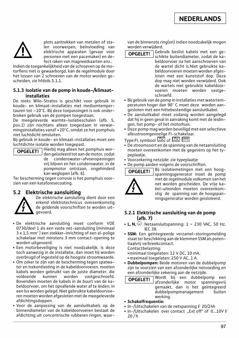
NEDERLANDS
97
plots aantrekken van metalen of sta-len voorwerpen, beïnvloeding vanelektrische apparaten (gevaar voorpersonen met een pacemaker) en de-fect raken van magneetkaarten enz..
Indien de toegankelijkheid van de schroeven op de mo-torflens niet is gewaarborgd, kan de regelmodule doorhet lossen van 2 schroeven van de motor worden ge-scheiden, zie hfdstk.5.1.1.
5.1.3 Isolatie van de pomp in koude-/klimaat-installaties
De reeks Wilo-Stratos is geschikt voor gebruik inkoude- en klimaat-installaties met mediumtemper-tauren tot –10°C. Bij deze toepassingen is ook onder-broken gebruik van de pompen toegestaan.De meegeleverde warmte-isolatieschalen (afb. 5,pos.1) zijn nochtans alleen toegestaan in verwar-mingsinstallaties vanaf +20°C, omdat ze het pomphuisniet luchtdicht omsluiten.Bij gebruik in koude- en klimaat-installaties moet eenluchtdichte isolatie worden toegepast.
Hierbij mag alleen het pomphuis wor-den geïsoleerd tot aan de motor, zodatde condenswater-afvoeropeningenvrij blijven en het condenswater, in depompmotor ontstaan, ongehinderdkan weglopen (afb. 6).
Ter bescherming tegen corrosie is het pomphuis voor-zien van een kataforesecoating.
5.2 Elektrische aansluitingDe elektrische aansluiting dient door eenerkend elektrotechnicus overeenkomstigde geldende voorschriften te worden uit-gevoerd.
x De elektrische aansluiting moet conform VDE0730/deel 1 als een vaste net-aansluiting (minimaal3 x 1,5 mm2 ) een stekker-inrichting of een al-poligeschakelaar met minstens 3 mm contact-opening teworden uitgevoerd.
x Een motorbeveiliging is niet noodzakelijk. Is dezetoch aanwezig in de installatie, dan moet hij wordenoverbrugd of ingesteld op de hoogste stroomwaarde.
x Om zeker te zijn van de bescherming tegen spatwa-ter en trekontlasting in de kabeldoorvoeren, moetenkabels worden gebruikt van de juiste diameter, dievoldoende kunnen worden vastgeschroefd.Bovendien moeten de kabels in de buurt van de ka-beldoorvoer, om het opvallende water af te leiden, ineen lus worden gelegd. Niet gebruikte kabeldoorvoe-ren moeten worden afgesloten met de meegeleverdeafdichtingsdoppen.
x Voor de aanpassing van de aansluitkabels op debinnendiameter van de kabeldoorvoeren bestaat deafdichting uit concentrische rubberen ringen, waar-
OPGELET!
van de binnenste ring(en) indien noodzakelijk mogenworden verwijderd.
Gebruik beslist kabels met een ge-schikte buitendiameter, zodat de ka-beldoorvoer na het aanschroeven vande wartel dicht is.Niet gebruikte ka-beldoorvoeren moeten worden afges-loten met een kunststof dop. Dezedop mag niet worden verwijderd. Ookde wartels niet gebruikte kabeldoor-voeren moeten worden vastge-schroefd.
x Bij gebruik van de pomp in installaties met watertem-peraturen hoger dan 90° C moet deze worden aan-gesloten met een hittebestendige aansluitkabel.
x De aansluitkabel moet zodanig worden aangelegddat hij in geen geval in aanraking komt met de leidin-gen, het pomp- of het motorhuis.
x Deze pomp mag worden beveiligd met een selectieveallesstroomgevoelige FI-schakelaar.
Type:FI, symbool of x De stroomsoort en de spanning van de netaansluiting
moeten overeenkomen met de gegevens op het ty-peplaatje,
x Voorzekering netzijde: zie typeplaatjex De pomp aarden volgens de voorschriften.
Bij isolatiemetingen met een hoog-spanningsgenerator moet de pompmet de regelmodule volkomen van hetnet worden gescheiden. De vrije ka-bel-uiteinden moeten overeenkom-stig de spanning van de hoogspan-ningsgenerator worden geisloleerd.
5.2.1 Elektrische aansluiting van de pomp(afb. 7)
x L, N, : Netaansluitspanning: 1 ~ 230 VAC, 50 Hz,IEC 38.
x SSM: Een geïntegreerde verzamel-storingsmeldingstaat ter beschikking aan de klemmen SSM als poten-tiaalvrij verbreekcontact.Contactbelasting:x minimaal toegelaten: 12 V DC, 10 mA,x maximaal toegelaten: 250 V AC, 1 A.
x Dubbelpompen: Beide motoren van de dubbelpompzijn te voorzien van een afzonderlijke netvoeding eneen afzonderlijke zekering aan de netzijde.
Wordt bij een dubbelpomp een afzonderlijke motor spanningsvrij gemaakt, dan is het geïntegreerd dubbelpompmanagement buitenwerking.
x Schakelfrequentie:x In-/Uitschakelen van de netspanning F 20/24hx In-/Uitschakelen over contact „Ext off“ of 0...10V F
20 / h
OPGELET!
OPGELET!
OPGELET!
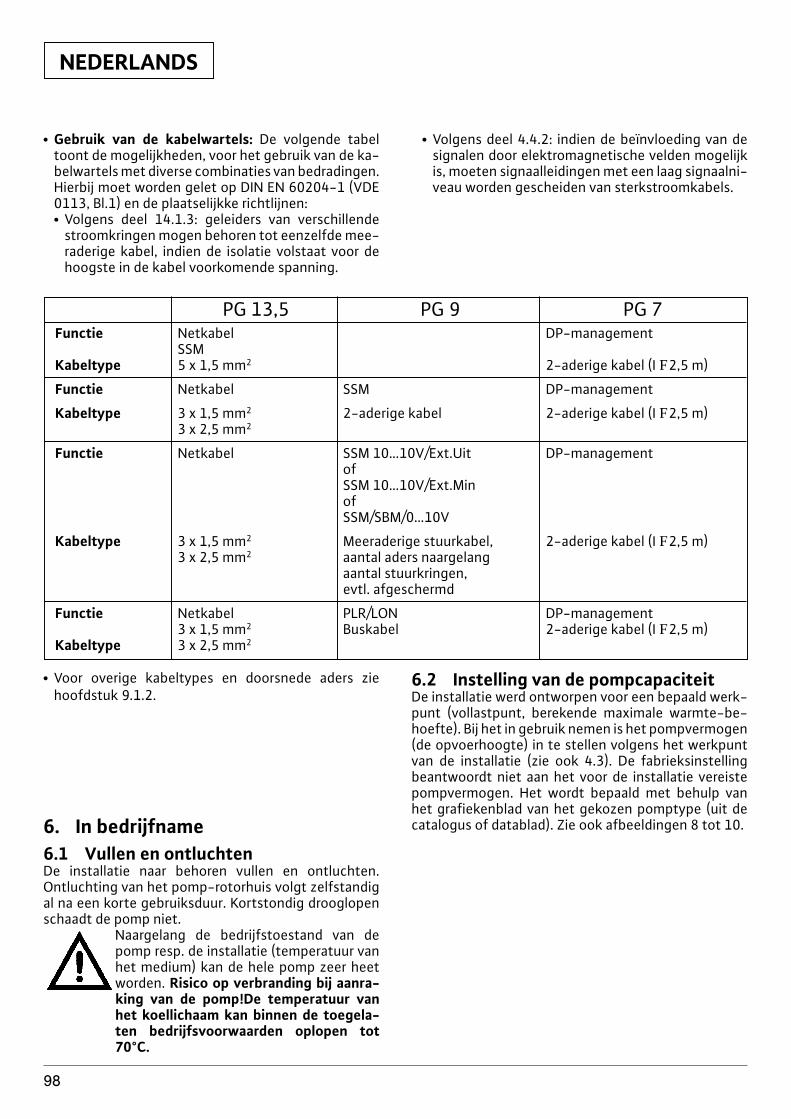
NEDERLANDS
98
x Gebruik van de kabelwartels: De volgende tabeltoont de mogelijkheden, voor het gebruik van de ka-belwartels met diverse combinaties van bedradingen.Hierbij moet worden gelet op DIN EN 60204-1 (VDE0113, Bl.1) en de plaatselijkke richtlijnen:x Volgens deel 14.1.3: geleiders van verschillende
stroomkringen mogen behoren tot eenzelfde mee-raderige kabel, indien de isolatie volstaat voor dehoogste in de kabel voorkomende spanning.
x Volgens deel 4.4.2: indien de beïnvloeding van designalen door elektromagnetische velden mogelijkis, moeten signaalleidingen met een laag signaalni-veau worden gescheiden van sterkstroomkabels.
PG 13,5 PG 9 PG 7Functie Netkabel DP-management
SSMKabeltype 5 x 1,5 mm2 2-aderige kabel (I F2,5 m)
Functie Netkabel SSM DP-management
Kabeltype 3 x 1,5 mm2 2-aderige kabel 2-aderige kabel (I F2,5 m)3 x 2,5 mm2
Functie Netkabel SSM 10…10V/Ext.Uit DP-managementofSSM 10…10V/Ext.MinofSSM/SBM/0…10V
Kabeltype 3 x 1,5 mm2 Meeraderige stuurkabel, 2-aderige kabel (I F2,5 m)3 x 2,5 mm2 aantal aders naargelang
aantal stuurkringen,evtl. afgeschermd
Functie Netkabel PLR/LON DP-management3 x 1,5 mm2 Buskabel 2-aderige kabel (I F2,5 m)
Kabeltype 3 x 2,5 mm2
x Voor overige kabeltypes en doorsnede aders ziehoofdstuk 9.1.2.
6. In bedrijfname6.1 Vullen en ontluchtenDe installatie naar behoren vullen en ontluchten.Ontluchting van het pomp-rotorhuis volgt zelfstandigal na een korte gebruiksduur. Kortstondig drooglopenschaadt de pomp niet.
Naargelang de bedrijfstoestand van depomp resp. de installatie (temperatuur vanhet medium) kan de hele pomp zeer heetworden. Risico op verbranding bij aanra-king van de pomp!De temperatuur vanhet koellichaam kan binnen de toegela-ten bedrijfsvoorwaarden oplopen tot70°C.
6.2 Instelling van de pompcapaciteitDe installatie werd ontworpen voor een bepaald werk-punt (vollastpunt, berekende maximale warmte-be-hoefte). Bij het in gebruik nemen is het pompvermogen(de opvoerhoogte) in te stellen volgens het werkpuntvan de installatie (zie ook 4.3). De fabrieksinstellingbeantwoordt niet aan het voor de installatie vereistepompvermogen. Het wordt bepaald met behulp vanhet grafiekenblad van het gekozen pomptype (uit decatalogus of datablad). Zie ook afbeeldingen 8 tot 10.
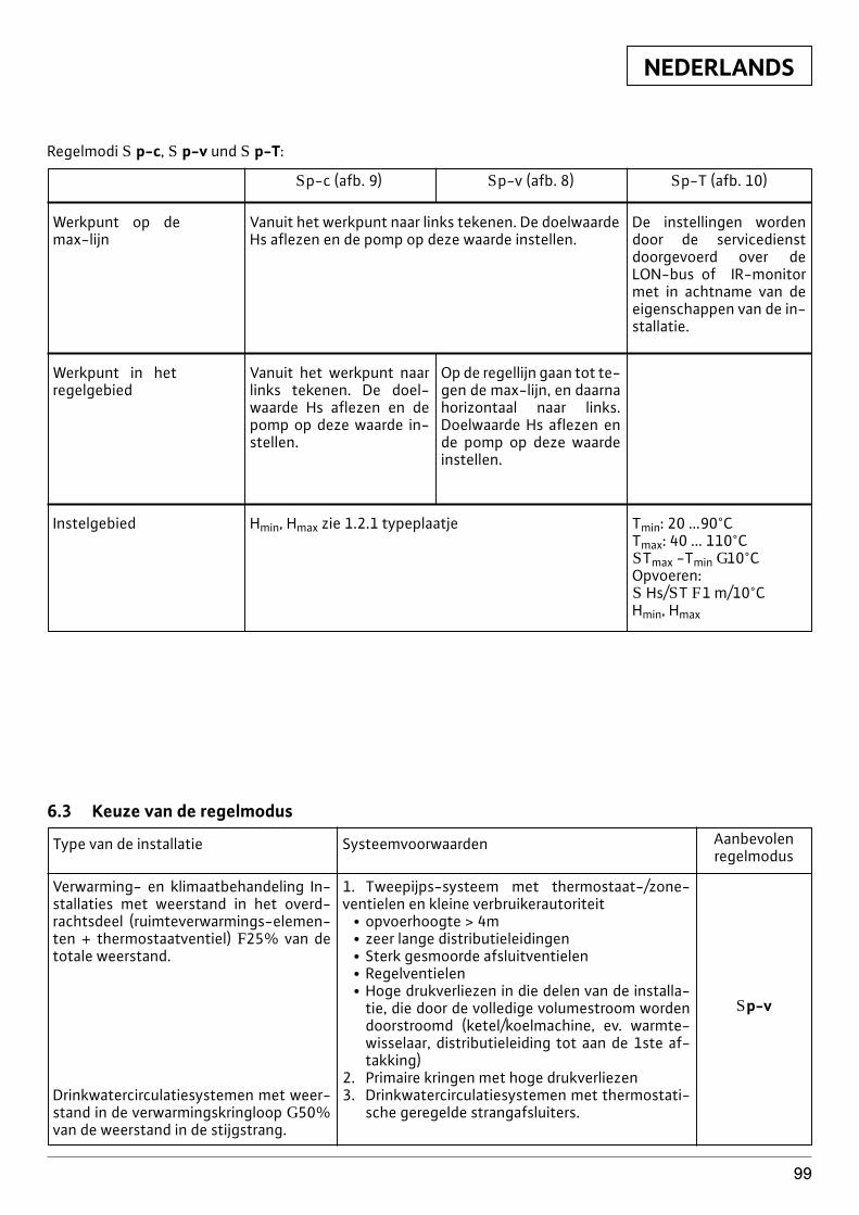
NEDERLANDS
99
Regelmodi S p-c, S p-v und S p-T:
Werkpunt op demax-lijn
Vanuit het werkpunt naar links tekenen. De doelwaardeHs aflezen en de pomp op deze waarde instellen.
De instellingen wordendoor de servicedienstdoorgevoerd over deLON-bus of IR-monitormet in achtname van deeigenschappen van de in-stallatie.
Instelgebied Hmin, Hmax zie 1.2.1 typeplaatje Tmin: 20 ...90°CTmax: 40 ... 110°CSTmax -Tmin G10°COpvoeren:S Hs/ST F1 m/10°CHmin, Hmax
Werkpunt in hetregelgebied
Vanuit het werkpunt naarlinks tekenen. De doel-waarde Hs aflezen en depomp op deze waarde in-stellen.
Op de regellijn gaan tot te-gen de max-lijn, en daarna horizontaal naar links.Doelwaarde Hs aflezen ende pomp op deze waardeinstellen.
Sp-c (afb. 9) Sp-v (afb. 8) Sp-T (afb. 10)
6.3 Keuze van de regelmodus
Verwarming- en klimaatbehandeling In-stallaties met weerstand in het overd-rachtsdeel (ruimteverwarmings-elemen-ten + thermostaatventiel) F25% van detotale weerstand.
Drinkwatercirculatiesystemen met weer-stand in de verwarmingskringloop G 50%van de weerstand in de stijgstrang.
Type van de installatie Systeemvoorwaarden Aanbevolenregelmodus
1. Tweepijps-systeem met thermostaat-/zone-ventielen en kleine verbruikerautoriteit
x opvoerhoogte > 4mx zeer lange distributieleidingenx Sterk gesmoorde afsluitventielenx Regelventielenx Hoge drukverliezen in die delen van de installa-
tie, die door de volledige volumestroom wordendoorstroomd (ketel/koelmachine, ev. warmte-wisselaar, distributieleiding tot aan de 1ste af-takking)
2. Primaire kringen met hoge drukverliezen3. Drinkwatercirculatiesystemen met thermostati-
sche geregelde strangafsluiters.
Sp-v
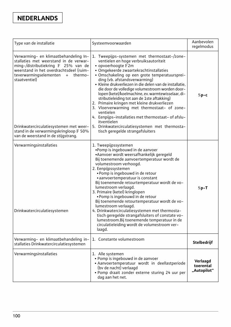
NEDERLANDS
100
Type van de installatie Systeemvoorwaarden Aanbevolenregelmodus
Verwarming- en klimaatbehandeling In-stallaties met weerstand in de verwar-ming-/distributiekring F 25% van deweerstand in het overdrachtsdeel (ruim-teverwarmingselementen + thermo-staatventiel)
Drinkwatercirculatiesystemen met weer-stand in de verwarmingskringloop F 50%van de weerstand in de stijgstrang.
1. Tweepijps-systemen met thermostaat-/zone-ventielen en hoge verbruiksautoriteit
x opvoerhoogte F2mx Omgekeerde zwaartekrachtinstallatiesx Omschakeling op een grote temperatuursprei-
ding (vb. afstandsverwarming)x Kleine drukverliezen in die delen van de installatie,
die door de volledige volumestroom worden door-lopen (ketel/koelmachine, ev. warmtewisselaar, di-stributieleiding tot aan de 1ste aftakking)
2. Primaire kringen met kleine drukverliezen3. Vloerverwarming met thermostaat- of zone-
ventielen4. Eenpijps-installaties met thermostaat- of afslu-
itventielen5. Drinkwatercirculatiesystemen met thermosta-
tisch geregelde strangafsluiters
Sp-c
Verwarmingsinstallaties
Drinkwatercirculatiesystemen
1. Tweepijpssystemenx Pomp is ingebouwd in de aanvoerx Aanvoer wordt weersafhankelijk geregeldBij toenemende aanvoertemperatuur wordt devolumestroom verhoogd.
2. Eenpijpssystemenx Pomp is ingebouwd in de retourx aanvoertemperatuur is constant
Bij toenemende retourtemperatuur wordt de vo-lumestroom verlaagd.
3. Primaire (ketel) kringlopenx Pomp is ingebouwd in de retour
Bij toenemende retourtemperatuur wordt de vo-lumestroom verlaagd.
4. Drinkwatercirculatiesystemen met thermosta-tisch geregelde strangafsluiters of constate vo-lumestroom.Bij toenemende temperatuur in decirculatieleiding wordt de volumestroom ver-laagd.
Sp-T
Verwarming- en klimaatbehandeling in-stallaties Drinkwatercirculatiesystemen
1. Constante volumestroom
Verwarmingsinstallaties 1. Alle systemenx Pomp is ingebouwd in de aanvoerx Aanvoertemperatuur wordt in deellastperiode
(bv de nacht) verlaagdx Pomp draait zonder externe sturing 24 uur per
dag aan het net.
Stelbedrijf
Verlaagdtoerental
„Autopilot“
NEDERLANDS
101
7 Onderhoud/serviceVoor alle onderhouds- of reparatiewerk-zaamheden de installatie spanningsvrijmaken en beveiligen tegen onbevoegd te-rug inschakelen.
Bij hoge watertemperaturen en systeem-drukken de pomp vooraf laten afkoelen.Gevaar voor verbranding!
Indien bij onderhouds- of reparatie-werkzaamheden de motorkop van hetpomphuis wordt gescheiden, moet deO-ring, die zich bevindt tussen mo-torkop en pomphuis, worden vervan-gen door een nieuwe. Bij de montagevan de motorkop moet worden geletop een correcte plaatsing van de O-ring
8 Storingen, oorzaken en oplossingen
Voor Storingen, oorzaken en oplossingen zie overzicht„Storing-/Waarschuwingsmelding“ in Tabel I.De eerste kolom van de tabel geeft de codenummersen de tweede kolom de foutoorzaak aan, die het di-splay weergeeft in het geval van een storing. De weergaves van de meeste storingen verdwijnenautomatisch,zodra de storingsoorzaak is opgeheven.
8.1 StoringsmeldingenIndien zich een storing voordoet, wordt de pomp uit-geschakeld. De storings-LED (continu rood licht) lichtop. Na een wachttijd van 5 minuten schakelt de pompautomatisch terug in. Als dezelfde storing zich 6 maalbinnen 24 uur voordoet wordt de pomp blijvend uitge-schakeld. Het SSM-contact wordt geopend en deinterface PLR of LON geven de storingsmelding door.De storing moet daarop worden gereset met de hand.
Uitzondering: Bij de code-nrs. „E10“en „E25“ schakelt de installatie me-teen bij het eerste optreden uit.
8.2 WaarschuwingsmeldingenDe storing (alleen een waarschuwing) wordt weliswaarweergegeven, maar de storings-LED en het SSM-relaisspreken niet aan. De pomp loopt verder, de storing kanwillekeurig vaak optreden. De gemelde waarschuwin-gen mogen niet over een langere tijdsduur optreden.De oorzaak dient te worden verholpen.
Uitzondering: indien de gemeldewaarschuwingen „E04“ en „E05“ lan-ger dan 5 minuten voorkomen, wor-den ze als storingsmeldingen (zie sto-ringsoverzicht) doorgegeven.
OPGELET!
OPGELET!
OPGELET!
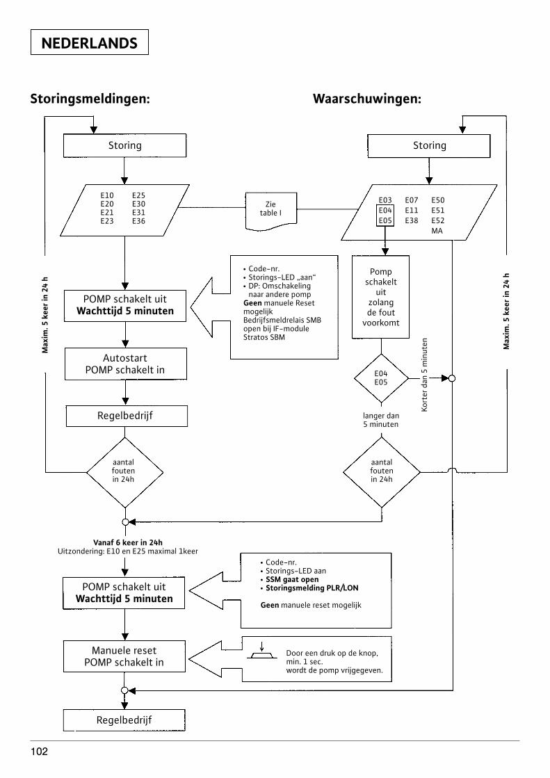
NEDERLANDS
102
E10 E25E20 E30E21 E31E23 E36
Storing
POMP schakelt uitWachttijd 5 minuten
AutostartPOMP schakelt in
Regelbedrijf
POMP schakelt uitWachttijd 5 minuten
Vanaf 6 keer in 24hUitzondering: E10 en E25 maximal 1keer
Manuele resetPOMP schakelt in
Regelbedrijf
Storing
Zietable I
E03 E07 E50E04 E11 E51E05 E38 E52
MA
Pompschakelt
uitzolangde fout
voorkomt
E04E05
langer dan5 minuten
aantalfoutenin 24h
aantalfoutenin 24h
Kort
er d
an 5
min
uten Max
im. 5
kee
r in
24 h
Max
im. 5
kee
r in
24 h
x Code-nr.x Storings-LED „aan“x DP: Omschakeling
naar andere pompGeen manuele ResetmogelijkBedrijfsmeldrelais SMBopen bij IF-moduleStratos SBM
x Code-nr.x Storings-LED aanx SSM gaat openx Storingsmelding PLR/LON
Geen manuele reset mogelijk
Door een druk op de knop,min. 1 sec.wordt de pomp vrijgegeven.
Storingsmeldingen: Waarschuwingen:
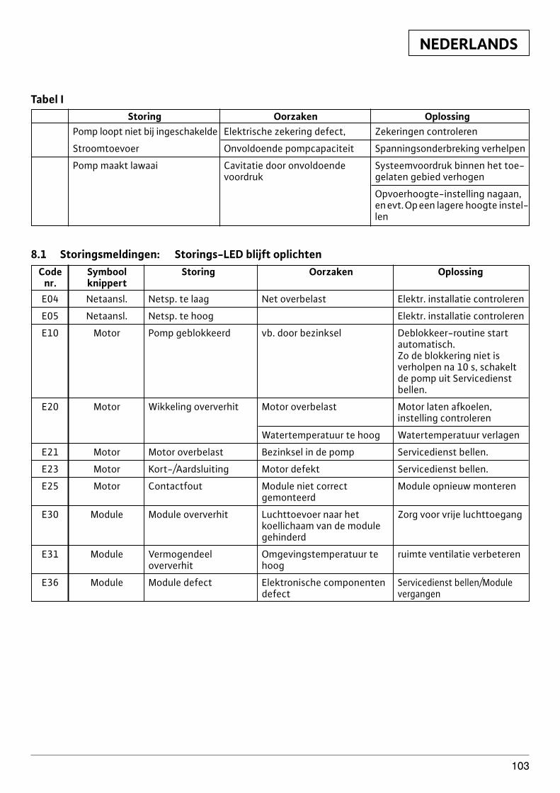
NEDERLANDS
103
Tabel IStoring Oorzaken Oplossing
Pomp loopt niet bij ingeschakelde Elektrische zekering defect, Zekeringen controleren
Stroomtoevoer Onvoldoende pompcapaciteit Spanningsonderbreking verhelpen
Pomp maakt lawaai Cavitatie door onvoldoende Systeemvoordruk binnen het toe-voordruk gelaten gebied verhogen
Opvoerhoogte-instelling nagaan,en evt. Op een lagere hoogte instel-len
8.1 Storingsmeldingen: Storings-LED blijft oplichtenCode Symbool Storing Oorzaken Oplossing
nr. knippertE04 Netaansl. Netsp. te laag Net overbelast Elektr. installatie controleren
E05 Netaansl. Netsp. te hoog Elektr. installatie controleren
E10 Motor Pomp geblokkeerd vb. door bezinksel Deblokkeer-routine start automatisch.Zo de blokkering niet is verholpen na 10 s, schakelt de pomp uit Servicedienstbellen.
E20 Motor Wikkeling oververhit Motor overbelast Motor laten afkoelen, instelling controleren
Watertemperatuur te hoog Watertemperatuur verlagen
E21 Motor Motor overbelast Bezinksel in de pomp Servicedienst bellen.
E23 Motor Kort-/Aardsluiting Motor defekt Servicedienst bellen.
E25 Motor Contactfout Module niet correct Module opnieuw monterengemonteerd
E30 Module Module oververhit Luchttoevoer naar het Zorg voor vrije luchttoegangkoellichaam van de module gehinderd
E31 Module Vermogendeel Omgevingstemperatuur te ruimte ventilatie verbeterenoververhit hoog
E36 Module Module defect Elektronische componenten Servicedienst bellen/Moduledefect vergangen
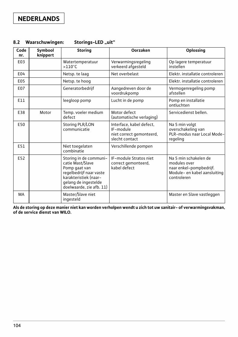
NEDERLANDS
104
8.2 Waarschuwingen: Storings-LED „uit“
Code Symbool Storing Oorzaken Oplossingnr. knippert
E03 Watertemperatuur Verwarmingsregeling Op lagere temperatuur >110°C verkeerd afgesteld instellen
E04 Netsp. te laag Net overbelast Elektr. installatie controleren
E05 Netsp. te hoog Elektr. installatie controleren
E07 Generatorbedrijf Aangedreven door de Vermogenregeling pompvoordrukpomp afstellen
E11 leegloop pomp Lucht in de pomp Pomp en installatie ontluchten
E38 Motor Temp. voeler medium Motor defect Servicedienst bellen.defect (automatische verlaging)
E50 Storing PLR/LON Interface, kabel defect, Na 5 min volgt communicatie IF-module overschakeling van
niet correct gemonteerd, PLR-modus naar Local Mode-slecht contact regeling
E51 Niet toegelaten Verschillende pompencombinatie
E52 Storing in de communi- IF-module Stratos niet Na 5 min schakelen de catie Mast/Slave correct gemonteerd, modules overPomp gaat van kabel defect naar enkel-pompbedrijf.regelbedrijf naar vaste Module- en kabel aansluitingkarakteristiek (naar- controlerengelang de ingesteldedoelwaarde, zie afb. 11)
MA Master/Slave niet Master en Slave vastleggeningesteld
Als de storing op deze manier niet kan worden verholpen wendt u zich tot uw sanitair- of verwarmingsvakman,of de service dienst van WILO.
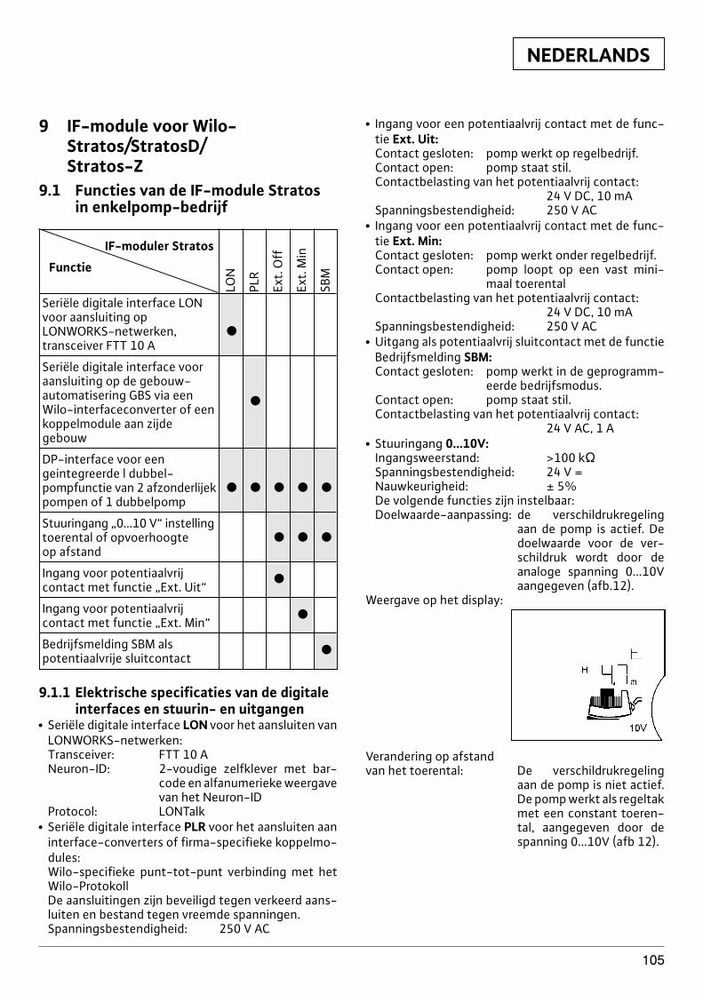
NEDERLANDS
105
9 IF-module voor Wilo-Stratos/StratosD/Stratos-Z
9.1 Functies van de IF-module Stratosin enkelpomp-bedrijf
IF-moduler Stratos
Functie
Seriële digitale interface LONvoor aansluiting op LONWORKS-netwerken, xtransceiver FTT 10 A
Seriële digitale interface voor aansluiting op de gebouw-automatisering GBS via een xWilo-interfaceconverter of eenkoppelmodule aan zijde gebouw
DP-interface voor een geintegreerde l dubbel-pompfunctie van 2 afzonderlijek x x x x xpompen of 1 dubbelpomp
Stuuringang „0...10 V“ instellingtoerental of opvoerhoogte x x xop afstand
Ingang voor potentiaalvrij xcontact met functie „Ext. Uit“
Ingang voor potentiaalvrij xcontact met functie „Ext. Min“
Bedrijfsmelding SBM als xpotentiaalvrije sluitcontact
LON
PLR
Ext.
Off
Ext.
Min
SBM
9.1.1 Elektrische specificaties van de digitaleinterfaces en stuurin- en uitgangen
x Seriële digitale interface LON voor het aansluiten vanLONWORKS-netwerken:Transceiver: FTT 10 ANeuron-ID: 2-voudige zelfklever met bar-
code en alfanumerieke weergavevan het Neuron-ID
Protocol: LONTalkx Seriële digitale interface PLR voor het aansluiten aan
interface-converters of firma-specifieke koppelmo-dules:Wilo-specifieke punt-tot-punt verbinding met hetWilo-ProtokollDe aansluitingen zijn beveiligd tegen verkeerd aans-luiten en bestand tegen vreemde spanningen.Spanningsbestendigheid: 250 V AC
x Ingang voor een potentiaalvrij contact met de func-tie Ext. Uit:Contact gesloten: pomp werkt op regelbedrijf.Contact open: pomp staat stil.Contactbelasting van het potentiaalvrij contact:
24 V DC, 10 mASpanningsbestendigheid: 250 V AC
x Ingang voor een potentiaalvrij contact met de func-tie Ext. Min:Contact gesloten: pomp werkt onder regelbedrijf.Contact open: pomp loopt op een vast mini-
maal toerentalContactbelasting van het potentiaalvrij contact:
24 V DC, 10 mASpanningsbestendigheid: 250 V AC
x Uitgang als potentiaalvrij sluitcontact met de functieBedrijfsmelding SBM:Contact gesloten: pomp werkt in de geprogramm-
eerde bedrijfsmodus.Contact open: pomp staat stil.Contactbelasting van het potentiaalvrij contact:
24 V AC, 1 Ax Stuuringang 0...10V:
Ingangsweerstand: >100 kVSpanningsbestendigheid: 24 V =Nauwkeurigheid: ± 5%De volgende functies zijn instelbaar:Doelwaarde-aanpassing: de verschildrukregeling
aan de pomp is actief. Dedoelwaarde voor de ver-schildruk wordt door deanaloge spanning 0...10Vaangegeven (afb.12).
Weergave op het display:
Verandering op afstandvan het toerental: De verschildrukregeling
aan de pomp is niet actief.De pomp werkt als regeltakmet een constant toeren-tal, aangegeven door despanning 0...10V (afb 12).
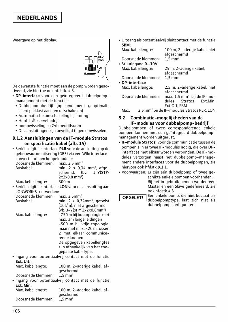
NEDERLANDS
106
Weergave op het display:
De gewenste functie moet aan de pomp worden geac-tiveerd, zie hiertoe ook hfdstk. 4.3.x DP-interface voor een geïntegreerd dubbelpomp-
management met de functies:x Dubbelpompbedrijf (op rendement geoptimali-
seerd pieklast aan- en uitschakelen)x Automatische omschakeling bij storingx Hoofd-/Reservebedrijfx pompwisseling na 24h bedrijfsurenx De aansluitingen zijn beveiligd tegen omwisselen.
9.1.2 Aansluitingen van de IF-module Stratosen specificatie kabel (afb. 14)
x Seriële digitale interface PLR voor de ansluiting op degebouwautomatisering (GBS) via een Wilo interface-converter of een koppelmodule:Doorsnede klemmen: max. 2,5 mm2
Buskabel: min. 2 x 0,34 mm2, afge-schermd, (bv. J-Y(ST)Y2x2x0,8 mm2)
Max. kebellengte: 500 m x Seriële digitale interface LON voor de aansluiting aan
LONWORKS-netwerken:Doorsnede klemmen: max. 2,5mm2
Buskabel: min. 2 x 0,34mm2, getwist(10t/m), niet afgeschermd(vb. J-Y(st)Y 2x2x0,8mm2)
Max. kabellengte: -750 m bij bustopologie metmax. 3m lange leidingen-500 m bij vrije topologie,maar met max. 320 m tussen2 met elkaar communice-rende knopenDe opgegeven kabellengteszijn afhankelijk van het toe-gepaste kabeltype.
x Ingang voor potentiaalvrij contact met de functieExt. Uit:Max. kabellengte: 100 m, 2-aderige kabel, af-
geschermdDoorsnede klemmen: 1,5 mm2
x Ingang voor potentiaalvrij contact met de functieExt. Min:Max. kabellengte: 100 m, 2-aderige kabel, af-
geschermdDoorsnede klemmen: 1,5 mm2
x Uitgang als potentiaalvrij sluitcontact met de functieSBM:Max. kabellengte: 100 m, 2-aderige kabel, niet
afgeschermdDoorsnede klemmen: 1,5 mm2
x Stuuringang 0...10V:Max. kabellengte: 25 m, 2-aderige kabel,
afgeschermdDoorsnede klemmen: 1,5 mm2
x DP-interfaceMax. kabellengte: 2,5 m, 2-aderige kabel, niet
afgeschermdDoorsnede klemmen: max. 1,5 mm2 bij de IF-mo-
dules Stratos Ext.Min,Ext.Off, SBM
Max. 2,5 mm2 bij de IF-modules Stratos PLR, LON
9.2 Combinatie-mogelijkheden van de IF-modules voor dubbelpomp-bedrijf
Dubbelpompen of twee corresponderende enkelepompen kunnen met een geïntegreerd dubbelpomp-management worden uitgerust.x IF-module Stratos: Voor de communicatie tussen de
pompen zijn er twee IF-modules nodig, die over DP-interfaces met elkaar worden verbonden. De IF-mo-dules verzorgen naast het dubbelpomp-manage-ment andere interfaces voor de dubbelpompen, ziehiervoor ook hfdstk.9.1.1.
x Voorwaarden: Er zijn één dubbelpomp of twee ge-schikte enkele pompen voorhanden.Bij het in gebruik nemen worden éénMaster en een Slave gedefinieerd, zieook hfdstk.4.3.Een enkele pomp, die niet bestaat alsdubbelpomptype, laat zich niet alsdubbelpomp configureren.
OPGELET!
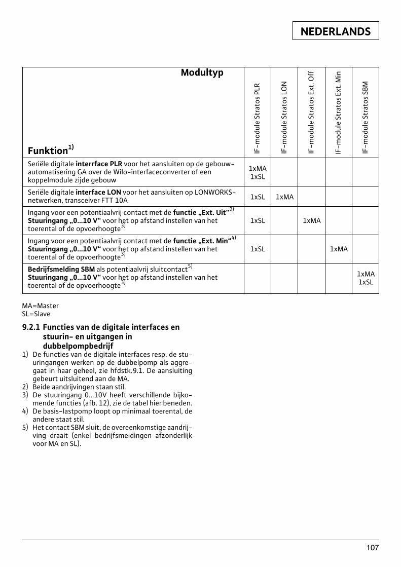
NEDERLANDS
107
Modultyp
Funktion1)
Seriële digitale interrface PLR voor het aansluiten op de gebouw-automatisering GA over de Wilo-interfaceconverter of een 1xMA
koppelmodule zijde gebouw 1xSL
Seriële digitale interface LON voor het aansluiten op LONWORKS-netwerken, transceiver FTT 10A 1xSL 1xMA
Ingang voor een potentiaalvrij contact met de functie „Ext. Uit“2)
Stuuringang „0...10 V“ voor het op afstand instellen van het 1xSL 1xMAtoerental of de opvoerhoogte3)
Ingang voor een potentiaalvrij contact met de functie „Ext. Min“4)
Stuuringang „0...10 V“ voor het op afstand instellen van het 1xSL 1xMAtoerental of de opvoerhoogte3)
Bedrijfsmelding SBM als potentiaalvrij sluitcontact5)
Stuuringang „0...10 V“ voor het op afstand instellen van het 1xMA
toerental of de opvoerhoogte3) 1xSL
IF-m
odul
e St
rato
s PL
R
IF-m
odul
e St
rato
s LO
N
IF-m
odul
e St
rato
s Ex
t. O
ff
IF-m
odul
e St
rato
s Ex
t. M
in
IF-m
odul
e St
rato
s SB
M
MA=MasterSL=Slave
9.2.1 Functies van de digitale interfaces enstuurin- en uitgangen indubbelpompbedrijf
1) De functies van de digitale interfaces resp. de stu-uringangen werken op de dubbelpomp als aggre-gaat in haar geheel, zie hfdstk.9.1. De aansluitinggebeurt uitsluitend aan de MA.
2) Beide aandrijvingen staan stil.3) De stuuringang 0...10V heeft verschillende bijko-
mende functies (afb. 12), zie de tabel hier beneden.4) De basis-lastpomp loopt op minimaal toerental, de
andere staat stil.5) Het contact SBM sluit, de overeenkomstige aandrij-
ving draait (enkel bedrijfsmeldingen afzonderlijkvoor MA en SL).
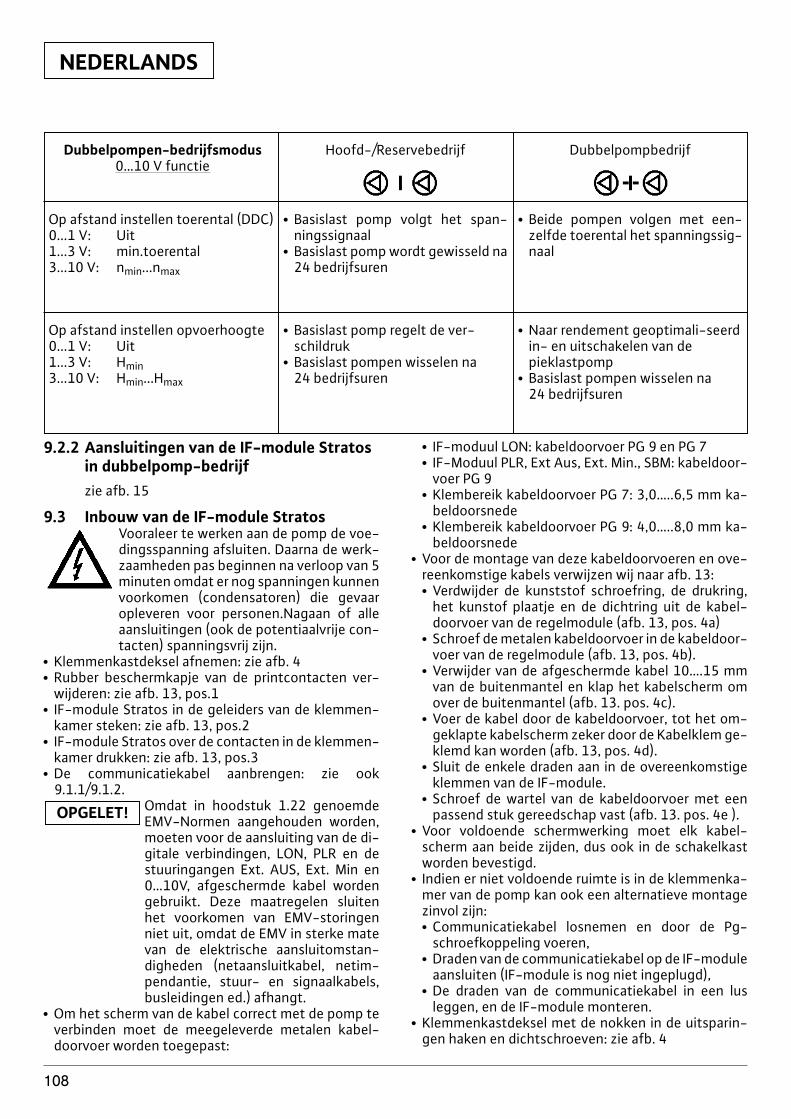
NEDERLANDS
108
Dubbelpompen-bedrijfsmodus0…10 V functie
Op afstand instellen toerental (DDC)0...1 V: Uit1...3 V: min.toerental3...10 V: nmin...nmax
Hoofd-/Reservebedrijf
x Basislast pomp volgt het span-ningssignaal
x Basislast pomp wordt gewisseld na24 bedrijfsuren
x Beide pompen volgen met een-zelfde toerental het spanningssig-naal
Op afstand instellen opvoerhoogte0...1 V: Uit1...3 V: Hmin3...10 V: Hmin...Hmax
x Basislast pomp regelt de ver-schildruk
x Basislast pompen wisselen na 24 bedrijfsuren
x Naar rendement geoptimali-seerdin- en uitschakelen van de pieklastpomp
x Basislast pompen wisselen na 24 bedrijfsuren
Dubbelpompbedrijf
9.2.2 Aansluitingen van de IF-module Stratosin dubbelpomp-bedrijfzie afb. 15
9.3 Inbouw van de IF-module StratosVooraleer te werken aan de pomp de voe-dingsspanning afsluiten. Daarna de werk-zaamheden pas beginnen na verloop van 5minuten omdat er nog spanningen kunnenvoorkomen (condensatoren) die gevaaropleveren voor personen.Nagaan of alleaansluitingen (ook de potentiaalvrije con-tacten) spanningsvrij zijn.
x Klemmenkastdeksel afnemen: zie afb. 4x Rubber beschermkapje van de printcontacten ver-
wijderen: zie afb. 13, pos.1x IF-module Stratos in de geleiders van de klemmen-
kamer steken: zie afb. 13, pos.2x IF-module Stratos over de contacten in de klemmen-
kamer drukken: zie afb. 13, pos.3x De communicatiekabel aanbrengen: zie ook
9.1.1/9.1.2.Omdat in hoodstuk 1.22 genoemdeEMV-Normen aangehouden worden,moeten voor de aansluiting van de di-gitale verbindingen, LON, PLR en destuuringangen Ext. AUS, Ext. Min en0…10V, afgeschermde kabel wordengebruikt. Deze maatregelen sluitenhet voorkomen van EMV-storingenniet uit, omdat de EMV in sterke matevan de elektrische aansluitomstan-digheden (netaansluitkabel, netim-pendantie, stuur- en signaalkabels,busleidingen ed.) afhangt.
x Om het scherm van de kabel correct met de pomp teverbinden moet de meegeleverde metalen kabel-doorvoer worden toegepast:
OPGELET!
x IF-moduul LON: kabeldoorvoer PG 9 en PG 7x IF-Moduul PLR, Ext Aus, Ext. Min., SBM: kabeldoor-
voer PG 9x Klembereik kabeldoorvoer PG 7: 3,0…..6,5 mm ka-
beldoorsnedex Klembereik kabeldoorvoer PG 9: 4,0…..8,0 mm ka-
beldoorsnedex Voor de montage van deze kabeldoorvoeren en ove-
reenkomstige kabels verwijzen wij naar afb. 13:x Verdwijder de kunststof schroefring, de drukring,
het kunstof plaatje en de dichtring uit de kabel-doorvoer van de regelmodule (afb. 13, pos. 4a)
x Schroef de metalen kabeldoorvoer in de kabeldoor-voer van de regelmodule (afb. 13, pos. 4b).
x Verwijder van de afgeschermde kabel 10….15 mmvan de buitenmantel en klap het kabelscherm omover de buitenmantel (afb. 13. pos. 4c).
x Voer de kabel door de kabeldoorvoer, tot het om-geklapte kabelscherm zeker door de Kabelklem ge-klemd kan worden (afb. 13, pos. 4d).
x Sluit de enkele draden aan in de overeenkomstigeklemmen van de IF-module.
x Schroef de wartel van de kabeldoorvoer met eenpassend stuk gereedschap vast (afb. 13. pos. 4e ).
x Voor voldoende schermwerking moet elk kabel-scherm aan beide zijden, dus ook in de schakelkastworden bevestigd.
x Indien er niet voldoende ruimte is in de klemmenka-mer van de pomp kan ook een alternatieve montagezinvol zijn:x Communicatiekabel losnemen en door de Pg-
schroefkoppeling voeren,x Draden van de communicatiekabel op de IF-module
aansluiten (IF-module is nog niet ingeplugd),x De draden van de communicatiekabel in een lus
leggen, en de IF-module monteren.x Klemmenkastdeksel met de nokken in de uitsparin-
gen haken en dichtschroeven: zie afb. 4

NEDERLANDS
109
Technische wijzigingen voorbehouden!
x IF-module Stratos LON: op de IF-module bevindt zicheen zelfklever\sticker met de Neuron-ID. De anderesticker kan bvb. op de plaats van de betreffendepomp in het installatietekening worden geplakt. Bijhet aansluiten kan daarop de Neuron-ID vanaf de te-kening worden ingelezen met een barcode-lezer, ofmet de hand worden ingevoerd.
D EG - KonformitätserklärungGB EC - Declaration of conformityF Déclaration de conformité CEE
Hiermit erklären wir, dass die Bauarten der Baureihe : StratosHerewith, we declare that this product:Par le présent, nous déclarons que cet agrégat :
in der gelieferten Ausführung folgenden einschlägigen Bestimmungen entspricht:in its delivered state complies with the following relevant provisions:est conforme aux dispositions suivants dont il relève:
EG-Maschinenrichtlinie 98/37/EGEC-Machinery directiveDirectives CEE relatives aux machines
Elektromagnetische Verträglichkeit - Richtlinie 89/336/EWGElektromagnetic compatability - directive i.d.F/ as amended/
avec les amendements suivants:Compatibilité électromagnétique- directive 91/263/EWG
92/31/EWG93/68/EWG
Niederspannungsrichtlinie 73/23/EWGLow voltage directive i.d.F/ as amended/
avec les amendements suivants :Direction basse-tension 93/68/EWG
Angewendete harmonisierte Normen, insbesondere: EN 809Applied harmonized standards, in particular: EN 60335-1Normes harmonisées, notamment: EN 60335-2-51
EN 61800-3
Dortmund, 18. 06. 2003
Document: 2047111.1
WILO AGNortkirchenstraße 10044263 Dortmund
Oliver BreuingQuality Manager
NL EG-verklaring van overeenstemmingHiermede verklaren wij dat dit aggregaat in degeleverde uitvoering voldoet aan de volgendebepalingen:EG-richtlijnen betreffende machines 98/37/EGElektromagnetische compatibiliteit 89/336/EEGals vervolg op 91/263/EEG, 92/31/EEG,93/68/EEGEG-laagspanningsrichtlijn 73/23/EEG als vervolg op 93/68/EEGGebruikte geharmoniseerde normen, in het bijzonder: 1)
P Declaração de Conformidade CEPela presente, declaramos que esta unidadeno seu estado original, está conforme osseguintes requisitos:Directivas CEE relativas a máquinas98/37/CECompatibilidade electromagnética89/336/CEE com os aditamentos seguintes91/263/CEE, 92/31/CEE, 93/68/CEEDirectiva de baixa voltagem 73/23/CEE comos aditamentos seguintes 93/68/CEENormas harmonizadas aplicadas,especialmente: 1)
FIN CE-standardinmukaisuusselosteIlmoitamme täten, että tämä laite vastaa seuraa-via asiaankuuluvia määräyksiä:EU-konedirektiivit: 98/37/EG
Sähkömagneettinen soveltuvuus 89/336/EWGseuraavin täsmennyksin 91/263/EWG92/31/EWG, 93/68/EWGMatalajännite direktiivit: 73/23/EWG seuraavintäsmennyksin 93/68/EWGKäytetyt yhteensovitetut standardit, erityisesti: 1)
CZ Prohlášení o shodě EU
Prohlašujeme tímto, že tento agregát v dodanémprovedení odpovídá následujícím příslušnýmustanovením:Směrnicím EU–strojní zařízení 98/37/EGSměrnicím EU–EMV 89/336/EWG ve sledu91/263/EWG, 92/31/EWG, 93/68/EWGSměrnicím EU–nízké napětí 73/23/EWG ve sledu93/68/EWGPouæité harmonizaËnÌ normy, zejména: 1)
GR ∆ήλωση πρσαρµγής στιςπρδιαγρα�ές της Ε.Ε.(Ευρωπαϊκής Ένωσης)∆ηλών�υµε τι τ� πρ�ϊν αυτ σ’ αυτήτην κατάσταση παράδ�σης ικαν�π�ιεί τιςακλ�υθες διατά�εις :�δηγίες EG σ�ετικά µε µη�ανήµατα98/37/EGΗλεκτρ�µαγνητική συµ�αττητα EG-89/336/EWG πως τρ�π�π�ιήθηκε91/263/EWG 92/31/EWG, 93/68/EWG�δηγία �αµηλής τάσης EG-73/23/EWGπως τρ�π�π�ιήθηκε 93/68/EWGΕναρµ�νισµένα �ρησιµ�π�ι�ύµεναπρτυπα, ιδιαίτερα: 1)
I Dichiarazione di conformità CE
Con la presente si dichiara che i presenti prodottisono conformi alle seguenti disposizioni e diretti-ve rilevanti:Direttiva macchine 98/37/CECompatibilità elettromagnetica 89/336/CEE eseguenti modifiche 91/263/CEE, 92/31/CEE,93/68/CEEDirettiva bassa tensione 73/23/CEE e seguentimodifiche 93/68/CEENorme armonizzate applicate, in particolare: 1)
S CE- försäkranHärmed förklarar vi att denna maskin i lever-erat utförande motsvarar följande tillämpliga bestämmelser:EG-Maskindirektiv 98/37/EG
EG-Elektromagnetisk kompatibilitet - rikt-linje 89/336/EWG med följande ändringar91/263/EWG, 92/31/EWG, 93/68/EWGEG-Lågspänningsdirektiv 73/23/EWG medföljande ändringar 93/68/EWGTillämpade harmoniserade normer, i synner-het: 1)
DK EF-overensstemmelseserklæringVi erklærer hermed, at denne enhed ved leveringoverholder følgende relevante bestemmelser:EU-maskindirektiver 89/392EWG, følgende98/37/EGElektromagnetisk kompatibilitet: 89/336/EWG,følgende 91/263/EWG, 92/31/EWG, 93/68/EWG
Lavvolts-direktiv 73/23/EWG følgende93/68/EWGAnvendte harmoniserede standarder, særligt: 1)
PL Deklaracja Zgodności CE
Niniejszym deklarujemy z pełną odpowiedzial-noscią że dostarczony wyrób jest zgdony znastępującymi dokumentami:
EC–dyrektywa dla przemysłu maszynowego98/37/EGOdpowiedniość elektromagnetyczna89/336/EWG ze zmianą 91/263/EWG,92/31/EWG, 93/68/EWGNormie niskich napięć 73/23/EWG ze zmianą93/68/EWGWyroby są zgodne ze szczegółowymi normami zharmonizowanymi: 1)
TR CE Uygunluk Teyid Belgesi
Bu cihazın teslim edildi¤i șekliyle așa¤ıdaki standartlara uygun oldu¤unu teyid ederiz:
AB-Makina Standartları 98/37/EG
Elektromanyetik Uyumluluk 89/336/EWG vetakip eden, 91/263/EWG, 92/31/EWG,93/68/EWGAlçak gerilim direktifi 73/23/EWG ve takip eden,93/68/EWGKısmen kullanılan standartlar: 1)
E Declaración de conformidad CE
Por la presente declaramos la conformidad delproducto en su estado de suministro con lasdisposiciones pertinentes siguientes:Directiva sobre máquinas 98/37/CEDirectiva sobre compatibilidad electromagnética89/336/CEE modificada por 91/263/CEE,92/31/CEE, 93/68/CEEDirectiva sobre equipos de baja tensión73/23/CEE modificada por 93/68/CEENormas armonizadas adoptadas,especialmente: 1)
N EU-OverensstemmelseserklæringVi erklærer hermed at denne enheten i utfø-relse som levert er i overensstemmelse medfølgende relevante bestemmelser:EG-Maskindirektiv 98/37/EG
EG-EMV-Elektromagnetisk kompatibilitet89/336/EWG med senere tilføyelser:91/263/EWG, 92/31/EWG, 93/68/EWGEG-Lavspenningsdirektiv 73/23/EWG medsenere tilføyelser: 93/68/EWGAnvendte harmoniserte standarder, særlig: 1)
H EK. Azonossági nyilatkozatEzennel kijelentjük,hogy az berendezés az aláb-biaknak megfelel:EK Irányelvek gépekhez: 98/37/EG
Elektromágneses zavarás/türés: 89/336/EWG ésaz azt kiváltó 91/263/EWG, 92/31/EWG,93/68/EWGKisfeszültségü berendezések irány-Elve:73/23/EWG és az azt kiváltó 93/68/EWGFelhasznált harmonizált szabványok,különösen: 1)
RUS Деклация о соответствииЕвропейским нормамНастоящим документом заявляем, чтоданный агрегат в его объеме поставкисоответствует следующим нормативнымдокументам:Директивы EC в отношении машин98/37/EGЭлектромагнитная устойчивость89/336/EWG с поправками 91/263/EWG,92/31/EWG, 93/68/EWGДирективы по низковольтномунапряжению 73/23/EWG с поправками93/68/EWGИспользуемые согласованные стандартыи нормы, в частности : 1)
1) EN 809EN 60335-1EN 60335-2-51EN 61800-3
WILO AGNortkirchenstraße 10044263 Dortmund
Oliver BreuingQuality Manager

✍
WILO AGNortkirchenstraße 10044263 DortmundGermanyT +49 231 4102-0F +49 231 4102-7363www.wilo.com
Azerbaijan370141 BakuT +994 50 2100890F +994 12 [email protected]
Bosnia and Herzegovina71000 Sarajevo T +387 33 714511F +387 33 [email protected]
Croatia10000 ZagrebT +385 1 3680474F +385 1 [email protected]
Georgia38007 TbilisiT/F +995 32 [email protected]
Macedonia1000 SkopjeT/F +389 [email protected]
Moldova2012 ChisinauT/F +373 22 [email protected]
Tajikistan734025 DushanbeT +992 372 [email protected]
Uzbekistan700029 TaschkentT/F +998 71 [email protected]
März 2005
Wilo – International (Subsidiaries)
Wilo – International (Representation offices)
AustriaWILO Handelsges. m.b.H.1230 WienT +43 1 25062-0F +43 1 [email protected]
BelarusWILO Bel OOO220035 MinskT +375 17 [email protected]
BelgiumWILO NV/SA1083 GanshorenT +32 2 4823333F +32 2 [email protected]
BulgariaWILO Bulgaria EOOD1125 Sofia T +359 2 9701970F +359 2 [email protected]
CanadaWILO Canada Inc. Calgary, Alberta T2A5L4T +1 403 2769456F +1 403 [email protected]
ChinaWILO SALMSON (Beijing) Pumps System Ltd.101300 BeijingT +86 10 804939700F +86 10 [email protected]
Czech RepublicWILO Praha s.r.o.25101 CestliceT +420 234 098 711F +420 234 098 [email protected]
DenmarkWILO Danmark A/S2690 KarlslundeT +45 70 253312F +45 70 [email protected]
FinlandWILO Finland OY02320 EspooT +358 9 26065222F +358 9 [email protected]
FranceWILO S.A.S.78310 CoignièresT +33 1 30050930F +33 1 [email protected]
Great BritainWILO SALMSON Pumps Ltd.DE14 2WJ Burton-on-TrentT +44 1283 523000F +44 1283 [email protected]
GreeceWILO Hellas AG14569 Anixi (Attika)T +30 10 6248300F +30 10 [email protected]
HungaryWILO Magyarország Kft1144 Budapest XIVT +36 1 46770-70 Sales Dep.
46770-80 Tech. Serv.F +36 1 [email protected]
IrelandWILO Engineering Ltd.LimerickT +353 61 227566F +353 61 [email protected]
ItalyWILO Italia s.r.l.20068 Peschiera Borromeo(Milano)T +39 02 5538351F +39 02 [email protected]
KazakhstanTOO WILO Central Asia480100 AlmatyT +7 3272 507333F +7 3272 [email protected]
KoreaWILO Industries Ltd. 137-818 SeoulT +82 2 34716600F +82 2 [email protected]
LatviaWILO Baltic SIA1019 RigaT +371 7 145229F +371 7 [email protected]
LebanonWILO SALMSON Lebanon s.a.r.l.12022030 El MetnT +961 4 722280F +961 4 [email protected]
LithuaniaUAB WILO Lietuva03202 VilniusT +370 2 236495F +370 2 [email protected]
The NetherlandsWILO Nederland b.v.1948 RC BeverwijkT +31 251 220844F +31 251 [email protected]
NorwayWILO Norge A/S0901 OsloT +47 22 804570F +47 22 [email protected]
PolandWILO Polska Sp. z.o.o.05-090 Raszyn k/WarszawyT +48 22 7201111F +48 22 [email protected]
PortugalBombas Wilo-SalmsonPortugal4050-040 PortoT +351 22 2080350F +351 22 [email protected]
RomaniaWILO Romania s.r.l.7000 BucurestiT +40 21 4600612F +40 21 [email protected]
RussiaWILO Rus o.o.o.123592 MoskauT +7 095 7810690F +7 095 [email protected]
Serbia & MontenegroWILO Beograd d.o.o.11000 BeogradT +381 11 765871F +381 11 [email protected]
SlovakiaWILO Slovakia s.r.o.82008 Bratislava 28T +421 2 45520122F +421 2 [email protected]
SloveniaWILO Adriatic d.o.o.1000 LjubljanaT +386 1 5838130F +386 1 [email protected]
SpainWILO Ibérica S.A.28806 Alcalá de Henares(Madrid)T +34 91 8797100F +34 91 [email protected]
SwedenWILO Sverige AB35033 VäxjöT +46 470 727600F +46 470 [email protected]
SwitzerlandEMB Pumpen AG4310 RheinfeldenT +41 61 8368020F +41 61 [email protected]
TurkeyWILO Pompa Sistemleri San. ve Tic. A.S.34530 IstanbulT +90 216 6610211F +90 216 [email protected]
UkrainaWILO Ukraina t.o.w.01033 KiewT +38 044 2011870F +38 044 [email protected]
USAWILO USA LLCCalgary, Alberta T2A5L4T +1 403 2769456F +1 403 [email protected]

WILO AGNortkirchenstraße 10044263 DortmundGermanyT 0231 4102-0F 0231 [email protected]
G1 NordWILO AGVertriebsbüro HamburgSinstorfer Kirchweg 74–9221077 HamburgT 040 5559490F 040 55594949
G2 OstWILO AGVertriebsbüro BerlinJuliusstraße 52–5312051 Berlin-NeuköllnT 030 6289370F 030 62893770
G3 Sachsen/ThüringenWILO AGVertriebsbüro DresdenFrankenring 801723 KesselsdorfT 035204 7050 F 035204 70570
G4 SüdostWILO AGVertriebsbüro MünchenLandshuter Straße 2085716 UnterschleißheimT 089 4200090F 089 42000944
G5 SüdwestWILO AGVertriebsbüro StuttgartHertichstraße 1071229 LeonbergT 07152 94710 F 07152 947141
G6 Rhein-MainWILO AGVertriebsbüro FrankfurtAn den drei Hasen 3161440 Oberursel/Ts.T 06171 70460F 06171 704665
G7 WestWILO AGVertriebsbüro DüsseldorfHans-Sachs-Straße 440721 HildenT 02103 90920 F 02103 909215
G8 NordwestWILO AGVertriebsbüro HannoverAhrensburger Straße 130659 Hannover-LaheT 0511 438840F 0511 4388444
Zentrale Auftrags-bearbeitung für denFachgroßhandel
WILO AGAuftragsbearbeitungNortkirchenstraße 10044263 DortmundT 0231 4102-0 F 0231 4102-7555
Wilo-Kompetenz-Team
– Antworten auf alle Fragen rund um das Produkt, Lieferzeiten, Versand, Verkaufspreise
– Abwicklung Ihrer Aufträge– Ersatzteilbestellungen –
mit 24-Stunden-Lieferzeit für alle gängigenErsatzteile
– Versand von Informationsmaterial
T 01805 R•U•F•W•I•L•O*7•8•3•9•4•5•6
F 0231 4102-7666
Werktags erreichbar von 7–18 Uhr
Wilo-Kundendienst
WILO AGWilo-Service-CenterNortkirchenstraße 10044263 Dortmund
– Kundendienststeuerung– Wartung und
Inbetriebnahme– Werksreparaturen– Ersatzteilberatung
T 01805 W•I•L•O•K•D*9•4•5•6•5•3
0231 4102-7900F 0231 4102-7126
Werktags erreichbar von 7–17 Uhr, ansonsten elektronische Bereit-schaft mit Rückruf-Garantie!
Wilo-International
ÖsterreichZentrale Wien:WILO Handels-gesellschaft mbHEitnergasse 131230 WienT +43 1 25062-0F +43 1 25062-15
Vertriebsbüro Salzburg:Gnigler Straße 565020 SalzburgT +43 662 8716410F +43 662 878470
VertriebsbüroOberösterreich:Trattnachtalstraße 74710 GrieskirchenT +43 7248 65051F +43 7248 65054
SchweizEMB Pumpen AGGerstenweg 74310 RheinfeldenT +41 61 8368020F +41 61 8368021
Standorte weiterer Tochtergesellschaften
Belarus, Belgien, Bulgarien,China, Dänemark,Finnland, Frankreich,Griechenland,Großbritannien,Irland,Italien, Kanada,Kasachstan, Korea,Libanon, Litauen, Lettland,Niederlande, Norwegen,Polen, Rumänien,Russland, Schweden,Serbien & Montenegro,Slowakei, Slowenien,Spanien, Tschechien,Türkei, Ukraine, Ungarn
Die Adressen finden Sieunter www.wilo.de oderwww.wilo.com.
Stand März 2005* 12 Cent pro Minute
Wilo-Vertriebsbüros