Embed Size (px)
Citation preview

Wir verbinden Qualität
Friedrich Geldbach GmbHBergmannstrasse 170
D- 45886 GelsenkirchenTel. +49 209 170990Fax +49 209 1709955
ASME
Flanschenkatalog
Ausgabe 2015
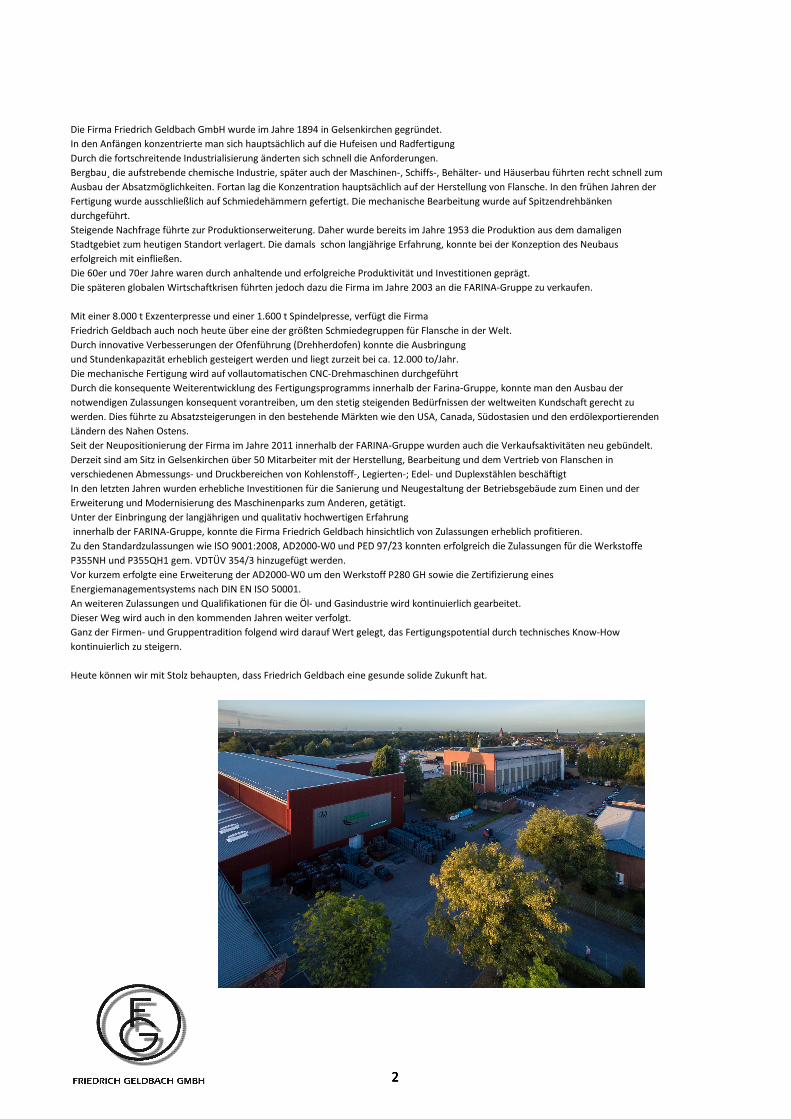
Die Firma Friedrich Geldbach GmbH wurde im Jahre 1894 in Gelsenkirchen gegründet.In den Anfängen konzentrierte man sich hauptsächlich auf die Hufeisen und RadfertigungDurch die fortschreitende Industrialisierung änderten sich schnell die Anforderungen.Bergbau¸ die aufstrebende chemische Industrie, später auch der Maschinen-, Schiffs-, Behälter- und Häuserbau führten recht schnell zum Ausbau der Absatzmöglichkeiten. Fortan lag die Konzentration hauptsächlich auf der Herstellung von Flansche. In den frühen Jahren der Fertigung wurde ausschließlich auf Schmiedehämmern gefertigt. Die mechanische Bearbeitung wurde auf Spitzendrehbänken durchgeführt.Steigende Nachfrage führte zur Produktionserweiterung. Daher wurde bereits im Jahre 1953 die Produktion aus dem damaligen Stadtgebiet zum heutigen Standort verlagert. Die damals schon langjährige Erfahrung, konnte bei der Konzeption des Neubaus erfolgreich mit einfließen. Die 60er und 70er Jahre waren durch anhaltende und erfolgreiche Produktivität und Investitionen geprägt.Die späteren globalen Wirtschaftkrisen führten jedoch dazu die Firma im Jahre 2003 an die FARINA-Gruppe zu verkaufen.
Mit einer 8.000 t Exzenterpresse und einer 1.600 t Spindelpresse, verfügt die FirmaFriedrich Geldbach auch noch heute über eine der größten Schmiedegruppen für Flansche in der Welt. Durch innovative Verbesserungen der Ofenführung (Drehherdofen) konnte die Ausbringungund Stundenkapazität erheblich gesteigert werden und liegt zurzeit bei ca. 12.000 to/Jahr.Die mechanische Fertigung wird auf vollautomatischen CNC-Drehmaschinen durchgeführtDurch die konsequente Weiterentwicklung des Fertigungsprogramms innerhalb der Farina-Gruppe, konnte man den Ausbau der notwendigen Zulassungen konsequent vorantreiben, um den stetig steigenden Bedürfnissen der weltweiten Kundschaft gerecht zu werden. Dies führte zu Absatzsteigerungen in den bestehende Märkten wie den USA, Canada, Südostasien und den erdölexportierenden Ländern des Nahen Ostens.Seit der Neupositionierung der Firma im Jahre 2011 innerhalb der FARINA-Gruppe wurden auch die Verkaufsaktivitäten neu gebündelt.Derzeit sind am Sitz in Gelsenkirchen über 50 Mitarbeiter mit der Herstellung, Bearbeitung und dem Vertrieb von Flanschen in verschiedenen Abmessungs- und Druckbereichen von Kohlenstoff-, Legierten-; Edel- und Duplexstählen beschäftigtIn den letzten Jahren wurden erhebliche Investitionen für die Sanierung und Neugestaltung der Betriebsgebäude zum Einen und der Erweiterung und Modernisierung des Maschinenparks zum Anderen, getätigt.Unter der Einbringung der langjährigen und qualitativ hochwertigen Erfahrung innerhalb der FARINA-Gruppe, konnte die Firma Friedrich Geldbach hinsichtlich von Zulassungen erheblich profitieren. Zu den Standardzulassungen wie ISO 9001:2008, AD2000-W0 und PED 97/23 konnten erfolgreich die Zulassungen für die Werkstoffe
2
Zu den Standardzulassungen wie ISO 9001:2008, AD2000-W0 und PED 97/23 konnten erfolgreich die Zulassungen für die Werkstoffe P355NH und P355QH1 gem. VDTÜV 354/3 hinzugefügt werden. Vor kurzem erfolgte eine Erweiterung der AD2000-W0 um den Werkstoff P280 GH sowie die Zertifizierung eines Energiemanagementsystems nach DIN EN ISO 50001.An weiteren Zulassungen und Qualifikationen für die Öl- und Gasindustrie wird kontinuierlich gearbeitet.Dieser Weg wird auch in den kommenden Jahren weiter verfolgt. Ganz der Firmen- und Gruppentradition folgend wird darauf Wert gelegt, das Fertigungspotential durch technisches Know-How kontinuierlich zu steigern.
Heute können wir mit Stolz behaupten, dass Friedrich Geldbach eine gesunde solide Zukunft hat.
22
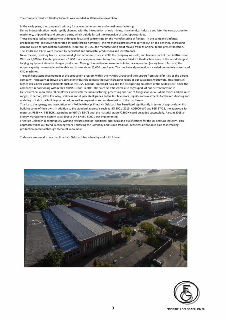
The company Friedrich Geldbach GmbH was founded in 1894 in Gelsenkirchen. In the early years, the company's primary focus was on horseshoe and wheel manufacturing.During Industrialisation needs rapidly changed with the introduction of cole mining, the chemical industry and later the construction for machinery, shipbuilding and pressure parts, which quickly forced the expansion of sales opportunities. These changes led our company to shifting its focus and concentrate on the manufacturing of flanges. In the company's infancy, production was exclusively generated through forging hammers; the mechanical process was carried out on top benches. Increasing demand called for production expansion. Therefore, in 1953 the manufacturing plant moved from its original to the present location. The 1960s and 1970s were marked by persistent and successful productions and investments. Nevertheless, resulting from a subsequent global economic crisis, in 2003 the company was sold, and become part of the FARINA Group. With an 8,000 ton Exenter press and a 1,600 ton screw press, even today the company Friedrich Geldbach has one of the world's largest forging equipment aimed at flanges production. Through innovative improvements in furnace operation (rotary hearth furnace) the output capacity increased considerably and is now about 12,000 tons / year. The mechanical production is carried out on fully automated CNC machines. Through consistent development of the production program within the FARINA-Group and the support from Metalfar Italy as the parent company, necessary approvals are consistently pushed to meet the ever increasing needs of our customers worldwide. This results in higher sales in the existing markets such as the USA, Canada, Southeast Asia and the oil exporting countries of the Middle East. Since the company's repositioning within the FARINA-Group in 2011, the sales activities were also regrouped. At our current location in Gelsenkirchen, more than 50 employees work with the manufacturing, processing and sale of flanges for various dimensions and pressure ranges, in carbon, alloy, low alloy, stainless and duplex steel grades. In the last few years, significant investments for the refurbishing and updating of industrial buildings occurred, as well as expansion and modernisation of the machinery. Thanks to the synergy and association with FARINA-Group, Friedrich Geldbach has benefitted significantly in terms of approvals, whilst building some of their own. In addition to the standard approvals such as ISO 9001: 2015, AD2000-W0 and PED 97/23, the approvals for materials P355NH, P355QH1 according to VDTÜV 354/3 and the material grade P280GH could be added successfully. Also, in 2015 an Energy-Management-System according to DIN EN ISO 50001 was implemented. Friedrich Geldbach is continuously working towards gaining additional approvals and qualifications for the Oil and Gas Industry . This approach will be our trend in coming years. Following the Company and Group tradition, ceaseless attention is paid to increasing production potential through technical know-how. Today we are proud to say that Friedrich Geldbach has a healthy and solid future.
333

Index
3 3
4 4
5 5
6 6
7 7
8 8
9 9
10 10
11 11
12 12
13 13
14-15 14-15
16 16
17 17
18 18
19-22 19-22
23-36 23-36
37-42 37-42
43-44 43-44
45-51 45-51
69-71 69-71
72-78 72-78
79-80 79-80
81 81
82 82
83 83
Kennzeichnung
Inhaltsverzeichnis
65-68
Wanddickentabelle Table of wallthicknesses
Materialspezifikationen ASTM-Werkstoffe Material Specifications for ASTM-Materials
52-57
Long Welding Neck Flanges
Flansche mit glatter Dichtleiste, Dichtfläche und Ring-
Nut
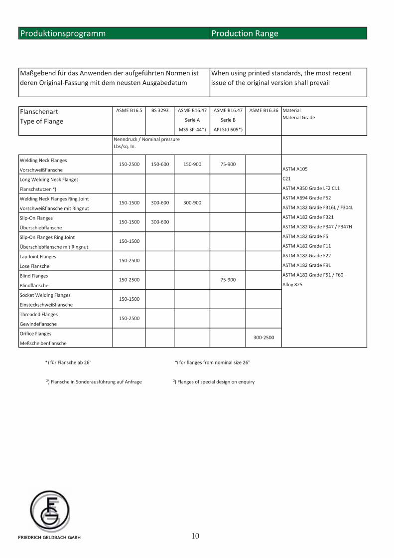
Produktionsprogramm
Einsteckschweißflansche
Welding Neck and Blind Flanges
Gewichtstabelle Flansche nach ASME B16.5
to ASME B16.47 Serie A
Table of weights for flanges acc. to ASME B16.47
Production Range
Toleranzen: allgemeine Angaben
General Survey
Technical terms of delivery
Hinweise zum Katalog
Allgemeingültige Festlegungen General Provisions
Marking
Comparison of Materials
Tolerances: generell notes
Raised face, flat face and ring-joint flanges
Verwendete Symbole
Friedrich Geldbach approvals
Lapped Flanges
Welding Neck and Slip-On Flanges
according to BS 3293
Welding Neck Flanges according
according to ASME B16.47 Serie B
Orifice Flanges B16.36
Friedrich Geldbach Zulassungen
Seite
Lose Flansche
Vorschweiß- u. Überschiebflansche
Vorschweißflansche nach
Vorschweißflansche und Blindflansche
Gewichtstabelle Flansche nach ASME B16.47
Vorschweißflansche und Blindflansche
Überschiebschweißflansche und Gewindeflansche
52-57
Werkstoffe für Flanschen
nach BS 3293
ASME B16.47 Serie A
nach ASME B16.47 Serie B
Materials for Flanges
Slip-On Flanges and Threaded Flanges
Socket Welding Flanges
Vorschweißflansche mit langem Ansatz
Meßscheibenflansche B16.36
Inhaltsverzeichnis
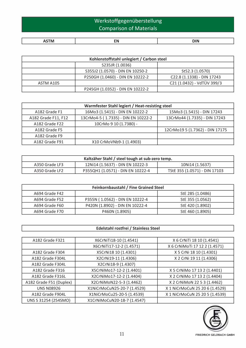
Werkstoffgegenüberstellung
Druck-Temperatur-Zuordnung
Tolerances ASME B16.5
58-64
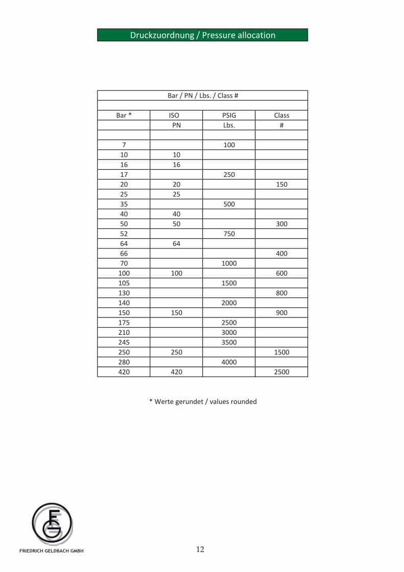
Druckzuordnung Pressure allocation
Page
Pressure Temperature Ratings
Index
Firmenprofil
Table of weights for flanges acc. to ASME B16.5
Toleranzen ASME B16.5
Welding Neck Flanges and Blind Flanges
65-68
58-64
Used Symbols
Company Profile
General Remarks
Allgemeiner Überblick
Technische Lieferbedingungen
FRIEDRICH GELDBACH GMBH
Hinweise zum Flanschenkatalog General Remarks
In diesem Katalog sind die wesentlichen Inhalte
für geschmiedete und aus Flacherzeugnissen
hergestellte Flansche der Normen: ASME B16.5
und ASME B16.47 wiedergegeben, ergänzt
durch für Flansche erforderliche Details aus
den Normen: ASME B36.10M, ASME B36.19M,
MSS SP 9, MSS SP44 und MSS SP 25. Der
Katalog beinhaltet entsprechend den zugrunde
liegenden Standards die Angaben im
metrischen und U.S. Maßsystem. (Hinweis: Die
Nennmaße und Toleranzen beider Maßsysteme
entsprechen sich nicht exakt).
Alle gennanten Normen beziehen sich auf die
jeweils letzte gültige Ausgabe
Abweichungen:
Die Normen und Anhänge sind nicht vollständig
enthalten. Die verwendeten Inhalte der
Normen sind abweichend gegliedert. Im
Katalog werden eigene Darstellungen
verwendet. Im Katalog verwendete Verweise
entsprechen dem Kataloginhalt und nicht den
Originalnormen. Die deutsche Übersetzung
wurde vom Katalogherausgeber
vorgenommen. Die angegebenen Gewichte
sind vom Katalogherausgeber berechnet. Die
sich aus den Standards ASME B36.10M und
ASME B36.19M ergebenden Maße für den
Rohrinnendurchmesser wurden eingefügt.
Erläuterungen:
Die im Katalog angegebenen Symbole STD, XS,
XXS und Schedule sind Abkürzungen für die
Wandstärke.
This catalogue covers the main contents of the
standards: ASME B16.5 and ASME B16.47 for
flanges made from forgings and plate
materials, supplementary reference is made to
details from Standards:
ASME B36.10M, ASME B36.19M, MSS SP 9 ,
MSS SP44 and MSS SP 25 insofar required for
flanges covered by this catalogue.
This catalogue states values in metric and U.S.
Customary units. (Remark: the nominal sizes
and tolerances stated of both systems are not
exact equivalent).
All mentioned standards refer to the latest
revision.
Deviations:
The standards and the related Annexes are
provided in parts only.
The structure of contents of the Standards used
may differs from the original. The figures
shown in this catalogue are own figures.
References and notes in this catalogue
correspond with the content of this catalogue
and are not related to the original Standards.
The translation into German language was
performed by the editor of this catalogue.
Calculation of weights was performed by the
editor. The dimension of the inner diameters of
the pipes have been included in this catalogue
and are in acc. with the Standards ASME
B36.10M and ASME B36.19M
Further explanations: Symbols STD, XS, XXS
and Schedules are abbreviations describing
wall thicknesses.
FRIEDRICH GELDBACH GMBH
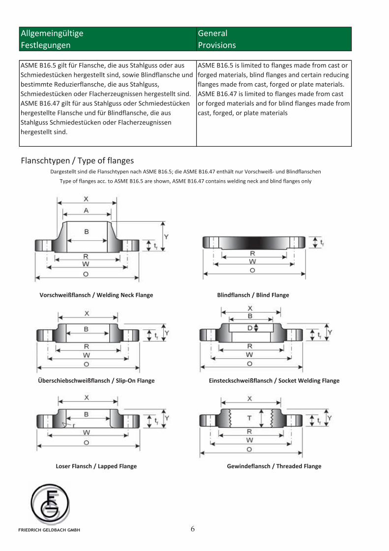
Flanschtypen / Type of flanges
Provisions
ASME B16.5 is limited to flanges made from cast or
forged materials, blind flanges and certain reducing
flanges made from cast, forged or plate materials.
ASME B16.47 is limited to flanges made from cast
or forged materials and for blind flanges made from
cast, forged, or plate materials
ASME B16.5 gilt für Flansche, die aus Stahlguss oder aus
Schmiedestücken hergestellt sind, sowie Blindflansche und
bestimmte Reduzierflansche, die aus Stahlguss,
Schmiedestücken oder Flacherzeugnissen hergestellt sind.
ASME B16.47 gilt für aus Stahlguss oder Schmiedestücken
hergestellte Flansche und für Blindflansche, die aus
Stahlguss Schmiedestücken oder Flacherzeugnissen
hergestellt sind.
Allgemeingültige
Dargestellt sind die Flanschtypen nach ASME B16.5; die ASME B16.47 enthält nur Vorschweiß- und Blindflanschen
Type of flanges acc. to ASME B16.5 are shown, ASME B16.47 contains welding neck and blind flanges only
General
Festlegungen
Überschiebschweißflansch / Slip-On Flange Einsteckschweißflansch / Socket Welding Flange
Loser Flansch / Lapped Flange Gewindeflansch / Threaded Flange
Blindflansch / Blind FlangeVorschweißflansch / Welding Neck Flange
FRIEDRICH GELDBACH GMBH
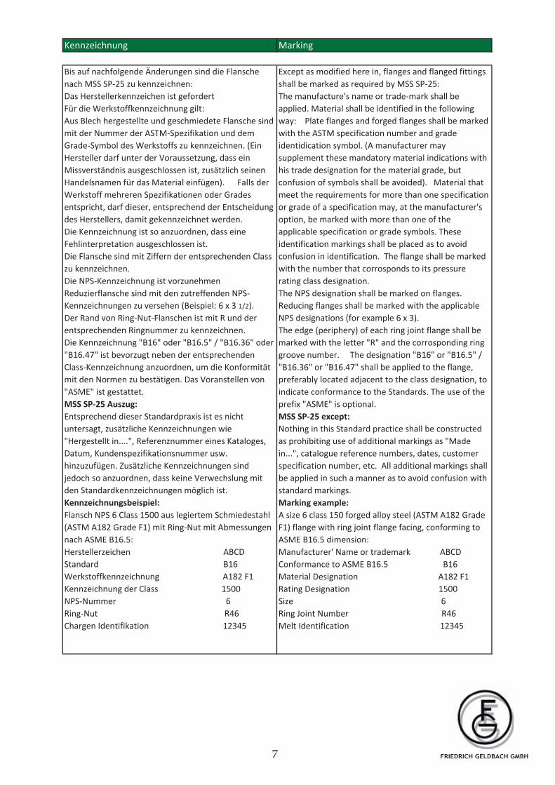
Kennzeichnung Marking
Bis auf nachfolgende Änderungen sind die Flansche
nach MSS SP-25 zu kennzeichnen:
Das Herstellerkennzeichen ist gefordert
Für die Werkstoffkennzeichnung gilt:
Aus Blech hergestellte und geschmiedete Flansche sind
mit der Nummer der ASTM-Spezifikation und dem
Grade-Symbol des Werkstoffs zu kennzeichnen. (Ein
Hersteller darf unter der Voraussetzung, dass ein
Missverständnis ausgeschlossen ist, zusätzlich seinen
Handelsnamen für das Material einfügen). Falls der
Werkstoff mehreren Spezifikationen oder Grades
entspricht, darf dieser, entsprechend der Entscheidung
des Herstellers, damit gekennzeichnet werden.
Die Kennzeichnung ist so anzuordnen, dass eine
Fehlinterpretation ausgeschlossen ist.
Die Flansche sind mit Ziffern der entsprechenden Class
zu kennzeichnen.
Die NPS-Kennzeichnung ist vorzunehmen
Reduzierflansche sind mit den zutreffenden NPS-
Kennzeichnungen zu versehen (Beispiel: 6 x 3 1/2).
Der Rand von Ring-Nut-Flanschen ist mit R und der
entsprechenden Ringnummer zu kennzeichnen.
Die Kennzeichnung "B16" oder "B16.5" / "B16.36" oder
"B16.47" ist bevorzugt neben der entsprechenden
Class-Kennzeichnung anzuordnen, um die Konformität
mit den Normen zu bestätigen. Das Voranstellen von
"ASME" ist gestattet.
MSS SP-25 Auszug:
Entsprechend dieser Standardpraxis ist es nicht
untersagt, zusätzliche Kennzeichnungen wie
"Hergestellt in....", Referenznummer eines Kataloges,
Datum, Kundenspezifikationsnummer usw.
hinzuzufügen. Zusätzliche Kennzeichnungen sind
jedoch so anzuordnen, dass keine Verwechslung mit
den Standardkennzeichnungen möglich ist.
Kennzeichnungsbeispiel:
Flansch NPS 6 Class 1500 aus legiertem Schmiedestahl
(ASTM A182 Grade F1) mit Ring-Nut mit Abmessungen
nach ASME B16.5:
Herstellerzeichen ABCD
Standard B16
Werkstoffkennzeichnung A182 F1
Kennzeichnung der Class 1500
NPS-Nummer 6
Ring-Nut R46
Chargen Identifikation 12345
Except as modified here in, flanges and flanged fittings
shall be marked as required by MSS SP-25:
The manufacture's name or trade-mark shall be
applied. Material shall be identified in the following
way: Plate flanges and forged flanges shall be marked
with the ASTM specification number and grade
identidication symbol. (A manufacturer may
supplement these mandatory material indications with
his trade designation for the material grade, but
confusion of symbols shall be avoided). Material that
meet the requirements for more than one specification
or grade of a specification may, at the manufacturer's
option, be marked with more than one of the
applicable specification or grade symbols. These
identification markings shall be placed as to avoid
confusion in identification. The flange shall be marked
with the number that corrosponds to its pressure
rating class designation.
The NPS designation shall be marked on flanges.
Reducing flanges shall be marked with the applicable
NPS designations (for example 6 x 3).
The edge (periphery) of each ring joint flange shall be
marked with the letter "R" and the corrosponding ring
groove number. The designation "B16" or "B16.5" /
"B16.36" or "B16.47" shall be applied to the flange,
preferably located adjacent to the class designation, to
indicate conformance to the Standards. The use of the
prefix "ASME" is optional.
MSS SP-25 except:
Nothing in this Standard practice shall be constructed
as prohibiting use of additional markings as "Made
in...", catalogue reference numbers, dates, customer
specification number, etc. All additional markings shall
be applied in such a manner as to avoid confusion with
standard markings.
Marking example:
A size 6 class 150 forged alloy steel (ASTM A182 Grade
F1) flange with ring joint flange facing, conforming to
ASME B16.5 dimension:
Manufacturer' Name or trademark ABCD
Conformance to ASME B16.5 B16
Material Designation A182 F1
Rating Designation 1500
Size 6
Ring Joint Number R46
Melt Identification 12345
FRIEDRICH GELDBACH GMBH
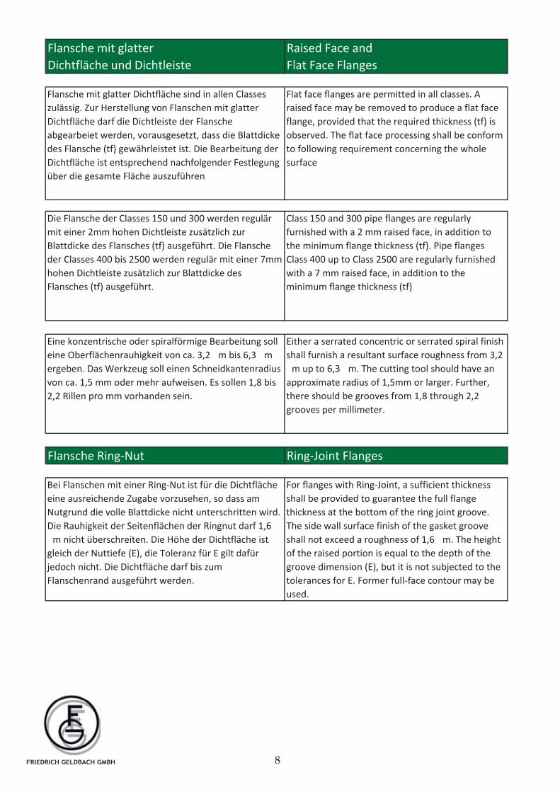
Bei Flanschen mit einer Ring-Nut ist für die Dichtfläche
eine ausreichende Zugabe vorzusehen, so dass am
Nutgrund die volle Blattdicke nicht unterschritten wird.
Die Rauhigkeit der Seitenflächen der Ringnut darf 1,6
m nicht überschreiten. Die Höhe der Dichtfläche ist
gleich der Nuttiefe (E), die Toleranz für E gilt dafür
jedoch nicht. Die Dichtfläche darf bis zum
Flanschenrand ausgeführt werden.
For flanges with Ring-Joint, a sufficient thickness
shall be provided to guarantee the full flange
thickness at the bottom of the ring joint groove.
The side wall surface finish of the gasket groove
shall not exceed a roughness of 1,6 m. The height
of the raised portion is equal to the depth of the
groove dimension (E), but it is not subjected to the
tolerances for E. Former full-face contour may be
used.
Die Flansche der Classes 150 und 300 werden regulär
mit einer 2mm hohen Dichtleiste zusätzlich zur
Blattdicke des Flansches (tf) ausgeführt. Die Flansche
der Classes 400 bis 2500 werden regulär mit einer 7mm
hohen Dichtleiste zusätzlich zur Blattdicke des
Flansches (tf) ausgeführt.
Class 150 and 300 pipe flanges are regularly
furnished with a 2 mm raised face, in addition to
the minimum flange thickness (tf). Pipe flanges
Class 400 up to Class 2500 are regularly furnished
with a 7 mm raised face, in addition to the
minimum flange thickness (tf)
Eine konzentrische oder spiralförmige Bearbeitung soll
eine Oberflächenrauhigkeit von ca. 3,2 m bis 6,3 m
ergeben. Das Werkzeug soll einen Schneidkantenradius
von ca. 1,5 mm oder mehr aufweisen. Es sollen 1,8 bis
2,2 Rillen pro mm vorhanden sein.
Either a serrated concentric or serrated spiral finish
shall furnish a resultant surface roughness from 3,2
m up to 6,3 m. The cutting tool should have an
approximate radius of 1,5mm or larger. Further,
there should be grooves from 1,8 through 2,2
grooves per millimeter.
Flansche Ring-Nut Ring-Joint Flanges
Flat face flanges are permitted in all classes. A
raised face may be removed to produce a flat face
flange, provided that the required thickness (tf) is
observed. The flat face processing shall be conform
to following requirement concerning the whole
surface
Flansche mit glatter Dichtfläche sind in allen Classes
zulässig. Zur Herstellung von Flanschen mit glatter
Dichtfläche darf die Dichtleiste der Flansche
abgearbeiet werden, vorausgesetzt, dass die Blattdicke
des Flansche (tf) gewährleistet ist. Die Bearbeitung der
Dichtfläche ist entsprechend nachfolgender Festlegung
über die gesamte Fläche auszuführen
Flansche mit glatter
Dichtfläche und Dichtleiste Flat Face Flanges
Raised Face and
FRIEDRICH GELDBACH GMBH
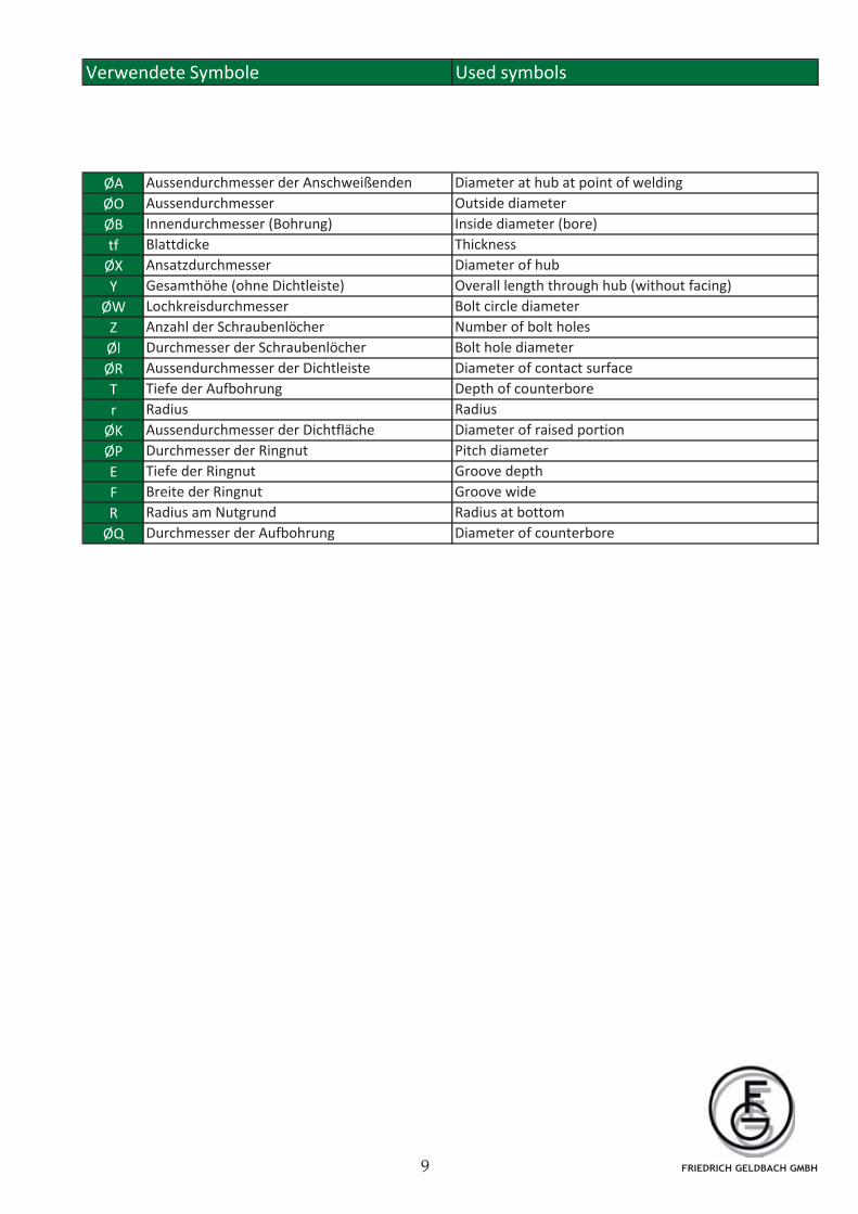
Verwendete Symbole Used symbols
ØA
ØO
ØB
tf
ØX
Y
ØW
Z
Øl
ØR
T
r
ØK
ØP
E
F
R
ØQ
Aussendurchmesser der Anschweißenden
Aussendurchmesser
Innendurchmesser (Bohrung)
Blattdicke
Diameter at hub at point of welding
Outside diameter
Inside diameter (bore)
Thickness
Ansatzdurchmesser
Gesamthöhe (ohne Dichtleiste)
Lochkreisdurchmesser
Anzahl der Schraubenlöcher
Durchmesser der Schraubenlöcher
Aussendurchmesser der Dichtleiste
Tiefe der Aufbohrung
Radius
Aussendurchmesser der Dichtfläche
Durchmesser der Ringnut
Tiefe der Ringnut
Breite der Ringnut
Radius am Nutgrund
Durchmesser der Aufbohrung
Diameter of hub
Overall length through hub (without facing)
Bolt circle diameter
Number of bolt holes
Bolt hole diameter
Diameter of contact surface
Depth of counterbore
Radius
Diameter of raised portion
Pitch diameter
Groove depth
Groove wide
Radius at bottom
Diameter of counterbore
FRIEDRICH GELDBACH GMBH
Production Range
ASME B16.47 ASME B16.47
Serie A Serie B
MSS SP-44*) API Std 605*)
When using printed standards, the most recent
issue of the original version shall prevail
Alloy 825
Maßgebend für das Anwenden der aufgeführten Normen ist
deren Original-Fassung mit dem neusten Ausgabedatum
ASTM A182 Grade F347 / F347H
ASTM A182 Grade F5
ASTM A182 Grade F11
ASTM A182 Grade F22
ASTM A182 Grade F91
Slip-On Flanges Ring Joint
Lap Joint Flanges150-2500
ASTM A182 Grade F51 / F60
ASTM A105
C21
ASTM A350 Grade LF2 Cl.1
ASTM A694 Grade F52
ASTM A182 Grade F316L / F304L
ASTM A182 Grade F321
ASME B16.5 BS 3293 ASME B16.36Flanschenart
Type of Flange
Blindflansche
Welding Neck Flanges
Long Welding Neck Flanges
Welding Neck Flanges Ring Joint
Slip-On Flanges
Threaded Flanges
Vorschweißflansche
Flanschstutzen ²)
Vorschweißflansche mit Ringnut
Überschiebflansche
Überschiebflansche mit Ringnut
Lose Flansche
Einsteckschweißflansche
Gewindeflansche
Orifice Flanges
Meßscheibenflansche
150-2500
150-1500
150-1500
150-1500
Blind Flanges
Socket Welding Flanges
150-2500
150-1500
150-2500
150-600
300-600
300-600
150-900
300-900
75-900
Material
Material Grade
75-900
Produktionsprogramm
*) für Flansche ab 26" *) for flanges from nominal size 26"
²) Flansche in Sonderausführung auf Anfrage ²) Flanges of special design on enquiry
Nenndruck / Nominal pressure
Lbs/sq. In.
300-2500
FRIEDRICH GELDBACH GMBH
X 1 NiCrMoCuN 25 20 5 (1.4539)
X 2 CrNi 19 11 (1.4306)
X 5 CrNiMo 17 13 2 (1.4401)
X 2 CrNiMo 17 13 2 (1.4404)
X 2 CrNiMoN 22 5 3 (1.4462)
X 1 NiCrMoCuN 25 20 6 (1.4529)
UNS S 31254 (254SMO)
X5CrNi18 10 (1.4301)
X2CrNi19-11 (1.4306)
X2CrNi18-9 (1.4307)
X5CrNiMo17-12-2 (1.4401)
X2CrNiMo17-12-2 (1.4404)
X2CrNiMoN22-5-3 (1.4462)
X1NiCrMoCuN25-20-7 (1.4529)
X1NiCrMoCu25-20-5 (1.4539)
X1CrNiMoCuN20-18-7 (1.4547)
A182 Grade F304L
A182 Grade F316
A182 Grade F316L
A182 Grade F51 (Duplex)
UNS N08926
A182 Grade F904L
ASTM EN DIN
X 5 CrNi 18 10 (1.4301)
ASTM A105
13CrMo4-5 ( 1.7335) - DIN EN 10222-2
10CrMo 9 10 (1.7380) -
X10 CrMoVNb9-1 (1.4903)
A182 Grade F304
A182 Grade F11, F12
A182 Grade F22
A182 Grade F5
A182 Grade F9
A350 Grade LF3
S355J2 (1.0570) - DIN EN 10250-2
P250GH (1.0460) - DIN EN 10222-2
P245GH (1.0352) - DIN EN 10222-2
A182 Grade F321
A182 Grade F1 16Mo3 (1.5415) - DIN EN 10222-2
A694 Grade F42
A694 Grade F52
A182 Grade F91
P355N ( 1.0562) - DIN EN 10222-4
A350 Grade LF2
12Ni14 (1.5637) - DIN EN 10222-3
P355QH1 (1.0571) - DIN EN 10222-4
St52.3 (1.0570)
C22.8 (1.1338) - DIN 17243
C21 (1.0432) - VdTÜV 399/3
S235JR (1.0036)
TStE 355 (1.0571) - DIN 17103
12CrMo19 5 (1.7362) - DIN 17175
A694 Grade F60
A694 Grade F70
13CrMo44 (1.7335) - DIN 17243
X6CrNiTi17-12-2 (1.4571) X 6 CrNiMoTi 17 12 2 (1.4571)
StE 285 (1.0486)
StE 355 (1.0562)
Kohlenstoffstahl unlegiert / Carbon steel
15Mo3 (1.5415) - DIN 17243
Warmfester Stahl legiert / Heat-resisting steel
Kaltzäher Stahl / steel tough at sub-zero temp.
Feinkornbaustahl / Fine Grained Steel
10Ni14 (1.5637)
Werkstoffgegenüberstellung
Comparison of Materials
A182 Grade F304L
P420N (1.8902) - DIN EN 10222-4
P460N (1.8905)
StE 420 (1.8902)
StE 460 (1.8905)
Edelstahl rostfrei / Stainless Steel
X6CrNiTi18-10 (1.4541) X 6 CrNiTi 18 10 (1.4541)
FRIEDRICH GELDBACH GMBH
Bar * ISO PSIG Class
PN Lbs. #
7 100
10 10
16 16
17 250
20 20 150
25 25
35 500
40 40
50 50 300
52 750
64 64
66 400
70 1000
100 100 600
105 1500
130 800
140 2000
150 150 900
175 2500
210 3000
245 3500
250 250 1500
280 4000
420 420 2500
Bar / PN / Lbs. / Class #
* Werte gerundet / values rounded
Druckzuordnung / Pressure allocation
FRIEDRICH GELDBACH GMBH
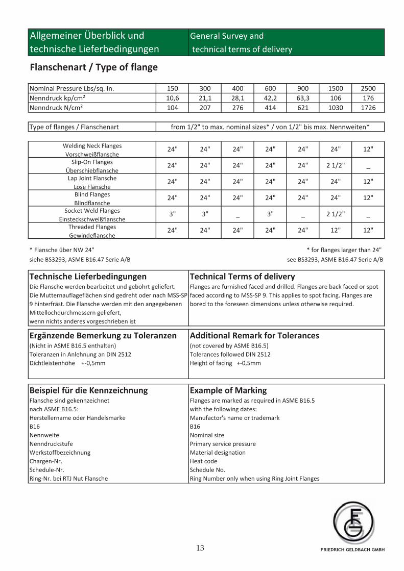
Allgemeiner Überblick und General Survey and
technische Lieferbedingungen technical terms of delivery
Flanschenart / Type of flange
Nominal Pressure Lbs/sq. In. 150 300 400 600 900 1500 2500
Nenndruck kp/cm² 10,6 21,1 28,1 42,2 63,3 106 176
Nenndruck N/cm² 104 207 276 414 621 1030 1726
Type of flanges / Flanschenart
* Flansche über NW 24"
siehe BS3293, ASME B16.47 Serie A/B see BS3293, ASME B16.47 Serie A/B
* for flanges larger than 24"
from 1/2" to max. nominal sizes* / von 1/2" bis max. Nennweiten*
Welding Neck Flanges
VorschweißflanscheSlip-On Flanges
ÜberschiebflanscheLap Joint Flansche
Lose FlanscheBlind Flanges
BlindflanscheSocket Weld Flanges
Einsteckschweißflansche
24"
24"
Threaded Flanges
Gewindeflansche
24"
24"
24"
24"
3"
24" 24"
24"
24"
24"
24"
_
24"
24"
24"
3"
24"
24"
24"
24"
3"
24"
24"
24"
24"
24"
_
24"
24"
2 1/2"
24"
24"
2 1/2"
12"
12"
_
12"
12"
_
12"
Additional Remark for Tolerances (not covered by ASME B16.5)
Tolerances followed DIN 2512
Height of facing +-0,5mm
Beispiel für die Kennzeichnung Flansche sind gekennzeichnet
nach ASME B16.5:
Herstellername oder Handelsmarke
B16
Nennweite
Nenndruckstufe
Werkstoffbezeichnung
Chargen-Nr.
Schedule-Nr.
Ring-Nr. bei RTJ Nut Flansche
Example of Marking Flanges are marked as required in ASME B16.5
with the following dates:
Manufactor's name or trademark
B16
Nominal size
Primary service pressure
Material designation
Heat code
Schedule No.
Ring Number only when using Ring Joint Flanges
Technical Terms of delivery Flanges are furnished faced and drilled. Flanges are back faced or spot
faced according to MSS-SP 9. This applies to spot facing. Flanges are
bored to the foreseen dimensions unless otherwise required.
Technische Lieferbedingungen Die Flansche werden bearbeitet und gebohrt geliefert.
Die Mutternauflageflächen sind gedreht oder nach MSS-SP
9 hinterfräst. Die Flansche werden mit den angegebenen
Mittellochdurchmessern geliefert,
wenn nichts anderes vorgeschrieben ist
Ergänzende Bemerkung zu Toleranzen (Nicht in ASME B16.5 enthalten)
Toleranzen in Anlehnung an DIN 2512
Dichtleistenhöhe +-0,5mm
FRIEDRICH GELDBACH GMBH
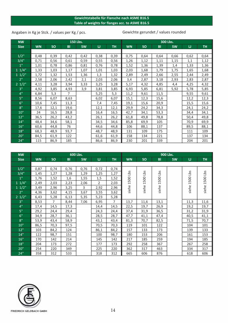
Gewichte gerundet / values rounded
NW
Size WN SO Bl SW LJ TH WN SO Bl SW LJ TH
1/2" 0,48 0,39 0,42 0,42 0,38 0,39 0,75 0,64 0,64 0,66 0,62 0,64
3/4" 0,71 0,56 0,61 0,59 0,55 0,56 1,26 1,12 1,11 1,15 1,1 1,12
1" 1,01 0,78 0,86 0,81 0,76 0,78 1,52 1,36 1,39 1,4 1,33 1,36
1 1/4" 1,33 1,03 1,17 1,07 1,01 1,03 2,03 1,68 1,79 1,75 1,65 1,68
1 1/2" 1,72 1,32 1,53 1,36 1,3 1,32 2,89 2,49 2,66 2,55 2,44 2,49
2" 2,58 2,06 2,42 2,1 2,03 2,06 3,4 2,87 3,18 2,93 2,83 2,87
2 1/2" 4,11 3,28 3,94 3,33 3,25 3,28 5,17 4,32 4,85 4,4 4,25 4,32
3" 4,92 3,85 4,93 3,9 3,81 3,85 6,93 5,85 6,81 5,92 5,78 5,85
4" 6,84 5,3 7 5,25 5,3 11,2 9,61 11,5 9,55 9,61
5" 8,56 6,07 8,63 6,02 6,07 15,1 12,3 15,6 12,2 12,3
6" 10,6 7,45 11,3 7,4 7,45 19,1 15,6 20,9 15,5 15,6
8" 17,6 12,1 19,6 12,1 12,1 29,9 24,2 34,3 24,1 24,2
10" 24 16,5 28,8 16,4 16,5 42,7 34,1 53,3 34,4 34,1
12" 36,5 26,2 43,2 26,1 26,2 61,8 49,8 78,8 50,4 49,8
14" 48,4 34,6 58,1 34,5 34,6 85,8 69,9 105 70,9 69,9
16" 60,6 44,8 76 44,6 44,8 106 88,1 137 89,5 88,1
18" 68,3 48,9 93,7 48,7 48,9 131 109 175 111 109
20" 84,5 61,9 122 61,6 61,9 158 134 221 137 134
24" 115 86,9 185 86,6 86,9 230 201 339 204 201
NW
Size WN SO Bl SW LJ TH WN SO Bl SW LJ TH
1/2" 0,87 0,74 0,76 0,76 0,72 0,74
3/4" 1,45 1,27 1,28 1,29 1,25 1,27
1" 1,76 1,52 1,6 1,55 1,5 1,52
1 1/4" 2,49 2,03 2,23 2,06 2 2,03
1 1/2" 3,49 2,96 3,25 3 2,92 2,96
2" 4,36 3,62 4,15 3,67 3,55 3,62
2 1/2" 6,43 5,28 6,13 5,35 5,23 5,28
3" 8,53 7 8,44 7,06 6,95 7 13,7 11,6 13,1 11,3 11,6
4" 17,4 14,5 17,3 14,4 14,5 22,5 19,7 26,9 19,2 19,7
5" 29,2 24,4 29,4 24,3 24,4 37,4 31,9 36,5 31,2 31,9
6" 34,9 28,7 36,1 28,5 28,7 47,7 41,1 47,4 40,5 41,1
8" 53,9 43,4 58,9 43,1 43,4 81,3 70,7 82,5 71,5 70,7
10" 86,5 70,3 97,5 70,5 70,3 119 101 122 104 101
12" 103 84,2 124 86,1 84,2 157 133 173 139 133
14" 122 98,7 151 100 98,7 180 153 206 161 153
16" 170 142 214 145 142 217 185 259 194 185
18" 204 173 272 177 173 292 258 367 267 258
20" 254 220 349 225 220 362 317 463 334 317
24" 358 312 533 318 312 665 606 876 618 606
Gewichtstabelle für Flansche nach ASME B16.5
Table of weights for flanges acc. to ASME B16.5
150 Lbs. 300 Lbs.
600 Lbs. 900 Lbs.
sie
he
15
00
Lb
s
sie
he
15
00
Lb
s
sie
he
15
00
Lb
s
sie
he
15
00
Lb
s
Angaben in Kg je Stck. / values per Kg / pcs.
sie
he
15
00
Lb
s
FRIEDRICH GELDBACH GMBH
NW
Size WN SO Bl SW LJ TH WN SO Bl SW LJ TH
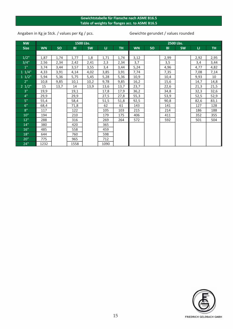
1/2" 1,87 1,74 1,77 1,8 1,71 1,74 3,12 2,99 2,92 2,95
3/4" 2,56 2,34 2,42 2,41 2,3 2,34 3,7 3,5 3,4 3,44
1" 3,74 3,44 3,57 3,55 3,4 3,44 5,24 4,96 4,77 4,82
1 1/4" 4,33 3,91 4,14 4,02 3,85 3,91 7,74 7,35 7,08 7,14
1 1/2" 5,94 5,36 5,75 5,45 5,28 5,36 10,9 10,4 9,93 10
2" 10,8 9,85 10,1 10,2 9,78 9,85 16,2 15,6 14,7 14,8
2 1/2" 15 13,7 14 13,9 13,6 13,7 23,7 22,6 21,3 21,5
3" 19,9 19,1 17,8 17,9 36,2 34,8 32,3 32,6
4" 29,9 29,9 27,5 27,8 55,3 53,9 52,5 52,9
5" 55,4 58,4 51,5 51,8 92,5 90,8 82,6 83,1
6" 68,4 71,8 62 61 143 141 127 128
8" 117 122 105 103 215 214 186 188
10" 194 210 179 175 406 411 352 355
12" 288 316 269 264 572 592 501 504
14" 380 420 365
16" 485 558 459
18" 644 760 598
20" 775 965 712
24" 1232 1558 1090
Gewichtstabelle für Flansche nach ASME B16.5
Table of weights for flanges acc. to ASME B16.5
2500 Lbs.1500 Lbs.
Angaben in Kg je Stck. / values per Kg / pcs. Gewichte gerundet / values rounded
FRIEDRICH GELDBACH GMBH
Angaben in Kg je Stck. / values per Kg / pcs. Gewichte gerundet / values rounded
NW
Size WN Bl WN Bl WN Bl
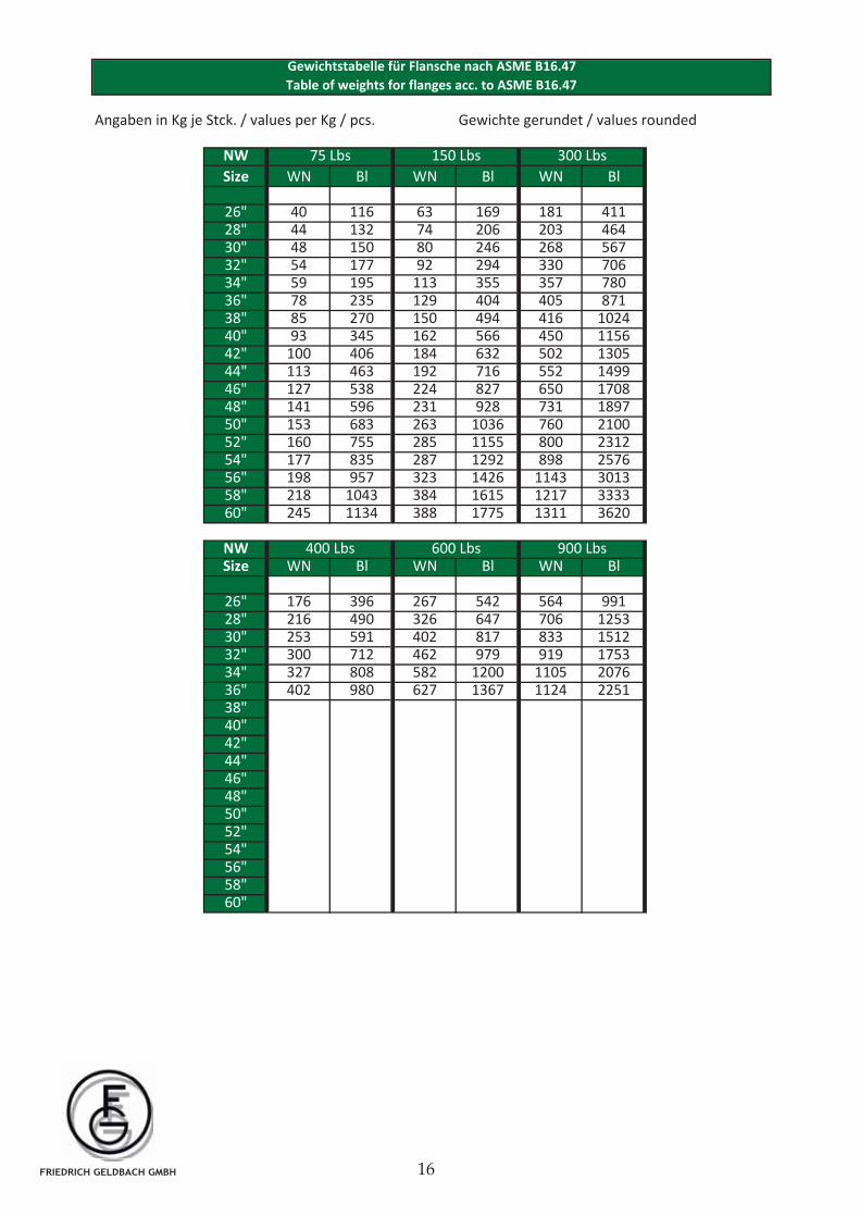
26" 40 116 63 169 181 41128" 44 132 74 206 203 46430" 48 150 80 246 268 56732" 54 177 92 294 330 70634" 59 195 113 355 357 78036" 78 235 129 404 405 87138" 85 270 150 494 416 102440" 93 345 162 566 450 115642" 100 406 184 632 502 130544" 113 463 192 716 552 149946" 127 538 224 827 650 170848" 141 596 231 928 731 189750" 153 683 263 1036 760 210052" 160 755 285 1155 800 231254" 177 835 287 1292 898 257656" 198 957 323 1426 1143 301358" 218 1043 384 1615 1217 333360" 245 1134 388 1775 1311 3620
NWSize WN Bl WN Bl WN Bl
26" 176 396 267 542 564 99128" 216 490 326 647 706 125330" 253 591 402 817 833 151232" 300 712 462 979 919 175334" 327 808 582 1200 1105 207636" 402 980 627 1367 1124 225138"40"42"44"46"48"50"52"54"56"58"60"
75 Lbs 150 Lbs
Gewichtstabelle für Flansche nach ASME B16.47
Table of weights for flanges acc. to ASME B16.47
300 Lbs
400 Lbs 600 Lbs 900 Lbs
FRIEDRICH GELDBACH GMBH
Class
Temperature
oC 150 300 400 600 900 1500 2500
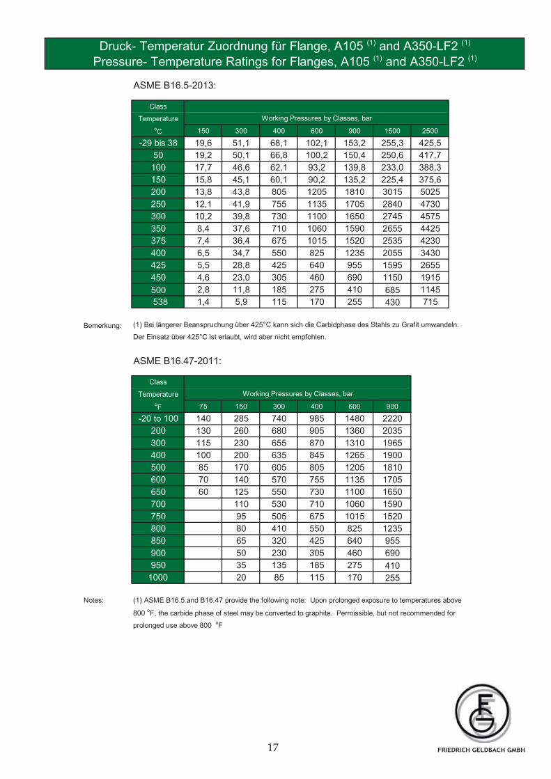
-29 bis 38 19,6 51,1 68,1 102,1 153,2 255,3 425,5
50 19,2 50,1 66,8 100,2 150,4 250,6 417,7
100 17,7 46,6 62,1 93,2 139,8 233,0 388,3
150 15,8 45,1 60,1 90,2 135,2 225,4 375,6
200 13,8 43,8 805 1205 1810 3015 5025
250 12,1 41,9 755 1135 1705 2840 4730
300 10,2 39,8 730 1100 1650 2745 4575
350 8,4 37,6 710 1060 1590 2655 4425
375 7,4 36,4 675 1015 1520 2535 4230
400 6,5 34,7 550 825 1235 2055 3430
425 5,5 28,8 425 640 955 1595 2655
450 4,6 23,0 305 460 690 1150 1915
500 2,8 11,8 185 275 410 685 1145
538 1,4 5,9 115 170 255 430 715
Bemerkung: (1) Bei längerer Beanspruchung über 425°C kann sich die Carbidphase des Stahls zu Grafit umwandeln.
Der Einsatz über 425°C ist erlaubt, wird aber nicht empfohlen.
Class
Temperature
oF 75 150 300 400 600 900
-20 to 100 140 285 740 985 1480 2220
200 130 260 680 905 1360 2035
300 115 230 655 870 1310 1965
400 100 200 635 845 1265 1900
500 85 170 605 805 1205 1810
600 70 140 570 755 1135 1705
650 60 125 550 730 1100 1650
700 110 530 710 1060 1590
750 95 505 675 1015 1520
800 80 410 550 825 1235
850 65 320 425 640 955
900 50 230 305 460 690
950 35 135 185 275 410
1000 20 85 115 170 255
Notes: (1) ASME B16.5 and B16.47 provide the following note: Upon prolonged exposure to temperatures above
800 oF, the carbide phase of steel may be converted to graphite. Permissible, but not recommended for
prolonged use above 800 oF
Druck- Temperatur Zuordnung für Flange, A105 (1) and A350-LF2 (1)
Working Pressures by Classes, bar
Working Pressures by Classes, bar
ASME B16.5-2013:
ASME B16.47-2011:
Pressure- Temperature Ratings for Flanges, A105 (1) and A350-LF2 (1)
FRIEDRICH GELDBACH GMBH
A105 (1) (2)
A350-LF2 (1) (2) C21 F52 F304 F316
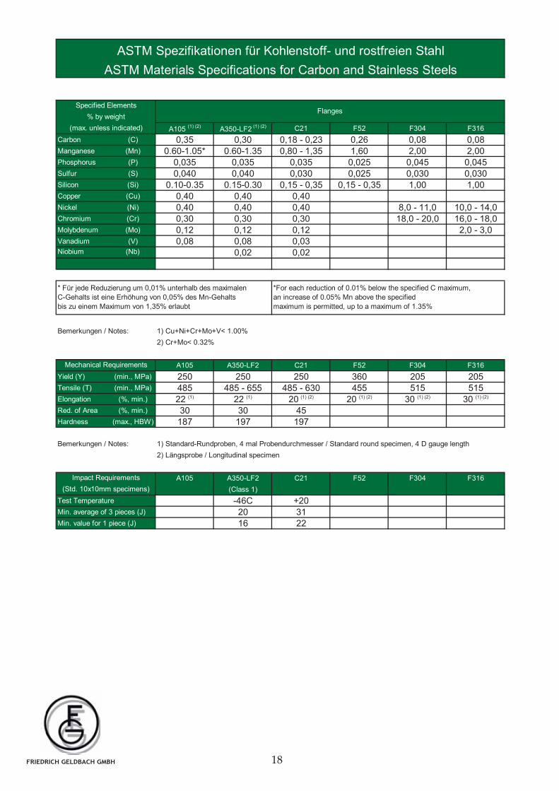
Carbon (C) 0,35 0,30 0,18 - 0,23 0,26 0,08 0,08Manganese (Mn) 0.60-1.05* 0.60-1.35 0,80 - 1,35 1,60 2,00 2,00Phosphorus (P) 0,035 0,035 0,035 0,025 0,045 0,045Sulfur (S) 0,040 0,040 0,030 0,025 0,030 0,030Silicon (Si) 0.10-0.35 0.15-0.30 0,15 - 0,35 0,15 - 0,35 1,00 1,00Copper (Cu) 0,40 0,40 0,40Nickel (Ni) 0,40 0,40 0,40 8,0 - 11,0 10,0 - 14,0Chromium (Cr) 0,30 0,30 0,30 18,0 - 20,0 16,0 - 18,0Molybdenum (Mo) 0,12 0,12 0,12 2,0 - 3,0Vanadium (V) 0,08 0,08 0,03Niobium (Nb) 0,02 0,02
A105 A350-LF2 C21 F52 F304 F316
Yield (Y) (min., MPa) 250 250 250 360 205 205Tensile (T) (min., MPa) 485 485 - 655 485 - 630 455 515 515Elongation (%, min.) 22 (1) 22 (1) 20
(1) (2) 20 (1) (2) 30 (1) (2) 30 (1) (2)
Red. of Area (%, min.) 30 30 45Hardness (max., HBW) 187 197 197
A105 A350-LF2 C21 F52 F304 F316
(Class 1)
Test Temperature -46C +20Min. average of 3 pieces (J) 20 31Min. value for 1 piece (J) 16 22
ASTM Spezifikationen für Kohlenstoff- und rostfreien Stahl
ASTM Materials Specifications for Carbon and Stainless Steels
Flanges
*For each reduction of 0.01% below the specified C maximum,
an increase of 0.05% Mn above the specified
maximum is permitted, up to a maximum of 1.35%
* Für jede Reduzierung um 0,01% unterhalb des maximalen
C-Gehalts ist eine Erhöhung von 0,05% des Mn-Gehalts
bis zu einem Maximum von 1,35% erlaubt
Bemerkungen / Notes:
Bemerkungen / Notes: 1) Cu+Ni+Cr+Mo+V< 1.00%
2) Cr+Mo< 0.32%
1) Standard-Rundproben, 4 mal Probendurchmesser / Standard round specimen, 4 D gauge length
(Std. 10x10mm specimens)
% by weight
(max. unless indicated)
Mechanical Requirements
Specified Elements
Impact Requirements
2) Längsprobe / Longitudinal specimen
FRIEDRICH GELDBACH GMBH
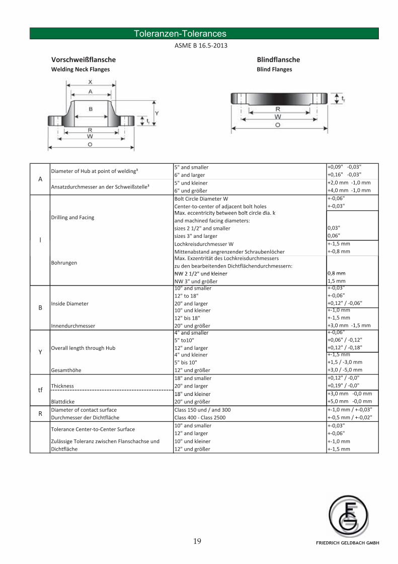
Toleranzen-Tolerances
ASME B 16.5-2013
Vorschweißflansche BlindflanscheWelding Neck Flanges Blind Flanges
+0,09" -0,03"
+0,16" -0,03"
+2,0 mm -1,0 mm
+4,0 mm -1,0 mm
+-0,06"
+-0,03"Max eccentricity between bolt circle dia k
A5" und kleiner
6" und größer
5" and smaller
6" and largerDiameter of Hub at point of welding³
Bolt Circle Diameter W
Center-to-center of adjacent bolt holes
Ansatzdurchmesser an der Schweißstelle³
0,03"
0,06"
+-1,5 mm
+-0,8 mm
0 8 mm
Max. eccentricity between bolt circle dia. k
and machined facing diameters:
sizes 2 1/2" and smaller
sizes 3" and larger
Lochkreisdurchmesser W
Mittenabstand angrenzender SchraubenlöcherMax. Exzentrität des Lochkreisdurchmessers
zu den bearbeitenden Dichtflächendurchmessern:
NW 2 1/2" und kleiner
l
Drilling and Facing
Bohrungen
0,8 mm
1,5 mm+-0,03"
+-0,06"
+0,12" / -0,06"+-1,0 mm
+-1,5 mm
+3,0 mm -1,5 mm+-0,06"
Innendurchmesser
10" und kleiner
12" bis 18"
20" und größer
NW 2 1/2" und kleiner
NW 3" und größer10" and smaller
12" to 18"
20" and larger
4" and smaller
BInside Diameter
,
+0,06" / -0,12"
+0,12" / -0,18"+-1,5 mm
+1,5 / -3,0 mm
+3,0 / -5,0 mm
+0,12" / -0,0"
+0,19" / -0,0"
+3,0 mm -0,0 mm
Y
18" und kleiner
4 and smaller
5" to10"
12" and larger Overall length through Hub
tf
18" and smaller
20" and larger
Gesamthöhe
Thickness
4" und kleiner
5" bis 10"
12" und größer
, ,
+5,0 mm -0,0 mm
+-1,0 mm / +-0,03"
+-0,5 mm / +-0,02"
Diameter of contact surface
Durchmesser der Dichtfläche
Class 150 und / and 300
Class 400 - Class 2500R
Tolerance Center-to-Center Surface10" and smaller
12" and larger
18 und kleiner
20" und größerBlattdicke
+-0,03"
+-0,06"
Zulässige Toleranz zwischen Flanschachse und
Dichtfläche
10" und kleiner
12" und größer
+-1,0 mm
+-1,5 mm
FRIEDRICH GELDBACH GMBH
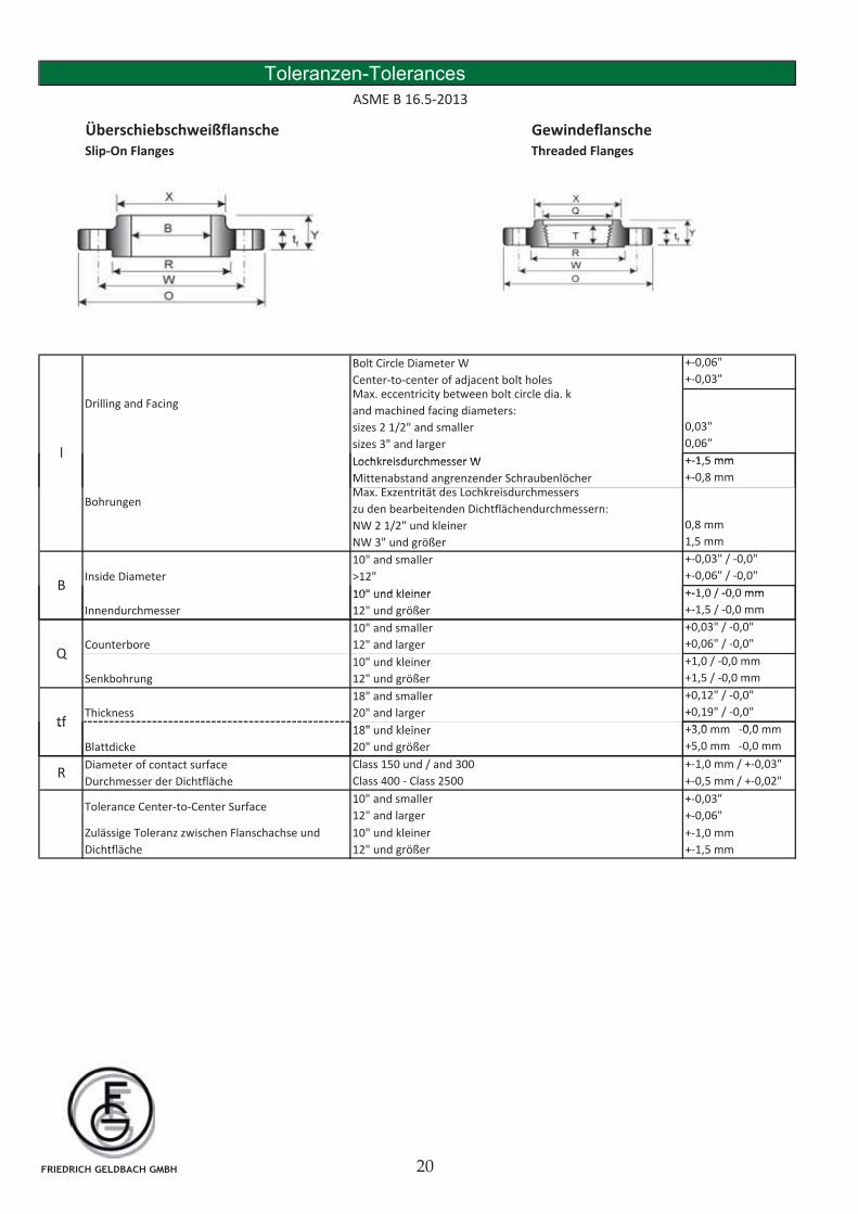
Toleranzen-Tolerances
ASME B 16.5-2013
Überschiebschweißflansche GewindeflanscheSlip-On Flanges Threaded Flanges
+-0,06"
+-0,03"
0,03"
0,06"
+-1 5 mm
Max. eccentricity between bolt circle dia. k
and machined facing diameters:
sizes 2 1/2" and smaller
sizes 3" and larger
Bolt Circle Diameter W
Center-to-center of adjacent bolt holes
l
Drilling and Facing
Lochkreisdurchmesser W +-1,5 mm
+-0,8 mm
0,8 mm
1,5 mm
+-0,03" / -0,0"
+-0,06" / -0,0"
+-1 0 / -0 0 mmB
Bohrungen
Inside Diameter
Max. Exzentrität des Lochkreisdurchmessers
zu den bearbeitenden Dichtflächendurchmessern:
NW 2 1/2" und kleiner
NW 3" und größer
10" und kleiner
10" and smaller
>12"
Lochkreisdurchmesser W
Mittenabstand angrenzender Schraubenlöcher
+-1,0 / -0,0 mm
+-1,5 / -0,0 mm
+0,03" / -0,0"
+0,06" / -0,0"
+1,0 / -0,0 mm
+1,5 / -0,0 mm
+0,12" / -0,0"
+0,19" / -0,0"
+3 0 mm 0 0 mm
10" and smaller
12" and larger
Innendurchmesser
tf
18" and smaller
20" and larger
Senkbohrung
10" und kleiner
12" und größer
18" d kl i
Q
Thickness
10" und kleiner
12" und größer
Counterbore
+3,0 mm -0,0 mm
+5,0 mm -0,0 mm
+-1,0 mm / +-0,03"
+-0,5 mm / +-0,02"R
tf
Diameter of contact surface
Durchmesser der Dichtfläche
18" und kleiner
20" und größer
Class 150 und / and 300
Class 400 - Class 2500
Blattdicke
+-0,03"
+-0,06"
Zulässige Toleranz zwischen Flanschachse und
Dichtfläche
10" und kleiner
12" und größer
+-1,0 mm
+-1,5 mm
Tolerance Center-to-Center Surface10" and smaller
12" and larger
FRIEDRICH GELDBACH GMBH
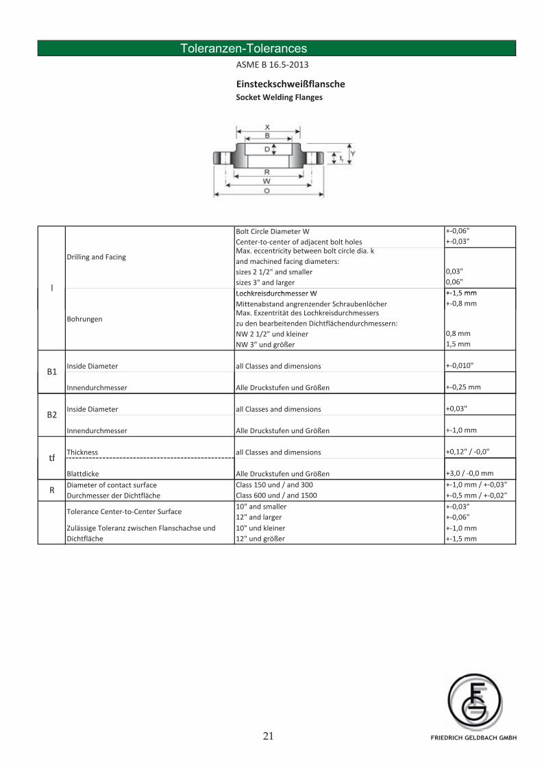
Toleranzen-Tolerances
ASME B 16.5-2013
Einsteckschweißflansche Socket Welding Flanges
+-0,06"
+-0,03"
0,03"
0,06"
+-1 5 mmLochkreisdurchmesser W
Drilling and Facing
Bolt Circle Diameter W
Center-to-center of adjacent bolt holes
l
Max. eccentricity between bolt circle dia. k
and machined facing diameters:
sizes 2 1/2" and smaller
sizes 3" and larger
+-1,5 mm
+-0,8 mm
0,8 mm
1,5 mm
+-0,010"
Lochkreisdurchmesser W
Mittenabstand angrenzender Schraubenlöcher
Bohrungen
Inside Diameter
Max. Exzentrität des Lochkreisdurchmessers
zu den bearbeitenden Dichtflächendurchmessern:
NW 2 1/2" und kleiner
NW 3" und größer
all Classes and dimensionsB1
+-0,25 mm
+0,03"
+-1,0 mm
+0,12" / -0,0"
Inside Diameter B2
Thickness
Alle Druckstufen und Größen
all Classes and dimensions
Innendurchmesser
tfall Classes and dimensions
Innendurchmesser Alle Druckstufen und Größen
+3,0 / -0,0 mm
+-1,0 mm / +-0,03"
+-0,5 mm / +-0,02"
Class 150 und / and 300
Class 600 und / and 1500
Blattdicke
+-0,03"
+-0,06"
Zulässige Toleranz zwischen Flanschachse und
Dichtfläche
10" und kleiner
12" und größer
+-1,0 mm
+-1,5 mm
Tolerance Center-to-Center Surface10" and smaller
12" and larger
Diameter of contact surface
Durchmesser der Dichtfläche
Alle Druckstufen und Größen
R
tf
FRIEDRICH GELDBACH GMBH
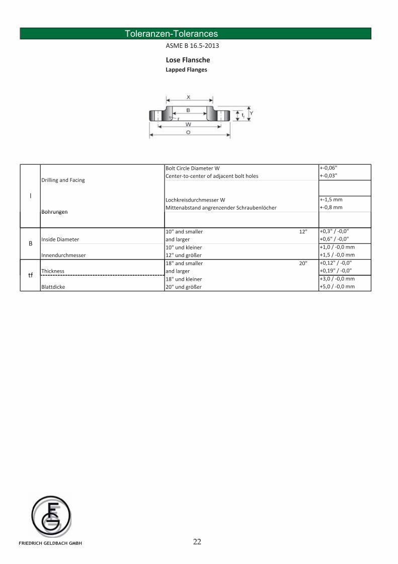
Toleranzen-Tolerances
ASME B 16.5-2013
Lose Flansche Lapped Flanges
+-0,06"
+-0,03"
+-1,5 mm
+-0,8 mm
Bolt Circle Diameter W
Center-to-center of adjacent bolt holes
lLochkreisdurchmesser W
Mittenabstand angrenzender Schraubenlöcher
Drilling and Facing
Bohrungen
+0,3" / -0,0"
+0,6" / -0,0"
+1,0 / -0,0 mm
+1,5 / -0,0 mm
+0,12" / -0,0"
+0,19" / -0,0"
Innendurchmesser
tf
18" and smaller 20"
and larger
B
10" and smaller 12"
and larger
Bohrungen
Inside Diameter
Thickness
10" und kleiner
12" und größer
+3,0 / -0,0 mm
+5,0 / -0,0 mm
tf18" und kleiner
20" und größerBlattdicke
FRIEDRICH GELDBACH GMBH
Vorschweißflansche BlindflanscheWelding Neck Flanges Blind Flanges
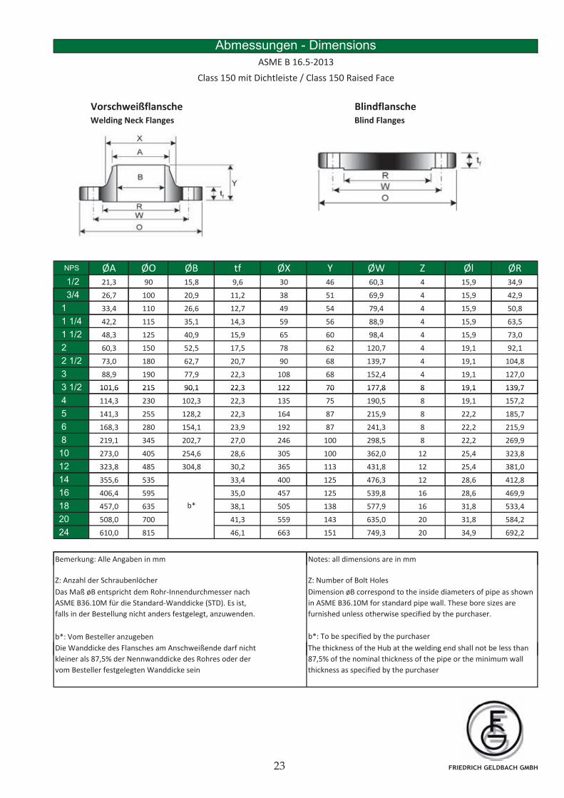
Abmessungen - Dimensions
ASME B 16.5-2013
Class 150 mit Dichtleiste / Class 150 Raised Face
NPS ØA ØO ØB tf ØX Y ØW Z Øl ØR1/2 21,3 90 15,8 9,6 30 46 60,3 4 15,9 34,9
3/4 26,7 100 20,9 11,2 38 51 69,9 4 15,9 42,9
1 33,4 110 26,6 12,7 49 54 79,4 4 15,9 50,8
1 1/4 42,2 115 35,1 14,3 59 56 88,9 4 15,9 63,5
1 1/2 48,3 125 40,9 15,9 65 60 98,4 4 15,9 73,0
2 60,3 150 52,5 17,5 78 62 120,7 4 19,1 92,1
2 1/2 73,0 180 62,7 20,7 90 68 139,7 4 19,1 104,8
3 88,9 190 77,9 22,3 108 68 152,4 4 19,1 127,0
3 1/2 101,6 215 90,1 22,3 122 70 177,8 8 19,1 139,73 1/2 101,6 215 90,1 22,3 122 70 177,8 8 19,1 139,7
4 114,3 230 102,3 22,3 135 75 190,5 8 19,1 157,2
5 141,3 255 128,2 22,3 164 87 215,9 8 22,2 185,7
6 168,3 280 154,1 23,9 192 87 241,3 8 22,2 215,9
8 219,1 345 202,7 27,0 246 100 298,5 8 22,2 269,9
10 273,0 405 254,6 28,6 305 100 362,0 12 25,4 323,8
12 323,8 485 304,8 30,2 365 113 431,8 12 25,4 381,0
14 355 6 535 33 4 400 125 476 3 12 28 6 412 814 355,6 535 33,4 400 125 476,3 12 28,6 412,8
16 406,4 595 35,0 457 125 539,8 16 28,6 469,9
18 457,0 635 38,1 505 138 577,9 16 31,8 533,4
20 508,0 700 41,3 559 143 635,0 20 31,8 584,2
24 610,0 815 46,1 663 151 749,3 20 34,9 692,2
Bemerkung: Alle Angaben in mm Notes: all dimensions are in mm
b*
g g
Dimension øB correspond to the inside diameters of pipe as shown
in ASME B36.10M for standard pipe wall. These bore sizes are
furnished unless otherwise specified by the purchaser.
Das Maß øB entspricht dem Rohr-Innendurchmesser nach
ASME B36.10M für die Standard-Wanddicke (STD). Es ist,
falls in der Bestellung nicht anders festgelegt, anzuwenden.
b*: Vom Besteller anzugeben b*: To be specified by the purchaser
Die Wanddicke des Flansches am Anschweißende darf nicht The thickness of the Hub at the welding end shall not be less than
Z: Anzahl der Schraubenlöcher Z: Number of Bolt Holes
kleiner als 87,5% der Nennwanddicke des Rohres oder der
vom Besteller festgelegten Wanddicke sein
g
87,5% of the nominal thickness of the pipe or the minimum wall
thickness as specified by the purchaser
FRIEDRICH GELDBACH GMBH
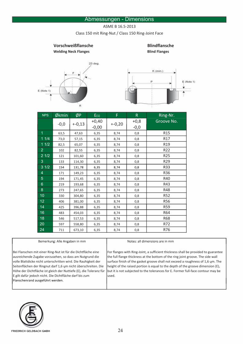
Vorschweißflansche BlindflanscheWelding Neck Flanges Blind Flanges
Abmessungen - Dimensions
Class 150 mit Ring-Nut / Class 150 Ring-Joint Face
ASME B 16.5-2013
NPS Økmin ØP E(1) F R
+0,40 +0,8
-0,00 -0,0
Groove No.+-0,13 +-0,20-0,0
Ring-Nr.
, ,1 63,5 47,63 6,35 8,74 0,8
1 1/4 73,0 57,15 6,35 8,74 0,8
1 1/2 82,5 65,07 6,35 8,74 0,8
2 102 82,55 6,35 8,74 0,8
2 1/2 121 101,60 6,35 8,74 0,8
3 133 114,30 6,35 8,74 0,8
3 1/2 154 131 78 6 35 8 74 0 8
R17
R19
R22
R25
R29
R33
R15
3 1/2 154 131,78 6,35 8,74 0,8
4 171 149,23 6,35 8,74 0,8
5 194 171,45 6,35 8,74 0,8
6 219 193,68 6,35 8,74 0,8
8 273 247,65 6,35 8,74 0,8
10 330 304,80 6,35 8,74 0,8
12 406 381,00 6,35 8,74 0,8
14
R48
R52
R56
R36
R40
R43
R33
14 425 396,88 6,35 8,74 0,8
16 483 454,03 6,35 8,74 0,8
18 546 517,53 6,35 8,74 0,8
20 597 558,80 6,35 8,74 0,8
24 711 673,10 6,35 8,74 0,8
Bemerkung: Alle Angaben in mm Notes: all dimensions are in mm
R68
R72
R76
R59
R64
e e u g e gabe otes a d e s o s a e
Bei Flanschen mit einer Ring-Nut ist für die Dichtfläche eine
ausreichende Zugabe vorzusehen, so dass am Nutgrund die
volle Blattdicke nicht unterschritten wird. Die Rauhigkeit der
Seitenflächen der Ringnut darf 1,6 m nicht überschreiten. Die
Höhe der Dichtfläche ist gleich der Nuttiefe (E), die Toleranz für
E gilt dafür jedoch nicht. Die Dichtfläche darf bis zum
Flanschenrand ausgeführt werden
For flanges with Ring-Joint, a sufficient thickness shall be provided to guarantee
the full flange thickness at the bottom of the ring joint groove. The side wall
surface finish of the gasket groove shall not exceed a roughness of 1,6 m. The
height of the raised portion is equal to the depth of the groove dimension (E),
but it is not subjected to the tolerances for E. Former full-face contour may be
used.
Flanschenrand ausgeführt werden.
FRIEDRICH GELDBACH GMBH
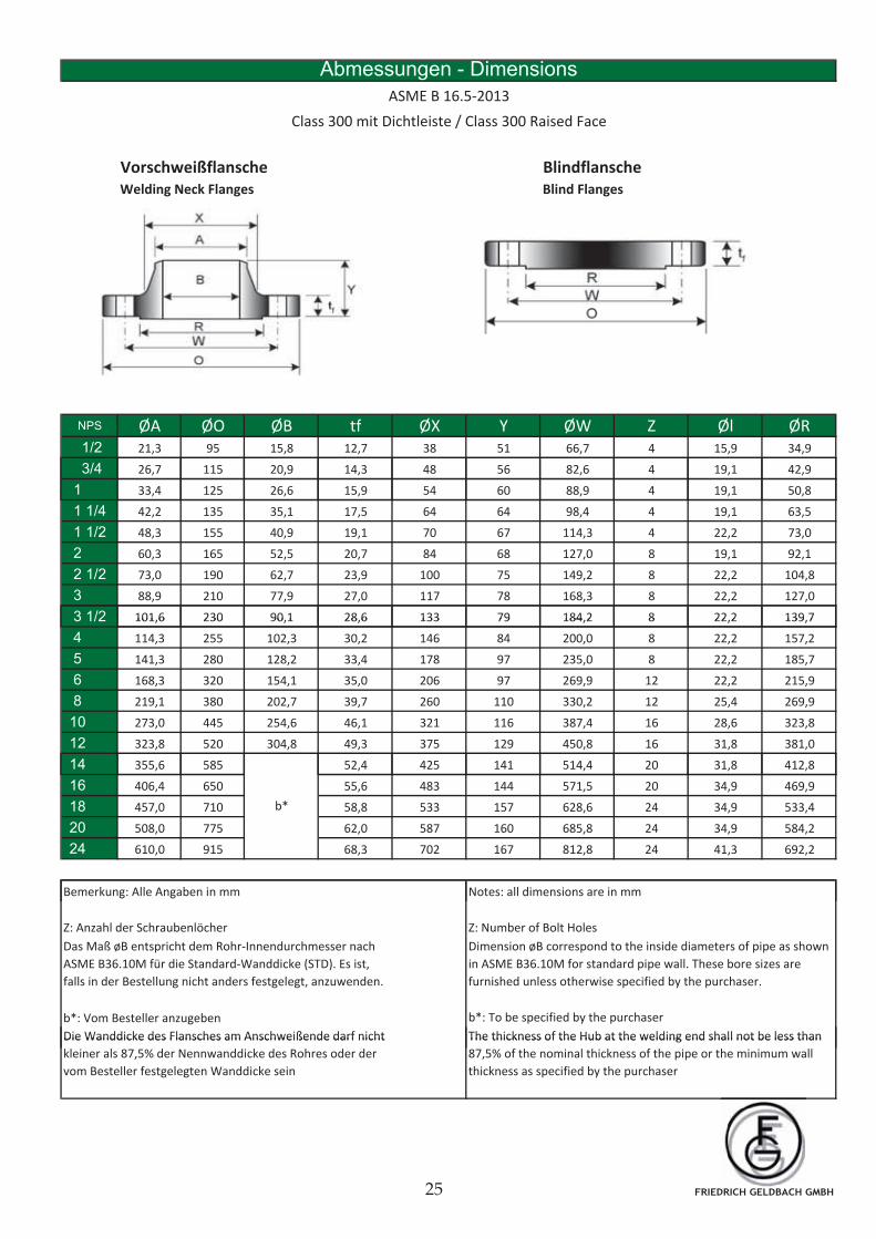
Vorschweißflansche BlindflanscheWelding Neck Flanges Blind Flanges
Abmessungen - Dimensions
ASME B 16.5-2013
Class 300 mit Dichtleiste / Class 300 Raised Face
NPS ØA ØO ØB tf ØX Y ØW Z Øl ØR1/2 21,3 95 15,8 12,7 38 51 66,7 4 15,9 34,9
3/4 26,7 115 20,9 14,3 48 56 82,6 4 19,1 42,9
1 33,4 125 26,6 15,9 54 60 88,9 4 19,1 50,8
1 1/4 42,2 135 35,1 17,5 64 64 98,4 4 19,1 63,5
1 1/2 48,3 155 40,9 19,1 70 67 114,3 4 22,2 73,0
2 60,3 165 52,5 20,7 84 68 127,0 8 19,1 92,1
2 1/2 73,0 190 62,7 23,9 100 75 149,2 8 22,2 104,8
3 88,9 210 77,9 27,0 117 78 168,3 8 22,2 127,0
3 1/2 101,6 230 90,1 28,6 133 79 184,2 8 22,2 139,73 1/2 101,6 230 90,1 28,6 133 79 184,2 8 22,2 139,7
4 114,3 255 102,3 30,2 146 84 200,0 8 22,2 157,2
5 141,3 280 128,2 33,4 178 97 235,0 8 22,2 185,7
6 168,3 320 154,1 35,0 206 97 269,9 12 22,2 215,9
8 219,1 380 202,7 39,7 260 110 330,2 12 25,4 269,9
10 273,0 445 254,6 46,1 321 116 387,4 16 28,6 323,8
12 323,8 520 304,8 49,3 375 129 450,8 16 31,8 381,0
14 355 6 585 52 4 425 141 514 4 20 31 8 412 814 355,6 585 52,4 425 141 514,4 20 31,8 412,8
16 406,4 650 55,6 483 144 571,5 20 34,9 469,9
18 457,0 710 58,8 533 157 628,6 24 34,9 533,4
20 508,0 775 62,0 587 160 685,8 24 34,9 584,2
24 610,0 915 68,3 702 167 812,8 24 41,3 692,2
Bemerkung: Alle Angaben in mm Notes: all dimensions are in mm
b*
g g
Dimension øB correspond to the inside diameters of pipe as shown
in ASME B36.10M for standard pipe wall. These bore sizes are
furnished unless otherwise specified by the purchaser.
Das Maß øB entspricht dem Rohr-Innendurchmesser nach
ASME B36.10M für die Standard-Wanddicke (STD). Es ist,
falls in der Bestellung nicht anders festgelegt, anzuwenden.
b*: Vom Besteller anzugeben b*: To be specified by the purchaser
Die Wanddicke des Flansches am Anschweißende darf nicht The thickness of the Hub at the welding end shall not be less than
Z: Anzahl der Schraubenlöcher Z: Number of Bolt Holes
Die Wanddicke des Flansches am Anschweißende darf nicht
kleiner als 87,5% der Nennwanddicke des Rohres oder der
vom Besteller festgelegten Wanddicke sein
The thickness of the Hub at the welding end shall not be less than
87,5% of the nominal thickness of the pipe or the minimum wall
thickness as specified by the purchaser
FRIEDRICH GELDBACH GMBH
Vorschweißflansche BlindflanscheWelding Neck Flanges Blind Flanges
Abmessungen - Dimensions
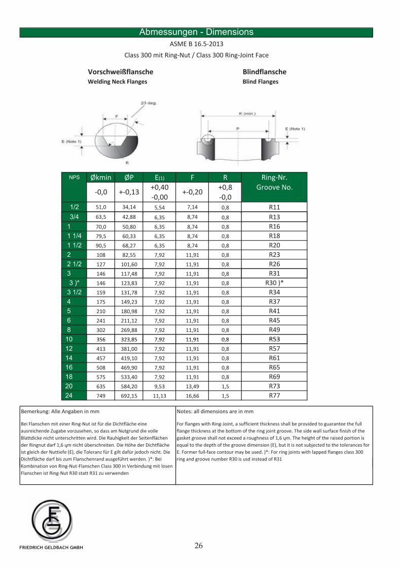
Class 300 mit Ring-Nut / Class 300 Ring-Joint Face
ASME B 16.5-2013
NPS Økmin ØP E(1) F R
+0,40 +0,8
-0,00 -0,0
1/2 51,0 34,14 5,54 7,14 0,8
3/4 63 2 88 8
Ring-Nr.
Groove No.
R11
R13
+-0,13 +-0,20-0,0
3/4 63,5 42,88 6,35 8,74 0,8
1 70,0 50,80 6,35 8,74 0,8
1 1/4 79,5 60,33 6,35 8,74 0,8
1 1/2 90,5 68,27 6,35 8,74 0,8
2 108 82,55 7,92 11,91 0,8
2 1/2 127 101,60 7,92 11,91 0,8
3 146 117,48 7,92 11,91 0,8
R20
R16
R13
R18
R23
R26
R31, , , ,
3 )* 146 123,83 7,92 11,91 0,8
3 1/2 159 131,78 7,92 11,91 0,8
4 175 149,23 7,92 11,91 0,8
5 210 180,98 7,92 11,91 0,8
6 241 211,12 7,92 11,91 0,8
8 302 269,88 7,92 11,91 0,8
10 356 323 85 7 92 11 91 0 8 R53
R34
R41
R45
R49
R30 )*
R37
10 356 323,85 7,92 11,91 0,8
12 413 381,00 7,92 11,91 0,8
14 457 419,10 7,92 11,91 0,8
16 508 469,90 7,92 11,91 0,8
18 575 533,40 7,92 11,91 0,8
20 635 584,20 9,53 13,49 1,5
24 749 692,15 11,13 16,66 1,5
R53
R57
R61
R65
R69
R73
R77
Notes: all dimensions are in mm
Bei Flanschen mit einer Ring-Nut ist für die Dichtfläche eine
ausreichende Zugabe vorzusehen, so dass am Nutgrund die volle
Blattdicke nicht unterschritten wird. Die Rauhigkeit der Seitenflächen
der Ringnut darf 1,6 m nicht überschreiten. Die Höhe der Dichtfläche
ist gleich der Nuttiefe (E), die Toleranz für E gilt dafür jedoch nicht. Die
Dichtfläche darf bis zum Flanschenrand ausgeführt werden. )*: Bei
For flanges with Ring-Joint, a sufficient thickness shall be provided to guarantee the full
flange thickness at the bottom of the ring joint groove. The side wall surface finish of the
gasket groove shall not exceed a roughness of 1,6 m. The height of the raised portion is
equal to the depth of the groove dimension (E), but it is not subjected to the tolerances for
E. Former full-face contour may be used. )*: For ring joints with lapped flanges class 300
ring and groove number R30 is usd instead of R31
Bemerkung: Alle Angaben in mm
Kombination von Ring-Nut-Flanschen Class 300 in Verbindung mit losen
Flanschen ist Ring-Nut R30 statt R31 zu verwenden
FRIEDRICH GELDBACH GMBH
Vorschweißflansche BlindflanscheWelding Neck Flanges Blind Flanges
Abmessungen - Dimensions
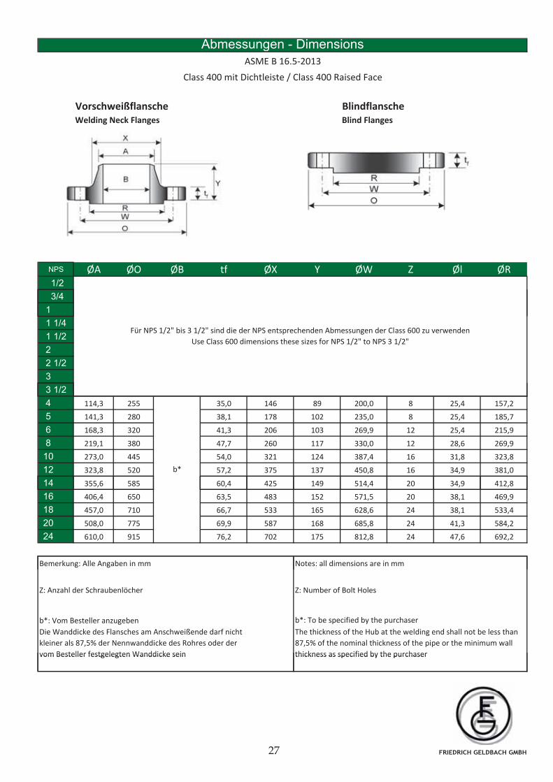
ASME B 16.5-2013
Class 400 mit Dichtleiste / Class 400 Raised Face
NPS ØA ØO ØB tf ØX Y ØW Z Øl ØR1/2
3/4
1
1 1/4
1 1/2
2
2 1/2
3
3 1/2
Für NPS 1/2" bis 3 1/2" sind die der NPS entsprechenden Abmessungen der Class 600 zu verwenden
Use Class 600 dimensions these sizes for NPS 1/2" to NPS 3 1/2"
3 1/2
4 114,3 255 35,0 146 89 200,0 8 25,4 157,2
5 141,3 280 38,1 178 102 235,0 8 25,4 185,7
6 168,3 320 41,3 206 103 269,9 12 25,4 215,9
8 219,1 380 47,7 260 117 330,0 12 28,6 269,9
10 273,0 445 54,0 321 124 387,4 16 31,8 323,8
12 323,8 520 57,2 375 137 450,8 16 34,9 381,0
14 355 6 585 60 4 425 149 514 4 20 34 9 412 8
b*
14 355,6 585 60,4 425 149 514,4 20 34,9 412,8
16 406,4 650 63,5 483 152 571,5 20 38,1 469,9
18 457,0 710 66,7 533 165 628,6 24 38,1 533,4
20 508,0 775 69,9 587 168 685,8 24 41,3 584,2
24 610,0 915 76,2 702 175 812,8 24 47,6 692,2
Bemerkung: Alle Angaben in mm Notes: all dimensions are in mmg g
Z: Anzahl der Schraubenlöcher Z: Number of Bolt Holes
b*: Vom Besteller anzugeben b*: To be specified by the purchaser
Die Wanddicke des Flansches am Anschweißende darf nicht
kleiner als 87,5% der Nennwanddicke des Rohres oder der
vom Besteller festgelegten Wanddicke sein
The thickness of the Hub at the welding end shall not be less than
87,5% of the nominal thickness of the pipe or the minimum wall
thickness as specified by the purchaservom Besteller festgelegten Wanddicke sein thickness as specified by the purchaser
FRIEDRICH GELDBACH GMBH
Vorschweißflansche BlindflanscheWelding Neck Flanges Blind Flanges
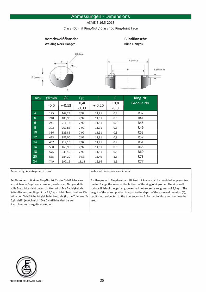
Abmessungen - Dimensions
Class 400 mit Ring-Nut / Class 400 Ring-Joint Face
ASME B 16.5-2013
NPS Økmin ØP E(1) F R
+0,40 +0,8
-0,00 -0,0+-0,13 +-0,20-0,0
Ring-Nr.
Groove No.
, ,4 175 149,23 7,92 11,91 0,8
5 210 180,98 7,92 11,91 0,8
6 241 211,12 7,92 11,91 0,8
8 302 269,88 7,92 11,91 0,8
10 356 323,85 7,92 11,91 0,8
12 413 381,00 7,92 11,91 0,8
14 457 419 10 7 92 11 91 0 8 R61
R41
R45
R53
R57
R37
R49
14 457 419,10 7,92 11,91 0,8
16 508 469,90 7,92 11,91 0,8
18 575 533,40 7,92 11,91 0,8
20 635 584,20 9,53 13,49 1,5
24 749 692,15 11,13 16,66 1,5
Notes: all dimensions are in mm
R61
R65
R69
R73
R77
Bemerkung: Alle Angaben in mm
Bei Flanschen mit einer Ring-Nut ist für die Dichtfläche eine
ausreichende Zugabe vorzusehen, so dass am Nutgrund die
volle Blattdicke nicht unterschritten wird. Die Rauhigkeit der
Seitenflächen der Ringnut darf 1,6 m nicht überschreiten. Die
Höhe der Dichtfläche ist gleich der Nuttiefe (E), die Toleranz für
E gilt dafür jedoch nicht. Die Dichtfläche darf bis zum
Flanschenrand ausgeführt werden.
For flanges with Ring-Joint, a sufficient thickness shall be provided to guarantee
the full flange thickness at the bottom of the ring joint groove. The side wall
surface finish of the gasket groove shall not exceed a roughness of 1,6 m. The
height of the raised portion is equal to the depth of the groove dimension (E),
but it is not subjected to the tolerances for E. Former full-face contour may be
used.
FRIEDRICH GELDBACH GMBH
Vorschweißflansche BlindflanscheWelding Neck Flanges Blind Flanges
Abmessungen - Dimensions
ASME B 16.5-2013
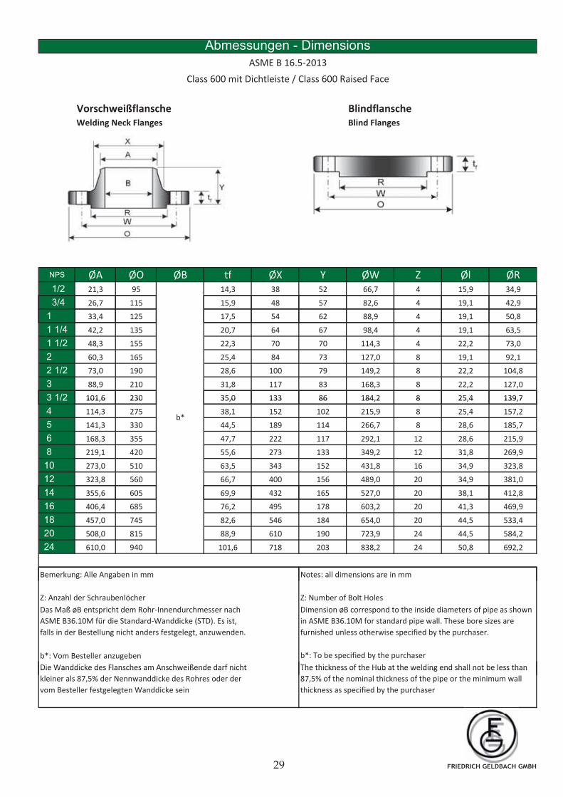
Class 600 mit Dichtleiste / Class 600 Raised Face
NPS ØA ØO ØB tf ØX Y ØW Z Øl ØR1/2 21,3 95 14,3 38 52 66,7 4 15,9 34,9
3/4 26,7 115 15,9 48 57 82,6 4 19,1 42,9
1 33,4 125 17,5 54 62 88,9 4 19,1 50,8
1 1/4 42,2 135 20,7 64 67 98,4 4 19,1 63,5
1 1/2 48,3 155 22,3 70 70 114,3 4 22,2 73,0
2 60,3 165 25,4 84 73 127,0 8 19,1 92,1
2 1/2 73,0 190 28,6 100 79 149,2 8 22,2 104,8
3 88,9 210 31,8 117 83 168,3 8 22,2 127,0
3 1/2 101,6 230 35,0 133 86 184,2 8 25,4 139,73 1/2 101,6 230 35,0 133 86 184,2 8 25,4 139,7
4 114,3 275 38,1 152 102 215,9 8 25,4 157,2
5 141,3 330 44,5 189 114 266,7 8 28,6 185,7
6 168,3 355 47,7 222 117 292,1 12 28,6 215,9
8 219,1 420 55,6 273 133 349,2 12 31,8 269,9
10 273,0 510 63,5 343 152 431,8 16 34,9 323,8
12 323,8 560 66,7 400 156 489,0 20 34,9 381,0
14 355 6 605 69 9 432 165 527 0 20 38 1 412 8
b*
14 355,6 605 69,9 432 165 527,0 20 38,1 412,8
16 406,4 685 76,2 495 178 603,2 20 41,3 469,9
18 457,0 745 82,6 546 184 654,0 20 44,5 533,4
20 508,0 815 88,9 610 190 723,9 24 44,5 584,2
24 610,0 940 101,6 718 203 838,2 24 50,8 692,2
Bemerkung: Alle Angaben in mm Notes: all dimensions are in mmg g
Dimension øB correspond to the inside diameters of pipe as shown
in ASME B36.10M for standard pipe wall. These bore sizes are
furnished unless otherwise specified by the purchaser.
Das Maß øB entspricht dem Rohr-Innendurchmesser nach
ASME B36.10M für die Standard-Wanddicke (STD). Es ist,
falls in der Bestellung nicht anders festgelegt, anzuwenden.
b*: Vom Besteller anzugeben b*: To be specified by the purchaser
Die Wanddicke des Flansches am Anschweißende darf nicht The thickness of the Hub at the welding end shall not be less than
Z: Anzahl der Schraubenlöcher Z: Number of Bolt Holes
Die Wanddicke des Flansches am Anschweißende darf nicht
kleiner als 87,5% der Nennwanddicke des Rohres oder der
vom Besteller festgelegten Wanddicke sein
The thickness of the Hub at the welding end shall not be less than
87,5% of the nominal thickness of the pipe or the minimum wall
thickness as specified by the purchaser
FRIEDRICH GELDBACH GMBH

Vorschweißflansche BlindflanscheWelding Neck Flanges Blind Flanges
Abmessungen - Dimensions
Class 600 mit Ring-Nut / Class 600 Ring-Joint Face
ASME B 16.5-2013
NPS Økmin ØP E(1) F R
+0,40 +0,8
-0,00 -0,0
1/2 51,0 34,14 5,54 7,14 0,8
3/4 63 2 88 8
+-0,13 +-0,20-0,0
Ring-Nr.
Groove No.
R11
R133/4 63,5 42,88 6,35 8,74 0,8
1 70,0 50,80 6,35 8,74 0,8
1 1/4 79,5 60,33 6,35 8,74 0,8
1 1/2 90,5 68,27 6,35 8,74 0,8
2 108 82,55 7,92 11,91 0,8
2 1/2 127 101,60 7,92 11,91 0,8
3 146 117,48 7,92 11,91 0,8
R13
R18
R23
R16
R20
R26
R31, , , ,
3 )* 146 123,83 7,92 11,91 0,8
3 1/2 159 131,78 7,92 11,91 0,8
4 175 149,23 7,92 11,91 0,8
5 210 180,98 7,92 11,91 0,8
6 241 211,12 7,92 11,91 0,8
8 302 269,88 7,92 11,91 0,8
10 356 323 85 7 92 11 91 0 8
R30 )*
R37
R34
R41
R45
R49
R5310 356 323,85 7,92 11,91 0,8
12 413 381,00 7,92 11,91 0,8
14 457 419,10 7,92 11,91 0,8
16 508 469,90 7,92 11,91 0,8
18 575 533,40 7,92 11,91 0,8
20 635 584,20 9,53 13,49 1,5
24 749 692,15 11,13 16,66 1,5
R61
R65
R69
R73
R77
R53
R57
Bemerkung: Alle Angaben in mm Notes: all dimensions are in mm
Bei Flanschen mit einer Ring-Nut ist für die Dichtfläche eine
ausreichende Zugabe vorzusehen, so dass am Nutgrund die volle
Blattdicke nicht unterschritten wird. Die Rauhigkeit der Seitenflächen
der Ringnut darf 1,6 m nicht überschreiten. Die Höhe der Dichtfläche
ist gleich der Nuttiefe (E), die Toleranz für E gilt dafür jedoch nicht. Die
Dichtfläche darf bis zum Flanschenrand ausgeführt werden. )*: Bei
For flanges with Ring-Joint, a sufficient thickness shall be provided to guarantee the full
flange thickness at the bottom of the ring joint groove. The side wall surface finish of the
gasket groove shall not exceed a roughness of 1,6 m. The height of the raised portion is
equal to the depth of the groove dimension (E), but it is not subjected to the tolerances for
E. Former full-face contour may be used. )*: For ring joints with lapped flanges class 600
ring and groove number R30 is usd instead of R31
Kombination von Ring-Nut-Flanschen Class 600 in Verbindung mit losen
Flanschen ist Ring-Nut R30 statt R31 zu verwenden
FRIEDRICH GELDBACH GMBH
Vorschweißflansche BlindflanscheWelding Neck Flanges Blind Flanges
Abmessungen - Dimensions
ASME B 16.5-2013
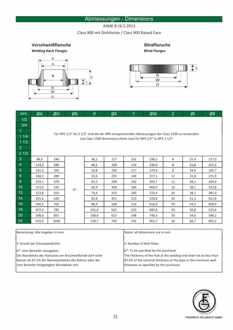
Class 900 mit Dichtleiste / Class 900 Raised Face
NPS ØA ØO ØB tf ØX Y ØW Z Øl ØR1/2
3/4
1
1 1/4
1 1/2
2
2 1/2
3 88,9 240 38,1 127 102 190,5 8 25,4 127,0
4 114,3 290 44,5 159 114 235,0 8 31,8 157,2
Für NPS 1/2" bis 2 1/2" sind die der NPS entsprechenden Abmessungen der Class 1500 zu verwenden
Use Class 1500 dimensions these sizes for NPS 1/2" to NPS 2 1/2"
4 114,3 290 44,5 159 114 235,0 8 31,8 157,2
5 141,3 350 50,8 190 127 279,4 8 34,9 185,7
6 168,3 380 55,6 235 140 317,5 12 31,8 215,9
8 219,1 470 63,5 298 162 393,7 12 38,1 269,9
10 273,0 545 69,9 368 184 469,9 16 38,1 323,8
12 323,8 610 79,4 419 200 533,4 20 38,1 381,0
14 355,6 640 85,8 451 213 558,8 20 41,3 412,8
16 406 4 705 88 9 508 216 616 0 20 44 5 469 9
b*
16 406,4 705 88,9 508 216 616,0 20 44,5 469,9
18 457,0 785 101,6 565 229 685,8 20 50,8 533,4
20 508,0 855 108,0 622 248 749,3 20 54,0 584,2
24 610,0 1040 139,7 749 292 901,7 20 66,7 692,2
Bemerkung: Alle Angaben in mm Notes: all dimensions are in mm
Z: Anzahl der Schraubenlöcher Z: Number of Bolt Holes
b*: Vom Besteller anzugeben b*: To be specified by the purchaser
Die Wanddicke des Flansches am Anschweißende darf nicht
kleiner als 87,5% der Nennwanddicke des Rohres oder der
vom Besteller festgelegten Wanddicke sein
The thickness of the Hub at the welding end shall not be less than
87,5% of the nominal thickness of the pipe or the minimum wall
thickness as specified by the purchaser
FRIEDRICH GELDBACH GMBH
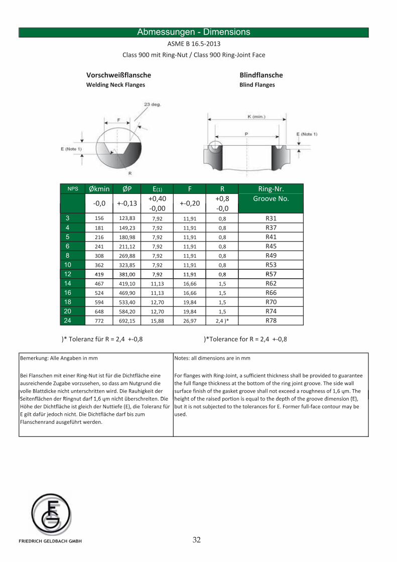
Vorschweißflansche BlindflanscheWelding Neck Flanges Blind Flanges
Abmessungen - Dimensions
Class 900 mit Ring-Nut / Class 900 Ring-Joint Face
ASME B 16.5-2013
NPS Økmin ØP E(1) F R
+0,40 +0,8
-0,00 -0,0+-0,13 +-0,20-0,0
Ring-Nr.
Groove No.
, ,
3 156 123,83 7,92 11,91 0,8
4 181 149,23 7,92 11,91 0,8
5 216 180,98 7,92 11,91 0,8
6 241 211,12 7,92 11,91 0,8
8 308 269,88 7,92 11,91 0,8
10 362 323,85 7,92 11,91 0,8
12 419 381 00 7 92 11 91 0 8
R31
R37
R41
R53
R57
R45
R49
12 419 381,00 7,92 11,91 0,8
14 467 419,10 11,13 16,66 1,5
16 524 469,90 11,13 16,66 1,5
18 594 533,40 12,70 19,84 1,5
20 648 584,20 12,70 19,84 1,5
24 772 692,15 15,88 26,97 2,4 )*
R62
R66
R70
R74
R57
R78
)* Toleranz für R = 2,4 +-0,8 )*Tolerance for R = 2,4 +-0,8
Bemerkung: Alle Angaben in mm Notes: all dimensions are in mm
Bei Flanschen mit einer Ring-Nut ist für die Dichtfläche eine
ausreichende Zugabe vorzusehen, so dass am Nutgrund die
volle Blattdicke nicht unterschritten wird. Die Rauhigkeit der
Seitenflächen der Ringnut darf 1 6 m nicht überschreiten Die
For flanges with Ring-Joint, a sufficient thickness shall be provided to guarantee
the full flange thickness at the bottom of the ring joint groove. The side wall
surface finish of the gasket groove shall not exceed a roughness of 1,6 m. The
height of the raised portion is equal to the depth of the groove dimension (E)Seitenflächen der Ringnut darf 1,6 m nicht überschreiten. Die
Höhe der Dichtfläche ist gleich der Nuttiefe (E), die Toleranz für
E gilt dafür jedoch nicht. Die Dichtfläche darf bis zum
Flanschenrand ausgeführt werden.
height of the raised portion is equal to the depth of the groove dimension (E),
but it is not subjected to the tolerances for E. Former full-face contour may be
used.
FRIEDRICH GELDBACH GMBH
Vorschweißflansche BlindflanscheWelding Neck Flanges Blind Flanges
Abmessungen - Dimensions
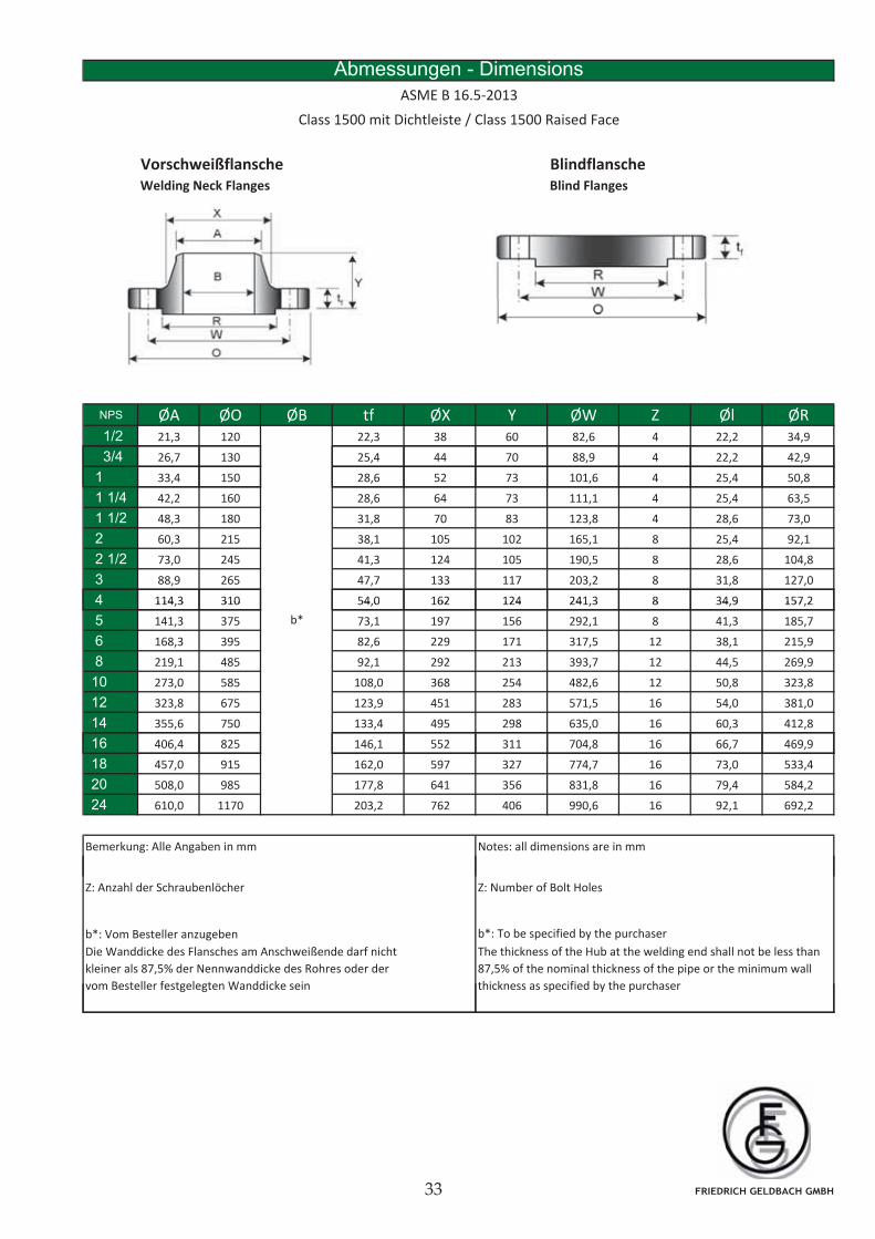
ASME B 16.5-2013
Class 1500 mit Dichtleiste / Class 1500 Raised Face
NPS ØA ØO ØB tf ØX Y ØW Z Øl ØR1/2 21,3 120 22,3 38 60 82,6 4 22,2 34,9
3/4 26,7 130 25,4 44 70 88,9 4 22,2 42,9
1 33,4 150 28,6 52 73 101,6 4 25,4 50,8
1 1/4 42,2 160 28,6 64 73 111,1 4 25,4 63,5
1 1/2 48,3 180 31,8 70 83 123,8 4 28,6 73,0
2 60,3 215 38,1 105 102 165,1 8 25,4 92,1
2 1/2 73,0 245 41,3 124 105 190,5 8 28,6 104,8
3 88,9 265 47,7 133 117 203,2 8 31,8 127,0
4 114,3 310 54,0 162 124 241,3 8 34,9 157,24 114,3 310 54,0 162 124 241,3 8 34,9 157,2
5 141,3 375 73,1 197 156 292,1 8 41,3 185,7
6 168,3 395 82,6 229 171 317,5 12 38,1 215,9
8 219,1 485 92,1 292 213 393,7 12 44,5 269,9
10 273,0 585 108,0 368 254 482,6 12 50,8 323,8
12 323,8 675 123,9 451 283 571,5 16 54,0 381,0
14 355,6 750 133,4 495 298 635,0 16 60,3 412,8
16 406 4 825 146 1 552 311 704 8 16 66 7 469 9
b*
16 406,4 825 146,1 552 311 704,8 16 66,7 469,9
18 457,0 915 162,0 597 327 774,7 16 73,0 533,4
20 508,0 985 177,8 641 356 831,8 16 79,4 584,2
24 610,0 1170 203,2 762 406 990,6 16 92,1 692,2
Bemerkung: Alle Angaben in mm Notes: all dimensions are in mm
Z: Anzahl der Schraubenlöcher Z: Number of Bolt Holes
b*: Vom Besteller anzugeben b*: To be specified by the purchaser
Die Wanddicke des Flansches am Anschweißende darf nicht
kleiner als 87,5% der Nennwanddicke des Rohres oder der
vom Besteller festgelegten Wanddicke sein
The thickness of the Hub at the welding end shall not be less than
87,5% of the nominal thickness of the pipe or the minimum wall
thickness as specified by the purchaser
FRIEDRICH GELDBACH GMBH
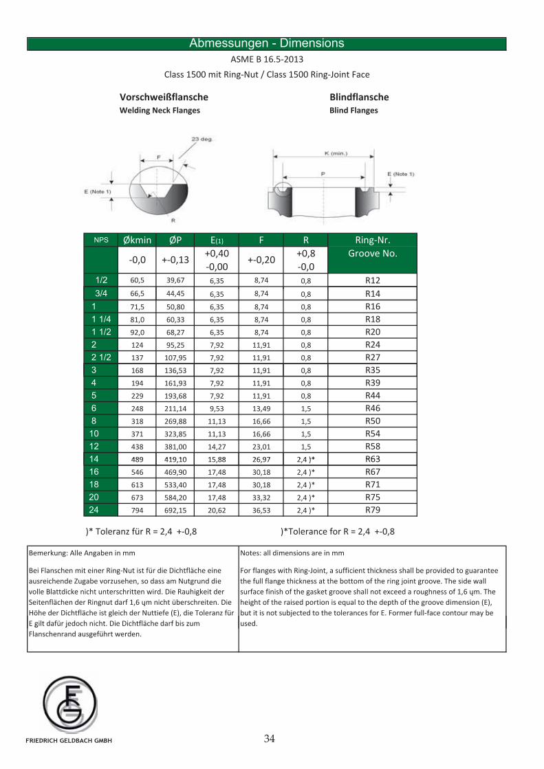
Vorschweißflansche BlindflanscheWelding Neck Flanges Blind Flanges
Abmessungen - Dimensions
Class 1500 mit Ring-Nut / Class 1500 Ring-Joint Face
ASME B 16.5-2013
NPS Økmin ØP E(1) F R
+0,40 +0,8
-0,00 -0,0
1/2 60,5 39,67 6,35 8,74 0,8
3/4 66 8
R12
R14
+-0,13 +-0,20-0,0Groove No.
Ring-Nr.
3/4 66,5 44,45 6,35 8,74 0,8
1 71,5 50,80 6,35 8,74 0,8
1 1/4 81,0 60,33 6,35 8,74 0,8
1 1/2 92,0 68,27 6,35 8,74 0,8
2 124 95,25 7,92 11,91 0,8
2 1/2 137 107,95 7,92 11,91 0,8
3 168 136,53 7,92 11,91 0,8
R16
R14
R18
R20
R24
R27
R35, , , ,
4 194 161,93 7,92 11,91 0,8
5 229 193,68 7,92 11,91 0,8
6 248 211,14 9,53 13,49 1,5
8 318 269,88 11,13 16,66 1,5
10 371 323,85 11,13 16,66 1,5
12 438 381,00 14,27 23,01 1,5
14 489 419 10 15 88 26 97 2 4 )*
R46
R50
R54
R58
R39
R44
R6314 489 419,10 15,88 26,97 2,4 )*
16 546 469,90 17,48 30,18 2,4 )*
18 613 533,40 17,48 30,18 2,4 )*
20 673 584,20 17,48 33,32 2,4 )*
24 794 692,15 20,62 36,53 2,4 )*
)* Toleranz für R = 2,4 +-0,8 )*Tolerance for R = 2,4 +-0,8
R79
R63
R67
R75
R71
Bei Flanschen mit einer Ring-Nut ist für die Dichtfläche eine
ausreichende Zugabe vorzusehen, so dass am Nutgrund die
volle Blattdicke nicht unterschritten wird. Die Rauhigkeit der
Seitenflächen der Ringnut darf 1,6 m nicht überschreiten. Die
Höhe der Dichtfläche ist gleich der Nuttiefe (E), die Toleranz für
E gilt dafür jedoch nicht. Die Dichtfläche darf bis zum
For flanges with Ring-Joint, a sufficient thickness shall be provided to guarantee
the full flange thickness at the bottom of the ring joint groove. The side wall
surface finish of the gasket groove shall not exceed a roughness of 1,6 m. The
height of the raised portion is equal to the depth of the groove dimension (E),
but it is not subjected to the tolerances for E. Former full-face contour may be
used.
Bemerkung: Alle Angaben in mm Notes: all dimensions are in mm
g j
Flanschenrand ausgeführt werden.
FRIEDRICH GELDBACH GMBH
Vorschweißflansche BlindflanscheWelding Neck Flanges Blind Flanges
Abmessungen - Dimensions
ASME B 16.5-2013
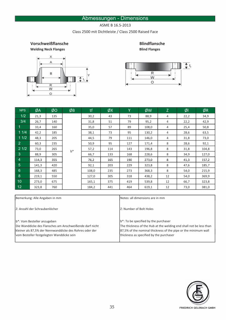
Class 2500 mit Dichtleiste / Class 2500 Raised Face
NPS ØA ØO ØB tf ØX Y ØW Z Øl ØR1/2 21,3 135 30,2 43 73 88,9 4 22,2 34,9
3/4 26,7 140 31,8 51 79 95,2 4 22,2 42,9
1 33,4 160 35,0 57 89 108,0 4 25,4 50,8
1 1/4 42,2 185 38,1 73 95 130,2 4 28,6 63,5
1 1/2 48,3 205 44,5 79 111 146,0 4 31,8 73,0
2 60,3 235 50,9 95 127 171,4 8 28,6 92,1
2 1/2 73,0 265 57,2 114 143 196,8 8 31,8 104,8
3 88,9 305 66,7 133 168 228,6 8 34,9 127,0
4 114,3 355 76,2 165 190 273,0 8 41,3 157,2
b*
4 114,3 355 76,2 165 190 273,0 8 41,3 157,2
5 141,3 420 92,1 203 229 323,8 8 47,6 185,7
6 168,3 485 108,0 235 273 368,3 8 54,0 215,9
8 219,1 550 127,0 305 318 438,2 12 54,0 369,9
10 273,0 675 165,1 375 419 539,8 12 66,7 323,8
12 323,8 760 184,2 441 464 619,1 12 73,0 381,0
B k All A b i N ll di i iBemerkung: Alle Angaben in mm Notes: all dimensions are in mm
Z: Anzahl der Schraubenlöcher Z: Number of Bolt Holes
b*: Vom Besteller anzugeben b*: To be specified by the purchaser
Die Wanddicke des Flansches am Anschweißende darf nicht
kleiner als 87,5% der Nennwanddicke des Rohres oder der
The thickness of the Hub at the welding end shall not be less than
87,5% of the nominal thickness of the pipe or the minimum wall
vom Besteller festgelegten Wanddicke sein thickness as specified by the purchaser
FRIEDRICH GELDBACH GMBH
Vorschweißflansche BlindflanscheWelding Neck Flanges Blind Flanges
Abmessungen - Dimensions
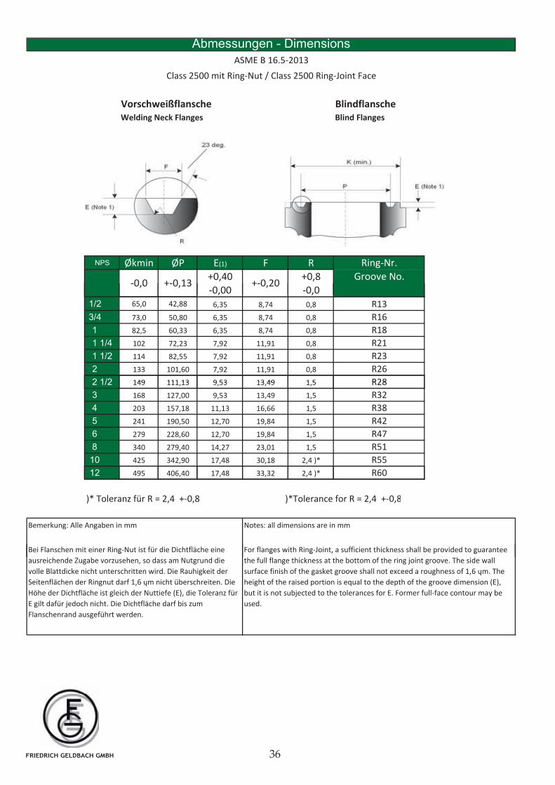
Class 2500 mit Ring-Nut / Class 2500 Ring-Joint Face
ASME B 16.5-2013
NPS Økmin ØP E(1) F R
+0,40 +0,8
-0,00 -0,0
Groove No.+-0,13 +-0,20-0,0
Ring-Nr.
, ,
1/2 65,0 42,88 6,35 8,74 0,8
3/4 73,0 50,80 6,35 8,74 0,8
1 82,5 60,33 6,35 8,74 0,8
1 1/4 102 72,23 7,92 11,91 0,8
1 1/2 114 82,55 7,92 11,91 0,8
2 133 101,60 7,92 11,91 0,8
2 1/2 149 111 13 9 53 13 49 1 5
R13
R18
R21
R16
R23
R26
R282 1/2 149 111,13 9,53 13,49 1,5
3 168 127,00 9,53 13,49 1,5
4 203 157,18 11,13 16,66 1,5
5 241 190,50 12,70 19,84 1,5
6 279 228,60 12,70 19,84 1,5
8 340 279,40 14,27 23,01 1,5
10 425 342,90 17,48 30,18 2,4 )*
R51
R55
R47
R32
R38
R28
R42
12 495 406,40 17,48 33,32 2,4 )*
)* Toleranz für R = 2,4 +-0,8 )*Tolerance for R = 2,4 +-0,8
Bemerkung: Alle Angaben in mm Notes: all dimensions are in mm
Bei Flanschen mit einer Ring-Nut ist für die Dichtfläche eine For flanges with Ring-Joint, a sufficient thickness shall be provided to guarantee
R60
g
ausreichende Zugabe vorzusehen, so dass am Nutgrund die
volle Blattdicke nicht unterschritten wird. Die Rauhigkeit der
Seitenflächen der Ringnut darf 1,6 m nicht überschreiten. Die
Höhe der Dichtfläche ist gleich der Nuttiefe (E), die Toleranz für
E gilt dafür jedoch nicht. Die Dichtfläche darf bis zum
Flanschenrand ausgeführt werden.
g g , p g
the full flange thickness at the bottom of the ring joint groove. The side wall
surface finish of the gasket groove shall not exceed a roughness of 1,6 m. The
height of the raised portion is equal to the depth of the groove dimension (E),
but it is not subjected to the tolerances for E. Former full-face contour may be
used.
FRIEDRICH GELDBACH GMBH
Überschiebschweißflansche GewindeflanscheSlip-On Flanges Threaded Flanges
Abmessungen - Dimensions
ASME B 16.5-2013
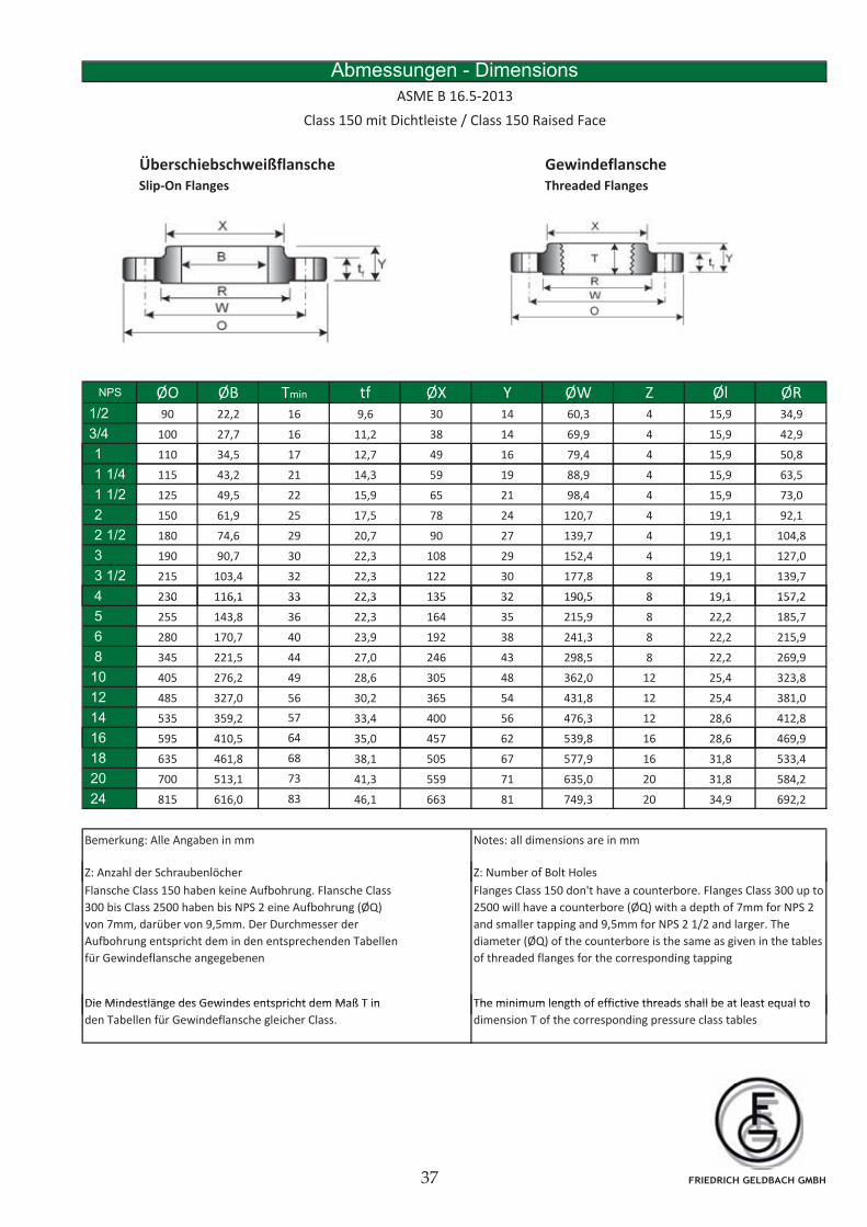
Class 150 mit Dichtleiste / Class 150 Raised Face
NPS ØO ØB Tmin tf ØX Y ØW Z Øl ØR1/2 90 22,2 16 9,6 30 14 60,3 4 15,9 34,9
3/4 100 27,7 16 11,2 38 14 69,9 4 15,9 42,9
1 110 34,5 17 12,7 49 16 79,4 4 15,9 50,8
1 1/4 115 43,2 21 14,3 59 19 88,9 4 15,9 63,5
1 1/2 125 49,5 22 15,9 65 21 98,4 4 15,9 73,0
2 150 61,9 25 17,5 78 24 120,7 4 19,1 92,1
2 1/2 180 74,6 29 20,7 90 27 139,7 4 19,1 104,8
3 190 90,7 30 22,3 108 29 152,4 4 19,1 127,0
3 1/2 215 103,4 32 22,3 122 30 177,8 8 19,1 139,7
4 230 116,1 33 22,3 135 32 190,5 8 19,1 157,24 230 116,1 33 22,3 135 32 190,5 8 19,1 157,2
5 255 143,8 36 22,3 164 35 215,9 8 22,2 185,7
6 280 170,7 40 23,9 192 38 241,3 8 22,2 215,9
8 345 221,5 44 27,0 246 43 298,5 8 22,2 269,9
10 405 276,2 49 28,6 305 48 362,0 12 25,4 323,8
12 485 327,0 56 30,2 365 54 431,8 12 25,4 381,0
14 535 359,2 57 33,4 400 56 476,3 12 28,6 412,8
16 595 410 5 64 35 0 457 62 539 8 16 28 6 469 916 595 410,5 64 35,0 457 62 539,8 16 28,6 469,9
18 635 461,8 68 38,1 505 67 577,9 16 31,8 533,4
20 700 513,1 73 41,3 559 71 635,0 20 31,8 584,2
24 815 616,0 83 46,1 663 81 749,3 20 34,9 692,2
Bemerkung: Alle Angaben in mm Notes: all dimensions are in mm
Z A hl d S h b lö h Z N b f B lt H l
Die Mindestlänge des Gewindes entspricht dem Maß T in The minimum length of effictive threads shall be at least equal to
Z: Anzahl der Schraubenlöcher Z: Number of Bolt Holes
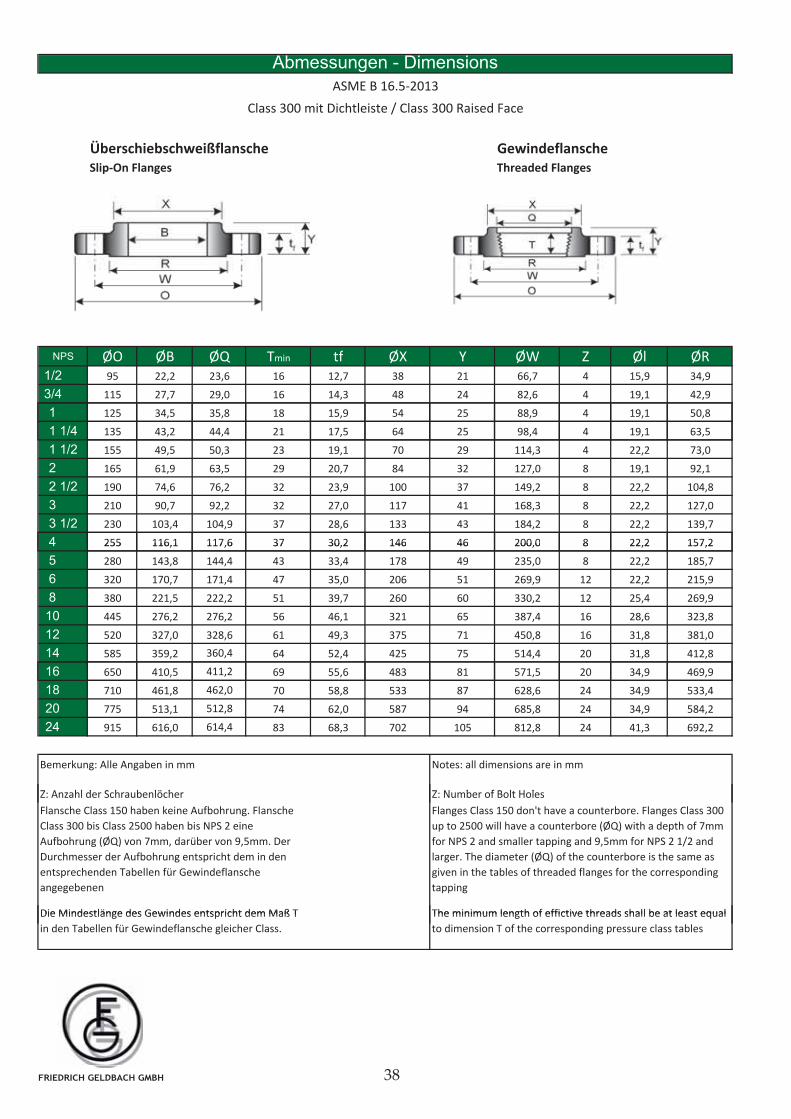
Flansche Class 150 haben keine Aufbohrung. Flansche Class
300 bis Class 2500 haben bis NPS 2 eine Aufbohrung (ØQ)
von 7mm, darüber von 9,5mm. Der Durchmesser der
Aufbohrung entspricht dem in den entsprechenden Tabellen
für Gewindeflansche angegebenen
Flanges Class 150 don't have a counterbore. Flanges Class 300 up to
2500 will have a counterbore (ØQ) with a depth of 7mm for NPS 2
and smaller tapping and 9,5mm for NPS 2 1/2 and larger. The
diameter (ØQ) of the counterbore is the same as given in the tables
of threaded flanges for the corresponding tapping
Die Mindestlänge des Gewindes entspricht dem Maß T in
den Tabellen für Gewindeflansche gleicher Class.
The minimum length of effictive threads shall be at least equal to
dimension T of the corresponding pressure class tables
FRIEDRICH GELDBACH GMBH
Überschiebschweißflansche GewindeflanscheSlip-On Flanges Threaded Flanges
Abmessungen - Dimensions
ASME B 16.5-2013
Class 300 mit Dichtleiste / Class 300 Raised Face
NPS ØO ØB ØQ Tmin tf ØX Y ØW Z Øl ØR1/2 95 22,2 23,6 16 12,7 38 21 66,7 4 15,9 34,9
3/4 115 27,7 29,0 16 14,3 48 24 82,6 4 19,1 42,9
1 125 34,5 35,8 18 15,9 54 25 88,9 4 19,1 50,8
1 1/4 135 43,2 44,4 21 17,5 64 25 98,4 4 19,1 63,5
1 1/2 155 49,5 50,3 23 19,1 70 29 114,3 4 22,2 73,0
2 165 61,9 63,5 29 20,7 84 32 127,0 8 19,1 92,1
2 1/2 190 74,6 76,2 32 23,9 100 37 149,2 8 22,2 104,8
3 210 90,7 92,2 32 27,0 117 41 168,3 8 22,2 127,0
3 1/2 230 103,4 104,9 37 28,6 133 43 184,2 8 22,2 139,7
4 255 116,1 117,6 37 30,2 146 46 200,0 8 22,2 157,24 255 116,1 117,6 37 30,2 146 46 200,0 8 22,2 157,2
5 280 143,8 144,4 43 33,4 178 49 235,0 8 22,2 185,7
6 320 170,7 171,4 47 35,0 206 51 269,9 12 22,2 215,9
8 380 221,5 222,2 51 39,7 260 60 330,2 12 25,4 269,9
10 445 276,2 276,2 56 46,1 321 65 387,4 16 28,6 323,8
12 520 327,0 328,6 61 49,3 375 71 450,8 16 31,8 381,0
14 585 359,2 360,4 64 52,4 425 75 514,4 20 31,8 412,8
16 650 410 5 411 2 69 55 6 483 81 571 5 20 34 9 469 916 650 410,5 411,2 69 55,6 483 81 571,5 20 34,9 469,9
18 710 461,8 462,0 70 58,8 533 87 628,6 24 34,9 533,4
20 775 513,1 512,8 74 62,0 587 94 685,8 24 34,9 584,2
24 915 616,0 614,4 83 68,3 702 105 812,8 24 41,3 692,2
Bemerkung: Alle Angaben in mm Notes: all dimensions are in mm
Z A hl d S h b lö h Z N b f B lt H l
Die Mindestlänge des Gewindes entspricht dem Maß T The minimum length of effictive threads shall be at least equal
Z: Anzahl der Schraubenlöcher Z: Number of Bolt Holes
Flansche Class 150 haben keine Aufbohrung. Flansche
Class 300 bis Class 2500 haben bis NPS 2 eine
Aufbohrung (ØQ) von 7mm, darüber von 9,5mm. Der
Durchmesser der Aufbohrung entspricht dem in den
entsprechenden Tabellen für Gewindeflansche
angegebenen
Flanges Class 150 don't have a counterbore. Flanges Class 300
up to 2500 will have a counterbore (ØQ) with a depth of 7mm
for NPS 2 and smaller tapping and 9,5mm for NPS 2 1/2 and
larger. The diameter (ØQ) of the counterbore is the same as
given in the tables of threaded flanges for the corresponding
tapping
Die Mindestlänge des Gewindes entspricht dem Maß T
in den Tabellen für Gewindeflansche gleicher Class.
The minimum length of effictive threads shall be at least equal
to dimension T of the corresponding pressure class tables
FRIEDRICH GELDBACH GMBH
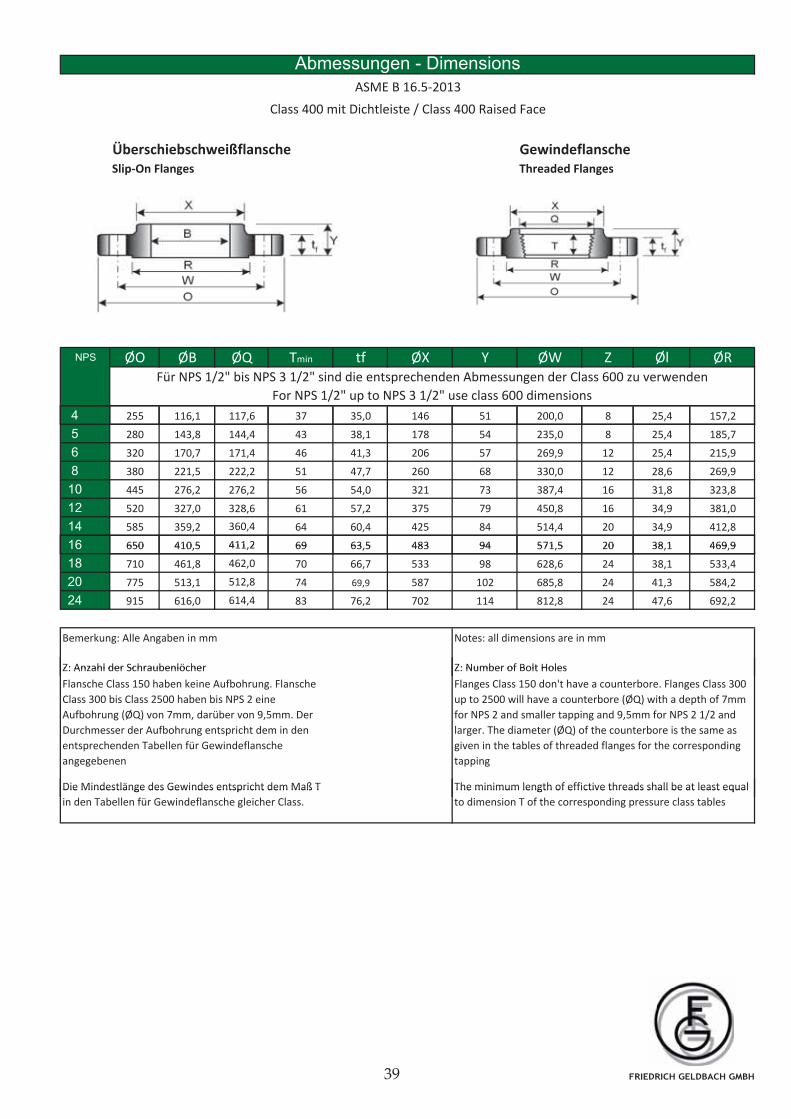
Überschiebschweißflansche GewindeflanscheSlip-On Flanges Threaded Flanges
Abmessungen - Dimensions
ASME B 16.5-2013
Class 400 mit Dichtleiste / Class 400 Raised Face
NPS ØO ØB ØQ Tmin tf ØX Y ØW Z Øl ØR
4 255 116,1 117,6 37 35,0 146 51 200,0 8 25,4 157,2
Für NPS 1/2" bis NPS 3 1/2" sind die entsprechenden Abmessungen der Class 600 zu verwenden
For NPS 1/2" up to NPS 3 1/2" use class 600 dimensions
5 280 143,8 144,4 43 38,1 178 54 235,0 8 25,4 185,7
6 320 170,7 171,4 46 41,3 206 57 269,9 12 25,4 215,9
8 380 221,5 222,2 51 47,7 260 68 330,0 12 28,6 269,9
10 445 276,2 276,2 56 54,0 321 73 387,4 16 31,8 323,8
12 520 327,0 328,6 61 57,2 375 79 450,8 16 34,9 381,0
14 585 359,2 360,4 64 60,4 425 84 514,4 20 34,9 412,8
16 650 410 5 411 2 69 63 5 483 94 571 5 20 38 1 469 916 650 410,5 411,2 69 63,5 483 94 571,5 20 38,1 469,9
18 710 461,8 462,0 70 66,7 533 98 628,6 24 38,1 533,4
20 775 513,1 512,8 74 69,9 587 102 685,8 24 41,3 584,2
24 915 616,0 614,4 83 76,2 702 114 812,8 24 47,6 692,2
Bemerkung: Alle Angaben in mm Notes: all dimensions are in mm
Z: Anzahl der Schraubenlöcher Z: Number of Bolt Holes
Die Mindestlänge des Gewindes entspricht dem Maß T The minimum length of effictive threads shall be at least equal
Z: Anzahl der Schraubenlöcher Z: Number of Bolt Holes
Flansche Class 150 haben keine Aufbohrung. Flansche
Class 300 bis Class 2500 haben bis NPS 2 eine
Aufbohrung (ØQ) von 7mm, darüber von 9,5mm. Der
Durchmesser der Aufbohrung entspricht dem in den
entsprechenden Tabellen für Gewindeflansche
angegebenen
Flanges Class 150 don't have a counterbore. Flanges Class 300
up to 2500 will have a counterbore (ØQ) with a depth of 7mm
for NPS 2 and smaller tapping and 9,5mm for NPS 2 1/2 and
larger. The diameter (ØQ) of the counterbore is the same as
given in the tables of threaded flanges for the corresponding
tapping
Die Mindestlänge des Gewindes entspricht dem Maß T
in den Tabellen für Gewindeflansche gleicher Class.
The minimum length of effictive threads shall be at least equal
to dimension T of the corresponding pressure class tables
FRIEDRICH GELDBACH GMBH
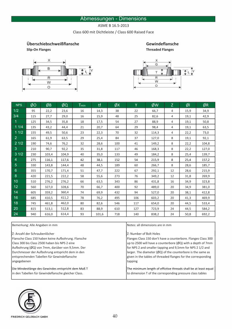
Überschiebschweißflansche GewindeflanscheSlip-On Flanges Threaded Flanges
Abmessungen - Dimensions
ASME B 16.5-2013
Class 600 mit Dichtleiste / Class 600 Raised Face
NPS ØO ØB ØQ Tmin tf ØX Y ØW Z Øl ØR1/2 95 22,2 23,6 16 14,3 38 22 66,7 4 15,9 34,9
3/4 115 27,7 29,0 16 15,9 48 25 82,6 4 19,1 42,9
1 125 34,5 35,8 18 17,5 54 27 88,9 4 19,1 50,8
1 1/4 135 43,2 44,4 21 20,7 64 29 98,4 4 19,1 63,5
1 1/2 155 49,5 50,6 23 22,3 70 32 114,3 4 22,2 73,0
2 165 61,9 63,5 29 25,4 84 37 127,0 8 19,1 92,1
2 1/2 190 74,6 76,2 32 28,6 100 41 149,2 8 22,2 104,8
3 210 90,7 92,2 35 31,8 117 46 168,3 8 22,2 127,0
3 1/2 230 103,4 104,9 40 35,0 133 49 184,2 8 25,4 139,7
4 275 116,1 117,6 42 38,1 152 54 215,9 8 25,4 157,24 275 116,1 117,6 42 38,1 152 54 215,9 8 25,4 157,2
5 330 143,8 144,4 48 44,5 189 60 266,7 8 28,6 185,7
6 355 170,7 171,4 51 47,7 222 67 292,1 12 28,6 215,9
8 420 221,5 222,2 58 55,6 273 76 349,2 12 31,8 269,9
10 510 276,2 276,2 66 63,5 343 86 431,8 16 34,9 323,8
12 560 327,0 328,6 70 66,7 400 92 489,0 20 34,9 381,0
14 605 359,2 360,4 74 69,9 432 94 527,0 20 38,1 412,8
16 685 410 5 411 2 78 76 2 495 106 603 2 20 41 3 469 916 685 410,5 411,2 78 76,2 495 106 603,2 20 41,3 469,9
18 745 461,8 462,0 80 82,6 546 117 654,0 20 44,5 533,4
20 815 513,1 512,8 83 88,9 610 127 723,9 24 44,5 584,2
24 940 616,0 614,4 93 101,6 718 140 838,2 24 50,8 692,2
Bemerkung: Alle Angaben in mm Notes: all dimensions are in mm
Z A hl d S h b lö h Z N b f B lt H l
Die Mindestlänge des Gewindes entspricht dem Maß T The minimum length of effictive threads shall be at least equal
Z: Anzahl der Schraubenlöcher Z: Number of Bolt Holes
Flansche Class 150 haben keine Aufbohrung. Flansche
Class 300 bis Class 2500 haben bis NPS 2 eine
Aufbohrung (ØQ) von 7mm, darüber von 9,5mm. Der
Durchmesser der Aufbohrung entspricht dem in den
entsprechenden Tabellen für Gewindeflansche
angegebenen
Flanges Class 150 don't have a counterbore. Flanges Class 300
up to 2500 will have a counterbore (ØQ) with a depth of 7mm
for NPS 2 and smaller tapping and 9,5mm for NPS 2 1/2 and
larger. The diameter (ØQ) of the counterbore is the same as
given in the tables of threaded flanges for the corresponding
tapping
Die Mindestlänge des Gewindes entspricht dem Maß T
in den Tabellen für Gewindeflansche gleicher Class.
The minimum length of effictive threads shall be at least equal
to dimension T of the corresponding pressure class tables
FRIEDRICH GELDBACH GMBH
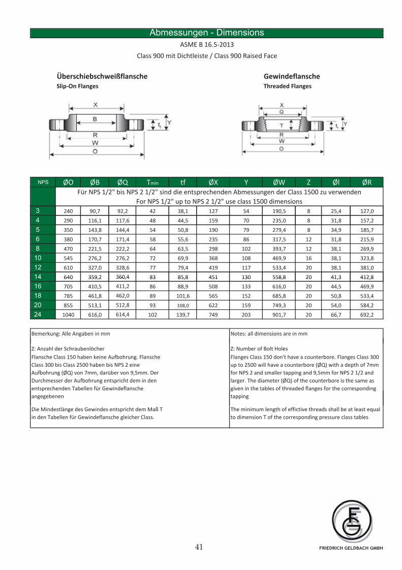
Überschiebschweißflansche GewindeflanscheSlip-On Flanges Threaded Flanges
Abmessungen - Dimensions
ASME B 16.5-2013
Class 900 mit Dichtleiste / Class 900 Raised Face
NPS ØO ØB ØQ Tmin tf ØX Y ØW Z Øl ØR
3 240 90,7 92,2 42 38,1 127 54 190,5 8 25,4 127,0
Für NPS 1/2" bis NPS 2 1/2" sind die entsprechenden Abmessungen der Class 1500 zu verwenden
For NPS 1/2" up to NPS 2 1/2" use class 1500 dimensions
4 290 116,1 117,6 48 44,5 159 70 235,0 8 31,8 157,2
5 350 143,8 144,4 54 50,8 190 79 279,4 8 34,9 185,7
6 380 170,7 171,4 58 55,6 235 86 317,5 12 31,8 215,9
8 470 221,5 222,2 64 63,5 298 102 393,7 12 38,1 269,9
10 545 276,2 276,2 72 69,9 368 108 469,9 16 38,1 323,8
12 610 327,0 328,6 77 79,4 419 117 533,4 20 38,1 381,0
14 640 359,2 360,4 83 85,8 451 130 558,8 20 41,3 412,814 640 359,2 360,4 83 85,8 451 130 558,8 20 41,3 412,8
16 705 410,5 411,2 86 88,9 508 133 616,0 20 44,5 469,9
18 785 461,8 462,0 89 101,6 565 152 685,8 20 50,8 533,4
20 855 513,1 512,8 93 108,0 622 159 749,3 20 54,0 584,2
24 1040 616,0 614,4 102 139,7 749 203 901,7 20 66,7 692,2
Bemerkung: Alle Angaben in mm Notes: all dimensions are in mm
Z: Anzahl der Schraubenlöcher Z: Number of Bolt Holes
Flansche Class 150 haben keine Aufbohrung. Flansche
Class 300 bis Class 2500 haben bis NPS 2 eine
Aufbohrung (ØQ) von 7mm, darüber von 9,5mm. Der
Durchmesser der Aufbohrung entspricht dem in den
entsprechenden Tabellen für Gewindeflansche
angegebenen
Flanges Class 150 don't have a counterbore. Flanges Class 300
up to 2500 will have a counterbore (ØQ) with a depth of 7mm
for NPS 2 and smaller tapping and 9,5mm for NPS 2 1/2 and
larger. The diameter (ØQ) of the counterbore is the same as
given in the tables of threaded flanges for the corresponding
tapping
Die Mindestlänge des Gewindes entspricht dem Maß T
in den Tabellen für Gewindeflansche gleicher Class.
The minimum length of effictive threads shall be at least equal
to dimension T of the corresponding pressure class tables
FRIEDRICH GELDBACH GMBH
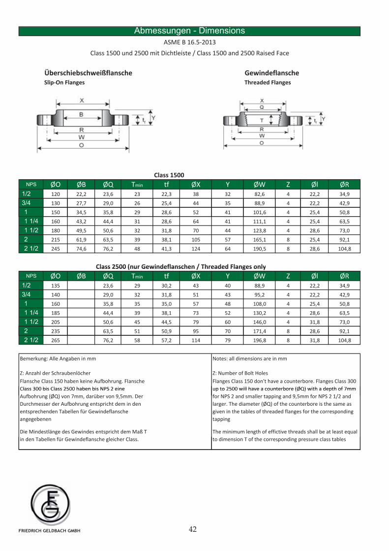
Überschiebschweißflansche GewindeflanscheSlip-On Flanges Threaded Flanges
Abmessungen - Dimensions
ASME B 16.5-2013
Class 1500 und 2500 mit Dichtleiste / Class 1500 and 2500 Raised Face
Class 1500
NPS ØO ØB ØQ Tmin tf ØX Y ØW Z Øl ØR1/2 120 22,2 23,6 23 22,3 38 32 82,6 4 22,2 34,9
3/4 130 27,7 29,0 26 25,4 44 35 88,9 4 22,2 42,9
1 150 34,5 35,8 29 28,6 52 41 101,6 4 25,4 50,8
1 1/4 160 43,2 44,4 31 28,6 64 41 111,1 4 25,4 63,5
1 1/2 180 49,5 50,6 32 31,8 70 44 123,8 4 28,6 73,0
2 215 61,9 63,5 39 38,1 105 57 165,1 8 25,4 92,1
2 1/2 245 74,6 76,2 48 41,3 124 64 190,5 8 28,6 104,8
Class 2500 (nur Gewindeflanschen / Threaded Flanges onlyClass 2500 (nur Gewindeflanschen / Threaded Flanges only
NPS ØO ØB ØQ Tmin tf ØX Y ØW Z Øl ØR1/2 135 23,6 29 30,2 43 40 88,9 4 22,2 34,9
3/4 140 29,0 32 31,8 51 43 95,2 4 22,2 42,9
1 160 35,8 35 35,0 57 48 108,0 4 25,4 50,8
1 1/4 185 44,4 39 38,1 73 52 130,2 4 28,6 63,5
1 1/2 205 50,6 45 44,5 79 60 146,0 4 31,8 73,0
22 235 63,5 51 50,9 95 70 171,4 8 28,6 92,1
2 1/2 265 76,2 58 57,2 114 79 196,8 8 31,8 104,8
Bemerkung: Alle Angaben in mm Notes: all dimensions are in mm
Z: Anzahl der Schraubenlöcher Z: Number of Bolt Holes
Flansche Class 150 haben keine Aufbohrung. Flansche
Class 300 bis Class 2500 haben bis NPS 2 eine
Flanges Class 150 don't have a counterbore. Flanges Class 300
up to 2500 will have a counterbore (ØQ) with a depth of 7mm
Die Mindestlänge des Gewindes entspricht dem Maß T
in den Tabellen für Gewindeflansche gleicher Class.
The minimum length of effictive threads shall be at least equal
to dimension T of the corresponding pressure class tables
Class 300 bis Class 2500 haben bis NPS 2 eine
Aufbohrung (ØQ) von 7mm, darüber von 9,5mm. Der
Durchmesser der Aufbohrung entspricht dem in den
entsprechenden Tabellen für Gewindeflansche
angegebenen
up to 2500 will have a counterbore (ØQ) with a depth of 7mm
for NPS 2 and smaller tapping and 9,5mm for NPS 2 1/2 and
larger. The diameter (ØQ) of the counterbore is the same as
given in the tables of threaded flanges for the corresponding
tapping
FRIEDRICH GELDBACH GMBH
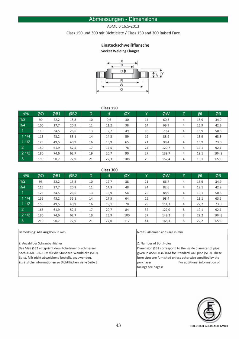
EinsteckschweißflanscheSocket Welding Flanges
Abmessungen - Dimensions
ASME B 16.5-2013
Class 150 und 300 mit Dichtleiste / Class 150 and 300 Raised Face
Class 150
NPS ØO ØB1 ØB2 D tf ØX Y ØW Z Øl ØR1/2 90 22,2 15,8 10 9,6 30 14 60,3 4 15,9 34,9
3/4 100 27,7 20,9 11 11,2 38 14 69,9 4 15,9 42,9
1 110 34,5 26,6 13 12,7 49 16 79,4 4 15,9 50,8
1 1/4 115 43,2 35,1 14 14,3 59 19 88,9 4 15,9 63,5
1 1/2 125 49,5 40,9 16 15,9 65 21 98,4 4 15,9 73,0
2 150 61,9 52,5 17 17,5 78 24 120,7 4 19,1 92,1
2 1/2 180 74,6 62,7 19 20,7 90 27 139,7 4 19,1 104,8
3 190 90,7 77,9 21 22,3 108 29 152,4 4 19,1 127,0
Class 300
NPS ØO ØB1 ØB2 D tf ØX Y ØW Z Øl ØR1/2 95 22,2 15,8 10 12,7 38 21 66,7 4 15,9 34,9
3/4 115 27,7 20,9 11 14,3 48 24 82,6 4 19,1 42,9
1 125 34,5 26,6 13 15,9 54 25 88,9 4 19,1 50,8
1 1/4 135 43,2 35,1 14 17,5 64 25 98,4 4 19,1 63,5
1 1/21 1/2 155 49,5 40,9 16 19,1 70 29 114,3 4 22,2 73,0
2 165 61,9 52,5 17 20,7 84 32 127,0 8 19,1 92,1
2 1/2 190 74,6 62,7 19 23,9 100 37 149,2 8 22,2 104,8
3 210 90,7 77,9 21 27,0 117 41 168,3 8 22,2 127,0
Bemerkung: Alle Angaben in mm Notes: all dimensions are in mm
Z: Anzahl der Schraubenlöcher Z: Number of Bolt Holes
Das Maß ØB2 entspricht dem Rohr-Innendurchmesser
nach ASME B36.10M für die Standard-Wanddicke (STD).
Es ist, falls nicht abweichend bestellt, anzuwenden.
Zusätzliche Informationen zu Dichtflächen siehe Seite 8
Dimension ØB2 correspond to the inside diameter of pipe
given in ASME B36.10M for Standard wall pipe (STD). These
bore sizes are furnished unless otherwise specified by the
purchaser. For additional information of
facings see page 8
FRIEDRICH GELDBACH GMBH
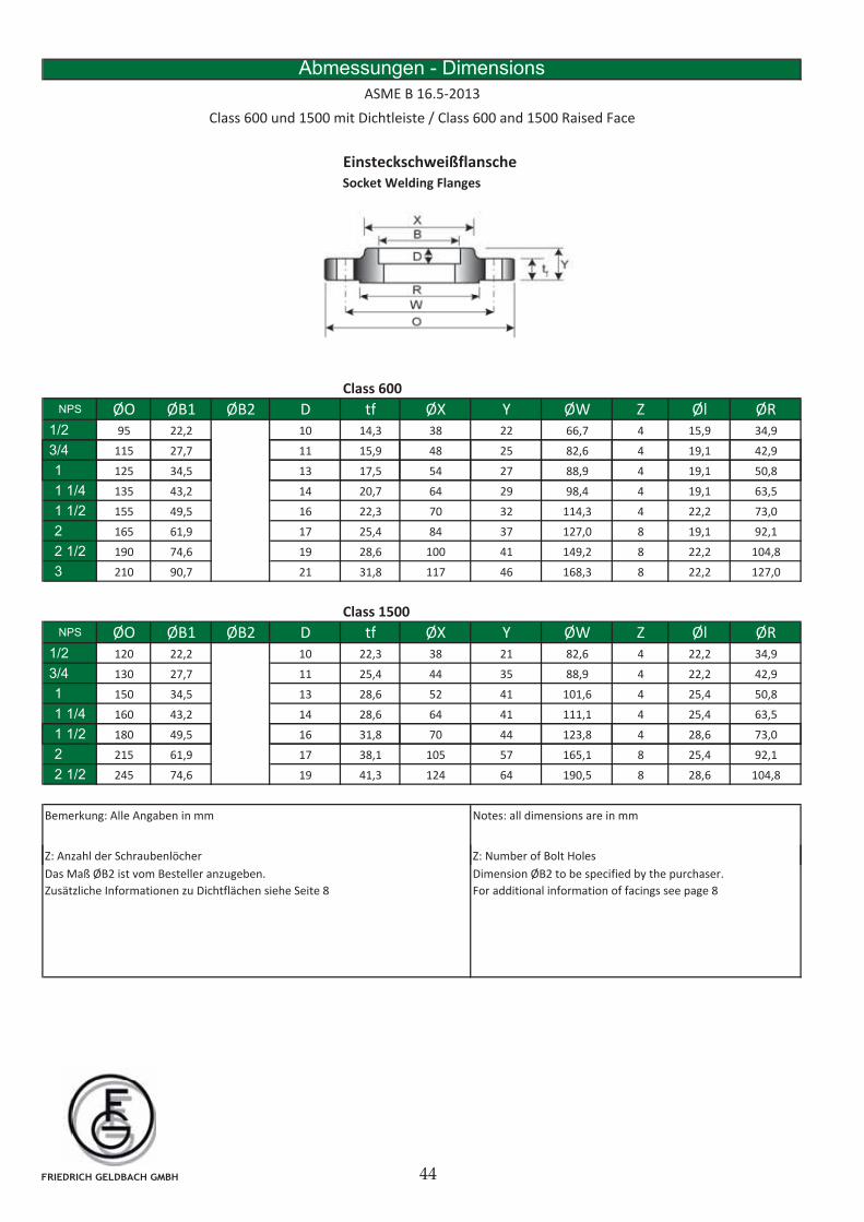
EinsteckschweißflanscheSocket Welding Flanges
Abmessungen - Dimensions
ASME B 16.5-2013
Class 600 und 1500 mit Dichtleiste / Class 600 and 1500 Raised Face
Class 600
NPS ØO ØB1 ØB2 D tf ØX Y ØW Z Øl ØR1/2 95 22,2 10 14,3 38 22 66,7 4 15,9 34,9
3/4 115 27,7 11 15,9 48 25 82,6 4 19,1 42,9
1 125 34,5 13 17,5 54 27 88,9 4 19,1 50,8
1 1/4 135 43,2 14 20,7 64 29 98,4 4 19,1 63,5
1 1/2 155 49,5 16 22,3 70 32 114,3 4 22,2 73,0
2 165 61,9 17 25,4 84 37 127,0 8 19,1 92,1
2 1/2 190 74,6 19 28,6 100 41 149,2 8 22,2 104,8
3 210 90,7 21 31,8 117 46 168,3 8 22,2 127,0
Class 1500
NPS ØO ØB1 ØB2 D tf ØX Y ØW Z Øl ØR1/2 120 22,2 10 22,3 38 21 82,6 4 22,2 34,9
3/4 130 27,7 11 25,4 44 35 88,9 4 22,2 42,9
1 150 34,5 13 28,6 52 41 101,6 4 25,4 50,8
1 1/4 160 43,2 14 28,6 64 41 111,1 4 25,4 63,5
1 1/21 1/2 180 49,5 16 31,8 70 44 123,8 4 28,6 73,0
2 215 61,9 17 38,1 105 57 165,1 8 25,4 92,1
2 1/2 245 74,6 19 41,3 124 64 190,5 8 28,6 104,8
Bemerkung: Alle Angaben in mm Notes: all dimensions are in mm
Z: Anzahl der Schraubenlöcher Z: Number of Bolt Holes
Das Maß ØB2 ist vom Besteller anzugeben.
Zusätzliche Informationen zu Dichtflächen siehe Seite 8
Dimension ØB2 to be specified by the purchaser.
For additional information of facings see page 8
FRIEDRICH GELDBACH GMBH
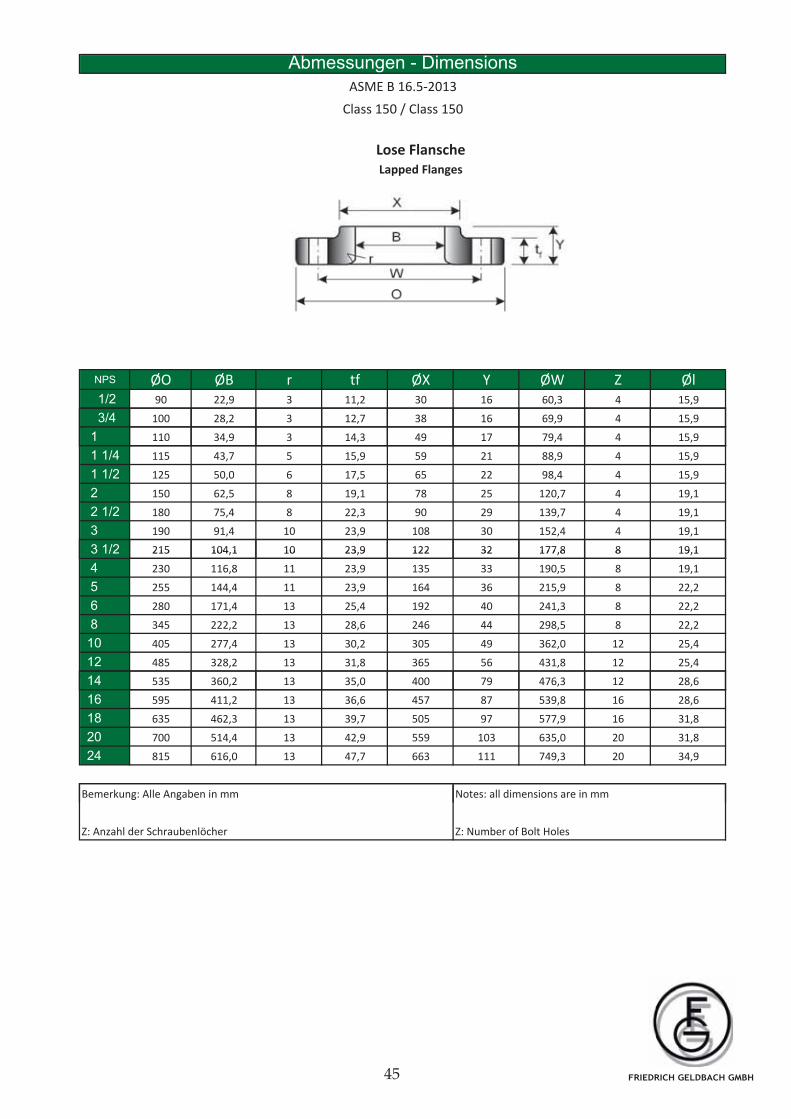
FRIEDRICH GELDBACH GMBH
Abmessungen - Dimensions
ASME B 16.5-2013
Class 150 / Class 150
Lose Flansche
Lapped Flanges
NPS ØO ØB r tf ØX Y ØW Z Øl1/2 90 22,9 3 11,2 30 16 60,3 4 15,9
3/4 100 28,2 3 12,7 38 16 69,9 4 15,9
1 110 34,9 3 14,3 49 17 79,4 4 15,9
1 1/4 115 43,7 5 15,9 59 21 88,9 4 15,9
1 1/2 125 50,0 6 17,5 65 22 98,4 4 15,9
2 150 62,5 8 19,1 78 25 120,7 4 19,1
2 1/2 180 75,4 8 22,3 90 29 139,7 4 19,1
3 190 91,4 10 23,9 108 30 152,4 4 19,1
3 1/2 215 104,1 10 23,9 122 32 177,8 8 19,13 1/2 215 104,1 10 23,9 122 32 177,8 8 19,1
4 230 116,8 11 23,9 135 33 190,5 8 19,1
5 255 144,4 11 23,9 164 36 215,9 8 22,2
6 280 171,4 13 25,4 192 40 241,3 8 22,2
8 345 222,2 13 28,6 246 44 298,5 8 22,2
10 405 277,4 13 30,2 305 49 362,0 12 25,4
12 485 328,2 13 31,8 365 56 431,8 12 25,4
14 535 360 2 13 35 0 400 79 476 3 12 28 614 535 360,2 13 35,0 400 79 476,3 12 28,6
16 595 411,2 13 36,6 457 87 539,8 16 28,6
18 635 462,3 13 39,7 505 97 577,9 16 31,8
20 700 514,4 13 42,9 559 103 635,0 20 31,8
24 815 616,0 13 47,7 663 111 749,3 20 34,9
Bemerkung: Alle Angaben in mm Notes: all dimensions are in mmg g
Z: Anzahl der Schraubenlöcher Z: Number of Bolt Holes
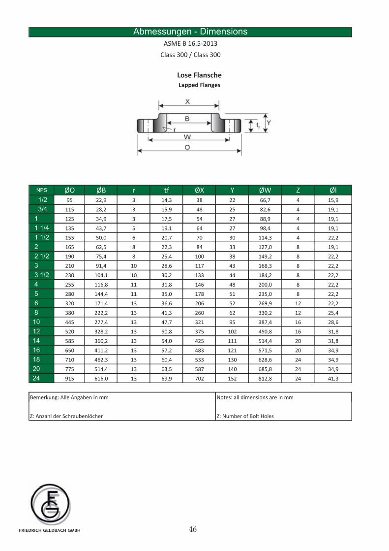
Abmessungen - Dimensions
ASME B 16.5-2013
Class 300 / Class 300
Lose Flansche
Lapped Flanges
NPS ØO ØB r tf ØX Y ØW Z Øl1/2 95 22,9 3 14,3 38 22 66,7 4 15,9
3/4 115 28,2 3 15,9 48 25 82,6 4 19,1
1 125 34,9 3 17,5 54 27 88,9 4 19,1
1 1/4 135 43,7 5 19,1 64 27 98,4 4 19,1
1 1/2 155 50,0 6 20,7 70 30 114,3 4 22,2
2 165 62,5 8 22,3 84 33 127,0 8 19,1
2 1/2 190 75,4 8 25,4 100 38 149,2 8 22,2
3 210 91,4 10 28,6 117 43 168,3 8 22,2
3 1/2 230 104,1 10 30,2 133 44 184,2 8 22,23 1/2 230 104,1 10 30,2 133 44 184,2 8 22,2
4 255 116,8 11 31,8 146 48 200,0 8 22,2
5 280 144,4 11 35,0 178 51 235,0 8 22,2
6 320 171,4 13 36,6 206 52 269,9 12 22,2
8 380 222,2 13 41,3 260 62 330,2 12 25,4
10 445 277,4 13 47,7 321 95 387,4 16 28,6
12 520 328,2 13 50,8 375 102 450,8 16 31,8
14 585 360 2 13 54 0 425 111 514 4 20 31 814 585 360,2 13 54,0 425 111 514,4 20 31,8
16 650 411,2 13 57,2 483 121 571,5 20 34,9
18 710 462,3 13 60,4 533 130 628,6 24 34,9
20 775 514,4 13 63,5 587 140 685,8 24 34,9
24 915 616,0 13 69,9 702 152 812,8 24 41,3
Bemerkung: Alle Angaben in mm Notes: all dimensions are in mmg g
Z: Anzahl der Schraubenlöcher Z: Number of Bolt Holes
FRIEDRICH GELDBACH GMBH
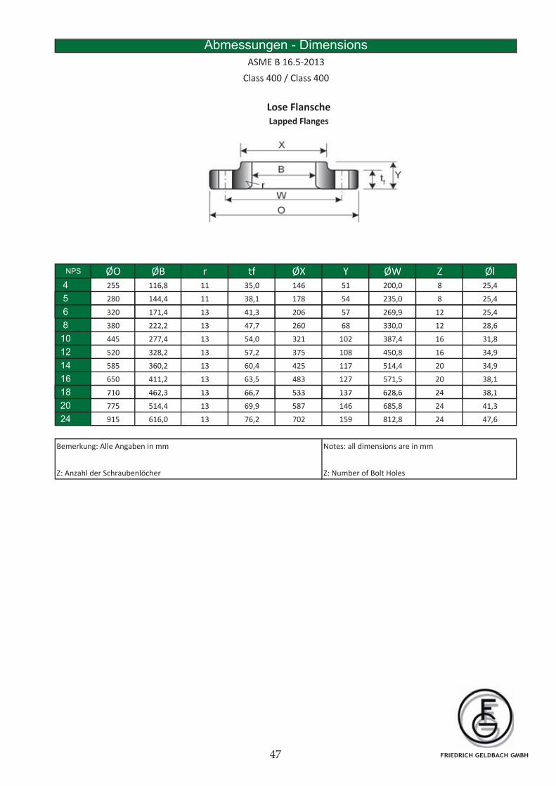
Abmessungen - Dimensions
ASME B 16.5-2013
Class 400 / Class 400
Lose Flansche
Lapped Flanges
NPS ØO ØB r tf ØX Y ØW Z Øl4 255 116,8 11 35,0 146 51 200,0 8 25,4
5 280 144,4 11 38,1 178 54 235,0 8 25,4
6 320 171,4 13 41,3 206 57 269,9 12 25,4
8 380 222,2 13 47,7 260 68 330,0 12 28,6
10 445 277,4 13 54,0 321 102 387,4 16 31,8
12 520 328,2 13 57,2 375 108 450,8 16 34,9
14 585 360,2 13 60,4 425 117 514,4 20 34,9
16 650 411,2 13 63,5 483 127 571,5 20 38,1
18 710 462,3 13 66,7 533 137 628,6 24 38,118 710 462,3 13 66,7 533 137 628,6 24 38,1
20 775 514,4 13 69,9 587 146 685,8 24 41,3
24 915 616,0 13 76,2 702 159 812,8 24 47,6
Bemerkung: Alle Angaben in mm Notes: all dimensions are in mm
Z: Anzahl der Schraubenlöcher Z: Number of Bolt Holes
FRIEDRICH GELDBACH GMBH
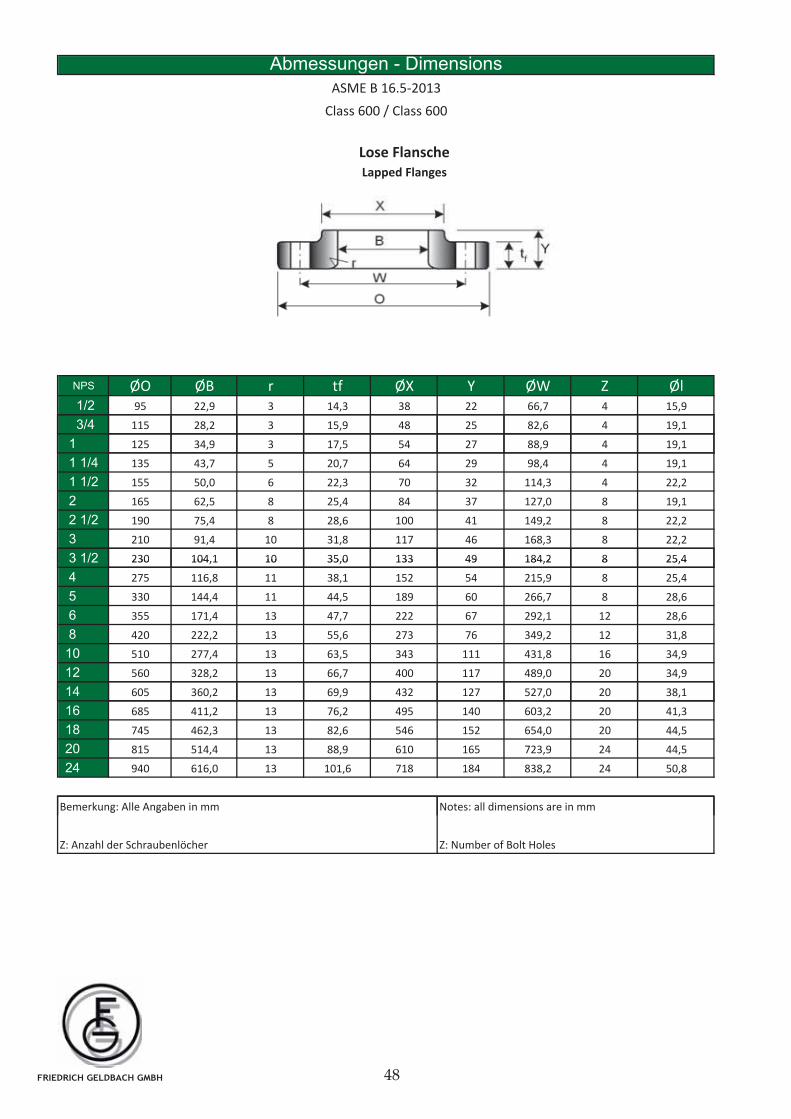
Abmessungen - Dimensions
ASME B 16.5-2013
Class 600 / Class 600
Lose Flansche
Lapped Flanges
NPS ØO ØB r tf ØX Y ØW Z Øl1/2 95 22,9 3 14,3 38 22 66,7 4 15,9
3/4 115 28,2 3 15,9 48 25 82,6 4 19,1
1 125 34,9 3 17,5 54 27 88,9 4 19,1
1 1/4 135 43,7 5 20,7 64 29 98,4 4 19,1
1 1/2 155 50,0 6 22,3 70 32 114,3 4 22,2
2 165 62,5 8 25,4 84 37 127,0 8 19,1
2 1/2 190 75,4 8 28,6 100 41 149,2 8 22,2
3 210 91,4 10 31,8 117 46 168,3 8 22,2
3 1/2 230 104,1 10 35,0 133 49 184,2 8 25,43 1/2 230 104,1 10 35,0 133 49 184,2 8 25,4
4 275 116,8 11 38,1 152 54 215,9 8 25,4
5 330 144,4 11 44,5 189 60 266,7 8 28,6
6 355 171,4 13 47,7 222 67 292,1 12 28,6
8 420 222,2 13 55,6 273 76 349,2 12 31,8
10 510 277,4 13 63,5 343 111 431,8 16 34,9
12 560 328,2 13 66,7 400 117 489,0 20 34,9
14 605 360 2 13 69 9 432 127 527 0 20 38 114 605 360,2 13 69,9 432 127 527,0 20 38,1
16 685 411,2 13 76,2 495 140 603,2 20 41,3
18 745 462,3 13 82,6 546 152 654,0 20 44,5
20 815 514,4 13 88,9 610 165 723,9 24 44,5
24 940 616,0 13 101,6 718 184 838,2 24 50,8
Bemerkung: Alle Angaben in mm Notes: all dimensions are in mmg g
Z: Anzahl der Schraubenlöcher Z: Number of Bolt Holes
FRIEDRICH GELDBACH GMBH
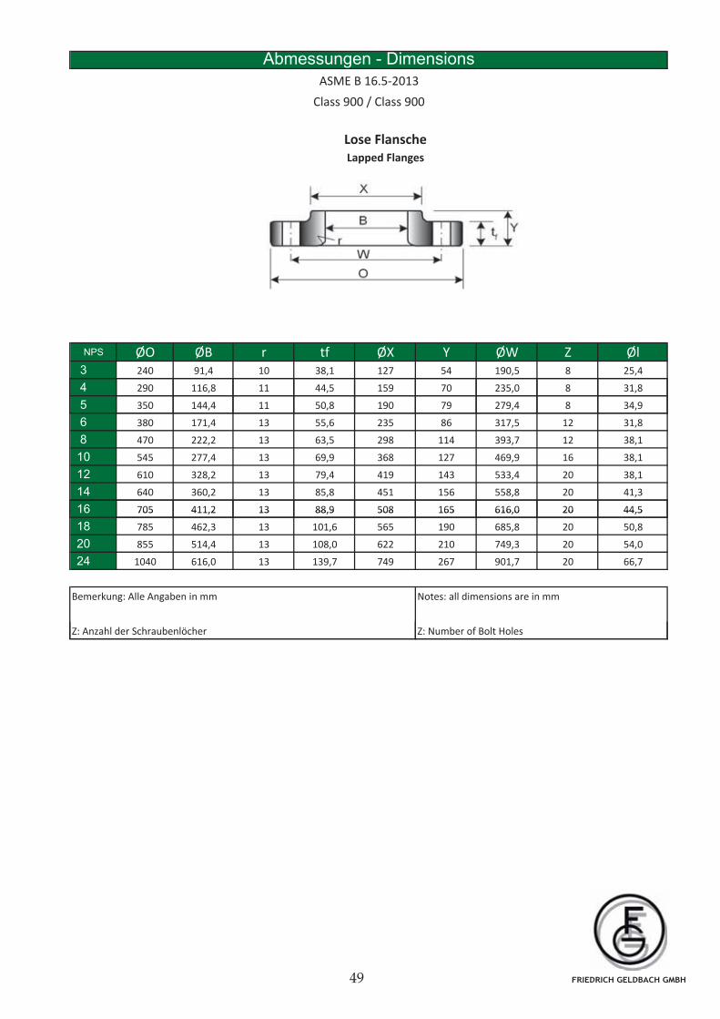
Abmessungen - Dimensions
ASME B 16.5-2013
Class 900 / Class 900
Lose Flansche
Lapped Flanges
NPS ØO ØB r tf ØX Y ØW Z Øl3 240 91,4 10 38,1 127 54 190,5 8 25,4
4 290 116,8 11 44,5 159 70 235,0 8 31,8
5 350 144,4 11 50,8 190 79 279,4 8 34,9
6 380 171,4 13 55,6 235 86 317,5 12 31,8
8 470 222,2 13 63,5 298 114 393,7 12 38,1
10 545 277,4 13 69,9 368 127 469,9 16 38,1
12 610 328,2 13 79,4 419 143 533,4 20 38,1
14 640 360,2 13 85,8 451 156 558,8 20 41,3
16 705 411,2 13 88,9 508 165 616,0 20 44,516 705 411,2 13 88,9 508 165 616,0 20 44,5
18 785 462,3 13 101,6 565 190 685,8 20 50,8
20 855 514,4 13 108,0 622 210 749,3 20 54,0
24 1040 616,0 13 139,7 749 267 901,7 20 66,7
Bemerkung: Alle Angaben in mm Notes: all dimensions are in mm
Z A hl d S h b lö h Z N b f B l H lZ: Anzahl der Schraubenlöcher Z: Number of Bolt Holes
FRIEDRICH GELDBACH GMBH
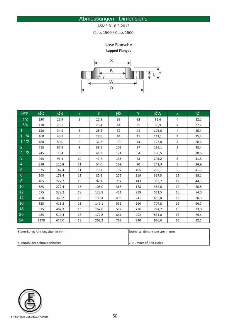
Abmessungen - Dimensions
ASME B 16.5-2013
Class 1500 / Class 1500
Lose Flansche
Lapped Flanges
NPS ØO ØB r tf ØX Y ØW Z Øl1/2 120 22,9 3 22,3 38 32 82,6 4 22,2
3/4 130 28,2 3 25,4 44 35 88,9 4 22,2
1 150 34,9 3 28,6 52 41 101,6 4 25,4
1 1/4 160 43,7 5 28,6 64 41 111,1 4 25,4
1 1/2 180 50,0 6 31,8 70 44 123,8 4 28,6
2 215 62,5 8 38,1 105 57 165,1 8 25,4
2 1/2 245 75,4 8 41,3 124 64 190,5 8 28,6
3 265 91,4 10 47,7 133 73 203,2 8 31,8
4 310 116,8 11 54,0 162 90 241,3 8 34,94 310 116,8 11 54,0 162 90 241,3 8 34,9
5 375 144,4 11 73,1 197 105 292,1 8 41,3
6 395 171,4 13 82,6 229 119 317,5 12 38,1
8 485 222,2 13 92,1 292 143 393,7 12 44,5
10 585 277,4 13 108,0 368 178 482,6 12 50,8
12 675 328,2 13 123,9 451 219 571,5 16 54,0
14 750 360,2 13 133,4 495 241 635,0 16 60,3
16 825 411 2 13 146 1 552 260 704 8 16 66 716 825 411,2 13 146,1 552 260 704,8 16 66,7
18 915 462,3 13 162,0 597 276 774,7 16 73,0
20 985 514,4 13 177,8 641 292 831,8 16 79,4
24 1170 616,0 13 203,2 762 330 990,6 16 92,1
Bemerkung: Alle Angaben in mm Notes: all dimensions are in mm
Z: Anzahl der Schraubenlöcher Z: Number of Bolt Holes
FRIEDRICH GELDBACH GMBH
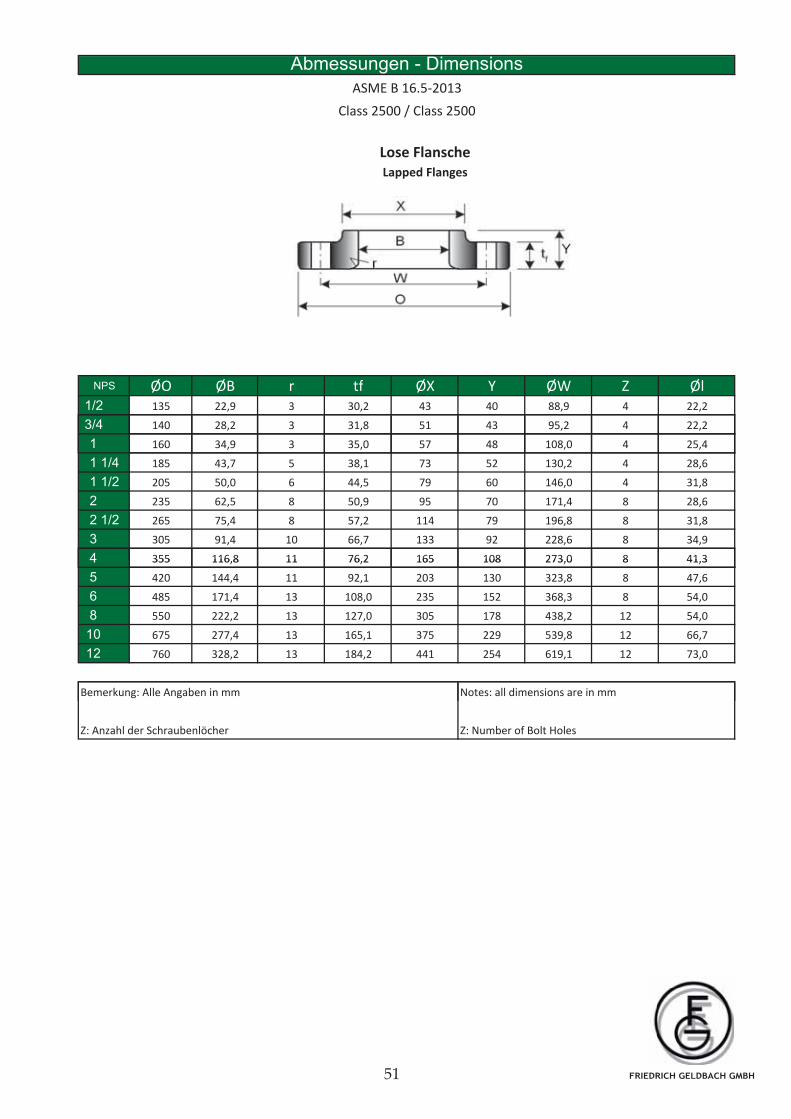
Abmessungen - Dimensions
ASME B 16.5-2013
Class 2500 / Class 2500
Lose Flansche
Lapped Flanges
NPS ØO ØB r tf ØX Y ØW Z Øl1/2 135 22,9 3 30,2 43 40 88,9 4 22,2
3/4 140 28,2 3 31,8 51 43 95,2 4 22,2
1 160 34,9 3 35,0 57 48 108,0 4 25,4
1 1/4 185 43,7 5 38,1 73 52 130,2 4 28,6
1 1/2 205 50,0 6 44,5 79 60 146,0 4 31,8
2 235 62,5 8 50,9 95 70 171,4 8 28,6
2 1/2 265 75,4 8 57,2 114 79 196,8 8 31,8
3 305 91,4 10 66,7 133 92 228,6 8 34,9
4 355 116,8 11 76,2 165 108 273,0 8 41,34 355 116,8 11 76,2 165 108 273,0 8 41,3
5 420 144,4 11 92,1 203 130 323,8 8 47,6
6 485 171,4 13 108,0 235 152 368,3 8 54,0
8 550 222,2 13 127,0 305 178 438,2 12 54,0
10 675 277,4 13 165,1 375 229 539,8 12 66,7
12 760 328,2 13 184,2 441 254 619,1 12 73,0
B k All A b i N ll di i iBemerkung: Alle Angaben in mm Notes: all dimensions are in mm
Z: Anzahl der Schraubenlöcher Z: Number of Bolt Holes
FRIEDRICH GELDBACH GMBH
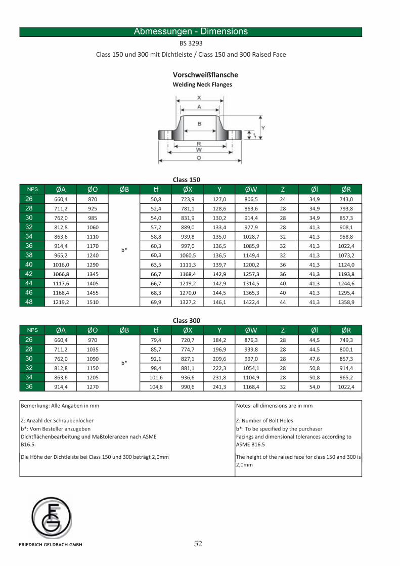
VorschweißflanscheWelding Neck Flanges
Abmessungen - Dimensions
BS 3293
Class 150 und 300 mit Dichtleiste / Class 150 and 300 Raised Face
Class 150
NPS ØA ØO ØB tf ØX Y ØW Z Øl ØR26 660,4 870 50,8 723,9 127,0 806,5 24 34,9 743,0
28 711,2 925 52,4 781,1 128,6 863,6 28 34,9 793,8
30 762,0 985 54,0 831,9 130,2 914,4 28 34,9 857,3
32 812,8 1060 57,2 889,0 133,4 977,9 28 41,3 908,1
34 863,6 1110 58,8 939,8 135,0 1028,7 32 41,3 958,8
36 914,4 1170 60,3 997,0 136,5 1085,9 32 41,3 1022,4
38 965,2 1240 60,3 1060,5 136,5 1149,4 32 41,3 1073,2
40 1016,0 1290 63,5 1111,3 139,7 1200,2 36 41,3 1124,0
42 1066,8 1345 66,7 1168,4 142,9 1257,3 36 41,3 1193,8
b*
42 1066,8 1345 66,7 1168,4 142,9 1257,3 36 41,3 1193,8
44 1117,6 1405 66,7 1219,2 142,9 1314,5 40 41,3 1244,6
46 1168,4 1455 68,3 1270,0 144,5 1365,3 40 41,3 1295,4
48 1219,2 1510 69,9 1327,2 146,1 1422,4 44 41,3 1358,9
Class 300
NPS ØA ØO ØB tf ØX Y ØW Z Øl ØR2626 660,4 970 79,4 720,7 184,2 876,3 28 44,5 749,3
28 711,2 1035 85,7 774,7 196,9 939,8 28 44,5 800,1
30 762,0 1090 92,1 827,1 209,6 997,0 28 47,6 857,3
32 812,8 1150 98,4 881,1 222,3 1054,1 28 50,8 914,4
34 863,6 1205 101,6 936,6 231,8 1104,9 28 50,8 965,2
36 914,4 1270 104,8 990,6 241,3 1168,4 32 54,0 1022,4
b*
Bemerkung: Alle Angaben in mm Notes: all dimensions are in mm
Z: Anzahl der Schraubenlöcher Z: Number of Bolt Holes
b*: Vom Besteller anzugeben
Dichtflächenbearbeitung und Maßtoleranzen nach ASME
B16.5.
b*: To be specified by the purchaser
Facings and dimensional tolerances according to
ASME B16.5
Die Höhe der Dichtleiste bei Class 150 und 300 beträgt 2,0mm The height of the raised face for class 150 and 300 is
2,0mm
FRIEDRICH GELDBACH GMBH
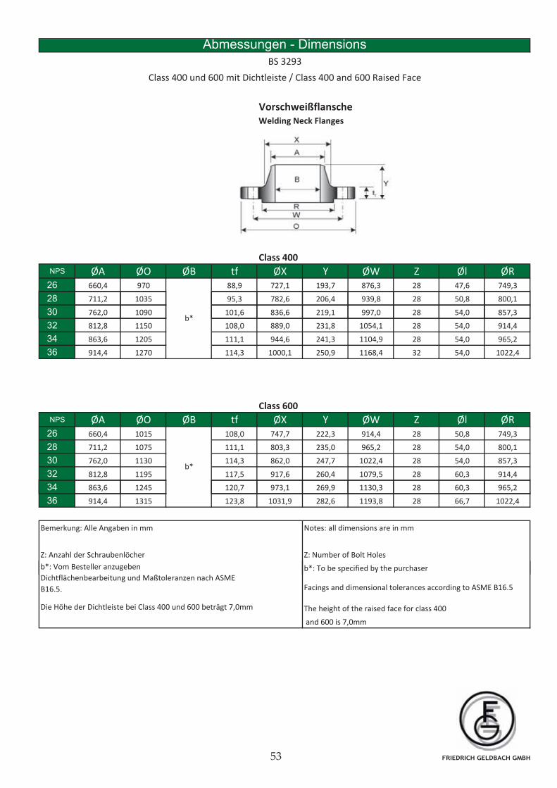
VorschweißflanscheWelding Neck Flanges
Abmessungen - Dimensions
BS 3293
Class 400 und 600 mit Dichtleiste / Class 400 and 600 Raised Face
Class 400
NPS ØA ØO ØB tf ØX Y ØW Z Øl ØR26 660,4 970 88,9 727,1 193,7 876,3 28 47,6 749,3
28 711,2 1035 95,3 782,6 206,4 939,8 28 50,8 800,1
30 762,0 1090 101,6 836,6 219,1 997,0 28 54,0 857,3
32 812,8 1150 108,0 889,0 231,8 1054,1 28 54,0 914,4
34 863,6 1205 111,1 944,6 241,3 1104,9 28 54,0 965,2
36 914,4 1270 114,3 1000,1 250,9 1168,4 32 54,0 1022,4
b*
Class 600
NPS ØA ØO ØB tf ØX Y ØW Z Øl ØR26 660,4 1015 108,0 747,7 222,3 914,4 28 50,8 749,3
28 711,2 1075 111,1 803,3 235,0 965,2 28 54,0 800,1
30 762,0 1130 114,3 862,0 247,7 1022,4 28 54,0 857,3
32 812,8 1195 117,5 917,6 260,4 1079,5 28 60,3 914,4
34
b*
34 863,6 1245 120,7 973,1 269,9 1130,3 28 60,3 965,2
36 914,4 1315 123,8 1031,9 282,6 1193,8 28 66,7 1022,4
Bemerkung: Alle Angaben in mm Notes: all dimensions are in mm
Z: Number of Bolt Holes
b*: Vom Besteller anzugeben b*: To be specified by the purchaser
Z: Anzahl der Schraubenlöcher
The height of the raised face for class 400
and 600 is 7,0mm
Dichtflächenbearbeitung und Maßtoleranzen nach ASME
B16.5.
Die Höhe der Dichtleiste bei Class 400 und 600 beträgt 7,0mm
p y p
Facings and dimensional tolerances according to ASME B16.5
FRIEDRICH GELDBACH GMBH
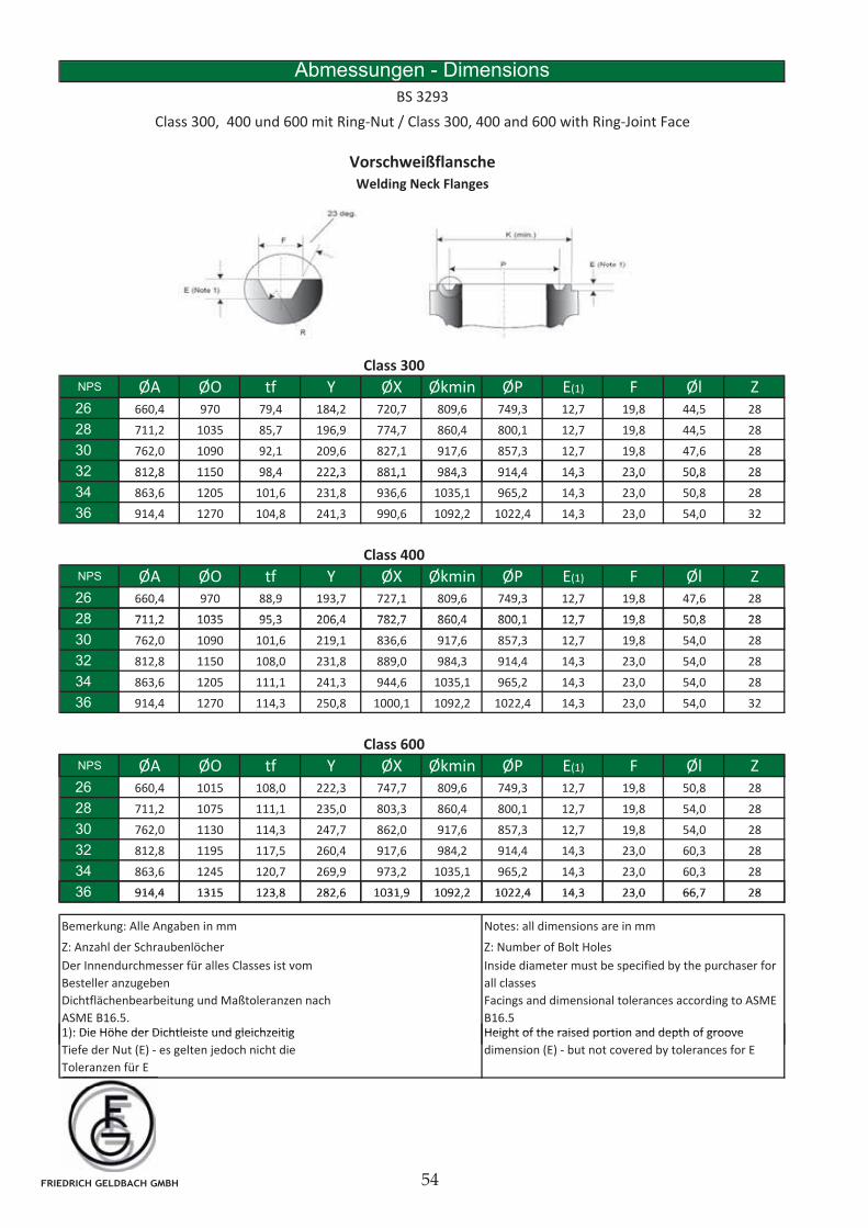
Abmessungen - Dimensions
BS 3293
Class 300, 400 und 600 mit Ring-Nut / Class 300, 400 and 600 with Ring-Joint Face
Vorschweißflansche
Welding Neck Flanges
Class 300
NPS ØA ØO tf Y ØX Økmin ØP E(1) F Øl Z26 660,4 970 79,4 184,2 720,7 809,6 749,3 12,7 19,8 44,5 28
28 711,2 1035 85,7 196,9 774,7 860,4 800,1 12,7 19,8 44,5 28
30 762,0 1090 92,1 209,6 827,1 917,6 857,3 12,7 19,8 47,6 28
32 812,8 1150 98,4 222,3 881,1 984,3 914,4 14,3 23,0 50,8 2832 812,8 1150 98,4 222,3 881,1 984,3 914,4 14,3 23,0 50,8 28
34 863,6 1205 101,6 231,8 936,6 1035,1 965,2 14,3 23,0 50,8 28
36 914,4 1270 104,8 241,3 990,6 1092,2 1022,4 14,3 23,0 54,0 32
Class 400
NPS ØA ØO tf Y ØX Økmin ØP E(1) F Øl Z26 660,4 970 88,9 193,7 727,1 809,6 749,3 12,7 19,8 47,6 28
28 711 2 1035 95 3 206 4 782 7 860 4 800 1 12 7 19 8 50 8 2828 711,2 1035 95,3 206,4 782,7 860,4 800,1 12,7 19,8 50,8 28
30 762,0 1090 101,6 219,1 836,6 917,6 857,3 12,7 19,8 54,0 28
32 812,8 1150 108,0 231,8 889,0 984,3 914,4 14,3 23,0 54,0 28
34 863,6 1205 111,1 241,3 944,6 1035,1 965,2 14,3 23,0 54,0 28
36 914,4 1270 114,3 250,8 1000,1 1092,2 1022,4 14,3 23,0 54,0 32
Class 600
NPS ØA ØO tf Y ØX Økmin ØP E(1) F Øl Z26 660,4 1015 108,0 222,3 747,7 809,6 749,3 12,7 19,8 50,8 28
28 711,2 1075 111,1 235,0 803,3 860,4 800,1 12,7 19,8 54,0 28
30 762,0 1130 114,3 247,7 862,0 917,6 857,3 12,7 19,8 54,0 28
32 812,8 1195 117,5 260,4 917,6 984,2 914,4 14,3 23,0 60,3 28
34 863,6 1245 120,7 269,9 973,2 1035,1 965,2 14,3 23,0 60,3 28
36 914 4 1315 123 8 282 6 1031 9 1092 2 1022 4 14 3 23 0 66 7 2836 914,4 1315 123,8 282,6 1031,9 1092,2 1022,4 14,3 23,0 66,7 28
Bemerkung: Alle Angaben in mm Notes: all dimensions are in mm
Z: Number of Bolt Holes
Der Innendurchmesser für alles Classes ist vom
Besteller anzugeben
Dichtflächenbearbeitung und Maßtoleranzen nach
ASME B16.5.
Inside diameter must be specified by the purchaser for
all classes
Facings and dimensional tolerances according to ASME
B16.5Height of the raised portion and depth of groove1): Die Höhe der Dichtleiste und gleichzeitig
Z: Anzahl der Schraubenlöcher
Height of the raised portion and depth of groove
dimension (E) - but not covered by tolerances for E
1): Die Höhe der Dichtleiste und gleichzeitig
Tiefe der Nut (E) - es gelten jedoch nicht die
Toleranzen für E
FRIEDRICH GELDBACH GMBH
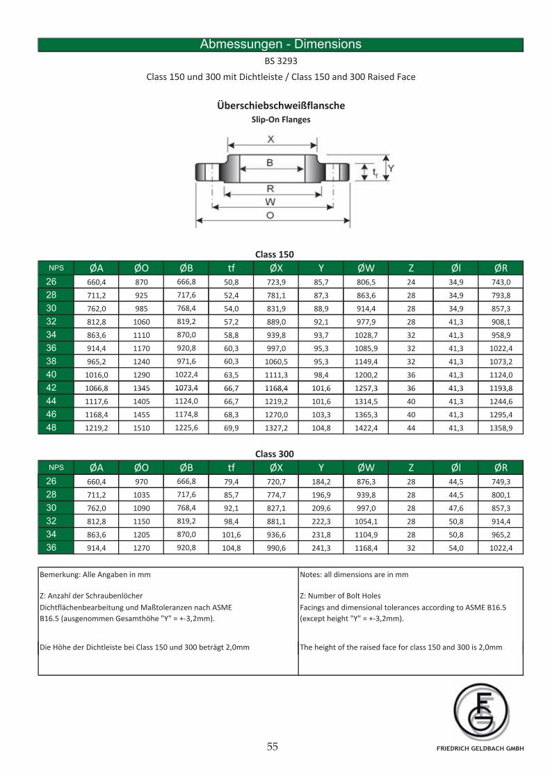
Abmessungen - Dimensions
BS 3293
Class 150 und 300 mit Dichtleiste / Class 150 and 300 Raised Face
Überschiebschweißflansche
Slip-On Flanges
Class 150
NPS ØA ØO ØB tf ØX Y ØW Z Øl ØR26 660,4 870 666,8 50,8 723,9 85,7 806,5 24 34,9 743,0
28 711,2 925 717,6 52,4 781,1 87,3 863,6 28 34,9 793,8
30 762,0 985 768,4 54,0 831,9 88,9 914,4 28 34,9 857,3
32 812,8 1060 819,2 57,2 889,0 92,1 977,9 28 41,3 908,1
34 863,6 1110 870,0 58,8 939,8 93,7 1028,7 32 41,3 958,9
36 914,4 1170 920,8 60,3 997,0 95,3 1085,9 32 41,3 1022,4
38 965,2 1240 971,6 60,3 1060,5 95,3 1149,4 32 41,3 1073,2
40 1016,0 1290 1022,4 63,5 1111,3 98,4 1200,2 36 41,3 1124,0
42 1066,8 1345 1073,4 66,7 1168,4 101,6 1257,3 36 41,3 1193,842 1066,8 1345 1073,4 66,7 1168,4 101,6 1257,3 36 41,3 1193,8
44 1117,6 1405 1124,0 66,7 1219,2 101,6 1314,5 40 41,3 1244,6
46 1168,4 1455 1174,8 68,3 1270,0 103,3 1365,3 40 41,3 1295,4
48 1219,2 1510 1225,6 69,9 1327,2 104,8 1422,4 44 41,3 1358,9
Class 300
NPS ØA ØO ØB tf ØX Y ØW Z Øl ØR2626 660,4 970 666,8 79,4 720,7 184,2 876,3 28 44,5 749,3
28 711,2 1035 717,6 85,7 774,7 196,9 939,8 28 44,5 800,1
30 762,0 1090 768,4 92,1 827,1 209,6 997,0 28 47,6 857,3
32 812,8 1150 819,2 98,4 881,1 222,3 1054,1 28 50,8 914,4
34 863,6 1205 870,0 101,6 936,6 231,8 1104,9 28 50,8 965,2
36 914,4 1270 920,8 104,8 990,6 241,3 1168,4 32 54,0 1022,4
Bemerkung: Alle Angaben in mm Notes: all dimensions are in mm
Z: Number of Bolt HolesZ: Anzahl der Schraubenlöcher
Facings and dimensional tolerances according to ASME B16.5
(except height "Y" = +-3,2mm).
Dichtflächenbearbeitung und Maßtoleranzen nach ASME
B16.5 (ausgenommen Gesamthöhe "Y" = +-3,2mm).
Die Höhe der Dichtleiste bei Class 150 und 300 beträgt 2,0mm The height of the raised face for class 150 and 300 is 2,0mm
FRIEDRICH GELDBACH GMBH
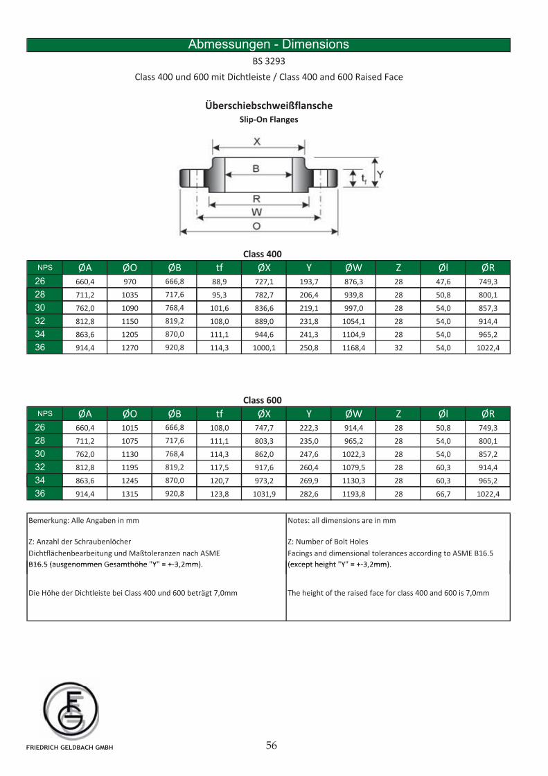
Abmessungen - Dimensions
BS 3293
Class 400 und 600 mit Dichtleiste / Class 400 and 600 Raised Face
Überschiebschweißflansche
Slip-On Flanges
Class 400
NPS ØA ØO ØB tf ØX Y ØW Z Øl ØR26 660,4 970 666,8 88,9 727,1 193,7 876,3 28 47,6 749,3
28 711,2 1035 717,6 95,3 782,7 206,4 939,8 28 50,8 800,1
30 762,0 1090 768,4 101,6 836,6 219,1 997,0 28 54,0 857,3
32 812,8 1150 819,2 108,0 889,0 231,8 1054,1 28 54,0 914,4
34 863,6 1205 870,0 111,1 944,6 241,3 1104,9 28 54,0 965,2
36 914,4 1270 920,8 114,3 1000,1 250,8 1168,4 32 54,0 1022,4
Class 600
NPS ØA ØO ØB tf ØX Y ØW Z Øl ØR26 660,4 1015 666,8 108,0 747,7 222,3 914,4 28 50,8 749,3
28 711,2 1075 717,6 111,1 803,3 235,0 965,2 28 54,0 800,1
30 762,0 1130 768,4 114,3 862,0 247,6 1022,3 28 54,0 857,2
32 812,8 1195 819,2 117,5 917,6 260,4 1079,5 28 60,3 914,4
3434 863,6 1245 870,0 120,7 973,2 269,9 1130,3 28 60,3 965,2
36 914,4 1315 920,8 123,8 1031,9 282,6 1193,8 28 66,7 1022,4
Bemerkung: Alle Angaben in mm Notes: all dimensions are in mm
Dichtflächenbearbeitung und Maßtoleranzen nach ASME
B16 5 (ausgenommen Gesamthöhe "Y" = +-3 2mm)
Z: Number of Bolt Holes
Facings and dimensional tolerances according to ASME B16.5
(except height "Y" = +-3 2mm)
Z: Anzahl der Schraubenlöcher
B16.5 (ausgenommen Gesamthöhe Y = +-3,2mm).
Die Höhe der Dichtleiste bei Class 400 und 600 beträgt 7,0mm
(except height Y = +-3,2mm).
The height of the raised face for class 400 and 600 is 7,0mm
FRIEDRICH GELDBACH GMBH
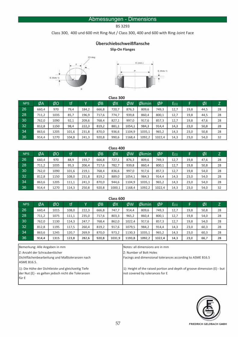
Abmessungen - Dimensions
BS 3293
Class 300, 400 und 600 mit Ring-Nut / Class 300, 400 and 600 with Ring-Joint Face
Überschiebschweißflansche
Slip-On Flanges
Class 300
NPS ØA ØO tf Y ØB ØX ØW Økmin ØP E(1) F Øl Z26 660,4 970 79,4 184,2 666,8 720,7 876,3 809,6 749,3 12,7 19,8 44,5 28
28 711,2 1035 85,7 196,9 717,6 774,7 939,8 860,4 800,1 12,7 19,8 44,5 28
30 762,0 1090 92,1 209,6 768,4 827,1 997,0 917,6 857,3 12,7 19,8 47,6 28
32 812,8 1150 98,4 222,3 819,2 881,1 1054,1 984,3 914,4 14,3 23,0 50,8 2832 812,8 1150 98,4 222,3 819,2 881,1 1054,1 984,3 914,4 14,3 23,0 50,8 28
34 863,6 1205 101,6 231,8 870,0 936,6 1104,9 1035,1 965,2 14,3 23,0 50,8 28
36 914,4 1270 104,8 241,3 920,8 990,6 1168,4 1092,2 1022,4 14,3 23,0 54,0 32
Class 400
NPS ØA ØO tf Y ØB ØX ØW Økmin ØP E(1) F Øl Z26 660,4 970 88,9 193,7 666,8 727,1 876,3 809,6 749,3 12,7 19,8 47,6 28
28 711 2 1035 95 3 206 4 717 6 782 7 939 8 860 4 800 1 12 7 19 8 50 8 2828 711,2 1035 95,3 206,4 717,6 782,7 939,8 860,4 800,1 12,7 19,8 50,8 28
30 762,0 1090 101,6 219,1 768,4 836,6 997,0 917,6 857,3 12,7 19,8 54,0 28
32 812,8 1150 108,0 231,8 819,2 889,0 1054,1 984,3 914,4 14,3 23,0 54,0 28
34 863,6 1205 111,1 241,3 870,0 944,6 1104,9 1035,1 965,2 14,3 23,0 54,0 28
36 914,4 1270 114,3 250,8 920,8 1000,1 1168,4 1092,2 1022,4 14,3 23,0 54,0 32
Class 600
NPS ØA ØO tf Y ØB ØX ØW Økmin ØP E(1) F Øl Z26 660,4 1015 108,0 222,3 666,8 747,7 914,4 809,6 749,3 12,7 19,8 50,8 28
28 711,2 1075 111,1 235,0 717,6 803,3 965,2 860,4 800,1 12,7 19,8 54,0 28
30 762,0 1130 114,3 247,7 768,4 862,0 1022,4 917,6 857,3 12,7 19,8 54,0 28
32 812,8 1195 117,5 260,4 819,2 917,6 1079,5 984,2 914,4 14,3 23,0 60,3 28
34 863,6 1245 120,7 269,9 870,0 973,2 1130,3 1035,1 965,2 14,3 23,0 60,3 28
36 914 4 1315 123 8 282 6 920 8 1031 9 1193 8 1092 2 1022 4 14 3 23 0 66 7 2836 914,4 1315 123,8 282,6 920,8 1031,9 1193,8 1092,2 1022,4 14,3 23,0 66,7 28
Bemerkung: Alle Angaben in mm Notes: all dimensions are in mm
Z: Number of Bolt Holes
Facings and dimensional tolerances according to ASME B16.5
1): Height of the raised portion and depth of groove dimension (E) - but
not covered by tolerances for E
1): Die Höhe der Dichtleiste und gleichzeitig Tiefe
der Nut (E) - es gelten jedoch nicht die Toleranzen
Dichtflächenbearbeitung und Maßtoleranzen nach
ASME B16.5.
Z: Anzahl der Schraubenlöcher
y( ) g j
für E
FRIEDRICH GELDBACH GMBH
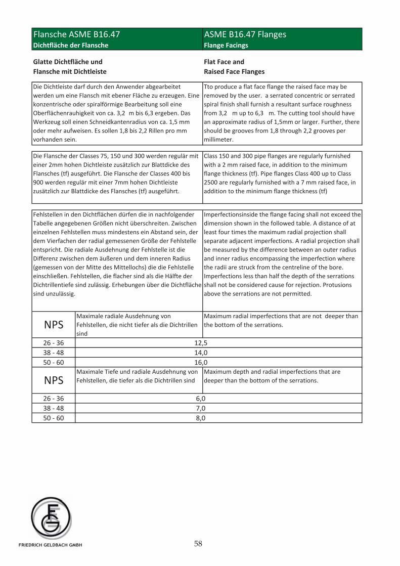
26 - 36
38 - 48
50 - 60
26 - 36
38 - 48
50 - 60 8,0
NPSMaximale Tiefe und radiale Ausdehnung von
Fehlstellen, die tiefer als die Dichtrillen sind
Maximum depth and radial imperfections that are
deeper than the bottom of the serrations.
Fehlstellen in den Dichtflächen dürfen die in nachfolgender
Tabelle angegebenen Größen nicht überschreiten. Zwischen
einzelnen Fehlstellen muss mindestens ein Abstand sein, der
dem Vierfachen der radial gemessenen Größe der Fehlstelle
entspricht. Die radiale Ausdehnung der Fehlstelle ist die
Differenz zwischen dem äußeren und dem inneren Radius
(gemessen von der Mitte des Mittellochs) die die Fehlstelle
einschließen. Fehlstellen, die flacher sind als die Hälfte der
Dichtrillentiefe sind zulässig. Erhebungen über die Dichtfläche
sind unzulässig.
12,5
Class 150 and 300 pipe flanges are regularly furnished
with a 2 mm raised face, in addition to the minimum
flange thickness (tf). Pipe flanges Class 400 up to Class
2500 are regularly furnished with a 7 mm raised face, in
addition to the minimum flange thickness (tf)
16,0
6,0
7,0
Die Dichtleiste darf durch den Anwender abgearbeitet
werden um eine Flansch mit ebener Fläche zu erzeugen. Eine
konzentrische oder spiralförmige Bearbeitung soll eine
Oberflächenrauhigkeit von ca. 3,2 m bis 6,3 ergeben. Das
Werkzeug soll einen Schneidkantenradius von ca. 1,5 mm
oder mehr aufweisen. Es sollen 1,8 bis 2,2 Rillen pro mm
vorhanden sein.
Die Flansche der Classes 75, 150 und 300 werden regulär mit
einer 2mm hohen Dichtleiste zusätzlich zur Blattdicke des
Flansches (tf) ausgeführt. Die Flansche der Classes 400 bis
900 werden regulär mit einer 7mm hohen Dichtleiste
zusätzlich zur Blattdicke des Flansches (tf) ausgeführt.
Glatte Dichtfläche und
Flansche mit Dichtleiste
Flat Face and
Raised Face Flanges
Flansche ASME B16.47Dichtfläche der Flansche Flange Facings
ASME B16.47 Flanges
14,0
Imperfectionsinside the flange facing shall not exceed the
dimension shown in the followed table. A distance of at
least four times the maximum radial projection shall
separate adjacent imperfections. A radial projection shall
be measured by the difference between an outer radius
and inner radius encompassing the imperfection where
the radii are struck from the centreline of the bore.
Imperfections less than half the depth of the serrations
shall not be considered cause for rejection. Protusions
above the serrations are not permitted.
NPSMaximale radiale Ausdehnung von
Fehlstellen, die nicht tiefer als die Dichtrillen
sind
Maximum radial imperfections that are not deeper than
the bottom of the serrations.
Tto produce a flat face flange the raised face may be
removed by the user. a serrated concentric or serrated
spiral finish shall furnish a resultant surface roughness
from 3,2 m up to 6,3 m. The cutting tool should have
an approximate radius of 1,5mm or larger. Further, there
should be grooves from 1,8 through 2,2 grooves per
millimeter.
FRIEDRICH GELDBACH GMBH
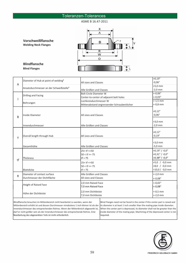
Toleranzen-Tolerances
ASME B 16.47-2011
VorschweißflanscheVorschweißflanscheWelding Neck Flanges
BlindflanscheBlind Flanges
+0,19"
-0,06"
+5,0 mm
-2,0 mm
+-0,06"
+-0,03"
Ansatzdurchmesser an der Schweißstelle³
A
Alle Größen und Classes
All sizes and ClassesDiameter of Hub at point of welding³
lDrilling and Facing
Bolt Circle Diameter W
Center-to-center of adjacent bolt holes
+-1,5 mm
+-0,8 mm
+0,12"
-0,06"
+3,0 mm
-2,0 mm
Inside Diameter
lLochkreisdurchmesser W
Mittenabstand angrenzender Schraubenlöcher
All sizes and Classes
Bohrungen
Innendurchmesser Alle Größen und Classes
B
+0,12"
-0,19"
+3,0 mm
-5,0 mm
+0,19" / -0,0"
+0,31" / -0,0"
+0 38" / 0 0"Thi k
Alle Größen und Classes
25< tf <=50
50 < tf <= 75
tf 75
All sizes and ClassesOverall length through HubY
Gesamthöhe
+0,38" / -0,0"
+5,0 / -0,0 mm
+8,0 / -0,0 mm
+10,0 / -0,0 mm
+-2,0 mm
+-0,08"
+-0,02"
+ 0 08"
Thicknesstf
tf > 75
25< tf <=50
50 < tf <= 75
tf > 75 Blattdicke
Diameter of contact surface
Durchmesser der Dichtfläche
Alle Größen und Classes
All sizes and ClassesR
Height of Raised Face2,0 mm Raised Face
7 0 mm Raised Face
Blindflansche brauchen im Mittenbereich nicht bearbeitet zu werden, wenn der
Mittenbereich erhöht ist und dessen Durchmesser mindestens 1 inch kleiner ist als der
Innendurchmesser des entsprechenden Rohres. Wenn der Mittenbreich abgesenkt ist,
darf er nicht größer sein als der Innendurchmesser des entsprechende Rohres. Eine
Bearbeitung des abgesenkten Teils ist nicht erforderlich
Blind Flanges need not be faced in the center if this center part is raised and
its diameter is at least 1 inch smaller than the mating pipe inside diameter.
When the center part is depressed, its diameter shall not be greater than the
inside diameter of the mating pipe. Machining of the depressed center is not
required
+-0,08"
Höhe der Dichtleiste2,0 mm Dichtleiste
7,0 mm Dichtleiste
+-0,5 mm
+-2,0 mm
g7,0 mm Raised Face
Bearbeitung des abgesenkten Teils ist nicht erforderlich. required.
FRIEDRICH GELDBACH GMBH
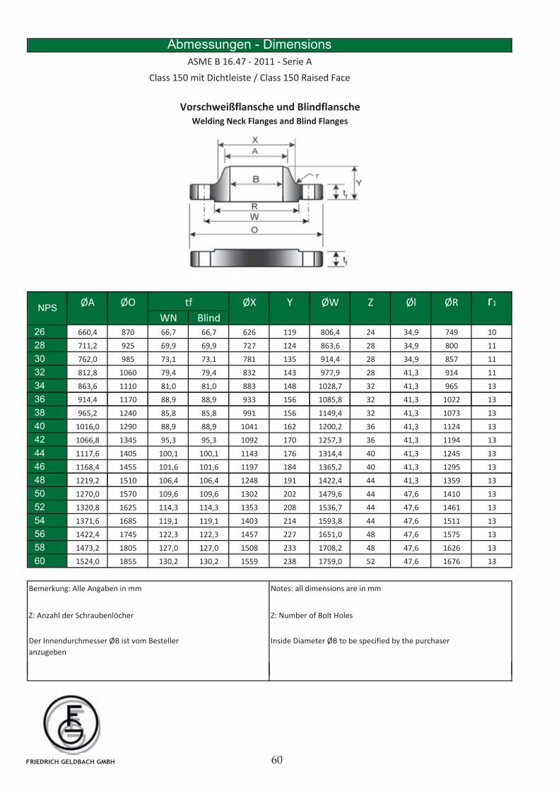
Abmessungen - Dimensions
ASME B 16.47 - 2011 - Serie A
Class 150 mit Dichtleiste / Class 150 Raised Face
Vorschweißflansche und Blindflansche
Welding Neck Flanges and Blind Flanges
ØA ØO ØX Y ØW Z Øl ØR r1tfNPS
ØA ØO ØX Y ØW Z Øl ØR r1
WN Blind26 660,4 870 66,7 66,7 626 119 806,4 24 34,9 749 10
28 711,2 925 69,9 69,9 727 124 863,6 28 34,9 800 11
30 762,0 985 73,1 73,1 781 135 914,4 28 34,9 857 11
32 812,8 1060 79,4 79,4 832 143 977,9 28 41,3 914 11
34 863,6 1110 81,0 81,0 883 148 1028,7 32 41,3 965 13
36
tfNPS
36 914,4 1170 88,9 88,9 933 156 1085,8 32 41,3 1022 13
38 965,2 1240 85,8 85,8 991 156 1149,4 32 41,3 1073 13
40 1016,0 1290 88,9 88,9 1041 162 1200,2 36 41,3 1124 13
42 1066,8 1345 95,3 95,3 1092 170 1257,3 36 41,3 1194 13
44 1117,6 1405 100,1 100,1 1143 176 1314,4 40 41,3 1245 13
46 1168,4 1455 101,6 101,6 1197 184 1365,2 40 41,3 1295 13
48 1219,2 1510 106,4 106,4 1248 191 1422,4 44 41,3 1359 13, , , , ,
50 1270,0 1570 109,6 109,6 1302 202 1479,6 44 47,6 1410 13
52 1320,8 1625 114,3 114,3 1353 208 1536,7 44 47,6 1461 13
54 1371,6 1685 119,1 119,1 1403 214 1593,8 44 47,6 1511 13
56 1422,4 1745 122,3 122,3 1457 227 1651,0 48 47,6 1575 13
58 1473,2 1805 127,0 127,0 1508 233 1708,2 48 47,6 1626 13
60 1524,0 1855 130,2 130,2 1559 238 1759,0 52 47,6 1676 13
Bemerkung: Alle Angaben in mm Notes: all dimensions are in mm
Z: Anzahl der Schraubenlöcher Z: Number of Bolt Holes
Inside Diameter ØB to be specified by the purchaser Der Innendurchmesser ØB ist vom Besteller
anzugeben
FRIEDRICH GELDBACH GMBH

Abmessungen - Dimensions
ASME B 16.47 - 2011 - Serie A
Class 300 mit Dichtleiste / Class 300 Raised Face
Vorschweißflansche und Blindflansche
Welding Neck Flanges and Blind Flanges
ØA ØO ØX Y ØW Z Øl ØR r1tfNPS
ØA ØO ØX Y ØW Z Øl ØR r1
WN Blind26 660,4 970 77,8 82,6 721 183 876,3 28 44,5 749 10
28 711,2 1035 84,2 88,9 775 195 939,8 28 44,5 800 11
30 762,0 1090 90,5 93,7 827 208 997,0 28 47,6 857 11
32 812,8 1150 96,9 98,5 881 221 1054,1 28 50,8 914 11
34 863,6 1205 100,1 103,2 937 230 1104,9 28 50,8 965 13
36
tfNPS
36 914,4 1270 103,2 109,6 991 240 1168,4 32 54,0 1022 13
38 965,2 1170 106,4 106,4 994 179 1092,2 32 41,3 1029 13
40 1016,0 1240 112,8 112,8 1048 192 1155,7 32 44,5 1086 13
42 1066,8 1290 117,5 117,5 1099 198 1206,5 32 44,5 1137 13
44 1117,6 1355 122,3 122,3 1149 205 1263,6 32 47,6 1194 13
46 1168,4 1415 127,0 127,0 1203 214 1320,8 28 50,8 1245 13
48 1219,2 1465 131,8 131,8 1254 222 1371,6 32 50,8 1302 13, , , , ,
50 1270,0 1530 138,2 138,2 1305 230 1428,8 32 54,0 1359 13
52 1320,8 1580 142,9 142,9 1356 237 1479,6 32 54,0 1410 13
54 1371,6 1660 150,9 150,9 1410 251 1549,4 28 60,3 1467 13
56 1422,4 1710 152,4 152,4 1464 259 1600,2 28 60,3 1518 13
58 1473,2 1760 157,2 157,2 1514 265 1651,0 32 60,3 1575 13
60 1524,0 1810 162,0 162,0 1565 271 1701,8 32 60,3 1626 13
Bemerkung: Alle Angaben in mm Notes: all dimensions are in mm
Inside Diameter ØB to be specified by the purchaser Der Innendurchmesser ØB ist vom Besteller
anzugeben
Z: Anzahl der Schraubenlöcher Z: Number of Bolt Holes
FRIEDRICH GELDBACH GMBH
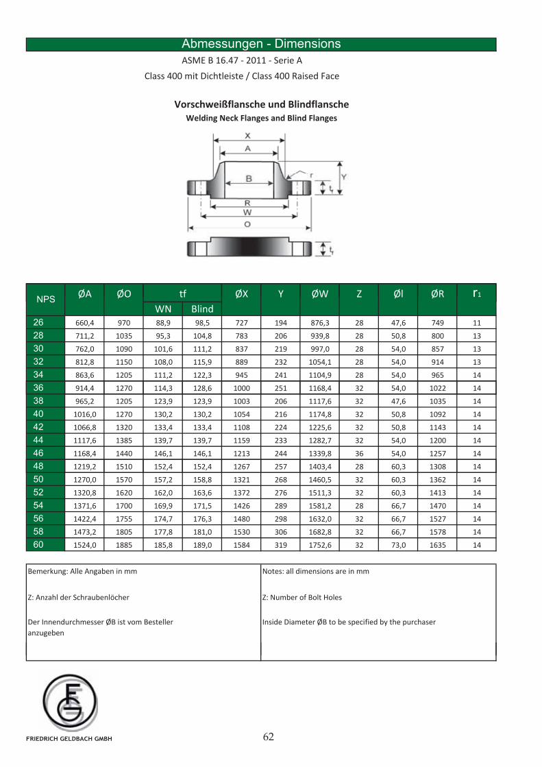
Abmessungen - Dimensions
ASME B 16.47 - 2011 - Serie A
Class 400 mit Dichtleiste / Class 400 Raised Face
Vorschweißflansche und Blindflansche
Welding Neck Flanges and Blind Flanges
ØA ØO ØX Y ØW Z Øl ØR r1tfNPS
ØA ØO ØX Y ØW Z Øl ØR r1
WN Blind26 660,4 970 88,9 98,5 727 194 876,3 28 47,6 749 11
28 711,2 1035 95,3 104,8 783 206 939,8 28 50,8 800 13
30 762,0 1090 101,6 111,2 837 219 997,0 28 54,0 857 13
32 812,8 1150 108,0 115,9 889 232 1054,1 28 54,0 914 13
34 863,6 1205 111,2 122,3 945 241 1104,9 28 54,0 965 14
36
tfNPS
36 914,4 1270 114,3 128,6 1000 251 1168,4 32 54,0 1022 14
38 965,2 1205 123,9 123,9 1003 206 1117,6 32 47,6 1035 14
40 1016,0 1270 130,2 130,2 1054 216 1174,8 32 50,8 1092 14
42 1066,8 1320 133,4 133,4 1108 224 1225,6 32 50,8 1143 14
44 1117,6 1385 139,7 139,7 1159 233 1282,7 32 54,0 1200 14
46 1168,4 1440 146,1 146,1 1213 244 1339,8 36 54,0 1257 14
48 1219,2 1510 152,4 152,4 1267 257 1403,4 28 60,3 1308 14, , , , ,
50 1270,0 1570 157,2 158,8 1321 268 1460,5 32 60,3 1362 14
52 1320,8 1620 162,0 163,6 1372 276 1511,3 32 60,3 1413 14
54 1371,6 1700 169,9 171,5 1426 289 1581,2 28 66,7 1470 14
56 1422,4 1755 174,7 176,3 1480 298 1632,0 32 66,7 1527 14
58 1473,2 1805 177,8 181,0 1530 306 1682,8 32 66,7 1578 14
60 1524,0 1885 185,8 189,0 1584 319 1752,6 32 73,0 1635 14
Bemerkung: Alle Angaben in mm Notes: all dimensions are in mm
Inside Diameter ØB to be specified by the purchaser Der Innendurchmesser ØB ist vom Besteller
anzugeben
Z: Anzahl der Schraubenlöcher Z: Number of Bolt Holes
FRIEDRICH GELDBACH GMBH
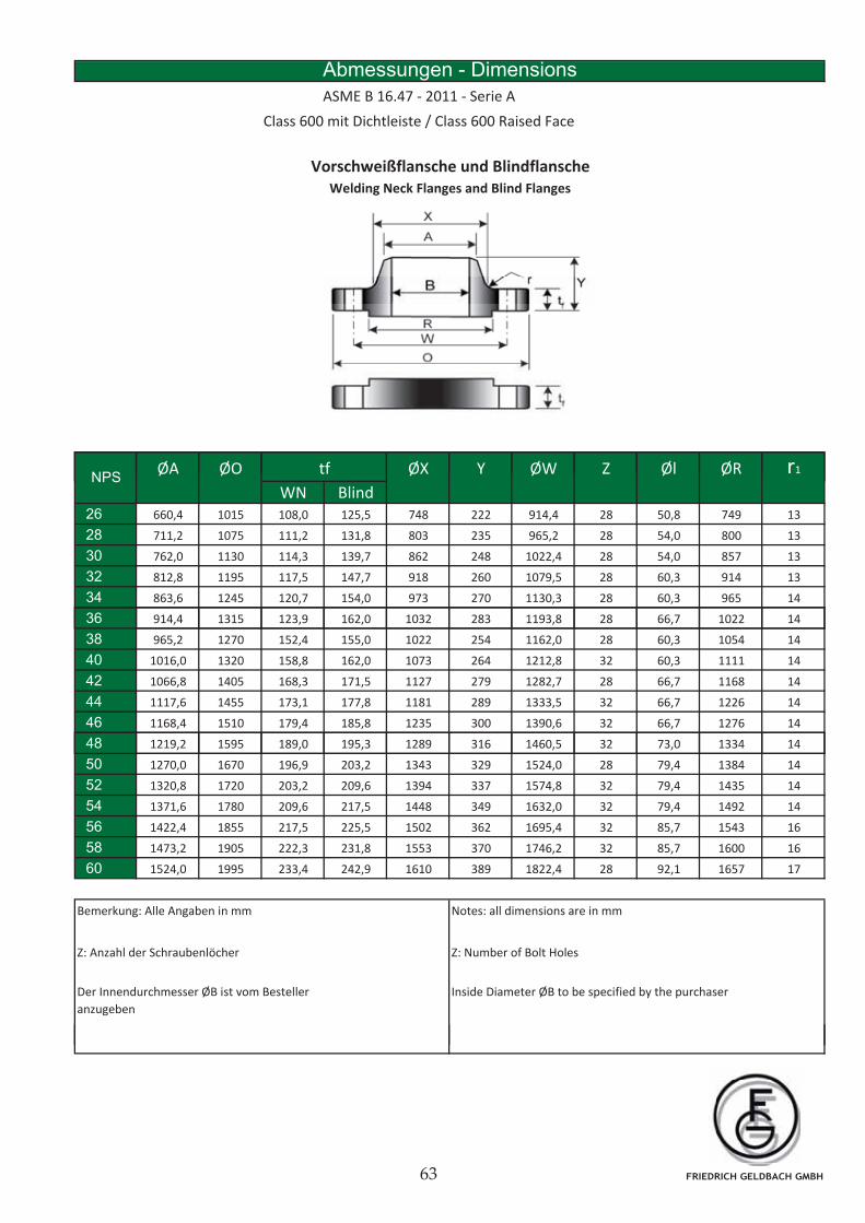
Abmessungen - Dimensions
ASME B 16.47 - 2011 - Serie A
Class 600 mit Dichtleiste / Class 600 Raised Face
Vorschweißflansche und Blindflansche
Welding Neck Flanges and Blind Flanges
ØA ØO ØX Y ØW Z Øl ØR r1tfNPS
ØA ØO ØX Y ØW Z Øl ØR r1
WN Blind26 660,4 1015 108,0 125,5 748 222 914,4 28 50,8 749 13
28 711,2 1075 111,2 131,8 803 235 965,2 28 54,0 800 13
30 762,0 1130 114,3 139,7 862 248 1022,4 28 54,0 857 13
32 812,8 1195 117,5 147,7 918 260 1079,5 28 60,3 914 13
34 863,6 1245 120,7 154,0 973 270 1130,3 28 60,3 965 14
36
tfNPS
36 914,4 1315 123,9 162,0 1032 283 1193,8 28 66,7 1022 14
38 965,2 1270 152,4 155,0 1022 254 1162,0 28 60,3 1054 14
40 1016,0 1320 158,8 162,0 1073 264 1212,8 32 60,3 1111 14
42 1066,8 1405 168,3 171,5 1127 279 1282,7 28 66,7 1168 14
44 1117,6 1455 173,1 177,8 1181 289 1333,5 32 66,7 1226 14
46 1168,4 1510 179,4 185,8 1235 300 1390,6 32 66,7 1276 14
48 1219,2 1595 189,0 195,3 1289 316 1460,5 32 73,0 1334 14, , , , ,
50 1270,0 1670 196,9 203,2 1343 329 1524,0 28 79,4 1384 14
52 1320,8 1720 203,2 209,6 1394 337 1574,8 32 79,4 1435 14
54 1371,6 1780 209,6 217,5 1448 349 1632,0 32 79,4 1492 14
56 1422,4 1855 217,5 225,5 1502 362 1695,4 32 85,7 1543 16
58 1473,2 1905 222,3 231,8 1553 370 1746,2 32 85,7 1600 16
60 1524,0 1995 233,4 242,9 1610 389 1822,4 28 92,1 1657 17
Bemerkung: Alle Angaben in mm Notes: all dimensions are in mm
Z: Anzahl der Schraubenlöcher Z: Number of Bolt Holes
Inside Diameter ØB to be specified by the purchaser Der Innendurchmesser ØB ist vom Besteller
anzugeben
FRIEDRICH GELDBACH GMBH
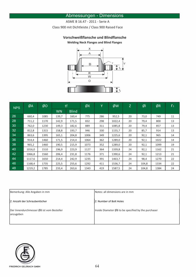
Vorschweißflansche und Blindflansche
Welding Neck Flanges and Blind Flanges
Abmessungen - Dimensions
ASME B 16.47 - 2011 - Serie A
Class 900 mit Dichtleiste / Class 900 Raised Face
ØA ØO ØX Y ØW Z Øl ØR r1tfNPS
ØA ØO ØX Y ØW Z Øl ØR r1
WN Blind26 660,4 1085 139,7 160,4 775 286 952,5 20 73,0 749 11
28 711,2 1170 142,9 171,5 832 298 1022,4 20 79,4 800 13
30 762,0 1230 149,3 182,6 889 311 1085,8 20 79,4 857 13
32 812,8 1315 158,8 193,7 946 330 1155,7 20 85,7 914 13
34 863,6 1395 165,1 204,8 1006 349 1225,6 20 92,1 965 14
36
tfNPS
36 914,4 1460 171,5 214,4 1064 362 1289,0 20 92,1 1022 14
38 965,2 1460 190,5 215,9 1073 352 1289,0 20 92,1 1099 19
40 1016,0 1510 196,9 223,9 1127 364 1339,8 24 92,1 1162 21
42 1066,8 1560 206,4 231,8 1176 371 1390,6 24 92,1 1213 21
44 1117,6 1650 214,4 242,9 1235 391 1463,7 24 98,4 1270 22
46 1168,4 1735 225,5 255,6 1292 411 1536,7 24 104,8 1334 22
48 1219,2 1785 233,4 263,6 1343 419 1587,5 24 104,8 1384 24, , , , ,
Bemerkung: Alle Angaben in mm Notes: all dimensions are in mm
Z: Number of Bolt HolesZ: Anzahl der Schraubenlöcher Z: Number of Bolt Holes
Inside Diameter ØB to be specified by the purchaser Der Innendurchmesser ØB ist vom Besteller
anzugeben
Z: Anzahl der Schraubenlöcher
FRIEDRICH GELDBACH GMBH
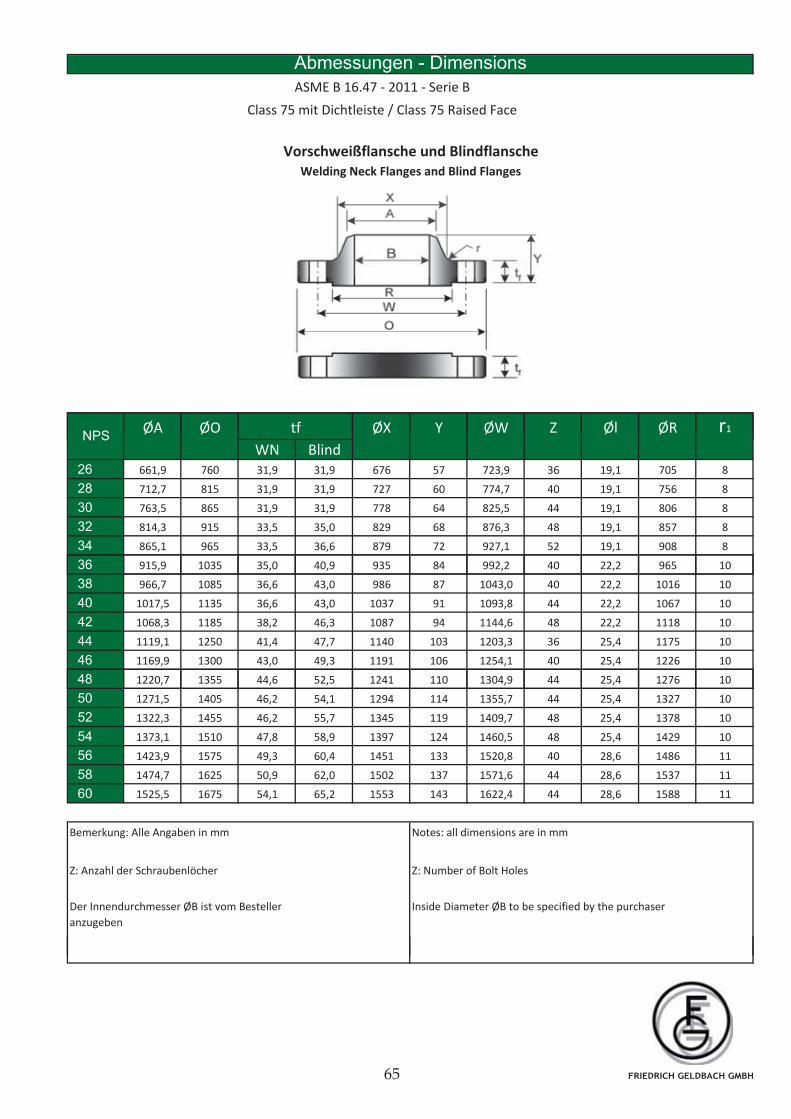
Abmessungen - Dimensions
ASME B 16.47 - 2011 - Serie B
Class 75 mit Dichtleiste / Class 75 Raised Face
Vorschweißflansche und Blindflansche
Welding Neck Flanges and Blind Flanges
ØA ØO ØX Y ØW Z Øl ØR r1tfNPS
ØA ØO ØX Y ØW Z Øl ØR r1
WN Blind26 661,9 760 31,9 31,9 676 57 723,9 36 19,1 705 8
28 712,7 815 31,9 31,9 727 60 774,7 40 19,1 756 8
30 763,5 865 31,9 31,9 778 64 825,5 44 19,1 806 8
32 814,3 915 33,5 35,0 829 68 876,3 48 19,1 857 8
34 865,1 965 33,5 36,6 879 72 927,1 52 19,1 908 8
36
tfNPS
36 915,9 1035 35,0 40,9 935 84 992,2 40 22,2 965 10
38 966,7 1085 36,6 43,0 986 87 1043,0 40 22,2 1016 10
40 1017,5 1135 36,6 43,0 1037 91 1093,8 44 22,2 1067 10
42 1068,3 1185 38,2 46,3 1087 94 1144,6 48 22,2 1118 10
44 1119,1 1250 41,4 47,7 1140 103 1203,3 36 25,4 1175 10
46 1169,9 1300 43,0 49,3 1191 106 1254,1 40 25,4 1226 10
48 1220,7 1355 44,6 52,5 1241 110 1304,9 44 25,4 1276 10, , , , ,
50 1271,5 1405 46,2 54,1 1294 114 1355,7 44 25,4 1327 10
52 1322,3 1455 46,2 55,7 1345 119 1409,7 48 25,4 1378 10
54 1373,1 1510 47,8 58,9 1397 124 1460,5 48 25,4 1429 10
56 1423,9 1575 49,3 60,4 1451 133 1520,8 40 28,6 1486 11
58 1474,7 1625 50,9 62,0 1502 137 1571,6 44 28,6 1537 11
60 1525,5 1675 54,1 65,2 1553 143 1622,4 44 28,6 1588 11
Bemerkung: Alle Angaben in mm Notes: all dimensions are in mm
Inside Diameter ØB to be specified by the purchaser Der Innendurchmesser ØB ist vom Besteller
anzugeben
Z: Anzahl der Schraubenlöcher Z: Number of Bolt Holes
FRIEDRICH GELDBACH GMBH
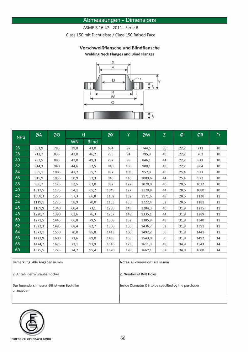
Vorschweißflansche und Blindflansche
Welding Neck Flanges and Blind Flanges
Abmessungen - Dimensions
ASME B 16.47 - 2011 - Serie B
Class 150 mit Dichtleiste / Class 150 Raised Face
ØA ØO ØX Y ØW Z Øl ØR r1tfNPS
ØA ØO ØX Y ØW Z Øl ØR r1
WN Blind26 661,9 785 39,8 43,0 684 87 744,5 36 22,2 711 10
28 712,7 835 43,0 46,2 735 94 795,3 40 22,2 762 10
30 763,5 885 43,0 49,3 787 98 846,1 44 22,2 813 10
32 814,3 940 44,6 52,5 840 106 900,1 48 22,2 864 10
34 865,1 1005 47,7 55,7 892 109 957,3 40 25,4 921 10
36
tfNPS
36 915,9 1055 50,9 57,3 945 116 1009,6 44 25,4 972 10
38 966,7 1125 52,5 62,0 997 122 1070,0 40 28,6 1022 10
40 1017,5 1175 54,1 65,2 1049 127 1120,8 44 28,6 1080 10
42 1068,3 1225 57,3 66,8 1102 132 1171,6 48 28,6 1130 11
44 1119,1 1275 58,9 70,0 1153 135 1222,4 52 28,6 1181 11
46 1169,9 1340 60,4 73,1 1205 143 1284,3 40 31,8 1235 11
48 1220,7 1390 63,6 76,3 1257 148 1335,1 44 31,8 1289 11, , , , ,
50 1271,5 1445 66,8 79,5 1308 152 1385,9 48 31,8 1340 11
52 1322,3 1495 68,4 82,7 1360 156 1436,7 52 31,8 1391 11
54 1373,1 1550 70,0 85,8 1413 160 1492,2 56 31,8 1441 11
56 1423,9 1600 71,6 89,0 1465 165 1543,0 60 31,8 1492 14
58 1474,7 1675 73,1 91,9 1516 173 1611,3 48 34,9 1543 14
60 1525,5 1725 74,7 95,4 1570 178 1662,1 52 34,9 1600 14
Bemerkung: Alle Angaben in mm Notes: all dimensions are in mm
Z: Number of Bolt Holes
Inside Diameter ØB to be specified by the purchaser Der Innendurchmesser ØB ist vom Besteller
anzugeben
Z: Anzahl der Schraubenlöcher
FRIEDRICH GELDBACH GMBH
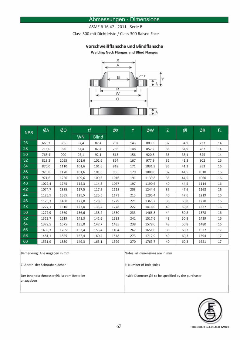
Vorschweißflansche und Blindflansche
Welding Neck Flanges and Blind Flanges
Abmessungen - Dimensions
ASME B 16.47 - 2011 - Serie B
Class 300 mit Dichtleiste / Class 300 Raised Face
ØA ØO ØX Y ØW Z Øl ØR r1tfNPS
ØA ØO ØX Y ØW Z Øl ØR r1
WN Blind26 665,2 865 87,4 87,4 702 143 803,3 32 34,9 737 14
28 716,0 920 87,4 87,4 756 148 857,2 36 34,9 787 14
30 768,4 990 92,1 92,1 813 156 920,8 36 38,1 845 14
32 819,2 1055 101,6 101,6 864 167 977,9 32 41,3 902 16
34 870,0 1110 101,6 101,6 918 171 1031,9 36 41,3 953 16
36
tfNPS
36 920,8 1170 101,6 101,6 965 179 1089,0 32 44,5 1010 16
38 971,6 1220 109,6 109,6 1016 191 1139,8 36 44,5 1060 16
40 1022,4 1275 114,3 114,3 1067 197 1190,6 40 44,5 1114 16
42 1074,7 1335 117,5 117,5 1118 203 1244,6 36 47,6 1168 16
44 1125,5 1385 125,5 125,5 1173 213 1295,4 40 47,6 1219 16
46 1176,3 1460 127,0 128,6 1229 221 1365,2 36 50,8 1270 16
48 1227,1 1510 127,0 133,4 1278 222 1416,0 40 50,8 1327 16, , , , ,
50 1277,9 1560 136,6 138,2 1330 233 1466,8 44 50,8 1378 16
52 1328,7 1615 141,3 142,6 1383 241 1517,6 48 50,8 1429 16
54 1379,5 1675 135,0 147,7 1435 238 1578,0 48 50,8 1480 16
56 1430,3 1765 152,4 155,4 1494 267 1651,0 36 60,3 1537 17
58 1481,1 1825 152,4 160,4 1548 273 1712,9 40 60,3 1594 17
60 1531,9 1880 149,3 165,1 1599 270 1763,7 40 60,3 1651 17
Bemerkung: Alle Angaben in mm Notes: all dimensions are in mm
Z: Number of Bolt Holes
Inside Diameter ØB to be specified by the purchaser Der Innendurchmesser ØB ist vom Besteller
anzugeben
Z: Anzahl der Schraubenlöcher
FRIEDRICH GELDBACH GMBH
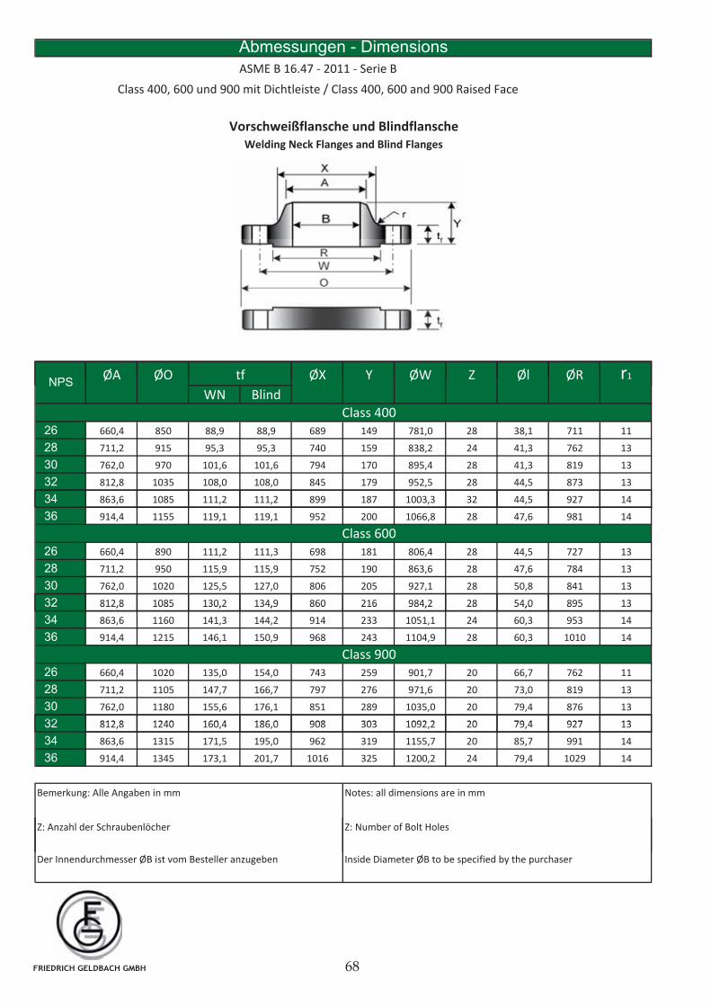
Abmessungen - Dimensions
ASME B 16.47 - 2011 - Serie B
Class 400, 600 und 900 mit Dichtleiste / Class 400, 600 and 900 Raised Face
Vorschweißflansche und Blindflansche
Welding Neck Flanges and Blind Flanges
ØA ØO ØX Y ØW Z Øl ØR r1tfNPS
ØA ØO ØX Y ØW Z Øl ØR r1
WN Blind
26 660,4 850 88,9 88,9 689 149 781,0 28 38,1 711 11
28 711,2 915 95,3 95,3 740 159 838,2 24 41,3 762 13
30 762,0 970 101,6 101,6 794 170 895,4 28 41,3 819 13
32 812,8 1035 108,0 108,0 845 179 952,5 28 44,5 873 13
34
tfNPS
Class 400
34 863,6 1085 111,2 111,2 899 187 1003,3 32 44,5 927 14
36 914,4 1155 119,1 119,1 952 200 1066,8 28 47,6 981 14
26 660,4 890 111,2 111,3 698 181 806,4 28 44,5 727 13
28 711,2 950 115,9 115,9 752 190 863,6 28 47,6 784 13
30 762,0 1020 125,5 127,0 806 205 927,1 28 50,8 841 13
32 812,8 1085 130,2 134,9 860 216 984,2 28 54,0 895 13
Class 600
32 812,8 1085 130,2 134,9 860 216 984,2 28 54,0 895 13
34 863,6 1160 141,3 144,2 914 233 1051,1 24 60,3 953 14
36 914,4 1215 146,1 150,9 968 243 1104,9 28 60,3 1010 14
26 660,4 1020 135,0 154,0 743 259 901,7 20 66,7 762 11
28 711,2 1105 147,7 166,7 797 276 971,6 20 73,0 819 13
30 762,0 1180 155,6 176,1 851 289 1035,0 20 79,4 876 13
32 812 8 1240 160 4 186 0 908 303 1092 2 20 79 4 927 13
Class 900
32 812,8 1240 160,4 186,0 908 303 1092,2 20 79,4 927 13
34 863,6 1315 171,5 195,0 962 319 1155,7 20 85,7 991 14
36 914,4 1345 173,1 201,7 1016 325 1200,2 24 79,4 1029 14
Bemerkung: Alle Angaben in mm Notes: all dimensions are in mm
Z: Anzahl der Schraubenlöcher Z: Number of Bolt Holes
Der Innendurchmesser ØB ist vom Besteller anzugeben Inside Diameter ØB to be specified by the purchaser
FRIEDRICH GELDBACH GMBH
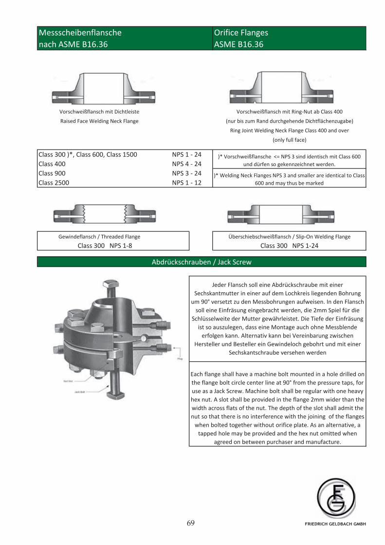
nach ASME B16.36 ASME B16.36
Abdrückschrauben / Jack Screw
Vorschweißflansch mit Dichtleiste
Raised Face Welding Neck Flange
Vorschweißflansch mit Ring-Nut ab Class 400
(nur bis zum Rand durchgehende Dichtflächenzugabe)
Ring Joint Welding Neck Flange Class 400 and over
(only full face)
NPS 3 - 24
Überschiebschweißflansch / Slip-On Welding FlangeGewindeflansch / Threaded Flange
Messscheibenflansche Orifice Flanges
Class 300 )*, Class 600, Class 1500
Class 400
Class 900
Class 2500
Class 300 NPS 1-8
NPS 1 - 24
NPS 4 - 24
NPS 1 - 12
)* Vorschweißflansche <= NPS 3 sind identisch mit Class 600
und dürfen so gekennzeichnet werden.
)* Welding Neck Flanges NPS 3 and smaller are identical to Class
600 and may thus be marked
Class 300 NPS 1-24
Abdrückschrauben / Jack Screw
Jeder Flansch soll eine Abdrückschraube mit einer
Sechskantmutter in einer auf dem Lochkreis liegenden Bohrung
um 90° versetzt zu den Messbohrungen aufweisen. In den Flansch
soll eine Einfräsung eingebracht werden, die 2mm Spiel für die
Schlüsselweite der Mutter gewährleistet. Die Tiefe der Einfräsung
ist so auszulegen, dass eine Montage auch ohne Messblende
erfolgen kann. Alternativ kann bei Vereinbarung zwischen
Hersteller und Besteller ein Gewindeloch gebohrt und mit einer
Sechskantschraube versehen werden
Each flange shall have a machine bolt mounted in a hole drilled on
the flange bolt circle center line at 90° from the pressure taps, for
use as a Jack Screw. Machine bolt shall be regular with one heavy
hex nut. A slot shall be provided in the flange 2mm wider than the
width across flats of the nut. The depth of the slot shall admit the
nut so that there is no interference with the joining of the flanges
when bolted together without orifice plate. As an alternative, a
tapped hole may be provided and the hex nut omitted when
agreed on between purchaser and manufacture.
FRIEDRICH GELDBACH GMBH
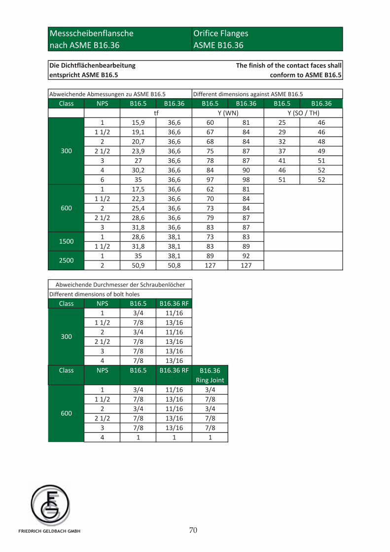
ASME B16.36
Class NPS B16.5 B16.36 B16.5 B16.36 B16.5 B16.36
1 15,9 36,6 60 81 25 46
1 1/2 19,1 36,6 67 84 29 46
2 20,7 36,6 68 84 32 48
2 1/2 23,9 36,6 75 87 37 49
3 27 36,6 78 87 41 51
4 30,2 36,6 84 90 46 52
6 35 36,6 97 98 51 52
1 17,5 36,6 62 81
1 1/2 22,3 36,6 70 84
2 25,4 36,6 73 84
2 1/2 28,6 36,6 79 87
3 31,8 36,6 83 87
1 28,6 38,1 73 83
1 1/2 31,8 38,1 83 89
1 35 38,1 89 92
2 50,9 50,8 127 127
Class NPS B16.5 B16.36 RF
1 3/4 11/16
1 1/2 7/8 13/16
2 3/4 11/16
2 1/2 7/8 13/16
3 7/8 13/16
4 7/8 13/16
Class NPS B16.5 B16.36 RF B16.36
Ring Joint
1 3/4 11/16 3/4
1 1/2 7/8 13/16 7/8
2 3/4 11/16 3/4
2 1/2 7/8 13/16 7/8
3 7/8 13/16 7/8
4 1 1 1
Abweichende Abmessungen zu ASME B16.5
nach ASME B16.36
Different dimensions against ASME B16.5
300
tf
600
Y (WN) Y (SO / TH)
Die Dichtflächenbearbeitung
entspricht ASME B16.5
The finish of the contact faces shall
conform to ASME B16.5
Orifice Flanges
Abweichende Durchmesser der Schraubenlöcher
Different dimensions of bolt holes
300
600
1500
2500
Messscheibenflansche
FRIEDRICH GELDBACH GMBH
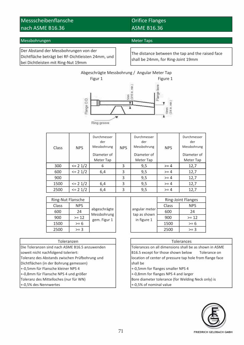
Messbohrungen Meter Taps
Figur 1 Figure 1
300 <= 2 1/2 6 3 9,5 >= 4 12,7
Durchmesser
der
Messbohrung
Diameter of
Meter Tap
NPS NPS
Messscheibenflansche
nach ASME B16.36
Orifice Flanges
ASME B16.36
Abgeschrägte Messbohrung / Angular Meter Tap
Durchmesser
der
Messbohrung
Diameter of
Meter Tap
Durchmesser
der
Messbohrung
Diameter of
Meter Tap
Der Abstand der Messbohrungen von der
Dichtfläche beträgt bei RF-Dichtleisten 24mm, und
bei Dichtleisten mit Ring-Nut 19mm
The distance between the tap and the raised face
shall be 24mm, for Ring-Joint 19mm
Class NPS
300 <= 2 1/2 6 3 9,5 >= 4 12,7
600 <= 2 1/2 6,4 3 9,5 >= 4 12,7
900 3 9,5 >= 4 12,7
1500 <= 2 1/2 6,4 3 9,5 >= 4 12,7
2500 <= 2 1/2 6,4 3 9,5 >= 4 12,7
Class NPS Class NPS
600 24 600 24
900 >= 12 900 >= 12
1500 >= 6 1500 >= 6
2500 >= 3 2500 >= 3
abgeschrägte
Messbohrung
gem. Figur 1
angular meter
tap as shown
in figure 1
Toleranzen Tolerances
Die Toleranzen sind nach ASME B16.5 anzuwenden
soweit nicht nachfolgend toleriert:
Toleranz des Abstands zwischen Prüfbohrung und
Dichtflächen (in der Bohrung gemessen)
+-0,5mm für Flansche kleiner NPS 4
+-0,8mm für Flansche NPS 4 und größer
Toleranz des Mittelloches (nur für WN)
+-0,5% des Nennwertes
Tolerances on all dimensions shall be as shown in ASME
B16.5 except for those shown below Tolerance on
location of center of pressure tap hole from flange face
shall be
+-0,5mm for flanges smaller NPS 4
+-0,8mm for flanges NPS 4 and larger
Bore diameter tolerance (for Welding Neck only) is
+-0,5% of nominal value
Ring-Nut Flansche Ring-Joint Flanges
FRIEDRICH GELDBACH GMBH
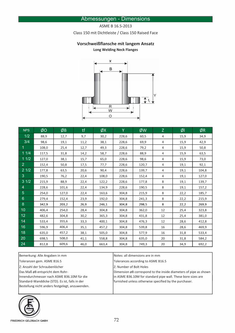
Vorschweißflansche mit langem Ansatz
Long Welding Neck Flanges
Abmessungen - Dimensions
ASME B 16.5-2013
Class 150 mit Dichtleiste / Class 150 Raised Face
NPS ØO ØB tf ØX Y ØW Z Øl ØRNPS ØO ØB tf ØX Y ØW Z Øl ØR1/2 88,9 12,7 9,7 30,2 228,6 60,5 4 15,9 34,9
3/4 98,6 19,1 11,2 38,1 228,6 69,9 4 15,9 42,9
1 108,0 25,4 12,7 49,3 228,6 79,2 4 15,9 50,8
1 1/4 117,5 31,8 14,2 58,7 228,6 88,9 4 15,9 63,5
1 1/2 127,0 38,1 15,7 65,0 228,6 98,6 4 15,9 73,0
2 152,4 50,8 17,5 77,7 228,6 120,7 4 19,1 92,1, , , , , , , ,
2 1/2 177,8 63,5 20,6 90,4 228,6 139,7 4 19,1 104,8
3 190,5 76,2 22,4 108,0 228,6 152,4 4 19,1 127,0
3 1/2 215,9 88,9 22,4 122,2 228,6 177,8 8 19,1 139,7
4 228,6 101,6 22,4 134,9 228,6 190,5 8 19,1 157,2
5 254,0 127,0 22,4 163,6 304,8 215,9 8 22,2 185,7
6 279,4 152,4 23,9 192,0 304,8 241,3 8 22,2 215,9
8 342 9 203 2 26 9 246 1 304 8 298 5 8 22 2 269 98 342,9 203,2 26,9 246,1 304,8 298,5 8 22,2 269,9
10 406,4 254,0 28,4 304,8 304,8 362,0 12 25,4 323,8
12 482,6 304,8 30,2 365,3 304,8 431,8 12 25,4 381,0
14 533,4 355,6 33,3 400,1 304,8 476,3 12 28,6 412,8
16 596,9 406,4 35,1 457,2 304,8 539,8 16 28,6 469,9
18 635,0 457,2 38,1 505,0 304,8 577,9 16 31,8 533,4
20 698,5 508,0 41,1 558,8 304,8 635,0 20 31,8 584,2
24 812,8 609,6 46,0 663,4 304,8 749,3 20 34,9 692,2
Bemerkung: Alle Angaben in mm Notes: all dimensions are in mm
Toleranzen gem. ASME B16.5 Tolerances according to ASME B16.5
Dimension øB correspond to the inside diameters of pipe as shown
in ASME B36.10M for standard pipe wall. These bore sizes are
Das Maß øB entspricht dem Rohr-
Innendurchmesser nach ASME B36.10M für die
( )
Z: Anzahl der Schraubenlöcher Z: Number of Bolt Holes
furnished unless otherwise specified by the purchaser.Standard-Wanddicke (STD). Es ist, falls in der
Bestellung nicht anders festgelegt, anzuwenden.
FRIEDRICH GELDBACH GMBH
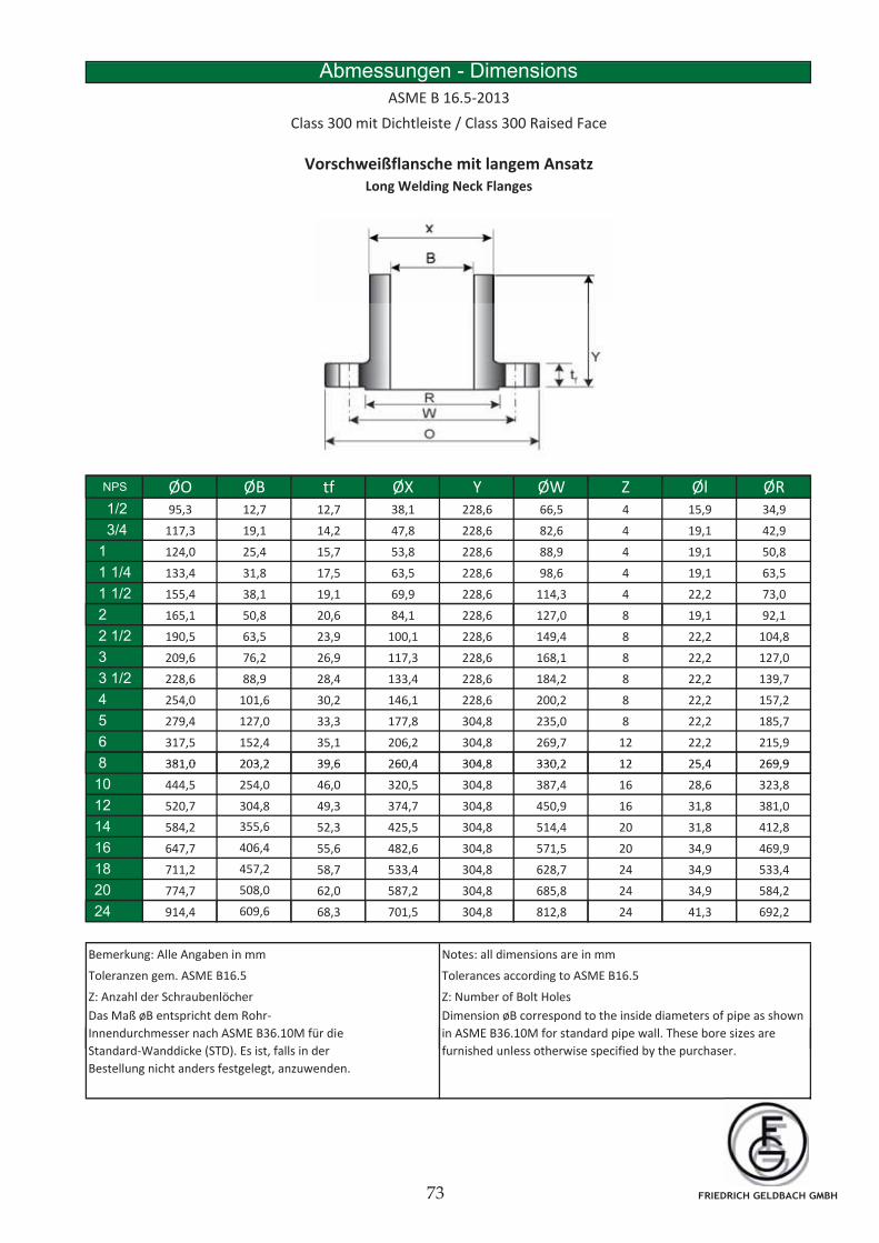
Abmessungen - Dimensions
ASME B 16.5-2013
Class 300 mit Dichtleiste / Class 300 Raised Face
Vorschweißflansche mit langem Ansatz
Long Welding Neck Flanges
NPS ØO ØB tf ØX Y ØW Z Øl ØRNPS ØO ØB tf ØX Y ØW Z Øl ØR1/2 95,3 12,7 12,7 38,1 228,6 66,5 4 15,9 34,9
3/4 117,3 19,1 14,2 47,8 228,6 82,6 4 19,1 42,9
1 124,0 25,4 15,7 53,8 228,6 88,9 4 19,1 50,8
1 1/4 133,4 31,8 17,5 63,5 228,6 98,6 4 19,1 63,5
1 1/2 155,4 38,1 19,1 69,9 228,6 114,3 4 22,2 73,0
2 165,1 50,8 20,6 84,1 228,6 127,0 8 19,1 92,1, , , , , , , ,
2 1/2 190,5 63,5 23,9 100,1 228,6 149,4 8 22,2 104,8
3 209,6 76,2 26,9 117,3 228,6 168,1 8 22,2 127,0
3 1/2 228,6 88,9 28,4 133,4 228,6 184,2 8 22,2 139,7
4 254,0 101,6 30,2 146,1 228,6 200,2 8 22,2 157,2
5 279,4 127,0 33,3 177,8 304,8 235,0 8 22,2 185,7
6 317,5 152,4 35,1 206,2 304,8 269,7 12 22,2 215,9
8 381 0 203 2 39 6 260 4 304 8 330 2 12 25 4 269 98 381,0 203,2 39,6 260,4 304,8 330,2 12 25,4 269,9
10 444,5 254,0 46,0 320,5 304,8 387,4 16 28,6 323,8
12 520,7 304,8 49,3 374,7 304,8 450,9 16 31,8 381,0
14 584,2 355,6 52,3 425,5 304,8 514,4 20 31,8 412,8
16 647,7 406,4 55,6 482,6 304,8 571,5 20 34,9 469,9
18 711,2 457,2 58,7 533,4 304,8 628,7 24 34,9 533,4
20 774,7 508,0 62,0 587,2 304,8 685,8 24 34,9 584,2
24 914,4 609,6 68,3 701,5 304,8 812,8 24 41,3 692,2
Bemerkung: Alle Angaben in mm Notes: all dimensions are in mm
Z: Anzahl der Schraubenlöcher Z: Number of Bolt Holes
Toleranzen gem. ASME B16.5 Tolerances according to ASME B16.5
Dimension øB correspond to the inside diameters of pipe as shown
in ASME B36.10M for standard pipe wall. These bore sizes are
Das Maß øB entspricht dem Rohr-
Innendurchmesser nach ASME B36.10M für die
( ) furnished unless otherwise specified by the purchaser.Standard-Wanddicke (STD). Es ist, falls in der
Bestellung nicht anders festgelegt, anzuwenden.
FRIEDRICH GELDBACH GMBH
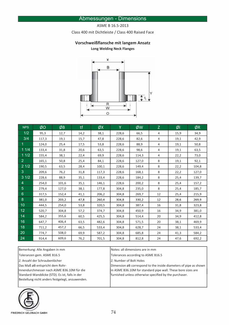
Abmessungen - Dimensions
ASME B 16.5-2013
Class 400 mit Dichtleiste / Class 400 Raised Face
Vorschweißflansche mit langem Ansatz
Long Welding Neck Flanges
NPS ØO ØB tf ØX Y ØW Z Øl ØRNPS ØO ØB tf ØX Y ØW Z Øl ØR1/2 95,3 12,7 14,2 38,1 228,6 66,5 4 15,9 34,9
3/4 117,3 19,1 15,7 47,8 228,6 82,6 4 19,1 42,9
1 124,0 25,4 17,5 53,8 228,6 88,9 4 19,1 50,8
1 1/4 133,4 31,8 20,6 63,5 228,6 98,6 4 19,1 63,5
1 1/2 155,4 38,1 22,4 69,9 228,6 114,3 4 22,2 73,0
2 165,1 50,8 25,4 84,1 228,6 127,0 8 19,1 92,1, , , , , , , ,
2 1/2 190,5 63,5 28,4 100,1 228,6 149,4 8 22,2 104,8
3 209,6 76,2 31,8 117,3 228,6 168,1 8 22,2 127,0
3 1/2 228,6 88,9 35,1 133,4 228,6 184,2 8 25,4 139,7
4 254,0 101,6 35,1 146,1 228,6 200,2 8 25,4 157,2
5 279,4 127,0 38,1 177,8 304,8 235,0 8 25,4 185,7
6 317,5 152,4 41,1 206,2 304,8 269,7 12 25,4 215,9
8 381 0 203 2 47 8 260 4 304 8 330 2 12 28 6 269 98 381,0 203,2 47,8 260,4 304,8 330,2 12 28,6 269,9
10 444,5 254,0 53,8 320,5 304,8 387,4 16 31,8 323,8
12 520,7 304,8 57,2 374,7 304,8 450,9 16 34,9 381,0
14 584,2 355,6 60,5 425,5 304,8 514,4 20 34,9 412,8
16 647,7 406,4 63,5 482,6 304,8 571,5 20 38,1 469,9
18 711,2 457,2 66,5 533,4 304,8 628,7 24 38,1 533,4
20 774,7 508,0 69,9 587,2 304,8 685,8 24 41,3 584,2
24 914,4 609,6 76,2 701,5 304,8 812,8 24 47,6 692,2
Bemerkung: Alle Angaben in mm Notes: all dimensions are in mm
Z: Anzahl der Schraubenlöcher Z: Number of Bolt Holes
Toleranzen gem. ASME B16.5 Tolerances according to ASME B16.5
Dimension øB correspond to the inside diameters of pipe as shown
in ASME B36.10M for standard pipe wall. These bore sizes are
Das Maß øB entspricht dem Rohr-
Innendurchmesser nach ASME B36.10M für die
( ) furnished unless otherwise specified by the purchaser.Standard-Wanddicke (STD). Es ist, falls in der
Bestellung nicht anders festgelegt, anzuwenden.
FRIEDRICH GELDBACH GMBH
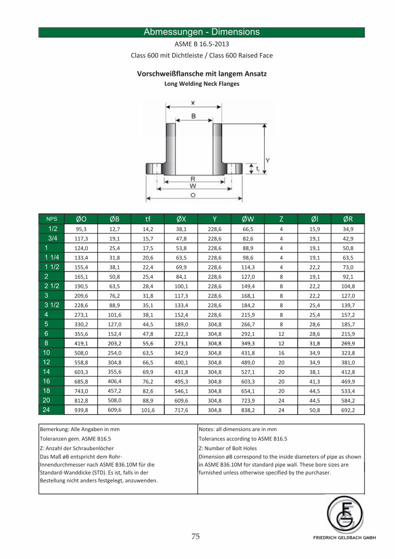
Abmessungen - Dimensions
ASME B 16.5-2013
Class 600 mit Dichtleiste / Class 600 Raised Face
Vorschweißflansche mit langem Ansatz
Long Welding Neck Flanges
NPS ØO ØB tf ØX Y ØW Z Øl ØRNPS ØO ØB tf ØX Y ØW Z Øl ØR1/2 95,3 12,7 14,2 38,1 228,6 66,5 4 15,9 34,9
3/4 117,3 19,1 15,7 47,8 228,6 82,6 4 19,1 42,9
1 124,0 25,4 17,5 53,8 228,6 88,9 4 19,1 50,8
1 1/4 133,4 31,8 20,6 63,5 228,6 98,6 4 19,1 63,5
1 1/2 155,4 38,1 22,4 69,9 228,6 114,3 4 22,2 73,0
2 165,1 50,8 25,4 84,1 228,6 127,0 8 19,1 92,1, , , , , , , ,
2 1/2 190,5 63,5 28,4 100,1 228,6 149,4 8 22,2 104,8
3 209,6 76,2 31,8 117,3 228,6 168,1 8 22,2 127,0
3 1/2 228,6 88,9 35,1 133,4 228,6 184,2 8 25,4 139,7
4 273,1 101,6 38,1 152,4 228,6 215,9 8 25,4 157,2
5 330,2 127,0 44,5 189,0 304,8 266,7 8 28,6 185,7
6 355,6 152,4 47,8 222,3 304,8 292,1 12 28,6 215,9
8 419 1 203 2 55 6 273 1 304 8 349 3 12 31 8 269 98 419,1 203,2 55,6 273,1 304,8 349,3 12 31,8 269,9
10 508,0 254,0 63,5 342,9 304,8 431,8 16 34,9 323,8
12 558,8 304,8 66,5 400,1 304,8 489,0 20 34,9 381,0
14 603,3 355,6 69,9 431,8 304,8 527,1 20 38,1 412,8
16 685,8 406,4 76,2 495,3 304,8 603,3 20 41,3 469,9
18 743,0 457,2 82,6 546,1 304,8 654,1 20 44,5 533,4
20 812,8 508,0 88,9 609,6 304,8 723,9 24 44,5 584,2
24 939,8 609,6 101,6 717,6 304,8 838,2 24 50,8 692,2
Bemerkung: Alle Angaben in mm Notes: all dimensions are in mm
Dimension øB correspond to the inside diameters of pipe as shown
in ASME B36.10M for standard pipe wall. These bore sizes are
Das Maß øB entspricht dem Rohr-
Innendurchmesser nach ASME B36.10M für die
( )
Z: Anzahl der Schraubenlöcher Z: Number of Bolt Holes
Toleranzen gem. ASME B16.5 Tolerances according to ASME B16.5
furnished unless otherwise specified by the purchaser.Standard-Wanddicke (STD). Es ist, falls in der
Bestellung nicht anders festgelegt, anzuwenden.
FRIEDRICH GELDBACH GMBH
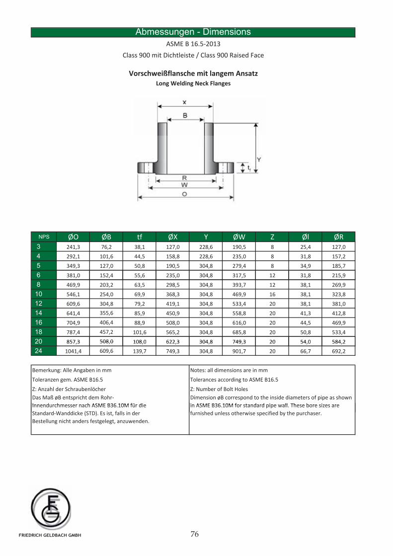
Abmessungen - Dimensions
ASME B 16.5-2013
Class 900 mit Dichtleiste / Class 900 Raised Face
Vorschweißflansche mit langem Ansatz
Long Welding Neck Flanges
NPS ØO ØB tf ØX Y ØW Z Øl ØR3 241,3 76,2 38,1 127,0 228,6 190,5 8 25,4 127,0
4 292,1 101,6 44,5 158,8 228,6 235,0 8 31,8 157,2
5 349,3 127,0 50,8 190,5 304,8 279,4 8 34,9 185,7
6 381,0 152,4 55,6 235,0 304,8 317,5 12 31,8 215,9, , , , , , , ,
8 469,9 203,2 63,5 298,5 304,8 393,7 12 38,1 269,9
10 546,1 254,0 69,9 368,3 304,8 469,9 16 38,1 323,8
12 609,6 304,8 79,2 419,1 304,8 533,4 20 38,1 381,0
14 641,4 355,6 85,9 450,9 304,8 558,8 20 41,3 412,8
16 704,9 406,4 88,9 508,0 304,8 616,0 20 44,5 469,9
18 787,4 457,2 101,6 565,2 304,8 685,8 20 50,8 533,4
20 857 3 508 0 108 0 622 3 304 8 749 3 20 54 0 584 220 857,3 508,0 108,0 622,3 304,8 749,3 20 54,0 584,2
24 1041,4 609,6 139,7 749,3 304,8 901,7 20 66,7 692,2
Bemerkung: Alle Angaben in mm Notes: all dimensions are in mm
Tolerances according to ASME B16.5
Dimension øB correspond to the inside diameters of pipe as shown
in ASME B36 10M for standard pipe wall These bore sizes are
Das Maß øB entspricht dem Rohr-
Innendurchmesser nach ASME B36 10M für die
Z: Anzahl der Schraubenlöcher Z: Number of Bolt Holes
Toleranzen gem. ASME B16.5
in ASME B36.10M for standard pipe wall. These bore sizes are
furnished unless otherwise specified by the purchaser.
Innendurchmesser nach ASME B36.10M für die
Standard-Wanddicke (STD). Es ist, falls in der
Bestellung nicht anders festgelegt, anzuwenden.
FRIEDRICH GELDBACH GMBH
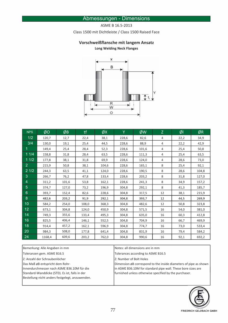
Abmessungen - Dimensions
ASME B 16.5-2013
Class 1500 mit Dichtleiste / Class 1500 Raised Face
Vorschweißflansche mit langem Ansatz
Long Welding Neck Flanges
NPS ØO ØB tf ØX Y ØW Z Øl ØR1/2 120,7 12,7 22,4 38,1 228,6 82,6 4 22,2 34,9
3/4 130,0 19,1 25,4 44,5 228,6 88,9 4 22,2 42,9
1 149,4 25,4 28,4 52,3 228,6 101,6 4 25,4 50,8
1 1/4 158,8 31,8 28,4 63,5 228,6 111,3 4 25,4 63,5
1 1/2 177,8 38,1 31,8 69,9 228,6 124,0 4 28,6 73,0, , , , , , , ,
2 215,9 50,8 38,1 104,6 228,6 165,1 8 25,4 92,1
2 1/2 244,3 63,5 41,1 124,0 228,6 190,5 8 28,6 104,8
3 266,7 76,2 47,8 133,4 228,6 203,2 8 31,8 127,0
4 311,2 101,6 53,8 162,1 228,6 241,3 8 34,9 157,2
5 374,7 127,0 73,2 196,9 304,8 292,1 8 41,3 185,7
6 393,7 152,4 82,6 228,6 304,8 317,5 12 38,1 215,9
8 482 6 203 2 91 9 292 1 304 8 393 7 12 44 5 269 98 482,6 203,2 91,9 292,1 304,8 393,7 12 44,5 269,9
10 584,2 254,0 108,0 368,3 304,8 482,6 12 50,8 323,8
12 673,1 304,8 124,0 450,9 304,8 571,5 16 54,0 381,0
14 749,3 355,6 133,4 495,3 304,8 635,0 16 60,3 412,8
16 825,5 406,4 146,1 552,5 304,8 704,9 16 66,7 469,9
18 914,4 457,2 162,1 596,9 304,8 774,7 16 73,0 533,4
20 984,3 508,0 177,8 641,4 304,8 831,9 16 79,4 584,2
24 1168,4 609,6 203,2 762,0 304,8 990,6 16 92,1 692,2
Bemerkung: Alle Angaben in mm Notes: all dimensions are in mm
Tolerances according to ASME B16.5
Dimension øB correspond to the inside diameters of pipe as shown
in ASME B36.10M for standard pipe wall. These bore sizes are
Das Maß øB entspricht dem Rohr-
Innendurchmesser nach ASME B36.10M für die
( )
Z: Anzahl der Schraubenlöcher Z: Number of Bolt Holes
Toleranzen gem. ASME B16.5
furnished unless otherwise specified by the purchaser.Standard-Wanddicke (STD). Es ist, falls in der
Bestellung nicht anders festgelegt, anzuwenden.
FRIEDRICH GELDBACH GMBH
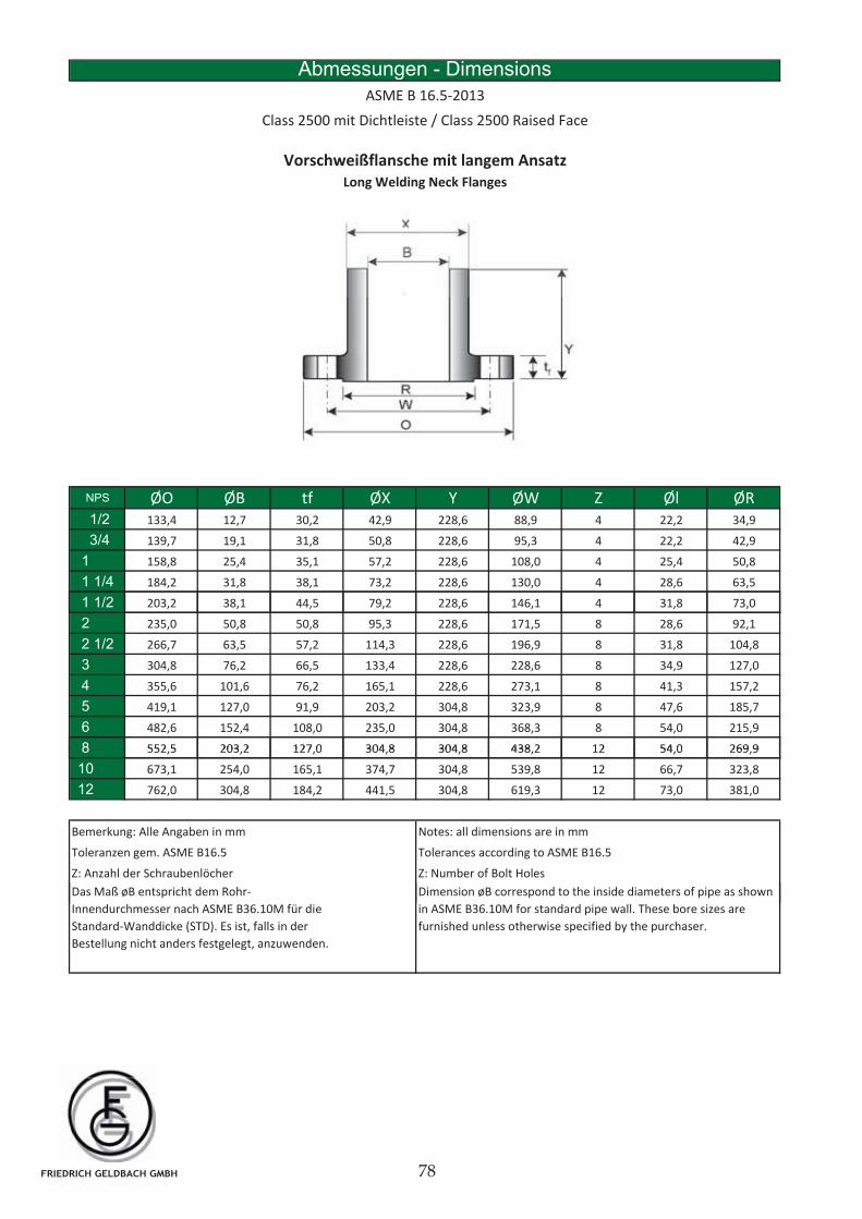
Abmessungen - Dimensions
ASME B 16.5-2013
Class 2500 mit Dichtleiste / Class 2500 Raised Face
Vorschweißflansche mit langem Ansatz
Long Welding Neck Flanges
NPS ØO ØB tf ØX Y ØW Z Øl ØR1/2 133,4 12,7 30,2 42,9 228,6 88,9 4 22,2 34,9
3/4 139,7 19,1 31,8 50,8 228,6 95,3 4 22,2 42,9
1 158,8 25,4 35,1 57,2 228,6 108,0 4 25,4 50,8
1 1/4 184,2 31,8 38,1 73,2 228,6 130,0 4 28,6 63,5
1 1/2 203,2 38,1 44,5 79,2 228,6 146,1 4 31,8 73,0, , , , , , , ,
2 235,0 50,8 50,8 95,3 228,6 171,5 8 28,6 92,1
2 1/2 266,7 63,5 57,2 114,3 228,6 196,9 8 31,8 104,8
3 304,8 76,2 66,5 133,4 228,6 228,6 8 34,9 127,0
4 355,6 101,6 76,2 165,1 228,6 273,1 8 41,3 157,2
5 419,1 127,0 91,9 203,2 304,8 323,9 8 47,6 185,7
6 482,6 152,4 108,0 235,0 304,8 368,3 8 54,0 215,9
8 552 5 203 2 127 0 304 8 304 8 438 2 12 54 0 269 98 552,5 203,2 127,0 304,8 304,8 438,2 12 54,0 269,9
10 673,1 254,0 165,1 374,7 304,8 539,8 12 66,7 323,8
12 762,0 304,8 184,2 441,5 304,8 619,3 12 73,0 381,0
Bemerkung: Alle Angaben in mm Notes: all dimensions are in mm
Toleranzen gem. ASME B16.5 Tolerances according to ASME B16.5
i i d h i id di f i hß i h d h
Z: Anzahl der Schraubenlöcher Z: Number of Bolt Holes
Dimension øB correspond to the inside diameters of pipe as shown
in ASME B36.10M for standard pipe wall. These bore sizes are
furnished unless otherwise specified by the purchaser.
Das Maß øB entspricht dem Rohr-
Innendurchmesser nach ASME B36.10M für die
Standard-Wanddicke (STD). Es ist, falls in der
Bestellung nicht anders festgelegt, anzuwenden.
FRIEDRICH GELDBACH GMBH
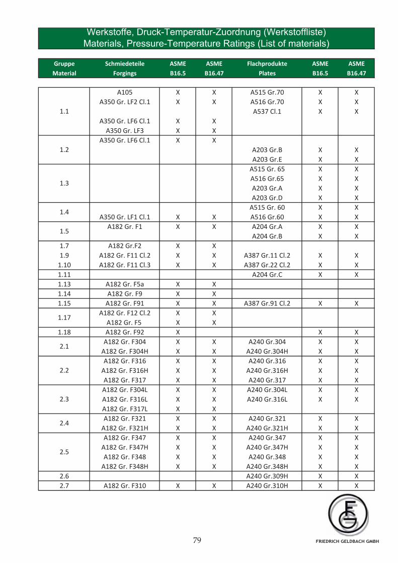
Gruppe Schmiedeteile ASME ASME Flachprodukte ASME ASME
Material Forgings B16.5 B16.47 Plates B16.5 B16.47
A105 X X A515 Gr.70 X X
A350 Gr. LF2 Cl.1 X X A516 Gr.70 X X
A537 Cl.1 X X
A350 Gr. LF6 Cl.1 X X
A350 Gr. LF3 X X
A350 Gr. LF6 Cl.1 X X
A203 Gr.B X X
A203 Gr.E X X
A515 Gr. 65 X X
A516 Gr.65 X X
A203 Gr.A X X
A203 Gr.D X X
A515 Gr. 60 X X
A350 Gr. LF1 Cl.1 X X A516 Gr.60 X X
A182 Gr. F1 X X A204 Gr.A X X
A204 Gr.B X X
1.7 A182 Gr.F2 X X
1.9 A182 Gr. F11 Cl.2 X X A387 Gr.11 Cl.2 X X
1.10 A182 Gr. F11 Cl.3 X X A387 Gr.22 Cl.2 X X
1.11 A204 Gr.C X X
1.13 A182 Gr. F5a X X
1.14 A182 Gr. F9 X X
1.15 A182 Gr. F91 X X A387 Gr.91 Cl.2 X X
A182 Gr. F12 Cl.2 X X
A182 Gr. F5 X X
1.18 A182 Gr. F92 X X X
A182 Gr. F304 X X A240 Gr.304 X X
A182 Gr. F304H X X A240 Gr.304H X X
A182 Gr. F316 X X A240 Gr.316 X X
A182 Gr. F316H X X A240 Gr.316H X X
A182 Gr. F317 X X A240 Gr.317 X X
A182 Gr. F304L X X A240 Gr.304L X X
A182 Gr. F316L X X A240 Gr.316L X X
A182 Gr. F317L X X
A182 Gr. F321 X X A240 Gr.321 X X
A182 Gr. F321H X X A240 Gr.321H X X
A182 Gr. F347 X X A240 Gr.347 X X
A182 Gr. F347H X X A240 Gr.347H X X
A182 Gr. F348 X X A240 Gr.348 X X
A182 Gr. F348H X X A240 Gr.348H X X
2.6 A240 Gr.309H X X
2.7 A182 Gr. F310 X X A240 Gr.310H X X
1.5
1.17
2.1
2.2
2.3
2.4
2.5
Werkstoffe, Druck-Temperatur-Zuordnung (Werkstoffliste)
Materials, Pressure-Temperature Ratings (List of materials)
1.4
1.3
1.2
1.1
FRIEDRICH GELDBACH GMBH
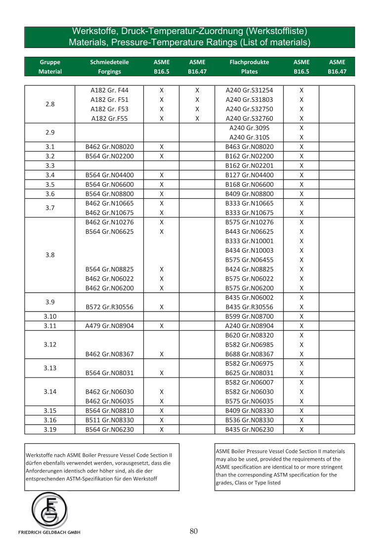
Gruppe Schmiedeteile ASME ASME Flachprodukte ASME ASME
Material Forgings B16.5 B16.47 Plates B16.5 B16.47
A182 Gr. F44 X X A240 Gr.S31254 X
A182 Gr. F51 X X A240 Gr.S31803 X
A182 Gr. F53 X X A240 Gr.S32750 X
A182 Gr.F55 X X A240 Gr.S32760 X
A240 Gr.309S X
A240 Gr.310S X
3.1 B462 Gr.N08020 X B463 Gr.N08020 X
3.2 B564 Gr.N02200 X B162 Gr.N02200 X
3.3 B162 Gr.N02201 X
3.4 B564 Gr.N04400 X B127 Gr.N04400 X
3.5 B564 Gr.N06600 X B168 Gr.N06600 X
3.6 B564 Gr.N08800 X B409 Gr.N08800 X
B462 Gr.N10665 X B333 Gr.N10665 X
B462 Gr.N10675 X B333 Gr.N10675 X
B462 Gr.N10276 X B575 Gr.N10276 X
B564 Gr.N06625 X B443 Gr.N06625 X
B333 Gr.N10001 X
B434 Gr.N10003 X
B575 Gr.N06455 X
B564 Gr.N08825 X B424 Gr.N08825 X
B462 Gr.N06022 X B575 Gr.N06022 X
B462 Gr.N06200 X B575 Gr.N06200 X
B435 Gr.N06002 X
B572 Gr.R30556 X B435 Gr.R30556 X
3.10 B599 Gr.N08700 X
3.11 A479 Gr.N08904 X A240 Gr.N08904 X
B620 Gr.N08320 X
B582 Gr.N06985 X
B462 Gr.N08367 X B688 Gr.N08367 X
B582 Gr.N06975 X
B564 Gr.N08031 X B625 Gr.N08031 X
B582 Gr.N06007 X
B462 Gr.N06030 X B582 Gr.N06030 X
B462 Gr.N06035 X B575 Gr.N06035 X
3.15 B564 Gr.N08810 X B409 Gr.N08330 X
3.16 B511 Gr.N08330 X B536 Gr.N08330 X
3.19 B564 Gr.N06230 X B435 Gr.N06230 X
3.13
3.14
Werkstoffe, Druck-Temperatur-Zuordnung (Werkstoffliste)
Materials, Pressure-Temperature Ratings (List of materials)
2.9
Werkstoffe nach ASME Boiler Pressure Vessel Code Section II
dürfen ebenfalls verwendet werden, vorausgesetzt, dass die
Anforderungen identisch oder höher sind, als die der
entsprechenden ASTM-Spezifikation für den Werkstoff
ASME Boiler Pressure Vessel Code Section II materials
may also be used, provided the requirements of the
ASME specification are identical to or more stringent
than the corresponding ASTM specification for the
grades, Class or Type listed
3.7
3.9
2.8
3.8
3.12
FRIEDRICH GELDBACH GMBH
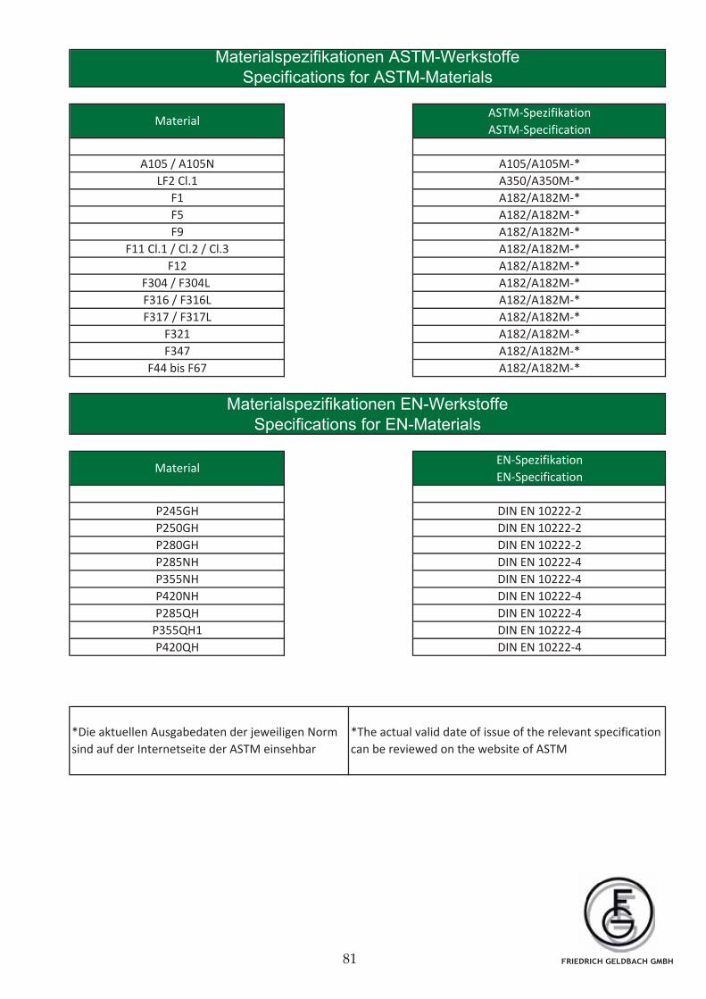
Material
MaterialEN-Spezifikation
EN-Specification
*Die aktuellen Ausgabedaten der jeweiligen Norm
sind auf der Internetseite der ASTM einsehbar
*The actual valid date of issue of the relevant specification
can be reviewed on the website of ASTM
DIN EN 10222-4
P250GH
P280GH
P285NH
P355NH
P420NH
P285QH
P245GH
P355QH1
Materialspezifikationen EN-Werkstoffe
Specifications for EN-Materials
P420QH
F304 / F304L
F316 / F316L
F317 / F317L
F321
F347
F44 bis F67
DIN EN 10222-4
DIN EN 10222-4
DIN EN 10222-4
A105 / A105N
LF2 Cl.1
F1
F5
F9
F11 Cl.1 / Cl.2 / Cl.3
F12
DIN EN 10222-2
DIN EN 10222-2
DIN EN 10222-2
DIN EN 10222-4
DIN EN 10222-4
A182/A182M-*
A182/A182M-*
A182/A182M-*
A182/A182M-*
A182/A182M-*
A182/A182M-*
A182/A182M-*
A182/A182M-*
A182/A182M-*
A182/A182M-*
Materialspezifikationen ASTM-Werkstoffe
Specifications for ASTM-Materials
ASTM-Spezifikation
ASTM-Specification
A105/A105M-*
A350/A350M-*
A182/A182M-*
FRIEDRICH GELDBACH GMBH
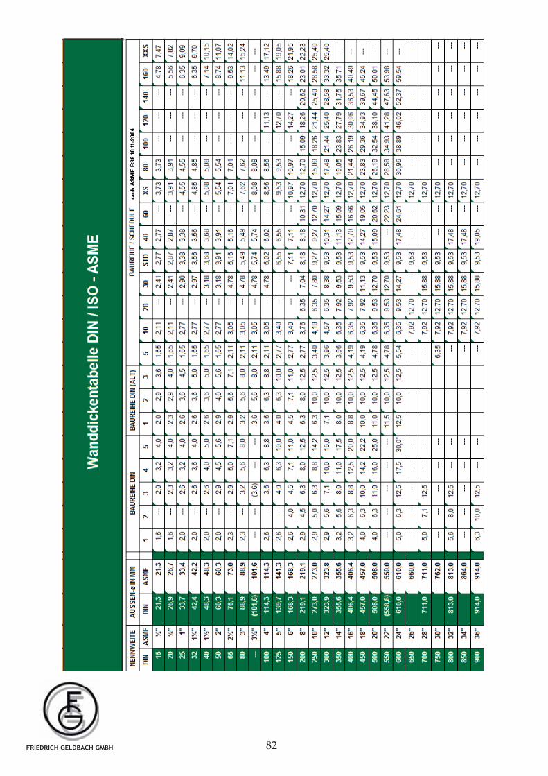
FRIEDRICH GELDBACH GMBH
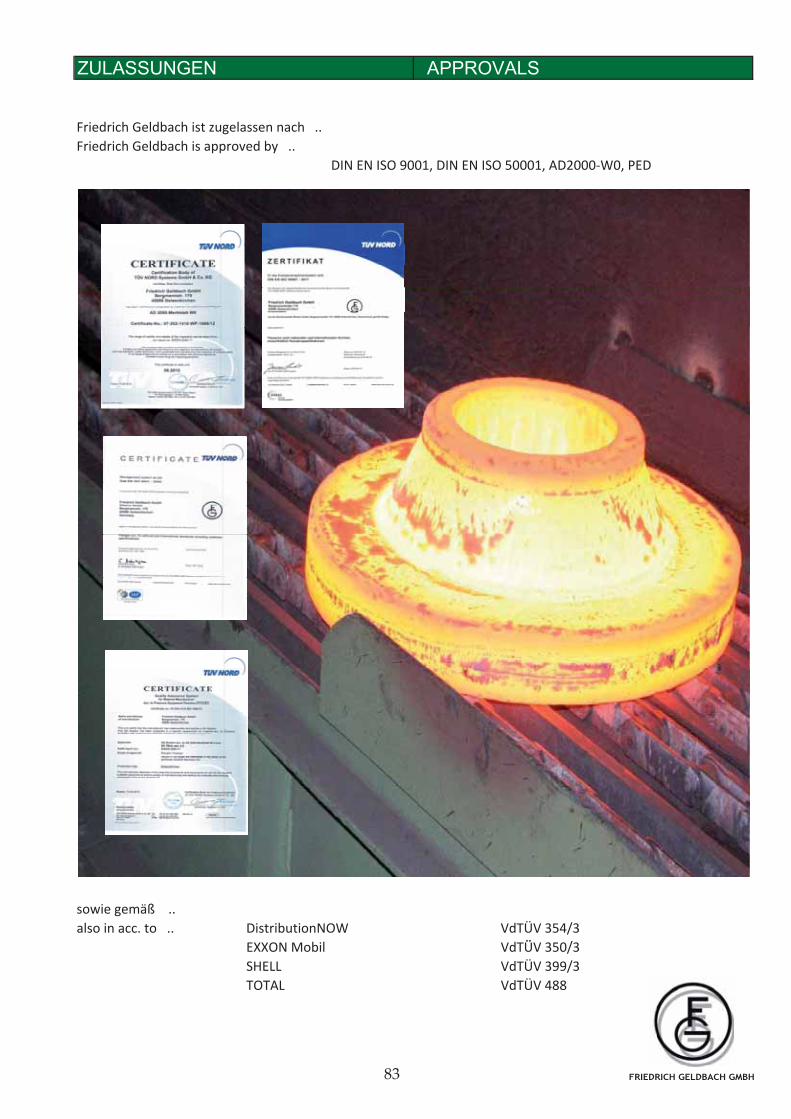
Friedrich Geldbach ist zugelassen nach ..
Friedrich Geldbach is approved by ..
DIN EN ISO 9001, DIN EN ISO 50001, AD2000-W0, PED
APPROVALSZULASSUNGEN A
sowie gemäß ..
also in acc. to .. DistributionNOW VdTÜV 354/3
O bil d Ü 3 0/3EXXON Mobil VdTÜV 350/3
SHELL VdTÜV 399/3
TOTAL VdTÜV 488
FRIEDRICH GELDBACH GMBH