Embed Size (px)
Citation preview
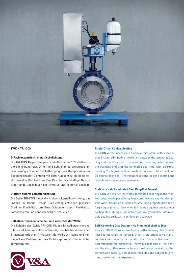
ZWICK TRI-CON
3-Fach exzentrisch, metallisch dichtend
Die TRI-CON Absperrklappen beinhalten einen 25° Dichtkonus,
um ein reibungfreies Öffnen und Schließen zu gewährleisten.
Dies ermöglicht einen Schließvorgang ohne Kompression der
Edestahl-Graphit Dichtung mit dem Klappensitz, da beide ex-
akt dasselbe Maß besitzen. Das Resultat: Nachhaltige Abdich-
tung, lange Lebesdauer der Armatur und keinerlei Leckage.
Statisch fixierte Lamellendichtung
Die Serie TRI-CON bietet die breiteste Lamellendichtung, das
„Konus- in- Konus“ Design. Dies ermöglicht einen gewissen
Grad an Flexibilität, um Beschädigungen durch Partikel zu
kompensieren und dennoch dicht zu schließen.
Selbstzentrierende Scheibe- kein Verstiften der Welle
Die Scheibe der Zwick TRI-CON Klappe ist selbstzentrierend,
d.h. es ist kein Verstiften notwendig wie bei herkömmlichen
3-fachexzentrischen Armaturen. Es wird auch keine und ver-
hindert ein Verklemmen des Dichtrings im Sitz bei erhöhten
Temperaturen.
Triple-Offset Conical Seating
TRI-CON valves incorporate a unique third offset with a 25-de-
gree incline, eliminating the friction between the laminated seal
ring and the body seat. The resulting camming action allows
the stainless and graphite laminated seal ring, with a corres-
ponding 25-degree inclined surface, to seat into an inclined
25-degree body seat. The result: true cone-in-cone seating and
reliable zero-leakage performance.
Statically Held Laminated Seal Ring/Flat Gasket
TRI-CON valves offer the widest laminated seal ring in the mar-
ket today, made possible by true cone-in-cone seating design.
This wide lamination of stainless steel and graphite provides a
forgiving sealing surface when it is seated against line scale or
particulates. Multiple laminations naturally translate into mul-
tiple sealing surfaces to achieve zero leakage.
Self-Centering Disc Design – No Pinning of shaft to Disc
Zwick’s TRI-CON valve employs a self-centering disc that is
keyed to the shaft, not pinned. Other triple-offset valve manu-
facturers permanently pin or affix their discs to the shaft. To
accommodate for differential thermal expansion of the shaft
and the disc, other manufacturers must rely on a seal ring that
compresses radially. This makes their designs subject to jam-
ming due to thermal expansion.
V
�
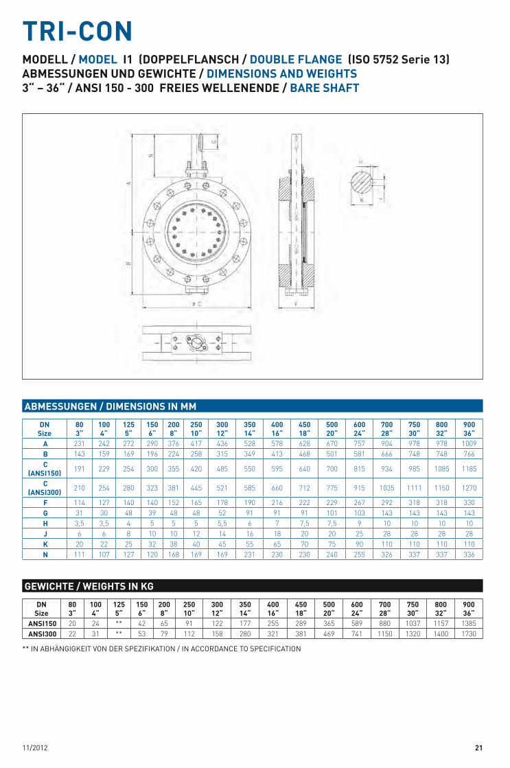
TRI-CON
2111/2012
MODELL / MODEL I1 (DOPPELFLANSCH / DOUBLE FLANGE (ISO 5752 Serie 13)ABMESSUNGEN UND GEWICHTE / DIMENSIONS AND WEIGHTS 3“ – 36“ / ANSI 150 - 300 FREIES WELLENENDE / BARE SHAFT
ABMESSUNGEN / DIMENSIONS IN MM
GEWICHTE / WEIGHTS IN KG
DN Size
803“
1004“
1255“
1506“
2008“
25010“
30012“
35014“
40016“
45018“
50020“
60024“
70028“
75030“
80032“
90036“
A 231 242 272 290 376 417 436 528 578 628 670 757 904 978 978 1009
B 143 159 169 196 224 258 315 349 413 468 501 581 666 748 748 766
C (ANSI150)
191 229 254 300 355 420 485 550 595 640 700 815 934 985 1085 1185
C (ANSI300)
210 254 280 323 381 445 521 585 660 712 775 915 1035 1111 1150 1270
F 114 127 140 140 152 165 178 190 216 222 229 267 292 318 318 330
G 31 30 48 39 48 48 52 91 91 91 101 103 143 143 143 143
H 3,5 3,5 4 5 5 5 5,5 6 7 7,5 7,5 9 10 10 10 10
J 6 6 8 10 10 12 14 16 18 20 20 25 28 28 28 28
K 20 22 25 32 38 40 45 55 65 70 75 90 110 110 110 110
N 111 107 127 120 168 169 169 231 230 230 240 255 326 337 337 336
DN Size
803“
1004“
1255“
1506“
2008“
25010“
30012“
35014“
40016“
45018“
50020“
60024“
70028“
75030“
80032“
90036“
ANSI150 20 24 ** 42 65 91 122 177 255 289 365 589 880 1037 1157 1385
ANSI300 22 31 ** 53 79 112 158 280 321 381 469 741 1150 1320 1400 1730
** IN ABHÄNGIGKEIT VON DER SPEZIFIKATION / IN ACCORDANCE TO SPECIFICATION
TRI-CON
22 11/2012
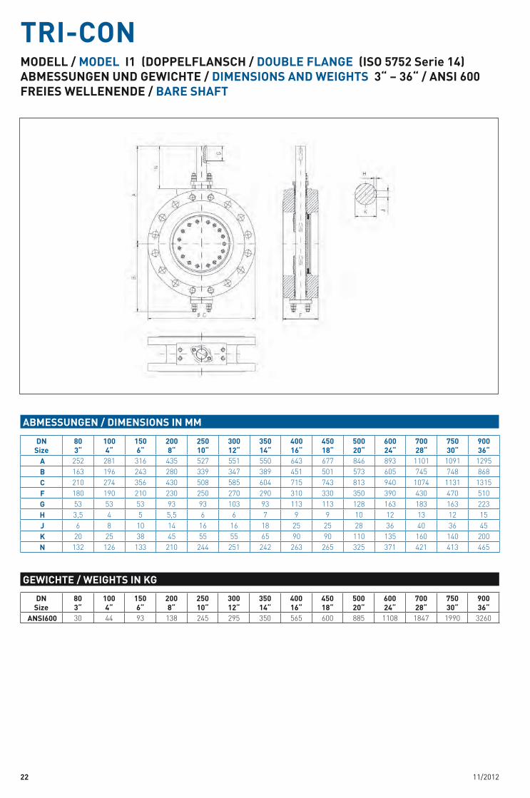
MODELL / MODEL I1 (DOPPELFLANSCH / DOUBLE FLANGE (ISO 5752 Serie 14)ABMESSUNGEN UND GEWICHTE / DIMENSIONS AND WEIGHTS 3“ – 36“ / ANSI 600FREIES WELLENENDE / BARE SHAFT
DN Size
803“
1004“
1506“
2008“
25010“
30012“
35014“
40016“
45018“
50020“
60024“
70028“
75030“
90036“
A 252 281 316 435 527 551 550 643 677 846 893 1101 1091 1295
B 163 196 243 280 339 347 389 451 501 573 605 745 748 868
C 210 274 356 430 508 585 604 715 743 813 940 1074 1131 1315
F 180 190 210 230 250 270 290 310 330 350 390 430 470 510
G 53 53 53 93 93 103 93 113 113 128 163 183 163 223
H 3,5 4 5 5,5 6 6 7 9 9 10 12 13 12 15
J 6 8 10 14 16 16 18 25 25 28 36 40 36 45
K 20 25 38 45 55 55 65 90 90 110 135 160 140 200
N 132 126 133 210 244 251 242 263 265 325 371 421 413 465
DN Size
803“
1004“
1506“
2008“
25010“
30012“
35014“
40016“
45018“
50020“
60024“
70028“
75030“
90036“
ANSI600 30 44 93 138 245 295 350 565 600 885 1108 1847 1990 3260
ABMESSUNGEN / DIMENSIONS IN MM
GEWICHTE / WEIGHTS IN KG

2911/2012
MO
DE
L N
UM
BE
RS
TR
I-C
ON
De
sig
na
tio
nS
ize
Pre
ssu
re c
lass
Bo
dy
& D
isc
ma
teri
al
Sh
aft
ma
teri
al
Pa
ckin
gL
am
ina
tio
n m
ate
ria
lE
xecu
tio
nO
pe
rati
on
A1
= A
PI
60
9 L
ug
Typ
e T
ab
le 2
0050
= D
N 5
0 =
2“A
= P
N 1
0A
= G
P24
0GH
/ P
265G
HA
= 1
.405
7 (S
S43
1)1
= G
raph
ite
1 =S
tain
less
Ste
el /
Gra
phit
eA
= S
tan
dard
A =
Bar
e S
haf
t
B1
= B
16
.10
Ga
te V
alv
e D
ou
ble
Fla
ng
e00
65 =
DN
65
= 2,
5“B
= P
N 1
6B
= 1
.455
2 (C
F8C
)B
= 1
.457
1 (S
S31
6Ti)
2 =
PTF
E2
= S
tain
less
Ste
el S
olid
L
amin
ate
B =
Inco
nel
Sea
tE
= E
lect
rica
l Act
uat
or
I1 =
IS
O 5
75
2 D
ou
ble
Fla
ng
e00
80 =
DN
80
= 3“
C =
PN
25
C =
1.4
571
(SS
316T
i)C
= 1
.498
0 (A
ISI6
60)
3 =
Kal
rez
3 =
Sta
inle
ss S
teel
/ P
TFE
C =
Fla
nge
wit
h G
roov
eG
= G
ear
W1
= W
afe
r ty
pe
AP
I 6
09
0100
= D
N 1
00 =
4“
D =
PN
40
D =
1.4
408
D =
Du
plex
4 =
Spe
cial
4 =
Has
tell
oy /
Gra
phit
eD
= H
igh
Cyl
ce B
eari
ng
H =
Hyd
rau
lic A
ctu
ator
D1
= E
N 5
58
R1
3/R
14
(DIN
32
02
/ F
16
/ F
4)
Do
ub
le F
lan
ge
0125
= D
N 1
25 =
5”
E =
PN
63
E =
1.4
301
(SS
304)
E =
1.4
301
(SS
304)
5 =
Gra
phit
e /
Liv
e-L
oadi
ng
5 =
Spe
cial
E =
Sea
led
Bea
rin
gI =
Gea
r w
ith
Sw
itch
Box
F1
= E
N 5
58
R1
4(D
IN 3
20
2 /
F4
) D
ou
ble
Fla
ng
e01
50 =
DN
150
= 6
“F
= P
N 1
00F
= 1
.430
7 (S
S30
4L)
F =
1.4
307
(SS
304L
)6
= P
TFE
/ L
ive-
Loa
din
g6
= D
upl
ex /
Gra
phit
eF
= S
tell
ite
Sea
tM
= M
oun
tin
g B
rack
et
L1
= E
N 5
58
R1
6(D
IN 3
20
2 /
K3
) L
ug
typ
e02
00 =
DN
200
= 8
”G
= P
N 1
60G
= 1
.735
7 (W
C6)
G =
1.4
923
7 =
O2-
Gra
phit
e7
= In
con
el /
O2-
Gra
phit
eG
= B
low
ou
t pr
oof
shaf
t ac
c.
AP
I 609
for
DIN
Val
ves
P =
Pn
eum
atic
Act
uat
or
S1
= E
N 5
58
R1
4(D
IN 3
20
2 /
F4
) B
utt
we
ld /
Fa
bri
cate
d02
50 =
DN
250
= 1
0”H
= P
N 2
50H
= H
aste
lloy
H
= H
aste
lloy
8
= O
2-G
raph
ite
/ L
ive-
Loa
din
g8
= H
aste
lloy
H =
Com
bin
atio
n E
+ F
Q =
Ele
ctro
hyd
rau
lic A
ctu
ator
S2
= E
N 5
58
R1
4(D
IN 3
20
2 /
F4
) B
utt
we
ld /
Ca
stin
g03
00 =
DN
300
= 1
2”I
= P
N 6
I = In
con
elI =
Inco
nel
9 =
EP
AG
RA
PH
9 =
Du
plex
I = C
ombi
nat
ion
D +
FS
= S
peci
al
WD
= E
N 5
58
R1
6(D
IN 3
20
2 /
K3
) W
afe
r T
ype
0350
= D
N 3
50 =
14”
J =
JIS
Sta
nda
rdJ
= D
upl
exJ
= 1.
4401
/ 1
.440
4 (S
S31
6/31
6L)
0 =
Inco
nel
J =
Com
bin
atio
n D
+ F
& H
T-B
olti
ng
L =
Low
Tem
pera
ture
Gea
r
WS
= E
N 5
58
R2
0/R
25
(DIN
32
02
/ K
1/K
2)
Wa
fer
Typ
e03
75 =
DN
375
= 1
5”X
= A
NS
I 150
K =
1.4
401
/ 1.
4404
(SS
316/
316L
)K
=1.
4541
(SS
321)
A =
Mon
el /
O2-
Gra
phit
eK
= C
ombi
nat
ion
D +
F +
HT-
Bol
tin
g +
Ext
ensi
onT
= H
igh
Tem
pera
ture
Gea
r
LS
= E
N 5
58
R2
0/R
25
(DIN
32
02
/ K
1/K
2)
Lu
g T
ype
0400
= D
N 4
00 =
16”
Y =
AN
SI 3
00L
= 1
.622
0 /
P35
5NL
M =
Mon
el K
500
B =
Bro
nze
/ G
raph
ite
L =
Bod
y E
xten
sion
O =
O2-
Gea
r
DB
= D
ou
ble
Blo
ck a
nd
Ble
ed
0450
= D
N 4
50 =
18”
Z =
AN
SI 6
00M
= M
onel
N =
Nit
ron
ics
50C
= M
onel
M =
Sea
led
bear
ing
+ N
AC
EN
= O
ffsh
ore
Gea
r
CF
= E
N 5
58
R1
4(D
IN 3
20
2 /
F4
) F
lan
ge
d C
he
ck V
alv
e05
00 =
DN
500
= 2
0”
W =
AN
SI 9
00N
= C
S B
ody
& S
S D
isc
P =
17-
4 P
H /
1.4
542
D =
Su
perd
upl
ex /
Gra
phit
eN
= N
AC
ER
= G
ear
wit
h P
adlo
ck F
lan
ge
CS
= E
N 5
58
R1
4(D
IN 3
20
2 /
F4
) B
utt
we
ld C
he
ck V
alv
e06
00 =
DN
600
= 2
4”V
= A
NS
I 150
0O
= O
2 B
rass
Q =
Su
perd
upl
exO
= S
team
Jac
ket
FA
= E
N 5
58
R1
4D
ou
ble
Fla
ng
e w
ith
AN
SI
Co
nn
ect
ion
0650
= D
N 6
50 =
26”
S =
Spe
cial
P =
C95
800/
C95
500
U =
1.4
536-
39 (9
04/9
04L
)P
= S
eale
d be
arin
g +
Ste
am
Jack
et
0700
= D
N 7
00 =
28”
Q =
Su
perd
upl
exS
= S
peci
alQ
= S
eale
d be
arin
g +
Ste
am
Jack
et +
NA
CE
0750
= D
N 7
50 =
30”
R =
16M
o3 /
1.5
415
/ G
20M
o5 /
1.5
419
R =
Rin
g-Jo
int
Faci
ng
0800
= D
N 8
00 =
32”
S =
Spe
cial
S =
Spe
cial
0900
= D
N 9
00 =
36”
T =
1.48
27T
= H
T-B
olti
ng
1000
= D
N 1
000
= 40
”U
= 1
.485
9U
= C
ombi
nat
ion
L &
T
1050
= D
N 1
050
= 42
”V
= S
S /
O2
Bra
ssV
= S
haf
t E
xten
sion
.W
= W
C9
W =
Com
bin
atio
n T
+ V
X =
LCB
X =
Com
bin
atio
n L
+ N
+ T
Y =
CF
8M
.Z
= W
CB
/ A
516G
r.70
.1
= 1.
4536
-39
(904
/904
L)
.3
= C
F3
4 =
CF
3M
.5
= C
5
2200
= D
N 2
200
= 88
”6
= C
12
8 =
CF
8
TRI-CON
3111/2012
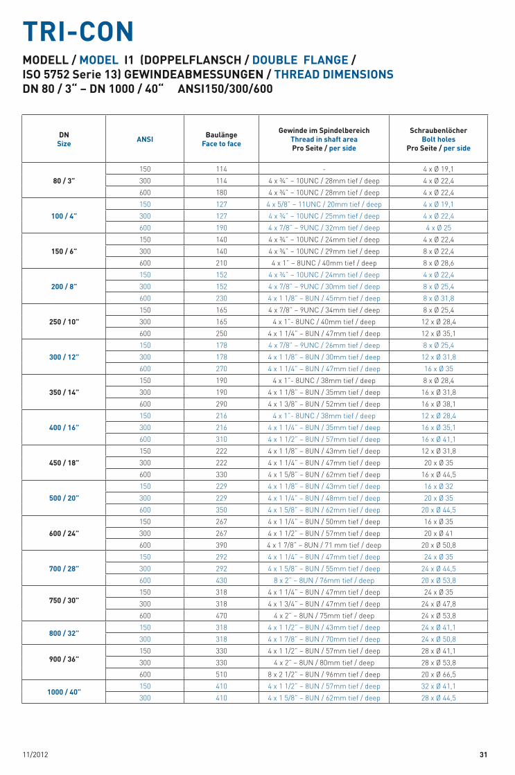
MODELL / MODEL I1 (DOPPELFLANSCH / DOUBLE FLANGE / ISO 5752 Serie 13) GEWINDEABMESSUNGEN / THREAD DIMENSIONSDN 80 / 3“ – DN 1000 / 40“ ANSI150/300/600
DNSize
ANSIBaulänge
Face to face
Gewinde im SpindelbereichThread in shaft areaPro Seite / per side
SchraubenlöcherBolt holes
Pro Seite / per side
80 / 3”
150 114 - 4 x Ø 19,1
300 114 4 x ¾” – 10UNC / 28mm tief / deep 4 x Ø 22,4
600 180 4 x ¾” – 10UNC / 28mm tief / deep 4 x Ø 22,4
100 / 4”
150 127 4 x 5/8” – 11UNC / 20mm tief / deep 4 x Ø 19,1
300 127 4 x ¾” – 10UNC / 25mm tief / deep 4 x Ø 22,4
600 190 4 x 7/8” – 9UNC / 32mm tief / deep 4 x Ø 25
150 / 6”
150 140 4 x ¾” – 10UNC / 24mm tief / deep 4 x Ø 22,4
300 140 4 x ¾” – 10UNC / 29mm tief / deep 8 x Ø 22,4
600 210 4 x 1” – 8UNC / 40mm tief / deep 8 x Ø 28,6
200 / 8”
150 152 4 x ¾” – 10UNC / 24mm tief / deep 4 x Ø 22,4
300 152 4 x 7/8” – 9UNC / 30mm tief / deep 8 x Ø 25,4
600 230 4 x 1 1/8” – 8UN / 45mm tief / deep 8 x Ø 31,8
250 / 10”
150 165 4 x 7/8” – 9UNC / 34mm tief / deep 8 x Ø 25,4
300 165 4 x 1”- 8UNC / 40mm tief / deep 12 x Ø 28,4
600 250 4 x 1 1/4” – 8UN / 47mm tief / deep 12 x Ø 35,1
300 / 12”
150 178 4 x 7/8” – 9UNC / 26mm tief / deep 8 x Ø 25,4
300 178 4 x 1 1/8” – 8UN / 30mm tief / deep 12 x Ø 31,8
600 270 4 x 1 1/4” – 8UN / 47mm tief / deep 16 x Ø 35
350 / 14”
150 190 4 x 1”- 8UNC / 38mm tief / deep 8 x Ø 28,4
300 190 4 x 1 1/8” – 8UN / 35mm tief / deep 16 x Ø 31,8
600 290 4 x 1 3/8” – 8UN / 52mm tief / deep 16 x Ø 38,1
400 / 16”
150 216 4 x 1”- 8UNC / 38mm tief / deep 12 x Ø 28,4
300 216 4 x 1 1/4” – 8UN / 35mm tief / deep 16 x Ø 35,1
600 310 4 x 1 1/2” – 8UN / 57mm tief / deep 16 x Ø 41,1
450 / 18”
150 222 4 x 1 1/8” – 8UN / 43mm tief / deep 12 x Ø 31,8
300 222 4 x 1 1/4” – 8UN / 47mm tief / deep 20 x Ø 35
600 330 4 x 1 5/8” – 8UN / 62mm tief / deep 16 x Ø 44,5
500 / 20”
150 229 4 x 1 1/8” – 8UN / 43mm tief / deep 16 x Ø 32
300 229 4 x 1 1/4” – 8UN / 48mm tief / deep 20 x Ø 35
600 350 4 x 1 5/8” – 8UN / 62mm tief / deep 20 x Ø 44,5
600 / 24”
150 267 4 x 1 1/4” – 8UN / 50mm tief / deep 16 x Ø 35
300 267 4 x 1 1/2” – 8UN / 57mm tief / deep 20 x Ø 41
600 390 4 x 1 7/8” – 8UN / 71 mm tief / deep 20 x Ø 50,8
700 / 28”
150 292 4 x 1 1/4” – 8UN / 47mm tief / deep 24 x Ø 35
300 292 4 x 1 5/8” – 8UN / 55mm tief / deep 24 x Ø 44,5
600 430 8 x 2” – 8UN / 76mm tief / deep 20 x Ø 53,8
750 / 30”150 318 4 x 1 1/4” – 8UN / 47mm tief / deep 24 x Ø 35
300 318 4 x 1 3/4” – 8UN / 47mm tief / deep 24 x Ø 47,8
600 470 4 x 2” – 8UN / 75mm tief / deep 24 x Ø 53,8
800 / 32”150 318 4 x 1 1/2” – 8UN / 43mm tief / deep 24 x Ø 41,1
300 318 4 x 1 7/8” – 8UN / 70mm tief / deep 24 x Ø 50,8
900 / 36”150 330 4 x 1 1/2” – 8UN / 57mm tief / deep 28 x Ø 41,1
300 330 4 x 2” – 8UN / 80mm tief / deep 28 x Ø 53,8
600 510 8 x 2 1/2” – 8UN / 96mm tief / deep 20 x Ø 66,5
1000 / 40”150 410 4 x 1 1/2” – 8UN / 57mm tief / deep 32 x Ø 41,1
300 410 4 x 1 5/8” – 8UN / 62mm tief / deep 28 x Ø 44,5
TRI-CON
3511/2012
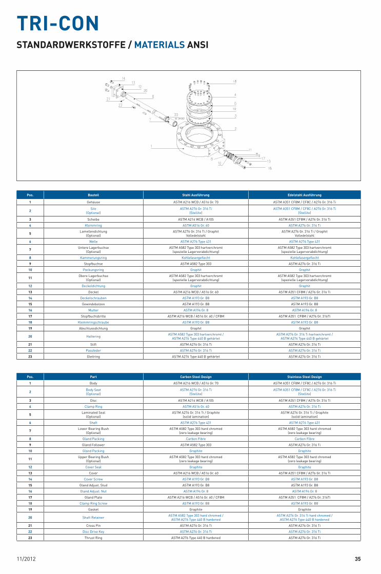
STANDARDWERKSTOFFE / MATERIALS ANSI
Pos. Bauteil Stahl Ausführung Edelstahl Ausführung
1 Gehäuse ASTM A216 WCB / A516 Gr. 70 ASTM A351 CF8M / CF8C / A276 Gr. 316 Ti
2Sitz
(Optional)ASTM A276 Gr. 316 Ti
(Stellite)ASTM A351 CF8M / CF8C / A276 Gr. 316 Ti
(Stellite)
3 Scheibe ASTM A216 WCB / A105 ASTM A351 CF8M / A276 Gr. 316 Ti
4 Klemmring ASTM A516 Gr. 60 ASTM A276 Gr. 316 Ti
5Lamellendichtung
(Optional)ASTM A276 Gr. 316 Ti / Graphit
VolledelstahlASTM A276 Gr. 316 Ti / Graphit
Volledelstahl
6 Welle ASTM A276 Type 431 ASTM A276 Type 431
7Untere Lagerbuchse
(Optional)ASTM A582 Type 303 hartverchromt
(spezielle Lagervorabdichtung)ASTM A582 Type 303 hartverchromt
(spezielle Lagervorabdichtung)
8 Kammerungsring Kohlefasergeflecht Kohlefasergeflecht
9 Stopfbuchse ASTM A582 Type 303 ASTM A276 Gr. 316 Ti
10 Packungsring Graphit Graphit
11Obere Lagerbuchse
(Optional)ASTM A582 Type 303 hartverchromt
(spezielle Lagervorabdichtung)ASTM A582 Type 303 hartverchromt
(spezielle Lagervorabdichtung)
12 Deckeldichtung Graphit Graphit
13 Deckel ASTM A216 WCB / A516 Gr. 60 ASTM A351 CF8M / A276 Gr. 316 Ti
14 Deckelschrauben ASTM A193 Gr. B8 ASTM A193 Gr. B8
15 Gewindebolzen ASTM A193 Gr. B8 ASTM A193 Gr. B8
16 Mutter ASTM A194 Gr. 8 ASTM A194 Gr. 8
17 Stopfbuchsbrille ASTM A216 WCB / A516 Gr. 60 / CF8M ASTM A351 CF8M / A276 Gr. 316Ti
18 Klemmringschraube ASTM A193 Gr. B8 ASTM A193 Gr. B8
19 Abschlussdichtung Graphit Graphit
20 HalteringASTM A582 Type 303 hartverchromt /
ASTM A276 Type 440 B gehärtetASTM A276 Gr. 316 Ti hartverchromt /
ASTM A276 Type 440 B gehärtet
21 Stift ASTM A276 Gr. 316 Ti ASTM A276 Gr. 316 Ti
22 Passfeder ASTM A276 Gr. 316 Ti ASTM A276 Gr. 316 Ti
23 Gleitring ASTM A276 Type 440 B gehärtet ASTM A276 Gr. 316 Ti
Pos. Part Carbon Steel Design Stainless Steel Design
1 Body ASTM A216 WCB / A516 Gr. 70 ASTM A351 CF8M / CF8C / A276 Gr. 316 Ti
2Body Seat(Optional)
ASTM A276 Gr. 316 Ti(Stellite)
ASTM A351 CF8M / CF8C / A276 Gr. 316 Ti(Stellite)
3 Disc ASTM A216 WCB / A105 ASTM A351 CF8M / A276 Gr. 316 Ti
4 Clamp Ring ASTM A516 Gr. 60 ASTM A276 Gr. 316 Ti
5Laminated Seal
(Optional)ASTM A276 Gr. 316 Ti / Graphite
(solid lamination)ASTM A276 Gr. 316 Ti / Graphite
(solid lamination)
6 Shaft ASTM A276 Type 431 ASTM A276 Type 431
7Lower Bearing Bush
(Optional)ASTM A582 Type 303 hard chromed
(zero leakage bearing)ASTM A582 Type 303 hard chromed
(zero leakage bearing)
8 Gland Packing Carbon Fibre Carbon Fibre
9 Gland Follower ASTM A582 Type 303 ASTM A276 Gr. 316 Ti
10 Gland Packing Graphite Graphite
11Upper Bearing Bush
(Optional)ASTM A582 Type 303 hard chromed
(zero leakage bearing)ASTM A582 Type 303 hard chromed
(zero leakage bearing)
12 Cover Seal Graphite Graphite
13 Cover ASTM A216 WCB / A516 Gr. 60 ASTM A351 CF8M / A276 Gr. 316 Ti
14 Cover Screw ASTM A193 Gr. B8 ASTM A193 Gr. B8
15 Gland Adjust. Stud ASTM A193 Gr. B8 ASTM A193 Gr. B8
16 Gland Adjust. Nut ASTM A194 Gr. 8 ASTM A194 Gr. 8
17 Gland Plate ASTM A216 WCB / A516 Gr. 60 / CF8M ASTM A351 CF8M / A276 Gr. 316Ti
18 Clamp Ring Screw ASTM A193 Gr. B8 ASTM A193 Gr. B8
19 Gasket Graphite Graphite
20 Shaft RetainerASTM A582 Type 303 hard chromed /
ASTM A276 Type 440 B hardenedASTM A276 Gr. 316 Ti hard chromed /
ASTM A276 Type 440 B hardened
21 Cross Pin ASTM A276 Gr. 316 Ti ASTM A276 Gr. 316 Ti
22 Disc Drive Key ASTM A276 Gr. 316 Ti ASTM A276 Gr. 316 Ti
23 Thrust Ring ASTM A276 Type 440 B hardened ASTM A276 Gr. 316 Ti
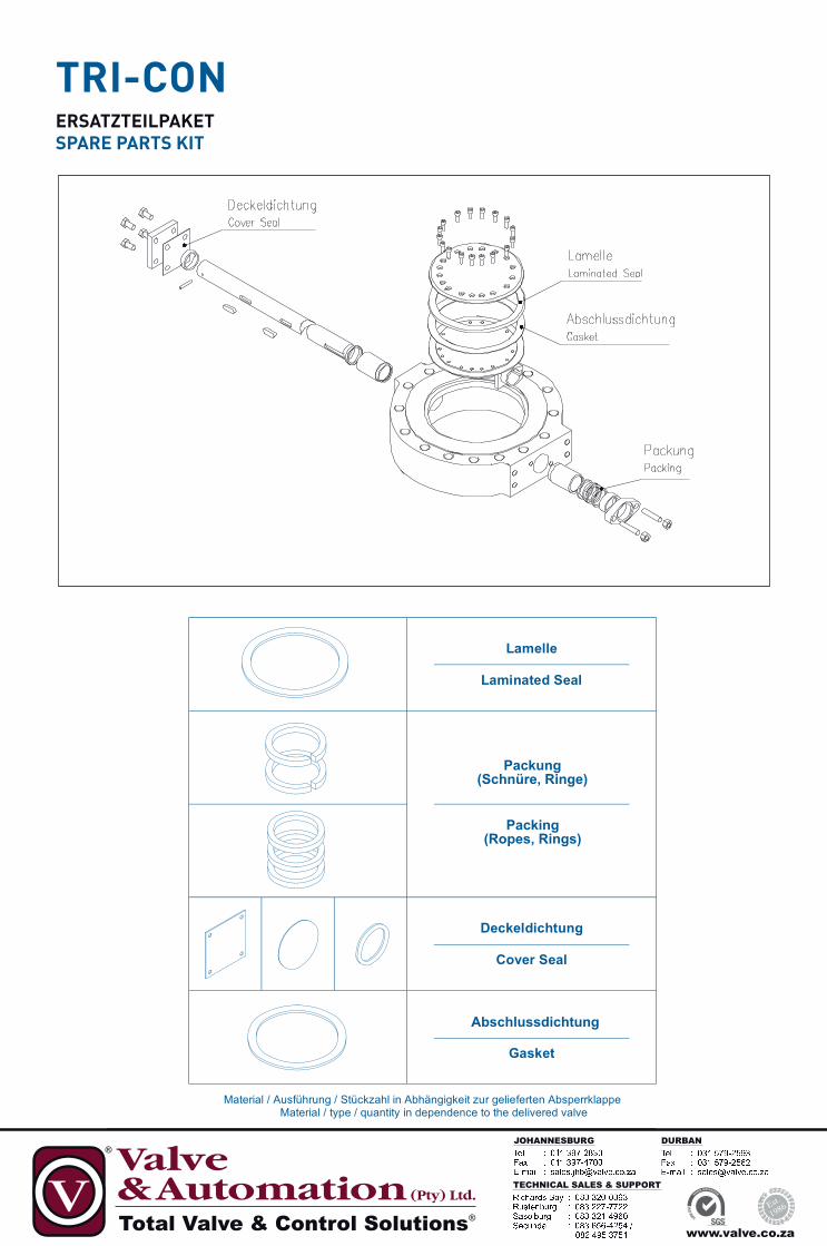
TRI-CONERSATZTEILPAKET
SPARE PARTS KIT
� � � � � � � � � � �� � � � � � � � � � � � � � � � � � � � � � � � �� � � � �� � � � � DURBAN� � � � � � ! " # � �� � � � � � ! $ � �� % & ' ( % ) * + , - . & ' . ( ) / 0 ) 1 &2 ( '3 & 45 ! 6 & 7 'JOHANNESBURG� � 8 � � � � � � � �� � 8 � � � � � � � 8 � � � � 9 � �� � 8 � � � 9 � 9 :� 8 9 � � � � � �; � � < � = > � ? � @; A � B � C D A = EF � � � D A = EF � � A C > �TECHNICAL SALES & SUPPORT
www.valve.co.za


![Druckmessumformer Für Anwendungen in explosionsgefährdeten ...€¦ · DIN EN ISO 1179-2 (ehemals DIN 3852-E) G ¼ A 400 bar [5.800 psi] 600 bar [8.700 psi] ANSI/ASME B1.20.1 ½](https://img.pdfslide.org/doc/110x75/60e833b166a260495f162e4c/druckmessumformer-fr-anwendungen-in-explosionsgefhrdeten-din-en-iso-1179-2.jpg)