ITAS - Industrielle Treppen und Arbeitsbühnen
ITAS - Industrial stairs and working platforms
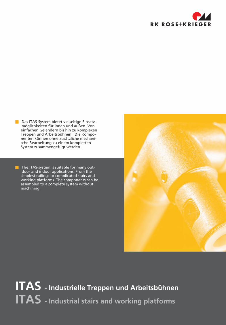
Das ITAS-System bietet vielseitige Einsatz-möglichkeiten für innen und außen. Voneinfachen Geländern bis hin zu komplexenTreppen und Arbeitsbühnen. Die Kompo-nenten können ohne zusätzliche mechani-sche Bearbeitung zu einem komplettenSystem zusammengefügt werden.
The ITAS-system is suitable for many out-door and indoor applications. From thesimplest railings to complicated stairs andworking platforms. The components can beassembled to a complete system withoutmachining.
VII - 2
ITAS – Industrielle Treppen und ArbeitsbühnenITAS – Industrial stairs and working platforms
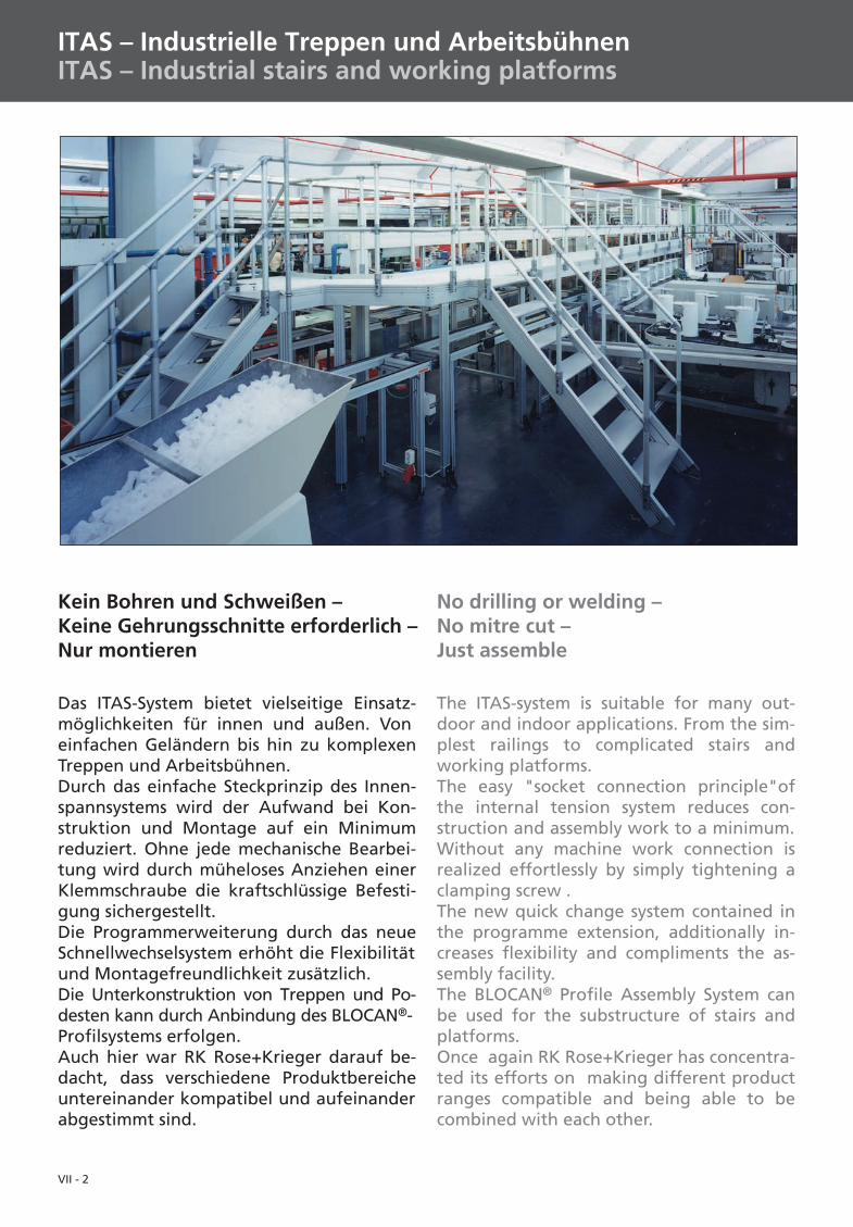
Das ITAS-System bietet vielseitige Einsatz-möglichkeiten für innen und außen. Voneinfachen Geländern bis hin zu komplexenTreppen und Arbeitsbühnen.Durch das einfache Steckprinzip des Innen-spannsystems wird der Aufwand bei Kon-struktion und Montage auf ein Minimumreduziert. Ohne jede mechanische Bearbei-tung wird durch müheloses Anziehen einerKlemmschraube die kraftschlüssige Befesti-gung sichergestellt.Die Programmerweiterung durch das neueSchnellwechselsystem erhöht die Flexibilitätund Montagefreundlichkeit zusätzlich.Die Unterkonstruktion von Treppen und Po-desten kann durch Anbindung des BLOCAN®-Profilsystems erfolgen.Auch hier war RK Rose+Krieger darauf be-dacht, dass verschiedene Produktbereicheuntereinander kompatibel und aufeinanderabgestimmt sind.
Kein Bohren und Schweißen –Keine Gehrungsschnitte erforderlich –Nur montieren
No drilling or welding –No mitre cut –Just assemble
The ITAS-system is suitable for many out-door and indoor applications. From the sim-plest railings to complicated stairs andworking platforms.The easy "socket connection principle"ofthe internal tension system reduces con-struction and assembly work to a minimum.Without any machine work connection isrealized effortlessly by simply tightening aclamping screw .The new quick change system contained inthe programme extension, additionally in-creases flexibility and compliments the as-sembly facility.The BLOCAN® Profile Assembly System canbe used for the substructure of stairs andplatforms.Once again RK Rose+Krieger has concentra-ted its efforts on making different productranges compatible and being able to becombined with each other.
VII - 3
I
II
IV
III
V
VI
VII
VIII
IX
SystembschreibungBestellbeispielTechnische Daten, Vorschriften Seite 3 - 7System descriptionOrder exampleSpecifications, instructions pages 3 - 7
Innenspannsystem Seite 8 - 15Internal tension system pages 8 - 15
Schnellwechselsystem Seite 16 - 19Quick change system pages 16 - 19
ITAS-Zubehör Seite 20 - 29ITAS-Accessories pages 21 - 29
Fax-Anfrage Seite 30 - 32Fax enquiry pages 30 - 33
VII - 4
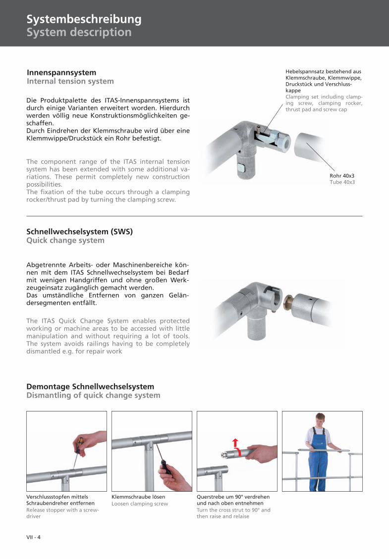
Schnellwechselsystem (SWS)Quick change system
Abgetrennte Arbeits- oder Maschinenbereiche kön-nen mit dem ITAS Schnellwechselsystem bei Bedarfmit wenigen Handgriffen und ohne großen Werk-zeugeinsatz zugänglich gemacht werden.Das umständliche Entfernen von ganzen Gelän-dersegmenten entfällt.
The ITAS Quick Change System enables protectedworking or machine areas to be accessed with littlemanipulation and without requiring a lot of tools.The system avoids railings having to be completelydismantled e.g. for repair work
InnenspannsystemInternal tension system
Rohr 40x3Tube 40x3
Hebelspannsatz bestehend ausKlemmschraube, Klemmwippe,Druckstück und Verschluss-kappeClamping set including clamp-ing screw, clamping rocker,thrust pad and screw cap
The component range of the ITAS internal tensionsystem has been extended with some additional va-riations. These permit completely new constructionpossibilities.The fixation of the tube occurs through a clampingrocker/thrust pad by turning the clamping screw.
Die Produktpalette des ITAS-Innenspannsystems istdurch einige Varianten erweitert worden. Hierdurchwerden völlig neue Konstruktionsmöglichkeiten ge-schaffen.Durch Eindrehen der Klemmschraube wird über eineKlemmwippe/Druckstück ein Rohr befestigt.
Verschlussstopfen mittelsSchraubendreher entfernenRelease stopper with a screw-driver
Klemmschraube lösenLoosen clamping screw
Querstrebe um 90° verdrehenund nach oben entnehmenTurn the cross strut to 90° andthen raise and relaise
Demontage SchnellwechselsystemDismantling of quick change system
SystembeschreibungSystem description
VII - 5
I
II
IV
III
V
VI
VII
VIII
IX
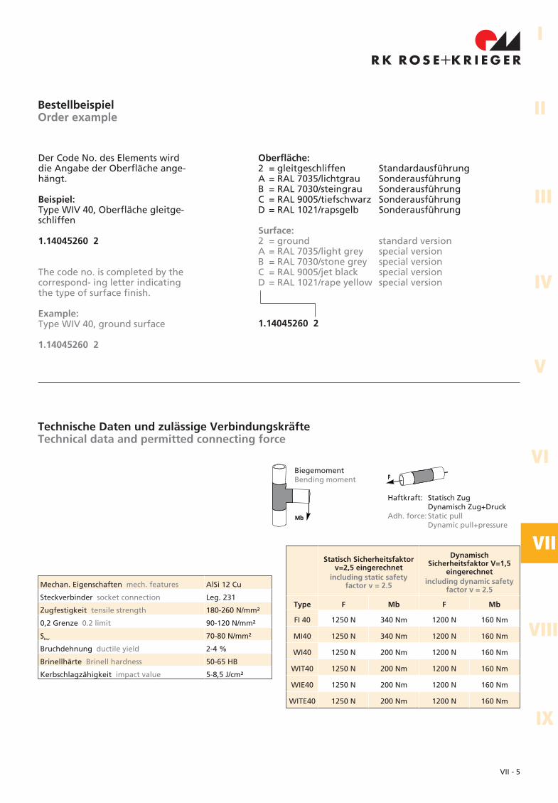
Technische Daten und zulässige VerbindungskräfteTechnical data and permitted connecting force
Mechan. Eigenschaften mech. features AlSi 12 Cu
Steckverbinder socket connection Leg. 231
Zugfestigkeit tensile strength 180-260 N/mm²
0,2 Grenze 0.2 limit 90-120 N/mm²
Sbw 70-80 N/mm²
Bruchdehnung ductile yield 2-4 %
Brinellhärte Brinell hardness 50-65 HB
Kerbschlagzähigkeit impact value 5-8,5 J/cm²
Statisch Sicherheitsfaktorv=2,5 eingerechnet
including static safetyfactor v = 2.5
DynamischSicherheitsfaktor V=1,5
eingerechnetincluding dynamic safety
factor v = 2.5
Type F Mb F Mb
FI 40 1250 N 340 Nm 1200 N 160 Nm
MI40 1250 N 340 Nm 1200 N 160 Nm
WI40 1250 N 200 Nm 1200 N 160 Nm
WIT40 1250 N 200 Nm 1200 N 160 Nm
WIE40 1250 N 200 Nm 1200 N 160 Nm
WITE40 1250 N 200 Nm 1200 N 160 Nm
Haftkraft: Statisch ZugDynamisch Zug+Druck
Adh. force: Static pullDynamic pull+pressure
BiegemomentBending moment
1.14045260 2
Oberfläche:2 = gleitgeschliffen StandardausführungA = RAL 7035/lichtgrau SonderausführungB = RAL 7030/steingrau SonderausführungC = RAL 9005/tiefschwarz SonderausführungD = RAL 1021/rapsgelb Sonderausführung
Surface:2 = ground standard versionA = RAL 7035/light grey special versionB = RAL 7030/stone grey special versionC = RAL 9005/jet black special versionD = RAL 1021/rape yellow special version
BestellbeispielOrder example
Der Code No. des Elements wirddie Angabe der Oberfläche ange-hängt.
Beispiel:Type WIV 40, Oberfläche gleitge-schliffen
1.14045260 2
The code no. is completed by thecorrespond- ing letter indicatingthe type of surface finish.
Example:Type WIV 40, ground surface
1.14045260 2
VII - 6
Techn. Daten, VorschriftenSpecifications, instructions
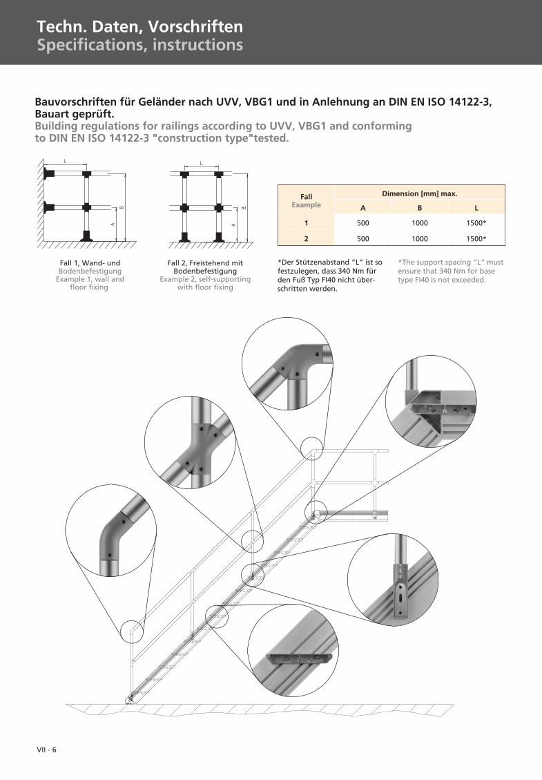
Fall 1, Wand- undBodenbefestigung
Example 1, wall andfloor fixing
Fall 2, Freistehend mitBodenbefestigung
Example 2, self-supportingwith floor fixing
FallExample
Dimension [mm] max.
A B L
1 500 1000 1500*
2 500 1000 1500*
*Der Stützenabstand “L” ist sofestzulegen, dass 340 Nm fürden Fuß Typ FI40 nicht über-schritten werden.
*The support spacing “L” mustensure that 340 Nm for basetype FI40 is not exceeded.
Bauvorschriften für Geländer nach UVV, VBG1 und in Anlehnung an DIN EN ISO 14122-3,Bauart geprüft.Building regulations for railings according to UVV, VBG1 and conformingto DIN EN ISO 14122-3 "construction type"tested.
VII - 7
I
II
IV
III
V
VI
VII
VIII
IX
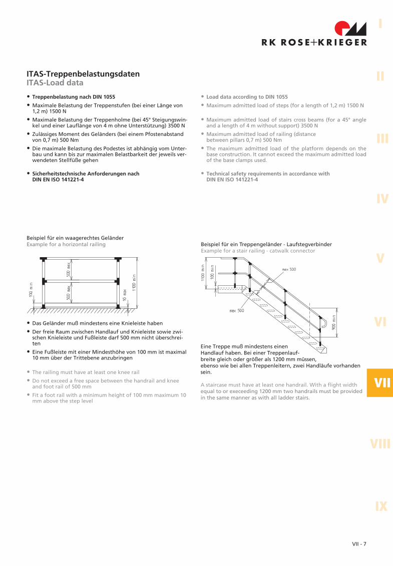
ITAS-TreppenbelastungsdatenITAS-Load data
• Treppenbelastung nach DIN 1055
• Maximale Belastung der Treppenstufen (bei einer Länge von1,2 m) 1500 N
• Maximale Belastung der Treppenholme (bei 45° Steigungswin-kel und einer Lauflänge von 4 m ohne Unterstützung) 3500 N
• Zulässiges Moment des Geländers (bei einem Pfostenabstandvon 0,7 m) 500 Nm
• Die maximale Belastung des Podestes ist abhängig vom Unter-bau und kann bis zur maximalen Belastbarkeit der jeweils ver-wendeten Stellfüße gehen
• Load data according to DIN 1055
• Maximum admitted load of steps (for a length of 1,2 m) 1500 N
• Maximum admitted load of stairs cross beams (for a 45° angleand a length of 4 m without support) 3500 N
• Maximum admitted load of railing (distancebetween pillars 0,7 m) 500 Nm
• The maximum admitted load of the platform depends on thebase construction. It cannot exceed the maximum admitted loadof the base clamps used.
Beispiel für ein Treppengeländer - LaufstegverbinderExample for a stair railing - catwalk connector
Beispiel für ein waagerechtes GeländerExample for a horizontal railing
• Das Geländer muß mindestens eine Knieleiste haben
• Der freie Raum zwischen Handlauf und Knieleiste sowie zwi-schen Knieleiste und Fußleiste darf 500 mm nicht überschrei-ten
• Eine Fußleiste mit einer Mindesthöhe von 100 mm ist maximal10 mm über der Trittebene anzubringen
• The railing must have at least one knee rail
• Do not exceed a free space between the handrail and kneeand foot rail of 500 mm
• Fit a foot rail with a minimum height of 100 mm maximum 10mm above the step level
Eine Treppe muß mindestens einenHandlauf haben. Bei einer Treppenlauf-breite gleich oder größer als 1200 mm müssen,ebenso wie bei allen Treppenleitern, zwei Handläufe vorhandensein.
A staircase must have at least one handrail. With a flight widthequal to or execeeding 1200 mm two handrails must be providedin the same manner as with all ladder stairs.
• Sicherheitstechnische Anforderungen nachDIN EN ISO 141221-4
• Technical safety requirements in accordance withDIN EN ISO 141221-4
VII - 8
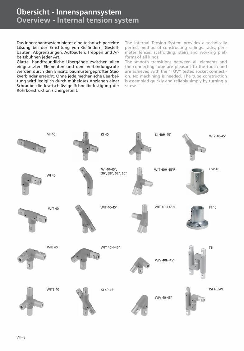
Übersicht - InnenspannsystemOverview - Internal tension system
WIT 40H-45°L
WIV 40-45°
MI 40
WI 40
WIE 40
WITE 40
KI 40
WIT 40-45°
WIT 40H-45°
KI 40-45°
FIW 40
WIT 40
TSI
TSI 40-WI
Das Innenspannsystem bietet eine technisch perfekteLösung bei der Errichtung von Geländern, Gestell-bauten, Abgrenzungen, Aufbauten, Treppen und Ar-beitsbühnen jeder Art.Glatte, handfreundliche Übergänge zwischen alleneingesetzten Elementen und dem Verbindungsrohrwerden durch den Einsatz baumustergeprüfter Stec-kverbinder erreicht. Ohne jede mechanische Bearbei-tung wird lediglich durch müheloses Anziehen einerSchraube die kraftschlüssige Schnellbefestigung derRohrkonstruktion sichergestellt.
WI 40-45°,30°, 38°, 52°, 60°
KI 40H-45°
FI 40
WIV 40H-45°
WIY 40-45°
WIT 40H-45°R
The internal Tension System provides a technicallyperfect method of constructing railings, racks, peri-meter fences, scaffolding, stairs and working plat-forms of all kinds.The smooth transitions between all elements andthe connecting tube are pleasant to the touch andare achieved with the “TÜV” tested socket connecti-on. No machining is needed. The tube constructionis assembled quickly and reliably simply by turning ascrew.
VII - 9
I
II
IV
III
V
VI
VII
VIII
IX
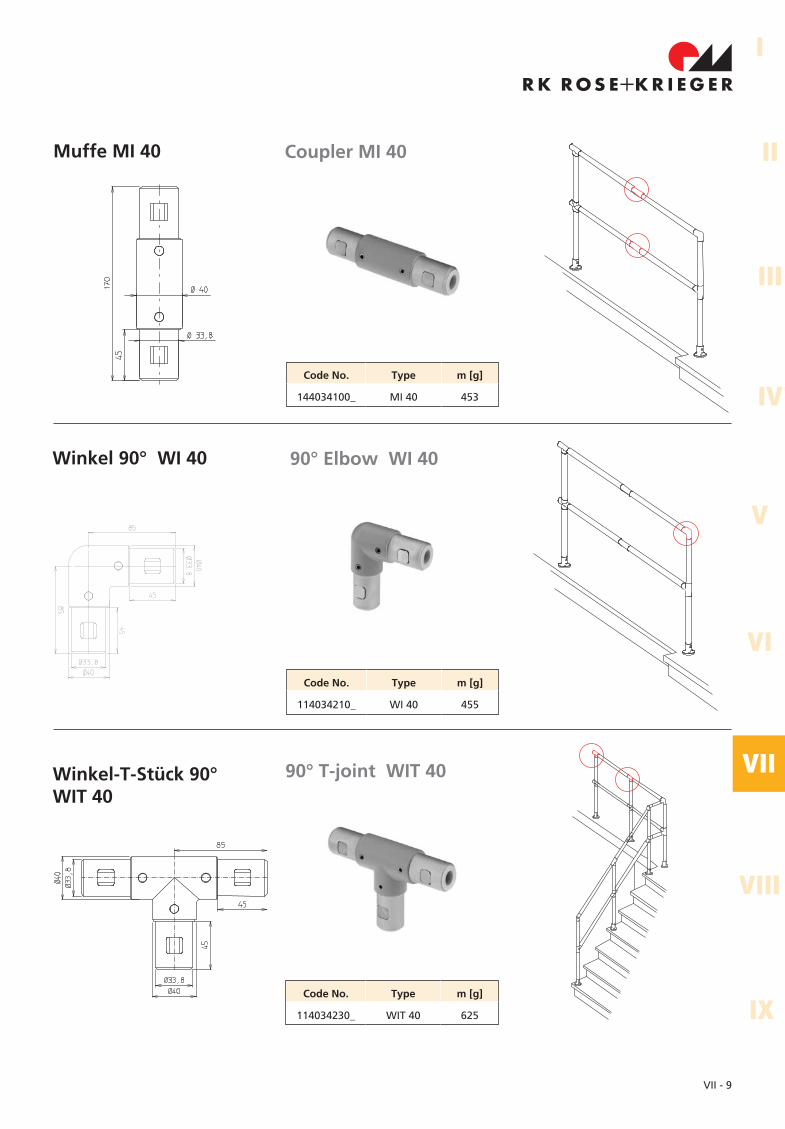
Muffe MI 40
Winkel 90° WI 40
Coupler MI 40
90° Elbow WI 40
Code No. Type m [g]
114034230_ WIT 40 625
Code No. Type m [g]
114034210_ WI 40 455
Code No. Type m [g]
144034100_ MI 40 453
Winkel-T-Stück 90°WIT 40
90° T-joint WIT 40
VII - 10
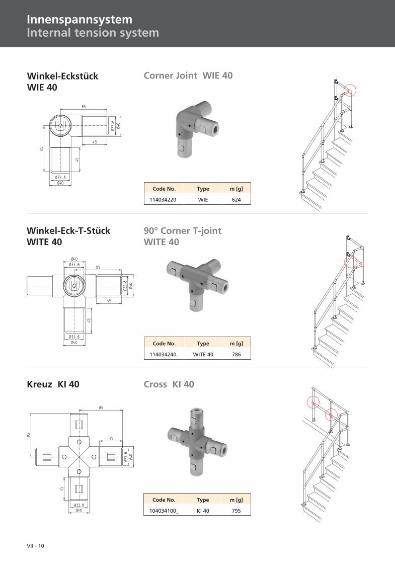
Kreuz KI 40
Winkel-Eck-T-StückWITE 40
Winkel-EckstückWIE 40
Cross KI 40
90° Corner T-jointWITE 40
Corner Joint WIE 40
Code No. Type m [g]
104034100_ KI 40 795
Code No. Type m [g]
114034240_ WITE 40 786
Code No. Type m [g]
114034220_ WIE 624
InnenspannsystemInternal tension system
VII - 11
I
II
IV
III
V
VI
VII
VIII
IXCode No. Type m [g]
114045250_ WIT40 H-45° 715
Code No. Type m [g]
114045230_ WIT40-45° 715
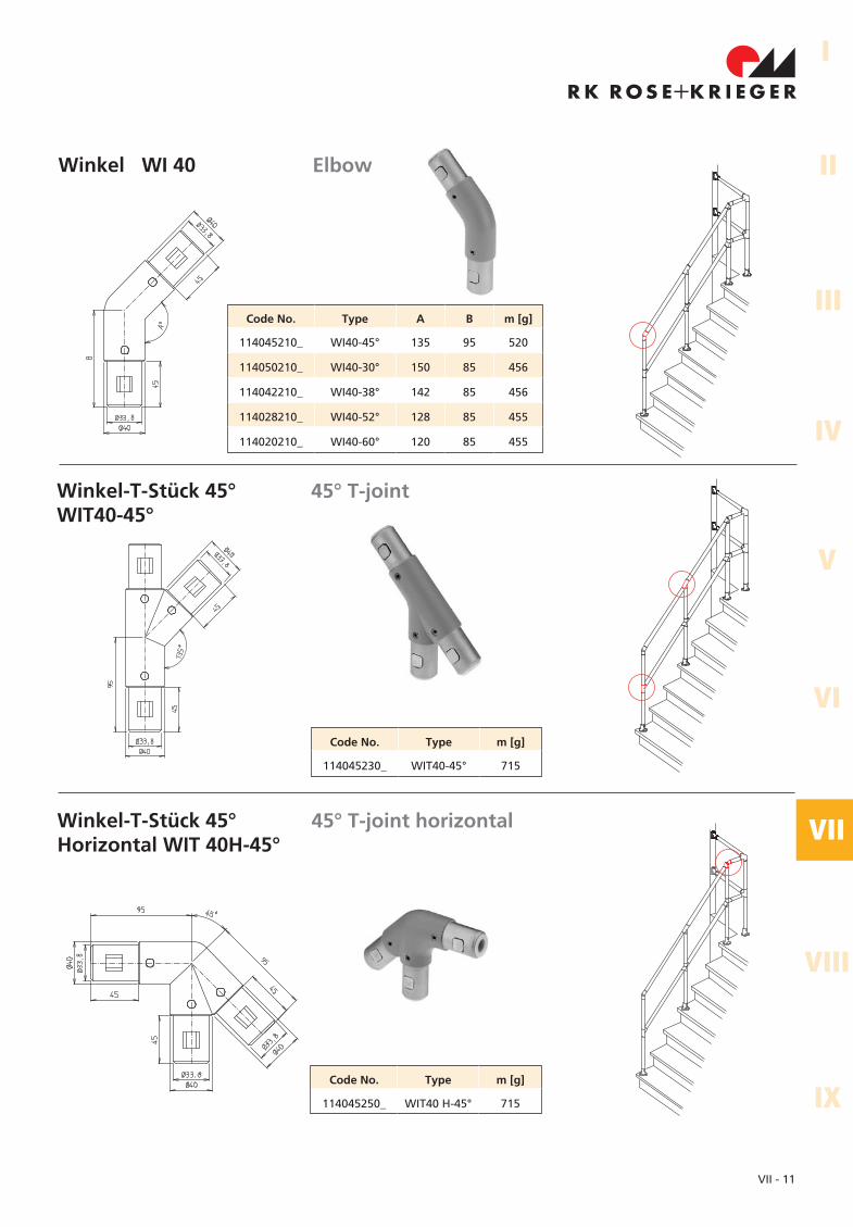
Winkel-T-Stück 45°Horizontal WIT 40H-45°
45° T-joint horizontal
Winkel-T-Stück 45°WIT40-45°
45° T-joint
Winkel WI 40 Elbow
Code No. Type A B m [g]
114045210_ WI40-45° 135 95 520
114050210_ WI40-30° 150 85 456
114042210_ WI40-38° 142 85 456
114028210_ WI40-52° 128 85 455
114020210_ WI40-60° 120 85 455
VII - 12
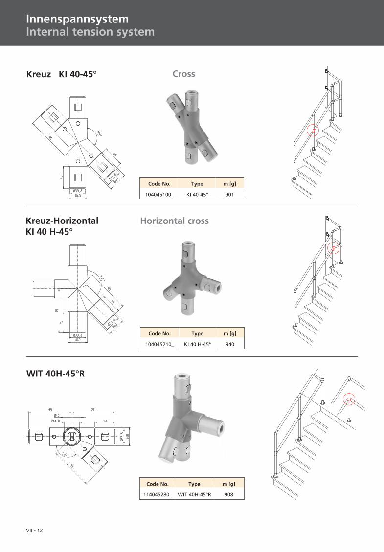
Code No. Type m [g]
104045210_ KI 40 H-45° 940
Code No. Type m [g]
104045100_ KI 40-45° 901
Kreuz-HorizontalKI 40 H-45°
Horizontal cross
Kreuz KI 40-45° Cross
InnenspannsystemInternal tension system
WIT 40H-45°R
Code No. Type m [g]
114045280_ WIT 40H-45°R 908
VII - 13
I
II
IV
III
V
VI
VII
VIII
IX
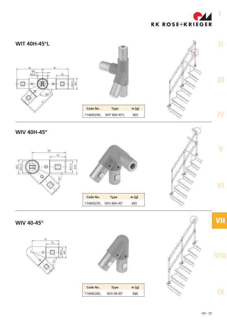
WIT 40H-45°L
WIV 40-45°
Code No. Type m [g]
114045290_ WIT 40H-45°L 903
Code No. Type m [g]
114045260_ WIV 40-45° 486
WIV 40H-45°
Code No. Type m [g]
114045270_ WIV 40H-45° 693
VII - 14
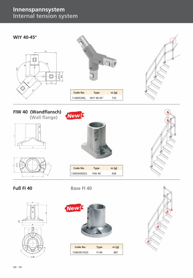
Code No. Type m [g]
13403430025 FIW 40 428
FIW 40 (Wandflansch)(Wall flange)
WIY 40-45°
Code No. Type m [g]
114045300_ WIY 40-45° 733
InnenspannsystemInternal tension system
Code No. Type m [g]
13403431025 FI 40 487
Fuß FI 40 Base FI 40
New!
New!
VII - 15
I
II
IV
III
V
VI
VII
VIII
IX
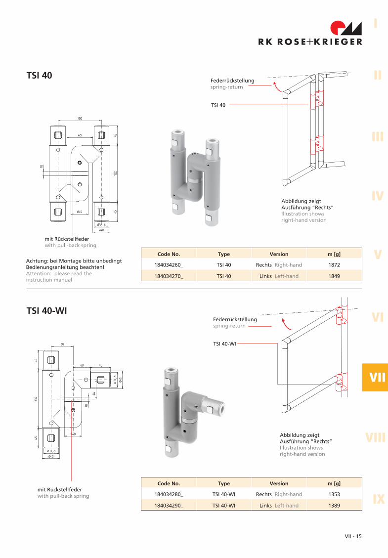
TSI 40
mit Rückstellfederwith pull-back spring
Code No. Type Version m [g]
184034260_ TSI 40 Rechts Right-hand 1872
184034270_ TSI 40 Links Left-hand 1849
Abbildung zeigtAusführung “Rechts”Illustration showsright-hand version
mit Rückstellfederwith pull-back spring
Abbildung zeigtAusführung “Rechts”Illustration showsright-hand version
TSI 40-WI
Code No. Type Version m [g]
184034280_ TSI 40-WI Rechts Right-hand 1353
184034290_ TSI 40-WI Links Left-hand 1389
Federrückstellungspring-return
TSI 40
TSI 40-WI
Federrückstellungspring-return
Achtung: bei Montage bitte unbedingtBedienungsanleitung beachten!Attention: please read theinstruction manual
VII - 16
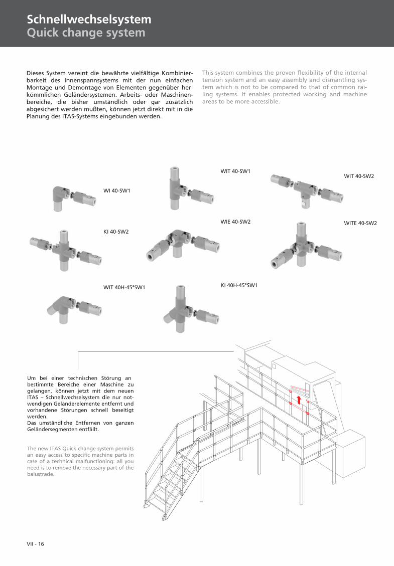
SchnellwechselsystemQuick change system
Dieses System vereint die bewährte vielfältige Kombinier-barkeit des Innenspannsystems mit der nun einfachenMontage und Demontage von Elementen gegenüber her-kömmlichen Geländersystemen. Arbeits- oder Maschinen-bereiche, die bisher umständlich oder gar zusätzlichabgesichert werden mußten, können jetzt direkt mit in diePlanung des ITAS-Systems eingebunden werden.
KI 40H-45°SW1
WIT 40-SW1
WITE 40-SW2
KI 40-SW2
WIE 40-SW2
WIT 40H-45°SW1
WI 40-SW1
WIT 40-SW2
Um bei einer technischen Störung anbestimmte Bereiche einer Maschine zugelangen, können jetzt mit dem neuenITAS – Schnellwechselsystem die nur not-wendigen Geländerelemente entfernt undvorhandene Störungen schnell beseitigtwerden.Das umständliche Entfernen von ganzenGeländersegmenten entfällt.
The new ITAS Quick change system permitsan easy access to specific machine parts incase of a technical malfunctioning: all youneed is to remove the necessary part of thebalustrade.
This system combines the proven flexibility of the internaltension system and an easy assembly and dismantling sys-tem which is not to be compared to that of common rai-ling systems. It enables protected working and machineareas to be more accessible.
VII - 17
I
II
IV
III
V
VI
VII
VIII
IX
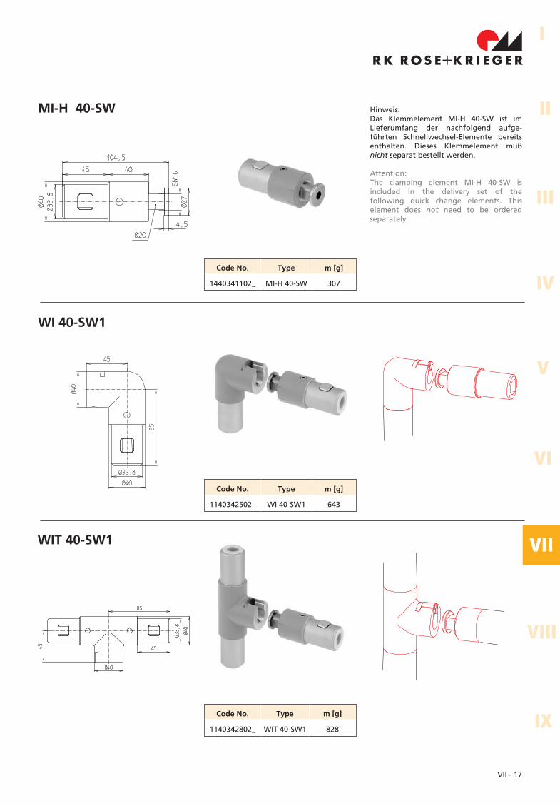
MI-H 40-SW
WI 40-SW1
WIT 40-SW1
Code No. Type m [g]
1440341102_ MI-H 40-SW 307
Code No. Type m [g]
1140342802_ WIT 40-SW1 828
Code No. Type m [g]
1140342502_ WI 40-SW1 643
Hinweis:Das Klemmelement MI-H 40-SW ist imLieferumfang der nachfolgend aufge-führten Schnellwechsel-Elemente bereitsenthalten. Dieses Klemmelement mußnicht separat bestellt werden.
Attention:The clamping element MI-H 40-SW isincluded in the delivery set of thefollowing quick change elements. Thiselement does not need to be orderedseparately
VII - 18
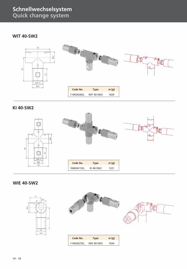
WIE 40-SW2
Code No. Type m [g]
1140342702_ WIE 40-SW2 1034
Code No. Type m [g]
1140342602_ WIT 40-SW2 1020
WIT 40-SW2
KI 40-SW2
Code No. Type m [g]
1040341102_ KI 40-SW2 1221
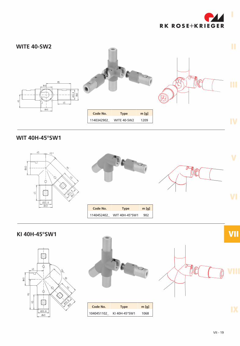
SchnellwechselsystemQuick change system
VII - 19
I
II
IV
III
V
VI
VII
VIII
IX
WITE 40-SW2
Code No. Type m [g]
1140342902_ WITE 40-SW2 1209
Code No. Type m [g]
1140452402_ WIT 40H-45°SW1 902
WIT 40H-45°SW1
Code No. Type m [g]
1040451102_ KI 40H-45°SW1 1068
KI 40H-45°SW1
VII - 20
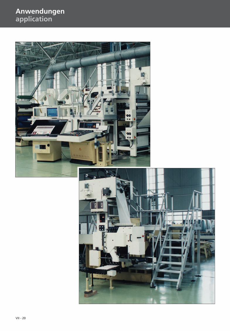
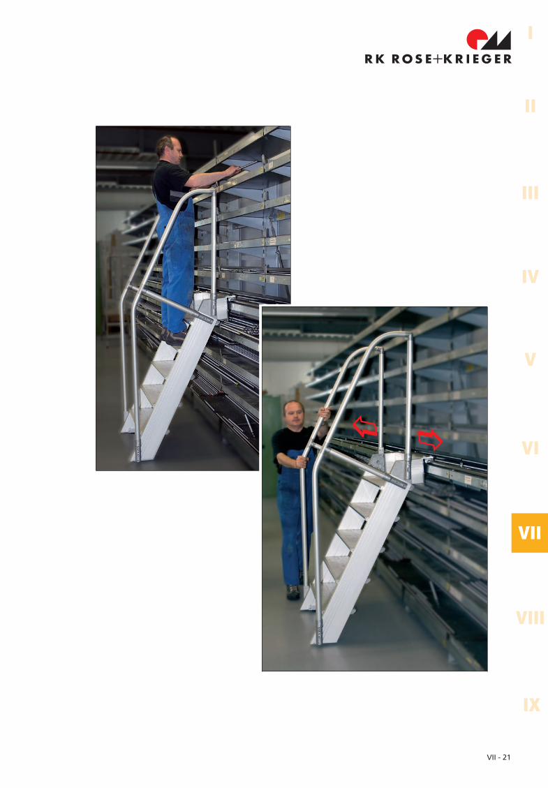
Anwendungenapplication
VII - 21
I
II
IV
III
V
VI
VII
VIII
IX
��
New!
VII - 22
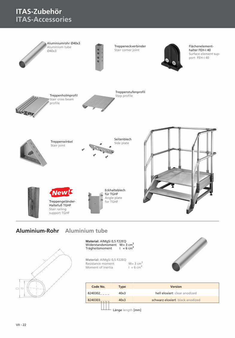
ITAS-ZubehörITAS-Accessories
TreppenholmprofilStair cross beamprofile
TreppenstufenprofilStep profile
TreppenwinkelStair joint
SeitenblechSide plate
Aluminiumrohr Ø40x3Aluminium tubeØ40x3
TreppeneckverbinderStair corner joint
Flächenelement-halter FEH-I 40Surface element sup-port FEH-I 40
Aluminium-Rohr Aluminium tube
Material: AlMgSi 0,5 F22EQWiderstandsmoment W= 3 cm3
Trägheitsmoment I = 6 cm4
Material: AlMgSi 0,5 F22EQResistance moment W= 3 cm3
Moment of inertia I = 6 cm4
Code No. Type Version
8240302_ _ _ _ 40x3 hell eloxiert clear anodized
8240303_ _ _ _ 40x3 schwarz eloxiert black anodized
Länge length [mm]
Treppengeländer-Haltefuß TGHFStair railingsupport TGHF
Eckhalteblechfür TGHFAngle platefor TGHF
VII - 23
I
II
IV
III
V
VI
VII
VIII
IX
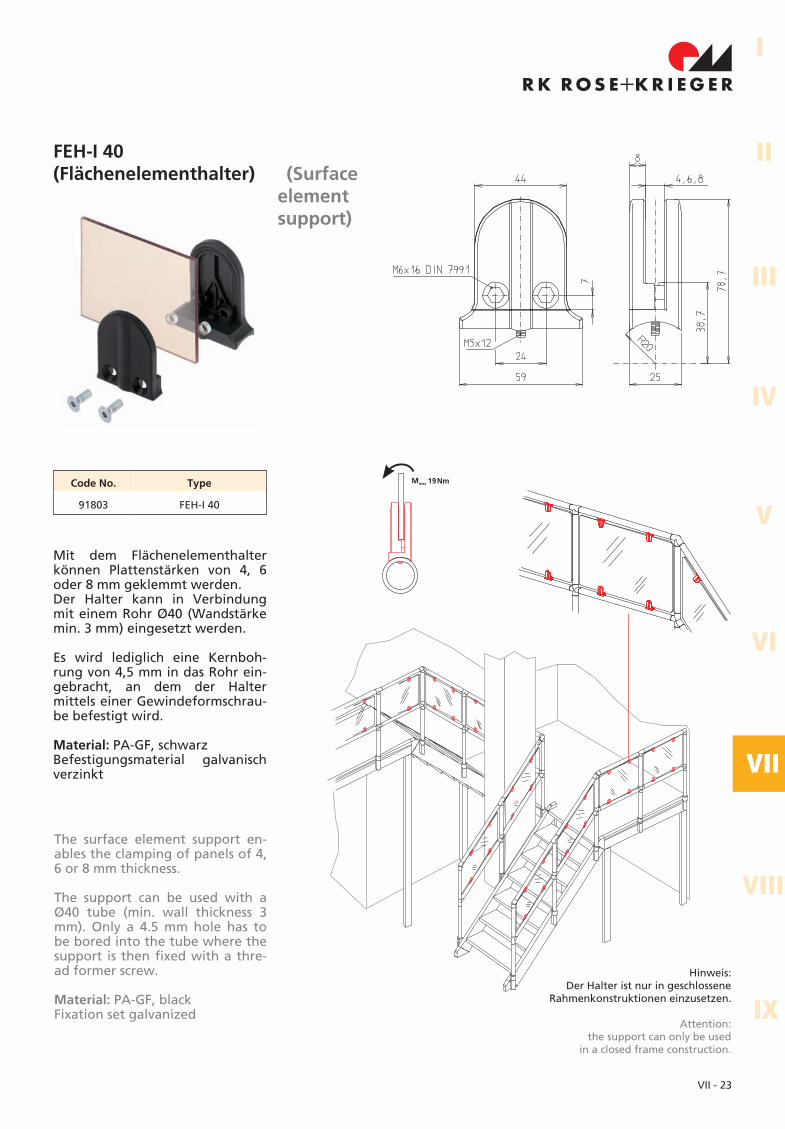
FEH-I 40(Flächenelementhalter) (Surface
elementsupport)
Code No. Type
91803 FEH-I 40
The surface element support en-ables the clamping of panels of 4,6 or 8 mm thickness.
The support can be used with aØ40 tube (min. wall thickness 3mm). Only a 4.5 mm hole has tobe bored into the tube where thesupport is then fixed with a thre-ad former screw.
Material: PA-GF, blackFixation set galvanized
Mit dem Flächenelementhalterkönnen Plattenstärken von 4, 6oder 8 mm geklemmt werden.Der Halter kann in Verbindungmit einem Rohr Ø40 (Wandstärkemin. 3 mm) eingesetzt werden.
Es wird lediglich eine Kernboh-rung von 4,5 mm in das Rohr ein-gebracht, an dem der Haltermittels einer Gewindeformschrau-be befestigt wird.
Material: PA-GF, schwarzBefestigungsmaterial galvanischverzinkt
Hinweis:Der Halter ist nur in geschlossene
Rahmenkonstruktionen einzusetzen.
Attention:the support can only be used
in a closed frame construction.
M 19Nmmax
VII - 24
ITAS-ZubehörITAS-Accessories
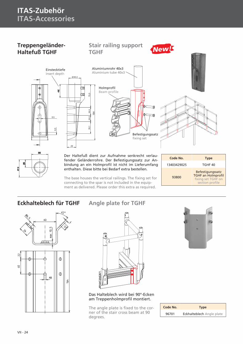
Treppengeländer-Haltefuß TGHF
Stair railing supportTGHF
Code No. Type
13403429025 TGHF 40
93800
BefestigungssatzTGHF an Holmprofilfixing set TGHF on
section profile
Einstecktiefeinsert depth
Der Haltefuß dient zur Aufnahme senkrecht verlau-fender Geländerrohre. Der Befestigungssatz zur An-bindung an ein Holmprofil ist nicht im Lieferumfangenthalten. Diese bitte bei Bedarf extra bestellen.
The base houses the vertical railings. The fixing set forconnecting to the spar is not included in the equip-ment as delivered. Please order this extra as required.
Aluminiumrohr 40x3Aluminium tube 40x3
Angle plate for TGHF
Code No. Type
96701 Eckhalteblech Angle plate
Das Halteblech wird bei 90°-Eckenam Treppenholmprofil montiert.
The angle plate is fixed to the cor-ner of the stair cross beam at 90degrees.
Eckhalteblech für TGHF
New!
Befestigungssatzfixing set
HolmprofilBeam profile
VII - 25
I
II
IV
III
V
VI
VII
VIII
IX
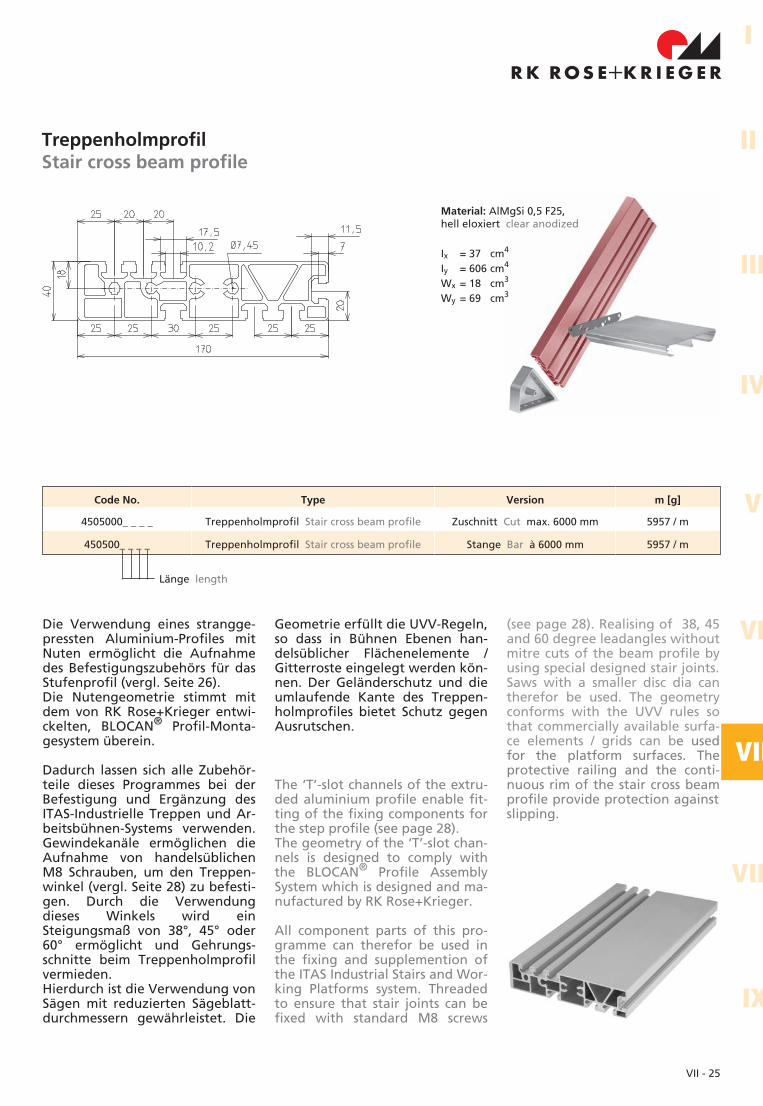
TreppenholmprofilStair cross beam profile
Die Verwendung eines strangge-pressten Aluminium-Profiles mitNuten ermöglicht die Aufnahmedes Befestigungszubehörs für dasStufenprofil (vergl. Seite 26).Die Nutengeometrie stimmt mitdem von RK Rose+Krieger entwi-ckelten, BLOCAN® Profil-Monta-gesystem überein.
Dadurch lassen sich alle Zubehör-teile dieses Programmes bei derBefestigung und Ergänzung desITAS-Industrielle Treppen und Ar-beitsbühnen-Systems verwenden.Gewindekanäle ermöglichen dieAufnahme von handelsüblichenM8 Schrauben, um den Treppen-winkel (vergl. Seite 28) zu befesti-gen. Durch die Verwendungdieses Winkels wird einSteigungsmaß von 38°, 45° oder60° ermöglicht und Gehrungs-schnitte beim Treppenholmprofilvermieden.Hierdurch ist die Verwendung vonSägen mit reduzierten Sägeblatt-durchmessern gewährleistet. Die
Geometrie erfüllt die UVV-Regeln,so dass in Bühnen Ebenen han-delsüblicher Flächenelemente /Gitterroste eingelegt werden kön-nen. Der Geländerschutz und dieumlaufende Kante des Treppen-holmprofiles bietet Schutz gegenAusrutschen.
The ‘T’-slot channels of the extru-ded aluminium profile enable fit-ting of the fixing components forthe step profile (see page 28).The geometry of the ‘T’-slot chan-nels is designed to comply withthe BLOCAN® Profile AssemblySystem which is designed and ma-nufactured by RK Rose+Krieger.
All component parts of this pro-gramme can therefor be used inthe fixing and supplemention ofthe ITAS Industrial Stairs and Wor-king Platforms system. Threadedto ensure that stair joints can befixed with standard M8 screws
(see page 28). Realising of 38, 45and 60 degree leadangles withoutmitre cuts of the beam profile byusing special designed stair joints.Saws with a smaller disc dia cantherefor be used. The geometryconforms with the UVV rules sothat commercially available surfa-ce elements / grids can be usedfor the platform surfaces. Theprotective railing and the conti-nuous rim of the stair cross beamprofile provide protection againstslipping.
Material: AlMgSi 0,5 F25,hell eloxiert clear anodized
Ix = 37 cm4
Iy = 606 cm4
Wx = 18 cm3
Wy = 69 cm3
Code No. Type Version m [g]
4505000_ _ _ _ Treppenholmprofil Stair cross beam profile Zuschnitt Cut max. 6000 mm 5957 / m
450500_ _ _ _ Treppenholmprofil Stair cross beam profile Stange Bar à 6000 mm 5957 / m
Länge length
VII - 26
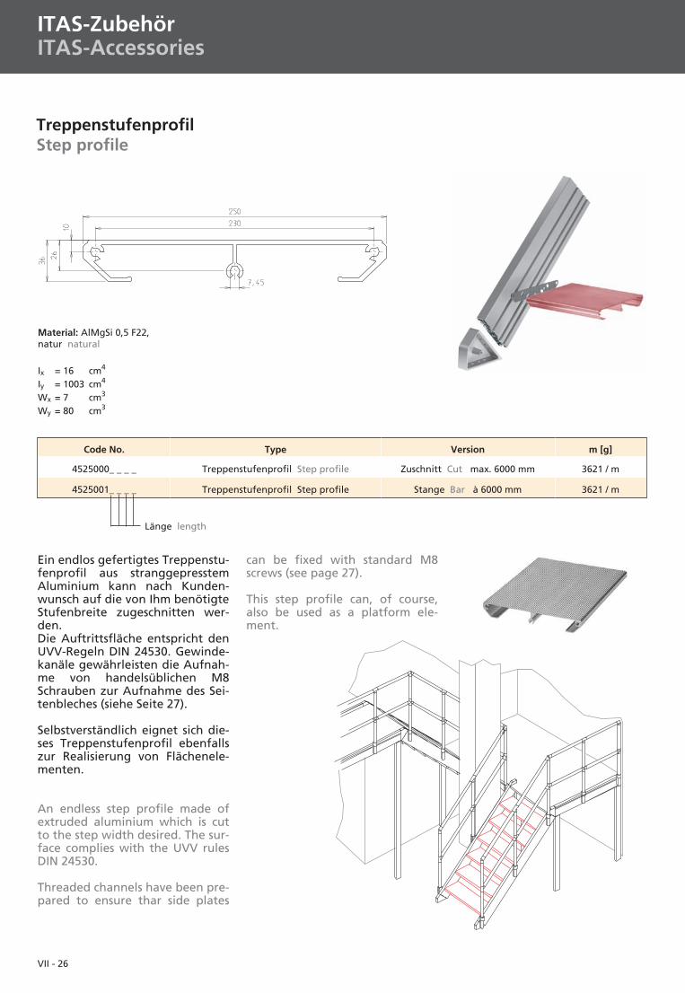
TreppenstufenprofilStep profile
Ein endlos gefertigtes Treppenstu-fenprofil aus stranggepresstemAluminium kann nach Kunden-wunsch auf die von Ihm benötigteStufenbreite zugeschnitten wer-den.Die Auftrittsfläche entspricht denUVV-Regeln DIN 24530. Gewinde-kanäle gewährleisten die Aufnah-me von handelsüblichen M8Schrauben zur Aufnahme des Sei-tenbleches (siehe Seite 27).
Selbstverständlich eignet sich die-ses Treppenstufenprofil ebenfallszur Realisierung von Flächenele-menten.
An endless step profile made ofextruded aluminium which is cutto the step width desired. The sur-face complies with the UVV rulesDIN 24530.
Threaded channels have been pre-pared to ensure thar side plates
can be fixed with standard M8screws (see page 27).
This step profile can, of course,also be used as a platform ele-ment.
Material: AlMgSi 0,5 F22,natur natural
Ix = 16 cm4
Iy = 1003 cm4
Wx = 7 cm3
Wy = 80 cm3
ITAS-ZubehörITAS-Accessories
Code No. Type Version m [g]
4525000_ _ _ _ Treppenstufenprofil Step profile Zuschnitt Cut max. 6000 mm 3621 / m
4525001_ _ _ _ Treppenstufenprofil Step profile Stange Bar à 6000 mm 3621 / m
Länge length
VII - 27
I
II
IV
III
V
VI
VII
VIII
IX
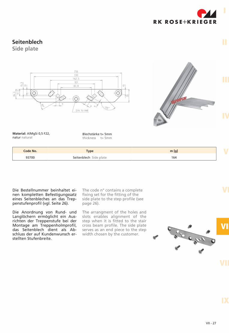
SeitenblechSide plate
Blechstärke t= 5mmthickness t= 5mm
Material: AlMgSi 0,5 F22,natur natural
Die Bestellnummer beinhaltet ei-nen kompletten Befestigungssatzeines Seitenbleches an das Trep-penstufenprofil (vgl. Seite 26).
Die Anordnung von Rund- undLanglöchern ermöglicht ein Aus-richten der Treppenstufe bei derMontage am Treppenholmprofil,das Seitenblech dient als Ab-schluss der auf Kundenwunsch er-stellten Stufenbreite.
The code n° contains a completefixing set for the fitting of theside plate to the step profile (seepage 26).
The arrangment of the holes andslots enables alignment of thestep when it is fitted to the staircross beam profile. The side plateserves as an end piece to the stepwidth chosen by the customer.
Code No. Type m [g]
93700 Seitenblech Side plate 164
VII - 28
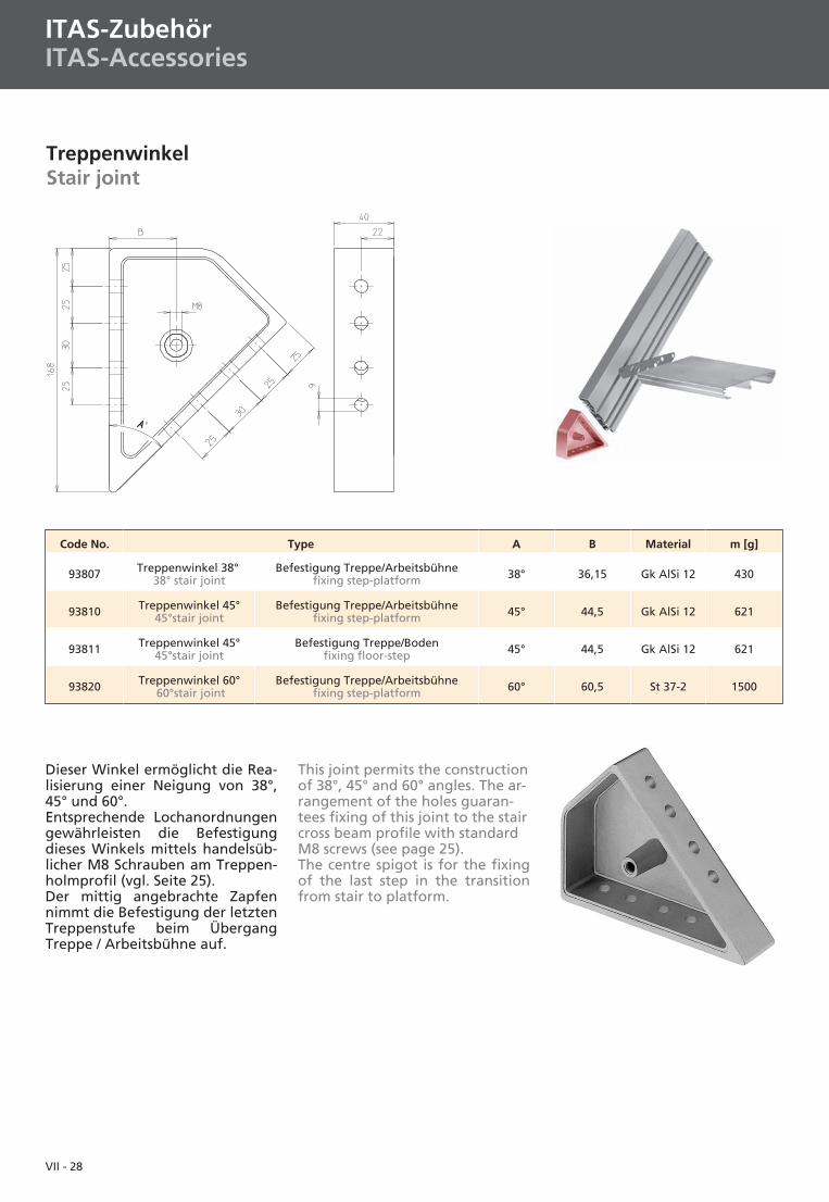
TreppenwinkelStair joint
Dieser Winkel ermöglicht die Rea-lisierung einer Neigung von 38°,45° und 60°.Entsprechende Lochanordnungengewährleisten die Befestigungdieses Winkels mittels handelsüb-licher M8 Schrauben am Treppen-holmprofil (vgl. Seite 25).Der mittig angebrachte Zapfennimmt die Befestigung der letztenTreppenstufe beim ÜbergangTreppe / Arbeitsbühne auf.
This joint permits the constructionof 38°, 45° and 60° angles. The ar-rangement of the holes guaran-tees fixing of this joint to the staircross beam profile with standardM8 screws (see page 25).The centre spigot is for the fixingof the last step in the transitionfrom stair to platform.
ITAS-ZubehörITAS-Accessories
Code No. Type A B Material m [g]
93807 Treppenwinkel 38°38° stair joint
Befestigung Treppe/Arbeitsbühnefixing step-platform 38° 36,15 Gk AlSi 12 430
93810 Treppenwinkel 45°45°stair joint
Befestigung Treppe/Arbeitsbühnefixing step-platform 45° 44,5 Gk AlSi 12 621
93811 Treppenwinkel 45°45°stair joint
Befestigung Treppe/Bodenfixing floor-step 45° 44,5 Gk AlSi 12 621
93820 Treppenwinkel 60°60°stair joint
Befestigung Treppe/Arbeitsbühnefixing step-platform 60° 60,5 St 37-2 1500
VII - 29
I
II
IV
III
V
VI
VII
VIII
IX
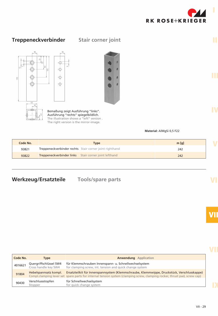
Treppeneckverbinder Stair corner joint
Material: AlMgSi 0,5 F22
Werkzeug/Ersatzteile Tools/spare parts
Code No. Type Anwendung Application
4016621 Quergriffschlüssel SW4Cross handle key SW4
für Klemmschrauben Innenspann- u. Schnellwechselsystemfor clamping screw, int. tension and quick change system
91804 Hebelspannsatz kompl.Compl.clamping lever set
Ersatzteilkit für Innenspannsystem (Klemmschraube, Klemmwippe, Druckstück, Verschlusskappe)spare parts for internal tension system (clamping screw, clamping rocker, thrust pad, screw cap)
90430 VerschlussstopfenStopper
für Schnellwechselsystemfor quick change system
Bemaßung zeigt Ausführung “links”.Ausführung “rechts” spiegelbildlich.The illustration shows a “left” version .The right version is the mirror-image.
Code No. Type m [g]
93821 Treppeneckverbinder rechts Stair corner joint righthand 242
93822 Treppeneckverbinder links Stair corner joint lefthand 242
VII - 30
Laufbreite
Steigungswinkel
Trep
pen
lau
fhö
he
Podestlänge
Fax-AnfrageRK Rose+Krieger GmbH Postfach 15 64, 32375 MindenTel. 0571-93 35-0, Fax 0571-93 35-119
Firma: .................................................................................................................................Kd-Nr.: .............................................................................
Telefon: ..............................................................................................................................Telefax: ............................................................................
Ansprechpartner: ..............................................................................................................Abtl.:................................................................................
Bemerkung:.................................................................................................................................................................................................................
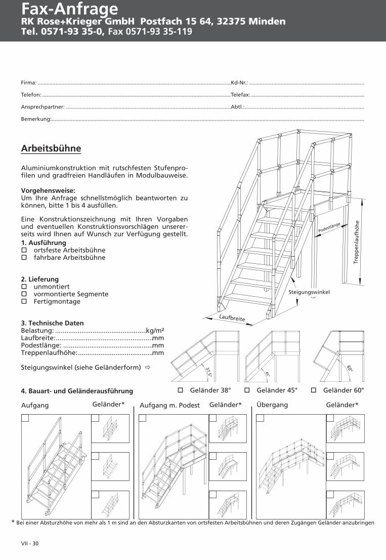
Arbeitsbühne
Aluminiumkonstruktion mit rutschfesten Stufenpro-filen und gradfreien Handläufen in Modulbauweise.
Vorgehensweise:Um Ihre Anfrage schnellstmöglich beantworten zukönnen, bitte 1 bis 4 ausfüllen.
Eine Konstruktionszeichnung mit Ihren Vorgabenund eventuellen Konstruktionsvorschlägen unserer-seits wird Ihnen auf Wunsch zur Verfügung gestellt.1. Ausführung� ortsfeste Arbeitsbühne� fahrbare Arbeitsbühne
2. Lieferung� unmontiert� vormontierte Segmente� Fertigmontage
3. Technische DatenBelastung: .................................................kg/m²Laufbreite:....................................................mmPodestlänge: ................................................mmTreppenlaufhöhe:........................................mm
Steigungswinkel (siehe Geländerform) �
4. Bauart- und Geländerausführung � Geländer 38° � Geländer 45° � Geländer 60°
Aufgang m. PodestAufgang Geländer* Geländer* Übergang Geländer*
* Bei einer Absturzhöhe von mehr als 1 m sind an den Absturzkanten von ortsfesten Arbeitsbühnen und deren Zugängen Geländer anzubringen
Railing* Bridge Railing*
step width
angle of inclination
Hei
gh
to
fp
latf
orm
Fax enquiryRK Rose+Krieger GmbHPostfach 15 64, 32375 MindenTel. 0571-93 35-0, Fax 0571-93 35-119
A Phoenix Mecano Company
R K R OS E K R I EG E R+
Company:...........................................................................................................................Customer no.: .................................................................
Phone: ................................................................................................................................Telefax: ............................................................................
Responsible:.......................................................................................................................Dept.:...............................................................................
Remarks:......................................................................................................................................................................................................................
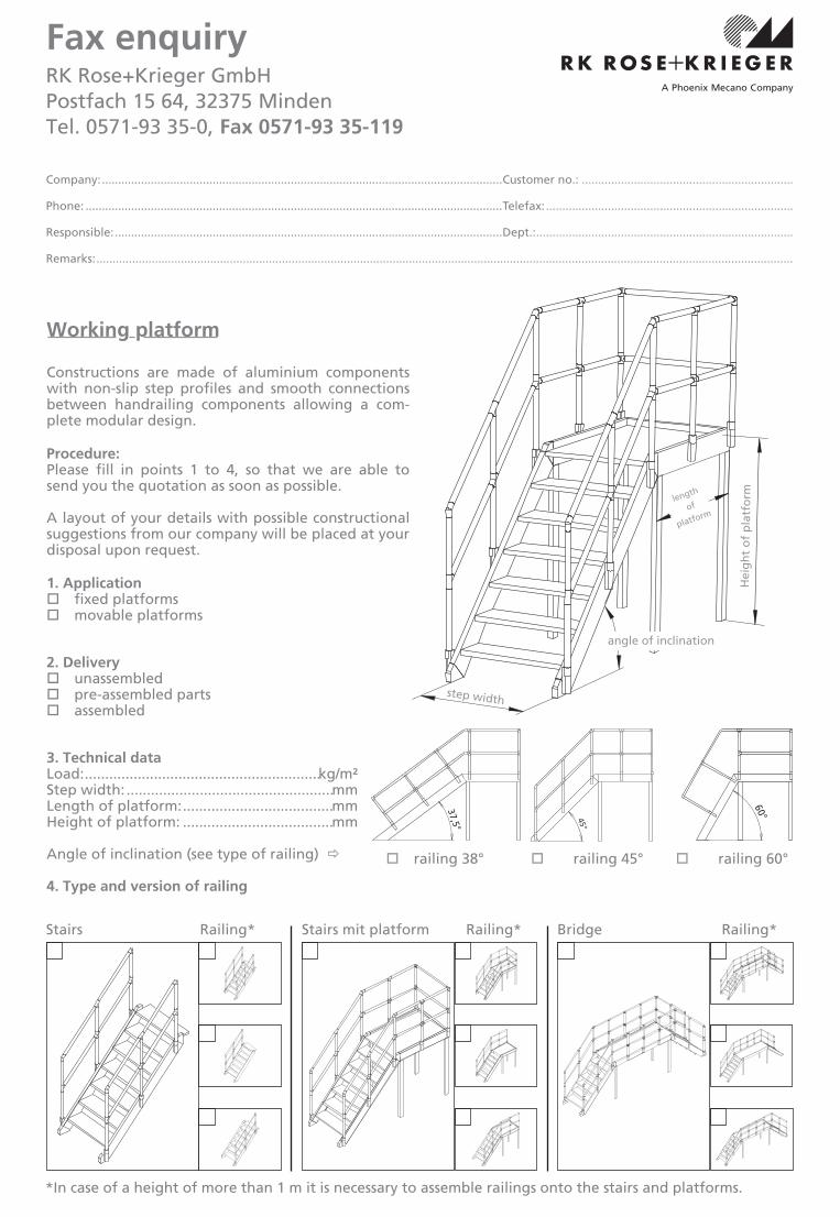
*In case of a height of more than 1 m it is necessary to assemble railings onto the stairs and platforms.
Stairs mit platformStairs Railing*
length
of
platform
Working platform
Constructions are made of aluminium componentswith non-slip step profiles and smooth connectionsbetween handrailing components allowing a com-plete modular design.
Procedure:Please fill in points 1 to 4, so that we are able tosend you the quotation as soon as possible.
A layout of your details with possible constructionalsuggestions from our company will be placed at yourdisposal upon request.
1. Application� fixed platforms� movable platforms
2. Delivery� unassembled� pre-assembled parts� assembled
3. Technical dataLoad:..........................................................kg/m²Step width: ...................................................mmLength of platform:.....................................mmHeight of platform: .....................................mm
Angle of inclination (see type of railing) �
4. Type and version of railing
� railing 38° � railing 45° � railing 60°

VII - 32
Recommended