Magnetic Fluid Control for Optimizing the Energy Efficiency for MRF-Actuators
(Magnetische Fluidsteuerung zur Optimierung der Energieeffizienz von MRF-Aktoren)
Dirk Güth, Jürgen Maas
Workshop der Nachwuchswissenschaftler im Rahmen der Fachausschusssitzung „Unkonventionelle Aktorik”
(23. Oktober 2014)
Prof. Dr.-Ing. Jürgen Maas
Ostwestfalen-Lippe University of Applied Sciences
Control Engineering and Mechatronic Systems
Liebigstraße 87, Lemgo, Germany
[email protected], www.motion-ctrl.de
(C) Control Engineering and Mechatronic Systems - Prof. Dr.-Ing. Jürgen Maas, Dirk Güth Magnetic Fluid Control for Optimizing the Energy Efficiency for MRF-Actuators
Outline
Introduction and motivation
Introductions and methodology of MR-fluid control
Concept for MRF-Clutch System with fluid control Conclusion
2
1. Introduction and motivation
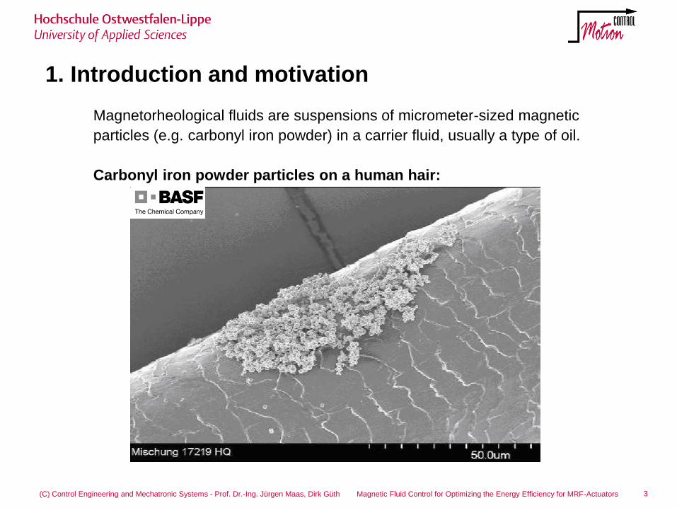
Magnetorheological fluids are suspensions of micrometer-sized magnetic
particles (e.g. carbonyl iron powder) in a carrier fluid, usually a type of oil.
Carbonyl iron powder particles on a human hair:
3 (C) Control Engineering and Mechatronic Systems - Prof. Dr.-Ing. Jürgen Maas, Dirk Güth Magnetic Fluid Control for Optimizing the Energy Efficiency for MRF-Actuators
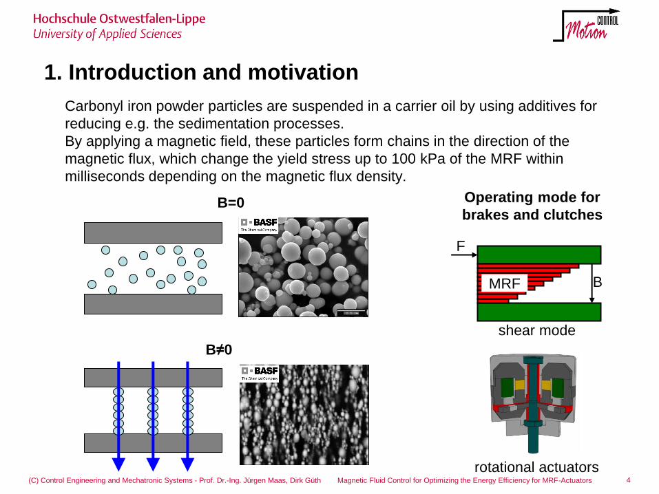
Carbonyl iron powder particles are suspended in a carrier oil by using additives for
reducing e.g. the sedimentation processes.
By applying a magnetic field, these particles form chains in the direction of the
magnetic flux, which change the yield stress up to 100 kPa of the MRF within
milliseconds depending on the magnetic flux density.
1. Introduction and motivation
Operating mode for
brakes and clutches
rotational actuators
shear mode
B
F
MRF
4 (C) Control Engineering and Mechatronic Systems - Prof. Dr.-Ing. Jürgen Maas, Dirk Güth Magnetic Fluid Control for Optimizing the Energy Efficiency for MRF-Actuators
B=0
B≠0
1. Introduction and motivation
5 (C) Control Engineering and Mechatronic Systems - Prof. Dr.-Ing. Jürgen Maas, Dirk Güth Magnetic Fluid Control for Optimizing the Energy Efficiency for MRF-Actuators
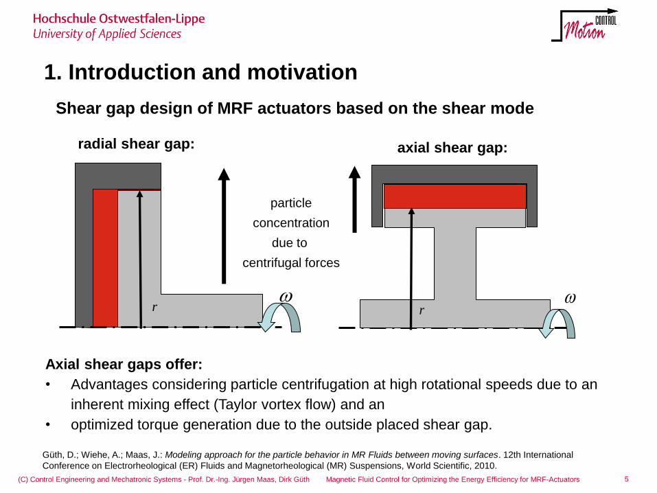
axial shear gap:
particle
concentration
due to
centrifugal forces
radial shear gap:
r r
Axial shear gaps offer:
• Advantages considering particle centrifugation at high rotational speeds due to an
inherent mixing effect (Taylor vortex flow) and an
• optimized torque generation due to the outside placed shear gap.
Shear gap design of MRF actuators based on the shear mode
Güth, D.; Wiehe, A.; Maas, J.: Modeling approach for the particle behavior in MR Fluids between moving surfaces. 12th International
Conference on Electrorheological (ER) Fluids and Magnetorheological (MR) Suspensions, World Scientific, 2010.
1. Introduction and motivation
(C) Control Engineering and Mechatronic Systems - Prof. Dr.-Ing. Jürgen Maas, Dirk Güth Magnetic Fluid Control for Optimizing the Energy Efficiency for MRF-Actuators
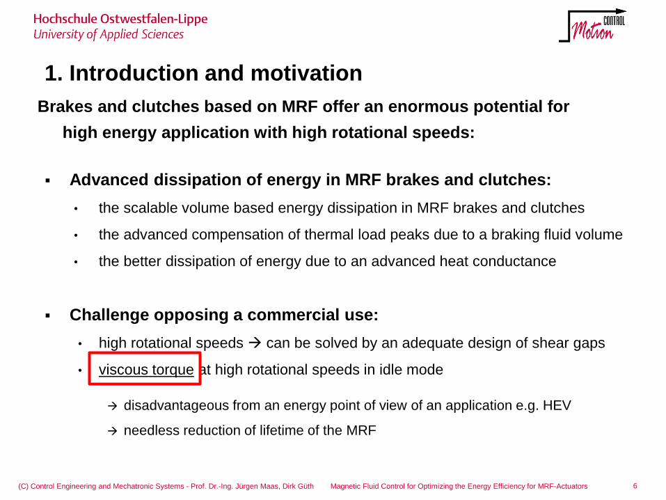
Brakes and clutches based on MRF offer an enormous potential for
high energy application with high rotational speeds:
Advanced dissipation of energy in MRF brakes and clutches:
• the scalable volume based energy dissipation in MRF brakes and clutches
• the advanced compensation of thermal load peaks due to a braking fluid volume
• the better dissipation of energy due to an advanced heat conductance
Challenge opposing a commercial use:
• high rotational speeds can be solved by an adequate design of shear gaps
• viscous torque at high rotational speeds in idle mode
disadvantageous from an energy point of view of an application e.g. HEV
needless reduction of lifetime of the MRF
6
(C) Control Engineering and Mechatronic Systems - Prof. Dr.-Ing. Jürgen Maas, Dirk Güth Magnetic Fluid Control for Optimizing the Energy Efficiency for MRF-Actuators
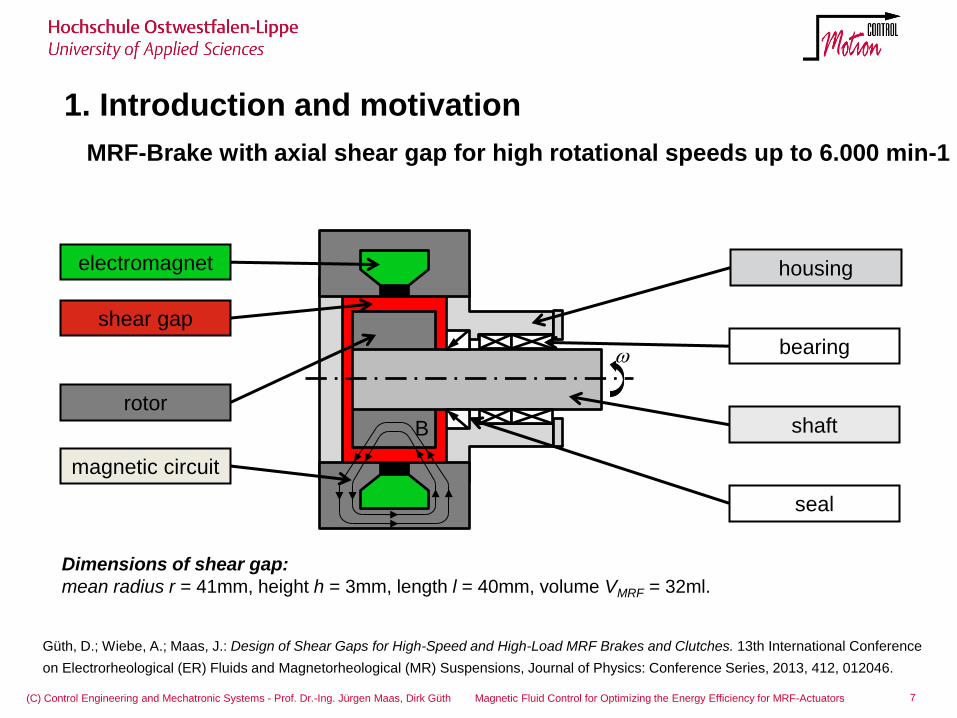
1. Introduction and motivation
MRF-Brake with axial shear gap for high rotational speeds up to 6.000 min-1
B
shear gap
electromagnet
shaft
seal
housing
magnetic circuit
bearing
rotor
Dimensions of shear gap:
mean radius r = 41mm, height h = 3mm, length l = 40mm, volume VMRF = 32ml.
7
Güth, D.; Wiebe, A.; Maas, J.: Design of Shear Gaps for High-Speed and High-Load MRF Brakes and Clutches. 13th International Conference
on Electrorheological (ER) Fluids and Magnetorheological (MR) Suspensions, Journal of Physics: Conference Series, 2013, 412, 012046.
(C) Control Engineering and Mechatronic Systems - Prof. Dr.-Ing. Jürgen Maas, Dirk Güth Magnetic Fluid Control for Optimizing the Energy Efficiency for MRF-Actuators
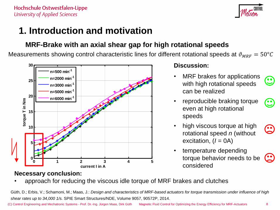
1. Introduction and motivation
MRF-Brake with an axial shear gap for high rotational speeds
0 1 2 3 4 50
5
10
15
20
25
30
current I in A
torq
ue T
in
Nm
n=500 min-1
n=2000 min-1
n=3000 min-1
n=5000 min-1
n=6000 min-1
Measurements showing control characteristic lines for different rotational speeds at 𝜗𝑀𝑅𝐹 = 50°𝐶
Discussion:
• MRF brakes for applications
with high rotational speeds
can be realized
• reproducible braking torque
even at high rotational
speeds
• high viscous torque at high
rotational speed n (without
excitation, (I = 0A)
• temperature depending
torque behavior needs to be
considered
Necessary conclusion:
• approach for reducing the viscous idle torque of MRF brakes and clutches
8
Güth, D.; Erbis, V.; Schamoni, M.; Maas, J.: Design and characteristics of MRF-based actuators for torque transmission under influence of high
shear rates up to 34,000 1/s. SPIE Smart Structures/NDE, Volume 9057, 90572P, 2014.
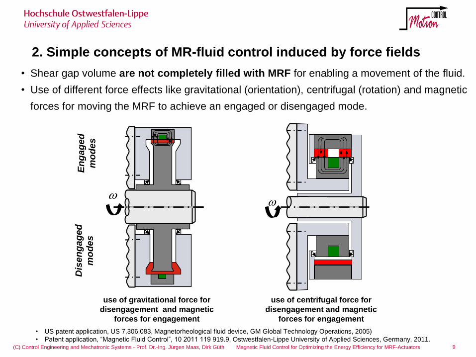
2. Simple concepts of MR-fluid control induced by force fields
9 (C) Control Engineering and Mechatronic Systems - Prof. Dr.-Ing. Jürgen Maas, Dirk Güth Magnetic Fluid Control for Optimizing the Energy Efficiency for MRF-Actuators
• Shear gap volume are not completely filled with MRF for enabling a movement of the fluid.
• Use of different force effects like gravitational (orientation), centrifugal (rotation) and magnetic
forces for moving the MRF to achieve an engaged or disengaged mode.
• US patent application, US 7,306,083, Magnetorheological fluid device, GM Global Technology Operations, 2005)
• Patent application, “Magnetic Fluid Control”, 10 2011 119 919.9, Ostwestfalen-Lippe University of Applied Sciences, Germany, 2011.
use of gravitational force for
disengagement and magnetic
forces for engagement
Dis
en
ga
ge
d
mo
de
s
En
ga
ge
d
mo
de
s
use of centrifugal force for
disengagement and magnetic
forces for engagement
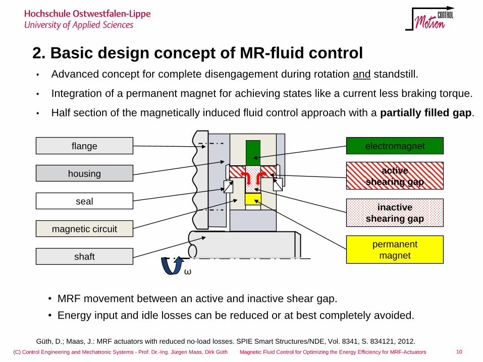
2. Basic design concept of MR-fluid control
10 (C) Control Engineering and Mechatronic Systems - Prof. Dr.-Ing. Jürgen Maas, Dirk Güth Magnetic Fluid Control for Optimizing the Energy Efficiency for MRF-Actuators
• MRF movement between an active and inactive shear gap.
• Energy input and idle losses can be reduced or at best completely avoided.
• Advanced concept for complete disengagement during rotation and standstill.
• Integration of a permanent magnet for achieving states like a current less braking torque.
• Half section of the magnetically induced fluid control approach with a partially filled gap.
ω
permanent
magnet
active
shearing gap
inactive
shearing gap
electromagnet
shaft
flange
seal
magnetic circuit
housing
Güth, D.; Maas, J.: MRF actuators with reduced no-load losses. SPIE Smart Structures/NDE, Vol. 8341, S. 834121, 2012.
2. Basic design concept of MR-fluid control
11 (C) Control Engineering and Mechatronic Systems - Prof. Dr.-Ing. Jürgen Maas, Dirk Güth Magnetic Fluid Control for Optimizing the Energy Efficiency for MRF-Actuators
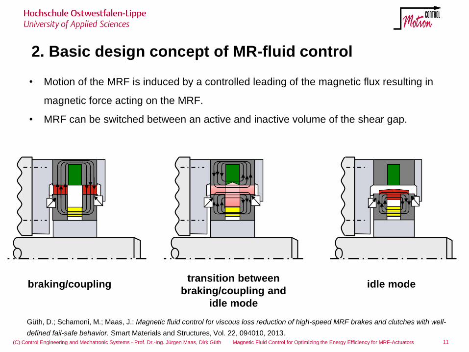
• Motion of the MRF is induced by a controlled leading of the magnetic flux resulting in
magnetic force acting on the MRF.
• MRF can be switched between an active and inactive volume of the shear gap.
b)
transition between
braking/coupling and
idle mode
idle mode braking/coupling
Güth, D.; Schamoni, M.; Maas, J.: Magnetic fluid control for viscous loss reduction of high-speed MRF brakes and clutches with well-
defined fail-safe behavior. Smart Materials and Structures, Vol. 22, 094010, 2013.
(C) Control Engineering and Mechatronic Systems - Prof. Dr.-Ing. Jürgen Maas, Dirk Güth Magnetic Fluid Control for Optimizing the Energy Efficiency for MRF-Actuators
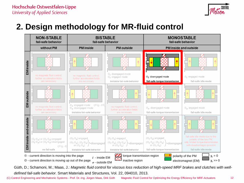
2. Design methodology for MR-fluid control
12
- current direction is moving into the page
- current direction is moving up out of the page
torque transmission region
inactive region i - inside EM
o - outside EM
polarity of the PM
electromagnet (EM)
χr = 0
χr >> 0
•disengaged •disengaged •disengaged •(Fig. 4)
•(Fig. 2/5)
Güth, D.; Schamoni, M.; Maas, J.: Magnetic fluid control for viscous loss reduction of high-speed MRF brakes and clutches with well-
defined fail-safe behavior. Smart Materials and Structures, Vol. 22, 094010, 2013.
3. Concept for MRF-clutch system with fluid control
13 (C) Control Engineering and Mechatronic Systems - Prof. Dr.-Ing. Jürgen Maas, Dirk Güth Magnetic Fluid Control for Optimizing the Energy Efficiency for MRF-Actuators
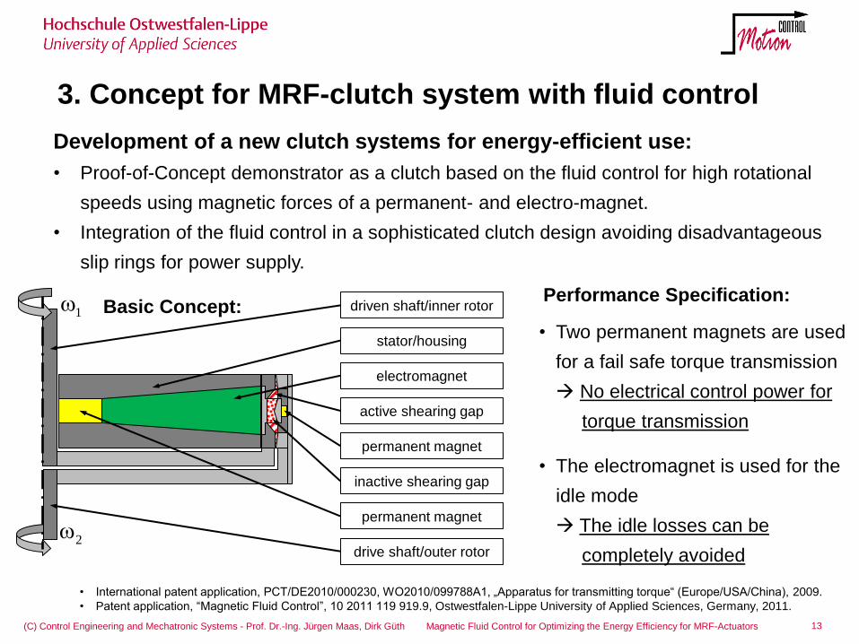
Development of a new clutch systems for energy-efficient use:
• Proof-of-Concept demonstrator as a clutch based on the fluid control for high rotational
speeds using magnetic forces of a permanent- and electro-magnet.
• Integration of the fluid control in a sophisticated clutch design avoiding disadvantageous
slip rings for power supply.
active shearing gap
inactive shearing gap
stator/housing
electromagnet
permanent magnet
driven shaft/inner rotor
drive shaft/outer rotor
• Two permanent magnets are used
for a fail safe torque transmission
No electrical control power for
torque transmission
• The electromagnet is used for the
idle mode
The idle losses can be
completely avoided
Basic Concept: Performance Specification:
1
2
• International patent application, PCT/DE2010/000230, WO2010/099788A1, „Apparatus for transmitting torque“ (Europe/USA/China), 2009.
• Patent application, “Magnetic Fluid Control”, 10 2011 119 919.9, Ostwestfalen-Lippe University of Applied Sciences, Germany, 2011.
permanent magnet
3. Concept for MRF-clutch system with fluid control
14 (C) Control Engineering and Mechatronic Systems - Prof. Dr.-Ing. Jürgen Maas, Dirk Güth Magnetic Fluid Control for Optimizing the Energy Efficiency for MRF-Actuators
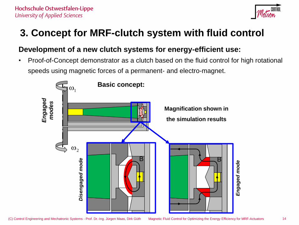
Magnification shown in
the simulation results
2
1Basic concept:
B B
Dis
en
ga
ge
d m
od
e
En
ga
ge
d
mo
de
s
En
gag
ed
mo
de
Development of a new clutch systems for energy-efficient use:
• Proof-of-Concept demonstrator as a clutch based on the fluid control for high rotational
speeds using magnetic forces of a permanent- and electro-magnet.
3. Modeling of the magnetic field and the fluid movement
15 (C) Control Engineering and Mechatronic Systems - Prof. Dr.-Ing. Jürgen Maas, Dirk Güth Magnetic Fluid Control for Optimizing the Energy Efficiency for MRF-Actuators
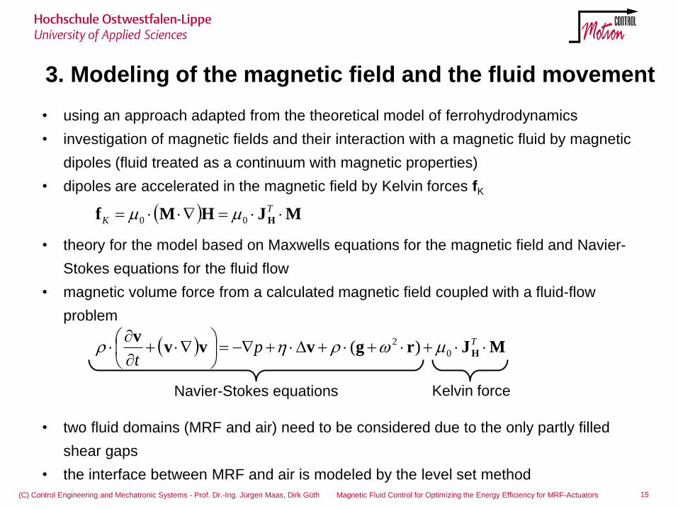
• using an approach adapted from the theoretical model of ferrohydrodynamics
• investigation of magnetic fields and their interaction with a magnetic fluid by magnetic
dipoles (fluid treated as a continuum with magnetic properties)
• dipoles are accelerated in the magnetic field by Kelvin forces fK
• theory for the model based on Maxwells equations for the magnetic field and Navier-
Stokes equations for the fluid flow
• magnetic volume force from a calculated magnetic field coupled with a fluid-flow
problem
• two fluid domains (MRF and air) need to be considered due to the only partly filled
shear gaps
• the interface between MRF and air is modeled by the level set method
MJrgvvvv
H
Tp
t0
2 )(
MJHMf H T
K 00
Navier-Stokes equations Kelvin force
16 (C) Control Engineering and Mechatronic Systems - Prof. Dr.-Ing. Jürgen Maas, Dirk Güth Magnetic Fluid Control for Optimizing the Energy Efficiency for MRF-Actuators
3. Simulation of MRF-clutch system with fluid control
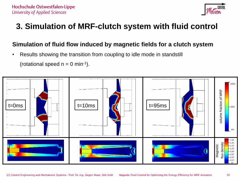
Simulation of fluid flow induced by magnetic fields for a clutch system
• Results showing the transition from coupling to idle mode in standstill
(rotational speed n = 0 min-1).
1.6T
0.4T
0T
0.6T
0.8T
1.0T
1.4T
0.2T
1.2T
100%
50%
0%
volu
me f
raction
of M
RF
M
agnetic
flux d
ensity
t=0ms t=10ms t=95ms
3. Realization of MRF-Clutch System with Fluid Control
17 (C) Control Engineering and Mechatronic Systems - Prof. Dr.-Ing. Jürgen Maas, Dirk Güth Magnetic Fluid Control for Optimizing the Energy Efficiency for MRF-Actuators
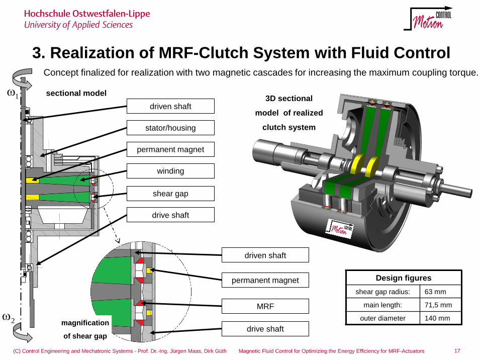
Design figures
shear gap radius: 63 mm
main length: 71,5 mm
outer diameter 140 mm
driven shaft
stator/housing
winding
shear gap
drive shaft
permanent magnet
driven shaft
permanent magnet
MRF
drive shaft
3D sectional
model of realized
clutch system
sectional model
magnification
of shear gap
2
1
Concept finalized for realization with two magnetic cascades for increasing the maximum coupling torque.
-50 -40 -30 -20 -10 0 10 20 30 40 50
0
2
4
6
8
torq
ue
T in
Nm
n=500min-1
-50 -40 -30 -20 -10 0 10 20 30 40 50-6
-4
-2
0
2
time t in ms
cu
rre
nt
I in
A
desired current
measured current
-5 -4 -3 -2 -1 00
1
2
3
4
5
6
7
8
current i in A
torq
ue
T in
Nm
n=3000min-1
n=2000min-1
n=1000min-1
n=500min-1
n=250min-1
n=100min-1
3. Measurements of MRF-clutch system with fluid control
18 (C) Control Engineering and Mechatronic Systems - Prof. Dr.-Ing. Jürgen Maas, Dirk Güth Magnetic Fluid Control for Optimizing the Energy Efficiency for MRF-Actuators
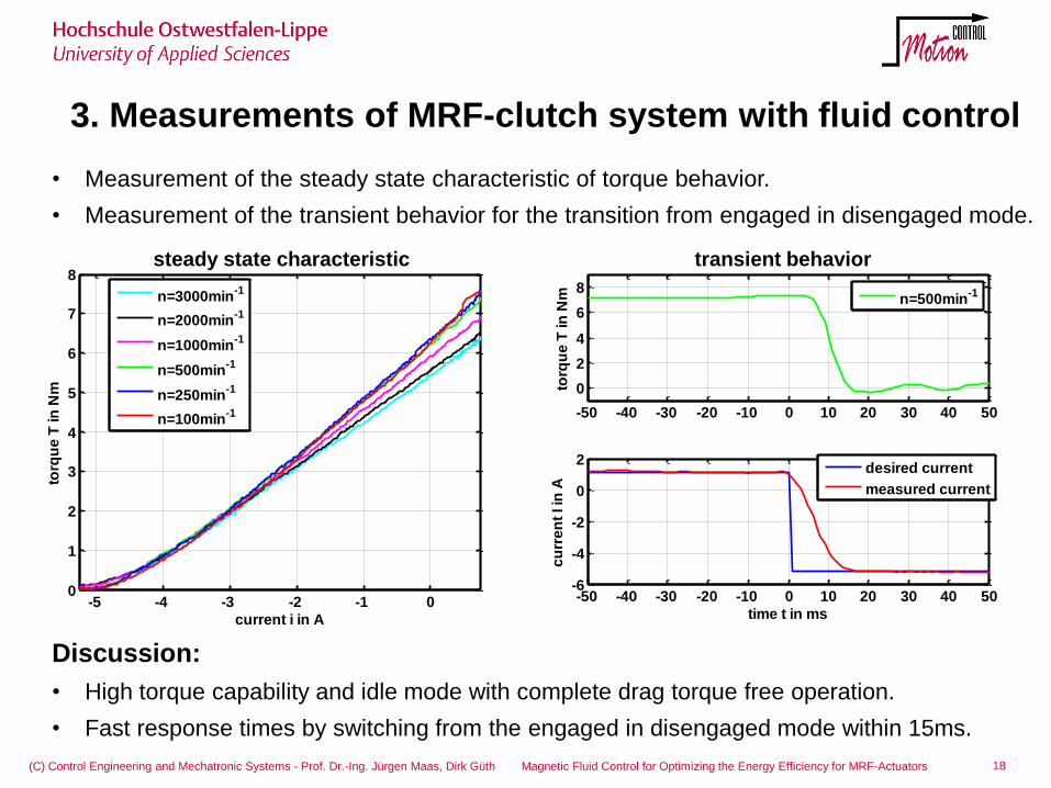
• Measurement of the steady state characteristic of torque behavior.
• Measurement of the transient behavior for the transition from engaged in disengaged mode.
Discussion:
• High torque capability and idle mode with complete drag torque free operation.
• Fast response times by switching from the engaged in disengaged mode within 15ms.
transient behavior steady state characteristic
P
E
HIL test rig
electrical
drive
MRF clutch axle / street
3. Measurements of MRF-clutch system with fluid control
19 (C) Control Engineering and Mechatronic Systems - Prof. Dr.-Ing. Jürgen Maas, Dirk Güth Magnetic Fluid Control for Optimizing the Energy Efficiency for MRF-Actuators
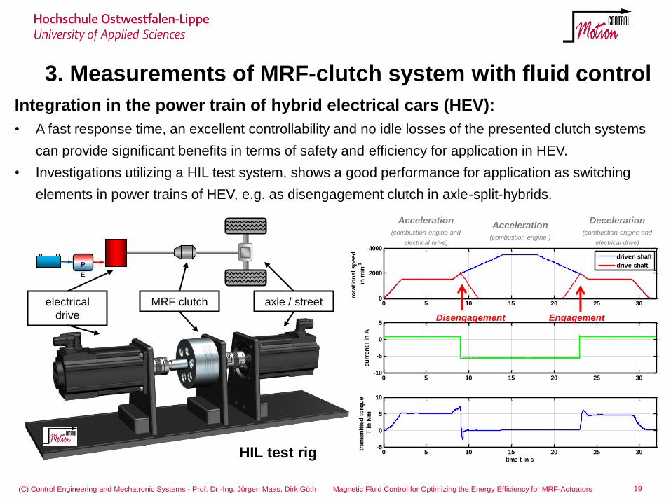
Integration in the power train of hybrid electrical cars (HEV):
• A fast response time, an excellent controllability and no idle losses of the presented clutch systems
can provide significant benefits in terms of safety and efficiency for application in HEV.
• Investigations utilizing a HIL test system, shows a good performance for application as switching
elements in power trains of HEV, e.g. as disengagement clutch in axle-split-hybrids.
0 5 10 15 20 25 300
2000
4000
rota
tio
nal sp
eed
in m
in-1
driven shaft
drive shaft
0 5 10 15 20 25 30-10
-5
0
5
cu
rren
t I in
A
0 5 10 15 20 25 30-5
0
5
10
time t in s
tran
sm
itte
d t
orq
ue
T in
Nm
Acceleration
(combustion engine and
electrical drive)
Acceleration
(combustion engine )
Deceleration
(combustion engine and
electrical drive)
Disengagement Engagement
3. Measurements of MRF-clutch system with fluid control
20 (C) Control Engineering and Mechatronic Systems - Prof. Dr.-Ing. Jürgen Maas, Dirk Güth Magnetic Fluid Control for Optimizing the Energy Efficiency for MRF-Actuators
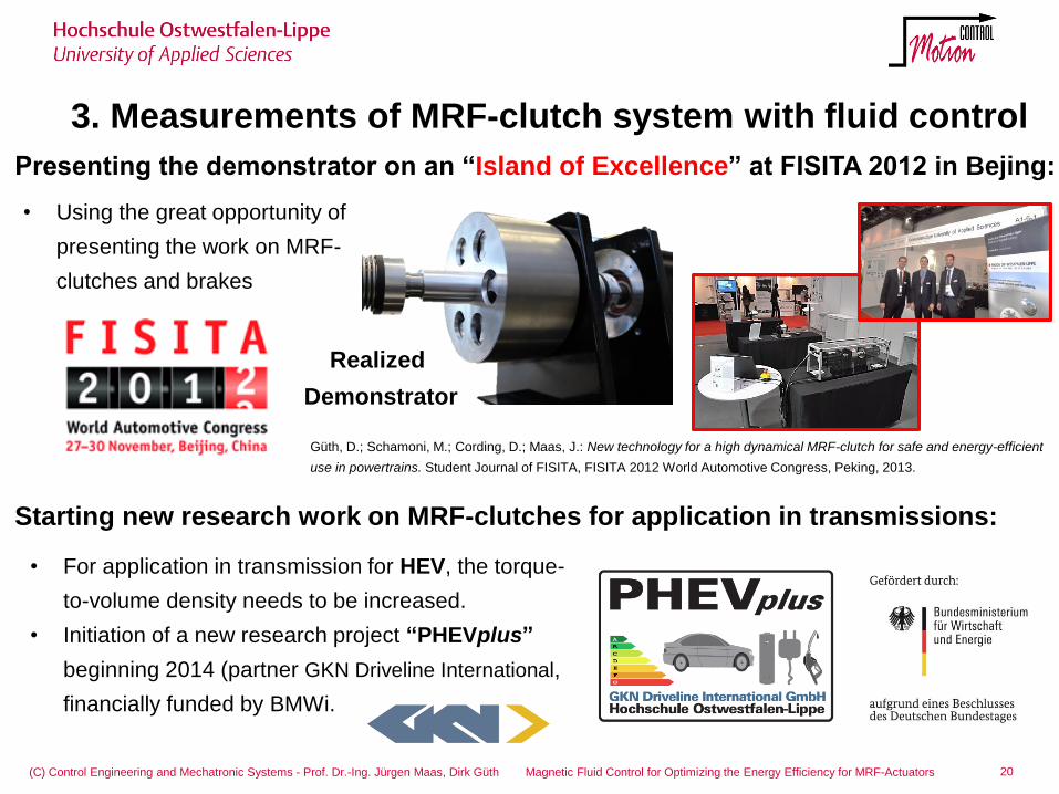
Presenting the demonstrator on an “Island of Excellence” at FISITA 2012 in Bejing:
Starting new research work on MRF-clutches for application in transmissions:
• For application in transmission for HEV, the torque-
to-volume density needs to be increased.
• Initiation of a new research project “PHEVplus”
beginning 2014 (partner GKN Driveline International,
financially funded by BMWi.
• Using the great opportunity of
presenting the work on MRF-
clutches and brakes
Realized
Demonstrator
Güth, D.; Schamoni, M.; Cording, D.; Maas, J.: New technology for a high dynamical MRF-clutch for safe and energy-efficient
use in powertrains. Student Journal of FISITA, FISITA 2012 World Automotive Congress, Peking, 2013.
21 (C) Control Engineering and Mechatronic Systems - Prof. Dr.-Ing. Jürgen Maas, Dirk Güth Magnetic Fluid Control for Optimizing the Energy Efficiency for MRF-Actuators
5. Conclusion
• Necessity of reducing the viscous losses of MRF actuators was shown by
measurements of an actuator with maximum rotational speeds.
• Idea of moving MRF within the shear gap for reducing the viscous drag losses in
the disengaged mode was introduced. • Approach for a novel actuator design was presented.
• The functionality of the basic concepts is proven by measurement with a first
design.
• Development, modeling and simulation of an enhanced clutch design were shown
and a realized proof-of-concept clutch actuator was introduced. • Measurements with the proof-of-concept clutch actuator were performed that show
the feasibility and the high potential of MRF clutches without idle losses e.g. for the
use in drive trains of vehicles. • Improved concepts with higher torque exploitation are introduced.
• Considering the application in hybrid electrical cars (e.g. axle-split-parallel-hybrids), a fast response time, an excellent controllability and no idle losses of the
presented clutch systems provide significant benefits in terms of safety and efficiency.
Thanks for your attention!
Prof. Dr. Jürgen Maas
Ostwestfalen-Lippe University of Applied Sciences
Department of Electrical Engineering and Computer Science
Control Engineering and Mechatronic Systems
Phone: +49 (0)5261 702-192
Dirk Güth M.Sc
Phone: +49 (0)5261 702-489
Research project PHEVplus, funded by the Federal
Ministry for Economic Affairs and Energy (BMWi) of
Germany under grant number 01MY13004B.
Recommended