Embed Size (px)
Citation preview
1
D Montageanleitung
Das "WT 2"-Modul (Wireless Transmitter 2) ist ein Audio-Sender welcher je nach Stellung des Drehschalters "Speaker Install"1-4 Audio-Signale zu aktiven Lautsprechern überträgt und diese über einen bidirektionalen Datenfunk steuert. Die Installation beiTV-Geräten mit I2C-Bus-Verbindung ist über das OSD-Menü (easy Dialog) durchzuführen.Auslieferungsstand "WT 2"-Modul: Wahlschalter E in Stellung 2 = 2 Aktive Lautsprecher. Gegebenenfalls auf die zu installierendeAnzahl der Aktiv-Lautsprecher stellen. Bei TV-Geräten mit I2C-Bus-Anbindung hat der Wahlschalter E keine Funktion!Das "WT 2"-Modul steht immer unter Spannung und darf im Bedarfsfall nur vom Netz getrennt werden wenn die Aktiv-Lautsprecherzuvor ausgeschaltet werden oder im Standby-Betrieb sind.
Achtung: Der Einbau ist ausschließlich von ausgebildeten Service-Technikern des Fachhandels (Elektrofachkraft) durch-zuführen unter Beachtung der Vorschriften gemäß GRUNDIG Service Manual "Sicherheit" (Materialnummer720108000000)!
ESD-Vorschriften beachten
Inhaltsverzeichnis:Seite
1. Bedienelemente "WT 2" ..............................................................................................................................................................12. "WT 2"-Montage in LENARO 82 MFW 82-6210/9 Dolby, 82 MFW 82-6210/9 IDTV, 82 MFW 82-6211/9 DVD und
92 MFW 92-6110/9 DVD .............................................................................................................................................................23. "WT 2"-Montage in Fine Arts Vision MFW 82-710/9 DVD und MFW 82-720/9 DVD ..................................................................44. "WT 2"-Montage in Fine Arts Vision MFW 82-725/9 DVD und MFW 82-730/9 DVD ..................................................................75. "WT 2"-Montage in PlanaVision ..................................................................................................................................................96. Installationshinweise zum Anschluss an geregelten Audioquellen (z.B. HiFi-Anlage) ..............................................................10
"WT 2" Bestellnummer GAG8900bestehend aus:• "WT 2" 928016191900 • Antennenkabel 292104450103• Montageclip 296338270100 • 2 Stereo-Cinch-Kabel 292104353201
– 2 Schrauben (für PlanaVision) 811699532300 • I2C-Bus-Kabel 292106061201– 2 Schrauben (für Lenaro) 811699876100 • 1 Kabelbinder lösbar/rot 829099021000
• Netzkabel (für Anschluss an • 2 Kabelbinder weißdie Netzschalterplatte) 292104356301 (für Clip an Fine Arts Vision Rückwand) 829099055800
• Netzkabel (mit Euro-Stecker) 829099131600 • 12 Kabelhalter (selbstklebend) 296380330102• Antennenmodul (für Fine Arts Vision) 296384160204 • Bedienungsanleitung 280179422000
– 1 Schraube 811699907000• Antennenplatte (für Lenaro) 293051308100
– 2 Schrauben 811699844000
1. Bedienelemente "WT 2"
A B C D E
F G H I J
A Stereo-Eingangsbuchsen A / B
B Installations-/ Reset-Taster
C Antennen-Buchse
D I2C-Bus-Buchse für Datenaustausch (z.B. Lenaro…)
E Wahlschalter:– Lautsprecher (1…4)– für Selektion des Übertragungskanals
F Netzbuchse
G "INSTALL"-Leuchtdiode (rot/grün/orange)
H "ERROR"-Leuchtdiode (rot)
I "MUTE"-Leuchtdiode (rot)
J "On/Standby"-Leuchtdiode (rot)
2
Fig. 3
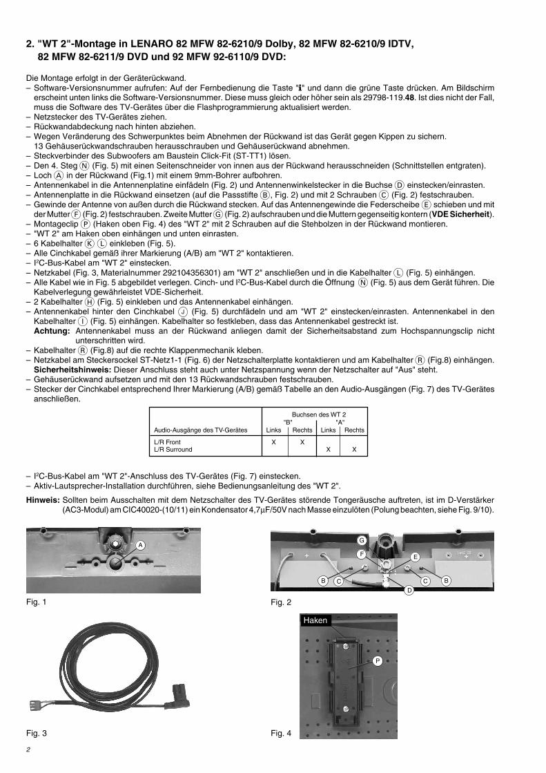
2. "WT 2"-Montage in LENARO 82 MFW 82-6210/9 Dolby, 82 MFW 82-6210/9 IDTV,82 MFW 82-6211/9 DVD und 92 MFW 92-6110/9 DVD:
Die Montage erfolgt in der Geräterückwand.– Software-Versionsnummer aufrufen: Auf der Fernbedienung die Taste "" und dann die grüne Taste drücken. Am Bildschirm
erscheint unten links die Software-Versionsnummer. Diese muss gleich oder höher sein als 29798-119.48. Ist dies nicht der Fall,muss die Software des TV-Gerätes über die Flashprogrammierung aktualisiert werden.
– Netzstecker des TV-Gerätes ziehen.– Rückwandabdeckung nach hinten abziehen.– Wegen Veränderung des Schwerpunktes beim Abnehmen der Rückwand ist das Gerät gegen Kippen zu sichern.
13 Gehäuserückwandschrauben herausschrauben und Gehäuserückwand abnehmen.– Steckverbinder des Subwoofers am Baustein Click-Fit (ST-TT1) lösen.– Den 4. Steg N (Fig. 5) mit einen Seitenschneider von innen aus der Rückwand herausschneiden (Schnittstellen entgraten).– Loch A in der Rückwand (Fig.1) mit einem 9mm-Bohrer aufbohren.– Antennenkabel in die Antennenplatine einfädeln (Fig. 2) und Antennenwinkelstecker in die Buchse D einstecken/einrasten.– Antennenplatte in die Rückwand einsetzen (auf die Passstifte B, Fig. 2) und mit 2 Schrauben C (Fig. 2) festschrauben.– Gewinde der Antenne von außen durch die Rückwand stecken. Auf das Antennengewinde die Federscheibe E schieben und mit
der Mutter F (Fig. 2) festschrauben. Zweite Mutter G (Fig. 2) aufschrauben und die Muttern gegenseitig kontern (VDE Sicherheit).– Montageclip P (Haken oben Fig. 4) des "WT 2" mit 2 Schrauben auf die Stehbolzen in der Rückwand montieren.– "WT 2" am Haken oben einhängen und unten einrasten.– 6 Kabelhalter K L einkleben (Fig. 5).– Alle Cinchkabel gemäß ihrer Markierung (A/B) am "WT 2" kontaktieren.– I2C-Bus-Kabel am "WT 2" einstecken.– Netzkabel (Fig. 3, Materialnummer 292104356301) am "WT 2" anschließen und in die Kabelhalter L (Fig. 5) einhängen.– Alle Kabel wie in Fig. 5 abgebildet verlegen. Cinch- und I2C-Bus-Kabel durch die Öffnung N (Fig. 5) aus dem Gerät führen. Die
Kabelverlegung gewährleistet VDE-Sicherheit.– 2 Kabelhalter H (Fig. 5) einkleben und das Antennenkabel einhängen.– Antennenkabel hinter den Cinchkabel J (Fig. 5) durchfädeln und am "WT 2" einstecken/einrasten. Antennenkabel in den
Kabelhalter I (Fig. 5) einhängen. Kabelhalter so festkleben, dass das Antennenkabel gestreckt ist.Achtung: Antennenkabel muss an der Rückwand anliegen damit der Sicherheitsabstand zum Hochspannungsclip nicht
unterschritten wird.– Kabelhalter R (Fig.8) auf die rechte Klappenmechanik kleben.– Netzkabel am Steckersockel ST-Netz1-1 (Fig. 6) der Netzschalterplatte kontaktieren und am Kabelhalter R (Fig.8) einhängen.
Sicherheitshinweis: Dieser Anschluss steht auch unter Netzspannung wenn der Netzschalter auf "Aus" steht.– Gehäuserückwand aufsetzen und mit den 13 Rückwandschrauben festschrauben.– Stecker der Cinchkabel entsprechend Ihrer Markierung (A/B) gemäß Tabelle an den Audio-Ausgängen (Fig. 7) des TV-Gerätes
anschließen.
– I2C-Bus-Kabel am "WT 2"-Anschluss des TV-Gerätes (Fig. 7) einstecken.– Aktiv-Lautsprecher-Installation durchführen, siehe Bedienungsanleitung des "WT 2".
Hinweis: Sollten beim Ausschalten mit dem Netzschalter des TV-Gerätes störende Tongeräusche auftreten, ist im D-Verstärker(AC3-Modul) am CIC40020-(10/11) ein Kondensator 4,7µF/50V nach Masse einzulöten (Polung beachten, siehe Fig. 9/10).
Fig. 1 Fig. 2
B C
D
EF
BC
GA
Fig. 4
P
Buchsen des WT 2"B" "A"
Audio-Ausgänge des TV-Gerätes Links Rechts Links Rechts
L/R Front X XL/R Surround X X
Haken

3
Fig. 6
Fig. 7
Fig. 5
ST-NETZ1-1
Fig. 8
R
100
CR40030
+
22u/50V
C40028
2,2k
CR40027
2,2k
R40021
2,2k
CR40022
+
22u/50V
C40023
4,7k
CR
4002
9
1
2
3
4
5
6 7 8
9
10
11
12
13
14
15
16
HEF4053CIC40020
7
8
6
100
CR40025 100
L414
8
4045
2
12
CR4
12
CR4
100
CR
4045
2
2,2k
R40026
2,2M
CR
4045
1
+G/1
-G/1
+F
A
A
A
AA
A
D-VERSTAERKER 29504-204.16
AMPL. BFBF AMPL.AMPL. BFAF AMPLIFIER
+
4,7u/50VA
N
J
H
WT 2I
Zu ST-NETZ1-1
CC
40375
CC40366CC40376
CC
40336
CC40326
CC
40356
CC
40346
CC40046
CC40036
CC40032 CC4
CC
400
CC40064
CC
40063C
C
CC40041
CC
40062
CC40048
CC40037
CC
40047
CC
40188C
C40186
CC40
CC
40189
CC
CC40156
CC
C
CC
40164
CC
C
CC40198
CC
40035
CC
40155C
C40195
CT40465
CT40360
CT40320
CT40335
CT40330CT40325
CT40355
CT40350
CT40340
CT40345
1
CIC
40020
CB
R303
CBR307
CB
R308
CBR309
CBR310
CBR311
CBR313
CC
40184
CC40191
CB
R317
CB
R319
CB
R322
CBR324
CR40027
CR
40022
CR40363
CR40362
CR
40367 CR40361
CR40364
CR40366
CR40372
CR40374
CR
40324C
R40321
CR40354
CR40353
CR40352
CR40334
CR40326CR40322
CR40323
CR40336
CR40333
CR40332
CR40357
CR40337
CR
40331
CR40351
CR40327
CR40356
CR40346
CR40344
CR40341
CR
40347
CR40342
CR
40343
CR40046C
CR
40033
CR400
C
CR
40038 CR
CR
4C
R40061
CR40062CR40048
CR
40047
CR400
CR40077CR40032
CR40192
CR
40184CR40183CR40191
CR
40197
CR
40174
CR
40156
CR
40182
CR
40169
CR
40153
CR
C
CR
40164
CR40201
CR
40065
CR
40045
CR
40029
CC4003
CC
40364
CC40374
CC40354
CC
40344
CC
40324
CC40334
100
110
120
130
140
150
160
170
180
Fig. 9 Fig. 10
+
4,7µ50V
L
KL
K N
ÖffnungÖffnung
Öffnung
Öffnung
4
3. "WT 2"-Montage in Fine Arts Vision MFW 82-710/9 DVD und MFW 82-720/9 DVD:
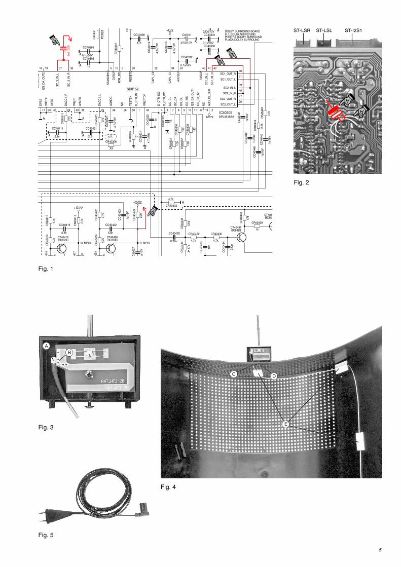
Mögliche Varianten:EPROM-Versionsnr. 29798-102.06: Nur kabellose Rear-Übertragung (Mono) möglich.
Ab EPROM-Versionsnr. 29798-102.07: Kabellose Rear-Übertragung (Mono) möglich.Zusätzlich kabellose Front-Übertragung möglich, wenn:– das Dolby-NF-Modul 295042041300 eingebaut ist,– oder das Dolby-NF-Modul 295042040300 eingebaut ist und die Drahtbrücken von Pin 41auf Pin 39 und von Pin 42 auf Pin 40 am IC40305 eingelötet sind (Fig. 1/2).
Ab EPROM-Versionsnr. 29798-102.10: Kabellose Rear-Übertragung (Mono) möglich.Zusätzlich kabellose Front-Übertragung möglich, wenn:– das Dolby-NF-Modul 295042041300 eingebaut ist,– oder das Dolby-NF-Modul 295042040300 eingebaut ist und die Drahtbrücken von Pin 41auf Pin 39 und von Pin 42 auf Pin 40 am IC40305 eingelötet sind.Der interne linke und rechte Lautsprecher des TV-Gerätes ist im DPL-Mode als Center-lautsprecher hinzugeschaltet (höhere Centerlautstärke), wenn ein 2,2µF/25V-Elko zwi-schen den Pins 37/38 am IC40305 und dem Emitter von CT40420 eingebaut wurde(Fig. 1/2).Hinweis: Beim Betrieb des Fine Arts Audion muss das TV-Gerät stumm bzw. ausgeschal-
tet sein.
EPROM-Versionsnummer aufrufen:Mit der Fernbedienung folgendes ausführen.– Mit der Taste "" das Menü "DIALOG CENTER" –> OK aufrufen.– Taste "AUX" drücken. Oben links am Bildschirm wird die EPROM-Versionsnummer angezeigt.
Zum Prüfen bzw. Umrüsten muss das TV-Gerät geöffnet werden.– Netzstecker des TV-Gerätes ziehen.– Rückwandabdeckung nach hinten abziehen.– Rückwand demontieren.
Achtung: Wegen des hohen Gewichtes der Rückwand darf diese nur nach oben abgenommen werden um Beschädigungen derBildrohrplatte und des Bildrohrs zu vermeiden. Beim Herausschrauben der 6 Rückwandschrauben die Rückwand festhalten undvorsichtig nach oben abnehmen bis die Masseverbindung und die Subwoofer-Leitung gelöst werden kann.
– Das Dolby-NF-Modul 29504-204.13 im Händler-Menü einstellen (siehe Service Manual 720100249200).
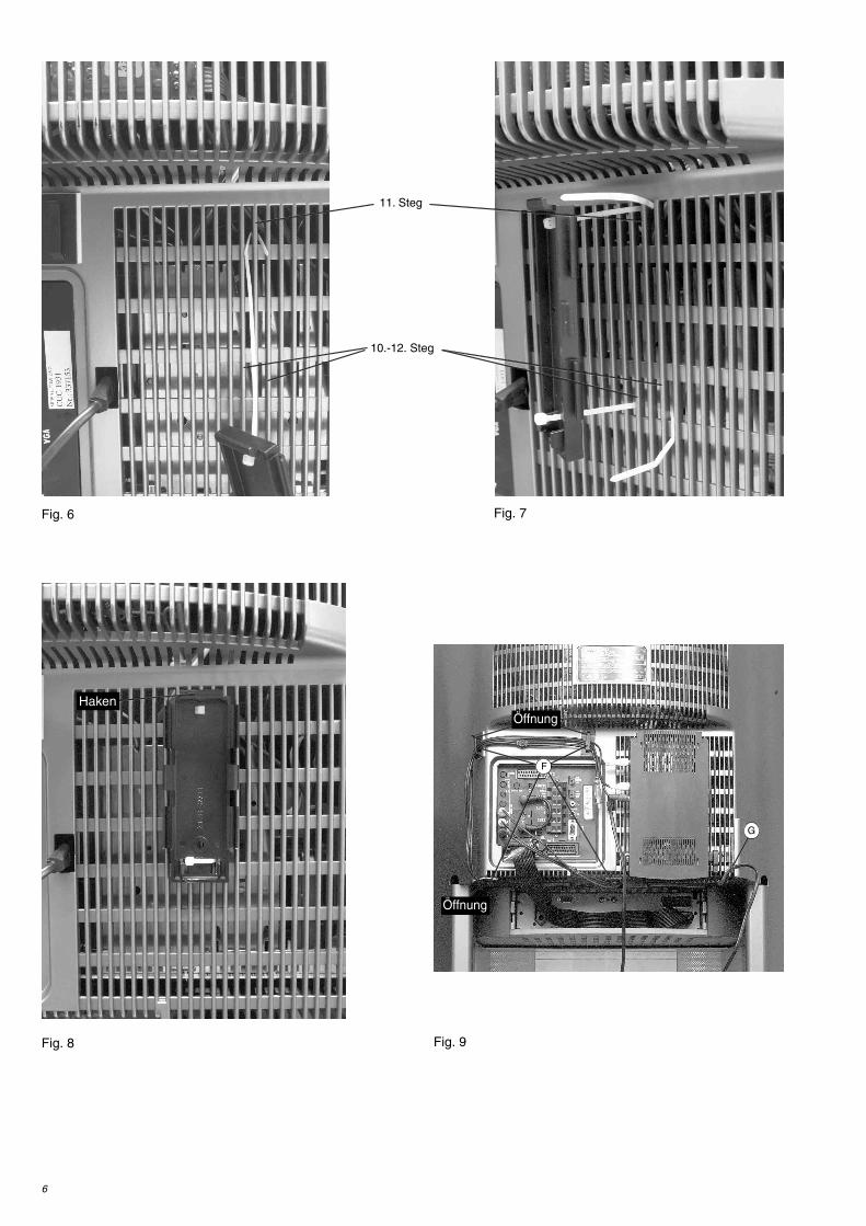
MontageDie Montage des "WT2" erfolgt an der Geräterückwand.– Antennenwinkelstecker A (Fig. 3) in die Buchse der Antennenplatte B (Fig. 3) einstecken/einrasten.– Antennenkabel durch die Rückwandabdeckung ziehen (1. Reihe / 20. Loch von links C Fig. 4).– Antenne komplett mit den Pass-Stiften in die Rückwandabdeckung stecken (Fig. 4) und mit der Schraube D (Fig. 4) festschrauben.– Antennenkabel mit 3 Klebestreifen (handelsüblich) E (Fig. 4) fixieren.– Montageclip mit weißen Kabelbindern befestigen ohne die Rückwand zu demontieren:
– Weißen Kabelbinder durch das obere Loch des Montageclips stecken (Fig. 6).– Kabelbinder (ca. 1 cm von der Spitze) umknicken,– Kabelbinder um den 11.Steg von links (Fig. 6) herumschlaufen und anziehen (Fig. 7).– Zweiten weißen Kabelbinder durch das untere linke rechteckige Loch des Montageclip stecken.– Kabelbinder in Abstand der Stege 10-12 von links rechteckig abknicken und um diese Stege 10-12 herumschlaufen (Fig. 7).– Unteren Kabelbinder durch das rechte rechteckige Loch des Montageclip stecken.– Oberen Kabelbinder durch das obere Loch des Montageclip ziehen und den Kabelbinder schließen.– Montageclip wie in Fig. 8 gezeigt positionieren, beide Kabelbinder schließen und festziehen (überstehende Enden kurz
abschneiden).– 4 Kabelhalter F einkleben (Fig. 9).– "WT 2" am Haken (Fig. 8) oben einhängen und unten einrasten.– Cinchkabel entsprechend der Tabelle und ihrer Markierung (A/B) am "WT 2" kontaktieren. Die entsprechende Schalterstellung
"CH-SELECT" wählen.
– Stecker der Cinchkabel entsprechend Ihrer Markierung (A/B) an den Audio-Ausgängen des TV-Gerätes anschließen.– Leitungen in die Kabelhalter F (Fig. 9) einhängen.– Netzkabel mit EURO-Stecker (Fig. 5, Materialnummer 829099131600) am "WT 2" kontaktieren und an eine externe Steckdose
anschließen (nicht an die TV-Gerätesteckdose, da diese mit dem TV-Netzschalter abgeschaltet wird). Mit einem Kabelbinder dasNetzkabel an der Rückwand G (Fig. 9) fixieren.
– Antennenkabel am "WT 2" einstecken/einrasten.– Cinch-Ausgänge des TV-Gerätes für die "WT 2"-Übertragung konfigurieren, siehe Bedienungsanleitung des "WT 2".– Aktiv-Lautsprecher-Installation durchführen, siehe Bedienungsanleitung des "WT 2".– Rückwandabdeckung montieren.
Buchsen "B" Buchsen "A" Schalterstellung Beispiele fürAktiv-Lautsprecher-Anzahl Links Rechts Links Rechts CH-SELECT Aktiv-Lautsprecher-Variationen
1 X 1 Mono RearSurround (2) X 2 2 Mono Rear
2 X X 2 2 Stereo Front oder 2 Rear3 X X X 3 2 Stereo Front und Mono Rear4 X X X 4 2 Stereo Front und 2 Mono Rear
5
*
CR
4031
2
n.V. 0
CR
4030
5
u/16
V
C40
427
6V0417
220u/10V
1n
CC403020,1u/50V
CC40301
270
CR
4041
1
270
CR
4042
1
CR
4044
1
4,7u
/10V
CC
4033
1
1n
CC
4033
2
1n
CC
4033
3
4,7u
/10V
CC
4031
4
1u/1
6V
CC
4042
3
4,7k
CR40333
4,7k
CR4043633
0p
CC
4043
4
1k
CR40439
BC848BCT40431
47k
CR
4043
8
100
CR
4033
6
47n
CC40308
2
CR
2
4,7k
CR404326,8n
CC40413
0p0414
180
CR
4033
7
1n
CC40306
BC858CT4044
47k
CR
4043
4
1u/1
6V
CC
4034
1
0,1u/50V
CC40312
1u/1
6V
CC
4034
2
+
470u/10V
C40311
4,7u
/10V
CC
4032
7
0,1u/50V
CC40304
PE
RLE
L403
02
2,2k
CR
4042
3
2,2k
CR
4041
3
XX
CR40306
120k
CR
4043
3
10n
CC
4043
3
100
CR
4033
4
MP70
4,7k
CR
4041
2
0,22u
CC40432
180
CR
4033
8
BC858CCT40410
4,7k
CR
4041
4
6,8n
CC40422
0p0424
4,7k
CR
4042
4
BC858CCT40420
4,7k
CR
4042
2
2,2n
CC40411
2,2n
CC40421
4,7u
/10V
CC
4031
3
1u/1
6V
CC
4044
6
1u/1
6V
CC
4044
92,
2k
CR
4044
6
MP60
2,2k
CR
4044
9
MP61
I2S
_DA
_OU
T2
CA
PL_
C2
CA
PL_
C1
NC
I2S
_DA
_OU
T1
D_C
TR_I
O1
D_C
TR_I
O0
D_C
TR_I
N
NC
DA
CC
1_L
DA
CC
1_R
SC2_OUT_L
SC2_OUT_R
SC2_IN_R
SC2_IN_L
SC1_OUT_L
SC1_OUT_R
SC
1_IN
_R
SC
1_IN
_L
VR
EF2
DV
SS
AV
SS
VR
EF1
AH
VS
S
AG
ND
C
TES
TEN
VR
EFT
OP
AU
D_C
L_O
UT
I2S
_DA
_IN
1
I2S
_WS
I2S
_CL
I2C
_DA
I2C
_CL
AV
SU
P
AH
VS
UP
AD
R_S
EL
DV
SU
P
STA
ND
BY
Q
SC
_3_I
N_R
SC
_3_I
N_L
RE
SE
TQ
I2S
_DA
_IN
2
50
46
27
28
29
30
31
32 3334
35 36
37 38
39
40
41 42
4345
56
7 8 9 10 11 12 13
16
17
18 19 20
23 24 25 26 341 2IC40305DPL3519A2
+Q/22
+Q/22
+Q/2
A
A
A
A
A
A
A
A
A
A
A
A
AAA
AA
A
A
A
A
SDIP 52
PLACA DOLBY SURROUNDPIASTRA DOLBY SURROUNDC. I. DOLBY SURROUNDDOLBY SURROUND BOARD
+
2u2
/ 25V
Fig. 1
A
B
C D
EFig. 3
Fig. 4
Fig. 5
Fig. 2
ST-LSR ST-LSL ST-I2S1
6
Fig. 8 Fig. 9
Fig. 6 Fig. 7
11. Steg
10.-12. Steg
F
G
Öffnung
Öffnung
Haken
7
A
B
C D
E
4. "WT 2"-Montage in Fine Arts Vision MFW 82-725/9 DVD und MFW 82-730/9 DVD:
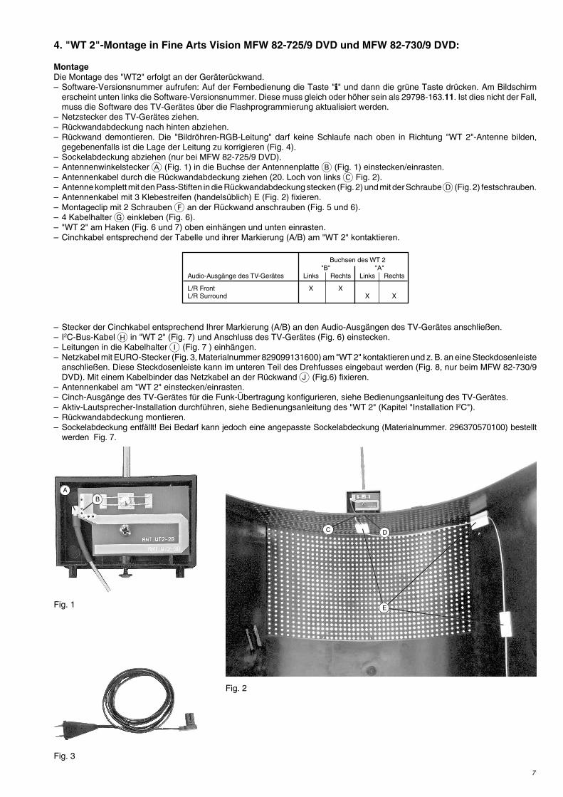
MontageDie Montage des "WT2" erfolgt an der Geräterückwand.– Software-Versionsnummer aufrufen: Auf der Fernbedienung die Taste "" und dann die grüne Taste drücken. Am Bildschirm
erscheint unten links die Software-Versionsnummer. Diese muss gleich oder höher sein als 29798-163.11. Ist dies nicht der Fall,muss die Software des TV-Gerätes über die Flashprogrammierung aktualisiert werden.
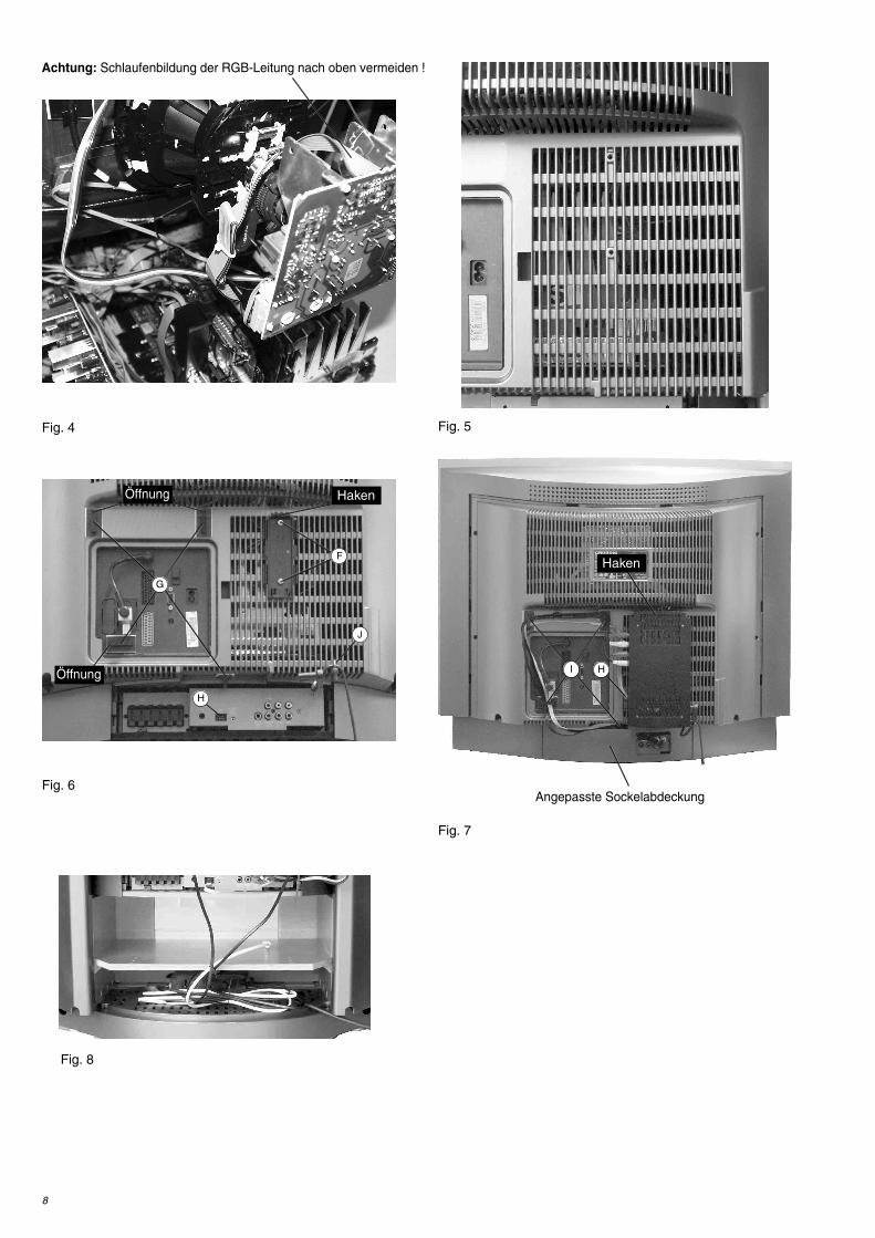
– Netzstecker des TV-Gerätes ziehen.– Rückwandabdeckung nach hinten abziehen.– Rückwand demontieren. Die "Bildröhren-RGB-Leitung" darf keine Schlaufe nach oben in Richtung "WT 2"-Antenne bilden,
gegebenenfalls ist die Lage der Leitung zu korrigieren (Fig. 4).– Sockelabdeckung abziehen (nur bei MFW 82-725/9 DVD).– Antennenwinkelstecker A (Fig. 1) in die Buchse der Antennenplatte B (Fig. 1) einstecken/einrasten.– Antennenkabel durch die Rückwandabdeckung ziehen (20. Loch von links C Fig. 2).– Antenne komplett mit den Pass-Stiften in die Rückwandabdeckung stecken (Fig. 2) und mit der Schraube D (Fig. 2) festschrauben.– Antennenkabel mit 3 Klebestreifen (handelsüblich) E (Fig. 2) fixieren.– Montageclip mit 2 Schrauben F an der Rückwand anschrauben (Fig. 5 und 6).– 4 Kabelhalter G einkleben (Fig. 6).– "WT 2" am Haken (Fig. 6 und 7) oben einhängen und unten einrasten.– Cinchkabel entsprechend der Tabelle und ihrer Markierung (A/B) am "WT 2" kontaktieren.
– Stecker der Cinchkabel entsprechend Ihrer Markierung (A/B) an den Audio-Ausgängen des TV-Gerätes anschließen.– I2C-Bus-Kabel H in "WT 2" (Fig. 7) und Anschluss des TV-Gerätes (Fig. 6) einstecken.– Leitungen in die Kabelhalter I (Fig. 7 ) einhängen.– Netzkabel mit EURO-Stecker (Fig. 3, Materialnummer 829099131600) am "WT 2" kontaktieren und z. B. an eine Steckdosenleiste
anschließen. Diese Steckdosenleiste kann im unteren Teil des Drehfusses eingebaut werden (Fig. 8, nur beim MFW 82-730/9DVD). Mit einem Kabelbinder das Netzkabel an der Rückwand J (Fig.6) fixieren.
– Antennenkabel am "WT 2" einstecken/einrasten.– Cinch-Ausgänge des TV-Gerätes für die Funk-Übertragung konfigurieren, siehe Bedienungsanleitung des TV-Gerätes.– Aktiv-Lautsprecher-Installation durchführen, siehe Bedienungsanleitung des "WT 2" (Kapitel "Installation I2C").– Rückwandabdeckung montieren.– Sockelabdeckung entfällt! Bei Bedarf kann jedoch eine angepasste Sockelabdeckung (Materialnummer. 296370570100) bestellt
werden Fig. 7.
Buchsen des WT 2"B" "A"
Audio-Ausgänge des TV-Gerätes Links Rechts Links Rechts
L/R Front X XL/R Surround X X
Fig. 1
Fig. 2
Fig. 3
8
Fig. 8
Fig. 4 Fig. 5
Fig. 6
Fig. 7
F
H
G
I
J
Öffnung
Öffnung
Haken
Haken
H
Achtung: Schlaufenbildung der RGB-Leitung nach oben vermeiden !
Angepasste Sockelabdeckung
9
Fig. 1 Fig. 2
5. "WT 2"-Montage in PlanaVision
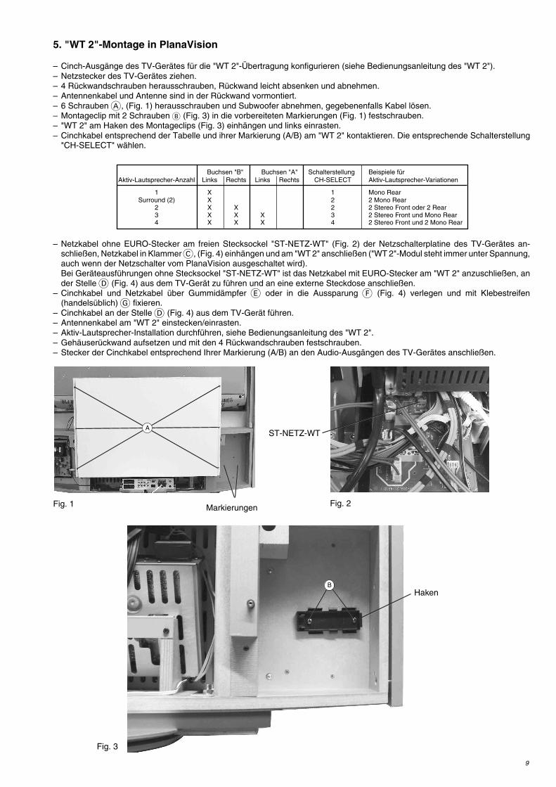
– Cinch-Ausgänge des TV-Gerätes für die "WT 2"-Übertragung konfigurieren (siehe Bedienungsanleitung des "WT 2").– Netzstecker des TV-Gerätes ziehen.– 4 Rückwandschrauben herausschrauben, Rückwand leicht absenken und abnehmen.– Antennenkabel und Antenne sind in der Rückwand vormontiert.– 6 Schrauben A, (Fig. 1) herausschrauben und Subwoofer abnehmen, gegebenenfalls Kabel lösen.– Montageclip mit 2 Schrauben B (Fig. 3) in die vorbereiteten Markierungen (Fig. 1) festschrauben.– "WT 2" am Haken des Montageclips (Fig. 3) einhängen und links einrasten.– Cinchkabel entsprechend der Tabelle und ihrer Markierung (A/B) am "WT 2" kontaktieren. Die entsprechende Schalterstellung
"CH-SELECT" wählen.
– Netzkabel ohne EURO-Stecker am freien Stecksockel "ST-NETZ-WT" (Fig. 2) der Netzschalterplatine des TV-Gerätes an-schließen, Netzkabel in Klammer C, (Fig. 4) einhängen und am "WT 2" anschließen ("WT 2"-Modul steht immer unter Spannung,auch wenn der Netzschalter vom PlanaVision ausgeschaltet wird).Bei Geräteausführungen ohne Stecksockel "ST-NETZ-WT" ist das Netzkabel mit EURO-Stecker am "WT 2" anzuschließen, ander Stelle D (Fig. 4) aus dem TV-Gerät zu führen und an eine externe Steckdose anschließen.
– Cinchkabel und Netzkabel über Gummidämpfer E oder in die Aussparung F (Fig. 4) verlegen und mit Klebestreifen(handelsüblich) G fixieren.
– Cinchkabel an der Stelle D (Fig. 4) aus dem TV-Gerät führen.– Antennenkabel am "WT 2" einstecken/einrasten.– Aktiv-Lautsprecher-Installation durchführen, siehe Bedienungsanleitung des "WT 2".– Gehäuserückwand aufsetzen und mit den 4 Rückwandschrauben festschrauben.– Stecker der Cinchkabel entsprechend Ihrer Markierung (A/B) an den Audio-Ausgängen des TV-Gerätes anschließen.
ST-NETZ-WT
Buchsen "B" Buchsen "A" Schalterstellung Beispiele fürAktiv-Lautsprecher-Anzahl Links Rechts Links Rechts CH-SELECT Aktiv-Lautsprecher-Variationen
1 X 1 Mono RearSurround (2) X 2 2 Mono Rear
2 X X 2 2 Stereo Front oder 2 Rear3 X X X 3 2 Stereo Front und Mono Rear4 X X X 4 2 Stereo Front und 2 Mono Rear
Fig. 3
A
BHaken
Markierungen
10
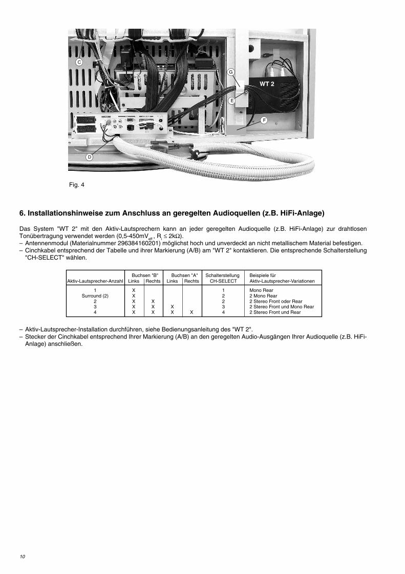
6. Installationshinweise zum Anschluss an geregelten Audioquellen (z.B. HiFi-Anlage)
Das System "WT 2" mit den Aktiv-Lautsprechern kann an jeder geregelten Audioquelle (z.B. HiFi-Anlage) zur drahtlosenTonübertragung verwendet werden (0,5-450mVeff , Ri ≤ 2kΩ).– Antennenmodul (Materialnummer 296384160201) möglichst hoch und unverdeckt an nicht metallischem Material befestigen.– Cinchkabel entsprechend der Tabelle und ihrer Markierung (A/B) am "WT 2" kontaktieren. Die entsprechende Schalterstellung
"CH-SELECT" wählen.
– Aktiv-Lautsprecher-Installation durchführen, siehe Bedienungsanleitung des "WT 2".– Stecker der Cinchkabel entsprechend Ihrer Markierung (A/B) an den geregelten Audio-Ausgängen Ihrer Audioquelle (z.B. HiFi-
Anlage) anschließen.
Buchsen "B" Buchsen "A" Schalterstellung Beispiele fürAktiv-Lautsprecher-Anzahl Links Rechts Links Rechts CH-SELECT Aktiv-Lautsprecher-Variationen
1 X 1 Mono RearSurround (2) X 2 2 Mono Rear
2 X X 2 2 Stereo Front oder Rear3 X X X 3 2 Stereo Front und Mono Rear4 X X X X 4 2 Stereo Front und Rear
Fig. 4
WT 2
C
D
E
F
G
11
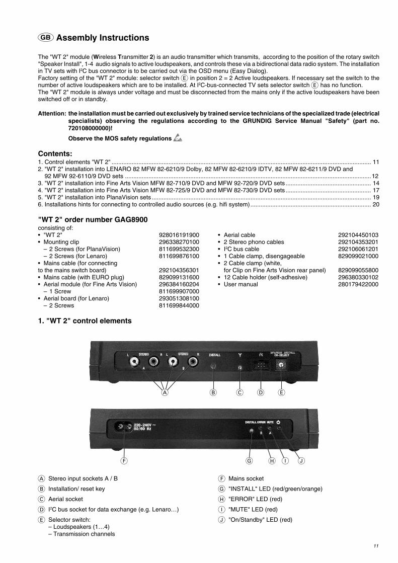
GB Assembly Instructions
The "WT 2" module (Wireless Transmitter 2) is an audio transmitter which transmits, according to the position of the rotary switch"Speaker Install", 1-4 audio signals to active loudspeakers, and controls these via a bidirectional data radio system. The installationin TV sets with I2C bus connector is to be carried out via the OSD menu (Easy Dialog).Factory setting of the "WT 2" module: selector switch E in position 2 = 2 Active loudspeakers. If necessary set the switch to thenumber of active loudspeakers which are to be installed. At I2C-bus-connected TV sets selector switch E has no function.The "WT 2" module is always under voltage and must be disconnected from the mains only if the active loudspeakers have beenswitched off or in standby.
Attention: the installation must be carried out exclusively by trained service technicians of the specialized trade (electricalspecialists) observing the regulations according to the GRUNDIG Service Manual "Safety" (part no.720108000000)!
Observe the MOS safety regulations
Contents:1. Control elements "WT 2" ........................................................................................................................................................... 112. "WT 2" installation into LENARO 82 MFW 82-6210/9 Dolby, 82 MFW 82-6210/9 IDTV, 82 MFW 82-6211/9 DVD and
92 MFW 92-6110/9 DVD sets ...................................................................................................................................................123. "WT 2" installation into Fine Arts Vision MFW 82-710/9 DVD and MFW 92-720/9 DVD sets ................................................... 144. "WT 2" installation into Fine Arts Vision MFW 82-725/9 DVD and MFW 82-730/9 DVD sets ................................................... 175. "WT 2" installation into PlanaVision sets ................................................................................................................................... 196. Installations hints for connecting to controlled audio sources (e.g. hifi system)........................................................................ 20
"WT 2" order number GAG8900consisting of:• "WT 2" 928016191900 • Aerial cable 292104450103• Mounting clip 296338270100 • 2 Stereo phono cables 292104353201
– 2 Screws (for PlanaVision) 811699532300 • I2C bus cable 292106061201– 2 Screws (for Lenaro) 811699876100 • 1 Cable clamp, disengageable 829099021000
• Mains cable (for connecting • 2 Cable clamp (white,to the mains switch board) 292104356301 for Clip on Fine Arts Vision rear panel) 829099055800• Mains cable (with EURO plug) 829099131600 • 12 Cable holder (self-adhesive) 296380330102• Aerial module (for Fine Arts Vision) 296384160204 • User manual 280179422000
– 1 Screw 811699907000• Aerial board (for Lenaro) 293051308100
– 2 Screws 811699844000
1. "WT 2" control elements
A Stereo input sockets A / B
B Installation/ reset key
C Aerial socket
D I2C bus socket for data exchange (e.g. Lenaro…)
E Selector switch:– Loudspeakers (1…4)– Transmission channels
F Mains socket
G "INSTALL" LED (red/green/orange)
H "ERROR" LED (red)
I "MUTE" LED (red)
J "On/Standby" LED (red)
A B C D E
F G H I J
12
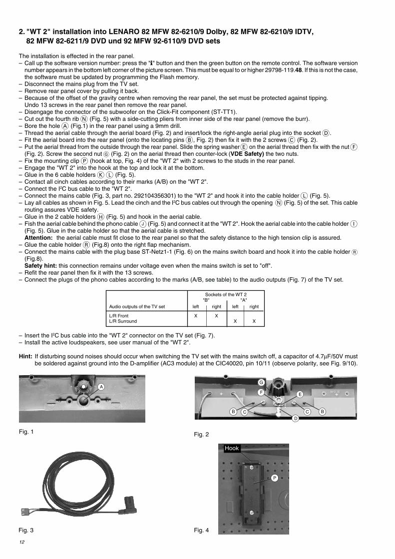
2. "WT 2" installation into LENARO 82 MFW 82-6210/9 Dolby, 82 MFW 82-6210/9 IDTV,82 MFW 82-6211/9 DVD und 92 MFW 92-6110/9 DVD sets
The installation is effected in the rear panel.– Call up the software version number: press the "" button and then the green button on the remote control. The software version
number appears in the bottom left corner of the picture screen. This must be equal to or higher 29798-119.48. If this is not the case,the software must be updated by programming the Flash memory.
– Disconnect the mains plug from the TV set.– Remove rear panel cover by pulling it back.– Because of the offset of the gravity centre when removing the rear panel, the set must be protected against tipping.
Undo 13 screws in the rear panel then remove the rear panel.– Disengage the connector of the subwoofer on the Click-Fit component (ST-TT1).– Cut out the fourth rib N (Fig. 5) with a side-cutting pliers from inner side of the rear panel (remove the burr).– Bore the hole A (Fig.1) in the rear panel using a 9mm drill.– Thread the aerial cable through the aerial board (Fig. 2) and insert/lock the right-angle aerial plug into the socket D.– Fit the aerial board into the rear panel (onto the locating pins B, Fig. 2) then fix it with the 2 screws C (Fig. 2).– Put the aerial thread from the outside through the rear panel. Slide the spring washer E on the aerial thread then fix with the nut F
(Fig. 2). Screw the second nut G (Fig. 2) on the aerial thread then counter-lock (VDE Safety) the two nuts.– Fix the mounting clip P (hook at top, Fig. 4) of the "WT 2" with 2 screws to the studs in the rear panel.– Engage the "WT 2" into the hook at the top and lock it at the bottom.– Glue in the 6 cable holders K L (Fig. 5).– Contact all cinch cables according to their marks (A/B) on the "WT 2".– Connect the I2C bus cable to the "WT 2".– Connect the mains cable (Fig. 3, part no. 292104356301) to the "WT 2" and hook it into the cable holder L (Fig. 5).– Lay all cables as shown in Fig. 5. Lead the cinch and the I2C bus cables out through the opening N (Fig. 5) of the set. This cable
routing assures VDE safety.– Glue in the 2 cable holders H (Fig. 5) and hook in the aerial cable.– Fish the aerial cable behind the phono cable J (Fig. 5) and connect it at the "WT 2". Hook the aerial cable into the cable holder I
(Fig. 5). Glue in the cable holder so that the aerial cable is stretched.Attention: the aerial cable must fit close to the rear panel so that the safety distance to the high tension clip is assured.
– Glue the cable holder R (Fig.8) onto the right flap mechanism.– Connect the mains cable with the plug base ST-Netz1-1 (Fig. 6) on the mains switch board and hook it into the cable holder R
(Fig.8).Safety hint: this connection remains under voltage even when the mains switch is set to "off".
– Refit the rear panel then fix it with the 13 screws.– Connect the plugs of the phono cables according to the marks (A/B, see table) to the audio outputs (Fig. 7) of the TV set.
– Insert the I2C bus cable into the "WT 2" connector on the TV set (Fig. 7).– Install the active loudspeakers, see user manual of the "WT 2".
Hint: If disturbing sound noises should occur when switching the TV set with the mains switch off, a capacitor of 4.7µF/50V mustbe soldered against ground into the D-amplifier (AC3 module) at the CIC40020, pin 10/11 (observe polarity, see Fig. 9/10).
Fig. 1
Fig. 3
B CD
EF
BC
GA
Fig. 2
Fig. 4
P
Sockets of the WT 2"B" "A"
Audio outputs of the TV set left right left right
L/R Front X XL/R Surround X X
Hook
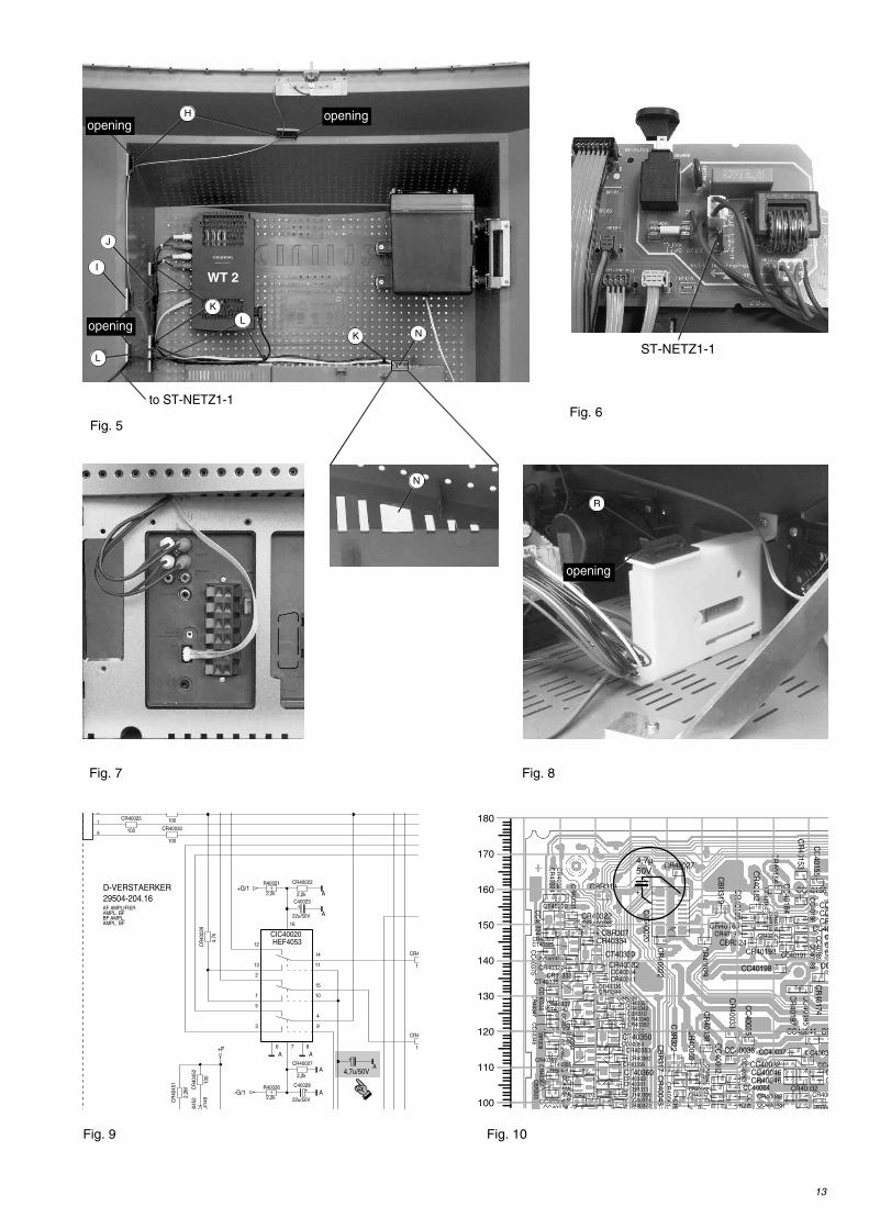
13
Fig. 6
Fig. 7
Fig. 5
ST-NETZ1-1
Fig. 8
R
100
CR40030
+
22u/50V
C40028
2,2k
CR40027
2,2k
R40021
2,2k
CR40022
+
22u/50V
C40023
4,7k
CR
4002
9
1
2
3
4
5
6 7 8
9
10
11
12
13
14
15
16
HEF4053CIC40020
7
8
6
100
CR40025 100
L414
8
4045
2
12
CR4
12
CR4
100
CR
4045
2
2,2k
R40026
2,2M
CR
4045
1
+G/1
-G/1
+F
A
A
A
AA
A
D-VERSTAERKER 29504-204.16
AMPL. BFBF AMPL.AMPL. BFAF AMPLIFIER
+
4,7u/50VA
CC
40375
CC40366CC40376
CC
40336
CC40326
CC
40356
CC
40346
CC40046
CC40036
CC40032 CC4
CC
400
CC40064
CC
40063C
C
CC40041
CC
40062
CC40048
CC40037
CC
40047
CC
40188C
C40186
CC40
CC
40189
CC
CC40156
CC
C
CC
40164
CC
C
CC40198
CC
40035
CC
40155C
C40195
CT40465
CT40360
CT40320
CT40335
CT40330CT40325
CT40355
CT40350
CT40340
CT40345
1
CIC
40020
CB
R303
CBR307
CB
R308
CBR309
CBR310
CBR311
CBR313
CC
40184
CC40191
CB
R317
CB
R319
CB
R322
CBR324
CR40027
CR
40022
CR40363
CR40362
CR
40367 CR40361
CR40364
CR40366
CR40372
CR40374
CR
40324C
R40321
CR40354
CR40353
CR40352
CR40334
CR40326CR40322
CR40323
CR40336
CR40333
CR40332
CR40357
CR40337
CR
40331
CR40351
CR40327
CR40356
CR40346
CR40344
CR40341
CR
40347
CR40342
CR
40343
CR40046C
CR
40033
CR400
C
CR
40038 CR
CR
4C
R40061
CR40062CR40048
CR
40047
CR400
CR40077CR40032
CR40192
CR
40184CR40183CR40191
CR
40197
CR
40174
CR
40156
CR
40182
CR
40169
CR
40153
CR
C
CR
40164
CR40201
CR
40065
CR
40045
CR
40029
CC4003
CC
40364
CC40374
CC40354
CC
40344
CC
40324
CC40334
100
110
120
130
140
150
160
170
180
Fig. 9 Fig. 10
+
4,7µ50V
to ST-NETZ1-1
N
J
H
WT 2I
L
KL
K N
openingopening
opening
opening
14
3. "WT 2" installation into Fine Arts Vision MFW 82-710/9 DVD and MFW 82-720/9 DVD sets:
Possible variants:EPROM version no. 29798-102.06: only wireless rear transmission (mono) possible.From EPROM version no. 29798-102.07 on: wireless rear transmission (mono) possible.
Wireless front transmission possible if:– the Dolby-AF module 295042041300 is fitted,– or the Dolby-AF module 295042040300 is fitted and the wire bridges from pin 41to pin 39 and from pin 42 to pin 40 of the IC40305 are soldered in (Fig. 1/2).
From EPROM version no. 29798-102.10 on: wireless rear transmission (mono) possible.Wireless front transmission possible if:– the Dolby-AF module 295042041300 is fitted,– or the Dolby-AF module 295042040300 is fitted and the wire bridges from pin 41to pin 39 and from pin 42 to pin 40 of the IC40305 are soldered in.The internal left and right speakers of the TV set are added on in DPL mode as centrespeaker (higher centre volume), if an additional electrolytic capacitor 2.2µF/25V istmounted between Pins 37/38 of IC40305 an emitter of T40420 (Fig. 1/2).Attention: On Fine Arts Audion operation the TV set have to be muted or switched off.
Calling up the EPROM version number:Effect the following operations with the remote control.– Using the "" button call up the "DIALOG CENTER" –> OK.– Press the "AUX" button. In the upper left corner of the picture screen the EPROM version number is shown.
For checking or retrofitting the TV set must be opened.– Disconnect the mains plug of the TV set.– Pull the rear panel by back.– Remove the rear panel.
Attention: To avoid damage to the picture tube panel and the picture tube, the rear panel is to be removed only in upward directionbecause of its considerable weight. Hold the rear panel when undoing the 6 screws and lift it carefully by an amount so that it ispossible to disconnect the earthing cable and the subwoofer cable.
– Set up the Dolby-AF module 29504-204.13 in the Dealer menu (see Service Manual 720100249200).
InstallationThe installation of the "WT2" is effected to the rear panel.– Insert/lock the right-angle aerial plug A (Fig. 3) into the socket on the aerial board B, (Fig. 3).– Pull the aerial cable through the hole in the rear panel (1st row / 20th hole from the left C, Fig. 4).– Insert the aerial along with the locating pins into the rear panel (Fig. 4) and fix it with the screws D, (Fig. 4).– Fix the aerial cable with 3 adhesive tapes (commonly availlable) E, (Fig. 4).– Fix the mounting clip with the white cable clamps without removing the rear panel:
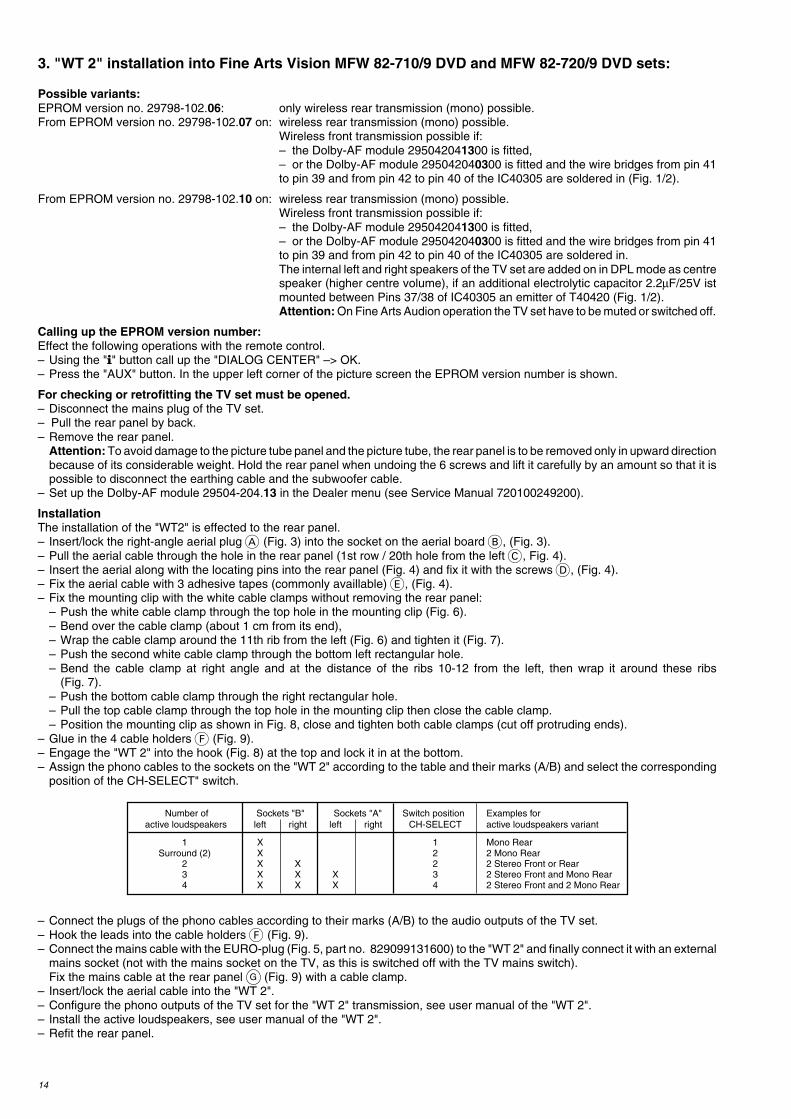
– Push the white cable clamp through the top hole in the mounting clip (Fig. 6).– Bend over the cable clamp (about 1 cm from its end),– Wrap the cable clamp around the 11th rib from the left (Fig. 6) and tighten it (Fig. 7).– Push the second white cable clamp through the bottom left rectangular hole.– Bend the cable clamp at right angle and at the distance of the ribs 10-12 from the left, then wrap it around these ribs
(Fig. 7).– Push the bottom cable clamp through the right rectangular hole.– Pull the top cable clamp through the top hole in the mounting clip then close the cable clamp.– Position the mounting clip as shown in Fig. 8, close and tighten both cable clamps (cut off protruding ends).
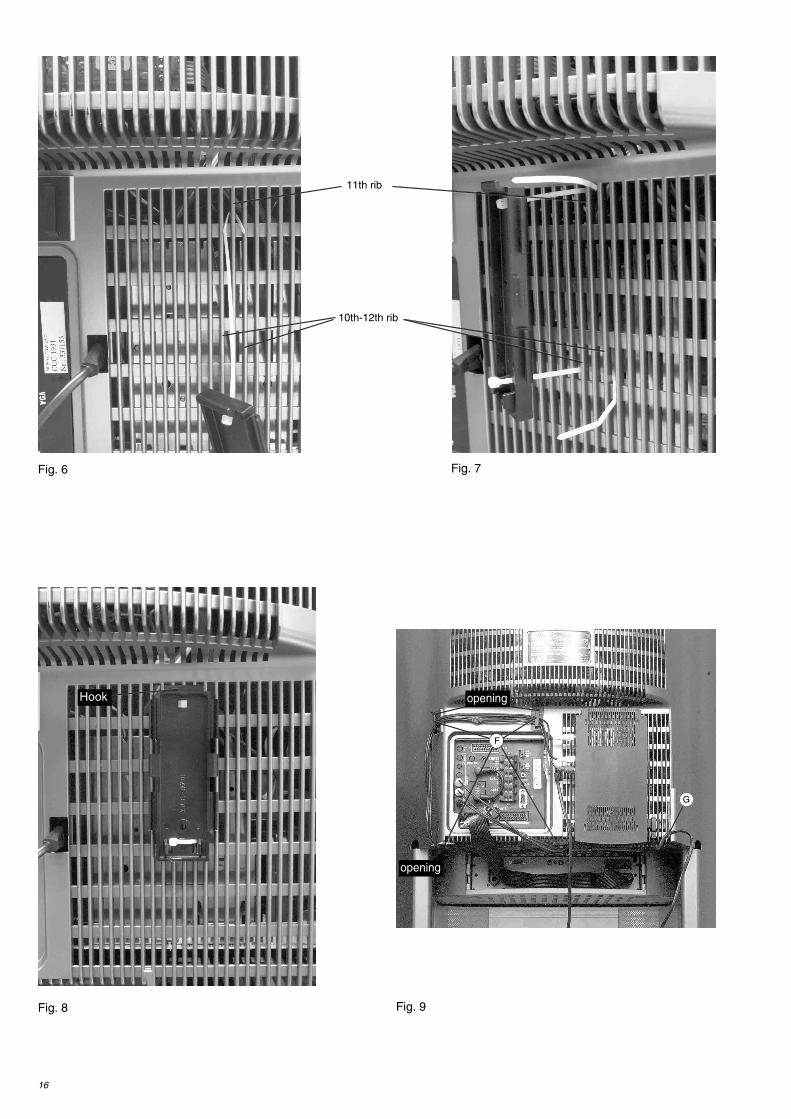
– Glue in the 4 cable holders F (Fig. 9).– Engage the "WT 2" into the hook (Fig. 8) at the top and lock it in at the bottom.– Assign the phono cables to the sockets on the "WT 2" according to the table and their marks (A/B) and select the corresponding
position of the CH-SELECT" switch.
– Connect the plugs of the phono cables according to their marks (A/B) to the audio outputs of the TV set.– Hook the leads into the cable holders F (Fig. 9).– Connect the mains cable with the EURO-plug (Fig. 5, part no. 829099131600) to the "WT 2" and finally connect it with an external
mains socket (not with the mains socket on the TV, as this is switched off with the TV mains switch).Fix the mains cable at the rear panel G (Fig. 9) with a cable clamp.
– Insert/lock the aerial cable into the "WT 2".– Configure the phono outputs of the TV set for the "WT 2" transmission, see user manual of the "WT 2".– Install the active loudspeakers, see user manual of the "WT 2".– Refit the rear panel.
Number of Sockets "B" Sockets "A" Switch position Examples for active loudspeakers left right left right CH-SELECT active loudspeakers variant
1 X 1 Mono RearSurround (2) X 2 2 Mono Rear
2 X X 2 2 Stereo Front or Rear3 X X X 3 2 Stereo Front and Mono Rear4 X X X 4 2 Stereo Front and 2 Mono Rear

15
Fig. 1
A
B
C D
EFig. 3
Fig. 4
Fig. 5
Fig. 2
ST-LSR ST-LSL ST-I2S1
*
CR
4031
2
n.V. 0
CR
4030
5
u/16
V
C40
427
6V0417
220u/10V
1n
CC403020,1u/50V
CC40301
270
CR
4041
1
270
CR
4042
1
CR
4044
1
4,7u
/10V
CC
4033
1
1n
CC
4033
2
1n
CC
4033
3
4,7u
/10V
CC
4031
4
1u/1
6V
CC
4042
3
4,7k
CR40333
4,7k
CR4043633
0p
CC
4043
4
1k
CR40439
BC848BCT40431
47k
CR
4043
8
100
CR
4033
6
47n
CC40308
2
CR
2
4,7k
CR404326,8n
CC40413
0p0414
180
CR
4033
7
1n
CC40306
BC858CT4044
47k
CR
4043
4
1u/1
6V
CC
4034
1
0,1u/50V
CC40312
1u/1
6V
CC
4034
2
+
470u/10V
C40311
4,7u
/10V
CC
4032
7
0,1u/50V
CC40304
PE
RLE
L403
02
2,2k
CR
4042
3
2,2k
CR
4041
3
XX
CR40306
120k
CR
4043
3
10n
CC
4043
3
100
CR
4033
4
MP70
4,7k
CR
4041
2
0,22u
CC40432
180
CR
4033
8
BC858CCT40410
4,7k
CR
4041
4
6,8n
CC40422
0p0424
4,7k
CR
4042
4
BC858CCT40420
4,7k
CR
4042
2
2,2n
CC40411
2,2n
CC40421
4,7u
/10V
CC
4031
3
1u/1
6V
CC
4044
6
1u/1
6V
CC
4044
92,
2k
CR
4044
6
MP60
2,2k
CR
4044
9
MP61
I2S
_DA
_OU
T2
CA
PL_
C2
CA
PL_
C1
NC
I2S
_DA
_OU
T1
D_C
TR_I
O1
D_C
TR_I
O0
D_C
TR_I
N
NC
DA
CC
1_L
DA
CC
1_R
SC2_OUT_L
SC2_OUT_R
SC2_IN_R
SC2_IN_L
SC1_OUT_L
SC1_OUT_R
SC
1_IN
_R
SC
1_IN
_L
VR
EF2
DV
SS
AV
SS
VR
EF1
AH
VS
S
AG
ND
C
TES
TEN
VR
EFT
OP
AU
D_C
L_O
UT
I2S
_DA
_IN
1
I2S
_WS
I2S
_CL
I2C
_DA
I2C
_CL
AV
SU
P
AH
VS
UP
AD
R_S
EL
DV
SU
P
STA
ND
BY
Q
SC
_3_I
N_R
SC
_3_I
N_L
RE
SE
TQ
I2S
_DA
_IN
2
50
46
27
28
29
30
31
32 3334
35 36
37 38
39
40
41 42
4345
56
7 8 9 10 11 12 13
16
17
18 19 20
23 24 25 26 341 2IC40305DPL3519A2
+Q/22
+Q/22
+Q/2
A
A
A
A
A
A
A
A
A
A
A
A
AAA
AA
A
A
A
A
SDIP 52
PLACA DOLBY SURROUNDPIASTRA DOLBY SURROUNDC. I. DOLBY SURROUNDDOLBY SURROUND BOARD
+
2u2
/ 25V
16
Fig. 6 Fig. 7
Fig. 8 Fig. 9
11th rib
10th-12th rib
F
G
opening
opening
Hook
17
A
B
C D
E
4. "WT 2" installation into Fine Arts Vision MFW 82-725/9 DVD and MFW 82-730/9 DVD sets:
InstallationThe installation of the "WT2" is effected to the rear panel.– Call up the software version number: on the remote control, first press the "" button and then the green button. In the bottom left
corner of the picture screen then appears the software version number. This must be equal to or higher than 29798-163.11. If thisis not the case, the software of the TV set must be updated by flash-programming.
– Disconnect the mains plug of the TV set.– Pull the rear panel back.– Remove the rear panel. The "picture tube RGB lead“ must not form an upward loop in direction of the "WT 2" antenna. If necessary,
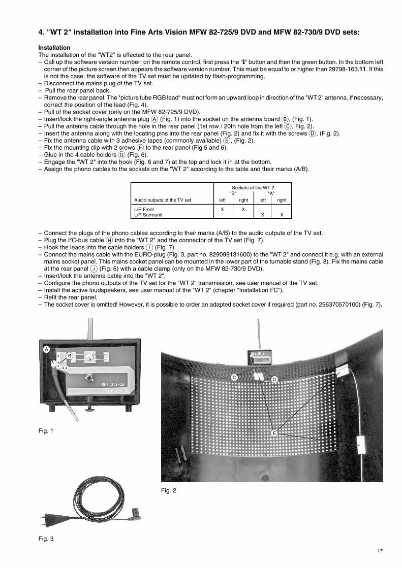
correct the position of the lead (Fig. 4).– Pull of the socket cover (only on the MFW 82-725/9 DVD).– Insert/lock the right-angle antenna plug A (Fig. 1) into the socket on the antenna board B, (Fig. 1).– Pull the antenna cable through the hole in the rear panel (1st row / 20th hole from the left C, Fig. 2).– Insert the antenna along with the locating pins into the rear panel (Fig. 2) and fix it with the screws D, (Fig. 2).– Fix the antenna cable with 3 adhesive tapes (commonly available) E, (Fig. 2).– Fix the mounting clip with 2 srews F to the rear panel (Fig 5 and 6).– Glue in the 4 cable holders G (Fig. 6).– Engage the "WT 2" into the hook (Fig. 6 and 7) at the top and lock it in at the bottom.– Assign the phono cables to the sockets on the "WT 2" according to the table and their marks (A/B).
– Connect the plugs of the phono cables according to their marks (A/B) to the audio outputs of the TV set.– Plug the I2C-bus cable H into the "WT 2" and the connector of the TV set (Fig. 7).– Hook the leads into the cable holders I (Fig. 7).– Connect the mains cable with the EURO-plug (Fig. 3, part no. 829099131600) to the "WT 2" and connect it e.g. with an external
mains socket panel. This mains socket panel can be mounted in the lower part of the turnable stand (Fig. 8). Fix the mains cableat the rear panel J (Fig. 6) with a cable clamp (only on the MFW 82-730/9 DVD).
– Insert/lock the antenna cable into the "WT 2".– Configure the phono outputs of the TV set for the "WT 2" transmission, see user manual of the TV set.– Install the active loudspeakers, see user manual of the "WT 2" (chapter "Installation I2C").– Refit the rear panel.– The socket cover is omitted! However, it is possible to order an adapted socket cover if required (part no. 296370570100) (Fig. 7).
Sockets of the WT 2"B" "A"
Audio outputs of the TV set left right left right
L/R Front X XL/R Surround X X
Fig. 1
Fig. 2
Fig. 3

18
Fig. 8
Fig. 4 Fig. 5
Fig. 6
Fig. 7
F
H
G
I
J
opening
opening
Hook
Hook
H
Attention: The RGB lead must not form an upward loop!
adapted socket cover
19
5. "WT 2" installation into PlanaVision sets
– Configure the phono outputs of the TV set for the "WT 2" transmission mode, see user manual of the "WT 2".– Disconnect the mains plug of the TV set.– Undo the 4 screws in the rear panel, then slightly lower and remove the rear panel.– The aerial cable and the aerial are premounted in the rear panel.– Undo the 6 screws A (Fig. 1), then remove the subwoofer; disengage the cables if necessary.– Fix the mounting clip with the 2 screws B (Fig. 3) at the prepared markings (Fig. 1).– Engage the "WT 2" into the hook on the mounting clip (Fig. 3) and lock it in at the left side.– Assign the phono cables to the sockets on the "WT 2" according to the table and their marks (A/B) and select the corresponding
position of the "CH-SELECT" switch.
– Connect the mains cable without EURO plug to the free connector "ST-NETZ-WT" (Fig. 2) on the mains switch board of the TVset, hook the mains cable into the clamp C (Fig. 4), then connect it to the "WT 2" (the "WT 2" module is always under voltage,even when the mains switch of the Plana Vision is switched off).On models without the connector "ST-NETZ-WT", the mains cable is connected with the EURO plug to the "WT 2", then led outof the TV set at the position D (Fig. 4) and connected to an external mains socket.
– Lay the phono cable and the mains cable over the rubber dampers E or inside the groove F (Fig. 4) and fix the cables withadhesive tape G.
– Lead the phono cable out of the TV set at the position D (Fig. 4).– Insert/lock the aerial cable into the "WT 2".– Install the active loudspeakers, see user manual of the "WT 2".– Refit the rear panel and fix it with the 4 screws.– Connect the plugs of the phono cables according to their marks (A/B) to the audio outputs of the TV set.
Number of Sockets "B" Sockets "A" Switch position Examples for active loudspeakers left right left right CH-SELECT active loudspeakers variant
1 X 1 Mono RearSurround (2) X 2 2 Mono Rear
2 X X 2 2 Stereo Front or Rear3 X X X 3 2 Stereo Front and Mono Rear4 X X X 4 2 Stereo Front and 2 Mono Rear
Fig. 1 Fig. 2
ST-NETZ-WT
Fig. 3
A
B
Marks
Hook
20
Änderungen vorbehalten / Subject to alteration • 720100430003 • 0403 • H-S42
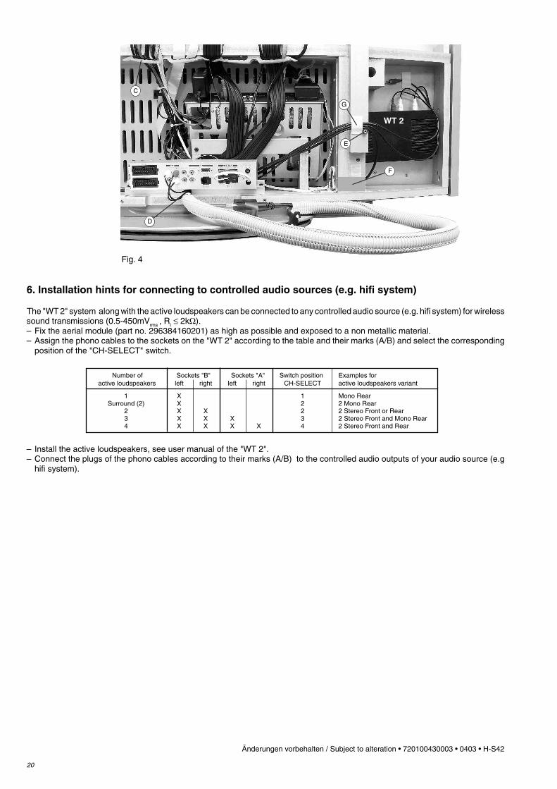
6. Installation hints for connecting to controlled audio sources (e.g. hifi system)
The "WT 2" system along with the active loudspeakers can be connected to any controlled audio source (e.g. hifi system) for wirelesssound transmissions (0.5-450mVrms , Ri ≤ 2kΩ).– Fix the aerial module (part no. 296384160201) as high as possible and exposed to a non metallic material.– Assign the phono cables to the sockets on the "WT 2" according to the table and their marks (A/B) and select the corresponding
position of the "CH-SELECT" switch.
– Install the active loudspeakers, see user manual of the "WT 2".– Connect the plugs of the phono cables according to their marks (A/B) to the controlled audio outputs of your audio source (e.g
hifi system).
Number of Sockets "B" Sockets "A" Switch position Examples for active loudspeakers left right left right CH-SELECT active loudspeakers variant
1 X 1 Mono RearSurround (2) X 2 2 Mono Rear
2 X X 2 2 Stereo Front or Rear3 X X X 3 2 Stereo Front and Mono Rear4 X X X X 4 2 Stereo Front and Rear
Fig. 4
WT 2
C
D
E
F
G