Embed Size (px)
Citation preview
56
MODULHARD’ANDREA
EXTENSIONS REDUCTIONS AND COOLANT FEEDVERLÄNGERUNGEN, REDUZIERUNGEN UND KÜHLMITTELZUFUHRPROLONGACIONES REDUCCIONES Y CONDUCTORES PARA REFRIGERANTERALLONGES-RÉDUCTIONS ET ADDUCTEURS ARROSAGEPROLUNGHE RIDUZIONI E ADDUTTORI REFRIGERANTE
ARBORSGRUNDAUFNAHMEN
ACOPLAMIENTOS BASE
MANDRINSATTACCHI BASE
CHUCKING TOOLSADAPTER
ADAPTADORES
ADAPTATEURSADATTATORI
DIN 69893 p. 61-63RFR p. 229
DIN 69871 p. 64-65TNT p. 228
MAS403BT p. 66-67TNT p. 228
TNT p. 228
DIN 2080 p. 68
CAPTO p. 72
DIN 2079 p. 71
R8 p. 70
DIN 2079 p 71
R8 p. 70R8 70
DIN 228/A p. 69 2207
KM p. 72
MR p. 71MR p 71
BR p. 70BR 70
DIN 228/B p. 69 1806
BMD p. 74-75
ANSI/CAT p. 68
PR p.76
RD p.77
RD p.78
RD p.78
RAV p.79
BLC p.80
ACR/NC p.198
GRINTA p.204-207
PE p.192 - 230 - 231
MHD FORCE p.192
AW p.193
PF p.194
CM p.195
AM p. 196
B16 p. 197
NS p. 197
ACR p. 199
57
MODULHARD’ANDREA
Index
Inhaltsverzeichnis
Índice
Index
Indice
KITSET
KITS
KITKIT
TESTAROSSATESTAROSSA
TESTAROSSA
TESTAROSSATESTAROSSA
DOUBLE-BIT HEADSZWEISCHNEIDERBOHRKÖPFE
CABEZALES DE DOS CUCHILLAS
TÊTES À DOUBLE TRANCHANTTESTINE BITAGLIENTI
TRD 25-80 p. 100-103Ø 28 ~ 120
TRC 32 HS p. 116Ø 2.5 ~ 18
TRC 50 HS p. 116Ø 2.5 ~ 22
TRM 16-40 p. 120-123Ø 18 ~ 63
TRM 50 p. 124-127Ø 2.5 ~ 108
TRM 50/63 p. 128-131TRM 63/63Ø 6 ~ 125
TRM 50/80 p. 132-135TRM 80/80Ø 6 ~ 160
TRM 80/125 p. 136-139Ø 36 ~ 500
TS . . p. 84-89Ø 18 ~ 200
BPS . . . p. 90-93Ø 200 ~ 1100
BPS . . . p. 140-145Ø 200~ 1100
TRM 32 HSB p. 146Ø 2.5 ~ 18
TRM 50 HS p. 146Ø 2.5 ~ 22
TRC HS p. 152-155Ø 2.5 ~ 22
TP p. 94 TU p. 94
SS . . p. 176-181
P20.30 - B. . . p. 182-185
SF . . p. 188-189
INSERT . . . . p. 218-220
CW200 p. 179 PRL ... p. 179
p 182 185
PRL ... p. 179
P25 . . p. 187 P . . p. 187
PC p. 95 AS..45° p. 96
Win Tool p.276
INFO p.257
TRM p. 166-173Ø 6 ~ 410
TRM HSB p. 162-165Ø 2.5 ~ 22
TRC p. 156-161Ø 6 ~ 200
TRC 50 p. 108-111Ø 2.5 ~ 110
TRC 63 p. 112-113Ø 72 ~ 125
TRC 80 p. 114-115Ø 88 ~ 200
TRC 14-40 p. 104-107Ø 14.5 ~ 66
PS . . p. 186 P . . p. 186
MODULHARD’ANDREA
58
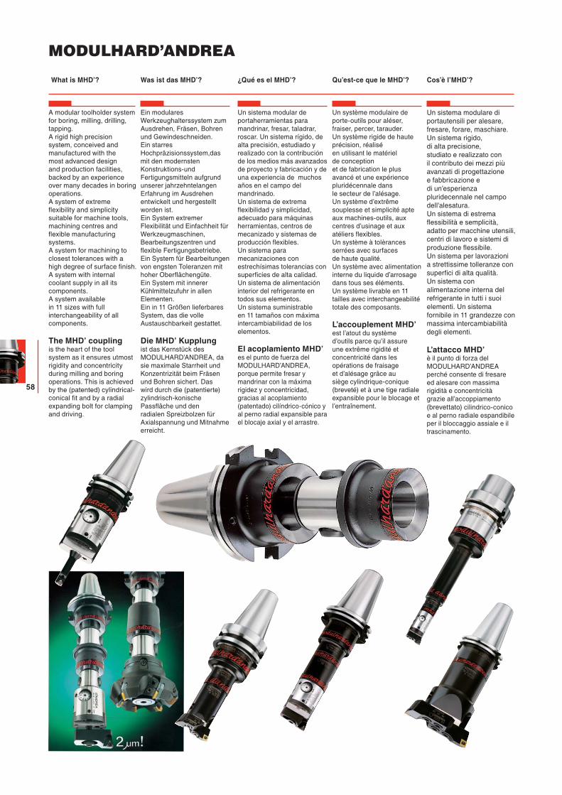
A modular toolholder system for boring, milling, drilling, tapping.A rigid high precision system, conceived and manufactured with the most advanced design and production facilities, backed by an experience over many decades in boring operations.A system of extreme flexibility and simplicity suitable for machine tools, machining centres and flexible manufacturing systems.A system for machining to closest tolerances with a high degree of surface finish.A system with internal coolant supply in all its components.A system available in 11 sizes with full interchangeability of all components.
The MHD’ coupling is the heart of the tool system as it ensures utmost rigidity and concentricity during milling and boring operations. This is achieved by the (patented) cylindrical-conical fit and by a radial expanding bolt for clamping and driving.
Ein modulares Werkzeughalterssystem zum Ausdrehen, Fräsen, Bohren und Gewindeschneiden. Ein starres Hochpräzisionssystem,das mit den modernsten Konstruktions-und Fertigungsmitteln aufgrund unserer jahrzehntelangen Erfahrung im Ausdrehen entwickelt und hergestellt worden ist.Ein System extremer Flexibilität und Einfachheit für Werkzeugmaschinen, Bearbeitungszentren und flexible Fertigungsbetriebe.Ein System für Bearbeitungen von engsten Toleranzen mit hoher Oberflächengüte.Ein System mit innerer Kühlmittelzufuhr in allen Elementen.Ein in 11 Größen lieferbares System, das die volle Austauschbarkeit gestattet.
Die MHD’ Kupplung ist das Kernstück des MODULHARD’ANDREA, da sie maximale Starrheit und Konzentrizität beim Fräsen und Bohren sichert. Das wird durch die (patentierte) zylindrisch-konische Passfläche und den radialen Spreizbolzen für Axialspannung und Mitnahme erreicht.
Un sistema modular de portaherramientas para mandrinar, fresar, taladrar, roscar. Un sistema rígido, de alta precisión, estudiado y realizado con la contribución de los medios más avanzados de proyecto y fabricación y de una experiencia de muchos años en el campo del mandrinado.Un sistema de extrema flexibilidad y simplicidad, adecuado para máquinas herramientas, centros de mecanizado y sistemas de producción flexibles.Un sistema para mecanizaciones con estrechísimas tolerancias con superficies de alta calidad.Un sistema de alimentación interior del refrigerante en todos sus elementos. Un sistema suministrable en 11 tamaños con máxima intercambiabilidad de los elementos.
El acoplamiento MHD’ es el punto de fuerza del MODULHARD’ANDREA, porque permite fresar y mandrinar con la máxima rigidez y concentricidad, gracias al acoplamiento (patentado) cilíndrico-cónico y al perno radial expansible para el blocaje axial y el arrastre.
Un système modulaire de porte-outils pour aléser, fraiser, percer, tarauder.Un système rigide de haute précision, réalisé en utilisant le matériel de conception et de fabrication le plus avancé et une expérience pluridécennale dans le secteur de l’alésage.Un système d’extrême souplesse et simplicité apte aux machines-outils, aux centres d’usinage et aux atéliers flexibles. Un système à tolèrances serrées avec surfaces de haute qualité.Un système avec alimentation interne du liquide d’arrosage dans tous ses éléments. Un système livrable en 11 tailles avec interchangeabilité totale des composants.
L’accouplement MHD’ est l’atout du système d’outils parce qu’il assure une extrême rigidité et concentricité dans les opérations de fraisage et d’alésage grâce au siège cylindrique-conique (breveté) et à une tige radiale expansible pour le blocage et l’entraînement.
Un sistema modulare di portautensili per alesare, fresare, forare, maschiare.Un sistema rigido, di alta precisione, studiato e realizzato con il contributo dei mezzi più avanzati di progettazione e fabbricazione e di un’esperienza pluridecennale nel campo dell'alesatura.Un sistema di estrema flessibilità e semplicità, adatto per macchine utensili, centri di lavoro e sistemi di produzione flessibile. Un sistema per lavorazioni a strettissime tolleranze con superfici di alta qualità.Un sistema con alimentazione interna del refrigerante in tutti i suoi elementi. Un sistema fornibile in 11 grandezze con massima intercambiabilità degli elementi.
L’attacco MHD’ è il punto di forza del MODULHARD’ANDREA perché consente di fresare ed alesare con massima rigidità e concentricità grazie all’accoppiamento (brevettato) cilindrico-conico e al perno radiale espandibile per il bloccaggio assiale e il trascinamento.
Was ist das MHD’? ¿Qué es el MHD’? Qu’est-ce que le MHD’? Cos’è l’MHD’?What is MHD’?
59
S
Ø m
1
Ø d
1
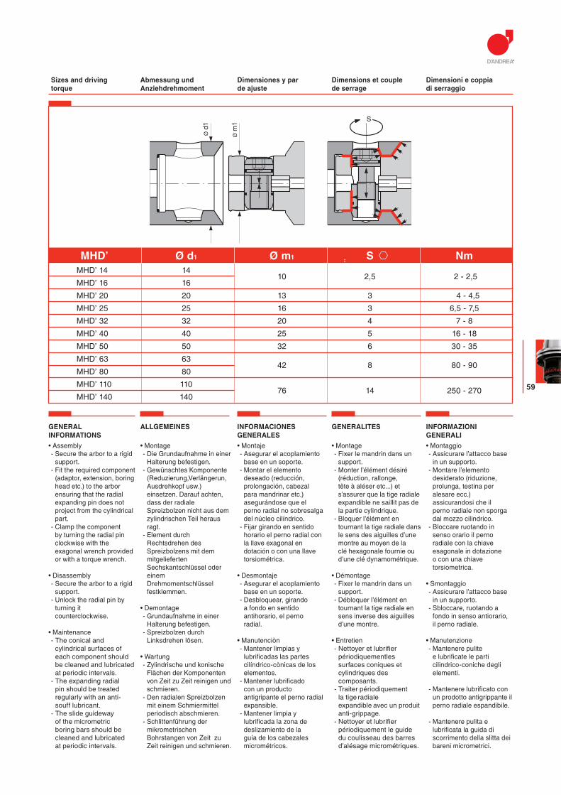
Abmessung und Anziehdrehmoment
Dimensiones y par de ajuste
Dimensions et couple de serrage
Dimensioni e coppia di serraggio
Sizes and driving torque
• Montaje- Asegurar el acoplamiento
base en un soporte.- Montar el elemento
deseado (reducción, prolongación, cabezal para mandrinar etc.) asegurándose que el perno radial no sobresalga del núcleo cilíndrico.
- Fijar girando en sentido horario el perno radial con la llave exagonal en dotación o con una llave torsiométrica.
• Desmontaje- Asegurar el acoplamiento
base en un soporte.- Desbloquear, girando
a fondo en sentido antihorario, el perno radial.
• Manutenciòn- Mantener limpias y
lubrificadas las partes cilíndrico-cònicas de los elementos.
- Mantener lubrificado con un producto antigripante el perno radial expansible.
- Mantener limpia y lubrificada la zona de deslizamiento de la guía de los cabezales micrométricos.
• Montage- Fixer le mandrin dans un
support.- Monter l’élément désiré
(réduction, rallonge, tête à aléser etc...) et s’assurer que la tige radiale expandible ne saillit pas de la partie cylindrique.
- Bloquer l’élément en tournant la tige radiale dans le sens des aiguilles d’une montre au moyen de la clé hexagonale fournie ou d’une clé dynamométrique.
• Démontage- Fixer le mandrin dans un
support.- Débloquer l’élément en
tournant la tige radiale en sens inverse des aiguilles d’une montre.
• Entretien- Nettoyer et lubrifier
périodiquementles surfaces coniques et cylindriques des composants.
- Traiter périodiquement la tige radiale expandible avec un produit anti-grippage.
- Nettoyer et lubrifier périodiquement le guide du coulisseau des barres d’alésage micrométriques.
• Montaggio- Assicurare l’attacco base
in un supporto.- Montare l’elemento
desiderato (riduzione, prolunga, testina per alesare ecc.) assicurandosi che il perno radiale non sporga dal mozzo cilindrico.
- Bloccare ruotando in senso orario il perno radiale con la chiave esagonale in dotazione o con una chiave torsiometrica.
• Smontaggio- Assicurare l’attacco base
in un supporto.- Sbloccare, ruotando a
fondo in senso antiorario, il perno radiale.
• Manutenzione - Mantenere pulite
e lubrificate le parti cilindrico-coniche degli elementi.
- Mantenere lubrificato con un prodotto antigrippante il perno radiale espandibile.
- Mantenere pulita e lubrificata la guida di scorrimento della slitta dei bareni micrometrici.
ALLGEMEINES INFORMACIONES GENERALES
GENERALITES INFORMAZIONI GENERALI
GENERAL INFORMATIONS• Assembly- Secure the arbor to a rigid
support.- Fit the required component
(adaptor, extension, boring head etc.) to the arbor ensuring that the radial expanding pin does not project from the cylindrical part.
- Clamp the component by turning the radial pin clockwise with the exagonal wrench provided or with a torque wrench.
• Disassembly- Secure the arbor to a rigid
support.- Unlock the radial pin by
turning it counterclockwise.
• Maintenance - The conical and
cylindrical surfaces of each component should be cleaned and lubricated at periodic intervals.
- The expanding radial pin should be treated regularly with an anti-souff lubricant.
- The slide guideway of the micrometric boring bars should be cleaned and lubricated at periodic intervals.
• Montage- Die Grundaufnahme in einer
Halterung befestigen.- Gewünschtes Komponente
(Reduzierung,Verlängerun, Ausdrehkopf usw.) einsetzen. Darauf achten, dass der radiale Spreizbolzen nicht aus dem zylindrischen Teil heraus ragt.
- Element durch Rechtsdrehen des Spreizbolzens mit dem mitgelieferten Sechskantschlüssel oder einem Drehmomentschlüssel festklemmen.
• Demontage- Grundaufnahme in einer
Halterung befestigen.- Spreizbolzen durch
Linksdrehen lösen.
• Wartung- Zylindrische und konische
Flächen der Komponenten von Zeit zu Zeit reinigen und schmieren.
- Den radialen Spreizbolzen mit einem Schmiermittel periodisch abschmieren.
- Schlittenführung der mikrometrischen Bohrstangen von Zeit zu Zeit reinigen und schmieren.
MHD’ Ø d1 Ø m1 S Nm MHD’ 14 14
10 2,5 2 - 2,5
MHD’ 16 16
MHD’ 20 20 13 3 4 - 4,5
MHD’ 25 25 16 3 6,5 - 7,5
MHD’ 32 32 20 4 7 - 8
MHD’ 40 40 25 5 16 - 18
MHD’ 50 50 32 6 30 - 35
MHD’ 63 63 42 8 80 - 90
MHD’ 80 80
MHD’ 110 110 76 14 250 - 270
MHD’ 140 140
MODULHARD’ANDREA
60
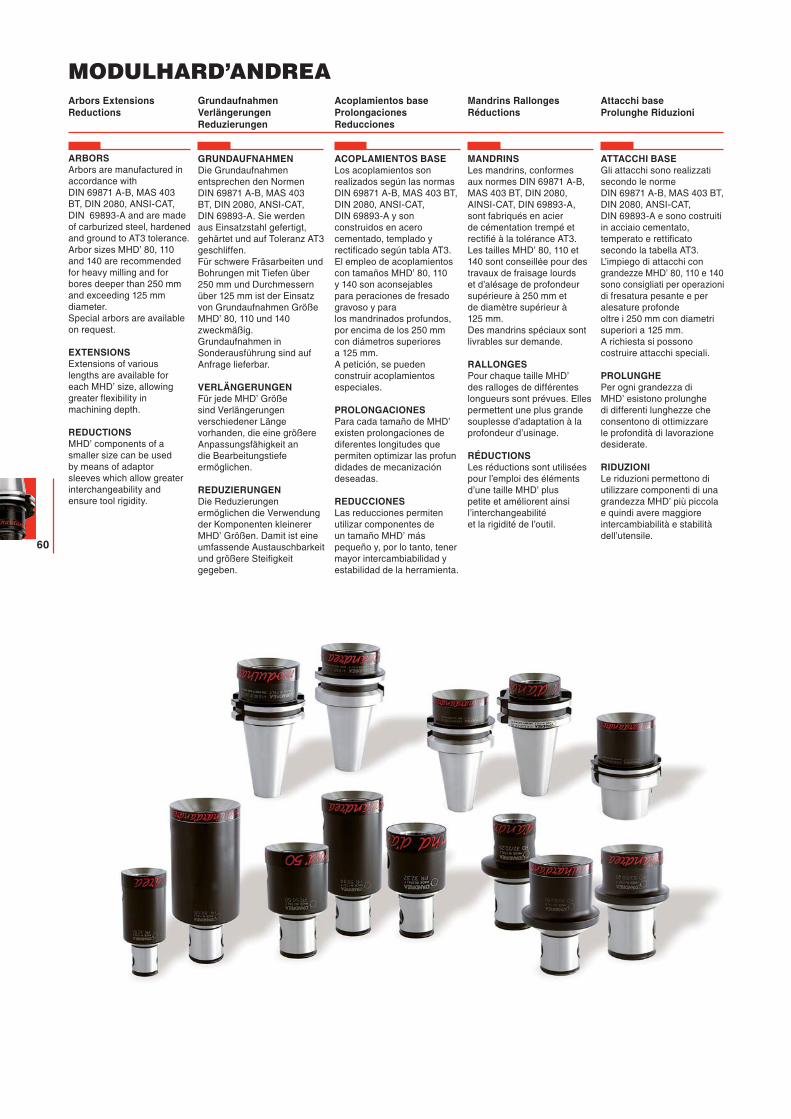
ARBORSArbors are manufactured in accordance with DIN 69871 A-B, MAS 403 BT, DIN 2080, ANSI-CAT, DIN 69893-A and are made of carburized steel, hardened and ground to AT3 tolerance. Arbor sizes MHD’ 80, 110and 140 are recommended for heavy milling and for bores deeper than 250 mm and exceeding 125 mm diameter. Special arbors are available on request.
EXTENSIONSExtensions of various lengths are available for each MHD’ size, allowing greater flexibility in machining depth.
REDUCTIONSMHD’ components of a smaller size can be used by means of adaptor sleeves which allow greater interchangeability and ensure tool rigidity.
GRUNDAUFNAHMENDie Grundaufnahmen entsprechen den Normen DIN 69871 A-B, MAS 403 BT, DIN 2080, ANSI-CAT, DIN 69893-A. Sie werden aus Einsatzstahl gefertigt, gehärtet und auf Toleranz AT3 geschliffen.Für schwere Fräsarbeiten und Bohrungen mit Tiefen über 250 mm und Durchmessern über 125 mm ist der Einsatz von Grundaufnahmen Größe MHD’ 80, 110 und 140 zweckmäßig. Grundaufnahmen in Sonderausführung sind auf Anfrage lieferbar.
VERLÄNGERUNGENFür jede MHD’ Größe sind Verlängerungen verschiedener Länge vorhanden, die eine größere Anpassungsfähigkeit an die Bearbeitungstiefe ermöglichen.
REDUZIERUNGENDie Reduzierungen ermöglichen die Verwendung der Komponenten kleinerer MHD’ Größen. Damit ist eine umfassende Austauschbarkeit und größere Steifigkeit gegeben.
ACOPLAMIENTOS BASELos acoplamientos son realizados según las normas DIN 69871 A-B, MAS 403 BT, DIN 2080, ANSI-CAT, DIN 69893-A y son construidos en acero cementado, templado y rectificado según tabla AT3. El empleo de acoplamientos con tamaños MHD’ 80, 110 y 140 son aconsejables para peraciones de fresado gravoso y para los mandrinados profundos, por encima de los 250 mm con diámetros superiores a 125 mm.A petición, se pueden construir acoplamientos especiales.
PROLONGACIONESPara cada tamaño de MHD’ existen prolongaciones de diferentes longitudes que permiten optimizar las profun didades de mecanización deseadas.
REDUCCIONESLas reducciones permiten utilizar componentes de un tamaño MHD’ más pequeño y, por lo tanto, tener mayor intercambiabilidad y estabilidad de la herramienta.
MANDRINSLes mandrins, conformes aux normes DIN 69871 A-B, MAS 403 BT, DIN 2080, AINSI-CAT, DIN 69893-A, sont fabriqués en acier de cémentation trempé et rectifié à la tolérance AT3. Les tailles MHD’ 80, 110 et 140 sont conseillée pour des travaux de fraisage lourds et d’alésage de profondeur supérieure à 250 mm et de diamètre supérieur à 125 mm. Des mandrins spéciaux sont livrables sur demande.
RALLONGESPour chaque taille MHD’ des ralloges de différentes longueurs sont prévues. Elles permettent une plus grande souplesse d’adaptation à la profondeur d’usinage.
RÉDUCTIONSLes réductions sont utilisées pour l’emploi des éléments d’une taille MHD’ plus petite et améliorent ainsi l’interchangeabilité et la rigidité de l’outil.
ATTACCHI BASEGli attacchi sono realizzati secondo le norme DIN 69871 A-B, MAS 403 BT, DIN 2080, ANSI-CAT, DIN 69893-A e sono costruiti in acciaio cementato, temperato e rettificato secondo la tabella AT3.L’impiego di attacchi con grandezze MHD’ 80, 110 e 140 sono consigliati per operazioni di fresatura pesante e per alesature profonde oltre i 250 mm con diametri superiori a 125 mm. A richiesta si possono costruire attacchi speciali.
PROLUNGHEPer ogni grandezza di MHD’ esistono prolunghe di differenti lunghezze che consentono di ottimizzare le profondità di lavorazione desiderate.
RIDUZIONILe riduzioni permettono di utilizzare componenti di una grandezza MHD’ più piccola e quindi avere maggiore intercambiabilità e stabilità dell’utensile.
Grundaufnahmen Verlängerungen Reduzierungen
Acoplamientos base Prolongaciones Reducciones
Mandrins Rallonges Réductions
Attacchi base Prolunghe Riduzioni
Arbors Extensions Reductions
61
p. 269p. 229
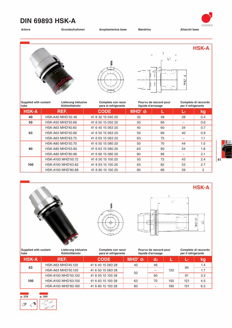
DIN 69893 HSK-AGrundaufnahmen Acoplamientos base Mandrins Attacchi baseArbors
HSK-A REF. CODE MHD’ d1 L L1 kg 40 HSK-A40 MHD’32.48 41 6 32 15 040 20 32 48 28 0.4
50 HSK-A50 MHD’50.66 41 6 50 15 050 20 50 66 – 0.6
HSK-A63 MHD’40.60 41 6 40 15 063 20 40 60 34 0.7
63 HSK-A63 MHD’50.66 41 6 50 15 063 20 50 66 40 0.9
HSK-A63 MHD’63.75 41 6 63 15 063 20 63 75 – 1.1
HSK-A80 MHD’50.70 41 6 50 15 080 20 50 70 44 1.5
80 HSK-A80 MHD’63.80 41 6 63 15 080 20 63 80 54 1.8
HSK-A80 MHD’80.86 41 6 80 15 080 20 80 86 – 2.1
HSK-A100 MHD’50.72 41 6 50 15 100 20 50 72 43 2.4
100 HSK-A100 MHD’63.82 41 6 63 15 100 20 63 82 53 2.7
HSK-A100 MHD’80.88 41 6 80 15 100 20 80 88 59 3
Lieferung inklusive Kühlmittelrohr
Completo con racorpara el refrigerante
Pourvu de raccord pour liquide d'arrosage
Completo di raccordo per il refrigerante
Supplied with coolant tube
Lieferung inklusive Kühlmittelrohr
Completo con racorpara el refrigerante
Pourvu de raccord pour liquide d'arrosage
Completo di raccordo per il refrigerante
Supplied with coolant tube
HSK-A
HSK-A
HSK-A REF. CODE MHD’ d1 d2 L L1 kg
63 HSK-A63 MHD’40.120 41 6 40 15 063 28 40 46
94 1.4
HSK-A63 MHD’50.120 41 6 50 15 063 28 50
– 120 1.7
HSK-A100 MHD’50.120 41 6 50 15 100 28 60 91 3.2
100 HSK-A100 MHD’63.150 41 6 63 15 100 28 63 70 150 121 4.5
HSK-A100 MHD’80.180 41 6 80 15 100 28 80 – 180 151 6.5
MODULHARD’ANDREA
62
p.269 p.229
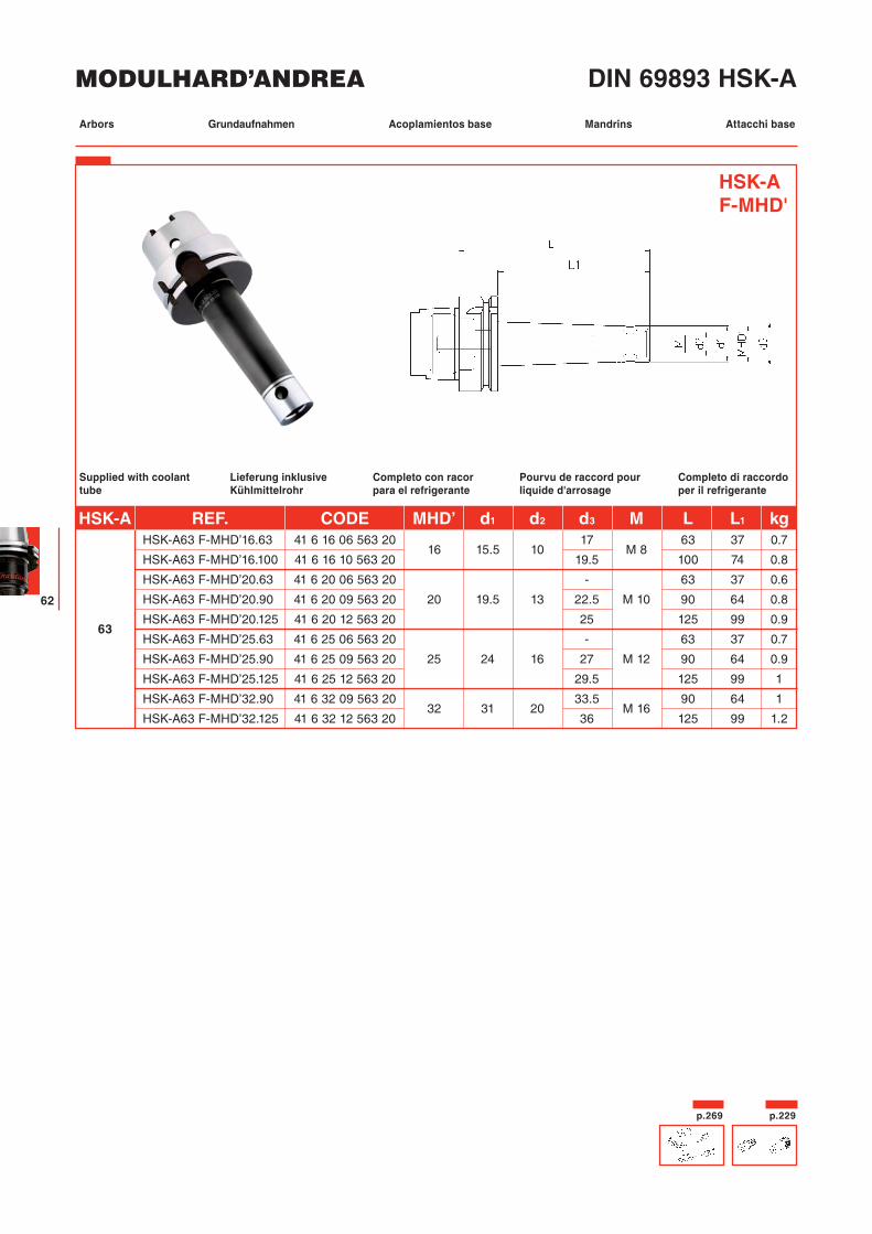
DIN 69893 HSK-A
HSK-A F-MHD'
Lieferung inklusive Kühlmittelrohr
Completo con racorpara el refrigerante
Pourvu de raccord pour liquide d'arrosage
Completo di raccordo per il refrigerante
Supplied with coolant tube
HSK-A REF. CODE MHD’ d1 d2 d3 M L L1 kg HSK-A63 F-MHD’16.63 41 6 16 06 563 20
16 15.5 10 17
M 8 63 37 0.7
HSK-A63 F-MHD’16.100 41 6 16 10 563 20 19.5 100 74 0.8
HSK-A63 F-MHD’20.63 41 6 20 06 563 20 - 63 37 0.6
HSK-A63 F-MHD’20.90 41 6 20 09 563 20 20 19.5 13 22.5 M 10 90 64 0.8
63
HSK-A63 F-MHD’20.125 41 6 20 12 563 20 25 125 99 0.9
HSK-A63 F-MHD’25.63 41 6 25 06 563 20 - 63 37 0.7
HSK-A63 F-MHD’25.90 41 6 25 09 563 20 25 24 16 27 M 12 90 64 0.9
HSK-A63 F-MHD’25.125 41 6 25 12 563 20 29.5 125 99 1
HSK-A63 F-MHD’32.90 41 6 32 09 563 20 32 31 20
33.5 M 16
90 64 1
HSK-A63 F-MHD’32.125 41 6 32 12 563 20 36 125 99 1.2
Grundaufnahmen Acoplamientos base Mandrins Attacchi baseArbors
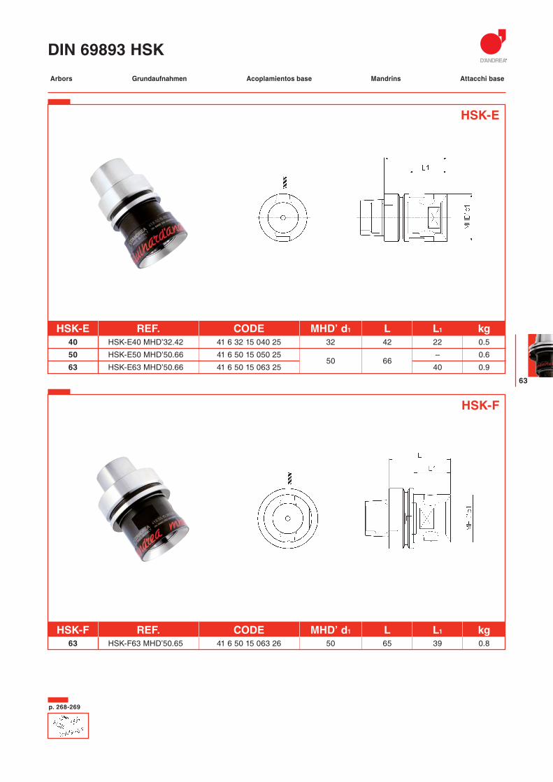
63
p. 268-269
DIN 69893 HSK
HSK-E
HSK-F
HSK-F REF. CODE MHD’ d1 L L1 kg 63 HSK-F63 MHD’50.65 41 6 50 15 063 26 50 65 39 0.8
HSK-E REF. CODE MHD’ d1 L L1 kg 40 HSK-E40 MHD’32.42 41 6 32 15 040 25 32 42 22 0.5
50 HSK-E50 MHD’50.66 41 6 50 15 050 25 50 66
– 0.6
63 HSK-E63 MHD’50.66 41 6 50 15 063 25 40 0.9
Grundaufnahmen Acoplamientos base Mandrins Attacchi baseArbors
MODULHARD’ANDREA
64
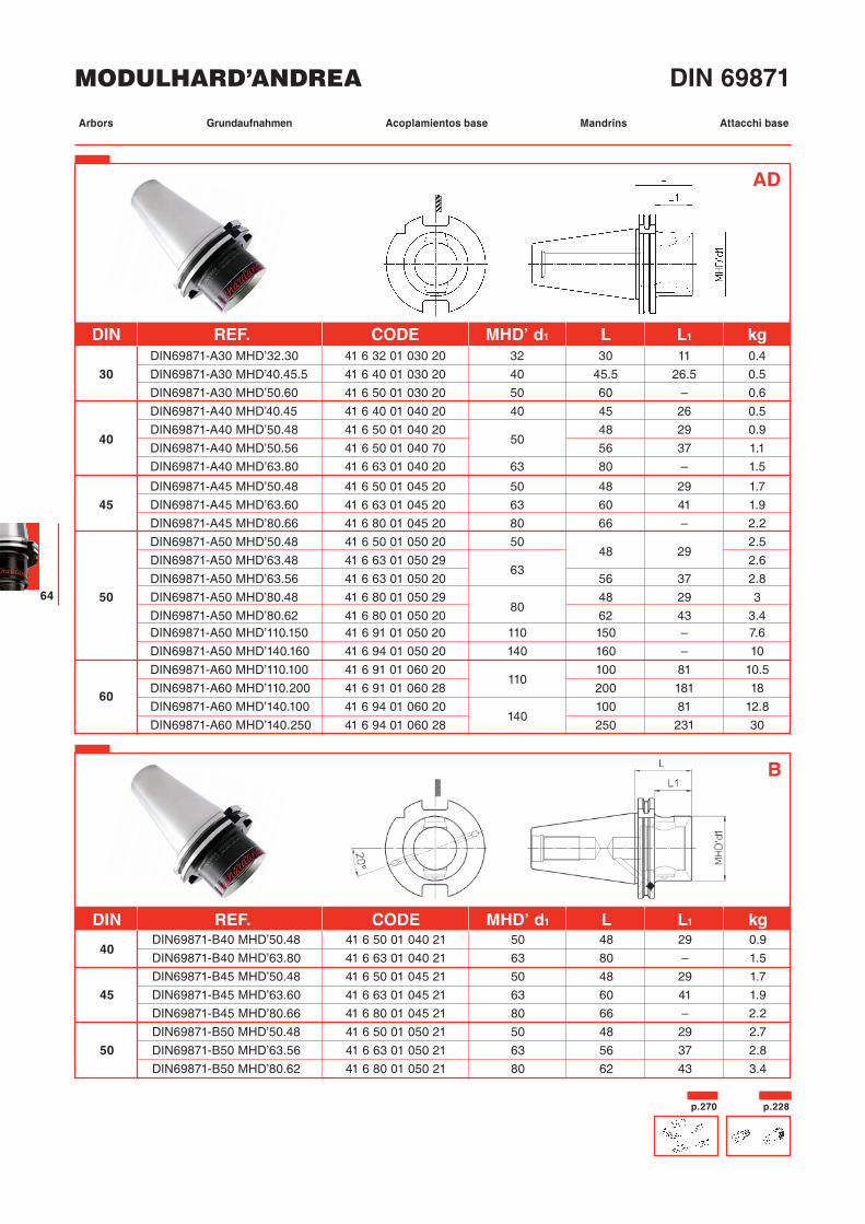
DIN 69871
p.270 p.228
AD
Grundaufnahmen Acoplamientos base Mandrins Attacchi baseArbors
B
DIN REF. CODE MHD’ d1 L L1 kg
40 DIN69871-B40 MHD’50.48 41 6 50 01 040 21 50 48 29 0.9
DIN69871-B40 MHD’63.80 41 6 63 01 040 21 63 80 – 1.5
DIN69871-B45 MHD’50.48 41 6 50 01 045 21 50 48 29 1.7
45 DIN69871-B45 MHD’63.60 41 6 63 01 045 21 63 60 41 1.9
DIN69871-B45 MHD’80.66 41 6 80 01 045 21 80 66 – 2.2
DIN69871-B50 MHD’50.48 41 6 50 01 050 21 50 48 29 2.7
50 DIN69871-B50 MHD’63.56 41 6 63 01 050 21 63 56 37 2.8
DIN69871-B50 MHD’80.62 41 6 80 01 050 21 80 62 43 3.4
DIN REF. CODE MHD’ d1 L L1 kg DIN69871-A30 MHD’32.30 41 6 32 01 030 20 32 30 11 0.4
30 DIN69871-A30 MHD’40.45.5 41 6 40 01 030 20 40 45.5 26.5 0.5
DIN69871-A30 MHD’50.60 41 6 50 01 030 20 50 60 – 0.6
DIN69871-A40 MHD’40.45 41 6 40 01 040 20 40 45 26 0.5
40
DIN69871-A40 MHD’50.48 41 6 50 01 040 20 50
48 29 0.9
DIN69871-A40 MHD’50.56 41 6 50 01 040 70 56 37 1.1
DIN69871-A40 MHD’63.80 41 6 63 01 040 20 63 80 – 1.5
DIN69871-A45 MHD’50.48 41 6 50 01 045 20 50 48 29 1.7
45 DIN69871-A45 MHD’63.60 41 6 63 01 045 20 63 60 41 1.9
DIN69871-A45 MHD’80.66 41 6 80 01 045 20 80 66 – 2.2
DIN69871-A50 MHD’50.48 41 6 50 01 050 20 50 48 29
2.5
DIN69871-A50 MHD’63.48 41 6 63 01 050 29 63
2.6
DIN69871-A50 MHD’63.56 41 6 63 01 050 20 56 37 2.8
50 DIN69871-A50 MHD’80.48 41 6 80 01 050 29 80
48 29 3
DIN69871-A50 MHD’80.62 41 6 80 01 050 20 62 43 3.4
DIN69871-A50 MHD’110.150 41 6 91 01 050 20 110 150 – 7.6
DIN69871-A50 MHD’140.160 41 6 94 01 050 20 140 160 – 10
DIN69871-A60 MHD’110.100 41 6 91 01 060 20 110
100 81 10.5
60
DIN69871-A60 MHD’110.200 41 6 91 01 060 28 200 181 18
DIN69871-A60 MHD’140.100 41 6 94 01 060 20 140
100 81 12.8
DIN69871-A60 MHD’140.250 41 6 94 01 060 28 250 231 30
65
p. 270p. 228
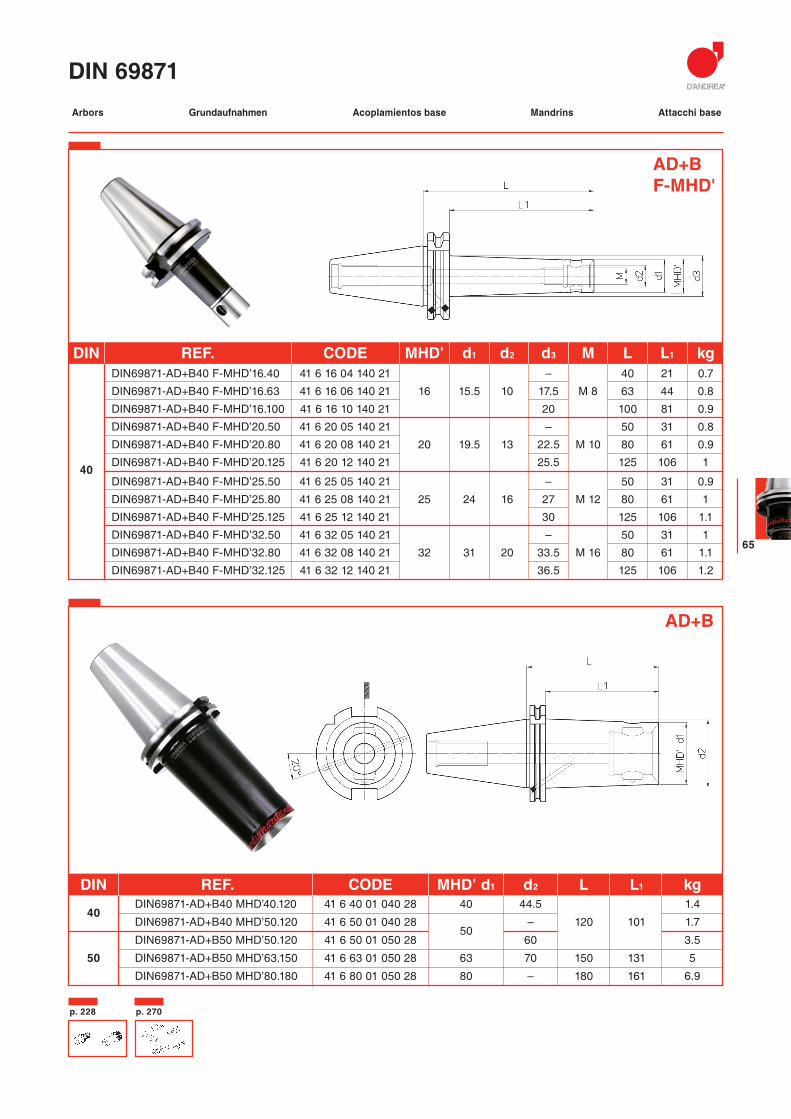
DIN 69871
AD+BF-MHD'
DIN REF. CODE MHD’ d1 d2 d3 M L L1 kg DIN69871-AD+B40 F-MHD’16.40 41 6 16 04 140 21 – 40 21 0.7
DIN69871-AD+B40 F-MHD’16.63 41 6 16 06 140 21 16 15.5 10 17.5 M 8 63 44 0.8
DIN69871-AD+B40 F-MHD’16.100 41 6 16 10 140 21 20 100 81 0.9
DIN69871-AD+B40 F-MHD’20.50 41 6 20 05 140 21 – 50 31 0.8
DIN69871-AD+B40 F-MHD’20.80 41 6 20 08 140 21 20 19.5 13 22.5 M 10 80 61 0.9
40
DIN69871-AD+B40 F-MHD’20.125 41 6 20 12 140 21 25.5 125 106 1
DIN69871-AD+B40 F-MHD’25.50 41 6 25 05 140 21 – 50 31 0.9
DIN69871-AD+B40 F-MHD’25.80 41 6 25 08 140 21 25 24 16 27 M 12 80 61 1
DIN69871-AD+B40 F-MHD’25.125 41 6 25 12 140 21 30 125 106 1.1
DIN69871-AD+B40 F-MHD’32.50 41 6 32 05 140 21 – 50 31 1
DIN69871-AD+B40 F-MHD’32.80 41 6 32 08 140 21 32 31 20 33.5 M 16 80 61 1.1
DIN69871-AD+B40 F-MHD’32.125 41 6 32 12 140 21 36.5 125 106 1.2
AD+B
DIN REF. CODE MHD’ d1 d2 L L1 kg
40 DIN69871-AD+B40 MHD’40.120 41 6 40 01 040 28 40 44.5
1.4
DIN69871-AD+B40 MHD’50.120 41 6 50 01 040 28 50
– 120 101 1.7
DIN69871-AD+B50 MHD’50.120 41 6 50 01 050 28 60 3.5
50 DIN69871-AD+B50 MHD’63.150 41 6 63 01 050 28 63 70 150 131 5
DIN69871-AD+B50 MHD’80.180 41 6 80 01 050 28 80 – 180 161 6.9
Grundaufnahmen Acoplamientos base Mandrins Attacchi baseArbors
MODULHARD’ANDREA
66
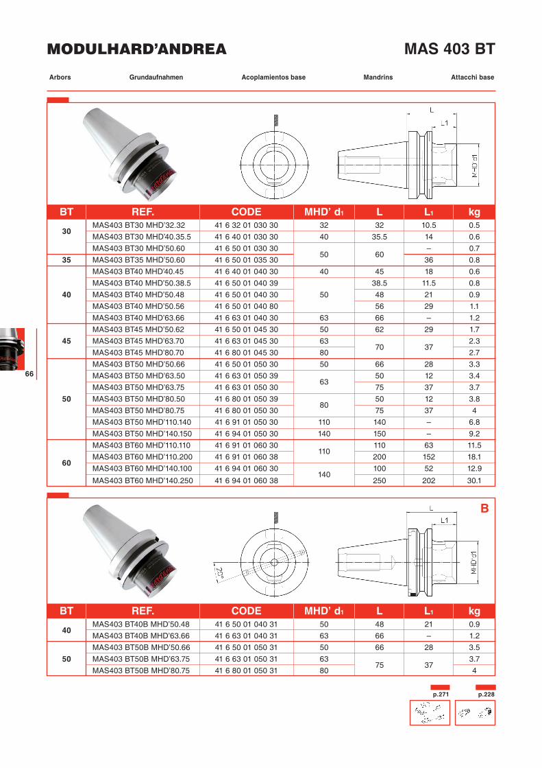
MAS 403 BT
B
p.271 p.228
Grundaufnahmen Acoplamientos base Mandrins Attacchi baseArbors
BT REF. CODE MHD’ d1 L L1 kg
30 MAS403 BT30 MHD’32.32 41 6 32 01 030 30 32 32 10.5 0.5
MAS403 BT30 MHD’40.35.5 41 6 40 01 030 30 40 35.5 14 0.6
MAS403 BT30 MHD’50.60 41 6 50 01 030 30 50 60
– 0.7
35 MAS403 BT35 MHD’50.60 41 6 50 01 035 30 36 0.8
MAS403 BT40 MHD’40.45 41 6 40 01 040 30 40 45 18 0.6
MAS403 BT40 MHD’50.38.5 41 6 50 01 040 39 38.5 11.5 0.8
40 MAS403 BT40 MHD’50.48 41 6 50 01 040 30 50 48 21 0.9
MAS403 BT40 MHD’50.56 41 6 50 01 040 80 56 29 1.1
MAS403 BT40 MHD’63.66 41 6 63 01 040 30 63 66 – 1.2
MAS403 BT45 MHD’50.62 41 6 50 01 045 30 50 62 29 1.7
45 MAS403 BT45 MHD’63.70 41 6 63 01 045 30 63 70 37
2.3
MAS403 BT45 MHD’80.70 41 6 80 01 045 30 80 2.7
MAS403 BT50 MHD’50.66 41 6 50 01 050 30 50 66 28 3.3
MAS403 BT50 MHD’63.50 41 6 63 01 050 39 63
50 12 3.4
MAS403 BT50 MHD’63.75 41 6 63 01 050 30 75 37 3.7
50 MAS403 BT50 MHD’80.50 41 6 80 01 050 39 80
50 12 3.8
MAS403 BT50 MHD’80.75 41 6 80 01 050 30 75 37 4
MAS403 BT50 MHD’110.140 41 6 91 01 050 30 110 140 – 6.8
MAS403 BT50 MHD’140.150 41 6 94 01 050 30 140 150 – 9.2
MAS403 BT60 MHD’110.110 41 6 91 01 060 30 110
110 63 11.5
60
MAS403 BT60 MHD’110.200 41 6 91 01 060 38 200 152 18.1
MAS403 BT60 MHD’140.100 41 6 94 01 060 30 140
100 52 12.9
MAS403 BT60 MHD’140.250 41 6 94 01 060 38 250 202 30.1
BT REF. CODE MHD’ d1 L L1 kg
40 MAS403 BT40B MHD’50.48 41 6 50 01 040 31 50 48 21 0.9
MAS403 BT40B MHD’63.66 41 6 63 01 040 31 63 66 – 1.2
MAS403 BT50B MHD’50.66 41 6 50 01 050 31 50 66 28 3.5
50 MAS403 BT50B MHD’63.75 41 6 63 01 050 31 63 75 37
3.7
MAS403 BT50B MHD’80.75 41 6 80 01 050 31 80 4
67
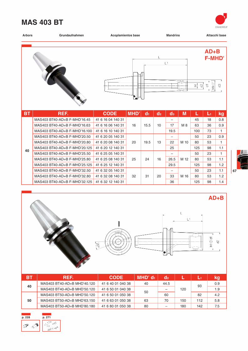
MAS 403 BT
BT REF. CODE MHD’ d1 d2 d3 M L L1 kg MAS403 BT40-AD+B F-MHD’16.45 41 6 16 04 140 31 – 45 18 0.8
MAS403 BT40-AD+B F-MHD’16.63 41 6 16 06 140 31 16 15.5 10 17 M 8 63 36 0.9
MAS403 BT40-AD+B F-MHD’16.100 41 6 16 10 140 31 19.5 100 73 1
MAS403 BT40-AD+B F-MHD’20.50 41 6 20 05 140 31 – 50 23 0.9
MAS403 BT40-AD+B F-MHD’20.80 41 6 20 08 140 31 20 19.5 13 22 M 10 80 53 1
40
MAS403 BT40-AD+B F-MHD’20.125 41 6 20 12 140 31 25 125 98 1.1
MAS403 BT40-AD+B F-MHD’25.50 41 6 25 05 140 31 – 50 23 1
MAS403 BT40-AD+B F-MHD’25.80 41 6 25 08 140 31 25 24 16 26.5 M 12 80 53 1.1
MAS403 BT40-AD+B F-MHD’25.125 41 6 25 12 140 31 29.5 125 98 1.2
MAS403 BT40-AD+B F-MHD’32.50 41 6 32 05 140 31 – 50 23 1.1
MAS403 BT40-AD+B F-MHD’32.80 41 6 32 08 140 31 32 31 20 33 M 16 80 53 1.2
MAS403 BT40-AD+B F-MHD’32.125 41 6 32 12 140 31 36 125 98 1.4
p. 271p. 228
AD+B
BT REF. CODE MHD’ d1 d2 L L1 kg
40 MAS403 BT40-AD+B MHD’40.120 41 6 40 01 040 38 40 44.5
93 0.9
MAS403 BT40-AD+B MHD’50.120 41 6 50 01 040 38 50
– 120 1.9
MAS403 BT50-AD+B MHD’50.120 41 6 50 01 050 38 60 82 4.2
50 MAS403 BT50-AD+B MHD’63.150 41 6 63 01 050 38 63 70 150 112 5.8
MAS403 BT50-AD+B MHD’80.180 41 6 80 01 050 38 80 – 180 142 7.5
AD+BF-MHD'
Grundaufnahmen Acoplamientos base Mandrins Attacchi baseArbors
MODULHARD’ANDREA
68
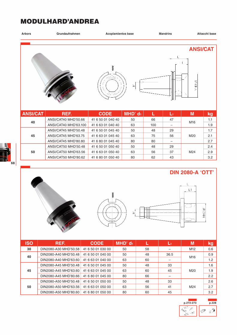
ANSI/CAT
p.272-273
DIN 2080-A ‘OTT’
ISO REF. CODE MHD’ d1 L L1 M kg 30 DIN2080-A30 MHD’50.58 41 6 50 01 030 00 50 58 – M12 0.6
40
DIN2080-A40 MHD’50.48 41 6 50 01 040 00 50 48 36.5 M16
0.9
DIN2080-A40 MHD’63.60 41 6 63 01 040 00 63 60 – 1.2
DIN2080-A45 MHD’50.48 41 6 50 01 045 00 50 48 33 1.6
45 DIN2080-A45 MHD’63.60 41 6 63 01 045 00 63 60 45 M20 1.9
DIN2080-A45 MHD’80.66 41 6 80 01 045 00 80 66 – 2.2
DIN2080-A50 MHD’50.48 41 6 50 01 050 00 50 48 33 2.6
50 DIN2080-A50 MHD’63.56 41 6 63 01 050 00 63 56 41 M24 2.7
DIN2080-A50 MHD’80.60 41 6 80 01 050 00 80 60 45 3.2
ANSI/CAT REF. CODE MHD’ d1 L L1 M kg
40 ANSI/CAT40 MHD’50.66 41 6 50 01 040 40 50 66 47
M16 1.1
ANSI/CAT40 MHD’63.100 41 6 63 01 040 40 63 100 – 1.9
ANSI/CAT45 MHD’50.48 41 6 50 01 045 40 50 48 29 1.7
45 ANSI/CAT45 MHD’63.75 41 6 63 01 045 40 63 75 56 M20 2.1
ANSI/CAT45 MHD’80.80 41 6 80 01 045 40 80 80 – 2.7
ANSI/CAT50 MHD’50.48 41 6 50 01 050 40 50 48 29 2.4
50 ANSI/CAT50 MHD’63.56 41 6 63 01 050 40 63 56 37 M24 2.9
ANSI/CAT50 MHD’80.62 41 6 80 01 050 40 80 62 43 3.2
p.228
Grundaufnahmen Acoplamientos base Mandrins Attacchi baseArbors
69
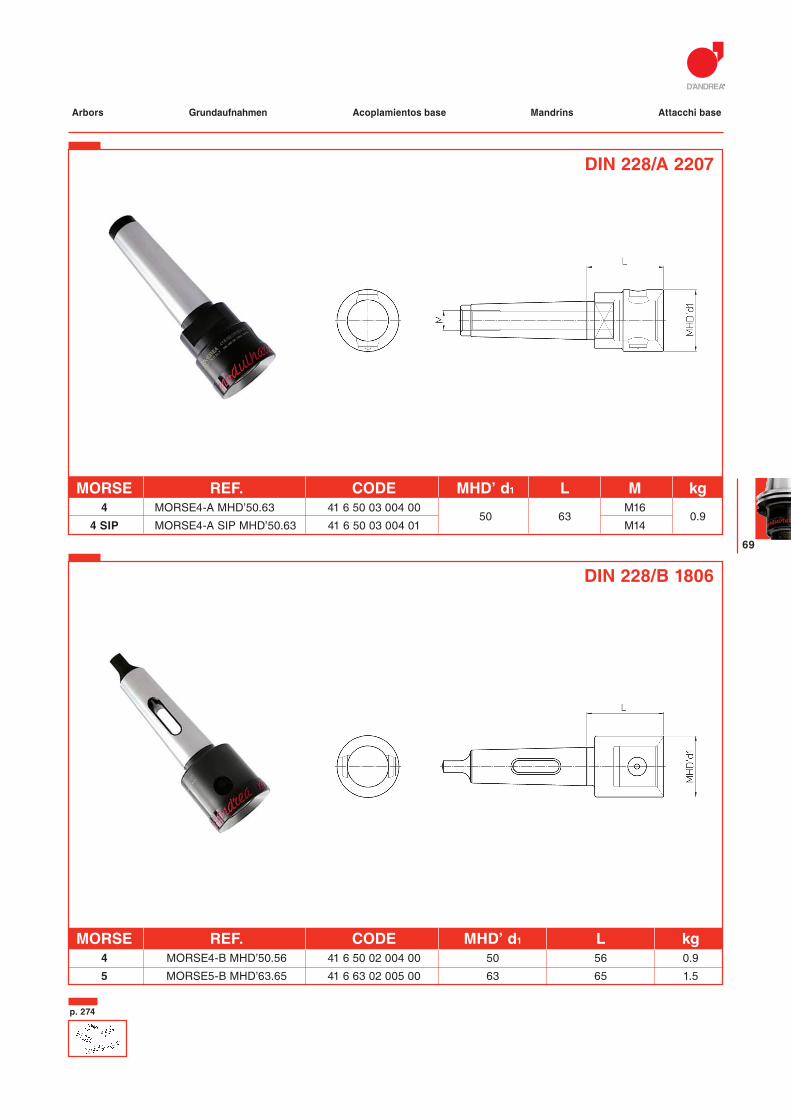
DIN 228/A 2207
MORSE REF. CODE MHD’ d1 L M kg 4 MORSE4-A MHD’50.63 41 6 50 03 004 00
50 63 M16
0.9
4 SIP MORSE4-A SIP MHD’50.63 41 6 50 03 004 01 M14
DIN 228/B 1806
MORSE REF. CODE MHD’ d1 L kg 4 MORSE4-B MHD’50.56 41 6 50 02 004 00 50 56 0.9
5 MORSE5-B MHD’63.65 41 6 63 02 005 00 63 65 1.5
p. 274
Grundaufnahmen Acoplamientos base Mandrins Attacchi baseArbors
MODULHARD’ANDREA
70
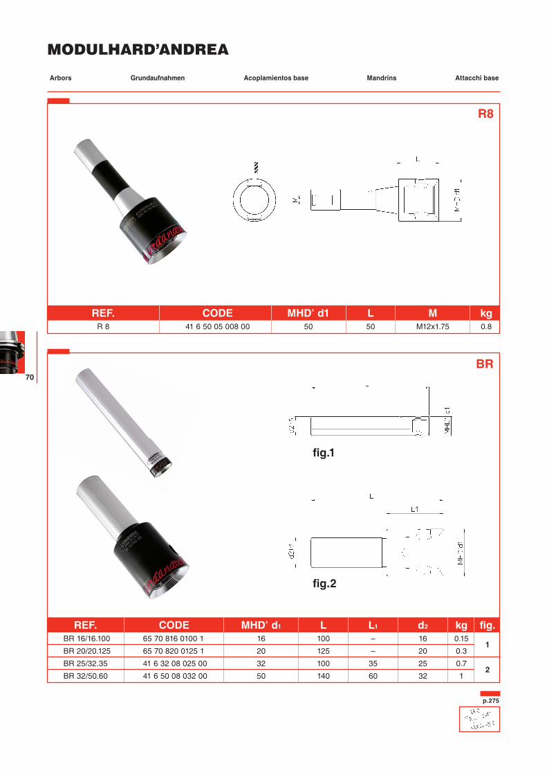
R8
BR
REF. CODE MHD’ d1 L M kg R 8 41 6 50 05 008 00 50 50 M12x1.75 0.8
REF. CODE MHD’ d1 L L1 d2 kg fig. BR 16/16.100 65 70 816 0100 1 16 100 – 16 0.15
1
BR 20/20.125 65 70 820 0125 1 20 125 – 20 0.3
BR 25/32.35 41 6 32 08 025 00 32 100 35 25 0.7 2
BR 32/50.60 41 6 50 08 032 00 50 140 60 32 1
p.275
fig.1
fig.2
Grundaufnahmen Acoplamientos base Mandrins Attacchi baseArbors
71
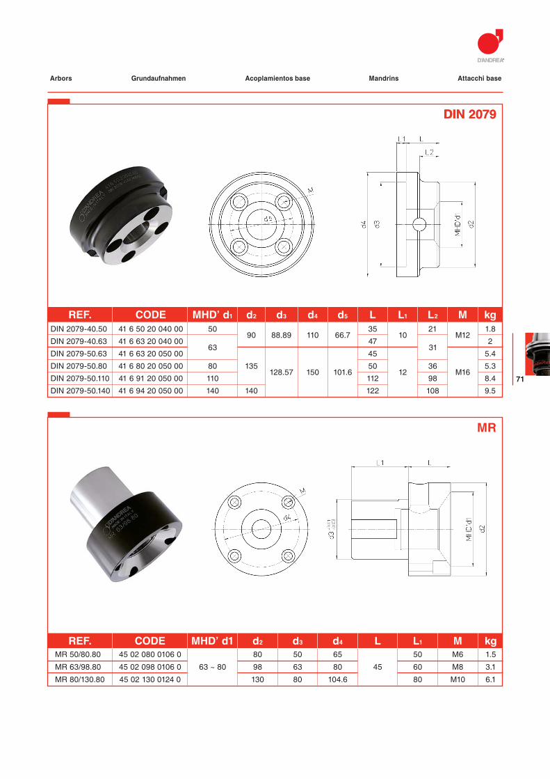
DIN 2079DIN 2079
MR
Grundaufnahmen Acoplamientos base Mandrins Attacchi baseArbors
REF. CODE MHD’ d1 d2 d3 d4 d5 L L1 L2 M kg DIN 2079-40.50 41 6 50 20 040 00 50
90 88.89 110 66.7 35
10 21
M12 1.8
DIN 2079-40.63 41 6 63 20 040 00 63
47 331
1 2
DIN 2079-50.63 41 6 63 20 050 00
45 5.4
DIN 2079-50.80 41 6 80 20 050 00 80 135 128.57
150
101.6
50 12
36 M16
5.3
DIN 2079-50.110 41 6 91 20 050 00 110
112 98 8.4
DIN 2079-50.140 41 6 94 20 050 00 140 140 122 108 9.5
REF. CODE MHD’ d1 d2 d3 d4 L L1 M kg MR 50/80.80 45 02 080 0106 0 80 50 65 50 M6 1.5
MR 63/98.80 45 02 098 0106 0 63 ~ 80 98 63 80 45 60 M8 3.1
MR 80/130.80 45 02 130 0124 0 130 80 104.6 80 M10 6.1
MODULHARD’ANDREA
72
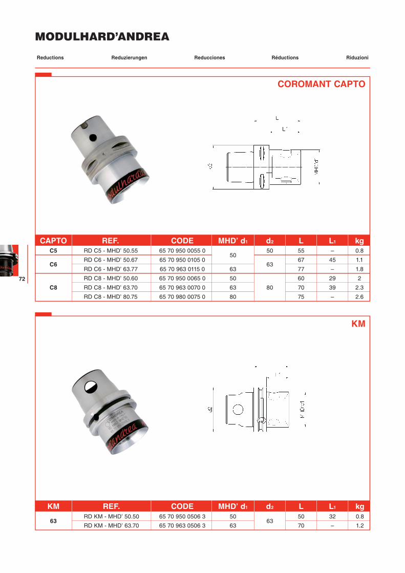
COROMANT CAPTO
Reduzierungen Reducciones Réductions RiduzioniReductions
CAPTO REF. CODE MHD’ d1 d2 L L1 kg C5 RD C5 - MHD’ 50.55 65 70 950 0055 0
50 50 55 – 0.8
C6
RD C6 - MHD’ 50.67 65 70 950 0105 0 63
67 45 1.1
RD C6 - MHD’ 63.77 65 70 963 0115 0 63 77 – 1.8
RD C8 - MHD’ 50.60 65 70 950 0065 0 50 60 29 2
C8 RD C8 - MHD’ 63.70 65 70 963 0070 0 63 80 70 39 2.3
RD C8 - MHD’ 80.75 65 70 980 0075 0 80 75 – 2.6
KM
KM REF. CODE MHD’ d1 d2 L L1 kg
63 RD KM - MHD’ 50.50 65 70 950 0506 3 50
63 50 32 0.8
RD KM - MHD’ 63.70 65 70 963 0506 3 63 70 – 1.2
73
MODULHARD’ANDREA
74
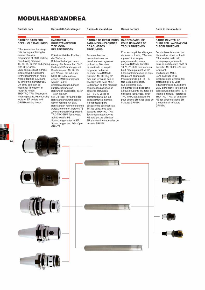
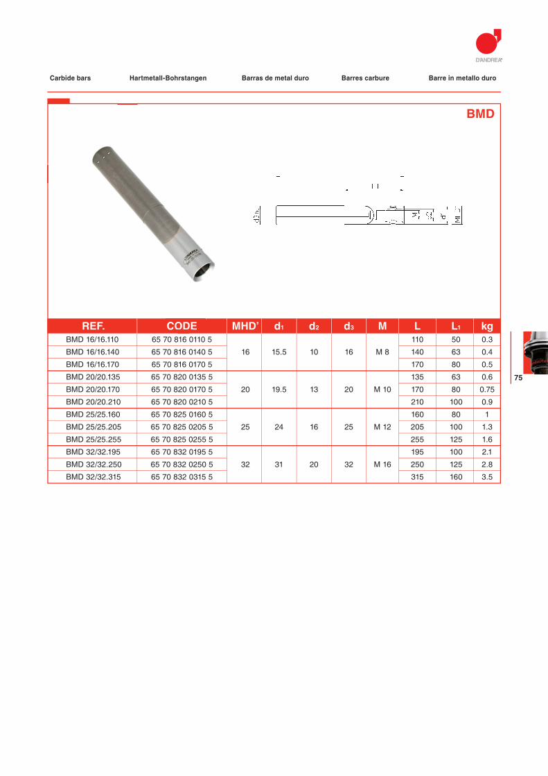
Hartmetall-Bohrstangen Barras de metal duro Barres carbure Barre in metallo duroCarbide bars
CARBIDE BARS FOR DEEP-HOLE MACHINING
D’Andrea solves the deep-hole boring machining by means of a wide programme of BMD carbide bars having diameter 16, 20, 25, 32 mm and ending with MHD’ arbor.BMD bars are built in three different working lengths for the machining of holes, whose depth is 6.3, 8 and 10 times the diameter/bar.On BMD bars can be mounted: TS double-bit roughing heads, TRD-TRC-TRM Testarossa finishing heads, PE chucking tools for ER collets and GRINTA milling heads.
HARTMETALL-BOHRSTANGENFÜR TIEFLOCH-BEARBEITUNGEN
D’Andrea löst das Problem der Tiefloch-Bohrbearbeitungen durch eine große Auswahl an BMD Hartmetall-Bohrstangen mit Durchmessern 16, 20, 25 und 32 mm, die mit einer MHD’ Grundaufnahme enden. BMD Bohrstangen werden in drei unterschiedlichen Längen zur Bearbeitung von Bohrungen angeboten, deren Tiefen bis zum 6,3- , 8- oder 10-fachen des Bohrstangendurchmessers gehen können. An BMD Bohrstangen können folgende Aufsätze montiert werden: TS Zweischneiderschruppköpfe, TRD-TRC-TRM Testarossa Schlichtköpfe, PE Spannzangenfutter für ER Spannzangen und Fräsköpfe GRINTA.
BARRAS DE METAL DURO PARA MECANIZACIONES DE AGUJEROS PROFUNDOS
Para resolver las mecanizaciones de mandrinado en agujeros profundos, D’Andrea ha realizado un amplio programa de barras de metal duro BMD de diámetro 16, 20, 25 y 32 mm, que terminan con el acoplamiento base MHD’. Se fabrican en tres medidas para mecanizaciones en agujeros profundos 6,3 – 8 y 10 veces el diámetro/barra. En las barras BMD se montan: los cabezales para desbaste de dos cuchillas TS, los cabezales para acabado TRD-TRC-TRM Testarossa,adaptadores PE para pinzas elásticas ER y los testine cabezales de fresado GRINTA.
BARRES CARBURE POUR USINAGES DE TROUS PROFONDS
Pour accomplir les alésages de trous profonds, D’Andrea a projecté un ample programme de barres carbure BMD de diamètre 16,20, 25 et 32 mm, avec au bout l’accouplement MHD’.Elles sont fabriquées en trois longueurs pour usiner trous profonds 6,3 – 8 – 10 fois le diamètre/barre.Sur les barres BMD on monte: têtes d’ébauche à deux coupants TS, têtes de finissage Testarossa TRD-TRC-TRM, adaptateurs PE pour pinces ER et les têtes de fraisage GRINTA.
BARRE IN METALLO DURO PER LAVORAZIONI DI FORI PROFONDI
Per risolvere le lavorazioni di alesatura di fori profondi D’Andrea ha realizzato un ampio programma di barre in metallo duro BMD di diametro 16, 20,25 e 32 mm, terminanti con l’attacco MHD’.Sono costruite in tre lunghezze per lavorare fori profondi 6,3-8-10 volte il diametro/barra.Sulle barre BMD si montano: le testine di sgrossatura bitaglienti TS, le testine di finitura Testarossa TRD-TRC-TRM, gli adattatori PE per pinze elastiche ER e le testine di fresatura GRINTA.
75
Hartmetall-Bohrstangen Barras de metal duro Barres carbure Barre in metallo duroCarbide bars
BMD
REF. CODE MHD’ d1 d2 d3 M L L1 kg BMD 16/16.110 65 70 816 0110 5 110 50 0.3
BMD 16/16.140 65 70 816 0140 5 16 15.5 10 16 M 8 140 63 0.4
BMD 16/16.170 65 70 816 0170 5 170 80 0.5
BMD 20/20.135 65 70 820 0135 5 135 63 0.6
BMD 20/20.170 65 70 820 0170 5 20 19.5 13 20 M 10 170 80 0.75
BMD 20/20.210 65 70 820 0210 5 210 100 0.9
BMD 25/25.160 65 70 825 0160 5 160 80 1
BMD 25/25.205 65 70 825 0205 5 25 24 16 25 M 12 205 100 1.3
BMD 25/25.255 65 70 825 0255 5 255 125 1.6
BMD 32/32.195 65 70 832 0195 5 195 100 2.1
BMD 32/32.250 65 70 832 0250 5 32 31 20 32 M 16 250 125 2.8
BMD 32/32.315 65 70 832 0315 5 315 160 3.5
CODE16
MODULHARD’ANDREA
76
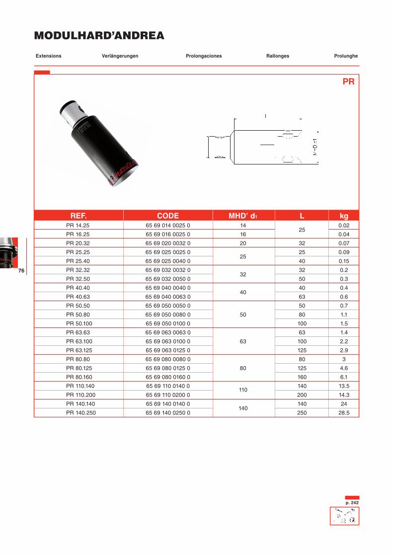
Verlängerungen Prolongaciones Rallonges ProlungheExtensions
PR
p. 242
REF. CODE MHD’ d1 L kg PR 14.25 65 69 014 0025 0 14
25 0.02
PR 16.25 65 69 016 0025 0 16 0.04
PR 20.32 65 69 020 0032 0 20 32 0.07
PR 25.25 65 69 025 0025 0 25
25 0.09
PR 25.40 65 69 025 0040 0 40 0.15
PR 32.32 65 69 032 0032 0 32
32 0.2
PR 32.50 65 69 032 0050 0 50 0.3
PR 40.40 65 69 040 0040 0 40
40 0.4
PR 40.63 65 69 040 0063 0 63 0.6
PR 50.50 65 69 050 0050 0 50 0.7
PR 50.80 65 69 050 0080 0 50 80 1.1
PR 50.100 65 69 050 0100 0 100 1.5
PR 63.63 65 69 063 0063 0 63 1.4
PR 63.100 65 69 063 0100 0 63 100 2.2
PR 63.125 65 69 063 0125 0 125 2.9
PR 80.80 65 69 080 0080 0 80 3
PR 80.125 65 69 080 0125 0 80 125 4.6
PR 80.160 65 69 080 0160 0 160 6.1
PR 110.140 65 69 110 0140 0 110
140 13.5
PR 110.200 65 69 110 0200 0 200 14.3
PR 140.140 65 69 140 0140 0 140
140 24
PR 140.250 65 69 140 0250 0 250 28.5
77
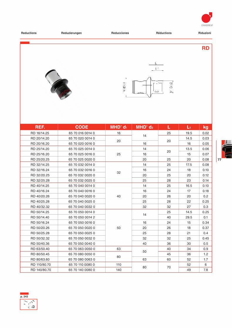
Reduzierungen Reducciones Réductions RiduzioniReductions
RD
p. 242
REF. CODE MHD’ d1 MHD’ d2 L L1 kg RD 16/14.25 65 70 016 0014 0 16
14 25 19.5 0.02
RD 20/14.20 65 70 020 0014 0 20
20
14.5 0.03
RD 20/16.20 65 70 020 0016 0 16 16 0.05
RD 25/14.20 65 70 025 0014 0 14 20
13.5 0.06
RD 25/16.20 65 70 025 0016 0 25 16 15 0.07
RD 25/20.25 65 70 025 0020 0 20 25 20 0.08
RD 32/14.25 65 70 032 0014 0 14 25 17.5 0.08
RD 32/16.24 65 70 032 0016 0 32
16 24 18 0.10
RD 32/20.25 65 70 032 0020 0 20 25 20 0.12
RD 32/25.28 65 70 032 0025 0 25 28 23 0.14
RD 40/14.25 65 70 040 0014 0 14 25 16.5 0.10
RD 40/16.24 65 70 040 0016 0 16 24 17 0.18
RD 40/20.26 65 70 040 0020 0 40 20 26 20 0.2
RD 40/25.28 65 70 040 0025 0 25 28 22 0.25
RD 40/32.32 65 70 040 0032 0 32 32 27 0.3
RD 50/14.25 65 70 050 0014 0 14
25 14.5 0.25
RD 50/14.40 65 70 050 0014 2 40 29.5 0.1
RD 50/16.24 65 70 050 0016 0 16 24 15 0.34
RD 50/20.26 65 70 050 0020 0 50 20 26 18 0.37
RD 50/25.28 65 70 050 0025 0 25 28 21 0.4
RD 50/32.32 65 70 050 0032 0 32 32 25 0.45
RD 50/40.36 65 70 050 0040 0 40 36 30 0.5
RD 63/50.40 65 70 063 0050 0 63 50
40 34 0.9
RD 80/50.45 65 70 080 0050 0 80
45 36 1.2
RD 80/63.60 65 70 080 0063 0 63 60 52 1.7
RD 110/80.70 65 70 110 0080 0 110 80
70
52 6
RD 140/80.70 65 70 140 0080 0 140 49 7.8
MODULHARD’ANDREA
78
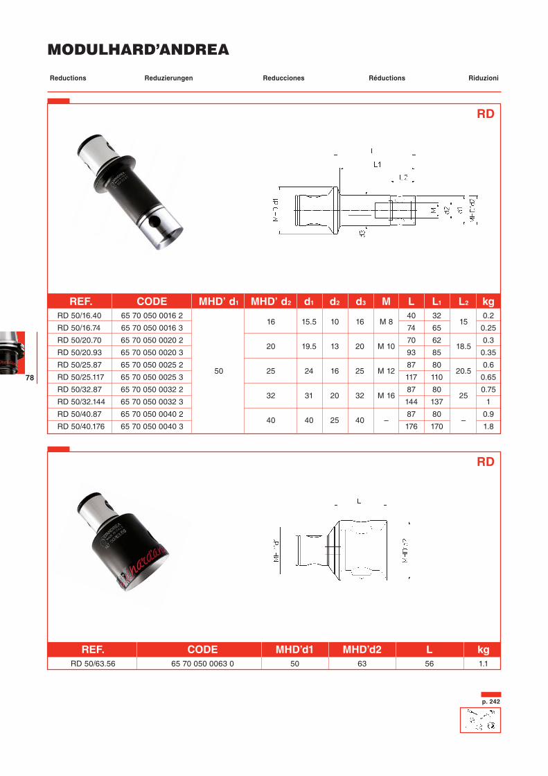
RD
p. 242
REF. CODE MHD’d1 MHD’d2 L kg
RD 50/63.56 65 70 050 0063 0 50 63 56 1.1
RD
Reduzierungen Reducciones Réductions RiduzioniReductions
REF. CODE MHD’ d1 MHD’ d2 d1 d2 d3 M L L1 L2 kg RD 50/16.40 65 70 050 0016 2
16 15.5 10 16 M 8 40 32
15 0.2
RD 50/16.74 65 70 050 0016 3 74 65 0.25
RD 50/20.70 65 70 050 0020 2 20 19.5 13 20 M 10
70 62 18.5
0.3
RD 50/20.93 65 70 050 0020 3 93 85 0.35
RD 50/25.87 65 70 050 0025 2 50
25 24 16 25 M 12
87 80 20.5
0.6
RD 50/25.117 65 70 050 0025 3 117 110 0.65
RD 50/32.87 65 70 050 0032 2 32 31 20 32 M 16
87 80 25
0.75
RD 50/32.144 65 70 050 0032 3 144 137 1
RD 50/40.87 65 70 050 0040 2 40 40 25 40 –
87 80 –
0.9
RD 50/40.176 65 70 050 0040 3 176 170 1.8
79
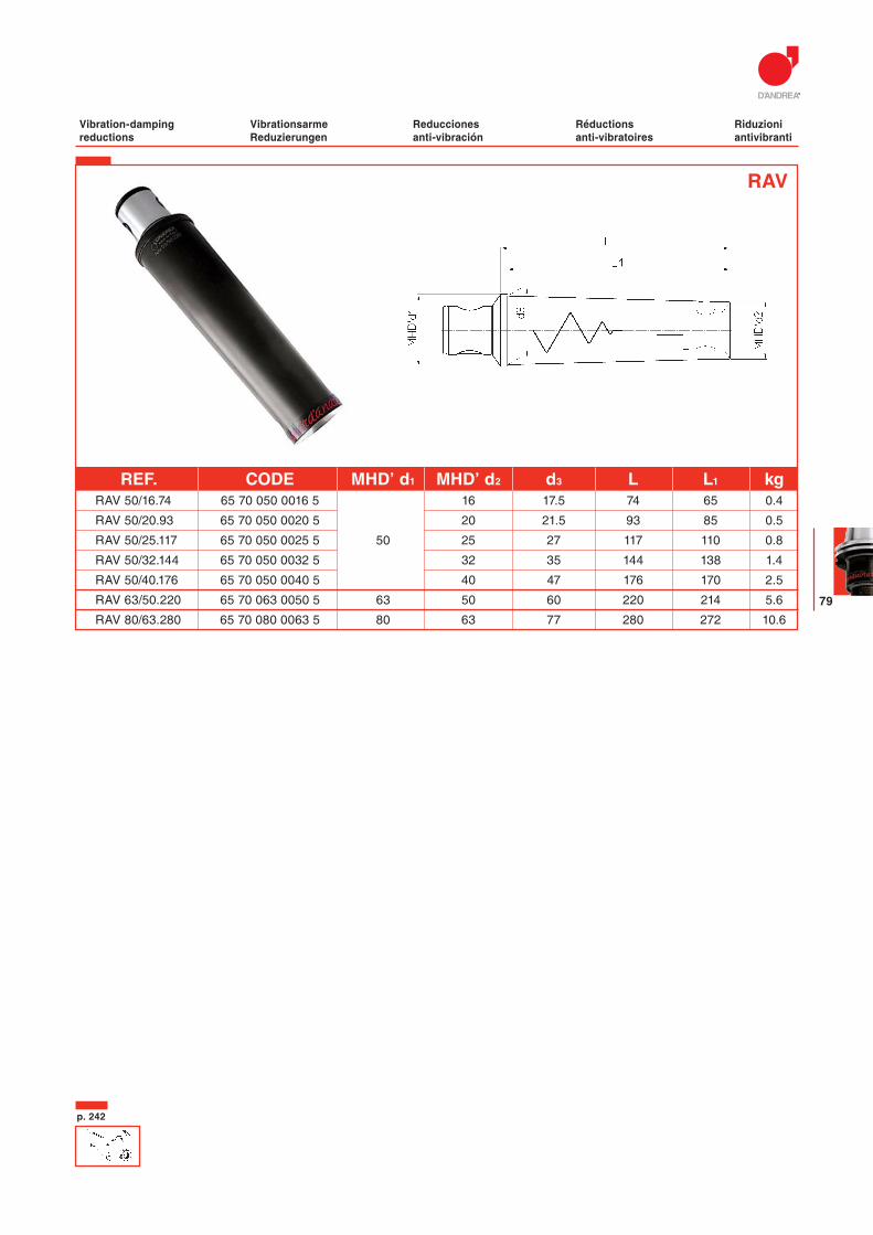
Vibrationsarme Reduzierungen
Reducciones anti-vibración
Réductions anti-vibratoires
Riduzioni antivibranti
Vibration-damping reductions
REF. CODE MHD’ d1 MHD’ d2 d3 L L1 kg RAV 50/16.74 65 70 050 0016 5 16 17.5 74 65 0.4
RAV 50/20.93 65 70 050 0020 5 20 21.5 93 85 0.5
RAV 50/25.117 65 70 050 0025 5 50 25 27 117 110 0.8
RAV 50/32.144 65 70 050 0032 5 32 35 144 138 1.4
RAV 50/40.176 65 70 050 0040 5 40 47 176 170 2.5
RAV 63/50.220 65 70 063 0050 5 63 50 60 220 214 5.6
RAV 80/63.280 65 70 080 0063 5 80 63 77 280 272 10.6
RAV
p. 242
MODULHARD’ANDREA
80
Auswuchtringe Anillos de equilibrado Bagues d’équilibrage Anelli di bilanciaturaBalancing rings
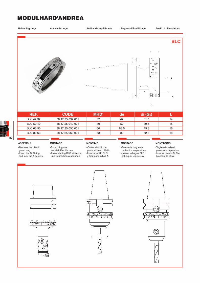
MONTAGE
- Schutzring aus Kunststoff entfernen.- Auswuchtring BLC einsetzen und Schrauben A spannen.
MONTAJE
- Quitar el anillo de protección en plástico
- Insertar anillo BLC y fijar los tornillos A.
MONTAGE
- Enlever la bague de protection en plastique
- Insérer la bague BLC et bloquer les clefs A.
MONTAGGIO
- Togliere l'anello di protezione in plastica- Inserire l'anello BLC e bloccare le viti A.
ASSEMBLY
- Remove the plastic guard ring
- Insert the BLC ring and lock the A screws.
BLC
REF. CODE MHD’ de di (G6) L BLC 42.32 38 17 25 032 001 32 42 31.5 14
BLC 50.40 38 17 25 040 001 40 50 39.5 15
BLC 63.50 38 17 25 050 001 50 63.5 49.8 16
BLC 80.63 38 17 25 063 001 63 80 62.8 18
81
Auswuchtringe Anillos de equilibrado Bagues d’équilibrage Anelli di bilanciaturaBalancing rings
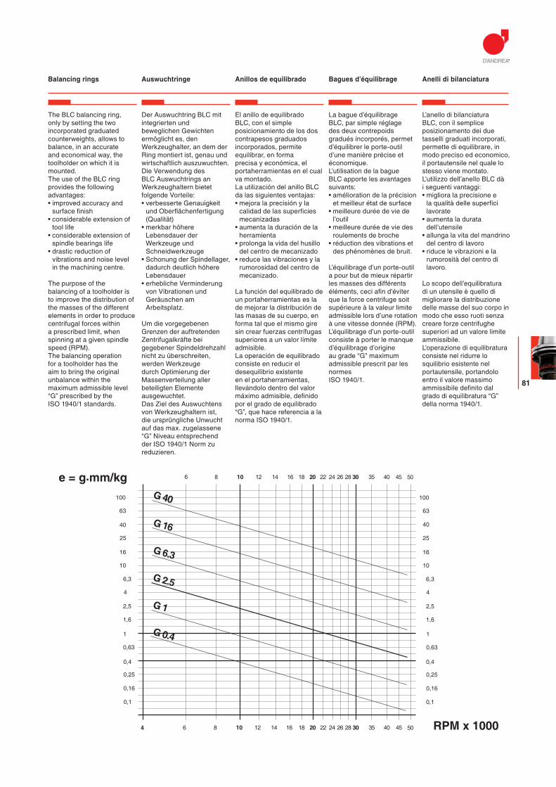
The BLC balancing ring, only by setting the two incorporated graduated counterweights, allows to balance, in an accurate and economical way, the toolholder on which it is mounted.The use of the BLC ring provides the following advantages:• improved accuracy and
surface finish• considerable extension of
tool life• considerable extension of
spindle bearings life• drastic reduction of
vibrations and noise level in the machining centre.
The purpose of the balancing of a toolholder is to improve the distribution of the masses of the different elements in order to produce centrifugal forces within a prescribed limit, when spinning at a given spindle speed (RPM).The balancing operation for a toolholder has the aim to bring the original unbalance within the maximum admissible level “G” prescribed by the ISO 1940/1 standards.
Der Auswuchtring BLC mit integrierten und beweglichen Gewichten ermöglicht es, den Werkzeughalter, an dem der Ring montiert ist, genau und wirtschaftlich auszuwuchten.Die Verwendung des BLC Auswuchtrings an Werkzeughaltern bietet folgende Vorteile:• verbesserte Genauigkeit
und Oberflächenfertigung (Qualität)
• merkbar höhere Lebensdauer der Werkzeuge und Schneidwerkzeuge
• Schonung der Spindellager, dadurch deutlich höhere Lebensdauer
• erhebliche Verminderung von Vibrationen und Geräuschen am Arbeitsplatz.
Um die vorgegebenen Grenzen der auftretenden Zentrifugalkräfte bei gegebener Spindeldrehzahl nicht zu überschreiten, werden Werkzeuge durch Optimierung der Massenverteilung aller beteiligten Elemente ausgewuchtet. Das Ziel des Auswuchtens von Werkzeughaltern ist, die ursprüngliche Unwucht auf das max. zugelassene “G” Niveau entsprechend der ISO 1940/1 Norm zu reduzieren.
El anillo de equilibrado BLC, con el simple posicionamiento de los dos contrapesos graduados incorporados, permite equilibrar, en forma precisa y económica, el portaherramientas en el cual va montado.La utilización del anillo BLC da las siguientes ventajas:• mejora la precisión y la
calidad de las superficies mecanizadas
• aumenta la duración de la herramienta
• prolonga la vida del husillo del centro de mecanizado
• reduce las vibraciones y la rumorosidad del centro de mecanizado.
La función del equilibrado de un portaherramientas es la de mejorar la distribución de las masas de su cuerpo, en forma tal que el mismo gire sin crear fuerzas centrífugas superiores a un valor límite admisible.La operación de equilibrado consiste en reducir el desequilibrio existente en el portaherramientas, llevándolo dentro del valor máximo admisible, definido por el grado de equilibrado “G”, que hace referencia a la norma ISO 1940/1.
La bague d’équilibrage BLC, par simple réglage des deux contrepoids gradués incorporés, permet d’équilibrer le porte-outil d’une manière précise et économique.L’utilisation de la bague BLC apporte les avantages suivants:• amélioration de la précision
et meilleur état de surface• meilleure durée de vie de
l’outil• meilleure durée de vie des
roulements de broche• réduction des vibrations et
des phénomènes de bruit.
L’équilibrage d’un porte-outil a pour but de mieux répartir les masses des différents éléments, ceci afin d’éviter que la force centrifuge soit supérieure à la valeur limite admissible lors d’une rotation à une vitesse donnée (RPM).L’équilibrage d’un porte-outil consiste à porter le manque d’équilibrage d’origine au grade “G” maximum admissible prescrit par les normes ISO 1940/1.
L’anello di bilanciatura BLC, con il semplice posizionamento dei due tasselli graduati incorporati, permette di equilibrare, in modo preciso ed economico, il portautensile nel quale lo stesso viene montato. L’utilizzo dell’anello BLC dà i seguenti vantaggi:• migliora la precisione e
la qualità delle superfici lavorate
• aumenta la durata dell’utensile
• allunga la vita del mandrino del centro di lavoro
• riduce le vibrazioni e la rumorosità del centro di lavoro.
Lo scopo dell’equilibratura di un utensile è quello di migliorare la distribuzione delle masse del suo corpo in modo che esso ruoti senza creare forze centrifughe superiori ad un valore limite ammissibile.L’operazione di equilibratura consiste nel ridurre lo squilibrio esistente nel portautensile, portandolo entro il valore massimo ammissibile definito dal grado di equilibratura “G” della norma 1940/1.
G 16
G 6.3
G 2.5
G 1
G 0.4
G 40
6,3
10
16
25
40
63
100
10
16
25
40
63
100
86 10 12 14 16 18 20 22 24 26 28 30 35 40 45 50
0,1
0,16
0,25
0,4
0,63
1
1,6
2,5
4
0,1
RPM x 1000
0,16
0,25
0,4
0,63
1
1,6
2,5
4
6,3
4 6 8 10 12 14 16 18 20 22 24 26 28 30 35 40 45 50
e = g.mm/kg
MODULHARD’ANDREA
82
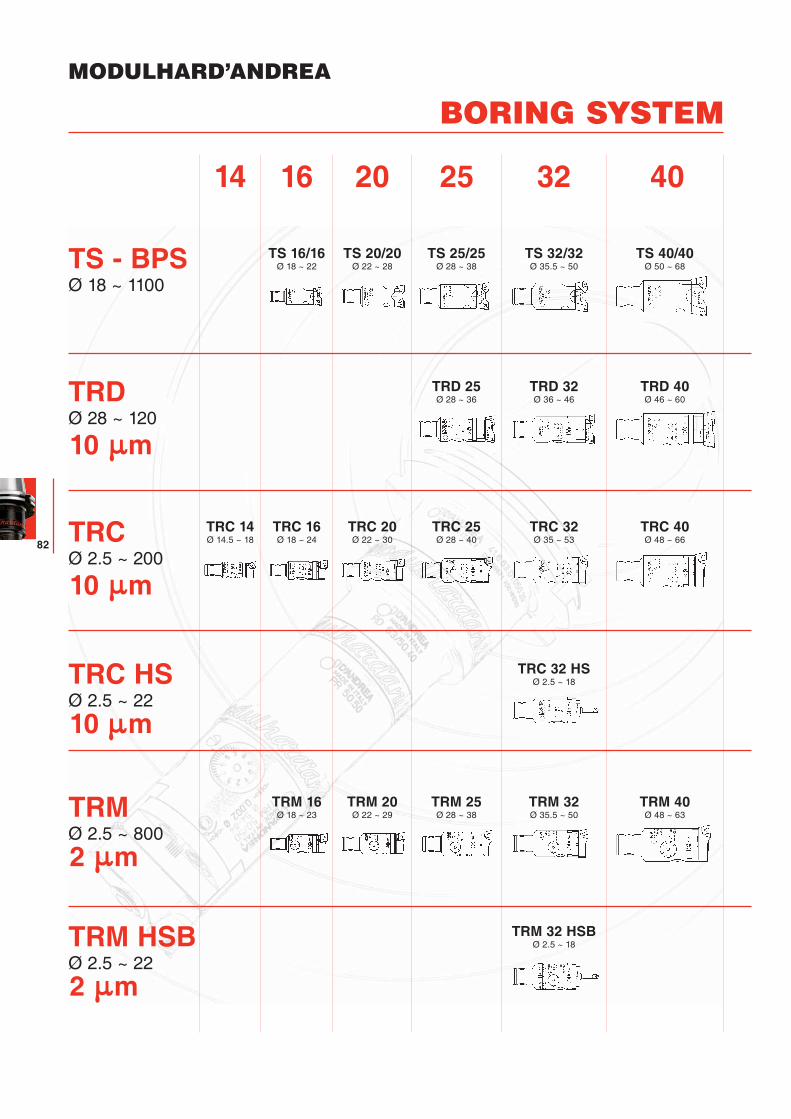
14 16 20 25 32 40
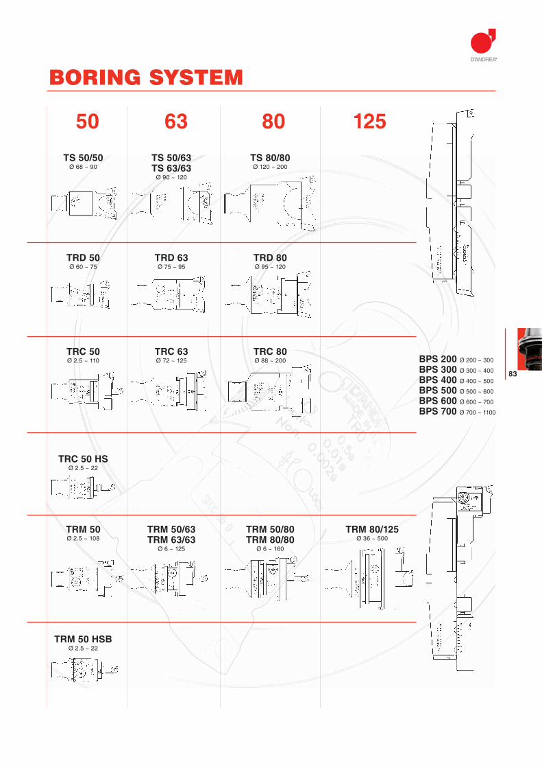
BORING SYSTEM
TS - BPSØ 18 ~ 1100
TRDØ 28 ~ 120
TRCØ 2.5 ~ 200
TRC HSØ 2.5 ~ 22
TRMØ 2.5 ~ 800
TRM HSBØ 2.5 ~ 22
10 m
10 m
10 m
2 m
2 m
TS 40/40Ø 50 ~ 68
TS 32/32Ø 35.5 ~ 50
TS 25/25Ø 28 ~ 38
TS 20/20Ø 22 ~ 28
TS 16/16Ø 18 ~ 22
TRD 40Ø 46 ~ 60
TRD 32Ø 36 ~ 46
TRD 25Ø 28 ~ 36
TRC 40Ø 48 ~ 66
TRC 32Ø 35 ~ 53
TRC 25Ø 28 ~ 40
TRC 20Ø 22 ~ 30
TRC 16Ø 18 ~ 24
TRC 14Ø 14.5 ~ 18
TRC 32 HSØ 2.5 ~ 18
TRM 40Ø 48 ~ 63
TRM 32Ø 35.5 ~ 50
TRM 25Ø 28 ~ 38
TRM 20Ø 22 ~ 29
TRM 16Ø 18 ~ 23
TRM 32 HSBØ 2.5 ~ 18
83
50 63 80 125
BORING SYSTEM
TS 50/63TS 63/63
Ø 90 ~ 120
TS 80/80Ø 120 ~ 200
TS 50/50Ø 68 ~ 90
TRD 50Ø 60 ~ 75
TRD 63Ø 75 ~ 95
TRD 80Ø 95 ~ 120
TRC 80Ø 88 ~ 200
TRC 50Ø 2.5 ~ 110
TRC 50 HSØ 2.5 ~ 22
TRM 50/63TRM 63/63
Ø 6 ~ 125
TRM 50Ø 2.5 ~ 108
TRC 63Ø 72 ~ 125
TRM 80/125Ø 36 ~ 500
TRM 50 HSBØ 2.5 ~ 22
TRM 50/80TRM 80/80
Ø 6 ~ 160
BPS 200 Ø 200 ~ 300
BPS 300 Ø 300 ~ 400
BPS 400 Ø 400 ~ 500
BPS 500 Ø 500 ~ 600
BPS 600 Ø 600 ~ 700
BPS 700 Ø 700 ~ 1100
MODULHARD’ANDREA
84
Zweischneiderbohrköpfe Cabezales de dos cuchillas
Têtes à double tranchant
Testine bitaglientiDouble-bit heads
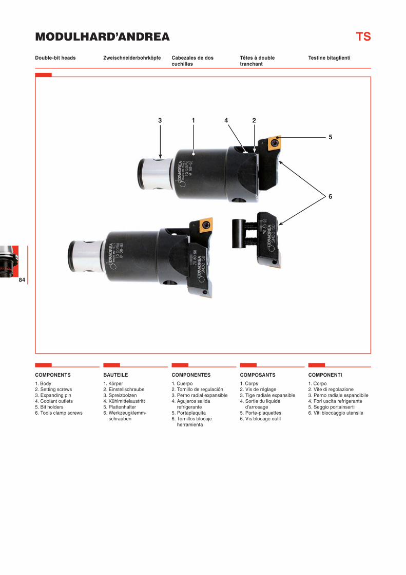
COMPONENTS 1. Body2. Setting screws3. Expanding pin4. Coolant outlets 5. Bit holders6. Tools clamp screws
BAUTEILE
1. Körper2. Einstellschraube 3. Spreizbolzen4. Kühlmittelaustritt 5. Plattenhalter6. Werkzeugklemm-
schrauben
COMPONENTES
1. Cuerpo2. Tornillo de regulación3. Perno radial expansible4. Agujeros salida
refrigerante5. Portaplaquita6. Tornillos blocaje
herramienta
COMPOSANTS
1. Corps 2. Vis de réglage3. Tige radiale expansible 4. Sortie du liquide
d’arrosage5. Porte-plaquettes6. Vis blocage outil
COMPONENTI
1. Corpo2. Vite di regolazione3. Perno radiale espandibile4. Fori uscita refrigerante 5. Seggio portainserti6. Viti bloccaggio utensile
TS
1 4 2
5
6
3
85
FEATURES
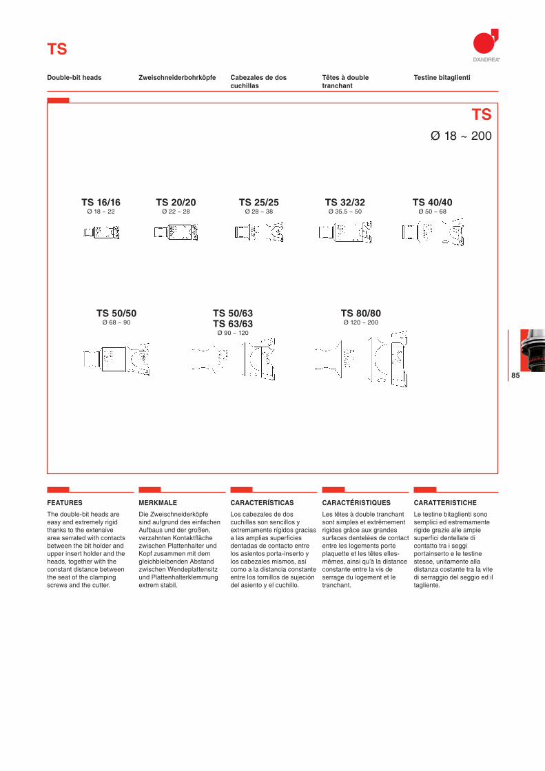
The double-bit heads are easy and extremely rigid thanks to the extensive area serrated with contacts between the bit holder and upper insert holder and the heads, together with the constant distance between the seat of the clamping screws and the cutter.
MERKMALE
Die Zweischneiderköpfe sind aufgrund des einfachen Aufbaus und der großen, verzahnten Kontaktfläche zwischen Plattenhalter und Kopf zusammen mit dem gleichbleibenden Abstand zwischen Wendeplattensitz und Plattenhalterklemmung extrem stabil.
CARACTERÍSTICAS
Los cabezales de dos cuchillas son sencillos y extremamente rígidos gracias a las amplias superficies dentadas de contacto entre los asientos porta-inserto y los cabezales mismos, así como a la distancia constante entre los tornillos de sujeción del asiento y el cuchillo.
CARACTÉRISTIQUES
Les têtes à double tranchant sont simples et extrêmement rigides grâce aux grandes surfaces dentelées de contact entre les logements porte plaquette et les têtes elles-mêmes, ainsi qu’à la distance constante entre la vis de serrage du logement et le tranchant.
CARATTERISTICHE
Le testine bitaglienti sono semplici ed estremamente rigide grazie alle ampie superfici dentellate di contatto tra i seggi portainserto e le testine stesse, unitamente alla distanza costante tra la vite di serraggio del seggio ed il tagliente.
TSØ 18 ~ 200
TS
TS 40/40Ø 50 ~ 68
TS 32/32Ø 35.5 ~ 50
TS 25/25Ø 28 ~ 38
TS 20/20Ø 22 ~ 28
TS 16/16Ø 18 ~ 22
TS 50/63TS 63/63
Ø 90 ~ 120
TS 80/80Ø 120 ~ 200
TS 50/50Ø 68 ~ 90
Zweischneiderbohrköpfe Cabezales de dos cuchillas
Têtes à double tranchant
Testine bitaglientiDouble-bit heads
MODULHARD’ANDREA
86
fig.1 fig.2 fig.3
TS
Zweischneiderbohrköpfe Cabezales de dos cuchillas
Têtes à double tranchant
Testine bitaglientiDouble-bit heads
87
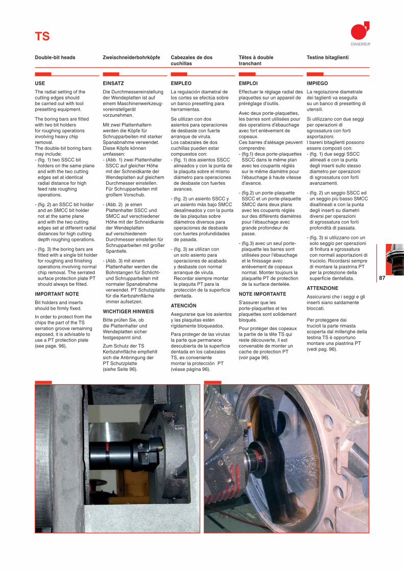
USE
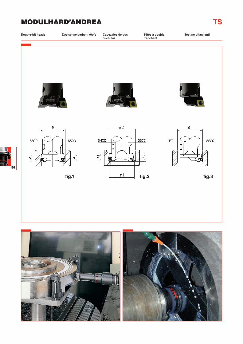
The radial setting of the cutting edges should be carried out with tool presetting equipment.
The boring bars are fitted with two bit holders for roughing operations involving heavy chip removal.The double-bit boring bars may include:- (fig. 1) two SSCC bit
holders on the same plane and with the two cutting edges set at identical radial distance for high feed rate roughing operations.
- (fig. 2) an SSCC bit holder and an SMCC bit holder not at the same plane and with the two cutting edges set at different radial distances for high cutting depth roughing operations.
- (fig. 3) the boring bars are fitted with a single bit holder for roughing and finishing operations involving normal chip removal. The serrated surface protection plate PT should always be fitted.
IMPORTANT NOTE
Bit holders and inserts should be firmly fixed.
In order to protect from the chips the part of the TS serration groove remaining exposed, it is advisable to use a PT protection plate (see page. 96).
EINSATZ
Die Durchmessereinstellung der Wendeplatten ist auf einem Maschinenwerkzeug-voreinstellgerät vorzunehmen.
Mit zwei Plattenhaltern werden die Köpfe für Schrupparbeiten mit starker Spanabnahme verwendet.Diese Köpfe können umfassen:- (Abb. 1) zwei Plattenhalter
SSCC auf gleicher Höhe mit der Schneidkante der Wendeplatten auf gleichem Durchmesser einstellen. Für Schrupparbeiten mit großem Vorschub.
- (Abb. 2) je einen Plattenhalter SSCC und SMCC auf verschiedener Höhe mit der Schneidkante der Wendeplatten auf verschiedenem Durchmesser einstellen für Schrupparbeiten mit großer Spantiefe.
- (Abb. 3) mit einem Plattenhalter werden die Bohrstangen für Schlicht- und Schrupparbeiten mit normaler Spanabnahme verwendet. PT Schutzplatte für die Kerbzahnfläche immer aufsetzen.
WICHTIGER HINWEIS
Bitte prüfen Sie, ob die Plattenhalter und Wendeplatten sicher festgespannt sind.
Zum Schutz der TS Kerbzahnfläche empfiehlt sich die Anbringung der PT Schutzplatte (siehe Seite 96).
EMPLEO
La regulación diametral de los cortes se efectúa sobre un banco presetting para herramientas.
Se utilizan con dos asientos para operaciones de desbaste con fuerte arranque de viruta.Los cabezales de dos cuchillas pueden estar compuestos con:- (fig. 1) dos asientos SSCC
alineados y con la punta de la plaquita sobre el mismo diámetro para operaciones de desbaste con fuertes avances.
- (fig. 2) un asiento SSCC y un asiento más bajo SMCC desalineados y con la punta de las plaquitas sobre diámetros diversos para operaciones de desbaste con fuertes profundidades de pasada.
- (fig. 3) se utilizan con un solo asiento para operaciones de acabado y desbaste con normal arranque de viruta.Recordar siempre montar la plaquita PT para la protección de la superficie dentada.
ATENCIÓN
Asegurarse que los asientos y las plaquitas estén rígidamente bloqueados.
Para proteger de las virutas la parte que permanece descubierta de la superficie dentada en los cabezales TS, es conveniente montar la protección PT (véase página 96).
EMPLOI
Effectuer le réglage radial des plaquettes sur un appareil de préréglage d’outils.
Avec deux porte-plaquettes, les barres sont utilisées pour des operations d’ébauchage avec fort enlèvement de copeaux. Ces barres d’alésage peuvent comprendre: - (fig.1) deux porte-plaquettes
SSCC dans le même plan avec les coupants réglés sur le même diamètre pour l’ébauchage à haute vitesse d’avance.
- (fig.2) un porte-plaquette SSCC et un porte-plaquette SMCC dans deux plans avec les coupants réglés sur des différents diamètres pour l’ébauchage avec grande profondeur de passe.
- (fig.3) avec un seul porte-plaquette les barres sont utilisées pour l’ébauchage et le finissage avec enlèvement de copeaux normal. Monter toujours la plaquette PT de protection de la surface dentelée.
NOTE IMPORTANTE
S’assurer que les porte-plaquettes et les plaquettes sont solidement bloqués.
Pour protéger des copeaux la partie de la tête TS qui reste découverte, il est convenable de monter un cache de protection PT (voir page 96).
IMPIEGO
La regolazione diametrale dei taglienti va eseguita su un banco di presetting di utensili.
Si utilizzano con due seggi per operazioni di sgrossatura con forti asportazioni.I bareni bitaglienti possono essere composti con: - (fig. 1) due seggi SSCC
allineati e con la punta degli inserti sullo stesso diametro per operazioni di sgrossatura con forti avanzamenti.
- (fig. 2) un seggio SSCC ed un seggio più basso SMCC disallineati e con la punta degli inserti su diametri diversi per operazioni di sgrossatura con forti profondità di passata.
- (fig. 3) si utilizzano con un solo seggio per operazioni di finitura e sgrossatura con normali asportazioni di truciolo. Ricordarsi sempre di montare la piastrina PT per la protezione della superficie dentellata.
ATTENZIONE
Assicurarsi che i seggi e gli inserti siano saldamente bloccati.
Per proteggere dai trucioli la parte rimasta scoperta dal millerighe della testina TS è opportuno montare una piastrina PT (vedi pag. 96).
TS
Zweischneiderbohrköpfe Cabezales de dos cuchillas
Têtes à double tranchant
Testine bitaglientiDouble-bit heads
MODULHARD’ANDREA
88
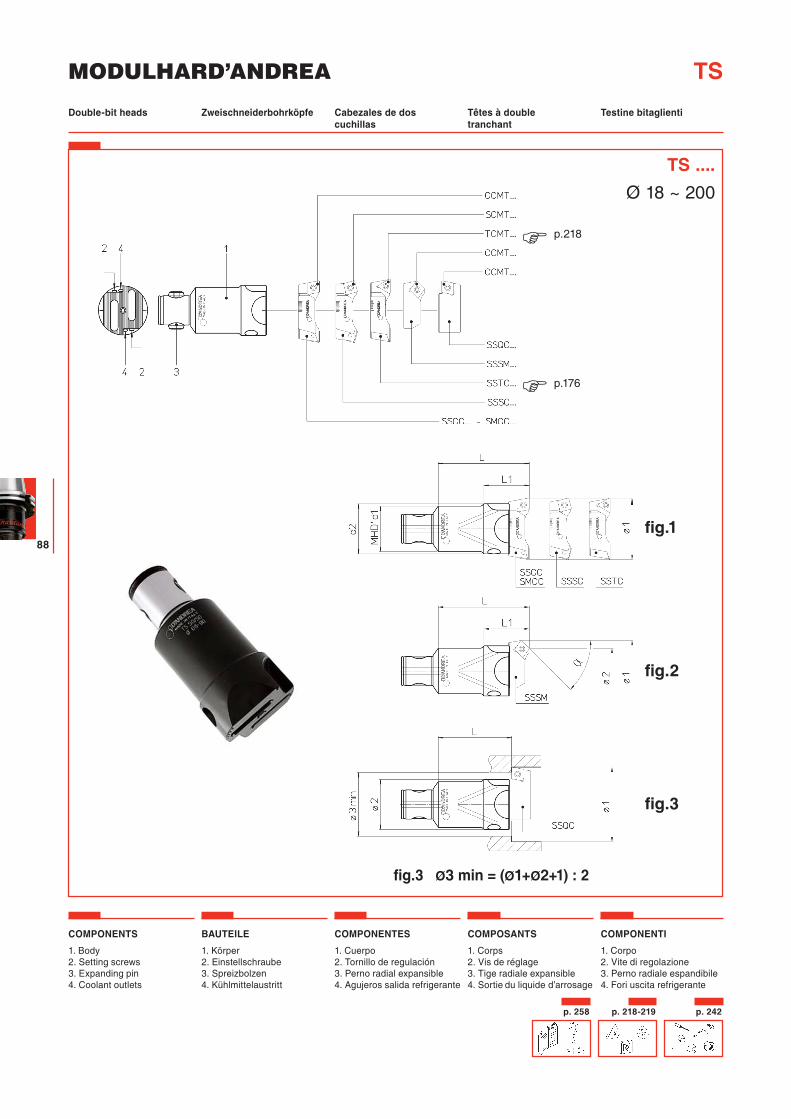
TS ....
Ø 18 ~ 200
p. 258 p. 218-219 p. 242
TS
p.176�
p.218�
COMPONENTS 1. Body2. Setting screws3. Expanding pin4. Coolant outlets
BAUTEILE
1. Körper2. Einstellschraube 3. Spreizbolzen4. Kühlmittelaustritt
COMPONENTES
1. Cuerpo2. Tornillo de regulación3. Perno radial expansible4. Agujeros salida refrigerante
COMPOSANTS
1. Corps 2. Vis de réglage3. Tige radiale expansible 4. Sortie du liquide d’arrosage
COMPONENTI
1. Corpo2. Vite di regolazione3. Perno radiale espandibile4. Fori uscita refrigerante
fig.1
fig.2
fig.3
fig.3 Ø3 min = (Ø1+Ø2+1) : 2
Zweischneiderbohrköpfe Cabezales de dos cuchillas
Têtes à double tranchant
Testine bitaglientiDouble-bit heads
89
TS
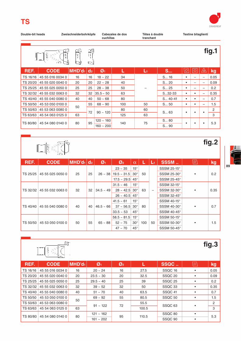
REF. CODE MHD’d1 Ø1 Ø2 L SSQC .. kg TS 16/16 45 55 016 0034 0 16 20 ~ 24 16 27.5 SSQC 16 • 0.05
TS 20/20 45 55 020 0040 0 20 23.5 ~ 30 20 32.5 SSQC 20 • 0.09
TS 25/25 45 55 025 0050 0 25 29.5 ~ 40 25 39 SSQC 25 • 0.2
TS 32/32 45 55 032 0063 0 32 39 ~ 52 32 50 SSQC 33 • 0.35
TS 40/40 45 55 040 0080 0 40 51 ~ 70 40 63.5 SSQC 41 • 0.7
TS 50/50 45 53 050 0100 0 50
69 ~ 92 55 80.5 SSQC 50 • 1.5
TS 50/63 45 53 063 0080 0 91 ~ 122 72
55.5 SSQC 63 •
2
TS 63/63 45 54 063 0125 0 63 100.5 3
TS 80/80 45 54 080 0140 0 80
121 ~ 162 95 110.5
SSQC 80 • 5.3
161 ~ 202 SSQC 90 •
Zweischneiderbohrköpfe Cabezales de dos cuchillas
Têtes à double tranchant
Testine bitaglientiDouble-bit heads
fig.2
fig.3
fig.1
REF. CODE MHD’d1 d2 Ø1 L L1 S... kg TS 16/16 45 55 016 0034 0 16 16 18 ~ 22 34 S... 16 • – – 0.05
TS 20/20 45 55 020 0040 0 20 20 22 ~ 28 40 S... 20 • – – 0.09
TS 25/25 45 55 025 0050 0 25 25 28 ~ 38 50 – S... 25 • – – 0.2
TS 32/32 45 55 032 0063 0 32 32 35.5 ~ 50 63 S...32-33 • • – 0.35
TS 40/40 45 55 040 0080 0 40 40 50 ~ 68 80 S... 40-41 • • – 0.7
TS 50/50 45 53 050 0100 0 50
55 68 ~ 90 100 50 S... 50 • • – 1.5
TS 50/63 45 53 063 0080 0 72 90 ~ 120
80 60 S... 63 • • •
2
TS 63/63 45 54 063 0125 0 63 125 63 3
TS 80/80 45 54 080 0140 0 80 95
120 ~ 160 140 75
S... 80 • • • 5.3
160 ~ 200 S... 90
REF. CODE MHD’d1 d2 Ø1 Ø2 α L L1 SSSM .. kg 23 ~ 35 15° SSSM 25-15°
TS 25/25 45 55 025 0050 0 25 25 26 ~ 38 19.5 ~ 31.5 30° 50 SSSM 25-30° • 0.2
17.5 ~ 29.5 45° SSSM 25-45°
31.5 ~ 46 15° SSSM 32-15°
TS 32/32 45 55 032 0063 0 32 32 34.5 ~ 49 28 ~ 42.5 30° 63 – SSSM 32-30° • 0.35
26 ~ 40.5 45° SSSM 32-45°
41.5 ~ 61 15° SSSM 40-15°
TS 40/40 45 55 040 0080 0 40 40 46.5 ~ 66 37 ~ 56.5 30° 80 SSSM 40-30° • 0.7
33.5 ~ 53 45° SSSM 40-45°
58.5 ~ 81.5 15° SSSM 50-15°
TS 50/50 45 53 050 0100 0 50 55 65 ~ 88 52 ~ 75 30° 100 50 SSSM 50-30° • 1.5
47 ~ 70 45° SSSM 50-45°
MODULHARD’ANDREA
90
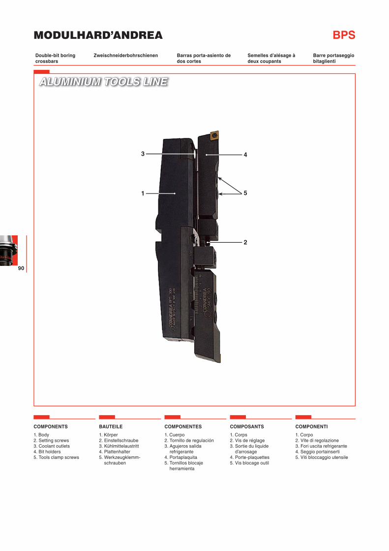
COMPONENTS 1. Body2. Setting screws3. Coolant outlets 4. Bit holders5. Tools clamp screws
BAUTEILE
1. Körper2. Einstellschraube 3. Kühlmittelaustritt 4. Plattenhalter5. Werkzeugklemm-
schrauben
COMPONENTES
1. Cuerpo2. Tornillo de regulación3. Agujeros salida
refrigerante4. Portaplaquita5. Tornillos blocaje
herramienta
COMPOSANTS
1. Corps 2. Vis de réglage3. Sortie du liquide
d’arrosage4. Porte-plaquettes5. Vis blocage outil
COMPONENTI
1. Corpo2. Vite di regolazione3. Fori uscita refrigerante 4. Seggio portainserti5. Viti bloccaggio utensile
Zweischneiderbohrschienen Barras porta-asiento de dos cortes
Semelles d’alésage à deux coupants
Barre portaseggio bitaglienti
Double-bit boring crossbars
BPS
2
51
43
ALUMINIUM TOOLS LINEALUMINIUM TOOLS LINE
91
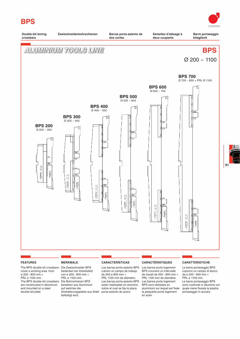
FEATURES
The BPS double-bit crossbars cover a working area from ø 200 - 800 mm + PRL ø 1100 mm.The BPS double-bit crossbars are constructed in alluminum and mounted on a steel double-bit plate.
MERKMALE
Die Zweischneider BPS bedecken ein Arbeitsfeld von ø 200 - 800 mm + PRL ø 1100 mm.Die Bohrschienen BPS bestehen aus Aluminium auf welches die Sitzhalterungsplatte aus Stahl befestigt wird.
CARACTERÍSTICAS
Las barras porta-asiento BPS cubren un campo de trabajo de 200 a 800 mm + PRL 1100 mm de diámetro. Las barras porta-asiento BPS están realizadas en aluminio, sobre el cual se fija la placa porta-asiento de acero.
CARACTÉRISTIQUES
Les barres porte logement BPS couvrent un intervalle de travail de 200 - 800 mm + PRL 1100 mm de diamètre.Les barres porte logement BPS sont réalisées en aluminium sur lequel est fixée la plaquette porte logement en acier
CARATTERISTICHE
Le barre portaseggio BPS coprono un campo di lavoro da ø 200 - 800 mm + PRL ø 1100 mm.Le barre portaseggio BPS sono costruite in alluminio sul quale viene fissata la piastra portaseggio in acciaio.
Zweischneiderbohrschienen Barras porta-asiento de dos cortes
Semelles d’alésage à deux coupants
Barre portaseggio bitaglienti
Double-bit boring crossbars
BPS
ALUMINIUM TOOLS LINEALUMINIUM TOOLS LINE BPSØ 200 ~ 1100
BPS 200Ø 200 ~ 300
BPS 300Ø 300 ~ 400
BPS 400Ø 400 ~ 500
BPS 500Ø 500 ~ 600
BPS 600Ø 600 ~ 700
BPS 700Ø 700 ~ 800 + PRL Ø 1100
MODULHARD’ANDREA
92
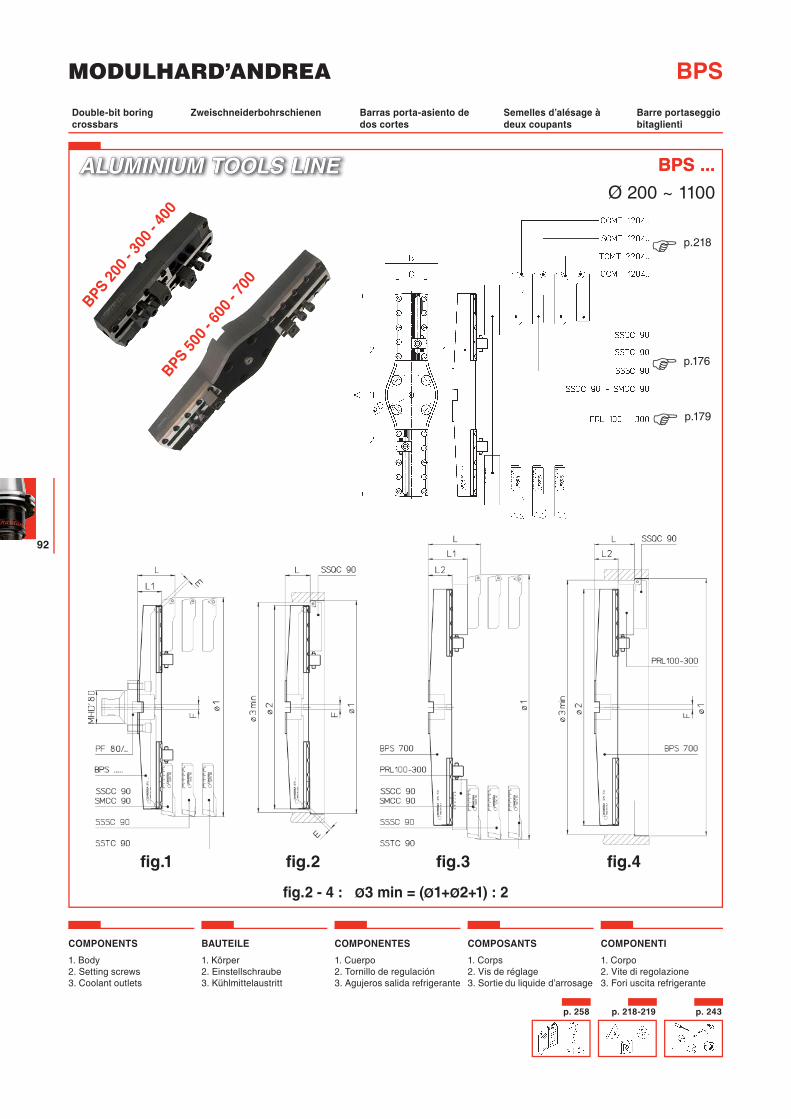
COMPONENTS 1. Body2. Setting screws3. Coolant outlets
BAUTEILE
1. Körper2. Einstellschraube 3. Kühlmittelaustritt
COMPONENTES
1. Cuerpo2. Tornillo de regulación3. Agujeros salida refrigerante
COMPOSANTS
1. Corps 2. Vis de réglage3. Sortie du liquide d’arrosage
COMPONENTI
1. Corpo2. Vite di regolazione3. Fori uscita refrigerante
Zweischneiderbohrschienen Barras porta-asiento de dos cortes
Semelles d’alésage à deux coupants
Barre portaseggio bitaglienti
Double-bit boring crossbars
ALUMINIUM TOOLS LINEALUMINIUM TOOLS LINE
BPS
BPS ...BPS ...
Ø 200 ~ 1100
p.176�
p.179�
p.218�
fig.2 - 4 : Ø3 min = (Ø1+Ø2+1) : 2
BPS 500
- 60
0 - 7
00
BPS 200
- 30
0 - 4
00
p. 258 p. 218-219 p. 243
fig.2fig.1 fig.3 fig.4
93
Zweischneiderbohrschienen Barras porta-asiento de dos cortes
Semelles d’alésage à deux coupants
Barre portaseggio bitaglienti
Double-bit boring crossbars
BPS
Ohne PF 80/.. PF 80/.. excluido Sauf PF 80/.. PF 80/.. esclusoPF 80/.. excluded
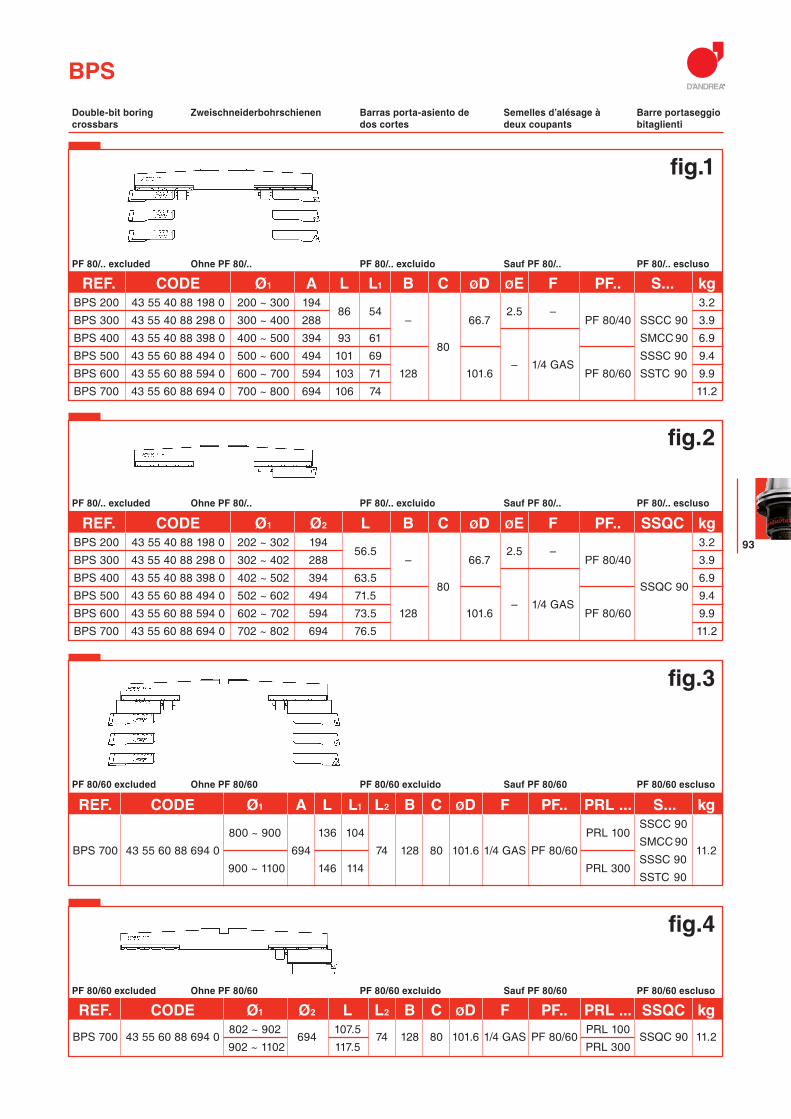
REF. CODE Ø1 A L L1 B C ØD ØE F PF.. S... kg BPS 200 43 55 40 88 198 0 200 ~ 300 194
86 54
2.5 – 3.2
BPS 300 43 55 40 88 298 0 300 ~ 400 288 – 66.7 PF 80/40 SSCC 90 3.9
BPS 400 43 55 40 88 398 0 400 ~ 500 394 93 61 80
SMCC 90 6.9
BPS 500 43 55 60 88 494 0 500 ~ 600 494 101 69 – 1/4 GAS
SSSC 90 9.4
BPS 600 43 55 60 88 594 0 600 ~ 700 594 103 71 128 101.6 PF 80/60 SSTC 90 9.9
BPS 700 43 55 60 88 694 0 700 ~ 800 694 106 74 11.2
Ohne PF 80/.. PF 80/.. excluido Sauf PF 80/.. PF 80/.. esclusoPF 80/.. excluded
REF. CODE Ø1 Ø2 L B C ØD ØE F PF.. SSQC kg BPS 200 43 55 40 88 198 0 202 ~ 302 194
56.5
2.5 – 3.2
BPS 300 43 55 40 88 298 0 302 ~ 402 288 – 66.7 PF 80/40 3.9
BPS 400 43 55 40 88 398 0 402 ~ 502 394 63.5 80
SSQC 90
6.9
BPS 500 43 55 60 88 494 0 502 ~ 602 494 71.5 – 1/4 GAS
9.4
BPS 600 43 55 60 88 594 0 602 ~ 702 594 73.5 128 101.6 PF 80/60 9.9
BPS 700 43 55 60 88 694 0 702 ~ 802 694 76.5 11.2
fig.1
fig.3
fig.2
fig.4
Ohne PF 80/60 PF 80/60 excluido Sauf PF 80/60 PF 80/60 esclusoPF 80/60 excluded
REF. CODE Ø1 A L L1 L2 B C ØD F PF.. PRL ... S... kg
800 ~ 900
136 104 PRL 100 SSCC 90
BPS 700 43 55 60 88 694 0 694 74 128 80 101.6 1/4 GAS PF 80/60 SMCC 90
11.2
900 ~ 1100
146 114 PRL 300
SSSC 90
SSTC 90
Ohne PF 80/60 PF 80/60 excluido Sauf PF 80/60 PF 80/60 esclusoPF 80/60 excluded
REF. CODE Ø1 Ø2 L L2 B C ØD F PF.. PRL ... SSQC kg 802 ~ 902 107.5 PRL 100
BPS 700 43 55 60 88 694 0
902 ~ 1102 694
117.5 74 128 80 101.6 1/4 GAS PF 80/60
PRL 300 SSQC 90 11.2
MODULHARD’ANDREA
94
MODULHARD’ANDREA
Werkzeughalter Portaherramientas Porte-outils PortautensileToolholders
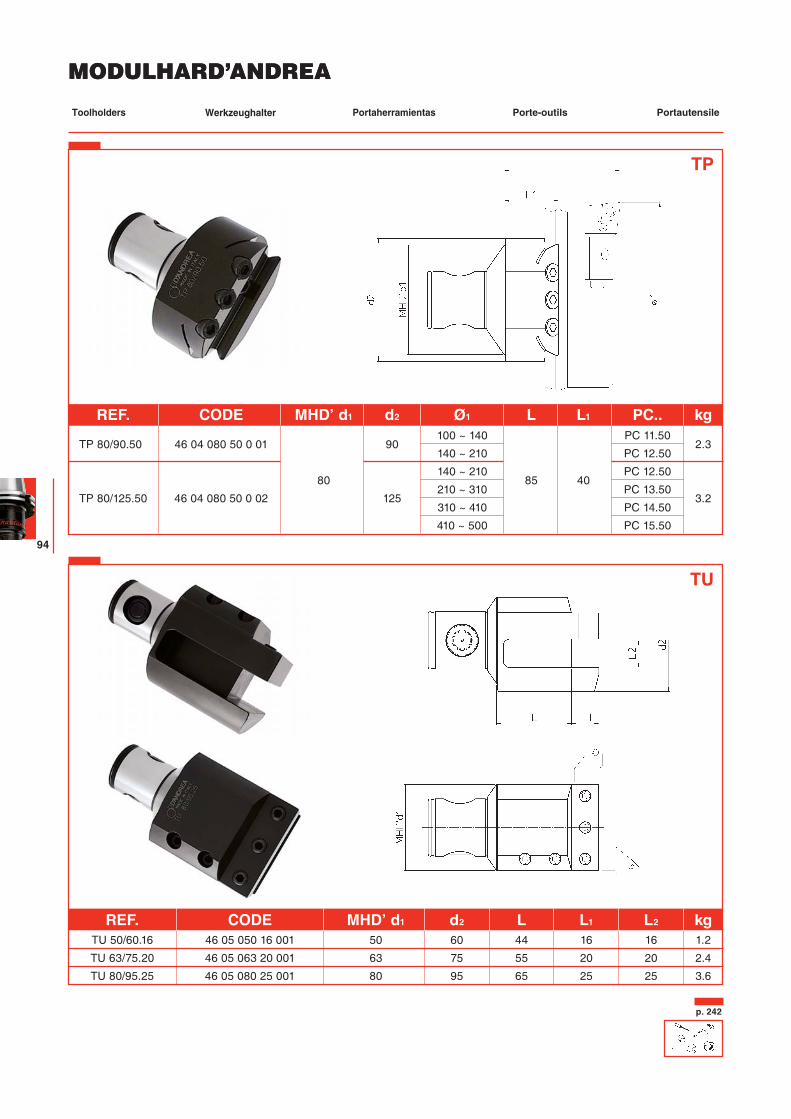
TP
TU
REF. CODE MHD’ d1 d2 L L1 L2 kg
TU 50/60.16 46 05 050 16 001 50 60 44 16 16 1.2
TU 63/75.20 46 05 063 20 001 63 75 55 20 20 2.4
TU 80/95.25 46 05 080 25 001 80 95 65 25 25 3.6
p. 242
REF. CODE MHD’ d1 d2 Ø1 L L1 PC.. kg
TP 80/90.50 46 04 080 50 0 01 90 100 ~ 140
PC 11.50
2.3
140 ~ 210 PC 12.50
80
140 ~ 210 85
40
PC 12.50
TP 80/125.50 46 04 080 50 0 02 125
210 ~ 310
PC 13.50 3.2
310 ~ 410 PC 14.50
410 ~ 500 PC 15.50
95
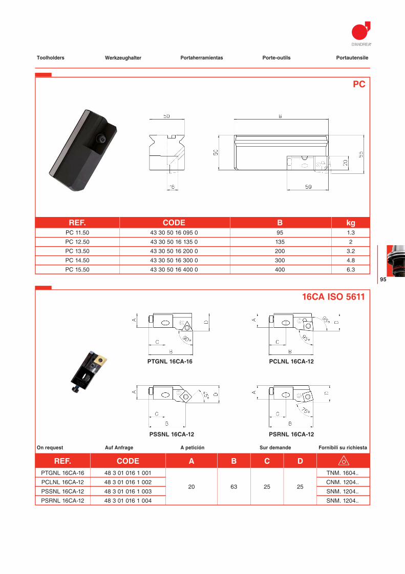
Auf Anfrage A petición Sur demandeOn request
PC
REF. CODE B kg PC 11.50 43 30 50 16 095 0 95 1.3
PC 12.50 43 30 50 16 135 0 135 2
PC 13.50 43 30 50 16 200 0 200 3.2
PC 14.50 43 30 50 16 300 0 300 4.8
PC 15.50 43 30 50 16 400 0 400 6.3
PCLNL 16CA-12PTGNL 16CA-16
PSRNL 16CA-12PSSNL 16CA-12
16CA ISO 5611
Fornibili su richiesta
REF. CODE A B C D PTGNL 16CA-16 48 3 01 016 1 001 TNM. 1604..
PCLNL 16CA-12 48 3 01 016 1 002 20 63 25 25
CNM. 1204..
PSSNL 16CA-12 48 3 01 016 1 003 SNM. 1204..
PSRNL 16CA-12 48 3 01 016 1 004 SNM. 1204..
Werkzeughalter Portaherramientas Porte-outils PortautensileToolholders
MODULHARD’ANDREA
96
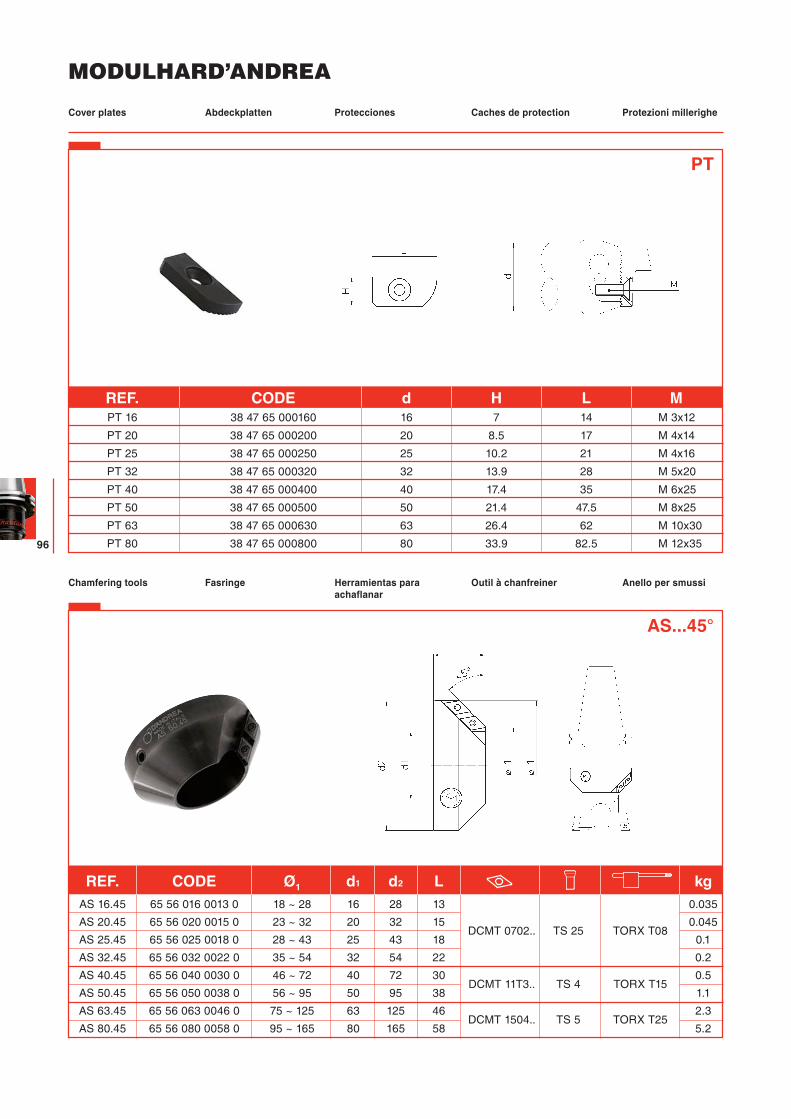
Fasringe Herramientas para achaflanar
Outil à chanfreiner Anello per smussiChamfering tools
AS...45°
REF. CODE Ø1 d1 d2 L kg AS 16.45 65 56 016 0013 0 18 ~ 28 16 28 13 0.035
AS 20.45 65 56 020 0015 0 23 ~ 32 20 32 15 DCMT 0702.. TS 25 TORX T08
0.045
AS 25.45 65 56 025 0018 0 28 ~ 43 25 43 18 0.1
AS 32.45 65 56 032 0022 0 35 ~ 54 32 54 22 0.2
AS 40.45 65 56 040 0030 0 46 ~ 72 40 72 30 DCMT 11T3.. TS 4 TORX T15
0.5
AS 50.45 65 56 050 0038 0 56 ~ 95 50 95 38 1.1
AS 63.45 65 56 063 0046 0 75 ~ 125 63 125 46 DCMT 1504.. TS 5 TORX T25
2.3
AS 80.45 65 56 080 0058 0 95 ~ 165 80 165 58 5.2
Abdeckplatten Protecciones Caches de protection Protezioni millerigheCover plates
REF. CODE d H L M PT 16 38 47 65 000160 16 7 14 M 3x12
PT 20 38 47 65 000200 20 8.5 17 M 4x14
PT 25 38 47 65 000250 25 10.2 21 M 4x16
PT 32 38 47 65 000320 32 13.9 28 M 5x20
PT 40 38 47 65 000400 40 17.4 35 M 6x25
PT 50 38 47 65 000500 50 21.4 47.5 M 8x25
PT 63 38 47 65 000630 63 26.4 62 M 10x30
PT 80 38 47 65 000800 80 33.9 82.5 M 12x35
PT

97
98
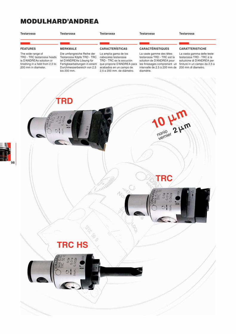
Testarossa Testarossa Testarossa TestarossaTestarossa
10 mnonio
vernier 2 m
TRC
TRD
TRC HS
FEATURES
The wide range of TRD - TRC testarossa heads is D’ANDREAs solution or finishing in a field from 2,5 to 200 mm in diameter.
MERKMALE
Die umfangreiche Reihe der Testarossa Köpfe TRD - TRC ist D’ANDREAs Lösung für Fertigbearbeitungen in einem Durchmesserbereich von 2,5 bis 200 mm.
CARACTERÍSTICAS
La amplia gama de los cabezales testarossa TRD - TRC es la socución que propone D’ANDREA para acabados en un campo de 2,5 a 200 mm. de diámetro.
CARACTÉRISTIQUES
La vaste gamme des têtes testarossa TRD - TRC est la solution de D’ANDREA pour les finissages comprenant un intervalle de 2.5 à 200 mm de diamètre.
CARATTERISTICHE
La vasta gamma delle teste testarossa TRD - TRC è la soluzione di D’ANDREA per finiture in un campo da 2,5 a 200 mm di diametro.
MODULHARD’ANDREA
99
2 mTRM
TRM HSB
TRM
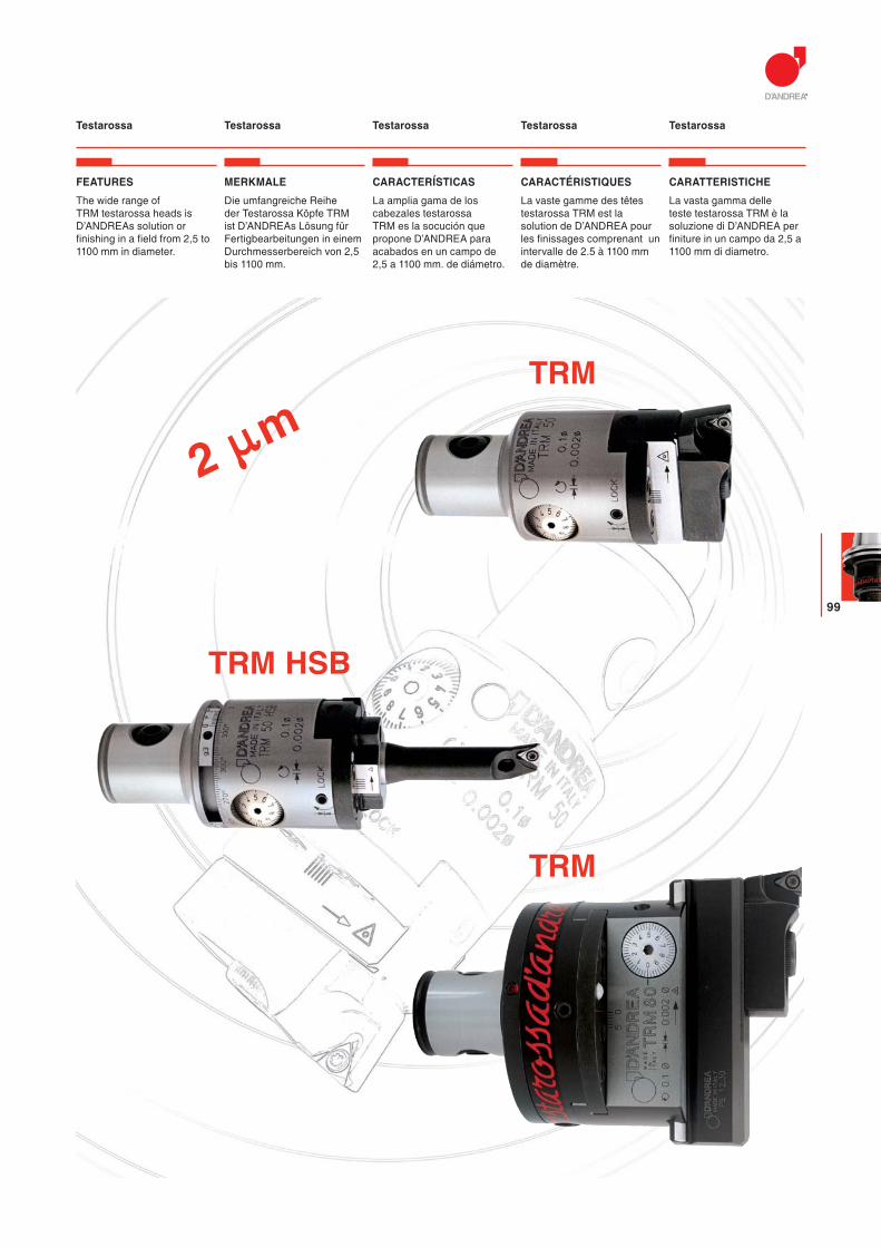
Testarossa Testarossa Testarossa TestarossaTestarossa
FEATURES
The wide range of TRM testarossa heads is D’ANDREAs solution or finishing in a field from 2,5 to 1100 mm in diameter.
MERKMALE
Die umfangreiche Reihe der Testarossa Köpfe TRM ist D’ANDREAs Lösung für Fertigbearbeitungen in einem Durchmesserbereich von 2,5 bis 1100 mm.
CARACTERÍSTICAS
La amplia gama de los cabezales testarossa TRM es la socución que propone D’ANDREA para acabados en un campo de 2,5 a 1100 mm. de diámetro.
CARACTÉRISTIQUES
La vaste gamme des têtes testarossa TRM est la solution de D’ANDREA pour les finissages comprenant un intervalle de 2.5 à 1100 mm de diamètre.
CARATTERISTICHE
La vasta gamma delle teste testarossa TRM è la soluzione di D’ANDREA per finiture in un campo da 2,5 a 1100 mm di diametro.
MODULHARD’ANDREA
100
Testarossa Zweischneiderköpfe
Testarossa de dos cuchillas
Double tranchant Testarossa
Testarossa Bitagliente Double-bit Testarossa
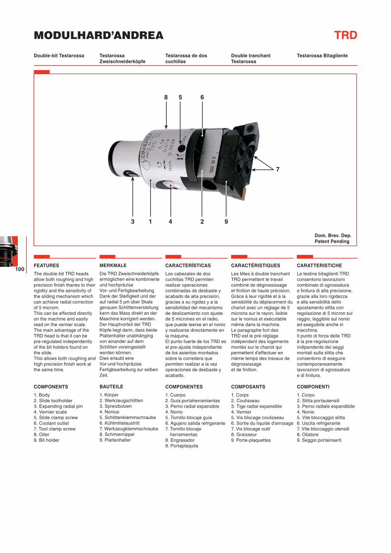
FEATURES
The double-bit TRD heads allow both roughing and high precision finish thanks to their rigidity and the sensitivity of the sliding mechanism which can achieve radial correction of 5 microm.This can be effected directly on the machine and easily read on the vernier scale. The main advantage of the TRD head is that it can be pre-regulated independently of the bit holders found on the slide.This allows both roughing and high precision finish work at the same time.
COMPONENTS
1. Body2. Slide toolholder3. Expanding radial pin4. Vernier scale5. Slide clamp screw6. Coolant outlet7. Tool clamp screw8. Oiler 9. Bit holder
MERKMALE
Die TRD Zweischneiderköpfe ermöglichen eine kombinierte und hochpräziseVor- und Fertigbearbeitung.Dank der Steifigkeit und der auf radial 5 �m über Skala genauen Schlittenverstellung kann das Mass direkt an der Maschine korrigiert werden.Der Hauptvorteil der TRD Köpfe liegt darin, dass beide Plattenhalter unabhänging von einander auf dem Schlitten voreingestellt werden können. Dies erlaubt eine Vor-und hochpräzise Fertigbearbeitung zur selben Zeit.
BAUTEILE
1. Körper2. Werkzeugschlitten3. Spreizbolzen4. Nonius5. Schlittenklemmschraube6. Kühlmittelaustritt7. Werkzeugklemmschraube8. Schmiernippel9. Plattenhalter
CARACTERÍSTICAS
Los cabezales de dos cuchillas TRD permiten realizar operaciones combinadas de desbaste y acabado de alta precisión, gracias a su rigidez y a la sensibilidad del mecanismo de deslizamiento con ajuste de 5 micrones en el radio, que puede leerse en el nonio y realizarse directamente en la máquina.El punto fuerte de los TRD es el pre-ajuste independiente de los asientos montados sobre la corredera que permiten realizar a la vez operaciones de desbaste y acabado.
COMPONENTES
1. Cuerpo2. Guía portaherramientas3. Perno radial expansible4. Nonio5. Tornillo blocaje guía6. Agujero salida refrigerante7. Tornillo blocaje
herramientas8. Engrasador9. Portaplaquita
CARACTÉRISTIQUES
Les têtes à double tranchant TRD permettent le travail combiné de dégrossissage et finition de haute précision. Grâce à leur rigidité et à la sensibilité du déplacement du chariot avec un réglage de 5 microns sur le rayon, lisible sur le nonius et exécutable même dans la machine.Le paragraphe fort des TRD est le pré-réglage indépendant des logements montés sur le chariot qui permettent d’effectuer en même temps des travaux de dégrossissage et de finition.
COMPOSANTS
1. Corps 2. Coulisseau 3. Tige radial expansible4. Vernier5. Vis blocage coulisseau6. Sortie du liquide d’arrosage7. Vis blocage outil8. Graisseur9. Porte-plaquettes
CARATTERISTICHE
Le testine bitaglienti TRD consentono lavorazioni combinate di sgrossatura e finitura di alta precisione, grazie alla loro rigidezza e alla sensibilità dello spostamento slitta con regolazione di 5 micron sul raggio, leggibile sul nonio ed eseguibile anche in macchina.Il punto di forza delle TRD è la pre-regolazione indipendente dei seggi montati sulla slitta che consentono di eseguire contemporaneamente lavorazioni di sgrossatura e di finitura.
COMPONENTI
1. Corpo 2. Slitta portautensili3. Perno radiale espandibile4. Nonio 5. Vite bloccaggio slitta6. Uscita refrigerante7. Vite bloccaggio utensili8. Oliatore9. Seggio portainserti
TRD
58
3 2 91 4
6
7
Dom. Brev. Dep.Patent Pending
101
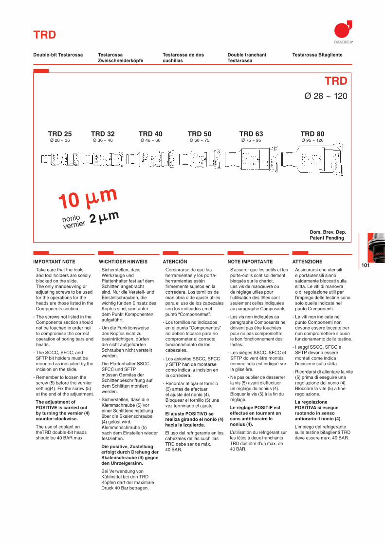
TRDØ 28 ~ 120
TRD
10 mnoniovernier 2 m
TRD 40Ø 46 ~ 60
TRD 32Ø 36 ~ 46
TRD 25Ø 28 ~ 36
TRD 50Ø 60 ~ 75
TRD 63Ø 75 ~ 95
TRD 80Ø 95 ~ 120
IMPORTANT NOTE
- Take care that the tools and tool holders are solidly blocked on the slide. The only manoeuvring or adjusting screws to be used for the operations for the heads are those listed in the Components section.
- The screws not listed in the Components section should not be touched in order not to compromise the correct operation of boring bars and heads.
- The SCCC, SFCC, and SFTP bit holders must be mounted as indicated by the incision on the slide.
- Remember to loosen the screw (5) before the vernier setting(4). Fix the screw (5) at the end of the adjustment.
The adjustment of POSITIVE is carried out by turning the vernier (4) counter-clockwise.
The use of coolant on theTRD double-bit heads should be 40 BAR max.
WICHTIGER HINWEIS
- Sicherstellen, dass Werkzeuge und Plattenhalter fest auf dem Schlitten angebracht sind. Nur die Verstell- und Einstellschrauben, die wichtig für den Einsatz des Kopfes sind, sind unter dem Punkt Komponenten aufgeführt.
- Um die Funktionsweise des Kopfes nicht zu beeinträchtigen, dürfen die nicht aufgeführten Schrauben nicht verstellt werden.
- Die Plattenhalter SSCC, SFCC und SFTP müssen Gemäss der Schlittenbeschriftung auf dem Schlitten montiert werden.
- Sicherstellen, dass di e Klemmschraube (5) vor einer Schlitteneinstellung über die Skalenschraube (4) gelöst wird.Klemmenschraube (5) nach dem Einstellen wieder festziehen.
Die positive, Zustellung erfolgt durch Drehung der Skalenschraube (4) gegen den Uhrzeigersinn.
Bei Verwendung von Kühlmittel bei den TRD Köpfen darf der maximale Druck 40 Bar betragen.
ATENCIÓN
- Cerciorarse de que las herramientas y los porta-herramientas estén firmemente sujetos en la corredera. Los tornillos de maniobra o de ajuste útiles para el uso de los cabezales son los indicados en el punto “Componentes”.
- Los tornillos no indicados en el punto “Componentes” no deben tocarse para no comprometer el correcto funcionamiento de los cabezales.
- Los asientos SSCC, SFCC y SFTP han de montarse como indica la incisión en la corredera.
- Recordar aflojar el tornillo (5) antes de efectuar el ajuste del nonio (4). Bloquear el tornillo (5) una vez terminado el ajuste.
El ajuste POSITIVO se realiza girando el nonio (4) hacia la izquierda.
El uso del refrigerante en los cabezales de las cuchillas TRD debe ser de máx. 40 BAR.
NOTE IMPORTANTE
- S’assurer que les outils et les porte-outils sont solidement bloqués sur le chariot. Les vis de manœuvre ou de réglage utiles pour l’utilisation des têtes sont seulement celles indiquées au paragraphe Composants.
- Les vis non indiquées au paragraphe Composants ne doivent pas être touchées pour ne pas compromettre le bon fonctionnement des testes.
- Les sièges SSCC, SFCC et SFTP doivent être montés comme cela est indiqué sur la glissière.
- Ne pas oublier de desserrer la vis (5) avant d’effectuer un réglage du nonius (4). Bloquer la vis (5) à la fin du réglage.
Le réglage POSITIF est effectué en tournant en sans anti-horaire le nonius (4).
L’utilisation du réfrigérant sur les têtes à deux tranchants TRD doit être d’un max. de 40 BAR.
ATTENZIONE
- Assicurarsi che utensili e portautensili siano saldamente bloccati sulla slitta. Le viti di manovra o di regolazione utili per l’impiego delle testine sono solo quelle indicate nel punto Componenti.
- Le viti non indicate nel punto Componenti non devono essere toccate per non compromettere il buon funzionamento delle testine.
- I seggi SSCC, SFCC e SFTP devono essere montati come indica l'incisione sulla slitta.
- Ricordarsi di allentare la vite (5) prima di eseguire una regolazione del nonio (4). Bloccare la vite (5) a fine regolazione.
La regolazione POSITIVA si esegue ruotando in senso antiorario il nonio (4).
L'impiego del refrigerante sulle testine bitaglienti TRD deve essere max. 40 BAR.
Testarossa Zweischneiderköpfe
Testarossa de dos cuchillas
Double tranchant Testarossa
Testarossa Bitagliente Double-bit Testarossa
Dom. Brev. Dep.Patent Pending
MODULHARD’ANDREA
102
p. 259 p. 218-219 p. 242
TRD
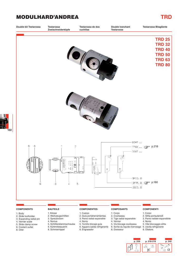
COMPONENTS
1. Body2. Slide toolholder3. Expanding radial pin4. Vernier scale5. Slide clamp screw6. Coolant outlet8. Oiler
BAUTEILE
1. Körper2. Werkzeugschlitten3. Spreizbolzen4. Nonius5. Schlittenklemmschraube6. Kühlmittelaustritt 8. Schmiernippel
COMPONENTES
1. Cuerpo2. Guía portaherramientas3. Perno radial expansible4. Nonio5. Tornillo blocaje guía6. Agujero salida refrigerante8. Engrasador
COMPOSANTS
1. Corps 2. Coulisseau 3. Tige radial expansible4. Vernier5. Vis blocage coulisseau6. Sortie du liquide d’arrosage8. Graisseur
COMPONENTI
1. Corpo 2. Slitta portautensili3. Perno radiale espandibile4. Nonio 5. Vite bloccaggio slitta6. Uscita refrigerante8. Oliatore
TRD 25TRD 32TRD 40TRD 50TRD 63TRD 80
Testarossa Zweischneiderköpfe
Testarossa de dos cuchillas
Double tranchant Testarossa
Testarossa Bitagliente Double-bit Testarossa
p.180�
p.218�
+
103
p. 218-219 p. 259p. 242
TRD
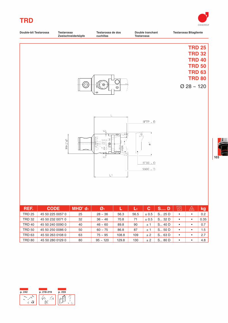
TRD 25TRD 32TRD 40TRD 50TRD 63TRD 80
Ø 28 ~ 120
REF. CODE MHD’ d1 Ø1 L L1 C S.... D kg TRD 25 45 50 225 0057 0 25 28 ~ 36 56.3 56.5 ± 0.5 S... 25 D • • 0.2
TRD 32 45 50 232 0071 0 32 36 ~ 46 70.8 71 ± 0.5 S... 32 D • • 0.35
TRD 40 45 50 240 0090 0 40 46 ~ 60 89.8 90 ± 1 S... 40 D • • 0.7
TRD 50 45 50 250 0086 0 50 60 ~ 75 86.8 87 ± 1 S... 50 D • • 1.5
TRD 63 45 50 263 0108 0 63 75 ~ 95 108.8 109 ± 2 S... 63 D • • 2.7
TRD 80 45 50 280 0129 0 80 95 ~ 120 129.8 130 ± 2 S... 80 D • • 4.8
Testarossa Zweischneiderköpfe
Testarossa de dos cuchillas
Double tranchant Testarossa
Testarossa Bitagliente Double-bit Testarossa
MODULHARD’ANDREA
104
FEATURES
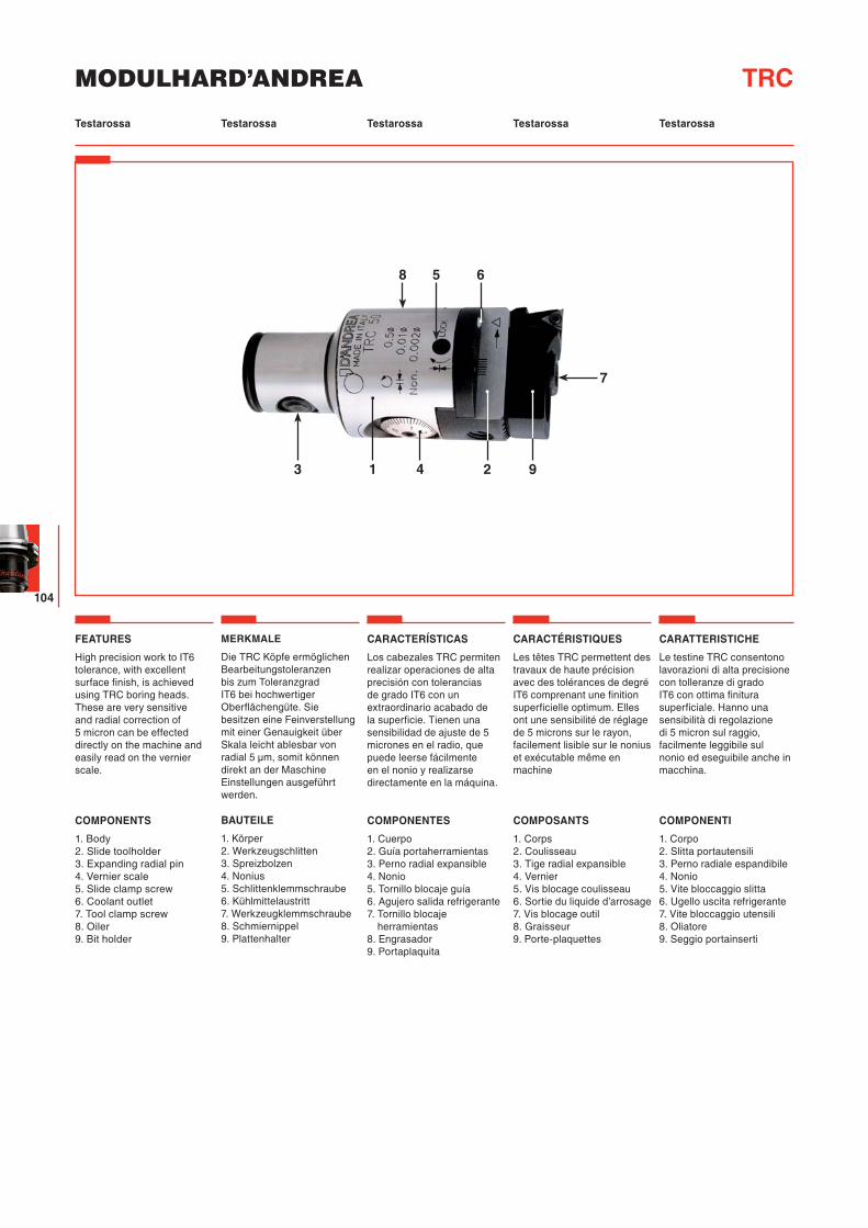
High precision work to IT6 tolerance, with excellent surface finish, is achieved using TRC boring heads. These are very sensitive and radial correction of 5 micron can be effected directly on the machine and easily read on the vernier scale.
COMPONENTS
1. Body2. Slide toolholder3. Expanding radial pin4. Vernier scale5. Slide clamp screw6. Coolant outlet7. Tool clamp screw8. Oiler 9. Bit holder
MERKMALE
Die TRC Köpfe ermöglichen Bearbeitungstoleranzen bis zum Toleranzgrad IT6 bei hochwertiger Oberflächengüte. Sie besitzen eine Feinverstellung mit einer Genauigkeit über Skala leicht ablesbar von radial 5 �m, somit können direkt an der Maschine Einstellungen ausgeführt werden.
BAUTEILE
1. Körper2. Werkzeugschlitten3. Spreizbolzen4. Nonius5. Schlittenklemmschraube6. Kühlmittelaustritt7. Werkzeugklemmschraube8. Schmiernippel9. Plattenhalter
CARACTERÍSTICAS
Los cabezales TRC permiten realizar operaciones de alta precisión con tolerancias de grado IT6 con un extraordinario acabado de la superficie. Tienen una sensibilidad de ajuste de 5 micrones en el radio, que puede leerse fácilmente en el nonio y realizarse directamente en la máquina.
COMPONENTES
1. Cuerpo2. Guía portaherramientas3. Perno radial expansible4. Nonio5. Tornillo blocaje guía6. Agujero salida refrigerante7. Tornillo blocaje
herramientas8. Engrasador9. Portaplaquita
CARACTÉRISTIQUES
Les têtes TRC permettent des travaux de haute précision avec des tolérances de degré IT6 comprenant une finition superficielle optimum. Elles ont une sensibilité de réglage de 5 microns sur le rayon, facilement lisible sur le nonius et exécutable même en machine
COMPOSANTS
1. Corps 2. Coulisseau 3. Tige radial expansible4. Vernier5. Vis blocage coulisseau6. Sortie du liquide d’arrosage7. Vis blocage outil8. Graisseur9. Porte-plaquettes
CARATTERISTICHE
Le testine TRC consentono lavorazioni di alta precisione con tolleranze di grado IT6 con ottima finitura superficiale. Hanno una sensibilità di regolazione di 5 micron sul raggio, facilmente leggibile sul nonio ed eseguibile anche in macchina.
COMPONENTI
1. Corpo 2. Slitta portautensili3. Perno radiale espandibile4. Nonio5. Vite bloccaggio slitta6. Ugello uscita refrigerante7. Vite bloccaggio utensili8. Oliatore9. Seggio portainserti
TRC
3 41 92
5
7
8 6
Testarossa Testarossa Testarossa TestarossaTestarossa
105
TRCØ 2.5 ~ 200
TRC
10 mnoniovernier 2 m
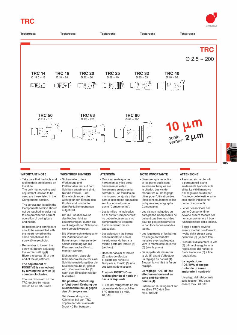
IMPORTANT NOTE
- Take care that the tools and tool holders are blocked on the slide. The only maneuvering and adjustment screws to be used are those listed in the Components section.
- The screws not listed in the Components section should not be touched in order not to compromise the correct operation of boring bars and heads.
- Bit holders and boring bars should be assembled with the insert turned on the same direction as the screw (5) (see photo).
- Remember to loosen the screw (5) before adjusting the vernier setting(4). Block the screw (5) at the end of the adjustment.
The adjustment of POSITIVE is carried out by turning the vernier (4) counter-clockwise.
The use of coolant on the TRC double-bit heads should be 40 BAR max.
WICHTIGER HINWEIS
- Sicherstellen, dass Werkzeuge und Plattenhalter fest auf dem Schlitten angebracht sind.Nur die Verstell- und Einstellschrauben, die wichtig für den Einsatz des Kopfes sind, sind unter dem Punkt Komponenten aufgeführt.
- Um die Funktionsweise des Kopfes nicht zu beeinträchtigen, dürfen die nicht aufgeführten Schrauben nicht verstellt werden.
- Die Wendenschneidenplatten der Plattenhalter und Bohrstangen müssen in der selben Richtung wie die Klemmschraube (5) sitzt, montiert werden.
- Sicherstellen, dass die Klemmschraube (5) vor einer Schlitteneinstellung über die Skalenschraube (4) gelöst wird. Klemmschraube (5) nach dem Einstellen wieder festziehen.
Die positive, Zustellung erfolgt durch Drehung der Skalenschraube (4) gegen den Uhrzeigersinn.
Bei Verwendung von Kühlmittel bei den TRC Köpfen darf der maximale Druck 40 Bar betragen.
ATENCIÓN
- Cerciorarse de que las herramientas y los porta-herramientas estén firmemente sujetos en la corredera. Los tornillos de maniobra o de ajuste útiles para el uso de los cabezales son los indicados en el punto “Componentes”.
- Los tornillos no indicados en el punto “Componentes” no deben tocarse para no comprometer el correcto funcionamiento de los cabezales.
- Los asientos y las barras deben montarse con el inserto mirando hacia la misma parte del tornillo (5) (ver foto).
- Recordar aflojar el tornillo (5) antes de efectuar el ajuste del nonio (4). Bloquear el tornillo (5) una vez terminado el ajuste.
El ajuste POSITIVO se realiza girando el nonio (4) hacia la izquierda.
El uso del refrigerante en los cabezales de las cuchillas TRC debe ser de máx. 40 BAR.
NOTE IMPORTANTE
- S’assurer que les outils et les porte-outils sont solidement bloqués sur le chariot. Les vis de manœuvre ou de réglage utiles pour l’utilisation des têtes sont seulement celles indiquées au paragraphe Composants.
- Les vis non indiquées au paragraphe Composants ne doivent pas être touchées pour ne pas compromettre le bon fonctionnement des testes.
- Les logements et les barres d’alésage doivent être installés avec la plaquette vers le même coté de la vis (5) (voir la photo)
- Se rappeler de desserrer la vis (5) avant d’effectuer un réglage du nonius (4). Bloquer la vis (5) à la fin du réglage.
Le réglage POSITIF est effectué en tournant en sans anti-horaire le nonius (4).
L’utilisation du réfrigérant sur les têtes TRC doit être max. 40 BAR
ATTENZIONE
- Assicurarsi che utensili e portautensili siano saldamente bloccati sulla slitta. Le viti di manovra o di regolazione utili per l’impiego delle testine sono solo quelle indicate nel punto Componenti.
- Le viti non indicate nel punto Componenti non devono essere toccate per non compromettere il buon funzionamento delle testine.
- Seggi e bareni devono essere montati con l’inserto rivolto dalla stessa parte della vite (5) (vedere foto).
- Ricordarsi di allentare la vite (5) prima di eseguire una regolazione del nonio (4). Bloccare la vite (5) a fine regolazione.
La regolazione POSITIVA si esegue ruotando in senso antiorario il nonio (4).
L'impiego del refrigerante sulle testine TRC deve essere max. 40 BAR.
TRC 80Ø 88 ~ 200
TRC 50Ø 2.5 ~ 110
TRC 63Ø 72 ~ 125
TRC 40Ø 48 ~ 66
TRC 32Ø 35 ~ 53
TRC 25Ø 28 ~ 40
TRC 20Ø 22 ~ 30
TRC 16Ø 18 ~ 24
TRC 14Ø 14.5 ~ 18
Testarossa Testarossa Testarossa TestarossaTestarossa
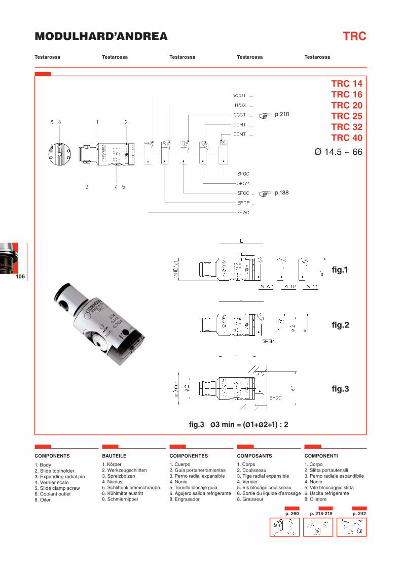
MODULHARD’ANDREA
106
COMPONENTS
1. Body2. Slide toolholder3. Expanding radial pin4. Vernier scale5. Slide clamp screw6. Coolant outlet8. Oiler
BAUTEILE
1. Körper2. Werkzeugschlitten3. Spreizbolzen4. Nonius5. Schlittenklemmschraube6. Kühlmittelaustritt8. Schmiernippel
COMPONENTES
1. Cuerpo2. Guía portaherramientas3. Perno radial expansible4. Nonio5. Tornillo blocaje guía6. Agujero salida refrigerante8. Engrasador
COMPOSANTS
1. Corps 2. Coulisseau 3. Tige radial expansible4. Vernier5. Vis blocage coulisseau6. Sortie du liquide d’arrosage8. Graisseur
COMPONENTI
1. Corpo 2. Slitta portautensili3. Perno radiale espandibile4. Nonio5. Vite bloccaggio slitta6. Uscita refrigerante8. Oliatore
TRC
p.188�
p.218�
TRC 14TRC 16TRC 20TRC 25TRC 32TRC 40
Ø 14.5 ~ 66
fig.3 Ø3 min = (Ø1+Ø2+1) : 2
fig.3
fig.2
fig.1
p. 218-219 p. 242p. 260
Testarossa Testarossa Testarossa TestarossaTestarossa
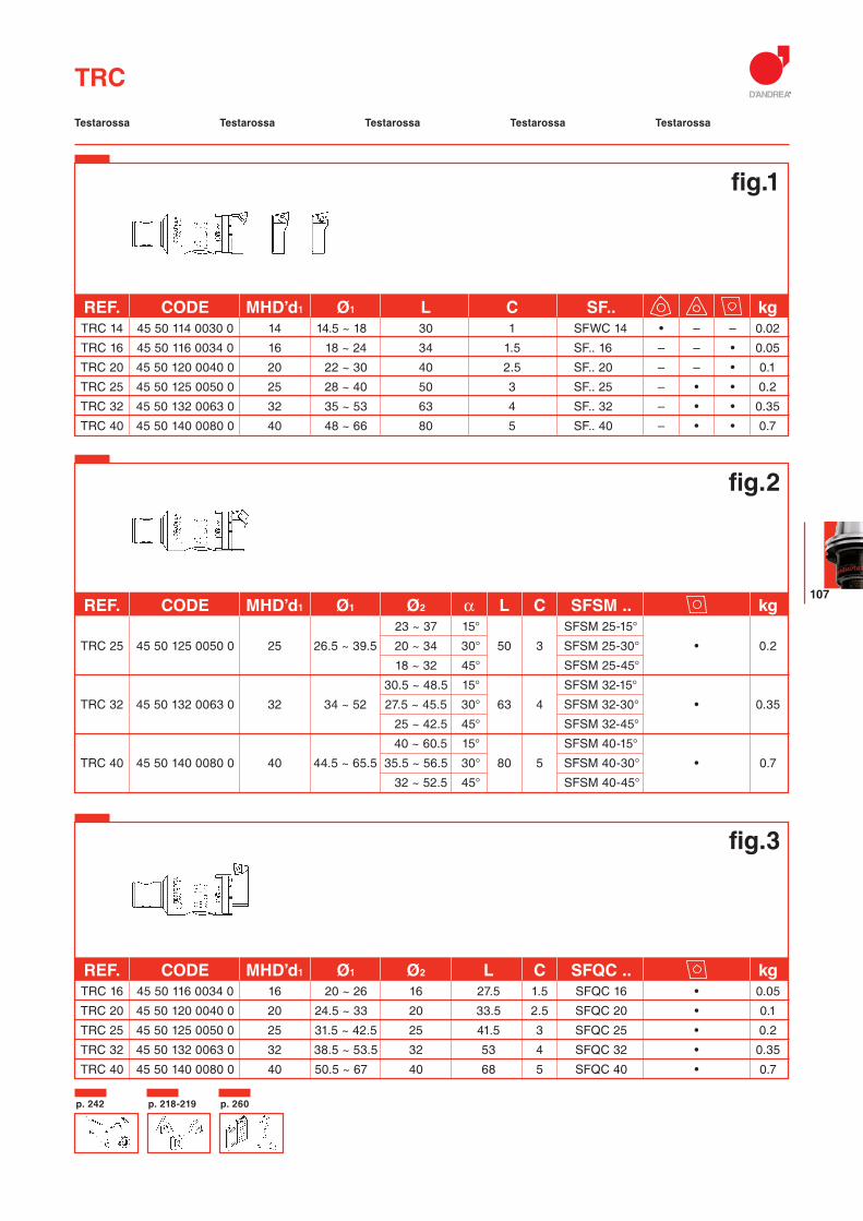
107
TRC
REF. CODE MHD’d1 Ø1 Ø2 L C SFQC .. kg TRC 16 45 50 116 0034 0 16 20 ~ 26 16 27.5 1.5 SFQC 16 • 0.05
TRC 20 45 50 120 0040 0 20 24.5 ~ 33 20 33.5 2.5 SFQC 20 • 0.1
TRC 25 45 50 125 0050 0 25 31.5 ~ 42.5 25 41.5 3 SFQC 25 • 0.2
TRC 32 45 50 132 0063 0 32 38.5 ~ 53.5 32 53 4 SFQC 32 • 0.35
TRC 40 45 50 140 0080 0 40 50.5 ~ 67 40 68 5 SFQC 40 • 0.7
REF. CODE MHD’d1 Ø1 Ø2 α L C SFSM .. kg 23 ~ 37 15° SFSM 25-15°
TRC 25 45 50 125 0050 0 25 26.5 ~ 39.5 20 ~ 34 30° 50 3 SFSM 25-30° • 0.2
18 ~ 32 45° SFSM 25-45°
30.5 ~ 48.5 15° SFSM 32-15°
TRC 32 45 50 132 0063 0 32 34 ~ 52 27.5 ~ 45.5 30° 63 4 SFSM 32-30° • 0.35
25 ~ 42.5 45° SFSM 32-45°
40 ~ 60.5 15° SFSM 40-15°
TRC 40 45 50 140 0080 0 40 44.5 ~ 65.5 35.5 ~ 56.5 30° 80 5 SFSM 40-30° • 0.7
32 ~ 52.5 45° SFSM 40-45°
REF. CODE MHD’d1 Ø1 L C SF.. kg TRC 14 45 50 114 0030 0 14 14.5 ~ 18 30 1 SFWC 14 • – – 0.02
TRC 16 45 50 116 0034 0 16 18 ~ 24 34 1.5 SF.. 16 – – • 0.05
TRC 20 45 50 120 0040 0 20 22 ~ 30 40 2.5 SF.. 20 – – • 0.1
TRC 25 45 50 125 0050 0 25 28 ~ 40 50 3 SF.. 25 – • • 0.2
TRC 32 45 50 132 0063 0 32 35 ~ 53 63 4 SF.. 32 – • • 0.35
TRC 40 45 50 140 0080 0 40 48 ~ 66 80 5 SF.. 40 – • • 0.7
fig.2
fig.1
fig.3
p. 218-219p. 242 p. 260
Testarossa Testarossa Testarossa TestarossaTestarossa
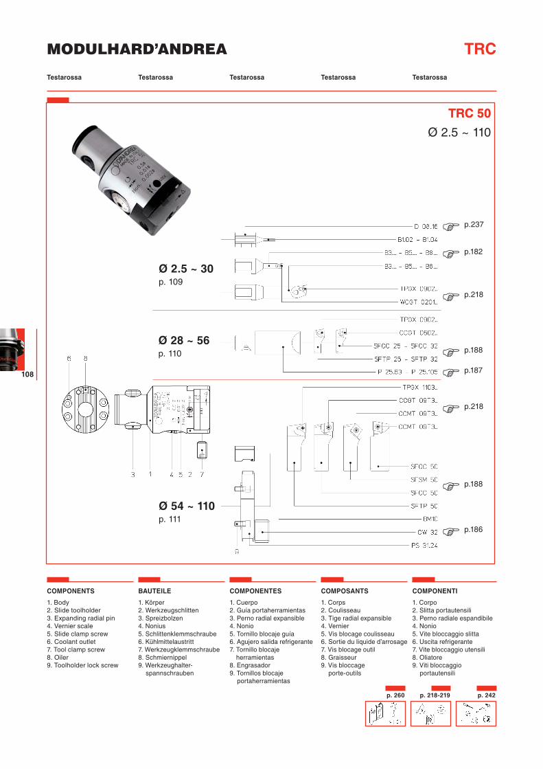
MODULHARD’ANDREA
108
TRC
TRC 50
COMPONENTS
1. Body2. Slide toolholder3. Expanding radial pin4. Vernier scale5. Slide clamp screw6. Coolant outlet7. Tool clamp screw8. Oiler 9. Toolholder lock screw
BAUTEILE
1. Körper2. Werkzeugschlitten3. Spreizbolzen4. Nonius5. Schlittenklemmschraube6. Kühlmittelaustritt7. Werkzeugklemmschraube8. Schmiernippel 9. Werkzeughalter-
spannschrauben
COMPONENTES
1. Cuerpo2. Guía portaherramientas3. Perno radial expansible4. Nonio5. Tornillo blocaje guía6. Agujero salida refrigerante7. Tornillo blocaje
herramientas8. Engrasador9. Tornillos blocaje
portaherramientas
COMPOSANTS
1. Corps 2. Coulisseau 3. Tige radial expansible4. Vernier5. Vis blocage coulisseau6. Sortie du liquide d’arrosage7. Vis blocage outil8. Graisseur9. Vis bloccage
porte-outils
COMPONENTI
1. Corpo 2. Slitta portautensili3. Perno radiale espandibile4. Nonio5. Vite bloccaggio slitta6. Uscita refrigerante7. Vite bloccaggio utensili8. Oliatore9. Viti bloccaggio
portautensili
TRC 50
Ø 2.5 ~ 110
Ø 2.5 ~ 30 p. 109
Ø 28 ~ 56 p. 110
Ø 54 ~ 110 p. 111
p.237�p.182�
p.218�
p.188�p.187�p.218�
p.188�
p.186�
Testarossa Testarossa Testarossa TestarossaTestarossa
p. 218-219 p. 242p. 260
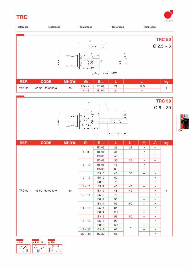
109
TRC
REF. CODE MHD’d1 Ø1 B... L L1 kg
TRC 50 45 50 150 0080 0 50 2.5 ~ 4 B1.02 21 12.5
1
4 ~ 6 B1.04 24 –
REF. CODE MHD’d1 Ø1 B... L L1 kg B3.06 29 21 • –
6 ~ 8 B5.06 36 –
• –
B8.06 45 • –
B3.08 36 28 • –
8 ~ 10 B5.08 48 –
• –
B8.08 60 • –
B3.10 43 35 – •
10 ~ 12 B5.10 60 –
– •
B8.10 75 – •
11 ~ 13 B3.11 48 40 – • TRC 50 45 50 150 0080 0 50 B3.12 48 42 – • 1
12 ~ 14 B5.12 72 –
– •
B8.12 90 – •
B3.14 52 50 – •
14 ~ 16 B5.14 84 –
– •
B8.14 105 – •
B3.16 58 50 – •
16 ~ 18 B5.16 96 – •
B8.16 120 –
– •
18 ~ 22 B3.18 63 – •
22 ~ 30 B3.22 68 – •
TRC 50
Ø 2.5 ~ 6
TRC 50
Ø 6 ~ 30
Testarossa Testarossa Testarossa TestarossaTestarossa
p. 218-219p. 242 p. 260

MODULHARD’ANDREA
110
TRC
TRC 50
Ø 28 ~ 56
REF. CODE MHD’d1 Ø1 L P 25.. SF.. kg
28 ~ 44 63 P 25.63 SFTP 25 •
TRC 50 45 50 150 0080 0 50
105 P 25.105 SFCC 25 • 1
36 ~ 56
63 P 25.63 SFTP 32 •
105 P 25.105 SFCC 32 •
Testarossa Testarossa Testarossa TestarossaTestarossa
p. 218-219 p. 242p. 260
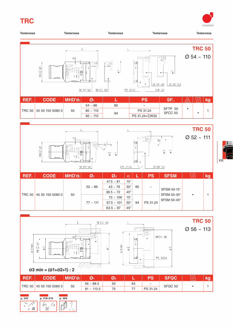
111
TRC
TRC 50
Ø 54 ~ 110
REF. CODE MHD’d1 Ø1 L PS SF.. kg 54 ~ 86 80 –
SFTP 50
•
TRC 50 45 50 150 0080 0 50 80 ~ 110 94
PS 31.24 SFCC 50
• 1
92 ~ 110 PS 31.24+CW32
REF. CODE MHD’d1 Ø1 Ø2 α L PS SFSM kg 47.5 ~ 81 15°
52 ~ 86 43 ~ 76 30° 80 – SFSM 50-15°
TRC 50 45 50 150 0080 0 50
38.5 ~ 72 45° SFSM 50-30°
•
1
72 ~ 106 15° SFSM 50-45°
77 ~ 111 67.5 ~ 101 30° 94 PS 31.24
63.5 ~ 97 45°
REF. CODE MHD’d1 Ø1 Ø2 L PS SFQC kg TRC 50 45 50 150 0080 0 50
56 ~ 88.5 50 63 – SFQC 50
•
1
81 ~ 113.5 75 77 PS 31.24
Ø3 min = (Ø1+Ø2+1) : 2
TRC 50
Ø 52 ~ 111
TRC 50
Ø 56 ~ 113
Testarossa Testarossa Testarossa TestarossaTestarossa
p. 218-219p. 242 p. 260
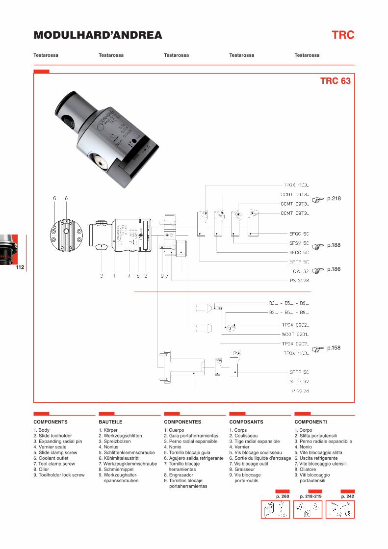
MODULHARD’ANDREA
112
TRC
TRC 63
COMPONENTS
1. Body2. Slide toolholder3. Expanding radial pin4. Vernier scale5. Slide clamp screw6. Coolant outlet7. Tool clamp screw8. Oiler 9. Toolholder lock screw
BAUTEILE
1. Körper2. Werkzeugschlitten3. Spreizbolzen4. Nonius5. Schlittenklemmschraube6. Kühlmittelaustritt7. Werkzeugklemmschraube8. Schmiernippel9. Werkzeughalter-
spannschrauben
COMPONENTES
1. Cuerpo2. Guía portaherramientas3. Perno radial expansible4. Nonio5. Tornillo blocaje guía6. Agujero salida refrigerante7. Tornillo blocaje
herramientas8. Engrasador9. Tornillos blocaje
portaherramientas
COMPOSANTS
1. Corps 2. Coulisseau 3. Tige radial expansible4. Vernier5. Vis blocage coulisseau6. Sortie du liquide d’arrosage7. Vis blocage outil8. Graisseur9. Vis bloccage
porte-outils
COMPONENTI
1. Corpo 2. Slitta portautensili3. Perno radiale espandibile4. Nonio5. Vite bloccaggio slitta6. Uscita refrigerante7. Vite bloccaggio utensili8. Oliatore9. Viti bloccaggio
portautensili
TRC 63
p.158�
p.218�
p.188�p.186�
Testarossa Testarossa Testarossa TestarossaTestarossa
p. 218-219 p. 242p. 260
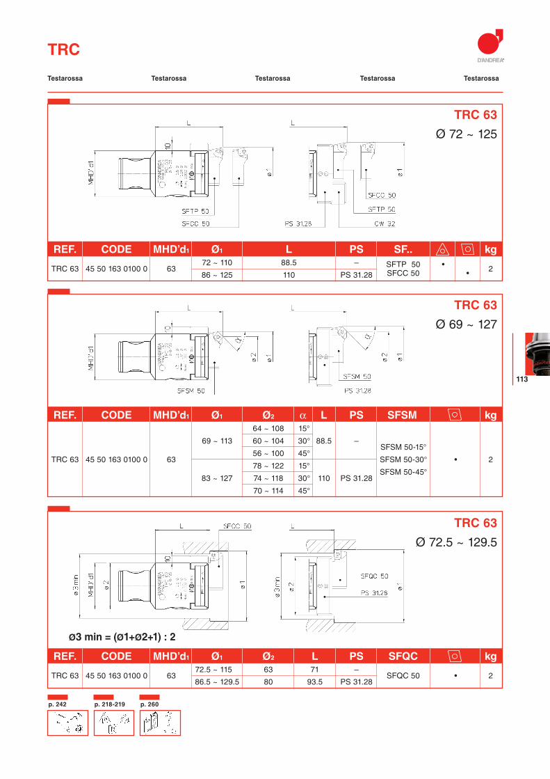
113
TRC
REF. CODE MHD’d1 Ø1 L PS SF.. kg TRC 63 45 50 163 0100 0 63
72 ~ 110 88.5 – SFTP 50 • 2
86 ~ 125 110 PS 31.28 SFCC 50 •
REF. CODE MHD’d1 Ø1 Ø2 α L PS SFSM kg 64 ~ 108 15°
69 ~ 113 60 ~ 104 30° 88.5 – SFSM 50-15°
TRC 63 45 50 163 0100 0 63
56 ~ 100 45° SFSM 50-30°
•
2
78 ~ 122 15° SFSM 50-45°
83 ~ 127 74 ~ 118 30° 110 PS 31.28
70 ~ 114 45°
REF. CODE MHD’d1 Ø1 Ø2 L PS SFQC kg TRC 63 45 50 163 0100 0 63
72.5 ~ 115 63 71 – SFQC 50
•
2
86.5 ~ 129.5 80 93.5 PS 31.28
TRC 63
Ø 72 ~ 125
Ø3 min = (Ø1+Ø2+1) : 2
TRC 63
Ø 69 ~ 127
TRC 63
Ø 72.5 ~ 129.5
Testarossa Testarossa Testarossa TestarossaTestarossa
p. 218-219p. 242 p. 260
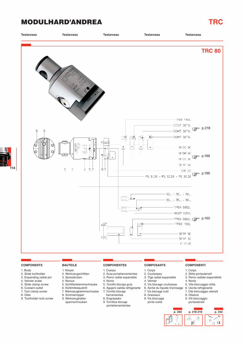
MODULHARD’ANDREA
114
TRC
COMPONENTS
1. Body2. Slide toolholder3. Expanding radial pin4. Vernier scale5. Slide clamp screw6. Coolant outlet7. Tool clamp screw8. Oiler 9. Toolholder lock screw
BAUTEILE
1. Körper2. Werkzeugschlitten3. Spreizbolzen4. Nonius5. Schlittenklemmschraube6. Kühlmittelaustritt7. Werkzeugklemmschraube8. Schmiernippel9. Werkzeughalter-
spannschrauben
COMPONENTES
1. Cuerpo2. Guía portaherramientas3. Perno radial expansible4. Nonio5. Tornillo blocaje guía6. Agujero salida refrigerante7. Tornillo blocaje
herramientas8. Engrasador9. Tornillos blocaje
portaherramientas
COMPOSANTS
1. Corps 2. Coulisseau 3. Tige radial expansible4. Vernier5. Vis blocage coulisseau6. Sortie du liquide d’arrosage7. Vis blocage outil8. Graisseur9. Vis bloccage
porte-outils
COMPONENTI
1. Corpo 2. Slitta portautensili3. Perno radiale espandibile4. Nonio5. Vite bloccaggio slitta6. Uscita refrigerante7. Vite bloccaggio utensili8. Oliatore9. Viti bloccaggio
portautensili
TRC 80
p.160�
p.218�
p.188�
p.186�
Testarossa Testarossa Testarossa TestarossaTestarossa
p. 218-219 p. 242p. 260
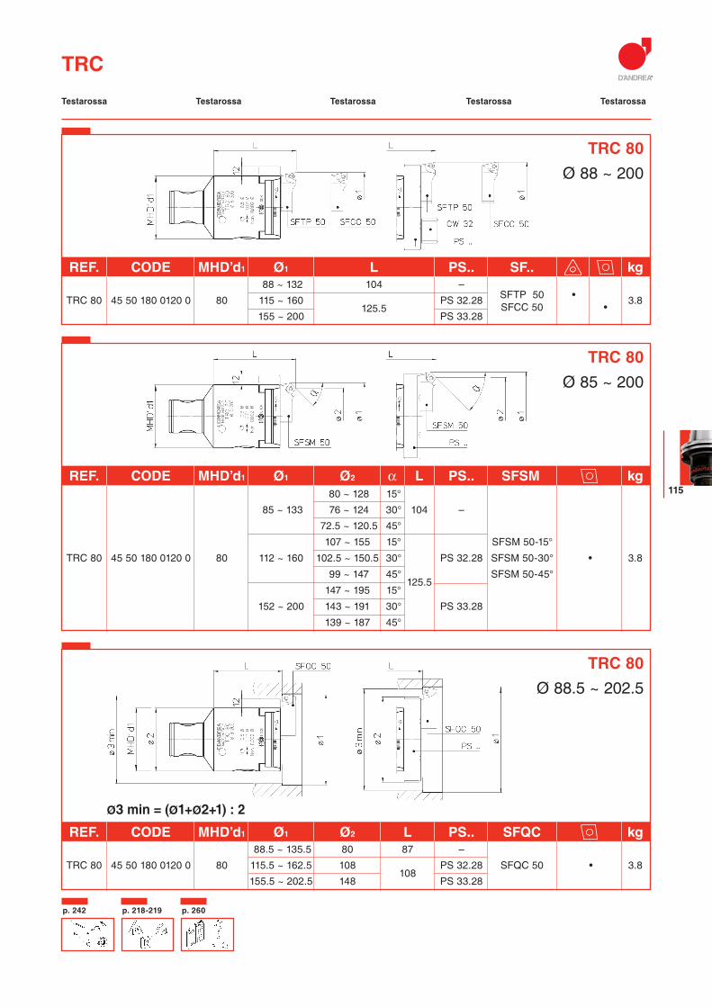
115
TRC
Ø3 min = (Ø1+Ø2+1) : 2
TRC 80
Ø 88 ~ 200
REF. CODE MHD’d1 Ø1 L PS.. SF.. kg 88 ~ 132 104 –
SFTP 50
•
TRC 80 45 50 180 0120 0 80 115 ~ 160 125.5
PS 32.28 SFCC 50
• 3.8
155 ~ 200 PS 33.28
REF. CODE MHD’d1 Ø1 Ø2 α L PS.. SFSM kg 80 ~ 128 15°
85 ~ 133 76 ~ 124 30° 104 –
72.5 ~ 120.5 45°
107 ~ 155 15° SFSM 50-15°
TRC 80 45 50 180 0120 0 80 112 ~ 160 102.5 ~ 150.5 30° PS 32.28 SFSM 50-30° • 3.8
99 ~ 147 45° 125.5
SFSM 50-45°
147 ~ 195 15°
152 ~ 200 143 ~ 191 30° PS 33.28
139 ~ 187 45°
REF. CODE MHD’d1 Ø1 Ø2 L PS.. SFQC kg 88.5 ~ 135.5 80 87 –
TRC 80 45 50 180 0120 0 80 115.5 ~ 162.5 108 108
PS 32.28 SFQC 50 • 3.8
155.5 ~ 202.5 148 PS 33.28
TRC 80
Ø 85 ~ 200
TRC 80
Ø 88.5 ~ 202.5
Testarossa Testarossa Testarossa TestarossaTestarossa
p. 218-219p. 242 p. 260
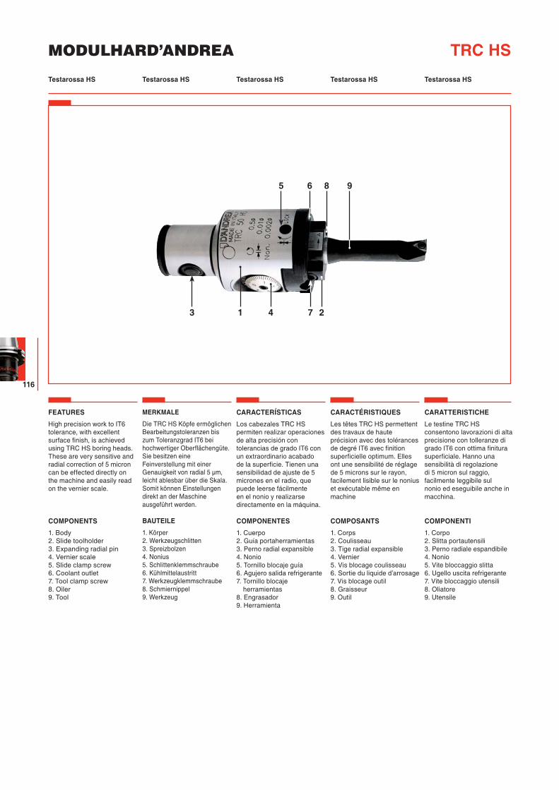
MODULHARD’ANDREA
116
Testarossa HS Testarossa HS Testarossa HS Testarossa HSTestarossa HS
FEATURES
High precision work to IT6 tolerance, with excellent surface finish, is achieved using TRC HS boring heads. These are very sensitive and radial correction of 5 micron can be effected directly on the machine and easily read on the vernier scale.
COMPONENTS
1. Body2. Slide toolholder3. Expanding radial pin4. Vernier scale5. Slide clamp screw6. Coolant outlet7. Tool clamp screw8. Oiler 9. Tool
MERKMALE
Die TRC HS Köpfe ermöglichen Bearbeitungstoleranzen bis zum Toleranzgrad IT6 bei hochwertiger Oberflächengüte.Sie besitzen eine Feinverstellung mit einer Genauigkeit von radial 5 �m, leicht ablesbar über die Skala. Somit können Einstellungen direkt an der Maschine ausgeführt werden.
BAUTEILE
1. Körper2. Werkzeugschlitten3. Spreizbolzen4. Nonius5. Schlittenklemmschraube6. Kühlmittelaustritt 7. Werkzeugklemmschraube8. Schmiernippel9. Werkzeug
CARACTERÍSTICAS
Los cabezales TRC HS permiten realizar operaciones de alta precisión con tolerancias de grado IT6 con un extraordinario acabado de la superficie. Tienen una sensibilidad de ajuste de 5 micrones en el radio, que puede leerse fácilmente en el nonio y realizarse directamente en la máquina.
COMPONENTES
1. Cuerpo2. Guía portaherramientas3. Perno radial expansible4. Nonio5. Tornillo blocaje guía6. Agujero salida refrigerante7. Tornillo blocaje
herramientas8. Engrasador9. Herramienta
CARACTÉRISTIQUES
Les têtes TRC HS permettent des travaux de haute précision avec des tolérances de degré IT6 avec finition superficielle optimum. Elles ont une sensibilité de réglage de 5 microns sur le rayon, facilement lisible sur le nonius et exécutable même en machine
COMPOSANTS
1. Corps 2. Coulisseau 3. Tige radial expansible4. Vernier5. Vis blocage coulisseau6. Sortie du liquide d’arrosage7. Vis blocage outil8. Graisseur9. Outil
CARATTERISTICHE
Le testine TRC HS consentono lavorazioni di alta precisione con tolleranze di grado IT6 con ottima finitura superficiale. Hanno una sensibilità di regolazione di 5 micron sul raggio, facilmente leggibile sul nonio ed eseguibile anche in macchina.
COMPONENTI
1. Corpo 2. Slitta portautensili3. Perno radiale espandibile4. Nonio5. Vite bloccaggio slitta6. Ugello uscita refrigerante7. Vite bloccaggio utensili8. Oliatore9. Utensile
TRC HS
3
9
21 4 7
65 8
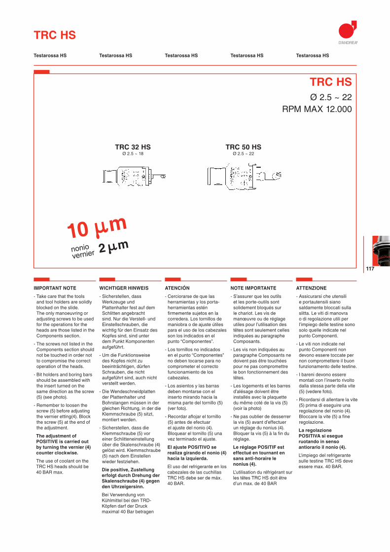
117
TRC HSØ 2.5 ~ 22
RPM MAX 12.000
TRC HS
10 mnoniovernier 2 m
IMPORTANT NOTE
- Take care that the tools and tool holders are solidly blocked on the slide. The only manoeuvring or adjusting screws to be used for the operations for the heads are those listed in the Components section.
- The screws not listed in the Components section should not be touched in order not to compromise the correct operation of the heads.
- Bit holders and boring bars should be assembled with the insert turned on the same direction as the screw (5) (see photo).
- Remember to loosen the screw (5) before adjusting the vernier etting(4). Block the screw (5) at the end of the adjustment.
The adjustment of POSITIVE is carried out by turning the vernier (4) counter clockwise.
The use of coolant on the TRC HS heads should be 40 BAR max.
WICHTIGER HINWEIS
- Sicherstellen, dass Werkzeuge und Plattenhalter fest auf dem Schlitten angebracht sind. Nur die Verstell- und Einstellschrauben, die wichtig für den Einsatz des Kopfes sind, sind unter dem Punkt Komponenten aufgeführt.
- Um die Funktionsweise des Kopfes nicht zu beeinträchtigen, dürfen Schrauben, die nicht aufgeführt sind, auch nicht verstellt werden.
- Die Wendeschneidplatten der Plattenhalter und Bohrstangen müssen in der gleichen Richtung, in der die Klemmschraube (5) sitzt, montiert werden.
- Sicherstellen, dass die Klemmschraube (5) vor einer Schlitteneinstellung über die Skalenschraube (4) gelöst wird. Klemmschraube (5) nach dem Einstellen wieder festziehen.
Die positive, Zustellung erfolgt durch Drehung der Skalenschraube (4) gegen den Uhrzeigersinn.
Bei Verwendung von Kühlmittel bei den TRD-Köpfen darf der Druck maximal 40 Bar betragen
ATENCIÓN
- Cerciorarse de que las herramientas y los porta-herramientas estén firmemente sujetos en la corredera. Los tornillos de maniobra o de ajuste útiles para el uso de los cabezales son los indicados en el punto “Componentes”.
- Los tornillos no indicados en el punto “Componentes” no deben tocarse para no comprometer el correcto funcionamiento de los cabezales.
- Los asientos y las barras deben montarse con el inserto mirando hacia la misma parte del tornillo (5) (ver foto).
- Recordar aflojar el tornillo (5) antes de efectuar el ajuste del nonio (4). Bloquear el tornillo (5) una vez terminado el ajuste.
El ajuste POSITIVO se realiza girando el nonio (4) hacia la izquierda.
El uso del refrigerante en los cabezales de las cuchillas TRC HS debe ser de máx. 40 BAR.
NOTE IMPORTANTE
- S’assurer que les outils et les porte-outils sont solidement bloqués sur le chariot. Les vis de manœuvre ou de réglage utiles pour l’utilisation des têtes sont seulement celles indiquées au paragraphe Composants.
- Les vis non indiquées au paragraphe Composants ne doivent pas être touchées pour ne pas compromettre le bon fonctionnement des têtes.
- Les logements et les barres d’alésage doivent être installés avec la plaquette du même coté de la vis (5) (voir la photo)
- Ne pas oublier de desserrer la vis (5) avant d’effectuer un réglage du nonius (4). Bloquer la vis (5) à la fin du réglage.
Le réglage POSITIF est effectué en tournant en sans anti-horaire le nonius (4).
L’utilisation du réfrigérant sur les têtes TRC HS doit être d’un max. de 40 BAR
ATTENZIONE
- Assicurarsi che utensili e portautensili siano saldamente bloccati sulla slitta. Le viti di manovra o di regolazione utili per l’impiego delle testine sono solo quelle indicate nel punto Componenti.
- Le viti non indicate nel punto Componenti non devono essere toccate per non compromettere il buon funzionamento delle testine.
- I bareni devono essere montati con l’inserto rivolto dalla stessa parte della vite (5) (vedere foto).
- Ricordarsi di allentare la vite (5) prima di eseguire una regolazione del nonio (4). Bloccare la vite (5) a fine regolazione.
La regolazione POSITIVA si esegue ruotando in senso antiorario il nonio (4).
L'impiego del refrigerante sulle testine TRC HS deve essere max. 40 BAR.
TRC 32 HSØ 2.5 ~ 18
TRC 50 HSØ 2.5 ~ 22
Testarossa HS Testarossa HS Testarossa HS Testarossa HSTestarossa HS
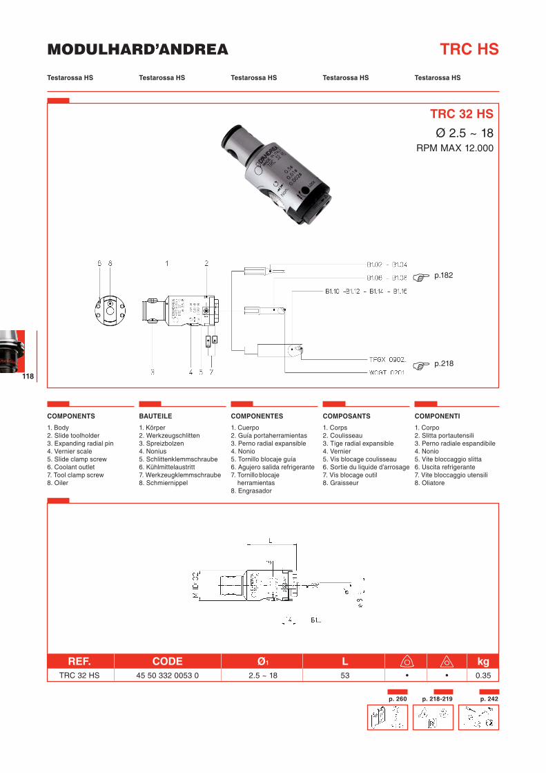
MODULHARD’ANDREA
118
TRC 32 HS
Ø 2.5 ~ 18RPM MAX 12.000
REF. CODE Ø1 L kg
TRC 32 HS 45 50 332 0053 0 2.5 ~ 18 53 • • 0.35
TRC HS
COMPONENTS
1. Body2. Slide toolholder3. Expanding radial pin4. Vernier scale5. Slide clamp screw6. Coolant outlet7. Tool clamp screw8. Oiler
BAUTEILE
1. Körper2. Werkzeugschlitten3. Spreizbolzen4. Nonius5. Schlittenklemmschraube6. Kühlmittelaustritt 7. Werkzeugklemmschraube8. Schmiernippel
COMPONENTES
1. Cuerpo2. Guía portaherramientas3. Perno radial expansible4. Nonio5. Tornillo blocaje guía6. Agujero salida refrigerante7. Tornillo blocaje
herramientas8. Engrasador
COMPOSANTS
1. Corps 2. Coulisseau 3. Tige radial expansible4. Vernier5. Vis blocage coulisseau6. Sortie du liquide d’arrosage7. Vis blocage outil8. Graisseur
COMPONENTI
1. Corpo 2. Slitta portautensili3. Perno radiale espandibile4. Nonio5. Vite bloccaggio slitta6. Uscita refrigerante7. Vite bloccaggio utensili8. Oliatore
p.182�
p.218�
Testarossa HS Testarossa HS Testarossa HS Testarossa HSTestarossa HS
p. 218-219 p. 242p. 260
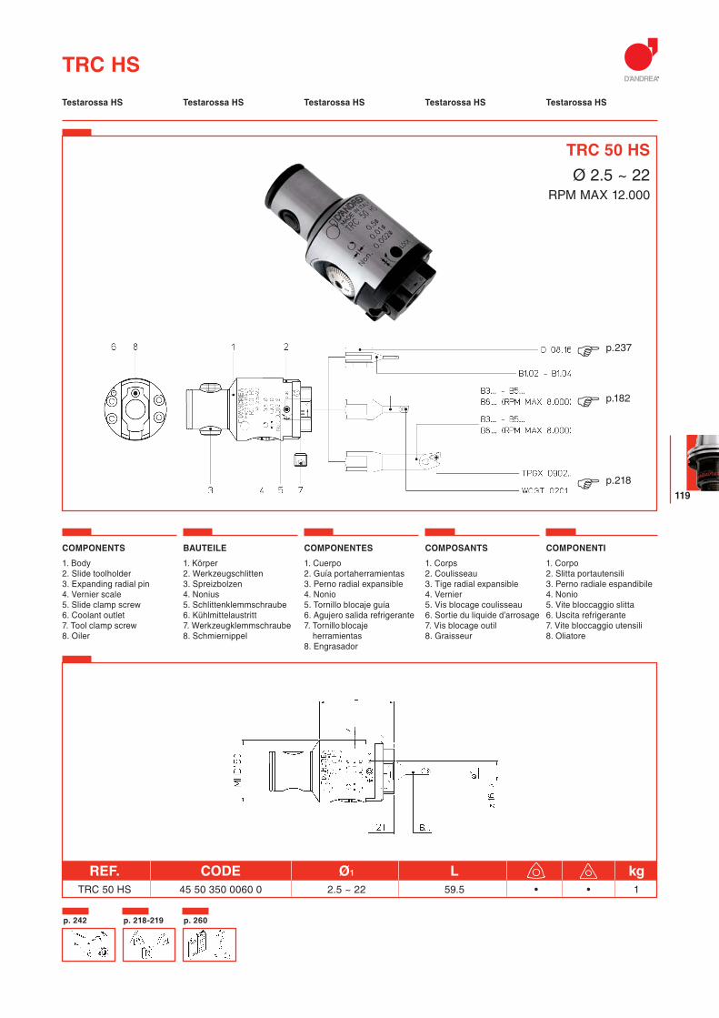
119
TRC HS
COMPONENTS
1. Body2. Slide toolholder3. Expanding radial pin4. Vernier scale5. Slide clamp screw6. Coolant outlet7. Tool clamp screw8. Oiler
BAUTEILE
1. Körper2. Werkzeugschlitten3. Spreizbolzen4. Nonius5. Schlittenklemmschraube6. Kühlmittelaustritt7. Werkzeugklemmschraube8. Schmiernippel
COMPONENTES
1. Cuerpo2. Guía portaherramientas3. Perno radial expansible4. Nonio5. Tornillo blocaje guía6. Agujero salida refrigerante7. Tornillo blocaje
herramientas8. Engrasador
COMPOSANTS
1. Corps 2. Coulisseau 3. Tige radial expansible4. Vernier5. Vis blocage coulisseau6. Sortie du liquide d’arrosage7. Vis blocage outil8. Graisseur
COMPONENTI
1. Corpo 2. Slitta portautensili3. Perno radiale espandibile4. Nonio5. Vite bloccaggio slitta6. Uscita refrigerante7. Vite bloccaggio utensili8. Oliatore
TRC 50 HS
Ø 2.5 ~ 22RPM MAX 12.000
REF. CODE Ø1 L kg
TRC 50 HS 45 50 350 0060 0 2.5 ~ 22 59.5 • • 1
p.237�
p.218�
p.182�
Testarossa HS Testarossa HS Testarossa HS Testarossa HSTestarossa HS
p. 218-219p. 242 p. 260
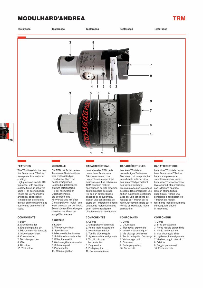
MODULHARD’ANDREA
120
6
7
10
9
21
3 5 4
8
Testarossa Testarossa Testarossa TestarossaTestarossa
FEATURES
The TRM heads in the new line Testarossa D’Andrea have protective rustproof coating.High precision work to IT6 tolerance, with excellent surface finish, is achieved using TRM boring heads. These are very sensitive and radial correction of 1 micron can be effected directly on the machine and easily read on the vernier scale.
COMPONENTS
1. Body2. Slide toolholder3. Expanding radial pin4. Micrometric vernier scale5. Slide clamp screw6. Coolant outlet7. Tool clamp screw8. Oiler 9. Bit holder10. Tool holder
MERKMALE
Die TRM Köpfe der neuen Testarossa Serie besitzen eine rostbeständige Oberfläche. Die TRM-Köpfe ermöglichen Bearbeitungstoleranzen bis zum Toleranzgrad IT6 bei hochwertiger Oberflächengüte.Sie besitzen eine Feinverstellung mit einer Genauigkeit von radial 1 �m, leicht ablesbar auf der Skala. Somit können Einstellungen direkt an der Maschine ausgeführt werden.
BAUTEILE
1. Körper2. Werkzeugschlitten3. Spreizbolzen4. Mikrometrischer Nonius5. Schlittenklemmschraube6. Kühlmittelaustritt 7. Werkzeugklemmschraube8. Schmiernippel9. Plattenhalter10. Werkzeughalter
CARACTERÍSTICAS
Los cabezales TRM de la nueva línea Testarossa D’Andrea cuentan con una protección superficial anticorrosión. Los cabezales TRM permiten realizar operaciones de alta precisión con tolerancias de grado IT6 con un extraordinario acabado de la superficie. Tienen una sensibilidad de ajuste de 1 micrón en el radio, que puede leerse fácilmente en el nonio y realizarse directamente en la máquina.
COMPONENTES
1. Cuerpo2. Guía portaherramientas3. Perno radial expansible4. Nonio micrométrico5. Tornillo blocaje guía6. Agujero salida refrigerante7. Tornillo blocaje
herramientas8. Engrasador9. Portaplaquita10. Portaherramienta
CARACTÉRISTIQUES
Les têtes TRM de la nouvelle ligne Testarossa D’Andrea ont une protection superficielle anticorrosion. Les têtes TRM permettent des travaux de haute précision avec des tolérances de degré IT6 comprenant une finition superficielle optimum. Elles ont une sensibilité de réglage de 1 micron sur le rayon, facilement lisible sur le nonius et exécutable même en machine.
COMPOSANTS
1. Corps 2. Coulisseau 3. Tige radial expansible4. Vernier micrométrique5. Vis blocage coulisseau6. Sortie du liquide d’arrosage7. Vis blocage outil8. Graisseur9. Porte-plaquettes10. Porte-outil
CARATTERISTICHE
Le testine TRM della nuova linea Testarossa D’Andrea hanno una protezione superficiale anticorrosiva.Le testine TRM consentono lavorazioni di alta precisione con tolleranze di grado IT6 con ottima finitura superficiale. Hanno una sensibilità di regolazione di 1 micron sul raggio, facilmente leggibile sul nonio ed eseguibile anche in macchina.
COMPONENTI
1. Corpo 2. Slitta portautensili3. Perno radiale espandibile4. Nonio micrometrico5. Vite bloccaggio slitta6. Ugello uscita refrigerante7. Vite bloccaggio utensili8. Oliatore9. Seggio portainserti10. Porta utensile
TRM
7
9
4 1 265
3 8
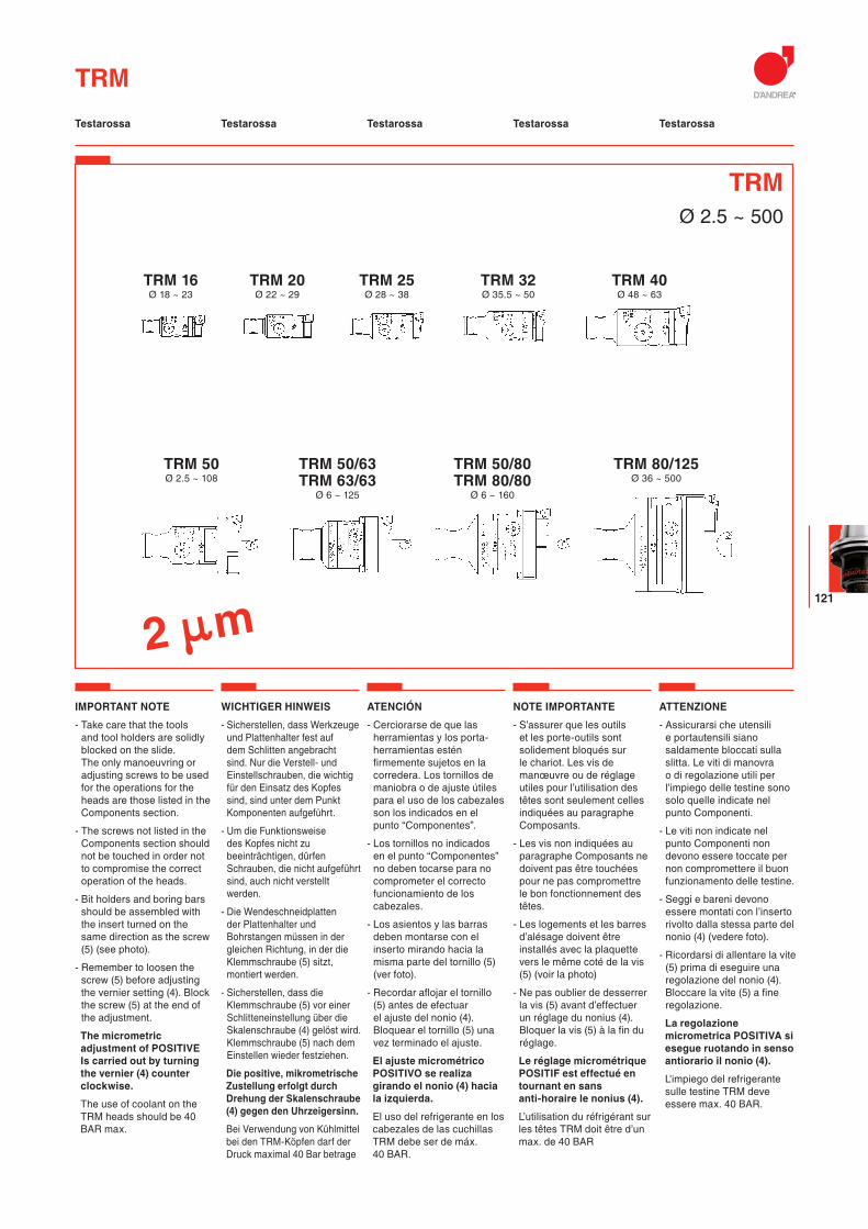
121
TRMØ 2.5 ~ 500
TRM
2 m
Testarossa Testarossa Testarossa TestarossaTestarossa
IMPORTANT NOTE
- Take care that the tools and tool holders are solidly blocked on the slide. The only manoeuvring or adjusting screws to be used for the operations for the heads are those listed in the Components section.
- The screws not listed in the Components section should not be touched in order not to compromise the correct operation of the heads.
- Bit holders and boring bars should be assembled with the insert turned on the same direction as the screw (5) (see photo).
- Remember to loosen the screw (5) before adjusting the vernier setting (4). Block the screw (5) at the end of the adjustment.
The micrometric adjustment of POSITIVE Is carried out by turning the vernier (4) counter clockwise.
The use of coolant on the TRM heads should be 40 BAR max.
WICHTIGER HINWEIS
- Sicherstellen, dass Werkzeuge und Plattenhalter fest auf dem Schlitten angebracht sind. Nur die Verstell- und Einstellschrauben, die wichtig für den Einsatz des Kopfes sind, sind unter dem Punkt Komponenten aufgeführt.
- Um die Funktionsweise des Kopfes nicht zu beeinträchtigen, dürfen Schrauben, die nicht aufgeführt sind, auch nicht verstellt werden.
- Die Wendeschneidplatten der Plattenhalter und Bohrstangen müssen in der gleichen Richtung, in der die Klemmschraube (5) sitzt, montiert werden.
- Sicherstellen, dass die Klemmschraube (5) vor einer Schlitteneinstellung über die Skalenschraube (4) gelöst wird. Klemmschraube (5) nach dem Einstellen wieder festziehen.
Die positive, mikrometrische Zustellung erfolgt durch Drehung der Skalenschraube (4) gegen den Uhrzeigersinn.
Bei Verwendung von Kühlmittel bei den TRM-Köpfen darf der Druck maximal 40 Bar betrage
ATENCIÓN
- Cerciorarse de que las herramientas y los porta-herramientas estén firmemente sujetos en la corredera. Los tornillos de maniobra o de ajuste útiles para el uso de los cabezales son los indicados en el punto “Componentes”.
- Los tornillos no indicados en el punto “Componentes” no deben tocarse para no comprometer el correcto funcionamiento de los cabezales.
- Los asientos y las barras deben montarse con el inserto mirando hacia la misma parte del tornillo (5) (ver foto).
- Recordar aflojar el tornillo (5) antes de efectuar el ajuste del nonio (4). Bloquear el tornillo (5) una vez terminado el ajuste.
El ajuste micrométrico POSITIVO se realiza girando el nonio (4) hacia la izquierda.
El uso del refrigerante en los cabezales de las cuchillas TRM debe ser de máx. 40 BAR.
NOTE IMPORTANTE
- S’assurer que les outils et les porte-outils sont solidement bloqués sur le chariot. Les vis de manœuvre ou de réglage utiles pour l’utilisation des têtes sont seulement celles indiquées au paragraphe Composants.
- Les vis non indiquées au paragraphe Composants ne doivent pas être touchées pour ne pas compromettre le bon fonctionnement des têtes.
- Les logements et les barres d’alésage doivent être installés avec la plaquette vers le même coté de la vis (5) (voir la photo)
- Ne pas oublier de desserrer la vis (5) avant d’effectuer un réglage du nonius (4). Bloquer la vis (5) à la fin du réglage.
Le réglage micrométrique POSITIF est effectué en tournant en sans anti-horaire le nonius (4).
L’utilisation du réfrigérant sur les têtes TRM doit être d’un max. de 40 BAR
ATTENZIONE
- Assicurarsi che utensili e portautensili siano saldamente bloccati sulla slitta. Le viti di manovra o di regolazione utili per l’impiego delle testine sono solo quelle indicate nel punto Componenti.
- Le viti non indicate nel punto Componenti non devono essere toccate per non compromettere il buon funzionamento delle testine.
- Seggi e bareni devono essere montati con l’inserto rivolto dalla stessa parte del nonio (4) (vedere foto).
- Ricordarsi di allentare la vite (5) prima di eseguire una regolazione del nonio (4). Bloccare la vite (5) a fine regolazione.
La regolazione micrometrica POSITIVA si esegue ruotando in senso antiorario il nonio (4).
L'impiego del refrigerante sulle testine TRM deve essere max. 40 BAR.
TRM 40Ø 48 ~ 63
TRM 32Ø 35.5 ~ 50
TRM 25Ø 28 ~ 38
TRM 20Ø 22 ~ 29
TRM 16Ø 18 ~ 23
TRM 50/63TRM 63/63
Ø 6 ~ 125
TRM 50Ø 2.5 ~ 108
TRM 80/125Ø 36 ~ 500
TRM 50/80TRM 80/80
Ø 6 ~ 160
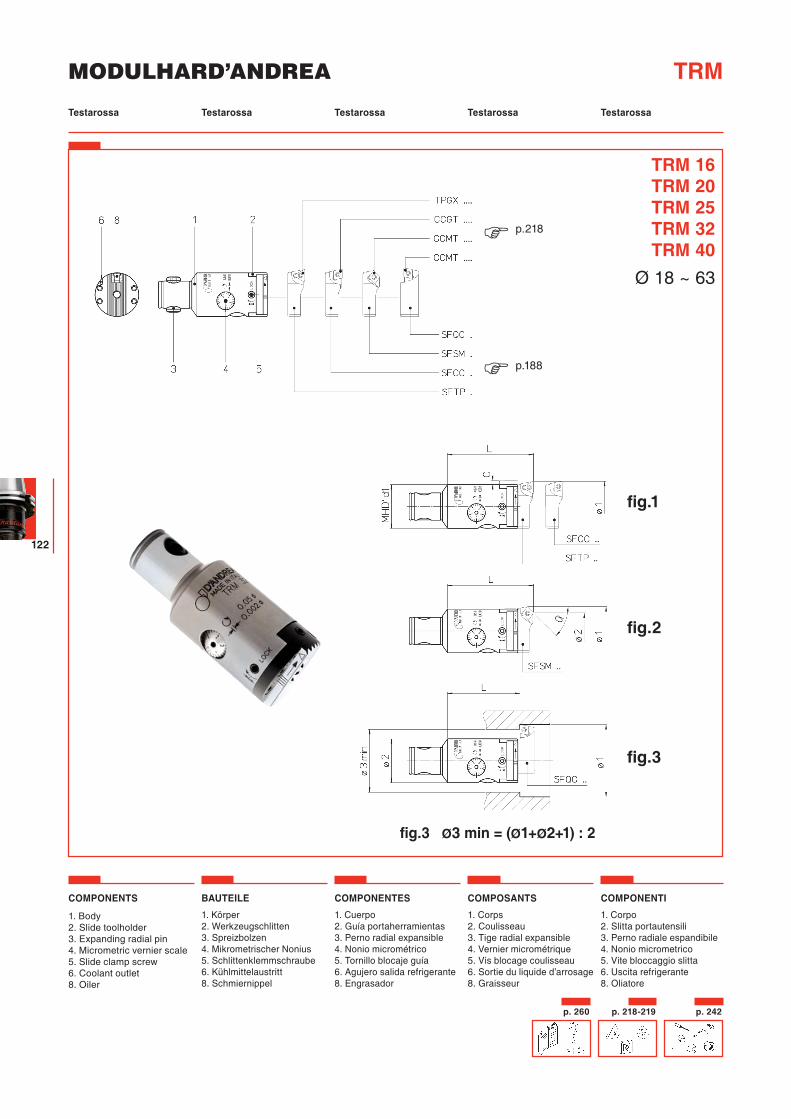
MODULHARD’ANDREA
122
COMPONENTS
1. Body2. Slide toolholder3. Expanding radial pin4. Micrometric vernier scale5. Slide clamp screw6. Coolant outlet8. Oiler
BAUTEILE
1. Körper2. Werkzeugschlitten3. Spreizbolzen4. Mikrometrischer Nonius5. Schlittenklemmschraube6. Kühlmittelaustritt8. Schmiernippel
COMPONENTES
1. Cuerpo2. Guía portaherramientas3. Perno radial expansible4. Nonio micrométrico5. Tornillo blocaje guía6. Agujero salida refrigerante8. Engrasador
COMPOSANTS
1. Corps 2. Coulisseau 3. Tige radial expansible4. Vernier micrométrique5. Vis blocage coulisseau6. Sortie du liquide d’arrosage8. Graisseur
COMPONENTI
1. Corpo 2. Slitta portautensili3. Perno radiale espandibile4. Nonio micrometrico5. Vite bloccaggio slitta6. Uscita refrigerante8. Oliatore
fig.1
fig.2
fig.3
fig.3 Ø3 min = (Ø1+Ø2+1) : 2
TRM
TRM 16TRM 20TRM 25TRM 32TRM 40
Ø 18 ~ 63
p.188�
p.218�
Testarossa Testarossa Testarossa TestarossaTestarossa
p. 218-219 p. 242p. 260
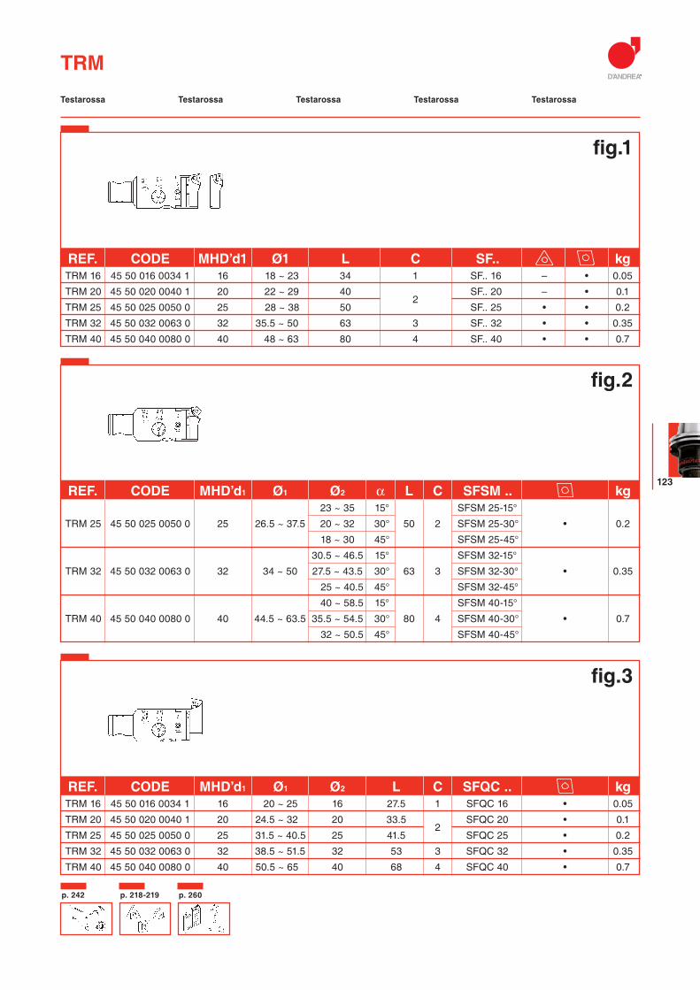
123
TRM
fig.1
REF. CODE MHD’d1 Ø1 Ø2 α L C SFSM .. kg 23 ~ 35 15° SFSM 25-15°
TRM 25 45 50 025 0050 0 25 26.5 ~ 37.5 20 ~ 32 30° 50 2 SFSM 25-30° • 0.2
18 ~ 30 45° SFSM 25-45°
30.5 ~ 46.5 15° SFSM 32-15°
TRM 32 45 50 032 0063 0 32 34 ~ 50 27.5 ~ 43.5 30° 63 3 SFSM 32-30° • 0.35
25 ~ 40.5 45° SFSM 32-45°
40 ~ 58.5 15° SFSM 40-15°
TRM 40 45 50 040 0080 0 40 44.5 ~ 63.5 35.5 ~ 54.5 30° 80 4 SFSM 40-30° • 0.7
32 ~ 50.5 45° SFSM 40-45°
fig.2
REF. CODE MHD’d1 Ø1 Ø2 L C SFQC .. kg TRM 16 45 50 016 0034 1 16 20 ~ 25 16 27.5 1 SFQC 16 • 0.05
TRM 20 45 50 020 0040 1 20 24.5 ~ 32 20 33.5 2
SFQC 20 • 0.1
TRM 25 45 50 025 0050 0 25 31.5 ~ 40.5 25 41.5 SFQC 25 • 0.2
TRM 32 45 50 032 0063 0 32 38.5 ~ 51.5 32 53 3 SFQC 32 • 0.35
TRM 40 45 50 040 0080 0 40 50.5 ~ 65 40 68 4 SFQC 40 • 0.7
fig.3
REF. CODE MHD’d1 Ø1 L C SF.. kg TRM 16 45 50 016 0034 1 16 18 ~ 23 34 1 SF.. 16 – • 0.05
TRM 20 45 50 020 0040 1 20 22 ~ 29 40 2
SF.. 20 – • 0.1
TRM 25 45 50 025 0050 0 25 28 ~ 38 50 SF.. 25 • • 0.2
TRM 32 45 50 032 0063 0 32 35.5 ~ 50 63 3 SF.. 32 • • 0.35
TRM 40 45 50 040 0080 0 40 48 ~ 63 80 4 SF.. 40 • • 0.7
Testarossa Testarossa Testarossa TestarossaTestarossa
p. 218-219p. 242 p. 260
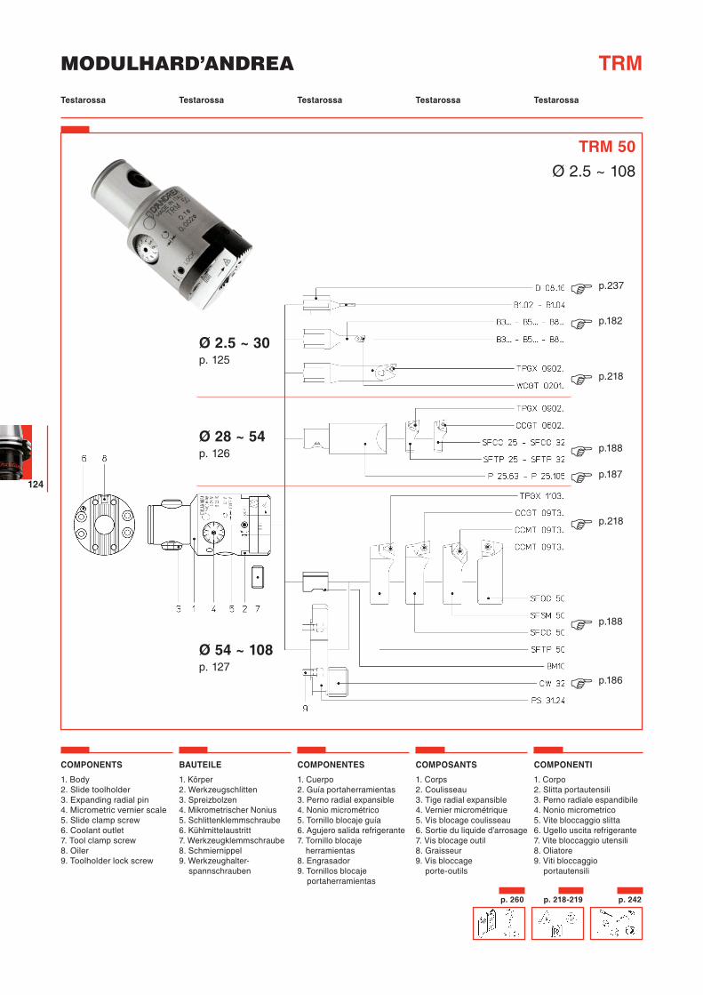
MODULHARD’ANDREA
124
COMPONENTS
1. Body2. Slide toolholder3. Expanding radial pin4. Micrometric vernier scale5. Slide clamp screw6. Coolant outlet7. Tool clamp screw8. Oiler 9. Toolholder lock screw
BAUTEILE
1. Körper2. Werkzeugschlitten3. Spreizbolzen4. Mikrometrischer Nonius5. Schlittenklemmschraube6. Kühlmittelaustritt7. Werkzeugklemmschraube8. Schmiernippel9. Werkzeughalter-
spannschrauben
COMPONENTES
1. Cuerpo2. Guía portaherramientas3. Perno radial expansible4. Nonio micrométrico5. Tornillo blocaje guía6. Agujero salida refrigerante7. Tornillo blocaje
herramientas8. Engrasador9. Tornillos blocaje
portaherramientas
COMPOSANTS
1. Corps 2. Coulisseau 3. Tige radial expansible4. Vernier micrométrique5. Vis blocage coulisseau6. Sortie du liquide d’arrosage7. Vis blocage outil8. Graisseur9. Vis bloccage
porte-outils
COMPONENTI
1. Corpo 2. Slitta portautensili3. Perno radiale espandibile4. Nonio micrometrico5. Vite bloccaggio slitta6. Ugello uscita refrigerante7. Vite bloccaggio utensili8. Oliatore9. Viti bloccaggio
portautensili
TRM
TRM 50
Ø 2.5 ~ 108
Ø 2.5 ~ 30 p. 125
Ø 28 ~ 54 p. 126
Ø 54 ~ 108 p. 127
p.237�p.182�
p.218�
p.188�p.187�p.218�
p.188�
p.186�
Testarossa Testarossa Testarossa TestarossaTestarossa
p. 218-219 p. 242p. 260
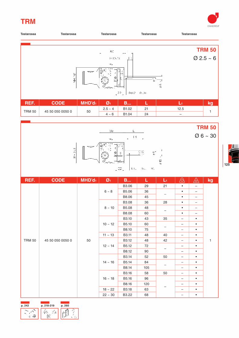
125
TRM
REF. CODE MHD’d1 Ø1 B... L L1 kg
TRM 50 45 50 050 0050 0 50 2.5 ~ 4 B1.02 21 12.5
1
4 ~ 6 B1.04 24 –
REF. CODE MHD’d1 Ø1 B... L L1 kg B3.06 29 21 • –
6 ~ 8 B5.06 36 –
• –
B8.06 45 • –
B3.08 36 28 • –
8 ~ 10 B5.08 48 –
• –
B8.08 60 • –
B3.10 43 35 – •
10 ~ 12 B5.10 60 –
– •
B8.10 75 – •
11 ~ 13 B3.11 48 40 – • TRM 50 45 50 050 0050 0 50 B3.12 48 42 – • 1
12 ~ 14 B5.12 72 –
– •
B8.12 90 – •
B3.14 52 50 – •
14 ~ 16 B5.14 84 –
– •
B8.14 105 – •
B3.16 58 50 – •
16 ~ 18 B5.16 96 – •
B8.16 120 –
– •
18 ~ 22 B3.18 63 – •
22 ~ 30 B3.22 68 – •
TRM 50
Ø 2.5 ~ 6
TRM 50
Ø 6 ~ 30
Testarossa Testarossa Testarossa TestarossaTestarossa
p. 218-219p. 242 p. 260
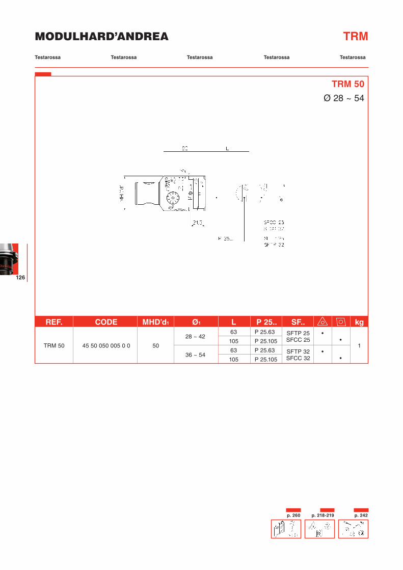
MODULHARD’ANDREA
126
TRM
TRM 50
Ø 28 ~ 54
REF. CODE MHD’d1 Ø1 L P 25.. SF.. kg
28 ~ 42 63 P 25.63 SFTP 25 •
TRM 50 45 50 050 005 0 0 50
105 P 25.105 SFCC 25 • 1
36 ~ 54
63 P 25.63 SFTP 32 •
105 P 25.105 SFCC 32 •
Testarossa Testarossa Testarossa TestarossaTestarossa
p. 218-219 p. 242p. 260
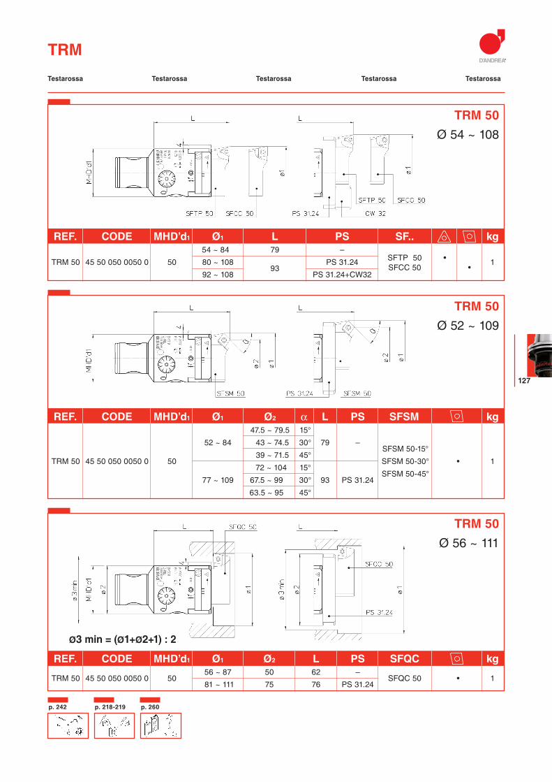
127
TRM
TRM 50
Ø 54 ~ 108
REF. CODE MHD’d1 Ø1 L PS SF.. kg 54 ~ 84 79 –
SFTP 50
•
TRM 50 45 50 050 0050 0 50 80 ~ 108 93
PS 31.24 SFCC 50
• 1
92 ~ 108 PS 31.24+CW32
REF. CODE MHD’d1 Ø1 Ø2 α L PS SFSM kg 47.5 ~ 79.5 15°
52 ~ 84 43 ~ 74.5 30° 79 – SFSM 50-15°
TRM 50 45 50 050 0050 0 50
39 ~ 71.5 45° SFSM 50-30°
•
1
72 ~ 104 15° SFSM 50-45°
77 ~ 109 67.5 ~ 99 30° 93 PS 31.24
63.5 ~ 95 45°
REF. CODE MHD’d1 Ø1 Ø2 L PS SFQC kg TRM 50 45 50 050 0050 0 50
56 ~ 87 50 62 – SFQC 50
•
1
81 ~ 111 75 76 PS 31.24
Ø3 min = (Ø1+Ø2+1) : 2
TRM 50
Ø 52 ~ 109
TRM 50
Ø 56 ~ 111
Testarossa Testarossa Testarossa TestarossaTestarossa
p. 218-219p. 242 p. 260
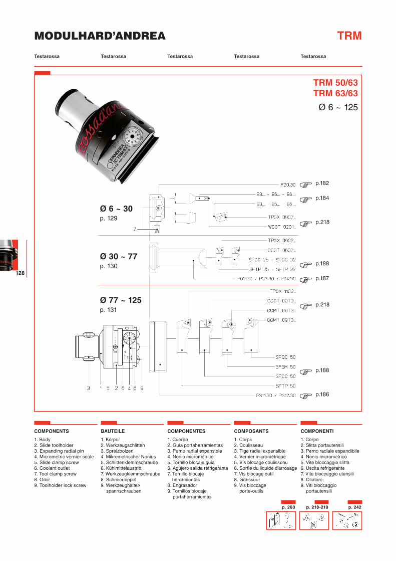
MODULHARD’ANDREA
128
COMPONENTS
1. Body2. Slide toolholder3. Expanding radial pin4. Micrometric vernier scale5. Slide clamp screw6. Coolant outlet7. Tool clamp screw8. Oiler 9. Toolholder lock screw
BAUTEILE
1. Körper2. Werkzeugschlitten3. Spreizbolzen4. Mikrometrischer Nonius5. Schlittenklemmschraube6. Kühlmittelaustritt7. Werkzeugklemmschraube8. Schmiernippel9. Werkzeughalter-
spannschrauben
COMPONENTES
1. Cuerpo2. Guía portaherramientas3. Perno radial expansible4. Nonio micrométrico5. Tornillo blocaje guía6. Agujero salida refrigerante7. Tornillo blocaje
herramientas8. Engrasador9. Tornillos blocaje
portaherramientas
COMPOSANTS
1. Corps 2. Coulisseau 3. Tige radial expansible4. Vernier micrométrique5. Vis blocage coulisseau6. Sortie du liquide d’arrosage7. Vis blocage outil8. Graisseur9. Vis bloccage
porte-outils
COMPONENTI
1. Corpo 2. Slitta portautensili3. Perno radiale espandibile4. Nonio micrometrico5. Vite bloccaggio slitta6. Uscita refrigerante7. Vite bloccaggio utensili8. Oliatore9. Viti bloccaggio
portautensili
TRM
TRM 50/63TRM 63/63
Ø 6 ~ 125
Ø 6 ~ 30 p. 129
Ø 30 ~ 77 p. 130
Ø 77 ~ 125 p. 131
p.182�p.184�p.218�
p.188�p.187�p.218�
p.188�p.186�
Testarossa Testarossa Testarossa TestarossaTestarossa
p. 218-219 p. 242p. 260
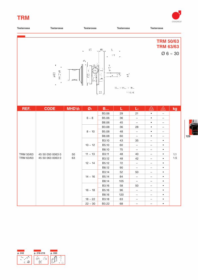
129
REF. CODE MHD’d1 Ø1 B... L L1 kg B3.06 29 21 • –
6 ~ 8 B5.06 36 – • –
B8.06 45 – • –
B3.08 36 28 • –
8 ~ 10 B5.08 48 – • –
B8.08 60 – • –
B3.10 43 35 – •
10 ~ 12 B5.10 60 – – •
B8.10 75 – – •
TRM 50/63 45 50 050 0063 0 50 11 ~ 13 B3.11 48 40 – • 1.1
TRM 63/63 45 50 063 0063 0 63 B3.12 48 42 – • 1.5
12 ~ 14 B5.12 72 – – •
B8.12 90 – – •
B3.14 52 50 – •
14 ~ 16 B5.14 84 – – •
B8.14 105 – – •
B3.16 58 50 – •
16 ~ 18 B5.16 96 – – •
B8.16 120 – – •
18 ~ 22 B3.18 63 – – •
22 ~ 30 B3.22 68 – – •
TRM
TRM 50/63TRM 63/63
Ø 6 ~ 30
Testarossa Testarossa Testarossa TestarossaTestarossa
p. 218-219p. 242 p. 260
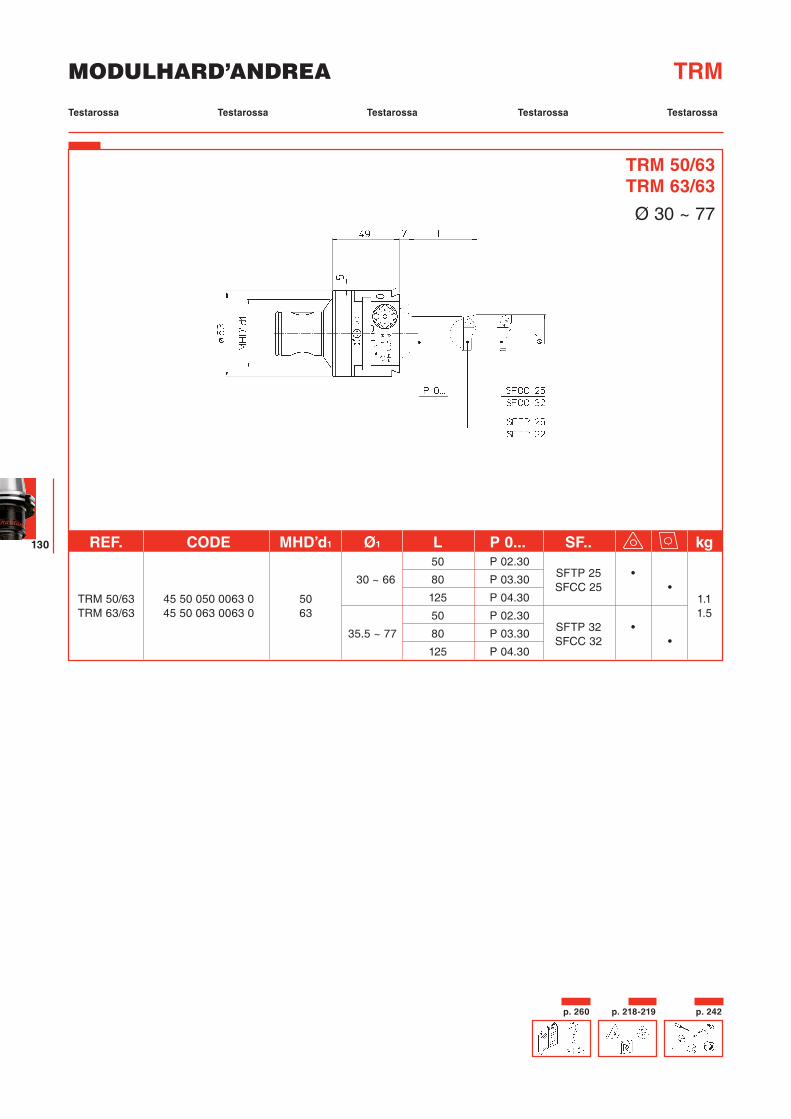
MODULHARD’ANDREA
130
TRM
TRM 50/63TRM 63/63
Ø 30 ~ 77
REF. CODE MHD’d1 Ø1 L P 0... SF.. kg 50 P 02.30
SFTP 25 •
30 ~ 66 80 P 03.30 SFCC 25 •
TRM 50/63 45 50 050 0063 0 50 125 P 04.30 1.1
TRM 63/63 45 50 063 0063 0 63 50 P 02.30 SFTP 32 •
1.5
35.5 ~ 77 80 P 03.30 SFCC 32 •
125 P 04.30
Testarossa Testarossa Testarossa TestarossaTestarossa
p. 218-219 p. 242p. 260

131
TRM
Ø3 min = (Ø1+Ø2+1) : 2
TRM 50/63TRM 63/63
Ø 77~ 125
REF. CODE MHD’d1 Ø1 L PS.. SF.. kg TRM 50/63 45 50 050 0063 0 50 77 ~ 100
87.5 PS 11.30 SFTP 50 • 1.1
TRM 63/63 45 50 063 0063 0 63 95 ~ 125 PS 12.30 SFCC 50 • 1.5
REF. CODE MHD’d1 Ø1 Ø2 α L PS.. SFSM kg 72 ~ 95 15°
77 ~ 100 67 ~ 90 30° PS 11.30 SFSM 50-15°
TRM 50/63 45 50 050 0063 0 50 63.5 ~ 86.5 45° 87.5
SFSM 50-30°
• 1.1
TRM 63/63 45 50 063 0063 0 63 90 ~ 120 15° SFSM 50-45°
1.5
95 ~ 125 85.5 ~ 115.5 30° PS 12.30
81.5 ~ 111.5 45°
REF. CODE MHD’d1 Ø1 Ø2 L PS.. SFQC kg TRM 50/63 45 50 050 0063 0 50 82 ~ 102 75
70.5 PS 11.30
SFQC 50
• 1.1
TRM 63/63 45 50 063 0063 0 63 100 ~ 127 93 PS 12.30 1.5
TRM 50/63TRM 63/63
Ø 77 ~ 125
TRM 50/63TRM 63/63
Ø 82 ~ 127
Testarossa Testarossa Testarossa TestarossaTestarossa
p. 218-219p. 242 p. 260
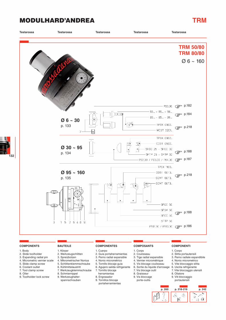
MODULHARD’ANDREA
132
TRM 50/80TRM 80/80
Ø 6 ~ 160
COMPONENTS
1. Body2. Slide toolholder3. Expanding radial pin4. Micrometric vernier scale5. Slide clamp screw6. Coolant outlet7. Tool clamp screw8. Oiler 9. Toolholder lock screw
BAUTEILE
1. Körper2. Werkzeugschlitten3. Spreizbolzen4. Mikrometrischer Nonius5. Schlittenklemmschraube6. Kühlmittelaustritt7. Werkzeugklemmschraube8. Schmiernippel9. Werkzeughalter-
spannschrauben
COMPONENTES
1. Cuerpo2. Guía portaherramientas3. Perno radial expansible4. Nonio micrométrico5. Tornillo blocaje guía6. Agujero salida refrigerante7. Tornillo blocaje
herramientas8. Engrasador9. Tornillos blocaje
portaherramientas
COMPOSANTS
1. Corps 2. Coulisseau 3. Tige radial expansible4. Vernier micrométrique5. Vis blocage coulisseau6. Sortie du liquide d’arrosage7. Vis blocage outil8. Graisseur9. Vis bloccage
porte-outils
COMPONENTI
1. Corpo 2. Slitta portautensili3. Perno radiale espandibile4. Nonio micrometrico5. Vite bloccaggio slitta6. Uscita refrigerante7. Vite bloccaggio utensili8. Oliatore9. Viti bloccaggio
portautensili
TRM
p.182�Ø 6 ~ 30 p. 133
Ø 30 ~ 95 p. 134
Ø 95 ~ 160 p. 135
p.184�p.218�
p.188�p.187�
p.218�
p.188�p.186�
Testarossa Testarossa Testarossa TestarossaTestarossa
p. 218-219 p. 242p. 260
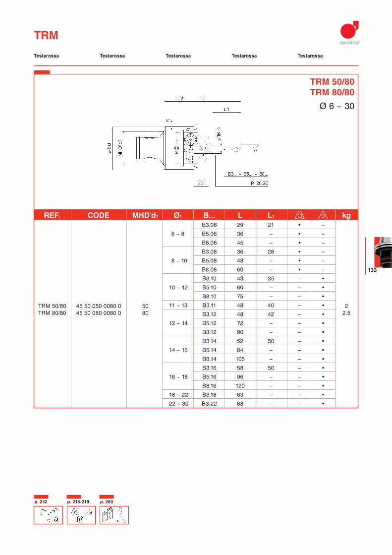
133
REF. CODE MHD’d1 Ø1 B... L L1 kg B3.06 29 21 • –
6 ~ 8 B5.06 36 – • –
B8.06 45 – • –
B3.08 36 28 • –
8 ~ 10 B5.08 48 – • –
B8.08 60 – • –
B3.10 43 35 – •
10 ~ 12 B5.10 60 – – •
B8.10 75 – – •
TRM 50/80 45 50 050 0080 0 50 11 ~ 13 B3.11 48 40 – • 2
TRM 80/80 45 50 080 0080 0 80 B3.12 48 42 – • 2.5
12 ~ 14 B5.12 72 – – •
B8.12 90 – – •
B3.14 52 50 – •
14 ~ 16 B5.14 84 – – •
B8.14 105 – – •
B3.16 58 50 – •
16 ~ 18 B5.16 96 – – •
B8.16 120 – – •
18 ~ 22 B3.18 63 – – •
22 ~ 30 B3.22 68 – – •
TRM
TRM 50/80TRM 80/80
Ø 6 ~ 30
Testarossa Testarossa Testarossa TestarossaTestarossa
p. 218-219p. 242 p. 260

MODULHARD’ANDREA
134
TRM
TRM 50/80TRM 80/80
Ø 30 ~ 95
REF. CODE MHD’d1 Ø1 L P 0... SF.. kg 50 P 02.30
SFTP 25 •
30 ~ 83 80 P 03.30 SFCC 25 •
TRM 50/80 45 50 050 0080 0 50 125 P 04.30 2
TRM 80/80 45 50 080 0080 0 80 50 P 02.30 SFTP 32 •
2.5
35.5 ~ 95 80 P 03.30 SFCC 32 •
125 P 04.30
Testarossa Testarossa Testarossa TestarossaTestarossa
p. 218-219 p. 242p. 260
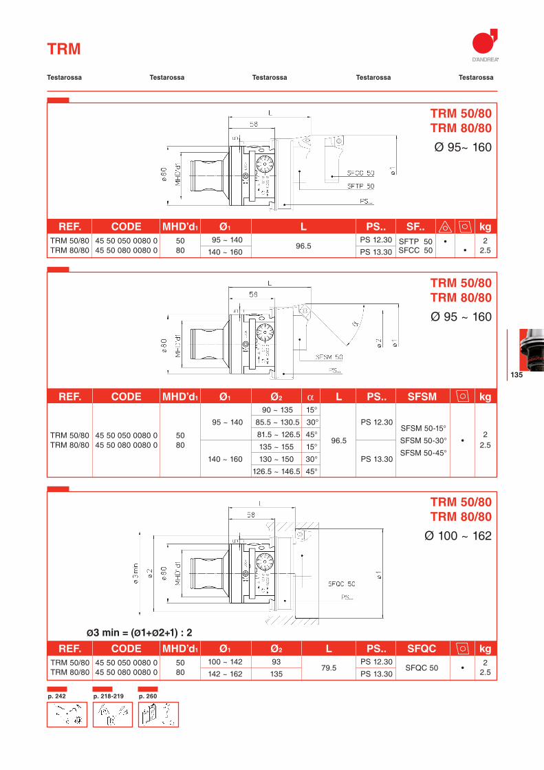
135
TRM
Ø3 min = (Ø1+Ø2+1) : 2
TRM 50/80TRM 80/80
Ø 95~ 160
REF. CODE MHD’d1 Ø1 L PS.. SF.. kg TRM 50/80 45 50 050 0080 0 50 95 ~ 140
96.5 PS 12.30 SFTP 50 • 2
TRM 80/80 45 50 080 0080 0 80 140 ~ 160 PS 13.30 SFCC 50 • 2.5
REF. CODE MHD’d1 Ø1 Ø2 α L PS.. SFSM kg 90 ~ 135 15°
95 ~ 140 85.5 ~ 130.5 30° PS 12.30 SFSM 50-15°
TRM 50/80 45 50 050 0080 0 50 81.5 ~ 126.5 45° 96.5
SFSM 50-30°
• 2
TRM 80/80 45 50 080 0080 0 80 135 ~ 155 15° SFSM 50-45°
2.5
140 ~ 160 130 ~ 150 30° PS 13.30
126.5 ~ 146.5 45°
REF. CODE MHD’d1 Ø1 Ø2 L PS.. SFQC kg TRM 50/80 45 50 050 0080 0 50 100 ~ 142 93
79.5 PS 12.30
SFQC 50
• 2
TRM 80/80 45 50 080 0080 0 80 142 ~ 162 135 PS 13.30 2.5
TRM 50/80TRM 80/80
Ø 95 ~ 160
TRM 50/80TRM 80/80
Ø 100 ~ 162
Testarossa Testarossa Testarossa TestarossaTestarossa
p. 218-219p. 242 p. 260
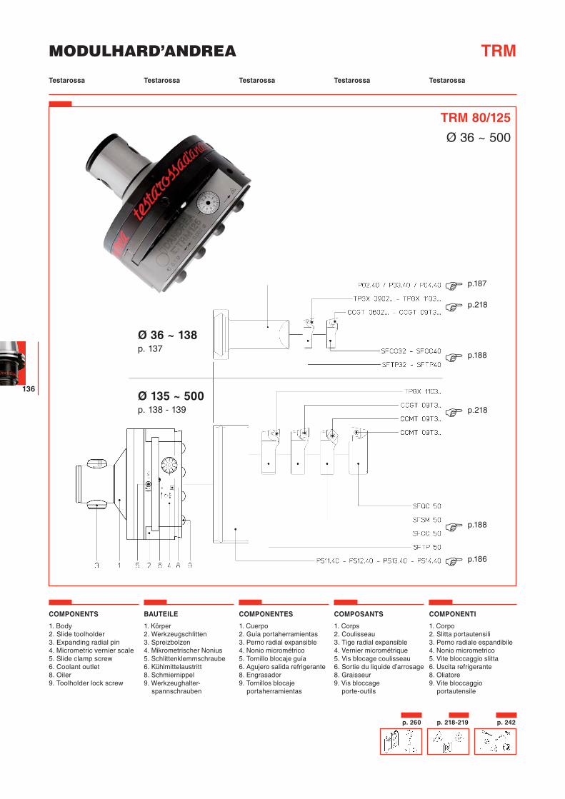
MODULHARD’ANDREA
136
TRM 80/125
Ø 36 ~ 500
COMPONENTS
1. Body2. Slide toolholder3. Expanding radial pin4. Micrometric vernier scale5. Slide clamp screw6. Coolant outlet8. Oiler 9. Toolholder lock screw
BAUTEILE
1. Körper2. Werkzeugschlitten3. Spreizbolzen4. Mikrometrischer Nonius5. Schlittenklemmschraube6. Kühlmittelaustritt8. Schmiernippel9. Werkzeughalter-
spannschrauben
COMPONENTES
1. Cuerpo2. Guía portaherramientas3. Perno radial expansible4. Nonio micrométrico5. Tornillo blocaje guía6. Agujero salida refrigerante8. Engrasador9. Tornillos blocaje
portaherramientas
COMPOSANTS
1. Corps 2. Coulisseau 3. Tige radial expansible4. Vernier micrométrique5. Vis blocage coulisseau6. Sortie du liquide d’arrosage8. Graisseur9. Vis bloccage
porte-outils
COMPONENTI
1. Corpo 2. Slitta portautensili3. Perno radiale espandibile4. Nonio micrometrico5. Vite bloccaggio slitta6. Uscita refrigerante8. Oliatore9. Vite bloccaggio
portautensile
TRM
Ø 36 ~ 138 p. 137
Ø 135 ~ 500 p. 138 - 139
p.218�
p.188�
p.218�
p.188�p.186�
p.187�
Testarossa Testarossa Testarossa TestarossaTestarossa
p. 218-219 p. 242p. 260
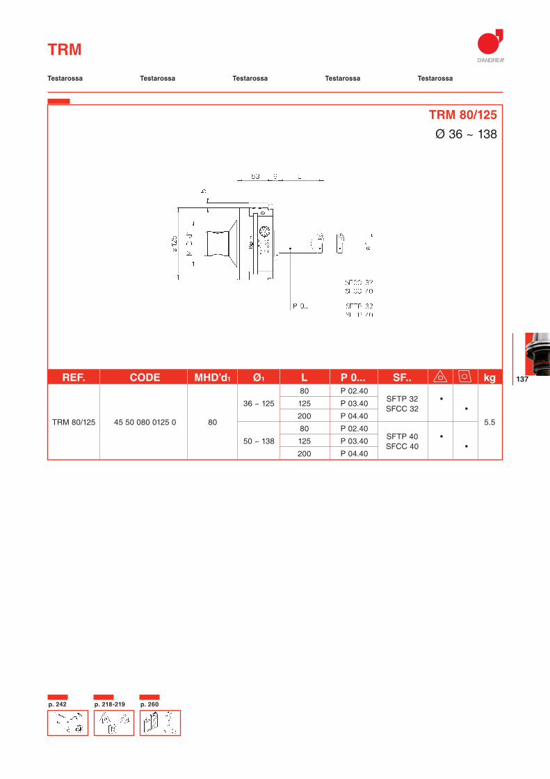
137
TRM
TRM 80/125
Ø 36 ~ 138
REF. CODE MHD’d1 Ø1 L P 0... SF.. kg 80 P 02.40
SFTP 32 •
36 ~ 125 125 P 03.40 SFCC 32 •
TRM 80/125 45 50 080 0125 0 80
200 P 04.40 5.5
80 P 02.40 SFTP 40 •
50 ~ 138 125 P 03.40 SFCC 40 •
200 P 04.40
Testarossa Testarossa Testarossa TestarossaTestarossa
p. 218-219p. 242 p. 260
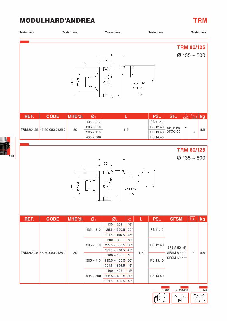
MODULHARD’ANDREA
138
TRM 80/125
Ø 135 ~ 500
TRM
REF. CODE MHD’d1 Ø1 L PS.. SF.. kg 135 ~ 210 PS 11.40
TRM 80/125 45 50 080 0125 0 80
205 ~ 310 115
PS 12.40 SFTP 50 • 5.5
305 ~ 410 PS 13.40 SFCC 50 •
405 ~ 500 PS 14.40
TRM 80/125
Ø 135 ~ 500
REF. CODE MHD’d1 Ø1 Ø2 α L PS.. SFSM kg 130 ~ 205 15°
135 ~ 210 125.5 ~ 200.5 30° PS 11.40
121.5 ~ 196.5 45°
200 ~ 305 15°
205 ~ 310 195.5 ~ 300.5 30° PS 12.40 SFSM 50-15°
TRM 80/125 45 50 080 0125 0 80
191.5 ~ 296.5 45° 115
SFSM 50-30°
•
5.5
300 ~ 405 15° SFSM 50-45°
305 ~ 410 295.5 ~ 400.5 30° PS 13.40
291.5 ~ 396.5 45°
400 ~ 495 15°
405 ~ 500 395.5 ~ 490.5 30° PS 14.40
391.5 ~ 486.5 45°
Testarossa Testarossa Testarossa TestarossaTestarossa
p. 218-219 p. 242p. 260
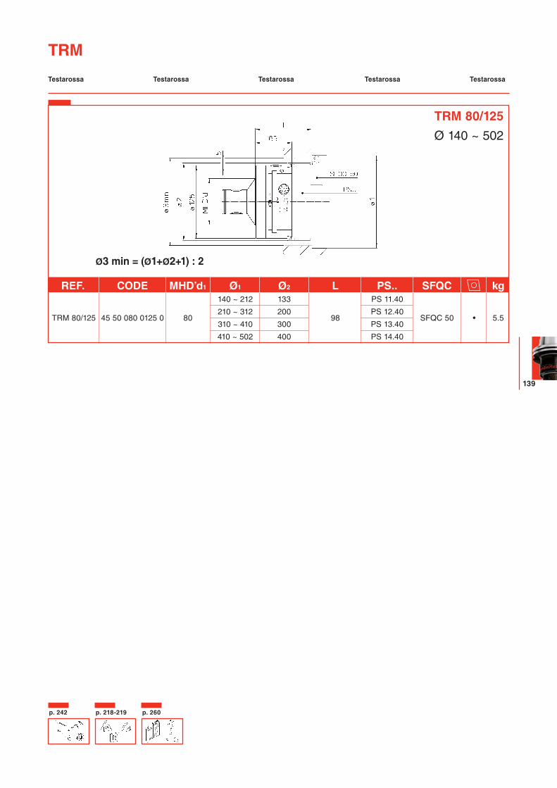
139
Ø3 min = (Ø1+Ø2+1) : 2
TRM 80/125
Ø 140 ~ 502
TRM
REF. CODE MHD’d1 Ø1 Ø2 L PS.. SFQC kg
140 ~ 212 133
PS 11.40
TRM 80/125 45 50 080 0125 0 80
210 ~ 312 200 98
PS 12.40 SFQC 50
•
5.5
310 ~ 410 300 PS 13.40
410 ~ 502 400 PS 14.40
Testarossa Testarossa Testarossa TestarossaTestarossa
p. 218-219p. 242 p. 260
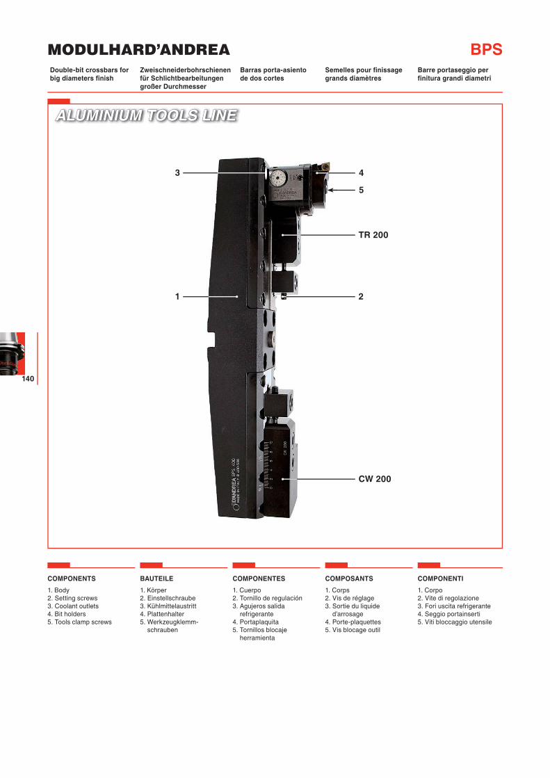
MODULHARD’ANDREA
140
ALUMINIUM TOOLS LINEALUMINIUM TOOLS LINE
BPSZweischneiderbohrschienen für Schlichtbearbeitungen großer Durchmesser
Barras porta-asiento de dos cortes
Semelles pour finissage grands diamètres
Barre portaseggio per finitura grandi diametri
Double-bit crossbars for big diameters finish
COMPONENTS 1. Body2. Setting screws3. Coolant outlets 4. Bit holders5. Tools clamp screws
BAUTEILE
1. Körper2. Einstellschraube 3. Kühlmittelaustritt 4. Plattenhalter5. Werkzeugklemm-
schrauben
COMPONENTES
1. Cuerpo2. Tornillo de regulación3. Agujeros salida
refrigerante4. Portaplaquita5. Tornillos blocaje
herramienta
COMPOSANTS
1. Corps 2. Vis de réglage3. Sortie du liquide
d’arrosage4. Porte-plaquettes5. Vis blocage outil
COMPONENTI
1. Corpo2. Vite di regolazione3. Fori uscita refrigerante 4. Seggio portainserti5. Viti bloccaggio utensile
2
5
1
43
TR 200
CW 200
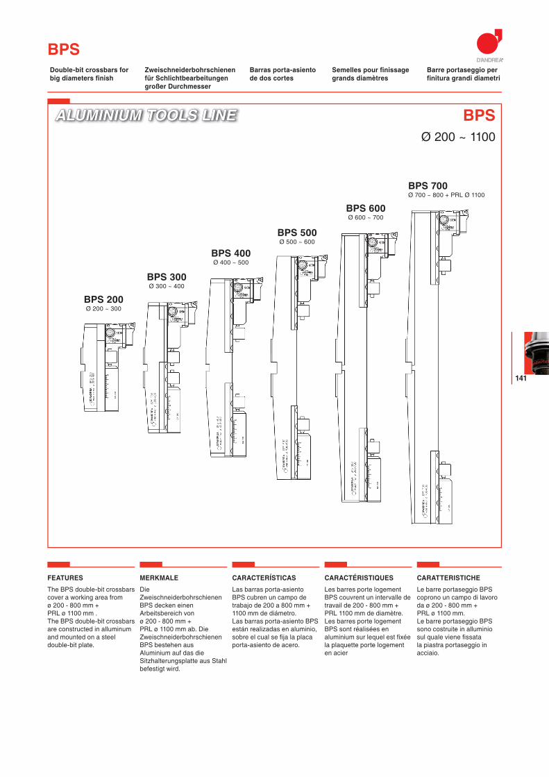
141
ALUMINIUM TOOLS LINEALUMINIUM TOOLS LINE BPSØ 200 ~ 1100
BPS 200Ø 200 ~ 300
BPS 300Ø 300 ~ 400
BPS 400Ø 400 ~ 500
BPS 500Ø 500 ~ 600
BPS 600Ø 600 ~ 700
BPS 700Ø 700 ~ 800 + PRL Ø 1100
BPSZweischneiderbohrschienen für Schlichtbearbeitungen großer Durchmesser
Barras porta-asiento de dos cortes
Semelles pour finissage grands diamètres
Barre portaseggio per finitura grandi diametri
Double-bit crossbars for big diameters finish
FEATURES
The BPS double-bit crossbars cover a working area from ø 200 - 800 mm + PRL ø 1100 mm .The BPS double-bit crossbars are constructed in alluminum and mounted on a steel double-bit plate.
MERKMALE
Die Zweischneiderbohrschienen BPS decken einen Arbeitsbereich von ø 200 - 800 mm + PRL ø 1100 mm ab. Die Zweischneiderbohrschienen BPS bestehen aus Aluminium auf das die Sitzhalterungsplatte aus Stahl befestigt wird.
CARACTERÍSTICAS
Las barras porta-asiento BPS cubren un campo de trabajo de 200 a 800 mm +1100 mm de diámetro. Las barras porta-asiento BPS están realizadas en aluminio, sobre el cual se fija la placa porta-asiento de acero.
CARACTÉRISTIQUES
Les barres porte logement BPS couvrent un intervalle de travail de 200 - 800 mm + PRL 1100 mm de diamètre.Les barres porte logement BPS sont réalisées en aluminium sur lequel est fixée la plaquette porte logement en acier
CARATTERISTICHE
Le barre portaseggio BPS coprono un campo di lavoro da ø 200 - 800 mm + PRL ø 1100 mm.Le barre portaseggio BPS sono costruite in alluminio sul quale viene fissata la piastra portaseggio in acciaio.
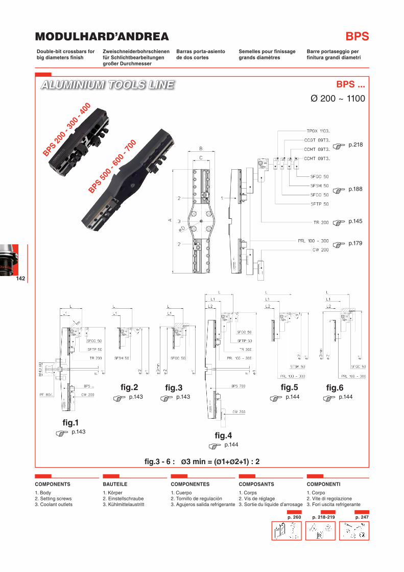
MODULHARD’ANDREA
142
COMPONENTS 1. Body2. Setting screws3. Coolant outlets
BAUTEILE
1. Körper2. Einstellschraube 3. Kühlmittelaustritt
COMPONENTES
1. Cuerpo2. Tornillo de regulación3. Agujeros salida refrigerante
COMPOSANTS
1. Corps 2. Vis de réglage3. Sortie du liquide d’arrosage
COMPONENTI
1. Corpo2. Vite di regolazione3. Fori uscita refrigerante
ALUMINIUM TOOLS LINEALUMINIUM TOOLS LINE
fig.3 - 6 : Ø3 min = (Ø1+Ø2+1) : 2
BPS ...
Ø 200 ~ 1100
BPSZweischneiderbohrschienen für Schlichtbearbeitungen großer Durchmesser
Barras porta-asiento de dos cortes
Semelles pour finissage grands diamètres
Barre portaseggio per finitura grandi diametri
Double-bit crossbars for big diameters finish
fig.1
fig.4
fig.2 fig.5fig.3 fig.6
p.218�
p.188�
p.179�
p.145�
p.143�p.144�
p.143� p.144�p.143� p.144�
BPS 500
- 60
0 - 7
00
BPS 200
- 30
0 - 4
00
p. 247p. 218-219p. 260
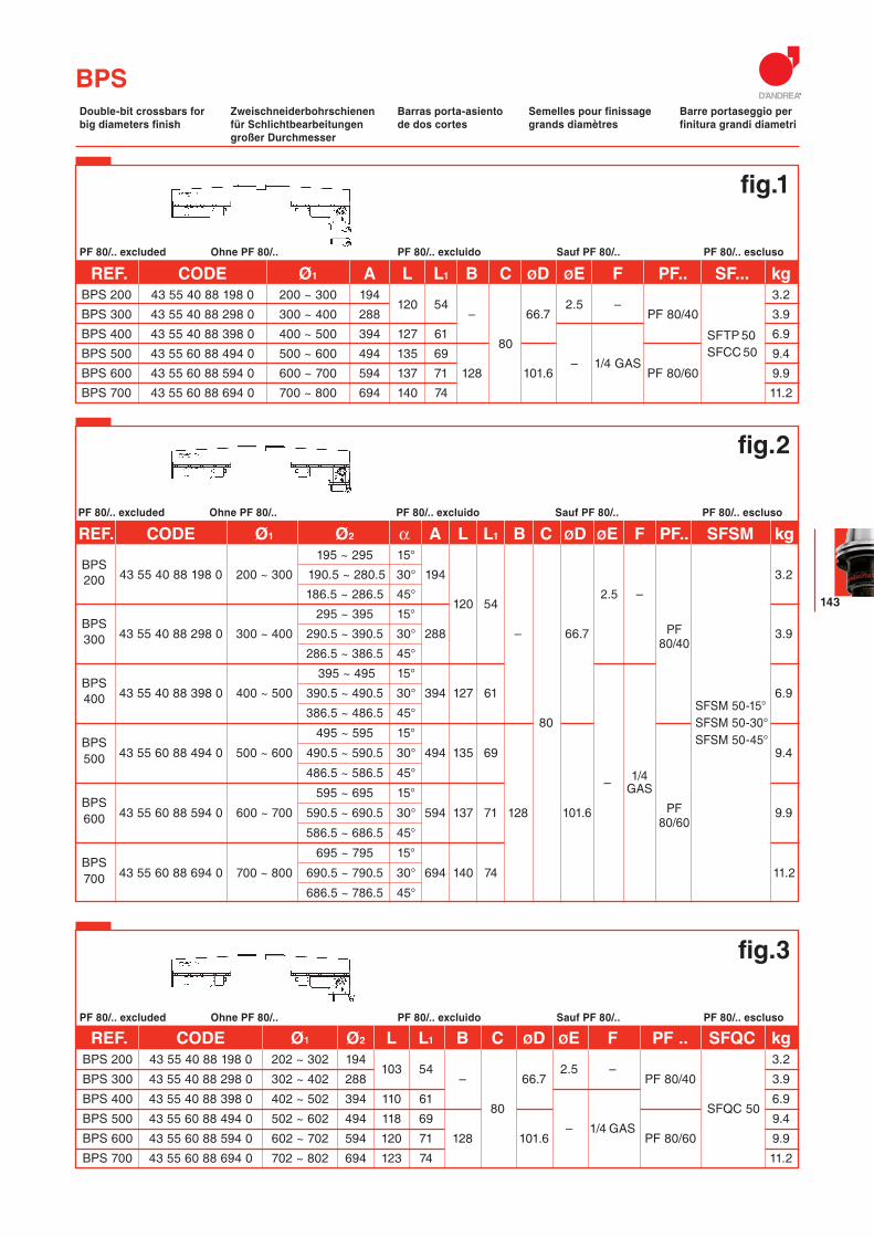
143
BPSZweischneiderbohrschienen für Schlichtbearbeitungen großer Durchmesser
Barras porta-asiento de dos cortes
Semelles pour finissage grands diamètres
Barre portaseggio per finitura grandi diametri
Double-bit crossbars for big diameters finish
Ohne PF 80/.. PF 80/.. excluido Sauf PF 80/.. PF 80/.. esclusoPF 80/.. excluded
Ohne PF 80/.. PF 80/.. excluido Sauf PF 80/.. PF 80/.. esclusoPF 80/.. excluded
fig.1
fig.3
Ohne PF 80/.. PF 80/.. excluido Sauf PF 80/.. PF 80/.. esclusoPF 80/.. excluded
REF. CODE Ø1 Ø2 α A L L1 B C ØD ØE F PF.. SFSM kg BPS
195 ~ 295 15°
43 55 40 88 198 0 200 ~ 300 190.5 ~ 280.5 30° 194 3.2
200
186.5 ~ 286.5 45° 120 54
2.5 –
BPS
295 ~ 395 15° PF
43 55 40 88 298 0 300 ~ 400 290.5 ~ 390.5 30° 288 – 66.7 80/40
3.9
300
286.5 ~ 386.5 45°
BPS
395 ~ 495 15°
43 55 40 88 398 0 400 ~ 500 390.5 ~ 490.5 30° 394 127 61 SFSM 50-15°
6.9
400
386.5 ~ 486.5 45° 80
SFSM 50-30°
BPS
495 ~ 595 15° SFSM 50-45°
43 55 60 88 494 0 500 ~ 600 490.5 ~ 590.5 30° 494 135 69 9.4
500
486.5 ~ 586.5 45° –
1/4
BPS
595 ~ 695 15° GAS PF
43 55 60 88 594 0 600 ~ 700 590.5 ~ 690.5 30° 594 137 71 128 101.6 80/60
9.9
600
586.5 ~ 686.5 45°
BPS
695 ~ 795 15°
43 55 60 88 694 0 700 ~ 800 690.5 ~ 790.5 30° 694 140 74 11.2
700
686.5 ~ 786.5 45°
fig.2
REF. CODE Ø1 A L L1 B C ØD ØE F PF.. SF... kg BPS 200 43 55 40 88 198 0 200 ~ 300 194
120 54
2.5 – 3.2
BPS 300 43 55 40 88 298 0 300 ~ 400 288 – 66.7 PF 80/40 3.9
BPS 400 43 55 40 88 398 0 400 ~ 500 394 127 61 80
SFTP 50 6.9
BPS 500 43 55 60 88 494 0 500 ~ 600 494 135 69 – 1/4 GAS
SFCC 50 9.4
BPS 600 43 55 60 88 594 0 600 ~ 700 594 137 71 128 101.6 PF 80/60 9.9
BPS 700 43 55 60 88 694 0 700 ~ 800 694 140 74 11.2
REF. CODE Ø1 Ø2 L L1 B C ØD ØE F PF .. SFQC kg BPS 200 43 55 40 88 198 0 202 ~ 302 194
103
54
2.5 – 3.2
BPS 300 43 55 40 88 298 0 302 ~ 402 288 – 66.7 PF 80/40 3.9
BPS 400 43 55 40 88 398 0 402 ~ 502 394 110 61 80
SFQC 50
6.9
BPS 500 43 55 60 88 494 0 502 ~ 602 494 118 69 – 1/4 GAS
9.4
BPS 600 43 55 60 88 594 0 602 ~ 702 594 120 71 128 101.6 PF 80/60 9.9
BPS 700 43 55 60 88 694 0 702 ~ 802 694 123 74 11.2
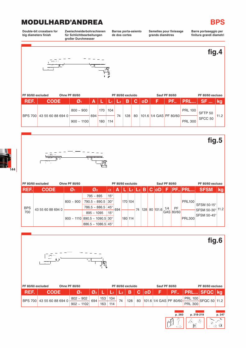
MODULHARD’ANDREA
144
Zweischneiderbohrschienen für Schlichtbearbeitungen großer Durchmesser
Barras porta-asiento de dos cortes
Semelles pour finissage grands diamètres
Barre portaseggio per finitura grandi diametri
Double-bit crossbars for big diameters finish
BPS
fig.4
Ohne PF 80/60 PF 80/60 excluido Sauf PF 80/60 PF 80/60 esclusoPF 80/60 excluded
REF. CODE Ø1 A L L1 L2 B C ØD F PF.. PRL... SF ... kg
800 ~ 900
170 104 PRL 100
BPS 700 43 55 60 88 694 0 694 74 128 80 101.6 1/4 GAS PF 80/60 SFTP 50
11.2
900 ~ 1100
180 114 PRL 300
SFCC 50
fig.6
Ohne PF 80/60 PF 80/60 excluido Sauf PF 80/60 PF 80/60 esclusoPF 80/60 excluded
REF. CODE Ø1 Ø2 L L1 L2 B C ØD F PF.. PRL... SFQC kg 802 ~ 902 153 104 PRL 100
BPS 700 43 55 60 88 694 0
902 ~ 1102 694
163 114 74 128 80 101.6 1/4 GAS PF 80/60
PRL 300 SFQC 50 11.2
p. 247p. 218-219p. 260
fig.5
Ohne PF 80/60 PF 80/60 excluido Sauf PF 80/60 PF 80/60 esclusoPF 80/60 excluded
REF. CODE Ø1 Ø2 α A L L1 L2 B C ØD F PF.. PRL... SFSM kg 795 ~ 895 15°
800 ~ 900 790.5 ~ 890.5 30° 170 104 PRL100
11.2
BPS 43 55 60 88 694 0 786.5 ~ 886.5 45°
694
74 128 80 101.6 1/4 PF
SFSM 50-15°
700 895 ~ 1095 15° GAS 80/60 SFSM 50-30°
900 ~ 1110 890.5 ~ 1090.5 30° 180 114 PRL300 SFSM 50-45°
886.5 ~ 1086.5 45°
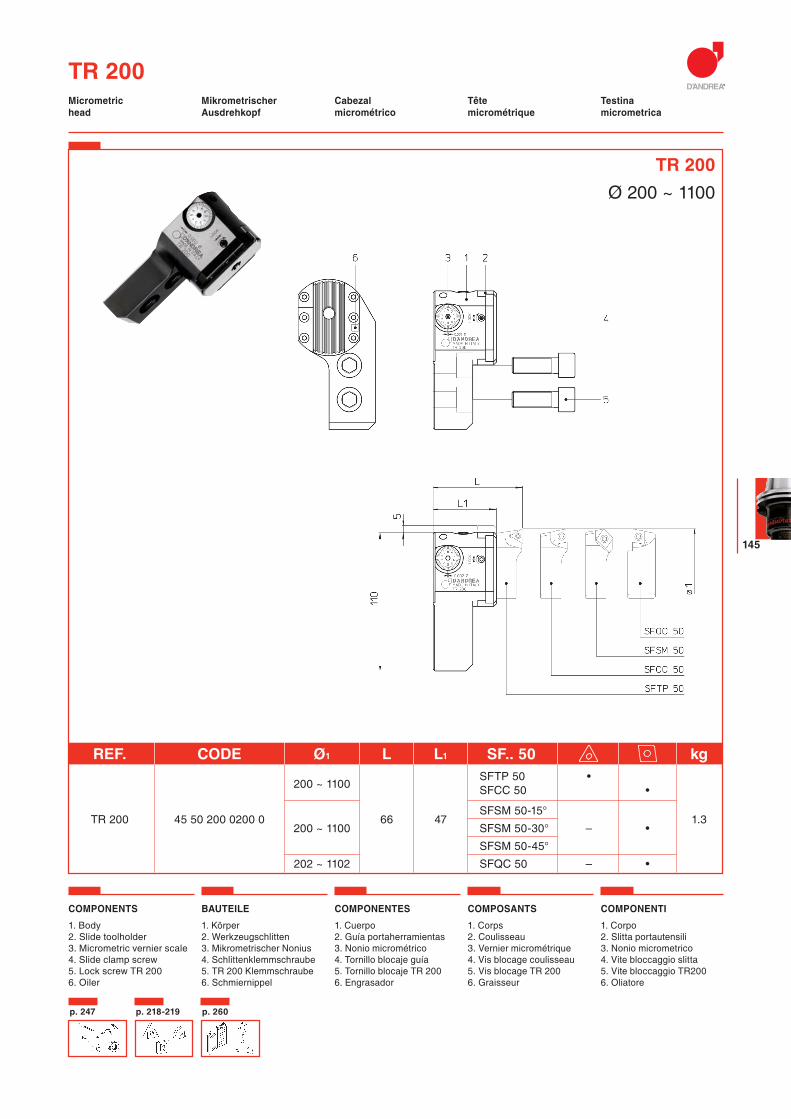
145
Mikrometrischer Ausdrehkopf
Cabezal micrométrico
Tête micrométrique
Testina micrometrica
Micrometric head
TR 200
Ø 200 ~ 1100
COMPONENTS
1. Body2. Slide toolholder3. Micrometric vernier scale4. Slide clamp screw5. Lock screw TR 2006. Oiler
BAUTEILE
1. Körper2. Werkzeugschlitten3. Mikrometrischer Nonius4. Schlittenklemmschraube5. TR 200 Klemmschraube6. Schmiernippel
COMPONENTES
1. Cuerpo2. Guía portaherramientas3. Nonio micrométrico4. Tornillo blocaje guía5. Tornillo blocaje TR 200 6. Engrasador
COMPOSANTS
1. Corps 2. Coulisseau 3. Vernier micrométrique4. Vis blocage coulisseau5. Vis blocage TR 200 6. Graisseur
COMPONENTI
1. Corpo 2. Slitta portautensili3. Nonio micrometrico4. Vite bloccaggio slitta5. Vite bloccaggio TR200 6. Oliatore
p. 218-219p. 247 p. 260
TR 200
REF. CODE Ø1 L L1 SF.. 50 kg
200 ~ 1100 SFTP 50 •
SFCC 50 •
TR 200 45 50 200 0200 0
66 47
SFSM 50-15° 1.3
200 ~ 1100 SFSM 50-30° – •
SFSM 50-45°
202 ~ 1102 SFQC 50 – •
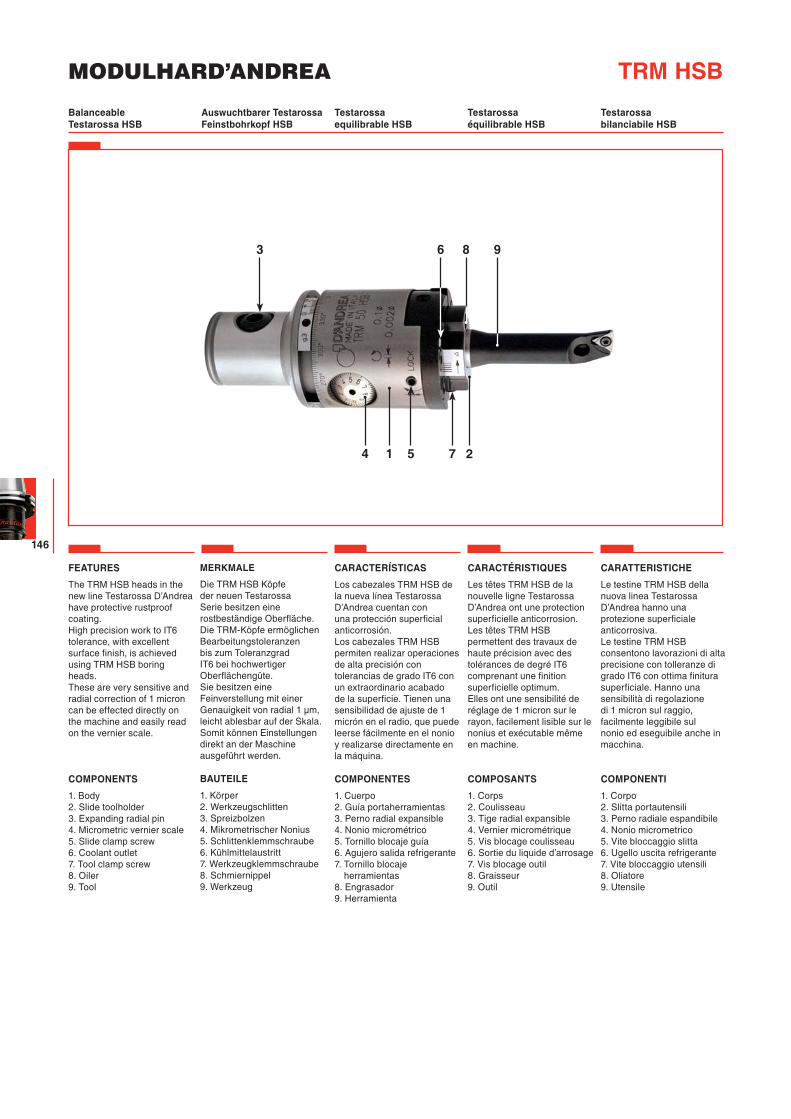
MODULHARD’ANDREA
146
Auswuchtbarer Testarossa Feinstbohrkopf HSB
Testarossa equilibrable HSB
Testarossa équilibrable HSB
Testarossa bilanciabile HSB
Balanceable Testarossa HSB
TRM HSB
214 75
983 6
FEATURES
The TRM HSB heads in the new line Testarossa D’Andrea have protective rustproof coating.High precision work to IT6 tolerance, with excellent surface finish, is achieved using TRM HSB boring heads. These are very sensitive and radial correction of 1 micron can be effected directly on the machine and easily read on the vernier scale.
COMPONENTS
1. Body2. Slide toolholder3. Expanding radial pin4. Micrometric vernier scale5. Slide clamp screw6. Coolant outlet7. Tool clamp screw8. Oiler 9. Tool
MERKMALE
Die TRM HSB Köpfe der neuen Testarossa Serie besitzen eine rostbeständige Oberfläche. Die TRM-Köpfe ermöglichen Bearbeitungstoleranzen bis zum Toleranzgrad IT6 bei hochwertiger Oberflächengüte.Sie besitzen eine Feinverstellung mit einer Genauigkeit von radial 1 �m, leicht ablesbar auf der Skala. Somit können Einstellungen direkt an der Maschine ausgeführt werden.
BAUTEILE
1. Körper2. Werkzeugschlitten3. Spreizbolzen4. Mikrometrischer Nonius5. Schlittenklemmschraube6. Kühlmittelaustritt7. Werkzeugklemmschraube8. Schmiernippel9. Werkzeug
CARACTERÍSTICAS
Los cabezales TRM HSB de la nueva línea Testarossa D’Andrea cuentan con una protección superficial anticorrosión. Los cabezales TRM HSB permiten realizar operaciones de alta precisión con tolerancias de grado IT6 con un extraordinario acabado de la superficie. Tienen una sensibilidad de ajuste de 1 micrón en el radio, que puede leerse fácilmente en el nonio y realizarse directamente en la máquina.
COMPONENTES
1. Cuerpo2. Guía portaherramientas3. Perno radial expansible4. Nonio micrométrico5. Tornillo blocaje guía6. Agujero salida refrigerante7. Tornillo blocaje
herramientas8. Engrasador9. Herramienta
CARACTÉRISTIQUES
Les têtes TRM HSB de la nouvelle ligne Testarossa D’Andrea ont une protection superficielle anticorrosion. Les têtes TRM HSB permettent des travaux de haute précision avec des tolérances de degré IT6 comprenant une finition superficielle optimum. Elles ont une sensibilité de réglage de 1 micron sur le rayon, facilement lisible sur le nonius et exécutable même en machine.
COMPOSANTS
1. Corps 2. Coulisseau 3. Tige radial expansible4. Vernier micrométrique5. Vis blocage coulisseau6. Sortie du liquide d’arrosage7. Vis blocage outil8. Graisseur9. Outil
CARATTERISTICHE
Le testine TRM HSB della nuova linea Testarossa D’Andrea hanno una protezione superficiale anticorrosiva.Le testine TRM HSB consentono lavorazioni di alta precisione con tolleranze di grado IT6 con ottima finitura superficiale. Hanno una sensibilità di regolazione di 1 micron sul raggio, facilmente leggibile sul nonio ed eseguibile anche in macchina.
COMPONENTI
1. Corpo 2. Slitta portautensili3. Perno radiale espandibile4. Nonio micrometrico5. Vite bloccaggio slitta6. Ugello uscita refrigerante7. Vite bloccaggio utensili8. Oliatore9. Utensile
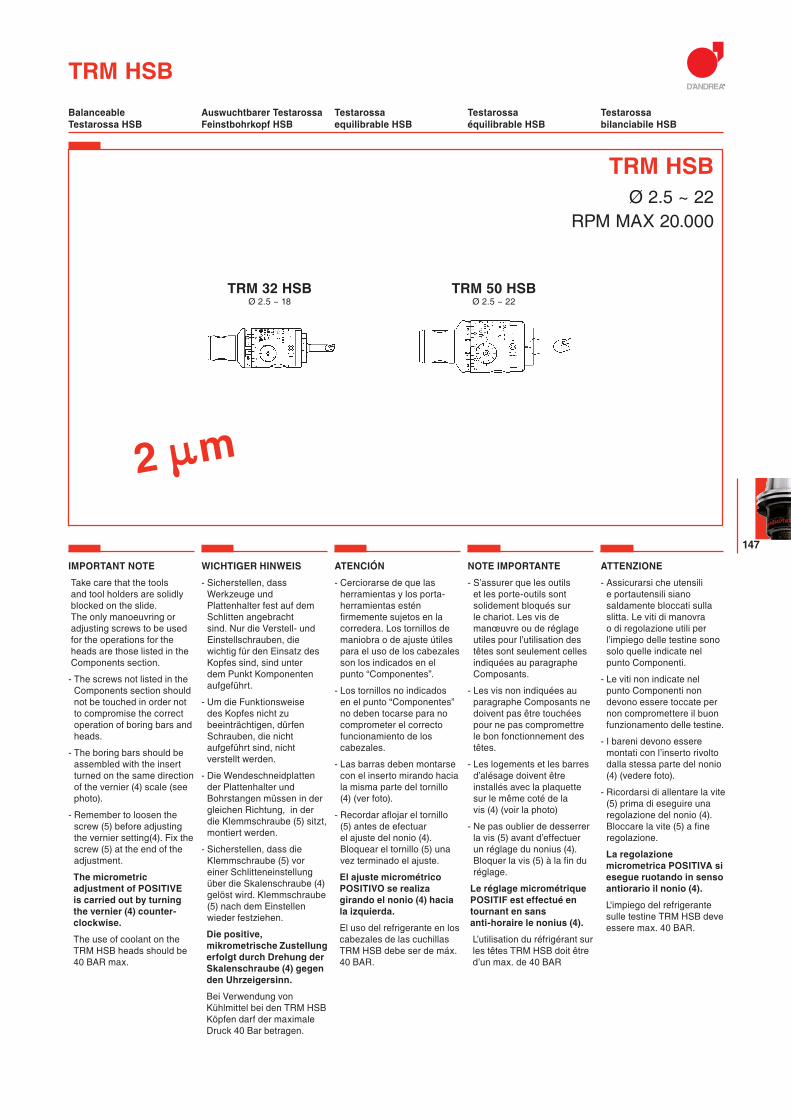
147
TRM HSBØ 2.5 ~ 22
RPM MAX 20.000
TRM HSB
TRM 32 HSBØ 2.5 ~ 18
TRM 50 HSBØ 2.5 ~ 22
IMPORTANT NOTE
Take care that the tools and tool holders are solidly blocked on the slide. The only manoeuvring or adjusting screws to be used for the operations for the heads are those listed in the Components section.
- The screws not listed in the Components section should not be touched in order not to compromise the correct operation of boring bars and heads.
- The boring bars should be assembled with the insert turned on the same direction of the vernier (4) scale (see photo).
- Remember to loosen the screw (5) before adjusting the vernier setting(4). Fix the screw (5) at the end of the adjustment.
The micrometric adjustment of POSITIVE is carried out by turning the vernier (4) counter-clockwise.
The use of coolant on the TRM HSB heads should be 40 BAR max.
WICHTIGER HINWEIS
- Sicherstellen, dass Werkzeuge und Plattenhalter fest auf dem Schlitten angebracht sind. Nur die Verstell- und Einstellschrauben, die wichtig für den Einsatz des Kopfes sind, sind unter dem Punkt Komponenten aufgeführt.
- Um die Funktionsweise des Kopfes nicht zu beeinträchtigen, dürfen Schrauben, die nicht aufgeführt sind, nicht verstellt werden.
- Die Wendeschneidplatten der Plattenhalter und Bohrstangen müssen in der gleichen Richtung, in der die Klemmschraube (5) sitzt, montiert werden.
- Sicherstellen, dass die Klemmschraube (5) vor einer Schlitteneinstellung über die Skalenschraube (4) gelöst wird. Klemmschraube (5) nach dem Einstellen wieder festziehen.
Die positive, mikrometrische Zustellung erfolgt durch Drehung der Skalenschraube (4) gegen den Uhrzeigersinn.
Bei Verwendung von Kühlmittel bei den TRM HSB Köpfen darf der maximale Druck 40 Bar betragen.
ATENCIÓN
- Cerciorarse de que las herramientas y los porta-herramientas estén firmemente sujetos en la corredera. Los tornillos de maniobra o de ajuste útiles para el uso de los cabezales son los indicados en el punto “Componentes”.
- Los tornillos no indicados en el punto “Componentes” no deben tocarse para no comprometer el correcto funcionamiento de los cabezales.
- Las barras deben montarse con el inserto mirando hacia la misma parte del tornillo (4) (ver foto).
- Recordar aflojar el tornillo (5) antes de efectuar el ajuste del nonio (4). Bloquear el tornillo (5) una vez terminado el ajuste.
El ajuste micrométrico POSITIVO se realiza girando el nonio (4) hacia la izquierda.
El uso del refrigerante en los cabezales de las cuchillas TRM HSB debe ser de máx. 40 BAR.
NOTE IMPORTANTE
- S’assurer que les outils et les porte-outils sont solidement bloqués sur le chariot. Les vis de manœuvre ou de réglage utiles pour l’utilisation des têtes sont seulement celles indiquées au paragraphe Composants.
- Les vis non indiquées au paragraphe Composants ne doivent pas être touchées pour ne pas compromettre le bon fonctionnement des têtes.
- Les logements et les barres d’alésage doivent être installés avec la plaquette sur le même coté de la vis (4) (voir la photo)
- Ne pas oublier de desserrer la vis (5) avant d’effectuer un réglage du nonius (4). Bloquer la vis (5) à la fin du réglage.
Le réglage micrométrique POSITIF est effectué en tournant en sans anti-horaire le nonius (4).
L’utilisation du réfrigérant sur les têtes TRM HSB doit être d’un max. de 40 BAR
ATTENZIONE
- Assicurarsi che utensili e portautensili siano saldamente bloccati sulla slitta. Le viti di manovra o di regolazione utili per l’impiego delle testine sono solo quelle indicate nel punto Componenti.
- Le viti non indicate nel punto Componenti non devono essere toccate per non compromettere il buon funzionamento delle testine.
- I bareni devono essere montati con l’inserto rivolto dalla stessa parte del nonio (4) (vedere foto).
- Ricordarsi di allentare la vite (5) prima di eseguire una regolazione del nonio (4). Bloccare la vite (5) a fine regolazione.
La regolazione micrometrica POSITIVA si esegue ruotando in senso antiorario il nonio (4).
L'impiego del refrigerante sulle testine TRM HSB deve essere max. 40 BAR.
2 m
Auswuchtbarer Testarossa Feinstbohrkopf HSB
Testarossa equilibrable HSB
Testarossa équilibrable HSB
Testarossa bilanciabile HSB
Balanceable Testarossa HSB
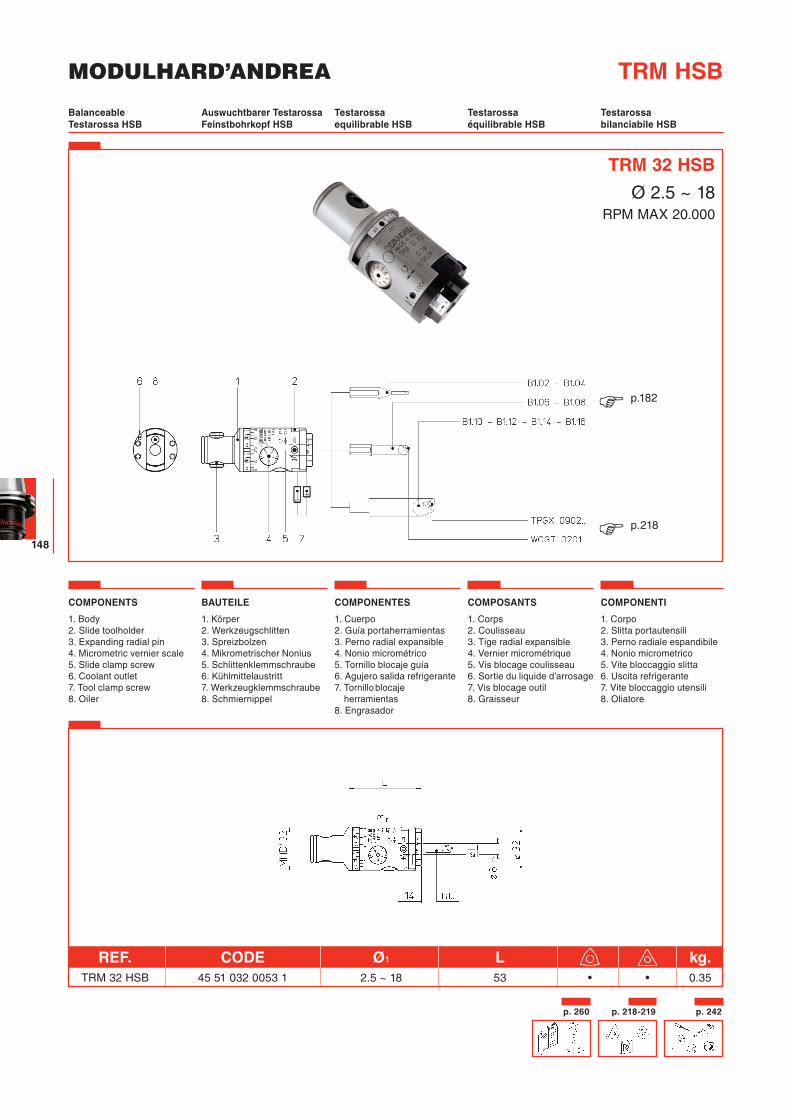
MODULHARD’ANDREA
148
TRM 32 HSB
Ø 2.5 ~ 18RPM MAX 20.000
REF. CODE Ø1 L kg. TRM 32 HSB 45 51 032 0053 1 2.5 ~ 18 53 • • 0.35
COMPONENTS
1. Body2. Slide toolholder3. Expanding radial pin4. Micrometric vernier scale5. Slide clamp screw6. Coolant outlet7. Tool clamp screw8. Oiler
BAUTEILE
1. Körper2. Werkzeugschlitten3. Spreizbolzen4. Mikrometrischer Nonius5. Schlittenklemmschraube6. Kühlmittelaustritt7. Werkzeugklemmschraube8. Schmiernippel
COMPONENTES
1. Cuerpo2. Guía portaherramientas3. Perno radial expansible4. Nonio micrométrico5. Tornillo blocaje guía6. Agujero salida refrigerante7. Tornillo blocaje
herramientas8. Engrasador
COMPOSANTS
1. Corps 2. Coulisseau 3. Tige radial expansible4. Vernier micrométrique5. Vis blocage coulisseau6. Sortie du liquide d’arrosage7. Vis blocage outil8. Graisseur
COMPONENTI
1. Corpo 2. Slitta portautensili3. Perno radiale espandibile4. Nonio micrometrico5. Vite bloccaggio slitta6. Uscita refrigerante7. Vite bloccaggio utensili8. Oliatore
Auswuchtbarer Testarossa Feinstbohrkopf HSB
Testarossa equilibrable HSB
Testarossa équilibrable HSB
Testarossa bilanciabile HSB
Balanceable Testarossa HSB
TRM HSB
p.182�
p.218�
p. 218-219 p. 242p. 260
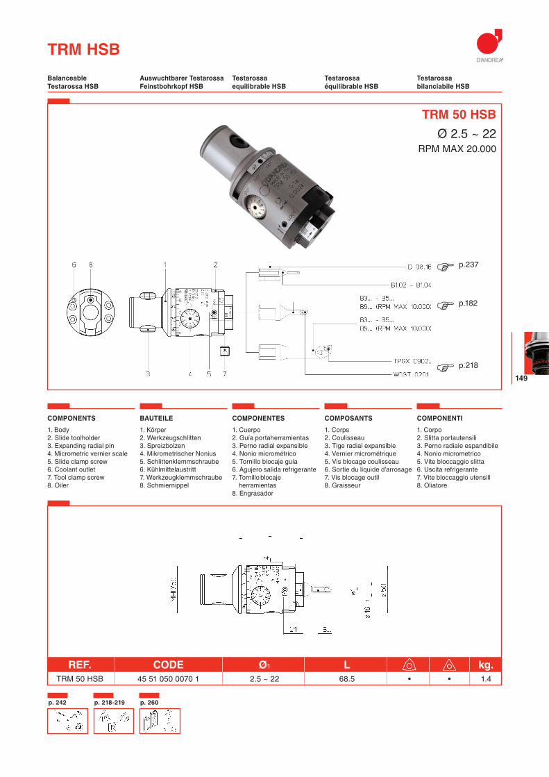
149
COMPONENTS
1. Body2. Slide toolholder3. Expanding radial pin4. Micrometric vernier scale5. Slide clamp screw6. Coolant outlet7. Tool clamp screw8. Oiler
BAUTEILE
1. Körper2. Werkzeugschlitten3. Spreizbolzen4. Mikrometrischer Nonius5. Schlittenklemmschraube6. Kühlmittelaustritt7. Werkzeugklemmschraube8. Schmiernippel
COMPONENTES
1. Cuerpo2. Guía portaherramientas3. Perno radial expansible4. Nonio micrométrico5. Tornillo blocaje guía6. Agujero salida refrigerante7. Tornillo blocaje
herramientas8. Engrasador
COMPOSANTS
1. Corps 2. Coulisseau 3. Tige radial expansible4. Vernier micrométrique5. Vis blocage coulisseau6. Sortie du liquide d’arrosage7. Vis blocage outil8. Graisseur
COMPONENTI
1. Corpo 2. Slitta portautensili3. Perno radiale espandibile4. Nonio micrometrico5. Vite bloccaggio slitta6. Uscita refrigerante7. Vite bloccaggio utensili8. Oliatore
TRM 50 HSB
Ø 2.5 ~ 22RPM MAX 20.000
REF. CODE Ø1 L kg. TRM 50 HSB 45 51 050 0070 1 2.5 ~ 22 68.5 • • 1.4
TRM HSB
Auswuchtbarer Testarossa Feinstbohrkopf HSB
Testarossa equilibrable HSB
Testarossa équilibrable HSB
Testarossa bilanciabile HSB
Balanceable Testarossa HSB
p.182�
p.218�
p.237�
p. 218-219p. 242 p. 260
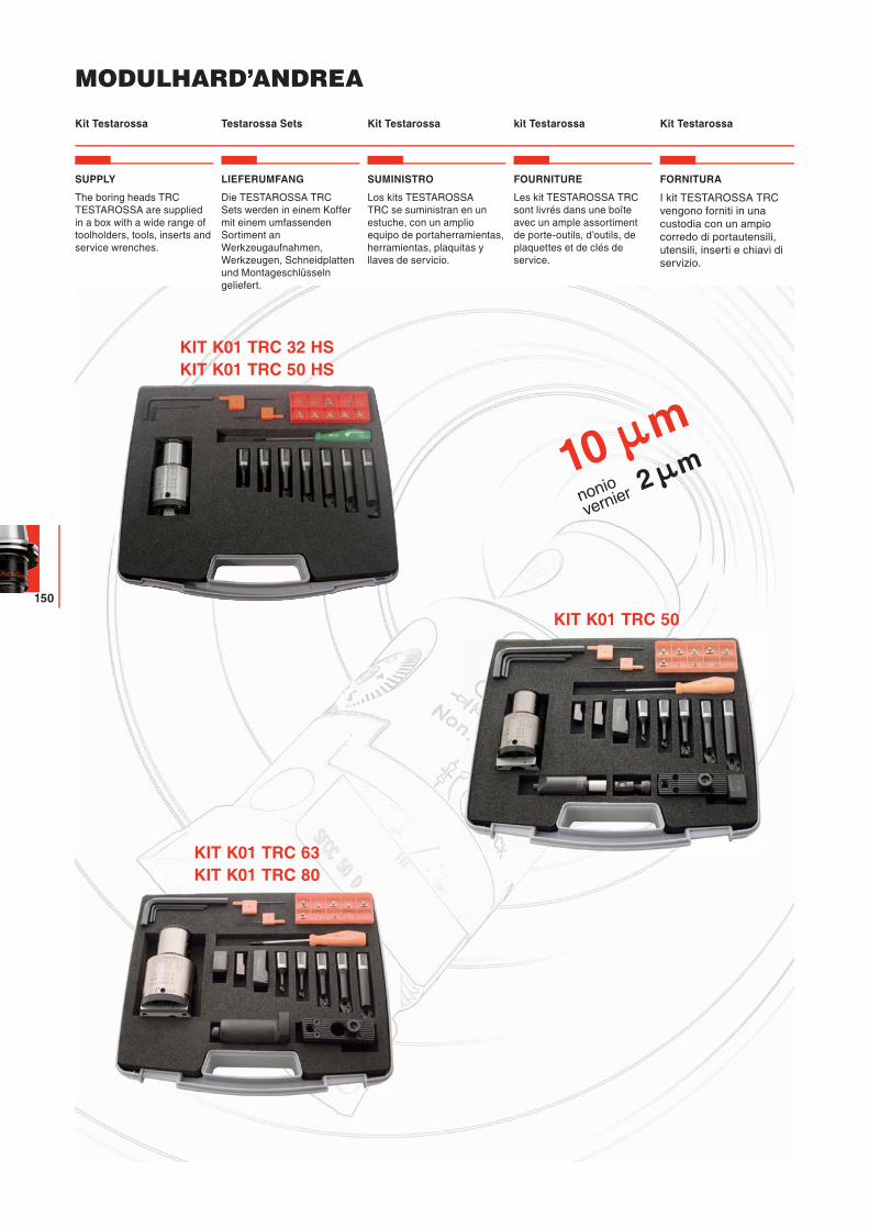
MODULHARD’ANDREA
150
10 mnonio
vernier 2 m
SUPPLY
The boring heads TRC TESTAROSSA are supplied in a box with a wide range of toolholders, tools, inserts and service wrenches.
LIEFERUMFANG
Die TESTAROSSA TRCSets werden in einem Koffer mit einem umfassenden Sortiment an Werkzeugaufnahmen, Werkzeugen, Schneidplatten und Montageschlüsseln geliefert.
SUMINISTRO
Los kits TESTAROSSA TRC se suministran en un estuche, con un amplio equipo de portaherramientas, herramientas, plaquitas y llaves de servicio.
FOURNITURE
Les kit TESTAROSSA TRC sont livrés dans une boîte avec un ample assortiment de porte-outils, d’outils, de plaquettes et de clés de service.
Testarossa Sets Kit Testarossa kit Testarossa Kit TestarossaKit Testarossa
KIT K01 TRC 32 HSKIT K01 TRC 50 HS
FORNITURA
I kit TESTAROSSA TRC vengono forniti in una custodia con un ampio corredo di portautensili, utensili, inserti e chiavi di servizio.
KIT K01 TRC 63KIT K01 TRC 80
KIT K01 TRC 50
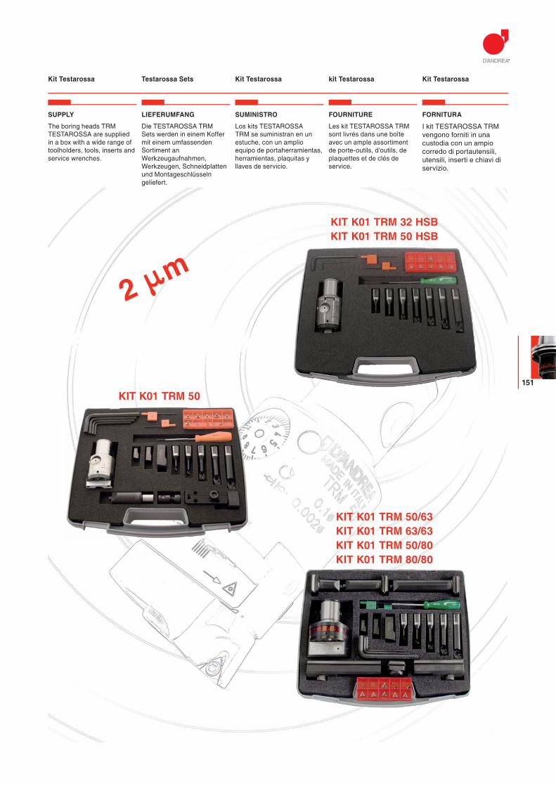
151
2 m
Testarossa Sets Kit Testarossa kit Testarossa Kit TestarossaKit Testarossa
SUPPLY
The boring heads TRM TESTAROSSA are supplied in a box with a wide range of toolholders, tools, inserts and service wrenches.
LIEFERUMFANG
Die TESTAROSSA TRMSets werden in einem Koffer mit einem umfassenden Sortiment an Werkzeugaufnahmen, Werkzeugen, Schneidplatten und Montageschlüsseln geliefert.
SUMINISTRO
Los kits TESTAROSSA TRM se suministran en un estuche, con un amplio equipo de portaherramientas, herramientas, plaquitas y llaves de servicio.
FOURNITURE
Les kit TESTAROSSA TRM sont livrés dans une boîte avec un ample assortiment de porte-outils, d’outils, de plaquettes et de clés de service.
FORNITURA
I kit TESTAROSSA TRM vengono forniti in una custodia con un ampio corredo di portautensili, utensili, inserti e chiavi di servizio.
KIT K01 TRM 32 HSBKIT K01 TRM 50 HSB
KIT K01 TRM 50/63KIT K01 TRM 63/63KIT K01 TRM 50/80KIT K01 TRM 80/80
KIT K01 TRM 50
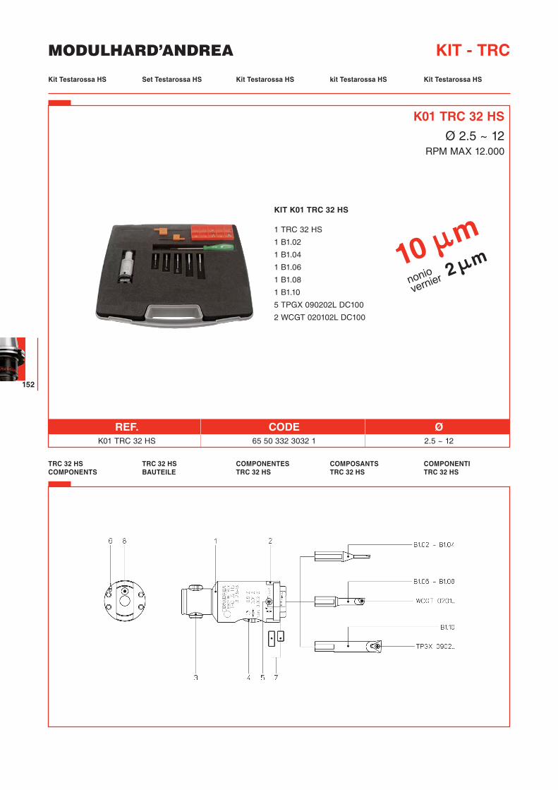
MODULHARD’ANDREA
152
KIT K01 TRC 32 HS
1 TRC 32 HS
1 B1.02
1 B1.04
1 B1.06
1 B1.08
1 B1.10
5 TPGX 090202L DC100
2 WCGT 020102L DC100
Set Testarossa HS Kit Testarossa HS kit Testarossa HS Kit Testarossa HSKit Testarossa HS
KIT - TRC
REF. CODE Ø K01 TRC 32 HS 65 50 332 3032 1 2.5 ~ 12
TRC 32 HS BAUTEILE
COMPONENTES TRC 32 HS
COMPOSANTS TRC 32 HS
COMPONENTI TRC 32 HS
TRC 32 HS COMPONENTS
10 mnonio
vernier 2 m
K01 TRC 32 HS
Ø 2.5 ~ 12RPM MAX 12.000

153
KIT - TRC
Arbeitsbereich Campo de trabajo Capacité d’usinage Campo di lavoroWorking range
COMPONENTS
1. Body2. Tool slide3. Expanding pin4. Vernier scale5. Slide lock screw6. Coolant outlet7. Tool lock screw8. Oiler
The boring head TRC 32 HS bores diameters from 2.5 to 12 mm.
- Fit the tool B.. into seat and lock with screw (7). The cutting tool must be on the slide longitudinal axis.
BAUTEILE
1. Körper2. Werkzeugschlitten3. Spreizbolzen4. Nonius5. Werkzeugschlitten-
klemmschraube6. Kühlmittelaustritt7. Werkzeugklemmschraube8. Schmiernippel
Der Kopf TRC 32 HS dreht Durchmesser von 2,5 bis 12 mm aus.
- Werkzeug B.. in die Aufnahme einsetzen und mit Schraube (7) spannen. Versichern Sie sich, dass die Schneide der Wendeplatte auf der Längsachse des Schlittens liegt.
COMPONENTES
1. Cuerpo2. Guía portaherramientas3. Perno radial expansible4. Nonio5. Tornillo blocaje guía
portaherramientas6. Agujero salida refrigerante7. Tornillo blocaje
herramientas8. Engrasador
El Kit TRC 32 HS mandrina agujeros de Ø 2,5 a 12 mm.
- Colocar en el alojamiento la herramienta B.. bloqueándola con el tornillo (7), asegurándose que el corte de la plaquita se encuentre sobre el eje longitudinal de la guía.
COMPOSANTS
1. Corps 2. Coulisseau3. Tige radiale expansible 4. Vernier 5. Vis bloccage coulisseau 6. Sortie du liquide d’arrosage7. Vis bloccage outil8. Graisseur
Le kit TRC 32 HS alèse des diamètres allant de 2,5 à 12 mm.
- Introduire l’outil B.. dans le logement et le bloquer au moyen de la vis (7) n’oubliant pas de vérifier si le taillant de l’élément intercalaire est disposé sur l’axe longitudinal du coulisseau.
COMPONENTI
1. Corpo2. Slitta portautensili3. Perno radiale espandibile4. Nonio5. Vite bloccaggio slitta6. Uscita refrigerante7. Vite bloccaggio utensili8. Oliatore
Con il Kit TRC 32 HS si alesano fori da Ø 2,5 a 12 mm.
- Inserire nell’alloggiamento l’utensile B.. bloccandolo con la vite (7) assicurandosi che il tagliente dell’inserto si trovi sull’asse longitudinale della slitta.
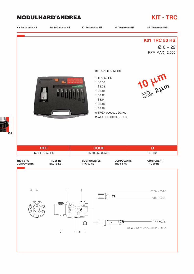
MODULHARD’ANDREA
154
KIT K01 TRC 50 HS
1 TRC 50 HS
1 B3.06
1 B3.08
1 B3.10
1 B3.12
1 B3.14
1 B3.16
1 B3.18
5 TPGX 090202L DC100
2 WCGT 020102L DC100
Set Testarossa HS Kit Testarossa HS kit Testarossa HS Kit Testarossa HSKit Testarossa HS
KIT - TRC
REF. CODE Ø K01 TRC 50 HS 65 50 350 3050 1 6 ~ 22
TRC 50 HS BAUTEILE
COMPONENTES TRC 50 HS
COMPOSANTS TRC 50 HS
COMPONENTI TRC 50 HS
TRC 50 HS COMPONENTS
10 mnonio
vernier 2 m
K01 TRC 50 HS
Ø 6 ~ 22RPM MAX 12.000

155
KIT - TRC
COMPONENTS
1. Body2. Tool slide3. Expanding pin4. Vernier scale5. Slide lock screw6. Coolant outlet7. Tool lock screw8. Oiler
The boring head TRC 50 HS bores diameters from 6 to 22 mm.
- Fit the tool B.. into seat and lock with screw (7). The cutting tool must be on the slide longitudinal axis.
BAUTEILE
1. Körper2. Werkzeugschlitten3. Spreizbolzen4. Nonius5. Werkzeugschlitten-
klemmschraube6. Kühlmittelaustritt7. Werkzeugklemmschraube8. Schmiernippel
Der Feinstbohrkopf TRC 50 HS dreht Durchmesser von 6 bis 22 mm aus.
- Werkzeug B.. in die Aufnahme einsetzen und mit Schraube (7) spannen. Versichern Sie sich, dass die Schneide der Wendeplatte auf der Längsachse des Schlittens liegt.
COMPONENTES
1. Cuerpo2. Guía portaherramientas3. Perno radial expansible4. Nonio5. Tornillo blocaje guía
portaherramientas6. Agujero salida refrigerante7. Tornillo blocaje
herramientas8. Engrasador
El Kit TRC 50 HS mandrina agujeros de Ø 6 a 22 mm.
- Colocar en el alojamiento la herramienta B.. bloqueándola con el tornillo (7), asegurándose que el corte de la plaquita se encuentre sobre el eje longitudinal de la guía.
COMPOSANTS
1. Corps2. Coulisseau3. Tige radiale expansible 4. Vernier5. Vis bloccage coulisseau6. Sortie du liquide d’arrosage7. Vis bloccage outil8. Graisseur
Le kit TRC 50 HS alèse des diamètres allant de 6 à 22 mm.
- Introduire l’outil B.. dans le logement et le bloquer au moyen de la vis (7) n’oubliant pas de vérifier si le taillant de l’élément intercalaire est disposé sur l’axe longitudinal du coulisseau.
COMPONENTI
1. Corpo2. Slitta portautensili3. Perno radiale espandibile4. Nonio5. Vite bloccaggio slitta6. Ugello uscita refrigerante7. Vite bloccaggio utensili8. Oliatore
Con il Kit TRC 50 HS si alesano fori da Ø 6 a 22 mm.
- Inserire nell’alloggiamento l’utensile B.. bloccandolo con la vite (7) assicurandosi che il tagliente dell’inserto si trovi sull’asse longitudinale della slitta.
Arbeitsbereich Campo de trabajo Capacité d’usinage Campo di lavoroWorking range
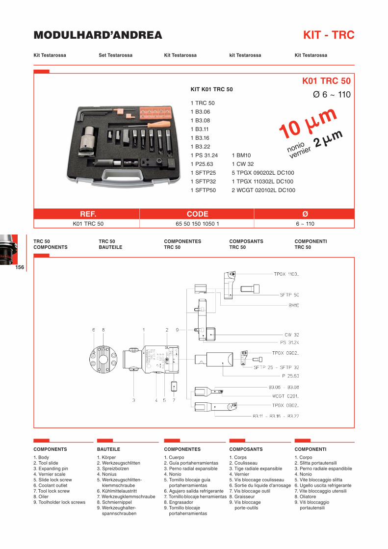
MODULHARD’ANDREA
156
KIT - TRC
KIT K01 TRC 50
1 TRC 50
1 B3.06
1 B3.08
1 B3.11
1 B3.16
1 B3.22
1 PS 31.24 1 BM10
1 P25.63 1 CW 32
1 SFTP25 5 TPGX 090202L DC100
1 SFTP32 1 TPGX 110302L DC100
1 SFTP50 2 WCGT 020102L DC100
Set Testarossa Kit Testarossa kit Testarossa Kit TestarossaKit Testarossa
TRC 50 BAUTEILE
COMPONENTES TRC 50
COMPOSANTS TRC 50
COMPONENTI TRC 50
TRC 50 COMPONENTS
K01 TRC 50
Ø 6 ~ 110
10 mnonio
vernier 2 m
REF. CODE Ø K01 TRC 50 65 50 150 1050 1 6 ~ 110
COMPONENTS
1. Body2. Tool slide3. Expanding pin4. Vernier scale5. Slide lock screw6. Coolant outlet7. Tool lock screw8. Oiler9. Toolholder lock screws
BAUTEILE
1. Körper2. Werkzeugschlitten3. Spreizbolzen4. Nonius5. Werkzeugschlitten-
klemmschraube6. Kühlmittelaustritt7. Werkzeugklemmschraube8. Schmiernippel9. Werkzeughalter-
spannschrauben
COMPONENTES
1. Cuerpo2. Guía portaherramientas3. Perno radial expansible4. Nonio5. Tornillo blocaje guía
portaherramientas6. Agujero salida refrigerante7. Tornillo blocaje herramientas8. Engrasador9. Tornillo blocaje
portaherramientas
COMPOSANTS
1. Corps2. Coulisseau3. Tige radiale expansible 4. Vernier 5. Vis bloccage coulisseau6. Sortie du liquide d’arrosage7. Vis bloccage outil8. Graisseur9. Vis bloccage
porte-outils
COMPONENTI
1. Corpo2. Slitta portautensili3. Perno radiale espandibile4. Nonio5. Vite bloccaggio slitta6. Ugello uscita refrigerante7. Vite bloccaggio utensili8. Oliatore9. Viti bloccaggio
portautensili
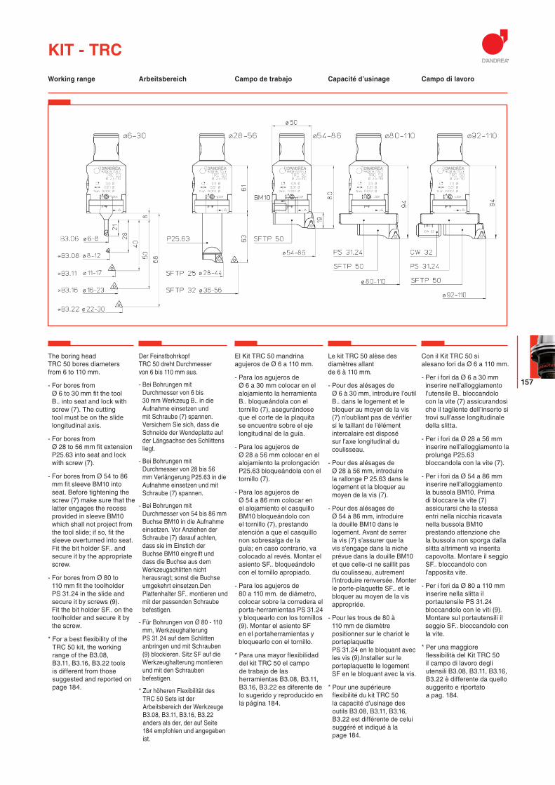
157
KIT - TRC
The boring head TRC 50 bores diameters from 6 to 110 mm.
- For bores from Ø 6 to 30 mm fit the tool B.. into seat and lock with screw (7). The cutting tool must be on the slide longitudinal axis.
- For bores from Ø 28 to 56 mm fit extension P25.63 into seat and lock with screw (7).
- For bores from Ø 54 to 86 mm fit sleeve BM10 into seat. Before tightening the screw (7) make sure that the latter engages the recess provided in sleeve BM10 which shall not project from the tool slide; if so, fit the sleeve overturned into seat. Fit the bit holder SF.. and secure it by the appropriate screw.
- For bores from Ø 80 to 110 mm fit the toolholder PS 31.24 in the slide and secure it by screws (9). Fit the bit holder SF.. on the toolholder and secure it by the screw.
* For a best flexibility of the TRC 50 kit, the working range of the B3.08, B3.11, B3.16, B3.22 tools is different from those suggested and reported on page 184.
Der Feinstbohrkopf TRC 50 dreht Durchmesser von 6 bis 110 mm aus.
- Bei Bohrungen mit Durchmesser von 6 bis 30 mm Werkzeug B.. in die Aufnahme einsetzen und mit Schraube (7) spannen. Versichern Sie sich, dass die Schneide der Wendeplatte auf der Längsachse des Schlittens liegt.
- Bei Bohrungen mit Durchmesser von 28 bis 56 mm Verlängerung P25.63 in die Aufnahme einsetzen und mit Schraube (7) spannen.
- Bei Bohrungen mit Durchmesser von 54 bis 86 mm Buchse BM10 in die Aufnahme einsetzen. Vor Anziehen der Schraube (7) darauf achten, dass sie im Einstich der Buchse BM10 eingreift und dass die Buchse aus dem Werkzeugschlitten nicht herausragt; sonst die Buchse umgekehrt einsetzen.Den Plattenhalter SF.. montieren und mit der passenden Schraube befestigen.
- Für Bohrungen von Ø 80 - 110 mm, Werkzeughalterung PS 31.24 auf dem Schlitten anbringen und mit Schrauben (9) blockieren. Sitz SF auf die Werkzeughalterung montieren und mit den Schrauben befestigen.
* Zur höheren Flexibilität des TRC 50 Sets ist der Arbeitsbereich der Werkzeuge B3.08, B3.11, B3.16, B3.22 anders als der, der auf Seite 184 empfohlen und angegeben ist.
El Kit TRC 50 mandrina agujeros de Ø 6 a 110 mm.
- Para los agujeros de Ø 6 a 30 mm colocar en el alojamiento la herramienta B.. bloqueándola con el tornillo (7), asegurándose que el corte de la plaquita se encuentre sobre el eje longitudinal de la guía.
- Para los agujeros de Ø 28 a 56 mm colocar en el alojamiento la prolongación P25.63 bloqueándola con el tornillo (7).
- Para los agujeros de Ø 54 a 86 mm colocar en el alojamiento el casquillo BM10 bloqueándolo con el tornillo (7), prestando atención a que el casquillo non sobresalga de la guía; en caso contrario, va colocado al revés. Montar el asiento SF.. bloqueándolo con el tornillo apropiado.
- Para los agujeros de 80 a 110 mm. de diámetro, colocar sobre la corredera el porta-herramientas PS 31.24 y bloquearlo con los tornillos (9). Montar el asiento SF en el portaherramientas y bloquearlo con el tornillo.
* Para una mayor flexibilidad del kit TRC 50 el campo de trabajo de las herramientas B3.08, B3.11, B3.16, B3.22 es diferente de lo sugerido y reproducido en la página 184.
Le kit TRC 50 alèse des diamètres allant de 6 à 110 mm.
- Pour des alésages de Ø 6 à 30 mm, introduire l’outil B.. dans le logement et le bloquer au moyen de la vis (7) n’oubliant pas de vérifier si le taillant de l’élément intercalaire est disposé sur l’axe longitudinal du coulisseau.
- Pour des alésages de Ø 28 à 56 mm, introduire la rallonge P 25.63 dans le logement et la bloquer au moyen de la vis (7).
- Pour des alésages de Ø 54 à 86 mm, introduire la douille BM10 dans le logement. Avant de serrer la vis (7) s’assurer que la vis s’engage dans la niche prévue dans la douille BM10 et que celle-ci ne saillit pas du coulisseau, autrement l’introduire renversée. Monter le porte-plaquette SF.. et le bloquer au moyen de la vis appropriée.
- Pour les trous de 80 à 110 mm de diamètre positionner sur le chariot le porteplaquette PS 31.24 en le bloquant avec les vis (9).Installer sur le porteplaquette le logement SF en le bloquant avec la vis.
* Pour une supérieure flexibilité du kit TRC 50 la capacité d’usinage des outils B3.08, B3.11, B3.16, B3.22 est différente de celui suggéré et indiqué à la page 184.
Con il Kit TRC 50 si alesano fori da Ø 6 a 110 mm.
- Per i fori da Ø 6 a 30 mm inserire nell’alloggiamento l’utensile B.. bloccandolo con la vite (7) assicurandosi che il tagliente dell’inserto si trovi sull’asse longitudinale della slitta.
- Per i fori da Ø 28 a 56 mm inserire nell’alloggiamento la prolunga P25.63 bloccandola con la vite (7).
- Per i fori da Ø 54 a 86 mm inserire nell’alloggiamento la bussola BM10. Prima di bloccare la vite (7) assicurarsi che la stessa entri nella nicchia ricavata nella bussola BM10 prestando attenzione che la bussola non sporga dalla slitta altrimenti va inserita capovolta. Montare il seggio SF.. bloccandolo con l’apposita vite.
- Per i fori da Ø 80 a 110 mm inserire nella slitta il portautensile PS 31.24 bloccandolo con le viti (9). Montare sul portautensili il seggio SF.. bloccandolo con la vite.
* Per una maggiore flessibilità del Kit TRC 50 il campo di lavoro degli utensili B3.08, B3.11, B3.16, B3.22 è differente da quello suggerito e riportato a pag. 184.
Arbeitsbereich Campo de trabajo Capacité d’usinage Campo di lavoroWorking range
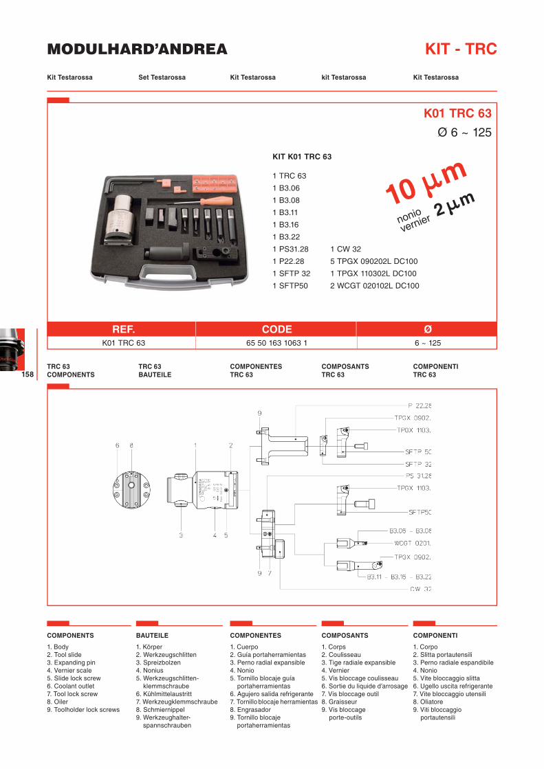
MODULHARD’ANDREA
158
KIT K01 TRC 63
1 TRC 63
1 B3.06
1 B3.08
1 B3.11
1 B3.16
1 B3.22
1 PS31.28 1 CW 32
1 P22.28 5 TPGX 090202L DC100
1 SFTP 32 1 TPGX 110302L DC100
1 SFTP50 2 WCGT 020102L DC100
Set Testarossa Kit Testarossa kit Testarossa Kit TestarossaKit Testarossa
KIT - TRC
REF. CODE Ø K01 TRC 63 65 50 163 1063 1 6 ~ 125
TRC 63 BAUTEILE
COMPONENTES TRC 63
COMPOSANTS TRC 63
COMPONENTI TRC 63
TRC 63 COMPONENTS
K01 TRC 63
Ø 6 ~ 125
COMPONENTS
1. Body2. Tool slide3. Expanding pin4. Vernier scale5. Slide lock screw6. Coolant outlet7. Tool lock screw8. Oiler9. Toolholder lock screws
BAUTEILE
1. Körper2. Werkzeugschlitten3. Spreizbolzen4. Nonius5. Werkzeugschlitten-
klemmschraube6. Kühlmittelaustritt7. Werkzeugklemmschraube8. Schmiernippel9. Werkzeughalter-
spannschrauben
COMPONENTES
1. Cuerpo2. Guía portaherramientas3. Perno radial expansible4. Nonio5. Tornillo blocaje guía
portaherramientas6. Agujero salida refrigerante7. Tornillo blocaje herramientas8. Engrasador9. Tornillo blocaje
portaherramientas
COMPOSANTS
1. Corps2. Coulisseau3. Tige radiale expansible 4. Vernier 5. Vis bloccage coulisseau6. Sortie du liquide d’arrosage7. Vis bloccage outil8. Graisseur9. Vis bloccage
porte-outils
COMPONENTI
1. Corpo2. Slitta portautensili3. Perno radiale espandibile4. Nonio5. Vite bloccaggio slitta6. Ugello uscita refrigerante7. Vite bloccaggio utensili8. Oliatore9. Viti bloccaggio
portautensili
10 mnonio
vernier 2 m
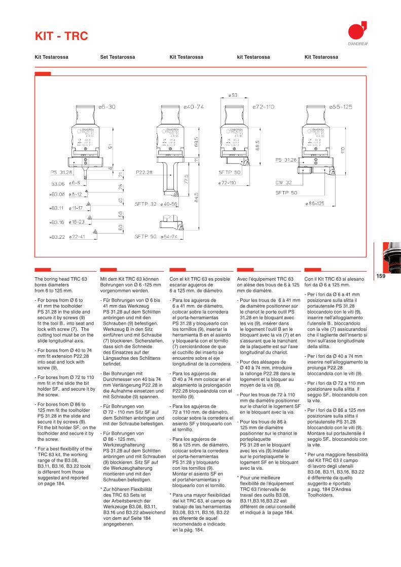
159
KIT - TRC
The boring head TRC 63 bores diameters from 6 to 125 mm.
- For bores from Ø 6 to 41 mm the toolholder PS 31.28 in the slide and secure it by screws (9) fit the tool B.. into seat and lock with screw (7). The cutting tool must be on the slide longitudinal axis.
- For bores from Ø 40 to 74 mm fit extension P22.28 into seat and lock with screw (9).
- For bores from Ø 72 to 110 mm fit in the slide the bit holder SF.. and secure it by the screw.
- For bores from Ø 86 to 125 mm fit the toolholder PS 31.28 in the slide and secure it by screws (9). Fit the bit holder SF.. on the toolholder and secure it by the screw.
* For a best flexibility of the TRC 63 kit, the working range of the B3.08, B3.11, B3.16, B3.22 tools is different from those suggested and reported on page 184.
Mit dem Kit TRC 63 können Bohrungen von Ø 6 -125 mm vorgenommen werden.
- Für Bohrungen von Ø 6 bis 41 mm das Werkzeug PS 31.28 auf dem Schlitten anbringen und mit den Schrauben (9) befestigen. Werkzeug B in den Sitz einführen und mit Schraube (7) blockieren. Sicherstellen, dass sich die Schneide des Einsatzes auf der Längsachse des Schlittens befindet.
- Bei Bohrungen mit Durchmesser von 40 bis 74 mm Verlängerung P22.28 in die Aufnahme einsetzen und mit Schraube (9) spannen.
- Für Bohrungen von Ø 72 - 110 mm Sitz SF auf dem Schlitten anbringen und mit der Schraube befestigen.
- Für Bohrungen von Ø 86 - 125 mm, Werkzeughalterung PS 31.28 auf dem Schlitten anbringen und mit Schrauben (9) blockieren. Sitz SF auf die Werkzeughalterung montieren und mit den Schrauben befestigen.
* Zur höheren Flexibilität des TRC 63 Sets ist der Arbeitsbereich der Werkzeuge B3.08, B3.11, B3.16 und B3.22 abweichend von dem auf Seite 184 angegebenen.
Con el kit TRC 63 es posible escariar agujeros de 6 a 125 mm. de diámetro.
- Para los agujeros de 6 a 41 mm. de diámetro, colocar sobre la corredera el porta-herramientas PS 31.28 y bloquearlo con los tornillos (9), insertar la herramienta B en el asiento y bloquearla con el tornillo (7) cerciorándose de que el cuchillo del inserto se encuentre sobre el eje longitudinal de la corredera.
- Para los agujeros de Ø 40 a 74 mm colocar en el alojamiento la prolongación P22.28 bloqueándola con el tornillo (9).
- Para los agujeros de 72 a 110 mm. de diámetro, colocar sobre la corredera el asiento SF y bloquearlo con el tornillo.
- Para los agujeros de 86 a 125 mm. de diámetro, colocar sobre la corredera el porta-herramientas PS 31.28 y bloquearlo con los tornillos (9). Montar el asiento SF en el portaherramientas y bloquearlo con el tornillo.
* Para una mayor flexibilidad del kit TRC 63, el campo de trabajo de las herramientas B3.08, B3.11, B3.16, B3.22 es diferente de aquel recomendado e indicado en la pág. 184.
Avec l’équipement TRC 63 on alèse des trous de 6 à 125 mm de diamètre.
- Pour les trous de 6 à 41 mm de diamètre positionner sur le chariot le porte outil PS 31.28 en le bloquant avec les vis (9), insérer dans le logement l’outil B en le bloquant avec la vis (7) et en s’assurant que le tranchant de la plaquette est sur l’axe longitudinal du chariot.
- Pour des alésages de Ø 40 à 74 mm, introduire la rallonge P22.28 dans le logement et la bloquer au moyen de la vis (9).
- Pour les trous de 72 à 110 mm de diamètre positionner sur le chariot le logement SF en le bloquant avec la vis.
- Pour les trous de 86 à 125 mm de diamètre positionner sur le chariot le porteplaquette PS 31.28 en le bloquant avec les vis (9).Installer sur le porteplaquette le logement SF en le bloquant avec la vis.
* Pour une meilleure flexibilité de l’équipement TRC 63 l’intervalle de travail des outils B3.08, B3.11,B3.16,B3.22 est différent de celui conseillé et indiqué à la page 184.
Con il Kit TRC 63 si alesano fori da Ø 6 a 125 mm.
- Per i fori da Ø 6 a 41 mm posizionare sulla slitta il portautensile PS 31.28 bloccandolo con le viti (9), inserire nell’alloggiamento l’utensile B.. bloccandolo con la vite (7) assicurandosi che il tagliente dell’inserto si trovi sull’asse longitudinale della slitta.
- Per i fori da Ø 40 a 74 mm inserire nell’alloggiamento la prolunga P22.28 bloccandola con le viti (9).
- Per i fori da Ø 72 a 110 mm posizionare sulla slitta il seggio SF.. bloccandolo con la vite.
- Per i fori da Ø 86 a 125 mm posizionare sulla slitta il portautensile PS 31.28 bloccandolo con le viti (9). Montare sul portautensile il seggio SF.. bloccandolo con la vite.
* Per una maggiore flessibilità del Kit TRC 63 il campo di lavoro degli utensili B3.08, B3.11, B3.16, B3.22 è differente da quello suggerito e riportato a pag. 184 D'Andrea Toolholders.
Set Testarossa Kit Testarossa kit Testarossa Kit TestarossaKit Testarossa
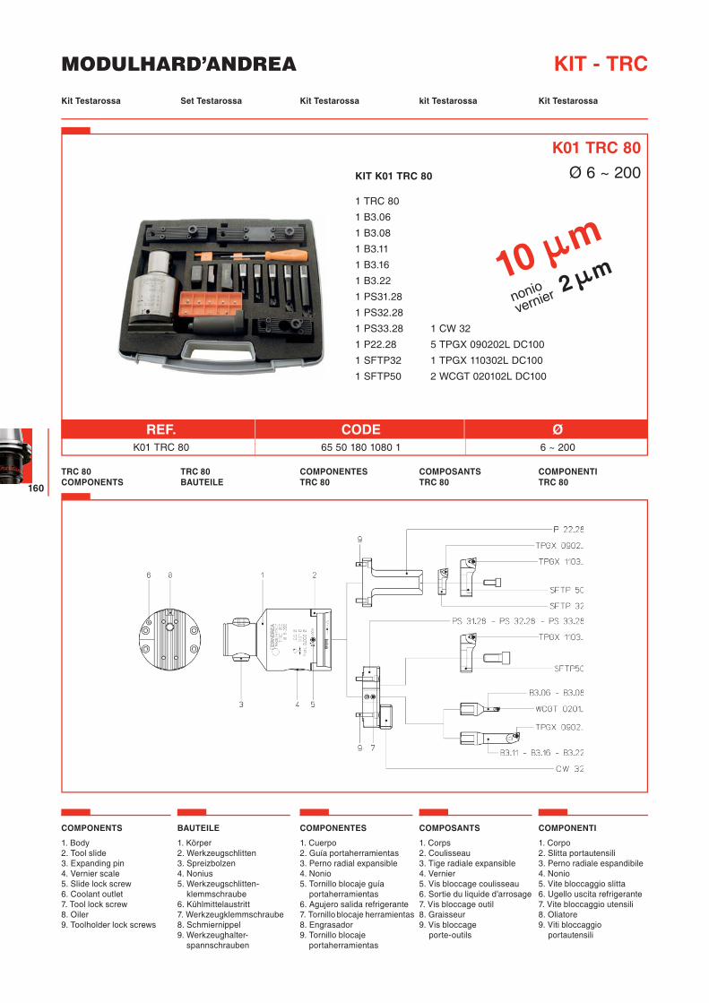
MODULHARD’ANDREA
160
Set Testarossa Kit Testarossa kit Testarossa Kit TestarossaKit Testarossa
KIT - TRC
REF. CODE Ø K01 TRC 80 65 50 180 1080 1 6 ~ 200
TRC 80 BAUTEILE
COMPONENTES TRC 80
COMPOSANTS TRC 80
COMPONENTI TRC 80
TRC 80 COMPONENTS
K01 TRC 80
Ø 6 ~ 200
COMPONENTS
1. Body2. Tool slide3. Expanding pin4. Vernier scale5. Slide lock screw6. Coolant outlet7. Tool lock screw8. Oiler9. Toolholder lock screws
BAUTEILE
1. Körper2. Werkzeugschlitten3. Spreizbolzen4. Nonius5. Werkzeugschlitten-
klemmschraube6. Kühlmittelaustritt7. Werkzeugklemmschraube8. Schmiernippel9. Werkzeughalter-
spannschrauben
COMPONENTES
1. Cuerpo2. Guía portaherramientas3. Perno radial expansible4. Nonio5. Tornillo blocaje guía
portaherramientas6. Agujero salida refrigerante7. Tornillo blocaje herramientas8. Engrasador9. Tornillo blocaje
portaherramientas
COMPOSANTS
1. Corps2. Coulisseau3. Tige radiale expansible 4. Vernier 5. Vis bloccage coulisseau6. Sortie du liquide d’arrosage7. Vis bloccage outil8. Graisseur9. Vis bloccage
porte-outils
COMPONENTI
1. Corpo2. Slitta portautensili3. Perno radiale espandibile4. Nonio5. Vite bloccaggio slitta6. Ugello uscita refrigerante7. Vite bloccaggio utensili8. Oliatore9. Viti bloccaggio
portautensili
KIT K01 TRC 80
1 TRC 80
1 B3.06
1 B3.08
1 B3.11
1 B3.16
1 B3.22
1 PS31.28
1 PS32.28
1 PS33.28 1 CW 32
1 P22.28 5 TPGX 090202L DC100
1 SFTP32 1 TPGX 110302L DC100
1 SFTP50 2 WCGT 020102L DC100
10 mnonio
vernier 2 m
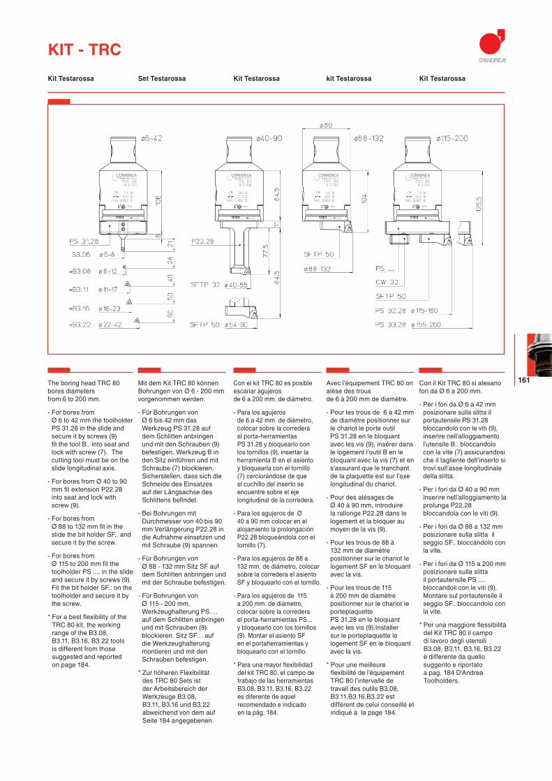
161
KIT - TRC
The boring head TRC 80 bores diameters from 6 to 200 mm.
- For bores from Ø 6 to 42 mm the toolholder PS 31.28 in the slide and secure it by screws (9) fit the tool B.. into seat and lock with screw (7). The cutting tool must be on the slide longitudinal axis.
- For bores from Ø 40 to 90 mm fit extension P22.28 into seat and lock with screw (9).
- For bores from Ø 88 to 132 mm fit in the slide the bit holder SF.. and secure it by the screw.
- For bores from Ø 115 to 200 mm fit the toolholder PS .... in the slide and secure it by screws (9). Fit the bit holder SF.. on the toolholder and secure it by the screw.
* For a best flexibility of the TRC 80 kit, the working range of the B3.08, B3.11, B3.16, B3.22 tools is different from those suggested and reported on page 184.
Mit dem Kit TRC 80 können Bohrungen von Ø 6 - 200 mm vorgenommen werden.
- Für Bohrungen von Ø 6 bis 42 mm das Werkzeug PS 31.28 auf dem Schlitten anbringen und mit den Schrauben (9) befestigen. Werkzeug B in den Sitz einführen und mit Schraube (7) blockieren. Sicherstellen, dass sich die Schneide des Einsatzes auf der Längsachse des Schlittens befindet.
- Bei Bohrungen mit Durchmesser von 40 bis 90 mm Verlängerung P22.28 in die Aufnahme einsetzen und mit Schraube (9) spannen.
- Für Bohrungen von Ø 88 - 132 mm Sitz SF auf dem Schlitten anbringen und mit der Schraube befestigen.
- Für Bohrungen von Ø 115 - 200 mm, Werkzeughalterung PS…. auf dem Schlitten anbringen und mit Schrauben (9) blockieren. Sitz SF… auf die Werkzeughalterung montieren und mit den Schrauben befestigen.
* Zur höheren Flexibilität des TRC 80 Sets ist der Arbeitsbereich der Werkzeuge B3.08, B3.11, B3.16 und B3.22 abweichend von dem auf Seite 184 angegebenen.
Con el kit TRC 80 es posible escariar agujeros de 6 a 200 mm. de diámetro.
- Para los agujeros de 6 a 42 mm. de diámetro, colocar sobre la corredera el porta-herramientas PS 31.28 y bloquearlo con los tornillos (9), insertar la herramienta B en el asiento y bloquearla con el tornillo (7) cerciorándose de que el cuchillo del inserto se encuentre sobre el eje longitudinal de la corredera.
- Para los agujeros de Ø 40 a 90 mm colocar en el alojamiento la prolongación P22.28 bloqueándola con el tornillo (7).
- Para los agujeros de 88 a 132 mm. de diámetro, colocar sobre la corredera el asiento SF y bloquearlo con el tornillo.
- Para los agujeros de 115 a 200 mm. de diámetro, colocar sobre la corredera el porta-herramientas PS... y bloquearlo con los tornillos (9). Montar el asiento SF en el portaherramientas y bloquearlo con el tornillo.
* Para una mayor flexibilidad del kit TRC 80, el campo de trabajo de las herramientas B3.08, B3.11, B3.16, B3.22 es diferente de aquel recomendado e indicado en la pág. 184.
Avec l’équipement TRC 80 on alèse des trous de 6 à 200 mm de diamètre.
- Pour les trous de 6 à 42 mm de diamètre positionner sur le chariot le porte outil PS 31.28 en le bloquant avec les vis (9), insérer dans le logement l’outil B en le bloquant avec la vis (7) et en s’assurant que le tranchant de la plaquette est sur l’axe longitudinal du chariot.
- Pour des alésages de Ø 40 à 90 mm, introduire la rallonge P22.28 dans le logement et la bloquer au moyen de la vis (9).
- Pour les trous de 88 à 132 mm de diamètre positionner sur le chariot le logement SF en le bloquant avec la vis.
- Pour les trous de 115 à 200 mm de diamètre positionner sur le chariot le porteplaquette PS 31.28 en le bloquant avec les vis (9).Installer sur le porteplaquette le logement SF en le bloquant avec la vis.
* Pour une meilleure flexibilité de l’équipement TRC 80 l’intervalle de travail des outils B3.08, B3.11,B3.16,B3.22 est différent de celui conseillé et indiqué à la page 184.
Con il Kit TRC 80 si alesano fori da Ø 6 a 200 mm.
- Per i fori da Ø 6 a 42 mm posizionare sulla slitta il portautensile PS 31.28 bloccandolo con le viti (9), inserire nell’alloggiamento l’utensile B.. bloccandolo con la vite (7) assicurandosi che il tagliente dell’inserto si trovi sull’asse longitudinale della slitta.
- Per i fori da Ø 40 a 90 mm inserire nell’alloggiamento la prolunga P22.28 bloccandola con le viti (9).
- Per i fori da Ø 88 a 132 mm posizionare sulla slitta il seggio SF.. bloccandolo con la vite.
- Per i fori da Ø 115 a 200 mm posizionare sulla slitta il portautensile PS .... bloccandoli con le viti (9). Montare sul portautensile il seggio SF.. bloccandolo con la vite.
* Per una maggiore flessibilità del Kit TRC 80 il campo di lavoro degli utensili B3.08, B3.11, B3.16, B3.22 è differente da quello suggerito e riportato a pag. 184 D'Andrea Toolholders.
Set Testarossa Kit Testarossa kit Testarossa Kit TestarossaKit Testarossa

MODULHARD’ANDREA
162
KIT K01 TRM 32 HSB
1 TRM 32 HSB
1 B1.02
1 B1.04
1 B1.06
1 B1.08
1 B1.10
5 TPGX 090202L DC100
2 WCGT 020102L DC100
Auswuchtbares Set HSB
Kit equilibrable HSB
Kit équilibrable HSB
Kit Testarossabilanciabile HSB
Balanceable kit HSB
KIT - TRM
REF. CODE Ø K01 TRM 32 HSB 65 50 032 3032 1 2.5 ~ 12
TRM 32 HSB BAUTEILE
COMPONENTES TRM 32 HSB
COMPOSANTS TRM 32 HSB
COMPONENTI TRM 32 HSB
TRM 32 HSB COMPONENTS
K01 TRM 32 HSB
Ø 2.5 ~ 12RPM MAX 20.000
2 m
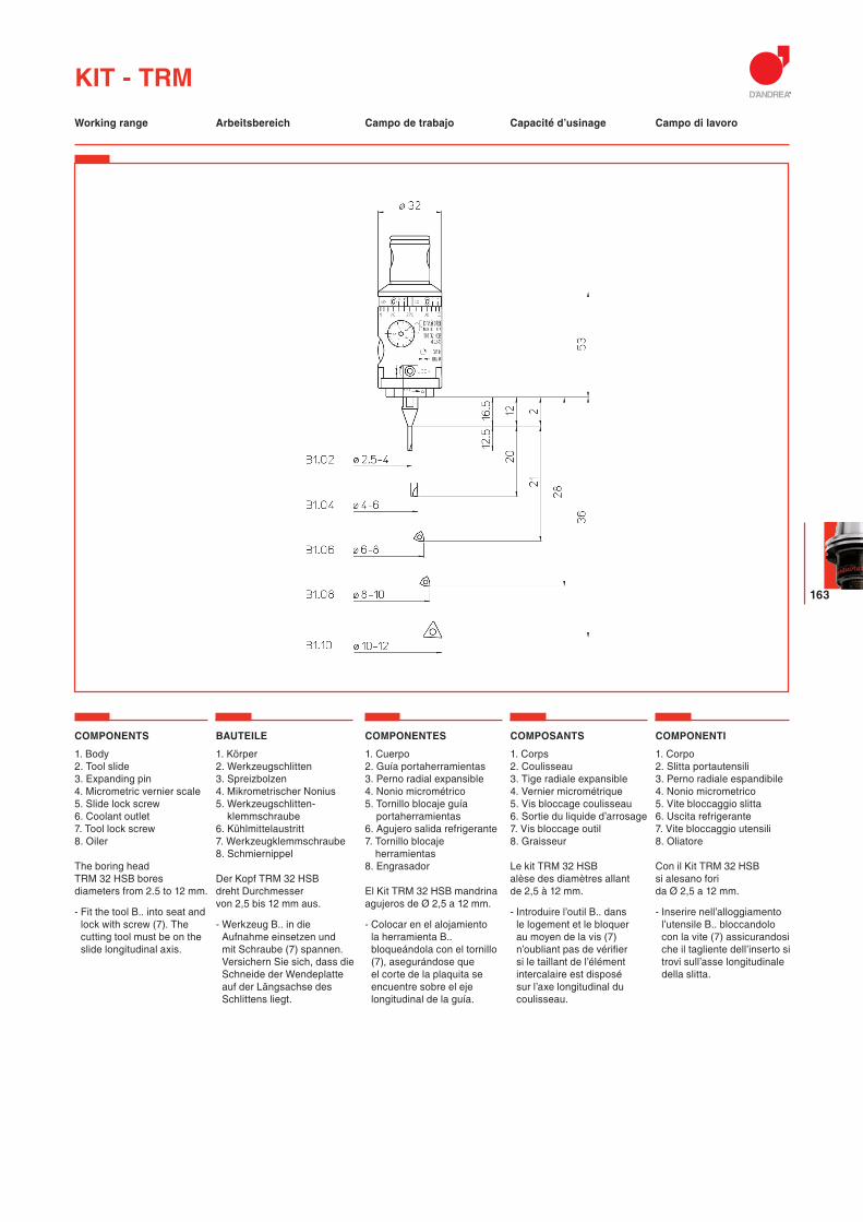
163
KIT - TRM
COMPONENTS
1. Body2. Tool slide3. Expanding pin4. Micrometric vernier scale5. Slide lock screw6. Coolant outlet7. Tool lock screw8. Oiler
The boring head TRM 32 HSB bores diameters from 2.5 to 12 mm.
- Fit the tool B.. into seat and lock with screw (7). The cutting tool must be on the slide longitudinal axis.
BAUTEILE
1. Körper2. Werkzeugschlitten3. Spreizbolzen4. Mikrometrischer Nonius5. Werkzeugschlitten-
klemmschraube6. Kühlmittelaustritt7. Werkzeugklemmschraube8. Schmiernippel
Der Kopf TRM 32 HSB dreht Durchmesser von 2,5 bis 12 mm aus.
- Werkzeug B.. in die Aufnahme einsetzen und mit Schraube (7) spannen. Versichern Sie sich, dass die Schneide der Wendeplatte auf der Längsachse des Schlittens liegt.
COMPONENTES
1. Cuerpo2. Guía portaherramientas3. Perno radial expansible4. Nonio micrométrico5. Tornillo blocaje guía
portaherramientas6. Agujero salida refrigerante7. Tornillo blocaje
herramientas8. Engrasador
El Kit TRM 32 HSB mandrina agujeros de Ø 2,5 a 12 mm.
- Colocar en el alojamiento la herramienta B.. bloqueándola con el tornillo (7), asegurándose que el corte de la plaquita se encuentre sobre el eje longitudinal de la guía.
COMPOSANTS
1. Corps 2. Coulisseau3. Tige radiale expansible 4. Vernier micrométrique 5. Vis bloccage coulisseau 6. Sortie du liquide d’arrosage7. Vis bloccage outil8. Graisseur
Le kit TRM 32 HSBalèse des diamètres allant de 2,5 à 12 mm.
- Introduire l’outil B.. dans le logement et le bloquer au moyen de la vis (7) n’oubliant pas de vérifier si le taillant de l’élément intercalaire est disposé sur l’axe longitudinal du coulisseau.
COMPONENTI
1. Corpo2. Slitta portautensili3. Perno radiale espandibile4. Nonio micrometrico5. Vite bloccaggio slitta6. Uscita refrigerante7. Vite bloccaggio utensili8. Oliatore
Con il Kit TRM 32 HSB si alesano fori da Ø 2,5 a 12 mm.
- Inserire nell’alloggiamento l’utensile B.. bloccandolo con la vite (7) assicurandosi che il tagliente dell’inserto si trovi sull’asse longitudinale della slitta.
Arbeitsbereich Campo de trabajo Capacité d’usinage Campo di lavoroWorking range
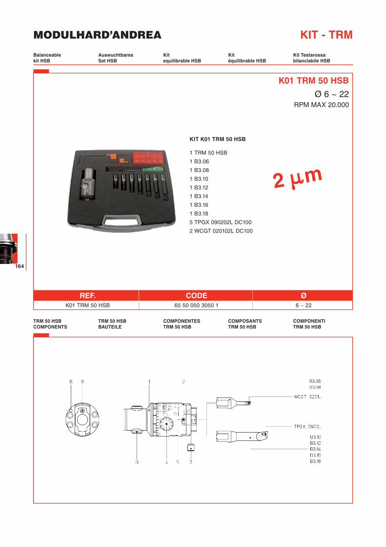
MODULHARD’ANDREA
164
KIT K01 TRM 50 HSB
1 TRM 50 HSB
1 B3.06
1 B3.08
1 B3.10
1 B3.12
1 B3.14
1 B3.16
1 B3.18
5 TPGX 090202L DC100
2 WCGT 020102L DC100
Auswuchtbares Set HSB
Kit equilibrable HSB
Kit équilibrable HSB
Kit Testarossabilanciabile HSB
Balanceable kit HSB
KIT - TRM
REF. CODE Ø K01 TRM 50 HSB 65 50 050 3050 1 6 ~ 22
TRM 50 HSB BAUTEILE
COMPONENTES TRM 50 HSB
COMPOSANTS TRM 50 HSB
COMPONENTI TRM 50 HSB
TRM 50 HSB COMPONENTS
K01 TRM 50 HSB
Ø 6 ~ 22RPM MAX 20.000
2 m
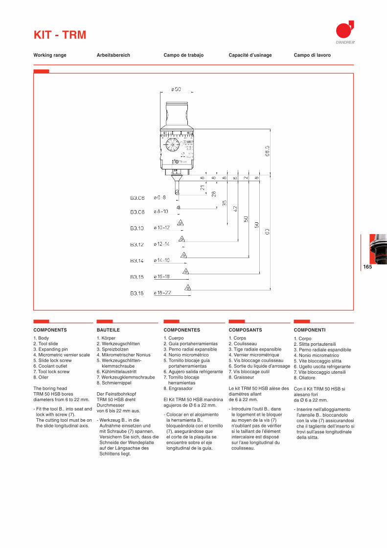
165
KIT - TRM
COMPONENTS
1. Body2. Tool slide3. Expanding pin4. Micrometric vernier scale5. Slide lock screw6. Coolant outlet7. Tool lock screw8. Oiler
The boring head TRM 50 HSB bores diameters from 6 to 22 mm.
- Fit the tool B.. into seat and lock with screw (7). The cutting tool must be on the slide longitudinal axis.
BAUTEILE
1. Körper2. Werkzeugschlitten3. Spreizbolzen4. Mikrometrischer Nonius5. Werkzeugschlitten-
klemmschraube6. Kühlmittelaustritt7. Werkzeugklemmschraube8. Schmiernippel
Der Feinstbohrkopf TRM 50 HSB dreht Durchmesser von 6 bis 22 mm aus.
- Werkzeug B.. in die Aufnahme einsetzen und mit Schraube (7) spannen. Versichern Sie sich, dass die Schneide der Wendeplatte auf der Längsachse des Schlittens liegt.
COMPONENTES
1. Cuerpo2. Guía portaherramientas3. Perno radial expansible4. Nonio micrométrico5. Tornillo blocaje guía
portaherramientas6. Agujero salida refrigerante7. Tornillo blocaje
herramientas8. Engrasador
El Kit TRM 50 HSB mandrina agujeros de Ø 6 a 22 mm.
- Colocar en el alojamiento la herramienta B.. bloqueándola con el tornillo (7), asegurándose que el corte de la plaquita se encuentre sobre el eje longitudinal de la guía.
COMPOSANTS
1. Corps2. Coulisseau3. Tige radiale expansible 4. Vernier micrométrique5. Vis bloccage coulisseau6. Sortie du liquide d’arrosage7. Vis bloccage outil8. Graisseur
Le kit TRM 50 HSB alèse des diamètres allant de 6 à 22 mm.
- Introduire l’outil B.. dans le logement et le bloquer au moyen de la vis (7) n’oubliant pas de vérifier si le taillant de l’élément intercalaire est disposé sur l’axe longitudinal du coulisseau.
COMPONENTI
1. Corpo2. Slitta portautensili3. Perno radiale espandibile4. Nonio micrometrico5. Vite bloccaggio slitta6. Ugello uscita refrigerante7. Vite bloccaggio utensili8. Oliatore
Con il Kit TRM 50 HSB si alesano fori da Ø 6 a 22 mm.
- Inserire nell’alloggiamento l’utensile B.. bloccandolo con la vite (7) assicurandosi che il tagliente dell’inserto si trovi sull’asse longitudinale della slitta.
Arbeitsbereich Campo de trabajo Capacité d’usinage Campo di lavoroWorking range
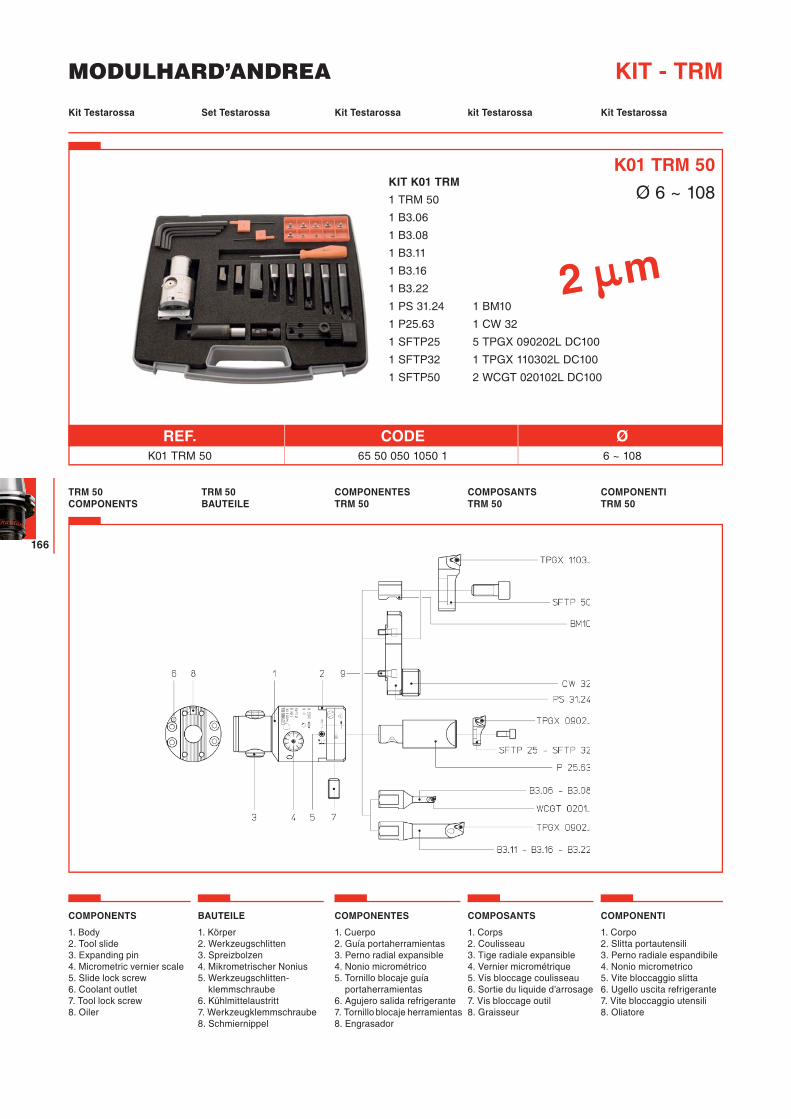
MODULHARD’ANDREA
166
Set Testarossa Kit Testarossa kit Testarossa Kit TestarossaKit Testarossa
KIT - TRM
TRM 50 BAUTEILE
COMPONENTES TRM 50
COMPOSANTS TRM 50
COMPONENTI TRM 50
TRM 50 COMPONENTS
K01 TRM 50
Ø 6 ~ 108
COMPONENTS
1. Body2. Tool slide3. Expanding pin4. Micrometric vernier scale5. Slide lock screw6. Coolant outlet7. Tool lock screw8. Oiler
BAUTEILE
1. Körper2. Werkzeugschlitten3. Spreizbolzen4. Mikrometrischer Nonius5. Werkzeugschlitten-
klemmschraube6. Kühlmittelaustritt7. Werkzeugklemmschraube8. Schmiernippel
COMPONENTES
1. Cuerpo2. Guía portaherramientas3. Perno radial expansible4. Nonio micrométrico5. Tornillo blocaje guía
portaherramientas6. Agujero salida refrigerante7. Tornillo blocaje herramientas8. Engrasador
COMPOSANTS
1. Corps2. Coulisseau3. Tige radiale expansible 4. Vernier micrométrique5. Vis bloccage coulisseau6. Sortie du liquide d’arrosage7. Vis bloccage outil8. Graisseur
COMPONENTI
1. Corpo2. Slitta portautensili3. Perno radiale espandibile4. Nonio micrometrico5. Vite bloccaggio slitta6. Ugello uscita refrigerante7. Vite bloccaggio utensili8. Oliatore
2 m
REF. CODE Ø K01 TRM 50 65 50 050 1050 1 6 ~ 108
KIT K01 TRM
1 TRM 50
1 B3.06
1 B3.08
1 B3.11
1 B3.16
1 B3.22
1 PS 31.24 1 BM10
1 P25.63 1 CW 32
1 SFTP25 5 TPGX 090202L DC100
1 SFTP32 1 TPGX 110302L DC100
1 SFTP50 2 WCGT 020102L DC100

167
KIT - TRM
The boring head TRM 50 bores diameters from 6 to 108 mm.
- For bores from Ø 6 to 30 mm fit the tool B.. into seat and lock with screw (7). The cutting tool must be on the slide longitudinal axis.
- For bores from Ø 28 to 54 mm fit extension P25.63 into seat and lock with screw (7).
- For bores from Ø 54 to 84 mm fit sleeve BM10 into seat. Before tightening the screw (7) make sure that the latter engages the recess provided in sleeve BM10 which shall not project from the tool slide; if so, fit the sleeve overturned into seat. Fit the bit holder SF.. and secure it by the appropriate screw.
- For bores from Ø 80 to 108 mm fit the toolholder PS 31.24 in the slide and secure it by screws (9). Fit the bit holder SF.. on the toolholder and secure it by the screw.
* For a best flexibility of the TRM 50 kit, the working range of the B3.08, B3.11, B3.16, B3.22 tools is different from those suggested and reported on page 184.
Der Feinstbohrkopf TRM 50 dreht Durchmesser von 6 bis 108 mm aus.
- Bei Bohrungen mit Durchmesser von 6 bis 30 mm Werkzeug B.. in die Aufnahme einsetzen und mit Schraube (7) spannen. Versichern Sie sich, dass die Schneide der Wendeplatte auf der Längsachse des Schlittens liegt.
- Bei Bohrungen mit Durchmesser von 28 bis 54 mm Verlängerung P25.63 in die Aufnahme einsetzen und mit Schraube (7) spannen.
- Bei Bohrungen mit Durchmesser von 54 bis 84 mm Buchse BM10 in die Aufnahme einsetzen. Vor Anziehen der Schraube (7) darauf achten, dass sie im Einstich der Buchse BM10 eingreift und dass die Buchse aus dem Werkzeugschlitten nicht herausragt; sonst die Buchse umgekehrt einsetzen.Den Plattenhalter SF.. montieren und mit der passenden Schraube befestigen.
- Für Bohrungen von Ø 80 - 108 mm, Werkzeughalterung PS 31.24 auf dem Schlitten anbringen und mit Schrauben (9) blockieren. Sitz SF auf die Werkzeughalterung montieren und mit den Schrauben befestigen.
* Zur höheren Flexibilität des TRM 50 Sets ist der Arbeitsbereich der Werkzeuge B3.08, B3.11, B3.16, B3.22 anders als der, der auf Seite 184 empfohlen und angegeben ist.
El Kit TRM 50 mandrina agujeros de Ø 6 a 108 mm.
- Para los agujeros de Ø 6 a 30 mm colocar en el alojamiento la herramienta B.. bloqueándola con el tornillo (7), asegurándose que el corte de la plaquita se encuentre sobre el eje longitudinal de la guía.
- Para los agujeros de Ø 28 a 54 mm colocar en el alojamiento la prolongación P25.63 bloqueándola con el tornillo (7).
- Para los agujeros de Ø 54 a 84 mm colocar en el alojamiento el casquillo BM10 bloqueándolo con el tornillo (7), prestando atención a que el casquillo non sobresalga de la guía; en caso contrario, va colocado al revés. Montar el asiento SF.. bloqueándolo con el tornillo apropiado.
- Para los agujeros de 80 a 108 mm. de diámetro, colocar sobre la corredera el porta-herramientas PS 31.24 y bloquearlo con los tornillos (9). Montar el asiento SF en el portaherramientas y bloquearlo con el tornillo.
* Para una mayor flexibilidad del kit TRM 50 el campo de trabajo de las herramientas B3.08, B3.11, B3.16, B3.22 es diferente de lo sugerido y reproducido en la página 184.
Le kit TRM 50 alèse des diamètres allant de 6 à 108 mm.
- Pour des alésages de Ø 6 à 30 mm, introduire l’outil B.. dans le logement et le bloquer au moyen de la vis (7) n’oubliant pas de vérifier si le taillant de l’élément intercalaire est disposé sur l’axe longitudinal du coulisseau.
- Pour des alésages de Ø 28 à 54 mm, introduire la rallonge P 25.63 dans le logement et la bloquer au moyen de la vis (7).
- Pour des alésages de Ø 54 à 84 mm, introduire la douille BM10 dans le logement. Avant de serrer la vis (7) s’assurer que la vis s’engage dans la niche prévue dans la douille BM10 et que celle-ci ne saillit pas du coulisseau, autrement l’introduire renversée. Monter le porte-plaquette SF.. et le bloquer au moyen de la vis appropriée.
- Pour les trous de 80 à 108 mm de diamètre positionner sur le chariot le porteplaquette PS 31.24 en le bloquant avec les vis (9).Installer sur le porteplaquette le logement SF en le bloquant avec la vis.
* Pour une supérieure flexibilité du kit TRM 50 la capacité d’usinage des outils B3.08, B3.11, B3.16, B3.22 est différente de celui suggéré et indiqué à la page 184.
Con il Kit TRM 50 si alesano fori da Ø 6 a 108 mm.
- Per i fori da Ø 6 a 30 mm inserire nell’alloggiamento l’utensile B.. bloccandolo con la vite (7) assicurandosi che il tagliente dell’inserto si trovi sull’asse longitudinale della slitta.
- Per i fori da Ø 28 a 54 mm inserire nell’alloggiamento la prolunga P25.63 bloccandola con la vite (7).
- Per i fori da Ø 54 a 84 mm inserire nell’alloggiamento la bussola BM10. Prima di bloccare la vite (7) assicurarsi che la stessa entri nella nicchia ricavata nella bussola BM10 prestando attenzione che la bussola non sporga dalla slitta altrimenti va inserita capovolta. Montare il seggio SF.. bloccandolo con l’apposita vite.
- Per i fori da Ø 80 a 108 mm inserire nella slitta il portautensile PS 31.24 bloccandolo con le viti (9). Montare sul portautensili il seggio SF.. bloccandolo con la vite.
* Per una maggiore flessibilità del Kit TRM 50 il campo di lavoro degli utensili B3.08, B3.11, B3.16, B3.22 è differente da quello suggerito e riportato a pag. 184 D'Andrea Toolholders.
Arbeitsbereich Campo de trabajo Capacité d’usinage Campo di lavoroWorking range
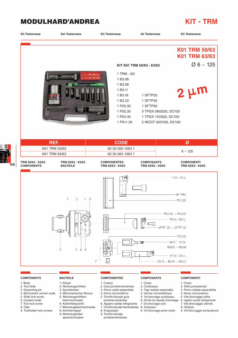
MODULHARD’ANDREA
168
KIT K01 TRM 50/63 - 63/63
1 TRM ../63
1 B3.06
1 B3.08
1 B3.11
1 B3.16 1 SFTP25
1 B3.22 1 SFTP32
1 P20.30 1 SFTP50
1 P02.30 5 TPGX 090202L DC100
1 P03.30 1 TPGX 110302L DC100
1 PS11.30 2 WCGT 020102L DC100
Set Testarossa Kit Testarossa kit Testarossa Kit TestarossaKit Testarossa
KIT - TRM
TRM 50/63 - 63/63 BAUTEILE
COMPONENTES TRM 50/63 - 63/63
COMPOSANTS TRM 50/63 - 63/63
COMPONENTI TRM 50/63 - 63/63
TRM 50/63 - 63/63 COMPONENTS
K01 TRM 50/63K01 TRM 63/63
Ø 6 ~ 125
2 m
REF. CODE Ø K01 TRM 50/63 65 50 050 1063 1
6 ~ 125
K01 TRM 63/63 65 50 063 1063 1
COMPONENTS
1. Body2. Tool slide3. Expanding pin4. Micrometric vernier scale5. Slide lock screw6. Coolant outlet7. Tool lock screw8. Oiler9. Toolholder lock screws
BAUTEILE
1. Körper2. Werkzeugschlitten3. Spreizbolzen4. Mikrometrischer Nonius5. Werkzeugschlitten-
klemmschraube6. Kühlmittelaustritt7. Werkzeugklemmschraube8. Schmiernippel9. Werkzeughalter-
spannschrauben
COMPONENTES 1. Cuerpo2. Guía portaherramientas3. Perno radial expansible4. Nonio micrométrico5. Tornillo blocaje guía
portaherramientas6. Agujero salida refrigerante7. Tornillo blocaje herramientas8. Engrasador9. Tornillo blocaje
portaherramientas
COMPOSANTS
1. Corps2. Coulisseau3. Tige radiale expansible 4. Vernier micrométrique 5. Vis bloccage coulisseau 6. Sortie du liquide d’arrosage7. Vis bloccage outil8. Graisseur9. Vis bloccage porte-outils
COMPONENTI
1. Corpo2. Slitta portautensili3. Perno radiale espandibile4. Nonio micrometrico5. Vite bloccaggio slitta6. Ugello uscita refrigerante7. Vite bloccaggio utensili8. Oliatore9. Viti bloccaggio portautensili
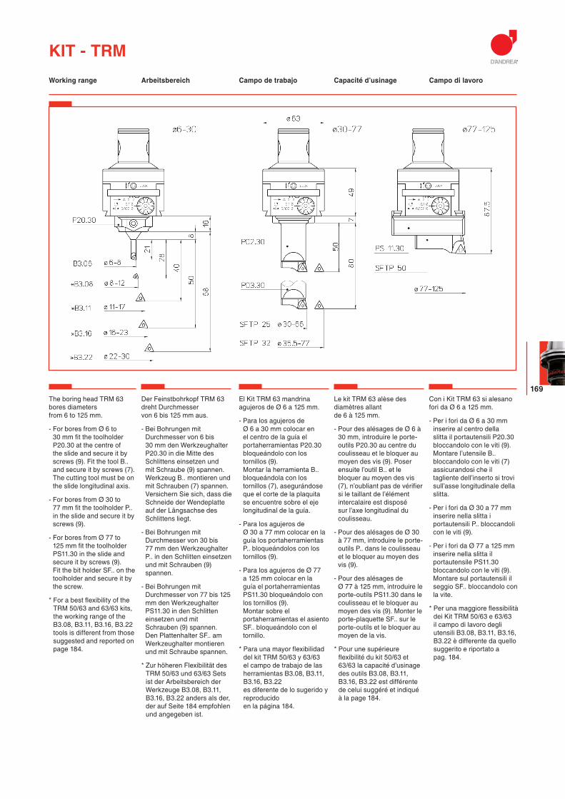
169
KIT - TRM
Arbeitsbereich Campo de trabajo Capacité d’usinage Campo di lavoroWorking range
The boring head TRM 63 bores diameters from 6 to 125 mm.
- For bores from Ø 6 to 30 mm fit the toolholder P20.30 at the centre of the slide and secure it by screws (9). Fit the tool B.. and secure it by screws (7). The cutting tool must be on the slide longitudinal axis.
- For bores from Ø 30 to 77 mm fit the toolholder P.. in the slide and secure it by screws (9).
- For bores from Ø 77 to 125 mm fit the toolholder PS11.30 in the slide and secure it by screws (9). Fit the bit holder SF.. on the toolholder and secure it by the screw.
* For a best flexibility of the TRM 50/63 and 63/63 kits, the working range of the B3.08, B3.11, B3.16, B3.22 tools is different from those suggested and reported on page 184.
Der Feinstbohrkopf TRM 63 dreht Durchmesser von 6 bis 125 mm aus.
- Bei Bohrungen mit Durchmesser von 6 bis 30 mm den Werkzeughalter P20.30 in die Mitte des Schlittens einsetzen und mit Schraube (9) spannen. Werkzeug B.. montieren und mit Schrauben (7) spannen. Versichern Sie sich, dass die Schneide der Wendeplatte auf der Längsachse des Schlittens liegt.
- Bei Bohrungen mit Durchmesser von 30 bis 77 mm den Werkzeughalter P.. in den Schlitten einsetzen und mit Schrauben (9) spannen.
- Bei Bohrungen mit Durchmesser von 77 bis 125 mm den Werkzeughalter PS11.30 in den Schlitten einsetzen und mit Schrauben (9) spannen. Den Plattenhalter SF.. am Werkzeughalter montieren und mit Schraube spannen.
* Zur höheren Flexibilität des TRM 50/63 und 63/63 Sets ist der Arbeitsbereich der Werkzeuge B3.08, B3.11, B3.16, B3.22 anders als der, der auf Seite 184 empfohlen und angegeben ist.
El Kit TRM 63 mandrina agujeros de Ø 6 a 125 mm.
- Para los agujeros de Ø 6 a 30 mm colocar en el centro de la guía el portaherramientas P20.30 bloqueándolo con los tornillos (9).Montar la herramienta B.. bloqueándola con los tornillos (7), asegurándose que el corte de la plaquita se encuentre sobre el eje longitudinal de la guía.
- Para los agujeros de Ø 30 a 77 mm colocar en la guía los portaherramientas P.. bloqueándolos con los tornillos (9).
- Para los agujeros de Ø 77 a 125 mm colocar en la guía el portaherramientas PS11.30 bloqueándolo con los tornillos (9).Montar sobre el portaherramientas el asiento SF.. bloqueándolo con el tornillo.
* Para una mayor flexibilidad del kit TRM 50/63 y 63/63 el campo de trabajo de las herramientas B3.08, B3.11, B3.16, B3.22 es diferente de lo sugerido y reproducido en la página 184.
Le kit TRM 63 alèse des diamètres allant de 6 à 125 mm.
- Pour des alésages de Ø 6 à 30 mm, introduire le porte-outils P20.30 au centre du coulisseau et le bloquer au moyen des vis (9). Poser ensuite l’outil B.. et le bloquer au moyen des vis (7), n’oubliant pas de vérifier si le taillant de l’élément intercalaire est disposé sur l’axe longitudinal du coulisseau.
- Pour des alésages de Ø 30 à 77 mm, introduire le porte-outils P.. dans le coulisseau et le bloquer au moyen des vis (9).
- Pour des alésages de Ø 77 à 125 mm, introduire le porte-outils PS11.30 dans le coulisseau et le bloquer au moyen des vis (9). Monter le porte-plaquette SF.. sur le porte-outils et le bloquer au moyen de la vis.
* Pour une supérieure flexibilité du kit 50/63 et 63/63 la capacité d’usinage des outils B3.08, B3.11, B3.16, B3.22 est différente de celui suggéré et indiqué à la page 184.
Con i Kit TRM 63 si alesano fori da Ø 6 a 125 mm.
- Per i fori da Ø 6 a 30 mm inserire al centro della slitta il portautensili P20.30 bloccandolo con le viti (9). Montare l’utensile B.. bloccandolo con le viti (7) assicurandosi che il tagliente dell’inserto si trovi sull’asse longitudinale della slitta.
- Per i fori da Ø 30 a 77 mm inserire nella slitta i portautensili P.. bloccandoli con le viti (9).
- Per i fori da Ø 77 a 125 mm inserire nella slitta il portautensile PS11.30 bloccandolo con le viti (9). Montare sul portautensili il seggio SF.. bloccandolo con la vite.
* Per una maggiore flessibilità dei Kit TRM 50/63 e 63/63 il campo di lavoro degli utensili B3.08, B3.11, B3.16, B3.22 è differente da quello suggerito e riportato a pag. 184.
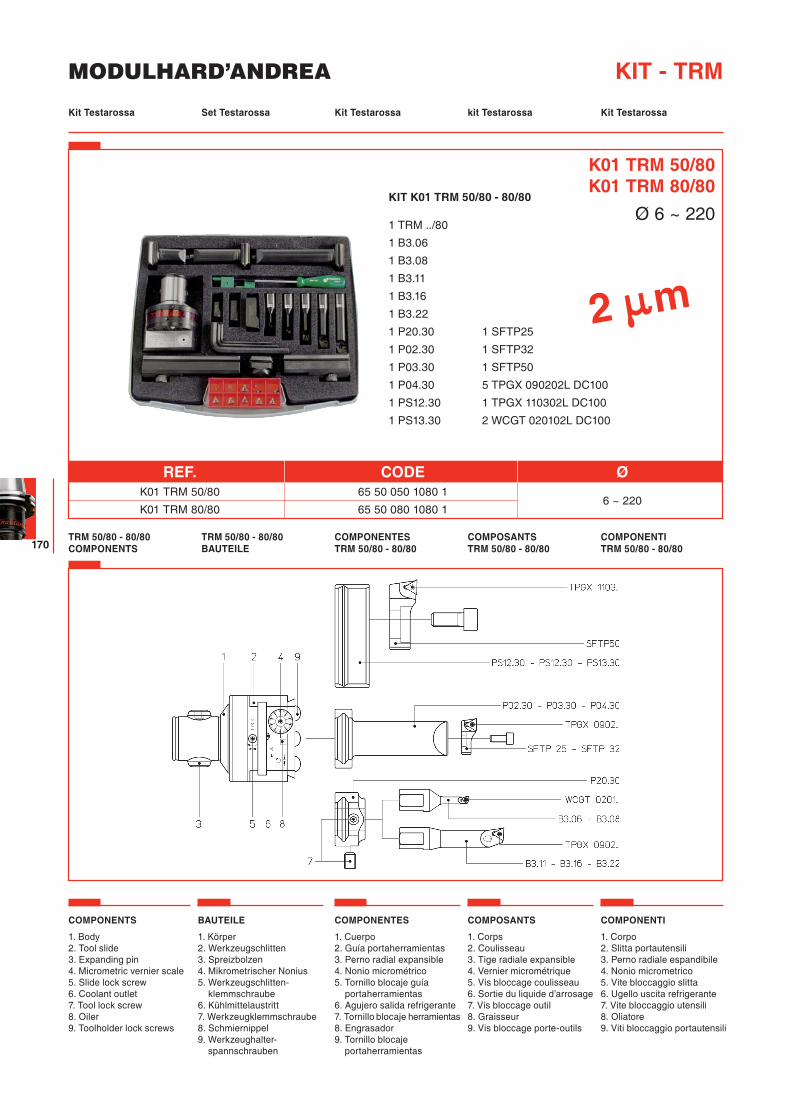
MODULHARD’ANDREA
170
Set Testarossa Kit Testarossa kit Testarossa Kit TestarossaKit Testarossa
KIT - TRM
TRM 50/80 - 80/80 BAUTEILE
COMPONENTES TRM 50/80 - 80/80
COMPOSANTS TRM 50/80 - 80/80
COMPONENTI TRM 50/80 - 80/80
TRM 50/80 - 80/80 COMPONENTS
K01 TRM 50/80K01 TRM 80/80
Ø 6 ~ 220
2 m
REF. CODE Ø K01 TRM 50/80 65 50 050 1080 1
6 ~ 220
K01 TRM 80/80 65 50 080 1080 1
COMPONENTS
1. Body2. Tool slide3. Expanding pin4. Micrometric vernier scale5. Slide lock screw6. Coolant outlet7. Tool lock screw8. Oiler9. Toolholder lock screws
BAUTEILE
1. Körper2. Werkzeugschlitten3. Spreizbolzen4. Mikrometrischer Nonius5. Werkzeugschlitten-
klemmschraube6. Kühlmittelaustritt7. Werkzeugklemmschraube8. Schmiernippel9. Werkzeughalter-
spannschrauben
COMPONENTES 1. Cuerpo2. Guía portaherramientas3. Perno radial expansible4. Nonio micrométrico5. Tornillo blocaje guía
portaherramientas6. Agujero salida refrigerante7. Tornillo blocaje herramientas8. Engrasador9. Tornillo blocaje
portaherramientas
COMPOSANTS
1. Corps2. Coulisseau3. Tige radiale expansible 4. Vernier micrométrique 5. Vis bloccage coulisseau 6. Sortie du liquide d’arrosage7. Vis bloccage outil8. Graisseur9. Vis bloccage porte-outils
COMPONENTI
1. Corpo2. Slitta portautensili3. Perno radiale espandibile4. Nonio micrometrico5. Vite bloccaggio slitta6. Ugello uscita refrigerante7. Vite bloccaggio utensili8. Oliatore9. Viti bloccaggio portautensili
KIT K01 TRM 50/80 - 80/80
1 TRM ../80
1 B3.06
1 B3.08
1 B3.11
1 B3.16
1 B3.22
1 P20.30 1 SFTP25
1 P02.30 1 SFTP32
1 P03.30 1 SFTP50
1 P04.30 5 TPGX 090202L DC100
1 PS12.30 1 TPGX 110302L DC100
1 PS13.30 2 WCGT 020102L DC100
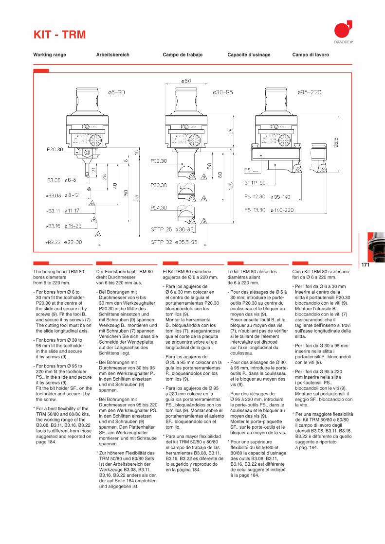
171
KIT - TRM
Arbeitsbereich Campo de trabajo Capacité d’usinage Campo di lavoroWorking range
The boring head TRM 80 bores diameters from 6 to 220 mm.
- For bores from Ø 6 to 30 mm fit the toolholder P20.30 at the centre of the slide and secure it by screws (9). Fit the tool B.. and secure it by screws (7). The cutting tool must be on the slide longitudinal axis.
- For bores from Ø 30 to 95 mm fit the toolholder in the slide and secure it by screws (9).
- For bores from Ø 95 to 220 mm fit the toolholder PS.. in the slide and secure it by screws (9). Fit the bit holder SF.. on the toolholder and secure it by the screw.
* For a best flexibility of the TRM 50/80 and 80/80 kits, the working range of the B3.08, B3.11, B3.16, B3.22 tools is different from those suggested and reported on page 184.
Der Feinstbohrkopf TRM 80 dreht Durchmesser von 6 bis 220 mm aus.
- Bei Bohrungen mit Durchmesser von 6 bis 30 mm den Werkzeughalter P20.30 in die Mitte des Schlittens einsetzen und mit Schrauben (9) spannen. Werkzeug B.. montieren und mit Schrauben (7) spannen. Versichern Sie sich, dass die Schneide der Wendeplatte auf der Längsachse des Schlittens liegt.
- Bei Bohrungen mit Durchmesser von 30 bis 95 mm den Werkzeughalter P.. in den Schlitten einsetzen und mit Schrauben (9) spannen.
- Bei Bohrungen mit Durchmesser von 95 bis 220 mm den Werkzeughalter PS.. in den Schlitten einsetzen und mit Schrauben (9) spannen. Den Plattenhalter SF.. am Werkzeughalter montieren und mit Schraube spannen.
* Zur höheren Flexibilität des TRM 50/80 und 80/80 Sets ist der Arbeitsbereich der Werkzeuge B3.08, B3.11, B3.16, B3.22 anders als der, der auf Seite 184 empfohlen und angegeben ist.
El Kit TRM 80 mandrina agujeros de Ø 6 a 220 mm.
- Para los agujeros de Ø 6 a 30 mm colocar en el centro de la guía el portaherramientas P20.30 bloqueándolo con los tornillos (9).Montar la herramienta B.. bloqueándola con los tornillos (7), asegurándose que el corte de la plaquita se encuentre sobre el eje longitudinal de la guía.
- Para los agujeros de Ø 30 a 95 mm colocar en la guía los portaherramientas P.. bloqueándolos con los tornillos (9).
- Para los agujeros de Ø 95 a 220 mm colocar en la guía los portaherramientas PS.. bloqueándolos con los tornillos (9). Montar sobre el portaherramientas el asiento SF.. bloqueándolo con el tornillo.
* Para una mayor flexibilidad del kit TRM 50/80 y 80/80 el campo de trabajo de las herramientas B3.08, B3.11, B3.16, B3.22 es diferente de lo sugerido y reproducido en la página 184.
Le kit TRM 80 alèse des diamètres allant de 6 à 220 mm.
- Pour des alésages de Ø 6 à 30 mm, introduire le porte-outils P20.30 au centre du coulisseau et le bloquer au moyen des vis (9). Poser ensuite l’outil B..et le bloquer au moyen des vis (7), n’oubliant pas de vérifier si le taillant de l’élément intercalaire est disposé sur l’axe longitudinal du coulisseau.
- Pour des alésages de Ø 30 à 95 mm, introduire le porte-outils P.. dans le coulisseau et le bloquer au moyen des vis (9).
- Pour des alésages de Ø 95 à 220 mm, introduire le porte-outils PS.. dans le coulisseau et le bloquer au moyen des vis (9). Monter le porte-plaquette SF.. sur le porte-outils et le bloquer au moyen de la vis.
* Pour une supérieure flexibilité du kit 50/80 et 80/80 la capacité d’usinage des outils B3.08, B3.11, B3.16, B3.22 est différente de celui suggéré et indiqué à la page 184.
Con i Kit TRM 80 si alesano fori da Ø 6 a 220 mm.
- Per i fori da Ø 6 a 30 mm inserire al centro della slitta il portautensili P20.30 bloccandolo con le viti (9). Montare l’utensile B.. bloccandolo con le viti (7) assicurandosi che il tagliente dell’inserto si trovi sull’asse longitudinale della slitta.
- Per i fori da Ø 30 a 95 mm inserire nella slitta i portautensili P.. bloccandoli con le viti (9).
- Per i fori da Ø 95 a 220 mm inserire nella slitta i portautensili PS.. bloccandoli con le viti (9). Montare sul portautensili il seggio SF.. bloccandolo con la vite.
* Per una maggiore flessibilità dei Kit TRM 50/80 e 80/80 il campo di lavoro degli utensili B3.08, B3.11, B3.16, B3.22 è differente da quello suggerito e riportato a pag. 184.
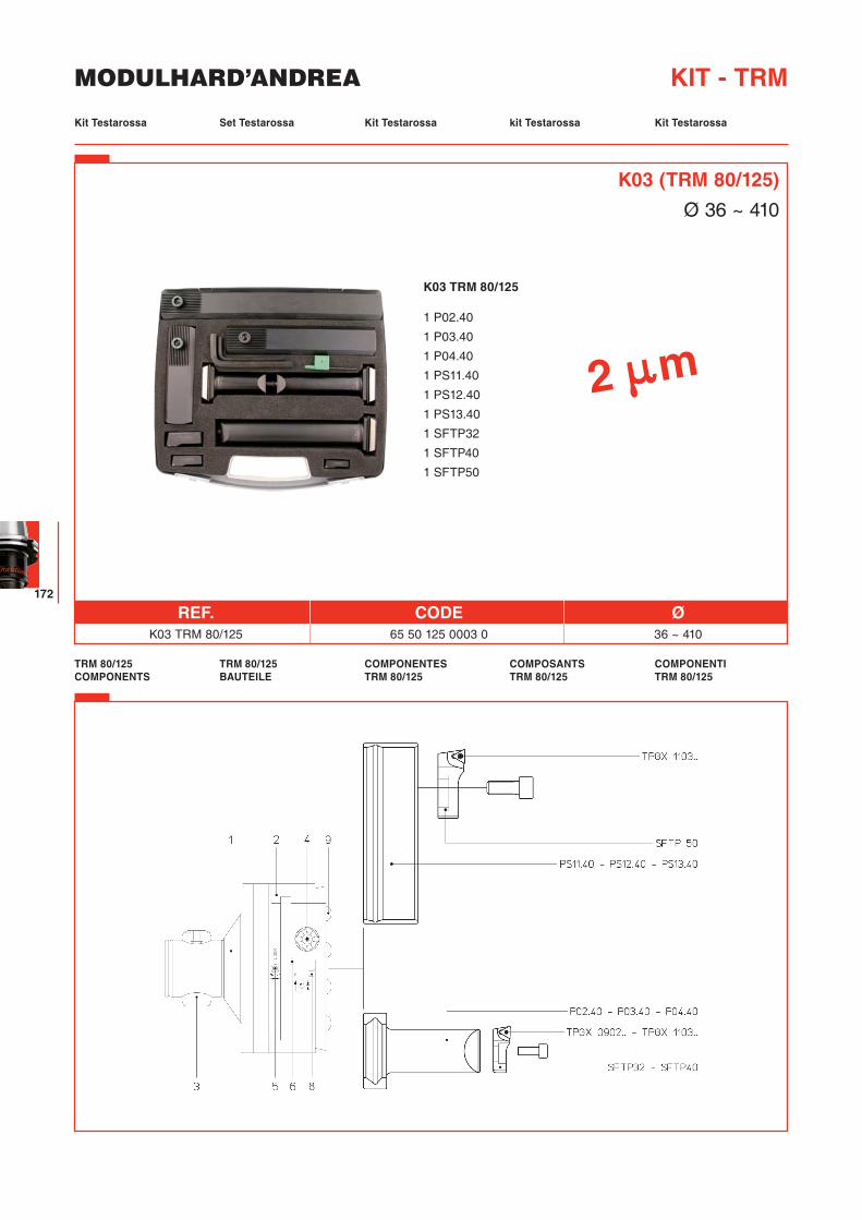
MODULHARD’ANDREA
172
Set Testarossa Kit Testarossa kit Testarossa Kit TestarossaKit Testarossa
KIT - TRM
TRM 80/125 BAUTEILE
COMPONENTES TRM 80/125
COMPOSANTS TRM 80/125
COMPONENTI TRM 80/125
TRM 80/125 COMPONENTS
K03 (TRM 80/125)
Ø 36 ~ 410
K03 TRM 80/125
1 P02.40
1 P03.40
1 P04.40
1 PS11.40
1 PS12.40
1 PS13.40
1 SFTP32
1 SFTP40
1 SFTP50
2 m
REF. CODE Ø K03 TRM 80/125 65 50 125 0003 0 36 ~ 410
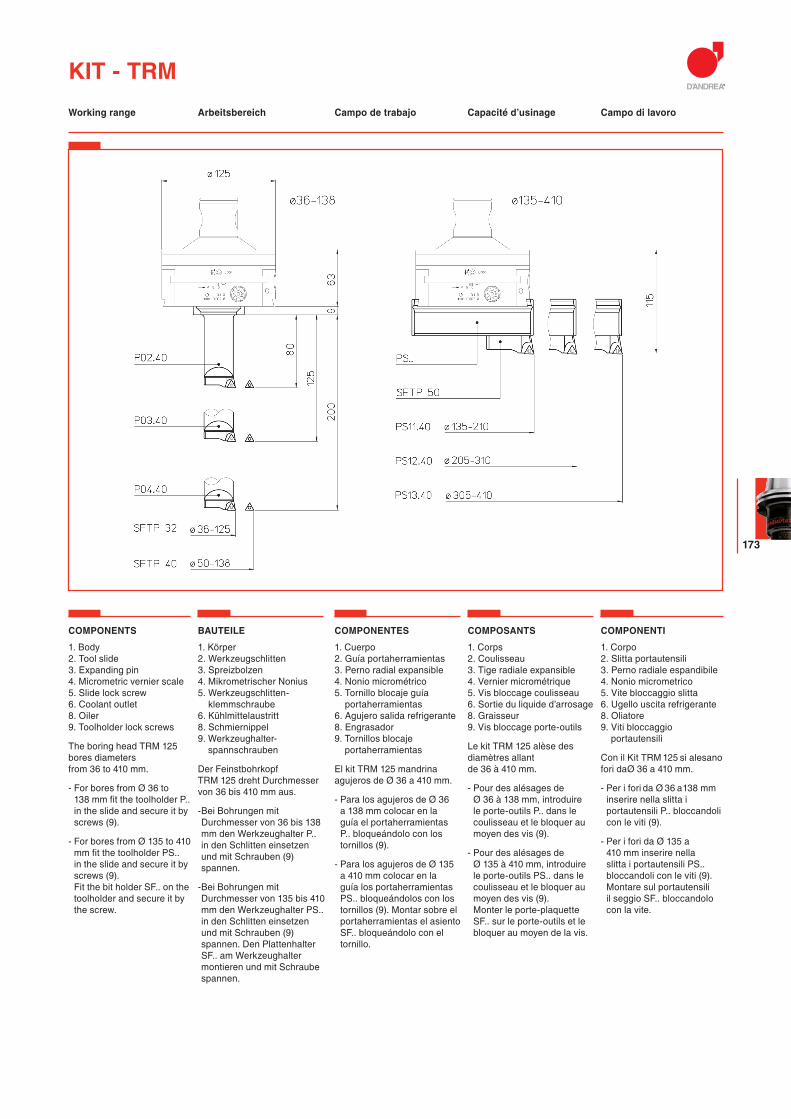
173
KIT - TRM
Arbeitsbereich Campo de trabajo Capacité d’usinage Campo di lavoroWorking range
COMPONENTS
1. Body2. Tool slide3. Expanding pin4. Micrometric vernier scale5. Slide lock screw6. Coolant outlet8. Oiler9. Toolholder lock screws
The boring head TRM 125 bores diameters from 36 to 410 mm.
- For bores from Ø 36 to 138 mm fit the toolholder P.. in the slide and secure it by screws (9).
- For bores from Ø 135 to 410 mm fit the toolholder PS.. in the slide and secure it by screws (9). Fit the bit holder SF.. on the toolholder and secure it by the screw.
BAUTEILE
1. Körper2. Werkzeugschlitten3. Spreizbolzen4. Mikrometrischer Nonius5. Werkzeugschlitten-
klemmschraube6. Kühlmittelaustritt8. Schmiernippel9. Werkzeughalter-
spannschrauben
Der Feinstbohrkopf TRM 125 dreht Durchmesser von 36 bis 410 mm aus.
- Bei Bohrungen mit Durchmesser von 36 bis 138 mm den Werkzeughalter P.. in den Schlitten einsetzen und mit Schrauben (9) spannen.
- Bei Bohrungen mit Durchmesser von 135 bis 410 mm den Werkzeughalter PS.. in den Schlitten einsetzen und mit Schrauben (9) spannen. Den Plattenhalter SF.. am Werkzeughalter montieren und mit Schraube spannen.
COMPONENTES
1. Cuerpo 2. Guía portaherramientas3. Perno radial expansible4. Nonio micrométrico5. Tornillo blocaje guía
portaherramientas6. Agujero salida refrigerante8. Engrasador9. Tornillos blocaje
portaherramientas
El kit TRM 125 mandrina agujeros de Ø 36 a 410 mm.
- Para los agujeros de Ø 36 a 138 mm colocar en la guía el portaherramientas P.. bloqueándolo con los tornillos (9).
- Para los agujeros de Ø 135 a 410 mm colocar en la guía los portaherramientas PS.. bloqueándolos con los tornillos (9). Montar sobre el portaherramientas el asiento SF.. bloqueándolo con el tornillo.
COMPOSANTS
1. Corps2. Coulisseau3. Tige radiale expansible 4. Vernier micrométrique 5. Vis bloccage coulisseau 6. Sortie du liquide d’arrosage8. Graisseur9. Vis bloccage porte-outils
Le kit TRM 125 alèse des diamètres allant de 36 à 410 mm.
- Pour des alésages de Ø 36 à 138 mm, introduire le porte-outils P.. dans le coulisseau et le bloquer au moyen des vis (9).
- Pour des alésages de Ø 135 à 410 mm, introduire le porte-outils PS.. dans le coulisseau et le bloquer au moyen des vis (9).Monter le porte-plaquette SF.. sur le porte-outils et le bloquer au moyen de la vis.
COMPONENTI
1. Corpo2. Slitta portautensili3. Perno radiale espandibile4. Nonio micrometrico5. Vite bloccaggio slitta6. Ugello uscita refrigerante8. Oliatore9. Viti bloccaggio
portautensili
Con il Kit TRM 125 si alesano fori daØ 36 a 410 mm.
- Per i fori da Ø 36 a 138 mm inserire nella slitta i portautensili P.. bloccandoli con le viti (9).
- Per i fori da Ø 135 a 410 mm inserire nella slitta i portautensili PS.. bloccandoli con le viti (9). Montare sul portautensili il seggio SF.. bloccandolo con la vite.
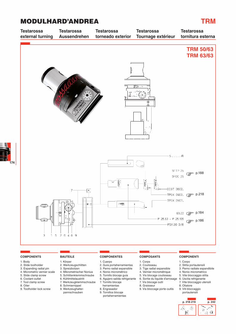
MODULHARD’ANDREA
174
COMPONENTS
1. Body2. Slide toolholder3. Expanding radial pin4. Micrometric vernier scale5. Slide clamp screw6. Coolant outlet7. Tool clamp screw8. Oiler 9. Toolholder lock screw
BAUTEILE
1. Körper2. Werkzeugschlitten3. Spreizbolzen4. Mikrometrischer Nonius5. Schlittenklemmschraube6. Kühlmittelaustritt7. Werkzeugklemmschraube8. Schmiernippel9. Werkzeughalter-
pannschrauben
COMPONENTES
1. Cuerpo2. Guía portaherramientas3. Perno radial expansible4. Nonio micrométrico5. Tornillo blocaje guía6. Agujero salida refrigerante7. Tornillo blocaje
herramientas8. Engrasador9. Tornillos blocaje
portaherramientas
COMPOSANTS
1. Corps 2. Coulisseau 3. Tige radial expansible4. Vernier micrométrique5. Vis blocage coulisseau6. Sortie du liquide d’arrosage7. Vis blocage outil8. Graisseur9. Vis bloccage porte-outils
COMPONENTI
1. Corpo 2. Slitta portautensili3. Perno radiale espandibile4. Nonio micrometrico5. Vite bloccaggio slitta6. Uscita refrigerante7. Vite bloccaggio utensili8. Oliatore9. Viti bloccaggio
portautensili
TRM
TRM 50/63TRM 63/63
p.218�
p.184�
p.188�
p.186�
p. 218-219 p. 242
TestarossaAussendrehen
Testarossatorneado exterior
TestarossaTournage extérieur
Testarossa tornitura esterna
Testarossa external turning
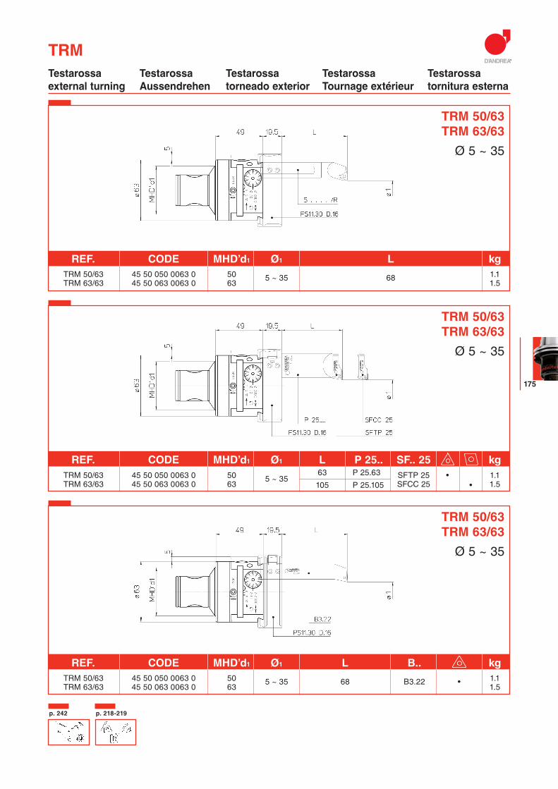
175
TRM
TRM 50/63TRM 63/63
Ø 5 ~ 35
TRM 50/63TRM 63/63
Ø 5 ~ 35
REF. CODE MHD’d1 Ø1 L kg TRM 50/63 45 50 050 0063 0 50
5 ~ 35 68 1.1
TRM 63/63 45 50 063 0063 0 63 1.5
TRM 50/63TRM 63/63
Ø 5 ~ 35
REF. CODE MHD’d1 Ø1 L B.. kg kg TRM 50/63 45 50 050 0063 0 50
5 ~ 35 68
B3.22
• 1.1
TRM 63/63 45 50 063 0063 0 63 1.5
p. 218-219p. 242
TestarossaAussendrehen
Testarossatorneado exterior
TestarossaTournage extérieur
Testarossa tornitura esterna
Testarossa external turning
REF. CODE MHD’d1 Ø1 L P 25.. SF.. 25 kg TRM 50/63 45 50 050 0063 0 50
5 ~ 35 63 P 25.63 SFTP 25 •
1.1
TRM 63/63 45 50 063 0063 0 63 105 P 25.105 SFCC 25 • 1.5
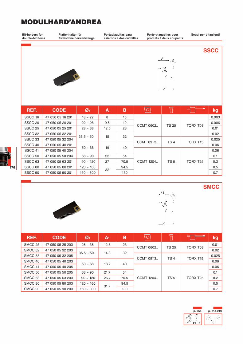
MODULHARD’ANDREA
176
Plattenhalter für Zweischneiderwerkzeuge
Portaplaquitas para asientos a dos cuchillas
Porte-plaquettes pour produits à deux coupants
Seggi per bitaglientiBit-holders for double-bit items
SSCC
SMCC
REF. CODE Ø1 A1 B kg SMCC 25 47 050 05 25 203 28 ~ 38 12.3 23
CCMT 0602.. TS 25 TORX T08 0.01
SMCC 32 47 050 05 32 203 35.5 ~ 50 14.8 32
0.02
SMCC 33 47 050 05 32 205 CCMT 09T3.. TS 4 TORX T15
0.025
SMCC 40 47 050 05 40 203 50 ~ 68 18.7 40
0.06
SMCC 41 47 050 05 40 205 0.06
SMCC 50 47 050 05 50 205 68 ~ 90 21.7 54 0.1
SMCC 63 47 050 05 63 203 90 ~ 120 26.7 70.5 CCMT 1204.. TS 5 TORX T25 0.2
SMCC 80 47 050 05 80 203 120 ~ 160 31.7
94.5 0.5
SMCC 90 47 050 05 90 203 160 ~ 800 130 0.7
p. 258 p. 218-219
REF. CODE Ø1 A B kg SSCC 16 47 050 05 16 201 18 ~ 22 8 15 0.003
SSCC 20 47 050 05 20 201 22 ~ 28 9.5 19 CCMT 0602.. TS 25 TORX T08
0.006
SSCC 25 47 050 05 25 201 28 ~ 38 12.5 23 0.01
SSCC 32 47 050 05 32 201 35.5 ~ 50 15 32
0.02
SSCC 33 47 050 05 32 204 CCMT 09T3.. TS 4 TORX T15
0.025
SSCC 40 47 050 05 40 201 50 ~ 68 19 40
0.06
SSCC 41 47 050 05 40 204 0.06
SSCC 50 47 050 05 50 204 68 ~ 90 22 54 0.1
SSCC 63 47 050 05 63 201 90 ~ 120 27 70.5 CCMT 1204.. TS 5 TORX T25 0.2
SSCC 80 47 050 05 80 201 120 ~ 160 32
94.5 0.5
SSCC 90 47 050 05 90 201 160 ~ 800 130 0.7
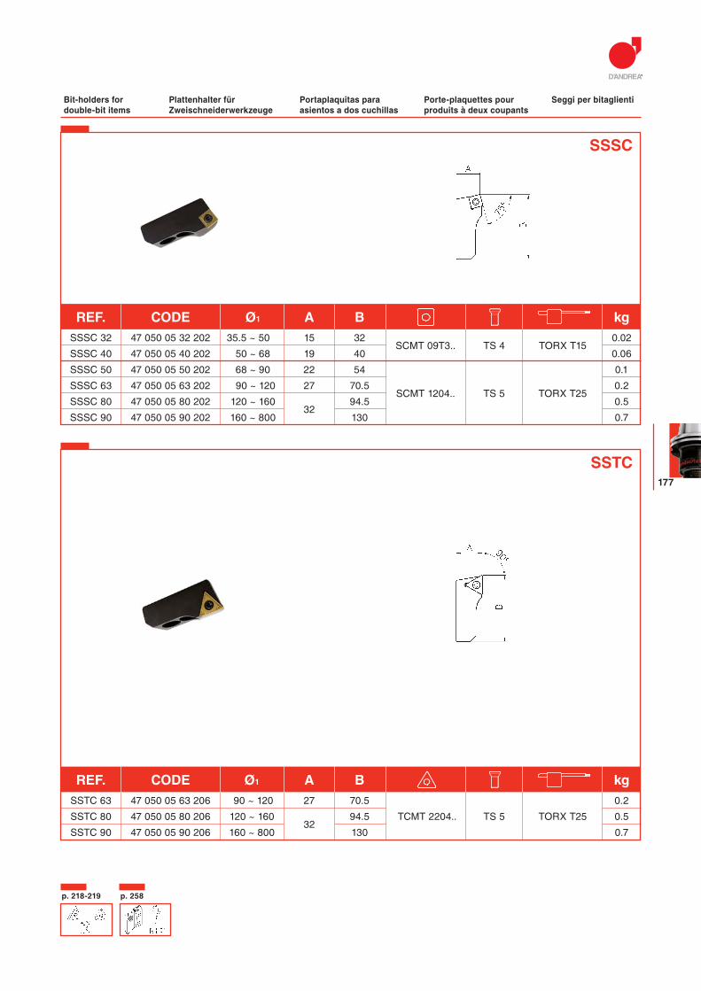
177
SSSC
Plattenhalter für Zweischneiderwerkzeuge
Portaplaquitas para asientos a dos cuchillas
Porte-plaquettes pour produits à deux coupants
Seggi per bitaglientiBit-holders for double-bit items
SSTC
REF. CODE Ø1 A B kg SSSC 32 47 050 05 32 202 35.5 ~ 50 15 32
SCMT 09T3.. TS 4 TORX T15 0.02
SSSC 40 47 050 05 40 202 50 ~ 68 19 40 0.06
SSSC 50 47 050 05 50 202 68 ~ 90 22 54 0.1
SSSC 63 47 050 05 63 202 90 ~ 120 27 70.5 SCMT 1204.. TS 5 TORX T25
0.2
SSSC 80 47 050 05 80 202 120 ~ 160 32
94.5 0.5
SSSC 90 47 050 05 90 202 160 ~ 800 130 0.7
REF. CODE Ø1 A B kg SSTC 63 47 050 05 63 206 90 ~ 120 27 70.5 0.2
SSTC 80 47 050 05 80 206 120 ~ 160 32
94.5 TCMT 2204.. TS 5 TORX T25 0.5
SSTC 90 47 050 05 90 206 160 ~ 800 130 0.7
p. 218-219 p. 258
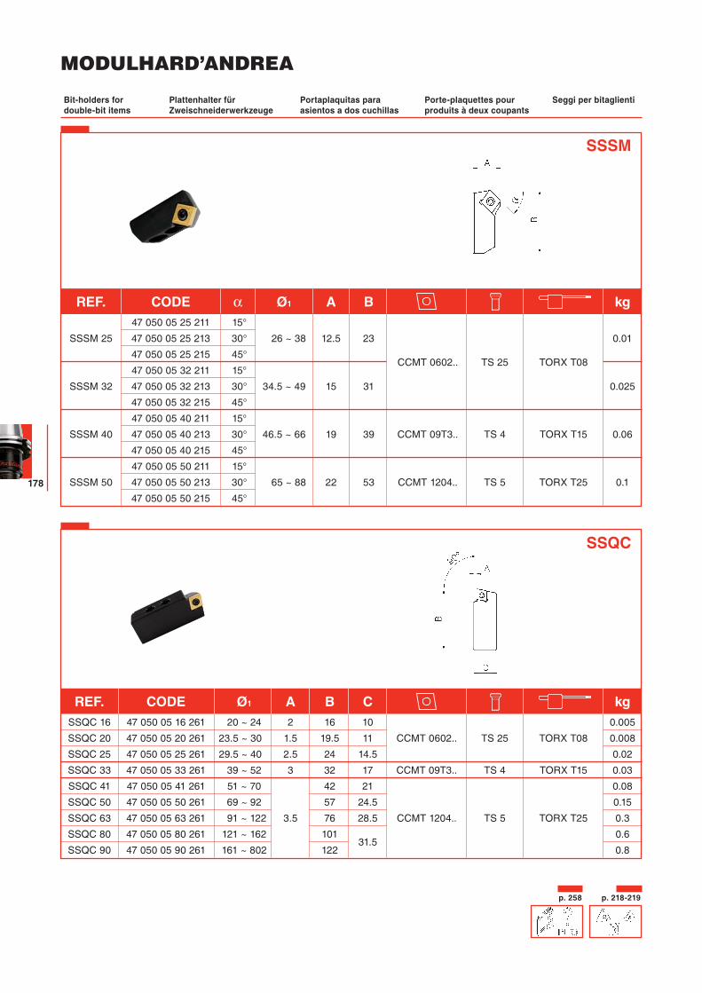
MODULHARD’ANDREA
178
Plattenhalter für Zweischneiderwerkzeuge
Portaplaquitas para asientos a dos cuchillas
Porte-plaquettes pour produits à deux coupants
Seggi per bitaglientiBit-holders for double-bit items
SSSM
SSQC
REF. CODE α Ø1 A B kg
47 050 05 25 211 15°
SSSM 25 47 050 05 25 213 30° 26 ~ 38 12.5 23 0.01
47 050 05 25 215 45° CCMT 0602.. TS 25 TORX T08
47 050 05 32 211 15°
SSSM 32 47 050 05 32 213 30° 34.5 ~ 49 15 31 0.025
47 050 05 32 215 45°
47 050 05 40 211 15°
SSSM 40 47 050 05 40 213 30° 46.5 ~ 66 19 39 CCMT 09T3.. TS 4 TORX T15 0.06
47 050 05 40 215 45°
47 050 05 50 211 15°
SSSM 50 47 050 05 50 213 30° 65 ~ 88 22 53 CCMT 1204.. TS 5 TORX T25 0.1
47 050 05 50 215 45°
REF. CODE Ø1 A B C kg
SSQC 16 47 050 05 16 261 20 ~ 24 2 16 10 0.005
SSQC 20 47 050 05 20 261 23.5 ~ 30 1.5 19.5 11 CCMT 0602.. TS 25 TORX T08 0.008
SSQC 25 47 050 05 25 261 29.5 ~ 40 2.5 24 14.5 0.02
SSQC 33 47 050 05 33 261 39 ~ 52 3 32 17 CCMT 09T3.. TS 4 TORX T15 0.03
SSQC 41 47 050 05 41 261 51 ~ 70 42 21 0.08
SSQC 50 47 050 05 50 261 69 ~ 92 57 24.5 0.15
SSQC 63 47 050 05 63 261 91 ~ 122 3.5 76 28.5 CCMT 1204.. TS 5 TORX T25 0.3
SSQC 80 47 050 05 80 261 121 ~ 162 101 31.5
0.6
SSQC 90 47 050 05 90 261 161 ~ 802 122 0.8
p. 258 p. 218-219
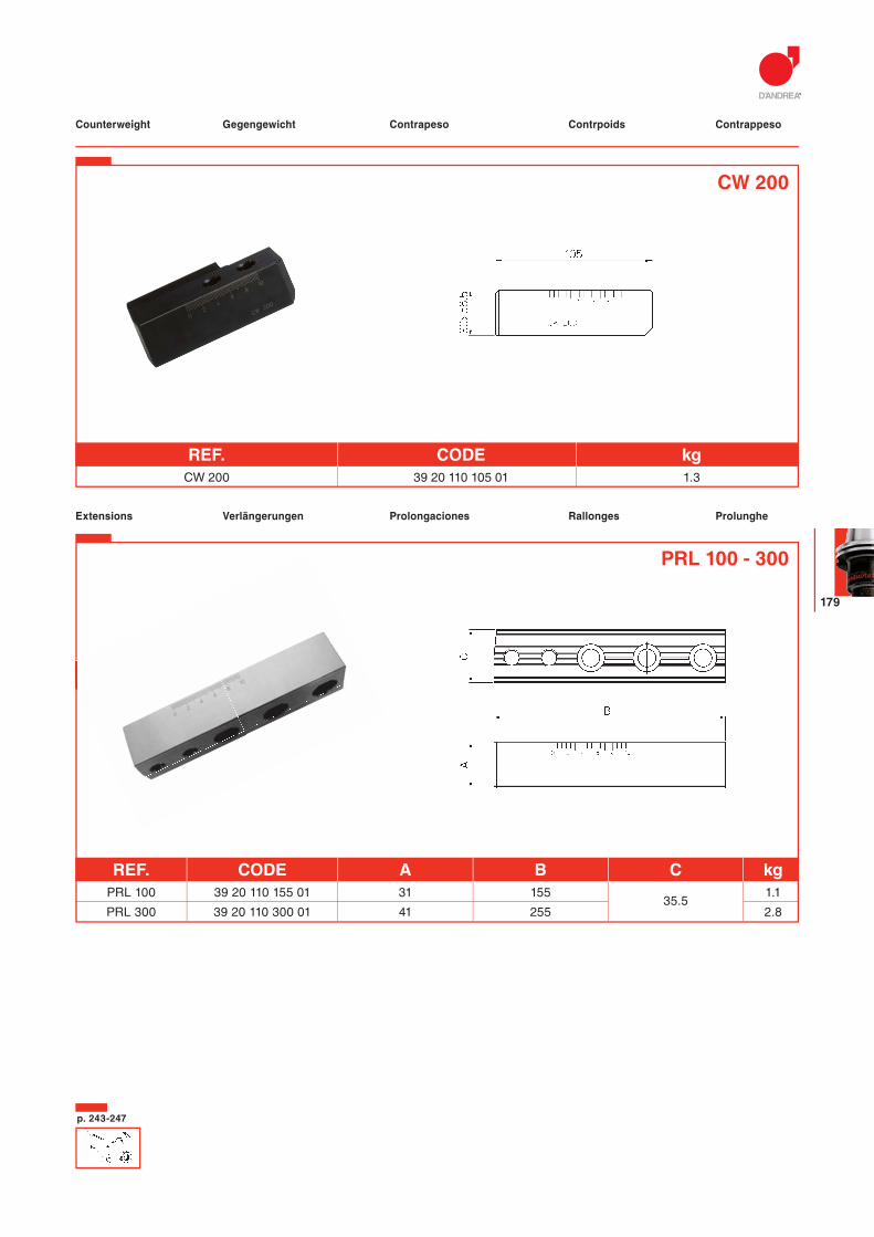
179
PRL 100 - 300
REF. CODE kg CW 200 39 20 110 105 01 1.3
CW 200
Gegengewicht Contrapeso Contrpoids ContrappesoCounterweight
Verlängerungen Prolongaciones Rallonges ProlungheExtensions
REF. CODE A B C kg PRL 100 39 20 110 155 01 31 155 1.1
PRL 300 39 20 110 300 01 41 255 35.5
2.8
p. 243-247
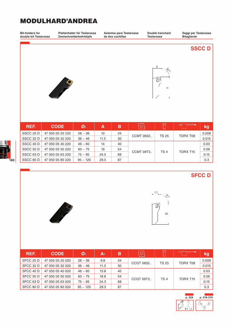
MODULHARD’ANDREA
180
Plattenhalter für Testarossa Zweischneiderbohrköpfe
Asientos para Testarossa de dos cuchillas
Double tranchant Testarossa
Seggi per Testarossa Bitagliente
Bit-holders for double-bit Testarossa
SFCC D
SSCC D
REF. CODE Ø1 A B kg SSCC 25 D 47 050 05 25 220 28 ~ 36 10 24
CCMT 0602.. TS 25 TORX T08 0.008
SSCC 32 D 47 050 05 32 220 36 ~ 46 11.5 30 0.015
SSCC 40 D 47 050 05 40 220 46 ~ 60 14 40 0.03
SSCC 50 D 47 050 05 50 220 60 ~ 75 19 54 CCMT 09T3.. TS 4 TORX T15
0.06
SSCC 63 D 47 050 05 63 220 75 ~ 95 24.5 68 0.15
SSCC 80 D 47 050 05 80 220 95 ~ 120 29.5 87 0.3
REF. CODE Ø1 A1 B kg SFCC 25 D 47 050 05 25 020 28 ~ 36 9.8 24
CCGT 0602.. TS 25 TORX T08 0.008
SFCC 32 D 47 050 05 32 020 36 ~ 46 11.3 30 0.015
SFCC 40 D 47 050 05 40 020 46 ~ 60 13.8 40 0.03
SFCC 50 D 47 050 05 50 020 60 ~ 75 18.8 54 CCGT 09T3.. TS 4 TORX T15
0.06
SFCC 63 D 47 050 05 63 020 75 ~ 95 24.3 68 0.15
SFCC 80 D 47 050 05 80 020 95 ~ 120 29.3 87 0.3
p. 259 p. 218-219
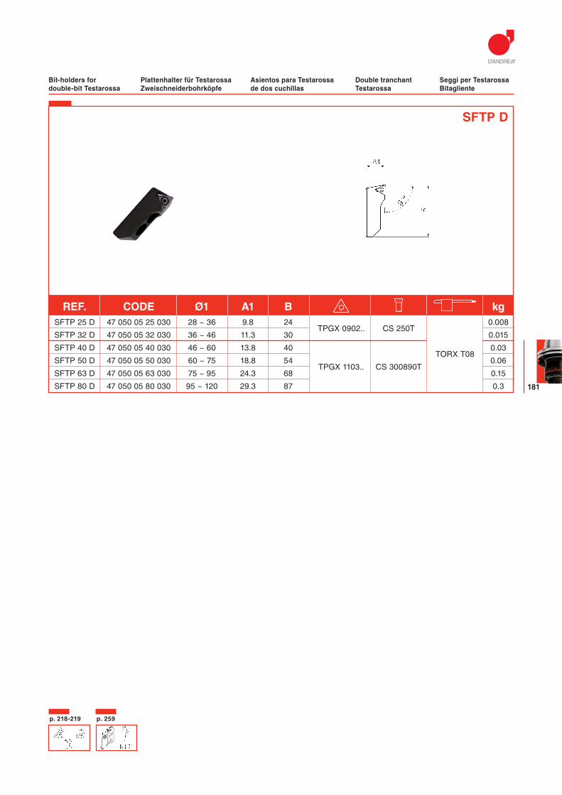
181
SFTP D
REF. CODE Ø1 A1 B kg SFTP 25 D 47 050 05 25 030 28 ~ 36 9.8 24
TPGX 0902.. CS 250T 0.008
SFTP 32 D 47 050 05 32 030 36 ~ 46 11.3 30 0.015
SFTP 40 D 47 050 05 40 030 46 ~ 60 13.8 40 TORX T08
0.03
SFTP 50 D 47 050 05 50 030 60 ~ 75 18.8 54 TPGX 1103.. CS 300890T
0.06
SFTP 63 D 47 050 05 63 030 75 ~ 95 24.3 68 0.15
SFTP 80 D 47 050 05 80 030 95 ~ 120 29.3 87 0.3
Plattenhalter für Testarossa Zweischneiderbohrköpfe
Asientos para Testarossa de dos cuchillas
Double tranchant Testarossa
Seggi per Testarossa Bitagliente
Bit-holders for double-bit Testarossa
p. 218-219 p. 259
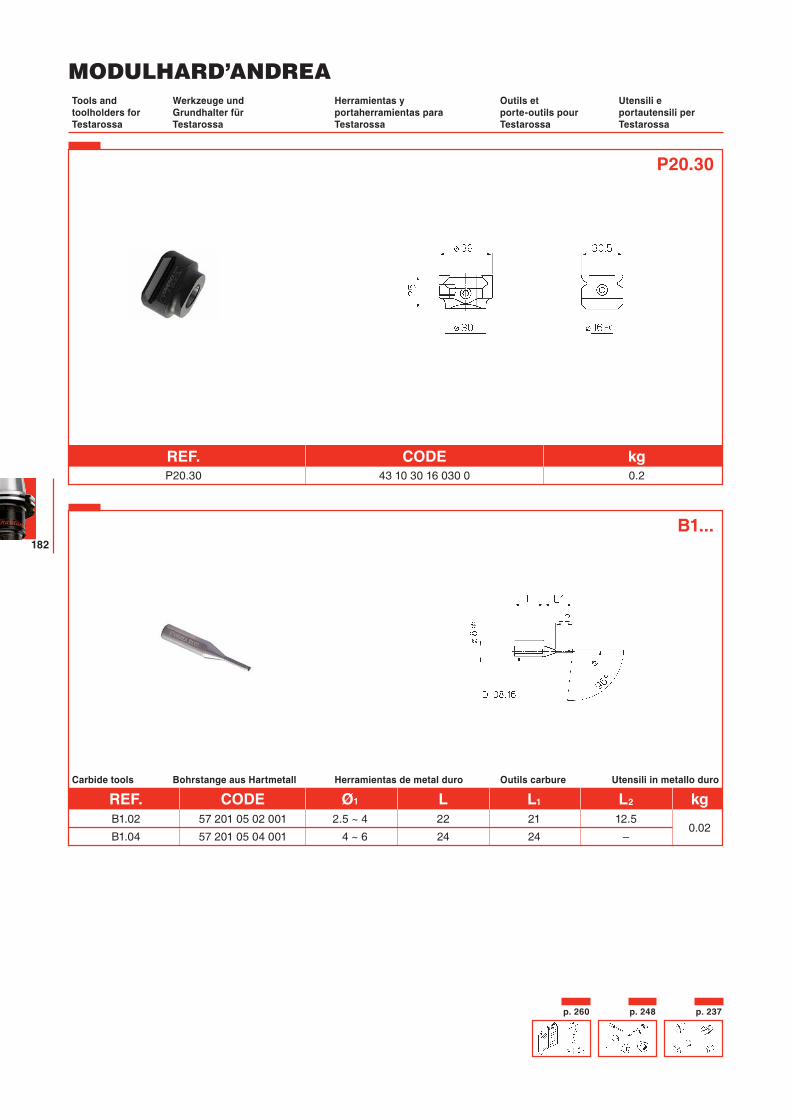
MODULHARD’ANDREA
182
P20.30
REF. CODE kg P20.30 43 10 30 16 030 0 0.2
p. 260 p. 248 p. 237
Bohrstange aus Hartmetall Herramientas de metal duro Outils carbure Utensili in metallo duroCarbide tools
B1...
Werkzeuge und Grundhalter für Testarossa
Herramientas y portaherramientas para Testarossa
Outils et porte-outils pour Testarossa
Utensili e portautensili per Testarossa
Tools and toolholders for Testarossa
REF. CODE Ø1 L L1 L2 kg
B1.02 57 201 05 02 001 2.5 ~ 4 22 21 12.5 0.02
B1.04 57 201 05 04 001 4 ~ 6 24 24 –
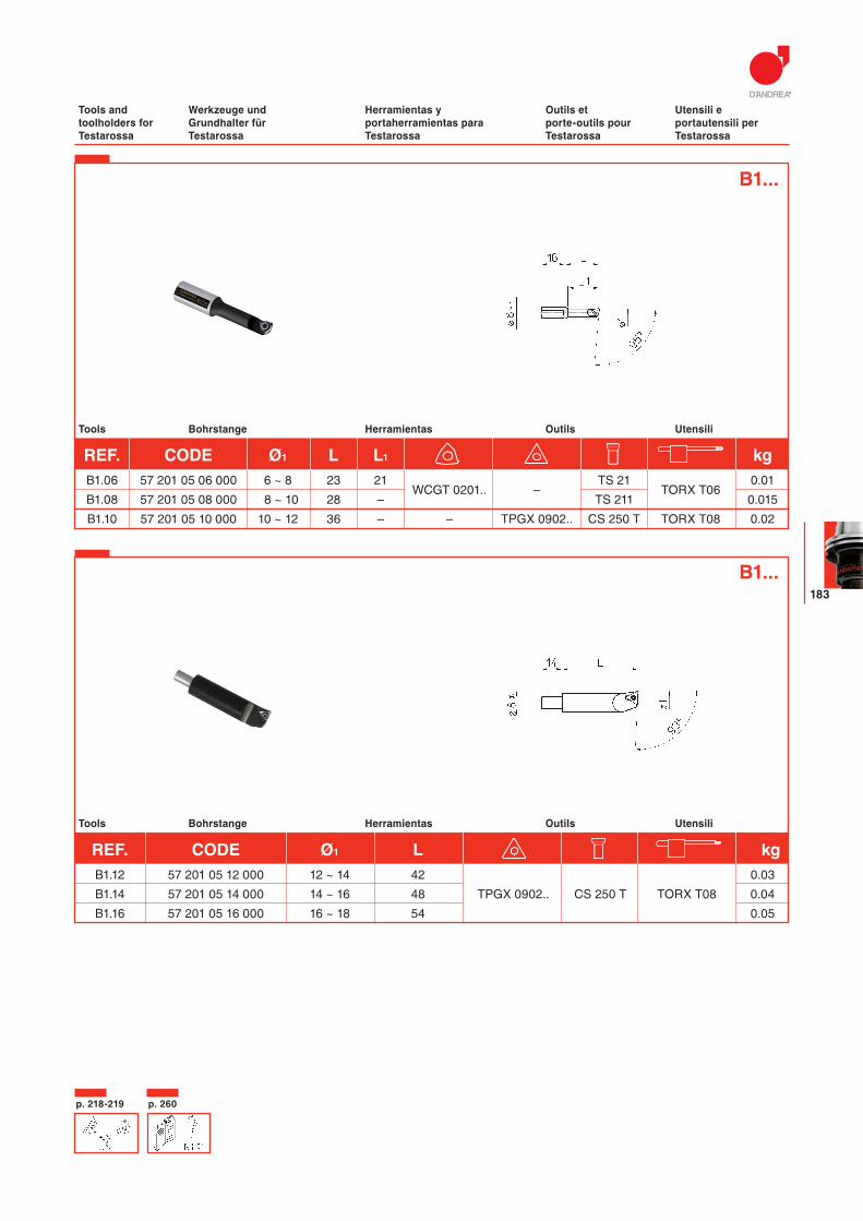
183
Bohrstange Herramientas Outils UtensiliTools
B1...
Bohrstange Herramientas Outils UtensiliTools
B1...
REF. CODE Ø1 L L1 kg B1.06 57 201 05 06 000 6 ~ 8 23 21
WCGT 0201.. – TS 21
TORX T06 0.01
B1.08 57 201 05 08 000 8 ~ 10 28 – TS 211 0.015
B1.10 57 201 05 10 000 10 ~ 12 36 – – TPGX 0902.. CS 250 T TORX T08 0.02
REF. CODE Ø1 L kg B1.12 57 201 05 12 000 12 ~ 14 42 0.03
B1.14 57 201 05 14 000 14 ~ 16 48 TPGX 0902.. CS 250 T TORX T08 0.04
B1.16 57 201 05 16 000 16 ~ 18 54 0.05
p. 218-219 p. 260
Werkzeuge und Grundhalter für Testarossa
Herramientas y portaherramientas para Testarossa
Outils et porte-outils pour Testarossa
Utensili e portautensili per Testarossa
Tools and toolholders for Testarossa
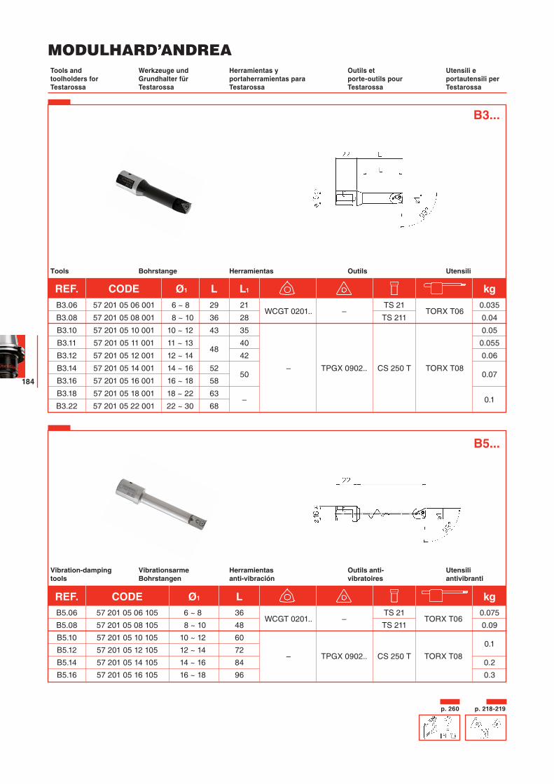
MODULHARD’ANDREA
184
Bohrstange Herramientas Outils UtensiliTools
Vibrationsarme Bohrstangen
Herramientas anti-vibración
Outils anti-vibratoires
Utensiliantivibranti
Vibration-damping tools
B3...
B5...
REF. CODE Ø1 L L1 kg
B3.06 57 201 05 06 001 6 ~ 8 29 21 WCGT 0201.. –
TS 21 TORX T06
0.035
B3.08 57 201 05 08 001 8 ~ 10 36 28 TS 211 0.04
B3.10 57 201 05 10 001 10 ~ 12 43 35 0.05
B3.11 57 201 05 11 001 11 ~ 13 48
40 0.055
B3.12 57 201 05 12 001 12 ~ 14 42 0.06
B3.14 57 201 05 14 001 14 ~ 16 52 50
– TPGX 0902.. CS 250 T TORX T08 0.07
B3.16 57 201 05 16 001 16 ~ 18 58
B3.18 57 201 05 18 001 18 ~ 22 63 –
0.1
B3.22 57 201 05 22 001 22 ~ 30 68
REF. CODE Ø1 L kg
B5.06 57 201 05 06 105 6 ~ 8 36 WCGT 0201.. –
TS 21 TORX T06
0.075
B5.08 57 201 05 08 105 8 ~ 10 48 TS 211 0.09
B5.10 57 201 05 10 105 10 ~ 12 60 0.1
B5.12 57 201 05 12 105 12 ~ 14 72 – TPGX 0902.. CS 250 T TORX T08
B5.14 57 201 05 14 105 14 ~ 16 84 0.2
B5.16 57 201 05 16 105 16 ~ 18 96 0.3
p. 260 p. 218-219
Werkzeuge und Grundhalter für Testarossa
Herramientas y portaherramientas para Testarossa
Outils et porte-outils pour Testarossa
Utensili e portautensili per Testarossa
Tools and toolholders for Testarossa
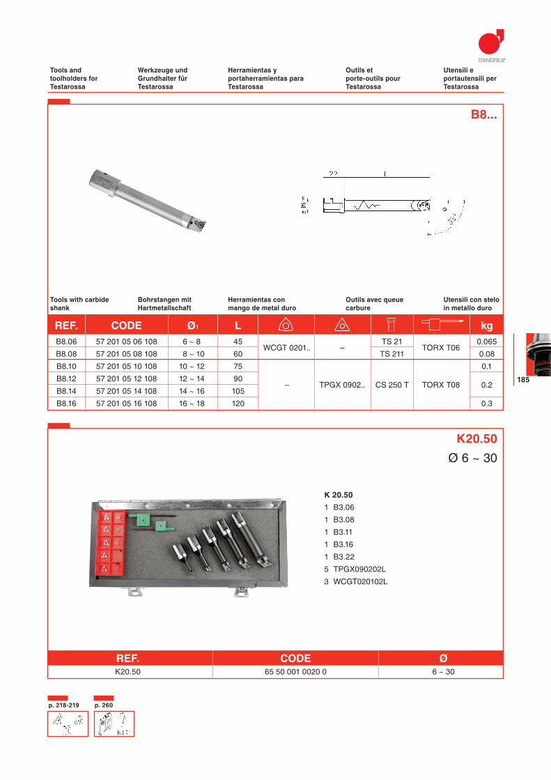
185
B8...
Bohrstangen mit Hartmetallschaft
Herramientas con mango de metal duro
Outils avec queue carbure
Utensili con steloin metallo duro
Tools with carbide shank
K 20.50
1 B3.06
1 B3.08
1 B3.11
1 B3.16
1 B3.22
5 TPGX090202L
3 WCGT020102L
K20.50
Ø 6 ~ 30
REF. CODE Ø K20.50 65 50 001 0020 0 6 ~ 30
REF. CODE Ø1 L kg B8.06 57 201 05 06 108 6 ~ 8 45
WCGT 0201.. – TS 21
TORX T06 0.065
B8.08 57 201 05 08 108 8 ~ 10 60 TS 211 0.08
B8.10 57 201 05 10 108 10 ~ 12 75 0.1
B8.12 57 201 05 12 108 12 ~ 14 90 – TPGX 0902.. CS 250 T TORX T08
0.2
B8.14 57 201 05 14 108 14 ~ 16 105
B8.16 57 201 05 16 108 16 ~ 18 120 0.3
Werkzeuge und Grundhalter für Testarossa
Herramientas y portaherramientas para Testarossa
Outils et porte-outils pour Testarossa
Utensili e portautensili per Testarossa
Tools and toolholders for Testarossa
p. 218-219 p. 260
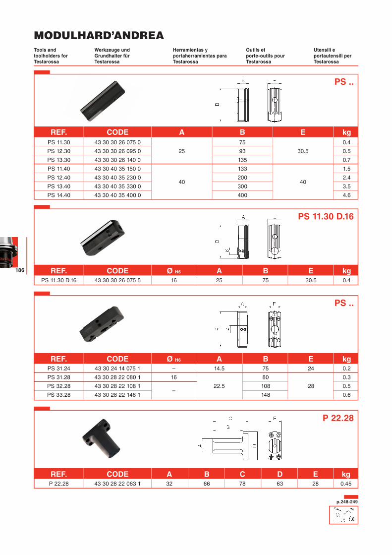
MODULHARD’ANDREA
186
PS ..
PS ..
REF. CODE Ø H6 A B E kg PS 31.24 43 30 24 14 075 1 – 14.5 75 24 0.2
PS 31.28 43 30 28 22 080 1 16 80 0.3
PS 32.28 43 30 28 22 108 1 –
22.5 108 28 0.5
PS 33.28 43 30 28 22 148 1 148 0.6
REF. CODE A B E kg PS 11.30 43 30 30 26 075 0 75 0.4
PS 12.30 43 30 30 26 095 0 25 93 30.5 0.5
PS 13.30 43 30 30 26 140 0 135 0.7
PS 11.40 43 30 40 35 150 0 133 1.5
PS 12.40 43 30 40 35 230 0 40
200 40
2.4
PS 13.40 43 30 40 35 330 0 300 3.5
PS 14.40 43 30 40 35 400 0 400 4.6
p.248-249
REF. CODE Ø H6 A B E kg PS 11.30 D.16 43 30 30 26 075 5 16 25 75 30.5 0.4
REF. CODE A B C D E kg P 22.28 43 30 28 22 063 1 32 66 78 63 28 0.45
PS 11.30 D.16
P 22.28
Werkzeuge und Grundhalter für Testarossa
Herramientas y portaherramientas para Testarossa
Outils et porte-outils pour Testarossa
Utensili e portautensili per Testarossa
Tools and toolholders for Testarossa
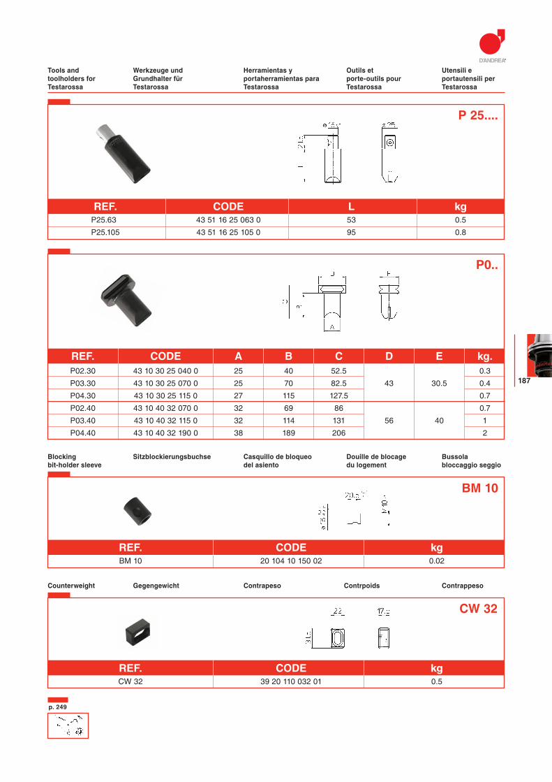
187
CW 32
Gegengewicht Contrapeso Contrpoids ContrappesoCounterweight
P0..
REF. CODE A B C D E kg. P02.30 43 10 30 25 040 0 25 40 52.5 0.3
P03.30 43 10 30 25 070 0 25 70 82.5 43 30.5 0.4
P04.30 43 10 30 25 115 0 27 115 127.5 0.7
P02.40 43 10 40 32 070 0 32 69 86 0.7
P03.40 43 10 40 32 115 0 32 114 131 56 40 1
P04.40 43 10 40 32 190 0 38 189 206 2
P 25....
p. 249
Sitzblockierungsbuchse Casquillo de bloqueo del asiento
Douille de blocage du logement
Bussola bloccaggio seggio
Blocking bit-holder sleeve
BM 10
Werkzeuge und Grundhalter für Testarossa
Herramientas y portaherramientas para Testarossa
Outils et porte-outils pour Testarossa
Utensili e portautensili per Testarossa
Tools and toolholders for Testarossa
REF. CODE L kg P25.63 43 51 16 25 063 0 53 0.5
P25.105 43 51 16 25 105 0 95 0.8
REF. CODE kg BM 10 20 104 10 150 02 0.02
REF. CODE kg CW 32 39 20 110 032 01 0.5
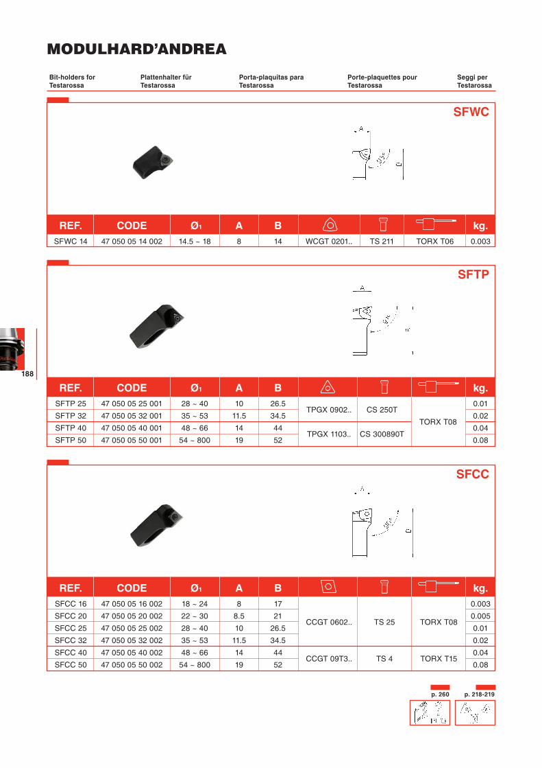
MODULHARD’ANDREA
188
SFWC
SFTP
Plattenhalter für Testarossa
Porta-plaquitas para Testarossa
Porte-plaquettes pour Testarossa
Seggi perTestarossa
Bit-holders for Testarossa
SFCC
REF. CODE Ø1 A B kg. SFWC 14 47 050 05 14 002 14.5 ~ 18 8 14 WCGT 0201.. TS 211 TORX T06 0.003
REF. CODE Ø1 A B kg. SFTP 25 47 050 05 25 001 28 ~ 40 10 26.5
TPGX 0902.. CS 250T 0.01
SFTP 32 47 050 05 32 001 35 ~ 53 11.5 34.5 TORX T08
0.02
SFTP 40 47 050 05 40 001 48 ~ 66 14 44 TPGX 1103.. CS 300890T
0.04
SFTP 50 47 050 05 50 001 54 ~ 800 19 52 0.08
REF. CODE Ø1 A B kg. SFCC 16 47 050 05 16 002 18 ~ 24 8 17 0.003
SFCC 20 47 050 05 20 002 22 ~ 30 8.5 21 CCGT 0602.. TS 25 TORX T08
0.005
SFCC 25 47 050 05 25 002 28 ~ 40 10 26.5 0.01
SFCC 32 47 050 05 32 002 35 ~ 53 11.5 34.5 0.02
SFCC 40 47 050 05 40 002 48 ~ 66 14 44 CCGT 09T3.. TS 4 TORX T15
0.04
SFCC 50 47 050 05 50 002 54 ~ 800 19 52 0.08
p. 218-219p. 260
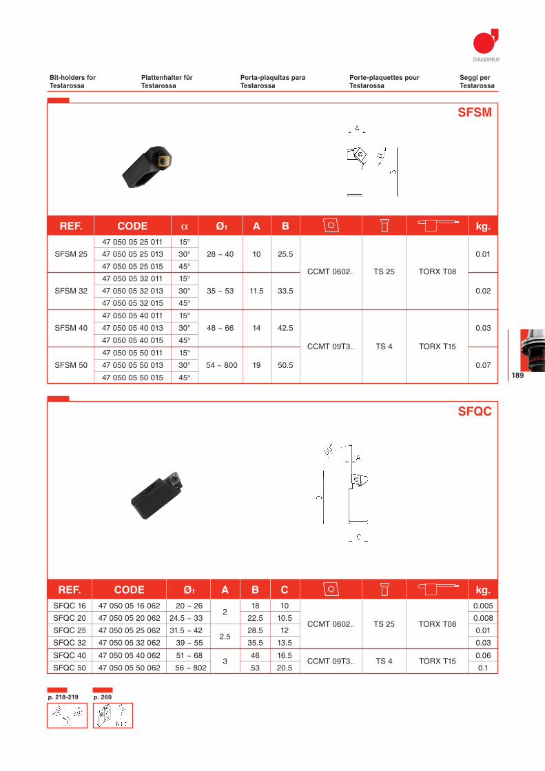
189
SFSM
SFQC
REF. CODE α Ø1 A B kg. 47 050 05 25 011 15°
SFSM 25 47 050 05 25 013 30° 28 ~ 40 10 25.5 0.01
47 050 05 25 015 45° CCMT 0602.. TS 25 TORX T08
47 050 05 32 011 15°
SFSM 32 47 050 05 32 013 30° 35 ~ 53 11.5 33.5 0.02
47 050 05 32 015 45°
47 050 05 40 011 15°
SFSM 40 47 050 05 40 013 30° 48 ~ 66 14 42.5 0.03
47 050 05 40 015 45° CCMT 09T3.. TS 4 TORX T15
47 050 05 50 011 15°
SFSM 50 47 050 05 50 013 30° 54 ~ 800 19 50.5 0.07
47 050 05 50 015 45°
REF. CODE Ø1 A B C kg. SFQC 16 47 050 05 16 062 20 ~ 26
2 18 10 0.005
SFQC 20 47 050 05 20 062 24.5 ~ 33 22.5 10.5 CCMT 0602.. TS 25 TORX T08
0.008
SFQC 25 47 050 05 25 062 31.5 ~ 42 2.5
28.5 12 0.01
SFQC 32 47 050 05 32 062 39 ~ 55 35.5 13.5 0.03
SFQC 40 47 050 05 40 062 51 ~ 68 3
46 16.5 CCMT 09T3.. TS 4 TORX T15
0.06
SFQC 50 47 050 05 50 062 56 ~ 802 53 20.5 0.1
p. 218-219 p. 260
Plattenhalter für Testarossa
Porta-plaquitas para Testarossa
Porte-plaquettes pour Testarossa
Seggi perTestarossa
Bit-holders for Testarossa
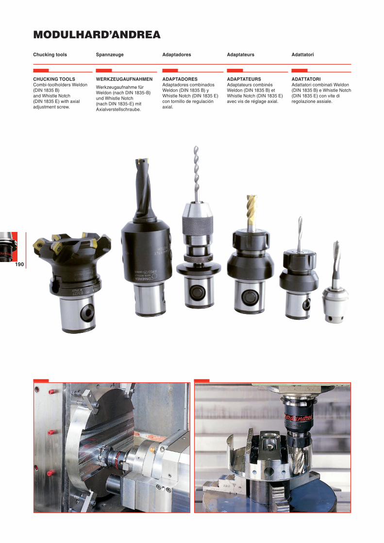
MODULHARD’ANDREA
190
Spannzeuge
Adaptadores
Adaptateurs
Adattatori Chucking tools
CHUCKING TOOLS Combi-toolholders Weldon (DIN 1835 B) and Whistle Notch (DIN 1835 E) with axial adjustment screw.
WERKZEUGAUFNAHMEN Werkzeugaufnahme für Weldon (nach DIN 1835-B) und Whistle Notch (nach DIN 1835-E) mit Axialverstellschraube.
ADAPTADORES Adaptadores combinados Weldon (DIN 1835 B) y Whistle Notch (DIN 1835 E) con tornillo de regulación axial.
ADAPTATEURS Adaptateurs combinés Weldon (DIN 1835 B) et Whistle Notch (DIN 1835 E) avec vis de réglage axial.
ADATTATORI Adattatori combinati Weldon (DIN 1835 B) e Whistle Notch (DIN 1835 E) con vite di regolazione assiale.
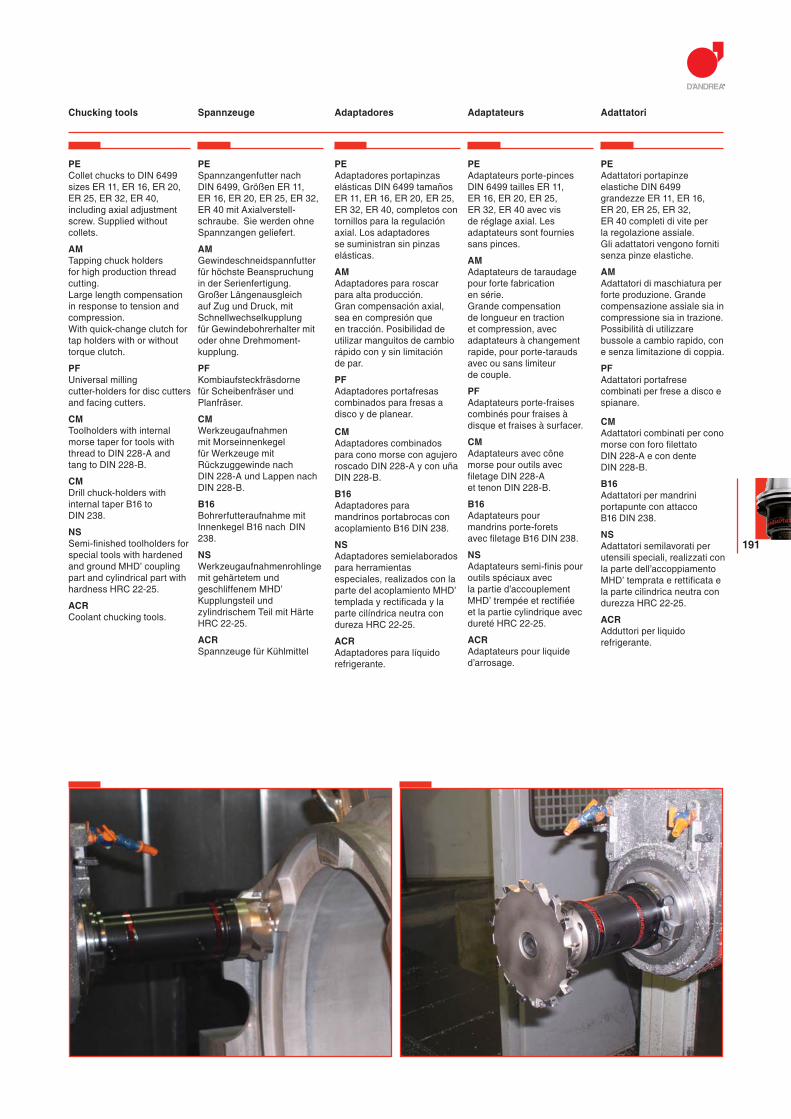
191
Spannzeuge
Adaptadores
Adaptateurs
Adattatori
Chucking tools
PE Collet chucks to DIN 6499 sizes ER 11, ER 16, ER 20, ER 25, ER 32, ER 40, including axial adjustment screw. Supplied without collets.
AMTapping chuck holders for high production thread cutting. Large length compensation in response to tension and compression.With quick-change clutch for tap holders with or without torque clutch.
PFUniversal milling cutter-holders for disc cutters and facing cutters.
CMToolholders with internal morse taper for tools with thread to DIN 228-A and tang to DIN 228-B.
CMDrill chuck-holders with internal taper B16 to DIN 238.
NSSemi-finished toolholders for special tools with hardened and ground MHD’ coupling part and cylindrical part with hardness HRC 22-25.
ACRCoolant chucking tools.
PE Spannzangenfutter nach DIN 6499, Größen ER 11, ER 16, ER 20, ER 25, ER 32, ER 40 mit Axialverstell-schraube. Sie werden ohne Spannzangen geliefert.
AMGewindeschneidspannfutter für höchste Beanspruchung in der Serienfertigung. Großer Längenausgleich auf Zug und Druck, mit Schnellwechselkupplung für Gewindebohrerhalter mit oder ohne Drehmoment- kupplung.
PF Kombiaufsteckfräsdorne für Scheibenfräser und Planfräser.
CM Werkzeugaufnahmen mit Morseinnenkegel für Werkzeuge mit Rückzuggewinde nach DIN 228-A und Lappen nach DIN 228-B.
B16 Bohrerfutteraufnahme mit Innenkegel B16 nach DIN 238.
NS Werkzeugaufnahmenrohlinge mit gehärtetem und geschliffenem MHD’ Kupplungsteil und zylindrischem Teil mit Härte HRC 22-25.
ACR Spannzeuge für Kühlmittel
PEAdaptadores portapinzas elásticas DIN 6499 tamaños ER 11, ER 16, ER 20, ER 25, ER 32, ER 40, completos con tornillos para la regulación axial. Los adaptadores se suministran sin pinzas elásticas.
AMAdaptadores para roscar para alta producción. Gran compensación axial, sea en compresión que en tracción. Posibilidad de utilizar manguitos de cambio rápido con y sin limitación de par.
PFAdaptadores portafresas combinados para fresas a disco y de planear.
CMAdaptadores combinados para cono morse con agujero roscado DIN 228-A y con uña DIN 228-B.
B16Adaptadores para mandrinos portabrocas con acoplamiento B16 DIN 238.
NSAdaptadores semielaborados para herramientas especiales, realizados con la parte del acoplamiento MHD’ templada y rectificada y la parte cilíndrica neutra con dureza HRC 22-25.
ACRAdaptadores para líquido refrigerante.
PEAdaptateurs porte-pinces DIN 6499 tailles ER 11, ER 16, ER 20, ER 25, ER 32, ER 40 avec vis de réglage axial. Les adaptateurs sont fournies sans pinces.
AMAdaptateurs de taraudage pour forte fabrication en série. Grande compensation de longueur en traction et compression, avec adaptateurs à changement rapide, pour porte-tarauds avec ou sans limiteur de couple.
PFAdaptateurs porte-fraises combinés pour fraises à disque et fraises à surfacer.
CMAdaptateurs avec cône morse pour outils avec filetage DIN 228-A et tenon DIN 228-B.
B16Adaptateurs pour mandrins porte-forets avec filetage B16 DIN 238.
NSAdaptateurs semi-finis pour outils spéciaux avec la partie d’accouplement MHD’ trempée et rectifiée et la partie cylindrique avec dureté HRC 22-25.
ACRAdaptateurs pour liquide d’arrosage.
PEAdattatori portapinze elastiche DIN 6499 grandezze ER 11, ER 16, ER 20, ER 25, ER 32, ER 40 completi di vite per la regolazione assiale. Gli adattatori vengono forniti senza pinze elastiche.
AMAdattatori di maschiatura per forte produzione. Grande compensazione assiale sia in compressione sia in trazione. Possibilità di utilizzare bussole a cambio rapido, con e senza limitazione di coppia.
PFAdattatori portafrese combinati per frese a disco e spianare.
CMAdattatori combinati per cono morse con foro filettato DIN 228-A e con dente DIN 228-B.
B16Adattatori per mandrini portapunte con attacco B16 DIN 238.
NSAdattatori semilavorati per utensili speciali, realizzati con la parte dell’accoppiamento MHD’ temprata e rettificata e la parte cilindrica neutra con durezza HRC 22-25.
ACRAdduttori per liquido refrigerante.
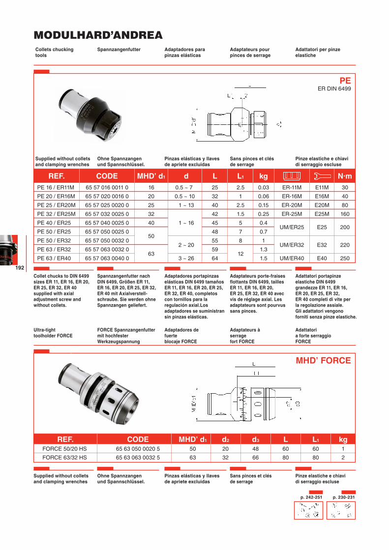
MODULHARD’ANDREA
192
Spannzangenfutter Adaptadores para pinzas elásticas
Adaptateurs pour pinces de serrage
Adattatori per pinze elastiche
Collets chucking tools
Ohne Spannzangen und Spannschlüssel.
Pinzas elásticas y llaves de apriete excluidas
Sans pinces et clés de serrage
Pinze elastiche e chiavi di serraggio escluse
Supplied without collets and clamping wrenches
Collet chucks to DIN 6499 sizes ER 11, ER 16, ER 20, ER 25, ER 32, ER 40 supplied with axial adjustment screw and without collets.
Spannzangenfutter nach DIN 6499, Größen ER 11, ER 16, ER 20, ER 25, ER 32, ER 40 mit Axialverstell-schraube. Sie werden ohne Spannzangen geliefert.
Adaptadores portapinzas elásticas DIN 6499 tamaños ER 11, ER 16, ER 20, ER 25, ER 32, ER 40, completos con tornillos para la regulación axial.Los adaptadores se suministran sin pinzas elásticas.
Adaptateurs porte-fraises flottants DIN 6499, tailles ER 11, ER 16, ER 20, ER 25, ER 32, ER 40 avec vis de réglage axial. Les adaptateurs sont pourvus sans pinces.
Adattatori portapinze elastiche DIN 6499 grandezze ER 11, ER 16, ER 20, ER 25, ER 32, ER 40 completi di vite per la regolazione assiale. Gli adattatori vengono forniti senza pinze elastiche.
PEER DIN 6499
p. 230-231p. 242-251
REF. CODE MHD’ d1 d L L1 kg N·m PE 16 / ER11M 65 57 016 0011 0 16 0.5 ~ 7 25 2.5 0.03 ER-11M E11M 30
PE 20 / ER16M 65 57 020 0016 0 20 0.5 ~ 10 32 1 0.06 ER-16M E16M 40
PE 25 / ER20M 65 57 025 0020 0 25 1 ~ 13 40 2.5 0.15 ER-20M E20M 80
PE 32 / ER25M 65 57 032 0025 0 32 42 1.5 0.25 ER-25M E25M 160
PE 40 / ER25 65 57 040 0025 0 40 1 ~ 16 45 5 0.4 UM/ER25 E25 200
PE 50 / ER25 65 57 050 0025 0 50
48 7 0.7
PE 50 / ER32 65 57 050 0032 0 2 ~ 20
55 8 1 UM/ER32 E32 220
PE 63 / ER32 65 57 063 0032 0 63
59 12
1.3
PE 63 / ER40 65 57 063 0040 0 3 ~ 26 64 1.5 UM/ER40 E40 250
FORCE Spannzangenfutter mit hochfester Werkzeugspannung
Adaptadores de fuerte blocaje FORCE
Adaptateurs à serrage fort FORCE
Adattatori a forte serraggio FORCE
Ultra-tight toolholder FORCE
MHD’ FORCE
REF. CODE MHD’ d1 d2 d3 L L1 kg FORCE 50/20 HS 65 63 050 0020 5 50 20 48 60 60 1
FORCE 63/32 HS 65 63 063 0032 5 63 32 66 80 80 2
Ohne Spannzangen und Spannschlüssel.
Pinzas elásticas y llaves de apriete excluidas
Sans pinces et clés de serrage
Pinze elastiche e chiavi di serraggio escluse
Supplied without collets and clamping wrenches
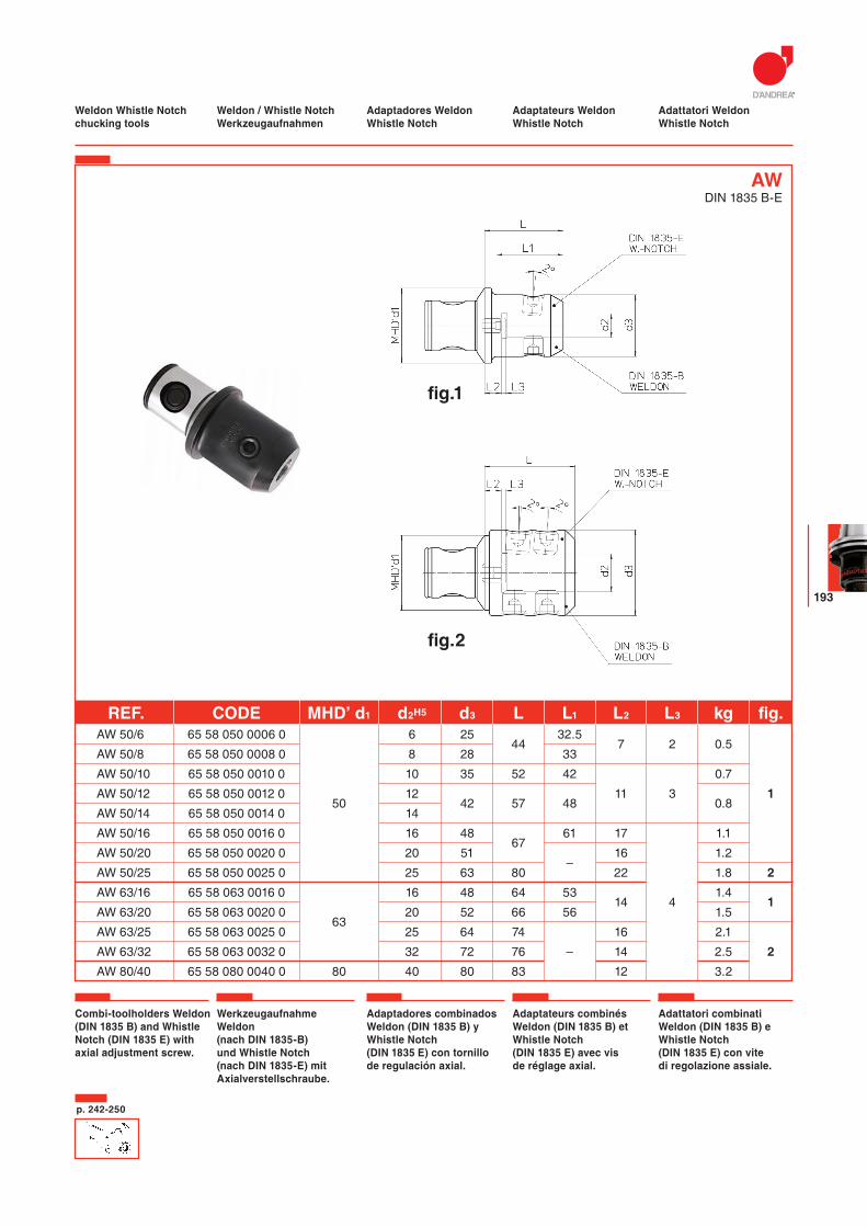
193
p. 242-250
Weldon / Whistle Notch Werkzeugaufnahmen
Adaptadores Weldon Whistle Notch
Adaptateurs Weldon Whistle Notch
Adattatori Weldon Whistle Notch
Weldon Whistle Notch chucking tools
Combi-toolholders Weldon (DIN 1835 B) and Whistle Notch (DIN 1835 E) with axial adjustment screw.
Werkzeugaufnahme Weldon (nach DIN 1835-B) und Whistle Notch (nach DIN 1835-E) mit Axialverstellschraube.
Adaptadores combinados Weldon (DIN 1835 B) y Whistle Notch (DIN 1835 E) con tornillo de regulación axial.
Adaptateurs combinés Weldon (DIN 1835 B) et Whistle Notch (DIN 1835 E) avec vis de réglage axial.
Adattatori combinati Weldon (DIN 1835 B) e Whistle Notch (DIN 1835 E) con vite di regolazione assiale.
AWDIN 1835 B-E
fig.1
fig.2
REF. CODE MHD’ d1 d2H5 d3 L L1 L2 L3 kg fig. AW 50/6 65 58 050 0006 0 6 25
44 32.5
7 2
0.5
AW 50/8 65 58 050 0008 0 8 28 33
AW 50/10 65 58 050 0010 0 10 35 52 42 0.7
AW 50/12 65 58 050 0012 0 50
12 42 57 48
11 3 0.8
1
AW 50/14 65 58 050 0014 0 14
AW 50/16 65 58 050 0016 0 16 48 67
61 17
1.1
AW 50/20 65 58 050 0020 0 20 51 –
16 1.2
AW 50/25 65 58 050 0025 0 25 63 80 22 1.8 2
AW 63/16 65 58 063 0016 0 16 48 64 53 14
4
1.4 1
AW 63/20 65 58 063 0020 0 63
20 52 66 56 1.5
AW 63/25 65 58 063 0025 0 25 64 74 16 2.1
AW 63/32 65 58 063 0032 0 32 72 76 – 14 2.5 2
AW 80/40 65 58 080 0040 0 80 40 80 83 12 3.2
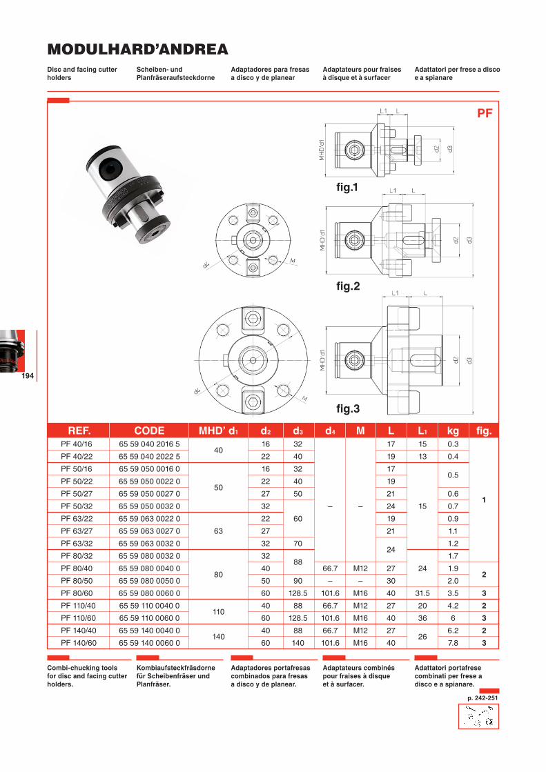
MODULHARD’ANDREA
194
Scheiben- und Planfräseraufsteckdorne
Adaptadores para fresas a disco y de planear
Adaptateurs pour fraises à disque et à surfacer
Adattatori per frese a disco e a spianare
Disc and facing cutter holders
Combi-chucking tools for disc and facing cutter holders.
Kombiaufsteckfräsdorne für Scheibenfräser und Planfräser.
Adaptadores portafresas combinados para fresas a disco y de planear.
Adaptateurs combinés pour fraises à disque et à surfacer.
Adattatori portafrese combinati per frese a disco e a spianare.
PF
fig.1
fig.2
fig.3
p. 242-251
REF. CODE MHD’ d1 d2 d3 d4 M L L1 kg fig. PF 40/16 65 59 040 2016 5
40 16 32 17 15 0.3
PF 40/22 65 59 040 2022 5 22 40 19 13 0.4
PF 50/16 65 59 050 0016 0 16 32 17 0.5
PF 50/22 65 59 050 0022 0 50
22 40 19
PF 50/27 65 59 050 0027 0 27 50 21 0.6 1
PF 50/32 65 59 050 0032 0 32 – – 24 15 0.7
PF 63/22 65 59 063 0022 0 22 60 19 0.9
PF 63/27 65 59 063 0027 0 63 27 21 1.1
PF 63/32 65 59 063 0032 0 32 70 24
1.2
PF 80/32 65 59 080 0032 0 32 88
1.7
PF 80/40 65 59 080 0040 0 80
40 66.7 M12 27 24 1.9 2
PF 80/50 65 59 080 0050 0 50 90 – – 30 2.0
PF 80/60 65 59 080 0060 0 60 128.5 101.6 M16 40 31.5 3.5 3
PF 110/40 65 59 110 0040 0 110
40 88 66.7 M12 27 20 4.2 2
PF 110/60 65 59 110 0060 0 60 128.5 101.6 M16 40 36 6 3
PF 140/40 65 59 140 0040 0 140
40 88 66.7 M12 27 26
6.2 2
PF 140/60 65 59 140 0060 0 60 140 101.6 M16 40 7.8 3
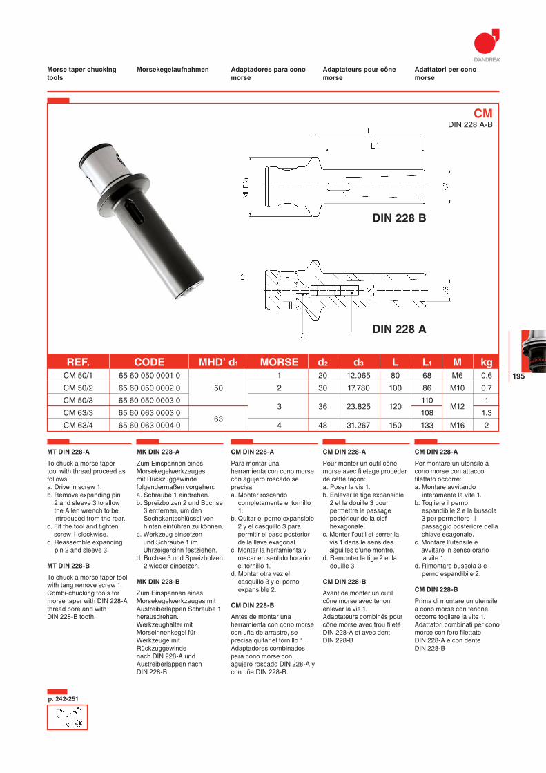
195
MT DIN 228-A
To chuck a morse taper tool with thread proceed as follows:a. Drive in screw 1.b. Remove expanding pin
2 and sleeve 3 to allow the Allen wrench to be introduced from the rear.
c. Fit the tool and tighten screw 1 clockwise.
d. Reassemble expanding pin 2 and sleeve 3.
MT DIN 228-B
To chuck a morse taper tool with tang remove screw 1. Combi-chucking tools for morse taper with DIN 228-A thread bore and with DIN 228-B tooth.
MK DIN 228-A
Zum Einspannen eines Morsekegelwerkzeuges mit Rückzuggewinde folgendermaßen vorgehen: a. Schraube 1 eindrehen. b. Spreizbolzen 2 und Buchse
3 entfernen, um den Sechskantschlüssel von hinten einführen zu können.
c. Werkzeug einsetzen und Schraube 1 im Uhrzeigersinn festziehen.
d. Buchse 3 und Spreizbolzen 2 wieder einsetzen.
MK DIN 228-B
Zum Einspannen eines Morsekegelwerkzeuges mit Austreiberlappen Schraube 1 herausdrehen. Werkzeughalter mit Morseinnenkegel für Werkzeuge mit Rückzuggewinde nach DIN 228-A und Austreiberlappen nach DIN 228-B.
CM DIN 228-A
Para montar una herramienta con cono morse con agujero roscado se precisa: a. Montar roscando
completamente el tornillo 1.
b. Quitar el perno expansible 2 y el casquillo 3 para permitir el paso posterior de la llave exagonal.
c. Montar la herramienta y roscar en sentido horario el tornillo 1.
d. Montar otra vez el casquillo 3 y el perno expansible 2.
CM DIN 228-B
Antes de montar una herramienta con cono morse con uña de arrastre, se precisa quitar el tornillo 1. Adaptadores combinados para cono morse con agujero roscado DIN 228-A y con uña DIN 228-B.
CM DIN 228-A
Pour monter un outil cône morse avec filetage procéder de cette façon:a. Poser la vis 1. b. Enlever la tige expansible
2 et la douille 3 pour permettre le passage postérieur de la clef hexagonale.
c. Monter l’outil et serrer la vis 1 dans le sens des aiguilles d’une montre.
d. Remonter la tige 2 et la douille 3.
CM DIN 228-B
Avant de monter un outil cône morse avec tenon, enlever la vis 1.Adaptateurs combinés pour cône morse avec trou fileté DIN 228-A et avec dent DIN 228-B
CM DIN 228-A
Per montare un utensile a cono morse con attacco filettato occorre: a. Montare avvitando
interamente la vite 1.b. Togliere il perno
espandibile 2 e la bussola 3 per permettere il passaggio posteriore della chiave esagonale.
c. Montare l’utensile e avvitare in senso orario la vite 1.
d. Rimontare bussola 3 e perno espandibile 2.
CM DIN 228-B
Prima di montare un utensile a cono morse con tenone occorre togliere la vite 1. Adattatori combinati per cono morse con foro filettato DIN 228-A e con dente DIN 228-B
Morsekegelaufnahmen Adaptadores para cono morse
Adaptateurs pour cône morse
Adattatori per cono morse
Morse taper chucking tools
CMDIN 228 A-B
DIN 228 B
DIN 228 A
p. 242-251
REF. CODE MHD’ d1 MORSE d2 d3 L L1 M kg CM 50/1 65 60 050 0001 0 1 20 12.065 80 68 M6 0.6
CM 50/2 65 60 050 0002 0 50 2 30 17.780 100 86 M10 0.7
CM 50/3 65 60 050 0003 0 3 36 23.825 120
110 M12
1
CM 63/3 65 60 063 0003 0 63
108 1.3
CM 63/4 65 60 063 0004 0 4 48 31.267 150 133 M16 2
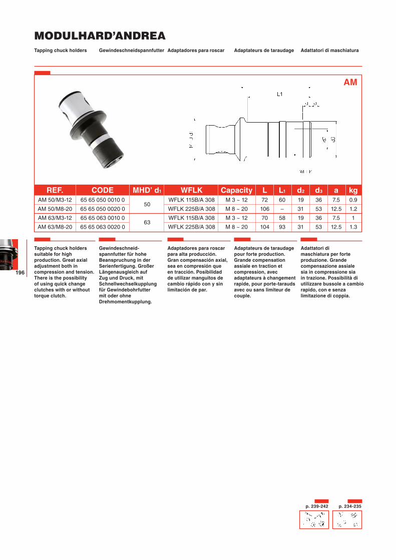
MODULHARD’ANDREA
196
Gewindeschneidspannfutter Adaptadores para roscar Adaptateurs de taraudage Adattatori di maschiaturaTapping chuck holders
Gewindeschneid-spannfutter für hohe Beanspruchung in der Serienfertigung. Großer Längenausgleich auf Zug und Druck, mit Schnellwechselkupplung für Gewindebohrfutter mit oder ohne Drehmomentkupplung.
Tapping chuck holders suitable for high production. Great axial adjustment both in compression and tension. There is the possibility of using quick change clutches with or without torque clutch.
Adaptadores para roscar para alta producción. Gran compensación axial, sea en compresión que en tracción. Posibilidad de utilizar manguitos de cambio rápido con y sin limitación de par.
Adaptateurs de taraudage pour forte production. Grande compensation assiale en traction et compression, avec adaptateurs à changement rapide, pour porte-tarauds avec ou sans limiteur de couple.
Adattatori di maschiatura per forte produzione. Grande compensazione assiale sia in compressione sia in trazione. Possibilità di utilizzare bussole a cambio rapido, con e senza limitazione di coppia.
REF. CODE MHD’ d1 WFLK Capacity L L1 d2 d3 a kg AM 50/M3-12 65 65 050 0010 0
50 WFLK 115B/A 308 M 3 ~ 12 72 60 19 36 7.5 0.9
AM 50/M8-20 65 65 050 0020 0 WFLK 225B/A 308 M 8 ~ 20 106 – 31 53 12.5 1.2
AM 63/M3-12 65 65 063 0010 0 63
WFLK 115B/A 308 M 3 ~ 12 70 58 19 36 7.5 1
AM 63/M8-20 65 65 063 0020 0 WFLK 225B/A 308 M 8 ~ 20 104 93 31 53 12.5 1.3
AM
p. 234-235p. 239-242
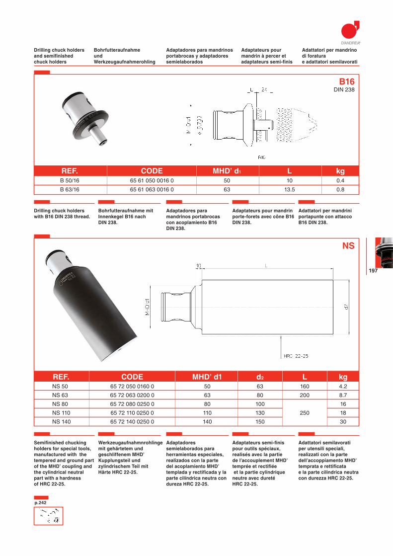
197
Bohrfutteraufnahme und Werkzeugaufnahmerohling
Adaptadores para mandrinos portabrocas y adaptadores semielaborados
Adaptateurs pour mandrin à percer et adaptateurs semi-finis
Adattatori per mandrino di foratura e adattatori semilavorati
Drilling chuck holders and semifinished chuck holders
Drilling chuck holders with B16 DIN 238 thread.
Bohrfutteraufnahme mit Innenkegel B16 nach DIN 238.
Adaptadores para mandrinos portabrocas con acoplamiento B16 DIN 238.
Adaptateurs pour mandrin porte-forets avec cône B16 DIN 238.
Adattatori per mandrini portapunte con attacco B16 DIN 238.
REF. CODE MHD’ d1 L kg
B 50/16 65 61 050 0016 0 50 10 0.4
B 63/16 65 61 063 0016 0 63 13.5 0.8
B16DIN 238
Semifinished chucking holders for special tools, manufactured with the tempered and ground part of the MHD’ coupling and the cylindrical neutral part with a hardness of HRC 22-25.
Werkzeugaufnahmnrohlinge mit gehärtetem und geschliffenem MHD’ Kupplungsteil und zylindrischem Teil mit Härte HRC 22-25.
Adaptadores semielaborados para herramientas especiales, realizados con la parte del acoplamiento MHD’ templada y rectificada y la parte cilíndrica neutra con dureza HRC 22-25.
Adaptateurs semi-finis pour outils spéciaux, realisés avec la partie de l’accouplement MHD’ temprée et rectifiée et la partie cylindrique neutre avec dureté HRC 22-25.
Adattatori semilavorati per utensili speciali, realizzati con la parte dell’accoppiamento MHD’ temprata e rettificata e la parte cilindrica neutra con durezza HRC 22-25.
NS
p.242
REF. CODE MHD’ d1 d2 L kg
NS 50 65 72 050 0160 0 50 63 160 4.2
NS 63 65 72 063 0200 0 63 80 200 8.7
NS 80 65 72 080 0250 0 80 100 16
NS 110 65 72 110 0250 0 110 130 250 18
NS 140 65 72 140 0250 0 140 150 30
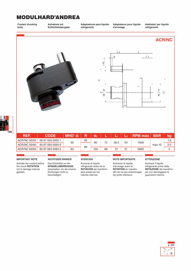
MODULHARD’ANDREA
198
Aufnahme mit Kühlmittelübergabe
Adaptadores para líquido refrigerante
Adaptateurs pour liquide d’arrosage
Adattatori per liquido refrigerante
Coolant chucking tools
ACR/NC
p. 242
REF. CODE MHD’ d1 R d2 L L1 L2 RPM max BAR kg ACR/NC 50/50 65 67 050 0050 1
50 65
80 72 28.5 43 7000 1.9
ACR/NC 50/50 65 67 050 0050 0 80
max 10 2.5
ACR/NC 63/63 65 67 063 0063 0 63 100 88 37 51 5600 5
IMPORTANT NOTE
Activate the coolant before the chuck ROTATION not to damage internal gaskets.
WICHTIGER HINWEIS
Das Kühlmittel vor der SPINDELUMDREHUNG einschalten, um die inneren Dichtungen nicht zu beschädigen.
ATENCIÓN
Accionar el líquido refrigerante antes de la ROTACIÓN del mandrino para preservar los retenes internos.
NOTE IMPORTANTE
Actionner le liquide d’arrosage avant la ROTATION du mandrin afin de ne pas endommager les joints intérieurs
ATTENZIONE
Azionare il liquido refrigerante prima della ROTAZIONE del mandrino per non danneggiare le guarnizioni interne.
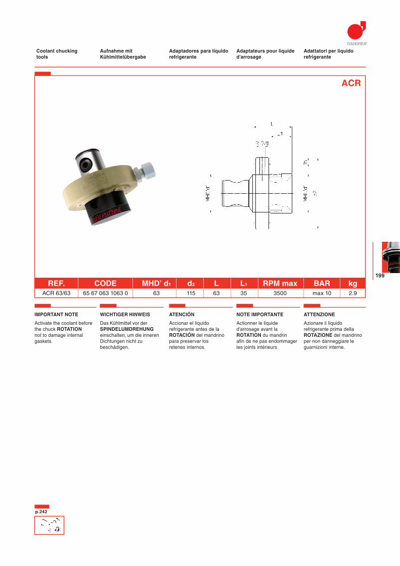
199
Aufnahme mit Kühlmittelübergabe
Adaptadores para líquido refrigerante
Adaptateurs pour liquide d’arrosage
Adattatori per liquido refrigerante
Coolant chucking tools
REF. CODE MHD’ d1 d2 L L1 RPM max BAR kg ACR 63/63 65 67 063 1063 0 63 115 63 35 3500 max 10 2.9
ACR
p.242
IMPORTANT NOTE
Activate the coolant before the chuck ROTATION not to damage internal gaskets.
WICHTIGER HINWEIS
Das Kühlmittel vor der SPINDELUMDREHUNG einschalten, um die inneren Dichtungen nicht zu beschädigen.
ATENCIÓN
Accionar el líquido refrigerante antes de la ROTACIÓN del mandrino para preservar los retenes internos.
NOTE IMPORTANTE
Actionner le liquide d’arrosage avant la ROTATION du mandrin afin de ne pas endommager les joints intérieurs
ATTENZIONE
Azionare il liquido refrigerante prima della ROTAZIONE del mandrino per non danneggiare le guarnizioni interne.